Embed Size (px)
Citation preview
Magnetic Reluctance Method for Dynamical Modeling of Squirrel Cage Induction Machines
Jalal Nazarzadeh and Vahid NaeiniFaculty of Engineering
Shahed University, TehranIran
1. Introduction
Nowadays, induction machines play important role in electromechanical energy conversion inindustry. These machines are often operated in critical conditions where can cause unexpectedfailures and outages. Generally, stator and bearing faults, broken rotor bar and end-rings,air-gap irregularities are some of the major faults in an induction machine (Al-Shahrani, 2005;Sprooten, 2007) which may be situated the induction machines in out of service (Siddiqueet al., 2005). Fourier analysis for stator currents (Bellini et al., 2001; Benbouzid, 2000; Junget al., 2006), torque and rotor speed, acoustic noise and temperature analysis (Siddique et
al., 2005) are some classical techniques which introduced for identification and diagnosis ofinduction machines faults. Additionally, other heuristic methods were proposed to monitorof the induction machines for fault detection. For instance, neural network modelling wereapplied to monitor an induction machine for fault detection (Su & Chong, 2007). Also, spacevector of rotor magnetic field (Mirafzal & Demerdash, 2004) based on artificial intelligentapproaches and pendulous oscillation of the rotor magnetic field were proposed. Recently,a new technique based on the analysis of three-phase stator current envelopes was presented(Mirafzalet & Demerdash, 2008). In all monitoring and fault detection techniques, we needto tune up the monitoring systems based on response of induction machines for properoperations. However, experimental set up for testing any arbitrary fault conditions are notpractical. Thus, an accuracy dynamic and steady state models of induction machines are veryimportant for this propose.Also, for dynamical modelling of induction machines, space harmonic distribution, coresaturation and loss are often neglected in abc quantitative and two-axis methods (Krause etal., 1995). Thus, these approaches do not have an efficient accuracy for modelling of inductionmachines in asymmetrical and non-linear conditions. For considering distribution rotor bars,
coupled magnetic circuit method (Muñoz & Lipo, 1999), abc quantitative based on rotor barcurrents (Alemi & Nazarzadeh, 1996) can be utilized. Furthermore, winding function methodmay be used to include the stator winding distribution effect in the air gap flux (Luos et al.,1995). However, in all mentioned methods, the core saturation, stator and rotor teeth effectsand distributions of the rotor and stator windings can not be investigated, simultaneously.Also, Finite Element Method (FEM) is a professional technique for analysis of anyelectromagnetic systems, which needs to magnetic and geometry details of the systems (Faiz
3
www.intechopen.com
et al., 2002). This method is very accurate and flexible, but due to complexity, the dynamicalmodelling of an induction machine is quite complicated. Contrary to FEM, the MagneticEquivalent Circuit Method (MECM) can apply to analysis of the electro magnetics problemswith lower complexity. Magnetic saturation, space harmonics in stator and rotor teeth, statorwindings and distributed structure of a squirrel-cage rotor can be considered by MECM formodelling and analysis of any induction machines (Jeong et al., 2003; Ostovic, 1989). In thisapproach, the non-linear reluctances of flux paths use to configure magnetic equivalent circuit.This method has less complexity than FEM for dynamical modelling of induction machines.Therefore, developing an exact details model of induction machine for analysis of transient,sensitivity and fault diagnosis in the asymmetrical conditions are very essential.The present chapter introduces methodology of MECM for modelling and analysis ofasymmetrical non-linear systems in transient and steady state conditions. MECM is verysuitable method for finding a generalized accurate dynamical model of squirrel cage inductionmachines with asymmetrical conditions. For evaluation of the method, several simulationsin linear and non-linear conditions are made. Also, some simulations results for induction
machines with broken bar faults and core saturation conditions are included to illustratecapability of the method in asymmetrical conditions.
2. Electric and magnetic based model of squirrel cage induction machines
For detailed modelling of any electromagnetic systems, we have to find a correlation betweenelectric and magnetic variables of the system. Generally, a set of non-linear differentialequations presents dynamical model of a electromagnetic system that by using numerical
analysis, transient response of the electrical variables can be obtained. In addition, non-linearalgebraic equations illustrate non-linear relations between electrical and magnetic variables.MECM provides an augmented model of the electromagnetic systems, in which we canachieve all variables of the systems in transient and steady state, simultaneously. Also, themain advantages of MECM for modelling of induction machines are; simple algorithm forincluding distribution winding, stator and rotor teeth effects and magnetic core saturationphenomena. Global non-linear model of squirrel cage induction machines can be offeredin algebraical (magnetic) and differential (electric) equations which will be presented in thefollowing sections.
3. Magnetic equivalent circuit of induction machines
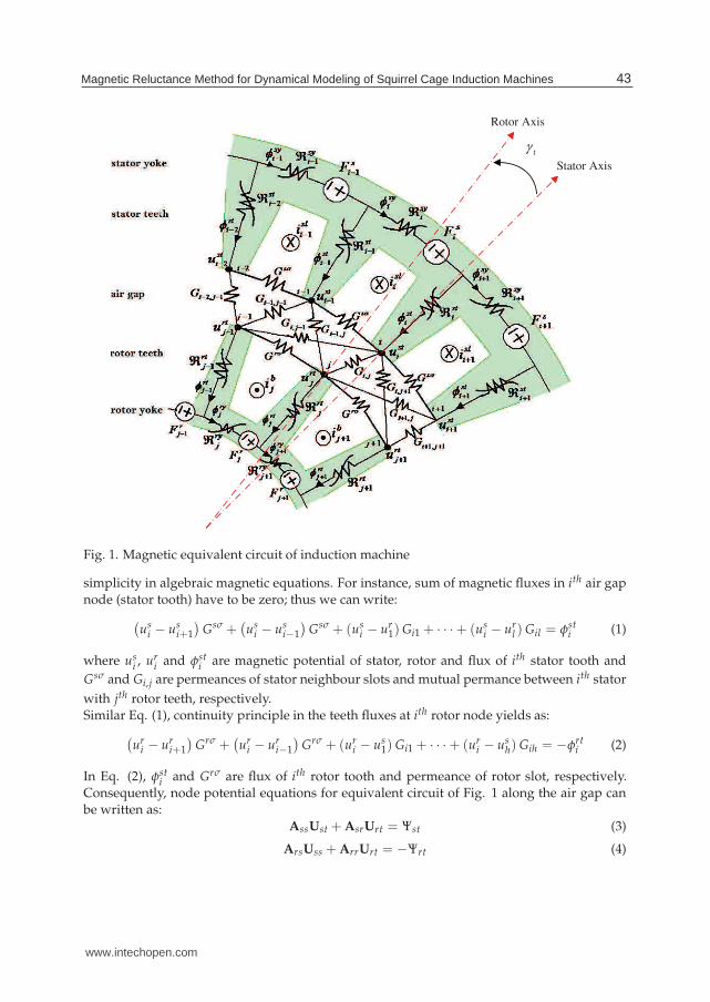
Fig. 1 shows a part of rotor and stator structures for a typical squirrel cage inductionmachine that magnetic circuit elements are presented for rotor and stator teeth and yoke.Numbers of rotor and stator teeth are considered by h and l, respectively. Also in this figure,magnetic mutual permeances of rotor and stator teeth in air gap are shown. Due to non-linearcharacteristics of flux and magnetic current in iron core, permeances of the rotor and stator inthe magnetic cores are illustrated as non-linear elements. Gi,j is linear permeance of flux path
between ith stator and jth rotor teeth in the air gap.
3.1 Magnetic node equations
Due to the fact that magnetic permeances of each stator and rotor teeth make several magneticloops in the air gap, we apply node magnetic potential equations to the each air gap nodes for
42 Electric Machines and Drives
www.intechopen.com
ti Stator Axis
Rotor Axis
Fig. 1. Magnetic equivalent circuit of induction machine
simplicity in algebraic magnetic equations. For instance, sum of magnetic fluxes in ith air gapnode (stator tooth) have to be zero; thus we can write:
(
usi − us
i+1
)
Gsσ +(
usi − us
i−1
)
Gsσ + (usi − ur
1) Gi1 + · · ·+ (usi − ur
l ) Gil = φsti (1)
where usi , ur
i and φsti are magnetic potential of stator, rotor and flux of ith stator tooth and
Gsσ and Gi,j are permeances of stator neighbour slots and mutual permance between ith stator
with jth rotor teeth, respectively.Similar Eq. (1), continuity principle in the teeth fluxes at ith rotor node yields as:
(
uri − ur
i+1
)
Grσ +(
uri − ur
i−1
)
Grσ + (uri − us
1) Gi1 + · · ·+ (uri − us
h) Gih = −φrti (2)
In Eq. (2), φsti and Grσ are flux of ith rotor tooth and permeance of rotor slot, respectively.
Consequently, node potential equations for equivalent circuit of Fig. 1 along the air gap canbe written as:
AssUst + AsrUrt = Ψst (3)
ArsUss + ArrUrt = −Ψrt (4)
43Magnetic Reluctance Method for Dynamical Modeling of Squirrel Cage Induction Machines
www.intechopen.com
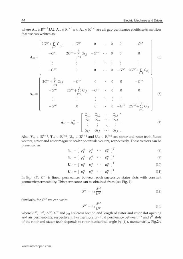
where Ass ∈Rh×hâAc, Arr ∈R
l×l and Asr ∈Rh×l are air gap permeance coefficients matrices
that we can written as:
Ass=
⎡
⎢
⎢
⎢
⎢
⎢
⎢
⎢
⎢
⎢
⎢
⎢
⎣
2Gsσ+l
∑j=1
G1,j −Gsσ 0 · · · 0 0 −Gsσ
−Gsσ 2Gsσ+l
∑j=1
G2,j −Gsσ · · · 0 0 0
......
.... . .
......
...
−Gsσ 0 0 · · · 0 −Gsσ 2Gsσ+l
∑j=1
Gh,j
⎤
⎥
⎥
⎥
⎥
⎥
⎥
⎥
⎥
⎥
⎥
⎥
⎦
(5)
Arr =
⎡
⎢
⎢
⎢
⎢
⎢
⎢
⎢
⎢
⎢
⎢
⎣
2Grσ+h
∑i=1
Gi,1 −Grσ 0 · · · 0 0 −Grσ
−Grσ 2Grσ+h
∑i=1
Gi,2 −Grσ · · · 0 0 0
......
.... . .
......
...
−Grσ 0 0 · · · 0 −Grσ 2Grσ+h
∑i=1
Gi,l
⎤
⎥
⎥
⎥
⎥
⎥
⎥
⎥
⎥
⎥
⎥
⎦
(6)
Asr = ATrs =
⎡
⎢
⎢
⎢
⎣
G1,1 G1,2 · · · G1,l
G2,1 G2,2 · · · G2,l...
.... . .
...Gh,1 Gh,2 · · · Gh,l
⎤
⎥
⎥
⎥
⎦
(7)
Also, Ψst ∈ Rh×1, Ψrt ∈ R
l×1, Ust ∈ Rh×1 and Urt ∈ R
l×1 are stator and rotor teeth fluxesvectors, stator and rotor magnetic scalar potentials vectors, respectively. These vectors can bepresented as:
Ψst =[
φst1 φst
2 · · · φsth
]T(8)
Ψrt =[
φrt1 φrt
2 · · · φrtl
]T(9)
Ust =[
ust1 ust
2 · · · usth
]T(10)
Urt =[
urt1 urt
2 · · · urtl
]T(11)
In Eq. (5), Gsσ is linear permeances between each successive stator slots with constantgeometric permeability. This permeance can be obtained from (see Fig. 1):
Gsσ = μ0Asσ
Lsσ(12)
Similarly, for Grσ we can write:
Grσ = μ0Arσ
Lrσ(13)
where Asσ, Lsσ, Arσ, Lrσ and μ0 are cross section and length of stator and rotor slot openingand air permeability, respectively. Furthermore, mutual permeance between ith and jth slotsof the rotor and stator teeth depends to rotor mechanical angle (γi(t)), momentarily. Fig.2-a
44 Electric Machines and Drives
www.intechopen.com
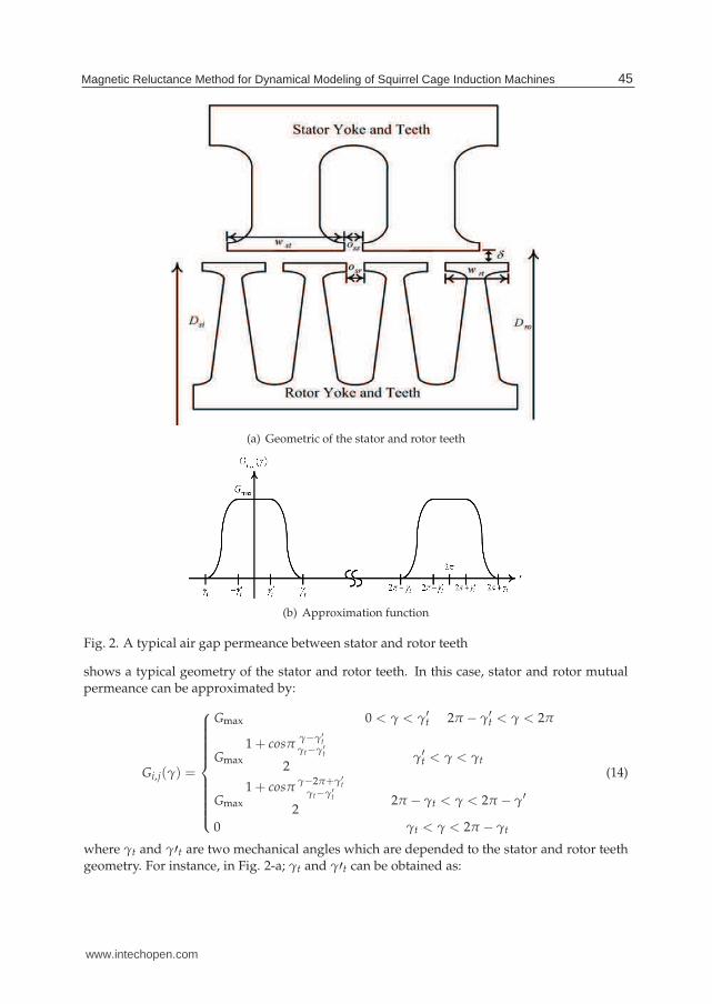
(a) Geometric of the stator and rotor teeth
(b) Approximation function
Fig. 2. A typical air gap permeance between stator and rotor teeth
shows a typical geometry of the stator and rotor teeth. In this case, stator and rotor mutualpermeance can be approximated by:
Gi,j(γ) =
⎧
⎪
⎪
⎪
⎪
⎪
⎪
⎪
⎪
⎪
⎨
⎪
⎪
⎪
⎪
⎪
⎪
⎪
⎪
⎪
⎩
Gmax 0 < γ < γ′t 2π − γ′
t < γ < 2π
Gmax
1 + cosπγ−γ′
t
γt−γ′t
2γ′
t < γ < γt
Gmax
1 + cosπγ−2π+γ′
t
γt−γ′t
22π − γt < γ < 2π − γ′
0 γt < γ < 2π − γt
(14)
where γt and γ′t are two mechanical angles which are depended to the stator and rotor teethgeometry. For instance, in Fig. 2-a; γt and γ′t can be obtained as:
45Magnetic Reluctance Method for Dynamical Modeling of Squirrel Cage Induction Machines
www.intechopen.com
γt =wst + wrt + oss + osr
Dag(15)
γ′t =
|wst − wrt|Dag
(16)
where wst, wrt, oss and osr are dimensions of stator and rotor which are shown in Fig. 2-a andDag is :
Dag =Dsi + Dro
2(17)
The maximum value of air gap permeance Gmax can be written as
Gmax = μ0l × min [wst, wrt]
δ(18)
where l and δ are lengths of machine and air gap.
3.2 Magnetic mesh equations
Eqs. (3) and (4) present l + h node equations which are shown relation between magneticpotentials of teeth nodes with stator and rotor teeth fluxes. Attention to Fig. 1, two neighbourstator teeth and yoke paths make a simple mesh in each stator slots, that sum of the magneticpotentials in these mesh have to be zero. For instance, magnetic mesh equation in ith and(i + 1)th stator teeth and yoke can be written as:
usti − ust
i−1 −ℜsti−1φst
i−1 +ℜsti φst
i +ℜsyi φ
syi = FS
i (19)
Similarly, mesh equation for ith rotor tooth and yoke with (i + 1)th rotor tooth can be obtainedas:
urti − urt
i−1 +ℜrti−1φrt
i−1 −ℜrti φrt
i +ℜryi φ
ryi = Fr
i (20)
Thus, magnetic mesh equations for all rotor and stator meshes can be expressed as:
AustUst + AΨsyΨsy + AϕstΨst = Fs (21)
AurtUrt + AφryΨry + AφrtΨrt = Fr (22)
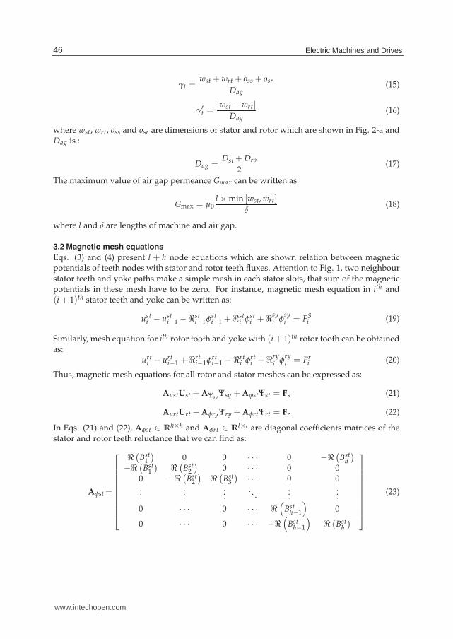
In Eqs. (21) and (22), Aφst ∈ Rh×h and Aφrt ∈ R
l×l are diagonal coefficients matrices of thestator and rotor teeth reluctance that we can find as:
Aφst=
⎡
⎢
⎢
⎢
⎢
⎢
⎢
⎢
⎢
⎢
⎣
ℜ(
Bst1
)
0 0 · · · 0 −ℜ(
Bsth
)
−ℜ(
Bst1
)
ℜ(
Bst2
)
0 · · · 0 00 −ℜ
(
Bst2
)
ℜ(
Bst3
)
· · · 0 0...
......
. . ....
...
0 · · · 0 · · · ℜ(
Bsth−1
)
0
0 · · · 0 · · · −ℜ(
Bsth−1
)
ℜ(
Bsth
)
⎤
⎥
⎥
⎥
⎥
⎥
⎥
⎥
⎥
⎥
⎦
(23)
46 Electric Machines and Drives
www.intechopen.com
Aφrt=
⎡
⎢
⎢
⎢
⎢
⎢
⎢
⎢
⎢
⎢
⎣
−ℜ(
Brt1
)
0 0 · · · 0 ℜ(
Brtl
)
ℜ(
Brt1
)
−ℜ(
Brt2
)
0 · · · 0 00 ℜ
(
Brt2
)
−ℜ(
Brt3
)
· · · 0 0...
......
. . ....
...
0 · · · 0 · · · −ℜ(
Brtl−1
)
0
0 · · · 0 · · · ℜ(
Brtl−1
)
−ℜ(
Brtl
)
⎤
⎥
⎥
⎥
⎥
⎥
⎥
⎥
⎥
⎥
⎦
(24)
also Aφsy ∈ Rh×h and Aφry ∈ R
l×l are stator and rotor yoke reluctance coefficients matriceswhich can be written as
Aφsy=diag(
ℜ(Bsy1 ),ℜ(Bsy
2 ), · · · ,ℜ(Bsyh )
)
(25)
Aφry=diag(
ℜ(Bry1 ),ℜ(Bry
2 ), · · · ,ℜ(Bryl )
)
(26)
which Ψsy ∈ Rh×1, Ψry ∈ R
l×1 are stator and rotor yoke fluxes vectors and Fs ∈ Rh×1 and
Fr ∈ Rl×1 are stator and rotor ampere-turn vectors, respectively. These vectors are considered
as:
Ψsy =[
φsy1 φ
sy2 · · · φ
syh
]T(27)
Ψry =[
φry1 φ
ry2 · · · φ
ryl
]T(28)
Fs =[
Fs1 Fs
2 · · · Fsh
]T(29)
Fr =[
Fr1 Fr
2 · · · Frl
]T(30)
Also, Aust ∈ Rh×h and Aurt ∈ R
l×lare constant matrices which are given by:
Aust=Aurt=
⎡
⎢
⎢
⎢
⎢
⎢
⎢
⎢
⎣
1 0 0 · · · 0 −1−1 1 0 · · · 0 00 −1 1 · · · 0 0...
......
. . ....
...
0 0 0 · · · 1 00 0 0 · · · −1 1
⎤
⎥
⎥
⎥
⎥
⎥
⎥
⎥
⎦
(31)
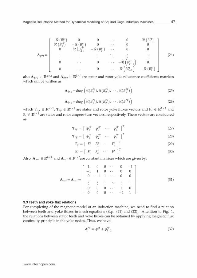
3.3 Teeth and yoke flux relations
For completing of the magnetic model of an induction machine, we need to find a relationbetween teeth and yoke fluxes in mesh equations (Eqs. (21) and (22)). Attention to Fig. 1,the relations between stator teeth and yoke fluxes can be obtained by applying magnetic fluxcontinuity principle in the yoke nodes. Thus, we have:
φsyi = φst
i + φsyi+1 (32)
47Magnetic Reluctance Method for Dynamical Modeling of Squirrel Cage Induction Machines
www.intechopen.com
Similarly, relation between the rotor fluxes are:
φryj+1 = φrt
j + φryj (33)
Eqs. (32) and (33) can be presented in matrix form as:
Ψst = AsytΨsy (34)
Ψrt = ArytΨry (35)
where Asyt ∈ Rh×h and Aryt ∈ R
l×l can be written as
Aryt= −Asyt=
⎡
⎢
⎢
⎢
⎢
⎢
⎢
⎢
⎣
−1 1 0 · · · 0 00 −1 1 · · · 0 00 0 −1 · · · 0 0...
......
. . ....
...0 0 0 · · · −1 11 0 0 · · · 0 −1
⎤
⎥
⎥
⎥
⎥
⎥
⎥
⎥
⎦
(36)
In a squirrel cage induction machine, a stator winding is not concentrated in single slot, but itis distributed along air gap for harmonics reduction, full utilization of core and reduction ofmechanical stress to the winding. Thus, flux of stator coil equals the sum of fluxes of statorteeth in the coil pitch. If three phase flux vector of the stator windings denotes as Ψ3φ, we canfind a matrix relation between stator teeth and windings fluxes as:
Ψ3φ = Mc f Ψst (37)
where Mc f ∈ R3×h is a connected matrix which can be obtained based on the connection
diagram of stator windings.
4. Core saturation characteristic
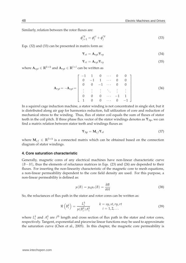
Generally, magnetic cores of any electrical machines have non-linear characteristic curve(B−H), thus the elements of reluctance matrices in Eqs. (23) and (24) are depended to theirfluxes. For inserting the non-linearity characteristic of the magnetic core to mesh equations,a non-linear permeability dependent to the core field density are used. For this purpose, anon-linear permeability is defined as:
μ(B) = μ0μr(B) =∂B
∂H(38)
So, the reluctances of flux path in the stator and rotor cores can be written as:
ℜ(
Bki
)
=Lk
i
μ(Bki )Ak
i
k = sy, st, ry, rti = 1, 2, . . .
(39)
where Lki and Ak
i are ith length and cross section of flux path in the stator and rotor cores,respectively. Tangent, exponential and piecewise linear functions may be used to approximatethe saturation curve (Chen et al., 2005). In this chapter, the magnetic core permeability is
48 Electric Machines and Drives
www.intechopen.com
0 5000 10 000 15 000 20 000 25 000 30 000
0.0
0.5
1.0
1.5
2.0
2.5
H
A
m
BT
esl
a
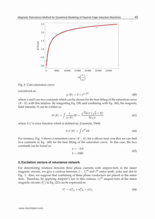
Fig. 3. Core saturation curve
considered as:μ (B) = b × ea×B2
(40)
where a and b are two constants which can be chosen for the best fitting of the saturation curve(B−H) with this relation. By integrating Eq. (38) and combining with Eq. (40), the magnetic
field intensity H can be written as
H (B) =∫
1
μ (B)dB =
√πEr f
(√a × B
)
2b√
a(41)
where Er f is error function which is defined as: (Gautschi, 1964):
Er f (B) =∫
eB2dB (42)
For instance, Fig. 3 shows a saturation curve (B − H) for a silicon steel core that we can findtwo constants in Eq. (40) for the best fitting of the saturation curve. In this case, the twoconstants can be found as:
a = −0.8
b = 1000(43)
5. Excitation vectors of reluctance network
For determining relations between three phase currents with ampere-turn in the statormagnetic circuits, we give a contour between (i − 1)th and ith stator teeth, yoke and slot in
Fig. 1. Also, we suppose that combining of three phase conductors are placed in the statorslots. Therefore, by applying Ampere’s law to this contour, (i)th ampere-turn of the statormagnetic circuits (Fs
i ) in Eq. (21) can be expressed as:
Fsi = wa
i ia + wbi ib + wc
i ic (44)
49Magnetic Reluctance Method for Dynamical Modeling of Squirrel Cage Induction Machines
www.intechopen.com
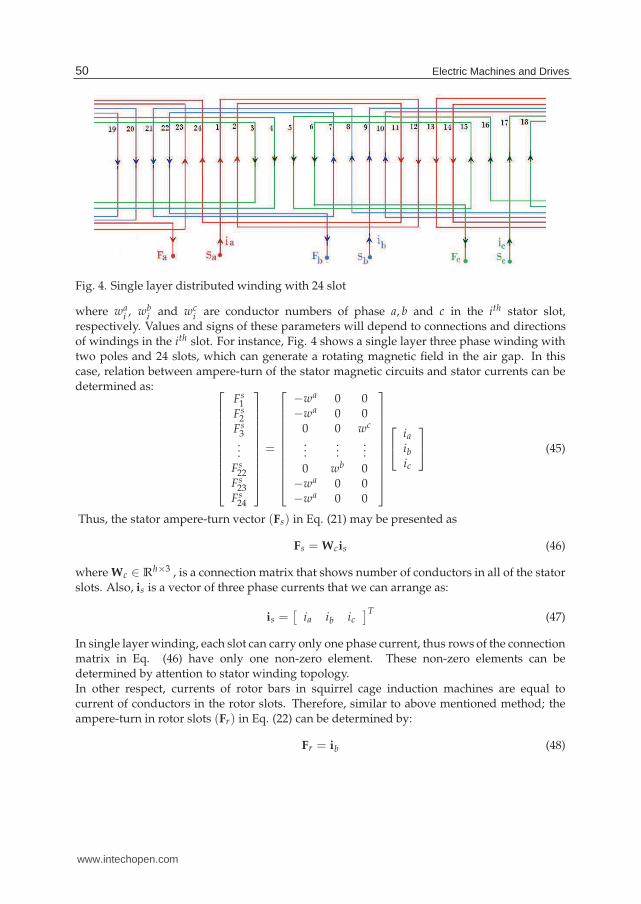
Fig. 4. Single layer distributed winding with 24 slot
where wai , wb
i and wci are conductor numbers of phase a, b and c in the ith stator slot,
respectively. Values and signs of these parameters will depend to connections and directionsof windings in the ith slot. For instance, Fig. 4 shows a single layer three phase winding withtwo poles and 24 slots, which can generate a rotating magnetic field in the air gap. In thiscase, relation between ampere-turn of the stator magnetic circuits and stator currents can bedetermined as:
⎡
⎢
⎢
⎢
⎢
⎢
⎢
⎢
⎢
⎢
⎢
⎣
Fs1
Fs2
Fs3...
Fs22
Fs23
Fs24
⎤
⎥
⎥
⎥
⎥
⎥
⎥
⎥
⎥
⎥
⎥
⎦
=
⎡
⎢
⎢
⎢
⎢
⎢
⎢
⎢
⎢
⎢
⎢
⎣
−wa 0 0−wa 0 0
0 0 wc
......
...
0 wb 0−wa 0 0−wa 0 0
⎤
⎥
⎥
⎥
⎥
⎥
⎥
⎥
⎥
⎥
⎥
⎦
⎡
⎣
ia
ib
ic
⎤
⎦ (45)
Thus, the stator ampere-turn vector (Fs) in Eq. (21) may be presented as
Fs = Wcis (46)
where Wc ∈ Rh×3 , is a connection matrix that shows number of conductors in all of the stator
slots. Also, is is a vector of three phase currents that we can arrange as:
is =[
ia ib ic]T
(47)
In single layer winding, each slot can carry only one phase current, thus rows of the connectionmatrix in Eq. (46) have only one non-zero element. These non-zero elements can bedetermined by attention to stator winding topology.In other respect, currents of rotor bars in squirrel cage induction machines are equal tocurrent of conductors in the rotor slots. Therefore, similar to above mentioned method; theampere-turn in rotor slots (Fr) in Eq. (22) can be determined by:
Fr = ib (48)
50 Electric Machines and Drives
www.intechopen.com
where ib , the rotor bars currents vector is defined as
ib =[
ib1 ib
2 · · · ibl
]T(49)
Substituting Eqs. (34), (35), (46) and (48) into (21) and (22) and combining with Eqs. (3) and(4), the magnetic algebraic equations of squirrel cage induction machines in matrix form canbe augmented as
⎡
⎢
⎢
⎣
Aφsy+AφstAsyt 0 Aust 00 Aφry+AφrtAryt 0 Aurt
−Asyt 0 Ass Asr
0 Aryt Ars Arr
⎤
⎥
⎥
⎦
⎡
⎢
⎢
⎣
Ψsy
Ψry
Ust
Urt
⎤
⎥
⎥
⎦
=
⎡
⎢
⎢
⎣
Wcis
ib
00
⎤
⎥
⎥
⎦
(50)
Due to core saturation characteristic is a non-linear curve, the matrix Eq. (50) is non-linear andsome coefficient matrices depends to the core fluxes density. Thus, ordinary methods cannotbe employed for solving Eq. (50). Furthermore, rotor and stator currents are depended tostator three phase source voltages and rotor speed in differential equation forms. Therefore,for detailed analysis of squirrel cage induction machine, it is necessary to solve an electric,mechanic and magnetic algebraic differential equations, simultaneously
6. Electrical voltage equations of squirrel cage induction machines
Generally, a set of differential equations in an electrical machine is used to describe rates ofthe electrical and mechanical variables. These equations establish the relationship betweenfluxes, currents and the three phase source voltage variables. In the next section, rotor andstator voltage relations are be derived.
6.1 Stator voltage equations
For an induction machine, we can write electrical differential equations in stator windings as:
Vs = Rsis +d
dtΛs (51)
where Vs and Rs are voltage and stator resistances matrix, respectively which are defined by
Vs =[
va vb vc]T
(52)
Rs = diag[
ra rb rc]
(53)
Moreover, Λs is linkage flux vector and equals to the product of turn number of statorwindings and the phase fluxes. Thus, we can write:
Λs =[
λa λb λc]T
(54)
Λs = wcΨ3ϕ (55)
By substituting Eqs. (34) and (37) into (55), we obtain:
Λs = wcMc f AsytΨsy (56)
51Magnetic Reluctance Method for Dynamical Modeling of Squirrel Cage Induction Machines
www.intechopen.com
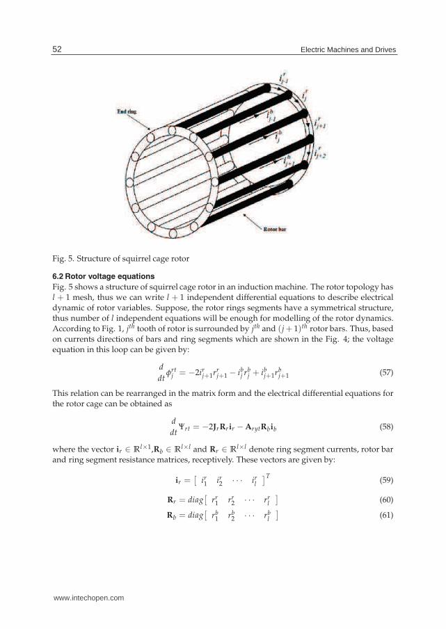
Fig. 5. Structure of squirrel cage rotor
6.2 Rotor voltage equations
Fig. 5 shows a structure of squirrel cage rotor in an induction machine. The rotor topology hasl + 1 mesh, thus we can write l + 1 independent differential equations to describe electricaldynamic of rotor variables. Suppose, the rotor rings segments have a symmetrical structure,thus number of l independent equations will be enough for modelling of the rotor dynamics.According to Fig. 1, jth tooth of rotor is surrounded by jth and (j+ 1)th rotor bars. Thus, basedon currents directions of bars and ring segments which are shown in the Fig. 4; the voltageequation in this loop can be given by:
d
dtφrt
j = −2irj+1rr
j+1 − ibj rb
j + ibj+1rb
j+1 (57)
This relation can be rearranged in the matrix form and the electrical differential equations forthe rotor cage can be obtained as
d
dtΨrt = −2JrRrir − ArytRbib (58)
where the vector ir ∈ Rl×1,Rb ∈ R
l×l and Rr ∈ Rl×l denote ring segment currents, rotor bar
and ring segment resistance matrices, receptively. These vectors are given by:
ir =[
ir1 ir
2 · · · irl
]T(59)
Rr = diag[
rr1 rr
2 · · · rrl
]
(60)
Rb = diag[
rb1 rb
2 · · · rbl
]
(61)
52 Electric Machines and Drives
www.intechopen.com
Also, constant matrix Jr ∈ Rl×l is defined as
Jr =
⎡
⎢
⎢
⎢
⎢
⎢
⎢
⎢
⎣
0 1 0 · · · 0 00 0 1 · · · 0 00 0 0 · · · 0 0...
......
. . ....
...0 0 0 · · · 0 11 0 0 · · · 0 0
⎤
⎥
⎥
⎥
⎥
⎥
⎥
⎥
⎦
(62)
Moreover, there are two current vectors in left hand side of Eq. (58) which have to find arelation between them. For this propose, Kirchhoff’s Current Law (KCL) can be used todetermined a relation between rotor bars and ring segments currents. By applying KCL tojth node (bar) in the rotor cage (Fig. 4), we can write:
ibj = ir
j+1 − irj (63)
Therefore, for l nodes in the rotor cage; Eq. (63) can be expressed in matrix form as:
ib = Arytir (64)
By substituting Eqs. (64) into (58), we can get:
d
dtΨrt =
(
−2JrRr + ArytRbAryt)
ir (65)
Up to this stage, two separate sets of non-linear equations are derived to established ofalgebraical (magnetic) and dynamicalal (electric) models of a squirrel cage induction machine.By combining of Eqs. (50), (51) and (65), the total algebria-differential equations of the systemcan be augmented as:
⎡
⎢
⎢
⎢
⎢
⎢
⎢
⎣
wcMc f Asyt p 0 0 0 Rs 0
0 Arytp 0 0 0 2JrRr−ArytRbAryt
Aφsy+AφstAsyt 0 Aust 0 −Wc 00 Aφry+AφrtAryt 0 Aurt 0 Aryt
−Asyt 0 Ass Asr 0 00 −Aryt Ars Arr 0 0
⎤
⎥
⎥
⎥
⎥
⎥
⎥
⎦
⎡
⎢
⎢
⎢
⎢
⎢
⎢
⎣
Ψsy
Ψry
Ust
Urt
is
ir
⎤
⎥
⎥
⎥
⎥
⎥
⎥
⎦
=
⎡
⎢
⎢
⎢
⎢
⎢
⎢
⎣
Vs
00000
⎤
⎥
⎥
⎥
⎥
⎥
⎥
⎦
(66)
where p denotes time derivative operator ( ddt ).
6.3 Mechanical differential equations
Some of the matrix coefficients in Eq.(66) are depended to mechanical instantaneous angleγ. In variable speed conditions, the mechanical variables of the system can be determined
by solving differential equations of the rotor angel and speed. Generally, mechanical torquebalance equation can be expressed as:
Jdω
dt= Tem − Tl (67)
53Magnetic Reluctance Method for Dynamical Modeling of Squirrel Cage Induction Machines
www.intechopen.com
Quantity Symbol ValuePower P 1.1kwVoltage V 220VFrequency f 50HzNumber of pole p 2Stator resistance rs 5Ω
Rotor bar resistance rb 20μΩ
Rotor ring sector resistance re 1.1μΩ
Inertia moment j 0.02kgm2
Number of turns per slot 68Number of rotor slots 18
Table 1. Parameters of squirrel cage induction machine
in whichdγ
dt= ω (68)
also, ω, J, Tl and Tem are the rotor angular speed, total inertia on the shaft, load torque andelectromagnetic torque, respectively. The electromagnetic torque is depended to mmf alongair gap and derivative of air gap permeances with respect to rotor angel (γ) (Ostovic, 1989).For an induction machines, we can express as:
Tem =h
∑i=1
l
∑j=1
(
usti − urt
j
)2 dGi,j (γ)
dγ(69)
By substuting Eqs.(7), (10) and (11) into (69), air gap electromagnetic torque can be obtainedas:
Tem =(
UTst − UT
rt
) d
dγAsr (Ust − Urt) (70)
Therefore, the mechanical non-linear differential equations (67) to (70), with the magneticnon-linear differential-algebraic equations (66), describe the generalized non-linear dynamic
model of squirrel cage induction machine. Because of non-linearity of the model, theadvantage numerical solution methods must be used. In the next section, some simulationresults are presented for demonstration of capability validation of the new model. After that,asymmetrical situations of squirrel cage induction machine such as broken rotor bar fault withsaturation effects are analysed and evaluated.
7. Simulations and experiment of results
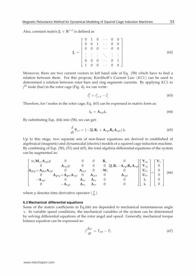
Table 1 shows the electrical parameters of the squirrel cage induction machine which is usedto obtain numerical simulation and experimental results. Air gap, rotor and stator slots andother main dimensions of the induction machines are presented in Fig. (5) and windingsconnection diagram are assumed similar to Fig. (4). In the next section, some differentdynamical conditions are implemented to obtain numerical results of the non-linear modelof induction machines.
54 Electric Machines and Drives
www.intechopen.com
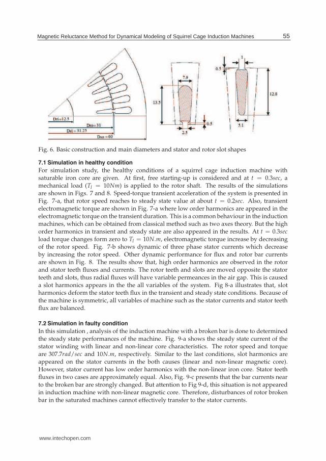
Fig. 6. Basic construction and main diameters and stator and rotor slot shapes
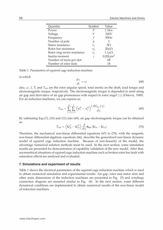
7.1 Simulation in healthy condition
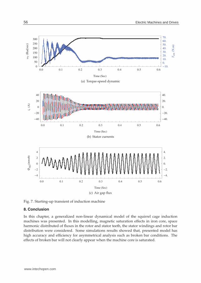
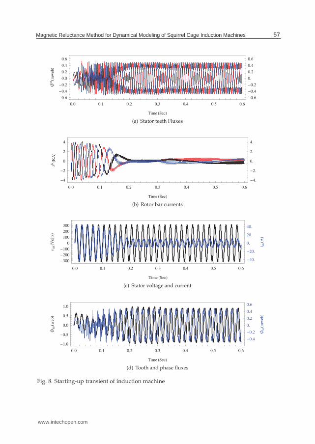
For simulation study, the healthy conditions of a squirrel cage induction machine withsaturable iron core are given. At first, free starting-up is considered and at t = 0.3sec, amechanical load (Tl = 10Nm) is applied to the rotor shaft. The results of the simulationsare shown in Figs. 7 and 8. Speed-torque transient acceleration of the system is presented inFig. 7-a, that rotor speed reaches to steady state value at about t = 0.2sec. Also, transientelectromagnetic torque are shown in Fig. 7-a where low order harmonics are appeared in theelectromagnetic torque on the transient duration. This is a common behaviour in the inductionmachines, which can be obtained from classical method such as two axes theory. But the highorder harmonics in transient and steady state are also appeared in the results. At t = 0.3secload torque changes form zero to Tl = 10N.m, electromagnetic torque increase by decreasingof the rotor speed. Fig. 7-b shows dynamic of three phase stator currents which decreaseby increasing the rotor speed. Other dynamic performance for flux and rotor bar currentsare shown in Fig. 8. The results show that, high order harmonics are observed in the rotorand stator teeth fluxes and currents. The rotor teeth and slots are moved opposite the stator
teeth and slots, thus radial fluxes will have variable permeances in the air gap. This is causeda slot harmonics appears in the the all variables of the system. Fig 8-a illustrates that, slotharmonics deform the stator teeth flux in the transient and steady state conditions. Because ofthe machine is symmetric, all variables of machine such as the stator currents and stator teethflux are balanced.
7.2 Simulation in faulty condition
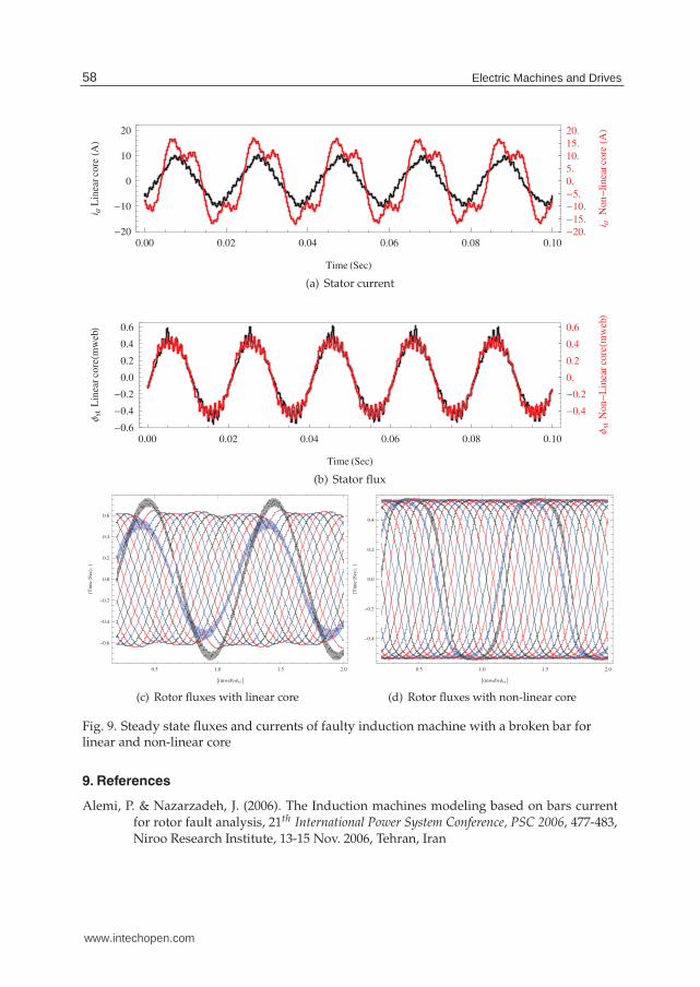
In this simulation , analysis of the induction machine with a broken bar is done to determinedthe steady state performances of the machine. Fig. 9-a shows the steady state current of thestator winding with linear and non-linear core characteristics. The rotor speed and torqueare 307.7rad/sec and 10N.m, respectively. Similar to the last conditions, slot harmonics areappeared on the stator currents in the both causes (linear and non-linear magnetic core).However, stator current has low order harmonics with the non-linear iron core. Stator teethfluxes in two cases are approximately equal. Also, Fig. 9-c presents that the bar currents nearto the broken bar are strongly changed. But attention to Fig 9-d, this situation is not appearedin induction machine with non-linear magnetic core. Therefore, disturbances of rotor broken
bar in the saturated machines cannot effectively transfer to the stator currents.
55Magnetic Reluctance Method for Dynamical Modeling of Squirrel Cage Induction Machines
www.intechopen.com
0.0 0.1 0.2 0.3 0.4 0.5 0.6
0
50
100
150
200
250
300
10.
0.
10.
20.
30.
40.
50.
60.
70.
Time Sec
ΩrR
ads
ec
TemN
.m
(a) Torque-speed dynamic
0.0 0.1 0.2 0.3 0.4 0.5 0.6
40
20
0
20
40
40.
20.
0.
20.
40.
Time Sec
i sA
(b) Stator currents
0.0 0.1 0.2 0.3 0.4 0.5 0.6
4
2
0
2
4
4.
2.
0.
2.
4.
Time Sec
A
Gm
web
(c) Air gap flux
Fig. 7. Starting-up transient of induction machine
8. Conclusion
In this chapter, a generalized non-linear dynamical model of the squirrel cage inductionmachines was presented. In this modelling, magnetic saturation effects in iron core, spaceharmonic distributed of fluxes in the rotor and stator teeth, the stator windings and rotor bardistribution were considered. Some simulations results showed that, presented model has
high accuracy and efficiency for asymmetrical analysis such as broken bar conditions. Theeffects of broken bar will not clearly appear when the machine core is saturated.
56 Electric Machines and Drives
www.intechopen.com
0.0 0.1 0.2 0.3 0.4 0.5 0.6
0.6
0.4
0.2
0.0
0.2
0.4
0.6
0.6
0.4
0.2
0.
0.2
0.4
0.6
Time Sec
stm
web
(a) Stator teeth Fluxes
0.0 0.1 0.2 0.3 0.4 0.5 0.6
4
2
0
2
4
4.
2.
0.
2.
4.
Time Sec
ibK
A
(b) Rotor bar currents
0.0 0.1 0.2 0.3 0.4 0.5 0.6
300
200
100
0
100
200
300
40.
20.
0.
20.
40.
Time Sec
vasV
olt
s
i asA
(c) Stator voltage and current
0.0 0.1 0.2 0.3 0.4 0.5 0.6
1.0
0.5
0.0
0.5
1.0
0.4
0.2
0.
0.2
0.4
0.6
Time Sec
asw
eb
stm
web
(d) Tooth and phase fluxes
Fig. 8. Starting-up transient of induction machine
57Magnetic Reluctance Method for Dynamical Modeling of Squirrel Cage Induction Machines
www.intechopen.com
0.00 0.02 0.04 0.06 0.08 0.10
20
10
0
10
20
20.
15.
10.
5.
0.
5.
10.
15.
20.
Time Sec
i aL
inear
coreA
i aN
on
linearcoreA
(a) Stator current
0.00 0.02 0.04 0.06 0.08 0.10
0.6
0.4
0.2
0.0
0.2
0.4
0.6
0.4
0.2
0.
0.2
0.4
0.6
Time Sec
Φst
Lin
ear
co
rem
web
Φst
No
n
Lin
ear
co
rem
web
(b) Stator flux
0.5 1.0 1.5 2.0
0.6
0.4
0.2
0.0
0.2
0.4
0.6
mweb Φrt
Tim
eS
ec,
(c) Rotor fluxes with linear core
0.5 1.0 1.5 2.0
0.4
0.2
0.0
0.2
0.4
mweb Φrt
Tim
eS
ec,
(d) Rotor fluxes with non-linear core
Fig. 9. Steady state fluxes and currents of faulty induction machine with a broken bar forlinear and non-linear core
9. References
Alemi, P. & Nazarzadeh, J. (2006). The Induction machines modeling based on bars currentfor rotor fault analysis, 21th International Power System Conference, PSC 2006, 477-483,Niroo Research Institute, 13-15 Nov. 2006, Tehran, Iran
58 Electric Machines and Drives
www.intechopen.com
Al-Shahrani, A. S. (2005). Influence of adjustable speed drive on induction motor fault detectionusing stator current monitoring. Ph.D. thesis, Oregon State University
Bellini, A.; Filippetti, F.; Franceschini, G.; Tassoni, C. & Kliman G. B. (2001). Quantitativeevaluation of induction motor broken bars by means of electrical signature analysis.IEEE Transactions on Industry Applications, Vol. 37, No. 5, (Sep./Oct. 2001), 1248-1255
Benbouzid, M. E. H. (2000). A review of induction motors signature analysis as a medium forfaults detection.IEEE Transactions on Industry Electronics, Vol. 47, No. 5, (Oct. 2000),984-993
Chen, S. D.; Lin, R. L & Cheng, C. K.(2005). Magnetizing inrush model of transformers basedon structure parameters.IEEE Transactions on Industry Electronics, Vol. 20, No. 3, (July2005), 1947-1954
Faiz, J.; Sharifian, M. B. B.; Feyzi, M. R.; & Shaarbafi, K. (2002). A complete lumped equivalentcircuit of three-phase squirrel-cage induction motors using two-dimensionalfinite-elements technique. IEEE Transactions on Energy Conversion, Vol. 17, No. 3,(Spet. 2002), 363-367
Gautschi W. (1964). Error function and Fresnel integrals, Handbook of Mathematical Functions, NBSAppl. Math. Series, Vol. 55, U.S. Government Printing Office, Washington, D.C.
Jeong, J. H.; Lee E. W. & Cho, H. K. (2003). Analysis of transient state of the squirrel cageinduction motor by using magnetic equivalent circuit method, Sixth InternationalConference on Electrical Machines and Systems, Vol. 2, 720-723, 2003
Jung, J. H.; Lee, J. J. & Kwon, B. H. (2006). Online diagnosis of induction motors using MCSA.IEEE Transactions on Industry Electronics, Vol. 53, No. 6, (Dec 2006), 1842-1852
Krause, P. C.; Wasynczuk, O. & Sudhoff, S. D. (2002). Analysis of Electric Machinery and DriveSystems (2nd Edition), Wiley-IEEE Press, ISBN 047114326X, New York.
Luos, X.; Liao, Y.; Toliyaty, H.; El-Antably, A. & Lipos, T. A. (1995). Multiple coupled circuitmodeling of induction machines. IEEE Transactions on Industry Applications, Vol. 31,No.2, (Mar./Apr. 1995), 311-318
Mirafzal, B.& Demerdash, N. A. O. (2004). Induction machine broken-bar fault diagnosisusing the rotor magnetic field space-vector orientation. IEEE Transactions on IndustryApplications, Vol. 40, No. 2, (Mar./Apr. 2004), 534-542
Mirafzal, B.& Demerdash, N. A. O. (2008). Induction machine broken bar and stator
short-circuit fault diagnostics based on three-phase stator current envelopes. IEEETransactions on Industry Applications, Vol. 55, No. 3, (March 2008), 1310-1318
Muñoz, A. R. & Lipo, T. A. (1999). Complex vector model of the squirrel-cage inductionmachine including instantaneous rotor bar currents. IEEE Transactions on IndustryApplications, Vol. 35, No. 6, (Nov./Dec. 1999), 1332-1340
Ostovic, V. (1989). A novel method for evaluation of transient states in saturated electricmachine. IEEE Transactions on Industry Applications, Vol. 25, No. 1, (Feb. 1989), 96-1000
Ostovic, V. (1989). Dynamics of Saturated Machines, Springer-Verlag, ISBN 0387970797, NewYork
Siddique, A.; Yadava, G. S. & Singh, B. (2005). A review of stator fault monitoring techniquesof induction motors. IEEE Transactions on Energy Conversion, Vol. 20, No. 1, (March2005), 106-114
Sprooten, J. (2007). Finite element and electrical circuit modeling of faulty induction machines studyof internal effects and fault detection techniques. Ph.D. thesis, Department of Bio, Electroand Mechanical Systems (BEAMS), University Libre de Bruxelles
59Magnetic Reluctance Method for Dynamical Modeling of Squirrel Cage Induction Machines
www.intechopen.com

Su, H. & Chong, K. T. (2007). Induction machine condition monitoring using neural networkmodelling. IEEE Transactions on Industry Applications, Vol. 54, No. 1, (Feb. 2007),241-249
60 Electric Machines and Drives
www.intechopen.com
Electric Machines and DrivesEdited by Dr. Miroslav Chomat
ISBN 978-953-307-548-8Hard cover, 262 pagesPublisher InTechPublished online 28, February, 2011Published in print edition February, 2011
InTech EuropeUniversity Campus STeP Ri Slavka Krautzeka 83/A 51000 Rijeka, Croatia Phone: +385 (51) 770 447 Fax: +385 (51) 686 166www.intechopen.com
InTech ChinaUnit 405, Office Block, Hotel Equatorial Shanghai No.65, Yan An Road (West), Shanghai, 200040, China
Phone: +86-21-62489820 Fax: +86-21-62489821
The subject of this book is an important and diverse field of electric machines and drives. The twelve chaptersof the book written by renowned authors, both academics and practitioners, cover a large part of the field ofelectric machines and drives. Various types of electric machines, including three-phase and single-phaseinduction machines or doubly fed machines, are addressed. Most of the chapters focus on modern controlmethods of induction-machine drives, such as vector and direct torque control. Among others, the bookaddresses sensorless control techniques, modulation strategies, parameter identification, artificial intelligence,operation under harsh or failure conditions, and modelling of electric or magnetic quantities in electricmachines. Several chapters give an insight into the problem of minimizing losses in electric machines andincreasing the overall energy efficiency of electric drives.
How to referenceIn order to correctly reference this scholarly work, feel free to copy and paste the following:
Jalal Nazarzadeh and Vahid Naeini (2011). Magnetic Reluctance Method for Dynamical Modeling of SquirrelCage Induction Machines, Electric Machines and Drives, Dr. Miroslav Chomat (Ed.), ISBN: 978-953-307-548-8, InTech, Available from: http://www.intechopen.com/books/electric-machines-and-drives/magnetic-reluctance-method-for-dynamical-modeling-of-squirrel-cage-induction-machines