Embed Size (px)
Citation preview

Make a Strong Finish! Revit® Interiors and Finishes Paul F. Aubin
SESSION DESCRIPTION
Sure Revit can do walls, doors and even furniture…but what about finishes? If you are responsible for interior design and have tried using Revit to produce finish plans or interior elevations, you may have come up a little short. Sure Revit has Materials and yes, we are in a BIM world, but material and "finish" are not the same thing, and modeling is not always the answer. In this class, we will explore how far we can push our Revit model and learn what to do when modeling proves impractical. Want to make detailed finish plans? Want to call out multiple finishes on the same elevation or detail complex floor tile patterns complete with quantities? Revit can do all of this, just maybe not exactly the way you would expect. If you are stalling on giving Revit a try because you assumed it did not do much for interiors, think again. Come to this class and see how Revit can help you make a strong finish (plan)! Learning Objectives
1. Learn how to do finishes in Revit 2. Understand the various “correct” methods 3. Explore the pros and cons of alternate approaches 4. Critically evaluate procedures based on the benefit to the team
About the Speakers
Paul F. Aubin, Paul F. Aubin Consulting Services
Paul F. Aubin is the author of many CAD and BIM book titles including the widely acclaimed: The Aubin Academy Mastering Series: Revit Architecture, AutoCAD Architecture, AutoCAD MEP and Revit MEP titles. Paul has also authored several video training courses for lynda.com (www.lynda.com/paulaubin). Paul is an independent architectural consultant who travels internationally providing Revit® Architecture and AutoCAD® Architecture implementation, training, and support services. Paul’s involvement in the architectural profession spans over 20 years, with experience that includes design, production, CAD management, mentoring, coaching and training. He is an active member of the Autodesk user community, and has been a top-rated speaker at Autodesk University (Autodesk’s annual user convention) for many years. Paul has also received high ratings at the Revit Technology Conference (RTC) in both the US and Australia and he spoke at the inaugural Central States Revit Workshop last year. His diverse experience in architectural firms, as a CAD manager, and as an educator gives his writing and his classroom instruction a fresh and credible focus. Paul is an associate member of the American Institute of Architects. He lives in Chicago with his wife and three children.
Contact me directly from the contact form at my website: www.paulaubin.com Follow me on Twitter: @ @paulfaubin
1
CENTRAL STATES REVIT WORKSHOP
Introduction, Assumptions and Supplemental Resources If you are involved in Interior Architecture or Interior Design are considering the use of or already use Revit in your practice, and want to understand how to apply, report and document finish selections, then you have come to the right place. My assumptions for this class are simple:
• I assume that you are either currently using Revit or plan to very soon • You produce Finish Plans, Floor Finish Plans and/or Interior Elevations • You are interested in Finish Schedules and Legends • Most importantly, you would like Revit to begin improving the execution of these tasks
We should start our discussion with the understanding that there is no “one correct” way to designate and/or document finish selections in Revit. However, there are lots of “acceptable” ways to do it. (Naturally some are more suitable than others). Before embarking on any of the specifics of any particular technique, I would like to cement one very important concept first. Nearly everything we do can be measured against a simple litmus test:
How much effort is required? and what benefit do we receive from doing it?
When measured against this criterion, some tasks in Revit are clear “winners.” Building a model from walls, doors, floors and ceilings requires a relatively low degree of effort and offers many benefits. The project browser requires little effort to learn and use and offers tremendous benefit to the project and process. And the list goes on. On the other hand, there are other procedures that do not offer such clear benefits for the amount of effort expended. For example, it would be theoretically possible to model each piece of door hardware and physically add this geometry to the doors in the model. This might offer some benefit vis-à-vis the compilation of the door schedule and perhaps in generating renderings, but in most cases, the amount of effort expended and the drain on overall performance that the project team would experience as a result would not be sufficient to justify the approach.
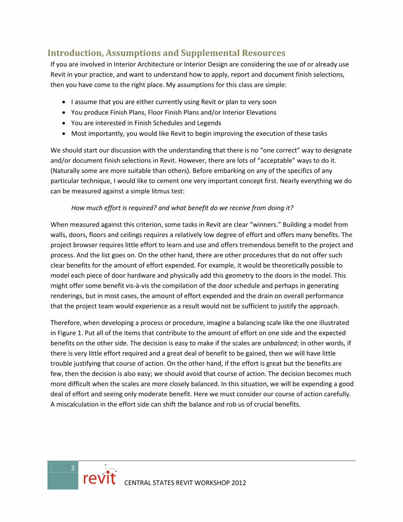
Therefore, when developing a process or procedure, imagine a balancing scale like the one illustrated in Figure 1. Put all of the items that contribute to the amount of effort on one side and the expected benefits on the other side. The decision is easy to make if the scales are unbalanced; in other words, if there is very little effort required and a great deal of benefit to be gained, then we will have little trouble justifying that course of action. On the other hand, if the effort is great but the benefits are few, then the decision is also easy; we should avoid that course of action. The decision becomes much more difficult when the scales are more closely balanced. In this situation, we will be expending a good deal of effort and seeing only moderate benefit. Here we must consider our course of action carefully. A miscalculation in the effort side can shift the balance and rob us of crucial benefits.
2
CENTRAL STATES REVIT WORKSHOP 2012

Effort vs. Benefit (EVB)
Figure 1
Figure 2
In many ways there is not a completely scientific way to perform the effort vs. benefit analysis, but none-the-less, for the purposes of our discussion let’s refer to this analysis of effort vs. benefit as the “EVB ratio” or EVB. Consider then Figure 2. If we assume that for any given task that we currently perform, we expend a certain amount of effort and in exchange we receive certain benefits, this can be seen as our “Current EVB.” Our goal therefore when implementing new technology or procedures should be to increase the EVB (shift to the right of the scale) where possible and at the very least, equal our Current EVB. We definitely do not want to end up with a negative or Lower EVB than we currently enjoy.
Note: Another important consideration when making the EVB analysis is to consider factors beyond technology. In other words, don’t just put Revit-specific items on the scales. Also factor in the personnel who will perform the tasks, each person’s level of training in the tools and techniques, project budgets, timeframes, etc. Sometimes you find the scales are perfectly balanced until you add some critical non-technology based criterion into the mix.
With this backdrop in place, we can move into the very specific discussion of specifying, documenting and reporting finishes in a Revit Architecture project. It is important to reiterate that there are many potential approaches to this topic. Whether a particular approach will make sense for your firm has much to do with how you arrive at your firm’s specific EVB. So please keep the concept of EVB in mind as we explore the possibilities.
Manually Drafted Finish Designations I am not necessarily going to present these in a particular order. But I want to start with the manual process because it will serve as sort of a benchmark for the rest of the procedures. It is likely that before moving to Revit, you used some form of CAD, probably AutoCAD to generate your documentation. In AutoCAD, you typically draft divisions between one material and the next using simple linework on appropriate layers. This can be done in either plans or elevations. In some cases, the regions are hatched and the various patterns defined on a legend to represent various materials and finishes. In other instances, blocks with attributes are used to callout finishes within a certain area. The values in the blocks must be manually input into the attributes for each block. In some firms, an
3
CENTRAL STATES REVIT WORKSHOP 2012

attribute extraction is performed to generate at least the start of a finish schedule, in some cases, LISP or VBA routines have been devised that automate some of the process, but often the schedule must be manually drafted line by line and all text input and typed manually using standard text objects. So with this manual process as our backdrop and benchmark, let’s look at a similar workflow in Revit.
There are three basic components to the solution:
• Drafting the plan or elevation boundaries separating one finish from another • Adding the finish tags • Creating a schedule and/or finish legend.
Drafting Tools For the drafting step, we can work directly in any Revit view. Appropriate views include plans, elevations, callout views or sections. Set up the view using typical Revit procedures. Assign the scale, detail level and visibility/graphic overrides as required. Often you can simply duplicate an existing view or create a callout to do the bulk of this work. Once you have the view, you can draw Filled Regions, Masking Regions or Detail Lines to represent the boundaries between one finish and the next.
Figure 3
The Annotate tab is pictured here (see Figure 3). On the Detail panel, you will find the Detail Line button and a Region drop-down button containing both Filled Region and Masking Region.
If you need a simple boundary line between the two areas, use the Detail Line tool. You can draw in any shape like straight lines, arcs, rectangles and polygons. If you want to fill in the enclosed area with a pattern, use a Filled Region. You have the same shapes, but with a Filled Region you must draw an enclosed shape. Both tools allow you to choose a Line Style for each segment you draw. When you complete the Filled Region, choose a pattern from the Type Selector on the Properties palette. You can click Edit Type and then Duplicate to create Region types using patterns other than those available.
Generic Annotation Symbols and Note Block Schedules Once you have drafted the divisions between finishes, you can call them out with simple Generic Annotation symbols. This is easy to do except for some unfortunate terminology obstacles. In Revit, a
4
CENTRAL STATES REVIT WORKSHOP 2012

Generic Annotation Family is a simple 2D symbol. It can optionally have parameters (fields) in which we can input values. (If you are familiar with AutoCAD, it is like a block with attributes). The first terminology obstacle is this: “Generic Annotation” and “Symbol” mean the same thing in Revit. Generic Annotation is the kind of Family and Symbol is the tool used to insert a Generic Annotation in a project. Said another way, you use the Symbol tool to insert Generic Annotation Families. To create Symbols you use the Generic Annotation Family template. Clear as mud?
Symbols (Generic Annotations) are 2D annotation and like other 2D annotation, appear only in the view to which they are added. They also respond to the scale of the view automatically. Let’s assume that you wanted to add finish designations to a plan or interior elevation with this method. You simply draft with Detail Lines any transitions between finishes and then add a Generic Annotation Symbol to call out the finish areas. To input the finish value, you just click on the Symbol and edit the value (similar to other tags) as shown in Figure 4. However, keep in mind that Symbols like this are not linked to anything in the model. So this approach is not very “BIM-like,” but is basically equivalent to the corresponding AutoCAD procedure used in many firms.
Figure 4
This approach effectively establishes our Current EVB as depicted in Figure 2 above. However, there is one important upside (which slightly tips the scales). In Revit, we can create a Schedule of all Generic Annotation Symbols that report all of the values input into the symbols! To create such a Schedule, you must learn the second terminology obstacle. A Generic Annotation (Symbol) Schedule is called a “Note Block.” Said another way, a Note Block will list all instances of your Generic Annotation symbols and their associated values! So, even though the solution is not very “BIM-like” overall, it is still more effective and powerful than what we are used to with traditional methods. Let’s walk through the steps:
5
CENTRAL STATES REVIT WORKSHOP 2012

Goal: Create a Finish Symbol with finish designation displayed and hidden fields for other values and then report all instances of this symbol on a Schedule.
1. From the Application Menu (the big “R” menu), choose New > Annotation Symbol. In the “New Annotation Symbol” dialog, choose the Generic Annotaiton.rft template and then click Open.
2. Delete the red note. On the Create tab, click the Line tool and draw a simple symbol shape. It can be any shape you like and should be drawn centered on the two reference planes onscreen. Draw it the size it will be on paper when printed (13/32″ x 5/32″ for example).
3. On the Create tab, click the Label tool (a Label is a piece of text that references a parameter so that you will be able to edit the value in the project). Click in the middle of the screen to place it.
The “Edit Label” dialog will appear. Since this is Generic Annotation, there are no predefined parameters in the list at the left. However, we can add any parameters we wish to include in our final Finish Schedule.
4. To add a parameter, click the Add Parameter icon (bottom left). In the “Parameter Properties” dialog, type Finish Code for the name, choose Instance, make the Type of Parameter Text group it under Identity Data and then click OK (see Figure 5).
Figure 5
5. Add other Parameters if you like, such as Color Number, Manufacturer and Remarks. Configure them all the same way: Instance, Text and Identity Data.
6. Select Finish Code and then click the Add Parameter to Label icon in the middle. Change the Sample Value to something like X-1 and then click OK (see Figure 6).
6
CENTRAL STATES REVIT WORKSHOP 2012

Figure 6
7. Save the Family file and then on the ribbon, click the Load into Project button. 8. In the project, place a few instances of the Symbol. When you first load it into the project, the tool will
already be active. You can cancel the command if you are not in the correct view. To get back to the command, remember, a Generic Annotation Family is actually a Symbol. On the Annotate tab, click the Symbol tool. Use the Detail Line tool to draw any finish boundaries as required (see the top of Figure 7).
Figure 7
7
CENTRAL STATES REVIT WORKSHOP 2012

9. Like other annotation, you can select the Symbol after you place it and then use the tools on the ribbon to add leaders if required.
10. To edit the hidden fields, select the symbol and edit its properties on the Properties palette. Or wait till you have a schedule and edit there.
11. Add several Symbols and fill in various values. To add the Schedule, use the Note Block tool. On the View tab of the ribbon, click the Schedules drop-down button and then choose Note Block.
12. Each of the Generic Annotation Symbols in the project will be listed. Select your Finish symbol, type a name and then click OK.
13. In the “Note Block Properties” dialog, add all the fields. On the Sorting/Grouping tab, you can uncheck the “Itemize every instance” checkbox and you will end up with only one entry for each unique value. For example, if you want PT-1, PT-2 and PT-3 to each be listed only once, uncheck this box. Further, setting it up this way allows you to easily edit the other fields associated with PT-1 directly in the Schedule rather than having to edit them individually in the project views (see the bottom of Figure 7).
In summary, this approach is presented first as a means of establishing the Current EVB benchmark. Once the Generic Annotation Symbol is created, placing it and editing its values is comparable to the similar approach in CAD with respect to the amount of effort. The benefit is actually slightly better when the Note Block Schedule is factored in. But again, this is BIM after all, so we are looking for something better than we have today, not comparable. So let’s continue to explore other avenues.
Simple Room Finish Schedules Perhaps the easiest way to create a Room Finish Schedule in Revit is to simply schedule the Rooms. Room elements have built-in text fields for the input of finish designations and we can add additional fields as required. In order to utilize this approach we need Room elements in our model. We need any custom parameters we require to be included as shared parameters in our office standard project template file and we optionally need a custom Room Tag that reports the finish designations if so desired.
Room Elements A Room element is a non-graphic selectable element in your model used to represent an actual room or other defined named space in your project. Rooms are used for the obvious spaces that you would consider rooms like offices, kitchens, corridors, closets, and lobbies. However, you can define a Room for any program space you wish to label or quantify as such. Rooms are considered model elements even though by default they do not display graphically. Rooms are useful to generate room Schedules, reports, perform area calculations, volume calculations, finish Schedules, and of course for Room Tags. Rooms are used for any occupied space. In most instances, Rooms can be created automatically from the bounding Walls and other elements already in your model. However, in situations where the shape of the Room you wish to define is not enclosed by Walls or other “hard” boundaries you can manually sketch Room Separations to indicate its boundaries. Add Rooms with the tool on the Architecture tab, on the Room & Area panel. The Room element in Revit has some unique characteristics:
• By default Rooms will conform to the size and shape of the bounding elements in the model.
8
CENTRAL STATES REVIT WORKSHOP 2012

• To calculate area and volume a valid enclosure of room bounding elements must be present. We can use Room Separation Lines to add boundaries as required by the design when physical boundaries (like walls) are not present.
• The graphical components of Rooms are turned off by default. They will only display when selected unless you override the visibility/graphics and turn on the Interior Fill and/or Reference components.
Figure 8
Figure 8 shows several Room features. On the left, we see the Room Bounding setting for a selected wall element in the Properties palette. In the middle, a selected Room shows its Interior Fill component represented as blue shading across the room’s area. The “X” running through the Room is the Reference element. Both of these are off by default but can be optionally turned on in the Visibility/Graphic Overrides dialog (type the shortcut VG to open this dialog). Room Bounding Lines are also shown on the right side of the figure to subdivide what would otherwise be a single large room in an open plan portion of the design. These are seen as orange lines in the figure. They are not orange by default. You can make such a customization again with VG or in the “Line Styles” dialog (Manage Tab > Additional Settings drop-down).
Rooms have several additional properties that you can view and modify on the Properties palette when the Room is selected. Some are physical settings like the Upper Limit and Limit Offset which offer ways to control the height of the Room. Most of the other settings appear beneath Identity Data and include Number, Name and finishes. These are all text fields that receive manual text-based input. For items like Room Name and Comments, a manual text field is perfectly appropriate. For finishes, it is acceptable for basic functionality, such as when the finishes in each room are simple and do not vary from surface to surface (the entire Room uses PT-1 for example). Room objects have simple text fields for inputting finishes. The default project template includes a field for Wall, Base, Floor and Ceiling finishes. To use this functionality, add Rooms, edit the Room’s properties and fill in the values for Floor Finish, Wall Finish, etc. Create a Room Finish Schedule that reports these fields. However, in many cases such an approach falls short of what is required for construction documents.
9
CENTRAL STATES REVIT WORKSHOP 2012

Shared Parameters The fields like the ones shown in the Figure 9 must be added as Shared Parameters to be included in a tag as shown. To create a Shared Parameter, click the Manage tab and then the Shared Parameters button. In the “Edit Shared Parameters” dialog, verify that a Shared Parameter file exists. If it does not, check with your CAD or BIM Manager before creating one. You can create one in this dialog, but it is very important that there be only one Shared Parameter file in your office. This single file should be on the network server and accessible to all users. Your CAD or BIM Manager can help you set one up if necessary or locate the existing office standard as appropriate.
Shared Parameter files are organized in groups. Check each group in the file first to see if the parameter you need is already defined before creating a new one. Use the buttons on the right of the dialog to create and edit parameters and groups.
Figure 9
Once your shared parameters are defined like the North, South, East and West Wall Finishes shown here, they must be added as Project Parameters. The best way to do this is in your office standard template file. This way, the setup is a one-time task that will benefit all future projects. Check with your CAD or BIM Manager for help on this. With shared parameters so defined, you can create custom Room Tags that report them and also add the custom parameters to schedules as shown in Figure 9 on the right.
If your finishes are fairly straight-forward, this approach has a few advantages. Editing the material designations is easy and can be done either by selecting the Room in the model or directly in the schedule. Rooms that have the same finishes can be selected and edited together, speeding input. There are no modifications required to the model. Therefore, there is no chance that folks will get carried away modeling lots of detail which could be detrimental to certain views and overall performance.
Key Schedules A Key Schedule provides a way for you to expedite data input in a Schedule. For example, if most of the offices in your project use the same finish palette, we could define a key called: “Standard Office.” This key could then be used to fill in all of the finishes for us in one click including the walls, floor and base. To create a Key Schedule, you choose the “Schedule keys” option in the “New Schedule” dialog.
10
CENTRAL STATES REVIT WORKSHOP 2012

On the View tab, click the Schedules drop-down button and choose Schedule/Quantities. In the “New Schedule” dialog choose the Rooms category and then select the Schedule Keys radio button. Type in a Key name such as “Finish Styles” or “Finish Palette,” Click OK and then on the Fields tab add each of the finish fields and then click OK again. All of the built-in System parameters will be listed as available fields. It is possible to click the Add Parameter button in the middle of the dialog and add custom Project Parameters, but unfortunately, you cannot add Shared Parameters to a Key Schedule. (Autodesk knows about this and they are working on it… I asked).
A “Schedule Only” Approach As you can see, Room elements offer a means to create a simple and traditional room finish schedule. The focus on this approach is completely on the schedule. Since all the fields are text fields you are not really assigning actual materials. Furthermore, while the Rooms gain their shape and size from the bounding walls, the relationship is one-way; the Rooms do not have any ability to edit the walls. Therefore, even if you defined actual material shared parameters for the Rooms (which is possible, see Figure 10), they would not have the ability to transfer these material assignments back to the walls. You would be choosing materials from your material list in these custom parameters, but they would simply appear on the Properties palette and the schedule. They would not show anywhere in the model.
Figure 10
Another problem with using material properties is that the parameter points to the name of the material. So unless you are willing to rename your materials to a shorter and more reasonable name for your schedule, it is likely that the name that typically appears in the “Material Browser” dialog is not what you would want to see on your finish schedule. So, while using actual material properties seems logical at first, it has some significant drawbacks. Therefore, if you are using your rooms to generate your finish schedule, it is probably better to stick with text fields.
11
CENTRAL STATES REVIT WORKSHOP 2012

Should I Focus on the “I” or the “M” in BIM? In a Building Information Model, many would argue that the “I” or information is as important as the model graphics or the “M.” Given the variety of factors typically involved, we sometimes arrive at solutions that favor one over the other. Ideally you would achieve both at the same time. After all, shouldn’t that be the point of BIM? Regrettably, this is not always possible in all cases. So the challenge of course is to strike the right balance between the “I” and the “M” and the amount of effort expended to achieve results (refer back to our effort vs. benefit scales pictured in Figure 1 above).
The topics discussed so far focused more on data only solutions. In other words, the input of finish values in the above techniques had little to no impact on the model graphics. Rather, input finish values were visible in schedules and/or tags only. Such techniques can be effective, but there is a risk that data input in the various text fields can get out of synch with what the actual model shows; particularly if you intend to render, share or export the model.
In the next few topics, we will consider some options that focus more on the model. This is not to suggest that such techniques are inherently superior to the previous ones. Each technique has its own pros and cons. I suppose that the most important point to make is a word of caution. It is possible to build most finishes and materials directly into the model with a great deal of accuracy. Some may argue that to have “true BIM” this is what we are called to do. Therefore you would model each material transition in 3D directly. If you have a tile wall, you would use a wall type or sweep to model a very thin component for tile. If you have carpet flooring adjoining wood floor, you could model each material as a separate floor, embed one in the other or use split face. Each of these techniques will be given coverage below. However, please remember that there is no one “correct” technique. Each approach has its pros and cons and should be put to the requisite EVB scrutiny.
It continues to be important to remember that even in BIM, “just because you can do something, does not always mean you should do it.”
Techniques to Model Finishes Revit does not make a distinction between the material from which something is made and the way in which it is finished. Both items are represented with Revit Materials (Manage tab). For example, in a building, interior partitions are made of studs and drywall (materials) but the drywall can be painted, tiled or have wall covering (finishes). Finishes like tile and carpet do have thickness, so if you chose to, you could actually model such items three-dimensionally while paint and wall covering could be considered to be two-dimensional (no thickness) for all practical purposes. Consider such issues carefully before deciding on a course of action. In general, we are typically encouraged to model things in Revit as close as possible to the way that they will actually be built in real life. This makes it tempting to model the actual finish components in our model three-dimensionally. The advantages of doing so could include more accurate graphical representation in all views, better quantity takeoffs and the ability to render the model directly in Revit. There are disadvantages as well. These include additional time and
12
CENTRAL STATES REVIT WORKSHOP 2012

effort expended to model sometimes very fine details in the model, reduced performance resulting from more highly detailed 3D models, and difficulties achieving desired graphics in traditional 2D views like plans, sections and elevations.
In general, the more desired outputs from the BIM model (plans, sections, elevations, schedules, quantities and renderings), the easier it is to swing your EVB analysis toward modeling finishes in 3D. However, the more varied the needs of each of these deliverables (2D floor plan vs. 3D rendering for example), the more challenging the creation of a single model capable of accommodating all required needs becomes.
Time and space here do not allow coverage of every possible technique. I will however try to outline several approaches here and then present a few of my favorites in more detail following that.
Walls Where should one wall end and another begin? If you are only concerned with 2D plans, sections and elevations presented in hidden line with no materials displayed, then walls should be drawn continuous and broken only when necessary to change type.
For example, consider the three offices depicted in Figure 11. The horizontal wall running across the top is shared by all three offices and in general should be drawn as a single wall element in the Revit model. However, if you wish to accurately model finishes, this wall would need to be broken into three separate walls to accommodate two kinds of paint. Furthermore, the wall separating Office 1425 from Office 1426 is painted with P2 on the left side and P3 on the right. The wall between Office 1426 and 1427 however is P4 on the left and P3 on the right. This means that we must potentially create and maintain at least five wall types just to accommodate all the left and right face variations of just the walls shown here. Naturally in a full floor plan, this quantity could get out of hand very quickly.
Figure 11
13
CENTRAL STATES REVIT WORKSHOP 2012

If you have more than one finish on a single wall forming a wainscot or other pattern on the wall’s surface, you could be required to add even more variations. Not to mention the extra effort of having to constantly switch views to ensure that you have the wall oriented the correct way. In other words, in plan view, there is no way to tell if the wall between Office 1426 and 1427 correctly shows the P4 on the left and P3 on the right or has that reversed. Reversing a wall is a simple as clicking the flip grip, but assessing if the flip needs to be made means lots of switching from plan to 3D or elevation and back.
Despite the potential issues, here are some options for modeling walls and wall finishes:
• Split walls at each transition and Duplicate Types to create new variations—This technique will work if the color and finish transitions apply to the entire wall. In other words, if you split the wall, you end up with two walls and a vertical seam between the two. The wall on each side can be assigned to a different type each using different materials. The down side of this technique is that you must create many copies of each wall type for each variation in material/finish. This could yield an unwieldy quantity of types to manage. If your material/finish transitions are not vertical, you must modify the geometry further using one of the next two techniques.
• Use Edit Profile when the shape of the transition is not a vertical line—with Edit Profile (available on the ribbon when a wall is selected), you can modify the shape of the wall in elevation to be non-rectangular. You do this by editing the sketch. You must form a valid enclosed sketch when editing the profile. This can be effective if the shape of material/finish transitions are not vertical, but can be tedious to create if several transitions are required. Furthermore, breaking walls at many locations to serve the needs of materials/finishes might not serve other drawings like plans well. For example, it could become difficult to add wall tags in plan views.
• Embed one wall in another using Cut or Join Geometry—if there are certain areas of the wall’s surface that have accent colors and patterns, you can consider building such areas as separate walls (these could be just the thickness of the drywall with a material assigned) and then embed them in the host wall using Join Geometry. The order that you choose the two elements when joining matters. Be sure to choose the wall you wish to embed first, and then select the host wall.
Figure 12
14
CENTRAL STATES REVIT WORKSHOP 2012

(If you forget to pick in the correct order, and you are using Revit 2014, there is a new “Switch Join Order” tool on the Join Geometry dropdown to reverse the join order). Some might argue that the preceding three techniques give a more accurate representation, and therefore a more “BIM-like” model. Theoretically this approach would maximize the amount of data you could extract from your model, and some might argue was a more “accurate” rendition of the true conditions that would ultimately be built. I do not think this is always the case. I feel that the preceding three techniques often require more effort than is justified by the benefits that they impart in many (not all) cases. This is true not just because of the additional effort required to build the extra model elements, but also because they introduce additional levels of model and type management that are not present otherwise and would be more difficult to maintain as the project progressed. While not discounting these techniques completely, (every approach has its place), in my opinion, other techniques are available which strike a better balance of overall effort and benefit and ultimately achieve just as robust of a BIM solution.
Split Face and Paint An alternative to modeling every material change and surface is the Split Face tool. Not everyone agrees that this a better alternative, but it is worthy of consideration nonetheless. With this tool, you can split the surface of a model element into two or more distinct regions. On the Modify tab, on the Geometry panel, click the Split Face tool and then select a face of a single model element such as a Wall or Floor (see Figure 13).
Figure 13
This will enable sketch tools and allow you to sketch the shape of the split face. The sketch must form an enclosed region to be considered valid. Once you have completed the sketch, use the Paint tool to apply a different Material to the Split Face region. Revit will literally paint the material onto the surface within this region. Unlike the modeling approaches discussed above, the underlying structure of the model element will be unaffected by Split Face and Paint. However, painted Materials will appear in schedules and you can even tag them with Material tags. In schedules, there is an “As Paint” property that allows you identify the painted materials from the normal (non-painted) ones directly in the schedule.
15
CENTRAL STATES REVIT WORKSHOP 2012

To schedule materials, you create a Material Takeoff. This is simply a schedule that can report on the Material properties of elements in your model. To limit this takeoff to just Materials that are used as finishes, add a prefix in front of each of the material names you wish to include on your finish schedule. Then use the filter option in the schedule to include only Materials whose name begins with the prefix you designate (see Figure 14).
Figure 14
Finish plans—You can do Finish Plans the same way. Simply use the Split Face and Paint tools on the Floor element in a plan view. (There are other alternatives as well, see below).
Finish schedules—As noted, use a Material Takeoff for a Finish Schedule. When you first create it, decide if you want a single material list for the entire project, or want separate lists for Walls and Floors. If you want a single list, use the <Multi-Category> option when you create the Material Takeoff. If you wish to have a separate Wall or Floor finish list, you can choose the appropriate category instead (see Figure 15).
Figure 15
16
CENTRAL STATES REVIT WORKSHOP 2012

On the Fields tab, the only difference between a Material Takeoff and regular Schedule is the availability of “Material” fields for the Material Takeoff. Material fields are prefixed with “Material:” When you select one of these fields, you are instructing Revit to give you the information about the Material instead of the object to which the Material is assigned. You can tell Materials that have been “painted” onto a surface in the schedule if you include the Material: Volume field. The volume of painted Materials will be zero. You can also use the Material: As Paint field specifically to identify those that are painted.
Split Face and Paint gets mixed reviews in the Revit community. Not everyone is a fan so to speak. It can work well for designating the break between different paint colors or wall covering on walls, or to differentiate different tile patterns and colors. Think of those situations where the underlying material is unchanged, and the only difference is finish applied on top. Paint and wall covering have negligible thickness. So the tool really works well for these finishes. There is no need to model separate walls when in reality, the underlying wall construction is actually unchanged and we really are painting different colors on the same surface. Floors might not be as successful. Many different floor finishes actually vary in thickness which means that if you want the finish floor surface to be flush, you actually do have to change the thickness of the subfloor material. So you might want to avoid the split face and paint on floor finishes.
Finally, one big disadvantage of the split face tool is that you cannot hide the split face edges by category or by element (see Figure 16). You can use the Linework tool with an <Invisible lines> style.
Figure 16
This means that even in views where you do not want to display the different materials, the edges will still show. You would have to use the Linework tool in each such view and manually hide each edge with the <Invisible lines> line style. This can be tedious to say the least.
Additional Modeling Techniques There are many other modeling tools available. These techniques are not limited to designating finishes, but can certainly be used for this purpose as appropriate.
• Add Wall Sweeps or Reveals (both integral to the Wall Type and as hosted components)—Sweeps and Reveals modify the form of the wall by extruding a profile along the wall’s length or height. A sweep is additive and a reveal is subtractive. Sweeps and Reveals can be added at the type level or individually to selected walls. When you apply a sweep or reveal to a wall type, it occurs everywhere that wall type is used throughout the entire project. When you add them to
17
CENTRAL STATES REVIT WORKSHOP 2012

individual walls, you must select only the walls to which you wish it to apply. Integral type-level sweeps and reveals can be effective for overall exterior moldings, parapet caps and the like. For interior moldings it is usually better to apply them individually. When applied individually, you also have more control over display and you can schedule them (see below). If you do them at the type level, you will be faced with the same issue noted above whereby each condition will require a separate type: Wall A with trim on one side, Wall A with trim on both sides, Wall A with trim and wainscot, etc. This means that managing multiple nearly identical types again presents a significant management challenge.
• Vertically compound Walls—When defining the components of a wall type structure, you can manipulate composition of wall layers running vertically as well as horizontally. Sweeps and Reveals discussed in the previous bullet point are examples of ways that you can manipulate the vertical structure of the wall type. You can also split components vertically and assign layers to different materials. This can be an effective way to represent changes in material and finish like horizontal bands, wainscot and even moldings and wall base (see below).
• Stacked Walls—When your desired wall structure must change as it moves vertically up the height of the wall, Stacked Walls offer another option. The Stacked Wall Family allows types to be defined that incorporate two or more Basic Walls stacked up vertically on top of one another. To create a Stacked Wall type, you first need to ensure that the component Basic Walls that you require are defined in the project. Then you create the Stacked Wall type and assign the Basic Walls to it. Stacked Walls are most often used for exterior walls, but could be used in interior applications if the wall structure warranted it. Tip: If you create a Stacked Wall type and use it in your project and then later decide that you would prefer to have individual Basic Walls in its place, you can right-click the Stacked Wall instance onscreen and choose Break Apart.
• Slab Edges—A slab edge is a profile based object that can follow the path along the edge of a floor element or even a model line. (I learned this technique one year at Revit Technology Conference from a presenter named Scott Brown. He showed many fantastic tools of use and interest to interiors. He did a similar session at Autodesk University and I have included a link to the PDF of his paper below). The model line trick is the important part of this tip. You can draw a model line anywhere you have a work plane, even on the surfaces of other objects. A slab edge is much like a sweep and can even use the same profile families for its shape. When you place the slab edge, Revit will prompt for an edge of a floor, slab or model line to define the path. If you pick the previously drawn model line, you can build a slab edge anywhere; even places where there is no slab!
Adding Wall Base (Three approaches) We have discussed many approaches to modeling wall finish components. One common request that I get a lot is for a way to add 4″ wall base (such as vinyl or wood) directly to the wall so that when you draw walls in plan, they will automatically show wall base in any elevations that you generate. There are two basic ways to achieve this: Use a Wall Sweep or use a Vertically Compound wall structure. I personally prefer the vertically compound wall approach, but let’s look briefly at each.
18
CENTRAL STATES REVIT WORKSHOP 2012

Wall Sweeps (Integral)—If you go with the Wall Sweep approach, select the wall, on the Properties palette, click the Edit Type button. In the “Type Properties” dialog, click the Edit button next to Structure. In the “Edit Assembly” dialog, click the Preview button at the bottom and change the preview to a Section view. (If you do not change to section, you cannot modify the vertical structure). Click the Sweeps button and then add a sweep (see the left side of Figure 17).
Figure 17
The trouble with this approach is shown on the right. Depending on the scale that you have displayed in your views, the specific profile you choose for your sweep and the level of detail displayed, your views may become too busy to be legible. Furthermore, the sweep will show beyond in plan views and likely cause issues with wall joins on complex wall intersections.
Wall Sweeps (Hosted)—Another limitation when you apply an integral Wall Sweep is that you cannot turn their display off independently from the wall. However, you can control their display independently if you apply them as host sweeps individually wall by wall instead of at the type level. So if you are committed to having a 3D base molding, crown molding or other wall sweep, consider using the Wall Sweep tool on the wall dropdown instead. With a Wall (Host) Sweep, you can assign them to a subcategory of walls. This allows you to control the display in different views using the visibility/graphic overrides. First, from the Manage tab, open the Object Styles dialog and add a Subcategory for Walls (for example: Wall Base).
19
CENTRAL STATES REVIT WORKSHOP 2012

Figure 18
To add a Wall Sweep, you must work in a 3D or elevation view. On the Architecture tab, click the Wall drop-down button and choose Wall: Sweep (see the left side of Figure 18). Click on a wall to add the sweep. This is a model component so it will show in all views including plan views (see the middle of Figure 18), however, you can type VG and edit the Visibility/Graphic Overrides and turn off the Wall Base component to hide them in views where you do not wish them to display like 1/8"=1'-0" floor plans and other similar views (see the right side of Figure 18).
If you decide to use Slab Edges, the approach will be similar. The one advantage of slab edges that follow model lines is that you draw the model lines. So the path can be exactly what you need and turn corners, go around openings in walls and stop at doors and other obstructions. You cannot assign slab edges to custom subcategories, but there is a built-in subcategory of floors for slab edges. So you can turn this subcategory off in views that do not need to display the moldings in much the same way as noted here for wall sweeps.
Vertically Compound Walls—The third approach does not use a sweep at all. Rather, you simply split the wall layer and assign a different material to the lower portion. This will give you a line at the correct height in elevation views representing the presence of a wall base without the overhead and management of additional 3D geometry. To use this approach follow these steps:
1. Draw a wall segment using any type such as the out-of-the-box Interior - 4 7/8" Partition (1-hr) wall type.
2. Select the wall, on the Properties palette, click Edit Type and then click the Duplicate button. Name the new type something like: Interior - 4 7/8" Partition (4" vinyl base).
3. Click the Edit button next to structure, click the Preview button and then set the preview to a Section view. Change the Sample Height to a shorter value and then zoom in on the preview (see Figure 19).
20
CENTRAL STATES REVIT WORKSHOP 2012

Figure 19
You can add the vinyl base to one side of the wall or both. If only one side is needed, decide which side and then perform the following steps:
4. At the bottom of the dialog, click the Split Region button. Move the cursor over the layer you wish to split (like one of the drywall layers) and then click. Use the temporary dimension to guide you (see the bottom of Figure 19).
If you need to adjust the height of the split region after you split, click the Modify button, select the boundary between the two split regions and then edit the temporary dimension.
5. Insert a new layer on the same side as the side you split. Use the up and down buttons to position it between inside of the existing finish layer and outside the core boundary. Assign the Function to Finish 2 [5] and the Material to your desired base material such as rubber or vinyl (see Figure 20).
The sequence of clicks for the next steps is important. They are labeled in the figure.
6. Click the Assign Layers button (see item 1 in Figure 20). Click on the new finish layer in the list (see item 2 in Figure 20), and then click on the lower split region in the preview window (see item 3 in Figure 20).
21
CENTRAL STATES REVIT WORKSHOP 2012

Figure 20
Repeat for the other side of the wall if you wish. The advantages to this approach include that there is no additional 3D geometry, but the line still appears automatically in all elevation, section and 3D views. Materials can also be assigned to each component, tagged and scheduled (see Figure 21). The main downside to this approach is similar to the integral sweep approach above; you may need to create several versions of each wall type to accommodate different base conditions.
Figure 21
22
CENTRAL STATES REVIT WORKSHOP 2012

Which Modeling Technique? Any of these modeling techniques can be employed with success. The real trick is managing the workflow so that the steps and effort involved is manageable and justifiable given the outcome of the results. Again: Effort vs. Benefit. Another item to consider is model composition. If the interiors work is being done separately from the architecture, but two different teams or maybe even different firms, you can separate the interiors out into its own model and link in the architecture. In this case, the walls could literally be modeled by area of ownership, having the Architect model to the studs, and the Interior Designer model from the drywall out. Some firms have had success with this approach as well. Please refer to the resource by Scott Brown mentioned previously for more details on this method.
Revit Parts Let’s consider one more modeling approach that has some interesting potential. One of the issues that all of the modeling approaches share is that they are mostly “all or nothing” approaches. Split face edges for example show in all views in course, medium and fine displays. Integral sweeps are the same. Hosted sweeps can be controlled with subcategories but not level of detail. Even materials in general require visibility/graphic overrides if you want them to display in one view and not in another.
Parts offer a compelling alternative. Parts were introduced to Revit as a construction modeling toolset. The concept is simple. The Architect or primary author of the model can build the major components of the design using overall modeling components such as Walls, Floors, Ceilings and Roofs. Contractors receiving the model downstream can then use Parts to subdivide these overall components into more discrete pieces that represent the actual modular building components that will be used in construction. This functionality even works through Revit Links! This means that the person building the Parts does not need to have direct access to the original model.
When enabling Parts for layered components like Walls, Floor and Ceilings, a Part is automatically created for each layer. You can further subdivide each layer into smaller Parts using the Divide Parts tool. Parts can be manipulated further using a variety of tools to edit their shape, material and even phase. They can be merged and deleted. But perhaps one of the most powerful features of Parts is that the original model is fully preserved and if it is edited, changes are propagated to the associated Parts—even through links! Furthermore, the display of Parts is controlled at the view level! This means that you can decide in each view if you want to see the Parts, the original model or both at the same time.
Consider a few common use cases that are often demonstrated: An Architect creates a single Floor element for each story of the building. The contractor, using Parts, subdivides this single slab into multiple segments representing the individual concrete pours. Another example involves using Parts to create a standard 4 x 8 pattern on the surface of wall to help determine how many sheets of drywall will be required. Parts can be scheduled, so this is just one example of where they can be used to help generate construction quantities.
23
CENTRAL STATES REVIT WORKSHOP 2012

Using Parts for Interior Finishes Examples like these are how Parts was conceived and how the feature has been promoted. However, if we consider the advantages noted, most “downstream” disciplines can benefit from the Parts functionality. Since our focus here in this class is on finishes let’s consider the advantages for finishes.
Separation of ownership—The Architect can maintain ownership of the main model geometry and the Interior Designer can use Parts to further articulate the finishes. And as noted, they work through Links so if the Interiors is in a separate model, Parts is still a viable option.
Finishes can be modeled rather than drafted—This is not always an advantage, as sometimes the model can become too “heavy” when finishes are modeled, but since Parts remain associated to their parent object, it is easier to maintain them.
Better control over display—with Parts, it is almost like working on a separate layer. Parts can be shown or hidden per view. So views that do not need to the Parts can hide them and only the original model geometry will show.
Parts can have their own Materials—Materials have traditionally had workflow issues as we discussed in detail above. Parts can be assigned their own Material. So using Parts and Materials together offers a compelling solution.
Creating Parts Let’s walk through a quick exercise to see the basic features of Parts.
1. Create a new Revit project from the default Architectural template. (If you don’t have access to this template, you can use whatever default template you have).
2. Draw a single Wall and a small Floor slab. The sizes are not important. For the Wall, use the Interior - 4 7/8" Partition (1-hr) Wall Type or something similar. For the Floor, use the Steel Bar Joist 14" - VCT on Concrete Floor Type or something similar.
3. Open a default 3D view (see Figure 22).
24
CENTRAL STATES REVIT WORKSHOP 2012

Figure 22
4. Select both items and on the Modify | Multi-Select tab, on the Create panel, click the Create Parts button (see Figure 23).
Figure 23
5. Move your mouse around the edges of each element to pre-highlight the new Parts. Notice that each layer of the Wall and Floor structure is now a separate Part (see Figure 24).
Figure 24
Displaying Parts The original elements are still preserved. To see and edit them, change The Parts Visibility setting on the Properties palette (see Figure 25).
25
CENTRAL STATES REVIT WORKSHOP 2012

Figure 25
You can Show just the Parts, just the Original or both. If you show both, you may need to use the TAB key to assist you in selections.
Dividing Parts Now let’s sub-divide our Parts. Make sure that Show Parts is selected for Parts Visibility on the Properties palette.
6. Select the topmost layer (Part) of the Floor element. Take note of the settings and data on the Properties palette. Notice that the Thickness of the Part is just ¼". The Area and Volume of this Part is also shown. In the Identity Data grouping, we see the original Category and Family as well as the Material. We’ll be making an adjustment here in just a moment (see Figure 26).
Figure 26
7. On the ribbon, click the Divide Parts button. 8. On the Modify | Division tab, click the Edit Sketch button.
This takes us into a sketch mode.
26
CENTRAL STATES REVIT WORKSHOP 2012

9. Using the sketch tools, you can draw any shape you like. Your goal is to divide the field into two or more smaller areas. You can draw past the edges of the Part, or create completely enclosed shapes (see Figure 27).
Figure 27
10. When you are done, click the Finish Edit Mode button to complete the sketch. Finish Edit Mode again to complete the Division.
Change Part Materials On the Properties palette we can now change the Material assigned to one or more of the Parts.
11. Each of the subdivided areas is now its own Part. Select one of them. 12. On the Properties palette, uncheck the Material by Original checkbox. 13. This will enable the Material setting. Click the Browse icon and choose a new Material (see Figure 28).
27
CENTRAL STATES REVIT WORKSHOP 2012

Figure 28
There are several other things we can do with Parts, but those are the basic steps. If you look at the new Part, you should notice that the Area and Volume have adjusted to reflect the divisions you created. Depending on the Material you chose, the pattern and/or color onscreen should also have changed.
Edit Division After you have subdivided a Part, you can use the Edit Division tool to modify the division later. This tool activates the Modify | Division tab of the ribbon. Use the Add and Remove buttons to add and remove other Parts to the current division (see Figure 29).
Figure 29
For example, if you have two adjacent Walls that have both had Parts enabled and you want to create a single division sketch that spans across both Wall, you first edit the division of one of the Wall/Parts, and then use the Add button to add in the other Wall/Part. Use Remove to reverse.
Intersecting References This is a fast way to create division lines instead of sketching them. You can have Revit create a sketch line automatically wherever a Level, Grid or Reference Plane intersects the Part. The Intersecting References button launches a dialog for this purpose (see Figure 30).
28
CENTRAL STATES REVIT WORKSHOP 2012

Figure 30
Merge Parts Select two or more adjacent Parts (Parts that share a physical edge) and then click the Merge Parts button to have them joined to create a single Part. If you edit the division, the original division line between the Parts will still be there, but it will not be expressed onscreen outside of Edit Division mode. This is similar to the behavior when merging more than one Curtain Wall Panel.
Exclude Parts This removes a Part. It is like deleting the Part, however, it can still be highlighted and restored if desired.
Shape Handles If you want to customize the shape of a Part beyond its boundaries (bigger or smaller), you can select the Part and on the Properties palette, check the Show Shape Handles checkbox. This will give you shape handle grips on all sides of the Part. You can then manipulate its shape directly onscreen.
Keep in mind that both exclude Parts and Shape Handle edits can make the Part’s appearance very different from the original. This can be useful in making a cutaway 3D detail or other diagram (see Figure 31).
29
CENTRAL STATES REVIT WORKSHOP 2012

Figure 31
Floor elements and Parts When you create Parts from a Floor element, keep one thing in mind. Floor elements occur below the current Level (their thickness projects down instead of up). So a Floor element on Level 1 has a negative thickness if you will. This is important because when you convert them to Parts, they will disappear in plan views. Why? Floor elements have special built-in behavior for display in plans. They will automatically display a few feet below the current Level. Parts do not have this behavior. So if you want to see your Parts in plan views, you must adjust the View Range of the floor plan view. Change the View Depth only or both the Bottom and View Depth to a small negative value. Just enough to display your Parts (see Figure 32).
Figure 32
Should I Use Parts or Other Modeling Techniques? It is a very good question. All of the techniques covered so far have advantages and disadvantages. Parts solve a few of the very specific issues encountered when using some of the other techniques. For example,
30
CENTRAL STATES REVIT WORKSHOP 2012

you can use split face and paint to easily apply two paint colors to the same wall. So why bother with parts? Well, as we indicated above, the split line between the two split surfaces will display in all views at all levels of detail regardless of the shading style used and without any way to control it in visibility/graphics. We can use the linework tool as noted, but this is manual and tedious and difficult to maintain. Parts solves this issue easily. It allows us to have a single wall type that contains studs and drywall on each side, but then by dividing the parts in whatever fashion is required for each space, you can divide up the walls’ surfaces and apply materials as required by the design. But since parts has a display setting for each view, it is easy to “turn them off” in views that do not need to see the finishes. This approach can work well if the only discipline using parts is interiors. If the Architect or another discipline is also using parts for another purpose, the technique will be less successful.
Remember our initial EVB assumptions at the start of the paper and be sure to discuss the various options with your team at the project kickoff meeting. This is the only way to choose the best option for all parties involved.
Understanding Autodesk Materials Before leaving modeling techniques, let’s dig a little deeper into the Autodesk Materials library included with Revit. Nearly all Autodesk products ship with the same core material library. This is important if you have one of the Autodesk Suites. Material libraries you use and create in one Autodesk product will be easily transferable to other products such as AutoCAD, Inventor and Showcase. The default library includes a good basic set of architectural materials you can use right away in your projects. The material library can also be modified to create new materials to match your project’s specific needs.
As you may already be aware, materials are applied to elements in your model as either type or instance parameters. For layered elements such as Walls, Floors, Ceilings, and Floors, you apply materials to each individual layer in the assembly at the type level. Loadable component Families such as Doors, Windows, Furniture, and Equipment can use material parameters either at the type or instance level (see Figure 33).
Figure 33
Another way materials can be applied to objects is with the Paint tool. As discussed above, this tool is found on the Modify tab, on the Geometry panel. There is also a Remove Paint tool.
31
CENTRAL STATES REVIT WORKSHOP 2012

The final way in which materials can be defined is at the category level. When the material assignment is: <By Category> the category level material will be used. Use Object Styles on the Manage tab to view and assign category level materials. This can be helpful for items like trim applied as Wall Sweeps. In the Object Styles, you can assign the default Material to that subcategory and all the trim in the model will receive the designated material (see Figure 34).
Figure 34
The Material Browser and Editor The out-of-the-box collection of materials shipping with Revit offers a good starting point. However, at some point you will need to modify and/or create your own materials. The process to edit and create materials is similar. There are three parts to the Materials interface: the Material Browser, the Material Editor and the Asset Browser. The Material Browser is the primary material interface element. Use it to browse and assign materials to elements in the model. The Material Editor is accessed from the Material Browser and can be used to edit a material selected in the browser or to create a new material. Materials are comprised of "assets". Assets can be viewed and edited using the Asset Browser. Any work you do with materials usually begins with the Material Browser.
The “Materials Browser” dialog can be accessed from the Manage tab, on the Settings panel.
You will also access this dialog when assigning a material to an element. The dialog lists all materials defined in your project. This is the top portion of the dialog. If the list is long, you can use the search field at the top to find a specific material. It also provides access to libraries stored outside your project. (This is the lower part of the dialog). This is a very useful feature of the Material Browser. You can create and load material libraries (saved as ADSKLIB files). These files contain collections of materials that can
32
CENTRAL STATES REVIT WORKSHOP 2012

be shared with other Revit users. In fact, and ADSKLIB file can be accessed by any Autodesk product that supports materials! This makes it very easy to share materials between project files and even Family files. We’ll look at this functionality in more detail below.
To use or edit a material already in your project, simply select it from the list in the top portion of the Material Browser. Its properties will appear in the Material Editor. If you wish to use a material from the library, locate it in the library portion (lower) of the browser and then click the small icon that appears to add it to the current file. If you wish to edit a material, select it in the top portion of the browser and then edit its properties in the Material Editor.
A material is comprised of a collection of assets. At a minimum, a Revit material must contain a Graphics aspect and an Appearance aspect. You can see these assets listed as tabs on the right side of the dialog. The Graphics aspect controls the most basic settings used by 2D and 3D hidden line and shaded views like plans, sections and axonometric views (see Figure 35).
Figure 35
The identity data of the material such as model and manufacturer and keynote is on the first tab. In Figure 35 the Graphics tab is selected. Here you can change the color and patterns.
33
CENTRAL STATES REVIT WORKSHOP 2012

It should also be noted that the default material tag that ships with Revit looks to the Description field in on the Identity tab. You may prefer to have your Material Tags reference a different field such as the “Mark”. To do this, edit the Material Tag family and change the field referenced by the label (see Figure 36).
Figure 36
Click the Appearance tab to see the settings that are used in realistic and ray trace visual styles and when rendering. Appearance usually includes a bitmap texture such as bricks or wood grain. There are often other settings specific to the kind of material. Many materials will have a second bitmap for a relief (similar to bump map) parameter and some (like glass) have transparency, reflectivity and even self-illumination. You can click through several materials in the browser and compare settings to get a sense of what is possible.
When image files are used for some part of the material, you can click the image to edit or view the properties of that image. This includes seeing the path to the image file, (or changing it to a different file if required), offsets, scale, etc. (see Figure 37).
34
CENTRAL STATES REVIT WORKSHOP 2012

Figure 37
Most materials will use some kind of image file. If you can obtain an image file of the material you are trying to create you can substitute your image file to get a custom look for the material. (Search the web or take a digital photo). Click on the Image shown in the “Material Browser” to get to the “Texture Editor.” The image settings will also include sizing information. You can use this to match the image used for the material to a real world size. Using the preview of the image and the sample size value you can get the image scaled properly to match a real world size when rendered. (For example, if you are creating a custom tile material that uses 4" tiles, and the image file you have is ten tiles wide by ten bricks tall, you would set the size to 3'-4"). Images may also be rotated if required.
Most default materials use the Graphics and Appearance aspects. If you are only concerned with how the material displays in your drawings and renderings, these two will give you everything you need. However, we can add additional assets to our materials. These include Thermal and Physical aspects. Thermal aspects allow materials to report their actual performance values when performing green building analysis. Properties include light transmittance, permeability, reflectivity and thermal conductivity to name a few. Physical aspects can be used by your structural engineer to calculate actual load and strength characteristics of structural materials. If you wish to explore these properties, feel free to open the Asset Browser (there is an icon on the far right of the “Material Browser”, or you can use the Additional Settings drop-down on the Manage tab) and explore. Just be sure to create a "dummy" material before you begin so that you do not inadvertently change one of your project materials.
35
CENTRAL STATES REVIT WORKSHOP 2012

Starting with the provided library should get you going in most cases. Add custom materials after you have familiarized yourself with the out-of-the-box offerings.
Understanding and Sharing Material Libraries If you do any customization to your material library, you should realize that you have the ability to save and share material libraries. Material libraries are external files with an ADSKLIB extension. This file will contain all information required for each material. You can store the file anywhere you like such as a network server. The best part is that once you have it loaded in your Material Browser, it remains loaded until you unload and is therefore available to any Revit project file you open. You can share the file across the office or even send it to external recipients. ADSKLIB files are usable by Revit and several other Autodesk software packages. To create or access an existing library file, use the small folder icon at the bottom of the “Material Browser”. After you create a library, you can use the same icon to add categories to organize your materials. To add materials to your library, you can right-click in the project materials area at the top and choose Add to > and then choose the library name and category. You can also simply drag and drop the materials (see Figure 38).
Figure 38
You can create a single master library for the entire office, or several smaller ones for particular projects or project types. Material libraries can also be loaded when working in the Family Editor, making it easy to share materials across all Revit files.
Area Elements For basic square footage calculations, you can query the area of the Room elements in your project. Rooms provide basic “finished” area, volume and simple finish designations (we discussed Rooms above). Also, Rooms report the name and number for tags and schedules. For more control over square footage calculations, Revit has a special floor plan type called an “Area Plan.” Area Plans use Area Boundary Lines and Area elements to designate important areas of your plan and calculate their values very precisely (see Figure 39).
36
CENTRAL STATES REVIT WORKSHOP 2012

Figure 39
The basic procedure for creating an Area Plan is as follows:
1. On the Architecture tab, on the Room & Area panel, click the Area tool and choose Area Plan. 2. In the “New Area Plan” dialog, choose the Type of Area plan (Rentable or Gross Building), the floor level
and the scale and then click OK. 3. You will be prompted to automatically create boundary lines. If you answer yes, Revit will attempt to
determine the location of the area boundaries (center of wall, face of glass, etc) based on the rules built into the system. (The rules vary depending on your choice of rentable vs. gross building; consult the online help for more information). You can always override any automatically generated boundary lines by adding your own manually.
4. Click the Area tool again and choose Area Boundary Line to add additional boundary lines required. Your goal is to enclose each region that you wish to measure.
5. Once all Area Boundaries are placed, use the Area tool to add Areas. Simply click in an enclosed region to add the Area. Optionally rename them. The experience is much like adding Rooms.
6. Generate a schedule to see a list of all areas with their values or assign a color scheme to color-code the areas on the Area Plan graphically.
The focus of this class is finishes, so you may be wondering why bring up Areas? We are going to look at a technique to use Area elements to help us create a complex floor finish plan. You can use the Split Face and Paint technique covered above or you can model each Floor element by sketching several Floors or embedding one within another (also discussed above). However there are some challenges with these approaches as you might expect. You will have a difficult time controlling the display of the split lines in views where you do not want them to display such as an overall floor plan. We can use the Linework tool to hide them in views where we do not wish them to display of course, but this may not always be practical. Furthermore, the more complex the floor pattern you are trying to represent, the more challenging you will find Split Face becomes.
You can build several separate floors or use parts instead. Both of these will likely be easier to manage than highly complex split face regions. The real question gets back to whether a modeled solution is
37
CENTRAL STATES REVIT WORKSHOP 2012

necessary. If you are looking for a simple 2D solution that does not require modeling, you could resort to drafting lines and regions, but using a customized Area Plan instead offers some compelling advantages.
Area Plans are not modeled—An area plan is a special kind of view. Like other view-specific elements, none of the elements created in an area plan display in any other view. This makes them easy to isolate.
Creating Area Boundaries is quick and easy—Area boundaries are created as easily as any other drafted 2D element. So they are very quick and easy to create. Unlike split face, modeled elements or even parts, you are not working in sketch mode. So you are not required to complete the sketch before performing other tasks.
Areas can use color schemes—Like rooms, areas can use color schemes. This makes presenting finishes and graphical finish legends very easy to accomplish.
Calculate the area of each type of flooring—Since it is an area plan, you have access to the square footage of each enclosed shape you draw. This means that even on the most complex floor patterns, you can easily determine how much of each material you have in your design.
The first step in the procedure is to create a custom Area Scheme.
Area Schemes There are two schemes included in the out-of-the-box templates. Gross Building Area and Rentable. Gross Building Area will automatically generate Area Boundary Lines to the outside edge of exterior Walls, while Rentable will look at adjacencies and inserts in Walls to determine if lines should be placed at the face or center of the Wall or at the face of glazing. You can always add lines manually without applying the rules if required. Clear the “Apply Area Rules” checkbox on the Options Bar to do so. These two default Area Schemes are focused on overall building square footage calculations for the two very common scenarios for which they are named. We can however create additional schemes for other types of calculations. To use areas for floor finishes, we need to create a custom area scheme:
1. On the Architecture tab, expand the Room & Area panel, and then click Area & Volume Computations. 2. On the Area Schemes tab, click the New button and name it Floor Finish. Edit the Description if you like
and then click OK. 3. On the Architecture tab, on the Room & Area panel, click the Room drop-down button and choose Area
Plan. Change the Type to your new Floor Finish, choose a level and then click OK. In the message that appears about automatically creating area boundary lines, click No.
Area Plans in Project Browser Each type of Area Plan will create a separate branch on the Project Browser. You should now have an Area Plans (Floor Finish) branch on the browser with an Area Plan such as Level 1 beneath it. You can rename this plan as desired. This is your floor finish plan for this level. The next step is to create Area Boundary Lines on this plan to form your floor patterns.
38
CENTRAL STATES REVIT WORKSHOP 2012

4. On the Architecture tab, click the Area Boundary button and then on the Options Bar, clear the “Apply Area Rules” checkbox.
5. Draw boundaries using any of the drawing shapes. Unlike Split Face, these can overlap if required (see Figure 40).
Figure 40
Add Areas Area elements are added just like Rooms. When you click the tool, they look for an enclosed region defined by Area Boundary Lines. So as long as you have enclosed the region in which you wish to place the Area, it will find the boundaries and automatically conform to that shape. Revit will then calculate the area of that region and if you enable Area Tags, can even report it onscreen. Like Rooms, you can name your Areas to make the regions more descriptive. In our case, we’ll “name” then using our finish designations.
6. Use the Area tool on the Area drop-down to add an Area to each enclosed region.
Color Schemes Color schemes can be applied to plan, section and elevation views and apply colors and patterns to Rooms or Areas based upon a particular rule. Any parameter of a Room or Area object can be used as a criterion for the color scheme. For example, if you have named each of your Area elements with the finish name, you can create a Color Scheme that displays each finish in a color or pattern. You can even add a legend to the view that defines each possible color or pattern used in the view. Color Schemes provide an effective way to display useful information in a graphical way.
39
CENTRAL STATES REVIT WORKSHOP 2012

To create a color scheme, be sure you have either Rooms or Areas in a view and open that view onscreen.
1. On the Architecture tab, expand the Room & Area panel and then click the Color Schemes tool. 2. From the Category list at the left, choose Areas (Floor Finish).
Figure 41
3. Beneath Category, a Scheme name will be suggested. You can use this one, or use the icons at the bottom to duplicate or rename it.
4. On the right side, input a title and then choose what parameter will be used from the Color list (Name in this case). A collection of colors will appear automatically based on the elements appearing in the model in the current view.
5. Edit the color or pattern of any of the items if you wish and then click OK. 6. To apply the Scheme to a View, edit the Properties of the view and choose it for the Color Scheme
property. There is a Legend button on the ribbon if you wish to add a legend to the view (see Figure 41). You can create as many Color Schemes as you wish in a project. However, you can only apply one scheme to a view at a time. To display the same view using different schemes, duplicate the View first and then apply different schemes to each one.
Areas of Finishes A nice bonus of this technique is that since these are Area elements, the overall quantities of each material is readily available. You can see the Area onscreen with Area Tags and you can create a schedule to report the overall totals as well.
40
CENTRAL STATES REVIT WORKSHOP 2012

Figure 42
Unfortunately the approach outlined here only works for floor finishes. This is because the Area element is only available for plans. So you will have to use one of the other techniques discussed above for elevations, such as parts. I developed the area technique some time ago before parts were available in Revit. I still like the approach as a quick way to represent complex floor finish plans when 2D is sufficient. If you need to show the patterns in 3D, I think that the parts approach is a better choice. The nice thing about both techniques is that when you return to your normal floor plan, none of the detailed pattern will display; just the underlying floor element. This is advantageous for typical construction floor plans, furniture plans, etc.
41
CENTRAL STATES REVIT WORKSHOP 2012

Wrap up We have covered a lot of ground in this paper. I would like to summarize the various techniques that we have explored as a way to wrap up our discussion.
Technique Page Pro Con Manually Drafted Finish Designations Drafting Tools 3 Familiar
Easy No 3D Overhead Note Block Schedule available Comparable to current non-BIM procedures
Manual Does not appear in the model Not very “BIM-like”
Simple Room Finish Schedules
8 Easy to input data Generates quick finish schedules No 3D Overhead
Manual Does not appear in the model Not very “BIM-like”
Techniques to Model Finishes Walls
Split Walls Edit Profile Embed Walls
13 More accurately represent “actual” building conditions Finishes appear in all views Arguably more “BIM-like”
Requires more effort to implement Introduces more 3D Overhead More difficult ongoing management
Split Face and Paint 15 Convenient way to represent finishes in the model Does not change the underlying structure of the model More true to life representation for applied finishes like paint and wall covering Does not introduce additional 3D overhead, but shows in multiple views
Can be difficult to implement on complex surfaces Complex patterns can require multiple split faces Hiding split lines is cumbersome in views where they need to be hidden
Stacked Walls 18 Provides another alternative to build more complex geometry
Not often used for interior walls
Parts 23 Separate representation of the live model geometry; does not change the actual model. Can be created in the live model or through a Revit linked file Subdivide, merge and split parts to suit the needs of the finishes being modeled Hide and show parts in any view Assign and schedule materials
Challenging to implement if more than one discipline like Architecture and Interiors is using parts for different uses. Parts can be tough to schedule as they schedule as parts, not the original category Must adjust view range to see floor parts in plan
42
CENTRAL STATES REVIT WORKSHOP 2012

Technique Page Pro Con Adding Wall Base Wall Sweeps (Integral)
18 Part of the Wall Type so it appears everywhere Define once
Requires the creation of many (somewhat redundant) Wall Types Cannot individually turn off sweeps in views Cannot schedule integral sweeps Can adversely affect joins
Wall Sweeps (Hosted) 19 Can place them at specific heights and locations both horizontally and vertically Can hide them in view where not needed Do not need multiple versions of the same wall type Can schedule them Do not adversely affect joins
Requires more work to place each segment individually
Vertically Compound Walls
20 No additional 3D geometry but a line shows on all elevations, sections and 3D views automatically Materials can be assigned to each component, tagged and scheduled No wall join issues
May require the creation of many (somewhat redundant) Wall Types
Finish Plans Using Area Elements and Area Plans
36 Work is performed in a separate plan view Area boundaries are easy to draw and can overlap Complex patterns are easier to create The creation of custom Area Schemes provide limitless potential Areas can be scheduled Color Schemes can be applied to show finishes graphically You are not actually modifying the floor elements, so there are no edges to hide
Technique only works in plans – not elevations Using the tool slightly differently than intended You are not actually applying the materials to the model, so there can be a disconnect between the area plan and the model
43
CENTRAL STATES REVIT WORKSHOP 2012

Web Links The following are websites and blog posts that offer useful information relevant to the topics in this session:
The Revit Clinic Here are several posts from the Revit Clinic. This blog is a must-read. I have included a small selection of posts related to finishes and materials.
http://revitclinic.typepad.com/my_weblog/2010/07/render-appearance-image-fade.html
http://revitclinic.typepad.com/my_weblog/2010/10/wall-paint-glossy-wall-paint-matte-and-paint-render-appearances.html
http://revitclinic.typepad.com/my_weblog/2010/05/troubleshooting-revit-material-rendering.html
http://revitclinic.typepad.com/my_weblog/2010/08/material-schemes.html
http://revitclinic.typepad.com/my_weblog/2009/10/material-takeoff-area.html
http://revitclinic.typepad.com/my_weblog/2008/12/material-family-frustration.html
Do U Revit? http://do-u-revit.blogspot.com/2010/10/materials.html
AUGI http://forums.augi.com/showthread.php?p=1047638&highlight=wall+sweep+material#post1047638
http://forums.augi.com/showthread.php?p=1095500#post1095500
Seek http://seek.autodesk.com/revit.htm
AU Paper: Scott Brown http://aucache.autodesk.com/au2009/sessions/5503/AB322-3-AU_09_Intergrated-Architecture-and-Interior-Design-Doc-with-Revit.pdf
44
CENTRAL STATES REVIT WORKSHOP 2012

Further Study You can find more information and tutorials in The Aubin Academy Master Series: Revit Architecture.
I also have Revit video training available at: www.lynda.com/paulaubin. I have nine courses at lynda.com: Revit Essentials (2014, 2013 and 2011),
Up and Running with Revit, Revit Family Editor, Revit Architecture Rendering, Migrating from AutoCAD to Revit, Phasing and Design Options and Advanced Modeling in Revit Architecture.
If you have any questions about this session or Revit in general, you can use the contact form at www.paulaubin.com to send me an email.
Follow me on titter: @paulfaubin
Thank you!
45
CENTRAL STATES REVIT WORKSHOP 2012