Embed Size (px)
Citation preview
M
akin
g a
Pew
ter
Cas
ting Making a Pewter Casting Mould
Pro|ENGINEER Wildfire 4.0 Schools & Schools Advance Edition
Pro|ENGINEER Wildfire 4.0
Pewter Casting.doc of 27 2
Written by
John E. Forth Copyright © 2008, DTE Consultancy All rights reserved under copyright laws of the United Kingdom, United States and other countries. PTC, the PTC Logo, Pro|ENGINEER, Pro|DESKTOP, Wildfire, Windchill, and all PTC product names and logos are trademarks or registered trademarks of PTC and/or its subsidiaries in the United States and in other countries.
Conditions of use Copying and use of these materials is authorised only in the schools, colleges and universities of teachers who are authorised to teach Pro|ENGINEER in the classroom. All other use is prohibited unless written permission is obtained from the copyright holder
Acknowledgements Flamefast Ltd
Feedback
In order to ensure these materials are of the highest quality, users are asked to report errors to the author. Suggestions for improvements and other activities would also be very welcome.
Product code WF3M-SE-L1-010-1.0
Pro|ENGINEER Wildfire 4.0
Pewter Casting.doc of 27 3
Table of Contents Making a Pewter Casting Mould 1
Table of Contents 3
Introduction 4 Pre-requisites 4 Abbreviations and terminology used within this tutorial 5 Installation and setup 5 Pro|ENGINEER functionality addressed in this tutorial. 6 STEM subject concepts in this module 6 Science concepts addressed in this tutorial 6 D&T subject areas addressed in this tutorial 6 Engineering areas addressed in this tutorial 7 Maths areas addressed in this tutorial 7 Module aims and objectives 7 Aim: 7 Learning objectives: 7
Background 8
Creating the Mould 10 Task 1: Create the Basic Mould parts. 10 Task 2: Assemble the mould parts. 12 Task3: Create the item to be cast with its Sprue pin 14 Task4: Creating the Sprue Pin 16 Task 5: Creating the Mould cavity. a) Assembling the model to the Mould 19 Task 5: Creating the Mould Cavity b) Using the model to subtract material. 21 Task 6: Setting material properties for mass calculations. 24 Task 7: Create files that can be taken to a CNC Router 25
Pro|ENGINEER Wildfire 4.0
Pewter Casting.doc of 27 4
° Teachers’ notes
Introduction The health and safety problems associated with casting metals in schools has led to the demise of this most valuable learning experience for pupils. Man has, since the Bronze Age, been shaping metal by raising its temperature to melting point and pouring the resultant liquid into a shaped cavity called a mould. Many schools have used aluminium as the metal of choice but even that has fallen foul of the H&S hurdles and has all but disappeared from the curriculum. However there is light at the end of the tunnel in the form of specialist low temperature casting equipment using lead free pewter as the medium. This material melts at about 140o C and in a controlled environment is quite safe for pupils to use from Y7 upwards (S1 in Scotland). This equipment is available from several suppliers including:- Flamefast Ltd Techsoft Middlesex University Teaching Resources The advantage of using pewter is that the moulds can me made from materials that are readily available and easily machined on a CNC router in a school workshop. For one-off situations the mould can be made from Jelutong or MDF. This tutorial shows how a simple pendant, designed using Pro|ENGINEER Wildfire4®, can be used to model the part file from which the mould can be created. In principle you will create the pendant or other part to be cast, then use it to perform a NOT intersection with the mould parts to produce the cavity. The mould parts can then be exported as an ‘stl’ file, machined on a CNC router and used to cast the finished pendant.
Pre-requisites Pro|ENGINEER Wildfire 4.0 Schools Edition or Pro|ENGINEER Wildfire 4.0 Schools Advanced Edition* or Pro|ENGINEER Wildfire 4.0 University Plus Edition or Pro|ENGINEER Wildfire 4.0 Student Edition *There is a specific mould application within the Advanced Edition which can be used to create much more comprehensive types of moulds where shrinkage and mould
Pro|ENGINEER Wildfire 4.0
Pewter Casting.doc of 27 5
release functions apply. This tutorial is for the much simpler application found in lower secondary school syllabuses. The tutorial is written for teachers but can be modified for pupil use. This tutorial contains screen and menu images taken from the Schools Edition so Users of other Pro|ENGINEER Editions may notice some slight differences. This tutorial has also been based on the use of Pro|ENGINEER start parts & templates supplied as part of the PTC D&T programme. While this tutorial can be used with other Pro|ENGINEER start parts there may be changes required in terms of view orientation, datum plane and coordinate system references etc. This tutorial requires some previous modelling experience in Pro|ENGINEER. Pro|ENGINEER Wildfire requires the use of a 3 button mouse. If possible a mouse with a combined middle wheel & button can improve User interaction with Pro|ENGINEER Wildfire.
Abbreviations and terminology used within this tutorial Left-click Press and release the left-hand mouse button Left-click-drag Press and hold-down the left-hand mouse button and move the
mouse Right-click Press and release the right-hand mouse button Middle-click Press and release the middle mouse button Middle-drag Press and hold-down the middle mouse button and move the mouse Note: The word “mould” (E) is used in this tutorial but it is the same as “mold” (US)
Installation and setup These Installation notes have been compiled based on a directory structure used as part of the PTC D&T programme, the UK CAD in Schools initiative and the deployment of Pro|ENGINEER. Users not part of this programme can still use this tutorial but may need to adapt either their Pro|ENGINEER configuration files or the directory structure used in the tutorial. Please ensure you have the required materials (Pewter, Jelutong or any hardwood etc) in the material library folder within C:/Program File/Pro|ENGINEER Wildfire4®/pro-standards/material_database. You should create a directory under their documents or network folder called “Pewter Casting”. The part files mould1.prt, mould2.prt and mould_ass.asm together with the materials file pewter.mtl can be placed in this folder for use during the tutorial and as a common folder for all to use.
Pro|ENGINEER Wildfire 4.0
Pewter Casting.doc of 27 6
Pro|ENGINEER functionality addressed in this tutorial.
• Sketching o 2D geometry creation & modification
• Circles, Lines, Centrelines, Trimming.
• References o Geometric & dimensional constraints
• Weak, Strong & Locked dimensions
• Linear and angular dimensional constraints
• Equal radius and tangent geometric constraints
• Modelling o Revolve o Extrude o Parametric modifications o Set Materials o Export as a *.stl file for CNC machining
• Assemblies o Assembly constraints o Component Operation o Hide/Unhide components
STEM subject concepts in this module
Science concepts addressed in this tutorial • Modelling
• Communication
• Handling data
• Making things happen
• Materials
• Melting points
D&T subject areas addressed in this tutorial • CAD
Pro|ENGINEER Wildfire 4.0
Pewter Casting.doc of 27 7
• Mould making
Engineering areas addressed in this tutorial • Casting procedures
Maths areas addressed in this tutorial • Volumes
• Shapes
Module aims and objectives The aim of this tutorial is to learn how to use Pro|ENGINEER Wildfire4® to create a mould that can be used with Flamefast LT1 Low Temperature casting equipment to create a pewter casting.
Aim: During this module you will learn..
• To assemble different parts together.
• Use the ‘Component Operations’ feature to create a cavity in one part from a solid shape of another
• Create stl files that can be used by CNC and RP equipment
Learning objectives: By the end of this module you should:
° Be aware of the relationship between a part and a mould
° Understand the concept of logically operating on parametric solid objects to create new objects.
° Be able to create a mould from a modelled object so that a casting can be made.
° Understand the relationship between 3D Solid modelling and CNC machining.
Pro|ENGINEER Wildfire 4.0
Pewter Casting.doc of 27 8
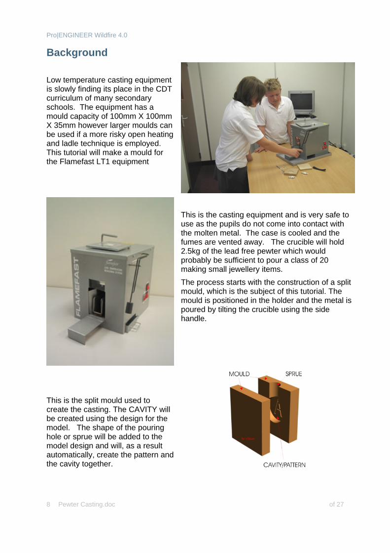
Background Low temperature casting equipment is slowly finding its place in the CDT curriculum of many secondary schools. The equipment has a mould capacity of 100mm X 100mm X 35mm however larger moulds can be used if a more risky open heating and ladle technique is employed. This tutorial will make a mould for the Flamefast LT1 equipment
This is the casting equipment and is very safe to use as the pupils do not come into contact with the molten metal. The case is cooled and the fumes are vented away. The crucible will hold 2.5kg of the lead free pewter which would probably be sufficient to pour a class of 20 making small jewellery items. The process starts with the construction of a split mould, which is the subject of this tutorial. The mould is positioned in the holder and the metal is poured by tilting the crucible using the side handle.
This is the split mould used to create the casting. The CAVITY will be created using the design for the model. The shape of the pouring hole or sprue will be added to the model design and will, as a result automatically, create the pattern and the cavity together.
Pro|ENGINEER Wildfire 4.0
Pewter Casting.doc of 27 9
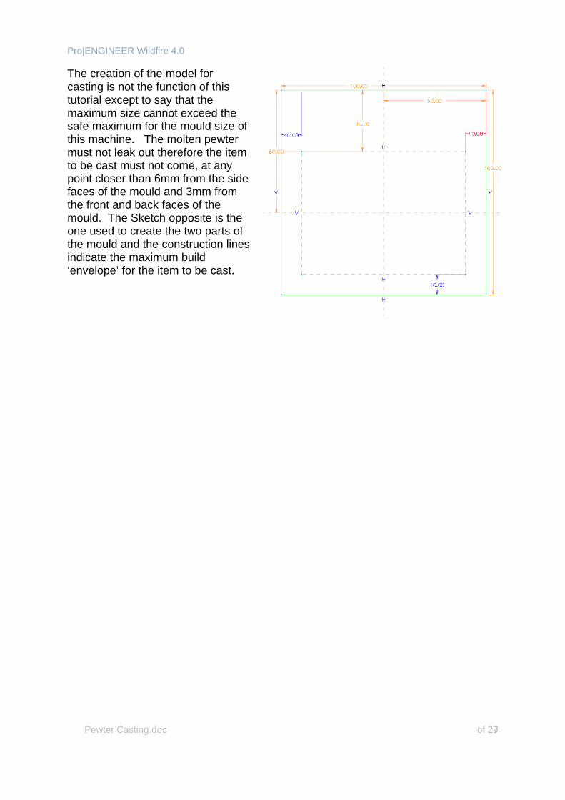
The creation of the model for casting is not the function of this tutorial except to say that the maximum size cannot exceed the safe maximum for the mould size of this machine. The molten pewter must not leak out therefore the item to be cast must not come, at any point closer than 6mm from the side faces of the mould and 3mm from the front and back faces of the mould. The Sketch opposite is the one used to create the two parts of the mould and the construction lines indicate the maximum build ‘envelope’ for the item to be cast.
Pro|ENGINEER Wildfire 4.0
Pewter Casting.doc of 27 10
Creating the Mould Task 1: Create the Basic Mould parts. Note: *This is assuming you have the Flamefast LT1 Low temperature casting
equipment. If you have any other machine or are using a brazing hearth/ ladle approach then vary the sizes accordingly. You can, as a teacher create these mould parts and save them in a common folder so that pupils can access them and create their moulds as required. Alternatively you can allow pupils to create their own.
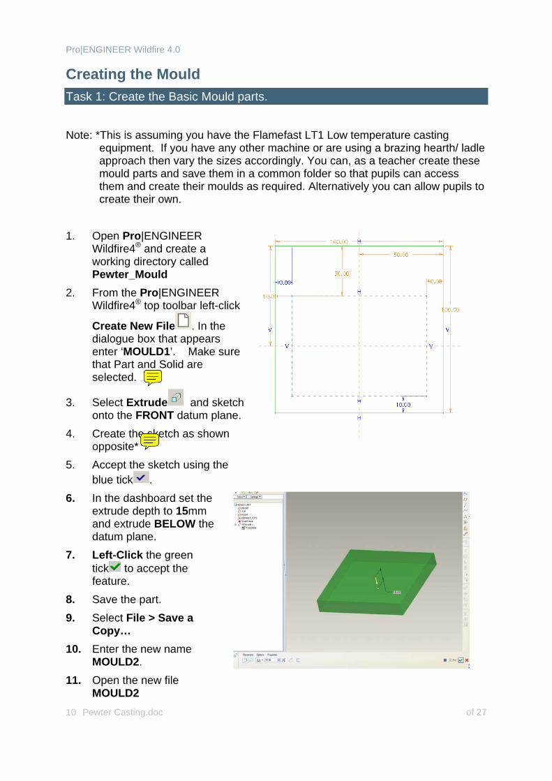
1. Open Pro|ENGINEER
Wildfire4® and create a working directory called Pewter_Mould
2. From the Pro|ENGINEER Wildfire4® top toolbar left-click
Create New File . In the dialogue box that appears enter ‘MOULD1’. Make sure that Part and Solid are selected.
3. Select Extrude and sketch onto the FRONT datum plane.
4. Create the sketch as shown opposite*
5. Accept the sketch using the blue tick .
6. In the dashboard set the extrude depth to 15mm and extrude BELOW the datum plane.
7. Left-Click the green tick to accept the feature.
8. Save the part. 9. Select File > Save a
Copy… 10. Enter the new name
MOULD2. 11. Open the new file
MOULD2
Pro|ENGINEER Wildfire 4.0
Pewter Casting.doc of 27 11
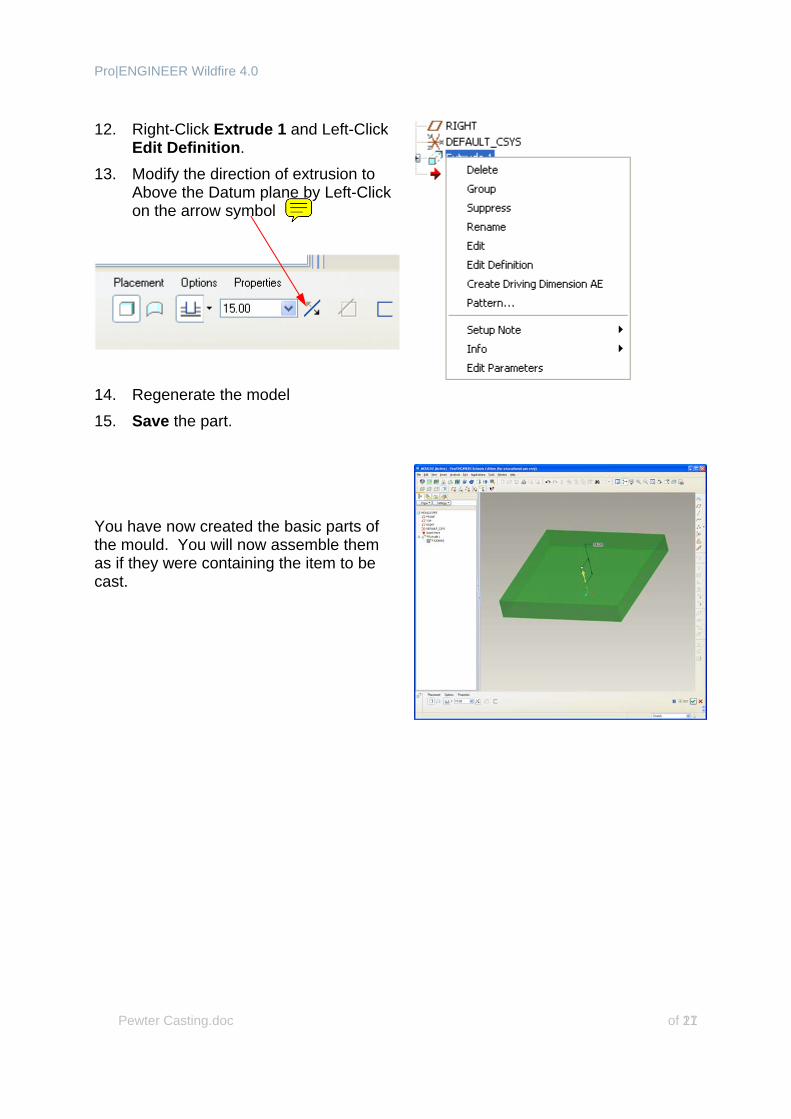
12. Right-Click Extrude 1 and Left-Click
Edit Definition. 13. Modify the direction of extrusion to
Above the Datum plane by Left-Click on the arrow symbol
14. Regenerate the model 15. Save the part.
You have now created the basic parts of the mould. You will now assemble them as if they were containing the item to be cast.
Pro|ENGINEER Wildfire 4.0
Pewter Casting.doc of 27 12
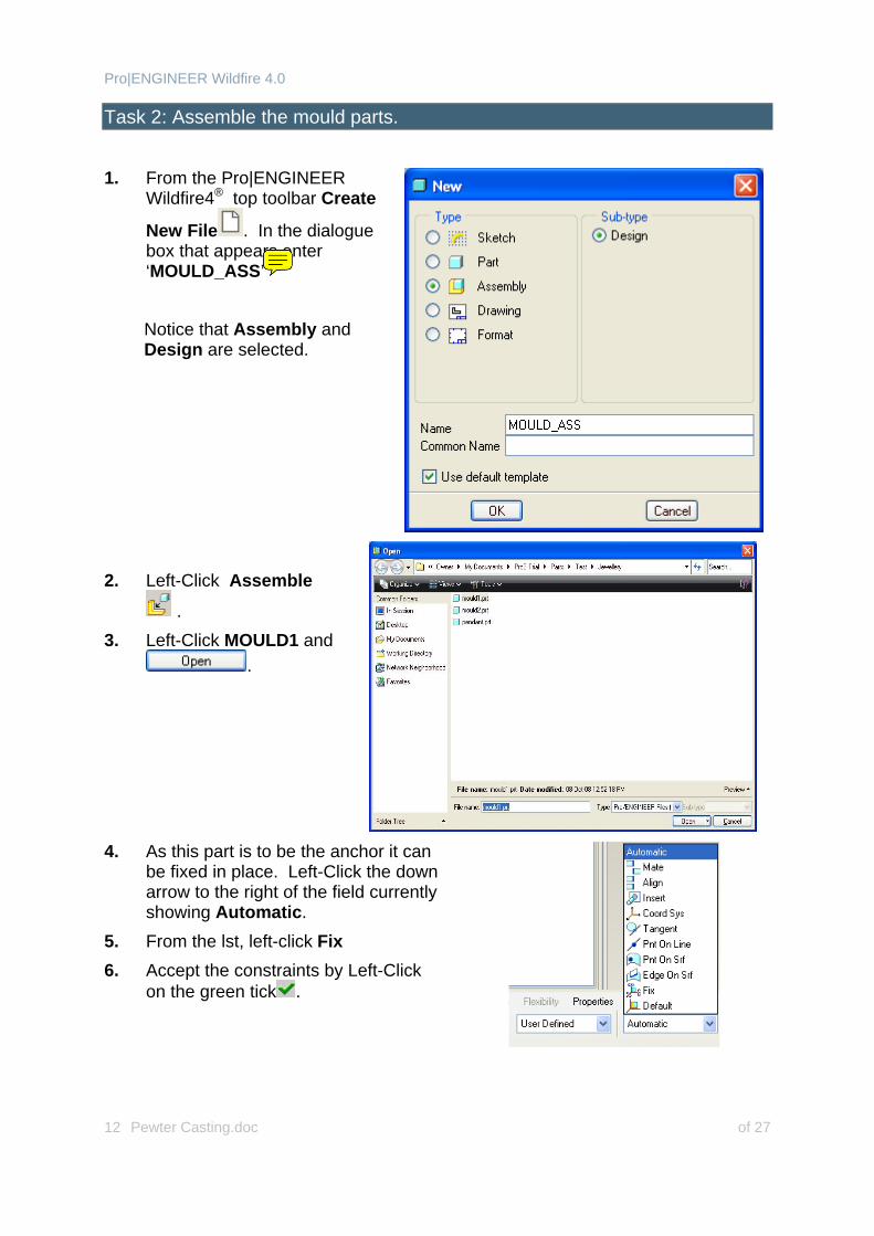
Task 2: Assemble the mould parts. 1. From the Pro|ENGINEER
Wildfire4® top toolbar Create
New File . In the dialogue box that appears enter ‘MOULD_ASS’
Notice that Assembly and Design are selected.
2. Left-Click Assemble
. 3. Left-Click MOULD1 and
.
4. As this part is to be the anchor it can
be fixed in place. Left-Click the down arrow to the right of the field currently showing Automatic.
5. From the lst, left-click Fix 6. Accept the constraints by Left-Click
on the green tick .
Pro|ENGINEER Wildfire 4.0
Pewter Casting.doc of 27 13
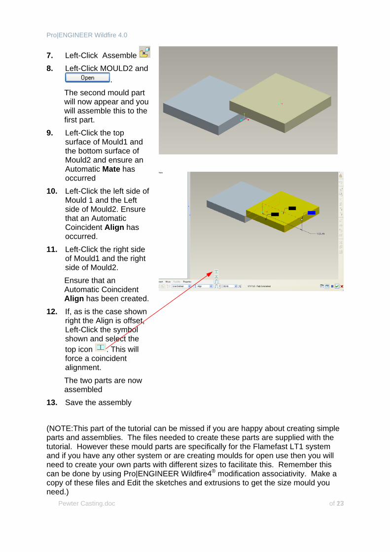
7. Left-Click Assemble 8. Left-Click MOULD2 and
. The second mould part will now appear and you will assemble this to the first part.
9. Left-Click the top surface of Mould1 and the bottom surface of Mould2 and ensure an Automatic Mate has occurred
10. Left-Click the left side of Mould 1 and the Left side of Mould2. Ensure that an Automatic Coincident Align has occurred.
11. Left-Click the right side of Mould1 and the right side of Mould2. Ensure that an Automatic Coincident Align has been created.
12. If, as is the case shown right the Align is offset, Left-Click the symbol shown and select the top icon . This will force a coincident alignment.
The two parts are now assembled
13. Save the assembly
(NOTE:This part of the tutorial can be missed if you are happy about creating simple parts and assemblies. The files needed to create these parts are supplied with the tutorial. However these mould parts are specifically for the Flamefast LT1 system and if you have any other system or are creating moulds for open use then you will need to create your own parts with different sizes to facilitate this. Remember this can be done by using Pro|ENGINEER Wildfire4® modification associativity. Make a copy of these files and Edit the sketches and extrusions to get the size mould you need.)
Pro|ENGINEER Wildfire 4.0
Pewter Casting.doc of 27 14
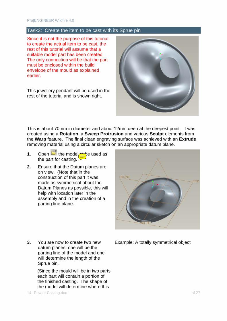
Task3: Create the item to be cast with its Sprue pin Since it is not the purpose of this tutorial to create the actual item to be cast, the rest of this tutorial will assume that a suitable model part has been created. The only connection will be that the part must be enclosed within the build envelope of the mould as explained earlier. This jewellery pendant will be used in the rest of the tutorial and is shown right.
This is about 70mm in diameter and about 12mm deep at the deepest point. It was created using a Rotation, a Sweep Protrusion and various Sculpt elements from the Warp feature. The final clean engraving surface was achieved with an Extrude removing material using a circular sketch on an appropriate datum plane.
1. Open the model to be used as the part for casting.
2. Ensure that the Datum planes are on view. (Note that in the construction of this part it was made as symmetrical about the Datum Planes as possible, this will help with location later in the assembly and in the creation of a parting line plane.
3. You are now to create two new
datum planes, one will be the parting line of the model and one will determine the length of the Sprue pin. (Since the mould will be in two parts each part will contain a portion of the finished casting. The shape of the model will determine where this
Example: A totally symmetrical object
Pro|ENGINEER Wildfire 4.0
Pewter Casting.doc of 27 15
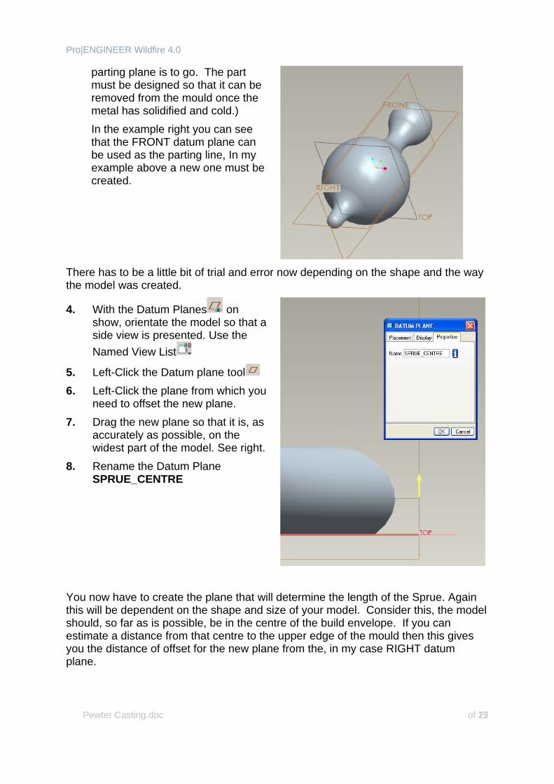
parting plane is to go. The part must be designed so that it can be removed from the mould once the metal has solidified and cold.) In the example right you can see that the FRONT datum plane can be used as the parting line, In my example above a new one must be created.
There has to be a little bit of trial and error now depending on the shape and the way the model was created.
4. With the Datum Planes on show, orientate the model so that a side view is presented. Use the Named View List
5. Left-Click the Datum plane tool 6. Left-Click the plane from which you
need to offset the new plane. 7. Drag the new plane so that it is, as
accurately as possible, on the widest part of the model. See right.
8. Rename the Datum Plane SPRUE_CENTRE
You now have to create the plane that will determine the length of the Sprue. Again this will be dependent on the shape and size of your model. Consider this, the model should, so far as is possible, be in the centre of the build envelope. If you can estimate a distance from that centre to the upper edge of the mould then this gives you the distance of offset for the new plane from the, in my case RIGHT datum plane.
Pro|ENGINEER Wildfire 4.0
Pewter Casting.doc of 27 16
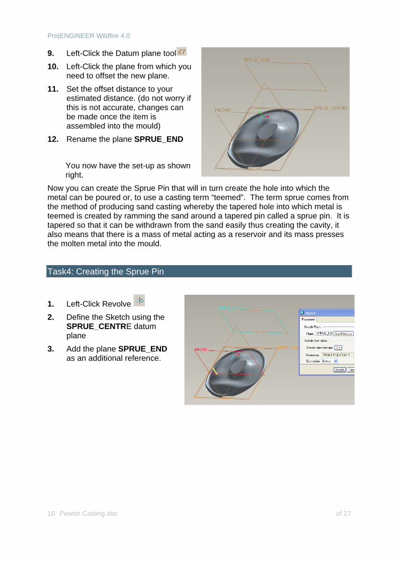
9. Left-Click the Datum plane tool 10. Left-Click the plane from which you
need to offset the new plane. 11. Set the offset distance to your
estimated distance. (do not worry if this is not accurate, changes can be made once the item is assembled into the mould)
12. Rename the plane SPRUE_END
You now have the set-up as shown right.
Now you can create the Sprue Pin that will in turn create the hole into which the metal can be poured or, to use a casting term “teemed”. The term sprue comes from the method of producing sand casting whereby the tapered hole into which metal is teemed is created by ramming the sand around a tapered pin called a sprue pin. It is tapered so that it can be withdrawn from the sand easily thus creating the cavity, it also means that there is a mass of metal acting as a reservoir and its mass presses the molten metal into the mould.
Task4: Creating the Sprue Pin
1. Left-Click Revolve 2. Define the Sketch using the
SPRUE_CENTRE datum plane
3. Add the plane SPRUE_END as an additional reference.
Pro|ENGINEER Wildfire 4.0
Pewter Casting.doc of 27 17
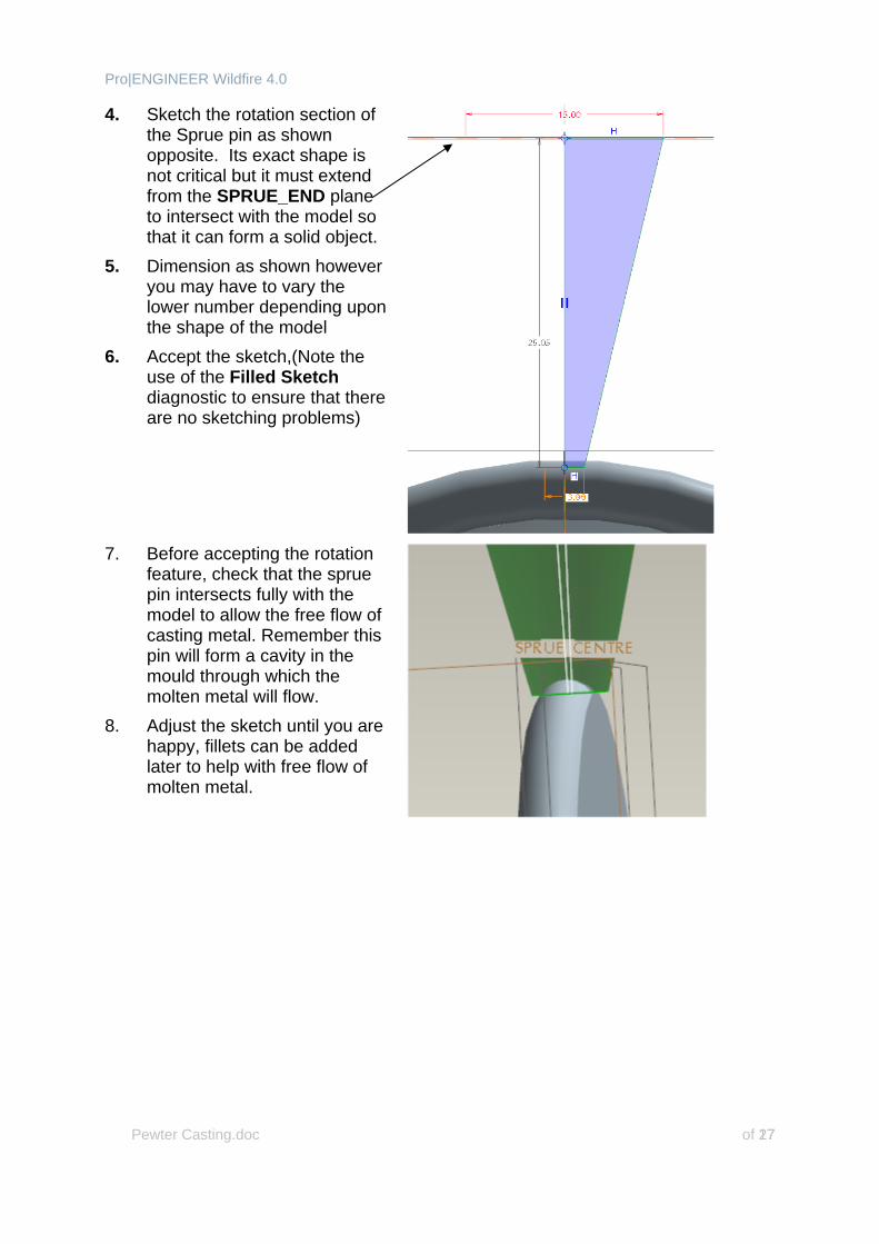
4. Sketch the rotation section of the Sprue pin as shown opposite. Its exact shape is not critical but it must extend from the SPRUE_END plane to intersect with the model so that it can form a solid object.
5. Dimension as shown however you may have to vary the lower number depending upon the shape of the model
6. Accept the sketch,(Note the use of the Filled Sketch diagnostic to ensure that there are no sketching problems)
7. Before accepting the rotation
feature, check that the sprue pin intersects fully with the model to allow the free flow of casting metal. Remember this pin will form a cavity in the mould through which the molten metal will flow.
8. Adjust the sketch until you are happy, fillets can be added later to help with free flow of molten metal.
Pro|ENGINEER Wildfire 4.0
Pewter Casting.doc of 27 18
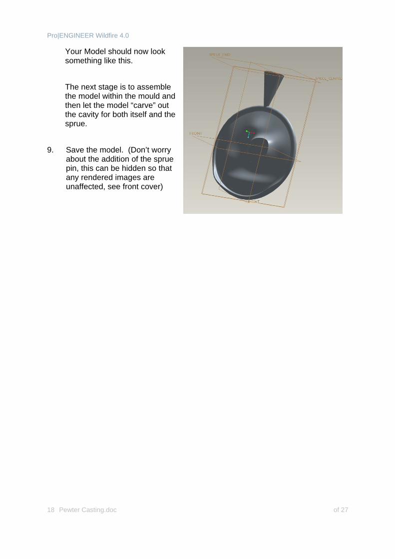
Your Model should now look something like this.
The next stage is to assemble the model within the mould and then let the model “carve” out the cavity for both itself and the sprue.
9. Save the model. (Don’t worry
about the addition of the sprue pin, this can be hidden so that any rendered images are unaffected, see front cover)
Pro|ENGINEER Wildfire 4.0
Pewter Casting.doc of 27 19
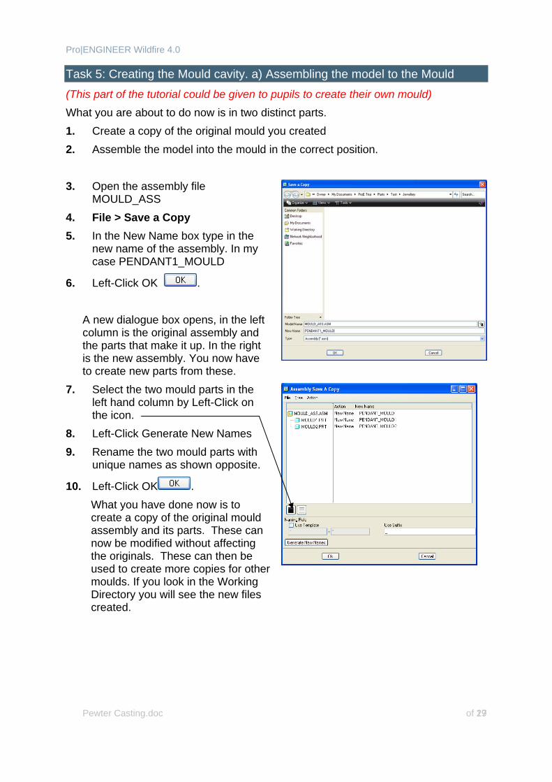
Task 5: Creating the Mould cavity. a) Assembling the model to the Mould (This part of the tutorial could be given to pupils to create their own mould) What you are about to do now is in two distinct parts. 1. Create a copy of the original mould you created 2. Assemble the model into the mould in the correct position. 3. Open the assembly file
MOULD_ASS 4. File > Save a Copy 5. In the New Name box type in the
new name of the assembly. In my case PENDANT1_MOULD
6. Left-Click OK . A new dialogue box opens, in the left column is the original assembly and the parts that make it up. In the right is the new assembly. You now have to create new parts from these.
7. Select the two mould parts in the left hand column by Left-Click on the icon.
8. Left-Click Generate New Names 9. Rename the two mould parts with
unique names as shown opposite.
10. Left-Click OK . What you have done now is to create a copy of the original mould assembly and its parts. These can now be modified without affecting the originals. These can then be used to create more copies for other moulds. If you look in the Working Directory you will see the new files created.
Pro|ENGINEER Wildfire 4.0
Pewter Casting.doc of 27 20
11. Close the original assembly and Erase from the session.
12. Close any other open parts and Erase from the session if you have found that with a few parts open the m/c has slowed down. This will free up RAM and allow the PC to run more efficiently
13. Open the newly created copy assembly. In my case PENDANT1_MOULD.ass
14. Left-Click Assembly . 15. Left-Click <modelname>.part
(where ‘modelname’ is the name of the item you wish to cast)
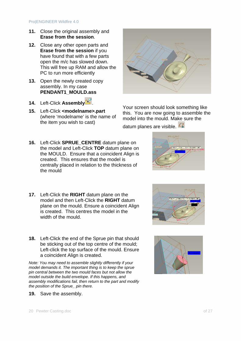
Your screen should look something like this. You are now going to assemble the model into the mould. Make sure the datum planes are visible.
16. Left-Click SPRUE_CENTRE datum plane on
the model and Left-Click TOP datum plane on the MOULD. Ensure that a coincident Align is created. This ensures that the model is centrally placed in relation to the thickness of the mould
17. Left-Click the RIGHT datum plane on the
model and then Left-Click the RIGHT datum plane on the mould. Ensure a coincident Align is created. This centres the model in the width of the mould.
18. Left-Click the end of the Sprue pin that should be sticking out of the top centre of the mould; Left-click the top surface of the mould. Ensure a coincident Align is created.
Note: You may need to assemble slightly differently if your model demands it. The important thing is to keep the sprue pin central between the two mould faces but not allow the model outside the build envelope. If this happens, and assembly modifications fail, then return to the part and modify the position of the Sprue_ pin there.
19. Save the assembly.
Pro|ENGINEER Wildfire 4.0
Pewter Casting.doc of 27 21
You have now successfully placed the model within the mould, to best see how it is placed change the shade to Hidden Lines.
20. Make any assembly adjustments now so that the model is exactly where you want it within the mould.
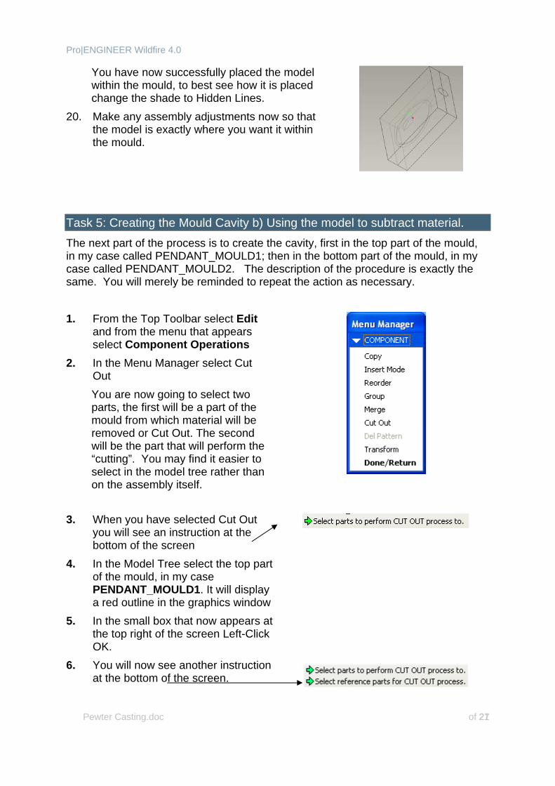
Task 5: Creating the Mould Cavity b) Using the model to subtract material. The next part of the process is to create the cavity, first in the top part of the mould, in my case called PENDANT_MOULD1; then in the bottom part of the mould, in my case called PENDANT_MOULD2. The description of the procedure is exactly the same. You will merely be reminded to repeat the action as necessary. 1. From the Top Toolbar select Edit
and from the menu that appears select Component Operations
2. In the Menu Manager select Cut Out You are now going to select two parts, the first will be a part of the mould from which material will be removed or Cut Out. The second will be the part that will perform the “cutting”. You may find it easier to select in the model tree rather than on the assembly itself.
3. When you have selected Cut Out you will see an instruction at the bottom of the screen
4. In the Model Tree select the top part of the mould, in my case PENDANT_MOULD1. It will display a red outline in the graphics window
5. In the small box that now appears at the top right of the screen Left-Click OK.
6. You will now see another instruction at the bottom of the screen.
Pro|ENGINEER Wildfire 4.0
Pewter Casting.doc of 27 22
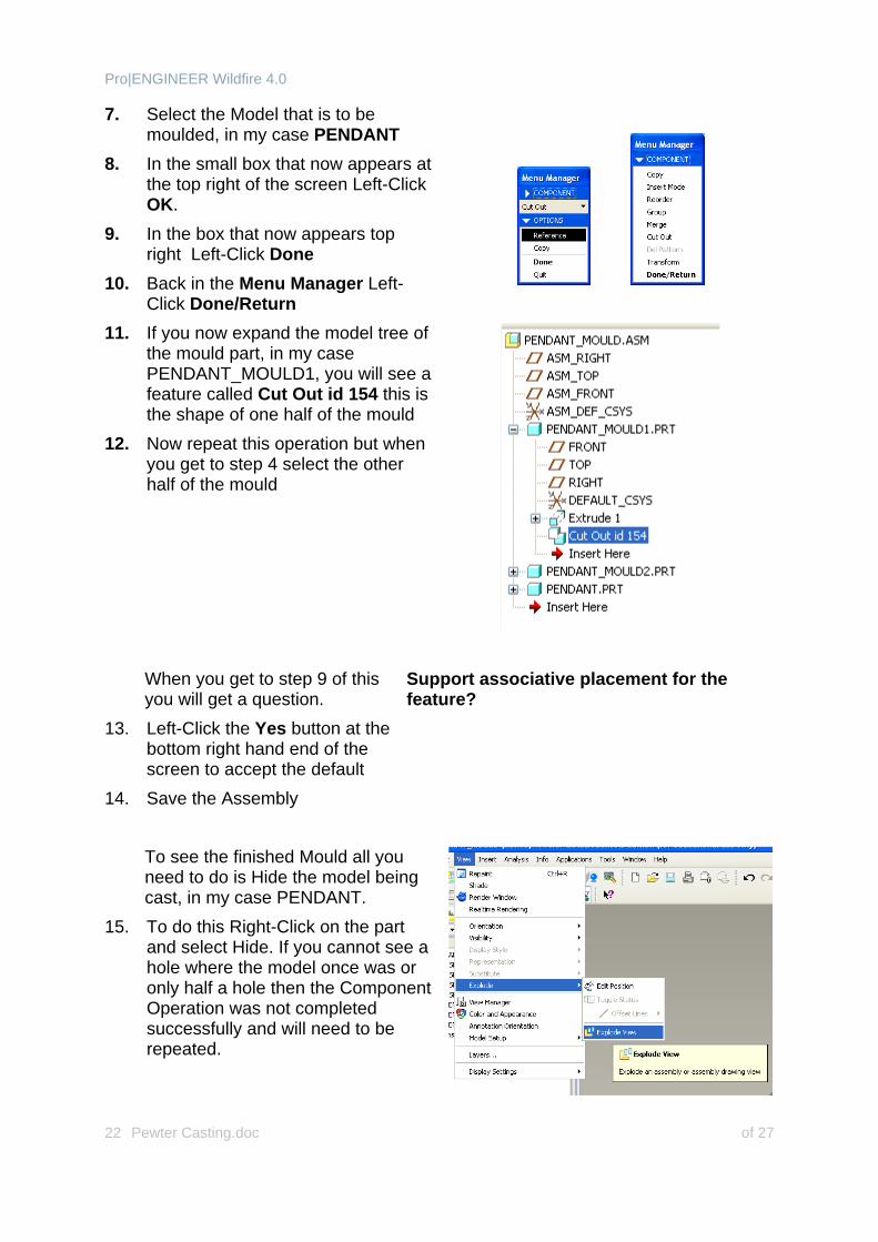
7. Select the Model that is to be moulded, in my case PENDANT
8. In the small box that now appears at the top right of the screen Left-Click OK.
9. In the box that now appears top right Left-Click Done
10. Back in the Menu Manager Left-Click Done/Return
11. If you now expand the model tree of the mould part, in my case PENDANT_MOULD1, you will see a feature called Cut Out id 154 this is the shape of one half of the mould
12. Now repeat this operation but when you get to step 4 select the other half of the mould
When you get to step 9 of this you will get a question.
13. Left-Click the Yes button at the bottom right hand end of the screen to accept the default
14. Save the Assembly
Support associative placement for the feature?
To see the finished Mould all you need to do is Hide the model being cast, in my case PENDANT.
15. To do this Right-Click on the part and select Hide. If you cannot see a hole where the model once was or only half a hole then the Component Operation was not completed successfully and will need to be repeated.
Pro|ENGINEER Wildfire 4.0
Pewter Casting.doc of 27 23
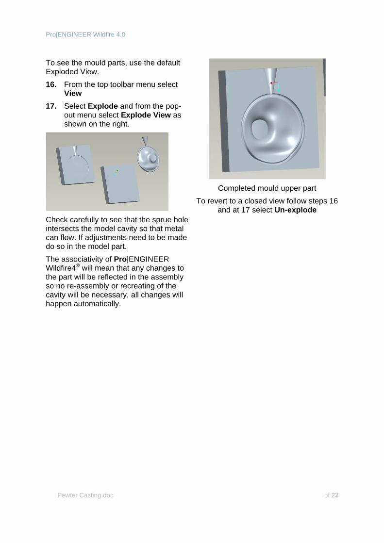
To see the mould parts, use the default Exploded View. 16. From the top toolbar menu select
View 17. Select Explode and from the pop-
out menu select Explode View as shown on the right.
Check carefully to see that the sprue hole intersects the model cavity so that metal can flow. If adjustments need to be made do so in the model part. The associativity of Pro|ENGINEER Wildfire4® will mean that any changes to the part will be reflected in the assembly so no re-assembly or recreating of the cavity will be necessary, all changes will happen automatically.
Completed mould upper part
To revert to a closed view follow steps 16 and at 17 select Un-explode
Pro|ENGINEER Wildfire 4.0
Pewter Casting.doc of 27 24
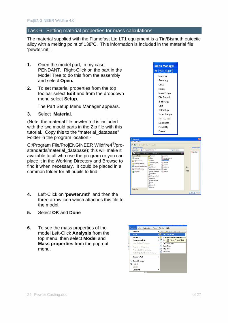
Task 6: Setting material properties for mass calculations. The material supplied with the Flamefast Ltd LT1 equipment is a Tin/Bismuth eutectic alloy with a melting point of 138oC. This information is included in the material file ‘pewter.mtl’. 1. Open the model part, in my case
PENDANT. Right-Click on the part in the Model Tree to do this from the assembly and select Open.
2. To set material properties from the top toolbar select Edit and from the dropdown menu select Setup. The Part Setup Menu Manager appears.
3. Select Material. (Note: the material file pewter.mtl is included with the two mould parts in the Zip file with this tutorial. Copy this to the “material_database” Folder in the program location:- C:/Program File/Pro|ENGINEER Wildfire4®/pro-standards/material_database); this will make it available to all who use the program or you can place it in the Working Directory and Browse to find it when necessary. It could be placed in a common folder for all pupils to find. 4. Left-Click on ‘pewter.mtl’ and then the
three arrow icon which attaches this file to the model.
5. Select OK and Done
6. To see the mass properties of the model Left-Click Analysis from the top menu; then select Model and Mass properties from the pop-out menu.
Pro|ENGINEER Wildfire 4.0
Pewter Casting.doc of 27 25
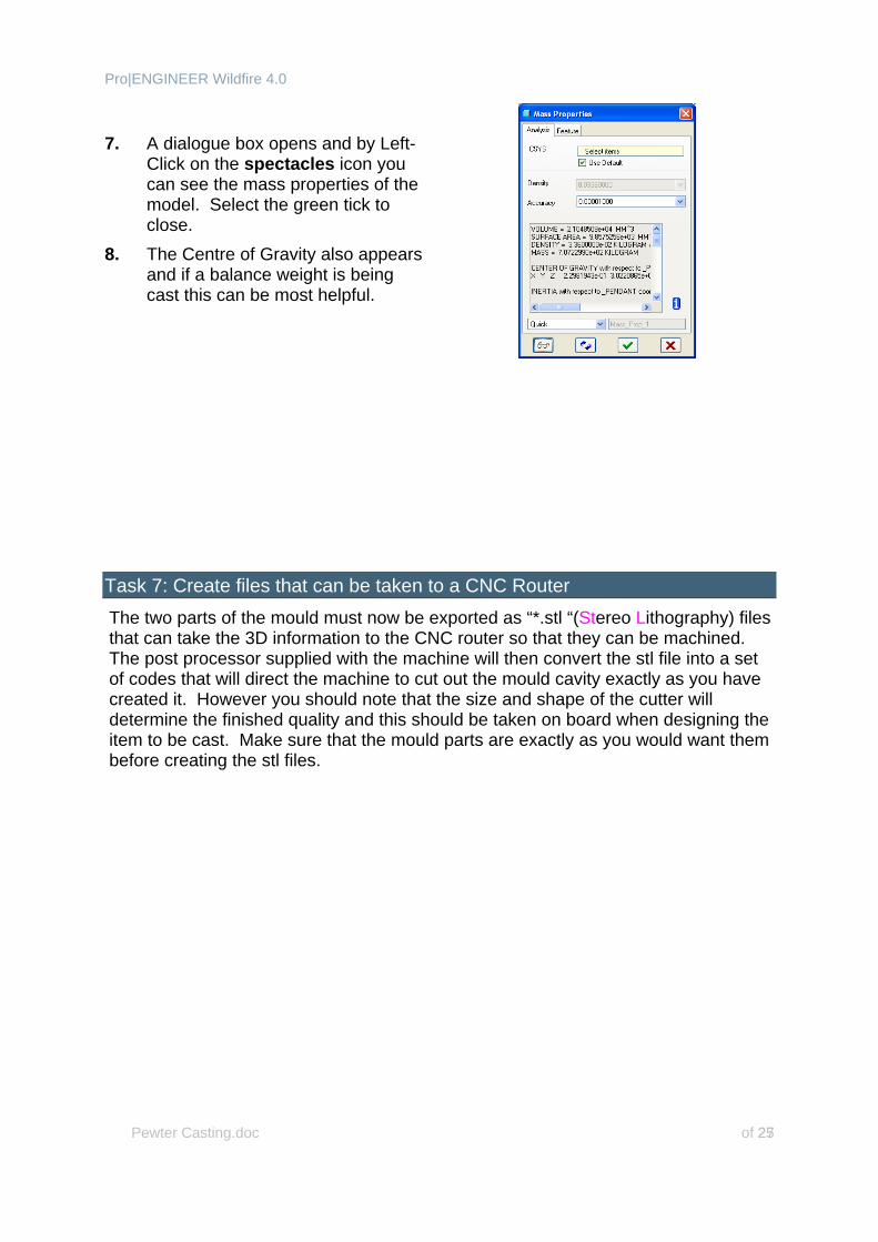
7. A dialogue box opens and by Left-
Click on the spectacles icon you can see the mass properties of the model. Select the green tick to close.
8. The Centre of Gravity also appears and if a balance weight is being cast this can be most helpful.
Task 7: Create files that can be taken to a CNC Router The two parts of the mould must now be exported as “*.stl “(Stereo Lithography) files that can take the 3D information to the CNC router so that they can be machined. The post processor supplied with the machine will then convert the stl file into a set of codes that will direct the machine to cut out the mould cavity exactly as you have created it. However you should note that the size and shape of the cutter will determine the finished quality and this should be taken on board when designing the item to be cast. Make sure that the mould parts are exactly as you would want them before creating the stl files.
Pro|ENGINEER Wildfire 4.0
Pewter Casting.doc of 27 26
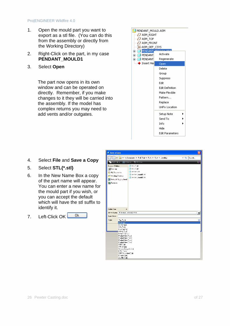
1. Open the mould part you want to export as a stl file. (You can do this from the assembly or directly from the Working Directory)
2. Right-Click on the part, in my case PENDANT_MOULD1
3. Select Open
The part now opens in its own window and can be operated on directly. Remember, if you make changes to it they will be carried into the assembly. If the model has complex returns you may need to add vents and/or outgates.
4. Select File and Save a Copy 5. Select STL{*.stl} 6. In the New Name Box a copy
of the part name will appear. You can enter a new name for the mould part if you wish, or you can accept the default which will have the stl suffix to identify it.
7. Left-Click OK
Pro|ENGINEER Wildfire 4.0
Pewter Casting.doc of 27 27
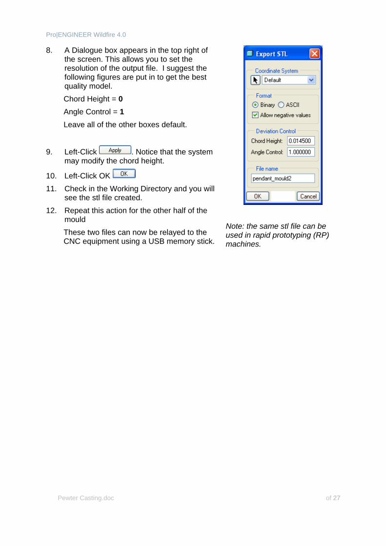
8. A Dialogue box appears in the top right of the screen. This allows you to set the resolution of the output file. I suggest the following figures are put in to get the best quality model. Chord Height = 0 Angle Control = 1 Leave all of the other boxes default.
9. Left-Click . Notice that the system may modify the chord height.
10. Left-Click OK 11. Check in the Working Directory and you will
see the stl file created. 12. Repeat this action for the other half of the
mould These two files can now be relayed to the CNC equipment using a USB memory stick.
Note: the same stl file can be used in rapid prototyping (RP) machines.