Embed Size (px)
Citation preview
High quality custom rocket motor igniters can be made quickly, easily, and inexpensively. You can maketiny igniters that will fit in the nozzle of small composite motors (e.g. 24mm E15, E30) up to massiveigniters suitable for the largest motors. And best of all, they won’t take a lot of current for firing, whichmeans that they can be used for staging and airstarts with a timer (e.g. PerfectFlite MT4) and a small,lightweight battery.
If you want to ignite a large cluster of motors, keeping the current requirement of each igniter low isimportant, because the firing system (ground launch or onboard electronics for airstart) needs to supplythe igniter current multiplied by the number of igniters wired in parallel. Using the techniques describedin this document you will be able to fire dozens of igniters simultaneously for a really impressive airstartusing a timer and battery that together weigh less than one ounce.
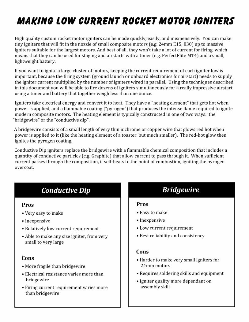
Igniters take electrical energy and convert it to heat. They have a “heating element” that gets hot whenpower is applied, and a flammable coating (“pyrogen”) that produces the intense flame required to ignitemodern composite motors. The heating element is typically constructed in one of two ways: the
“bridgewire” or the “conductive dip”.
A bridgewire consists of a small length of very thin nichrome or copper wire that glows red hot whenpower is applied to it (like the heating element of a toaster, but much smaller). The red-hot glow thenignites the pyrogen coating.
Conductive Dip igniters replace the bridgewire with a flammable chemical composition that includes aquantity of conductive particles (e.g. Graphite) that allow current to pass through it. When sufficientcurrent passes through the composition, it self-heats to the point of combustion, igniting the pyrogenovercoat.
Making Low Current Rocket Motor Igniters
Conductive Dip
Pros• Very easy to make• Inexpensive• Relatively low current requirement• Able to make any size igniter, from very
small to very large
Cons• More fragile than bridgewire• Electrical resistance varies more than
bridgewire• Firing current requirement varies more
than bridgewire
Bridgewire
Pros• Easy to make• Inexpensive• Low current requirement• Best reliability and consistency
Cons• Harder to make very small igniters for
24mm motors• Requires soldering skills and equipment• Igniter quality more dependant on
assembly skill
Making Conductive Dip Igniters
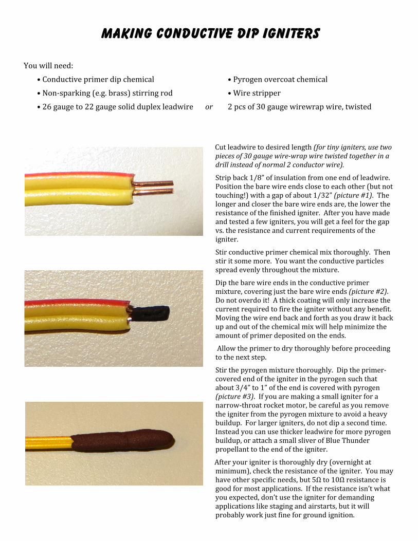
You will need:
• Conductive primer dip chemical • Pyrogen overcoat chemical
• Non-sparking (e.g. brass) stirring rod • Wire stripper
• 26 gauge to 22 gauge solid duplex leadwire or 2 pcs of 30 gauge wirewrap wire, twisted
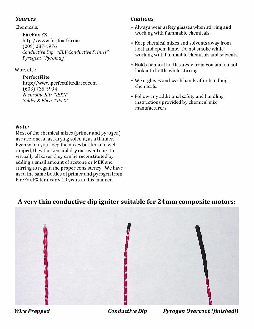
Cut leadwire to desired length (for tiny igniters, use twopieces of 30 gauge wire-wrap wire twisted together in adrill instead of normal 2 conductor wire).
Strip back 1/8” of insulation from one end of leadwire.Position the bare wire ends close to each other (but nottouching!) with a gap of about 1/32” (picture #1). Thelonger and closer the bare wire ends are, the lower theresistance of the finished igniter. After you have madeand tested a few igniters, you will get a feel for the gapvs. the resistance and current requirements of theigniter.
Stir conductive primer chemical mix thoroughly. Thenstir it some more. You want the conductive particlesspread evenly throughout the mixture.
Dip the bare wire ends in the conductive primermixture, covering just the bare wire ends (picture #2).Do not overdo it! A thick coating will only increase thecurrent required to fire the igniter without any benefit.Moving the wire end back and forth as you draw it backup and out of the chemical mix will help minimize theamount of primer deposited on the ends.
Allow the primer to dry thoroughly before proceedingto the next step.
Stir the pyrogen mixture thoroughly. Dip the primer-covered end of the igniter in the pyrogen such thatabout 3/4” to 1” of the end is covered with pyrogen(picture #3). If you are making a small igniter for anarrow-throat rocket motor, be careful as you removethe igniter from the pyrogen mixture to avoid a heavybuildup. For larger igniters, do not dip a second time.Instead you can use thicker leadwire for more pyrogenbuildup, or attach a small sliver of Blue Thunderpropellant to the end of the igniter.
After your igniter is thoroughly dry (overnight atminimum), check the resistance of the igniter. You mayhave other specific needs, but 5Ω to 10Ω resistance isgood for most applications. If the resistance isn’t whatyou expected, don’t use the igniter for demandingapplications like staging and airstarts, but it willprobably work just fine for ground ignition.
Making Bridgewire Igniters
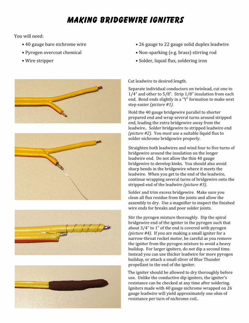
You will need:
• 40 gauge bare nichrome wire • 26 gauge to 22 gauge solid duplex leadwire
• Pyrogen overcoat chemical • Non-sparking (e.g. brass) stirring rod
• Wire stripper • Solder, liquid flux, soldering iron
Cut leadwire to desired length.
Separate individual conductors on twinlead, cut one to1/4” and other to 5/8”. Strip 1/8” insulation from eachend. Bend ends slightly in a “Y” formation to make nextstep easier (picture #1).
Hold the 40 gauge bridgewire parallel to shorterprepared end and wrap several turns around strippedend, leading the extra bridgewire away from theleadwire.. Solder bridgewire to stripped leadwire end(picture #2). You must use a suitable liquid flux tosolder nichrome bridgewire properly.
Straighten both leadwires and wind four to five turns ofbridgewire around the insulation on the longerleadwire end. Do not allow the thin 40 gaugebridgewire to develop kinks. You should also avoidsharp bends in the bridgewire where it meets theleadwire. When you get to the end of the leadwire,continue wrapping several turns of bridgewire onto thestripped end of the leadwire (picture #3).
Solder and trim excess bridgewire. Make sure youclean all flux residue from the joints and allow theassembly to dry. Use a magnifier to inspect the finishedwire ends for breaks and poor solder joints.
Stir the pyrogen mixture thoroughly. Dip the spiralbridgewire end of the igniter in the pyrogen such thatabout 3/4” to 1” of the end is covered with pyrogen(picture #4). If you are making a small igniter for anarrow-throat rocket motor, be careful as you removethe igniter from the pyrogen mixture to avoid a heavybuildup. For larger igniters, do not dip a second time.Instead you can use thicker leadwire for more pyrogenbuildup, or attach a small sliver of Blue Thunderpropellant to the end of the igniter.
The igniter should be allowed to dry thoroughly beforeuse. Unlike the conductive dip igniters, the igniter’sresistance can be checked at any time after soldering.Igniters made with 40 gauge nichrome wrapped on 26gauge leadwire will yield approximately one ohm ofresistance per turn of nichrome coil..
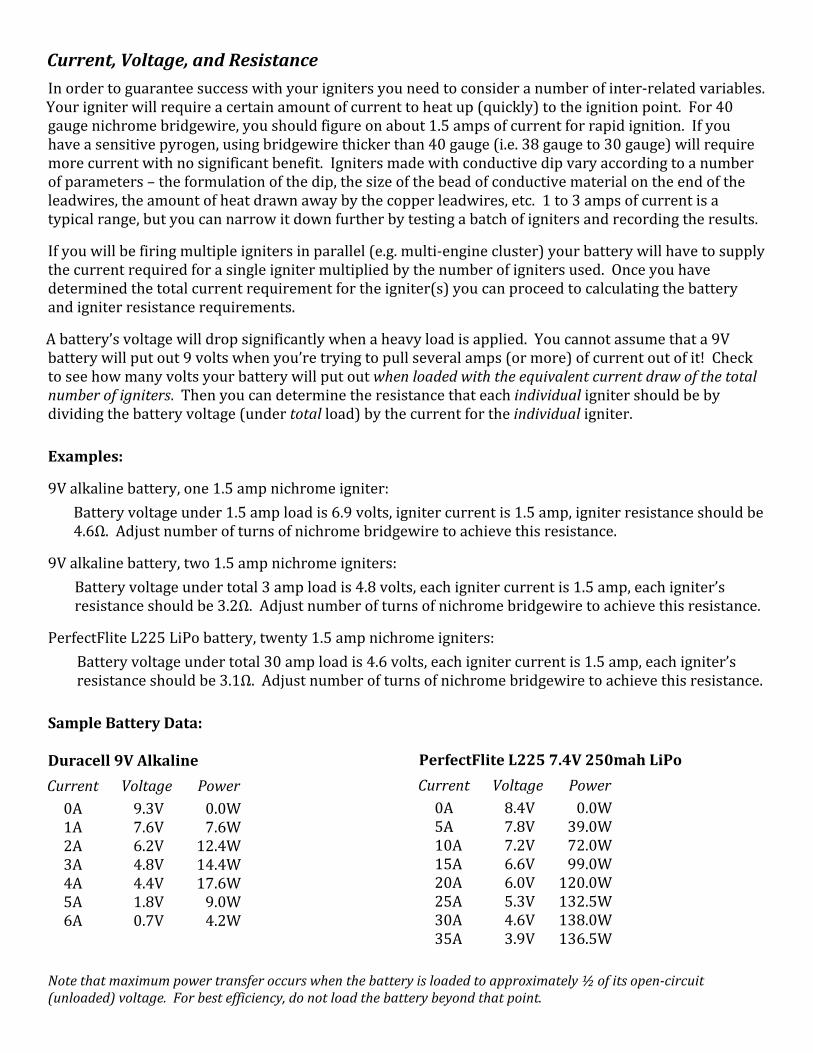
Current, Voltage, and ResistanceIn order to guarantee success with your igniters you need to consider a number of inter-related variables.Your igniter will require a certain amount of current to heat up (quickly) to the ignition point. For 40gauge nichrome bridgewire, you should figure on about 1.5 amps of current for rapid ignition. If youhave a sensitive pyrogen, using bridgewire thicker than 40 gauge (i.e. 38 gauge to 30 gauge) will requiremore current with no significant benefit. Igniters made with conductive dip vary according to a numberof parameters – the formulation of the dip, the size of the bead of conductive material on the end of theleadwires, the amount of heat drawn away by the copper leadwires, etc. 1 to 3 amps of current is atypical range, but you can narrow it down further by testing a batch of igniters and recording the results.
If you will be firing multiple igniters in parallel (e.g. multi-engine cluster) your battery will have to supplythe current required for a single igniter multiplied by the number of igniters used. Once you havedetermined the total current requirement for the igniter(s) you can proceed to calculating the batteryand igniter resistance requirements.
A battery’s voltage will drop significantly when a heavy load is applied. You cannot assume that a 9Vbattery will put out 9 volts when you’re trying to pull several amps (or more) of current out of it! Checkto see how many volts your battery will put out when loaded with the equivalent current draw of the totalnumber of igniters. Then you can determine the resistance that each individual igniter should be bydividing the battery voltage (under total load) by the current for the individual igniter.
Examples:
9V alkaline battery, one 1.5 amp nichrome igniter:Battery voltage under 1.5 amp load is 6.9 volts, igniter current is 1.5 amp, igniter resistance should be4.6Ω. Adjust number of turns of nichrome bridgewire to achieve this resistance.
9V alkaline battery, two 1.5 amp nichrome igniters:Battery voltage under total 3 amp load is 4.8 volts, each igniter current is 1.5 amp, each igniter’sresistance should be 3.2Ω. Adjust number of turns of nichrome bridgewire to achieve this resistance.
PerfectFlite L225 LiPo battery, twenty 1.5 amp nichrome igniters:Battery voltage under total 30 amp load is 4.6 volts, each igniter current is 1.5 amp, each igniter’sresistance should be 3.1Ω. Adjust number of turns of nichrome bridgewire to achieve this resistance.
Sample Battery Data:
Duracell 9V AlkalineCurrent Voltage Power
0A 9.3V 0.0W1A 7.6V 7.6W2A 6.2V 12.4W3A 4.8V 14.4W4A 4.4V 17.6W5A 1.8V 9.0W6A 0.7V 4.2W
PerfectFlite L225 7.4V 250mah LiPoCurrent Voltage Power
0A 8.4V 0.0W5A 7.8V 39.0W10A 7.2V 72.0W15A 6.6V 99.0W20A 6.0V 120.0W25A 5.3V 132.5W30A 4.6V 138.0W35A 3.9V 136.5W
Note that maximum power transfer occurs when the battery is loaded to approximately ½ of its open-circuit(unloaded) voltage. For best efficiency, do not load the battery beyond that point.
SourcesChemicals:
FireFox FXhttp://www.firefox-fx.com(208) 237-1976Conductive Dip: “ELV Conductive Primer”Pyrogen: “Pyromag”
Wire, etc.:PerfectFlitehttp://www.perfectflitedirect.com(603) 735-5994Nichrome Kit: “IEKN”Solder & Flux: “SFLX”
A very thin conductive dip igniter suitable for 24mm composite motors:
Wire Prepped Conductive Dip Pyrogen Overcoat (finished!)
Cautions• Always wear safety glasses when stirring and
working with flammable chemicals.
• Keep chemical mixes and solvents away fromheat and open flame. Do not smoke whileworking with flammable chemicals and solvents.
• Hold chemical bottles away from you and do notlook into bottle while stirring.
• Wear gloves and wash hands after handlingchemicals.
• Follow any additional safety and handlinginstructions provided by chemical mixmanufacturers.
Note:Most of the chemical mixes (primer and pyrogen)use acetone, a fast drying solvent, as a thinner.Even when you keep the mixes bottled and wellcapped, they thicken and dry out over time. Invirtually all cases they can be reconstituted byadding a small amount of acetone or MEK andstirring to regain the proper consistency. We haveused the same bottles of primer and pyrogen fromFireFox FX for nearly 10 years in this manner.


![Detonators, Igniters, Primers, And Other Initiating Devices[1]](https://img.pdfslide.net/doc/110x75/543cbed5b1af9fc02e8b4772/detonators-igniters-primers-and-other-initiating-devices1.jpg)


