Embed Size (px)
Citation preview

INSTRUCTION MANUAL
RUNVECTOR INVERTER
Global LeaderGlobal Leader
DOC. NO
HYUNDAI INVERTER
H Y U N D A I
IN V E R T E R
Building a better futureISO 9001 REGISTEREDISO 9001 REGISTERED
DNV Certification B.V., THE NETHERLANDS DNV Certification B.V., THE NETHERLANDS MGMT. SYS.MGMT. SYS.RvA CO24RvA CO24
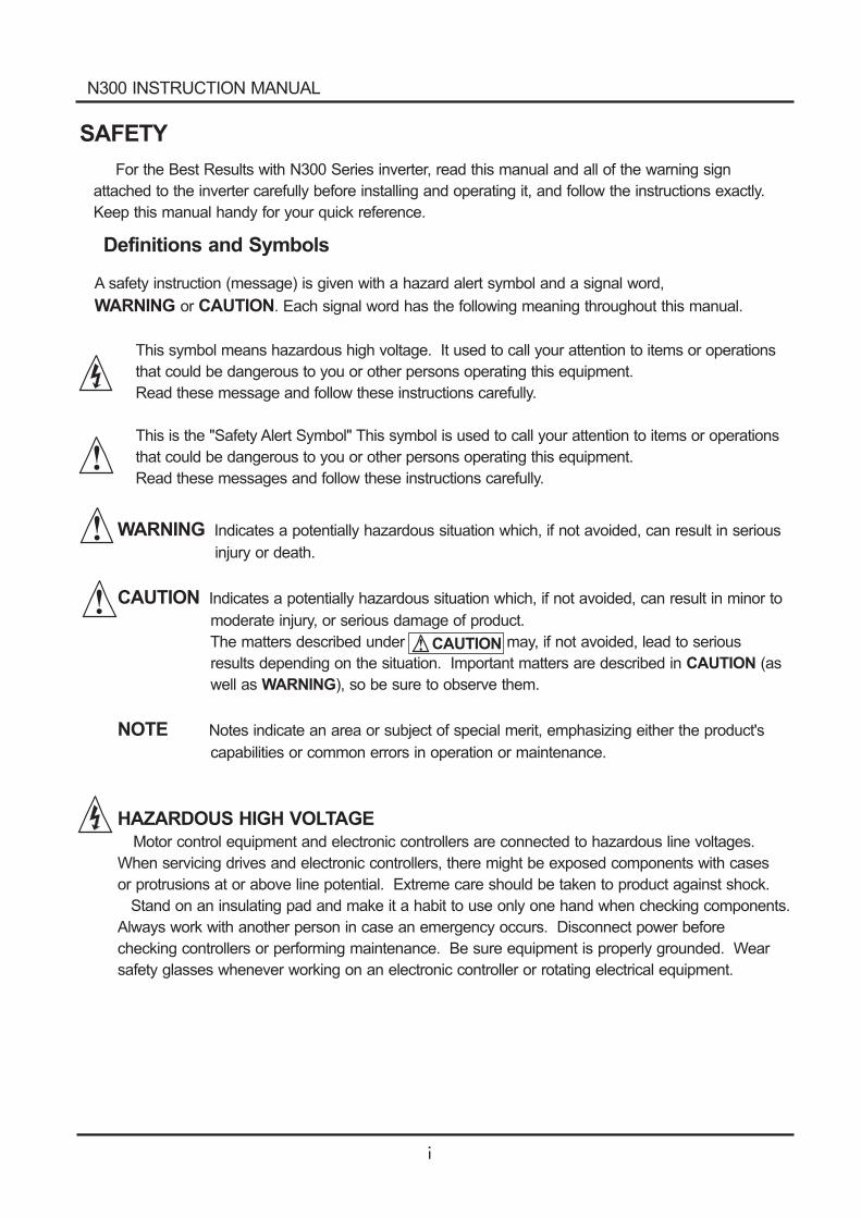
SAFETY
For the Best Results with N300 Series inverter, read this manual and all of the warning sign
attached to the inverter carefully before installing and operating it, and follow the instructions exactly.
Keep this manual handy for your quick reference.
Definitions and Symbols
A safety instruction (message) is given with a hazard alert symbol and a signal word,
or . Each signal word has the following meaning throughout this manual.WARNING CAUTION
This symbol means hazardous high voltage. It used to call your attention to items or operations
that could be dangerous to you or other persons operating this equipment.
Read these message and follow these instructions carefully.
This is the "Safety Alert Symbol" This symbol is used to call your attention to items or operations
that could be dangerous to you or other persons operating this equipment.
Read these messages and follow these instructions carefully.
CAUTION
WARNING
CAUTION
NOTE
Indicates a potentially hazardous situation which, if not avoided, can result in serious
injury or death.
Indicates a potentially hazardous situation which, if not avoided, can result in minor to
moderate injury, or serious damage of product.
The matters described under may, if not avoided, lead to serious
results depending on the situation. Important matters are described in (as
well as ), so be sure to observe them.
Notes indicate an area or subject of special merit, emphasizing either the product's
capabilities or common errors in operation or maintenance.
CAUTION
WARNING
HAZARDOUS HIGH VOLTAGEMotor control equipment and electronic controllers are connected to hazardous line voltages.
When servicing drives and electronic controllers, there might be exposed components with cases
or protrusions at or above line potential. Extreme care should be taken to product against shock.
Stand on an insulating pad and make it a habit to use only one hand when checking components.
Always work with another person in case an emergency occurs. Disconnect power before
checking controllers or performing maintenance. Be sure equipment is properly grounded. Wear
safety glasses whenever working on an electronic controller or rotating electrical equipment.
N300 INSTRUCTION MANUAL
PRECAUTION
CAUTION : These instructions should be read and clearly understood before working onN300 series equipment.
NOTE : POLLUTION DEGREE2The inverter must be used environment of the degree 2.
Typical constructions that reduce the possibility of conductive pollution are,
1) The use of an unventilated enclosure
2) The use of a filtered ventilated enclosure when the ventilation is fan forced that is, ventilation is
accomplished by one more blowers within the enclosure that provide a positive intake and
exhaust.
WARNING : This is equipment should be installed, adjusted and serviced by qualified electricalmaintenance personal familiar with the construction and operation of the equipment and the hazardsinvolved. Failure to observe this precaution could results in bodily injury.
WARNING :The user is responsible for ensuring that all driven machinery, drive train mechanism notsupplied by HYUNDAI and process line material are capable of safe operation at an applied frequencyof 150% of the maximum selected frequency range to the AC motor. Failure to do so can result indestruction of equipment and injury to personnel should a single point failure occur.
WARNING : For protection, install an earth leakage breaker with a high frequency circuit capable oflarge currents to avoid an unnecessary operation. The ground fault protection circuit is not designedto protect personal injury.
WARNING : Hazard of electrical shock. Disconnect incoming power before working on this control.
WARNING : Separate motor overcurrent, overload and overheating protection is required to beprovided in accordance with the safety codes required by jurisdictional authorities.
CAUTION : Proper grounds, disconnecting devices and other safety devices and theirlocation are the responsibility of the user and are not provided by HYUNDAI.
CAUTION : Be sure to connect a motor thermal switch or overload devices to the N300series controller to assure that inverter will shut down in the event of an overload or anoverheated motor.
CAUTION : Dangerous voltage exists until charge lamp is off.
CAUTION : Rotating shafts and above ground electrical potentials can be hazardous.Therefore, it is strongly recommended that all electrical work conform to the NationalElectrical Codes and local regulations. Only qualified personnel should perform installation,alignment and maintenance. Factory recommended test procedures, included in theinstruction manual, should be followed. Always disconnect electrical power before workingon the unit.
N300 INSTRUCTION MANUAL
Cautions for EMC (Electromagnetic Compatibility)
To safety the EMC directive and to comply with standard, follows the checklist below.
WARNING
This equipment should be installed, adjusted, and serviced by qualified personal familiar withconstruction and operation of the equipment and the hazards involved. Failure to observethis precaution could result in bodily injury.
1. The power supply to N300 inverter must meet these specifications
a. Voltage fluctuation 10% or less.
b. Voltage imbalance 3% or less.
c. Frequency variation 4% or less.
d. Voltage distortion THD = 10% or less.
2. Installation measure :
a. Use a filter designed for N300 inverter
3. Wiring
a. Shielded wire (screened cable) is required for motor wiring, and the length must be less
than 20 meters.
b. The carrier frequency setting must be less than 5kHz to satisfy EMC requirements.
c. Separate the main circuit from the signal/process circuit wiring.
d. In case of remote operating with connector cable, the inverter does not conform to EMC.
4. Environmental conditions - when using a filter, follow these guidelines:
a. Ambient air temperature : -10 - +50 .
b. Humidity : 20 to 90% RH(non-condensing)
c. Vibration : 5.9 m/sec (0.6 G) 10 - 55Hz ( N300- 055 - 220LF / 055 - 220HF)
2.94
2
m/sec (0.6 G) 10 - 55Hz ( N300- 300 - 550LF / 300 - 1320HF)
d. Location : 1000meters of less altitude, indoors (no corrosive gas or dust)
2
N300 INSTRUCTION MANUAL
Conformity to the Low Voltage Directive (LVD)
The protective enclosure must conform to the Low Voltage Directive.
The inverter can conform to the LVD by mounting into a cabinet or by adding covers as follows.
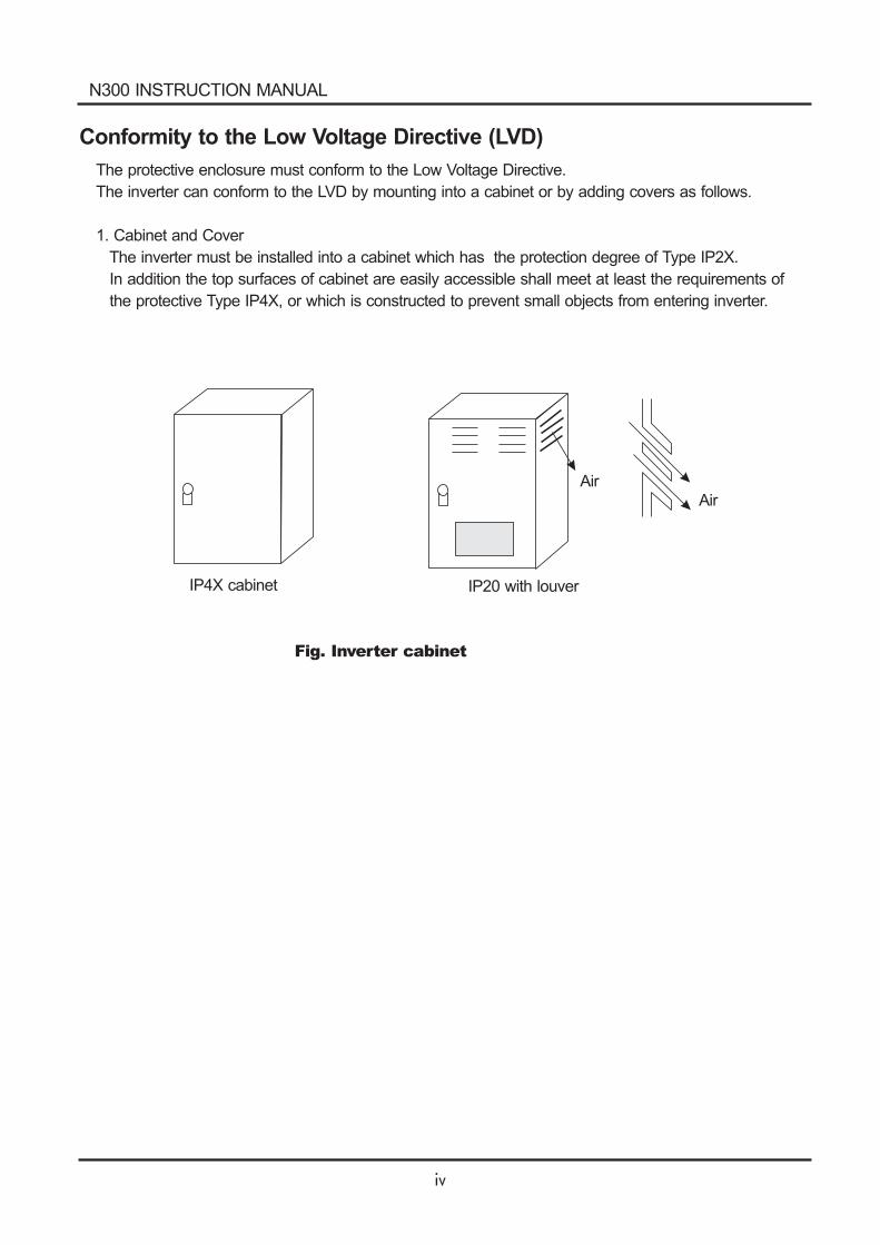
1. Cabinet and Cover
The inverter must be installed into a cabinet which has the protection degree of Type IP2X.
In addition the top surfaces of cabinet are easily accessible shall meet at least the requirements of
the protective Type IP4X, or which is constructed to prevent small objects from entering inverter.
IP4X cabinet IP20 with louver
Fig. Inverter cabinet
AirAir
N300 INSTRUCTION MANUAL
UL Warnings and Cautions Manual for N300 series
This auxiliary instruction manual should be delivered to the end user.
1. Wiring warnings for Electrical Practices and Wire Specifications
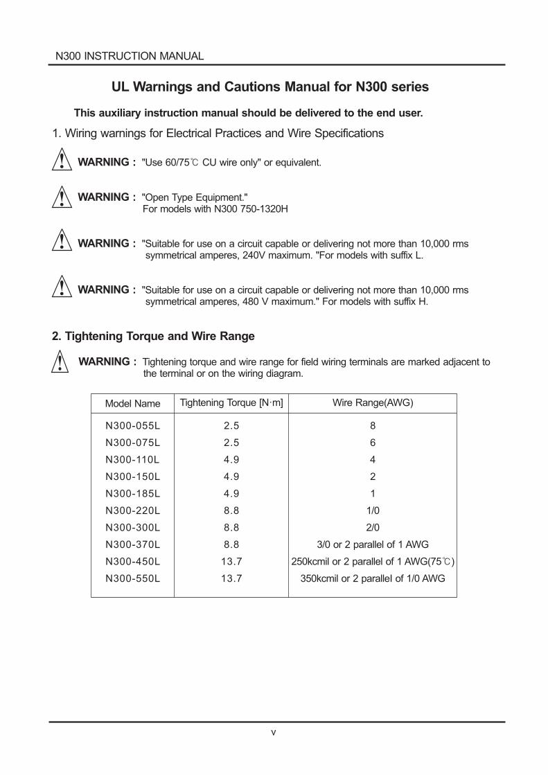
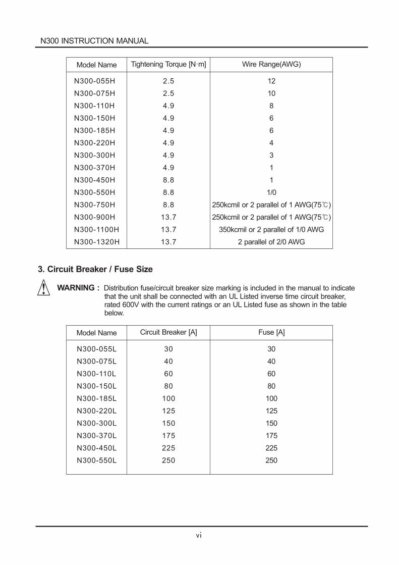
2. Tightening Torque and Wire Range
WARNING :
WARNING :
"Use 60/75 CU wire only" or equivalent.
"Open Type Equipment."For models with N300 750-1320H
WARNING :
WARNING :
"Suitable for use on a circuit capable or delivering not more than 10,000 rmssymmetrical amperes, 240V maximum. "For models with suffix L.
"Suitable for use on a circuit capable or delivering not more than 10,000 rmssymmetrical amperes, 480 V maximum." For models with suffix H.
WARNING : Tightening torque and wire range for field wiring terminals are marked adjacent tothe terminal or on the wiring diagram.
8
6
4
2
1
1/0
2/0
3/0 or 2 parallel of 1 AWG
250kcmil or 2 parallel of 1 AWG
350kcmil or 2 paralleI of 1/0 AWG
(75 )
Model Name Tightening Torque [N m] Wire Range(AWG)
N300-055L
N300-075L
N300-110L
N300-150L
N300-185L
N300-220L
N300-300L
N300-370L
N300-450L
N300-550L
2.5
2.5
4.9
4.9
4.9
8.8
8.8
8.8
13.7
13.7
N300 INSTRUCTION MANUAL
12
10
8
6
6
4
3
1
1
1/0
250kcmil or 2 parallel of 1 AWG(75 )
250kcmil or 2 parallel of 1 AWG(75 )
350kcmil or 2 parallel of 1/0 AWG
2 parallel of 2/0 AWG
Model Name Tightening Torque [N m] Wire Range(AWG)
N300-055H
N300-075H
N300-110H
N300-150H
N300-185H
N300-220H
N300-300H
N300-370H
N300-450H
N300-550H
N300-750H
N300-900H
N300-1100H
N300-1320H
2.5
2.5
4.9
4.9
4.9
4.9
4.9
4.9
8.8
8.8
8.8
13.7
13.7
13.7
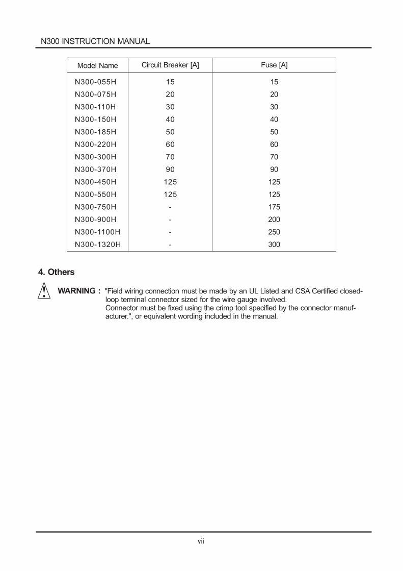
3. Circuit Breaker / Fuse Size
WARNING : Distribution fuse/circuit breaker size marking is included in the manual to indicatethat the unit shall be connected with an UL Listed inverse time circuit breaker,rated 600V with the current ratings or an UL Listed fuse as shown in the tablebelow.
30
40
60
80
100
125
150
175
225
250
Model Name Circuit Breaker [A] Fuse [A]
N300-055L
N300-075L
N300-110L
N300-150L
N300-185L
N300-220L
N300-300L
N300-370L
N300-450L
N300-550L
30
40
60
80
100
125
150
175
225
250
N300 INSTRUCTION MANUAL
15
20
30
40
50
60
70
90
125
125
175
200
250
300
Model Name
N300-055H
N300-075H
N300-110H
N300-150H
N300-185H
N300-220H
N300-300H
N300-370H
N300-450H
N300-550H
N300-750H
N300-900H
N300-1100H
N300-1320H
15
20
30
40
50
60
70
90
125
125
-
-
-
-
4. Others
WARNING : "Field wiring connection must be made by an UL Listed and CSA Certified closed-loop terminal connector sized for the wire gauge involved.Connector must be fixed using the crimp tool specified by the connector manuf-acturer.", or equivalent wording included in the manual.
Circuit Breaker [A] Fuse [A]
N300 INSTRUCTION MANUAL
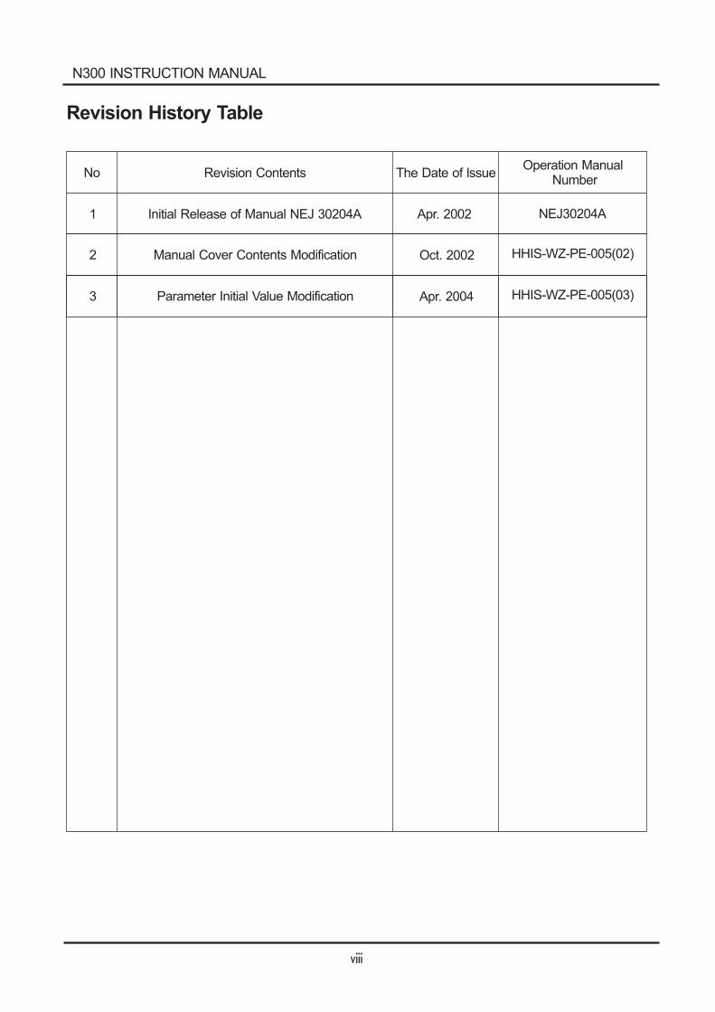
Revision History Table
No Revision Contents The Date of lssueOperation Manual
Number
1 Initial Release of Manual NEJ 30204A Apr. 2002 NEJ30204A
N300 INSTRUCTION MANUAL
2 Manual Cover Contents Modification Oct. 2002 HHIS-WZ-PE-005(02)
3 Parameter Initial Value Modification Apr. 2004 HHIS-WZ-PE-005(03)
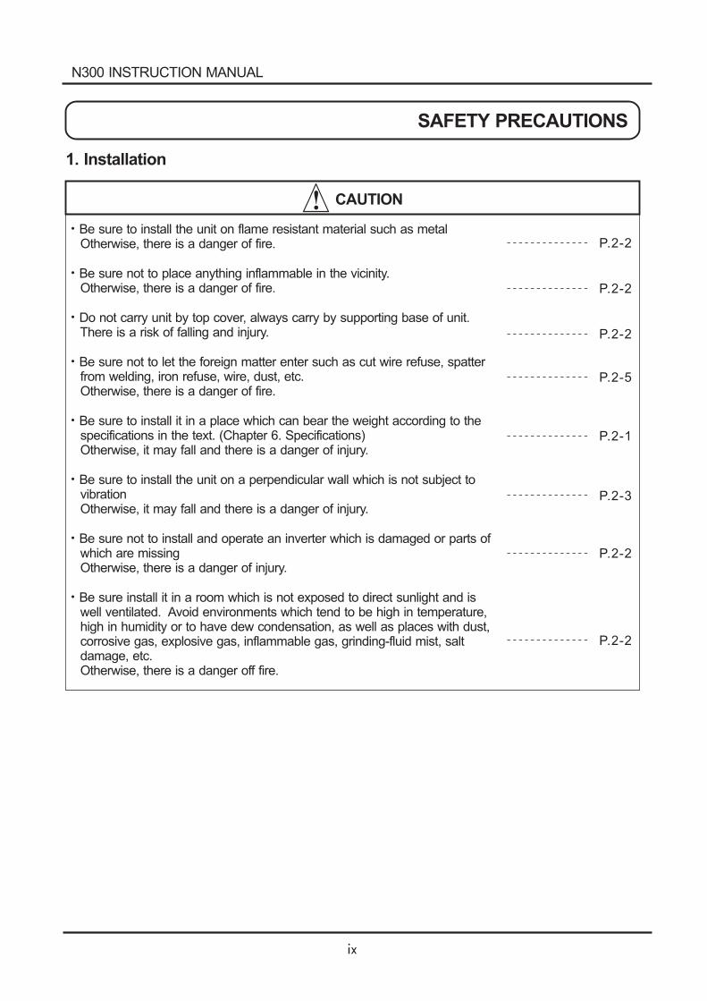
SAFETY PRECAUTIONS
1. Installation
CAUTION
Be sure to install the unit on flame resistant material such as metalOtherwise, there is a danger of fire.
Be sure not to place anything inflammable in the vicinity.Otherwise, there is a danger of fire.
Do not carry unit by top cover, always carry by supporting base of unit.There is a risk of falling and injury.
Be sure not to let the foreign matter enter such as cut wire refuse, spatterfrom welding, iron refuse, wire, dust, etc.Otherwise, there is a danger of fire.
Be sure to install it in a place which can bear the weight according to thespecifications in the text. (Chapter 6. Specifications)Otherwise, it may fall and there is a danger of injury.
Be sure to install the unit on a perpendicular wall which is not subject tovibrationOtherwise, it may fall and there is a danger of injury.
Be sure not to install and operate an inverter which is damaged or parts ofwhich are missingOtherwise, there is a danger of injury.
Be sure install it in a room which is not exposed to direct sunlight and iswell ventilated. Avoid environments which tend to be high in temperature,high in humidity or to have dew condensation, as well as places with dust,corrosive gas, explosive gas, inflammable gas, grinding-fluid mist, saltdamage, etc.Otherwise, there is a danger off fire.
P.2-2
P.2-2
P.2-2
P.2-5
P.2-1
P.2-3
P.2-2
P.2-2
N300 INSTRUCTION MANUAL
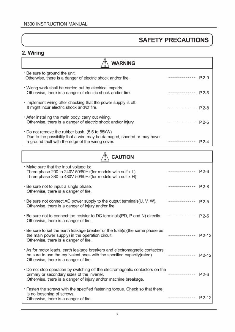
2. Wiring
WARNING
Be sure to ground the unit.Otherwise, there is a danger of electric shock and/or fire.
Wiring work shall be carried out by electrical experts.Otherwise, there is a danger of electric shock and/or fire.
Implement wiring after checking that the power supply is off.It might incur electric shock and/of fire.
After installing the main body, carry out wiring.Otherwise, there is a danger of electric shock and/or injury.
Do not remove the rubber bush. (5.5 to 55kW)Due to the possibility that a wire may be damaged, shorted or may havea ground fault with the edge of the wiring cover.
P.2-9
P.2-6
P.2-8
P.2-5
P.2-4
CAUTION
Make sure that the input voltage is:Three phase 200 to 240V 50/60Hz(for models with suffix L)Three phase 380 to 480V 50/60Hz(for models with suffix H)
Be sure not to input a single phase.Otherwise, there is a danger of fire.
Be sure not connect AC power supply to the output terminals(U, V, W).Otherwise, there is a danger of injury and/or fire.
Be sure not to connect the resistor to DC terminals(PD, P and N) directly.Otherwise, there is a danger of fire.
Be sure to set the earth leakage breaker or the fuse(s)(the same phase asthe main power supply) in the operation circuit.Otherwise, there is a danger of fire.
As for motor leads, earth leakage breakers and electromagnetic contactors,be sure to use the equivalent ones with the specified capacity(rated).Otherwise, there is a danger of fire.
Do not stop operation by switching off the electromagnetic contactors on theprimary or secondary sides of the inverter.Otherwise, there is a danger of injury and/or machine breakage.
Fasten the screws with the specified fastening torque. Check so that thereis no loosening of screws.Otherwise, there is a danger of fire.
P.2-6
P.2-8
P.2-5
P.2-5
P.2-12
P.2-12
P.2-6
P.2-12
N300 INSTRUCTION MANUAL
SAFETY PRECAUTIONS
WARNING
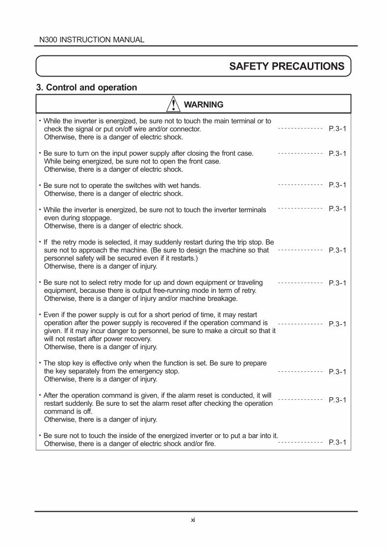
While the inverter is energized, be sure not to touch the main terminal or tocheck the signal or put on/off wire and/or connector.Otherwise, there is a danger of electric shock.
Be sure to turn on the input power supply after closing the front case.While being energized, be sure not to open the front case.Otherwise, there is a danger of electric shock.
Be sure not to operate the switches with wet hands.Otherwise, there is a danger of electric shock.
While the inverter is energized, be sure not to touch the inverter terminalseven during stoppage.Otherwise, there is a danger of electric shock.
If the retry mode is selected, it may suddenly restart during the trip stop. Besure not to approach the machine. (Be sure to design the machine so thatpersonnel safety will be secured even if it restarts.)Otherwise, there is a danger of injury.
Be sure not to select retry mode for up and down equipment or travelingequipment, because there is output free-running mode in term of retry.Otherwise, there is a danger of injury and/or machine breakage.
Even if the power supply is cut for a short period of time, it may restartoperation after the power supply is recovered if the operation command isgiven. If it may incur danger to personnel, be sure to make a circuit so that itwill not restart after power recovery.Otherwise, there is a danger of injury.
The stop key is effective only when the function is set. Be sure to preparethe key separately from the emergency stop.Otherwise, there is a danger of injury.
After the operation command is given, if the alarm reset is conducted, it willrestart suddenly. Be sure to set the alarm reset after checking the operationcommand is off.Otherwise, there is a danger of injury.
Be sure not to touch the inside of the energized inverter or to put a bar into it.Otherwise, there is a danger of electric shock and/or fire.
P.3-1
P.3-1
P.3-1
P.3-1
P.3-1
P.3-1
P.3-1
P.3-1
3. Control and operation
P.3-1
P.3-1
N300 INSTRUCTION MANUAL
SAFETY PRECAUTIONS
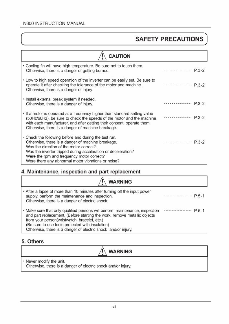
CAUTION
Cooling fin will have high temperature. Be sure not to touch them.Otherwise, there is a danger of getting burned.
Low to high speed operation of the inverter can be easily set. Be sure tooperate it after checking the tolerance of the motor and machine.Otherwise, there is a danger of injury.
Install external break system if needed.Otherwise, there is a danger of injury.
If a motor is operated at a frequency higher than standard setting value(50Hz/60Hz), be sure to check the speeds of the motor and the machinewith each manufacturer, and after getting their consent, operate them.Otherwise, there is a danger of machine breakage.
Check the following before and during the test run.Otherwise, there is a danger of machine breakage.Was the direction of the motor correct?Was the inverter tripped during acceleration or deceleration?Were the rpm and frequency motor correct?Were there any abnormal motor vibrations or noise?
P.3-2
P.3-2
P.3-2
P.3-2
P.3-2
WARNING
WARNING
After a lapse of more than 10 minutes after turning off the input powersupply, perform the maintenance and inspection.Otherwise, there is a danger of electric shock.
Make sure that only qualified persons will perform maintenance, inspectionand part replacement. (Before starting the work, remove metallic objectsfrom your person(wristwatch, bracelet, etc.)(Be sure to use tools protected with insulation)Otherwise, there is a danger of electric shock and/or injury.
Never modify the unit.Otherwise, there is a danger of electric shock and/or injury.
P.5-1
P.5-1
4. Maintenance, inspection and part replacement
5. Others
N300 INSTRUCTION MANUAL
SAFETY PRECAUTIONS
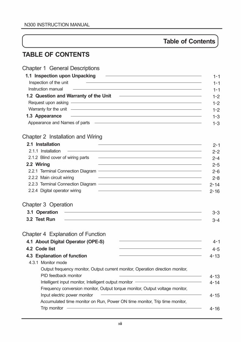
Table of Contents
TABLE OF CONTENTS
Chapter 1 General Descriptions
1.1 Inspection upon Unpacking
1.2 Question and Warranty of the Unit
1.3 Appearance
Inspection of the unit
Instruction manual
Request upon asking
Warranty for the unit
Appearance and Names of parts
Chapter 2 Installation and Wiring
Chapter 3 Operation
Chapter 4 Explanation of Function
2.1 Installation
2.2 Wiring
3.1 Operation
3.2 Test Run
4.1 About Digital Operator (OPE-S)
4.2 Code list
4.3 Explanation of function
2.1.1 Installation
2.1.2 Blind cover of wiring parts
2.2.1 Terminal Connection Diagram
2.2.2 Main circuit wiring
2.2.3 Terminal Connection Diagram
2.2.4 Digital operator wiring
4.3.1 Monitor mode
Output frequency monitor, Output current monitor, Operation direction monitor,
PID feedback monitor
Intelligent input monitor, Intelligent output monitor
Frequency conversion monitor, Output torque monitor, Output voltage monitor,
Input electric power monitor
Accumulated time monitor on Run, Power ON time monitor, Trip time monitor,
Trip monitor
N300 INSTRUCTION MANUAL
Table of Contents
4.3.2 Function mode
Output frequency setting, Operation direction, Selection with limits of operation direction,
Frequency command selection
Operation command selection, Selection no stop, Selection of stop key
Adjustable time
Base frequency
Maximum frequency, Carrier frequency
External analog input (0, 02, 01)
Input frequency Start / End
Setting analog input filter, Output voltage gain
Control system (V/f Characteristic)
Torque boost
Direct current braking (DB)
Frequency limiter
Frequency jump function, Acceleration stop function
PID function
Automatic energy-saving operation function
Two-stage acceleration and deceleration on function (2CH)
Acceleration and deceleration pattern
Instantaneous power failure / under-voltage
Open phase protection function selection, Electronic thermal function
Overload restriction / Overload advance notice
Start frequency, Reduced voltage start selection
BRD (Dynamic breaking) function, Cooling fan operating selection
Intelligent input terminal setting
Input terminal a/b (NO / NC) selection, Multi-speed operation function
Jogging operation (JG)
Second / Third control function (SET, SET3)
Software lock mode selection (SFT), Force operation ope function (OPE)
Free-run stop (FRS)
Commercial power source switching (CS)
Reset (RS)
Unattended start protection (USP), UP / DOWN selection (UP, DWN, UDC)
External trip (EXT), 3 wire input function (STA, STP, F/R)
Control gain switch function (CAS), P/PI switching function (PPI)
Intelligent output terminal setting
Intelligent output terminal a/b (NO / NC) selection
Signal during run (RUN), Frequency arrival signal (FA1, FA2, FA3, FA4, FA5)
N300 INSTRUCTION MANUAL
4.4 Protection function list
5.1 Precaution for Maintenance / Inspection
5.2 Daily inspection and regular inspection
5.3 Megger test
5.4 Withstand Voltage test
5.5 The method to check Inverter, converter part
5.6 Capacitor Life Curve
6.1 Standard specification list
6.2 Dimension
RUN time / power ON time over (RNT / ONT), Zero speed signal (ZS)
Over torque (OTQ), Alarm code output (AC0 - AC3)
FM terminal
AM terminal, AMI terminal, External thermistor
Initialization setting
Display selection
Stabilized factor, Motor constant
Fuzzy most suitable acceleration and deceleration
Braking control function
Stopping of deceleration at power off
Offline autotuning function
Motor constant selection
Online autotuning function
Sensorless vector control
0 Hz domain sensorless vector control
Torque monitor function
Torque limit function
Torque LADSTOP function
Communication function
4.4.1 Protection function
4.4.2 Trip monitor display
4.4.3 Warning Monitor display
5.1.1 Daily inspection
5.1.2 Cleaning
5.1.3 Regular inspection
Chapter 5 Maintenance, Inspection
Chapter 6 Specification
N300 INSTRUCTION MANUAL
Table of Contents
Chapter 1 General Descriptions
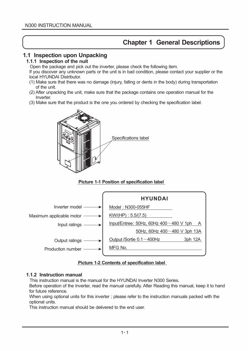
1.1 Inspection upon Unpacking1.1.1 Inspection of the nuit
Open the package and pick out the inverter, please check the following item.If you discover any unknown parts or the unit is in bad condition, please contact your supplier or thelocal HYUNDAI Distributor.(1) Make sure that there was no damage (injury, falling or dents in the body) during transportation
of the unit.(2) After unpacking the unit, make sure that the package contains one operation manual for the
Inverter.(3) Make sure that the product is the one you ordered by checking the specification label.
Specifications label
Model : N300-055HF
KW/(HP) : 5.5/(7.5)
Input/Entree: 50Hz, 60Hz 400 480 V 1ph A
50Hz, 60Hz 400 480 V 3ph 13A
Output /Sortie 0.1 400Hz 3ph 12A
MFG No.
HYUNDAI
Picture 1-1 Position of specification label
Picture 1-2 Contents of specification label
Inverter model
Maximum applicable motor
Input ratings
Output ratings
Production number
1.1.2 Instruction manualThis instruction manual is the manual for the HYUNDAI Inverter N300 Series.Before operation of the Inverter, read the manual carefully. After Reading this manual, keep it to handfor future reference.When using optional units for this inverter ; please refer to the instruction manuals packed with theoptional units.This instruction manual should be delivered to the end user.
N300 INSTRUCTION MANUAL
1.2 Question and Warranty of the Unit
1.2.1 Request upon asking
1.2.2 Warranty for the unit
If you have any questions regarding damage to the unit, unknown parts or for general enquiries
please contact your supplier or the local HYUNDAI Distributor with the following information.
(1) Inverter Model
(2) Production Number (MFG No.)
(3) Date of purchase
(4) Reason for Calling
Damaged part and its condition etc.
Unknown parts and their contents etc.
The warranty period of the unit is one year after the purchase date. However within the warranty
period, the warranty will be void if the fault is due to;
(1) Incorrect use as directed in this manual, or attempted repair by unauthorized personnel.
(2) Any damage sustained other than from transportation (Which should be reported immediately).
(3) Using the unit beyond the limits of the specification.
(4) Natural Disasters : Earthquakes, Lightning, etc
The warranty is for inverter only, any damage caused to other equipment by malfunction of the inverter
is not covered by the warranty.
Any examination or repair after the warranty period (one-year) is not covered. And within the warranty
period any repair and examination which results in information showing the fault was caused by any of
the items mentioned above, the repair and examination cost are not covered. If you have any questions
regarding the warranty please contact either your supplier or the local HYUNDAI Distributor.
Please refer to the back cover for a list of the local HYUNDAI Distributors.
N300 INSTRUCTION MANUAL
Chapter 1 General Descriptions
1.3 Appearance
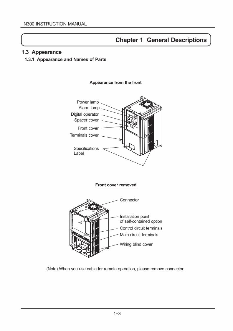
1.3.1 Appearance and Names of Parts
Appearance from the front
Front cover removed
Power lamp
Alarm lamp
Digital operator
Spacer cover
Front cover
Terminals cover
SpecificationsLabel
Connector
Installation pointof self-contained option
Main circuit terminals
Wiring blind cover
Control circuit terminals
(Note) When you use cable for remote operation, please remove connector.
N300 INSTRUCTION MANUAL
Chapter 1 General Descriptions
1.4 Application Method for J61 Connector Pin according to Input
Power Grounding Condition
1.4.1 Usage of J61 Connector Pin and its application
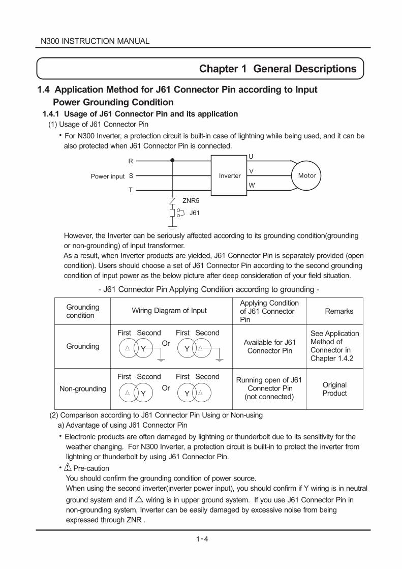
(1) Usage of J61 Connector Pin
For N300 Inverter, a protection circuit is built-in case of lightning while being used, and it can be
also protected when J61 Connector Pin is connected.
However, the Inverter can be seriously affected according to its grounding condition(grounding
or non-grounding) of input transformer.
As a result, when Inverter products are yielded, J61 Connector Pin is separately provided (open
condition). Users should choose a set of J61 Connector Pin according to the second grounding
condition of input power as the below picture after deep consideration of your field situation.
(2) Comparison according to J61 Connector Pin Using or Non-using
a) Advantage of using J61 Connector Pin
Electronic products are often damaged by lightning or thunderbolt due to its sensitivity for the
weather changing. For N300 Inverter, a protection circuit is built-in to protect the inverter from
lightning or thunderbolt by using J61 Connector Pin.
Pre-caution
You should confirm the grounding condition of power source.
When using the second inverter(inverter power input), you should confirm if Y wiring is in neutral
ground system and if wiring is in upper ground system. If you use J61 Connector Pin in
non-grounding system, Inverter can be easily damaged by excessive noise from being
expressed through ZNR .
Chapter 1 General Descriptions
Inverter
ZNR5
J61
Power input
R
S
T
Motor
U
V
W
- J61 Connector Pin Applying Condition according to grounding -
Groundingcondition
Wiring Diagram of InputApplying Conditionof J61 ConnectorPin
Remarks
See ApplicationMethod ofConnector inChapter 1.4.2
Available for J61Connector Pin
Running open of J61Connector Pin
(not connected)
Y Y
First Second
Or
Y YOrNon-grounding
Grounding
OriginalProduct
First Second
First Second First Second
N300 INSTRUCTION MANUAL
b) Features of Non-using J61 Connector Pin
Although any transformer products are not grounded, there is little damage of Inverter due to no
corruption in ZNR, as noise is intercepted from electric panel.
Attention
It is not protected from the whether changing such as lightning.
c) Inquiry about J61 Connector
If you have any technical inquires about grounding and J61 Connector, please contact our
company.
1.4.2. Application of Connector Pin
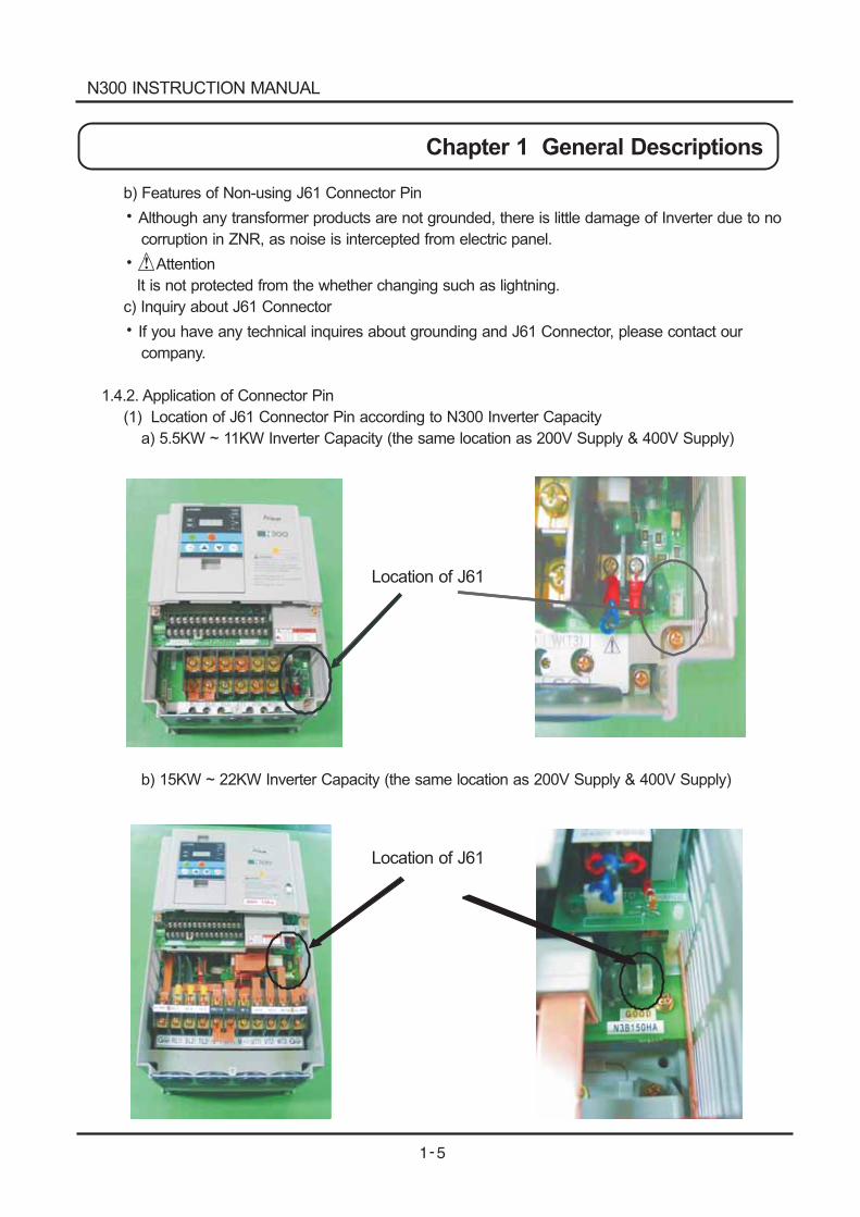
(1) Location of J61 Connector Pin according to N300 Inverter Capacity
a) 5.5KW ~ 11KW Inverter Capacity (the same location as 200V Supply & 400V Supply)
b) 15KW ~ 22KW Inverter Capacity (the same location as 200V Supply & 400V Supply)
Chapter 1 General Descriptions
Location of J61
Location of J61
N300 INSTRUCTION MANUAL
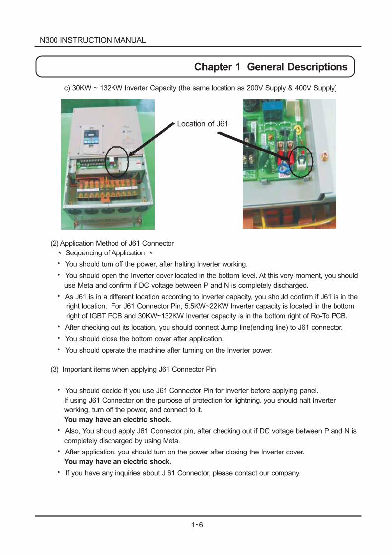
c) 30KW ~ 132KW Inverter Capacity (the same location as 200V Supply & 400V Supply)
(2) Application Method of J61 Connector
Sequencing of Application
You should turn off the power, after halting Inverter working.
You should open the Inverter cover located in the bottom level. At this very moment, you should
use Meta and confirm if DC voltage between P and N is completely discharged.
As J61 is in a different location according to Inverter capacity, you should confirm if J61 is in the
right location. For J61 Connector Pin, 5.5KW~22KW Inverter capacity is located in the bottom
right of IGBT PCB and 30KW~132KW Inverter capacity is in the bottom right of Ro-To PCB.
After checking out its location, you should connect Jump line(ending line) to J61 connector.
You should close the bottom cover after application.
You should operate the machine after turning on the Inverter power.
(3) Important items when applying J61 Connector Pin
You should decide if you use J61 Connector Pin for Inverter before applying panel.
If using J61 Connector on the purpose of protection for lightning, you should halt Inverter
working, turn off the power, and connect to it.
Also, You should apply J61 Connector pin, after checking out if DC voltage between P and N is
completely discharged by using Meta.
After application, you should turn on the power after closing the Inverter cover.
If you have any inquiries about J 61 Connector, please contact our company.
You may have an electric shock.
You may have an electric shock.
Chapter 1 General Descriptions
Location of J61
N300 INSTRUCTION MANUAL
CAUTION
Be sure to install the unit on flame resistant material such as metal.Otherwise, there is a danger of fire.
Be sure to place anything inflammable in the vicinity.Otherwise, there is a danger of fire.
Do not carry unit by top cover, always carry by supporting base of unit.There is a risk of falling and injury.
Be sure not to let the foreign matter enter such as cut wire refuse, spatter from welding, iron refuse,wire, dust, ect.Otherwise, there is a danger of fire.
Be sure to install it in a place which can bear the weight according to the specifications in the text.(Chapter 6. Specifications)Otherwise, it may fall and there is a danger of injury.
Be sure to install the unit on a perpendicular wall which is not subject to vibration.Otherwise, it may fall and there is a danger of injury.
Be sure not to install and operate an inverter which is damaged or parts of which are missing.Otherwise, there is a danger of injury.
Be sure to install it in a room which is not exposed to direct sunlight and is well ventilated. Avoidenvironments which tend to be high in temperature, high in humidity or to have dew condensation,as well as places with dust, corrosive gas, explosive gas, inflammable gas, grinding-fluid mist, saltdamage, etc.Otherwise, there is a danger of fire.
2.1 Installation
N300 INSTRUCTION MANUAL
Chapter 2 Installation and Wiring
Chapter 2 Installation and Wiring
2.1.1 Installation
1. Transportation
This inverter has plastic parts. So handle with care.
Do not over tighten the wall mounting fixings as the mountings may crack, causing is a risk of
falling.
Do not install or operate the inverter if there appears to be damage or parts missing.
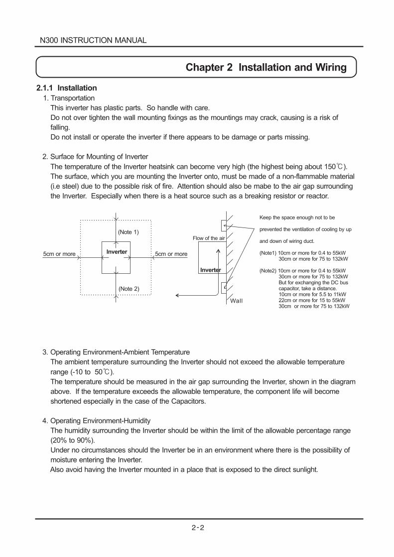
2. Surface for Mounting of Inverter
The temperature of the Inverter heatsink can become very high (the highest being about 150 ).
The surface, which you are mounting the Inverter onto, must be made of a non-flammable material
(i.e steel) due to the possible risk of fire. Attention should also be mabe to the air gap surrounding
the Inverter. Especially when there is a heat source such as a breaking resistor or reactor.
3. Operating Environment-Ambient Temperature
The ambient temperature surrounding the Inverter should not exceed the allowable temperature
range (-10 to 50 ).
The temperature should be measured in the air gap surrounding the Inverter, shown in the diagram
above. If the temperature exceeds the allowable temperature, the component life will become
shortened especially in the case of the Capacitors.
4. Operating Environment-Humidity
The humidity surrounding the Inverter should be within the limit of the allowable percentage range
(20% to 90%).
Under no circumstances should the Inverter be in an environment where there is the possibility of
moisture entering the Inverter.
Also avoid having the Inverter mounted in a place that is exposed to the direct sunlight.
5cm or more Inverter
Inverter
(Note 2)
(Note 1)
5cm or more
Flow of the air
Wall
Keep the space enough not to be
prevented the ventilation of cooling by up
and down of wiring duct.
(Note1) 10cm or more for 0.4 to 55kW30cm or more for 75 to 132kW
(Note2) 10cm or more for 0.4 to 55kW30cm or more for 75 to 132kWBut for exchanging the DC buscapacitor, take a distance.10cm or more for 5.5 to 11kW22cm or more for 15 to 55kW30cm or more for 75 to 132kW
N300 INSTRUCTION MANUAL
5. Operating Environment-Air
Install the Inverter avoiding any place that has dust, corrosive gas, explosive gas, combustible gas,
mist of coolant and sea damage.
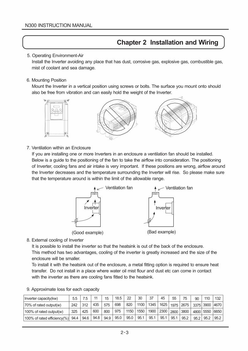
6. Mounting Position
Mount the Inverter in a vertical position using screws or bolts. The surface you mount onto should
also be free from vibration and can easily hold the weight of the Inverter.
7. Ventilation within an Enclosure
If you are installing one or more Inverters in an enclosure a ventilation fan should be installed.
Below is a guide to the positioning of the fan to take the airflow into consideration. The positioning
of Inverter, cooling fans and air intake is very important. If these positions are wrong, airflow around
the Inverter decreases and the temperature surrounding the Inverter will rise. So please make sure
that the temperature around is within the limit of the allowable range.
8. External cooling of Inverter
It is possible to install the inverter so that the heatsink is out of the back of the enclosure.
This method has two advantages, cooling of the inverter is greatly increased and the size of the
enclosure will be smaller.
To install it with the heatsink out of the enclosure, a metal fitting option is required to ensure heat
transfer. Do not install in a place where water oil mist flour and dust etc can come in contact
with the inverter as there are cooling fans fitted to the heatsink.
9. Approximate loss for each capacity
Ventilation fan Ventilation fan
Inverter Inverter
(Good example) (Bad example)
5.5 7.5 11 15 18.5 22 30 37 45 55 75 110 13290
242 312 435 575 698 820 1100 1345 1625 1975 2675 3900 46703375
325 425 600 800 975 1150 1550 1900 2300 2800 3800 5550 66504800
94.4 94.6 94.8 94.9 95.0 95.0 95.1 95.1 95.1 95.1 95.2 95.2 95.295.2
Inverter capacity(kw)
70% of rated output(w)
100% of rated output(w)
100% of rated efficiency(%)
N300 INSTRUCTION MANUAL
Chapter 2 Installation and Wiring
Wiring cover
Rubber bushes
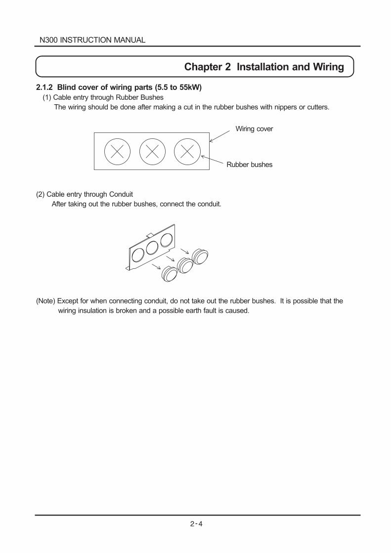
2.1.2 Blind cover of wiring parts (5.5 to 55kW)
(1) Cable entry through Rubber Bushes
The wiring should be done after making a cut in the rubber bushes with nippers or cutters.
(2) Cable entry through Conduit
After taking out the rubber bushes, connect the conduit.
(Note) Except for when connecting conduit, do not take out the rubber bushes. It is possible that the
wiring insulation is broken and a possible earth fault is caused.
N300 INSTRUCTION MANUAL
Chapter 2 Installation and Wiring
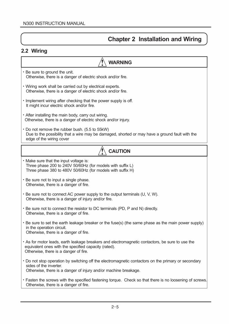
2.2 Wiring
WARNING
Be sure to ground the unit.Otherwise, there is a danger of electric shock and/or fire.
Wiring work shall be carried out by electrical experts.Otherwise, there is a danger of electric shock and/or fire.
Implement wiring after checking that the power supply is off.It might incur electric shock and/or fire.
After installing the main body, carry out wiring.Otherwise, there is a danger of electric shock and/or injury.
Do not remove the rubber bush. (5.5 to 55kW)Due to the possibility that a wire may be damaged, shorted or may have a ground fault with theedge of the wiring cover
CAUTION
Make sure that the input voltage is:Three phase 200 to 240V 50/60Hz (for models with suffix L)Three phase 380 to 480V 50/60Hz (for models with suffix H)
Be sure not to input a single phase.Otherwise, there is a danger of fire.
Be sure not to connect AC power supply to the output terminals (U, V, W).Otherwise, there is a danger of injury and/or fire.
Be sure not to connect the resistor to DC terminals (PD, P and N) directly.Otherwise, there is a danger of fire.
Be sure to set the earth leakage breaker or the fuse(s) (the same phase as the main power supply)in the operation circuit.Otherwise, there is a danger of fire.
As for motor leads, earth leakage breakers and electromagnetic contactors, be sure to use theequivalent ones with the specified capacity (rated).Otherwise, there is a danger of fire.
Do not stop operation by switching off the electromagnetic contactors on the primary or secondarysides of the inverter.Otherwise, there is a danger of injury and/or machine breakage.
Fasten the screws with the specified fastening torque. Check so that there is no loosening of screws.Otherwise, there is a danger of fire.
N300 INSTRUCTION MANUAL
Chapter 2 Installation and Wiring
R
ST
R
TRO
TO
P24
PLC
FW
8
7
6
1
FM
CM1
TH
H
0
OI
L
AM
100
02
DC0-10V
HYUNDAIPOWERALRAM
RUNPRG
VA%
RUN STOP/RESET
FUNC STR1 2
U
V
W
P
PD
RB
N
IM
AL0
AL1
AL2
DC24V
DC0-10V
DC0-10V(12bit)
DC0-10/0/-10V(12bit)
DC4-20mA(12bit)ohm
10k
0-10V(8bit)
4-20mA(8bit)
AMI
ohm
ohm10k
15
11
CM2
SP
SN
RP
SN
RS485
200 240V 10%(50,60 5%)
380 480V 10%(50,60 5%) 8.8.8.8.
PowerSource 3phase
Short wire
Short bar
(at sink type)
Forward
Intelligent input(8 connection)
FM output monitor(PWM output)
AM output monitor
(Analogue output)
AMI output monitor
(Analogue output)
Thermistor
Earth
Option 2
Option 1
For terminal resistance
Intelligent output(5 connection)
Intelligent relay outputconnection(Initial alarm)
Put and takeas terminal substrate
Shortbar Braking resistor
(Option)
BRD circuit:Installed on5.5 to 11kW
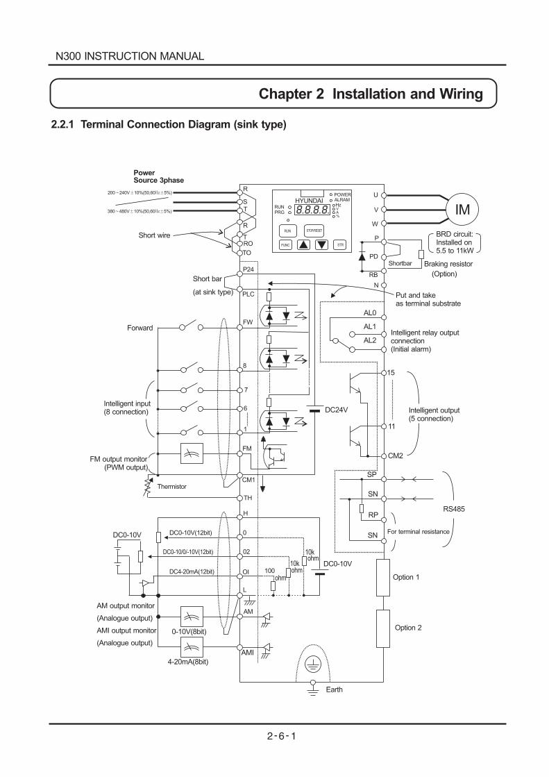
2.2.1 Terminal Connection Diagram (sink type)
N300 INSTRUCTION MANUAL
Hz
Chapter 2 Installation and Wiring
R
ST
R
TRO
TO
P24
PLC
FW
8
7
6
1
FM
CM1
TH
H
0
OI
L
AM
100
02
DC0-10V
HYUNDAIPOWERALRAM
RUNPRG
VA%
RUN STOP/RESET
FUNC STR1 2
U
V
W
P
PD
RB
N
IM
AL0
AL1
AL2
DC24V
DC0-10V
DC0-10V(12bit)
DC0-10/0/-10V(12bit)
DC4-20mA(12bit)ohm
10k
0-10V(8bit)
4-20mA(8bit)
AMI
ohm
ohm10k
15
11
CM2
SP
SN
RP
SN
RS485
200 240V 10%(50,60 5%)
380 480V 10%(50,60 5%) 8.8.8.8.
PowerSource 3phase
Short wire
Short bar
(at source type)
Forward
Intelligent input(8 connection)
FM output monitor(PWM output)
AM output monitor
(Analogue output)
AMI output monitor
(Analogue output)
Thermistor
Earth
Option 2
Option 1
For terminal resistance
Intelligent output(5 connection)
Intelligent relay outputconnection(Initial alarm)
Put and takeas terminal substrate
Shortbar Braking resistor
(Option)
BRD circuit:Installed on5.5 to 11kW
CM1
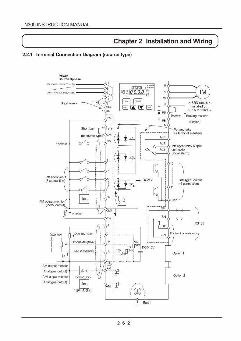
2.2.1 Terminal Connection Diagram (source type)
N300 INSTRUCTION MANUAL
Chapter 2 Installation and Wiring
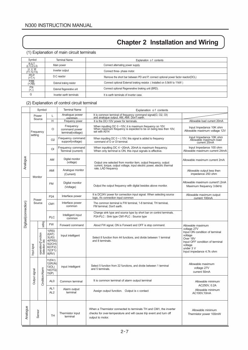
(1) Explanation of main circuit terminals
Symbol
R,S,T(L1,L2,L3)U, V, W
(T1,T2,T3)PD,P(+1,+)P,RB
(+,RB)
P,N(+,-)
G
Terminal Name
Main power
Inverter output
D.C reactor
External braking resistor
External Regenerative unit
Inverter earth terminals
Explanation o f contents
Connect alternating power supply.
Connect three- phase motor.
Remove the short bar between PD and P, connect optional power factor reactor(DCL)
Connect optional External braking resistor. ( Installed on 5.5kW to 11kW )
Connect optional Regenerative braking unit (BRD).
It is earth terminals of inverter case.
(2) controlExplanation of circuit terminal
Allowable minimumAC100V,10mA
It is common terminal of frequency command signal(O, O2, OI)and analogue output, AM, AMI. Don"t earth.
It is the DC+10V power for terminals.
When inputting DC 0 ~10V, it is maximum frequency on 10V.When maximum frequency is expected to be on being less then 10V,set with A014
When inputting DC 0 ~ 10V, this signal is added to frequencycommand of O or OI terminal.
Output one selected from monitor item, output frequency, outputcurrent, torque, output voltage, input electric power, electric thermalrate, LAD frequency
Output the output frequency with digital besides above monitor.
It is DC24V power for connection input signal. When selecting sourcelogic, it's connection input common
The common terminal is FW terminal, 1-8 terminal, TH terminal,FM terminal, Don't earth.
About FW signal, ON is Forward and OFF is stop command.
Select 8 function from 44 functions, and divide between 1 terminaland 8 terminals.
Select 5 function from 22 functions, and divide between 1 terminaland 5 terminals.
Change sink type and source type by short bar on control terminals.
P24-PLC : Sink type CM1-PLC : Source type
Analo
gue
Analo
gue
L
H
O
O2
OI
AM
AMI
FM
P24
CM1
FW
1(RS)2(AT)3(JG)4(FRS)5(2CH)6(CF2)7(CF1)8(RV)
PLC
When a Thermistor connected to terminals TH and CM1, the inverter
checks for over-temperature and will cause trip event and turn off
output to motor.
11(FA1)12(RUN)13(OL)14(OTQ)15(IP)
TH
AL0
AL1
AL2
setti
ngopera
tion/F
unct
ion
Sele
ctio
netc
Analogue powercommon
Frequency power
Frequency commandsupport(voltage)
Frequency commandTerminal (current)
Digital monitor(voltage)
Analogue monitor
(Current)
Digital monitor
(Voltage)
Interface power
Interface powercommon
Forward command
Input intelligent
Intelligent inputcommon
Frequencycommand powerterminal(voltage)
Allowable load current 20mA
Input Impedance 10K ohmAllowable maximum voltage 12V
loadcurrent 20mA
Input Impedance 10K ohmAllowable maximum
04
Input Impedance 10 ohmAllowable maximum current 2 mA
Allowable maximum current 2mA
Allowable output less thenimpedance 250 ohm
1.2mAAllowable maximum current
Maximum frequency 3.6kHz
Allowable maximum outputcurrent 100mA
Allowable maximumvoltage 27VInput ON condition of terminalvoltageOver 18VInput OFF condition of terminalvoltageunder 3 VInput impedance 4.7k ohm
Allowable maximum
voltage 27V
current 50mA
Allowable minimum
Thermistor power 100mW
Allowable minimum
AC250V, 0.2ACin
diti
on/A
larm
input Intelligent
Thermistor inputterminal
Alarm outputterminal
Common terminal
IInpu
tsig
nal
Senso
r
Outp
utsi
gnal
It is common terminal of alarm output terminal
Assign output function. Output is c contact
Explanation o f contentsTerminal Name
Dig
itasl
(connect
ion)
Symbol
PowerSource
Frequencysetting
When inputting DC 4 ~20mA, 20mA is maximum frequency.When only terminal is ON, this input signals is effective.
Monitor
PowerSource
N300 INSTRUCTION MANUAL
Chapter 2 Installation and Wiring
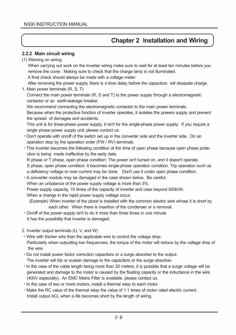
2.2.2 Main circuit wiring
(1) Warning on wiring
When carrying out work on the Inverter wiring make sure to wait for at least ten minutes before you
remove the cover. Making sure to check that the charge lamp is not illuminated.
A final check should always be made with a voltage meter.
After removing the power supply, there is a time delay before the capacitors will dissipate charge.
1. Main power terminals (R, S, T)
Connect the main power terminals (R, S and T) to the power supply through a electromagnetic
contactor or an earth-leakage breaker.
We recommend connecting the electromagnetic contactor to the main power terminals.
Because when the protective function of inverter operates, it isolates the powers supply and prevent
the spread of damages and accidents.
This unit is for three-phase power supply. It isn't for the single-phase power supply. If you require a
single phase power supply unit, please contact us.
Don't operate with on/off of the switch set up in the converter side and the inverter side. Do an
operation stop by the operation order (FW / RV) terminals.
This inverter becomes the following condition at the time of open phase because open phase prote-
ction is being made ineffective by the early data.
R phase or T phase, open phase condition: The power isn't turned on, and it doesn't operate.
S phase, open phase condition: It becomes single-phase operation condition. Trip operation such as
a deficiency voltage or over current may be done. Don't use it under open phase condition.
A converter module may be damaged in the case shown below. Be careful.
When an unbalance of the power supply voltage is more than 3%.
Power supply capacity, 10 times of the capacity of inverter and case beyond 500kVA.
When a change in the rapid power supply voltage occur.
(Example) When inverter of the plural is installed with the common electric wire whose it is short by
each other. When there is insertion of the condenser or a removal.
On/off of the power supply isn't to do it more than three times in one minute.
It has the possibility that inverter is damaged.
2. Inverter output terminals (U, V, and W)
Wire with thicker wire than the applicable wire to control the voltage drop.
Particularly when outputting low frequencies, the torque of the motor will reduce by the voltage drop of
the wire.
Do not install power factor correction capacitors or a surge absorber to the output.
The inverter will trip or sustain damage to the capacitors or the surge absorber.
In the case of the cable length being more than 20 meters, it is possible that a surge voltage will be
generated and damage to the motor is caused by the floating capacity or the inductance in the wire
(400V especially). An EMC Mains Filter is available, please contact us.
In the case of two or more motors, install a thermal relay to each motor.
Make the RC value of the thermal relay the value of 1.1 times of motor rated electric current.
Install output ACL when a life becomes short by the length of wiring.
N300 INSTRUCTION MANUAL
Chapter 2 Installation and Wiring
3. Direct current reactor (DCL) connection terminals (PD, P)
These are the terminals to connect the current reactor DCL (Option) to help improve the power factor.
The short bar is connected to the terminals when shipped from the factory, if you are to connect a DCL
you will need to disconnect the short bar first.
When you dont' use a DCL, don't disconnect the short bar.
4. External braking resistor connection terminals (P, RB)
The regenerative braking circuit (BRD) is built-in as standard up to the 11kW Inverter.
When braking is required, install an external-braking resistor to these terminals.
The cable length should be less than 5 meters, and twist the two connecting wires to reduce
inductance.
Don't connect any other device other than the external braking resistor to these terminals.
When installing an external braking resistor make sure that the resistance is correctly rated to limit the
current drawn through the BRD.
5. Regenerative breaking unit connection terminals (P, N)
The Inverters rated more than 15kW don't contain a BRD circuit. If regenerative braking is required
an external BRD circuit (Option) is required along with the resistor (Option).
Connect external regenerative braking unit terminals (P, N) to terminals (P, N) on the inverter.
The braking resistor is then wired into the External Braking unit and not directly to the Inverter.
The cable length should be less than 5 meters, and twist the two connecting wires to reduce
inductance.
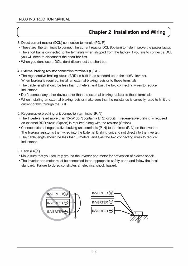
6. Earth (G )
Make sure that you securely ground the Inverter and motor for prevention of electric shock.
The inverter and motor must be connected to an appropriate safety earth and follow the local
standard. Failure to do so constitutes an electrical shock hazard.
INVERTER INVERTER
INVERTER
INVERTER
INVERTER
INVERTER
N300 INSTRUCTION MANUAL
Chapter 2 Installation and Wiring
N300-055LF/HF
Ro-To : M4
Other : M5
N300-100LF/HF
Ro-To : M4
Other : M6
N300-150,185LF
N300-150-370HF
Ro-To : M4Other : M6
N300-220LF
Ro-To : M4Earth terminal : M6
Other : M8
N300-450,550LF
N300-750-1320HFRo-To : M4
Earth terminal : M8Other : M10
N300-300,370LFN300-450, 550HF
Ro-To : M4Other : M8
N300-075LF/HF
Ro-To : M4
: M5Other
Ro To
R S T U V W
PD P N RB G
Short bar
Short bar
Short bar
Short bar
Charge lamp
Charge lamp
Charge lamp
Charge lamp
(L1) (L2) (L3) (T1) (T2) (T3)
(+1) (+) (-)
G
R S T U V W
PD P N RB G
(L1) (L2) (L3) (T1) (T2) (T3)
(+1) (+) (-)
G
Ro To
Ro To
PD P N
(+1) (+) (-)
U V W
(T1) (T2) (T3)
GG R S T
(L1) (L2) (L3)
Ro To
PD P N
(+1) (+) (-)
U V W
(T1) (T2) (T3)
R S T
(L1) (L2) (L3)
Wiring of terminals Corresponding type
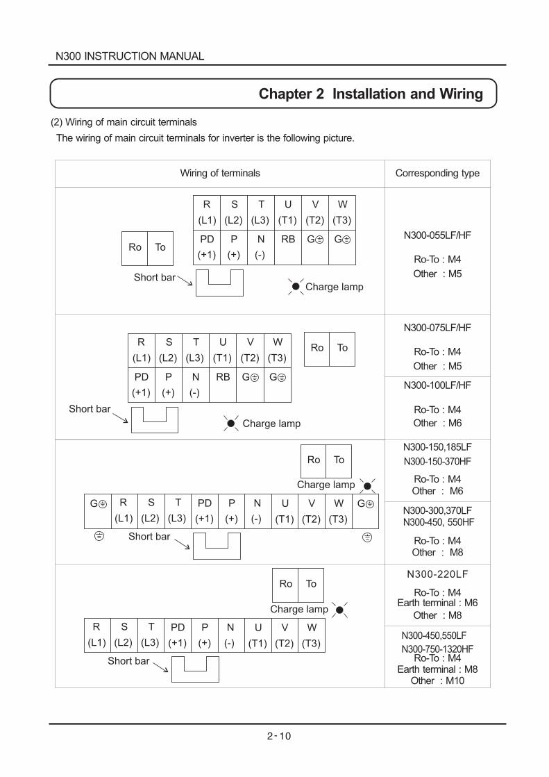
(2) Wiring of main circuit terminals
The wiring of main circuit terminals for inverter is the following picture.
N300 INSTRUCTION MANUAL
Chapter 2 Installation and Wiring
}
MCCB
R S T
RO
TO
PD
P
RB
N
U V W
IM
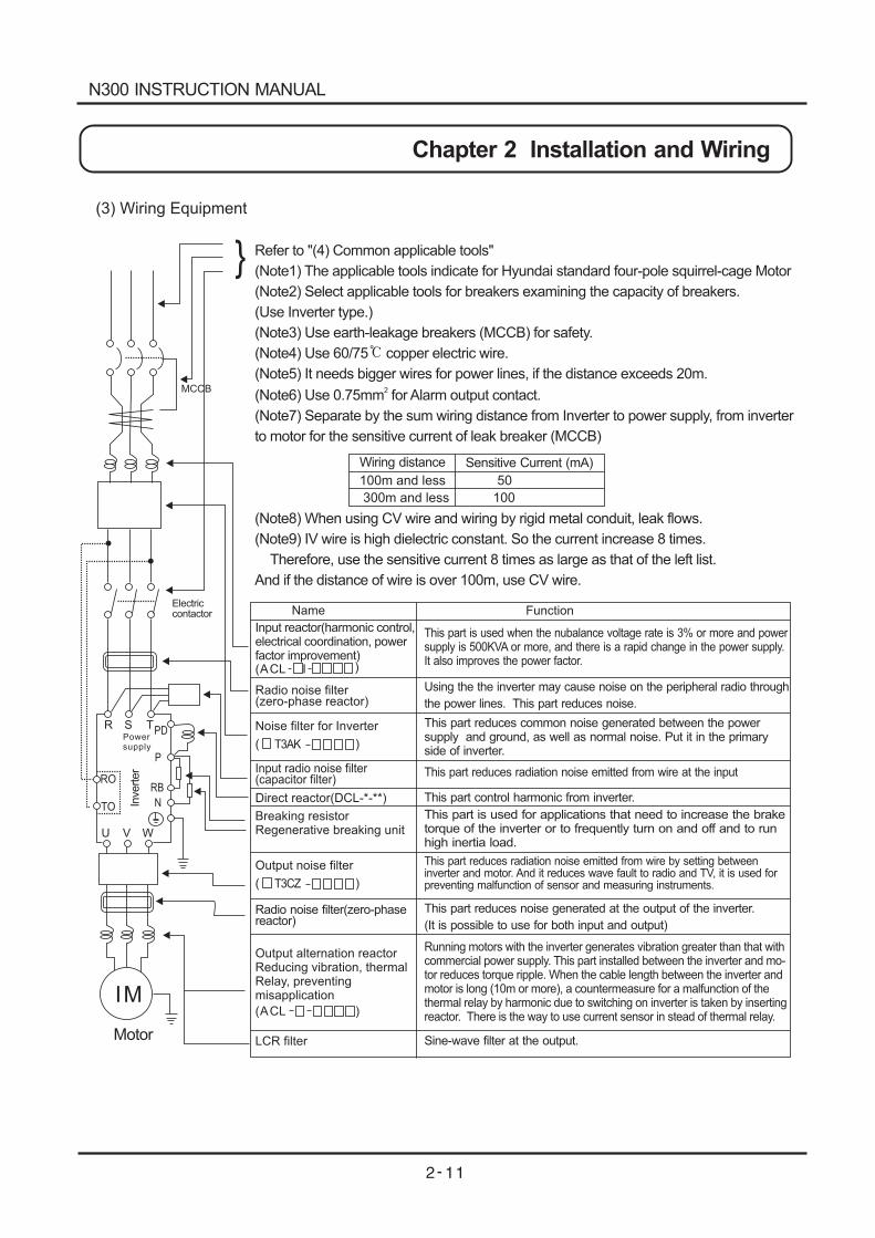
(3) Wiring Equipment
Refer to "(4) Common applicable tools"
(Note1) The applicable tools indicate for Hyundai standard four-pole squirrel-cage Motor
(Note2) Select applicable tools for breakers examining the capacity of breakers.
(Use Inverter type.)
(Note3) Use earth-leakage breakers (MCCB) for safety.
(Note4) Use 60/75 copper electric wire.
(Note5) It needs bigger wires for power lines, if the distance exceeds 20m.
(Note6) Use 0.75mm for Alarm output contact.
(Note7) Separate by the sum wiring distance from Inverter to power supply, from inverter
to motor for the sensitive current of leak breaker (MCCB)
(Note8) When using CV wire and wiring by rigid metal conduit, leak flows.
(Note9) IV wire is high dielectric constant. So the current increase 8 times.
Therefore, use the sensitive current 8 times as large as that of the left list.
And if the distance of wire is over 100m, use CV wire.
2
Wiring distance Sensitive Current (mA)
100m and less 50
300m and less 100
Name
Input reactor(harmonic control,electrical coordination, powerfactor improvement)
Radio noise filter(zero-phase reactor)
Noise filter for Inverter
Direct reactor(DCL-*-**)
Breaking resistorRegenerative breaking unit
Output noise filter
Radio noise filter(zero-phasereactor)
Output alternation reactorReducing vibration, thermalRelay, preventingmisapplication
LCR filter
(ACL I )
( )T3AK
Input radio noise filter(capacitor filter)
( )T3CZ
(ACL )
This part is used when the nubalance voltage rate is 3% or more and powersupply is 500KVA or more, and there is a rapid change in the power supply.It also improves the power factor.
Using the the inverter may cause noise on the peripheral radio through
the power lines. This part reduces noise.
This part reduces common noise generated between the powersupply and ground, as well as normal noise. Put it in the primaryside of inverter.
This part reduces radiation noise emitted from wire at the input
This part control harmonic from inverter.
This part is used for applications that need to increase the braketorque of the inverter or to frequently turn on and off and to runhigh inertia load.
This part reduces radiation noise emitted from wire by setting betweeninverter and motor. And it reduces wave fault to radio and TV, it is used forpreventing malfunction of sensor and measuring instruments.
This part reduces noise generated at the output of the inverter.
(It is possible to use for both input and output)
Running motors with the inverter generates vibration greater than that withcommercial power supply. This part installed between the inverter and mo-tor reduces torque ripple. When the cable length between the inverter andmotor is long (10m or more), a countermeasure for a malfunction of thethermal relay by harmonic due to switching on inverter is taken by insertingreactor. There is the way to use current sensor in stead of thermal relay.
Sine-wave filter at the output.
Function
Motor
Inverter
Electriccontactor
Powersupply
N300 INSTRUCTION MANUAL
Chapter 2 Installation and Wiring
Torque
(N.m)Electromagnetic
controller(MC)
Power lines
R,S,T,U,V,W,P,PD,N
5.5
7.5
11
15
18.5
22
30
37
45
55
5.5
7.5
11
15
18.5
22
30
37
45
55
Applicable ToolsMotoroutput(kw)
200V
cla
ss
400V
cla
ss
N300-300LF
5.5
8
14
22
30
38
60(22 2)
80 2
3.5
3.5
5.5
8
14
22
30
38
50
60
ApplicableI n v e r t e rModel
5.5
5.5
5.5
-
-
-
-
-
-
-
3.5
3.5
5.5
-
-
-
-
-
-
--
-
-
-
-
External resisterbetweenP and RB
M5
M5
M6
M6
M6
M8
M8
M8
M10
M10
M5
M5
M6
M6
M6
M6
M6
M6
M8
M10
M10
M10
M10
2.0
2.0
2.5
2.5
2.5
6.0
6.0
6.0
10.0
10.0
2.0
2.0
2.5
2.5
2.5
2.5
2.5
2.5
6.0
10.0
10.0
10.0
10.0
HBS60N
HBS60N
HBS100N
HBS100N
HBS225N
HBS225N
HBS225N
HBS225N
HBS400N
HBS400N
HBS30N
HBS30N
HBS60N
HBS100N
HBS100N
HBS100N
HBS100N
HBS225N
HBS225N
HBS225N
HBS400N
HBS400N
HBS400N
HBS400N
50A
50A
75A
100A
150A
150A
200A
225A
225A
350A
30A
30A
50A
50A
75A
75A
100A
100A
175A
225A
225A
350A
350A
H Mc22
H Mc32
H Mc50
H Mc65
H Mc80
H Mc80
H Mc110
H Mc130
H Mc180
H Mc220
H Mc18
H Mc18
H Mc32
H Mc40
H Mc40
H Mc50
H Mc65
H Mc80
H Mc110
H Mc130
H Mc180
H Mc220
H Mc260
H Mc300
Screwsize ofTerminal
Leak breaker(MCCB)
N300-055LF
N300-055HF
N300-075HF
N300-110HF
N300-150HF
N300-185HF
N300-220HF
N300-300HF
N300-370HF
75
90
110
132
150(60 2)
125(50 2)
100(38 2)
N300-450HF
N300-550HF
N300-750HF
N300-900HF
N300-1100HF
N300-1320HF
N300-110LF
N300-150LF
N300-185LF
N300-220LF
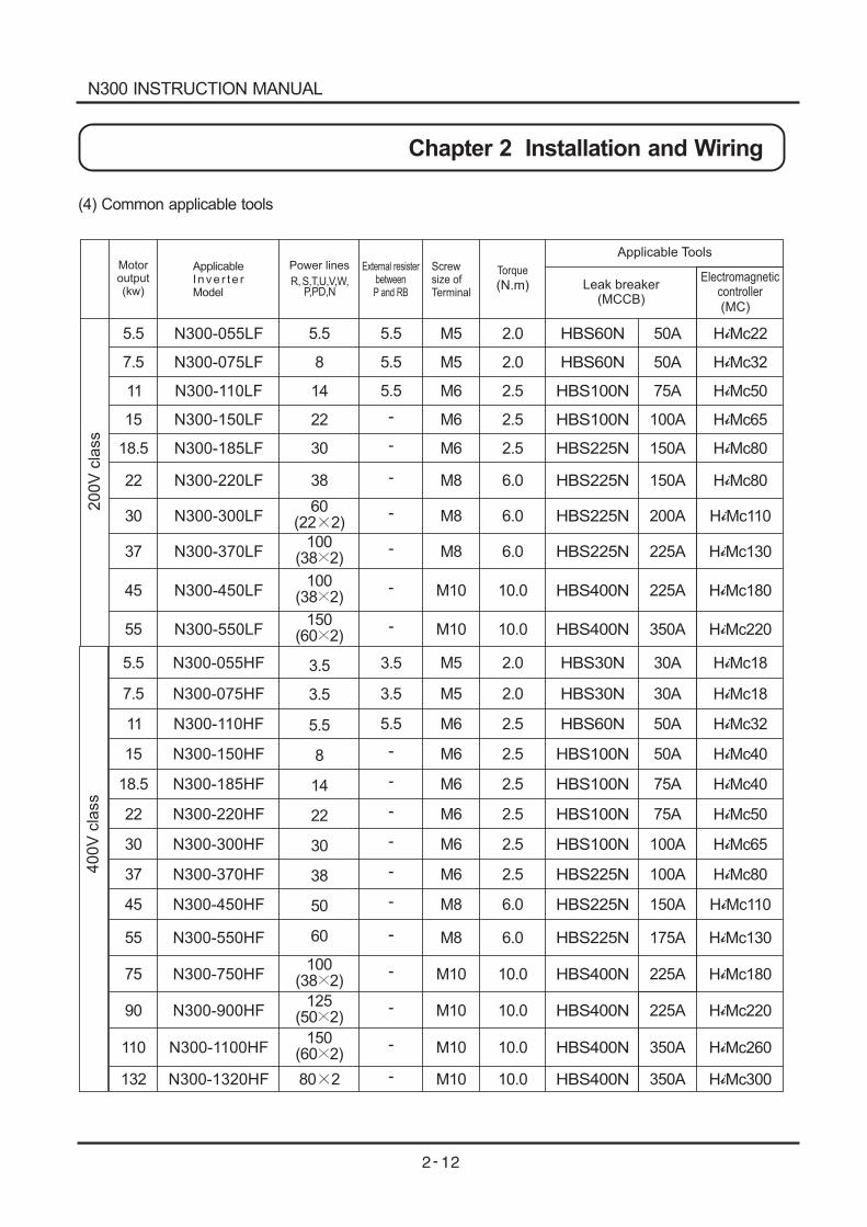
(4) Common applicable tools
N300-075LF
N300-370LF
N300-450LF
N300-550LF
N300 INSTRUCTION MANUAL
Chapter 2 Installation and Wiring
M8 6.0 150A
150(60 2)
100(38 2)
100(38 2)
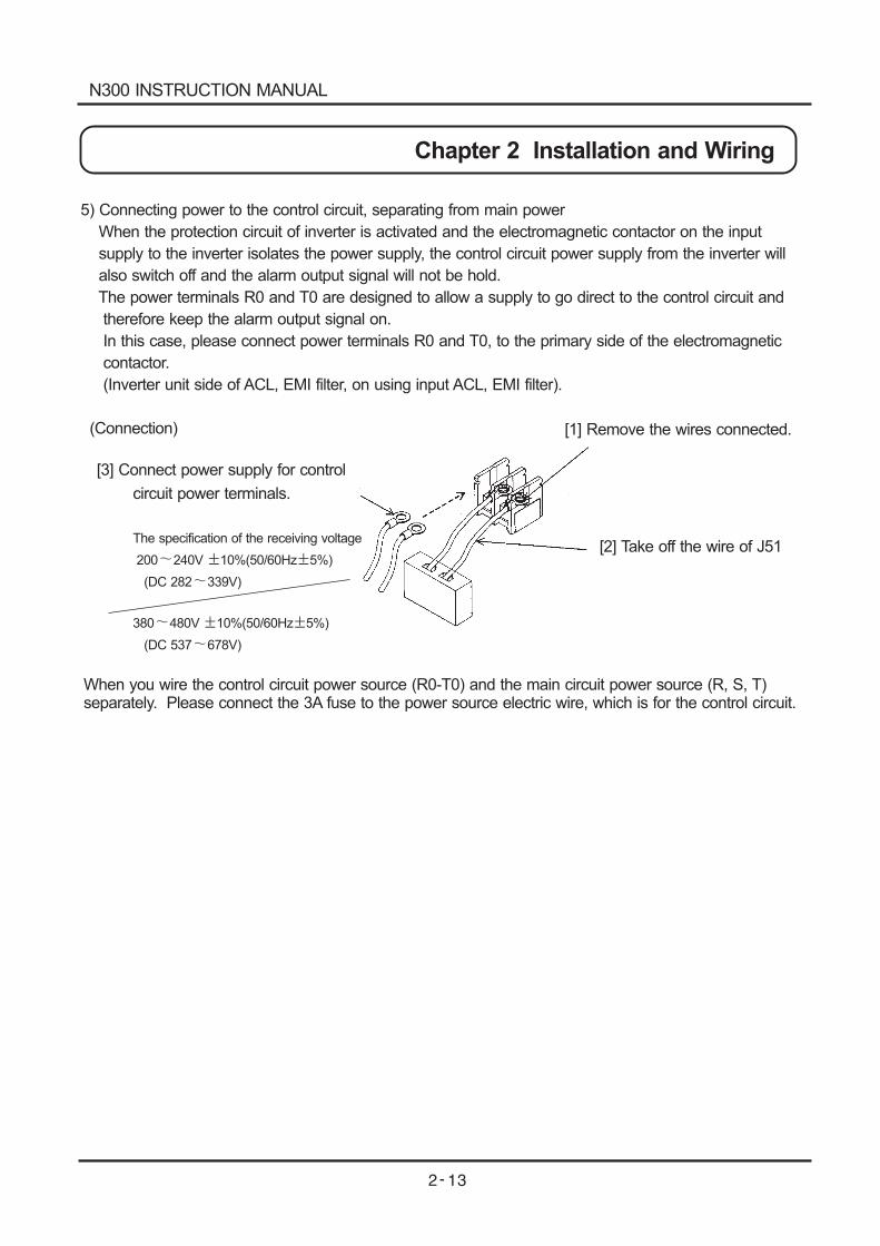
5) Connecting power to the control circuit, separating from main power
When the protection circuit of inverter is activated and the electromagnetic contactor on the input
supply to the inverter isolates the power supply, the control circuit power supply from the inverter will
also switch off and the alarm output signal will not be hold.
The power terminals R0 and T0 are designed to allow a supply to go direct to the control circuit and
therefore keep the alarm output signal on.
In this case, please connect power terminals R0 and T0, to the primary side of the electromagnetic
contactor.
(Inverter unit side of ACL, EMI filter, on using input ACL, EMI filter).
(Connection)
[3] Connect power supply for control
circuit power terminals.
The specification of the receiving voltage
200 240V 10%(50/60Hz 5%)
(DC 282 339V)
380 480V 10%(50/60Hz 5%)
(DC 537 678V)
[1] Remove the wires connected.
[2] Take off the wire of J51
When you wire the control circuit power source (R0-T0) and the main circuit power source (R, S, T)separately. Please connect the 3A fuse to the power source electric wire, which is for the control circuit.
N300 INSTRUCTION MANUAL
Chapter 2 Installation and Wiring
TH FW CM1
PLC CM1 7 6
8 Sequence
Thermistor
H O2 AM FM8
(RV) CM15
(2CH)3
(JG)1
(RS)14
(OTQ)13
(OL)11
(FA1) AL1
L O OI AMI P24 PLC CM17
(CF1)6
(CF2)4
(FRS)2
(AT)15(IP) CM2
12(RUN) AL0 AL2
The terminal screw size : M3
TH FW
2.2.3 Terminal connection diagram
(1) Wiring
1. Both the CM1 and L terminal is insulated to both the common terminal of the input and output
signals.
Do not short or earth these common terminals.
2. Use twisted screened cable, for the input and output wires of the control circuit terminals.
Connect the screen to the common terminal.
3. Limit connection wires to 20m. When it is necessary to wire over 20m, use a VX applied
controller RCD-A (Remoter operation bar) or a CVD-E (Insulated signal transducer)
4. Separate the control circuit wiring from the main power and relay control wiring.
5. If control and power wires must cross make sure they cross at 90 degrees to each other.
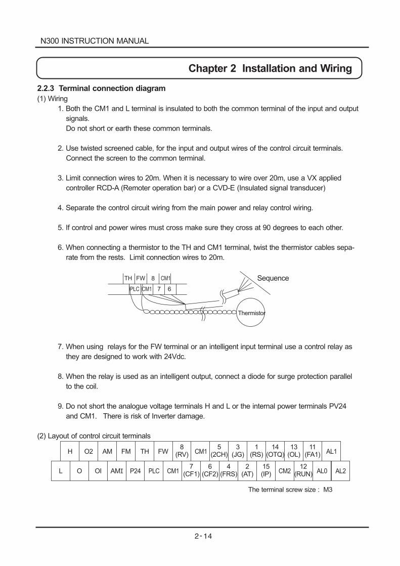
6. When connecting a thermistor to the TH and CM1 terminal, twist the thermistor cables sepa-
rate from the rests. Limit connection wires to 20m.
7. When using relays for the FW terminal or an intelligent input terminal use a control relay as
they are designed to work with 24Vdc.
8. When the relay is used as an intelligent output, connect a diode for surge protection parallel
to the coil.
9. Do not short the analogue voltage terminals H and L or the internal power terminals PV24
and CM1. There is risk of Inverter damage.
(2) Layout of control circuit terminals
N300 INSTRUCTION MANUAL
Chapter 2 Installation and Wiring
Short bar
Output module
Output module Output module
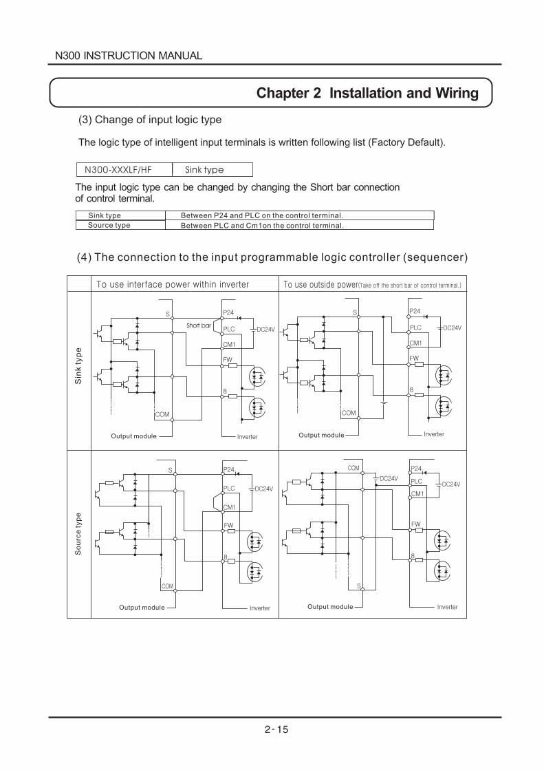
(3) Change of input logic type
The logic type of intelligent input terminals is written following list (Factory Default).
N300-XXXLF/HF Sink type
The input logic type can be changed by changing the Short bar connectionof control terminal.
Sink type
Source type
Between P24 and PLC on the control terminal.
Between PLC and Cm1on the control terminal.
(4) The connection to the input programmable logic controller (sequencer)
Output module
Sin
kty
pe
So
urc
ety
pe
N300 INSTRUCTION MANUAL
Chapter 2 Installation and Wiring
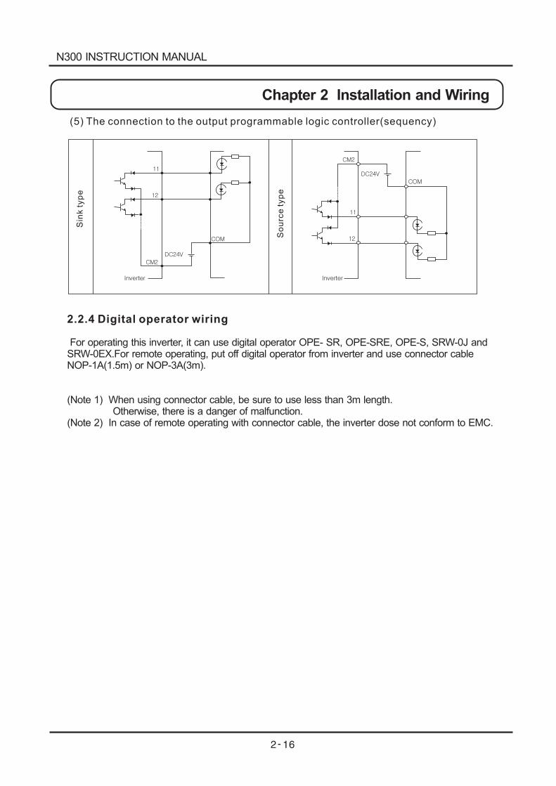
(5) The connection to the output programmable logic controller(sequency)
Sin
kty
pe
So
urc
ety
pe
2.2.4 Digital operator wiring
For operating this inverter, it can use digital operator OPE- SR, OPE-SRE, OPE-S, SRW-0J andSRW-0EX.For remote operating, put off digital operator from inverter and use connector cableNOP-1A(1.5m) or NOP-3A(3m).
(Note 1) When using connector cable, be sure to use less than 3m length.Otherwise, there is a danger of malfunction.
(Note 2) In case of remote operating with connector cable, the inverter dose not conform to EMC.
N300 INSTRUCTION MANUAL
Chapter 2 Installation and Wiring
Chapter 3 Operation
WARNING
Be sure not to touch the main terminal or to check the signal or put on/off wire and/or connector. Otherwise, there is a danger of electric shock.
Be sure to turn on the input power supply after closing from cover. While being energized, be sure not to open the front cover. Otherwise, there is a danger of electric shock.
Be sure not to operate the switches with wet hands. Otherwise, there is a danger of electric shock.
While the inverter is energized, be sure not to touch the inverter terminals even during stoppage. Otherwise, there is a danger of electric shock.
If the retry mode is selected, it may suddenly restart during the trip stop. Be sure not to approach the machine.(Be sure to design the machine so that personnel safety will be secured even if it restarts.) Otherwise, there is a danger of injury.
Be sure not to select retry mode for up and down equipment or traveling equipment, because there is output free-running mode in term of retry. Otherwise, there is a danger of injury and/or machine breakage
Even if the power supply is cut for a short period of time, it may restart operation after the power supply is recovered if the operation command is given. If it may incur danger to personnel, be suer to make a circuit so that it will not restart after power recovery. Otherwise, there is a danger of injury.
The stop key is effective only when the function is set. Be sure to prepare the key separately from the emergency stop. Otherwise, there is a danger of injury.
After the operation command is given, if the alarm reset is conducted, it will restart suddenly. Be sure to set the alarm reset after checking the operation command is off. Otherwise, there is a danger of injury.
Be sure not to touch the inside of the energized inverter or to put a bar into it. Otherwise, there is a danger of electric shock and/or fire.
N300 INSTRUCTION MANUAL
CAUTION
Cooling fin will have high temperature. Be sure not to touch them.
Otherwise, there is a danger of getting burned.
Low to high speed operation of the inverter can be easily set. Be sure to operate it after checking the
tolerance of the motor and machine.
Otherwise, there is a danger of injury.
Install external break system if needed.
Otherwise, there is a danger of injury.
If a motor is operated at a frequency higher than standard setting value(50Hz / 60Hz), be sure to check
the speeds of the motor and the machine with each manufacturer, and after getting their consent,
operate them.
Otherwise, there is a danger of machine breakage.
Check the following before and during the test run.
Otherwise, there is a danger of machine breakage.
Was the direction of motor correct?
Was the inverter tripped during acceleration or deceleration?
Were the rpm and frequency meter correct?
Were there any abnormal motor vibrations or noise?
N300 INSTRUCTION MANUAL
Chapter 3 Operation
3.1 Operation3.1 Operation
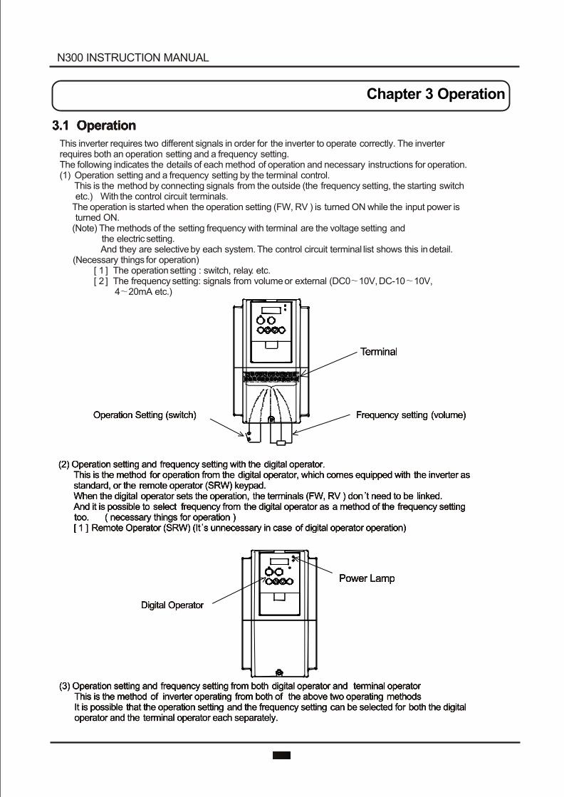
This inverter requires two different signals in order for the inverter to operate correctly. The inverter requires both an operation setting and a frequency setting.The following indicates the details of each method of operation and necessary instructions for operation. (1) Operation setting and a frequency setting by the terminal control. This is the method by connecting signals from the outside (the frequency setting, the starting switch etc.) With the control circuit terminals. The operation is started when the operation setting (FW, RV ) is turned ON while the input power is turned ON. (Note) The methods of the setting frequency with terminal are the voltage setting and the electric setting. And they are selective by each system. The control circuit terminal list shows this in detail. (Necessary things for operation) [ 1 ] The operation setting : switch, relay. etc. [ 2 ] The frequency setting: signals from volume or external (DC0 10V, DC-10 10V, 4 20mA etc.)
TerminalTerminal
Operation Setting (switch) Operation Setting (switch) Frequency setting (volume)Frequency setting (volume)
(2) Operation setting and frequency setting with the digital operator. This is the method for operation from the digital operator, which comes equipped with the inverter as standard, or the remote operator (SRW) keypad. When the digital operator sets the operation, the terminals (FW, RV ) don t need to be linked. And it is possible to select frequency from the digital operator as a method of the frequency setting too. ( necessary things for operation ) [ 1 ] Remote Operator (SRW) (It s unnecessary in case of digital operator operation)
(2) Operation setting and frequency setting with the digital operator. This is the method for operation from the digital operator, which comes equipped with the inverter as standard, or the remote operator (SRW) keypad. When the digital operator sets the operation, the terminals (FW, RV ) don t need to be linked. And it is possible to select frequency from the digital operator as a method of the frequency setting too. ( necessary things for operation ) [ 1 ] Remote Operator (SRW) (It s unnecessary in case of digital operator operation)
Power LampPower Lamp
Digital OperatorDigital Operator
(3) Operation setting and frequency setting from both digital operator and terminal operator This is the method of inverter operating from both of the above two operating methods It is possible that the operation setting and the frequency setting can be selected for both the digital operator and the terminal operator each separately.
(3) Operation setting and frequency setting from both digital operator and terminal operator This is the method of inverter operating from both of the above two operating methods It is possible that the operation setting and the frequency setting can be selected for both the digital operator and the terminal operator each separately.
N300 INSTRUCTION MANUAL
Chapter 3 Operation
3.2 Test RUN3.2 Test RUN
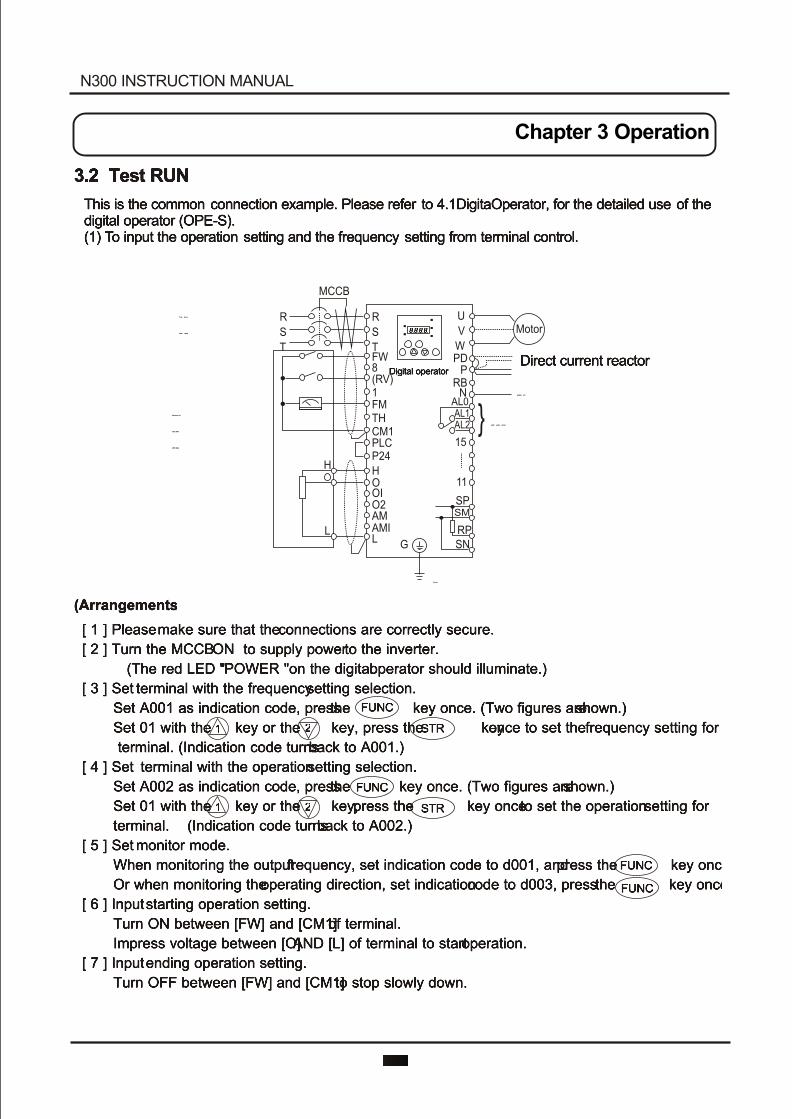
This is the common connection example. Please refer to 4.1DigitaOperator, for the detailed use of thedigital operator (OPE-S).(1) To input the operation setting and the frequency setting from terminal control.
This is the common connection example. Please refer to 4.1DigitaOperator, for the detailed use of the
digital operator (OPE-S).
(1) T o input the operation setting and the frequency setting from terminal control.
(Arrangements)(Arrangements)
[ 1 ] Please make sure that the connections are correctly secure.
[ 2 ] Turn the MCCB ON to supply power to the inverter.
(The red LED " 'POWER "on the digital operator should illuminate.)
[ 3 ] Set terminal with the frequency setting selection.
Set A001 as indication code, press the key once. (Two figures are shown.)
Set 01 with the key or the key, press the key once to set the frequency setting for
terminal. (Indication code turns back to A001.)
[ 4 ] Set terminal with the operation setting selection.
Set A002 as indication code, press the key once. (Two figures are shown.)
Set 01 with the key or the key; press the key once to set the operation setting for
terminal. (Indication code turns back to A002.)
[ 5 ] Set monitor mode.
When monitoring the output frequency, set indication code to d001, and press the key once.
Or when monitoring the operating direction, set indication code to d003, press the key once.
[ 6 ] Input starting operation setting.
Turn ON between [FW] and [CM1] of terminal.
Impress voltage between [O] AND [L] of terminal to start operation.
[ 7 ] Input ending operation setting.
Turn OFF between [FW] and [CM1] to stop slowly down.
Three phase
Power supply
Three phase
Power supply
Digital operatorDigital operatorDirect current reactorDirect current reactor
Braking unitBraking unit
Alarm output contactAlarm output contact
GroundGround
Operating box
(OPE-8MA)
(OPE-4MA)
Operating box
(OPE-8MA)
(OPE-4MA)
MCCB
U
V
W
Motor
PDP
RBN
AL0AL1AL2
15
11
SPSM
RPSN
R
S
TFW8(RV)1FMTHCM1PLCP24
HOOIO2AMAMIL G
H
L
}
R
S
T
8.8.8.8.8.8.8.8.
FUNCFUNC
FUNCFUNC
FUNCFUNC
FUNCFUNC
STRSTR
STRSTR11
11
22
22
N300 INSTRUCTION MANUAL
Chapter 3 Operation
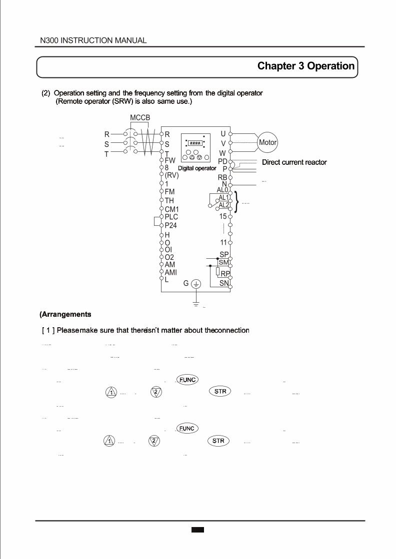
(2) Operation setting and the frequency setting from the digital operator (Remote operator (SRW) is also same use.)
(2) Operation setting and the frequency setting from the digital operator
(Remote operator (SRW) is also same use.)
(Arrangements)(Arrangements)
[ 1 ] Please make sure that there isn t matter about the connection.[ 1 ] Please make sure that there isn t matter about the connection.
[ 2 ] Turn the MCCB on to supply power to the inverter.[ 2 ] Turn the MCCB on to supply power to the inverter.
(The red LED " 'POWER "on the digital operator should illuminate.) (The red LED " 'POWER "on the digital operator should illuminate.)
[ 3 ] Set operator with the frequency setting selection.[ 3 ] Set operator with the frequency setting selection.
Set A001 as indication code, press the key once. (Two figures are shown.) Set A001 as indication code, press the key once. (Two figures are shown.)
Set 02 with the key or the key, press the key once to set the frequency setting for Set 02 with the key or the key, press the key once to set the frequency setting for
the operator. (Indication code turns back to A001.) the operator. (Indication code turns back to A001.)
[ 4 ] Set operator with the operation setting selection. [ 4 ] Set operator with the operation setting selection.
Set A002 as indication code, press the key once. (Two figures are shown.) Set A002 as indication code, press the key once. (Two figures are shown.)
Set 02 with the key or the key, press the key once to set the operation setting for Set 02 with the key or the key, press the key once to set the operation setting for
the operator. (Indication code turns back to A002.) the operator. (Indication code turns back to A002.)
Three phase
Power supply
Three phase
Power supply
Digital operatorDigital operatorDirect current reactorDirect current reactor
Braking unitBraking unit
Alarm output contactAlarm output contact
GroundGround
MCCB
U
V
W
Motor
PDP
RBN
AL0AL1AL2
15
11
SPSM
RPSN
R
S
TFW8(RV)1FMTHCM1PLCP24
HOOIO2AMAMIL G
}
R
S
T
8.8.8.8.8.8.8.8.
FUNCFUNC
11 22 STRSTR
FUNCFUNC
11 22 STRSTR
N300 INSTRUCTION MANUAL
Chapter 3 Operation
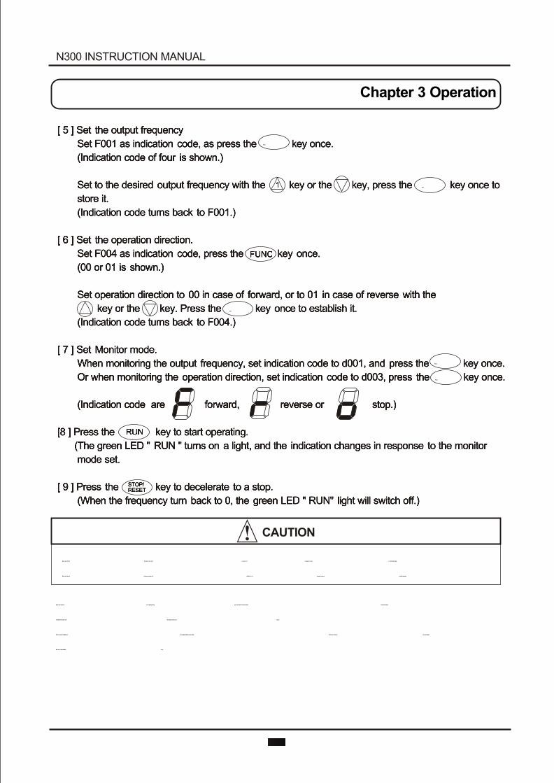
[ 5 ] Set the output frequency
Set F001 as indication code, as press the key once.
(Indication code of four is shown.)
Set to the desired output frequency with the key or the key, press the key once to
store it.
(Indication code turns back to F001.)
[ 6 ] Set the operation direction.
Set F004 as indication code, press the key once.
(00 or 01 is shown.)
Set operation direction to 00 in case of forward, or to 01 in case of reverse with the
key or the key. Press the key once to establish it.
(Indication code turns back to F004.)
[ 7 ] Set Monitor mode.
When monitoring the output frequency, set indication code to d001, and press the key once.
Or when monitoring the operation direction, set indication code to d003, press the key once.
(Indication code are forward, reverse or stop.)
[8 ] Press the key to start operating.
(The green LED " RUN " turns on a light, and the indication changes in response to the monitor
mode set.
[ 9 ] Press the key to decelerate to a stop.
(When the frequency turn back to 0, the green LED " RUN" light will switch off.)
Make sure that the direction of the motor is correct. It is in danger of injury or machine damage.
Make sure there is no abnormal noise and vibration. It is in danger of injury or machine damage.
Make sure that the direction of the motor is correct. It is in danger of injury or machine damage.
Make sure there is no abnormal noise and vibration. It is in danger of injury or machine damage.
Make sure that there is no tripping during the acceleration and deceleration and check that the
revolution per minute and the frequency meter are correct.
When overcurrent tripping or overvoltage tripping occurs during the test run, increase the acceleration
time or the deceleration time.
Make sure that there is no tripping during the acceleration and deceleration and check that the
revolution per minute and the frequency meter are correct.
When overcurrent tripping or overvoltage tripping occurs during the test run, increase the acceleration
time or the deceleration time.
STOP/RESETSTOP/
RESET
RUNRUN
STRSTR
STRSTR
FUNCFUNC
11
11
22
22
FUNCFUNC
FUNCFUNC
FUNCFUNC
CAUTION
N300 INSTRUCTION MANUAL
Chapter 3 Operation
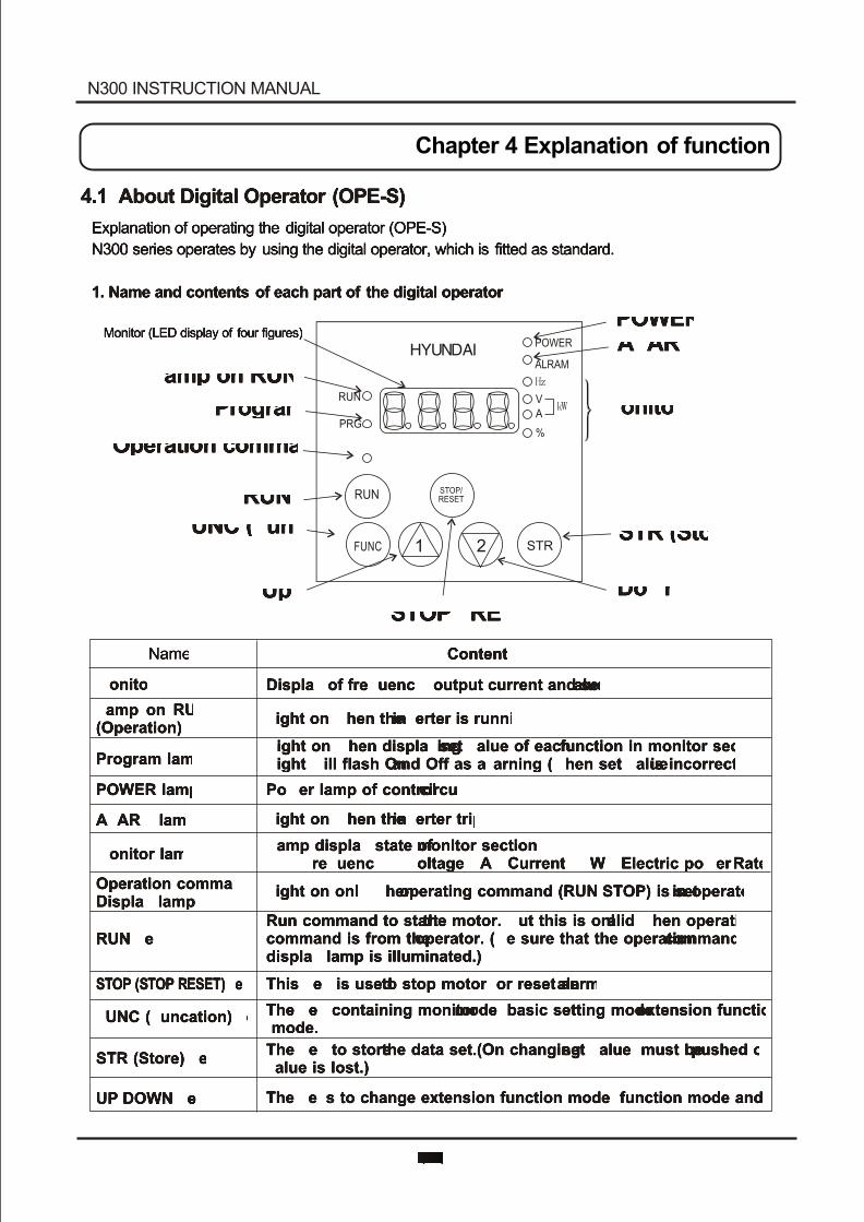
4.1 About Digital Operator (OPE-S)4.1 About Digital Operator (OPE-S)
Explanation of operating the digital operator (OPE-S)
N300 series operates by using the digital operator, which is fitted as standard.
1. Name and contents of each part of the digital operator
Explanation of operating the digital operator (OPE-S)
N300 series operates by using the digital operator, which is fitted as standard.
1. Name and contents of each part of the digital operator
NameName ContentsContents
MonitorMonitor Display of frequency, output current and set valueDisplay of frequency, output current and set value
Lamp on RUN(Operation)Lamp on RUN(Operation)
Light on when the inverter is runningLight on when the inverter is running
Program lampProgram lampLight on when displaying set value of each function in monitor sectionLight will flash On and Off as a warning (when set value is incorrect)Light on when displaying set value of each function in monitor sectionLight will flash On and Off as a warning (when set value is incorrect)
POWER lampPOWER lamp Power lamp of control circuitPower lamp of control circuit
ALARM lampALARM lamp Light on when the inverter tripsLight on when the inverter trips
Monitor lampMonitor lampLamp display state of monitor sectionHz : Frequency V : Voltage A : Current kW : Electric power % : RateLamp display state of monitor sectionHz : Frequency V : Voltage A : Current kW : Electric power % : Rate
Operation commandDisplay lampOperation commandDisplay lamp
Light on only when operating command (RUN/STOP) is set in operatorLight on only when operating command (RUN/STOP) is set in operator
RUN keyRUN keyRun command to start the motor. But this is only valid when operation command is from the operator. (Be sure that the operation command display lamp is illuminated.)
Run command to start the motor. But this is only valid when operation command is from the operator. (Be sure that the operation command display lamp is illuminated.)
STOP (STOP/RESET) keySTOP (STOP/RESET) key This key is used to stop motor, or reset an alarm.This key is used to stop motor, or reset an alarm.
FUNC (Funcation) keyFUNC (Funcation) keyThe key containing monitor mode, basic setting mode, extension functions mode.The key containing monitor mode, basic setting mode, extension functions mode.
STR (Store) keySTR (Store) keyThe key to store the data set.(On changing set value, must be pushed or value is lost.)The key to store the data set.(On changing set value, must be pushed or value is lost.)
UP/DOWN keyUP/DOWN key The keys to change extension function mode, function mode and set value.The keys to change extension function mode, function mode and set value.
Chapter 4 Explanation of function
Monitor (LED display of four figures)Monitor (LED display of four figures)
Lamp on RUN (operation)Lamp on RUN (operation)
Program lampProgram lamp
Operation command display lampOperation command display lamp
RUN keyRUN key
FUNC (Function) keyFUNC (Function) key
Up keyUp key
POWER lampPOWER lampALARM lampALARM lamp
Monitor lampMonitor lamp
STR (Store) keySTR (Store) key
Down keyDown keySTOP / RESET keySTOP / RESET key
1 2
RUN
PRG
POWER
ALRAM
VA
%
STR
STOP/RESETRUN
FUNC
N300 INSTRUCTION MANUAL
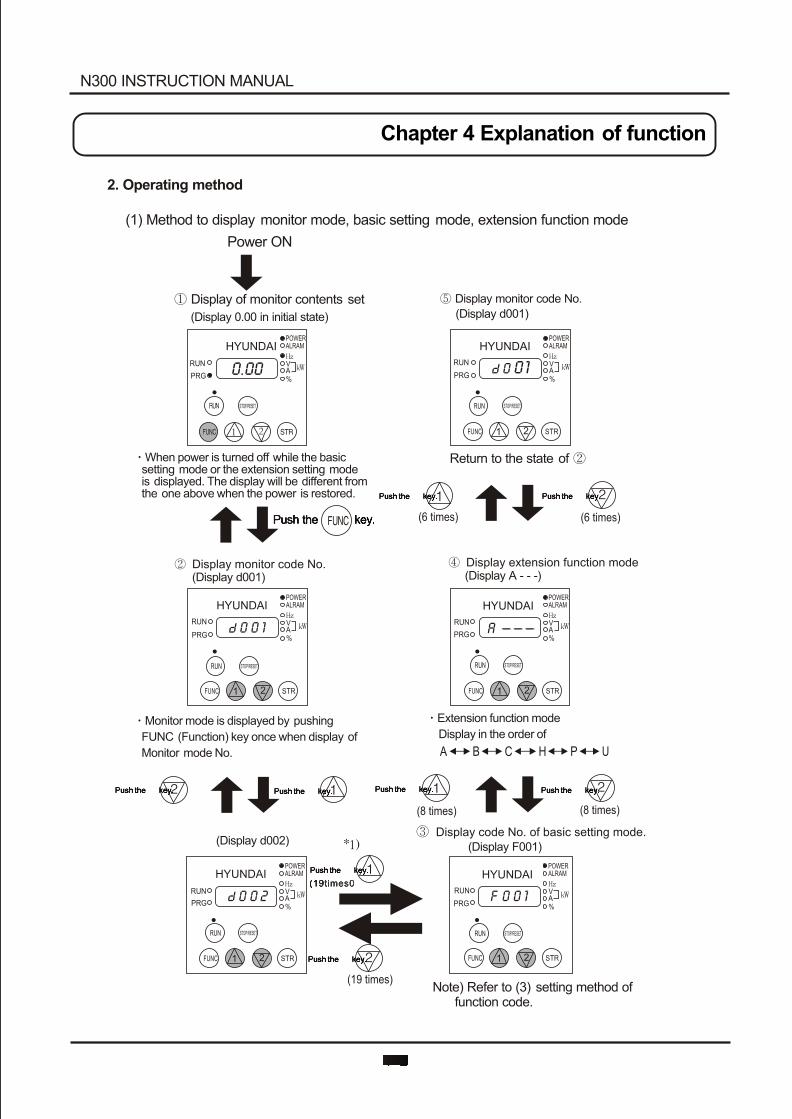
HYUNDAIPOWERALRAM
VA%
RUN
PRG0 2
HYUNDAIPOWERALRAM
VA%
RUN
PRG0 1F
1 2 1 2
2. Operating method
(1) Method to display monitor mode, basic setting mode, extension function mode
Power ON
Display of monitor contents set
(Display 0.00 in initial state)
When power is turned off while the basic setting mode or the extension setting mode is displayed. The display will be different from the one above when the power is restored.
Monitor mode is displayed by pushing
FUNC (Function) key once when display of
Monitor mode No.
Extension function mode
Display in the order of
Display monitor code No.
(Display d001)
(Display d001)
(Display d002)(Display F001)
(Display A - - -)Display monitor code No. Display extension function mode
A B C H P U
Display code No. of basic setting mode.
Note) Refer to (3) setting method of function code.
(6 times)
(8 times) (8 times)
(6 times)
Return to the state of
STR STRFUNC FUNC
RUN RUN
HYUNDAIPOWERALRAM
VA%
RUN
PRG 0.00
HYUNDAIPOWERALRAM
VA%
RUN
PRG01
1 2 STRFUNC
RUN STOP/RESET
HYUNDAIPOWERALRAM
VA%
RUN
PRG A ---
1 2 STRFUNC
RUN STOP/RESET
HYUNDAIPOWERALRAM
VA%
RUN
PRG0 1
1 2 STRFUNC
RUN STOP/RESET
STOP/RESET STOP/RESET
Push the key.Push the key.
Push the key.Push the key. Push the key.Push the key.
Push the key.Push the key.Push the key.Push the key.Push the key.Push the key.Push the key.Push the key.
Push the key.Push the key.
Push the key.Push the key.
N300 INSTRUCTION MANUAL
Chapter 4 Explanation of function

HYUNDAIPOWERALRAM
VA%
RUN
PRG A---HYUNDAI
POWERALRAM
VA%
RUN
PRG A---
HYUNDAIPOWERALRAM
VA%
RUN
PRG A 0 0 1
HYUNDAIPOWERALRAM
VA%
RUN
PRG A002
HYUNDAIPOWERALRAM
VA%
RUN
PRG 02
HYUNDAIPOWERALRAM
VA%
RUN
PRG 0 1
2
Display extension function mode
Make monitor display "A " by referring to (1) displaying method. Now operating command part is by the operator, so operating command display lamp should illuminate.
Display extension function mode (Display A )
It is possible to shift to other extension
function modes, monitor modes and basic
modes in this state.
Display code No. of function mode
Display contents of function mode
Display code No. of monitor mode.
(Display A002)
The changed set value is confirmed by pushingthe STR key.Operation command display lamplight will switchoff so that operation command is now changed to the control terminal.
(Display A002 )
Change operation command part to control terminal 01.
Operation command part displays
02(operator).
Program(PRG) light on by displaying
contents of function mode.
HYUNDAIPOWERALRAM
VA%
RUN
PRG 02
1
1
2 1 2
2
2
STR STRFUNC FUNC
1 2 STRFUNC
RUN
RUN
STOP/RESET
STOP/RESET
Push the key.
Push the key.
Push the key.
(2) Setting method of function Change operation command part. (Operator Control terminal)(2) Setting method of function Change operation command part. (Operator Control terminal)
Push the key.Push the key.
Push the key.Push the key.
Push the key.Push the key.
RUN STOP/RESET
1 STRFUNC
RUN STOP/RESET
21FUNC
RUN STOP/RESET
STRSTR
STRFUNC
RUN STOP/RESET
N300 INSTRUCTION MANUAL
Chapter 4 Explanation of function
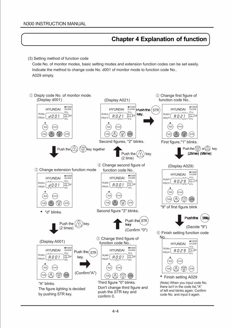
(3) Setting method of function code
Code No. of monitor modes, basic setting modes and extension function codes can be set easily.
Indicate the method to change code No. d001 of monitor mode to function code No..
A029 simply.
HYUNDAIPOWERALRAM
VA%
RUN
PRG 0 0 1
HYUNDAIPOWERALRAM
VA%
RUN
PRG A 0 2 1
HYUNDAIPOWERALRAM
VA%
RUN
PRG A 0 2 1
HYUNDAIPOWERALRAM
VA%
RUN
PRG 0 0 1
HYUNDAIPOWERALRAM
VA%
RUN
PRG A 0 0 1
HYUNDAIPOWERALRAM
VA%
RUN
PRGA 0 0 1
HYUNDAIPOWERALRAM
VA%
RUN
PRG A 0 0 1
HYUNDAIPOWERALRAM
VA%
RUN
PRG A 0 2 9
HYUNDAIPOWERALRAM
VA%
RUN
PRG A 0 2 9
Push the key.(2 time)
Push the or key.
Push the key.(2 times)
(Confirm "0")(Decide "9")
( "A")Confirm
Disply code No. of monitor mode. (Display d001)
Change extension function mode
(Display A001)
"A" blinks.
The figure lighting is decided
by pushing STR key.
"d" blinks.
(Display A021)
Second figures, "2" blinks.
Change first figure of function code No..
First figure,"1" blinks.
(Display A029)
"9" of first figure blink
Change second figure of
function code No..
Second figure "2" blinks.
Change third figure of function code No..
Third figure "0" blinks.
Don't change third figure and push the STR key and confirm 0.
Finish setting function code No.
Finish setting A029
(Note) When you input code No. there isn't in the code list,"A"of left end blinks again. Confirmcode No. and input it again.
Push the key together
1 2 STRFUNC
RUN STOP/RESET
1 STRFUNC
STOP/RESET
RUN
RUN
STOP/RESET
STOP/RESET
1FUNC STR
1FUNC 2 STR
11
1
122
2
2FUNCFUNC
FUNC
FUNC
RUNRUN
RUN
RUN RUN
RUNSTOP/RESETSTOP/RESET
STOP/RESET
STOP/RESET
STOP/RESET
STRSTRSTR
STR
STR
1 2FUNC STR
Push the
Push the
key.
key.key.
Push thePush thekey.key.
(2time) (9time)(2time) (9time)
Push the key.Push the key.
N300 INSTRUCTION MANUAL
Chapter 4 Explanation of function
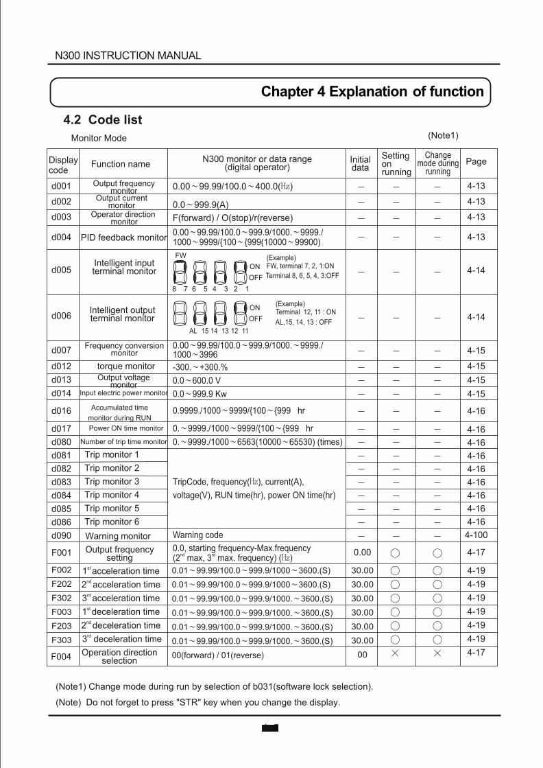
Initialdata
Settingonrunning
Changemode during
running PageFunction nameDisplay
code
4.2 Code list
Monitor Mode (Note1)
d001
d002
d003
d004
d005
d006
d007
d012
d013
d014
d016
d017
d080
d081
d082
d083
d084
d085
d086
d090
F001
F002
F202
F302
F003
F203
F303
F004
Output frequency monitor
Output current monitor
Operator direction monitor
PID feedback monitor
Intelligent inputterminal monitor
Intelligent outputterminal monitor
Frequency conversion monitor
torque monitorOutput voltage
monitorInput electric power monitor
Accumulated time
monitor during RUN
Power ON time monitor
Number of trip time monitor
Trip monitor 1
2Trip monitor
3Trip monitor
4Trip monitor
5Trip monitor
6Trip monitor
Warning monitor
Output frequency setting
st 1 acceleration timend 2 acceleration timerd 3 acceleration time
decest 1 leration time
nd 2 deceleration timerd 3 deceleration time
Operation direction selection
(Note1) Change mode during run by selection of b031(software lock selection).
(Note) Do not forget to press "STR" key when you change the display.
4-13
4-13
4-13
4-13
4-14
4-14
4-15
4-15
4-15
4-15
4-16
4-16
4-16
4-16
4-16
4-16
4-16
4-16
4-16
4-100
4-17
4-19
4-19
4-19
4-19
4-19
4-19
4-17
0.00
30.00
30.00
30.00
30.00
30.00
30.00
00
0.00 99.99/100.0 400.0( )
0.0 999.9(A)
F(forward) / O(stop)/r(reverse)
0.00 99.99/100.0 999.9/1000. 9999./1000 9999/{100 {999(10000 99900)
N300 monitor or data range(digital operator)
FW
ON
OFF
8 7 6 5 4 3 2
AL 15 14 13 12 11
1
(Example)FW, terminal 7, 2, 1:ON
Terminal 8, 6, 5, 4, 3:OFF
ON
OFF
( ) 12, 11 : ON
ExampleTerminal
AL,15, 14, 13 : OFF
0.00 99.99/100.0 999.9/1000. 9999./1000 3996
-300. +300.%
0.0 600.0 V
0.0 999.9 Kw
0.9999./1000 9999/{100 {999 hr
0. 9999./1000 9999/{100 {999 hr
0. 9999./1000 6563(10000 65530) (times)
TripCode, frequency( ), current(A),
voltage(V), RUN time(hr), power ON time(hr)
Warning code
0.0, starting frequency-Max.frequencynd rd(2 max, 3 max. frequency) ( )
0.01 99.99/100.0 999.9/1000 3600.(S)
0.01 99.99/100.0 999.9/1000 3600.(S)
0.01 99.99/100.0 999.9/1000. 3600.(S)
0.01 99.99/100.0 999.9/1000. 3600.(S)
0.01 99.99/100.0 999.9/1000. 3600.(S)
0.01 99.99/100.0 999.9/1000. 3600.(S)
00(forward) / 01(reverse)
N300 INSTRUCTION MANUAL
Chapter 4 Explanation of function
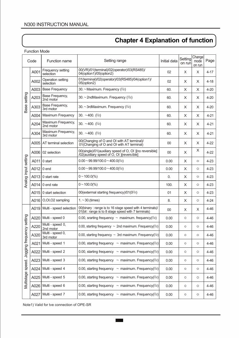
Note1) Valid for tve connection of OPE-SR
Function Mode
Initial data PageFunction nameCode Setting range
Operation setting selection
Base Frequency
Base Frequency, 2nd motor
Base Frequencyd motor
, 3r
Maximum Frequency
Maximum Frequency, 2nd motor
Maximum Frequency, 3rd motor
AT terminal selection
02 selection
0 start
0 end
0 start rate
0 end rate
0 start selection
O,OI,O2 sampling
Multi - speed selection
Multi - speed 0
Multi - speed2nd motor
0,
Multi - speed 0, d motor3r
Multi - speed 1
Multi - speed 2
Multi - speed 3
Multi - speed 4
Multi - speed 5
Multi - speed 6
Multi - speed 7
Frequency setting selectionA001
A002
A003
A203
A303
A004
A204
A304
A005
A006
A011
A012
A013
A014
A015
A016
A019
A020
A220
A320
A021
A022
A023
A024
A025
A026
A027
4-17
4-18
4-20
4-20
4-20
4-21
4-21
4-21
4-22
4-22
4-23
4-23
4-23
4-23
4-23
4-24
4-46
4-46
4-46
4-46
4-46
4-46
4-46
4-46
4-46
4-46
4-46
02
02
60.
60.
60.
60.
60.
60.
00
00
0.00
0.00
0.
100.
01
8.
00
0.00
0.00
0.00
0.00
0.00
0.00
0.00
0.00
0.00
0.00
01(terminal)/02(operator)/03(RS485)/04(option1)/05(option2)
30. Maximum. Frequency ( )
30. 3rdMaximum. Frequency ( )
30. 400. ( )
30. 400. ( )
30. 400. ( )
00(Changing of O and OI with AT terminal)/01(Changing of O and OI with AT terminal)
00(single)/01(auxiliary speed of O, OI )[no reversible]/02(auxiliary speed of O, OI )[revers ible]
0.00 99.99/100.0 400.0( )
0.00 99.99/100.0 400.0( )
0 100.0(%)
0 100.0(%)
00(extermal starting frequency)/01(0 )
1. 30.(times)
00(binary : range is to 16 stage speed with 4 terminals)/01(bit : range is to 8 stage speed with 7 terminals)
0.00, srarting frequency maximum. frequency( )
0.00, starting frequency 2nd maximum. Frequency( )
0.00, starting frequency 3rd maximum. Frequency( )
0.00, starting frequency maximum. Frequency( )
0.00, starting frequency maximum. Frequency( )
0.00, starting frequency maximum. Frequency( )
0.00, starting frequency maximum. Frequency( )
0.00, starting frequency maximum. Frequency( )
0.00, starting frequency maximum. Frequency( )
0.00, starting frequency maximum. Frequency( )
00(VR)/01(terminal)/02(operator)/03(RS485)/04(option1)/05(option2)
Changemode on run
X
X
X
X
X
X
X
X
X
X
X
Setting on run
X
X
X
X
X
X
X
X
X
X
X
X
X
X
X
X
X
Base
settin
g
30. 2ndMaximum. Frequency ( )
Analo
g in
put se
ttin
gM
ulti
stage
speed. Jo
ggin
g fre
quency
settin
gN300 INSTRUCTION MANUAL
Chapter 4 Explanation of function
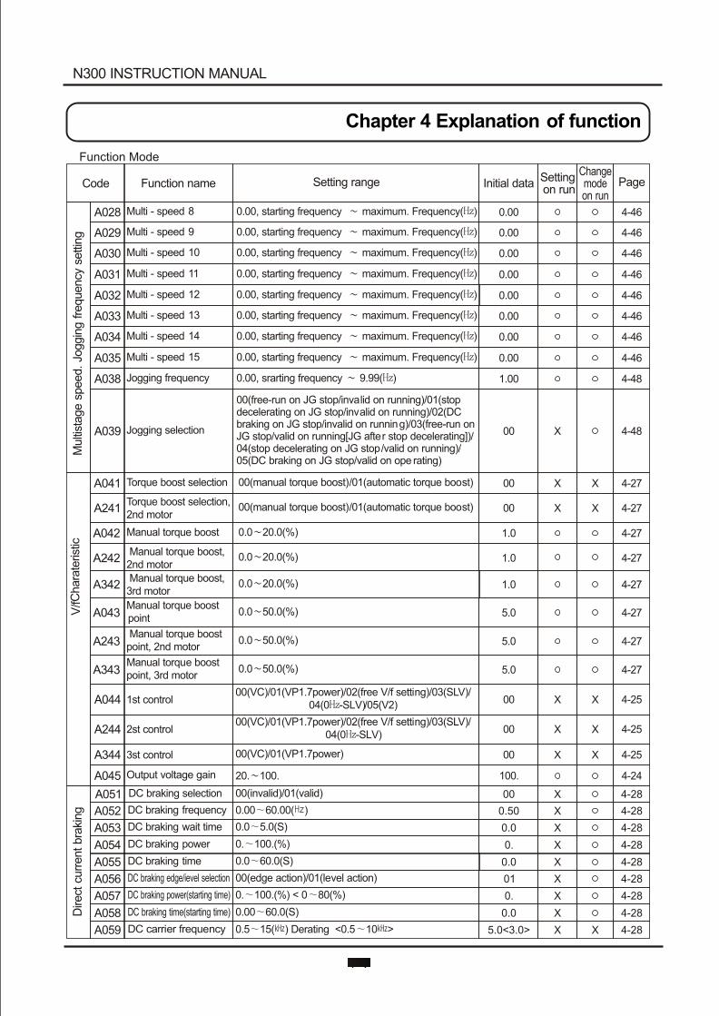
Function Mode
N300 INSTRUCTION MANUAL
Chapter 4 Explanation of function
Initial data PageFunction nameCode Setting rangeChangemode on run
Setting on run
Multi
stage
speed. Jo
ggin
g fre
quency
settin
g
Multi - speed 8
Multi - speed 9
Multi - speed 10
Multi - speed 11
Multi - speed 12
Multi - speed 13
Multi - speed 14
Multi - speed 15
Jogging frequency
A028
A029
A030
A031
A032
A033
A034
A035
A038
A039
0.00, starting frequency maximum. Frequency( )
0.00, starting frequency maximum. Frequency( )
0.00, starting frequency maximum. Frequency( )
0.00, starting frequency maximum. Frequency( )
0.00, starting frequency maximum. Frequency( )
0.00, starting frequency maximum. Frequency( )
0.00, starting frequency maximum. Frequency( )
0.00, starting frequency maximum. Frequency( )
0.00, srarting frequency 9.99( )
4-46
4-46
4-46
4-46
4-46
4-46
4-46
4-46
4-48
0.00
0.00
0.00
0.00
0.00
0.00
0.00
0.00
1.00
00(free-run on JG stop/invalid on running)/01(stop decelerating on JG stop/invalid on running)/02(DC braking on JG stop/invalid on running)/03(free-run on JG stop/valid on running[JG after stop decelerating])/04(stop decelerating on JG stop/valid on running)/05(DC braking on JG stop/valid on ope rating)
Jogging selection 4-4800 X
Torque boost selection
Torque boost selection, 2nd motor
M anual torque boost
Manual torque boost, 2nd motor
Manual torque boost, 3rd motor
pointManual torque boost
Manual torque boost point, 2nd motor
Manual torque boost point, 3rd motor
1st control
2st control
3st control
A041
A241
A042
A242
A342
A043
A243
A343
A044
A244
A344
A045
4-27
4-27
4-27
4-27
4-27
4-27
4-27
4-27
4-25
4-25
4-25
4-24
00
1.0
1.0
1.0
5.0
5.0
5.0
00
00
00
100.
0000(manual torque boost)/01(automatic torque boost)
00(manual torque boost)/01(automatic torque boost)
0.0 20.0(%)
0.0 20.0(%)
0.0 20.0(%)
0.0 50.0(%)
0.0 50.0(%)
0.0 50.0(%)
00(VC)/01(VP1.7power)/02(free V/f setting)/03(SLV)/04(0 -SLV)/05(V2)
00(VC)/01(VP1.7power)/02(free V/f setting)/03(SLV)/04(0 -SLV)
00(VC)/01(VP1.7power)
20. 100.
X
X
X
X
X X
X X
X X
V/f
.
Output voltage gain
Chara
teris
tic
DC braking selection
DC braking frequency
DC braking wait time
DC braking power
DC braking time
DC braking edge/ievel selection
DC braking power(starting time)
DC braking time(starting time)
DC carrier frequency
A051
A052
A053
A054
A055
A056
A057
A058
A059
4-28
4-28
4-28
4-28
4-28
4-28
4-28
4-28
4-28
00
0.50
0.0
0.
0.0
01
0.
0.0
00(invalid)/01(valid)
0.00 60.00( )
0.0 5.0(S)
0. 100.(%)
0.0 60.0(S)
00(edge action)/01(level action)
0. 100.(%) < 0 80(%)
0.00 60.0(S)
0.5 15( ) Derating <0.5 10 > 5.0<3.0>
X
X
X
X
X
X
X
X
X X
Dire
ct c
urr
ent bra
king
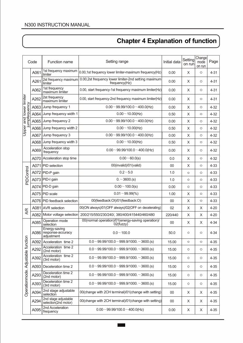
N300 INSTRUCTION MANUAL
Chapter 4 Explanation of function
Initial data PageFunction nameCode Setting rangeChangemode on run
Setting on run
AVR
A061
A261
A062
A262
A063
A064
A065
A066
A067
A068
A069
A070
A071
A072
A073
A074
A075
A076
A081
A082
1st frequency maximum limiter
2st frequency maximum limiter
1st frequency maximum limiter
2st frequency maximum limiter
Jump frequency 1
Jump frequency width 1
Jump frequency 2
Jump frequency width 2
Jump frequency 3
Jump frequency width 3
Acceleration stop frequency
Acceleration stop time
PID selection
PID-P gain
PID-I gain
PID-D gain
PID scale
PID feedback selection
AVR selection
Motor voltage selection
0.00, (Hz)1st frequency lower limiter-maximum frequency
0.00,2(Hz)
st frequency lower limiter-2nd setting maximum frequency
0.00, start (Hz)frequency-1st frequency maximum limiter
0.00, start frequency-2nd frequency maximum limiter(Hz)
0.00
0.00
0.00
0.00
0.00
0.50
0.00
0.50
0.00
0.50
0.00
0.0
00
1.0
1.0
0.00
1.00
00
02
220/440
4-31
4-31
4-31
4-31
4-32
4-32
4-32
4-32
4-32
4-32
4-32
4-32
4-33
4-33
4-33
4-33
4-33
4-33
4-20
4-20
X
X
X
X
X
X
X
X
X
X
X
X
X
X
X
X
X
X
X
PID
Upper
and
low
er
limiter
jum
pfe
quency
Control
0.00 99.99/100.0 400.0(Hz)
0.00 10.00(Hz)
0.00 99.99/100.0 400.0(Hz)
0.00 10.00(Hz)
0.00 99.99/100.0 400.0(Hz)
0.00 10.00(Hz)
0.00 99.99/100.0 400.0(Hz)
0.00 60.0(s)
00(invalid)/01(valid)
0.2 5.0
0. 3600.(s)
0.00 100.0(s)
0.01 99.99(%)
00(feedback:OI)/01(feedback:O)
00(ON always)/01(OFF always)/02(OFF on decelerating)
200/215/550/230/240/, 380/400/415440/460/480
A085
A086
A092
A292
A392
A093
A293
A393
A094
A294
A095
Operation mode selectionEnergy-saving response-accuracy adjustment
Acceleration time 2
Acceleration time 2(2nd motor)
Acceleration time 2(3rd motor)
Deceleration time 2
Deceleration time 2(2nd motor)
Deceleration time 2(3rd motor)
2nd stage adjustable selection
2nd stage adjustable selection(2nd motor)
2nd Acceleration frequency
00
50.0
15.00
15.00
15.00
15.00
15.00
15.00
00
00
0.00
4-34
4-34
4-35
4-35
4-35
4-35
4-35
4-35
4-35
4-35
4-35
X X
X X
X X
XX00(normal operation)/01(energy-saving operation)/
02(fuzzy)
0.0 100.0
0.0 99.99/100.0 999.9/1000. 3600.(s)
0.0 99.99/100.0 999.9/1000. 3600.(s)
0.0 99.99/100.0 999.9/1000. 3600.(s)
0.0 99.99/100.0 999.9/1000. 3600.(s)
0.0 99.99/100.0 999.9/1000. 3600.(s)
0.0 99.99/100.0 999.9/1000. 3600.(s)
00(change with 2CH terminal)/01(change with setting)
00(change with 2CH terminal)/01(change with setting)
0.00 99.99/100.0 400.0(Hz)
Opera
tionm
ode. A
dju
stable
funct
ion
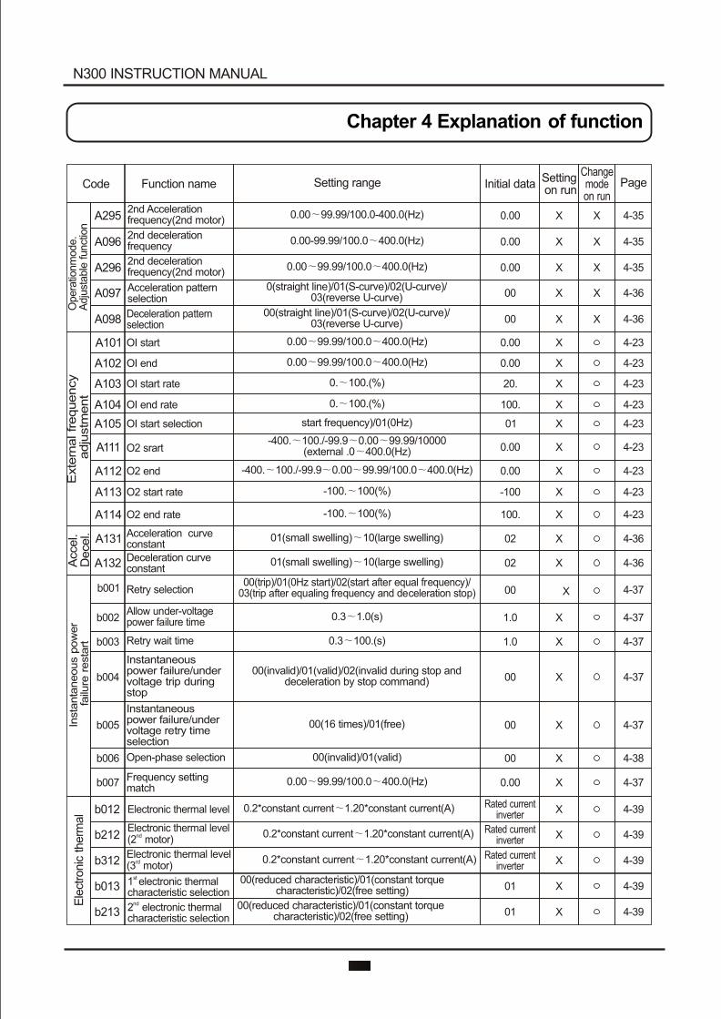
N300 INSTRUCTION MANUAL
Chapter 4 Explanation of function
Initial data PageFunction nameCode Setting rangeChangemode on run
Setting on run
4-35
4-35
4-35
4-36
4-36
4-23
4-23
4-23
4-23
4-23
4-23
4-23
4-23
4-23
4-36
4-36
4-37
4-37
4-37
4-37
4-37
4-38
4-37
A295
A096
A296
A097
A098
X
X
X
X
X
X
X
X
X
X
2nd Acceleration frequency(2nd motor)
2nd deceleration frequency
2nd deceleration frequency(2nd motor)
Acceleration pattern selection
Deceleration pattern selection
0.00
0.00
0.00
00
00
0.00 99.99/100.0-400.0(Hz)
0.00-99.99/100.0 400.0(Hz)
0.00 99.99/100.0 400.0(Hz)
0(straight line)/01(S-curve)/02(U-curve)/03(reverse U-curve)
00(straight line)/01(S-curve)/02(U-curve)/03(reverse U-curve)
A101
A102
A103
A104
A105
A111
A112
A113
A114
A131
A132
b001
b002
b003
b004
b005
b006
b007
OI start
OI end
OI start rate
OI end rate
OI start selection
O2 srart
O2 end
O2 start rate
O2 end rate
Acceleration curve constantDeceleration curve constant
Retry selection
Allow under-voltage power failure time
Retry wait time
Instantaneous power failure/undervoltage trip during stop
Open-phase selection
0.00
0.00
20.
100.
01
0.00
0.00
-100
100.
02
02
00
1.0
1.0
00
00
00
0.00
X
X
X
X
X
X
X
X
X
X
X
X
X
X
X
X
X
X
Instantaneous power failure/undervoltage retry time selection
Frequency setting match
Opera
tionm
ode.
Adju
stable
funct
ion
Exte
rnal frequency
adju
stm
ent
Accel.
Decel.
Insta
nta
neous p
ow
er
failu
re r
esta
rt
0.00 99.99/100.0 400.0(Hz)
0.00 99.99/100.0 400.0(Hz)
0. 100.(%)
0. 100.(%)
start frequency)/01(0Hz)
-400. 100./-99.9 0.00 99.99/10000(external .0 400.0(Hz)
-400. 100./-99.9 0.00 99.99/100.0 400.0(Hz)
-100. 100(%)
-100. 100(%)
01(small swelling) 10(large swelling)
01(small swelling) 10(large swelling)
00(trip)/01(0Hz start)/02(start after equal frequency)/03(trip after equaling frequency and deceleration stop)
0.3 1.0(s)
0.3 100.(s)
00(invalid)/01(valid)/02(invalid during stop and deceleration by stop command)
00(16 times)/01(free)
00(invalid)/01(valid)
0.00 99.99/100.0 400.0(Hz)
b012
b212
b312
b013
b213
Electronic thermal level
Electronic thermal levelnd(2 motor)
Electronic thermal levelrd(3 motor)
st 1 electronic thermal characteristic selection
nd2 electronic thermal characteristic selection
0.2*constant current 1.20*constant current(A)
0.2*constant current 1.20*constant current(A)
00(reduced characteristic)/01(constant torque characteristic)/02(free setting)
Rated current inverter
Rated current inverter
Rated current inverter
01
01
4-39
4-39
4-39
4-39
4-39
X
X
X
X
X
0.2*constant current 1.20*constant current(A)
00(reduced characteristic)/01(constant torque characteristic)/02(free setting)
Ele
ctro
nic
therm
al

N300 INSTRUCTION MANUAL
Chapter 4 Explanation of function
Initial data PageFunction nameCode Setting rangeChangemode on run
Setting on run
b015
b016
b017
b018
b019
b020
b021
b022
b023
b024
b025
b031
Free electronic thermal frequency 1
Free electronic thermal current 1
Free electronic thermal frequency 2
Free electronic thermal current 2
Free electronic thermal frequency 3
Free electronic hermal current 3
Overload restriction selection
Overload restriction level
Overload restriction limit constant
Overload restriction 2 selection
Overload restriction level 2
Software lock mode selection
0. 400.(Hz)
0.0 1000.(A)
0. 400.(Hz)
0.0 1000.(A)
0. 400.(Hz)
0.0 1000.(A)
00(invalid)/01(enabled on acceleration/constant peed)/02(enabled on constant speed)/03(enabled on acceleration/constant speed[speed increasing at regenerating mode])
0.50*rated current 2.00*rated current(A)< 1.80*rated current(A)>
0.10 30.00(s)
00(invalid)/01(enabled on acceleration/constant speed)/02(enabled on constant speed)/03(enabled on acceleration/constant speed[speed increasing at regenerating mode])
0.50*rated current-2.00*rated current(A)< 1.80*rated current(A)>
0.10 30.00(s)
00(impossible to change the data except this item when SFT terminal is ON)/01(impossible to change the data except setting frequency item when SFT terminal is ON)/02(impossible to change the data except this item)03(impossible to change the data except setting frequency item)/10(possible to change data on operating)
0.
0.0
0.
0.0
0.
0.0
01
Rated current of
inverter 1.50
1.00
01
1.00
01
4-40
4-40
4-40
4-40
4-40
4-40
4-41
4-41
4-41
4-41
4-41
4-41
4-50
X
X
X
X
X
X
X
X
X
X
X
X
X
Rated current of
inverter 1.50
Ele
ctro
nic
therm
al
Ove
rload
lim
itLock
Lock
b042
Torque limit level 2 setting(Reverse regenerating at 4 quadrant mode)
b035
b036
b037
b040
b041
RUN time/Power ON time level
Operation direction restrict
Start reduced voltage
Display selection
Torque limit mode selection
Torque limit level 1 setting(Forward driving at 4 quadrant mode)
0
00
06
00
00
150.
150.
4-61
4-17
4-43
4-66
4-79
4-79
4-79
0. 9999./1000 6563(100000 655300)h
00(Reverse is valid)/01(Only forward)/02(Only reverse)
00(Start reduced voltage time small)06(Start reduced voltage time large)
00(all display)/01(each function display)/02(User setting/main setting)
00(4 quadrant mode)/01(Terminal operation)/02(Analog input)/03(Option 1)/04(Option 2)
0. 200.(%)/no(Invalid)< 0 180% / no >
0. 200.(%)/no(Invalid)< 0 180% / no >
X
X
X
X
X
X
X
b3133rd electronic thermal characteristic selection
00(reduced characteristic)/01(constant torque characteristic)/02(free setting)
01 4-39X
Oth
er
Oth
er
Overload restrictionconstant 2
b034
b026
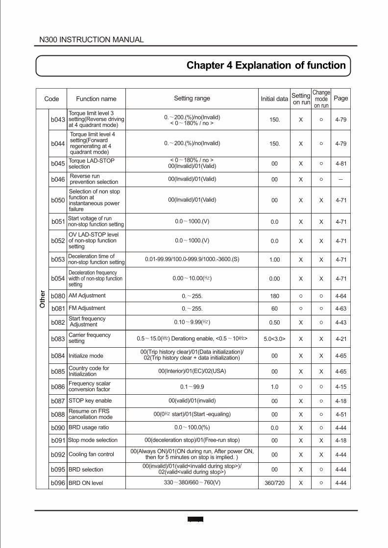
N300 INSTRUCTION MANUAL
Chapter 4 Explanation of function
Initial data PageFunction nameCode Setting rangeChangemode on run
Setting on run
b043Torque limit level 3 setting(Reverse driving at 4 quadrant mode)
150. 4-79X
150.
00
00
00
0.0
0.0
1.00
0.00
4-79
4-81
4-71
4-71
4-71
4-71
4-71
0. 200.(%)/no(Invalid)
< 0 180% / no >00(Invalid)/01(Valid)
00(Invalid)/01(Valid)
00(Invalid)/01(Valid)
0.0 1000.(V)
0.0 1000.(V)
0.01-99.99/100.0-999.9/1000.-3600.(S)
0.00 10.00( )
X
X
X
X X
X X
X X
X X
X X
b045
b046
b050
b051
b052
b053
b054
Torque limit level 4 setting(Forward regenerating at 4 quadrant mode)
Torque LAD-STOP selection
Reverse run prevention selection
Selection of non stop function at instantaneous power failure
Start voltage of run non-stop function setting
OV LAD-STOP levelof non-stop function setting
Deceleration time of non-stop function setting
Deceleration frequency width of non-stop function setting
0. 200.(%)/no(Invalid)< 0 180% / no >
Oth
er
Oth
er
4-64
4-63
4-43
4-21
4-65
4-65
4-15
4-18
4-51
4-44
4-18
4-44
4-44
4-44
X
X X
X
X
X
X
X X
X
X X
X X
X X
b080
b081
b082
b083
b084
b085
b086
b087
b088
b090
b091
b092
b095
b096
AM Adjustment
FM Adjustment
Start frequency Adjustment
Carrier frequency setting
Initialize mode
Country code for Initialization
Frequency scalar conversion factor
STOP key enable
Resume on FRS cancellation mode
BRD usage ratio
Stop mode selection
Cooling fan control
BRD selection
BRD ON level
180
60
0.50
5.0<3.0>
00
00
1.0
00
00
0.0
00
00
00
360/720
0. 255.
0. 255.
0.10 9.99( )
0.5 15.0( ) Derationg enable, <0.5 10 >
00(Trip history clear)/01(Data initialization)/02(Trip history clear + data initialization)
00(Interior)/01(EC)/02(USA)
0.1 99.9
00(valid)/01(invalid)
00(0 start)/01(Start -equaling)
0.0 100.0(%)
00(deceleration stop)/01(Free-run stop)
00(Always ON)/01(ON during run, After power ON, then for 5 minutes on stop is implied. )
00(invalid)/01(valid<invalid during stop>)/02(valid<valid during stop>)
330 380/660 760(V)
b044
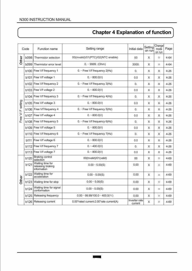
Fre
e V
/ F
settin
g
b120
b121
b122
b123
b124
b125
b126
Braking control selectionWaiting time forreleasing braking information
Waiting time for acceleration
Waiting time for stop
Waiting time for signalconformation
Releasing frequency
Releasing current
00
0.00
0.00
0.00
0.00
0.00
Inverter ratecurrent
4-69
4-69
4-69
4-69
4-69
4-69
4-69
00(Invalid)/01(valid)
0.00 5.00(S)
0.00 5.00(S)
0.00 5.00(S)
0.00 5.00(S)
0.00 99.99/100.0 400.0( )
0.00*rated current-2.00*rate current(A)
X
X
X
X
X
X
X
N300 INSTRUCTION MANUAL
Chapter 4 Explanation of function
Initial data PageFunction nameCode Setting rangeChangemode on run
Setting on run
Oth
er
Oth
er
Oth
er
Oth
er
4-64X0000(invalid)/01(PTC)/02(NTC enable)b098 Thermistor selection
4-64X3000.b099 Thermistor error level 0. 9999. (Ohm)
b100
b101
b102
b103
b104
b105
b106
b107
b108
b109
b110
b111
b112
b113
Free V/f frequency 1
Free V/f voltage 1
Free V/f frequency 2
Free V/f voltage 2
Free V/f frequency 3
Free V/f voltage 3
Free V/f frequency 4
Free V/f voltage 4
Free V/f frequency 5
Free V/f voltage 5
Free V/f frequency 6
Free V/f voltage 6
Free V/f frequency 7
Free V/f voltage 7
0. Free V/f frequency 2(Hz)
0. 800.0(V)
0. Free V/f frequency 3(Hz)
0. 800.0(V)
0. Free V/f frequency 4(Hz)
0. 800.0(V)
0. Free V/f frequency 5(Hz)
0. 800.0(V)
0. Free V/f frequency 6(Hz)
0. 800.0(V)
0. Free V/f frequency 7(Hz)
0. 800.0(V)
0. 400.0(V)
0. 800.0(V)
0. 4-26X X
0.0 4-26X X
0. 4-26X X
0.0 4-26X X
0. 4-26X X
0.0 4-26X X
0. 4-26X X
0.0 4-26X X
0. 4-26X X
0.0 4-26X X
0. 4-26X X
0.0 4-26X X
0. 4-26X X
0.0 4-26X X
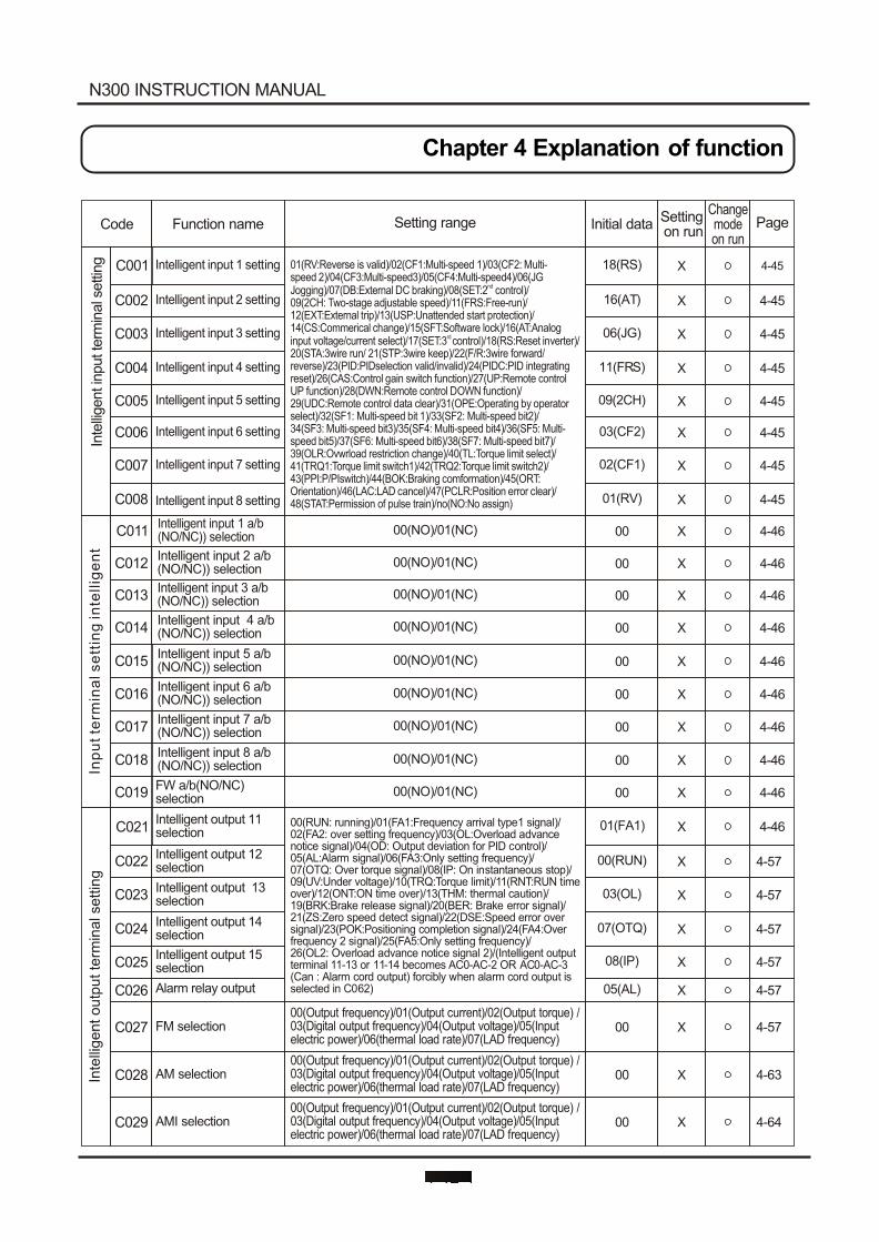
N300 INSTRUCTION MANUAL
Chapter 4 Explanation of function
Initial data PageFunction nameCode Setting rangeChangemode on run
Setting on run
C001
C002
C003
C004
C005
C006
C007
C008
Intelligent input 1 setting
Intelligent input 2 setting
Intelligent input 3 setting
Intelligent input 4 setting
Intelligent input 5 setting
Intelligent input 6 setting
Intelligent input 7 setting
Intelligent input 8 setting
01(RV:Reverse is valid)/02(CF1:Multi-speed 1)/03(CF2: Multi-speed 2)/04(CF3:Multi-speed3)/05(CF4:Multi-speed4)/06(JG
ndJogging)/07(DB:External DC braking)/08(SET:2 control)/09(2CH: Two-stage adjustable speed)/11(FRS:Free-run)/12(EXT:External trip)/13(USP:Unattended start protection)/14(CS:Commerical change)/15(SFT:Software lock)/16(AT:Analog
rd input voltage/current select)/17(SET:3 control)/18(RS:Reset inverter)/20(STA:3wire run/ 21(STP:3wire keep)/22(F/R:3wire forward/reverse)/23(PID:PIDselection valid/invalid)/24(PIDC:PID integrating reset)/26(CAS:Control gain switch function)/27(UP:Remote control UP function)/28(DWN:Remote control DOWN function)/29(UDC:Remote control data clear)/31(OPE:Operating by operator select)/32(SF1: Multi-speed bit 1)/33(SF2: Multi-speed bit2)/34(SF3: Multi-speed bit3)/35(SF4: Multi-speed bit4)/36(SF5: Multi-speed bit5)/37(SF6: Multi-speed bit6)/38(SF7: Multi-speed bit7)/39(OLR:Ovwrload restriction change)/40(TL:Torque limit select)/41(TRQ1:Torque limit switch1)/42(TRQ2:Torque limit switch2)/43(PPI:P/PIswitch)/44(BOK:Braking comformation)/45(ORT:Orientation)/46(LAC:LAD cancel)/47(PCLR:Position error clear)/48(STAT:Permission of pulse train)/no(NO:No assign)
Inte
lligent in
put te
rmin
al s
ettin
g 18(RS)
16(AT)
06(JG)
11(FRS)
09(2CH)
03(CF2)
02(CF1)
01(RV)
4-45
4-45
4-45
4-45
4-45
4-45
4-45
4-45
X
X
X
X
X
X
X
X
C011
C012
C013
C014
C015
C016
C017
C018
C019
C021
C022
C023
C024
C025
C026
C027
C028
C029
Intelligent input 1 a/b(NO/NC)) selection
Intelligent input 2 a/b(NO/NC)) selection
Intelligent input 3 a/b(NO/NC)) selection
Intelligent input 4 a/b(NO/NC)) selection
Intelligent input 5 a/b(NO/NC)) selection
Intelligent input 6 a/b(NO/NC)) selection
Intelligent input 7 a/b(NO/NC)) selection
Intelligent input 8 a/b(NO/NC)) selection
FW a/b(NO/NC) selection
Intelligent output 11 selection
Intelligent output 12 selection
Intelligent output 13 selection
Intelligent output 14 selection
Intelligent output 15 selection
Alarm relay output
FM selection
AM selection
AMI selection
00(RUN: running)/01(FA1:Frequency arrival type1 signal)/02(FA2: over setting frequency)/03(OL:Overload advance notice signal)/04(OD: Output deviation for PID control)/05(AL:Alarm signal)/06(FA3:Only setting frequency)/07(OTQ: Over torque signal)/08(IP: On instantaneous stop)/09(UV:Under voltage)/10(TRQ:Torque limit)/11(RNT:RUN time over)/12(ONT:ON time over)/13(THM: thermal caution)/19(BRK:Brake release signal)/20(BER: Brake error signal)/21(ZS:Zero speed detect signal)/22(DSE:Speed error over signal)/23(POK:Positioning completion signal)/24(FA4:Over frequency 2 signal)/25(FA5:Only setting frequency)/26(OL2: Overload advance notice signal 2)/(Intelligent output terminal 11-13 or 11-14 becomes AC0-AC-2 OR AC0-AC-3(Can : Alarm cord output) forcibly when alarm cord output is selected in C062)
00(Output frequency)/01(Output current)/02(Output torque) /03(Digital output frequency)/04(Output voltage)/05(Input electric power)/06(thermal load rate)/07(LAD frequency)
00(Output frequency)/01(Output current)/02(Output torque) /03(Digital output frequency)/04(Output voltage)/05(Input electric power)/06(thermal load rate)/07(LAD frequency)
00(Output frequency)/01(Output current)/02(Output torque) /03(Digital output frequency)/04(Output voltage)/05(Input electric power)/06(thermal load rate)/07(LAD frequency)
00(NO)/01(NC)
00(NO)/01(NC)
00(NO)/01(NC)
00(NO)/01(NC)
00(NO)/01(NC)
00(NO)/01(NC)
00(NO)/01(NC)
00(NO)/01(NC)
00(NO)/01(NC)
00
00
00
00
00
00
00
00
00
01(FA1)
00(RUN)
03(OL)
07(OTQ)
08(IP)
05(AL)
00
00
00
4-46
4-46
X
X
X
X
X
X
X
X
X
X
X
X
X
X
X
X
X
X
4-57
4-57
4-57
4-57
4-57
4-57
4-63
4-64
Inte
llig
en
t o
utp
ut te
rmin
al s
ettin
gIn
pu
t te
rmin
al s
ett
ing
in
tellig
en
t
4-46
4-46
4-46
4-46
4-46
4-46
4-46
4-46
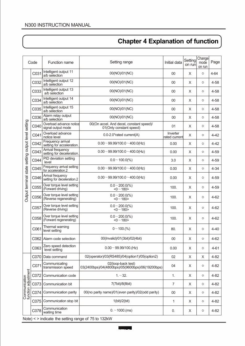
N300 INSTRUCTION MANUAL
Chapter 4 Explanation of function
Initial data PageFunction nameCode Setting rangeChangemode on run
Setting on run
C031 Intelligent output 11 a/b selection
00(NO)/01(NC) 00 X 4-64
C032 Intelligent output 12 a/b selection
00(NO)/01(NC) 00 X 4-58
C033 Intelligent output 13 a/b selection
00(NO)/01(NC) 00 X 4-58
C034 Intelligent output 14 a/b selection
00(NO)/01(NC) 00 X 4-58
C035 Intelligent output 15 a/b selection
00(NO)/01(NC) 00 X 4-58
C036 Alarm relay output a/b selection
00(NO)/01(NC) 00 X 4-58
C040Overload advance noticesignal output mode
00(On accel. And decel, constant speed)/01(Only constant speed) 01 X 4-58
C041 Overload advance notice level
0.0-2.0*rated current(A) Inverterrated current X 4-42
C042Frequency arrival setting for acceleration. 0.00 99.99/100.0 400.0(Hz) 0.00 X 4-42
C043Arrival frequency setting for deceleration.
0.00 99.99/100.0 400.0(Hz) 0.00 X 4-59
C044 PID deviation setting level
0.0 100.0(%) 3.0 X 4-59
C045 Frequency arrival setting for acceleration.2
0.00 99.99/100.0 400.0(Hz) 0.00 X 4-34
C046
C055
C056
C057
C058
C061
C062
C063
C070
C071
C072
C073
C074
C075
C078
Arrival frequency setting for deceleration.2
Over torque level setting(Forward driving)
Over torque level setting(Reverse regenerating)
Over torque level setting(Reverse driving)
Over torque level setting(Forward regenerating)
Thermal warning level setting
Alarm code selection
Zero speed detection level setting
Data command
Communicating transmission speed
Communication code
Communication bit
Communication parity
Communication stop bit
Communication waiting time
0.00 99.99/100.0 400.0(Hz)
0.0 200.0(%)<0 180>
0.0 200.0(%)<0 180>
0.0 200.0(%)<0 180>
0.0 200.0(%)<0 180>
0 100.(%)
00(Invalid)/01(3bit)/02(4bit)
0.00 99.99/100.(Hz)
02(operator)/03(RS485)/04(option1)/05(option2)
02(loop-back test)03(2400bps)/04(4800bps)/05(9600bps)/06(19200bps)
1. 32.
7(7bit)/8(8bit)
00(no parity name)/01(even parity)/02(odd parity)
1(bit)/2(bit)
0. 1000.(ms)
0.00
100.
100.
100.
100.
80.
00
0.00
02
04
1.
7
00
1
0.
Note) < > indicate the setting range of 75 to 132kW
X
X
X
X X
X
X
X
X
X
X
X
X
X
X
X
4-59
4-59
4-62
4-62
4-62
4-40
4-62
4-61
4-82
4-82
4-82
4-82
4-82
4-82
4-82
Com
munic
atio
n
funct
ion
adju
stm
ent
Outp
ut te
rmin
al s
tate
settin
g o
utp
ut le
vel s
ettin
g
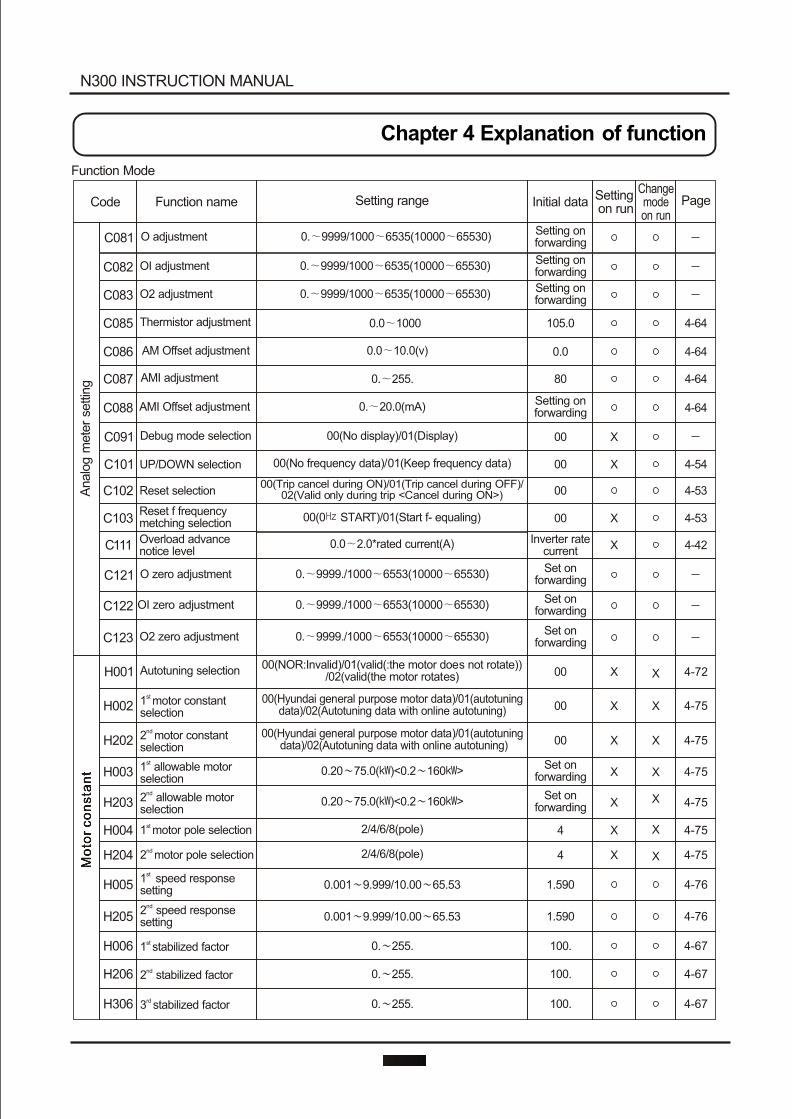
N300 INSTRUCTION MANUAL
Chapter 4 Explanation of function
Initial data PageFunction nameCode Setting rangeChangemode on run
Setting on run
X
X
X
X
X
X
X
C091
C101
C102
C103
C111
C121
C122
C123
Function Mode
Debug mode selection
UP/DOWN selection
Reset selection
Reset f frequency metching selection
Overload advance notice level
O zero adjustment
00
00
00
00
Inverter ratecurrent
Set on forwarding
Set on forwarding
Set on forwarding
00(No display)/01(Display)
00(No frequency data)/01(Keep frequency data)
00(Trip cancel during ON)/01(Trip cancel during OFF)/02(Valid only during trip <Cancel during ON>)
00(0 START)/01(Start f- equaling)
0.0 2.0*rated current(A)
0. 9999./1000 6553(10000 65530)
0. 9999./1000 6553(10000 65530)
0. 9999./1000 6553(10000 65530)
X
X
X
X
C081
C082
C083
C085
C086
C087
C088
O adjustment
OI adjustment
O2 adjustment
Thermistor adjustment
AM Offset adjustment
AMI adjustment
AMI Offset adjustment
0. 9999/1000 6535(10000 65530)
0. 9999/1000 6535(10000 65530)
0. 9999/1000 6535(10000 65530)
0.0 1000
0.0 10.0(v)
0. 255.
0. 20.0(mA)
Setting on forwarding
Setting on forwarding
Setting on forwarding
105.0
0.0
80
Setting on forwarding
OI zero adjustment
O2 zero adjustment
Analo
g m
ete
r se
ttin
g
H001
H002
H202
H003
H203
H004
H204
H005
H205
H006
H206
H306
Autotuning selection
st 1 motor constant selection
nd 2 motor constant selection
st1 allowable motor selection
nd2 allowable motor selection
st 1 motor pole selection
nd 2 motor pole selection
st 1 speed response setting
nd 2 speed response setting
st 1 stabilized factor
nd2 stabilized factor
rd 3 stabilized factor
00(NOR:Invalid)/01(valid(:the motor does not rotate))/02(valid(the motor rotates)
00(Hyundai general purpose motor data)/01(autotuning data)/02(Autotuning data with online autotuning)
00(Hyundai general purpose motor data)/01(autotuning data)/02(Autotuning data with online autotuning)
0.20 75.0( )<0.2 160 >
0.20 75.0( )<0.2 160 >
2/4/6/8(pole)
2/4/6/8(pole)
0.001 9.999/10.00 65.53
0.001 9.999/10.00 65.53
0. 255.
0. 255.
0. 255.
00
00
00
Set on forwarding
Set on forwarding
4
4
1.590
1.590
100.
100.
100.
4-54
4-53
4-53
4-42
4-64
4-64
4-64
4-64
4-72
4-75
4-75
4-75
4-75
4-75
4-75
4-76
4-76
4-67
4-67
4-67
X
X
X
X
X
X
X
Mo
tor
co
nsta
nt
Mo
tor
co
ns
tan
t
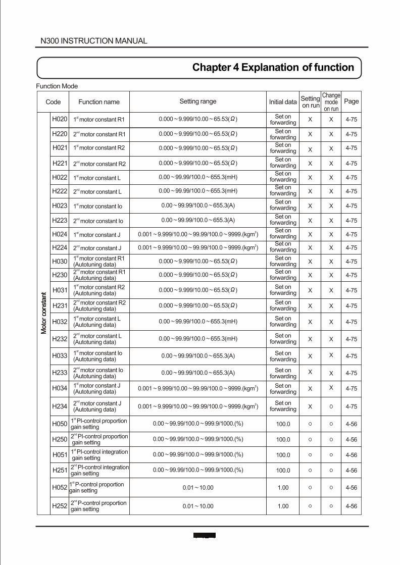
H250
H051
H251
H052
H252
nd 2 PI-control proportion gain setting
st 1 PI-control integration gain setting
nd 2 PI-control integration gain setting
st 1 P-control proportion gain setting
nd 2 P-control proportion gain setting
0.00 99.99/100.0 999.9/1000.(%)
0.00 99.99/100.0 999.9/1000.(%)
0.00 99.99/100.0 999.9/1000.(%)
0.01 10.00
0.01 10.00
100.0
100.0
100.0
1.00
1.00
4-56
4-56
4-56
4-56
4-56
H020
H220
H021
H221
H022
H222
H023
H223
H024
H224
H030
H230
H031
H231
H032
H232
H033
H233
H034
H234
H050
st 1 motor constant R1
nd 2 motor constant R1
st 1 motor constant R2
nd 2 motor constant R2
st 1 motor constant L
nd 2 motor constant L
st 1 motor constant Io
nd 2 motor constant Io
st 1 motor constant J
nd 2 motor constant Jst 1 motor constant R1
(Autotuning data)nd 2 motor constant R1
(Autotuning data)st 1 motor constant R2
(Autotuning data)nd 2 motor constant R2
(Autotuning data)st 1 motor constant L
(Autotuning data)
nd 2 motor constant L(Autotuning data)
st 1 motor constant Io(Autotuning data)
nd 2 motor constant Io(Autotuning data)
st 1 motor constant J(Autotuning data)
nd 2 motor constant J(Autotuning data)
st 1 PI-control proportion gain setting
0.000 9.999/10.00 65.53( )
0.000 9.999/10.00 65.53( )
0.000 9.999/10.00 65.53( )
0.000 9.999/10.00 65.53( )
0.00 99.99/100.0 655.3(mH)
0.00 99.99/100.0 655.3(mH)
0.00 99.99/100.0 655.3(A)
0.00 99.99/100.0 655.3(A)
20.001 9.999/10.00 99.99/100.0 9999.(kgm )
20.001 9.999/10.00 99.99/100.0 9999.(kgm )
0.000 9.999/10.00 65.53( )
0.000 9.999/10.00 65.53( )
0.000 9.999/10.00 65.53( )
0.000 9.999/10.00 65.53( )
0.00 99.99/100.0 655.3(mH)
0.00 99.99/100.0 655.3(mH)
0.00 99.99/100.0 655.3(A)
0.00 99.99/100.0 655.3(A)
20.001 9.999/10.00 99.99/100.0 9999.(kgm )
20.001 9.999/10.00 99.99/100.0 9999.(kgm )
0.00 99.99/100.0 999.9/1000.(%)
Set on forwarding
Set on forwarding
Set on forwarding
Set on forwarding
100.0
4-75
4-75
4-75
4-75
4-75
4-75
4-75
4-75
4-75
4-75
4-75
4-75
4-75
4-75
4-75
4-75
4-75
4-75
4-75
4-75
4-56
X X
X
X
X
X
X
X
X
X
X
X
X
X
X
X
X
X
X
X X
X
X
X
X
X
X
X
X
X
X
X
X
X
X
X
X
X
X
Set on forwarding
Set on forwarding
Set on forwarding
Set on forwarding
Set on forwarding
Set on forwarding
Set on forwarding
Set on forwarding
Set on forwarding
Set on forwarding
Set on forwarding
Set on forwarding
Set on forwarding
Set on forwarding
Set on forwarding
Set on forwarding
Moto
r co
nst
ant
Mo
tor
co
nsta
nt
N300 INSTRUCTION MANUAL
Chapter 4 Explanation of function
Initial data PageFunction nameCode Setting range Setting on run
Function Mode
Changemode on run
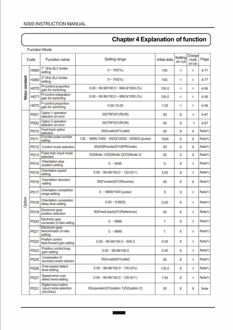
P031Digital input option input mode selection (Acc/Dec)
00(operator)/01(option 1)/02(option 2) 00 NoteX X
P018Orientation completion delay time setting
0.00 9.99(S) 0.00 Note1)X
0.00 99.99/100.0 150.0(%)P026Over-speed detect level setting 135.0 Note1)
Note1)
X
P016Orientation direction setting
00(Forward)/01(Reverse) 00 Note1)X X
P021Electronic gear denominator of ratio setting
0. 9999. 1. Note1)X
P023Position control loop gain setting 0.00 99.99/100.0 0.50 Note1)X
P019Electronic gear position selection
00(Feed-back)/01(Reference) 00 Note1)X
P001 Option 1 operation selection on error
00(TRP)/01(RUN) 00 4-67X
P027Speed-error over detect level setting 0.00 99.99/100.0 120.0( ) 7.50 X
0. 9999/1000 (pulse)P017Orientation completion range setting 5 Note1)X
P022Position control feed-forward gain setting 0.00 99.99/100.0 655.3 0.00 Note1)X
P014Orientation stop position setting 0. 4095. 0. Note1)X
P013 Pulse train input mode selection
00(Mode 1)/02(Mode 2)/03(Mode 3) 00 Note1)XX
P025Compensation of secondary resistor selection
00(Invalid)/01(valid) 00 Note1)X
P015Orientation speed setting 0.00 99.99/100.0 120.0( ) 5.00 Note1)X
Note1)P020Electronic gear numerator of ratio setting 0. 9999. 1. X
P011Encoder pulse number setting 128. 9999./1000 6500(10000 65000) (pulse) 1024 Note1)XX
P012 Control mode selection 00(ASRmode)/01(APRmode) 00 Note1)X X
P002 Option 2 operation selection on error
00(TRP)/01(RUN) 00 4-67X
P010 Feed-back optionselection
00(Invalid)/01(valid) 00 Note1)X X
N300 INSTRUCTION MANUAL
Chapter 4 Explanation of function
Function Mode
Moto
r co
nst
ant
Moto
r co
nst
ant
Initial data PageFunction nameCode Setting range Setting on run
Changemode on run
H060
H260
H070
H071
H072
st 1 0Hz-SLV limiter setting
nd 2 0Hz-SLV limiter setting
PI-control proportion gain for switching
PI-control integration gain for switching
P-control proportion gain for switching
0 100(%)
0 100(%)
0.00 99.99/100.0 999.9/1000.(%)
0.00 99.99/100.0 999.9/1000.(%)
0.00-10.00
100.
100.
100.0
100.0
1.00
4-77
4-77
4-56
4-56
4-56
Optio
n
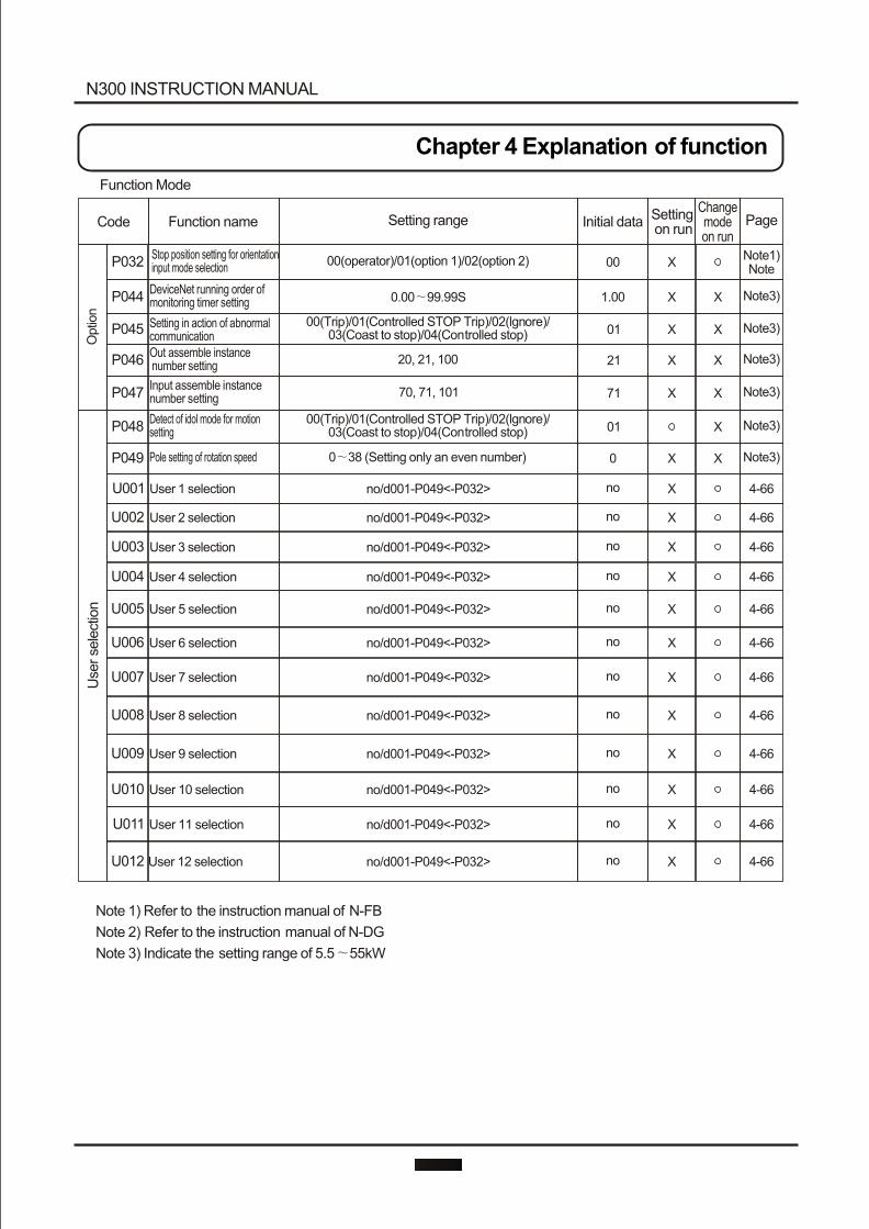
N300 INSTRUCTION MANUAL
Chapter 4 Explanation of function
Function Mode
Initial data PageFunction nameCode Setting range Setting on run
Changemode on run
U011
U012
no/d001-P049<-P032>
no/d001-P049<-P032>
no
no
4-66
4-66
Note 1) Refer to the instruction manual of N-FB
Note 2) Refer to the instruction manual of N-DG
Note 3) Indicate the setting range of 5.5 55kW
X
X
U005 no/d001-P049<-P032> no 4-66XUser 5 selection
U006 no/d001-P049<-P032> no 4-66XUser 6 selection
U007 no/d001-P049<-P032> no 4-66XUser 7 selection
U008 no/d001-P049<-P032> no 4-66XUser 8 selection
U009 no/d001-P049<-P032> no 4-66XUser 9 selection
U010 no/d001-P049<-P032> no 4-66XUser 10 selection
User 11 selection
User 12 selection
U003 User 3 selection no/d001-P049<-P032> no 4-66X
U001 User 1 selection no/d001-P049<-P032> no 4-66X
U002 User 2 selection no/d001-P049<-P032> no 4-66X
U004 no/d001-P049<-P032> no 4-66XUser 4 selection
P048Detect of idol mode for motion setting
00(Trip)/01(Controlled STOP Trip)/02(lgnore)/03(Coast to stop)/04(Controlled stop) 01 Note3)X
P046Out assemble instance number setting 20, 21, 100 21 Note3)X X
P044DeviceNet running order of monitoring timer setting 0.00 99.99S 1.00 Note3)X X
P049 Pole setting of rotation speed 0 38 (Setting only an even number) 0 Note3)X X
P047Input assemble instance number setting 70, 71, 101 71 Note3)X X
P045 Setting in action of abnormal communication
00(Trip)/01(Controlled STOP Trip)/02(lgnore)/03(Coast to stop)/04(Controlled stop) 01 Note3)X X
P032Stop position setting for orientation input mode selection
00(operator)/01(option 1)/02(option 2) 00Note1)Note
X
Optio
nU
ser se
lect
ion
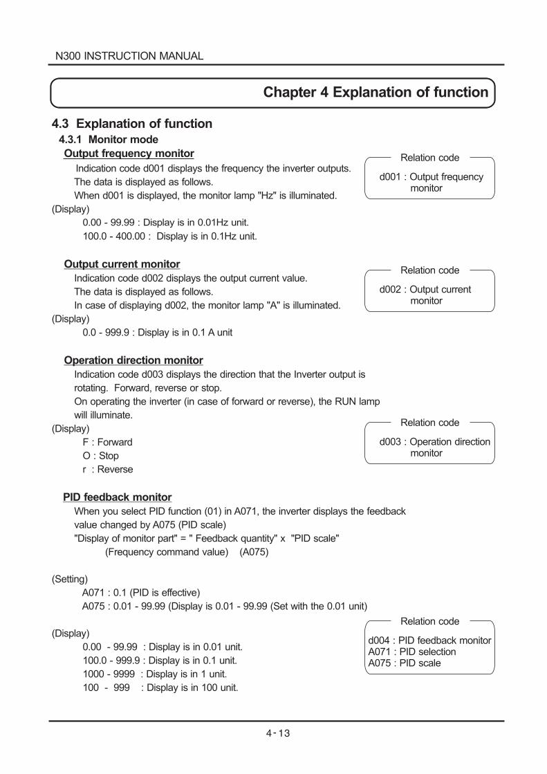
4.3 Explanation of function
4.3.1 Monitor mode
Output frequency monitor
Indication code d001 displays the frequency the inverter outputs.
The data is displayed as follows.
When d001 is displayed, the monitor lamp "Hz" is illuminated.
(Display)
0.00 - 99.99 : Display is in 0.01Hz unit.
100.0 - 400.00 : Display is in 0.1Hz unit.
Output current monitor
Indication code d002 displays the output current value.
The data is displayed as follows.
In case of displaying d002, the monitor lamp "A" is illuminated.
(Display)
0.0 - 999.9 : Display is in 0.1 A unit
Operation direction monitor
Indication code d003 displays the direction that the Inverter output is
rotating. Forward, reverse or stop.
On operating the inverter (in case of forward or reverse), the RUN lamp
will illuminate.
(Display)
F : Forward
O : Stop
r : Reverse
PID feedback monitor
When you select PID function (01) in A071, the inverter displays the feedback
value changed by A075 (PID scale)
"Display of monitor part" = " Feedback quantity" x "PID scale"
(Frequency command value) (A075)
(Setting)
A071 : 0.1 (PID is effective)
A075 : 0.01 - 99.99 (Display is 0.01 - 99.99 (Set with the 0.01 unit)
(Display)
0.00 - 99.99 : Display is in 0.01 unit.
100.0 - 999.9 : Display is in 0.1 unit.
1000 - 9999 : Display is in 1 unit.
100 - 999 : Display is in 100 unit.
Relation code
d001 : Output frequencymonitor
Relation code
d002 : Output currentmonitor
Relation code
d003 : Operation directionmonitor
Relation code
d004 : PID feedback monitorA071 : PID selectionA075 : PID scale
N300 INSTRUCTION MANUAL
Chapter 4 Explanation of functionChapter 4 Explanation of function
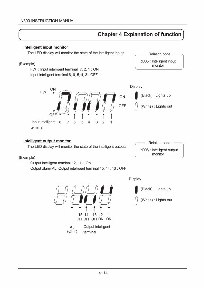
Intelligent input monitor
The LED display will monitor the state of the intelligent inputs.
(Example)
FW : Input intelligent terminal 7, 2, 1 : ON
Input intelligent terminal 8, 6, 5, 4, 3 : OFF
Relation code
d005 : Intelligent inputmonitor
Intelligent output monitor
The LED display will monitor the state of the intelligent outputs.
(Example)
Output intelligent terminal 12, 11 : ON
Output alarm AL, Output intelligent terminal 15, 14, 13 : OFF
Relation code
d006 : Intelligent outputmonitor
N300 INSTRUCTION MANUAL
Chapter 4 Explanation of function
Display
ONOFF
AL(OFF)
15 14 13 12 11OFF OFF ON
Output intelligent
terminal
(Black) : Lights up
(White) : Lights out
8 7 6 5 4 3 2 1
Display
(Black) : Lights up
(White) : Lights out
FWON
OFF
ON
OFF
Input intelligent
terminal
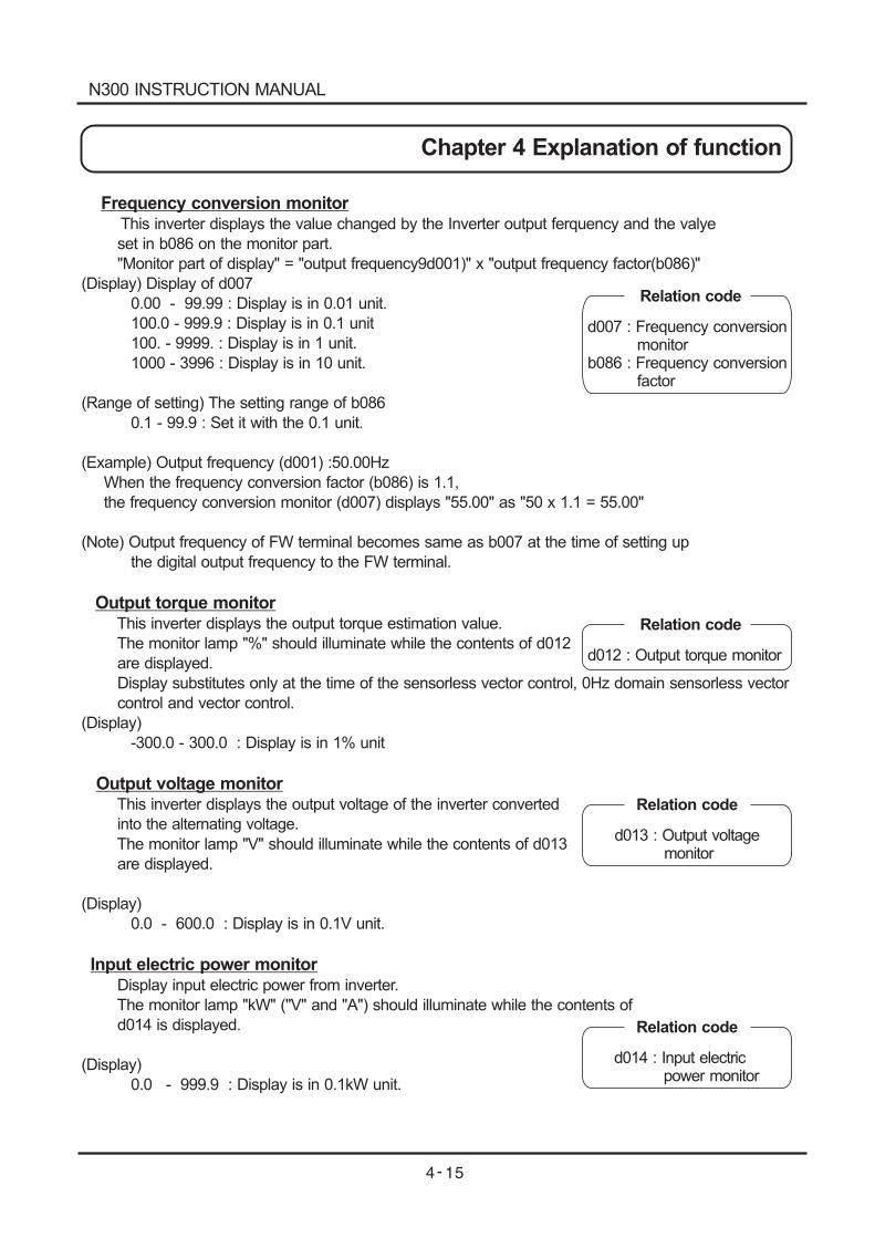
Frequency conversion monitorThis inverter displays the value changed by the Inverter output ferquency and the valye
set in b086 on the monitor part.
"Monitor part of display" = "output frequency9d001)" x "output frequency factor(b086)"
(Display) Display of d007
0.00 - 99.99 : Display is in 0.01 unit.
100.0 - 999.9 : Display is in 0.1 unit
100. - 9999. : Display is in 1 unit.
1000 - 3996 : Display is in 10 unit.
(Range of setting) The setting range of b086
0.1 - 99.9 : Set it with the 0.1 unit.
(Example) Output frequency (d001) :50.00Hz
When the frequency conversion factor (b086) is 1.1,
the frequency conversion monitor (d007) displays "55.00" as "50 x 1.1 = 55.00"
(Note) Output frequency of FW terminal becomes same as b007 at the time of setting up
the digital output frequency to the FW terminal.
Output torque monitorThis inverter displays the output torque estimation value.
The monitor lamp "%" should illuminate while the contents of d012
are displayed.
Display substitutes only at the time of the sensorless vector control, 0Hz domain sensorless vector
control and vector control.
(Display)
-300.0 - 300.0 : Display is in 1% unit
Output voltage monitorThis inverter displays the output voltage of the inverter converted
into the alternating voltage.
The monitor lamp "V" should illuminate while the contents of d013
are displayed.
(Display)
0.0 - 600.0 : Display is in 0.1V unit.
Input electric power monitorDisplay input electric power from inverter.
The monitor lamp "kW" ("V" and "A") should illuminate while the contents of
d014 is displayed.
(Display)
0.0 - 999.9 : Display is in 0.1kW unit.
Relation code
d007 : Frequency conversionmonitor
b086 : Frequency conversionfactor
Relation code
d012 : Output torque monitor
Relation code
d013 : Output voltagemonitor
Relation code
d014 : Input electricpower monitor
N300 INSTRUCTION MANUAL
Chapter 4 Explanation of function
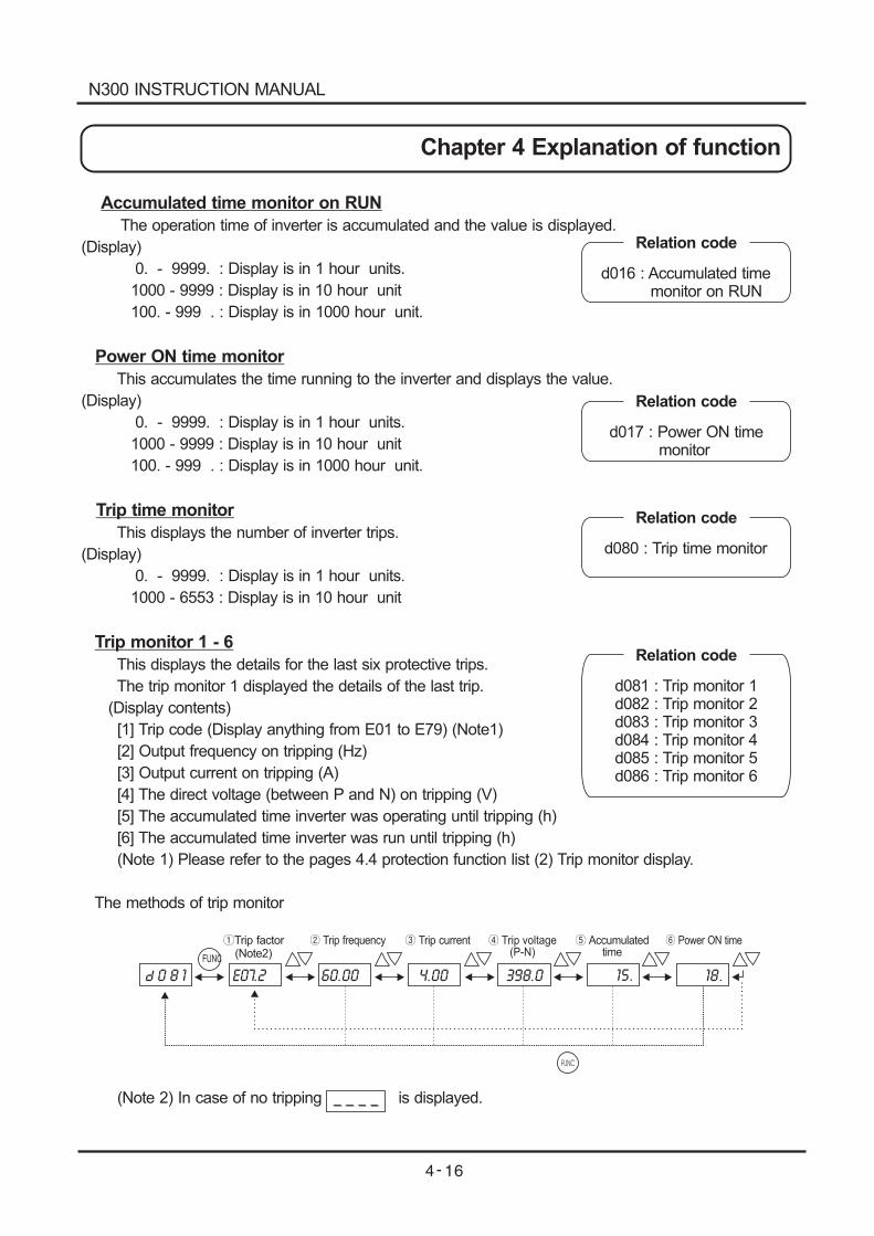
8 1 E07.2 60.00 398.04.00 15. 18.
FUNC
Trip factor(Note2)
Trip frequency Trip current Trip voltage(P-N)
Accumulatedtime
Power ON time
FUNC
Accumulated time monitor on RUN
The operation time of inverter is accumulated and the value is displayed.
(Display)
0. - 9999. : Display is in 1 hour units.
1000 - 9999 : Display is in 10 hour unit
100. - 999 . : Display is in 1000 hour unit.
Power ON time monitor
This accumulates the time running to the inverter and displays the value.
(Display)
0. - 9999. : Display is in 1 hour units.
1000 - 9999 : Display is in 10 hour unit
100. - 999 . : Display is in 1000 hour unit.
Trip time monitor
This displays the number of inverter trips.
(Display)
0. - 9999. : Display is in 1 hour units.
1000 - 6553 : Display is in 10 hour unit
Trip monitor 1 - 6
This displays the details for the last six protective trips.
The trip monitor 1 displayed the details of the last trip.
(Display contents)
[1] Trip code (Display anything from E01 to E79) (Note1)
[2] Output frequency on tripping (Hz)
[3] Output current on tripping (A)
[4] The direct voltage (between P and N) on tripping (V)
[5] The accumulated time inverter was operating until tripping (h)
[6] The accumulated time inverter was run until tripping (h)
(Note 1) Please refer to the pages 4.4 protection function list (2) Trip monitor display.
The methods of trip monitor
(Note 2) In case of no tripping is displayed.
Relation code
d016 : Accumulated timemonitor on RUN
Relation code
d017 : Power ON timemonitor
Relation code
d080 : Trip time monitor
Relation code
d081 : Trip monitor 1d082 : Trip monitor 2d083 : Trip monitor 3d084 : Trip monitor 4d085 : Trip monitor 5d086 : Trip monitor 6
N300 INSTRUCTION MANUAL
Chapter 4 Explanation of function
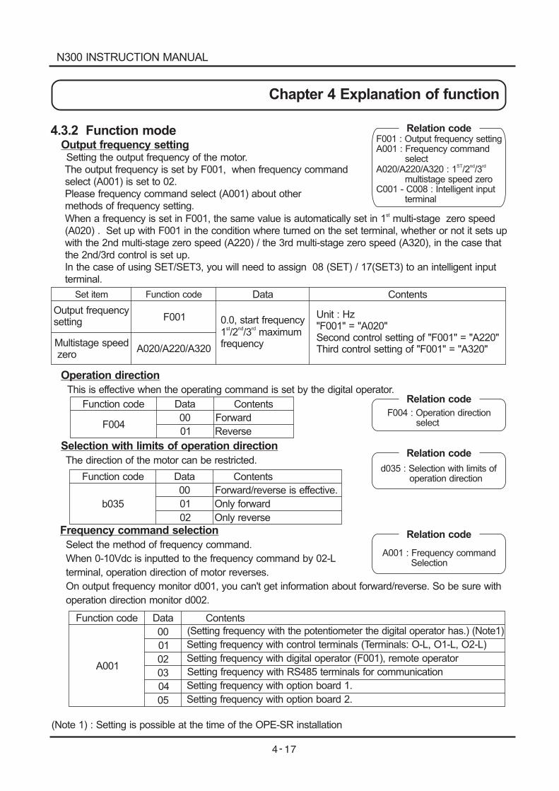
4.3.2 Function modeOutput frequency settingSetting the output frequency of the motor.The output frequency is set by F001, when frequency commandselect (A001) is set to 02.Please frequency command select (A001) about othermethods of frequency setting.
When a frequency is set in F001, the same value is automatically set in 1 multi-stage zero speedst
(A020) . Set up with F001 in the condition where turned on the set terminal, whether or not it sets upwith the 2nd multi-stage zero speed (A220) / the 3rd multi-stage zero speed (A320), in the case thatthe 2nd/3rd control is set up.In the case of using SET/SET3, you will need to assign 08 (SET) / 17(SET3) to an intelligent inputterminal.
Set item Function code
Output frequencysetting
Multistage speedzero
F001
A020/A220/A320
Data Contents
0.0, start frequency1 /2 /3 maximumfrequency
st nd rd
Unit : Hz"F001" = "A020"Second control setting of "F001" = "A220"Third control setting of "F001" = "A320"
Relation codeF001 : Output frequency settingA001 : Frequency command
selectA020/A220/A320 : 1 /2 /3
multistage speed zeroC001 - C008 : Intelligent input
terminal
ST nd rd
Operation direction
This is effective when the operating command is set by the digital operator.
Selection with limits of operation direction
The direction of the motor can be restricted.
Frequency command selection
Select the method of frequency command.
When 0-10Vdc is inputted to the frequency command by 02-L
terminal, operation direction of motor reverses.
On output frequency monitor d001, you can't get information about forward/reverse. So be sure with
operation direction monitor d002.
(Note 1) : Setting is possible at the time of the OPE-SR installation
Function code
F004
Data
00
01
Contents
Forward
Reverse
Function code
b035
Data
00
01
Contents
Forward/reverse is effective.
Only forward
02 Only reverse
Function code
A001
Data
00
01
Contents
(Setting frequency with the potentiometer the digital operator has.) (Note1)
Setting frequency with control terminals (Terminals: O-L, O1-L, O2-L)
02 Setting frequency with digital operator (F001), remote operator
03
04
Setting frequency with RS485 terminals for communication
Setting frequency with option board 1.
05 Setting frequency with option board 2.
Relation code
F004 : Operation directionselect
Relation code
d035 : Selection with limits ofoperation direction
Relation code
A001 : Frequency commandSelection
N300 INSTRUCTION MANUAL
Chapter 4 Explanation of function
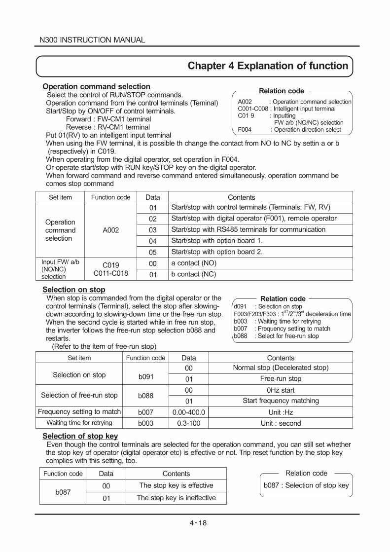
Operation command selectionSelect the control of RUN/STOP commands.Operation command from the control terminals (Teminal)Start/Stop by ON/OFF of control terminals.
Forward : FW-CM1 terminalReverse : RV-CM1 terminal
Put 01(RV) to an intelligent input terminalWhen using the FW terminal, it is possible th change the contact from NO to NC by settin a or b(respectively) in C019.When operating from the digital operator, set operation in F004.Or operate start/stop with RUN key/STOP key on the digital operator.When forward command and reverse command entered simultaneously, operation command becomes stop command
Relation code
A002 : Operation command selectionC001-C008 : Intelligent input terminalC01 9 : Inputting
FW a/b (NO/NC) selectionF004 : Operation direction select
Data
01
01
00
02
03
04
05
Function codeSet item Contents
Start/stop with control terminals (Terminals: FW, RV)
Start/stop with digital operator (F001), remote operator
Start/stop with RS485 terminals for communication
Start/stop with option board 1.
Start/stop with option board 2.
Operationcommandselection
Input FW/ a/b(NO/NC)selection
A002
C019C011-C018
a contact (NO)
b contact (NC)
Selection on stopWhen stop is commanded from the digital operator or thecontrol terminals (Terminal), select the stop after slowing-down according to slowing-down time or the free run stop.When the second cycle is started while in free run stop,the inverter follows the free-run stop selection b088 andrestarts.
(Refer to the item of free-run stop)
Relation coded091 : Selection on stop
F003/F203/F303 : 1 /2 /3 deceleration timeb003 : Waiting time for retryingb007 : Frequency setting to matchb088 : Select for free-run stop
ST nd rd
Data
Data
00
00
0.3-100
01
01
00
01
0.00-400.0
Function code
Function code
Set item Contents
Contents
Selection on stop
Selection of free-run stop
Waiting time for retrying
b091
b087
b088
b007
b003
Frequency setting to match
Normal stop (Decelerated stop)
The stop key is effective
Free-run stop
The stop key is ineffective
0Hz start
Start frequency matching
Unit :Hz
Unit : second
Selection of stop keyEven though the control terminals are selected for the operation command, you can still set whetherthe stop key of operator (digital operator etc) is effective or not. Trip reset function by the stop keycomplies with this setting, too.
Relation code
b087 : Selection of stop key
N300 INSTRUCTION MANUAL
Chapter 4 Explanation of function
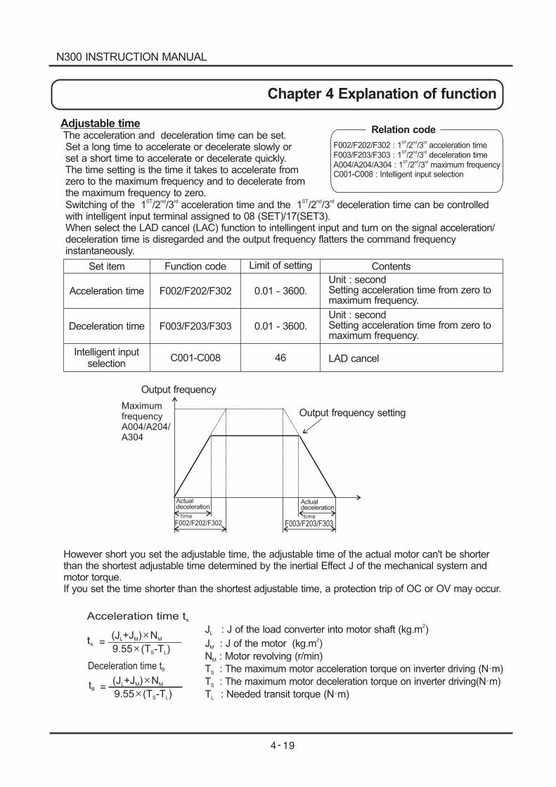
ts =(J +J ) NL M M
9.55 (T -T )S L
Acceleration time ts
tB
(J +J ) NL M M
9.55 (T -T )S L
=
J : J of the load converter into motor shaft (kg.m )L
2
Deceleration time tB
J : J of the motor (kg.m )M
2
N : Motor revolving (r/min)M
T : The maximum motor acceleration torque on inverter driving (N m)S
T : The maximum motor deceleration torque on inverter driving(N m)S
T : Needed transit torque (N m)L
Adjustable timeThe acceleration and deceleration time can be set.Set a long time to accelerate or decelerate slowly orset a short time to accelerate or decelerate quickly.The time setting is the time it takes to accelerate fromzero to the maximum frequency and to decelerate fromthe maximum frequency to zero.Switching of the time can be controlled1 /2 /3 acceleration time and the 1 /2 /3 deceleration
ST nd rd ST nd rd
with intelligent input terminal assigned to 08 (SET)/17(SET3).When select the LAD cancel (LAC) function to intellingent input and turn on the signal acceleration/deceleration time is disregarded and the output frequency flatters the command frequencyinstantaneously.
Relation code
F002/F202/F302 :F003/F203/F303 :A004/A204/A304 :C001-C008 : Intelligent input selection
1 /2 /3 acceleration time1 /2 /3 deceleration time1 /2 /3 maximum frequency
ST nd rd
ST nd rd
ST nd rd
Set item
Acceleration time
Deceleration time
Intelligent inputselection
Function code
F002/F202/F302
F003/F203/F303
C001-C008
Limit of setting
0.01 - 3600.
0.01 - 3600.
46
Unit : secondSetting acceleration time from zero tomaximum frequency.
Unit : secondSetting acceleration time from zero tomaximum frequency.
Contents
LAD cancel
MaximumfrequencyA004/A204/A304
F002/F202/F302 F003/F203/F303
Output frequency
Output frequency setting
Actualdeceleration
Actualdeceleration
time time
However short you set the adjustable time, the adjustable time of the actual motor can't be shorterthan the shortest adjustable time determined by the inertial Effect J of the mechanical system andmotor torque.If you set the time shorter than the shortest adjustable time, a protection trip of OC or OV may occur.
N300 INSTRUCTION MANUAL
Chapter 4 Explanation of function
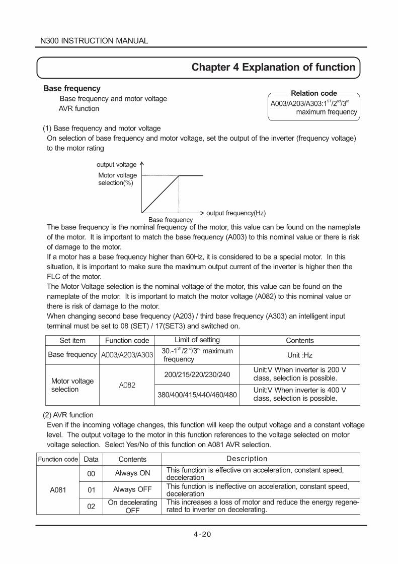
output voltage
Motor voltageselection(%)
Base frequencyoutput frequency(Hz)
Base frequency
Base frequency and motor voltage
AVR function
(1) Base frequency and motor voltage
On selection of base frequency and motor voltage, set the output of the inverter (frequency voltage)
to the motor rating
The base frequency is the nominal frequency of the motor, this value can be found on the nameplate
of the motor. It is important to match the base frequency (A003) to this nominal value or there is risk
of damage to the motor.
If a motor has a base frequency higher than 60Hz, it is considered to be a special motor. In this
situation, it is important to make sure the maximum output current of the inverter is higher then the
FLC of the motor.
The Motor Voltage selection is the nominal voltage of the motor, this value can be found on the
nameplate of the motor. It is important to match the motor voltage (A082) to this nominal value or
there is risk of damage to the motor.
When changing second base frequency (A203) / third base frequency (A303) an intelligent input
terminal must be set to 08 (SET) / 17(SET3) and switched on.
(2) AVR function
Even if the incoming voltage changes, this function will keep the output voltage and a constant voltage
level. The output voltage to the motor in this function references to the voltage selected on motor
voltage selection. Select Yes/No of this function on A081 AVR selection.
Set item
Base frequency
Motor voltageselection
Function code Limit of setting Contents
A003/A203/A303
A082
30.-1 /2 /3 maximumfrequency
ST nd rd
200/215/220/230/240
380/400/415/440/460/480
Unit :Hz
Unit:V When inverter is 200 Vclass, selection is possible.
Unit:V When inverter is 400 Vclass, selection is possible.
Data
00
01
Function code Contents
A081
Always ON
Always OFF
02On decelerating
OFF
Description
This function is effective on acceleration, constant speed,deceleration
This function is ineffective on acceleration, constant speed,decelerationThis increases a loss of motor and reduce the energy regene-rated to inverter on decelerating.
Relation code
A003/A203/A303:1 /2 /3maximum frequency
ST nd rd
N300 INSTRUCTION MANUAL
Chapter 4 Explanation of function
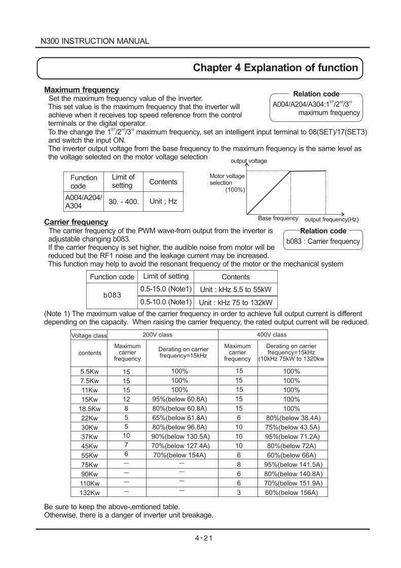
Maximum frequencySet the maximum frequency value of the inverter.This set value is the maximum frequency that the inverter willachieve when it receives top speed reference from the controlterminals or the digital operator.To the change the 1 /2 /3 maximum frequency, set an intelligent input terminal to 08(SET)/17(SET3)
ST nd rd
and switch the input ON.The inverter output voltage from the base frequency to the maximum frequency is the same level asthe voltage selected on the motor voltage selection
Relation code
Relation code
A004/A204/A304:1 /2 /3maximum frequency
ST nd rd
b083 : Carrier frequency
5.5
7.5
11
15
18.5
22
30
37
45
55
75
90
110
132
Kw
Kw
Kw
Kw
Kw
Kw
Kw
Kw
Kw
Kw
Kw
Kw
Kw
Kw
Voltage class
contents
15
15
15
12
8
5
5
10
7
6
100%
100%
100%
95%(below 60.8A)
80%(below 60.8A)
65%(below 61.8A)
80%(below 96.8A)
90%(below 130.5A)
70%(below 127.4A)
70%(below 154A)
200V class
Maximumcarrier
frequency
Maximumcarrier
frequency
Derating on carrierfrequency=15kHz
Derating on carrierfrequency=15kHz
(10kHz 75kW to 1320kw
400V class
15
15
15
15
15
6
10
10
10
6
8
6
6
3
100%
100%
100%
100%
100%
80%(below 38.4A)
75%(below 43.5A)
95%(below 71.2A)
80%(below 72A)
60%(below 66A)
95%(below 141.5A)
80%(below 140.8A)
70%(below 151.9A)
60%(below 156A)
(100%)
output voltage
Motor voltageselection
Base frequency output frequency(Hz)
Functioncode
Function code
Limit ofsetting
Limit of setting
Contents
Contents
A004/A204/A304
30. - 400. Unit ; Hz
Unit : kHz 5.5 to 55kW
Unit : kHz 75 to 132kW
Carrier frequencyThe carrier frequency of the PWM wave-from output from the inverter isadjustable changing b083.If the carrier frequency is set higher, the audible noise from motor will bereduced but the RF1 noise and the leakage current may be increased.This function may help to avoid the resonant frequency of the motor or the mechanical system
(Note 1) The maximum value of the carrier frequency in order to achieve full output current is differentdepending on the capacity. When raising the carrier frequency, the rated output current will be reduced.
0.5-15.0 (Note1)
0.5-10.0 (Note1)b083
Be sure to keep the above-,emtioned table.Otherwise, there is a danger of inverter unit breakage.
N300 INSTRUCTION MANUAL
Chapter 4 Explanation of function
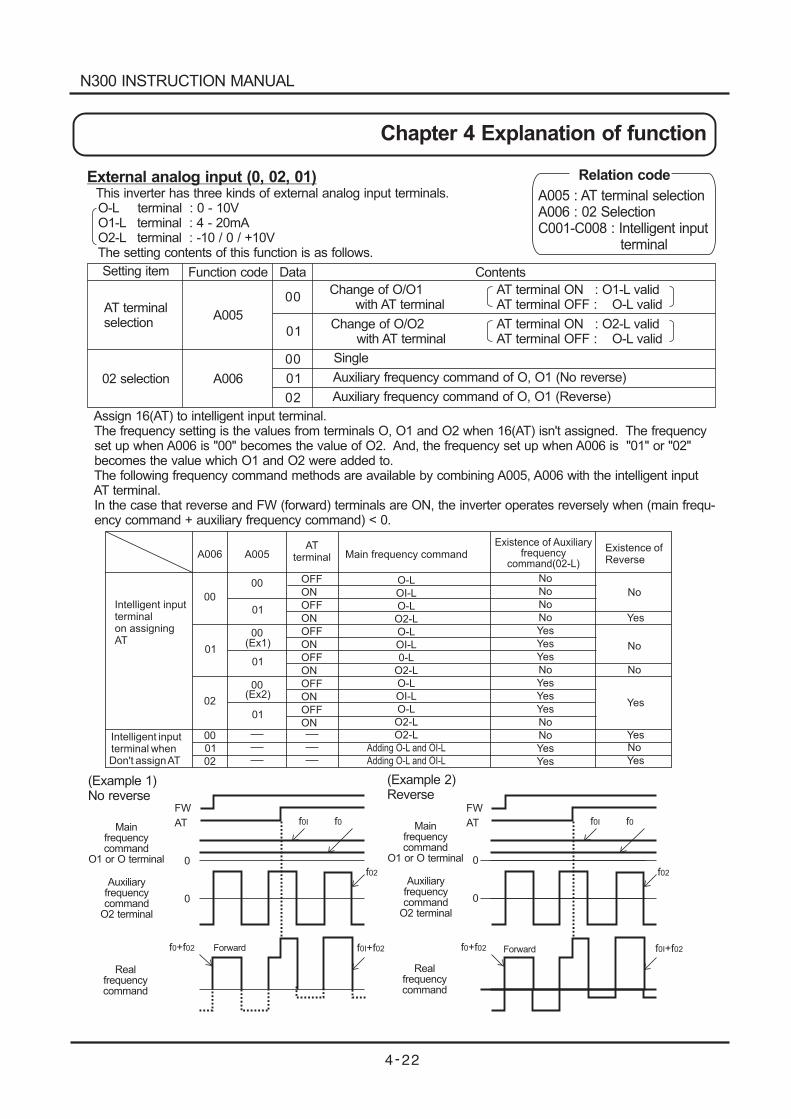
FW
0
f +f0 02
0
AT f f0I 0
f02
f +f0I 02
FW
0
f +f0 02
0
AT f f0I 0
f02
f +f0I 02
Intelligent inputterminalon assigningAT
Intelligent inputterminal whenDon't assignAT
A006
00
01
02
00
01
02
A005
00
01
00(Ex1)
01
00(Ex2)
01
O-L
OI-L
O-L
O2-L
O-L
OI-L
0-L
O2-L
O-L
OI-L
O-L
O2-L
O2-L
Adding O-L and OI-L
Adding O-L and OI-L
Existence ofReverse
No
No
No
Yes
Yes
No
Yes
OFF
ON
OFF
ON
OFF
ON
OFF
ON
OFF
ON
OFF
ON
ATterminal Main frequency command
No
No
No
No
Yes
Yes
Yes
No
Yes
Yes
Yes
No
No
Yes
Yes
Existence of Auxiliaryfrequency
command(02-L)
Yes
External analog input (0, 02, 01)This inverter has three kinds of external analog input terminals.O-L terminal : 0 - 10VO1-L terminal : 4 - 20mAO2-L terminal : -10 / 0 / +10VThe setting contents of this function is as follows.
Assign 16(AT) to intelligent input terminal.The frequency setting is the values from terminals O, O1 and O2 when 16(AT) isn't assigned. The frequencyset up when A006 is "00" becomes the value of O2. And, the frequency set up when A006 is "01" or "02"becomes the value which O1 and O2 were added to.The following frequency command methods are available by combining A005, A006 with the intelligent inputAT terminal.In the case that reverse and FW (forward) terminals are ON, the inverter operates reversely when (main frequ-ency command + auxiliary frequency command) < 0.
Setting item Function code Data Contents
AT terminalselection
02 selection
A005
A006
00
01
00
01
02
Change of O/O1with AT terminal
Change of O/O2with AT terminal
AT terminal ON : O1-L validAT terminal OFF : O-L valid
AT terminal ON : O2-L validAT terminal OFF : O-L valid
Single
Auxiliary frequency command of O, O1 (No reverse)
Auxiliary frequency command of O, O1 (Reverse)
(Example 1)No reverse
(Example 2)Reverse
Mainfrequencycommand
O1 or O terminal
Mainfrequencycommand
O1 or O terminal
Auxiliaryfrequencycommand
O2 terminal
Auxiliaryfrequencycommand
O2 terminal
Realfrequencycommand
Realfrequencycommand
ForwardForward
Relation code
A005 : AT terminal selectionA006 : 02 SelectionC001-C008 : Intelligent input
terminal
N300 INSTRUCTION MANUAL
Chapter 4 Explanation of function
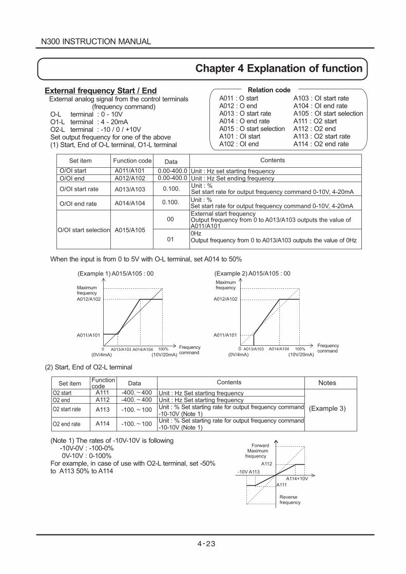
ForwardMaximum
frequency
A112
-10V A113
A114+10V
A111
Reversefrequency
(Example 1) A015/A105 : 00
A012/A102
A011/A101
0 100%
(0V/4mA) (10V/20mA)
(Example 2) A015/A105 : 00
A012/A102
A011/A101
A013/A1030 100%
(0V/4mA) (10V/20mA)A013/A103 A014/A104 A014/A104
External frequency Start / EndExternal analog signal from the control terminals
(frequency command)O-L terminal : 0 - 10VO1-L terminal : 4 - 20mAO2-L terminal : -10 / 0 / +10VSet output frequency for one of the above(1) Start, End of O-L terminal, O1-L terminal
When the input is from 0 to 5V with O-L terminal, set A014 to 50%
Set item
O/OI start
O/OI end
O/OI start rate
O/OI end rate
O/OI start selection
Function code
Functioncode
A011/A101
A012/A102
A013/A103
A014/A104
A015/A105
Data
Data
0.00-400.00.00-400.0
0.100.
0.100.
00
01
Contents
Contents
Unit : Hz set starting frequencyUnit : Hz Set ending frequency
Unit : %Set start rate for output frequency command 0-10V, 4-20mA
Unit : %Set start rate for output frequency command 0-10V, 4-20mA
External start frequencyOutput frequency from 0 to A013/A103 outputs the value ofA011/A101
0HzOutput frequency from 0 to A013/A103 outputs the value of 0Hz
Maximumfrequency
Maximumfrequency
Frequencycommand
Frequencycommand
O2 start
O2 end
O2 start rate
O2 end rate
A111
Set item
A112
A113
A114
-400. 400
-400. 400
-100. 100
-100. 100
Unit : Hz Set starting frequencyUnit : Hz Set starting frequencyUnit : % Set starting rate for output frequency command-10-10V (Note 1)Unit : % Set starting rate for output frequency command-10-10V (Note 1)
Notes
(Example 3)
(2) Start, End of O2-L terminal
(Note 1) The rates of -10V-10V is following-10V-0V : -100-0%0V-10V : 0-100%
For example, in case of use with O2-L terminal, set -50%to A113 50% to A114
Relation code
A011 : O startA012 : O endA013 : O start rateA014 : O end rateA015 : O start selectionA101 : OI startA102 : OI end
A103 : OI start rateA104 : OI end rateA105 : OI start selectionA111 : O2 startA112 : O2 endA113 : O2 start rateA114 : O2 end rate
N300 INSTRUCTION MANUAL
Chapter 4 Explanation of function
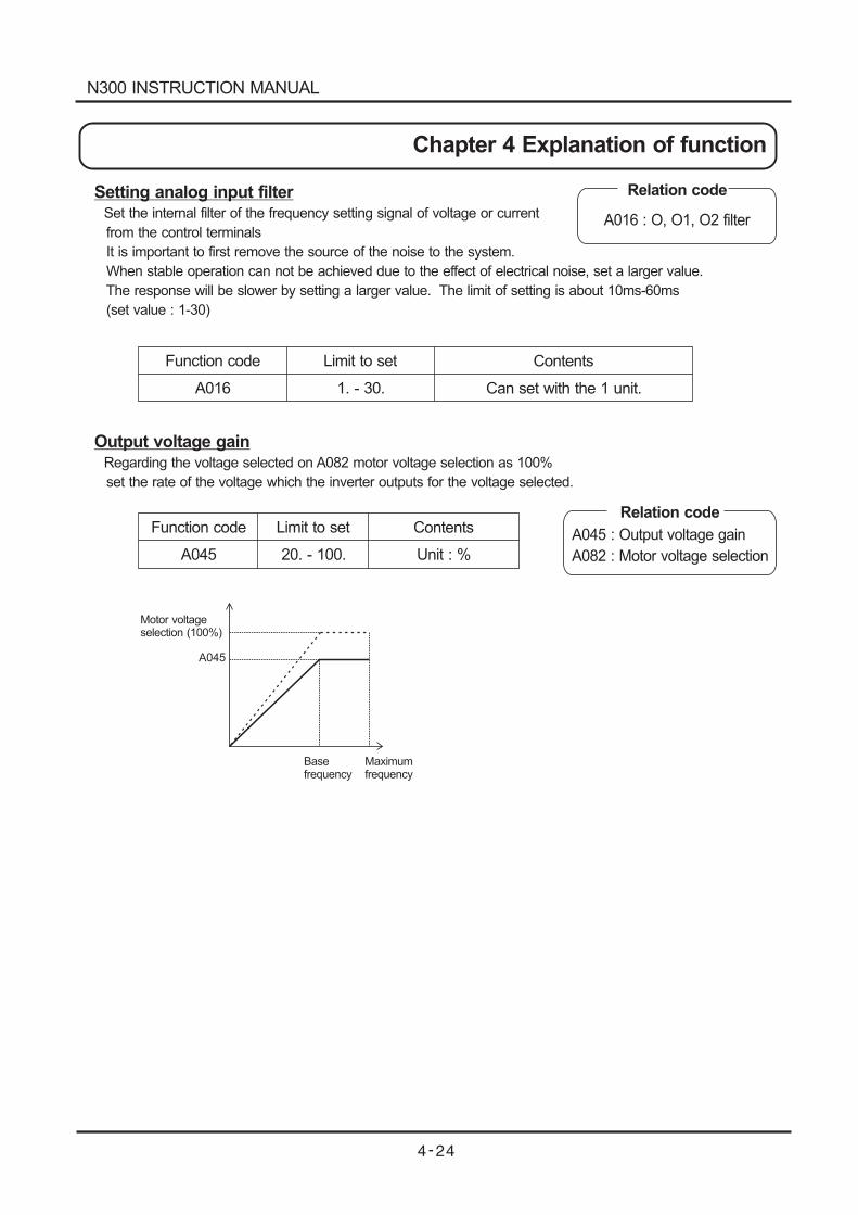
Setting analog input filterSet the internal filter of the frequency setting signal of voltage or current
from the control terminals
It is important to first remove the source of the noise to the system.
When stable operation can not be achieved due to the effect of electrical noise, set a larger value.
The response will be slower by setting a larger value. The limit of setting is about 10ms-60ms
(set value : 1-30)
Function code
A016
Limit to set
1. - 30.
Contents
Can set with the 1 unit.
Output voltage gainRegarding the voltage selected on A082 motor voltage selection as 100%
set the rate of the voltage which the inverter outputs for the voltage selected.
Function code
A045
Limit to set
20. - 100.
Contents
Unit : %
Relation code
A016 : O, O1, O2 filter
Relation code
A045 : Output voltage gain
A082 : Motor voltage selection
A045
Motor voltageselection (100%)
Maximumfrequency
Basefrequency
N300 INSTRUCTION MANUAL
Chapter 4 Explanation of function
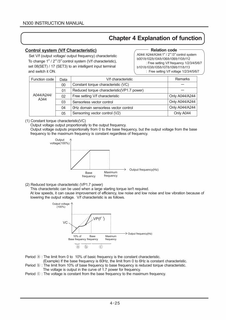
Control system (V/f Characteristic)Set V/f (output voltage/ output frequency) characteristic
To change 1 / 2 /3 control system (V/f characteristic),st nd rd
set 08(SET) / 17 (SET3) to an intelligent input terminal
and switch it ON.
Function code Data V/f characteristic Remarks
00
01
02
03
04
05
Constant torque characteristic (VC)
Reduced torque characteristic(VP1.7 power)
Free setting V/f characteristic
Sensorless vector control
0Hz domain sensorless vector control
Sensorring vector control (V2)
Only A044/A244
Only A044/A244
Only A044/A244
Only A044
-
-
A044/A244/A344
Outputvoltage(100%)
Basefrequency
Maximumfrequency
Output frequency(Hz)
Output voltage(100%)
10% ofBase frequency
Maximumfrequency
Output frequency(Hz)
VCVP(f )
1. 7
Basefrequency
(1) Constant torque characteristic(VC)Output voltage output proportionally to the output frequency.Output voltage outputs proportionally from 0 to the base frequency, but the output voltage from the basefrequency to the maximum frequency is constant regardless of frequency.
(2) Reduced torque characteristic (VP1.7 power)This characteristic can be used when a large starting torque isn't required.At low speeds, it can cause improvement of efficiency, low noise and low noise and low vibration because oflowering the output voltage. V/f characteristic is as follows.
Period : The limit from 0 to 10% of basic frequency is the constant characteristic.(Example) If the base frequency is 60Hz, the limit from 0 to 6Hz is constant characteristic.
Period : The limit from 10% of base frequency to base frequency is reduced torque characteristic.The voltage is output in the curve of 1.7 power for frequency.
Period : The voltage is constant from the base frequency to the maximum frequency.
Relation codeA044/ A244/A344:1 / 2 /3 control system
b001/b102/b104/b106/b108/b110/b112
: Free setting V/f frequency 1/2/3/4/5/6/7
b101/b103/b105/b107/b109/b111/b113
: Free setting V/f voltage 1/2/3/4/5/6/7
st nd rd
N300 INSTRUCTION MANUAL
Chapter 4 Explanation of function
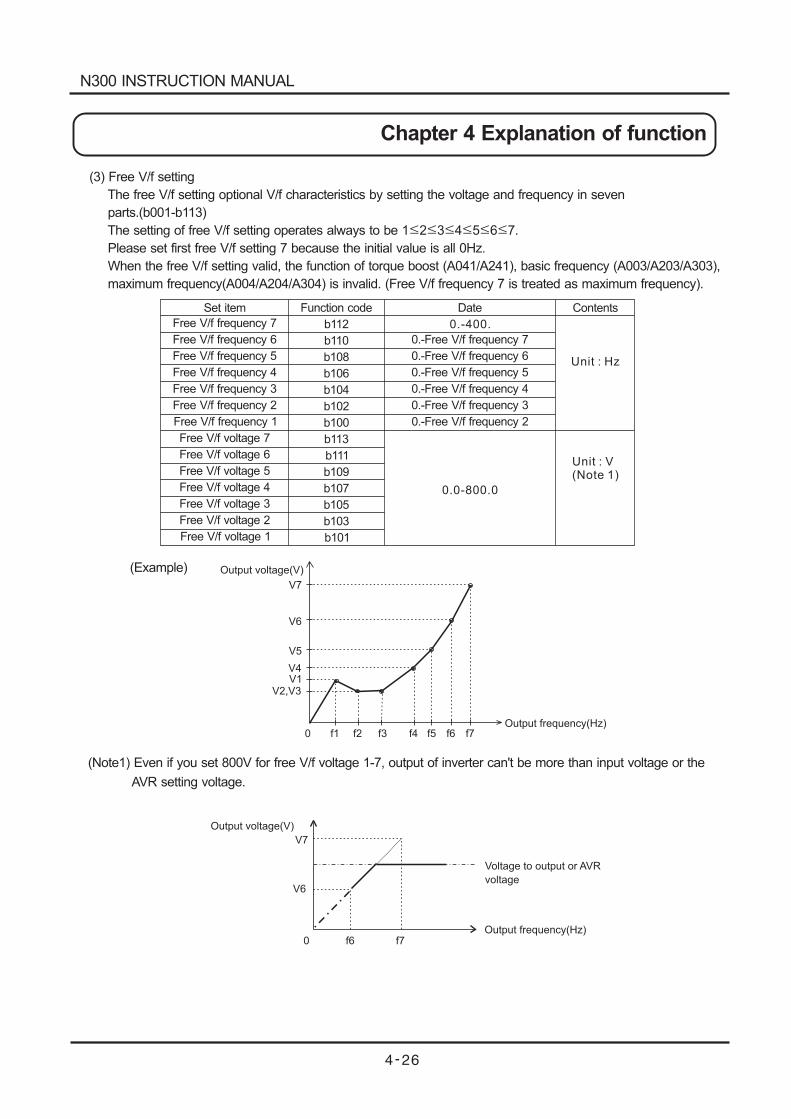
(3) Free V/f setting
The free V/f setting optional V/f characteristics by setting the voltage and frequency in seven
parts.(b001-b113)
The setting of free V/f setting operates always to be 1 2 3 4 5 6 7.
Please set first free V/f setting 7 because the initial value is all 0Hz.
When the free V/f setting valid, the function of torque boost (A041/A241), basic frequency (A003/A203/A303),
maximum frequency(A004/A204/A304) is invalid. (Free V/f frequency 7 is treated as maximum frequency).
Free V/f frequency 7
Free V/f frequency 6
Free V/f frequency 5
Free V/f frequency 4
Free V/f frequency 3
Free V/f frequency 2
Free V/f frequency 1
Free V/f voltage 7
Free V/f voltage 6
Free V/f voltage 5
Free V/f voltage 4
Free V/f voltage 3
Free V/f voltage 2
Free V/f voltage 1
Function codeSet item Date Contents
0.-Free V/f frequency 7
0.-Free V/f frequency 6
0.-Free V/f frequency 5
0.-Free V/f frequency 4
0.-Free V/f frequency 3
0.-Free V/f frequency 2
b112
b110
b108
b106
b104
b102
b100
b113
b111
b109
b107
b105
b103
b101
0.-400.
0.0-800.0
Unit : Hz
Unit : V(Note 1)
Output voltage(V)
V7
V6
V5
V4V1
V2,V3
Output frequency(Hz)0 f1 f2 f3 f4 f5 f6 f7
V7
V6
Output voltage(V)
Output frequency(Hz)0 f6 f7
Voltage to output or AVR
voltage
(Example)
(Note1) Even if you set 800V for free V/f voltage 1-7, output of inverter can't be more than input voltage or the
AVR setting voltage.
N300 INSTRUCTION MANUAL
Chapter 4 Explanation of function
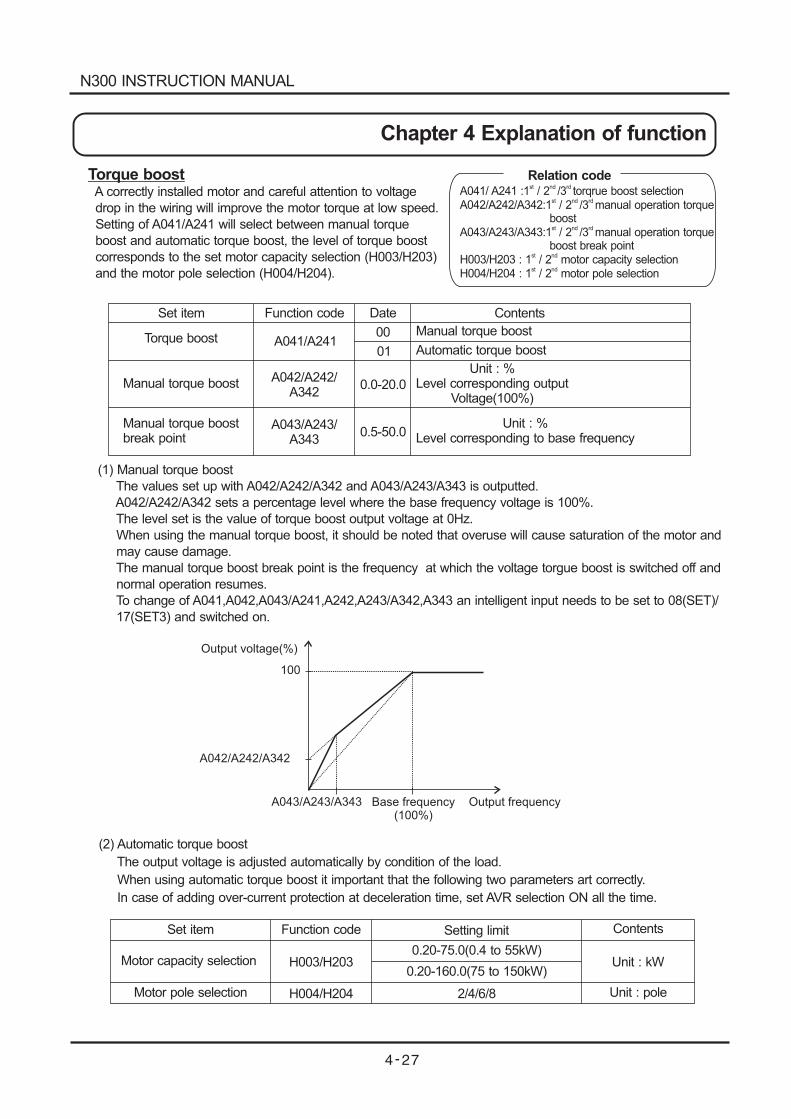
Torque boostA correctly installed motor and careful attention to voltage
drop in the wiring will improve the motor torque at low speed.
Setting of A041/A241 will select between manual torque
boost and automatic torque boost, the level of torque boost
corresponds to the set motor capacity selection (H003/H203)
and the motor pole selection (H004/H204).
Set item Function code Date Contents
Torque boost
Manual torque boost
Manual torque boostbreak point
A041/A241
A042/A242/A342
A043/A243/A343
00
01
0.0-20.0
0.5-50.0
Manual torque boost
Automatic torque boost
Unit : %Level corresponding output
Voltage(100%)
Unit : %Level corresponding to base frequency
(1) Manual torque boost
The values set up with A042/A242/A342 and A043/A243/A343 is outputted.
A042/A242/A342 sets a percentage level where the base frequency voltage is 100%.
The level set is the value of torque boost output voltage at 0Hz.
When using the manual torque boost, it should be noted that overuse will cause saturation of the motor and
may cause damage.
The manual torque boost break point is the frequency at which the voltage torgue boost is switched off and
normal operation resumes.
To change of A041,A042,A043/A241,A242,A243/A342,A343 an intelligent input needs to be set to 08(SET)/
17(SET3) and switched on.
Base frequency(100%)
Output frequency
Output voltage(%)
100
A042/A242/A342
A043/A243/A343
(2) Automatic torque boost
The output voltage is adjusted automatically by condition of the load.
When using automatic torque boost it important that the following two parameters art correctly.
In case of adding over-current protection at deceleration time, set AVR selection ON all the time.
Set item
Motor capacity selection
Motor pole selection
Function code
H003/H203
H004/H204
Setting limit
0.20-75.0(0.4 to 55kW)
0.20-160.0(75 to 150kW)
2/4/6/8
Contents
Unit : kW
Unit : pole
Relation codeA041/ A241 :1 / 2 /3 torqrue boost selectionA042/A242/A342:1 / 2 /3 manual operation torque
boostA043/A243/A343:1 / 2 /3 manual operation torque
boost break pointH003/H203 : 1 / 2 motor capacity selectionH004/H204 : 1 / 2 motor pole selection
st nd rd
st nd rd
st nd rd
st nd
st nd
N300 INSTRUCTION MANUAL
Chapter 4 Explanation of function
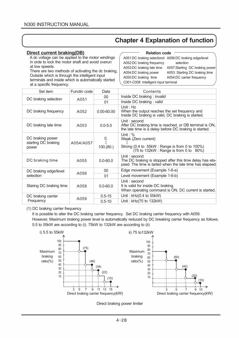
Direct current braking(DB)A dc voltage can be applied to the motor windingsin orde to lock the motor shaft and avoid overunat low speeds.There are two methods of activating the dc braking,Outside which is through the intelligent inputterminals and inside which is automatically startedat a specific frequency.
Set item
DC braking selection
DC braking late time
DC braking frequency
Functin code Data
0.00-60.00
Contents
Inside DC braking : invalid
Inside DC braking : valid
Unit : HzWhen the output reaches the set frequency andInside DC braking is valid, DC braking is started.
Unit : secondAfter DC braking time is reached, or DB terminal is ON,the late time is a delay before DC braking is started.
Unit : %Weak (Zero current)
Strong (0.4 to 55kW : Range is from 0 to 100%)(75 to 132kW : Range is from 0 to 80%)
Unit : secondThe DC braking is stopped after this time delay has ela-psed. The time is tarted when the late time has elapsed.
Edge movement (Example 1-6-a)
Level movement (Example 1-6-b)
Unit : secondIt is valid for inside DC braking.When operating command is ON, DC current is started.
Unit : kHz(0.4 to 55kW)
Unit : kHz(75 to 132kW)
DC braking powerstarting DC brakingpower
DC braking time
DC braking edge/levelselection
Staring DC braking time
DC braking carrierFrequency
A051
A052
A053
A054/A057
A055
A056
A058
A059
00
01
0.0-5.0
0.
100.(80.)
0.0-60.0
00
01
0.0-60.0
0.5-15
0.5-10
(1) DC braking carrier frequency
It is possible to alter the DC braking carrier frequency. Set DC braking carrier frequency with A059.
However, Maximum braking power level is automatically reduced by DC breaking carrier frequency as follows.
5.5 to 55kW are according to (i). 75kW to 132kW are according to (ii)
100
90
80
70
60
50
40
30
20
10
3 5 7 9 11 13 15
(75)
(46)
(34)
(22)
(10)
i) 5.5 to 55kW
Maximum
braking
ratio(%)
Direct braking carrier frequency(kW)
100
90
80
70
60
50
40
30
20
10
3 5 7 9 10
ii) 75 to132kW
(60)
(40)
(20)
(10)
Maximum
braking
ratio(%)
Direct braking carrier frequency(kW)
Direct braking power limiter
Relation code
A051:DC braking selectiond
A052:
A053:
A054:
A055:
DC braking frequency
DC braking late time
DC braking power
DC braking time
C001-C008: Intelligent input terminal
A056:DC braking edge/level
selection
A057:Starting
A053: Starting
A054:
DC braking power
DC braking time
DC carrier frequency
N300 INSTRUCTION MANUAL
Chapter 4 Explanation of function
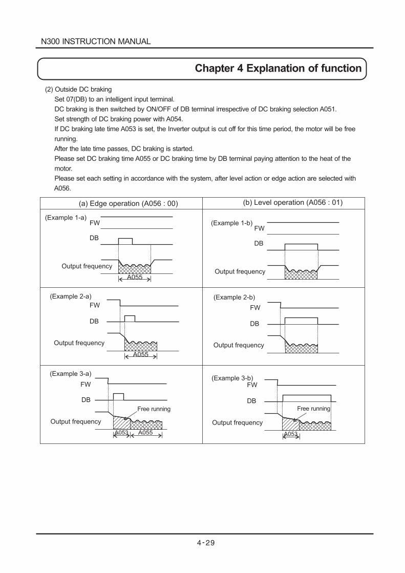
(2) Outside DC braking
Set 07(DB) to an intelligent input terminal.
DC braking is then switched by ON/OFF of DB terminal irrespective of DC braking selection A051.
Set strength of DC braking power with A054.
If DC braking late time A053 is set, the Inverter output is cut off for this time period, the motor will be free
running.
After the late time passes, DC braking is started.
Please set DC braking time A055 or DC braking time by DB terminal paying attention to the heat of the
motor.
Please set each setting in accordance with the system, after level action or edge action are selected with
A056.
A055
Output frequency
Output frequency
Output frequency Output frequency
Output frequency
Output frequency
FW
DB
(Example 1-a)
FW
DB
(Example 1-b)
A055
FW
DB
( 2-a)Example
FW
DB
(Example 2-b)
FW
DB
A055A053
(Example 3-a)
FW
DB
A053
(Example 3-b)
(a) Edge operation (A056 : 00) (b) Level operation (A056 : 01)
Free running Free running
N300 INSTRUCTION MANUAL
Chapter 4 Explanation of function
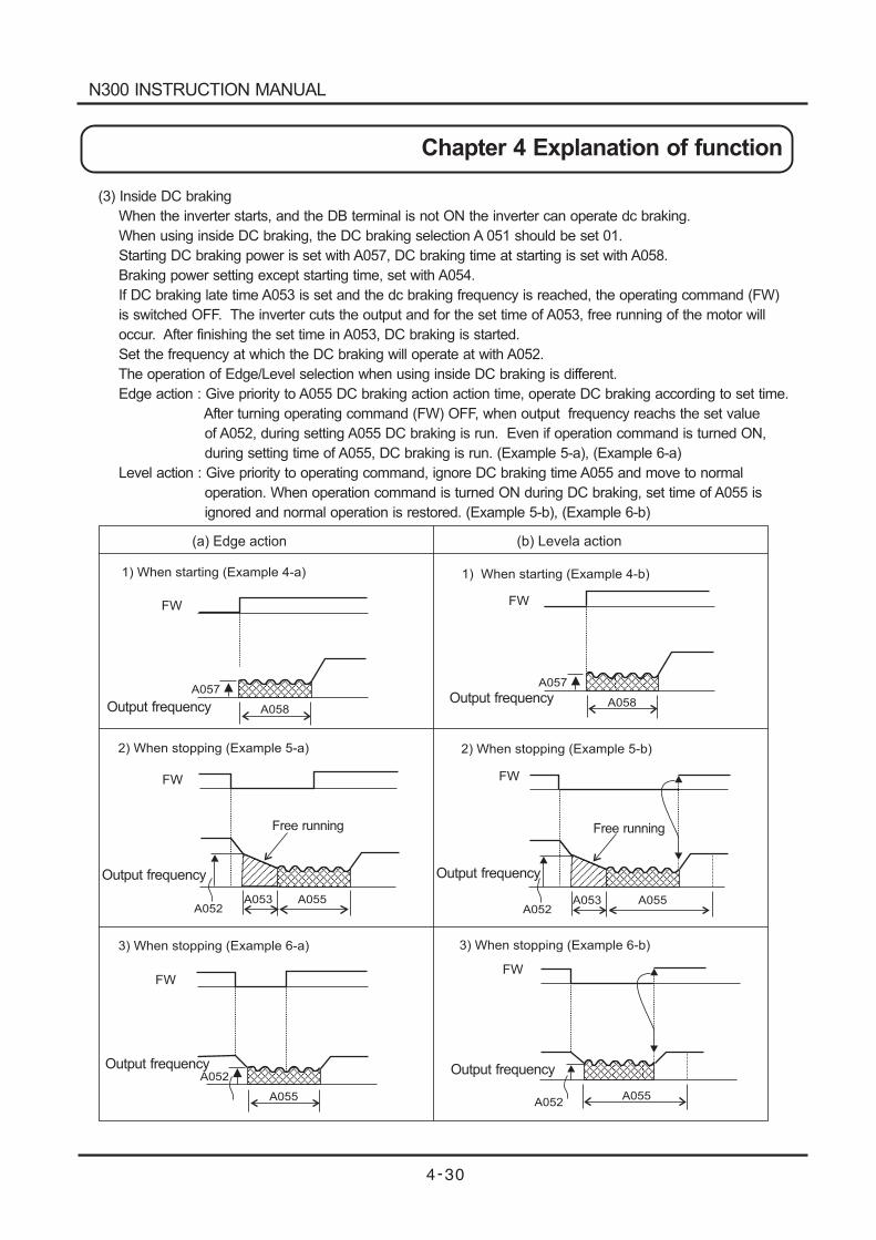
(3) Inside DC braking
When the inverter starts, and the DB terminal is not ON the inverter can operate dc braking.
When using inside DC braking, the DC braking selection A 051 should be set 01.
Starting DC braking power is set with A057, DC braking time at starting is set with A058.
Braking power setting except starting time, set with A054.
If DC braking late time A053 is set and the dc braking frequency is reached, the operating command (FW)
is switched OFF. The inverter cuts the output and for the set time of A053, free running of the motor will
occur. After finishing the set time in A053, DC braking is started.
Set the frequency at which the DC braking will operate at with A052.
The operation of Edge/Level selection when using inside DC braking is different.
Edge action : Give priority to A055 DC braking action action time, operate DC braking according to set time.
After turning operating command (FW) OFF, when output frequency reachs the set value
of A052, during setting A055 DC braking is run. Even if operation command is turned ON,
during setting time of A055, DC braking is run. (Example 5-a), (Example 6-a)
Level action : Give priority to operating command, ignore DC braking time A055 and move to normal
operation. When operation command is turned ON during DC braking, set time of A055 is
ignored and normal operation is restored. (Example 5-b), (Example 6-b)
(a) Edge action (b) Levela action
A058
A057
FW
1) When starting (Example 4-a)
A058
A057
FW
1) 4-b)When starting (Example
A053A052
FW
2) When stopping (Example 5-a)
A055 A053A052
FW
2) 5-b)When stopping (Example
A055
A052
FW
3) 6-b)When stopping (Example
A055A055
A052
FW
3) 6-a)When stopping (Example
Output frequency Output frequency
Output frequencyOutput frequency
Output frequencyOutput frequency
Free running Free running
N300 INSTRUCTION MANUAL
Chapter 4 Explanation of function
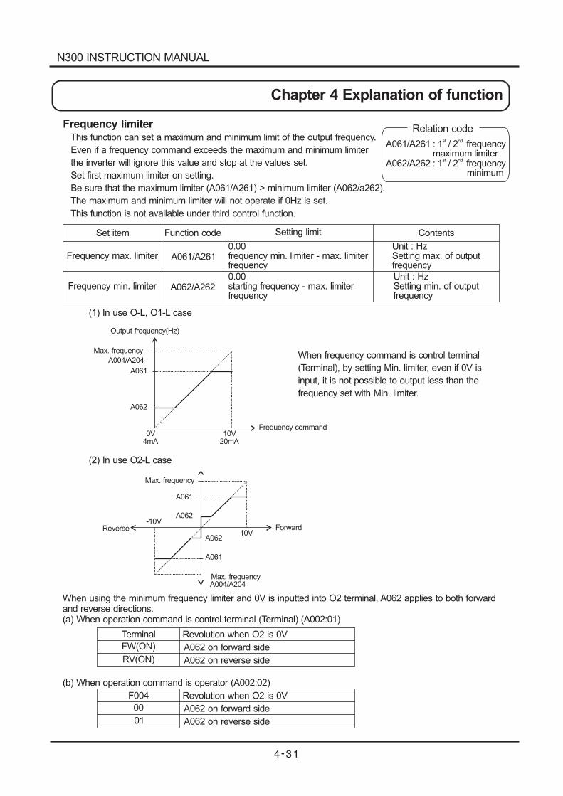
Frequency limiterThis function can set a maximum and minimum limit of the output frequency.
Even if a frequency command exceeds the maximum and minimum limiter
the inverter will ignore this value and stop at the values set.
Set first maximum limiter on setting.
Be sure that the maximum limiter (A061/A261) > minimum limiter (A062/a262).
The maximum and minimum limiter will not operate if 0Hz is set.
This function is not available under third control function.
Set item
Frequency max. limiter
Frequency min. limiter
Function code
0.00frequency min. limiter - max. limiterfrequency
0.00starting frequency - max. limiterfrequency
A061/A261
A062/A262
Setting limit Contents
Unit : HzSetting max. of outputfrequency
Unit : HzSetting min. of outputfrequency
Output frequency(Hz)
Max. frequency
A004/A204
A061
A062
0V 10V4mA 20mA
Frequency command
Max. frequency
Max. frequency
A061
A062-10V
A062
A061
10V
A004/A204
Reverse Forward
(2) In use O2-L case
(1) In use O-L, O1-L case
When frequency command is control terminal
(Terminal), by setting Min. limiter, even if 0V is
input, it is not possible to output less than the
frequency set with Min. limiter.
When using the minimum frequency limiter and 0V is inputted into O2 terminal, A062 applies to both forwardand reverse directions.(a) When operation command is control terminal (Terminal) (A002:01)
(b) When operation command is operator (A002:02)
Terminal
FW(ON)
RV(ON)
Revolution when O2 is 0V
A062 on forward side
A062 on reverse side
F004
00
01
Revolution when O2 is 0V
A062 on forward side
A062 on reverse side
Relation code
A061/A261 : 1 / 2 frequencymaximum limiter
st nd
A062/A262 : 1 / 2 frequencyminimum
st nd
N300 INSTRUCTION MANUAL
Chapter 4 Explanation of function
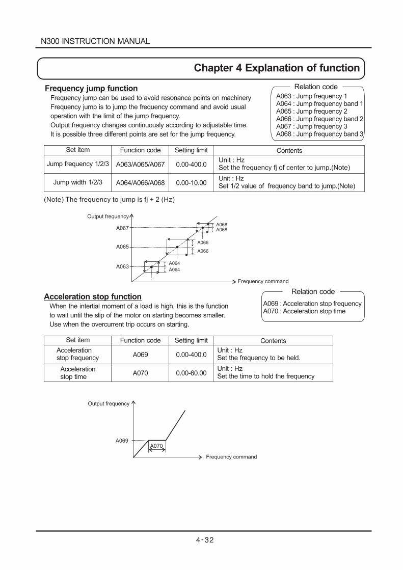
Frequency jump functionFrequency jump can be used to avoid resonance points on machinery
Frequency jump is to jump the frequency command and avoid usual
operation with the limit of the jump frequency.
Output frequency changes continuously according to adjustable time.
It is possible three different points are set for the jump frequency.
Set item
Jump frequency 1/2/3
Jump width 1/2/3
Function code
A063/A065/A067
A064/A066/A068
Setting limit
0.00-400.0
0.00-10.00
Contents
Unit : HzSet the frequency fj of center to jump.(Note)
Unit : HzSet 1/2 value of frequency band to jump.(Note)
(Note) The frequency to jump is fj + 2 (Hz)
Output frequency
A067
A065
A063
Frequency command
A064
A066
A068A068
A064
A066
A070A069
Output frequency
Frequency command
Acceleration stop functionWhen the intertial moment of a load is high, this is the function
to wait until the slip of the motor on starting becomes smaller.
Use when the overcurrent trip occurs on starting.
Set item
Accelerationstop frequency
Accelerationstop time
Function code
A069
A070
Setting limit
0.00-400.0
0.00-60.00
Contents
Unit : HzSet the frequency to be held.
Unit : HzSet the time to hold the frequency
Relation code
A063 : Jump frequency 1A064 : Jump frequency band 1A065 : Jump frequency 2A066 : Jump frequency band 2A067 : Jump frequency 3A068 : Jump frequency band 3
Relation code
A069 : Acceleration stop frequencyA070 : Acceleration stop time
N300 INSTRUCTION MANUAL
Chapter 4 Explanation of function
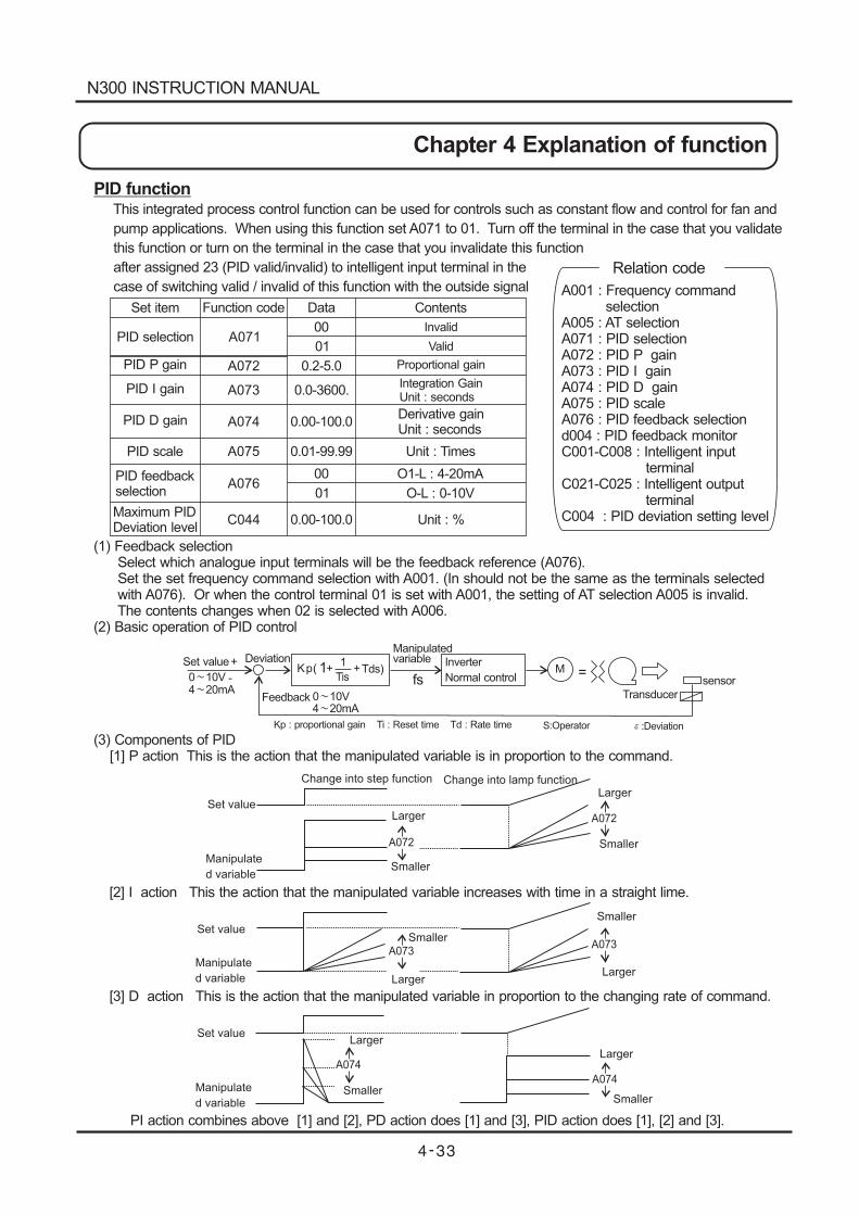
PID functionThis integrated process control function can be used for controls such as constant flow and control for fan and
pump applications. When using this function set A071 to 01. Turn off the terminal in the case that you validate
this function or turn on the terminal in the case that you invalidate this function
after assigned 23 (PID valid/invalid) to intelligent input terminal in the
case of switching valid / invalid of this function with the outside signal
Set item
PID selection
PID P gain
PID I gain
PID D gain
PID scale
PID feedbackselection
Maximum PIDDeviation level
Function code Data Contents
A071
A072
A073
A074
A075
A076
C044
00
00
01
01
0.2-5.0
0.0-3600.
0.00-100.0
0.00-100.0
0.01-99.99
Invalid
Valid
Proportional gain
Integration GainUnit : seconds
Derivative gainUnit : seconds
Unit : Times
O1-L : 4-20mA
O-L : 0-10V
Unit : %
Set value+
-
Deviation
0 10V4 20mA
Kp(1
+Tis
+Tds)
Manipulatedvariable Inverter
Normal controlM
sensor
Feedback
Kp : proportional gain Ti : Reset time Td : Rate time
0 10V4 20mA
A074
A074
A072
Larger
Larger
Larger
Larger
Larger
Larger
Smaller
Smaller
Smaller
SmallerSmaller
Smaller
A072
Set value
Manipulate
d variable
Change into step function Change into lamp function
A073A073
1fs
=
Transducer
S:Operator :Deviation
(1) Feedback selectionSelect which analogue input terminals will be the feedback reference (A076).Set the set frequency command selection with A001. (In should not be the same as the terminals selectedwith A076). Or when the control terminal 01 is set with A001, the setting of AT selection A005 is invalid.The contents changes when 02 is selected with A006.
(2) Basic operation of PID control
(3) Components of PID[1] P action This is the action that the manipulated variable is in proportion to the command.
[2] I action This the action that the manipulated variable increases with time in a straight lime.
[3] D action This is the action that the manipulated variable in proportion to the changing rate of command.
PI action combines above [1] and [2], PD action does [1] and [3], PID action does [1], [2] and [3].
Set value
Manipulate
d variable
Set value
Manipulate
d variable
Relation code
A001 : Frequency commandselection
A005 : AT selectionA071 : PID selectionA072 : PID P gainA073 : PID I gainA074 : PID D gainA075 : PID scaleA076 : PID feedback selectiond004 : PID feedback monitorC001-C008 : Intelligent input
terminalC021-C025 : Intelligent output
terminalC004 : PID deviation setting level
N300 INSTRUCTION MANUAL
Chapter 4 Explanation of function
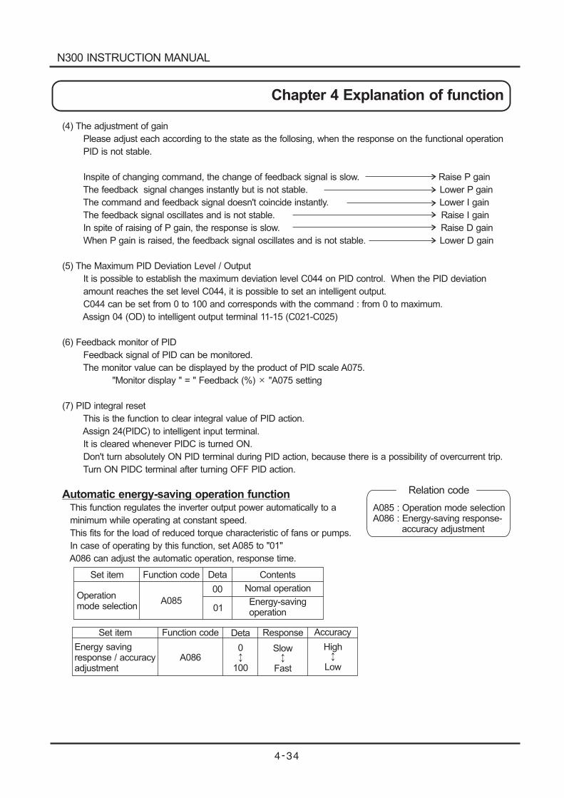
(4) The adjustment of gain
Please adjust each according to the state as the follosing, when the response on the functional operation
PID is not stable.
Inspite of changing command, the change of feedback signal is slow. Raise P gain
The feedback signal changes instantly but is not stable. Lower P gain
The command and feedback signal doesn't coincide instantly. Lower I gain
The feedback signal oscillates and is not stable. Raise I gain
In spite of raising of P gain, the response is slow. Raise D gain
When P gain is raised, the feedback signal oscillates and is not stable. Lower D gain
(5) The Maximum PID Deviation Level / Output
It is possible to establish the maximum deviation level C044 on PID control. When the PID deviation
amount reaches the set level C044, it is possible to set an intelligent output.
C044 can be set from 0 to 100 and corresponds with the command : from 0 to maximum.
Assign 04 (OD) to intelligent output terminal 11-15 (C021-C025)
(6) Feedback monitor of PID
Feedback signal of PID can be monitored.
The monitor value can be displayed by the product of PID scale A075.
"Monitor display " = " Feedback (%) "A075 setting
(7) PID integral reset
This is the function to clear integral value of PID action.
Assign 24(PIDC) to intelligent input terminal.
It is cleared whenever PIDC is turned ON.
Don't turn absolutely ON PID terminal during PID action, because there is a possibility of overcurrent trip.
Turn ON PIDC terminal after turning OFF PID action.
Automatic energy-saving operation functionThis function regulates the inverter output power automatically to a
minimum while operating at constant speed.
This fits for the load of reduced torque characteristic of fans or pumps.
In case of operating by this function, set A085 to "01"
A086 can adjust the automatic operation, response time.
Set item
Set item
Operationmode selection
Function code
Function code
A085
Deta
Deta
00
01
Contents
Nomal operation
Energy-savingoperation
Response Accuracy
Energy savingresponse / accuracyadjustment
A0860
100
Slow
Fast
High
Low
Relation code
A085 : Operation mode selectionA086 : Energy-saving response-
accuracy adjustment
N300 INSTRUCTION MANUAL
Chapter 4 Explanation of function
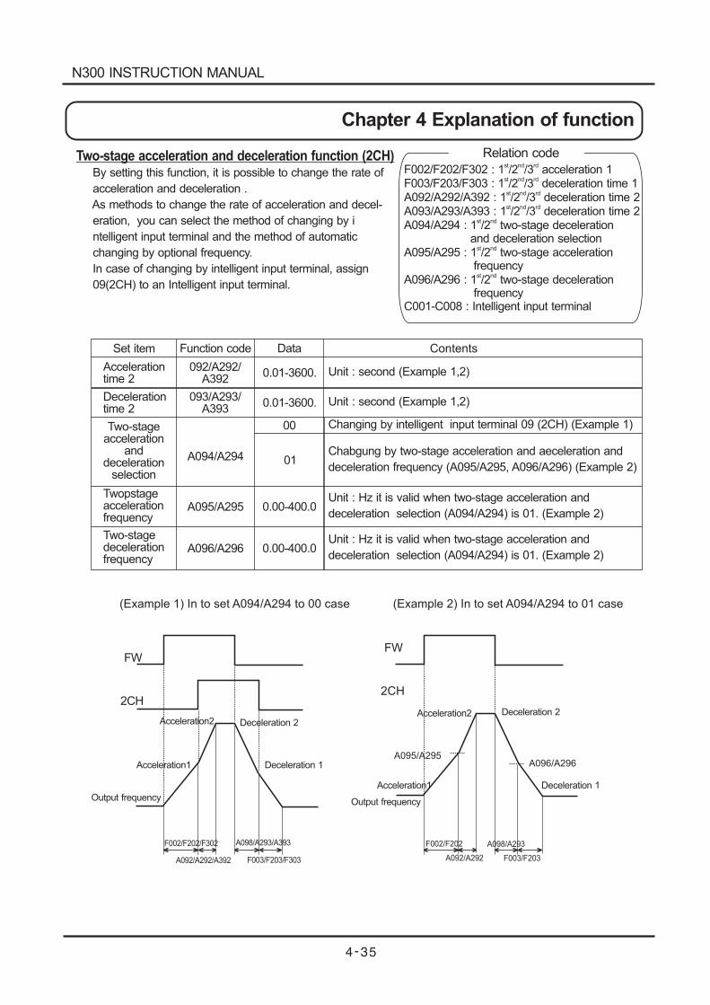
Two-stage acceleration and deceleration function (2CH)By setting this function, it is possible to change the rate of
acceleration and deceleration .
As methods to change the rate of acceleration and decel-
eration, you can select the method of changing by i
ntelligent input terminal and the method of automatic
changing by optional frequency.
In case of changing by intelligent input terminal, assign
09(2CH) to an Intelligent input terminal.
Set item
Accelerationtime 2
Function code Data
0.01-3600.
0.01-3600.Decelerationtime 2
Two-stageacceleration
anddeceleration
selection
Twopstageaccelerationfrequency
Two-stagedecelerationfrequency
092/A292/A392
093/A293/A393
A094/A294
A095/A295
A096/A296
00
01
0.00-400.0
0.00-400.0
Contents
Unit : second (Example 1,2)
Unit : second (Example 1,2)
Changing by intelligent input terminal 09 (2CH) (Example 1)
Chabgung by two-stage acceleration and aeceleration and
deceleration frequency (A095/A295, A096/A296) (Example 2)
Unit : Hz it is valid when two-stage acceleration and
deceleration selection (A094/A294) is 01. (Example 2)
Unit : Hz it is valid when two-stage acceleration and
deceleration selection (A094/A294) is 01. (Example 2)
FW
2CH
Acceleration2Acceleration2
Acceleration1
Acceleration1
Deceleration 2Deceleration 2
Deceleration 1
Deceleration 1
Output frequency Output frequency
F002/F202/F302 A098/A293/A393
A092/A292/A392 F003/F203/F303
FW
2CH
F002/F202 A098/A293
A092/A292 F003/F203
A095/A295A096/A296
(Example 1) In to set A094/A294 to 00 case (Example 2) In to set A094/A294 to 01 case
Relation code
F002/F202/F302 : 1 /2 /3 acceleration 1st nd rd
F003/F203/F303 : 1 /2 /3 deceleration time 1A092/A292/A392 : 1 /2 /3 deceleration time 2A093/A293/A393 : 1 /2 /3 deceleration time 2A094/A294 : 1 /2 two-stage deceleration
and deceleration selectionA095/A295 : 1 /2 two-stage acceleration
frequencyA096/A296 : 1 /2 two-stage deceleration
frequencyC001-C008 : Intelligent input terminal
st nd rd
st nd rd
st nd rd
st nd
st nd
st nd
N300 INSTRUCTION MANUAL
Chapter 4 Explanation of function
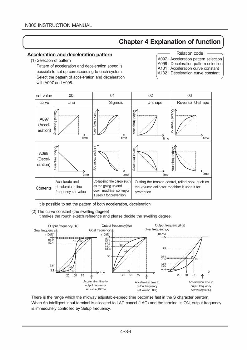
Acceleration and deceleration pattern(1) Selection of pattern
Pattern of acceleration and deceleration speed is
possible to set up corresponding to each system.
Select the pattern of acceleration and deceleration
with A097 and A098.
Outp
ut
frequency
time time time time
timetimetimetime
Output frequency(Hz) Output frequency(Hz) Output frequency(Hz)
Goal frequency Goal frequency Goal frequency
(100%)
96.982.4
17.6
3.1
25 50 75time
02
10
Acceleration time to
output frequency
set value(100%)
Acceleration time to
output frequency
set value(100%)
Acceleration time to
output frequency
set value(100%)
10 02
(100%) (100%)
99.693.887.5
68.464.6
35
25 50 75
02
1065
35.431.6
12.56.25
25 50 75
10
1002
It is possible to set the pattern of both acceleration, deceleration
set value 00 01 02 03
curve Line Sigmoid U-shape Reverse U-shape
A097
(Accel-
eration)
A098
(Decel-
eration)
Contents
Accelerate and
decelerate in line
frequency set value
Collapsing the cargo such
as the going up and
down machine, conveyor
it uses it for prevention
Cutting the tension control, rolled book such as
the volume collector machine it uses it for
prevention
0.39
Outp
ut
frequency
Outp
ut
frequency
Outp
ut
frequency
Outp
ut
frequency
Outp
ut
frequency
Outp
ut
frequency
Outp
ut
frequency
(2) The curve constant (the swelling degree)It makes the rough sketch reference and please decide the swelling degree.
There is the range which the midway adjustable-speed time becomse fast in the S character parrtern.
When An intelligent input terminal is allocated to LAD cancel (LAC) and the terminal is ON, output frequency
is immediately controlled by Setup frequency.
Relation code
A097 : Acceleration pattern selectionA098 : Deceleration pattern selectionA131 : Acceleration curve constantA132 : Deceleration curve constant
N300 INSTRUCTION MANUAL
Chapter 4 Explanation of function
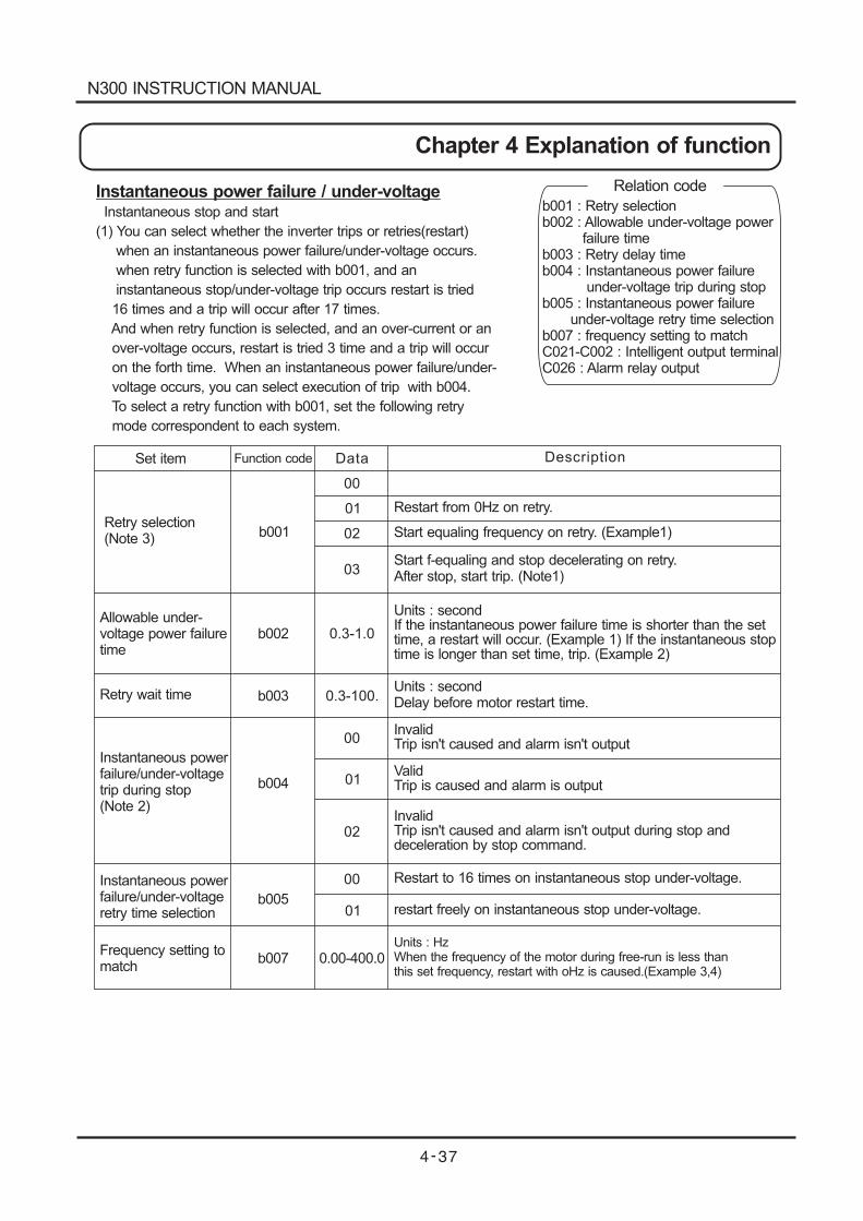
Instantaneous power failure / under-voltageInstantaneous stop and start
(1) You can select whether the inverter trips or retries(restart)
when an instantaneous power failure/under-voltage occurs.
when retry function is selected with b001, and an
instantaneous stop/under-voltage trip occurs restart is tried
16 times and a trip will occur after 17 times.
And when retry function is selected, and an over-current or an
over-voltage occurs, restart is tried 3 time and a trip will occur
on the forth time. When an instantaneous power failure/under-
voltage occurs, you can select execution of trip with b004.
To select a retry function with b001, set the following retry
mode correspondent to each system.
Retry selection(Note 3)
Allowable under-voltage power failuretime
Retry wait time
Instantaneous powerfailure/under-voltagetrip during stop(Note 2)
Function code
0.00-400.0
Instantaneous powerfailure/under-voltageretry time selection
Frequency setting tomatch
Set item
b001
b002
b003
b004
b005
b007
00
01
02
03
0.3-100.
00
01
02
00
01
0.3-1.0
Data Description
Restart from 0Hz on retry.
Start equaling frequency on retry. (Example1)
Start f-equaling and stop decelerating on retry.After stop, start trip. (Note1)
Units : secondIf the instantaneous power failure time is shorter than the settime, a restart will occur. (Example 1) If the instantaneous stoptime is longer than set time, trip. (Example 2)
Units : secondDelay before motor restart time.
InvalidTrip isn't caused and alarm isn't output
ValidTrip is caused and alarm is output
InvalidTrip isn't caused and alarm isn't output during stop anddeceleration by stop command.
Restart to 16 times on instantaneous stop under-voltage.
restart freely on instantaneous stop under-voltage.
Units : HzWhen the frequency of the motor during free-run is less thanthis set frequency, restart with oHz is caused.(Example 3,4)
Relation code
b001 : Retry selectionb002 : Allowable under-voltage power
failure timeb003 : Retry delay timeb004 : Instantaneous power failure
under-voltage trip during stopb005 : Instantaneous power failure
under-voltage retry time selectionb007 : frequency setting to matchC021-C002 : Intelligent output terminalC026 : Alarm relay output
N300 INSTRUCTION MANUAL
Chapter 4 Explanation of function
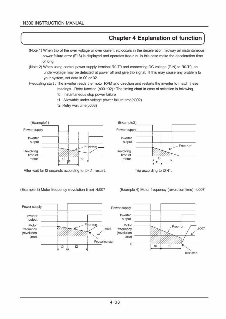
(Example1)
Power supply
Power supply Power supply
Inverteroutput
Inverteroutput
Inverteroutput
Revolvingtime ofmotor
Motorfrequency(revolution
time)
Motorfrequency(revolution
time)
Free-run
Free-runFree-run
Free-run
t0t1
t2 t0t1
After wait for t2 seconds according to t0<t1, restart.
t0 t2
Fequaling start
b007
0t0 t2
0Hz start
b007
Trip according to t0>t1.
(Note 1) When trip of the over voltage or over current etc.occurs in the deceleration midway an instantaneous
power failure error (E16) is displayed and operates free-run. In this case make the deceleration time
of long
(Note 2) When using control power supply terminal R0-T0 and connecting DC voltage (P-N) to R0-T0, an
under-voltage may be detected at power off and give trip signal. If this may cause any problem to
your system, set data in 00 or 02.
F-equaling start : The inverter reads the motor RPM and direction and restarts the inverter to match these
readings. Retry function (b001:02) : The timing chart in case of selection is following.
t0 : Instantaneous stop power failure
t1 : Allowable under-voltage power failure time(b002)
t2: Retry wait time(b003)
(Example2)
Power supply
Inverteroutput
Revolvingtime ofmotor
(Example 3) Motor frequency (revolution time) >b007 (Example 4) Motor frequency (revolution time) >b007
N300 INSTRUCTION MANUAL
Chapter 4 Explanation of function
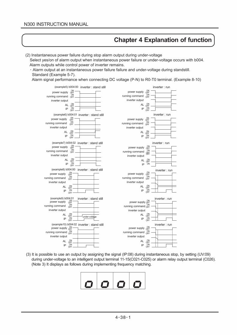
(example5) b004:00
power supply
running command
inverter output
AL
IP
OFFON
ONOFF
OFFON
ONOFF
inverter : stand still
running command
power supply
inverter output
inverter : stand still( 6) b004:01example
AL
IP
OFFON
ONOFF
OFFON
ONOFF
power supply
running command
inverter output
AL
IP
OFFON
ONOFF
OFFON
ONOFF
inverter : run
power supply
running command
inverter output
inverter : run
AL
IP
OFFON
ONOFF
OFFON
ONOFF
power supply
running command
inverter output
inverter : stand still( 7) b004:02example
AL
IP
OFFON
ONOFF
OFFON
ONOFF
OFF
power supply
running command
inverter output
inverter : run
AL
IP
OFFON
ONOFF
OFFON
ON
power supply
running command
inverter output
inverter : run
AL
IP
OFFON
ONOFF
OFFON
ONOFF
inverter : runpower supply
running command
inverter output
AL
IP
OFFON
ONOFF
OFFON
ONOFF
(2) Instantaneous power failure during stop alarm output during under-voltage
Select yes/on of alarm output when instantaneous power failure or under-voltage occurs with b004.
Alarm outputs while control power of inverter remains.
Alarm output at an instantaneous power failure failure and under-voltage during standstill.
Standard (Example 5-7).
Alarm signal performance when connecting DC voltage (P-N) to R0-T0 terminal. (Example 8-10)
(3) It is possible to use an output by assigning the signal (IP:08) during instantaneous stop, by setting (UV:09)
during under-voltage to an intelligent output terminal 11-15(C021-C025) or alarm relay output terminal (C026).
(Note 3) It displays as follows during implementing frequency matching.
power supply
running command
inverter output
inverter : stand still
AL
IP
OFFON
ONOFF
OFFON
ON
OFF
( 8) b004:00example
inverter : stand stillpower supply
running command
inverter output
AL
IP
OFFON
ONOFF
OFFON
ONOFF
( 10) b004:02example
inverter : runpower supply
running command
inverter output
AL
IP
OFFON
ONOFF
OFFON
ONOFF
inverter : stand still( 9) b004:01example
power supply
running command
inverter output
AL
IP
OFFON
ONOFF
OFFON
ONOFF
under-voltage
N300 INSTRUCTION MANUAL
Chapter 4 Explanation of function
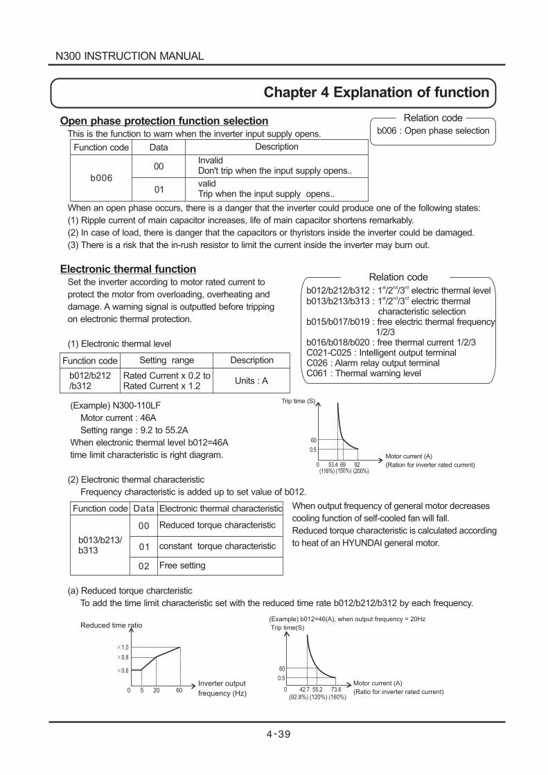
Open phase protection function selectionThis is the function to warn when the inverter input supply opens.
When an open phase occurs, there is a danger that the inverter could produce one of the following states:
(1) Ripple current of main capacitor increases, life of main capacitor shortens remarkably.
(2) In case of load, there is danger that the capacitors or thyristors inside the inverter could be damaged.
(3) There is a risk that the in-rush resistor to limit the current inside the inverter may burn out.
Electronic thermal functionSet the inverter according to motor rated current to
protect the motor from overloading, overheating and
damage. A warning signal is outputted before tripping
on electronic thermal protection.
(1) Electronic thermal level
(Example) N300-110LF
Motor current : 46A
Setting range : 9.2 to 55.2A
When electronic thermal level b012=46A
time limit characteristic is right diagram.
(2) Electronic thermal characteristic
Frequency characteristic is added up to set value of b012.
(a) Reduced torque charcteristic
To add the time limit characteristic set with the reduced time rate b012/b212/b312 by each frequency.
Function code
b006
Data
00
01
Description
InvalidDon't trip when the input supply opens..
validTrip when the input supply opens..
Relation code
b006 : Open phase selection
Relation code
b012/b212/b312 : 1 /2 /3 electric thermal levelst nd rd
b013/b213/b313 : 1 /2 /3 electric thermalcharacteristic selection
b015/b017/b019 : free electric thermal frequency1/2/3
b016/b018/b020 : free thermal current 1/2/3C021-C025 : Intelligent output terminalC026 : Alarm relay output terminalC061 : Thermal warning level
st nd rd
Function code
Function code
b012/b212/b312
Setting range
Rated Current x 0.2 toRated Current x 1.2
Description
Units : A
Trip time (S)
60
0.5
0 53.4 69 92(116%) (150%) (200%)
Motor current (A)
(Ration for inverter rated current)
When output frequency of general motor decreases
cooling function of self-cooled fan will fall.
Reduced torque characteristic is calculated according
to heat of an HYUNDAI general motor.
1.0
0.8
0.6
0 5 20 60
Reduced time ratio
Inverter output
frequency (Hz)
(Example) b012=46(A), when output frequency = 20Hz
Trip time(S)
60
0.5
0 42.7 55.2 73.6(92.8%) (120%) (160%)
Motor current (A)
(Ratio for inverter rated current)
Data Electronic thermal characteristic
b013/b213/b313
00
01
02
Reduced torque characteristic
constant torque characteristic
Free setting
N300 INSTRUCTION MANUAL
Chapter 4 Explanation of function
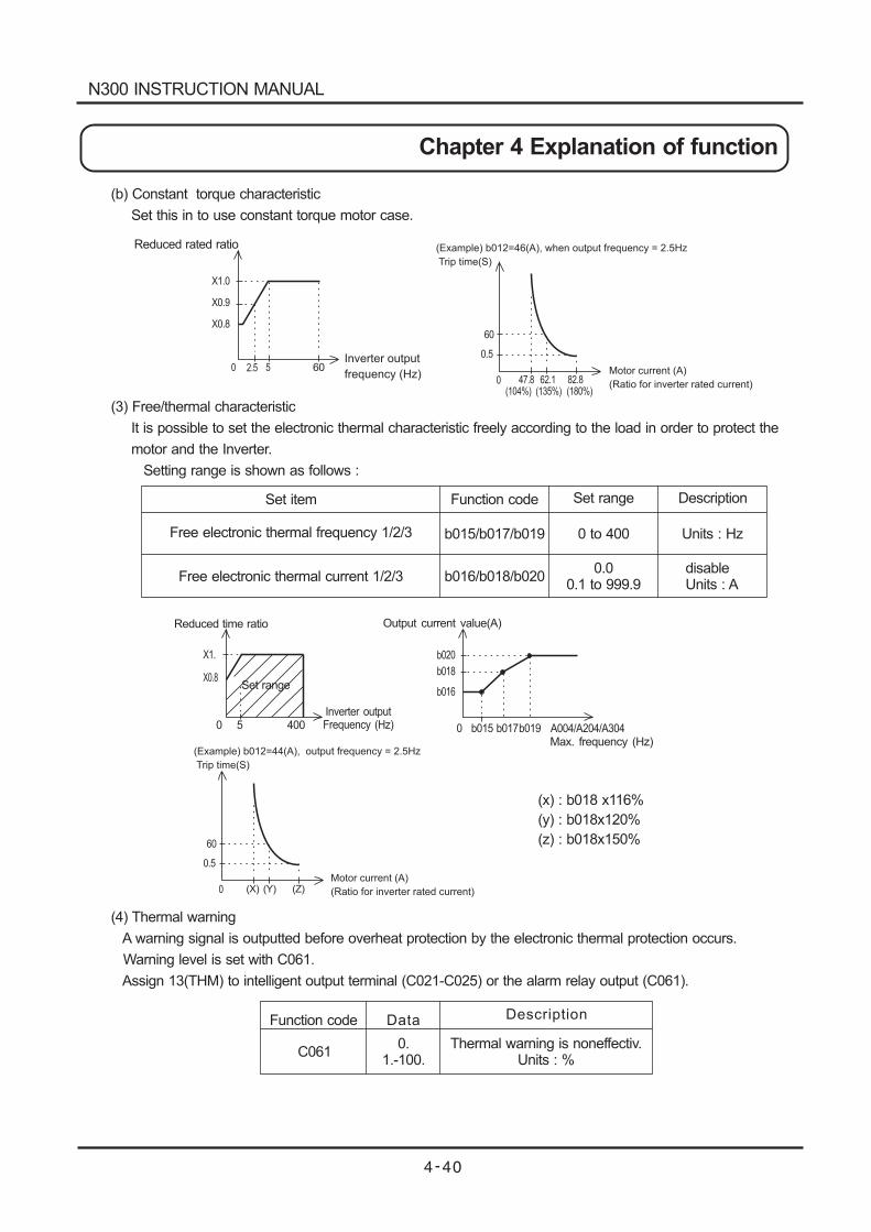
Reduced rated ratio
X1.0
X0.9
X0.8
0 2.5 5 60
60
0.5
0 47.8 62.1 82.8(104%) (135%) (180%)
Reduced time ratio
X1.
X0.8
0 5 400
Set range
Inverter outputFrequency (Hz)
Output current value(A)
b020
b018
b016
0 b015 b017b019 A004/A204/A304Max. frequency (Hz)
(X) (Y) (Z)
60
0.5
0
(b) Constant torque characteristic
Set this in to use constant torque motor case.
(3) Free/thermal characteristic
It is possible to set the electronic thermal characteristic freely according to the load in order to protect the
motor and the Inverter.
Setting range is shown as follows :
(4) Thermal warning
A warning signal is outputted before overheat protection by the electronic thermal protection occurs.
Warning level is set with C061.
Assign 13(THM) to intelligent output terminal (C021-C025) or the alarm relay output (C061).
Inverter output
frequency (Hz)
(Example) b012=46(A), when output frequency = 2.5Hz
Trip time(S)
Motor current (A)
(Ratio for inverter rated current)
Motor current (A)
(Ratio for inverter rated current)
Function code
Function code
Set item
Free electronic thermal frequency 1/2/3
Free electronic thermal current 1/2/3
b015/b017/b019
b016/b018/b020
Set range
0 to 400
0.00.1 to 999.9
Units : Hz
disableUnits : A
Description
(Example) b012=44(A), output frequency = 2.5Hz
Trip time(S)
(x) : b018 x116%
(y) : b018x120%
(z) : b018x150%
Data Description
C0610.
1.-100.Thermal warning is noneffectiv.
Units : %
N300 INSTRUCTION MANUAL
Chapter 4 Explanation of function
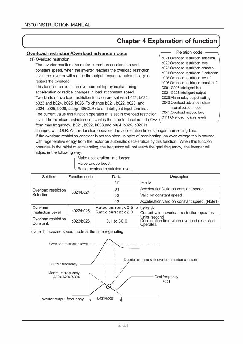
Overload restriction/Overload advance notice(1) Overload restriction
The Inverter monitors the motor current on acceleration and
constant speed, when the inverter reaches the overload restriction
level, the Inverter will reduce the output frequency automatically to
restrict the overload.
This function prevents an over-current trip by inertia during
acceleration or radical changes in load at constant speed.
Two kinds of overload restriction function are set with b021, b022,
b023 and b024, b025, b026. To change b021, b022, b023, and
b024, b025, b026, assign 39(OLR) to an intelligent input terminal.
The current value this function operates at is set in overload restriction
level. The overload restriction constant is the time to decelerate to 0Hz
from max frequency. b021, b022, b023 and b024, b025, b026 is
changed with OLR. As this function operates, the acceleration time is longer than setting time.
If the overload restriction constant is set too short, in spite of accelerating, an over-voltage trip is caused
with regenerative enegy from the motor on automatic deceleration by this function. When this function
operates in the midst of accelerating, the frequency will not reach the goal frequency, the Inverter will
adjust in the following way.
Make acceleration time longer.
Raise torque boost.
Raise overload restriction level.
Overload restriction level
Output frequency
Deceleration set with overload restrion constant
Goal frequency
F001
Maximum frequency
A004/A204/A304
b023/b026
C
Inverter output frequency
Set item
Overload restrictionSelection
Overloadrestriction Level.
Overload restrictionConstant.
Function code
b021/b024
b022/b025
b023/b026
Data
00
01
02
03
Rated current x 0.5 toRated current x 2.0
0.1 to 30.0
Description
Invalid
Acceleration/valid on constant speed.
Valid on constant speed.
Acceleration/valid on constant speed. (Note1)
Units :ACurrent value overload restriction operates.Units :secondDeceleration time when overload restrictionOperates.
(Note 1) Increase speed mode at the time regenating
Relation code
b021:Overload restriction selection
b022:Overload restriction level
b023:Overload restriction constant
b024:Overload restriction 2 selection
b025:Overload restriction level 2
b026:Overload restriction constant 2
C001-C008:Intelligent input
C021-C025:Intelligent output
C026:Alarm relay output setting
C040:Overload advance notice
signal output mode
C041:Overload notices level
C111:Overload notices level2
N300 INSTRUCTION MANUAL
Chapter 4 Explanation of function
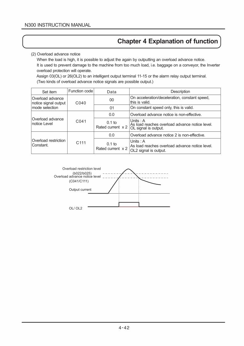
(2) Overload advance notice
When the load is high, it is possible to adjust the again by outputting an overload advance notice.
It is used to prevent damage to the machine from too much load, i.e. baggage on a conveyor, the Inverter
overload protection will operate.
Assign 03(OL) or 26(OL2) to an intelligent output terminal 11-15 or the alarm relay output terminal.
(Two kinds of overload advance notice signals are possible output.)
Set item
Overload advancenotice signal outputmode selection
Overload advancenotice Level
Overload restrictionConstant.
Function code Data Description
C040
C041
C111
00
01
0.0
0.0
0.1 toRated current x 2
0.1 toRated current x 2
On acceleration/deceleration, constant speed,this is valid.
On constant speed only, this is valid.
Overload advance notice is non-effective.
Units : AAs load reaches overload advance notice level.OL signal is output.
Units : AAs load reaches overload advance notice level.OL2 signal is output.
Overload advance notice 2 is non-effective.
Overload restriction level
(b022/b025)Overload advance notice level
(C041/C111)
Output current
OL/ OL2
N300 INSTRUCTION MANUAL
Chapter 4 Explanation of function
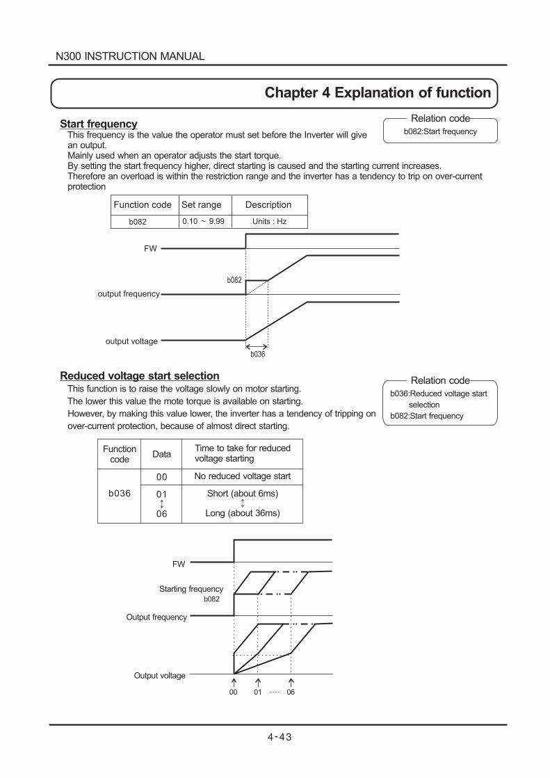
Start frequencyThis frequency is the value the operator must set before the Inverter will givean output.Mainly used when an operator adjusts the start torque.By setting the start frequency higher, direct starting is caused and the starting current increases.Therefore an overload is within the restriction range and the inverter has a tendency to trip on over-currentprotection
Relation code
Relation code
b082:Start frequency
b036:Reduced voltage start
selection
b082:Start frequency
FW
b082
b036
output frequency
output voltage
Function code Set range Description
b082 0.10 9.99 Units : Hz
Reduced voltage start selectionThis function is to raise the voltage slowly on motor starting.
The lower this value the mote torque is available on starting.
However, by making this value lower, the inverter has a tendency of tripping on
over-current protection, because of almost direct starting.
Functioncode
DataTime to take for reducedvoltage starting
b036
00
01
06
No reduced voltage start
Short (about 6ms)
Long (about 36ms)
FW
b082
Starting frequency
Output frequency
Output voltage
00 01 06
N300 INSTRUCTION MANUAL
Chapter 4 Explanation of function
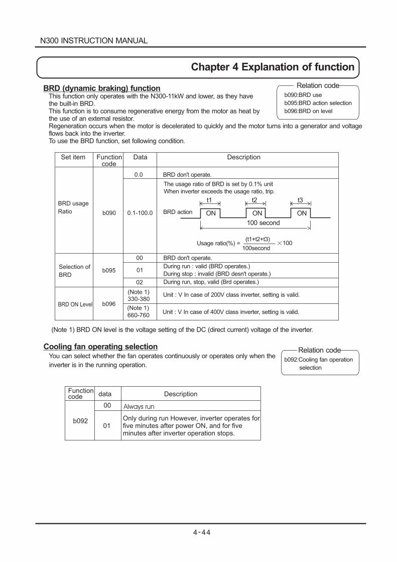
0.0
0.1-100.0
00
01
02
(Note 1)
(Note 1)
330-380
660-760
BRD don't operate.
The usage ratio of BRD is set by 0.1% unit
When inverter exceeds the usage ratio, trip.
BRD don't operate.
During run : valid (BRD operates.)
During stop : invalid (BRD desn't operate.)
During run, stop, valid (Brd operates.)
Unit : V In case of 200V class inverter, setting is valid.
Unit : V In case of 400V class inverter, setting is valid.
Functioncode data Description
b092
00
01
Always run
Only during run However, inverter operates forfive minutes after power ON, and for fiveminutes after inverter operation stops.
b090
b095
b096
Set item Function Data Descriptioncode
BRD usage
Ratio
Selection of
BRD
BRD ON Level
BRD action ON
t1 t2 t3
ON ON
100 second
Usage ratio(%) =(t1+t2+t3)
100second100
BRD (dynamic braking) functionThis function only operates with the N300-11kW and lower, as they havethe built-in BRD.This function is to consume regenerative energy from the motor as heat bythe use of an external resistor.Regeneration occurs when the motor is decelerated to quickly and the motor turns into a generator and voltageflows back into the inverter.To use the BRD function, set following condition.
Relation code
Relation code
b090:BRD use
b095:BRD action selection
b096:BRD on level
b092:Cooling fan operation
selection
(Note 1) BRD ON level is the voltage setting of the DC (direct current) voltage of the inverter.
Cooling fan operating selectionYou can select whether the fan operates continuously or operates only when the
inverter is in the running operation.
N300 INSTRUCTION MANUAL
Chapter 4 Explanation of function
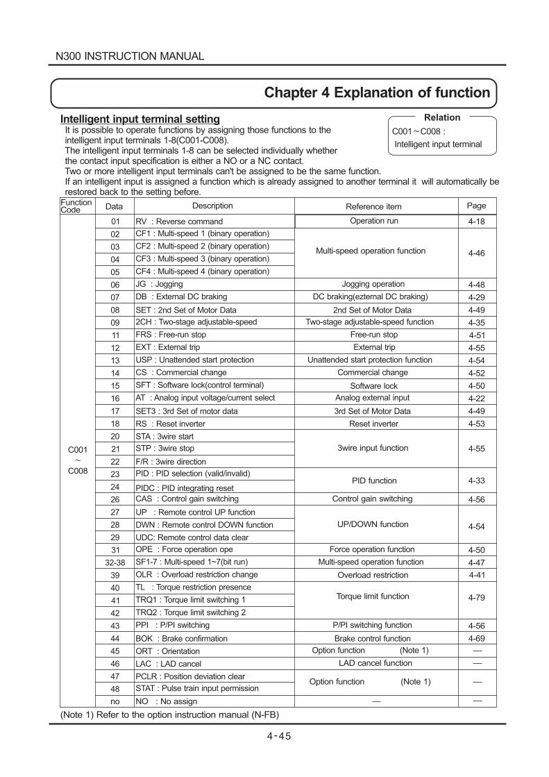
Description Reference item Page
4-18
4-46
4-48
4-29
4-49
4-35
4-51
4-55
4-54
4-52
4-50
4-22
4-49
4-53
4-55
4-33
4-56
4-54
4-50
4-47
4-41
4-79
4-56
4-69
Multi-speed operation function
Overload restriction
3wire input function
PID function
Control gain switching
UP/DOWN function
LAD cancel function
Torque limit function
Option function (Note 1)
C001
C008
Intelligent input terminal settingIt is possible to operate functions by assigning those functions to theintelligent input terminals 1-8(C001-C008).The intelligent input terminals 1-8 can be selected individually whetherthe contact input specification is either a NO or a NC contact.Two or more intelligent input terminals can't be assigned to be the same function.If an intelligent input is assigned a function which is already assigned to another terminal it will automatically berestored back to the setting before.
Relation
C001 C008 :
Intelligent input terminal
no NO : No assign
(Note 1) Refer to the option instruction manual (N-FB)
FunctionCode Data
01
02
03
04
05
06
07
08
09
11
12
13
14
15
16
17
18
20
21
22
23
24
26
27
28
29
31
32-38
39
40
41
42
43
44
45
46
47
48
RV : Reverse command
CF1 : Multi-speed 1 (binary operation)
CF2 : Multi-speed 2 (binary operation)
CF3 : Multi-speed 3 (binary operation)
CF4 : Multi-speed 4 (binary operation)
JG : Jogging
DB : External DC braking
SET : 2nd Set of Motor Data
2CH : Two-stage adjustable-speed
FRS : Free-run stop
EXT : External trip
USP : Unattended start protection
CS : Commercial change
SFT : Software lock(control terminal)
AT : Analog input voltage/current select
SET3 : 3rd Set of motor data
RS : Reset inverter
STA : 3wire start
STP : 3wire stop
F/R : 3wire direction
PIDC : PID integrating reset
PID : PID selection (valid/invalid)
CAS : Control gain switching
UP : Remote control UP function
DWN : Remote control DOWN function
UDC: Remote control data clear
OPE : Force operation ope
SF1-7 : Multi-speed 1~7(bit run)
OLR : Overload restriction change
TL : Torque restriction presence
TRQ1 : Torque limit switching 1
TRQ2 : Torque limit switching 2
PPI : P/PI switching
BOK : Brake confirmation
ORT : Orientation
LAC : LAD cancel
PCLR : Position deviation clear
STAT : Pulse train input permission
Jogging operation
DC braking(ezternal DC braking)
2nd Set of Motor Data
Two-stage adjustable-speed function
Free-run stop
External trip
Unattended start protection function
Commercial change
Software lock
Analog external input
3rd Set of Motor Data
Reset inverter
Operation run
Force operation function
Multi-speed operation function
P/PI switching function
Brake control function
Option function (Note 1)
N300 INSTRUCTION MANUAL
Chapter 4 Explanation of function
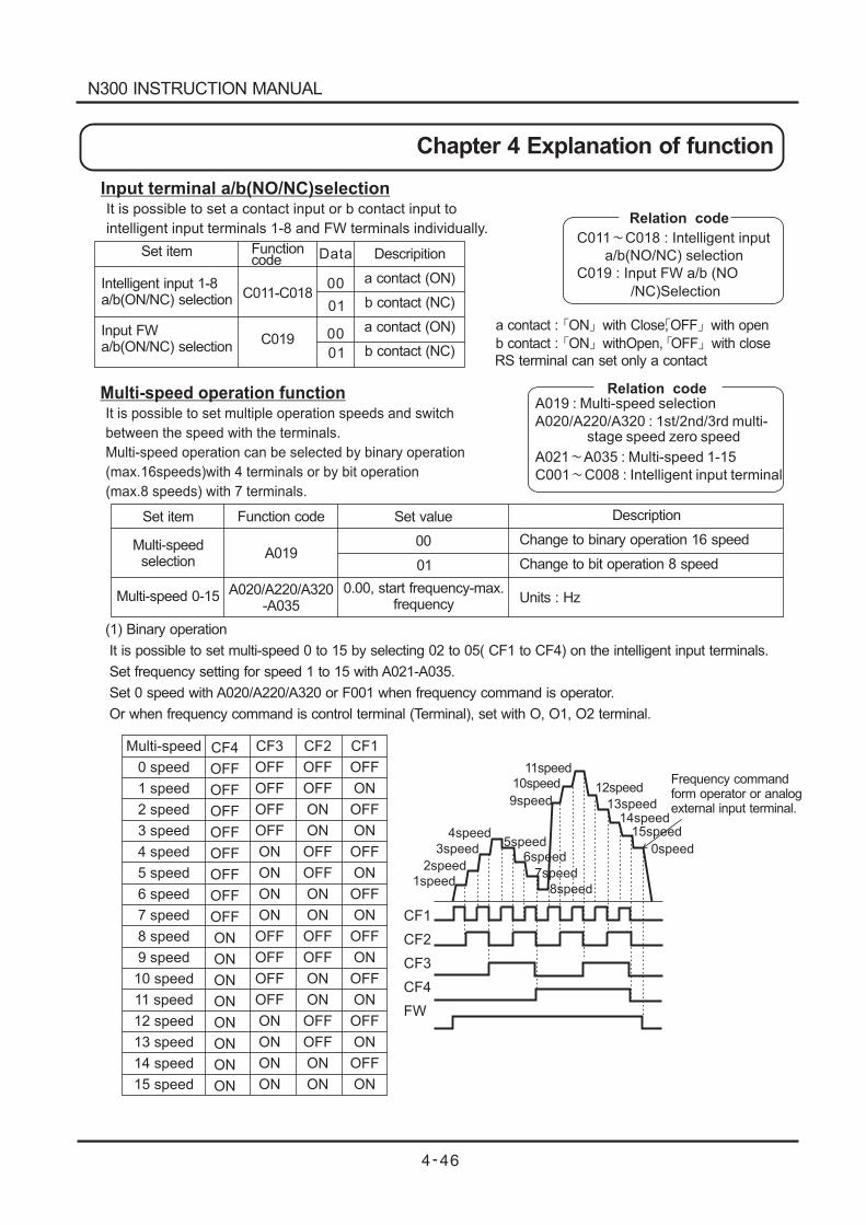
Multi-speed
0 speed
1 speed
2 speed
3 speed
4 speed
5 speed
6 speed
7 speed
8 speed
9 speed
10 speed
11 speed
12 speed
13 speed
14 speed
15 speed
CF4
OFF
OFF
OFF
OFF
OFF
OFF
OFF
OFF
ON
ON
ON
ON
ON
ON
ON
ON
CF3
OFF
OFF
OFF
OFF
ON
ON
ON
ON
OFF
OFF
OFF
OFF
ON
ON
ON
ON
CF2
OFF
OFF
ON
ON
OFF
OFF
ON
ON
OFF
OFF
ON
ON
OFF
OFF
ON
ON
CF1
OFF
ON
OFF
ON
OFF
ON
OFF
ON
OFF
ON
OFF
ON
OFF
ON
OFF
ON
1speed
2speed
3speed
4speed5speed
6speed
7speed
8speed
9speed
10speed
11speed
12speed
13speed14speed
15speed
0speed
Frequency commandform operator or analogexternal input terminal.
CF1
CF2
CF3
CF4
FW
Relation code
C011 C018 : Intelligent input
a/b(NO/NC) selection
C019 : Input FW a/b (NO
/NC)Selection
Input terminal a/b(NO/NC)selectionIt is possible to set a contact input or b contact input to
intelligent input terminals 1-8 and FW terminals individually.
Multi-speed operation functionIt is possible to set multiple operation speeds and switch
between the speed with the terminals.
Multi-speed operation can be selected by binary operation
(max.16speeds)with 4 terminals or by bit operation
(max.8 speeds) with 7 terminals.
a contact : ON with Close,OFF with open
b contact : ON withOpen, OFF with close
RS terminal can set only a contact
Relation codeA019 : Multi-speed selection
A020/A220/A320 : 1st/2nd/3rd multi-stage speed zero speed
A021 A035 : Multi-speed 1-15
C001 C008 : Intelligent input terminal
Set item
Intelligent input 1-8a/b(ON/NC) selection
Input FWa/b(ON/NC) selection
Functioncode
C011-C018
C019
Data
00
00
01
01
Descripition
a contact (ON)
b contact (NC)
a contact (ON)
b contact (NC)
Set item
Multi-speedselection
Multi-speed 0-15
Function code
A019
A020/A220/A320-A035
Set value
00
01
0.00, start frequency-max.frequency
Description
Change to binary operation 16 speed
Change to bit operation 8 speed
Units : Hz
(1) Binary operation
It is possible to set multi-speed 0 to 15 by selecting 02 to 05( CF1 to CF4) on the intelligent input terminals.
Set frequency setting for speed 1 to 15 with A021-A035.
Set 0 speed with A020/A220/A320 or F001 when frequency command is operator.
Or when frequency command is control terminal (Terminal), set with O, O1, O2 terminal.
N300 INSTRUCTION MANUAL
Chapter 4 Explanation of function
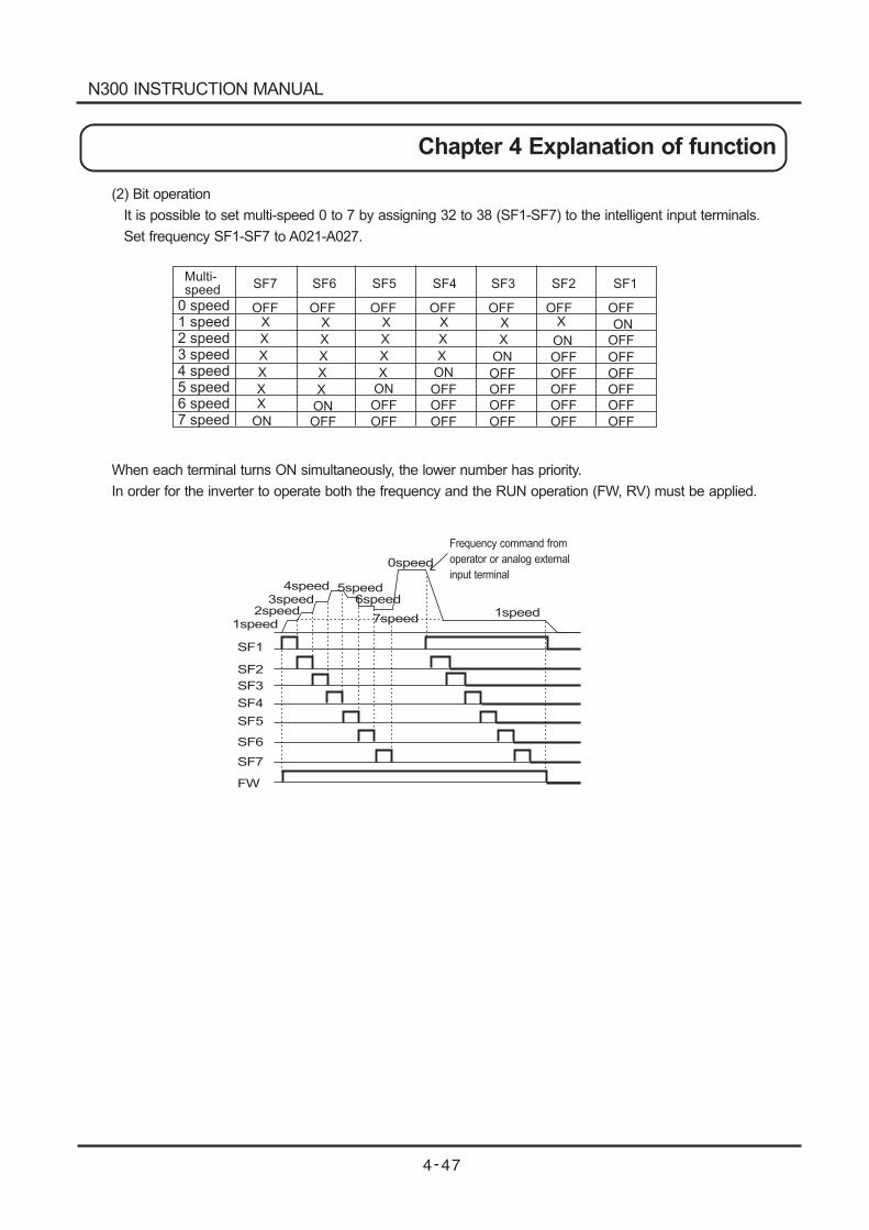
1speed2speed
3speed4speed 5speed
6speed
7speed
0speed
Frequency command from
operator or analog external
input terminal
SF1
SF2
SF3
SF4
FW
1speed
SF5
SF6
SF7
Multi-speed SF7 SF6 SF5 SF4 SF3
0 speed1 speed234567
speedspeedspeedspeedspeedspeed
SF1SF2
OFF OFF OFF OFF OFF OFF OFF
OFF
OFF
OFF
OFF
OFF
OFF
OFF
OFF
OFF
OFF
OFF
OFF
OFF
OFF
OFF
OFF
OFF
OFF
OFF
OFFOFFON
ON
ON
ON
ON
ON
ON
X X X X X X
X X X X X
X X X X
X X X
X XX
(2) Bit operation
It is possible to set multi-speed 0 to 7 by assigning 32 to 38 (SF1-SF7) to the intelligent input terminals.
Set frequency SF1-SF7 to A021-A027.
When each terminal turns ON simultaneously, the lower number has priority.
In order for the inverter to operate both the frequency and the RUN operation (FW, RV) must be applied.
N300 INSTRUCTION MANUAL
Chapter 4 Explanation of function
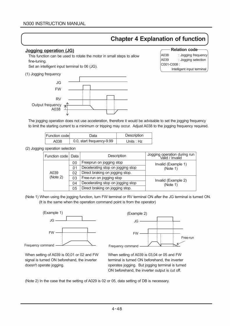
JG
FW
RV
Output frequencyA038
JG
FW
Frequency command
(Example 1)
JG
FW
Frequency command
(Example 2)
Free-run
Jogging operation (JG)This function can be used to rotate the motor in small steps to allow
fine-tuning.
Set an intelligent input terminal to 06 (JG).
Relation code
A038 : Jogging frequency
A039 : Jogging selection
C001-C008 :
Intelligent input terminal
Function code
Function code
A038
Data
0.0, start frequency-9.99
Description
Units : Hz
(1) Jogging frequency
The jogging operation does not use acceleration, therefore it would be advisable to set the jogging frequency
to limit the starting current to a minimum or tripping may occur. Adjust A038 to the jogging frequency required.
(2) Jogging operation selection
(Note 1) When using the jogging function, turn FW terminal or RV terminal ON after the JG terminal is turned ON.
(It is the same when the operation command point is from the operator)
Data Jogging operation during runValid / Invalid
A039(Note 2)
00
01
02
03
04
05
Description
Freeprun on jogging stop
Free-run on jogging stop
Decelerating stop on jogging stop
Decelerating stop on jogging stop
Direct braking on jogging stop.
Direct braking on jogging stop.
Invalid (Example 1)(Note 1)
Invalid (Example 2)(Note 1)
When setting of A039 is 00,01 or 02 and FW
signal is turned ON beforehand, the inverter
doesn't operate jogging.
When setting of A039 is 03,04 or 05 and FW
terminal is turned ON beforehand, the inverter
operates jogging. But jogging terminal is turned
ON beforehand, the inverter output is cut off.
(Note 2) In the case that the setting of A029 is 02 or 05, data setting of DB is necessary.
N300 INSTRUCTION MANUAL
Chapter 4 Explanation of function
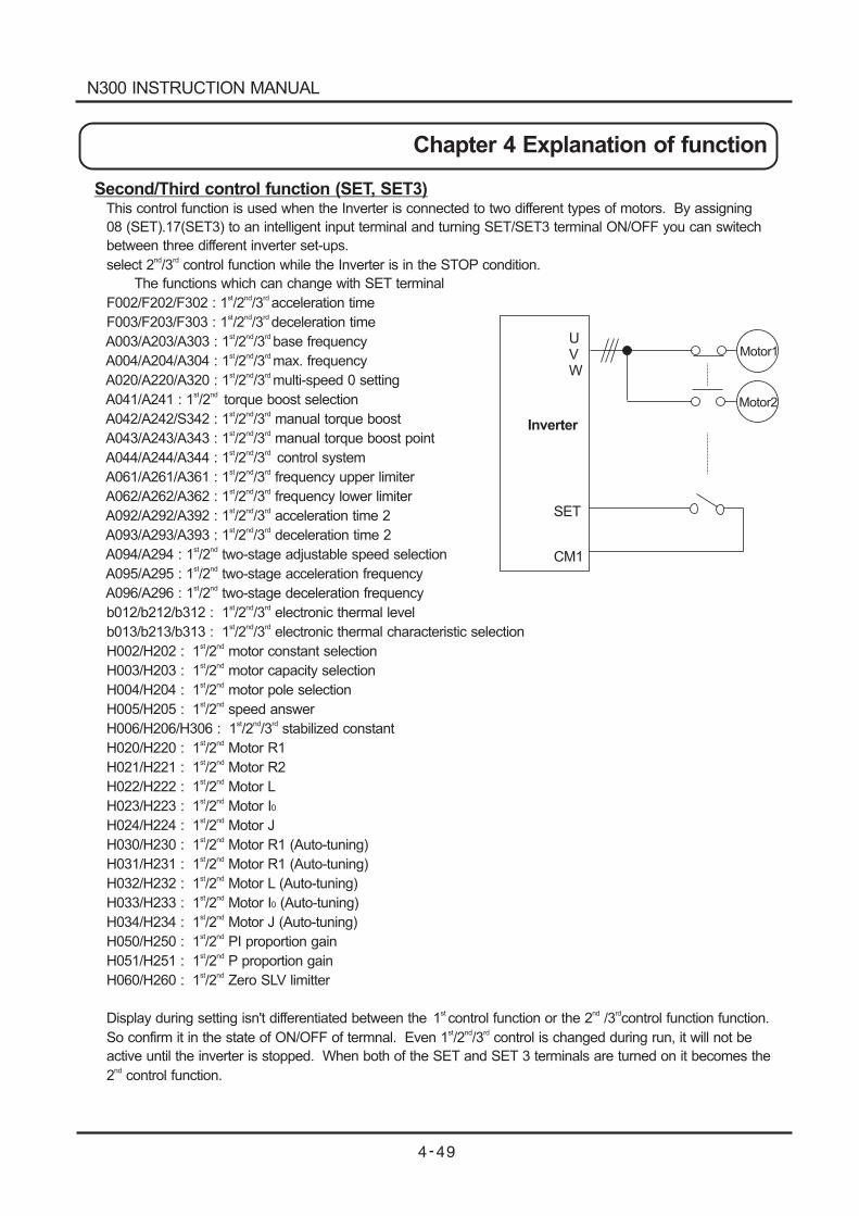
Second/Third control function (SET, SET3)This control function is used when the Inverter is connected to two different types of motors. By assigning
08 (SET).17(SET3) to an intelligent input terminal and turning SET/SET3 terminal ON/OFF you can switech
between three different inverter set-ups.
select 2 /3 control function while the Inverter is in the STOP condition.nd rd
The functions which can change with SET terminal
F002/F202/F302 : 1 /2 /3 acceleration timest nd rd
F003/F203/F303 : 1 /2 /3 deceleration timest nd rd
A003/A203/A303 : 1 /2 /3 base frequencyst nd rd
A004/A204/A304 : 1 /2 /3 max. frequencyst nd rd
A020/A220/A320 : 1 /2 /3 multi-speed 0 settingst nd rd
A041/A241 : 1 /2 torque boost selectionst nd
A042/A242/S342 : 1 /2 /3 manual torque boostst nd rd
A043/A243/A343 : 1 /2 /3 manual torque boost pointst nd rd
A044/A244/A344 : 1 /2 /3 control systemst nd rd
A061/A261/A361 : 1 /2 /3 frequency upper limiterst nd rd
A062/A262/A362 : 1 /2 /3 frequency lower limiterst nd rd
A092/A292/A392 : 1 /2 /3 acceleration time 2st nd rd
A093/A293/A393 : 1 /2 /3 deceleration time 2st nd rd
A094/A294 : 1 /2 two-stage adjustable speed selectionst nd
A095/A295 : 1 /2 two-stage acceleration frequencyst nd
A096/A296 : 1 /2 two-stage deceleration frequencyst nd
b012/b212/b312 : 1 /2 /3 electronic thermal levelst nd rd
b013/b213/b313 : 1 /2 /3 electronic thermal characteristic selectionst nd rd
H002/H202 : 1 /2 motor constant selectionst nd
H003/H203 : 1 /2 motor capacity selectionst nd
H004/H204 : 1 /2 motor pole selectionst nd
H005/H205 : 1 /2 speed answerst nd
H006/H206/H306 : 1 /2 /3 stabilized constantst nd rd
H020/H220 : 1 /2 Motor R1st nd
H021/H221 : 1 /2 Motor R2st nd
H022/H222 : 1 /2 Motor Lst nd
H023/H223 : 1 /2 Motor Ist nd
0
H024/H224 : 1 /2 Motor Jst nd
H030/H230 : 1 /2 Motor R1 (Auto-tuning)st nd
H031/H231 : 1 /2 Motor R1 (Auto-tuning)st nd
H032/H232 : 1 /2 Motor L (Auto-tuning)st nd
H033/H233 : 1 /2 Motor I (Auto-tuning)st nd
0
H034/H234 : 1 /2 Motor J (Auto-tuning)st nd
H050/H250 : 1 /2 PI proportion gainst nd
H051/H251 : 1 /2 P proportion gainst nd
H060/H260 : 1 /2 Zero SLV limitterst nd
Display during setting isn't differentiated between the 1 control function or the 2 /3 control function function.st nd rd
So confirm it in the state of ON/OFF of termnal. Even 1 /2 /3 control is changed during run, it will not best nd rd
active until the inverter is stopped. When both of the SET and SET 3 terminals are turned on it becomes the
2 control function.nd
Inverter
UVW
SET
CM1
Motor1
Motor2
N300 INSTRUCTION MANUAL
Chapter 4 Explanation of function
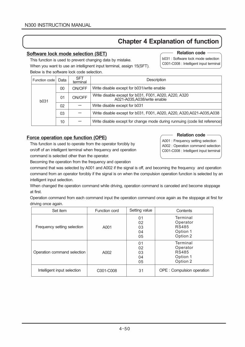
Software lock mode selection (SET)
This function is used to prevent changing data by mistake.
When you want to use an intellignent input terminal, assign 15(SFT).
Below is the software lock code selection.
Force operation ope function (OPE)
This function is used to operate from the operator forcibly by
on/off of an intelligent terminal when frequency and operation
command is selected other than the operator.
Becoming the operation from the frequency and operation
command that was selected by A001 and A002 if the signal is off, and becoming the frequency and operation
command from an operator forcibly if the signal is on when the compulsion operation function is selected by an
intelligent input selection.
When changed the operation command while driving, operation command is canceled and become stoppage
at first.
Operation command from each command input the operation command once again as the stoppage at first for
driving once again.
Relation code
b031 : Software lock mode selection
C001-C008 : Intelligent input terminal
Function code Data SFTterminal
b031
00
01
02
03
10
ON/OFF
ON/OFF
-
-
-
Description
Write disable except for b031/write enable
Write disable except for b031, F001, A020, A220, A320A021-A035,A038/write enable
Write disable except for b031, F001, A020, A220, A320,A021-A035,A038
Write disable except for b031
Write disable except for change mode during runnuing (code list reference)
Set item Function cord Setting value Contents
Frequency setting selection
Operation command selection
Intelligent input selection
A001
A002
C001-C008
0102030405
0102030405
TerminalOperatorRS485Option 1Option 2
TerminalOperatorRS485Option 1Option 2
OPE : Compulsion operation31
Relation code
A001 : Frequency setting selection
A002 : Operation command selection
C001-C008 : Intelligent input terminal
N300 INSTRUCTION MANUAL
Chapter 4 Explanation of function
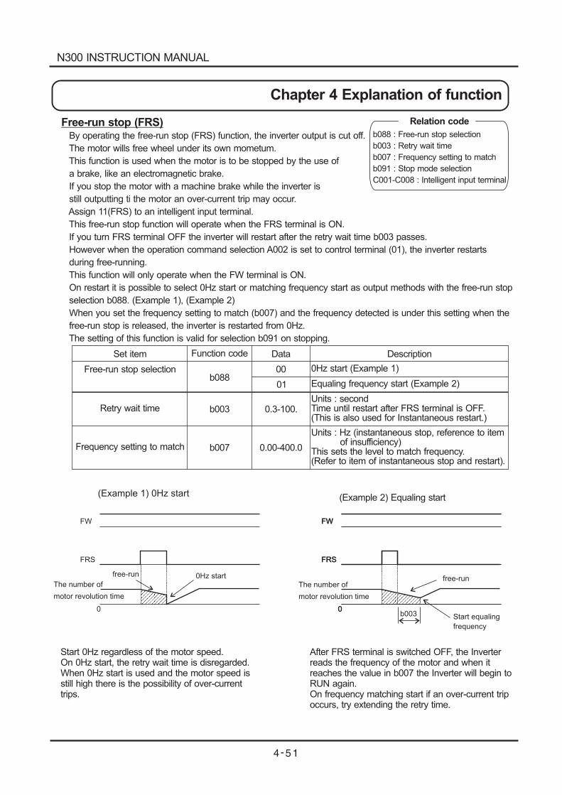
FW
FRS
The number of
motor revolution time
The number of
motor revolution time
0Hz startfree-runfree-run
(Example 1) 0Hz start
0
FW
FRS
0
FW
FRS
(Example 2) Equaling start
0Start equaling
frequency
b003
Free-run stop (FRS)By operating the free-run stop (FRS) function, the inverter output is cut off.
The motor wills free wheel under its own mometum.
This function is used when the motor is to be stopped by the use of
a brake, like an electromagnetic brake.
If you stop the motor with a machine brake while the inverter is
still outputting ti the motor an over-current trip may occur.
Assign 11(FRS) to an intelligent input terminal.
This free-run stop function will operate when the FRS terminal is ON.
If you turn FRS terminal OFF the inverter will restart after the retry wait time b003 passes.
However when the operation command selection A002 is set to control terminal (01), the inverter restarts
during free-running.
This function will only operate when the FW terminal is ON.
On restart it is possible to select 0Hz start or matching frequency start as output methods with the free-run stop
selection b088. (Example 1), (Example 2)
When you set the frequency setting to match (b007) and the frequency detected is under this setting when the
free-run stop is released, the inverter is restarted from 0Hz.
The setting of this function is valid for selection b091 on stopping.
Set item
Free-run stop selection
Retry wait time
Frequency setting to match
Function code
b088
b003
b007
Data
00
01
0.3-100.
0.00-400.0
Description
0Hz start (Example 1)
Equaling frequency start (Example 2)
Units : secondTime until restart after FRS terminal is OFF.(This is also used for Instantaneous restart.)
Units : Hz (instantaneous stop, reference to itemof insufficiency)
This sets the level to match frequency.(Refer to item of instantaneous stop and restart).
Start 0Hz regardless of the motor speed.On 0Hz start, the retry wait time is disregarded.When 0Hz start is used and the motor speed isstill high there is the possibility of over-currenttrips.
After FRS terminal is switched OFF, the Inverterreads the frequency of the motor and when itreaches the value in b007 the Inverter will begin toRUN again.On frequency matching start if an over-current tripoccurs, try extending the retry time.
Relation code
b088 : Free-run stop selection
b003 : Retry wait time
b007 : Frequency setting to match
b091 : Stop mode selection
C001-C008 : Intelligent input terminal
N300 INSTRUCTION MANUAL
Chapter 4 Explanation of function
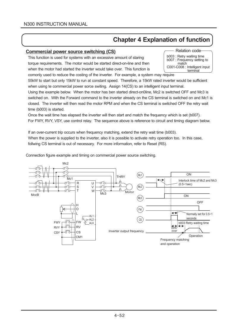
Mc2
Mc1
Mc3MccB
THRY
H
O
L
FWY
RVY
CSY
FW
RV
CS
CM1
AL1
AL2
AL0
Mc1
Mc2
Mc3
FW
CS
ON
OFF
b003 Retry waiting time
20msover
Interlock time of Mc2 and Mc3(0.5~1sec)
Normally set for 0.5~1
seconds
Inverter output frequency
Operation
Frequency matching
and operation
ON
R
S
T
U
V
W
Commercial power source switching (CS)
This function is used for systems with an excessive amount of staring
torque requirements. The motor would be started direct-on-line and then
when the motor had started the inverter would take over. This function is
comonly used to reduce the costing of the inverter. For example, a system may require
55kW to start but only 15kW to run at constant speed. Therefore, a 15kW rated inverter would be sufficient
when using te commercial power sorce switing. Assign 14(CS) to an intelligent input terminal.
Using the example below. When the motor has ben started direct-on0line, Mc2 is switched OFF and Mc3 is
switched on. With the Forward command to the inverter already on the CS terminal is switched on and Mc1 is
closed. The inverter will then read the motor RPM and when the CS terminal is switched OFF the retry wait
time (b003) is started.
Once the wait time has elapsed the inverter will then start and match the frequency which is set (b007).
For FWY, RVY, VSY, use control relay. The sequence above is reference to circuit and timing diagram below.
If an over-current trip occurs when frequency matching, extend the retry wait time (b003).
When the power is supplied to the inverter, also it is possible to activate retry operation too. In this case,
follwing CS terminal is out of necessary. For more information, refer to Reset (RS).
Connection figure example and timing on commercial power source switching.
Motor
Relation code
b003 : Retry waiting timeb007 : Frequency setting to
matchC001-C008 : Intelligent input
terminal
N300 INSTRUCTION MANUAL
Chapter 4 Explanation of function
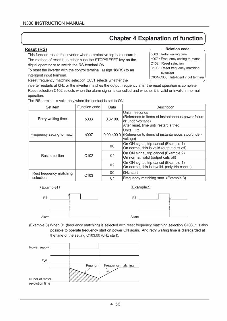
Example
RS
Alarm Alarm
Example
RS
(Example 3) When 01 (frequency matching) is selected with reset frequency matching selection C103, it is also
possible to operate frequency start on power ON again. And retry waiting time is disregarded at
the time of the setting C103:00 (0Hz start).
Power supply
FW
Nuber of motor
revolution time
Free-run Frequency matching
Reset (RS)This function resets the inverter when a protective trip has occurred.
The method of reset is to either push the STOP/RESET key on the
digital operator or to switch the RS terminal ON.
To reset the inverter with the control terminal, assign 18(RS) to an
intelligent input terminal.
Reset frequency matching selection C031 selects whether the
inverter restarts at 0Hz or the inverter matches the output frequency after the reset operation is complete.
Reset selection C102 selects when the alarm signal is cancelled and whether it is valid or invalid in normal
operation.
The RS terminal is valid only when the contact is set to ON.
Set item
Retry waiting time
Frequency setting to match
Rest selection
Rest frequency matchingselection
Function code
b003
b007
C102
C103
Data
0.3-100.
0.00-400.0
Description
Units : seconds(Reference to items of instantaneous power failureor under-voltage)After reset, time until restart is tried.
Units : Hz(Reference to items of instantaneous stop/under-voltage)
Relation code
b003 : Retry waiting time
b007 : Frequency setting to match
C102 : Reset selection
C103 : Reset frequency matching
selection
C001-C008 : Intelligent input terminal
On ON signal, trip cancel (Example 1)On normal, this is valid (output cuts off)
On ON signal, trip cancel (Example 2)On normal, valid (output cuts off)
On ON signal, trip cancel (Example 1)On normal, this is invalid. (only trip cancel)
0Hz start
Frequency matching start. (Example 3)
00
00
01
01
02
N300 INSTRUCTION MANUAL
Chapter 4 Explanation of function
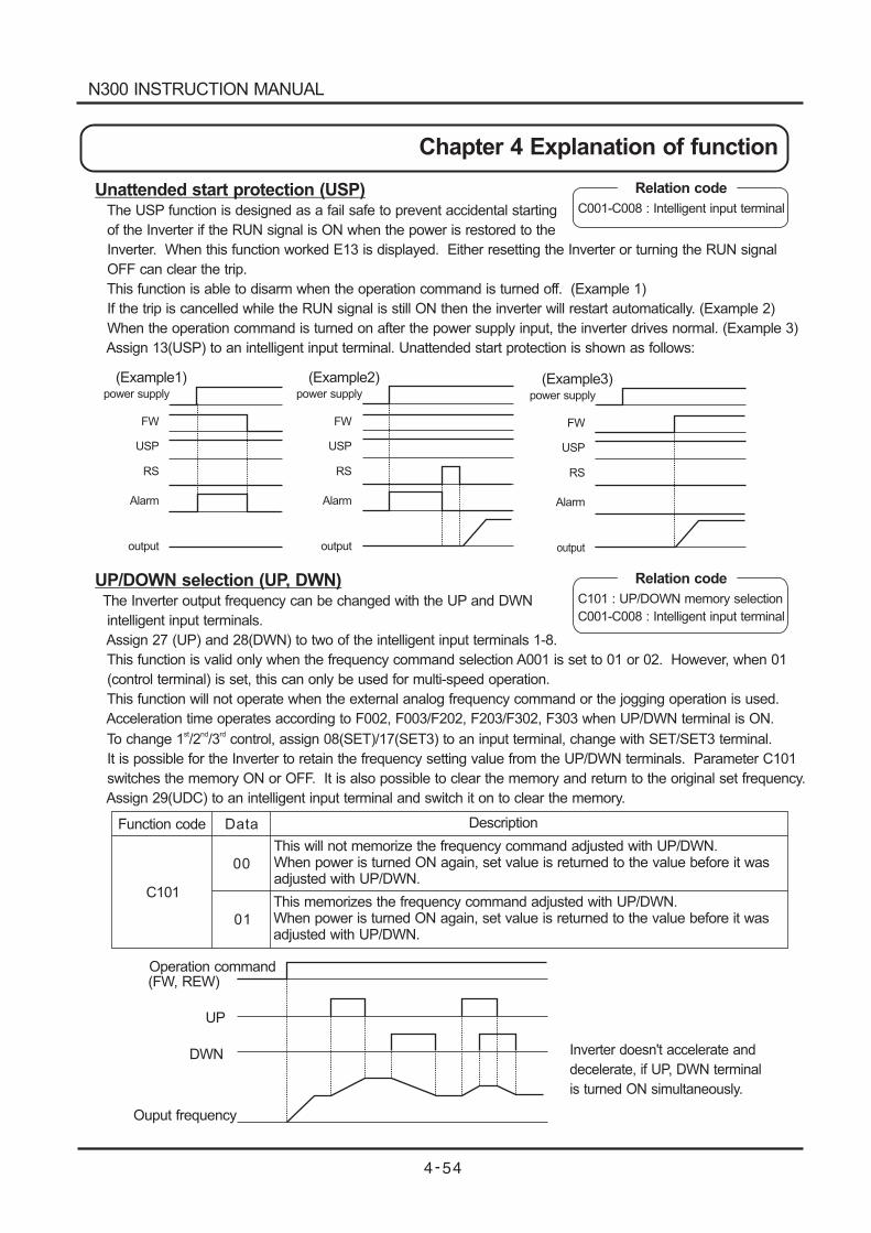
Ouput frequency
Inverter doesn't accelerate and
decelerate, if UP, DWN terminal
is turned ON simultaneously.
Operation command(FW, REW)
UP
DWN
(Example1)power supply
FW
USP
RS
Alarm
output
(Example2)power supply
FW
USP
RS
Alarm
output
(Example3)power supply
FW
USP
RS
Alarm
output
Unattended start protection (USP)The USP function is designed as a fail safe to prevent accidental starting
of the Inverter if the RUN signal is ON when the power is restored to the
Inverter. When this function worked E13 is displayed. Either resetting the Inverter or turning the RUN signal
OFF can clear the trip.
This function is able to disarm when the operation command is turned off. (Example 1)
If the trip is cancelled while the RUN signal is still ON then the inverter will restart automatically. (Example 2)
When the operation command is turned on after the power supply input, the inverter drives normal. (Example 3)
Assign 13(USP) to an intelligent input terminal. Unattended start protection is shown as follows:
Relation code
C001-C008 : Intelligent input terminal
UP/DOWN selection (UP, DWN)The Inverter output frequency can be changed with the UP and DWN
intelligent input terminals.
Assign 27 (UP) and 28(DWN) to two of the intelligent input terminals 1-8.
This function is valid only when the frequency command selection A001 is set to 01 or 02. However, when 01
(control terminal) is set, this can only be used for multi-speed operation.
This function will not operate when the external analog frequency command or the jogging operation is used.
Acceleration time operates according to F002, F003/F202, F203/F302, F303 when UP/DWN terminal is ON.
To change 1 /2 /3 control, assign 08(SET)/17(SET3) to an input terminal, change with SET/SET3 terminal.st nd rd
It is possible for the Inverter to retain the frequency setting value from the UP/DWN terminals. Parameter C101
switches the memory ON or OFF. It is also possible to clear the memory and return to the original set frequency.
Assign 29(UDC) to an intelligent input terminal and switch it on to clear the memory.
Relation code
C101 : UP/DOWN memory selection
C001-C008 : Intelligent input terminal
Function code
C101
Data
00
01
Description
This will not memorize the frequency command adjusted with UP/DWN.When power is turned ON again, set value is returned to the value before it wasadjusted with UP/DWN.
This memorizes the frequency command adjusted with UP/DWN.When power is turned ON again, set value is returned to the value before it wasadjusted with UP/DWN.
N300 INSTRUCTION MANUAL
Chapter 4 Explanation of function
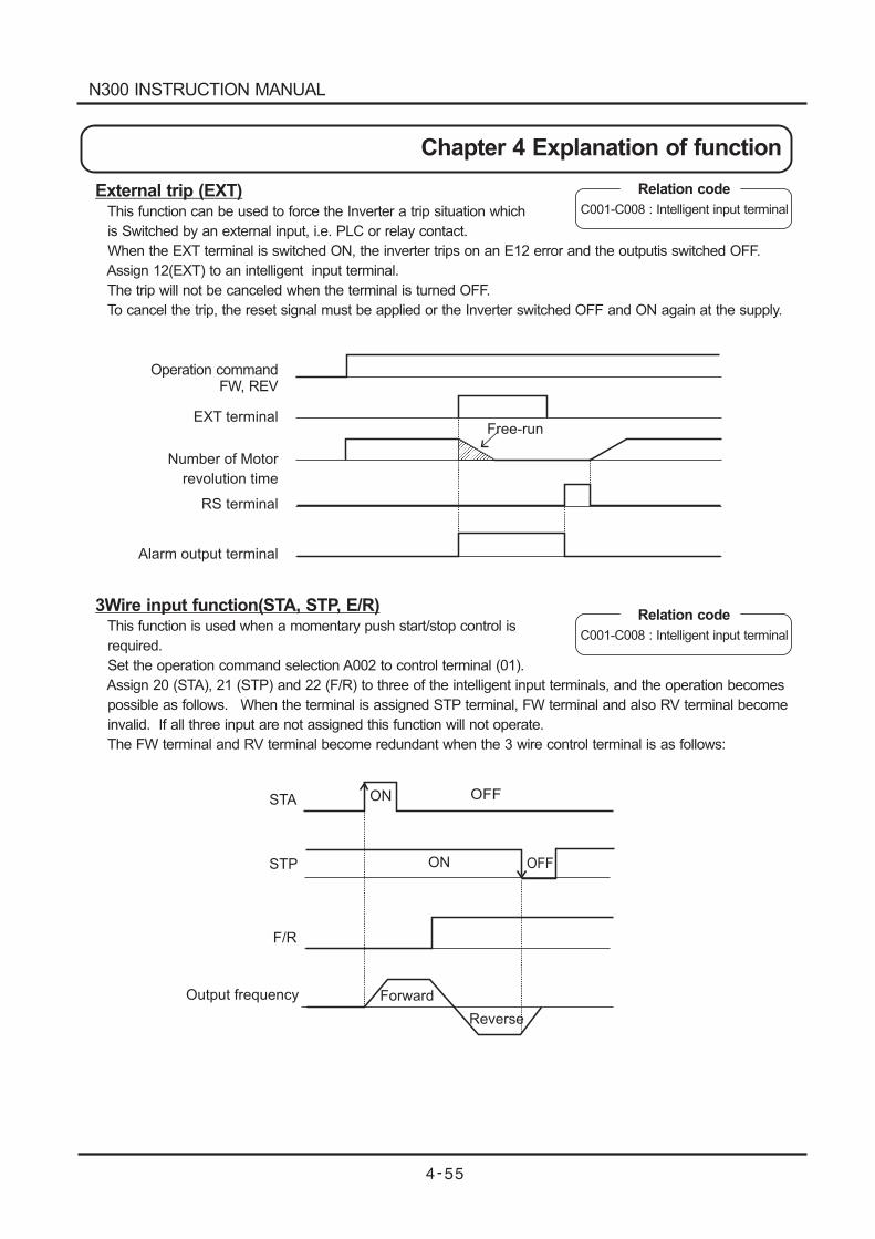
Operation commandFW, REV
EXT terminal
Number of Motor
revolution time
RS terminal
Alarm output terminal
Free-run
STA
STP
F/R
Output frequency
ON
ON OFF
Forward
Reverse
OFF
External trip (EXT)This function can be used to force the Inverter a trip situation which
is Switched by an external input, i.e. PLC or relay contact.
When the EXT terminal is switched ON, the inverter trips on an E12 error and the outputis switched OFF.
Assign 12(EXT) to an intelligent input terminal.
The trip will not be canceled when the terminal is turned OFF.
To cancel the trip, the reset signal must be applied or the Inverter switched OFF and ON again at the supply.
3Wire input function(STA, STP, E/R)This function is used when a momentary push start/stop control is
required.
Set the operation command selection A002 to control terminal (01).
Assign 20 (STA), 21 (STP) and 22 (F/R) to three of the intelligent input terminals, and the operation becomes
possible as follows. When the terminal is assigned STP terminal, FW terminal and also RV terminal become
invalid. If all three input are not assigned this function will not operate.
The FW terminal and RV terminal become redundant when the 3 wire control terminal is as follows:
Relation code
Relation code
C001-C008 : Intelligent input terminal
C001-C008 : Intelligent input terminal
N300 INSTRUCTION MANUAL
Chapter 4 Explanation of function
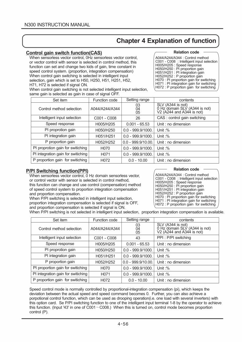
Control gain switch function(CAS)When sensorless vector control, 0Hz sensorless vector control,or vector control with sensor is selected in control method, thisfunction can set and change two kids of gain, time constant inspeed control system. (proportion, integration compensation)When control gain switching is selected in intelligent inputselection, gain which is set to H50, H250, H51, H251, H52,H71, H72 is selected if signal ON.When control gain switching is not selected intelligent input selection,same gain is selected as gain in case of signal OFF.
P/PI Switching function(PPI)When sensorless vector control, 0 Hz domain sensorless vector,or control vector with sensor is selected in control method,this function can change and use control (compensation) methodof speed control system to proportion integration compensationand proportion compensation.When P/PI switching is selected in intelligent input selection,proportion integration compensation is selected if signal is OFF,and proportion compensation is selected if signal is ON.When P/PI switching is not selected in intelligent input selection, proportion integration compensation is available.
Speed control mode is normally controlled by proportional-integration compensation (pi), which keeps thedeviation between the actual speed and speed command becomes 0. Further, you can also achieve aporpotional control function, which can be used as drooping operation(i.e. one load with several inverters) withthis option card. Se P/PI switching function to one of the intelligent input terminal 1-8 by the operator to achievethis function. (Input '43' in one of C001 C008.) When this is turned on, control mode becomes proportioncontrol (P).
Relation code
A044/A244/A344 : Control methodC001 - C008 : Intelligent input selectionH005/H205 : Speed responseH050/H250 : PI proportion gainH051/H251 : PI integration gainH052/H252 : P proportion gainH070 : PI proportion gain for switichingH071 : PI integration gain for switichingH072 : P proportion gain for switiching
Set item
Set item
Function code
Function code
Setting range
Setting range
contents
contents
Control method selection
Control method selection
Intelligent input selection
Intelligent input selection
Speed response
Speed response
PI proprotion gain
PI proprotion gain
PI integration gain
PI integration gain
P proportion gain
P proportion gain
PI proprotion gain for switiching
PI proportion gain for switiching
PI integration gain for switiching
PI integration gain for switiching
P proportion gain for switiching
P proportion gain for switiching
H072
H072
A044/A244/A344
A044/A244/A344
C001 - C008
C001 - C008
H005/H205
H005/H205
H050/H250
H050/H250
H051/H251
H051/H251
H052/H252
H052/H252
H070
H070
H071
H071
030405
030405
26
43
0.001 - 65.53
0.001 - 65.53
0.0 - 999.9/1000.
0.0 - 999.9/1000.
0.0 - 999.9/1000.
0.0 - 999.9/1000.
0.0 - 999.9/10.00.
0.0 - 999.9/10.00.
0.0 - 999.9/1000.
0.0 - 999.9/1000.
0.0 - 999.9/1000.
0.0 - 999.9/1000.
0.0 - 10.00
0.0 - 10.00
SLV (A344 is not)0 Hz domain SLV (A344 is not)V2 (A244 and A344 is not)
SLV (A344 is not)0 Hz domain SLV (A344 is not)V2 (A244 and A344 is not)
CAS : control gain switching
PPI : P/PI switching
Unit : no dimension
Unit : no dimension
Unit : no dimension
Unit : no dimension
Unit : no dimension
Unit : no dimension
Unit :%
Unit :%
Unit :%
Unit :%
Unit :%
Unit :%
Unit :%
Unit :%
Relation code
A044/A244/A344 : Control methodC001 - C008 : Intelligent input selectionH005/H205 : Speed responseH050/H250 : PI proportion gainH051/H251 : PI integration gainH052/H252 : P proportion gainH070 : PI proportion gain for switichingH071 : PI integration gain for switichingH072 : P proportion gain for switiching
N300 INSTRUCTION MANUAL
Chapter 4 Explanation of function
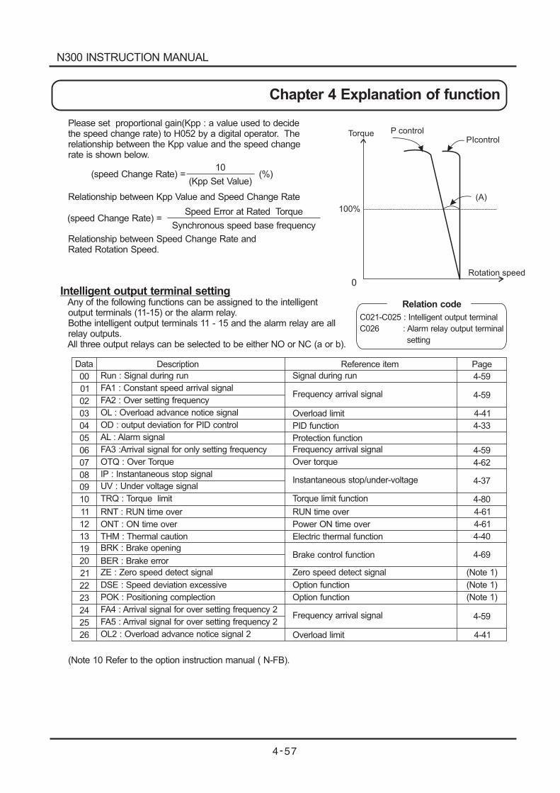
(speed Change Rate) = (%)10
(Kpp Set Value)
(speed Change Rate) =Speed Error at Rated Torque
Synchronous speed base frequency
Torque P controlPIcontrol
(A)
Rotation speed
100%
0
Please set proportional gain(Kpp : a value used to decidethe speed change rate) to H052 by a digital operator. Therelationship between the Kpp value and the speed changerate is shown below.
Relationship between Kpp Value and Speed Change Rate
Relationship between Speed Change Rate andRated Rotation Speed.
Intelligent output terminal settingAny of the following functions can be assigned to the intelligentoutput terminals (11-15) or the alarm relay.Bothe intelligent output terminals 11 - 15 and the alarm relay are allrelay outputs.All three output relays can be selected to be either NO or NC (a or b).
(Note 10 Refer to the option instruction manual ( N-FB).
Relation code
C021-C025 : Intelligent output terminal
C026 : Alarm relay output terminal
setting
00
01
02
03
04
05
06
07
08
09
10
11
12
13
19
20
21
22
23
24
25
26
Data Page
4-59
4-59
4-59
4-59
4-41
4-41
4-33
4-40
4-62
4-37
4-80
4-61
4-61
4-69
(Note 1)
(Note 1)
(Note 1)
Run : Signal during run
FA1 : Constant speed arrival signal
FA2 : Over setting frequency
OL : Overload advance notice signal
Description
OD : output deviation for PID control
AL : Alarm signal
FA3 :Arrival signal for only setting frequency
OTQ : Over Torque
IP : Instantaneous stop signal
UV : Under voltage signal
TRQ : Torque limit
RNT : RUN time over
ONT : ON time over
THM : Thermal caution
BRK : Brake opening
BER : Brake error
ZE : Zero speed detect signal
DSE : Speed deviation excessive
POK : Positioning complection
FA4 : Arrival signal for over setting frequency 2
FA5 : Arrival signal for over setting frequency 2
OL2 : Overload advance notice signal 2
Signal during run
Frequency arrival signal
Overload limit
PID function
Protection function
Frequency arrival signal
Over torque
Instantaneous stop/under-voltage
Reference item
Torque limit function
RUN time over
Power ON time over
Electric thermal function
Brake control function
Zero speed detect signal
Option function
Option function
Frequency arrival signal
Overload limit
N300 INSTRUCTION MANUAL
Chapter 4 Explanation of function
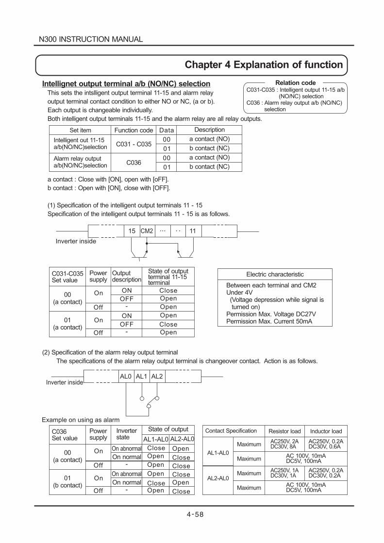
Inverter insideAL0 AL1 AL2
Example on using as alarm
Inverter inside
15 CM2 11
Intellignet output terminal a/b (NO/NC) selectionThis sets the intslligent output terminal 11-15 and alarm relay
output terminal contact condition to either NO or NC, (a or b).
Each output is changeable individually.
Both intelligent output terminals 11-15 and the alarm relay are all relay outputs.
a contact : Close with [ON], open with [oFF].
b contact : Open with [ON], close with [OFF].
(1) Specification of the intelligent output terminals 11 - 15
Specification of the intelligent output terminals 11 - 15 is as follows.
(2) Specification of the alarm relay output terminal
The specifications of the alarm relay output terminal is changeover contact. Action is as follows.
Relation codeC031-C035 : Intelligent output 11-15 a/b
(NO/NC) selectionC036 : Alarm relay output a/b (NO/NC)
selection
Set item
Intelligent out 11-15a/b(NO/NC)selection
Alarm relay outputa/b(NO/NC)selection
Function code
C031 - C035
C036
Data
00
00
01
01
Description
a contact (NO)
a contact (NO)
b contact (NC)
b contact (NC)
C031-C035Set value
Powersupply
Outputdescription
State of outputterminal 11-15terminal
00(a contact)
01(a contact)
On
On
Off
Off
ON
ON
OFF
OFF
-
-
Close
Close
Open
Open
Open
Open
Electric characteristic
Between each terminal and CM2Under 4V(Voltage depression while signal isturned on)
Permission Max. Voltage DC27VPermission Max. Current 50mA
C036Set value
Powersupply
Inverterstate
State of output
00(a contact)
01(b contact)
On
On
Off
Off
On abnormal
On abnormal
On normal
On normal
-
-
Close
Close
Close
Close
Open
Open
Contact Specification Resistor load Inductor load
AL1-AL0
AL2-AL0
Maximum
Maximum
Maximum
Maximum
AC250V, 2ADC30V, 8A
AC250V, 1ADC30V, 1A
AC 100V, 10mADC5V, 100mA
AC 100V, 10mADC5V, 100mA
AC250V, 0.2ADC30V, 0.6A
AC250V, 0.2ADC30V, 0.2A
Close
Open
Open
Open
CloseOpen
AL1-AL0 AL2-AL0
N300 INSTRUCTION MANUAL
Chapter 4 Explanation of function
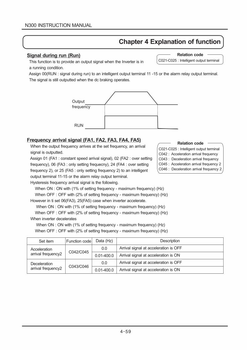
RUN
Signal during run (Run)
This function is to provide an output signal when the Inverter is in
a running condition.
Assign 00(RUN : signal during run) to an intelligent output terminal 11 -15 or the alarm relay output terminal.
The signal is still outputted when the dc braking operates.
Frequency arrival signal (FA1, FA2, FA3, FA4, FA5)
When the output frequency arrives at the set frequency, an arrival
signal is outputted.
Assign 01 (FA1 : constant speed arrival signal), 02 (FA2 : over setting
frequency), 06 (FA3 : only setting frequecny), 24 (FA4 : over setting
frequency 2), or 25 (FA5 : only setting frequency 2) to an intelligent
output terminal 11-15 or the alarm relay output terminal.
Hysteresis frequency arrival signal is the following.
When ON : ON with (1% of setting frequency - maximum frequency) (Hz)
When OFF : OFF with (2% of setting frequency - maximum frequency) (Hz)
However in ti set 06(FA3), 25(FA5) case when inverter accelerate.
When ON : ON with (1% of setting frequency - maximum frequency) (Hz)
When OFF : OFF with (2% of setting frequency - maximum frequency) (Hz)
When inverter decelerates
When ON : ON with (1% of setting frequency - maximum frequency) (Hz)
When OFF : OFF with (2% of setting frequency - maximum frequency) (Hz)
Output
frequency
Set item
Accelerationarrival frequency2
Decelerationarrival frequency2
Function code
C042/C045
C043/C046
Data (Hz)
0.0
0.0
0.01-400.0
0.01-400.0
Description
Arrival signal at acceleration is OFF
Arrival signal at acceleration is ON
Arrival signal at acceleration is OFF
Arrival signal at acceleration is ON
Relation code
C021-C025 : Intelligent output terminal
C042 : Acceleration arrival frequency
C043 :
C045
C046
Deceleration arrival frequency
: Acceleration arrival frequency 2
: Deceleration arrival frequency 2
Relation code
C021-C025 : Intelligent output terminal
N300 INSTRUCTION MANUAL
Chapter 4 Explanation of function
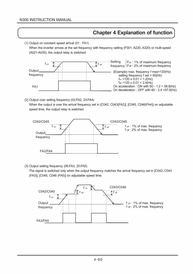
Output
frequency
Output
frequency
Output
frequency
f on f off
FA1
C042/C045 C043/C046
C042/C045
FA3/FA5
f on
f on
f offf off
C043/C046
Setting
frequency
f on f off
FA2/FA4
(1) Output on constant speed arrival (01 : FA1)
When the inverter arrives at the set frequency with frequency setting (F001, A220, A320) or multi-speed
(A021-A035), the output relay is switched.
(2) Output over setting frequency (02:FA2, 24:FA4)
When the output is over the arrival frequency set in [C042, C043(FA2)], [C045, C046(FA4)] on adjustable
speed time, the output relay is switched.
(3) Output setting frequency (06:FA3, 25:FA5)
The signal is switched only when the output frequency matches the arrival frequency set in [C042, C043
(FA3)], [C045, C046 (FA5)] on adjustable speed time.
F : 1% of maximum frequencyon
F : 2% of maximum frequencyoff
f : 1% of max. frequencyf
on
off : 2% of max. frequency
f : 1% of max. frequencyf
on
off : 2% of max. frequency
(Example) max. frequency f max=120(Hz)setting frequency f set = 60(Hz)f =120 x 0.01 = 1.2(Hz)on
f =120 x 0.01 = 2.4(Hz)On acceleration : ON with 60 - 1.2 = 58.8(Hz)On deceleration : OFF with 60 - 2.4 =57.6(Hz)
off
N300 INSTRUCTION MANUAL
Chapter 4 Explanation of function
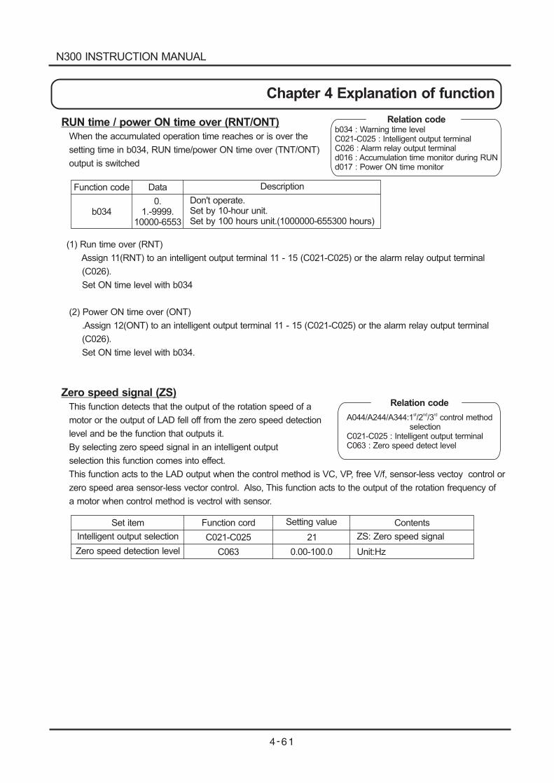
RUN time / power ON time over (RNT/ONT)
When the accumulated operation time reaches or is over the
setting time in b034, RUN time/power ON time over (TNT/ONT)
output is switched
(1) Run time over (RNT)
Assign 11(RNT) to an intelligent output terminal 11 - 15 (C021-C025) or the alarm relay output terminal
(C026).
Set ON time level with b034
(2) Power ON time over (ONT)
.Assign 12(ONT) to an intelligent output terminal 11 - 15 (C021-C025) or the alarm relay output terminal
(C026).
Set ON time level with b034.
Zero speed signal (ZS)
This function detects that the output of the rotation speed of a
motor or the output of LAD fell off from the zero speed detection
level and be the function that outputs it.
By selecting zero speed signal in an intelligent output
selection this function comes into effect.
This function acts to the LAD output when the control method is VC, VP, free V/f, sensor-less vectoy control or
zero speed area sensor-less vector control. Also, This function acts to the output of the rotation frequency of
a motor when control method is vectrol with sensor.
Function code Data Description
b0340.
1.-9999.10000-6553
Don't operate.Set by 10-hour unit.Set by 100 hours unit.(1000000-655300 hours)
Relation codeb034 : Warning time levelC021-C025 : Intelligent output terminalC026 : Alarm relay output terminald016 : Accumulation time monitor during RUNd017 : Power ON time monitor
Set item
Intelligent output selection
Zero speed detection level
Function cord
C021-C025
C063
Setting value
21
0.00-100.0
Contents
ZS: Zero speed signal
Unit:Hz
Relation code
A044/A244/A344:1 /2 /3 control methodselection
C021-C025 : Intelligent output terminalC063 : Zero speed detect level
st nd rd
N300 INSTRUCTION MANUAL
Chapter 4 Explanation of function
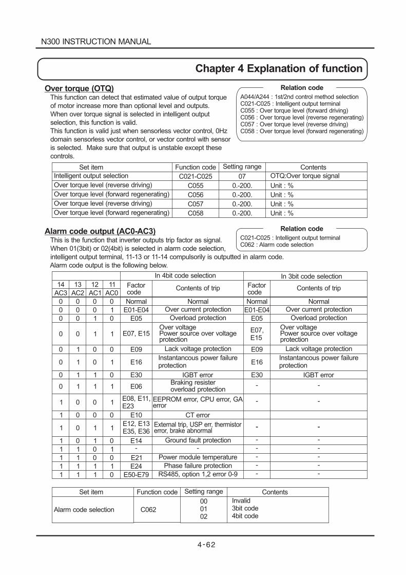
Over torque (OTQ)This function can detect that estimated value of output torque
of motor increase more than optional level and outputs.
When over torque signal is selected in intelligent output
selection, this function is valid.
This function is valid just when sensorless vector control, 0Hz
domain sensorless vector control, or vector control with sensor
is selected. Make sure that output is unstable except these
controls.
Alarm code output (AC0-AC3)This is the function that inverter outputs trip factor as signal.
When 01(3bit) or 02(4bit) is selected in alarm code selection,
intelligent output terminal, 11-13 or 11-14 compulsorily is outputted in alarm code.
Alarm code output is the following below.
Relation code
A044/A244 : 1st/2nd control method selectionC021-C025 : Intelligent output terminalC055 : Over torque level (forward driving)C056 : Over torque level (reverse regenerating)C057 : Over torque level (reverse driving)C058 : Over torque level (forward regenerating)
Set item
Intelligent output selection
Over torque level (reverse driving)
Over torque level (forward regenerating)
Over torque level (reverse driving)
Over torque level (forward regenerating)
Function code
C021-C025
C055
C056
C057
C058
Setting range
07
0.-200.
0.-200.
0.-200.
0.-200.
Contents
OTQ:Over torque signal
Unit : %
Unit : %
Unit : %
Unit : %
Relation code
C021-C025 : Intelligent output terminalC062 : Alarm code selection
14 13 12 11
AC3 AC2 AC1 AC0Factorcode
Factorcode
0 0 0 0
0 0 0 1
0 0 1 0
0 0 1 1
0 1 0 0
0 1 0 1
0 1 1 0
0 1 1 1
1 0 0 1
1 0 0 0
1 0 1 1
1 0 1 0
1 1 0 1
1 1 0 0
1 1 1 1
1 1 1 0
Normal
E01-E04 E01-E04
E05 E05
E07, E15E07,E15
E09 E09
E16 E16
E30 E30
E06
E08, E11,E23
E10
E12, E13E35, E36
E14- -
- -
- -
- -- -
- -
- -
- -
- -
- -
E21
E24
E50-E79
Contents of trip Contents of trip
Normal NormalNormalOver current protection Over current protection
Overload protection Overload protection
Over voltagePower source over voltageprotection
Over voltagePower source over voltageprotection
Lack voltage protection Lack voltage protection
Instantancous power failureprotection
Instantancous power failureprotection
IGBT error IGBT errorBraking resisteroverload protection
EEPROM error, CPU error, GAerror
CT error
External trip, USP err, thermistorerror, brake abnormal
Ground fault protection
Power module temperature
Phase failure protection
RS485, option 1,2 error 0-9
In 4bit code selection In 3bit code selection
Set item
Alarm code selection
Function code
C062
Setting range
000102
Contents
Invalid3bit code4bit code
N300 INSTRUCTION MANUAL
Chapter 4 Explanation of function
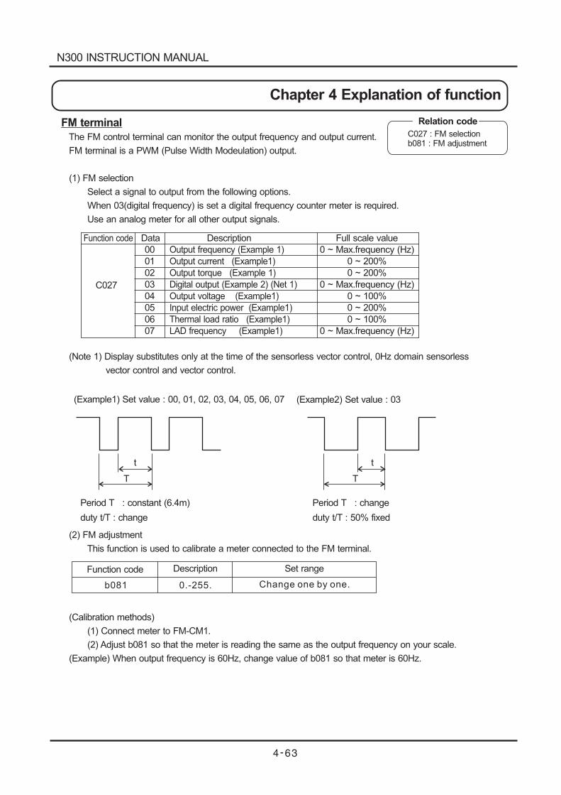
C027
00
01
02
03
04
05
06
07
Output frequency (Example 1)
( 1)
( 1)
Digital output ( 2) (Net 1)
( 1)
Input electric power ( 1)
Thermal load ratio ( 1)
LAD frequency (
Output current Example
Output torque Example
Example
Output voltage Example
Example
Example
Example1)
0 ~ Max.frequency (Hz)
0 ~ 200%
0 ~ 200%
0 ~ (Hz)
0 ~ 100%
0 ~ 200%
0 ~ 100%
0 ~ (Hz)
Max.frequency
Max.frequency
Function code Data Description Full scale value
( 1) Set value : 00, 01, 02, 03, 04, 05, 06, 07Example
Period T : constant (6.4m)
duty t/T : change
( 2) Set value : 03Example
Period T : change
duty t/T : 50% fixed
t
T
t
T
FM terminal
The FM control terminal can monitor the output frequency and output current.
FM terminal is a PWM (Pulse Width Modeulation) output.
(1) FM selection
Select a signal to output from the following options.
When 03(digital frequency) is set a digital frequency counter meter is required.
Use an analog meter for all other output signals.
(Note 1) Display substitutes only at the time of the sensorless vector control, 0Hz domain sensorless
vector control and vector control.
(2) FM adjustment
This function is used to calibrate a meter connected to the FM terminal.
(Calibration methods)
(1) Connect meter to FM-CM1.
(2) Adjust b081 so that the meter is reading the same as the output frequency on your scale.
(Example) When output frequency is 60Hz, change value of b081 so that meter is 60Hz.
Function code Set rangeDescription
b081 0.-255. Change one by one.
Relation code
C027 : FM selectionb081 : FM adjustment
N300 INSTRUCTION MANUAL
Chapter 4 Explanation of function
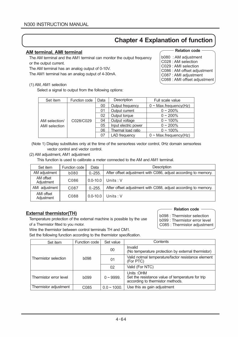
b080 : AM adjustmentC028 : AM selectionC029 : AMI selectionC086 : AM offset adjustmentC087 : AMI adjustmentC088 : AMI offset adjustment
Set item
AM selection/
AMI selection
C028/C029
00
01
02
04
05
06
07
0 ~ (Hz)
0 ~ 200%
0 ~ 200%
0 ~ 100%
0 ~ 200%
0 ~ 100%
0 ~ (Hz)
Max.frequency
Max.frequency
Set item
AM adjustment
AM offsetAdjustment
AMI adjustment
AMI offsetAdjustment
00
01
02
0 ~ 9999.
b098
b099
C085 0.0 ~ 1000.
Relation codeAM terminal, AMI terminalThe AM terminal and the AM1 terminal can monitor the output frequency
or the output current.
The AM terminal has an analog output of 0-10V.
The AM1 terminal has an analog output of 4-30mA.
(1) AM, AM1 selection
Select a signal to output from the following options:
(Note 1) Display substitutes only at the time of the sensorless vector control, 0Hz domain sensorless
vector control and vector control.
(2) AM adjustment, AM1 adjustment
This function is used to calibrate a meter connected to the AM and AM1 terminal.
External thermistor(TH)Temperature protection of the external machine is possible by the use
of a Thermistor fitted to you motor.
Wire the thermistor between control terminals TH and CM1.
Set the following function according to the thermistor specification.
Output frequency
Input electric power
Thermal load ratio
LAD frequency
Output current
Output torque
Output voltage
Function code
Function code
Data
Data
Description
Description
Full scale value
b080
C086
C087
C088
0.-255.
0.-255.
0.0-10.0
0.0-10.0
After offset adjustment with C086, adjust according to memory.
After offset adjustment with C088, adjust according to memory.
Units : V
Units : V
b098 : Thermistor selectionb099 : Thermistor error levelC085 : Thermistor adjustment
Relation code
Set item
Thermistor selection
Thermistor error level
Thermistor adjustment
Function code Set value Contents
Invalid(No temperature protection by external thermistor)
Valid notmal temperature/factor resistance element(For PTC)
Valid (For NTC)
Units :OHMSet the resistance value of temperature for tripaccording to thermistor methods.
Use this as gain adjustment
N300 INSTRUCTION MANUAL
Chapter 4 Explanation of function
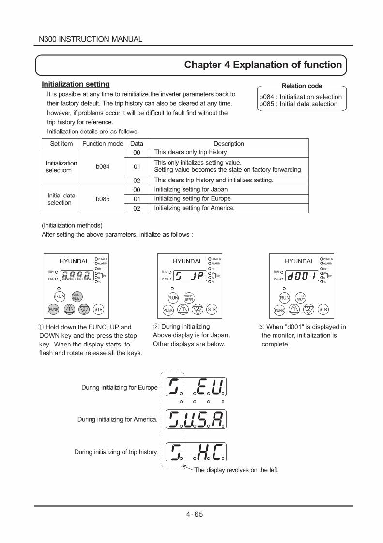
HYUNDAIPOWER
ALARM
Hz
V
A
%
RUN
PRG
STOPRESET
RUN
8.8.8.8. kw
STR
HYUNDAIPOWER
ALARM
Hz
V
A
%
RUN
PRG
RUNSTOP/RESET
PUNK
kw
STR1 2
HYUNDAIPOWER
ALARM
Hz
W
A
%
RUN
PRGkw
Hold down the FUNC, UP and
DOWN key and the press the stop
key. When the display starts to
flash and rotate release all the keys.
During initializing
Above display is for Japan.
Other displays are below.
When "d001" is displayed in
the monitor, initialization is
complete.
PUNK 1 2
During initializing for Europe
During initializing for America.
During initializing of trip history.
The display revolves on the left.
3
5
H
RUNSTOP/RESET
PUNK STR1 2
Initialization setting
It is possible at any time to reinitialize the inverter parameters back to
their factory default. The trip history can also be cleared at any time,
however, if problems occur it will be difficult to fault find without the
trip history for reference.
Initialization details are as follows.
(Initialization methods)
After setting the above parameters, initialize as follows :
Set item
Initializationselectiom
Initial dataselection
Function mode
b084
b085
Data
00
00
01
01
02
02
Description
This clears only trip history
This only initalizes setting value.Setting value becomes the state on factory forwarding
This clears trip history and initializes setting.
Initializing setting for Japan
Initializing setting for Europe
Initializing setting for America.
b084 : Initialization selectionb085 : Initial data selection
Relation code
N300 INSTRUCTION MANUAL
Chapter 4 Explanation of function
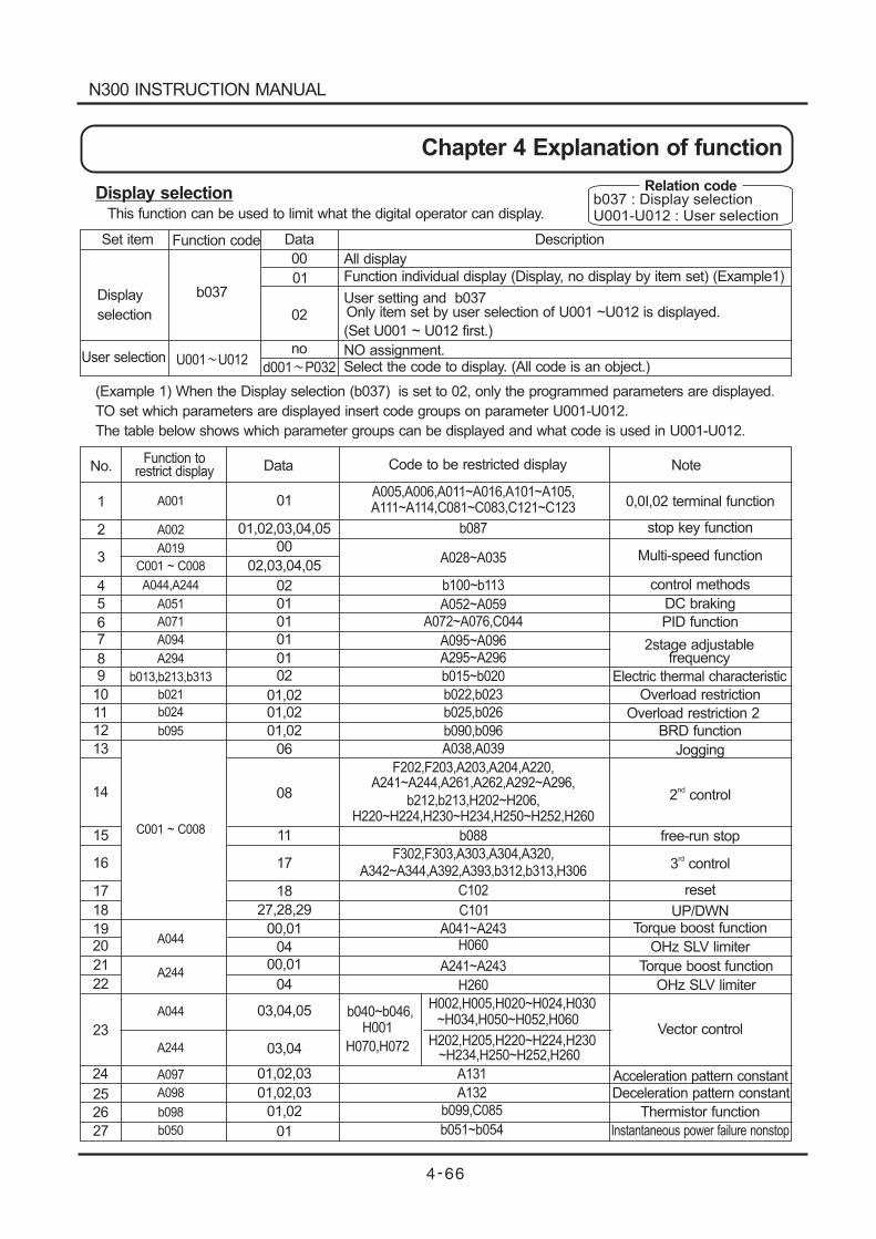
Set item Function code Data Description
Display
selection
User selection
No.Function to
restrict display Data Code to be restricted display Note
All display
Function individual display (Display, no display by item set) (Example1)
User setting and b037Only item set by user selection of U001 ~U012 is displayed.
(Set U001 ~ U012 first.)
NO assignment.Select the code to display. (All code is an object.)
1
2
3
4
5
67
89
10
11
12
13
14
15
16
17
18
1920
21
22
23
24
25
26
27
01
01,02,03,04,05
00
02,03,04,05
02
01
01
01
01
02
01,0201,02
01,02
06
08
11
17
18
27,28,29
00,01
04
00,01
04
03,04,05
03,04
01,02,03
01,02,03
01,02
01
A001
A019
C001 ~ C008
A044,A244
A051
A071
A094
A294
b013,b213,b313
b021
b024
b095
C001 ~ C008
A044
A244
A044
A097
A098
b098
b050
A002
A244
A005,A006,A011~A016,A101~A105,A111~A114,C081~C083,C121~C123
b087
A028~A035
b100~b113
A052~A059A072~A076,C044
A095~A096A295~A296
b015~b020
b022,b023
b025,b026
b090,b096
F202,F203,A203,A204,A220,A241~A244,A261,A262,A292~A296,
b212,b213,H202~H206,H220~H224,H230~H234,H250~H252,H260
b088
F302,F303,A303,A304,A320,A342~A344,A392,A393,b312,b313,H306
C102
C101
A041~A243H060
H260
b040~b046,H001
H070,H072
H002,H005,H020~H024,H030~H034,H050~H052,H060
H202,H205,H220~H224,H230
A131
A132
b099,C085
b051~b054
A038,A039
A241~A243
~H234,H250~H252,H260
0,0I,02 terminal function
stop key function
Multi-speed function
control methods
DC braking
PID function
2stage adjustablefrequency
Electric thermal characteristic
Overload restriction
Overload restriction 2
BRD function
Jogging
2 controlnd
free-run stop
3 controlrd
reset
UP/DWNTorque boost function
Torque boost function
OHz SLV limiter
OHz SLV limiter
Vector control
Acceleration pattern constant
Thermistor function
Instantaneous power failure nonstop
Deceleration pattern constant
b037
00
01
02
no
d001 P032U001 U012
Display selectionThis function can be used to limit what the digital operator can display.
(Example 1) When the Display selection (b037) is set to 02, only the programmed parameters are displayed.
TO set which parameters are displayed insert code groups on parameter U001-U012.
The table below shows which parameter groups can be displayed and what code is used in U001-U012.
b037 : Display selectionU001-U012 : User selection
Relation code
N300 INSTRUCTION MANUAL
Chapter 4 Explanation of function
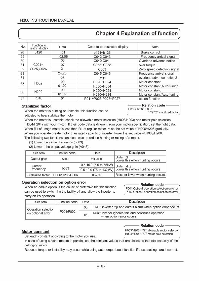
No.
Brake control
Frequency arrival signal
Overload advance notice
over torque
Zero speed detection signal
Frequency arrival signal
overload advance notice 2
Motor constant
Motor constant(Auto-tuning)
Motor constant
Motor constant(Auto-tuning)
option function
28
29
30
31
32
33
34
35
36
37
b120
C021~
C025,C026
H002
H202
P010
01
02,0603
0721
24,25
26
0001,02
00
01,02
01
b121~b126
C042,C043
C040,C041
C055~C058
C063
C045,C046
C111H020~H024
H030~H034
H220~H224H230~H234
P011~P023,P025~P027
Function torestrict display Data Code to be restricted display Note
Stabilized factorWhen the motor is hunting or unstable, this function can be
adjusted to help stabilize the motor.
When the motor is unstable, check the allowable motor selection (H003/H203) and motor pole selection
(H004/H204) with your motor. If their code data is different from your motor specification, set the right data.
When R1 of usage motor is less then R1 of regular motor, raise the set value of H006/H206 gradually.
When you operate greate motor than rated capacity of inverter, lower the set value of H006/H206.
The following two functions can also assist to reduce hunting or ratting of a motor.
(1) Lower the carrier frequency (b083).
(2) Lower the output voltage gain (A045).
Operation selection on option errorWhen an add-in option is the cause of protective trip this function
can be used to switch the trip facility off and allow the Inverter to
carry on it's operation
Motor constantSet each constant according to the motor you use.
In case of using several motors in parallel, set the constant values that are closest to the total capacity of the
belonging motor.
Reduced torque or instability may occur while using auto torque boost function if these settings are incorrect.
Relation codeH006/H206/H306 :
1 /2 /3 stabilized factorst nd rd
Set item Function code Data Description
Output gain
Carrierfrequency
Stabilized factor
A045
b083
H006/H206/H306
20.-100.
0.5-15.0 (5.5 to 55kW)
0.5-10.0 (75 to 132kW)
0.-255.
Units : %Lower this when hunting occurs
Units : kHzLower this when hunting occurs
Raise or lower when hunting occurs.
Relation codeP001:Option1 operation selection on errorP002:Option2 operation selection on error
Set item
Operation selectionon optional error
Function code Data
00
01
Description
TRP : inverter trip and output alarm when option error occurs.
Run : inverter ignores this and continues operationwhen option error occurs.
P001/P002
Relation code
H003/H203:1 /2 allowable motor selectionst nd
H004/H204:1 /2 motor pole selectionst nd
N300 INSTRUCTION MANUAL
Chapter 4 Explanation of function
Fuzzy most suitable acceleration and deceleration
Fuzzy acceleration and deceleration function eliminates setting of
acceleration and deceleration time in using inverter.
Inverter acceleration time should be set every time before, but this
function applies the theory of fuzzy, using inverter capability at its
maximum, can set acceleration and deceleration time automatically.
The acceleration time is, a time for acceleration at the current specified by the overload restriction constant
when it is valid, and a time for acceleration within 150% of the reqular current when it is invalid.
The deceleration time is a time for decelerating so that the current does not exceed 150% of the specified one
of the DC voltage in the inverter curcuit does not exceed 358V (770V for the 400V class).
The function sets the acceleration and deceleration time automatically in response to a change in the load or
inertia in real time.
Precautions
(1) This function is not suitable for a machine which requires a constant acceleration and deceleration time.
The acceleration and deceleration time varies with the magnitude of the load or inertia.
(2) When the inertia of machine is more than about 20 times of the motor shaft, a trip may occur.
(3) The acceleration and deceleration time of the same motor always varies with a change of the current.
(4) The fuzzy most suitable acceleration and deceleration setting function is valid only the V/F control.
(5) If the jogging running is executed when the fuzzy most suitable acceleration and deceleration setting function
is selected, the normal jogging operation cannot be performed due to the fuzzy acceleration.
(6) When the load is more than the rated one, the deceleration time may be increased.
(7) When the acceleration and deceleration are repeated frequently, a trip may occur.
(8) If an internal regenerating braking circuit is used, or an external braking unit is used, the moter cannot stop
within the deceleration time set with a braking resistor. In this case, do not use the fuzzy suitable acceleration
and deceleration function.
(9) When using on class low motor against the inverter. Validate overload restriction function, than set the
overload restriction level 1.5 times as high as rated output current of motor.
Principle
The acceleration and deceleration speed is set acceleration with the fuzzy rule from the distance to the overload
restriction level and the start slopes of current and voltage.
Set item
Running modeselection
Function code
A085
Data
00
01
02
Contents
Normal running
Energy conservation running
Fuzzy running
A044/A244/A344:1 /2 /3 control methodA085 : Running mode selectionb021/b024:Overload restriction
selection 1/2b021/b024:Overload restriction level 1/2
st nd rd
Relation code
N300 INSTRUCTION MANUAL
Chapter 4 Explanation of function
Braking control function
This is a function that the inverter controls external braking used
in systems like elevators. By braking control function selection
(b120) is set to valid(01), this function is performed as the
following below.
(1) When running command turns on, the inverter begins to
operate and accelerate to releasing frequency.
(2) After output frequency arrives releasing frequency, the inverter
output breaking releasing signal (BRK) after waiting for the time
for confirmation of releasing braking which is set in (b121).
However, if output current of the inverter is within releasing
current which is set in (b121), braking releasing signal would not output
the inverter would occur the trip and output braking error signal (BER).
(3) When braking confirmation signal (BOK) is set to intelligent input terminal (when 44 is set to C001 - C008),
if braking releasing signal is outputted, the inverter would not accelerate just waitng time for braking
confirmation which is set in (b124).
If braking confirmation signal is not inputted within waiting time for braking confirmation, the inverter would
output braking error signal (BER) and would occur the trip.
If braking confirmation signal is not set to intelligent input braking terminal, the waiting confirmation would
be invalid, and after the inverter would output braking releasing signal, proceed to (4).
(4) After braking confirmation signal is inputted(after braking releasing signal is outputted when BOK is not
selected), the inverter waits for the time for acceleration, and the begins to accelerates again and accerates
to the frequency.
(5) When running command turns off, the inverter decelerates to releasing frequency and turns braking releasing
signal (BRK) off.
(6) When braking confirmation signal (BOK) is set to intelligent input terminal (when 44 is set to C001-C008),
after braking releasing signal turns off, the inverter would not decelerate during just the waitng time for
braking confirmation which is set in (b124), and would wait for braking confirmation singal turnning off.
If braking confirmation signal does not turn off within the waiting time for braking confirmation , rhe inverter
would output braking error signal (BER) and would occur the trip
If braking confirmation signal is not set to intelligent input braking terminal, the waiting time for braking
confirmation would be invalid and after the inverter would output braking releasing signal, proceed to (7).
(7) After braking confirmation signal turns off (after braking releasing signal turns off), the inverter waits for the
waiting time for stop, and then begins to decelerate again and decelerates to 0 Hz.
Relation codeb120 : Braking control selection
b121 : Waiting time for releasing braking
conformation
b122 : Waiting time for acceleration
b123 : Waiting time for stop
b124 : Waiting time for signal conformation
b125 : Releasing frequency
b126 : Releasing current
C021-C025 : Intelligent output terminal
C001-C008 : Intelligent input terminal
N300 INSTRUCTION MANUAL
Chapter 4 Explanation of function
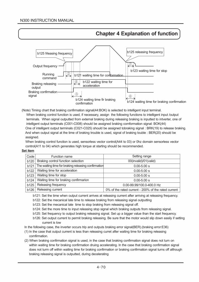
b125 frleasing frequency
Output frequency
Runningcommand
Braking releasingoutput
Braking confirmationsignal
b123 waiting time for stop
b121 waiting time for conformation
b122 waiting time foracceleration
b124 waiting time for braking confirmationb124 waiting time fir brakingconfirmation
b125 releasing frequency
(Note) Timing chart that braking confirmation signal(44:BOK) is selected to intelligent input terminal.
When braking control function is used, if necessary, assign the following functions to intelligent input /output
terminals. When signal outputted from external braking during releasing braking is inputted to intverter, one of
intelligent output terminals (C001-C008) should be assigned braking comformation signal: BOK(44)
One of intelligent output terminals (C021-C025) should be assigned tobraking signal : BRK(19) to release braking.
And when output signal at the time of braking trouble is used, signal of braking touble : BER(20) should be
assigned.
When braking control function is used, sensorless vector control(A44 to 03) or 0hz domain sensorless vector
control(A11 to 04) which generates high torque at starting should be recommended.
Set item
b121: Set the time when output current arrives at releasing current after arriving at releasing frequency.
b122: Set the mecanical late time to release braking from releasing signal outputting
b123: Set the mecanical late time to stop braking from releasing signal off.
b124: Set the more time to input releasing stop signal which braking outputs from releasing signal.
b125: Set frequency to output braking releasing signal. Set up a bigger value than the start frequency.
b126: Set output current to permit braking releasing. Be sure that the motor would slip down easily if setting
current is low
ln the following case, the inverter occurs trip and outputs braking error signal(BER).(braking error:E36)
(1) ln the case that output current is less than releasing curret after waiting time for braking releasing
comfirmation.
(2) When braking confirmation signal is used, in the case that braking confirmation signal does not turn on
within waiting time for braking confirmation druing accelerating. ln the case that braking confirmation signal
does not turm off within waiting time for braking confirmation or braking confirmation signal turns off although
braking releasing signal is outputted, during decelerating
Code
b120
b121
b122
b123
b124
b125
b126
Function name
Braking control function selection
The waiting time for braking releasing confirmation
Waiting time for acceleration
Waiting time for stop
Waiting time for braking confirmarion
Releasing frequency
Releasing current
Setting range
00(invalid)/01(valid)
0.00-5.00 s
0.00-5.00 s
0.00-5.00 s
0.00-5.00 s
0.00-99.99/100.0-400.0 Hz
0% of the rated current - 200% of the rated current
N300 INSTRUCTION MANUAL
Chapter 4 Explanation of function
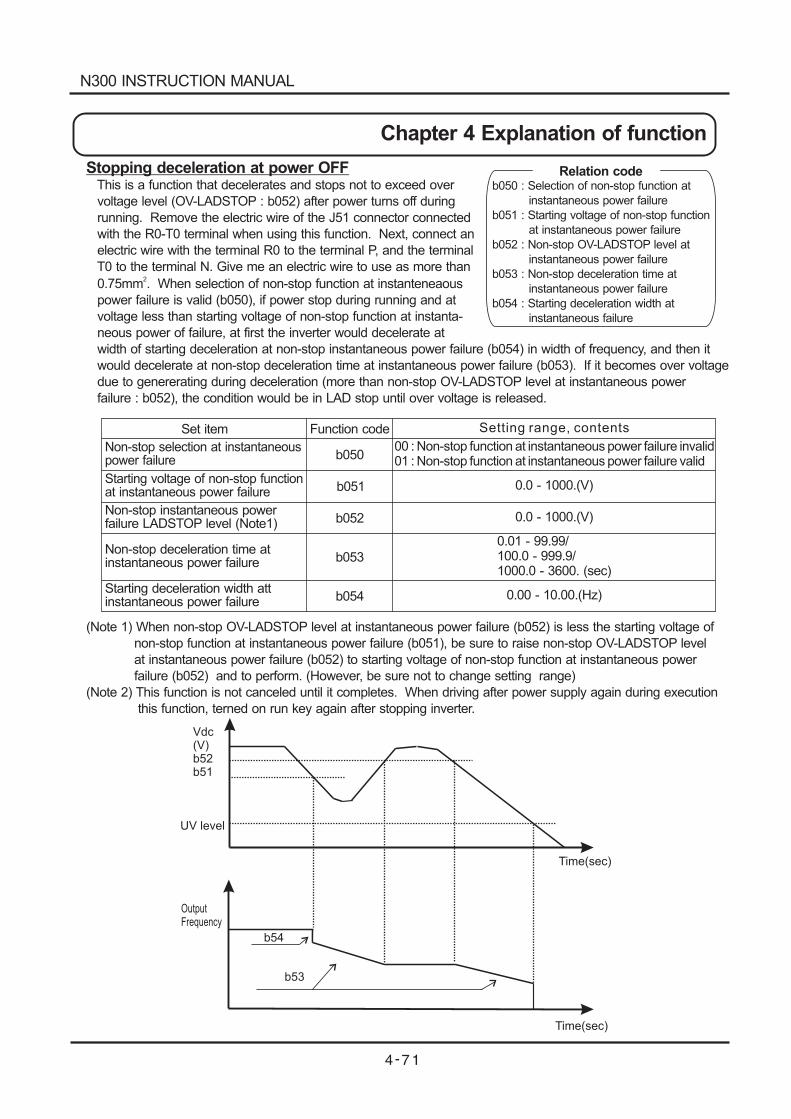
Vdc(V)b52b51
Time(sec)
UV level
Time(sec)
OutputFrequency
b54
b53
Stopping deceleration at power OFFThis is a function that decelerates and stops not to exceed over
voltage level (OV-LADSTOP : b052) after power turns off during
running. Remove the electric wire of the J51 connector connected
with the R0-T0 terminal when using this function. Next, connect an
electric wire with the terminal R0 to the terminal P, and the terminal
T0 to the terminal N. Give me an electric wire to use as more than
0.75mm . When selection of non-stop function at instanteneaous2
power failure is valid (b050), if power stop during running and at
voltage less than starting voltage of non-stop function at instanta-
neous power of failure, at first the inverter would decelerate at
width of starting deceleration at non-stop instantaneous power failure (b054) in width of frequency, and then it
would decelerate at non-stop deceleration time at instantaneous power failure (b053). If it becomes over voltage
due to genererating during deceleration (more than non-stop OV-LADSTOP level at instantaneous power
failure : b052), the condition would be in LAD stop until over voltage is released.
(Note 1) When non-stop OV-LADSTOP level at instantaneous power failure (b052) is less the starting voltage of
non-stop function at instantaneous power failure (b051), be sure to raise non-stop OV-LADSTOP level
at instantaneous power failure (b052) to starting voltage of non-stop function at instantaneous power
failure (b052) and to perform. (However, be sure not to change setting range)
(Note 2) This function is not canceled until it completes. When driving after power supply again during execution
this function, terned on run key again after stopping inverter.
Set item
Non-stop selection at instantaneouspower failure
Starting voltage of non-stop functionat instantaneous power failure
Starting deceleration width attinstantaneous power failure
Non-stop instantaneous powerfailure LADSTOP level (Note1)
Non-stop deceleration time atinstantaneous power failure
Function code
b050
b051
b052
b053
b054
Setting range, contents
00 : Non-stop function at instantaneous power failure invalid01 : Non-stop function at instantaneous power failure valid
0.0 - 1000.(V)
0.0 - 1000.(V)
0.00 - 10.00.(Hz)
0.01 - 99.99/100.0 - 999.9/1000.0 - 3600. (sec)
Relation codeb050 : Selection of non-stop function at
instantaneous power failure
b051 : Starting voltage of non-stop function
at instantaneous power failure
b052 : Non-stop OV-LADSTOP level at
instantaneous power failure
b053 : Non-stop deceleration time at
instantaneous power failure
b054 : Starting deceleration width at
instantaneous failure
N300 INSTRUCTION MANUAL
Chapter 4 Explanation of function
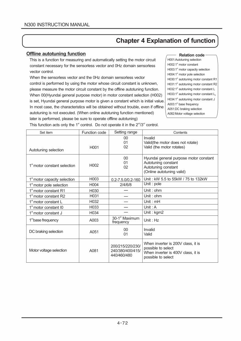
Offline autotuning function
This is a function for measuring and automatically setting the motor circuit
constant necessary for the sensorless vector and 0Hz domain sensorless
vector control.
When the sensorless vector and the 0Hz domain sensorless vector
control is performed by using the motor whose circuit constant is unknown,
please measure the motor circuit constant by the offline autotuning function.
When 00(Hyundai general purpose motor) in motor constant selection (H002)
is set, Hyundai general purpose motor is given a constant which is initial value.
In most case, the characteristics will be obtained without trouble, even if offline
autotuning is not executed. (When online autotuning function mentioned)
later is performed, please be sure to operate offline autotuning)
This function acts only the 1 control. Do not operate it in the 2 /3 control.st nd rd
1 motor constant selectionst
1 motor capacity selectionst
1 motor pole selectionst
1 motor constant R1st
1 motorst
constant R2
1 motorst
constant L
1 motorst
constant I0
1 motorst
constant J
1 base frequencyst
DC braking selection
Motor voltage selection
Autotuning selection
Function code
0.2-7.5.0/0.2-160
2/4/6/8
-
-
-
-
-
30-1 Maximumfrequency
st
0001
200/215/220/230/240/380/400/415/440/460/480
InvalidValid(the motor does not rotate)Valid (the motor rotates)
Hyundai general purpose motor constantAutotuning constantAutotuning constant(Online autotuning valid)
000102
000102
H001
H002
H003
H004
H030
H031
H032
H033
H034
A003
A051
A081
Unit : kW 5.5 to 55kW / 75 to 132kWUnit : pole
Unit : ohm
Unit : Hz
InvalidValid
Unit : ohm
Unit : mH
When inverter is 200V class, it ispossible to selectWhen inverter is 400V class, it ispossible to select
Unit : A
Unit : kgm2
Set item Setting range Contents
Relation codeH001:Autotuning selection
H002:1 motor constant
H003:1 motor capacity selection
H004:1 motor pole selection
H030: autotuning motor constant R1
H031:
H032:
H033:
H034:
A003:
A051:DC braking selection
A082:Motor voltage selection
st
st
st
1
1 autotuning motor constant R2
1 autotuning motor constant L
1 autotuning motor constant L
1 autotuning motor constant J
1 base frequency
st
st
st
st
st
st
0
N300 INSTRUCTION MANUAL
Chapter 4 Explanation of function
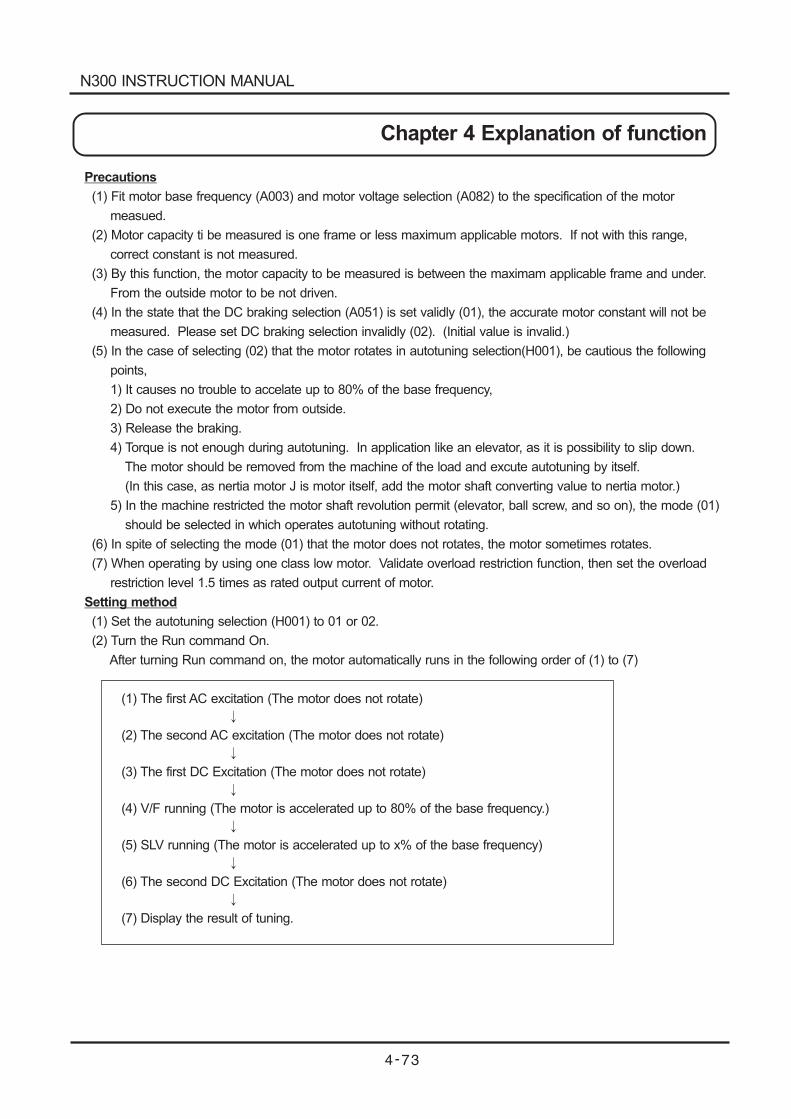
Precautions
(1) Fit motor base frequency (A003) and motor voltage selection (A082) to the specification of the motor
measued.
(2) Motor capacity ti be measured is one frame or less maximum applicable motors. If not with this range,
correct constant is not measured.
(3) By this function, the motor capacity to be measured is between the maximam applicable frame and under.
From the outside motor to be not driven.
(4) In the state that the DC braking selection (A051) is set validly (01), the accurate motor constant will not be
measured. Please set DC braking selection invalidly (02). (Initial value is invalid.)
(5) In the case of selecting (02) that the motor rotates in autotuning selection(H001), be cautious the following
points,
1) It causes no trouble to accelate up to 80% of the base frequency,
2) Do not execute the motor from outside.
3) Release the braking.
4) Torque is not enough during autotuning. In application like an elevator, as it is possibility to slip down.
The motor should be removed from the machine of the load and excute autotuning by itself.
(In this case, as nertia motor J is motor itself, add the motor shaft converting value to nertia motor.)
5) In the machine restricted the motor shaft revolution permit (elevator, ball screw, and so on), the mode (01)
should be selected in which operates autotuning without rotating.
(6) In spite of selecting the mode (01) that the motor does not rotates, the motor sometimes rotates.
(7) When operating by using one class low motor. Validate overload restriction function, then set the overload
restriction level 1.5 times as rated output current of motor.
Setting method
(1) Set the autotuning selection (H001) to 01 or 02.
(2) Turn the Run command On.
After turning Run command on, the motor automatically runs in the following order of (1) to (7)
(1) The first AC excitation (The motor does not rotate)
(2) The second AC excitation (The motor does not rotate)
(3) The first DC Excitation (The motor does not rotate)
(4) V/F running (The motor is accelerated up to 80% of the base frequency.)
(5) SLV running (The motor is accelerated up to x% of the base frequency)
(6) The second DC Excitation (The motor does not rotate)
(7) Display the result of tuning.
N300 INSTRUCTION MANUAL
Chapter 4 Explanation of function
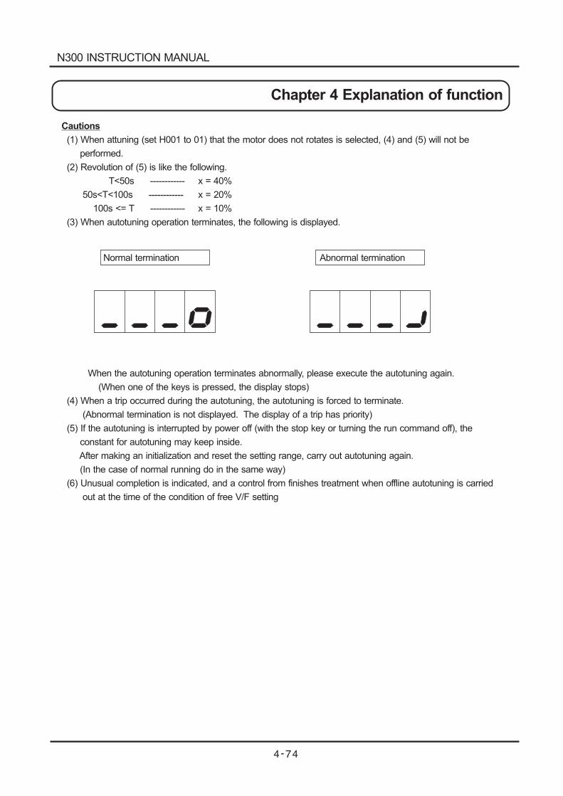
Cautions
(1) When attuning (set H001 to 01) that the motor does not rotates is selected, (4) and (5) will not be
performed.
(2) Revolution of (5) is like the following.
T<50s ------------ x = 40%
50s<T<100s ------------ x = 20%
100s <= T ------------ x = 10%
(3) When autotuning operation terminates, the following is displayed.
When the autotuning operation terminates abnormally, please execute the autotuning again.
(When one of the keys is pressed, the display stops)
(4) When a trip occurred during the autotuning, the autotuning is forced to terminate.
(Abnormal termination is not displayed. The display of a trip has priority)
(5) If the autotuning is interrupted by power off (with the stop key or turning the run command off), the
constant for autotuning may keep inside.
After making an initialization and reset the setting range, carry out autotuning again.
(In the case of normal running do in the same way)
(6) Unusual completion is indicated, and a control from finishes treatment when offline autotuning is carried
out at the time of the condition of free V/F setting
Normal termination Abnormal termination
N300 INSTRUCTION MANUAL
Chapter 4 Explanation of function

Motor constant selectionMotor constant used sensorless vector control and 0 Hz domain sensorless vector and vector control with
sensor can be selected from the following the three.
(1) Hyundai general purpose motor constant
(2) Motor constant measured in offline autotuning
(3) Optional setting motor constant
When selecting 3 control mode, motor constant in 1 control mode appears.rd st
(Note 1) In 1 control method, it is possible to select setting range 00-05.st
In 1 control method, it is possible to select setting range 00-04.st
In 1 control method, it is possible to select setting range 00-01.st
(Note 2) The second motor constant selection uses it with 00 (Hyundai standard motor constant).
Optional setting of motor constantWhen motor constant is set optionally, function code is as the following below.
1 control is valid and motor constant is 00 Input H020 - H024 directly.st
1 control is valid and motor constant is 01/02 Input H030 - H034 directly.st
1 control is valid and motor constant is 00 Input H020 - H224 directly.rd
When offline autotuning is not executed, in H030/H230 - H034/H234, the same frame constant as the constant
(Hyundai general purpose motor constant) is set.
1 motor constant selection(Note 2)
st
1 motor capacity selectionst
1 motor pole selectionst
1 motor constant R1st
1 motorst
constant R2
1 motorst
constant L
1 motorst
constant I0
1 motorst
constant J
1 autotuning motorst
constant R1
1stautotuning motor constant R2
1stautotuning motor constant L
1stautotuning motor constant I0
1stautotuning motor constant J
1 /2 /3 control methodst nd rd
Function code
0.2-7.5.0/0.2-160
2/4/6/8
0.000-65.53
0.000-65.53
0.00-655.3
0.00-655.3
0.001-9999.
0.000-65.53
0.000-65.53
0.00-655.3
0.00-655.3
0.001-9999
Constant torque characteristicsReduced torque characteristicsV/F free settingSensorless vector control0 Hz domain sensorless vector controlFB optional vector control
Hyundai general purpose motor constantAutotuning constantAutotuning constant(Online autotuning valid)
0001
02(Note 1)03 (Note 1)04 (Note 1)05 (Note 1)
000102
A044/A244/A344
H002
H003
H004
H020
H021
H022
H023
H024
H030
H031
H032
H033
H034
Unit : kW 5.5 to 55kW / 75 to 132kWUnit : pole
Unit : ohm
Unit : ohm
Unit : ohm
Unit : ohm
Unit : mH
Unit : mH
Unit : A
Unit : A
Unit : kgm2
Unit : kgm2
Set item Setting range Contents
N300 INSTRUCTION MANUAL
Chapter 4 Explanation of function
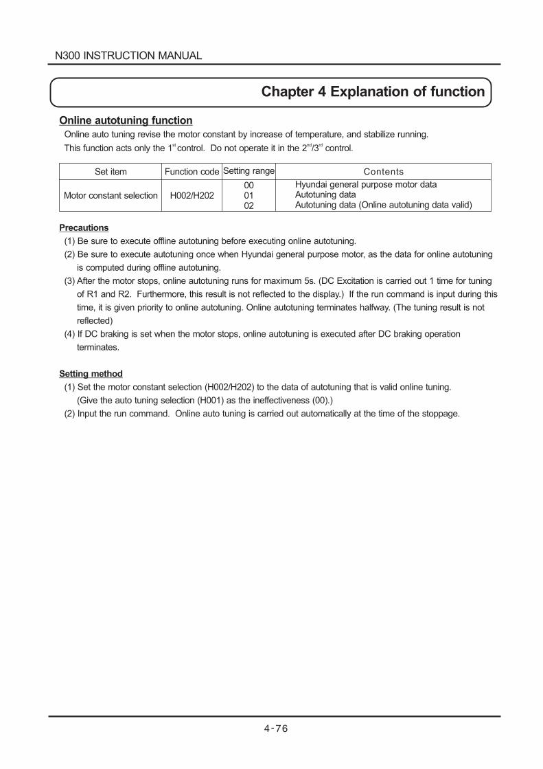
Online autotuning function
Online auto tuning revise the motor constant by increase of temperature, and stabilize running.
This function acts only the 1 control. Do not operate it in the 2 /3 control.st nd rd
Precautions
(1) Be sure to execute offline autotuning before executing online autotuning.
(2) Be sure to execute autotuning once when Hyundai general purpose motor, as the data for online autotuning
is computed during offline autotuning.
(3) After the motor stops, online autotuning runs for maximum 5s. (DC Excitation is carried out 1 time for tuning
of R1 and R2. Furthermore, this result is not reflected to the display.) If the run command is input during this
time, it is given priority to online autotuning. Online autotuning terminates halfway. (The tuning result is not
reflected)
(4) If DC braking is set when the motor stops, online autotuning is executed after DC braking operation
terminates.
Setting method
(1) Set the motor constant selection (H002/H202) to the data of autotuning that is valid online tuning.
(Give the auto tuning selection (H001) as the ineffectiveness (00).)
(2) Input the run command. Online auto tuning is carried out automatically at the time of the stoppage.
Set item
Motor constant selection
Function code
H002/H202
Setting range
000102
Hyundai general purpose motor dataAutotuning dataAutotuning data (Online autotuning data valid)
Contents
N300 INSTRUCTION MANUAL
Chapter 4 Explanation of function
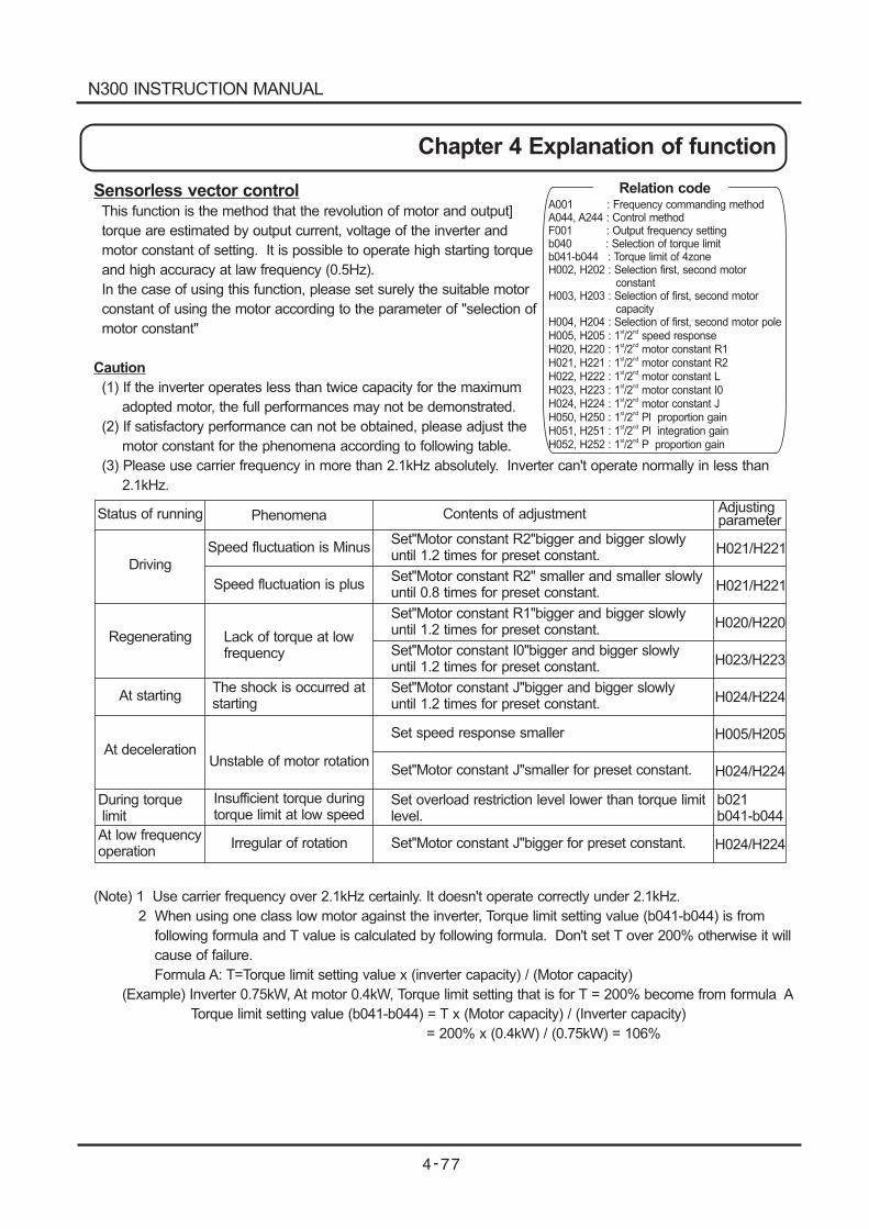
Sensorless vector controlThis function is the method that the revolution of motor and output]
torque are estimated by output current, voltage of the inverter and
motor constant of setting. It is possible to operate high starting torque
and high accuracy at law frequency (0.5Hz).
In the case of using this function, please set surely the suitable motor
constant of using the motor according to the parameter of "selection of
motor constant"
Caution
(1) If the inverter operates less than twice capacity for the maximum
adopted motor, the full performances may not be demonstrated.
(2) If satisfactory performance can not be obtained, please adjust the
motor constant for the phenomena according to following table.
(3) Please use carrier frequency in more than 2.1kHz absolutely. Inverter can't operate normally in less than
2.1kHz.
(Note) 1 Use carrier frequency over 2.1kHz certainly. It doesn't operate correctly under 2.1kHz.
2 When using one class low motor against the inverter, Torque limit setting value (b041-b044) is from
following formula and T value is calculated by following formula. Don't set T over 200% otherwise it will
cause of failure.
Formula A: T=Torque limit setting value x (inverter capacity) / (Motor capacity)
(Example) Inverter 0.75kW, At motor 0.4kW, Torque limit setting that is for T = 200% become from formula A
Torque limit setting value (b041-b044) = T x (Motor capacity) / (Inverter capacity)
= 200% x (0.4kW) / (0.75kW) = 106%
Status of running Phenomena Contents of adjustment Adjustingparameter
Speed fluctuation is Minus
Speed fluctuation is plus
Lack of torque at lowfrequency
The shock is occurred atstarting
Unstable of motor rotation
Irregular of rotation
Insufficient torque duringtorque limit at low speed
Set"Motor constant R2"bigger and bigger slowlyuntil 1.2 times for preset constant.
Set"Motor constant R2" smaller and smaller slowlyuntil 0.8 times for preset constant.
Set"Motor constant R1"bigger and bigger slowlyuntil 1.2 times for preset constant.
Set"Motor constant I0"bigger and bigger slowlyuntil 1.2 times for preset constant.
Set"Motor constant J"bigger and bigger slowlyuntil 1.2 times for preset constant.
Set speed response smaller
Set"Motor constant J"smaller for preset constant.
Set"Motor constant J"bigger for preset constant.
Set overload restriction level lower than torque limitlevel.
Driving
Regenerating
At starting
At deceleration
At low frequencyoperation
During torquelimit
H021/H221
H021/H221
H020/H220
H023/H223
H024/H224
H005/H205
H024/H224
H024/H224
b021b041-b044
Relation codeA001 : Frequency commanding methodA044, A244 : Control methodF001 : Output frequency settingb040 : Selection of torque limitb041-b044 : Torque limit of 4zoneH002, H202 : Selection first, second motor
constantH003, H203 : Selection of first, second motor
capacityH004, H204 : Selection of first, second motor poleH005, H205 : 1 /2 speed responseH020, H220 : 1 /2 motor constant R1H021, H221H022, H222H023, H223H024, H224H050, H250H051, H251H052, H252
st nd
st nd
: 1 /2 motor constant R2: 1 /2 motor constant L: 1 /2 motor constant I0: 1 /2 motor constant J: 1 /2 Pl proportion gain: 1 /2 Pl integration gain: 1 /2 P proportion gain
st nd
st nd
st nd
st nd
st nd
st nd
st nd
N300 INSTRUCTION MANUAL
Chapter 4 Explanation of function
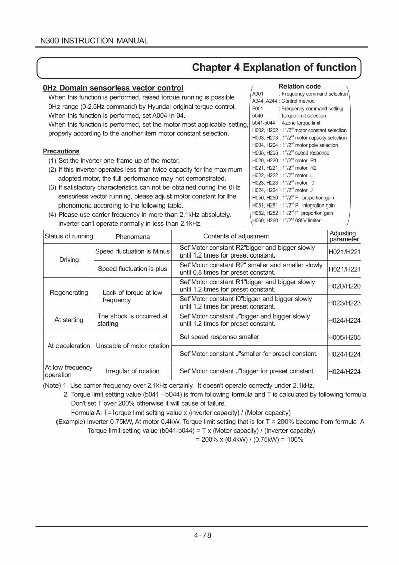
0Hz Domain sensorless vector controlWhen this function is performed, raised torque running is possible
0Hz range (0-2.5Hz command) by Hyundai original torque control.
When this function is performed, set A004 in 04.
When this function is performed, set the motor most applicable setting,
properly according to the another item motor constant selection.
Precautions
(1) Set the inverter one frame up of the motor.
(2) If this inverter operates less than twice capacity for the maximum
adopted motor, the full performance may not demonstrated.
(3) If satisfactory characteristics can not be obtained during the 0Hz
sensorless vector running, please adjust motor constant for the
phenomena according to the following table.
(4) Please use carrier frequency in more than 2.1kHz absolutely.
Inverter can't operate normally in less than 2.1kHz.
(Note) 1 Use carrier frequency over 2.1kHz certainly. It doesn't operate correctly under 2.1kHz.
2 Torque limit setting value (b041 - b044) is from following formula and T is calculated by following formula.
Don't set T over 200% otherwise it will cause of failure.
Formula A: T=Torque limit setting value x (inverter capacity) / (Motor capacity)
(Example) Inverter 0.75kW, At motor 0.4kW, Torque limit setting that is for T = 200% become from formula A
Torque limit setting value (b041-b044) = T x (Motor capacity) / (Inverter capacity)
= 200% x (0.4kW) / (0.75kW) = 106%
Status of running Phenomena Contents of adjustment Adjustingparameter
Speed fluctuation is Minus
Speed fluctuation is plus
Lack of torque at lowfrequency
The shock is occurred atstarting
Unstable of motor rotation
Irregular of rotation
Set"Motor constant R2"bigger and bigger slowlyuntil 1.2 times for preset constant.
Set"Motor constant R2" smaller and smaller slowlyuntil 0.8 times for preset constant.
Set"Motor constant R1"bigger and bigger slowlyuntil 1.2 times for preset constant.
Set"Motor constant I0"bigger and bigger slowlyuntil 1.2 times for preset constant.
Set"Motor constant J"bigger and bigger slowlyuntil 1.2 times for preset constant.
Set speed response smaller
Set"Motor constant J"smaller for preset constant.
Set"Motor constant J"bigger for preset constant.
Driving
Regenerating
At starting
At deceleration
At low frequencyoperation
H021/H221
H021/H221
H020/H220
H023/H223
H024/H224
H005/H205
H024/H224
H024/H224
Relation codeA001 : Frequency command selection
A044, A244 : Control method
F001 : Frequency command setting
b040 : Torque limit selection
b041-b044 : 4zone torque limit
H002, H202 :
H003, H203 : capacity selection
H004, H204 : pole selection
H005, H205 : 1 /2 speed response
H020, H220 : 1 /2 motor R1
H021, H221
H022, H222
H023, H223
H024, H224
H050, H250
H051, H251
H052, H252
st nd
st nd
1 /2 motor constant selection
1 /2 motor
1 /2 motor
: 1 /2 motor R2
: 1 /2 motor L
: 1 /2 motor I0
: 1 /2 motor J
: 1 /2 Pl proportion gain
: 1 /2 Pl integration gain
: 1 /2 P proportion gain
H060, H260 : 1 /2 0SLV limiter
st nd
st nd
st nd
st nd
st nd
st nd
st nd
st nd
st nd
st nd
st nd
N300 INSTRUCTION MANUAL
Chapter 4 Explanation of function
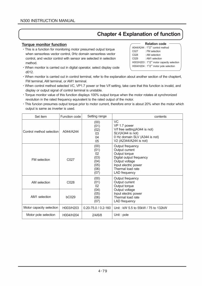
Torque monitor functionThis is a function for monitoring motor presumed output torque
when sensorless vector control, 0Hz domain sensorless vector
control, and vector control with sensor are selected in selection
method.
When monitor is carried out in digital operator, select display code
d012.
When monitor is carried out in control terminal, refer to the explanation about another section of the chapter4,
FM terminal, AM terminal, or AM1 terminal.
When control method selected VC, VP1.7 power or free V/f setting, take care that this function is invalid, and
display or output signal of control terminal is unstable.
Torque monitor value of this function displays 100% output torque when the motor rotates at synchronized
revolution in the rated frequency equivalent to the rated output of the motor.
This funcion presumes output torque prior to motor current, therefore error is about 20% when the motor which
output is same as inverter is used.
Set item Function code Setting range contents
Control method selection A044/A244
(00)(01)(02)030405
FM selection C027
(00)(01)02
(03)(04)(05)(06)(07)
AM selection
AM1 selection
Motor capacity selection
Motor pole selection
C028
bC029
H003/H203
H004/H204
(00)(01)02
(04)(05)(06)(07)
0.20-75.0 / 0.2-160
2/4/6/8
VCVP 1.7 powerV/f free setting)A344 is not)SLV(A344 is not)0 Hz domain SLV (A344 is not)V2 (A2344/A244 is not)
Output frequencyOutput currentOutput torqueDigital output frequencyOutput voltageInput electric powerThermal load rateLAD frequency
Output frequencyOutput currentOutput torqueOutput voltageInput electric powerThermal load rateLAD frequency
Unit : kW 5.5 to 55kW / 75 to 132kW
Unit : pole
Relation codeA044/A244 : 1 /2 control method
C027 : FM selection
C028 : AM selection
C029 : AM1 selection
H003/H203 : 1 /2 motor capacity selection
H004/H204 : 1 /2 motor pole selection
st nd
st nd
st nd
N300 INSTRUCTION MANUAL
Chapter 4 Explanation of function
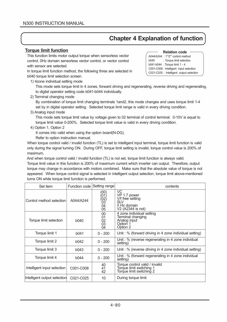
Torque limit functionThis function limits motor output torque when sensorless vector
control, 0Hz domain sensorless vector control, or vector control
with sensor are selected.
In torque limit function method, the following three are selected in
b040 torque limit selection screen.
1) 4zone individual setting mode
This mode sets torque limit in 4 zones, forward driving and regenerating, reverse driving and regenerating,
to digital operator setting code b041-b044 individually.
2) Terminal changing mode
By combination of torque limit changing terminals 1and2, this mode changes and uses torque limit 1-4
set by in digital operator setting. Selected torque limit range is valid in every driving condition.
3) Analog input mode
This mode sets torque limit value by voltage given to 02 terminal of control terminal. 0-10V is equal to
torque limit value 0-200%. Selected torque limit value is valid in every driving condition.
4) Option 1, Option 2
It comes into valid when using the option board(N-DG).
Refer to option instruction manual.
When torque control valid / invalid function (TL) is set to intelligent input terminal, torque limit function is valid
only during the signal turning ON. During OFF, torque limit setting is invalid, torque control value is 200% of
maximum.
And when torque control valid / invalid function (TL) is not set, torque limit function is always valid.
Torque limit value in this function is 200% of maximum current which inverter can output. Therefore, output
torque may change in accordance with motors combined. Make sure that the absolute value of torque is not
appeared. When torque control signal is selected in intelligent output selection, torque limit above-mentioned
turns ON while torque limit function is performed.
Set item Function code Setting range contents
Control method selection A044/A244
(00)(01)(02)030405
Torque limit selection b040
0001020304
Torque limit 1
Torque limit 2
Torque limit 3
Torque limit 4
Intelligent input selection
Intelligent output selection
b041
b042
b043
b044
C001-C008
C021-C025
0 - 200
0 - 200
0 - 200
0 - 200
404142
10
VCVP 1.7 powerV/f free settingSLV0 Hz domainV2 (A2344 is not)
4 zone individual settingTerminal changingAnalog inputOption 1Option 2
Unit : % (forward driving in 4 zone individual setting)
Unit : % (reverse regenerating in 4 zone individualsetting)
Unit : % (reverse driving in 4 zone individual setting)
Unit : % (forward regenerating in 4 zone individualsetting)
Torque control valid / invalidTorque limit switching 1Torque limit switching 2
During torque limit
Relation codeA044/A244 : 1 /2 control method
b040 : Torque limit selection
b041-b044 : Torque limit 1 - 4
C001-C008 : Intelligent input selection
C021-C025 :
st nd
Intelligent output selection
N300 INSTRUCTION MANUAL
Chapter 4 Explanation of function
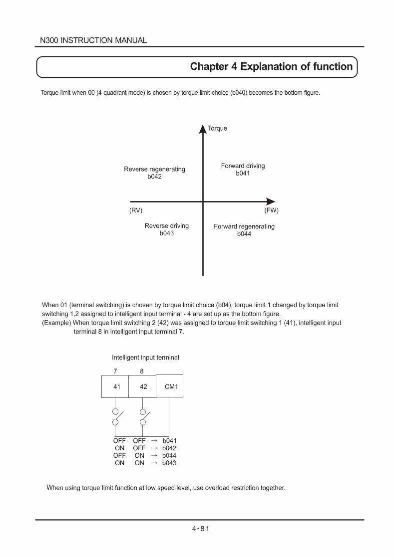
Torque limit when 00 (4 quadrant mode) is chosen by torque limit choice (b040) becomes the bottom figure.
Reverse regeneratingb042
Forward drivingb041
Reverse drivingb043
Forward regeneratingb044
(RV) (FW)
Torque
When 01 (terminal switching) is chosen by torque limit choice (b04), torque limit 1 changed by torque limit
switching 1,2 assigned to intelligent input terminal - 4 are set up as the bottom figure.
(Example) When torque limit switching 2 (42) was assigned to torque limit switching 1 (41), intelligent input
terminal 8 in intelligent input terminal 7.
41 42 CM1
Intelligent input terminal
7 8
OFF OFF b041ON OFF b042OFF ON b044ON ON b043
When using torque limit function at low speed level, use overload restriction together.
N300 INSTRUCTION MANUAL
Chapter 4 Explanation of function
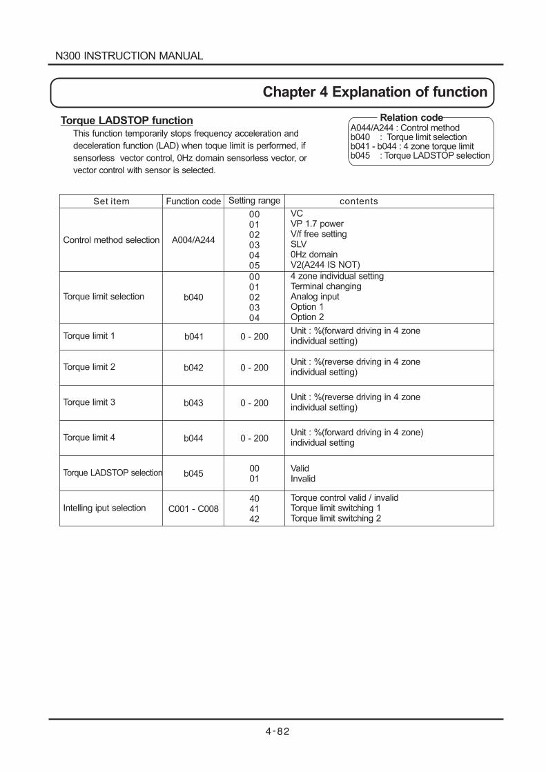
Torque LADSTOP functionThis function temporarily stops frequency acceleration and
deceleration function (LAD) when toque limit is performed, if
sensorless vector control, 0Hz domain sensorless vector, or
vector control with sensor is selected.
Control method selection
C001 - C008
Function code Setting range
000102030405
0001020304
Torque limit selection
Torque limit 1
Torque limit 2
Torque limit 3
Torque limit 4
Torque LADSTOP selection
Intelling iput selection
A004/A244
b041
b040
b043
b042
b044
b045
0 - 200
0 - 200
0 - 200
0 - 200
0001
404142
VCVP 1.7 powerV/f free settingSLV0Hz domainV2(A244 IS NOT)
4 zone individual settingTerminal changingAnalog inputOption 1Option 2
Unit : %(forward driving in 4 zoneindividual setting)
Unit : %(forward driving in 4 zone)individual setting
Unit : %(reverse driving in 4 zoneindividual setting)
Unit : %(reverse driving in 4 zoneindividual setting)
ValidInvalid
Torque control valid / invalidTorque limit switching 1Torque limit switching 2
contentsSet item
Relation codeA044/A244 : Control methodb040 : Torque limit selectionb041 - b044 : 4 zone torque limitb045 : Torque LADSTOP selection
N300 INSTRUCTION MANUAL
Chapter 4 Explanation of function
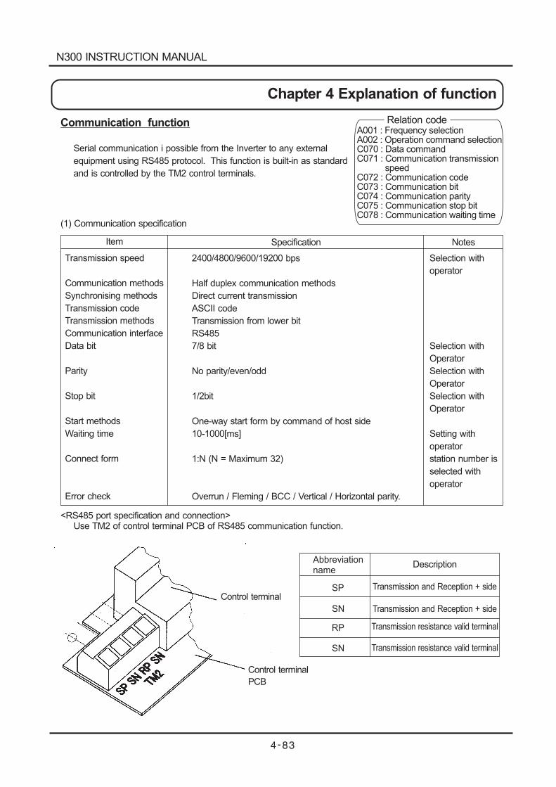
Abbreviationname
SP
SN
RP
SN
Transmission and Reception + side
Transmission and Reception + side
Transmission resistance valid terminal
Transmission resistance valid terminal
Control terminal
Control terminal
PCB
Communication function
Serial communication i possible from the Inverter to any external
equipment using RS485 protocol. This function is built-in as standard
and is controlled by the TM2 control terminals.
(1) Communication specification
Transmission speed
Communication methods
Synchronising methods
Transmission code
Transmission methods
Communication interface
Data bit
Parity
Stop bit
Start methods
Waiting time
Connect form
Error check
Selection with
operator
Selection with
Operator
Selection with
Operator
Selection with
Operator
Setting with
operator
station number is
selected with
operator
2400/4800/9600/19200 bps
Half duplex communication methods
Direct current transmission
ASCII code
Transmission from lower bit
RS485
7/8 bit
No parity/even/odd
1/2bit
One-way start form by command of host side
10-1000[ms]
1:N (N = Maximum 32)
Overrun / Fleming / BCC / Vertical / Horizontal parity.
Item Specification Notes
<RS485 port specification and connection>Use TM2 of control terminal PCB of RS485 communication function.
Description
Relation codeA001 : Frequency selectionA002 : Operation command selectionC070 : Data commandC071 : Communication transmission
speedC072 : Communication codeC073 : Communication bitC074 : Communication parityC075 : Communication stop bitC078 : Communication waiting time
N300 INSTRUCTION MANUAL
Chapter 4 Explanation of function
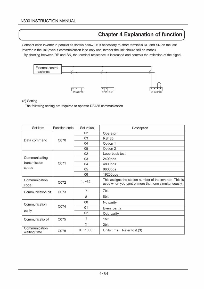
Connect each inverter in parallel as shown below. It is necessary to short terminals RP and SN on the last
inverter in the link(even if communication is to only one inverter the link should still be mabe)
By shorting between RP and SN, the terminal resistance is increased and controls the reflection of the signal.
External controlmachines
SP SN RP SN SP SN RP SNSP SN RP SN
(2) Setting
The following setting are required to operate RS485 communication
Data command
Communicating
transmission
speed
Communication
code
Operator
RS485
Option 1
Option 2
Loop-back test
C070
C071
C072
C073
C074
02
03
04
05
02
03
04
05
06
7
8
00
01
02
1
2
2400bps
4800bps
9600bps
19200bps
This assigns the station number of the inverter. This isused when you control more than one simultaneously.
C075
C078
Communicatio bit
Communicationwaiting time
7bit
8bit
No parity
Even parity
Odd parity
1bit
2bit
Units : ms Refer to it.(3)0. ~1000.
1. ~32.
Set item Function code Set value Description
Communication bit
Communication
parity
N300 INSTRUCTION MANUAL
Chapter 4 Explanation of function
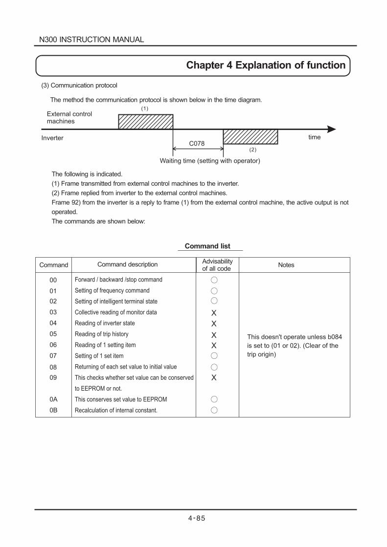
(3) Communication protocol
The method the communication protocol is shown below in the time diagram.
External controlmachines
InverterC078
time
Waiting time (setting with operator)
The following is indicated.
(1) Frame transmitted from external control machines to the inverter.
(2) Frame replied from inverter to the external control machines.
Frame 92) from the inverter is a reply to frame (1) from the external control machine, the active output is not
operated.
The commands are shown below:
This doesn't operate unless b084
is set to (01 or 02). (Clear of the
trip origin)
Forward / backward /stop command
Setting of frequency command
Setting of intelligent terminal state
Collective reading of monitor data
Reading of inverter state
Reading of trip history
Reading of 1 setting item
Setting of 1 set item
Returning of each set value to initial value
This checks whether set value can be conserved
to EEPROM or not.
This conserves set value to EEPROM
Recalculation of internal constant.
00
01
02
03
04
05
06
07
08
09
0A
0B
X
X
X
X
X
Command Command descriptionAdvisabilityof all code
Notes
Command list
(2)
(1)
N300 INSTRUCTION MANUAL
Chapter 4 Explanation of function
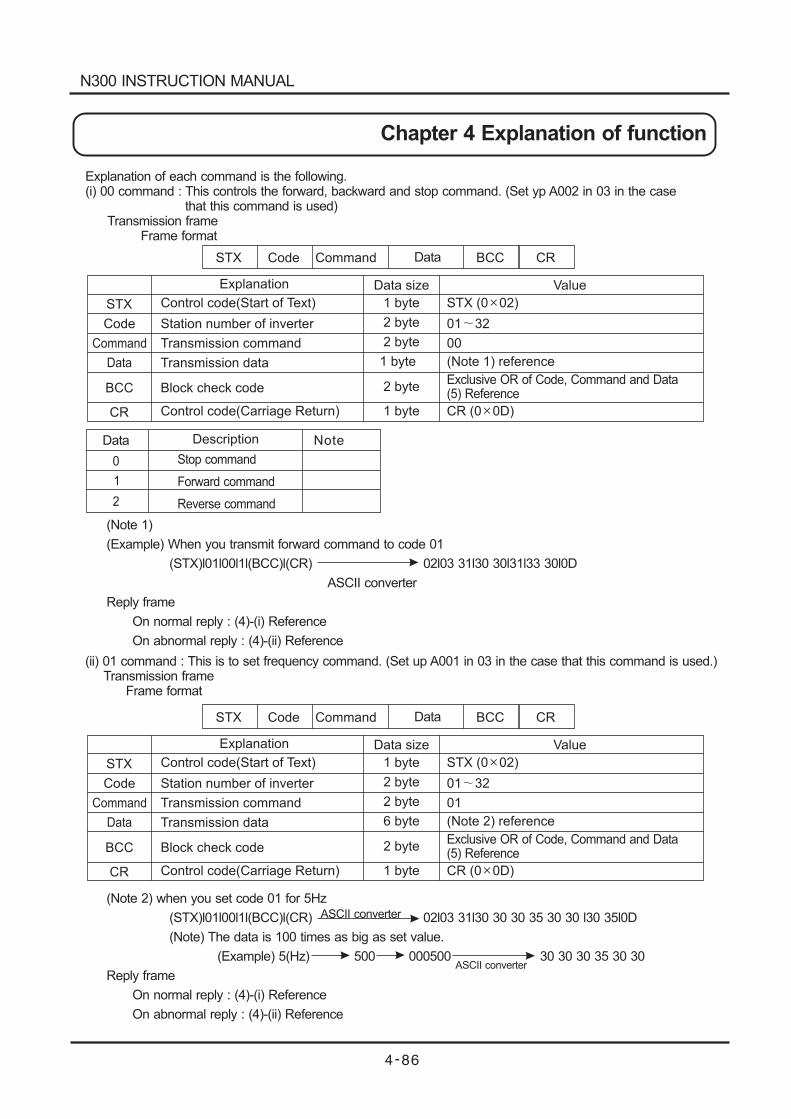
Code
Explanation Data size Value
STX
Command
BCC
CR
Control code(Start of Text)
Station number of inverter
Transmission command
Block check code
Control code(Carriage Return)
1 byte
2 byte
2 byte
1 byte
STX (0 02)
01 32
00
Exclusive OR of Code, Command and Data(5) Reference
CR (0 0D)
2 byte
Explanation of each command is the following.(i) 00 command : This controls the forward, backward and stop command. (Set yp A002 in 03 in the case
that this command is used)Transmission frame
Frame format
STX Code Command BCC CRData
Data Transmission data (Note 1) reference1 byte
0
1
2
Stop command
Forward command
Reverse command
Data Description Note
(Note 1)
(Example) When you transmit forward command to code 01
(STX)l01l00l1l(BCC)l(CR) 02l03 31l30 30l31l33 30l0D
ASCII converter
Reply frame
On normal reply : (4)-(i) Reference
On abnormal reply : (4)-(ii) Reference
(ii) 01 command : This is to set frequency command. (Set up A001 in 03 in the case that this command is used.)Transmission frame
Frame format
Code
Explanation Data size Value
STX
Command
BCC
CR
Control code(Start of Text)
Station number of inverter
Transmission command
Block check code
Control code(Carriage Return)
1 byte
2 byte
2 byte
1 byte
STX (0 02)
01 32
01
Exclusive OR of Code, Command and Data(5) Reference
CR (0 0D)
2 byte
STX Code Command BCC CRData
Data Transmission data (Note 2) reference6 byte
(Note 2) when you set code 01 for 5Hz
(STX)l01l00l1l(BCC)l(CR) 02l03 31l30 30 30 35 30 30 l30 35l0D
(Note) The data is 100 times as big as set value.
(Example) 5(Hz) 500 000500 30 30 30 35 30 30
Reply frame
On normal reply : (4)-(i) Reference
On abnormal reply : (4)-(ii) Reference
ASCII converter
ASCII converter
N300 INSTRUCTION MANUAL
Chapter 4 Explanation of function
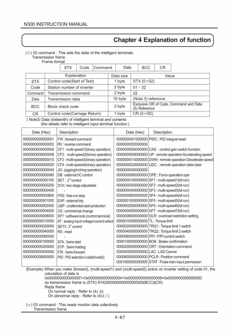
Code
Explanation Data size Value
STX
Command
BCC
CR
Control code(Start of Text)
Station number of inverter
Transmission command
Block check code
Control code(Carriage Return)
1 byte
2 byte
2 byte
1 byte
STX (0 02)
01 32
02
Exclusive OR of Code, Command and Data(5) Reference
CR (0 0D)
2 byte
( ) 02 command : This sets the state of the intelligent terminals.Transmission frame
Frame format
( Note3) Data (sixteenth) of intelligent terminal and contents(the details refer to intelligent input terminal function.)
STX Code Command BCC CRData
Data Transmission data (Note 3) reference16 byte
PIDC : PID integral reset
CAS : control gain switch function
UP : remote operationAccelerating speed
DWN : remote operation Decelerate speed
UDC : remote operation data clear
OPE : Force operation ope
SF1 : multi-speed1(bit run)
SF2 : multi-speed2(bit run)
SF3 : multi-speed3(bit run)
SF4 : multi-speed4(bit run)
SF5 : multi-speed5(bit run)
SF6 : multi-speed6(bit run)
SF7 : multi-speed7(bit run)
OLR : overload restriction setting
TL : Torque limit
TRQ1 : Torque limit 1 switch
TRQ2 : Torque limit 2 switch
PPI : P/PI control switch
BOK : Brake confirmation
ORT : Orientation command
LAC : LAD Cancel
PCLR : Position command
STAT : Pulse train input permission
0000000000000001
0000000000000002
0000000000000004
0000000000000008
0000000000000010
0000000000000020
0000000000000040
0000000000000080
0000000000000100
0000000000000200
0000000000000400
0000000000000800
0000000000001000
0000000000002000
0000000000004000
0000000000008000
0000000000010000
0000000000020000
0000000000040000
0000000000080000
0000000000100000
0000000000200000
0000000000400000
0000000000800000
0000000001000000
0000000002000000
0000000004000000
0000000008000000
0000000010000000
0000000020000000
0000000040000000
0000000080000000
0000000100000000
0000000200000000
0000000400000000
0000000800000000
0000001000000000
0000002000000000
0000004000000000
0000008000000000
0000010000000000
0000020000000000
0000040000000000
0000080000000000
0000100000000000
0000200000000000
0000400000000000
0000800000000000
0001000000000000
FW : forward command
RV : reverse command
CF1 : multi-speed1(binary operation)
CF2 : multi-speed2(binary operation)
CF3 : multi-speed3(binary operation)
CF4 : multi-speed4(binary operation)
JG : jogging(inching operation)
DB : external DC control
SET : 2 control
2CH : two stage adjustable
-
FRS : free-run stop
EXP : external trip
USP : unattended start protection
CS : commercial change
SFT : software lock (control terminal)
AT : analog input voltage/current select
SET3 : 3 control
RS : reset
-
STA: 3wire start
STP : 3wire holding
F/R : 3wire forward
PID : PID selection (valid/invalid)
nd
rd
Data (Hex) Data (Hex)Description Description
(Example) When you make (forward), (multi-speed1) and (multi-speed2) active on inverter setting of code 01, thecalculation of data is0x0000000000000001+0x0000000000000004+0x0000000000000008=0x000000000000000Dso transmission frame is (STX) l01l02l000000000000000Dl(BCC)l(CR)Reply frame
On normal reply : Refer to (4) -(i)On abnormal reply : Refer to (4)-( )
( ) 03 command : This reads monitor data collectively.Transmission frame
N300 INSTRUCTION MANUAL
Chapter 4 Explanation of function
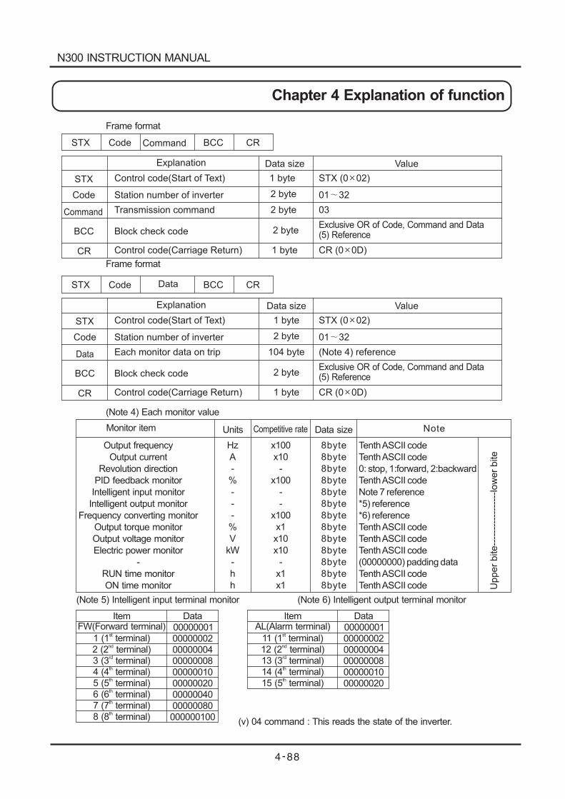
STX Code
Code
Command BCC CR
Explanation Data size Value
STX
Command
BCC
CR
Control code(Start of Text)
Station number of inverter
Transmission command
Block check code
Control code(Carriage Return)
1 byte
2 byte
2 byte
1 byte
STX (0 02)
01 32
03
Exclusive OR of Code, Command and Data(5) Reference
CR (0 0D)
2 byte
Frame format
Frame format
STX Code
Code
Data BCC CR
Explanation Data size Value
STX
Data
BCC
CR
Control code(Start of Text)
Station number of inverter
Each monitor data on trip
Block check code
Control code(Carriage Return)
1 byte
2 byte
2 byte
1 byte
STX (0 02)
01 32
(Note 4) reference
Exclusive OR of Code, Command and Data(5) Reference
CR (0 0D)
104 byte
Monitor item
Output frequency
Output current
Revolution direction
PID feedback monitor
Intelligent input monitor
Intelligent output monitor
Frequency converting monitor
Output torque monitor
Output voltage monitor
Electric power monitor
-
RUN time monitor
ON time monitor
Units
Hz
A
-
%
-
-
-
%
V
kW
-
h
h
x100
x10
-
x100
-
-
x100
x1
x10
x10
-
x1
x1
Competitive rate Data size
8byte
8byte
8byte
8byte
8byte
8byte
8byte
8byte
8byte
8byte
8byte
8byte
8byte
Note
Upper
bite--
----
----
----
---low
er
bite
TenthASCII code
TenthASCII code
0: stop, 1:forward, 2:backward
TenthASCII code
TenthASCII code
TenthASCII code
(00000000) padding data
TenthASCII code
TenthASCII code
Note 7 reference
*5) reference
*6) reference
TenthASCII code
(Note 4) Each monitor value
(Note 5) Intelligent input terminal monitor (Note 6) Intelligent output terminal monitor
ItemFW(Forward terminal)
1 (1 terminal)st
2 (2 terminal)nd
3 (3 terminal)rd
4 (4 terminal)th
5 (5 terminal)th
6 (6 terminal)th
7 (7 terminal)th
8 (8 terminal)th
Data
00000001
00000002
00000004
00000008
00000010
00000020
00000040
00000080
000000100
ItemAL(Alarm terminal)
11 (1 terminal)st
12 (2 terminal)nd
13 (3 terminal)rd
14 (4 terminal)th
15 (5 terminal)th
Data
00000001
00000002
00000004
00000008
00000010
00000020
(v) 04 command : This reads the state of the inverter.
N300 INSTRUCTION MANUAL
Chapter 4 Explanation of function
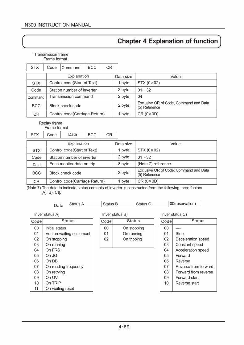
STX Code
Code
Command BCC CR
Explanation Data size Value
STX
Command
BCC
CR
Control code(Start of Text)
Station number of inverter
Transmission command
Block check code
Control code(Carriage Return)
1 byte
2 byte
2 byte
1 byte
STX (0 02)
01 32
04
Exclusive OR of Code, Command and Data(5) Reference
CR (0 0D)
2 byte
Transmission frameFrame format
Replay frameFrame format
STX Code
Code
Data BCC CR
Explanation Data size Value
STX
Data
BCC
CR
Control code(Start of Text)
Station number of inverter
Each monitor data on trip
Block check code
Control code(Carriage Return)
1 byte
2 byte
2 byte
1 byte
STX (0 02)
01 32
(Note 7) reference
Exclusive OR of Code, Command and Data(5) Reference
CR (0 0D)
8 byte
(Note 7) The data to indicate status contents of inverter is constructed from the following three factors[A), B), C)].
Status A Status B Status C 00(reservation)Data
00
01
02
03
04
05
06
07
08
09
10
11
Initial status
Vdc on waiting settlement
On stopping
On running
On FRS
On JG
On DB
On reading frequency
On retrying
On UV
On TRIP
On waiting reset
StatusCode
00
01
02
03
04
05
06
07
08
09
10
----
Stop
Deceleration speed
Constant speed
Acceleration speed
Forward
Reverse
Reverse from forward
Forward from reverse
Forward start
Reverse start
StatusCode
00
01
02
On stopping
On running
On tripping
StatusCode
Inver status A) Inver status B) Inver status C)
N300 INSTRUCTION MANUAL
Chapter 4 Explanation of function
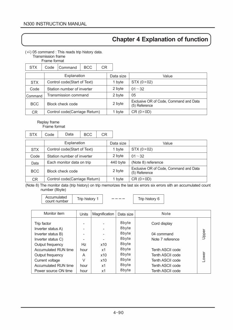
STX Code
Code
Command BCC CR
Explanation Data size Value
STX
Command
BCC
CR
Control code(Start of Text)
Station number of inverter
Transmission command
Block check code
Control code(Carriage Return)
1 byte
2 byte
2 byte
1 byte
STX (0 02)
01 32
05
Exclusive OR of Code, Command and Data(5) Reference
CR (0 0D)
2 byte
( ) 05 command : This reads trip history data.Transmission frame
Frame format
Replay frameFrame format
STX Code
Code
Data BCC CR
Explanation Data size Value
STX
Data
BCC
CR
Control code(Start of Text)
Station number of inverter
Each monitor data on trip
Block check code
Control code(Carriage Return)
1 byte
2 byte
2 byte
1 byte
STX (0 02)
01 32
(Note 8) reference
Exclusive OR of Code, Command and Data(5) Reference
CR (0 0D)
440 byte
(Note 8) The monitor data (trip history) on trip memorizes the last six errors six errors sith an accumulated countnumber (8byte)
Accumulatedcount number
Trip history 1 Trip history 6----
Monitor item
Trip factor
Inverter status A)
Inverter status B)
Inverter status C)
Output frequency
Accumulated RUN time
Output frequency
Current voltage
Accumulated RUN time
Power source ON time
Units
-
-
-
-
Hz
hour
A
V
hour
hour
-
-
-
-
x10
x1
x10
x10
x1
x1
Magnification Data size
8byte
8byte
8byte
8byte
8byte
8byte
8byte
8byte
8byte
8byte
Note
Low
er
Upper
Cord display
04 command
Note 7 reference
Tenth ASCII code
Tenth ASCII code
Tenth ASCII code
Tenth ASCII code
Tenth ASCII code
N300 INSTRUCTION MANUAL
Chapter 4 Explanation of function
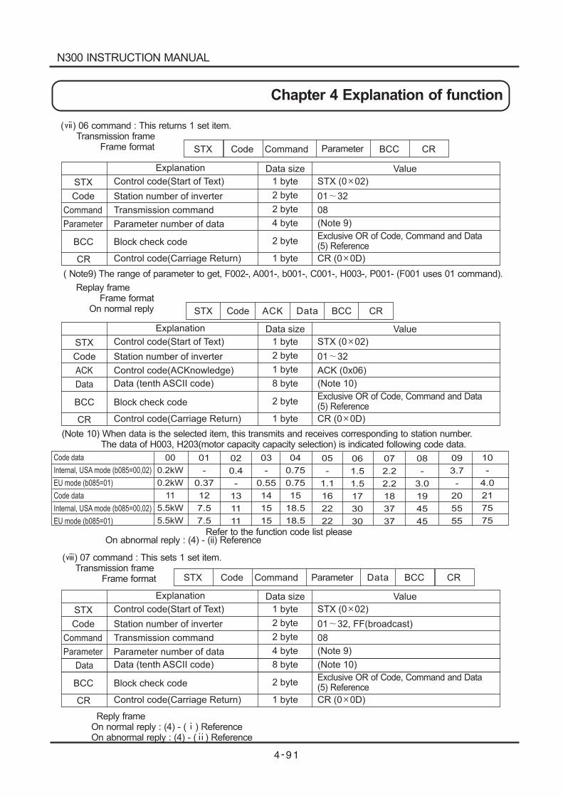
Code
Explanation Data size Value
STX
Command
BCC
CR
Control code(Start of Text)
Station number of inverter
Transmission command
Block check code
Control code(Carriage Return)
1 byte
2 byte
2 byte
1 byte
STX (0 02)
01 32
08
Exclusive OR of Code, Command and Data(5) Reference
CR (0 0D)
2 byte
( ) 06 command : This returns 1 set item.Transmission frame
Frame format
( Note9) The range of parameter to get, F002-, A001-, b001-, C001-, H003-, P001- (F001 uses 01 command).
STX Code BCC CR
( ) 07 command : This sets 1 set item.Transmission frame
Frame format
Reply frameOn normal reply : (4) - ( ) ReferenceOn abnormal reply : (4) - ( ) Reference
STX
STX
Code
Code
Command
Command
BCC
BCC
CR
CR
Parameter
Parameter
Parameter Parameter number of data (Note 9)4 byte
Replay frameFrame format
On normal reply ACK Data
Data
Code
Explanation Data size Value
STX
ACK
BCC
CR
Control code(Start of Text)
Station number of inverter
Control code(ACKnowledge)
Block check code
Control code(Carriage Return)
1 byte
2 byte
2 byte
1 byte
STX (0 02)
01 32
ACK (0x06)
Exclusive OR of Code, Command and Data(5) Reference
CR (0 0D)
1 byte
Data
Data
Data (tenth ASCII code)
Data (tenth ASCII code)
(Note 10)
(Note 10)
8 byte
8 byte
(Note 10) When data is the selected item, this transmits and receives corresponding to station number.The data of H003, H203(motor capacity capacity selection) is indicated following code data.
00
0.2kW
0.2kW
11
5.5kW
5.5kW
01
-
0.37
12
7.5
7.5
02
0.4
-
13
11
11
03
-
0.55
14
15
15
04
0.75
0.75
15
18.5
18.5
05
-
1.1
16
22
22
06
1.5
1.5
17
30
30
07
2.2
2.2
18
37
37
08
-
3.0
19
45
45
09
3.7
-
20
55
55
10
-
4.0
21
75
75
Code data
Internal, USA mode (b085=00,02)
EU mode (b085=01)
Code data
Internal, USA mode (b085=00,02)
EU mode (b085=01)
Refer to the function code list pleaseOn abnormal reply : (4) - (ii) Reference
Code
Explanation Data size Value
STX
Command
BCC
CR
Control code(Start of Text)
Station number of inverter
Transmission command
Block check code
Control code(Carriage Return)
1 byte
2 byte
2 byte
1 byte
STX (0 02)
01 32, FF(broadcast)
08
Exclusive OR of Code, Command and Data(5) Reference
CR (0 0D)
2 byte
Parameter Parameter number of data (Note 9)4 byte
N300 INSTRUCTION MANUAL
Chapter 4 Explanation of function
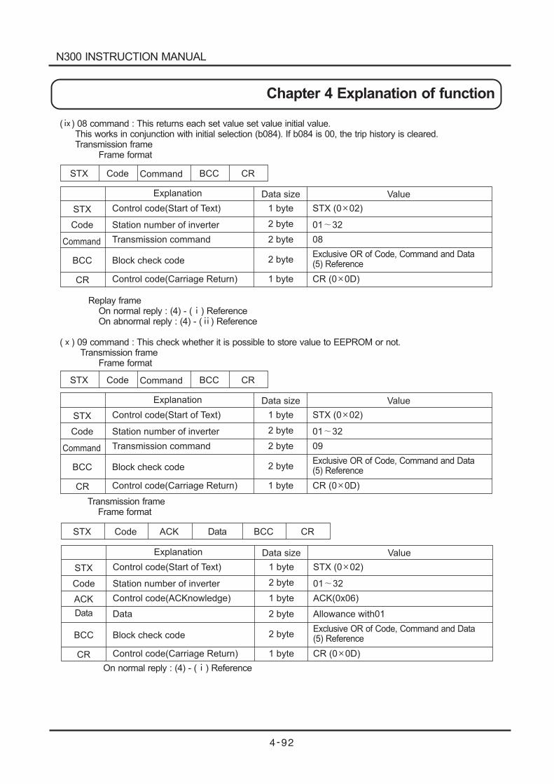
STX Code
Code
Command BCC CR
Explanation Data size Value
STX
Command
BCC
CR
Control code(Start of Text)
Station number of inverter
Transmission command
Block check code
Control code(Carriage Return)
1 byte
2 byte
2 byte
1 byte
STX (0 02)
01 32
08
Exclusive OR of Code, Command and Data(5) Reference
CR (0 0D)
2 byte
( ) 08 command : This returns each set value set value initial value.This works in conjunction with initial selection (b084). If b084 is 00, the trip history is cleared.Transmission frame
Frame format
Replay frameOn normal reply : (4) - ( )On abnormal reply : (4) - ( ) Reference
( ) 09 command : This check whether it is possible to store value to EEPROM or not.Transmission frame
Frame format
Reference
STX Code
Code
Command BCC CR
Explanation Data size Value
STX
Command
BCC
CR
Control code(Start of Text)
Station number of inverter
Transmission command
Block check code
Control code(Carriage Return)
1 byte
2 byte
2 byte
1 byte
STX (0 02)
01 32
09
Exclusive OR of Code, Command and Data(5) Reference
CR (0 0D)
2 byte
Transmission frameFrame format
On normal reply : (4) - ( ) Reference
Code
Explanation Data size Value
STX
ACK
BCC
CR
Control code(Start of Text)
Station number of inverter
Control code(ACKnowledge)
Data
Block check code
Control code(Carriage Return)
1 byte
2 byte
2 byte
1 byte
STX (0 02)
01 32
ACK(0x06)
Allowance with01
Exclusive OR of Code, Command and Data(5) Reference
CR (0 0D)
STX Code ACK BCC CRData
Data
1 byte
2 byte
N300 INSTRUCTION MANUAL
Chapter 4 Explanation of function
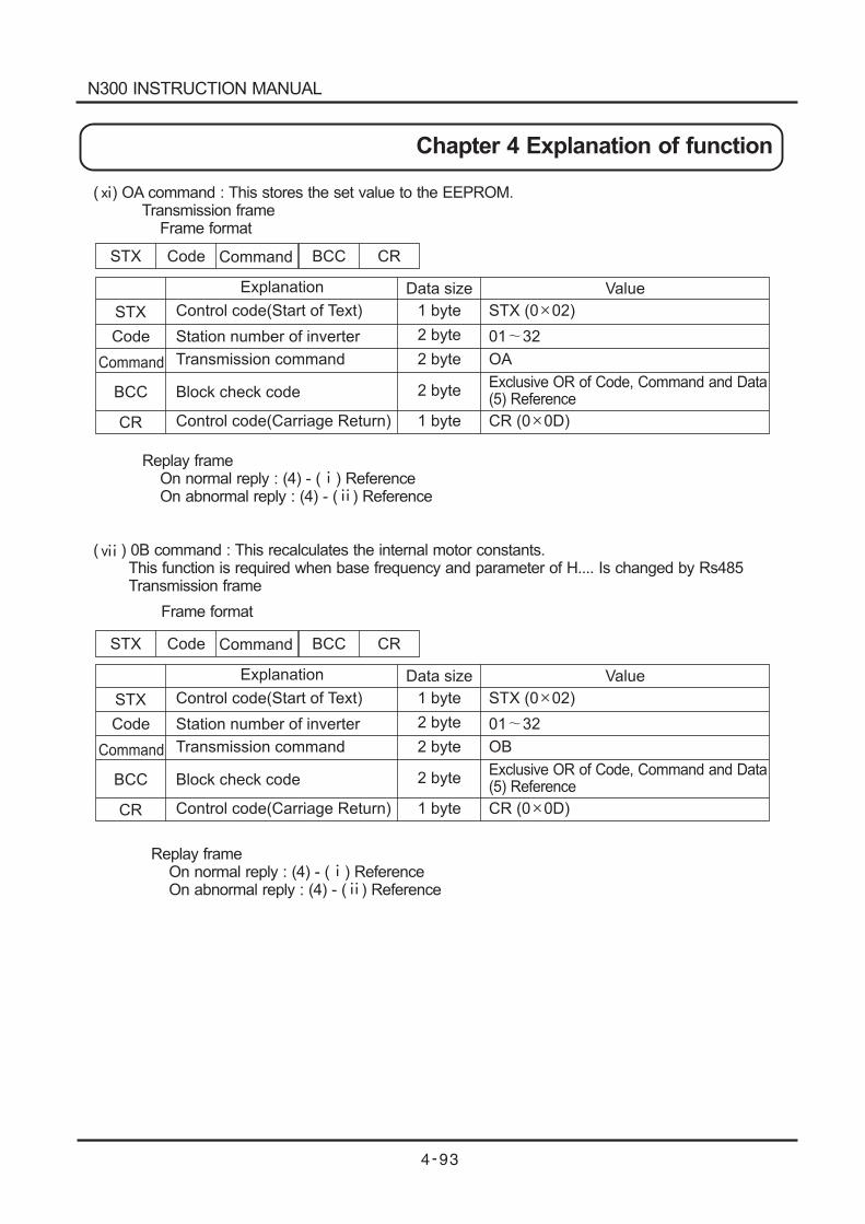
STX Code
Code
Command BCC CR
Explanation Data size Value
STX
Command
BCC
CR
Control code(Start of Text)
Station number of inverter
Transmission command
Block check code
Control code(Carriage Return)
1 byte
2 byte
2 byte
1 byte
STX (0 02)
01 32
OA
Exclusive OR of Code, Command and Data(5) Reference
CR (0 0D)
2 byte
( ) OA command : This stores the set value to the EEPROM.Transmission frame
Frame format
Replay frameOn normal reply : (4) - ( )On abnormal reply : (4) - ( ) Reference
( ) 0B command : This recalculates the internal motor constants.This function is required when base frequency and parameter of H.... Is changed by Rs485Transmission frame
Reference
Replay frameOn normal reply : (4) - ( ) ReferenceOn abnormal reply : (4) - ( ) Reference
STX Code
Code
Command BCC CR
Explanation Data size Value
STX
Command
BCC
CR
Control code(Start of Text)
Station number of inverter
Transmission command
Block check code
Control code(Carriage Return)
1 byte
2 byte
2 byte
1 byte
STX (0 02)
01 32
OB
Exclusive OR of Code, Command and Data(5) Reference
CR (0 0D)
2 byte
Frame format
N300 INSTRUCTION MANUAL
Chapter 4 Explanation of function
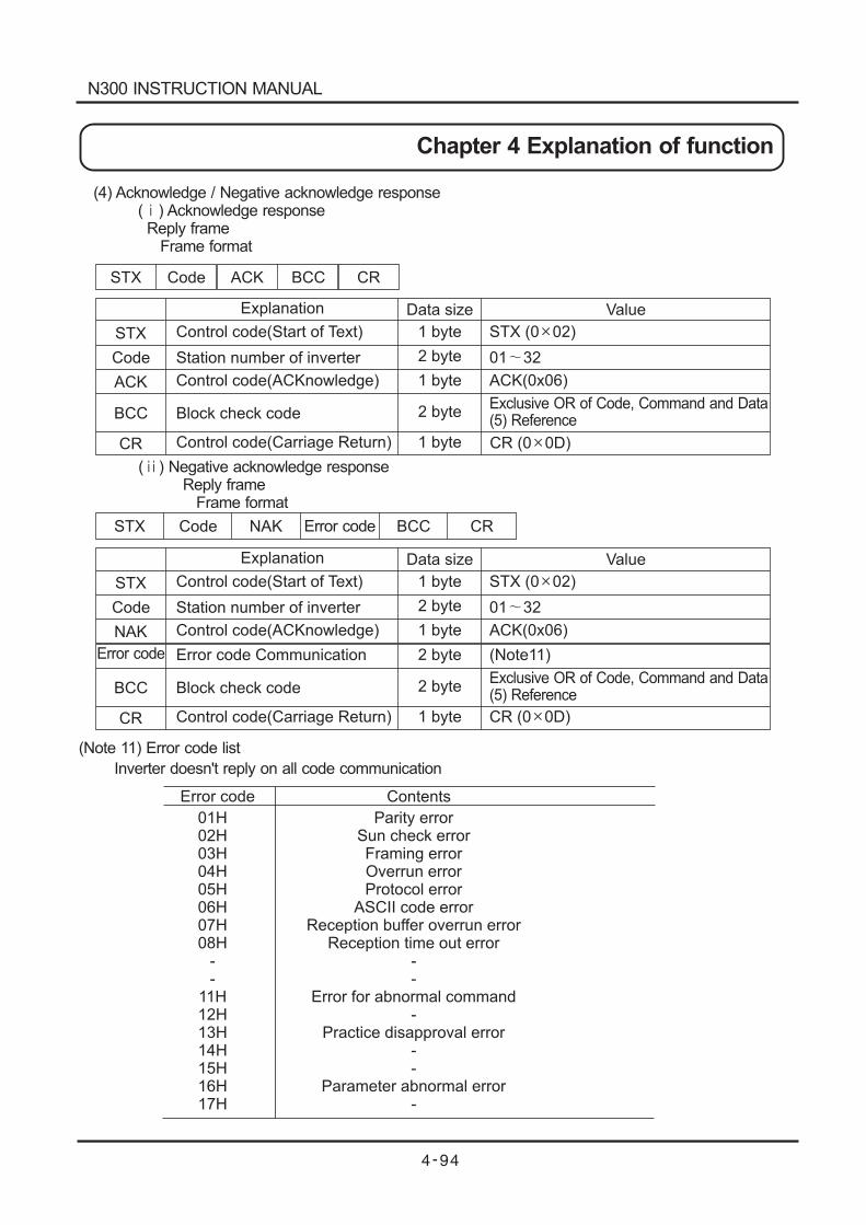
STX Code
Code
Code
ACK BCC CR
Explanation
Explanation
Data size
Data size
Value
Value
STX
STX
ACK
NAK
BCC
BCC
CR
CR
Control code(Start of Text)
Control code(Start of Text)
Station number of inverter
Station number of inverter
Control code(ACKnowledge)
Control code(ACKnowledge)
Error code Communication
Block check code
Block check code
Control code(Carriage Return)
Control code(Carriage Return)
1 byte
1 byte
2 byte
2 byte
2 byte
2 byte
1 byte
1 byte
STX (0 02)
STX (0 02)
01 32
01 32
ACK(0x06)
ACK(0x06)
(Note11)
Exclusive OR of Code, Command and Data(5) Reference
Exclusive OR of Code, Command and Data(5) Reference
CR (0 0D)
CR (0 0D)
STX Code NAK BCC CRError code
Error code
Parity errorSun check errorFraming errorOverrun errorProtocol error
ASCII code errorReception buffer overrun error
Reception time out error--
Error for abnormal command-
Practice disapproval error--
Parameter abnormal error-
(Note 11) Error code list
Inverter doesn't reply on all code communication
Error code Contents
01H02H03H04H05H06H07H08H
--
11H12H13H14H15H16H17H
1 byte
1 byte
2 byte
(4) Acknowledge / Negative acknowledge response( ) Acknowledge responseReply frame
Frame format
( ) Negative acknowledge responseReply frame
Frame format
N300 INSTRUCTION MANUAL
Chapter 4 Explanation of function
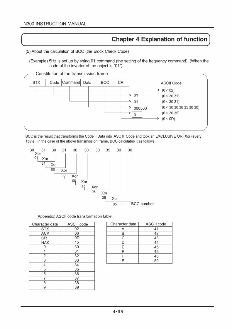
(0 02)
(0 30 31)
(0 30 31)
(0 30 30 30 35 30 30)
(0 30 35)
(0 0D)
Constitution of the transmission frame
STX Code Command Data BCC CR
01
01
000500
0
ASCII Code
Character data Character dataASC code ASC code
STXACK
CRNAK
BCC is the result that transforms the Code Data into ASC Code and took an EXCLUSIVE OR (Xor) every
1byte. In the case of the above transmission frame, BCC calculates it as follows.
30 31 30 31 30 30 30 35 30 30Xor
BCC number
Xor
Xor
Xor
Xor
Xor
Xor
Xor
Xor
01
31
00
30
00
30
05
35
05
0123456789
02060D1530313233343536373839
ABCDEFHP
4142434445464850
(Appendix) ASCII code transformation table
(5) About the calculation of BCC (the Block Check Code)
(Example) 5Hz is set up by using 01 command (the setting of the frequency command). (When thecode of the inverter of the object is "01")
N300 INSTRUCTION MANUAL
Chapter 4 Explanation of function
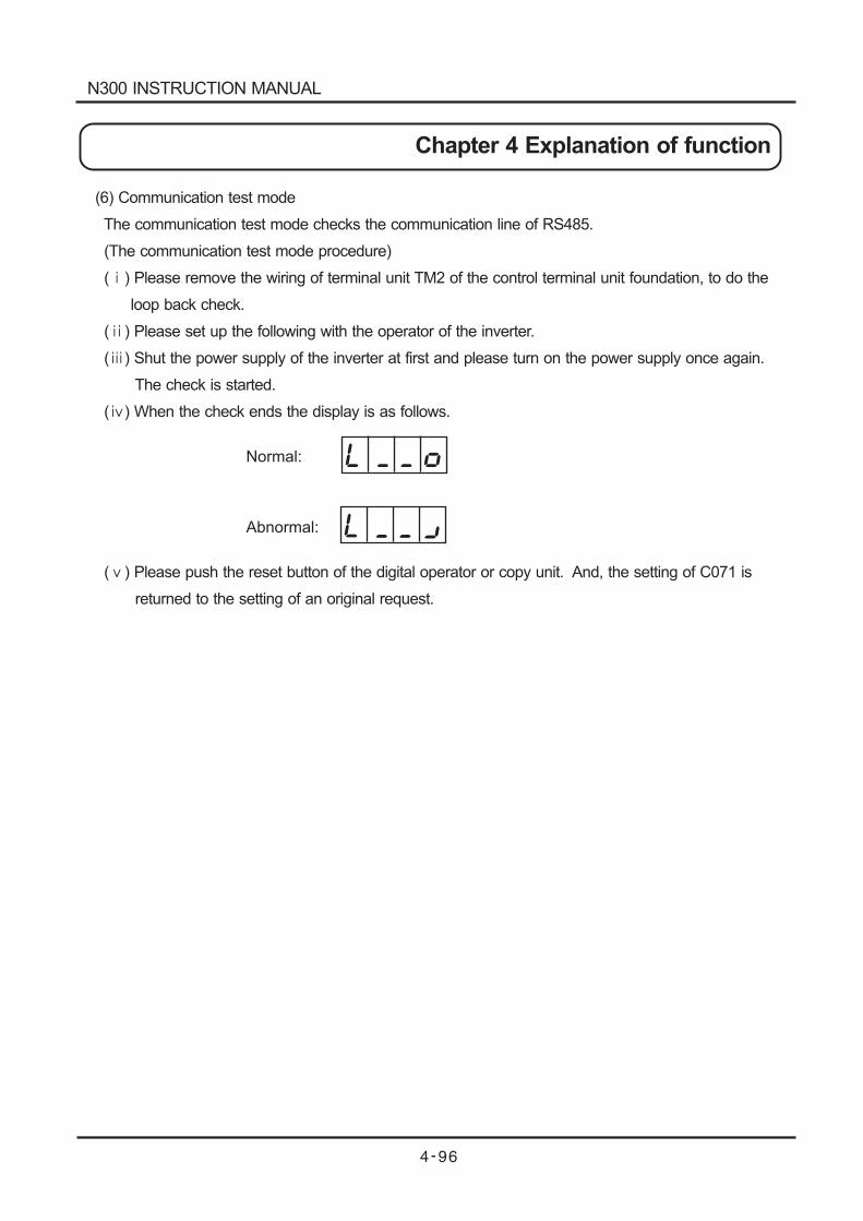
(6) Communication test mode
The communication test mode checks the communication line of RS485.
(The communication test mode procedure)
( ) Please remove the wiring of terminal unit TM2 of the control terminal unit foundation, to do the
loop back check.
( ) Please set up the following with the operator of the inverter.
( ) Shut the power supply of the inverter at first and please turn on the power supply once again.
The check is started.
( ) When the check ends the display is as follows.
( ) Please push the reset button of the digital operator or copy unit. And, the setting of C071 is
returned to the setting of an original request.
Normal:
Abnormal:
N300 INSTRUCTION MANUAL
Chapter 4 Explanation of function
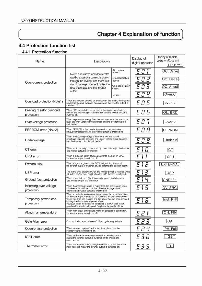
Over-current protection
Overload protection(Note1)
Braking resistor overload
protection
Over-voltage protection
EEPROM error (Note2)
Under-voltage
CT error
CPU error
External trip
USP error
Ground fault protection
Incoming over-voltage
protection
Temporary power loss
protection
Abnormal temperature
Gate Allay error
IGBT error
Thermistor error
Name DescriptionDisplay of
digital operator
When BRD exceeds the usage ratio of the regenerative brakingresistor, the over-voltage circuit operates and the inverter output isswitched off.
When regenerative energy from the motor exceeds the maximumlevel, the over -voltage circuit operates and the inverter output isswitched off.
When EEPROM in the inverter is subject to radiated noise orunusual temperature rises, the inverter output is switched off.
When the incoming voltage of inverter is low, the controlcircuit can 't operate correctly. The under -voltage circuit operatesand the inverter output is switched off.
When a mistaken action causes an error to the built -in CPU,the inverter output is switched off.
When a signal is given to the EXT intelligent input terminal,the inverter output is switched off. (on external trip function selsct)
This is the error displayed when the inverter power is restored whilestill in the RUN mode. (Valid when the USP function is selected)
When power is turned ON, this detects ground faults betweenthe inverter output and the motor.
When the incoming voltage is higher than the specification value,this detects it for 60 seconds then the over -voltage circuitoperates and inverter output is switched off.
When an instantaneous power failure occurs for more than 15ms,the inverter output is switched off. Once the
as a normal power failure.However, when the operation command is still ON with restartselection the inverter will restart. So please be careful of this.
instantaneous powerfailure wait time has elapsed and the power has not been restoredit is regarded
When main circuit temperature raises by stopping of cooling fan,the inverter output is switched off.
Communication error between CUP and gate array indicate
When an open - phase on the input supply occurs theinverter output is switched off.
When an instantaneous over -current is detected on theoutput the inverter output is switched off to protect themain devices.
When the inverter detects a high resistance on the thermistorinput from the motor the inverter output is switched off.
Open-phase protection
At constantspeed
Motor is restricted and deceleratesrapidly, excessive current is drawnthrough the inverter and there is arisk of damage. Current protectioncircuit operates and the inverteroutput
When the inverter detects an overload in the motor, the internalelectronic thermal overload operates and the inverter output isswitched off.
When an abnormality occurs to a ct (current detector) in the inverter,the inverter output is switched off.
OC. Drive
OC. Decel
OC. Accel
Over.C
over. L
Over.V
EEPROM
Under.V
CT
CPU
EXTERNAL
USP
GND. Flt
OV. SRC
Inst. P-F
OH. FIN
GA
PH. Fail
TH
E 0 1
E 0 2
E 0 3
E 0 4
E 0 5
E 0 6
E 0 7
E 0 8
E 0 9
E 1 0
E 1 1
E 1 2
E 1 3
E 1 4
E 1 5
E 1 6
E 2 1
E 2 3
E 2 4
E 3 0
E 3 5
OL. BRD
IGBT
4.4 Protection function list
4.4.1 Protection function
Display of remoteoperator /Copy unit
ERR1***
On decelerationspeed
On accelerationspeed
Other
N300 INSTRUCTION MANUAL
Chapter 4 Explanation of function
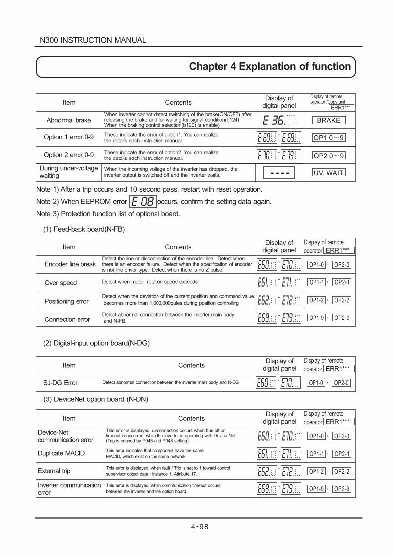
Note 1) After a trip occurs and 10 second pass, restart with reset operation.
Note 2) When EEPROM error occurs, confirm the setting data again.
Note 3) Protection function list of optional board.
E 36.
E 70. E 79.~
BRAKE
OP1 0 9
OP2 0 9
UV. WAIT
E 08
Item ContentsDisplay of
digital panel
E 60. E 69.~
Abnormal brake
Option 1 error 0-9
Option 2 error 0-9
During under-voltagewaiting
When inverter cannot detect switching of the brake(ON/OFF) afterreleasing the brake and for waiting for signal condition(b124)When the braking control selection(b120) is enable)
These indicate the error of option1, You can realizethe details each instruction manual.
These indicate the error of option2, You can realizethe details each instruction manual.
When the incoming voltage of the inverter has dropped, theinverter output is switched off and the inverter waits.
E60. E70.~Encoder line break
Over speed
Positioning error
Connection error
Detect the line or disconnection of the encoder line. Detect whenthere is an encoder failure. Detect when the specification of encoderis not line driver type. Detect when there is no Z pulse.
Detect when motor rotation speed exceeds.
Detect when the deviation of the current position and command value
becomes more than 1,000,000pules during position controlling
Detect abnormal connection between the inverter main bady
and N-FB.
E61. E71.~
E62. E72.~
E69. E79.~
OP1-0 OP2-0,
OP1-1 OP2-1,
OP1-2 OP2-2,
OP1-9 OP2-9,
(2) Digital-input option board(N-DG)
Item Contents
E60. E70.~ OP1-0 OP2-0,SJ-DG Error Detect abnormal connection between the inverter main bady and N-DG
(3) DeviceNet option board (N-DN)
Device-Netcommunication error
Duplicate MACID
External trip
Inverter communicationerror
Display ofdigital panel
Display of remote
operator ERR1***
E60. E70.~
E61. E71.~
E62. E72.~
E69. E79.~
OP1-0 OP2-0,
OP1-1 OP2-1,
OP1-2 OP2-2,
OP1-9 OP2-9,
This error is displayed, disconnection occurs when bus off ortimeout is occurred, while the inverter is operating with Device Net.(Trip is caused by P045 and P048 setting)
This error indicates that component have the same
MACID, which exist on the same network.
This error is displayed, when fault / Trip is set to 1 toward control
supervisor object data : Instance 1, Attribute 17.
This error is displayed, when communication timeout occurs
between the inverter and the option board.
Item ContentsDisplay of
digital panel
Display of remote
operator ERR1***
Item ContentsDisplay of
digital panel
Display of remote
operator ERR1***
(1) Feed-back board(N-FB)
Display of remoteoperator /Copy unit
ERR1***
----
N300 INSTRUCTION MANUAL
Chapter 4 Explanation of function
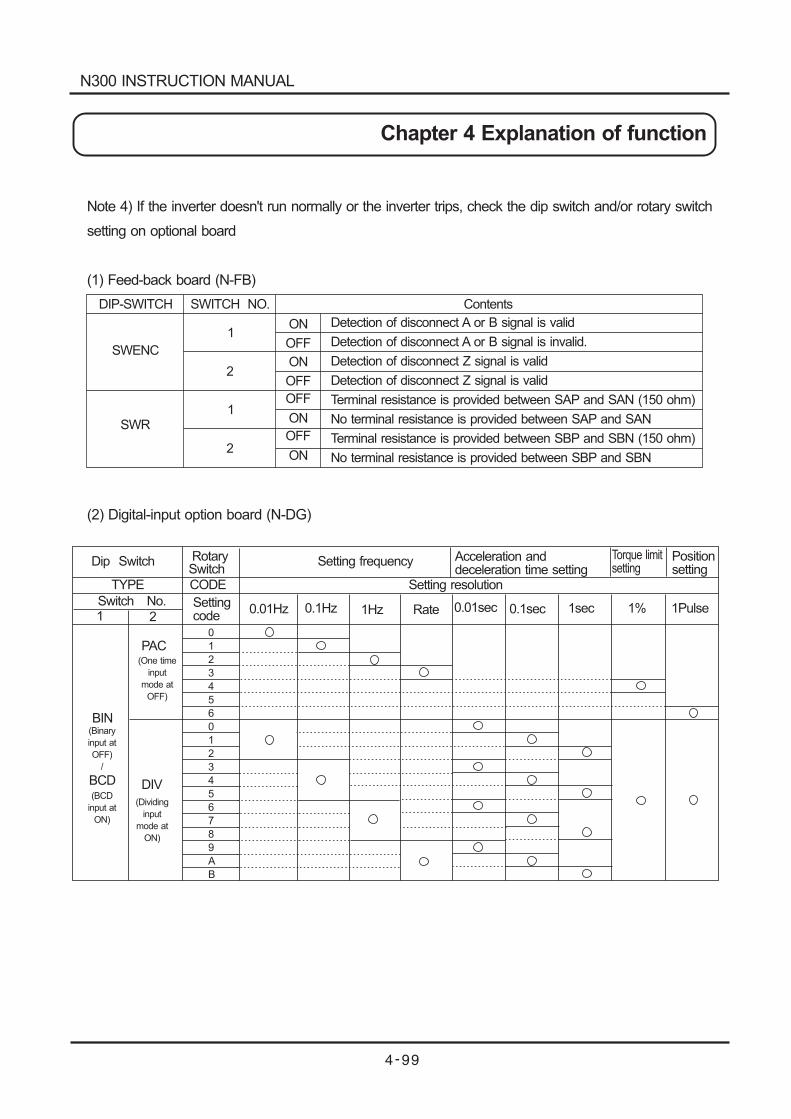
DIP-SWITCH
SWENC
1
2ON
OFF
Note 4) If the inverter doesn't run normally or the inverter trips, check the dip switch and/or rotary switch
setting on optional board
(1) Feed-back board (N-FB)
Detection of disconnect A or B signal is valid
Detection of disconnect A or B signal is invalid.
Detection of disconnect Z signal is valid
Detection of disconnect Z signal is valid
Terminal resistance is provided between SAP and SAN (150 ohm)
No terminal resistance is provided between SAP and SAN
Terminal resistance is provided between SBP and SBN (150 ohm)
No terminal resistance is provided between SBP and SBN
1
2
SWR
SWITCH NO. Contents
OFF
ON
ON
OFF
OFF
ON
Dip Switch RotarySwitch
Setting frequency Acceleration anddeceleration time setting
Torque limitsetting
Positionsetting
TYPE CODE
Switch No. Settingcode
0.01Hz 0.1Hz 1Hz Rate 0.01sec 0.1sec 1sec 1% 1Pulse
BIN(Binary
input at
OFF)
/
(BCD
input at
ON)
Setting resolution
0
1
2
3
4
5
6
0
1
2
3
4
5
6
7
8
9
A
B
1 2
BCD
PAC(One time
input
mode at
OFF)
(Dividing
input
mode at
ON)
DIV
(2) Digital-input option board (N-DG)
N300 INSTRUCTION MANUAL
Chapter 4 Explanation of function
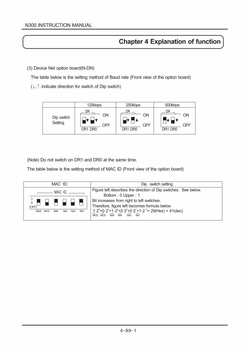
125kbps 250kbps 500kbps
Dip switch
Setting
DRON
OFFDR1 DR0
DRON
OFFDR1 DR0
DRON
OFFDR1 DR0
MAC ID.
10
(OFF)
NA32 NA16 NA8 NA4 NA2 NA1
Figure left describes the direction of Dip switches. See below.
Bottom : 0 Upper : 1
Bit increases from right to left switches.
Therefore, figure left becomes formula below.
1 2 +0 2 +1 2 +0 2 +0 2 +1 2 = 29(Hex) = 41(dec)5 4 3 2 1 0
Dip switch setting
MAC ID.
NA32 NA16 NA8 NA4 NA2 NA1
(3) Device Net option board(N-DN)
The table below is the setting method of Baud rate (Front view of the option board)
( , indicate direction for switch of Dip switch)
(Note) Do not switch on DR1 and DR0 at the same time.
The table below is the setting method of MAC ID (Front view of the option board)
N300 INSTRUCTION MANUAL
Chapter 4 Explanation of function
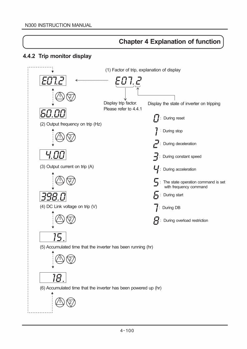
(1) Factor of trip, explanation of display
Display trip factor.
Please refer to 4.4.1
(2) Output frequency on trip (Hz)
(3) Output current on trip (A)
(4) DC Link voltage on trip (V)
(5) Accumulated time that the inverter has been running (hr)
(6) Accumulated time that the inverter has been powered up (hr)
0 : During reset
1 : During stop
2 : During deceleration
3 : During constant speed
4 : During acceleration
5 : The state operation command is setwith frequency command
6 : During start
7 : During DB
8 : During overload restriction
E07.2
60.00
4.00
398.0
15.
18.
E07.2
1 2
1 2
1 2
1 2
1 2
1 2
Display the state of inverter on tripping
4.4.2 Trip monitor display
N300 INSTRUCTION MANUAL
Chapter 4 Explanation of function
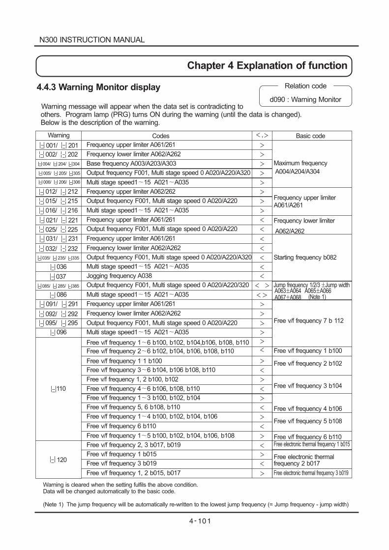
4.4.3 Warning Monitor display
Warning message will appear when the data set is contradicting toothers. Program lamp (PRG) turns ON during the warning (until the data is changed).Below is the description of the warning.
Relation code
d090 : Warning Monitor
001/ 201
002/ 202
004/ 204/ 304
012/ 212
016/ 216
021/ 221
025/ 225
031/ 231
032/ 232
036
037
086
091/ 291
092/ 292
095/ 295
096
110
120
Warning Codes Basic code
015/ 215
Frequency upper limiter A061/261
Frequency upper limiter A061/261
Frequency upper limiter A061/261
Frequency upper limiter A061/261
Frequency upper limiter A062/262
Free v/f frequency 1, 2 b100, b102
Maximum frequency
A004/A204/A304
Frequency upper limiterA061/A261
Frequency lower limiter
A062/A262
Starting frequency b082
Free v/f frequency 2 b102
Free v/f frequency 3 b104
Free v/f frequency 4 b106
Free v/f frequency 5 b108
Free v/f frequency 6 b110Free electronic thermal frequency 1 b015
Free electronic thermalfrequency 2 b017
Free electronic thermal frequency 3 b019
Free v/f frequency 7 b 112
Free v/f frequency 1 b100
Jump frequency 1/2/3 Jump widthA063 A064 A065 A066A067 A068 (Note 1)
Free v/f frequency 1 6 b100, b102, b104,b106, b108, b110
Free v/f frequency 2 6 b102, b104, b106, b108, b110
Free v/f frequency 1 1 b100
Free v/f frequency 3 6 b104, b106 b108, b110
Free v/f frequency 1, 2 b015, b017
Free v/f frequency 3 b019
Free v/f frequency 1 b015
Free v/f frequency 2, 3 b017, b019
Free v/f frequency 1 5 b100, b102, b104, b106, b108
Free v/f frequency 6 b110
Free v/f frequency 1 4 b100, b102, b104, b106
Free v/f frequency 5, 6 b108, b110
Free v/f frequency 1 3 b100, b102, b104
Free v/f frequency 4 6 b106, b108, b110
Frequency lower limiter A062/A262
Frequency lower limiter A062/A262
Frequency lower limiter A062/A262
Base frequency A003/A203/A303
Output frequency F001, Multi stage speed 0 A020/A220/A320
Output frequency F001, Multi stage speed 0 A020/A220
Output frequency F001, Multi stage speed 0 A020/A220
Output frequency F001, Multi stage speed 0 A020/A220/A320
Output frequency F001, Multi stage speed 0 A020/A220/320
Output frequency F001, Multi stage speed 0 A020/A220
Multi stage speed1 15 A021 A035
Multi stage speed1 15 A021 A035
Multi stage speed1 15 A021 A035
Multi stage speed1 15 A021 A035
Multi stage speed1 15 A021 A035
Jogging frequency A038
,
005/ 205/ 305
006/ 206/ 306
035/ 235/ 335
085/ 285/ 385
Warning is cleared when the setting fulfils the above condition.Data will be changed automatically to the basic code.
(Nete 1) The jump frequency will be automatically re-written to the lowest jump frequency (= Jump frequency - jump width)
N300 INSTRUCTION MANUAL
Chapter 4 Explanation of function
Chapter 5 Maintenance, Inspection
WARNING
After a lapse of more than 10 minutes after tuning off the input power supply, perform the
maintenance and inspection.
Otherwise, there is a danger of electric shock.
Make sure that only qualified persons will perform maintenance, inspection and part replacement.
(Before starting the work, remove metallic objects from your person wristwatch, bracelet, etc.)
(Be sure to use tools protected with insulation)
Otherwise, there is a danger of electric shock and/or injury.
5.1 Precautions for Maintenance/Inspection5.1.1 Daily inspection
5.1.2 Cleaning
Every day before operation check the following:
[1] Does the motor operate according to the settings?
[2] Is there any trouble with the surroundings of the installation?
[3] Is there any trouble with the cooling or ventilation system?
[4] Is there any abnormal vibration or sound?
[5] Are their any signs of over-current or discoloration?
[6] Is their any unusual odor present?
Check the input voltage to the inverter by using a meter during running
[1] Is the supply voltage constant?
[2] Are all the phases of the supply balanced?
Make sure that the inverter is not dirty when operating.
Wipe clean with a soft cloth and synthetic detergent.
(Note) Don't use solvents containing any of the following, acetone, benzene, toluene, alcohol etc.
As they can cause melting of the inverter surface, peeling of paint.
Never clean the display part of the digital operator with detergent of alcohol.
Inspections should be regularly carried out on the parts that can't be inspected while the inverter is
running.
[1] Is there any trouble with the cooling system? ---- Cleaning of air filter etc.
[2] Check that all screw terminals and fixings are tight as they may loosen due to vibration or
temperature change etc.
[3] Is there any corroison, damage to insulators?
[4] Measurement of insulation resistance.
[5] Check of cooling fan, smoothing capacitor, relay and exchange if necessary.
5.1.3 Regular inspection
N300 INSTRUCTION MANUAL
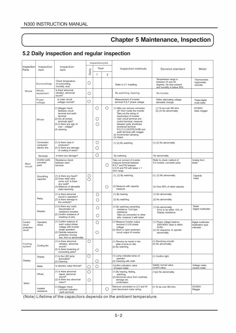
5.2 Daily inspection and regular inspection
InspectionParts
Inspectionitem
Inspectionitem
Inspectioncycle
Da
ily Year
1 2
Inspection methods Decision standard Meter
Whole
SurroundingsCheck temperatureof surrounding,humidity, dust.
Is there abnormalvibration, abnormalsound?
Wholeequipment
Powervoltage
Is main circuitvoltage normal?
Whole
Maincircuit
(1) Megger checkBetween circuitterminal and earthterminal
(2) Are all screwsterminals tight?
(3) Is there any sign ofover - voltage?
(4) cleaning
(1) After you remove connectorJ61 from inside the inverterTake out the wiring ofinput/output of invertermain circuit terminal andcontrol terminal, measurebetween parts shortenedshortened terminalR,S,T,U,V,W,P,PD,N,RB andearth terminal with megger
(2) Incremental clamping.(3) Watch
Refer to 2.1 Installing.
By watching, hearing.
Measurement of inverterterminal R,S,T phase voltage
Temperature range isbetween-10 and 40degrees. No dew presentand humidity is below 90%
No trouble
Within alternating voltageallowable change.
Thermometer,hygrometer,recorder
Tester,digitalmulti-meter
DC500Vclass megger
(1) To be over 5M ohm.(2) (3) No abnormality.
Connectionconductor/electric line
(1) Is there warp inconductor?
(2) Is there any damageof coating of wires?
(1) (2) By watching (1) (2) No abnormality
Terminals Is there any damage? By watching. No abnormality.
Inverter partsconverterparts
Resistance checkbetween eachterminal.
Take out connect of inverter,measure terminal betweenR,S,T and P,N betweenU,V,W and P,N with tester x 1ohm range.
Refer to check method of5.5 inverter, converter parts.
Analog formtester
Smoothingcapacitor
(1) Is there any liquid?(2) Does relief valve
come out? Is thereany swell?
(3) Measure of allowablestatic-electricity.
(1), (2) By watching.
(3) Measure with capacitymeasure
(1), (2) No abnormality
(3) Over 80% of rated capacity.
Capacitymeter
Relay
(1) Is there abnormalsound in operation?
(2) Is there damage tothe contacts?
(1) By hearing
(2) By watching
(1) No abnormality
(2) No abnormality
Resistor
(1) Is there any crack,discoloration ofresistance insulator.
(2) Confirm existance ofbreaking of wire.
(1) By watching cementingresistance. Curl typeresistance.Take out connection to otherside, measure it with tester.
(1) No abnormalityError to be within 10% ofDisplay resistance.
TesterDigital multimeter
Digital multimeterrectification typevoltmeter
Controlcircuitprotectioncircuit
Operationcheck
(1) Confirm balance ofeach output phasevoltage with invertersingle operation.
(2) Operate sequenceprotection movingtest. And no abnormality.
(1) Measure inverter outputterminal U,V,W phasevoltage.
(2) Short or open protectioncircuit output of inverter.
(1) Phase voltage balance200V/400V class is within4V/8V.
(2) On sequence, to operateabnormality.
Coolingsystem Cooling fan
(1) Is there abnormalvibration, abnormalsound?
(2) Is there loosening ofconnecting parts?
(1) Revolve by hands in thestate of tone-on idle.
(2) By watching.
(1) Revolving smooth.(2) No abnormality.
Display
Display
Meter
(1) Is the LED lampilluninated?
(2) Cleaning.
(1) Lamp indicates lamp onoperator.
(2) Cleaning with cloth.
(1) Confirm light.
Is direction value Normal? Confirm indication valueof board meter.
Satisfy normal value,control value.
Voltage meter,current meter
Motor
Whole
Inslatedresistance
(1) Is there abnormalsignal, abnormalsound?
(2) Is there any abnormalodour?
(1) Megger check( terminal collectionearth terminal)
(1) By hearing, feeling,watching.
(2) Abnormal odour from overheat,damage etc.confirmation.
Remove connection to U,V and Wand disconnect motor wiring.
(1)(2) No abnormality.
(1) To be over 5M ohm. DC500VMegger
(Note) Lifetime of the capacitors depends on the ambient temperature.
N300 INSTRUCTION MANUAL
Chapter 5 Maintenance, Inspection
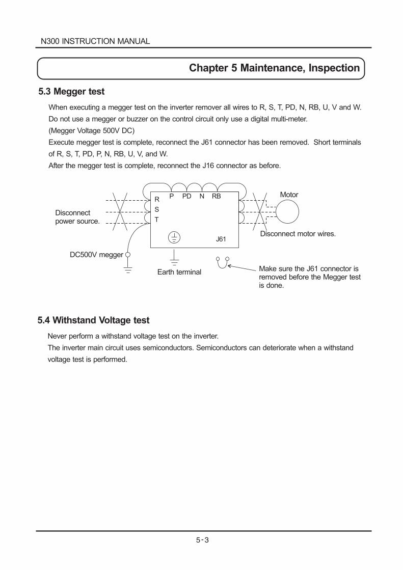
5.3 Megger test
5.4 Withstand Voltage test
R
S
T
P PD N RB
J61
When executing a megger test on the inverter remover all wires to R, S, T, PD, N, RB, U, V and W.
Do not use a megger or buzzer on the control circuit only use a digital multi-meter.
(Megger Voltage 500V DC)
Execute megger test is complete, reconnect the J61 connector has been removed. Short terminals
of R, S, T, PD, P, N, RB, U, V, and W.
After the megger test is complete, reconnect the J16 connector as before.
Never perform a withstand voltage test on the inverter.
The inverter main circuit uses semiconductors. Semiconductors can deteriorate when a withstand
voltage test is performed.
Disconnectpower source.
DC500V megger
Earth terminal
Disconnect motor wires.
Motor
Make sure the J61 connector isremoved before the Megger testis done.
N300 INSTRUCTION MANUAL
Chapter 5 Maintenance, Inspection
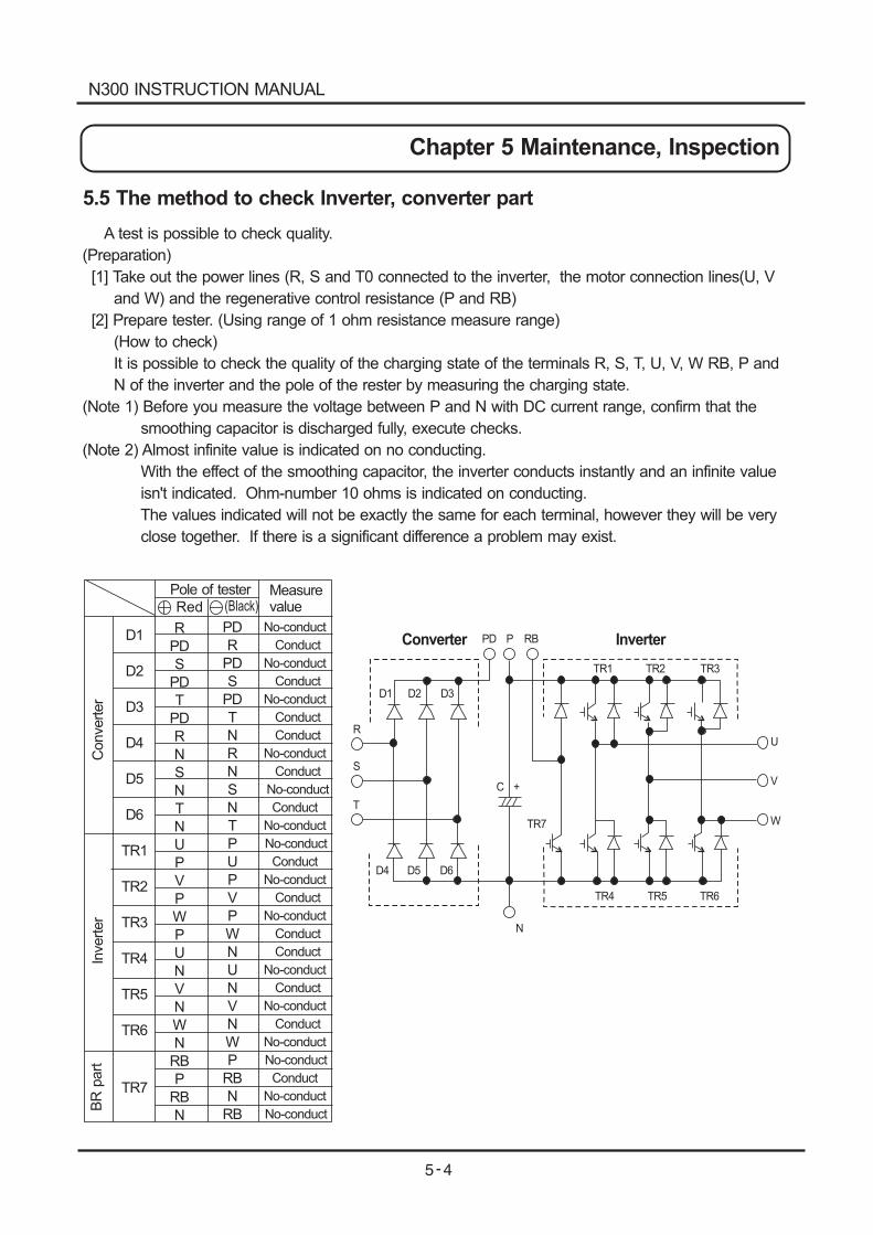
5.5 The method to check Inverter, converter part
A test is possible to check quality.
(Preparation)
[1] Take out the power lines (R, S and T0 connected to the inverter, the motor connection lines(U, V
and W) and the regenerative control resistance (P and RB)
[2] Prepare tester. (Using range of 1 ohm resistance measure range)
(How to check)
It is possible to check the quality of the charging state of the terminals R, S, T, U, V, W RB, P and
N of the inverter and the pole of the rester by measuring the charging state.
(Note 1) Before you measure the voltage between P and N with DC current range, confirm that the
smoothing capacitor is discharged fully, execute checks.
(Note 2) Almost infinite value is indicated on no conducting.
With the effect of the smoothing capacitor, the inverter conducts instantly and an infinite value
isn't indicated. Ohm-number 10 ohms is indicated on conducting.
The values indicated will not be exactly the same for each terminal, however they will be very
close together. If there is a significant difference a problem may exist.
Converter InverterPD P RB
D1 D2 D3
R
S
T
D4 D5 D6
C +
N
TR1 TR2 TR3
TR7
TR4 TR5 TR6
U
V
W
D1
D2
D3
D4
D5
D6
TR1
TR2
TR3
TR4
TR5
TR6
TR7
R
PD
S
PD
T
PD
R
N
S
N
T
N
U
P
V
P
W
P
U
N
V
N
W
N
RB
P
RB
N
PD
R
PD
S
PD
T
N
R
N
S
N
T
P
U
P
V
P
W
N
U
N
V
N
W
P
RB
N
RB
No-conduct
Conduct
No-conduct
Conduct
No-conduct
Conduct
Conduct
No-conduct
Conduct
No-conduct
Conduct
No-conduct
No-conduct
Conduct
No-conduct
Conduct
No-conduct
Conduct
Conduct
No-conduct
Conduct
No-conduct
Conduct
No-conduct
No-conduct
Conduct
No-conduct
No-conduct
Pole of tester
Red (Black)Measurevalue
Converter
Inverter
BR
part
N300 INSTRUCTION MANUAL
Chapter 5 Maintenance, Inspection
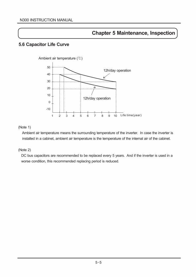
5.6 Capacitor Life Curve
50
40
30
20
10
0
-10
1 2 3 4 5 6 7 8 9 10
Ambient air temperature ( )
12h/day operation
12h/day operation
(Note 1)
Ambient air temperature means the surrounding temperature of the inverter. In case the inverter is
installed in a cabinet, ambient air temperature is the temperature of the internal air of the cabinet.
(Note 2)
DC bus capacitors are recommended to be replaced every 5 years. And if the inverter is used in a
worse condition, this recommended replacing period is reduced.
Life time(year)
N300 INSTRUCTION MANUAL
Chapter 5 Maintenance, Inspection
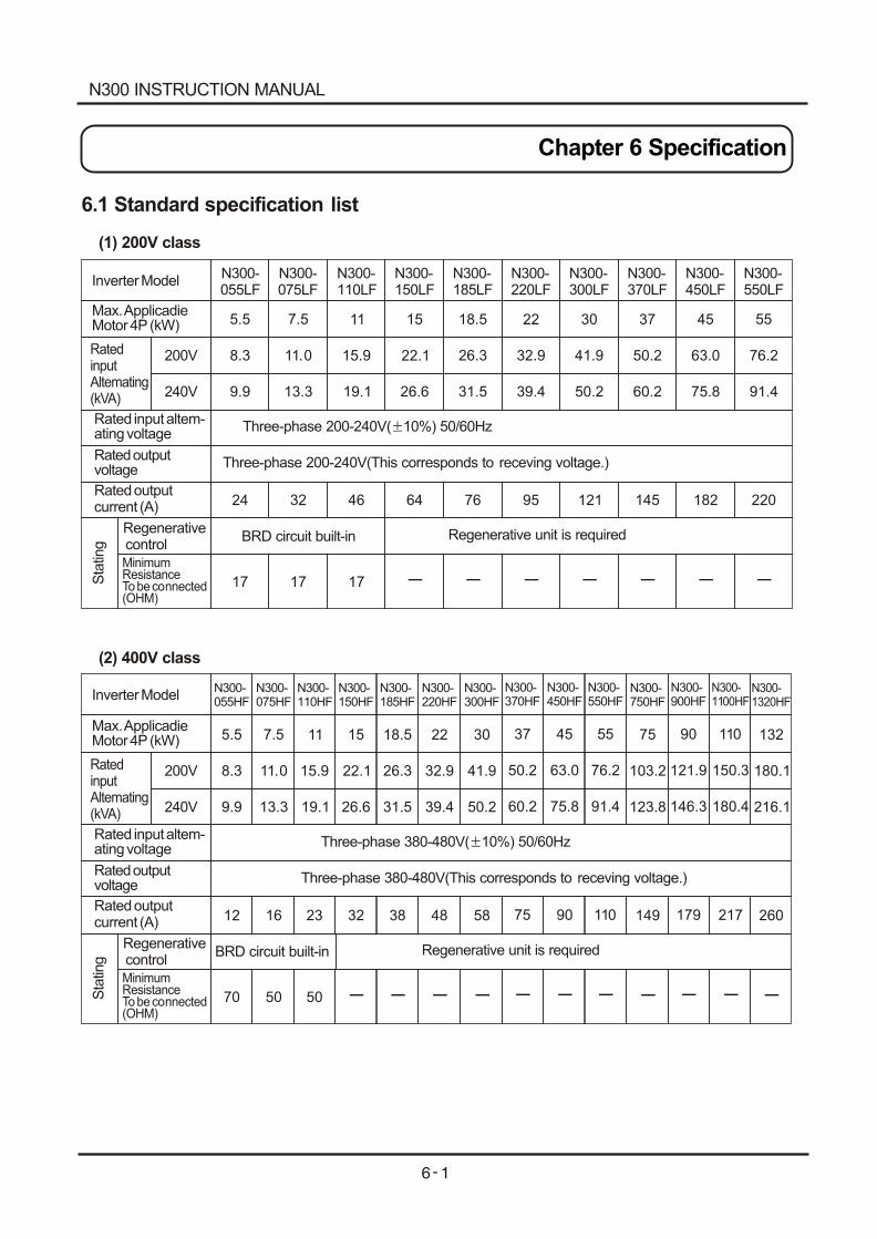
Chapter 6 Specification
N300-055LF
N300-055HF
N300-075LF
N300-075HF
N300-110LF
N300-110HF
N300-150LF
N300-150HF
N300-185LF
N300-185HF
N300-220LF
N300-220HF
N300-300LF
N300-300HF
N300-370LF
N300-370HF
N300-450LF
N300-450HF
N300-550LF
N300-550HF
N300-750HF
N300-900HF
N300-1100HF
N300-1320HF
6.1 Standard specification list
(1) 200V class
(2) 400V class
Inverter Model
Inverter Model
Max. Applicadie Motor 4P (kW)
Max. Applicadie Motor 4P (kW)
Rated inputAltemating(kVA)
Rated inputAltemating(kVA)
200V
200V
240V
240V
Rated input altem-ating voltage
Rated input altem-ating voltage
Rated output voltage
Rated output voltage
Rated output current (A)
Rated output current (A)
Sta
ting
Sta
ting
Regenerative control
Regenerative control
Minimum ResistanceTo be connected (OHM)
Minimum ResistanceTo be connected (OHM)
5.5
5.5
8.3
8.3
9.9
9.9
24
12
70
17 17 17
7.5
7.5
11.0
11.0
13.3
13.3
32
16
50
11
11
15.9
15.9
19.1
19.1
46
23
50
15
15
22.1
22.1
26.6
26.6
64
32
18.5
18.5
26.3
26.3
31.5
31.5
76
38
22
22
32.9
32.9
39.4
39.4
95
48
30
30
41.9
41.9
50.2
50.2
121
58
37
37
50.2
50.2
60.2
60.2
145
75
45
45
63.0
63.0
75.8
75.8
182
90
55
55 75 90 110 132
76.2
76.2 103.2 121.9 150.3 180.1
91.4
91.4 123.8 146.3 180.4 216.1
220
110 149 179 217 260
Three-phase 200-240V( 10%) 50/60Hz
Three-phase 380-480V( 10%) 50/60Hz
Three-phase 200-240V(This corresponds to receving voltage.)
Three-phase 380-480V(This corresponds to receving voltage.)
-
-
-
-
-
-
-
-
-
-
-
-
-
- - - - -
BRD circuit built-in
BRD circuit built-in
Regenerative unit is required
Regenerative unit is required
N300 INSTRUCTION MANUAL
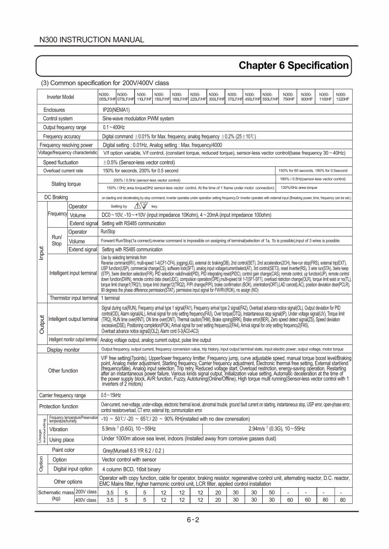
(3) Common specification for 200V/400V class
Inverter Model
Enclosures IP20(NEMA1)
Control system Sine-wave modulation PWM system
Output frequency range 0.1 400Hz
Frequency accuracy Digital command 0.01% for Max. frequency, analog frequency 0.2% (25 10 )
Frequency resolving power Digital setting : 0.01Hz, Analog setting : Max. frequency/4000
Voltage/frequency characteristic
Speed fluctuation 0.5% (Sensor-less vector control)
Overload current rate 150% for seconds, 200% for 0.5 second
Stating torque
DC Braking on starting and decelerating by stop command, inverter operates under operation setting frequency.Or inverter operates with external input (Breaking power, time, frequency can be set.)
Input
Outp
ut
Frequency
Run/ Stop
Operator
Volume
Extend signal
Operator
Volume
Extend signal
1 2
DC0 10V, -10 +10V (input impedance 10Kohn), 4 20mA (input impedance 100ohm)
Setting with RS485 communication
Run/Stop
Forward Run/Stop(1a connect),reverse command is impossible on assigning of terminal(selection of 1a, 1b is possible),input of 3 wires is possible.
Setting with RS485 communication
Intelligent input terminal
Intelligent output terminal
Thermistor input terminal
Intelligent monitor output terminal
Use by selecting terminals fromReverse command(RV), multi-speed 1-4(CF1-CF4), jogging(JG), extemal dc braking(DB), 2nd control(SET), 2nd acceleration(2CH), free-run stop(FRS), extemal trip(EXT), USP function(USP), commercial change(CS), software lock(SFT), analog input voltage/current/select(AT), 3rd control(SET3), reset inverter(RS), 3 wire run(STA), 3wire keep(STP), 3wire direction selection(F/R), PID selection valid/invalid(PID), PID integrating reset(PIDC), control gain change(CAS), remote control, up function(UP), remote control down function(DWN), remote control data clear(UDC), compulsion operation(OPE),multi-speed bit 1-7(SF1-SF7), overload ristriction change(OLR), torque limit exist or no(TL), torque limit change1(TRQ1), torque limit change12(TRQ2), P/PI change(P/PI), brake confirmation (BOK), orientration(ORT),LAD cancel(LAC), position deviation dear(PCLR), 90 degrees the phase difference permission(STAT), permissive input signal for FW/RV(ROK), no assign (NO)
1 terminal
Signal during rus(RUN), Frequency arrival type 1 signal(FA1), Frequency arrival type 2 signal(FA2), Overload advance notice signal(OL), Output deviation for PID control(OD), Alarm signal(AL), Arrival signal for only setting frequency(FA3), Over torque(OTQ), Instantaneous stop signal(IP), Under voltage signal(UV), Torque limit(TRQ), RUN time over(RNT), ON time over(ONT), Thermal caution(THM), Brake opning(BRK), Brake error(BER), Zero speed detect signal(ZS), Speed deviationexcessive(DSE), Positioning completion(POK), Arrival signal for over setting frequency2(FA4), Arrival signal for only setting frequency2(FA5), Overload advance notice signal2(OL2), Alarm cord 0-3(AC0-AC3)
Analog voltage output, analog current output, pulse line output
Display monitor Output frequency, output current, frequency conversion value, trip history, input output terminal state, input electric power, output voltage, motor torque
Other function
V/F free setting(7points), Upper/lower frequency limitter, Frequency jump, curve adjustable speed, manual torque boost level/Brakingpoint, Analog meter adjustment, Starting frequency, Carrier frequency adjustment, Electronic thermal free setting, External start/end(frequency/tate), Analog input selection, Trip retry, Reduced voltage start, Overload restriction, energy-saving operation, Restarting after an instantaneous power failure, Various kinds signal output, Initialization value setting, Automatic deceleration at the time ofthe power supply block, AVR function, Fuzzy, Autotuning(Online/Offline), High torque multi running(Sensor-less vector control with 1 inverters of 2 motors)
Carrier frequency range 0.5 15kHz
Protection function Over-current, over-voltage, under-voltage, electronic thermal lecvel, abnormal trouble, ground fault current on starting, instantaneous stop, USP error, open-phase error, control resistoroverload, CT error, external trip, communication error.
Usage
surr
oundin
g
Frequency temperature/Preservationtemperature/humidty
Vibration
Using place
-10 50 / -20 65 / 20 90% RH(installed with no dew conensation)
5.9m/s (0.6G), 10 55Hz 2.94m/s (0.3G), 10 55Hz
Under 1000m above sea level, indoors (Installed away from corrosive gasses dust)
Paint color Grey(Munsell 8.5 YR 6.2 / 0.2 )
Option Option
Digital input option
Other options
Vector control with sensor
4 column BCD, 16bit binary
Operator with copy function, cable for operator, braking resistor, regenerative control unit, altemating reactor, D.C. reactor, EMC Mains filter, higher harmonic control unit, LCR filter, applied control installation
180% / 0.5Hz(sensor-less vector control)
V/f option variable, V/f control, (constant torque, reduced torque), sensor-less vector control(base frequency 30 40Hz)
150% for 60 seconds, 180% for 0.5second
200% / 0.5Hz (sensor-less vector control)
150% / 0Hz area torque(0Hz sensor-less vector control, At the time of 1 frame under motor connection) 130%/0Hz area torque
Setting by key.
N300-055LF/HF
N300-075LF/HF
N300-110LF/HF
N300-150LF/HF
N300-185LF/HF
N300-220LF/HF
N300-300LF/HF
N300-370LF/HF
N300-450LF/HF
N300-550LF/HF
N300-750HF
N300-900HF
N300-1100HF
N300-1320HF
3.5
3.5
5
5
12
12
20
20
30
30
30
30
50
30
-
60
-
60
-
80
-
80
5
5
12
12
12
12
Schematic mass(kg)
200V class
400V class
N300 INSTRUCTION MANUAL
Chapter 6 Specification
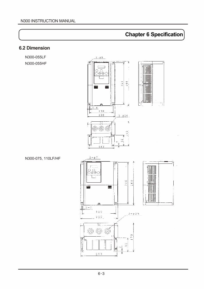
N300-055LF
N300-055HF
N300-075, 110LF/HF
6.2 Dimension
N300 INSTRUCTION MANUAL
Chapter 6 Specification
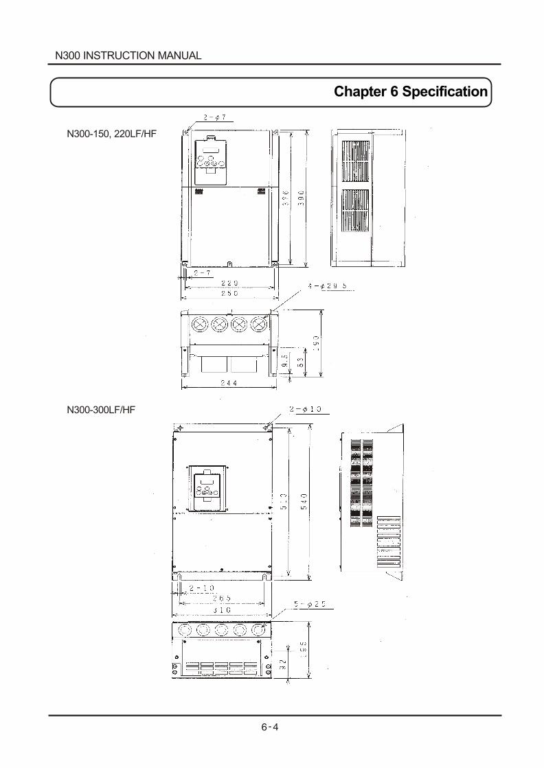
N300-150, 220LF/HF
N300-300LF/HF
N300 INSTRUCTION MANUAL
Chapter 6 Specification
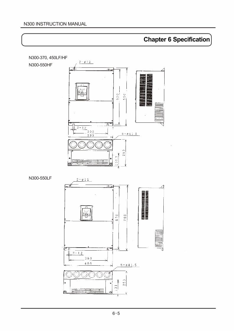
N300-370, 450LF/HF
N300-550HF
N300-550LF
N300 INSTRUCTION MANUAL
Chapter 6 Specification
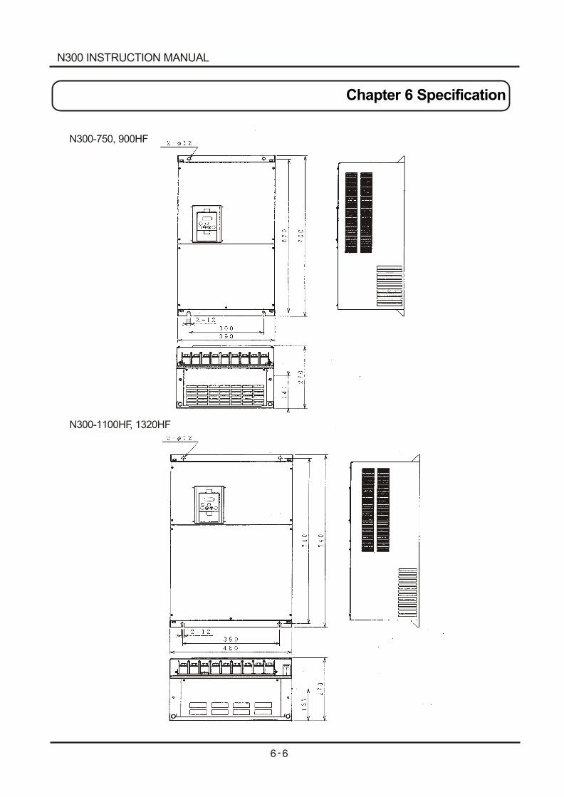
N300-750, 900HF
N300-1100HF, 1320HF
N300 INSTRUCTION MANUAL
Chapter 6 Specification