Embed Size (px)
DESCRIPTION
Managing Remote Network Devices With Telnet
Citation preview
CCNA Discovery
Working at a Small-to-Medium Business or ISP
Lab 8.3.3a Managing Remote Network Devices with Telnet
Device Host Name Interface IP Address Subnet Mask
RIP v2 Network Statements
R1 R1 Serial 0/0/0 (DTE) 10.10.10.1 255.255.255.0 10.0.0.0 Fast Ethernet 0/0 192.168.1.1 255.255.255.0 192.168.1.0 R2 R2 Serial 0/0/0 (DCE) 10.10.10.2 255.255.255.0 10.0.0.0 Serial 0/0/1 (DCE) 172.16.1.1 255.255.255.0 172.16.0.0 Fast Ethernet 0/0 192.168.2.1 255.255.255.0 192.168.2.0 R3 R3 Serial 0/0/1 (DTE) 172.16.1.2 255.255.255.0 172.16.0.0 Fast Ethernet 0/0 192.168.3.1 255.255.255.0 192.168.3.0 S1 S1 VLAN 1 (mgmt) 192.168.2.99 255.255.255.0 N/A
Objectives • Establish a Telnet connection to a remote router.
All contents are Copyright © 1992–2008 Cisco Systems, Inc. All rights reserved. This document is Cisco Public Information. Page 1 of 8
CCNA Discovery Working at a Small-to-Medium Business or ISP
• Verify that the Application Layer between the source and destination is working properly. • Retrieve information about remote routers using show commands. • Retrieve CDP information from routers not directly connected. • Suspend and reestablish a Telnet session. • Disconnect from a Telnet session. • Engage in multiple Telnet sessions. • Display active Telnet sessions.
Background / Preparation This lab focuses on the Telnet (remote terminal) utility to access routers remotely. Telnet is used to connect from a local router to another remote router to simulate being at the console on the remote router. The local router acts as a Telnet client, and the remote router acts as a Telnet server. You can also Telnet from a workstation as a client into any router with IP connectivity on the network. If an Ethernet switch has an IP address assigned, you can Telnet into it from a workstation or any networking device that has IP connectivity. Telnet is a good testing and troubleshooting tool because it is an Application Layer utility. A successful Telnet demonstrates that the entire TCP/IP protocol stack on both the client and server are functioning properly.
Set up a network similar to the one in the diagram above. You can use any router or combination of routers that meets the interface requirements in the diagram, such as 800, 1600, 1700, 1800, 2500, or 2600 routers. Refer to the chart at the end of the lab to identify the interface identifiers to be used based on the equipment in the lab. Depending on the model of router, the output may vary from the output shown in this lab.
Required Resources The following resources are required:
• One router with two serial interfaces and one Fast Ethernet (1841 or other) • Two routers with one serial interface and one Fast Ethernet (1841 or other) • One 2960 switch (or comparable) for the R2 LAN • Three windows XP computers (hosts H2 and H3 are mainly for configuring routers R2 and R3) • Straight-through and crossover Category 5 Ethernet cables as required • Two null serial cables • Console cable to configure routers • Access to host H1 command prompt • Access to host H1 network TCP/IP configuration
On hosts H1, H2, and H3, start a HyperTerminal session to each router.
Note: Make sure that the routers and switches have been erased and have no startup configurations. Instructions for erasing are provided in the Lab Manual, located on Academy Connection in the Tools section. Check with the instructor if you are unsure of how to do this.
Task 1: Build the Network and Verify Connectivity
Step 1: Configure basic information on each router and the switch. a. Build and configure the network according to the topology diagram and device configuration table. If
necessary, see Lab 5.3.5, “Configuring Basic Router Settings with the Cisco IOS CLI,” for instructions.
b. Configure RIPv2 on each router and advertise the networks shown in the device configuration table. If necessary, see Lab 6.1.5, “Configuring and Verifying RIP,” for instructions.
c. Configure basic settings on switch S1 to include host name, passwords, and VLAN 1 IP address. If necessary, see Lab 5.5.4, “Configuring the Cisco 2960 Switch,” for instructions.
All contents are Copyright © 1992–2008 Cisco Systems, Inc. All rights reserved. This document is Cisco Public Information. Page 2 of 8
CCNA Discovery Working at a Small-to-Medium Business or ISP
Step 2: Configure each host.
Configure H1, H2, and H3 with an IP address, subnet mask, and default gateway that are compatible with the IP address of the router default gateway interface address for the LAN to which they are attached.
Step 3: Verify end-to-end connectivity. a. Open a command prompt on host H1 and ping from the R1 LAN to host H3 on the R3 LAN.
C:\>ping 192.168.3.2
b. If host H3 is not attached to router R3, ping the R3 serial 0/0/0 interface IP address 172.16.1.2. C:\>ping 172.16.1.2
Note: If the pings are not successful, troubleshoot the router and host configurations and connections.
Task 2: Establish a Telnet Session from a Host Computer
Step 1: Telnet from host H1 to remote router R2. The Cisco IOS software has built-in Telnet client and server software. Nearly all computer operating systems have a Telnet client. Many server operating systems also have a Telnet server, although Microsoft Windows desktop operating systems typically do not.
In many cases, you will not have direct access to a router through the console so that you can access other networking devices. Usually, you Telnet to a router or switch from a host computer. Once you have gained access to the router or switch command prompt, you can Telnet to other networking devices that are accessible via the network.
a. From the command prompt on H1, telnet to the R2 router Fast Ethernet 0/0 interface. C:\>telnet 192.168.2.1
b. Enter the password cisco to access the router.
c. What prompt did the router display? _____
Step 2: End the Telnet session from host H1 to remote router R2. Exit the Telnet session from host H1 to R1 by typing exit.
Task 3: Perform Basic Telnet Operations Between the Routers
Step 1: Use the help feature to get telnet information. a. From the router R1 HyperTerminal session, enter telnet ? at either the user EXEC or the privileged
EXEC router prompt.
What is displayed? ___________________________________________________
b. What happens if you just type telnet and press Enter? ____________________________________________________________________________
Step 2: Telnet from R1 to remote router R2. Note: Telnet uses the vty lines on the remote router to connect. If the vty lines are not configured for login or there is no password set, you cannot connect to the remote router using Telnet.
a. Telnet to the IP address of the R2 serial 0/0/0 interface 10.10.10.2. R1>telnet 10.10.10.2 Trying 10.10.10.2 ... Open User Access Verification
All contents are Copyright © 1992–2008 Cisco Systems, Inc. All rights reserved. This document is Cisco Public Information. Page 3 of 8
CCNA Discovery Working at a Small-to-Medium Business or ISP
Password:
b. Use the password cisco to enter the router.
c. What prompt did the router display? _____
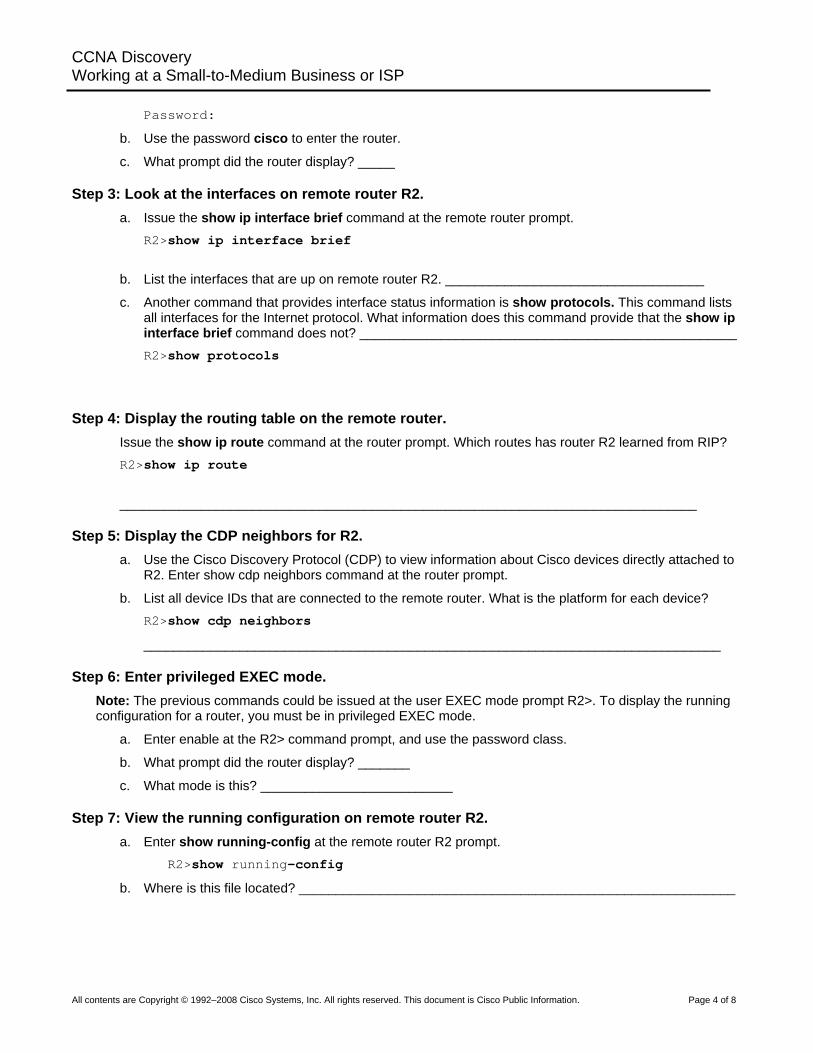
Step 3: Look at the interfaces on remote router R2. a. Issue the show ip interface brief command at the remote router prompt.
R2>show ip interface brief
b. List the interfaces that are up on remote router R2. ___________________________________
c. Another command that provides interface status information is show protocols. This command lists all interfaces for the Internet protocol. What information does this command provide that the show ip interface brief command does not? ___________________________________________________ R2>show protocols
Step 4: Display the routing table on the remote router. Issue the show ip route command at the router prompt. Which routes has router R2 learned from RIP? R2>show ip route
______________________________________________________________________________
Step 5: Display the CDP neighbors for R2. a. Use the Cisco Discovery Protocol (CDP) to view information about Cisco devices directly attached to
R2. Enter show cdp neighbors command at the router prompt.
b. List all device IDs that are connected to the remote router. What is the platform for each device? R2>show cdp neighbors
______________________________________________________________________________
Step 6: Enter privileged EXEC mode. Note: The previous commands could be issued at the user EXEC mode prompt R2>. To display the running configuration for a router, you must be in privileged EXEC mode.
a. Enter enable at the R2> command prompt, and use the password class.
b. What prompt did the router display? _______
c. What mode is this? __________________________
Step 7: View the running configuration on remote router R2. a. Enter show running-config at the remote router R2 prompt.
R2>show running-config
b. Where is this file located? ___________________________________________________________
All contents are Copyright © 1992–2008 Cisco Systems, Inc. All rights reserved. This document is Cisco Public Information. Page 4 of 8
CCNA Discovery Working at a Small-to-Medium Business or ISP
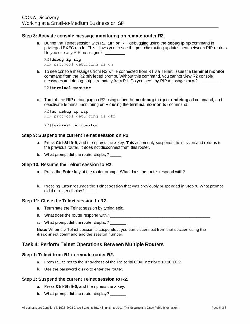
Step 8: Activate console message monitoring on remote router R2.
a. During the Telnet session with R2, turn on RIP debugging using the debug ip rip command in privileged EXEC mode. This allows you to see the periodic routing updates sent between RIP routers. Do you see any RIP messages? _________ R2#debug ip rip RIP protocol debugging is on
b. To see console messages from R2 while connected from R1 via Telnet, issue the terminal monitor command from the R2 privileged prompt. Without this command, you cannot view R2 console messages and debug output remotely from R1. Do you see any RIP messages now? _________ R2#terminal monitor
c. Turn off the RIP debugging on R2 using either the no debug ip rip or undebug all command, and deactivate terminal monitoring on R2 using the terminal no monitor command. R2#no debug ip rip RIP protocol debugging is off R2#terminal no monitor
Step 9: Suspend the current Telnet session on R2. a. Press Ctrl-Shift-6, and then press the x key. This action only suspends the session and returns to
the previous router. It does not disconnect from this router.
b. What prompt did the router display? _____
Step 10: Resume the Telnet session to R2. a. Press the Enter key at the router prompt. What does the router respond with?
_______________________________________________________________________________
b. Pressing Enter resumes the Telnet session that was previously suspended in Step 9. What prompt did the router display? _____
Step 11: Close the Telnet session to R2. a. Terminate the Telnet session by typing exit.
b. What does the router respond with? ____________________________________________
c. What prompt did the router display? _______
Note: When the Telnet session is suspended, you can disconnect from that session using the disconnect command and the session number.
Task 4: Perform Telnet Operations Between Multiple Routers
Step 1: Telnet from R1 to remote router R2. a. From R1, telnet to the IP address of the R2 serial 0/0/0 interface 10.10.10.2.
b. Use the password cisco to enter the router.
Step 2: Suspend the current Telnet session to R2. a. Press Ctrl-Shift-6, and then press the x key.
b. What prompt did the router display? _______
All contents are Copyright © 1992–2008 Cisco Systems, Inc. All rights reserved. This document is Cisco Public Information. Page 5 of 8
CCNA Discovery Working at a Small-to-Medium Business or ISP
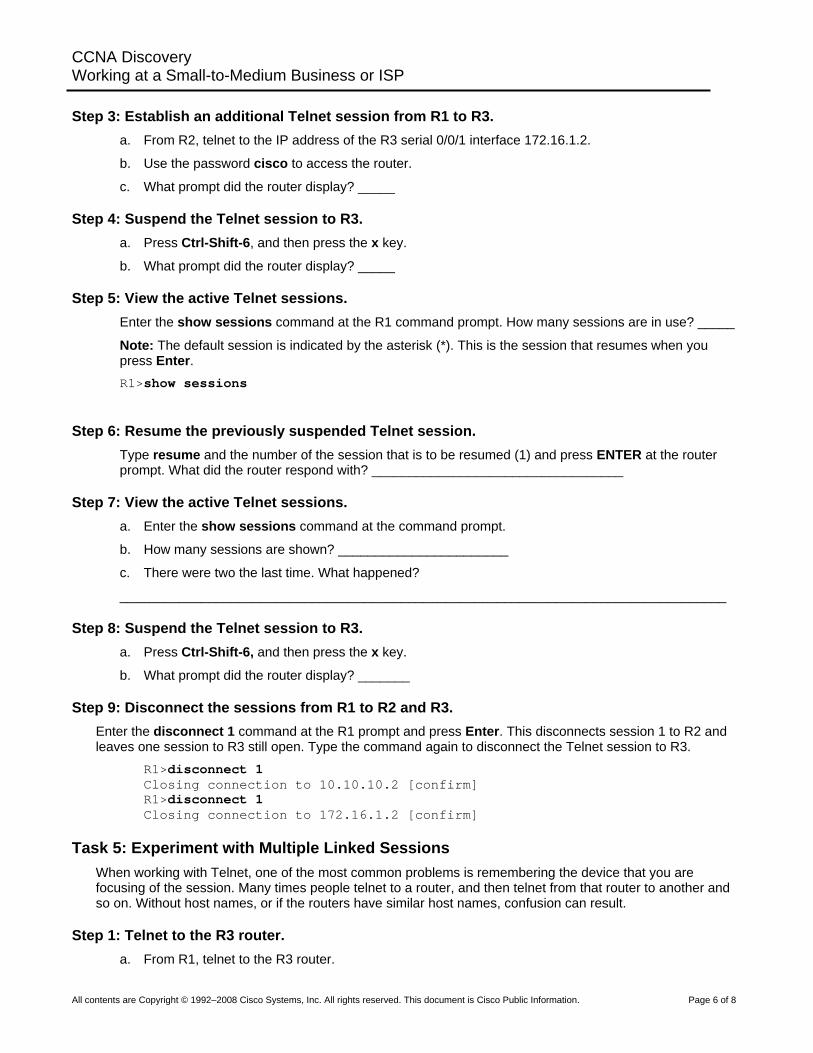
Step 3: Establish an additional Telnet session from R1 to R3.
a. From R2, telnet to the IP address of the R3 serial 0/0/1 interface 172.16.1.2.
b. Use the password cisco to access the router.
c. What prompt did the router display? _____
Step 4: Suspend the Telnet session to R3. a. Press Ctrl-Shift-6, and then press the x key.
b. What prompt did the router display? _____
Step 5: View the active Telnet sessions. Enter the show sessions command at the R1 command prompt. How many sessions are in use? _____
Note: The default session is indicated by the asterisk (*). This is the session that resumes when you press Enter. R1>show sessions
Step 6: Resume the previously suspended Telnet session. Type resume and the number of the session that is to be resumed (1) and press ENTER at the router prompt. What did the router respond with? __________________________________
Step 7: View the active Telnet sessions. a. Enter the show sessions command at the command prompt.
b. How many sessions are shown? _______________________
c. There were two the last time. What happened?
__________________________________________________________________________________
Step 8: Suspend the Telnet session to R3. a. Press Ctrl-Shift-6, and then press the x key.
b. What prompt did the router display? _______
Step 9: Disconnect the sessions from R1 to R2 and R3. Enter the disconnect 1 command at the R1 prompt and press Enter. This disconnects session 1 to R2 and leaves one session to R3 still open. Type the command again to disconnect the Telnet session to R3.
R1>disconnect 1 Closing connection to 10.10.10.2 [confirm] R1>disconnect 1 Closing connection to 172.16.1.2 [confirm]
Task 5: Experiment with Multiple Linked Sessions When working with Telnet, one of the most common problems is remembering the device that you are focusing of the session. Many times people telnet to a router, and then telnet from that router to another and so on. Without host names, or if the routers have similar host names, confusion can result.
Step 1: Telnet to the R3 router. a. From R1, telnet to the R3 router.
All contents are Copyright © 1992–2008 Cisco Systems, Inc. All rights reserved. This document is Cisco Public Information. Page 6 of 8
CCNA Discovery Working at a Small-to-Medium Business or ISP
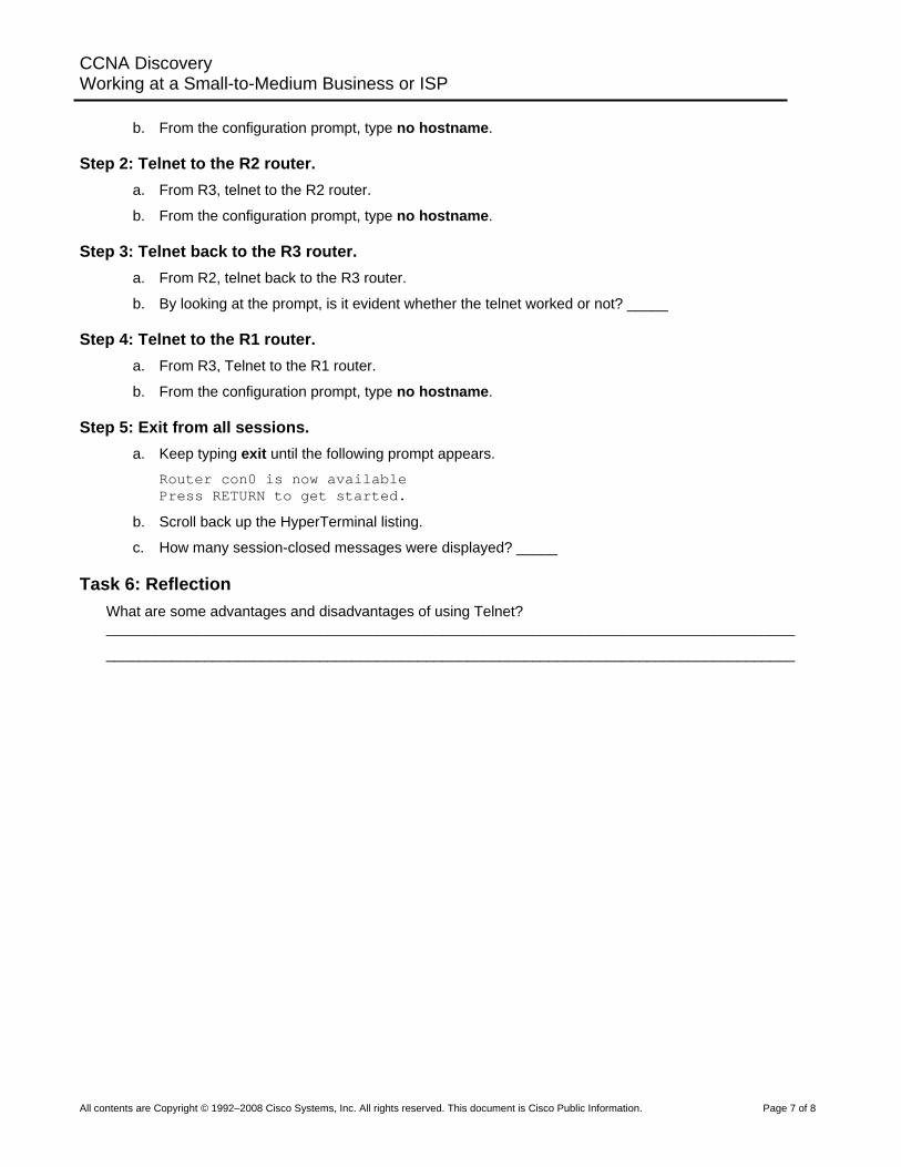
b. From the configuration prompt, type no hostname.
Step 2: Telnet to the R2 router. a. From R3, telnet to the R2 router.
b. From the configuration prompt, type no hostname.
Step 3: Telnet back to the R3 router. a. From R2, telnet back to the R3 router.
b. By looking at the prompt, is it evident whether the telnet worked or not? _____
Step 4: Telnet to the R1 router. a. From R3, Telnet to the R1 router.
b. From the configuration prompt, type no hostname.
Step 5: Exit from all sessions. a. Keep typing exit until the following prompt appears.
Router con0 is now available Press RETURN to get started.
b. Scroll back up the HyperTerminal listing.
c. How many session-closed messages were displayed? _____
Task 6: Reflection What are some advantages and disadvantages of using Telnet? ____________________________________________________________________________________
____________________________________________________________________________________
All contents are Copyright © 1992–2008 Cisco Systems, Inc. All rights reserved. This document is Cisco Public Information. Page 7 of 8
CCNA Discovery Working at a Small-to-Medium Business or ISP
All contents are Copyright © 1992–2008 Cisco Systems, Inc. All rights reserved. This document is Cisco Public Information. Page 8 of 8
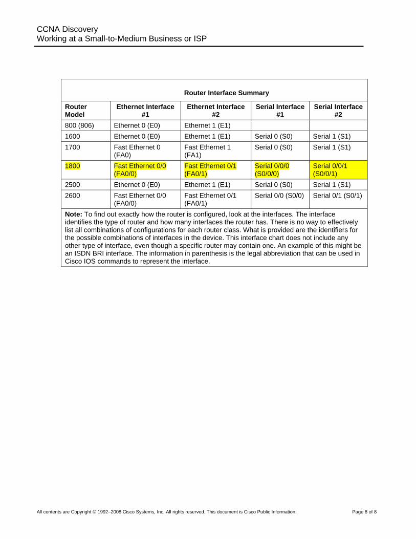
Router Interface Summary
Router Model
Ethernet Interface #1
Ethernet Interface #2
Serial Interface #1
Serial Interface #2
800 (806) Ethernet 0 (E0) Ethernet 1 (E1) 1600 Ethernet 0 (E0) Ethernet 1 (E1) Serial 0 (S0) Serial 1 (S1) 1700 Fast Ethernet 0
(FA0) Fast Ethernet 1 (FA1)
Serial 0 (S0) Serial 1 (S1)
1800 Fast Ethernet 0/0 (FA0/0)
Fast Ethernet 0/1 (FA0/1)
Serial 0/0/0 (S0/0/0)
Serial 0/0/1 (S0/0/1)
2500 Ethernet 0 (E0) Ethernet 1 (E1) Serial 0 (S0) Serial 1 (S1) 2600 Fast Ethernet 0/0
(FA0/0) Fast Ethernet 0/1 (FA0/1)
Serial 0/0 (S0/0) Serial 0/1 (S0/1)
Note: To find out exactly how the router is configured, look at the interfaces. The interface identifies the type of router and how many interfaces the router has. There is no way to effectively list all combinations of configurations for each router class. What is provided are the identifiers for the possible combinations of interfaces in the device. This interface chart does not include any other type of interface, even though a specific router may contain one. An example of this might be an ISDN BRI interface. The information in parenthesis is the legal abbreviation that can be used in Cisco IOS commands to represent the interface.

![[MS-TSRAP]: Telnet Server Remote Administration Protocol...telnet server: An implementation of the server side of Telnet Protocol [RFC854]. telnet session: An active telnet connection](https://img.pdfslide.net/doc/110x75/60b2d507b3d5e976d8381236/ms-tsrap-telnet-server-remote-administration-protocol-telnet-server-an-implementation.jpg)


![[MS-TSRAP]: Telnet Server Remote Administration Protocol... · 2016. 6. 22. · telnet server: An implementation of the server side of Telnet Protocol [RFC854]. telnet session: An](https://img.pdfslide.net/doc/110x75/60b2d555f3bc7731e14c7b76/ms-tsrap-telnet-server-remote-administration-protocol-2016-6-22-telnet.jpg)

![[MS-TSRAP]: Telnet Server Remote Administration Protocol...The Telnet Server Remote Administration Protocol is a Distributed Component Object Model (DCOM) Protocol [MS-DCOM] interface](https://img.pdfslide.net/doc/110x75/60b2d507b3d5e976d8381237/ms-tsrap-telnet-server-remote-administration-protocol-the-telnet-server-remote.jpg)