Embed Size (px)
Citation preview
J Oral Maxillofac Surg59:539-544, 2001
Mandibular Distraction Force: LaboratoryData and Clinical Correlation
Randolph C. Robinson, MD, DDS,* Patrick J. O’Neal, BS,†
and Ginger H. Robinson, BSN, RN‡
Purpose: In vitro data were collected to measure torque-force values of an internal distraction device.The measurements were correlated with in vivo torque readings in an attempt to better understand theforce required to distract the osteogenic bone callus of the human mandible during distraction osteo-genesis.
Methods and Materials: Five internal craniofacial distraction devices were mounted on an apparatusto test load limits and torque measurements. The apparatus aligned the devices so that weight provideda force opposite and parallel to the vector of distraction. Weights were added in 5-lb increments, and thedevices were activated 0.5 mm for each torque reading. Torque readings were obtained from a calibratedtorque wrench. Measurements were plotted on a graph and correlated with clinical torque readingsobtained from 8 patients undergoing mandibular lengthening.
Results: The average torque for distracting the human mandible 0.5 mm twice a day was 4.2 � 1.6Newton-centimeters (N-cm). The average slope of the in vitro data shows that 4.2 N-cm of torque isequivalent to a force of 35.6 N. The average force of device failure was 235.8 N.
Conclusion: Torque-force diagrams offer an effective means for calibrating safety margins and loadcapabilities for internal distraction devices. Quantification of axial forces encountered in mandibularlengthening will help contribute to the overall understanding and biomechanics of mandibular distrac-tion osteogenesis.© 2001 American Association of Oral and Maxillofacial Surgeons
Distraction osteogenesis is becoming more com-mon for reconstruction of facial bone deficiencies.However, it is difficult to quantify the forces nec-essary to distract the active reparative bone callusin the human during this process. Therefore, astudy of an internal distraction device is needed todetermine the torque-force values for the facialbones, failure load limit requirements, and correla-tion of these in vitro measurements with thosefound in clinical cases.
Force is the mass times the acceleration (F � ma).In other words, force is the influence to cause a
change in velocity of an object. The unit of force inthe metric system is the Newton (N). A Newton is thatforce which, when applied to a 1 kg mass, gives it anacceleration of 1 m/s/s. Therefore:
1 N � 1 kg � 1 m/s2 � 1 kg � m/s2
1 lb � 4.45 NTorque is the force needed to cause a rotational
movement and is measured in Newton-meters orNewton-centimeters (N-cm). Because most distrac-tion devices use a threaded drive shaft to move theends apart, clinical measurements of torque are theeasiest to make. However, although torque is reflec-tive of the load on the device, it is not a directmeasure of the distraction force at the osteotomy site.Torque is a factor of the coefficient of friction of thematerials, the diameter of the drive shaft, and thepitch angle of the threads in the gears, the surround-ing soft tissue, and the bone callus. Therefore, torquemeasurements are specific to a particular device, andso it is necessary to establish the relationship betweenthe torque and the load for each device design. Thisrelationship is the slope of the line when a load isplotted on the x axis and torque is plotted on the yaxis. This linear correlation can be used to indirectlymeasure the force of distraction at the bone level fora given torque observed during activation. This infor-mation can then be used in the clinical setting to
*Chief of Oral and Maxillofacial Surgery, Saint Joseph Hospital,
Denver, CO.
†Director of Research and Development, Inter-Os Technologies,
Inc, Lone Tree, CO.
‡Nursing Researcher, 3110 Enterprises, Centennial, CO.
Dr Robinson is President of Inter-Os Technologies, Inc and Mr
O’Neal is Director of Research and Development at Inter-Os Tech-
nologies, Inc, Lone Tree, CO.
Address correspondence and reprint requests to Mr O’Neal:
7430 E Park Meadows Dr, Suite 300, Lone Tree, CO 80124; e-mail:
© 2001 American Association of Oral and Maxillofacial Surgeons
0278-2391/01/5905-0010$35.00/0
doi:10.1053/joms.2001.22688
539
determine the safety margins for device manufactur-ing and to give immediate clinical feedback regardingwhat may be happening in the distraction site (eg,premature consolidation, device failure, or incom-plete osteotomies). This information can then be usedto determine if the rate, rhythm, or distance of dis-traction should be modified. It can also indicate ifadditional radiographs should be taken, if an explora-tion should be made, or if the device should be re-placed.
Even though distraction osteogenesis of the mandi-ble is well reported in the literature,1-17 no study hasbeen published describing the force necessary to dis-tract the human mandible. The purpose of this articleis to report laboratory data on the torque-force mea-surements of an internal craniofacial distractor, theBone Generator (Inter-Os Technologies Inc, LoneTree, CO) and to correlate the data to clinical cases ofmandibular distraction with the same device (Figs 1,2). The study also measured device load limits tofailure and related the results to an overall margin ofsafety for internal distraction.
Methods and Materials
IN VITRO STUDY
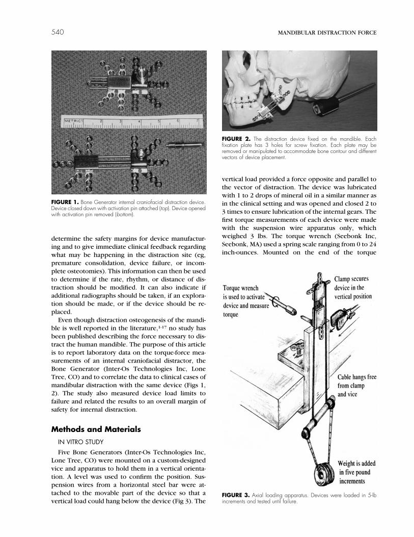
Five Bone Generators (Inter-Os Technologies Inc,Lone Tree, CO) were mounted on a custom-designedvice and apparatus to hold them in a vertical orienta-tion. A level was used to confirm the position. Sus-pension wires from a horizontal steel bar were at-tached to the movable part of the device so that avertical load could hang below the device (Fig 3). The
vertical load provided a force opposite and parallel tothe vector of distraction. The device was lubricatedwith 1 to 2 drops of mineral oil in a similar manner asin the clinical setting and was opened and closed 2 to3 times to ensure lubrication of the internal gears. Thefirst torque measurements of each device were madewith the suspension wire apparatus only, whichweighed 3 lbs. The torque wrench (Seebonk Inc,Seebonk, MA) used a spring scale ranging from 0 to 24inch-ounces. Mounted on the end of the torque
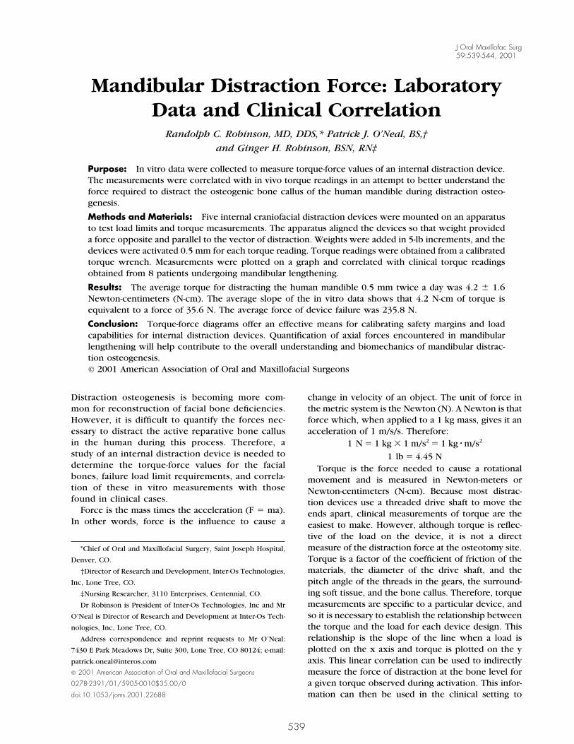
FIGURE 1. Bone Generator internal craniofacial distraction device.Device closed down with activation pin attached (top). Device openedwith activation pin removed (bottom).
FIGURE 2. The distraction device fixed on the mandible. Eachfixation plate has 3 holes for screw fixation. Each plate may beremoved or manipulated to accommodate bone contour and differentvectors of device placement.
FIGURE 3. Axial loading apparatus. Devices were loaded in 5-lbincrements and tested until failure.
540 MANDIBULAR DISTRACTION FORCE
wrench was an activation wrench used to activate thedevice in the clinical setting. The device was turned 2full revolutions, or 0.5 mm of distraction, and theaverage observed torque measurement was made andrecorded. The device was closed back down to itsoriginal position after the load was removed. Loadingand torque measurements proceeded in 5-lb incre-ments up to 28 lbs (including the 3 lb suspensionapparatus). The measurements were then plotted, atorque/force line was drawn for each of the 5 devices,and an average slope was established.
After the measurements were made to 28 lbs, eachdevice was progressively loaded in 5- or 10-lb incre-ments until failure. This process was carried out byactivating the device for 1 full millimeter or 4 fullturns using the activation wrench. Care was given tomaintain the vertical orientation because of the lateralload limits. After each test, the weight was removedand the device was closed back to its original posi-tion.
IN VIVO STUDY
The correlative torque data taken from the clinicaltrials involved patients who underwent mandibulardistraction osteogenesis using the Bone Generator.Fourteen distraction devices were used for both uni-
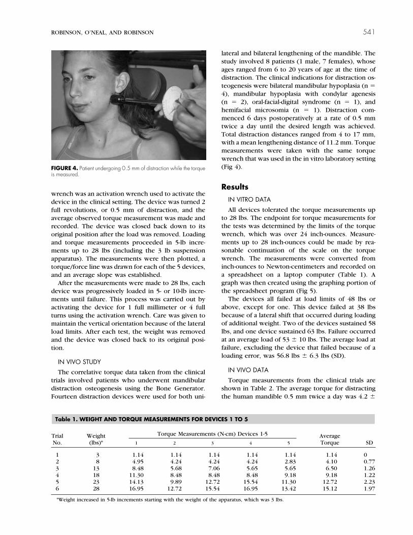
lateral and bilateral lengthening of the mandible. Thestudy involved 8 patients (1 male, 7 females), whoseages ranged from 6 to 20 years of age at the time ofdistraction. The clinical indications for distraction os-teogenesis were bilateral mandibular hypoplasia (n �4), mandibular hypoplasia with condylar agenesis(n � 2), oral-facial-digital syndrome (n � 1), andhemifacial microsomia (n � 1). Distraction com-menced 6 days postoperatively at a rate of 0.5 mmtwice a day until the desired length was achieved.Total distraction distances ranged from 4 to 17 mm,with a mean lengthening distance of 11.2 mm. Torquemeasurements were taken with the same torquewrench that was used in the in vitro laboratory setting(Fig 4).
Results
IN VITRO DATA
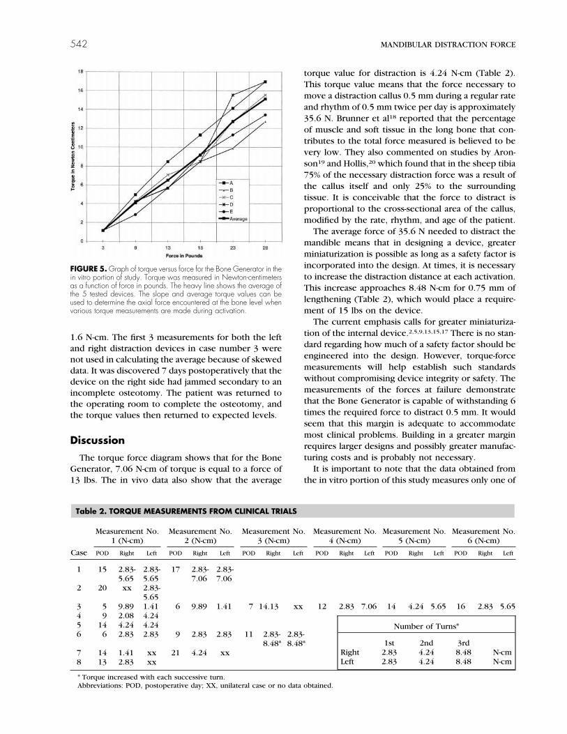
All devices tolerated the torque measurements upto 28 lbs. The endpoint for torque measurements forthe tests was determined by the limits of the torquewrench, which was over 24 inch-ounces. Measure-ments up to 28 inch-ounces could be made by rea-sonable continuation of the scale on the torquewrench. The measurements were converted frominch-ounces to Newton-centimeters and recorded ona spreadsheet on a laptop computer (Table 1). Agraph was then created using the graphing portion ofthe spreadsheet program (Fig 5).
The devices all failed at load limits of 48 lbs orabove, except for one. This device failed at 38 lbsbecause of a lateral shift that occurred during loadingof additional weight. Two of the devices sustained 58lbs, and one device sustained 63 lbs. Failure occurredat an average load of 53 � 10 lbs. The average load atfailure, excluding the device that failed because of aloading error, was 56.8 lbs � 6.3 lbs (SD).
IN VIVO DATA
Torque measurements from the clinical trials areshown in Table 2. The average torque for distractingthe human mandible 0.5 mm twice a day was 4.2 �
FIGURE 4. Patient undergoing 0.5 mm of distraction while the torqueis measured.
Table 1. WEIGHT AND TORQUE MEASUREMENTS FOR DEVICES 1 TO 5
TrialNo.
Weight(lbs)*
Torque Measurements (N-cm) Devices 1-5 AverageTorque SD1 2 3 4 5
1 3 1.14 1.14 1.14 1.14 1.14 1.14 02 8 4.95 4.24 4.24 4.24 2.83 4.10 0.773 13 8.48 5.68 7.06 5.65 5.65 6.50 1.264 18 11.30 8.48 8.48 8.48 9.18 9.18 1.225 23 14.13 9.89 12.72 15.54 11.30 12.72 2.236 28 16.95 12.72 15.54 16.95 13.42 15.12 1.97
*Weight increased in 5-lb increments starting with the weight of the apparatus, which was 3 lbs.
ROBINSON, O’NEAL, AND ROBINSON 541
1.6 N-cm. The first 3 measurements for both the leftand right distraction devices in case number 3 werenot used in calculating the average because of skeweddata. It was discovered 7 days postoperatively that thedevice on the right side had jammed secondary to anincomplete osteotomy. The patient was returned tothe operating room to complete the osteotomy, andthe torque values then returned to expected levels.
Discussion
The torque force diagram shows that for the BoneGenerator, 7.06 N-cm of torque is equal to a force of13 lbs. The in vivo data also show that the average
torque value for distraction is 4.24 N-cm (Table 2).This torque value means that the force necessary tomove a distraction callus 0.5 mm during a regular rateand rhythm of 0.5 mm twice per day is approximately35.6 N. Brunner et al18 reported that the percentageof muscle and soft tissue in the long bone that con-tributes to the total force measured is believed to bevery low. They also commented on studies by Aron-son19 and Hollis,20 which found that in the sheep tibia75% of the necessary distraction force was a result ofthe callus itself and only 25% to the surroundingtissue. It is conceivable that the force to distract isproportional to the cross-sectional area of the callus,modified by the rate, rhythm, and age of the patient.
The average force of 35.6 N needed to distract themandible means that in designing a device, greaterminiaturization is possible as long as a safety factor isincorporated into the design. At times, it is necessaryto increase the distraction distance at each activation.This increase approaches 8.48 N-cm for 0.75 mm oflengthening (Table 2), which would place a require-ment of 15 lbs on the device.
The current emphasis calls for greater miniaturiza-tion of the internal device.2,5,9,13,15,17 There is no stan-dard regarding how much of a safety factor should beengineered into the design. However, torque-forcemeasurements will help establish such standardswithout compromising device integrity or safety. Themeasurements of the forces at failure demonstratethat the Bone Generator is capable of withstanding 6times the required force to distract 0.5 mm. It wouldseem that this margin is adequate to accommodatemost clinical problems. Building in a greater marginrequires larger designs and possibly greater manufac-turing costs and is probably not necessary.
It is important to note that the data obtained fromthe in vitro portion of this study measures only one of
FIGURE 5. Graph of torque versus force for the Bone Generator in thein vitro portion of study. Torque was measured in Newton-centimetersas a function of force in pounds. The heavy line shows the average ofthe 5 tested devices. The slope and average torque values can beused to determine the axial force encountered at the bone level whenvarious torque measurements are made during activation.
Table 2. TORQUE MEASUREMENTS FROM CLINICAL TRIALS
Case
Measurement No.1 (N-cm)
Measurement No.2 (N-cm)
Measurement No.3 (N-cm)
Measurement No.4 (N-cm)
Measurement No.5 (N-cm)
Measurement No.6 (N-cm)
POD Right Left POD Right Left POD Right Left POD Right Left POD Right Left POD Right Left
1 15 2.83-5.65
2.83-5.65
17 2.83-7.06
2.83-7.06
2 20 xx 2.83-5.65
3 5 9.89 1.41 6 9.89 1.41 7 14.13 xx 12 2.83 7.06 14 4.24 5.65 16 2.83 5.654 9 2.08 4.245 14 4.24 4.246 6 2.83 2.83 9 2.83 2.83 11 2.83-
8.48*2.83-8.48*
7 14 1.41 xx 21 4.24 xx8 13 2.83 xx
* Torque increased with each successive turn.Abbreviations: POD, postoperative day; XX, unilateral case or no data obtained.
Number of Turns*
1st 2nd 3rdRight 2.83 4.24 8.48 N-cmLeft 2.83 4.24 8.48 N-cm
542 MANDIBULAR DISTRACTION FORCE
the variables related to the force encountered in man-dibular lengthening. The axial loads from the labora-tory provide a great deal of information about theforce required to distract the callus. However, the invitro testing neglects to account for lateral forces,such as forces from the suprahyoid muscles that arefrequently encountered during mandibular lengthen-ing.13 The exact response and degree to which lateralcounteractive forces affect the bone callus will varywith patient age, etiology,21 device rigidity,6,22,23 de-vice orientation,24,25 and the vector of distraction.26-28
The effects of device orientation have yet to be estab-lished in the clinical setting and have thus far beenuneventful.29 Future studies, similar to the previouslymentioned studies by Brunner et al,18 Aronson,19 andHollis et al,20 will aim to establish the percentage offorce for the craniofacial model that is contributed bythe callus versus the surrounding muscle and connec-tive tissue.
Device placement and the vector of distraction areof paramount importance when planning craniofacialdistraction.25,30,31 This is of particular concern forinternal devices, which currently lack the ability forbidirectional control. Even when multiplanar devicesare used, the planned distraction vector may differfrom the resultant vector because of forces encoun-tered during and after elongation. The multidirec-tional device allows for a change in the distractionvector. However, changing the vector of the distalsegment may induce a change in the position of theproximal segment.26 Recent studies have demon-strated ways to prevent and augment a faulty dis-traction vector.26,32 Nonaxial forces will vary withdifferent vectors of elongation. Torque-force measure-ments from the clinical portion of this study dealtprimarily with vectors that were parallel and obliqueto the mandibular rami. No significant difference wasnoted between torque readings with the varying vec-tors.
The ability to anticipate and quantify the forceencountered in mandibular distraction enhances thedevelopment and design of devices. Torque-forcemeasurements will contribute to manufacturing stan-dards and will help to establish an adequate margin ofsafety. Calibrating craniofacial distraction deviceswith torque-force measurements will also allow thesurgeon to monitor and exercise more control overthe distraction phase. For example, an incompleteosteotomy may be detected and resolved at an earlierstage. Premature consolidation may also be antici-pated and possibly avoided. In addition, device failuremay be anticipated with excessive or minimal torquemeasurements, leading to radiologic examination andearly detection. Case number 3 in the clinical trialdemonstrated 2 of the above situations (Table 2). Theprogressive nature of the torque values for this case
prompted radiologic review and surgical exploration.This patient maintained torque values on the rightside of the mandible of 9.89, 9.89, and 14.13 N-cm onthe fifth, sixth, and seventh day, postoperatively, re-spectively. These values were higher than expectedand considerably higher in comparison with the leftside, which only registered 1.41 N-cm. Surgical explo-ration confirmed an incomplete osteotomy causingthe right distraction device to jam.
Torque measurements are invaluable for monitor-ing the distraction phase from a perspective of safetyand control. Chin and Toth15 used torque measure-ments on patients who underwent a Le Fort III ad-vancement to test and monitor the limits of fracture,thus enabling rapid distraction. Chin and Toth used aprotocol that deviated from the standard by not ob-serving a latency period and by performing 10 mm ofdistraction intraoperatively followed by an additional10 mm of distraction within 2 to 3 days followingsurgery. Torque measurements of 14 to 18 N-cm wereobserved without fracture. However, other complica-tions are inherent with this technique.33 The protocolfor the current study maintained the standard rate andrhythm of 0.5 mm twice a day, with a latency periodof 6 days. This rate and rhythm have permitted theestablishment of an average torque that falls within arange of 1.5 to 7.0 N-cm. Clinical experience hasdemonstrated that torque-force values that fall withinthis range appear to be an acceptable measurementduring uneventful lengthening of the human man-dible.
Measuring the force required to distract the humanmandible is difficult and is not currently reported inthe literature. The force of distraction has been mea-sured in long bones, and this has helped to advancethe field of long bone distraction osteogenesis.22,34-38
Implications for future studies involving the force ofmandibular distraction will not only contribute to abetter understanding of mandibular distraction, butwill also offer the surgeon a valuable tool for moni-toring the progression of the distraction phase.
References1. Karp NS, Thorne CH, McCarthy JG: Bone lengthening in the
craniofacial skeleton. Ann Plast Surg 24:231, 19902. Maull DJ: Review of devices for distraction osteogenesis of the
craniofacial complex. Semin Orthod 5:64, 19993. McCarthy JG, Schrieber J, Karp N, et al: Lengthening the hu-
man mandible by gradual distraction. Plast Reconstr Surg 89:1,1992
4. Cohen SR, Rutrick RE, Burstein FD: Distraction osteogenesis ofthe human craniofacial skeleton: Initial experience with newdistraction system. J Craniofac Surg 6:368, 1995
5. Cohen SR: Craniofacial distraction with a modular internaldistraction system: Evolution of design and surgical techniques.Plast Reconstr Surg 103:1592, 1999
6. Haug RH, Nuveen EJ, Barber JE, et al: An in vitro evaluation ofdistractors used for osteogenesis. Oral Surg Oral Med OralPathol Oral Radiol Endod 86:648, 1998
ROBINSON, O’NEAL, AND ROBINSON 543
7. Guerrero CA, Bell WH, Contasti GI, et al: Mandibular wideningby intraoral distraction osteogenesis. Br J Oral Maxillofac Surg35:383, 1997
8. Guerrero CA, Bell WH, Contasti GI, et al: Intraoral mandibulardistraction osteogenesis. Semin Orthod 5:35, 1999
9. McCormick SU, Mizrahhi RD, Fox RM, et al: Distraction osteo-genesis of the mandible using a submerged intraoral device: Areport of three cases. J Oral Maxillofac Surg 57:192, 1999
10. Diner PA, Kollar EM, Martiinez H, et al: Intraoral distraction formandibular lengthening: A technical innovation. J CraniofacSurg 24:92, 1996
11. Diner PA, Kollar EM, Martiinez H, et al: Submerged intraoraldevice for mandibular lengthening. J Craniomaxillofac Surg25:116, 1997
12. McCarthy JG, Staffenberg DA, Wood RJ, et al: Introduction ofan intraoral bone-lengthening device. Plast Reconstr Surg 96:978, 1995
13. McCarthy JG, Stelnicki EJ, Grayson BH: Distraction osteogene-sis of the mandible: A ten-year experience. Semin Orthod 5:3,1999
14. Chin M, Toth BA: Distraction osteogenesis in maxillofacialsurgery using internal devices: Review of five cases. J OralMaxillofac Surg 54:45, 1996
15. Chin M, Toth BA: Le Fort III advancement with gradual distrac-tion using internal devices. Plast Reconstr Surg 100:819, 1997
16. McCarthy JG, Williams KJ, Grayson BH, et al: Controlled mul-tiplanar distraction of the mandible: Device development andclinical application. J Craniofac Surg 9:322, 1998
17. Tavakoli K, Stewart KJ, Poole MD: Distraction osteogenesis incraniofacial surgery: A review. Ann Plast Surg 40:88, 1998
18. Brunner UH, Cordey J, Schweiberer L, et al: Force required forbone segment transport in the treatment of large bone defectsusing medullary nail fixation. Clin Orthop Rel Res 301:147,1994
19. Aronson J: Mechanical factors generated during distractionosteogenesis. The International Society for Fracture Repair,Ottrot, France, April 1992
20. Hollis JM, Aronson J, Hofmann OE: Differential loads in tissuesduring limb lengthening. Trans Orthop Res Soc 38:14, 1992
21. Aldegheri R: Distraction osteogenesis for the lengthening ofthe tibia in patients who have limb-length discrepancy or shortstature. J Bone Joint Surg 81:624, 1999
22. Aronson J, Harrison B, Boyd CM, et al: Mechanical Induction ofosteogenesis: The importance of pin rigidity. J Pediatr Orthop8:396, 1988
23. Rowe NM, Mehrara BJ, Luchs JS, et al: Angiogenesis duringmandibular distraction osteogenesis. Ann Plast Surg 42:470,1999
24. Cope JB, Yamashita J, Healy S, et al: Force level and strainpatterns during bilateral mandibular osteodistraction. J OralMaxillofac Surg 58:171, 2000
25. Cope JB, Samchukov ML, Cherkashin AM, et al: Biomechanicsof mandibular distractor orientation: An animal model analysis.J Oral Maxillofac Surg 57:952, 1999
26. Hanson PR, Melugin MB: Orthodontic management of the pa-tient undergoing mandibular distraction osteogenesis. SeminOrthod 5:25, 1999
27. Ahn JG, Figueroa AA, Braun S, et al: Biomechanical consider-ations in distraction of the osteotomized dentomaxillary com-plex. Am J Orthod Dentofac Orthop 116:264, 1999
28. Grayson BH, McCormick MS, Santiago PE, et al: Vector ofdevice placement and trajectory of mandibular distraction. JCraniofac Surg 8:473, 1997
29. Grayson B: Force level and strain patterns during bilateralmandibular osteodistraction (discussion). J Oral MaxillofacSurg 58:178, 2000
30. Tharanon W, Sinn DP: Mandibular distraction osteogenesiswith multidirectional extraoral distraction device in hemifacialmicrosomia patients. Three-dimensional treatment planning,prediction tracings, and case outcomes. J Craniofac Surg 10:202, 1999
31. Samchukov ML, Cope JB, Cherkashin AM: The effect of sagittalorientation of the distractor on the biomechanics of mandibu-lar lengthening. J Oral Maxillofac Surg 57:1214, 1999
32. Kunz C, Hammer B, Prein J: Manipulation of callus after lineardistraction: A “lifeboat” or an alternative to multivectorial dis-traction osteogenesis of the mandible? Plast Reconstr Surg105:674, 2000
33. Polley JW, Figueroa AA: Commentary on midface advancementby bone distraction on the treatment of cleft deformities andon distraction osteogenesis and its application to the midfaceand bony orbit in the craniosynostosis syndrome. J CraniofacSurg 9:119, 1998
34. Gardner TN, Evans M, Simpson H, et al: Force-displacementbehaviour of biological tissue during distraction osteogenesis.Med Eng Phys 20:708, 1998
35. Wolfson N, Hearn TC, Thomason JJ, et al: Force and stiffnesschanges during Ilizarov leg lengthening. Clin Orthop Rel Res250:58, 1989
36. Meswania JM, Walker PS, Sneath RS, et al: In vivo distractionforces in extendible endoprosthetic replacements—a study of34 patients. Proc Inst Mech Eng 212:151, 1998
37. Aronson J: Experimental and clinical experience with distrac-tion osteogenesis. Cleft Palate Craniofac J 31:473, 1994
38. Simpson AHRW, Cunningham JL, Kenwright J: The forceswhich develop in the tissue during leg lengthening. A clinicalstudy. J Bone Joint Surg Br 78:979, 1996
544