Embed Size (px)
DESCRIPTION
Users Manual for 2008 Hyundai Tucson
Citation preview

2008
A010A02A-AAT
WARRANTIES FOR YOUR HYUNDAI VEHICLE
Please consult your Owner's Handbook & Warranty Information booklet for your vehicle's specificwarranty coverage.
A020A01A-AAT
RESPONSIBILITY FOR MAINTENANCE
The maintenance requirements for your new Hyundai are found in Section 5. As the owner, it is your responsibilityto see that all maintenance operations specified by the manufacturer are carried out at the appropriate intervals.When the vehicle is used in severe driving conditions, more frequent maintenance is required for some operations.Maintenance requirements for severe operating conditions are also included in Section 5.
F1
A030A01JM
OWNER'S MANUAL
A030A01JM-AAT
OperationMaintenanceSpecifications
All information in this Owner's Manual is current at the time of publication. However, Hyundai reserves the right to make changes at anytime so that our policy of continual product improvement may be carried out.
This manual applies to all Hyundai models and includes descriptions and explanations of optional as well as standardequipment. As a result, you may find material in this manual that does not apply to your specific vehicle.
F2
A070A01A-AAT
CAUTION: MODIFICATIONS TO YOUR HYUNDAI
Your Hyundai should not be modified in any way. Such modifications may adversely affect the performance, safetyor durability of your Hyundai and may, in addition, violate conditions of the limited warranties covering the vehicle.Certain modifications may also be in violation of regulations established by the U.S. Department of Transportationand other federal or state agencies.
A080A01S-AAT
TWO-WAY RADIO OR CELLULAR TELEPHONE INSTALLATION
Your vehicle is equipped with electronic fuel injection and other electronic components. It is possible for animproperly installed/adjusted two-way radio or cellular telephone to adversely affect electronic systems. For thisreason, we recommend that you carefully follow the radio manufacturer's instructions or consult your Hyundaidealer for precautionary measures or special instructions if you choose to install one of these devices.
!
F3
A090A01A-AAT
SAFETY AND VEHICLE DAMAGE WARNING
This manual includes information titled as WARNING, CAUTION and NOTE.These titles indicate the following:
WARNING:This indicates that a condition may result in harm, serious injury or death to you or other persons ifthe warning is not heeded. Follow the advice provided with the warning.
CAUTION:This indicates that a condition may result in damage to your vehicle or its equipment if the caution isnot heeded. Follow the advice provided with the caution.
NOTE:This indicates that interesting or helpful information is being provided.
!
!
F4
A110A01A-AAT
VEHICLE DATA COLLECTION AND EVENT DATA RECORDERS
Your Hyundai vehicle is equipped with many high technology, electronically controlled systems thathelp to ensure your vehicle operates properly and provides the performance that you expect. Thesesystems utilize computers to monitor the operation of various systems and components and help tocontrol their operation. These computerized system operations are wide-ranging and involvecomponents to reduce emissions, to continuously evaluate the readiness of the airbag and seat beltpretensioner systems, to determine when the airbag and seat belt pre-tensioner systems should bedeployed and then to activate the deployment, and if equipped, to operate anti-lock braking, tractioncontrol and electrical stability control to assist the driver to control the vehicle in difficult drivingsituations. These systems electronically store information that is useful to service technicians whenthey need to diagnose and repair these systems. Additional information is stored only when a crashoccurs that results in the deployment of the airbags or seat belt pre-tensioners. This type of data storageis done by devices called event data recorders(EDR).
After a crash event, the airbag and seat belt pre-tensioner computer system, known as the SupplementalRestraint System Control Module (SRSCM) or Airbag Control Unit (ACU), may record some informationabout the condition of the vehicle and how it was being operated. This information consists of datarelated to seat belt usage and if there was diagnostic information in the airbag or seat belt systemsat the time that a crash occurred, and if the ACU sensed that a crash of sufficient severity occurred torequire seat belt pre-tensioner or airbag deployment.
To retrieve this information, special equipment is needed and access to the vehicle or the device thatstores the data is required. Hyundai will not access information about a crash event or share it withothers except:
o in response to an official request of police or similar government office, oro with the consent of the vehicle owner or, if the vehicle is leased, with the consent of the lessee, oro as part of Hyundai’s defense of litigation, oro as required by law.

F5
A040A01A-AAT
FOREWORD
Thank you for choosing Hyundai. We are pleased to welcome you to the growing number of discriminating people whodrive Hyundais. The advanced engineering and high-quality construction of each Hyundai we build is something of whichwe're very proud.
Your Owner's Manual will introduce you to the features and operation of your new Hyundai. It is suggested that you readit carefully because the information it contains can contribute greatly to the satisfaction you receive from your new car.
The manufacturer also recommends that all service and maintenance on your car be performed by an authorized Hyundaidealer. Hyundai dealers are prepared to provide high-quality service, maintenance and any other assistance that maybe required.
A050A04A-AAT
HYUNDAI MOTOR COMPANY
Note : Because future owners will also need the information included in this manual, if you sell this Hyundai, please leavethe manual in the vehicle for their use. Thank you.
CAUTION:Severe engine and transaxle damage may result from the use of poor quality fuels and lubricants that do notmeet Hyundai specifications. You must always use high quality fuels and lubricants that meet the specifica-tions listed on Page 9-4 in the Vehicle Specifications section of the Owner's Manual and which also appearin the Service Station Information on the back cover of the Owner's Manual.
Copyright 2008 Hyundai Motor Company. All rights reserved. No part of this publication may be reproduced, stored inany retrieval system or transmitted in any form or by any means without the prior written permission of Hyundai MotorCompany.
!
F6
A100A03A-AAT
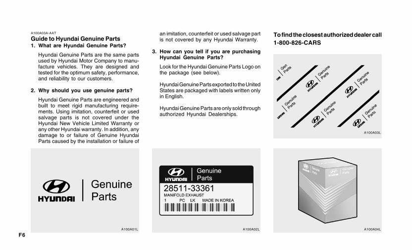
Guide to Hyundai Genuine Parts1. What are Hyundai Genuine Parts?
Hyundai Genuine Parts are the same partsused by Hyundai Motor Company to manu-facture vehicles. They are designed andtested for the optimum safety, performance,and reliability to our customers.
2. Why should you use genuine parts?
Hyundai Genuine Parts are engineered andbuilt to meet rigid manufacturing require-ments. Using imitation, counterfeit or usedsalvage parts is not covered under theHyundai New Vehicle Limited Warranty orany other Hyundai warranty. In addition, anydamage to or failure of Genuine HyundaiParts caused by the installation or failure of
an imitation, counterfeit or used salvage partis not covered by any Hyundai Warranty.
3. How can you tell if you are purchasingHyundai Genuine Parts?
Look for the Hyundai Genuine Parts Logo onthe package (see below).
Hyundai Genuine Parts exported to the UnitedStates are packaged with labels written onlyin English.
Hyundai Genuine Parts are only sold throughauthorized Hyundai Dealerships.
To find the closest authorized dealer call1-800-826-CARS
A100A01L A100A02L A100A04L
A100A03L
F7
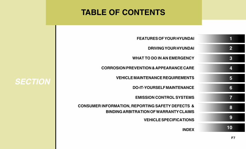
TABLE OF CONTENTS
SECTION 5
1
2
3
4
6
7
8
9
10
FEATURES OF YOUR HYUNDAI
DRIVING YOUR HYUNDAI
WHAT TO DO IN AN EMERGENCY
CORROSION PREVENTION & APPEARANCE CARE
VEHICLE MAINTENANCE REQUIREMENTS
DO-IT-YOURSELF MAINTENANCE
EMISSION CONTROL SYSTEMS
CONSUMER INFORMATION, REPORTING SAFETY DEFECTS &BINDING ARBITRATION OF WARRANTY CLAIMS
VEHICLE SPECIFICATIONS
INDEX
F8
INSTRUMENTS AND CONTROLS
B250A01JM-AAT
B250A01JM-U
F9
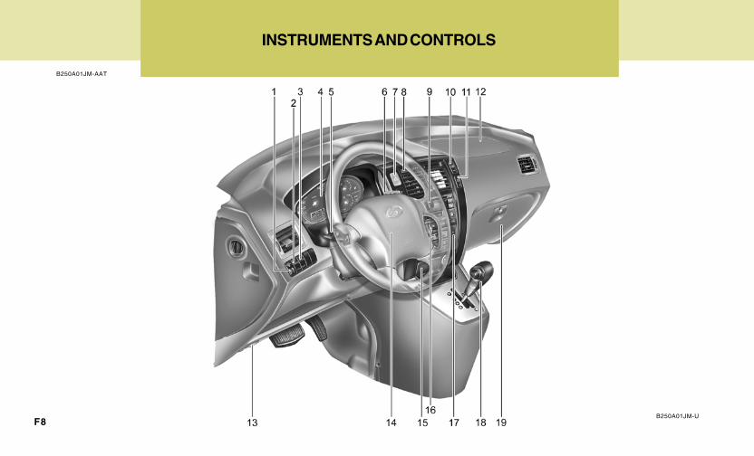
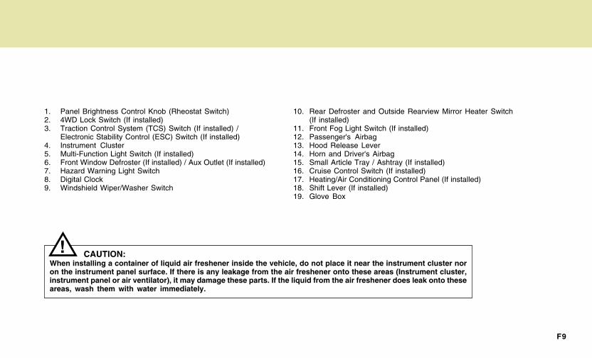
1. Panel Brightness Control Knob (Rheostat Switch)2. 4WD Lock Switch (If installed)3. Traction Control System (TCS) Switch (If installed) /
Electronic Stability Control (ESC) Switch (If installed)4. Instrument Cluster5. Multi-Function Light Switch (If installed)6. Front Window Defroster (If installed) / Aux Outlet (If installed)7. Hazard Warning Light Switch8. Digital Clock9. Windshield Wiper/Washer Switch
10. Rear Defroster and Outside Rearview Mirror Heater Switch(If installed)
11. Front Fog Light Switch (If installed)12. Passenger's Airbag13. Hood Release Lever14. Horn and Driver's Airbag15. Small Article Tray / Ashtray (If installed)16. Cruise Control Switch (If installed)17. Heating/Air Conditioning Control Panel (If installed)18. Shift Lever (If installed)19. Glove Box
CAUTION:When installing a container of liquid air freshener inside the vehicle, do not place it near the instrument cluster noron the instrument panel surface. If there is any leakage from the air freshener onto these areas (Instrument cluster,instrument panel or air ventilator), it may damage these parts. If the liquid from the air freshener does leak onto theseareas, wash them with water immediately.
!
YOUR VEHICLE AT A GLANCE
F10
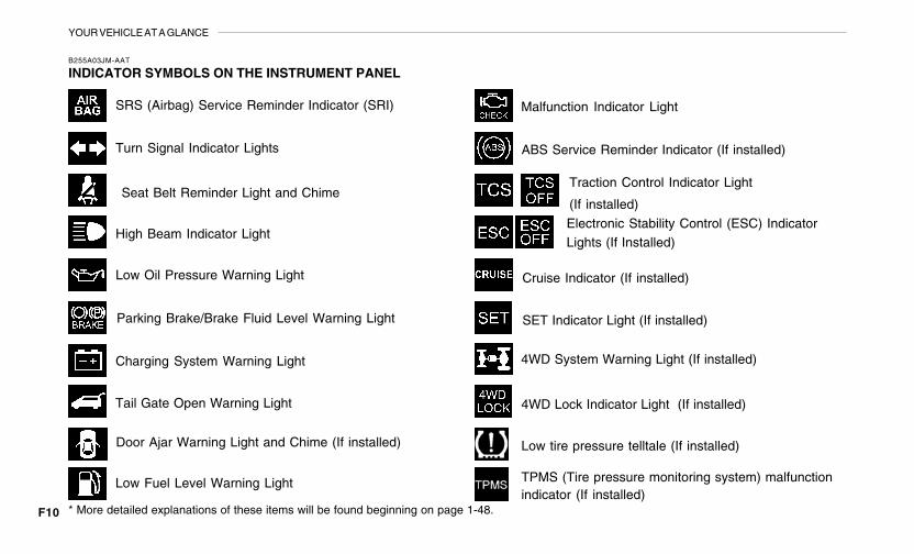
SRS (Airbag) Service Reminder Indicator (SRI)
B255A03JM-AAT
INDICATOR SYMBOLS ON THE INSTRUMENT PANEL
Turn Signal Indicator Lights
High Beam Indicator Light
Low Oil Pressure Warning Light
Charging System Warning Light
Seat Belt Reminder Light and Chime
* More detailed explanations of these items will be found beginning on page 1-48.
Parking Brake/Brake Fluid Level Warning Light
Malfunction Indicator Light
Tail Gate Open Warning Light
Low Fuel Level Warning Light
Door Ajar Warning Light and Chime (If installed)
Traction Control Indicator Light
(If installed)
ABS Service Reminder Indicator (If installed)
Cruise Indicator (If installed)
4WD Lock Indicator Light (If installed)
4WD System Warning Light (If installed)
SET Indicator Light (If installed)
Electronic Stability Control (ESC) IndicatorLights (If Installed)
Low tire pressure telltale (If installed)
TPMS (Tire pressure monitoring system) malfunctionindicator (If installed)
1Fuel Recommendations ................................................ 1-2Breaking in Your New Hyundai ..................................... 1-3Keys .............................................................................. 1-3Door .............................................................................. 1-4Power Windows .......................................................... 1-11Seats ........................................................................... 1-12Seat Belts.................................................................... 1-18Child Restraint System ............................................... 1-25Supplemental Restraint (AIRBAG) system................. 1-33Instrument Cluster and Indicator Lights ...................... 1-46Warning and Indicator Lights ...................................... 1-48Multi-Function Light Switch ......................................... 1-58Windshield Wiper/Washer Switch ............................... 1-60Sunroof ....................................................................... 1-68Mirror ........................................................................... 1-73How to use Luggage Room ........................................ 1-79Hood Release ............................................................. 1-84Cruise Control ............................................................. 1-87Heating and Cooling Control ..................................... 1-102Stereo Sound System ............................................... 1-109Audio System............................................................ 1-111Antenna ..................................................................... 1-126
1
FEATURES OF YOUR HYUNDAI
1FEATURES OF YOUR HYUNDAI
2
!
B010A01JM
FUEL RECOMMENDATIONS
CAUTION:Your Hyundai's New Vehicle Limited War-ranty may not cover damage to the fuelsystem and any performance problems thatare caused by the use of fuels containingmethanol or fuels containing MTBE (MethylTertiary Butyl Ether) over 15.0% vol. (Oxy-gen Content 2.7% weight.)
B010B01A-AAT
What About Gasohol?
Gasohol (a mixture of 90% unleaded gasolineand 10% ethanol or grain alcohol) may be usedin your Hyundai. However, if your engine devel-ops driveability problems, the use of 100%unleaded gasoline is recommended. Fuels withunspecified quantities of alcohol, or alcoholsother than ethanol, should not be used.
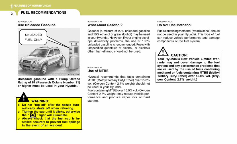
B010A05A-AAT
Use Unleaded Gasoline
Unleaded gasoline with a Pump OctaneRating of 87 (Research Octane Number 91)or higher must be used in your Hyundai.
B010C01A-AAT
Use of MTBE
Hyundai recommends that fuels containingMTBE (Methyl Tertiary Butyl Ether) over 15.0%vol. (Oxygen Content 2.7% weight) should notbe used in your Hyundai.Fuel containing MTBE over 15.0% vol. (OxygenContent 2.7% weight) may reduce vehicle per-formance and produce vapor lock or hardstarting.
B010D01A-AAT
Do Not Use Methanol
Fuels containing methanol (wood alcohol) shouldnot be used in your Hyundai. This type of fuelcan reduce vehicle performance and damagecomponents of the fuel system.
!
UNLEADED
FUEL ONLY
WARNING:o Do not "top off" after the nozzle auto-
matically shuts off when refueling.o Tighten the cap until it clicks, otherwise
the " " light will illuminate.o Always check that the fuel cap is in-
stalled securely to prevent fuel spillagein the event of an accident.
1FEATURES OF YOUR HYUNDAI
3KEYSBREAKING IN YOUR NEW HYUNDAI
B010F01A-AAT
Operation in Foreign Countries
If you are going to drive your Hyundai in anothercountry, be sure to:
o Observe all regulations regarding registra-tion and insurance.
o Determine that acceptable fuel is available.
B010E01A-AAT
Gasolines for Cleaner Air
To help contribute to cleaner air, Hyundai rec-ommends that you use gasolines treated withdetergent additives, which help prevent depositformation in the engine. These gasolines willhelp the engine run cleaner and enhance per-formance of the Emission Control System.
B020A01S-AAT
During the First 1,200 Miles (2,000 Km)
No formal "break-in" procedure is required withyour new Hyundai. However, you can contrib-ute to the economical operation and durability ofyour Hyundai by observing the following recom-mendations during the first 1,200 miles (2,000km).
o Don't drive faster than 55 MPH (88 km/h).o While driving, keep your engine speed (rpm,
or revolutions per minute) between 2,000rpm and 4,000 rpm.
o Use moderate acceleration. Don't startquickly or depress the accelerator pedalfully.
o For the first 200 miles (300 km), try to avoidhard stops.
o Don't lug the engine (in other words, don'tdrive so slowly in too high a gear that theengine "bucks"-shift to a lower gear).
o Whether going fast or slow, vary your speedfrom time to time.
o Don't let the engine idle longer than 3 minutesat one time.
o Don't tow a trailer during the first 1,200 miles(2,000 km) of operation.
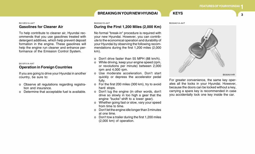
B030A01A-AAT
For greater convenience, the same key oper-ates all the locks in your Hyundai. However,because the doors can be locked without a key,carrying a spare key is recommended in caseyou accidentally lock one key inside the car.
B030A01HR
1FEATURES OF YOUR HYUNDAI
4
B030C01E-1
DOOR LOCKS
!B040A01A-AATB030C01JM-AAT
ILLUMINATED IGNITION SWITCH(If installed)
Whenever either front door is opened, the igni-tion switch will be illuminated for your conve-nience, provided the ignition switch is not in the"ON" position.The light will go off approximately 10 secondsafter closing the door or when the ignition switchis turned on.
WARNING:o Unlocked doors can be dangerous. Be-
fore you drive away (especially if thereare children in the car), be sure that all thedoors are securely closed and locked sothat the doors cannot be opened fromthe inside. This helps ensure that thedoors will not be opened accidentally.Also, when combined with the properuse of seat belts, locking the doors helpskeep occupants from being ejected fromthe car in case of an accident.
o Before opening the door, always look forand avoid oncoming traffic.
B030B01A-AAT
Record Your Key Number
A code number is stamped on the number platethat came with the keys to your Hyundai. Thiskey number plate should not be left with the keysbut kept in a safe place, not in the vehicle. Thekey number should also be recorded in a placewhere it can be found in an emergency.If you need additional keys, or if you should loseyour keys, your authorized Hyundai dealer canmake new keys if you can supply the keynumber.
B030B01HR
1FEATURES OF YOUR HYUNDAI
5
UNLOCK
LOCK
HJM2007
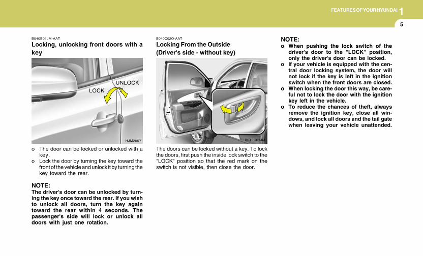
B040B01JM-AAT
Locking, unlocking front doors with akey
o The door can be locked or unlocked with akey.
o Lock the door by turning the key toward thefront of the vehicle and unlock it by turning thekey toward the rear.
NOTE:The driver's door can be unlocked by turn-ing the key once toward the rear. If you wishto unlock all doors, turn the key againtoward the rear within 4 seconds. Thepassenger's side will lock or unlock alldoors with just one rotation.
B040C01JM
B040C02O-AAT
Locking From the Outside(Driver's side - without key)
The doors can be locked without a key. To lockthe doors, first push the inside lock switch to the"LOCK" position so that the red mark on theswitch is not visible, then close the door.
NOTE:o When pushing the lock switch of the
driver's door to the "LOCK" position,only the driver's door can be locked.
o If your vehicle is equipped with the cen-tral door locking system, the door willnot lock if the key is left in the ignitionswitch when the front doors are closed.
o When locking the door this way, be care-ful not to lock the door with the ignitionkey left in the vehicle.
o To reduce the chances of theft, alwaysremove the ignition key, close all win-dows, and lock all doors and the tail gatewhen leaving your vehicle unattended.
1FEATURES OF YOUR HYUNDAI
6
B045D01JM-AAT
Locking From the Inside(Passenger's side)
To lock the door from the inside, simply close thedoor and push the lock switch to the "LOCK"position. When this is done, neither the outsidenor the passenger's inside door handles can beused.
The door can be locked without a key. To lockthe door, first push the inside lock switch to the"LOCK" position so that the red mark on theswitch is not visible, then close the door.
NOTE:o When pushing the lock switch of the
passenger's door to the "LOCK" posi-tion, only the passengers door will belocked.
o If your vehicle is equipped with the cen-tral door locking system, the door willnot lock if the key is left in the ignitionswitch when the front doors are closed.
B045C01JM-AAT
Locking From the Outside(Passenger's side - Without key)
o When locking the door this way, be care-ful not to lock the door with the ignitionkey left in the vehicle.
o To reduce the chances of theft, alwaysremove the ignition key, close all win-dows, and lock all doors and the tail gatewhen leaving your vehicle unattended.
B045C01JM
HJM2008-D
UNLOCKLOCK
B040D01O-AAT
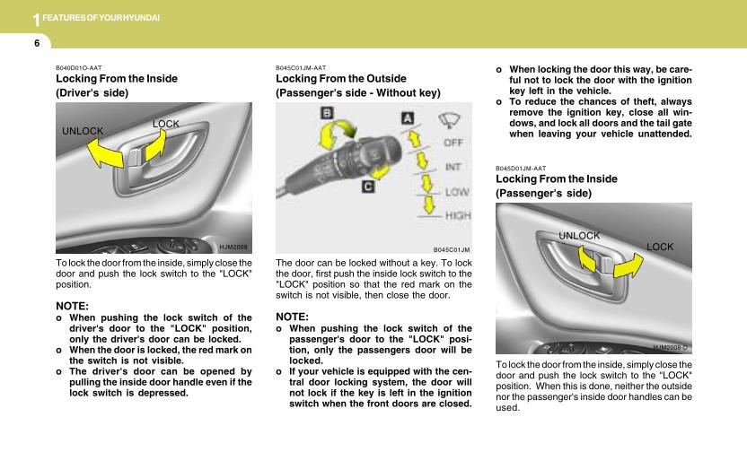
Locking From the Inside(Driver's side)
To lock the door from the inside, simply close thedoor and push the lock switch to the "LOCK"position.
NOTE:o When pushing the lock switch of the
driver's door to the "LOCK" position,only the driver's door can be locked.
o When the door is locked, the red mark onthe switch is not visible.
o The driver's door can be opened bypulling the inside door handle even if thelock switch is depressed.
HJM2008
UNLOCKLOCK
1FEATURES OF YOUR HYUNDAI
7
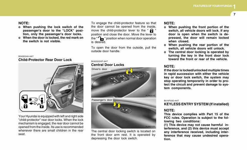
B040E04A-AAT
Child-Protector Rear Door Lock
Your Hyundai is equipped with left and right side"child-protector" rear door locks. When the lockmechanism is engaged, the rear door cannot beopened from the inside. Its use is recommendedwhenever there are small children in the rearseat.
HJM2011
B040G03HP-AAT
Central Door Locks
The central door locking switch is located onthe front door arm rest. It is operated bydepressing the door lock switch.
HJM2010
NOTE:o When pushing the lock switch of the
passenger's door to the "LOCK" posi-tion, only the passenger's door locks.
o When the door is locked, the red mark onthe switch is not visible.
To engage the child-protector feature so thatthe door cannot be opened from the inside,move the child-protector lever to the " "position and close the door. Move the lever tothe " " position when normal door operationis desired.
To open the door from the outside, pull theoutside door handle.
NOTE:o When pushing the front portion of the
switch, all vehicle doors will lock. If anydoor is open when the switch is de-pressed, the door will remain lockedwhen closed.
o When pushing the rear portion of theswitch, all vehicle doors will unlock.
o The central door locking is operated byturning the key in the front door locktoward the front or rear of the vehicle.
NOTE:If the door is locked/unlocked multiple timesin rapid succession with either the vehiclekey or door lock switch, the system maystop operating temporarily in order to pro-tect the circuit and prevent damage to sys-tem components.
B070F03O-AAT
KEYLESS ENTRY SYSTEM (If installed)
NOTE:This device complies with Part 15 of theFCC rules. Operation is subject to the fol-lowing two conditions:(1) This device may not cause harmful in-terference, and (2) this device must acceptany interference received, including inter-ference that may cause undesired opera-tion.
HJM2120
Driver's door
Passenger's door
1FEATURES OF YOUR HYUNDAI
8
B070B02JMUNLOCK
LOCK
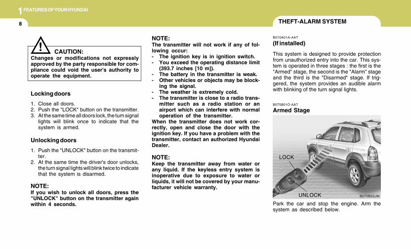
THEFT-ALARM SYSTEM
B075B01O-AAT
Armed Stage
Park the car and stop the engine. Arm thesystem as described below.
B070A01A-AAT
(If installed)
This system is designed to provide protectionfrom unauthorized entry into the car. This sys-tem is operated in three stages : the first is the"Armed" stage, the second is the "Alarm" stageand the third is the "Disarmed" stage. If trig-gered, the system provides an audible alarmwith blinking of the turn signal lights.
Locking doors
1. Close all doors.2. Push the "LOCK" button on the transmitter.3. At the same time all doors lock, the turn signal
lights will blink once to indicate that thesystem is armed.
Unlocking doors
1. Push the "UNLOCK" button on the transmit-ter.
2. At the same time the driver's door unlocks,the turn signal lights will blink twice to indicatethat the system is disarmed.
NOTE:If you wish to unlock all doors, press the"UNLOCK" button on the transmitter againwithin 4 seconds.
CAUTION:Changes or modifications not expresslyapproved by the party responsible for com-pliance could void the user's authority tooperate the equipment.
!NOTE:The transmitter will not work if any of fol-lowing occur:- The ignition key is in ignition switch.- You exceed the operating distance limit
(393.7 inches [10 m]).- The battery in the transmitter is weak.- Other vehicles or objects may be block-
ing the signal.- The weather is extremely cold.- The transmitter is close to a radio trans-
mitter such as a radio station or anairport which can interfere with normaloperation of the transmitter.
When the transmitter does not work cor-rectly, open and close the door with theignition key. If you have a problem with thetransmitter, contact an authorized HyundaiDealer.
NOTE:Keep the transmitter away from water orany liquid. If the keyless entry system isinoperative due to exposure to water orliquids, it will not be covered by your manu-facturer vehicle warranty.
1FEATURES OF YOUR HYUNDAI
9
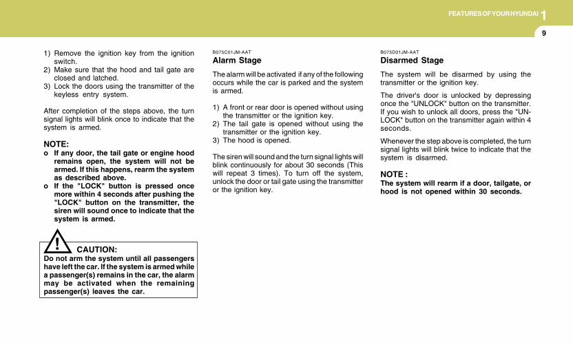
1) Remove the ignition key from the ignitionswitch.
2) Make sure that the hood and tail gate areclosed and latched.
3) Lock the doors using the transmitter of thekeyless entry system.
After completion of the steps above, the turnsignal lights will blink once to indicate that thesystem is armed.
NOTE:o If any door, the tail gate or engine hood
remains open, the system will not bearmed. If this happens, rearm the systemas described above.
o If the "LOCK" button is pressed oncemore within 4 seconds after pushing the"LOCK" button on the transmitter, thesiren will sound once to indicate that thesystem is armed.
CAUTION:Do not arm the system until all passengershave left the car. If the system is armed whilea passenger(s) remains in the car, the alarmmay be activated when the remainingpassenger(s) leaves the car.
!
B075C01JM-AAT
Alarm Stage
The alarm will be activated if any of the followingoccurs while the car is parked and the systemis armed.
1) A front or rear door is opened without usingthe transmitter or the ignition key.
2) The tail gate is opened without using thetransmitter or the ignition key.
3) The hood is opened.
The siren will sound and the turn signal lights willblink continuously for about 30 seconds (Thiswill repeat 3 times). To turn off the system,unlock the door or tail gate using the transmitteror the ignition key.
B075D01JM-AAT
Disarmed Stage
The system will be disarmed by using thetransmitter or the ignition key.
The driver's door is unlocked by depressingonce the "UNLOCK" button on the transmitter.If you wish to unlock all doors, press the "UN-LOCK" button on the transmitter again within 4seconds.
Whenever the step above is completed, the turnsignal lights will blink twice to indicate that thesystem is disarmed.
NOTE :The system will rearm if a door, tailgate, orhood is not opened within 30 seconds.
1FEATURES OF YOUR HYUNDAI
10
B070E02HP-AAT
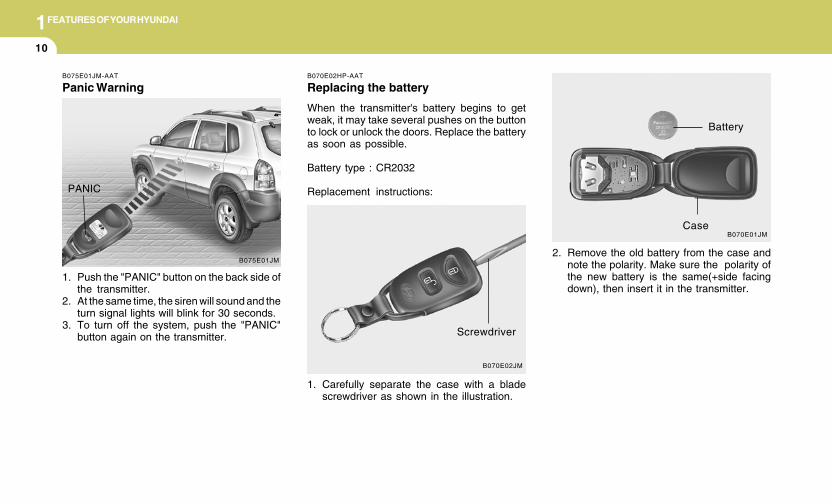
Replacing the battery
When the transmitter's battery begins to getweak, it may take several pushes on the buttonto lock or unlock the doors. Replace the batteryas soon as possible.
Battery type : CR2032
Replacement instructions:
1. Carefully separate the case with a bladescrewdriver as shown in the illustration.
2. Remove the old battery from the case andnote the polarity. Make sure the polarity ofthe new battery is the same(+side facingdown), then insert it in the transmitter.
B070E02JM
Screwdriver
B070E01JM
Battery
Case
B075E01JM-AAT
Panic Warning
1. Push the "PANIC" button on the back side ofthe transmitter.
2. At the same time, the siren will sound and theturn signal lights will blink for 30 seconds.
3. To turn off the system, push the "PANIC"button again on the transmitter.
B075E01JM
PANIC
1FEATURES OF YOUR HYUNDAI
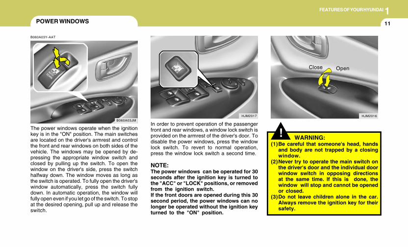
11POWER WINDOWS
B060A03Y-AAT
The power windows operate when the ignitionkey is in the "ON" position. The main switchesare located on the driver's armrest and controlthe front and rear windows on both sides of thevehicle. The windows may be opened by de-pressing the appropriate window switch andclosed by pulling up the switch. To open thewindow on the driver's side, press the switchhalfway down. The window moves as long asthe switch is operated. To fully open the driver'swindow automatically, press the switch fullydown. In automatic operation, the window willfully open even if you let go of the switch. To stopat the desired opening, pull up and release theswitch.
B060A03JM
!In order to prevent operation of the passengerfront and rear windows, a window lock switch isprovided on the armrest of the driver's door. Todisable the power windows, press the windowlock switch. To revert to normal operation,press the window lock switch a second time.
NOTE:The power windows can be operated for 30seconds after the ignition key is turned tothe "ACC" or "LOCK" positions, or removedfrom the ignition switch.If the front doors are opened during this 30second period, the power windows can nolonger be operated without the ignition keyturned to the "ON" position.
WARNING:(1)Be careful that someone's head, hands
and body are not trapped by a closingwindow.
(2)Never try to operate the main switch onthe driver's door and the individual doorwindow switch in opposing directionsat the same time. If this is done, thewindow will stop and cannot be openedor closed.
(3)Do not leave children alone in the car.Always remove the ignition key for theirsafety.
HJM2016
Close Open
HJM2017
1FEATURES OF YOUR HYUNDAI
12
HJM2033
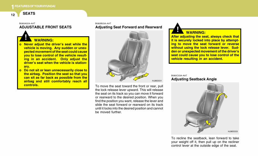
!B080B03A-AAT
Adjusting Seat Forward and Rearward
To move the seat toward the front or rear, pullthe lock release lever upward. This will releasethe seat on its track so you can move it forwardor rearward to the desired position. When youfind the position you want, release the lever andslide the seat forward or rearward on its trackuntil it locks into the desired position and cannotbe moved further.
B080C03A-AAT
Adjusting Seatback Angle
To recline the seatback, lean forward to takeyour weight off it, then pull up on the reclinercontrol lever at the outside edge of the seat.
WARNING:After adjusting the seat, always check thatit is securely locked into place by attempt-ing to move the seat forward or reversewithout using the lock release lever. Sud-den or unexpected movement of the driver'sseat could cause you to lose control of thevehicle resulting in an accident.
HJM2031
SEATS
B080A02A-AAT
ADJUSTABLE FRONT SEATS
! WARNING:o Never adjust the driver’s seat while the
vehicle is moving. Any sudden or unex-pected movement of the seat could causeyou to lose control of the vehicle result-ing in an accident. Only adjust thedriver’s seat when the vehicle is station-ary.
o Do not sit or lean unnecessarily close tothe airbag. Position the seat so that youcan sit as far back as possible from theairbag and still comfortably reach allcontrols.
1FEATURES OF YOUR HYUNDAI
13
! WARNING:Riding with a reclined seatback increasesyour chance of serious or fatal injuries inthe event of a collision or sudden stop. Theprotection of your restraint system (seatbelts and airbags) is greatly reduced byreclining your seat. Seat belts must be snugagainst your hips and chest to work prop-erly. The more the seatback is reclined, thegreater the chance that an occupant's hipswill slide under the lap belt or the occupant'sneck will strike the shoulder belt. Driversand passengers should always sit well backin their seats, properly belted, and with theseatbacks upright.
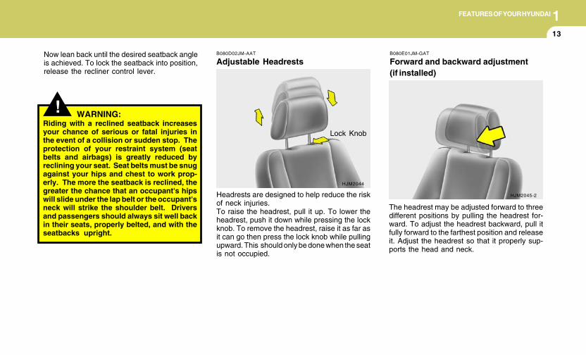
B080D02JM-AAT
Adjustable Headrests
Headrests are designed to help reduce the riskof neck injuries.To raise the headrest, pull it up. To lower theheadrest, push it down while pressing the lockknob. To remove the headrest, raise it as far asit can go then press the lock knob while pullingupward. This should only be done when the seatis not occupied.
HJM2044
Lock Knob
Now lean back until the desired seatback angleis achieved. To lock the seatback into position,release the recliner control lever.
B080E01JM-GAT
Forward and backward adjustment(if installed)
The headrest may be adjusted forward to threedifferent positions by pulling the headrest for-ward. To adjust the headrest backward, pull itfully forward to the farthest position and releaseit. Adjust the headrest so that it properly sup-ports the head and neck.
HJM2045-2
1FEATURES OF YOUR HYUNDAI
14
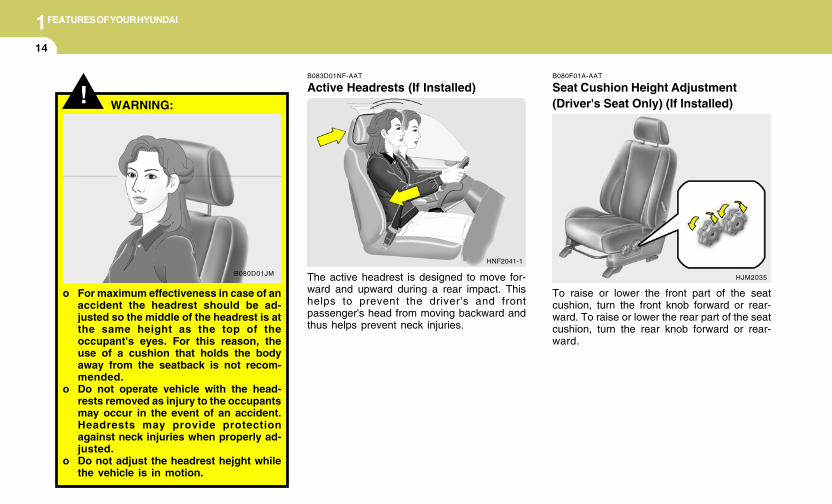
B080F01A-AAT
Seat Cushion Height Adjustment(Driver's Seat Only) (If Installed)
To raise or lower the front part of the seatcushion, turn the front knob forward or rear-ward. To raise or lower the rear part of the seatcushion, turn the rear knob forward or rear-ward.
HJM2035
!
B080D01JM
WARNING:
o For maximum effectiveness in case of anaccident the headrest should be ad-justed so the middle of the headrest is atthe same height as the top of theoccupant's eyes. For this reason, theuse of a cushion that holds the bodyaway from the seatback is not recom-mended.
o Do not operate vehicle with the head-rests removed as injury to the occupantsmay occur in the event of an accident.Headrests may provide protectionagainst neck injuries when properly ad-justed.
o Do not adjust the headrest hejght whilethe vehicle is in motion.
B083D01NF-AAT
Active Headrests (If Installed)
The active headrest is designed to move for-ward and upward during a rear impact. Thishelps to prevent the driver's and frontpassenger's head from moving backward andthus helps prevent neck injuries.
HNF2041-1
1FEATURES OF YOUR HYUNDAI
15
!
HJM2041
B080H02JM-GAT
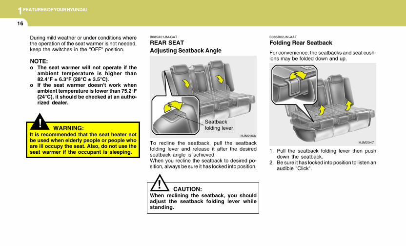
Seatback table (if installed)
The seatback table is made by folding the frontpassenger seat forward.
To operate the seatback table
1. Lower the headrest.2. With the recliner control lever pulled up, fold
the front passenger seatback forward to theflat position.
3. When returning the seatback to the uprightposition, ensure the seatback is completelylocked into place.
Recliner control lever
WARNING:o Do not sit on the seatback table.o Do not place items on the seatback table
when the vehicle is in motion.o Do not leave items on the seatback table
when the vehicle is in motion.
B100A02JM-AAT
SEAT WARMER (If installed)
HJM2042
The seat warmer is provided to warm the frontseats during cold weather. With the ignition keyin the "ON" position, push either of the switchesto warm the driver's seat or the passenger'sseat.
B080E01F-AAT
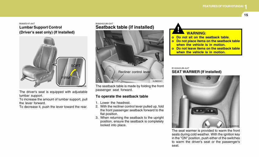
Lumbar Support Control(Driver's seat only) (If Installed)
The driver's seat is equipped with adjustablelumbar support.To increase the amount of lumbar support, pullthe lever forward.To decrease it, push the lever toward the rear.
SOFT
HJM2036
FIRM
1FEATURES OF YOUR HYUNDAI
16
B085A01JM-GAT
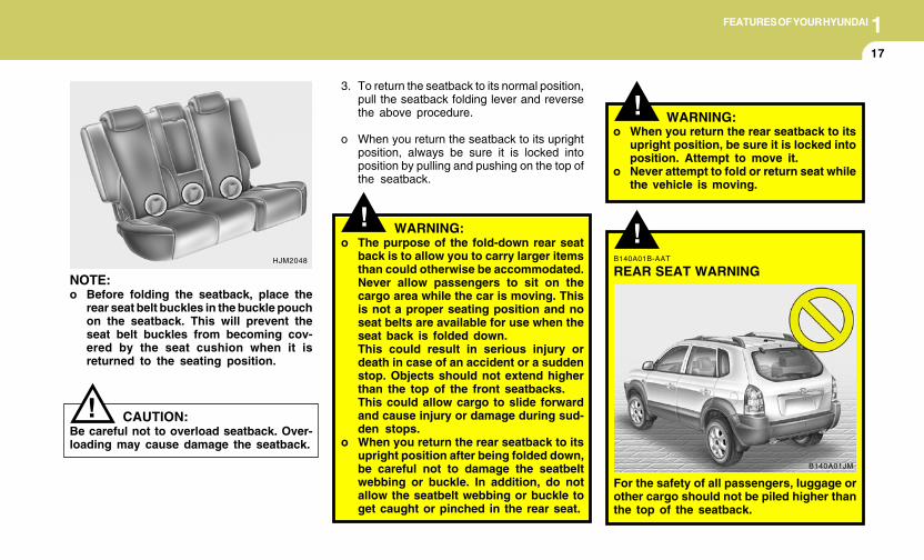
REAR SEATAdjusting Seatback Angle
To recline the seatback, pull the seatbackfolding lever and release it after the desiredseatback angle is achieved.When you recline the seatback to desired po-sition, always be sure it has locked into position.
HJM2046
Seatbackfolding lever
!
HJM2047
B085B02JM-AAT
Folding Rear Seatback
For convenience, the seatbacks and seat cush-ions may be folded down and up.
CAUTION:When reclining the seatback, you shouldadjust the seatback folding lever whilestanding.
1. Pull the seatback folding lever then pushdown the seatback.
2. Be sure it has locked into position to listen anaudible "Click".
! WARNING:It is recommended that the seat heater notbe used when elderly people or people whoare ill occupy the seat. Also, do not use theseat warmer if the occupant is sleeping.
During mild weather or under conditions wherethe operation of the seat warmer is not needed,keep the switches in the "OFF" position.
NOTE:o The seat warmer will not operate if the
ambient temperature is higher than82.4°F ± 6.3°F (28°C ± 3.5°C).
o If the seat warmer doesn't work whenambient temperature is lower than 75.2°F(24°C), it should be checked at an autho-rized dealer.
1FEATURES OF YOUR HYUNDAI
17
!
!
3. To return the seatback to its normal position,pull the seatback folding lever and reversethe above procedure.
o When you return the seatback to its uprightposition, always be sure it is locked intoposition by pulling and pushing on the top ofthe seatback.
WARNING:o The purpose of the fold-down rear seat
back is to allow you to carry larger itemsthan could otherwise be accommodated.Never allow passengers to sit on thecargo area while the car is moving. Thisis not a proper seating position and noseat belts are available for use when theseat back is folded down.This could result in serious injury ordeath in case of an accident or a suddenstop. Objects should not extend higherthan the top of the front seatbacks.This could allow cargo to slide forwardand cause injury or damage during sud-den stops.
o When you return the rear seatback to itsupright position after being folded down,be careful not to damage the seatbeltwebbing or buckle. In addition, do notallow the seatbelt webbing or buckle toget caught or pinched in the rear seat.
o When you return the rear seatback to itsupright position, be sure it is locked intoposition. Attempt to move it.
o Never attempt to fold or return seat whilethe vehicle is moving.
WARNING:
HJM2048
!
NOTE:o Before folding the seatback, place the
rear seat belt buckles in the buckle pouchon the seatback. This will prevent theseat belt buckles from becoming cov-ered by the seat cushion when it isreturned to the seating position.
CAUTION:Be careful not to overload seatback. Over-loading may cause damage the seatback.
!B140A01B-AAT
REAR SEAT WARNING
For the safety of all passengers, luggage orother cargo should not be piled higher thanthe top of the seatback.
B140A01JM
1FEATURES OF YOUR HYUNDAI
18
B150C02A-AAT
Larger Children
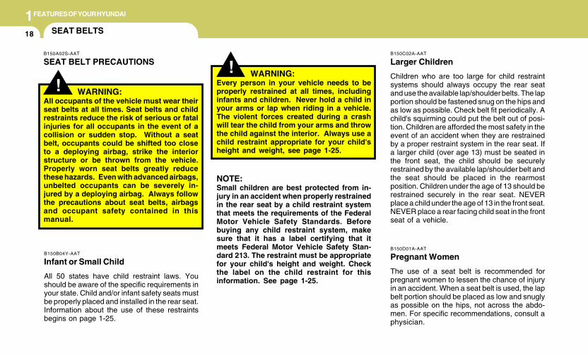
Children who are too large for child restraintsystems should always occupy the rear seatand use the available lap/shoulder belts. The lapportion should be fastened snug on the hips andas low as possible. Check belt fit periodically. Achild's squirming could put the belt out of posi-tion. Children are afforded the most safety in theevent of an accident when they are restrainedby a proper restraint system in the rear seat. Ifa larger child (over age 13) must be seated inthe front seat, the child should be securelyrestrained by the available lap/shoulder belt andthe seat should be placed in the rearmostposition. Children under the age of 13 should berestrained securely in the rear seat. NEVERplace a child under the age of 13 in the front seat.NEVER place a rear facing child seat in the frontseat of a vehicle.
B150D01A-AAT
Pregnant Women
The use of a seat belt is recommended forpregnant women to lessen the chance of injuryin an accident. When a seat belt is used, the lapbelt portion should be placed as low and snuglyas possible on the hips, not across the abdo-men. For specific recommendations, consult aphysician.
SEAT BELTS
B150B04Y-AAT
Infant or Small Child
All 50 states have child restraint laws. Youshould be aware of the specific requirements inyour state. Child and/or infant safety seats mustbe properly placed and installed in the rear seat.Information about the use of these restraintsbegins on page 1-25.
!
B150A02S-AAT
SEAT BELT PRECAUTIONS
WARNING:All occupants of the vehicle must wear theirseat belts at all times. Seat belts and childrestraints reduce the risk of serious or fatalinjuries for all occupants in the event of acollision or sudden stop. Without a seatbelt, occupants could be shifted too closeto a deploying airbag, strike the interiorstructure or be thrown from the vehicle.Properly worn seat belts greatly reducethese hazards. Even with advanced airbags,unbelted occupants can be severely in-jured by a deploying airbag. Always followthe precautions about seat belts, airbagsand occupant safety contained in thismanual.
! WARNING:Every person in your vehicle needs to beproperly restrained at all times, includinginfants and children. Never hold a child inyour arms or lap when riding in a vehicle.The violent forces created during a crashwill tear the child from your arms and throwthe child against the interior. Always use achild restraint appropriate for your child'sheight and weight, see page 1-25.
NOTE:Small children are best protected from in-jury in an accident when properly restrainedin the rear seat by a child restraint systemthat meets the requirements of the FederalMotor Vehicle Safety Standards. Beforebuying any child restraint system, makesure that it has a label certifying that itmeets Federal Motor Vehicle Safety Stan-dard 213. The restraint must be appropriatefor your child's height and weight. Checkthe label on the child restraint for thisinformation. See page 1-25.
1FEATURES OF YOUR HYUNDAI
19
WARNING:Riding with a reclined seatback increasesyour chance of serious or fatal injuries inthe event of a collision or sudden stop. Theprotection of your restraint system (seatbelts and airbags) is greatly reduced byreclining your seat. Seat belts must be snugagainst your hips and chest to work prop-erly. The more the seatback is reclined, thegreater the chance that an occupant's hipswill slide under the lap belt causing seriousinternal injuries or the occupant's neckcould strike the shoulder belt. Drivers andpassengers should always sit well back intheir seats, properly belted (see page 1-21),and with the seatbacks upright.
!B150E01A-AAT
Injured Person
A seat belt should be used when an injuredperson is being transported. When this is nec-essary, you should consult a physician forrecommendations.
B150F01A-AAT
One Person Per Belt
Two people (including children) should neverattempt to use a single seat belt. This couldincrease the severity of injuries in case of anaccident.
B150G02A-AAT
Do Not Lie Down
To reduce the chance of injuries in the event ofan accident and to achieve maximum effective-ness of the restraint system, all passengersshould be sitting up and the front seats shouldbe in an upright position when the car is moving.A seat belt cannot provide proper protection ifthe person is lying down in the rear seat or if thefront seat is in a reclined position.
!
B160A02A-AAT
CARE OF SEAT BELTS
Seat belt systems should never be disassembledor modified. In addition, care should be taken toassure that seat belts and belt hardware are notdamaged by seat hinges, doors or other abuse.
WARNING:When you return the rear seatback to itsupright position after the rear seatback wasfolded down, be careful not to damage theseat belt webbing or buckle. Be sure thatthe webbing or buckle does not get caughtor pinched in the rear seat. A seat belt withdamaged webbing or buckle will not be asstrong and could possibly fail during acollision or sudden stop, resulting in seri-ous injury.
B160B01A-AAT
Periodic Inspection
It is recommended that all seat belts be in-spected periodically for wear or damage of anykind. Parts of the system that are damagedshould be replaced as soon as possible.
1FEATURES OF YOUR HYUNDAI
20
! WARNING:o Verify the shoulder belt anchor is locked
into position at the appropriate height.Never position the shoulder belt acrossyour neck or face. Improperly posi-tioned seat belts can cause serious inju-ries in an accident.
o Failure to replace seat belts after anaccident could leave you with damagedseat belts that will not provide protec-tion in the event of another collisionleading to personal injury or death.Replace your seat belts after being in anaccident as soon as possible.
Release the button to lock the anchor intoposition. Try sliding the height adjuster to makesure that it has locked into the position.
HJM2050
B160C01A-AAT
Keep Belts Clean and Dry
Seat belts should be kept clean and dry. If beltsbecome dirty, they can be cleaned by using amild soap solution and warm water. Bleach, dye,strong detergents or abrasives should not beused because they may damage and weakenthe fabric.
B160D01A-AAT
When to Replace Seat Belts
Entire in-use seat belt assembly or assembliesshould be replaced if the vehicle has beeninvolved in an accident. This should be doneeven if no damage is visible. Additional ques-tions concerning seat belt operation should bedirected to your Hyundai Dealer.
B170A05Y-AAT
HEIGHT ADJUSTABLE FRONT SEATSHOULDER BELT
You can adjust the height of the shoulder beltanchor to one of the 4 positions for maximumcomfort and safety.If the height of the adjusting seat belt is too nearyour neck, you will not be getting the mosteffective protection. The shoulder portion shouldbe adjusted so that it lies across your chest andmidway over your shoulder nearest the doorand not your neck.To adjust the height of the seat belt anchor,lower or raise the height adjuster into an appro-priate position. To raise the height adjuster, pullit up. To lower it, push it down while pressing theheight adjuster button.
1FEATURES OF YOUR HYUNDAI
21
B190A02Y-AAT
SEAT BELTS-Front Passenger and RearSeat 3-Point System with CombinationLocking Retractor
Combination retractor type seat belts are in-stalled in the rear seat positions to help accom-modate the installation of child restraint systems.Although a combination retractor is also installedin the front passenger seat position, Hyundaistrongly recommends that children always beseated in the rear seat. NEVER place any infantrestraint system in the front seat of the vehicle.This type of seat belt combines the features ofboth an emergency locking retractor seat beltand an automatic locking retractor seat belt. Tofasten your seat belt, pull it out of the retractorand insert the metal tab into the buckle. Therewill be an audible "click" when the tab locks intothe buckle. When not securing a child restraint,the seat belt operates in the same way as thedriver's seat belt (Emergency Locking Retrac-tor Type). It automatically adjusts to the properlength only after the lap belt portion of the seatbelt is adjusted manually so that it fits snuglyaround your hips. When the seat belt is fullyextended from the retractor to allow the instal-lation of a child restraint system, the seat beltoperation changes to allow the belt to retract, butnot to extend (Automatic Locking RetractorType). See page 1-29.
To fasten your seat belt, pull it out of the retractorand insert the metal tab into the buckle. Therewill be an audible "click" when the tab locks intothe buckle.The seat belt automatically adjusts to the properlength only after the lap belt portion is adjustedmanually so that it fits snugly around your hips.If you lean forward in a slow, easy motion, thebelt will extend and let you move around. If thereis a sudden stop or impact, however, the belt willlock into position. It will also lock if you try to leanforward too quickly.
B180A02A-AAT
SEAT BELT-Driver's 3-Point System withEmergency Locking RetractorTo Fasten Your Belt
B180A01L
NOTE:o If you are not able to pull out the safety
belt from the retractor, firmly pull the beltout and release it. Then you will be ableto pull the belt out smoothly.
o If the driver's seat belt is not fastenedwhen the ignition key is in the "ON"position, the seat belt warning light willflash and the warning chime will soundfor approximately six seconds.
1FEATURES OF YOUR HYUNDAI
22
!
NOTE:Although the combination retractor pro-vides the same level of protection for seatedpassengers in either emergency or auto-matic locking modes, it is recommendedthat seated passengers use the emergencylocking feature for improved convenience.The automatic locking function is intendedto facilitate child restraint installation. Toconvert from the automatic locking featureto the emergency locking operation mode,allow the unbuckled seat belt to fully re-tract.
WARNING:o For maximum restraint system protec-
tion, the seat belts must always be usedwhenever the car is moving.
o Seat belts are most effective whenseatbacks are in the upright position.
o Children age 12 and younger must al-ways be properly restrained in the rearseat. Never allow children to ride in thefront passenger seat. If a child over 13must be seated in the front seat, he/shemust be properly belted and the seatshould be moved as far back as possible.
o Never wear the shoulder belt under yourarm or behind your back. An improperlypositioned shoulder belt can cause se-rious injuries in a crash. The shoulderbelt should be positioned midway overyour shoulder across your collarbone.
o Avoid wearing twisted seat belts. Atwisted belt can't do its job as well. In acollision, it could even cut into you. Besure the belt webbing is straight and nottwisted.
o Be careful not to damage the belt web-bing or hardware. If the belt webbing orhardware is damaged, replace it.
!
WARNING:You should place the lap belt portion as lowas possible and snugly across your hips,not on your waist. If the lap belt is locatedtoo high on your waist, it may increase thechance of injury in the event of a collision.Both arms should not be under or over thebelt. Rather, one should be over and theother under, as shown in the illustration.Never wear the seat belt under the armnearest the door.
!
B200A01A-AAT
Adjusting Your Seat Belt
B200A01L
WARNING:
1FEATURES OF YOUR HYUNDAI
23
! WARNING:o Never let anyone ride in the rear center
seat without fastening all metal tabs andbuckles as described in this section.This seat belt is designed to function asa typical 3-point restraint (lap/shoulderbelt). Using only the shoulder portion orlap portion of the belt can result in seri-ous or fatal injuries in the event of acollision or sudden stop.
B220A02JM-AAT
SEAT BELTS - Center Rear Seat 3-PointSystem With Combination Locking Re-tractor
1. Before fastening the rear seat center belt,confirm the metal tab (a) and buckle (b) arelatched together.
2. After confirming that (a) and (b) are latched,pull the seat belt out of the retractor and insertthe metal tab (c) into the buckle (d).
There will be an audible "click" when the tablocks in the buckle. The seat belt automaticallyadjusts to the proper length only after the lap beltis adjusted manually so that it fits snugly aroundyour hips. If you lean forward in a slow, easymotion, the belt will extend and let you move
around. If there is a sudden stop or impact, thebelt will lock into position. It will also lock if youtry to lean forward too quickly.
(d)B220A02Y
B220A01JM-A
(c)
The seat belt is released by pressing the re-lease button in the locking buckle. When it isreleased, the belt should automatically drawback into the retractor.If this does not happen, check the belt to be sureit is not twisted, then try again.
B210A01A-AAT
To Release the Seat Belt
B210A01L
(a)
(b)
1FEATURES OF YOUR HYUNDAI
24
! WARNING:!o Never unlock the metal tab (a) and the
buckle (b) with the following excep-tions.(1) In case of folding rear seatbacks
down.(2) If transporting an object on the rear
seat may cause damage to the rearseat center belt.
o Always lock metal tab (a) into buckle (b)immediately after returning the rearseatbacks to an upright position. Thisportion of the rear center seat belt shouldonly be unbuckled when the rear seatbackis folded down.
WARNING:
!
B220C01Y-AAT
To Release the Seat Belt
When you want to release the seat belt, pressthe button in the locking buckle.
WARNING:The rear seat center belt latching mecha-nism is different from those for the out-board rear seat shoulder belts. When fas-tening the outboard rear seat shoulder beltsor the rear seat center belt, make sure theyare inserted into the correct buckles toobtain maximum protection from the seatbelt system and assure proper operation.
B220C01JM
B220A02JM
o In case of unlocking metal tab (a) and thebuckle (b), place metal (a) in the seat beltclip not to make noise while driving.
To disconnect the metal tab (a) from the buckle(b) , insert a narrow-ended tool into the groovelocated on the buckle (b).
1FEATURES OF YOUR HYUNDAI
25CHILD RESTRAINT SYSTEM
B230A05O-AAT
Children riding in the car should sit in the rearseat and must always be properly restrained tominimize the risk of injury in an accident, suddenstop or sudden maneuver. According to acci-dent statistics provided by the National High-way Traffic Safety Administration (NHTSA),children are safer when properly restrained inthe rear seats than in the front seat. Largerchildren not in a child restraint should use oneof the seat belts provided.All 50 states have child restraint laws. Youshould be aware of the specific requirements inyour state. Child and/or infant safety seats mustbe properly placed and installed in the rear seat.You must use a commercially available childrestraint system that meets the requirements ofthe Federal Motor Vehicle Safety Standards(FMVSS). Child restraint systems are designedto be secured in vehicle seats by lap belts or thelap belt portion of a lap/shoulder belt, or by aLATCH system (if equipped).Children could be injured or killed in a crash iftheir restraints are not properly secured. Forsmall children and babies, a child seat or infantseat must be used. Before buying a particularchild restraint system, make sure it fits your carseat and seat belts, and fits your child. Followall the instructions provided by the manufac-turer when installing the child restraint system.
WARNING:To reduce the chance or serious or fatalinjuries:o Children of all ages are safer when re-
strained in the rear seat. A child riding inthe front passenger seat can be force-fully struck by an inflating airbag result-ing in serious or fatal injuries.
o Always follow the instructions for in-stallation and use of the child restraintmaker.
o Always make sure the child seat is se-cured properly in the car and your childis securely restrained in the child seat.
o Never hold a child in your arms or lapwhen riding in a vehicle. The violentforces created during a crash will tear thechild from your arms and throw the childagainst the car’s interior.
o Never put a seat belt over yourself and achild. During a crash, the belt couldpress deep into the child causing seri-ous internal injuries.
o Never leave children unattended in avehicle – not even for a short time. Thecar can heat up very quickly, resulting inserious injuries to children inside. Evenvery young children may inadvertentlycause the vehicle to move, entangle them-selves in the windows, or lock them-selves or others inside the vehicle.
!! WARNING:o A child restraint system must be placed
in the rear seat. Never install a child orinfant seat on the front passenger's seat.Should an accident occur and cause thepassenger side airbag to deploy, it couldseverely injure or kill an infant or childseated in an infant or child seat. Thusonly use a child restraint in the rear seatof your vehicle.
o A safety belt or child restraint systemcan become very hot if it is left in a closedvehicle on a sunny day, even if the out-side temperature does not feel hot. Besure to check the seat cover and bucklesbefore placing a child there.
o When the child restraint system is not inuse, store it in the luggage compartmentor fasten it with a safety belt so that it willnot be thrown forward in the case of asudden stop or an accident.
o Children may be seriously injured orkilled by an inflating airbag. All children,even those too large for child restraints,must ride in the rear seat.
1FEATURES OF YOUR HYUNDAI
26
B230C07O-AAT
Installing a Child Restraint Seat with the"Tether Anchorage" System
Three child restraint hook holders are locatedon the rear luggage compartment floor.
This symbol indicates the location of each userready tether anchorage.
B230C04JM
B230B01E-AAT
Using a Child Restraint System
For small children and babies, the use of a childseat or infant seat is required. This child seat orinfant seat should be of appropriate size for thechild and should be installed in accordance withthe manufacturer's instructions. It is furtherrequired that the seat be placed in the vehicle'srear seat since this can make an importantcontribution to safety. Your vehicle is providedwith three child restraint hook holders for install-ing the child seat or infant seat.
!o Never allow two children, or any two
persons, to use the same seat belt.o Children often squirm and reposition
themselves improperly. Never let a childride with the shoulder belt under theirarm or behind their back. Always prop-erly position and secure children in rearseat.
o Never allow a child to stand-up or kneelon the seat or floorboard of a movingvehicle. During a collision or suddenstop, the child can be violently thrownagainst the vehicles interior, resulting inserious injury.
o Never use an infant carrier or a childsafety seat that "hooks" over a seatback,it may not provide adequate security inan accident.
o Seat belts can become very hot, espe-cially when the car is parked in directsunlight. Always check seat belt buck-les before fastening them over a child.
o Always store or secure a child seat, evenwhen it is not in use. During a collisionor sudden stop, the child seat could bethrown inside the vehicle.
WARNING:
1FEATURES OF YOUR HYUNDAI
27
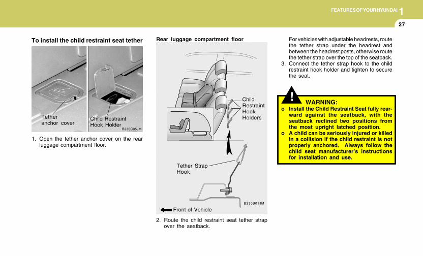
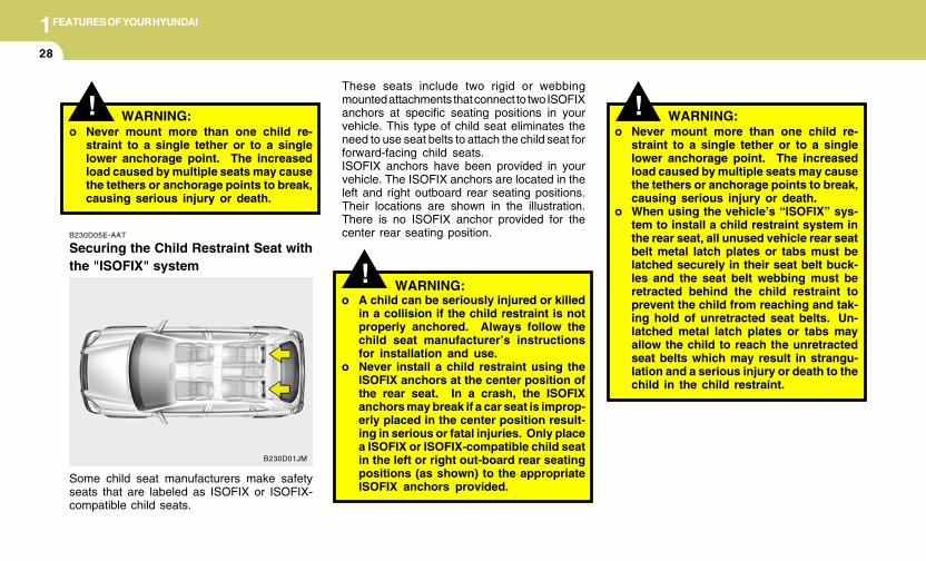
To install the child restraint seat tether
1. Open the tether anchor cover on the rearluggage compartment floor.
B230C05JM
Tetheranchor cover
Child RestraintHook Holder
2. Route the child restraint seat tether strapover the seatback.
Rear luggage compartment floor
B230B01JM
Front of Vehicle
ChildRestraintHookHolders
Tether StrapHook
!
For vehicles with adjustable headrests, routethe tether strap under the headrest andbetween the headrest posts, otherwise routethe tether strap over the top of the seatback.
3. Connect the tether strap hook to the childrestraint hook holder and tighten to securethe seat.
WARNING:o Install the Child Restraint Seat fully rear-
ward against the seatback, with theseatback reclined two positions fromthe most upright latched position.
o A child can be seriously injured or killedin a collision if the child restraint is notproperly anchored. Always follow thechild seat manufacturer’s instructionsfor installation and use.
1FEATURES OF YOUR HYUNDAI
28
! WARNING: !o Never mount more than one child re-
straint to a single tether or to a singlelower anchorage point. The increasedload caused by multiple seats may causethe tethers or anchorage points to break,causing serious injury or death.
o When using the vehicle’s “ISOFIX” sys-tem to install a child restraint system inthe rear seat, all unused vehicle rear seatbelt metal latch plates or tabs must belatched securely in their seat belt buck-les and the seat belt webbing must beretracted behind the child restraint toprevent the child from reaching and tak-ing hold of unretracted seat belts. Un-latched metal latch plates or tabs mayallow the child to reach the unretractedseat belts which may result in strangu-lation and a serious injury or death to thechild in the child restraint.
! WARNING:o A child can be seriously injured or killed
in a collision if the child restraint is notproperly anchored. Always follow thechild seat manufacturer’s instructionsfor installation and use.
o Never install a child restraint using theISOFIX anchors at the center position ofthe rear seat. In a crash, the ISOFIXanchors may break if a car seat is improp-erly placed in the center position result-ing in serious or fatal injuries. Only placea ISOFIX or ISOFIX-compatible child seatin the left or right out-board rear seatingpositions (as shown) to the appropriateISOFIX anchors provided.
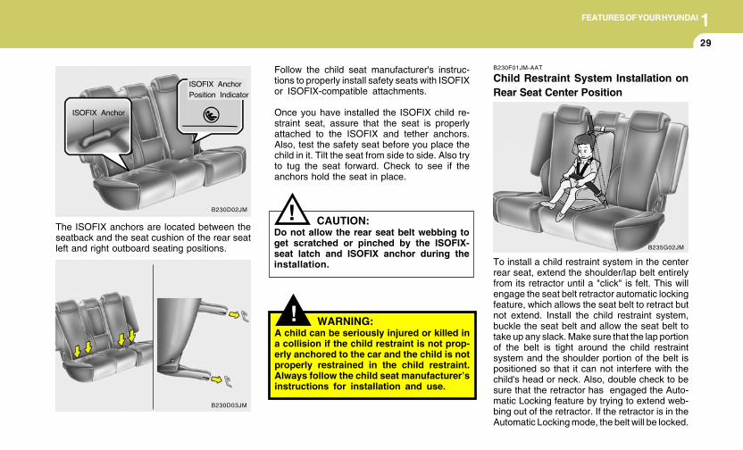
B230D05E-AAT
Securing the Child Restraint Seat withthe "ISOFIX" system
Some child seat manufacturers make safetyseats that are labeled as ISOFIX or ISOFIX-compatible child seats.
B230D01JM
WARNING:o Never mount more than one child re-
straint to a single tether or to a singlelower anchorage point. The increasedload caused by multiple seats may causethe tethers or anchorage points to break,causing serious injury or death.
These seats include two rigid or webbingmounted attachments that connect to two ISOFIXanchors at specific seating positions in yourvehicle. This type of child seat eliminates theneed to use seat belts to attach the child seat forforward-facing child seats.ISOFIX anchors have been provided in yourvehicle. The ISOFIX anchors are located in theleft and right outboard rear seating positions.Their locations are shown in the illustration.There is no ISOFIX anchor provided for thecenter rear seating position.
1FEATURES OF YOUR HYUNDAI
29
!
The ISOFIX anchors are located between theseatback and the seat cushion of the rear seatleft and right outboard seating positions.
Follow the child seat manufacturer's instruc-tions to properly install safety seats with ISOFIXor ISOFIX-compatible attachments.
Once you have installed the ISOFIX child re-straint seat, assure that the seat is properlyattached to the ISOFIX and tether anchors.Also, test the safety seat before you place thechild in it. Tilt the seat from side to side. Also tryto tug the seat forward. Check to see if theanchors hold the seat in place.
ISOFIX AnchorPosition Indicator
ISOFIX Anchor
B230D02JM
B230D03JM
WARNING:A child can be seriously injured or killed ina collision if the child restraint is not prop-erly anchored to the car and the child is notproperly restrained in the child restraint.Always follow the child seat manufacturer’sinstructions for installation and use.
B230F01JM-AAT
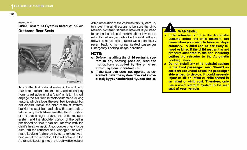
Child Restraint System Installation onRear Seat Center Position
To install a child restraint system in the centerrear seat, extend the shoulder/lap belt entirelyfrom its retractor until a "click" is felt. This willengage the seat belt retractor automatic lockingfeature, which allows the seat belt to retract butnot extend. Install the child restraint system,buckle the seat belt and allow the seat belt totake up any slack. Make sure that the lap portionof the belt is tight around the child restraintsystem and the shoulder portion of the belt ispositioned so that it can not interfere with thechild's head or neck. Also, double check to besure that the retractor has engaged the Auto-matic Locking feature by trying to extend web-bing out of the retractor. If the retractor is in theAutomatic Locking mode, the belt will be locked.
B235G02JM
CAUTION:Do not allow the rear seat belt webbing toget scratched or pinched by the ISOFIX-seat latch and ISOFIX anchor during theinstallation.
!
1FEATURES OF YOUR HYUNDAI
30
!B230G02O-AAT
Child Restraint System Installation onOutboard Rear Seats WARNING:
o If the retractor is not in the AutomaticLocking mode, the child restraint canmove when your vehicle turns or stopssuddenly. A child can be seriously in-jured or killed if the child restraint is notproperly anchored to the car, includingsetting the retractor to the AutomaticLocking mode.
o Do not install any child restraint systemin the front passenger seat. Should anaccident occur and cause the passengerside airbag to deploy, it could severelyinjure or kill an infant or child seated inan infant or child seat. Therefore, onlyuse a child restraint system in the rearseat of your vehicle.To install a child restraint system in the outboard
rear seats, extend the shoulder/lap belt entirelyfrom its retractor until a "click" is felt. This willengage the seat belt retractor automatic lockingfeature, which allows the seat belt to retract butnot extend. Install the child restraint system,buckle the seat belt and allow the seat belt totake up any slack. Make sure that the lap portionof the belt is tight around the child restraintsystem and the shoulder portion of the belt ispositioned so that it can not interfere with thechild's head or neck. Also, double check to besure that the retractor has engaged the Auto-matic Locking feature by trying to extend web-bing out of the retractor. If the retractor is in theAutomatic Locking mode, the belt will be locked.
After installation of the child restraint system, tryto move it in all directions to be sure the childrestraint system is securely installed. If you needto tighten the belt, pull more webbing toward theretractor. When you unbuckle the seat belt andallow it to retract, the retractor will automaticallyrevert back to its normal seated passengerEmergency Locking usage condition.
NOTE:o Before installing the child restraint sys-
tem in any seating position, read theinstructions supplied by the child re-straint system manufacturer.
o If the seat belt does not operate as de-scribed, have the system checked imme-diately by your authorized Hyundai dealer.
B235G03JM-B
1FEATURES OF YOUR HYUNDAI
31
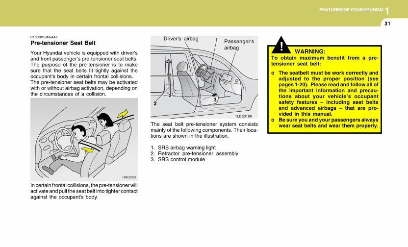
HXG229
In certain frontal collisions, the pre-tensioner willactivate and pull the seat belt into tighter contactagainst the occupant's body.
B180B05JM-AAT
Pre-tensioner Seat Belt
Your Hyundai vehicle is equipped with driver'sand front passenger's pre-tensioner seat belts.The purpose of the pre-tensioner is to makesure that the seat belts fit tightly against theoccupant's body in certain frontal collisions.The pre-tensioner seat belts may be activatedwith or without airbag activation, depending onthe circumstances of a collision.
!
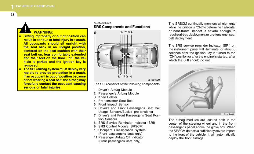
The seat belt pre-tensioner system consistsmainly of the following components. Their loca-tions are shown in the illustration.
1. SRS airbag warning light2. Retractor pre-tensioner assembly3. SRS control module
WARNING:To obtain maximum benefit from a pre-tensioner seat belt:
o The seatbelt must be work correctly andadjusted to the proper position (seepages 1-20). Please read and follow all ofthe important information and precau-tions about your vehicle’s occupantsafety features – including seat beltsand advanced airbags – that are pro-vided in this manual.
o Be sure you and your passengers alwayswear seat belts and wear them properly.
1LDE3100
Driver's airbag 1
2
Passenger'sairbag
3
1FEATURES OF YOUR HYUNDAI
32
! WARNING:o Pre-tensioners are designed to operate
only one time. After activation, pre-tensioner seat belts must be replaced.All seat belts, of any type, should alwaysbe replaced after they have been wornduring a collision.
o The pre-tensioner seat belt assemblymechanisms become hot during activa-tion. Do not touch the pre-tensioner seatbelt assemblies for several minutes afterthey have been activated.
o Do not attempt to inspect or replace thepre-tensioner seat belts yourself. Thismust be done by an authorized Hyundaidealer.
o Do not strike the pre-tensioner seat beltassemblies.
o Do not attempt to service or repair thepre-tensioner seat belt system in anymanner.
o Improper handling of the pre-tensionerseat belt assemblies, and failure to heedthe warnings to not strike, modify, in-spect, replace, service or repair the pre-tensioner seat belt assemblies may leadto improper operation or inadvertentactivation and serious injury.
o Always wear seat belts when driving orriding in a motor vehicle.
CAUTION:o The sensor that activates the SRS airbag
is connected with the pre-tensioner seatbelts. The SRS airbag warning light onthe instrument panel will illuminate forapproximately 6 seconds after the igni-tion key has been turned to the "ON"position, and then it should turn off.
o If the pre-tensioner seat belt is not work-ing properly, this warning light will illu-minate even if there is no malfunction ofthe SRS airbag system. If the SRS airbagwarning light does not illuminate whenthe ignition key is turned to "ON" or if itremains illuminated after approximately6 seconds, or if it illuminates while thevehicle is being driven, please have anauthorized Hyundai dealer inspect thepre-tensioner seat belts and SRS airbagsystem as soon as possible.
AIRBAG
!NOTE:o Both the driver's and front passenger's
pre-tensioner seat belts will be activatedin certain frontal collisions. The pre-tensioner seat belt may be activated withor without airbag activation, dependingon the circumstances of a collision. Thepre-tensioners will not be activated if theseat belts are not being worn at the timeof the collision.
o When the pre-tensioner seat belts areactivated, a loud noise may be heard andfine dust, which may appear to be smoke,may be visible in the passenger com-partment. These are normal operatingconditions and are not hazardous.
o Although it is harmless, the fine dustmay cause skin irritation and should notbe breathed for prolonged periods. Washall exposed skin areas thoroughly afteran accident in which the pre-tensionerseat belts were activated.
1FEATURES OF YOUR HYUNDAI
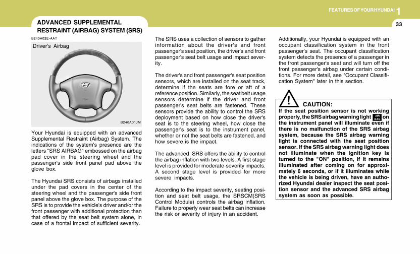
33ADVANCED SUPPLEMENTALRESTRAINT (AIRBAG) SYSTEM (SRS)
B240A02E-AAT
Your Hyundai is equipped with an advancedSupplemental Restraint (Airbag) System. Theindications of the system's presence are theletters "SRS AIRBAG" embossed on the airbagpad cover in the steering wheel and thepassenger's side front panel pad above theglove box.
The Hyundai SRS consists of airbags installedunder the pad covers in the center of thesteering wheel and the passenger's side frontpanel above the glove box. The purpose of theSRS is to provide the vehicle's driver and/or thefront passenger with additional protection thanthat offered by the seat belt system alone, incase of a frontal impact of sufficient severity.
B240A01JM
Driver's AirbagThe SRS uses a collection of sensors to gatherinformation about the driver's and frontpassenger's seat position, the driver's and frontpassenger's seat belt usage and impact sever-ity.
The driver's and front passenger's seat positionsensors, which are installed on the seat track,determine if the seats are fore or aft of areference position. Similarly, the seat belt usagesensors determine if the driver and frontpassenger's seat belts are fastened. Thesesensors provide the ability to control the SRSdeployment based on how close the driver'sseat is to the steering wheel, how close thepassenger's seat is to the instrument panel,whether or not the seat belts are fastened, andhow severe is the impact.
The advanced SRS offers the ability to controlthe airbag inflation with two levels. A first stagelevel is provided for moderate-severity impacts.A second stage level is provided for moresevere impacts.
According to the impact severity, seating posi-tion and seat belt usage, the SRSCM(SRSControl Module) controls the airbag inflation.Failure to properly wear seat belts can increasethe risk or severity of injury in an accident.
CAUTION:If the seat position sensor is not workingproperly, the SRS airbag warning light onthe instrument panel will illuminate even ifthere is no malfunction of the SRS airbagsystem, because the SRS airbag warninglight is connected with the seat positionsensor. If the SRS airbag warning light doesnot illuminate when the ignition key isturned to the "ON" position, if it remainsilluminated after coming on for approxi-mately 6 seconds, or if it illuminates whilethe vehicle is being driven, have an autho-rized Hyundai dealer inspect the seat posi-tion sensor and the advanced SRS airbagsystem as soon as possible.
!AIR
BAG
Additionally, your Hyundai is equipped with anoccupant classification system in the frontpassenger's seat. The occupant classificationsystem detects the presence of a passenger inthe front passenger's seat and will turn off thefront passenger's airbag under certain condi-tions. For more detail, see "Occupant Classifi-cation System" later in this section.
1FEATURES OF YOUR HYUNDAI
34
!! WARNING:Always use seat belts and child restraints –every trip, every time, everyone! Airbagsinflate with considerable force and in theblink of an eye. Seat belts help keep occu-pants in proper position to obtain maxi-mum benefit from the airbag. Even withadvanced airbags, improperly and unbeltedoccupants can be severely injured whenthe airbag inflates. Always follow the pre-cautions about seat belts, airbags and oc-cupant safety contained in this manual.
To reduce the chance of serious or fatalinjuries and receive the maximum safetybenefit from your restraint system:o Never place a child in any child or booster
seat in the front seat (see child restraints1-25).
o ABC – Always Buckle Children in theback seat. It is the safest place forchildren of any age to ride.
o Front and side impact airbags can injureoccupants improperly positioned in thefront seats.
o Move your seat as far back as practicalfrom the front airbags, while still main-taining control of the vehicle.
o Never sit or lean unnecessarily close tothe front or side airbags.
! WARNING:o Modification to the seat structure can
adversely affect the seat position sensorand cause the airbag to deploy at adifferent level than should be provided.
o Do not place any objects underneath thefront seats which could damage the seatposition sensor or interfere with theoccupant classification system.
o Do not place any objects that may causemagnetic fields near the front seats.These may cause a malfunction of theseat position sensor.
NOTE:o Be sure to read information about the
SRS on the labels provided on the back-side of the sun visor.
o Advanced airbags are combined withpre-tensioner seat belts to help provideenhanced occupant protection in fron-tal crashes. Front airbags are not in-tended to deploy in light collisions inwhich protection can be provided by thepre-tensioner seat belt.
o If you are considering modification ofyour vehicle due to a disability, pleasecontact the Hyundai Customer Assis-tance Center at 1-800-633-5151.
o Never lean against the door or centerconsole – always sit in an upright posi-tion.
o Do not allow an adult passenger to ridein the front seat when the “PassengerAirbag OFF” indicator is illuminated,because the airbag will not deploy in theevent of a moderate or severe frontalcrash.
o Never place objects over or near anyairbag module (front or side impactairbags), because these objects can in-jure passengers in a crash.
o Never place covers, blankets or after-market seat warmers on the passengerseat as these may interfere with theoccupant classification system.
o Do not tamper or disconnect SRS wiringor other components. Injuries couldresult from inadvertent deployment orfailure of the airbag to deploy in a crash.
o If the SRS airbag warning light (see pg 1-48) remains illuminated while the vehicleis being driven, have an authorizedHyundai dealer inspect the airbag sys-tem as soon as possible.
o Airbags can only be used once – have anauthorized Hyundai dealer replace theairbag immediately after deployment.
WARNING:
1FEATURES OF YOUR HYUNDAI
35
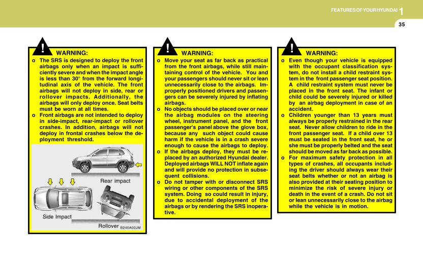
B240A02JM
!
Rear impact
Side Impact
Rollover
WARNING:o The SRS is designed to deploy the front
airbags only when an impact is suffi-ciently severe and when the impact angleis less than 30° from the forward longi-tudinal axis of the vehicle. The frontairbags will not deploy in side, rear orrollover impacts. Additionally, theairbags will only deploy once. Seat beltsmust be worn at all times.
o Front airbags are not intended to deployin side-impact, rear-impact or rollovercrashes. In addition, airbags will notdeploy in frontal crashes below the de-ployment threshold.
! WARNING:o Move your seat as far back as practical
from the front airbags, while still main-taining control of the vehicle. You andyour passengers should never sit or leanunnecessarily close to the airbags. Im-properly positioned drivers and passen-gers can be severely injured by inflatingairbags.
o No objects should be placed over or nearthe airbag modules on the steeringwheel, instrument panel, and the frontpassenger's panel above the glove box,because any such object could causeharm if the vehicle is in a crash severeenough to cause the airbags to deploy.
o If the airbags deploy, they must be re-placed by an authorized Hyundai dealer.Deployed airbags WILL NOT inflate againand will provide no protection in subse-quent collisions.
o Do not tamper with or disconnect SRSwiring or other components of the SRSsystem. Doing so could result in injury,due to accidental deployment of theairbags or by rendering the SRS inopera-tive.
o Even though your vehicle is equippedwith the occupant classification sys-tem, do not install a child restraint sys-tem in the front passenger seat position.A child restraint system must never beplaced in the front seat. The infant orchild could be severely injured or killedby an airbag deployment in case of anaccident.
o Children younger than 13 years mustalways be properly restrained in the rearseat. Never allow children to ride in thefront passenger seat. If a child over 13must be seated in the front seat, he orshe must be properly belted and the seatshould be moved as far back as possible.
o For maximum safety protection in alltypes of crashes, all occupants includ-ing the driver should always wear theirseat belts whether or not an airbag isalso provided at their seating position tominimize the risk of severe injury ordeath in the event of a crash. Do not sitor lean unnecessarily close to the airbagwhile the vehicle is in motion.
! WARNING:
1FEATURES OF YOUR HYUNDAI
36
! WARNING:
The SRSCM continually monitors all elementswhile the ignition is "ON" to determine if a frontalor near-frontal impact is severe enough torequire airbag deployment or pre-tensioner seatbelt deployment.
The SRS service reminder indicator (SRI) onthe instrument panel will illuminate for about 6seconds after the ignition key is turned to the"ON" position or after the engine is started, afterwhich the SRI should go out.
The airbag modules are located both in thecenter of the steering wheel and in the frontpassenger's panel above the glove box. Whenthe SRSCM detects a sufficiently severe impactto the front of the vehicle, it will automaticallydeploy the front airbags.
B240B02JM-AAT
SRS Components and Functions
The SRS consists of the following components:
1. Driver's Airbag Module2. Passenger's Airbag Module3. Knee Bolster4. Pre-tensioner Seat Belt5. Front Impact Sensor6. Driver's and Front Passenger's Seat Belt
Usage Sensors/Buckle pre-tensioner7. Driver's and Front Passenger's Seat Posi-
tion Sensors8. SRS Service Reminder Indicator (SRI)9. SRS Control Module (SRSCM)10.Occupant Classification System
(Front passenger's seat only)11.Passenger Airbag Off Indicator
(Front passenger's seat only)
B240B02JM
11
1
2 710
7 9
5
6
4
348
3
B240B01L
o Sitting improperly or out of position canresult in serious or fatal injury in a crash.All occupants should sit upright withthe seat back in an upright position,centered on the seat cushion with theirseat belt on, legs comfortably extendedand their feet on the floor until the ve-hicle is parked and the ignition key isremoved.
o The SRS airbag system must deploy veryrapidly to provide protection in a crash.If an occupant is out of position becauseof not wearing a seat belt, the airbag mayforcefully contact the occupant causingserious or fatal injuries.
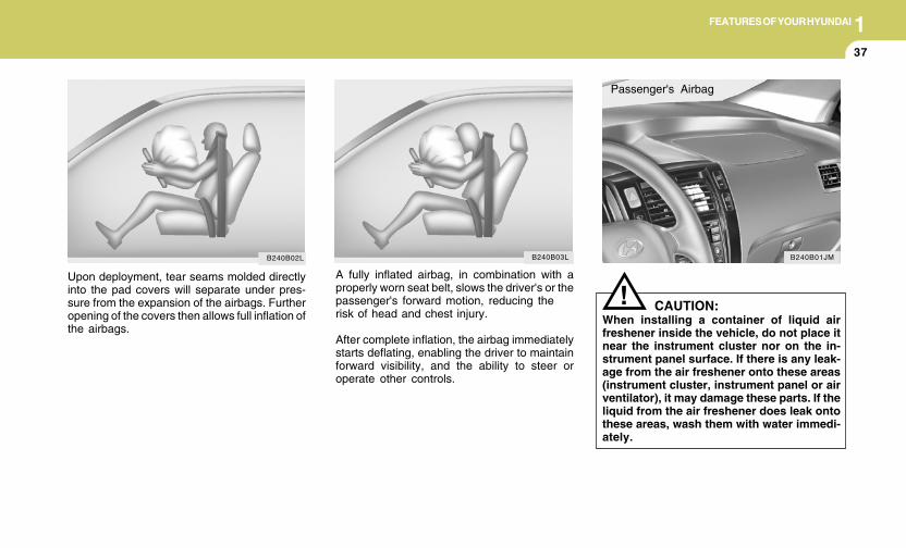
1FEATURES OF YOUR HYUNDAI
37
A fully inflated airbag, in combination with aproperly worn seat belt, slows the driver's or thepassenger's forward motion, reducing therisk of head and chest injury.
After complete inflation, the airbag immediatelystarts deflating, enabling the driver to maintainforward visibility, and the ability to steer oroperate other controls.
CAUTION:When installing a container of liquid airfreshener inside the vehicle, do not place itnear the instrument cluster nor on the in-strument panel surface. If there is any leak-age from the air freshener onto these areas(instrument cluster, instrument panel or airventilator), it may damage these parts. If theliquid from the air freshener does leak ontothese areas, wash them with water immedi-ately.
!
Passenger's Airbag
B240B01JMB240B03L
Upon deployment, tear seams molded directlyinto the pad covers will separate under pres-sure from the expansion of the airbags. Furtheropening of the covers then allows full inflation ofthe airbags.
B240B02L
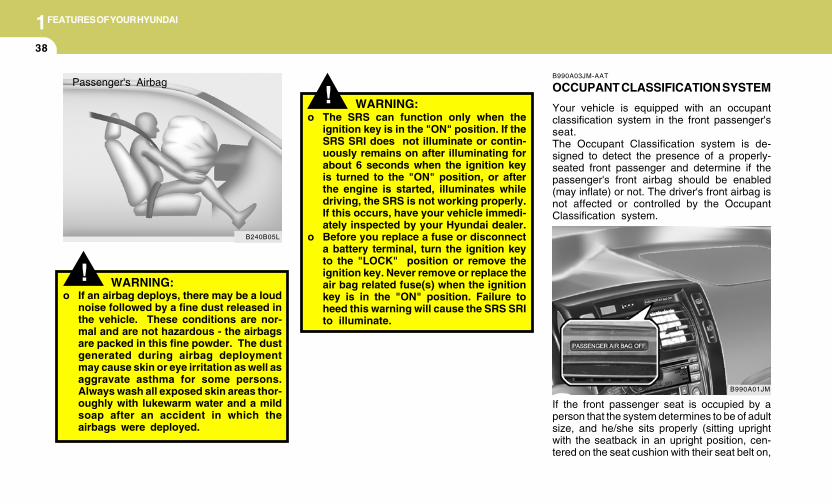
1FEATURES OF YOUR HYUNDAI
38
! WARNING:o If an airbag deploys, there may be a loud
noise followed by a fine dust released inthe vehicle. These conditions are nor-mal and are not hazardous - the airbagsare packed in this fine powder. The dustgenerated during airbag deploymentmay cause skin or eye irritation as well asaggravate asthma for some persons.Always wash all exposed skin areas thor-oughly with lukewarm water and a mildsoap after an accident in which theairbags were deployed.
Passenger's Airbag
B240B05L
!o The SRS can function only when the
ignition key is in the "ON" position. If theSRS SRI does not illuminate or contin-uously remains on after illuminating forabout 6 seconds when the ignition keyis turned to the "ON" position, or afterthe engine is started, illuminates whiledriving, the SRS is not working properly.If this occurs, have your vehicle immedi-ately inspected by your Hyundai dealer.
o Before you replace a fuse or disconnecta battery terminal, turn the ignition keyto the "LOCK" position or remove theignition key. Never remove or replace theair bag related fuse(s) when the ignitionkey is in the "ON" position. Failure toheed this warning will cause the SRS SRIto illuminate.
WARNING:
B990A03JM-AAT
OCCUPANT CLASSIFICATION SYSTEM
Your vehicle is equipped with an occupantclassification system in the front passenger'sseat.The Occupant Classification system is de-signed to detect the presence of a properly-seated front passenger and determine if thepassenger's front airbag should be enabled(may inflate) or not. The driver's front airbag isnot affected or controlled by the OccupantClassification system.
If the front passenger seat is occupied by aperson that the system determines to be of adultsize, and he/she sits properly (sitting uprightwith the seatback in an upright position, cen-tered on the seat cushion with their seat belt on,
B990A01JM
1FEATURES OF YOUR HYUNDAI
39
!
legs comfortably extended and their feet on thefloor), the "PASSENGER AIR BAG OFF" indi-cator will be turned off and the front passenger'sairbag will be able to inflate, if necessary, infrontal crashes.You will find the "PASSENGER AIR BAG OFF"indicator on the center facia panel. This systemdetects the conditions 1~4 in the following tableand activates or deactivates front passengerairbags based on these conditions.
Condition and operation in the front pas-senger occupant classification system
*1)The system judges a person of adult size asan adult. When a smaller adult sits in the frontpassenger seat, the system may detect him/her as a child depending on his/her physiqueand posture.
*2) When a larger child who has outgrown a childrestraint system sits in the passenger seat,the system may detect him/her as an adultdepending on his/her physique and posture.
*3)Never install a child restraint system on thefront passenger seat.
WARNING:Riding in an improper position or placingweight on the front passenger's seat whenit is unoccupied by a passenger adverselyaffects the occupant classification system(OCS).
o NEVER excessively recline the front pas-senger seatback.
B990A03O
o NEVER put a heavy load in the frontpassenger seat.
B990A08O
Frontpassenger
airbag
Activated
Deactivated
Deactivated
Deactivated
Conditiondetected bythe occupantclassification
system1. Adult*1
2. Child*2 orchild restraintsystem*3
3. Unoccupied4. There is a
malfunctionin thesystem
SRSwarning
light
Off
Off
Off
On
"PASSEN-GER
AIR BAGOFF"
indicator lightOff
On
On
On
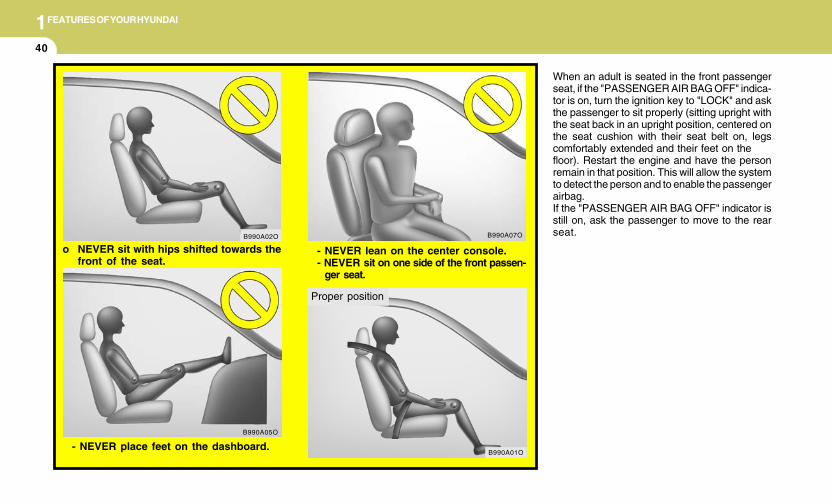
1FEATURES OF YOUR HYUNDAI
40
When an adult is seated in the front passengerseat, if the "PASSENGER AIR BAG OFF" indica-tor is on, turn the ignition key to "LOCK" and askthe passenger to sit properly (sitting upright withthe seat back in an upright position, centered onthe seat cushion with their seat belt on, legscomfortably extended and their feet on thefloor). Restart the engine and have the personremain in that position. This will allow the systemto detect the person and to enable the passengerairbag.If the "PASSENGER AIR BAG OFF" indicator isstill on, ask the passenger to move to the rearseat.
- NEVER place feet on the dashboard.
B990A07O
B990A05O
- NEVER lean on the center console.- NEVER sit on one side of the front passen-
ger seat.
o NEVER sit with hips shifted towards thefront of the seat.
B990A02O
Proper position
B990A01O
1FEATURES OF YOUR HYUNDAI
41
!
!
NOTE:The "PASSENGER AIR BAG OFF" indicatorilluminates for about 4 seconds after theignition key is turned to the "ON" positionor after the engine is started. If the frontpassenger seat is occupied, the occupantclassification sensor will then classify thefront passenger after several more sec-onds.
CAUTION:If the occupant classification system is notworking properly, the SRS airbag warninglight on the instrument panel willilluminate because the passenger's frontairbags are connected with the occupantclassification system. If there is a malfunc-tion of the occupant classification system,the "PASSENGER AIR BAG OFF" indicatorwill illuminate and the passenger's frontairbags will not inflate in frontal impactcrashes even if there is adult occupant inthe front passenger's seat. If the SRS airbagwarning light does not illuminate when theignition key is turned to the "ON" position,remains illuminated after approximately 6seconds when the ignition key is turned tothe "ON" position, or if it illuminates whilethe vehicle is being driven, have an autho-rized Hyundai dealer inspect the occupantclassification system and the SRS airbagsystem as soon as possible.
! WARNING:o Even though your vehicle is equipped
with the occupation classification sys-tem, never install a child restraint systemin the front passenger's seat. A deploy-ing airbag can forcefully strike a childresulting in serious injuries or death.Any child under 13 years of age shouldride in the rear seat. Children too largefor child restraints should use the avail-able lap/shoulder belts. No matter whattype of crash, children of all ages aresafer when restrained in the rear seat.
o If the "PASSENGER AIR BAG OFF" indi-cator is illuminated when the frontpassenger's seat is occupied by an adultand he/she sits properly (sitting uprightwith the seatback in an upright position,centered on the seat cushion with theirseat belt on, legs comfortably extendedand their feet on the floor), have thatperson sit in the rear seat.
o Do not modify or replace the front pas-senger seat. Don't place anything on orattach anything such as a blanket orafter market seat heater to the frontpassenger seat. This can adversely af-fect the occupant classification system.
WARNING:Do not allow an adult passenger to ride inthe front seat when the “PASSENGERAIRBAG OFF” indicator is illuminated, be-cause the airbag will not deploy in the eventof a crash. If the "PASSENGER AIR BAGOFF" indicator remains illuminated afterthe passenger repositions themselves prop-erly and the car is restarted, Hyundai recom-mends that passenger move to the rear seatbecause the passenger's front airbag willnot deploy.Front seat passengers must stay properlyseated to avoid serious injury from a de-ploying airbag. For more information seepage 1-38.
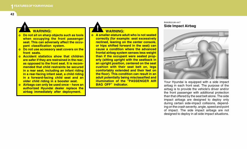
1FEATURES OF YOUR HYUNDAI
42
B990B02JM-AAT
Side Impact Airbag
Your Hyundai is equipped with a side impactairbag in each front seat. The purpose of theairbag is to provide the vehicle's driver and/orthe front passenger with additional protectionthan that offered by the seat belt alone. The sideimpact airbags are designed to deploy onlyduring certain side-impact collisions, depend-ing on the crash severity, angle, speed and pointof impact. The side impact airbags are notdesigned to deploy in all side impact situations.
B990B02JM
! WARNING:o Do not sit on sharp objects such as tools
when occupying the front passengerseat. This can adversely affect the occu-pant classification system.
o Do not use accessory seat covers on thefront seats.
o Accident statistics show that childrenare safer if they are restrained in the rear,as opposed to the front seat. It is recom-mended that child restraints be securedin a rear seat, including an infant ridingin a rear-facing infant seat, a child ridingin a forward-facing child seat and anolder child riding in a booster seat.
o Airbags can only be used once – have anauthorized Hyundai dealer replace theairbag immediately after deployment.
! WARNING:o A smaller-stature adult who is not seated
correctly (for example: seat excessivelyreclined, leaning on the center console,or hips shifted forward in the seat) cancause a condition where the advancedfrontal airbag system senses less weightthan if the occupant were seated prop-erly (sitting upright with the seatback inan upright position, centered on the seatcushion with their seat belt on, legscomfortably extended and their feet onthe floor). This condition can result in anadult potentially being misclassified andillumination of the "PASSENGER AIRBAG OFF" indicator.
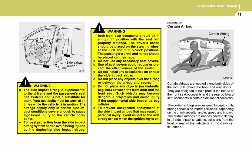
1FEATURES OF YOUR HYUNDAI
43
! WARNING:
WARNING:o The side impact airbag is supplemental
to the driver's and the passenger's seatbelt systems and is not a substitute forthem. Your seat belts must be worn at alltimes while the vehicle is in motion. Theairbags deploy only in certain side im-pact conditions severe enough to causesignificant injury to the vehicle occu-pants.
o For best protection from the side impactairbag system and to avoid being injuredby the deploying side impact airbag,
!
HTB072
Side airbagsensor
both front seat occupants should sit inan upright position with the seat beltproperly fastened. The driver's handsshould be placed on the steering wheelat the 9:00 and 3:00 o'clock positions.The passenger's arms and hands shouldbe placed on their laps.
o Do not use any accessory seat covers.o Use of seat covers could reduce or pre-
vent the effectiveness of the system.o Do not install any accessories on or near
the side impact airbag.o Do not place any objects over the airbag
or between the airbag and yourself.o Do not place any objects (an umbrella,
bag, etc.) between the front door and thefront seat. Such objects may becomedangerous projectiles and cause injuryif the supplemental side impact air baginflates.
o To prevent unexpected deployment ofthe side impact air bag that may result inpersonal injury, avoid impact to the sideairbag sensor when the ignition key is on.
B990C01LZ-GAT
Curtain Airbag
Curtain airbags are located along both sides ofthe roof rails above the front and rear doors.They are designed to help protect the heads ofthe front seat occupants and the rear outboardseat occupants in certain side impact collisions.
The curtain airbags are designed to deploy onlyduring certain side impact collisions, dependingon the crash severity, angle, speed and impact.The curtain airbags are not designed to deployin all side impact situations, collisions from thefront or rear of the vehicle or in most rolloversituations.
HJM2056
Curtain Airbag
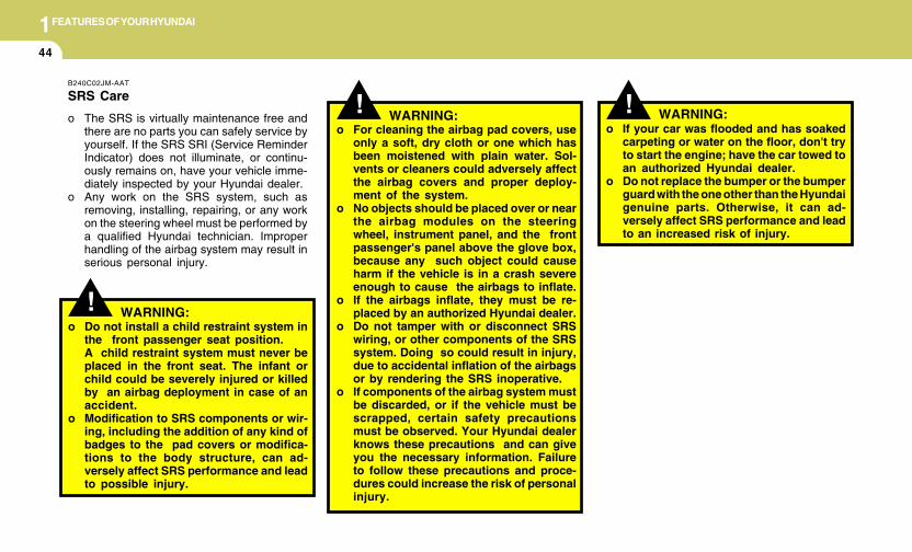
1FEATURES OF YOUR HYUNDAI
44
!o If your car was flooded and has soaked
carpeting or water on the floor, don't tryto start the engine; have the car towed toan authorized Hyundai dealer.
o Do not replace the bumper or the bumperguard with the one other than the Hyundaigenuine parts. Otherwise, it can ad-versely affect SRS performance and leadto an increased risk of injury.
WARNING:o For cleaning the airbag pad covers, use
only a soft, dry cloth or one which hasbeen moistened with plain water. Sol-vents or cleaners could adversely affectthe airbag covers and proper deploy-ment of the system.
o No objects should be placed over or nearthe airbag modules on the steeringwheel, instrument panel, and the frontpassenger's panel above the glove box,because any such object could causeharm if the vehicle is in a crash severeenough to cause the airbags to inflate.
o If the airbags inflate, they must be re-placed by an authorized Hyundai dealer.
o Do not tamper with or disconnect SRSwiring, or other components of the SRSsystem. Doing so could result in injury,due to accidental inflation of the airbagsor by rendering the SRS inoperative.
o If components of the airbag system mustbe discarded, or if the vehicle must bescrapped, certain safety precautionsmust be observed. Your Hyundai dealerknows these precautions and can giveyou the necessary information. Failureto follow these precautions and proce-dures could increase the risk of personalinjury.
! WARNING:
! WARNING:o Do not install a child restraint system in
the front passenger seat position.A child restraint system must never beplaced in the front seat. The infant orchild could be severely injured or killedby an airbag deployment in case of anaccident.
o Modification to SRS components or wir-ing, including the addition of any kind ofbadges to the pad covers or modifica-tions to the body structure, can ad-versely affect SRS performance and leadto possible injury.
B240C02JM-AAT
SRS Care
o The SRS is virtually maintenance free andthere are no parts you can safely service byyourself. If the SRS SRI (Service ReminderIndicator) does not illuminate, or continu-ously remains on, have your vehicle imme-diately inspected by your Hyundai dealer.
o Any work on the SRS system, such asremoving, installing, repairing, or any workon the steering wheel must be performed bya qualified Hyundai technician. Improperhandling of the airbag system may result inserious personal injury.
1FEATURES OF YOUR HYUNDAI
45
B240D02JM-AAT
Additional Safety Precautionso Never let passengers ride in the cargo
area (trunk) or on top of a folded-downback seat. All occupants should sit upright,fully back in their seats with their seat beltson and their feet on the floor.
o Passengers should not move out of orchange seats while the vehicle is mov-ing. A passenger who is not wearing a seatbelt during a crash or emergency stop canbe thrown against the inside of the vehicle,against other occupants, or out of the ve-hicle.
o Each seat belt is designed to restrain oneoccupant. If more than one person uses thesame seat belt, they could be seriouslyinjured or killed in a collision.
o Do not use any accessories on seatbelts. Devices claiming to improve occu-pant comfort or reposition the seat belt canreduce the protection provided by the seatbelt and increase the chance of seriousinjury in a crash.
o Passengers should not place hard orsharp objects between themselves andthe airbags. Carrying hard or sharp objectson your lap or in your mouth can result ininjuries if an airbag inflates.
o Keep occupants away from the airbagcovers. All occupants should sit upright, fullyback in their seats with their seat belts on andtheir feet on the floor. If occupants are tooclose to the airbag covers, they could beinjured if the airbags inflate.
o Do not attach or place objects on or nearthe airbag covers. Any object attached toor placed on the front or side impact airbagcovers could interfere with the proper opera-tion of the airbags.
o Do not modify the front seats. Modifica-tion of the front seats could interfere with theoperation of the supplemental restraint sys-tem sensing components or side impactairbags.
o Do not place items under the front seats.Placing items under the front seats couldinterfere with the operation of the supple-mental restraint system sensing compo-nents and wiring harnesses.
o Never hold an infant or child on your lap.The infant or child could be seriously injuredor killed in the event of a crash. All infants andchildren should be properly restrained inappropriate child safety seats or seat beltsin the rear seat.
! WARNING:o Sitting improperly or out of position can
cause occupants to be shifted too closeto a deploying airbag, strike the interiorstructure or be thrown from the vehicleresulting in serious injury or death.
o Always sit upright with the seatback inan upright position, centered on the seatcushion with your seat belt on, legscomfortably extended and your feet onthe floor.
Adding Equipment to or Modifying YourAirbag-Equipped Vehicle.
If you modify your vehicle by changing yourvehicle's frame, bumper system, front end orside sheet metal or ride height, this may affectthe operation of your vehicle's airbag system.
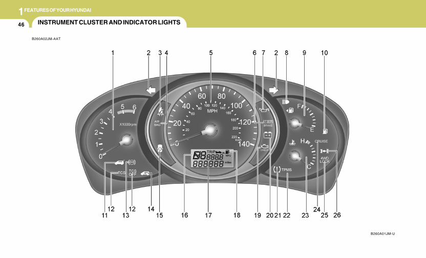
1FEATURES OF YOUR HYUNDAI
46 INSTRUMENT CLUSTER AND INDICATOR LIGHTS
B260A02JM-AAT
B260A01JM-U
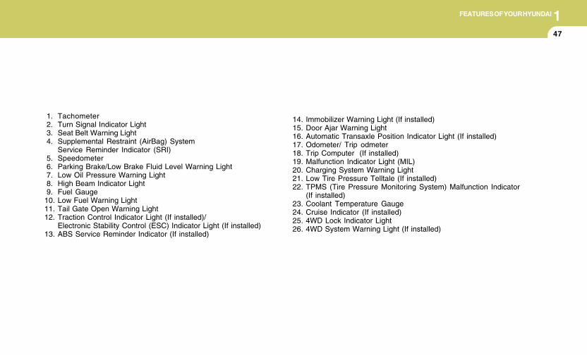
1FEATURES OF YOUR HYUNDAI
47
1. Tachometer 2. Turn Signal Indicator Light 3. Seat Belt Warning Light 4. Supplemental Restraint (AirBag) System
Service Reminder Indicator (SRI) 5. Speedometer 6. Parking Brake/Low Brake Fluid Level Warning Light 7. Low Oil Pressure Warning Light 8. High Beam Indicator Light 9. Fuel Gauge10. Low Fuel Warning Light11. Tail Gate Open Warning Light12. Traction Control Indicator Light (If installed)/
Electronic Stability Control (ESC) Indicator Light (If installed)13. ABS Service Reminder Indicator (If installed)
14. Immobilizer Warning Light (If installed)15. Door Ajar Warning Light16. Automatic Transaxle Position Indicator Light (If installed)17. Odometer/ Trip odmeter18. Trip Computer (If installed)19. Malfunction Indicator Light (MIL)20. Charging System Warning Light21. Low Tire Pressure Telltale (If installed)22. TPMS (Tire Pressure Monitoring System) Malfunction Indicator
(If installed)23. Coolant Temperature Gauge24. Cruise Indicator (If installed)25. 4WD Lock Indicator Light26. 4WD System Warning Light (If installed)
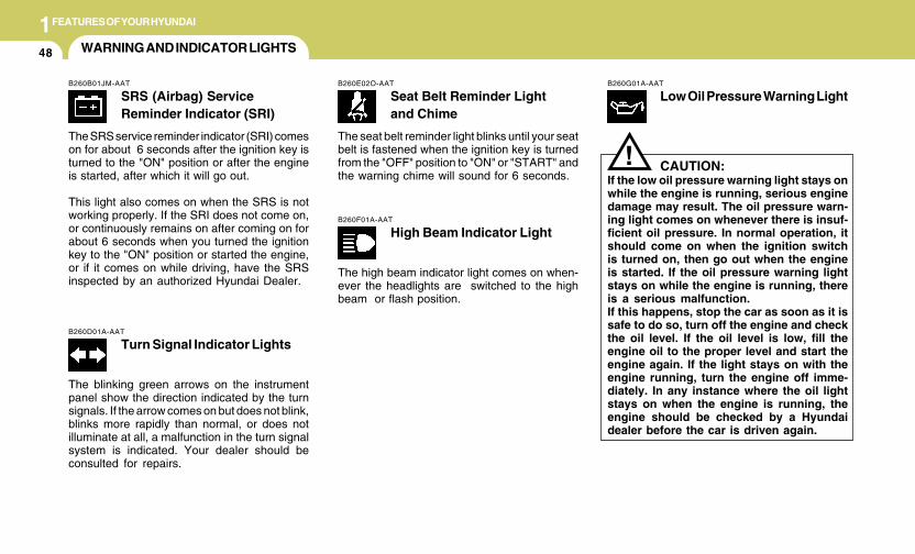
1FEATURES OF YOUR HYUNDAI
48 WARNING AND INDICATOR LIGHTS
B260B01JM-AAT
SRS (Airbag) ServiceReminder Indicator (SRI)
The SRS service reminder indicator (SRI) comeson for about 6 seconds after the ignition key isturned to the "ON" position or after the engineis started, after which it will go out.
This light also comes on when the SRS is notworking properly. If the SRI does not come on,or continuously remains on after coming on forabout 6 seconds when you turned the ignitionkey to the "ON" position or started the engine,or if it comes on while driving, have the SRSinspected by an authorized Hyundai Dealer.
B260D01A-AAT
Turn Signal Indicator Lights
The blinking green arrows on the instrumentpanel show the direction indicated by the turnsignals. If the arrow comes on but does not blink,blinks more rapidly than normal, or does notilluminate at all, a malfunction in the turn signalsystem is indicated. Your dealer should beconsulted for repairs.
B260E02O-AAT
Seat Belt Reminder Lightand Chime
The seat belt reminder light blinks until your seatbelt is fastened when the ignition key is turnedfrom the "OFF" position to "ON" or "START" andthe warning chime will sound for 6 seconds.
B260F01A-AAT
High Beam Indicator Light
The high beam indicator light comes on when-ever the headlights are switched to the highbeam or flash position.
B260G01A-AAT
Low Oil Pressure Warning Light
CAUTION:If the low oil pressure warning light stays onwhile the engine is running, serious enginedamage may result. The oil pressure warn-ing light comes on whenever there is insuf-ficient oil pressure. In normal operation, itshould come on when the ignition switchis turned on, then go out when the engineis started. If the oil pressure warning lightstays on while the engine is running, thereis a serious malfunction.If this happens, stop the car as soon as it issafe to do so, turn off the engine and checkthe oil level. If the oil level is low, fill theengine oil to the proper level and start theengine again. If the light stays on with theengine running, turn the engine off imme-diately. In any instance where the oil lightstays on when the engine is running, theengine should be checked by a Hyundaidealer before the car is driven again.
!
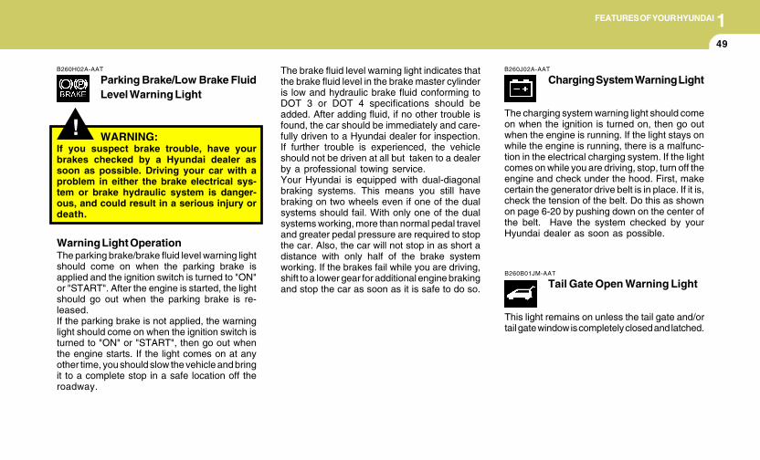
1FEATURES OF YOUR HYUNDAI
49
!
B260H02A-AAT
Parking Brake/Low Brake FluidLevel Warning Light
The brake fluid level warning light indicates thatthe brake fluid level in the brake master cylinderis low and hydraulic brake fluid conforming toDOT 3 or DOT 4 specifications should beadded. After adding fluid, if no other trouble isfound, the car should be immediately and care-fully driven to a Hyundai dealer for inspection.If further trouble is experienced, the vehicleshould not be driven at all but taken to a dealerby a professional towing service.Your Hyundai is equipped with dual-diagonalbraking systems. This means you still havebraking on two wheels even if one of the dualsystems should fail. With only one of the dualsystems working, more than normal pedal traveland greater pedal pressure are required to stopthe car. Also, the car will not stop in as short adistance with only half of the brake systemworking. If the brakes fail while you are driving,shift to a lower gear for additional engine brakingand stop the car as soon as it is safe to do so.
WARNING:If you suspect brake trouble, have yourbrakes checked by a Hyundai dealer assoon as possible. Driving your car with aproblem in either the brake electrical sys-tem or brake hydraulic system is danger-ous, and could result in a serious injury ordeath.
Warning Light OperationThe parking brake/brake fluid level warning lightshould come on when the parking brake isapplied and the ignition switch is turned to "ON"or "START". After the engine is started, the lightshould go out when the parking brake is re-leased.If the parking brake is not applied, the warninglight should come on when the ignition switch isturned to "ON" or "START", then go out whenthe engine starts. If the light comes on at anyother time, you should slow the vehicle and bringit to a complete stop in a safe location off theroadway.
B260J02A-AAT
Charging System Warning Light
The charging system warning light should comeon when the ignition is turned on, then go outwhen the engine is running. If the light stays onwhile the engine is running, there is a malfunc-tion in the electrical charging system. If the lightcomes on while you are driving, stop, turn off theengine and check under the hood. First, makecertain the generator drive belt is in place. If it is,check the tension of the belt. Do this as shownon page 6-20 by pushing down on the center ofthe belt. Have the system checked by yourHyundai dealer as soon as possible.
B260B01JM-AAT
Tail Gate Open Warning Light
This light remains on unless the tail gate and/ortail gate window is completely closed and latched.
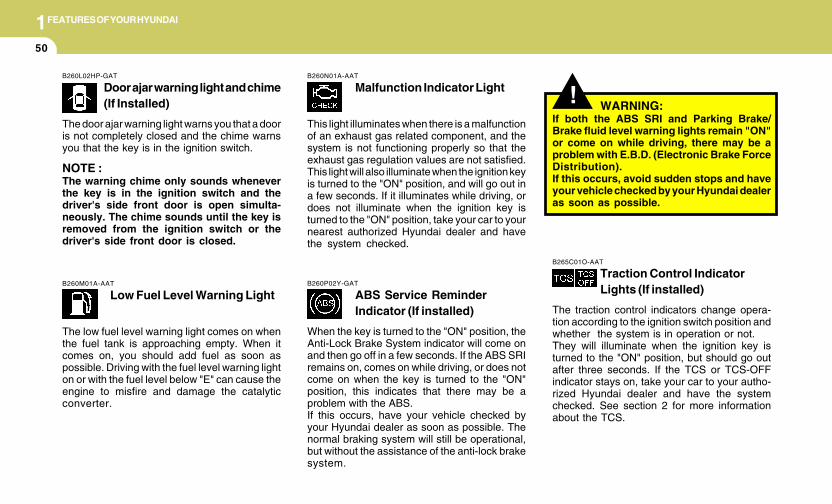
1FEATURES OF YOUR HYUNDAI
50
B260L02HP-GAT
Door ajar warning light and chime(If Installed)
The door ajar warning light warns you that a dooris not completely closed and the chime warnsyou that the key is in the ignition switch.
NOTE :The warning chime only sounds wheneverthe key is in the ignition switch and thedriver's side front door is open simulta-neously. The chime sounds until the key isremoved from the ignition switch or thedriver's side front door is closed.
!
B260M01A-AAT
Low Fuel Level Warning Light
The low fuel level warning light comes on whenthe fuel tank is approaching empty. When itcomes on, you should add fuel as soon aspossible. Driving with the fuel level warning lighton or with the fuel level below "E" can cause theengine to misfire and damage the catalyticconverter.
B260N01A-AAT
Malfunction Indicator Light
This light illuminates when there is a malfunctionof an exhaust gas related component, and thesystem is not functioning properly so that theexhaust gas regulation values are not satisfied.This light will also illuminate when the ignition keyis turned to the "ON" position, and will go out ina few seconds. If it illuminates while driving, ordoes not illuminate when the ignition key isturned to the "ON" position, take your car to yournearest authorized Hyundai dealer and havethe system checked.
B260P02Y-GAT
ABS Service ReminderIndicator (If installed)
When the key is turned to the "ON" position, theAnti-Lock Brake System indicator will come onand then go off in a few seconds. If the ABS SRIremains on, comes on while driving, or does notcome on when the key is turned to the "ON"position, this indicates that there may be aproblem with the ABS.If this occurs, have your vehicle checked byyour Hyundai dealer as soon as possible. Thenormal braking system will still be operational,but without the assistance of the anti-lock brakesystem.
WARNING:If both the ABS SRI and Parking Brake/Brake fluid level warning lights remain "ON"or come on while driving, there may be aproblem with E.B.D. (Electronic Brake ForceDistribution).If this occurs, avoid sudden stops and haveyour vehicle checked by your Hyundai dealeras soon as possible.
B265C01O-AAT
Traction Control IndicatorLights (If installed)
The traction control indicators change opera-tion according to the ignition switch position andwhether the system is in operation or not.They will illuminate when the ignition key isturned to the "ON" position, but should go outafter three seconds. If the TCS or TCS-OFFindicator stays on, take your car to your autho-rized Hyundai dealer and have the systemchecked. See section 2 for more informationabout the TCS.

1FEATURES OF YOUR HYUNDAI
51
B260T01O-GAT
4WD System Warning Light(If installed)
When the key is turned to the "ON" position, the4WD(Four Wheel Drive) system warning lightwill come on and then go off in a few seconds.
CAUTION:If the 4WD system warning light ( ) blinkswhile driving, this indicates that there is amalfunction in the 4WD system. If this oc-curs, have your vehicle checked by an au-thorized Hyundai dealer as soon as pos-sible.
!
B265C02LZ-AAT
Electronic StabilityControl Indicator Lights(If installed)
The electronic stability control indicators changeoperation according to the ignition switch posi-tion and whether the system is in operation ornot.They will illuminate when the ignition key isturned to the "ON" position, but should go outafter three seconds. If the ESC or ESC-OFFindicator stays on, take your car to your autho-rized Hyundai dealer and have the systemchecked. See section 2 for more informationabout the ESC.
B260V01JM-GAT
4WD Lock Indicator Light(If installed)
The 4WD (Four Wheel Drive) lock indicator lightin the instrument cluster is illuminated when theThe 4WD lock switch is pushed.The purpose of this switch is to increase thedrive power when driving on wet pavement,snow-covered roads and/or off-road.The 4WD lock indicator light is turned off bypushing the switch again.
NOTE:Do not use 4WD on normal dry pavementconditions.
B260R01E-GAT
SET Indicator Light(If installed)
The SET indicator light in the instrument clusteris illuminated when the cruise control switch ispushed downward to "SET (COAST)".The SET indicator light does not illuminate whenthe control switch is in the "CANCEL" position.
B260Q01E-GAT
Cruise Indicator Light(If installed)
The cruise indicator light in the instrument clus-ter is illuminated when the cruise control mainswitch on the end of the barrel is pushed.When the cruise control main switch is pusheda second time, the cruise control system will beand the light will turn off.Information on the use of cruise control may befound on page 1-87.
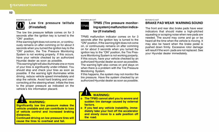
1FEATURES OF YOUR HYUNDAI
52
!!
B270A01O-AAT
BRAKE PAD WEAR WARNING SOUND
The front and rear disc brake pads have wearindicators that should make a high-pitchedsquealing or scraping noise when new pads areneeded. The sound may come and go or beheard all the time when the vehicle is moving. Itmay also be heard when the brake pedal ispushed down firmly. Excessive rotor damagewill result if the worn pads are not replaced. Seeyour Hyundai dealer immediately.
WARNING:Significantly low tire pressure makes thevehicle unstable and can contribute to lossof vehicle control and increased brakingdistances.Continued driving on low pressure tires willcause the tires to overheat and fail.
B260W02JM-GAT
Low tire pressure telltale(If installed)
The low tire pressure telltale comes on for 3seconds after the ignition key is turned to the"ON" position.If the warning light does not come on, or continu-ously remains on after comming on for about 3seconds when you turned the ignition key to the"ON" position, the Tire Pressure MonitoringSystem is not working properly. If this occurs,have your vehicle checked by an authorizedHyundai dealer as soon as possible.This warning light will also illuminate one or moreof your tires is significantly under-inflated. Youshould stop and check your tires as soon aspossible. If the warning light illuminates whiledriving, reduce vehicle speed immediately andstop the vehicle. Avoid hard braking and over-correcting at the steering wheel. Inflate the tiresto the proper pressure as indicated on thevehicle’s tire information placard.
B265W02JM-GAT
TPMS (Tire pressure monitor-ing system) malfunction indica-tor (If installed)
TPMS malfunction indicator comes on for 3seconds after the ignition key is turned to the"ON" position. If the warning light does not comeon, or continuously remains on after commingon for about 3 seconds when you turned theignition key to the "ON" position, the Tire Pres-sure Monitoring System is not working porperly.If this occurs, have your vehicle checked by anauthorized Hyundai dealer as soon as possible.The warning light also comes on and stays onwhen there is a problem with the Tire PressureMonitoring System.If this happens, the system may not monitor thetire pressure. Have the system checked by anauthorized Hyundai dealer as soon as possible.
WARNING:o The TPMS cannot alert you to severe and
sudden tire damage caused by externalfactors.
o If you feel any vehicle instability, imme-diately take your foot off the acceleratorand slowly move to a safe position offthe road.
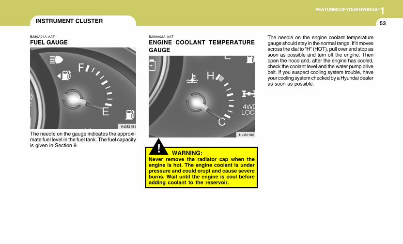
1FEATURES OF YOUR HYUNDAI
53
!
B290A02A-AAT
ENGINE COOLANT TEMPERATUREGAUGE
WARNING:Never remove the radiator cap when theengine is hot. The engine coolant is underpressure and could erupt and cause severeburns. Wait until the engine is cool beforeadding coolant to the reservoir.
B280A01A-AAT
FUEL GAUGE
The needle on the gauge indicates the approxi-mate fuel level in the fuel tank. The fuel capacityis given in Section 9.
INSTRUMENT CLUSTER
HJM2182
HJM2181
The needle on the engine coolant temperaturegauge should stay in the normal range. If it movesacross the dial to "H" (HOT), pull over and stop assoon as possible and turn off the engine. Thenopen the hood and, after the engine has cooled,check the coolant level and the water pump drivebelt. If you suspect cooling system trouble, haveyour cooling system checked by a Hyundai dealeras soon as possible.
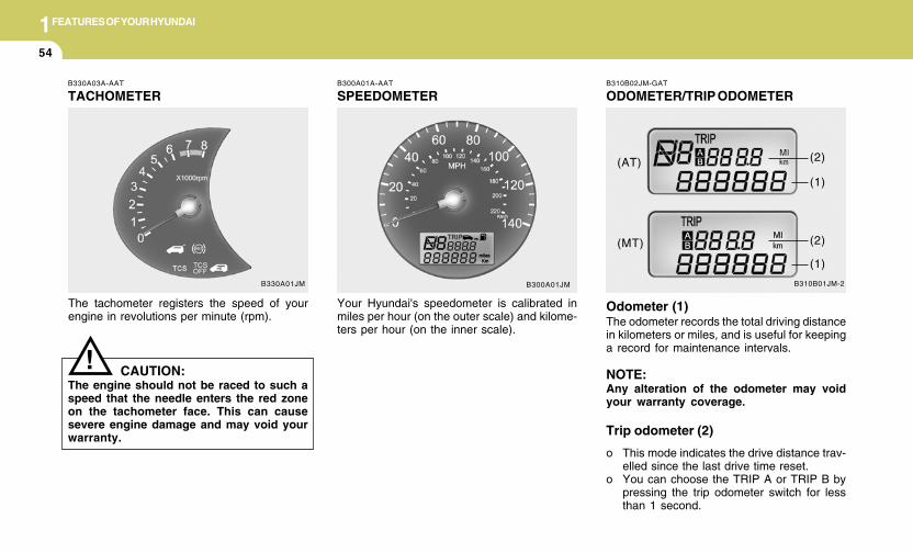
1FEATURES OF YOUR HYUNDAI
54
B330A03A-AAT
TACHOMETER
The tachometer registers the speed of yourengine in revolutions per minute (rpm).
CAUTION:The engine should not be raced to such aspeed that the needle enters the red zoneon the tachometer face. This can causesevere engine damage and may void yourwarranty.
!
B300A01A-AAT
SPEEDOMETER
Your Hyundai's speedometer is calibrated inmiles per hour (on the outer scale) and kilome-ters per hour (on the inner scale).
B300A01JMB330A01JM
B310B02JM-GAT
ODOMETER/TRIP ODOMETER
B310B01JM-2
Odometer (1)The odometer records the total driving distancein kilometers or miles, and is useful for keepinga record for maintenance intervals.
NOTE:Any alteration of the odometer may voidyour warranty coverage.
Trip odometer (2)
o This mode indicates the drive distance trav-elled since the last drive time reset.
o You can choose the TRIP A or TRIP B bypressing the trip odometer switch for lessthan 1 second.
(AT)
(MT)
(1)
(2)
(1)
(2)
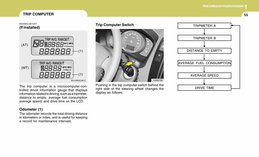
1FEATURES OF YOUR HYUNDAI
55
B310B02JM-C
(AT)
(MT)
(1)
(1)
TRIP COMPUTER
B400B02JM-GAT
(If installed)
The trip computer is a microcomputer-con-trolled driver information gauge that displaysinformation related to driving, such as a tripmeter,distance to empty, average fuel consumptionaverage speed, and drive time on the LCD.
Odometer (1)The odometer records the total driving distancein kilometers or miles, and is useful for keepinga record for maintenance intervals.
Trip Computer Switch
HJM2185
Pushing in the trip computer switch behind theright side of the steering wheel changes thedisplay as follows;
TRIPMETER A
TRIPMETER B
DISTANCE TO EMPTY
AVERAGE FUEL CONSUMPTION
AVERAGE SPEED
DRIVE TIME
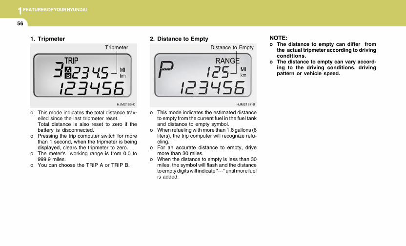
1FEATURES OF YOUR HYUNDAI
56
HJM2186-C
o This mode indicates the total distance trav-elled since the last tripmeter reset.Total distance is also reset to zero if thebattery is disconnected.
o Pressing the trip computer switch for morethan 1 second, when the tripmeter is beingdisplayed, clears the tripmeter to zero.
o The meter's working range is from 0.0 to999.9 miles.
o You can choose the TRIP A or TRIP B.
1. TripmeterTripmeter
o This mode indicates the estimated distanceto empty from the current fuel in the fuel tankand distance to empty symbol.
o When refueling with more than 1.6 gallons (6liters), the trip computer will recognize refu-eling.
o For an accurate distance to empty, drivemore than 30 miles.
o When the distance to empty is less than 30miles, the symbol will flash and the distanceto empty digits will indicate "---" until more fuelis added.
2. Distance to Empty
HJM2187-B
Distance to Empty
NOTE:o The distance to empty can differ from
the actual tripmeter according to drivingconditions.
o The distance to empty can vary accord-ing to the driving conditions, drivingpattern or vehicle speed.
1FEATURES OF YOUR HYUNDAI
57
3. Average Fuel Consumption
o This mode calculates the average fuel con-sumption from the total fuel used and thedistance since the last average consump-tion reset.
o The total fuel used is calculated from the fuelconsumption input.
o For an accurate calculation, drive more than30 miles.
o The meter's working range is from 0.1 to199.9 MPG.
o This mode indicates the average speedsince the last tripmeter reset.
o Even if the vehicle is not in motion, theaverage speed keeps going while the engineis running.
o The meter’s working range is from 0 to 999MPH.
o Press the trip computer switch for more than1 seconds, when the average speed is beingdisplayed, clears the average speed to "---".
4. Average Speed
HJM2187-A
Average Speed
MPH
5. Drive Time
o This mode indicates the drive time since thelast tripmeter reset.
o Even if the vehicle is not in motion, the drivetime keeps going while the engine is running.
o The meter’s working range is from 0:00 to99:59.
o Press the trip computer switch for more than1 second, when the drive time is beingdisplayed, clears the drive time to zero.
HJM2187-C
Drive Time
B400B02JM-C
Average Fuel Consumption
1FEATURES OF YOUR HYUNDAI
58
B340C04A-AAT
Headlight Switch
To operate the headlights, turn the barrel on theend of the multi-function switch. The first posi-tion turns on the parking lights, sidelights, taillights and instrument panel lights. The secondposition turns on the headlights.
NOTE:The ignition must be in the "ON" positionto turn on the headlights.
HJM2084
MULTI-FUNCTION LIGHT SWITCH
B340A01A-AAT
COMBINATION TURN SIGNAL,HEADLIGHT AND HIGH-BEAMSWITCHTurn Signal Operation
Pulling down on the lever causes the turnsignals on the left side of the car to blink. Pushingupwards on the lever causes the turn signals onthe right side of the car to blink. As the turn iscompleted, the lever will automatically return tothe center position and turn off the turn signalsat the same time. If either turn signal indicatorlight blinks more rapidly than usual, goes on butdoes not blink, or does not go on at all, there isa malfunction in the system. Check for a burned-out fuse or bulb or see your Hyundai dealer.
B340B01A-AAT
Lane Change Signal
To indicate a lane change, move the lever up ordown to a point where it begins flashing.The lever will automatically return to the centerposition when released.
HJM2089
1FEATURES OF YOUR HYUNDAI
59
B340D01A-AAT
High-beam Switch
To turn on the headlight high beams, push thelever forward (away from you). The High BeamIndicator Light will come on at the same time. Forlow beams, pull the lever back toward you.
B340E01A-AAT
Headlight Flasher
To flash the headlights, pull the switch levertoward you, then release it. The headlights canbe flashed even though the headlight switch isin the "OFF" position.
HJM2088
Parking Light Auto Cut
o The purpose of this feature is to prevent thebattery from being discharged.The system automatically turns off the head-lights and parking lights when the driverremoves the ignition key and opens thedriver- side door.
o With this feature, the parking light will beturned off automatically if the driver parks onthe side of road at night.If necessary, to keep the lights on when theignition key is removed, perform the follow-ing :1) Open the driver-side door.2) Turn the parking lights OFF and ON again
using the light switch on the steeringcolumn.
B340G01L-GAT
Auto Light (If installed)
To operate the automatic light feature, turn thebarrel on the end of the multi-function switch. Ifyou set the multi-function switch to "AUTO", thetail lights and headlights will be turned automati-cally on or off according to external illumination.
HJM2085
1FEATURES OF YOUR HYUNDAI
60 WINDSHIELD WIPER AND WASHER SWITCH
Rear window wiper/washer(If installed)
A : Wiper speed control· MIST – Single wipe· OFF – Off· INT – Intermittent wipe· LO – Low wiper speed· HI – High wiper speed
B : Intermittent wipe time adjustment
C : Wash with brief wipes
D : Rear wiper/washer control· – Spraying washer fluid· OFF – Off· INT – Intermittent wipe (If installed)· ON – Continuous wipe· – Wash with brief wipe
Windshield wiper/washer
Type A
Type B
Type A
Type B
B350A06JM-U/B350A07JM-U/B350A08JM-U/B350A09JM-U
B350A01JM-AAT
1FEATURES OF YOUR HYUNDAI
61
B350B01JM-GAT
Windshield Washer Operation
B350B03JM-U
B350A02A-AAT
Windshield wipers
B350A10JM-U
MIST : For a single wiping cycle, push the leverupward and release it with the lever in theOFF position. The wipers will operatecontinuously if the lever is pushed up-ward and held.
OFF : Wiper is not in operationINT : Wiper operates intermittently at the same
wiping intervals. Use this mode in a lightrain or mist. To vary the speed setting,turn the speed control knob.
LO : Normal wiper speedHI : Fast wiper speed
NOTE:To prevent damage to the wiper system, donot attempt to wipe away heavy accumula-tions of snow or ice. Accumulated snowand ice should be removed manually. Ifthere is only a light layer of snow or ice,operate the heater in the defrost mode tomelt the snow or ice before using the wiperor activate the windshield wiper bladedeicer.(If installed)
Type A
B350A11JM-U
Type B
Operates as follows when the ignition switch isturned ON.
To use the windshield washer, pull the wiper/washer lever toward the steering wheel.
Type A
B350B05JM-U
Type B
Fast
Fast
Slow
Slow
1FEATURES OF YOUR HYUNDAI
62
If a single wipe is desired in mist, push thewindshield wiper and washer control lever up-wards.
B350B04JM-U
Mist Wiper Operation
Type A
B350B06JM-U
Type B
When the washer lever is operated, the wipersautomatically three passes across the wind-shield. The washer continues to operate untilthe lever is released.
NOTE:o Do not operate the washer more than 15
seconds at a time or when the fluidreservoir is empty.
o In icy or freezing weather, be sure thewiper blades are not frozen to the glassprior to operating the wipers.
o In areas where water freezes in winter,use windshield washer antifreeze.
B350C01O-GAT
Adjustable Intermittent Wiper Operation
B350C02JM-U
Type A
B350C03JM-U
Type B
1FEATURES OF YOUR HYUNDAI
63
To use the intermittent wiper feature, place thewiper switch in the "INT" position. With theswitch in this position, the interval betweenwipes can be varied from approximately 1 to 18seconds by turning the interval adjuster barrel.
B390A01JM-AAT
Rear Window Wiper And Washer(If installed)
B390A02JM-U
: The rear window wiper starts to operatethree times after the washer fluid spraysonto the rear window.
OFF : Wiper is not in operationINT : The interval between wipes operates
every 5 seconds intermittently.(If installed)
ON : The rear window wiper starts to operatecontinuously.
: The washer fluid will be sprayed onto therear window and the wiper operateswhile the rear window wiper barrel isplaced in this position.
Do not operate the washer continuously formore than 15 seconds or when the fluid reser-voir is empty; this could damage the system. Donot operate the wiper when the window is dry;this can result in scratching as well as prema-ture wiper blade wear.
Type A
B390A03JM-U
Type B
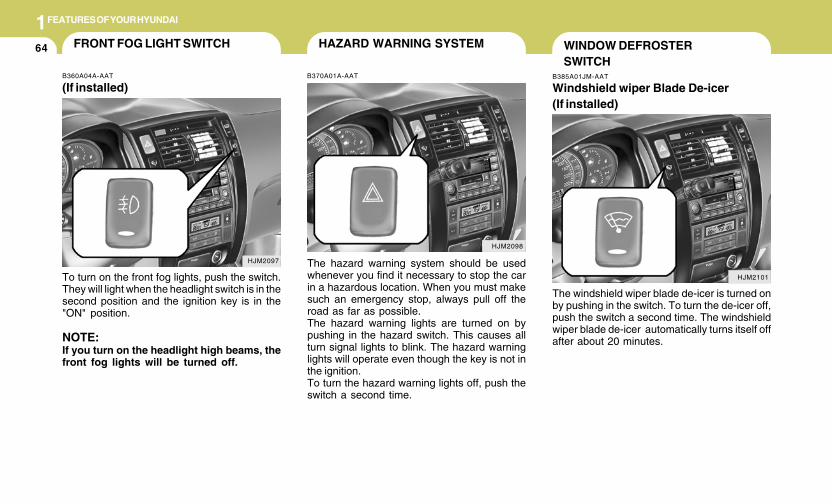
1FEATURES OF YOUR HYUNDAI
64
B385A01JM-AAT
Windshield wiper Blade De-icer(If installed)
The windshield wiper blade de-icer is turned onby pushing in the switch. To turn the de-icer off,push the switch a second time. The windshieldwiper blade de-icer automatically turns itself offafter about 20 minutes.
HJM2101
WINDOW DEFROSTERSWITCH
HJM2098
HAZARD WARNING SYSTEM
B370A01A-AAT
The hazard warning system should be usedwhenever you find it necessary to stop the carin a hazardous location. When you must makesuch an emergency stop, always pull off theroad as far as possible.The hazard warning lights are turned on bypushing in the hazard switch. This causes allturn signal lights to blink. The hazard warninglights will operate even though the key is not inthe ignition.To turn the hazard warning lights off, push theswitch a second time.
HJM2097
FRONT FOG LIGHT SWITCH
B360A04A-AAT
(If installed)
To turn on the front fog lights, push the switch.They will light when the headlight switch is in thesecond position and the ignition key is in the"ON" position.
NOTE:If you turn on the headlight high beams, thefront fog lights will be turned off.
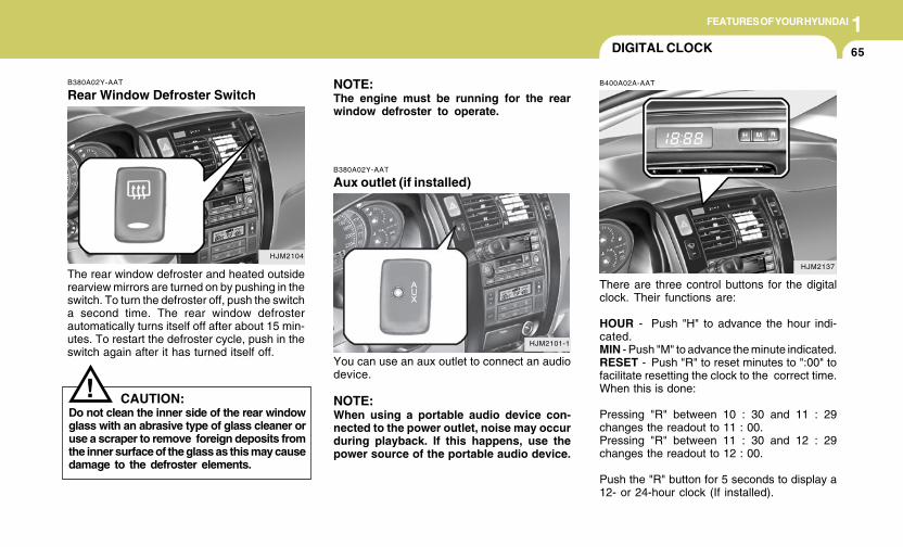
1FEATURES OF YOUR HYUNDAI
65
B380A02Y-AAT
Rear Window Defroster Switch
The rear window defroster and heated outsiderearview mirrors are turned on by pushing in theswitch. To turn the defroster off, push the switcha second time. The rear window defrosterautomatically turns itself off after about 15 min-utes. To restart the defroster cycle, push in theswitch again after it has turned itself off.
HJM2104
NOTE:The engine must be running for the rearwindow defroster to operate.
CAUTION:Do not clean the inner side of the rear windowglass with an abrasive type of glass cleaner oruse a scraper to remove foreign deposits fromthe inner surface of the glass as this may causedamage to the defroster elements.
!
DIGITAL CLOCK
B400A02A-AAT
There are three control buttons for the digitalclock. Their functions are:
HOUR - Push "H" to advance the hour indi-cated.MIN - Push "M" to advance the minute indicated.RESET - Push "R" to reset minutes to ":00" tofacilitate resetting the clock to the correct time.When this is done:
Pressing "R" between 10 : 30 and 11 : 29changes the readout to 11 : 00.Pressing "R" between 11 : 30 and 12 : 29changes the readout to 12 : 00.
Push the "R" button for 5 seconds to display a12- or 24-hour clock (If installed).
HJM2137
B380A02Y-AAT
Aux outlet (if installed)
You can use an aux outlet to connect an audiodevice.
NOTE:When using a portable audio device con-nected to the power outlet, noise may occurduring playback. If this happens, use thepower source of the portable audio device.
HJM2101-1
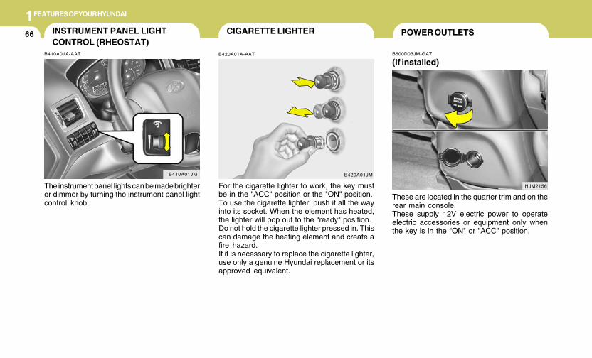
1FEATURES OF YOUR HYUNDAI
66 CIGARETTE LIGHTER
B420A01A-AAT
For the cigarette lighter to work, the key mustbe in the "ACC" position or the "ON" position.To use the cigarette lighter, push it all the wayinto its socket. When the element has heated,the lighter will pop out to the "ready" position.Do not hold the cigarette lighter pressed in. Thiscan damage the heating element and create afire hazard.If it is necessary to replace the cigarette lighter,use only a genuine Hyundai replacement or itsapproved equivalent.
B420A01JM
POWER OUTLETS
B500D03JM-GAT
(If installed)
These are located in the quarter trim and on therear main console.These supply 12V electric power to operateelectric accessories or equipment only whenthe key is in the "ON" or "ACC" position.
HJM2156
INSTRUMENT PANEL LIGHTCONTROL (RHEOSTAT)
B410A01A-AAT
The instrument panel lights can be made brighteror dimmer by turning the instrument panel lightcontrol knob.
B410A01JM
1FEATURES OF YOUR HYUNDAI
67
! CAUTION:o Use when the engine is running and
remove a plug from the power outletafter using the electric appliance. Usingwhen the engine stops or remaining theelectric appliance with plugged in formany hours may cause the battery to bedischarged.
o Do not use the power outlet to connectelectric accessories or equipment otherthan those designed to operate on 12volts.
o Some electronic devices can cause elec-tronic interference when plugged intothe power outlet. These devices maycause excessive audio noise and mal-functions in other electronic systems ordevices used in your vehicle.
ASHTRAY / COIN TRAY
B430A01JM-AAT
The front ashtray/coin tray may be opened bypushing and releasing the ashtray lid. To re-move the ashtray to empty or clean it, lift theashtray upward and pull it out. The ashtray cointray light will only illuminate when the externallights are on.
B430A01JM
HJM2159
DRINK HOLDER
!
B450A01JM-AAT
Front Drink Holder
The front drink holder is located on the mainconsole .
WARNING:o Use caution when using the drink hold-
ers. A spilled beverage that is very hotcan injure you or your passengers. Spilledliquids can damage interior trim andelectrical components.
o Do not place objects other than cups orcans in the drink holder. The objects canbe thrown out in the event of a suddenstop or an accident, possibly injuringthe passengers in the vehicle.
1FEATURES OF YOUR HYUNDAI
68 SUNROOF
!
B460A01Y-AAT
(If installed)Sun Shade
Your HYUNDAI is equipped with a sliding sun-shade which you can manually adjust to let inlight with the sunroof closed, or to block sunlight.
WARNING:Never adjust the sunshade while driving.
HJM2029
B460B02JM-GAT
Opening the Sunroof
If your vehicle is equipped with this feature, youcan slide or tilt your sunroof with the sunroofcontrol buttons located on the overhead con-sole.The sunroof can only be opened, closed, ortilted when the ignition switch is in the "ON"position.
Sliding the sunroofAuto slide open
To use the autoslide feature, momentarily (morethan 1 second) press the SLIDE OPEN buttonon the overhead console. The sunroof will slideall the way open. To stop the sunroof sliding atany point, press any sunroof control button.
HJM2025
! WARNING:Do not place objects other than cups orcans in the drink holder. This objects can bethrown out in the event of a sudden stop oran accident, possibly injuring the passen-gers in the vehicle.
B450B01JM-AAT
REAR DRINK HOLDER(If installed)
The rear drink holders is located in the rear seatarm rest. The rear drink holder can be used bypulling the rear seat armrest.
HJM2160
1FEATURES OF YOUR HYUNDAI
69
!
Manual slide open
Press the SLIDE OPEN button on the overheadconsole for less than 0.5 second.
Auto slide close
To close the sunroof, press the CLOSE buttonon the overhead console for more than 1 sec-ond.The sunroof will slide all the way close. To stopat the desired point, press any sunroof controlbutton.
Auto Reverse
If an object or part of the body is detected whilethe sunroof is closing automatically, it will re-verse direction, and then stop.Auto reverse function does not work if a tinyobstacle is blocked between the sliding glassand the sunroof sash. You should always checkthat all passengers and objects are away fromthe sunroof before closing it.
! WARNING:o Do not close a sunroof if anyone's hands,
arms or body are between the slidingglass and the sunroof sash, as this couldresult in injury.
o Do not place your head or arms out of thesunroof opening at any time.
o While the vehicle is moving, always keepthe head, hands and other parts of thebody of all occupants away from the roofopening. Otherwise, you could be seri-ously injured if the vehicle stops sud-denly or if the vehicle is involved in anaccident.
! CAUTION:o Do not open the sunroof in severely cold
temperature or when it is covered withice or snow.
o Periodically remove any dirt that mayhave accumulated on the guide rails.
o Do not press any sunroof control buttonlonger than necessary.Damage to the motor or system compo-nents could occur.
WARNING:Be careful that someone’s head, handsand body are not trapped by a closingsunroof.
Manual slide close
To close the sunroof, press the CLOSE buttonon the overhead console and hold it until thesunroof is closed.
B460C01JM-AAT
Tilting the Sunroof
Auto tilt open
To use the autotilt feature, momentarily (morethan 1 second) press the TILT UP button on theoverhead console. The sunroof will tilt all theway open. To stop the sunroof tilting at any point,press any sunroof control button.
Manual tilt open
Press the TILT UP button on the overheadconsole for less than 0.5 second.
HJM2024
1FEATURES OF YOUR HYUNDAI
70
B460D03B-GAT
Manual Operation of Sunroof
If the sunroof does not electrically operate: 2. Remove the mounting screws of the frontoverhead console with a (+) driver.
HJM2026
HJM2027
1. Remove the rectangular plastic interior lightlenses in the front overhead console byusing a flat blade screwdriver.
HJM2028
3. Insert the hexagonal head wrench providedwith the vehicle into the socket. This wrenchcan be found in the vehicle's glove box.
Close
To close the sunroof, press the CLOSE buttonon the overhead console and hold it until thesunroof is closed.
NOTE:After washing the car or after there is rain,be sure to wipe off any water that is on thesunroof before operating it.
B460E01JM-GAT
Resetting the sunroof
Whenever the vehicle battery is disconnectedor discharged, or you use the emergency handleto operate the sunroof, you have to reset yoursunroof system as follows:
1. Turn the ignition key to the ON position.2. According to the position of the sunroof, do
as follows.1) In case that the sunroof has closed com-
pletely or been tilted : Press the TILT UPbutton for 1 second.
2) In case that the sunroof has slide-opened:Press and hold the CLOSE button formore than 5 seconds until the sunroofhas closed completely. And then pressthe TILT UP button for 1 second
3. Then, release it.4. Press and hold the TILT UP button once
again until the sunroof has returned to theoriginal position of TILT UP after it is raiseda little higher than the maximum TILT UPposition. When this is complete, the sunroofsystem is reset.
CAUTION:If the sunroof is not reset, it may not operateproperly.
!
4. Turn the wrench clockwise to open or coun-terclockwise to close the sunroof.
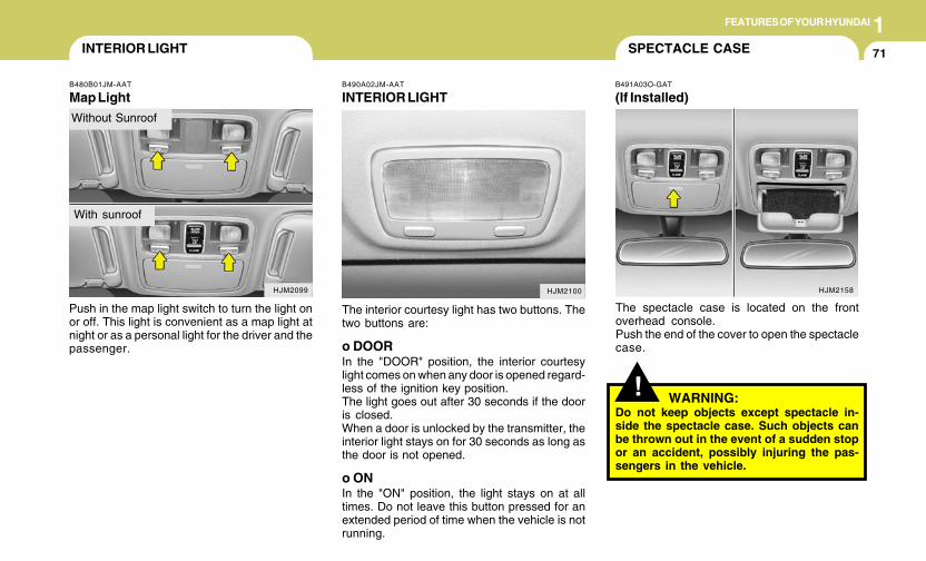
1FEATURES OF YOUR HYUNDAI
71INTERIOR LIGHT
B480B01JM-AAT
Map Light
Push in the map light switch to turn the light onor off. This light is convenient as a map light atnight or as a personal light for the driver and thepassenger.
HJM2099
Without Sunroof
With sunroof
B490A02JM-AAT
INTERIOR LIGHT
The interior courtesy light has two buttons. Thetwo buttons are:
o DOORIn the "DOOR" position, the interior courtesylight comes on when any door is opened regard-less of the ignition key position.The light goes out after 30 seconds if the dooris closed.When a door is unlocked by the transmitter, theinterior light stays on for 30 seconds as long asthe door is not opened.
o ONIn the "ON" position, the light stays on at alltimes. Do not leave this button pressed for anextended period of time when the vehicle is notrunning.
HJM2100 HJM2158
SPECTACLE CASE
!
B491A03O-GAT
(If Installed)
The spectacle case is located on the frontoverhead console.Push the end of the cover to open the spectaclecase.
WARNING:Do not keep objects except spectacle in-side the spectacle case. Such objects canbe thrown out in the event of a sudden stopor an accident, possibly injuring the pas-sengers in the vehicle.
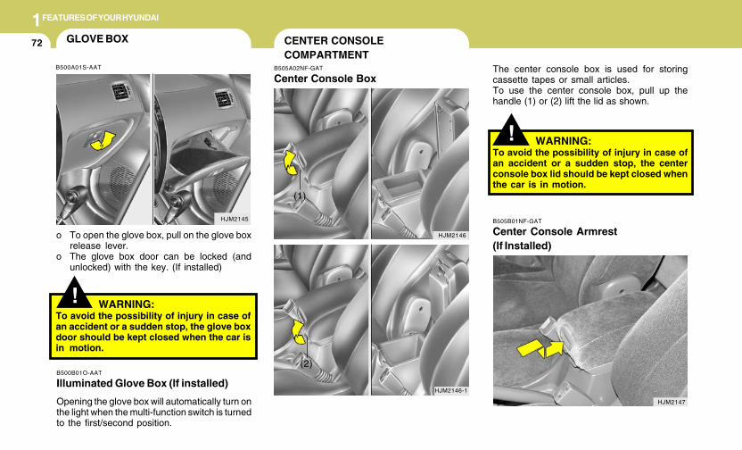
1FEATURES OF YOUR HYUNDAI
72
HJM2145
GLOVE BOX
!
o To open the glove box, pull on the glove boxrelease lever.
o The glove box door can be locked (andunlocked) with the key. (If installed)
WARNING:To avoid the possibility of injury in case ofan accident or a sudden stop, the glove boxdoor should be kept closed when the car isin motion.
B500B01O-AAT
Illuminated Glove Box (If installed)
Opening the glove box will automatically turn onthe light when the multi-function switch is turnedto the first/second position.
B500A01S-AAT
! WARNING:To avoid the possibility of injury in case ofan accident or a sudden stop, the centerconsole box lid should be kept closed whenthe car is in motion.
The center console box is used for storingcassette tapes or small articles.To use the center console box, pull up thehandle (1) or (2) lift the lid as shown.
CENTER CONSOLECOMPARTMENT
B505A02NF-GAT
Center Console Box
HJM2146
HJM2146-1
HJM2147
B505B01NF-GAT
Center Console Armrest(If Installed)
(1)
(2)
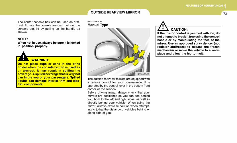
1FEATURES OF YOUR HYUNDAI
73
B510A01A-AAT
Manual Type
The outside rearview mirrors are equipped witha remote control for your convenience. It isoperated by the control lever in the bottom frontcorner of the window.Before driving away, always check that yourmirrors are positioned so you can see behindyou, both to the left and right sides, as well asdirectly behind your vehicle. When using themirror, always exercise caution when attempt-ing to judge the distance of vehicles behind oralong side of you.
OUTSIDE REARVIEW MIRROR
CAUTION:If the mirror control is jammed with ice, donot attempt to break it free using the controlhandle or by manipulating the face of themirror. Use an approved spray de-icer (notradiator antifreeze) to release the frozenmechanism or move the vehicle to a warmplace and allow the ice to melt.
!
B510A01JM
The center console box can be used as arm-rest. To use the console armrest, pull out theconsole box lid by pulling up the handle asshown.
NOTE:When not in use, always be sure it is lockedin position properly.
! WARNING:Do not place cups or cans in the drinkholder when the console box lid is used asan armrest. It may result in spilling thebeverage. A spilled beverage that is very hotcan injure you or your passengers. Spilledliquids can damage interior trim and elec-tric components.
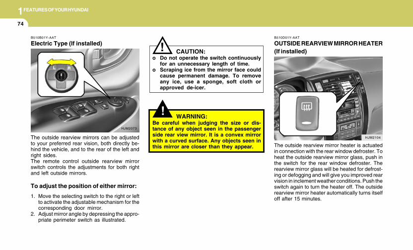
1FEATURES OF YOUR HYUNDAI
74
HJM2104
!WARNING:
Be careful when judging the size or dis-tance of any object seen in the passengerside rear view mirror. It is a convex mirrorwith a curved surface. Any objects seen inthis mirror are closer than they appear.
CAUTION:o Do not operate the switch continuously
for an unnecessary length of time.o Scraping ice from the mirror face could
cause permanent damage. To removeany ice, use a sponge, soft cloth orapproved de-icer.
!B510D01Y-AAT
OUTSIDE REARVIEW MIRROR HEATER(If installed)
The outside rearview mirror heater is actuatedin connection with the rear window defroster. Toheat the outside rearview mirror glass, push inthe switch for the rear window defroster. Therearview mirror glass will be heated for defrost-ing or defogging and will give you improved rearvision in inclement weather conditions. Push theswitch again to turn the heater off. The outsiderearview mirror heater automatically turns itselfoff after 15 minutes.
The outside rearview mirrors can be adjustedto your preferred rear vision, both directly be-hind the vehicle, and to the rear of the left andright sides.The remote control outside rearview mirrorswitch controls the adjustments for both rightand left outside mirrors.
To adjust the position of either mirror:
1. Move the selecting switch to the right or leftto activate the adjustable mechanism for thecorresponding door mirror.
2. Adjust mirror angle by depressing the appro-priate perimeter switch as illustrated.
B510B01Y-AAT
Electric Type (If installed)
HJM2073
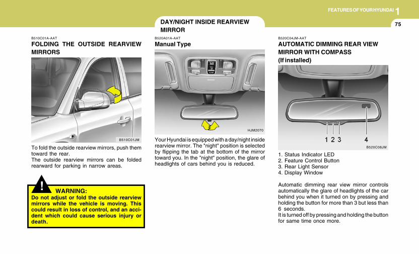
1FEATURES OF YOUR HYUNDAI
75
!
B510C01A-AAT
FOLDING THE OUTSIDE REARVIEWMIRRORS
To fold the outside rearview mirrors, push themtoward the rear.The outside rearview mirrors can be foldedrearward for parking in narrow areas.
WARNING:Do not adjust or fold the outside rearviewmirrors while the vehicle is moving. Thiscould result in loss of control, and an acci-dent which could cause serious injury ordeath.
B510C01JM
DAY/NIGHT INSIDE REARVIEWMIRROR
B520A01A-AAT
Manual Type
Your Hyundai is equipped with a day/night insiderearview mirror. The "night" position is selectedby flipping the tab at the bottom of the mirrortoward you. In the "night" position, the glare ofheadlights of cars behind you is reduced.
HJM2070
B520C04JM-AAT
AUTOMATIC DIMMING REAR VIEWMIRROR WITH COMPASS(If installed)
1. Status Indicator LED2. Feature Control Button3. Rear Light Sensor4. Display Window
Automatic dimming rear view mirror controlsautomatically the glare of headlights of the carbehind you when it turned on by pressing andholding the button for more than 3 but less than6 seconds.It is turned off by pressing and holding the buttonfor same time once more.
B520C08JM
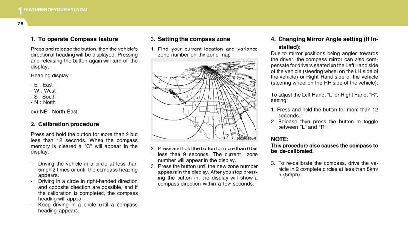
1FEATURES OF YOUR HYUNDAI
76
3. Setting the compass zone
1. Find your current location and variancezone number on the zone map.
2. Press and hold the button for more than 6 butless than 9 seconds. The current zonenumber will appear in the display.
3. Press the button until the new zone numberappears in the display. After you stop press-ing the button in, the display will show acompass direction within a few seconds.
B520C06JM
4. Changing Mirror Angle setting (If In-stalled):
Due to mirror positions being angled towardsthe driver, the compass mirror can also com-pensate for drivers seated on the Left Hand sideof the vehicle (steering wheel on the LH side ofthe vehicle) or Right Hand side of the vehicle(steering wheel on the RH side of the vehicle).
To adjust the Left Hand, “L” or Right Hand, “R”,setting:
1. Press and hold the button for more than 12seconds.
2. Release then press the button to togglebetween “L” and “R”.
NOTE:This procedure also causes the compass tobe de-calibrated.
3. To re-calibrate the compass, drive the ve-hicle in 2 complete circles at less than 8km/h (5mph).
1. To operate Compass feature
Press and release the button, then the vehicle'sdirectional heading will be displayed. Pressingand releasing the button again will turn off thedisplay.
Heading display
- E : East- W : West- S : South- N : North
ex) NE : North East
2. Calibration procedure
Press and hold the button for more than 9 butless than 12 seconds. When the compassmemory is cleared a "C" will appear in thedisplay.
- Driving the vehicle in a circle at less than5mph 2 times or until the compass headingappears.
- Driving in a circle in right-handed directionand opposite direction are possible, and ifthe calibration is completed, the compassheading will appear.
- Keep driving in a circle until a compassheading appears.
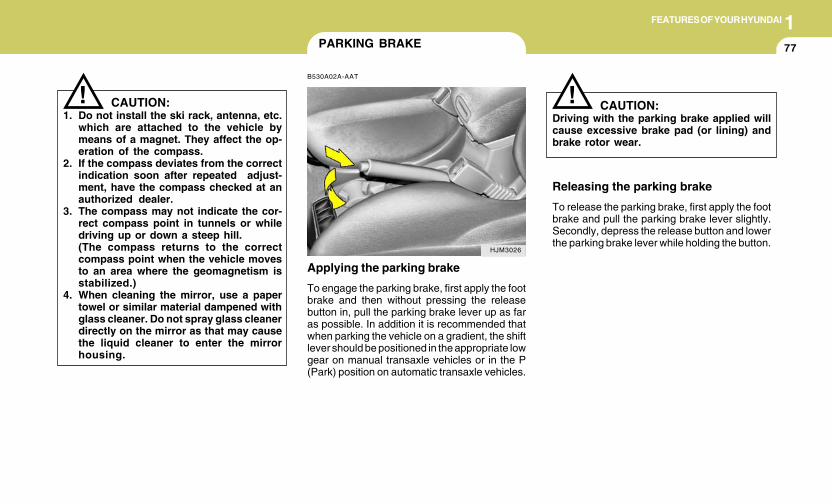
1FEATURES OF YOUR HYUNDAI
77
CAUTION:1. Do not install the ski rack, antenna, etc.
which are attached to the vehicle bymeans of a magnet. They affect the op-eration of the compass.
2. If the compass deviates from the correctindication soon after repeated adjust-ment, have the compass checked at anauthorized dealer.
3. The compass may not indicate the cor-rect compass point in tunnels or whiledriving up or down a steep hill.(The compass returns to the correctcompass point when the vehicle movesto an area where the geomagnetism isstabilized.)
4. When cleaning the mirror, use a papertowel or similar material dampened withglass cleaner. Do not spray glass cleanerdirectly on the mirror as that may causethe liquid cleaner to enter the mirrorhousing.
!
PARKING BRAKE
B530A02A-AAT
Applying the parking brake
To engage the parking brake, first apply the footbrake and then without pressing the releasebutton in, pull the parking brake lever up as faras possible. In addition it is recommended thatwhen parking the vehicle on a gradient, the shiftlever should be positioned in the appropriate lowgear on manual transaxle vehicles or in the P(Park) position on automatic transaxle vehicles.
HJM3026
Releasing the parking brake
To release the parking brake, first apply the footbrake and pull the parking brake lever slightly.Secondly, depress the release button and lowerthe parking brake lever while holding the button.
CAUTION:Driving with the parking brake applied willcause excessive brake pad (or lining) andbrake rotor wear.
!
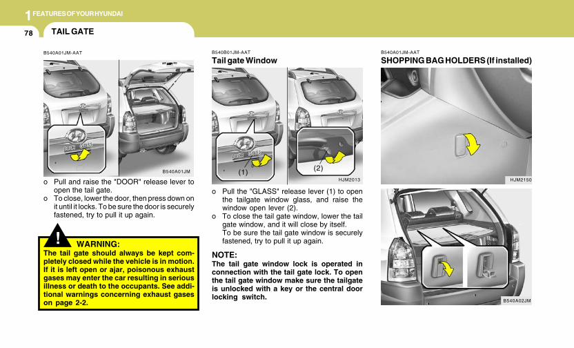
1FEATURES OF YOUR HYUNDAI
78
B540A01JM-AAT
SHOPPING BAG HOLDERS (If installed)
HJM2150
B540A02JM
B540B01JM-AAT
Tail gate Window
o Pull the "GLASS" release lever (1) to openthe tailgate window glass, and raise thewindow open lever (2).
o To close the tail gate window, lower the tailgate window, and it will close by itself.To be sure the tail gate window is securelyfastened, try to pull it up again.
NOTE:The tail gate window lock is operated inconnection with the tail gate lock. To openthe tail gate window make sure the tailgateis unlocked with a key or the central doorlocking switch.
HJM2013(1) (2)
!
TAIL GATE
B540A01JM-AAT
o Pull and raise the "DOOR" release lever toopen the tail gate.
o To close, lower the door, then press down onit until it locks. To be sure the door is securelyfastened, try to pull it up again.
B540A01JM
WARNING:The tail gate should always be kept com-pletely closed while the vehicle is in motion.If it is left open or ajar, poisonous exhaustgases may enter the car resulting in seriousillness or death to the occupants. See addi-tional warnings concerning exhaust gaseson page 2-2.
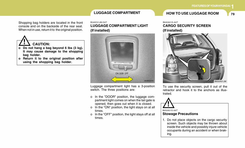
1FEATURES OF YOUR HYUNDAI
79
Shopping bag holders are located in the frontconsole and on the backside of the rear seat.When not in use, return it to the original position.
CAUTION:o Do not hang a bag beyond 6 Ibs (3 kg).
It may cause damage to the shoppingbag holder.
o Return it to the original position afterusing the shopping bag holder.
!
HOW TO USE LUGGAGE ROOM
B650A01JM
B640A01S-AAT
CARGO SECURITY SCREEN(If installed)
To use the security screen, pull it out of theretractor and hook it to the anchors as illus-trated.
B650A01S-AAT
Stowage Precautions
1. Do not place objects on the cargo securityscreen. Such objects may be thrown aboutinside the vehicle and possibly injure vehicleoccupants during an accident or when brak-ing.
!
B540C01JM-GAT
LUGGAGE COMPARTMENT LIGHT(If installed)
Luggage compartment light has a 3-positionswitch. The three positions are:
o In the "DOOR" position, the luggage com-partment light comes on when the tail gate isopened, then goes out when it is closed.
o In the "ON" position, the light stays on at alltimes.
o In the "OFF" position, the light stays off at alltimes.
HHR2070
LUGGAGE COMPARTMENT
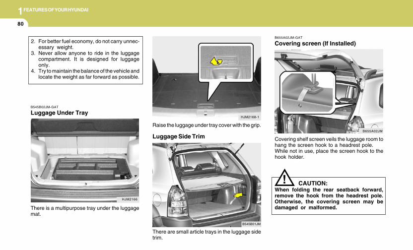
1FEATURES OF YOUR HYUNDAI
80
Luggage Side Trim
B545B01JM
There are small article trays in the luggage sidetrim.
B655A02JM-GAT
Covering screen (If Installed)
Covering shelf screen veils the luggage room tohang the screen hook to a headrest pole.While not in use, place the screen hook to thehook holder.
B655A02JM
CAUTION:When folding the rear seatback forward,remove the hook from the headrest pole.Otherwise, the covering screen may bedamaged or malformed.
!
Raise the luggage under tray cover with the grip.
HJM2168-1
2. For better fuel economy, do not carry unnec-essary weight.
3. Never allow anyone to ride in the luggagecompartment. It is designed for luggageonly.
4. Try to maintain the balance of the vehicle andlocate the weight as far forward as possible.
HJM2166
B545B02JM-GAT
Luggage Under Tray
There is a multipurpose tray under the luggagemat.
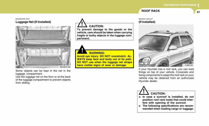
1FEATURES OF YOUR HYUNDAI
81
B540D03HP-GAT
Luggage Net (If Installed)
Some objects can be kept in the net in theluggage compartment.Use the luggage net on the floor or at the backof the luggage compartment to prevent objectsfrom sliding.
B540D01JM
!
! CAUTION:To prevent damage to the goods or thevehicle, care should be taken when carryingfragile or bulky objects in the luggage com-partment.
WARNING:Avoid eye injury. DO NOT overstretch. AL-WAYS keep face and body out of its path.DO NOT use when the luggage net strapshave visible signs of wear or damage.
ROOF RACK
B630A01JM-AAT
(If installed)
If your Hyundai has a roof rack, you can loadthings on top of your vehicle. Crossrails andfixing components to adapt the roof rack on yourvehicle may be obtained from an authorizedHyundai dealer.
CAUTION:o In case a sunroof is installed, do not
position roof rack loads that could inter-fere with opening of the sunroof.
o The following specifications are recom-mended when loading cargo or luggage.
!
HJM2162
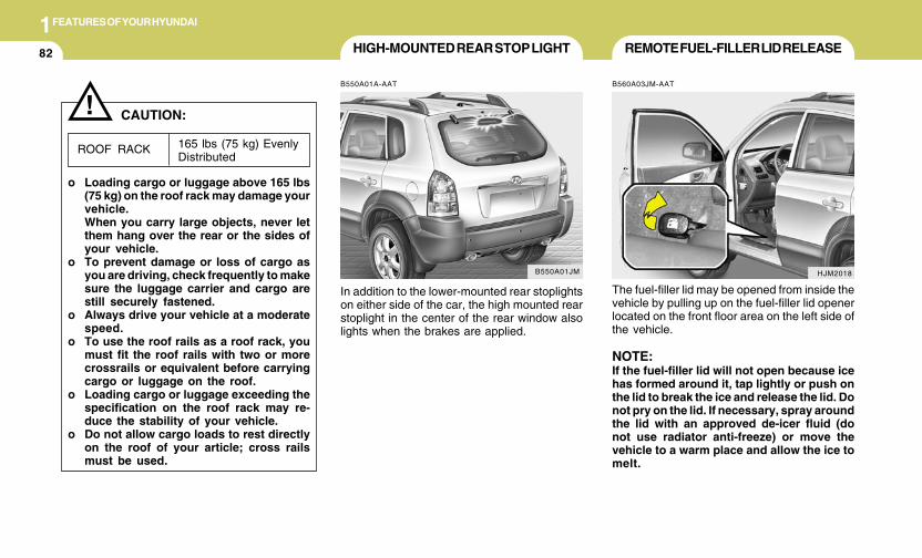
1FEATURES OF YOUR HYUNDAI
82
!
HIGH-MOUNTED REAR STOP LIGHT
B550A01A-AAT
In addition to the lower-mounted rear stoplightson either side of the car, the high mounted rearstoplight in the center of the rear window alsolights when the brakes are applied.
B550A01JM
165 lbs (75 kg) EvenlyDistributed
ROOF RACK
CAUTION:
o Loading cargo or luggage above 165 lbs(75 kg) on the roof rack may damage yourvehicle.When you carry large objects, never letthem hang over the rear or the sides ofyour vehicle.
o To prevent damage or loss of cargo asyou are driving, check frequently to makesure the luggage carrier and cargo arestill securely fastened.
o Always drive your vehicle at a moderatespeed.
o To use the roof rails as a roof rack, youmust fit the roof rails with two or morecrossrails or equivalent before carryingcargo or luggage on the roof.
o Loading cargo or luggage exceeding thespecification on the roof rack may re-duce the stability of your vehicle.
o Do not allow cargo loads to rest directlyon the roof of your article; cross railsmust be used.
HJM2018
REMOTE FUEL-FILLER LID RELEASE
B560A03JM-AAT
The fuel-filler lid may be opened from inside thevehicle by pulling up on the fuel-filler lid openerlocated on the front floor area on the left side ofthe vehicle.
NOTE:If the fuel-filler lid will not open because icehas formed around it, tap lightly or push onthe lid to break the ice and release the lid. Donot pry on the lid. If necessary, spray aroundthe lid with an approved de-icer fluid (donot use radiator anti-freeze) or move thevehicle to a warm place and allow the ice tomelt.
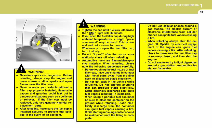
1FEATURES OF YOUR HYUNDAI
83
B560A01JM
!o Tighten the cap until it clicks, otherwise
the " " light will illuminate.o If you open the fuel filler cap during high
ambient temperatures, a slight "pres-sure sound" may be heard. This is nor-mal and not a cause for concern.Whenever you open the fuel filler cap,turn it slowly.
o Do not "top-off" after the nozzle auto-matically shuts off when refueling.
o Automotive fuels are flammable/explo-sive materials. When refueling, pleasenote the following guidelines carefully.- Before touching the fuel nozzle or fuel
filler cap, have one's hands in contactwith metal parts away from the fillerneck to discharge static electricity.
- Do not get back in the vehicle whilerefueling. Do not operate anythingthat can produce static electricity.Static electricity discharge can ignitefuel vapors resulting in explosion.
- When using a portable fuel containerbe sure to place the container on theground while refueling. Static elec-tricity discharge from the containercan ignite fuel vapors causing a fire.While starting refueling contact shouldbe maintained until the filling is com-plete.
! WARNING:o Gasoline vapors are dangerous. Before
refueling, always stop the engine andnever smoke or allow sparks and openflames near the filler area.
o Never operate your vehicle without afiller cap properly installed, flammablevapors and gasoline could leak out indangerous situations such as a collisionor rollover. If the filler cap must bereplaced, only use genuine Hyundai re-placement parts.
o After refueling, make sure the fuel cap isinstalled securely to prevent fuel spill-age in the event of an accident.
- Do not use cellular phones around agas station. The electric current orelectronic interference from cellularphones can ignite fuel vapors causinga fire.
- When refueling always shut the en-gine off. Sparks by electrical equip-ment of the engine can ignite fuelvapors causing a fire. After refueling,check to make sure the fuel filler capis securely closed, and then start theengine.
- Do not smoke or try to light cigarettesaround a gas station. Automotive fu-els are flammable.
WARNING:
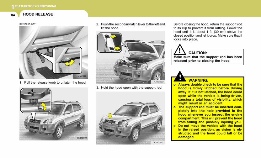
1FEATURES OF YOUR HYUNDAI
84
2. Push the secondary latch lever to the left andlift the hood.
HJM2022
HJM2023
HOOD RELEASE
B570A03A-GAT
1. Pull the release knob to unlatch the hood.
HJM2020
HJM2021
3. Hold the hood open with the support rod.
!
Before closing the hood, return the support rodto its clip to prevent it from rattling. Lower thehood until it is about 1 ft. (30 cm) above theclosed position and let it drop. Make sure that itlocks into place.
WARNING:o Always double check to be sure that the
hood is firmly latched before drivingaway. If it is not latched, the hood couldopen while the vehicle is being driven,causing a total loss of visibility, whichmight result in an accident.
o The support rod must be inserted com-pletely into the hole provided in thehood whenever you inspect the enginecompartment. This will prevent the hoodfrom falling and possibly injuring you.
o Do not move the vehicle with the hoodin the raised position, as vision is ob-structed and the hood could fall or bedamaged.
CAUTION:Make sure that the support rod has beenreleased prior to closing the hood.
!
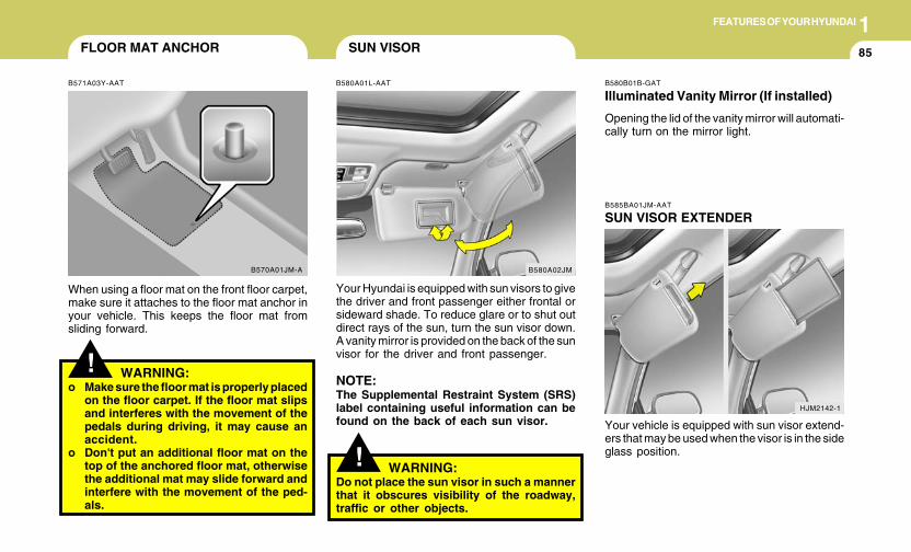
1FEATURES OF YOUR HYUNDAI
85FLOOR MAT ANCHOR
!
B571A03Y-AAT
When using a floor mat on the front floor carpet,make sure it attaches to the floor mat anchor inyour vehicle. This keeps the floor mat fromsliding forward.
WARNING:o Make sure the floor mat is properly placed
on the floor carpet. If the floor mat slipsand interferes with the movement of thepedals during driving, it may cause anaccident.
o Don't put an additional floor mat on thetop of the anchored floor mat, otherwisethe additional mat may slide forward andinterfere with the movement of the ped-als.
B570A01JM-A
SUN VISOR
B580A01L-AAT
Your Hyundai is equipped with sun visors to givethe driver and front passenger either frontal orsideward shade. To reduce glare or to shut outdirect rays of the sun, turn the sun visor down.A vanity mirror is provided on the back of the sunvisor for the driver and front passenger.
NOTE:The Supplemental Restraint System (SRS)label containing useful information can befound on the back of each sun visor.
B580A02JM
! WARNING:Do not place the sun visor in such a mannerthat it obscures visibility of the roadway,traffic or other objects.
HJM2142-1
B585BA01JM-AAT
SUN VISOR EXTENDER
Your vehicle is equipped with sun visor extend-ers that may be used when the visor is in the sideglass position.
B580B01B-GAT
Illuminated Vanity Mirror (If installed)
Opening the lid of the vanity mirror will automati-cally turn on the mirror light.
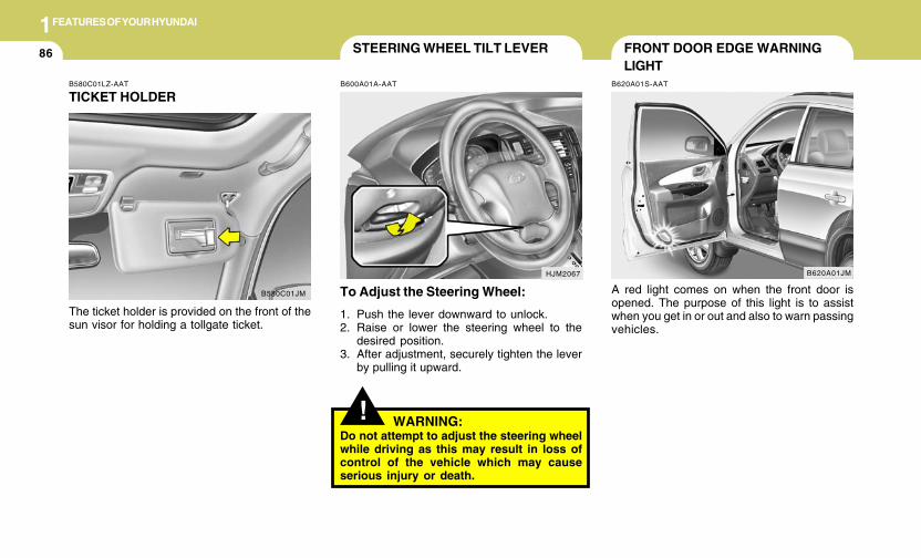
1FEATURES OF YOUR HYUNDAI
86
HJM2067
STEERING WHEEL TILT LEVER
!
To Adjust the Steering Wheel:
1. Push the lever downward to unlock.2. Raise or lower the steering wheel to the
desired position.3. After adjustment, securely tighten the lever
by pulling it upward.
WARNING:Do not attempt to adjust the steering wheelwhile driving as this may result in loss ofcontrol of the vehicle which may causeserious injury or death.
B600A01A-AATB580C01LZ-AAT
TICKET HOLDER
The ticket holder is provided on the front of thesun visor for holding a tollgate ticket.
B580C01JM
FRONT DOOR EDGE WARNINGLIGHT
B620A01S-AAT
A red light comes on when the front door isopened. The purpose of this light is to assistwhen you get in or out and also to warn passingvehicles.
B620A01JM
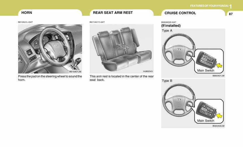
1FEATURES OF YOUR HYUNDAI
87
B610A01JM
HORN
B610A01L-GAT
Press the pad on the steering wheel to sound thehorn.
HJM2043
REAR SEAT ARM REST
B611A01Y-AAT
This arm rest is located in the center of the rearseat back.
CRUISE CONTROL
B660A02S-AAT
(If installed)
B660A01JM
Main Switch
Type A
B660A02JM
Main Switch
Type B
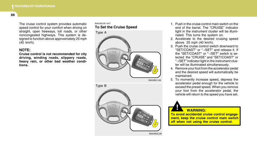
1FEATURES OF YOUR HYUNDAI
88
!
B660B03E-AAT
To Set the Cruise Speed1. Push in the cruise control main switch on the
end of the barrel. The "CRUISE" indicatorlight in the instrument cluster will be illumi-nated. This turns the system on.
2. Accelerate to the desired cruising speedabove 25 mph (40 km/h).
3. Push the cruise control switch downward to"SET/COAST" or "−/SET" and release it. Ifthe "SET/COAST" or "−/SET" switch is se-lected the "CRUISE" and "SET/COAST" or"−/SET" indicator light in the instrument clus-ter will be illuminated simultaneously.
4. Remove your foot from the accelerator pedaland the desired speed will automatically bemaintained.
5. To momently increase speed, depress theaccelerator pedal enough for the vehicle toexceed the preset speed. When you removeyour foot from the accelerator pedal, thevehicle will return to the speed you have set.
The cruise control system provides automaticspeed control for your comfort when driving onstraight, open freeways, toll roads, or othernoncongested highways. This system is de-signed to function above approximately 25 mph(40 km/h).
NOTE:Cruise control is not recommended for citydriving, winding roads, slippery roads,heavy rain, or other bad weather condi-tions.
B660B01JM
Type A
B660B02JM
Type B
WARNING:To avoid accidental cruise control engage-ment, keep the cruise control main switchoff when not using the cruise control.
1FEATURES OF YOUR HYUNDAI
89
B660C04E-AAT
To Cancel the Cruise SpeedTo disengage the cruise control system, pull thecontrol switch toward the steering wheel to the"CANCEL" position.Additionally, the followingactions will disengage the system:
o Depress the brake pedal.o Depress the clutch pedal (Manual transaxle).o Shift the selector lever to "P" or "N" position
(Automatic transaxle).o Decrease the vehicle speed to less than 25
mph (40 km/h).o Release the main switch.
B660C01JM
Type A
B660C02JM
Type B
B660D02E-AAT
To Resume the Preset Speed
B660D01JM
Type A
B660D02JM
Type B
1FEATURES OF YOUR HYUNDAI
90
B660E01E-AAT
To Reset at a Faster Speed
1. Push the control switch upward to the "RES/ACC" or "+/RES" position and hold it.
2. Accelerate to desired speed and release thecontrol switch. While the control switch isheld, the vehicle will gradually gain speed.
The vehicle will automatically resume the speedset prior to cancellation when you push thecontrol switch upward to the "RES/ACC" or "+/RES" position and release it, providing thevehicle speed is above 25 mph (40 km/h).
B660F04E-AAT
To Reset at a Slower Speed1. Push the control switch downward to "SET
/COAST" or "−/SET"and hold it. The vehiclewill decelerate.
2. When the desired speed is obtained, releasethe control switch. While the control switchis pushed, the vehicle speed will graduallydecrease.
! WARNING:o Keep the cruise control main switch off
when not using the cruise control toavoid inadvertently setting a speed.
o Use the cruise control system only whentraveling on open highways in goodweather.
o Do not use the cruise control when itmay not be safe to keep the car at aconstant speed, for instance, driving inheavy or varying traffic, or on slippery(rainy, icy or snow-covered) or windingroads or over 6% up-hill or down-hillroads.
o Pay particular attention to the drivingconditions whenever using the cruisecontrol system.
B660B01JM
Type A
B660B02JM
Type B
1FEATURES OF YOUR HYUNDAI
91
! WARNING:o During cruise-control driving with a
manual transaxle vehicle, do not shiftinto neutral without depressing theclutch pedal, or the engine will beoverrevved. If this happens, depress theclutch pedal or release the main switch.
o With the cruise control engaged, whenthe brake pedal is applied, it is normal tohear the cruise control system deacti-vate. This is an indication of normalsystem operation.
o During normal cruise control operation,when the "SET(COAST)" is activated orreactivated after applying the brakes,the cruise control will energize afterapproximately 3 seconds. This delay isnormal.
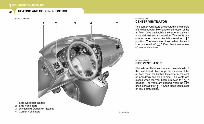
1FEATURES OF YOUR HYUNDAI
92 HEATING AND COOLING CONTROL
B710A01JM-GAT
1. Side Defroster Nozzle2. Side Ventilators3. Windshield Defroster Nozzles4. Center Ventilators
B710B02O-AAT
CENTER VENTILATOR
The center ventilators are located in the middleof the dashboard. To change the direction of theair flow, move the knob in the center of the ventup-and-down and side-to-side. The vents areopened when the vent knob is moved to " "position. The vents are closed when the ventknob is moved to " ". Keep these vents clearof any obstructions.
B710C02HP-AAT
SIDE VENTILATOR
The side ventilators are located on each side ofthe dash board. To change the direction of theair flow, move the knob in the center of the ventup-and-down and side-to-side. The vents areclosed when the vent knob is moved to " "position. The vents are opened when the ventknob is moved to " ". Keep these vents clearof any obstructions.
B710A02JM
1FEATURES OF YOUR HYUNDAI
9393939393
B670A01JM-AAT
There are three controls and two switches forthe heating and cooling system. They are:
1. Air flow control2. Fan speed control3. Temperature control4. Air intake control switch5. Air conditioning switch
HJM2109A
HJM2116A
B670B01A-AAT
Fan Speed Control(Blower Control)
This is used to turn the blower fan on and off andto select the fan speed.The blower fan speed, and therefore the volumeof air delivered from the system, may be con-trolled manually by setting the blower controlbetween the "1" and "4" position.
HEATING AND VENTILATION
B670C03E-AAT
Air Intake Control
This is used to select fresh outside air orrecirculating inside air.To change the air intake control mode, (Freshmode, Recirculation mode) push the controlbutton.
FRESH MODE ( ) : The indicator light onthe button goes off when the air intake controlis fresh mode.
RECIRCULATION MODE ( ): The indicatorlight on the button is illuminated when the airintake control is recirculation mode.
HJM2118A
1FEATURES OF YOUR HYUNDAI
94
With the "Fresh" mode selected, air enters thevehicle from the outside and is heated or cooledaccording to the function selected.
With the "Recirculation" mode selected, air fromwithin the passenger compartment will be drawnthrough the heating system and heated orcooled according to the function selected.
NOTE:It should be noted that prolonged opera-tion of the heating in "Recirculation" mode( ) may result in fogging of the wind-shield and side windows and the air withinthe passenger compartment will becomestale. In addition, prolonged use of the airconditioning with the "Recirculation" mode( ) selected may result in the air withinthe passenger compartment becoming ex-cessively dry.
B670D01JM-GAT
Air Flow Control
HJM2111
HJM2110A
This is used to turn the blower fan on/off and todirect the flow of air. Air can be directed to thefloor, dashboard outlets, or windshield. Fivesymbols are used to represent Face, Bi-Level,Floor, Floor-Defrost and Defrost air position.The MAX A/C mode is used to cool the inside ofthe vehicle faster. The "OFF" mode is used toturn the blower fan off.
Face-Level
Selecting the "Face" mode will cause air to bedischarged through the side and center venti-lators.

1FEATURES OF YOUR HYUNDAI
9595959595
HJM2114 HJM2113
Bi-Level
Air is discharged through the face vents and thefloor vents.
Floor-Level
Air is discharged through the floor vents, wind-shield defroster nozzle, side defroster nozzleand side ventilator.
HJM2112
Floor-Defrost Level
Air is discharged through the windshield de-froster nozzle, the floor vents, side defrosternozzle and side ventilator.If the "Floor-Defrost" mode is selected, the A/Cwill be turned on automatically and "Fresh"mode will be activated.
1FEATURES OF YOUR HYUNDAI
96
HJM2115
Defrost-Level
Air is discharged through the windshield de-froster nozzle, side defroster nozzle and sideventilator.If the "Defrost" mode is selected, the A/C will beturned turn on automatically and "Fresh" modewill be activated to improve windshield defrost-ing.
MAXA/C
B670C02JM
MAX A/C-Level
Air is discharged through the face level vents.If the "MAX A/C" mode is selected, the A/C willturn on automatically and "Recirculation" modewill be activated.
* The A/C or the air intake control switchreturns to its former setting.
A/C
ON
ON or OFF *
OFF
ON or OFF *
ON
ON
Air Intake
Control Switch
or
OFF
NOTE:o The air intake control switch will change
to " " mode when the ignition switchis turned "ON" with the MAX A/C modeselected.
o When you change to another mode fromMAX A/C, the A/C and the air intakecontrol switch are set to the followingchart.
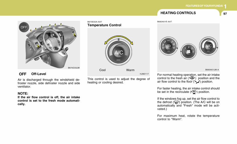
1FEATURES OF YOUR HYUNDAI
9797979797
HJM2117
Cool Warm
B670E02A-AAT
Temperature Control
This control is used to adjust the degree ofheating or cooling desired.
B690A01E-AAT
For normal heating operation, set the air intakecontrol to the fresh air ( ) position and theair flow control to the floor ( ) position.
For faster heating, the air intake control shouldbe set in the recirculate ( ) position.
If the windows fog up, set the air flow control tothe defrost ( ) position. (The A/C will be onautomatically and "Fresh" mode will be acti-vated.)
For maximum heat, rotate the temperaturecontrol to "Warm".
B690A01JM-A
HEATING CONTROLS
B670C03JM
OFF Off-Level
Air is discharged through the windshield de-froster nozzle, side defroster nozzle and sideventilator.
NOTE:If the air flow control is off, the air intakecontrol is set to the fresh mode automati-cally.
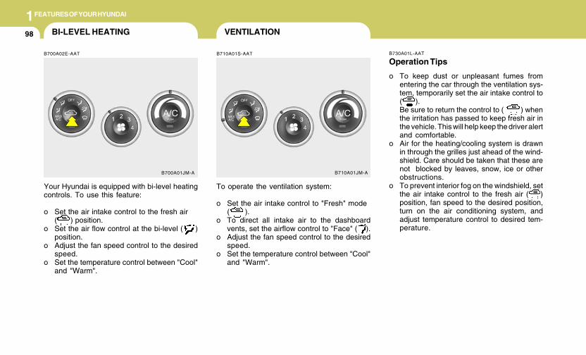
1FEATURES OF YOUR HYUNDAI
98 VENTILATIONBI-LEVEL HEATING
B710A01S-AATB700A02E-AAT
Your Hyundai is equipped with bi-level heatingcontrols. To use this feature:
o Set the air intake control to the fresh air( ) position.
o Set the air flow control at the bi-level ( )position.
o Adjust the fan speed control to the desiredspeed.
o Set the temperature control between "Cool"and "Warm".
To operate the ventilation system:
o Set the air intake control to "Fresh" mode( ).
o To direct all intake air to the dashboardvents, set the airflow control to "Face" ( ).
o Adjust the fan speed control to the desiredspeed.
o Set the temperature control between "Cool"and "Warm".
B700A01JM-A B710A01JM-A
B730A01L-AAT
Operation Tips
o To keep dust or unpleasant fumes fromentering the car through the ventilation sys-tem, temporarily set the air intake control to( ).Be sure to return the control to ( ) whenthe irritation has passed to keep fresh air inthe vehicle. This will help keep the driver alertand comfortable.
o Air for the heating/cooling system is drawnin through the grilles just ahead of the wind-shield. Care should be taken that these arenot blocked by leaves, snow, ice or otherobstructions.
o To prevent interior fog on the windshield, setthe air intake control to the fresh air ( )position, fan speed to the desired position,turn on the air conditioning system, andadjust temperature control to desired tem-perature.
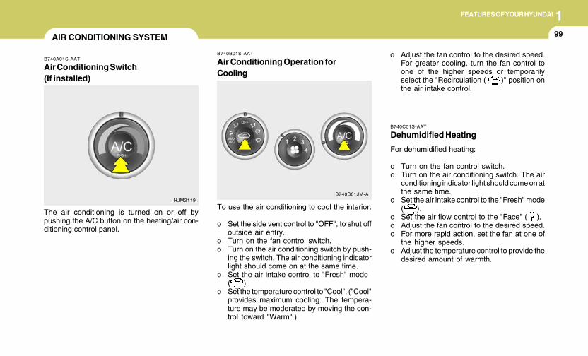
1FEATURES OF YOUR HYUNDAI
9999999999
B740C01S-AAT
Dehumidified Heating
For dehumidified heating:
o Turn on the fan control switch.o Turn on the air conditioning switch. The air
conditioning indicator light should come on atthe same time.
o Set the air intake control to the "Fresh" mode( ).
o Set the air flow control to the "Face" ( ).o Adjust the fan control to the desired speed.o For more rapid action, set the fan at one of
the higher speeds.o Adjust the temperature control to provide the
desired amount of warmth.
B740B01S-AAT
Air Conditioning Operation forCooling
To use the air conditioning to cool the interior:
o Set the side vent control to "OFF", to shut offoutside air entry.
o Turn on the fan control switch.o Turn on the air conditioning switch by push-
ing the switch. The air conditioning indicatorlight should come on at the same time.
o Set the air intake control to "Fresh" mode( ).
o Set the temperature control to "Cool". ("Cool"provides maximum cooling. The tempera-ture may be moderated by moving the con-trol toward "Warm".)
o Adjust the fan control to the desired speed.For greater cooling, turn the fan control toone of the higher speeds or temporarilyselect the "Recirculation ( )" position onthe air intake control.
B740B01JM-A
AIR CONDITIONING SYSTEM
B740A01S-AAT
Air Conditioning Switch(If installed)
The air conditioning is turned on or off bypushing the A/C button on the heating/air con-ditioning control panel.
HJM2119
1FEATURES OF YOUR HYUNDAI
100
B740D01A-AAT
Operation Tips
o If the interior of the car is hot when you firstget in, open the windows for a few minutesto expel the hot air.
o When you are using the air conditioningsystem, keep all windows closed to keep hotair out.
o When moving slowly, as in heavy traffic, shiftto a lower gear. This increases engine speed,which in turn increases the speed of the airconditioning compressor.
o On steep grades, turn the air conditioning offto avoid the possibility of the engine over-heating.
o During winter months or in periods when theair conditioning is not used regularly, run theair conditioning once every month for a fewminutes. This will help circulate the lubri-cants and keep your system in peak oper-ating condition.
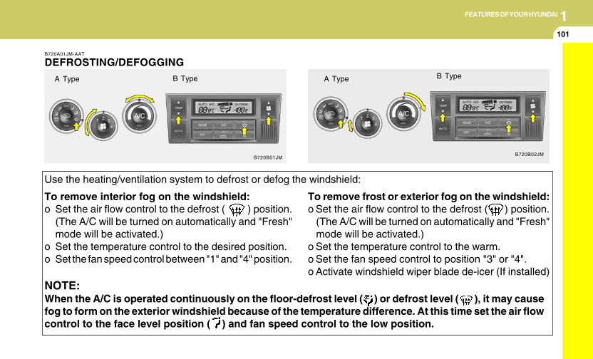
1FEATURES OF YOUR HYUNDAI
101101101101101
NOTE:When the A/C is operated continuously on the floor-defrost level ( ) or defrost level ( ), it may causefog to form on the exterior windshield because of the temperature difference. At this time set the air flowcontrol to the face level position ( ) and fan speed control to the low position.
To remove interior fog on the windshield:o Set the air flow control to the defrost ( ) position.
(The A/C will be turned on automatically and "Fresh"mode will be activated.)
o Set the temperature control to the desired position.o Set the fan speed control between "1" and "4" position.
To remove frost or exterior fog on the windshield:o Set the air flow control to the defrost ( ) position.
(The A/C will be turned on automatically and "Fresh"mode will be activated.)
o Set the temperature control to the warm.o Set the fan speed control to position "3" or "4".o Activate windshield wiper blade de-icer (If installed)
B720A01JM-AAT
DEFROSTING/DEFOGGING
B720B01JMB720B02JM
Use the heating/ventilation system to defrost or defog the windshield:
A Type B Type A Type B Type
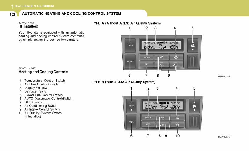
1FEATURES OF YOUR HYUNDAI
102 AUTOMATIC HEATING AND COOLING CONTROL SYSTEM
B970A01Y-AAT
(If installed)
Your Hyundai is equipped with an automaticheating and cooling control system controlledby simply setting the desired temperature.
TYPE A (Without A.Q.S: Air Quality System)
B970B01JM
B970B02JM
B970B01JM-GAT
Heating and Cooling Controls
1. Temperature Control Switch 2. Air Flow Control Switch 3. Display Window 4. Defroster Switch 5. Blower Fan Control Switch 6. AUTO (Automatic Control)Switch 7. OFF Switch 8. Air Conditioning Switch 9. Air lntake Control Switch10. Air Quality System Switch
(If installed)
TYPE B (With A.Q.S: Air Quality System)
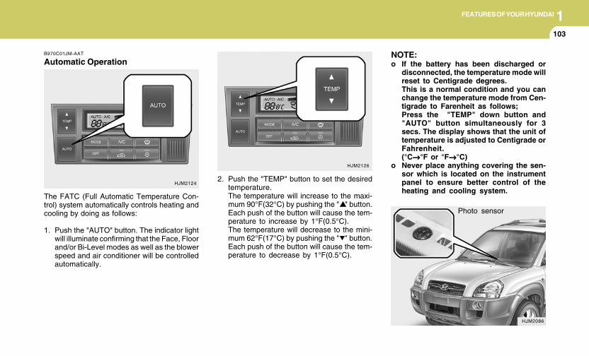
1FEATURES OF YOUR HYUNDAI
103103103103103
Photo sensor
HJM2086
NOTE:o If the battery has been discharged or
disconnected, the temperature mode willreset to Centigrade degrees.This is a normal condition and you canchange the temperature mode from Cen-tigrade to Farenheit as follows;Press the "TEMP" down button and"AUTO" button simultaneously for 3secs. The display shows that the unit oftemperature is adjusted to Centigrade orFahrenheit.(°C→→→→→°F or °F→→→→→°C)
o Never place anything covering the sen-sor which is located on the instrumentpanel to ensure better control of theheating and cooling system.
B970C01JM-AAT
Automatic Operation
The FATC (Full Automatic Temperature Con-trol) system automatically controls heating andcooling by doing as follows:
1. Push the "AUTO" button. The indicator lightwill illuminate confirming that the Face, Floorand/or Bi-Level modes as well as the blowerspeed and air conditioner will be controlledautomatically.
2. Push the "TEMP" button to set the desiredtemperature.The temperature will increase to the maxi-mum 90°F(32°C) by pushing the " " button.Each push of the button will cause the tem-perature to increase by 1°F(0.5°C).The temperature will decrease to the mini-mum 62°F(17°C) by pushing the " " button.Each push of the button will cause the tem-perature to decrease by 1°F(0.5°C).
HJM2124
HJM2126
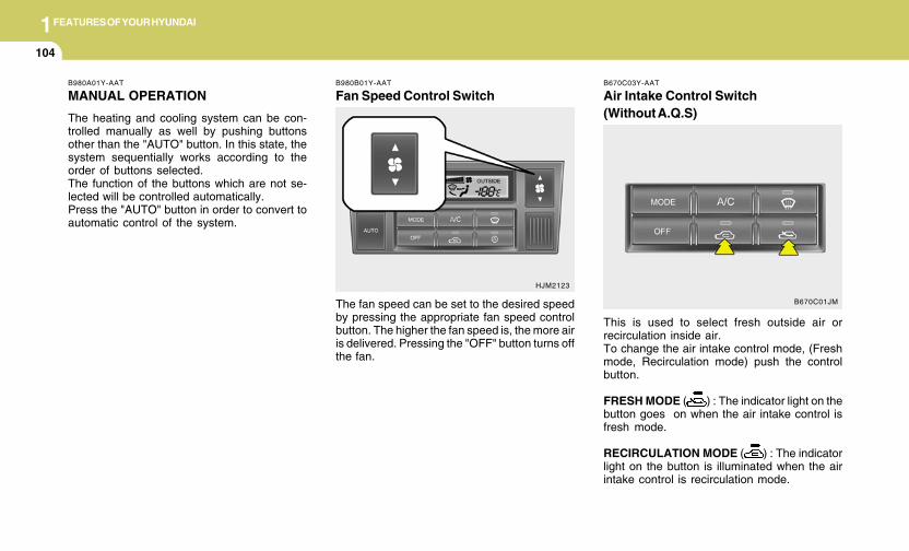
1FEATURES OF YOUR HYUNDAI
104
B980B01Y-AAT
Fan Speed Control Switch
The fan speed can be set to the desired speedby pressing the appropriate fan speed controlbutton. The higher the fan speed is, the more airis delivered. Pressing the "OFF" button turns offthe fan.
HJM2123
B980A01Y-AAT
MANUAL OPERATION
The heating and cooling system can be con-trolled manually as well by pushing buttonsother than the "AUTO" button. In this state, thesystem sequentially works according to theorder of buttons selected.The function of the buttons which are not se-lected will be controlled automatically.Press the "AUTO" button in order to convert toautomatic control of the system.
B670C03Y-AAT
Air Intake Control Switch(Without A.Q.S)
This is used to select fresh outside air orrecirculation inside air.To change the air intake control mode, (Freshmode, Recirculation mode) push the controlbutton.
FRESH MODE ( ) : The indicator light on thebutton goes on when the air intake control isfresh mode.
RECIRCULATION MODE ( ) : The indicatorlight on the button is illuminated when the airintake control is recirculation mode.
B670C01JM
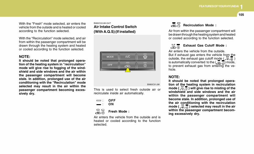
1FEATURES OF YOUR HYUNDAI
105105105105105
B980C02JM-GAT
Air Intake Control Switch(With A.Q.S) (If installed)
This is used to select fresh outside air orrecirculate inside air automatically.
: OFF: ON
Fresh Mode :
Air enters the vehicle from the outside and isheated or cooled according to the functionselected.
Recirculation Mode :
Air from within the passenger compartment willbe drawn through the heating system and heatedor cooled according to the function selected.
Exhaust Gas Cutoff Mode :
Air enters the vehicle from the outside.But if exhaust gas enters the vehicle from theoutside, the exhaust gas cutoff mode ( )is automatically converted to the ( ) mode,to prevent exhaust gas from entering the ve-hicle.
NOTE:It should be noted that prolonged opera-tion of the heating system in recirculationmode ( ) will give rise to misting of thewindshield and side windows and the airwithin the passenger compartment willbecome stale. In addition, prolonged use ofthe air conditioning with the recirculationmode ( ) selected may result in the airwithin the passenger compartment becom-ing excessively dry.
B980C01JM
With the "Fresh" mode selected, air enters thevehicle from the outside and is heated or cooledaccording to the function selected.
With the "Recirculation" mode selected, and airfrom within the passenger compartment will bedrawn through the heating system and heatedor cooled according to the function selected.
NOTE:It should be noted that prolonged opera-tion of the heating system in "recirculation"mode will give rise to fogging of the wind-shield and side windows and the air withinthe passenger compartment will becomestale. In addition, prolonged use of the airconditioning with the "Recirculation" modeselected may result in the air within thepassenger compartment becoming exces-sively dry.
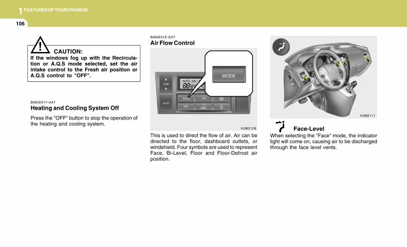
1FEATURES OF YOUR HYUNDAI
106
B980D01Y-AAT
Heating and Cooling System Off
Press the "OFF" button to stop the operation ofthe heating and cooling system.
! CAUTION:If the windows fog up with the Recircula-tion or A.Q.S mode selected, set the airintake control to the Fresh air position orA.Q.S control to "OFF".
HJM2111
B980E01E-GAT
Air Flow Control
HJM2128
This is used to direct the flow of air. Air can bedirected to the floor, dashboard outlets, orwindshield. Four symbols are used to representFace, Bi-Level, Floor and Floor-Defrost airposition.
Face-LevelWhen selecting the "Face" mode, the indicatorlight will come on, causing air to be dischargedthrough the face level vents.
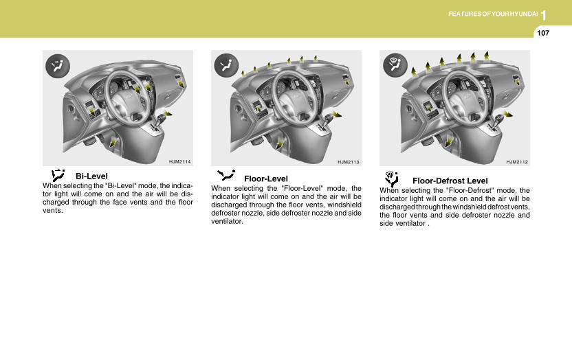
1FEATURES OF YOUR HYUNDAI
107107107107107
HJM2113 HJM2112
Floor-LevelWhen selecting the "Floor-Level" mode, theindicator light will come on and the air will bedischarged through the floor vents, windshielddefroster nozzle, side defroster nozzle and sideventilator.
Floor-Defrost LevelWhen selecting the "Floor-Defrost" mode, theindicator light will come on and the air will bedischarged through the windshield defrost vents,the floor vents and side defroster nozzle andside ventilator .
HJM2114
Bi-LevelWhen selecting the "Bi-Level" mode, the indica-tor light will come on and the air will be dis-charged through the face vents and the floorvents.
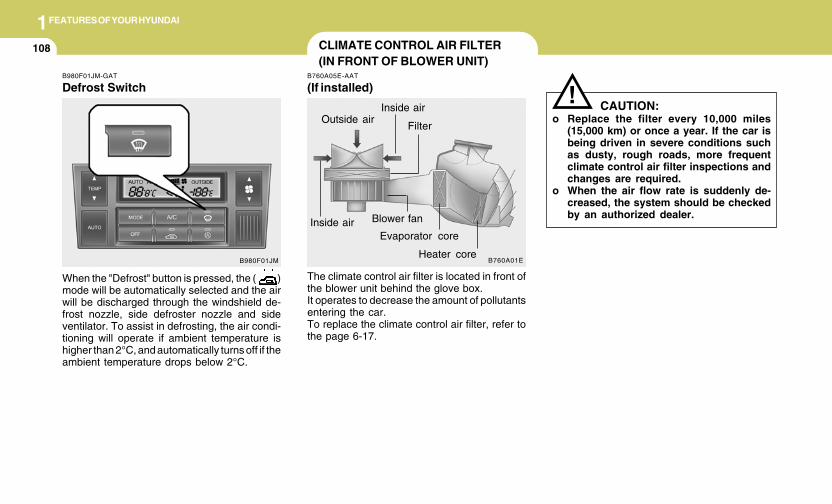
1FEATURES OF YOUR HYUNDAI
108 CLIMATE CONTROL AIR FILTER(IN FRONT OF BLOWER UNIT)
B760A05E-AAT
(If installed)
The climate control air filter is located in front ofthe blower unit behind the glove box.It operates to decrease the amount of pollutantsentering the car.To replace the climate control air filter, refer tothe page 6-17.
CAUTION:o Replace the filter every 10,000 miles
(15,000 km) or once a year. If the car isbeing driven in severe conditions suchas dusty, rough roads, more frequentclimate control air filter inspections andchanges are required.
o When the air flow rate is suddenly de-creased, the system should be checkedby an authorized dealer.
!
B760A01E
Evaporator core
Filter
Heater core
Outside air
Inside air
Inside air
Blower fan
B980F01JM-GAT
Defrost Switch
When the "Defrost" button is pressed, the ( )mode will be automatically selected and the airwill be discharged through the windshield de-frost nozzle, side defroster nozzle and sideventilator. To assist in defrosting, the air condi-tioning will operate if ambient temperature ishigher than 2°C, and automatically turns off if theambient temperature drops below 2°C.
B980F01JM
1FEATURES OF YOUR HYUNDAI
109109109109109STEREO SOUND SYSTEM
B750A02A-AAT
How Car Audio Works
AM broadcasts can be received at greaterdistances than FM broadcasts. This is becauseAM radio waves are transmitted at low frequen-cies. These long, low frequency radio wavescan follow the curvature of the earth rather thantravelling straight out into the atmosphere. Inaddition, they curve around obstructions so thatthey can provide better signal coverage.
AM and FM radio signals are broadcast fromtransmitter towers located around your city.They are intercepted by the radio antenna onyour car. This signal is then received by theradio and sent to your car speakers.When a strong radio signal has reached yourvehicle, the precise engineering of your audiosystem ensures the best possible quality repro-duction. However, in some cases the signalcoming to your vehicle may not be strong andclear. This can be due to factors such as thedistance from the radio station, closeness ofother strong radio stations or the presence ofbuildings, bridges or other large obstructions inthe area.
FM broadcasts are transmitted at high frequen-cies and do not bend to follow the earth'ssurface. Because of this, FM broadcasts gen-erally begin to fade at short distances from thestation. Also, FM signals are easily affected bybuildings, mountains, or other obstructions.These can result in certain listening conditionswhich might lead you to believe a problem existswith your radio. The following conditions arenormal and do not indicate radio trouble:
Ionosphere
B750A02L
AM reception
Mountains
Buildings
Unobstructedarea
FM radio station
B750A03L
Ionosphere
FM reception
B750A01L
Obstructed areaIron bridges
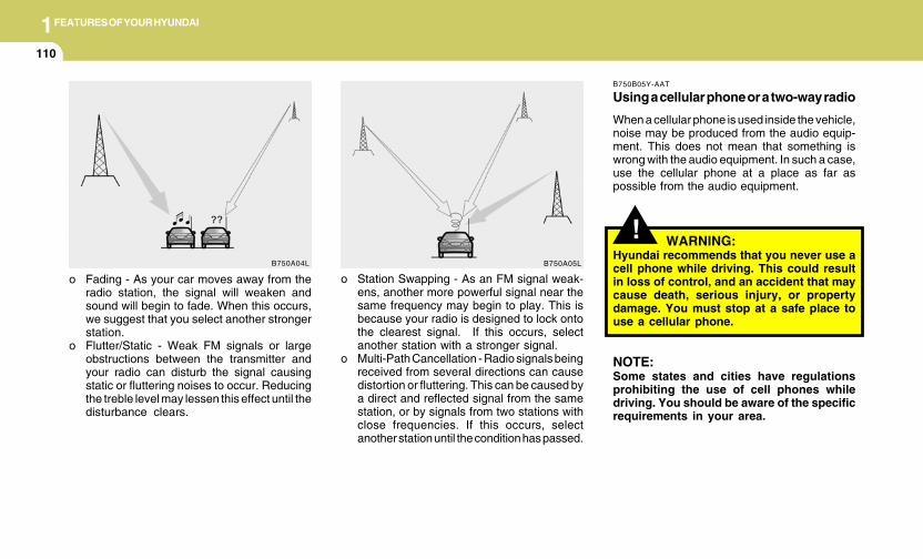
1FEATURES OF YOUR HYUNDAI
110
o Fading - As your car moves away from theradio station, the signal will weaken andsound will begin to fade. When this occurs,we suggest that you select another strongerstation.
o Flutter/Static - Weak FM signals or largeobstructions between the transmitter andyour radio can disturb the signal causingstatic or fluttering noises to occur. Reducingthe treble level may lessen this effect until thedisturbance clears.
o Station Swapping - As an FM signal weak-ens, another more powerful signal near thesame frequency may begin to play. This isbecause your radio is designed to lock ontothe clearest signal. If this occurs, selectanother station with a stronger signal.
o Multi-Path Cancellation - Radio signals beingreceived from several directions can causedistortion or fluttering. This can be caused bya direct and reflected signal from the samestation, or by signals from two stations withclose frequencies. If this occurs, selectanother station until the condition has passed.
B750A04L B750A05L
!
B750B05Y-AAT
Using a cellular phone or a two-way radio
When a cellular phone is used inside the vehicle,noise may be produced from the audio equip-ment. This does not mean that something iswrong with the audio equipment. In such a case,use the cellular phone at a place as far aspossible from the audio equipment.
WARNING:Hyundai recommends that you never use acell phone while driving. This could resultin loss of control, and an accident that maycause death, serious injury, or propertydamage. You must stop at a safe place touse a cellular phone.
NOTE:Some states and cities have regulationsprohibiting the use of cell phones whiledriving. You should be aware of the specificrequirements in your area.
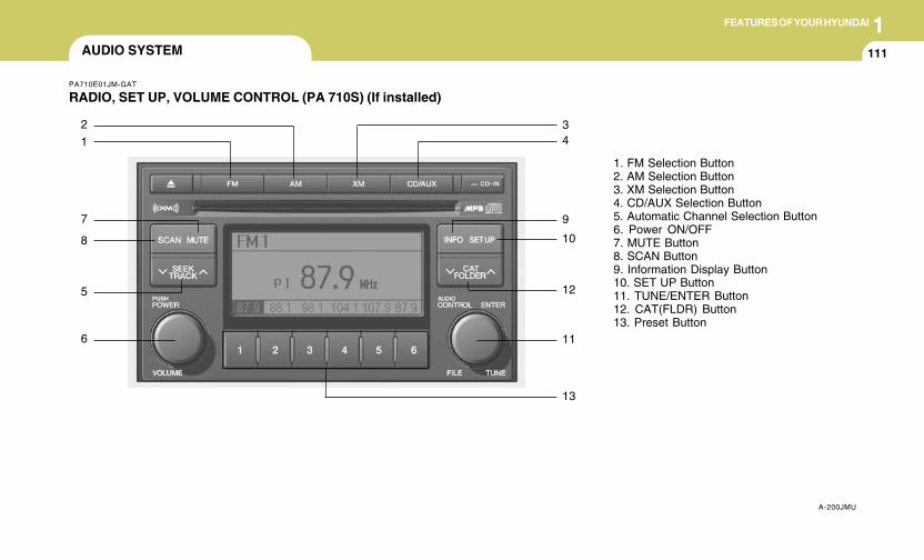
1FEATURES OF YOUR HYUNDAI
111111111111111AUDIO SYSTEM
PA710E01JM-GAT
RADIO, SET UP, VOLUME CONTROL (PA 710S) (If installed)
A-200JMU
1. FM Selection Button2. AM Selection Button3. XM Selection Button4. CD/AUX Selection Button5. Automatic Channel Selection Button6. Power ON/OFF7. MUTE Button8. SCAN Button9. Information Display Button10. SET UP Button11. TUNE/ENTER Button12. CAT(FLDR) Button13. Preset Button
1
2
7
8
5
6
13
11
12
10
9
43
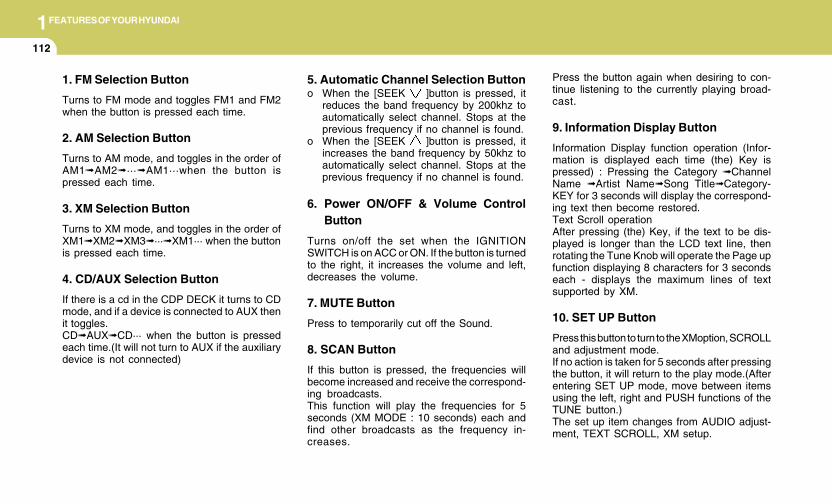
1FEATURES OF YOUR HYUNDAI
112
1. FM Selection Button
Turns to FM mode and toggles FM1 and FM2when the button is pressed each time.
2. AM Selection Button
Turns to AM mode, and toggles in the order ofAM1➟AM2➟···➟AM1···when the button ispressed each time.
3. XM Selection Button
Turns to XM mode, and toggles in the order ofXM1➟XM2➟XM3➟···➟XM1··· when the buttonis pressed each time.
4. CD/AUX Selection Button
If there is a cd in the CDP DECK it turns to CDmode, and if a device is connected to AUX thenit toggles.CD➟AUX➟CD··· when the button is pressedeach time.(It will not turn to AUX if the auxiliarydevice is not connected)
5. Automatic Channel Selection Buttono When the [SEEK ]button is pressed, it
reduces the band frequency by 200khz toautomatically select channel. Stops at theprevious frequency if no channel is found.
o When the [SEEK ]button is pressed, itincreases the band frequency by 50khz toautomatically select channel. Stops at theprevious frequency if no channel is found.
6. Power ON/OFF & Volume ControlButton
Turns on/off the set when the IGNITIONSWITCH is on ACC or ON. If the button is turnedto the right, it increases the volume and left,decreases the volume.
7. MUTE Button
Press to temporarily cut off the Sound.
8. SCAN Button
If this button is pressed, the frequencies willbecome increased and receive the correspond-ing broadcasts.This function will play the frequencies for 5seconds (XM MODE : 10 seconds) each andfind other broadcasts as the frequency in-creases.
Press the button again when desiring to con-tinue listening to the currently playing broad-cast.
9. Information Display Button
Information Display function operation (Infor-mation is displayed each time (the) Key ispressed) : Pressing the Category ➟ChannelName ➟Artist Name➟Song Title➟Category-KEY for 3 seconds will display the correspond-ing text then become restored.Text Scroll operationAfter pressing (the) Key, if the text to be dis-played is longer than the LCD text line, thenrotating the Tune Knob will operate the Page upfunction displaying 8 characters for 3 secondseach - displays the maximum lines of textsupported by XM.
10. SET UP Button
Press this button to turn to the XMoption, SCROLLand adjustment mode.If no action is taken for 5 seconds after pressingthe button, it will return to the play mode.(Afterentering SET UP mode, move between itemsusing the left, right and PUSH functions of theTUNE button.)The set up item changes from AUDIO adjust-ment, TEXT SCROLL, XM setup.
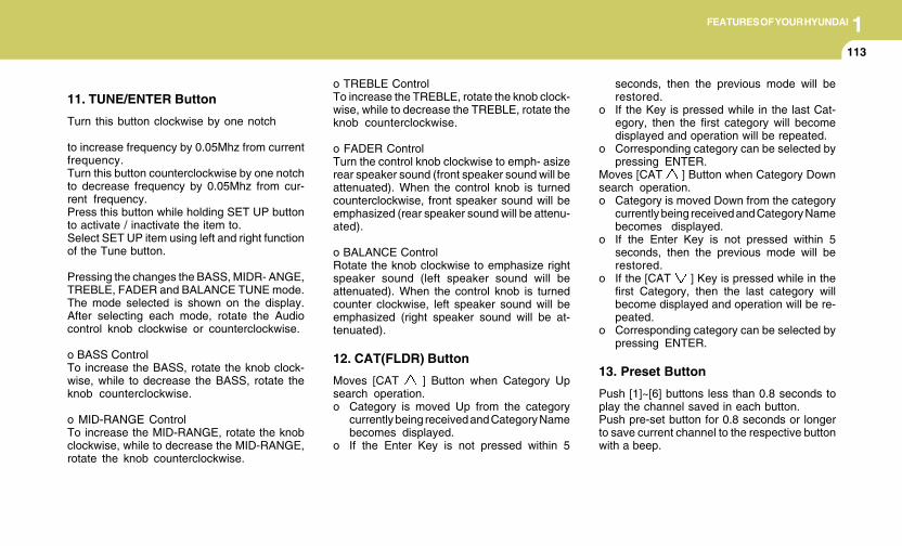
1FEATURES OF YOUR HYUNDAI
113113113113113
11. TUNE/ENTER Button
Turn this button clockwise by one notch
to increase frequency by 0.05Mhz from currentfrequency.Turn this button counterclockwise by one notchto decrease frequency by 0.05Mhz from cur-rent frequency.Press this button while holding SET UP buttonto activate / inactivate the item to.Select SET UP item using left and right functionof the Tune button.
Pressing the changes the BASS, MIDR- ANGE,TREBLE, FADER and BALANCE TUNE mode.The mode selected is shown on the display.After selecting each mode, rotate the Audiocontrol knob clockwise or counterclockwise.
o BASS ControlTo increase the BASS, rotate the knob clock-wise, while to decrease the BASS, rotate theknob counterclockwise.
o MID-RANGE ControlTo increase the MID-RANGE, rotate the knobclockwise, while to decrease the MID-RANGE,rotate the knob counterclockwise.
o TREBLE ControlTo increase the TREBLE, rotate the knob clock-wise, while to decrease the TREBLE, rotate theknob counterclockwise.
o FADER ControlTurn the control knob clockwise to emph- asizerear speaker sound (front speaker sound will beattenuated). When the control knob is turnedcounterclockwise, front speaker sound will beemphasized (rear speaker sound will be attenu-ated).
o BALANCE ControlRotate the knob clockwise to emphasize rightspeaker sound (left speaker sound will beattenuated). When the control knob is turnedcounter clockwise, left speaker sound will beemphasized (right speaker sound will be at-tenuated).
12. CAT(FLDR) Button
Moves [CAT ] Button when Category Upsearch operation.o Category is moved Up from the category
currently being received and Category Namebecomes displayed.
o If the Enter Key is not pressed within 5
seconds, then the previous mode will berestored.
o If the Key is pressed while in the last Cat-egory, then the first category will becomedisplayed and operation will be repeated.
o Corresponding category can be selected bypressing ENTER.
Moves [CAT ] Button when Category Downsearch operation.o Category is moved Down from the category
currently being received and Category Namebecomes displayed.
o If the Enter Key is not pressed within 5seconds, then the previous mode will berestored.
o If the [CAT ] Key is pressed while in thefirst Category, then the last category willbecome displayed and operation will be re-peated.
o Corresponding category can be selected bypressing ENTER.
13. Preset Button
Push [1]~[6] buttons less than 0.8 seconds toplay the channel saved in each button.Push pre-set button for 0.8 seconds or longerto save current channel to the respective buttonwith a beep.
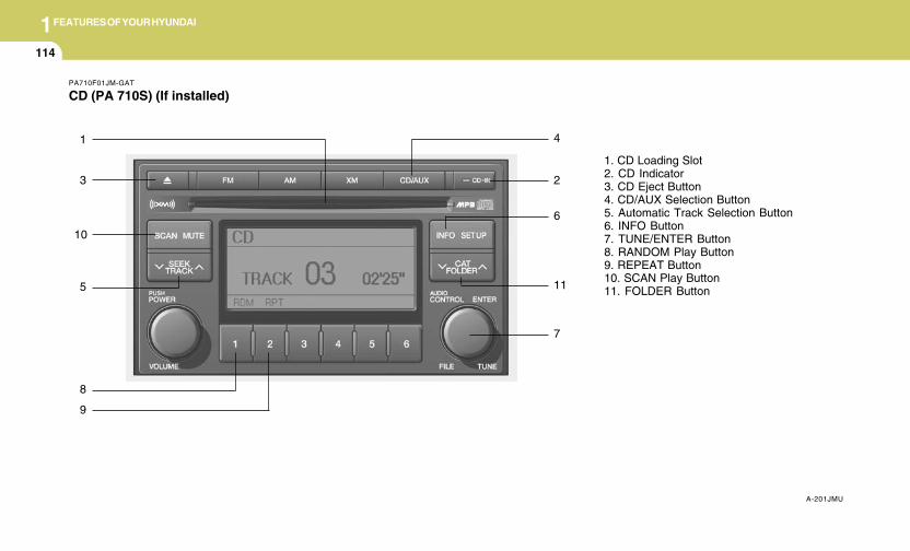
1FEATURES OF YOUR HYUNDAI
114
PA710F01JM-GAT
CD (PA 710S) (If installed)
A-201JMU
1. CD Loading Slot2. CD Indicator3. CD Eject Button4. CD/AUX Selection Button5. Automatic Track Selection Button6. INFO Button7. TUNE/ENTER Button8. RANDOM Play Button9. REPEAT Button10. SCAN Play Button11. FOLDER Button
1
3
5
8
7
11
2
6
4
9
10
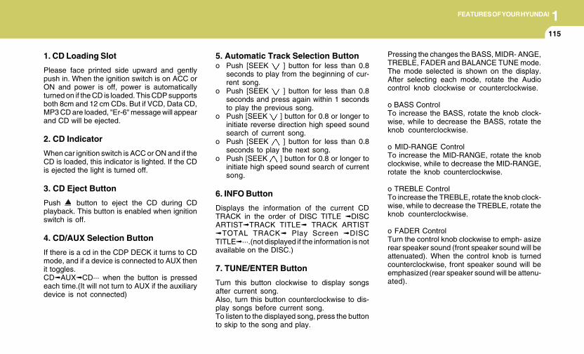
1FEATURES OF YOUR HYUNDAI
115115115115115
1. CD Loading Slot
Please face printed side upward and gentlypush in. When the ignition switch is on ACC orON and power is off, power is automaticallyturned on if the CD is loaded. This CDP supportsboth 8cm and 12 cm CDs. But if VCD, Data CD,MP3 CD are loaded, "Er-6" message will appearand CD will be ejected.
2. CD Indicator
When car ignition switch is ACC or ON and if theCD is loaded, this indicator is lighted. If the CDis ejected the light is turned off.
3. CD Eject Button
Push button to eject the CD during CDplayback. This button is enabled when ignitionswitch is off.
4. CD/AUX Selection Button
If there is a cd in the CDP DECK it turns to CDmode, and if a device is connected to AUX thenit toggles.CD➟AUX➟CD··· when the button is pressedeach time.(It will not turn to AUX if the auxiliarydevice is not connected)
5. Automatic Track Selection Buttono Push [SEEK ] button for less than 0.8
seconds to play from the beginning of cur-rent song.
o Push [SEEK ] button for less than 0.8seconds and press again within 1 secondsto play the previous song.
o Push [SEEK ] button for 0.8 or longer toinitiate reverse direction high speed soundsearch of current song.
o Push [SEEK ] button for less than 0.8seconds to play the next song.
o Push [SEEK ] button for 0.8 or longer toinitiate high speed sound search of currentsong.
6. INFO Button
Displays the information of the current CDTRACK in the order of DISC TITLE ➟DISCARTIST➟TRACK TITLE➟ TRACK ARTIST➟TOTAL TRACK➟ Play Screen ➟DISCTITLE➟···.(not displayed if the information is notavailable on the DISC.)
7. TUNE/ENTER Button
Turn this button clockwise to display songsafter current song.Also, turn this button counterclockwise to dis-play songs before current song.To listen to the displayed song, press the buttonto skip to the song and play.
Pressing the changes the BASS, MIDR- ANGE,TREBLE, FADER and BALANCE TUNE mode.The mode selected is shown on the display.After selecting each mode, rotate the Audiocontrol knob clockwise or counterclockwise.
o BASS ControlTo increase the BASS, rotate the knob clock-wise, while to decrease the BASS, rotate theknob counterclockwise.
o MID-RANGE ControlTo increase the MID-RANGE, rotate the knobclockwise, while to decrease the MID-RANGE,rotate the knob counterclockwise.
o TREBLE ControlTo increase the TREBLE, rotate the knob clock-wise, while to decrease the TREBLE, rotate theknob counterclockwise.
o FADER ControlTurn the control knob clockwise to emph- asizerear speaker sound (front speaker sound will beattenuated). When the control knob is turnedcounterclockwise, front speaker sound will beemphasized (rear speaker sound will be attenu-ated).
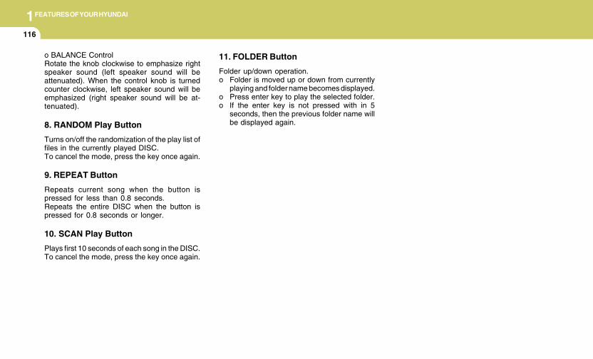
1FEATURES OF YOUR HYUNDAI
116
o BALANCE ControlRotate the knob clockwise to emphasize rightspeaker sound (left speaker sound will beattenuated). When the control knob is turnedcounter clockwise, left speaker sound will beemphasized (right speaker sound will be at-tenuated).
8. RANDOM Play Button
Turns on/off the randomization of the play list offiles in the currently played DISC.To cancel the mode, press the key once again.
9. REPEAT Button
Repeats current song when the button ispressed for less than 0.8 seconds.Repeats the entire DISC when the button ispressed for 0.8 seconds or longer.
10. SCAN Play Button
Plays first 10 seconds of each song in the DISC.To cancel the mode, press the key once again.
11. FOLDER Button
Folder up/down operation.o Folder is moved up or down from currently
playing and folder name becomes displayed.o Press enter key to play the selected folder.o If the enter key is not pressed with in 5
seconds, then the previous folder name willbe displayed again.
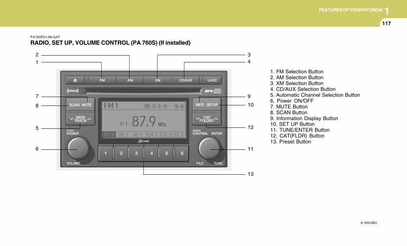
1FEATURES OF YOUR HYUNDAI
117117117117117
PA760E01JM-GAT
RADIO, SET UP, VOLUME CONTROL (PA 760S) (If installed)
A-300JMU
1. FM Selection Button2. AM Selection Button3. XM Selection Button4. CD/AUX Selection Button5. Automatic Channel Selection Button6. Power ON/OFF7. MUTE Button8. SCAN Button9. Information Display Button10. SET UP Button11. TUNE/ENTER Button12. CAT(FLDR) Button13. Preset Button
1
2
7
8
5
6
13
11
12
10
9
43
1FEATURES OF YOUR HYUNDAI
118
1. FM Selection Button
Turns to FM mode and toggles FM1 and FM2when the button is pressed each time.
2. AM Selection Button
Turns to AM mode, and toggles in the order ofAM1➟AM2➟···➟AM1···when the button ispressed each time.
3. XM Selection Button
Turns to XM mode, and toggles in the order ofXM1➟XM2➟XM3➟···➟XM1··· when the buttonis pressed each time.
4. CD/AUX Selection Button
If there is a cd in the CDP DECK it turns to CDmode, and if a device is connected to AUX thenit toggles.CD➟AUX➟CD··· when the button is pressedeach time.(It will not turn to AUX if the auxiliarydevice is not connected)
5. Automatic Channel Selection Button
o When the [SEEK ]button is pressed, itreduces the band frequency by 200khz toautomatically select channel. Stops at theprevious frequency if no channel is found.
o When the [SEEK ]button is pressed, itincreases the band frequency by 50khz toautomatically select channel. Stops at theprevious frequency if no channel is found.
6. Power ON/OFF & Volume ControlButton
Turns on/off the set when the IGNITIONSWITCH is on ACC or ON. If the button is turnedto the right, it increases the volume and left,decreases the volume.
7. MUTE Button
Press to temporarily cut off the Sound.
8. SCAN Button
If this button is pressed, the frequencies willbecome increased and receive the correspond-ing broadcasts.This function will play the frequencies for 5seconds (XM MODE : 10 seconds) each andfind other broadcasts as the frequency in-creases.
Press the button again when desiring to con-tinue listening to the currently playing broad-cast.
9. Information Display Button
Information Display function operation (Infor-mation is displayed each time (the) Key ispressed) : Pressing the Category ➟ChannelName ➟Artist Name➟Song Title➟Category-KEY for 3 seconds will display the correspond-ing text then become restored.Text Scroll operationAfter pressing (the) Key, if the text to be dis-played is longer than the LCD text line, thenrotating the Tune Knob will operate the Page upfunction displaying 8 characters for 3 secondseach - displays the maximum lines of textsupported by XM.
10. SET UP Button
Press this button to turn to the XMoption, SCROLLand adjustment mode.If no action is taken for 5 seconds after pressingthe button, it will return to the play mode.(Afterentering SET UP mode, move between itemsusing the left, right and PUSH functions of theTUNE button.)The set up item changes from AUDIO adjust-ment, TEXT SCROLL, XM setup.
1FEATURES OF YOUR HYUNDAI
119119119119119
11. TUNE/ENTER Button
Turn this button clockwise by one notch toincrease frequency by 0.05Mhz from currentfrequency.Turn this button counterclockwise by one notchto decrease frequency by 0.05Mhz from cur-rent frequency.Press this button while holding SET UP buttonto activate / inactivate the item to.Select SET UP item using left and right functionof the Tune button.
Pressing the changes the BASS, MIDR- ANGE,TREBLE, FADER and BALANCE TUNE mode.The mode selected is shown on the display.After selecting each mode, rotate the Audiocontrol knob clockwise or counterclockwise.
o BASS ControlTo increase the BASS, rotate the knob clock-wise, while to decrease the BASS, rotate theknob counterclockwise.
o MID-RANGE ControlTo increase the MID-RANGE, rotate the knobclockwise, while to decrease the MID-RANGE,rotate the knob counterclockwise.
o TREBLE ControlTo increase the TREBLE, rotate the knob clock-wise, while to decrease the TREBLE, rotate theknob counterclockwise.
o FADER ControlTurn the control knob clockwise to emph- asizerear speaker sound (front speaker sound will beattenuated). When the control knob is turnedcounterclockwise, front speaker sound will beemphasized (rear speaker sound will be attenu-ated).
o BALANCE ControlRotate the knob clockwise to emphasize rightspeaker sound (left speaker sound will beattenuated). When the control knob is turnedcounter clockwise, left speaker sound will beemphasized (right speaker sound will be at-tenuated).
12. CAT(FLDR) ButtonMoves [CAT ] Button when Category Upsearch operation.o Category is moved Up from the category
currently being received and Category Namebecomes displayed.
o If the Enter Key is not pressed within 5seconds, then the previous mode will berestored.
o If the Key is pressed while in the last Cat-egory, then the first category will becomedisplayed and operation will be repeated.
o Corresponding category can be selected bypressing ENTER.
Moves [CAT ] Button when Category Downsearch operation.o Category is moved Down from the category
currently being received and Category Namebecomes displayed.
o If the Enter Key is not pressed within 5seconds, then the previous mode will berestored.
o If the [CAT ] Key is pressed while in thefirst Category, then the last category willbecome displayed and operation will be re-peated.
o Corresponding category can be selected bypressing ENTER.
13. Preset Button
Push [1]~[6] buttons less than 0.8 seconds toplay the channel saved in each button.Push pre-set button for 0.8 seconds or longerto save current channel to the respective buttonwith a beep.
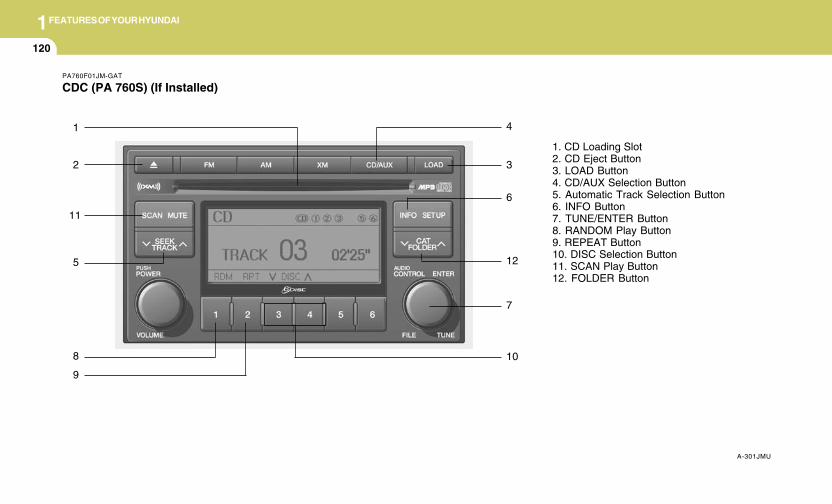
1FEATURES OF YOUR HYUNDAI
120
PA760F01JM-GAT
CDC (PA 760S) (If Installed)
A-301JMU
1. CD Loading Slot2. CD Eject Button3. LOAD Button4. CD/AUX Selection Button5. Automatic Track Selection Button6. INFO Button7. TUNE/ENTER Button8. RANDOM Play Button9. REPEAT Button10. DISC Selection Button11. SCAN Play Button12. FOLDER Button
1
2
5
8
7
12
3
6
4
9
10
11
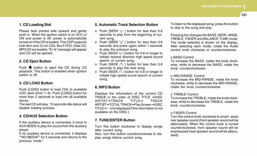
1FEATURES OF YOUR HYUNDAI
121121121121121
1. CD Loading Slot
Please face printed side upward and gentlypush in. When the ignition switch is on ACC orON and power is off, power is automaticallyturned on if the CD is loaded. This CDP supportsboth 8cm and 12 cm CDs. But if VCD, Data CD,MP3 CD are loaded, "Er-6" message will appearand CD will be ejected.
2. CD Eject Button
Push button to eject the CD during CDplayback. This button is enabled when ignitionswitch is off.
3. CD LOAD Button
Push [LOAD] button to load CDs to availableCDC deck (from 1~6). Push [LOAD] button formore than 2 seconds to load into all availabledecks.The last CD will play. 10 seconds idle status willdisable loading process.
4. CD/AUX Selection Button
If the auxiliary device is connected, it turns toAUX MODE to play the sound from the auxiliaryplayer.If no auxiliary device is connected, it displays""NO MEDIA"" for 5 seconds and returns to theprevious mode."
5. Automatic Track Selection Button
o Push [SEEK ] button for less than 0.8seconds to play from the beginning of cur-rent song.
o Push [SEEK ] button for less than 0.8seconds and press again within 1 secondsto play the previous song.
o Push [SEEK ] button for 0.8 or longer toinitiate reverse direction high speed soundsearch of current song.
o Push [SEEK ] button for less than 0.8seconds to play the next song.
o Push [SEEK ] button for 0.8 or longer toinitiate high speed sound search of currentsong.
6. INFO Button
Displays the information of the current CDTRACK in the order of DISC TITLE ➟DISCARTIST➟TRACK TITLE➟ TRACKARTIST➟TOTAL TRACK➟Play Screen ➟DISCTITLE➟···.(not displayed if the information is notavailable on the DISC.)
7. TUNE/ENTER Button
Turn this button clockwise to display songsafter current song.Also, turn this button counterclockwise to dis-play songs before current song.
To listen to the displayed song, press the buttonto skip to the song and play.
Pressing the changes the BASS, MIDR- ANGE,TREBLE, FADER and BALANCE TUNE mode.The mode selected is shown on the display.After selecting each mode, rotate the Audiocontrol knob clockwise or counterclockwise.
o BASS ControlTo increase the BASS, rotate the knob clock-wise, while to decrease the BASS, rotate theknob counterclockwise.
o MID-RANGE ControlTo increase the MID-RANGE, rotate the knobclockwise, while to decrease the MID-RANGE,rotate the knob counterclockwise.
o TREBLE ControlTo increase the TREBLE, rotate the knob clock-wise, while to decrease the TREBLE, rotate theknob counterclockwise.
o FADER ControlTurn the control knob clockwise to emph- asizerear speaker sound (front speaker sound will beattenuated). When the control knob is turnedcounterclockwise, front speaker sound will beemphasized (rear speaker sound will be attenu-ated).
1FEATURES OF YOUR HYUNDAI
122
o BALANCE ControlRotate the knob clockwise to emphasize rightspeaker sound (left speaker sound will beattenuated). When the control knob is turnedcounter clockwise, left speaker sound will beemphasized (right speaker sound will be at-tenuated).
8. RANDOM Play Button
Turns on/off the randomization of the play list offiles in the currently played DISC.To cancel the mode, press the key once again.
9. REPEAT Button
Repeats current song when the button ispressed for less than 0.8 seconds.Repeats the entire DISC when the button ispressed for 0.8 seconds or longer.
10. DISC Selection Button
o [DISC ] Change ButtonChanges disc to the previous disc.
o [DISC ] Change ButtonChanges disc to the next disc.
11. SCAN Play Button
Plays first 10 seconds of each song in the DISC.To cancel the mode, press the key once again.
12. FOLDER Button
Folder up/down operation.o Folder is moved up or down from currently
playing and folder name becomes displayed.o Press enter key to play the selected folder.o If the enter key is not pressed with in 5
seconds, then the previous folder name willbe displayed again.
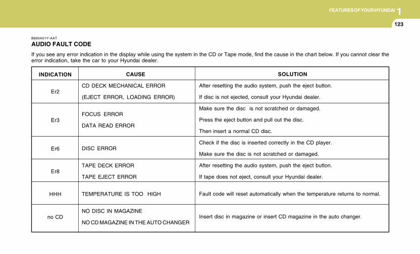
1FEATURES OF YOUR HYUNDAI
123123123123123
INDICATION
Er2
Er3
Er6
Er8
HHH
no CD
B890A01Y-AAT
AUDIO FAULT CODE
If you see any error indication in the display while using the system in the CD or Tape mode, find the cause in the chart below. If you cannot clear theerror indication, take the car to your Hyundai dealer.
SOLUTION
After resetting the audio system, push the eject button.
If disc is not ejected, consult your Hyundai dealer.
Make sure the disc is not scratched or damaged.
Press the eject button and pull out the disc.
Then insert a normal CD disc.
Check if the disc is inserted correctly in the CD player.
Make sure the disc is not scratched or damaged.
After resetting the audio system, push the eject button.
If tape does not eject, consult your Hyundai dealer.
Fault code will reset automatically when the temperature returns to normal.
Insert disc in magazine or insert CD magazine in the auto changer.
CAUSE
CD DECK MECHANICAL ERROR
(EJECT ERROR, LOADING ERROR)
FOCUS ERROR
DATA READ ERROR
DISC ERROR
TAPE DECK ERROR
TAPE EJECT ERROR
TEMPERATURE IS TOO HIGH
NO DISC IN MAGAZINE
NO CD MAGAZINE IN THE AUTO CHANGER
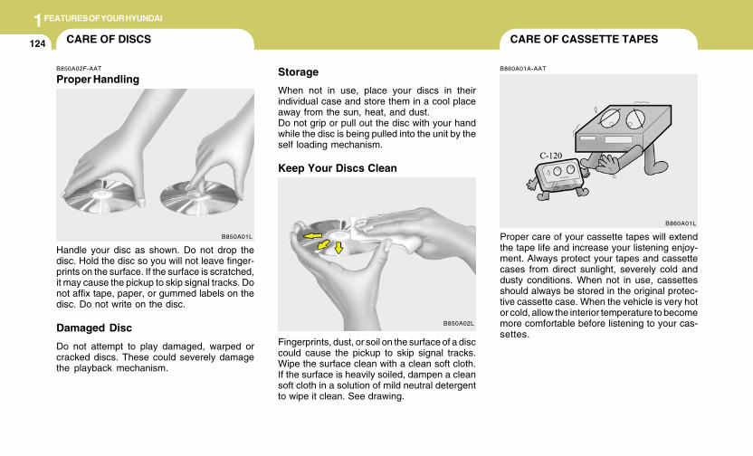
1FEATURES OF YOUR HYUNDAI
124 CARE OF CASSETTE TAPESCARE OF DISCS
B850A02L
B850A02F-AAT
Proper HandlingStorage
When not in use, place your discs in theirindividual case and store them in a cool placeaway from the sun, heat, and dust.Do not grip or pull out the disc with your handwhile the disc is being pulled into the unit by theself loading mechanism.
Keep Your Discs Clean
Handle your disc as shown. Do not drop thedisc. Hold the disc so you will not leave finger-prints on the surface. If the surface is scratched,it may cause the pickup to skip signal tracks. Donot affix tape, paper, or gummed labels on thedisc. Do not write on the disc.
Damaged Disc
Do not attempt to play damaged, warped orcracked discs. These could severely damagethe playback mechanism.
Fingerprints, dust, or soil on the surface of a disccould cause the pickup to skip signal tracks.Wipe the surface clean with a clean soft cloth.If the surface is heavily soiled, dampen a cleansoft cloth in a solution of mild neutral detergentto wipe it clean. See drawing.
B860A01A-AAT
Proper care of your cassette tapes will extendthe tape life and increase your listening enjoy-ment. Always protect your tapes and cassettecases from direct sunlight, severely cold anddusty conditions. When not in use, cassettesshould always be stored in the original protec-tive cassette case. When the vehicle is very hotor cold, allow the interior temperature to becomemore comfortable before listening to your cas-settes.
B850A01L
B860A01L
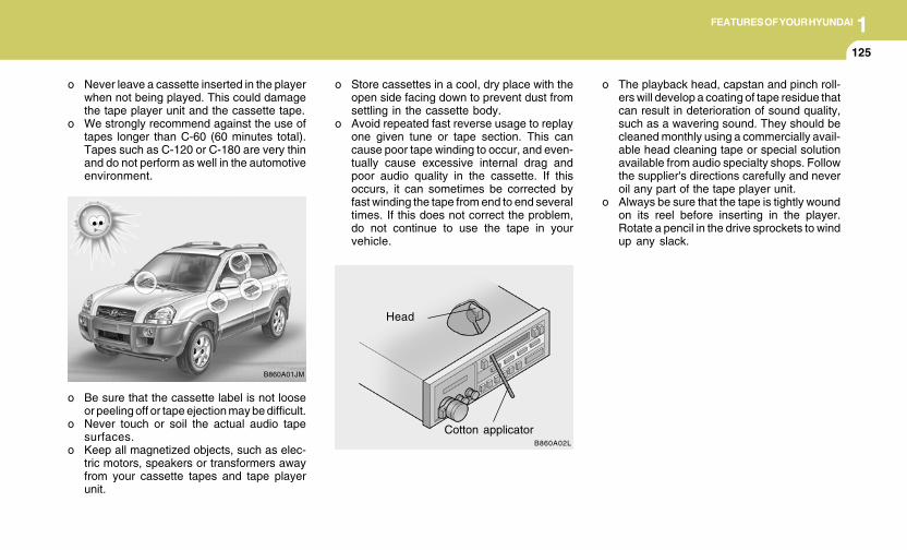
1FEATURES OF YOUR HYUNDAI
125125125125125
o Be sure that the cassette label is not looseor peeling off or tape ejection may be difficult.
o Never touch or soil the actual audio tapesurfaces.
o Keep all magnetized objects, such as elec-tric motors, speakers or transformers awayfrom your cassette tapes and tape playerunit.
Head
Cotton applicator
B860A01JM
B860A02L
o The playback head, capstan and pinch roll-ers will develop a coating of tape residue thatcan result in deterioration of sound quality,such as a wavering sound. They should becleaned monthly using a commercially avail-able head cleaning tape or special solutionavailable from audio specialty shops. Followthe supplier's directions carefully and neveroil any part of the tape player unit.
o Always be sure that the tape is tightly woundon its reel before inserting in the player.Rotate a pencil in the drive sprockets to windup any slack.
o Never leave a cassette inserted in the playerwhen not being played. This could damagethe tape player unit and the cassette tape.
o We strongly recommend against the use oftapes longer than C-60 (60 minutes total).Tapes such as C-120 or C-180 are very thinand do not perform as well in the automotiveenvironment.
o Store cassettes in a cool, dry place with theopen side facing down to prevent dust fromsettling in the cassette body.
o Avoid repeated fast reverse usage to replayone given tune or tape section. This cancause poor tape winding to occur, and even-tually cause excessive internal drag andpoor audio quality in the cassette. If thisoccurs, it can sometimes be corrected byfast winding the tape from end to end severaltimes. If this does not correct the problem,do not continue to use the tape in yourvehicle.
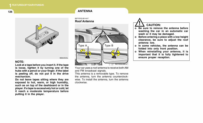
1FEATURES OF YOUR HYUNDAI
126
CAUTION:o Be sure to remove the antenna before
washing the car in an automatic carwash or it may be damaged.
o Before entering a place with a low heightclearance, be sure to adjust the roofantenna low.
o In some vehicles, the antenna can befolded into only front position.
o When reinstalling your antenna, it isimportant that it is fully tightened toensure proper reception.
!
ANTENNA
B870D02JM-U
B870D02JM-AAT
Roof Antenna
Your car uses a roof antenna to receive both AMand FM broadcast signals.This antenna is a removable type. To removethe antenna, turn the antenna counterclock-wise. To install the antenna, turn the antennaclockwise.
NOTE:Look at a tape before you insert it. If the tapeis loose, tighten it by turning one of thehubs with a pencil or your finger. If the labelis peeling off, do not put it in the drivemechanism.Do not leave tapes sitting where they areexposed to hot, warm, or high humidity,such as on top of the dashboard or in theplayer. If a tape is excessively hot or cold, letit reach a moderate temperature beforeputting it in the player.
B860A03L
Type A Type B
DRIVING YOUR HYUNDAI
2Engine Exhaust Can Be Dangerous! ............................ 2-2Before Starting the Engine ............................................ 2-4Key Positions ................................................................ 2-5Starting .......................................................................... 2-6Manual Transaxle ......................................................... 2-7Automatic Transaxle ..................................................... 2-9Anti-Lock Brake System (ABS) .................................. 2-13Traction Control System (TCS) .................................. 2-13Electronic Stability Control (ESC) ............................... 2-15Full-Time 4WD Operation ........................................... 2-164WD Lock System ...................................................... 2-19Good Braking Practices .............................................. 2-21Driving for Economy ................................................... 2-22Winter Driving ............................................................. 2-23Trailer or Vehicle Towing ............................................ 2-26Vehicle Load Limit ....................................................... 2-29
2
2 DRIVING YOUR HYUNDAI
2
WARNING: ENGINE EXHAUST CAN BE DANGEROUS!C010A02JM-AAT
Engine exhaust fumes can be extremely dangerous. If, at any time, you smell exhaust fumes inside the vehicle, open the windows immediately.
o Do not inhale exhaust fumes.Exhaust fumes contain carbon monoxide, a colorless, odorless gas that can cause unconsciousness and death by asphyxiation.
o Be sure the exhaust system does not leak.The exhaust system should be checked whenever the vehicle is raised to change the oil or for any other purpose. If you hear a changein the sound of the exhaust or if you drive over something that strikes the underneath side of the car, have the exhaust system checkedas soon as possible by your Hyundai dealer.
o Do not run the engine in an enclosed area.Letting the engine idle in your garage, even with the garage door open, is a hazardous practice. Never run the engine in your garageany longer than it takes to start the engine and back the car out.
o Avoid idling the engine for prolonged periods with people inside the car.If it is necessary to idle the engine for a prolonged period with people inside the car, be sure to do so only in an open area with the airintake set at "Fresh" and fan operating at one of the higher speeds so fresh air is drawn into the interior.
If you must drive with the tail gate open because you are carrying objects that make this necessary:
1. Close all windows.2. Open side vents.3. Set the air intake control at "Fresh", the air flow control at "Floor" or "Face" and the fan at one of the higher speeds.
To assure proper operation of the ventilation system, be sure the ventilation air intakes located just in front of the windshield are kept clearof snow, ice, leaves or other obstructions.
!
! PROPOSITION 65 WARNING:Engine exhaust and a wide variety of automobile components and parts, including components found in the interior furnishingsin a vehicle, contain or emit chemicals known to the State of California to cause cancer and birth defects and reproductive harm.In addition, certain fluids contained in vehicles and certain products of component wear contain or emit chemicals known tothe State of California to cause cancer and birth defects or other reproductive harm.
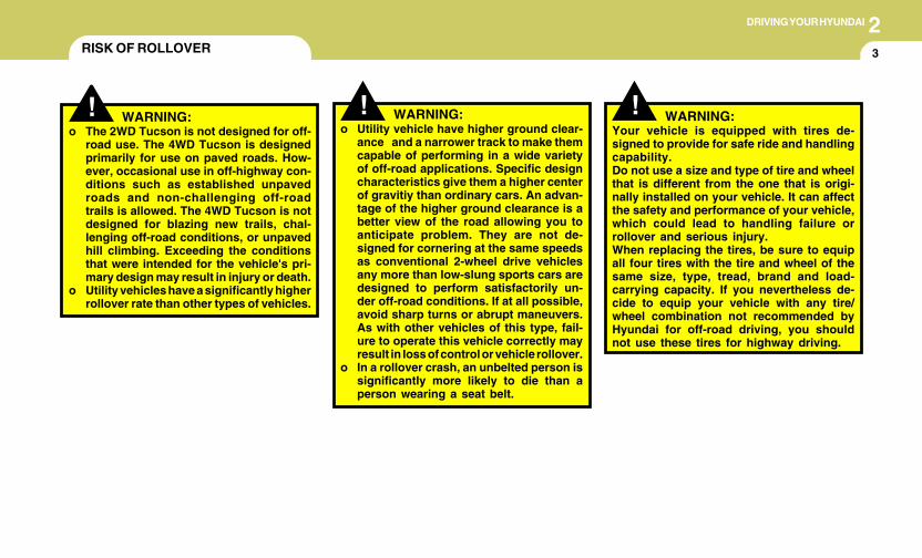
2DRIVING YOUR HYUNDAI
3
!! WARNING:o The 2WD Tucson is not designed for off-
road use. The 4WD Tucson is designedprimarily for use on paved roads. How-ever, occasional use in off-highway con-ditions such as established unpavedroads and non-challenging off-roadtrails is allowed. The 4WD Tucson is notdesigned for blazing new trails, chal-lenging off-road conditions, or unpavedhill climbing. Exceeding the conditionsthat were intended for the vehicle's pri-mary design may result in injury or death.
o Utility vehicles have a significantly higherrollover rate than other types of vehicles.
o Utility vehicle have higher ground clear-ance and a narrower track to make themcapable of performing in a wide varietyof off-road applications. Specific designcharacteristics give them a higher centerof gravitiy than ordinary cars. An advan-tage of the higher ground clearance is abetter view of the road allowing you toanticipate problem. They are not de-signed for cornering at the same speedsas conventional 2-wheel drive vehiclesany more than low-slung sports cars aredesigned to perform satisfactorily un-der off-road conditions. If at all possible,avoid sharp turns or abrupt maneuvers.As with other vehicles of this type, fail-ure to operate this vehicle correctly mayresult in loss of control or vehicle rollover.
o In a rollover crash, an unbelted person issignificantly more likely to die than aperson wearing a seat belt.
WARNING:
RISK OF ROLLOVER
! WARNING:Your vehicle is equipped with tires de-signed to provide for safe ride and handlingcapability.Do not use a size and type of tire and wheelthat is different from the one that is origi-nally installed on your vehicle. It can affectthe safety and performance of your vehicle,which could lead to handling failure orrollover and serious injury.When replacing the tires, be sure to equipall four tires with the tire and wheel of thesame size, type, tread, brand and load-carrying capacity. If you nevertheless de-cide to equip your vehicle with any tire/wheel combination not recommended byHyundai for off-road driving, you shouldnot use these tires for highway driving.
2 DRIVING YOUR HYUNDAI
4 TO START THE ENGINE
C030A01E-AAT
COMBINATION IGNITION SWITCH
o If your Hyundai is equipped with a manualtransaxle, place the shift lever in neutral anddepress the clutch pedal fully.
o If your Hyundai has an automatic transaxle,place the shift lever in "P" (park).
o To start the engine, insert the ignition key andturn it to the "START" position. Release it assoon as the engine starts. Do not hold thekey in the "START" position for more that 15seconds.
NOTE:o For safety, the engine will not start if the
clutch pedal is not depressed fully(Manual Transaxle) or the shift lever isnot in "P" or "N" Position (AutomaticTransaxle).
o The ignition key cannot be turned from"ACC" position to "LOCK" position un-less the shift lever is in the "P" (Park)position or the negative battery terminalis disconnected from the battery. Toremove the key, always confirm that theshift lever is securely positioned in "P"(Park) (For Automatic Transaxle).
o For additional information about start-ing, see page 2-6.
BEFORE STARTING THE ENGINE
C020A04A-AAT
Before you start the engine, you should always:
1. Look around the vehicle to be sure there areno flat tires, puddles of oil, water or otherindications of possible trouble.
2. After entering the car, check to be sure theparking brake is engaged.
3. Check that all windows, and lights are clean.4. Check that the interior and exterior mirrors
are clean and in position.5. Check your seat, seatback and headrest to
be sure they are in their proper positions.6. Lock all the doors.7. Fasten your seat belt and be sure that all
other occupants have fastened theirs.8. Turn off all lights and accessories that are
not needed.9. When you turn the ignition switch to "ON",
check that all appropriate warning lights areoperating and that you have sufficient fuel.
10.Check the operation of warning lights and allbulbs when key is in the "ON" position.
! WARNING:o All passengers must be properly belted
whenever the vehicle is moving. Refer topages: 1-18 through 1-24 for more infor-mation on their proper use.
o Always check the surrounding areas nearyour vehicle for people, especially chil-dren, before putting a car into 'drive.'
!WARNING:
Always wear appropriate shoes when oper-ating your vehicle.Unsuitable shoes (high heels, ski boots,etc.) may interfere with your ability to usethe brake and accelerator pedal, and theclutch (if installed).
! WARNING:When you intend to park or stop the vehiclewith the engine on, be careful not to de-press the accelerator pedal for a long periodof time. It may overheat the engine or ex-haust system and cause fire.
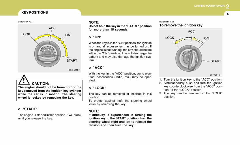
2DRIVING YOUR HYUNDAI
5KEY POSITIONS
C040A02A-AAT
CAUTION:The engine should not be turned off or thekey removed from the ignition key cylinderwhile the car is in motion. The steeringwheel is locked by removing the key.
!
o "START"
The engine is started in this position. It will crankuntil you release the key.
C040A01E-1
LOCK
ACC
ON
START
NOTE:Do not hold the key in the "START" positionfor more than 15 seconds.
o "ON"
When the key is in the "ON" position, the ignitionis on and all accessories may be turned on. Ifthe engine is not running, the key should not beleft in the "ON" position. This will discharge thebattery and may also damage the ignition sys-tem.
o "ACC"
With the key in the "ACC" position, some elec-trical accessories (radio, etc.) may be oper-ated.
o "LOCK"
The key can be removed or inserted in thisposition.To protect against theft, the steering wheellocks by removing the key.
NOTE:If difficulty is experienced in turning theignition key to the START position, turn thesteering wheel right and left to release thetension and then turn the key.
C070C01E-1
LOCK
ACC
ON
START
C070C01A-AAT
To remove the ignition key
1. Turn the ignition key to the "ACC" position.2. Simultaneously push and turn the ignition
key counterclockwise from the "ACC" posi-tion to the "LOCK" position.
3. The key can be removed in the "LOCK"position.
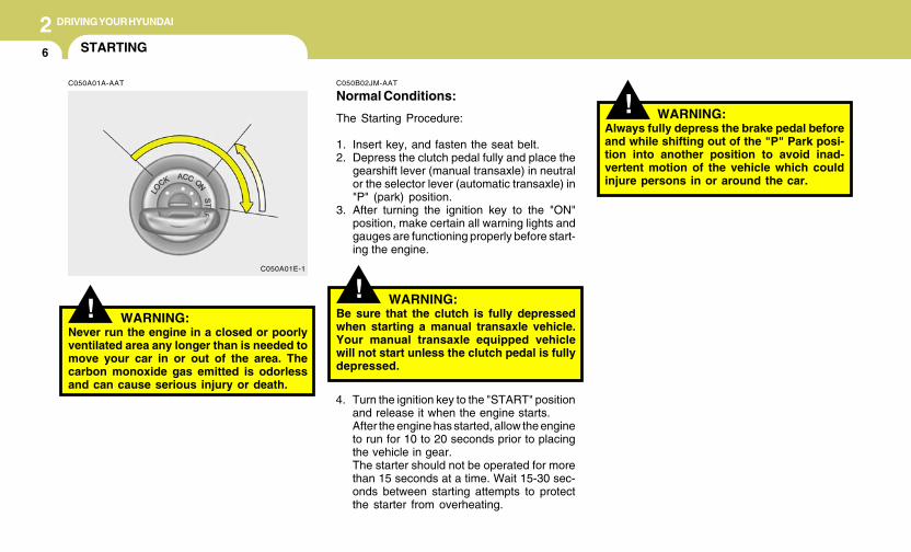
2 DRIVING YOUR HYUNDAI
6
!
4. Turn the ignition key to the "START" positionand release it when the engine starts.After the engine has started, allow the engineto run for 10 to 20 seconds prior to placingthe vehicle in gear.The starter should not be operated for morethan 15 seconds at a time. Wait 15-30 sec-onds between starting attempts to protectthe starter from overheating.
C050B02JM-AAT
Normal Conditions:
The Starting Procedure:
1. Insert key, and fasten the seat belt.2. Depress the clutch pedal fully and place the
gearshift lever (manual transaxle) in neutralor the selector lever (automatic transaxle) in"P" (park) position.
3. After turning the ignition key to the "ON"position, make certain all warning lights andgauges are functioning properly before start-ing the engine.
WARNING:Be sure that the clutch is fully depressedwhen starting a manual transaxle vehicle.Your manual transaxle equipped vehiclewill not start unless the clutch pedal is fullydepressed.
!C050A01E-1
STARTING
!
C050A01A-AAT
WARNING:Never run the engine in a closed or poorlyventilated area any longer than is needed tomove your car in or out of the area. Thecarbon monoxide gas emitted is odorlessand can cause serious injury or death.
WARNING:Always fully depress the brake pedal beforeand while shifting out of the "P" Park posi-tion into another position to avoid inad-vertent motion of the vehicle which couldinjure persons in or around the car.
2DRIVING YOUR HYUNDAI
7OPERATING THE MANUALTRANSAXLE
NOTE:o To shift into reverse, rest the lever in
neutral for at least 3 seconds after yourcar is completely stopped. Then movethe lever into the reverse position.
o During cold weather, shifting may bedifficult until the transaxle lubricant haswarmed up. This is normal and not harm-ful to the transaxle.
o If you've come to a complete stop andit's hard to shift into 1st or R(Reverse),put the shift lever in N(Neutral) positionand release the clutch. Press the clutchpedal down, and then shift into 1st orR(Reverse) gear position.
o Do not use the shift lever as a handrestduring driving, as this can result in pre-mature wear of the transaxle shift forks.
CAUTION:When downshifting from fifth gear to fourthgear, caution should be taken not to inad-vertently press the gear lever sideways insuch a manner that second gear is en-gaged. Such a drastic downshift may causethe engine speed to increase to the pointthat the tachometer will enter the red-zone.Such over-revving of the engine may causeengine damage.
!
C070A02A-AAT
Your Hyundai's manual transaxle has a con-ventional shift pattern. This shift pattern is im-printed on the shift knob. The transaxle is fullysynchronized in all forward gears so shifting toeither a higher or a lower gear is easily accom-plished.
HJM3017
C070B02A-AAT
Using the Clutch
The clutch should be pressed all the way to thefloor before shifting, then released slowly. Theclutch pedal should always be fully returned tothe original position. Do not rest your foot on theclutch pedal while driving. This can cause un-necessary wear.Do not partially engage the clutch to hold the caron an incline. This causes unnecessary wear.Use the foot brake or parking brake to hold thecar on an incline. Do not operate the clutch pedalrapidly and repeatedly.
2 DRIVING YOUR HYUNDAI
8
! WARNING:o Always buckle-up! In a collision, an
unbelted occupant is significantly morelikely to be seriously injured or killedthan a properly belted occupant.
o Avoid high speeds when cornering orturning.
o Do not make quick steering wheel move-ments, such as sharp lane changes orfast, sharp turns.
o The risk of rollover is greatly increased ifyou lose control of your vehicle at high-way speeds.
o Loss of control often occurs if two ormore wheels drop off the roadway andthe driver oversteers to reenter the road-way.
o In the event your vehicle leaves the road-way, do not steer sharply. Instead, slowdown before pulling back into the travellanes.
o Never exceed posted speed limits.
C070D02O-AAT
Recommended Shift Points
The shift points as shown on the chart arerecommended for optimum fuel economy andperformance.
Shift
from-to
1-2
2-3
3-4
4-5
Recommended
mph (km/h)
15 (20)
25 (40)
35 (55)
45 (75)
C070D04O-AAT
Good Driving Practices
o Never take the car out of gear and coastdown a hill. This is extremely hazardous.Always leave the car in gear.
o Don't "ride" the brakes. This can cause themto overheat and malfunction. Instead, whenyou are driving down a long hill, slow downand shift to a lower gear. When you do this,engine braking will help slow the car.
o Slow down before shifting to a lower gear.This will help avoid over-revving the engine,which can cause damage.
o Slow down when you encounter cross winds.This gives you much better control of yourcar.
o Be sure the car is completely stopped beforeyou attempt to shift into reverse. Thetransaxle can be damaged if you do not. Toshift into reverse, depress the clutch, movethe shift lever to neutral, wait three seconds,then shift to the reverse position.
o Exercise extreme caution when driving on aslippery surface. Be especially careful whenbraking, accelerating or shifting gears. On aslippery surface, an abrupt change in ve-hicle speed can cause the drive wheels tolose traction and the vehicle to go out ofcontrol.
o Optimum vehicle performance and economyis obtained by smoothly depressing andreleasing the accelerator pedal.
2DRIVING YOUR HYUNDAI
9
HJM3018
OPERATING THE AUTOMATICTRANSAXLE
C090A01O-GAT
The highly efficient Hyundai automatic transaxlehas four forward speeds and one reversespeed. The individual speeds are selected au-tomatically, depending on the position of thespeed selector lever. The selector lever has 2gates; the main gate and the manual gate.
NOTE:For information on manual gate operation,refer to "Sports Mode".
In the main gate, the selector lever has 4positions, and is equipped with a button to avoidinadvertent selection.
NOTE:Depress the brake pedal and push thebutton when shifting.
Push the button when shifting.
The selector lever can be shifted freely.
The first few shifts on a new vehicle, or if thebattery has been disconnected, may besomewhat abrupt. This is a normal condi-tion, and the shifting sequence will adjustafter shifts are cycled a few times by theT.C.M (Transaxle Control Module).
C090A01JM
The indicator lights in the instrument clusterindicate the selector lever position when theignition is switched "ON". During "D" rangeoperation, green lights indicate the gear cur-rently in use.
CAUTION:Never shift into "R" or "P" position while thevehicle is moving.
!
2 DRIVING YOUR HYUNDAI
10
!
C090E02O-AAT
o D(Drive):
Use for normal driving. Bring the car to acomplete stop before shifting the selector to "D"position. The transaxle will automatically shiftthrough a four gear sequence.
C090D02O-AAT
o N (Neutral):
In the "N" position, the transaxle is in neutral,which means that no gears are engaged. Theengine can be started with the shift lever in "N"position, although this is not recommendedexcept if the engine stalls while the car ismoving.
C090B02A-AAT
The function of each position is as fol-lows:
o P (Park):
Use to hold the vehicle in place when parked orwhile starting the engine. Whenever parking thecar, apply the parking brake and shift the selec-tor lever to the "P" (Park) position.
C090C01A-AAT
o R(Reverse):
Use for backing up the vehicle. Bring the car toa complete stop before shifting the selectorlever to "R" position.
CAUTION:Never place the selector lever in the "P"(Park) position unless the vehicle is fullystopped. Failure to observe this cautionwill cause severe damage to the transaxle.
C090F01JM-GAT
Sports Mode
Whether the vehicle is stationary or in motion,sports mode is selected by pushing the selectorlever from the "D" position into the manual gate.To return to "D" range operation, push theselector lever back into the main gate.In sports mode, moving the selector lever back-wards and forwards can make gearshifts simple.UP (+) : Push the lever forward once to shift upone gear.DOWN (-) : Pull the lever backwards once toshift down one gear.SKIP : By rapidly moving the selector forwardsor backwards twice, it is possible to skip onegear, i.e. 1st to 3rd or 3rd to 1st.
HJM3020
2DRIVING YOUR HYUNDAI
11
!o To maintain the required levels of ve-
hicle performance and safety, the sys-tem may not execute certain gearshiftswhen the selector lever is operated.
o Before driving away from a stop on aslippery road, push the selector leverforward into the +(UP) position. Thiscauses the transaxle to shift into 2ndgear which is better for smooth drivingaway on a slippery road. Push the selec-tor lever to the -(DOWN) side to shiftback to 1st gear.
CAUTION:o In sports mode, The driver must execute
shifts in accordance with prevailing roadconditions, taking care to keep the en-gine speed below the red zone. For en-gine protection, upward shifts are madeautomatically when the engine rpmreaches the red zone.
o By rapidly moving the selector lever back-wards (-) twice, it is possible to skip onegear, i.e., 3rd to 1st, 4th to 2nd. Sincesudden engine braking and/or rapid ac-celeration can cause a loss of traction,however, downshifts must be made care-fully in accordance with the vehicle'sspeed.
NOTE:o In sports mode, only the four forward
gears can be selected. To select reverseor park, move the selector lever to the "R"or "P" position as required.
o In sports mode, downward shifts aremade automatically when the vehicleslows down. When the vehicle stops, 1stgear is automatically selected.
C090H01L-GAT
NOTE:o For smooth and safe operation, depress
the brake pedal when shifting from "Neu-tral" position or "Park" position to aforward or reverse gear.
o The ignition key must be in the "ON"position and the brake pedal fully de-pressed in order to move the shift leverfrom the "P" (Park) position to any of theother positions.
o It is always possible to shift from "R","N", "D" position to "P" position. Thevehicle must be fully stopped to avoidtransaxle damage.
!
C090I04L-GAT
CAUTION:o Shift into "R", "D" and "P" position only
when the vehicle has completelystopped.
o Do not accelerate the engine in reverseor any of the forward positions with thebrakes applied.
o Always apply the footbrake when shift-ing from "P" or "N", to "R" or "D"position.
o Do not use the "P" (Park) position inplace of the parking brake. Always setthe parking brake, shift the transaxleinto "P" (Park) position and turn off theignition when you leave the vehicle, evenmomentarily. Never leave the vehicleunattended while the engine is running.
o When accelerating from a stop on asteep hill, the vehicle may have a ten-dency to roll backwards. Shifting theshift lever into 2nd gear while in Sportmode will help prevent the vehicle fromrolling backwards.
o Check the automatic transaxle fluid levelregularly, and add fluid as necessary.
o See the maintenance schedule for theproper fluid recommendation.
2 DRIVING YOUR HYUNDAI
12
!
C090N05O-AAT
Good Driving Practices
o Never move the gear selector lever from "P"or "N" to any other position with the accelera-tor pedal depressed.
o Never move the gear selector lever into "P"when the vehicle is in motion.
o Be sure the car is completely stopped beforeyou attempt to shift into "R" or "D".
o Never take the car out of gear and coastdown a hill. This may be extremely hazard-ous. Always leave the car in gear whenmoving.
o Do not "ride" the brakes. This can causethem to overheat and malfunction. Instead,when you are driving down a long hill, slowdown and shift to a lower gear. When you dothis, engine braking will help slow the car.
o Slow down before shifting to a lower gear.Otherwise, the lower gear may not be en-gaged.
o Always use the parking brake. Do not de-pend on placing the transaxle in "P" to keepthe car from moving.
o Exercise extreme caution when driving on aslippery surface. Be especially careful whenbraking, accelerating or shifting gears. On aslippery surface, an abrupt change in ve-hicle speed can cause the drive wheels tolose traction and the vehicle to go out ofcontrol.
WARNING:o Always buckle-up! In a collision, an
unbelted occupant is significantly morelikely to be seriously injured or killedthan a properly belted occupant.
o Avoid high speeds when cornering orturning.
o Do not make quick steering wheel move-ments, such as sharp lane changes orfast, sharp turns.
o The risk of rollover is greatly increased ifyou lose control of your vehicle at high-way speeds.
o Loss of control often occurs if two ormore wheels drop off the roadway andthe driver oversteers to reenter the road-way.
o In the event your vehicle leaves the road-way, do not steer sharply. Instead, slowdown before pulling back into the travellanes.
o Never exceed posted speed limits.
o Optimum vehicle performance and economyis obtained by smoothly depressing andreleasing the accelerator pedal. CAUTION:
If your vehicle becomes stuck in snow,mud, sand, etc., then you may attempt torock the vehicle free by moving it forwardand backward. Do not attempt this proce-dure if people or objects are anywhere nearthe vehicle. During the rocking operationthe vehicle may suddenly move forward ofbackward as it becomes unstuck, causinginjury to nearby people or damage to ob-jects.
!
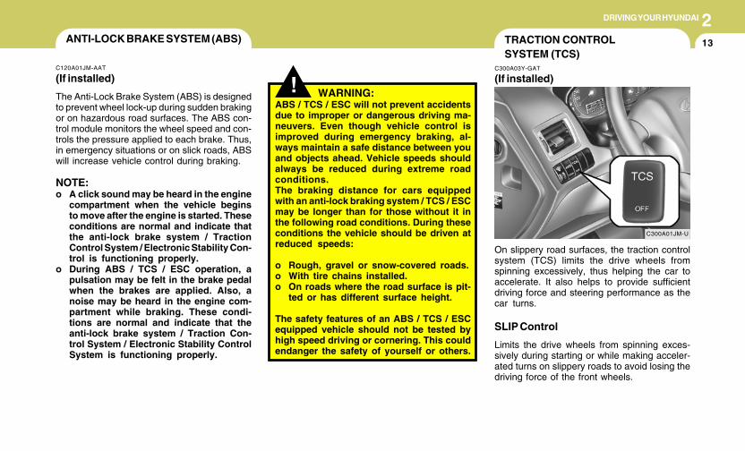
2DRIVING YOUR HYUNDAI
13
! WARNING:ABS / TCS / ESC will not prevent accidentsdue to improper or dangerous driving ma-neuvers. Even though vehicle control isimproved during emergency braking, al-ways maintain a safe distance between youand objects ahead. Vehicle speeds shouldalways be reduced during extreme roadconditions.The braking distance for cars equippedwith an anti-lock braking system / TCS / ESCmay be longer than for those without it inthe following road conditions. During theseconditions the vehicle should be driven atreduced speeds:
o Rough, gravel or snow-covered roads.o With tire chains installed.o On roads where the road surface is pit-
ted or has different surface height.
The safety features of an ABS / TCS / ESCequipped vehicle should not be tested byhigh speed driving or cornering. This couldendanger the safety of yourself or others.
TRACTION CONTROLSYSTEM (TCS)
C300A03Y-GAT
(If installed)
C300A01JM-U
On slippery road surfaces, the traction controlsystem (TCS) limits the drive wheels fromspinning excessively, thus helping the car toaccelerate. It also helps to provide sufficientdriving force and steering performance as thecar turns.
SLIP Control
Limits the drive wheels from spinning exces-sively during starting or while making acceler-ated turns on slippery roads to avoid losing thedriving force of the front wheels.
ANTI-LOCK BRAKE SYSTEM (ABS)
C120A01JM-AAT
(If installed)
The Anti-Lock Brake System (ABS) is designedto prevent wheel lock-up during sudden brakingor on hazardous road surfaces. The ABS con-trol module monitors the wheel speed and con-trols the pressure applied to each brake. Thus,in emergency situations or on slick roads, ABSwill increase vehicle control during braking.
NOTE:o A click sound may be heard in the engine
compartment when the vehicle beginsto move after the engine is started. Theseconditions are normal and indicate thatthe anti-lock brake system / TractionControl System / Electronic Stability Con-trol is functioning properly.
o During ABS / TCS / ESC operation, apulsation may be felt in the brake pedalwhen the brakes are applied. Also, anoise may be heard in the engine com-partment while braking. These condi-tions are normal and indicate that theanti-lock brake system / Traction Con-trol System / Electronic Stability ControlSystem is functioning properly.
2 DRIVING YOUR HYUNDAI
14
!
Driving Hints
TCS does not actively apply brakes. Be sure todecelerate the car sufficiently before enteringcurves.
CAUTION:When the TCS indicator blinks, SLIP con-trol function has been activated. It alsomeans that the road is slippery or your caris accelerating excessively. In this situa-tion, gently release foot pressure from theaccelerator pedal and maintain moderatespeed.
!
WARNING:Traction control is a driving aid; all normalprecautions for driving in inclement weath-er and on slippery driving surfaces shouldbe observed.
C310B02O-AAT
TCS ON/OFF Mode
When the TCS is operating, the TCS indicatorin the instrument cluster will blink.If you turn the system off by pressing the TCSswitch, the TCS-OFF indicator will come on andstay on. In the TCS-OFF mode, the SLIP controlwill be deactivated. Adjust you driving accord-ingly. To turn the system back on, press theswitch again. The TCS-OFF indicator should gooff.
NOTE:1) The TCS mode will automatically be
turned ON after the engine is turned offand restarted.
2) When the traction control system is op-erating properly, you can feel a slightpulsation in the vehicle. This is only theeffect of brake control and indicatesnothing unusual.
3) When the engine starts, a click may beheard from the engine compartment;this is the sound of the traction controlbeing checked.
4) When moving out of the mud or freshsnow, pressing the accelerator pedalmay not cause the engine speed to in-crease due to TCS operation.
C310D01JM-AAT
Indicators and Warning
The indicators should illuminate when the igni-tion key is turned to ON or START but shouldgo out after approximately three seconds.If the indicators do not illuminate, or the TCS orTCS-OFF indicator does not go out after 3seconds, have the system checked by anauthorized dealer.
Should there be any unusual conditions in theTCS System while driving, TCS-OFF indicatorilluminates as a warning.If TCS-OFF indicator illuminates, pull your carto a safe place and stop the engine.Then, start the engine again to check if the TCS-OFF indicator goes out.
If the indicator remains lit even after the enginehas been started, have your car checked by anauthorized Hyundai dealer.
NOTE:When the TCS-OFF indicator illuminates,traction control is automatically deacti-vated.
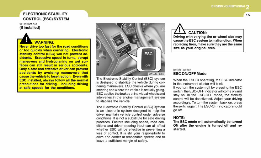
2DRIVING YOUR HYUNDAI
15
!CAUTION:
Driving with varying tire or wheel size maycause the ESC system to malfunction. Whenreplacing tires, make sure they are the samesize as your original tires.
!
ELECTRONIC STABILITYCONTROL (ESC) SYSTEM
C310A03JM-AAT
(If installed)
C310A01JM-U
The Electronic Stability Control (ESC) systemis designed to stabilize the vehicle during cor-nering manuevers. ESC checks where you aresteering and where the vehicle is actually going.ESC applies the brakes at individual wheels andintervenes in the engine management systemto stabilize the vehicle.
The Electronic Stability Control (ESC) systemis an electronic system designed to help thedriver maintain vehicle control under adverseconditions. It is not a substitute for safe drivingpractices. Factors including speed, road con-ditions and driver steering input can all affectwhether ESC will be effective in preventing aloss of control. It is still your responsibility todrive and corner at reasonable speeds and toleave a sufficient margin of safety.
WARNING:Never drive too fast for the road conditionsor too quickly when cornering. Electronicstability control (ESC) will not prevent ac-cidents. Excessive speed in turns, abruptmaneuvers and hydroplaning on wet sur-faces can still result in serious accidents.Only a safe and attentive driver can preventaccidents by avoiding maneuvers thatcause the vehicle to lose traction. Even withESC installed, always follow all the normalprecautions for driving - including drivingat safe speeds for the conditions.
C310B01JM-AAT
ESC ON/OFF Mode
When the ESC is operating, the ESC indicatorin the instrument cluster will blink.If you turn the system off by pressing the ESCswitch, the ESC-OFF indicator will come on andstay on. In the ESC-OFF mode, the stabilitycontrol will be deactivated. Adjust your drivingaccordingly. To turn the system back on, pressthe switch again. The ESC-OFF indicator shouldgo off.
NOTE:The ESC mode will automatically be turnedON after the engine is turned off and re-started.
2 DRIVING YOUR HYUNDAI
16
C310D01JM-AAT
Indicators and Warning
The indicators should illuminate when the igni-tion key is turned to ON or START but shouldgo out after three seconds.If the indicators do not illuminate, or the ESC orESC-OFF indicator does not go out after 3seconds, have the vehicle checked by anauthorized dealer.
Should there be any unusual conditions in thedevice while driving, ESC-OFF indicator illumi-nates as a warning.If ESC-OFF indicator illuminates, pull your carto a safe place and stop the engine.Then, start the engine again to check if the ESC-OFF indicator goes out.
If the indicator remains lit even after the enginehas been started, have your car checked by anauthorized Hyundai dealer.
FULL-TIME 4WD OPERATION
C350A02JM-AAT
(If installed)
Engine power can be delivered to all wheels.Full-time 4WD is useful when good traction isrequired, such as, when driving on slippery, wetor snow-covered roads and when moving outof mud. Your vehicle is not designed for chal-lenging off-road use. Full-time 4WD vehiclesare designed primarily to improve traction andperformance on paved roads and highways inwet and/or slippery conditions. Occasional off-road use such as established unpaved roadsand trails is considered normal use. It is alwaysimportant when traveling off-highway that thedriver carefully reduce their speed to a level thatdoes not exceed the safe operating speed forthose conditions. In general, off-road conditionsprovide less traction and braking effectivenessthan on road conditions. These factors must becarefully considered when driving off-road.Keeping the vehicle in contact with the drivingsurface and under control in these conditions isalways the driver's responsibility for the safetyof him/herself and his or her passengers.
! WARNING:This vehicle is designed primarily for onroad use. Driving the vehicle in challengingoff-road conditions may result in damageto the vehicle. Driving in conditions thatexceed the vehicle's intended design or thedriver's experience level may result in se-vere injury or death.
Driving 4WD Safely
(1)As always, be sure to wear the seat belt.(2)Do not drive in challenging off-road condi-
tions or areas that exceed the vehicle'sbasic design intent or the driver's experi-ence level.
(3)Drive at lower speeds in strong crosswinds.Because of your vehicle's higher center ofgravity, its stability will be affected in cross-winds. Slower speeds ensure better vehiclecontrol.
(4)Check the brake condition after driving in wetor muddy conditions. Press the brake sev-eral times as you move slowly until you feelnormal braking forces return.
(5)Do not drive the vehicle through water. (i.e.streams, rivers, lakes, etc.)
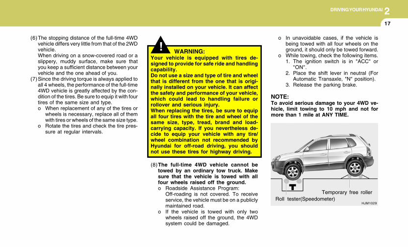
2DRIVING YOUR HYUNDAI
17
HJM1029Roll tester(Speedometer)
Temporary free roller
o In unavoidable cases, if the vehicle isbeing towed with all four wheels on theground, it should only be towed forward.
o While towing, check the following items.1. The ignition switch is in "ACC" or
"ON".2. Place the shift lever in neutral (For
Automatic Transaxle, "N" position).3. Release the parking brake.
NOTE:To avoid serious damage to your 4WD ve-hicle, limit towing to 10 mph and not formore than 1 mile at ANY TIME.
(8)The full-time 4WD vehicle cannot betowed by an ordinary tow truck. Makesure that the vehicle is towed with allfour wheels raised off the ground.o Roadside Assistance Program:
Off-roading is not covered. To receiveservice, the vehicle must be on a publiclymaintained road.
o If the vehicle is towed with only twowheels raised off the ground, the 4WDsystem could be damaged.
(6)The stopping distance of the full-time 4WDvehicle differs very little from that of the 2WDvehicle.When driving on a snow-covered road or aslippery, muddy surface, make sure thatyou keep a sufficient distance between yourvehicle and the one ahead of you.
(7)Since the driving torque is always applied toall 4 wheels, the performance of the full-time4WD vehicle is greatly affected by the con-dition of the tires. Be sure to equip it with fourtires of the same size and type.o When replacement of any of the tires or
wheels is necessary, replace all of themwith tires or wheels of the same size type.
o Rotate the tires and check the tire pres-sure at regular intervals.
! WARNING:Your vehicle is equipped with tires de-signed to provide for safe ride and handlingcapability.Do not use a size and type of tire and wheelthat is different from the one that is origi-nally installed on your vehicle. It can affectthe safety and performance of your vehicle,which could lead to handling failure orrollover and serious injury.When replacing the tires, be sure to equipall four tires with the tire and wheel of thesame size, type, tread, brand and load-carrying capacity. If you nevertheless de-cide to equip your vehicle with any tire/wheel combination not recommended byHyundai for off-road driving, you shouldnot use these tires for highway driving.
2 DRIVING YOUR HYUNDAI
18
! CAUTION:o While the full-time 4WD vehicle is being
raised on a jack, never start the engine orcause the tires to rotate.There is danger that rotating tires touch-ing the ground could cause the vehicleto go off the jack and to jump forward.
o If one of the front or rear wheels beginsto spin in mud, snow, etc., the vehiclecan sometimes be driven out by de-pressing the accelerator pedal further;however, avoid running the engine con-tinuously at high rpm because doing socould damage the 4WD system.
(10)When using tire chains, always attach themto the front wheels.
(11)If the front or rear wheels get stuck in themud, do not spin them recklessly. The 4WDsystem could be damaged.
o In rare cases when it's unavoidable thata 4WD vehicle is to be inspected on a2WD roll tester, strictly follow the proce-dures.1. Check the tire pressures recom-
mended for your vehicle.2. Place the front wheels on the roll
tester as shown in the illustration.3. Release the parking brake.4. Place the rear wheels on the tempo-
rary free roller as shown in the illustra-tion.
!
! WARNING:Keep away from the front of the vehiclewhile inspecting. This is very dangerous asthe vehicle can jump forward and causeserious injury or death.
! WARNING:o Avoid high cornering speeds.o Do not make quick steering wheel move-
ments, such as sharp lane charges orfast, sharp turns.
o The risk of rollover is greatly increased ifyou lose control of your vehicle at high-way speeds.
o In a collision, an unbelted person issignicantly more likely to be seriouslyinjured or killed than a person wearing aseat belt.
o Loss of control may occurs if two ormore wheels drop off the roadway andthe driver oversteers to reenter the road-way.
o In the event your vehicle leaves the road-way, do not steer sharply. Instead, slowdown before pulling back into the travellanes.
(9)For a speedometer test or inspection/main-tenance (I/M) program of a Tucson 4WDvehicle, use a four wheel chassis dynamom-eter.
CAUTION:Never engage the parking brake while per-forming these tests.
2DRIVING YOUR HYUNDAI
194WD LOCK SYSTEM
C360A01O-GAT
(With Electronic Control 4WD)(If installed)
This 4WD system is designed for dividing thepower ratio automatically in normal driving con-ditions.During off-road or low-friction driving condi-tions, press the 4WD lock button to drive in full-time 4WD, dividing the power ratio to 50:50 in thefront and rear wheels. The 4WD lock indicatorlight in the instrument cluster is illuminated.
This setup begins to get cancelled when thevehicle speed exceeds 30 km/h, and the func-tion is completely released at a speed of 40 km/h or higher. Conversely, the function is rerunwhen the speed again drops to 40 km/h or lower,and is fully established at speeds below 30 km/h.To release the 4WD lock function, press the4WD lock button again.The 4WD lock indicator light in the instrumentcluster should go off.
C360A01JM-U
1) Pressing the 4WD lock button on the toughterrain, the driving power is equally distrib-uted to the front and rear.4WD lock keeps activating when not ex-ceeding 40 km/h.
2) Release the 4WD lock button on the normaldriving conditions.
C360A02JM
1)
2)
2 DRIVING YOUR HYUNDAI
20
Four Wheel Drive (4WD) transfer mode selection
Transfer mode Selection button Indicator light Description
o This mode is used for climbing or descending sharp grades, off-roaddriving, driving on sandy and muddy roads etc. to maximize traction.
o This mode automatically begins to deactivate at speed above 19 mph(30 km/h) and is shifted to 4WD AUTO mode at speed above 25 mph(40 km/h). If the vehicle decelerates to speeds below 19 mph (30 km/h), however, the transfer mode is shifted into 4WD LOCK mode again.
o When driving in AUTO mode, the vehicle operates similar to theconventional 2WD vehicles under normal operating conditions.However, if the system determines that there is a need for the 4WDmode, the engine’s driving power is distributed to all four wheelsautomatically without driver intervention.
o When driving on normal roads and pavement, the vehicle movessimilar to the conventional 2WD vehicles.
4WDLOCK
(Indicator light isilluminated)
4WD LOCK
4WD AUTO(4WD LOCK is
deactivated)
(Indicator light isnot illuminated)
NOTE:o When driving on normal roads, deactivate the 4WD LOCK mode by pushing the 4WD LOCK button(the indicator light goes off). Driving
on normal roads with 4WD LOCK mode(especially, when cornering) may cause mechanical noise or vibration. The noise and vibrationwill disappear when the 4WD LOCK mode is deactivated. Some parts of the power train may be damaged by prolonged driving with thenoise and vibration.
o When the 4WD LOCK mode is deactivated, a shock may be felt as the drive power delivered entirely to the front wheels. This shock isnot a mechanical failure.
2DRIVING YOUR HYUNDAI
21GOOD BRAKING PRACTICES
C130A02A-AAT
WARNING:o Whenever leaving vehicle or parking,
always set the parking brake as far aspossible and fully engage the vehicle'stransaxle into the park position. Ve-hicles not fully engaged in park with theparking brake set are at risk for movinginadvertently and injuring yourself orothers.
o All vehicles should always have the park-ing brake fully engaged when parking toavoid inadvertent movement of the carwhich can injure occupants or pedestri-ans.
o Nothing should be carried on top of theshelf panel behind the rear seat. If therewere an accident or a sudden stop, suchobjects could move forward and causedamage to the vehicle or injure the occu-pants.
!
o If your car is equipped with an automatictransaxle, don't let your car creep forward.To avoid creeping forward, keep your footfirmly on the brake pedal when the car isstopped.
o Use caution when parking on a hill. Firmlyengage the parking brake and place the gearselector lever in "P" (automatic transaxle) orin first or reverse gear (manual transaxle).If your car is facing downhill, turn the frontwheels into the curb to help keep the car fromrolling. If your car is facing uphill, turn the frontwheels away from the curb to help keep thecar from rolling. If there is no curb or if it isrequired by other conditions to keep the carfrom rolling, block the wheels.
o Under some conditions your parking brakecan freeze in the engaged position. This ismost likely to happen when there is an ac-cumulation of snow or ice around or near therear brakes or if the brakes are wet. If thereis a risk that the parking brake may freeze,apply it only temporarily while you put thegear selector lever in "P" (automatic) or infirst or reverse gear (manual transaxle) andblock the rear wheels so the car cannot roll.Then release the parking brake.
o Do not hold the vehicle on the upgrade withthe accelerator pedal. This can cause thetransaxle to overheat. Always use the brakepedal or parking brake.
o After being parked, check to be sure theparking brake is not engaged and that theparking brake indicator light is out beforedriving away.
o Driving through water may get the brakeswet. They can also get wet when the car iswashed. Wet brakes can be dangerous!Your car will not stop as quickly if the brakesare wet. Wet brakes may cause the car topull to one side. To dry the brakes, apply thebrakes lightly while driving slowly until thebraking action returns to normal, taking careto keep the car under control at all times. Ifthe braking action does not return to normal,stop as soon as it is safe to do so and call yourHyundai dealer for assistance.
o Don't coast down hills with the car out of gear.This is extremely hazardous. Keep the carin gear at all times, use the brakes to slowdown, then shift to a lower gear so that enginebraking will help you maintain a safe speed.
o Don't "ride" the brake pedal. Resting yourfoot on the brake pedal while driving can bedangerous because it can result in the brakesoverheating and losing their effectiveness. Italso increases the wear of the brake com-ponents.
o If a tire goes flat while you are driving, applythe brakes gently and keep the car pointedstraight ahead while you slow down. Whenyou are moving slowly enough for it to be safeto do so, pull off the road and stop in a safeplace.
2 DRIVING YOUR HYUNDAI
22
o Be sure that the wheels are aligned cor-rectly. Improper alignment can result fromhitting curbs or driving too fast over irregularsurfaces. Poor alignment causes faster tirewear and may also result in other problemsas well as greater fuel consumption.
o Keep your car in good condition. For betterfuel economy and reduced maintenancecosts, maintain your car in accordance withthe maintenance schedule in Section 5. Ifyou drive your car in severe conditions,more frequent maintenance is required (seeSection 5 for details).
o Keep your car clean. For maximum service,your Hyundai should be kept clean and freeof corrosive materials. It is especially impor-tant that mud, dirt, ice, etc. not be allowed toaccumulate on the underside of the car. Thisextra weight can result in increased fuelconsumption and also contribute to corro-sion.
o Travel lightly. Don't carry unnecessaryweight in your car. Weight reduces fueleconomy.
o Don't let the engine idle longer than neces-sary. If you are waiting (and not in traffic),turn off your engine and restart only whenyou're ready to go.
o Remember, your Hyundai does not requireextended warm-up. After the engine hasstarted, allow the engine to run for 10 to 20seconds prior to placing the vehicle in gear.In very cold weather, however, give yourengine a slightly longer warm-up period.
o Don't "lug" or "over-rev" the engine. Luggingis driving too slowly in too high a gear result-ing in the engine bucking. If this happens,shift to a lower gear. Over-revving is racingthe engine beyond its safe limit. This can beavoided by shifting at the recommendedspeeds.
o Use your air conditioning sparingly. The airconditioning system is operated by enginepower so your fuel economy is reducedwhen you use it.
DRIVING FOR ECONOMY
C140A02A-AAT
You can save fuel and get more miles from yourcar if you follow these suggestions:
o Drive smoothly. Accelerate at a moderaterate. Don't make "jack-rabbit" starts or full-throttle shifts and maintain a steady cruisingspeed. Don't race between stoplights. Try toadjust your speed to that of the other trafficso you don't have to change speeds unnec-essarily. Avoid heavy traffic whenever pos-sible. Always maintain a safe distance fromother vehicles so you can avoid unneces-sary braking. This also reduces brake wear.
o Drive at a moderate speed. The faster youdrive, the more fuel your car uses. Driving ata moderate speed, especially on the high-way, is one of the most effective ways toreduce fuel consumption.
o Don't "ride" the brake or clutch pedal. Thiscan increase fuel consumption and alsoincrease wear on these components. Inaddition, driving with your foot resting on thebrake pedal may cause the brakes to over-heat, which reduces their effectiveness andmay lead to more serious consequences.
o Take care of your tires. Keep them inflatedto the recommended pressure. Incorrectinflation, either too much or too little, resultsin unnecessary tire wear. Check the tirepressures at least once a month.
2DRIVING YOUR HYUNDAI
23SMOOTH CORNERING
C150A01A-AAT
Avoid braking or gear changing in corners,especially when roads are wet. Ideally, cornersshould always be taken under gentle accelera-tion. If you follow these suggestions, tire wearwill be held to a minimum.
C160D01A-AAT
Check Battery and Cables
Winter puts additional burdens on the batterysystem. Visually inspect the battery and cablesas described in Section 6. The level of chargein your battery can be checked by your Hyundaidealer or a service station.
C160C01A-AAT
Use High Quality Ethylene GlycolCoolant
Your Hyundai is delivered with high qualityethylene glycol coolant in the cooling system. Itis the only type of coolant that should be usedbecause it helps prevent corrosion in the cool-ing system, lubricates the water pump andprevents freezing. Be sure to replace or replen-ish your coolant in accordance with the main-tenance schedule in Section 5. Before winter,have your coolant tested to assure that itsfreezing point is sufficient for the temperaturesanticipated during the winter.
NOTE:o Tire chains are not legal in all states.
Check state laws before fitting tirechains.
o Tire chains are to be used on front tiresonly.
C160A01A-AAT
The more severe weather conditions of winterresult in greater wear and other problems. Tominimize the problems of winter driving, youshould follow these suggestions:
C160B01JM-AAT
Snowy or Icy Conditions
To drive your vehicle in deep snow, it may benecessary to use snow tires or to install tirechains on your tires. If snow tires are needed,it is necessary to select tires equivalent in sizeand type of the original equipment tires. Failureto do so may adversely affect the safety andhandling of your car. Furthermore, speeding,rapid acceleration, sudden brake applications,and sharp turns are potentially very hazardouspractices.During deceleration, use engine braking to thefullest extent. Sudden brake applications onsnowy or icy roads may cause skids to occur.You need to keep sufficient distance betweenthe vehicle in operation in front and your vehicle.Also, apply the brake gently. It should be notedthat installing tire chains on the tire will providea greater driving force, but will not prevent sideskids.
WINTER DRIVING
2 DRIVING YOUR HYUNDAI
24
C160K01A-AAT
Carry Emergency Equipment
Depending on the severity of the weather whereyou drive your car, you should carry appropri-ate emergency equipment. Some of the itemsyou may want to carry include tire chains, towstraps or chains, flashlight, emergency flares,sand, a shovel, jumper cables, a window scraper,gloves, ground cloth, coveralls, a blanket, etc.
C160H02A-AAT
Use Approved Window Washer Anti-Freeze in System
To keep the water in the window washer systemfrom freezing, add an approved window washeranti-freeze solution in accordance with instruc-tions on the container. Window washer anti-freeze is available from Hyundai dealers andmost auto parts outlets. Do not use enginecoolant or other types of anti-freeze as thesemay damage the paint finish.
C160G01A-AAT
To Keep Locks from Freezing
To keep the locks from freezing, squirt anapproved de-icer fluid or glycerine into the keyopening. If a lock is covered with ice, squirt it withan approved de-icing fluid to remove the ice. Ifthe lock is frozen internally, you may be able tothaw it out by using a heated key. Handle theheated key with care to avoid injury.
C160J01A-AAT
Don't Let Ice and Snow AccumulateUnderneath
Under some conditions, snow and ice can buildup under the fenders and interfere with thesteering. When driving in severe winter condi-tions where this may happen, you should peri-odically check underneath the car to be sure themovement of the front wheels and the steeringcomponents is not obstructed.
C160I01A-AAT
Don't Let Your Parking Brake Freeze
Under some conditions your parking brake canfreeze in the engaged position. This is mostlikely to happen when there is an accumulationof snow or ice around or near the rear brakesor if the brakes are wet. If there is a risk theparking brake may freeze, apply it only tempo-rarily while you put the gear selector lever in "P"(automatic) or in first or reverse gear (manualtransaxle) and block the rear wheels so the carcannot roll. Then release the parking brake.
C160F01A-AAT
Check Spark Plugs and IgnitionSystem
Inspect your spark plugs as described in Sec-tion 6 and replace them if necessary. Alsocheck all ignition wiring and components to besure they are not cracked, worn or damaged inany way.
C160E01A-AAT
Change to "Winter Weight" Oil ifNecessary
In some climates it is recommended that a lowerviscosity "winter weight" oil be used during coldweather. See Section 9 for recommendations.If you aren't sure what weight oil you should use,consult your Hyundai dealer.
2DRIVING YOUR HYUNDAI
25
!
HIGHER SPEED MOTORING
C170A02A-AAT
Pre-Trip Inspections
1. Tires:Adjust the tire inflation pressures to specifica-tion. Low tire inflation pressures will result inoverheating and possible failure of the tires.Avoid using worn or damaged tires which mayresult in reduced traction or tire failure.
NOTE:Never exceed the maximum tire inflationpressure shown on the tires.
WARNING:o Underinflated or overinflated tires can
cause poor handling, loss of vehiclecontrol, and sudden tire failure leadingto accidents, injuries, and even death.Always check tires are properly inflatedbefore driving. Refer to pages 2-28 and8-3 for proper tire pressures and furtherinformation.
o Driving on tires with no or insufficienttread is dangerous. Worn-out tires canresult in loss of vehicle control, colli-sions, injury, and even death. Worn-outtires should be replaced as soon aspossible and should never be used fordriving. Always check tire tread beforedriving your car. Refer to 8-11 for furtherinformation and tread limits.
USE OF LIGHTS
C180A01A-AAT
Check your lights regularly for correct opera-tion and always keep them clean. When drivingduring the day in conditions of poor visibility, itis helpful to drive with headlights on low beam.This enables you to be seen as well as to see.
2. Fuel, engine coolant and engine oil:High speed travel consumes more fuel thanurban motoring. Do not forget to check bothengine coolant and engine oil.
3. Drive belt:A loose or damaged drive belt may result inoverheating of the engine.
2 DRIVING YOUR HYUNDAI
26
C190B01S-AAT
Trailer Hitches
Select the proper hitch and ball combination,making sure that its location is compatible withthat of the trailer or vehicle being towed.Use a quality non-equalizing hitch which distrib-utes the tongue load uniformly throughout thechassis.
The hitch should be bolted securely to the carand installed by a qualified technician. DO NOTUSE A HITCH DESIGNED FOR TEMPORARYINSTALLATION AND NEVER USE ONE THATATTACHES ONLY TO THE BUMPER.
C190C01Y-AAT
Trailer Brakes
If your trailer is equipped with a braking system,make sure it conforms to federal and/or localregulations and that it is properly installed andoperating correctly.
NOTE:If you tow a trailer or vehicle, your car willrequire more frequent maintenance due tothe additional load. See Maintenance UnderSevere Usage Conditions" on page 5-6.
C190D01S-AAT
Safety Chains
Should the hitch connection between your ve-hicle and the trailer or vehicle you are towing fail,the trailer or vehicle could wander dangerouslyacross other lanes of traffic and ultimately leavethe roadway. To eliminate this potentially dan-gerous situation, safety chains, attached be-tween your car and the trailer or towed vehicle,are required in most states.
CAUTION:o Never connect a trailer brake system
directly to the vehicle brake system.o When towing a trailer on steep grades (in
excess of 6%) pay close attention to theengine coolant temperature gauge toensure the engine does not overheat. Ifthe needle of the coolant temperaturegauge moves across the dial towards"H" (HOT), pull over and stop as soon asit is safe to do so, and allow the engineto idle until it cools down. You mayproceed once the engine has cooledsufficiently.
!
TRAILER OR VEHICLE TOWING
!
C190A01S-AAT
If you are considering towing with your car, youshould first check with your State's Departmentof Motor Vehicles to determine their legal re-quirements.Since laws vary from State to State the require-ments for towing trailers, cars, or other types ofvehicles or apparatus may differ. Ask yourHyundai dealer for further details before towing.
CAUTION:Do not do any towing with your car duringits first 1,200 miles (2,000 km) in order toallow the engine to properly break in. Fail-ure to heed this caution may result in seri-ous engine or transaxle damage.
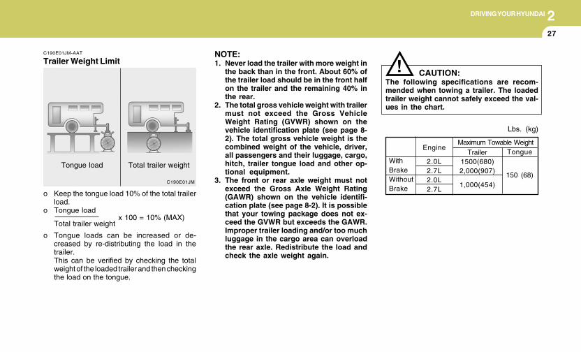
2DRIVING YOUR HYUNDAI
27
C190E01JM
x 100 = 10% (MAX)
C190E01JM-AAT
Trailer Weight Limit
o Keep the tongue load 10% of the total trailerload.
o Tongue load
o Tongue loads can be increased or de-creased by re-distributing the load in thetrailer.This can be verified by checking the totalweight of the loaded trailer and then checkingthe load on the tongue.
Total trailer weight
Tongue load Total trailer weight
Lbs. (kg)
Tongue
150 (68)
Engine
2.0L2.7L2.0L2.7L
Maximum Towable Weight
WithBrakeWithoutBrake
Trailer1500(680)2,000(907)
1,000(454)
NOTE:1. Never load the trailer with more weight in
the back than in the front. About 60% ofthe trailer load should be in the front halfon the trailer and the remaining 40% inthe rear.
2. The total gross vehicle weight with trailermust not exceed the Gross VehicleWeight Rating (GVWR) shown on thevehicle identification plate (see page 8-2). The total gross vehicle weight is thecombined weight of the vehicle, driver,all passengers and their luggage, cargo,hitch, trailer tongue load and other op-tional equipment.
3. The front or rear axle weight must notexceed the Gross Axle Weight Rating(GAWR) shown on the vehicle identifi-cation plate (see page 8-2). It is possiblethat your towing package does not ex-ceed the GVWR but exceeds the GAWR.Improper trailer loading and/or too muchluggage in the cargo area can overloadthe rear axle. Redistribute the load andcheck the axle weight again.
! CAUTION:The following specifications are recom-mended when towing a trailer. The loadedtrailer weight cannot safely exceed the val-ues in the chart.
2 DRIVING YOUR HYUNDAI
28
C190F01O-AAT
Trailer or Vehicle Towing Tips
1. Before towing, check hitch and safety chainconnections as well as proper operation ofthe trailer running lights, brake lights, andturn signals.
2. Trailer towing requires more fuel than normalconditions.
3. To maintain engine braking efficiency, do nottow a trailer with the transaxle in fifth gear(manual transaxle) or overdrive (automatictransaxle).
4. Always secure items in the trailer to preventload shift while driving.
5. Check the condition and air pressure of alltires on the trailer and your car. Low tirepressure can seriously affect the handling.Also check the spare tire.
6. The vehicle/trailer combination is more af-fected by crosswind and buffeting.When being passed by a large vehicle, keepa constant speed and steer straight ahead.If there is too much wind buffeting, slow downto get out of the other vehicle's air turbulence.
7. When parking your car and trailer, especiallyon a hill, be sure to follow all the normalprecautions. Turn your front wheel into thecurb, set the parking brake firmly, and put thetransaxle in 1st or Reverse (manual) or Park(automatic). In addition, place wheel chocksat each of the trailer's tires.
8. If the trailer has electric brakes, start yourvehicle and trailer moving, and then apply thetrailer brake controller by hand to be sure thebrakes are working. This lets you checkyour electrical connection at the same time.
9. During your trip, check occasionally to besure that the load is secure, and that thelights and any trailer brakes are still working.
10.Avoid jerky starts, sudden acceleration orsudden stops.
11.Avoid sharp turns and rapid lane changes.12.Avoid holding the brake pedal down too long
or too frequently. This could cause the brakesto overheat, resulting in reduced brakingefficiency.
13.When going down a hill, shift into a lower gearand use the engine braking effect.When ascending a long grade, downshift thetransaxle to a lower gear and reduce speedto reduce chances of engine overloadingand/or overheating.
14.If you have to stop while going uphill, do nothold the vehicle in place by pressing on theaccelerator. This can cause the automatictransaxle to overheat. Use the parking brakeor footbrake.
15.If the transaxle shifts frequently while goingup a hill, shift down one gear.
NOTE:When towing check transaxle fluid morefrequently.
! WARNING:o Improperly loading your vehicle and
trailer can seriously affect its steeringand braking performance causing acrash which could cause serious injuryor death.
o Towing a trailer affected vehicle han-dling and braking.
o Drive more slowly when towing a trailerand allow more distance when braking.
o Be careful when driving in slippery andwindy conditions.
o Be careful when turning and while driv-ing up and down hills.
o Do not exceed 45 mph or the postedtowing speed limit, whichever is lower.
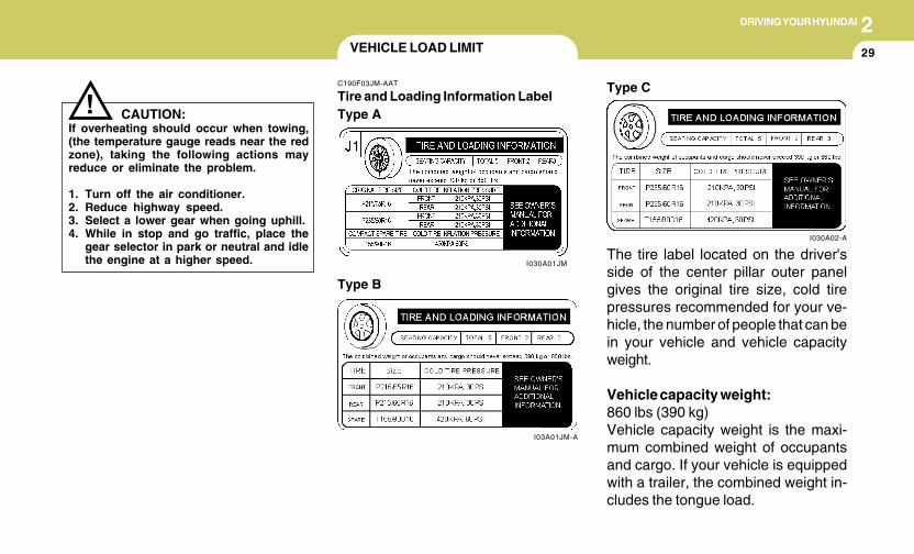
2DRIVING YOUR HYUNDAI
29
CAUTION:If overheating should occur when towing,(the temperature gauge reads near the redzone), taking the following actions mayreduce or eliminate the problem.
1. Turn off the air conditioner.2. Reduce highway speed.3. Select a lower gear when going uphill.4. While in stop and go traffic, place the
gear selector in park or neutral and idlethe engine at a higher speed.
!
VEHICLE LOAD LIMIT
C190F03JM-AAT
Tire and Loading Information Label
I03A01JM-A
Type B
The tire label located on the driver'sside of the center pillar outer panelgives the original tire size, cold tirepressures recommended for your ve-hicle, the number of people that can bein your vehicle and vehicle capacityweight.
Vehicle capacity weight:860 lbs (390 kg)Vehicle capacity weight is the maxi-mum combined weight of occupantsand cargo. If your vehicle is equippedwith a trailer, the combined weight in-cludes the tongue load.
I030A01JM
Type A
I030A02-A
Type C
2 DRIVING YOUR HYUNDAI
30
Cargo capacity:The cargo capacity of your vehicle willincrease or decrease depending on theweight and the number of occupantsand the tongue load, if your vehicle isequipped with a trailer.
Steps for Determining Correct LoadLimit(1)Locate the statement "The combined
weight of occupants and cargo shouldnever exceed XXX pounds'' on yourvehicle's placard.
(2)Determine the combined weight ofthe driver and passengers that will beriding in your vehicle.
(3)Subtract the combined weight of thedriver and passengers from XXXkilograms or XXX pounds.
(4)The resulting figure equals the avail-able amount of cargo and luggageload capacity. For example, if the"XXX" amount equals 1400 lbs, andthere will be five 150 lb. passengersin your vehicle, the amount of avail-able cargo and luggage load capac-ity is 650 lbs. (1400-750 (5 x 150) =650 lbs.)
(5)Determine the combined weight ofluggage and cargo being loaded onthe vehicle. That weight may notsafely exceed the available cargoand luggage load capacity calcu-lated in Step 4.
(6)If your vehicle will be towing a trailer,load from your trailer will be trans-ferred to your vehicle. Consult thismanual to determine how this re-duces the available cargo and lug-gage load capacity of your vehicle.
Seating capacity:Total: 5 persons
(Front seat: 2 persons,Rear seat: 3 persons)
Seating capacity is the maximum num-ber of occupants including a driver,your vehicle may carry.However the seating capacity may bereduced based upon the weight of all ofthe occupants, and the weight of thecargo being carried or towed. Do notoverload the vehicle as there is a limitto the total weight, or load limit includingoccupants and cargo, the vehicle cancarry.
Towing capacity:Towing capacity is the maximum trailerweight including its cargo weight, yourvehicle can tow. See the section "Traileror Vehicle Towing" for specificationsabout the trailer weight.
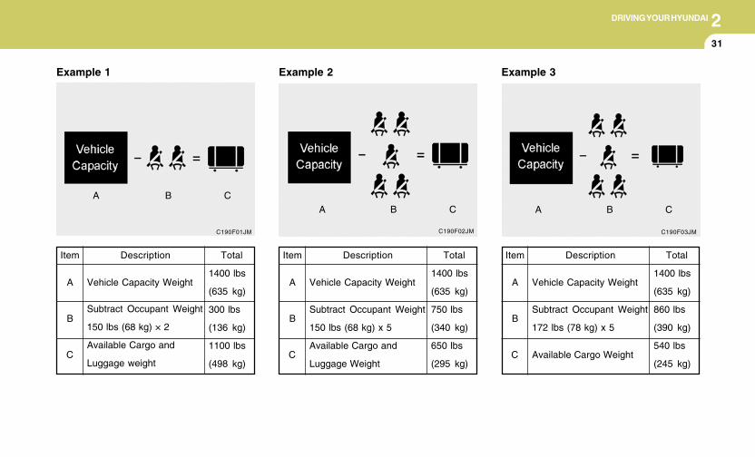
2DRIVING YOUR HYUNDAI
31
C190F01JM
Total
1400 lbs
(635 kg)
300 lbs
(136 kg)
1100 lbs
(498 kg)
Example 1
Item
A
B
C
Description
Vehicle Capacity Weight
Subtract Occupant Weight
150 lbs (68 kg) × 2
Available Cargo and
Luggage weight
A B C
C190F03JM
Total
1400 lbs
(635 kg)
860 lbs
(390 kg)
540 lbs
(245 kg)
Item
A
B
C
Description
Vehicle Capacity Weight
Subtract Occupant Weight
172 lbs (78 kg) x 5
Available Cargo Weight
Example 3
A B C
C190F02JM
Example 2
Total
1400 lbs
(635 kg)
750 lbs
(340 kg)
650 lbs
(295 kg)
Item
A
B
C
Description
Vehicle Capacity Weight
Subtract Occupant Weight
150 lbs (68 kg) x 5
Available Cargo and
Luggage Weight
A B C
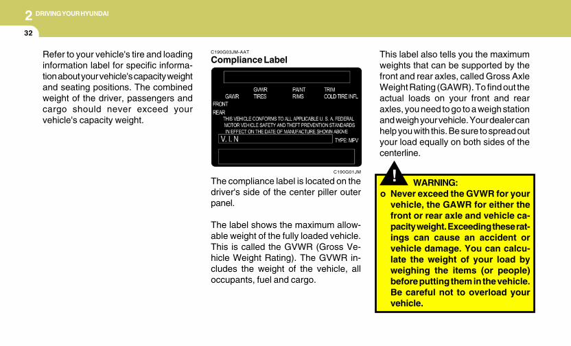
2 DRIVING YOUR HYUNDAI
32
C190G03JM-AAT
Compliance Label
The compliance label is located on thedriver's side of the center piller outerpanel.
The label shows the maximum allow-able weight of the fully loaded vehicle.This is called the GVWR (Gross Ve-hicle Weight Rating). The GVWR in-cludes the weight of the vehicle, alloccupants, fuel and cargo.
C190G01JM !
This label also tells you the maximumweights that can be supported by thefront and rear axles, called Gross AxleWeight Rating (GAWR). To find out theactual loads on your front and rearaxles, you need to go to a weigh stationand weigh your vehicle. Your dealer canhelp you with this. Be sure to spread outyour load equally on both sides of thecenterline.
WARNING:o Never exceed the GVWR for your
vehicle, the GAWR for either thefront or rear axle and vehicle ca-pacity weight. Exceeding these rat-ings can cause an accident orvehicle damage. You can calcu-late the weight of your load byweighing the items (or people)before putting them in the vehicle.Be careful not to overload yourvehicle.
Refer to your vehicle's tire and loadinginformation label for specific informa-tion about your vehicle's capacity weightand seating positions. The combinedweight of the driver, passengers andcargo should never exceed yourvehicle's capacity weight.
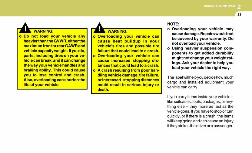
2DRIVING YOUR HYUNDAI
33
! WARNING:o Do not load your vehicle any
heavier than the GVWR, either themaximum front or rear GAWR andvehicle capacity weight. If you do,parts, including tires on your ve-hicle can break, and it can changethe way your vehicle handles andbraking ability. This could causeyou to lose control and crash.Also, overloading can shorten thelife of your vehicle.
!NOTE:o Overloading your vehicle may
cause damage. Repairs would notbe covered by your warranty. Donot overload your vehicle.
o Using heavier suspension com-ponents to get added durabilitymight not change your weight rat-ings. Ask your dealer to help youload your vehicle the right way.
The label will help you decide how muchcargo and installed equipment yourvehicle can carry.
If you carry items inside your vehicle –like suitcases, tools, packages, or any-thing else – they more as fast as thevehicle goes. If you have to stop or turnquickly, or if there is a crash, the itemswill keep going and can cause an injuryif they strikes the driver or a passenger.
WARNING:o Overloading your vehicle can
cause heat buildup in yourvehicle's tires and possible tirefailure that could lead to a crash.
o Overloading your vehicle cancause increased stopping dis-tances that could lead to a crash.
o A crash resulting from poor han-dling vehicle damage, tire failure,or increased stopping distancescould result in serious injury ordeath.

2 DRIVING YOUR HYUNDAI
34
!WARNING:
Items you carry inside your vehiclecan strike and injure people in asudden stop or turn, or in a crash.
o Put things in the cargo area ofyour vehicle. Try to spread theweight evenly.
o Never stack items, like suitcases,inside the vehicle above the topsof the seats.
o Do not leave an unsecured childrestraint in your vehicle.
o When you carry something insidethe vehicle, secure it.
o Do not drive with a seat foldeddown unless necessary.
If the Engine will not Start .............................................. 3-2Jump Starting ................................................................ 3-3If the Engine Overheats ................................................ 3-4Tire Pressure Monitoring System (TPMS) .................... 3-5Spare Tire ..................................................................... 3-9If You Have a Flat Tire ................................................ 3-10Changing a Flat Tire .................................................... 3-11If Your Car Must be Towed ......................................... 3-16Emergency Towing ..................................................... 3-18If You Lose Your Keys ................................................ 3-19 3
3
WHAT TO DO IN AN EMERGENCY
32
WHAT TO DO IN AN EMERGENCY
IF THE ENGINE WILL NOT START
!
D010A01A-AAT D010B02A-AAT
If Engine Doesn't Turn Over or TurnsOver Slowly
D010C02Y-AAT
If Engine Turns Over Normally but DoesNot Start
1. Check fuel level.2. With the key in the "OFF" position, check all
connectors at ignition, coil and spark plugs.Reconnect any that may be disconnected orloose.
3. Check the fuel line in the engine compart-ment.
4. If the engine still does not start, call a Hyundaidealer or seek other qualified assistance.
D010D01A-AAT
If Engine Stalls While Driving
1. Reduce your speed gradually, keeping astraight line. Move cautiously off the road toa safe place.
2. Turn on your emergency flashers.3. Try to start the engine again. If your vehicle
will not start, contact a Hyundai dealer orseek other qualified assistance.
WARNING:If the engine will not start, do not push orpull the car to start it. This could result in acollision or cause other damage. In addi-tion, push or pull starting may cause thecatalytic converter to be overloaded andcreate a fire hazard.
1. If your car has an automatic transaxle, besure the gear selector lever is in "N" or "P"and the emergency brake is set.
2. Check the battery connections to be surethey are clean and tight.
3. Turn on the interior light. If the light dims orgoes out when you operate the starter, thebattery is discharged.
4. Check the starter connections to be surethey are securely tightened.
5. Do not push or pull the vehicle to start it. Seeinstructions for "Jump Starting".
HJM5008
D010F01A-AAT
If the engine stalls at a crossroad orcrossing
If the engine stalls at a crossroad or crossing,set the shift lever in the N(Neutral) position andthen push the vehicle to a safe place.
3WHAT TO DO IN AN EMERGENCY
3JUMP STARTING
!
o If you should accidentally get acid on yourskin or in your eyes, immediately removeany contaminated clothing and flush the areawith clear water for at least 15 minutes. Thenpromptly obtain medical attention. If youmust be transported to an emergency facil-ity, continue to apply water to the affectedarea with a sponge or cloth.
o The gas produced by the battery during thejump-start operation is highly explosive. Donot smoke or allow a spark or an open flamein the vicinity.
o The battery being used to provide the jumpstart must be 12-volt. If you cannot deter-mine that it is a 12-volt battery, do not attemptto use it for the jump start.
o To jump start a car with a discharged battery,follow this procedure exactly:
1. If the booster battery is installed in anothervehicle, be sure the two vehicles are nottouching.
2. Turn off all unnecessary lights and acces-sories in both vehicles.
3. Attach the clamps of the jumper cable in theexact location shown on the illustration. First,attach one clamp of the jumper cable to thepositive (+) post or cable of the dischargedbattery.
Then attach the other end of the same cableto the positive (+) post or cable of the boosterbattery. Next, using the other cable, attachone clamp to the negative (-) post or cableof the booster battery. Then attach the otherend of that cable to a solid metal part of theengine of the vehicle with the dischargedbattery away from the battery. Do not con-nect the cable to any moving part.
4. Start the engine in the car with the boosterbattery and let it run for a few minutes. Thiswill help to assure that the booster battery isfully charged. During the jumping operation,run the engine in this vehicle at about 2,000rpm.
5. Start the engine in the car with the dis-charged battery using the normal startingprocedure. After the engine starts, leave thejumper cables connected and let the enginerun at fast idle or about 2,000 rpm for severalminutes.
6. Carefully remove the jumper cables in thereverse order of attachment.
If you do not know why your battery becamedischarged (because the lights were left on,etc.), have the charging system checked byyour Hyundai dealer.
D020A03A-AAT
WARNING:The gas produced by the battery during thejump-start operation is highly explosive. Ifthese instructions are not followed exactly,serious personal injury and damage to thevehicle may occur! If you are not sure howto follow this procedure, seek qualifiedassistance. Automobile batteries containsulfuric acid. This is poisonous and highlycorrosive. When jump starting, wear pro-tective glasses and be careful not to getacid on yourself, your clothing or on the car.
HJM4001Booster battery
Dischargedbattery
34
WHAT TO DO IN AN EMERGENCY
IF THE ENGINE OVERHEATS
!
!
!
WARNING:While the engine is running, keep hair,hands and clothing away from moving partssuch as the fan and drive belts to preventinjury.
5. If the water pump drive belt is broken orengine coolant is leaking out, stop the engineimmediately and call the nearest Hyundaidealer for assistance.
WARNING:Do not remove the radiator cap when theengine is hot. This can allow coolant to beblown out of the opening and cause seri-ous burns.
6. If you cannot find the cause of the overheat-ing, wait until the engine temperature hasreturned to normal. Then, if coolant has beenlost, carefully add coolant to the reservoir(page 6-9) to bring the fluid level in thereservoir up to the halfway mark.
7. Proceed with caution, keeping alert for fur-ther signs of overheating. If overheatinghappens again, call a Hyundai dealer forassistance.
CAUTION:Serious loss of coolant indicates there is aleak in the cooling system and this shouldbe checked as soon as possible by a Hyundaidealer.
D030A02A-AAT
If your temperature gauge indicates overheat-ing, you experience a loss of power, or hear loudpinging or knocking, the engine is probably toohot. If this happens, you should:
1. Pull off the road and stop as soon as it is safeto do so.
2. Place the gear selector lever in "P" (auto-matic), or neutral (manual transaxle) and setthe parking brake. If the air conditioning is on,turn it off.
3. If engine coolant is running out under the caror steam is coming out from the hood, stopthe engine. Do not open the hood until thecoolant has stopped running or the steaminghas stopped. If there is no visible loss ofengine coolant and no steam, leave theengine running and check to be sure theengine cooling fan is operating. If the fan isnot running, turn the engine off.
4. Check to see if the water pump drive belt ismissing. If it is not missing, check to see thatit is tight. If the drive belt seems to besatisfactory, check for coolant leaking fromthe radiator, hoses or under the car. (If theair conditioning had been in use, it is normalfor cold water to be draining from it when youstop).
3WHAT TO DO IN AN EMERGENCY
5TIRE PRESSURE MONITORING SYS-TEM (TPMS)
C320A01JM
C320A02JM-AAT
(If installed)
➀ Low Tire Pressure Telltale➁ TPMS Malfunction Indicator
Each tire, including the spare (if pro-vided), should be checked monthly whencold and inflated to the inflation pres-sure recommended by the vehicle manu-facturer on the vehicle placard or tireinflation pressure label. (If your vehiclehas tires of a different size than the sizeindicated on the vehicle placard or tireinflation pressure label, you should de-termine the proper tire inflation pres-sure for those tires.)
As an added safety feature, your ve-hicle has been equipped with a tirepressure monitoring system (TPMS)that illuminates a low tire pressure tell-tale when one or more of your tires issignificantly under-inflated. Accord-ingly, when the low tire pressure telltaleilluminates, you should stop and checkyour tires as soon as possible, andinflate them to the proper pressure.Driving on a significantly under-inflatedtire causes the tire to overheat and canlead to tire failure. Under-inflation alsoreduces fuel efficiency and tire treadlife, and may affect the vehicle’s han-dling and stopping ability.
Please note that the TPMS is not asubstitute for proper tire maintenance,and it is the driver’s responsibility tomaintain correct tire pressure, even ifunder-inflation has not reached the levelto trigger illumination of the TPMS lowtire pressure telltale.
Your vehicle has also been equippedwith a TPMS malfunction indicator toindicate when the system is not operat-ing properly. The TPMS malfunctionindicator is provided by a separate tell-tale, which displays the symbol "TPMS"when illuminated. When the malfunc-tion indicator is illuminated, the systemmay not be able to detect or signal lowtire pressure as intended. TPMS mal-functions may occur for a variety ofreasons, including the installation ofreplacement or alternate tires or wheelson the vehicle that prevent the TPMSfrom functioning properly. Always checkthe TPMS malfunction telltale after re-placing one or more tires or wheels onyour vehicle to ensure that the replace-ment or alternate tires and wheels allowthe TPMS to continue to function prop-erly.
36
WHAT TO DO IN AN EMERGENCY
!
TPMS (Tire pressure monitoringsystem) malfunction indicator
The TPMS malfunction indicator turnson and stays on when there is a problemwith the Tire Pressure Monitoring Sys-tem. If the system is able to correctlydetect an under-inflation warning at thesame time as system failure then it willilluminate both the TPMS malfunctionand the low tire pressure telltale e. g. ifFront Left sensor fails, the TPMS mal-function indicator turns on, but if FrontRight, Rear Left, or Rear Right tire is
Low tire pressure telltale
When the tire pressure monitoring sys-tem warning telltale is illuminated, oneor more of your tires is significantlyunder-inflated.Immediately reduce your speed, avoidhard cornering and anticipate increasedstopping distances. You should stopand check your tires as soon as pos-sible. Inflate the tires to the properpressure as indicated on the vehicle’splacard or tire inflation pressure labellocated on the driver’s side center pillarouter panel. If you cannot reach a ser-vice station or if the tire cannot hold thenewly added air, replace the low pres-sure tire with the temporary spare tire.Then the TPMS malfunction indicatormay turn on and the Low Tire Pressuretelltale may turn off after restarting andabout 20 minutes of continuous drivingbefore you have the low-pressure tirerepaired and replaced on the vehicle.
WARNING - Low pressuredamage
Significantly low tire pressure makesthe vehicle unstable and can contrib-ute to loss of vehicle control andincreased braking distances.Continued driving on low pressuretires can cause the tires to overheatand fail.
CAUTION - Changing tem-peratures
In winter or cold weather, the low tirepressure telltale may be illuminatedif the tire pressure was adjusted tothe recommended tire inflation pres-sure in warm weather. It does notmean your TPMS is malfunctioningbecause the decreased temperatureleads to a proportional lowering oftire pressure.When you drive your vehicle from awarm area to a cold area or from acold area to a warm area, or theoutside temperature is greatly higheror lower, you should check the tireinflation pressure and adjust the tiresto the recommended tire inflationpressure.
!

3WHAT TO DO IN AN EMERGENCY
7
under-inflated, the low tire pressure tell-tale may turn on at the same time as theTPMS malfunction indicator.Have the system checked by an autho-rized Hyundai dealer as soon as pos-sible to determine the cause of theproblem.
NOTE:o The TPMS malfunction indicator
may be illuminated if the vehicleis moving around electric powersupply cable or radio transmittersuch as police stations, govern-ment and public offices, broad-casting stations, military installa-tions, airports, or transmittingtower, etc. which can interfere withnormal operation of the Tire Pres-sure Monitoring System (TPMS).
o The TPMS malfunction indicatormay be illuminated if snow chainsor some electronic devices, suchas notebook computer, are usedin the vehicle. This can interferewith normal operation of the TirePressure Monitoring System(TPMS).
o If there is a failed tire sensor, it ispossible for the TPMS to tempo-rarily learn a replacement sensorif closely driven to another ve-hicle that is also equipped withTPMS. In rare cases, this maytemporarily delay the TPMS mal-function indicator from turningon.
Changing a tire with TPMS
If you have a flat tire, the Low TirePressure telltale will turn on. Have theflat tire repaired by an authorizedHyundai dealer as soon as possible orreplace the flat tire with the temporaryspare tire.
NOTE:NEVER use a puncture-repairingagent to repair and/or inflate a lowpressure tire. If used, you will haveto replace the tire pressure sensor.
Each wheel is equipped with a tirepressure sensor mounted inside the tirebehind the valve stem. You must useTPMS specific wheels.It is recommended that you alwayshave your tires serviced by an autho-rized Hyundai dealer as soon as pos-sible.After you replace the low pressure tirewith the temporary spare tire, the TPMSmalfunction indicator may illuminateafter restarting and about 20 minutes ofcontinuous driving.Once the low pressure tire is re-inflatedto the recommended pressure and in-stalled on the vehicle, the TPMS mal-function indicator and the low tire pres-sure telltale will be soon extinguished.If the low pressure and TPMS malfunc-tion indicators are not extinguished af-ter about 20 minutes of continuousdriving, please visit an authorizedHyundai dealer.You may not be able to identify a low tireby simply looking at it. Always use agood quality tire pressure gauge tomeasure the tire's inflation pressure.
38
WHAT TO DO IN AN EMERGENCY
!
!
!
This device complies with Part 15 ofthe FCC rules.Operation is subject to the following twoconditions:1. This device may not cause harmful
interference, and2. This device must accept any interfer-
ence received, including interferencethat may cause undesired operation.
WARNING - TPMSo The TPMS cannot alert you to se-
vere and sudden tire damagecaused by external factors such asnails or road debris.
o If you feel any vehicle instability,immediately take your foot off theaccelerator, apply the brakesgradually and with light force, andslowly move to a safe position offthe road.
WARNING:Changes or modifications not ex-pressly approved by the party re-sponsible for compliance could voidthe user’s authority to operate theequipment.
Please note that a tire that is hot (frombeing driven) will have a higher pres-sure measurement than a tire that iscold (from sitting stationary for at least3 hours and driven less than 1 mile (1.6km) during that 3 hour period). Allow thetire to cool before measuring the infla-tion pressure.Always be sure the tire is cold beforeinflating to the recommended pressure.A cold tire means the vehicle has beensitting for 3 hours and driven for lessthan 1 mile (1.6 km) in that 3 hourperiod.
CAUTION:Do not use any tire sealant if yourvehicle is equipped with a Tire Pres-sure Monitoring System. The liquidsealant can damage the tire pressuresensors.In order for the system to correctlymonitor tires for under-inflation,there should be a total of exactly 4sensors fitted to each of the fourdriven wheel positions.
!
WARNING - Protecting TPMSTampering with, modifying, or dis-abling the Tire Pressure MonitoringSystem (TPMS) components may in-terfere with the system's ability to warnthe driver of low tire pressure condi-tions and/or TPMS malfunctions.
There should be no other sensors inthe vehicle including spare tire po-sition since this could cause thesystem to monitor the wrong sen-sors.
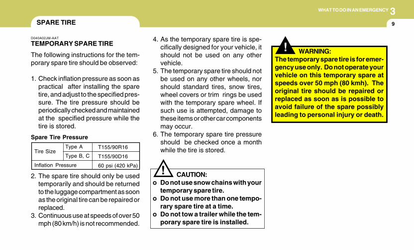
3WHAT TO DO IN AN EMERGENCY
9
!
!
4. As the temporary spare tire is spe-cifically designed for your vehicle, itshould not be used on any othervehicle.
5. The temporary spare tire should notbe used on any other wheels, norshould standard tires, snow tires,wheel covers or trim rings be usedwith the temporary spare wheel. Ifsuch use is attempted, damage tothese items or other car componentsmay occur.
6. The temporary spare tire pressureshould be checked once a monthwhile the tire is stored.
SPARE TIRE
2. The spare tire should only be usedtemporarily and should be returnedto the luggage compartment as soonas the original tire can be repaired orreplaced.
3. Continuous use at speeds of over 50mph (80 km/h) is not recommended.
D040A02JM-AAT
TEMPORARY SPARE TIRE
The following instructions for the tem-porary spare tire should be observed:
1. Check inflation pressure as soon aspractical after installing the sparetire, and adjust to the specified pres-sure. The tire pressure should beperiodically checked and maintainedat the specified pressure while thetire is stored.
Spare Tire Pressure
CAUTION:o Do not use snow chains with your
temporary spare tire.o Do not use more than one tempo-
rary spare tire at a time.o Do not tow a trailer while the tem-
porary spare tire is installed.
Tire Size
Inflation Pressure
T155/90R16
T155/90D16
60 psi (420 kPa)
Type A
Type B, C
WARNING:The temporary spare tire is for emer-gency use only. Do not operate yourvehicle on this temporary spare atspeeds over 50 mph (80 kmh). Theoriginal tire should be repaired orreplaced as soon as is possible toavoid failure of the spare possiblyleading to personal injury or death.
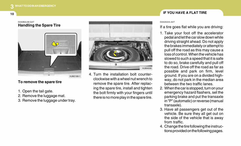
310
WHAT TO DO IN AN EMERGENCY
IF YOU HAVE A FLAT TIRE
D050A02A-AAT
If a tire goes flat while you are driving:
1. Take your foot off the acceleratorpedal and let the car slow down whiledriving straight ahead. Do not applythe brakes immediately or attempt topull off the road as this may cause aloss of control. When the vehicle hasslowed to such a speed that it is safeto do so, brake carefully and pull offthe road. Drive off the road as far aspossible and park on firm, levelground. If you are on a divided high-way, do not park in the median areabetween the two traffic lanes.
2. When the car is stopped, turn on youremergency hazard flashers, set theparking brake and put the transaxlein "P" (automatic) or reverse (manualtransaxle).
3. Have all passengers get out of thevehicle. Be sure they all get out onthe side of the vehicle that is awayfrom traffic.
4. Change the tire following the instruc-tions provided on the following pages.
HJM4008
4. Turn the installation bolt counter-clockwise with a wheel nut wrench toremove the spare tire. After replac-ing the spare tire, install and tightenthe bolt firmly with your fingers untilthere is no more play in the spare tire.
D040B02JM-GAT
Handling the Spare Tire
To remove the spare tire
1. Open the tail gate.2. Remove the luggage mat.3. Remove the luggage under tray.
HJM2168-1
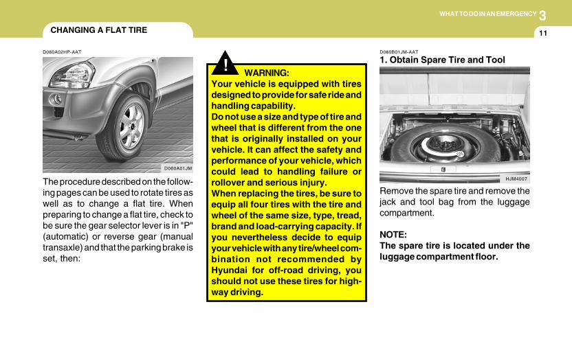
3WHAT TO DO IN AN EMERGENCY
11CHANGING A FLAT TIRE
D060A02HP-AAT
The procedure described on the follow-ing pages can be used to rotate tires aswell as to change a flat tire. Whenpreparing to change a flat tire, check tobe sure the gear selector lever is in "P"(automatic) or reverse gear (manualtransaxle) and that the parking brake isset, then:
D060A01JM
! WARNING:Your vehicle is equipped with tiresdesigned to provide for safe ride andhandling capability.Do not use a size and type of tire andwheel that is different from the onethat is originally installed on yourvehicle. It can affect the safety andperformance of your vehicle, whichcould lead to handling failure orrollover and serious injury.When replacing the tires, be sure toequip all four tires with the tire andwheel of the same size, type, tread,brand and load-carrying capacity. Ifyou nevertheless decide to equipyour vehicle with any tire/wheel com-bination not recommended byHyundai for off-road driving, youshould not use these tires for high-way driving.
Remove the spare tire and remove thejack and tool bag from the luggagecompartment.
NOTE:The spare tire is located under theluggage compartment floor.
D060B01JM-AAT
1. Obtain Spare Tire and Tool
HJM4007
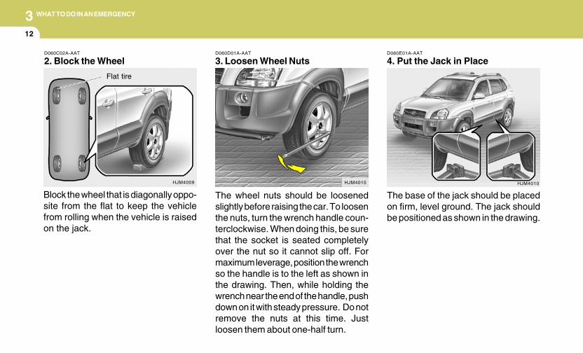
312
WHAT TO DO IN AN EMERGENCY
D060E01A-AAT
4. Put the Jack in Place
The base of the jack should be placedon firm, level ground. The jack shouldbe positioned as shown in the drawing.
HJM4010
D060D01A-AAT
3. Loosen Wheel Nuts
The wheel nuts should be loosenedslightly before raising the car. To loosenthe nuts, turn the wrench handle coun-terclockwise. When doing this, be surethat the socket is seated completelyover the nut so it cannot slip off. Formaximum leverage, position the wrenchso the handle is to the left as shown inthe drawing. Then, while holding thewrench near the end of the handle, pushdown on it with steady pressure. Do notremove the nuts at this time. Justloosen them about one-half turn.
HJM4015
D060C02A-AAT
2. Block the Wheel
Block the wheel that is diagonally oppo-site from the flat to keep the vehiclefrom rolling when the vehicle is raisedon the jack.
HJM4009
Flat tire
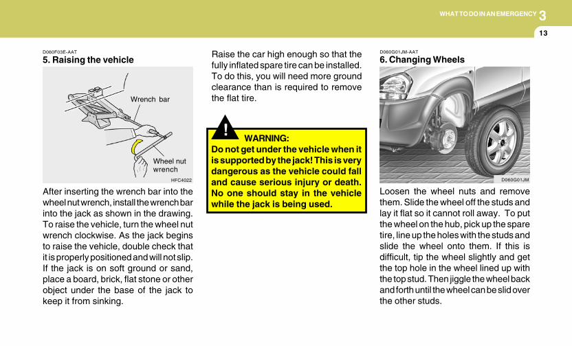
3WHAT TO DO IN AN EMERGENCY
13
D060F03E-AAT
5. Raising the vehicle
After inserting the wrench bar into thewheel nut wrench, install the wrench barinto the jack as shown in the drawing.To raise the vehicle, turn the wheel nutwrench clockwise. As the jack beginsto raise the vehicle, double check thatit is properly positioned and will not slip.If the jack is on soft ground or sand,place a board, brick, flat stone or otherobject under the base of the jack tokeep it from sinking.
HFC4022
Wrench bar
Wheel nutwrench
!
Raise the car high enough so that thefully inflated spare tire can be installed.To do this, you will need more groundclearance than is required to removethe flat tire.
WARNING:Do not get under the vehicle when itis supported by the jack! This is verydangerous as the vehicle could falland cause serious injury or death.No one should stay in the vehiclewhile the jack is being used.
D060G01JM-AAT
6. Changing Wheels
Loosen the wheel nuts and removethem. Slide the wheel off the studs andlay it flat so it cannot roll away. To putthe wheel on the hub, pick up the sparetire, line up the holes with the studs andslide the wheel onto them. If this isdifficult, tip the wheel slightly and getthe top hole in the wheel lined up withthe top stud. Then jiggle the wheel backand forth until the wheel can be slid overthe other studs.
D060G01JM
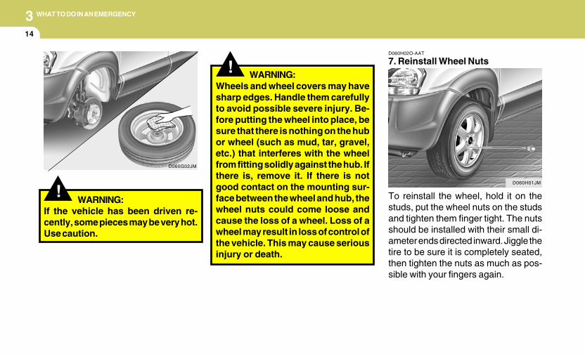
314
WHAT TO DO IN AN EMERGENCY
D060H02O-AAT
7. Reinstall Wheel Nuts
To reinstall the wheel, hold it on thestuds, put the wheel nuts on the studsand tighten them finger tight. The nutsshould be installed with their small di-ameter ends directed inward. Jiggle thetire to be sure it is completely seated,then tighten the nuts as much as pos-sible with your fingers again.
D060H01JM
!Wheels and wheel covers may havesharp edges. Handle them carefullyto avoid possible severe injury. Be-fore putting the wheel into place, besure that there is nothing on the hubor wheel (such as mud, tar, gravel,etc.) that interferes with the wheelfrom fitting solidly against the hub. Ifthere is, remove it. If there is notgood contact on the mounting sur-face between the wheel and hub, thewheel nuts could come loose andcause the loss of a wheel. Loss of awheel may result in loss of control ofthe vehicle. This may cause seriousinjury or death.
WARNING:
!WARNING:
If the vehicle has been driven re-cently, some pieces may be very hot.Use caution.
D060G02JM
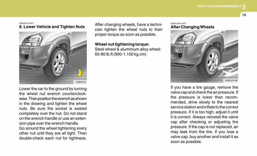
3WHAT TO DO IN AN EMERGENCY
15
D060I01E-AAT
8. Lower Vehicle and Tighten Nuts
Lower the car to the ground by turningthe wheel nut wrench counterclock-wise. Then position the wrench as shownin the drawing and tighten the wheelnuts. Be sure the socket is seatedcompletely over the nut. Do not standon the wrench handle or use an exten-sion pipe over the wrench handle.Go around the wheel tightening everyother nut until they are all tight. Thendouble-check each nut for tightness.
HJM4016
After changing wheels, have a techni-cian tighten the wheel nuts to theirproper torque as soon as possible.
Wheel nut tightening torque:Steel wheel & aluminium alloy wheel:65-80 lb.ft (900-1,100 kg.cm)
D060J02O-AAT
After Changing Wheels
If you have a tire gauge, remove thevalve cap and check the air pressure. Ifthe pressure is lower than recom-mended, drive slowly to the nearestservice station and inflate to the correctpressure. If it is too high, adjust it untilit is correct. Always reinstall the valvecap after checking or adjusting tirepressure. If the cap is not replaced, airmay leak from the tire. If you lose avalve cap, buy another and install it assoon as possible.
D060J01JM
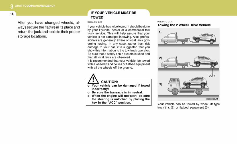
316
WHAT TO DO IN AN EMERGENCY
D080B01O-GAT
Towing the 2 Wheel Drive Vehicle
D080B03JM
Your vehicle can be towed by wheel lift typetruck (1), (2) or flatbed equipment (3).
1)
2)
3)
dolly
After you have changed wheels, al-ways secure the flat tire in its place andreturn the jack and tools to their properstorage locations.
IF YOUR VEHICLE MUST BETOWED
D080A01O-GAT
If your vehicle has to be towed, it should be doneby your Hyundai dealer or a commercial towtruck service. This will help assure that yourvehicle is not damaged in towing. Also, profes-sionals are generally aware of local laws gov-erning towing. In any case, rather than riskdamage to your car, it is suggested that youshow this information to the tow truck operator.Be sure that a safety chain system is used andthat all local laws are observed.It is recommended that your vehicle be towedwith a wheel lift and dollies or flatbed equipmentwith all the wheels off the ground.
! CAUTION:o Your vehicle can be damaged if towed
incorrectly!o Be sure the transaxle is in neutral.o When the engine will not start, be sure
the steering is unlocked by placing thekey in the "ACC" position.
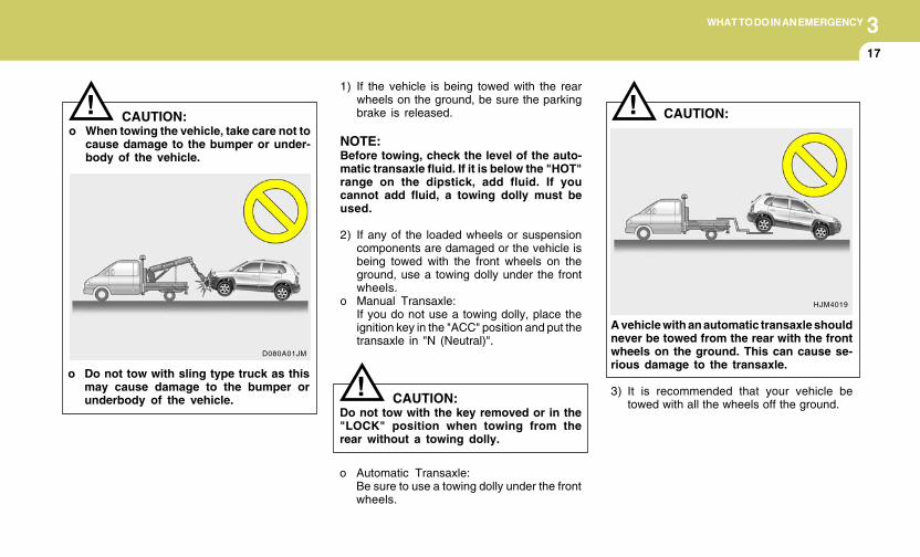
3WHAT TO DO IN AN EMERGENCY
17
1) If the vehicle is being towed with the rearwheels on the ground, be sure the parkingbrake is released.
NOTE:Before towing, check the level of the auto-matic transaxle fluid. If it is below the "HOT"range on the dipstick, add fluid. If youcannot add fluid, a towing dolly must beused.
2) If any of the loaded wheels or suspensioncomponents are damaged or the vehicle isbeing towed with the front wheels on theground, use a towing dolly under the frontwheels.
o Manual Transaxle:If you do not use a towing dolly, place theignition key in the "ACC" position and put thetransaxle in "N (Neutral)".
CAUTION:Do not tow with the key removed or in the"LOCK" position when towing from therear without a towing dolly.
o Automatic Transaxle:Be sure to use a towing dolly under the frontwheels.
!
!
D080A01JM
CAUTION:o When towing the vehicle, take care not to
cause damage to the bumper or under-body of the vehicle.
o Do not tow with sling type truck as thismay cause damage to the bumper orunderbody of the vehicle.
!
HJM4019
CAUTION:
A vehicle with an automatic transaxle shouldnever be towed from the rear with the frontwheels on the ground. This can cause se-rious damage to the transaxle.
3) It is recommended that your vehicle betowed with all the wheels off the ground.
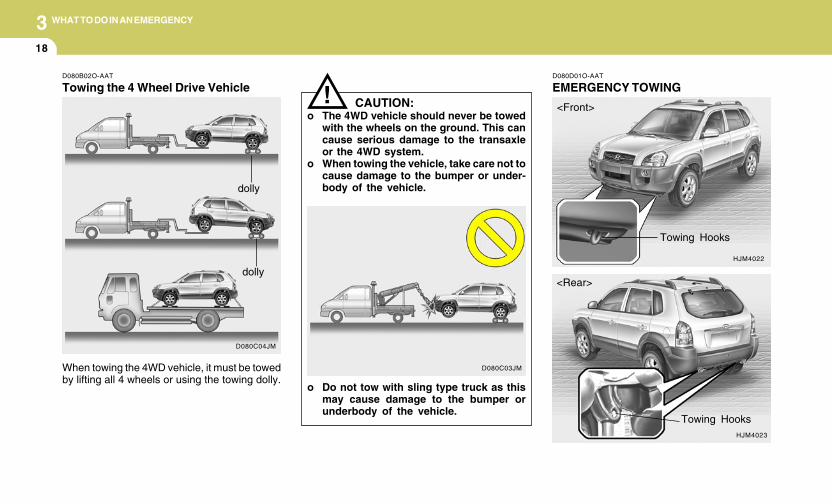
318
WHAT TO DO IN AN EMERGENCY
D080D01O-AAT
EMERGENCY TOWING
HJM4022
HJM4023
<Front>
<Rear>
Towing Hooks
Towing Hooks
D080B02O-AAT
Towing the 4 Wheel Drive Vehicle
D080C04JM
dolly
dolly
When towing the 4WD vehicle, it must be towedby lifting all 4 wheels or using the towing dolly.
CAUTION:o The 4WD vehicle should never be towed
with the wheels on the ground. This cancause serious damage to the transaxleor the 4WD system.
o When towing the vehicle, take care not tocause damage to the bumper or under-body of the vehicle.
!
D080C03JM
o Do not tow with sling type truck as thismay cause damage to the bumper orunderbody of the vehicle.
3WHAT TO DO IN AN EMERGENCY
19IF YOU LOSE YOUR KEYS
D120A01A-AAT
If you lose your keys, many Hyundai dealerscan make you a new key if you have your keynumber. If you lock the keys inside your car andyou cannot obtain a new key, many Hyundaidealers can use special tools to open the doorfor you.
For emergency towing when no commercialtow vehicle is available, attach a tow cable,chain or strap to one of the towing hooks underthe front/rear of your vehicle. Be very carefulwhen attempting this procedure when the ve-hicle is on any unpaved surface to avoid dam-age to your vehicle.Nor should towing be attempted if the wheels,drive train, axles, steering or brakes are dam-aged. Before towing, be sure the transaxle is inneutral and the key is in "ACC" (with the engineoff) or in the "ON" position (with the enginerunning). A driver must be in the towed vehicleto steer it and operate the brakes.
NOTE:To avoid serious damage to your 4WD ve-hicle, limit the towing to 10 mph and not formore than 1 mile at ANY TIME.
4Corrosion Protection ..................................................... 4-2To Help Prevent Corrosion ........................................... 4-2Washing and Waxing .................................................... 4-3Cleaning the Interior ...................................................... 4-5
4
CORROSION PREVENTION & APPEARANCE CARE

4 CORROSION PREVENTION AND APPEARANCE CARE
2 CORROSION PROTECTION
E020B01A-AAT
Keep Your Car Clean
The best way to prevent corrosion is to keepyour car clean and free of corrosive materials.Attention to the underside of the car is particu-larly important.
o If you live in a high-corrosion area — whereroad salts are used, near the ocean, areaswith industrial pollution, acid rain, etc.—, youshould take extra care to prevent corrosion.In winter, hose off the underside of your carat least once a month and be sure to cleanthe underside thoroughly when winter isover.
o When cleaning underneath the car, giveparticular attention to the components underthe fenders and other areas that are hiddenfrom view. Do a thorough job; just dampeningthe accumulated mud rather than washing itaway will accelerate corrosion rather thanprevent it. Water under high pressure andsteam are particularly effective in removingaccumulated mud and corrosive materials.
E020A01A-AAT
You can help prevent corrosion from gettingstarted by observing the following:
E010D01A-AAT
Moisture Breeds Corrosion
Moisture creates the conditions in which corro-sion is most likely to occur. For example, cor-rosion is accelerated by high humidity, particu-larly when temperatures are just above freez-ing. In such conditions, the corrosive material iskept in contact with the car surfaces by mois-ture that is slow to evaporate.Mud is particularly corrosive because it is slowto dry and holds moisture in contact with thevehicle. Although the mud appears to be dry, itcan still retain the moisture and promote corro-sion.High temperatures can also accelerate corro-sion of parts that are not properly ventilated sothe moisture can be dispersed. For all thesereasons, it is particularly important to keep yourcar clean and free of mud or accumulations ofother materials. This applies not only to thevisible surfaces but particularly to the undersideof the car.
E010C01A-AAT
High-Corrosion Areas
If you live in an area where your car is regularlyexposed to corrosive materials, corrosion pro-tection is particularly important. Some of thecommon causes of accelerated corrosion areroad salts, dust control chemicals, ocean airand industrial pollution.
E010B01A-AAT
Common Causes of Corrosion
The most common causes of corrosion on yourcar are:
o Road salt, dirt and moisture that is allowed toaccumulate underneath the car.
o Removal of paint or protective coatings bystones, gravel, abrasion or minor scrapesand dents which leave unprotected metalexposed to corrosion.
E010A01A-AAT
Protecting Your Hyundai from Corro-sion
By using the most advanced design and con-struction practices to combat corrosion,Hyundai produces cars of the highest quality.However, this is only part of the job. To achievethe long-term corrosion resistance yourHyundai can deliver, the owner's cooperationand assistance is also required.
TO HELP PREVENT CORROSION
4CORROSION PREVENTION AND APPEARANCE CARE
3WASHING AND WAXING
E020E01A-AAT
Don't Neglect the Interior
Moisture can collect under the floor mats andcarpeting to cause corrosion. Check under themats periodically to be sure the carpeting is dry.Use particular care if you carry fertilizers, clean-ing materials or chemicals in the car.These should be carried only in proper contain-ers and any spills or leaks should be cleaned up,flushed with clear water and thoroughly dried.
E020D02A-AAT
Keep Paint and Trim in Good Condition
Scratches or chips in the finish should becovered with "touch-up" paint as soon as pos-sible to reduce the possibility of corrosion. Ifbare metal is showing through, the attention ofa qualified body and paint shop is recommended.
Bird droppings : Bird droppings are highly cor-rosive and may damage painted surfaces in justa few hours. Always remove bird droppings assoon as possible.
E020C02A-AAT
Keep Your Garage Dry
Don't park your car in a damp, poorly ventilatedgarage. This creates a favorable environmentfor corrosion. This is particularly true if youwash your car in the garage or drive it into thegarage when it is still wet or covered with snow,ice or mud. Even a heated garage can contrib-ute to corrosion unless it is well ventilated somoisture is dispersed.
E030A03A-AAT
Washing Your Hyundai
Never wash your car when the surface is hotfrom being in the sun. Always wash your car inthe shade.
Wash your car frequently. Dirt is abrasive andcan scratch the paint if it is not removed. Airpollution or acid rain may damage the paint andtrim through chemical action if pollutants areallowed to remain in contact with the surface. Ifyou live near the ocean or in an area where roadsalts or dust control chemicals are used, youshould pay particular attention to the undersideof the car. Start by rinsing the car to remove dustand loose dirt. In winter, or if you have driventhrough mud or muddy water, be sure to thor-oughly clean the underside as well. Use a harddirect stream of water to remove accumulationsof mud or corrosive materials. Use a goodquality car-washing solution and follow themanufacturer's directions on the package.These are available at your Hyundai dealer orauto parts outlet. Don't use strong householddetergents, gasoline, strong solvents or abra-sive cleaning powders as these may damagethe finish.Use a clean sponge or cloth, rinse it frequentlyand don't damage the finish by rubbing too hard.For stubborn spots, dampen them frequentlyand remove them a little at a time.
o When cleaning lower door panels, rockerpanels and frame members, be sure thatdrain holes are kept open so that moisturecan escape and not be trapped inside to ac-celerate corrosion.
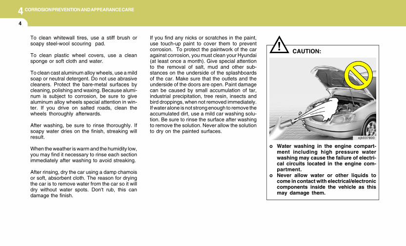
4 CORROSION PREVENTION AND APPEARANCE CARE
4
If you find any nicks or scratches in the paint,use touch-up paint to cover them to preventcorrosion. To protect the paintwork of the caragainst corrosion, you must clean your Hyundai(at least once a month). Give special attentionto the removal of salt, mud and other sub-stances on the underside of the splashboardsof the car. Make sure that the outlets and theunderside of the doors are open. Paint damagecan be caused by small accumulation of tar,industrial precipitation, tree resin, insects andbird droppings, when not removed immediately.If water alone is not strong enough to remove theaccumulated dirt, use a mild car washing solu-tion. Be sure to rinse the surface after washingto remove the solution. Never allow the solutionto dry on the painted surfaces.
To clean whitewall tires, use a stiff brush orsoapy steel-wool scouring pad.
To clean plastic wheel covers, use a cleansponge or soft cloth and water.
To clean cast aluminum alloy wheels, use a mildsoap or neutral detergent. Do not use abrasivecleaners. Protect the bare-metal surfaces bycleaning, polishing and waxing. Because alumi-num is subject to corrosion, be sure to givealuminum alloy wheels special attention in win-ter. If you drive on salted roads, clean thewheels thoroughly afterwards.
After washing, be sure to rinse thoroughly. Ifsoapy water dries on the finish, streaking willresult.
When the weather is warm and the humidity low,you may find it necessary to rinse each sectionimmediately after washing to avoid streaking.
After rinsing, dry the car using a damp chamoisor soft, absorbent cloth. The reason for dryingthe car is to remove water from the car so it willdry without water spots. Don't rub, this candamage the finish.
CAUTION:!
o Water washing in the engine compart-ment including high pressure waterwashing may cause the failure of electri-cal circuits located in the engine com-partment.
o Never allow water or other liquids tocome in contact with electrical/electroniccomponents inside the vehicle as thismay damage them.
ojb037800
4CORROSION PREVENTION AND APPEARANCE CARE
5CLEANING THE INTERIOR
E040A01A-AAT
To Clean the Vinyl Upholstery
To clean the vinyl upholstery, first remove loosedirt and dust with a vacuum cleaner. Then applya solution of mild soap or detergent and waterusing a clean sponge or soft cloth. Allow this tostay on the surface to loosen the dirt, then wipewith a clean damp sponge or cloth. If all the dirtstains are not removed, repeat this procedureuntil the upholstery is clean. Do not use gaso-line, solvent, paint thinner or other strong clean-ers.E030E01A-AAT
Maintaining Bumpers
Special precautions must be observed to pre-serve the appearance of the bumpers on yourHyundai. They are:
o Be careful not to spill battery electrolyte orhydraulic brake fluid on the bumpers. If youdo, wash it off immediately with clear water.
o Be gentle when cleaning the bumper sur-faces. They are made of soft plastic and thesurface can be damaged if mistreated. Donot use abrasive cleaners. Use warm waterand mild soap or car-washing solution.
o Do not expose the bumpers to high tem-peratures. For example, if you have your carrepainted, do not leave the bumpers on thecar if the car is going to be placed in a high-temperature paint booth.
E030D01A-AAT
When to Wax Again
You should polish and wax the car again whenwater no longer beads on a clean surface butspreads out over a larger area.
E030C01A-AAT
Polishing and Waxing
Always wash and dry the car before polishingor waxing or using a combination cleaner andwax. Use a good quality commercial productand follow the manufacturer's directions on thecontainer. Polish and wax the bright trim piecesas well as the paint.
E030B01A-AAT
Spot Cleaning
Don't use gasoline, strong solvents or corro-sive cleaning agents. These can damage thefinish of the car. To remove road tar, useturpentine on a clean, soft cloth. Be gentle.To remove dead insects or tree sap, use warmwater and mild soap or car-washing solution.Soak the spot and rub gently. If the paint has lostits luster, use a commercial car-cleaning polish.

4 CORROSION PREVENTION AND APPEARANCE CARE
6 ANY QUESTIONS?
E040D01A-AAT
Cleaning the Seat Belts
To clean the seat belts, use a cloth or spongewith mild soap or detergent and warm water. Donot use strong detergents, dye, bleach or abra-sive materials on the seat belts as this mayweaken the fabric.While cleaning the belts, inspect them for ex-cessive wear, cuts, fraying or other signs ofdamage and replace them if necessary.
E040C01A-AAT
Cleaning the Carpets
Use a foam-type carpet cleaner. Cleaners ofthis type are available in aerosol cans in liquidform or powder. Read the instructions andfollow them exactly. Using a vacuum cleanerwith the appropriate attachment, remove asmuch dirt from the carpets as possible. Applythe foam following the manufacturer's direc-tions, then rub in overlapping circles. Do not addwater. These cleaners work best when thecarpet is kept as dry as possible.
E050A01A-AAT
If you have any questions about the care of yourcar, consult your Hyundai dealer.
E040E01A-AAT
Cleaning the Windows
You may use any household window cleaner onthe windows. However, when cleaning the in-side of the rear window be careful not to damagethe rear window defroster wiring.
E040B01A-AAT
To Clean the Leather Upholstery(If installed)
In the normal course of use, leather upholsteredsurfaces will, like any material, pick-up dust anddirt. This dust and dirt must be cleaned off or itmay work into the surface of the leather, caus-ing damage.
Fine leather needs care, and should be cleanedwhen necessary. Washing leather thoroughlywith soap and water will keep your leatherlustrous, beautiful and ensure you have manyyears of wear.Take a piece of cheese cloth and using any mildsoap and lukewarm water, work up a goodlather. Thoroughly wash the leather. Wipe cleanwith a slightly damp cloth and dry with soft cloth.Do this as often as the leather becomes soiled.
During tanning operations, sufficient oils areincorporated through processing that none needbe applied during the life of the leather. Oilapplied to the finished surface will in no way helpthe leather and may do more harm than good.Varnishes and furniture polishes should neverbe used under any conditions.
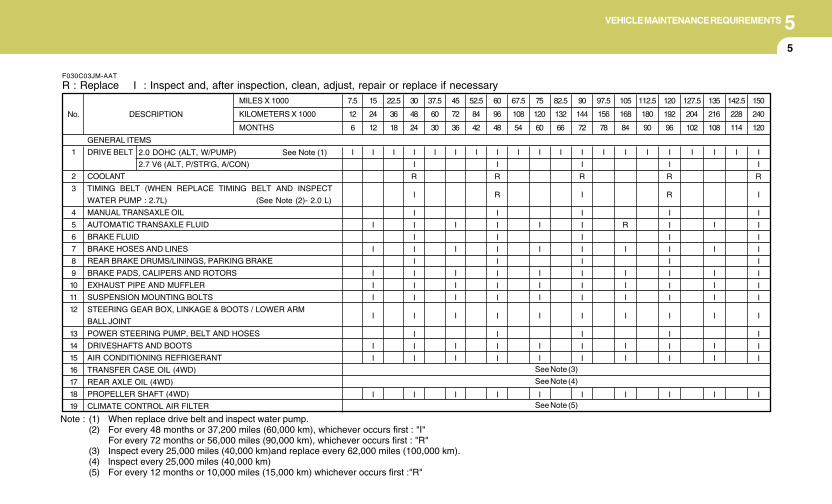
5VEHICLE MAINTENANCE REQUIREMENTS
5
Note : (1) When replace drive belt and inspect water pump.(2) For every 48 months or 37,200 miles (60,000 km), whichever occurs first : "I"
For every 72 months or 56,000 miles (90,000 km), whichever occurs first : "R"(3) Inspect every 25,000 miles (40,000 km)and replace every 62,000 miles (100,000 km).(4) lnspect every 25,000 miles (40,000 km)(5) For every 12 months or 10,000 miles (15,000 km) whichever occurs first :"R"
F030C03JM-AAT
R : Replace I : Inspect and, after inspection, clean, adjust, repair or replace if necessary
GENERAL ITEMS
DRIVE BELT
COOLANT
TIMING BELT (WHEN REPLACE TIMING BELT AND INSPECT
WATER PUMP : 2.7L) (See Note (2)- 2.0 L)
MANUAL TRANSAXLE OIL
AUTOMATIC TRANSAXLE FLUID
BRAKE FLUID
BRAKE HOSES AND LINES
REAR BRAKE DRUMS/LININGS, PARKING BRAKE
BRAKE PADS, CALIPERS AND ROTORS
EXHAUST PIPE AND MUFFLER
SUSPENSION MOUNTING BOLTS
STEERING GEAR BOX, LINKAGE & BOOTS / LOWER ARM
BALL JOINT
POWER STEERING PUMP, BELT AND HOSES
DRIVESHAFTS AND BOOTS
AIR CONDITIONING REFRIGERANT
TRANSFER CASE OIL (4WD)
REAR AXLE OIL (4WD)
PROPELLER SHAFT (4WD)
CLIMATE CONTROL AIR FILTER
1
2
3
4
5
6
7
8
9
10
11
12
13
14
15
16
17
18
19
No. DESCRIPTION
MILES X 1000
KILOMETERS X 1000
MONTHS
2.0 DOHC (ALT, W/PUMP) See Note (1)
2.7 V6 (ALT, P/STR'G, A/CON)
7.5
12
6
I
15
24
12
I
I
I
I
I
I
I
I
I
I
22.5
36
18
I
30
48
24
I
I
R
I
I
I
I
I
I
I
I
I
I
I
I
I
I
37.5
60
30
I
45
72
36
I
I
I
I
I
I
I
I
I
I
52.5
84
42
I
60
96
48
I
I
R
R
I
I
I
I
I
I
I
I
I
I
I
I
I
67.5
108
54
I
75
120
60
I
I
I
I
I
I
I
I
I
I
82.5
132
66
I
90
144
72
I
I
R
I
I
I
I
I
I
I
I
I
I
I
I
I
I
97.5
156
78
I
105
168
84
I
R
I
I
I
I
I
I
I
I
112.5
180
90
I
120
192
96
I
I
R
R
I
I
I
I
I
I
I
I
I
I
I
I
I
127.5
204
102
I
135
216
108
I
I
I
I
I
I
I
I
I
I
142.5
228
114
I
150
240
120
I
I
R
I
I
I
I
I
I
I
I
I
I
I
I
I
I
See Note (3)
See Note (4)
See Note (5)
6Engine Compartment .................................................... 6-2General Checks ............................................................ 6-4Checking the Engine Oil ............................................... 6-5Changing the Oil and Filter ............................................ 6-6Checking and Changing the Engine Coolant ................ 6-8Changing the Air Cleaner Filter ................................... 6-10Checking the Transaxle Oil (Manual) ......................... 6-11Checking the Transaxle Fluid (Automatic) .................. 6-12Checking the Brakes .................................................. 6-14Checking the Clutch Fluid ........................................... 6-16Air Conditioning Care .................................................. 6-16Changing the Climate Control Air Filter ....................... 6-17Checking the Free-play ............................................... 6-19Checking Drive Belts .................................................. 6-20Checking and Replacing Fuses .................................. 6-21Checking the Battery .................................................. 6-23Power Steering Fluid Level ......................................... 6-24Replacement of Light Bulbs ........................................ 6-27Bulb Wattage............................................................... 6-34Fuse Panel Description ............................................... 6-35
6
DO-IT-YOURSELF MAINTENANCE
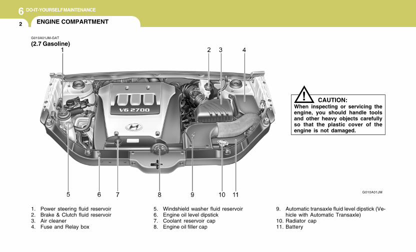
6 DO-IT-YOURSELF MAINTENANCE
2 ENGINE COMPARTMENT
G010A01JM-GAT
(2.7 Gasoline)
1. Power steering fluid reservoir2. Brake & Clutch fluid reservoir3. Air cleaner4. Fuse and Relay box
5. Windshield washer fluid reservoir6. Engine oil level dipstick7. Coolant reservoir cap8. Engine oil filler cap
9. Automatic transaxle fluid level dipstick (Ve-hicle with Automatic Transaxle)
10. Radiator cap11. Battery
G010A01JM
CAUTION:When inspecting or servicing theengine, you should handle toolsand other heavy objects carefullyso that the plastic cover of theengine is not damaged.
!
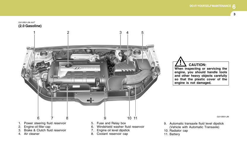
6DO-IT-YOURSELF MAINTENANCE
3
G010B01JM-AAT
(2.0 Gasoline)
G010B01JM
1. Power steering fluid reservoir2. Engine oil filler cap3. Brake & Clutch fluid reservoir4. Air cleaner
5. Fuse and Relay box6. Windshield washer fluid reservoir7. Engine oil level dipstick8. Coolant reservoir cap
9. Automatic transaxle fluid level dipstick(Vehicle with Automatic Transaxle)
10. Radiator cap11. Battery
CAUTION:When inspecting or servicing theengine, you should handle toolsand other heavy objects carefullyso that the plastic cover of theengine is not damaged.
!
6 DO-IT-YOURSELF MAINTENANCE
4 GENERAL CHECKS
G020C01A-AAT
Vehicle Interior
The following should be checked each timewhen the vehicle is driven:
o Lights operationo Windshield wiper operationo Horn operationo Defroster, heating system operation (and air
conditioning, if installed)o Steering operation and conditiono Mirror condition and operationo Turn signal operationo Accelerator pedal operationo Brake operation, including parking brakeo Manual transaxle operation, including clutch
operationo Automatic transaxle operation, including
"Park" mechanism operationo Seat control condition and operationo Seat belt condition and operationo Sunvisor operation
If you notice anything that does not operatecorrectly or appears to be functioning correctly,inspect it carefully and seek assistance fromyour Hyundai dealer if service is needed.
G020B01A-AAT
Vehicle Exterior
The following should be checked monthly:
o Overall appearance and conditiono Wheel condition and wheel nut torqueo Exhaust system conditiono Light condition and operationo Windshield glass conditiono Wiper blade conditiono Paint condition and body corrosiono Fluid leakso Door and hood lock conditiono Tire pressure and condition
(including spare tire)
G020A01A-AAT
Engine Compartment
The following should be checked regularly:
o Engine oil level and conditiono Transaxle fluid level and conditiono Brake fluid levelo Clutch fluid levelo Engine coolant levelo Windshield washer fluid levelo Accessory drive belt conditiono Engine coolant hose conditiono Fluid leaks (on or below components)o Power steering fluid levelo Battery conditiono Air filter condition
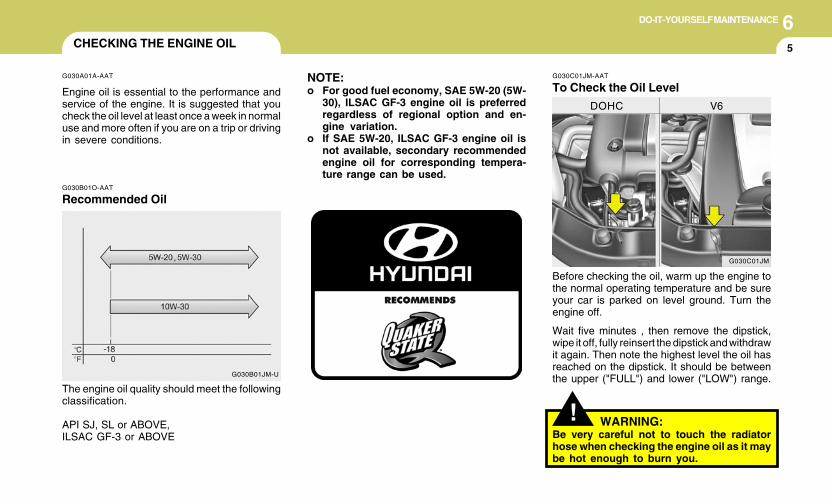
6DO-IT-YOURSELF MAINTENANCE
5CHECKING THE ENGINE OIL
G030A01A-AAT
Engine oil is essential to the performance andservice of the engine. It is suggested that youcheck the oil level at least once a week in normaluse and more often if you are on a trip or drivingin severe conditions.
G030C01JM-AAT
To Check the Oil Level
Before checking the oil, warm up the engine tothe normal operating temperature and be sureyour car is parked on level ground. Turn theengine off.
Wait five minutes , then remove the dipstick,wipe it off, fully reinsert the dipstick and withdrawit again. Then note the highest level the oil hasreached on the dipstick. It should be betweenthe upper ("FULL") and lower ("LOW") range.
G030C01JM
DOHC V6
! WARNING:Be very careful not to touch the radiatorhose when checking the engine oil as it maybe hot enough to burn you.
G030B01O-AAT
Recommended Oil
The engine oil quality should meet the followingclassification.
API SJ, SL or ABOVE,ILSAC GF-3 or ABOVE
G030B01JM-U
NOTE:o For good fuel economy, SAE 5W-20 (5W-
30), ILSAC GF-3 engine oil is preferredregardless of regional option and en-gine variation.
o If SAE 5W-20, ILSAC GF-3 engine oil isnot available, secondary recommendedengine oil for corresponding tempera-ture range can be used.
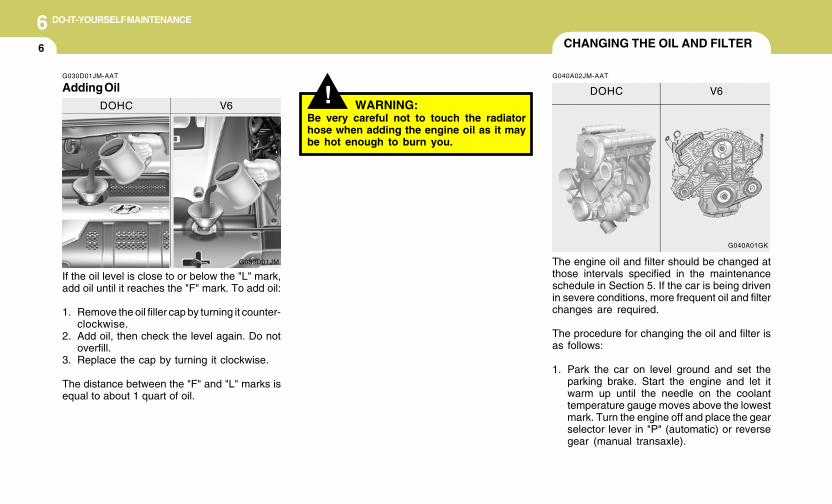
6 DO-IT-YOURSELF MAINTENANCE
6
WARNING:Be very careful not to touch the radiatorhose when adding the engine oil as it maybe hot enough to burn you.
!
CHANGING THE OIL AND FILTER
If the oil level is close to or below the "L" mark,add oil until it reaches the "F" mark. To add oil:
1. Remove the oil filler cap by turning it counter-clockwise.
2. Add oil, then check the level again. Do notoverfill.
3. Replace the cap by turning it clockwise.
The distance between the "F" and "L" marks isequal to about 1 quart of oil.
The engine oil and filter should be changed atthose intervals specified in the maintenanceschedule in Section 5. If the car is being drivenin severe conditions, more frequent oil and filterchanges are required.
The procedure for changing the oil and filter isas follows:
1. Park the car on level ground and set theparking brake. Start the engine and let itwarm up until the needle on the coolanttemperature gauge moves above the lowestmark. Turn the engine off and place the gearselector lever in "P" (automatic) or reversegear (manual transaxle).
G030D01JM-AAT
Adding Oil
G030D01JM
DOHC V6
G040A01GK
DOHC V6
G040A02JM-AAT
6DO-IT-YOURSELF MAINTENANCE
7
6. Install a new oil filter in accordance with theinstructions on the carton or on the filter itself.Do not over-tighten. (Tightening torque :1.2 ~ 1.6 kgf.m) Be sure that the mountingsurface on the engine is clean and that theold gasket is removed completely. Lubricatethe new gasket on the filter with clean engineoil before installation.
7. Remove the engine oil level dipstick.8. Refill the crankcase with the recommended
engine oil. Refer to the specification in chap-ter 9 for engine oil capacity.
! PROPOSITION 65 WARNING:This product contains a chemical known tothe State of California to cause cancer.Used engine oil may cause irritation orcancer of the skin if left in contact with theskin for prolonged periods of time. Usedengine oil contains chemicals that havecaused cancer in laboratory animals. Al-ways protect your skin by washing yourhands thoroughly with soap and warmwater as soon as possible after handlingused oil.
! WARNING:Be very careful when draining the engine oilas it may be hot enough to burn you!
2. Open the hood and remove the engine oilfiller cap.
3. Slide underneath the car and loosen thedrain plug by turning it counterclockwise witha wrench of the proper size. Be sure that adrain pan is in position to catch the oil as itdrains out, then remove the drain plug.
4. When the oil has stopped draining, replacethe drain plug using a new washer andretighten by turning it clockwise.
Oil pan drain plug tightening torque:3.5 ~ 4.5 kgf.m (2.7L)4.0 ~ 4.5 kgf.m (2.0L)
5. Remove the oil filter by turning it counter-clockwise with a oil filter wrench of the propersize. A certain amount of oil will come outwhen you remove the filter. So be sure tohave your drain pan in place underneath it.
CAUTION:Slowly pour the recommended oil using bya funnel. Do not overfill! Engine damagemay occur if overfilled.
!
9. Start the engine and check to be sure no oilis leaking from the drain plug or oil filter.
10.Shut off the engine and recheck the oil level.
NOTE:Always dispose of used engine oil in anenvironmentally acceptable manner. It issuggested that it be placed in a sealedcontainer and taken to a service station forreclamation. Do not pour the oil on theground or put it in with the householdtrash.
6 DO-IT-YOURSELF MAINTENANCE
8
G050B01A-AAT
Recommended Engine Coolant
Use a high quality ethylene-glycol coolant in a50/50 mix with water. The engine coolant shouldbe compatible with aluminum engine parts.Additional corrosion inhibitors or additives shouldnot be used. The cooling system must bemaintained with the correct concentration andtype of engine coolant to prevent freezing andcorrosion. Never allow the concentration ofantifreeze to exceed the 60% level or go belowthe 35% level, or damage to the cooling systemmay result. For proper concentration whenadding or replacing the engine coolant, refer tothe following table.
Ambient
temperature
°F (°C)
5 (-15)
-13 (-25)
-31 (-35)
-49 (-45)
65%
60%
50%
40%
35%
40%
50%
60%
WaterAntifreeze
solution
Engine Coolant concentration
G050C01A-AAT
To Check the Coolant Level
The coolant level can be seen on the side of theplastic coolant reservoir. The level of the cool-ant should be between the "L" and "F" lines onthe reservoir when the engine is cool. If the levelis below the "L" mark, add engine coolant tobring it up between "L" and "F". If the level is low,inspect for coolant leaks and recheck the fluidlevel frequently. If the level drops again, visityour Hyundai dealer for an inspection anddiagnosis of the reason.
CHECKING AND CHANGING THEENGINE COOLANT
!
G050A01A-AAT
WARNING:Do not remove the radiator cap when theengine is hot. When the engine is hot, theengine coolant is under pressure and mayerupt through the opening if the cap isremoved. You could be seriously burned ifyou do not observe this precaution. Do notremove the radiator cap until the radiator iscool to the touch.
G050C01JM
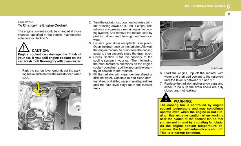
6DO-IT-YOURSELF MAINTENANCE
9
!
! WARNING:The cooling fan is controlled by enginecoolant temperature and may sometimesoperate even when the engine is not run-ning. Use extreme caution when workingnear the blades of the coolant fan so thatyou are not injured by a rotating fan blade.As the engine coolant temperature de-creases, the fan will automatically shut off.This is a normal condition.
2. Turn the radiator cap counterclockwise with-out pressing down on it, until it stops. Thisrelieves any pressure remaining in the cool-ing system. And remove the radiator cap bypushing down and turning counterclock-wise.
3. Be sure your drain receptacle is in place.Open the drain cock on the radiator. Allow allthe engine coolant to drain from the coolingsystem, then securely close the drain cock.
4. Check Section 9 for the capacity of thecooling system in your car. Then, followingthe manufacturer's directions on the enginecoolant container, add the appropriate quan-tity of coolant to the radiator.
5. Fill the radiator with clean demineralized ordistilled water. Continue to add clean dem-ineralized or distilled water in small quantitiesuntil the fluid level stays up in the radiatorneck.
6. Start the engine, top off the radiator withwater and then add coolant to the reservoiruntil the level is between "L" and "F".
7. Replace the radiator and reservoir caps andcheck to be sure the drain cocks are fullyclosed and not leaking.
G050D02A-AAT
To Change the Engine Coolant
The engine coolant should be changed at thoseintervals specified in the vehicle maintenanceschedule in Section 5.
HJM5034
G050D01JM
CAUTION:Engine coolant can damage the finish ofyour car. If you spill engine coolant on thecar, wash it off thoroughly with clean water.
1. Park the car on level ground, set the park-ing brake and remove the radiator cap whencool.
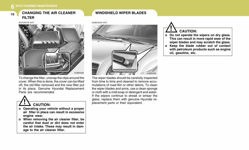
6 DO-IT-YOURSELF MAINTENANCE
10 WINDSHIELD WIPER BLADES
G080A02A-AAT
The wiper blades should be carefully inspectedfrom time to time and cleaned to remove accu-mulations of road film or other debris. To cleanthe wiper blades and arms, use a clean spongeor cloth with a mild soap or detergent and water.If the wipers continue to streak or smear theglass, replace them with genuine Hyundai re-placement parts or their equivalent.
! CAUTION:o Do not operate the wipers on dry glass.
This can result in more rapid wear of thewiper blades and may scratch the glass.
o Keep the blade rubber out of contactwith petroleum products such as engineoil, gasoline, etc.
HJM5032HJM5038
CHANGING THE AIR CLEANERFILTER
G070A01E-AAT
To change the filter, unsnap the clips around thecover. When this is done, the cover can be liftedoff, the old filter removed and the new filter putin its place. Genuine Hyundai ReplacementParts are recommended.
CAUTION:o Operating your vehicle without a proper
air filter in place can result in excessiveengine wear.
o When removing the air cleaner filter, becareful that dust or dirt does not enterthe air intake. These may result in dam-age to the air cleaner filter.
!
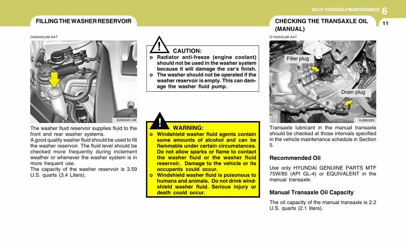
6DO-IT-YOURSELF MAINTENANCE
11
G090A01JM
FILLING THE WASHER RESERVOIR
G090A02JM-AAT
The washer fluid reservoir supplies fluid to thefront and rear washer systems.A good quality washer fluid should be used to fillthe washer reservoir. The fluid level should bechecked more frequently during inclementweather or whenever the washer system is inmore frequent use.The capacity of the washer reservoir is 3.59U.S. quarts (3.4 Liters).
CAUTION:o Radiator anti-freeze (engine coolant)
should not be used in the washer systembecause it will damage the car's finish.
o The washer should not be operated if thewasher reservoir is empty. This can dam-age the washer fluid pump.
!
! WARNING:o Windshield washer fluid agents contain
some amounts of alcohol and can beflammable under certain circumstances.Do not allow sparks or flame to contactthe washer fluid or the washer fluidreservoir. Damage to the vehicle or itsoccupants could occur.
o Windshield washer fluid is poisonous tohumans and animals. Do not drink wind-shield washer fluid. Serious injury ordeath could occur.
CHECKING THE TRANSAXLE OIL(MANUAL)
G100A02JM-AAT
Transaxle lubricant in the manual transaxleshould be checked at those intervals specifiedin the vehicle maintenance schedule in Section5.
Recommended Oil
Use only HYUNDAI GENUINE PARTS MTF75W/85 (API GL-4) or EQUIVALENT in themanual transaxle.
Manual Transaxle Oil Capacity
The oil capacity of the manual transaxle is 2.2U.S. quarts (2.1 liters).
HJM5009
Filler plug
Drain plug
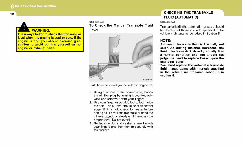
6 DO-IT-YOURSELF MAINTENANCE
12 CHECKING THE TRANSAXLEFLUID (AUTOMATIC)
G110A01E-AAT
Transaxle fluid in the automatic transaxle shouldbe checked at those intervals specified in thevehicle maintenance schedule in Section 5.
NOTE:Automatic transaxle fluid is basically redcolor. As driving distance increases, thefluid color turns darkish red gradually. It isa normal condition and you should notjudge the need to replace based upon thechanging color.You must replace the automatic transaxlefluid in accordance with intervals specifiedin the vehicle maintenance schedule insection 5.
G100B01L
!G100B02A-AAT
To Check the Manual Transaxle FluidLevelWARNING:
It is always better to check the transaxle oillevel when the engine is cool or cold. If theengine is hot, you should exercise greatcaution to avoid burning yourself on hotengine or exhaust parts.
Park the car on level ground with the engine off.
1. Using a wrench of the correct size, loosenthe oil filler plug by turning it counterclock-wise and remove it with your fingers.
2. Use your finger or suitable tool to feel insidethe hole. The oil level should be at its bottomedge. If it is not, check for leaks beforeadding oil. To refill the transaxle or bring theoil level up,add oil slowly until it reaches theproper level. Do not overfill.
3. Replace the plug and washer, screw it in withyour fingers and then tighten securely withthe wrench.
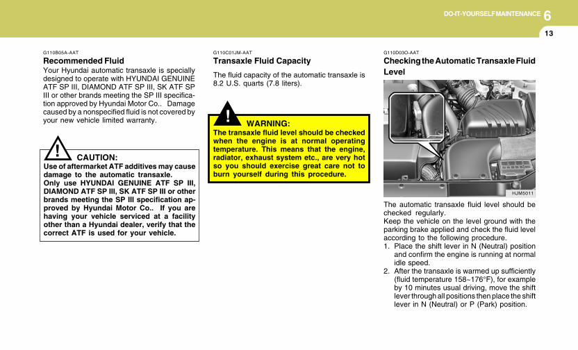
6DO-IT-YOURSELF MAINTENANCE
13
!
G110D03O-AAT
Checking the Automatic Transaxle FluidLevel
The automatic transaxle fluid level should bechecked regularly.Keep the vehicle on the level ground with theparking brake applied and check the fluid levelaccording to the following procedure.1. Place the shift lever in N (Neutral) position
and confirm the engine is running at normalidle speed.
2. After the transaxle is warmed up sufficiently(fluid temperature 158~176°F), for exampleby 10 minutes usual driving, move the shiftlever through all positions then place the shiftlever in N (Neutral) or P (Park) position.
G110C01JM-AAT
Transaxle Fluid Capacity
The fluid capacity of the automatic transaxle is8.2 U.S. quarts (7.8 liters).
WARNING:The transaxle fluid level should be checkedwhen the engine is at normal operatingtemperature. This means that the engine,radiator, exhaust system etc., are very hotso you should exercise great care not toburn yourself during this procedure.
HJM5011
!
G110B05A-AAT
Recommended FluidYour Hyundai automatic transaxle is speciallydesigned to operate with HYUNDAI GENUINEATF SP III, DIAMOND ATF SP III, SK ATF SPIII or other brands meeting the SP III specifica-tion approved by Hyundai Motor Co.. Damagecaused by a nonspecified fluid is not covered byyour new vehicle limited warranty.
CAUTION:Use of aftermarket ATF additives may causedamage to the automatic transaxle.Only use HYUNDAI GENUINE ATF SP III,DIAMOND ATF SP III, SK ATF SP III or otherbrands meeting the SP III specification ap-proved by Hyundai Motor Co.. If you arehaving your vehicle serviced at a facilityother than a Hyundai dealer, verify that thecorrect ATF is used for your vehicle.
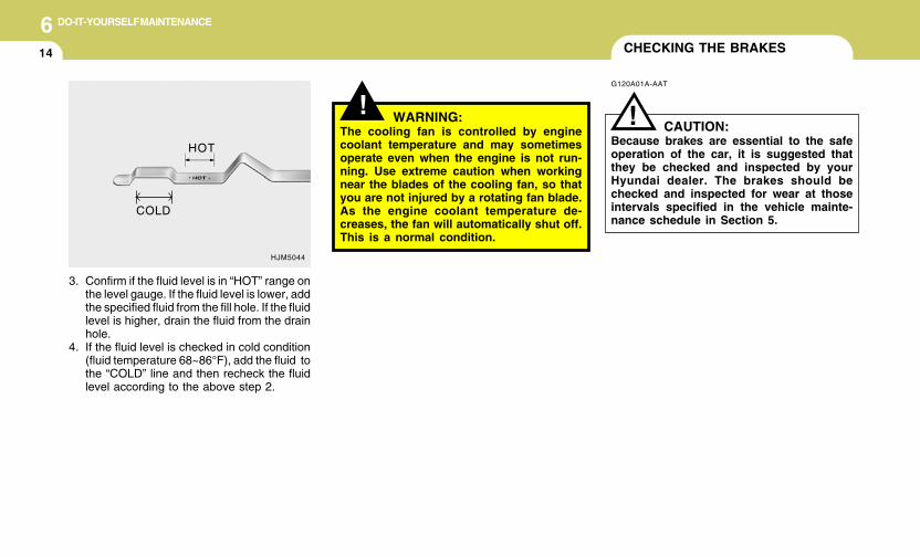
6 DO-IT-YOURSELF MAINTENANCE
14
3. Confirm if the fluid level is in “HOT” range onthe level gauge. If the fluid level is lower, addthe specified fluid from the fill hole. If the fluidlevel is higher, drain the fluid from the drainhole.
4. If the fluid level is checked in cold condition(fluid temperature 68~86°F), add the fluid tothe “COLD” line and then recheck the fluidlevel according to the above step 2.
HJM5044
CHECKING THE BRAKES
! WARNING:The cooling fan is controlled by enginecoolant temperature and may sometimesoperate even when the engine is not run-ning. Use extreme caution when workingnear the blades of the cooling fan, so thatyou are not injured by a rotating fan blade.As the engine coolant temperature de-creases, the fan will automatically shut off.This is a normal condition.
HOT
G120A01A-AAT
CAUTION:Because brakes are essential to the safeoperation of the car, it is suggested thatthey be checked and inspected by yourHyundai dealer. The brakes should bechecked and inspected for wear at thoseintervals specified in the vehicle mainte-nance schedule in Section 5.
!
COLD
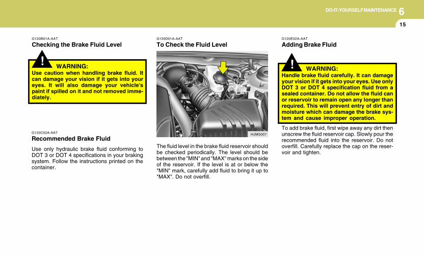
6DO-IT-YOURSELF MAINTENANCE
15
!
G120B01A-AAT
Checking the Brake Fluid Level
WARNING:Use caution when handling brake fluid. Itcan damage your vision if it gets into youreyes. It will also damage your vehicle'spaint if spilled on it and not removed imme-diately.
G120D01A-AAT
To Check the Fluid Level
G120C02A-AAT
Recommended Brake Fluid
Use only hydraulic brake fluid conforming toDOT 3 or DOT 4 specifications in your brakingsystem. Follow the instructions printed on thecontainer.
The fluid level in the brake fluid reservoir shouldbe checked periodically. The level should bebetween the "MIN" and "MAX" marks on the sideof the reservoir. If the level is at or below the"MIN" mark, carefully add fluid to bring it up to"MAX". Do not overfill.
HJM5007
!
G120E02A-AAT
Adding Brake Fluid
WARNING:Handle brake fluid carefully. It can damageyour vision if it gets into your eyes. Use onlyDOT 3 or DOT 4 specification fluid from asealed container. Do not allow the fluid canor reservoir to remain open any longer thanrequired. This will prevent entry of dirt andmoisture which can damage the brake sys-tem and cause improper operation.
To add brake fluid, first wipe away any dirt thenunscrew the fluid reservoir cap. Slowly pour therecommended fluid into the reservoir. Do notoverfill. Carefully replace the cap on the reser-voir and tighten.
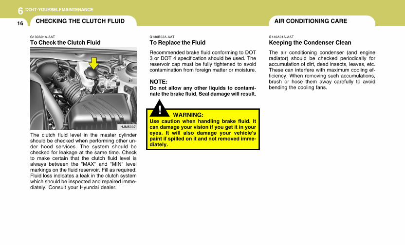
6 DO-IT-YOURSELF MAINTENANCE
16
!
G130B02A-AAT
To Replace the Fluid
Recommended brake fluid conforming to DOT3 or DOT 4 specification should be used. Thereservoir cap must be fully tightened to avoidcontamination from foreign matter or moisture.
NOTE:Do not allow any other liquids to contami-nate the brake fluid. Seal damage will result.
WARNING:Use caution when handling brake fluid. Itcan damage your vision if you get it in youreyes. It will also damage your vehicle'spaint if spilled on it and not removed imme-diately.
AIR CONDITIONING CARE
G140A01A-AAT
Keeping the Condenser Clean
The air conditioning condenser (and engineradiator) should be checked periodically foraccumulation of dirt, dead insects, leaves, etc.These can interfere with maximum cooling ef-ficiency. When removing such accumulations,brush or hose them away carefully to avoidbending the cooling fans.
HJM5007
CHECKING THE CLUTCH FLUID
G130A01A-AAT
To Check the Clutch Fluid
The clutch fluid level in the master cylindershould be checked when performing other un-der hood services. The system should bechecked for leakage at the same time. Checkto make certain that the clutch fluid level isalways between the "MAX" and "MIN" levelmarkings on the fluid reservoir. Fill as required.Fluid loss indicates a leak in the clutch systemwhich should be inspected and repaired imme-diately. Consult your Hyundai dealer.
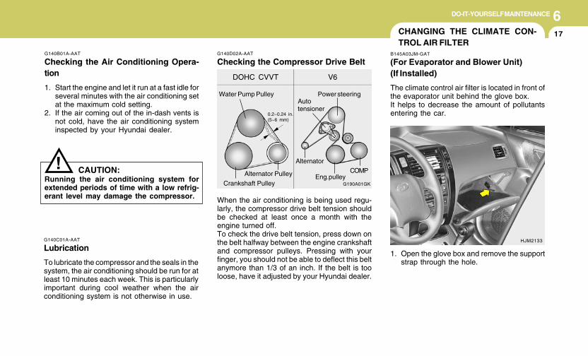
6DO-IT-YOURSELF MAINTENANCE
17
G190A01GK
DOHC CVVT V6
Water Pump Pulley
0.2~0.24 in.(5~6 mm)
Power steering
COMP
Autotensioner
Alternator Pulley
Crankshaft Pulley
Alternator
Eng.pulley
G140D02A-AAT
Checking the Compressor Drive Belt
!
G140C01A-AAT
Lubrication
To lubricate the compressor and the seals in thesystem, the air conditioning should be run for atleast 10 minutes each week. This is particularlyimportant during cool weather when the airconditioning system is not otherwise in use.
G140B01A-AAT
Checking the Air Conditioning Opera-tion
1. Start the engine and let it run at a fast idle forseveral minutes with the air conditioning setat the maximum cold setting.
2. If the air coming out of the in-dash vents isnot cold, have the air conditioning systeminspected by your Hyundai dealer.
CAUTION:Running the air conditioning system forextended periods of time with a low refrig-erant level may damage the compressor. When the air conditioning is being used regu-
larly, the compressor drive belt tension shouldbe checked at least once a month with theengine turned off.To check the drive belt tension, press down onthe belt halfway between the engine crankshaftand compressor pulleys. Pressing with yourfinger, you should not be able to deflect this beltanymore than 1/3 of an inch. If the belt is tooloose, have it adjusted by your Hyundai dealer.
CHANGING THE CLIMATE CON-TROL AIR FILTER
B145A03JM-GAT
(For Evaporator and Blower Unit)(If Installed)
The climate control air filter is located in front ofthe evaporator unit behind the glove box.It helps to decrease the amount of pollutantsentering the car.
1. Open the glove box and remove the supportstrap through the hole.
HJM2133
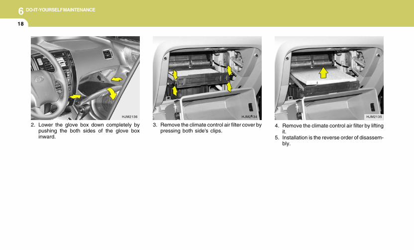
6 DO-IT-YOURSELF MAINTENANCE
18
3. Remove the climate control air filter cover bypressing both side's clips.
HJM2135
4. Remove the climate control air filter by liftingit.
5. Installation is the reverse order of disassem-bly.
2. Lower the glove box down completely bypushing the both sides of the glove boxinward.
HJM2136 HJM2134
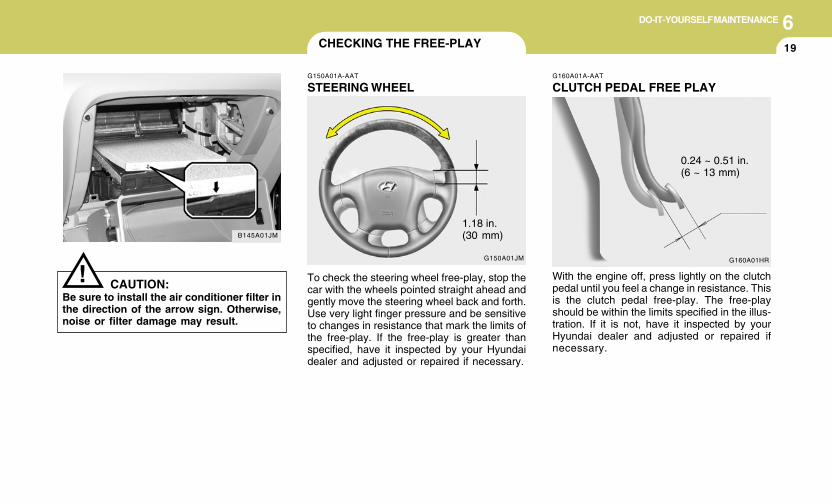
6DO-IT-YOURSELF MAINTENANCE
19
G150A01JM
!
B145A01JM
CAUTION:Be sure to install the air conditioner filter inthe direction of the arrow sign. Otherwise,noise or filter damage may result.
CHECKING THE FREE-PLAY
G150A01A-AAT
STEERING WHEEL
To check the steering wheel free-play, stop thecar with the wheels pointed straight ahead andgently move the steering wheel back and forth.Use very light finger pressure and be sensitiveto changes in resistance that mark the limits ofthe free-play. If the free-play is greater thanspecified, have it inspected by your Hyundaidealer and adjusted or repaired if necessary.
1.18 in.(30 mm)
G160A01HR
G160A01A-AAT
CLUTCH PEDAL FREE PLAY
With the engine off, press lightly on the clutchpedal until you feel a change in resistance. Thisis the clutch pedal free-play. The free-playshould be within the limits specified in the illus-tration. If it is not, have it inspected by yourHyundai dealer and adjusted or repaired ifnecessary.
0.24 ~ 0.51 in.(6 ~ 13 mm)
6 DO-IT-YOURSELF MAINTENANCE
20
G190A01GK
DOHC CVVT V6
Water Pump Pulley
0.2~0.24 in.(5~6 mm)
Power steering
COMP
Autotensioner
Alternator Pulley
Crankshaft Pulley
Alternator
Eng.pulley
CHECKING DRIVE BELTS
Drive belts should be checked periodically forproper tension and adjusted if necessary. At thesame time, belts should be examined for cracks,wear, fraying or other evidence of deteriorationand replaced if necessary.Belt routing should also be checked to be surethere is no interference between the belts andother parts of the engine. After a belt is replaced,the new belt should be adjusted again after twoor three weeks to eliminate slack resulting frominitial stretching after use.
G190A01A-AAT
G180A01L
G160A01HR
CHECKING BRAKE PEDALCLEARANCE
G180A01A-AAT
You need a helper to check the brake pedalclearance. With the engine running, have yourhelper press down on the brake pedal severaltimes and then hold it down with a force of about110 lbs (50 kg, 490 N). The brake pedal clear-ance is the distance from the top surface of thebrake pedal to the asphalt sheeting under thefloor mat.If the brake pedal clearance is not within thelimits specified in the illustration, have it in-spected by your Hyundai dealer and adjustedor repaired if necessary.
2.95 in. (75 mm)
G170A01A-AAT
BRAKE PEDAL FREE PLAY
With the engine off, press down on the brakepedal several times to reduce the vacuum in thebrake booster.Then, using your hand, press down slowly onthe brake pedal until you feel a change inresistance. This is the brake pedal free-play.The free-play should be within the limits speci-fied in the illustration above. If it is not, have itinspected by your Hyundai dealer and adjustedor repaired if necessary.
0.12 ~ 0.31 in.(3 ~ 8 mm)
6DO-IT-YOURSELF MAINTENANCE
21CHECKING AND REPLACINGFUSES
!G200B02JM-AAT
Replacing Accessory FusesCAUTION:
When replacing a fusible link, never useanything but a new fusible link with thesame or lower amperage rating. Never usea piece of wire or a higher-rated fusible link.This could result in serious damage andcreate a fire hazard.
The fuse box for the lights and other electricalaccessories will be found on the left side ofcrash pad. Inside the box you will find a listshowing the circuits protected by each fuse.If any of your car's lights or other electricalaccessories stop working, a blown (open) fusecould be the reason. If the fuse has opened, youwill see that the metal strip inside the fuse hasmelted through. If you suspect a blown fuse,follow this procedure:
G200A03A-AAT
Replacing a Fusible Link
A fusible link will melt if the electrical circuits fromthe battery are ever overloaded, thus prevent-ing damage to the entire wiring harness. (Thiscould be caused by a short in the systemdrawing too much current.) If this ever happens,have a Hyundai dealer determine the cause,repair the system and replace the fusible link.The fusible links are located in a relay box in theengine compartement for easy inspection.
HJM4002G200A01JM
Open-Replace Good
6 DO-IT-YOURSELF MAINTENANCE
22
G200B02L
!4. Replace the blown fuse by pressing a new
fuse of the same rating into place. The fuseshould be a snug fit. If it is not, have the fuseclip repaired or replaced by a Hyundai dealer.If you do not have a spare fuse, you may beable to borrow a fuse of the same or lowerrating from an accessory you can tempo-rarily get along without (the radio or cigarettelighter, for example). Always remember toreplace the borrowed fuse.
CAUTION:An open fuse indicates that there is a prob-lem in the electrical circuit. If you replace afuse and it blows as soon as the accessoryis turned on, the problem is serious andshould be referred to a Hyundai dealer fordiagnosis and repair. Never replace a fusewith anything except a fuse with the sameor a lower amperage rating. A higher capac-ity fuse could cause damage and create afire hazard.
NOTE:See page 6-35 for the fuse panel descrip-tions.
Good Open-Replace
1. Turn off the ignition and all other switches.2. Open the fuse box and examine each fuse.
Remove each fuse by pulling it toward you(a small "fuse puller" tool is contained in therelay and fuse box of the engine room tosimplify this operation).
3. Be sure to check all other fuses even if youfind one that appears to have opened.
G200B01JM
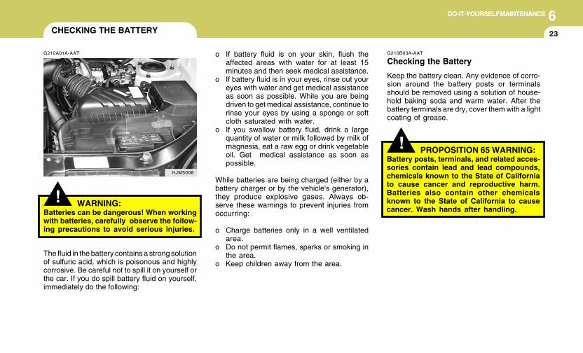
6DO-IT-YOURSELF MAINTENANCE
23CHECKING THE BATTERY
!
G210A01A-AAT
WARNING:Batteries can be dangerous! When workingwith batteries, carefully observe the follow-ing precautions to avoid serious injuries.
The fluid in the battery contains a strong solutionof sulfuric acid, which is poisonous and highlycorrosive. Be careful not to spill it on yourself orthe car. If you do spill battery fluid on yourself,immediately do the following:
HJM5008
!
G210B03A-AAT
Checking the Battery
Keep the battery clean. Any evidence of corro-sion around the battery posts or terminalsshould be removed using a solution of house-hold baking soda and warm water. After thebattery terminals are dry, cover them with a lightcoating of grease.
o If battery fluid is on your skin, flush theaffected areas with water for at least 15minutes and then seek medical assistance.
o If battery fluid is in your eyes, rinse out youreyes with water and get medical assistanceas soon as possible. While you are beingdriven to get medical assistance, continue torinse your eyes by using a sponge or softcloth saturated with water.
o If you swallow battery fluid, drink a largequantity of water or milk followed by milk ofmagnesia, eat a raw egg or drink vegetableoil. Get medical assistance as soon aspossible.
While batteries are being charged (either by abattery charger or by the vehicle's generator),they produce explosive gases. Always ob-serve these warnings to prevent injuries fromoccurring:
o Charge batteries only in a well ventilatedarea.
o Do not permit flames, sparks or smoking inthe area.
o Keep children away from the area.
PROPOSITION 65 WARNING:Battery posts, terminals, and related acces-sories contain lead and lead compounds,chemicals known to the State of Californiato cause cancer and reproductive harm.Batteries also contain other chemicalsknown to the State of California to causecancer. Wash hands after handling.
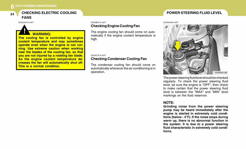
6 DO-IT-YOURSELF MAINTENANCE
24 POWER STEERING FLUID LEVEL
G230A03A-AAT
G220C01A-AAT
Checking Condenser Cooling Fan
The condenser cooling fan should come onautomatically whenever the air conditioning is inoperation.
The power steering fluid level should be checkedregularly. To check the power steering fluidlevel, be sure the engine is "OFF", then checkto make certain that the power steering fluidlevel is between the "MAX" and "MIN" levelmarkings on the fluid reservoir.
NOTE:Grinding noise from the power steeringpump may be heard immediately after theengine is started in extremely cold condi-tions (below - 4°F). If the noise stops duringwarm up, there is no abnormal function inthe system. It is due to a power steeringfluid characteristic in extremely cold condi-tions.
G220B01A-AAT
Checking Engine Cooling Fan
The engine cooling fan should come on auto-matically if the engine coolant temperature ishigh.
CHECKING ELECTRIC COOLINGFANS
!G220A01A-AAT
WARNING:The cooling fan is controlled by enginecoolant temperature and may sometimesoperate even when the engine is not run-ning. Use extreme caution when workingnear the blades of the cooling fan, so thatyou are not injured by a rotating fan blade.As the engine coolant temperature de-creases the fan will automatically shut off.This is a normal condition.
G230A01JM
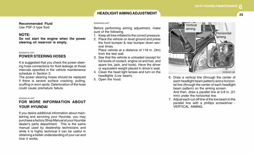
6DO-IT-YOURSELF MAINTENANCE
25HEADLIGHT AIMING ADJUSTMENT
6. Draw a vertical line (through the center ofeach headlight beam pattern) and a horizon-tal line (through the center of each headlightbeam pattern) on the aiming screen.And then, draw a parallel line at 0.8 in. (21mm) under the horizontal line.
7. Adjust each cut-off line of the low beam to theparallel line with a phillips screwdriver -VERTICAL AIMING.
G290A03O-AAT
Before performing aiming adjustment, makesure of the following.1. Keep all tires inflated to the correct pressure.2. Place the vehicle on level ground and press
the front bumper & rear bumper down sev-eral times.Place vehicle at a distance of 118 in. (3m)from the test wall.
3. See that the vehicle is unloaded (except forfull levels of coolant, engine oil and fuel, andspare tire, jack, and tools). Have the driveror equivalent weight placed in driver's seat.
4. Clean the head light lenses and turn on theheadlights (Low beam).
5. Open the hood.
G250A01A-AAT
FOR MORE INFORMATION ABOUTYOUR HYUNDAI
If you desire additional information about main-taining and servicing your Hyundai, you maypurchase a factory Shop Manual at your Hyundaidealer's parts department. This is the samemanual used by dealership technicians andwhile it is highly technical it can be useful inobtaining a better understanding of your car andhow it works.
G240A01A-AAT
POWER STEERING HOSES
It is suggested that you check the power steer-ing hose connections for fluid leakage at thoseintervals specified in the vehicle maintenanceschedule in Section 5.The power steering hoses should be replacedif there is severe surface cracking, pulling,scuffing or worn spots. Deterioration of the hosecould cause premature failure.
Recommended FluidUse PSF-3 type fluid
NOTE:Do not start the engine when the powersteering oil reservoir is empty.
G290A01JM
Verticalaiming
Horizontalaiming
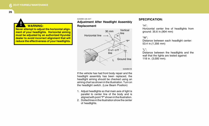
6 DO-IT-YOURSELF MAINTENANCE
26
SPECIFICATION:
"H";Horizontal center line of headlights fromground: 35.6 in.(904 mm)
"W";Distance between each headlight center:53.4 in.(1,356 mm)
"L";Distance between the headlights and thewall that the lights are tested against:118 in. (3,000 mm).
G290B01JM-AAT
Adjustment After Headlight AssemblyReplacement
If the vehicle has had front body repair and theheadlight assembly has been replaced, theheadlight aiming should be checked using anaiming chart as shown in the illustration. Turn onthe headlight switch. (Low Beam Position)
1. Adjust headlights so that main axis of light isparallel to center line of the body and isaligned with point "P" shown in the illustration.
2. Dotted lines in the illustration show the centerof headlights.
G290B01B
L
W
HC u t - o f fline
Ground line
"P"
Horizontal line
Verticalline
30 mm
! WARNING:Never attempt to adjust the horizontal align-ment of your headlights. Horizontal aimingmust be adjusted by an authorized Hyundaidealer to avoid incorrect alignment that willreduce the effectiveness of your headlights.
6DO-IT-YOURSELF MAINTENANCE
27REPLACEMENT OF LIGHT BULBS
!
G260A02A-AAT
Before attempting to replace a light bulb, be surethe switch is turned to the "OFF" position.The next paragraph shows how to reach thelight bulbs so they may be changed. Be sure toreplace the burned-out bulb with one of thesame number and wattage rating.
See page 6-34 for the wattage description.
CAUTION:o Keep the lamps out of contact with pe-
troleum products, such as oil, gasoline,etc.
o After heavy, driving rain or washing,headlight and taillight lenses could ap-pear frosty. This condition is caused bythe temperature difference between thelamp inside and outside. This is similarto the condensation on your windowsinside your vehicle during the rain anddoesn’t indicate a problem with yourvehicle. If the water leaks into the lampbulb circuitry, have the vehicle checkedby an Authorized Hyundai Dealer.
HJM5013
G270A02O-AAT
Headlight and Front Turn Signal Light
1. Allow the bulb to cool. Wear eye protection.2. Open the engine hood.3. Always grasp the bulb by its plastic base,
avoid touching the glass.
4. Using a socket wrench of the correct size,remove the headlight assembly mountingbolts.
HJM5012
5. Disconnect the power cord from the bulbbase in the back of the headlight.
6 DO-IT-YOURSELF MAINTENANCE
28
8. Push the bulb spring to remove the headlightbulb.
9. Remove the protective cap from the re-placement bulb and install the new bulb bymatching the plastic base with the headlighthole. Reattach the bulb spring and recon-nect the connector.
10.Use the protective cap and carton to prompt-ly dispose of the old bulb.
11.Check for proper headlight aim.12.To replace the front turn signal light bulb,
remove from the bulb holder and install thenew bulb. Do not touch the glass of the newbulb.
HJM5018HJM5016 HJM5017
6. Turn the plastic cover counterclockwiseand remove it.
7. Disconnect the connector from the bulbbase in the back of the headlight.
6DO-IT-YOURSELF MAINTENANCE
29
G270B01JM-AAT
Rear Combination Light
! WARNING:This halogen bulb contains gas under pres-sure and if impacted could shatter, result-ing in flying fragments. Always wear eyeprotection when servicing the bulb. Protectthe bulb against abrasions or scratchesand against liquids when lighted. Turn thebulb on only when installing in a headlight.Replace the headlight if damaged or cracked.Keep the bulb out of the reach of childrenand dispose of the used bulb with care.
G270A03O
HJM5020
HJM5021
HJM5022
(1)
(2)
(3)
(4)
1. Open the tail gate.2. Remove the mounting screws as shown
with a phillips screwdriver.
3. To replace the rear combination light (stop/tail light, turn signal light, back-up light, sidemark light), take it out from the bulb holder byturning it counterclockwise.
(1) Stop/Tail light(2) Turn signal light(3) Back-up light(4) Tail light
4. Install the new bulb.
6 DO-IT-YOURSELF MAINTENANCE
30
G270C02TB-GAT
Luggage Compartment Light(If Installed)
G270C01JM
1. Remove the cover with a flat blade screwdriver.
G270I02JM-GAT
Front fog Light (If installed)
HJM5047
1. Remove the cover with a phillips screwdriver.
2. Remove the bolts with a wrench.
3. Disconnect the power cord.
HJM5049
HJM5050
4. Replace to the new bulb.HJM5048
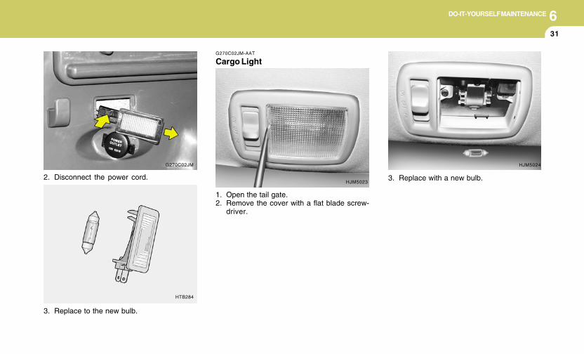
6DO-IT-YOURSELF MAINTENANCE
31
G270C02JM-AAT
Cargo Light
1. Open the tail gate.2. Remove the cover with a flat blade screw-
driver.
3. Replace to the new bulb.
HTB284
2. Disconnect the power cord.
G270C02JM
HJM5023
HJM5024
3. Replace with a new bulb.
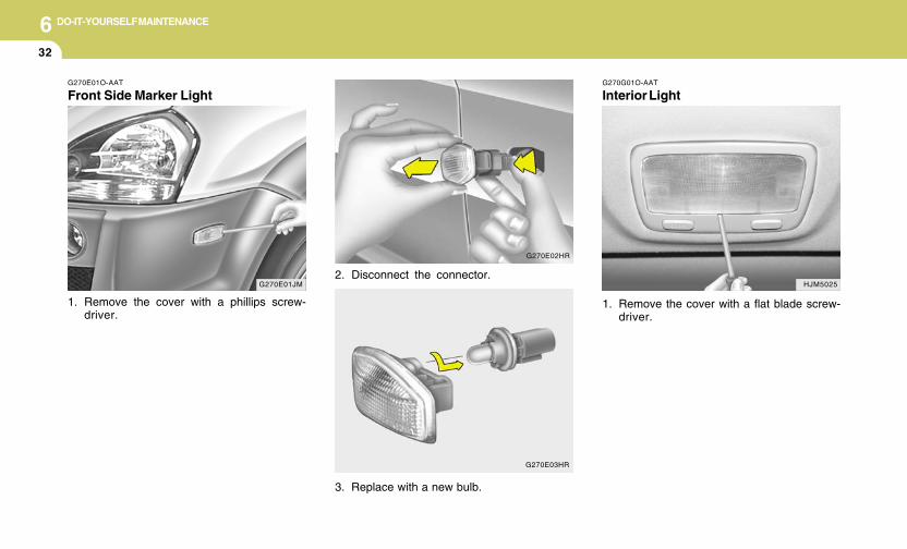
6 DO-IT-YOURSELF MAINTENANCE
32
G270G01O-AAT
Interior Light
1. Remove the cover with a flat blade screw-driver.
HJM5025G270E01JM
G270E01O-AAT
Front Side Marker Light
1. Remove the cover with a phillips screw-driver.
2. Disconnect the connector.
3. Replace with a new bulb.
G270E02HR
G270E03HR
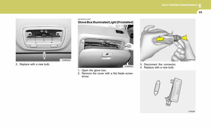
6DO-IT-YOURSELF MAINTENANCE
33
G270H01O-AAT
Glove Box Illuminated Light (If installed)
1. Open the glove box.2. Remove the cover with a flat blade screw-
driver.
HJM5026
HJM50452. Replace with a new bulb. 3. Disconnect the connector.
4. Replace with a new bulb.
HJM5039
HTB284
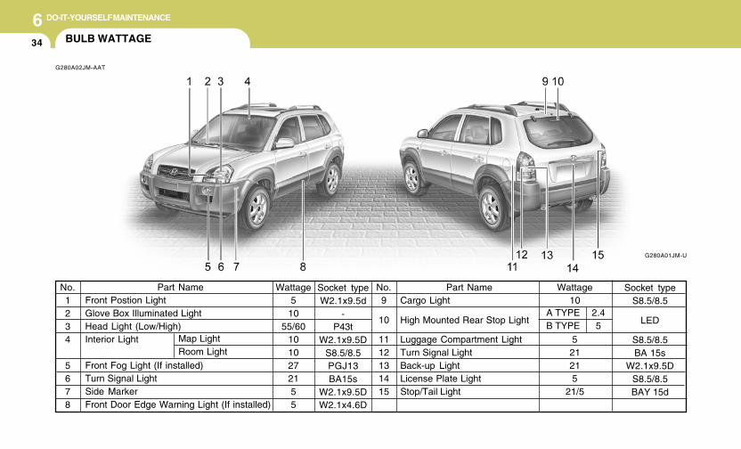
6 DO-IT-YOURSELF MAINTENANCE
34 BULB WATTAGE
G280A02JM-AAT
G280A01JM-U
Part NameFront Postion LightGlove Box Illuminated LightHead Light (Low/High)Interior Light
Front Fog Light (If installed)Turn Signal LightSide MarkerFront Door Edge Warning Light (If installed)
No.1234
5678
Wattage5
1055/60
1010272155
Wattage10
521215
21/5
No.9
10
1112131415
Part NameCargo Light
High Mounted Rear Stop Light
Luggage Compartment LightTurn Signal LightBack-up LightLicense Plate LightStop/Tail Light
Map LightRoom Light
A TYPEB TYPE
2.45
Socket typeS8.5/8.5
LED
S8.5/8.5BA 15s
W2.1x9.5DS8.5/8.5BAY 15d
Socket typeW2.1x9.5d
-P43t
W2.1x9.5DS8.5/8.5PGJ13BA15s
W2.1x9.5DW2.1x4.6D
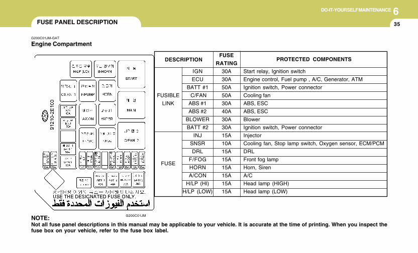
6DO-IT-YOURSELF MAINTENANCE
35FUSE PANEL DESCRIPTION
G200C01JM-GAT
Engine Compartment
G200C01JMNOTE:Not all fuse panel descriptions in this manual may be applicable to your vehicle. It is accurate at the time of printing. When you inspect thefuse box on your vehicle, refer to the fuse box label.
FUSE
RATING
30A
30A
50A
50A
30A
40A
30A
30A
15A
10A
15A
15A
15A
15A
15A
15A
PROTECTED COMPONENTS
Start relay, Ignition switch
Engine control, Fuel pump , A/C, Generator, ATM
Ignition switch, Power connector
Cooling fan
ABS, ESC
ABS, ESC
Blower
Ignition switch, Power connector
Injector
Cooling fan, Stop lamp switch, Oxygen sensor, ECM/PCM
DRL
Front fog lamp
Horn, Siren
A/C
Head lamp (HIGH)
Head lamp (LOW)
IGN
ECU
BATT #1
C/FAN
ABS #1
ABS #2
BLOWER
BATT #2
INJ
SNSR
DRL
F/FOG
HORN
A/CON
H/LP (HI)
H/LP (LOW)
FUSIBLE
LINK
FUSE
DESCRIPTION
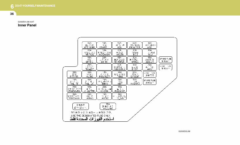
6 DO-IT-YOURSELF MAINTENANCE
36
G200E01JM-AAT
Inner Panel
G200E02JM

6DO-IT-YOURSELF MAINTENANCE
37
FUSE
P/WDW-LH
P/WDW-RH
TAIL RH
RR HTR
A/BAG
CLUSTER
TAIL LH
AUDIO
C/LIGHTER
& P/OUTLET
SPARE
RR FOG
HTD MIRR
AUDIO
IG COIL
IMMO
P/OUTLET
S/HTR
A/CON SW
START
PROTECTED COMPONENTS
Left power window
Right power window
Right rear combination lamp, Glove box lllumination
Rear defogger
SRS control
Instrument cluster, ETACM/TACM
Left head lamp, Left rear combination lamp, License lamp
Digital clock, Audio, Power outside mirror folding module, Power outside mirror & mirror folding switch
Cigarette lighter
(SPARE)
Rear fog lamp
Left/Right power outsider mirror & mirror folding motor, Rear defogger switch
Audio
Ignition coil (2.7 L)
Immobilizer control module (2.7 L)
Rear power outlet
(Not used)
Seat warmer
A/C control module (Manual A/C)
Theft alarm relay, Transaxle range switch, lgnition lock switch
FUSE
RATING
30A
30A
10A
30A
15A
10A
10A
10A
20A
15A
10A
10A
10A
20A
10A
15A
10A
20A
10A
10A

6 DO-IT-YOURSELF MAINTENANCE
38
FUSE
IG-SW
ROOM LP
AMP
T/SIG
A/BAG IND
RR WIPER
A/CON
IGN
HAZARD
S/ROOF
STOP
H/FREE
ECU
FF WIPER
4WD
DEICER
TCU
ABS
PROTECTED COMPONENTS
Ignition switch
Room lamp, A/C control module, Digital clock, ETACM/TACM Key remind switch
Audio
Hazard switch, Auto light & Photo sensor, Transaxle range switch
Instrument cluster
Safety relay
Sunroof controller, A/C control module, Blower relay, ETACM/TACM
PTC heater relay, Fuel filter heater relay, DRL CONTROL MODULE, head LAMP RELAY
Hazard switch, Hazard relay, Immobilizer control module (2.7 L)
Sunroof, Door lock/unlock relay
Stop lamp switch, Power outside mirror folding module
(Not used)
Cruise control, Stop lamp, TCS, ESC, 4WD ECM, ECM, PCM, TCM, Vehicle speed sensor
Front wiper, Multifunction switch
4WD/ECM
Windshield defogger
TCM (2.7 L)
G-Sensor, ESC, ABS
FUSE
RATING
30A
10A
20A
10A
10A
15A
10A
10A
10A
20A
15A
10A
10A
20A
20A
15A
10A
10A

7Emission Control System ............................................. 7-2Catalytic Converter ....................................................... 7-3
7
EMISSION CONTROL SYSTEMS

7 EMISSION CONTROL SYSTEMS
2 EMISSION CONTROL SYSTEM
H010D01A-AAT
3. Exhaust Emission Control System
The Exhaust Emission Control System is ahighly effective system which controls exhaustemissions while maintaining good vehicleperformace.
H010B01A-AAT
1. Crankcase Emission ControlSystem
The positive crankcase ventilation system isemployed to prevent air pollution caused byblow-by gases being emitted from the crank-case. This system supplies filtered air to thecrankcase through the air intake hose. Insidethe crankcase, the fresh air mixes with blow-bygases, which then pass through the PCV valveand into the induction system.
H010A02O-AAT
Your Hyundai is equipped with an emissioncontrol system to meet all requirements of theU.S. Environmental Protection Agency or Cali-fornia Air Resources Board.There are three emission control systems whichare as follows.
(1) Crankcase emission control system(2) Evaporative emission control system(3) Exhaust emission control system
In order to assure the proper function of theemission control systems, it is recommendedthat you have your car inspected and main-tained by an authorized Hyundai dealer in ac-cordance with the maintenance schedule in thismanual.
Caution for the Inspection and MaintenanceTest (V6 Vehicle with Traction Control Sys-tem)
o To prevent the vehicle from misfiringduring dynamometer testing, discon-nect the ABS connector in the enginecompartment. (2.7 V6 only)
o For more information, see shop manual(Wheel Speed Sensor).
o After dynamometer testing is completed,erase the ABS/TCS DTC (DiagnoticTrouble Code) with a GST (Generic ScanTool) or Hi-Scan Pro.
Canister
Fuel vapors generated inside the fuel tank areabsorbed and stored in the canister. When theengine is running, the fuel vapors absorbed inthe canister are drawn into the induction systemthrough the purge control solenoid valve.
Purge Control Solenoid Valve (PCSV)
The purge control solenoid valve is controlledby the Engine Control Module (ECM); when theengine coolant temperature is low during idling,the PCSV closes so that evaporated fuel is nottaken into the engine. After the engine warms-up during ordinary driving, the PCSV opens tointroduce evaporated fuel to the engine.
H010C01S-AAT
2. Evaporative Emission Control (Includ-ing ORVR: Onboard Refueling VaporRecovery) System
The Evaporative Emission Control System isdesigned to prevent fuel vapors from escapinginto the atmosphere.(The ORVR system is designed to allow thevapors from the fuel tank to be loaded into acanister while refueling at the gas station, pre-venting the escape of fuel vapors into theatmosphere.)
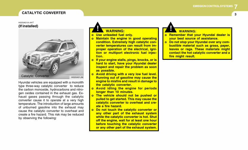
7EMISSION CONTROL SYSTEMS
3CATALYTIC CONVERTER
! WARNING:o Use unleaded fuel only.o Maintain the engine in good operating
condition. Extremely high catalytic con-verter temperatures can result from im-proper operation of the electrical, igni-tion or multiport electronic fuel injec-tion.
o If your engine stalls, pings, knocks, or ishard to start, have your Hyundai dealerinspect and repair the problem as soonas possible.
o Avoid driving with a very low fuel level.Running out of gasoline may cause theengine to misfire and result in damage tothe catalytic converter.
o Avoid idling the engine for periodslonger than 10 minutes.
o The vehicle should not be pushed orpulled to get started. This may cause thecatalytic converter to overheat and cre-ate a fire hazard.
o Do not touch the catalytic converter orany other part of the exhaust systemwhile the catalytic converter is hot. Shutoff the engine, wait for at least one hourbefore touching the catalytic converteror any other part of the exhaust system.
H020A01A-AAT
(If installed)
Hyundai vehicles are equipped with a monolithtype three-way catalytic converter to reducethe carbon monoxide, hydrocarbons and nitro-gen oxides contained in the exhaust gas. Ex-haust gases passing through the catalyticconverter cause it to operate at a very hightemperature. The introduction of large amountsof unburned gasoline into the exhaust maycause the catalytic converter to overheat andcreate a fire hazard. This risk may be reducedby observing the following:
H020A01JMCatalytic Converter
! WARNING:o Remember that your Hyundai dealer is
your best source of assistance.o Do not stop your Hyundai over any com-
bustible material such as grass, paper,leaves or rags. These materials mightcontact the hot catalytic converter and afire might result.

Vehicle Identification Number (VIN) .............................. 8-2Engine Number ............................................................. 8-2Tire Information ............................................................. 8-2Recommended Inflation Pressures ............................... 8-3Tire Sidewall Labeling ................................................... 8-6Tire Terminology and Definitions ................................... 8-7Snow Tires .................................................................. 8-10Tire Chains.................................................................. 8-10Tire Rotation................................................................ 8-11Tire Balancing ............................................................. 8-11Tire Traction ................................................................ 8-11When to Replace Tires ............................................... 8-12Tire Maintenance ........................................................ 8-13Spare Tire and Tools ................................................... 8-14Warranties for Your Hyundai Vehicle .......................... 8-14Consumer Information ................................................. 8-15Reporting Safety Defects ............................................ 8-17Binding Arbitration of Warranty Claims (U.S.A Only) .. 8-17
CONSUMER INFORMATION, REPORTINGSAFETY DEFECTS & BINDING
ARBITRATION OF WARRANTY CLAIMS
88
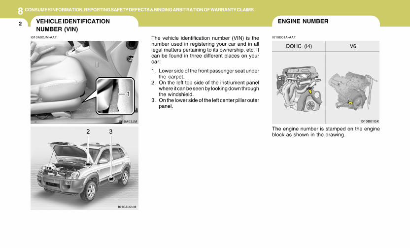
8 CONSUMER INFORMATION, REPORTING SAFETY DEFECTS & BINDING ARBITRATION OF WARRANTY CLAIMS
2 ENGINE NUMBERVEHICLE IDENTIFICATIONNUMBER (VIN)
I010B01A-AATI010A02JM-AAT The vehicle identification number (VIN) is thenumber used in registering your car and in alllegal matters pertaining to its ownership, etc. Itcan be found in three different places on yourcar:
1. Lower side of the front passenger seat underthe carpet.
2. On the left top side of the instrument panelwhere it can be seen by looking down throughthe windshield.
3. On the lower side of the left center pillar outerpanel.
The engine number is stamped on the engineblock as shown in the drawing.
I010A03JM I010B01GK
V6DOHC (I4)
I010A02JM
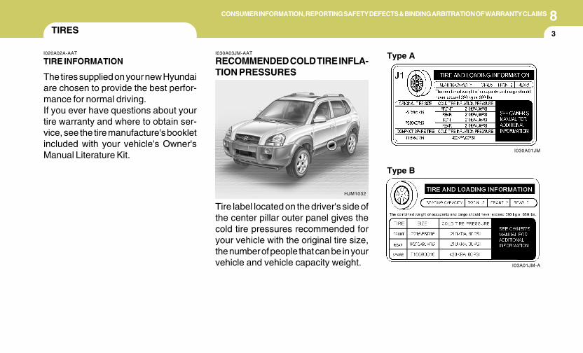
8CONSUMER INFORMATION, REPORTING SAFETY DEFECTS & BINDING ARBITRATION OF WARRANTY CLAIMS
3TIRES
I030A03JM-AAT
RECOMMENDED COLD TIRE INFLA-TION PRESSURES
I020A02A-AAT
TIRE INFORMATION
The tires supplied on your new Hyundaiare chosen to provide the best perfor-mance for normal driving.If you ever have questions about yourtire warranty and where to obtain ser-vice, see the tire manufacture's bookletincluded with your vehicle's Owner'sManual Literature Kit.
Tire label located on the driver's side ofthe center pillar outer panel gives thecold tire pressures recommended foryour vehicle with the original tire size,the number of people that can be in yourvehicle and vehicle capacity weight.
HJM1032
I03A01JM-A
Type B
I030A01JM
Type A
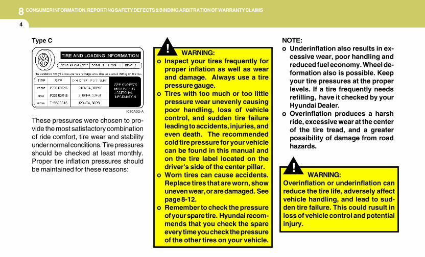
8 CONSUMER INFORMATION, REPORTING SAFETY DEFECTS & BINDING ARBITRATION OF WARRANTY CLAIMS
4
!
These pressures were chosen to pro-vide the most satisfactory combinationof ride comfort, tire wear and stabilityunder normal conditions. Tire pressuresshould be checked at least monthly.Proper tire inflation pressures shouldbe maintained for these reasons: !
WARNING:Overinflation or underinflation canreduce the tire life, adversely affectvehicle handling, and lead to sud-den tire failure. This could rusult inloss of vehicle control and potentialinjury.
Type C
I030A02-A
NOTE:o Underinflation also results in ex-
cessive wear, poor handling andreduced fuel economy. Wheel de-formation also is possible. Keepyour tire pressures at the properlevels. If a tire frequently needsrefilling, have it checked by yourHyundai Dealer.
o Overinflation produces a harshride, excessive wear at the centerof the tire tread, and a greaterpossibility of damage from roadhazards.
WARNING:o Inspect your tires frequently for
proper inflation as well as wearand damage. Always use a tirepressure gauge.
o Tires with too much or too littlepressure wear unevenly causingpoor handling, loss of vehiclecontrol, and sudden tire failureleading to accidents, injuries, andeven death. The recommendedcold tire pressure for your vehiclecan be found in this manual andon the tire label located on thedriver's side of the center pillar.
o Worn tires can cause accidents.Replace tires that are worn, showuneven wear, or are damaged. Seepage 8-12.
o Remember to check the pressureof your spare tire. Hyundai recom-mends that you check the spareevery time you check the pressureof the other tires on your vehicle.
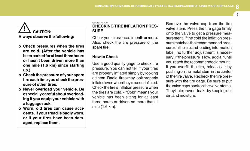
8CONSUMER INFORMATION, REPORTING SAFETY DEFECTS & BINDING ARBITRATION OF WARRANTY CLAIMS
5
CAUTION:Always observe the following:
o Check pressures when the tiresare cold. (After the vehicle hasbeen parked for at least three hoursor hasn't been driven more thanone mile (1.6 km) since startingup.)
o Check the pressure of your sparetire each time you check the pres-sure of other tires.
o Never overload your vehicle. Beespecially careful about overload-ing if you equip your vehicle witha luggage rack.
o Worn, old tires can cause acci-dents. If your tread is badly worn,or if your tires have been dam-aged, replace them.
!Remove the valve cap from the tirevalve stem. Press the tire gage firmlyonto the valve to get a pressure mea-surement. If the cold tire inflation pres-sure matches the recommended pres-sure on the tire and loading informationlabel, no further adjustment is neces-sary. If the pressure is low, add air untilyou reach the recommended amount.If you overfill the tire, release air bypushing on the metal stem in the centerof the tire valve. Recheck the tire pres-sure with the tire gage. Be sure to putthe valve caps back on the valve stems.They help prevent leaks by keeping outdirt and moisture.
I035A01JM-AAT
CHECKING TIRE INFLATION PRES-SURE
Check your tires once a month or more.Also, check the tire pressure of thespare tire.
How to Check
Use a good quality gage to check tirepressure. You can not tell if your tiresare properly inflated simply by lookingat them. Radial tires may look properlyinflated even when they're underinflated.Check the tire's inflation pressure whenthe tires are cold. - "Cold" means yourvehicle has been sitting for at leastthree hours or driven no more than 1mile (1.6 km).
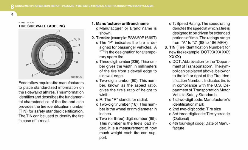
8 CONSUMER INFORMATION, REPORTING SAFETY DEFECTS & BINDING ARBITRATION OF WARRANTY CLAIMS
6
1. Manufacturer or Brand nameo Manufacturer or Brand name is
shown.2. Tire size (example: P235/60R16 99T)
o The "P" indicates the tire is de-signed for passenger vehicles. A"T" is the designation for a tempo-rary spare tire.
o Three-digit number (235): This num-ber gives the width in millimetersof the tire from sidewall edge tosidewall edge.
o Two-digit number (60): This num-ber, known as the aspect ratio,gives the tire's ratio of height towidth.
o R: The "R" stands for radial.o Two-digit number (16): This num-
ber is the wheel or rim diameter ininches.
o Two (or three) digit number (99):This number is the tire's load in-dex. It is a measurement of howmuch weight each tire can sup-port.
o T: Speed Rating. The speed ratingdenotes the speed at which a tire isdesigned to be driven for extendedperiods of time. The ratings rangefrom "A" to "Z" (98 to 186 MPH).
3. TIN (Tire Identification Number) fornew tire (example: DOT XX XX XXXXXXX)o DOT: Abbreviation for the "Depart-
ment of Transportation". The sym-bol can be placed above, below orto the left or right of the Tire Identification Number. Indicates tire isin compliance with the U.S. De-partment of Transportation MotorVehicle Safety Standards.
o 1st two-digit code: Manufacturer'sidentification mark
o 2nd two-digit code: Tire sizeo 3rd three-digit code: Tire type code
(Optional)o 4th four-digit code: Date of Manu-
facture
Federal law requires tire manufacturersto place standardized information onthe sidewall of all tires. This informationidentifies and describes the fundamen-tal characteristics of the tire and alsoprovides the tire identification number(TIN) for safety standard certification.The TIN can be used to identify the tirein case of a recall.
I030B01JM-AAT
TIRE SIDEWALL LABELING
I030B04JM
1
23
4
5, 6
7
1
8CONSUMER INFORMATION, REPORTING SAFETY DEFECTS & BINDING ARBITRATION OF WARRANTY CLAIMS
7
o Four numbers represent the weekand year the tire was built. Forexample, the numbers 3105 meansthe 31st week of 2005.
4. Tire ply composition and materialThe number of layers or plies ofrubbercoated fabric in the tire. Tiremanufacturers also must indicatethe materials in the tire, which in-clude steel, nylon, polyester, andothers. The letter "R" means radialply construction; the letter "D" meansdiagonal or bias ply construction;and the letter "B" means belted-biasply construction.
5. Maximum permissible inflationpressureThis number is the greatest amountof air pressure that should be put inthe tire. Do not exceed the maximumpermissible inflation pressure. Referto the Tire and Loading Informationlabel for recommended inflation pres-sure.
I030D01JM-AAT
TIRE TERMINOLOGY AND DEFINI-TIONS
Air Pressure: The amount of air insidethe tire pressing outward on the tire. Airpressure is expressed in pounds persquare inch (psi) or kilopascal (kPa).Accessory Weight: This means thecombined weight of optional accesso-ries. Some examples of optional ac-cessories are, automatic transmission,power seats, and air conditioning.Aspect Ratio: The relationship of atire's height to its width.Belt: A rubber coated layer of cords thatis located between the plies and thetread. Cords may be made from steel orother reinforcing materials.Bead: The tire bead contains steelwires wrapped by steel cords that holdthe tire onto the rim.Bias Ply Tire: A pneumatic tire in whichthe plies are laid at alternate anglesless than 90 degrees to the centerline ofthe tread.
6. Maximum load ratingThis number indicates the maximumload in kilograms and pounds thatcan be carried by the tire. Whenreplacing the tires on the vehicle,always use a tire that has the sameload rating as the factory installedtire.
7. Uniform Tire Quality Grading(UTQG):Tire manufacturers are required tograde tires based on three perfor-mance factors: treadwear, tractionand temperature resistance. For moreinformation, see Uniform Tire Qual-ity Grading on page 8-14.
8 CONSUMER INFORMATION, REPORTING SAFETY DEFECTS & BINDING ARBITRATION OF WARRANTY CLAIMS
8
Intended Outboard Sidewall: The sideof an asymmetrical tire, that must al-ways face outward when mounted on avehicle.Kilopascal (kPa): The metric unit forair pressure.Load Index: An assigned number rang-ing from 1 to 279 that corresponds tothe load carrying capacity of a tire.Maximum Inflation Pressure: Themaximum air pressure to which a coldtire may be inflated. The maximum airpressure is molded onto the sidewall.Maximum Load Rating: The load rat-ing for a tire at the maximum permis-sible inflation pressure for that tire.Maximum Loaded Vehicle Weight:The sum of curb weight; accessoryweight; vehicle capacity weight; andproduction options weight.Normal Occupant Weight: The num-ber of occupants a vehicle is designedto seat multiplied by 150 pounds (68kg).
Occupant Distribution: Designatedseating positions.Outward Facing Sidewall: The side ofa asymmetrical tire that has a particularside that faces outward when mountedon a vehicle. The side of the tire thatcontains a whitewall, bears white letter-ing or bears manufacturer, brand and ormodel name molding that is higher ordeeper than the same moldings on theother sidewall of the tire.Passenger (P-Metric) Tire: A tire usedon passenger cars and some light dutytrucks and multipurpose vehicles.Recommended Inflation Pressure:Vehicle manufacturer's recommendedtire inflation pressure and shown on thetire placard.Radial Ply tire: A pneumatic tire inwhich the ply cords that extend to thebeads are laid at 90 degrees to thecenterline of the tread.Rim: A metal support for a tire and uponwhich the tire beads are seated.
Cold Tire Pressure: The amount of airpressure in a tire, measured in poundsper square inch (psi) or kilopascals(kPa) before a tire has built up heat fromdriving.Curb Weight: This means the weight ofa motor vehicle with standard and op-tional equipment including the maxi-mum capacity of fuel, oil and coolant,but without passengers and cargo.DOT Markings: A code molded into thesidewall of a tire signifying that the tireis in compliance with the U.S. Depart-ment of Transportation motor vehiclesafety standards. The DOT code in-cludes the Tire Identification Number(TIN), an alphanumeric designator whichcan also identify the tire manufacturer,production plant, brand and date ofproduction.GVWR: Gross Vehicle Weight RatingGAWR FRT: Gross Axle Weight Ratingfor the front Axle.GAWR RR: Gross Axle Weight Ratingfor the rear axle.
8CONSUMER INFORMATION, REPORTING SAFETY DEFECTS & BINDING ARBITRATION OF WARRANTY CLAIMS
9
Sidewall: The portion of a tire betweenthe tread and the bead.Speed Rating: An alphanumeric codeassigned to a tire indicating the maxi-mum speed at which a tire can operate.Traction: The friction between the tireand the road surface. The amount ofgrip provided.Tread: The portion of a tire that comesinto contact with the road.Treadwear Indicators: Narrow bands,sometimes called "wear bars," that showacross the tread of a tire when only 2/32inch of tread remains.UTQGS: Uniform Tire Quality GradingStandards, a tire information systemthat provides consumers with ratingsfor a tire's traction, temperature andtreadwear. Ratings are determined bytire manufacturers using governmenttesting procedures. The ratings aremolded into the sidewall of the tire.
Vehicle Capacity Weight: The numberof designated seating positions multi-plied by 150 lbs. (68 kg) plus the ratedcargo and luggage loadVehicle Maximum Load on the Tire:Load on an individual tire due to curband accessory weight plus maximumoccupant and cargo weight.Vehicle Normal Load on the Tire:That load on an individual tire that isdetermined by distributing to each axleits share of the curb weight, accessoryweight, and normal occupant weightand driving by 2.Vehicle Placard: A label permanentlyattached to a vehicle showing the origi-nal equipment tire size and recom-mended inflation pressure
I040B01JM-AAT
ALL SEASON TIRES
Hyundai specifies all season tires onsome models to provide good perfor-mance for use all year round, includingsnowy and icy road conditions. All sea-son tires are identified by ALL SEASONand/or M+S (Mud and Snow) on the tiresidewall. Snow tires have better snowtraction than all season tires an may bemore appropriate in some areas.
I040C01JM-AAT
SUMMER TIRES
Hyundai specifies summer tires on somemodels to provide superior performanceon dry roads. Summer tire performanceis substantrally reduced in snow and ice.Summer tires do not have the tire trac-tion rating M+S (Mud and Snow) on thetire side wall. if you plan to operate yourvehicle in snowy or icy conditions.Hyundai recommends the use of snowtires or all season tires on all four wheels.
8 CONSUMER INFORMATION, REPORTING SAFETY DEFECTS & BINDING ARBITRATION OF WARRANTY CLAIMS
10
!
!
I050A06A-AAT
TIRE CHAINS
Tire chains, if necessary, should beinstalled on the front wheels. Be surethat the chains are installed in accor-dance with the manufacturer's instruc-tions.To minimize tire and chain wear, do notcontinue to use tire chains when theyare no longer needed.
WARNING:o When driving on roads covered
with snow or ice, drive at less than20 mph.
o Use the SAE "S" class or wire &plastic chains.
o Don't use a tire chains on a vehicleequipped with aluminium wheels.If it is unavoidable use wire-typechains.
WARNING:o Use wire chains less than 15mm to
prevent damage to the chain'sconnection.
o If you have noise caused by chainscontacting the body, retighten thechain to avoid contact with thevehicle body.
o To prevent body damage, retightenthe chains after driving 0.3~0.6miles.
I040A01O-AAT
SNOW TIRES
If you equip your car with snow tires,they should be the same size and havethe same load capacity as the originaltires. Snow tires should be installed onall four wheels; otherwise, poor han-dling may result.Snow tires should carry 4 psi (28 kPa)more air pressure than the pressurerecommended for the standard tires onthe tire label on the driver's side of thecenter pillar , or up to the maximumpressure shown on the tire sidewallwhichever is less.Do not drive faster than 75 mph (120km/h) when your car is equipped withsnow tires.
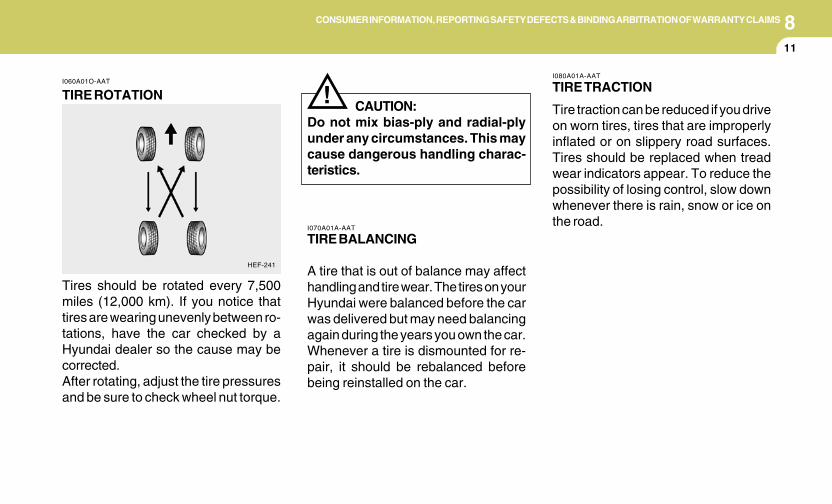
8CONSUMER INFORMATION, REPORTING SAFETY DEFECTS & BINDING ARBITRATION OF WARRANTY CLAIMS
11
HEF-241
I060A01O-AAT
TIRE ROTATION
Tires should be rotated every 7,500miles (12,000 km). If you notice thattires are wearing unevenly between ro-tations, have the car checked by aHyundai dealer so the cause may becorrected.After rotating, adjust the tire pressuresand be sure to check wheel nut torque.
I080A01A-AAT
TIRE TRACTION
Tire traction can be reduced if you driveon worn tires, tires that are improperlyinflated or on slippery road surfaces.Tires should be replaced when treadwear indicators appear. To reduce thepossibility of losing control, slow downwhenever there is rain, snow or ice onthe road.
I070A01A-AAT
TIRE BALANCING
A tire that is out of balance may affecthandling and tire wear. The tires on yourHyundai were balanced before the carwas delivered but may need balancingagain during the years you own the car.Whenever a tire is dismounted for re-pair, it should be rebalanced beforebeing reinstalled on the car.
! CAUTION:Do not mix bias-ply and radial-plyunder any circumstances. This maycause dangerous handling charac-teristics.
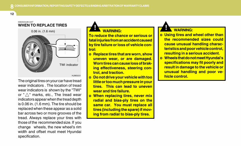
8 CONSUMER INFORMATION, REPORTING SAFETY DEFECTS & BINDING ARBITRATION OF WARRANTY CLAIMS
12
!!WARNING:
To reduce the chance or serious orfatal injuries from an accident causedby tire failure or loss of vehicle con-trol:o Replace tires that are worn, show
uneven wear, or are damaged.Worn tires can cause loss of brak-ing effectiveness, steering con-trol, and traction.
o Do not drive your vehicle with toolittle or too much pressure in yourtires. This can lead to unevenwear and tire failure.
o When replacing tires, never mixradial and bias-ply tires on thesame car. You must replace alltires (including the spare) if mov-ing from radial to bias-ply tires.
HJM5031
I090A04JM-AAT
WHEN TO REPLACE TIRES
The original tires on your car have treadwear indicators . The location of treadwear indicators is shown by the "TWI"or " " marks, etc., The tread wearindicators appear when the tread depthis 0.06 in. (1.6 mm). The tire should bereplaced when these appear as a solidbar across two or more grooves of thetread. Always replace your tires withthose of the recommended size. If youchange wheels, the new wheel's rimwidth and offset must meet Hyundaispecification.
TWI indicator
0.06 in. (1.6 mm)o Using tires and wheel other than
the recommended sizes couldcause unusual handling charac-teristics and poor vehicle control,resulting in a serious accident.
o Wheels that do not meet Hyundai'sspecifications may fit poorly andresult in damage to the vehicle orunusual handling and poor ve-hicle control.
WARNING:
8CONSUMER INFORMATION, REPORTING SAFETY DEFECTS & BINDING ARBITRATION OF WARRANTY CLAIMS
13
I090B02JM-AAT
TIRE MAINTENANCE
In addition to proper inflation, correctwheel alignment helps to decrease tirewear. If you find a tire is worn unevenly,have your dealer check the wheel align-ment.
When you have new tires installed,make sure they are balanced. This willincrease vehicle ride comfort and tirelife. Additionally, a tire shoud always berebalanced if it is removed from thewheel.
! WARNING:Your vehicle is equipped with tiresdesigned to provide for safe ride andhandling capability.Do not use a size and type of tire andwheel that is different from the onethat is originally installed on yourvehicle. It can affect the safety andperformance of your vehicle, whichcould lead to handling failure orrollover and serious injury.When replacing the tires, be sure toequip all four tires with the tire andwheel of the same size, type, tread,brand and load-carrying capacity. Ifyou nevertheless decide to equipyour vehicle with any tire/wheel com-bination not recommended byHyundai for off-road driving, youshould not use these tires for high-way driving.
! WARNING:Tires degrade over time, even whenthey are not being used. Regardlessof the remaining tread, it is recom-mended that tires tread, It is recom-mended that tires generally be re-placed after 6 years of normal ser-vice. Heat caused by not climates orfrequent high loading Conditions canaccelerate the aging process. Fail-ure to follow this Warning can resultin sudden tire failure, which couldlead to a loss of control and anaccident involving serious injury ordeath.
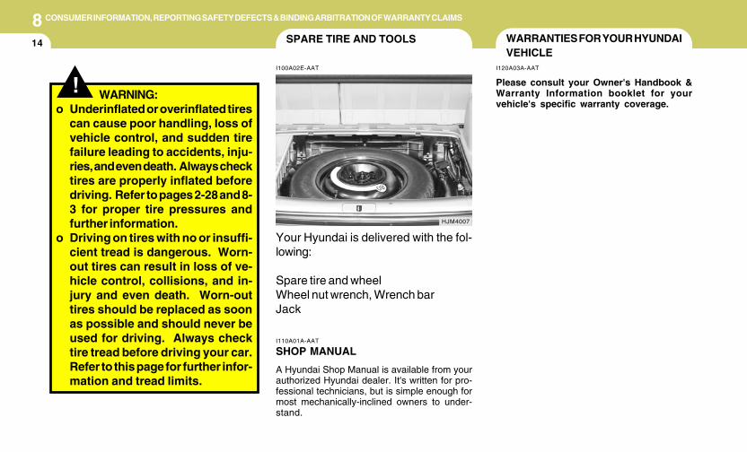
8 CONSUMER INFORMATION, REPORTING SAFETY DEFECTS & BINDING ARBITRATION OF WARRANTY CLAIMS
14 WARRANTIES FOR YOUR HYUNDAIVEHICLE
I120A03A-AAT
Please consult your Owner's Handbook &Warranty Information booklet for yourvehicle's specific warranty coverage.
SPARE TIRE AND TOOLS
I100A02E-AAT
Your Hyundai is delivered with the fol-lowing:
Spare tire and wheelWheel nut wrench, Wrench barJack
HJM4007
I110A01A-AAT
SHOP MANUAL
A Hyundai Shop Manual is available from yourauthorized Hyundai dealer. It's written for pro-fessional technicians, but is simple enough formost mechanically-inclined owners to under-stand.
! WARNING:o Underinflated or overinflated tires
can cause poor handling, loss ofvehicle control, and sudden tirefailure leading to accidents, inju-ries, and even death. Always checktires are properly inflated beforedriving. Refer to pages 2-28 and 8-3 for proper tire pressures andfurther information.
o Driving on tires with no or insuffi-cient tread is dangerous. Worn-out tires can result in loss of ve-hicle control, collisions, and in-jury and even death. Worn-outtires should be replaced as soonas possible and should never beused for driving. Always checktire tread before driving your car.Refer to this page for further infor-mation and tread limits.
8CONSUMER INFORMATION, REPORTING SAFETY DEFECTS & BINDING ARBITRATION OF WARRANTY CLAIMS
15
I130B04A-AAT
Tire Quality Grading
Department of Transportation qualitygrades - All passenger vehicle tiresmust conform to Federal Safety Stan-dards in addition to these grades. Thesequality grades are molded on thesidewall.
Treadwear - The treadwear grade is acomparative rating based on the wearrate of the tire when tested under con-trolled conditions on a specified gov-ernment test course. For example, atire graded 150 would wear one and ahalf (1 - 1/2) times as well on thegovernment course as a tire graded100. The relative performance of tiresdepends upon the actual conditions oftheir use, however, and may departsignificantly from the norm due to varia-tions in driving habits, service prac-tices and differences in road character-istics and climate.
Traction AA, A, B, C - The tractiongrades, from highest to lowest, are AA,A, B, and C. Those grades representthe tire's ability to stop on wet pave-ment as measured under controlledconditions on specified government testsurfaces of asphalt and concrete. A tiremarked C may have poor traction per-formance.
! WARNING:The traction grade assigned to thistire is based on straight-ahead brak-ing traction tests, and does not in-clude acceleration, cornering, hy-droplaning, or peak traction charac-teristics.
CONSUMER INFORMATION
I130A01A-AAT
This consumer information has been preparedin accordance with regulations issued by theNational Highway Traffic Safety Administrationof the U.S. Department of Transportation. Itprovides the purchasers and/or prospectivepurchasers of Hyundai automobiles with infor-mation on uniform tire quality grading. YourHyundai dealer will help answer any questionsyou may have as you read this information.
8 CONSUMER INFORMATION, REPORTING SAFETY DEFECTS & BINDING ARBITRATION OF WARRANTY CLAIMS
16
I130D04A-AAT
Hyundai motor vehicles are designed and manu-factured to meet or exceed all applicable safetystandards.
For your safety, however, we strongly urge youto read and follow all directions in this Owner'sManual, particularly the information under theheadings "NOTE", "CAUTION" and "WARN-ING".
If, after reading this manual, you have anyquestions regarding the operation of your ve-hicle, please contact your nearest HyundaiMotor America Regional Office as listed below:
Eastern Region : Connecticut, Delaware,Maine, Maryland, Massachusetts, New Hamp-shire, New Jersey, New York, Pennsylvanina,Rhode Island, Vermont, Virginia, West Virginia.
Eastern Region1100 Cranbury South River RoadJamesburg, NJ 08831(800) 633-5151
Southern Region: Florida, Georgia, North Caro-lina, South Carolina.
Southern Region270 Riverside Parkway, Suite AAustell, GA 30168(800) 633-5151
!WARNING:
The temperature grade for this tire isestablished for a tire that is properlyinflated and not overloaded. Exces-sive speed, underinflation, or exces-sive loading, either separately or incombination, can cause heat buildupand possible tire failure.
Uniform Tire Quality Grading - Qual-ity grades can be found on the tiresidewall between the tread shoulderand the maximum section width.For example :Treadwear 200 Traction AA Tempera-ture A
Temperature A, B, C - The tempera-ture grades are A (the highest), B, andC, representing the tire's resistance tothe generation of heat andits ability to dissipate heat when testedunder controlled conditions on a speci-fied indoor laboratory test wheel. Sus-tained high temperature can cause thematerial of the tire to degenerate andreduce tire life, and excessive tempera-ture can lead to sudden tire failure. Thegrade C corresponds to a level of perfor-mance which all passenger car tiresmust meet under the Federal MotorVehicle Safety Standard No. 109.Grades B and A represent higher levelsof performance on the laboratory testwheel than the minimum required bylaw.
8CONSUMER INFORMATION, REPORTING SAFETY DEFECTS & BINDING ARBITRATION OF WARRANTY CLAIMS
17REPORTING SAFETY DEFECTS(U.S.A only)
I130C02A-AAT
If you believe that your vehicle has a defectwhich could cause a crash or could causeinjury or death, you should immediatelyinform the National Highway Traffic SafetyAdministration (NHTSA) in addition tonotifying HYUNDAI MOTOR AMERICA. IfNHTSA receives similar complaints, it mayopen an investigation, and if it finds that asafety defect exists in a group of vehicles,it may order a recall and remedy cam-paign. However, NHTSA cannot becomeinvolved in individual problems betweenyou, your dealer, or HYUNDAI MOTORAMERICA.To contact NHTSA, you may call the Ve-hicle Safety Hotline toll-free at 1-888-327-4236 (TTY: 1-800-424-9153); go to http://www.safercar.gov; or write to: Administra-tor, NHTSA, 400 Seventh Street, SW.,Washington, DC 20590. You can alsoobtain other information about motor ve-hicle safety from http://www.safercar.gov.
I140A01A-AAT
Any claim or dispute you may haverelated to your vehicle's warranty or theduties contemplated under the warranty,including claims related to the refund orpartial refund of your vehicle's purchaseprice (excluding personal injury or prod-uct liability claims), shall be resolvedby binding arbitration. Binding arbitra-tion shall be administered by and throughthe National Arbitration Forum (NAF) orthe American Arbitration Association(AAA), under the Code of Procedure ofthe entity you select.You will not be responsible for payingfiling and hearing fees above $275.00.All other arbitration costs shall be borneby Hyundai Motor America. You are notresponsible to pay any of the costsHyundai incurs.
BINDING ARBITRATION(U.S.A Only)
South Central Region: Alabama, Arkansas,Colorado, Kansas, Louisiana, Mississippi, Mis-souri, New Mexico, Oklahoma, Tennessee,Texas, Wyoming.
South Central Region1421 South Beltline Road, Suite 400
Coppell, TX 75019(800) 633-5151
Central Region: Illinois, Indiana, lowa, Ken-tucky, Michigan, Minnesota, Nebraska, NorthDakota, South Dakota, Ohio, Wisconsin.
Central Region1705 Sequoia DriveAurora, Illinois 60506(800) 633-5151
Western Region: Alaska, Hawaii, Arizona,California, ldaho, Montana, Nevada, Oregon,Texas, Utah, Washington.
Western Region10550 Talbert AvenueP.O.Box 20850Fountain Valley, California 92728-0850(800) 633-5151
8 CONSUMER INFORMATION, REPORTING SAFETY DEFECTS & BINDING ARBITRATION OF WARRANTY CLAIMS
18
This Binding Arbitration Agreement shallnot deprive you of any remedies avail-able to you under applicable law. Theparties are waiving their right to seekremedies in court, including the right toa jury trial.This Binding Arbitration Agreement shallbe governed by and interpreted underthe Federal Arbitration Act, 9 U.S.C.sections 1-16. Judgment upon any awardmay be entered in any court havingjurisdiction.You may revoke this Arbitration Agree-ment by (1) written notice or (2) elec-tronic notice. Written notice must bedelivered (via certified mail) to HyundaiMotor America, Attn: Consumer Af-fairs, 10550 Talbert Avenue, P.O. Box20849, Fountain Valley, CA 92728-0849.Electronic notice must be submitted atthe following website address: http://warranty-arbitration.hyundaiUSA.com.Notice must be received within 90 daysafter you purchase your vehicle.
9Measurement ................................................................ 9-2Engine ........................................................................... 9-3Lubrication Chart ........................................................... 9-4
9
VEHICLE SPECIFICATIONS
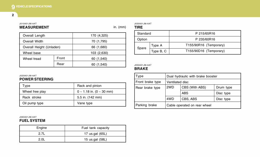
9 VEHICLE SPECIFICATIONS
2
J010A01JM-AAT
MEASUREMENT
170 (4,325)
70 (1,795)
66 (1,680)
103 (2,630)
60 (1,540)
60 (1,540)
Overall Length
Overall Width
Overall Height (Unladen)
Wheel base
Wheel tread Front
Rear
J060A01JM-AAT
FUEL SYSTEM
J020A01JM-AAT
POWER STEERING
in. (mm)
Engine
2.7L
2.0L
Fuel tank capacity
17 us.gal (65L)
15 us.gal (58L)
Type
Wheel free play
Rack stroke
Oil pump type
Rack and pinion
0 ~ 1.18 in. (0 ~ 30 mm)
5.5 in. (142 mm)
Vane type
J030A01JM-AAT
TIRE
Standard
Option
Spare
P 215/65R16
P 235/60R16
T155/90R16 (Temporary)
T155/90D16 (Temporary)
2WD
4WD
J050A01JM-AAT
BRAKE
Dual hydraulic with brake booster
Ventilated disc
Cable operated on rear wheel
Type
Front brake type
Rear brake type
Parking brake
CBS (With ABS)
ABS
CBS, ABS
Drum type
Disc type
Disc type
Type A
Type B, C
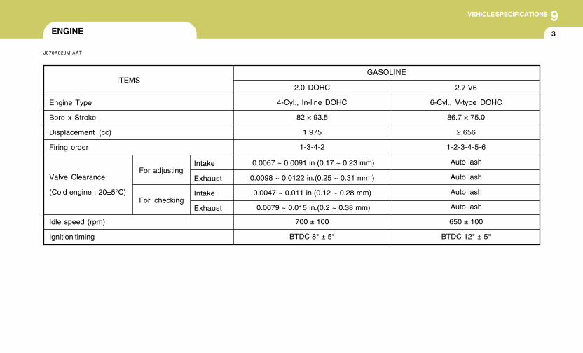
9VEHICLE SPECIFICATIONS
3
GASOLINE
2.7 V6
6-Cyl., V-type DOHC
86.7 × 75.0
2,656
1-2-3-4-5-6
Auto lash
Auto lash
Auto lash
Auto lash
650 ± 100
BTDC 12° ± 5°
2.0 DOHC
4-Cyl., In-line DOHC
82 × 93.5
1,975
1-3-4-2
700 ± 100
BTDC 8° ± 5°
ITEMS
Engine Type
Bore x Stroke
Displacement (cc)
Firing order
Valve Clearance
(Cold engine : 20±5°C)
Idle speed (rpm)
Ignition timing
ENGINE
J070A02JM-AAT
0.0067 ~ 0.0091 in.(0.17 ~ 0.23 mm)
0.0098 ~ 0.0122 in.(0.25 ~ 0.31 mm )
0.0047 ~ 0.011 in.(0.12 ~ 0.28 mm)
0.0079 ~ 0.015 in.(0.2 ~ 0.38 mm)
For adjusting
For checking
Intake
Exhaust
Intake
Exhaust
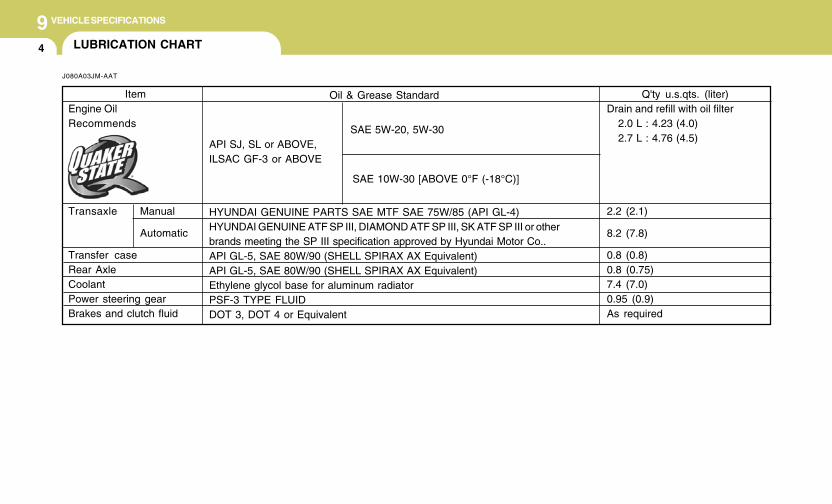
9 VEHICLE SPECIFICATIONS
4
Oil & Grease Standard
SAE 5W-20, 5W-30API SJ, SL or ABOVE,ILSAC GF-3 or ABOVE
SAE 10W-30 [ABOVE 0°F (-18°C)]
HYUNDAI GENUINE PARTS SAE MTF SAE 75W/85 (API GL-4)HYUNDAI GENUINE ATF SP III, DIAMOND ATF SP III, SK ATF SP III or otherbrands meeting the SP III specification approved by Hyundai Motor Co..API GL-5, SAE 80W/90 (SHELL SPIRAX AX Equivalent)API GL-5, SAE 80W/90 (SHELL SPIRAX AX Equivalent)Ethylene glycol base for aluminum radiatorPSF-3 TYPE FLUIDDOT 3, DOT 4 or Equivalent
ItemEngine OilRecommends
Transaxle Manual
Automatic
Transfer caseRear AxleCoolantPower steering gearBrakes and clutch fluid
LUBRICATION CHART
J080A03JM-AAT
Q'ty u.s.qts. (liter)Drain and refill with oil filter
2.0 L : 4.23 (4.0)2.7 L : 4.76 (4.5)
2.2 (2.1)
8.2 (7.8)
0.8 (0.8)0.8 (0.75)7.4 (7.0)0.95 (0.9)As required
1010
INDEX
10 INDEX
2
AAir bag ...............................................................................................1-33Air Cleaner Filter ............................................................................... 6-10Air Conditioning
Care .............................................................................................. 6-16Operation ............................................................................ 1-99, 6-16Switch ........................................................................................... 1-99
Antenna .......................................................................................... 1-126Ashtray .............................................................................................. 1-67Audio System ................................................................................. 1-111
BBattery ...............................................................................................6-23Binding Arbitration (U.S.A Only) ....................................................... 8-17Brake
Anti-lock brake system ................................................................ 2-13Traction control system (TCS) ...................................................2-13Checking the brakes ....................................................................6-14
Electronic Stability Control (ESC) .....................................................2-15Fluid .............................................................................................. 6-11Pedal clearance ...........................................................................6-20Pedal free-play .............................................................................6-19Practices ......................................................................................2-19
Breaking-In your New Hyundai .......................................................... 1-3Bulb Replacement .............................................................................6-27
CCalifornia Perchlorate Notice ............................................................5-10Care of Cassette Tapes ................................................................ 1-124
Care of Disc ................................................................................... 1-124Catalytic Converter ............................................................................. 7-3Child-Protector Rear Door Lock ......................................................... 1-7Child Restraint System .....................................................................1-25
Installing a Child Restraint Seat with the"Tether Anchorage" System .....................................................1-26
Securing the Child Restraint Seat with the "ISOFIX" System .... 1-28Cigarette Lighter ................................................................................1-66Clock ................................................................................................. 1-65Clutch
Checking fluid ............................................................................... 6-16Pedal free-play .............................................................................6-19
Combination LightAuto light .......................................................................................1-60Headlight flasher ..........................................................................1-59Headlight switch ...........................................................................1-59High-beam switch ........................................................................1-59Lane change signal ...................................................................... 1-58Parking light auto off .....................................................................1-59Turn signal operation ................................................................... 1-58
Consumer Information ...................................................................... 8-15Cooling Fans ..................................................................................... 6-24Corrosion protection
Cleaning the interior ....................................................................... 4-5Protecting your Hyundai from corrosion ....................................... 4-2Washing and waxing ...................................................................... 4-3
Cruise Control ...................................................................................1-87
10INDEX
3
DDefrosting / Defogging ................................................................... 1-100Door
Central door lock ............................................................................ 1-7Door locks ...................................................................................... 1-4Front door edge warning light ...................................................... 1-86
Drink Holder ...................................................................................... 1-67Drive Belts .........................................................................................6-20Driving
Driving for economy ..................................................................... 2-22Smooth cornering ......................................................................... 2-23Winter driving ............................................................................... 2-23
EEmission Control System ................................................................... 7-2Engine
Before starting the engine .............................................................. 2-4Compartment ................................................................................. 6-2Coolant ........................................................................................... 6-8Coolant temperature gauge ......................................................... 1-53If the engine overheats .................................................................. 3-4Number ........................................................................................... 8-2Oil ................................................................................................... 6-5Starting ........................................................................................... 2-6
Engine Exhaust Can Be Dangerous .................................................. 2-2
F4WD Lock System ............................................................................ 2-19Fan Speed Control ............................................................................ 1-93
Floor Mat Anchor ..............................................................................1-85Fog Light
Front .............................................................................................1-64Front Seats
Adjustable front seats ..................................................................1-12Adjustable headrests ................................................................... 1-13Adjusting seat forward and rearward ..........................................1-12Adjusting seatback angle ............................................................. 1-13
FuelCapacity .........................................................................................9-2Gauge ........................................................................................... 1-53Recommendations ......................................................................... 1-2
Fuel Filler LidRemote release ............................................................................ 1-82
Full-time 4WD Operation ..................................................................2-16Fuses ................................................................................................6-21Fuse panel description ...................................................................... 6-35
GGeneral Checks .................................................................................. 6-4Glove Box ..........................................................................................1-72
HHazard Warning System ..................................................................1-64Heating and Cooling Control .......................................................... 1-102Heating and Ventilation
Air flow control ..............................................................................1-94Air intake control switch ............................................................ 1-103Bi-level heating .............................................................................1-98
10 INDEX
4
Defrosting / Defogging .................................................................1-98Fan speed control (Blower control) .............................................1-93Temperature control ....................................................................1-97
High-Mounted Rear Stop Light .........................................................1-82Hood Release ....................................................................................1-84Horn ................................................................................................. 1-87How to Use Luggage Room ............................................................. 1-79
IIgnition Switch ......................................................................................2-5Instrument Cluster and Indicator Lights ........................................... 1-46Instrument Panel Light Control (Rheostat) .......................................1-66Interior Light .......................................................................................1-71
JJump Starting ......................................................................................3-3
KKeys ................................................................................................... 1-3
If you lose your keys ................................................................... 3-19Positions .........................................................................................2-5
LLight Bulbs Replacement ..................................................................6-27Luggage Compartment Light ............................................................1-79Luggage Net ......................................................................................1-81
MMaintenance Intervals
Explanation of scheduled maintenance items ............................... 5-7Maintenance under severe usage conditions ............................... 5-6Scheduled maintenance ................................................................ 5-4Service requirements .................................................................... 5-2
MirrorsAutomatic Dimming Rear View Mirror With Compass ................ 1-75Day-night inside rearview mirror ................................................. 1-75Outside rearview mirror ...............................................................1-73Outside rearview mirror Heater ..................................................1-74
OOdometer / Trip Odometer ...............................................................1-54Occupant Classification System ......................................................1-38
PParking Brake ....................................................................................1-77Power Outlet ......................................................................................1-66Power Steering Fluid Level ...............................................................6-24
RRear Seat
Adjusting seatback angle ............................................................. 1-16Folding rear seatback ..................................................................1-16
Rear Window Defroster Switch ........................................................1-65Reporting Safety Defects .................................................................8-17Risk of Rollover ................................................................................... 2-3Roof Rack .........................................................................................1-81
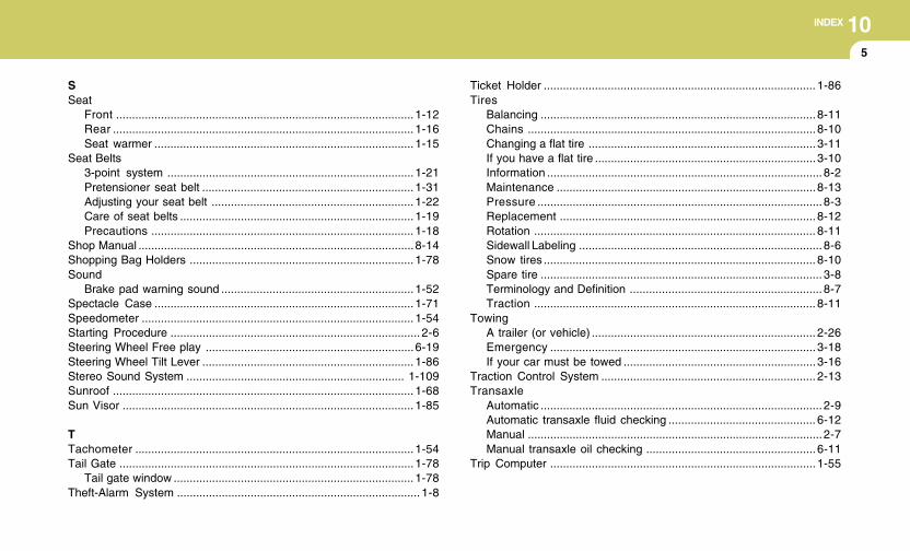
10INDEX
5
SSeat
Front ............................................................................................. 1-12Rear .............................................................................................. 1-16Seat warmer ................................................................................. 1-15
Seat Belts3-point system .............................................................................1-21Pretensioner seat belt .................................................................. 1-31Adjusting your seat belt ............................................................... 1-22Care of seat belts ......................................................................... 1-19Precautions .................................................................................. 1-18
Shop Manual ......................................................................................8-14Shopping Bag Holders ...................................................................... 1-78Sound
Brake pad warning sound ............................................................1-52Spectacle Case ................................................................................. 1-71Speedometer ..................................................................................... 1-54Starting Procedure .............................................................................. 2-6Steering Wheel Free play .................................................................6-19Steering Wheel Tilt Lever .................................................................. 1-86Stereo Sound System .................................................................... 1-109Sunroof .............................................................................................. 1-68Sun Visor ........................................................................................... 1-85
TTachometer ....................................................................................... 1-54Tail Gate ............................................................................................1-78
Tail gate window ........................................................................... 1-78Theft-Alarm System ............................................................................ 1-8
Ticket Holder ..................................................................................... 1-86Tires
Balancing ......................................................................................8-11Chains ..........................................................................................8-10Changing a flat tire .......................................................................3-11If you have a flat tire .....................................................................3-10Information ......................................................................................8-2Maintenance .................................................................................8-13Pressure .........................................................................................8-3Replacement ................................................................................8-12Rotation ........................................................................................ 8-11Sidewall Labeling ............................................................................ 8-6Snow tires ..................................................................................... 8-10Spare tire ........................................................................................ 3-8Terminology and Definition ............................................................ 8-7Traction ........................................................................................ 8-11
TowingA trailer (or vehicle) ...................................................................... 2-26Emergency ...................................................................................3-18If your car must be towed ............................................................3-16
Traction Control System ................................................................... 2-13Transaxle
Automatic ........................................................................................ 2-9Automatic transaxle fluid checking .............................................. 6-12Manual ............................................................................................2-7Manual transaxle oil checking .....................................................6-11
Trip Computer ...................................................................................1-55
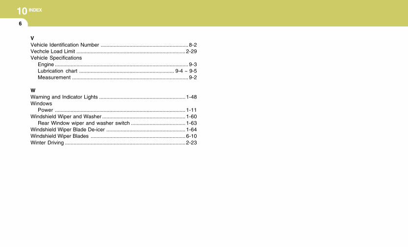
10 INDEX
6
VVehicle Identification Number ............................................................. 8-2Vechcle Load Limit ............................................................................ 2-29Vehicle Specifications
Engine ............................................................................................. 9-3Lubrication chart .................................................................. 9-4 ~ 9-5Measurement ................................................................................. 9-2
WWarning and Indicator Lights ............................................................1-48Windows
Power ........................................................................................... 1-11Windshield Wiper and Washer .......................................................... 1-60
Rear Window wiper and washer switch ......................................1-63Windshield Wiper Blade De-icer ....................................................... 1-64Windshield Wiper Blades ..................................................................6-10Winter Driving ....................................................................................2-23
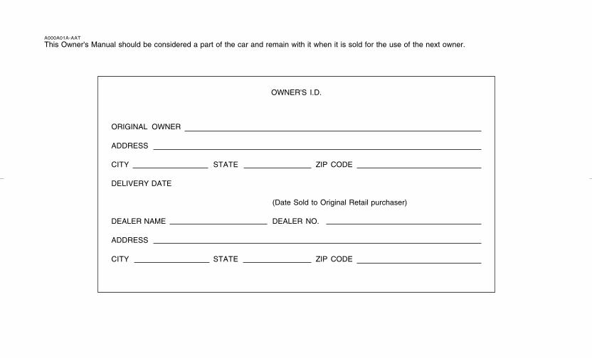
A000A01A-AAT
This Owner's Manual should be considered a part of the car and remain with it when it is sold for the use of the next owner.
OWNER'S I.D.
ORIGINAL OWNER
ADDRESS
CITY STATE ZIP CODE
DELIVERY DATE
(Date Sold to Original Retail purchaser)
DEALER NAME DEALER NO.
ADDRESS
CITY STATE ZIP CODE
gkflhma-0.p65 9/12/2006, 3:13 PM13
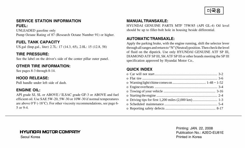
Seoul Korea
Printing: JAN. 22, 2008Publication No.: A2EO-EU81EPrinted in Korea
SERVICE STATION INFORMATIONFUEL:UNLEADED gasoline onlyPump Octane Rating of 87 (Research Octane Number 91) or higher.
FUEL TANK CAPACITYUS.gal (Imp.gal., liter) 2.7L: 17 (14.3, 65), 2.0L: 15 (12.8, 58)
TIRE PRESSURE:See the label on the driver's side of the center pillar outer panel.
OTHER TIRE INFORMATION:See pages 8-3 through 8-14.
HOOD RELEASE:Pull handle under left side of dash.
ENGINE OIL:API grade SJ, SL or ABOVE / ILSAC grade GF-3 or ABOVE and fuelefficient oil. Use SAE 5W-20, 5W-30 or 10W-30 if normal temperaturesare above 0°F (-18°C). For other viscosity recommendations, see page 6-5 or 9-4.
MANUAL TRANSAXLE:HYUNDAI GENUINE PARTS MTF 75W/85 (API GL-4) Oil levelshould be up to filler-bolt hole in housing beside differential.
AUTOMATIC TRANSAXLE:Apply the parking brake, with the engine running, shift the selector leverthrough all ranges and return to “N” (Neutral) position. Then check the levelof fluid on the dipstick. Use only HYUNDAI GENUINE ATF SP III,DIAMOND ATF SP III, SK ATF SP III or other brands meeting the SP IIIspecification approved by Hyundai Motor Co..
QUICK INDEXo Car will not start ....................................................................... 3-2o Flat tire ..................................................................................... 3-6o Warning light/chime comes on ...................................... 1-48 ~ 1-52o Engine overheats ....................................................................... 3-4o Towing of your vehicle ........................................................... 3-16o Starting the engine ..................................................................... 2-4o Driving tips for first 1,200 miles (2,000 km) ............................ 1-3o Scheduled maintenance ............................................................ 5-4o Reporting safety defects ......................................................... 8-17


![Mining Records Curator Arizona Geological Survey Tucson ...docs.azgs.az.gov/SpecColl/2008-01/2008-01-0707.pdf · Ro]l~n May 9750 East Tanque Verde'Road Tucson~ Arizona 85715 ANTHONY](https://img.pdfslide.net/doc/110x75/5fce35180002571324666e6c/mining-records-curator-arizona-geological-survey-tucson-docsazgsazgovspeccoll2008-012008-01-0707pdf.jpg)