Embed Size (px)
Citation preview
WinCC
Communication Manual
Manual 2
This manual is part of the documentation packagewith the order number:6AV6392-1CA05-0AB0C79000-G8276-C156-01
Release: September 1999

WinCC, SIMATIC, SINEC, STEP are trademarks of Siemens.
The other names used in this manual may be trademarks; their owners’ rights may be violated if they are used bythird parties for their own purposes.
(The transmission and reproduction of this document, andutilization and disclosure of its contents are not permittedunless expressly authorized.Offenders will be liable for damages. All rights, including rightscreated by patent grant or registration of a utility model ordesign, are reserved.)
(We have checked the contents of this manual for agreementwith the hardware and software described. Since deviationscannot be precluded entirely, we cannot guarantee fullagreement. However, the data in this manual are reviewedregularly and any necessary corrections included in subsequenteditions. Suggestions for improvements are welcomed.)
Siemens AG 1994 - 1999 All rights reserved Technical data subject to change
C79000-G8276-C156-01Printed in the Federal Republic of Germany Siemens Aktiengesellschaft
WinCC Communication Manual iC79000-G8276-C156-01
Table of contents
1 Sample Projects......................................................................... 1-1
2 Communication to the SIMATIC S7 via Industrial Ethernet(Hardnet)..................................................................................... 2-12.1 Startup of the Communication Processor CP 1413 ....................... 2-32.2 Creation of the STEP7 Project S7_IEH.......................................... 2-132.3 Creation of the WinCC Project WinCC_S7_IEH ............................ 2-322.4 Diagnosis of the Communication Connection ................................ 2-45
3 Communication to the SIMATIC S7 via Industrial Ethernet(Softnet) ...................................................................................... 3-13.1 Startup of the Communication Processor CP 1411 ....................... 3-33.2 Creation of the STEP7 Project S7_IES.......................................... 3-173.3 Creation of the WinCC Project WinCC_S7_IES ............................ 3-353.4 Diagnosis of the Communication Connection ................................ 3-48
4 Communication to the SIMATIC S7 via TCP/IP ....................... 4-14.1 Startup of the Communication Processor CP 1411 ....................... 4-34.2 Creation of the STEP7 Project S7_IETCP ..................................... 4-174.3 Creation of the WinCC Project WinCC_S7_IETCP........................ 4-354.4 Diagnosis of the Communication Connection ................................ 4-48
5 Communication to the SIMATIC S7 via OPC ........................... 5-15.1 Startup of the Communication Processor CP 1413 ....................... 5-35.2 Creation of the STEP7 Project S7_OPC........................................ 5-125.3 Configuration of the S7 OPC Server .............................................. 5-295.4 Creation of the WinCC Project WinCC_S7_OPC .......................... 5-445.5 Diagnosis of the Communication Connection ................................ 5-57
6 Communication to the SIMATIC S7 via PROFIBUS................. 6-16.1 Startup of the Communication Processor CP 5412 A2.................. 6-36.2 Creation of the STEP7 Project S7_PB........................................... 6-126.3 Creation of the WinCC Project WinCC_S7_PB ............................. 6-316.4 Diagnosis of the Communication Connection ................................ 6-45
7 Communication to the SIMATIC S5 via Industrial Ethernet ... 7-17.1 Startup of the Communication Processor CP 1413 ....................... 7-37.2 Creation of the STEP5 Project S5_IEHst....................................... 7-127.3 Creation of the WinCC Project WinCC_S5_IEH ............................ 7-187.4 Diagnosis of the Communication Connection ................................ 7-31
8 Communication to the SIMATIC S5 via PROFIBUS FMS........ 8-18.1 Startup of the Communication Processor CP 5412 A2.................. 8-38.2 Creation of the STEP5 Project S5_FMSst ..................................... 8-208.3 Creation of the WinCC Project WinCC_S5_FMS........................... 8-27
Table of contents 09.99
ii WinCC Communication ManualC79000-G8276-C156-01
8.4 Diagnosis of the Communication Connection ................................ 8-38
9 Communication to the SIMATIC S5 via PROFIBUS FDL......... 9-19.1 Startup of the Communication Processor CP 5412 A2 .................. 9-39.2 Creation of the STEP5 Project S5_FDLst ...................................... 9-139.3 Creation of the WinCC Project WinCC_S5_FDL ........................... 9-219.4 Diagnosis of the Communication Connection ................................ 9-33
10 Communication WinCC-WinCC via OPC ................................. 10-110.1 Configuration of the WinCC Stations.............................................. 10-310.2 Creation of the WinCC Project WinCC_OPC_SERVER................ 10-1110.3 Creation of the WinCC Project WinCC_OPC_CLIENT .................. 10-1910.4 Diagnosis of the Communication Connection ................................ 10-29
09.99 Preface
WinCC Communication Manual iiiC79000-G8276-C156-01
Preface
Purpose of this Manual
This manual contains various sample projects pertaining to the topic communicationbetween WinCC and a PLC. It emphasizes the different communication options to theSIMATIC S5 and SIMATIC S7.This manual is available in printed form as well as an electronic online document.The table of contents or the index will quickly point you to the information required. Theonline document also provides an expanded search function.
Additional Support
For technical questions, please contact your Siemens representative at your local Siemensbranch.In addition, you can contact our Hotline at the following number:+49 (911) 895-7000 (Fax -7001)
Information about SIMATIC Products
Constantly updated information about SIMATIC products can be found in the CA01catalog. This catalog can be accessed at the following Internet address:http://www.ad.siemens.de/ca01online/In addition, the SIEMENS Customer Support provides you with current information anddownloads. A collection of frequently asked questions is listed at the following Internetaddress:http://www.ad.siemens.de/support/html_00/index.shtml

Preface 09.99
iv WinCC Communication ManualC79000-G8276-C156-01
09.99 Sample Projects
WinCC Communication Manual 1-1C79000-G8276-C156-01
1 Sample ProjectsThis chapter illustrates the configuration of the communication between a WinCC stationand a PLC by means of sample projects. Each of the sample projects is based on theapplication of a certain communication option and hardware combination.
Content of the Examples
The sample projects described below can be copied directly from the online document toyour hard drive.The functionality of the sample projects is limited to the application and display of a fewtag values. The emphasis is placed on the configuration of the communication.
Structure of the Samples
The steps necessary to successfully start up the communication connection are described indetail. In general, the individual descriptions are structured into the following sections:
• Overview of the sample project
• Installation of the necessary components in the PC
• Creation of the project for the PLC
• Creation of the WinCC project
• Diagnosis of the communication connection
Software
The samples have been created with the following software versions:
• WinCC Version 5.0
• STEP5 Version 4.6
• STEP7 Version 5.0
• SIMATIC NET 05/99

Sample Projects 09.99
1-2 WinCC Communication ManualC79000-G8276-C156-01
09.99 Communication to the SIMATIC S7 via Industrial Ethernet (Hardnet)
WinCC Communication Manual 2-1C79000-G8276-C156-01
2 Communication to the SIMATIC S7 viaIndustrial Ethernet (Hardnet)
The projects created in this chapter can also be copied directly from the online document toyour hard drive. By default, they will be copied to the folder C:\Communication_Manual.You have the option to copy the following components to the hard drive:
S7_IEHThe STEP7 project we will create.
WinCC_S7_IEH
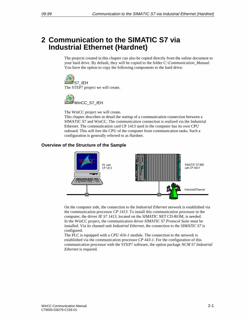
The WinCC project we will create.This chapter describes in detail the startup of a communication connection between aSIMATIC S7 and WinCC. The communication connection is realized via the IndustrialEthernet. The communication card CP 1413 used in the computer has its own CPUonboard. This will free the CPU of the computer from communication tasks. Such aconfiguration is generally referred to as Hardnet.
Overview of the Structure of the Sample
On the computer side, the connection to the Industrial Ethernet network is established viathe communication processor CP 1413. To install this communication processor in thecomputer, the driver IE S7 1413, located on the SIMATIC NET CD-ROM, is needed.In the WinCC project, the communication driver SIMATIC S7 Protocol Suite must beinstalled. Via its channel unit Industrial Ethernet, the connection to the SIMATIC S7 isconfigured.The PLC is equipped with a CPU 416-1 module. The connection to the network isestablished via the communication processor CP 443-1. For the configuration of thiscommunication processor with the STEP7 software, the option package NCM S7 IndustrialEthernet is required.
Communication to the SIMATIC S7 via Industrial Ethernet (Hardnet) 09.99
2-2 WinCC Communication ManualC79000-G8276-C156-01
Overview of the Configuration Steps
The following lists all configuration steps necessary for the creation of the communicationconnection:
• Startup of the Communication Processor CP 1413
• Creation of the STEP7 Project S7_IEH
• Creation of the WinCC Project WinCC_S7_IEH
• Diagnosis of the Communication Connection
Required Software
Name Description
SIMATIC NET Driver IE S7-1413 from the SIMATIC NET CD-ROMfor the installation of the communication processor CP1413.
STEP7 STEP7 software with option package NCM forIndustrial Ethernet for the creation of the STEP7project.
WinCC WinCC with the communication driver SIMATIC S7Protocol Suite for the creation of the WinCC project.
Required Computer Hardware
Name Description
Communication Processor Communication processor CP 1413 to establish theconnection to the PLC’s communication processor.
Required PLC Hardware
Name Description
Rack Rack UR1
Power Supply Power supply PS 407 10A in slot 1 and 2.
CPU Module CPU module CPU 416-1 in slot 3.
Communication Processor Communication processor CP 443-1 in slot 4.
09.99 Communication to the SIMATIC S7 via Industrial Ethernet (Hardnet)
WinCC Communication Manual 2-3C79000-G8276-C156-01
2.1 Startup of the Communication Processor CP 1413
The following description details the configuration steps necessary to successfully start upthe communication processor CP 1413.
Overview of the Configuration Steps
The following lists the configuration steps necessary to start up the communicationprocessor CP 1413:
• A: Mounting the Communication Processor in the Computer
• B: Installing the Communication Driver
• C: Installing the Communication Processor
• D: Assigning the Communication Processor
• E: Testing the Communication Processor
A: Mounting the Communication Processor in the Computer
Step A: Mounting the Communication Processor in the Computer
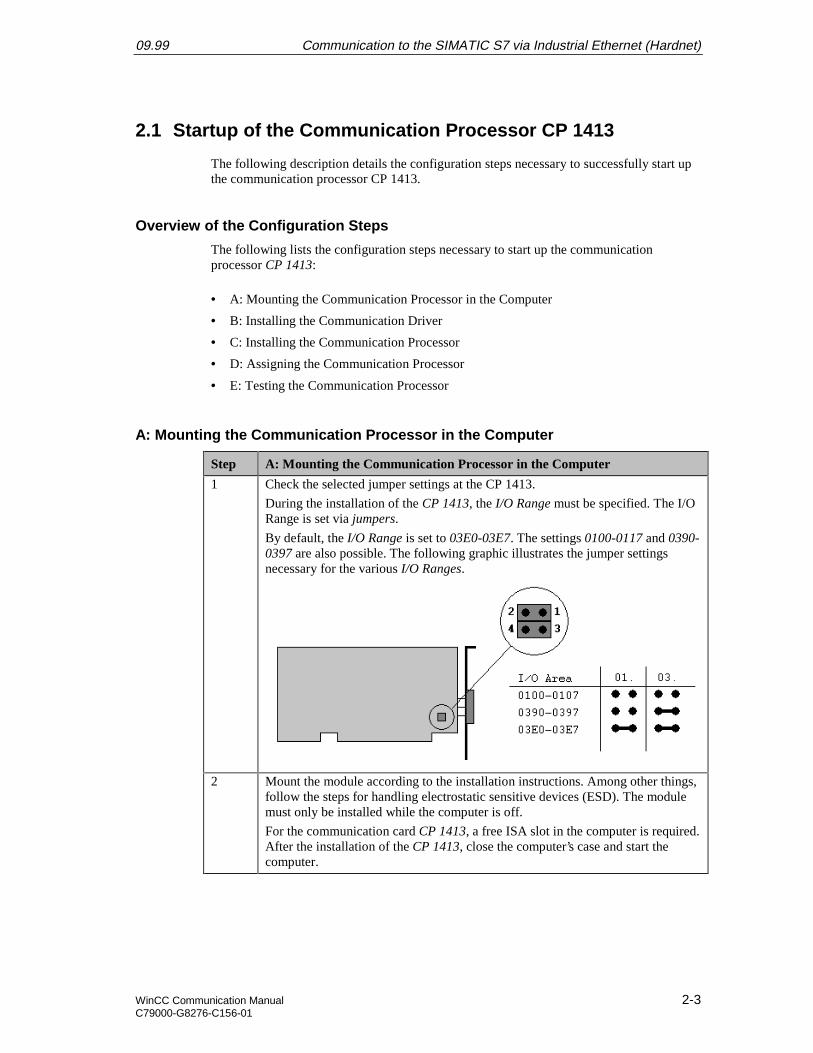
1 Check the selected jumper settings at the CP 1413.
During the installation of the CP 1413, the I/O Range must be specified. The I/ORange is set via jumpers.
By default, the I/O Range is set to 03E0-03E7. The settings 0100-0117 and 0390-0397 are also possible. The following graphic illustrates the jumper settingsnecessary for the various I/O Ranges.
2 Mount the module according to the installation instructions. Among other things,follow the steps for handling electrostatic sensitive devices (ESD). The modulemust only be installed while the computer is off.
For the communication card CP 1413, a free ISA slot in the computer is required.After the installation of the CP 1413, close the computer’s case and start thecomputer.
Communication to the SIMATIC S7 via Industrial Ethernet (Hardnet) 09.99
2-4 WinCC Communication ManualC79000-G8276-C156-01
B: Installing the Communication Driver
Step B: Installing the Communication Driver
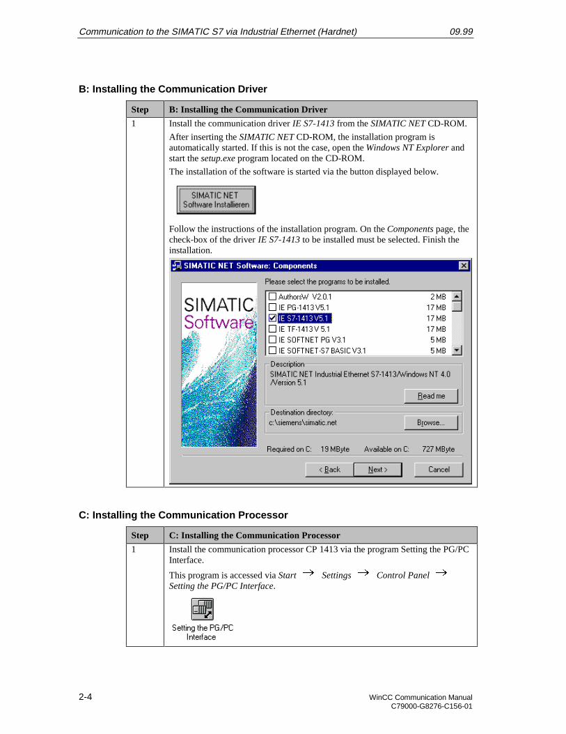
1 Install the communication driver IE S7-1413 from the SIMATIC NET CD-ROM.
After inserting the SIMATIC NET CD-ROM, the installation program isautomatically started. If this is not the case, open the Windows NT Explorer andstart the setup.exe program located on the CD-ROM.
The installation of the software is started via the button displayed below.
Follow the instructions of the installation program. On the Components page, thecheck-box of the driver IE S7-1413 to be installed must be selected. Finish theinstallation.
C: Installing the Communication Processor
Step C: Installing the Communication Processor
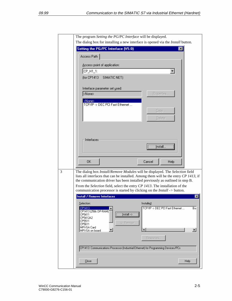
1 Install the communication processor CP 1413 via the program Setting the PG/PCInterface.
This program is accessed via Start Settings Control Panel Setting the PG/PC Interface.
09.99 Communication to the SIMATIC S7 via Industrial Ethernet (Hardnet)
WinCC Communication Manual 2-5C79000-G8276-C156-01
The program Setting the PG/PC Interface will be displayed.
The dialog box for installing a new interface is opened via the Install button.
3 The dialog box Install/Remove Modules will be displayed. The Selection fieldlists all interfaces that can be installed. Among them will be the entry CP 1413, ifthe communication driver has been installed previously as outlined in step B.
From the Selection field, select the entry CP 1413. The installation of thecommunication processor is started by clicking on the Install -> button.
Communication to the SIMATIC S7 via Industrial Ethernet (Hardnet) 09.99
2-6 WinCC Communication ManualC79000-G8276-C156-01
Step C: Installing the Communication Processor
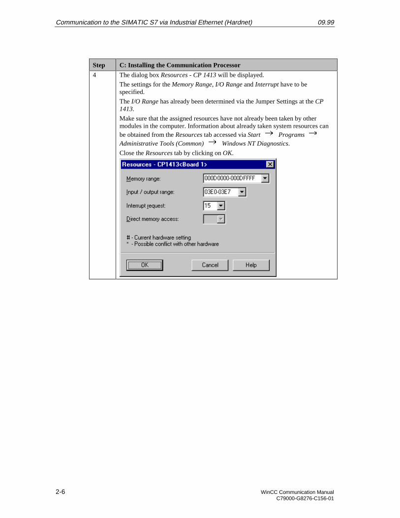
4 The dialog box Resources - CP 1413 will be displayed.
The settings for the Memory Range, I/O Range and Interrupt have to bespecified.
The I/O Range has already been determined via the Jumper Settings at the CP1413.
Make sure that the assigned resources have not already been taken by othermodules in the computer. Information about already taken system resources canbe obtained from the Resources tab accessed via Start Programs Administrative Tools (Common) Windows NT Diagnostics.
Close the Resources tab by clicking on OK.
09.99 Communication to the SIMATIC S7 via Industrial Ethernet (Hardnet)
WinCC Communication Manual 2-7C79000-G8276-C156-01
Step C: Installing the Communication Processor
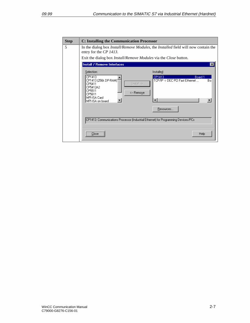
5 In the dialog box Install/Remove Modules, the Installed field will now contain theentry for the CP 1413.
Exit the dialog box Install/Remove Modules via the Close button.
Communication to the SIMATIC S7 via Industrial Ethernet (Hardnet) 09.99
2-8 WinCC Communication ManualC79000-G8276-C156-01
D: Assigning the Communication Processor
Step D: Assigning the Communication Processor
1 In the program Setting the PG/PC Interface, assign the access point CP_H1_1: tothe just installed interface.
The access point CP_H1_1: is the default access point used by WinCC for thecommunication via the Industrial Ethernet. It has been created automaticallyduring the installation of the communication driver IE S7-1413.
In the field Access Point of the Application, set the entry CP_H1_1:. In the fieldbelow, select the entry CP1413. This completes the assignment between theaccess point and the communication processor.
09.99 Communication to the SIMATIC S7 via Industrial Ethernet (Hardnet)
WinCC Communication Manual 2-9C79000-G8276-C156-01
Step D: Assigning the Communication Processor
2 Setting the properties of the communication processor CP 1413.
The dialog box for setting the properties is opened via the Properties button ofthe Setting the PG/PC Interface program.
The dialog box Properties - CP 1413 will be displayed.
In the Ethernet (MAC) Address tab, enter the Ethernet Address of the CP 1413.In our sample, this is 08.00.06.01.00.01.
The Ethernet Address is six Bytes long and structured as follows for SIEMENSdevices:
• 08.00.06: The first six digits of the hexadecimal value correspond to thenumber for SIEMENS.
• 01: The next two digits specify the range for SIEMENS.
• 0: The next digit signifies the SIMATIC system.
• 0.01: The last three digits correspond to the significant station address of aSIEMENS device.
Communication to the SIMATIC S7 via Industrial Ethernet (Hardnet) 09.99
2-10 WinCC Communication ManualC79000-G8276-C156-01
Step D: Assigning the Communication Processor
3 Exit the program Setting the PG/PC Interface via the OK button.
A dialog box will be displayed requesting the restart of the CP 1413.Acknowledge this dialog box by clicking on OK, which will result in the restartof the communication processor CP 1413.
This completes the installation of the communication processor.
E: Testing the Communication Processor
Step E: Testing the Communication Processor
1 Check the proper installation of the communication processor CP 1413 via theprogram Setting the PG/PC Interface.
This program is accessed via Start Settings Control Panel Setting the PG/PC Interface.
09.99 Communication to the SIMATIC S7 via Industrial Ethernet (Hardnet)
WinCC Communication Manual 2-11C79000-G8276-C156-01
Step E: Testing the Communication Processor
2 The program Setting the PG/PC Interface will be displayed.
Select the interface to be checked. In this case, select the entry CP 1413. Makesure that the assignments between access points and the interfaces are notchanged.
The check for a proper installation is activated by clicking on the Diagnosticsbutton.
Communication to the SIMATIC S7 via Industrial Ethernet (Hardnet) 09.99
2-12 WinCC Communication ManualC79000-G8276-C156-01
Step E: Testing the Communication Processor
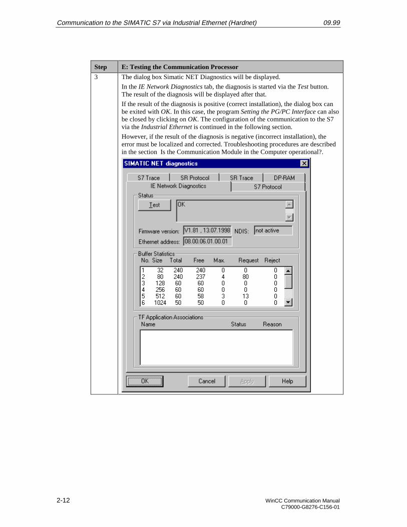
3 The dialog box Simatic NET Diagnostics will be displayed.
In the IE Network Diagnostics tab, the diagnosis is started via the Test button.The result of the diagnosis will be displayed after that.
If the result of the diagnosis is positive (correct installation), the dialog box canbe exited with OK. In this case, the program Setting the PG/PC Interface can alsobe closed by clicking on OK. The configuration of the communication to the S7via the Industrial Ethernet is continued in the following section.
However, if the result of the diagnosis is negative (incorrect installation), theerror must be localized and corrected. Troubleshooting procedures are describedin the section Is the Communication Module in the Computer operational?.
09.99 Communication to the SIMATIC S7 via Industrial Ethernet (Hardnet)
WinCC Communication Manual 2-13C79000-G8276-C156-01
2.3 Creation of the STEP7 Project S7_IEH
The following description details the configuration steps necessary to create and start up theSTEP7 project S7_IEH.
Overview of the Configuration Steps
The following lists the configuration steps necessary to create the STEP7 project S7_IEH:
• A: Installing the Hardware
• B: Installing the Option Package
• C: Creating the STEP7 Project
• D: Configuring the Hardware
• E: Loading the Hardware Configuration
• F: Testing the Hardware Configuration
• G: Creating the STEP7 Program
• H: Testing the STEP7 Program
A: Installing the Hardware
Step A: Installing the Hardware
1 Rack-mounting of the modules used.
In this sample, the modules to be installed are the power supply PS 407 10A, theCPU module CPU 416-1 and the communication processor CP 443-1.
Establishing the connection from the programming device to the programminginterface of the CPU module.
Establishing the connection from the communication processor CP 1413 in thecomputer to the communication processor CP 443-1 in the PLC.
Communication to the SIMATIC S7 via Industrial Ethernet (Hardnet) 09.99
2-14 WinCC Communication ManualC79000-G8276-C156-01
B: Installing the Option Package
Step B: Installing the Option Package
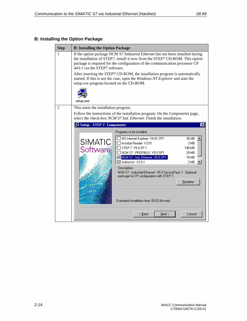
1 If the option package NCM S7 Industrial Ethernet has not been installed duringthe installation of STEP7, install it now from the STEP7 CD-ROM. This optionpackage is required for the configuration of the communication processor CP443-1 via the STEP7 software.
After inserting the STEP7 CD-ROM, the installation program is automaticallystarted. If this is not the case, open the Windows NT Explorer and start thesetup.exe program located on the CD-ROM.
2 This starts the installation program.
Follow the instructions of the installation program. On the Components page,select the check-box NCM S7 Ind. Ethernet. Finish the installation.
09.99 Communication to the SIMATIC S7 via Industrial Ethernet (Hardnet)
WinCC Communication Manual 2-15C79000-G8276-C156-01
C: Creating the STEP7 Project
Step C: Creating the STEP7 Project
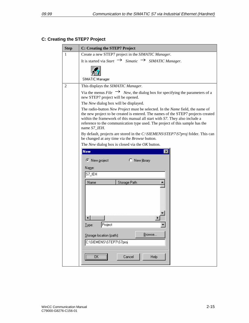
1 Create a new STEP7 project in the SIMATIC Manager.
It is started via Start Simatic SIMATIC Manager.
2 This displays the SIMATIC Manager.
Via the menus File New, the dialog box for specifying the parameters of anew STEP7 project will be opened.
The New dialog box will be displayed.
The radio-button New Project must be selected. In the Name field, the name ofthe new project to be created is entered. The names of the STEP7 projects createdwithin the framework of this manual all start with S7. They also include areference to the communication type used. The project of this sample has thename S7_IEH.
By default, projects are stored in the C:\SIEMENS\STEP7\S7proj folder. This canbe changed at any time via the Browse button.
The New dialog box is closed via the OK button.
Communication to the SIMATIC S7 via Industrial Ethernet (Hardnet) 09.99
2-16 WinCC Communication ManualC79000-G8276-C156-01
D: Configuring the Hardware
Step D: Configuring the Hardware
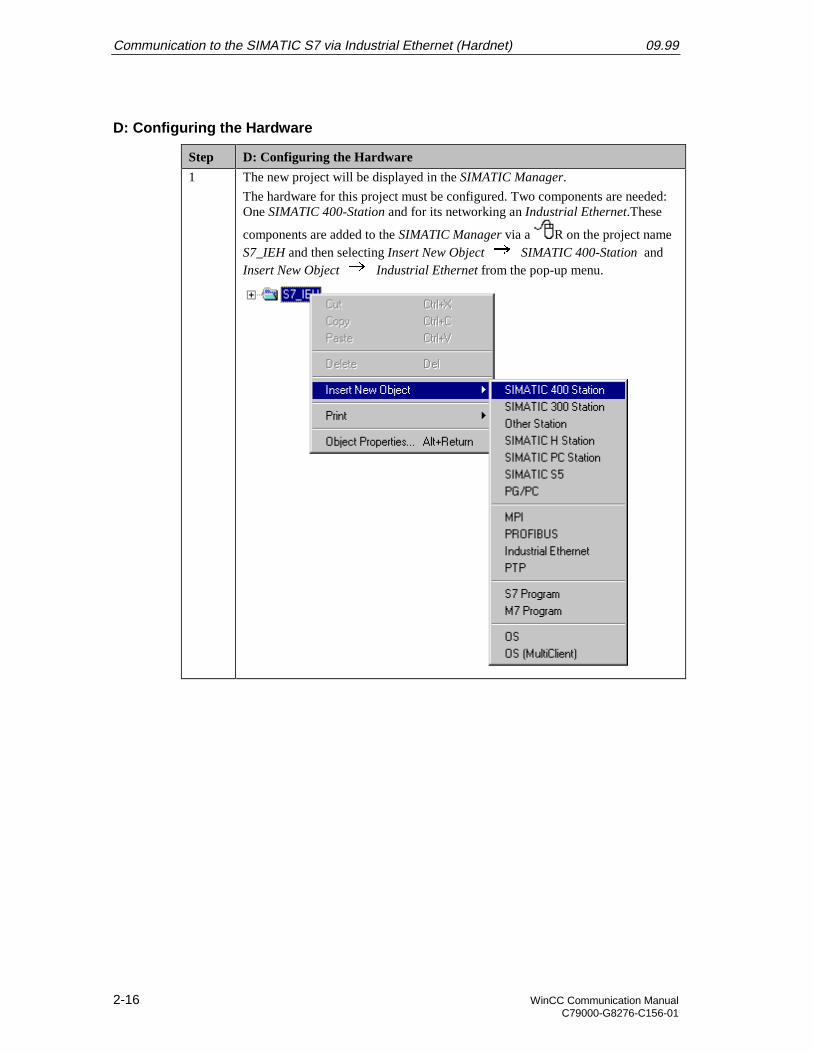
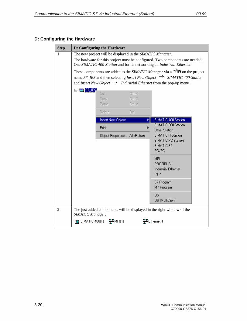
1 The new project will be displayed in the SIMATIC Manager.
The hardware for this project must be configured. Two components are needed:One SIMATIC 400-Station and for its networking an Industrial Ethernet.These
components are added to the SIMATIC Manager via a R on the project nameS7_IEH and then selecting Insert New Object SIMATIC 400-Station andInsert New Object Industrial Ethernet from the pop-up menu.
09.99 Communication to the SIMATIC S7 via Industrial Ethernet (Hardnet)
WinCC Communication Manual 2-17C79000-G8276-C156-01
Step D: Configuring the Hardware
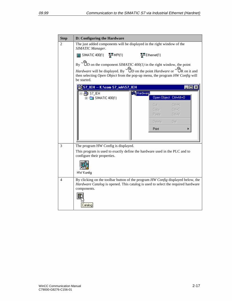
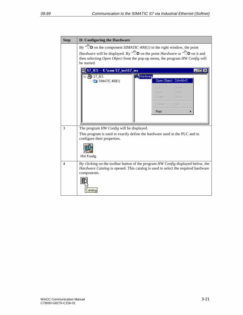
2 The just added components will be displayed in the right window of theSIMATIC Manager.
By D on the component SIMATIC 400(1) in the right window, the point
Hardware will be displayed. By D on the point Hardware or R on it andthen selecting Open Object from the pop-up menu, the program HW Config willbe started.
3 The program HW Config is displayed.
This program is used to exactly define the hardware used in the PLC and toconfigure their properties.
4 By clicking on the toolbar button of the program HW Config displayed below, theHardware Catalog is opened. This catalog is used to select the required hardwarecomponents.
Communication to the SIMATIC S7 via Industrial Ethernet (Hardnet) 09.99
2-18 WinCC Communication ManualC79000-G8276-C156-01
Step D: Configuring the Hardware
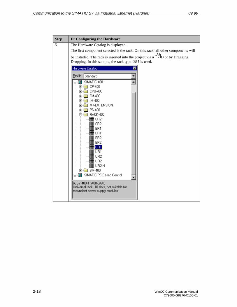
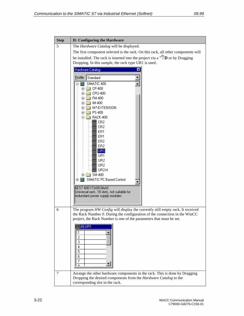
5 The Hardware Catalog is displayed.
The first component selected is the rack. On this rack, all other components will
be installed. The rack is inserted into the project via a D or by DraggingDropping. In this sample, the rack type UR1 is used.
09.99 Communication to the SIMATIC S7 via Industrial Ethernet (Hardnet)
WinCC Communication Manual 2-19C79000-G8276-C156-01
Step D: Configuring the Hardware
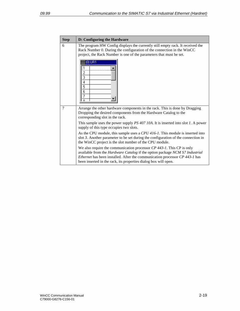
6 The program HW Config displays the currently still empty rack. It received theRack Number 0. During the configuration of the connection in the WinCCproject, the Rack Number is one of the parameters that must be set.
7 Arrange the other hardware components in the rack. This is done by DraggingDropping the desired components from the Hardware Catalog to thecorresponding slot in the rack.
This sample uses the power supply PS 407 10A. It is inserted into slot 1. A powersupply of this type occupies two slots.
As the CPU module, this sample uses a CPU 416-1. This module is inserted intoslot 3. Another parameter to be set during the configuration of the connection inthe WinCC project is the slot number of the CPU module.
We also require the communication processor CP 443-1. This CP is onlyavailable from the Hardware Catalog if the option package NCM S7 IndustrialEthernet has been installed. After the communication processor CP 443-1 hasbeen inserted in the rack, its properties dialog box will open.

Communication to the SIMATIC S7 via Industrial Ethernet (Hardnet) 09.99
2-20 WinCC Communication ManualC79000-G8276-C156-01
Step D: Configuring the Hardware
8 The Ethernet Interface properties dialog box of the CP 443-1 will be displayed.
In the MAC Address field of the Parameters tab, enter the desired Ethernetaddress of the communication processor. In this sample, the address08.00.06.01.00.00 is specified. Another parameter to be set during theconfiguration of the connection in the WinCC project is this Ethernet address.
In the Subnet field below, assign the entry Ethernet(1) to the communicationprocessor. Close the dialog box by clicking on OK.
9 The following graphic shows the completed hardware arrangement of the sample.
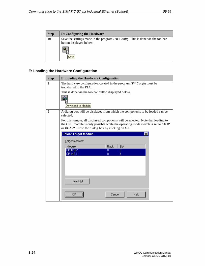
10 Save the settings made in the program HW Config. This is done via the toolbarbutton displayed below.
09.99 Communication to the SIMATIC S7 via Industrial Ethernet (Hardnet)
WinCC Communication Manual 2-21C79000-G8276-C156-01
E: Loading the Hardware Configuration
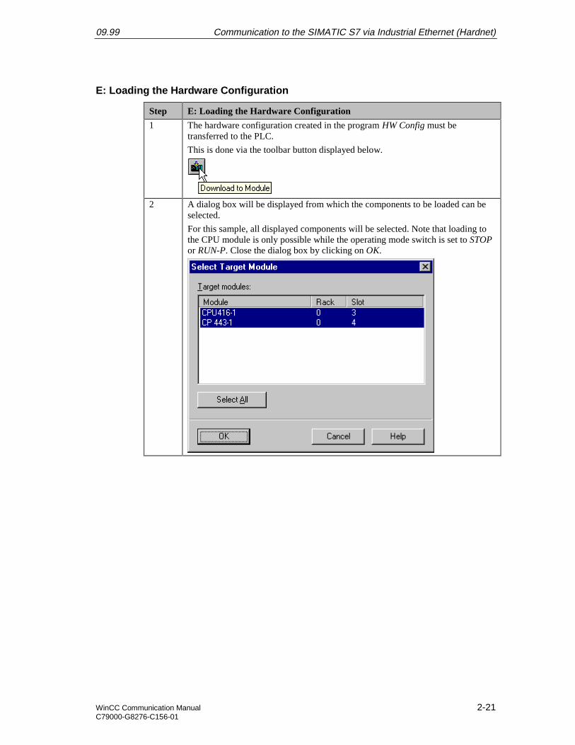
Step E: Loading the Hardware Configuration
1 The hardware configuration created in the program HW Config must betransferred to the PLC.
This is done via the toolbar button displayed below.
2 A dialog box will be displayed from which the components to be loaded can beselected.
For this sample, all displayed components will be selected. Note that loading tothe CPU module is only possible while the operating mode switch is set to STOPor RUN-P. Close the dialog box by clicking on OK.
Communication to the SIMATIC S7 via Industrial Ethernet (Hardnet) 09.99
2-22 WinCC Communication ManualC79000-G8276-C156-01
Step E: Loading the Hardware Configuration
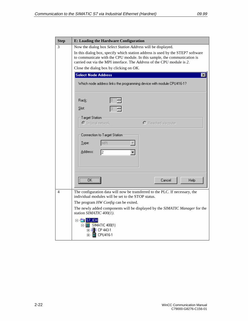
3 Now the dialog box Select Station Address will be displayed.
In this dialog box, specify which station address is used by the STEP7 softwareto communicate with the CPU module. In this sample, the communication iscarried out via the MPI interface. The Address of the CPU module is 2.
Close the dialog box by clicking on OK.
4 The configuration data will now be transferred to the PLC. If necessary, theindividual modules will be set to the STOP status.
The program HW Config can be exited.
The newly added components will be displayed by the SIMATIC Manager for thestation SIMATIC 400(1).
09.99 Communication to the SIMATIC S7 via Industrial Ethernet (Hardnet)
WinCC Communication Manual 2-23C79000-G8276-C156-01
F: Testing the Hardware Configuration
Step F: Testing the Hardware Configuration
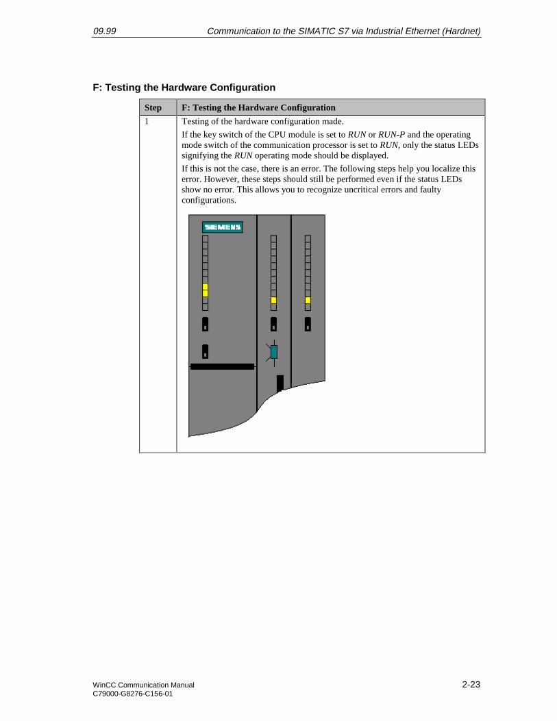
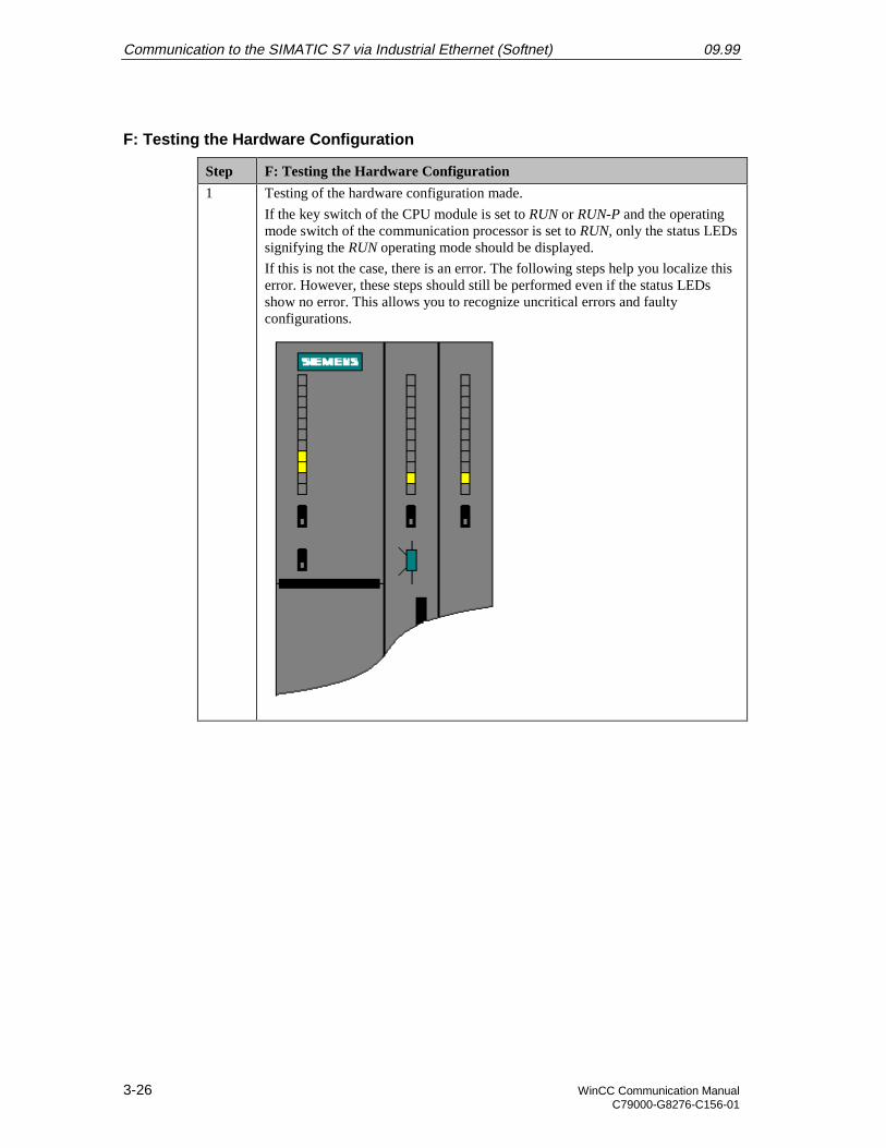
1 Testing of the hardware configuration made.
If the key switch of the CPU module is set to RUN or RUN-P and the operatingmode switch of the communication processor is set to RUN, only the status LEDssignifying the RUN operating mode should be displayed.
If this is not the case, there is an error. The following steps help you localize thiserror. However, these steps should still be performed even if the status LEDsshow no error. This allows you to recognize uncritical errors and faultyconfigurations.

Communication to the SIMATIC S7 via Industrial Ethernet (Hardnet) 09.99
2-24 WinCC Communication ManualC79000-G8276-C156-01
Step F: Testing the Hardware Configuration
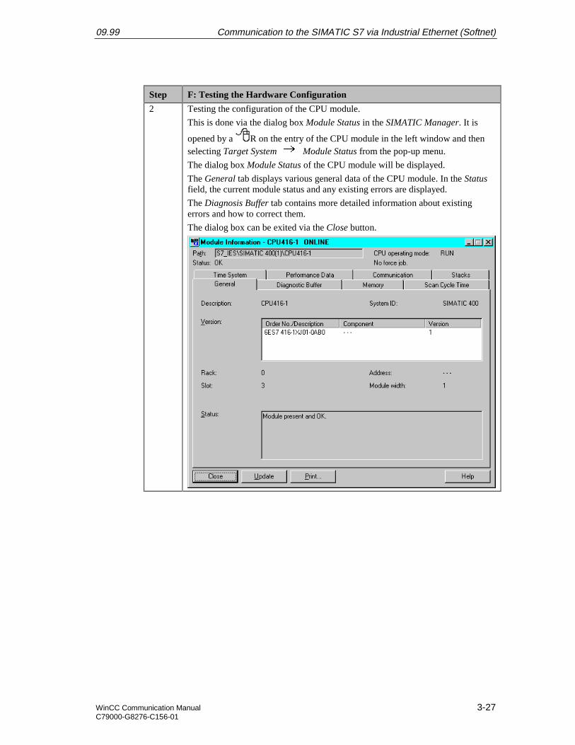
2 Testing the configuration of the CPU module.
This is done via the dialog box Module Status in the SIMATIC Manager. It is
opened by a R on the entry of the CPU module in the left window and thenselecting Target System Module Status from the pop-up menu.
The dialog box Module Status of the CPU module will be displayed.
The General tab displays various general data of the CPU module. In the Statusfield, the current module status and any existing errors are displayed.
The Diagnosis Buffer tab contains more detailed information about existingerrors and how to correct them.
The dialog box can be exited via the Close button.
09.99 Communication to the SIMATIC S7 via Industrial Ethernet (Hardnet)
WinCC Communication Manual 2-25C79000-G8276-C156-01
Step F: Testing the Hardware Configuration
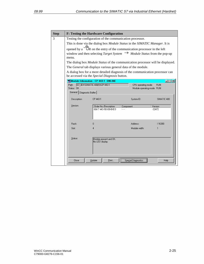
3 Testing the configuration of the communication processor.
This is done via the dialog box Module Status in the SIMATIC Manager. It is
opened by a R on the entry of the communication processor in the leftwindow and then selecting Target System Module Status from the pop-upmenu.
The dialog box Module Status of the communication processor will be displayed.
The General tab displays various general data of the module.
A dialog box for a more detailed diagnosis of the communication processor canbe accessed via the Special Diagnosis button.
Communication to the SIMATIC S7 via Industrial Ethernet (Hardnet) 09.99
2-26 WinCC Communication ManualC79000-G8276-C156-01
Step F: Testing the Hardware Configuration
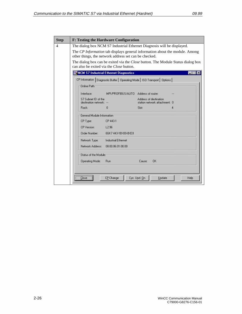
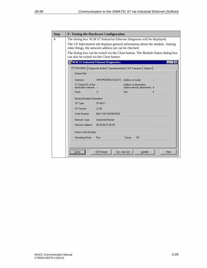
4 The dialog box NCM S7 Industrial Ethernet Diagnosis will be displayed.
The CP Information tab displays general information about the module. Amongother things, the network address set can be checked.
The dialog box can be exited via the Close button. The Module Status dialog boxcan also be exited via the Close button.
09.99 Communication to the SIMATIC S7 via Industrial Ethernet (Hardnet)
WinCC Communication Manual 2-27C79000-G8276-C156-01
G: Creating the STEP7 Program
Step G: Creating the STEP7 Program
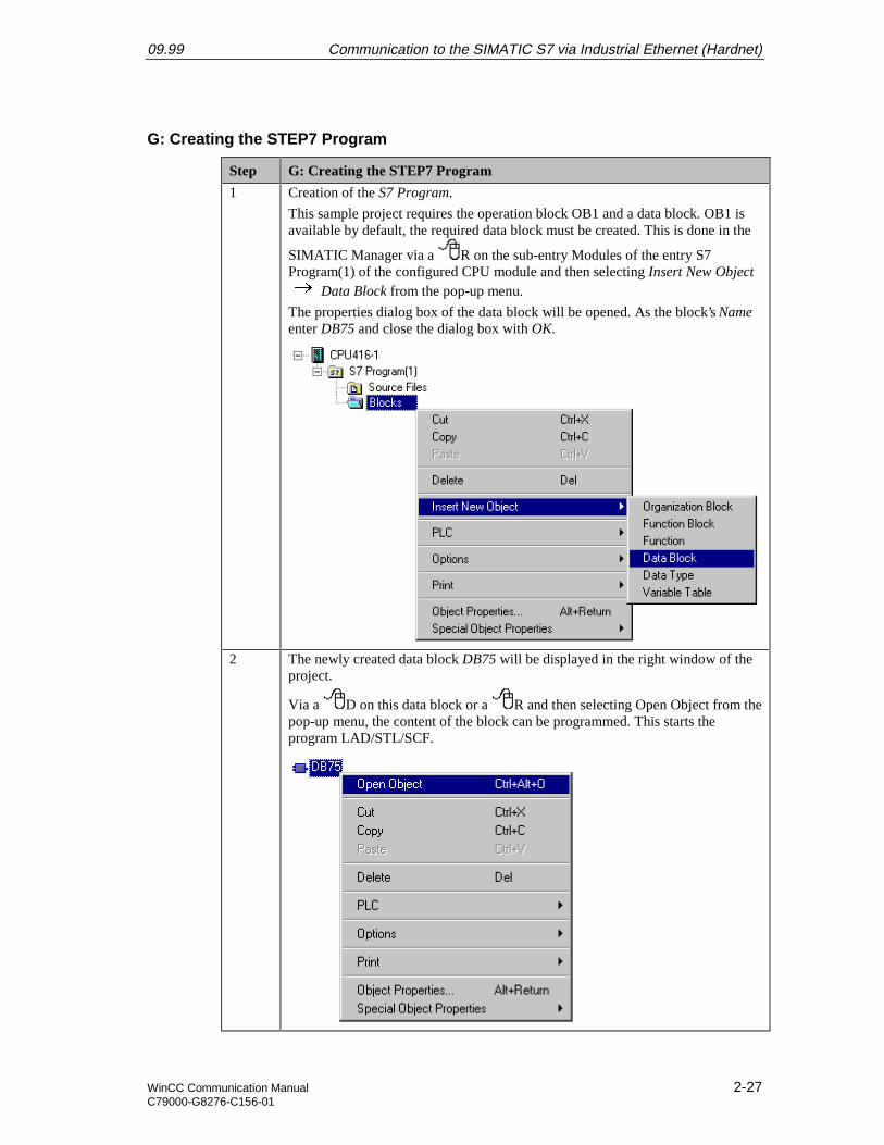
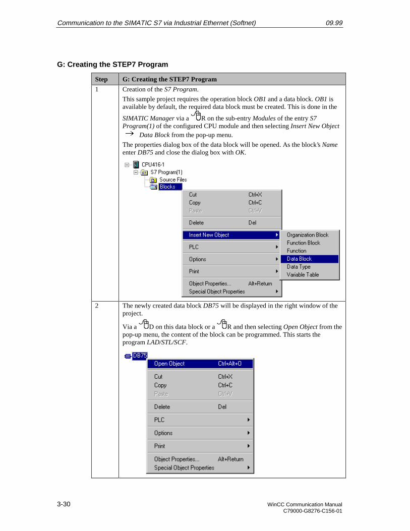
1 Creation of the S7 Program.
This sample project requires the operation block OB1 and a data block. OB1 isavailable by default, the required data block must be created. This is done in the
SIMATIC Manager via a R on the sub-entry Modules of the entry S7Program(1) of the configured CPU module and then selecting Insert New Object
Data Block from the pop-up menu.
The properties dialog box of the data block will be opened. As the block’s Nameenter DB75 and close the dialog box with OK.
2 The newly created data block DB75 will be displayed in the right window of theproject.
Via a D on this data block or a R and then selecting Open Object from thepop-up menu, the content of the block can be programmed. This starts theprogram LAD/STL/SCF.
Communication to the SIMATIC S7 via Industrial Ethernet (Hardnet) 09.99
2-28 WinCC Communication ManualC79000-G8276-C156-01
Step G: Creating the STEP7 Program
3 The program LAD/STL/SCF is displayed.
Acknowledge the dialog box New Data Block by clicking on OK.
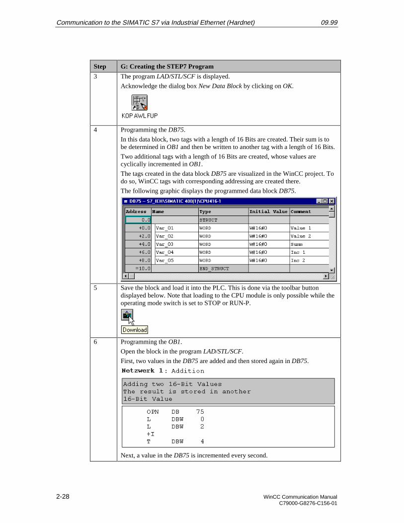
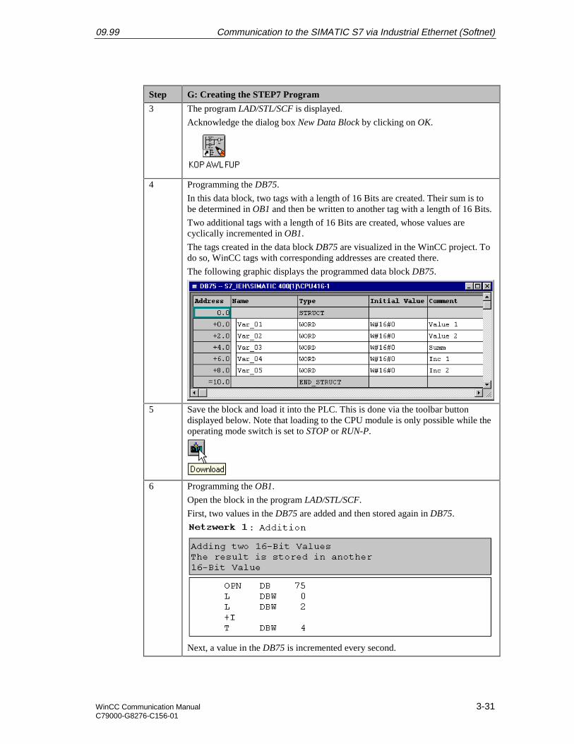
4 Programming the DB75.
In this data block, two tags with a length of 16 Bits are created. Their sum is tobe determined in OB1 and then be written to another tag with a length of 16 Bits.
Two additional tags with a length of 16 Bits are created, whose values arecyclically incremented in OB1.
The tags created in the data block DB75 are visualized in the WinCC project. Todo so, WinCC tags with corresponding addressing are created there.
The following graphic displays the programmed data block DB75.
5 Save the block and load it into the PLC. This is done via the toolbar buttondisplayed below. Note that loading to the CPU module is only possible while theoperating mode switch is set to STOP or RUN-P.
6 Programming the OB1.
Open the block in the program LAD/STL/SCF.
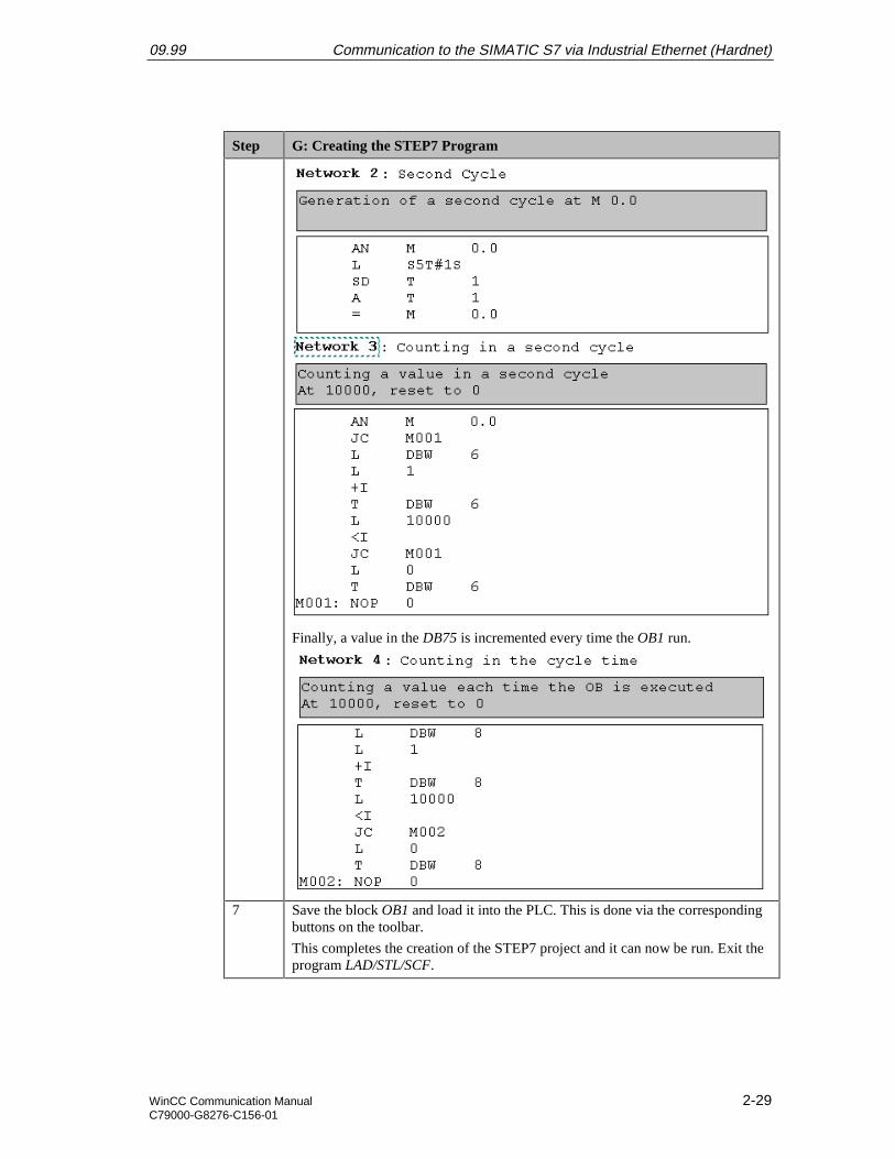
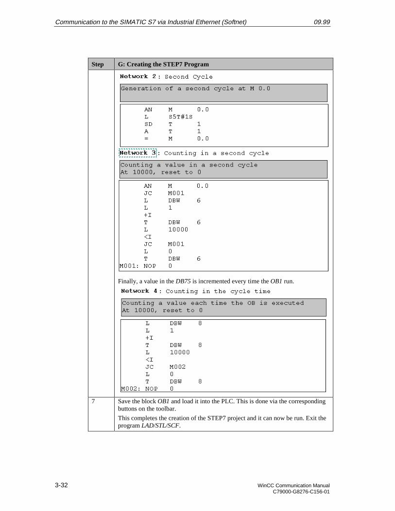
First, two values in the DB75 are added and then stored again in DB75.
Next, a value in the DB75 is incremented every second.
09.99 Communication to the SIMATIC S7 via Industrial Ethernet (Hardnet)
WinCC Communication Manual 2-29C79000-G8276-C156-01
Step G: Creating the STEP7 Program
Finally, a value in the DB75 is incremented every time the OB1 run.
7 Save the block OB1 and load it into the PLC. This is done via the correspondingbuttons on the toolbar.
This completes the creation of the STEP7 project and it can now be run. Exit theprogram LAD/STL/SCF.
Communication to the SIMATIC S7 via Industrial Ethernet (Hardnet) 09.99
2-30 WinCC Communication ManualC79000-G8276-C156-01
H: Testing the STEP7 Program
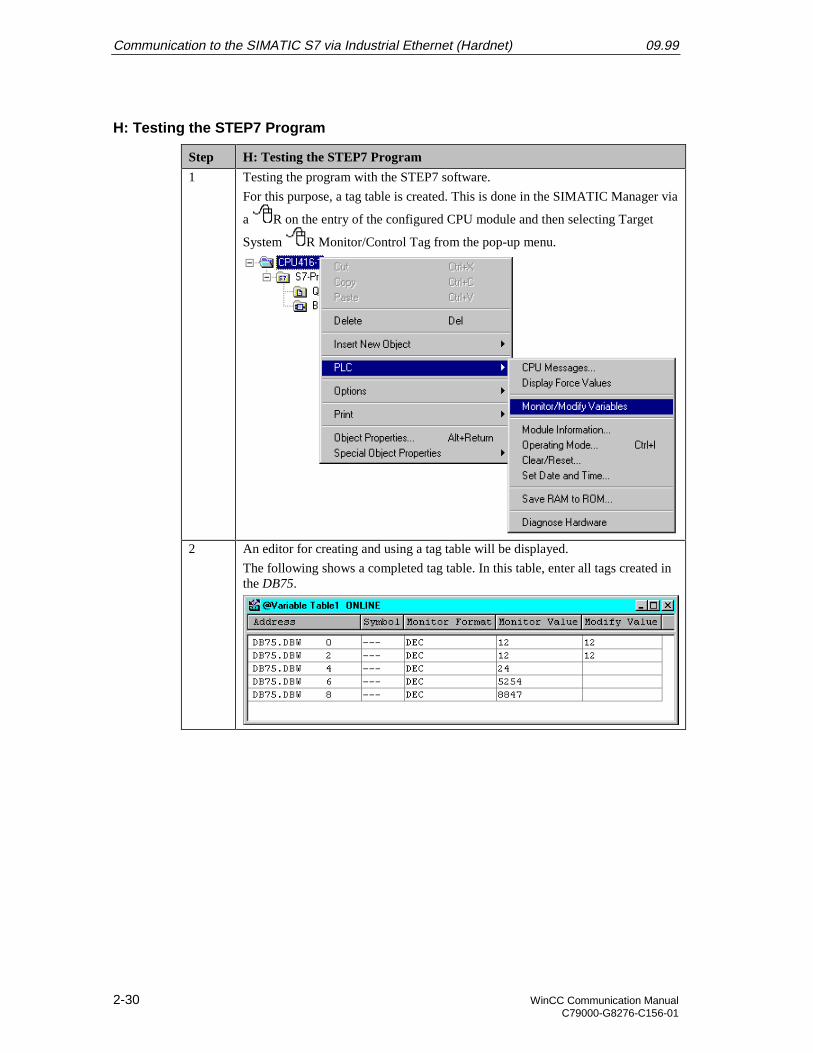
Step H: Testing the STEP7 Program
1 Testing the program with the STEP7 software.
For this purpose, a tag table is created. This is done in the SIMATIC Manager via
a R on the entry of the configured CPU module and then selecting Target
System R Monitor/Control Tag from the pop-up menu.
2 An editor for creating and using a tag table will be displayed.
The following shows a completed tag table. In this table, enter all tags created inthe DB75.
09.99 Communication to the SIMATIC S7 via Industrial Ethernet (Hardnet)
WinCC Communication Manual 2-31C79000-G8276-C156-01
Step H: Testing the STEP7 Program
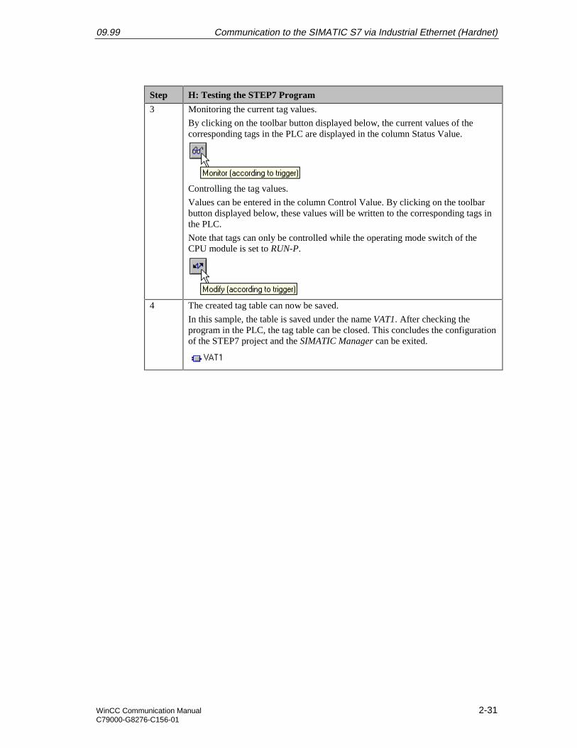
3 Monitoring the current tag values.
By clicking on the toolbar button displayed below, the current values of thecorresponding tags in the PLC are displayed in the column Status Value.
Controlling the tag values.
Values can be entered in the column Control Value. By clicking on the toolbarbutton displayed below, these values will be written to the corresponding tags inthe PLC.
Note that tags can only be controlled while the operating mode switch of theCPU module is set to RUN-P.
4 The created tag table can now be saved.
In this sample, the table is saved under the name VAT1. After checking theprogram in the PLC, the tag table can be closed. This concludes the configurationof the STEP7 project and the SIMATIC Manager can be exited.
Communication to the SIMATIC S7 via Industrial Ethernet (Hardnet) 09.99
2-32 WinCC Communication ManualC79000-G8276-C156-01
2.4 Creation of the WinCC Project WinCC_S7_IEH
The following description details the configuration steps necessary to create and start up theWinCC project WinCC_S7_IEH.
Overview of the Configuration Steps
The following lists the configuration steps necessary to create the WinCC projectWinCC_S7_IEH:
• A: Creating the WinCC Project
• B: Creating the Connection
• C: Creating the WinCC Tags
• D: Creating the WinCC Screen
A: Creating the WinCC Project
Step A: Creating the WinCC Project
1 Creation of a new WinCC project in the WinCC Explorer.
The WinCC Explorer is started via Start Simatic WinCC Windows Control Center.
2 The WinCC Explorer will be displayed.
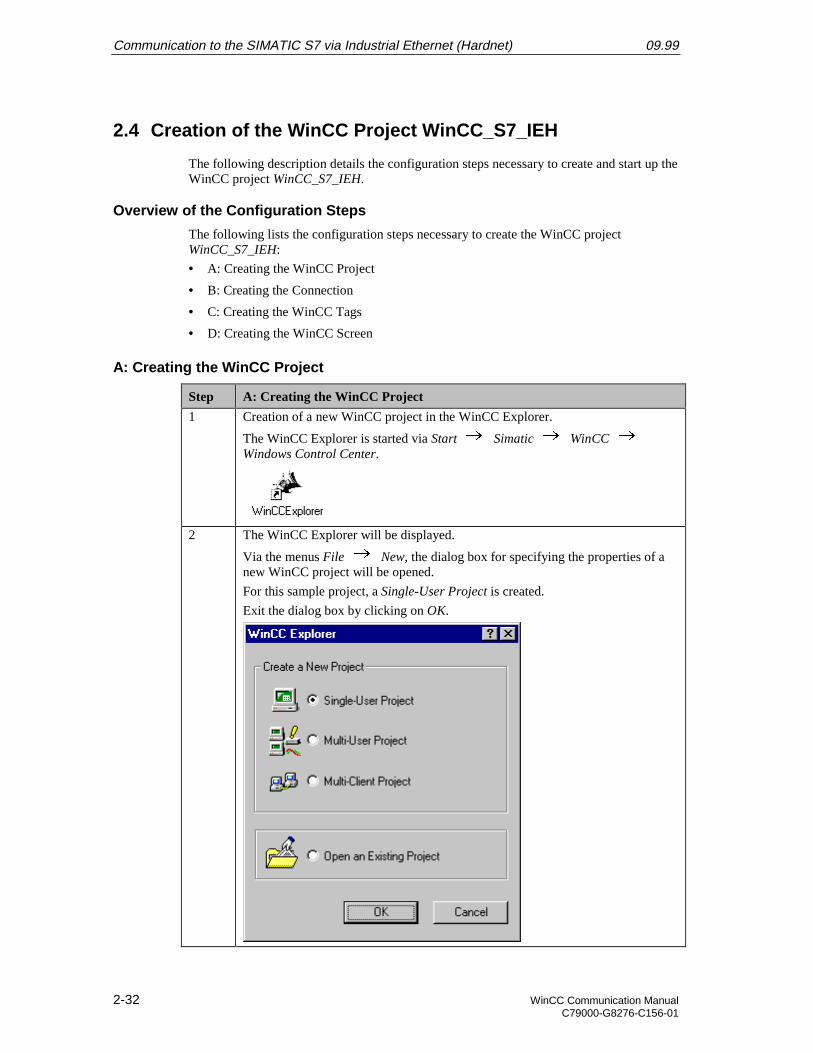
Via the menus File New, the dialog box for specifying the properties of anew WinCC project will be opened.
For this sample project, a Single-User Project is created.
Exit the dialog box by clicking on OK.
09.99 Communication to the SIMATIC S7 via Industrial Ethernet (Hardnet)
WinCC Communication Manual 2-33C79000-G8276-C156-01
Step A: Creating the WinCC Project
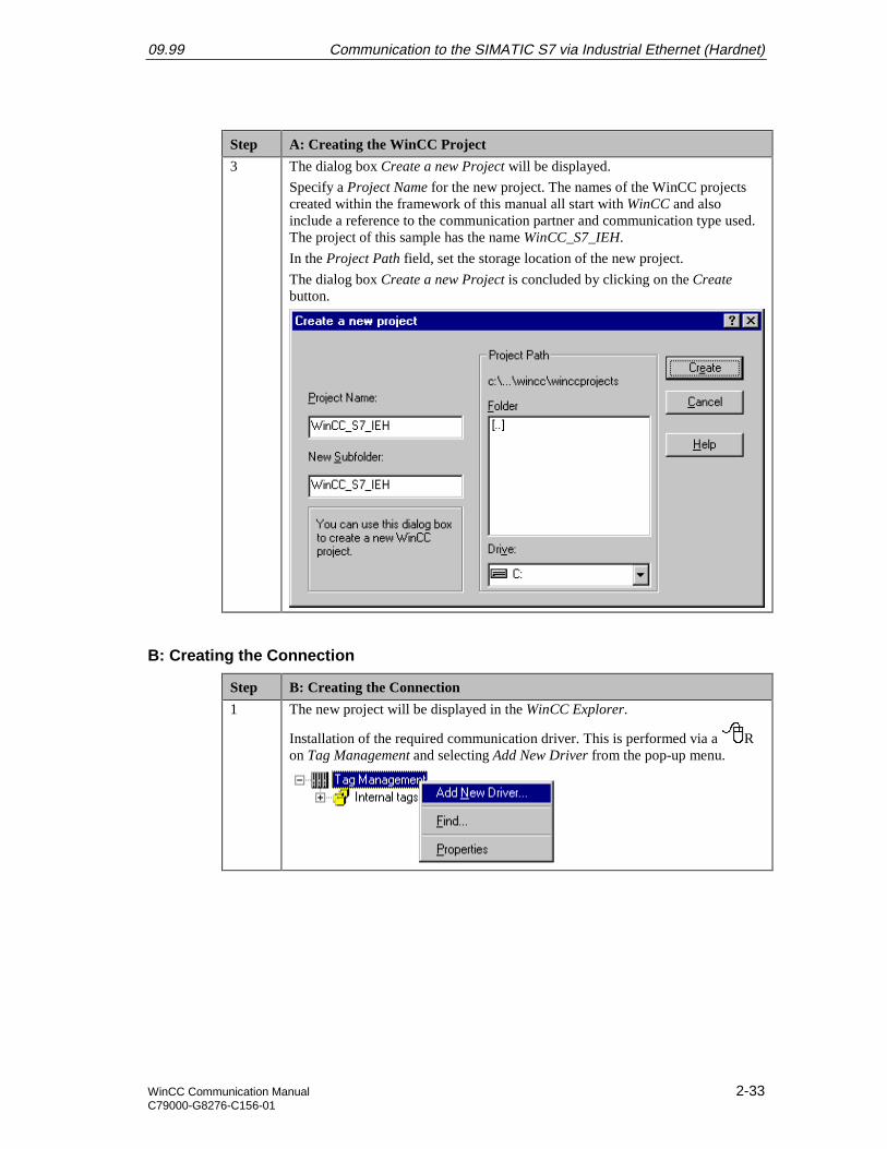
3 The dialog box Create a new Project will be displayed.
Specify a Project Name for the new project. The names of the WinCC projectscreated within the framework of this manual all start with WinCC and alsoinclude a reference to the communication partner and communication type used.The project of this sample has the name WinCC_S7_IEH.
In the Project Path field, set the storage location of the new project.
The dialog box Create a new Project is concluded by clicking on the Createbutton.
B: Creating the Connection
Step B: Creating the Connection
1 The new project will be displayed in the WinCC Explorer.
Installation of the required communication driver. This is performed via a Ron Tag Management and selecting Add New Driver from the pop-up menu.
Communication to the SIMATIC S7 via Industrial Ethernet (Hardnet) 09.99
2-34 WinCC Communication ManualC79000-G8276-C156-01
Step B: Creating the Connection
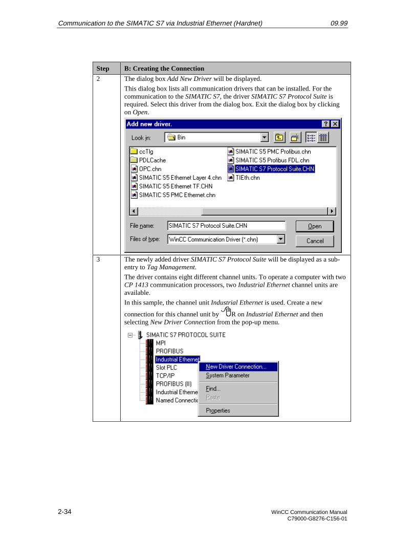
2 The dialog box Add New Driver will be displayed.
This dialog box lists all communication drivers that can be installed. For thecommunication to the SIMATIC S7, the driver SIMATIC S7 Protocol Suite isrequired. Select this driver from the dialog box. Exit the dialog box by clickingon Open.
3 The newly added driver SIMATIC S7 Protocol Suite will be displayed as a sub-entry to Tag Management.
The driver contains eight different channel units. To operate a computer with twoCP 1413 communication processors, two Industrial Ethernet channel units areavailable.
In this sample, the channel unit Industrial Ethernet is used. Create a new
connection for this channel unit by R on Industrial Ethernet and thenselecting New Driver Connection from the pop-up menu.
09.99 Communication to the SIMATIC S7 via Industrial Ethernet (Hardnet)
WinCC Communication Manual 2-35C79000-G8276-C156-01
Step B: Creating the Connection
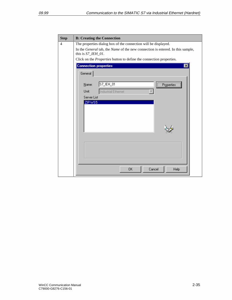
4 The properties dialog box of the connection will be displayed.
In the General tab, the Name of the new connection is entered. In this sample,this is S7_IEH_01.
Click on the Properties button to define the connection properties.
Communication to the SIMATIC S7 via Industrial Ethernet (Hardnet) 09.99
2-36 WinCC Communication ManualC79000-G8276-C156-01
Step B: Creating the Connection
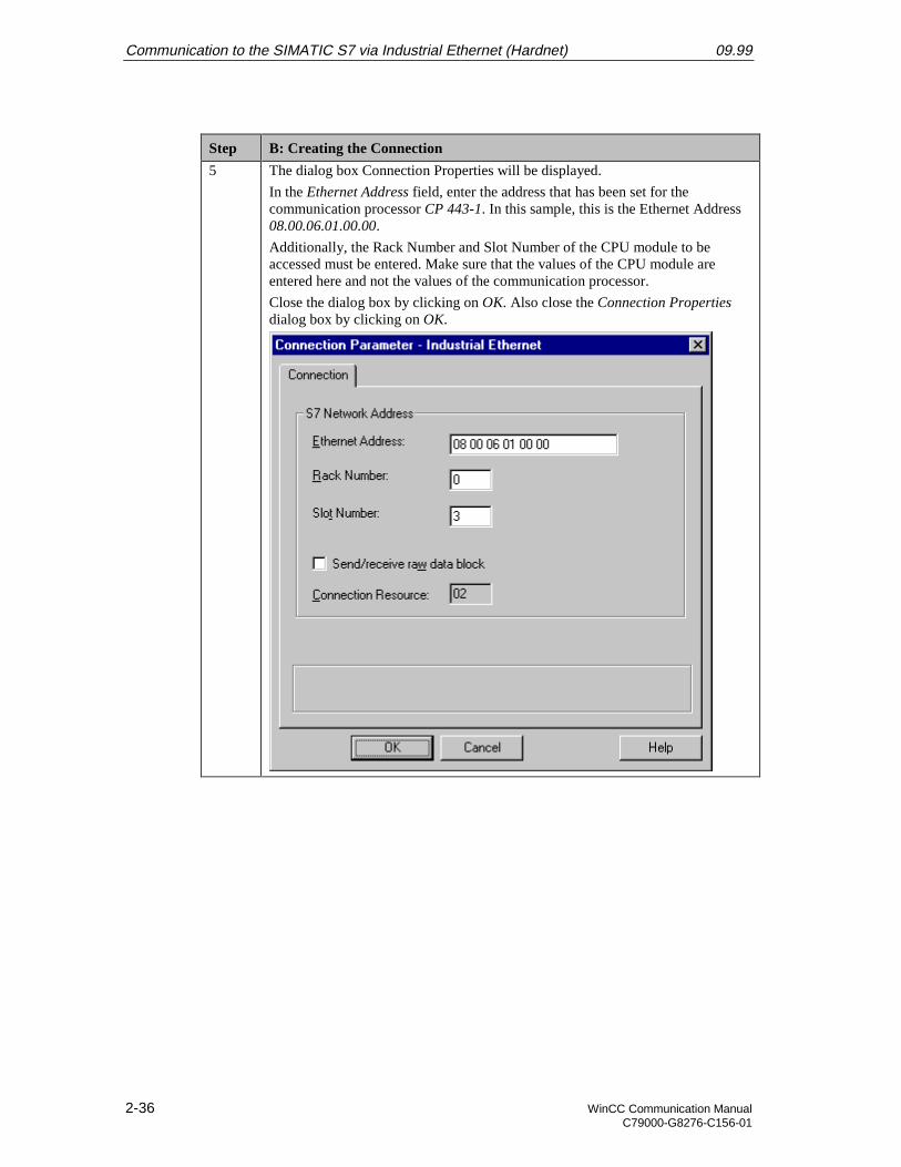
5 The dialog box Connection Properties will be displayed.
In the Ethernet Address field, enter the address that has been set for thecommunication processor CP 443-1. In this sample, this is the Ethernet Address08.00.06.01.00.00.
Additionally, the Rack Number and Slot Number of the CPU module to beaccessed must be entered. Make sure that the values of the CPU module areentered here and not the values of the communication processor.
Close the dialog box by clicking on OK. Also close the Connection Propertiesdialog box by clicking on OK.
09.99 Communication to the SIMATIC S7 via Industrial Ethernet (Hardnet)
WinCC Communication Manual 2-37C79000-G8276-C156-01
Step B: Creating the Connection
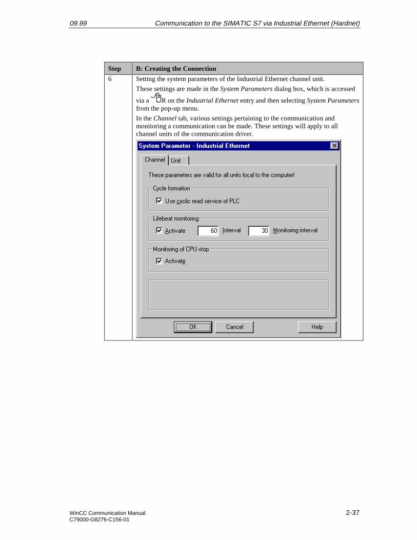
6 Setting the system parameters of the Industrial Ethernet channel unit.
These settings are made in the System Parameters dialog box, which is accessed
via a R on the Industrial Ethernet entry and then selecting System Parametersfrom the pop-up menu.
In the Channel tab, various settings pertaining to the communication andmonitoring a communication can be made. These settings will apply to allchannel units of the communication driver.
Communication to the SIMATIC S7 via Industrial Ethernet (Hardnet) 09.99
2-38 WinCC Communication ManualC79000-G8276-C156-01
Step B: Creating the Connection
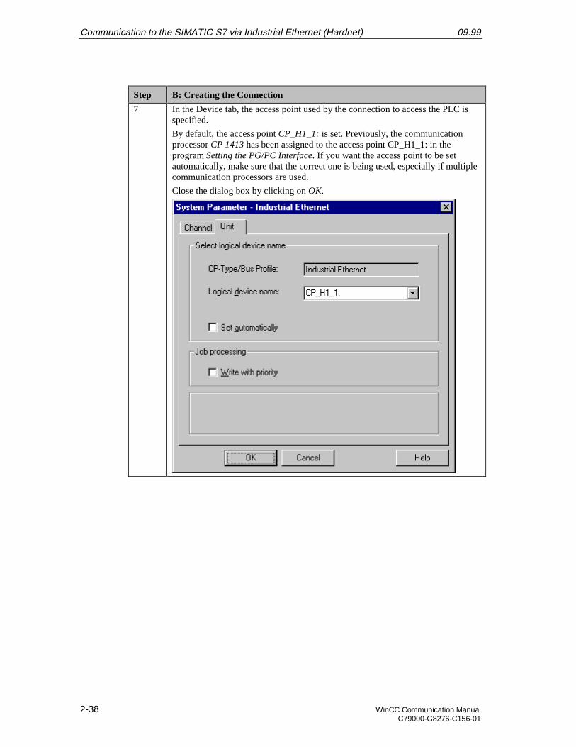
7 In the Device tab, the access point used by the connection to access the PLC isspecified.
By default, the access point CP_H1_1: is set. Previously, the communicationprocessor CP 1413 has been assigned to the access point CP_H1_1: in theprogram Setting the PG/PC Interface. If you want the access point to be setautomatically, make sure that the correct one is being used, especially if multiplecommunication processors are used.
Close the dialog box by clicking on OK.
09.99 Communication to the SIMATIC S7 via Industrial Ethernet (Hardnet)
WinCC Communication Manual 2-39C79000-G8276-C156-01
C: Creating the WinCC Tags
Step C: Creating the WinCC Tags
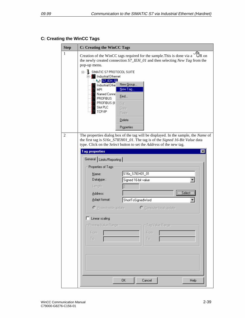
1Creation of the WinCC tags required for the sample.This is done via a R onthe newly created connection S7_IEH_01 and then selecting New Tag from thepop-up menu.
2 The properties dialog box of the tag will be displayed. In the sample, the Name ofthe first tag is S16x_S7IEH01_01. The tag is of the Signed 16-Bit Value datatype. Click on the Select button to set the Address of the new tag.
Communication to the SIMATIC S7 via Industrial Ethernet (Hardnet) 09.99
2-40 WinCC Communication ManualC79000-G8276-C156-01
Step C: Creating the WinCC Tags
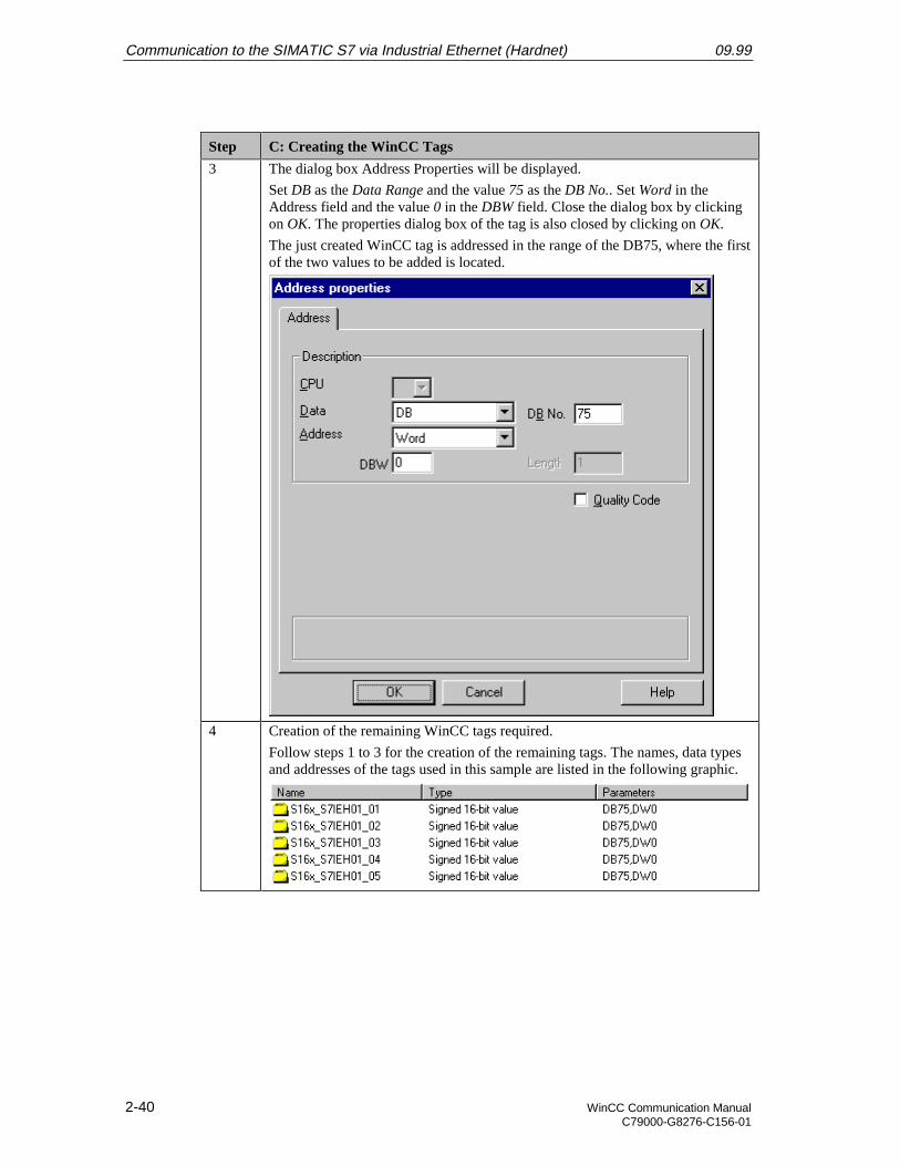
3 The dialog box Address Properties will be displayed.
Set DB as the Data Range and the value 75 as the DB No.. Set Word in theAddress field and the value 0 in the DBW field. Close the dialog box by clickingon OK. The properties dialog box of the tag is also closed by clicking on OK.
The just created WinCC tag is addressed in the range of the DB75, where the firstof the two values to be added is located.
4 Creation of the remaining WinCC tags required.
Follow steps 1 to 3 for the creation of the remaining tags. The names, data typesand addresses of the tags used in this sample are listed in the following graphic.

09.99 Communication to the SIMATIC S7 via Industrial Ethernet (Hardnet)
WinCC Communication Manual 2-41C79000-G8276-C156-01
D: Creating the WinCC Screen
Step D: Creating the WinCC Screen
1 Creation of a WinCC screen in which the previously created tags are visualized.
Open the Graphics Designer editor via a R and then selecting Open from thepop-up menu.
2 This will open the Graphics Designer editor with a new (blank) screen.
To display the first tag, configure a Smart Object I/O Field. To do so,select the I/O Field object from the Object Palette and place it on the screenusing the mouse.

Communication to the SIMATIC S7 via Industrial Ethernet (Hardnet) 09.99
2-42 WinCC Communication ManualC79000-G8276-C156-01
Step D: Creating the WinCC Screen
3 After placing the I/O Field on the screen, its Configuration dialog box will bedisplayed.
In the Tag field, set the tag S16x_S7IEH01_01 via the button displayed below.
Leave the Update of the tag at 2 s. Keep the default settings for the remainingoptions. Close the dialog box by clicking on OK.
4 Changing the output format of the I/O Field.
For this, open its properties dialog box via a R on the I/O Field and thenselect Properties from the pop-up menu.
09.99 Communication to the SIMATIC S7 via Industrial Ethernet (Hardnet)
WinCC Communication Manual 2-43C79000-G8276-C156-01
Step D: Creating the WinCC Screen
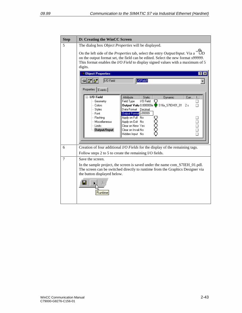
5 The dialog box Object Properties will be displayed.
On the left side of the Properties tab, select the entry Output/Input. Via a Don the output format set, the field can be edited. Select the new format s99999.This format enables the I/O Field to display signed values with a maximum of 5digits.
6 Creation of four additional I/O Fields for the display of the remaining tags.
Follow steps 2 to 5 to create the remaining I/O fields.
7 Save the screen.
In the sample project, the screen is saved under the name com_S7IEH_01.pdl.The screen can be switched directly to runtime from the Graphics Designer viathe button displayed below.
Communication to the SIMATIC S7 via Industrial Ethernet (Hardnet) 09.99
2-44 WinCC Communication ManualC79000-G8276-C156-01
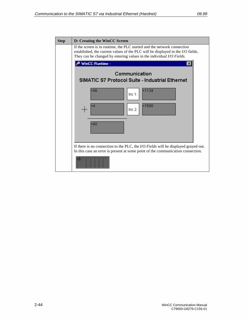
Step D: Creating the WinCC Screen
If the screen is in runtime, the PLC started and the network connectionestablished, the current values of the PLC will be displayed in the I/O fields.They can be changed by entering values in the individual I/O Fields.
If there is no connection to the PLC, the I/O Fields will be displayed grayed out.In this case an error is present at some point of the communication connection.
09.99 Communication to the SIMATIC S7 via Industrial Ethernet (Hardnet)
WinCC Communication Manual 2-45C79000-G8276-C156-01
2.5 Diagnosis of the Communication Connection
The following describes the options available for diagnosing the communication connectionbetween the WinCC project WinCC_S7_IEH and the SIMATIC S7 station.A diagnosis of the sample according to the following description makes only sense, if thechecks listed below have been completed successfully.Startup of the Communication Processor CP 1413
• E: Testing the Communication ProcessorCreation of the STEP7 Project S7_IEH
• F: Testing the Hardware Configuration
• I: Testing the STEP7 Program
WinCC Explorer
Step WinCC Explorer
1 Diagnosis of the communication connection in the WinCC Explorer.
Switch the project WinCC_S7_IEH into runtime. This is done from the WinCCExplorer via the toolbar button displayed below.
The created WinCC screen com_3_S7IEH_01.pdl can also be switched directlyfrom the Graphics Designer into runtime.
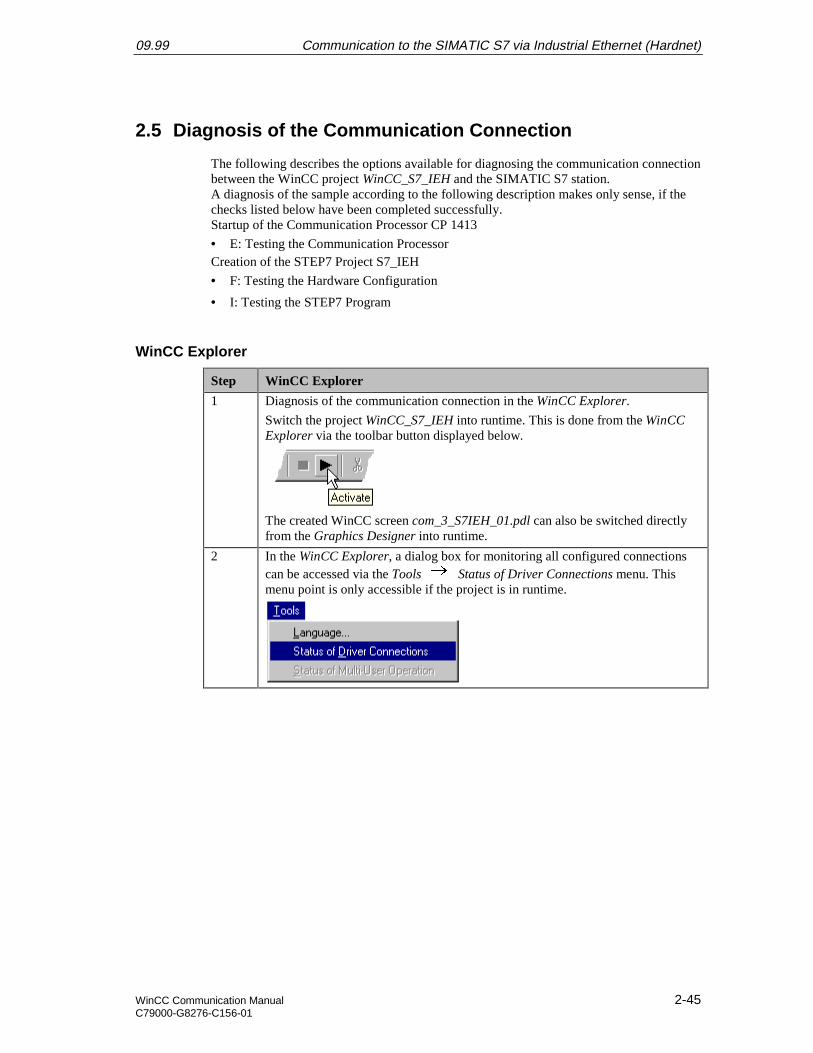
2 In the WinCC Explorer, a dialog box for monitoring all configured connectionscan be accessed via the Tools Status of Driver Connections menu. Thismenu point is only accessible if the project is in runtime.
Communication to the SIMATIC S7 via Industrial Ethernet (Hardnet) 09.99
2-46 WinCC Communication ManualC79000-G8276-C156-01
Step WinCC Explorer
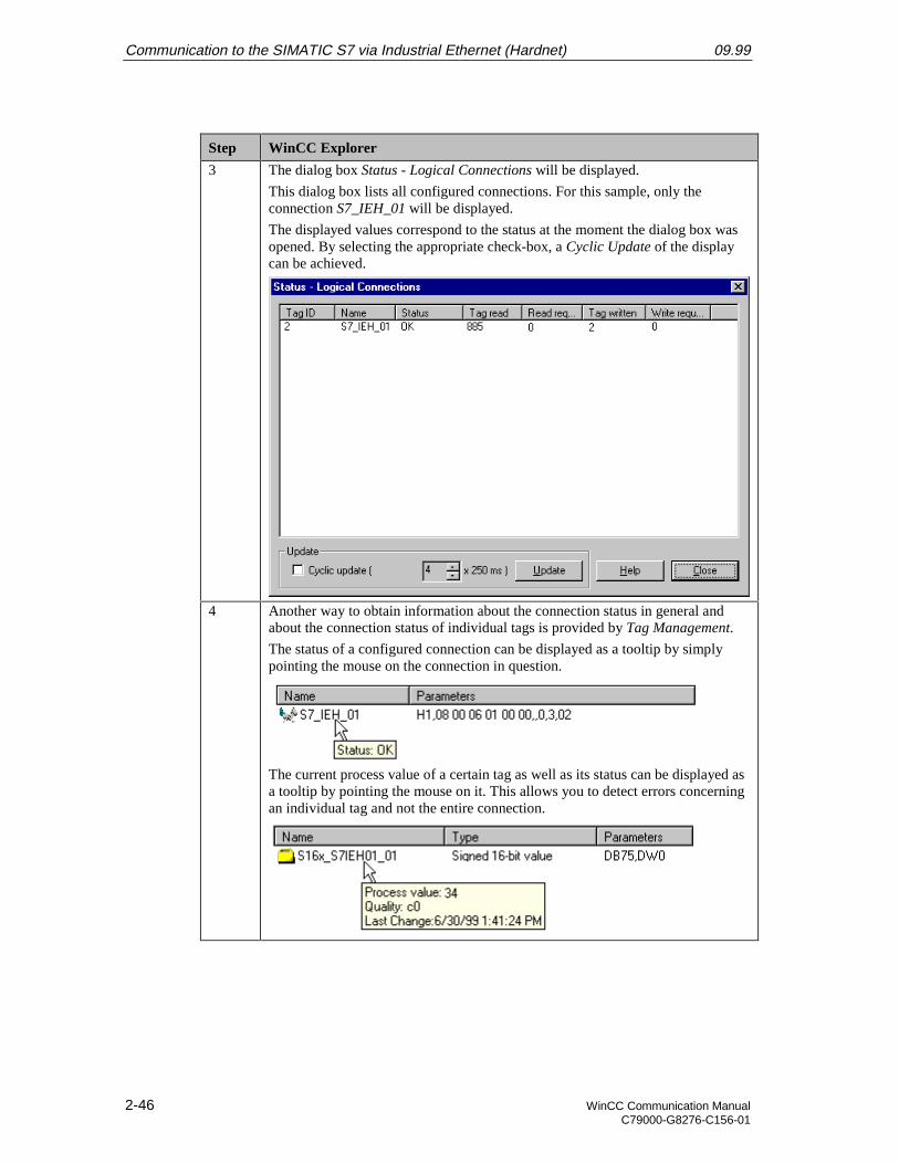
3 The dialog box Status - Logical Connections will be displayed.
This dialog box lists all configured connections. For this sample, only theconnection S7_IEH_01 will be displayed.
The displayed values correspond to the status at the moment the dialog box wasopened. By selecting the appropriate check-box, a Cyclic Update of the displaycan be achieved.
4 Another way to obtain information about the connection status in general andabout the connection status of individual tags is provided by Tag Management.
The status of a configured connection can be displayed as a tooltip by simplypointing the mouse on the connection in question.
The current process value of a certain tag as well as its status can be displayed asa tooltip by pointing the mouse on it. This allows you to detect errors concerningan individual tag and not the entire connection.
09.99 Communication to the SIMATIC S7 via Industrial Ethernet (Hardnet)
WinCC Communication Manual 2-47C79000-G8276-C156-01
Channel Diagnosis
Step Channel Diagnosis
1 Diagnosis of the communication connection via the program WinCC ChannelDiagnosis.
Start this program via Start Simatic WinCC ChannelDiagnosis.
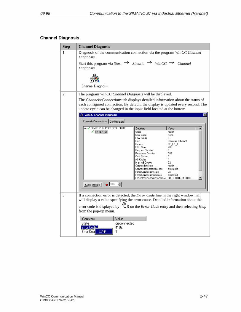
2 The program WinCC Channel Diagnosis will be displayed.
The Channels/Connections tab displays detailed information about the status ofeach configured connection. By default, the display is updated every second. Theupdate cycle can be changed in the input field located at the bottom.
3 If a connection error is detected, the Error Code line in the right window halfwill display a value specifying the error cause. Detailed information about this
error code is displayed by R on the Error Code entry and then selecting Helpfrom the pop-up menu.
Communication to the SIMATIC S7 via Industrial Ethernet (Hardnet) 09.99
2-48 WinCC Communication ManualC79000-G8276-C156-01
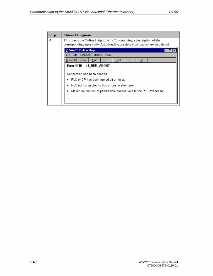
Step Channel Diagnosis
4 This opens the Online Help to WinCC containing a description of thecorresponding error code. Additionally, possible error causes are also listed.
09.99 Communication to the SIMATIC S7 via Industrial Ethernet (Softnet)
WinCC Communication Manual 3-1C79000-G8276-C156-01
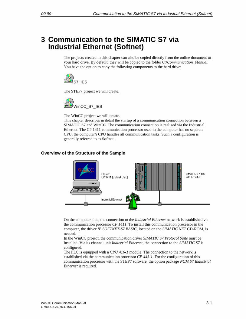
3 Communication to the SIMATIC S7 viaIndustrial Ethernet (Softnet)
The projects created in this chapter can also be copied directly from the online document toyour hard drive. By default, they will be copied to the folder C:\Communication_Manual.You have the option to copy the following components to the hard drive:
S7_IES
The STEP7 project we will create.
WinCC_S7_IES
The WinCC project we will create.This chapter describes in detail the startup of a communication connection between aSIMATIC S7 and WinCC. The communication connection is realized via the IndustrialEthernet. The CP 1411 communication processor used in the computer has no separateCPU, the computer’s CPU handles all communication tasks. Such a configuration isgenerally referred to as Softnet.
Overview of the Structure of the Sample
On the computer side, the connection to the Industrial Ethernet network is established viathe communication processor CP 1411. To install this communication processor in thecomputer, the driver IE SOFTNET-S7 BASIC, located on the SIMATIC NET CD-ROM, isneeded.In the WinCC project, the communication driver SIMATIC S7 Protocol Suite must beinstalled. Via its channel unit Industrial Ethernet, the connection to the SIMATIC S7 isconfigured.The PLC is equipped with a CPU 416-1 module. The connection to the network isestablished via the communication processor CP 443-1. For the configuration of thiscommunication processor with the STEP7 software, the option package NCM S7 IndustrialEthernet is required.
Communication to the SIMATIC S7 via Industrial Ethernet (Softnet) 09.99
3-2 WinCC Communication ManualC79000-G8276-C156-01
Overview of the Configuration Steps
The following lists all configuration steps necessary for the creation of the communicationconnection:
• Startup of the Communication Processor CP 1411
• Creation of the STEP7 Project S7_IES
• Creation of the WinCC Project WinCC_S7_IES
• Diagnosis of the Communication Connection
Required Software
Name Description
SIMATIC NET Driver IE SOFTNET S7 BASIC from the SIMATIC NETCD-ROM for the installation of the communicationprocessor CP 1411.
Windows NT Windows NT installation software for the installation of thecommunication processor CP 1411.
STEP7 STEP7 software with option package NCM for IndustrialEthernet for the creation of the STEP7 project.
WinCC WinCC with the communication driver SIMATIC S7Protocol Suite for the creation of the WinCC project.
Required Computer Hardware
Name Description
Communication Processor Communication processor CP 1411 to establish theconnection to the PLC’s communication processor.
Required PLC Hardware
Name Description
Rack Rack UR1
Power Supply Power supply PS 407 10A in slot 1 and 2.
CPU Module CPU module CPU 416-1 in slot 3.
Communication Processor Communication processor CP 443-1 in slot 4.
09.99 Communication to the SIMATIC S7 via Industrial Ethernet (Softnet)
WinCC Communication Manual 3-3C79000-G8276-C156-01
3.1 Startup of the Communication Processor CP 1411
The following description details the configuration steps necessary to successfully start upthe communication processor CP 1411. The communication is handled by the SIEMENSIndustrial Ethernet protocol.
Overview of the Configuration Steps
The following lists the configuration steps necessary to start up the communicationprocessor CP 1411:
• A: Mounting the Communication Processor in the Computer
• B: Installing the Communication Driver
• C: Installing the Communication Processor
• D: Installing the Communication Protocol
• E: Configuring the Bindings
• F: Creating an Access Point
• G: Testing the Communication Processor
A: Mounting the Communication Processor in the Computer
Step A: Mounting the Communication Processor in the Computer
1 Mount the module according to the installation instructions. Among other things,follow the steps for handling electrostatic sensitive devices (ESD). The modulemust only be installed while the computer is off.
The communication card CP 1411 requires a free ISA slot in the computer. Afterthe installation of the CP 1411, close the computer’s case and start the computer.
B: Installing the Communication Driver
Step B: Installing the Communication Driver
1 Install the communication driver IE SOFTNET S7 BASIC from the SIMATICNET CD-ROM.
After inserting the SIMATIC NET CD-ROM, the installation program isautomatically started. If this is not the case, open the Windows NT Explorer andstart the setup.exe program located on the CD-ROM.
The installation of the software is started via the button displayed below.
Communication to the SIMATIC S7 via Industrial Ethernet (Softnet) 09.99
3-4 WinCC Communication ManualC79000-G8276-C156-01
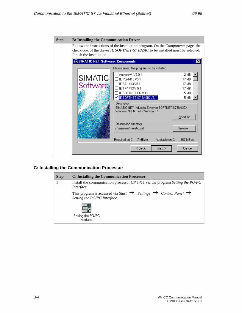
Step B: Installing the Communication Driver
Follow the instructions of the installation program. On the Components page, thecheck-box of the driver IE SOFTNET-S7 BASIC to be installed must be selected.Finish the installation.
C: Installing the Communication Processor
Step C: Installing the Communication Processor
1 Install the communication processor CP 1411 via the program Setting the PG/PCInterface.
This program is accessed via Start Settings Control Panel Setting the PG/PC Interface.
09.99 Communication to the SIMATIC S7 via Industrial Ethernet (Softnet)
WinCC Communication Manual 3-5C79000-G8276-C156-01
Step C: Installing the Communication Processor
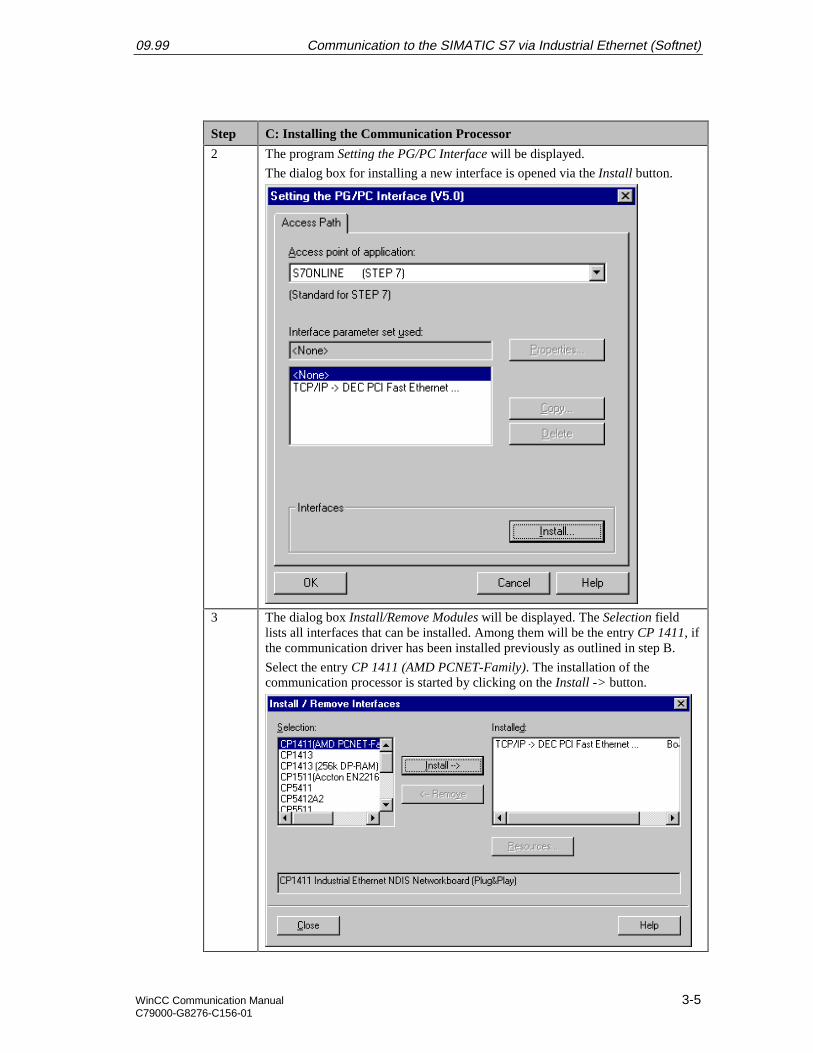
2 The program Setting the PG/PC Interface will be displayed.
The dialog box for installing a new interface is opened via the Install button.
3 The dialog box Install/Remove Modules will be displayed. The Selection fieldlists all interfaces that can be installed. Among them will be the entry CP 1411, ifthe communication driver has been installed previously as outlined in step B.
Select the entry CP 1411 (AMD PCNET-Family). The installation of thecommunication processor is started by clicking on the Install -> button.
Communication to the SIMATIC S7 via Industrial Ethernet (Softnet) 09.99
3-6 WinCC Communication ManualC79000-G8276-C156-01
Step C: Installing the Communication Processor
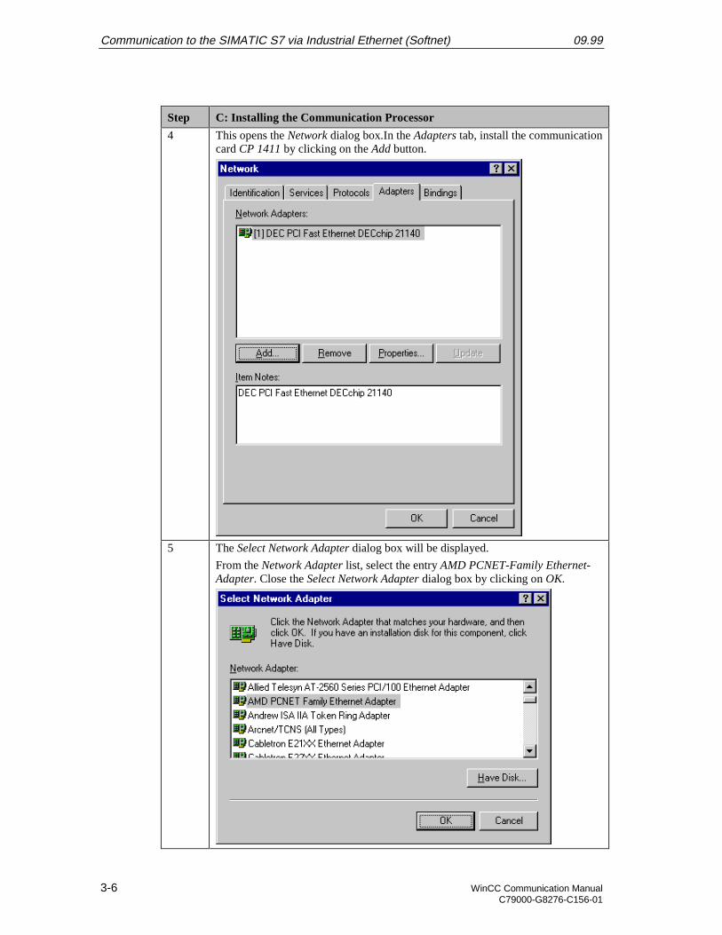
4 This opens the Network dialog box.In the Adapters tab, install the communicationcard CP 1411 by clicking on the Add button.
5 The Select Network Adapter dialog box will be displayed.
From the Network Adapter list, select the entry AMD PCNET-Family Ethernet-Adapter. Close the Select Network Adapter dialog box by clicking on OK.
09.99 Communication to the SIMATIC S7 via Industrial Ethernet (Softnet)
WinCC Communication Manual 3-7C79000-G8276-C156-01
Step C: Installing the Communication Processor
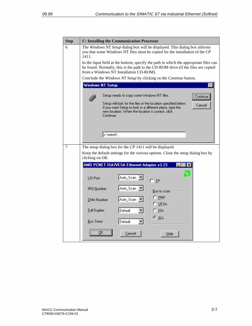
6 The Windows NT Setup dialog box will be displayed. This dialog box informsyou that some Windows NT files must be copied for the installation of the CP1411.
In the input field at the bottom, specify the path in which the appropriate files canbe found. Normally, this is the path to the CD-ROM drive (if the files are copiedfrom a Windows NT Installation CD-ROM).
Conclude the Windows NT Setup by clicking on the Continue button.
7 The setup dialog box for the CP 1411 will be displayed.
Keep the default settings for the various options. Close the setup dialog box byclicking on OK.
Communication to the SIMATIC S7 via Industrial Ethernet (Softnet) 09.99
3-8 WinCC Communication ManualC79000-G8276-C156-01
Step C: Installing the Communication Processor
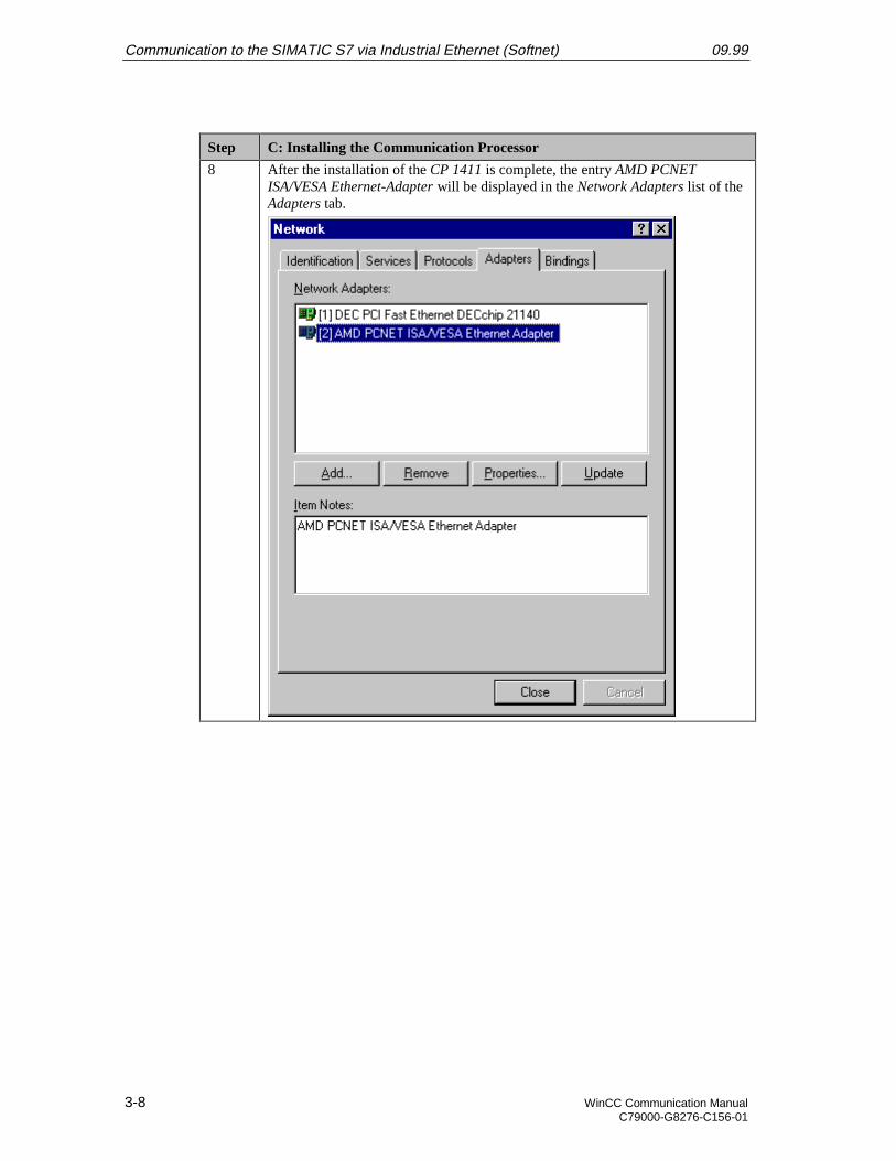
8 After the installation of the CP 1411 is complete, the entry AMD PCNETISA/VESA Ethernet-Adapter will be displayed in the Network Adapters list of theAdapters tab.
09.99 Communication to the SIMATIC S7 via Industrial Ethernet (Softnet)
WinCC Communication Manual 3-9C79000-G8276-C156-01
D: Installing the Communication Protocol
Step D: Installing the Communication Protocol
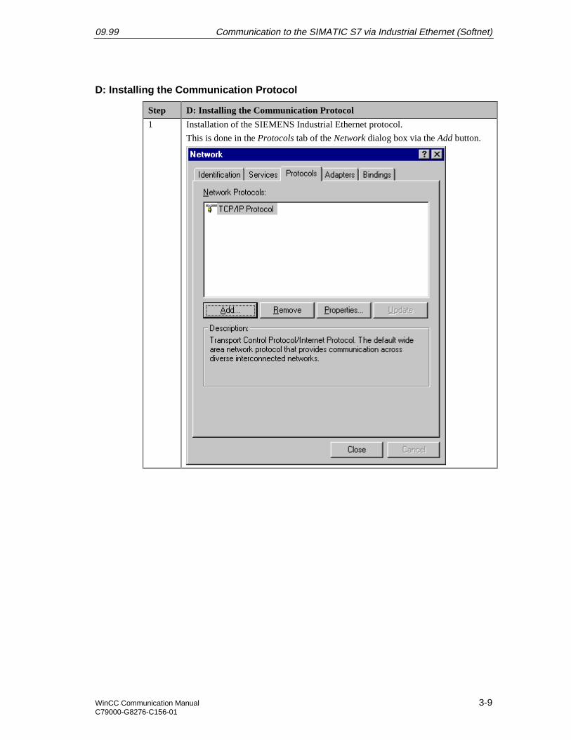
1 Installation of the SIEMENS Industrial Ethernet protocol.
This is done in the Protocols tab of the Network dialog box via the Add button.
Communication to the SIMATIC S7 via Industrial Ethernet (Softnet) 09.99
3-10 WinCC Communication ManualC79000-G8276-C156-01
Step D: Installing the Communication Protocol
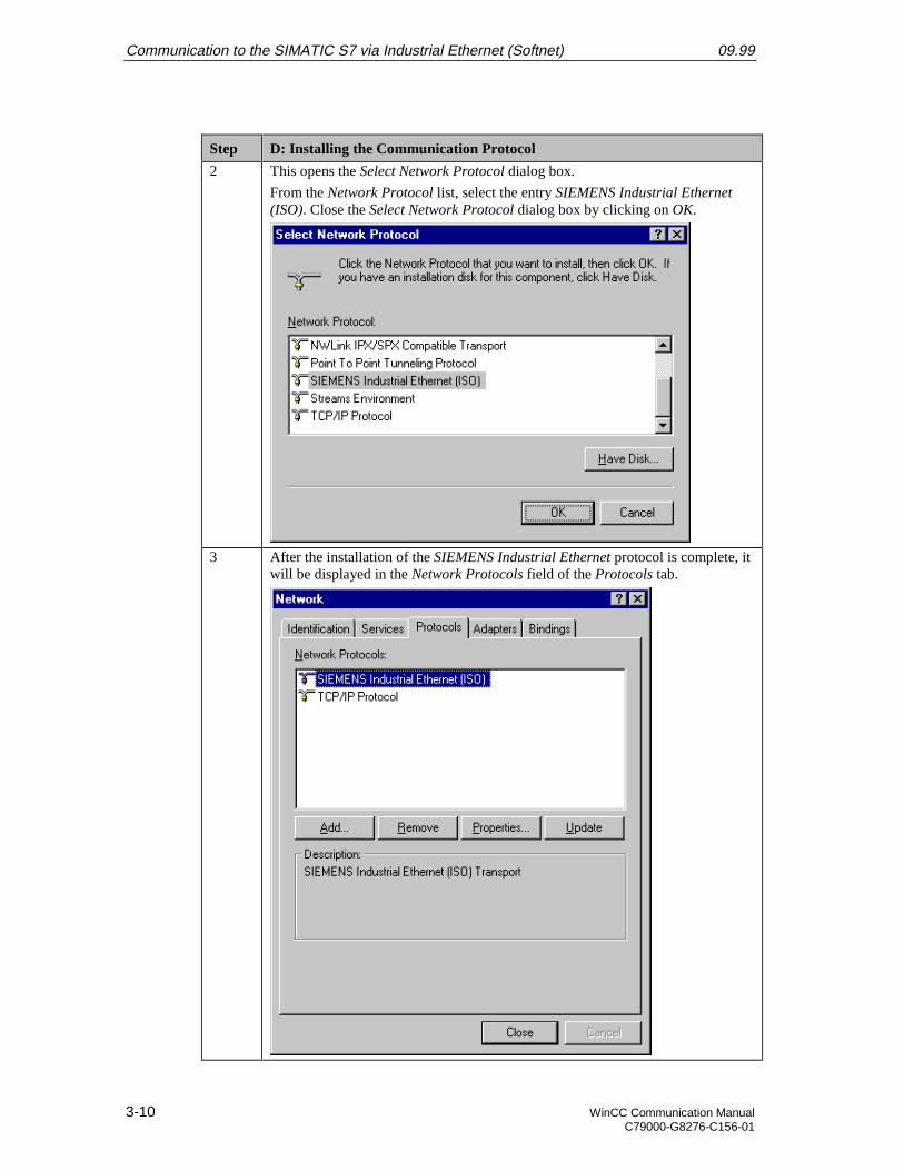
2 This opens the Select Network Protocol dialog box.
From the Network Protocol list, select the entry SIEMENS Industrial Ethernet(ISO). Close the Select Network Protocol dialog box by clicking on OK.
3 After the installation of the SIEMENS Industrial Ethernet protocol is complete, itwill be displayed in the Network Protocols field of the Protocols tab.
09.99 Communication to the SIMATIC S7 via Industrial Ethernet (Softnet)
WinCC Communication Manual 3-11C79000-G8276-C156-01
E: Configuring the Bindings
Step E: Configuring the Bindings
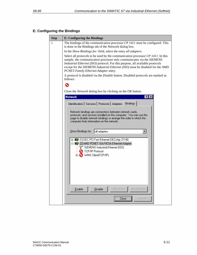
1 The bindings of the communication processor CP 1411 must be configured. Thisis done in the Bindings tab of the Network dialog box.
In the Show Bindings for: field, select the entry all adapters.
Select all protocols to be used by the communication processor CP 1411. In thissample, the communication processor only communicates via the SIEMENSIndustrial Ethernet (ISO) protocol. For this purpose, all available protocolsexcept for the SIEMENS Industrial Ethernet (ISO) must be disabled for the AMDPCNET-Family Ethernet-Adapter entry.
A protocol is disabled via the Disable button. Disabled protocols are marked asfollows:
Close the Network dialog box by clicking on the OK button.
Communication to the SIMATIC S7 via Industrial Ethernet (Softnet) 09.99
3-12 WinCC Communication ManualC79000-G8276-C156-01
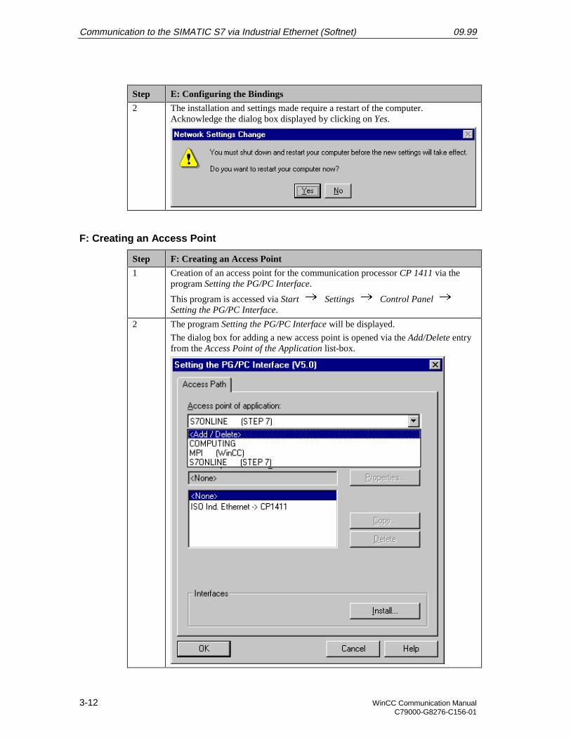
Step E: Configuring the Bindings
2 The installation and settings made require a restart of the computer.Acknowledge the dialog box displayed by clicking on Yes.
F: Creating an Access Point
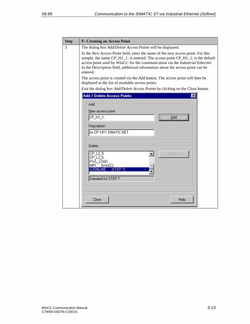
Step F: Creating an Access Point
1 Creation of an access point for the communication processor CP 1411 via theprogram Setting the PG/PC Interface.
This program is accessed via Start Settings Control Panel Setting the PG/PC Interface.
2 The program Setting the PG/PC Interface will be displayed.
The dialog box for adding a new access point is opened via the Add/Delete entryfrom the Access Point of the Application list-box.
09.99 Communication to the SIMATIC S7 via Industrial Ethernet (Softnet)
WinCC Communication Manual 3-13C79000-G8276-C156-01
Step F: Creating an Access Point
3 The dialog box Add/Delete Access Points will be displayed.
In the New Access Point field, enter the name of the new access point. For thissample, the name CP_H1_1: is entered. The access point CP_H1_1: is the defaultaccess point used by WinCC for the communication via the Industrial Ethernet.In the Description field, additional information about the access point can beentered.
The access point is created via the Add button. The access point will then bedisplayed in the list of available access points.
Exit the dialog box Add/Delete Access Points by clicking on the Close button.
Communication to the SIMATIC S7 via Industrial Ethernet (Softnet) 09.99
3-14 WinCC Communication ManualC79000-G8276-C156-01
Step F: Creating an Access Point
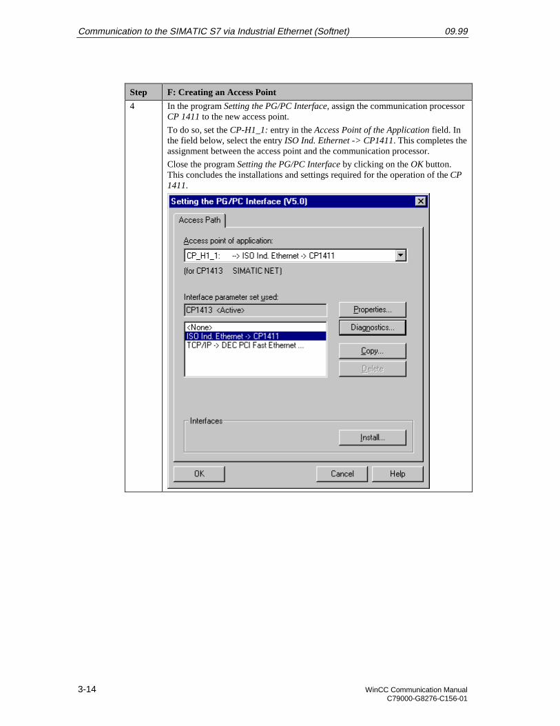
4 In the program Setting the PG/PC Interface, assign the communication processorCP 1411 to the new access point.
To do so, set the CP-H1_1: entry in the Access Point of the Application field. Inthe field below, select the entry ISO Ind. Ethernet -> CP1411. This completes theassignment between the access point and the communication processor.
Close the program Setting the PG/PC Interface by clicking on the OK button.This concludes the installations and settings required for the operation of the CP1411.
09.99 Communication to the SIMATIC S7 via Industrial Ethernet (Softnet)
WinCC Communication Manual 3-15C79000-G8276-C156-01
G: Testing the Communication Processor
Step G: Testing the Communication Processor
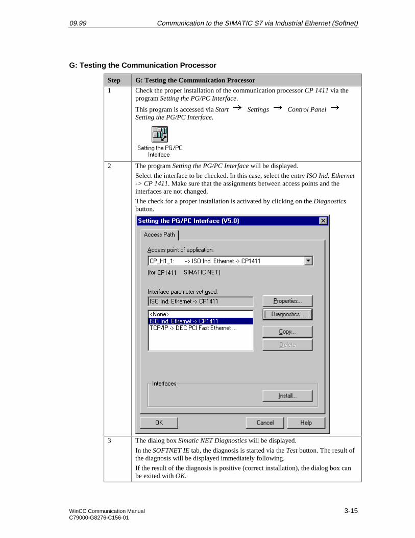
1 Check the proper installation of the communication processor CP 1411 via theprogram Setting the PG/PC Interface.
This program is accessed via Start Settings Control Panel Setting the PG/PC Interface.
2 The program Setting the PG/PC Interface will be displayed.
Select the interface to be checked. In this case, select the entry ISO Ind. Ethernet-> CP 1411. Make sure that the assignments between access points and theinterfaces are not changed.
The check for a proper installation is activated by clicking on the Diagnosticsbutton.
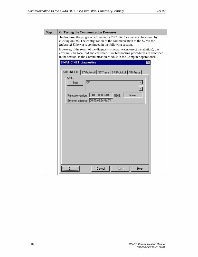
3 The dialog box Simatic NET Diagnostics will be displayed.
In the SOFTNET IE tab, the diagnosis is started via the Test button. The result ofthe diagnosis will be displayed immediately following.
If the result of the diagnosis is positive (correct installation), the dialog box canbe exited with OK.
Communication to the SIMATIC S7 via Industrial Ethernet (Softnet) 09.99
3-16 WinCC Communication ManualC79000-G8276-C156-01
Step G: Testing the Communication Processor
In this case, the program Setting the PG/PC Interface can also be closed byclicking on OK. The configuration of the communication to the S7 via theIndustrial Ethernet is continued in the following section.
However, if the result of the diagnosis is negative (incorrect installation), theerror must be localized and corrected. Troubleshooting procedures are describedin the section Is the Communication Module in the Computer operational?.
09.99 Communication to the SIMATIC S7 via Industrial Ethernet (Softnet)
WinCC Communication Manual 3-17C79000-G8276-C156-01
3.2 Creation of the STEP7 Project S7_IES
The following description details the configuration steps necessary to create and start up theSTEP7 project S7_IES.
Overview of the Configuration Steps
The following lists the configuration steps necessary to create the STEP7 project S7_IES:
• A: Installing the Hardware
• B: Installing the Option Package
• C: Creating the STEP7 Project
• D: Configuring the Hardware
• E: Loading the Hardware Configuration
• F: Testing the Hardware Configuration
• G: Creating the STEP7 Program
• H: Testing the STEP7 Program
A: Installing the Hardware
Step A: Installing the Hardware
1 Rack-mounting of the modules used.
In this sample, the modules to be installed are the power supply PS 407 10A, theCPU module CPU 416-1 and the communication processor CP 443-1.
Establishing the connection from the computer to the programming interface ofthe CPU module.
Establishing the connection from the communication processor CP 1411 in thecomputer to the communication processor CP 443-1 in the PLC.
B: Installing the Option Package
Step B: Installing the Option Package
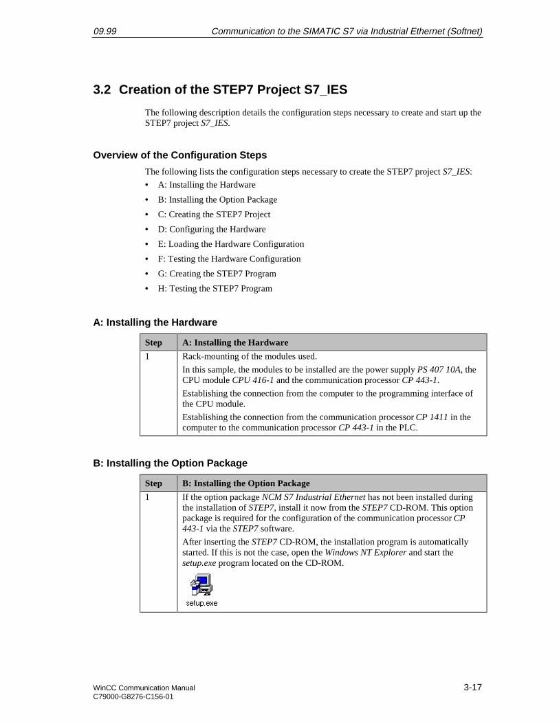
1 If the option package NCM S7 Industrial Ethernet has not been installed duringthe installation of STEP7, install it now from the STEP7 CD-ROM. This optionpackage is required for the configuration of the communication processor CP443-1 via the STEP7 software.
After inserting the STEP7 CD-ROM, the installation program is automaticallystarted. If this is not the case, open the Windows NT Explorer and start thesetup.exe program located on the CD-ROM.
Communication to the SIMATIC S7 via Industrial Ethernet (Softnet) 09.99
3-18 WinCC Communication ManualC79000-G8276-C156-01
Step B: Installing the Option Package
2 This starts the installation program.
Follow the instructions of the installation program. On the Components page,select the check-box NCM S7 Ind. Ethernet. Finish the installation.
C: Creating the STEP7 Project
Step C: Creating the STEP7 Project
1 Create a new STEP7 project in the SIMATIC Manager.
It is started via Start Simatic SIMATIC Manager.
2 This displays the SIMATIC Manager.
Via the menus File New, the dialog box for specifying the parameters of anew STEP7 project will be opened.
The New dialog box will be displayed.
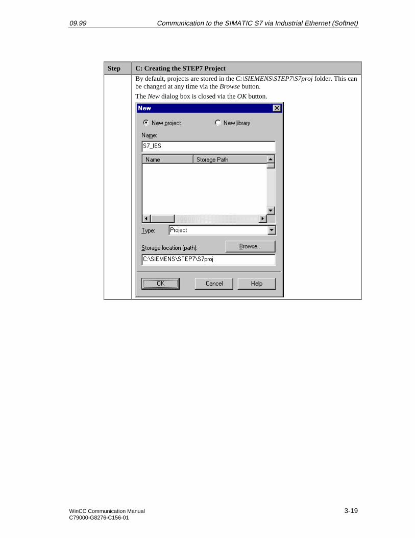
The radio-button New Project must be selected. In the Name field, the name ofthe new project to be created is entered. The names of the STEP7 projects createdwithin the framework of this manual all start with S7. They also include areference to the communication type used. The project of this sample has thename S7_IES.
09.99 Communication to the SIMATIC S7 via Industrial Ethernet (Softnet)
WinCC Communication Manual 3-19C79000-G8276-C156-01
Step C: Creating the STEP7 Project
By default, projects are stored in the C:\SIEMENS\STEP7\S7proj folder. This canbe changed at any time via the Browse button.
The New dialog box is closed via the OK button.
Communication to the SIMATIC S7 via Industrial Ethernet (Softnet) 09.99
3-20 WinCC Communication ManualC79000-G8276-C156-01
D: Configuring the Hardware
Step D: Configuring the Hardware
1 The new project will be displayed in the SIMATIC Manager.
The hardware for this project must be configured. Two components are needed:One SIMATIC 400-Station and for its networking an Industrial Ethernet.
These components are added to the SIMATIC Manager via a 8R on the project
name S7_IES and then selecting Insert New Object SIMATIC 400-Stationand Insert New Object Industrial Ethernet from the pop-up menu.
2 The just added components will be displayed in the right window of theSIMATIC Manager.
09.99 Communication to the SIMATIC S7 via Industrial Ethernet (Softnet)
WinCC Communication Manual 3-21C79000-G8276-C156-01
Step D: Configuring the Hardware
By 8D on the component SIMATIC 400(1) in the right window, the point
Hardware will be displayed. By 8D on the point Hardware or 8D on it andthen selecting Open Object from the pop-up menu, the program HW Config willbe started.
3 The program HW Config will be displayed.
This program is used to exactly define the hardware used in the PLC and toconfigure their properties.
4 By clicking on the toolbar button of the program HW Config displayed below, theHardware Catalog is opened. This catalog is used to select the required hardwarecomponents.
Communication to the SIMATIC S7 via Industrial Ethernet (Softnet) 09.99
3-22 WinCC Communication ManualC79000-G8276-C156-01
Step D: Configuring the Hardware
5 The Hardware Catalog will be displayed.
The first component selected is the rack. On this rack, all other components will
be installed. The rack is inserted into the project via a 8D or by DraggingDropping. In this sample, the rack type UR1 is used.
6 The program HW Config will display the currently still empty rack. It receivedthe Rack Number 0. During the configuration of the connection in the WinCCproject, the Rack Number is one of the parameters that must be set.
7 Arrange the other hardware components in the rack. This is done by DraggingDropping the desired components from the Hardware Catalog to thecorresponding slot in the rack.
09.99 Communication to the SIMATIC S7 via Industrial Ethernet (Softnet)
WinCC Communication Manual 3-23C79000-G8276-C156-01
Step D: Configuring the Hardware
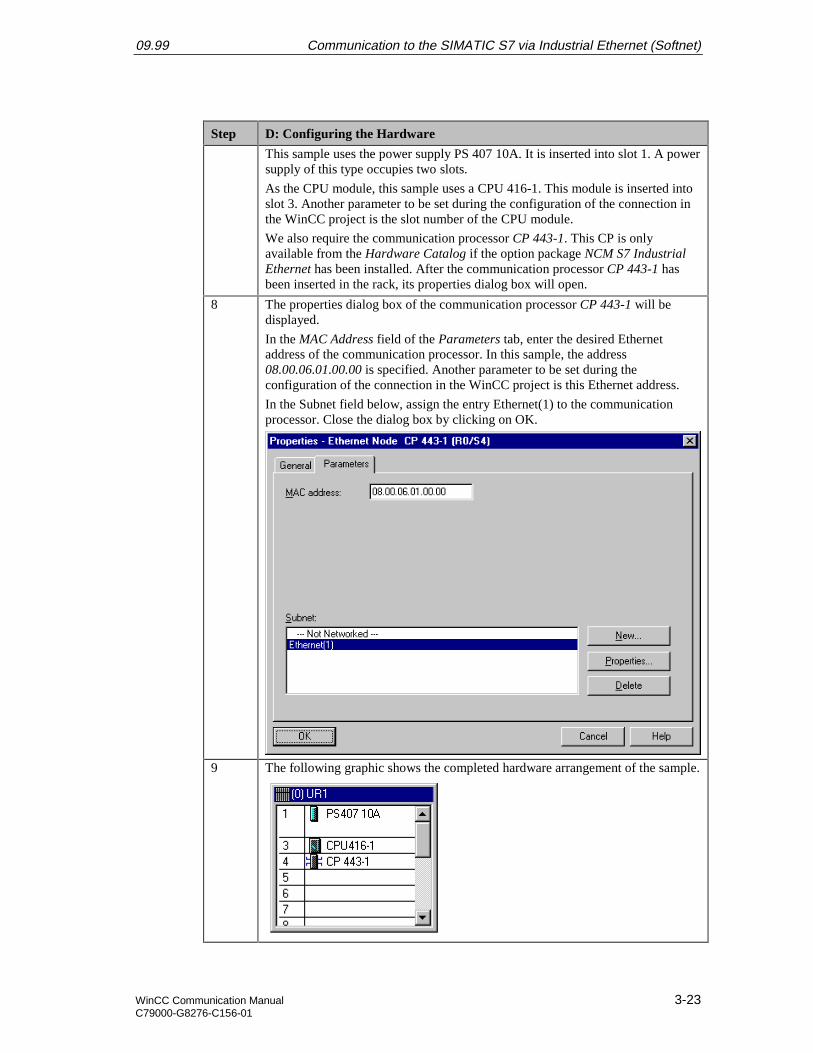
This sample uses the power supply PS 407 10A. It is inserted into slot 1. A powersupply of this type occupies two slots.
As the CPU module, this sample uses a CPU 416-1. This module is inserted intoslot 3. Another parameter to be set during the configuration of the connection inthe WinCC project is the slot number of the CPU module.
We also require the communication processor CP 443-1. This CP is onlyavailable from the Hardware Catalog if the option package NCM S7 IndustrialEthernet has been installed. After the communication processor CP 443-1 hasbeen inserted in the rack, its properties dialog box will open.
8 The properties dialog box of the communication processor CP 443-1 will bedisplayed.
In the MAC Address field of the Parameters tab, enter the desired Ethernetaddress of the communication processor. In this sample, the address08.00.06.01.00.00 is specified. Another parameter to be set during theconfiguration of the connection in the WinCC project is this Ethernet address.
In the Subnet field below, assign the entry Ethernet(1) to the communicationprocessor. Close the dialog box by clicking on OK.
9 The following graphic shows the completed hardware arrangement of the sample.
Communication to the SIMATIC S7 via Industrial Ethernet (Softnet) 09.99
3-24 WinCC Communication ManualC79000-G8276-C156-01
Step D: Configuring the Hardware
10 Save the settings made in the program HW Config. This is done via the toolbarbutton displayed below.
E: Loading the Hardware Configuration
Step E: Loading the Hardware Configuration
1 The hardware configuration created in the program HW Config must betransferred to the PLC.
This is done via the toolbar button displayed below.
2 A dialog box will be displayed from which the components to be loaded can beselected.
For this sample, all displayed components will be selected. Note that loading tothe CPU module is only possible while the operating mode switch is set to STOPor RUN-P. Close the dialog box by clicking on OK.
09.99 Communication to the SIMATIC S7 via Industrial Ethernet (Softnet)
WinCC Communication Manual 3-25C79000-G8276-C156-01
Step E: Loading the Hardware Configuration
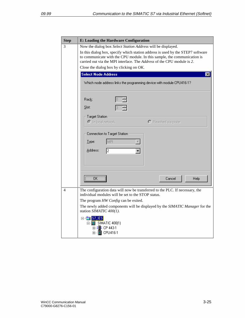
3 Now the dialog box Select Station Address will be displayed.
In this dialog box, specify which station address is used by the STEP7 softwareto communicate with the CPU module. In this sample, the communication iscarried out via the MPI interface. The Address of the CPU module is 2.
Close the dialog box by clicking on OK.
4 The configuration data will now be transferred to the PLC. If necessary, theindividual modules will be set to the STOP status.
The program HW Config can be exited.
The newly added components will be displayed by the SIMATIC Manager for thestation SIMATIC 400(1).
Communication to the SIMATIC S7 via Industrial Ethernet (Softnet) 09.99
3-26 WinCC Communication ManualC79000-G8276-C156-01
F: Testing the Hardware Configuration
Step F: Testing the Hardware Configuration
1 Testing of the hardware configuration made.
If the key switch of the CPU module is set to RUN or RUN-P and the operatingmode switch of the communication processor is set to RUN, only the status LEDssignifying the RUN operating mode should be displayed.
If this is not the case, there is an error. The following steps help you localize thiserror. However, these steps should still be performed even if the status LEDsshow no error. This allows you to recognize uncritical errors and faultyconfigurations.
09.99 Communication to the SIMATIC S7 via Industrial Ethernet (Softnet)
WinCC Communication Manual 3-27C79000-G8276-C156-01
Step F: Testing the Hardware Configuration
2 Testing the configuration of the CPU module.
This is done via the dialog box Module Status in the SIMATIC Manager. It is
opened by a R on the entry of the CPU module in the left window and thenselecting Target System Module Status from the pop-up menu.
The dialog box Module Status of the CPU module will be displayed.
The General tab displays various general data of the CPU module. In the Statusfield, the current module status and any existing errors are displayed.
The Diagnosis Buffer tab contains more detailed information about existingerrors and how to correct them.
The dialog box can be exited via the Close button.

Communication to the SIMATIC S7 via Industrial Ethernet (Softnet) 09.99
3-28 WinCC Communication ManualC79000-G8276-C156-01
Step F: Testing the Hardware Configuration
3 Testing the configuration of the communication processor.
This is done via the dialog box Module Status in the SIMATIC Manager. It is
opened by a R on the entry of the communication processor in the leftwindow and then selecting Target System Module Status from the pop-upmenu.
The dialog box Module Status of the communication processor will be displayed.
The General tab displays various general data of the module.
A dialog box for a more detailed diagnosis of the communication processor canbe accessed via the Special Diagnosis button.
09.99 Communication to the SIMATIC S7 via Industrial Ethernet (Softnet)
WinCC Communication Manual 3-29C79000-G8276-C156-01
Step F: Testing the Hardware Configuration
4 The dialog box NCM S7 Industrial Ethernet Diagnosis will be displayed.
The CP Information tab displays general information about the module. Amongother things, the network address set can be checked.
The dialog box can be exited via the Close button. The Module Status dialog boxcan also be exited via the Close button.
Communication to the SIMATIC S7 via Industrial Ethernet (Softnet) 09.99
3-30 WinCC Communication ManualC79000-G8276-C156-01
G: Creating the STEP7 Program
Step G: Creating the STEP7 Program
1 Creation of the S7 Program.
This sample project requires the operation block OB1 and a data block. OB1 isavailable by default, the required data block must be created. This is done in the
SIMATIC Manager via a R on the sub-entry Modules of the entry S7Program(1) of the configured CPU module and then selecting Insert New Object
Data Block from the pop-up menu.
The properties dialog box of the data block will be opened. As the block’s Nameenter DB75 and close the dialog box with OK.
2 The newly created data block DB75 will be displayed in the right window of theproject.
Via a D on this data block or a R and then selecting Open Object from thepop-up menu, the content of the block can be programmed. This starts theprogram LAD/STL/SCF.
09.99 Communication to the SIMATIC S7 via Industrial Ethernet (Softnet)
WinCC Communication Manual 3-31C79000-G8276-C156-01
Step G: Creating the STEP7 Program
3 The program LAD/STL/SCF is displayed.
Acknowledge the dialog box New Data Block by clicking on OK.
4 Programming the DB75.
In this data block, two tags with a length of 16 Bits are created. Their sum is tobe determined in OB1 and then be written to another tag with a length of 16 Bits.
Two additional tags with a length of 16 Bits are created, whose values arecyclically incremented in OB1.
The tags created in the data block DB75 are visualized in the WinCC project. Todo so, WinCC tags with corresponding addresses are created there.
The following graphic displays the programmed data block DB75.
5 Save the block and load it into the PLC. This is done via the toolbar buttondisplayed below. Note that loading to the CPU module is only possible while theoperating mode switch is set to STOP or RUN-P.
6 Programming the OB1.
Open the block in the program LAD/STL/SCF.
First, two values in the DB75 are added and then stored again in DB75.
Next, a value in the DB75 is incremented every second.
Communication to the SIMATIC S7 via Industrial Ethernet (Softnet) 09.99
3-32 WinCC Communication ManualC79000-G8276-C156-01
Step G: Creating the STEP7 Program
Finally, a value in the DB75 is incremented every time the OB1 run.
7 Save the block OB1 and load it into the PLC. This is done via the correspondingbuttons on the toolbar.
This completes the creation of the STEP7 project and it can now be run. Exit theprogram LAD/STL/SCF.
09.99 Communication to the SIMATIC S7 via Industrial Ethernet (Softnet)
WinCC Communication Manual 3-33C79000-G8276-C156-01
H: Testing the STEP7 Program
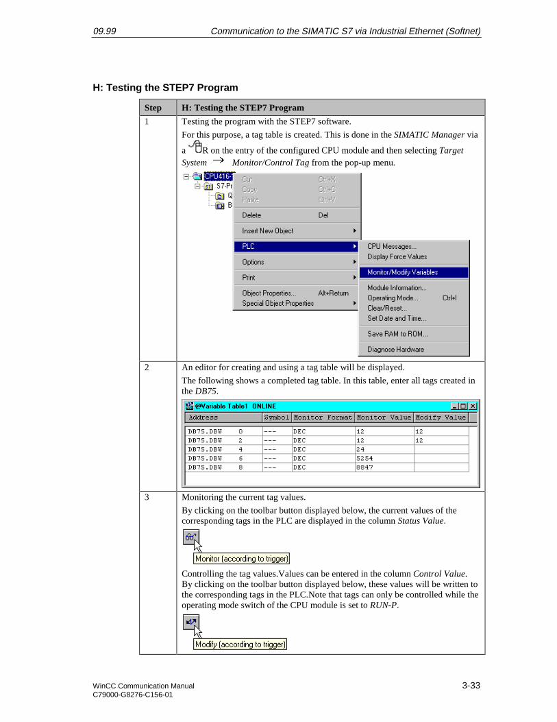
Step H: Testing the STEP7 Program
1 Testing the program with the STEP7 software.
For this purpose, a tag table is created. This is done in the SIMATIC Manager via
a R on the entry of the configured CPU module and then selecting TargetSystem Monitor/Control Tag from the pop-up menu.
2 An editor for creating and using a tag table will be displayed.
The following shows a completed tag table. In this table, enter all tags created inthe DB75.
3 Monitoring the current tag values.
By clicking on the toolbar button displayed below, the current values of thecorresponding tags in the PLC are displayed in the column Status Value.
Controlling the tag values.Values can be entered in the column Control Value.By clicking on the toolbar button displayed below, these values will be written tothe corresponding tags in the PLC.Note that tags can only be controlled while theoperating mode switch of the CPU module is set to RUN-P.

Communication to the SIMATIC S7 via Industrial Ethernet (Softnet) 09.99
3-34 WinCC Communication ManualC79000-G8276-C156-01
Step H: Testing the STEP7 Program
4 The created tag table can now be saved.
In this sample, the table is saved under the name VAT1. After checking theprogram in the PLC, the tag table can be closed. This concludes the configurationof the STEP7 project and the SIMATIC Manager can be exited.
09.99 Communication to the SIMATIC S7 via Industrial Ethernet (Softnet)
WinCC Communication Manual 3-35C79000-G8276-C156-01
3.3 Creation of the WinCC Project WinCC_S7_IES
The following description details the configuration steps necessary to create and start up theWinCC project WinCC_S7_IES.
Overview of the Configuration Steps
The following lists the configuration steps necessary to create the WinCC projectWinCC_S7_IES:
• A: Creating the WinCC Project
• B: Creating the Connection
• C: Creating the WinCC Tags
• D: Creating the WinCC Screen
A: Creating the WinCC Project
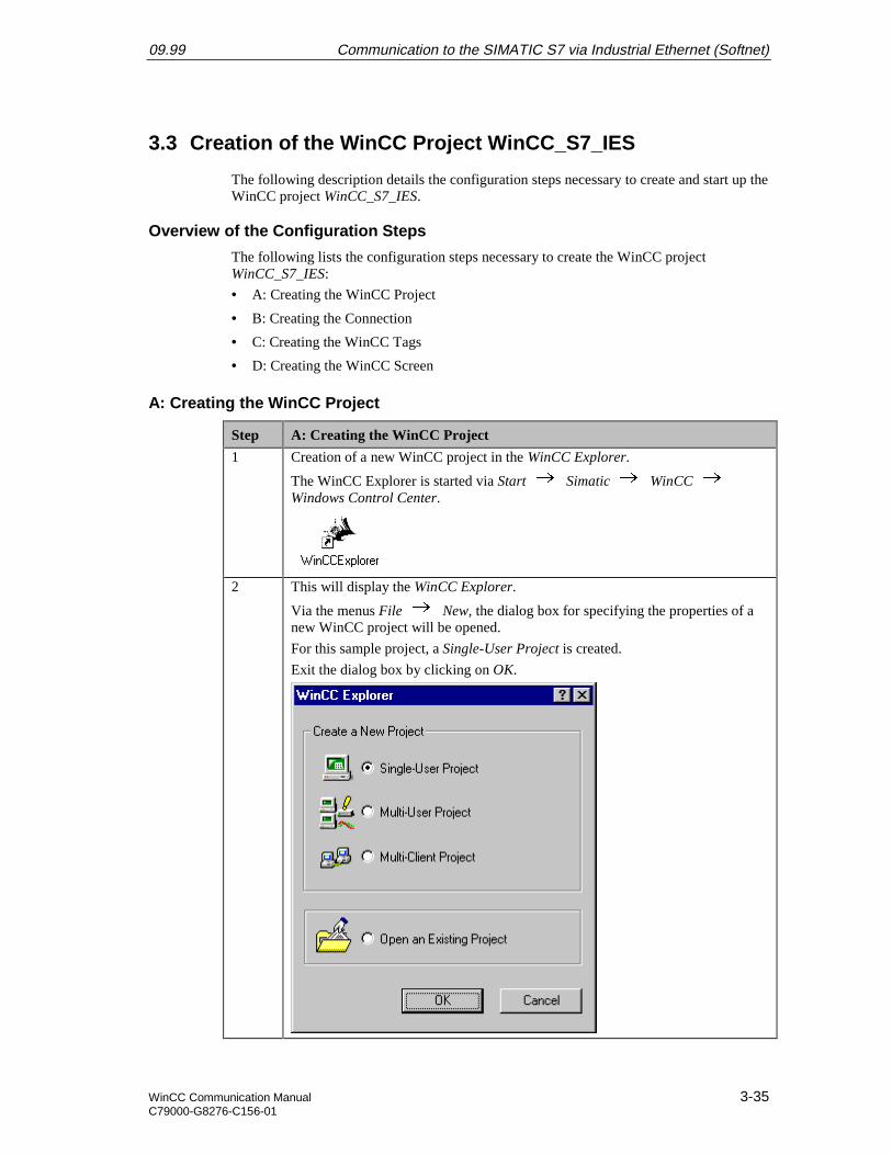
Step A: Creating the WinCC Project
1 Creation of a new WinCC project in the WinCC Explorer.
The WinCC Explorer is started via Start Simatic WinCC Windows Control Center.
2 This will display the WinCC Explorer.
Via the menus File New, the dialog box for specifying the properties of anew WinCC project will be opened.
For this sample project, a Single-User Project is created.
Exit the dialog box by clicking on OK.
Communication to the SIMATIC S7 via Industrial Ethernet (Softnet) 09.99
3-36 WinCC Communication ManualC79000-G8276-C156-01
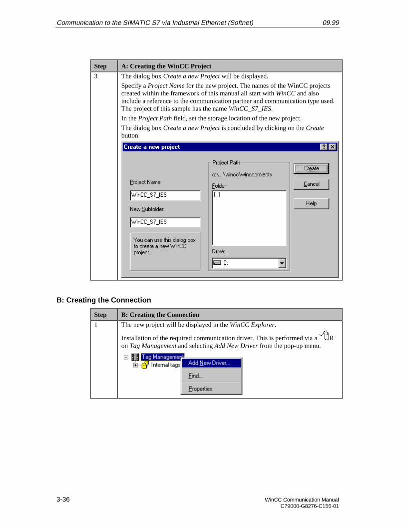
Step A: Creating the WinCC Project
3 The dialog box Create a new Project will be displayed.
Specify a Project Name for the new project. The names of the WinCC projectscreated within the framework of this manual all start with WinCC and alsoinclude a reference to the communication partner and communication type used.The project of this sample has the name WinCC_S7_IES.
In the Project Path field, set the storage location of the new project.
The dialog box Create a new Project is concluded by clicking on the Createbutton.
B: Creating the Connection
Step B: Creating the Connection
1 The new project will be displayed in the WinCC Explorer.
Installation of the required communication driver. This is performed via a Ron Tag Management and selecting Add New Driver from the pop-up menu.
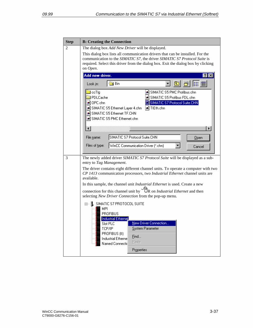
09.99 Communication to the SIMATIC S7 via Industrial Ethernet (Softnet)
WinCC Communication Manual 3-37C79000-G8276-C156-01
Step B: Creating the Connection
2 The dialog box Add New Driver will be displayed.
This dialog box lists all communication drivers that can be installed. For thecommunication to the SIMATIC S7, the driver SIMATIC S7 Protocol Suite isrequired. Select this driver from the dialog box. Exit the dialog box by clickingon Open.
3 The newly added driver SIMATIC S7 Protocol Suite will be displayed as a sub-entry to Tag Management.
The driver contains eight different channel units. To operate a computer with twoCP 1413 communication processors, two Industrial Ethernet channel units areavailable.
In this sample, the channel unit Industrial Ethernet is used. Create a new
connection for this channel unit by R on Industrial Ethernet and thenselecting New Driver Connection from the pop-up menu.

Communication to the SIMATIC S7 via Industrial Ethernet (Softnet) 09.99
3-38 WinCC Communication ManualC79000-G8276-C156-01
Step B: Creating the Connection
4 The properties dialog box of the connection will be displayed.
In the General tab, the Name of the new connection is entered. In this sample,this is S7_IES_01.
Click on the Properties button to define the connection properties.
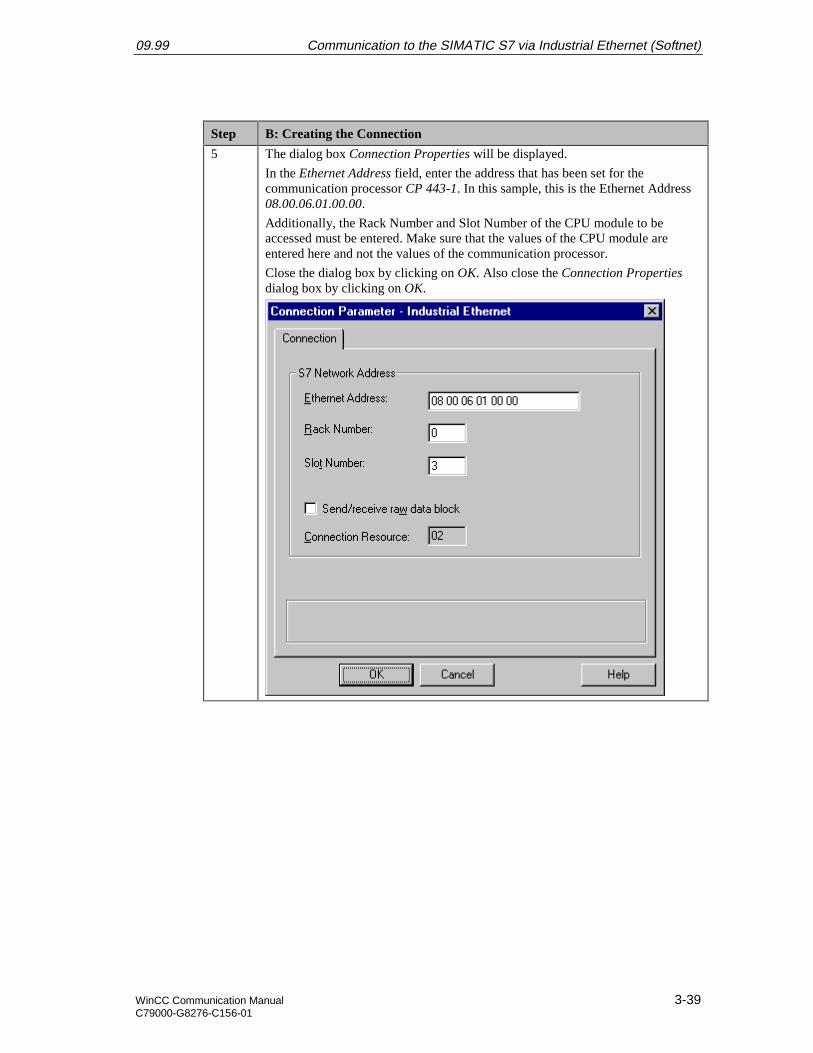
09.99 Communication to the SIMATIC S7 via Industrial Ethernet (Softnet)
WinCC Communication Manual 3-39C79000-G8276-C156-01
Step B: Creating the Connection
5 The dialog box Connection Properties will be displayed.
In the Ethernet Address field, enter the address that has been set for thecommunication processor CP 443-1. In this sample, this is the Ethernet Address08.00.06.01.00.00.
Additionally, the Rack Number and Slot Number of the CPU module to beaccessed must be entered. Make sure that the values of the CPU module areentered here and not the values of the communication processor.
Close the dialog box by clicking on OK. Also close the Connection Propertiesdialog box by clicking on OK.

Communication to the SIMATIC S7 via Industrial Ethernet (Softnet) 09.99
3-40 WinCC Communication ManualC79000-G8276-C156-01
Step B: Creating the Connection
6 Setting the system parameters of the Industrial Ethernet channel unit.
These settings are made in the System Parameters dialog box, which is accessed
via a R on the Industrial Ethernet entry and then selecting System Parametersfrom the pop-up menu.
In the Channel tab, various settings pertaining to the communication andmonitoring a communication can be made. These settings will apply to allchannel units of the communication driver.
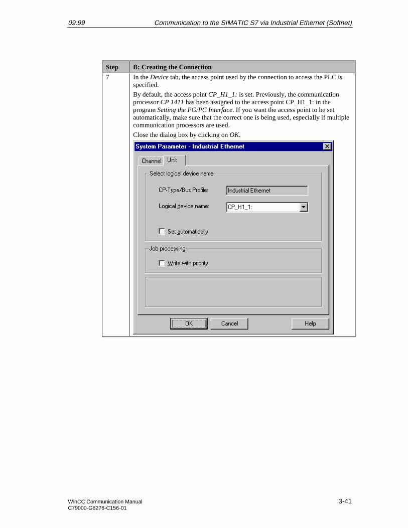
09.99 Communication to the SIMATIC S7 via Industrial Ethernet (Softnet)
WinCC Communication Manual 3-41C79000-G8276-C156-01
Step B: Creating the Connection
7 In the Device tab, the access point used by the connection to access the PLC isspecified.
By default, the access point CP_H1_1: is set. Previously, the communicationprocessor CP 1411 has been assigned to the access point CP_H1_1: in theprogram Setting the PG/PC Interface. If you want the access point to be setautomatically, make sure that the correct one is being used, especially if multiplecommunication processors are used.
Close the dialog box by clicking on OK.
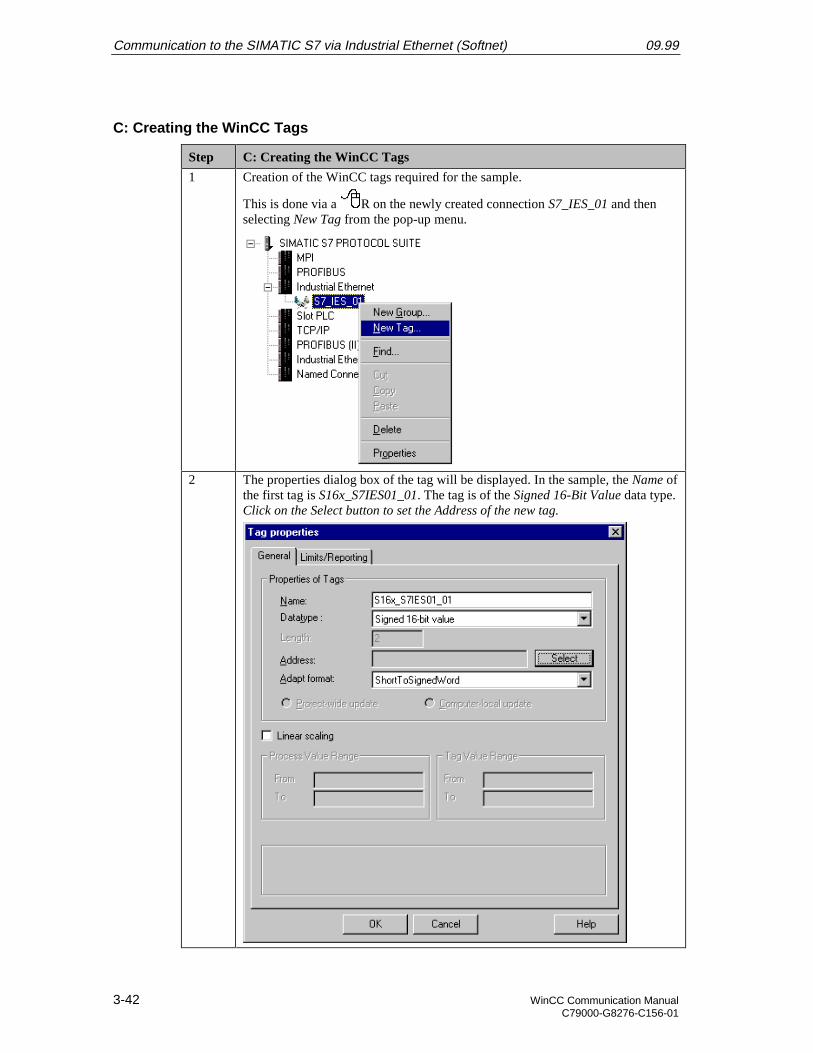
Communication to the SIMATIC S7 via Industrial Ethernet (Softnet) 09.99
3-42 WinCC Communication ManualC79000-G8276-C156-01
C: Creating the WinCC Tags
Step C: Creating the WinCC Tags
1 Creation of the WinCC tags required for the sample.
This is done via a R on the newly created connection S7_IES_01 and thenselecting New Tag from the pop-up menu.
2 The properties dialog box of the tag will be displayed. In the sample, the Name ofthe first tag is S16x_S7IES01_01. The tag is of the Signed 16-Bit Value data type.Click on the Select button to set the Address of the new tag.
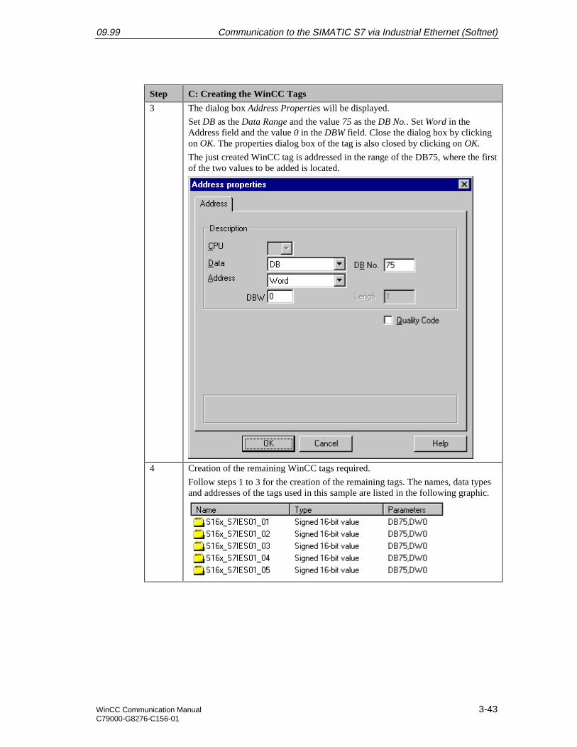
09.99 Communication to the SIMATIC S7 via Industrial Ethernet (Softnet)
WinCC Communication Manual 3-43C79000-G8276-C156-01
Step C: Creating the WinCC Tags
3 The dialog box Address Properties will be displayed.
Set DB as the Data Range and the value 75 as the DB No.. Set Word in theAddress field and the value 0 in the DBW field. Close the dialog box by clickingon OK. The properties dialog box of the tag is also closed by clicking on OK.
The just created WinCC tag is addressed in the range of the DB75, where the firstof the two values to be added is located.
4 Creation of the remaining WinCC tags required.
Follow steps 1 to 3 for the creation of the remaining tags. The names, data typesand addresses of the tags used in this sample are listed in the following graphic.
Communication to the SIMATIC S7 via Industrial Ethernet (Softnet) 09.99
3-44 WinCC Communication ManualC79000-G8276-C156-01
D: Creating the WinCC Screen
Step D: Creating the WinCC Screen
1 Creation of a WinCC screen in which the previously created tags are visualized.
Open the Graphics Designer editor via a R and then selecting Open from thepop-up menu.
2 This will open the Graphics Designer editor with a new (blank) screen.
To display the first tag, configure a Smart Object I/O Field. To do so,select the I/O Field object from the Object Palette and place it on the screenusing the mouse.
3 After placing the I/O Field on the screen, its Configuration dialog box will bedisplayed.
In the Tag field, set the tag S16x_S7IES01_01 via the button displayed below.
09.99 Communication to the SIMATIC S7 via Industrial Ethernet (Softnet)
WinCC Communication Manual 3-45C79000-G8276-C156-01
Step D: Creating the WinCC Screen
The Update of the tag is set to Upon Change. Keep the default settings for theremaining options. Close the dialog box by clicking on OK.
4 Changing the output format of the I/O Field.
For this, open its properties dialog box via a R on the I/O Field and thenselect Properties from the pop-up menu.
Communication to the SIMATIC S7 via Industrial Ethernet (Softnet) 09.99
3-46 WinCC Communication ManualC79000-G8276-C156-01
Step D: Creating the WinCC Screen
5 The dialog box Object Properties will be displayed.
On the left side of the Properties tab, select the entry Output/Input. Via a Don the output format set, the field can be edited. Select the new format s99999.This format enables the I/O Field to display signed values with a maximum of 5digits.
6 Creation of four additional I/O Fields for the display of the remaining tags.
Follow steps 2 to 5 to create the remaining I/O fields.
7 Save the screen.
In the sample project, the screen is saved under the name com_3_S7IES_01.pdl.The screen can be switched directly to runtime from the Graphics Designer viathe button displayed below.

09.99 Communication to the SIMATIC S7 via Industrial Ethernet (Softnet)
WinCC Communication Manual 3-47C79000-G8276-C156-01
Step D: Creating the WinCC Screen
If the screen is in runtime, the PLC started and the network connectionestablished, the current values of the PLC will be displayed in the I/O fields.They can be changed by entering values in the individual I/O Fields.
If there is no connection to the PLC, the I/O Fields will be displayed grayed out.In this case an error is present at some point of the communication connection.
Communication to the SIMATIC S7 via Industrial Ethernet (Softnet) 09.99
3-48 WinCC Communication ManualC79000-G8276-C156-01
3.4 Diagnosis of the Communication Connection
The following describes the options available for diagnosing the communication connectionbetween the WinCC project WinCC_S7_IES and the SIMATIC S7 station.A diagnosis of the sample according to this description makes only sense, if the checkslisted below have been completed successfully.Startup of the Communication Processor CP 1411
• G: Testing the Communication ProcessorCreation of the STEP7 Project S7_IES
• F: Testing the Hardware Configuration
• I: Testing the STEP7 Program
WinCC Explorer
Step WinCC Explorer
1 Diagnosis of the communication connection in the WinCC Explorer.
Switch the project WinCC_S7_IES into runtime. This is done from the WinCCExplorer via the toolbar button displayed below.
The created WinCC screen com_3_S7IES_01.pdl can also be switched directlyfrom the Graphics Designer into runtime.
2 In the WinCC Explorer, a dialog box for monitoring all configured connectionscan be accessed via the Tools Status of Driver Connections menu. Thismenu point is only accessible if the project is in runtime.
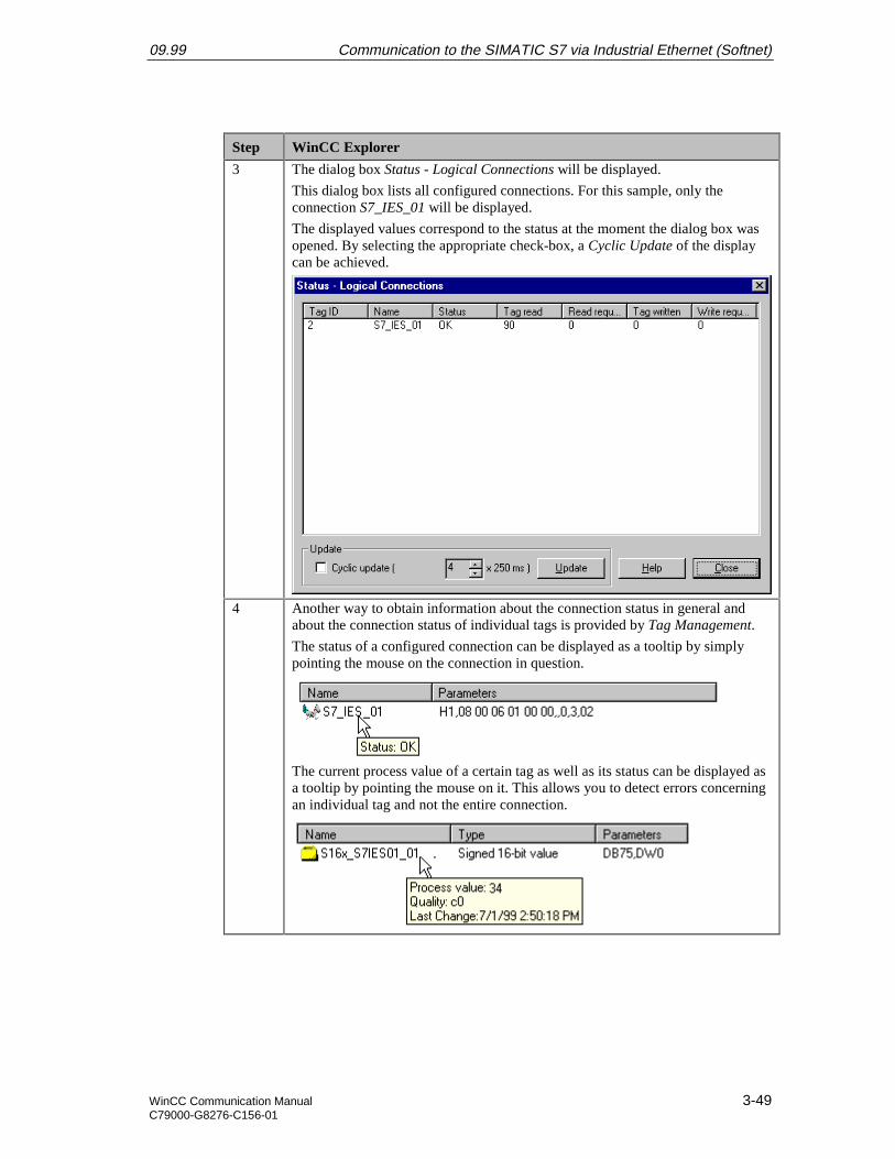
09.99 Communication to the SIMATIC S7 via Industrial Ethernet (Softnet)
WinCC Communication Manual 3-49C79000-G8276-C156-01
Step WinCC Explorer
3 The dialog box Status - Logical Connections will be displayed.
This dialog box lists all configured connections. For this sample, only theconnection S7_IES_01 will be displayed.
The displayed values correspond to the status at the moment the dialog box wasopened. By selecting the appropriate check-box, a Cyclic Update of the displaycan be achieved.
4 Another way to obtain information about the connection status in general andabout the connection status of individual tags is provided by Tag Management.
The status of a configured connection can be displayed as a tooltip by simplypointing the mouse on the connection in question.
The current process value of a certain tag as well as its status can be displayed asa tooltip by pointing the mouse on it. This allows you to detect errors concerningan individual tag and not the entire connection.
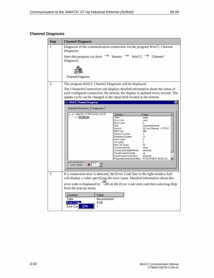
Communication to the SIMATIC S7 via Industrial Ethernet (Softnet) 09.99
3-50 WinCC Communication ManualC79000-G8276-C156-01
Channel Diagnosis
Step Channel Diagnosis
1 Diagnosis of the communication connection via the program WinCC ChannelDiagnosis.
Start this program via Start Simatic WinCC ChannelDiagnosis.
2 The program WinCC Channel Diagnosis will be displayed.
The Channels/Connections tab displays detailed information about the status ofeach configured connection. By default, the display is updated every second. Theupdate cycle can be changed in the input field located at the bottom.
3 If a connection error is detected, the Error Code line in the right window halfwill display a value specifying the error cause. Detailed information about this
error code is displayed by R on the Error Code entry and then selecting Helpfrom the pop-up menu.
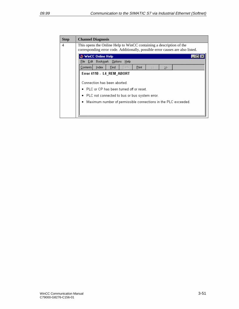
09.99 Communication to the SIMATIC S7 via Industrial Ethernet (Softnet)
WinCC Communication Manual 3-51C79000-G8276-C156-01
Step Channel Diagnosis
4 This opens the Online Help to WinCC containing a description of thecorresponding error code. Additionally, possible error causes are also listed.

Communication to the SIMATIC S7 via Industrial Ethernet (Softnet) 09.99
3-52 WinCC Communication ManualC79000-G8276-C156-01
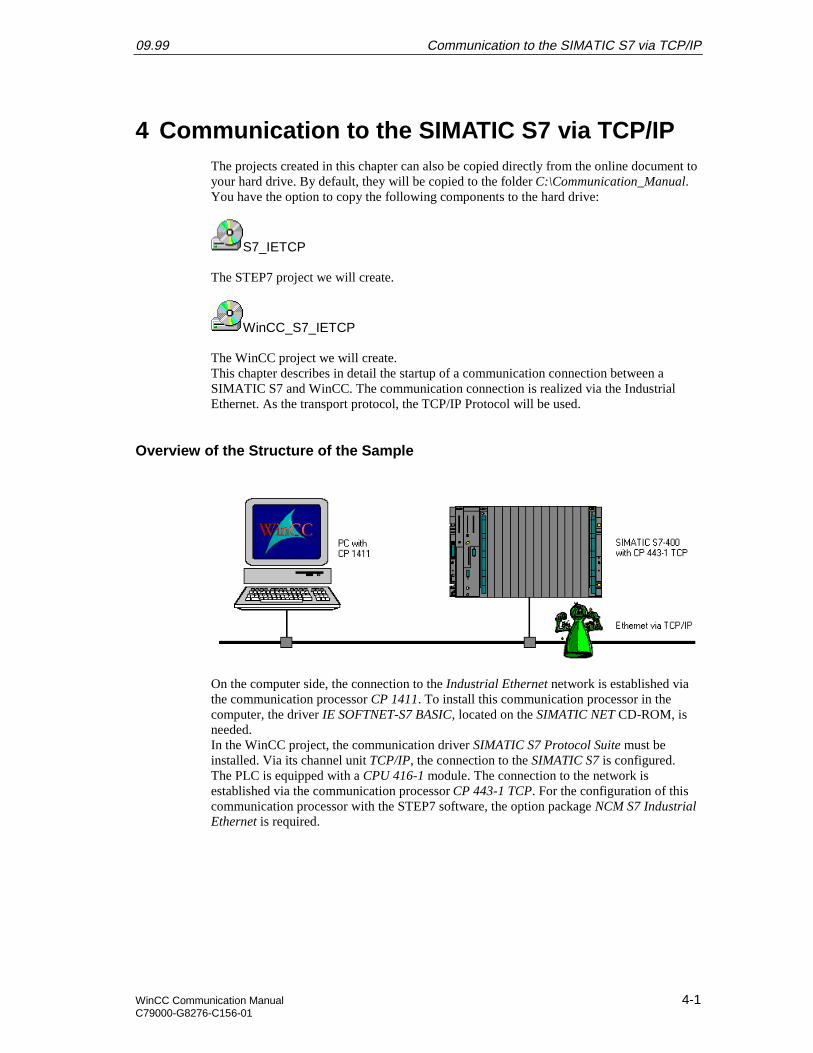
09.99 Communication to the SIMATIC S7 via TCP/IP
WinCC Communication Manual 4-1C79000-G8276-C156-01
4 Communication to the SIMATIC S7 via TCP/IPThe projects created in this chapter can also be copied directly from the online document toyour hard drive. By default, they will be copied to the folder C:\Communication_Manual.You have the option to copy the following components to the hard drive:
S7_IETCP
The STEP7 project we will create.
WinCC_S7_IETCP
The WinCC project we will create.This chapter describes in detail the startup of a communication connection between aSIMATIC S7 and WinCC. The communication connection is realized via the IndustrialEthernet. As the transport protocol, the TCP/IP Protocol will be used.
Overview of the Structure of the Sample
On the computer side, the connection to the Industrial Ethernet network is established viathe communication processor CP 1411. To install this communication processor in thecomputer, the driver IE SOFTNET-S7 BASIC, located on the SIMATIC NET CD-ROM, isneeded.In the WinCC project, the communication driver SIMATIC S7 Protocol Suite must beinstalled. Via its channel unit TCP/IP, the connection to the SIMATIC S7 is configured.The PLC is equipped with a CPU 416-1 module. The connection to the network isestablished via the communication processor CP 443-1 TCP. For the configuration of thiscommunication processor with the STEP7 software, the option package NCM S7 IndustrialEthernet is required.
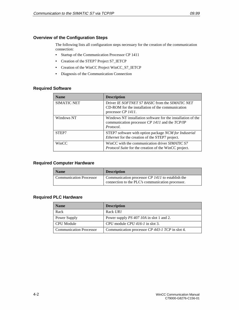
Communication to the SIMATIC S7 via TCP/IP 09.99
4-2 WinCC Communication ManualC79000-G8276-C156-01
Overview of the Configuration Steps
The following lists all configuration steps necessary for the creation of the communicationconnection:
• Startup of the Communication Processor CP 1411
• Creation of the STEP7 Project S7_IETCP
• Creation of the WinCC Project WinCC_S7_IETCP
• Diagnosis of the Communication Connection
Required Software
Name Description
SIMATIC NET Driver IE SOFTNET S7 BASIC from the SIMATIC NETCD-ROM for the installation of the communicationprocessor CP 1411.
Windows NT Windows NT installation software for the installation of thecommunication processor CP 1411 and the TCP/IPProtocol.
STEP7 STEP7 software with option package NCM for IndustrialEthernet for the creation of the STEP7 project.
WinCC WinCC with the communication driver SIMATIC S7Protocol Suite for the creation of the WinCC project.
Required Computer Hardware
Name Description
Communication Processor Communication processor CP 1411 to establish theconnection to the PLC’s communication processor.
Required PLC Hardware
Name Description
Rack Rack UR1
Power Supply Power supply PS 407 10A in slot 1 and 2.
CPU Module CPU module CPU 416-1 in slot 3.
Communication Processor Communication processor CP 443-1 TCP in slot 4.
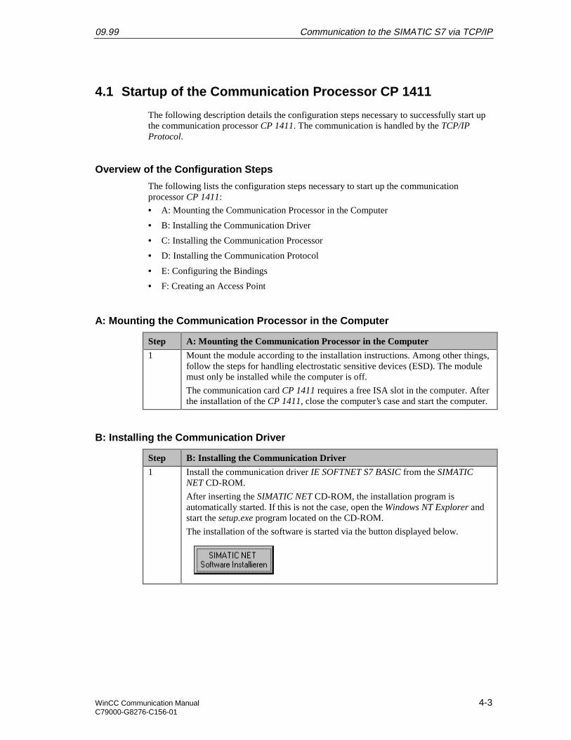
09.99 Communication to the SIMATIC S7 via TCP/IP
WinCC Communication Manual 4-3C79000-G8276-C156-01
4.1 Startup of the Communication Processor CP 1411
The following description details the configuration steps necessary to successfully start upthe communication processor CP 1411. The communication is handled by the TCP/IPProtocol.
Overview of the Configuration Steps
The following lists the configuration steps necessary to start up the communicationprocessor CP 1411:
• A: Mounting the Communication Processor in the Computer
• B: Installing the Communication Driver
• C: Installing the Communication Processor
• D: Installing the Communication Protocol
• E: Configuring the Bindings
• F: Creating an Access Point
A: Mounting the Communication Processor in the Computer
Step A: Mounting the Communication Processor in the Computer
1 Mount the module according to the installation instructions. Among other things,follow the steps for handling electrostatic sensitive devices (ESD). The modulemust only be installed while the computer is off.
The communication card CP 1411 requires a free ISA slot in the computer. Afterthe installation of the CP 1411, close the computer’s case and start the computer.
B: Installing the Communication Driver
Step B: Installing the Communication Driver
1 Install the communication driver IE SOFTNET S7 BASIC from the SIMATICNET CD-ROM.
After inserting the SIMATIC NET CD-ROM, the installation program isautomatically started. If this is not the case, open the Windows NT Explorer andstart the setup.exe program located on the CD-ROM.
The installation of the software is started via the button displayed below.
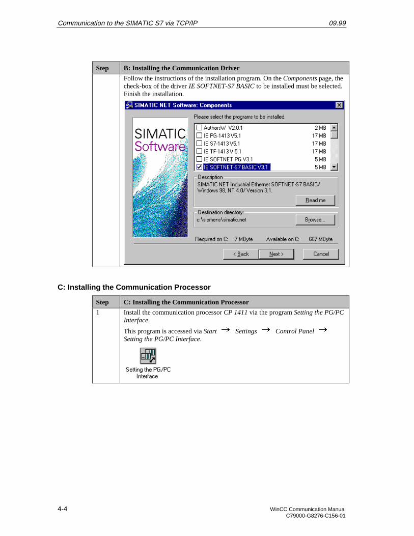
Communication to the SIMATIC S7 via TCP/IP 09.99
4-4 WinCC Communication ManualC79000-G8276-C156-01
Step B: Installing the Communication Driver
Follow the instructions of the installation program. On the Components page, thecheck-box of the driver IE SOFTNET-S7 BASIC to be installed must be selected.Finish the installation.
C: Installing the Communication Processor
Step C: Installing the Communication Processor
1 Install the communication processor CP 1411 via the program Setting the PG/PCInterface.
This program is accessed via Start Settings Control Panel Setting the PG/PC Interface.
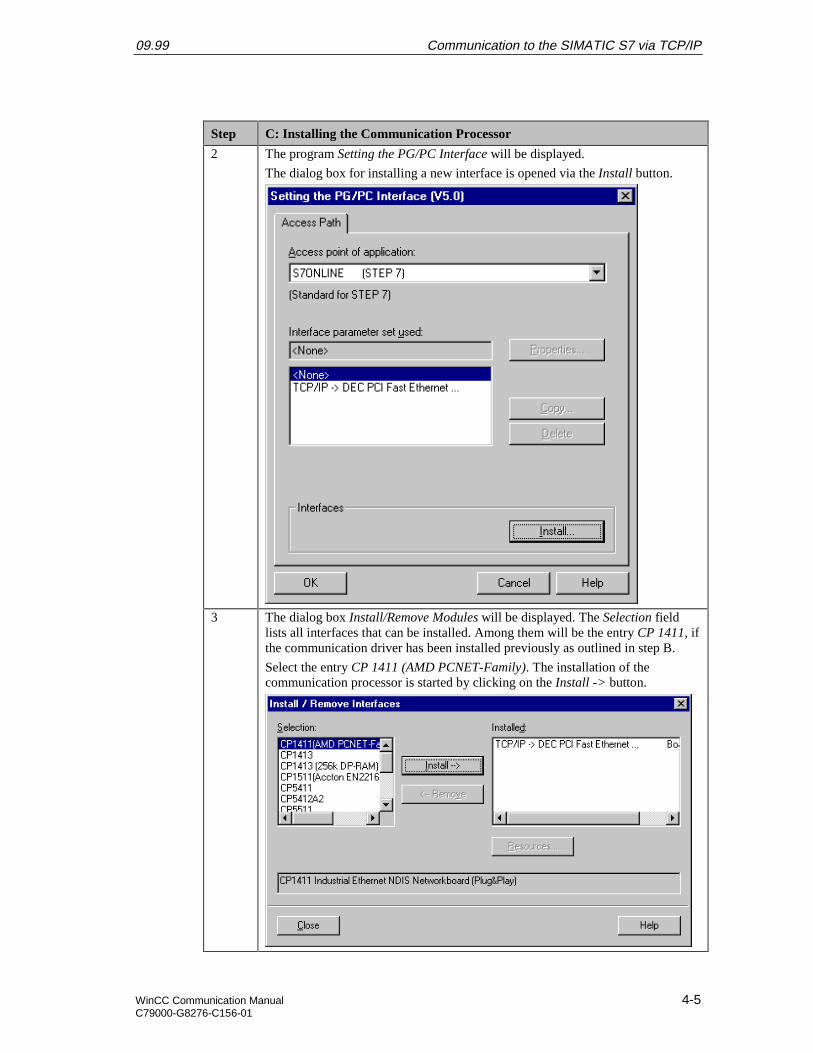
09.99 Communication to the SIMATIC S7 via TCP/IP
WinCC Communication Manual 4-5C79000-G8276-C156-01
Step C: Installing the Communication Processor
2 The program Setting the PG/PC Interface will be displayed.
The dialog box for installing a new interface is opened via the Install button.
3 The dialog box Install/Remove Modules will be displayed. The Selection fieldlists all interfaces that can be installed. Among them will be the entry CP 1411, ifthe communication driver has been installed previously as outlined in step B.
Select the entry CP 1411 (AMD PCNET-Family). The installation of thecommunication processor is started by clicking on the Install -> button.
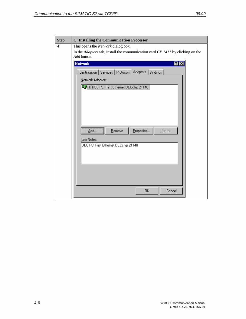
Communication to the SIMATIC S7 via TCP/IP 09.99
4-6 WinCC Communication ManualC79000-G8276-C156-01
Step C: Installing the Communication Processor
4 This opens the Network dialog box.
In the Adapters tab, install the communication card CP 1411 by clicking on theAdd button.
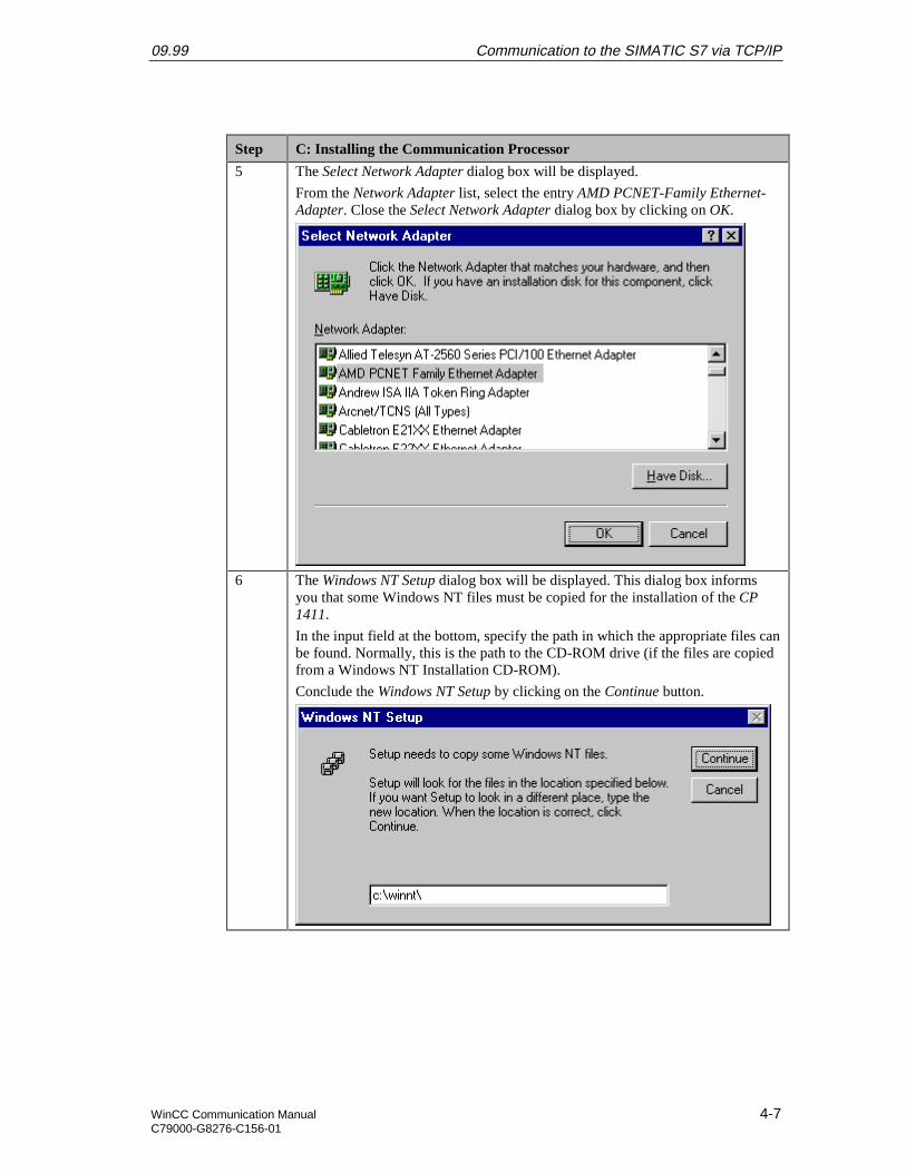
09.99 Communication to the SIMATIC S7 via TCP/IP
WinCC Communication Manual 4-7C79000-G8276-C156-01
Step C: Installing the Communication Processor
5 The Select Network Adapter dialog box will be displayed.
From the Network Adapter list, select the entry AMD PCNET-Family Ethernet-Adapter. Close the Select Network Adapter dialog box by clicking on OK.
6 The Windows NT Setup dialog box will be displayed. This dialog box informsyou that some Windows NT files must be copied for the installation of the CP1411.
In the input field at the bottom, specify the path in which the appropriate files canbe found. Normally, this is the path to the CD-ROM drive (if the files are copiedfrom a Windows NT Installation CD-ROM).
Conclude the Windows NT Setup by clicking on the Continue button.
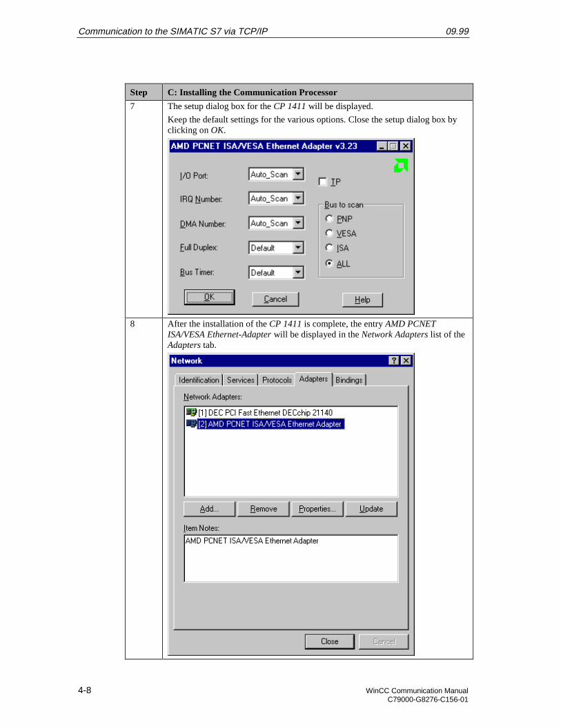
Communication to the SIMATIC S7 via TCP/IP 09.99
4-8 WinCC Communication ManualC79000-G8276-C156-01
Step C: Installing the Communication Processor
7 The setup dialog box for the CP 1411 will be displayed.
Keep the default settings for the various options. Close the setup dialog box byclicking on OK.
8 After the installation of the CP 1411 is complete, the entry AMD PCNETISA/VESA Ethernet-Adapter will be displayed in the Network Adapters list of theAdapters tab.
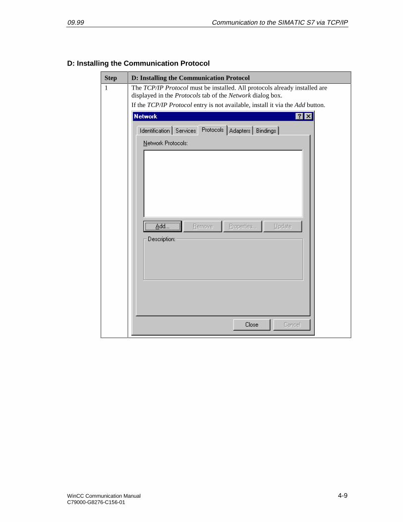
09.99 Communication to the SIMATIC S7 via TCP/IP
WinCC Communication Manual 4-9C79000-G8276-C156-01
D: Installing the Communication Protocol
Step D: Installing the Communication Protocol
1 The TCP/IP Protocol must be installed. All protocols already installed aredisplayed in the Protocols tab of the Network dialog box.
If the TCP/IP Protocol entry is not available, install it via the Add button.
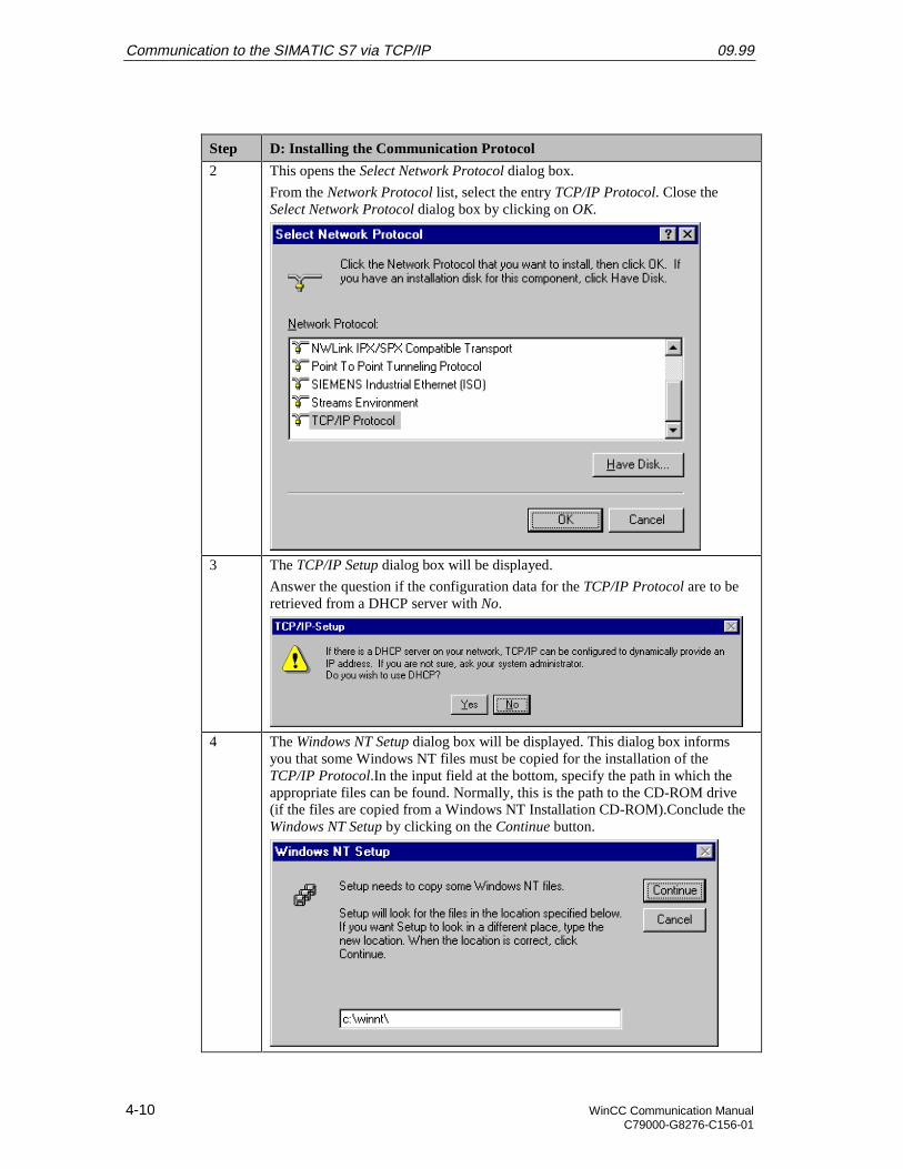
Communication to the SIMATIC S7 via TCP/IP 09.99
4-10 WinCC Communication ManualC79000-G8276-C156-01
Step D: Installing the Communication Protocol
2 This opens the Select Network Protocol dialog box.
From the Network Protocol list, select the entry TCP/IP Protocol. Close theSelect Network Protocol dialog box by clicking on OK.
3 The TCP/IP Setup dialog box will be displayed.
Answer the question if the configuration data for the TCP/IP Protocol are to beretrieved from a DHCP server with No.
4 The Windows NT Setup dialog box will be displayed. This dialog box informsyou that some Windows NT files must be copied for the installation of theTCP/IP Protocol.In the input field at the bottom, specify the path in which theappropriate files can be found. Normally, this is the path to the CD-ROM drive(if the files are copied from a Windows NT Installation CD-ROM).Conclude theWindows NT Setup by clicking on the Continue button.
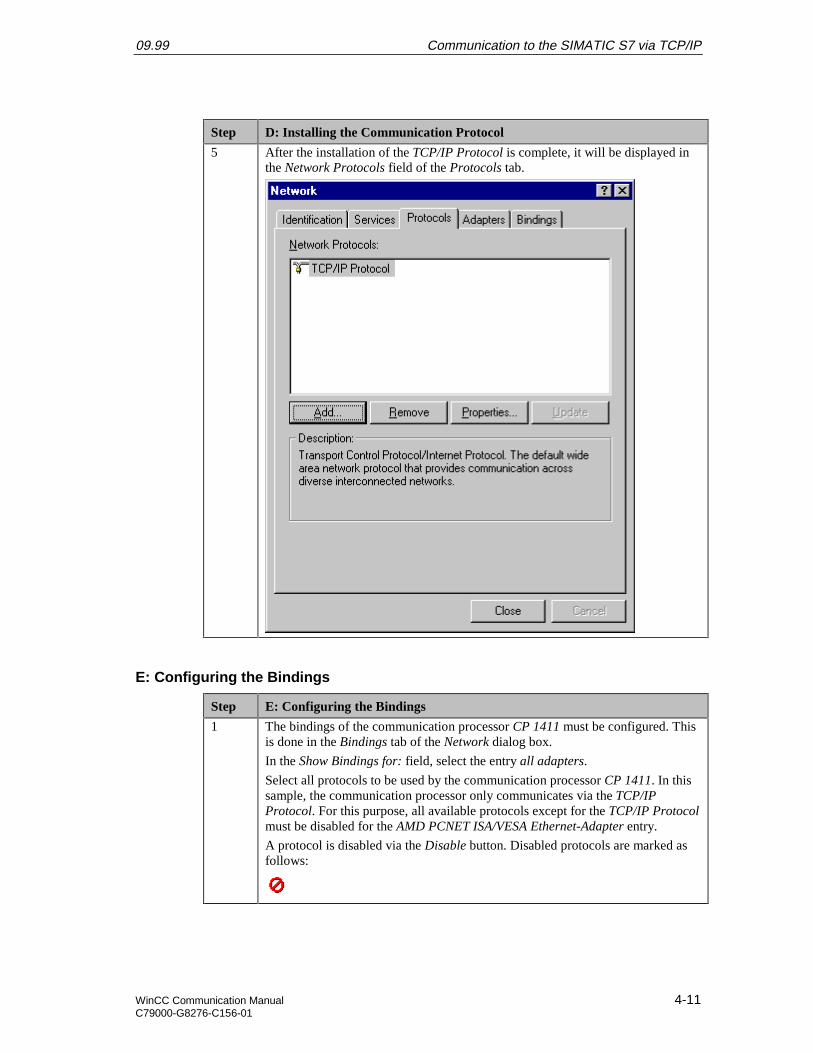
09.99 Communication to the SIMATIC S7 via TCP/IP
WinCC Communication Manual 4-11C79000-G8276-C156-01
Step D: Installing the Communication Protocol
5 After the installation of the TCP/IP Protocol is complete, it will be displayed inthe Network Protocols field of the Protocols tab.
E: Configuring the Bindings
Step E: Configuring the Bindings
1 The bindings of the communication processor CP 1411 must be configured. Thisis done in the Bindings tab of the Network dialog box.
In the Show Bindings for: field, select the entry all adapters.
Select all protocols to be used by the communication processor CP 1411. In thissample, the communication processor only communicates via the TCP/IPProtocol. For this purpose, all available protocols except for the TCP/IP Protocolmust be disabled for the AMD PCNET ISA/VESA Ethernet-Adapter entry.
A protocol is disabled via the Disable button. Disabled protocols are marked asfollows:
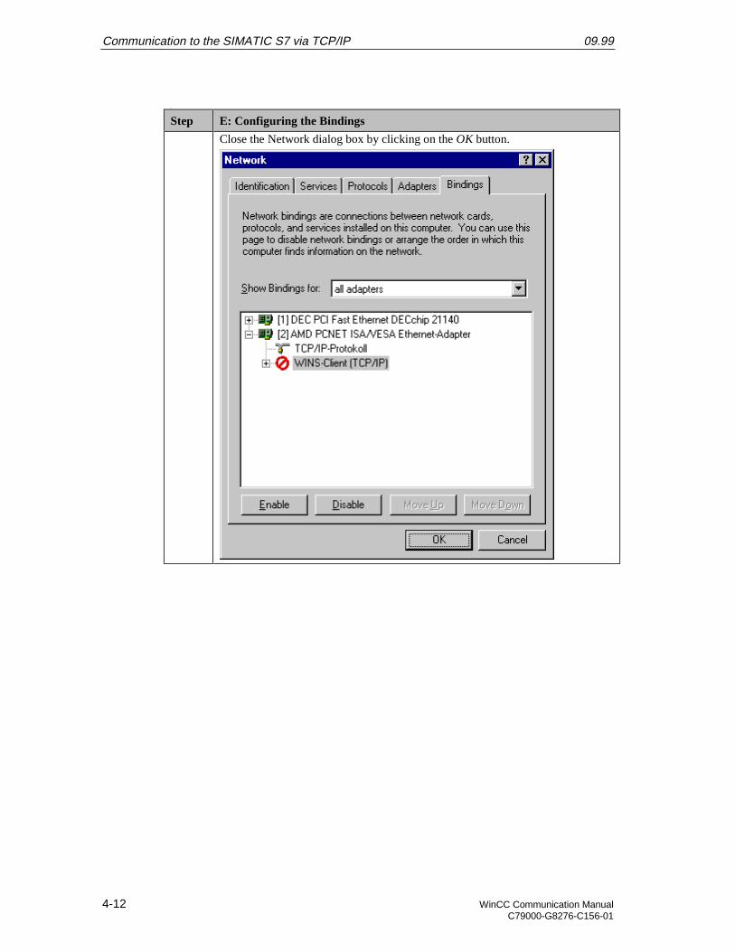
Communication to the SIMATIC S7 via TCP/IP 09.99
4-12 WinCC Communication ManualC79000-G8276-C156-01
q
Step E: Configuring the Bindings
Close the Network dialog box by clicking on the OK button.
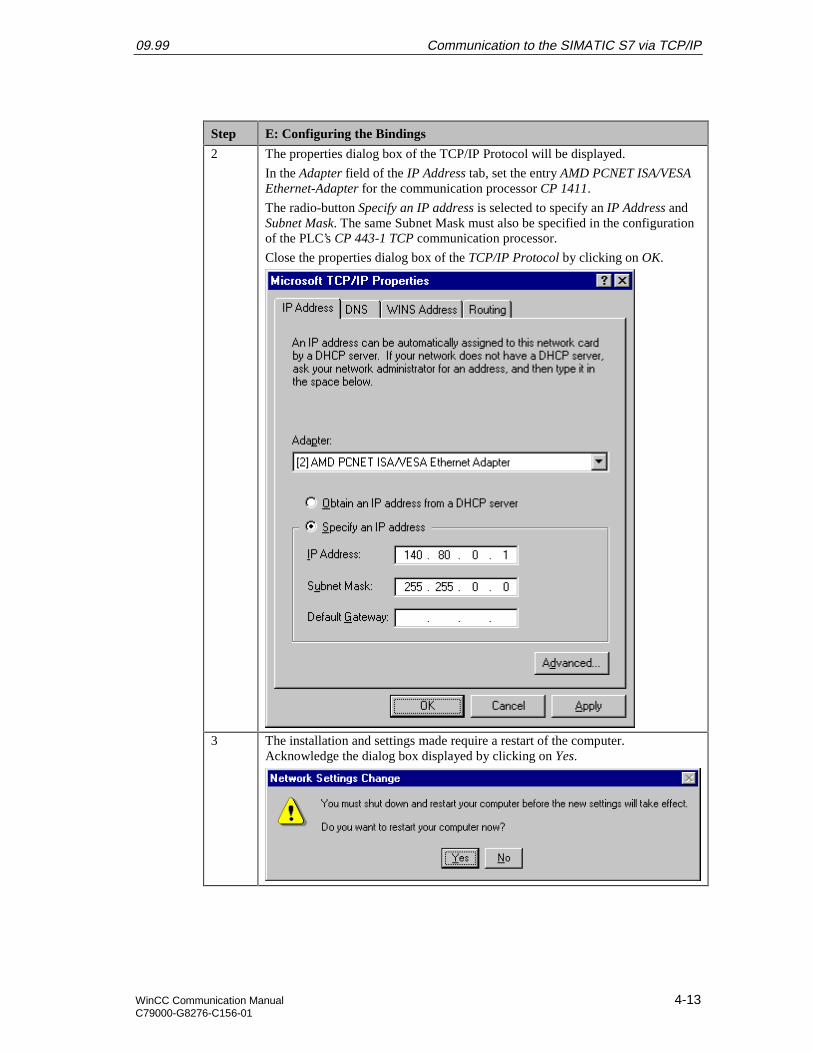
09.99 Communication to the SIMATIC S7 via TCP/IP
WinCC Communication Manual 4-13C79000-G8276-C156-01
Step E: Configuring the Bindings
2 The properties dialog box of the TCP/IP Protocol will be displayed.
In the Adapter field of the IP Address tab, set the entry AMD PCNET ISA/VESAEthernet-Adapter for the communication processor CP 1411.
The radio-button Specify an IP address is selected to specify an IP Address andSubnet Mask. The same Subnet Mask must also be specified in the configurationof the PLC’s CP 443-1 TCP communication processor.
Close the properties dialog box of the TCP/IP Protocol by clicking on OK.
3 The installation and settings made require a restart of the computer.Acknowledge the dialog box displayed by clicking on Yes.
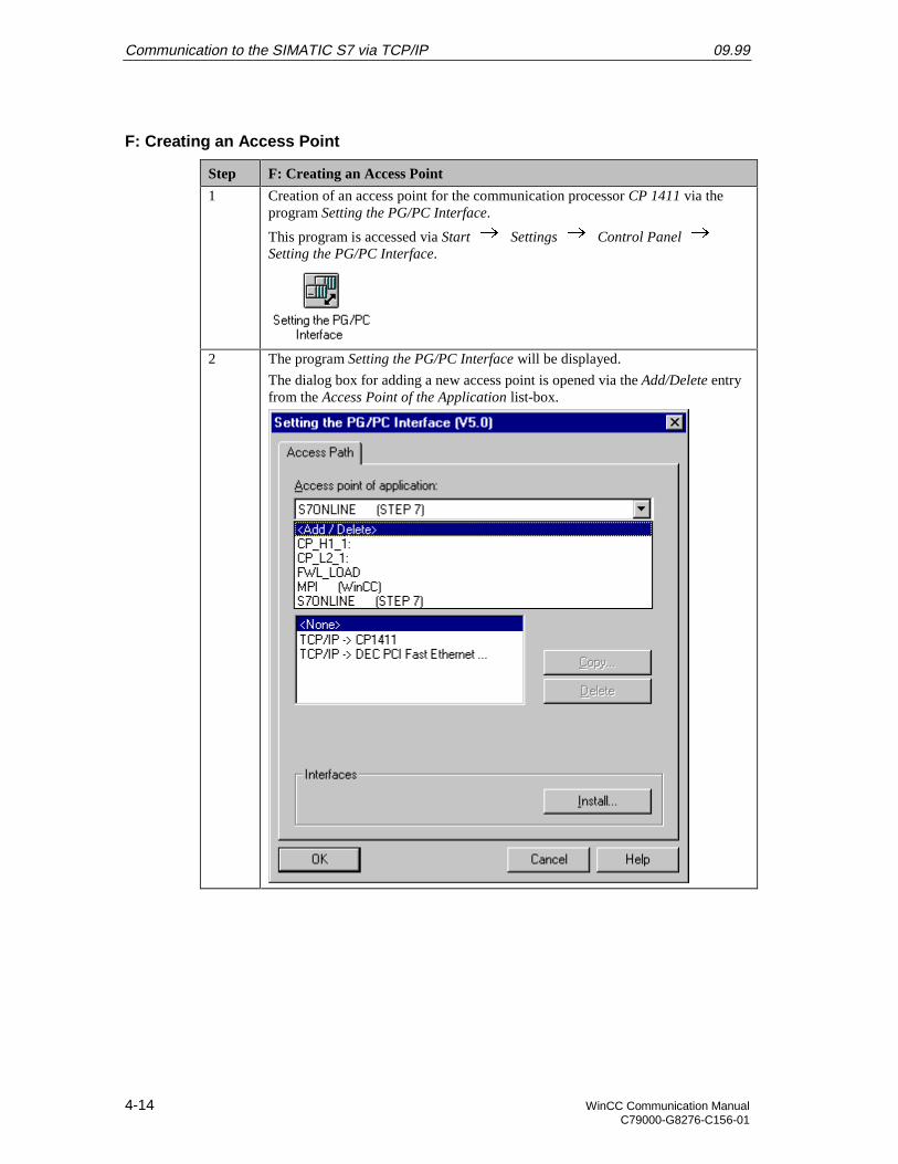
Communication to the SIMATIC S7 via TCP/IP 09.99
4-14 WinCC Communication ManualC79000-G8276-C156-01
F: Creating an Access Point
Step F: Creating an Access Point
1 Creation of an access point for the communication processor CP 1411 via theprogram Setting the PG/PC Interface.
This program is accessed via Start Settings Control Panel Setting the PG/PC Interface.
2 The program Setting the PG/PC Interface will be displayed.
The dialog box for adding a new access point is opened via the Add/Delete entryfrom the Access Point of the Application list-box.
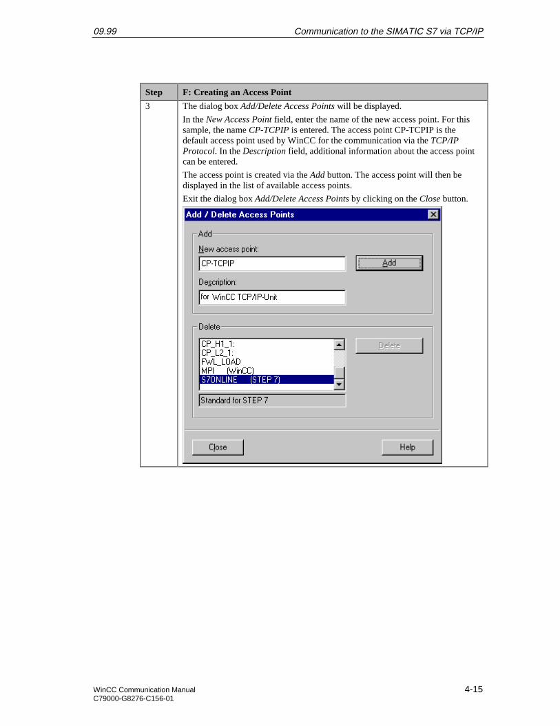
09.99 Communication to the SIMATIC S7 via TCP/IP
WinCC Communication Manual 4-15C79000-G8276-C156-01
Step F: Creating an Access Point
3 The dialog box Add/Delete Access Points will be displayed.
In the New Access Point field, enter the name of the new access point. For thissample, the name CP-TCPIP is entered. The access point CP-TCPIP is thedefault access point used by WinCC for the communication via the TCP/IPProtocol. In the Description field, additional information about the access pointcan be entered.
The access point is created via the Add button. The access point will then bedisplayed in the list of available access points.
Exit the dialog box Add/Delete Access Points by clicking on the Close button.
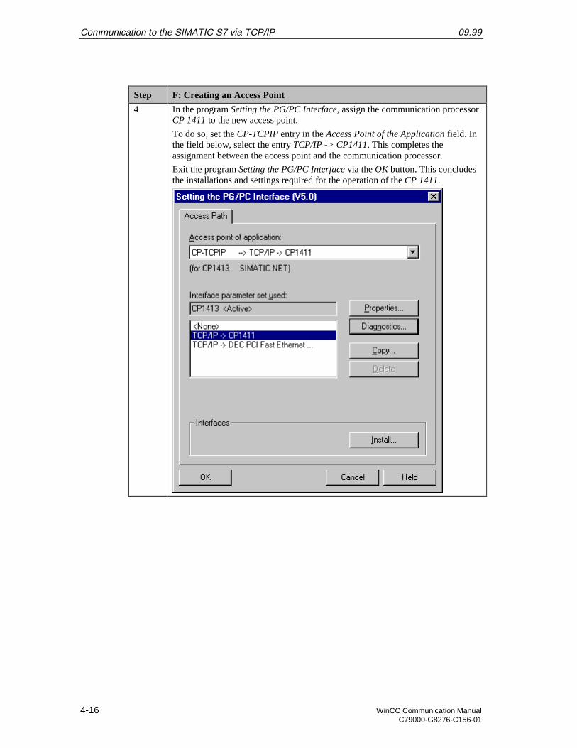
Communication to the SIMATIC S7 via TCP/IP 09.99
4-16 WinCC Communication ManualC79000-G8276-C156-01
Step F: Creating an Access Point
4 In the program Setting the PG/PC Interface, assign the communication processorCP 1411 to the new access point.
To do so, set the CP-TCPIP entry in the Access Point of the Application field. Inthe field below, select the entry TCP/IP -> CP1411. This completes theassignment between the access point and the communication processor.
Exit the program Setting the PG/PC Interface via the OK button. This concludesthe installations and settings required for the operation of the CP 1411.
09.99 Communication to the SIMATIC S7 via TCP/IP
WinCC Communication Manual 4-17C79000-G8276-C156-01
4.2 Creation of the STEP7 Project S7_IETCP
The following description details the configuration steps necessary to create and start up theSTEP7 project S7_IETCP.
Overview of the Configuration Steps
The following lists the configuration steps necessary to create the STEP7 projectS7_IETCP:
• A: Installing the Hardware
• B: Installing the Option Package
• C: Creating the STEP7 Project
• D: Configuring the Hardware
• E: Loading the Hardware Configuration
• F: Testing the Hardware Configuration
• G: Creating the STEP7 Program
• H: Testing the STEP7 Program
A: Installing the Hardware
Step A: Installing the Hardware
1 Rack-mounting of the modules used.
In this sample, the modules to be installed are the power supply PS 407 10A, theCPU module CPU 416-1 and the communication processor CP 443-1 TCP.
Establishing the connection from the computer to the programming interface ofthe CPU module.
Establishing the connection from the communication processor CP 1411 in thecomputer to the communication processor CP 443-1 TCP in the PLC.
B: Installing the Option Package
Step B: Installing the Option Package
1 If the option package NCM S7 Industrial Ethernet has not been installed duringthe installation of STEP7, install it now from the STEP7 CD-ROM. This optionpackage is required for the configuration of the communication processor CP443-1 TCP via the STEP7 software.
After inserting the STEP7 CD-ROM, the installation program is automaticallystarted. If this is not the case, open the Windows NT Explorer and start thesetup.exe program located on the CD-ROM.
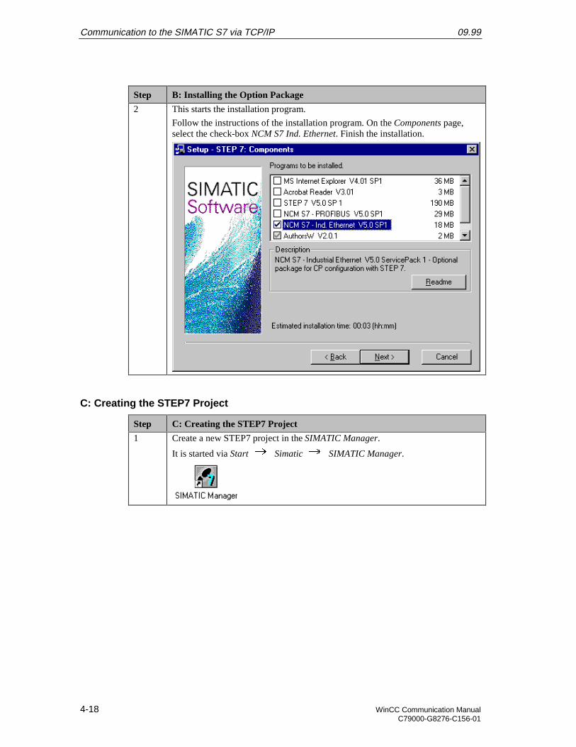
Communication to the SIMATIC S7 via TCP/IP 09.99
4-18 WinCC Communication ManualC79000-G8276-C156-01
Step B: Installing the Option Package
2 This starts the installation program.
Follow the instructions of the installation program. On the Components page,select the check-box NCM S7 Ind. Ethernet. Finish the installation.
C: Creating the STEP7 Project
Step C: Creating the STEP7 Project
1 Create a new STEP7 project in the SIMATIC Manager.
It is started via Start Simatic SIMATIC Manager.
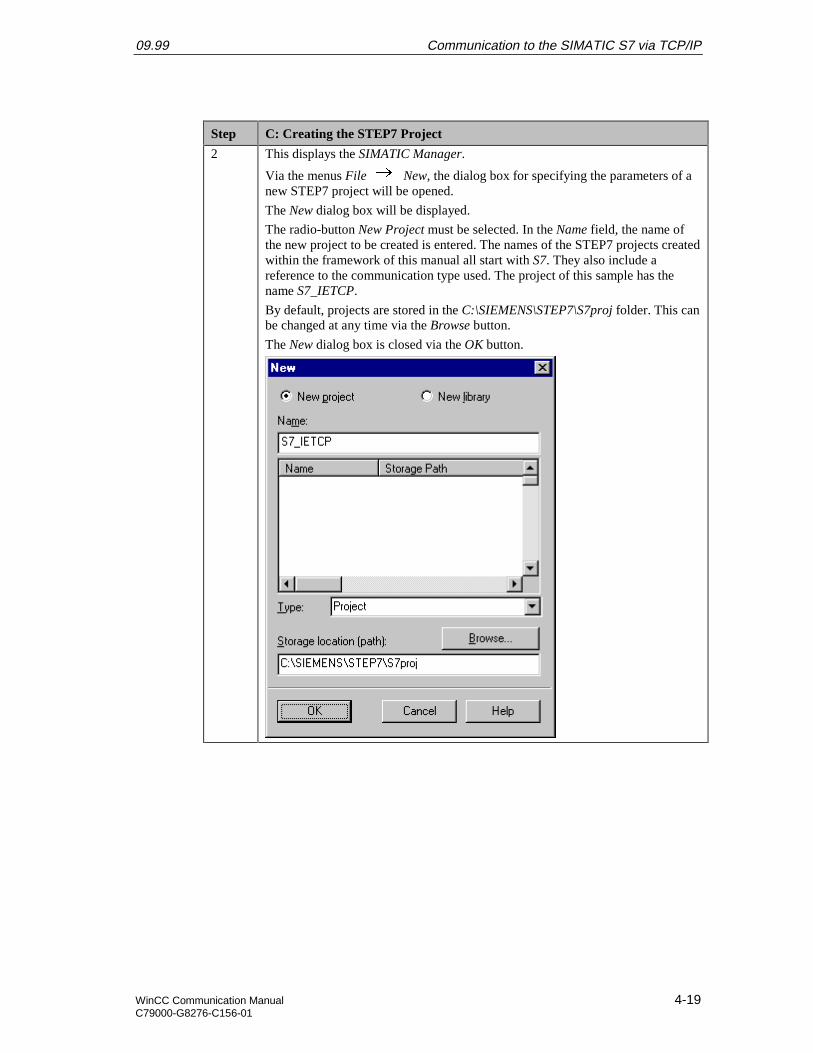
09.99 Communication to the SIMATIC S7 via TCP/IP
WinCC Communication Manual 4-19C79000-G8276-C156-01
Step C: Creating the STEP7 Project
2 This displays the SIMATIC Manager.
Via the menus File New, the dialog box for specifying the parameters of anew STEP7 project will be opened.
The New dialog box will be displayed.
The radio-button New Project must be selected. In the Name field, the name ofthe new project to be created is entered. The names of the STEP7 projects createdwithin the framework of this manual all start with S7. They also include areference to the communication type used. The project of this sample has thename S7_IETCP.
By default, projects are stored in the C:\SIEMENS\STEP7\S7proj folder. This canbe changed at any time via the Browse button.
The New dialog box is closed via the OK button.
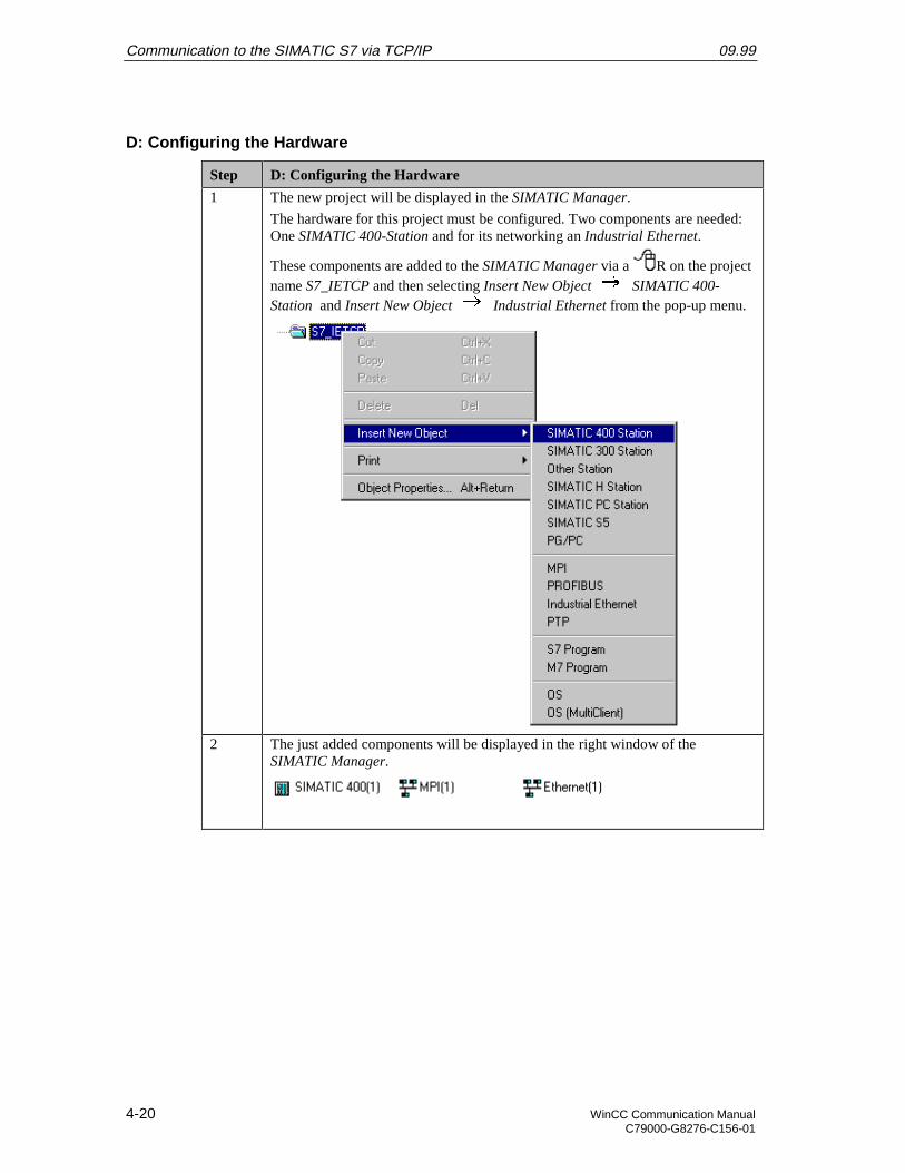
Communication to the SIMATIC S7 via TCP/IP 09.99
4-20 WinCC Communication ManualC79000-G8276-C156-01
D: Configuring the Hardware
Step D: Configuring the Hardware
1 The new project will be displayed in the SIMATIC Manager.
The hardware for this project must be configured. Two components are needed:One SIMATIC 400-Station and for its networking an Industrial Ethernet.
These components are added to the SIMATIC Manager via a R on the projectname S7_IETCP and then selecting Insert New Object SIMATIC 400-Station and Insert New Object Industrial Ethernet from the pop-up menu.
2 The just added components will be displayed in the right window of theSIMATIC Manager.

09.99 Communication to the SIMATIC S7 via TCP/IP
WinCC Communication Manual 4-21C79000-G8276-C156-01
Step D: Configuring the Hardware
By D on the component SIMATIC 400(1) in the right window, the point
Hardware will be displayed. By D on the point Hardware or R on it andthen selecting Open Object from the pop-up menu, the program HW Config willbe started.
3 The program HW Config will be displayed.
This program is used to exactly define the hardware used in the PLC and toconfigure their properties.
4 By clicking on the toolbar button of the program HW Config displayed below, theHardware Catalog is opened. This catalog is used to select the required hardwarecomponents.
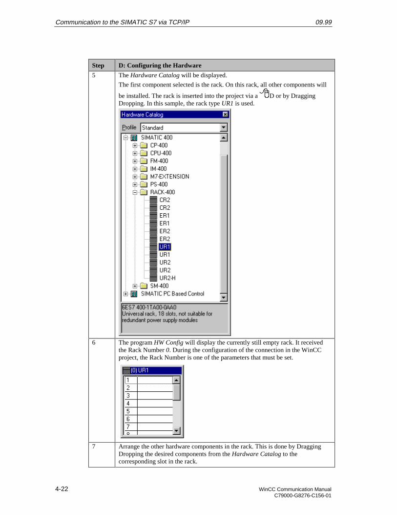
Communication to the SIMATIC S7 via TCP/IP 09.99
4-22 WinCC Communication ManualC79000-G8276-C156-01
Step D: Configuring the Hardware
5 The Hardware Catalog will be displayed.
The first component selected is the rack. On this rack, all other components will
be installed. The rack is inserted into the project via a D or by DraggingDropping. In this sample, the rack type UR1 is used.
6 The program HW Config will display the currently still empty rack. It receivedthe Rack Number 0. During the configuration of the connection in the WinCCproject, the Rack Number is one of the parameters that must be set.
7 Arrange the other hardware components in the rack. This is done by DraggingDropping the desired components from the Hardware Catalog to thecorresponding slot in the rack.
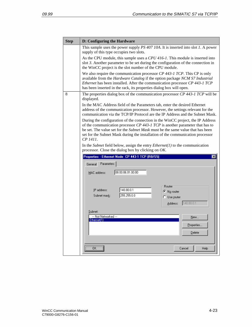
09.99 Communication to the SIMATIC S7 via TCP/IP
WinCC Communication Manual 4-23C79000-G8276-C156-01
Step D: Configuring the Hardware
This sample uses the power supply PS 407 10A. It is inserted into slot 1. A powersupply of this type occupies two slots.
As the CPU module, this sample uses a CPU 416-1. This module is inserted intoslot 3. Another parameter to be set during the configuration of the connection inthe WinCC project is the slot number of the CPU module.
We also require the communication processor CP 443-1 TCP. This CP is onlyavailable from the Hardware Catalog if the option package NCM S7 IndustrialEthernet has been installed. After the communication processor CP 443-1 TCPhas been inserted in the rack, its properties dialog box will open.
8 The properties dialog box of the communication processor CP 443-1 TCP will bedisplayed.
In the MAC Address field of the Parameters tab, enter the desired Ethernetaddress of the communication processor. However, the settings relevant for thecommunication via the TCP/IP Protocol are the IP Address and the Subnet Mask.
During the configuration of the connection in the WinCC project, the IP Addressof the communication processor CP 443-1 TCP is another parameter that has tobe set. The value set for the Subnet Mask must be the same value that has beenset for the Subnet Mask during the installation of the communication processorCP 1411.
In the Subnet field below, assign the entry Ethernet(1) to the communicationprocessor. Close the dialog box by clicking on OK.

Communication to the SIMATIC S7 via TCP/IP 09.99
4-24 WinCC Communication ManualC79000-G8276-C156-01
Step D: Configuring the Hardware
9 The following graphic shows the completed hardware arrangement of the sample.
10 Save the settings made in the program HW Config. This is done via the toolbarbutton displayed below.
E: Loading the Hardware Configuration
Step E: Loading the Hardware Configuration
1 The hardware configuration created in the program HW Config must betransferred to the PLC.
This is done via the toolbar button displayed below.
2 A dialog box will be displayed from which the components to be loaded can beselected.
For this sample, all displayed components will be selected. Note that loading tothe CPU module is only possible while the operating mode switch is set to STOPor RUN-P. Close the dialog box by clicking on OK.
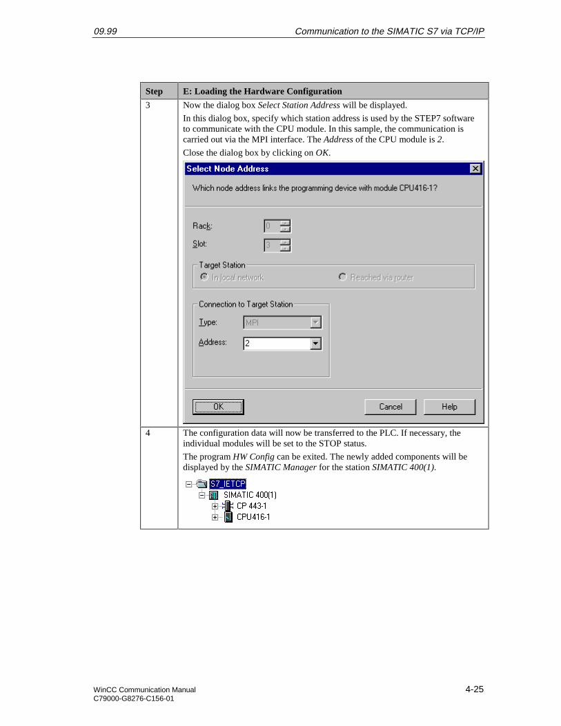
09.99 Communication to the SIMATIC S7 via TCP/IP
WinCC Communication Manual 4-25C79000-G8276-C156-01
Step E: Loading the Hardware Configuration
3 Now the dialog box Select Station Address will be displayed.
In this dialog box, specify which station address is used by the STEP7 softwareto communicate with the CPU module. In this sample, the communication iscarried out via the MPI interface. The Address of the CPU module is 2.
Close the dialog box by clicking on OK.
4 The configuration data will now be transferred to the PLC. If necessary, theindividual modules will be set to the STOP status.
The program HW Config can be exited. The newly added components will bedisplayed by the SIMATIC Manager for the station SIMATIC 400(1).

Communication to the SIMATIC S7 via TCP/IP 09.99
4-26 WinCC Communication ManualC79000-G8276-C156-01
F: Testing the Hardware Configuration
Step F: Testing the Hardware Configuration
1 Testing of the hardware configuration made.
If the key switch of the CPU module is set to RUN or RUN-P and the operatingmode switch of the communication processor is set to RUN, only the status LEDssignifying the RUN operating mode should be displayed.
If this is not the case, there is an error. The following steps help you localize thiserror. However, these steps should still be performed even if the status LEDsshow no error. This allows you to recognize uncritical errors and faultyconfigurations.

09.99 Communication to the SIMATIC S7 via TCP/IP
WinCC Communication Manual 4-27C79000-G8276-C156-01
Step F: Testing the Hardware Configuration
2 Testing the configuration of the CPU module.
This is done via the dialog box Module Status in the SIMATIC Manager. It is
opened by a R on the entry of the CPU module in the left window and thenselecting Target System Module Status from the pop-up menu.
The dialog box Module Status of the CPU module will be displayed.
The General tab displays various general data of the CPU module. In the Statusfield, the current module status and any existing errors are displayed.
The Diagnosis Buffer tab contains more detailed information about existingerrors and how to correct them.
The dialog box can be exited via the Close button.
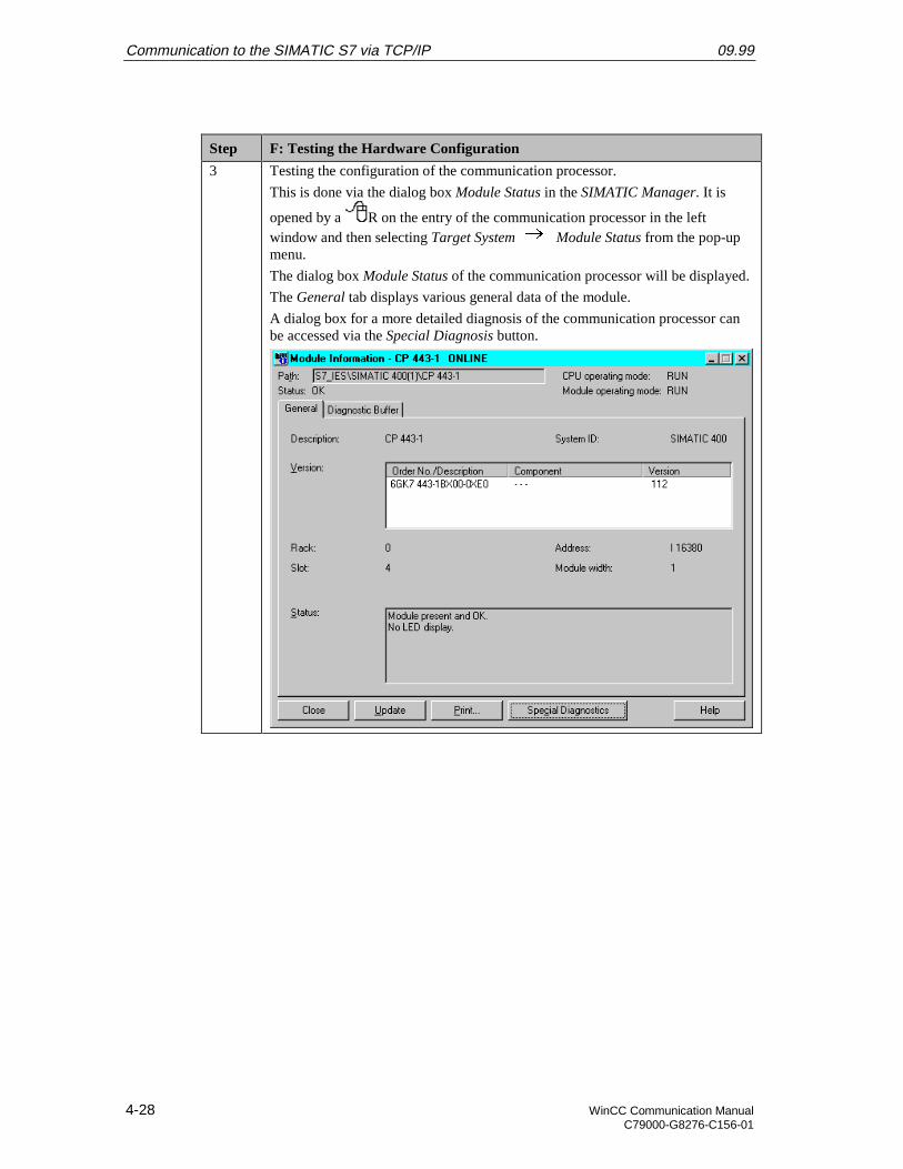
Communication to the SIMATIC S7 via TCP/IP 09.99
4-28 WinCC Communication ManualC79000-G8276-C156-01
Step F: Testing the Hardware Configuration
3 Testing the configuration of the communication processor.
This is done via the dialog box Module Status in the SIMATIC Manager. It is
opened by a R on the entry of the communication processor in the leftwindow and then selecting Target System Module Status from the pop-upmenu.
The dialog box Module Status of the communication processor will be displayed.
The General tab displays various general data of the module.
A dialog box for a more detailed diagnosis of the communication processor canbe accessed via the Special Diagnosis button.
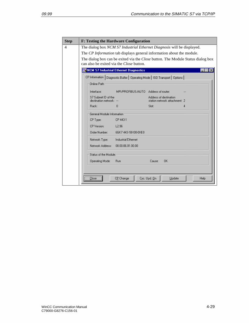
09.99 Communication to the SIMATIC S7 via TCP/IP
WinCC Communication Manual 4-29C79000-G8276-C156-01
Step F: Testing the Hardware Configuration
4 The dialog box NCM S7 Industrial Ethernet Diagnosis will be displayed.
The CP Information tab displays general information about the module.
The dialog box can be exited via the Close button. The Module Status dialog boxcan also be exited via the Close button.
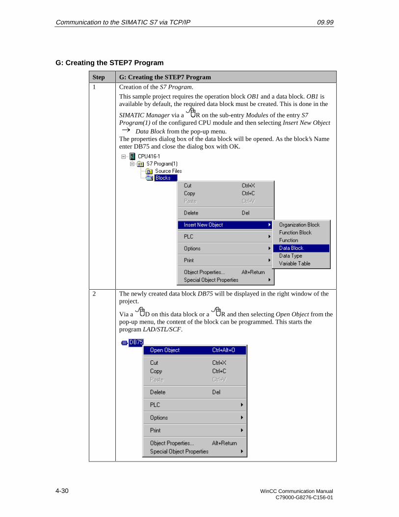
Communication to the SIMATIC S7 via TCP/IP 09.99
4-30 WinCC Communication ManualC79000-G8276-C156-01
G: Creating the STEP7 Program
Step G: Creating the STEP7 Program
1 Creation of the S7 Program.
This sample project requires the operation block OB1 and a data block. OB1 isavailable by default, the required data block must be created. This is done in the
SIMATIC Manager via a R on the sub-entry Modules of the entry S7Program(1) of the configured CPU module and then selecting Insert New Object
Data Block from the pop-up menu.The properties dialog box of the data block will be opened. As the block’s Nameenter DB75 and close the dialog box with OK.
2 The newly created data block DB75 will be displayed in the right window of theproject.
Via a D on this data block or a R and then selecting Open Object from thepop-up menu, the content of the block can be programmed. This starts theprogram LAD/STL/SCF.

09.99 Communication to the SIMATIC S7 via TCP/IP
WinCC Communication Manual 4-31C79000-G8276-C156-01
Step G: Creating the STEP7 Program
3 The program LAD/STL/SCF is displayed.
Acknowledge the dialog box New Data Block by clicking on OK.
4 Programming the DB75.
In this data block, two tags with a length of 16 Bits are created. Their sum is tobe determined in OB1 and then be written to another tag with a length of 16 Bits.
Two additional tags with a length of 16 Bits are created, whose values arecyclically incremented in OB1.
The tags created in the data block DB75 are visualized in the WinCC project. Todo so, WinCC tags with corresponding addresses are created there.
The following graphic displays the programmed data block DB75.
5 Save the block and load it into the PLC. This is done via the toolbar buttondisplayed below. Note that loading to the CPU module is only possible while theoperating mode switch is set to STOP or RUN-P.
6 Programming the OB1.
Open the block in the program LAD/STL/SCF.
First, two values in the DB75 are added and then stored again in DB75.
Next, a value in the DB75 is incremented every second.

Communication to the SIMATIC S7 via TCP/IP 09.99
4-32 WinCC Communication ManualC79000-G8276-C156-01
Step G: Creating the STEP7 Program
Finally, a value in the DB75 is incremented every time the OB1 run.
7 Save the block OB1 and load it into the PLC. This is done via the correspondingbuttons on the toolbar.
This completes the creation of the STEP7 project and it can now be run. Exit theprogram LAD/STL/SCF.
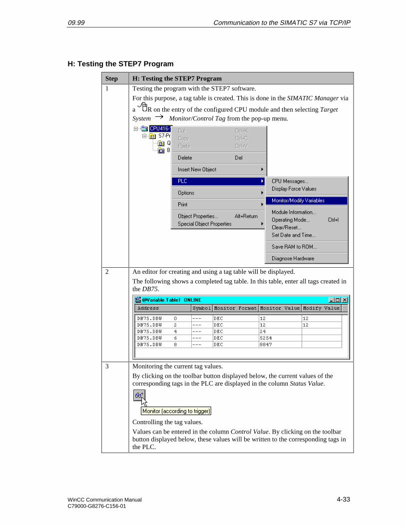
09.99 Communication to the SIMATIC S7 via TCP/IP
WinCC Communication Manual 4-33C79000-G8276-C156-01
H: Testing the STEP7 Program
Step H: Testing the STEP7 Program
1 Testing the program with the STEP7 software.
For this purpose, a tag table is created. This is done in the SIMATIC Manager via
a R on the entry of the configured CPU module and then selecting TargetSystem Monitor/Control Tag from the pop-up menu.
2 An editor for creating and using a tag table will be displayed.
The following shows a completed tag table. In this table, enter all tags created inthe DB75.
3 Monitoring the current tag values.
By clicking on the toolbar button displayed below, the current values of thecorresponding tags in the PLC are displayed in the column Status Value.
Controlling the tag values.
Values can be entered in the column Control Value. By clicking on the toolbarbutton displayed below, these values will be written to the corresponding tags inthe PLC.

Communication to the SIMATIC S7 via TCP/IP 09.99
4-34 WinCC Communication ManualC79000-G8276-C156-01
Step H: Testing the STEP7 Program
Note that tags can only be controlled while the operating mode switch of theCPU module is set to RUN-P.
4 The created tag table can now be saved.
In this sample, the table is saved under the name VAT1. After checking theprogram in the PLC, the tag table can be closed. This concludes the configurationof the STEP7 project and the SIMATIC Manager can be exited.
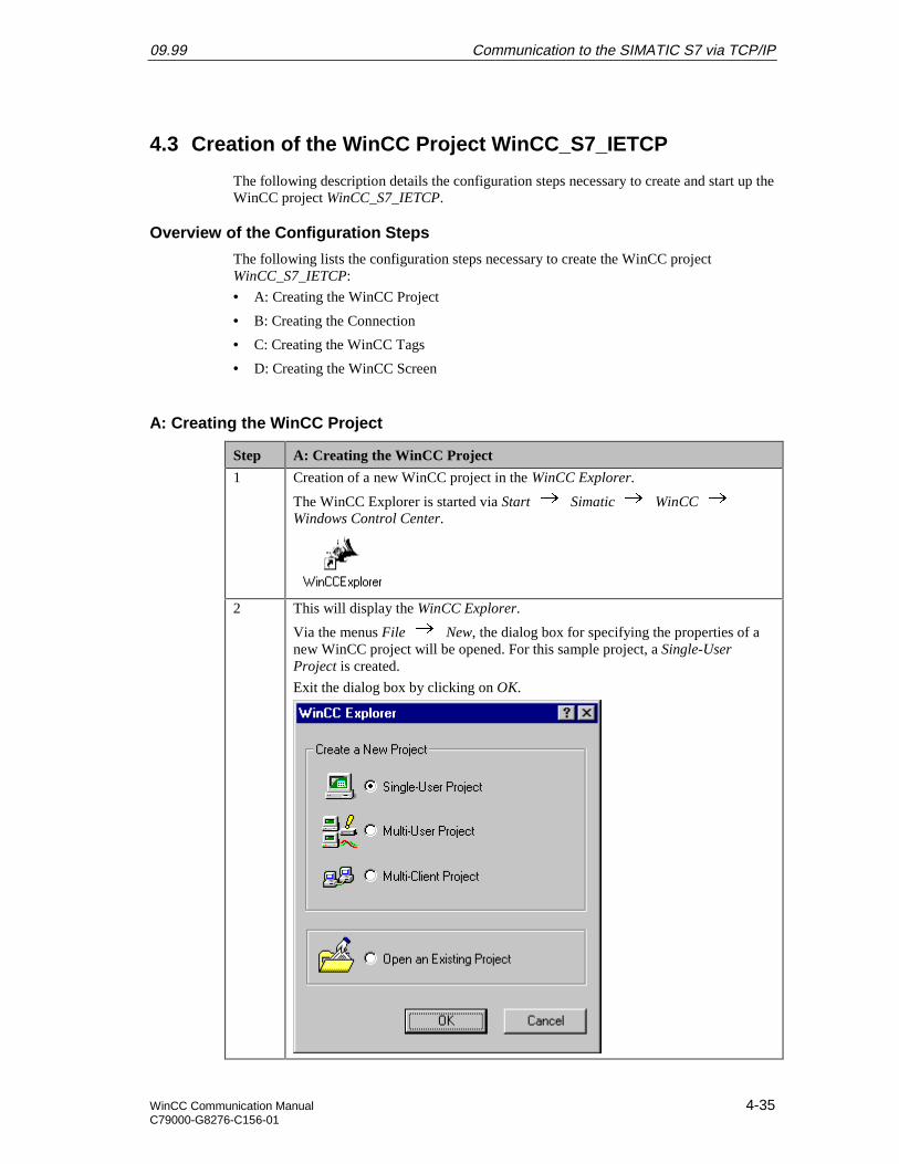
09.99 Communication to the SIMATIC S7 via TCP/IP
WinCC Communication Manual 4-35C79000-G8276-C156-01
4.3 Creation of the WinCC Project WinCC_S7_IETCP
The following description details the configuration steps necessary to create and start up theWinCC project WinCC_S7_IETCP.
Overview of the Configuration Steps
The following lists the configuration steps necessary to create the WinCC projectWinCC_S7_IETCP:
• A: Creating the WinCC Project
• B: Creating the Connection
• C: Creating the WinCC Tags
• D: Creating the WinCC Screen
A: Creating the WinCC Project
Step A: Creating the WinCC Project
1 Creation of a new WinCC project in the WinCC Explorer.
The WinCC Explorer is started via Start Simatic WinCC Windows Control Center.
2 This will display the WinCC Explorer.
Via the menus File New, the dialog box for specifying the properties of anew WinCC project will be opened. For this sample project, a Single-UserProject is created.
Exit the dialog box by clicking on OK.

Communication to the SIMATIC S7 via TCP/IP 09.99
4-36 WinCC Communication ManualC79000-G8276-C156-01
Step A: Creating the WinCC Project
3 The dialog box Create a new Project will be displayed.
Specify a Project Name for the new project. The names of the WinCC projectscreated within the framework of this manual all start with WinCC and alsoinclude a reference to the communication partner and communication type used.The project of this sample has the name WinCC_S7_IETCP.
In the Project Path field, set the storage location of the new project.
The dialog box Create a new Project is concluded by clicking on the Createbutton.
B: Creating the Connection
Step B: Creating the Connection
1 The new project will be displayed in the WinCC Explorer.
Installation of the required communication driver. This is performed via a Ron Tag Management and selecting Add New Driver from the pop-up menu.
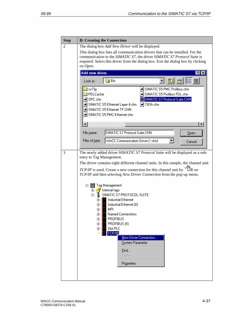
09.99 Communication to the SIMATIC S7 via TCP/IP
WinCC Communication Manual 4-37C79000-G8276-C156-01
Step B: Creating the Connection
2 The dialog box Add New Driver will be displayed.
This dialog box lists all communication drivers that can be installed. For thecommunication to the SIMATIC S7, the driver SIMATIC S7 Protocol Suite isrequired. Select this driver from the dialog box. Exit the dialog box by clickingon Open.
3 The newly added driver SIMATIC S7 Protocol Suite will be displayed as a sub-entry to Tag Management.
The driver contains eight different channel units. In this sample, the channel unit
TCP/IP is used. Create a new connection for this channel unit by R onTCP/IP and then selecting New Driver Connection from the pop-up menu.
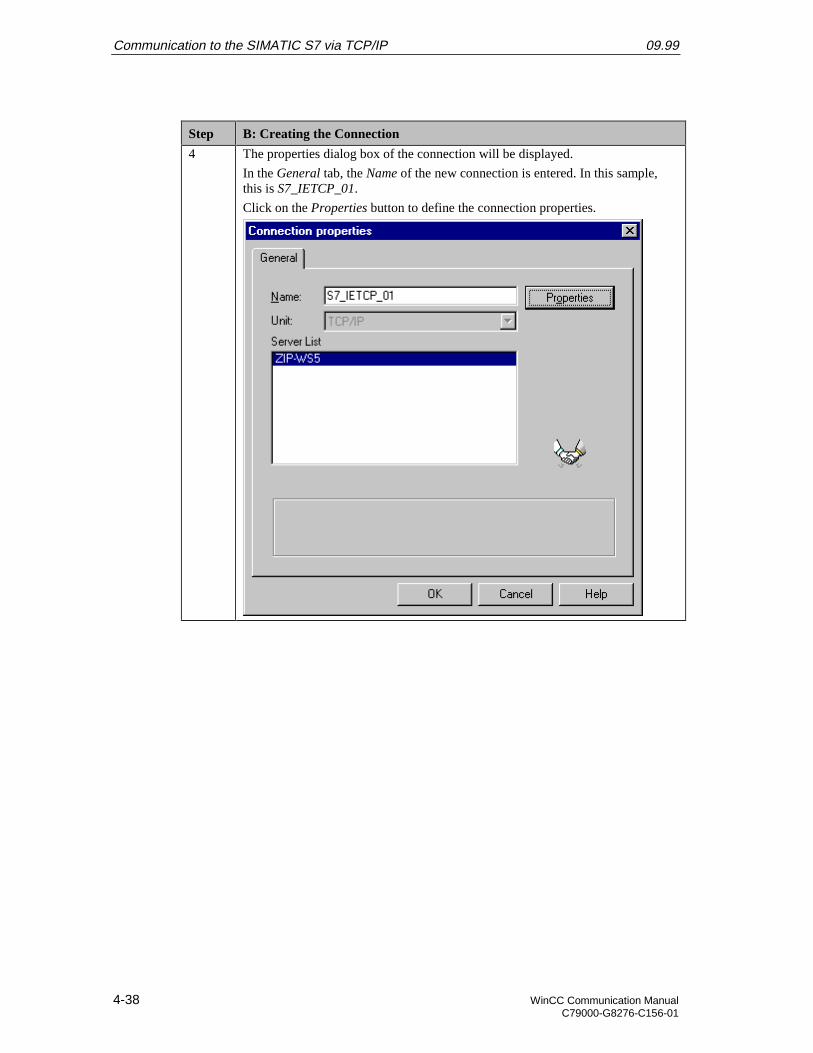
Communication to the SIMATIC S7 via TCP/IP 09.99
4-38 WinCC Communication ManualC79000-G8276-C156-01
Step B: Creating the Connection
4 The properties dialog box of the connection will be displayed.
In the General tab, the Name of the new connection is entered. In this sample,this is S7_IETCP_01.
Click on the Properties button to define the connection properties.
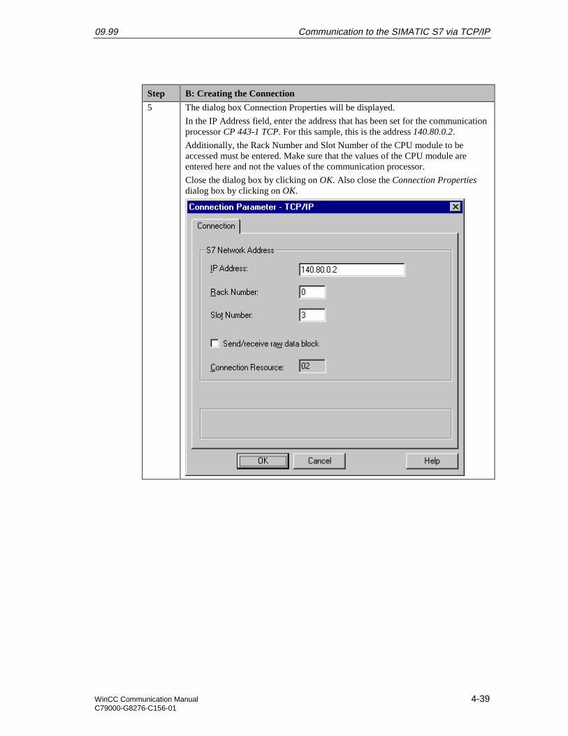
09.99 Communication to the SIMATIC S7 via TCP/IP
WinCC Communication Manual 4-39C79000-G8276-C156-01
Step B: Creating the Connection
5 The dialog box Connection Properties will be displayed.
In the IP Address field, enter the address that has been set for the communicationprocessor CP 443-1 TCP. For this sample, this is the address 140.80.0.2.
Additionally, the Rack Number and Slot Number of the CPU module to beaccessed must be entered. Make sure that the values of the CPU module areentered here and not the values of the communication processor.
Close the dialog box by clicking on OK. Also close the Connection Propertiesdialog box by clicking on OK.
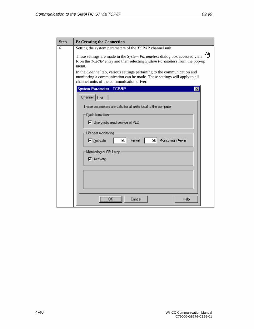
Communication to the SIMATIC S7 via TCP/IP 09.99
4-40 WinCC Communication ManualC79000-G8276-C156-01
Step B: Creating the Connection
6 Setting the system parameters of the TCP/IP channel unit.
These settings are made in the System Parameters dialog box accessed via a R on the TCP/IP entry and then selecting System Parameters from the pop-upmenu.
In the Channel tab, various settings pertaining to the communication andmonitoring a communication can be made. These settings will apply to allchannel units of the communication driver.
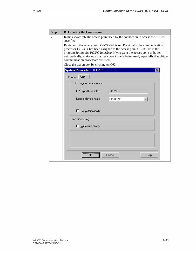
09.99 Communication to the SIMATIC S7 via TCP/IP
WinCC Communication Manual 4-41C79000-G8276-C156-01
Step B: Creating the Connection
7 In the Device tab, the access point used by the connection to access the PLC isspecified.
By default, the access point CP-TCPIP is set. Previously, the communicationprocessor CP 1411 has been assigned to the access point CP-TCPIP in theprogram Setting the PG/PC Interface. If you want the access point to be setautomatically, make sure that the correct one is being used, especially if multiplecommunication processors are used.
Close the dialog box by clicking on OK.
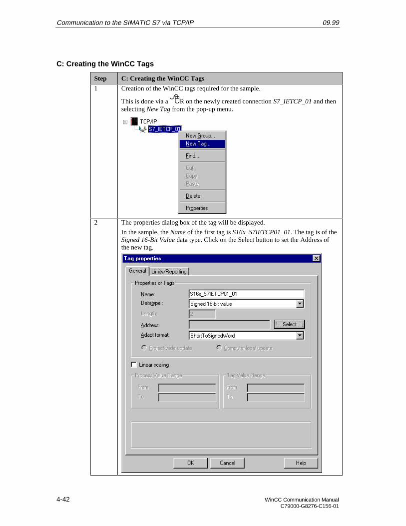
Communication to the SIMATIC S7 via TCP/IP 09.99
4-42 WinCC Communication ManualC79000-G8276-C156-01
C: Creating the WinCC Tags
Step C: Creating the WinCC Tags
1 Creation of the WinCC tags required for the sample.
This is done via a R on the newly created connection S7_IETCP_01 and thenselecting New Tag from the pop-up menu.
2 The properties dialog box of the tag will be displayed.
In the sample, the Name of the first tag is S16x_S7IETCP01_01. The tag is of theSigned 16-Bit Value data type. Click on the Select button to set the Address ofthe new tag.
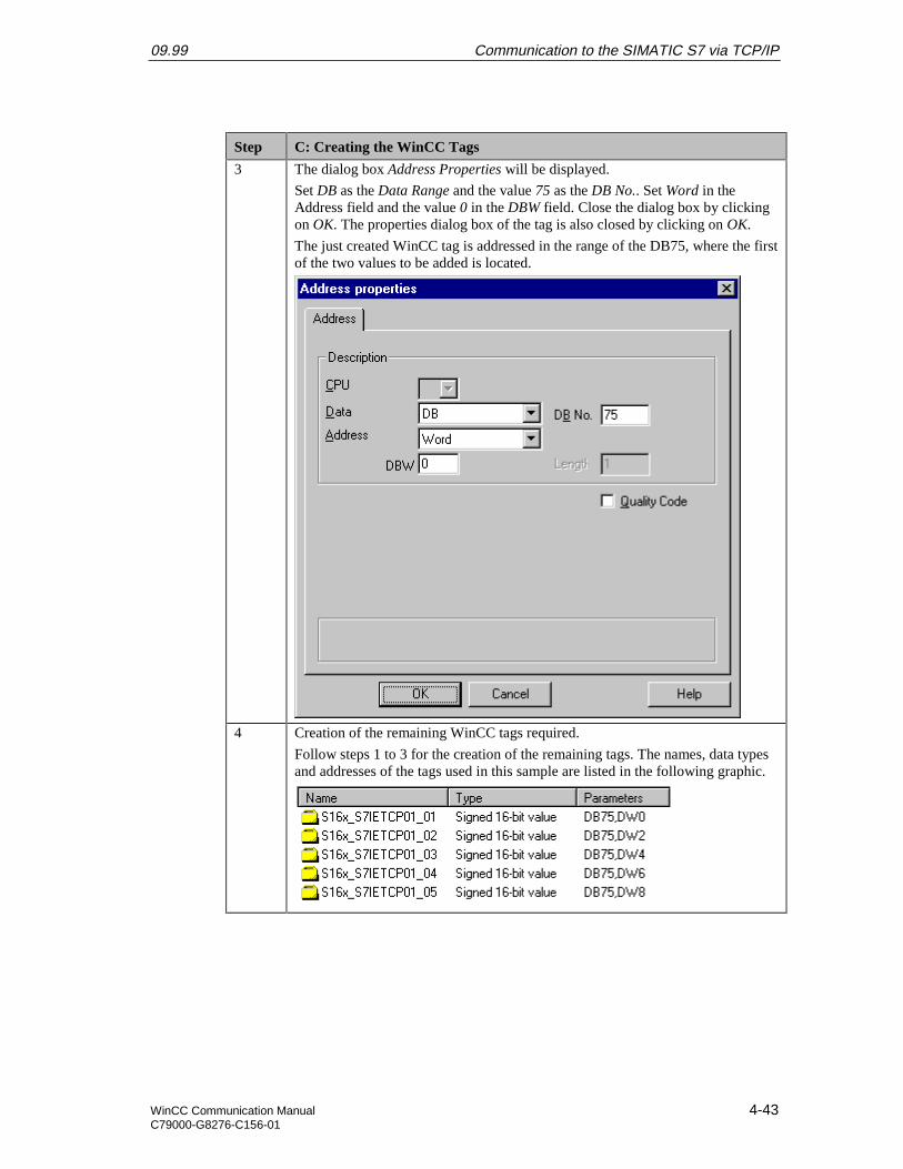
09.99 Communication to the SIMATIC S7 via TCP/IP
WinCC Communication Manual 4-43C79000-G8276-C156-01
Step C: Creating the WinCC Tags
3 The dialog box Address Properties will be displayed.
Set DB as the Data Range and the value 75 as the DB No.. Set Word in theAddress field and the value 0 in the DBW field. Close the dialog box by clickingon OK. The properties dialog box of the tag is also closed by clicking on OK.
The just created WinCC tag is addressed in the range of the DB75, where the firstof the two values to be added is located.
4 Creation of the remaining WinCC tags required.
Follow steps 1 to 3 for the creation of the remaining tags. The names, data typesand addresses of the tags used in this sample are listed in the following graphic.

Communication to the SIMATIC S7 via TCP/IP 09.99
4-44 WinCC Communication ManualC79000-G8276-C156-01
D: Creating the WinCC Screen
Step D: Creating the WinCC Screen
1 Creation of a WinCC screen in which the previously created tags are visualized.
Open the Graphics Designer editor via a R and then selecting Open from thepop-up menu.
2 This will open the Graphics Designer editor with a new (blank) screen.
To display the first tag, configure a Smart Object I/O Field. To do so,select the I/O Field object from the Object Palette and place it on the screenusing the mouse.
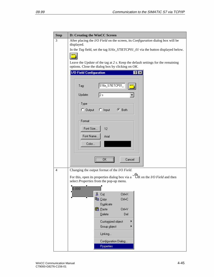
09.99 Communication to the SIMATIC S7 via TCP/IP
WinCC Communication Manual 4-45C79000-G8276-C156-01
Step D: Creating the WinCC Screen
3 After placing the I/O Field on the screen, its Configuration dialog box will bedisplayed.
In the Tag field, set the tag S16x_S7IETCP01_01 via the button displayed below.
Leave the Update of the tag at 2 s. Keep the default settings for the remainingoptions. Close the dialog box by clicking on OK.
4 Changing the output format of the I/O Field.
For this, open its properties dialog box via a R on the I/O Field and thenselect Properties from the pop-up menu.
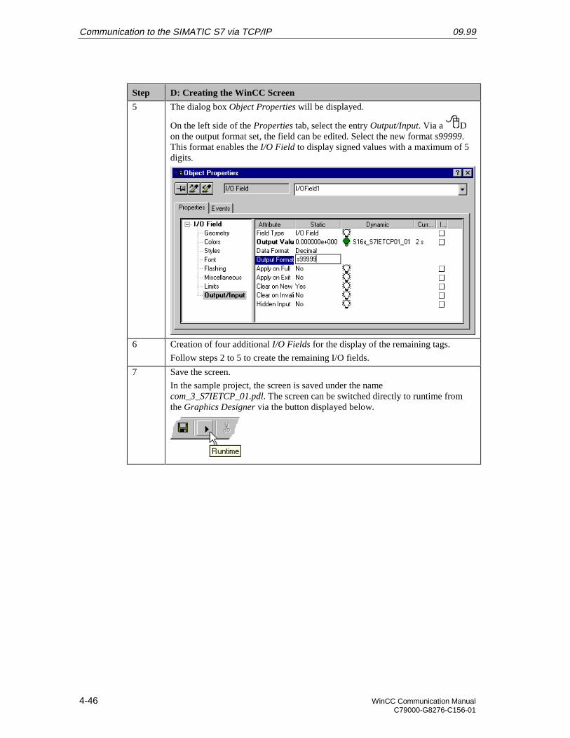
Communication to the SIMATIC S7 via TCP/IP 09.99
4-46 WinCC Communication ManualC79000-G8276-C156-01
Step D: Creating the WinCC Screen
5 The dialog box Object Properties will be displayed.
On the left side of the Properties tab, select the entry Output/Input. Via a Don the output format set, the field can be edited. Select the new format s99999.This format enables the I/O Field to display signed values with a maximum of 5digits.
6 Creation of four additional I/O Fields for the display of the remaining tags.
Follow steps 2 to 5 to create the remaining I/O fields.
7 Save the screen.
In the sample project, the screen is saved under the namecom_3_S7IETCP_01.pdl. The screen can be switched directly to runtime fromthe Graphics Designer via the button displayed below.

09.99 Communication to the SIMATIC S7 via TCP/IP
WinCC Communication Manual 4-47C79000-G8276-C156-01
Step D: Creating the WinCC Screen
If the screen is in runtime, the PLC started and the network connectionestablished, the current values of the PLC will be displayed in the I/O fields.They can be changed by entering values in the individual I/O Fields.
If there is no connection to the PLC, the I/O Fields will be displayed grayed out.In this case an error is present at some point of the communication connection.
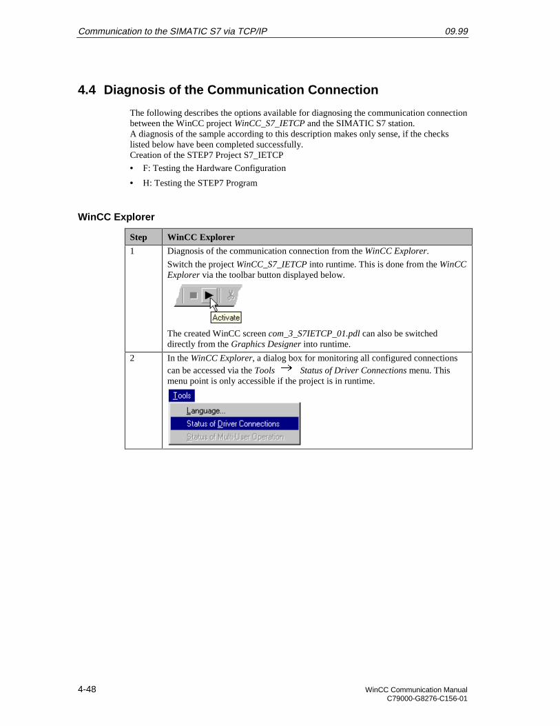
Communication to the SIMATIC S7 via TCP/IP 09.99
4-48 WinCC Communication ManualC79000-G8276-C156-01
4.4 Diagnosis of the Communication Connection
The following describes the options available for diagnosing the communication connectionbetween the WinCC project WinCC_S7_IETCP and the SIMATIC S7 station.A diagnosis of the sample according to this description makes only sense, if the checkslisted below have been completed successfully.Creation of the STEP7 Project S7_IETCP
• F: Testing the Hardware Configuration
• H: Testing the STEP7 Program
WinCC Explorer
Step WinCC Explorer
1 Diagnosis of the communication connection from the WinCC Explorer.
Switch the project WinCC_S7_IETCP into runtime. This is done from the WinCCExplorer via the toolbar button displayed below.
The created WinCC screen com_3_S7IETCP_01.pdl can also be switcheddirectly from the Graphics Designer into runtime.
2 In the WinCC Explorer, a dialog box for monitoring all configured connectionscan be accessed via the Tools Status of Driver Connections menu. Thismenu point is only accessible if the project is in runtime.
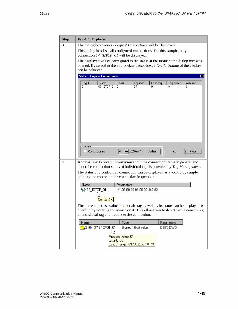
09.99 Communication to the SIMATIC S7 via TCP/IP
WinCC Communication Manual 4-49C79000-G8276-C156-01
Step WinCC Explorer
3 The dialog box Status - Logical Connections will be displayed.
This dialog box lists all configured connections. For this sample, only theconnection S7_IETCP_01 will be displayed.
The displayed values correspond to the status at the moment the dialog box wasopened. By selecting the appropriate check-box, a Cyclic Update of the displaycan be achieved.
4 Another way to obtain information about the connection status in general andabout the connection status of individual tags is provided by Tag Management.
The status of a configured connection can be displayed as a tooltip by simplypointing the mouse on the connection in question.
The current process value of a certain tag as well as its status can be displayed asa tooltip by pointing the mouse on it. This allows you to detect errors concerningan individual tag and not the entire connection.
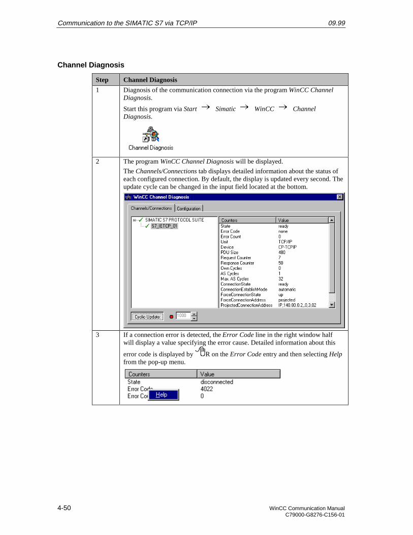
Communication to the SIMATIC S7 via TCP/IP 09.99
4-50 WinCC Communication ManualC79000-G8276-C156-01
Channel Diagnosis
Step Channel Diagnosis
1 Diagnosis of the communication connection via the program WinCC ChannelDiagnosis.
Start this program via Start Simatic WinCC ChannelDiagnosis.
2 The program WinCC Channel Diagnosis will be displayed.
The Channels/Connections tab displays detailed information about the status ofeach configured connection. By default, the display is updated every second. Theupdate cycle can be changed in the input field located at the bottom.
3 If a connection error is detected, the Error Code line in the right window halfwill display a value specifying the error cause. Detailed information about this
error code is displayed by R on the Error Code entry and then selecting Helpfrom the pop-up menu.
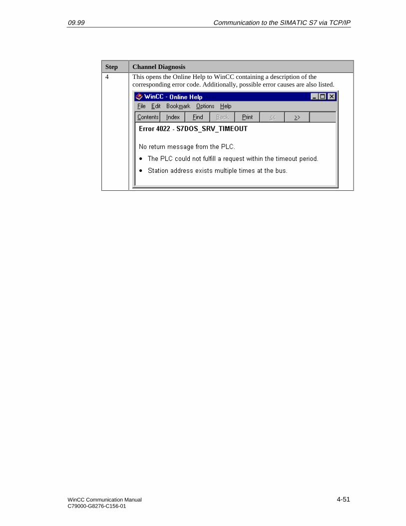
09.99 Communication to the SIMATIC S7 via TCP/IP
WinCC Communication Manual 4-51C79000-G8276-C156-01
Step Channel Diagnosis
4 This opens the Online Help to WinCC containing a description of thecorresponding error code. Additionally, possible error causes are also listed.

Communication to the SIMATIC S7 via TCP/IP 09.99
4-52 WinCC Communication ManualC79000-G8276-C156-01
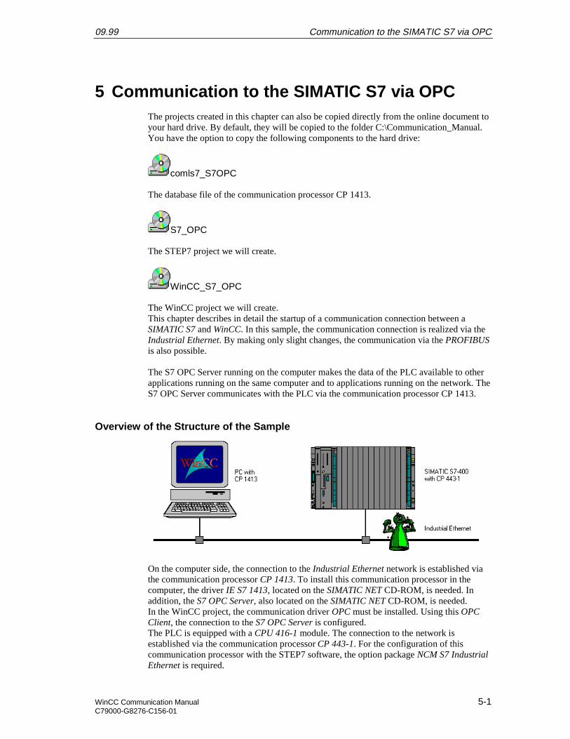
09.99 Communication to the SIMATIC S7 via OPC
WinCC Communication Manual 5-1C79000-G8276-C156-01
5 Communication to the SIMATIC S7 via OPCThe projects created in this chapter can also be copied directly from the online document toyour hard drive. By default, they will be copied to the folder C:\Communication_Manual.You have the option to copy the following components to the hard drive:
comls7_S7OPC
The database file of the communication processor CP 1413.
S7_OPC
The STEP7 project we will create.
WinCC_S7_OPC
The WinCC project we will create.This chapter describes in detail the startup of a communication connection between aSIMATIC S7 and WinCC. In this sample, the communication connection is realized via theIndustrial Ethernet. By making only slight changes, the communication via the PROFIBUSis also possible.
The S7 OPC Server running on the computer makes the data of the PLC available to otherapplications running on the same computer and to applications running on the network. TheS7 OPC Server communicates with the PLC via the communication processor CP 1413.
Overview of the Structure of the Sample
On the computer side, the connection to the Industrial Ethernet network is established viathe communication processor CP 1413. To install this communication processor in thecomputer, the driver IE S7 1413, located on the SIMATIC NET CD-ROM, is needed. Inaddition, the S7 OPC Server, also located on the SIMATIC NET CD-ROM, is needed.In the WinCC project, the communication driver OPC must be installed. Using this OPCClient, the connection to the S7 OPC Server is configured.The PLC is equipped with a CPU 416-1 module. The connection to the network isestablished via the communication processor CP 443-1. For the configuration of thiscommunication processor with the STEP7 software, the option package NCM S7 IndustrialEthernet is required.
Communication to the SIMATIC S7 via OPC 09.99
5-2 WinCC Communication ManualC79000-G8276-C156-01
Overview of the Configuration Steps
The following lists all configuration steps necessary for the creation of the communicationconnection:
• Startup of the Communication Processor CP 1413
• Creation of the STEP7 Project S7_OPC
• Configuration of the S7 OPC Server
• Creation of the WinCC Project WinCC_S7_OPC
• Diagnosis of the Communication Connection
Required Software
Name Description
SIMATIC NET Driver IE S7-1413 from the SIMATIC NET CD-ROM forthe installation of the communication processor CP 1413.
S7 OPC Server for the communication to the OPC Clientfrom WinCC.
STEP7 STEP7 software with option package NCM for IndustrialEthernet for the creation of the STEP7 project.
WinCC WinCC with the communication driver OPC for thecreation of the WinCC project.
Required Computer Hardware
Name Description
Communication Processor Communication processor CP 1413 to establish theconnection to the PLC’s communication processor.
Required PLC Hardware
Name Description
Rack Rack UR1
Power Supply Power supply PS 407 10A in slot 1 and 2.
CPU Module CPU module CPU 416-1 in slot 3.
Communication Processor Communication processor CP 443-1 in slot 4.
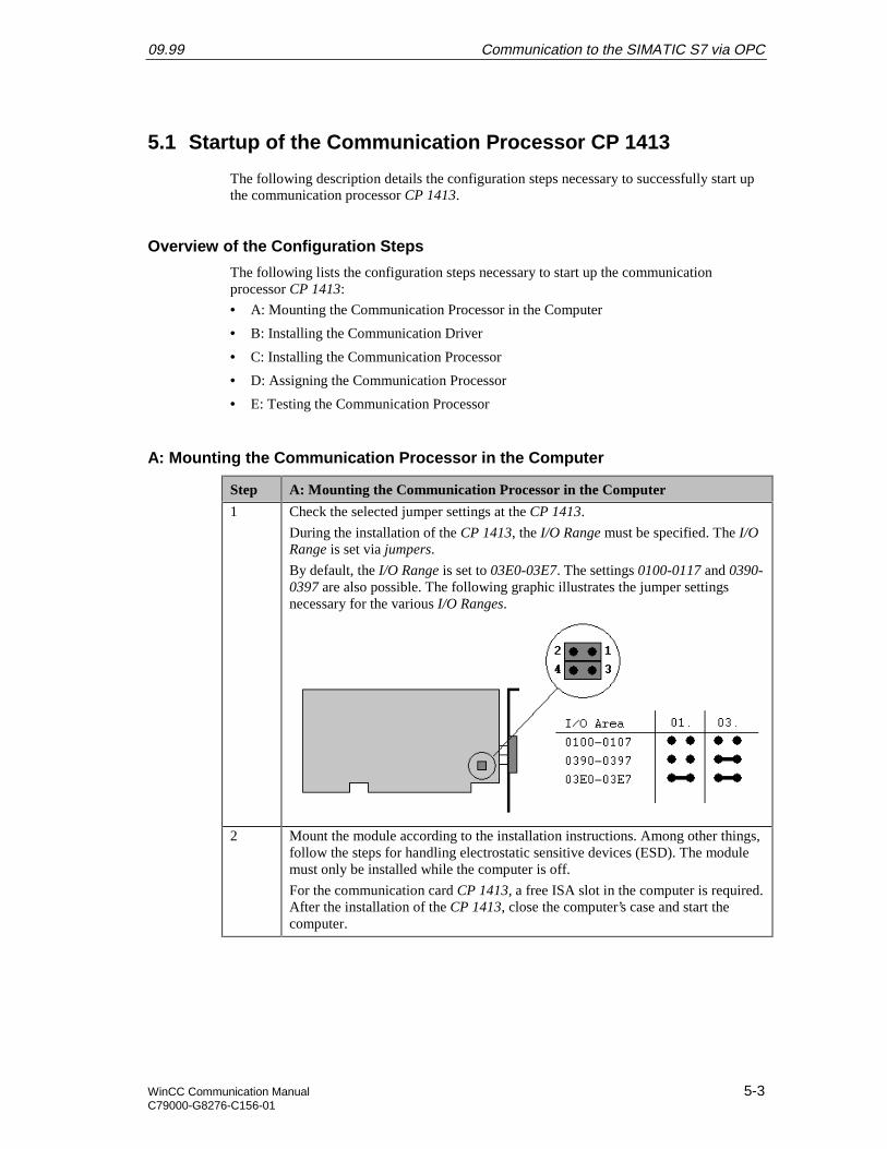
09.99 Communication to the SIMATIC S7 via OPC
WinCC Communication Manual 5-3C79000-G8276-C156-01
5.1 Startup of the Communication Processor CP 1413
The following description details the configuration steps necessary to successfully start upthe communication processor CP 1413.
Overview of the Configuration Steps
The following lists the configuration steps necessary to start up the communicationprocessor CP 1413:
• A: Mounting the Communication Processor in the Computer
• B: Installing the Communication Driver
• C: Installing the Communication Processor
• D: Assigning the Communication Processor
• E: Testing the Communication Processor
A: Mounting the Communication Processor in the Computer
Step A: Mounting the Communication Processor in the Computer
1 Check the selected jumper settings at the CP 1413.
During the installation of the CP 1413, the I/O Range must be specified. The I/ORange is set via jumpers.
By default, the I/O Range is set to 03E0-03E7. The settings 0100-0117 and 0390-0397 are also possible. The following graphic illustrates the jumper settingsnecessary for the various I/O Ranges.
2 Mount the module according to the installation instructions. Among other things,follow the steps for handling electrostatic sensitive devices (ESD). The modulemust only be installed while the computer is off.
For the communication card CP 1413, a free ISA slot in the computer is required.After the installation of the CP 1413, close the computer’s case and start thecomputer.
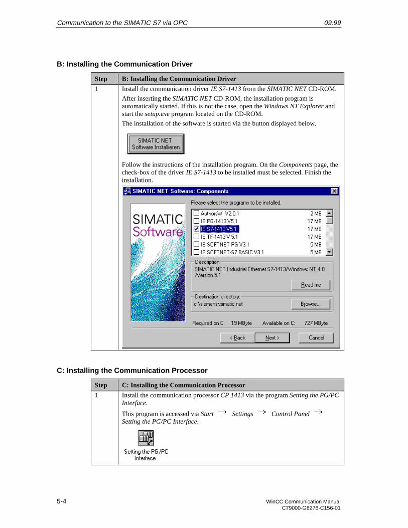
Communication to the SIMATIC S7 via OPC 09.99
5-4 WinCC Communication ManualC79000-G8276-C156-01
B: Installing the Communication Driver
Step B: Installing the Communication Driver
1 Install the communication driver IE S7-1413 from the SIMATIC NET CD-ROM.
After inserting the SIMATIC NET CD-ROM, the installation program isautomatically started. If this is not the case, open the Windows NT Explorer andstart the setup.exe program located on the CD-ROM.
The installation of the software is started via the button displayed below.
Follow the instructions of the installation program. On the Components page, thecheck-box of the driver IE S7-1413 to be installed must be selected. Finish theinstallation.
C: Installing the Communication Processor
Step C: Installing the Communication Processor
1 Install the communication processor CP 1413 via the program Setting the PG/PCInterface.
This program is accessed via Start Settings Control Panel Setting the PG/PC Interface.
09.99 Communication to the SIMATIC S7 via OPC
WinCC Communication Manual 5-5C79000-G8276-C156-01
Step C: Installing the Communication Processor
2 The program Setting the PG/PC Interface will be displayed.
The dialog box for installing a new interface is opened via the Install button.
3 The dialog box Install/Remove Modules will be displayed. The Selection fieldlists all interfaces that can be installed. Among them will be the entry CP 1413, ifthe communication driver has been installed previously as outlined in step B.
From the Selection field, select the entry CP 1413. The installation of thecommunication processor is started by clicking on the Install -> button.
Communication to the SIMATIC S7 via OPC 09.99
5-6 WinCC Communication ManualC79000-G8276-C156-01
Step C: Installing the Communication Processor
4 The dialog box Resources - CP 1413 will be displayed.
The settings for the Memory Range, I/O Range and Interrupt have to bespecified.
The I/O Range has already been determined via the Jumper Settings at the CP1413.
Make sure that the assigned resources have not already been taken by othermodules in the computer. Information about already taken system resources canbe obtained from the Resources tab accessed via Start Programs Administrative Tools (Common) Windows NT Diagnostics.
Close the Resources tab by clicking on OK.
5 In the dialog box Install/Remove Modules, the Installed field will now contain theentry for the CP 1413.
Exit the dialog box Install/Remove Modules via the Close button.
09.99 Communication to the SIMATIC S7 via OPC
WinCC Communication Manual 5-7C79000-G8276-C156-01
D: Assigning the Communication Processor
Step D: Assigning the Communication Processor
1 In the program Setting the PG/PC Interface, assign the access point CP_H1_1: tothe just installed interface.
It has been created automatically during the installation of the communicationdriver IE S7-1413.
In the field Access Point of the Application, set the entry CP_H1_1:. In the fieldbelow, select the entry CP1413. This completes the assignment between theaccess point and the communication processor.
Communication to the SIMATIC S7 via OPC 09.99
5-8 WinCC Communication ManualC79000-G8276-C156-01
Step D: Assigning the Communication Processor
2 Setting the properties of the communication processor CP 1413.
The dialog box for setting the properties is opened via the Properties button ofthe Setting the PG/PC Interface program.
The dialog box Properties - CP 1413 will be displayed.
In the Ethernet (MAC) Address tab, enter the Ethernet Address of the CP 1413.In our sample, this is 08.00.06.01.00.01.
The Ethernet Address is six Bytes long and structured as follows for SIEMENSdevices:
• 08.00.06: The first six digits of the hexadecimal value correspond to thenumber for SIEMENS.
• 01: The next two digits specify the range for SIEMENS.
• 0: The next digit signifies the SIMATIC system.
• 0.01: The last three digits correspond to the significant station address of aSIEMENS device.
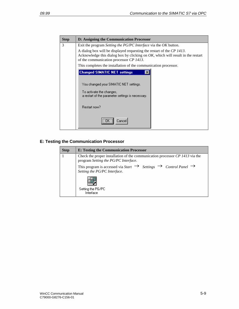
09.99 Communication to the SIMATIC S7 via OPC
WinCC Communication Manual 5-9C79000-G8276-C156-01
Step D: Assigning the Communication Processor
3 Exit the program Setting the PG/PC Interface via the OK button.
A dialog box will be displayed requesting the restart of the CP 1413.Acknowledge this dialog box by clicking on OK, which will result in the restartof the communication processor CP 1413.
This completes the installation of the communication processor.
E: Testing the Communication Processor
Step E: Testing the Communication Processor
1 Check the proper installation of the communication processor CP 1413 via theprogram Setting the PG/PC Interface.
This program is accessed via Start Settings Control Panel Setting the PG/PC Interface.
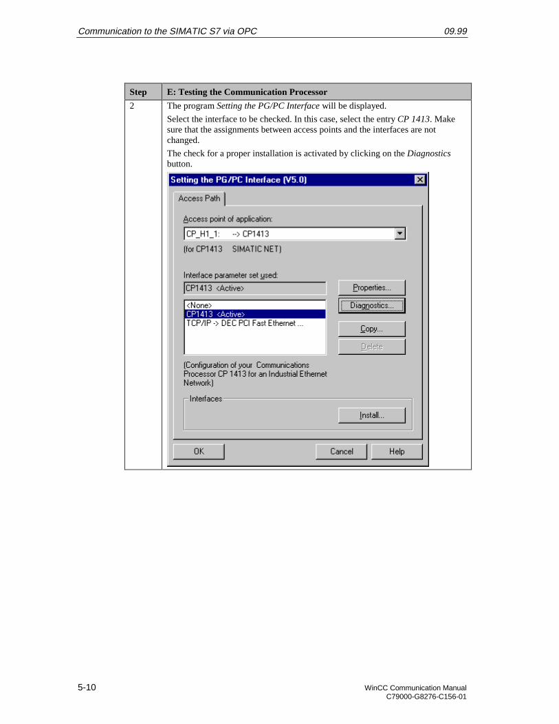
Communication to the SIMATIC S7 via OPC 09.99
5-10 WinCC Communication ManualC79000-G8276-C156-01
Step E: Testing the Communication Processor
2 The program Setting the PG/PC Interface will be displayed.
Select the interface to be checked. In this case, select the entry CP 1413. Makesure that the assignments between access points and the interfaces are notchanged.
The check for a proper installation is activated by clicking on the Diagnosticsbutton.
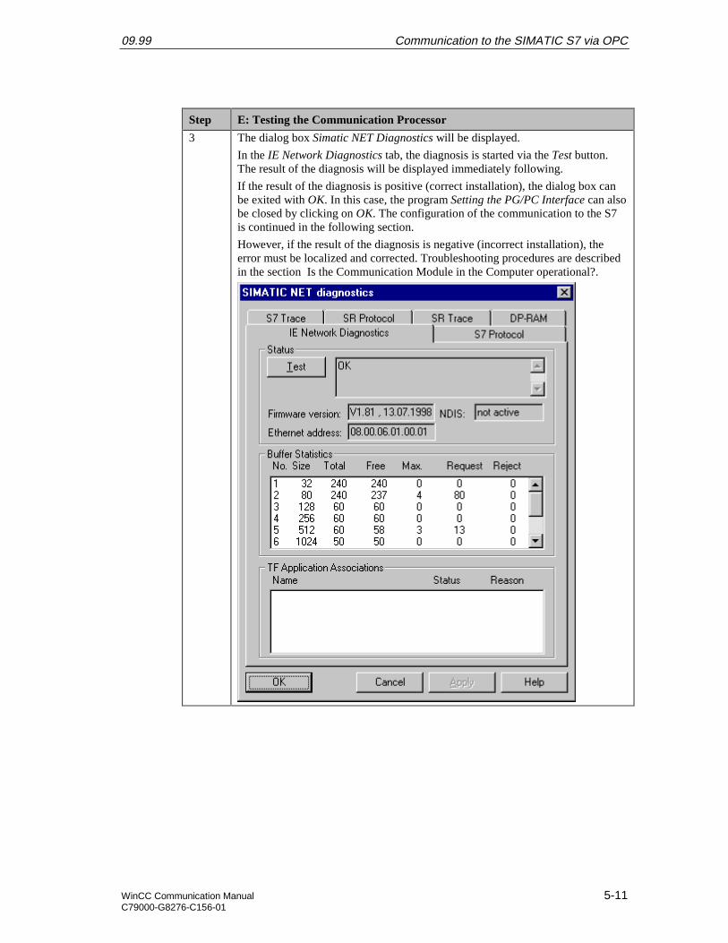
09.99 Communication to the SIMATIC S7 via OPC
WinCC Communication Manual 5-11C79000-G8276-C156-01
Step E: Testing the Communication Processor
3 The dialog box Simatic NET Diagnostics will be displayed.
In the IE Network Diagnostics tab, the diagnosis is started via the Test button.The result of the diagnosis will be displayed immediately following.
If the result of the diagnosis is positive (correct installation), the dialog box canbe exited with OK. In this case, the program Setting the PG/PC Interface can alsobe closed by clicking on OK. The configuration of the communication to the S7is continued in the following section.
However, if the result of the diagnosis is negative (incorrect installation), theerror must be localized and corrected. Troubleshooting procedures are describedin the section Is the Communication Module in the Computer operational?.
Communication to the SIMATIC S7 via OPC 09.99
5-12 WinCC Communication ManualC79000-G8276-C156-01
5.2 Creation of the STEP7 Project S7_OPC
The following description details the configuration steps necessary to create and start up theSTEP7 project S7_OPC.
Overview of the Configuration Steps
The following lists the configuration steps necessary to create the STEP7 project S7_OPC:
• A: Installing the Hardware
• B: Installing the Option Package
• C: Creating the STEP7 Project
• D: Configuring the Hardware
• E: Loading the Hardware Configuration
• F: Testing the Hardware Configuration
• G: Creating the STEP7 Program
• H: Testing the STEP7 Program
A: Installing the Hardware
Step A: Installing the Hardware
1 Rack-mounting of the modules used.
In this sample, the modules to be installed are the power supply PS 407 10A, theCPU module CPU 416-1 and the communication processor CP 443-1.
Establishing the connection from the programming device to the programminginterface of the CPU module.
Establishing the connection from the communication processor CP 1413 in thecomputer to the communication processor CP 443-1 in the PLC.
B: Installing the Option Package
Step B: Installing the Option Package
1 If the option package NCM S7 Industrial Ethernet has not been installed duringthe installation of STEP7, install it now from the STEP7 CD-ROM. This optionpackage is required for the configuration of the communication processor CP443-1 via the STEP7 software.
After inserting the STEP7 CD-ROM, the installation program is automaticallystarted. If this is not the case, open the Windows NT Explorer and start thesetup.exe program located on the CD-ROM.
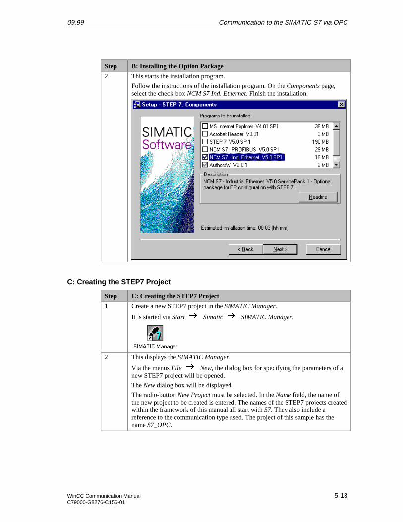
09.99 Communication to the SIMATIC S7 via OPC
WinCC Communication Manual 5-13C79000-G8276-C156-01
Step B: Installing the Option Package
2 This starts the installation program.
Follow the instructions of the installation program. On the Components page,select the check-box NCM S7 Ind. Ethernet. Finish the installation.
C: Creating the STEP7 Project
Step C: Creating the STEP7 Project
1 Create a new STEP7 project in the SIMATIC Manager.
It is started via Start Simatic SIMATIC Manager.
2 This displays the SIMATIC Manager.
Via the menus File New, the dialog box for specifying the parameters of anew STEP7 project will be opened.
The New dialog box will be displayed.
The radio-button New Project must be selected. In the Name field, the name ofthe new project to be created is entered. The names of the STEP7 projects createdwithin the framework of this manual all start with S7. They also include areference to the communication type used. The project of this sample has thename S7_OPC.
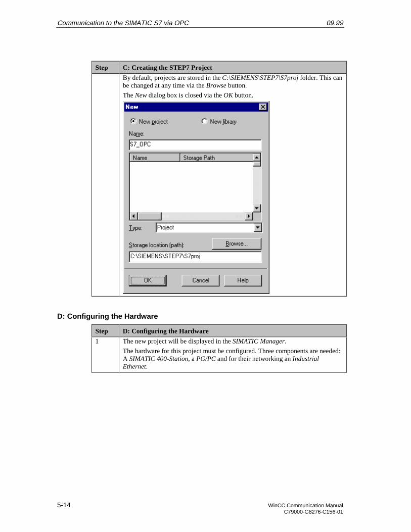
Communication to the SIMATIC S7 via OPC 09.99
5-14 WinCC Communication ManualC79000-G8276-C156-01
Step C: Creating the STEP7 Project
By default, projects are stored in the C:\SIEMENS\STEP7\S7proj folder. This canbe changed at any time via the Browse button.
The New dialog box is closed via the OK button.
D: Configuring the Hardware
Step D: Configuring the Hardware
1 The new project will be displayed in the SIMATIC Manager.
The hardware for this project must be configured. Three components are needed:A SIMATIC 400-Station, a PG/PC and for their networking an IndustrialEthernet.
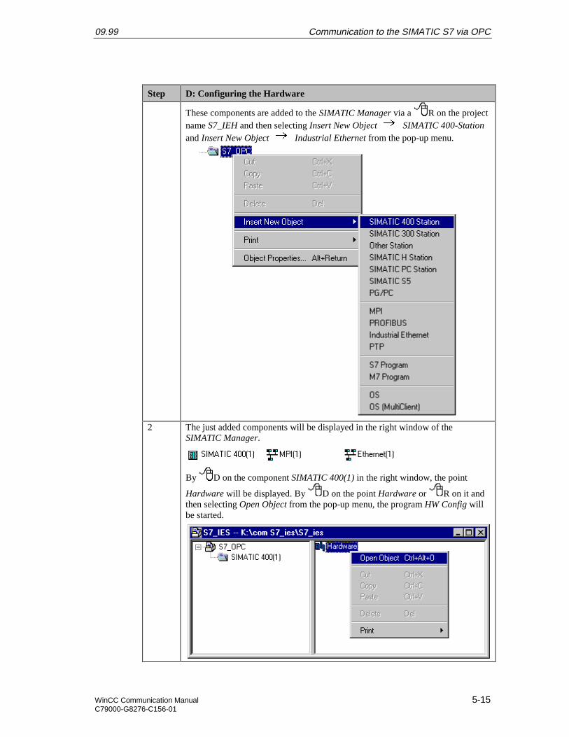
09.99 Communication to the SIMATIC S7 via OPC
WinCC Communication Manual 5-15C79000-G8276-C156-01
Step D: Configuring the Hardware
These components are added to the SIMATIC Manager via a R on the projectname S7_IEH and then selecting Insert New Object SIMATIC 400-Stationand Insert New Object Industrial Ethernet from the pop-up menu.
2 The just added components will be displayed in the right window of theSIMATIC Manager.
By D on the component SIMATIC 400(1) in the right window, the point
Hardware will be displayed. By D on the point Hardware or R on it andthen selecting Open Object from the pop-up menu, the program HW Config willbe started.
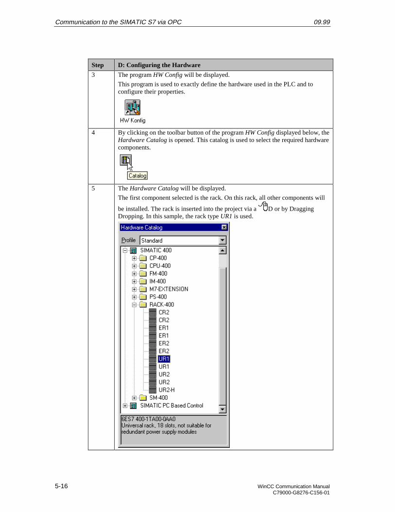
Communication to the SIMATIC S7 via OPC 09.99
5-16 WinCC Communication ManualC79000-G8276-C156-01
Step D: Configuring the Hardware
3 The program HW Config will be displayed.
This program is used to exactly define the hardware used in the PLC and toconfigure their properties.
4 By clicking on the toolbar button of the program HW Config displayed below, theHardware Catalog is opened. This catalog is used to select the required hardwarecomponents.
5 The Hardware Catalog will be displayed.
The first component selected is the rack. On this rack, all other components will
be installed. The rack is inserted into the project via a D or by DraggingDropping. In this sample, the rack type UR1 is used.
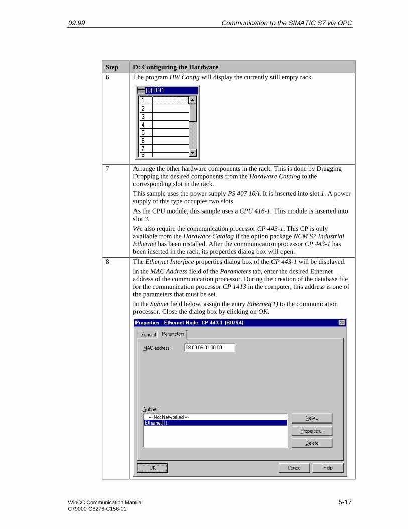
09.99 Communication to the SIMATIC S7 via OPC
WinCC Communication Manual 5-17C79000-G8276-C156-01
Step D: Configuring the Hardware
6 The program HW Config will display the currently still empty rack.
7 Arrange the other hardware components in the rack. This is done by DraggingDropping the desired components from the Hardware Catalog to thecorresponding slot in the rack.
This sample uses the power supply PS 407 10A. It is inserted into slot 1. A powersupply of this type occupies two slots.
As the CPU module, this sample uses a CPU 416-1. This module is inserted intoslot 3.
We also require the communication processor CP 443-1. This CP is onlyavailable from the Hardware Catalog if the option package NCM S7 IndustrialEthernet has been installed. After the communication processor CP 443-1 hasbeen inserted in the rack, its properties dialog box will open.
8 The Ethernet Interface properties dialog box of the CP 443-1 will be displayed.
In the MAC Address field of the Parameters tab, enter the desired Ethernetaddress of the communication processor. During the creation of the database filefor the communication processor CP 1413 in the computer, this address is one ofthe parameters that must be set.
In the Subnet field below, assign the entry Ethernet(1) to the communicationprocessor. Close the dialog box by clicking on OK.
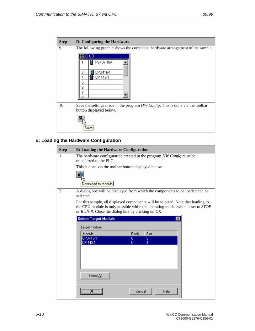
Communication to the SIMATIC S7 via OPC 09.99
5-18 WinCC Communication ManualC79000-G8276-C156-01
Step D: Configuring the Hardware
9 The following graphic shows the completed hardware arrangement of the sample.
10 Save the settings made in the program HW Config. This is done via the toolbarbutton displayed below.
E: Loading the Hardware Configuration
Step E: Loading the Hardware Configuration
1 The hardware configuration created in the program HW Config must betransferred to the PLC.
This is done via the toolbar button displayed below.
2 A dialog box will be displayed from which the components to be loaded can beselected.
For this sample, all displayed components will be selected. Note that loading tothe CPU module is only possible while the operating mode switch is set to STOPor RUN-P. Close the dialog box by clicking on OK.
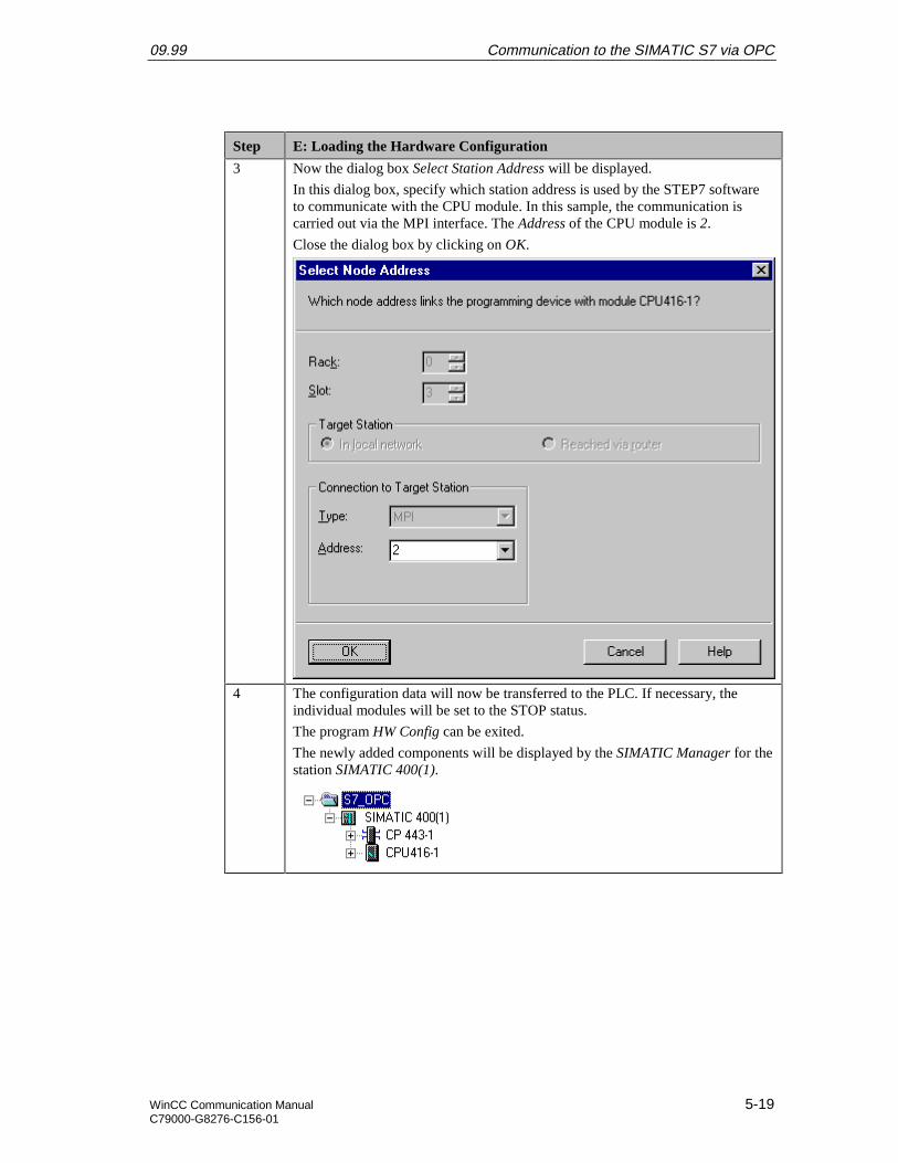
09.99 Communication to the SIMATIC S7 via OPC
WinCC Communication Manual 5-19C79000-G8276-C156-01
Step E: Loading the Hardware Configuration
3 Now the dialog box Select Station Address will be displayed.
In this dialog box, specify which station address is used by the STEP7 softwareto communicate with the CPU module. In this sample, the communication iscarried out via the MPI interface. The Address of the CPU module is 2.
Close the dialog box by clicking on OK.
4 The configuration data will now be transferred to the PLC. If necessary, theindividual modules will be set to the STOP status.
The program HW Config can be exited.
The newly added components will be displayed by the SIMATIC Manager for thestation SIMATIC 400(1).

Communication to the SIMATIC S7 via OPC 09.99
5-20 WinCC Communication ManualC79000-G8276-C156-01
F: Testing the Hardware Configuration
Step F: Testing the Hardware Configuration
1 Testing of the hardware configuration made.
If the key switch of the CPU module is set to RUN orRUN-P and the operatingmode switch of the communication processor is set to RUN, only the status LEDssignifying the RUN operating mode should be displayed.
If this is not the case, there is an error. The following steps help you localize thiserror. However, these steps should still be performed even if the status LEDsshow no error. This allows you to recognize uncritical errors and faultyconfigurations.
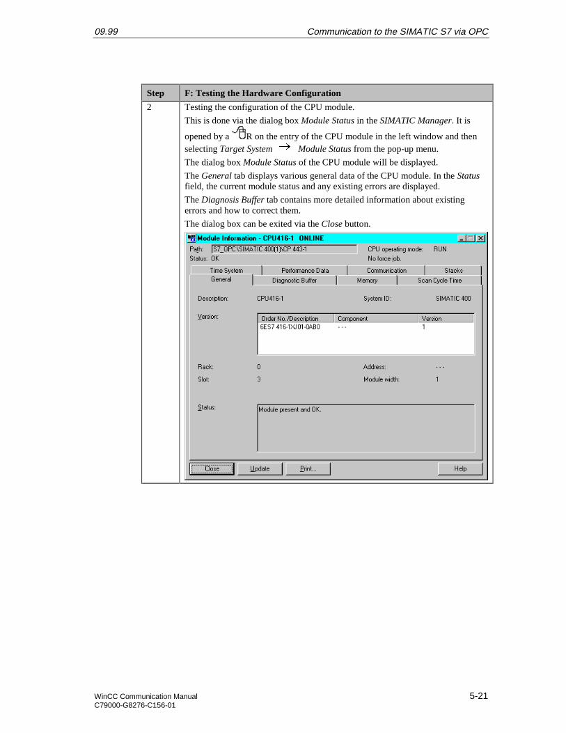
09.99 Communication to the SIMATIC S7 via OPC
WinCC Communication Manual 5-21C79000-G8276-C156-01
Step F: Testing the Hardware Configuration
2 Testing the configuration of the CPU module.
This is done via the dialog box Module Status in the SIMATIC Manager. It is
opened by a R on the entry of the CPU module in the left window and thenselecting Target System Module Status from the pop-up menu.
The dialog box Module Status of the CPU module will be displayed.
The General tab displays various general data of the CPU module. In the Statusfield, the current module status and any existing errors are displayed.
The Diagnosis Buffer tab contains more detailed information about existingerrors and how to correct them.
The dialog box can be exited via the Close button.

Communication to the SIMATIC S7 via OPC 09.99
5-22 WinCC Communication ManualC79000-G8276-C156-01
Step F: Testing the Hardware Configuration
3 Testing the configuration of the communication processor.
This is done via the dialog box Module Status in the SIMATIC Manager. It is
opened by a R on the entry of the communication processor in the leftwindow and then selecting Target System Module Status from the pop-upmenu.
The dialog box Module Status of the communication processor will be displayed.
The General tab displays various general data of the module.
A dialog box for a more detailed diagnosis of the communication processor canbe accessed via the Special Diagnosis button.
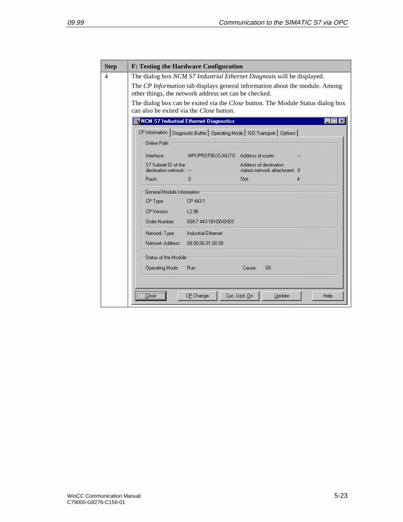
09.99 Communication to the SIMATIC S7 via OPC
WinCC Communication Manual 5-23C79000-G8276-C156-01
Step F: Testing the Hardware Configuration
4 The dialog box NCM S7 Industrial Ethernet Diagnosis will be displayed.
The CP Information tab displays general information about the module. Amongother things, the network address set can be checked.
The dialog box can be exited via the Close button. The Module Status dialog boxcan also be exited via the Close button.

Communication to the SIMATIC S7 via OPC 09.99
5-24 WinCC Communication ManualC79000-G8276-C156-01
G: Creating the STEP7 Program
Step G: Creating the STEP7 Program
1 Creation of the S7 Program.
This sample project requires the operation block OB1 and a data block. OB1 isavailable by default, the required data block must be created. This is done in the
SIMATIC Manager via a R on the sub-entry Modules of the entry S7Program(1) of the configured CPU module and then selecting Insert New Object
Data Block from the pop-up menu.
The properties dialog box of the data block will be opened. As the block’s Nameenter DB75 and close the dialog box with OK.
2 The newly created data block DB75 will be displayed in the right window of theproject.
Via a D on this data block or a R and then selecting Open Object from thepop-up menu, the content of the block can be programmed. This starts theprogram LAD/STL/SCF.
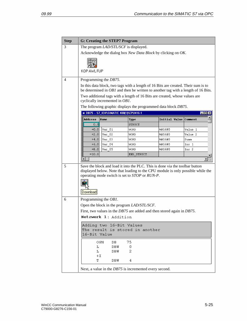
09.99 Communication to the SIMATIC S7 via OPC
WinCC Communication Manual 5-25C79000-G8276-C156-01
Step G: Creating the STEP7 Program
3 The program LAD/STL/SCF is displayed.
Acknowledge the dialog box New Data Block by clicking on OK.
4 Programming the DB75.
In this data block, two tags with a length of 16 Bits are created. Their sum is tobe determined in OB1 and then be written to another tag with a length of 16 Bits.
Two additional tags with a length of 16 Bits are created, whose values arecyclically incremented in OB1.
The following graphic displays the programmed data block DB75.
5 Save the block and load it into the PLC. This is done via the toolbar buttondisplayed below. Note that loading to the CPU module is only possible while theoperating mode switch is set to STOP or RUN-P.
6 Programming the OB1.
Open the block in the program LAD/STL/SCF.
First, two values in the DB75 are added and then stored again in DB75.
Next, a value in the DB75 is incremented every second.
Communication to the SIMATIC S7 via OPC 09.99
5-26 WinCC Communication ManualC79000-G8276-C156-01
Step G: Creating the STEP7 Program
Finally, a value in the DB75 is incremented every time the OB1 run.
7 Save the block OB1 and load it into the PLC. This is done via the correspondingbuttons on the toolbar.
This completes the creation of the STEP7 project and it can now be run. Exit theprogram LAD/STL/SCF.

09.99 Communication to the SIMATIC S7 via OPC
WinCC Communication Manual 5-27C79000-G8276-C156-01
H: Testing the STEP7 Program
Step H: Testing the STEP7 Program
1 Testing the program with the STEP7 software.
For this purpose, a tag table is created. This is done in the SIMATIC Manager via
a R on the entry of the configured CPU module and then selecting TargetSystem Monitor/Control Tag from the pop-up menu.
2 An editor for creating and using a tag table will be displayed.
The following shows a completed tag table. In this table, enter all tags created inthe DB75.
3 Monitoring the current tag values.
By clicking on the toolbar button displayed below, the current values of thecorresponding tags in the PLC are displayed in the column Status Value.
Controlling the tag values.
Values can be entered in the column Control Value. By clicking on the toolbarbutton displayed below, these values will be written to the corresponding tags inthe PLC.
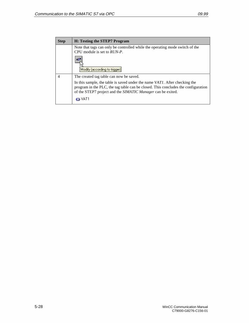
Communication to the SIMATIC S7 via OPC 09.99
5-28 WinCC Communication ManualC79000-G8276-C156-01
Step H: Testing the STEP7 Program
Note that tags can only be controlled while the operating mode switch of theCPU module is set to RUN-P.
4 The created tag table can now be saved.
In this sample, the table is saved under the name VAT1. After checking theprogram in the PLC, the tag table can be closed. This concludes the configurationof the STEP7 project and the SIMATIC Manager can be exited.
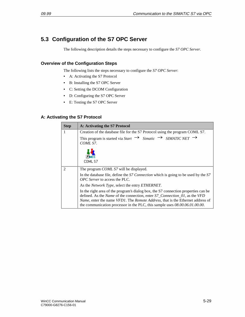
09.99 Communication to the SIMATIC S7 via OPC
WinCC Communication Manual 5-29C79000-G8276-C156-01
5.3 Configuration of the S7 OPC Server
The following description details the steps necessary to configure the S7 OPC Server.
Overview of the Configuration Steps
The following lists the steps necessary to configure the S7 OPC Server:
• A: Activating the S7 Protocol
• B: Installing the S7 OPC Server
• C: Setting the DCOM Configuration
• D: Configuring the S7 OPC Server
• E: Testing the S7 OPC Server
A: Activating the S7 Protocol
Step A: Activating the S7 Protocol
1 Creation of the database file for the S7 Protocol using the program COML S7.
This program is started via Start Simatic SIMATIC NET COML S7.
2 The program COML S7 will be displayed.
In the database file, define the S7 Connection which is going to be used by the S7OPC Server to access the PLC.
As the Network Type, select the entry ETHERNET.
In the right area of the program’s dialog box, the S7 connection properties can bedefined. As the Name of the connection, enter S7_Connection_01, as the VFDName, enter the name VFD1. The Remote Address, that is the Ethernet address ofthe communication processor in the PLC, this sample uses 08.00.06.01.00.00.
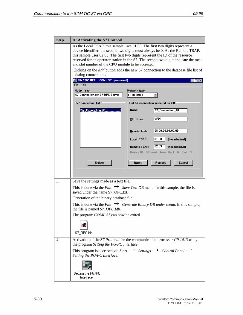
Communication to the SIMATIC S7 via OPC 09.99
5-30 WinCC Communication ManualC79000-G8276-C156-01
Step A: Activating the S7 Protocol
As the Local TSAP, this sample uses 01.00. The first two digits represent adevice identifier, the second two digits must always be 0. As the Remote TSAP,this sample uses 02.03. The first two digits represent the ID of the resourcereserved for an operator station in the S7. The second two digits indicate the rackand slot number of the CPU module to be accessed.
Clicking on the Add button adds the new S7 connection to the database file list ofexisting connections.
3 Save the settings made as a text file.
This is done via the File Save Text DB menu. In this sample, the file issaved under the name S7_OPC.txt.
Generation of the binary database file.
This is done via the File Generate Binary DB under menu. In this sample,the file is named S7_OPC.ldb.
The program COML S7 can now be exited.
4 Activation of the S7 Protocol for the communication processor CP 1413 usingthe program Setting the PG/PC Interface.
This program is accessed via Start Settings Control Panel Setting the PG/PC Interface.
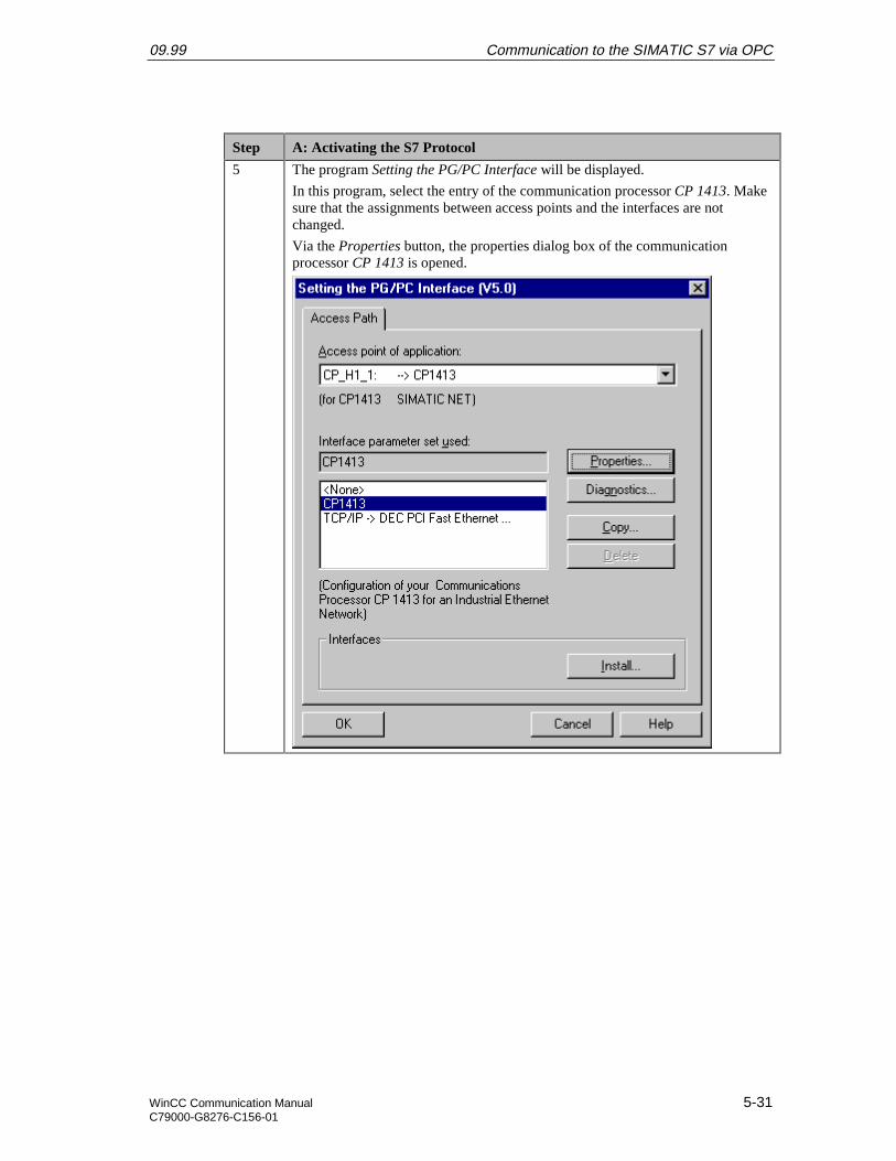
09.99 Communication to the SIMATIC S7 via OPC
WinCC Communication Manual 5-31C79000-G8276-C156-01
Step A: Activating the S7 Protocol
5 The program Setting the PG/PC Interface will be displayed.
In this program, select the entry of the communication processor CP 1413. Makesure that the assignments between access points and the interfaces are notchanged.
Via the Properties button, the properties dialog box of the communicationprocessor CP 1413 is opened.
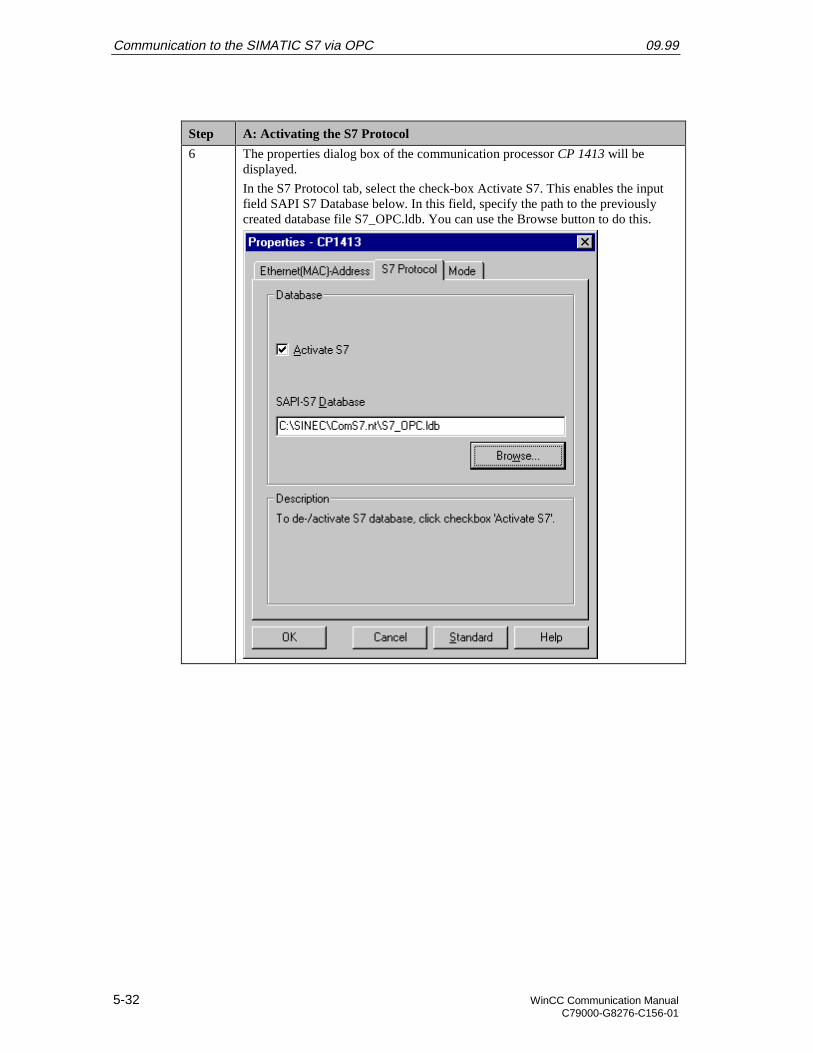
Communication to the SIMATIC S7 via OPC 09.99
5-32 WinCC Communication ManualC79000-G8276-C156-01
Step A: Activating the S7 Protocol
6 The properties dialog box of the communication processor CP 1413 will bedisplayed.
In the S7 Protocol tab, select the check-box Activate S7. This enables the inputfield SAPI S7 Database below. In this field, specify the path to the previouslycreated database file S7_OPC.ldb. You can use the Browse button to do this.
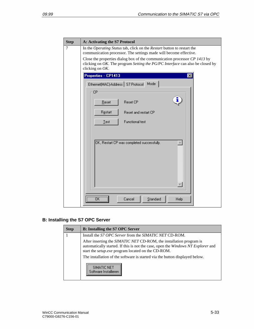
09.99 Communication to the SIMATIC S7 via OPC
WinCC Communication Manual 5-33C79000-G8276-C156-01
Step A: Activating the S7 Protocol
7 In the Operating Status tab, click on the Restart button to restart thecommunication processor. The settings made will become effective.
Close the properties dialog box of the communication processor CP 1413 byclicking on OK. The program Setting the PG/PC Interface can also be closed byclicking on OK.
B: Installing the S7 OPC Server
Step B: Installing the S7 OPC Server
1 Install the S7 OPC Server from the SIMATIC NET CD-ROM.
After inserting the SIMATIC NET CD-ROM, the installation program isautomatically started. If this is not the case, open the Windows NT Explorer andstart the setup.exe program located on the CD-ROM.
The installation of the software is started via the button displayed below.
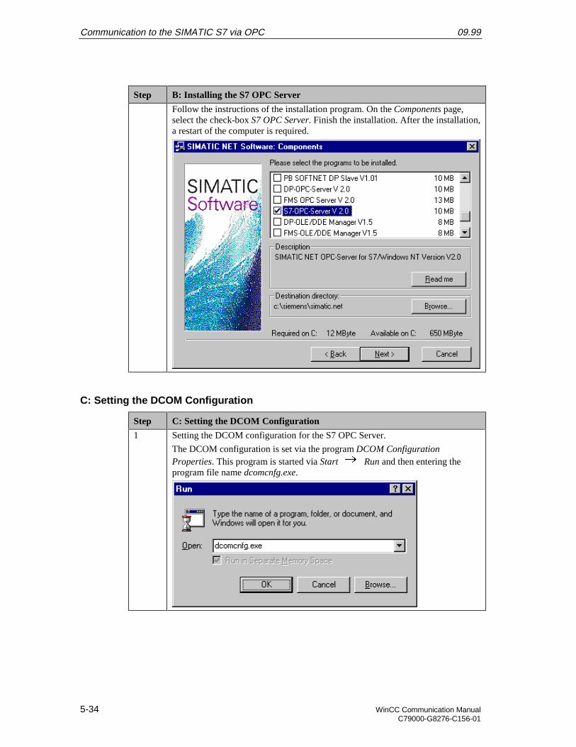
Communication to the SIMATIC S7 via OPC 09.99
5-34 WinCC Communication ManualC79000-G8276-C156-01
Step B: Installing the S7 OPC Server
Follow the instructions of the installation program. On the Components page,select the check-box S7 OPC Server. Finish the installation. After the installation,a restart of the computer is required.
C: Setting the DCOM Configuration
Step C: Setting the DCOM Configuration
1 Setting the DCOM configuration for the S7 OPC Server.
The DCOM configuration is set via the program DCOM ConfigurationProperties. This program is started via Start Run and then entering theprogram file name dcomcnfg.exe.
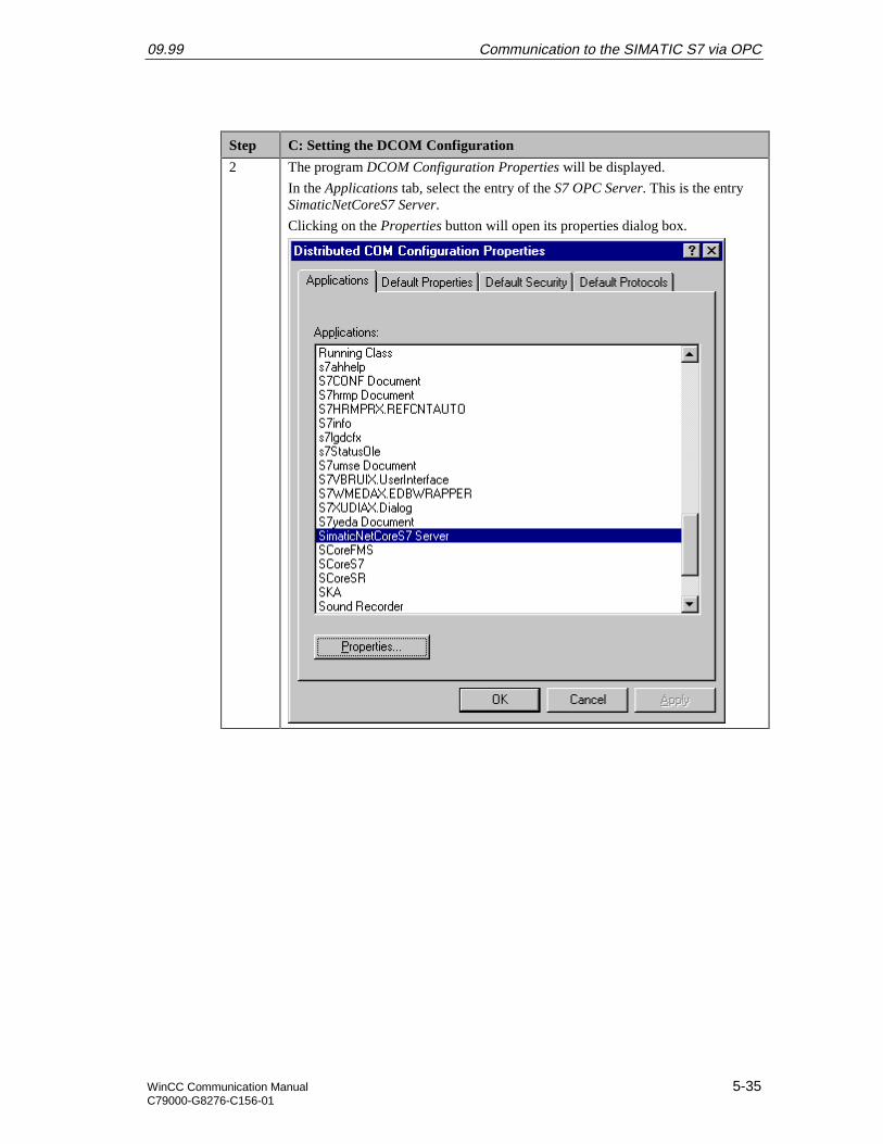
09.99 Communication to the SIMATIC S7 via OPC
WinCC Communication Manual 5-35C79000-G8276-C156-01
Step C: Setting the DCOM Configuration
2 The program DCOM Configuration Properties will be displayed.
In the Applications tab, select the entry of the S7 OPC Server. This is the entrySimaticNetCoreS7 Server.
Clicking on the Properties button will open its properties dialog box.
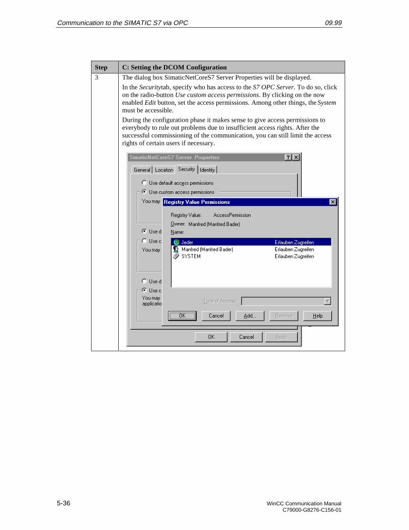
Communication to the SIMATIC S7 via OPC 09.99
5-36 WinCC Communication ManualC79000-G8276-C156-01
Step C: Setting the DCOM Configuration
3 The dialog box SimaticNetCoreS7 Server Properties will be displayed.
In the Securitytab, specify who has access to the S7 OPC Server. To do so, clickon the radio-button Use custom access permissions. By clicking on the nowenabled Edit button, set the access permissions. Among other things, the Systemmust be accessible.
During the configuration phase it makes sense to give access permissions toeverybody to rule out problems due to insufficient access rights. After thesuccessful commissioning of the communication, you can still limit the accessrights of certain users if necessary.
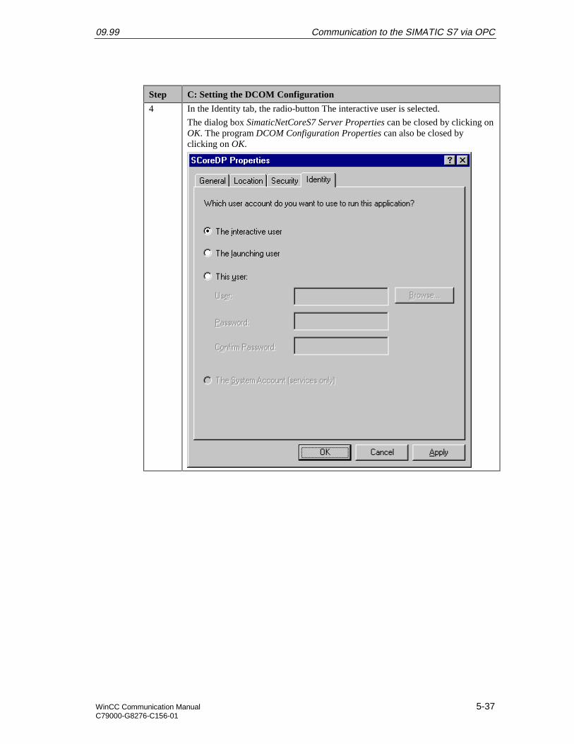
09.99 Communication to the SIMATIC S7 via OPC
WinCC Communication Manual 5-37C79000-G8276-C156-01
Step C: Setting the DCOM Configuration
4 In the Identity tab, the radio-button The interactive user is selected.
The dialog box SimaticNetCoreS7 Server Properties can be closed by clicking onOK. The program DCOM Configuration Properties can also be closed byclicking on OK.

Communication to the SIMATIC S7 via OPC 09.99
5-38 WinCC Communication ManualC79000-G8276-C156-01
Step C: Setting the DCOM Configuration
5 In the Default Properties tab, the general properties of the DCOMcommunication are defined.
DCOM must be activated on the computer. Via the Default Authentication Levellist box, the desired security at the packet level can be defined. Via the DefaultImpersonation Level list box, you can specify if accessing clients can beidentified.
During the configuration phase it makes sense to choose the lowest security levelfor both settings. This rules out problems caused by these settings from thebeginning.
The program DCOM Configuration Properties can also be exited by clicking onOK.
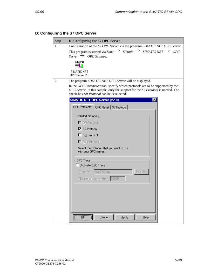
09.99 Communication to the SIMATIC S7 via OPC
WinCC Communication Manual 5-39C79000-G8276-C156-01
D: Configuring the S7 OPC Server
Step D: Configuring the S7 OPC Server
1 Configuration of the S7 OPC Server via the program SIMATIC NET OPC Server.
This program is started via Start Simatic SIMATIC NET OPCServer OPC Settings.
2 The program SIMATIC NET OPC Server will be displayed.
In the OPC Parameters tab, specify which protocols are to be supported by theOPC Server. In this sample, only the support for the S7 Protocol is needed. Thecheck-box SR Protocol can be deselected.
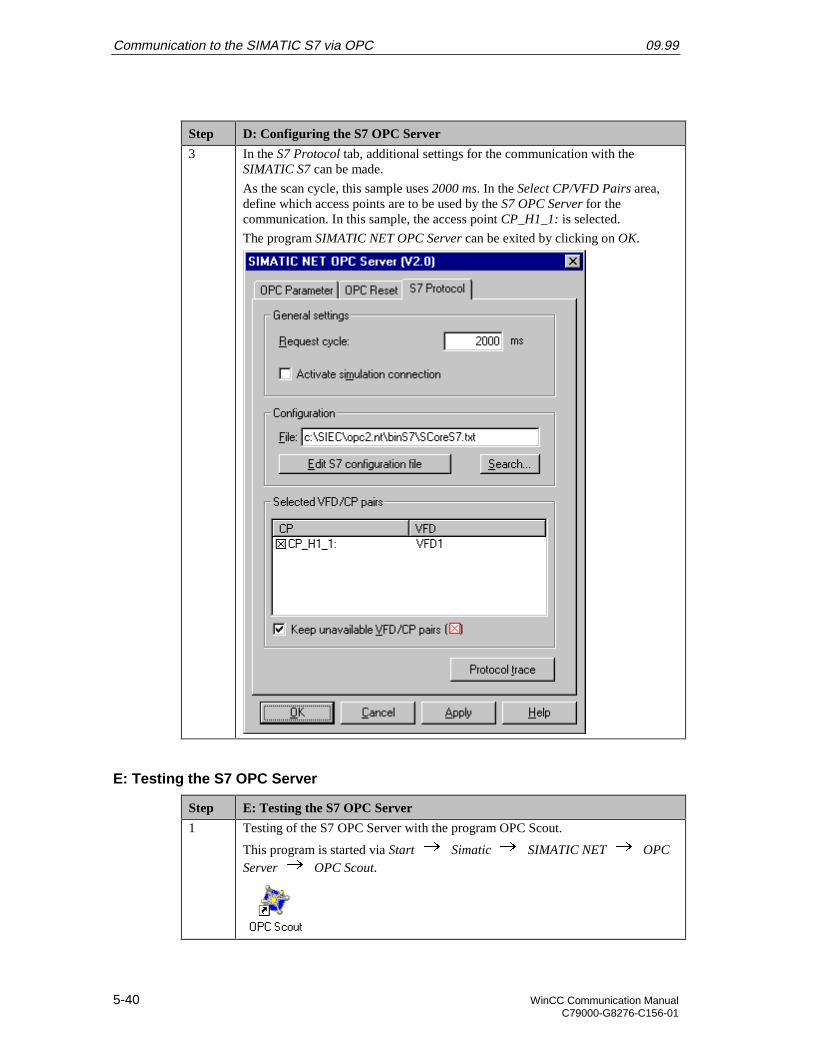
Communication to the SIMATIC S7 via OPC 09.99
5-40 WinCC Communication ManualC79000-G8276-C156-01
Step D: Configuring the S7 OPC Server
3 In the S7 Protocol tab, additional settings for the communication with theSIMATIC S7 can be made.
As the scan cycle, this sample uses 2000 ms. In the Select CP/VFD Pairs area,define which access points are to be used by the S7 OPC Server for thecommunication. In this sample, the access point CP_H1_1: is selected.
The program SIMATIC NET OPC Server can be exited by clicking on OK.
E: Testing the S7 OPC Server
Step E: Testing the S7 OPC Server
1 Testing of the S7 OPC Server with the program OPC Scout.
This program is started via Start Simatic SIMATIC NET OPCServer OPC Scout.
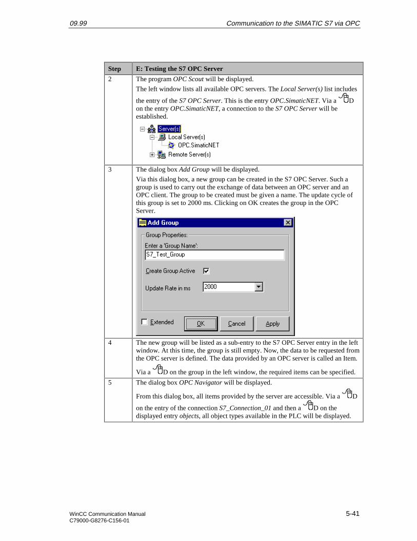
09.99 Communication to the SIMATIC S7 via OPC
WinCC Communication Manual 5-41C79000-G8276-C156-01
Step E: Testing the S7 OPC Server
2 The program OPC Scout will be displayed.
The left window lists all available OPC servers. The Local Server(s) list includes
the entry of the S7 OPC Server. This is the entry OPC.SimaticNET. Via a Don the entry OPC.SimaticNET, a connection to the S7 OPC Server will beestablished.
3 The dialog box Add Group will be displayed.
Via this dialog box, a new group can be created in the S7 OPC Server. Such agroup is used to carry out the exchange of data between an OPC server and anOPC client. The group to be created must be given a name. The update cycle ofthis group is set to 2000 ms. Clicking on OK creates the group in the OPCServer.
4 The new group will be listed as a sub-entry to the S7 OPC Server entry in the leftwindow. At this time, the group is still empty. Now, the data to be requested fromthe OPC server is defined. The data provided by an OPC server is called an Item.
Via a D on the group in the left window, the required items can be specified.
5 The dialog box OPC Navigator will be displayed.
From this dialog box, all items provided by the server are accessible. Via a D
on the entry of the connection S7_Connection_01 and then a D on thedisplayed entry objects, all object types available in the PLC will be displayed.
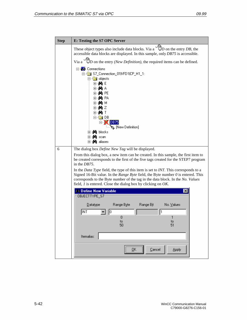
Communication to the SIMATIC S7 via OPC 09.99
5-42 WinCC Communication ManualC79000-G8276-C156-01
Step E: Testing the S7 OPC Server
These object types also include data blocks. Via a D on the entry DB, theaccessible data blocks are displayed. In this sample, only DB75 is accessible.
Via a D on the entry (New Definition), the required items can be defined.
6 The dialog box Define New Tag will be displayed.
From this dialog box, a new item can be created. In this sample, the first item tobe created corresponds to the first of the five tags created for the STEP7 programin the DB75.
In the Data Type field, the type of this item is set to INT. This corresponds to aSigned 16-Bit value. In the Range Byte field, the Byte number 0 is entered. Thiscorresponds to the Byte number of the tag in the data block. In the No. Valuesfield, 1 is entered. Close the dialog box by clicking on OK.
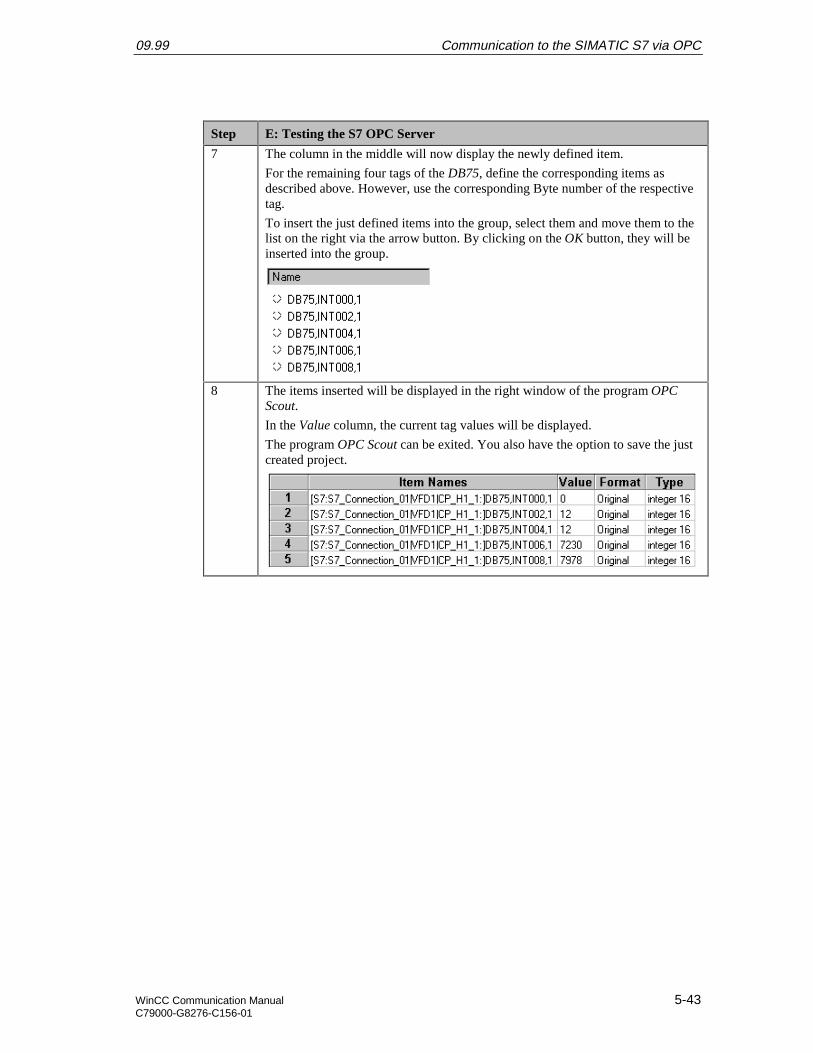
09.99 Communication to the SIMATIC S7 via OPC
WinCC Communication Manual 5-43C79000-G8276-C156-01
Step E: Testing the S7 OPC Server
7 The column in the middle will now display the newly defined item.
For the remaining four tags of the DB75, define the corresponding items asdescribed above. However, use the corresponding Byte number of the respectivetag.
To insert the just defined items into the group, select them and move them to thelist on the right via the arrow button. By clicking on the OK button, they will beinserted into the group.
8 The items inserted will be displayed in the right window of the program OPCScout.
In the Value column, the current tag values will be displayed.
The program OPC Scout can be exited. You also have the option to save the justcreated project.
Communication to the SIMATIC S7 via OPC 09.99
5-44 WinCC Communication ManualC79000-G8276-C156-01
5.4 Creation of the WinCC Project WinCC_S7_OPC
The following description details the configuration steps necessary to create and start up theWinCC project WinCC_S7_OPC.
Overview of the Configuration Steps
The following lists the configuration steps necessary to create the WinCC projectWinCC_S7_OPC:
• A: Installing the OPC Client
• B: Creating the WinCC Project
• C: Creating the Connection
• D: Conventional Configuration
• E: Creating the WinCC Screen
A: Installing the OPC Client
Step A: Installing the OPC Client
1 During the installation of WinCC, the OPC Client can be installed as an option.If the OPC client has not been installed yet, it can also be installed afterwardswithout any problems.
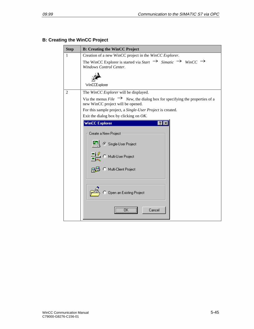
09.99 Communication to the SIMATIC S7 via OPC
WinCC Communication Manual 5-45C79000-G8276-C156-01
B: Creating the WinCC Project
Step B: Creating the WinCC Project
1 Creation of a new WinCC project in the WinCC Explorer.
The WinCC Explorer is started via Start Simatic WinCC Windows Control Center.
2 The WinCC Explorer will be displayed.
Via the menus File New, the dialog box for specifying the properties of anew WinCC project will be opened.
For this sample project, a Single-User Project is created.
Exit the dialog box by clicking on OK.
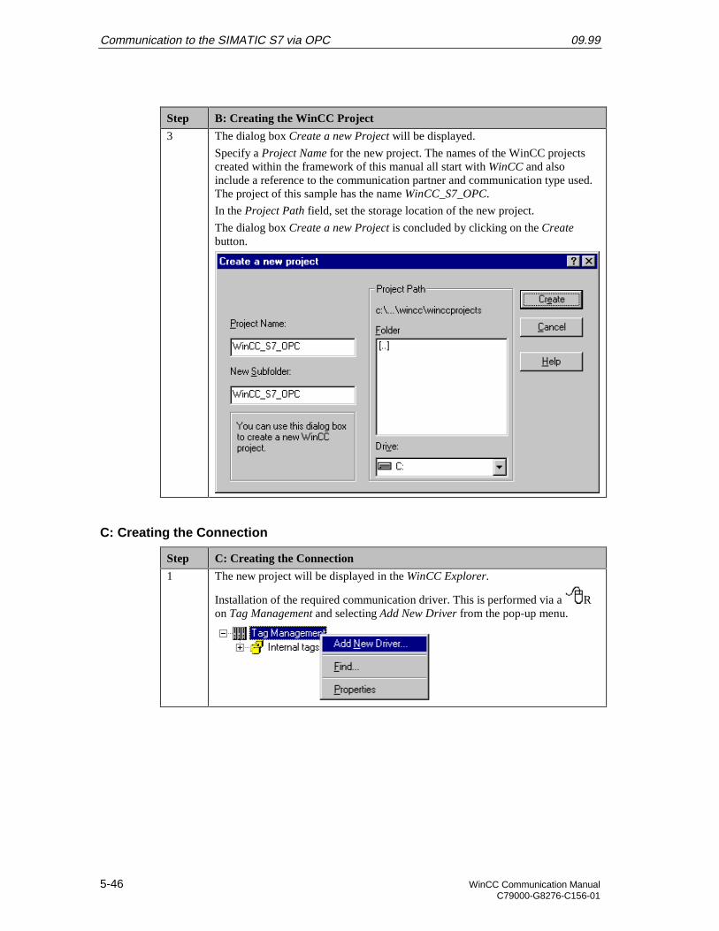
Communication to the SIMATIC S7 via OPC 09.99
5-46 WinCC Communication ManualC79000-G8276-C156-01
Step B: Creating the WinCC Project
3 The dialog box Create a new Project will be displayed.
Specify a Project Name for the new project. The names of the WinCC projectscreated within the framework of this manual all start with WinCC and alsoinclude a reference to the communication partner and communication type used.The project of this sample has the name WinCC_S7_OPC.
In the Project Path field, set the storage location of the new project.
The dialog box Create a new Project is concluded by clicking on the Createbutton.
C: Creating the Connection
Step C: Creating the Connection
1 The new project will be displayed in the WinCC Explorer.
Installation of the required communication driver. This is performed via a Ron Tag Management and selecting Add New Driver from the pop-up menu.
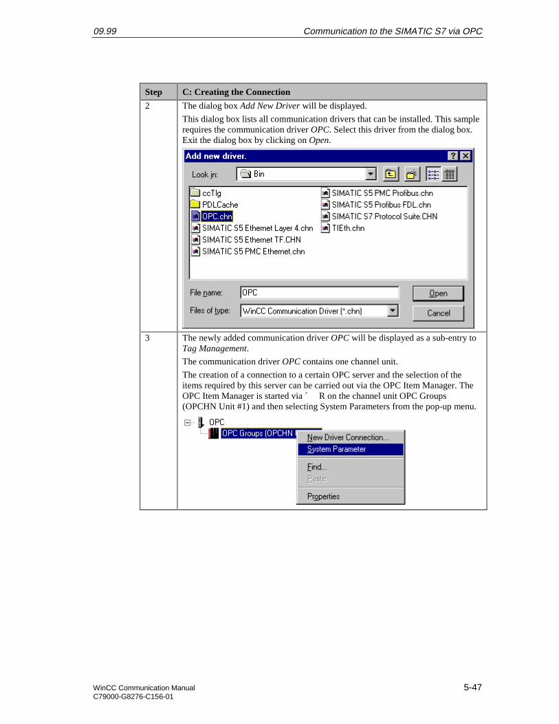
09.99 Communication to the SIMATIC S7 via OPC
WinCC Communication Manual 5-47C79000-G8276-C156-01
Step C: Creating the Connection
2 The dialog box Add New Driver will be displayed.
This dialog box lists all communication drivers that can be installed. This samplerequires the communication driver OPC. Select this driver from the dialog box.Exit the dialog box by clicking on Open.
3 The newly added communication driver OPC will be displayed as a sub-entry toTag Management.
The communication driver OPC contains one channel unit.
The creation of a connection to a certain OPC server and the selection of theitems required by this server can be carried out via the OPC Item Manager. TheOPC Item Manager is started via ´ R on the channel unit OPC Groups(OPCHN Unit #1) and then selecting System Parameters from the pop-up menu.
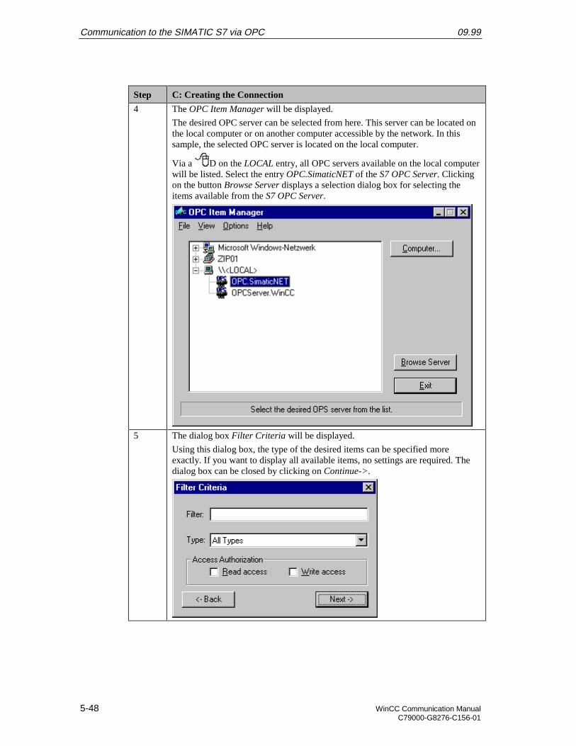
Communication to the SIMATIC S7 via OPC 09.99
5-48 WinCC Communication ManualC79000-G8276-C156-01
Step C: Creating the Connection
4 The OPC Item Manager will be displayed.
The desired OPC server can be selected from here. This server can be located onthe local computer or on another computer accessible by the network. In thissample, the selected OPC server is located on the local computer.
Via a D on the LOCAL entry, all OPC servers available on the local computerwill be listed. Select the entry OPC.SimaticNET of the S7 OPC Server. Clickingon the button Browse Server displays a selection dialog box for selecting theitems available from the S7 OPC Server.
5 The dialog box Filter Criteria will be displayed.
Using this dialog box, the type of the desired items can be specified moreexactly. If you want to display all available items, no settings are required. Thedialog box can be closed by clicking on Continue->.
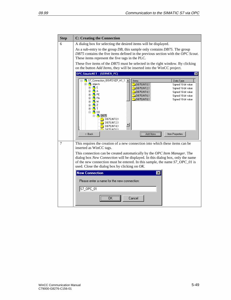
09.99 Communication to the SIMATIC S7 via OPC
WinCC Communication Manual 5-49C79000-G8276-C156-01
Step C: Creating the Connection
6 A dialog box for selecting the desired items will be displayed.
As a sub-entry to the group DB, this sample only contains DB75. The groupDB75 contains the five items defined in the previous section with the OPC Scout.These items represent the five tags in the PLC.
These five items of the DB75 must be selected in the right window. By clickingon the button Add Items, they will be inserted into the WinCC project.
7 This requires the creation of a new connection into which these items can beinserted as WinCC tags.
This connection can be created automatically by the OPC Item Manager. Thedialog box New Connection will be displayed. In this dialog box, only the nameof the new connection must be entered. In this sample, the name S7_OPC_01 isused. Close the dialog box by clicking on OK.
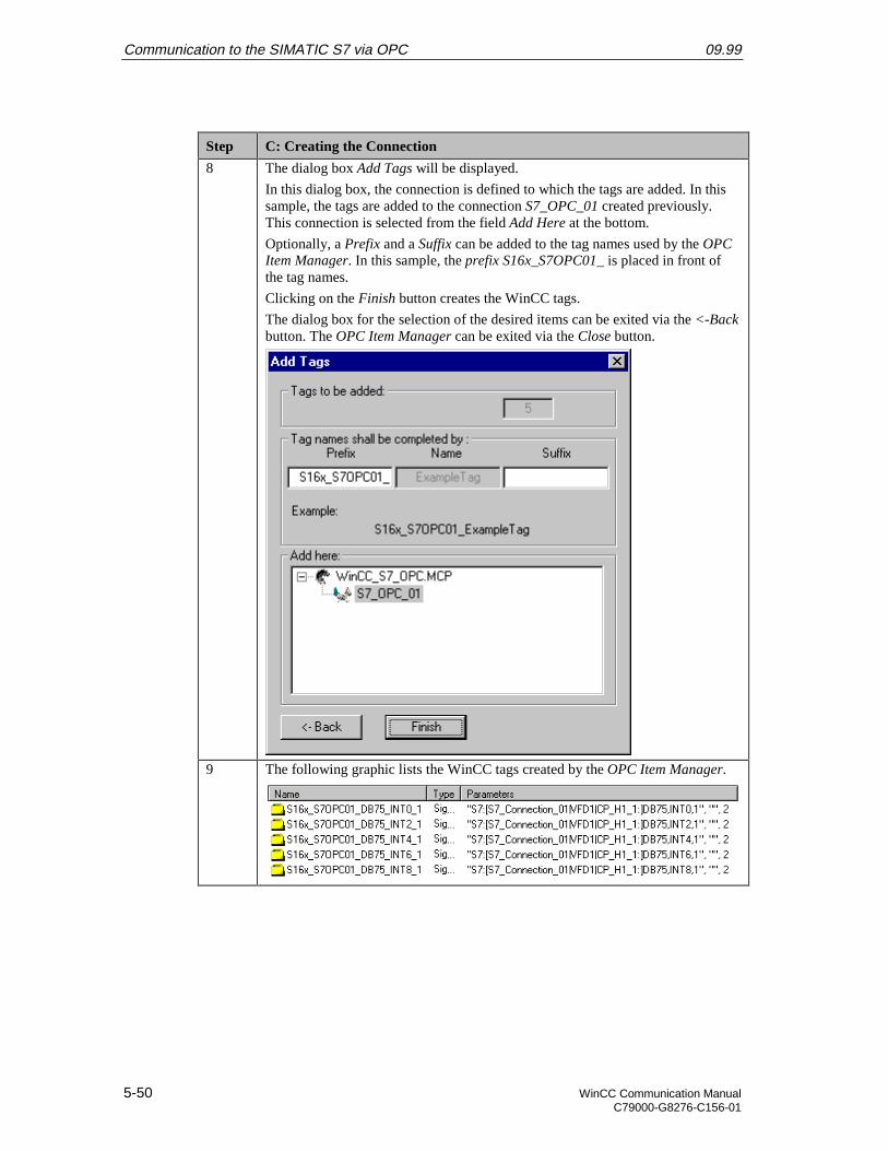
Communication to the SIMATIC S7 via OPC 09.99
5-50 WinCC Communication ManualC79000-G8276-C156-01
Step C: Creating the Connection
8 The dialog box Add Tags will be displayed.
In this dialog box, the connection is defined to which the tags are added. In thissample, the tags are added to the connection S7_OPC_01 created previously.This connection is selected from the field Add Here at the bottom.
Optionally, a Prefix and a Suffix can be added to the tag names used by the OPCItem Manager. In this sample, the prefix S16x_S7OPC01_ is placed in front ofthe tag names.
Clicking on the Finish button creates the WinCC tags.
The dialog box for the selection of the desired items can be exited via the <-Backbutton. The OPC Item Manager can be exited via the Close button.
9 The following graphic lists the WinCC tags created by the OPC Item Manager.
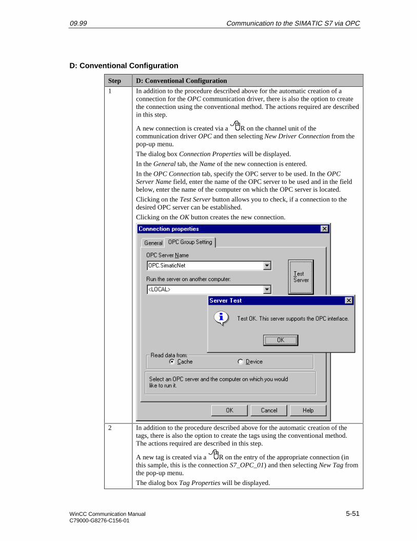
09.99 Communication to the SIMATIC S7 via OPC
WinCC Communication Manual 5-51C79000-G8276-C156-01
D: Conventional Configuration
Step D: Conventional Configuration
1 In addition to the procedure described above for the automatic creation of aconnection for the OPC communication driver, there is also the option to createthe connection using the conventional method. The actions required are describedin this step.
A new connection is created via a R on the channel unit of thecommunication driver OPC and then selecting New Driver Connection from thepop-up menu.
The dialog box Connection Properties will be displayed.
In the General tab, the Name of the new connection is entered.
In the OPC Connection tab, specify the OPC server to be used. In the OPCServer Name field, enter the name of the OPC server to be used and in the fieldbelow, enter the name of the computer on which the OPC server is located.
Clicking on the Test Server button allows you to check, if a connection to thedesired OPC server can be established.
Clicking on the OK button creates the new connection.
2 In addition to the procedure described above for the automatic creation of thetags, there is also the option to create the tags using the conventional method.The actions required are described in this step.
A new tag is created via a R on the entry of the appropriate connection (inthis sample, this is the connection S7_OPC_01) and then selecting New Tag fromthe pop-up menu.
The dialog box Tag Properties will be displayed.
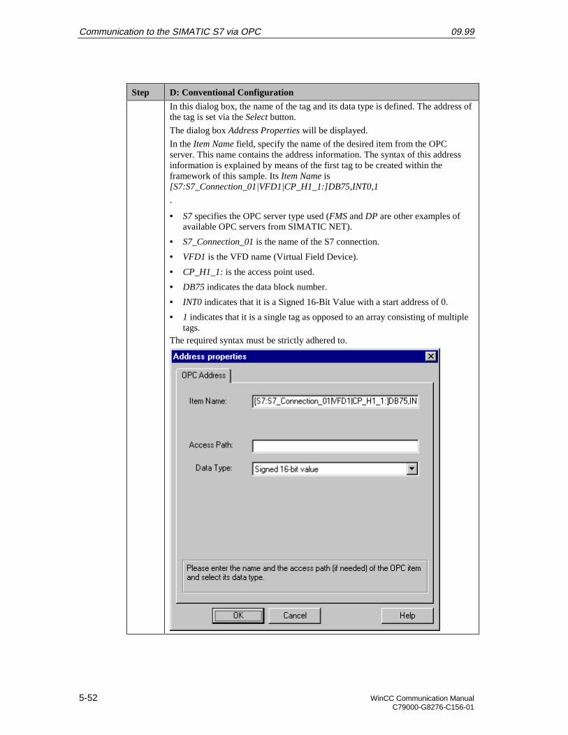
Communication to the SIMATIC S7 via OPC 09.99
5-52 WinCC Communication ManualC79000-G8276-C156-01
Step D: Conventional Configuration
In this dialog box, the name of the tag and its data type is defined. The address ofthe tag is set via the Select button.
The dialog box Address Properties will be displayed.
In the Item Name field, specify the name of the desired item from the OPCserver. This name contains the address information. The syntax of this addressinformation is explained by means of the first tag to be created within theframework of this sample. Its Item Name is[S7:S7_Connection_01|VFD1|CP_H1_1:]DB75,INT0,1
.
• S7 specifies the OPC server type used (FMS and DP are other examples ofavailable OPC servers from SIMATIC NET).
• S7_Connection_01 is the name of the S7 connection.
• VFD1 is the VFD name (Virtual Field Device).
• CP_H1_1: is the access point used.
• DB75 indicates the data block number.
• INT0 indicates that it is a Signed 16-Bit Value with a start address of 0.
• 1 indicates that it is a single tag as opposed to an array consisting of multipletags.
The required syntax must be strictly adhered to.

09.99 Communication to the SIMATIC S7 via OPC
WinCC Communication Manual 5-53C79000-G8276-C156-01
E: Creating the WinCC Screen
Step E: Creating the WinCC Screen
1 Creation of a WinCC screen in which the previously created tags are visualized.
Open the Graphics Designer editor via a R and then selecting Open from thepop-up menu.
2 This will open the Graphics Designer editor with a new (blank) screen.
To display the first tag, configure a Smart Object I/O Field. To do so,select the I/O Field object from the Object Palette and place it on the screenusing the mouse.
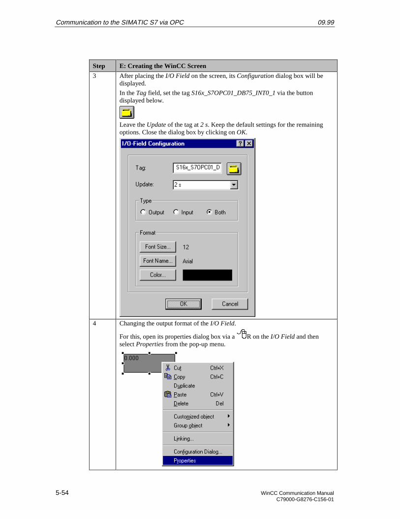
Communication to the SIMATIC S7 via OPC 09.99
5-54 WinCC Communication ManualC79000-G8276-C156-01
Step E: Creating the WinCC Screen
3 After placing the I/O Field on the screen, its Configuration dialog box will bedisplayed.
In the Tag field, set the tag S16x_S7OPC01_DB75_INT0_1 via the buttondisplayed below.
Leave the Update of the tag at 2 s. Keep the default settings for the remainingoptions. Close the dialog box by clicking on OK.
4 Changing the output format of the I/O Field.
For this, open its properties dialog box via a R on the I/O Field and thenselect Properties from the pop-up menu.
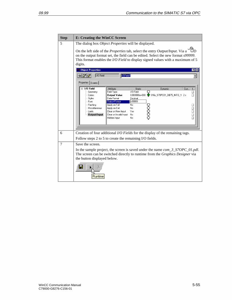
09.99 Communication to the SIMATIC S7 via OPC
WinCC Communication Manual 5-55C79000-G8276-C156-01
Step E: Creating the WinCC Screen
5 The dialog box Object Properties will be displayed.
On the left side of the Properties tab, select the entry Output/Input. Via a Don the output format set, the field can be edited. Select the new format s99999.This format enables the I/O Field to display signed values with a maximum of 5digits.
6 Creation of four additional I/O Fields for the display of the remaining tags.
Follow steps 2 to 5 to create the remaining I/O fields.
7 Save the screen.
In the sample project, the screen is saved under the name com_3_S7OPC_01.pdl.The screen can be switched directly to runtime from the Graphics Designer viathe button displayed below.
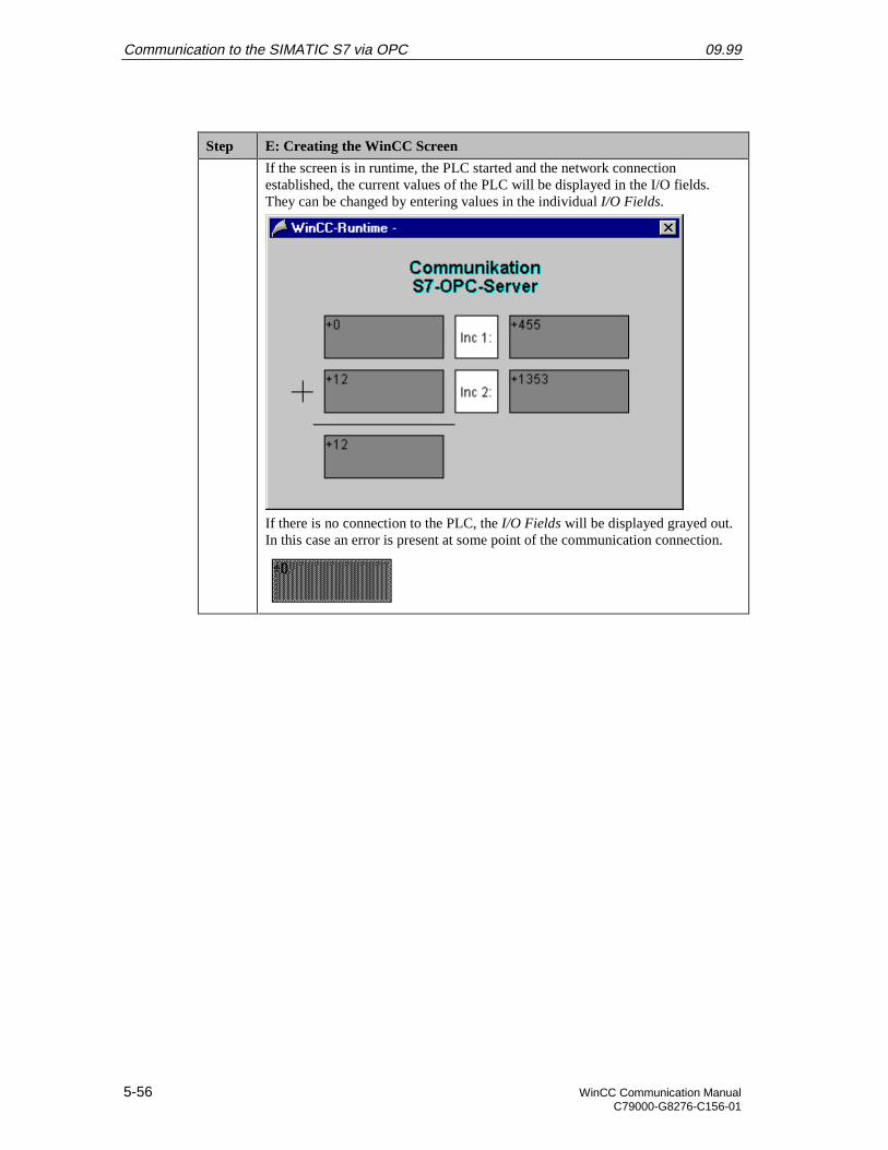
Communication to the SIMATIC S7 via OPC 09.99
5-56 WinCC Communication ManualC79000-G8276-C156-01
Step E: Creating the WinCC Screen
If the screen is in runtime, the PLC started and the network connectionestablished, the current values of the PLC will be displayed in the I/O fields.They can be changed by entering values in the individual I/O Fields.
If there is no connection to the PLC, the I/O Fields will be displayed grayed out.In this case an error is present at some point of the communication connection.
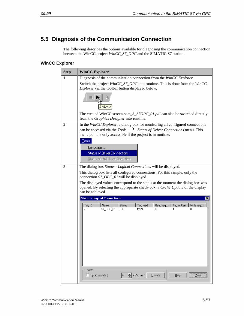
09.99 Communication to the SIMATIC S7 via OPC
WinCC Communication Manual 5-57C79000-G8276-C156-01
5.5 Diagnosis of the Communication Connection
The following describes the options available for diagnosing the communication connectionbetween the WinCC project WinCC_S7_OPC and the SIMATIC S7 station.
WinCC Explorer
Step WinCC Explorer
1 Diagnosis of the communication connection from the WinCC Explorer.
Switch the project WinCC_S7_OPC into runtime. This is done from the WinCCExplorer via the toolbar button displayed below.
The created WinCC screen com_3_S7OPC_01.pdl can also be switched directlyfrom the Graphics Designer into runtime.
2 In the WinCC Explorer, a dialog box for monitoring all configured connectionscan be accessed via the Tools Status of Driver Connections menu. Thismenu point is only accessible if the project is in runtime.
3 The dialog box Status - Logical Connections will be displayed.
This dialog box lists all configured connections. For this sample, only theconnection S7_OPC_01 will be displayed.
The displayed values correspond to the status at the moment the dialog box wasopened. By selecting the appropriate check-box, a Cyclic Update of the displaycan be achieved.
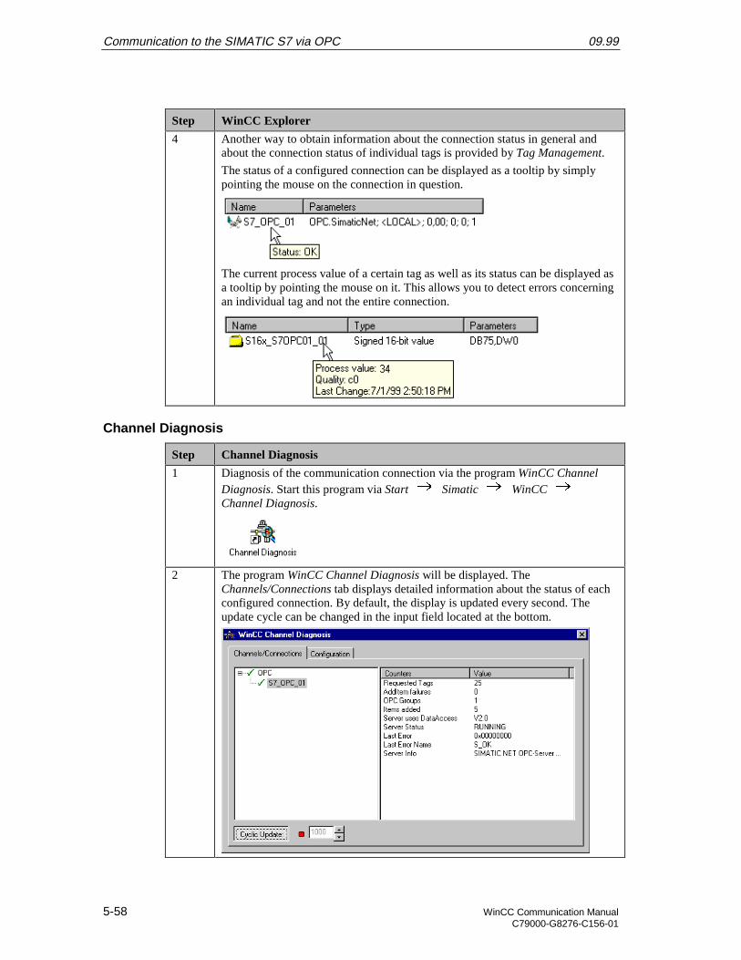
Communication to the SIMATIC S7 via OPC 09.99
5-58 WinCC Communication ManualC79000-G8276-C156-01
Step WinCC Explorer
4 Another way to obtain information about the connection status in general andabout the connection status of individual tags is provided by Tag Management.
The status of a configured connection can be displayed as a tooltip by simplypointing the mouse on the connection in question.
The current process value of a certain tag as well as its status can be displayed asa tooltip by pointing the mouse on it. This allows you to detect errors concerningan individual tag and not the entire connection.
Channel Diagnosis
Step Channel Diagnosis
1 Diagnosis of the communication connection via the program WinCC ChannelDiagnosis. Start this program via Start Simatic WinCC Channel Diagnosis.
2 The program WinCC Channel Diagnosis will be displayed. TheChannels/Connections tab displays detailed information about the status of eachconfigured connection. By default, the display is updated every second. Theupdate cycle can be changed in the input field located at the bottom.
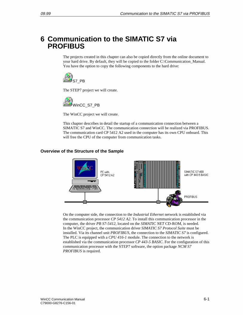
09.99 Communication to the SIMATIC S7 via PROFIBUS
WinCC Communication Manual 6-1C79000-G8276-C156-01
6 Communication to the SIMATIC S7 viaPROFIBUS
The projects created in this chapter can also be copied directly from the online document toyour hard drive. By default, they will be copied to the folder C:\Communication_Manual.You have the option to copy the following components to the hard drive:
S7_PB
The STEP7 project we will create.
WinCC_S7_PB
The WinCC project we will create.
This chapter describes in detail the startup of a communication connection between aSIMATIC S7 and WinCC. The communication connection will be realized via PROFIBUS.The communication card CP 5412 A2 used in the computer has its own CPU onboard. Thiswill free the CPU of the computer from communication tasks.
Overview of the Structure of the Sample
On the computer side, the connection to the Industrial Ethernet network is established viathe communication processor CP 5412 A2. To install this communication processor in thecomputer, the driver PB S7-5412, located on the SIMATIC NET CD-ROM, is needed.In the WinCC project, the communication driver SIMATIC S7 Protocol Suite must beinstalled. Via its channel unit PROFIBUS, the connection to the SIMATIC S7 is configured.The PLC is equipped with a CPU 416-1 module. The connection to the network isestablished via the communication processor CP 443-5 BASIC. For the configuration of thiscommunication processor with the STEP7 software, the option package NCM S7PROFIBUS is required.
Communication to the SIMATIC S7 via PROFIBUS 09.99
6-2 WinCC Communication ManualC79000-G8276-C156-01
Overview of the Configuration Steps
The following lists all configuration steps necessary for the creation of the communicationconnection:
• Startup of the Communication Processor CP 5412 A2
• Creation of the STEP7 Project S7_PB
• Creation of the WinCC Project WinCC_S7_PB
• Diagnosis of the Communication Connection
Required Software
Name Description
SIMATIC NET Driver PB S7-5412 from the SIMATIC NET CD-ROM for theinstallation of the communication processor CP 5412 A2.
STEP7 STEP7 software with option package NCM S7 PROFIBUSfor the creation of the STEP7 project.
WinCC WinCC with the communication driver SIMATIC S7Protocol Suite for the creation of the WinCC project.
Required Computer Hardware
Name Description
Communication Processor Communication processor CP 5412 A2 to establish theconnection to the PLC’s communication processor.
Required PLC Hardware
Name Description
Rack Rack UR1
Power Supply Power supply PS 407 10A in slot 1 and 2.
CPU Module CPU module CPU 416-1 in slot 3.
Communication Processor Communication processor CP 443-5 BASIC in slot 4.
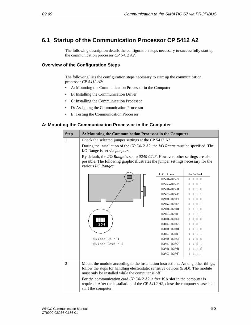
09.99 Communication to the SIMATIC S7 via PROFIBUS
WinCC Communication Manual 6-3C79000-G8276-C156-01
6.1 Startup of the Communication Processor CP 5412 A2
The following description details the configuration steps necessary to successfully start upthe communication processor CP 5412 A2.
Overview of the Configuration Steps
The following lists the configuration steps necessary to start up the communicationprocessor CP 5412 A2:
• A: Mounting the Communication Processor in the Computer
• B: Installing the Communication Driver
• C: Installing the Communication Processor
• D: Assigning the Communication Processor
• E: Testing the Communication Processor
A: Mounting the Communication Processor in the Computer
Step A: Mounting the Communication Processor in the Computer
1 Check the selected jumper settings at the CP 5412 A2.
During the installation of the CP 5412 A2, the I/O Range must be specified. TheI/O Range is set via jumpers.
By default, the I/O Range is set to 0240-0243. However, other settings are alsopossible. The following graphic illustrates the jumper settings necessary for thevarious I/O Ranges.
2 Mount the module according to the installation instructions. Among other things,follow the steps for handling electrostatic sensitive devices (ESD). The modulemust only be installed while the computer is off.
For the communication card CP 5412 A2, a free ISA slot in the computer isrequired. After the installation of the CP 5412 A2, close the computer’s case andstart the computer.
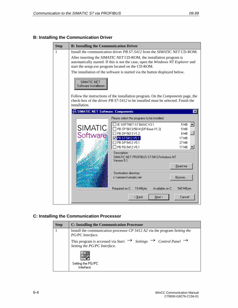
Communication to the SIMATIC S7 via PROFIBUS 09.99
6-4 WinCC Communication ManualC79000-G8276-C156-01
B: Installing the Communication Driver
Step B: Installing the Communication Driver
1 Install the communication driver PB S7-5412 from the SIMATIC NET CD-ROM.
After inserting the SIMATIC NET CD-ROM, the installation program isautomatically started. If this is not the case, open the Windows NT Explorer andstart the setup.exe program located on the CD-ROM.
The installation of the software is started via the button displayed below.
Follow the instructions of the installation program. On the Components page, thecheck-box of the driver PB S7-5412 to be installed must be selected. Finish theinstallation.
C: Installing the Communication Processor
Step C: Installing the Communication Processor
1 Install the communication processor CP 5412 A2 via the program Setting thePG/PC Interface.
This program is accessed via Start Settings Control Panel Setting the PG/PC Interface.
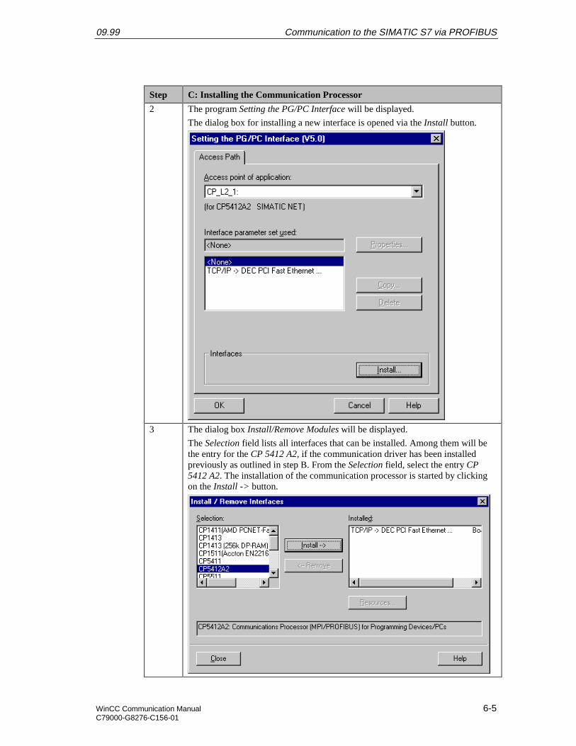
09.99 Communication to the SIMATIC S7 via PROFIBUS
WinCC Communication Manual 6-5C79000-G8276-C156-01
Step C: Installing the Communication Processor
2 The program Setting the PG/PC Interface will be displayed.
The dialog box for installing a new interface is opened via the Install button.
3 The dialog box Install/Remove Modules will be displayed.
The Selection field lists all interfaces that can be installed. Among them will bethe entry for the CP 5412 A2, if the communication driver has been installedpreviously as outlined in step B. From the Selection field, select the entry CP5412 A2. The installation of the communication processor is started by clickingon the Install -> button.
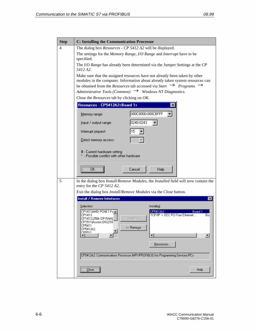
Communication to the SIMATIC S7 via PROFIBUS 09.99
6-6 WinCC Communication ManualC79000-G8276-C156-01
Step C: Installing the Communication Processor
4 The dialog box Resources - CP 5412 A2 will be displayed.
The settings for the Memory Range, I/O Range and Interrupt have to bespecified.
The I/O Range has already been determined via the Jumper Settings at the CP5412 A2.
Make sure that the assigned resources have not already been taken by othermodules in the computer. Information about already taken system resources canbe obtained from the Resources tab accessed via Start Programs Administrative Tools (Common) Windows NT Diagnostics.
Close the Resources tab by clicking on OK.
5 In the dialog box Install/Remove Modules, the Installed field will now contain theentry for the CP 5412 A2.
Exit the dialog box Install/Remove Modules via the Close button.
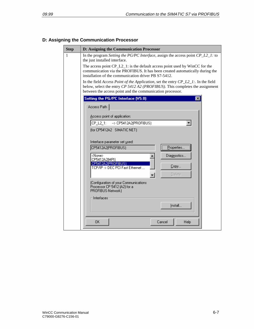
09.99 Communication to the SIMATIC S7 via PROFIBUS
WinCC Communication Manual 6-7C79000-G8276-C156-01
D: Assigning the Communication Processor
Step D: Assigning the Communication Processor
1 In the program Setting the PG/PC Interface, assign the access point CP_L2_1: tothe just installed interface.
The access point CP_L2_1: is the default access point used by WinCC for thecommunication via the PROFIBUS. It has been created automatically during theinstallation of the communication driver PB S7-5412.
In the field Access Point of the Application, set the entry CP_L2_1:. In the fieldbelow, select the entry CP 5412 A2 (PROFIBUS). This completes the assignmentbetween the access point and the communication processor.
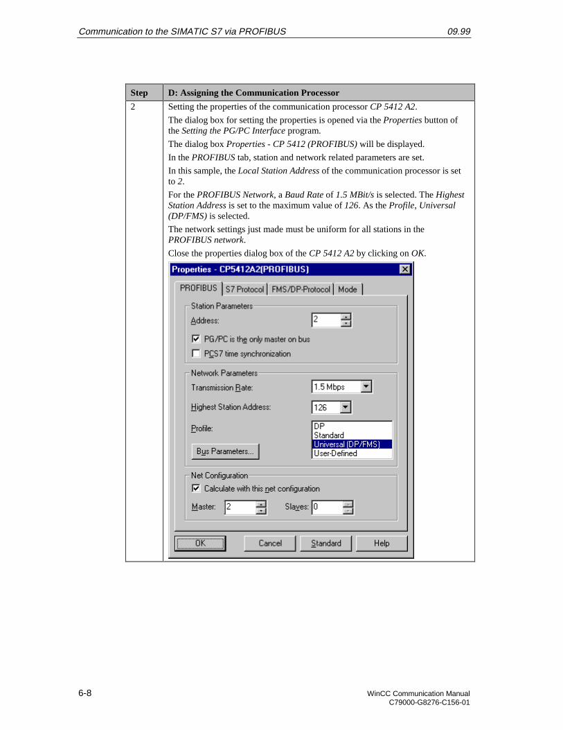
Communication to the SIMATIC S7 via PROFIBUS 09.99
6-8 WinCC Communication ManualC79000-G8276-C156-01
Step D: Assigning the Communication Processor
2 Setting the properties of the communication processor CP 5412 A2.
The dialog box for setting the properties is opened via the Properties button ofthe Setting the PG/PC Interface program.
The dialog box Properties - CP 5412 (PROFIBUS) will be displayed.
In the PROFIBUS tab, station and network related parameters are set.
In this sample, the Local Station Address of the communication processor is setto 2.
For the PROFIBUS Network, a Baud Rate of 1.5 MBit/s is selected. The HighestStation Address is set to the maximum value of 126. As the Profile, Universal(DP/FMS) is selected.
The network settings just made must be uniform for all stations in thePROFIBUS network.
Close the properties dialog box of the CP 5412 A2 by clicking on OK.

09.99 Communication to the SIMATIC S7 via PROFIBUS
WinCC Communication Manual 6-9C79000-G8276-C156-01
Step D: Assigning the Communication Processor
3 Exit the program Setting the PG/PC Interface via the OK button.
A dialog box will be displayed requesting the restart of the CP 5412 A2.Acknowledge this dialog box by clicking on OK, which will result in the restartof the communication processor CP 5412 A2.
This completes the installation of the communication processor.
E: Testing the Communication Processor
Step E: Testing the Communication Processor
1 Test the communication processor CP 5412 A2 via the program Setting thePG/PC Interface.
This program is accessed via Start Settings Control Panel Setting the PG/PC Interface.
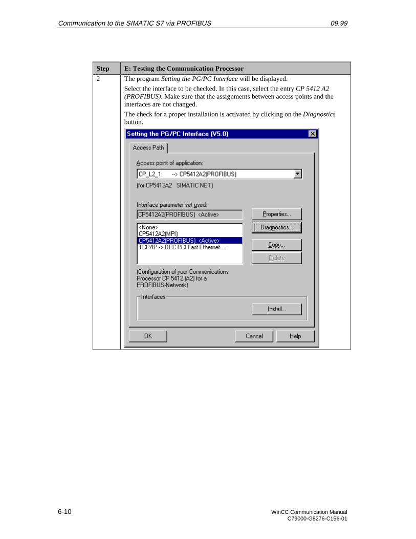
Communication to the SIMATIC S7 via PROFIBUS 09.99
6-10 WinCC Communication ManualC79000-G8276-C156-01
Step E: Testing the Communication Processor
2 The program Setting the PG/PC Interface will be displayed.
Select the interface to be checked. In this case, select the entry CP 5412 A2(PROFIBUS). Make sure that the assignments between access points and theinterfaces are not changed.
The check for a proper installation is activated by clicking on the Diagnosticsbutton.
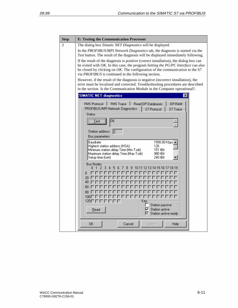
09.99 Communication to the SIMATIC S7 via PROFIBUS
WinCC Communication Manual 6-11C79000-G8276-C156-01
Step E: Testing the Communication Processor
3 The dialog box Simatic NET Diagnostics will be displayed.
In the PROFIBUS/MPI Network Diagnostics tab, the diagnosis is started via theTest button. The result of the diagnosis will be displayed immediately following.
If the result of the diagnosis is positive (correct installation), the dialog box canbe exited with OK. In this case, the program Setting the PG/PC Interface can alsobe closed by clicking on OK. The configuration of the communication to the S7via PROFIBUS is continued in the following section.
However, if the result of the diagnosis is negative (incorrect installation), theerror must be localized and corrected. Troubleshooting procedures are describedin the section Is the Communication Module in the Computer operational?.
Communication to the SIMATIC S7 via PROFIBUS 09.99
6-12 WinCC Communication ManualC79000-G8276-C156-01
6.2 Creation of the STEP7 Project S7_PB
The following description details the configuration steps necessary to create and start up theSTEP7 project S7_PB.
Overview of the Configuration Steps
The following lists the configuration steps necessary to create the STEP7 project S7_PB:
• A: Installing the Hardware
• B: Installing the Option Package
• C: Creating the STEP7 Project
• D: Configuring the Hardware
• E: Loading the Hardware Configuration
• F: Testing the Hardware Configuration
• G: Creating the STEP7 Program
• H: Testing the STEP7 Program
A: Installing the Hardware
Step A: Installing the Hardware
1 Rack-mounting of the modules used.
In this sample, the modules to be installed are the power supply PS 407 10A, theCPU module CPU 416-1 and the communication processor CP 443-5 BASIC.
Establishing the connection from the programming device to the programminginterface of the CPU module.
Establishing the connection from the communication processor CP 5412 A2 inthe computer to the communication processor CP 443-5 BASIC in the PLC.
B: Installing the Option Package
Step B: Installing the Option Package
1 If the option package NCM S7 PROFIBUS has not been installed during theinstallation of STEP7, install it now from the STEP7 CD-ROM. This optionpackage is required for the configuration of the communication processor CP443-5 BASIC via the STEP7 software.
After inserting the STEP7 CD-ROM, the installation program is automaticallystarted. If this is not the case, open the Windows NT Explorer and start thesetup.exe program located on the CD-ROM.

09.99 Communication to the SIMATIC S7 via PROFIBUS
WinCC Communication Manual 6-13C79000-G8276-C156-01
Step B: Installing the Option Package
2 This starts the installation program.
Follow the instructions of the installation program. On the Components page,select the check-box NCM S7-PROFIBUS. Finish the installation.
C: Creating the STEP7 Project
Step C: Creating the STEP7 Project
1 Create a new STEP7 project in the SIMATIC Manager.
It is started via Start Simatic SIMATIC Manager.
2 This displays the SIMATIC Manager.
Via the menus File New, the dialog box for specifying the parameters of anew STEP7 project will be opened.
The New dialog box will be displayed.
The radio-button New Project must be selected. In the Name field, the name ofthe new project to be created is entered. The names of the STEP7 projects createdwithin the framework of this manual all start with S7. They also include areference to the communication type used. The project of this sample has thename S7_PB.
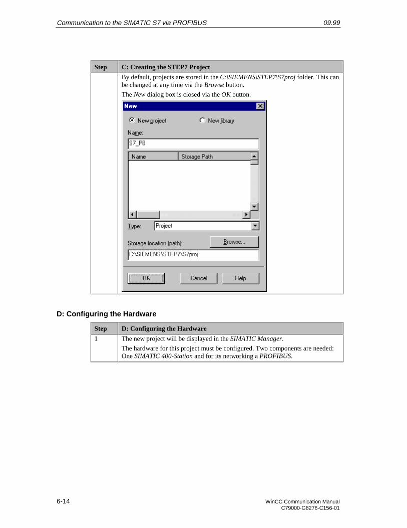
Communication to the SIMATIC S7 via PROFIBUS 09.99
6-14 WinCC Communication ManualC79000-G8276-C156-01
Step C: Creating the STEP7 Project
By default, projects are stored in the C:\SIEMENS\STEP7\S7proj folder. This canbe changed at any time via the Browse button.
The New dialog box is closed via the OK button.
D: Configuring the Hardware
Step D: Configuring the Hardware
1 The new project will be displayed in the SIMATIC Manager.
The hardware for this project must be configured. Two components are needed:One SIMATIC 400-Station and for its networking a PROFIBUS.
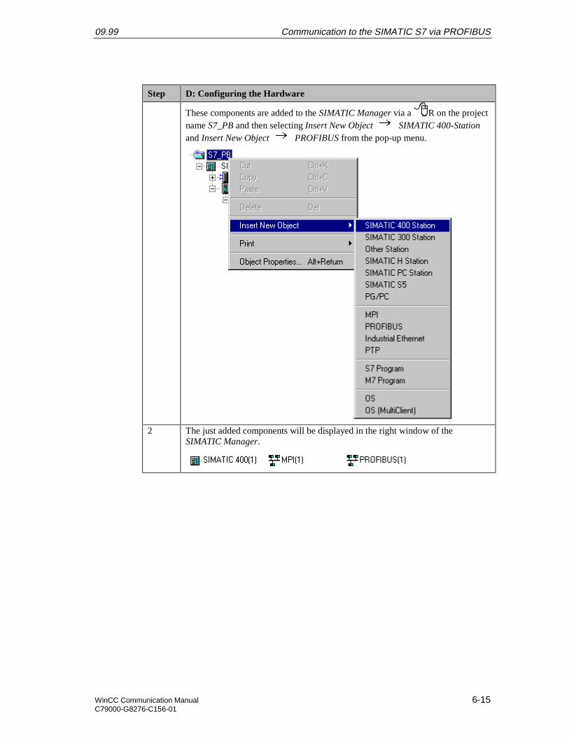
09.99 Communication to the SIMATIC S7 via PROFIBUS
WinCC Communication Manual 6-15C79000-G8276-C156-01
Step D: Configuring the Hardware
These components are added to the SIMATIC Manager via a R on the projectname S7_PB and then selecting Insert New Object SIMATIC 400-Stationand Insert New Object PROFIBUS from the pop-up menu.
2 The just added components will be displayed in the right window of theSIMATIC Manager.
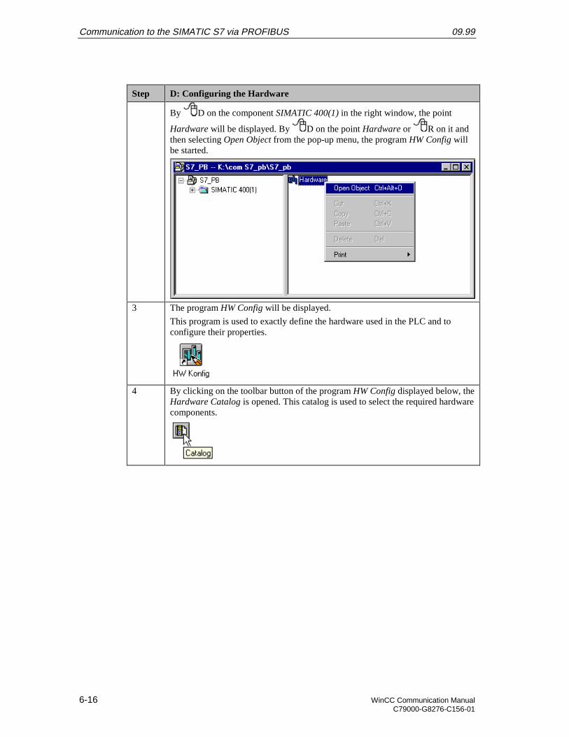
Communication to the SIMATIC S7 via PROFIBUS 09.99
6-16 WinCC Communication ManualC79000-G8276-C156-01
Step D: Configuring the Hardware
By D on the component SIMATIC 400(1) in the right window, the point
Hardware will be displayed. By D on the point Hardware or R on it andthen selecting Open Object from the pop-up menu, the program HW Config willbe started.
3 The program HW Config will be displayed.
This program is used to exactly define the hardware used in the PLC and toconfigure their properties.
4 By clicking on the toolbar button of the program HW Config displayed below, theHardware Catalog is opened. This catalog is used to select the required hardwarecomponents.
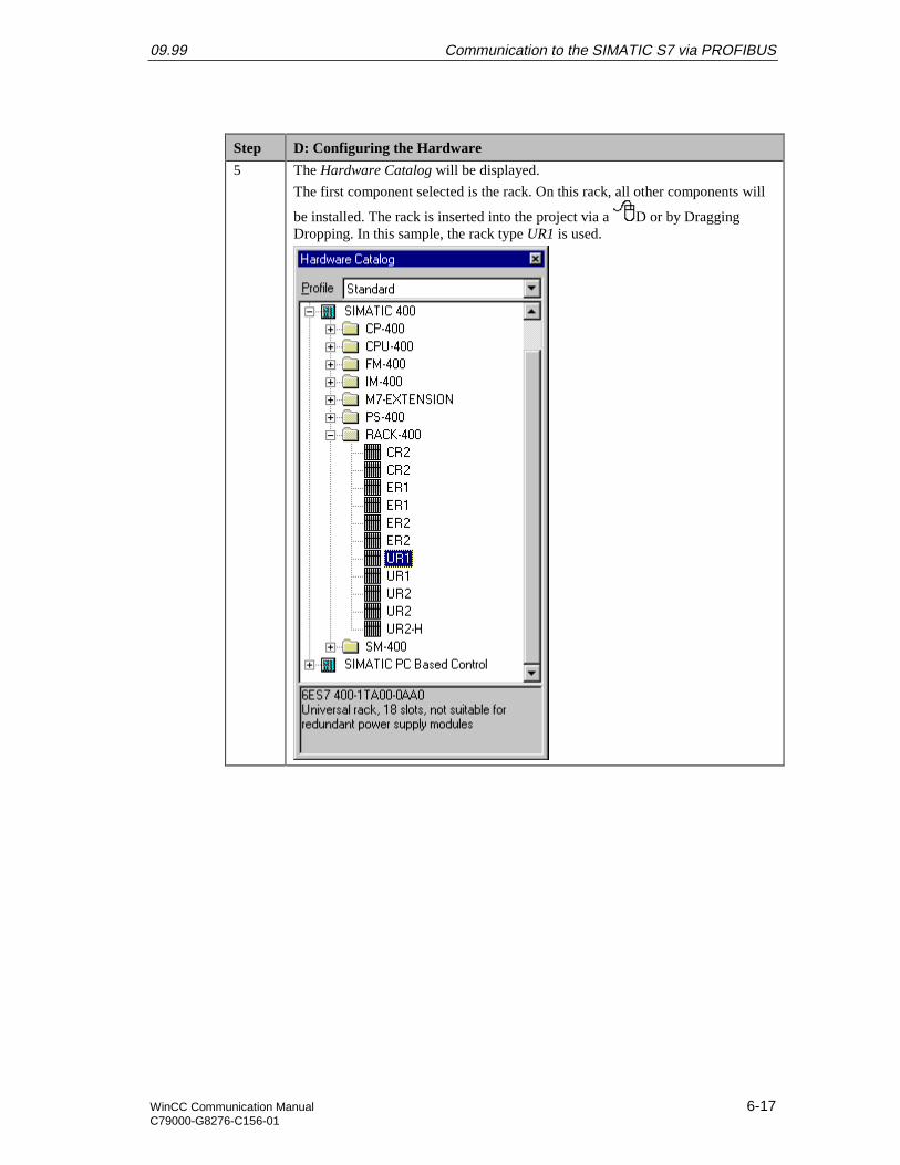
09.99 Communication to the SIMATIC S7 via PROFIBUS
WinCC Communication Manual 6-17C79000-G8276-C156-01
Step D: Configuring the Hardware
5 The Hardware Catalog will be displayed.
The first component selected is the rack. On this rack, all other components will
be installed. The rack is inserted into the project via a D or by DraggingDropping. In this sample, the rack type UR1 is used.
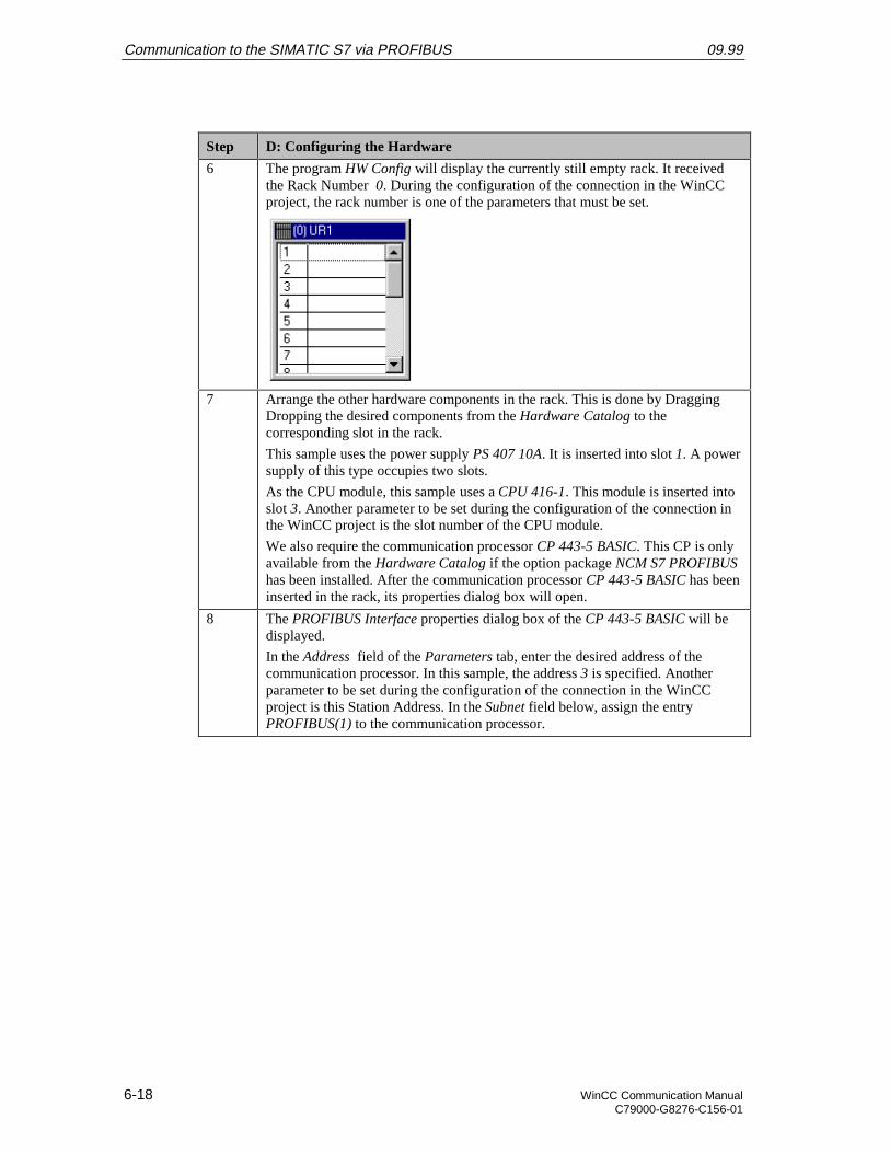
Communication to the SIMATIC S7 via PROFIBUS 09.99
6-18 WinCC Communication ManualC79000-G8276-C156-01
Step D: Configuring the Hardware
6 The program HW Config will display the currently still empty rack. It receivedthe Rack Number 0. During the configuration of the connection in the WinCCproject, the rack number is one of the parameters that must be set.
7 Arrange the other hardware components in the rack. This is done by DraggingDropping the desired components from the Hardware Catalog to thecorresponding slot in the rack.
This sample uses the power supply PS 407 10A. It is inserted into slot 1. A powersupply of this type occupies two slots.
As the CPU module, this sample uses a CPU 416-1. This module is inserted intoslot 3. Another parameter to be set during the configuration of the connection inthe WinCC project is the slot number of the CPU module.
We also require the communication processor CP 443-5 BASIC. This CP is onlyavailable from the Hardware Catalog if the option package NCM S7 PROFIBUShas been installed. After the communication processor CP 443-5 BASIC has beeninserted in the rack, its properties dialog box will open.
8 The PROFIBUS Interface properties dialog box of the CP 443-5 BASIC will bedisplayed.
In the Address field of the Parameters tab, enter the desired address of thecommunication processor. In this sample, the address 3 is specified. Anotherparameter to be set during the configuration of the connection in the WinCCproject is this Station Address. In the Subnet field below, assign the entryPROFIBUS(1) to the communication processor.
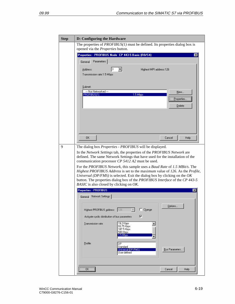
09.99 Communication to the SIMATIC S7 via PROFIBUS
WinCC Communication Manual 6-19C79000-G8276-C156-01
Step D: Configuring the Hardware
The properties of PROFIBUS(1) must be defined. Its properties dialog box isopened via the Properties button.
9 The dialog box Properties - PROFIBUS will be displayed.
In the Network Settings tab, the properties of the PROFIBUS Network aredefined. The same Network Settings that have used for the installation of thecommunication processor CP 5412 A2 must be used.
For the PROFIBUS Network, this sample uses a Baud Rate of 1.5 MBit/s. TheHighest PROFIBUS Address is set to the maximum value of 126. As the Profile,Universal (DP/FMS) is selected. Exit the dialog box by clicking on the OKbutton. The properties dialog box of the PROFIBUS Interface of the CP 443-5BASIC is also closed by clicking on OK.
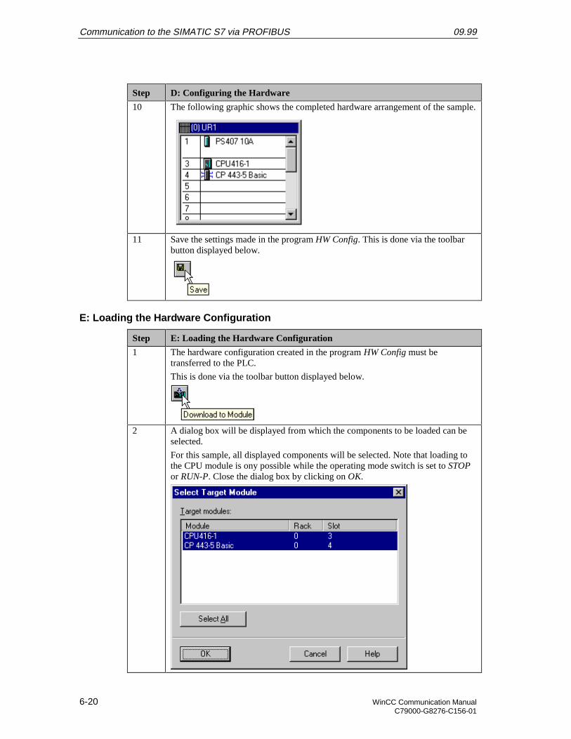
Communication to the SIMATIC S7 via PROFIBUS 09.99
6-20 WinCC Communication ManualC79000-G8276-C156-01
Step D: Configuring the Hardware
10 The following graphic shows the completed hardware arrangement of the sample.
11 Save the settings made in the program HW Config. This is done via the toolbarbutton displayed below.
E: Loading the Hardware Configuration
Step E: Loading the Hardware Configuration
1 The hardware configuration created in the program HW Config must betransferred to the PLC.
This is done via the toolbar button displayed below.
2 A dialog box will be displayed from which the components to be loaded can beselected.
For this sample, all displayed components will be selected. Note that loading tothe CPU module is ony possible while the operating mode switch is set to STOPor RUN-P. Close the dialog box by clicking on OK.
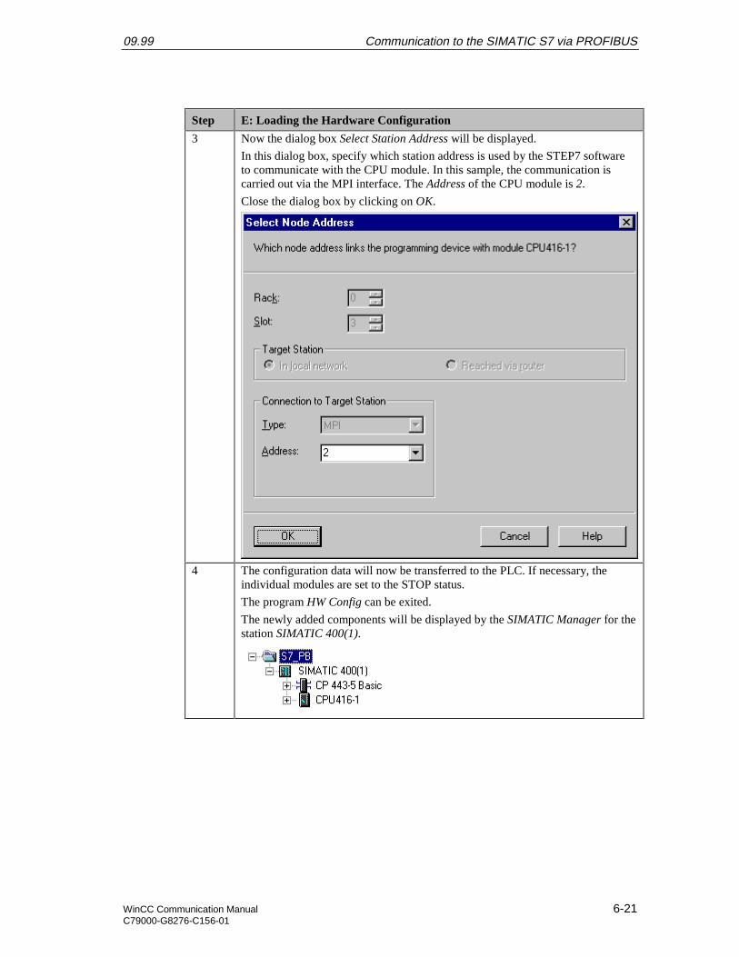
09.99 Communication to the SIMATIC S7 via PROFIBUS
WinCC Communication Manual 6-21C79000-G8276-C156-01
Step E: Loading the Hardware Configuration
3 Now the dialog box Select Station Address will be displayed.
In this dialog box, specify which station address is used by the STEP7 softwareto communicate with the CPU module. In this sample, the communication iscarried out via the MPI interface. The Address of the CPU module is 2.
Close the dialog box by clicking on OK.
4 The configuration data will now be transferred to the PLC. If necessary, theindividual modules are set to the STOP status.
The program HW Config can be exited.
The newly added components will be displayed by the SIMATIC Manager for thestation SIMATIC 400(1).

Communication to the SIMATIC S7 via PROFIBUS 09.99
6-22 WinCC Communication ManualC79000-G8276-C156-01
F: Testing the Hardware Configuration
Step F: Testing the Hardware Configuration
1 Testing of the hardware configuration made.
If the key switch of the CPU module is set to RUN or RUN-P and the operatingmode switch of the communication processor is set to RUN, only the status LEDssignifying the RUN operating mode should light up.
If this is not the case, there is an error. The following steps help you localize thiserror. However, these steps should still be performed even if the status LEDsshow no error. This allows you to recognize uncritical errors and faultyconfigurations.
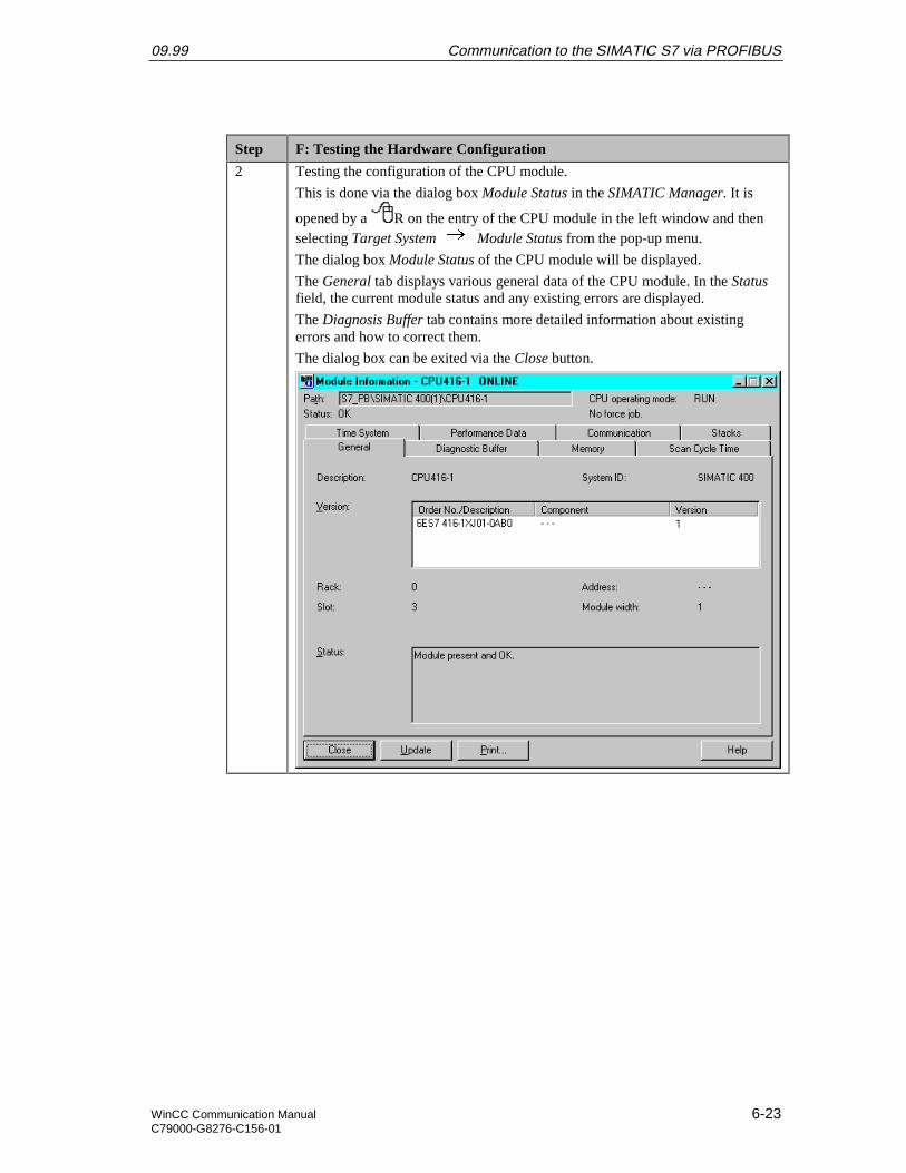
09.99 Communication to the SIMATIC S7 via PROFIBUS
WinCC Communication Manual 6-23C79000-G8276-C156-01
Step F: Testing the Hardware Configuration
2 Testing the configuration of the CPU module.
This is done via the dialog box Module Status in the SIMATIC Manager. It is
opened by a R on the entry of the CPU module in the left window and thenselecting Target System Module Status from the pop-up menu.
The dialog box Module Status of the CPU module will be displayed.
The General tab displays various general data of the CPU module. In the Statusfield, the current module status and any existing errors are displayed.
The Diagnosis Buffer tab contains more detailed information about existingerrors and how to correct them.
The dialog box can be exited via the Close button.
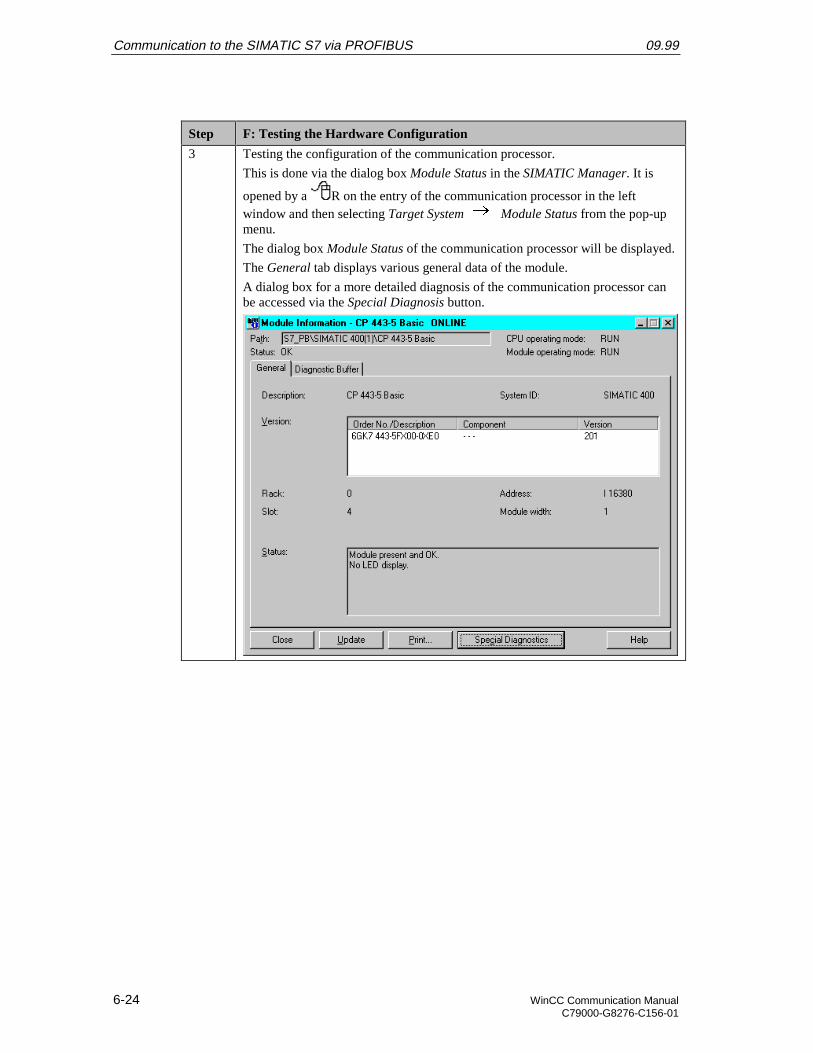
Communication to the SIMATIC S7 via PROFIBUS 09.99
6-24 WinCC Communication ManualC79000-G8276-C156-01
Step F: Testing the Hardware Configuration
3 Testing the configuration of the communication processor.
This is done via the dialog box Module Status in the SIMATIC Manager. It is
opened by a R on the entry of the communication processor in the leftwindow and then selecting Target System Module Status from the pop-upmenu.
The dialog box Module Status of the communication processor will be displayed.
The General tab displays various general data of the module.
A dialog box for a more detailed diagnosis of the communication processor canbe accessed via the Special Diagnosis button.
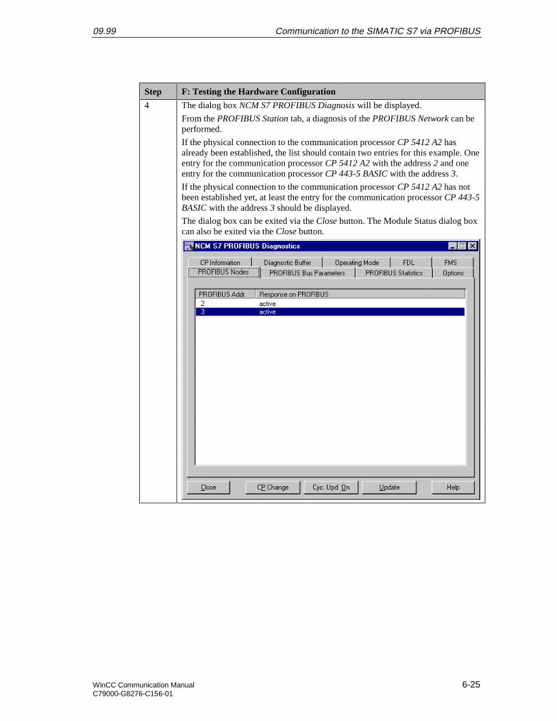
09.99 Communication to the SIMATIC S7 via PROFIBUS
WinCC Communication Manual 6-25C79000-G8276-C156-01
Step F: Testing the Hardware Configuration
4 The dialog box NCM S7 PROFIBUS Diagnosis will be displayed.
From the PROFIBUS Station tab, a diagnosis of the PROFIBUS Network can beperformed.
If the physical connection to the communication processor CP 5412 A2 hasalready been established, the list should contain two entries for this example. Oneentry for the communication processor CP 5412 A2 with the address 2 and oneentry for the communication processor CP 443-5 BASIC with the address 3.
If the physical connection to the communication processor CP 5412 A2 has notbeen established yet, at least the entry for the communication processor CP 443-5BASIC with the address 3 should be displayed.
The dialog box can be exited via the Close button. The Module Status dialog boxcan also be exited via the Close button.
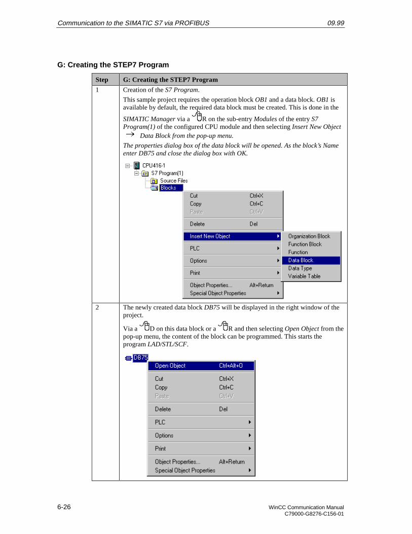
Communication to the SIMATIC S7 via PROFIBUS 09.99
6-26 WinCC Communication ManualC79000-G8276-C156-01
G: Creating the STEP7 Program
Step G: Creating the STEP7 Program
1 Creation of the S7 Program.
This sample project requires the operation block OB1 and a data block. OB1 isavailable by default, the required data block must be created. This is done in the
SIMATIC Manager via a R on the sub-entry Modules of the entry S7Program(1) of the configured CPU module and then selecting Insert New Object
Data Block from the pop-up menu.
The properties dialog box of the data block will be opened. As the block’s Nameenter DB75 and close the dialog box with OK.
2 The newly created data block DB75 will be displayed in the right window of theproject.
Via a D on this data block or a R and then selecting Open Object from thepop-up menu, the content of the block can be programmed. This starts theprogram LAD/STL/SCF.

09.99 Communication to the SIMATIC S7 via PROFIBUS
WinCC Communication Manual 6-27C79000-G8276-C156-01
Step G: Creating the STEP7 Program
3 The program LAD/STL/SCF is displayed.
Acknowledge the dialog box New Data Block by clicking on OK.
4 Programming the DB75.
In this data block, two tags with a length of 16 Bits are created. Their sum is tobe determined in OB1 and then be written to another tag with a length of 16 Bits.
Two additional tags with a length of 16 Bits are created, whose values arecyclically incremented in OB1.
The following graphic displays the programmed data block DB75.
5 Save the block and load it into the PLC. This is done via the toolbar buttondisplayed below. Note that loading to the CPU module is only possible while theoperating mode switch is set to STOP or RUN-P.
6 Programming the OB1.
Open the block in the program LAD/STL/SCF.
First, two values in the DB75 are added and then stored again in DB75.
Next, a value in the DB75 is incremented every second.

Communication to the SIMATIC S7 via PROFIBUS 09.99
6-28 WinCC Communication ManualC79000-G8276-C156-01
Step G: Creating the STEP7 Program
Finally, a value in the DB75 is incremented every time the OB1 run.
7 Save the block OB1 and load it into the PLC. This is done via the correspondingbuttons on the toolbar.
This completes the creation of the STEP7 project and it can now be run. Exit theprogram LAD/STL/SCF.

09.99 Communication to the SIMATIC S7 via PROFIBUS
WinCC Communication Manual 6-29C79000-G8276-C156-01
H: Testing the STEP7 Program
Step H: Testing the STEP7 Program
1 Testing the program with the STEP7 software.
For this purpose, a tag table is created. This is done in the SIMATIC Manager via
a R on the entry of the configured CPU module and then selecting TargetSystem Monitor/Control Tag from the pop-up menu.
2 An editor for creating and using a tag table will be displayed.
The following shows a completed tag table. In this table, enter all tags created inthe DB75.
3 Monitoring the current tag values.
By clicking on the toolbar button displayed below, the current values of thecorresponding tags in the PLC are displayed in the column Status Value.
Controlling the tag values.
Values can be entered in the column Control Value. By clicking on the toolbarbutton displayed below, these values will be written to the corresponding tags inthe PLC.
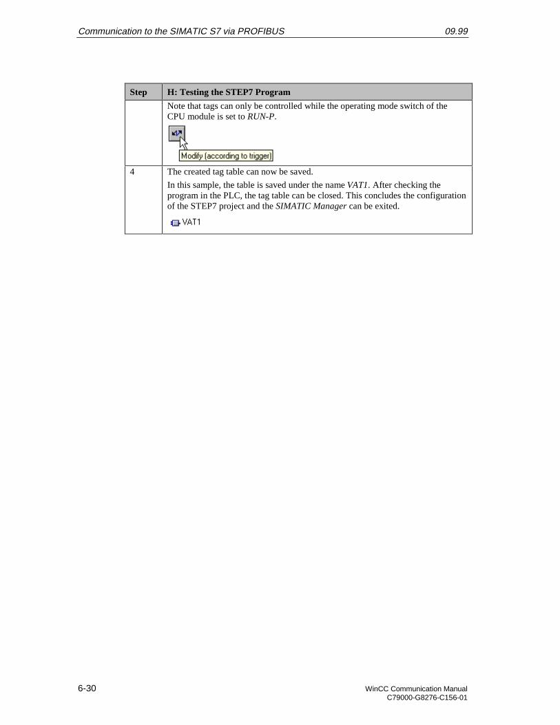
Communication to the SIMATIC S7 via PROFIBUS 09.99
6-30 WinCC Communication ManualC79000-G8276-C156-01
Step H: Testing the STEP7 Program
Note that tags can only be controlled while the operating mode switch of theCPU module is set to RUN-P.
4 The created tag table can now be saved.
In this sample, the table is saved under the name VAT1. After checking theprogram in the PLC, the tag table can be closed. This concludes the configurationof the STEP7 project and the SIMATIC Manager can be exited.
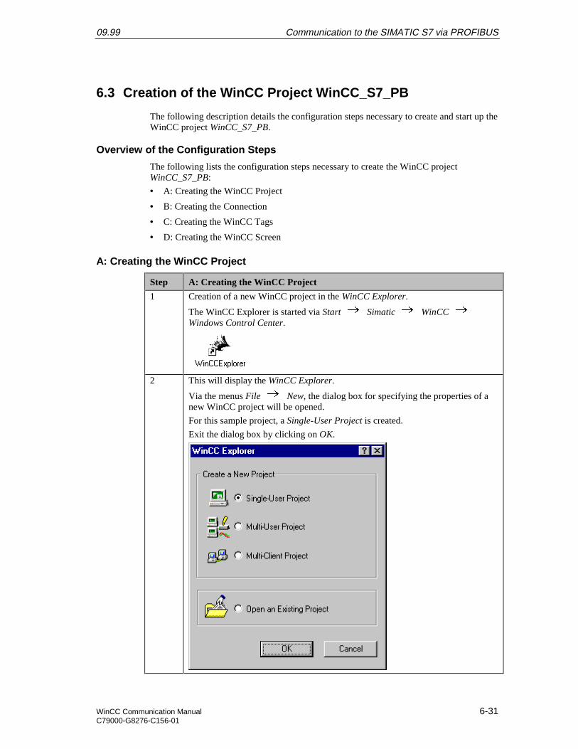
09.99 Communication to the SIMATIC S7 via PROFIBUS
WinCC Communication Manual 6-31C79000-G8276-C156-01
6.3 Creation of the WinCC Project WinCC_S7_PB
The following description details the configuration steps necessary to create and start up theWinCC project WinCC_S7_PB.
Overview of the Configuration Steps
The following lists the configuration steps necessary to create the WinCC projectWinCC_S7_PB:
• A: Creating the WinCC Project
• B: Creating the Connection
• C: Creating the WinCC Tags
• D: Creating the WinCC Screen
A: Creating the WinCC Project
Step A: Creating the WinCC Project
1 Creation of a new WinCC project in the WinCC Explorer.
The WinCC Explorer is started via Start Simatic WinCC Windows Control Center.
2 This will display the WinCC Explorer.
Via the menus File New, the dialog box for specifying the properties of anew WinCC project will be opened.
For this sample project, a Single-User Project is created.
Exit the dialog box by clicking on OK.
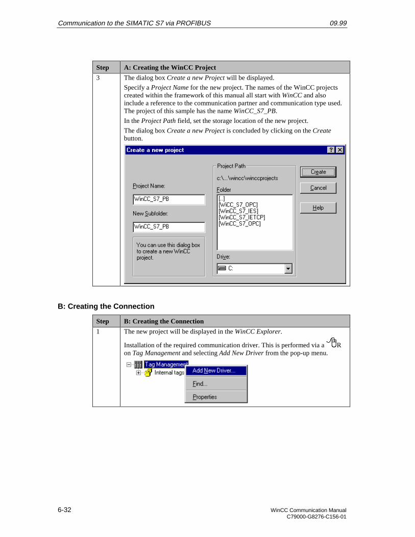
Communication to the SIMATIC S7 via PROFIBUS 09.99
6-32 WinCC Communication ManualC79000-G8276-C156-01
Step A: Creating the WinCC Project
3 The dialog box Create a new Project will be displayed.
Specify a Project Name for the new project. The names of the WinCC projectscreated within the framework of this manual all start with WinCC and alsoinclude a reference to the communication partner and communication type used.The project of this sample has the name WinCC_S7_PB.
In the Project Path field, set the storage location of the new project.
The dialog box Create a new Project is concluded by clicking on the Createbutton.
B: Creating the Connection
Step B: Creating the Connection
1 The new project will be displayed in the WinCC Explorer.
Installation of the required communication driver. This is performed via a Ron Tag Management and selecting Add New Driver from the pop-up menu.
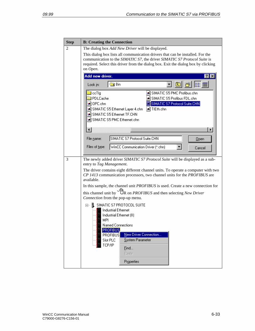
09.99 Communication to the SIMATIC S7 via PROFIBUS
WinCC Communication Manual 6-33C79000-G8276-C156-01
Step B: Creating the Connection
2 The dialog box Add New Driver will be displayed.
This dialog box lists all communication drivers that can be installed. For thecommunication to the SIMATIC S7, the driver SIMATIC S7 Protocol Suite isrequired. Select this driver from the dialog box. Exit the dialog box by clickingon Open.
3 The newly added driver SIMATIC S7 Protocol Suite will be displayed as a sub-entry to Tag Management.
The driver contains eight different channel units. To operate a computer with twoCP 1413 communication processors, two channel units for the PROFIBUS areavailable.
In this sample, the channel unit PROFIBUS is used. Create a new connection for
this channel unit by R on PROFIBUS and then selecting New DriverConnection from the pop-up menu.

Communication to the SIMATIC S7 via PROFIBUS 09.99
6-34 WinCC Communication ManualC79000-G8276-C156-01
Step B: Creating the Connection
4 The properties dialog box of the connection will be displayed.
In the General tab, the Name of the new connection is entered. In this sample,this is S7_PB_01.
Click on the Properties button to define the connection properties.
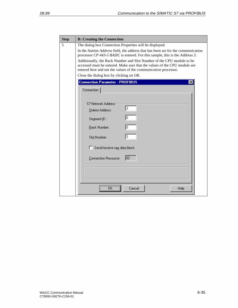
09.99 Communication to the SIMATIC S7 via PROFIBUS
WinCC Communication Manual 6-35C79000-G8276-C156-01
Step B: Creating the Connection
5 The dialog box Connection Properties will be displayed.
In the Station Address field, the address that has been set for the communicationprocessor CP 443-5 BASIC is entered. For this sample, this is the Address 3.
Additionally, the Rack Number and Slot Number of the CPU module to beaccessed must be entered. Make sure that the values of the CPU module areentered here and not the values of the communication processor.
Close the dialog box by clicking on OK.
Communication to the SIMATIC S7 via PROFIBUS 09.99
6-36 WinCC Communication ManualC79000-G8276-C156-01
Step B: Creating the Connection
6 Setting the system parameters of the PROFIBUS channel unit.
These settings are made in the System Parameters dialog box, which is accessed
via a R on the PROFIBUS entry and then selecting System Parameters fromthe pop-up menu.
In the Channel tab, various settings pertaining to the communication andmonitoring a communication can be made. These settings will apply to allchannel units of the communication driver.
09.99 Communication to the SIMATIC S7 via PROFIBUS
WinCC Communication Manual 6-37C79000-G8276-C156-01
Step B: Creating the Connection
7 In the Device tab, the access point used by the connection to access the PLC isspecified.
By default, the access point CP_L2_1: is set. Previously, the communicationprocessor CP 5412 A2 has been assigned to the access point CP_L2_1: in theprogram Setting the PG/PC Interface. If you want the access point to be setautomatically, make sure that the correct one is being used, especially if multiplecommunication processors are used.
Close the dialog box by clicking on OK.

Communication to the SIMATIC S7 via PROFIBUS 09.99
6-38 WinCC Communication ManualC79000-G8276-C156-01
C: Creating the WinCC Tags
Step C: Creating the WinCC Tags
1 Creation of the WinCC tags required for the sample.
This is done via a R on the newly created connection S7_PB_01 and thenselecting New Tag from the pop-up menu.
09.99 Communication to the SIMATIC S7 via PROFIBUS
WinCC Communication Manual 6-39C79000-G8276-C156-01
Step C: Creating the WinCC Tags
2 The properties dialog box of the tag will be displayed.
In the sample, the Name of the first tag is S16x_S7PB01_01. The tag is of theSigned 16-Bit Value data type. Click on the Select button to set the Address of thenew tag.
Communication to the SIMATIC S7 via PROFIBUS 09.99
6-40 WinCC Communication ManualC79000-G8276-C156-01
Step C: Creating the WinCC Tags
3 The dialog box Address Properties will be displayed.
Set DB as the Data Range and the value 75 as the DB No.. Set Word in theAddress field and the value 0 in the DBW field. Close the dialog box by clickingon OK. The properties dialog box of the tag is also closed by clicking on OK.
The just created tag is addressed in the range of the PLC, where the first of thetwo values to be added is located.
4 Creation of the remaining WinCC tags required.
Follow steps 1 to 3 for the creation of the remaining tags. The names, data typesand addresses of the tags used in this sample are listed in the following graphic.

09.99 Communication to the SIMATIC S7 via PROFIBUS
WinCC Communication Manual 6-41C79000-G8276-C156-01
D: Creating the WinCC Screen
Step D: Creating the WinCC Screen
1 Creation of a WinCC screen in which the previously created tags are visualized.
Open the Graphics Designer editor via a R and then selecting Open from thepop-up menu.
2 This will open the Graphics Designer editor with a new (blank) screen.
To display the first tag, configure a Smart Object I/O Field. To do so,select the I/O Field object from the Object Palette and place it on the screenusing the mouse.

Communication to the SIMATIC S7 via PROFIBUS 09.99
6-42 WinCC Communication ManualC79000-G8276-C156-01
Step D: Creating the WinCC Screen
3 After placing the I/O Field on the screen, its Configuration dialog box will bedisplayed.
In the Tag field, set the tag S16x_S7PB01_01 via the button displayed below.
Leave the Update of the tag at 2 s. Keep the default settings for the remainingoptions. Close the dialog box by clicking on OK.
4 Changing the output format of the I/O Field.
For this, open its properties dialog box via a R on the I/O Field and thenselect Properties from the pop-up menu.
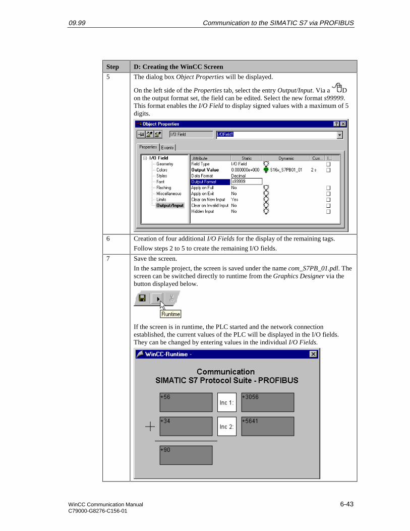
09.99 Communication to the SIMATIC S7 via PROFIBUS
WinCC Communication Manual 6-43C79000-G8276-C156-01
Step D: Creating the WinCC Screen
5 The dialog box Object Properties will be displayed.
On the left side of the Properties tab, select the entry Output/Input. Via a Don the output format set, the field can be edited. Select the new format s99999.This format enables the I/O Field to display signed values with a maximum of 5digits.
6 Creation of four additional I/O Fields for the display of the remaining tags.
Follow steps 2 to 5 to create the remaining I/O fields.
7 Save the screen.
In the sample project, the screen is saved under the name com_S7PB_01.pdl. Thescreen can be switched directly to runtime from the Graphics Designer via thebutton displayed below.
If the screen is in runtime, the PLC started and the network connectionestablished, the current values of the PLC will be displayed in the I/O fields.They can be changed by entering values in the individual I/O Fields.

Communication to the SIMATIC S7 via PROFIBUS 09.99
6-44 WinCC Communication ManualC79000-G8276-C156-01
Step D: Creating the WinCC Screen
If there is no connection to the PLC, the I/O Fields will be displayed grayed out.In this case an error is present at some point of the communication connection.

09.99 Communication to the SIMATIC S7 via PROFIBUS
WinCC Communication Manual 6-45C79000-G8276-C156-01
6.4 Diagnosis of the Communication Connection
The following describes the options available for diagnosing the communication connectionbetween the WinCC project WinCC_S7_PB and the SIMATIC S7 station.A diagnosis of the sample according to this description makes only sense, if the checkslisted below have been completed successfully.Startup of the Communication Processor CP 5412 A2
• E: Testing the Communication ProcessorCreation of the STEP7 Project S7_PB
• F: Testing the Hardware Configuration
• H: Testing the STEP7 Program
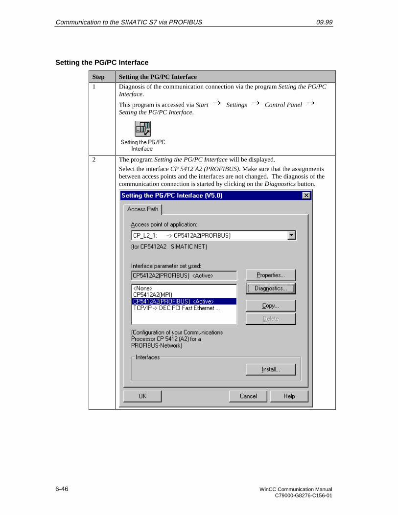
Communication to the SIMATIC S7 via PROFIBUS 09.99
6-46 WinCC Communication ManualC79000-G8276-C156-01
Setting the PG/PC Interface
Step Setting the PG/PC Interface
1 Diagnosis of the communication connection via the program Setting the PG/PCInterface.
This program is accessed via Start Settings Control Panel Setting the PG/PC Interface.
2 The program Setting the PG/PC Interface will be displayed.
Select the interface CP 5412 A2 (PROFIBUS). Make sure that the assignmentsbetween access points and the interfaces are not changed. The diagnosis of thecommunication connection is started by clicking on the Diagnostics button.
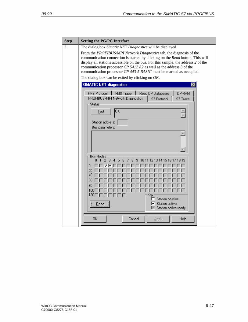
09.99 Communication to the SIMATIC S7 via PROFIBUS
WinCC Communication Manual 6-47C79000-G8276-C156-01
Step Setting the PG/PC Interface
3 The dialog box Simatic NET Diagnostics will be displayed.
From the PROFIBUS/MPI Network Diagnostics tab, the diagnosis of thecommunication connection is started by clicking on the Read button. This willdisplay all stations accessible on the bus. For this sample, the address 2 of thecommunication processor CP 5412 A2 as well as the address 3 of thecommunication processor CP 443-5 BASIC must be marked as occupied.
The dialog box can be exited by clicking on OK.
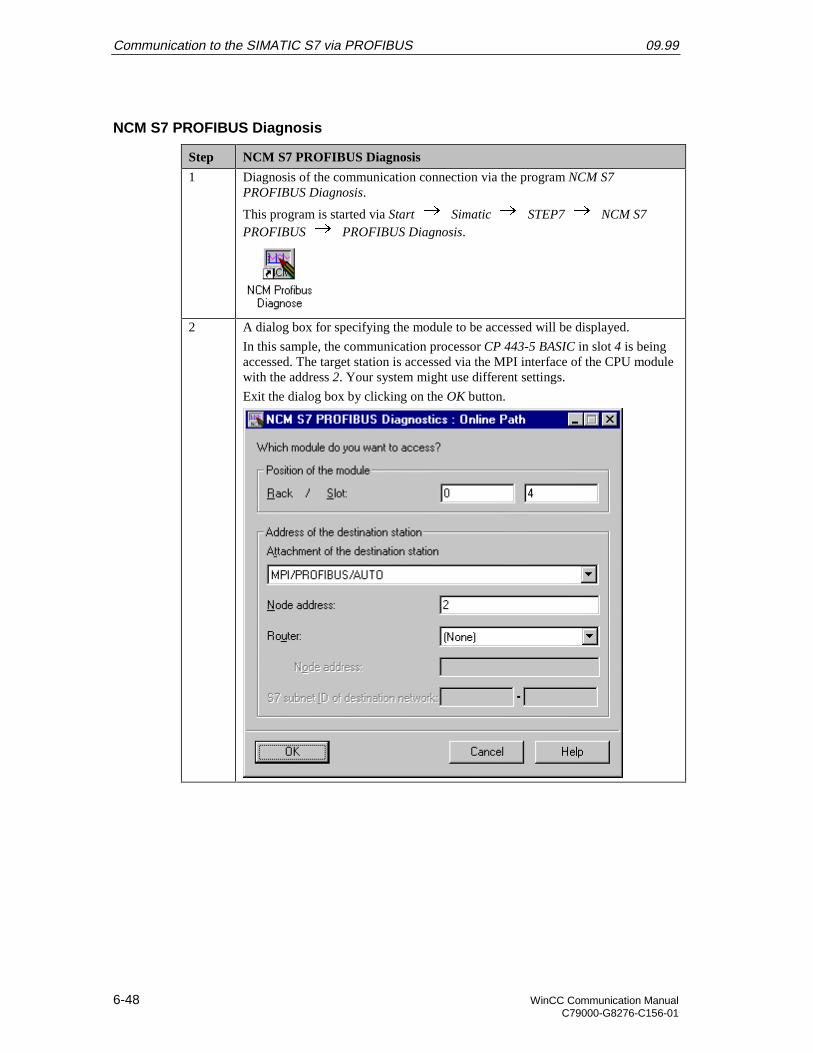
Communication to the SIMATIC S7 via PROFIBUS 09.99
6-48 WinCC Communication ManualC79000-G8276-C156-01
NCM S7 PROFIBUS Diagnosis
Step NCM S7 PROFIBUS Diagnosis
1 Diagnosis of the communication connection via the program NCM S7PROFIBUS Diagnosis.
This program is started via Start Simatic STEP7 NCM S7PROFIBUS PROFIBUS Diagnosis.
2 A dialog box for specifying the module to be accessed will be displayed.
In this sample, the communication processor CP 443-5 BASIC in slot 4 is beingaccessed. The target station is accessed via the MPI interface of the CPU modulewith the address 2. Your system might use different settings.
Exit the dialog box by clicking on the OK button.
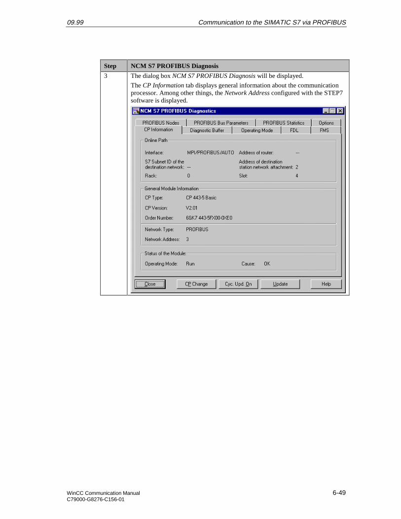
09.99 Communication to the SIMATIC S7 via PROFIBUS
WinCC Communication Manual 6-49C79000-G8276-C156-01
Step NCM S7 PROFIBUS Diagnosis
3 The dialog box NCM S7 PROFIBUS Diagnosis will be displayed.
The CP Information tab displays general information about the communicationprocessor. Among other things, the Network Address configured with the STEP7software is displayed.
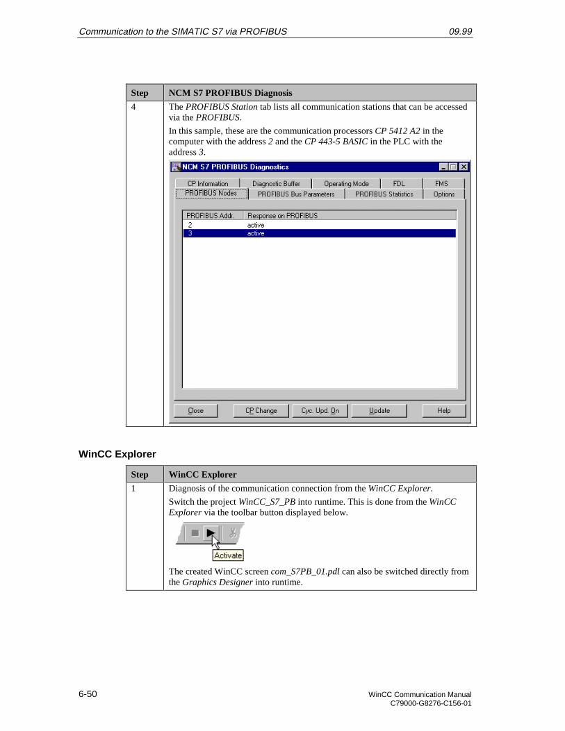
Communication to the SIMATIC S7 via PROFIBUS 09.99
6-50 WinCC Communication ManualC79000-G8276-C156-01
Step NCM S7 PROFIBUS Diagnosis
4 The PROFIBUS Station tab lists all communication stations that can be accessedvia the PROFIBUS.
In this sample, these are the communication processors CP 5412 A2 in thecomputer with the address 2 and the CP 443-5 BASIC in the PLC with theaddress 3.
WinCC Explorer
Step WinCC Explorer
1 Diagnosis of the communication connection from the WinCC Explorer.
Switch the project WinCC_S7_PB into runtime. This is done from the WinCCExplorer via the toolbar button displayed below.
The created WinCC screen com_S7PB_01.pdl can also be switched directly fromthe Graphics Designer into runtime.
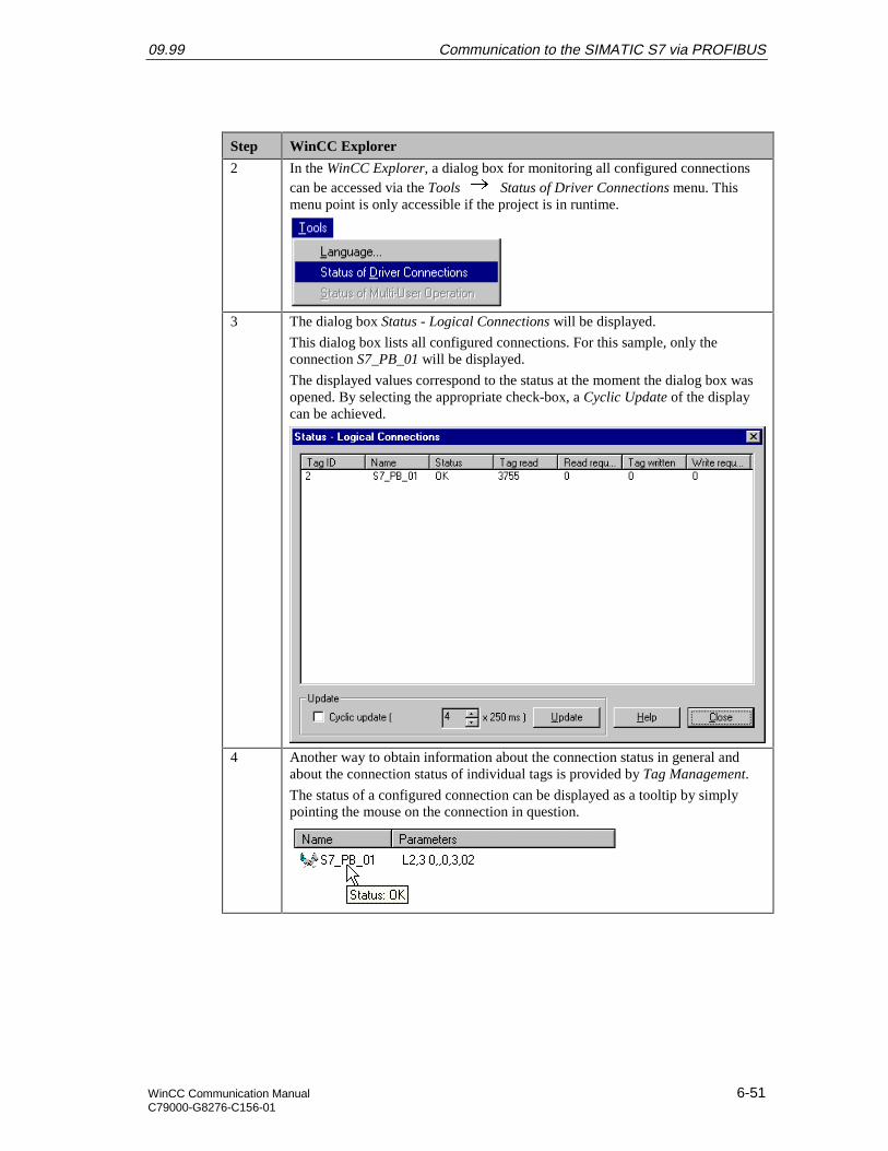
09.99 Communication to the SIMATIC S7 via PROFIBUS
WinCC Communication Manual 6-51C79000-G8276-C156-01
Step WinCC Explorer
2 In the WinCC Explorer, a dialog box for monitoring all configured connectionscan be accessed via the Tools Status of Driver Connections menu. Thismenu point is only accessible if the project is in runtime.
3 The dialog box Status - Logical Connections will be displayed.
This dialog box lists all configured connections. For this sample, only theconnection S7_PB_01 will be displayed.
The displayed values correspond to the status at the moment the dialog box wasopened. By selecting the appropriate check-box, a Cyclic Update of the displaycan be achieved.
4 Another way to obtain information about the connection status in general andabout the connection status of individual tags is provided by Tag Management.
The status of a configured connection can be displayed as a tooltip by simplypointing the mouse on the connection in question.
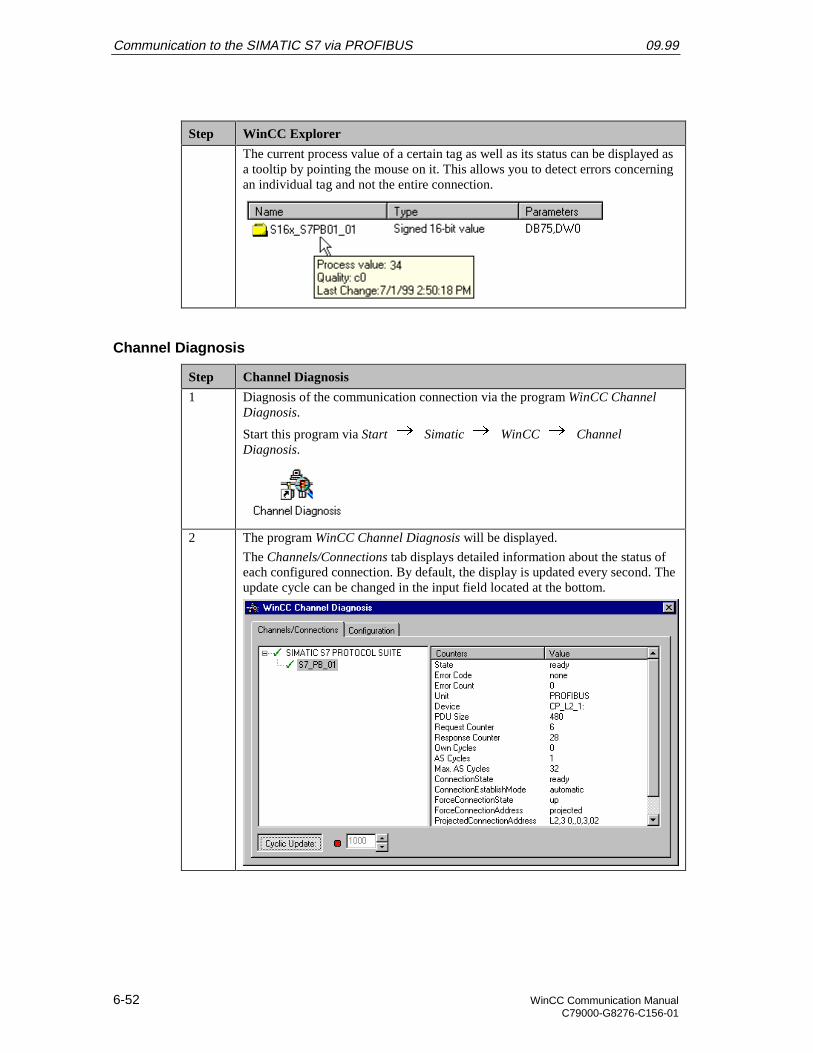
Communication to the SIMATIC S7 via PROFIBUS 09.99
6-52 WinCC Communication ManualC79000-G8276-C156-01
Step WinCC Explorer
The current process value of a certain tag as well as its status can be displayed asa tooltip by pointing the mouse on it. This allows you to detect errors concerningan individual tag and not the entire connection.
Channel Diagnosis
Step Channel Diagnosis
1 Diagnosis of the communication connection via the program WinCC ChannelDiagnosis.
Start this program via Start Simatic WinCC ChannelDiagnosis.
2 The program WinCC Channel Diagnosis will be displayed.
The Channels/Connections tab displays detailed information about the status ofeach configured connection. By default, the display is updated every second. Theupdate cycle can be changed in the input field located at the bottom.
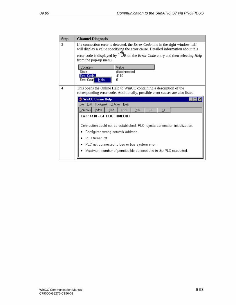
09.99 Communication to the SIMATIC S7 via PROFIBUS
WinCC Communication Manual 6-53C79000-G8276-C156-01
Step Channel Diagnosis
3 If a connection error is detected, the Error Code line in the right window halfwill display a value specifying the error cause. Detailed information about this
error code is displayed by R on the Error Code entry and then selecting Helpfrom the pop-up menu.
4 This opens the Online Help to WinCC containing a description of thecorresponding error code. Additionally, possible error causes are also listed.

Communication to the SIMATIC S7 via PROFIBUS 09.99
6-54 WinCC Communication ManualC79000-G8276-C156-01

09.99 Communication to the SIMATIC S5 via Industrial Ethernet
WinCC Communication Manual 7-1C79000-G8276-C156-01
7 Communication to the SIMATIC S5 viaIndustrial Ethernet
The projects created in this chapter can also be copied directly from the online document toyour hard drive. By default, they will be copied to the folder C:\Communication_Manual.You have the option to copy the following components to the hard drive:
S5_IEHst
The STEP5 project we will create including the database file of the communicationprocessor CP 1430 TF.
WinCC_S5_IEH
The WinCC project we will create.
This chapter describes in detail the startup of a communication connection between aSIMATIC S5 and WinCC. The communication connection is realized via the IndustrialEthernet. The communication card CP 1413 used in the computer has its own CPUonboard. This will free the CPU of the computer from communication tasks.
Overview of the Structure of the Sample
On the computer side, the connection to the Industrial Ethernet network is established viathe communication processor CP 1413. To install this communication processor in thecomputer, the driver IE TF-1413, located on the SIMATIC NET CD-ROM, is needed.In the WinCC project, the communication driver SIMATIC S5 Ethernet Layer 4 must beinstalled. This communication driver is used to configure the connection to the SIMATICS5.The PLC SIMATIC S5 115U is equipped with the CPU module CPU 944. The connectionto the network is established via the communication processor CP 1430 TF. For theconfiguration of this communication processor, the communication package SINEC NCMfor COMs is required.
Communication to the SIMATIC S5 via Industrial Ethernet 09.99
7-2 WinCC Communication ManualC79000-G8276-C156-01
Overview of the Configuration Steps
The following lists all configuration steps necessary for the creation of the communicationconnection:
• Startup of the Communication Processor CP 1413
• Creation of the STEP5 Project S5_IEHst
• Creation of the WinCC Project WinCC_S5_IEH
• Diagnosis of the Communication Connection
Required Software
Name Description
SIMATIC NET Driver IE TF-1413 from the SIMATIC NET CD-ROM forthe installation of the communication processor CP 1413.
STEP5 STEP5 software for the creation of the STEP5 project.Communication package SINEC NCM for COMs for theconfiguration of the communication processor CP 1430TF.
WinCC WinCC with communication driver SIMATIC S5 EthernetLayer 4 for the creation of the WinCC project and for theconfiguration of the connection to the PLC.
Required Computer Hardware
Name Description
Communication Processor Communication processor CP 1413 to establish theconnection to the PLC’s communication processor.
Required PLC Hardware
Name Description
Rack Rack CR 700-3.
Power Supply Power supply PS 951.
CPU Module CPU module CPU 944.
Communication Processor Communication processor CP 1430 TF.
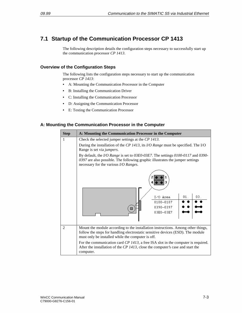
09.99 Communication to the SIMATIC S5 via Industrial Ethernet
WinCC Communication Manual 7-3C79000-G8276-C156-01
7.1 Startup of the Communication Processor CP 1413
The following description details the configuration steps necessary to successfully start upthe communication processor CP 1413.
Overview of the Configuration Steps
The following lists the configuration steps necessary to start up the communicationprocessor CP 1413:
• A: Mounting the Communication Processor in the Computer
• B: Installing the Communication Driver
• C: Installing the Communication Processor
• D: Assigning the Communication Processor
• E: Testing the Communication Processor
A: Mounting the Communication Processor in the Computer
Step A: Mounting the Communication Processor in the Computer
1 Check the selected jumper settings at the CP 1413.
During the installation of the CP 1413, its I/O Range must be specified. The I/ORange is set via jumpers.
By default, the I/O Range is set to 03E0-03E7. The settings 0100-0117 and 0390-0397 are also possible. The following graphic illustrates the jumper settingsnecessary for the various I/O Ranges.
2 Mount the module according to the installation instructions. Among other things,follow the steps for handling electrostatic sensitive devices (ESD). The modulemust only be installed while the computer is off.
For the communication card CP 1413, a free ISA slot in the computer is required.After the installation of the CP 1413, close the computer’s case and start thecomputer.
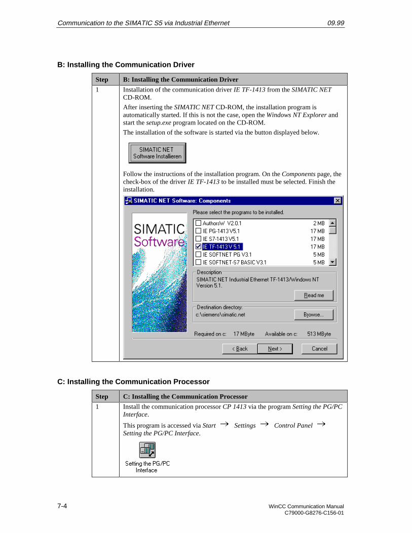
Communication to the SIMATIC S5 via Industrial Ethernet 09.99
7-4 WinCC Communication ManualC79000-G8276-C156-01
B: Installing the Communication Driver
Step B: Installing the Communication Driver
1 Installation of the communication driver IE TF-1413 from the SIMATIC NETCD-ROM.
After inserting the SIMATIC NET CD-ROM, the installation program isautomatically started. If this is not the case, open the Windows NT Explorer andstart the setup.exe program located on the CD-ROM.
The installation of the software is started via the button displayed below.
Follow the instructions of the installation program. On the Components page, thecheck-box of the driver IE TF-1413 to be installed must be selected. Finish theinstallation.
C: Installing the Communication Processor
Step C: Installing the Communication Processor
1 Install the communication processor CP 1413 via the program Setting the PG/PCInterface.
This program is accessed via Start Settings Control Panel Setting the PG/PC Interface.
09.99 Communication to the SIMATIC S5 via Industrial Ethernet
WinCC Communication Manual 7-5C79000-G8276-C156-01
Step C: Installing the Communication Processor
2 The program Setting the PG/PC Interface will be displayed.
The dialog box for installing a new interface is opened via the Install button.
3 The dialog box Install/Remove Modules will be displayed. The Selection fieldlists all interfaces that can be installed. Among them will be the entry CP 1413, ifthe communication driver has been installed previously as outlined in step B.
From the Selection field, select the entry CP 1413. The installation of thecommunication processor is started by clicking on the Install -> button.
Communication to the SIMATIC S5 via Industrial Ethernet 09.99
7-6 WinCC Communication ManualC79000-G8276-C156-01
Step C: Installing the Communication Processor
4 The dialog box Resources - CP 1413 will be displayed.
The settings for the Memory Range, I/O Range and Interrupt have to bespecified.
The I/O Range has already been determined via the Jumper Settings at the CP1413.
Make sure that the assigned resources have not already been taken by othermodules in the computer. Information about already taken system resources canbe obtained from the Resources tab accessed via Start Programs Administrative Tools (Common) Windows NT Diagnostics.
Close the Resources tab by clicking on OK.
5 In the dialog box Install/Remove Modules, the Installed field will now contain theentry for the CP 1413.
Exit the dialog box Install/Remove Modules via the Close button.
09.99 Communication to the SIMATIC S5 via Industrial Ethernet
WinCC Communication Manual 7-7C79000-G8276-C156-01
D: Assigning the Communication Processor
Step D: Assigning the Communication Processor
1 In the program Setting the PG/PC Interface, assign the access point CP_H1_1: tothe just installed interface.
The access point CP_H1_1: is the default access point used by WinCC for thecommunication via the Industrial Ethernet. It has been created automaticallyduring the installation of the communication driver IE TF-1413.
In the field Access Point of the Application, set the entry CP_H1_1:. In the fieldbelow, select the entry CP1413. This completes the assignment between theaccess point and the communication processor.
2 Setting the properties of the communication processor CP 1413.
The dialog box for setting the properties is opened via the Properties button ofthe Setting the PG/PC Interface program.
The dialog box Properties - CP 1413 will be displayed.
In the Ethernet (MAC) Address tab, enter the Ethernet Address of the CP 1413.In this sample, the address is 08.00.06.01.00.01, which must be specified duringthe configuration of the Transport Connections for the communication processorCP 1430.
Communication to the SIMATIC S5 via Industrial Ethernet 09.99
7-8 WinCC Communication ManualC79000-G8276-C156-01
Step D: Assigning the Communication Processor
The Ethernet Address is six Bytes long and structured as follows for SIEMENSdevices:
• 08.00.06: The first six digits of the hexadecimal value correspond to thenumber for SIEMENS.
• 01: The next two digits specify the range for SIEMENS.
• 0: The next digit signifies the SIMATIC system.
• 0.01: The last three digits correspond to the significant station address of aSIEMENS device.
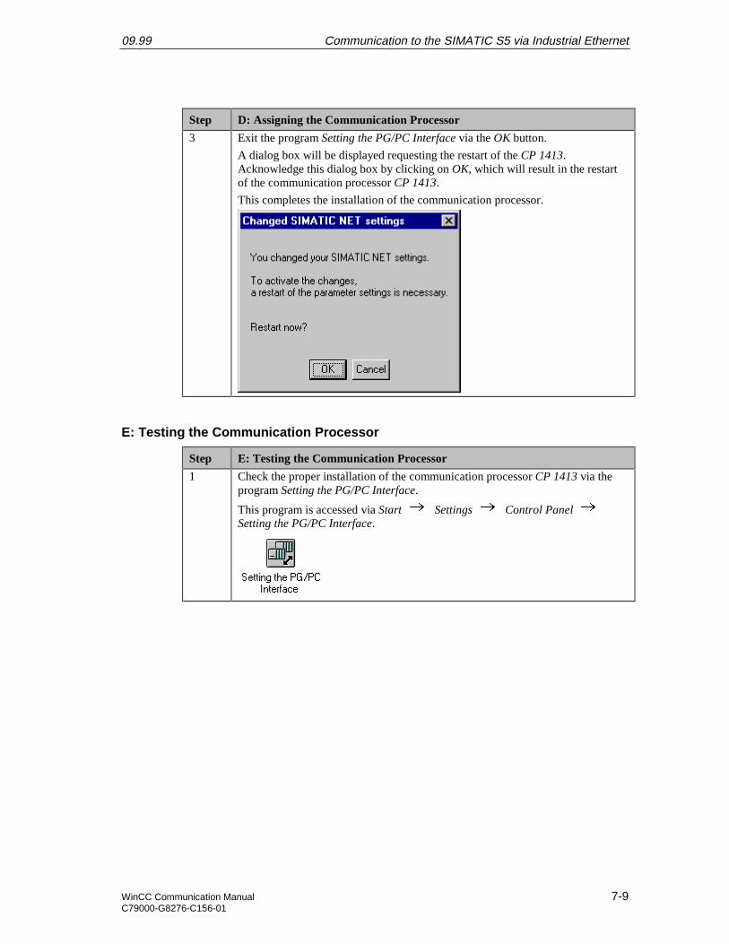
09.99 Communication to the SIMATIC S5 via Industrial Ethernet
WinCC Communication Manual 7-9C79000-G8276-C156-01
Step D: Assigning the Communication Processor
3 Exit the program Setting the PG/PC Interface via the OK button.
A dialog box will be displayed requesting the restart of the CP 1413.Acknowledge this dialog box by clicking on OK, which will result in the restartof the communication processor CP 1413.
This completes the installation of the communication processor.
E: Testing the Communication Processor
Step E: Testing the Communication Processor
1 Check the proper installation of the communication processor CP 1413 via theprogram Setting the PG/PC Interface.
This program is accessed via Start Settings Control Panel Setting the PG/PC Interface.
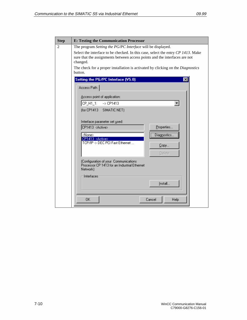
Communication to the SIMATIC S5 via Industrial Ethernet 09.99
7-10 WinCC Communication ManualC79000-G8276-C156-01
Step E: Testing the Communication Processor
2 The program Setting the PG/PC Interface will be displayed.
Select the interface to be checked. In this case, select the entry CP 1413. Makesure that the assignments between access points and the interfaces are notchanged.
The check for a proper installation is activated by clicking on the Diagnosticsbutton.
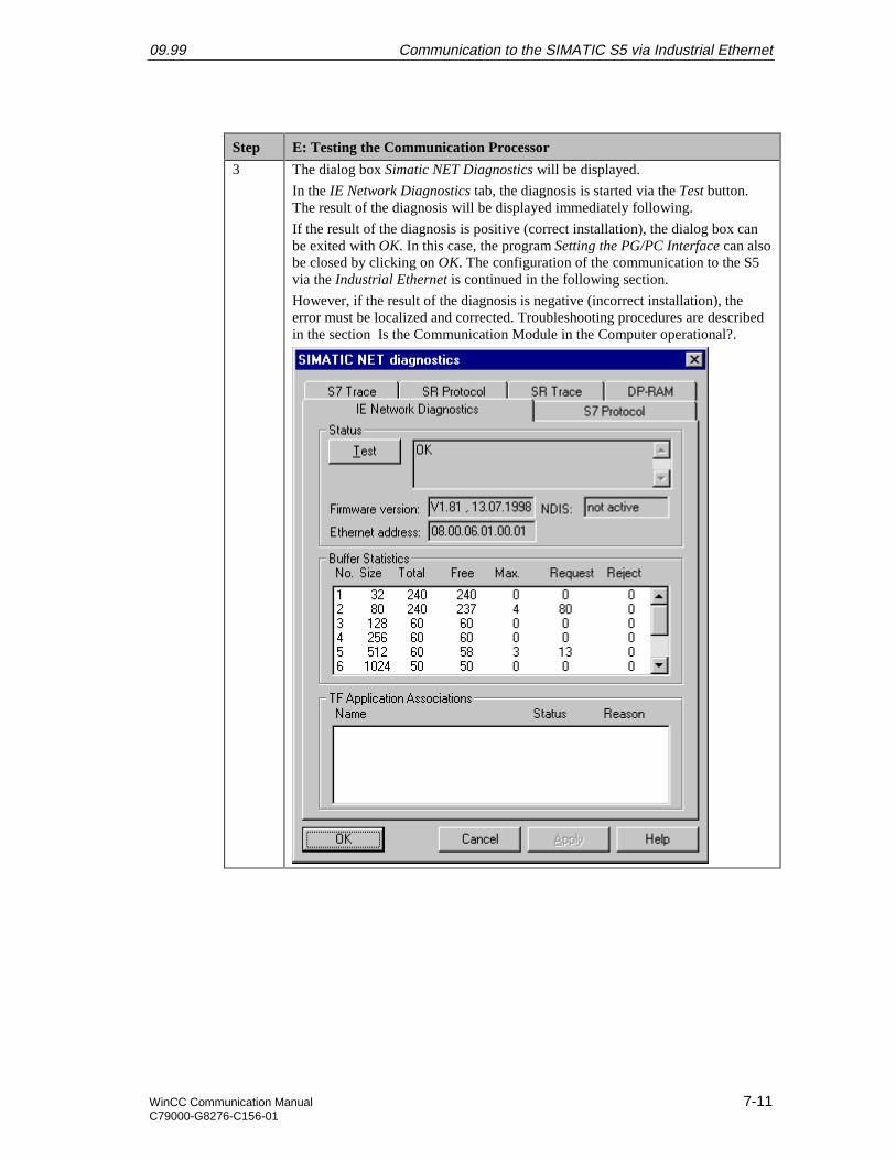
09.99 Communication to the SIMATIC S5 via Industrial Ethernet
WinCC Communication Manual 7-11C79000-G8276-C156-01
Step E: Testing the Communication Processor
3 The dialog box Simatic NET Diagnostics will be displayed.
In the IE Network Diagnostics tab, the diagnosis is started via the Test button.The result of the diagnosis will be displayed immediately following.
If the result of the diagnosis is positive (correct installation), the dialog box canbe exited with OK. In this case, the program Setting the PG/PC Interface can alsobe closed by clicking on OK. The configuration of the communication to the S5via the Industrial Ethernet is continued in the following section.
However, if the result of the diagnosis is negative (incorrect installation), theerror must be localized and corrected. Troubleshooting procedures are describedin the section Is the Communication Module in the Computer operational?.
Communication to the SIMATIC S5 via Industrial Ethernet 09.99
7-12 WinCC Communication ManualC79000-G8276-C156-01
7.2 Creation of the STEP5 Project S5_IEHst
The following description details the configuration steps necessary to create and start up theSTEP5 project S5_IEHst.
Overview of the Configuration Steps
The following lists the configuration steps necessary to create the STEP5 project S5_IEHst:
• A: Installing the Hardware and Software
• B: Creating the STEP5 Program
• C: Configuring the Communication Processor
• D: Starting up the PLC
A: Installing the Hardware and Software
Step A: Installing the Hardware and Software
1 Rack-mounting of the modules used.
In this sample, the modules to be installed are the power supply PS 951, the CPUmodule CPU 944 and the communication processor CP 1430.
Establishing the connection from the programming device to the programminginterface of the CPU module.
Establishing the connection from the communication processor CP 1413 in thecomputer to the communication processor CP 1430 in the PLC.
2 Installing the communication package SINEC NCM for COMs from thecorresponding installation disk. This communication package is required for theconfiguration of the communication processor CP 1430.
The installation disk contains the program file install.exe. Start this program.Follow the instructions of the installation program and complete the installation.
B: Creating the STEP5 Program
Step B: Creating the STEP5 Program
1 Creation of a new project with the STEP5 software.
Start the STEP5 software. From the Object Project Settings Page1 and Page2 menus, define the settings for the new project. In the ProgramFile field, specify the name of the new program file to be created. In this sample,the name S5_IEHST.S5D is used. Only the first six characters of the file namecan be changed by the user.
2 Creation of a data block.
In STEP5, this is accomplished via the Editor Data Block menus ofthe program file.
As the name of the data block, this sample uses DB5.
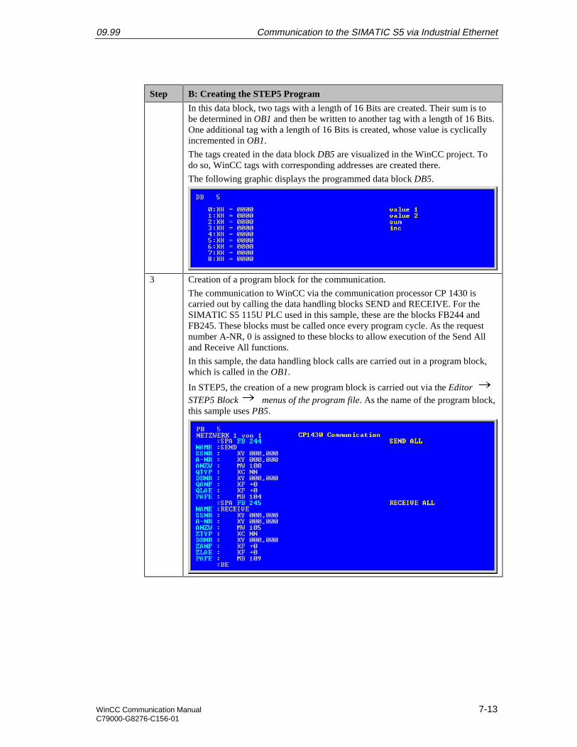
09.99 Communication to the SIMATIC S5 via Industrial Ethernet
WinCC Communication Manual 7-13C79000-G8276-C156-01
Step B: Creating the STEP5 Program
In this data block, two tags with a length of 16 Bits are created. Their sum is tobe determined in OB1 and then be written to another tag with a length of 16 Bits.One additional tag with a length of 16 Bits is created, whose value is cyclicallyincremented in OB1.
The tags created in the data block DB5 are visualized in the WinCC project. Todo so, WinCC tags with corresponding addresses are created there.
The following graphic displays the programmed data block DB5.
3 Creation of a program block for the communication.
The communication to WinCC via the communication processor CP 1430 iscarried out by calling the data handling blocks SEND and RECEIVE. For theSIMATIC S5 115U PLC used in this sample, these are the blocks FB244 andFB245. These blocks must be called once every program cycle. As the requestnumber A-NR, 0 is assigned to these blocks to allow execution of the Send Alland Receive All functions.
In this sample, the data handling block calls are carried out in a program block,which is called in the OB1.
In STEP5, the creation of a new program block is carried out via the Editor STEP5 Block menus of the program file. As the name of the program block,this sample uses PB5.
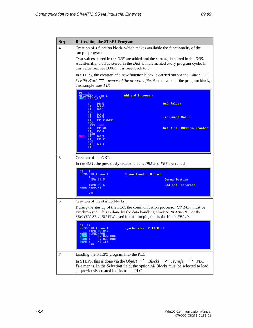
Communication to the SIMATIC S5 via Industrial Ethernet 09.99
7-14 WinCC Communication ManualC79000-G8276-C156-01
Step B: Creating the STEP5 Program
4 Creation of a function block, which makes available the functionality of thesample program.
Two values stored in the DB5 are added and the sum again stored in the DB5.Additionally, a value stored in the DB5 is incremented every program cycle. Ifthis value reaches 10000, it is reset back to 0.
In STEP5, the creation of a new function block is carried out via the Editor STEP5 Block menus of the program file. As the name of the program block,this sample uses FB6.
5 Creation of the OB1.
In the OB1, the previously created blocks PB5 and FB6 are called.
6 Creation of the startup blocks.
During the startup of the PLC, the communication processor CP 1430 must besynchronized. This is done by the data handling block SYNCHRON. For theSIMATIC S5 115U PLC used in this sample, this is the block FB249.
7 Loading the STEP5 program into the PLC.
In STEP5, this is done via the Object Blocks Transfer PLCFile menus. In the Selection field, the option All Blocks must be selected to loadall previously created blocks to the PLC.

09.99 Communication to the SIMATIC S5 via Industrial Ethernet
WinCC Communication Manual 7-15C79000-G8276-C156-01
C: Configuring the Communication Processor
Step C: Configuring the Communication Processor
1 Start the communication package SINEC NCM for COMs to configure thecommunication processor CP 1430.
From STEP5, start the communication package via the Change Additional SINEC NCM for COMs menus.
2 This will open the communication package SINEC NCM for COMs.
If no database file is set, the Basic Settings entry mask will initially be displayed.This entry mask can also be opened via the File Select (or Init. Edit)menus.
In the CP Type field, indicate the type of communication processor used. Via theF8 function key, one of the available communication processors can be set.Select the CP 1430. Set the Status field to OFFLINE FD via the F8 function key.This stores the configuration made in the program to a database file. In theDatabase File field, specify the name of this database file. This name has to startwith the letter A. For this sample, the name AS5_IEH.DAT is used for thedatabase file.
The settings made in the Basic Settings entry mask are applied via the F7function key.
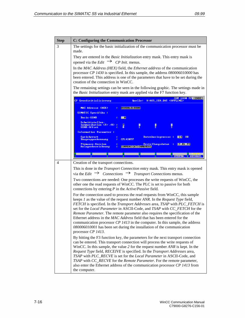
Communication to the SIMATIC S5 via Industrial Ethernet 09.99
7-16 WinCC Communication ManualC79000-G8276-C156-01
Step C: Configuring the Communication Processor
3 The settings for the basic initialization of the communication processor must bemade.
They are entered in the Basic Initialization entry mask. This entry mask isopened via the Edit CP Init. menus.
In the MAC Address (HEX) field, the Ethernet address of the communicationprocessor CP 1430 is specified. In this sample, the address 080006010000 hasbeen entered. This address is one of the parameters that have to be set during thecreation of the connection in WinCC.
The remaining settings can be seen in the following graphic. The settings made inthe Basic Initialization entry mask are applied via the F7 function key.
4 Creation of the transport connections.
This is done in the Transport Connection entry mask. This entry mask is openedvia the Edit Connections Transport Connections menus.
Two connections are needed: One processes the write requests of WinCC, theother one the read requests of WinCC. The PLC is set to passive for bothconnections by entering P in the Active/Passive field.
For the connection used to process the read requests from WinCC, this samplekeeps 1 as the value of the request number ANR. In the Request Type field,FETCH is specified. In the Transport Addresses area, TSAP with PLC_FETCH isset for the Local Parameter in ASCII-Code, and TSAP with CC_FETCH for theRemote Parameter. The remote parameter also requires the specification of theEthernet address in the MAC Address field that has been entered for thecommunication processor CP 1413 in the computer. In this sample, the address080006010001 has been set during the installation of the communicationprocessor CP 1413.
By hitting the F3 function key, the parameters for the next transport connectioncan be entered. This transport connection will process the write requests ofWinCC. In this sample, the value 2 for the request number ANR is kept. In theRequest Type field, RECEIVE is specified. In the Transport Addresses area,TSAP with PLC_RECVE is set for the Local Parameter in ASCII-Code, andTSAP with CC_RECVE for the Remote Parameter. For the remote parameter,also enter the Ethernet address of the communication processor CP 1413 fromthe computer.
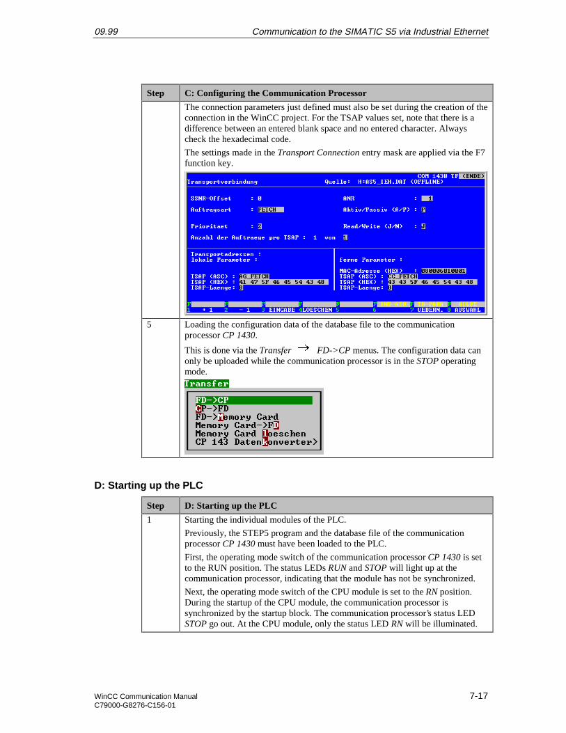
09.99 Communication to the SIMATIC S5 via Industrial Ethernet
WinCC Communication Manual 7-17C79000-G8276-C156-01
Step C: Configuring the Communication Processor
The connection parameters just defined must also be set during the creation of theconnection in the WinCC project. For the TSAP values set, note that there is adifference between an entered blank space and no entered character. Alwayscheck the hexadecimal code.
The settings made in the Transport Connection entry mask are applied via the F7function key.
5 Loading the configuration data of the database file to the communicationprocessor CP 1430.
This is done via the Transfer FD->CP menus. The configuration data canonly be uploaded while the communication processor is in the STOP operatingmode.
D: Starting up the PLC
Step D: Starting up the PLC
1 Starting the individual modules of the PLC.
Previously, the STEP5 program and the database file of the communicationprocessor CP 1430 must have been loaded to the PLC.
First, the operating mode switch of the communication processor CP 1430 is setto the RUN position. The status LEDs RUN and STOP will light up at thecommunication processor, indicating that the module has not be synchronized.
Next, the operating mode switch of the CPU module is set to the RN position.During the startup of the CPU module, the communication processor issynchronized by the startup block. The communication processor’s status LEDSTOP go out. At the CPU module, only the status LED RN will be illuminated.
Communication to the SIMATIC S5 via Industrial Ethernet 09.99
7-18 WinCC Communication ManualC79000-G8276-C156-01
7.3 Creation of the WinCC Project WinCC_S5_IEH
The following description details the configuration steps necessary to create and start up theWinCC project WinCC_S5_IEH.
Overview of the Configuration Steps
The following lists the configuration steps necessary to create the WinCC projectWinCC_S5_IEH:
• A: Creating the WinCC Project
• B: Creating the Connection
• C: Creating the WinCC Tags
• D: Creating the WinCC Screen
A: Creating the WinCC Project
Step A: Creating the WinCC Project
1 Creation of a new WinCC project in the WinCC Explorer.
The WinCC Explorer is started via Start Simatic WinCC Windows Control Center.
2 This will display the WinCC Explorer.
Via the menus File New, the dialog box for specifying the properties of anew WinCC project will be opened.
For this sample project, a Single-User Project is created.
Exit the dialog box by clicking on OK.
09.99 Communication to the SIMATIC S5 via Industrial Ethernet
WinCC Communication Manual 7-19C79000-G8276-C156-01
Step A: Creating the WinCC Project
3 The dialog box Create a new Project will be displayed.
Specify a Project Name for the new project. The names of the WinCC projectscreated within the framework of this manual all start with WinCC and alsoinclude a reference to the communication partner and communication type used.The project of this sample has the name WinCC_S5_IEH.
In the Project Path field, set the storage location of the new project.
The dialog box Create a new Project is concluded by clicking on the Createbutton.
B: Creating the Connection
Step B: Creating the Connection
1 The new project will be displayed in the WinCC Explorer.
Installation of the required communication driver. This is performed via a Ron Tag Management and selecting Add New Driver from the pop-up menu.
Communication to the SIMATIC S5 via Industrial Ethernet 09.99
7-20 WinCC Communication ManualC79000-G8276-C156-01
Step B: Creating the Connection
2 The dialog box Add New Driver will be displayed.
This dialog box lists all communication drivers that can be installed. For thecommunication to the SIMATIC S5 via Industrial Ethernet, the driver SIMATICS5 Ethernet Layer 4 is required. Select this driver from the dialog box. Exit thedialog box by clicking on Open.
3 The newly added driver SIMATIC S5 Ethernet Layer 4 will be displayed as a sub-entry to Tag Management.
The driver contains two channel units. The second channel unit is needed if twoCP 1413 communication processors are operated in the computer.
A new connection for the S5-Transport (CP1413-1) channel unit is created by
R on S5-Transport (CP1413-1) and then selecting New Driver Connectionfrom the pop-up menu.
09.99 Communication to the SIMATIC S5 via Industrial Ethernet
WinCC Communication Manual 7-21C79000-G8276-C156-01
Step B: Creating the Connection
4 The properties dialog box of the connection will be displayed.
In the General tab, the Name of the new connection is entered. In this sample,this is S5_IEH_01.
Click on the Properties button to define the connection properties.
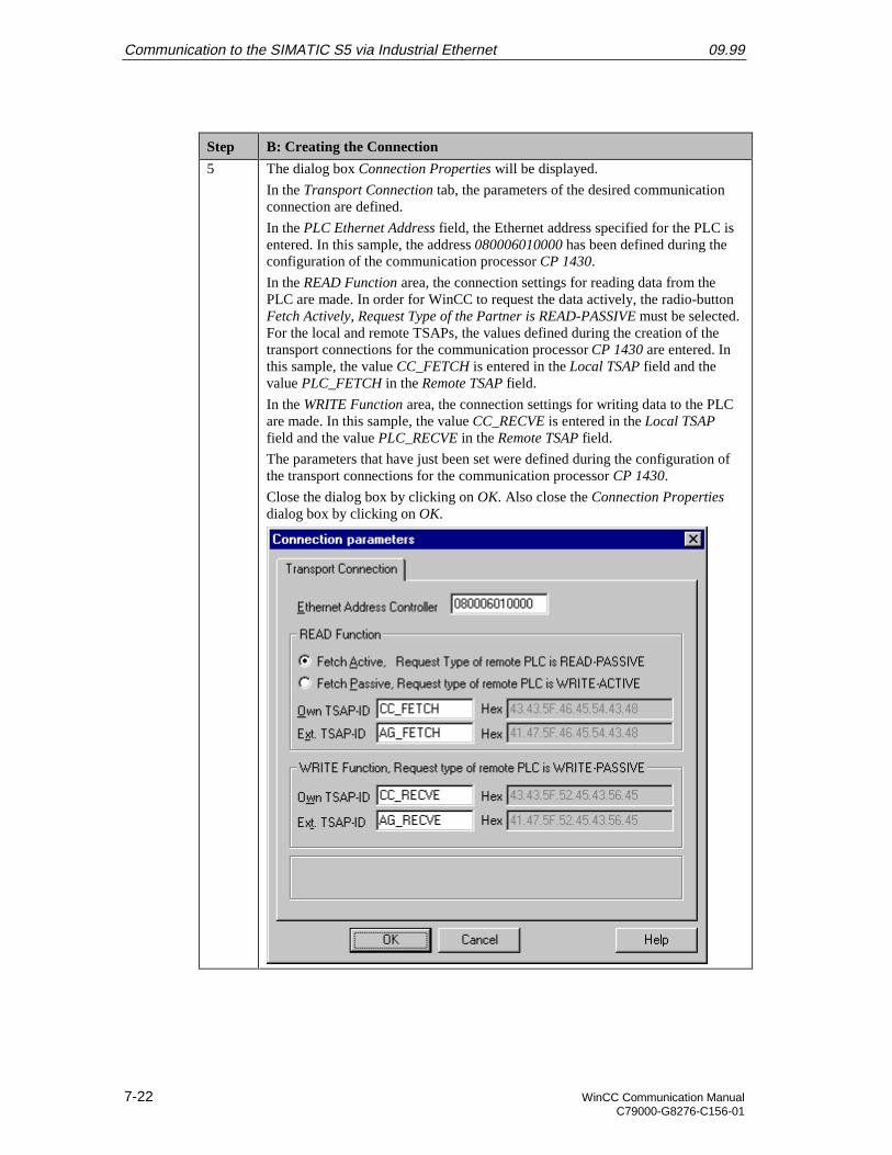
Communication to the SIMATIC S5 via Industrial Ethernet 09.99
7-22 WinCC Communication ManualC79000-G8276-C156-01
Step B: Creating the Connection
5 The dialog box Connection Properties will be displayed.
In the Transport Connection tab, the parameters of the desired communicationconnection are defined.
In the PLC Ethernet Address field, the Ethernet address specified for the PLC isentered. In this sample, the address 080006010000 has been defined during theconfiguration of the communication processor CP 1430.
In the READ Function area, the connection settings for reading data from thePLC are made. In order for WinCC to request the data actively, the radio-buttonFetch Actively, Request Type of the Partner is READ-PASSIVE must be selected.For the local and remote TSAPs, the values defined during the creation of thetransport connections for the communication processor CP 1430 are entered. Inthis sample, the value CC_FETCH is entered in the Local TSAP field and thevalue PLC_FETCH in the Remote TSAP field.
In the WRITE Function area, the connection settings for writing data to the PLCare made. In this sample, the value CC_RECVE is entered in the Local TSAPfield and the value PLC_RECVE in the Remote TSAP field.
The parameters that have just been set were defined during the configuration ofthe transport connections for the communication processor CP 1430.
Close the dialog box by clicking on OK. Also close the Connection Propertiesdialog box by clicking on OK.
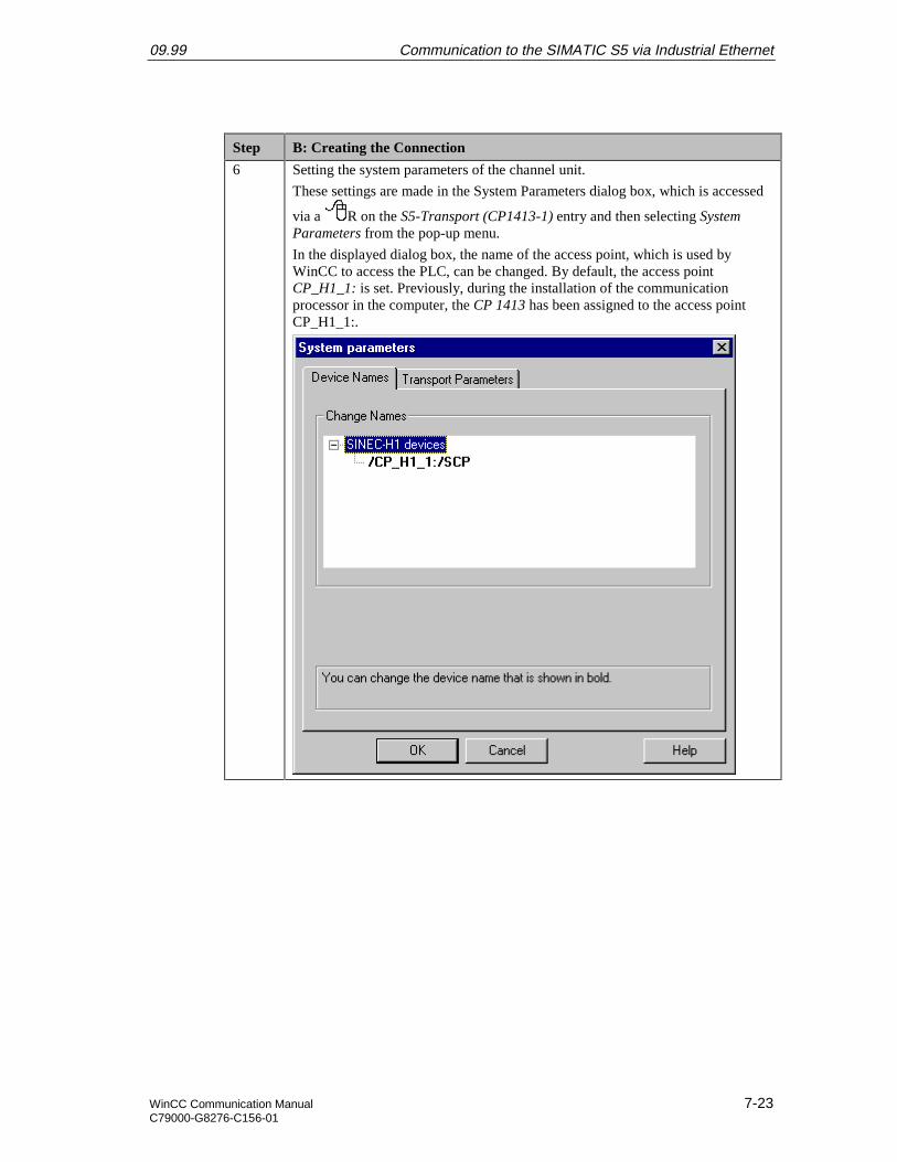
09.99 Communication to the SIMATIC S5 via Industrial Ethernet
WinCC Communication Manual 7-23C79000-G8276-C156-01
Step B: Creating the Connection
6 Setting the system parameters of the channel unit.
These settings are made in the System Parameters dialog box, which is accessed
via a R on the S5-Transport (CP1413-1) entry and then selecting SystemParameters from the pop-up menu.
In the displayed dialog box, the name of the access point, which is used byWinCC to access the PLC, can be changed. By default, the access pointCP_H1_1: is set. Previously, during the installation of the communicationprocessor in the computer, the CP 1413 has been assigned to the access pointCP_H1_1:.
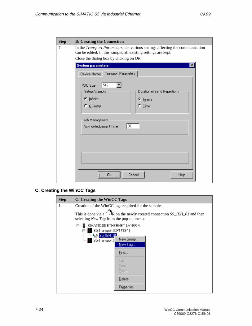
Communication to the SIMATIC S5 via Industrial Ethernet 09.99
7-24 WinCC Communication ManualC79000-G8276-C156-01
Step B: Creating the Connection
7 In the Transport Parameters tab, various settings affecting the communicationcan be edited. In this sample, all existing settings are kept.
Close the dialog box by clicking on OK.
C: Creating the WinCC Tags
Step C: Creating the WinCC Tags
1 Creation of the WinCC tags required for the sample.
This is done via a R on the newly created connection S5_IEH_01 and thenselecting New Tag from the pop-up menu.
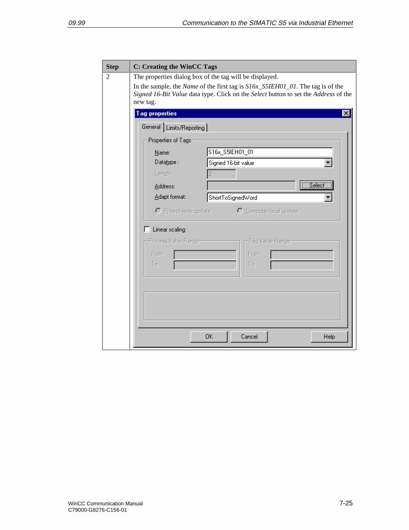
09.99 Communication to the SIMATIC S5 via Industrial Ethernet
WinCC Communication Manual 7-25C79000-G8276-C156-01
Step C: Creating the WinCC Tags
2 The properties dialog box of the tag will be displayed.
In the sample, the Name of the first tag is S16x_S5IEH01_01. The tag is of theSigned 16-Bit Value data type. Click on the Select button to set the Address of thenew tag.
Communication to the SIMATIC S5 via Industrial Ethernet 09.99
7-26 WinCC Communication ManualC79000-G8276-C156-01
Step C: Creating the WinCC Tags
3 The dialog box Address Properties will be displayed.
Set DB as the Data Range and the value 5 as the DB No.. Set Word in theAddress field and the value 0 in the DW field. Close the dialog box by clickingon OK. The properties dialog box of the tag is also closed by clicking on OK.
The just created WinCC tag is addressed in the range of the DB5, where the firstof the two values to be added is located.
The Address Properties and Tag Properties dialog boxes can be closed byclicking on the OK button.
4 Creation of the remaining WinCC tags required.
Follow steps 1 to 3 for the creation of the remaining tags. The names, data typesand addresses of the tags used in this sample are listed in the following graphic.

09.99 Communication to the SIMATIC S5 via Industrial Ethernet
WinCC Communication Manual 7-27C79000-G8276-C156-01
D: Creating the WinCC Screen
Step D: Creating the WinCC Screen
1 Creation of a WinCC screen in which the previously created tags are visualized.
Open the Graphics Designer editor via a R and then selecting Open from thepop-up menu.
2 This will open the Graphics Designer editor with a new (blank) screen.
To display the first tag, configure a Smart Object I/O Field. To do so,select the I/O Field object from the Object Palette and place it on the screenusing the mouse.
Communication to the SIMATIC S5 via Industrial Ethernet 09.99
7-28 WinCC Communication ManualC79000-G8276-C156-01
Step D: Creating the WinCC Screen
3 After placing the I/O Field on the screen, its Configuration dialog box will bedisplayed.
In the Tag field, set the tag S16x_S7IEH01_01 via the button displayed below.
Leave the Update of the tag at 2 s. Keep the default settings for the remainingoptions. Close the dialog box by clicking on OK.
4 Changing the output format of the I/O Field.
For this, open its properties dialog box via a R on the I/O Field and thenselect Properties from the pop-up menu.
09.99 Communication to the SIMATIC S5 via Industrial Ethernet
WinCC Communication Manual 7-29C79000-G8276-C156-01
Step D: Creating the WinCC Screen
5 The dialog box Object Properties will be displayed.
On the left side of the Properties tab, select the entry Output/Input. Via a Don the output format set, the field can be edited. Select the new format s99999.This format enables the I/O Field to display signed values with a maximum of 5digits.
6 Creation of three additional I/O Fields for the display of the remaining tags.
Follow steps 2 to 5 to create the remaining I/O fields.
7 Save the screen.
In the sample project, the screen is saved under the name com_3_S5IEH_01.pdl.The screen can be switched directly to runtime from the Graphics Designer viathe button displayed below.
Communication to the SIMATIC S5 via Industrial Ethernet 09.99
7-30 WinCC Communication ManualC79000-G8276-C156-01
Step D: Creating the WinCC Screen
If the screen is in runtime, the PLC started and the network connectionestablished, the current values of the PLC will be displayed in the I/O fields.They can be changed by entering values in the individual I/O Fields.
If there is no connection to the PLC, the I/O Fields will be displayed grayed out.In this case an error is present at some point of the communication connection.
09.99 Communication to the SIMATIC S5 via Industrial Ethernet
WinCC Communication Manual 7-31C79000-G8276-C156-01
7.4 Diagnosis of the Communication Connection
The following describes the options available for diagnosing the communication connectionbetween the WinCC project WinCC_S5_IEH and the SIMATIC S5 station.A diagnosis of the sample according to this description makes only sense, if the checkslisted below have been completed successfully.Startup of the Communication Processor CP 1413
• E: Testing the Communication ProcessorCreation of the STEP5 Project S5_IEHst
• D: Starting up the PLC
WinCC Explorer
Step WinCC Explorer
1 Diagnosis of the communication connection from the WinCC Explorer.
Switch the project WinCC_S5_IEH into runtime. This is done from the WinCCExplorer via the toolbar button displayed below.
The created WinCC screen com_3_S5IEH_01.pdl can also be switched directlyfrom the Graphics Designer into runtime.
2 In the WinCC Explorer, a dialog box for monitoring all configured connectionscan be accessed via the Tools Status of Driver Connections menu. Thismenu point is only accessible if the project is in runtime.
Communication to the SIMATIC S5 via Industrial Ethernet 09.99
7-32 WinCC Communication ManualC79000-G8276-C156-01
Step WinCC Explorer
3 The dialog box Status - Logical Connections will be displayed.
This dialog box lists all configured connections. For this sample, only theconnection S5_IEH_01 will be displayed.
The displayed values correspond to the status at the moment the dialog box wasopened. By selecting the appropriate check-box, a Cyclic Update of the displaycan be achieved.
4 Another way to obtain information about the connection status in general andabout the connection status of individual tags is provided by Tag Management.
The status of a configured connection can be displayed as a tooltip by simplypointing the mouse on the connection in question.
The current process value of a certain tag as well as its status can be displayed asa tooltip by pointing the mouse on it. This allows you to detect errors concerningan individual tag and not the entire connection.
09.99 Communication to the SIMATIC S5 via Industrial Ethernet
WinCC Communication Manual 7-33C79000-G8276-C156-01
Channel Diagnosis
Step Channel Diagnosis
1 Diagnosis of the communication connection via the program WinCC ChannelDiagnosis.
Start this program via Start Simatic WinCC ChannelDiagnosis.
2 The program WinCC Channel Diagnosis will be displayed.
The Channels/Connections tab displays detailed information about the status ofeach configured connection. By default, the display is updated every second. Theupdate cycle can be changed in the input field located at the bottom.

Communication to the SIMATIC S5 via Industrial Ethernet 09.99
7-34 WinCC Communication ManualC79000-G8276-C156-01
09.99 Communication to the SIMATIC S5 via PROFIBUS FMS
WinCC Communication Manual 8-1C79000-G8276-C156-01
8 Communication to the SIMATIC S5 viaPROFIBUS FMS
The projects created in this chapter can also be copied directly from the online document toyour hard drive. By default, they will be copied to the folder C:\Communication_Manual.You have the option to copy the following components to the hard drive:
comprofibus_S5FMS
The database file of the communication processor CP 5412 A2 and the files generatedduring its creation.
S5_FMSst
The STEP5 project we will create including the database file of the communicationprocessor CP 5431 FMS/DP.
WinCC_S5_FMS
The WinCC project we will create.
This chapter describes in detail the startup of a communication connection between aSIMATIC S5 station and a WinCC station. The communication connection is implementedvia the PROFIBUS, on which the FMS Protocol (Fieldbus Message Specification) isrunning.
Overview of the Structure of the Sample
On the computer side, the connection to the PROFIBUS network is established via thecommunication processor CP 5412 A2. To install this communication processor in thecomputer, the driver PB FMS-5412, located on the SIMATIC NET CD-ROM, is needed.In the WinCC project, the communication driver PROFIBUS FMS must be installed. Thiscommunication driver is used to configure the connection to the SIMATIC S5.The PLC SIMATIC S5 115U is equipped with the CPU module CPU 944. The connectionto the network is established via the communication processor CP 5431 FMS/DP. For theconfiguration of this communication processor, the communication package SINEC NCMfor COMs is required.
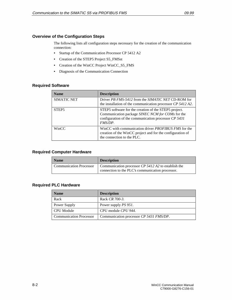
Communication to the SIMATIC S5 via PROFIBUS FMS 09.99
8-2 WinCC Communication ManualC79000-G8276-C156-01
Overview of the Configuration Steps
The following lists all configuration steps necessary for the creation of the communicationconnection:
• Startup of the Communication Processor CP 5412 A2
• Creation of the STEP5 Project S5_FMSst
• Creation of the WinCC Project WinCC_S5_FMS
• Diagnosis of the Communication Connection
Required Software
Name Description
SIMATIC NET Driver PB FMS-5412 from the SIMATIC NET CD-ROM forthe installation of the communication processor CP 5412 A2.
STEP5 STEP5 software for the creation of the STEP5 project.Communication package SINEC NCM for COMs for theconfiguration of the communication processor CP 5431FMS/DP.
WinCC WinCC with communication driver PROFIBUS FMS for thecreation of the WinCC project and for the configuration ofthe connection to the PLC.
Required Computer Hardware
Name Description
Communication Processor Communication processor CP 5412 A2 to establish theconnection to the PLC’s communication processor.
Required PLC Hardware
Name Description
Rack Rack CR 700-3.
Power Supply Power supply PS 951.
CPU Module CPU module CPU 944.
Communication Processor Communication processor CP 5431 FMS/DP.
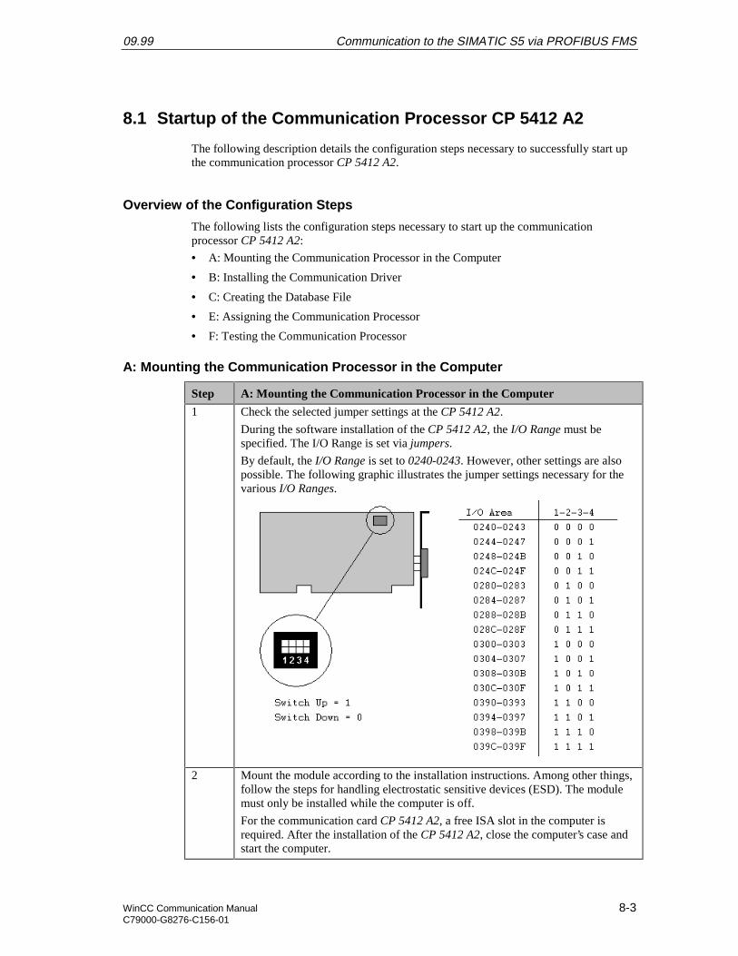
09.99 Communication to the SIMATIC S5 via PROFIBUS FMS
WinCC Communication Manual 8-3C79000-G8276-C156-01
8.1 Startup of the Communication Processor CP 5412 A2
The following description details the configuration steps necessary to successfully start upthe communication processor CP 5412 A2.
Overview of the Configuration Steps
The following lists the configuration steps necessary to start up the communicationprocessor CP 5412 A2:
• A: Mounting the Communication Processor in the Computer
• B: Installing the Communication Driver
• C: Creating the Database File
• E: Assigning the Communication Processor
• F: Testing the Communication Processor
A: Mounting the Communication Processor in the Computer
Step A: Mounting the Communication Processor in the Computer
1 Check the selected jumper settings at the CP 5412 A2.
During the software installation of the CP 5412 A2, the I/O Range must bespecified. The I/O Range is set via jumpers.
By default, the I/O Range is set to 0240-0243. However, other settings are alsopossible. The following graphic illustrates the jumper settings necessary for thevarious I/O Ranges.
2 Mount the module according to the installation instructions. Among other things,follow the steps for handling electrostatic sensitive devices (ESD). The modulemust only be installed while the computer is off.
For the communication card CP 5412 A2, a free ISA slot in the computer isrequired. After the installation of the CP 5412 A2, close the computer’s case andstart the computer.

Communication to the SIMATIC S5 via PROFIBUS FMS 09.99
8-4 WinCC Communication ManualC79000-G8276-C156-01
B: Installing the Communication Driver
Step B: Installing the Communication Driver
1 Installation of the communication driver PB FMS-5412 from the SIMATIC NETCD-ROM.
After inserting the SIMATIC NET CD-ROM, the installation program isautomatically started. If this is not the case, open the Windows NT Explorer andstart the setup.exe program located on the CD-ROM.
The installation of the software is started via the button displayed below.
Follow the instructions of the installation program. On the Components page, thecheck-box of the driver PB FMS-5412 to be installed must be selected. Finish theinstallation.
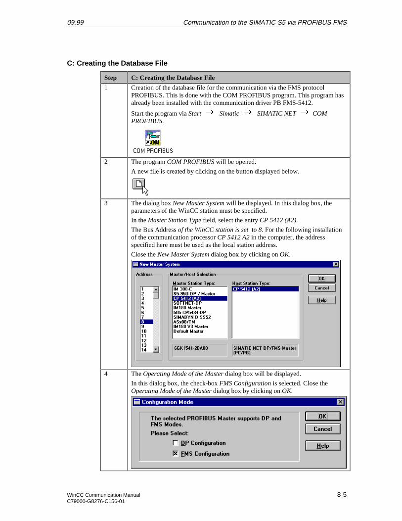
09.99 Communication to the SIMATIC S5 via PROFIBUS FMS
WinCC Communication Manual 8-5C79000-G8276-C156-01
C: Creating the Database File
Step C: Creating the Database File
1 Creation of the database file for the communication via the FMS protocolPROFIBUS. This is done with the COM PROFIBUS program. This program hasalready been installed with the communication driver PB FMS-5412.
Start the program via Start Simatic SIMATIC NET COMPROFIBUS.
2 The program COM PROFIBUS will be opened.
A new file is created by clicking on the button displayed below.
3 The dialog box New Master System will be displayed. In this dialog box, theparameters of the WinCC station must be specified.
In the Master Station Type field, select the entry CP 5412 (A2).
The Bus Address of the WinCC station is set to 8. For the following installationof the communication processor CP 5412 A2 in the computer, the addressspecified here must be used as the local station address.
Close the New Master System dialog box by clicking on OK.
4 The Operating Mode of the Master dialog box will be displayed.
In this dialog box, the check-box FMS Configuration is selected. Close theOperating Mode of the Master dialog box by clicking on OK.
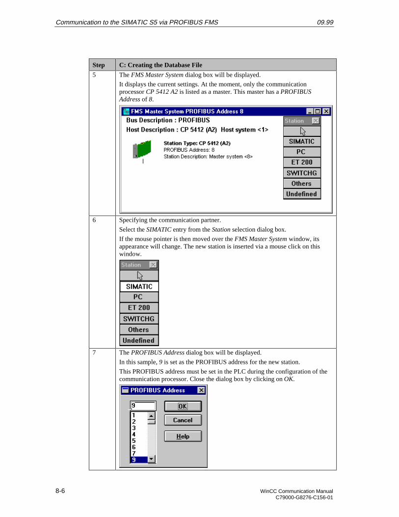
Communication to the SIMATIC S5 via PROFIBUS FMS 09.99
8-6 WinCC Communication ManualC79000-G8276-C156-01
Step C: Creating the Database File
5 The FMS Master System dialog box will be displayed.
It displays the current settings. At the moment, only the communicationprocessor CP 5412 A2 is listed as a master. This master has a PROFIBUSAddress of 8.
6 Specifying the communication partner.
Select the SIMATIC entry from the Station selection dialog box.
If the mouse pointer is then moved over the FMS Master System window, itsappearance will change. The new station is inserted via a mouse click on thiswindow.
7 The PROFIBUS Address dialog box will be displayed.
In this sample, 9 is set as the PROFIBUS address for the new station.
This PROFIBUS address must be set in the PLC during the configuration of thecommunication processor. Close the dialog box by clicking on OK.
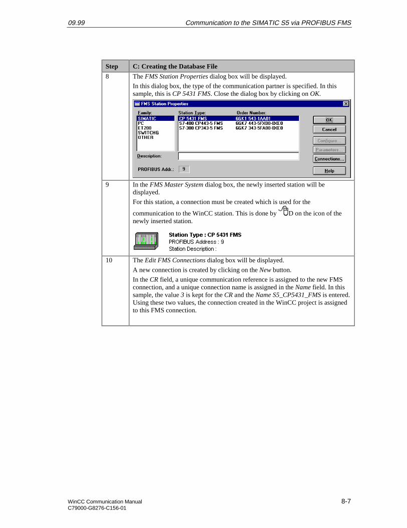
09.99 Communication to the SIMATIC S5 via PROFIBUS FMS
WinCC Communication Manual 8-7C79000-G8276-C156-01
Step C: Creating the Database File
8 The FMS Station Properties dialog box will be displayed.
In this dialog box, the type of the communication partner is specified. In thissample, this is CP 5431 FMS. Close the dialog box by clicking on OK.
9 In the FMS Master System dialog box, the newly inserted station will bedisplayed.
For this station, a connection must be created which is used for the
communication to the WinCC station. This is done by D on the icon of thenewly inserted station.
10 The Edit FMS Connections dialog box will be displayed.
A new connection is created by clicking on the New button.
In the CR field, a unique communication reference is assigned to the new FMSconnection, and a unique connection name is assigned in the Name field. In thissample, the value 3 is kept for the CR and the Name S5_CP5431_FMS is entered.Using these two values, the connection created in the WinCC project is assignedto this FMS connection.
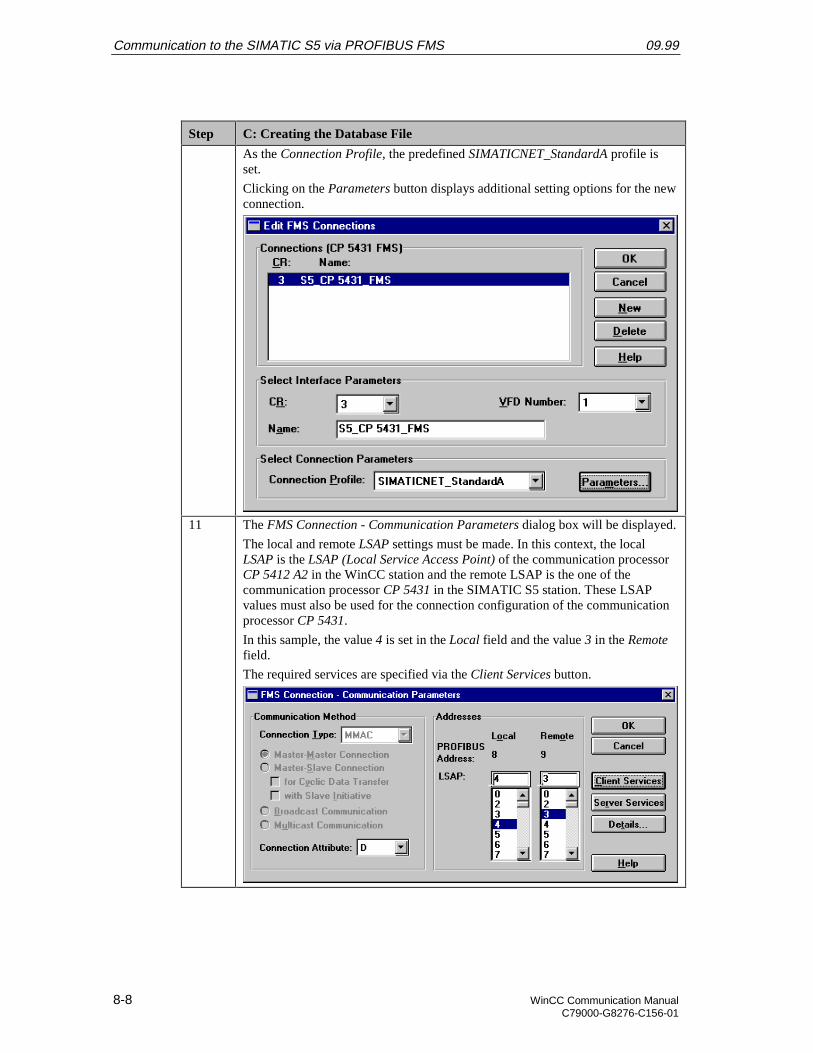
Communication to the SIMATIC S5 via PROFIBUS FMS 09.99
8-8 WinCC Communication ManualC79000-G8276-C156-01
Step C: Creating the Database File
As the Connection Profile, the predefined SIMATICNET_StandardA profile isset.
Clicking on the Parameters button displays additional setting options for the newconnection.
11 The FMS Connection - Communication Parameters dialog box will be displayed.
The local and remote LSAP settings must be made. In this context, the localLSAP is the LSAP (Local Service Access Point) of the communication processorCP 5412 A2 in the WinCC station and the remote LSAP is the one of thecommunication processor CP 5431 in the SIMATIC S5 station. These LSAPvalues must also be used for the connection configuration of the communicationprocessor CP 5431.
In this sample, the value 4 is set in the Local field and the value 3 in the Remotefield.
The required services are specified via the Client Services button.
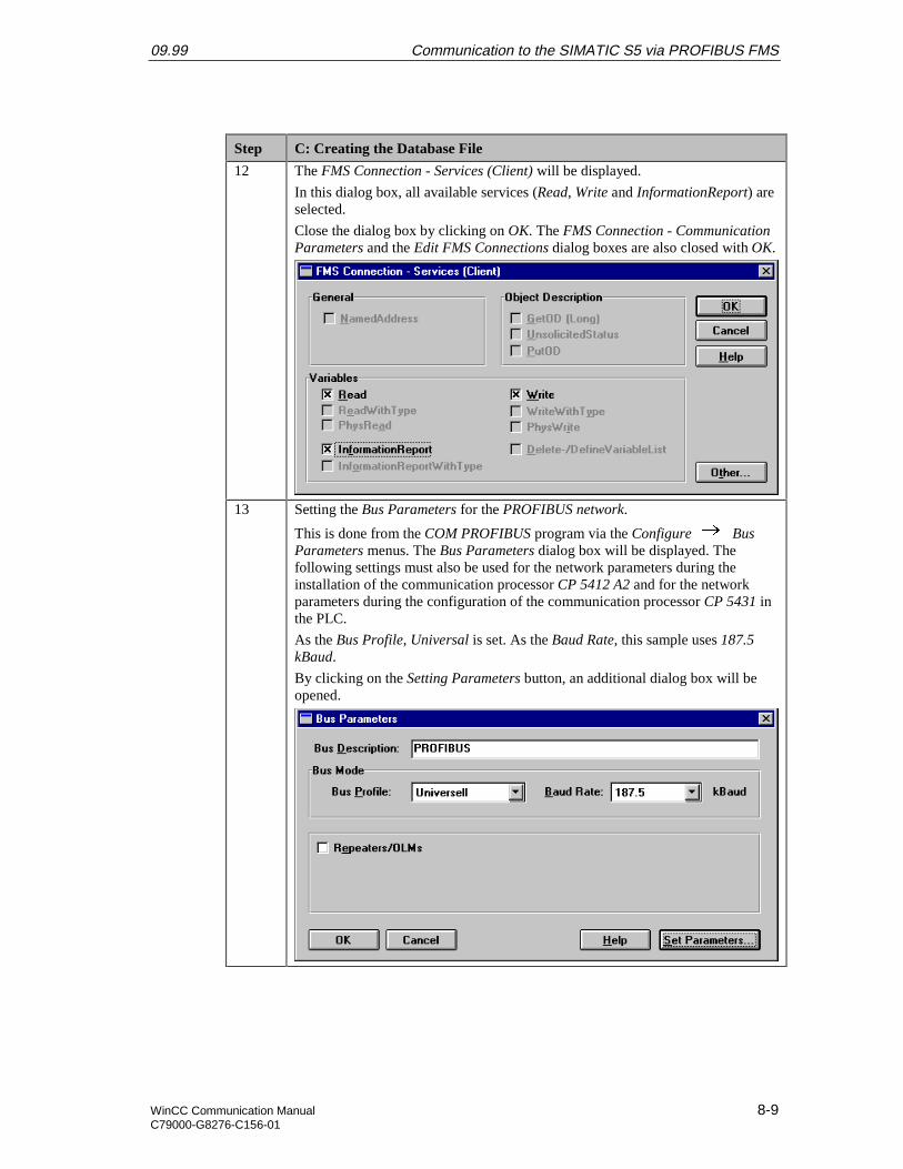
09.99 Communication to the SIMATIC S5 via PROFIBUS FMS
WinCC Communication Manual 8-9C79000-G8276-C156-01
Step C: Creating the Database File
12 The FMS Connection - Services (Client) will be displayed.
In this dialog box, all available services (Read, Write and InformationReport) areselected.
Close the dialog box by clicking on OK. The FMS Connection - CommunicationParameters and the Edit FMS Connections dialog boxes are also closed with OK.
13 Setting the Bus Parameters for the PROFIBUS network.
This is done from the COM PROFIBUS program via the Configure BusParameters menus. The Bus Parameters dialog box will be displayed. Thefollowing settings must also be used for the network parameters during theinstallation of the communication processor CP 5412 A2 and for the networkparameters during the configuration of the communication processor CP 5431 inthe PLC.
As the Bus Profile, Universal is set. As the Baud Rate, this sample uses 187.5kBaud.
By clicking on the Setting Parameters button, an additional dialog box will beopened.
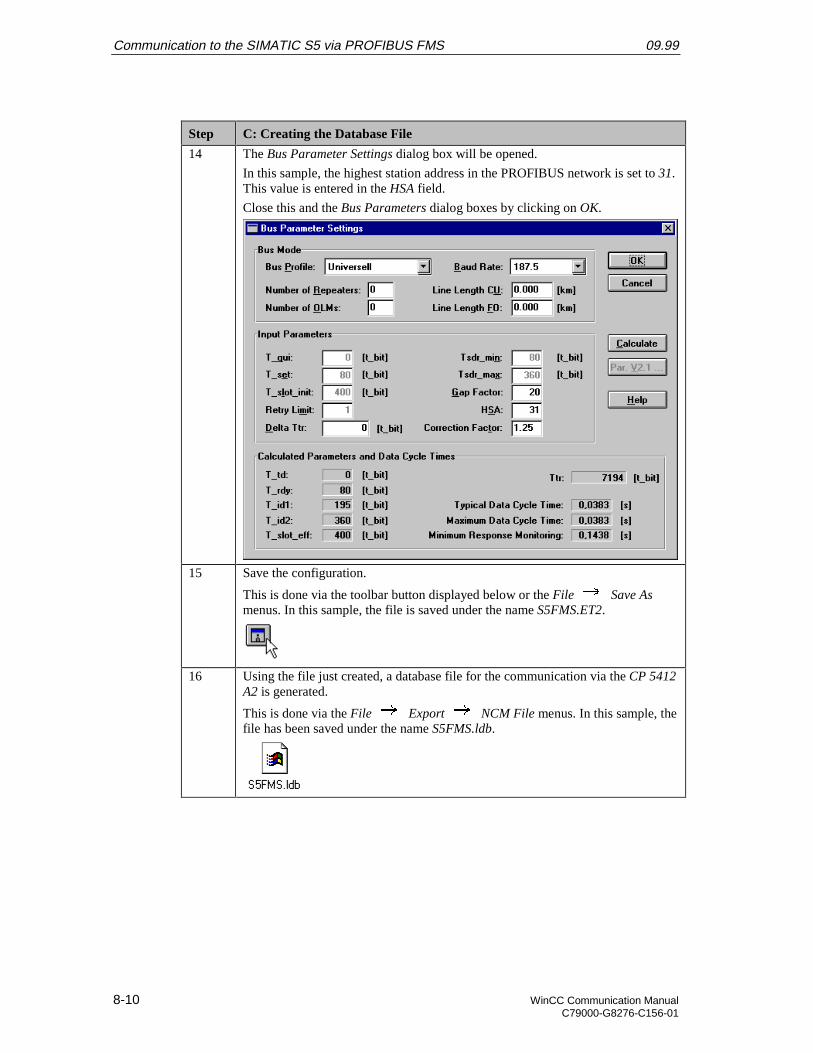
Communication to the SIMATIC S5 via PROFIBUS FMS 09.99
8-10 WinCC Communication ManualC79000-G8276-C156-01
Step C: Creating the Database File
14 The Bus Parameter Settings dialog box will be opened.
In this sample, the highest station address in the PROFIBUS network is set to 31.This value is entered in the HSA field.
Close this and the Bus Parameters dialog boxes by clicking on OK.
15 Save the configuration.
This is done via the toolbar button displayed below or the File Save Asmenus. In this sample, the file is saved under the name S5FMS.ET2.
16 Using the file just created, a database file for the communication via the CP 5412A2 is generated.
This is done via the File Export NCM File menus. In this sample, thefile has been saved under the name S5FMS.ldb.
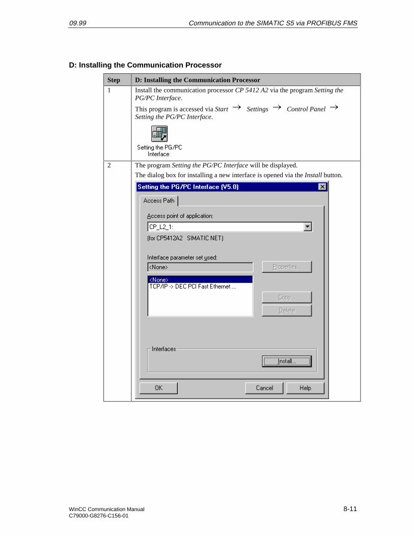
09.99 Communication to the SIMATIC S5 via PROFIBUS FMS
WinCC Communication Manual 8-11C79000-G8276-C156-01
D: Installing the Communication Processor
Step D: Installing the Communication Processor
1 Install the communication processor CP 5412 A2 via the program Setting thePG/PC Interface.
This program is accessed via Start Settings Control Panel Setting the PG/PC Interface.
2 The program Setting the PG/PC Interface will be displayed.
The dialog box for installing a new interface is opened via the Install button.

Communication to the SIMATIC S5 via PROFIBUS FMS 09.99
8-12 WinCC Communication ManualC79000-G8276-C156-01
Step D: Installing the Communication Processor
3 The dialog box Install/Remove Modules will be displayed. The Selection fieldlists all interfaces that can be installed. Among them will be the entry for the CP5412 A2, if the communication driver has been installed previously as outlined instep B.
From the Selection field, select the entry CP 5412 A2. The installation of thecommunication processor is started by clicking on the Install -> button.
4 The dialog box Resources - CP 5412 A2 will be displayed.
The settings for the Memory Range, I/O Range and Interrupt have to bespecified.
The I/O Range has already been determined via the Jumper Settings at the CP5412 A2.
Make sure that the assigned resources have not already been taken by othermodules in the computer. Information about already taken system resources canbe obtained from the Resources tab accessed via Start Programs Administrative Tools (Common) Windows NT Diagnostics.
Close the Resources tab by clicking on OK.
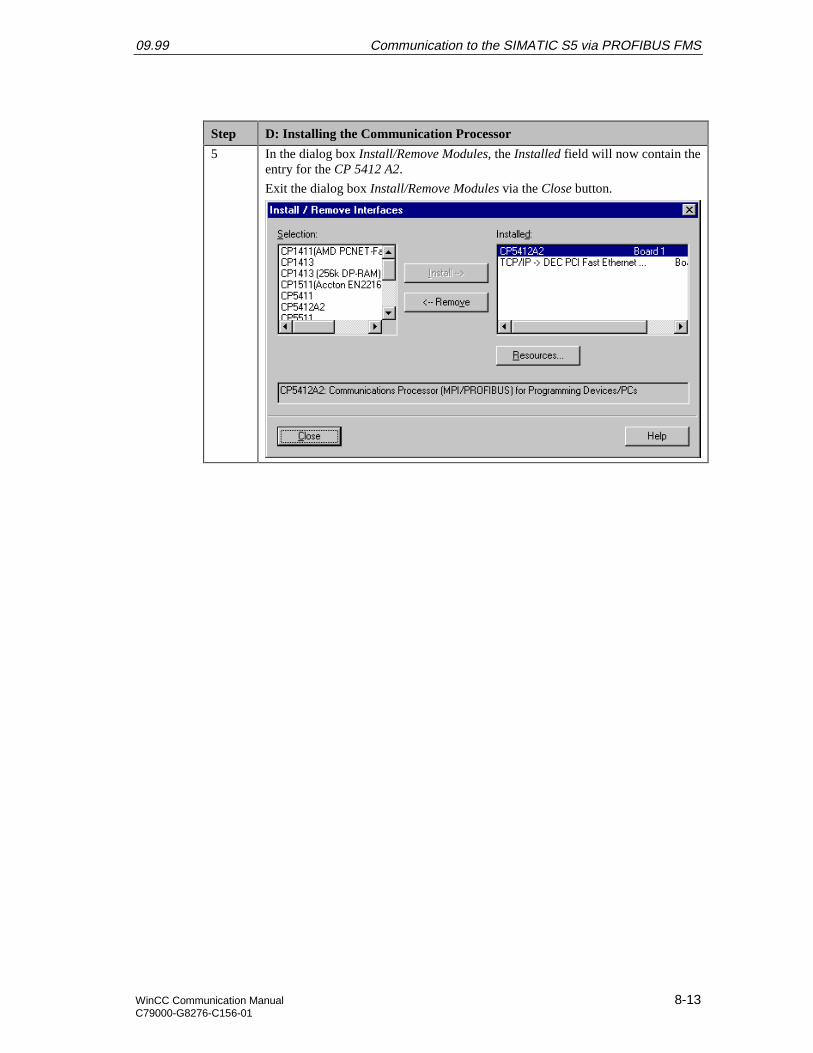
09.99 Communication to the SIMATIC S5 via PROFIBUS FMS
WinCC Communication Manual 8-13C79000-G8276-C156-01
Step D: Installing the Communication Processor
5 In the dialog box Install/Remove Modules, the Installed field will now contain theentry for the CP 5412 A2.
Exit the dialog box Install/Remove Modules via the Close button.
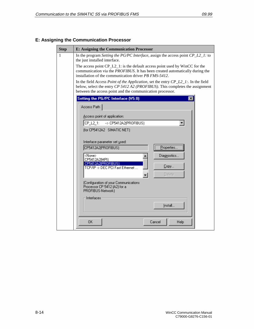
Communication to the SIMATIC S5 via PROFIBUS FMS 09.99
8-14 WinCC Communication ManualC79000-G8276-C156-01
E: Assigning the Communication Processor
Step E: Assigning the Communication Processor
1 In the program Setting the PG/PC Interface, assign the access point CP_L2_1: tothe just installed interface.
The access point CP_L2_1: is the default access point used by WinCC for thecommunication via the PROFIBUS. It has been created automatically during theinstallation of the communication driver PB FMS-5412.
In the field Access Point of the Application, set the entry CP_L2_1:. In the fieldbelow, select the entry CP 5412 A2 (PROFIBUS). This completes the assignmentbetween the access point and the communication processor.
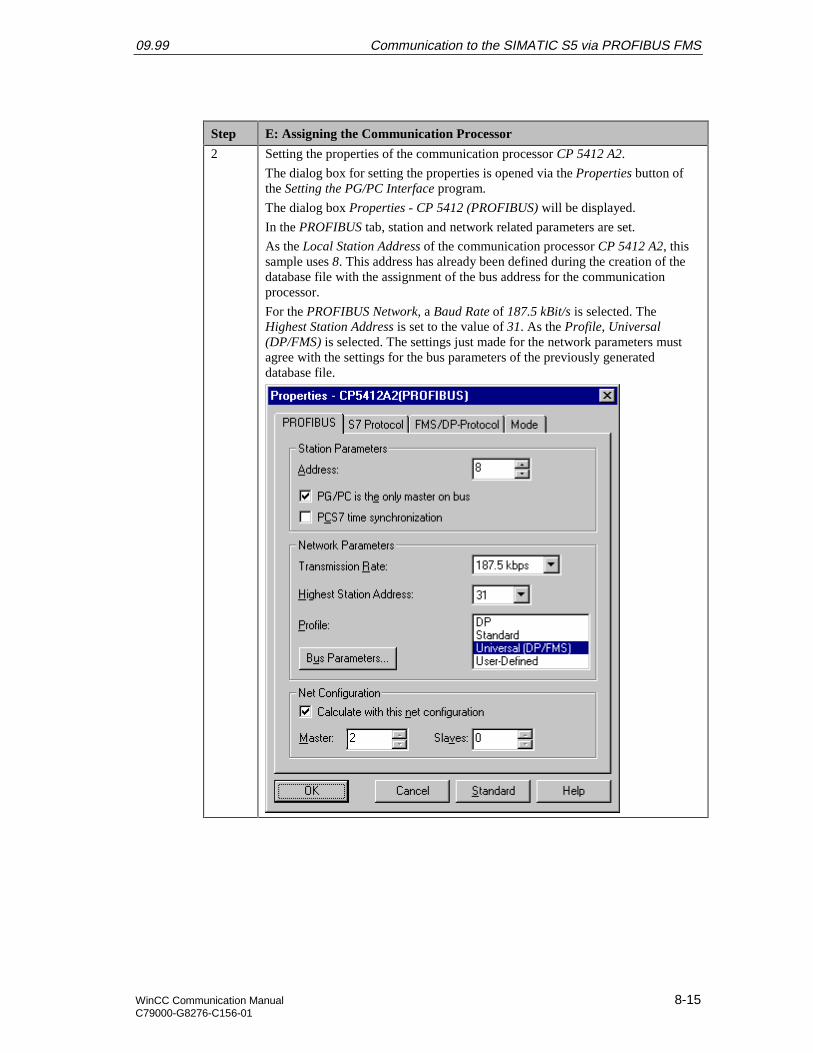
09.99 Communication to the SIMATIC S5 via PROFIBUS FMS
WinCC Communication Manual 8-15C79000-G8276-C156-01
Step E: Assigning the Communication Processor
2 Setting the properties of the communication processor CP 5412 A2.
The dialog box for setting the properties is opened via the Properties button ofthe Setting the PG/PC Interface program.
The dialog box Properties - CP 5412 (PROFIBUS) will be displayed.
In the PROFIBUS tab, station and network related parameters are set.
As the Local Station Address of the communication processor CP 5412 A2, thissample uses 8. This address has already been defined during the creation of thedatabase file with the assignment of the bus address for the communicationprocessor.
For the PROFIBUS Network, a Baud Rate of 187.5 kBit/s is selected. TheHighest Station Address is set to the value of 31. As the Profile, Universal(DP/FMS) is selected. The settings just made for the network parameters mustagree with the settings for the bus parameters of the previously generateddatabase file.
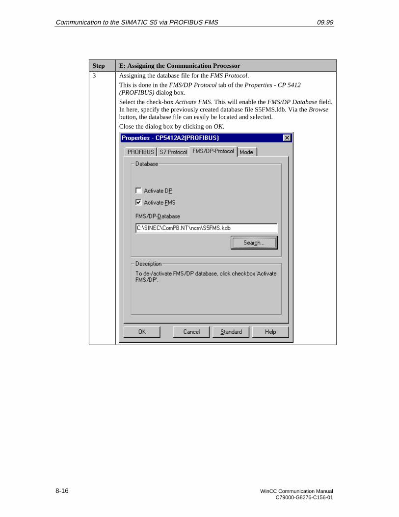
Communication to the SIMATIC S5 via PROFIBUS FMS 09.99
8-16 WinCC Communication ManualC79000-G8276-C156-01
Step E: Assigning the Communication Processor
3 Assigning the database file for the FMS Protocol.
This is done in the FMS/DP Protocol tab of the Properties - CP 5412(PROFIBUS) dialog box.
Select the check-box Activate FMS. This will enable the FMS/DP Database field.In here, specify the previously created database file S5FMS.ldb. Via the Browsebutton, the database file can easily be located and selected.
Close the dialog box by clicking on OK.
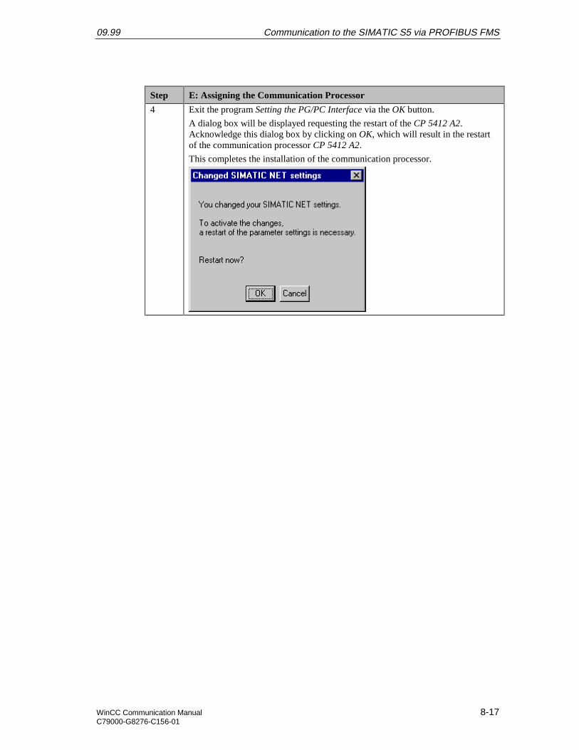
09.99 Communication to the SIMATIC S5 via PROFIBUS FMS
WinCC Communication Manual 8-17C79000-G8276-C156-01
Step E: Assigning the Communication Processor
4 Exit the program Setting the PG/PC Interface via the OK button.
A dialog box will be displayed requesting the restart of the CP 5412 A2.Acknowledge this dialog box by clicking on OK, which will result in the restartof the communication processor CP 5412 A2.
This completes the installation of the communication processor.
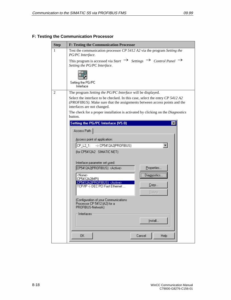
Communication to the SIMATIC S5 via PROFIBUS FMS 09.99
8-18 WinCC Communication ManualC79000-G8276-C156-01
F: Testing the Communication Processor
Step F: Testing the Communication Processor
1 Test the communication processor CP 5412 A2 via the program Setting thePG/PC Interface.
This program is accessed via Start Settings Control Panel Setting the PG/PC Interface.
2 The program Setting the PG/PC Interface will be displayed.
Select the interface to be checked. In this case, select the entry CP 5412 A2(PROFIBUS). Make sure that the assignments between access points and theinterfaces are not changed.
The check for a proper installation is activated by clicking on the Diagnosticsbutton.
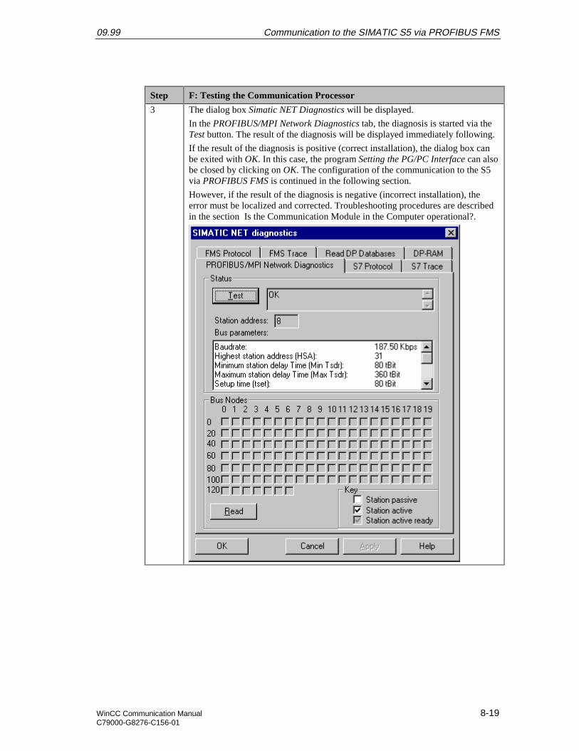
09.99 Communication to the SIMATIC S5 via PROFIBUS FMS
WinCC Communication Manual 8-19C79000-G8276-C156-01
Step F: Testing the Communication Processor
3 The dialog box Simatic NET Diagnostics will be displayed.
In the PROFIBUS/MPI Network Diagnostics tab, the diagnosis is started via theTest button. The result of the diagnosis will be displayed immediately following.
If the result of the diagnosis is positive (correct installation), the dialog box canbe exited with OK. In this case, the program Setting the PG/PC Interface can alsobe closed by clicking on OK. The configuration of the communication to the S5via PROFIBUS FMS is continued in the following section.
However, if the result of the diagnosis is negative (incorrect installation), theerror must be localized and corrected. Troubleshooting procedures are describedin the section Is the Communication Module in the Computer operational?.
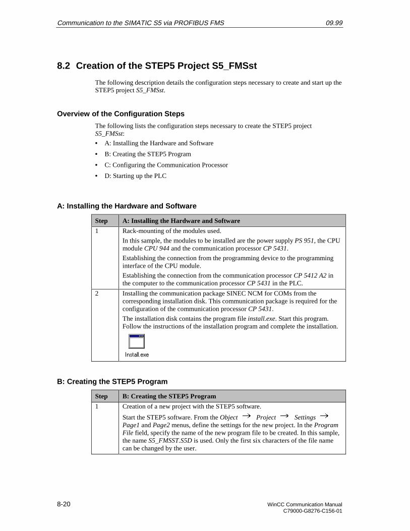
Communication to the SIMATIC S5 via PROFIBUS FMS 09.99
8-20 WinCC Communication ManualC79000-G8276-C156-01
8.2 Creation of the STEP5 Project S5_FMSst
The following description details the configuration steps necessary to create and start up theSTEP5 project S5_FMSst.
Overview of the Configuration Steps
The following lists the configuration steps necessary to create the STEP5 projectS5_FMSst:
• A: Installing the Hardware and Software
• B: Creating the STEP5 Program
• C: Configuring the Communication Processor
• D: Starting up the PLC
A: Installing the Hardware and Software
Step A: Installing the Hardware and Software
1 Rack-mounting of the modules used.
In this sample, the modules to be installed are the power supply PS 951, the CPUmodule CPU 944 and the communication processor CP 5431.
Establishing the connection from the programming device to the programminginterface of the CPU module.
Establishing the connection from the communication processor CP 5412 A2 inthe computer to the communication processor CP 5431 in the PLC.
2 Installing the communication package SINEC NCM for COMs from thecorresponding installation disk. This communication package is required for theconfiguration of the communication processor CP 5431.
The installation disk contains the program file install.exe. Start this program.Follow the instructions of the installation program and complete the installation.
B: Creating the STEP5 Program
Step B: Creating the STEP5 Program
1 Creation of a new project with the STEP5 software.
Start the STEP5 software. From the Object Project Settings Page1 and Page2 menus, define the settings for the new project. In the ProgramFile field, specify the name of the new program file to be created. In this sample,the name S5_FMSST.S5D is used. Only the first six characters of the file namecan be changed by the user.
09.99 Communication to the SIMATIC S5 via PROFIBUS FMS
WinCC Communication Manual 8-21C79000-G8276-C156-01
Step B: Creating the STEP5 Program
2 Creation of a data block.
In STEP5, this is accomplished via the Editor Data Block menus ofthe program file. As the name of the data block, this sample uses DB5.
In this data block, two tags with a length of 16 Bits are created. Their sum is tobe determined in OB1 and then be written to another tag with a length of 16 Bits.One additional tag with a length of 16 Bits is created, whose value is cyclicallyincremented in OB1.
The following graphic displays the programmed data block DB5. The data of theDB5 is made visible to WinCC via FMS tags created during the configuration ofthe communication processor CP 5431.
3 Creation of a program block for the communication.
The communication to WinCC via the communication processor CP 5431 iscarried out by calling the data handling blocks SEND and RECEIVE. For theSIMATIC S5 115U PLC used in this sample, these are the blocks FB244 andFB245. These blocks must be called once every program cycle. As the requestnumber A-NR, 0 is assigned to these blocks to allow execution of the Send Alland Receive All functions.
In this sample, the data handling block calls are carried out in a program block,which is called in the OB1.
In STEP5, the creation of a new program block is carried out via the Editor STEP5 Block menus of the program file. As the name of the program block,this sample uses PB5.

Communication to the SIMATIC S5 via PROFIBUS FMS 09.99
8-22 WinCC Communication ManualC79000-G8276-C156-01
Step B: Creating the STEP5 Program
4 Creation of a function block, which makes available the functionality of thesample program.
Two values stored in the DB5 are added and the sum again stored in the DB5.Additionally, a value stored in the DB5 is incremented every program cycle. Ifthis value reaches 10000, it is reset back to 0.
In STEP5, the creation of a new function block is carried out via the Editor STEP5 Block menus of the program file. As the name of the program block,this sample uses FB6.
5 Creation of the OB1.
In the OB1, the previously created blocks PB5 and FB6 are called.
6 Creation of the startup blocks.
During the startup of the PLC, the communication processor CP 5431 must besynchronized. This is done by the data handling block SYNCHRON. For theSIMATIC S5 115U PLC used in this sample, this is the block FB249.
7 Loading the STEP5 program into the PLC.
In STEP5, this is done via the Object Blocks Transfer PLCFile menus. In the Selection field, the option All Blocks must be selected to loadall previously created blocks to the PLC.

09.99 Communication to the SIMATIC S5 via PROFIBUS FMS
WinCC Communication Manual 8-23C79000-G8276-C156-01
C: Configuring the Communication Processor
Step C: Configuring the Communication Processor
1 Start the communication package SINEC NCM for COMs to configure thecommunication processor CP 5431.
From STEP5, start the communication package via the Change Additional SINEC NCM for COMs menus.
2 This will open the communication package SINEC NCM for COMs.
If no database file is set, the Basic Settings entry mask will initially be displayed.This entry mask can also be opened via the File Select (or Init. Edit)menus.
In the CP Type field, indicate the type of communication processor used. Via theF8 function key, one of the available communication processors can be set.Select the CP 5431. Set the Status field to OFFLINE FD via the F8 function key.This stores the configuration made in the program to a database file. In theDatabase File field, specify the name of this database file. This name has to startwith the letter Q. For this sample, the name QS5_FMS.DAT is used for thedatabase file.
The settings made in the Basic Settings entry mask are applied via the F7function key.
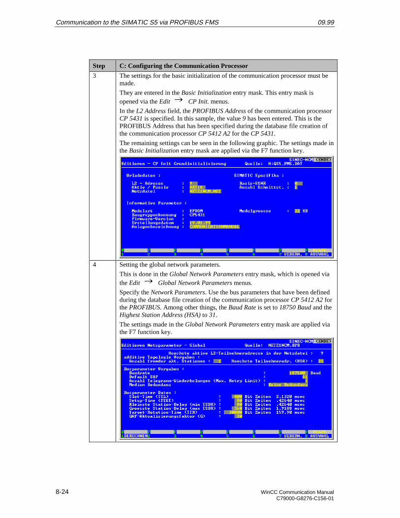
Communication to the SIMATIC S5 via PROFIBUS FMS 09.99
8-24 WinCC Communication ManualC79000-G8276-C156-01
Step C: Configuring the Communication Processor
3 The settings for the basic initialization of the communication processor must bemade.
They are entered in the Basic Initialization entry mask. This entry mask isopened via the Edit CP Init. menus.
In the L2 Address field, the PROFIBUS Address of the communication processorCP 5431 is specified. In this sample, the value 9 has been entered. This is thePROFIBUS Address that has been specified during the database file creation ofthe communication processor CP 5412 A2 for the CP 5431.
The remaining settings can be seen in the following graphic. The settings made inthe Basic Initialization entry mask are applied via the F7 function key.
4 Setting the global network parameters.
This is done in the Global Network Parameters entry mask, which is opened viathe Edit Global Network Parameters menus.
Specify the Network Parameters. Use the bus parameters that have been definedduring the database file creation of the communication processor CP 5412 A2 forthe PROFIBUS. Among other things, the Baud Rate is set to 18750 Baud and theHighest Station Address (HSA) to 31.
The settings made in the Global Network Parameters entry mask are applied viathe F7 function key.
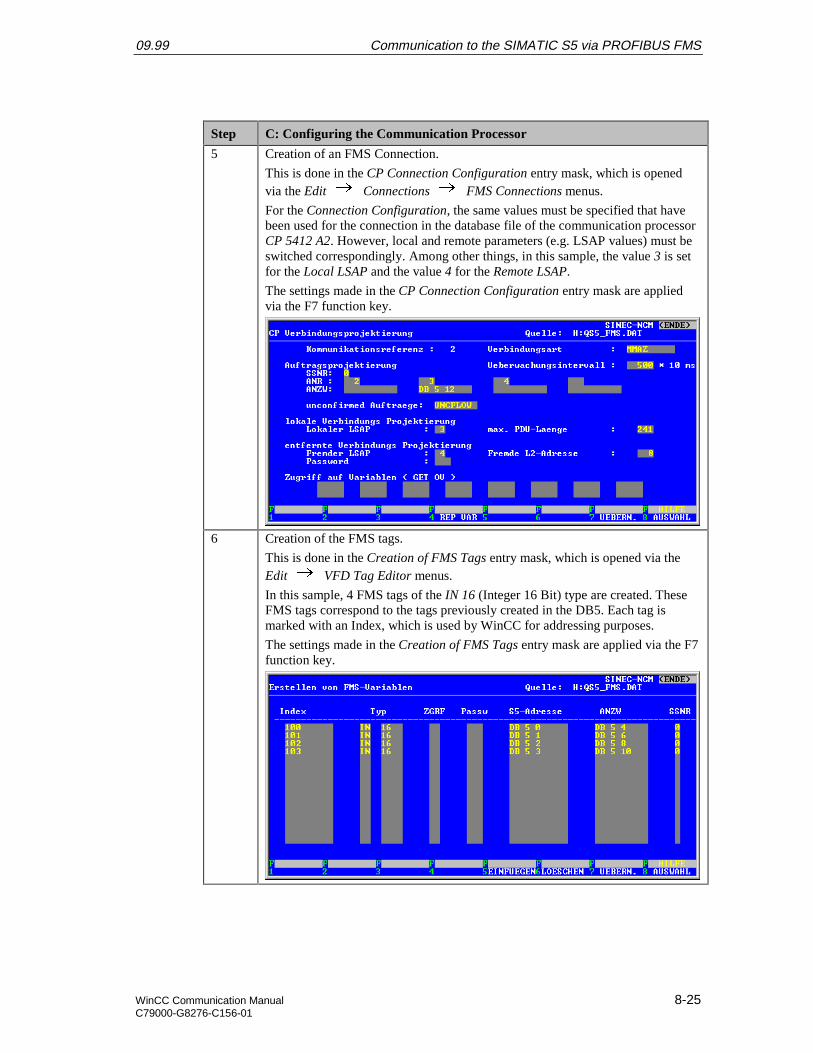
09.99 Communication to the SIMATIC S5 via PROFIBUS FMS
WinCC Communication Manual 8-25C79000-G8276-C156-01
Step C: Configuring the Communication Processor
5 Creation of an FMS Connection.
This is done in the CP Connection Configuration entry mask, which is openedvia the Edit Connections FMS Connections menus.
For the Connection Configuration, the same values must be specified that havebeen used for the connection in the database file of the communication processorCP 5412 A2. However, local and remote parameters (e.g. LSAP values) must beswitched correspondingly. Among other things, in this sample, the value 3 is setfor the Local LSAP and the value 4 for the Remote LSAP.
The settings made in the CP Connection Configuration entry mask are appliedvia the F7 function key.
6 Creation of the FMS tags.
This is done in the Creation of FMS Tags entry mask, which is opened via theEdit VFD Tag Editor menus.
In this sample, 4 FMS tags of the IN 16 (Integer 16 Bit) type are created. TheseFMS tags correspond to the tags previously created in the DB5. Each tag ismarked with an Index, which is used by WinCC for addressing purposes.
The settings made in the Creation of FMS Tags entry mask are applied via the F7function key.
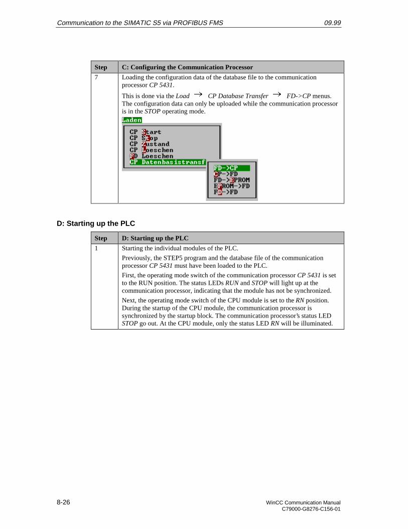
Communication to the SIMATIC S5 via PROFIBUS FMS 09.99
8-26 WinCC Communication ManualC79000-G8276-C156-01
Step C: Configuring the Communication Processor
7 Loading the configuration data of the database file to the communicationprocessor CP 5431.
This is done via the Load CP Database Transfer FD->CP menus.The configuration data can only be uploaded while the communication processoris in the STOP operating mode.
D: Starting up the PLC
Step D: Starting up the PLC
1 Starting the individual modules of the PLC.
Previously, the STEP5 program and the database file of the communicationprocessor CP 5431 must have been loaded to the PLC.
First, the operating mode switch of the communication processor CP 5431 is setto the RUN position. The status LEDs RUN and STOP will light up at thecommunication processor, indicating that the module has not be synchronized.
Next, the operating mode switch of the CPU module is set to the RN position.During the startup of the CPU module, the communication processor issynchronized by the startup block. The communication processor’s status LEDSTOP go out. At the CPU module, only the status LED RN will be illuminated.

09.99 Communication to the SIMATIC S5 via PROFIBUS FMS
WinCC Communication Manual 8-27C79000-G8276-C156-01
8.3 Creation of the WinCC Project WinCC_S5_FMS
The following description details the configuration steps necessary to create and start up theWinCC project WinCC_S5_FMS.
Overview of the Configuration Steps
The following lists the configuration steps necessary to create the WinCC projectWinCC_S5_FMS:
• A: Creating the WinCC Project
• B: Creating the Connection
• C: Creating the WinCC Tags
• D: Creating the WinCC Screen
A: Creating the WinCC Project
Step A: Creating the WinCC Project
1 Creation of a new WinCC project in the WinCC Explorer.
The WinCC Explorer is started via Start Simatic WinCC Windows Control Center.
2 This will display the WinCC Explorer.
Via the menus File New, the dialog box for specifying the properties of anew WinCC project will be opened.
For this sample project, a Single-User Project is created.
Exit the dialog box by clicking on OK.
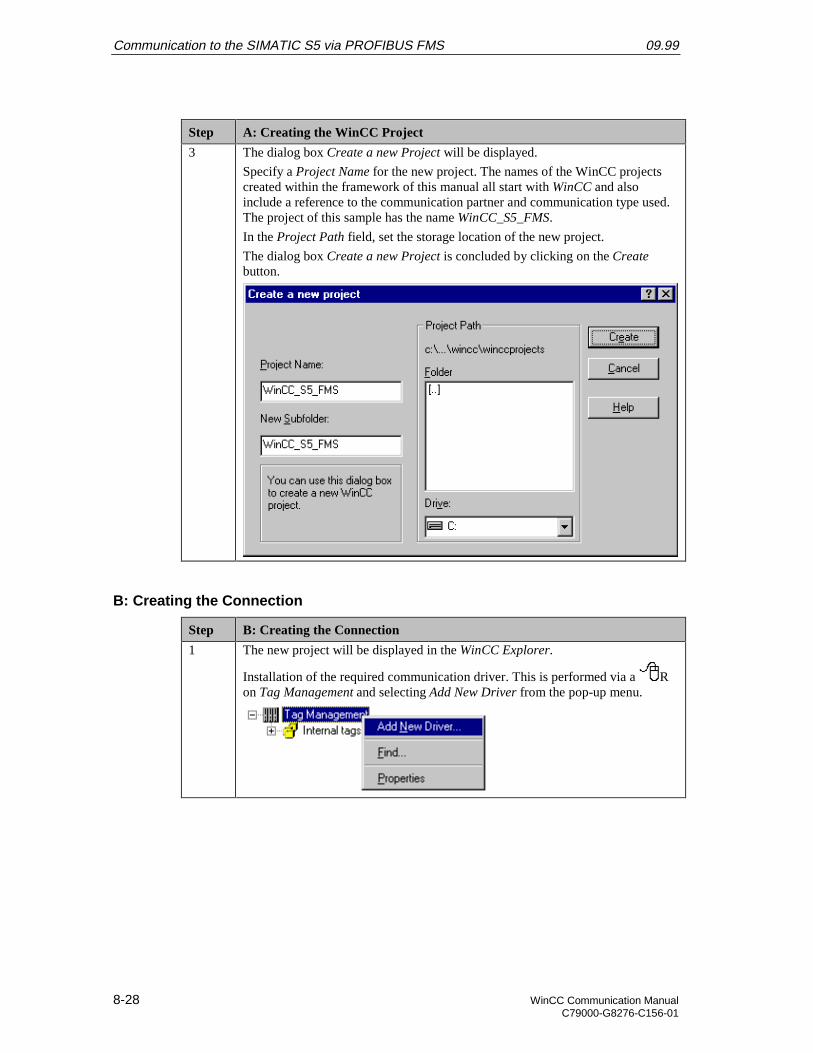
Communication to the SIMATIC S5 via PROFIBUS FMS 09.99
8-28 WinCC Communication ManualC79000-G8276-C156-01
Step A: Creating the WinCC Project
3 The dialog box Create a new Project will be displayed.
Specify a Project Name for the new project. The names of the WinCC projectscreated within the framework of this manual all start with WinCC and alsoinclude a reference to the communication partner and communication type used.The project of this sample has the name WinCC_S5_FMS.
In the Project Path field, set the storage location of the new project.
The dialog box Create a new Project is concluded by clicking on the Createbutton.
B: Creating the Connection
Step B: Creating the Connection
1 The new project will be displayed in the WinCC Explorer.
Installation of the required communication driver. This is performed via a Ron Tag Management and selecting Add New Driver from the pop-up menu.
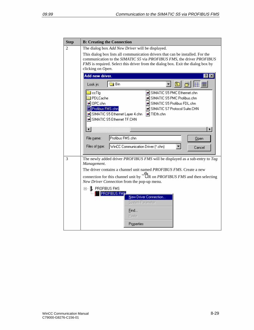
09.99 Communication to the SIMATIC S5 via PROFIBUS FMS
WinCC Communication Manual 8-29C79000-G8276-C156-01
Step B: Creating the Connection
2 The dialog box Add New Driver will be displayed.
This dialog box lists all communication drivers that can be installed. For thecommunication to the SIMATIC S5 via PROFIBUS FMS, the driver PROFIBUSFMS is required. Select this driver from the dialog box. Exit the dialog box byclicking on Open.
3 The newly added driver PROFIBUS FMS will be displayed as a sub-entry to TagManagement.
The driver contains a channel unit named PROFIBUS FMS. Create a new
connection for this channel unit by R on PROFIBUS FMS and then selectingNew Driver Connection from the pop-up menu.
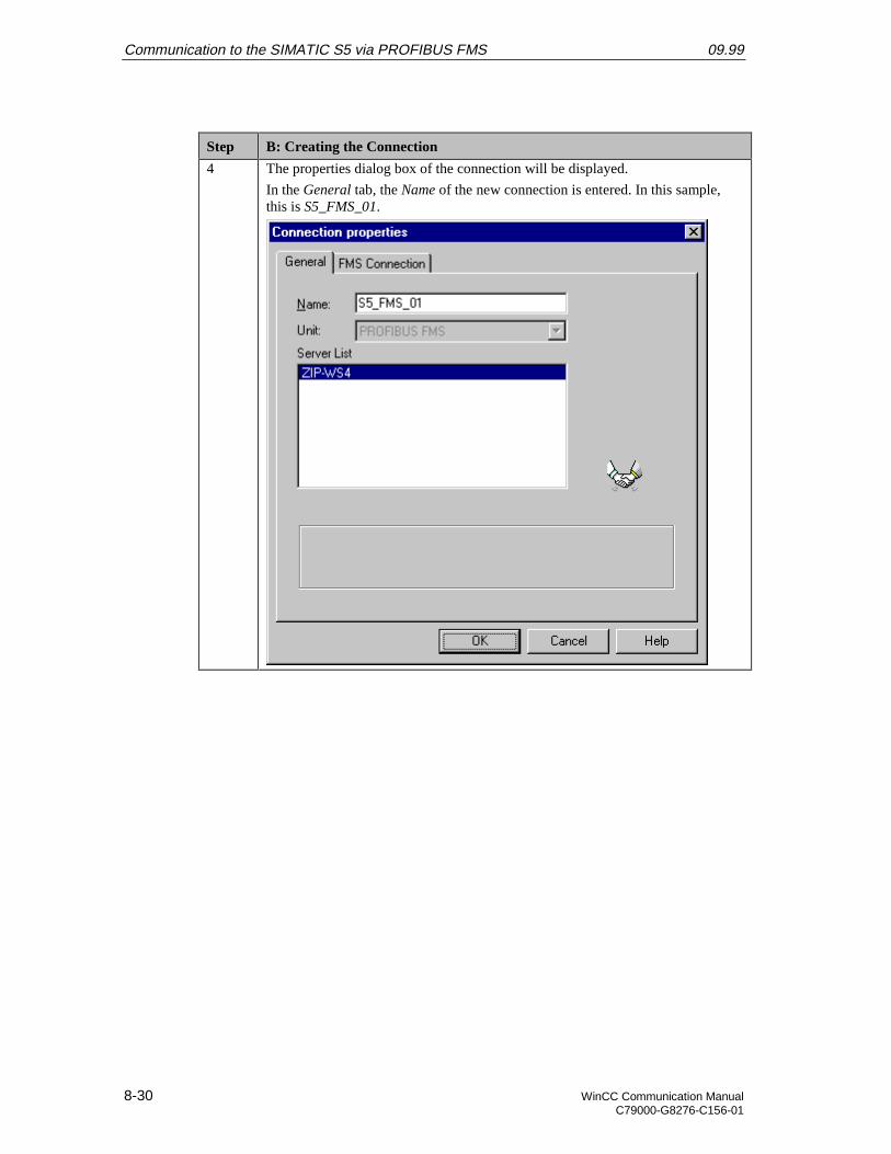
Communication to the SIMATIC S5 via PROFIBUS FMS 09.99
8-30 WinCC Communication ManualC79000-G8276-C156-01
Step B: Creating the Connection
4 The properties dialog box of the connection will be displayed.
In the General tab, the Name of the new connection is entered. In this sample,this is S5_FMS_01.
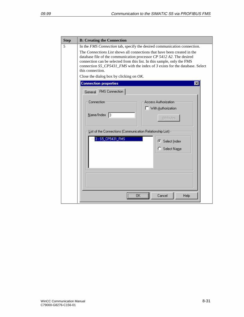
09.99 Communication to the SIMATIC S5 via PROFIBUS FMS
WinCC Communication Manual 8-31C79000-G8276-C156-01
Step B: Creating the Connection
5 In the FMS Connection tab, specify the desired communication connection.
The Connections List shows all connections that have been created in thedatabase file of the communication processor CP 5412 A2. The desiredconnection can be selected from this list. In this sample, only the FMSconnection S5_CP5431_FMS with the index of 3 exists for the database. Selectthis connection.
Close the dialog box by clicking on OK.
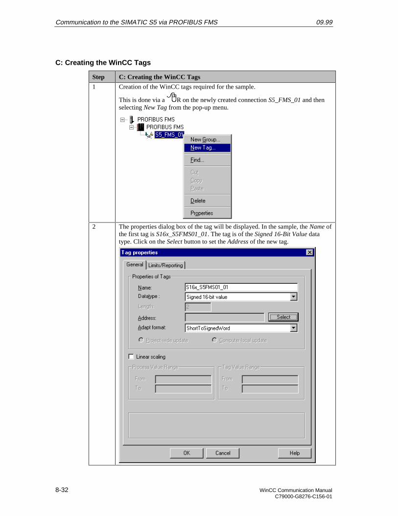
Communication to the SIMATIC S5 via PROFIBUS FMS 09.99
8-32 WinCC Communication ManualC79000-G8276-C156-01
C: Creating the WinCC Tags
Step C: Creating the WinCC Tags
1 Creation of the WinCC tags required for the sample.
This is done via a R on the newly created connection S5_FMS_01 and thenselecting New Tag from the pop-up menu.
2 The properties dialog box of the tag will be displayed. In the sample, the Name ofthe first tag is S16x_S5FMS01_01. The tag is of the Signed 16-Bit Value datatype. Click on the Select button to set the Address of the new tag.
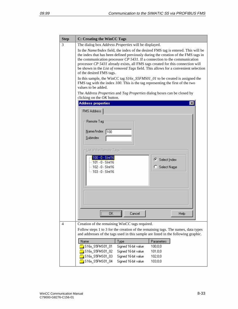
09.99 Communication to the SIMATIC S5 via PROFIBUS FMS
WinCC Communication Manual 8-33C79000-G8276-C156-01
Step C: Creating the WinCC Tags
3 The dialog box Address Properties will be displayed.
In the Name/Index field, the index of the desired FMS tag is entered. This will bethe index that has been defined previously during the creation of the FMS tags inthe communication processor CP 5431. If a connection to the communicationprocessor CP 5431 already exists, all FMS tags created for this connection willbe shown in the List of removed Tags field. This allows for a convenient selectionof the desired FMS tags.
In this sample, the WinCC tag S16x_S5FMS01_01 to be created is assigned theFMS tag with the index 100. This is the tag representing the first of the twovalues to be added.
The Address Properties and Tag Properties dialog boxes can be closed byclicking on the OK button.
4 Creation of the remaining WinCC tags required.
Follow steps 1 to 3 for the creation of the remaining tags. The names, data typesand addresses of the tags used in this sample are listed in the following graphic.
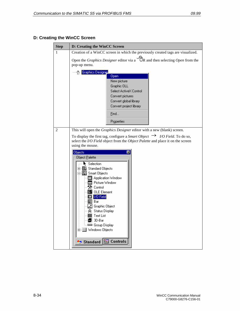
Communication to the SIMATIC S5 via PROFIBUS FMS 09.99
8-34 WinCC Communication ManualC79000-G8276-C156-01
D: Creating the WinCC Screen
Step D: Creating the WinCC Screen
1 Creation of a WinCC screen in which the previously created tags are visualized.
Open the Graphics Designer editor via a R and then selecting Open from thepop-up menu.
2 This will open the Graphics Designer editor with a new (blank) screen.
To display the first tag, configure a Smart Object I/O Field. To do so,select the I/O Field object from the Object Palette and place it on the screenusing the mouse.
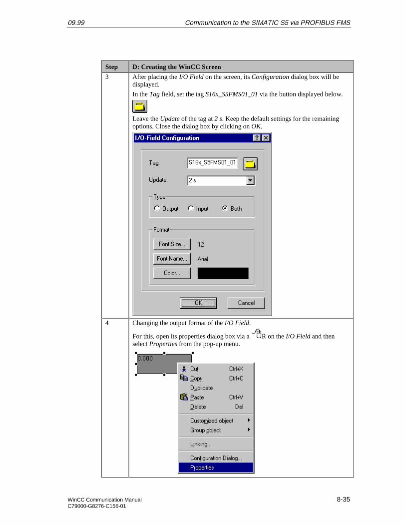
09.99 Communication to the SIMATIC S5 via PROFIBUS FMS
WinCC Communication Manual 8-35C79000-G8276-C156-01
Step D: Creating the WinCC Screen
3 After placing the I/O Field on the screen, its Configuration dialog box will bedisplayed.
In the Tag field, set the tag S16x_S5FMS01_01 via the button displayed below.
Leave the Update of the tag at 2 s. Keep the default settings for the remainingoptions. Close the dialog box by clicking on OK.
4 Changing the output format of the I/O Field.
For this, open its properties dialog box via a R on the I/O Field and thenselect Properties from the pop-up menu.
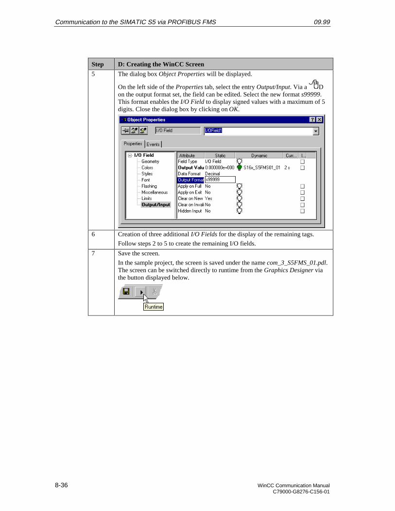
Communication to the SIMATIC S5 via PROFIBUS FMS 09.99
8-36 WinCC Communication ManualC79000-G8276-C156-01
Step D: Creating the WinCC Screen
5 The dialog box Object Properties will be displayed.
On the left side of the Properties tab, select the entry Output/Input. Via a Don the output format set, the field can be edited. Select the new format s99999.This format enables the I/O Field to display signed values with a maximum of 5digits. Close the dialog box by clicking on OK.
6 Creation of three additional I/O Fields for the display of the remaining tags.
Follow steps 2 to 5 to create the remaining I/O fields.
7 Save the screen.
In the sample project, the screen is saved under the name com_3_S5FMS_01.pdl.The screen can be switched directly to runtime from the Graphics Designer viathe button displayed below.
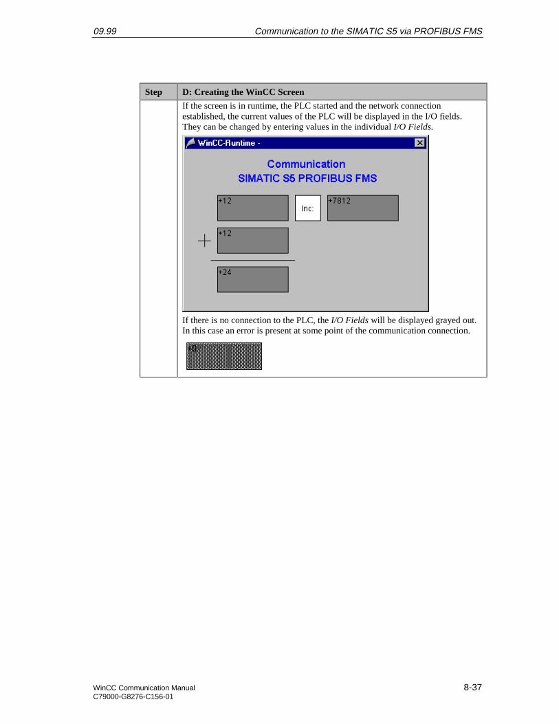
09.99 Communication to the SIMATIC S5 via PROFIBUS FMS
WinCC Communication Manual 8-37C79000-G8276-C156-01
Step D: Creating the WinCC Screen
If the screen is in runtime, the PLC started and the network connectionestablished, the current values of the PLC will be displayed in the I/O fields.They can be changed by entering values in the individual I/O Fields.
If there is no connection to the PLC, the I/O Fields will be displayed grayed out.In this case an error is present at some point of the communication connection.

Communication to the SIMATIC S5 via PROFIBUS FMS 09.99
8-38 WinCC Communication ManualC79000-G8276-C156-01
8.4 Diagnosis of the Communication Connection
The following describes the options available for diagnosing the communication connectionbetween the WinCC project WinCC_S5_FMS and the SIMATIC S5 station.A diagnosis of the sample according to the following description makes only sense, if thechecks listed below have been completed successfully.
Startup of the Communication Processor CP 5412 A2
• F: Testing the Communication ProcessorCreation of the STEP5 Project S5_FMSst
• D: Starting up the PLC
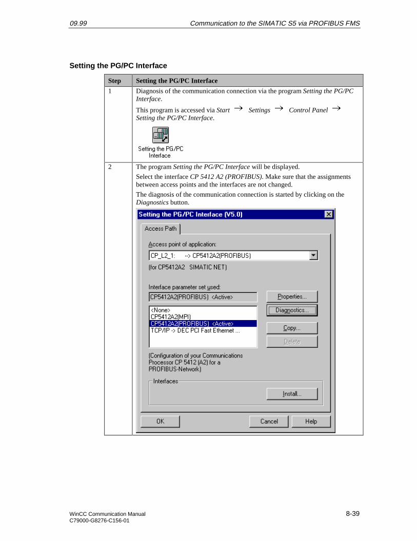
09.99 Communication to the SIMATIC S5 via PROFIBUS FMS
WinCC Communication Manual 8-39C79000-G8276-C156-01
Setting the PG/PC Interface
Step Setting the PG/PC Interface
1 Diagnosis of the communication connection via the program Setting the PG/PCInterface.
This program is accessed via Start Settings Control Panel Setting the PG/PC Interface.
2 The program Setting the PG/PC Interface will be displayed.
Select the interface CP 5412 A2 (PROFIBUS). Make sure that the assignmentsbetween access points and the interfaces are not changed.
The diagnosis of the communication connection is started by clicking on theDiagnostics button.
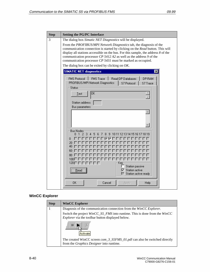
Communication to the SIMATIC S5 via PROFIBUS FMS 09.99
8-40 WinCC Communication ManualC79000-G8276-C156-01
Step Setting the PG/PC Interface
3 The dialog box Simatic NET Diagnostics will be displayed.
From the PROFIBUS/MPI Network Diagnostics tab, the diagnosis of thecommunication connection is started by clicking on the Read button. This willdisplay all stations accessible on the bus. For this sample, the address 8 of thecommunication processor CP 5412 A2 as well as the address 9 of thecommunication processor CP 5431 must be marked as occupied.
The dialog box can be exited by clicking on OK.
WinCC Explorer
Step WinCC Explorer
1 Diagnosis of the communication connection from the WinCC Explorer.
Switch the project WinCC_S5_FMS into runtime. This is done from the WinCCExplorer via the toolbar button displayed below.
The created WinCC screen com_3_S5FMS_01.pdl can also be switched directlyfrom the Graphics Designer into runtime.
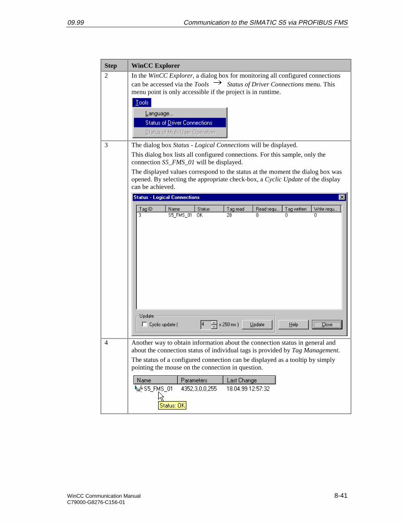
09.99 Communication to the SIMATIC S5 via PROFIBUS FMS
WinCC Communication Manual 8-41C79000-G8276-C156-01
Step WinCC Explorer
2 In the WinCC Explorer, a dialog box for monitoring all configured connectionscan be accessed via the Tools Status of Driver Connections menu. Thismenu point is only accessible if the project is in runtime.
3 The dialog box Status - Logical Connections will be displayed.
This dialog box lists all configured connections. For this sample, only theconnection S5_FMS_01 will be displayed.
The displayed values correspond to the status at the moment the dialog box wasopened. By selecting the appropriate check-box, a Cyclic Update of the displaycan be achieved.
4 Another way to obtain information about the connection status in general andabout the connection status of individual tags is provided by Tag Management.
The status of a configured connection can be displayed as a tooltip by simplypointing the mouse on the connection in question.
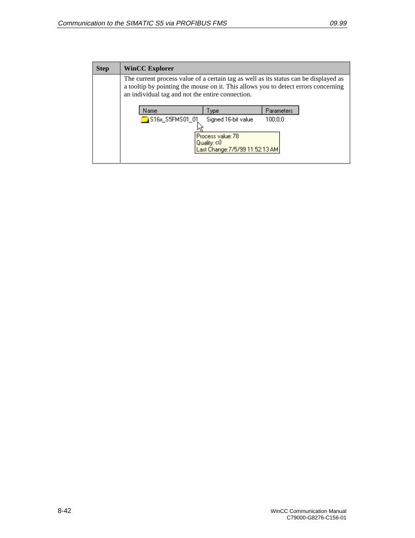
Communication to the SIMATIC S5 via PROFIBUS FMS 09.99
8-42 WinCC Communication ManualC79000-G8276-C156-01
Step WinCC Explorer
The current process value of a certain tag as well as its status can be displayed asa tooltip by pointing the mouse on it. This allows you to detect errors concerningan individual tag and not the entire connection.

09.99 Communication to the SIMATIC S5 via PROFIBUS FDL
WinCC Communication Manual 9-1C79000-G8276-C156-01
9 Communication to the SIMATIC S5 viaPROFIBUS FDL
The projects created in this chapter can also be copied directly from the online document toyour hard drive. By default, they will be copied to the folder C:\Communication_Manual.You have the option to copy the following components to the hard drive:
S5_FDLst
The STEP5 project we will create including the database file of the communicationprocessor CP 5431 FMS/DP.
WinCC_S5_FDL
The WinCC project we will create.
This chapter describes in detail the startup of a communication connection between aSIMATIC S5 and WinCC. The communication connection is implemented via thePROFIBUS, on which the FDL Protocol (Fieldbus Data Link) is running.
Overview of the Structure of the Sample
On the computer side, the connection to the PROFIBUS network is established via thecommunication processor CP 5412 A2. To install this communication processor in thecomputer, the driver PB DP-5412, located on the SIMATIC NET CD-ROM, is needed.However, it is also possible to use the PB S7-5412 or PB FMS-5412 drivers.In the WinCC project, the communication driver SIMATIC S5 PROFIBUS FDL must beinstalled. This communication driver is used to configure the connection to the SIMATICS5.The PLC SIMATIC S5 115U is equipped with the CPU module CPU 944. The connectionto the network is established via the communication processor CP 5431 FMS/DP. For theconfiguration of this communication processor, the communication package SINEC NCMfor COMs is required.
Communication to the SIMATIC S5 via PROFIBUS FDL 09.99
9-2 WinCC Communication ManualC79000-G8276-C156-01
Overview of the Configuration Steps
The following lists all configuration steps necessary for the creation of the communicationconnection:
• Startup of the Communication Processor CP 5412 A2
• Creation of the STEP5 Project S5_FDLst
• Creation of the WinCC Project WinCC_S5_FDL
• Diagnosis of the Communication Connection
Required Software
Name Description
SIMATIC NET Driver PB DP-5412 from the SIMATIC NET CD-ROM forthe installation of the communication processor CP 5412 A2.
STEP5 STEP5 software for the creation of the STEP5 project.Communication package SINEC NCM for COMs for theconfiguration of the communication processor CP 5431FMS/DP.
WinCC WinCC with communication driver SIMATIC S5 PROFIBUSFDL for the creation of the WinCC project and for theconfiguration of the connection to the PLC.
Required Computer Hardware
Name Description
Communication Processor Communication processor CP 5412 A2 to establish theconnection to the PLC’s communication processor.
Required PLC Hardware
Name Description
Rack Rack CR 700-3.
Power Supply Power supply PS 951.
CPU Module CPU module CPU 944.
Communication Processor Communication processor CP 5431 FMS/DP.

09.99 Communication to the SIMATIC S5 via PROFIBUS FDL
WinCC Communication Manual 9-3C79000-G8276-C156-01
9.1 Startup of the Communication Processor CP 5412 A2
The following description details the configuration steps necessary to successfully start upthe communication processor CP 5412 A2.
Overview of the Configuration Steps
The following lists the configuration steps necessary to start up the communicationprocessor CP 5412 A2:
• A: Mounting the Communication Processor in the Computer
• B: Installing the Communication Driver
• C: Installing the Communication Processor
• D: Assigning the Communication Processor
• E: Testing the Communication Processor
A: Mounting the Communication Processor in the Computer
Step A: Mounting the Communication Processor in the Computer
1 Check the selected jumper settings at the CP 5412 A2.
During the installation of the CP 5412 A2, the I/O Range must be specified. TheI/O Range is set via jumpers.
By default, the I/O Range is set to 0240-0243. However, other settings are alsopossible. The following graphic illustrates the jumper settings necessary for thevarious I/O Ranges.
2 Mount the module according to the installation instructions. Among other things,follow the steps for handling electrostatic sensitive devices (ESD). The modulemust only be installed while the computer is off.
For the communication card CP 5412 A2, a free ISA slot in the computer isrequired. After the installation of the CP 5412 A2, close the computer’s case andstart the computer.
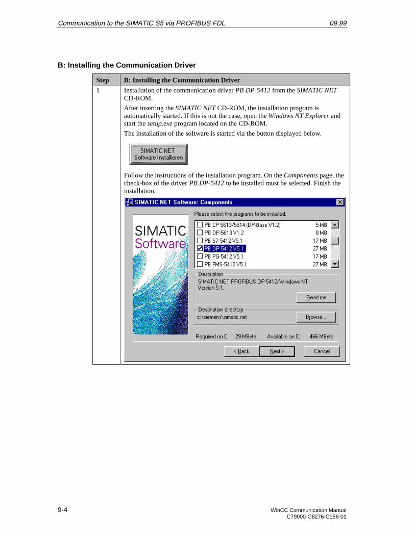
Communication to the SIMATIC S5 via PROFIBUS FDL 09.99
9-4 WinCC Communication ManualC79000-G8276-C156-01
B: Installing the Communication Driver
Step B: Installing the Communication Driver
1 Installation of the communication driver PB DP-5412 from the SIMATIC NETCD-ROM.
After inserting the SIMATIC NET CD-ROM, the installation program isautomatically started. If this is not the case, open the Windows NT Explorer andstart the setup.exe program located on the CD-ROM.
The installation of the software is started via the button displayed below.
Follow the instructions of the installation program. On the Components page, thecheck-box of the driver PB DP-5412 to be installed must be selected. Finish theinstallation.

09.99 Communication to the SIMATIC S5 via PROFIBUS FDL
WinCC Communication Manual 9-5C79000-G8276-C156-01
C: Installing the Communication Processor
Step C: Installing the Communication Processor
1 Install the communication processor CP 5412 A2 via the program Setting thePG/PC Interface.
This program is accessed via Start Settings Control Panel Setting the PG/PC Interface.
2 The program Setting the PG/PC Interface will be displayed.
The dialog box for installing a new interface is opened via the Install button.
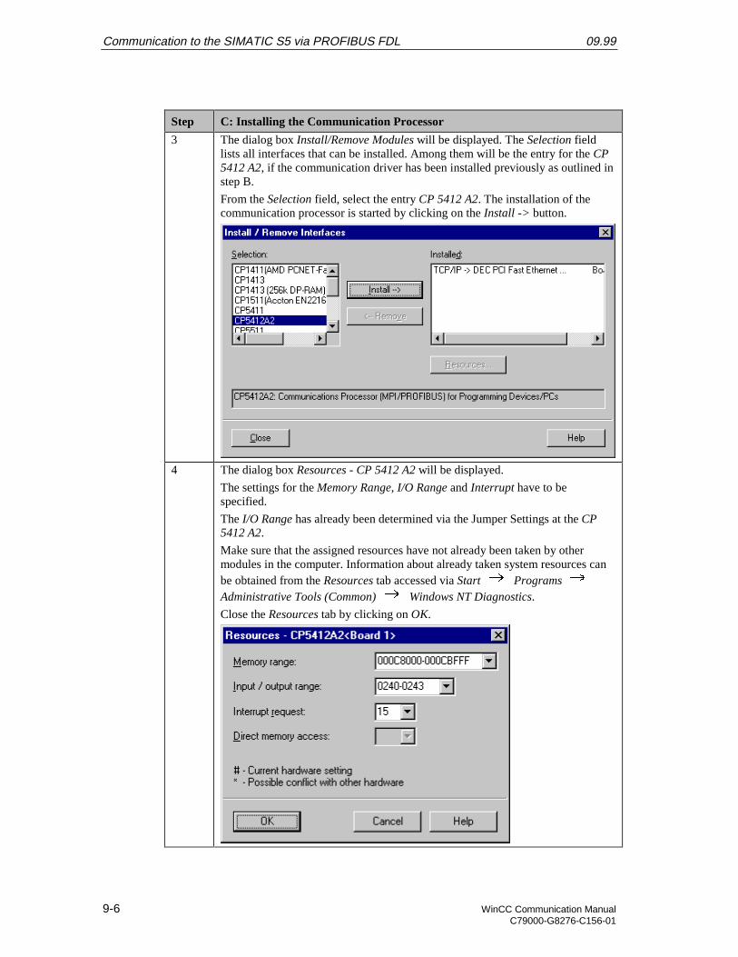
Communication to the SIMATIC S5 via PROFIBUS FDL 09.99
9-6 WinCC Communication ManualC79000-G8276-C156-01
Step C: Installing the Communication Processor
3 The dialog box Install/Remove Modules will be displayed. The Selection fieldlists all interfaces that can be installed. Among them will be the entry for the CP5412 A2, if the communication driver has been installed previously as outlined instep B.
From the Selection field, select the entry CP 5412 A2. The installation of thecommunication processor is started by clicking on the Install -> button.
4 The dialog box Resources - CP 5412 A2 will be displayed.
The settings for the Memory Range, I/O Range and Interrupt have to bespecified.
The I/O Range has already been determined via the Jumper Settings at the CP5412 A2.
Make sure that the assigned resources have not already been taken by othermodules in the computer. Information about already taken system resources canbe obtained from the Resources tab accessed via Start Programs Administrative Tools (Common) Windows NT Diagnostics.
Close the Resources tab by clicking on OK.

09.99 Communication to the SIMATIC S5 via PROFIBUS FDL
WinCC Communication Manual 9-7C79000-G8276-C156-01
Step C: Installing the Communication Processor
5 In the dialog box Install/Remove Modules, the Installed field will now contain theentry for the CP 5412 A2.
Exit the dialog box Install/Remove Modules via the Close button.

Communication to the SIMATIC S5 via PROFIBUS FDL 09.99
9-8 WinCC Communication ManualC79000-G8276-C156-01
D: Assigning the Communication Processor
Step D: Assigning the Communication Processor
1 In the program Setting the PG/PC Interface, assign the access point CP_L2_1: tothe just installed interface.
The access point CP_L2_1: is the default access point used by WinCC for thecommunication via the PROFIBUS. It has been created automatically during theinstallation of the communication driver PB DP-5412.
In the field Access Point of the Application, set the entry CP_L2_1:. In the fieldbelow, select the entry CP 5412 A2 (PROFIBUS). This completes the assignmentbetween the access point and the communication processor.
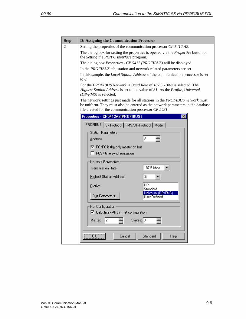
09.99 Communication to the SIMATIC S5 via PROFIBUS FDL
WinCC Communication Manual 9-9C79000-G8276-C156-01
Step D: Assigning the Communication Processor
2 Setting the properties of the communication processor CP 5412 A2.
The dialog box for setting the properties is opened via the Properties button ofthe Setting the PG/PC Interface program.
The dialog box Properties - CP 5412 (PROFIBUS) will be displayed.
In the PROFIBUS tab, station and network related parameters are set.
In this sample, the Local Station Address of the communication processor is setto 8.
For the PROFIBUS Network, a Baud Rate of 187.5 kBit/s is selected. TheHighest Station Address is set to the value of 31. As the Profile, Universal(DP/FMS) is selected.
The network settings just made for all stations in the PROFIBUS network mustbe uniform. They must also be entered as the network parameters in the databasefile created for the communication processor CP 5431.
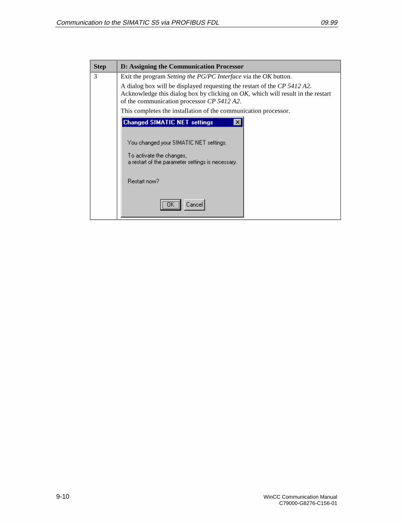
Communication to the SIMATIC S5 via PROFIBUS FDL 09.99
9-10 WinCC Communication ManualC79000-G8276-C156-01
Step D: Assigning the Communication Processor
3 Exit the program Setting the PG/PC Interface via the OK button.
A dialog box will be displayed requesting the restart of the CP 5412 A2.Acknowledge this dialog box by clicking on OK, which will result in the restartof the communication processor CP 5412 A2.
This completes the installation of the communication processor.
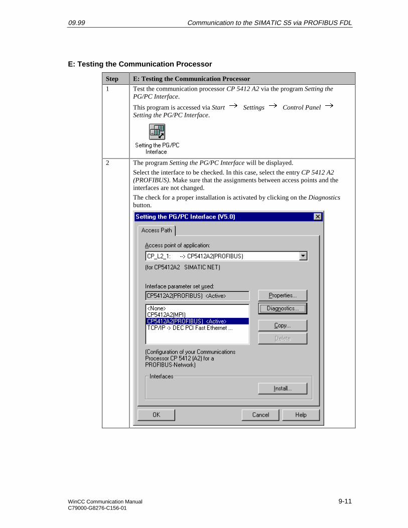
09.99 Communication to the SIMATIC S5 via PROFIBUS FDL
WinCC Communication Manual 9-11C79000-G8276-C156-01
E: Testing the Communication Processor
Step E: Testing the Communication Processor
1 Test the communication processor CP 5412 A2 via the program Setting thePG/PC Interface.
This program is accessed via Start Settings Control Panel Setting the PG/PC Interface.
2 The program Setting the PG/PC Interface will be displayed.
Select the interface to be checked. In this case, select the entry CP 5412 A2(PROFIBUS). Make sure that the assignments between access points and theinterfaces are not changed.
The check for a proper installation is activated by clicking on the Diagnosticsbutton.
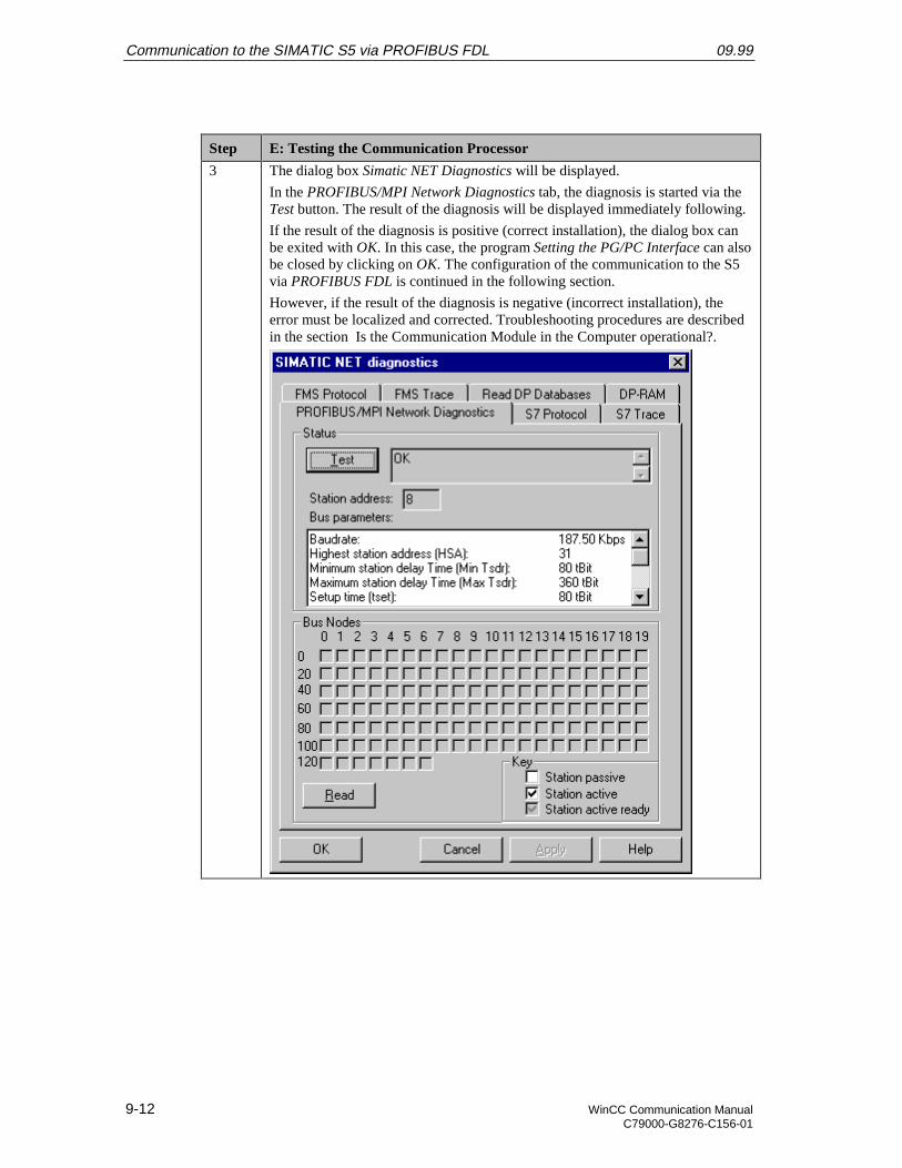
Communication to the SIMATIC S5 via PROFIBUS FDL 09.99
9-12 WinCC Communication ManualC79000-G8276-C156-01
Step E: Testing the Communication Processor
3 The dialog box Simatic NET Diagnostics will be displayed.
In the PROFIBUS/MPI Network Diagnostics tab, the diagnosis is started via theTest button. The result of the diagnosis will be displayed immediately following.
If the result of the diagnosis is positive (correct installation), the dialog box canbe exited with OK. In this case, the program Setting the PG/PC Interface can alsobe closed by clicking on OK. The configuration of the communication to the S5via PROFIBUS FDL is continued in the following section.
However, if the result of the diagnosis is negative (incorrect installation), theerror must be localized and corrected. Troubleshooting procedures are describedin the section Is the Communication Module in the Computer operational?.

09.99 Communication to the SIMATIC S5 via PROFIBUS FDL
WinCC Communication Manual 9-13C79000-G8276-C156-01
9.2 Creation of the STEP5 Project S5_FDLst
The following description details the configuration steps necessary to create and start up theSTEP5 project S5_FDLst.
Overview of the Configuration Steps
The following lists the configuration steps necessary to create the STEP5 projectS5_FDLst:
• A: Installing the Hardware and Software
• B: Creating the STEP5 Program
• C: Configuring the Communication Processor
• D: Starting up the PLC
A: Installing the Hardware and Software
Step A: Installing the Hardware and Software
1 Rack-mounting of the modules used.
In this sample, the modules to be installed are the power supply PS 951, the CPUmodule CPU 944 and the communication processor CP 5431.
Establishing the connection from the programming device to the programminginterface of the CPU module.
Establishing the connection from the communication processor CP 5412 A2 inthe computer to the communication processor CP 5431 in the PLC.
2 Installing the communication package SINEC NCM for COMs from thecorresponding installation disk. This communication package is required for theconfiguration of the communication processor CP 5431.
The installation disk contains the program file install.exe. Start this program.Follow the instructions of the installation program and complete the installation.
B: Creating the STEP5 Program
Step B: Creating the STEP5 Program
1 Creation of a new project with the STEP5 software.
Start the STEP5 software. From the Object Project Settings Page1 and Page2 menus, define the settings for the new project. In the ProgramFile field, specify the name of the new program file to be created. In this sample,the name S5_FDLST.S5D is used. Only the first six characters of the file namecan be changed by the user.
2 Creation of a data block.
In STEP5, this is accomplished via the Editor Data Block menus of
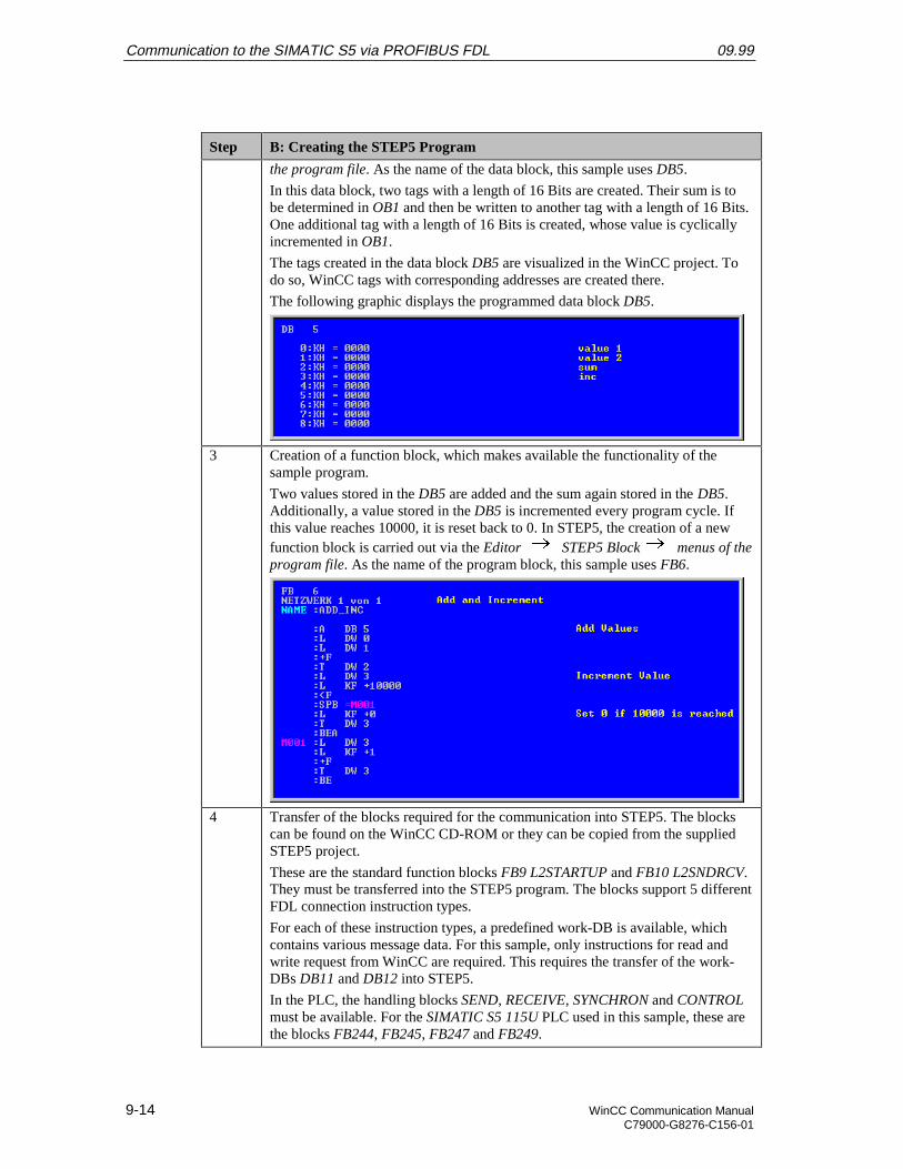
Communication to the SIMATIC S5 via PROFIBUS FDL 09.99
9-14 WinCC Communication ManualC79000-G8276-C156-01
Step B: Creating the STEP5 Program
the program file. As the name of the data block, this sample uses DB5.
In this data block, two tags with a length of 16 Bits are created. Their sum is tobe determined in OB1 and then be written to another tag with a length of 16 Bits.One additional tag with a length of 16 Bits is created, whose value is cyclicallyincremented in OB1.
The tags created in the data block DB5 are visualized in the WinCC project. Todo so, WinCC tags with corresponding addresses are created there.
The following graphic displays the programmed data block DB5.
3 Creation of a function block, which makes available the functionality of thesample program.
Two values stored in the DB5 are added and the sum again stored in the DB5.Additionally, a value stored in the DB5 is incremented every program cycle. Ifthis value reaches 10000, it is reset back to 0. In STEP5, the creation of a newfunction block is carried out via the Editor STEP5 Block menus of theprogram file. As the name of the program block, this sample uses FB6.
4 Transfer of the blocks required for the communication into STEP5. The blockscan be found on the WinCC CD-ROM or they can be copied from the suppliedSTEP5 project.
These are the standard function blocks FB9 L2STARTUP and FB10 L2SNDRCV.They must be transferred into the STEP5 program. The blocks support 5 differentFDL connection instruction types.
For each of these instruction types, a predefined work-DB is available, whichcontains various message data. For this sample, only instructions for read andwrite request from WinCC are required. This requires the transfer of the work-DBs DB11 and DB12 into STEP5.
In the PLC, the handling blocks SEND, RECEIVE, SYNCHRON and CONTROLmust be available. For the SIMATIC S5 115U PLC used in this sample, these arethe blocks FB244, FB245, FB247 and FB249.

09.99 Communication to the SIMATIC S5 via PROFIBUS FDL
WinCC Communication Manual 9-15C79000-G8276-C156-01
Step B: Creating the STEP5 Program
5 Creation of the startup blocks.
The startup blocks define the communication parameters, register the work-DBsand synchronize the communication processor. These steps are all performed bya call of the function block FB9 L2STARTUP.
During the call of the function block, the interface number SSNR of the CP 5431is transferred as a parameter. As the RADR parameter, the PROFIBUS address ofthe communication processor CP 5412 A2 in the computer is specified. In thissample, this is 8.
In addition, the connection parameters of the instruction types used must bespecified. On the one hand, these are the parameters RVC4 and RVC5, whichindicate the Service Access Points of the WinCC station. These SAPs arespecified in WinCC during the creation of the connection. On the other hand,these are the parameters ANR4 and ANR5. These are the instruction numbers,which have been set during the configuration of the FDL connections for thecommunication processor CP 5431. For both instructions, the numbers of thework-DBs must be indicated as well.
The remaining call parameters of the FB9 are not important for the functionalityof this sample.
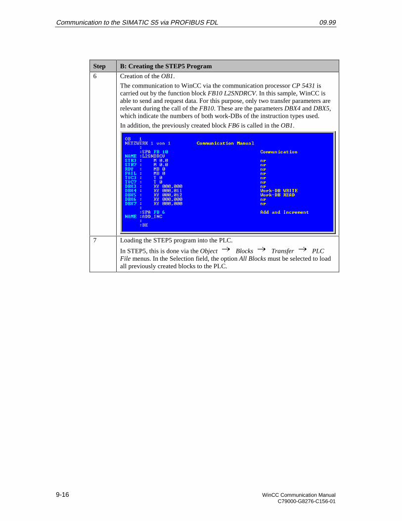
Communication to the SIMATIC S5 via PROFIBUS FDL 09.99
9-16 WinCC Communication ManualC79000-G8276-C156-01
Step B: Creating the STEP5 Program
6 Creation of the OB1.
The communication to WinCC via the communication processor CP 5431 iscarried out by the function block FB10 L2SNDRCV. In this sample, WinCC isable to send and request data. For this purpose, only two transfer parameters arerelevant during the call of the FB10. These are the parameters DBX4 and DBX5,which indicate the numbers of both work-DBs of the instruction types used.
In addition, the previously created block FB6 is called in the OB1.
7 Loading the STEP5 program into the PLC.
In STEP5, this is done via the Object Blocks Transfer PLCFile menus. In the Selection field, the option All Blocks must be selected to loadall previously created blocks to the PLC.
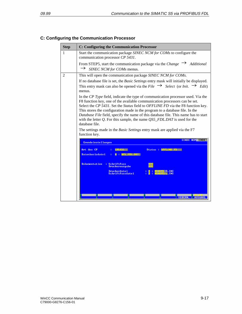
09.99 Communication to the SIMATIC S5 via PROFIBUS FDL
WinCC Communication Manual 9-17C79000-G8276-C156-01
C: Configuring the Communication Processor
Step C: Configuring the Communication Processor
1 Start the communication package SINEC NCM for COMs to configure thecommunication processor CP 5431.
From STEP5, start the communication package via the Change Additional SINEC NCM for COMs menus.
2 This will open the communication package SINEC NCM for COMs.
If no database file is set, the Basic Settings entry mask will initially be displayed.This entry mask can also be opened via the File Select (or Init. Edit)menus.
In the CP Type field, indicate the type of communication processor used. Via theF8 function key, one of the available communication processors can be set.Select the CP 5431. Set the Status field to OFFLINE FD via the F8 function key.This stores the configuration made in the program to a database file. In theDatabase File field, specify the name of this database file. This name has to startwith the letter Q. For this sample, the name QS5_FDL.DAT is used for thedatabase file.
The settings made in the Basic Settings entry mask are applied via the F7function key.

Communication to the SIMATIC S5 via PROFIBUS FDL 09.99
9-18 WinCC Communication ManualC79000-G8276-C156-01
Step C: Configuring the Communication Processor
3 The settings for the basic initialization of the communication processor must bemade.
They are entered in the Basic Initialization entry mask. This entry mask isopened via the Edit CP Init. menus.
In the L2 Address field, the PROFIBUS Address of the communication processorCP 5431 is specified. In this sample, the value 9 has been entered. This value isone of the parameters that have to be specified during the creation of theconnection in WinCC.
The remaining settings can be seen in the following graphic. The settings made inthe Basic Initialization entry mask are applied via the F7 function key.
4 Setting the global network parameters.
This is done in the Global Network Parameters entry mask, which is opened viathe Edit Global Network Parameters menus.
The same network parameters must be used that have been specified as thenetwork parameters during the installation of the communication processor CP5412 A2. Among other things, the Baud Rate is set to 18750 Baud and theHighest Station Address (HSA) to 31. The value for the Default SAP is set to 2.
The settings made in the Global Network Parameters entry mask are applied viathe F7 function key.
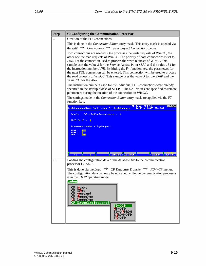
09.99 Communication to the SIMATIC S5 via PROFIBUS FDL
WinCC Communication Manual 9-19C79000-G8276-C156-01
Step C: Configuring the Communication Processor
5 Creation of the FDL connections.
This is done in the Connection Editor entry mask. This entry mask is opened viathe Edit Connections Free Layer2 Connectionsmenus.
Two connections are needed: One processes the write requests of WinCC, theother one the read requests of WinCC. The priority of both connections is set toLow. For the connection used to process the write requests of WinCC, thissample uses the value 3 for the Service Access Point SSAP and the value 134 forthe instruction number ANR. By hitting the F4 function key, the parameters forthe next FDL connection can be entered. This connection will be used to processthe read requests of WinCC. This sample uses the value 5 for the SSAP and thevalue 135 for the ANR.
The instruction numbers used for the individual FDL connections were alreadyspecified in the startup blocks of STEP5. The SAP values are specified as remoteparameters during the creation of the connection in WinCC.
The settings made in the Connection Editor entry mask are applied via the F7function key.
6 Loading the configuration data of the database file to the communicationprocessor CP 5431.
This is done via the Load CP Database Transfer FD->CP menus.The configuration data can only be uploaded while the communication processoris in the STOP operating mode.
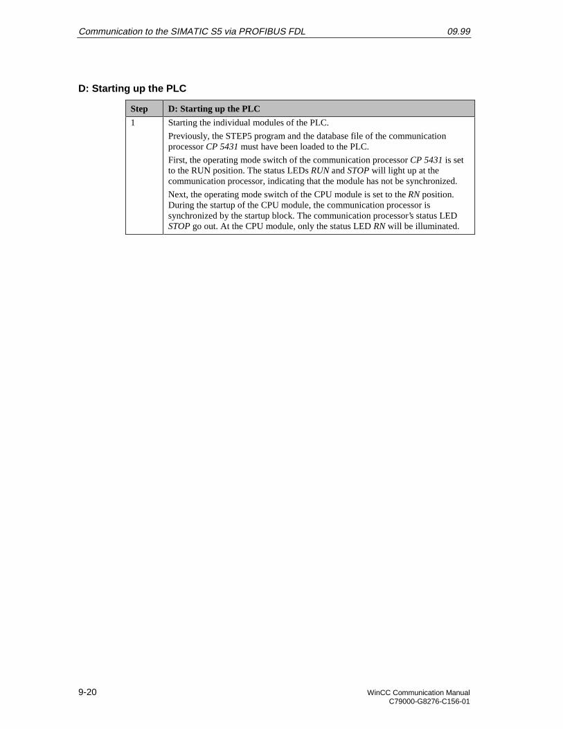
Communication to the SIMATIC S5 via PROFIBUS FDL 09.99
9-20 WinCC Communication ManualC79000-G8276-C156-01
D: Starting up the PLC
Step D: Starting up the PLC
1 Starting the individual modules of the PLC.
Previously, the STEP5 program and the database file of the communicationprocessor CP 5431 must have been loaded to the PLC.
First, the operating mode switch of the communication processor CP 5431 is setto the RUN position. The status LEDs RUN and STOP will light up at thecommunication processor, indicating that the module has not be synchronized.
Next, the operating mode switch of the CPU module is set to the RN position.During the startup of the CPU module, the communication processor issynchronized by the startup block. The communication processor’s status LEDSTOP go out. At the CPU module, only the status LED RN will be illuminated.
09.99 Communication to the SIMATIC S5 via PROFIBUS FDL
WinCC Communication Manual 9-21C79000-G8276-C156-01
9.3 Creation of the WinCC Project WinCC_S5_FDL
The following description details the configuration steps necessary to create and start up theWinCC project WinCC_S5_FDL.
Overview of the Configuration Steps
The following lists the configuration steps necessary to create the WinCC projectWinCC_S5_FDL:
• A: Creating the WinCC Project
• B: Creating the Connection
• C: Creating the WinCC Tags
• D: Creating the WinCC Screen
A: Creating the WinCC Project
Step A: Creating the WinCC Project
1 Creation of a new WinCC project in the WinCC Explorer.
The WinCC Explorer is started via Start Simatic WinCC Windows Control Center.
2 This will display the WinCC Explorer.
Via the menus File New, the dialog box for specifying the properties of anew WinCC project will be opened.
For this sample project, a Single-User Project is created.
Exit the dialog box by clicking on OK.

Communication to the SIMATIC S5 via PROFIBUS FDL 09.99
9-22 WinCC Communication ManualC79000-G8276-C156-01
Step A: Creating the WinCC Project
3 The dialog box Create a new Project will be displayed.
Specify a Project Name for the new project. The names of the WinCC projectscreated within the framework of this manual all start with WinCC and alsoinclude a reference to the communication partner and communication type used.The project of this sample has the name WinCC_S5_FDL.
In the Project Path field, set the storage location of the new project.
The dialog box Create a new Project is concluded by clicking on the Createbutton.
B: Creating the Connection
Step B: Creating the Connection
1 The new project will be displayed in the WinCC Explorer.
Installation of the required communication driver. This is performed via a Ron Tag Management and selecting Add New Driver from the pop-up menu.
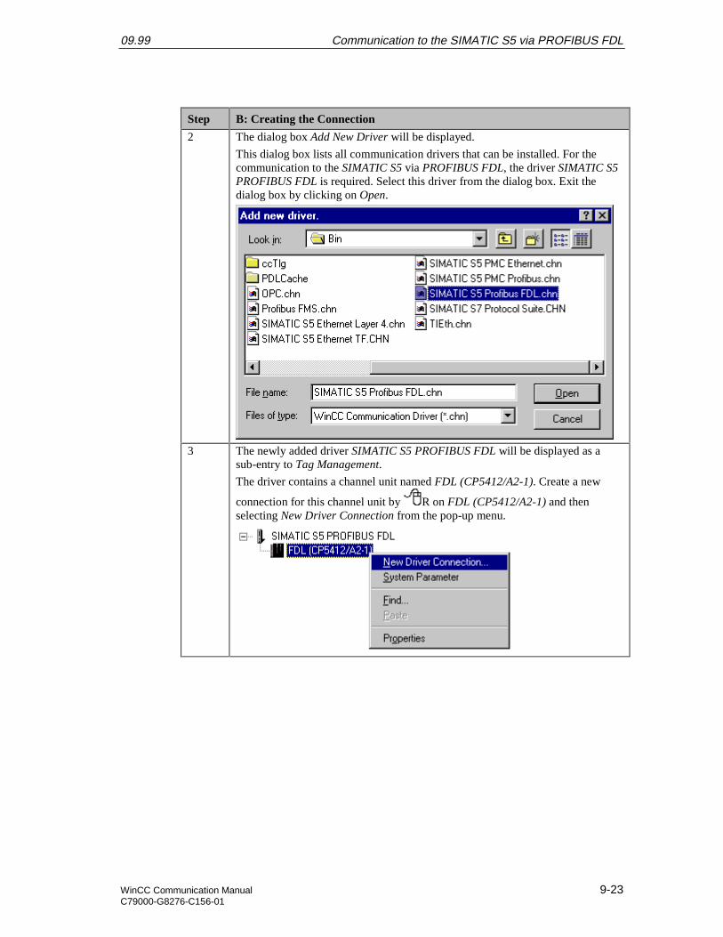
09.99 Communication to the SIMATIC S5 via PROFIBUS FDL
WinCC Communication Manual 9-23C79000-G8276-C156-01
Step B: Creating the Connection
2 The dialog box Add New Driver will be displayed.
This dialog box lists all communication drivers that can be installed. For thecommunication to the SIMATIC S5 via PROFIBUS FDL, the driver SIMATIC S5PROFIBUS FDL is required. Select this driver from the dialog box. Exit thedialog box by clicking on Open.
3 The newly added driver SIMATIC S5 PROFIBUS FDL will be displayed as asub-entry to Tag Management.
The driver contains a channel unit named FDL (CP5412/A2-1). Create a new
connection for this channel unit by R on FDL (CP5412/A2-1) and thenselecting New Driver Connection from the pop-up menu.

Communication to the SIMATIC S5 via PROFIBUS FDL 09.99
9-24 WinCC Communication ManualC79000-G8276-C156-01
Step B: Creating the Connection
4 The properties dialog box of the connection will be displayed.
In the General tab, the Name of the new connection is entered. In this sample,this is S7_FDL_01.
Click on the Properties button to define the connection properties.
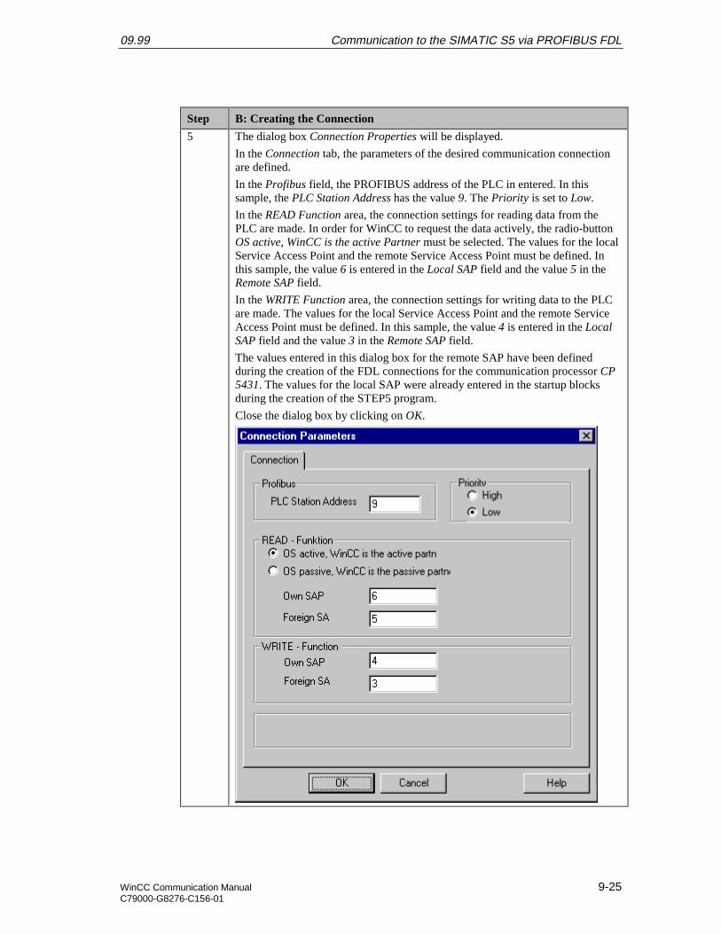
09.99 Communication to the SIMATIC S5 via PROFIBUS FDL
WinCC Communication Manual 9-25C79000-G8276-C156-01
Step B: Creating the Connection
5 The dialog box Connection Properties will be displayed.
In the Connection tab, the parameters of the desired communication connectionare defined.
In the Profibus field, the PROFIBUS address of the PLC in entered. In thissample, the PLC Station Address has the value 9. The Priority is set to Low.
In the READ Function area, the connection settings for reading data from thePLC are made. In order for WinCC to request the data actively, the radio-buttonOS active, WinCC is the active Partner must be selected. The values for the localService Access Point and the remote Service Access Point must be defined. Inthis sample, the value 6 is entered in the Local SAP field and the value 5 in theRemote SAP field.
In the WRITE Function area, the connection settings for writing data to the PLCare made. The values for the local Service Access Point and the remote ServiceAccess Point must be defined. In this sample, the value 4 is entered in the LocalSAP field and the value 3 in the Remote SAP field.
The values entered in this dialog box for the remote SAP have been definedduring the creation of the FDL connections for the communication processor CP5431. The values for the local SAP were already entered in the startup blocksduring the creation of the STEP5 program.
Close the dialog box by clicking on OK.
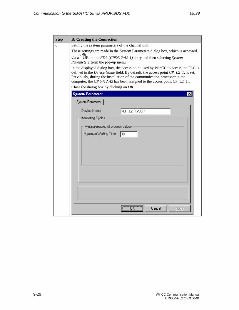
Communication to the SIMATIC S5 via PROFIBUS FDL 09.99
9-26 WinCC Communication ManualC79000-G8276-C156-01
Step B: Creating the Connection
6 Setting the system parameters of the channel unit.
These settings are made in the System Parameters dialog box, which is accessed
via a R on the FDL (CP5412/A2-1) entry and then selecting SystemParameters from the pop-up menu.
In the displayed dialog box, the access point used by WinCC to access the PLC isdefined in the Device Name field. By default, the access point CP_L2_1: is set.Previously, during the installation of the communication processor in thecomputer, the CP 5412 A2 has been assigned to the access point CP_L2_1:.
Close the dialog box by clicking on OK.
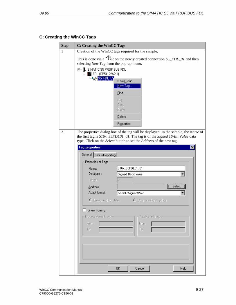
09.99 Communication to the SIMATIC S5 via PROFIBUS FDL
WinCC Communication Manual 9-27C79000-G8276-C156-01
C: Creating the WinCC Tags
Step C: Creating the WinCC Tags
1 Creation of the WinCC tags required for the sample.
This is done via a R on the newly created connection S5_FDL_01 and thenselecting New Tag from the pop-up menu.
2 The properties dialog box of the tag will be displayed. In the sample, the Name ofthe first tag is S16x_S5FDL01_01. The tag is of the Signed 16-Bit Value datatype. Click on the Select button to set the Address of the new tag.
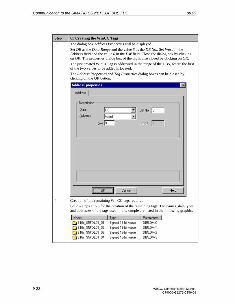
Communication to the SIMATIC S5 via PROFIBUS FDL 09.99
9-28 WinCC Communication ManualC79000-G8276-C156-01
Step C: Creating the WinCC Tags
3 The dialog box Address Properties will be displayed.
Set DB as the Data Range and the value 5 as the DB No.. Set Word in theAddress field and the value 0 in the DW field. Close the dialog box by clickingon OK. The properties dialog box of the tag is also closed by clicking on OK.
The just created WinCC tag is addressed in the range of the DB5, where the firstof the two values to be added is located.
The Address Properties and Tag Properties dialog boxes can be closed byclicking on the OK button.
4 Creation of the remaining WinCC tags required.
Follow steps 1 to 3 for the creation of the remaining tags. The names, data typesand addresses of the tags used in this sample are listed in the following graphic.
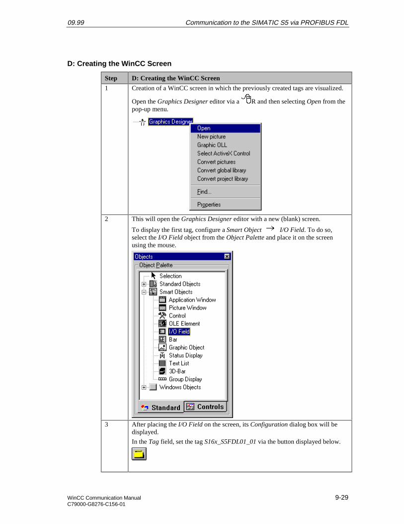
09.99 Communication to the SIMATIC S5 via PROFIBUS FDL
WinCC Communication Manual 9-29C79000-G8276-C156-01
D: Creating the WinCC Screen
Step D: Creating the WinCC Screen
1 Creation of a WinCC screen in which the previously created tags are visualized.
Open the Graphics Designer editor via a R and then selecting Open from thepop-up menu.
2 This will open the Graphics Designer editor with a new (blank) screen.
To display the first tag, configure a Smart Object I/O Field. To do so,select the I/O Field object from the Object Palette and place it on the screenusing the mouse.
3 After placing the I/O Field on the screen, its Configuration dialog box will bedisplayed.
In the Tag field, set the tag S16x_S5FDL01_01 via the button displayed below.
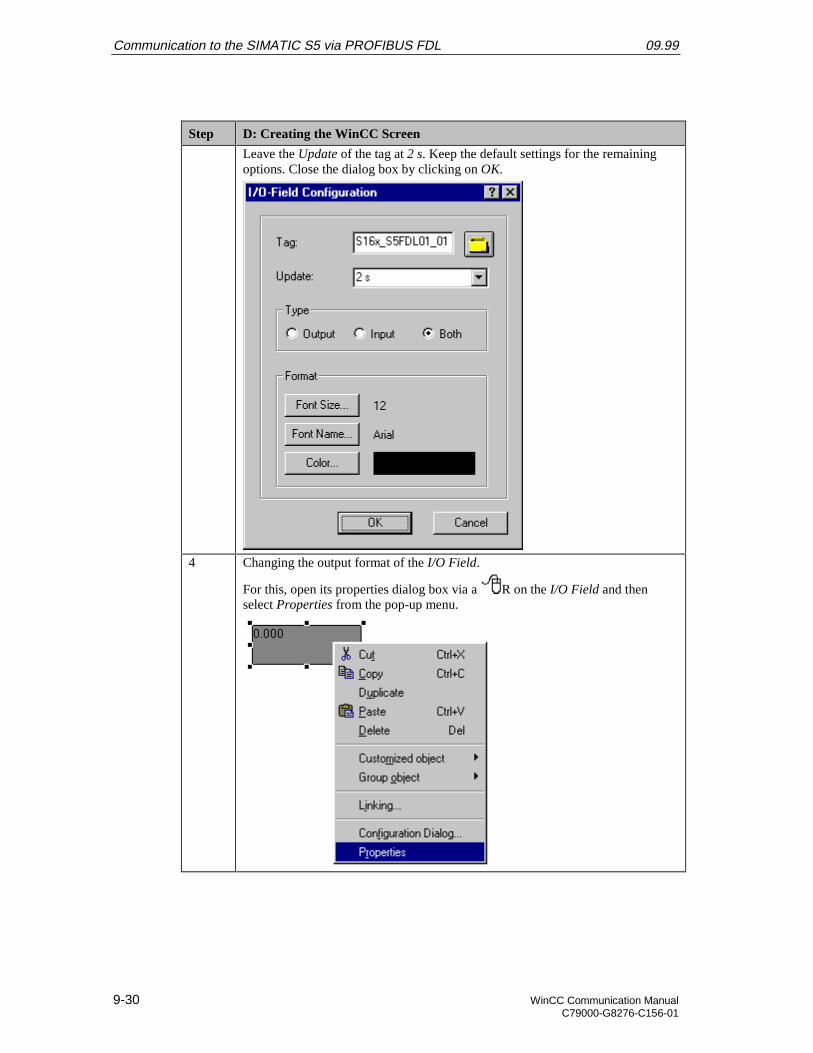
Communication to the SIMATIC S5 via PROFIBUS FDL 09.99
9-30 WinCC Communication ManualC79000-G8276-C156-01
Step D: Creating the WinCC Screen
Leave the Update of the tag at 2 s. Keep the default settings for the remainingoptions. Close the dialog box by clicking on OK.
4 Changing the output format of the I/O Field.
For this, open its properties dialog box via a R on the I/O Field and thenselect Properties from the pop-up menu.
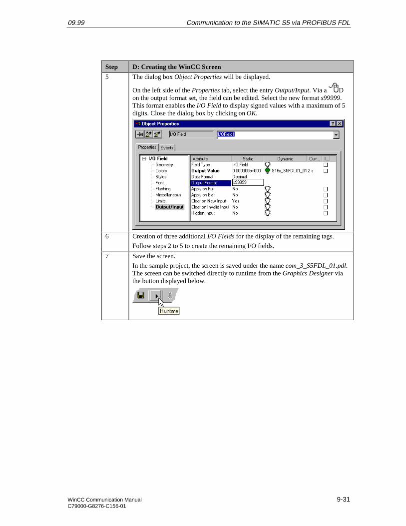
09.99 Communication to the SIMATIC S5 via PROFIBUS FDL
WinCC Communication Manual 9-31C79000-G8276-C156-01
Step D: Creating the WinCC Screen
5 The dialog box Object Properties will be displayed.
On the left side of the Properties tab, select the entry Output/Input. Via a Don the output format set, the field can be edited. Select the new format s99999.This format enables the I/O Field to display signed values with a maximum of 5digits. Close the dialog box by clicking on OK.
6 Creation of three additional I/O Fields for the display of the remaining tags.
Follow steps 2 to 5 to create the remaining I/O fields.
7 Save the screen.
In the sample project, the screen is saved under the name com_3_S5FDL_01.pdl.The screen can be switched directly to runtime from the Graphics Designer viathe button displayed below.
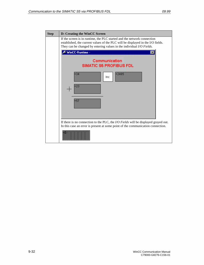
Communication to the SIMATIC S5 via PROFIBUS FDL 09.99
9-32 WinCC Communication ManualC79000-G8276-C156-01
Step D: Creating the WinCC Screen
If the screen is in runtime, the PLC started and the network connectionestablished, the current values of the PLC will be displayed in the I/O fields.They can be changed by entering values in the individual I/O Fields.
If there is no connection to the PLC, the I/O Fields will be displayed grayed out.In this case an error is present at some point of the communication connection.

09.99 Communication to the SIMATIC S5 via PROFIBUS FDL
WinCC Communication Manual 9-33C79000-G8276-C156-01
9.4 Diagnosis of the Communication Connection
The following describes the options available for diagnosing the communication connectionbetween the WinCC project WinCC_S5_FDL and the SIMATIC S5 station.A diagnosis of the sample according to this description makes only sense, if the checkslisted below have been completed successfully.Startup of the Communication Processor CP 5412 A2
• E: Testing the Communication ProcessorCreation of the STEP5 Project S5FDLst
• D: Starting up the PLC
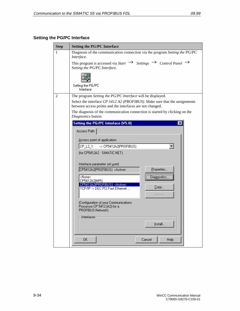
Communication to the SIMATIC S5 via PROFIBUS FDL 09.99
9-34 WinCC Communication ManualC79000-G8276-C156-01
Setting the PG/PC Interface
Step Setting the PG/PC Interface
1 Diagnosis of the communication connection via the program Setting the PG/PCInterface.
This program is accessed via Start Settings Control Panel Setting the PG/PC Interface.
2 The program Setting the PG/PC Interface will be displayed.
Select the interface CP 5412 A2 (PROFIBUS). Make sure that the assignmentsbetween access points and the interfaces are not changed.
The diagnosis of the communication connection is started by clicking on theDiagnostics button.
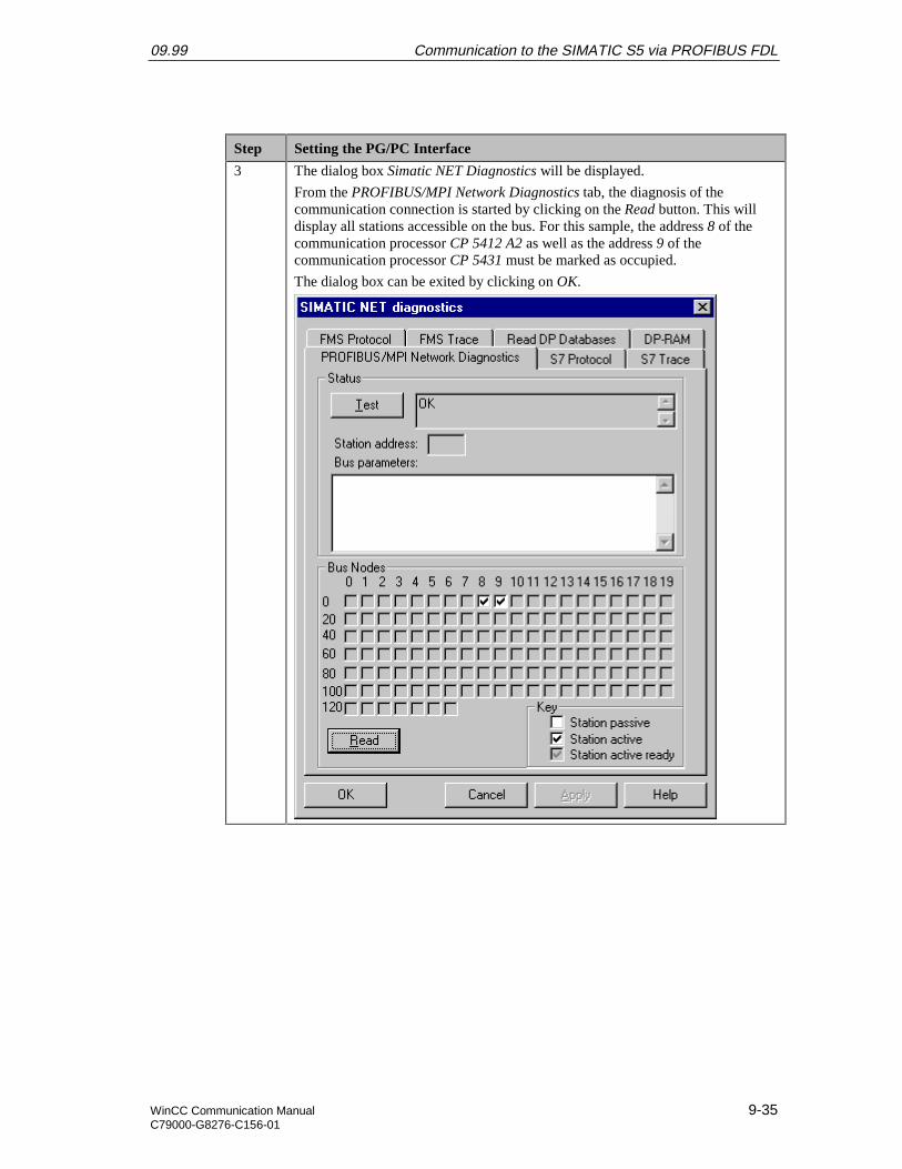
09.99 Communication to the SIMATIC S5 via PROFIBUS FDL
WinCC Communication Manual 9-35C79000-G8276-C156-01
Step Setting the PG/PC Interface
3 The dialog box Simatic NET Diagnostics will be displayed.
From the PROFIBUS/MPI Network Diagnostics tab, the diagnosis of thecommunication connection is started by clicking on the Read button. This willdisplay all stations accessible on the bus. For this sample, the address 8 of thecommunication processor CP 5412 A2 as well as the address 9 of thecommunication processor CP 5431 must be marked as occupied.
The dialog box can be exited by clicking on OK.
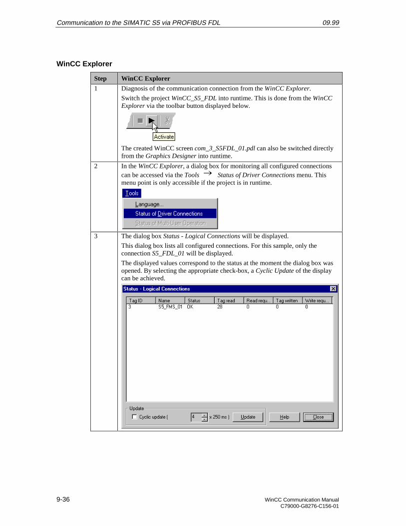
Communication to the SIMATIC S5 via PROFIBUS FDL 09.99
9-36 WinCC Communication ManualC79000-G8276-C156-01
WinCC Explorer
Step WinCC Explorer
1 Diagnosis of the communication connection from the WinCC Explorer.
Switch the project WinCC_S5_FDL into runtime. This is done from the WinCCExplorer via the toolbar button displayed below.
The created WinCC screen com_3_S5FDL_01.pdl can also be switched directlyfrom the Graphics Designer into runtime.
2 In the WinCC Explorer, a dialog box for monitoring all configured connectionscan be accessed via the Tools Status of Driver Connections menu. Thismenu point is only accessible if the project is in runtime.
3 The dialog box Status - Logical Connections will be displayed.
This dialog box lists all configured connections. For this sample, only theconnection S5_FDL_01 will be displayed.
The displayed values correspond to the status at the moment the dialog box wasopened. By selecting the appropriate check-box, a Cyclic Update of the displaycan be achieved.
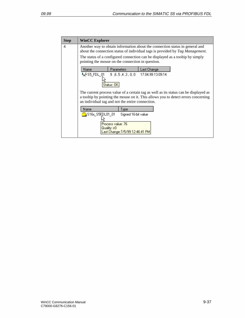
09.99 Communication to the SIMATIC S5 via PROFIBUS FDL
WinCC Communication Manual 9-37C79000-G8276-C156-01
Step WinCC Explorer
4 Another way to obtain information about the connection status in general andabout the connection status of individual tags is provided by Tag Management.
The status of a configured connection can be displayed as a tooltip by simplypointing the mouse on the connection in question.
The current process value of a certain tag as well as its status can be displayed asa tooltip by pointing the mouse on it. This allows you to detect errors concerningan individual tag and not the entire connection.

Communication to the SIMATIC S5 via PROFIBUS FDL 09.99
9-38 WinCC Communication ManualC79000-G8276-C156-01
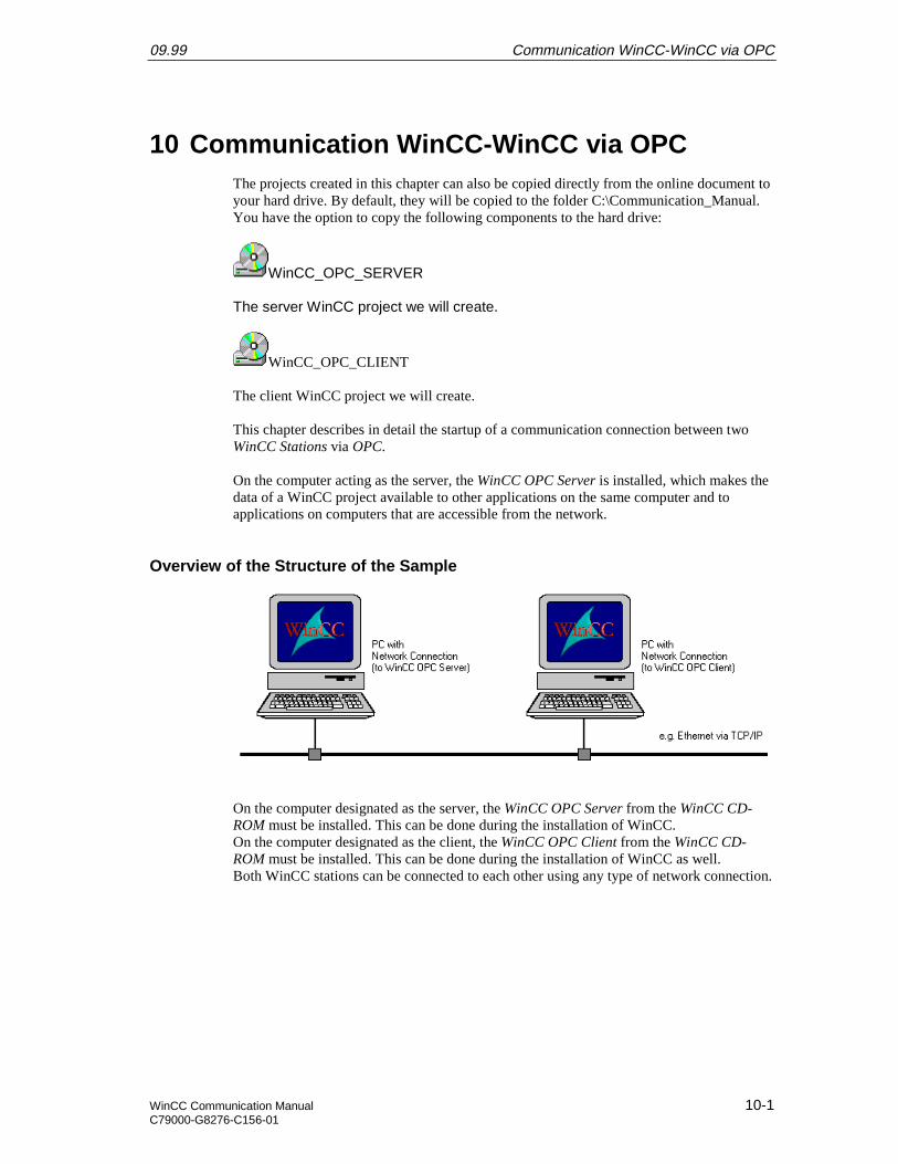
09.99 Communication WinCC-WinCC via OPC
WinCC Communication Manual 10-1C79000-G8276-C156-01
10 Communication WinCC-WinCC via OPCThe projects created in this chapter can also be copied directly from the online document toyour hard drive. By default, they will be copied to the folder C:\Communication_Manual.You have the option to copy the following components to the hard drive:
WinCC_OPC_SERVER
The server WinCC project we will create.
WinCC_OPC_CLIENT
The client WinCC project we will create.
This chapter describes in detail the startup of a communication connection between twoWinCC Stations via OPC.
On the computer acting as the server, the WinCC OPC Server is installed, which makes thedata of a WinCC project available to other applications on the same computer and toapplications on computers that are accessible from the network.
Overview of the Structure of the Sample
On the computer designated as the server, the WinCC OPC Server from the WinCC CD-ROM must be installed. This can be done during the installation of WinCC.On the computer designated as the client, the WinCC OPC Client from the WinCC CD-ROM must be installed. This can be done during the installation of WinCC as well.Both WinCC stations can be connected to each other using any type of network connection.
Communication WinCC-WinCC via OPC 09.99
10-2 WinCC Communication ManualC79000-G8276-C156-01
Overview of the Configuration Steps
The following lists all configuration steps necessary for the creation of the communicationconnection:
• Configuration of the WinCC Stations
• Creation of the WinCC Project WinCC_OPC_SERVER
• Creation of the WinCC Project WinCC_OPC_CLIENT
• Diagnosis of the Communication Connection
Required Software
Name Description
WinCC WinCC with OPC Server and OPC Client for the creation of theWinCC projects.
Required Compute Hardware
Name Description
Network Access Any type of network access to establish a connection to thenetwork.
09.99 Communication WinCC-WinCC via OPC
WinCC Communication Manual 10-3C79000-G8276-C156-01
10.1 Configuration of the WinCC Stations
The following description contains notes that should be observed during the configurationof the WinCC stations.In general, three configurations for the access from a WinCC client station to an OPCserver are possible. These configurations differ, depending on where both components arelocated:
• Server and client are located on the same computer
• Server and client are located on different computers of the same workgroup
• Server and client are located on different computers within the same domain or indifferent domains with trust setting
The first of the configurations mentioned is not practical for the communication between aWinCC OPC server and a WinCC OPC client. However, this configuration can be appliedto other cases, e.g. for the communication to the S7 OPC Server.For the steps described below, the conditions existing on site must be considered.
• A: Installing the Software Components
• B: Organization of the Network
• C: Organization of the User Structure
• D: Setting the DCOM Configuration
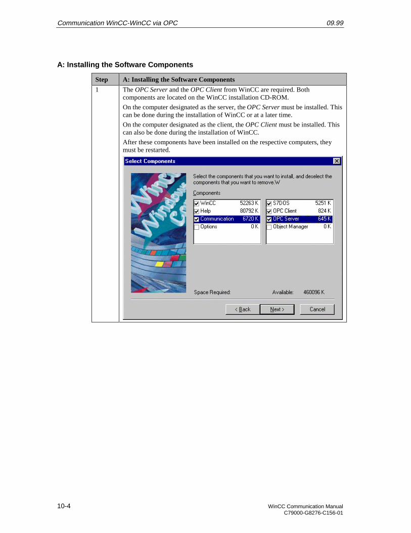
Communication WinCC-WinCC via OPC 09.99
10-4 WinCC Communication ManualC79000-G8276-C156-01
A: Installing the Software Components
Step A: Installing the Software Components
1 The OPC Server and the OPC Client from WinCC are required. Bothcomponents are located on the WinCC installation CD-ROM.
On the computer designated as the server, the OPC Server must be installed. Thiscan be done during the installation of WinCC or at a later time.
On the computer designated as the client, the OPC Client must be installed. Thiscan also be done during the installation of WinCC.
After these components have been installed on the respective computers, theymust be restarted.
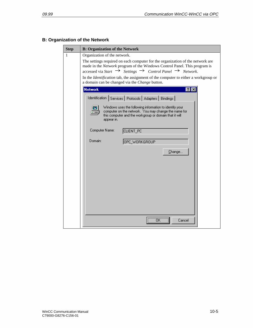
09.99 Communication WinCC-WinCC via OPC
WinCC Communication Manual 10-5C79000-G8276-C156-01
B: Organization of the Network
Step B: Organization of the Network
1 Organization of the network.
The settings required on each computer for the organization of the network aremade in the Network program of the Windows Control Panel. This program isaccessed via Start Settings Control Panel Network.
In the Identification tab, the assignment of the computer to either a workgroup ora domain can be changed via the Change button.
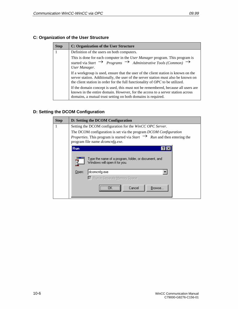
Communication WinCC-WinCC via OPC 09.99
10-6 WinCC Communication ManualC79000-G8276-C156-01
C: Organization of the User Structure
Step C: Organization of the User Structure
1 Definition of the users on both computers.
This is done for each computer in the User Manager program. This program isstarted via Start Programs Administrative Tools (Common) User Manager.
If a workgroup is used, ensure that the user of the client station is known on theserver station. Additionally, the user of the server station must also be known onthe client station in order for the full functionality of OPC to be utilized.
If the domain concept is used, this must not be remembered, because all users areknown in the entire domain. However, for the access to a server station acrossdomains, a mutual trust setting on both domains is required.
D: Setting the DCOM Configuration
Step D: Setting the DCOM Configuration
1 Setting the DCOM configuration for the WinCC OPC Server.
The DCOM configuration is set via the program DCOM ConfigurationProperties. This program is started via Start Run and then entering theprogram file name dcomcnfg.exe.
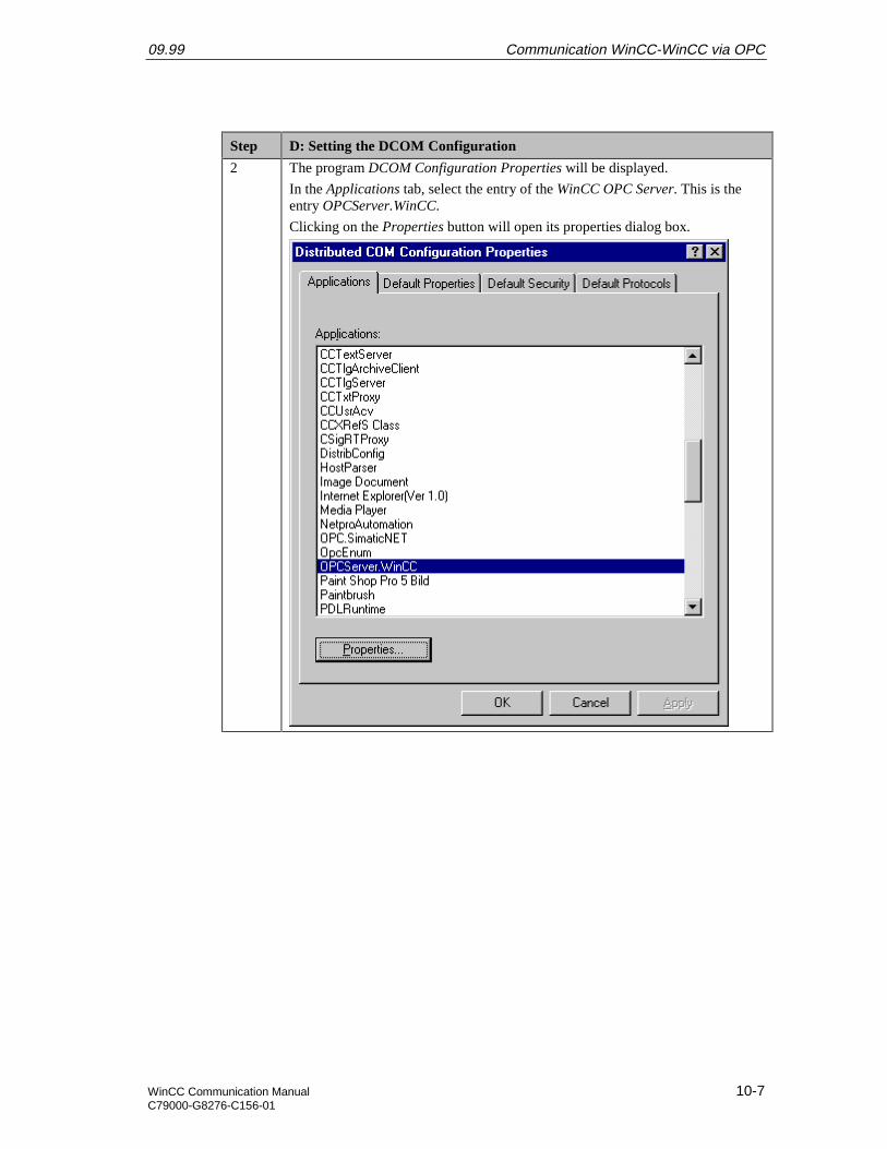
09.99 Communication WinCC-WinCC via OPC
WinCC Communication Manual 10-7C79000-G8276-C156-01
Step D: Setting the DCOM Configuration
2 The program DCOM Configuration Properties will be displayed.
In the Applications tab, select the entry of the WinCC OPC Server. This is theentry OPCServer.WinCC.
Clicking on the Properties button will open its properties dialog box.
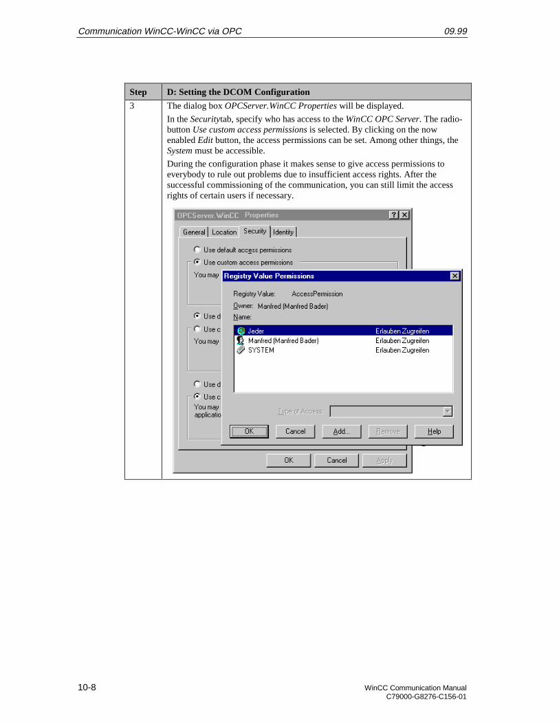
Communication WinCC-WinCC via OPC 09.99
10-8 WinCC Communication ManualC79000-G8276-C156-01
Step D: Setting the DCOM Configuration
3 The dialog box OPCServer.WinCC Properties will be displayed.
In the Securitytab, specify who has access to the WinCC OPC Server. The radio-button Use custom access permissions is selected. By clicking on the nowenabled Edit button, the access permissions can be set. Among other things, theSystem must be accessible.
During the configuration phase it makes sense to give access permissions toeverybody to rule out problems due to insufficient access rights. After thesuccessful commissioning of the communication, you can still limit the accessrights of certain users if necessary.
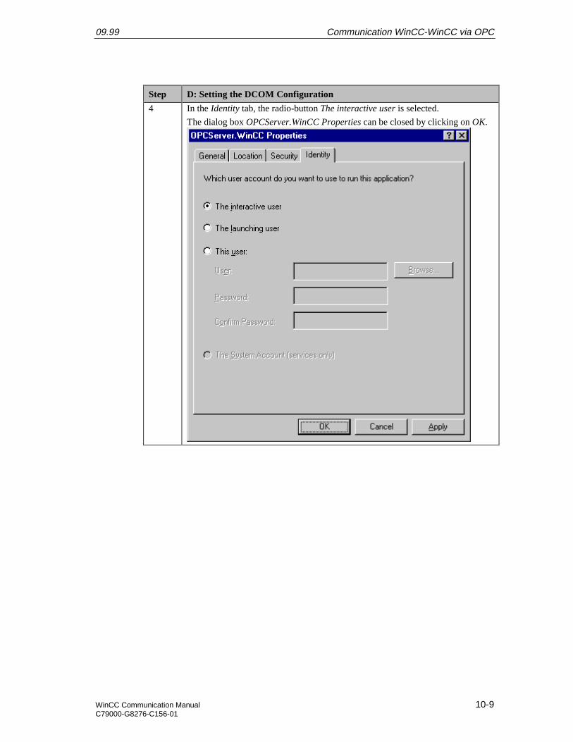
09.99 Communication WinCC-WinCC via OPC
WinCC Communication Manual 10-9C79000-G8276-C156-01
Step D: Setting the DCOM Configuration
4 In the Identity tab, the radio-button The interactive user is selected.
The dialog box OPCServer.WinCC Properties can be closed by clicking on OK.
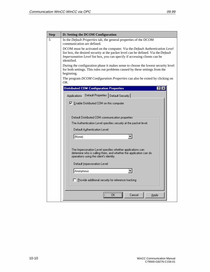
Communication WinCC-WinCC via OPC 09.99
10-10 WinCC Communication ManualC79000-G8276-C156-01
Step D: Setting the DCOM Configuration
5 In the Default Properties tab, the general properties of the DCOMcommunication are defined.
DCOM must be activated on the computer. Via the Default Authentication Levellist box, the desired security at the packet level can be defined. Via the DefaultImpersonation Level list box, you can specify if accessing clients can beidentified.
During the configuration phase it makes sense to choose the lowest security levelfor both settings. This rules out problems caused by these settings from thebeginning.
The program DCOM Configuration Properties can also be exited by clicking onOK.
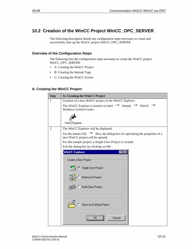
09.99 Communication WinCC-WinCC via OPC
WinCC Communication Manual 10-11C79000-G8276-C156-01
10.2 Creation of the WinCC Project WinCC_OPC_SERVER
The following description details the configuration steps necessary to create andsuccessfully start up the WinCC project WinCC_OPC_SERVER.
Overview of the Configuration Steps
The following lists the configuration steps necessary to create the WinCC projectWinCC_OPC_SERVER:
• A: Creating the WinCC Project
• B: Creating the Internal Tags
• C: Creating the WinCC Screen
A: Creating the WinCC Project
Step A: Creating the WinCC Project
1 Creation of a new WinCC project in the WinCC Explorer.
The WinCC Explorer is started via Start Simatic WinCC Windows Control Center.
2 The WinCC Explorer will be displayed.
Via the menus File New, the dialog box for specifying the properties of anew WinCC project will be opened.
For this sample project, a Single-User Project is created.
Exit the dialog box by clicking on OK.
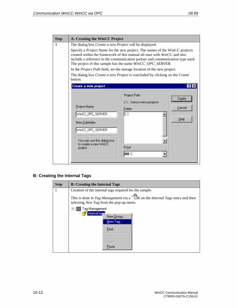
Communication WinCC-WinCC via OPC 09.99
10-12 WinCC Communication ManualC79000-G8276-C156-01
Step A: Creating the WinCC Project
3 The dialog box Create a new Project will be displayed.
Specify a Project Name for the new project. The names of the WinCC projectscreated within the framework of this manual all start with WinCC and alsoinclude a reference to the communication partner and communication type used.The project of this sample has the name WinCC_OPC_SERVER.
In the Project Path field, set the storage location of the new project.
The dialog box Create a new Project is concluded by clicking on the Createbutton.
B: Creating the Internal Tags
Step B: Creating the Internal Tags
1 Creation of the internal tags required for the sample.
This is done in Tag Management via a R on the Internal Tags entry and thenselecting New Tag from the pop-up menu.
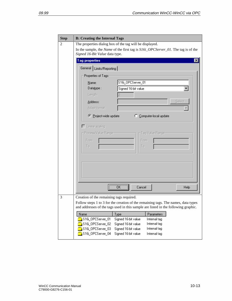
09.99 Communication WinCC-WinCC via OPC
WinCC Communication Manual 10-13C79000-G8276-C156-01
Step B: Creating the Internal Tags
2 The properties dialog box of the tag will be displayed.
In the sample, the Name of the first tag is S16i_OPCServer_01. The tag is of theSigned 16-Bit Value data type.
3 Creation of the remaining tags required.
Follow steps 1 to 3 for the creation of the remaining tags. The names, data typesand addresses of the tags used in this sample are listed in the following graphic.

Communication WinCC-WinCC via OPC 09.99
10-14 WinCC Communication ManualC79000-G8276-C156-01
C: Creating the WinCC Screen
Step C: Creating the WinCC Screen
1 Creation of a WinCC screen in which the previously created tags are visualized.
Open the Graphics Designer editor via a R and then selecting Open from thepop-up menu.
2 This will open the Graphics Designer editor with a new (blank) screen.
To display the first tag, configure a Smart Object I/O Field. To do so,select the I/O Field object from the Object Palette and place it on the screenusing the mouse.
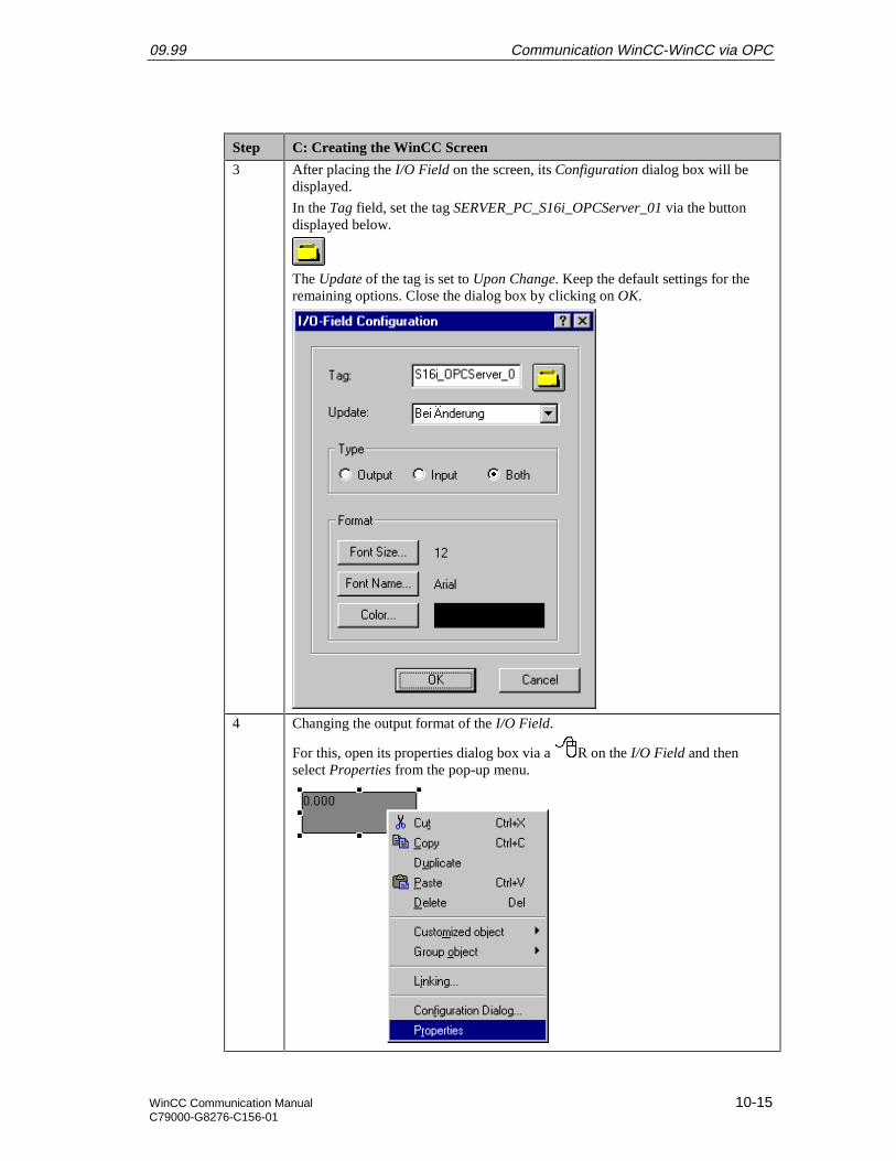
09.99 Communication WinCC-WinCC via OPC
WinCC Communication Manual 10-15C79000-G8276-C156-01
Step C: Creating the WinCC Screen
3 After placing the I/O Field on the screen, its Configuration dialog box will bedisplayed.
In the Tag field, set the tag SERVER_PC_S16i_OPCServer_01 via the buttondisplayed below.
The Update of the tag is set to Upon Change. Keep the default settings for theremaining options. Close the dialog box by clicking on OK.
4 Changing the output format of the I/O Field.
For this, open its properties dialog box via a R on the I/O Field and thenselect Properties from the pop-up menu.
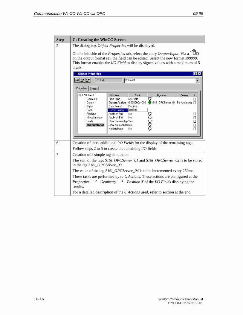
Communication WinCC-WinCC via OPC 09.99
10-16 WinCC Communication ManualC79000-G8276-C156-01
Step C: Creating the WinCC Screen
5 The dialog box Object Properties will be displayed.
On the left side of the Properties tab, select the entry Output/Input. Via a Don the output format set, the field can be edited. Select the new format s99999.This format enables the I/O Field to display signed values with a maximum of 5digits.
6 Creation of three additional I/O Fields for the display of the remaining tags.
Follow steps 2 to 5 to create the remaining I/O fields.
7 Creation of a simple tag simulation.
The sum of the tags S16i_OPCServer_01 and S16i_OPCServer_02 is to be storedin the tag S16i_OPCServer_03.
The value of the tag S16i_OPCServer_04 is to be incremented every 250ms.
These tasks are performed by to C Actions. These actions are configured at theProperties Geometry Position X of the I/O Fields displaying theresults.
For a detailed description of the C Actions used, refer to section at the end.
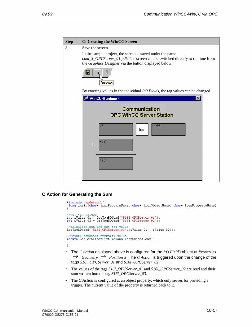
09.99 Communication WinCC-WinCC via OPC
WinCC Communication Manual 10-17C79000-G8276-C156-01
Step C: Creating the WinCC Screen
8 Save the screen.
In the sample project, the screen is saved under the namecom_3_OPCServer_01.pdl. The screen can be switched directly to runtime fromthe Graphics Designer via the button displayed below.
By entering values in the individual I/O Fields, the tag values can be changed.
C Action for Generating the Sum
• The C Action displayed above is configured for the I/O Field3 object at Properties Geometry Position X. The C Action is triggered upon the change of the
tags S16i_OPCServer_01 and S16i_OPCServer_02.
• The values of the tags S16i_OPCServer_01 and S16i_OPCServer_02 are read and theirsum written into the tag S16i_OPCServer_03.
• The C Action is configured at an object property, which only serves for providing atrigger. The current value of the property is returned back to it.
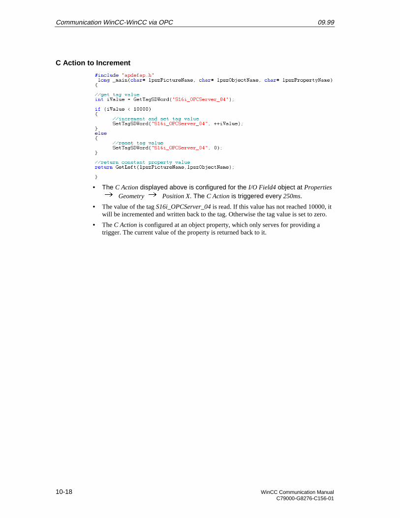
Communication WinCC-WinCC via OPC 09.99
10-18 WinCC Communication ManualC79000-G8276-C156-01
C Action to Increment
• The C Action displayed above is configured for the I/O Field4 object at Properties Geometry Position X. The C Action is triggered every 250ms.
• The value of the tag S16i_OPCServer_04 is read. If this value has not reached 10000, itwill be incremented and written back to the tag. Otherwise the tag value is set to zero.
• The C Action is configured at an object property, which only serves for providing atrigger. The current value of the property is returned back to it.
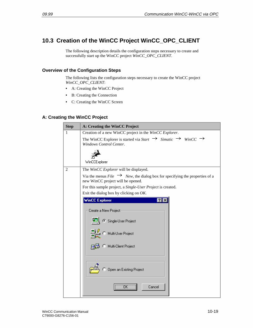
09.99 Communication WinCC-WinCC via OPC
WinCC Communication Manual 10-19C79000-G8276-C156-01
10.3 Creation of the WinCC Project WinCC_OPC_CLIENT
The following description details the configuration steps necessary to create andsuccessfully start up the WinCC project WinCC_OPC_CLIENT.
Overview of the Configuration Steps
The following lists the configuration steps necessary to create the WinCC projectWinCC_OPC_CLIENT:
• A: Creating the WinCC Project
• B: Creating the Connection
• C: Creating the WinCC Screen
A: Creating the WinCC Project
Step A: Creating the WinCC Project
1 Creation of a new WinCC project in the WinCC Explorer.
The WinCC Explorer is started via Start Simatic WinCC Windows Control Center.
2 The WinCC Explorer will be displayed.
Via the menus File New, the dialog box for specifying the properties of anew WinCC project will be opened.
For this sample project, a Single-User Project is created.
Exit the dialog box by clicking on OK.
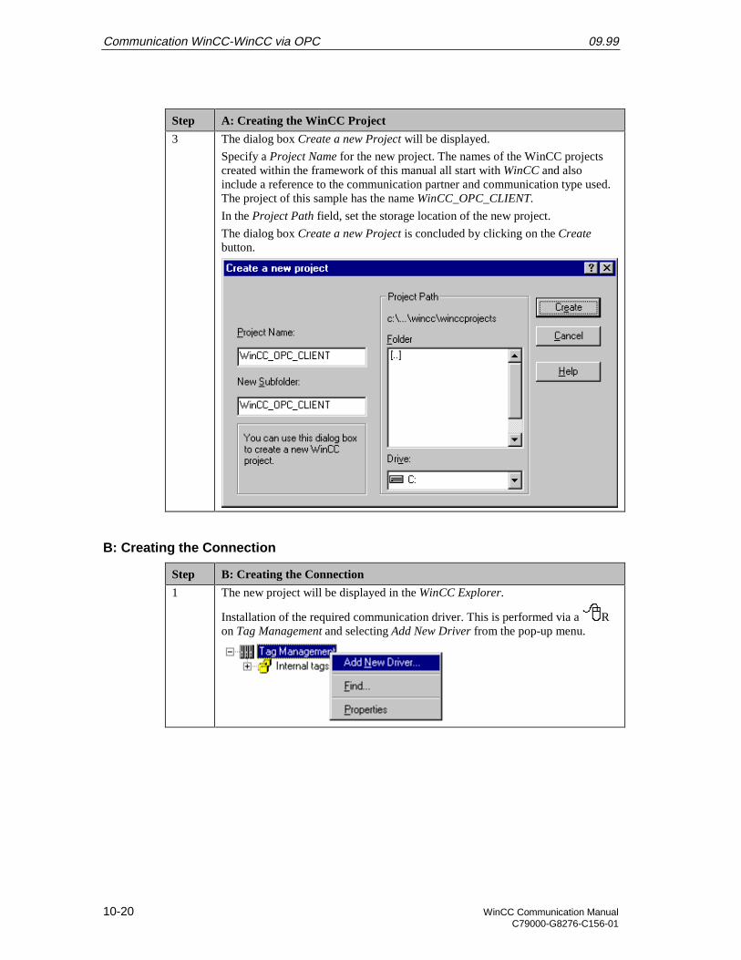
Communication WinCC-WinCC via OPC 09.99
10-20 WinCC Communication ManualC79000-G8276-C156-01
Step A: Creating the WinCC Project
3 The dialog box Create a new Project will be displayed.
Specify a Project Name for the new project. The names of the WinCC projectscreated within the framework of this manual all start with WinCC and alsoinclude a reference to the communication partner and communication type used.The project of this sample has the name WinCC_OPC_CLIENT.
In the Project Path field, set the storage location of the new project.
The dialog box Create a new Project is concluded by clicking on the Createbutton.
B: Creating the Connection
Step B: Creating the Connection
1 The new project will be displayed in the WinCC Explorer.
Installation of the required communication driver. This is performed via a Ron Tag Management and selecting Add New Driver from the pop-up menu.
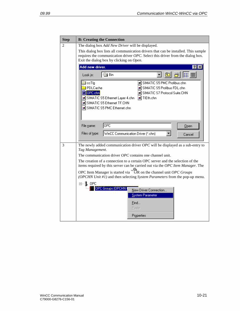
09.99 Communication WinCC-WinCC via OPC
WinCC Communication Manual 10-21C79000-G8276-C156-01
Step B: Creating the Connection
2 The dialog box Add New Driver will be displayed.
This dialog box lists all communication drivers that can be installed. This samplerequires the communication driver OPC. Select this driver from the dialog box.Exit the dialog box by clicking on Open.
3 The newly added communication driver OPC will be displayed as a sub-entry toTag Management.
The communication driver OPC contains one channel unit.
The creation of a connection to a certain OPC server and the selection of theitems required by this server can be carried out via the OPC Item Manager. The
OPC Item Manager is started via R on the channel unit OPC Groups(OPCHN Unit #1) and then selecting System Parameters from the pop-up menu.
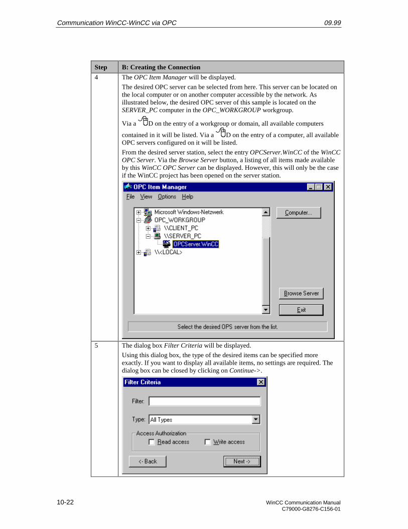
Communication WinCC-WinCC via OPC 09.99
10-22 WinCC Communication ManualC79000-G8276-C156-01
Step B: Creating the Connection
4 The OPC Item Manager will be displayed.
The desired OPC server can be selected from here. This server can be located onthe local computer or on another computer accessible by the network. Asillustrated below, the desired OPC server of this sample is located on theSERVER_PC computer in the OPC_WORKGROUP workgroup.
Via a D on the entry of a workgroup or domain, all available computers
contained in it will be listed. Via a D on the entry of a computer, all availableOPC servers configured on it will be listed.
From the desired server station, select the entry OPCServer.WinCC of the WinCCOPC Server. Via the Browse Server button, a listing of all items made availableby this WinCC OPC Server can be displayed. However, this will only be the caseif the WinCC project has been opened on the server station.
5 The dialog box Filter Criteria will be displayed.
Using this dialog box, the type of the desired items can be specified moreexactly. If you want to display all available items, no settings are required. Thedialog box can be closed by clicking on Continue->.
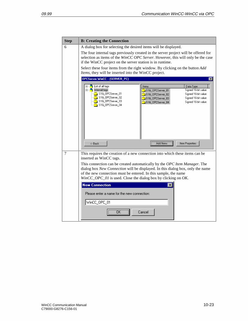
09.99 Communication WinCC-WinCC via OPC
WinCC Communication Manual 10-23C79000-G8276-C156-01
Step B: Creating the Connection
6 A dialog box for selecting the desired items will be displayed.
The four internal tags previously created in the server project will be offered forselection as items of the WinCC OPC Server. However, this will only be the caseif the WinCC project on the server station is in runtime.
Select these four items from the right window. By clicking on the button AddItems, they will be inserted into the WinCC project.
7 This requires the creation of a new connection into which these items can beinserted as WinCC tags.
This connection can be created automatically by the OPC Item Manager. Thedialog box New Connection will be displayed. In this dialog box, only the nameof the new connection must be entered. In this sample, the nameWinCC_OPC_01 is used. Close the dialog box by clicking on OK.
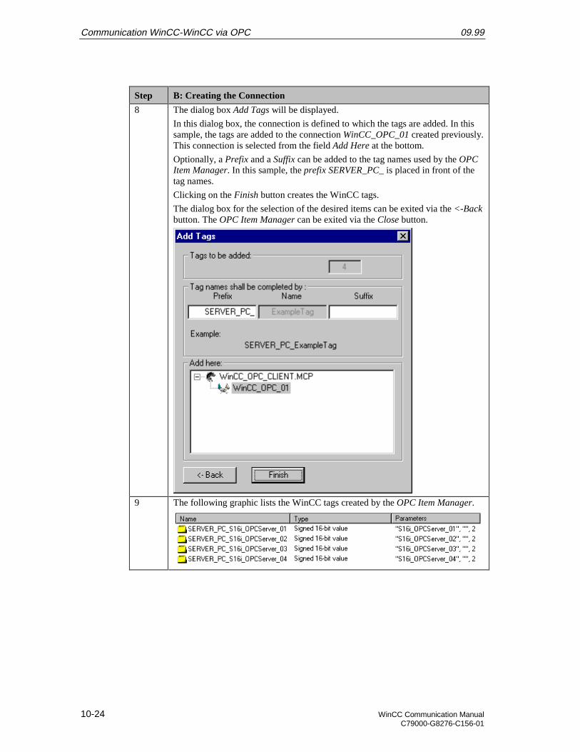
Communication WinCC-WinCC via OPC 09.99
10-24 WinCC Communication ManualC79000-G8276-C156-01
Step B: Creating the Connection
8 The dialog box Add Tags will be displayed.
In this dialog box, the connection is defined to which the tags are added. In thissample, the tags are added to the connection WinCC_OPC_01 created previously.This connection is selected from the field Add Here at the bottom.
Optionally, a Prefix and a Suffix can be added to the tag names used by the OPCItem Manager. In this sample, the prefix SERVER_PC_ is placed in front of thetag names.
Clicking on the Finish button creates the WinCC tags.
The dialog box for the selection of the desired items can be exited via the <-Backbutton. The OPC Item Manager can be exited via the Close button.
9 The following graphic lists the WinCC tags created by the OPC Item Manager.
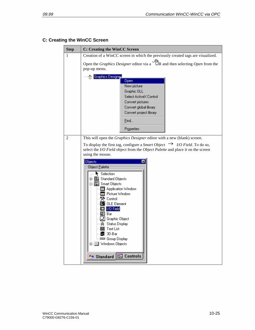
09.99 Communication WinCC-WinCC via OPC
WinCC Communication Manual 10-25C79000-G8276-C156-01
C: Creating the WinCC Screen
Step C: Creating the WinCC Screen
1 Creation of a WinCC screen in which the previously created tags are visualized.
Open the Graphics Designer editor via a R and then selecting Open from thepop-up menu.
2 This will open the Graphics Designer editor with a new (blank) screen.
To display the first tag, configure a Smart Object I/O Field. To do so,select the I/O Field object from the Object Palette and place it on the screenusing the mouse.

Communication WinCC-WinCC via OPC 09.99
10-26 WinCC Communication ManualC79000-G8276-C156-01
Step C: Creating the WinCC Screen
3 After placing the I/O Field on the screen, its Configuration dialog box will bedisplayed.
In the Tag field, set the tag SERVER_PC_S16i_OPCServer_01 via the buttondisplayed below.
Leave the Update of the tag at 2 s. Keep the default settings for the remainingoptions. Close the dialog box by clicking on OK.
4 Changing the output format of the I/O Field.
For this, open its properties dialog box via a R on the I/O Field and thenselect Properties from the pop-up menu.
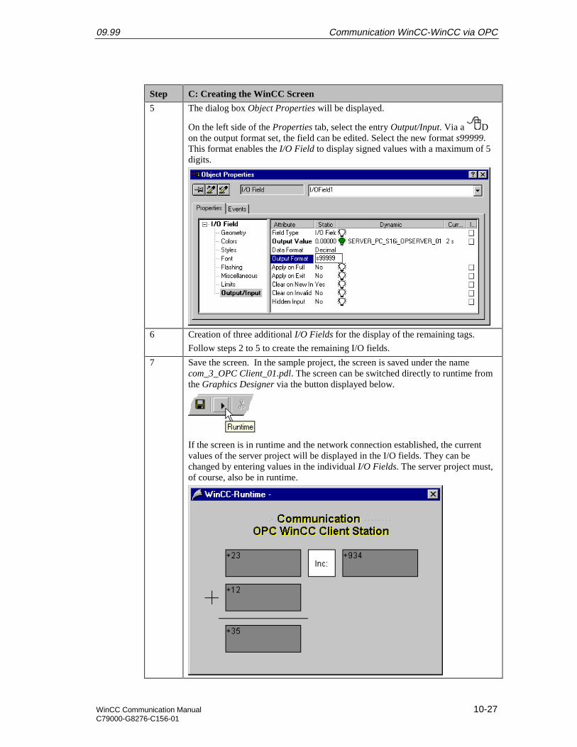
09.99 Communication WinCC-WinCC via OPC
WinCC Communication Manual 10-27C79000-G8276-C156-01
Step C: Creating the WinCC Screen
5 The dialog box Object Properties will be displayed.
On the left side of the Properties tab, select the entry Output/Input. Via a Don the output format set, the field can be edited. Select the new format s99999.This format enables the I/O Field to display signed values with a maximum of 5digits.
6 Creation of three additional I/O Fields for the display of the remaining tags.
Follow steps 2 to 5 to create the remaining I/O fields.
7 Save the screen. In the sample project, the screen is saved under the namecom_3_OPC Client_01.pdl. The screen can be switched directly to runtime fromthe Graphics Designer via the button displayed below.
If the screen is in runtime and the network connection established, the currentvalues of the server project will be displayed in the I/O fields. They can bechanged by entering values in the individual I/O Fields. The server project must,of course, also be in runtime.

Communication WinCC-WinCC via OPC 09.99
10-28 WinCC Communication ManualC79000-G8276-C156-01
Step C: Creating the WinCC Screen
If there is no connection, the I/O Fields will be displayed grayed out. In this casean error is present at some point of the communication connection.
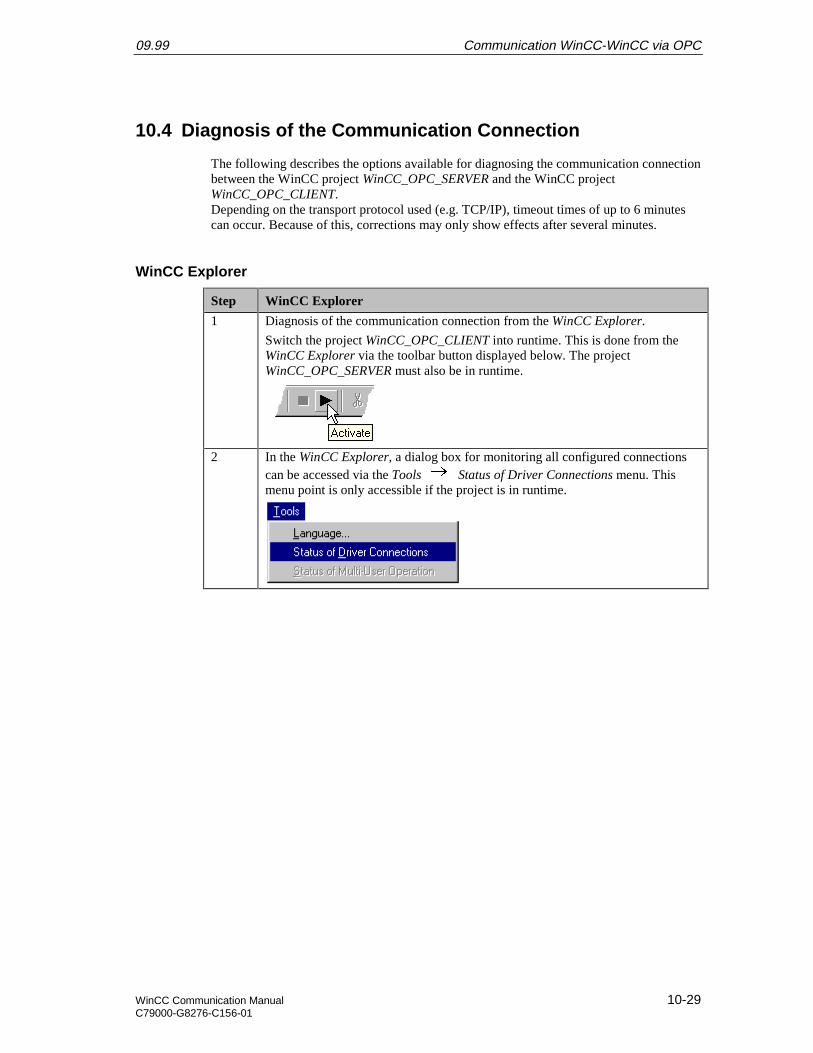
09.99 Communication WinCC-WinCC via OPC
WinCC Communication Manual 10-29C79000-G8276-C156-01
10.4 Diagnosis of the Communication Connection
The following describes the options available for diagnosing the communication connectionbetween the WinCC project WinCC_OPC_SERVER and the WinCC projectWinCC_OPC_CLIENT.Depending on the transport protocol used (e.g. TCP/IP), timeout times of up to 6 minutescan occur. Because of this, corrections may only show effects after several minutes.
WinCC Explorer
Step WinCC Explorer
1 Diagnosis of the communication connection from the WinCC Explorer.
Switch the project WinCC_OPC_CLIENT into runtime. This is done from theWinCC Explorer via the toolbar button displayed below. The projectWinCC_OPC_SERVER must also be in runtime.
2 In the WinCC Explorer, a dialog box for monitoring all configured connectionscan be accessed via the Tools Status of Driver Connections menu. Thismenu point is only accessible if the project is in runtime.
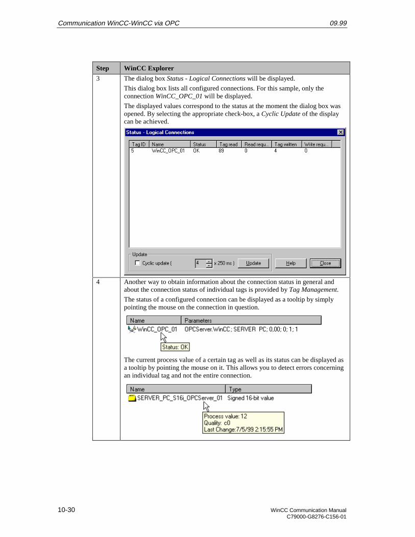
Communication WinCC-WinCC via OPC 09.99
10-30 WinCC Communication ManualC79000-G8276-C156-01
Step WinCC Explorer
3 The dialog box Status - Logical Connections will be displayed.
This dialog box lists all configured connections. For this sample, only theconnection WinCC_OPC_01 will be displayed.
The displayed values correspond to the status at the moment the dialog box wasopened. By selecting the appropriate check-box, a Cyclic Update of the displaycan be achieved.
4 Another way to obtain information about the connection status in general andabout the connection status of individual tags is provided by Tag Management.
The status of a configured connection can be displayed as a tooltip by simplypointing the mouse on the connection in question.
The current process value of a certain tag as well as its status can be displayed asa tooltip by pointing the mouse on it. This allows you to detect errors concerningan individual tag and not the entire connection.
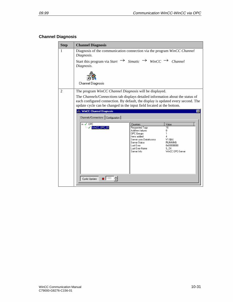
09.99 Communication WinCC-WinCC via OPC
WinCC Communication Manual 10-31C79000-G8276-C156-01
Channel Diagnosis
Step Channel Diagnosis
1 Diagnosis of the communication connection via the program WinCC ChannelDiagnosis.
Start this program via Start Simatic WinCC ChannelDiagnosis.
2 The program WinCC Channel Diagnosis will be displayed.
The Channels/Connections tab displays detailed information about the status ofeach configured connection. By default, the display is updated every second. Theupdate cycle can be changed in the input field located at the bottom.

Communication WinCC-WinCC via OPC 09.99
10-32 WinCC Communication ManualC79000-G8276-C156-01

09.99 Index
WinCC Communication Manual Index-1C79000-G8276-C156-01
Index
AAccess Point 2-8
Industrial Ethernet 2-8, 2-38PROFIBUS 6-7
Access Rights 5-36Addressing 2-40
BBindings 3-11
CCentral Processor Module 3-22COM PROFIBUS 8-5COML S7 5-29Communication Processor 3-3
CP 1411 3-3CP 1413 2-3CP 5412 A2 6-1Restart 2-10
Configuration Dialog Box 2-42Connection Parameters 2-36
Industrial Ethernet 2-36PROFIBUS 6-35TCP/IP 4-39
DData Block 2-27Database File 5-30DCOM 5-34Diagnosis 2-12
IE Network Diagnosis 2-12Industrial Ethernet 2-26
Diagnosis Buffer 2-24
EESD 2-3Ethernet Address 2-9, 2-20
FFDL 9-1FMS 8-1
HHandling Block 7-13
RECEIVE 7-13SEND 7-13
HardnetIndustrial Ethernet 2-1
Hardware Catalog 2-18HWConfig 2-17
II/O Field 2-41Identity 5-37Interactive User 5-37IP Address 4-13, 4-23ISA Slot 2-3
JJumper Setting 2-3
CP 1413 2-3CP 5412 A2 6-3
LLAD/STL/SCF 2-27Load 2-28
MMAC Address 2-9, 2-20Module State 2-25
Central Module 2-24Communication Processor 2-25
NNCM S7 2-14
Industrial Ethernet 2-14PROFIBUS 6-12
OOPC 5-41
Group 5-41

Index 09.99
Index-2 WinCC Communication ManualC79000-G8276-C156-01
Item 5-41OPC Item Manager 5-47OPC Scout 5-40S7 OPC Server 5-1WinCC OPC Server 10-1
Operation Block 2-27
PPower Supply Unit 3-23PROFIBUS
PROFIBUS FDL 9-1PROFIBUS FMS 8-1
ProtocolInstallation 3-9
RRack 3-22Rack Number 2-19Read Cyclically 2-37Runtime 2-43
SS7 Protocol 5-32Setting the PG/PC Interface 2-4SIMATIC Manager 3-18SIMATIC S5
Industrial Ethernet 7-1PROFIBUS FDL 9-1
PROFIBUS FMS 8-1SIMATIC S7
Industrial Ethernet 2-1, 3-1OPC 5-1PROFIBUS 6-1TCP/IP 4-1, 4-37
SINEC NCM 7-2Single Station Project 2-32Slot Number 2-19Softnet
Industrial Ethernet 3-1State LED 2-23Subnet 3-23Subnet Mask 4-13, 4-23System Parameters 2-37
TTag Table 2-30, 2-31
Control Value 2-31State Value 2-31
TCP/IP 4-1TSAP 5-30
UUpdate Cycle 2-42
WWinCC Explorer 2-32


![Manual Del Usuario de WinCC Flexible Es-ES[1]](https://img.pdfslide.net/doc/110x75/5572137b497959fc0b92638a/manual-del-usuario-de-wincc-flexible-es-es1.jpg)