Embed Size (px)
Citation preview
Manual forMult-O-Meter
V00
05
2
Manual for Mult-O-Meter
Model:
S/N:
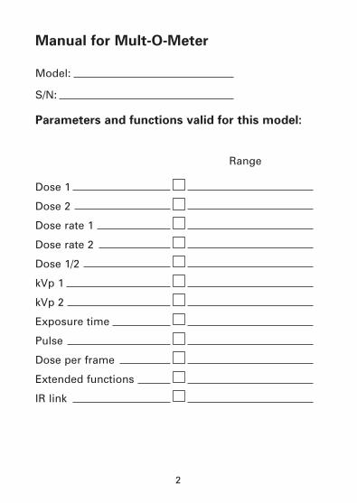
Parameters and functions valid for this model:
Range
Dose 1
Dose 2
Dose rate 1
Dose rate 2
Dose 1/2
kVp 1
kVp 2
Exposure time
Pulse
Dose per frame
Extended functions
IR link
3
Notice 4
Warranty 5
Product description 6
General philosophy 6
Economic design 6
Short presentation 7
Detector configuration 9
ON/OFF key 13
PARAMETER key 13
User’s menu 14
Extended functions 16
Gray or Roentgen 18
Principles of Operation 19
General 19
kVp 21
Dose 23
Dose rate 25
Dose 1/ Dose 2 ratio 26
Exposure Time 27
Pulse 28
Dose per frame 29
IR link 29
Measurement hints 30
kVp 30
Dose and Dose rate 32
Exposure time 33
Display codes 34
Specifications 35
General 35
kVp 36
Dose 39
Dose rate 42
Exposure time 44
Pulse 44
IR link 45
Filtration dependence
graphs 47
Energy dependence
graphs 50
Replacing the battery 51
Contents:
4
NOTICE
Thank you for buying the Mult-O-Meter from UNFORSINSTRUMENTS AB. Our aim is that your investmentshould pay back within the next few weeks.
Copyrightã 1997. Reproduction or use of any portion ofthis document, without expressed written permissionfrom UNFORS INSTRUMENTS is prohibited.
UNFORS INSTRUMENTS reserves all rights to makechanges in the Mult-O-Meter and the contents in thisdocument without notice. UNFORS INSTRUMENTSassumes no responsibility for any errors or consequen-tial damages that may result from use or misinterpreta-tion of any information contained in this document.
The Mult-O-Meter has been tested to meet the EMCrequirements in IEC Publication 801-2,-3 and EN55011.
This manual contains information about all mea-suring possibilities and functions with the Mult-O-Meter. There are a number of different models withcombinations of measuring parameters and func-tions, which are optimized for specific applications.The model delivered with this manual is specifiedon page 2. Some paragraphs in the manual maythus not be valid for your model.
US office:PMB Box 234, 19 Lore's Plaza, New Milford, CT 06776Phone: (888) 735-9803, Fax (860) 350-2664. www.unfors.com
UNFORS INSTRUMENTS ABUggledalsvägen 27, S-427 40 Billdal, SWEDEN.Tel +46 31 910 952. Fax +46 31 910 950. www.unfors.se
5
WARRANTY
UNFORS INSTRUMENTS AB (UI) warrants to the origi-nal product purchaser that each product it manufactu-res will be free from defects in material and workman-ship under normal use and service. The warranty periodis controlled by the warranty document furnished witheach product and begins on the date of purchase. UIwill at its option, repair or replace the defect productfree of charge or refund your purchase price. However,if UI determines that the failure was caused by misuse,alteration, accident or abnormal condition of operationor handling, you will be billed for the repair and therepaired product will be returned to you, transportationprepaid.This warranty is exclusive and is in lieu of all otherwarranties, expressed or implied, including but notlimited to any implied warranty of merchantability orfitness for a particular purpose or use. UI will not beliable for any special, indirect, incidental, or consequen-tial damages or loss of data, whether in contract, tort, or otherwise.
Return Procedure
You may return your unit for repair to UI or fax for ser-vice modules. Any unit returned to UI for repair mustbe accompanied by a completed service request form,including your name, address, phone/fax, product seri-al number and reason for return.
6
PRODUCT DESCRIPTION
General philosophy
You shall have a correct result instantly, independent offamiliarity with the pocket sized instrument, and youshall rely on your instrument year after year. “TheUnfors Concept“.
Pocket sized 10 s to learn Accurate result
Economic design
Unfors Instruments has minimized the life time costsfor you in “The Unfors Concept“.
- Low price- Accurate measurements- No false measurements because of human factors- Short learning time- High quality components - Fast calibration and technical service

7
Short presentation
PARAMETERON/OFF
Mult-O-Meter
kVpmR/min
m s
µmGy/s1/2
Infraredtransmitter
Detector identifier
Units
UnitsBatterycheck
Internaldetector
External detector
Value
2
Figure 1. The Mult-O-Meter general configuration.
8
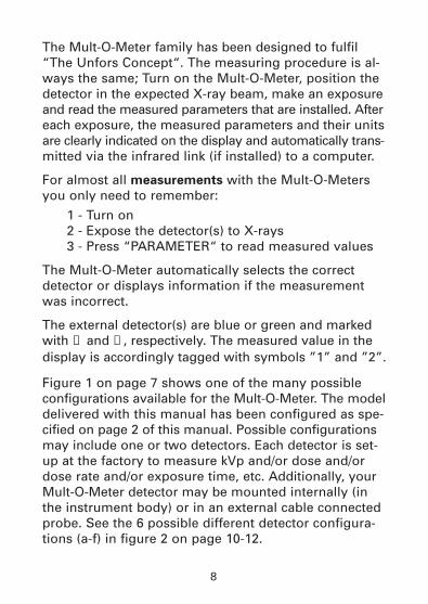
The Mult-O-Meter family has been designed to fulfil“The Unfors Concept“. The measuring procedure is al-ways the same; Turn on the Mult-O-Meter, position thedetector in the expected X-ray beam, make an exposureand read the measured parameters that are installed. Aftereach exposure, the measured parameters and their unitsare clearly indicated on the display and automatically trans-mitted via the infrared link (if installed) to a computer.
For almost all measurements with the Mult-O-Metersyou only need to remember:
1 - Turn on2 - Expose the detector(s) to X-rays3 - Press “PARAMETER“ to read measured values
The Mult-O-Meter automatically selects the correctdetector or displays information if the measurementwas incorrect.
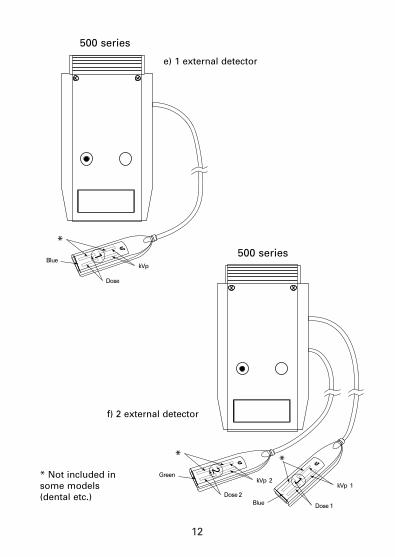
The external detector(s) are blue or green and markedwith ➀ and ➁, respectively. The measured value in thedisplay is accordingly tagged with symbols ”1” and ”2”.
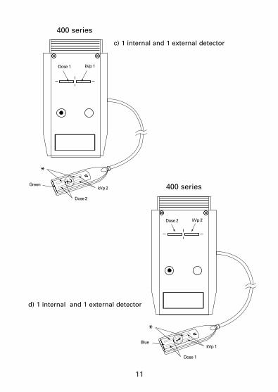
Figure 1 on page 7 shows one of the many possibleconfigurations available for the Mult-O-Meter. The modeldelivered with this manual has been configured as spe-cified on page 2 of this manual. Possible configurationsmay include one or two detectors. Each detector is set-up at the factory to measure kVp and/or dose and/ordose rate and/or exposure time, etc. Additionally, yourMult-O-Meter detector may be mounted internally (inthe instrument body) or in an external cable connectedprobe. See the 6 possible different detector configura-tions (a-f) in figure 2 on page 10-12.
9
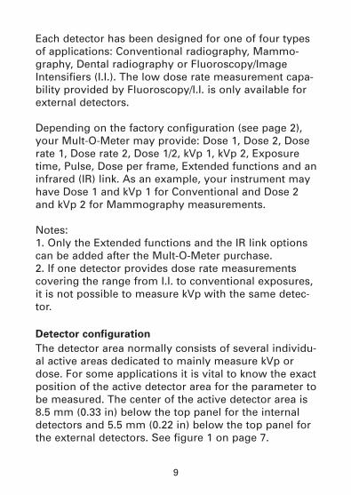
Each detector has been designed for one of four typesof applications: Conventional radiography, Mammo-graphy, Dental radiography or Fluoroscopy/ImageIntensifiers (I.I.). The low dose rate measurement capa-bility provided by Fluoroscopy/I.I. is only available forexternal detectors.
Depending on the factory configuration (see page 2),your Mult-O-Meter may provide: Dose 1, Dose 2, Doserate 1, Dose rate 2, Dose 1/2, kVp 1, kVp 2, Exposuretime, Pulse, Dose per frame, Extended functions and aninfrared (IR) link. As an example, your instrument mayhave Dose 1 and kVp 1 for Conventional and Dose 2and kVp 2 for Mammography measurements.
Notes:1. Only the Extended functions and the IR link optionscan be added after the Mult-O-Meter purchase.2. If one detector provides dose rate measurementscovering the range from I.I. to conventional exposures,it is not possible to measure kVp with the same detec-tor.
Detector configuration
The detector area normally consists of several individu-al active areas dedicated to mainly measure kVp ordose. For some applications it is vital to know the exactposition of the active detector area for the parameter tobe measured. The center of the active detector area is8.5 mm (0.33 in) below the top panel for the internaldetectors and 5.5 mm (0.22 in) below the top panel forthe external detectors. See figure 1 on page 7.
10
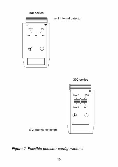
Dose kVp
Dose 2 kVp 2
Dose 1 kVp 1
a) 1 internal detector
b) 2 internal detectors
300 series
300 series
Figure 2. Possible detector configurations.
11
Dose 1
Dose 2
Green
*
kVp 1
kVp 2
2Dose 2
Dose 1
*
kVp 2
kVp 1
1
Blue
c) 1 internal and 1 external detector
d) 1 internal and 1 external detector
400 series
400 series
12
Dose
*
kVp Blue
1
Dose 2
*
kVp 2
Dose 1
*
kVp 1
Green
2
Blue
1
e) 1 external detector
f) 2 external detector
500 series
500 series
* Not included insome models(dental etc.)
13
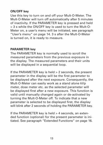
ON/OFF key
Use this key to turn on and off your Mult-O-Meter. TheMult-O-Meter will turn off automatically after 5 minutesof inactivity. If the PARAMETER key is pressed and held> 3 s while the ON/OFF key is used to turn the Mult-O-Meter on, a user’s menu will be initiated, see paragraph“User’s menu“ on page 14. 3 s after the Mult-O-Meteris turned on, it is ready to measure.
PARAMETER key
The PARAMETER key is normally used to scroll themeasured parameters from the previous exposure inthe display. The measured parameters and their unitswill be displayed in a sequential loop.
If the PARAMETER key is held > 2 seconds, the presentparameter in the display will be the first parameter tobe displayed after the next exposure. Consequently, theMult-O-Meter can easily work as a stand alone kVpmeter, dose meter etc. as the selected parameter willbe displayed first after a new exposure. This function isvalid until manually changed again or de-activated byturning the Mult-O-Meter off. To indicate that a newparameter is selected to be displayed first, the displaywill blink after 2 seconds of holding the PARAMETER key.
If the PARAMETER key is held > 4 seconds, an exten-ded function (optional) for the present parameter is ini-tiated. See paragraph “Extended Functions“ on page 16.
14
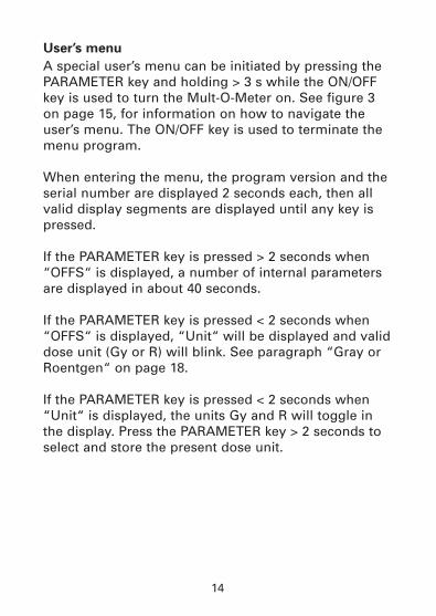
User’s menu
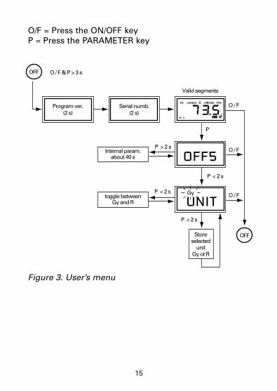
A special user’s menu can be initiated by pressing thePARAMETER key and holding > 3 s while the ON/OFFkey is used to turn the Mult-O-Meter on. See figure 3on page 15, for information on how to navigate theuser’s menu. The ON/OFF key is used to terminate themenu program.
When entering the menu, the program version and theserial number are displayed 2 seconds each, then allvalid display segments are displayed until any key ispressed.
If the PARAMETER key is pressed > 2 seconds when“OFFS“ is displayed, a number of internal parametersare displayed in about 40 seconds.
If the PARAMETER key is pressed < 2 seconds when“OFFS“ is displayed, “Unit“ will be displayed and validdose unit (Gy or R) will blink. See paragraph “Gray orRoentgen“ on page 18.
If the PARAMETER key is pressed < 2 seconds when“Unit“ is displayed, the units Gy and R will toggle inthe display. Press the PARAMETER key > 2 seconds toselect and store the present dose unit.
15
Program ver.(2 s)
Serial numb.(2 s)
Valid segments
O / F
P
O / F & P > 3 sOFF
O / F
O / F
Internal param.about 40 s
toggle betweenGy and R
OFF
P < 2 s
P < 2 s
P > 2 s
P > 2 s
Storeselected
unitGy ot R
Gy
kVpmR/min
m s
µmGy/s1/2
OFF5
UNIT
O/F = Press the ON/OFF keyP = Press the PARAMETER key
Figure 3. User’s menu
16
Extended functions (option)
Three extended functions can be added when measuring.
1. measuring delay (for kVp)2. 75 % trigger level (for exposure time)3. normalization (for dose)
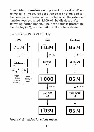
Each extended function is individually activated (andde-activated) by pressing the PARAMETER key > 4seconds, when the corresponding parameter is in thedisplay. See figure 4 on page 17 for information how tonavigate the extended function menu. The extendedfunction for each parameter is:kVp: Select measuring delay 5, 50 or 150 ms. The mea-surement of kVp starts after the selected delay. Thedelay is calculated from the time the exposure timestarts to be measured. The default delay value of 5 msis restored whenever the Mult-O-Meter is turned on. Exposure time: Select the start trigger level between a“low“ radiation (always valid when the Mult-O-Meter isturned on) and a value corresponding to 75 % of thekVp from the previous exposure, see figure 8 on page 28. When 75 % trigger level is selected, timing starts at alevel corresponding to 75 % of the kVp that was mea-sured during the previous exposure, rather than the”low” radiation. Selecting the 75 % trigger level alsofreezes the optimum measuring range that was deter-mined during the previous exposure, thereby de-activat-ing the auto-ranging. The defaults of ”low” radiationand auto-ranging are always restored whenever theMult-O-Meter is turned on. For all exposures, exposuretime terminates at a level corresponding to 75 % of thekVp measured during the present exposure.
17
Dose: Select normalization of present dose value. Whenactivated, all measured dose values are normalized tothe dose value present in the display when the extendedfunction was activated. 1.000 will be displayed afteractivating normalization. If no dose value is present inthe display (= 0), normalization will not be activated.
P = Press the PARAMETER key
Valid delaynor / On
x 2
nor / OFFx 2
kVp Dose
P > 4 s P > 4 s
P > 4 s
P < 2 s P > 2 s
Togglebetween5, 50,150ms delay
Storedisplayed
delay
kVp
m s
m s
µmGy
70.4 1.034
1.000
µmGy
1.034
75 Pr / Onx 2
75 Pr / OFFx 2
Exp. time
P > 4 s
P > 4 s
85.4
m s85.4
m s85.4
Figure 4. Extended functions menu.
18
Gray or Roentgen
Either Gray [Gy, Gy/s] or Roentgen [R, R/min] units maybe selected for dose and dose rate measurements.Selection of dose units is possible at any time and oncechanged will stay valid until manually changed again. Tochange the dose unit use the ”user’s menu” as explain-ed on page 15 and diagrammed in figure 3. The con-version factor between Gy and R is set to 1 Gy = 115 R.The Mult-O-Meter is originally calibrated in Gy and Gy/s.
19
PRINCIPLES OF OPERATION
General
The Mult-O-Meter is capable of measuring a combina-tion of several X-ray parameters described in the fol-lowing paragraphs. The methods to measure the para-meters will be individually explained.
The Mult-O-Meter may be configured with a wide varie-ty of detector combinations, measurement modes andoptions. The characteristics of your Mult-O-Meter aredetailed on page 2 of this manual. In the case whereyour Mult-O-Meter has multiple detectors, the parame-ters installed for your Mult-O-Meter will be measured,calculated and displayed for the detector that is irradia-ted. If both detectors are irradiated simultaneously,only the kVp and dose values corresponding to actualkVp range will be displayed. The automatic selection ofcorrect dose and kVp measuring range is only possibleif the kVp parameters are installed.
A new measurement will automatically reset allpreviously measured values. Directly after an exposureis finished, the new measured values are stored in theMult-O-Meter memory and also automatically transmit-ted via the infrared link. All stored values can bedisplayed by pressing the PARAMETER key.
The Mult-O-Meter is extremely easy to use, due to anumber of technical innovations:

20
After each exposure the Mult-O-Meter measures anumber of internal parameters for 2 s, to automaticallyadjust for temperature drift etc. To achieve maximumaccuracy, the first measurements may be neglectedafter the Mult-O-Meter has been turned on.
The Mult-O-Meter uses a fast auto range technique, eli-minating the need to manually find an optimum mea-suring range. Initially it takes some time, depending onthe signal amplitude, to find the optimum measuringrange for each parameter to be measured. The higheramplitude, the longer time to find the optimum mea-suring range. The maximum time is 1.6 ms (typically <1 ms). Consequently, measuring one short pulse inauto range (< 5 ms), may result in a displayed dosevalue that is lower than the true dose, but the followingpulses will be measured with the optimum range. Byactivating the “Extended function - 75 % trigger level“,the auto range technique is de-activated and the opti-mum range selected at the previous exposure will bevalid. Even single short pulses (< 5 ms) will then bemeasured with the highest accuracy.
The Mult-O-Meter has a trigger function in each instal-led detector. The dose sensor is the primary triggersource. The kVp sensor is the trigger source if dose isnot installed. The trigger level is up to two times higherthan the lower limit of the dose rate range for the irra-diated dose sensor. For the kVp sensor, the trigger levelis 2-6 times (kV dependent) lower than the lowest mea-surable signal level. It is possible to measure below thetrigging dose rate intensity.
21
kVp
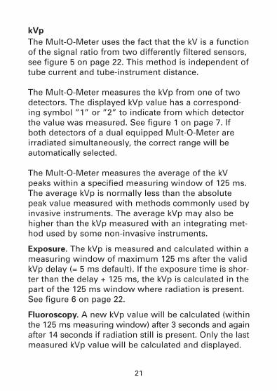
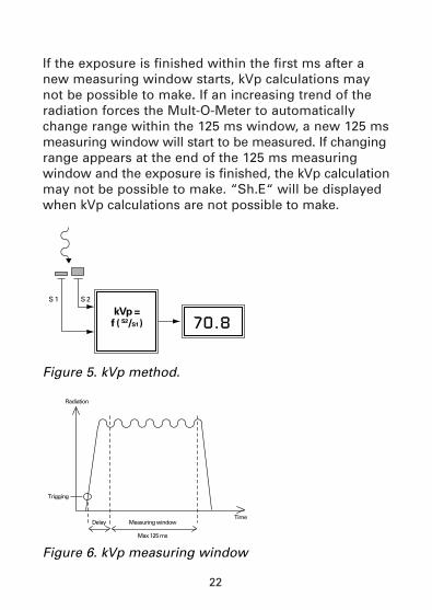
The Mult-O-Meter uses the fact that the kV is a functionof the signal ratio from two differently filtered sensors,see figure 5 on page 22. This method is independent oftube current and tube-instrument distance.
The Mult-O-Meter measures the kVp from one of twodetectors. The displayed kVp value has a correspond-ing symbol ”1” or ”2” to indicate from which detectorthe value was measured. See figure 1 on page 7. Ifboth detectors of a dual equipped Mult-O-Meter areirradiated simultaneously, the correct range will beautomatically selected.
The Mult-O-Meter measures the average of the kVpeaks within a specified measuring window of 125 ms.The average kVp is normally less than the absolutepeak value measured with methods commonly used byinvasive instruments. The average kVp may also behigher than the kVp measured with an integrating met-hod used by some non-invasive instruments.
Exposure. The kVp is measured and calculated within ameasuring window of maximum 125 ms after the validkVp delay (= 5 ms default). If the exposure time is shor-ter than the delay + 125 ms, the kVp is calculated in thepart of the 125 ms window where radiation is present.See figure 6 on page 22.
Fluoroscopy. A new kVp value will be calculated (withinthe 125 ms measuring window) after 3 seconds and againafter 14 seconds if radiation still is present. Only the lastmeasured kVp value will be calculated and displayed.
22
If the exposure is finished within the first ms after anew measuring window starts, kVp calculations maynot be possible to make. If an increasing trend of theradiation forces the Mult-O-Meter to automaticallychange range within the 125 ms window, a new 125 msmeasuring window will start to be measured. If changingrange appears at the end of the 125 ms measuring window and the exposure is finished, the kVp calculationmay not be possible to make. “Sh.E“ will be displayedwhen kVp calculations are not possible to make.
70.8kVp =f ( S2/S1 )
S 1 S 2
Radiation
Trigging
Delay Measuring window
Max 125 ms
Time
Figure 6. kVp measuring window
Figure 5. kVp method.
23
Dose
The Mult-O-Meter measures the dose from one or twodetectors. The displayed dose value has a correspon-ding symbol “1“ or “2“ to indicate from which detectorthe value was measured. See figure 1 on page 7. Ifboth detectors are irradiated simultaneously, only thedose value corresponding to the actual kVp range willbe displayed. The automatic selection of correct dosemeasuring range, is only possible if the kVp parame-ters are installed.
Dose measurements begins when the exposure timertriggers, see paragraph ”Exposure Time” on page 27,and stops when radiation is not detected for a timeinterval exceeding 100 ms.
There are a number of clear advantages using siliconinstead of ion chambers as radiation detectors. TheMult-O-Meter dose detectors are based on sealed sili-con, and an accurate result without corrections will bedisplayed within seconds.
1. The detectors are designed in a unique configurationwhich minimizes energy dependence problems, seeenergy dependence graphs under paragraph“Specifications“ on page 50.
2. There is a signal trigger level for dose measurements,see last paragraph on page 20. If no, or very low radia-tion is present, the measured dose value will not change,and hence no zero adjustment is required.
24
3. The Mult-O-Meter’s sealed silicon detectors havebeen engineered to make the dose measurement inde-
pendent of pressure and temperature corrections.
4. The detectors are mechanically stable and the Mult-O-Meter does not need to be handled with the samecare as an ion chamber.
5. The detectors are lead shielded, which prevents scat-
tered radiation from influencing the measurement,wherever the detector is positioned.
6. The high sensitivity to radiation of the silicon volu-me, allows a small size of the detector. Consequentlymeasurements in cassette holders, on image intensifi-ers, etc. are possible.
7. No bias voltage is required for the detectors.
25
Dose rate
The Mult-O-Meter measures the dose rate from one ortwo detectors. The displayed dose rate value has a cor-responding symbol “1“ or “2“ to indicate from whichdetector the value was measured, see figure 1 on page7. If both detectors are irradiated simultaneously, onlythe dose rate value corresponding to the actual kVprange will be displayed. The automatic selection ofcorrect dose rate measuring range, is only possible ifthe kVp parameters are installed.
Dose rate measurements begins when the exposuretimer triggers, see paragraph ”Exposure time” on page27. Dose rate continues to be measured until a deadtime interval > 100 ms is detected. After 4 seconds (forfluoroscopy), the dose rate from detector 1 is calcula-ted and displayed once every second.
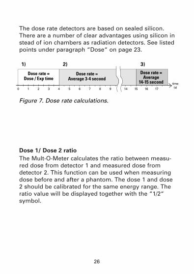
The stored and displayed dose rate after the radiationis finished, is calculated differently depending on thelength of the exposure time. See figure 7 on page 26.
1) For exposure time < 4 seconds: The dose rate = Dose / Exposure time
2) For exposure time > 4 seconds and < 15 seconds: The average dose rate between the 3rd and 4th second.
3) For exposure time > 15 seconds: The average dose rate between the 14th and 15th second.
26
The dose rate detectors are based on sealed silicon.There are a number of clear advantages using silicon instead of ion chambers as radiation detectors. See listedpoints under paragraph “Dose“ on page 23.
Dose 1/ Dose 2 ratio
The Mult-O-Meter calculates the ratio between measu-red dose from detector 1 and measured dose fromdetector 2. This function can be used when measuringdose before and after a phantom. The dose 1 and dose2 should be calibrated for the same energy range. Theratio value will be displayed together with the “1/2“symbol.
0 1
1) 2) 3)
2 3 4 5 6 7 8 9 14 15 16 17
time (s)
Dose rate = Dose / Exp time
Dose rate = Average 3-4 second
Dose rate = Average
14-15 second
Figure 7. Dose rate calculations.
27
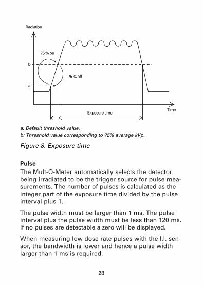
Exposure Time
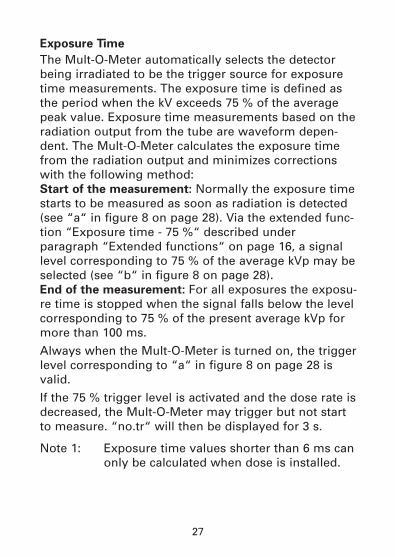
The Mult-O-Meter automatically selects the detectorbeing irradiated to be the trigger source for exposuretime measurements. The exposure time is defined asthe period when the kV exceeds 75 % of the averagepeak value. Exposure time measurements based on theradiation output from the tube are waveform depen-dent. The Mult-O-Meter calculates the exposure timefrom the radiation output and minimizes correctionswith the following method:Start of the measurement: Normally the exposure timestarts to be measured as soon as radiation is detected(see “a“ in figure 8 on page 28). Via the extended func-tion “Exposure time - 75 %“ described underparagraph “Extended functions“ on page 16, a signallevel corresponding to 75 % of the average kVp may beselected (see “b“ in figure 8 on page 28).End of the measurement: For all exposures the exposu-re time is stopped when the signal falls below the levelcorresponding to 75 % of the present average kVp formore than 100 ms.
Always when the Mult-O-Meter is turned on, the triggerlevel corresponding to “a“ in figure 8 on page 28 isvalid.
If the 75 % trigger level is activated and the dose rate isdecreased, the Mult-O-Meter may trigger but not startto measure. “no.tr“ will then be displayed for 3 s.
Note 1: Exposure time values shorter than 6 ms canonly be calculated when dose is installed.
28
Pulse
The Mult-O-Meter automatically selects the detectorbeing irradiated to be the trigger source for pulse mea-surements. The number of pulses is calculated as theinteger part of the exposure time divided by the pulseinterval plus 1.
The pulse width must be larger than 1 ms. The pulseinterval plus the pulse width must be less than 120 ms.If no pulses are detectable a zero will be displayed.
When measuring low dose rate pulses with the I.I. sen-sor, the bandwidth is lower and hence a pulse widthlarger than 1 ms is required.
Radiation
75 % on
75 % off
a
b
Exposure timeTime
a: Default threshold value.b: Threshold value corresponding to 75% average kVp.
Figure 8. Exposure time
29
Dose per frame
The Mult-O-Meter automatically selects the detectorbeing irradiated to be the trigger source for dose perframe measurements. The dose per frame is calculatedas the total dose divided by the number of pulses. Ifboth detectors are irradiated, dose 1 per frame will becalculated and displayed.
IR (= Infra Red) link
After an exposure is finished, all measured and instal-led values (with units) are automatically sent via the IRtransmitter from the side of the Mult-O-Meter. Thereceiver should be positioned within 0.5 m (20 in) fromthe Mult-O-Meter side and at an angle of +/- 15°.
Data is transmitted as ASCII characters with the following specifications:Baud rate: 9600Data bits: 8Parity: NoneStopbits: 2
Unfors Instruments offers a PC program which collectsthe measured data and exports it in EXCEL™ format forfurther calculations.
30
MEASUREMENT HINTS
kVp
General: Always try to position the Mult-O-Meter detec-tor(s) as close to the tube focus as possible. The signalto noise ratio is then the highest possible and thisassures the best measurement reproducibility. If adisplay code of “Hi Si“ occurs, increase the tube focusto instrument distance. The entire detector area mustbe irradiated to provide accurate results. The Mult-O-Meter is calibrated with total tube filtrations equivalentto 3 (or 2.5) mm Al for the 45-150 kV range and 30 mmfor the 24-40 kV range. If measurements are performedat other tube filtration’s (for instance CT equipment) acorrection factor according to filtration dependencegraphs on page 47 must be added.
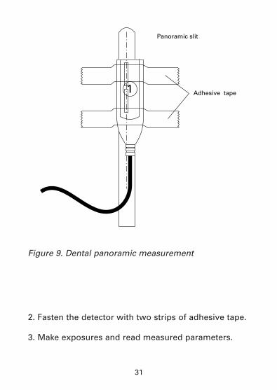
Dental panorama: When measuring on panoramic X-rayequipment, the entire detector area must be irradiatedto provide accurate results. The width of the X-raybeam, at the film cassette holder of the X-ray equip-ment, may be as narrow as 2.5 mm (0.1 in). The widthof the active detector area in the Mult-O-Meter is 1.5mm (0.6 in). Due to mechanical intolerance’s the indica-ted detector width on the outside panel of the Mult-O-Meter is 2.0 mm (0.8 in).
Measurement procedure:1. Position the Mult-O-Meter detector on the slit of thefilm cassette holder. Carefully center the detector to theexpected middle of the X-ray beam. The indicateddetector area must face the X-ray tube. See figure 9 onpage 31.
31
Figure 9. Dental panoramic measurement
2. Fasten the detector with two strips of adhesive tape.
3. Make exposures and read measured parameters.
Panoramic slit
Adhesive tape1
32
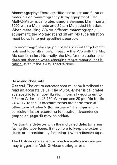
Mammography: There are different target and filtrationmaterials on mammography X-ray equipment. TheMult-O-Meter is calibrated using a Siemens Mammomat3000 with a Mo anode and 30 mm Mo added filtration.When measuring kVp on different mammographyequipment, the Mo target and 30 mm Mo tube filtrationmust be valid to get specified accuracy.
If a mammography equipment has several target mate-rials and tube filtration’s, measure the kVp with the Mo/Mo combination. Normally, the kVp for the equipmentdoes not change when changing target material or filt-ration, even if the X-ray spectra does.
Dose and dose rate
General: The entire detector area must be irradiated toread an accurate value. The Mult-O-Meter is calibratedat a specific total tube filtration, normally equivalent to 2.5 mm Al for the 45-150 kV range and 30 mm Mo for the24-40 kV range. If measurements are performed atother tube filtration’s (for instance CT equipment) acorrection factor according to filtration dependencegraphs on page 49 may be added.
Position the detector with the indicated detector areasfacing the tube focus. It may help to keep the externaldetector in position by fastening it with adhesive tape.
The I.I. dose rate sensor is mechanically sensitive andmay trigger the Mult-O-Meter during stress.
33
Please note that the dose mesurements begins whenthe exposure timing starts. Consequently, measure-ments using the extended function ”75% trigger level”may display a slightly smaller dose, see paragraph“Principles of operation/Exposure time“ on page 27.
Due to the auto range technique, the dose measuredon one short pulse (< 5 ms) may result in a displayeddose value lower than the true dose. By activating theextended function “75 % trigger level“, even short pul-ses will be more correctly measured.
Exposure time
If the exposure time is about 100 ms and the rise timeis about 1 ms, the threshold value for starting the mea-surement is not critical. The Mult-O-Meter selects a lowthreshold value when turned on.
The shorter the exposure is and/or longer the rise timeis, the more critical it is to select the threshold value tomeasure an accurate exposure time. The Mult-O-Metercan select a signal level corresponding to 75 % of theaverage kVp from the previous exposure as a startingthreshold value. The 75 % function can for instance beused when measuring on older single phase dentalequipment. It can be initiated in the extended functiondescribed under paragraph “Productdescription/Extended functions“ on page 16.
34
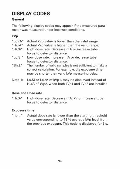
DISPLAY CODESGeneral
The following display codes may appear if the measured para-meter was measured under incorrect conditions.
kVp
“Lo.rA“ Actual kVp value is lower than the valid range.“Hi.rA“ Actual kVp value is higher than the valid range.“Hi.Si“ High dose rate. Decrease mA or increase tube
focus to detector distance.“Lo.Si“ Low dose rate. Increase mA or decrease tube
focus to detector distance.“Sh.E“ The number of valid samples is not sufficient to make a
correct calculation. For example, the exposure time may be shorter than valid kVp measuring delay.
Note 1: Lo.Si or Lo.rA of kVp1, may be displayed instead of Hi.rA of kVp2, when both kVp1 and kVp2 are installed.
Dose and Dose rate
“Hi.Si“ High dose rate. Decrease mA, kV or increase tube focus to detector distance.
Exposure time
“no.tr“ Actual dose rate is lower than the starting threshold value corresponding to 75 % average kVp level fromthe previous exposure. This code is displayed for 3 s.
35
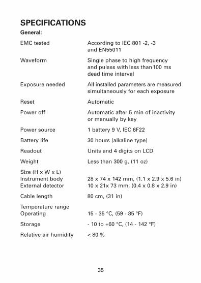
SPECIFICATIONSGeneral:
EMC tested According to IEC 801 -2, -3 and EN55011
Waveform Single phase to high frequency and pulses with less than100 ms dead time interval
Exposure needed All installed parameters are measuredsimultaneously for each exposure
Reset Automatic
Power off Automatic after 5 min of inactivity or manually by key
Power source 1 battery 9 V, IEC 6F22
Battery life 30 hours (alkaline type)
Readout Units and 4 digits on LCD
Weight Less than 300 g, (11 oz)
Size (H x W x L)Instrument body 28 x 74 x 142 mm, (1.1 x 2.9 x 5.6 in)External detector 10 x 21x 73 mm, (0.4 x 0.8 x 2.9 in)
Cable length 80 cm, (31 in)
Temperature rangeOperating 15 - 35 °C, (59 - 85 °F)
Storage - 10 to +60 °C, (14 - 142 °F)
Relative air humidity < 80 %
36
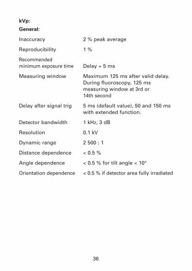
kVp:
General:
Inaccuracy 2 % peak average
Reproducibility 1 %
Recommended minimum exposure time Delay + 5 ms
Measuring window Maximum 125 ms after valid delay. During fluoroscopy, 125 ms measuring window at 3rd or 14th second
Delay after signal trig 5 ms (default value), 50 and 150 ms with extended function.
Detector bandwidth 1 kHz, 3 dB
Resolution 0.1 kV
Dynamic range 2 500 : 1
Distance dependence < 0.5 %
Angle dependence < 0.5 % for tilt angle < 10°
Orientation dependence < 0.5 % if detector area fully irradiated
37
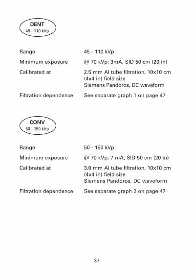
Range 45 - 110 kVp
Minimum exposure @ 70 kVp; 3mA, SID 50 cm (20 in)
Calibrated at 2.5 mm Al tube filtration, 10x10 cm (4x4 in) field sizeSiemens Pandoros, DC waveform
Filtration dependence See separate graph 1 on page 47
Range 50 - 150 kVp
Minimum exposure @ 70 kVp; 7 mA, SID 50 cm (20 in)
Calibrated at 3.0 mm Al tube filtration, 10x10 cm (4x4 in) field sizeSiemens Pandoros, DC waveform
Filtration dependence See separate graph 2 on page 47
CONV
50 - 150 kVp
DENT
45 - 110 kVp
38
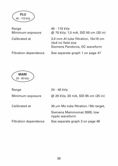
FLU
45 - 110 kVp
MAM
24 - 40 kVp
Range 45 - 110 kVpMinimum exposure @ 70 kVp; 1,5 mA, SID 50 cm (20 in)
Calibrated at 3.0 mm Al tube filtration, 10x10 cm (4x4 in) field sizeSiemens Pandoros, DC waveform
Filtration dependence See separate graph 1 on page 47
Range 24 - 40 kVp
Minimum exposure @ 28 kVp; 20 mA, SID 65 cm (25 in)
Calibrated at 30 mm Mo tube filtration / Mo target,
Siemens Mammomat 3000, low ripple waveform
Filtration dependence See separate graph 3 on page 48
39
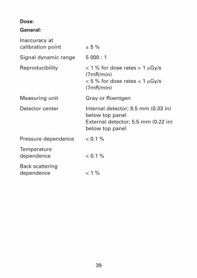
Dose:
General:
Inaccuracy at calibration point ± 5 %
Signal dynamic range 5 000 : 1
Reproducibility < 1 % for dose rates > 1 mGy/s (7mR/min)< 5 % for dose rates < 1 mGy/s (7mR/min)
Measuring unit Gray or Roentgen
Detector center Internal detector; 8.5 mm (0.33 in) below top panelExternal detector; 5.5 mm (0.22 in) below top panel
Pressure dependence < 0.1 %
Temperature dependence < 0.1 %
Back scattering dependence < 1 %
40
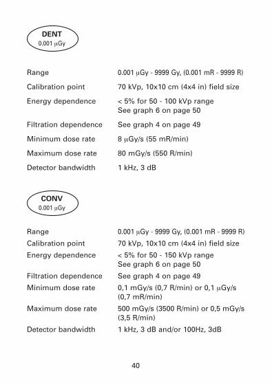
CONV
0.001 mGy
DENT
0.001 mGy
Range 0.001 mGy - 9999 Gy, (0.001 mR - 9999 R)
Calibration point 70 kVp, 10x10 cm (4x4 in) field size
Energy dependence < 5% for 50 - 100 kVp rangeSee graph 6 on page 50
Filtration dependence See graph 4 on page 49
Minimum dose rate 8 mGy/s (55 mR/min)
Maximum dose rate 80 mGy/s (550 R/min)
Detector bandwidth 1 kHz, 3 dB
Range 0.001 mGy - 9999 Gy, (0.001 mR - 9999 R)
Calibration point 70 kVp, 10x10 cm (4x4 in) field size
Energy dependence < 5% for 50 - 150 kVp rangeSee graph 6 on page 50
Filtration dependence See graph 4 on page 49
Minimum dose rate 0,1 mGy/s (0,7 R/min) or 0,1 mGy/s(0,7 mR/min)
Maximum dose rate 500 mGy/s (3500 R/min) or 0,5 mGy/s(3,5 R/min)
Detector bandwidth 1 kHz, 3 dB and/or 100Hz, 3dB
41
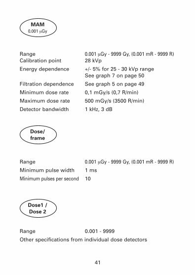
Range 0.001 mGy - 9999 Gy, (0.001 mR - 9999 R)Calibration point 28 kVp
Energy dependence +/- 5% for 25 - 30 kVp rangeSee graph 7 on page 50
Filtration dependence See graph 5 on page 49
Minimum dose rate 0,1 mGy/s (0,7 R/min)
Maximum dose rate 500 mGy/s (3500 R/min)
Detector bandwidth 1 kHz, 3 dB
Range 0.001 mGy - 9999 Gy, (0.001 mR - 9999 R)
Minimum pulse width 1 ms
Minimum pulses per second 10
Range 0.001 - 9999
Other specifications from individual dose detectors
MAM
0.001 mGy
Dose/
frame
Dose1 /
Dose 2
42
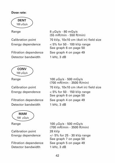
Dose rate:
Range 8 mGy/s - 80 mGy/s (55 mR/min - 550 R/min)
Calibration point 70 kVp, 10x10 cm (4x4 in) field sizeEnergy dependence < 5% for 50 - 100 kVp range
See graph 6 on page 50Filtration dependence See graph 4 on page 49Detector bandwidth 1 kHz, 3 dB
Range 100 mGy/s - 500 mGy/s (700 mR/min - 3500 R/min)
Calibration point 70 kVp, 10x10 cm (4x4 in) field sizeEnergy dependence < 5% for 50 - 150 kVp range
See graph 6 on page 50Filtration dependence See graph 4 on page 49Detector bandwidth 1 kHz, 3 dB
Range 100 mGy/s - 500 mGy/s (700 mR/min - 3500 R/min)
Calibration point 28 kVpEnergy dependence +/- 5% for 25 - 30 kVp range
See graph 7 on page 50Filtration dependence See graph 5 on page 49Detector bandwidth 1 kHz, 3 dB
DENT
100 mGy/s
CONV
100 mGy/s
MAM
100 mGy/s
43
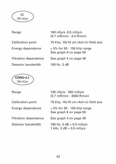
Range 100 nGy/s -0.5 mGy/s (0.7 mR/min - 3.4 R/min)
Calibration point 70 kVp, 10x10 cm (4x4 in) field size
Energy dependence < 5% for 50 - 150 kVp rangeSee graph 6 on page 50
Filtration dependence See graph 4 on page 49
Detector bandwidth 100 Hz, 3 dB
Range 100 nGy/s - 500 mGy/s (0.7 mR/min - 3500 R/min)
Calibration point 70 kVp, 10x10 cm (4x4 in) field size
Energy dependence < 5% for 50 - 150 kVp rangeSee graph 6 on page 50
Filtration dependence See graph 4 on page 49
Detector bandwidth 100 Hz, 3 dB < 0.5 mGy/s1 kHz, 3 dB > 0.5 mGy/s
I.I.
100 nGy/s
CONV+I.I.
100 nGy/s
44
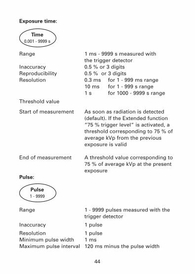
Exposure time:
Range 1 ms - 9999 s measured with the trigger detector
Inaccuracy 0.5 % or 3 digitsReproducibility 0.5 % or 3 digitsResolution 0.3 ms for 1 - 999 ms range
10 ms for 1 - 999 s range1 s for 1000 - 9999 s range
Threshold value
Start of measurement As soon as radiation is detected (default). If the Extended function “75 % trigger level“ is activated, a threshold corresponding to 75 % of average kVp from the previous exposure is valid
End of measurement A threshold value corresponding to 75 % of average kVp at the present exposure
Pulse:
Range 1 - 9999 pulses measured with the trigger detector
Inaccuracy 1 pulse
Resolution 1 pulseMinimum pulse width 1 msMaximum pulse interval 120 ms minus the pulse width
Pulse
1 - 9999
Time
0.001 - 9999 s
45
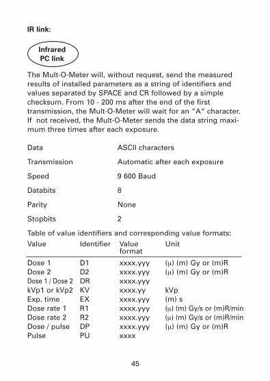
IR link:
The Mult-O-Meter will, without request, send the measuredresults of installed parameters as a string of identifiers andvalues separated by SPACE and CR followed by a simplechecksum. From 10 - 200 ms after the end of the firsttransmission, the Mult-O-Meter will wait for an “A“ character.If not received, the Mult-O-Meter sends the data string maxi-mum three times after each exposure.
Data ASCII characters
Transmission Automatic after each exposure
Speed 9 600 Baud
Databits 8
Parity None
Stopbits 2
Table of value identifiers and corresponding value formats:Value Identifier Value Unit
format
Dose 1 D1 xxxx.yyy (m) (m) Gy or (m)RDose 2 D2 xxxx.yyy (m) (m) Gy or (m)RDose 1 / Dose 2 DR xxxx.yyykVp1 or kVp2 KV xxxx.yy kVpExp. time EX xxxx.yyy (m) sDose rate 1 R1 xxxx.yyy (m) (m) Gy/s or (m)R/minDose rate 2 R2 xxxx.yyy (m) (m) Gy/s or (m)R/minDose / pulse DP xxxx.yyy (m) (m) Gy or (m)RPulse PU xxxx
Infrared
PC link
46
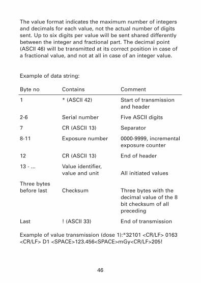
The value format indicates the maximum number of integersand decimals for each value, not the actual number of digitssent. Up to six digits per value will be sent shared differentlybetween the integer and fractional part. The decimal point(ASCII 46) will be transmitted at its correct position in case ofa fractional value, and not at all in case of an integer value.
Example of data string:
Byte no Contains Comment
1 * (ASCII 42) Start of transmission and header
2-6 Serial number Five ASCII digits
7 CR (ASCII 13) Separator
8-11 Exposure number 0000-9999, incrementalexposure counter
12 CR (ASCII 13) End of header
13 - ... Value identifier, value and unit All initiated values
Three bytes before last Checksum Three bytes with the
decimal value of the 8 bit checksum of all preceding
Last ! (ASCII 33) End of transmission
Example of value transmission (dose 1):*32101 <CR/LF> 0163<CR/LF> D1 <SPACE>123.456<SPACE>mGy<CR/LF>205!
47
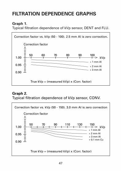
FILTRATION DEPENDENCE GRAPHS
Graph 1.
Typical filtration dependence of kVp sensor, DENT and FLU.
kVp50 60 70 80 90 100
+ 1 mm Al
+ 2 mm Al+ 3 mm Al
Correction factor
0.90
0.95
1.00
kVp50 13070 15090 110
+ 1 mm Al+ 2 mm Al+ 3 mm Al+ 0.1 mm Cu
Correction factor
0.90
0.95
1.00
Graph 2.
Typical filtration dependence of kVp sensor, CONV.
Correction factor vs. kVp (50 - 100). 2.5 mm Al is zero correction.
True kVp = (measured kVp) x (Corr. factor)
True kVp = (measured kVp) x (Corr. factor)
Correction factor vs. kVp (50 - 150). 3.0 mm Al is zero correction
48
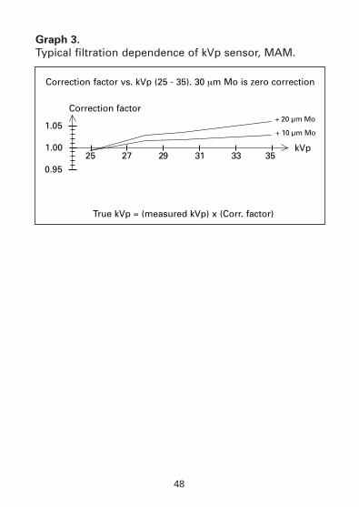
Graph 3.
Typical filtration dependence of kVp sensor, MAM.
kVp25 27 29 31 33 35
+ 20 µm MoCorrection factor
0.95
1.05
1.00
+ 10 µm Mo
Correction factor vs. kVp (25 - 35). 30 mm Mo is zero correction
True kVp = (measured kVp) x (Corr. factor)
49
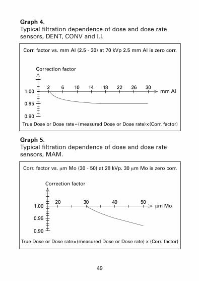
Graph 4.
Typical filtration dependence of dose and dose ratesensors, DENT, CONV and I.I.
Graph 5.
Typical filtration dependence of dose and dose ratesensors, MAM.
Correction factor
mm Al2
0.90
0.95
1.006 10 14 18 22 26 30
Correction factor
mm Mo20
0.90
0.95
1.0030 40 50
True Dose or Dose rate=(measured Dose or Dose rate)x(Corr. factor)
Corr. factor vs. mm Al (2.5 - 30) at 70 kVp 2.5 mm Al is zero corr.
True Dose or Dose rate=(measured Dose or Dose rate) x (Corr. factor)
Corr. factor vs. mm Mo (30 - 50) at 28 kVp. 30 mm Mo is zero corr.
50
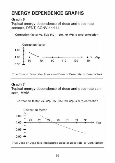
ENERGY DEPENDENCE GRAPHS
Graph 6.
Typical energy dependence of dose and dose rate sensors, DENT, CONV and I.I.
kVp50 13070 15090 110
Correction factor
0.95
1.00
1.05
kVp23 25 27 29 31 3533
Correction factor
0.90
0.95
1.00
1.05
Graph 7.
Typical energy dependence of dose and dose rate sen-sors, MAM.
True Dose or Dose rate=(measured Dose or Dose rate) x (Corr. factor)
Correction factor vs. kVp (40 - 150). 70 kVp is zero correction
True Dose or Dose rate=(measured Dose or Dose rate) x (Corr. factor)
Correction factor vs. kVp (25 - 35). 28 kVp is zero correction
51
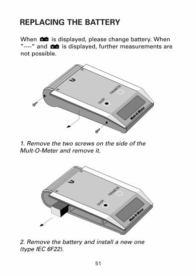
REPLACING THE BATTERY
ON/OFFPARAMETER
Mult-O-M
eter
ON/OFF
Mult-O-M
eter
PARAMETER
1. Remove the two screws on the side of the Mult-O-Meter and remove it.
2. Remove the battery and install a new one (type IEC 6F22).
When is displayed, please change battery. When ”----” and is displayed, further measurements arenot possible.

Uggledalsvägen 27, S-427 40 Billdal, SwedenPhone: +46 31 910952, Fax: +46 31 910950www.unfors.se