Embed Size (px)
Citation preview
Topic # 625-000-015
MANUAL OF UNIFORM MINIMUM STANDARDS FOR DESIGN, CONSTRUCTION AND MAINTENANCE
FOR STREETS AND HIGHWAYS (Commonly known as the "Florida Greenbook")
State of Florida Department of Transportation
MAY 2005 EDITION
Any updates to the Florida Greenbook will be posted on the FDOT Web Site at:
http://www.dot.state.fl.us/rddesign/Publications/pub.htm

USER REGISTRATION FORM
Manual of Uniform Minimum Standards for Design, Construction and
Maintenance for Streets and Highways (Commonly known as the "Florida Greenbook")
MAY – 2005
EDITION
To: “Florida Greenbook” Users In order to ensure you will receive notification of any future updates to this Manual, please complete the following.
Please print or type complete mailing address:
COMPANY: MANUAL HOLDER: ADDRESS: CITY: STATE: ZIP: PHONE: FAX: EMAIL:
Please return this original sheet to:
STATE ROADWAY DESIGN OFFICE 605 SUWANNEE STREET - MS #32
TALLAHASSEE, FLORIDA 32399-0450 FAX: (850) 414-5261
Or, email the above information to [email protected]
ANY QUESTIONS PLEASE CALL: (850) 414-4310

Topic # 625-000-015 May - 2005 Manual of Uniform Minimum Standards for Design, Construction and Maintenance for Streets and Highways
Table of Contents
TABLE OF CONTENTS
Florida Greenbook Committee Members Chapter Subcommittees Introduction Policy Objectives Definitions of Terms Chapter 1 Planning Chapter 2 Land Development Chapter 3 Geometric Design Chapter 4 Roadside Design Chapter 5 Pavement Design and Construction Chapter 6 Roadway Lighting Chapter 7 Rail-Highway Grade Crossings Chapter 8 Pedestrian Facilities Chapter 9 Bicycle Facilities Chapter 10 Maintenance Chapter 11 Work Zone Safety Chapter 12 Construction Chapter 13 Public Transit Chapter 14 Design Exceptions Chapter 15 Traffic Calming Chapter 16 Residential Street Design Chapter 17 Bridges and Other Structures

Topic # 625-000-015 May - 2005 Manual of Uniform Minimum Standards for Design, Construction and Maintenance for Streets and Highways
Table of Contents
THIS PAGE INTENTIONALLY LEFT BLANK
Topic # 625-000-015 May - 2005 Manual of Uniform Minimum Standards for Design, Construction and Maintenance for Streets and Highways
Committee Members
GREENBOOK COMMITTEE MEMBERS
MAY – 2005
DISTRICT 1
Bernie Masing, P.E. District Design Engineer FDOT - District 1 801 North Broadway Street Bartow, Florida 33830-1249 (863) 519-2543 FAX (863) 519-2892 [email protected]
Dennis Daughters, P.E. City Engineer/Director of Engineering City of Sarasota Post Office Box 1058 Sarasota, Florida 34230 (941) 954-4180 FAX (941) 954-4174 [email protected]
Ramon D. Gavarrete, P.E. County Engineer/Utilities Director Highlands County Board of County Commissioners 505 South Commerce Avenue Sebring, Florida 33870-3869 (863) 402-6877 FAX (863) 402-6548 [email protected]
Forrest Banks, P.E. Senior Project Manager Johnson Engineering, Inc. 2158 Johnson Street Fort Myers, Florida 33901 (239) 334-0046 FAX (239) 541-1383 [email protected]
DISTRICT 2
Jimmy Pitman, P.E. District Design Engineer FDOT - District 2 1901 South Marion Street Lake City, Florida 32025-5814 (386) 961-7583 FAX (386) 961-7809 [email protected]
William Lecher, P.E. Alachua County Public Works Department Post Office Box 1188 Gainesville, Florida 32602-1188 (352) 374-5245 FAX (352) 337-6243 [email protected]
Richard L. McCubbin, P.E. City Traffic Engineer City of Jacksonville 1007 Superior Street Jacksonville, Florida 32254 (904) 387-8953 FAX (904) 387-8894 [email protected]
David H. Evans, P.E. Associate Vice President HNTB Corporation 7707 Bonneval Road, Suite 600 Jacksonville, Florida 32216 (904) 296-0207 FAX (904) 279-0260 [email protected]
Topic # 625-000-015 May - 2005 Manual of Uniform Minimum Standards for Design, Construction and Maintenance for Streets and Highways
Committee Members
DISTRICT 3
Larry Kelley, P.E. District Design Engineer FDOT - District 3 Post Office Box 607 Chipley, Florida 32428 (850) 638-0250 FAX (850) 638-6148 [email protected]
Rick Hall, P.E. Hall Planning and Engineering, Inc. 1237 North Adams Street Tallahassee, Florida 32303 (850) 222-2277 FAX (850) 222-6555 [email protected]
Chuck Meister, P.E. City Engineer City of Destin 4200 Two Trees Road Destin, Florida 32541 (850) 837-4242 FAX (850) 837-3267 [email protected]
Roger A. Blaylock, P.E. County Engineer Santa Rosa County 6051 Old Bagdad Highway, Suite 300 Milton, Florida 32583 (850) 981-7100 FAX (850) 983-2161 [email protected]
DISTRICT 4
Howard Webb, P.E. District Design Engineer FDOT - District 4 3400 West Commercial Blvd Ft. Lauderdale, Florida 33309 (954) 777-4439 FAX (954) 777-4482 [email protected]
Tanzer Kalayci, P.E. President Keith & Schnars 6500 North Andrews Avenue Fort Lauderdale, Florida 33309 (954) 776-1616 FAX (954) 771-3636 [email protected]
James W. Davis, P.E. Public Works Director Indian River County 1840 25th Street Vero Beach, Florida 32960 (772) 567-8000 FAX (772) 778-9391 [email protected]
Henry P. Cook, P.E. Director Broward County Engineering Division One North University Drive, Suite 300B Plantation, Florida 33324 (954) 577-4567 FAX (954) 577-2338 [email protected]
Topic # 625-000-015 May - 2005 Manual of Uniform Minimum Standards for Design, Construction and Maintenance for Streets and Highways
Committee Members
DISTRICT 5
Annette Brennan, P.E. District Design Engineer FDOT - District 5 719 South Woodland Boulevard Deland, Florida 32720 (386) 943-5543 FAX (386) 736-5302 [email protected]
James E. Harrison, Esq., P.E. Director, Orange County Growth Management Department 201 S. Rosalind Avenue, 2nd Floor Orlando, Florida 32801 (407) 836-5312 FAX (407) 836-0995 [email protected]
James R. Sloane, P.E. Deputy Director of Public Works / City Engineer City of Daytona Beach Post Office Box 2451 Daytona Beach, Florida 32115-2451 (386) 671-8610 FAX (386) 671-8695 [email protected]
R. Craig Batterson, P.E. Principal Professional Engineering Consultants, Inc. 200 E. Robinson Street, Suite 1560 Orlando, Florida 32801 (407) 422-8062 FAX (407) 849-9401 [email protected]
DISTRICT 6
Harold Desdunes, P.E. District Design Engineer FDOT - District 6 1000 NW 111th Avenue Miami, Florida 33172 (305) 470-5250 FAX (305) 470 5338 [email protected]
Andres Garganta Principal / Director Consul-Tech Transportation, Inc. 10570 N.W. 27th Street, Suite 101 Miami, Florida 33172 (305) 599-3141 FAX (305) 599-3143 [email protected]
Gaspar Miranda, P.E. Chief, Highway Division Miami-Dade County Public Works Department 111 N.W. 1st Street, Suite 1510 Miami, Florida 33128 (305) 375-2130 FAX (305) 375-2548 [email protected]
Elyrosa Estevez, P.E. City of Miami Public Works Department 444 S.W. 2nd Avenue, 8th Floor Miami, Florida 33130 (305) 416-1217 FAX (305) 416-2153 [email protected]
Topic # 625-000-015 May - 2005 Manual of Uniform Minimum Standards for Design, Construction and Maintenance for Streets and Highways
Committee Members
DISTRICT 7
D. Dwayne Kile, P.E. District Design Engineer FDOT - District 7 11201 N. McKinley Drive Tampa, Florida 33612 (813) 975-6030 FAX (813) 975-6150 [email protected]
James Burnside, P.E. City of Tampa 306 East Jackson Street Tampa, Florida 33602 (813) 274-8054 FAX (813) 274-8901 [email protected]
Charles G. Mixson, P.E. DPW Director / County Engineer Hernando County 1525 E. Jefferson Street Brooksville, Florida 34601 (352) 754-4060 FAX (352) 754-4469 [email protected]
Richard Diaz, Jr., P.E. President Diaz Pearson & Associates, Inc. 1200 W. Platt Street, Suite 204 Tampa, Florida 33606 (813) 258-0444 FAX (813) 258-4440 [email protected]
ASSOCIATE MEMBERS
Chairperson State Roadway Design Engineer FDOT - Central Office 605 Suwannee St., MS 32 Tallahassee, Florida 32399-0450 (850) 414-4377 FAX (850) 414-5261
Dennis Scott State Pedestrian and Bicycle Coordinator FDOT - Central Office 605 Suwannee St., MS 53 Tallahassee, Florida 32399-0450 (850) 245-1527 FAX (850) 245-1554 [email protected]
Joy Puerta City Transportation Analyst City of Boca Raton, Municipal Services Dept. 201 West Palmetto Park Road Boca Raton, Florida 33432 (561) 416-3410 FAX (561) 416-3418 [email protected]
Robert F. Quigley, P.E. Roadway Design Engineer FDOT - Central Office 605 Suwannee St., MS 32 Tallahassee, Florida 32399-0450 (850) 414-4356 FAX (850) 414-5261 [email protected]

Topic # 625-000-015 May - 2005 Manual of Uniform Minimum Standards for Design, Construction and Maintenance for Streets and Highways
Committee Members
ASSOCIATE MEMBERS (Continued)
James A. Mills, P.E. Criteria & Standards Section Leader FDOT - Central Office 605 Suwannee St., MS 32 Tallahassee, Florida 32399-0450 (850) 414-4318 FAX (850) 414-5261 [email protected]
David F. Kuhlman Florida Power & Light Company Post Office Box 029100 Miami, Florida 33102-9100 (305) 552-2995 FAX (305) 228-5695 [email protected]
Melanie Weaver Carr Environmental Policy Coordinator Office of Policy Planning FDOT - Central Office 605 Suwannee St., MS 28 Tallahassee, Florida 32399-0450 (850) 414-4817 FAX (850) 488-3567 [email protected]
State Safety Engineer FDOT - Central Office 605 Suwannee St., MS 53 Tallahassee, Florida 32399-0450 (850) 245-1504 FAX (850) 245-1554
Joseph Santos, P.E. FDOT - Central Office 605 Suwannee Street, MS 19 Tallahassee, Florida 32399-0450 (850) 414-4909 FAX (850) 921-6361 [email protected]
Frederick J. Schneider, P.E. FACERS Representative Lake County Public Works 123 North Sinclair Avenue Tavares, Florida 32778 (352) 253-4944 FAX (352) 253-4915 [email protected]
Theo Petritsch, P.E. Senior Transportation Engineer Sprinkle Consulting, Inc. (SCI) 18115 US Highway 41 N. Suite 600 Lutz, Florida 33549 (813) 949-7449 FAX (813) 948-1712 [email protected]
Amy Datz Transit Planning/Design Program Manager FDOT - Central Office 605 Suwannee St., MS 26 Tallahassee, Florida 32399-0450 (850) 414-4239 FAX (850) 414-4508 [email protected]
Topic # 625-000-015 May - 2005 Manual of Uniform Minimum Standards for Design, Construction and Maintenance for Streets and Highways
Committee Members
ASSOCIATE MEMBERS (Continued)
Billy L. Hattaway, P.E. Vice President, Hall Planning & Engineering, Inc. 1237 North Adams Street Tallahassee, Florida 32303 (850) 222-2277 FAX (850) 222-6555 [email protected]
David C. O'Hagan, P.E. Assistant State Structures Design Engineer FDOT - Central Office 605 Suwannee St., MS 33 Tallahassee, Florida 32399-0450 (850) 414-4283 FAX (850) 414-4955 [email protected]
William N. Nickas, P.E. State Structures Design Engineer FDOT - Central Office 605 Suwannee St., MS 33 Tallahassee, Florida 32399-0450 (850) 414-4255 FAX (850) 414-4955 [email protected] Duane Brautigam, P.E. State Specifications Engineer FDOT - Central Office 605 Suwannee St., MS 75 Tallahassee, FL 32399-0450 (850) 414-4110 FAX (850) 414-4199 [email protected]
Allen W. Schrumpf, P.E. T2 Representative Senior Associate DRMP, Inc. 1505 East Colonial Drive Orlando, Florida 32803 (407) 897-0594 FAX (407) 896-4836 [email protected]
Topic # 625-000-015 May - 2005 Manual of Uniform Minimum Standards for Design, Construction and Maintenance for Streets and Highways
Committee Members
CHAPTER SUBCOMMITTEES
Chapter Chapter Author 1. Planning .............................................................................................Joseph Santos 2. Land Development ................................................................................James Davis 3. Geometric Design .............................................................................. Chuck Meister 4. Roadside Design.............................................................................. James Harrison 5. Pavement Design and Construction...................................................... Dwayne Kile 6. Roadway Lighting............................................................................... Bernie Masing 7. Rail-Highway Grade Crossings ...........................................................Jimmy Pitman 8. Pedestrian Facilities ................................................................................. Joy Puerta 9. Bicycle Facilities ....................................................................................... Joy Puerta 10. Maintenance........................................................................................James Sloane 11. Work Zone Safety ..................................................................... Frederick Schneider 12. Construction .......................................................................................Tanzer Kalayci 13. Public Transit ................................................................................. Annette Brennan 14. Design Exceptions.........................................................................Ramon Gavarrete 15. Traffic Calming ....................................................................................... Henry Cook 16. Residential Street Design................................................................. James Harrison 17. Bridges and Other Structures............................................................ David O'Hagan

Topic # 625-000-015 May - 2005 Manual of Uniform Minimum Standards for Design, Construction and Maintenance for Streets and Highways
Committee Members
THIS PAGE INTENTIONALLY LEFT BLANK
Topic # 625-000-015 May - 2005 Manual of Uniform Minimum Standards for Design, Construction and Maintenance for Streets and Highways
Introduction i
INTRODUCTION
The purpose of this Manual is to provide uniform minimum standards and criteria for the design, construction, and maintenance of all public streets, roads, highways, bridges, sidewalks, curbs and curb ramps, crosswalks (where feasible), bicycle facilities, underpasses, and overpasses used by the public for vehicular and pedestrian traffic as directed by Sections 334.044(10)(a) and 336.045, Florida Statutes.
In the following statutory excerpts, the term "Department" refers to the Florida Department of Transportation.
Section 334.044, Florida Statutes. Department; powers and duties. The department shall have the following general powers and duties: (10)(a) To develop and adopt uniform minimum standards and criteria for the design, construction, maintenance, and operation of public roads pursuant to the provisions of Section, 336.045, Florida Statutes.
Section 336.045, Florida Statutes. Uniform minimum standards for design, construction, and maintenance; advisory committees. (1) The department shall develop and adopt uniform minimum standards and criteria for the design, construction, and maintenance of all public streets, roads, highways, bridges, sidewalks, curbs and curb ramps, crosswalks, where feasible, bicycle ways, underpasses and overpasses used by the public for vehicular and pedestrian traffic. In developing such standards and criteria, the department shall consider design approaches which provide for the compatibility of such facilities with the surrounding natural or manmade environment; the safety and security of public spaces; and the appropriate aesthetics based upon scale, color, architectural style, materials used to construct the facilities, and the landscape design and landscape materials around the facilities....
(4) All design and construction plans for projects that are to become part of the county road system and are required to conform with the design and construction standards established pursuant to subsection (1) must be certified to be in substantial conformance with the standards established pursuant to subsection (1) that are then in effect by a professional engineer who is registered in this state.
These standards are intended to provide basic guidance for developing and maintaining a highway system with reasonable operating characteristics and a minimum number of hazards.

Topic # 625-000-015 May - 2005 Manual of Uniform Minimum Standards for Design, Construction and Maintenance for Streets and Highways
Introduction ii
Standards established by this Manual are intended for use on all new construction projects off the state highway and federal aid systems. It is understood that the standards herein cannot be applied completely to all reconstruction and maintenance type projects. However, the standards shall be applied to the extent that economic and environmental considerations and existing development will allow.
When this Manual refers to guidelines and design standards given by current American Association of State Highway and Transportation Officials (AASHTO) publications, these guidelines and standards shall generally be considered as minimum criteria. The Department may have standards and criteria that differ from the minimum presented in this Manual or by AASHTO for streets and highways under its jurisdiction. A county or municipality may substitute standards and criteria adopted by the Department for some or all portions of design, construction, and maintenance of their facilities. Department standards, criteria, and manuals must be used when preparing projects on the state highway system or the national highway system.
Criteria and standards set forth in other manuals, which have been incorporated by reference, shall be considered as requirements within the authority of this Manual.
This Manual is intended for use by qualified engineering practitioners for the communication of standards and criteria (including various numerical design values and use conditions). The design, construction, and maintenance references for the infrastructure features contained in this Manual recognize many variable and often complex process considerations. The engineering design process, and hence the associated use of this Manual, incorporates aspects of engineering judgment, design principles, science, and recognized standards towards matters involving roadway infrastructure.
Users of this Manual are cautioned that the strict application of exact numerical values, conditions or use information taken from portions of the text may not be appropriate for all circumstances. Individual references to design values or concepts should not be used out of context or without supporting engineering judgment.
The contents of this Manual are reviewed annually by the Florida "Greenbook" Advisory Committee. Membership of this committee is established by the above referenced Section 336.045(2), Florida Statutes. Notification of revisions or additions to the Manual will be distributed to all registered Manual holders and dated. Comments, suggestions, or questions may be directed to any committee member.
Topic # 625-000-015 May - 2005 Manual of Uniform Minimum Standards for Design, Construction and Maintenance for Streets and Highways
Policy and Objectives iii
POLICY
Specific policies governing the activities of planning, design, construction, reconstruction, maintenance, or operation of streets and highways are listed throughout this Manual. All agencies and individuals involved in these activities shall be governed by the following general policies:
• Each public street and highway, and all activities thereon, shall be assigned to the jurisdiction of some highway agency. Each highway agency should establish and maintain a program to promote safety in all activities on streets and highways under its jurisdiction.
• Highway safety shall be considered and given a high priority in order to promote the achievement of the maximum safety benefits for given expenditures and efforts.
• The provision for safe, high-quality streets and highways, and maximum transit opportunities should take priority over the provision for the maximum highway mileage obtainable for the available funds.
OBJECTIVES
The planning, design, construction, reconstruction, maintenance, and operation of streets and highways should be predicated upon meeting the following objectives:
• Develop and maintain a highway system that provides the safest practicable environment for motorists, cyclists, pedestrians, and workers.
• Establish and maintain procedures for construction, maintenance, utility, and emergency operations that provide for safe highway and transit operating conditions during these activities.
• Provide streets and highways with operating characteristics that allow for reasonable limitations upon the capabilities of vehicles, drivers, cyclists, pedestrians, and workers.
• Provide uniformity and consistency in the design and operation of streets and highways.
Topic # 625-000-015 May - 2005 Manual of Uniform Minimum Standards for Design, Construction and Maintenance for Streets and Highways
Policy and Objectives iv
• Provide for satisfactory resolution of conflicts between the surface transportation system and social and environmental considerations to aid neighborhood integrity.
• Reconstruct or modify existing facilities to reduce the hazard to the highway users.
• Reduce the deaths, injuries, and damage due to highway crashes.
Additional general and specific objectives related to various topics and activities are listed throughout this Manual. Where specific standards or recommendations are not available or applicable, the related objectives shall be utilized as general guidelines.
Topic # 625-000-015 May - 2005 Manual of Uniform Minimum Standards for Design, Construction, and Maintenance for Streets and Highways
Definitions of Terms v
DEFINITIONS OF TERMS
The following terms shall, for the purpose of this Manual, have the meanings respectively ascribed to them, except instances where the context clearly indicates a different meaning.
ADT - Average daily two-way volume of traffic.
AUXILIARY LANE - A designated width of roadway pavement marked to separate speed change, turning, passing, and climbing maneuvers from through traffic. It may provide short capacity segment.
AVERAGE RUNNING SPEED - For all traffic, or component thereof, the summation of distances divided by the summation of running times.
BICYCLE LANE (BIKE LANE) - A portion of a roadway (typically 4-5 ft) which has been designated by signing and pavement markings for the preferential or exclusive use by bicyclists.
BUS STOP PAD - A firm stable surface that accommodates passenger movement on or off a bus.
CLEAR ZONE - The total roadside border area starting at the edge of the motor vehicle travel lane, available for safe use by errant vehicles. This area may consist of a shoulder, a recoverable slope, a non-recoverable slope, and/or a clear runout area. The desired width is dependent upon the traffic volumes and speeds, and on the roadside geometry. Note: The aforementioned "border area" is not the same as "border width". Also, see Horizontal Clearance.
DHV - Design hourly two-way volume of traffic.
Topic # 625-000-015 May - 2005 Manual of Uniform Minimum Standards for Design, Construction, and Maintenance for Streets and Highways
Definitions of Terms vi
DESIGN SPEED - A selected rate of travel used to determine the various geometric features of the roadway.
EXPRESSWAY - A divided arterial highway for through traffic with full or partial control of access and generally with grade separations at major intersections.
FREEWAY - An expressway with full control of access.
FRONTAGE ROAD - A street or highway constructed adjacent to a higher classification street or other roadway network for the purpose of serving adjacent property or control access.
GRADE SEPARATION - A crossing of two roadways or a roadway and a railroad or pedestrian pathway at different levels.
HIGH SPEED - Speeds of 50 mph or greater.
HIGHWAY, STREET, OR ROAD - General terms, denoting a public way for purposes of traffic, both vehicular and pedestrian, including the entire area within the right of way. The term street is generally used for urban or suburban areas.
HORIZONTAL CLEARANCE - Lateral distance from edge of motor vehicle travel lane to a roadside object or feature.
INTERSECTION - The general area where two or more streets or highways join or cross.
Topic # 625-000-015 May - 2005 Manual of Uniform Minimum Standards for Design, Construction, and Maintenance for Streets and Highways
Definitions of Terms vii
MAY - A permissive condition. Where "may" is used, it is considered to denote permissive usage.
NEW CONSTRUCTION - The construction of any public road facility (paved or unpaved) where none previously existed, or the act of paving any previously unpaved road, except as provided in Chapter 3, Section A of these standards.
OPERATING SPEED - The rate of travel at which vehicles are observed traveling during free-flow conditions.
PUBLIC TRANSIT - Passenger transportation service, local or regional in nature, that is available to any person. Public transit includes bus, light rail, and rapid transit.
RECONSTRUCTION - Any road construction other than new construction.
RECOVERY AREA - Generally synonymous with clear zone.
RESIDENTIAL STREETS - Streets primarily serving residential access to the commercial, social, and recreational needs of the community. These are generally lower volume and lower speed facilities than the primary arterial and collector routes of the local system "or as adopted by local government ordinance".
Topic # 625-000-015 May - 2005 Manual of Uniform Minimum Standards for Design, Construction, and Maintenance for Streets and Highways
Definitions of Terms viii
RIGHT OF WAY - A general term denoting land, property or interest therein, usually in a strip, acquired or donated for transportation purposes. More specifically, land in which the State, the Department, a county, a transit authority, or a municipality owns the fee or has an easement devoted to or required for use as a public road.
ROADWAY - The portion of a street or highway, including shoulders, for vehicular use.
SHALL - A mandatory condition. (When certain requirements are described with the "shall" stipulation, it is mandatory these requirements be met.)
SHARED USE PATH - Facilities on exclusive right of way with minimal cross flow by motor vehicles. Users are non-motorized and may include but are not limited to: bicyclists, in-line skaters, wheelchair users (both non-motorized and motorized), and pedestrians.
SHOULD - An advisory condition. Where the word "should" is used, it is considered to denote advisable usage, recommended but not mandatory.
SLOPES - Slopes in this manual are expressed as a ratio of vertical to horizontal (V:H).
SURFACE TRANSPORTATION - Network of highways, streets, and/or SYSTEM roads. Term can be applied to local system or expanded to desired limits of influence.
Topic # 625-000-015 May - 2005 Manual of Uniform Minimum Standards for Design, Construction, and Maintenance for Streets and Highways
Definitions of Terms ix
TRAFFIC LANE / TRAVELED WAY - A designated width of the roadway exclusive of shoulders and bicycle lanes for the movement of vehicles. This includes auxiliary lanes.
TRAVEL LANE - A designated width of roadway pavement marked to carry through traffic and to separate it from opposing traffic or traffic occupying other traffic lanes. Generally, travel lanes equate to the basic number of lanes for a facility.
TURNING ROADWAY - A connecting roadway for traffic turning between two intersection legs.
UNDESIGNATED BIKE LANE - A bike lane which is not designated with the bike and arrow pavement markings. It is striped as a regular bike lane on approaches to intersections.
VEHICLE - Every device upon, or by which any person or property is or may be transported or drawn upon a traveled way, excepting devices used exclusively upon stationary rails or tracks. Bicycles are defined as vehicles per Section 315.003, Florida Statutes.
WIDE CURB LANE - A portion of the roadway which can be used by bicycles and motorized traffic, characterized by a curb lane, which is of such width that bicycle and motorized traffic can be accomplished in the same lane. This lane should always be the through lane closest to the curb (when a curb is provided) or the shoulder edge of the road when a curb is not provided.

Topic # 625-000-015 May - 2005 Manual of Uniform Minimum Standards for Design, Construction, and Maintenance for Streets and Highways
Definitions of Terms x
THIS PAGE INTENTIONALLY LEFT BLANK
Topic # 625-000-015 May - 2005 Manual of Uniform Minimum Standards for Design, Construction and Maintenance for Streets and Highways
Planning 1-i
CHAPTER 1
PLANNING
A INTRODUCTION............................................................................................... 1-1
B CONFLICTING CRITERIA................................................................................. 1-2 B.1 Economic Constraints .......................................................................... 1-2 B.2 Access ................................................................................................. 1-2 B.3 Maintenance Capabilities ..................................................................... 1-3 B.4 Utility and Transit Operations............................................................... 1-3 B.5 Emergency Response for Fire, Police, etc. .......................................... 1-3 B.6 Environmental Impact .......................................................................... 1-3 B.7 Community and Social Impact ............................................................. 1-4 B.8 Modes of Transportation ...................................................................... 1-4
C HIGHWAY FUNCTION AND CLASSIFICATION ............................................... 1-5 C.1 Function ............................................................................................... 1-5
C.1.a Volume................................................................................. 1-5 C.1.b Highway User Types............................................................ 1-5 C.1.c Trip Characteristics .............................................................. 1-5 C.1.d Speed .................................................................................. 1-5 C.1.e Safety................................................................................... 1-5 C.1.f Level of Service ................................................................... 1-6 C.1.g Access Requirements .......................................................... 1-6 C.1.h Public Transit Use................................................................ 1-6
C.2 Classification........................................................................................ 1-6 C.2.a Basic Classification .............................................................. 1-6
C.2.a.1 Local.................................................................. 1-7 C.2.a.2 Collector ............................................................ 1-7 C.2.a.3 Arterial ............................................................... 1-7
C.2.b Classification Modifications .................................................. 1-7 C.2.b.1 Urban ................................................................ 1-7 C.2.b.2 Major/Minor ....................................................... 1-8
Topic # 625-000-015 May - 2005 Manual of Uniform Minimum Standards for Design, Construction and Maintenance for Streets and Highways
Planning 1-ii
D OPERATION ..................................................................................................... 1-9 D.1 Policy ................................................................................................... 1-9 D.2 Objectives ............................................................................................ 1-9 D.3 Activities............................................................................................... 1-9
D.3.a Maintenance and Reconstruction....................................... 1-10 D.3.b Work Zone Safety .............................................................. 1-10 D.3.c Traffic Control .................................................................... 1-10 D.3.d Emergency Response........................................................ 1-11 D.3.e Coordination and Supervision ............................................ 1-11 D.3.f Inspection and Evaluation .................................................. 1-11
Topic # 625-000-015 May - 2005 Manual of Uniform Minimum Standards for Design, Construction and Maintenance for Streets and Highways
Planning 1-1
CHAPTER 1
PLANNING
A INTRODUCTION
Planning, as discussed in this section, is not to be confused with the broader transportation system's planning and project programming which normally precedes the design, construction, and maintenance of highways.
Developing and maintaining an efficient highway system requires careful planning by each unit in a highway agency. This includes both planning for the design and construction of streets and highways and planning for operating the facilities. Overall planning would include a consideration for all aspects of design, construction, and operations (including maintenance) affecting the resulting characteristics of streets and highways. These characteristics will be significantly affected by the degree to which the various demands and requirements on the highway system are satisfied in the initial planning and design.
Successful highway design requires that the role of each new facility in the overall highway system be clearly delineated. The determination and clear definition of the function and classification of each street and highway is also required. Safety and efficiency of new facilities is predicated, to a large extent, on corridor selection and provisions for adequate right of way, alignment, and access control. Initial planning and design should also consider provisions for future modifications and upgrading required by changes in speed, volume, or standards.
Plans for actually operating a new street or highway should be considered in the initial planning and should be closely coordinated with the design of the facility. Development of plans and procedures for successfully operating an existing highway system must include a consideration of all activities affecting the operating characteristics of each street and highway.
Planning, designing, operating, and maintaining a highway system has become more complex in recent years. These disciplines must now address the needs of increased public transit and pedestrian traffic, increasing bicyclist use, the growing number of elder road users, and the mobility needs of the disabled. This begins in planning and continues throughout the design and operational process.
Topic # 625-000-015 May - 2005 Manual of Uniform Minimum Standards for Design, Construction and Maintenance for Streets and Highways
Planning 1-2
B CONFLICTING CRITERIA
Development of safe streets and highways for all modes of surface transportation (autos, trucks, bicycles, pedestrians, transit vehicles, etc.) should receive the highest priority in the design process. This objective may tend to be compromised by other conflicting requirements and demands upon the highway system. The following criteria should be considered and resolved in the initial planning and design of streets and highways to avoid a sacrifice of required safety characteristics.
B.1 Economic Constraints
In determining the benefit/cost ratio for any proposed facility, the economic evaluation should go beyond the actual expenditure of highway funds and the capacity and efficiency of the facility. Overall costs and benefits of various alternatives should include an evaluation of the probable environmental, community, and social impact and their effect upon highway quality and cost.
Allocation of sufficient funds for obtaining the proper corridor and adequate right of way and alignment should receive the initial priority. Future acquisition of additional right of way and major changes in alignment are often economically prohibitive. This can result in substandard streets and highways with permanent hazards. Reconstruction or modification under traffic is expensive, inconvenient, and hazardous to the highway user. This increase in costs, hazards, and inconvenience can be limited by initial development of quality facilities.
B.2 Access
Demand for access to streets and highways by adjacent property owners can produce problems. Although the public must have reasonable access to the highway network, it is necessary to have certain controls and restrictions. Allowing indiscriminate access can seriously compromise the safety capacity and level of service of a street or highway, consequently reducing its utility and general economic value.
The proper layout of the highway network and the utilization of effective land use controls (CHAPTER 2 - LAND DEVELOPMENT) can provide the basis for regulating access. The actual access controls should conform to the guidelines given in CHAPTER 3 - GEOMETRIC DESIGN.
Topic # 625-000-015 May - 2005 Manual of Uniform Minimum Standards for Design, Construction and Maintenance for Streets and Highways
Planning 1-3
B.3 Maintenance Capabilities
Planning and design of streets and highways should include provisions for the performance of required maintenance. The planning of the expected maintenance program should be coordinated with the initial highway design to ensure maintenance activities may be conducted without excessive traffic conflicts or hazards.
B.4 Utility and Transit Operations
Utility accommodation within rights of way is generally considered to be in the public's best interest, since rights of way frequently offer the most practical engineering, construction, and maintenance solutions for utility service to businesses and residences. Utility and transit facility locations should be carefully chosen to minimize interference with the operations and safety of the transportation facility.
B.5 Emergency Response for Fire, Police, etc.
Development of an effective emergency response program is dependent upon the nature of the highway network and the effectiveness of the operation of the system. Provisions for emergency access and communication should be considered in the initial planning and design of all streets and highways. Local emergency response personnel should be included in primary activities.
B.6 Environmental Impact
Construction and operation of streets and highways frequently produces an adverse effect upon the environment. Early consideration and solution of environmental problems can avoid costly delays and modifications that may compromise the quality and efficiency of operation. Specific problems often encountered include the following:
• Noise pollution
• Air and water pollution
• Interruption of the hydrological system
• Degradation of the biological system
Topic # 625-000-015 May - 2005 Manual of Uniform Minimum Standards for Design, Construction and Maintenance for Streets and Highways
Planning 1-4
B.7 Community and Social Impact
Quality and value of a community is directly influenced by the layout and design of streets and highways. Quality of the network determines the freedom and efficiency of movement. Inadequate design of the network and poor land use practices can lead to undesirable community separation and deterioration. Specific design of streets and highways has a large effect upon the overall aesthetic value which is important to the motorist and resident.
Conflicting criteria should be resolved through early coordination. It is the responsibility of the planner and designer to consider, and where possible, select alternatives alleviating conflicts and promoting positive solutions to interrelated problems.
B.8 Modes of Transportation
Planning processes should analyze/evaluate other modes of transportation and their relationship to the highway system. Recommendations for incorporation into the design process should be made. This will involve coordination with local, city, county, special interest groups, etc., in developing such recommendations.
Topic # 625-000-015 May - 2005 Manual of Uniform Minimum Standards for Design, Construction and Maintenance for Streets and Highways
Planning 1-5
C HIGHWAY FUNCTION AND CLASSIFICATION
A determination of the function and operational requirements, and a clear definition of the classification of each new facility are required prior to the actual design.
C.1 Function
Design of each new street or highway is based upon its function in the highway system. Operational requirements that must be satisfied to fulfill this function are dependent upon the following factors:
C.1.a Volume
Volume of traffic that must be carried by the facility is a primary factor governing the design. Variations in volume with respect to direction and time should also be evaluated to determine the expected requirements for peak capacities.
C.1.b Highway User Types
Types and relative volumes of highway users expected to use the street or highway influence trip characteristics and design features.
C.1.c Trip Characteristics
Functions of a new facility are, to a large extent, determined by the length and purpose of vehicle trips. Trip characteristics are influenced by land use characteristics and the highway network layout.
C.1.d Speed
Operating speed (to be maintained) should meet reasonable expectations of the users.
C.1.e Safety
Provisions of streets and highways with safe operating characteristics shall be considered a primary requirement.
Topic # 625-000-015 May - 2005 Manual of Uniform Minimum Standards for Design, Construction and Maintenance for Streets and Highways
Planning 1-6
C.1.f Level of Service
Level of service is essentially a measure of the quality of the overall operating characteristics of a street or highway. Factors involved in determining the level of service include speed and safety, as well as travel time; traffic conflicts and interruptions; freedom to maneuver; driving convenience and comfort; and operating costs. Level of service is also dependent upon actual traffic volume and composition of traffic.
C.1.g Access Requirements
Degree and type of access permitted on a given facility is dependent upon its intended function and should conform to the guidelines in CHAPTER 3 - GEOMETRIC DESIGN. Reasonable access control must be exercised to allow a street or highway to fulfill its function.
C.1.h Public Transit Use
Both current and planned use by public transit influence design features. Transit vehicles increase capacity on a roadway. There must be the ability to safely stop along the roadway to board and discharge passengers.
C.2 Classification
Road classifications are defined in Section 334.03, Florida Statutes. Functional classification is the assignment of roads into systems according to the character of service they provide in relation to the total road network.
C.2.a Basic Classification
Basic functional categories include arterial, collector, and local roads which may be subdivided into principal, major, or minor levels. These levels may be additionally divided into rural and urban categories. This basic classification system is utilized throughout this Manual.
Topic # 625-000-015 May - 2005 Manual of Uniform Minimum Standards for Design, Construction and Maintenance for Streets and Highways
Planning 1-7
C.2.a.1 Local
A route providing service which is of relatively low average traffic volume, short average trip length or minimal through-traffic movements, and high land access for abutting property.
C.2.a.2 Collector
A route providing service which is of relatively moderate average traffic volume, moderately average trip length, and moderately average operating speed. These routes also collect and distribute traffic between local roads or arterial roads and serve as a linkage between land access and mobility needs.
C.2.a.3 Arterial
A route providing service which is relatively continuous and of relatively high traffic volume, long average trip length, generally higher operating speed, and high mobility importance. In addition, all United States numbered highways shall be arterial roads.
C.2.b Classification Modifications
Design and classification of streets and highways should also be based upon a consideration of highway user expectations. The function of any facility, as perceived by the user, essentially determines the driver's willingness to accept restrictions upon speed, capacity, access, or level of service. Basic classification systems may also be modified by the following variables:
C.2.b.1 Urban
Urban area highway users will generally accept lower speeds and levels of service. Economic constraints in urban areas are also generally more severe. Minor modifications in design criteria are, therefore, appropriate for urban streets.

Topic # 625-000-015 May - 2005 Manual of Uniform Minimum Standards for Design, Construction and Maintenance for Streets and Highways
Planning 1-8
C.2.b.2 Major/Minor
Streets and highways may be classified as major or minor depending upon traffic volume, trip length, and mobility.
Topic # 625-000-015 May - 2005 Manual of Uniform Minimum Standards for Design, Construction and Maintenance for Streets and Highways
Planning 1-9
D OPERATION
The concept of operating the existing highway network as a system is essential to promote safety, efficiency, mobility, and economy. This requires comprehensive planning and coordination of all activities on each street and highway. These activities would include maintenance, construction, utility operations, public transit operations, traffic control, and emergency response operations. Although the behavior of the individual motorist is somewhat independent, driver actions and response should also be considered as an integral part of the operation of streets and highways. Coordination of the planning and supervision of each activity on each facility is necessary to achieve safety and efficient operation of the total highway system.
D.1 Policy
Each highway agency with general responsibility for existing streets and highways should establish and maintain an operations department. Each existing street or highway should be assigned to the jurisdiction of the operations department. The operations department shall be responsible for planning, supervising, and coordinating all activities affecting the operating characteristics of the highway system under its jurisdiction.
D.2 Objectives
The primary objective of an operations department shall be to maintain or improve the operating characteristics of the highway system under its jurisdiction. These characteristics include safety, capacity, and level of service. The preservation of the function of each facility, which would include access control, is necessary to maintain these characteristics and the overall general value of a street or highway.
D.3 Activities
The achievement of these objectives requires the performance of a variety of coordinated activities by the operations department. The following activities should be considered as minimal for promoting the safe and efficient operation of a highway system.
Topic # 625-000-015 May - 2005 Manual of Uniform Minimum Standards for Design, Construction and Maintenance for Streets and Highways
Planning 1-10
D.3.a Maintenance and Reconstruction
Maintaining or upgrading the quality of existing facilities is an essential factor in preserving desirable operating characteristics. The planning and execution of maintenance and reconstruction activity on existing facilities must be closely coordinated with all other operational activities and, therefore, should be under the general supervision of the operations department.
All maintenance work should be conducted in accordance with the requirements of CHAPTER 10 - MAINTENANCE. The priorities and procedures utilized should be directed toward improvement of the existing system. The standards set forth in this Manual should be used as guidelines for establishing maintenance and reconstruction objectives. All maintenance and reconstruction projects should be planned to minimize traffic control conflicts and hazards.
D.3.b Work Zone Safety
An important responsibility of the operations department is the promotion of work zone safety on the existing highway system. The planning and execution of maintenance, construction, and other activities shall include provisions for the safety of motorists, bicyclists, pedestrians, and workers. All work shall be conducted in accordance with the requirements presented in CHAPTER 11 - WORK ZONE SAFETY.
D.3.c Traffic Control
Traffic engineering is a vital component of highway operations. The planning and design of traffic control devices should be carried out in conjunction with the overall design of the street or highway and highway user. The devices and procedures utilized for traffic control should be predicated upon developing uniformity throughout the system and compatibility with adjacent jurisdictions.
A primary objective to be followed in establishing traffic control procedures is the promotion of safe, orderly traffic flow. The cooperation of police agencies and coordination with local transit providers is essential for the achievement of this objective. Traffic control during maintenance, construction, utility, or emergency response operations should receive
Topic # 625-000-015 May - 2005 Manual of Uniform Minimum Standards for Design, Construction and Maintenance for Streets and Highways
Planning 1-11
special consideration.
D.3.d Emergency Response
The emergency response activities (i.e., emergency maintenance and traffic control) of the operations department should be closely coordinated with the work of police, fire, ambulance, medical, and other emergency response agencies. The provisions for emergency access and communications should be included in the initial planning for these activities.
D.3.e Coordination and Supervision
Coordination and supervision of activities on the highway system should include the following:
• Supervision and/or coordination of all activities of the operations department and other agencies to promote safe and efficient operation
• Coordination of all activities to provide consistency within a given jurisdiction
• Coordination with adjacent jurisdictions to develop compatible highway systems
• Coordination with other transportation modes to promote overall transportation efficiency
D.3.f Inspection and Evaluation
The actual operation of streets and highways provides valuable experience and information regarding the effectiveness of various activities. Each operations department should maintain a complete inventory of its highway system and continuously inspect and evaluate the priorities, procedures, and techniques utilized in all activities on the existing system under its jurisdiction. Activities by other agencies, as well as any highway agency, should be subjected to this supervision.
Promotion of highway safety should be aided by including a safety office (or
Topic # 625-000-015 May - 2005 Manual of Uniform Minimum Standards for Design, Construction and Maintenance for Streets and Highways
Planning 1-12
officer) as an integral part of the operations department. Functions of this office would include the identification and inventory of hazardous locations and procedures for improving the safety characteristics of highway operations.
Results of this inspection and evaluation program should be utilized to make the modification necessary to promote safe and efficient operation. Feedback for modifying design criteria should be generated by this program. Experience and data obtained from operating the system should be utilized as a basis for recommending regulatory changes. Cooperation of legislative, law enforcement, and regulatory agencies is essential to develop the regulation of vehicles, driver behavior, utility, emergency response activities, and the access land use practices necessary for the safe and efficient operation of the highway system.
Topic # 625-000-015 May - 2005 Manual of Uniform Minimum Standards for Design, Construction and Maintenance for Streets and Highways
Planning 2-i
CHAPTER 2
LAND DEVELOPMENT
A INTRODUCTION............................................................................................... 2-1
B OBJECTIVES .................................................................................................... 2-2
C PRINCIPLES AND GUIDELINES ...................................................................... 2-3 C.1 Network Design.................................................................................... 2-3 C.2 Access Control ..................................................................................... 2-4 C.3 Land Use Controls and Space Allocation............................................. 2-5
D CONFLICT AND COORDINATION ................................................................... 2-7
E CONTROL TECHNIQUES................................................................................. 2-8 E.1 Right of Way Acquisition ...................................................................... 2-8 E.2 Police Power ........................................................................................ 2-8
E.2.a General Regulatory Requirements....................................... 2-8 E.2.b Specific Control.................................................................... 2-9
E.3 Contracts and Agreements .................................................................. 2-9 E.4 Education ........................................................................................... 2-10

Topic # 625-000-015 May - 2005 Manual of Uniform Minimum Standards for Design, Construction and Maintenance for Streets and Highways
Planning 2-ii
THIS PAGE INTENTIONALLY LEFT BLANK

Topic # 625-000-015 May - 2005 Manual of Uniform Minimum Standards for Design, Construction and Maintenance for Streets and Highways
Land Development 2-1
CHAPTER 2
LAND DEVELOPMENT
A INTRODUCTION
A major portion of street and highway construction and reconstruction is generated by, and is accomplished as a result of, land development for residential, commercial, industrial, and public uses. The general land use layout influences, and is controlled by, connections to adjacent road networks with different transportation modes. Techniques, principles, and general layout used for any development also dictate the resulting internal road network. The arrangement and space allocations for this network may determine whether safe, efficient, and economical streets and highways are constructed or reconstructed.
Some land development practices do not promote the creation of a high quality road network. Poor development layouts often result in streets and highways with bad alignment, insufficient sight distance, and inadequate cross section. Insufficient space allocations result in cramped, hazardous intersections, narrow roadside clear zones, and inadequate room for future modifications and expansions. Failure to provide reasonable control of access causes hazardous operating conditions and a dramatic reduction in the capacity and economic value of streets and highways.
Although there are many conflicting demands in land development, the provision of an adequate road network is essential in preserving the social and economic value of any area. Development controls are needed to aid in the establishment of safe streets and highways that will retain their efficiency and economic worth. Provisions for adequate alignment, right of way, setbacks, expansion, and access control are essential.
It is recognized there are many legal, social, and economic problems involved in land use controls. Proper coordination among the public, various governmental bodies, and public transit and highway agencies should, however, allow for the solution of many problems. Implementation of responsible land use and development regulations along with intergovernmental respect for the goals and objectives of each, will promote a superior, long term transportation network.
Topic # 625-000-015 May - 2005 Manual of Uniform Minimum Standards for Design, Construction and Maintenance for Streets and Highways
Land Development 2-2
B OBJECTIVES
Provisions for vehicular and pedestrian safety are important objectives to be considered in land development. Other land development objectives, related to surface transportation, should include the promotion of smooth traffic flow, efficiency, economy, aesthetics, and environmental compatibility of the transportation network.
General objectives for land development that should be followed to promote good highway design include the following:
• Preserve the function of each street and highway (i.e., use of arterial and collector streets for local circulation seriously compromises safety and capacity)
• Provide for smooth, logical, and energy efficient traffic types and flow patterns
• Provide for the appropriate vehicular speed
• Reduce traffic conflicts to a minimum and eliminate confusion
• Allow for the application of safe geometric design principles
• Provide for bicycle and pedestrian safety
• Provide for future modifications and expansion
• Provide for aesthetic and environmental compatibility
• Develop economic design, construction, and maintenance strategies
• Provide for appropriate public transit facilities
Topic # 625-000-015 May - 2005 Manual of Uniform Minimum Standards for Design, Construction and Maintenance for Streets and Highways
Land Development 2-3
C PRINCIPLES AND GUIDELINES
There are many variables involved in land development; therefore, specific standards and requirements for land use and road network layouts cannot always be applied. Use of sound principles and guidelines can, however, aid in meeting the objectives of a better road network. Proper planning and design of the development layout are necessary to provide a satisfactory road network and to allow for the construction of safe roadways. The following principles and guidelines should be utilized in the design of the road network, in the control of access, and in the land use controls and space allocation that would affect vehicular and pedestrian use.
C.1 Network Design
The general layout of the road network establishes the traffic flow patterns and conflicts, thereby determining the basic safety and efficiency criteria. The design of the road network should be based on the following principles:
• The layout of street and highway systems should be logical and easily understood by the user.
• The design and layout of all streets and highways should clearly indicate their function (arterial, collector, etc.).
• Local circulation patterns should be compatible with adjacent areas. Arterials and collectors should not be interrupted or substantially altered at development or jurisdictional boundary lines.
• Flow patterns should be designed to interconnect neighborhoods while discouraging through motorized traffic on local street networks.
• Elements in the local circulation should be adequate to avoid the need for extensive traffic controls.
• Often there are streets where abuse of posted speed limits becomes an enforcement problem and can have a negative safety impact on the circulation within an urban or residential network. In other situations, there are community concerns with controlling speed levels such as in areas of concentrated pedestrian activities, those with narrow right of way, areas with numerous access points, on street parking, and other similar concerns. Local authorities may elect to use traffic calming design features which are presented in CHAPTER 15 - TRAFFIC CALMING.
Topic # 625-000-015 May - 2005 Manual of Uniform Minimum Standards for Design, Construction and Maintenance for Streets and Highways
Land Development 2-4
• The internal circulation should be sufficient to provide reasonable travel distance for local trips.
• The road network should be compatible with other transportation modes such as mass transit and pedestrian and bicycle facilities. Conflicts between different modes (particularly with pedestrian and bicycle traffic) should be kept to a minimum.
• The road network layout should be designed to reduce internal traffic and pedestrian conflicts and eliminate confusion. Particular emphasis should be directed toward eliminating substantial speed differentials and hazardous turning and crossing maneuvers. The following principles should be utilized for conflict reduction:
• Generally the number of intersections should be kept to a minimum but should meet land use needs and flow requirements.
• Local one-way streets are an option to consider where feasible.
• Local streets should be designed to limit vehicle speeds (length, width, alignment, and intersections).
• The network should be designed to reduce the number of crossings and left turn maneuvers that are required.
C.2 Access Control
The standards and requirements presented in CHAPTER 3 - GEOMETRIC DESIGN, are absolutely necessary to maintain safe and efficient streets and highways. Failure to provide adequate control of access has seriously damaged many existing roadways. Unrestricted access to major collectors and arterials has dramatically reduced their capacity and general economic value. The safety characteristics of these facilities have similarly been diminished by significantly increasing the number of vehicular, pedestrian, and bicycle traffic conflicts.
The utilization of proper control over access is one of the most effective and economical means for maintaining the safety and utility of streets and highways. The procedures and controls used for land development significantly affect access control. The following principles should be utilized in the formation of land use controls for limiting access:
Topic # 625-000-015 May - 2005 Manual of Uniform Minimum Standards for Design, Construction and Maintenance for Streets and Highways
Land Development 2-5
• The standards presented in CHAPTER 3 - GEOMETRIC DESIGN, C.8 Access Control, should provide the basis for establishing land development criteria for control of access.
• The use of an arterial or major collector as an integral part of the internal circulation pattern on private property should be prohibited.
• The intersection of private roads and driveways with arterials or major collectors should be strictly controlled.
• Access to sites which generate major traffic (vehicular, pedestrian, and bicycle), should be located to provide the minimum conflict with other traffic. These generators include schools, shopping centers, business establishments, industrial areas, entertainment facilities, etc.
• Commercial strip development, with the associated proliferation of driveways, should be eliminated. Vehicular and pedestrian interconnections should be encouraged.
• The function of all streets and highways should be preserved by the application of the appropriate access controls.
• The spacing and location of access points should be predicated upon reducing the total traffic and pedestrian conflict.
• Hazardous maneuvers should be restricted by access controls. For example, crossing and left turn maneuvers may be controlled by continuous median separation. Pedestrian access should be allowed at appropriate intervals. Medians with waiting space for pedestrians crossing the streetare often necessary.
C.3 Land Use Controls and Space Allocation
The provisions for adequate space and proper location of various activities is essential to promote safety and efficiency. The following guidelines should be utilized in land use:
• Adequate corridors and space should be considered for utilities. Utility locations should be carefully chosen to minimize interference with the operation of the streets, highways, and sidewalks.
Topic # 625-000-015 May - 2005 Manual of Uniform Minimum Standards for Design, Construction and Maintenance for Streets and Highways
Land Development 2-6
• Adequate space for drainage facilities should be provided. Open drainage facilities should be located well clear of the traveled way.
• Design for pedestrian and bicycle facilities should comply with CHAPTER 8 – PEDESTRIAN FACILITIES and CHAPTER 9 – BICYCLE FACILITIES.
• Adequate space should be provided for off-street and side-street parking. This is essential in commercial and industrial areas.
• Right of way and setback requirements should be adequate to provide ample sight distance at all intersections.
• Sufficient space should be allocated for the development of adequate intersections.
• Space allocation for street lighting (existing or planned) should be incorporated into the initial plan. Supports for this lighting should be located outside of the required clear zone unless they are clearly of breakaway type, or are guarded by adequate protective devices. Lighting plans should provide for well-lit, safe waiting and walking areas and shall conform with the provisions of CHAPTER 6 – ROADWAY LIGHTING.
• Sufficient right of way should be provided for future widening, modification, or expansion of the highway network.
• Adequate corridors for future freeways, High Occupancy Vehicle (HOV) lanes, arterials, or major collectors should be provided.
• Adequate space for desired or required greenways should be provided.
• Adequate space for appropriate public transit facilities should be provided.
Topic # 625-000-015 May - 2005 Manual of Uniform Minimum Standards for Design, Construction and Maintenance for Streets and Highways
Land Development 2-7
D CONFLICT AND COORDINATION
There are many demands that tend to conflict with the development of safe and efficient streets and highways. Meeting the demand for access can frequently destroy the capacity of a roadway. Pressure to limit the amount of land dedicated for streets and highways inhibits the construction of an adequate road system. Coordination between highway agencies and other governmental bodies can, however, assist in improving the procedures used in land development. Proper coordination should be solicited from legislative bodies, courts, planning and zoning departments, and transit and other governmental agencies to aid in guaranteeing a well designed and adequate highway network. Coordination with transit planners, developers, engineers, architects, contractors, and other private individuals, which is also beneficial, should be a continuous process.
Topic # 625-000-015 May - 2005 Manual of Uniform Minimum Standards for Design, Construction and Maintenance for Streets and Highways
Land Development 2-8
E CONTROL TECHNIQUES
The implementation of a sound highway transportation plan requires certain controls. A logical network design, adequate access controls, and proper land use controls are dependent upon and foster proper land development practices. Techniques that may be utilized to establish these necessary controls include the following:
E.1 Right of Way Acquisition
The acquisition of sufficient right of way is essential to allow for the construction of adequate streets and highways as specified in CHAPTER 3 - GEOMETRIC DESIGN and CHAPTER 4 - ROADSIDE DESIGN. The provision of adequate space for clear roadside, sight distance, drainage facilities, buffer zones, intersections, transit, sidewalks, frontage roads, and future expansion is also necessary to develop and maintain safe streets and highways.
E.2 Police Power
The regulatory authority of state and local highway agencies (and other related agencies) should be sufficient to implement the necessary land use controls. The following general regulatory requirements and specific areas of control should be considered as minimum:
E.2.a General Regulatory Requirements
The necessary elements for achieving the following transportation goals should be incorporated into all land use and zoning ordinances:
• General highway transportation plans should be created and implemented.
• Determination and acquisition of transportation corridors for future expansions is essential.
• Development plans clearly showing all street and highway layouts, transit facilities, pedestrian and bicycle facilities, and utility corridors should be required. The execution of these plans should be enforceable.
Topic # 625-000-015 May - 2005 Manual of Uniform Minimum Standards for Design, Construction and Maintenance for Streets and Highways
Land Development 2-9
• Development plans, building permits, and zoning should be reviewed by the appropriate agency.
• A safety check of proposed streets and highways should be a required step in the review and acceptance of all development plans.
E.2.b Specific Control
Specific areas of control necessary to develop adequate and efficient roadways include the following:
• Land use control and development regulations
• Control of access
• Driveway design
• Street and highway layouts
• Location of vehicular and pedestrian generators
• Location of transit, pedestrian, and bicycle facilities
• Right of way and setback requirements for sight distances and clear zone
• Provisions for drainage
E.3 Contracts and Agreements
Where land purchase or regulatory authority is not available or appropriate, the use of contractual arrangements or agreements with individuals can be beneficial. Negotiations with developers, builders, and private individuals should be used, where appropriate, to aid in the implementation of the necessary controls.
Topic # 625-000-015 May - 2005 Manual of Uniform Minimum Standards for Design, Construction and Maintenance for Streets and Highways
Land Development 2-10
E.4 Education
Education of the public, developers, and governmental bodies can be beneficial in promoting proper land development controls. The need for future planning, access control, and design standards should be clearly and continuously emphasized. Successful solidification of the cooperation of the public and other governmental bodies depends upon clear presentation of the necessity for reasonable land development controls.
Topic # 625-000-015 May - 2005 Manual of Uniform Minimum Standards for Design, Construction and Maintenance for Streets and Highways
Geometric Design 3-i
CHAPTER 3
GEOMETRIC DESIGN
A INTRODUCTION............................................................................................... 3-1
B OBJECTIVES .................................................................................................... 3-3
C DESIGN ELEMENTS ........................................................................................ 3-4 C.1 Design Speed ...................................................................................... 3-4 C.2 Design Vehicles ................................................................................... 3-5 C.3 Sight Distance...................................................................................... 3-6
C.3.a Stopping Sight Distance....................................................... 3-7 C.3.b Passing Sight Distance ........................................................ 3-7 C.3.c Sight Distance at Decision Points ........................................ 3-8 C.3.d Intersection Sight Distance .................................................. 3-9
C.4 Horizontal Alignment ............................................................................ 3-9 C.4.a General Criteria.................................................................... 3-9 C.4.b Superelevation ................................................................... 3-10 C.4.c Curvature ........................................................................... 3-11 C.4.d Superelevation Transition (superelevation runoffs plus
tangent runoff).................................................................... 3-12 C.4.e Lane Widening on Curves.................................................. 3-12
C.5 Vertical Alignment .............................................................................. 3-13 C.5.a General Criteria.................................................................. 3-13 C.5.b Grades ............................................................................... 3-13 C.5.c Vertical Curves................................................................... 3-14
C.6 Alignment Coordination...................................................................... 3-14 C.7 Cross Section Elements..................................................................... 3-16
C.7.a Number of Lanes ............................................................... 3-16 C.7.b Pavement........................................................................... 3-16
C.7.b.1 Pavement Width .............................................. 3-16 C.7.b.2 Pavement Cross Slope (not in
superelevation)................................................ 3-16 C.7.c Shoulders........................................................................... 3-17
Topic # 625-000-015 May - 2005 Manual of Uniform Minimum Standards for Design, Construction and Maintenance for Streets and Highways
Geometric Design 3-ii
C.7.c.1 Shoulder Width................................................ 3-17 C.7.c.2 Shoulder Cross Slope ..................................... 3-18
C.7.d Sidewalks........................................................................... 3-18 C.7.e Medians ............................................................................. 3-19
C.7.e.1 Type of Median................................................ 3-20 C.7.e.2 Median Width .................................................. 3-21 C.7.e.3 Median Slopes................................................. 3-21 C.7.e.4 Median Barriers ............................................... 3-22
C.7.f Roadside Clear Zone ......................................................... 3-23 C.7.f.1 Roadside Clear Zone Width ............................ 3-23 C.7.f.2 Roadside Slopes ............................................. 3-24 C.7.f.3 Criteria for Guardrail........................................ 3-24
C.7.g Curbs ................................................................................. 3-25 C.7.h Parking............................................................................... 3-25 C.7.i Right of Way ...................................................................... 3-25 C.7.j Changes in Typical Section................................................ 3-27
C.7.j.1 General Criteria ............................................... 3-27 C.7.j.2 Lane Deletions and Additions.......................... 3-27 C.7.j.3 Special Use Lanes .......................................... 3-27 C.7.j.4 Structures........................................................ 3-27
C.7.j.4.(a) Horizontal Clearance............... 3-28 C.7.j.4.(b) Vertical Clearance................... 3-28 C.7.j.4.(c) End Treatment ........................ 3-28
C.8 Access Control ................................................................................... 3-29 C.8.a Justification ........................................................................ 3-29 C.8.b General Criteria.................................................................. 3-29
C.8.b.1 Location of Access Points ............................... 3-29 C.8.b.2 Spacing of Access Points................................ 3-29 C.8.b.3 Restrictions of Maneuvers............................... 3-30 C.8.b.4 Turn Lanes ...................................................... 3-30 C.8.b.5 Grade Separation ............................................ 3-31 C.8.b.6 Roundabouts ................................................... 3-31
C.8.c Control for All Limited Access Highways............................ 3-31 C.8.d Control of Urban Streets .................................................... 3-32
Topic # 625-000-015 May - 2005 Manual of Uniform Minimum Standards for Design, Construction and Maintenance for Streets and Highways
Geometric Design 3-iii
C.8.e Control for Rural Highways ................................................ 3-33 C.8.f Land Development............................................................. 3-33
C.9 Intersection Design ............................................................................ 3-34 C.9.a General Criteria.................................................................. 3-34 C.9.b Sight Distance.................................................................... 3-35
C.9.b.1 General Criteria ............................................... 3-36 C.9.b.2 Obstructions to Sight Distance ........................ 3-37 C.9.b.3 Stopping Sight Distance .................................. 3-38
C.9.b.3.(a) Approach to Stops................... 3-38 C.9.b.3.(b) On Turning Roads................... 3-38
C.9.b.4 Sight Distance for Intersection Maneuvers...... 3-39 C.9.b.4.(a) Driver’s Eye Position and
Vehicle Stopping Position........ 3-40 C.9.b.4.(b) Design Vehicle ........................ 3-41 C.9.b.4.(c) Case B1 - Left Turns From
the Minor Road........................ 3-41 C.9.b.4.(d) Case B2 - Right Turns From
the Minor Road and Case B3 – Crossing Maneuver From the Minor Road ............................. 3-42
C.9.b.4.(e) Intersections with Traffic Signal Control (AASHTO Case D) ..... 3-43
C.9.b.4.(f) Intersections with All-Way Stop Control (AASHTO Case E)...... 3-43
C.9.b.4.(g) Left Turns from the Major Road (AASHTO Case F)......... 3-43
C.9.b.4.(h) Intersection Sight Distance References.............................. 3-44
C.9.c Auxiliary Lanes................................................................... 3-44 C.9.c.1 Merging Maneuvers......................................... 3-44 C.9.c.2 Acceleration Lanes.......................................... 3-45 C.9.c.3 Exit Lanes........................................................ 3-45
C.9.d Turning Roadways at Intersections.................................... 3-47 C.9.d.1 Design Speed.................................................. 3-47 C.9.d.2 Horizontal Alignment ....................................... 3-47 C.9.d.3 Vertical Alignment ........................................... 3-47
Topic # 625-000-015 May - 2005 Manual of Uniform Minimum Standards for Design, Construction and Maintenance for Streets and Highways
Geometric Design 3-iv
C.9.d.4 Cross Section Elements .................................. 3-48 C.9.e At Grade Intersections ....................................................... 3-49
C.9.e.1 Turning Radii ................................................... 3-49 C.9.e.2 Cross Section Correlation ............................... 3-49 C.9.e.3 Median Openings ............................................ 3-50 C.9.e.4 Channelization................................................. 3-50
C.9.f Driveways .......................................................................... 3-51 C.9.g Interchanges ...................................................................... 3-51 C.9.h Clear Zone ......................................................................... 3-52
C.10 Other Design Factors ......................................................................... 3-53 C.10.a Pedestrian Facilities........................................................... 3-53
C.10.a.1 Policy and Objectives - New Facilities............. 3-53 C.10.a.2 Accessibility Requirements.............................. 3-53 C.10.a.3 Sidewalks ........................................................ 3-53 C.10.a.4 Curb Ramps .................................................... 3-54 C.10.a.5 Additional Considerations................................ 3-55
C.10.b Bicycle Facilities................................................................. 3-55 C.10.c Bridge Design Loadings ..................................................... 3-56 C.10.d Dead End Streets and Cul-de-sacs.................................... 3-56 C.10.e Bus Benches and Transit Shelters..................................... 3-56 C.10.f Traffic Calming................................................................... 3-56
C.11 Reconstruction ................................................................................... 3-57 C.11.a Introduction ........................................................................ 3-57 C.11.b Evaluation of Streets and Highways .................................. 3-57 C.11.c Priorities ............................................................................. 3-57
C.12 Design Exceptions ............................................................................. 3-60
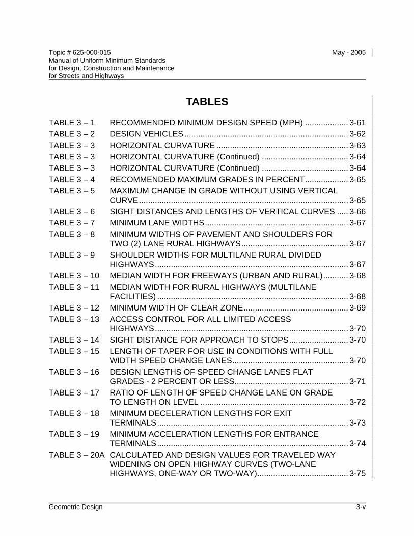
Topic # 625-000-015 May - 2005 Manual of Uniform Minimum Standards for Design, Construction and Maintenance for Streets and Highways
Geometric Design 3-v
TABLES
TABLE 3 – 1 RECOMMENDED MINIMUM DESIGN SPEED (MPH) ................... 3-61 TABLE 3 – 2 DESIGN VEHICLES........................................................................ 3-62 TABLE 3 – 3 HORIZONTAL CURVATURE .......................................................... 3-63 TABLE 3 – 3 HORIZONTAL CURVATURE (Continued) ...................................... 3-64 TABLE 3 – 3 HORIZONTAL CURVATURE (Continued) ...................................... 3-64 TABLE 3 – 4 RECOMMENDED MAXIMUM GRADES IN PERCENT................... 3-65 TABLE 3 – 5 MAXIMUM CHANGE IN GRADE WITHOUT USING VERTICAL
CURVE............................................................................................ 3-65 TABLE 3 – 6 SIGHT DISTANCES AND LENGTHS OF VERTICAL CURVES ..... 3-66 TABLE 3 – 7 MINIMUM LANE WIDTHS............................................................... 3-67 TABLE 3 – 8 MINIMUM WIDTHS OF PAVEMENT AND SHOULDERS FOR
TWO (2) LANE RURAL HIGHWAYS............................................... 3-67 TABLE 3 – 9 SHOULDER WIDTHS FOR MULTILANE RURAL DIVIDED
HIGHWAYS..................................................................................... 3-67 TABLE 3 – 10 MEDIAN WIDTH FOR FREEWAYS (URBAN AND RURAL)........... 3-68 TABLE 3 – 11 MEDIAN WIDTH FOR RURAL HIGHWAYS (MULTILANE
FACILITIES) .................................................................................... 3-68 TABLE 3 – 12 MINIMUM WIDTH OF CLEAR ZONE.............................................. 3-69 TABLE 3 – 13 ACCESS CONTROL FOR ALL LIMITED ACCESS
HIGHWAYS..................................................................................... 3-70 TABLE 3 – 14 SIGHT DISTANCE FOR APPROACH TO STOPS.......................... 3-70 TABLE 3 – 15 LENGTH OF TAPER FOR USE IN CONDITIONS WITH FULL
WIDTH SPEED CHANGE LANES................................................... 3-70 TABLE 3 – 16 DESIGN LENGTHS OF SPEED CHANGE LANES FLAT
GRADES - 2 PERCENT OR LESS.................................................. 3-71 TABLE 3 – 17 RATIO OF LENGTH OF SPEED CHANGE LANE ON GRADE
TO LENGTH ON LEVEL ................................................................. 3-72 TABLE 3 – 18 MINIMUM DECELERATION LENGTHS FOR EXIT
TERMINALS.................................................................................... 3-73 TABLE 3 – 19 MINIMUM ACCELERATION LENGTHS FOR ENTRANCE
TERMINALS.................................................................................... 3-74 TABLE 3 – 20A CALCULATED AND DESIGN VALUES FOR TRAVELED WAY
WIDENING ON OPEN HIGHWAY CURVES (TWO-LANE HIGHWAYS, ONE-WAY OR TWO-WAY)........................................ 3-75
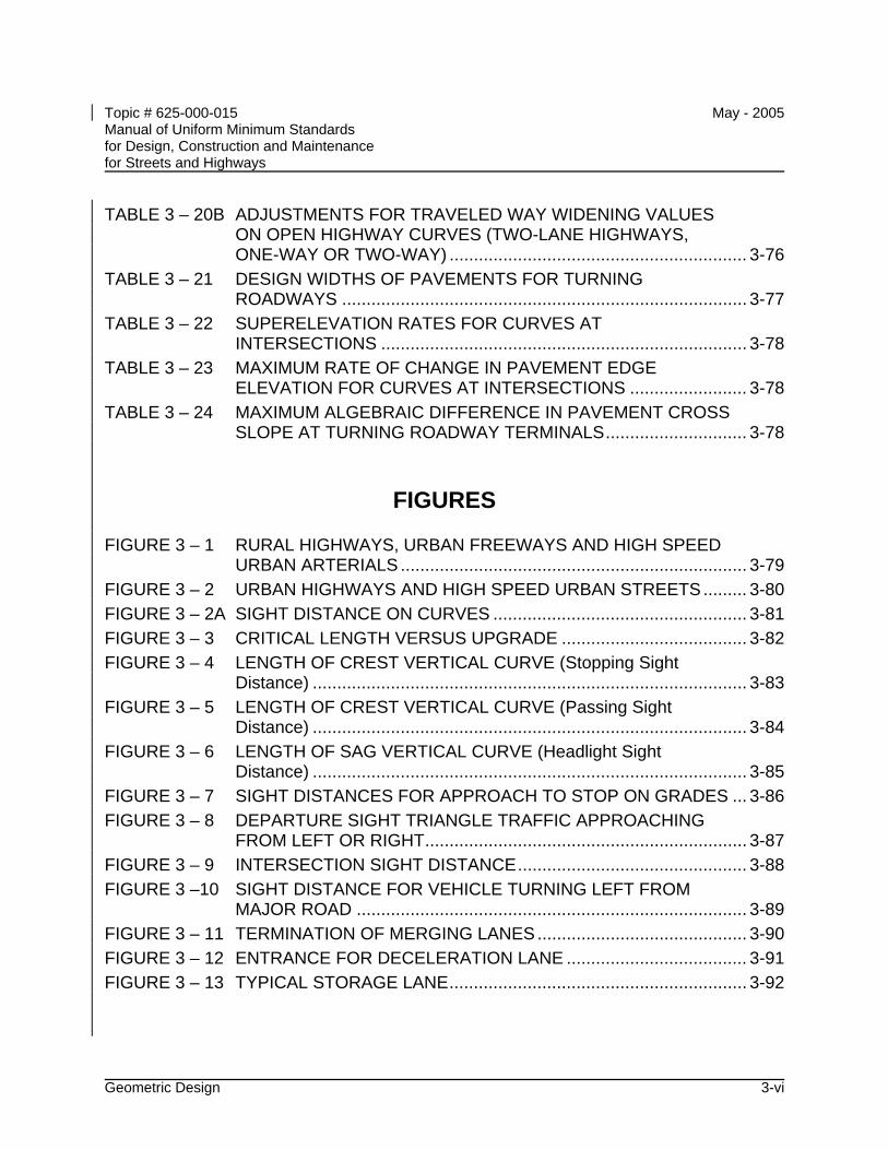
Topic # 625-000-015 May - 2005 Manual of Uniform Minimum Standards for Design, Construction and Maintenance for Streets and Highways
Geometric Design 3-vi
TABLE 3 – 20B ADJUSTMENTS FOR TRAVELED WAY WIDENING VALUES ON OPEN HIGHWAY CURVES (TWO-LANE HIGHWAYS, ONE-WAY OR TWO-WAY) ............................................................. 3-76
TABLE 3 – 21 DESIGN WIDTHS OF PAVEMENTS FOR TURNING ROADWAYS ................................................................................... 3-77
TABLE 3 – 22 SUPERELEVATION RATES FOR CURVES AT INTERSECTIONS ........................................................................... 3-78
TABLE 3 – 23 MAXIMUM RATE OF CHANGE IN PAVEMENT EDGE ELEVATION FOR CURVES AT INTERSECTIONS ........................ 3-78
TABLE 3 – 24 MAXIMUM ALGEBRAIC DIFFERENCE IN PAVEMENT CROSS SLOPE AT TURNING ROADWAY TERMINALS............................. 3-78
FIGURES
FIGURE 3 – 1 RURAL HIGHWAYS, URBAN FREEWAYS AND HIGH SPEED URBAN ARTERIALS ....................................................................... 3-79
FIGURE 3 – 2 URBAN HIGHWAYS AND HIGH SPEED URBAN STREETS......... 3-80 FIGURE 3 – 2A SIGHT DISTANCE ON CURVES .................................................... 3-81 FIGURE 3 – 3 CRITICAL LENGTH VERSUS UPGRADE ...................................... 3-82 FIGURE 3 – 4 LENGTH OF CREST VERTICAL CURVE (Stopping Sight
Distance) ......................................................................................... 3-83 FIGURE 3 – 5 LENGTH OF CREST VERTICAL CURVE (Passing Sight
Distance) ......................................................................................... 3-84 FIGURE 3 – 6 LENGTH OF SAG VERTICAL CURVE (Headlight Sight
Distance) ......................................................................................... 3-85 FIGURE 3 – 7 SIGHT DISTANCES FOR APPROACH TO STOP ON GRADES ... 3-86 FIGURE 3 – 8 DEPARTURE SIGHT TRIANGLE TRAFFIC APPROACHING
FROM LEFT OR RIGHT.................................................................. 3-87 FIGURE 3 – 9 INTERSECTION SIGHT DISTANCE............................................... 3-88 FIGURE 3 –10 SIGHT DISTANCE FOR VEHICLE TURNING LEFT FROM
MAJOR ROAD ................................................................................ 3-89 FIGURE 3 – 11 TERMINATION OF MERGING LANES........................................... 3-90 FIGURE 3 – 12 ENTRANCE FOR DECELERATION LANE ..................................... 3-91 FIGURE 3 – 13 TYPICAL STORAGE LANE............................................................. 3-92
Topic # 625-000-015 May - 2005 Manual of Uniform Minimum Standards for Design, Construction and Maintenance for Streets and Highways
Geometric Design 3-1
CHAPTER 3
GEOMETRIC DESIGN
A INTRODUCTION
Geometric design is defined as the design or proportioning of the visible elements of the street or highway. The geometry of the roadway is of central importance since it provides the framework for the design of other highway elements. In addition, the geometric design establishes the basic nature and quality of the vehicle path, which has a primary effect upon the overall safety characteristics of the street or highway.
The design of roadway geometry must be conducted in close coordination with other design elements. These other elements include: pavement design, roadway lighting, traffic control devices, transit, drainage, and structural design. The design should consider safe roadside clear zones, pedestrian safety, emergency response, and maintenance capabilities.
The safety characteristics of the design should be given primary consideration. The initial establishment of sufficient right of way and adequate horizontal and vertical alignment is not only essential from a safety standpoint, but also necessary to allow future upgrading and expansion without exorbitant expenditure of highway funds.
The design elements selected should be reasonably uniform but should not be inflexible.
The minimum standards presented in this chapter should not automatically become the standards for geometric design. The designer should consider use of a higher level, when practical, and consider cost-benefits as well as consistency with adjacent facilities. Reconstruction and maintenance of facilities should, where practical, include upgrading to these minimum standards.
In restricted or unusual conditions, it may not be possible to meet the minimum standards. In such cases, the designer must obtain an exception in accordance with CHAPTER 14 – DESIGN EXCEPTIONS from the reviewing or permitting organization. However, every effort should be made to obtain the best possible alignment, grade, sight distance, and proper drainage consistent with the terrain, the development, safety, and fund availability. The concept of highway users has expanded in recent years creating additional concerns for the designer.
In making decisions on the standards to be applied to a particular project, the designer
Topic # 625-000-015 May - 2005 Manual of Uniform Minimum Standards for Design, Construction and Maintenance for Streets and Highways
Geometric Design 3-2
must also now address the needs of pedestrians, transit, bicyclists, elder road users, the disabled, and other users. This is true for both urban and rural facilities.
The design features of urban local streets are governed by practical limitations to a greater extent than those of similar roads in rural areas. The two dominant design controls are: (1) the type and extent of urban development and its limitations on rights of way and (2) zoning or regulatory restrictions. Some streets primarily are land service streets in residential areas. In such cases, the overriding consideration is to foster a safe and pleasing environment. Other streets are land service only in part, and features of traffic and public transit service may be predominant.
The selection of the type and exact design details of a particular roadway or highway requires considerable study and thought. When reference is made to guidelines and design details given by current American Association of State Highway and Transportation Officials (AASHTO) publications, these guidelines and standards should generally be considered as minimum criteria. For the design of recreational roads, local service roads, and alleys, see AASHTO publications.
Right of way and pavement width requirements for new construction may be reduced for the paving of certain existing unpaved subdivision streets and low volume rural roads provided all of the conditions listed below are satisfied:
• The road is functionally classified as a local road.
• The 20-year projected ADT is less than 750 vehicles per day and the design year projected peak hourly volume is 100 vehicles per hour or less. Note: The design year may be any time within a range of the present to 20 years in the future, depending on the nature of the improvement.
• The road has no foreseeable probability of changing to a higher functional classification through changes in land use, extensions to serve new developing land areas, or any other use which would generate daily or hourly traffic volumes greater than those listed above.
• There is no reasonable possibility of acquiring additional right of way without:
• Incurring expenditures of public funds in an amount which would be excessive compared to the public benefits achieved
• Causing substantial damage or disruption to abutting property improvements to a degree that is unacceptable considering the local environment
Topic # 625-000-015 May - 2005 Manual of Uniform Minimum Standards for Design, Construction and Maintenance for Streets and Highways
Geometric Design 3-3
B OBJECTIVES
The major objective in geometric design is to establish a vehicle path and environment providing a reasonable margin of safety for the motorist, transit, bicyclist, and pedestrian under the expected operating conditions and speed. It is recognized that Florida's design driver is aging and tourism is our major industry. This gives even more emphasis to focus on simplicity and easily understood geometry and roadway features. The achievement of this objective may be realized by meeting certain specific objectives, which include the following:
• Provide the most simple geometry attainable, consistent with the physical constraints
• Provide a design that has a reasonable and consistent margin of safety at the expected operating speed
• Provide a design that is safe at night and under adverse weather conditions
• Provide a facility that is adequate for the expected traffic conditions and transit needs
• Allow for reasonable deficiencies in the driver, such as:
• Periodic inattention
• Reduced skill and judgment
• Slow reaction and response
• Provide an environment that minimizes hazards, is as hazard free as practical, and is "forgiving" to a vehicle that has deviated from the travel path or is out of control.
Topic # 625-000-015 May - 2005 Manual of Uniform Minimum Standards for Design, Construction and Maintenance for Streets and Highways
Geometric Design 3-4
C DESIGN ELEMENTS
C.1 Design Speed
The design speed is defined as a selected rate of travel used to determine the various geometric features of the roadway. The basic purpose in using the design speed concept is to achieve consistency in the various design elements that influence vehicle operations. Since many critical design features (e.g., sight distance and curvature) are predicated upon design speed, the selection of the proper value is essential to allow for the safe design of a street or highway.
The selection of an appropriate design speed is dependent on the predicted driver behavior and is, therefore, rather complex. This selection of design speed should receive considerable preliminary investigation and thought so safety will be realized from the design.
The primary basis for selecting the design speed should be a rational prediction of the probable maximum operating speed (by approximately 90 percent of the vehicles) on the street or highway. The "average running speed" is not acceptable as a design speed.
In selecting design speeds, consideration should also be given to pedestrians and bicycle usage and to the present and future adjacent land use.
Recommended minimum values for design speed are given in Table 3 - 1. These values should be considered as general guidelines only. The maximum normal operating speed is dependent on many variables including:
• Topography
• General roadway geometry
• Surrounding land use
• Degree of access
• Frequency of traffic signals or other traffic control devices
• Posted speed limit and the degree of enforcement
Topic # 625-000-015 May - 2005 Manual of Uniform Minimum Standards for Design, Construction and Maintenance for Streets and Highways
Geometric Design 3-5
The driver does not necessarily adjust speed to the classification of importance (or lack of it) of the street or highway.
The design speed shall not be less than the expected posted or legal speed limit. A design speed 5 mph to 10 mph greater than the posted speed limit will compensate for a slight overrunning of the speed limit by some drivers.
The use of the higher design speed (no speed restrictions) given in Table 3 - 1 is recommended for the following situations:
• Topography allowing or encouraging higher operating speeds
• Roadway geometry permitting high speeds
• Long uninterrupted sections of roadway
The design speed utilized should be consistent over a given section of highway. Required changes in design speed should be effected in a gradual fashion. When isolated reductions in design speed cannot reasonably be avoided, appropriate speed signs should be posted.
C.2 Design Vehicles
A "design vehicle" is a selected motor vehicle whose weight, dimensions, and operating characteristics are used to establish highway design controls to accommodate vehicles of a designated type. For the purpose of geometric design, the design vehicle should be one with dimensions and minimum turning radii larger than those of almost all vehicles in its class. Design vehicles are listed in Table 3 - 2. One or more of these vehicles should be used as a control in the selection of geometric design elements. In certain industrial (or other) areas, special service vehicles may have to be considered in the design. Fire equipment and emergency vehicles should have reasonable access to all areas.
If a significant number or percentage (5 percent of all the total traffic) of vehicles of those classes larger than passenger vehicles are likely to use a particular street or highway, that class should be used as a design control. The design of major arterial streets and highways should normally be adequate to accommodate all design vehicles. The decision as to which of the design vehicles (or other special vehicles) should be used as a control is complex and requires careful study. Each situation must be evaluated individually to arrive at a reasonable estimate of the type and
Topic # 625-000-015 May - 2005 Manual of Uniform Minimum Standards for Design, Construction and Maintenance for Streets and Highways
Geometric Design 3-6
volume of expected traffic.
• Design criteria significantly affected by the type of vehicle include:
• Horizontal and vertical clearances
• Alignment
• Lane widening on curves
• Shoulder width requirements
• Turning roadway and intersection radii
• Intersection sight distance
• Acceleration criteria
Particular care should be taken in establishing the radii at intersections, so vehicles may enter the street or highway without encroaching on adjacent travel lanes or leaving the pavement. It is acceptable for occasional trucks or buses to make use of both receiving lanes, especially on side streets.
C.3 Sight Distance
The provision for adequate horizontal and vertical sight distance is an essential factor in the development of a safe street or highway. An unobstructed view of the upcoming roadway is necessary to allow time and space for the safe execution of passing, stopping, intersection movements, and other normal and emergency maneuvers. It is also important to provide as great a sight distance as possible to allow the driver time to plan for future actions. The driver is continuously required to execute normal slowing, turning, and acceleration maneuvers. If he can plan in advance for these actions, traffic flow will be smoother and less hazardous. Unexpected emergency maneuvers will also be less hazardous if they are not combined with uncertainty regarding the required normal maneuvers. The appropriate use of lighting (CHAPTER 6 - ROADWAY LIGHTING) may be required to provide adequate sight distances for night driving.
Future obstruction to sight distance that may develop (e.g., vegetation) or be constructed should be taken into consideration in the initial design. Areas outside of the highway right of way that are not under the highway agency's jurisdiction should
Topic # 625-000-015 May - 2005 Manual of Uniform Minimum Standards for Design, Construction and Maintenance for Streets and Highways
Geometric Design 3-7
be considered as points of obstruction. Planned future construction of median barriers, guardrails, grade separations, or other structures should also be considered as possible sight obstructions.
C.3.a Stopping Sight Distance
Safe stopping sight distances shall be provided continuously on all streets and highways. The factors, which determine the minimum distance required to stop, include:
• Vehicle speed
• Driver's total reaction time
• Characteristics and conditions of the vehicle
• Friction capabilities between the tires and the roadway surface
• Vertical and horizontal alignment of the roadway
It is desirable that the driver be given sufficient sight distance to avoid an object or slow moving vehicle with a natural, smooth maneuver rather than an extreme or panic reaction.
The determination of available stopping sight distance shall be based on a height of the driver's eye equal to 3.50 feet and a height of obstruction to be avoided equal to 0.50 feet. It would, of course, be desirable to use a height of obstruction equal to zero (coincident with the roadway surface) to provide the driver with a more positive sight condition. Where horizontal sight distance may be obstructed on curves, the driver's eye and the obstruction shall be assumed to be located at the centerline of the travel lane on the inside of the curve.
The stopping sight distance shall be no less than the values given in Table 3 - 6.
C.3.b Passing Sight Distance
The passing maneuver, which requires occupation of the opposing travel lane, is inherently dangerous. The driver is required to make simultaneous
Topic # 625-000-015 May - 2005 Manual of Uniform Minimum Standards for Design, Construction and Maintenance for Streets and Highways
Geometric Design 3-8
estimates of time, distance, relative speeds, and vehicle capabilities. Errors in these estimates result in frequent and serious crashes.
Highways with two or more travel lanes in a given direction are not subject to requirements for safe passing sight distance. Two-lane, two-way highways should be provided with safe passing sight distance for as much of the highway as feasible. The driver demand for passing opportunity is high and serious limitations on the opportunity for passing reduces the capacity and safe characteristics of the highway.
The distance traveled after the driver's final decision to pass (while encroaching into the opposite travel path) is that which is required to pass and return to the original travel lane in front of the overtaken vehicle. In addition to this distance, the safe passing sight distance must include the distance traveled by an opposing vehicle during this time period, as well as a reasonable margin of safety. Due to the many variables in vehicle characteristics and driver behavior, the passing sight distance should be as long as is practicable.
The determination of passing sight distance shall be based on a height of eye equal to 3.50 feet and a height of object passing equal to 3.50 feet. Where passing is permitted, the passing sight distance shall be no less than the values given in Table 3 - 6.
C.3.c Sight Distance at Decision Points
It is desirable to provide sight distances exceeding the minimum at changes in geometry, approaches to intersections, entrances and exits, and other potential decision points or hazards. The sight distance should be adequate to allow the driver sufficient time to observe the upcoming situation, make the proper decision, and take the appropriate action in a normal manner.
Minimum stopping distance does not provide sufficient space or time for the driver to make decisions regarding complex situations requiring more than simple perception-reaction process. In many cases, rapid stopping or lane changing may be extremely undesirable and cause hazardous maneuvers (i.e., in heavy traffic conditions); therefore, it would be preferable to provide sufficient sight distance to allow for a more gradual reaction.
Topic # 625-000-015 May - 2005 Manual of Uniform Minimum Standards for Design, Construction and Maintenance for Streets and Highways
Geometric Design 3-9
The sight distance on a freeway preceding the approach nose of an exit ramp should exceed the minimum by 25 percent or more. A minimum sight distance of 1000 feet, measured from the driver's eye to the road surface is a desirable goal. There should be a clear view of the exit terminal including the exit nose.
C.3.d Intersection Sight Distance
Sight distances for intersection movements are given in the general intersection requirements (C.9 Intersection Design, this chapter).
C.4 Horizontal Alignment
C.4.a General Criteria
The standard of alignment selected for a particular section of highway should extend throughout the section with no sudden changes from easy to sharp curvature. Where sharper curvature is unavoidable, a sequence of curves of increasing degree should be utilized.
Winding alignment consisting of sharp curves is hazardous, reduces capacity, and should be avoided. The use of as flat a curve as possible is recommended. Flatter curves are not only less hazardous, but also frequently less costly due to the shortened roadway.
Maximum curvature should not be used in the following locations:
• High fills or elevated structures. The lack of surrounding objects reduces the driver's perception of the roadway alignment.
• At or near a crest in grade
• At or near a low point in a sag or grade
• At the end of long tangents
• At or near intersections, transit stops, or points of ingress or egress
• At or near other decision points
Topic # 625-000-015 May - 2005 Manual of Uniform Minimum Standards for Design, Construction and Maintenance for Streets and Highways
Geometric Design 3-10
The "broken back" arrangement of curves (short tangent between two curves in the same direction) should be avoided. This is acceptable only at design speeds of 30 mph or less. This arrangement produces an unexpected and hazardous situation.
When reversals in alignment are used and superelevation is required, a sufficient length of tangent between the reverse curves is required for adequate superelevation transition.
Compound curves should be avoided, especially when curves are sharp. They tend to produce erratic and dangerous vehicle operations. When compound curves are necessary, the radius of the flatter curve should not be more than 50 percent greater than the sharper curve.
The transition between tangents and curves should normally be accomplished by the use of appropriate straight-line transitions or spirals. This is essential to assist the driver in maintaining his vehicle in the proper travel path.
For small deflection angles, curves should be suitably lengthened to avoid the distracting appearance of a kink. Curves should be at least 900 feet long for a central angle of 1 degree or 500 feet long for a central angle of 5 degrees. Gently flowing alignment is generally more pleasing in appearance, as well as, superior from a safety standpoint.
C.4.b Superelevation
In the design of highway curves, it is necessary to establish a proper relationship between curvature of the roadway and design speed. The use of superelevation (rotation of the roadway about its axis) is employed to counteract centrifugal force and allow drivers to comfortably and safely travel through curves at the design speed.
The superelevation rates for rural highways, urban freeways, and high speed urban arterials are shown in Figure 3 - 1. These rates are based on a maximum rate of 0.10 foot per foot of roadway width. Additional superelevation details, given in the Department's Design Standards, may be considered.
Topic # 625-000-015 May - 2005 Manual of Uniform Minimum Standards for Design, Construction and Maintenance for Streets and Highways
Geometric Design 3-11
The superelevation rates recommended for urban highways are shown in Figure 3 -2. These rates are based on a maximum superelevation rate of 0.05 foot per foot of roadway width and are recommended for major streets in built up areas. Additional information regarding superelevation, given in the Department's Design Standards, and AASHTO – "A Policy on Geometric Design of Highways and Streets" -2001, may be considered.
Although superelevation is advantageous for traffic operations, various factors combine to make its use impractical in many built-up areas. Such factors include:
• Wide pavement areas
• Need to meet grade of adjacent property
• Surface drainage considerations
• Frequency of cross streets, alleys, and driveways
Therefore, horizontal curves on lower speed streets in subdivision and urban areas are usually designed without superelevation, only side friction being used to counteract the centrifugal force. Figure 3 - 2 may be used for determination of the maximum safe speed for horizontal curves on lower speed urban streets.
C.4.c Curvature
Where a directional change in alignment is required, every effort should be made to utilize the smallest degree (largest radius) curvature possible. The use of the maximum degree of curvature should be avoided when possible. Design speed maximum degree of curvature relationships are given in Table 3 - 3. The use of sharper curvature for the design speeds shown in Table 3 - 3 would call for superelevation beyond the limit considered practical or for operation with tire friction beyond safe or comfortable limits or both. The maximum degree of curvature is a significant value in alignment design.
Topic # 625-000-015 May - 2005 Manual of Uniform Minimum Standards for Design, Construction and Maintenance for Streets and Highways
Geometric Design 3-12
C.4.d Superelevation Transition (superelevation runoffs plus tangent runoff)
Superelevation runoff is the general term denoting the length of highway needed to accomplish the change in cross slope from a section with the adverse crown removed (level) fully superelevated section, or vice versa. Tangent runoff is the general term denoting the length of highway needed to accomplish the change in cross slope from a normal cross section to a section with the adverse crown removed, or vice versa. Spiral curves can be used to transition from the tangent to the curve. Where the spiral curve is employed, its length is used to make the entire superelevation transition.
The Department's Design Standards show in detail superelevation transitions for various sections and methods for determining length of transition.
C.4.e Lane Widening on Curves
The travel lane should be widened on sharp curves due to the increased difficulty for the driver to follow the proper path. Trucks and transit vehicles experience additional difficulty due to the fact that the rear wheels may track considerably inside the front wheels thus requiring additional width. Adjustments to lane widths for mainline and turning roadways are given in Tables 3 - 20A and 3 - 20B. A transition length shall be introduced in changing to an increased/decreased lane width. This transition length shall be proportional to the increase/decrease in pavement width in a ratio of not less than 50 feet of transition length for each foot of change in lane width.
Topic # 625-000-015 May - 2005 Manual of Uniform Minimum Standards for Design, Construction and Maintenance for Streets and Highways
Geometric Design 3-13
C.5 Vertical Alignment
C.5.a General Criteria
The selection of vertical alignment should be predicated to a large extent upon the following criteria:
• Obtaining maximum sight distances
• Limiting speed differences (particularly for trucks and buses) by reducing magnitude and length of grades
• A "hidden dip" which would not be apparent to the driver must be avoided.
• Steep grades and sharp crest vertical curves should be avoided at or near intersections.
• Flat grades and long gentle vertical curves should be used whenever possible.
C.5.b Grades
The grades selected for vertical alignment should be as flat as practical, and should not be greater than the value given in Table 3 - 4.
For streets and highways requiring long upgrades, the maximum grade should be reduced so the speed reduction of slow-moving vehicles (e.g., trucks and buses) is not greater than 10 mph. The critical lengths of grade for these speed reductions are shown in Figure 3 - 3. Where reduction of grade is not practical, climbing lanes should be provided to meet these speed reduction limitations.
The criteria for a climbing lane and the adjacent shoulder are the same as for any travel lane except that the climbing lane should be clearly designated by the appropriate pavement markings. Entrance to and exit from the climbing lane shall follow the same criteria as other merging traffic lanes; however, the climbing lane should not be terminated until well beyond the crest of the vertical curve. Differences in superelevation should not be sufficient to produce a change in pavement cross slope between the climbing lane and
Topic # 625-000-015 May - 2005 Manual of Uniform Minimum Standards for Design, Construction and Maintenance for Streets and Highways
Geometric Design 3-14
through lane in excess of 0.04 feet per foot.
Recommended minimum gutter grades:
Rolling terrain - 0.5% Flat terrain - 0.3%
C.5.c Vertical Curves
Changes in grade should be connected by a parabolic curve (the vertical offset being proportional to the square of the horizontal distance). Vertical curves are required when the algebraic difference of intersecting grades exceeds the values given in Table 3 - 5. The length of vertical curve on a crest, as governed by stopping sight distance, is obtained from Figure 3 - 4. The minimum length of a crest vertical curve to obtain minimum passing sight distance is given in Figure 3 - 5. The minimum length of a sag vertical curve, as governed by vehicle headlight capabilities, is obtained from Figure 3 - 6.
Wherever feasible, curves longer than the minimum should be considered to improve both aesthetic and safety characteristics.
C.6 Alignment Coordination
Horizontal and vertical alignment should not be designed independently. Poor combinations can spoil the good points of a design. Properly coordinated horizontal and vertical alignment can improve appearance, enhance community values, increase safety, and encourage uniform speed. Coordination of horizontal and vertical alignment should begin with preliminary design, during which stage adjustments can be readily made.
Proper combinations of horizontal alignment and profile can be obtained by engineering study and consideration of the following general controls:
• Curvature and grades should be in proper balance. Tangent alignment or flat curvature with steep grades and excessive curvature with flat grades are both poor design. A logical design is a compromise between the two conditions. Wherever feasible the roadway should "roll with" rather than "buck" the terrain.
Topic # 625-000-015 May - 2005 Manual of Uniform Minimum Standards for Design, Construction and Maintenance for Streets and Highways
Geometric Design 3-15
• Vertical curvature superimposed on horizontal curvature, or vice versa, generally results in a more pleasing facility, but it should be analyzed for effect on driver's view and operation. Changes in profile not in combination with horizontal alignment may result in a series of disconnected humps to the driver for some distance.
• Sharp horizontal curvature should not be introduced at or near the top of a pronounced crest vertical curve. Drivers cannot perceive the horizontal change in alignment, especially at night. This condition can be avoided by setting the horizontal curve so it leads the vertical curve or by making the horizontal curve longer. Suitable design can be made by using design values well above the minimums.
• Sharp horizontal curvature should not be introduced at or near the low point of a pronounced sag vertical curve to prevent an undesirable distorted appearance. Vehicle speeds are often high at the bottom of grades and erratic operation may result, especially at night.
• On divided highways, variation of the median width and the use of independent vertical and horizontal alignment should be considered. Where right of way is available, a superior design without significant additional costs can result from the use of independent alignment.
• Horizontal alignment and profile should be made as flat as possible at interchanges and intersections where sight distance along both highways is important. Sight distances above the minimum are desirable at these locations.
• Alignment should be designed to enhance scenic views for the motorists.
• In residential areas, the alignment should be designed to minimize nuisance to the neighborhood.
Topic # 625-000-015 May - 2005 Manual of Uniform Minimum Standards for Design, Construction and Maintenance for Streets and Highways
Geometric Design 3-16
C.7 Cross Section Elements
The design of the highway cross section should be predicated upon the design speed, terrain, adjacent land use, classification, and the type and volume of traffic expected. The cross section selected should be uniform throughout a given length of street or highway without frequent or abrupt changes.
C.7.a Number of Lanes
The number of travel lanes is determined by several interrelated factors such as capacity, level of service, and service volume. (AASHTO "A Policy on Geometric Design of Highways and Streets" - latest edition, and the current Highway Capacity Manual)
C.7.b Pavement
The paved surface of all travel lanes shall be designed and constructed in accordance with the requirements set forth in CHAPTER 5 - PAVEMENT DESIGN AND CONSTRUCTION.
C.7.b.1 Pavement Width
Traffic lanes should be 12 feet in width, but shall not be less than 10 feet in width. Streets and highways with significant truck/bus traffic should have 12 feet wide traffic lanes. For minimum lane widths, see Table 3 - 7 and Table 3 - 8. If additional lane width is required for bicycles, see CHAPTER 9 – BICYCLE FACILITIES.
C.7.b.2 Pavement Cross Slope (not in superelevation)
The selection of pavement cross slope should be a compromise between meeting the drainage requirements and providing for smooth vehicle operation. The recommended pavement cross slope is 0.02 feet per foot. When three lanes in each direction are necessary, the outside lane should have a cross slope of 0.03 feet per foot. The cross slope shall not be less than 0.015 feet per foot or greater than 0.04 feet per foot. The change in cross slope between adjacent through travel lanes should not exceed 0.04 feet per foot.
Topic # 625-000-015 May - 2005 Manual of Uniform Minimum Standards for Design, Construction and Maintenance for Streets and Highways
Geometric Design 3-17
C.7.c Shoulders
The primary functions of a shoulder are to provide emergency parking for disabled vehicles and an alternate path for vehicles during avoidance or other emergency maneuvers. In order to fulfill these functions satisfactorily, the shoulder should have adequate stability and surface characteristics. The design and construction of shoulders shall be in accordance with the requirements given in CHAPTER 5 - PAVEMENT DESIGN AND CONSTRUCTION.
Shoulders should be provided on all streets and highways incorporating open drainage. The absence of a contiguous emergency travel or storage lane is not only undesirable from a safety standpoint, but also is disadvantageous from an operations viewpoint. Disabled vehicles that must stop in a through lane impose a severe safety hazard and produce a dramatic reduction in traffic flow. Shoulders should be free of abrupt changes in slope, discontinuities, soft ground, or other hazards that would prevent the driver from retaining or regaining vehicle control.
Paved shoulders are recommended for added safety to the motorist, public transit and pedestrians, for accommodation of bicyclists, reduced shoulder maintenance costs, and improved drainage.
C.7.c.1 Shoulder Width
Since the function of the shoulders is to provide an emergency storage or travel path, the desirable width of all shoulders should be at least 10 feet. Where economic or practical constraints are severe, it is permissible, but not desirable, to reduce the shoulder width. Outside shoulders shall be provided on all streets and highways with open drainage and should be at least 6 feet wide. Facilities with a heavy traffic volume or a significant volume of truck traffic SHOULD have outside shoulders at least 8 feet wide. The width of outside shoulders for two-lane, two-way shoulders shall not be less than the values given in Table 3 - 8.
Median shoulders are desirable on all multi-lane, non-curb and gutter divided streets and highways. For shoulder widths on multi-lane divided highways see Table 3 - 9.
Topic # 625-000-015 May - 2005 Manual of Uniform Minimum Standards for Design, Construction and Maintenance for Streets and Highways
Geometric Design 3-18
C.7.c.2 Shoulder Cross Slope
The shoulder serves as a continuation of the drainage system, therefore, the shoulder cross slope should be somewhat greater than the adjacent travel lane. The cross slope of shoulders shall not be less than 0.03 feet per foot or greater than 0.08 feet per foot. For local subdivision type streets, a maximum cross slope of 0.12 feet per foot may be used.
Whenever possible, shoulders should be sloped away from the traffic lanes to aid in their drainage. The combination of shoulder cross slope and texture should be sufficient to promote rapid drainage and to avoid retention of surface water. The change in cross slope between a traffic lane and adjacent shoulder should not be greater than 0.07 feet per foot, except on local subdivision streets where the change in cross slope should not exceed 0.10 feet per foot. Shoulders on the outside of superelevated curves should be rounded (vertical curve) to avoid an excessive break in cross slope and to divert a portion of the drainage away from the adjacent travel lanes.
C.7.d Sidewalks
The design of sidewalks is affected by many factors, including, but not limited to, pedestrian volume, roadway type, characteristics of vehicular traffic, and other design elements. CHAPTER 8 - PEDESTRIAN FACILITIES of this Manual and the AASHTO – "A Policy on Geometric Design of Highways and Streets," present the various factors that influence the design of sidewalks and other pedestrian facilities.
Sidewalks should be constructed in conjunction with new construction and major reconstruction in an urban area. As a general rule, sidewalks should be constructed on both sides of the roadway. Exceptions may be made where physical barriers (e.g., a canal paralleling one side of the roadway) would substantially reduce the expectation of pedestrian use of one side of the roadway. Also, if only one side is possible, sidewalks should be used in the same side of the road as such features as transit stops or other pedestrian generators.
The decision to construct a sidewalk in a rural area should be based on engineering judgment, after observation of existing pedestrian traffic and
Topic # 625-000-015 May - 2005 Manual of Uniform Minimum Standards for Design, Construction and Maintenance for Streets and Highways
Geometric Design 3-19
expectation of additional demand, should a sidewalk be made available.
The standard width of a sidewalk should be 5 feet when separated from the back of curb by a buffer strip. A 4-foot sidewalk may be considered when physical constraints exist and where necessary right of way is unavailable or prohibitively expensive. When sidewalks must be constructed adjacent to the curb, the minimum width should be 6 feet. Sidewalks should be constructed as defined in this Manual - CHAPTER 8 - PEDESTRIAN FACILITIES. In areas of high use, refer to Chapter 18 of the Highway Capacity Manual for calculation of appropriate width. As noted in the Department's Bicycle Facilities Planning and Design Handbook, excessively wide sidewalks may not necessarily add to pedestrian and bicycle safety. Wide sidewalks may encourage higher speed bicycle use and can increase the potential for conflict with motor vehicles at intersections and driveways, as well as with pedestrians and fixed objects.
Maximum cross slope shall be 2%, and grades shall not exceed 8.33%. Curb ramps shall be provided at all intersections (Section 336.045 (3), Florida Statutes). For additional details, refer to the current Americans with Disabilities Act (ADA) Accessibility Guidelines (as described in the Federal Register), and the Florida Accessibility Code For Building Construction (Rule 9B-7.0042).
C.7.e Medians
Median separation of opposing traffic lanes provides a beneficial safety feature and should be used wherever feasible. Separation of the opposing traffic also reduces the problem of headlight glare, thus improving safety and comfort for night driving. When sufficient width of medians is available, some landscaping is also possible.
The use of medians often aids in the provision of drainage for the roadway surface, particularly for highways with six or more traffic lanes. The median also provides a vehicle refuge area, improves the safety of pedestrian crossings, provides a logical location for left turn storage lanes, and provides the means for future addition of traffic lanes and mass transit. In many situations, the median strip aids in roadway delineation and the overall highway aesthetics.
Topic # 625-000-015 May - 2005 Manual of Uniform Minimum Standards for Design, Construction and Maintenance for Streets and Highways
Geometric Design 3-20
Median separation is required on the following streets and highways:
• Freeways
• All streets and highways, rural and urban, with 4 or more travel lanes and with a design speed of 40 mph or greater
Median separation is desirable on all other multi-lane roadways to enhance pedestrian crossings.
The nature and degree of median separation required is dependent upon the design speed, traffic volume, adjacent land use, and the frequency of access. There are basically two approaches to median separation. The first is the use of horizontal separation of opposing lanes to reduce the probability of vehicles crossing the median into incoming traffic. The second method is to attempt to limit crossovers by introducing a positive median barrier structure.
In rural areas, the use of wide medians is not only aesthetically pleasing, but is often more economical than barriers. In urban areas where space and/or economic constraints are severe, the use of barriers is permitted to fulfill the requirements for median separation.
Uncurbed medians should be free of abrupt changes in slope, discontinuities, soft ground, or other hazards that would prevent the driver from retaining or regaining control of the vehicle. Consideration should be given to increasing the width and decreasing the slope of medians on horizontal curves. The requirements for a hazard free median environment are given in CHAPTER 4 - ROADSIDE DESIGN, and shall be followed in the design and construction of medians.
C.7.e.1 Type of Median
A wide, gently depressed median is the preferred design. This type allows a reasonable vehicle recovery area and aids in the drainage of the adjacent shoulders and travel lanes. Where space and drainage limitations are severe, narrower medians, flush with the roadway, or raised medians, are permitted. Raised medians should be used to support pedestrian crossings of multi-laned highways.
Topic # 625-000-015 May - 2005 Manual of Uniform Minimum Standards for Design, Construction and Maintenance for Streets and Highways
Geometric Design 3-21
C.7.e.2 Median Width
The median width is defined as the horizontal distance between the inside pavement edges of the opposing roadways. The selection of the median width for a given type of roadway is primarily dependent on design speed and traffic volume. Since the probability of crossover crashes is decreased by increasing the separation, medians should be as wide as practicable. Median widths in excess of 30 feet to 35 feet reduce the problem of disabling headlight glare from opposing traffic.
The minimum permitted widths of freeway medians are given in Table 3 - 10. Where the expected traffic volume is heavy, the widths should be increased over these minimum values. Median barriers shall be used on freeways when these minimum values are not attainable.
The minimum permitted median widths for multi-lane rural highways are given in Table 3 - 11. On urban streets, the median widths shall not be less than the values given in Table 3 - 11. Where median openings or access points are frequent, the median width should be increased.
The minimum median widths given in these Tables may have to be increased to meet the requirements for cross slopes, drainage, and turning movements (C.9 Intersection Design, this chapter). The median area should also include adequate additional width to allow for expected additions of through lanes and left turn storage lanes. Where the median width is sufficient to produce essentially two separate, independent roadways, the left side of each roadway shall meet the requirements for roadside clear zone. Changes in the median width should be accomplished by gently flowing horizontal alignment of one or both of the separate roadways.
C.7.e.3 Median Slopes
A vehicle should be able to transverse a median without turning over and with sufficient smoothness to allow the driver a reasonable chance to control the vehicle. The transition between the median slope and the shoulder (or pavement) slope should be smooth, gently rounded, and free from discontinuities.
Topic # 625-000-015 May - 2005 Manual of Uniform Minimum Standards for Design, Construction and Maintenance for Streets and Highways
Geometric Design 3-22
The median cross slope should not be steeper than1:6 (preferably not steeper than 1:10). The depth of depressed medians may be controlled by drainage requirements. Increasing the width of the median, rather than increasing the cross slope, is the proper method for developing the required median depth.
Longitudinal slopes (median profile parallel to the roadway) should be shallow and gently rounded at intersections of grade. The longitudinal slope, relative to the roadway slope, shall not exceed a ratio of 1:10 and preferably 1:20. The change in longitudinal slope shall not exceed 1:8 (change in grade of 12.5 %).
C.7.e.4 Median Barriers
The primary objective for placing a barrier structure in the median is to prevent vehicles from entering the opposing traffic stream, either accidentally or intentionally. Median barriers may also be used to reduce the glare produced by oncoming vehicle headlights. When selecting the type of barrier, care should be exercised to avoid headlight flicker through barriers.
The use of median barriers to reduce horizontal separation is permitted on facilities with substantially full control of access. Frequent openings in the barrier for intersections or crossovers expose the barrier end, which constitute severe hazard at locations with an inherently high crash potential and should be shielded. Median barriers may be considered for urban freeways and major arterials with controlled access.
Median barriers shall be used on controlled access facilities if the median width is less than the minimum permitted values given in Table 3 - 10. The median barrier should not be placed closer than 10 feet from the inside pavement edge. Further requirements for median barriers are given in CHAPTER 4 - ROADSIDE DESIGN.
Topic # 625-000-015 May - 2005 Manual of Uniform Minimum Standards for Design, Construction and Maintenance for Streets and Highways
Geometric Design 3-23
C.7.f Roadside Clear Zone
The roadside clear zone is that area outside the traveled way available for use by errant vehicles. Vehicles frequently leave the traveled way during avoidance maneuvers, due to loss of control by the driver (e.g., falling asleep) or due to collisions with other vehicles. The primary function of the clear zone is to allow space and time for the driver to retain control of his vehicle and avoid or reduce the consequences of collision with roadside objects. This area also serves as an emergency refuge location for disabled vehicles.
The design of the roadway must also provide for adequate drainage of the roadway. Drainage swales within the clear zone should be gently rounded and free of discontinuities. Where large volumes of water must be carried, the approach should be to provide wide, rather than deep drainage channels. Side slopes and drainage swales that lie within the clear zone should be free of protruding drainage structures (CHAPTER 4 - ROADSIDE DESIGN, D.6.c. Culverts).
In the design of the roadside, the designer should consider the consequences of a vehicle leaving the traveled way at any location. It should always be the policy that protection of vehicles and occupants shall take priority over the protection of roadside objects. Further criteria and requirements for safe roadside design are given in CHAPTER 4 - ROADSIDE DESIGN.
C.7.f.1 Roadside Clear Zone Width
The clear zone width is defined as follows:
• Rural sections - measured from the edge of the outside motor vehicular travel way
• Urban sections - measured from the face of the curb
The minimum permitted widths are provided in Table 3 - 12. These are minimum values only and should be increased wherever practical.
In rural areas, it is desirable, and frequently economically feasible, to
Topic # 625-000-015 May - 2005 Manual of Uniform Minimum Standards for Design, Construction and Maintenance for Streets and Highways
Geometric Design 3-24
increase the width of the clear zone. Where traffic volumes and speeds are high, the width should be increased. The clear zone on the outside of horizontal curves should be increased due to the possibility of vehicles leaving the roadway at a steeper angle.
C.7.f.2 Roadside Slopes
The slopes of all roadsides should be as flat as possible to allow for safe traversal by out of control vehicles. A slope of 1:4 or flatter should be used. The transition between the shoulder and adjacent side slope should be rounded and free from discontinuities. The adjacent side slope, within the clear zone, shall not be steeper than 1:3. The side slopes should be reduced flatter on the outside of horizontal curves.
Where roadside ditches or cuts require backslope, these slopes should not exceed 1:3 in steepness within the clear zone. The desirable backslope is 1:4. Ditch bottoms should be at least 4 feet wide and can be flat or gently rounded.
C.7.f.3 Criteria for Guardrail
If space and economic constraints are severe, it is permissible, but not desirable, to use guardrails in lieu of the requirements for width and slope of clear zone. Where the previously described requirements for clear zone are not met, guardrails (or other longitudinal barriers) should be considered. Guardrails should also be considered for protection of pedestrian pathways or protection from immovable roadside hazards.
The general policy to be followed is that guardrails should be used if impact with the guardrail is less likely or considered less severe than impact with roadside objects. Further requirements and design criteria for guardrails are given in CHAPTER 4 - ROADSIDE DESIGN.
Topic # 625-000-015 May - 2005 Manual of Uniform Minimum Standards for Design, Construction and Maintenance for Streets and Highways
Geometric Design 3-25
C.7.g Curbs
Curbs may be used to provide drainage control and to improve delineation of the roadway. Curbs are generally designed with a gutter to form a combination curb and gutter section. Curbs with nearly vertical faces are used along the outside edge of the roadway to discourage vehicles from leaving the roadway. In Florida, the standard curb of this type is 6 inches in height. These curbs are not to be used on facilities with design speeds greater than 45 mph.
C.7.h Parking
When on-street parking is to be an element of design, parallel parking should be considered. Under certain circumstances, angle parking is an allowable form of street parking. The type of on-street parking selected should depend on the specific function and width of the street, the adjacent land use, traffic volume, as well as existing and anticipated traffic operations.
It can generally be stated that on-street parking decreases through capacity, impedes traffic flow, and increases crash potential. However, where parking is needed, and adequate off-street parking facilities are not available or feasible, on-street parking may be necessary.
C.7.i Right of Way
The acquisition of sufficient right of way is necessary in order to provide space for a safe street or highway. The width of the right of way required depends on the design of the roadway, the arrangement of bridges, underpasses and other structures, and the need for cuts or fills. The right of way acquired should be sufficient to:
• Allow development of the full cross section, including adequate medians and roadside clear zones. Determination of the necessary width requires that adequate consideration also be given to the accommodation of utility poles beyond the clear zone.
• Allow the layout of safe intersections, interchanges, and other access points
Topic # 625-000-015 May - 2005 Manual of Uniform Minimum Standards for Design, Construction and Maintenance for Streets and Highways
Geometric Design 3-26
• Allow adequate sight distance at all points, particularly on horizontal curves, at an intersection, and other access points
• Allow, where appropriate, transit bus bays, additional buffer zones to improve roadside safety, noise attenuation, and the overall aesthetics of the street or highway
• Allow adequate space for placement of pedestrian and bicycle facilities, including curb ramps, storage turning areas, and transit shelters, where applicable
• Allow for future lane additions, increases in cross section, or other improvement. Frontage roads should also be considered in the ultimate development of many high volume facilities.
• Allow treatment of stormwater runoff
• Allow construction of future grade separations or other intersection improvements at selected crossroads
• Allow corner cuts for upstream corner crossing drainage systems and placement of poles, boxes, and other visual screens out of the critical sight triangle
• Allow landscaping and irrigation as required for the project
The acquisition of wide rights of way is costly, but it may be necessary to allow the construction and future improvement of safe streets and highways. The minimum right of way should be at least 50 feet for all two-lane roads. For pre-existing conditions, when the existing right of way is less than 50 feet, efforts should be made to acquire the necessary right of way.
Local cul-de-sac and dead end streets having an ADT of less than 250, and a length of 600 feet or less, may utilize a right of way of less than 50 feet, if all elements of the typical section meet the standards included in this Manual.
The right of way for frontage roads may be reduced depending on the typical section requirements and the ability to share right of way with the adjacent highway facility.
Topic # 625-000-015 May - 2005 Manual of Uniform Minimum Standards for Design, Construction and Maintenance for Streets and Highways
Geometric Design 3-27
C.7.j Changes in Typical Section
C.7.j.1 General Criteria
Changes in cross section should be avoided. When changes in widths, slopes, or other elements are necessary, they should be affected in a smooth, gradual fashion.
C.7.j.2 Lane Deletions and Additions
The addition or deletion of traffic lanes should be undertaken on tangent sections of roadways. The approach to lane deletions and additions should have ample advance warning and sight distance.
The termination of lanes (including auxiliary lanes) shall meet the general requirements for merging lanes.
Where additional lanes are intermittently provided on two-lane, two-way highways, median separation should be considered.
C.7.j.3 Special Use Lanes
To increase the efficiency and separation of different vehicle movements, special use lanes, such as bike lanes and bus lanes, should be considered. These lanes are often an enhancement to corridor safety and increase the horizontal clearance to roadside aboveground fixed objects.
C.7.j.4 Structures
The pavement, median, and shoulder width, and sidewalks should be carried across structures such as bridges and box culverts. Shoulder widths for multi-lane rural divided highway bridges may be reduced as shown in Table 3 - 9. The designer should evaluate the economic practicality of utilizing dual versus single bridges for roadway sections incorporating wide medians.
The minimum roadway width for bridges on urban streets with curb
Topic # 625-000-015 May - 2005 Manual of Uniform Minimum Standards for Design, Construction and Maintenance for Streets and Highways
Geometric Design 3-28
and gutter shall be the same as the curb-to-curb width of the approach roadway. Sidewalks on the approaches should be carried across all structures. Curbed sidewalks should not be used adjacent to traffic lanes when design speeds exceed 45 mph. When the bridge rail (barrier wall) is placed between the traffic and sidewalk, it should be offset a minimum distance of 2½ feet from the edge of the travel lane, wide curb lane or bicycle lane. For long (500 feet or greater), and/or high level bridges, it is desirable to provide an offset distance that will accommodate a disabled vehicle. The transition from the bridge to the adjacent roadway section may be made by dropping the curb at the first intersection or well in advance of the traffic barrier, or reducing the curb in front of the barrier to a low mountable curb with a gently sloped traffic face. See CHAPTER 17 – BRIDGES AND OTHER STRUCTURES for additional requirements.
C.7.j.4.(a) Horizontal Clearance Supports for bridges, barriers, or other structures should be placed at or beyond the required shoulder. Where possible, these structures should be located outside of the required clear zone.
C.7.j.4.(b) Vertical Clearance Vertical clearance should be adequate for the type of expected traffic. Freeways and major arterials shall have a vertical clearance of at least 16 feet. Other streets and highways should have a clearance of 16 feet unless the provision of a reduced clearance is fully justified by a specific analysis of the situation. Provision for additional clearance (3 inches to 6 inches) is recommended to allow for future resurfacing.
C.7.j.4.(c) End Treatment The termini of guardrails, bridge railings, abutments, and other structures should be constructed to protect vehicles and their occupants from serious impact. Requirements for end treatment of structures are given in CHAPTER 4 - ROADSIDE DESIGN.
Topic # 625-000-015 May - 2005 Manual of Uniform Minimum Standards for Design, Construction and Maintenance for Streets and Highways
Geometric Design 3-29
C.8 Access Control
All new facilities (and existing when possible) should have some degree of access control, since each point of access produces a traffic conflict. The control of access is one of the most effective, efficient, and economical methods for improving the capacity and safety characteristics of streets and highways. The reduction of the frequency of access points and the restriction of turning and crossing maneuvers, which should be primary objectives, is accomplished more effectively by the design of the roadway geometry than by the use of traffic control devices. Design criteria for access points are presented under the general requirements for intersection design.
C.8.a Justification
The justification for control of access should be based on several factors, including safety, capacity, economics, and aesthetics.
C.8.b General Criteria
C.8.b.1 Location of Access Points
All access locations should have adequate sight distance available for the safe execution of entrance, exit, and crossing maneuvers.
Locations of access points near structures, decision points, or the termination of highway lighting should be avoided.
Driveways should not be placed near intersections or other points that would tend to produce traffic conflict.
C.8.b.2 Spacing of Access Points
The spacing of access points should be adequate to prevent conflict or mutual interference of traffic flow.
Separation of entrance and exit ramps should be sufficient to provide adequate distance for required weaving maneuvers.
Topic # 625-000-015 May - 2005 Manual of Uniform Minimum Standards for Design, Construction and Maintenance for Streets and Highways
Geometric Design 3-30
Adequate spacing between access and decision points is necessary to avoid burdening the driver with the need for rapid decisions or maneuvers.
Frequent median openings should be avoided.
The use of a frontage road or other auxiliary roadways is recommended on minor arterials and higher classifications where the need for direct driveway or minor road access is frequent.
C.8.b.3 Restrictions of Maneuvers
Where feasible, the number and type of permitted maneuvers (crossing, turning slowing, etc.) should be restricted.
The restriction of crossing maneuvers may be accomplished by the use of grade separations and continuous raised medians.
The restriction of left turns is achieved most effectively by continuous medians.
Channelization should be considered for the purposes of guiding traffic flow and reducing vehicle conflicts.
C.8.b.4 Turn Lanes
Deceleration lanes for right turn exits (and left turns, where permitted) should be provided on all high-speed facilities. These turn lanes should not be excessive or continuous, since they complicate pedestrian crossings and bicycle/motor vehicle movements.
Storage (or deceleration lanes) to protect turning vehicles should be provided, particularly where turning volumes are significant.
Acceleration lanes are desirable for entrance maneuvers onto high-speed streets and highways.
Special consideration should be given to the provisions for
Topic # 625-000-015 May - 2005 Manual of Uniform Minimum Standards for Design, Construction and Maintenance for Streets and Highways
Geometric Design 3-31
deceleration, acceleration, and storage lanes in commercial or industrial areas with significant truck/bus traffic.
C.8.b.5 Grade Separation
Grade separation interchange design should be considered for junctions of major arterial streets and highways.
Grade separation (or an interchange) should be utilized when the expected traffic volume exceeds the intersection capacity.
Grade separation should be considered to eliminate conflict or long waiting periods at potentially hazardous intersections.
C.8.b.6 Roundabouts
Roundabouts are another tool for the designer to consider in intersection design. These have been used extensively in Europe and Australia. The true roundabout is characterized by the following:
• A central island of sufficient diameter to accommodate vehicle tracking and to provide sufficient deflection to promote lower speeds
• Entry is by gap acceptance through a yield condition at all legs
• Speeds through the intersection are 25 mph or less
The use of roundabouts should be determined by a detailed documented intersection analysis, as is also necessary for other type designs.
For further guidance, refer to the Federal Highway Administration (FHWA) Roundabout Guide, and the Florida Roundabout Guide
C.8.c Control for All Limited Access Highways
Entrances and exits on the right side only are highly desirable for all limited access highways. Acceleration and deceleration lanes are mandatory.
Topic # 625-000-015 May - 2005 Manual of Uniform Minimum Standards for Design, Construction and Maintenance for Streets and Highways
Geometric Design 3-32
Intersections shall be accomplished by grade separation (interchange) and should be restricted to connect with arterials or collector roads.
The control of access on freeways should conform to the requirements given in Table 3 - 13. The spacing of exits and entrances should be increased wherever possible to reduce conflicts. Safety and capacity characteristics are improved by restricting the number and increasing the spacing of access points.
C.8.d Control of Urban Streets
The design and construction of urban, as well as rural, highways should be governed by the general criteria for access control previously outlined. In addition, the design of urban streets should be in accordance with the criteria listed below:
• The general layout of local and collector streets should follow a branching network, rather than a highly interconnected grid pattern.
• The street network should be designed to reduce, consistent with origin/destination requirements, the number of crossing and left turn maneuvers.
• The design of the street layout should be predicated upon reducing the need for traffic signals.
• The use of a public street or highway as an integral part of the internal circulation pattern for commercial property should be discouraged.
• The number of driveway access points should be restricted as much as possible through areas of strip development.
• Special consideration should be given to providing turn lanes (auxiliary lane for turning maneuvers) where the total volume or truck/bus volume is high.
• Major traffic generators may be exempt from the restrictions on driveway access if the access point is designed as a normal intersection adequate to handle the expected traffic volume.
These are minimum requirements only; it is generally desirable to use more
Topic # 625-000-015 May - 2005 Manual of Uniform Minimum Standards for Design, Construction and Maintenance for Streets and Highways
Geometric Design 3-33
stringent criteria for control of access.
C.8.e Control for Rural Highways
The design of rural highways should be in accordance with the general criteria for access control for urban streets. The use of acceleration and deceleration lanes on all high-speed highways, particularly if truck and bus traffic is significant, is strongly recommended.
C.8.f Land Development
It should be the policy of each agency with responsibility for highway design, construction, or maintenance to promote close liaison with utility, lawmaking, zoning, building, and planning agencies. Cooperation should be solicited in the formulation of laws, regulations, and master plans for land use, zoning, and highway construction. Further requirements and criteria for access control and land use relationships are given in CHAPTER 2 - LAND DEVELOPMENT.
Topic # 625-000-015 May - 2005 Manual of Uniform Minimum Standards for Design, Construction and Maintenance for Streets and Highways
Geometric Design 3-34
C.9 Intersection Design
Intersections increase traffic conflicts and the demands on the driver, and are inherently hazardous locations. The design of an intersection should be predicated on reducing motor vehicle, bicycle, and pedestrian conflicts, minimizing the confusion and demands on the driver for rapid and/or complex decisions, and providing for smooth traffic flow. The location and spacing of intersections should follow the requirements presented in C.8 Access Control, this chapter. Intersections should be designed to minimize time and distance of all who pass through or turn at an intersection.
The additional effort and expense required to provide a high quality intersection is justified by the corresponding safety benefits. The overall reduction in crash potential derived from a given expenditure for intersection improvements is generally much greater than the same expenditure for improvements along an open roadway. Properly designed intersections increase capacity, reduce delays, and improve safety.
One of the most common deficiencies that may be easy to correct is lack of adequate left turn storage.
The requirements and design criteria contained in this section are applicable to all driveways, intersections, and interchanges. All entrances to, exits from, or interconnections between streets and highways are subject to these design standards.
C.9.a General Criteria
The layout of a given intersection may be influenced by constraints unique to a particular location or situation. The design shall conform to sound principles and criteria for safe intersections. The general criteria include the following:
• The layout of the intersection should be as simple as is practicable. Complex intersections, which tend to confuse and distract the driver, produce inefficient and hazardous operations.
• The intersection arrangement should not require the driver to make rapid or complex decisions.
Topic # 625-000-015 May - 2005 Manual of Uniform Minimum Standards for Design, Construction and Maintenance for Streets and Highways
Geometric Design 3-35
• The layout of the intersection should be clear and understandable so a proliferation of signs, signals, or markings is not required to adequately inform and direct the driver.
• The design of intersections, particularly along a given street or highway, should be as consistent as possible.
• The approach roadways should be free from steep grades and sharp horizontal or vertical curves.
• Intersections with driveways or other roadways should be as close to right angle as possible.
• Adequate sight distance should be provided to present the driver a clear view of the intersection and to allow for safe execution of crossing and turning maneuvers.
• The design of all intersection elements should be consistent with the design speeds of the approach roadways.
• The intersection layout and channelization should encourage smooth flow and discourage wrong way movements.
• Special attention should be directed toward the provision of safe roadside clear zones.
• The provision of special turn lanes should be in conformance with the criteria set forth in C.8 Access Control, this chapter.
• The requirements for bicycle and pedestrian movements should receive special consideration.
C.9.b Sight Distance
Inadequate sight distance is a contributing factor in the cause of a large percentage of intersection crashes. The provision of adequate sight distance at intersections is absolutely essential and should receive a high priority in the design process.
Topic # 625-000-015 May - 2005 Manual of Uniform Minimum Standards for Design, Construction and Maintenance for Streets and Highways
Geometric Design 3-36
C.9.b.1 General Criteria
General criteria to be followed in the provision of sight distance include the following:
• Sight distance exceeding the minimum stopping sight distance should be provided on the approach to all intersections (entrances, exits, stop signs, traffic signals, and intersecting roadways). The use of proper approach geometry free from sharp horizontal and vertical curvature will normally allow for adequate sight distance.
• The approaches to exits or intersections (including turn, storage, and deceleration lanes) should have adequate sight distance for the design speed and also to accommodate any allowed lane change maneuvers.
• Adequate sight distance should be provided on the through roadway approach to entrances (from acceleration or merge lanes, stop or yield signs, driveways or traffic signals) to provide capabilities for defensive driving. This lateral sight distance should include as much length of the entering lane or intersecting roadway as is feasible. A clear view of entering vehicles is necessary to allow through traffic to aid merging maneuvers and to avoid vehicles that have "run" or appear to have the intention of running stop signs or traffic signals.
• Approaches to school or pedestrian crossings and crosswalks should have sight distances exceeding the minimum values. This should also include a clear view of the adjacent pedestrian pathways or shared use paths.
• Sight distance in both directions should be provided for all entering roadways intersecting roadways and driveways) to allow entering vehicles to avoid through traffic. Refer to Figures 3 - 8 and 3 - 9.
• Safe stopping sight distances shall be provided throughout all intersections, including turn lanes, speed change lanes, and turning roadways.
Topic # 625-000-015 May - 2005 Manual of Uniform Minimum Standards for Design, Construction and Maintenance for Streets and Highways
Geometric Design 3-37
• The use of lighting (CHAPTER 6 - ROADWAY LIGHTING) should be considered to improve intersection sight distance for night driving.
C.9.b.2 Obstructions to Sight Distance
The provisions for sight distance are limited by the highway geometry and the nature and development of the area adjacent to the roadway. Where line of sight is limited by vertical curvature or obstructions, stopping sight distance shall be based on the eye height of 3.50 feet and an object height of 0.50 feet. At exits or other locations where the driver may be uncertain as to the roadway alignment, a clear view of the pavement surface should be provided. At locations requiring a clear view of other vehicles or pedestrians for the safe execution of crossing or entrance maneuvers, the sight distance should be based on a driver's eye height of 3.50 feet and an object height of 3.00 feet (preferably 1.50 feet). The height of eye for truck traffic may be increased for determination of line of sight obstructions for intersection maneuvers. Obstructions to sight distance at intersections include the following:
• Any property not under the highway agency's jurisdiction, through direct ownership or other regulations, should be considered as an area of potential sight distance obstruction. Based on the degree of obstruction, the property should be considered for acquisition by deed or easement.
• Areas which contain vegetation (trees, shrubbery, grass, etc.) that cannot easily be trimmed or removed by regular maintenance activity should be considered as sight obstructions.
• Parking lanes shall be considered as obstructions to line of sight. Parking shall be prohibited within clear areas required for sight distance at intersections.
• Large (or numerous) poles or support structures for lighting, signs, signals, or other purposes that significantly reduce the field of vision within the limits of clear sight shown in Figure 3 - 8 may constitute sight obstructions. Potential sight obstructions
Topic # 625-000-015 May - 2005 Manual of Uniform Minimum Standards for Design, Construction and Maintenance for Streets and Highways
Geometric Design 3-38
created by poles, supports, and signs near intersections should be carefully investigated.
In order to ensure the provision for adequate intersection sight distance, on-site inspections should be conducted before and after construction, including placement of signs, lighting, guardrails, or other objects and how they impact intersection sight distance.
C.9.b.3 Stopping Sight Distance
The provision for safe stopping sight distance at intersections and on turning roadways is even more critical than on open roadways. Vehicles are more likely to be traveling in excess of the design or posted speed and drivers are frequently distracted from maintaining a continuous view of the upcoming roadway.
C.9.b.3.(a) Approach to Stops The approach to stop signs, yield signs, or traffic signals should be provided with a sight distance no less than values given in Table 3 - 14. These values are applicable for any street, highway, or turning roadway. The driver should, at this required distance, have a clear view of the intersecting roadway, as well as the sign or traffic signal.
Where the approach roadway is on a grade or vertical curve, the sight distance should be no less than the values shown in Figure 3 - 7. In any situation where it is feasible, sight distances exceeding those should be provided. This is desirable to allow for more gradual stopping maneuvers and to reduce the likelihood of vehicles running through stop signs or signals. Advance warnings for stop signs are desirable.
C.9.b.3.(b) On Turning Roads The required stopping sight distance at any location on a turning roadway (loop, exit, etc.) shall be based on the design speed at that point. Ample sight distance should be provided since the driver is burdened with negotiating a curved travel path and the available friction factor for stopping has been reduced by the roadway curvature. The minimum sight distance values are given in Table 3 - 14 or Figure 3 - 7. Due
Topic # 625-000-015 May - 2005 Manual of Uniform Minimum Standards for Design, Construction and Maintenance for Streets and Highways
Geometric Design 3-39
to the inability of vehicle headlights to adequately illuminate a sharply curved travel path, roadway lighting should be considered for turning roadways.
C.9.b.4 Sight Distance for Intersection Maneuvers
Sight distance is also provided at intersections to allow the drivers of stopped vehicles a sufficient view of the intersecting highway to decide when to enter or cross the intersecting highway. Sight triangles, which are specified areas along intersection approach legs and across their included corners, shall, where practical, be clear of obstructions that would prohibit a driver’s view of potentially conflicting vehicles. Departure sight triangles shall be provided in each quandrant of each intersection approach controlled by stop signs. Figures 3 - 8 and 3 - 9 show typical departure sight triangles to the left and to the right of the location of a stopped vehicle on a minor road and the intersection sight distances for the various movements. Distance “a” is the length of leg of the sight triangle along the minor road. This distance is measured from the driver’s eye in the stopped vehicle to the center of the nearest lane on the major road for vehicles approaching from the left, and to the center of the nearest lane for vehicles approaching from the right.
Distance “b” is the length of the leg of the sight triangle along the major road measured from the center of the minor road entrance lane. This distance is a function of the design speed and the time gap in major road traffic needed for minor road drivers turning onto or crossing the major road. This distance is calculated as follows:
ISD = 1.47Vmajortg Where: ISD = Intersection Sight Distance (ft.) – length of leg of
sight triangle along the major road. Vmajor = Design Speed (mph) of the Major Road tg = Time gap (sec.) for minor road vehicle to enter
the major road.
Time gap values, tg, to be used in determination of ISD are based on studies and observations of the time gaps in major road traffic actually
Topic # 625-000-015 May - 2005 Manual of Uniform Minimum Standards for Design, Construction and Maintenance for Streets and Highways
Geometric Design 3-40
accepted by drivers turning onto or across the major road. Design time gaps will vary and depend on the design vehicle, the type of the maneuver, the crossing distance involved in the maneuver, and the minor road approach grade.
For intersections with stop control on the minor road, there are three maneuvers or cases that must be considered. ISD is calculated for each maneuver case that may occur at the intersection. The case requiring the greatest ISD will control. Cases that must be considered are as follows (Case numbers correspond to cases identified in the AASHTO Green Book):
Case B1 – Left Turns from the Minor (stop controlled) Road
Case B2 – Right Turns from the Minor (stop controlled) Road
Case B3 – Crossing the Major Road from the Minor (stop controlled) Road
See Sections C.9.b.4.(c) and (d) for design time gaps for Case B.
For Intersections with Traffic Signal Control see Section C.9.b.4.(e) (AASHTO Case D).
For intersections with all way stop control see Section C.9.b.4.(f) (AASHTO Case E).
For left turns from the major road see Section C.9.b.4.(g) (AASHTO Case F).
C.9.b.4.(a) Driver’s Eye Position and Vehicle Stopping Position
The vertex (decision point or driver’s eye position) of the departure sight triangle on the minor road shall be a minimum of 14.5 feet from the edge of the major road traveled way. This is based on observed measurements of vehicle stopping position and the distance from the front of the vehicle to the driver’s eye. Field observations of vehicle stopping positions found that, where necessary, drivers will stop with the front of their vehicle 6.5 feet or less from the edge of the major road
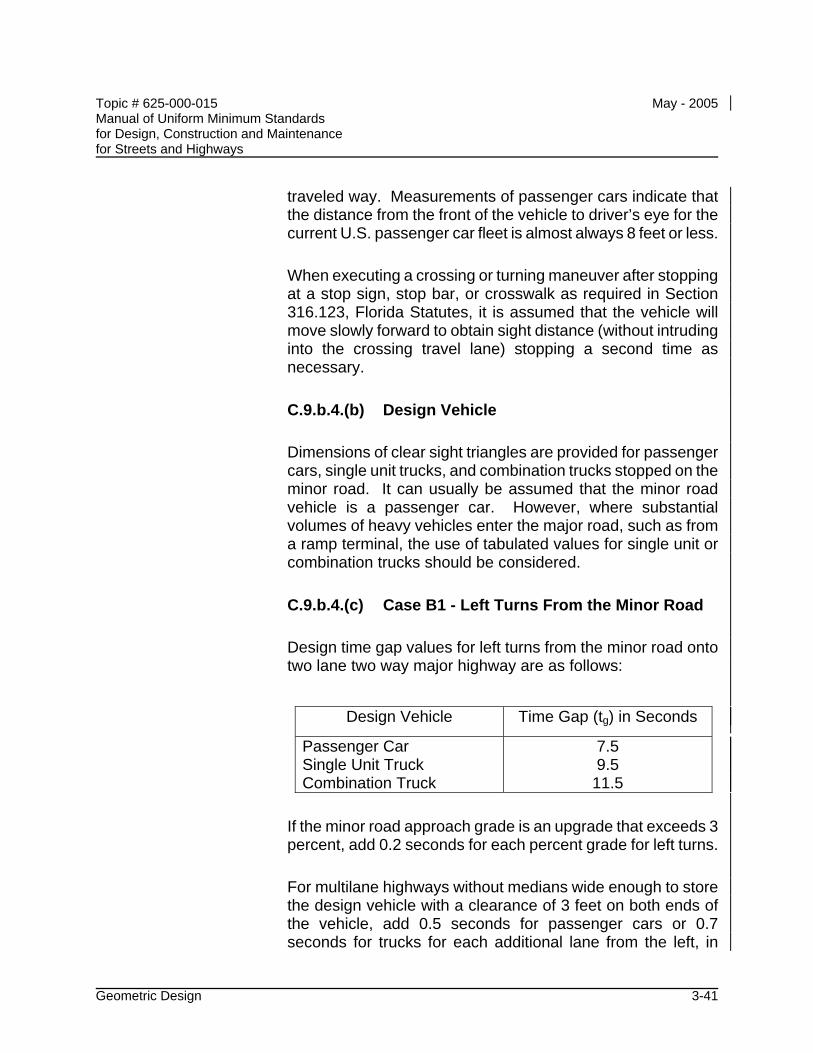
Topic # 625-000-015 May - 2005 Manual of Uniform Minimum Standards for Design, Construction and Maintenance for Streets and Highways
Geometric Design 3-41
traveled way. Measurements of passenger cars indicate that the distance from the front of the vehicle to driver’s eye for the current U.S. passenger car fleet is almost always 8 feet or less.
When executing a crossing or turning maneuver after stopping at a stop sign, stop bar, or crosswalk as required in Section 316.123, Florida Statutes, it is assumed that the vehicle will move slowly forward to obtain sight distance (without intruding into the crossing travel lane) stopping a second time as necessary.
C.9.b.4.(b) Design Vehicle
Dimensions of clear sight triangles are provided for passenger cars, single unit trucks, and combination trucks stopped on the minor road. It can usually be assumed that the minor road vehicle is a passenger car. However, where substantial volumes of heavy vehicles enter the major road, such as from a ramp terminal, the use of tabulated values for single unit or combination trucks should be considered.
C.9.b.4.(c) Case B1 - Left Turns From the Minor Road
Design time gap values for left turns from the minor road onto two lane two way major highway are as follows:
Design Vehicle Time Gap (tg) in Seconds
Passenger Car Single Unit Truck Combination Truck
7.5 9.5
11.5
If the minor road approach grade is an upgrade that exceeds 3 percent, add 0.2 seconds for each percent grade for left turns.
For multilane highways without medians wide enough to store the design vehicle with a clearance of 3 feet on both ends of the vehicle, add 0.5 seconds for passenger cars or 0.7 seconds for trucks for each additional lane from the left, in
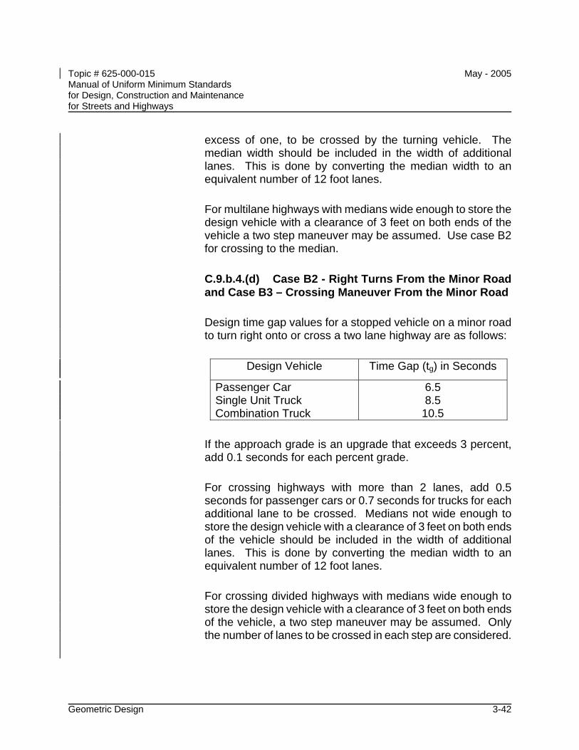
Topic # 625-000-015 May - 2005 Manual of Uniform Minimum Standards for Design, Construction and Maintenance for Streets and Highways
Geometric Design 3-42
excess of one, to be crossed by the turning vehicle. The median width should be included in the width of additional lanes. This is done by converting the median width to an equivalent number of 12 foot lanes.
For multilane highways with medians wide enough to store the design vehicle with a clearance of 3 feet on both ends of the vehicle a two step maneuver may be assumed. Use case B2 for crossing to the median.
C.9.b.4.(d) Case B2 - Right Turns From the Minor Road and Case B3 – Crossing Maneuver From the Minor Road
Design time gap values for a stopped vehicle on a minor road to turn right onto or cross a two lane highway are as follows:
Design Vehicle Time Gap (tg) in Seconds
Passenger Car Single Unit Truck Combination Truck
6.5 8.5
10.5
If the approach grade is an upgrade that exceeds 3 percent, add 0.1 seconds for each percent grade.
For crossing highways with more than 2 lanes, add 0.5 seconds for passenger cars or 0.7 seconds for trucks for each additional lane to be crossed. Medians not wide enough to store the design vehicle with a clearance of 3 feet on both ends of the vehicle should be included in the width of additional lanes. This is done by converting the median width to an equivalent number of 12 foot lanes.
For crossing divided highways with medians wide enough to store the design vehicle with a clearance of 3 feet on both ends of the vehicle, a two step maneuver may be assumed. Only the number of lanes to be crossed in each step are considered.
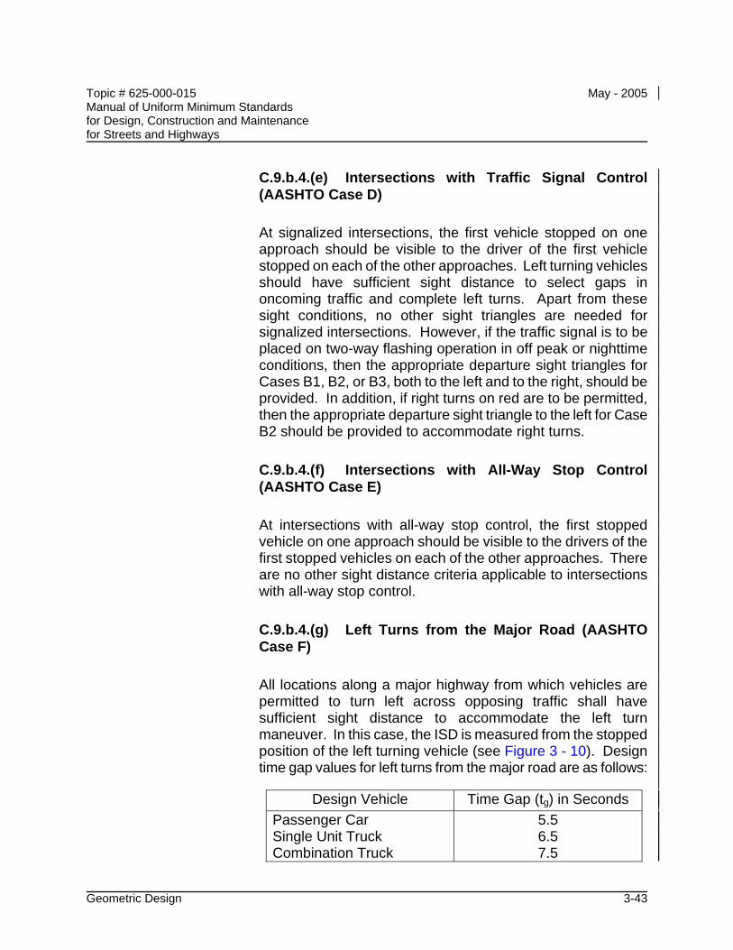
Topic # 625-000-015 May - 2005 Manual of Uniform Minimum Standards for Design, Construction and Maintenance for Streets and Highways
Geometric Design 3-43
C.9.b.4.(e) Intersections with Traffic Signal Control (AASHTO Case D)
At signalized intersections, the first vehicle stopped on one approach should be visible to the driver of the first vehicle stopped on each of the other approaches. Left turning vehicles should have sufficient sight distance to select gaps in oncoming traffic and complete left turns. Apart from these sight conditions, no other sight triangles are needed for signalized intersections. However, if the traffic signal is to be placed on two-way flashing operation in off peak or nighttime conditions, then the appropriate departure sight triangles for Cases B1, B2, or B3, both to the left and to the right, should be provided. In addition, if right turns on red are to be permitted, then the appropriate departure sight triangle to the left for Case B2 should be provided to accommodate right turns.
C.9.b.4.(f) Intersections with All-Way Stop Control (AASHTO Case E)
At intersections with all-way stop control, the first stopped vehicle on one approach should be visible to the drivers of the first stopped vehicles on each of the other approaches. There are no other sight distance criteria applicable to intersections with all-way stop control.
C.9.b.4.(g) Left Turns from the Major Road (AASHTO Case F)
All locations along a major highway from which vehicles are permitted to turn left across opposing traffic shall have sufficient sight distance to accommodate the left turn maneuver. In this case, the ISD is measured from the stopped position of the left turning vehicle (see Figure 3 - 10). Design time gap values for left turns from the major road are as follows:
Design Vehicle Time Gap (tg) in Seconds Passenger Car Single Unit Truck Combination Truck
5.5 6.5 7.5
Topic # 625-000-015 May - 2005 Manual of Uniform Minimum Standards for Design, Construction and Maintenance for Streets and Highways
Geometric Design 3-44
For left turning vehicles that cross more than one opposing lane, add 0.5 seconds for passenger cars and 0.7 seconds for trucks for each additional lane to be crossed.
C.9.b.4.(h) Intersection Sight Distance References
The Department’s Design Standards, Index 546, provides ISD values for several basic intersection configurations based on Cases B1, B2, B3, and D, and may be used when applicable. For additional guidance on Intersection Sight Distance, see the AASHTO Green Book.
C.9.c Auxiliary Lanes
Auxiliary lanes are desirable for the safe execution of speed change maneuvers (acceleration and deceleration) and for the storage and protection of turning vehicles. Auxiliary lanes for exit or entrance turning maneuvers shall be provided in accordance with the requirements set forth in C.8 Access Control, this chapter. The pavement width and cross slopes of auxiliary lanes should meet the minimum requirements for all travel lanes.
C.9.c.1 Merging Maneuvers
Merging maneuvers occur at the termination of climbing lanes, lane drops, entrance acceleration, and turning lanes. The location provided for this merging maneuver should, where possible, be on a tangent section of the roadway and should be of sufficient length to allow for a smooth, safe transition. The provision of ample distance for merging is essential to allow the driver time to find an acceptable gap in the through traffic and then execute a safe merging maneuver. It is recommended that a merging taper be on a 1:50 transition, but in no case shall the length be less than set forth in Table 3 - 15. The termination of this lane should be clearly visible from both the merging and through lane and should correspond to the general configuration shown in Figure 3 - 11. Advance warning of the merging lane termination should be provided. Lane drops shall be marked as required by the Manual on Uniform Traffic Control Devices (MUTCD).
Topic # 625-000-015 May - 2005 Manual of Uniform Minimum Standards for Design, Construction and Maintenance for Streets and Highways
Geometric Design 3-45
C.9.c.2 Acceleration Lanes
Acceleration lanes are required for all entrances to freeway ramps. Acceleration lanes may be desirable at access points to any street or highway with a large percentage of entering truck traffic.
The distance required for an acceleration maneuver is dependent on the vehicle acceleration capabilities, the grade, the initial entrance speed, and the final speed at the termination of the maneuver. The distances required for acceleration on level roadways for passenger cars are given in Table 3 - 16. Where acceleration occurs on a grade, the required distance is obtained by using Tables 3 - 16 and 3 - 17.
The final speed at the end of the acceleration lane, should, desirably, be assumed as the design speed of the through roadway. The length of acceleration lane provided should be at least as long as the distance required for acceleration between the initial and final speeds. Due to the uncertainties regarding vehicle capabilities and driver behavior, additional length is desirable. The acceleration lane should be followed by a merging taper (similar to Figure 3 - 11), not less than that length set forth in Table 3 - 15. The termination of acceleration lanes should conform to the general configuration shown for merging lanes in Figure 3 - 11. Recommended acceleration lanes for freeway entrance terminals are given in Table 3 - 19.
C.9.c.3 Exit Lanes
Auxiliary lanes for exiting maneuvers provide space outside the through lanes for protection and storage of decelerating vehicles exiting the facility.
• Deceleration Lanes - The primary function of deceleration lanes is to provide a safe travel path for vehicles decelerating from the operating speed on the through lanes. Deceleration lanes are required for all freeway exits and are desirable on high-speed (design speed greater than 50 mph) streets and highways.
The distance required for deceleration of passenger cars is given in Table 3 - 16.
Topic # 625-000-015 May - 2005 Manual of Uniform Minimum Standards for Design, Construction and Maintenance for Streets and Highways
Geometric Design 3-46
The required distance for deceleration on grades is given in Tables 3 - 16 and 3 - 17.
The length of deceleration lanes shall be no less than the values obtained from Tables 3 - 16 and 3 - 17, and should be increased wherever feasible. The initial speed should, desirably, be taken as the design speed of the highway. The final speed should be the design speed at the exit (e.g., a turning roadway) or zero, if the deceleration lane terminates at a stop or traffic signal. A reduction in the final speed to be used is particularly important if the exit traffic volume is high, since the speed of these vehicles may be significantly reduced.
The entrance to deceleration (and climbing) lanes should conform to the general configuration shown in Figure 3 - 12. The initial length of straight taper, shown in Table 3 - 16, may be utilized as a portion of the total required deceleration distance. The pavement surface of the deceleration lane should be clearly visible to approaching traffic, so drivers are aware of the maneuvers required. Recommended deceleration lanes for exit terminals are given in Table 3 - 18.
• Storage Lanes - Where exit lanes are required (C.8 Access Control, this chapter), or desirable on low speed streets and highways, storage lanes may be used in place of or in conjunction with deceleration lanes. Storage lanes should be considered on all facilities. Although the primary function of storage lanes is to provide protection and storage for turning vehicles, it is desirable to provide sufficient length to allow for deceleration capabilities. Storage lanes should conform to the general configuration shown in Figure 3 - 13.
The length of storage lanes for unsignalized intersections may be obtained from the table in Figure 3 - 13. The full width portion of storage lanes should, where possible, be increased to allow for expected storage of vehicles (Table 3 - 2 for vehicle lengths). As a minimum requirement, storage for at least two passenger cars (40 - 50 feet) should be provided.
On collector or arterial streets (design speed 45 mph or less), tapers preceding storage lanes and approaching intersections at grade may
Topic # 625-000-015 May - 2005 Manual of Uniform Minimum Standards for Design, Construction and Maintenance for Streets and Highways
Geometric Design 3-47
be shorter than those given in Table 3 - 16 (AASHTO for recommended lengths).
C.9.d Turning Roadways at Intersections
The design and construction of turning roadways shall meet the same general requirements for through roadways, except for the specific requirements given in the subsequent sections.
C.9.d.1 Design Speed
Lanes for turning movements at grade intersections may, where justified, be based on a design speed as low as 10 mph. Turning roadways with design speeds in excess of 40 mph shall be designed in accordance with the requirements for through roadways.
A variable design speed may be used to establish cross section and alignment criteria for turning roadways that will experience acceleration and deceleration maneuvers.
C.9.d.2 Horizontal Alignment
• Curvature - The minimum permitted radii (maximum degree) of curvature for various values of superelevation are given in Table 3 - 22. These should be considered as minimum values only and the radius of curvature should be increased wherever feasible. Further information contained in AASHTO – "A Policy on Geometric Design of Highways and Streets" - 2001, should also be considered.
• Superelevation Transition - Minimum superelevation transition (runoff) rates (maximum relative gradients) are given in Tables 3 - 23 and 3 - 24. Other information given in AASHTO – "A Policy on Geometric Design of Highways and Streets" - 2001, should also be considered.
C.9.d.3 Vertical Alignment
Grades on turning roadways should be as flat as practical and long
Topic # 625-000-015 May - 2005 Manual of Uniform Minimum Standards for Design, Construction and Maintenance for Streets and Highways
Geometric Design 3-48
vertical curves should be used wherever feasible. The length of vertical curves shall be no less than necessary to provide minimum stopping sight distance. Minimum stopping sight distance values are given in Table 3 - 14. For additional guidance on vertical alignment for turning roadways, see AASHTO – "A Policy on Geometric Design of Highways and Streets" - 2001.
C.9.d.4 Cross Section Elements
• Number of Lanes - One-way turning roadways are often limited to a single travel lane. In this case, the total width of the roadway shall be sufficient to allow traffic to pass a disabled vehicle. Two-way, undivided turning roadways should be avoided. Medians or barriers should be utilized to separate opposing traffic on turning roadways.
• Travel Lanes - The width of all travel lanes should be sufficient to accommodate (with adequate clearances) the turning movements of the expected types of vehicles. The minimum required lane widths for turning roadways are given in Table 3 - 21. Changes in lane widths should be gradual and should be accomplished in coordination with adequate transitions in horizontal curvature.
• Shoulders - On one-lane turning roadways, serving expressways and other principal arterials (e.g., loops, ramps), the right hand shoulder should be at least 6 feet wide. The left hand shoulder should be at least 6 feet wide in all cases. On two-lane, one-way roadways, both shoulders should be at least 6 feet wide. Where guardrails or other barriers are used, they should be placed at least 8 feet from edge of travel lane. Guardrails should be placed 2 feet outside the normal shoulder width.
• Clear Zones - Turning roadways should, as a minimum, meet all open highway criteria for clear zones on both sides of the roadway. The areas on the outside of curves should be wider and more gently sloped than the minimum values for open highways. Guardrails or similar barriers shall be used if the minimum width and slope requirements cannot be obtained.
Topic # 625-000-015 May - 2005 Manual of Uniform Minimum Standards for Design, Construction and Maintenance for Streets and Highways
Geometric Design 3-49
Further criteria and requirements for roadway design are given in CHAPTER 4 - ROADSIDE DESIGN.
C.9.e At Grade Intersections
C.9.e.1 Turning Radii
Where right turns from through or turn lanes will be negotiated at low speeds (less than 10 mph), the minimum turning capabilities of the vehicle may govern the design. It is desirable that the turning radius and the required lane width be provided in accordance with the criteria for turning roadways. The radius of the inside pavement edge should, however, be sufficient to allow the expected vehicles to negotiate the turn without encroaching the shoulder or adjacent travel lanes.
Where turning roadway criteria are not used, the radius of the inside pavement edge should be no less than 25 feet. The use of three-centered compound curves is also a reasonable practice to allow for transition into and out of the curve. The recommended radii and arrangement of compound curves instead of a single simple curve is given in AASHTO – "A Policy on Geometric Design of Highways and Streets" - 2001.
C.9.e.2 Cross Section Correlation
The correlation of the cross section of two intersecting roadways is frequently difficult. A careful analysis should be conducted to ensure changes in slope are not excessive and adequate drainage is provided. At stop-controlled intersections, the through roadway cross section should be carried through the intersection without interruption. Minor roadways should approach the intersection at a slightly reduced elevation so main highway cross section is not disturbed. At signalized intersections, it is sometimes necessary to remove part of the crown in order to avoid an undesirable hump in one roadway.
Intersections of grade or cross slope should be gently rounded to improve vehicle operation. Pavement generally should be sloped toward the intersection corners to provide superelevation for turning maneuvers and to promote proper drainage.
Topic # 625-000-015 May - 2005 Manual of Uniform Minimum Standards for Design, Construction and Maintenance for Streets and Highways
Geometric Design 3-50
Where islands are used for channelization, the width of travel lanes for turning movements shall be no less than the widths recommended by AASHTO.
C.9.e.3 Median Openings
Median openings should be restricted in accordance with the requirements presented in C.8 Access Control, this chapter. Where a median opening is required, the length of the opening shall be no less than 40 feet. Median curbs should be terminated gradually without the exposure of abrupt curb ends. The termination requirements are given in CHAPTER 4 - ROADSIDE DESIGN.
C.9.e.4 Channelization
Channelization of at grade intersections is the regulation or separation of conflicting movements into definite travel paths by islands, markings, or other means, to promote safe, orderly traffic flow. The major objective of channelization is to clearly define the appropriate paths of travel and thus assist in the prevention of vehicles deviating excessively or making wrong maneuvers. Channelization may be used effectively to define the proper path for exits, entrances, and intersection turning movements. The methods used for channelization should be as simple as possible and consistent in nature. The channelized intersection should appear open and natural to the approaching driver. Channelization should be informative rather than restrictive in nature.
The use of low easily mounted curbs and flush medians and islands can provide adequate delineation in most cases. Island should be clearly visible and, in general, should not be smaller than 100 square feet in area. The use of small and/or numerous islands should be avoided.
Pavement markings are a useful and effective tool for providing delineation and channelization in an informative rather than restrictive fashion. The layout of all traffic control devices should be closely coordinated with the design of all channelization.
Topic # 625-000-015 May - 2005 Manual of Uniform Minimum Standards for Design, Construction and Maintenance for Streets and Highways
Geometric Design 3-51
C.9.f Driveways
Direct driveway access within the area of influence of the intersection should be discouraged.
Driveways from major traffic generators (greater than 400 vpd), or those with significant truck/bus traffic, should be designed as normal intersections.
C.9.g Interchanges
The design of interchanges for the intersection of a freeway with a major highway, collector/distributor road, or other freeway is a complex problem. The location and spacing of intersections should follow the requirements presented in C.8 Access Control, this chapter. The design of interchanges shall follow the general intersection requirements for deceleration, acceleration, merging maneuvers, turning roadways, and sight distance.
Interchanges, particularly along a given freeway, should be reasonably consistent in their design. A basic principle in the design should be to develop simple open interchanges that are easily traversed and understandable to the driver. Complex interchanges with a profusion of possible travel paths are confusing and hazardous to the motorist and are generally inefficient.
Intersections with minor highway or collector/distributor roads may be accomplished by simple diamond interchanges. The intersection of exit and entrance ramps with the crossroad shall meet all intersection requirements.
The design of freeway exits should conform to the general configurations given in Table 3 - 18. Exits should be on the right and should be placed on horizontal curves. Where deceleration on an exit loop is required, the deceleration alignment should be designed so the driver receives adequate warning of the approaching increase in curvature. This is best accomplished by gradually increasing the curvature and the resulting centrifugal force. This increasing centrifugal force provides warning to the driver that he must slow down. A clear view of the exit loop should also be provided. The length of deceleration shall be no less than the values shown in Table 3 - 18.
Entrances to freeways should be designed in accordance with the general configurations shown below Table 3 - 19. Special care should be taken to
Topic # 625-000-015 May - 2005 Manual of Uniform Minimum Standards for Design, Construction and Maintenance for Streets and Highways
Geometric Design 3-52
ensure vehicles entering from loops are not directed across through travel lanes. The entering roadway should be brought parallel (or nearly so) to the through lanes before entry is permitted. Where acceleration is required, the distances shown in Table 3 - 19 shall, as a minimum, be provided. Exits and entrances to all high-speed facilities (design speed greater than 50 mph), should, where feasible, be designed in accordance with Tables 3 - 18 and 3 - 19. The lengths obtained from Tables 3 - 18 and 3 - 19 should be adjusted for grade by using the ratios in Table 3 - 17.
The selection of the type and exact design details of a particular interchange requires considerable study and thought. The guidelines and design details given in AASHTO "A Policy on Geometric Design of Highways and Streets" - 2001, should generally be considered as minimum criteria.
C.9.h Clear Zone
The provisions of ample clear zone or proper redirection of energy absorbing devices is particularly important at intersections. Every effort should be made to open up the area around the intersection to provide adequate clear zone for vehicles that have left the traveled way. Drivers frequently leave the proper travel path due to unsuccessful turning maneuvers or due to the necessity for emergency avoidance maneuvers. Vehicles also leave the roadway after intersection collisions and roadside objects should be removed to reduce the probability of second impacts. The roadside areas at all intersections and interchanges should be contoured to provide shallow slopes and gentle changes in grade.
The roadside clear zone of intersecting roadways should be carried throughout intersections with no discontinuities or interruptions. Poles and support structures for lights, signs, and signals should not be placed in medians or within the roadside clear zone.
The design of guardrails or other barriers should receive particular attention at intersections. Impact attenuators should be used in all gore and other areas where structures cannot be removed.
Particular attention should be given to the protection of pedestrians in intersection areas - CHAPTER 8 - PEDESTRIAN FACILITIES. Further criteria and requirements for clear zone and protection devices at intersections are given in CHAPTER 4 - ROADSIDE DESIGN.
Topic # 625-000-015 May - 2005 Manual of Uniform Minimum Standards for Design, Construction and Maintenance for Streets and Highways
Geometric Design 3-53
C.10 Other Design Factors
C.10.a Pedestrian Facilities
The layout and design of the highway network should include provisions for pedestrian traffic in urban areas. All pedestrian crossings and pathways within the highway right of way should be considered and designed as in integral part of any street or urban highway. Design shall be in compliance with the Accessibility Guidelines (as described in the Federal Register), and the Florida Accessibility Code For Building Construction (Rule 9B-7.0042).
C.10.a.1 Policy and Objectives - New Facilities
The planning and design of new streets and urban highways shall include provisions for the safe orderly movement of pedestrian traffic. Provisions for pedestrian travel outside of the highway right of way should be considered.
The overall objective is to provide a safe, secure, continuous, convenient, and comfortable trip continuity and access environment for pedestrian traffic.
C.10.a.2 Accessibility Requirements
Pedestrian facilities, such as walkways and sidewalks, must be designed to accommodate physically disabled persons whose mobility is dependent on wheelchairs and other devices. Note: Design shall be in compliance with the ADA Accessibility Guidelines (as described in the Federal Register), and the Florida Accessibility Code For Building Construction (Rule 9B-7.0042). Complete design criteria can be found in this publication.
C.10.a.3 Sidewalks
Sidewalks should provide a safe, comfortable space for pedestrians. The width of sidewalks is dependent upon the roadside environment; volume of pedestrians; and the presence of businesses, schools, parks, and other pedestrian attractors. The minimum width for sidewalks is 4 feet. Where sidewalks are placed adjacent to the curb,
Topic # 625-000-015 May - 2005 Manual of Uniform Minimum Standards for Design, Construction and Maintenance for Streets and Highways
Geometric Design 3-54
the walkway widths should be approximately 2 feet wider. To ensure compliance with the ADA Accessibility Guidelines (as described in the Federal Register), and the Florida Accessibility Code For Building Construction, sidewalk design shall meet the following criteria: Minimum clear width - 36 inches1, 2 Maximum cross slope - 0.02% Maximum slope - 1:203 1 Sidewalks less than 60 inches wide must have passing spaces at least 60 inches
by 60 inches at intervals not to exceed 200 feet. 2 The minimum clear width may be reduced to 32 inches for a short distance. This
distance must be less than 24 inches long and separated by 5-foot long sections with 36 inches of clear width.
3 Slopes greater than 1:20 are considered ramps and must be designed as such.
Sidewalks 5 feet wide or wider will provide for two adults to walk comfortably side by side.
C.10.a.4 Curb Ramps
In areas with sidewalks, curb ramps must be incorporated at locations where crosswalks adjoin the sidewalks. The basic curb ramp type and design application depends on the geometric characteristics of the intersection or other crossing location.
Typical curb ramp width shall be a minimum of 3 feet with 1:12 curb transitions on each side when pedestrians must walk across the ramp. Ramp slopes shall not exceed 1:12 and shall have a slip resistant surface texture. Ramp widths equal to crosswalk widths are encouraged.
Curb ramps at marked crossings shall be wholly contained within the crosswalk markings excluding any flared sides.
If diagonal ramps must be used, any returned curbs or other well-defined edges shall be parallel to the pedestrian flow. The bottom of diagonal curb ramps shall have 48-inch minimum clear space within the crosswalk. If diagonal curb ramps have flared sides, they shall also have at least a 24-inch long segment of straight curb located on each side of the curb ramp and within the marked crossing.
Topic # 625-000-015 May - 2005 Manual of Uniform Minimum Standards for Design, Construction and Maintenance for Streets and Highways
Geometric Design 3-55
It is important to visually impaired persons using the sidewalk that the location of the ramps be as uniform as possible. A contrasting surface texture should be used. On sections without curb and gutter, a contrasting surface texture should be used on the approach to crosswalks.
The Department's Design Standards, Index 304, which addresses the design of curb ramps, may be considered. Designers should keep in mind there are many variables involved making each street intersection a special problem. For this reason, standard guidelines will not fit all situations and cannot replace the need for the use of sound engineering judgment in the design of curb ramps.
Two ramps per corner are preferred to minimize the problems with entry angle and to decrease the delay to people in wheel chairs or visually impaired pedestrians entering and exiting the roadway.
C.10.a.5 Additional Considerations
For additional information on pedestrian facilities design, including physical separation from the roadway, over- and underpasses, pedestrian crossings, traffic control, sight distance and lighting, refer to CHAPTER 8 – PEDESTRIAN FACILITIES.
C.10.b Bicycle Facilities
Provisions for bicycle traffic should be incorporated into the original highway design. All new roadways and major corridor improvements, except limited access highways, should be designed and constructed under the assumption they will be used by bicyclists. Roadway conditions should be favorable for bicycling. This includes safe drainage grates, pavement markings, and railroad crossings, smooth pavements, and signals responsive to bicycles. In addition, facilities such as bicycle lanes, bicycle routes, and shoulder improvements, should be included to the fullest extent feasible. All rural arterial and collector sections should be given consideration for the construction of 4-foot or 5-foot paved shoulders. In addition, all urban arterial and collector sections should be given consideration for either undesignated or designated 4-foot bike lanes.
Topic # 625-000-015 May - 2005 Manual of Uniform Minimum Standards for Design, Construction and Maintenance for Streets and Highways
Geometric Design 3-56
For additional information on bicycle facilities design and the design of shared use paths, refer to CHAPTER 9 – BICYCLE FACILITIES.
C.10.c Bridge Design Loadings
The minimum design loading for all new and reconstructed bridges shall be in accordance with CHAPTER 17 – BRIDGES AND OTHER STRUCTURES.
C.10.d Dead End Streets and Cul-de-sacs
The end of a dead end street should permit travel return with a turn around area, considering backing movements, which will accommodate single truck or transit vehicles without encroachment upon private property. Recommended treatment for dead end streets and cul-de-sacs is given in Exhibit 5-8 of AASHTO – "A Policy on Geometric Design of Highways and Streets" - 2001.
C.10.e Bus Benches and Transit Shelters
Due to the length of exposure and discomfort from traffic, bus benches should be set back at least 10 feet from the travel lane in curbed sections and outside the clear zone (Table 3 - 12) in non curbed sections.
Any bus bench or transit shelter located adjacent to a sidewalk within the right of way of any road on the State Highway or County Road System shall be located so as to leave at least 36 inches clearance for pedestrians and persons in wheelchairs. Such clearance shall be measured in a direction perpendicular to the centerline of the road. A separate bench pad or sidewalk flareout should be considered. Transit shelters should be set back, rather than eliminated during roadway widening.
C.10.f Traffic Calming
Often there are community concerns with controlling travel speeds impacting the safety of a corridor such as in areas of concentrated pedestrian activities, those with narrow right of way, areas with numerous access points, on street parking, and other similar concerns. Local authorities may elect to use traffic calming design features that could include, but not be limited to, the installation of speed humps, speed tables, chicanes, or other pavement
Topic # 625-000-015 May - 2005 Manual of Uniform Minimum Standards for Design, Construction and Maintenance for Streets and Highways
Geometric Design 3-57
undulations. Roundabouts are also another method of dealing with this issue at intersections. For additional details and traffic calming treatments, refer to CHAPTER 15 – TRAFFIC CALMING.
C.11 Reconstruction
C.11.a Introduction
The reconstruction (improvement or upgrading) of existing facilities may generate equal or greater safety benefits than similar expenditures for the construction of new streets and highways. Modifications to increase capacity should be evaluated for the potential effect on the highway safety characteristics. The long-range objectives should be to bring the existing network into compliance with current standards.
C.11.b Evaluation of Streets and Highways
The evaluation of the safety characteristics of streets and highways should be directed towards the identification of undesirable features on the existing system. Particular effort should be exerted to identify the location and nature of features with a high crash potential. Methods for identifying and evaluating hazards include the following:
• Identification of any geometric design feature not in compliance with minimum or desirable standards. This could be accomplished through a systematic survey and evaluation of existing facilities.
• Review of conflict points along a corridor.
• Information from maintenance or other personnel.
• Review of crash reports and traffic counts to identify locations with a large number of crashes or a high crash rate.
• Review for expected pedestrian and bicycle needs.
C.11.c Priorities
A large percentage of highway reconstruction and improvements is directed toward increasing efficiency and capacity. The program of reconstruction
Topic # 625-000-015 May - 2005 Manual of Uniform Minimum Standards for Design, Construction and Maintenance for Streets and Highways
Geometric Design 3-58
should be based, to a large extent, upon priorities for the improvement of safety characteristics.
The priorities for safety improvements should be based on the objective of obtaining the maximum reduction in crash potential for a given expenditure of funds. Elimination of conditions that may result in serious or fatal crashes should receive the highest priority in the schedule for reconstruction.
Specific high priority problem areas that should be corrected by reconstruction include the following:
• Obstructions to sight distance which can be economically corrected. The removal of buildings, parked vehicles, vegetation, large poles or groups of poles that significantly reduce the field of vision, and signs to improve sight distance on curves and particularly at intersections, can be of immense benefit in reducing crashes. The purchase of required line of sight easements is often a wise expenditure of highway funds. The establishment of sight distance setback lines is encouraged.
• Roadside and median hazards which can often be removed or relocated farther from the traveled way. Where removal is not feasible, objects should be shielded by redirection or energy absorbing devices. The reduction of the roadside hazard problem generally provides a good return on the safety dollar. Details and priorities for roadside hazard reduction, which are presented in CHAPTER 4 - ROADSIDE DESIGN, should be incorporated into the overall priorities of the reconstruction program.
• Poor pavement surfaces which have become hazardous should be maintained or reconstructed in accordance with the design criteria set forth in CHAPTER 5 - PAVEMENT DESIGN AND CONSTRUCTION, and CHAPTER 10 - MAINTENANCE.
• Specific design features which could be applied during reconstruction to enhance the operations and safety characteristics of a roadway include the following:
• Addition of roadway lighting.
Topic # 625-000-015 May - 2005 Manual of Uniform Minimum Standards for Design, Construction and Maintenance for Streets and Highways
Geometric Design 3-59
• The provision of frontage roads of other alternate paths. This may be utilized to improve the efficiency and safety of streets and highways with poor control of access.
• Widening of pavements and shoulders. This is often an economically feasible method of increasing capacity and reducing traffic hazards. Provision of median barriers (CHAPTER 4 - ROADSIDE DESIGN) can also produce significant safety benefits.
• The removal, streamlining, or modification of drainage structures.
• Alignment modifications are usually extensive and require extensive reconstruction of the roadway. Removal of isolated sharp curves is a reasonable and logical step in alignment modification. If major realignment is to be undertaken, every effort should be made to bring the entire facility into compliance with the requirements for new construction.
• The use of traffic control devices. This is generally an inexpensive method of alleviating certain highway defects.
• Median opening modifications.
• Addition of median, channelized islands, and mid-block pedestrian crossings.
• Auxiliary lanes.
• Existing bridges that fail to meet current design standards which are available to bicycle traffic, should be retrofitted on an interim basis as follows: As a general practice, bridges 125 feet in length or longer, bridges with unusual sight problem, steep gradients (which require the cyclist longer time to clear the span) or other unusual conditions should display the standard W11-1 caution sign with an added sign "On Bridge" at either end of the structure. Special care should be given to the right most portion of the roadway, where bicyclists are expected to travel, assuring smoothness, pavement uniformity, and freedom from longitudinal joints, and to ensure cleanliness. Failure to do so forces bicyclists farther into the center portion of the bridge, reducing traffic flow and safety.
Topic # 625-000-015 May - 2005 Manual of Uniform Minimum Standards for Design, Construction and Maintenance for Streets and Highways
Geometric Design 3-60
• Addition of bike accommodations designated or undesignated.
• Addition of transit facilities, sidewalks, crosswalks, and other pedestrian features.
C.12 Design Exceptions
See CHAPTER 14 - DESIGN EXCEPTIONS for the process to use when the standard criteria found in this Manual cannot be met.
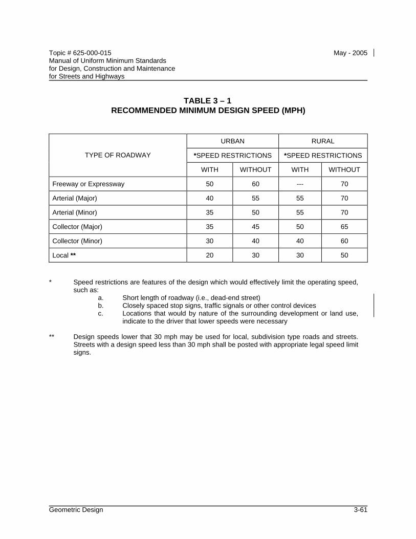
Topic # 625-000-015 May - 2005 Manual of Uniform Minimum Standards for Design, Construction and Maintenance for Streets and Highways
Geometric Design 3-61
TABLE 3 – 1 RECOMMENDED MINIMUM DESIGN SPEED (MPH)
URBAN RURAL
*SPEED RESTRICTIONS *SPEED RESTRICTIONS TYPE OF ROADWAY
WITH WITHOUT WITH WITHOUT
Freeway or Expressway 50 60 --- 70
Arterial (Major) 40 55 55 70
Arterial (Minor) 35 50 55 70
Collector (Major) 35 45 50 65
Collector (Minor) 30 40 40 60
Local ** 20 30 30 50
* Speed restrictions are features of the design which would effectively limit the operating speed,
such as: a. Short length of roadway (i.e., dead-end street) b. Closely spaced stop signs, traffic signals or other control devices c. Locations that would by nature of the surrounding development or land use,
indicate to the driver that lower speeds were necessary ** Design speeds lower that 30 mph may be used for local, subdivision type roads and streets.
Streets with a design speed less than 30 mph shall be posted with appropriate legal speed limit signs.
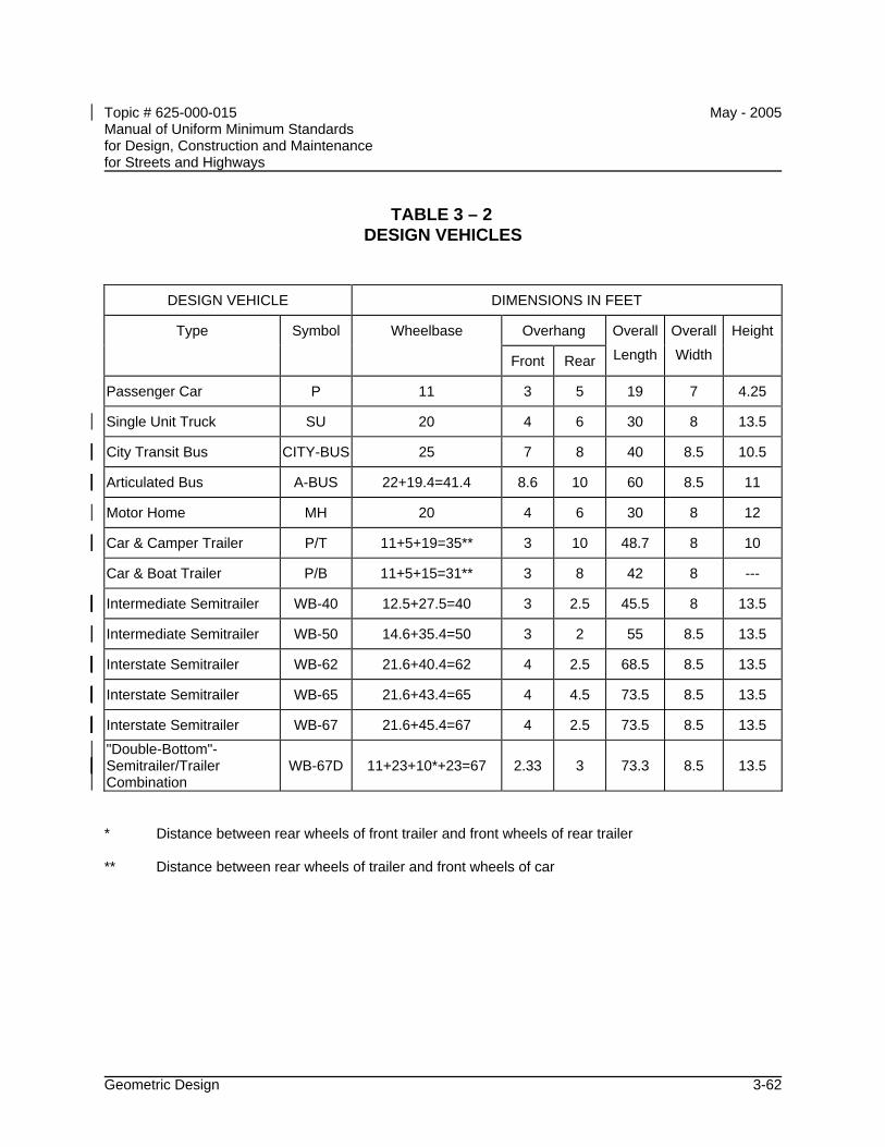
Topic # 625-000-015 May - 2005 Manual of Uniform Minimum Standards for Design, Construction and Maintenance for Streets and Highways
Geometric Design 3-62
TABLE 3 – 2 DESIGN VEHICLES
DESIGN VEHICLE DIMENSIONS IN FEET
Type Symbol Wheelbase Overhang Overall Overall Height
Front Rear Length Width
Passenger Car P 11 3 5 19 7 4.25
Single Unit Truck SU 20 4 6 30 8 13.5
City Transit Bus CITY-BUS 25 7 8 40 8.5 10.5
Articulated Bus A-BUS 22+19.4=41.4 8.6 10 60 8.5 11
Motor Home MH 20 4 6 30 8 12
Car & Camper Trailer P/T 11+5+19=35** 3 10 48.7 8 10
Car & Boat Trailer P/B 11+5+15=31** 3 8 42 8 ---
Intermediate Semitrailer WB-40 12.5+27.5=40 3 2.5 45.5 8 13.5
Intermediate Semitrailer WB-50 14.6+35.4=50 3 2 55 8.5 13.5
Interstate Semitrailer WB-62 21.6+40.4=62 4 2.5 68.5 8.5 13.5
Interstate Semitrailer WB-65 21.6+43.4=65 4 4.5 73.5 8.5 13.5
Interstate Semitrailer WB-67 21.6+45.4=67 4 2.5 73.5 8.5 13.5
"Double-Bottom"-Semitrailer/Trailer Combination
WB-67D 11+23+10*+23=67 2.33 3 73.3 8.5 13.5
* Distance between rear wheels of front trailer and front wheels of rear trailer ** Distance between rear wheels of trailer and front wheels of car
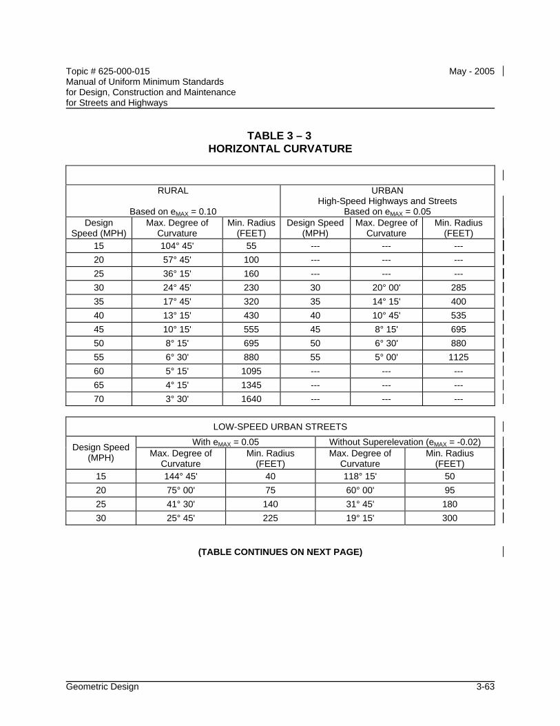
Topic # 625-000-015 May - 2005 Manual of Uniform Minimum Standards for Design, Construction and Maintenance for Streets and Highways
Geometric Design 3-63
TABLE 3 – 3 HORIZONTAL CURVATURE
RURAL
Based on eMAX = 0.10
URBAN High-Speed Highways and Streets
Based on eMAX = 0.05 Design
Speed (MPH) Max. Degree of
Curvature Min. Radius
(FEET) Design Speed
(MPH) Max. Degree of
Curvature Min. Radius
(FEET) 15 104° 45' 55 --- --- --- 20 57° 45' 100 --- --- --- 25 36° 15' 160 --- --- --- 30 24° 45' 230 30 20° 00' 285 35 17° 45' 320 35 14° 15' 400 40 13° 15' 430 40 10° 45' 535 45 10° 15' 555 45 8° 15' 695 50 8° 15' 695 50 6° 30' 880 55 6° 30' 880 55 5° 00' 1125 60 5° 15' 1095 --- --- --- 65 4° 15' 1345 --- --- --- 70 3° 30' 1640 --- --- ---
LOW-SPEED URBAN STREETS
With eMAX = 0.05 Without Superelevation (eMAX = -0.02) Design Speed (MPH) Max. Degree of
Curvature Min. Radius
(FEET) Max. Degree of
Curvature Min. Radius
(FEET) 15 144° 45' 40 118° 15' 50 20 75° 00' 75 60° 00' 95 25 41° 30' 140 31° 45' 180 30 25° 45' 225 19° 15' 300
(TABLE CONTINUES ON NEXT PAGE)
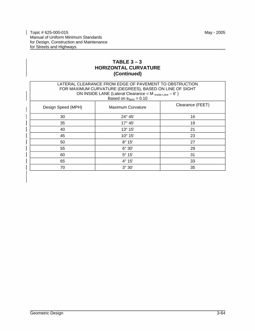
Topic # 625-000-015 May - 2005 Manual of Uniform Minimum Standards for Design, Construction and Maintenance for Streets and Highways
Geometric Design 3-64
TABLE 3 – 3 HORIZONTAL CURVATURE
(Continued)
LATERAL CLEARANCE FROM EDGE OF PAVEMENT TO OBSTRUCTION FOR MAXIMUM CURVATURE (DEGREES), BASED ON LINE OF SIGHT
ON INSIDE LANE (Lateral Clearance = M Inside Lane – 6' ) Based on eMAX = 0.10
Design Speed (MPH) Maximum Curvature Clearance (FEET)
30 24° 45' 16 35 17° 45' 19 40 13° 15' 21 45 10° 15' 23 50 8° 15' 27 55 6° 30' 29 60 5° 15' 31 65 4° 15' 33 70 3° 30' 35
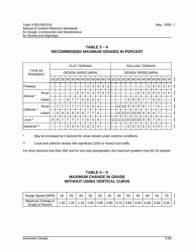
Topic # 625-000-015 May - 2005 Manual of Uniform Minimum Standards for Design, Construction and Maintenance for Streets and Highways
Geometric Design 3-65
TABLE 3 – 4 RECOMMENDED MAXIMUM GRADES IN PERCENT
FLAT TERRAIN ROLLING TERRAIN
DESIGN SPEED (MPH) DESIGN SPEED (MPH) TYPE OF ROADWAY
15 20 25 30 35 40 45 50 55 60 65 70 15 20 25 30 35 40 45 50 55 60 65 70
Freeway --- --- --- --- --- --- --- 4 4 3 3 3 --- --- --- --- --- --- --- 5 5 4 4 4
Rural --- --- --- --- --- 5 5 4 4 3 3 3 --- --- --- --- --- 6 6 5 5 4 4 4Arterial *
Urban --- --- --- 8 7 7 6 6 5 5 --- --- --- --- --- 9 8 8 7 7 6 6 --- ---
Rural --- 7 7 7 7 7 7 6 6 5 --- --- --- 10 10 9 9 8 8 7 7 6 --- ---Collector *
Urban --- 9 9 9 9 9 8 7 7 6 --- --- --- 12 12 11 10 10 9 8 8 7 --- ---
Local * 9 8 7 7 7 7 7 6 6 5 --- --- 12 11 11 10 10 10 9 8 7 6 --- ---
Industrial ** --- --- --- 4 4 4 4 3 3 3 --- --- --- --- --- 5 5 5 5 4 4 4 --- ---
* May be increased by 2 percent for urban streets under extreme conditions. ** Local and collector streets with significant (15% or more) truck traffic. For short sections less than 500' and for one-way downgrades, the maximum gradient may be 1% steeper.
TABLE 3 – 5 MAXIMUM CHANGE IN GRADE
WITHOUT USING VERTICAL CURVE
Design Speed (MPH) 15 20 25 30 35 40 45 50 55 60 65 70
Maximum Change in Grade in Percent 1.30 1.20 1.10 1.00 0.90 0.80 0.70 0.60 0.50 0.40 0.30 0.20
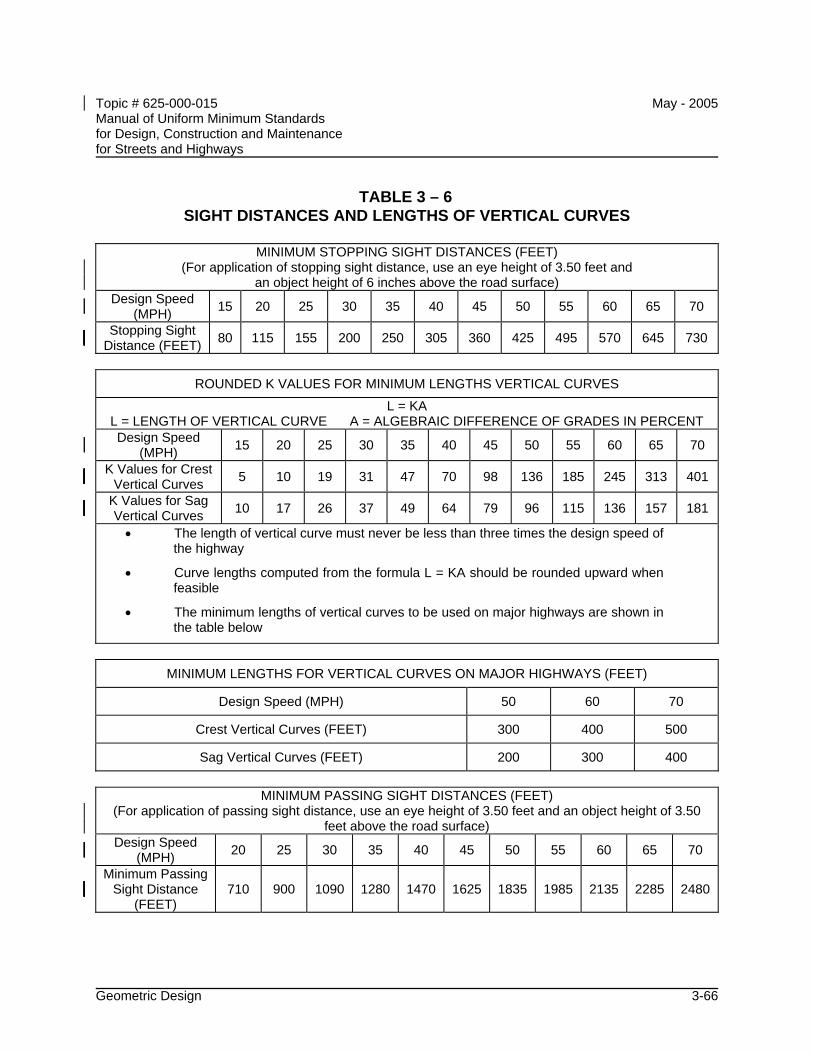
Topic # 625-000-015 May - 2005 Manual of Uniform Minimum Standards for Design, Construction and Maintenance for Streets and Highways
Geometric Design 3-66
TABLE 3 – 6 SIGHT DISTANCES AND LENGTHS OF VERTICAL CURVES
MINIMUM STOPPING SIGHT DISTANCES (FEET)
(For application of stopping sight distance, use an eye height of 3.50 feet and an object height of 6 inches above the road surface)
Design Speed (MPH) 15 20 25 30 35 40 45 50 55 60 65 70
Stopping Sight Distance (FEET) 80 115 155 200 250 305 360 425 495 570 645 730
ROUNDED K VALUES FOR MINIMUM LENGTHS VERTICAL CURVES
L = KA L = LENGTH OF VERTICAL CURVE A = ALGEBRAIC DIFFERENCE OF GRADES IN PERCENT Design Speed
(MPH) 15 20 25 30 35 40 45 50 55 60 65 70
K Values for Crest Vertical Curves 5 10 19 31 47 70 98 136 185 245 313 401
K Values for Sag Vertical Curves 10 17 26 37 49 64 79 96 115 136 157 181
• The length of vertical curve must never be less than three times the design speed of the highway
• Curve lengths computed from the formula L = KA should be rounded upward when feasible
• The minimum lengths of vertical curves to be used on major highways are shown in the table below
MINIMUM LENGTHS FOR VERTICAL CURVES ON MAJOR HIGHWAYS (FEET)
Design Speed (MPH) 50 60 70
Crest Vertical Curves (FEET) 300 400 500
Sag Vertical Curves (FEET) 200 300 400
MINIMUM PASSING SIGHT DISTANCES (FEET)
(For application of passing sight distance, use an eye height of 3.50 feet and an object height of 3.50 feet above the road surface)
Design Speed (MPH) 20 25 30 35 40 45 50 55 60 65 70
Minimum Passing Sight Distance
(FEET) 710 900 1090 1280 1470 1625 1835 1985 2135 2285 2480
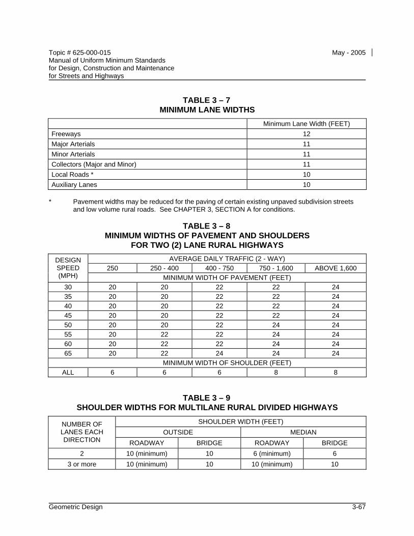
Topic # 625-000-015 May - 2005 Manual of Uniform Minimum Standards for Design, Construction and Maintenance for Streets and Highways
Geometric Design 3-67
TABLE 3 – 7 MINIMUM LANE WIDTHS
Minimum Lane Width (FEET) Freeways 12 Major Arterials 11 Minor Arterials 11 Collectors (Major and Minor) 11 Local Roads * 10 Auxiliary Lanes 10
* Pavement widths may be reduced for the paving of certain existing unpaved subdivision streets
and low volume rural roads. See CHAPTER 3, SECTION A for conditions.
TABLE 3 – 8 MINIMUM WIDTHS OF PAVEMENT AND SHOULDERS
FOR TWO (2) LANE RURAL HIGHWAYS AVERAGE DAILY TRAFFIC (2 - WAY)
250 250 - 400 400 - 750 750 - 1,600 ABOVE 1,600 DESIGN SPEED (MPH) MINIMUM WIDTH OF PAVEMENT (FEET)
30 20 20 22 22 24 35 20 20 22 22 24 40 20 20 22 22 24 45 20 20 22 22 24 50 20 20 22 24 24 55 20 22 22 24 24 60 20 22 22 24 24 65 20 22 24 24 24 MINIMUM WIDTH OF SHOULDER (FEET)
ALL 6 6 6 8 8
TABLE 3 – 9 SHOULDER WIDTHS FOR MULTILANE RURAL DIVIDED HIGHWAYS
SHOULDER WIDTH (FEET) OUTSIDE MEDIAN
NUMBER OF LANES EACH DIRECTION ROADWAY BRIDGE ROADWAY BRIDGE
2 10 (minimum) 10 6 (minimum) 6 3 or more 10 (minimum) 10 10 (minimum) 10
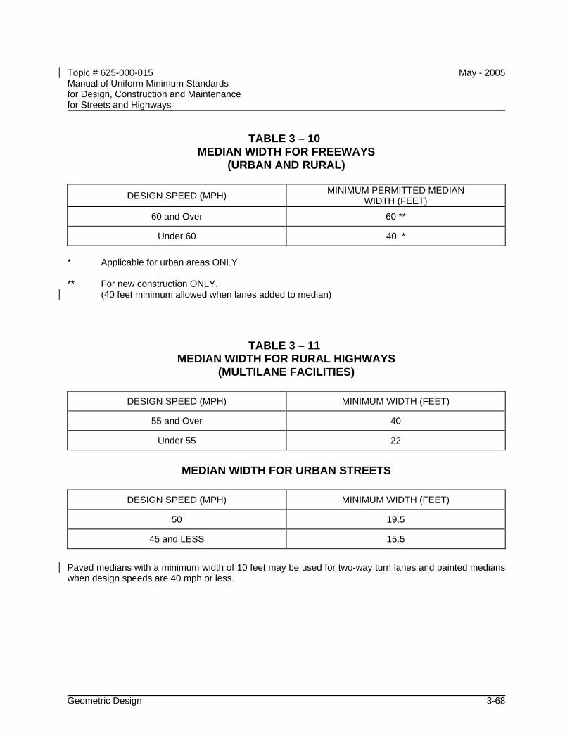
Topic # 625-000-015 May - 2005 Manual of Uniform Minimum Standards for Design, Construction and Maintenance for Streets and Highways
Geometric Design 3-68
TABLE 3 – 10 MEDIAN WIDTH FOR FREEWAYS
(URBAN AND RURAL)
DESIGN SPEED (MPH) MINIMUM PERMITTED MEDIAN WIDTH (FEET)
60 and Over 60 **
Under 60 40 *
* Applicable for urban areas ONLY. ** For new construction ONLY. (40 feet minimum allowed when lanes added to median)
TABLE 3 – 11 MEDIAN WIDTH FOR RURAL HIGHWAYS
(MULTILANE FACILITIES)
DESIGN SPEED (MPH) MINIMUM WIDTH (FEET)
55 and Over 40
Under 55 22
MEDIAN WIDTH FOR URBAN STREETS
DESIGN SPEED (MPH) MINIMUM WIDTH (FEET)
50 19.5
45 and LESS 15.5
Paved medians with a minimum width of 10 feet may be used for two-way turn lanes and painted medians when design speeds are 40 mph or less.
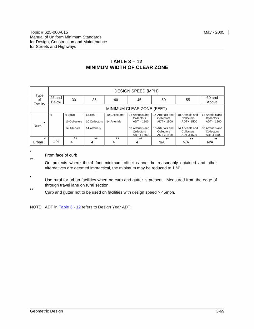
Topic # 625-000-015 May - 2005 Manual of Uniform Minimum Standards for Design, Construction and Maintenance for Streets and Highways
Geometric Design 3-69
TABLE 3 – 12 MINIMUM WIDTH OF CLEAR ZONE
DESIGN SPEED (MPH)
25 and Below 30 35 40 45 50 55 60 and
Above
Type of
Facility MINIMUM CLEAR ZONE (FEET)
Rural •
6 6 Local 10 Collectors 14 Arterials
6 Local 10 Collectors 14 Arterials
10 Collectors 14 Arterials
14 Arterials and Collectors ADT < 1500 18 Arterials and Collectors ADT ≥ 1500
14 Arterials and Collectors ADT < 1500 18 Arterials and Collectors ADT ≥ 1500
18 Arterials and Collectors ADT < 1500 24 Arterials and Collectors ADT ≥ 1500
18 Arterials and Collectors ADT < 1500 30 Arterials and Collectors ADT ≥ 1500
Urban * 1 ½ 4
** 4
** 4
** 4
** N/A
•• N/A
•• N/A
••
* From face of curb **
On projects where the 4 foot minimum offset cannot be reasonably obtained and other alternatives are deemed impractical, the minimum may be reduced to 1 ½'.
• Use rural for urban facilities when no curb and gutter is present. Measured from the edge of
through travel lane on rural section. ••
Curb and gutter not to be used on facilities with design speed > 45mph. NOTE: ADT in Table 3 - 12 refers to Design Year ADT.
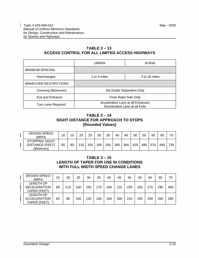
Topic # 625-000-015 May - 2005 Manual of Uniform Minimum Standards for Design, Construction and Maintenance for Streets and Highways
Geometric Design 3-70
TABLE 3 – 13 ACCESS CONTROL FOR ALL LIMITED ACCESS HIGHWAYS
URBAN RURAL
MINIMUM SPACING
Interchanges 1 to 3 miles 3 to 25 miles
MANEUVER RESTRICTIONS
Crossing Maneuvers Via Grade Separation Only
Exit and Entrance From Right Side Only
Turn Lane Required Acceleration Lane at all Entrances Deceleration Lane at all Exits
TABLE 3 – 14
SIGHT DISTANCE FOR APPROACH TO STOPS (Rounded Values)
DESIGN SPEED
(MPH) 10 15 20 25 30 35 40 45 50 55 60 65 70
STOPPING SIGHT DISTANCE (FEET)
(Minimum) 50 80 115 155 200 250 305 360 425 495 570 645 730
TABLE 3 – 15
LENGTH OF TAPER FOR USE IN CONDITIONS WITH FULL WIDTH SPEED CHANGE LANES
DESIGN SPEED
(MPH) 15 20 25 30 35 40 45 50 55 60 65 70
LENGTH OF DECELERATION TAPER (FEET)
80 110 130 150 170 190 210 230 250 270 290 300
LENGTH OF ACCELERATION TAPER (FEET)
60 80 100 120 140 160 180 210 230 250 260 280
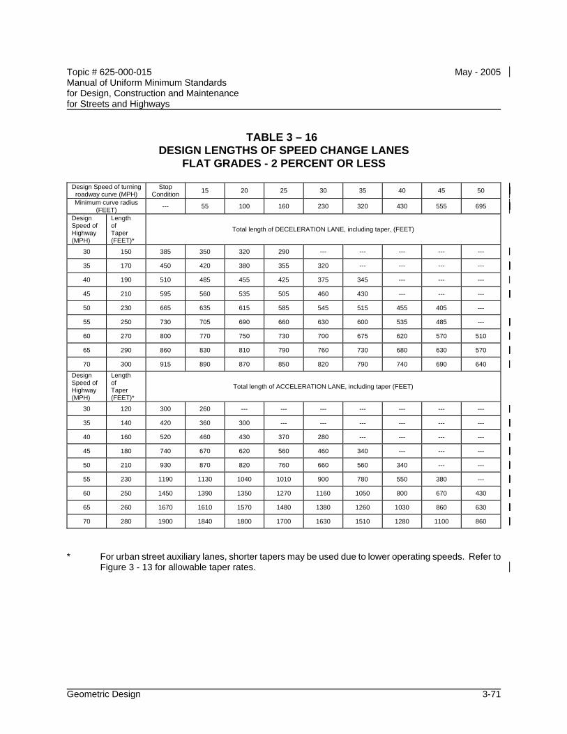
Topic # 625-000-015 May - 2005 Manual of Uniform Minimum Standards for Design, Construction and Maintenance for Streets and Highways
Geometric Design 3-71
TABLE 3 – 16 DESIGN LENGTHS OF SPEED CHANGE LANES
FLAT GRADES - 2 PERCENT OR LESS
Design Speed of turning roadway curve (MPH)
Stop Condition 15 20 25 30 35 40 45 50
Minimum curve radius (FEET) --- 55 100 160 230 320 430 555 695
Design Speed of Highway (MPH)
Length of Taper (FEET)*
Total length of DECELERATION LANE, including taper, (FEET)
30 150 385 350 320 290 --- --- --- --- ---
35 170 450 420 380 355 320 --- --- --- ---
40 190 510 485 455 425 375 345 --- --- ---
45 210 595 560 535 505 460 430 --- --- ---
50 230 665 635 615 585 545 515 455 405 ---
55 250 730 705 690 660 630 600 535 485 ---
60 270 800 770 750 730 700 675 620 570 510
65 290 860 830 810 790 760 730 680 630 570
70 300 915 890 870 850 820 790 740 690 640
Design Speed of Highway (MPH)
Length of Taper (FEET)*
Total length of ACCELERATION LANE, including taper (FEET)
30 120 300 260 --- --- --- --- --- --- ---
35 140 420 360 300 --- --- --- --- --- ---
40 160 520 460 430 370 280 --- --- --- ---
45 180 740 670 620 560 460 340 --- --- ---
50 210 930 870 820 760 660 560 340 --- ---
55 230 1190 1130 1040 1010 900 780 550 380 ---
60 250 1450 1390 1350 1270 1160 1050 800 670 430
65 260 1670 1610 1570 1480 1380 1260 1030 860 630
70 280 1900 1840 1800 1700 1630 1510 1280 1100 860
* For urban street auxiliary lanes, shorter tapers may be used due to lower operating speeds. Refer to
Figure 3 - 13 for allowable taper rates.
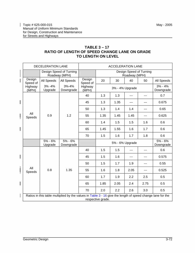
Topic # 625-000-015 May - 2005 Manual of Uniform Minimum Standards for Design, Construction and Maintenance for Streets and Highways
Geometric Design 3-72
TABLE 3 – 17 RATIO OF LENGTH OF SPEED CHANGE LANE ON GRADE
TO LENGTH ON LEVEL
DECELERATION LANE ACCELERATION LANE
Design Speed of Turning Roadway (MPH) Design Speed of Turning
Roadway (MPH)
All Speeds All Speeds 20 30 40 50 All Speeds Design Speed of Highway (MPH)
3% -4% Upgrade
3%-4% Downgrade
Design Speed of Highway (MPH)
3% - 4% Upgrade 3% - 4% Downgrade
40 1.3 1.3 --- --- 0.7
45 1.3 1.35 --- --- 0.675
50 1.3 1.4 1.4 --- 0.65
55 1.35 1.45 1.45 --- 0.625
60 1.4 1.5 1.5 1.6 0.6
65 1.45 1.55 1.6 1.7 0.6
All Speeds 0.9 1.2
70 1.5 1.6 1.7 1.8 0.6
5% - 6% Upgrade
5% - 6% Downgrade 5% - 6% Upgrade 5% - 6%
Downgrade
40 1.5 1.5 --- --- 0.6
45 1.5 1.6 --- --- 0.575
50 1.5 1.7 1.9 --- 0.55
55 1.6 1.8 2.05 --- 0.525
60 1.7 1.9 2.2 2.5 0.5
65 1.85 2.05 2.4 2.75 0.5
All Speeds 0.8 1.35
70 2.0 2.2 2.6 3.0 0.5
Ratios in this table multiplied by the values in Table 3 - 16 give the length of speed change lane for the respective grade.
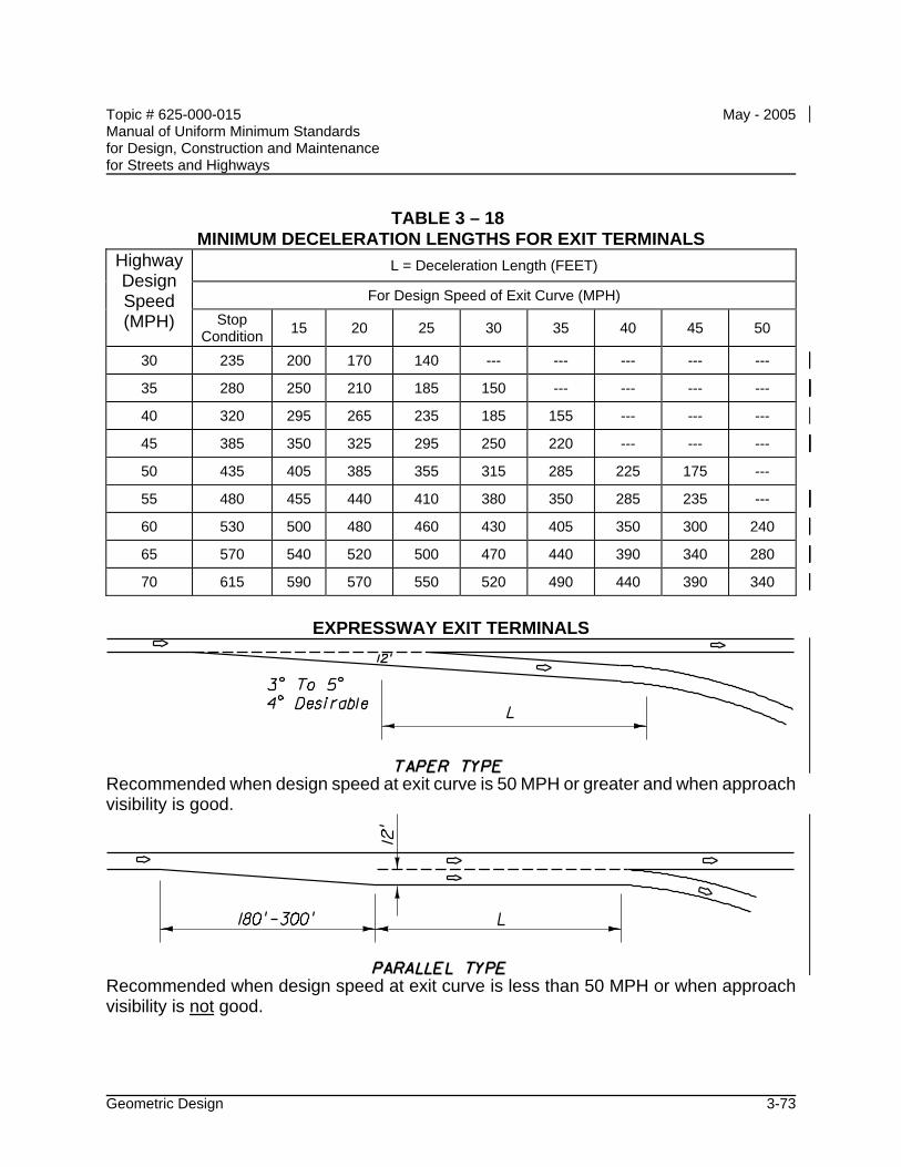
Topic # 625-000-015 May - 2005 Manual of Uniform Minimum Standards for Design, Construction and Maintenance for Streets and Highways
Geometric Design 3-73
TABLE 3 – 18 MINIMUM DECELERATION LENGTHS FOR EXIT TERMINALS
L = Deceleration Length (FEET)
For Design Speed of Exit Curve (MPH)
Highway Design Speed (MPH) Stop
Condition 15 20 25 30 35 40 45 50
30 235 200 170 140 --- --- --- --- ---
35 280 250 210 185 150 --- --- --- ---
40 320 295 265 235 185 155 --- --- ---
45 385 350 325 295 250 220 --- --- ---
50 435 405 385 355 315 285 225 175 ---
55 480 455 440 410 380 350 285 235 ---
60 530 500 480 460 430 405 350 300 240
65 570 540 520 500 470 440 390 340 280
70 615 590 570 550 520 490 440 390 340
EXPRESSWAY EXIT TERMINALS
Recommended when design speed at exit curve is 50 MPH or greater and when approach visibility is good.
Recommended when design speed at exit curve is less than 50 MPH or when approach visibility is not good.
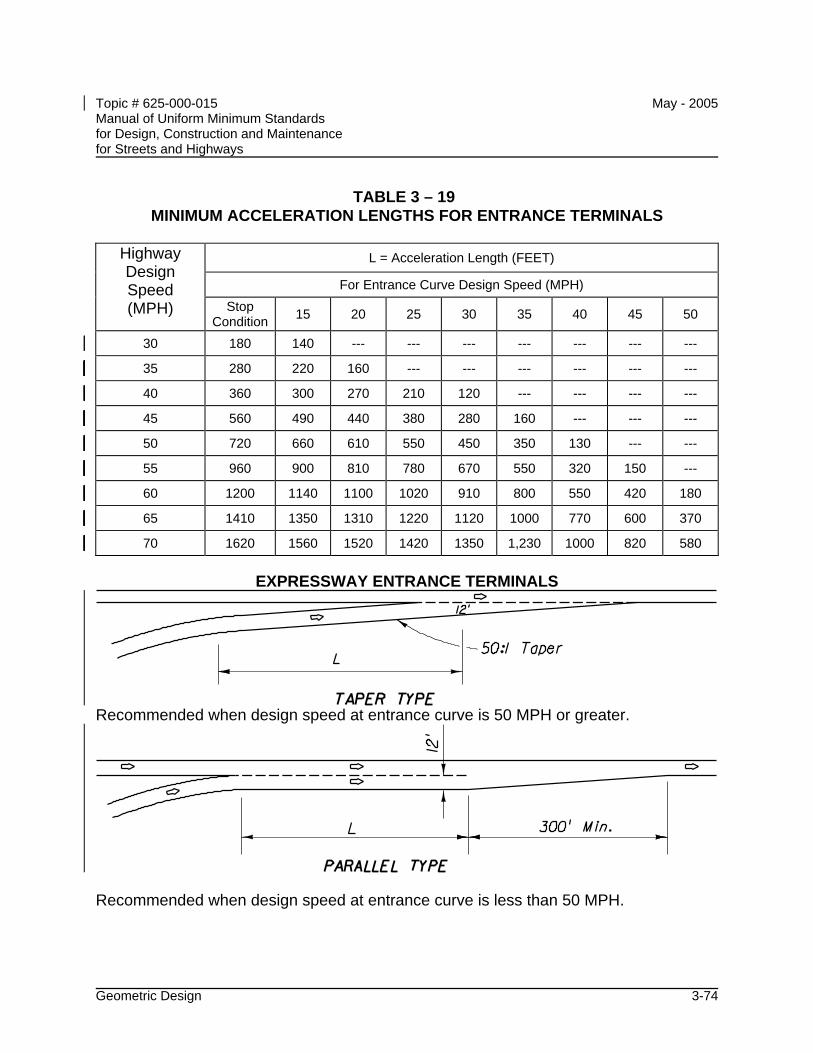
Topic # 625-000-015 May - 2005 Manual of Uniform Minimum Standards for Design, Construction and Maintenance for Streets and Highways
Geometric Design 3-74
TABLE 3 – 19 MINIMUM ACCELERATION LENGTHS FOR ENTRANCE TERMINALS
L = Acceleration Length (FEET)
For Entrance Curve Design Speed (MPH)
Highway Design Speed (MPH) Stop
Condition 15 20 25 30 35 40 45 50
30 180 140 --- --- --- --- --- --- ---
35 280 220 160 --- --- --- --- --- ---
40 360 300 270 210 120 --- --- --- ---
45 560 490 440 380 280 160 --- --- ---
50 720 660 610 550 450 350 130 --- ---
55 960 900 810 780 670 550 320 150 ---
60 1200 1140 1100 1020 910 800 550 420 180
65 1410 1350 1310 1220 1120 1000 770 600 370
70 1620 1560 1520 1420 1350 1,230 1000 820 580
EXPRESSWAY ENTRANCE TERMINALS
Recommended when design speed at entrance curve is 50 MPH or greater.
Recommended when design speed at entrance curve is less than 50 MPH.
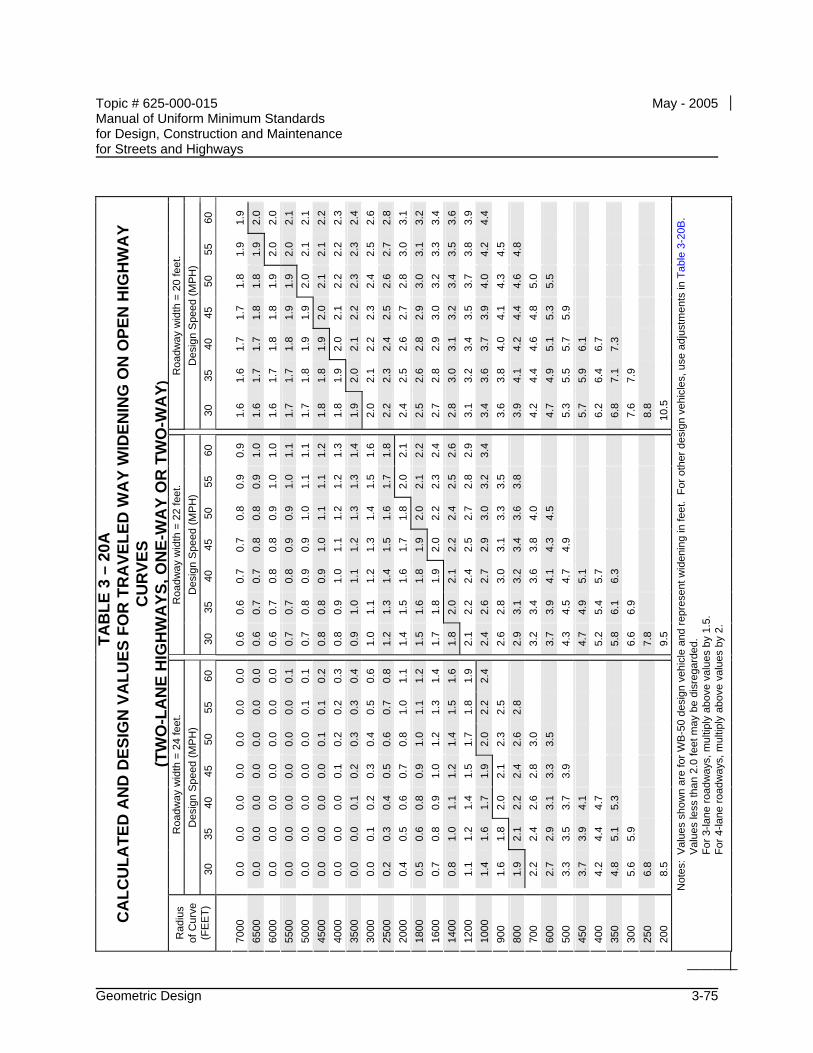
Topic # 625-000-015 May - 2005 Manual of Uniform Minimum Standards for Design, Construction and Maintenance for Streets and Highways
Geometric Design 3-75
60
1.9
2.0
2.0
2.1
2.1
2.2
2.3
2.4
2.6
2.8
3.1
3.2
3.4
3.6
3.9
4.4
55
1.9
1.9
2.0
2.0
2.1
2.1
2.2
2.3
2.5
2.7
3.0
3.1
3.3
3.5
3.8
4.2
4.5
4.8
50
1.8
1.8
1.9
1.9
2.0
2.1
2.2
2.3
2.4
2.6
2.8
3.0
3.2
3.4
3.7
4.0
4.3
4.6
5.0
5.5
45
1.7
1.8
1.8
1.9
1.9
2.0
2.1
2.2
2.3
2.5
2.7
2.9
3.0
3.2
3.5
3.9
4.1
4.4
4.8
5.3
5.9
40
1.7
1.7
1.8
1.8
1.9
1.9
2.0
2.1
2.2
2.4
2.6
2.8
2.9
3.1
3.4
3.7
4.0
4.2
4.6
5.1
5.7
6.1
6.7
7.3
35
1.6
1.7
1.7
1.7
1.8
1.8
1.9
2.0
2.1
2.3
2.5
2.6
2.8
3.0
3.2
3.6
3.8
4.1
4.4
4.9
5.5
5.9
6.4
7.1
7.9 R
oadw
ay w
idth
= 2
0 fe
et.
Des
ign
Spe
ed (M
PH
) 30
1.6
1.6
1.6
1.7
1.7
1.8
1.8
1.9
2.0
2.2
2.4
2.5
2.7
2.8
3.1
3.4
3.6
3.9
4.2
4.7
5.3
5.7
6.2
6.8
7.6
8.8
10.5
60
0.9
1.0
1.0
1.1
1.1
1.2
1.3
1.4
1.6
1.8
2.1
2.2
2.4
2.6
2.9
3.4
55
0.9
0.9
1.0
1.0
1.1
1.1
1.2
1.3
1.5
1.7
2.0
2.1
2.3
2.5
2.8
3.2
3.5
3.8
50
0.8
0.8
0.9
0.9
1.0
1.1
1.2
1.3
1.4
1.6
1.8
2.0
2.2
2.4
2.7
3.0
3.3
3.6
4.0
4.5
45
0.7
0.8
0.8
0.9
0.9
1.0
1.1
1.2
1.3
1.5
1.7
1.9
2.0
2.2
2.5
2.9
3.1
3.4
3.8
4.3
4.9
40
0.7
0.7
0.8
0.8
0.9
0.9
1.0
1.1
1.2
1.4
1.6
1.8
1.9
2.1
2.4
2.7
3.0
3.2
3.6
4.1
4.7
5.1
5.7
6.3
35
0.6
0.7
0.7
0.7
0.8
0.8
0.9
1.0
1.1
1.3
1.5
1.6
1.8
2.0
2.2
2.6
2.8
3.1
3.4
3.9
4.5
4.9
5.4
6.1
6.9 R
oadw
ay w
idth
= 2
2 fe
et.
Des
ign
Spe
ed (M
PH
) 30
0.6
0.6
0.6
0.7
0.7
0.8
0.8
0.9
1.0
1.2
1.4
1.5
1.7
1.8
2.1
2.4
2.6
2.9
3.2
3.7
4.3
4.7
5.2
5.8
6.6
7.8
9.5
60
0.0
0.0
0.0
0.1
0.1
0.2
0.3
0.4
0.6
0.8
1.1
1.2
1.4
1.6
1.9
2.4
55
0.0
0.0
0.0
0.0
0.1
0.1
0.2
0.3
0.5
0.7
1.0
1.1
1.3
1.5
1.8
2.2
2.5
2.8
50
0.0
0.0
0.0
0.0
0.0
0.1
0.2
0.3
0.4
0.6
0.8
1.0
1.2
1.4
1.7
2.0
2.3
2.6
3.0
3.5
45
0.0
0.0
0.0
0.0
0.0
0.0
0.1
0.2
0.3
0.5
0.7
0.9
1.0
1.2
1.5
1.9
2.1
2.4
2.8
3.3
3.9
40
0.0
0.0
0.0
0.0
0.0
0.0
0.0
0.1
0.2
0.4
0.6
0.8
0.9
1.1
1.4
1.7
2.0
2.2
2.6
3.1
3.7
4.1
4.7
5.3
35
0.0
0.0
0.0
0.0
0.0
0.0
0.0
0.0
0.1
0.3
0.5
0.6
0.8
1.0
1.2
1.6
1.8
2.1
2.4
2.9
3.5
3.9
4.4
5.1
5.9 R
oadw
ay w
idth
= 2
4 fe
et.
30
0.0
0.0
0.0
0.0
0.0
0.0
0.0
0.0
0.0
0.2
0.4
0.5
0.7
0.8
1.1
1.4
1.6
1.9
2.2
2.7
3.3
3.7
4.2
4.8
5.6
6.8
8.5
Des
ign
Spe
ed (M
PH
)
TAB
LE 3
– 2
0A
C
ALC
ULA
TED
AN
D D
ESIG
N V
ALU
ES F
OR
TR
AVE
LED
WA
Y W
IDEN
ING
ON
OPE
N H
IGH
WA
Y C
UR
VES
(TW
O-L
AN
E H
IGH
WA
YS, O
NE-
WA
Y O
R T
WO
-WA
Y)
Rad
ius
of C
urve
(F
EE
T)
7000
65
00
6000
55
00
5000
45
00
4000
35
00
3000
25
00
2000
18
00
1600
14
00
1200
10
00
900
800
700
600
500
450
400
350
300
250
200
N
otes
: V
alue
s sh
own
are
for W
B-5
0 de
sign
veh
icle
and
repr
esen
t wid
enin
g in
feet
. Fo
r oth
er d
esig
n ve
hicl
es, u
se a
djus
tmen
ts in
Tab
le 3
-20B
.
V
alue
s le
ss th
an 2
.0 fe
et m
ay b
e di
sreg
arde
d.
For 3
-lane
road
way
s, m
ultip
ly a
bove
val
ues
by 1
.5.
For 4
-lane
road
way
s, m
ultip
ly a
bove
val
ues
by 2
.
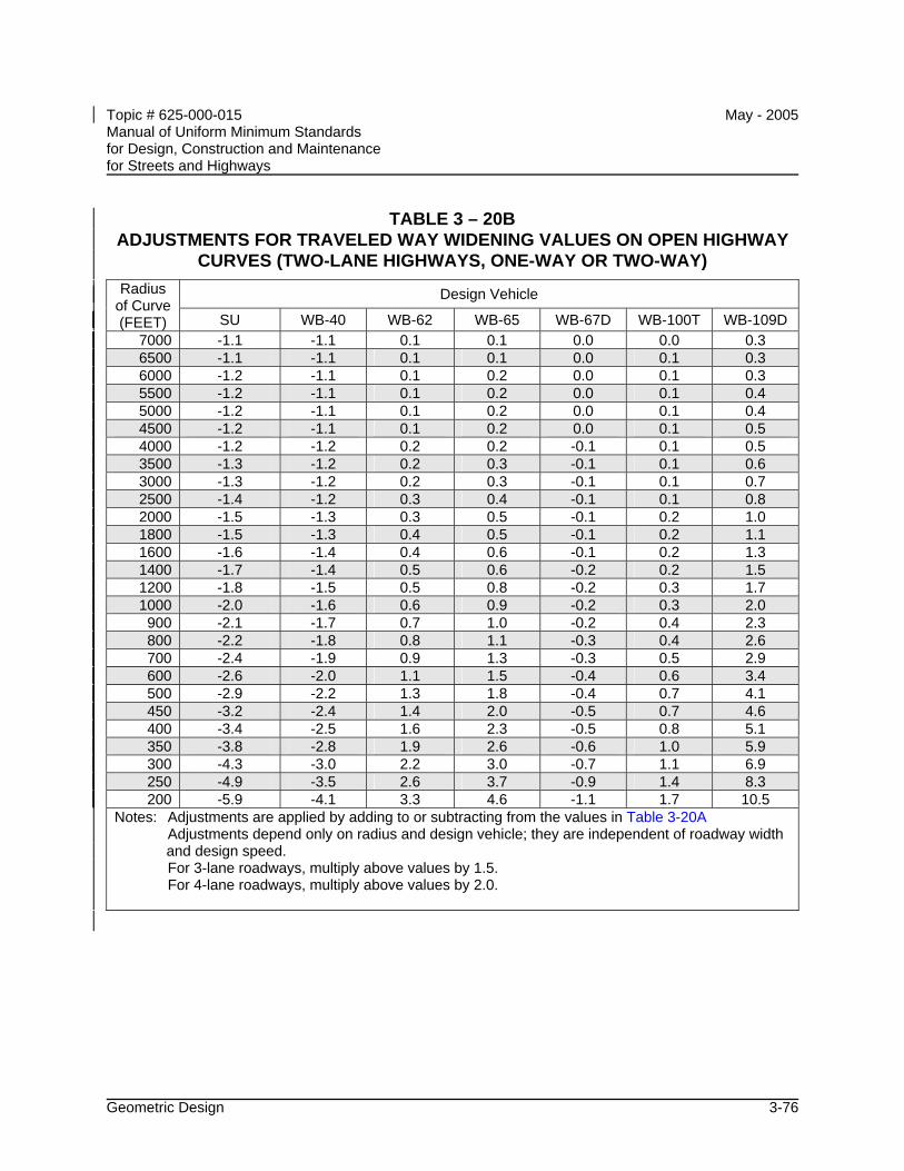
Topic # 625-000-015 May - 2005 Manual of Uniform Minimum Standards for Design, Construction and Maintenance for Streets and Highways
Geometric Design 3-76
TABLE 3 – 20B ADJUSTMENTS FOR TRAVELED WAY WIDENING VALUES ON OPEN HIGHWAY
CURVES (TWO-LANE HIGHWAYS, ONE-WAY OR TWO-WAY)
Design Vehicle Radius of Curve (FEET) SU WB-40 WB-62 WB-65 WB-67D WB-100T WB-109D
7000 -1.1 -1.1 0.1 0.1 0.0 0.0 0.3 6500 -1.1 -1.1 0.1 0.1 0.0 0.1 0.3 6000 -1.2 -1.1 0.1 0.2 0.0 0.1 0.3 5500 -1.2 -1.1 0.1 0.2 0.0 0.1 0.4 5000 -1.2 -1.1 0.1 0.2 0.0 0.1 0.4 4500 -1.2 -1.1 0.1 0.2 0.0 0.1 0.5 4000 -1.2 -1.2 0.2 0.2 -0.1 0.1 0.5 3500 -1.3 -1.2 0.2 0.3 -0.1 0.1 0.6 3000 -1.3 -1.2 0.2 0.3 -0.1 0.1 0.7 2500 -1.4 -1.2 0.3 0.4 -0.1 0.1 0.8 2000 -1.5 -1.3 0.3 0.5 -0.1 0.2 1.0 1800 -1.5 -1.3 0.4 0.5 -0.1 0.2 1.1 1600 -1.6 -1.4 0.4 0.6 -0.1 0.2 1.3 1400 -1.7 -1.4 0.5 0.6 -0.2 0.2 1.5 1200 -1.8 -1.5 0.5 0.8 -0.2 0.3 1.7 1000 -2.0 -1.6 0.6 0.9 -0.2 0.3 2.0 900 -2.1 -1.7 0.7 1.0 -0.2 0.4 2.3 800 -2.2 -1.8 0.8 1.1 -0.3 0.4 2.6 700 -2.4 -1.9 0.9 1.3 -0.3 0.5 2.9 600 -2.6 -2.0 1.1 1.5 -0.4 0.6 3.4 500 -2.9 -2.2 1.3 1.8 -0.4 0.7 4.1 450 -3.2 -2.4 1.4 2.0 -0.5 0.7 4.6 400 -3.4 -2.5 1.6 2.3 -0.5 0.8 5.1 350 -3.8 -2.8 1.9 2.6 -0.6 1.0 5.9 300 -4.3 -3.0 2.2 3.0 -0.7 1.1 6.9 250 -4.9 -3.5 2.6 3.7 -0.9 1.4 8.3 200 -5.9 -4.1 3.3 4.6 -1.1 1.7 10.5
Notes: Adjustments are applied by adding to or subtracting from the values in Table 3-20A Adjustments depend only on radius and design vehicle; they are independent of roadway width
and design speed. For 3-lane roadways, multiply above values by 1.5. For 4-lane roadways, multiply above values by 2.0.
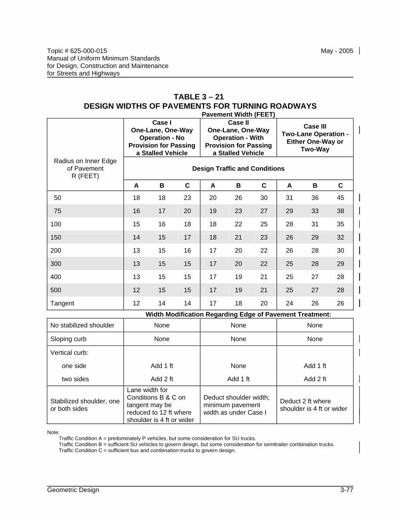
Topic # 625-000-015 May - 2005 Manual of Uniform Minimum Standards for Design, Construction and Maintenance for Streets and Highways
Geometric Design 3-77
TABLE 3 – 21 DESIGN WIDTHS OF PAVEMENTS FOR TURNING ROADWAYS
Pavement Width (FEET)
Case I One-Lane, One-Way
Operation - No Provision for Passing
a Stalled Vehicle
Case II One-Lane, One-Way
Operation - With Provision for Passing
a Stalled Vehicle
Case III Two-Lane Operation -
Either One-Way or Two-Way
Radius on Inner Edge of Pavement
R (FEET) Design Traffic and Conditions
A B C A B C A B C
50 18 18 23 20 26 30 31 36 45
75 16 17 20 19 23 27 29 33 38
100 15 16 18 18 22 25 28 31 35
150 14 15 17 18 21 23 26 29 32
200 13 15 16 17 20 22 26 28 30
300 13 15 15 17 20 22 25 28 29
400 13 15 15 17 19 21 25 27 28
500 12 15 15 17 19 21 25 27 28
Tangent 12 14 14 17 18 20 24 26 26
Width Modification Regarding Edge of Pavement Treatment: No stabilized shoulder None None None
Sloping curb None None None
Vertical curb:
one side Add 1 ft None Add 1 ft
two sides Add 2 ft Add 1 ft Add 2 ft
Stabilized shoulder, one or both sides
Lane width for Conditions B & C on tangent may be reduced to 12 ft where shoulder is 4 ft or wider
Deduct shoulder width; minimum pavement width as under Case I
Deduct 2 ft where shoulder is 4 ft or wider
Note: Traffic Condition A = predominately P vehicles, but some consideration for SU trucks. Traffic Condition B = sufficient SU vehicles to govern design, but some consideration for semitrailer combination trucks. Traffic Condition C = sufficient bus and combination-trucks to govern design.
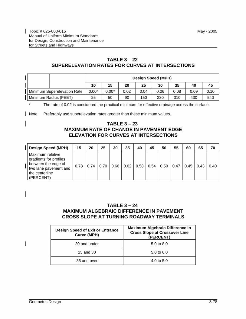
Topic # 625-000-015 May - 2005 Manual of Uniform Minimum Standards for Design, Construction and Maintenance for Streets and Highways
Geometric Design 3-78
TABLE 3 – 22 SUPERELEVATION RATES FOR CURVES AT INTERSECTIONS
Design Speed (MPH)
10 15 20 25 30 35 40 45 Minimum Superelevation Rate 0.00* 0.00* 0.02 0.04 0.06 0.08 0.09 0.10 Minimum Radius (FEET) 25 50 90 150 230 310 430 540 * The rate of 0.02 is considered the practical minimum for effective drainage across the surface. Note: Preferably use superelevation rates greater than these minimum values.
TABLE 3 – 23 MAXIMUM RATE OF CHANGE IN PAVEMENT EDGE
ELEVATION FOR CURVES AT INTERSECTIONS
Design Speed (MPH) 15 20 25 30 35 40 45 50 55 60 65 70 Maximum relative gradients for profiles between the edge of two lane pavement and the centerline (PERCENT)
0.78 0.74 0.70 0.66 0.62 0.58 0.54 0.50 0.47 0.45 0.43 0.40
TABLE 3 – 24 MAXIMUM ALGEBRAIC DIFFERENCE IN PAVEMENT CROSS SLOPE AT TURNING ROADWAY TERMINALS
Design Speed of Exit or Entrance
Curve (MPH)
Maximum Algebraic Difference in Cross Slope at Crossover Line
(PERCENT) 20 and under 5.0 to 8.0
25 and 30 5.0 to 6.0
35 and over 4.0 to 5.0
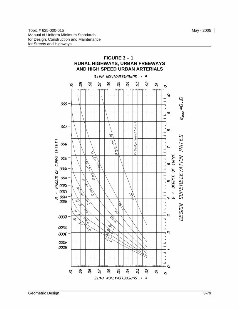
Topic # 625-000-015 May - 2005 Manual of Uniform Minimum Standards for Design, Construction and Maintenance for Streets and Highways
Geometric Design 3-79
FIGURE 3 – 1 RURAL HIGHWAYS, URBAN FREEWAYS AND HIGH SPEED URBAN ARTERIALS
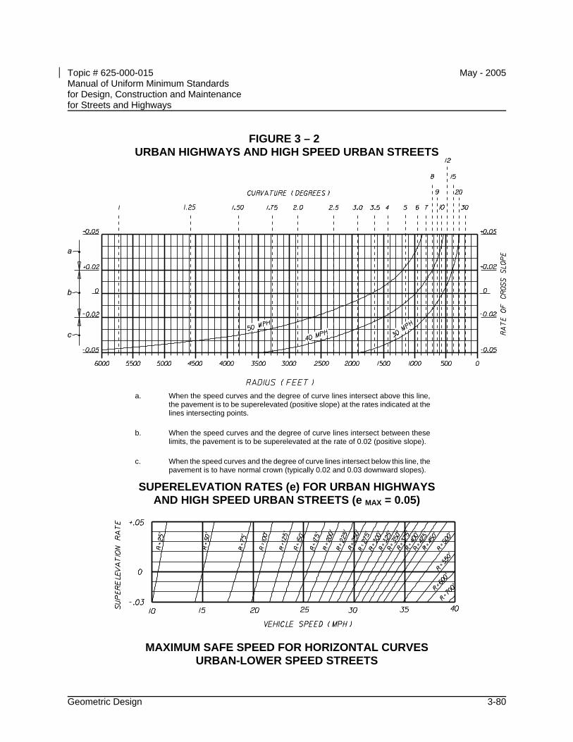
Topic # 625-000-015 May - 2005 Manual of Uniform Minimum Standards for Design, Construction and Maintenance for Streets and Highways
Geometric Design 3-80
FIGURE 3 – 2 URBAN HIGHWAYS AND HIGH SPEED URBAN STREETS
a. When the speed curves and the degree of curve lines intersect above this line,
the pavement is to be superelevated (positive slope) at the rates indicated at the lines intersecting points.
b. When the speed curves and the degree of curve lines intersect between these limits, the pavement is to be superelevated at the rate of 0.02 (positive slope).
c. When the speed curves and the degree of curve lines intersect below this line, the pavement is to have normal crown (typically 0.02 and 0.03 downward slopes).
SUPERELEVATION RATES (e) FOR URBAN HIGHWAYS AND HIGH SPEED URBAN STREETS (e MAX = 0.05)
MAXIMUM SAFE SPEED FOR HORIZONTAL CURVES URBAN-LOWER SPEED STREETS
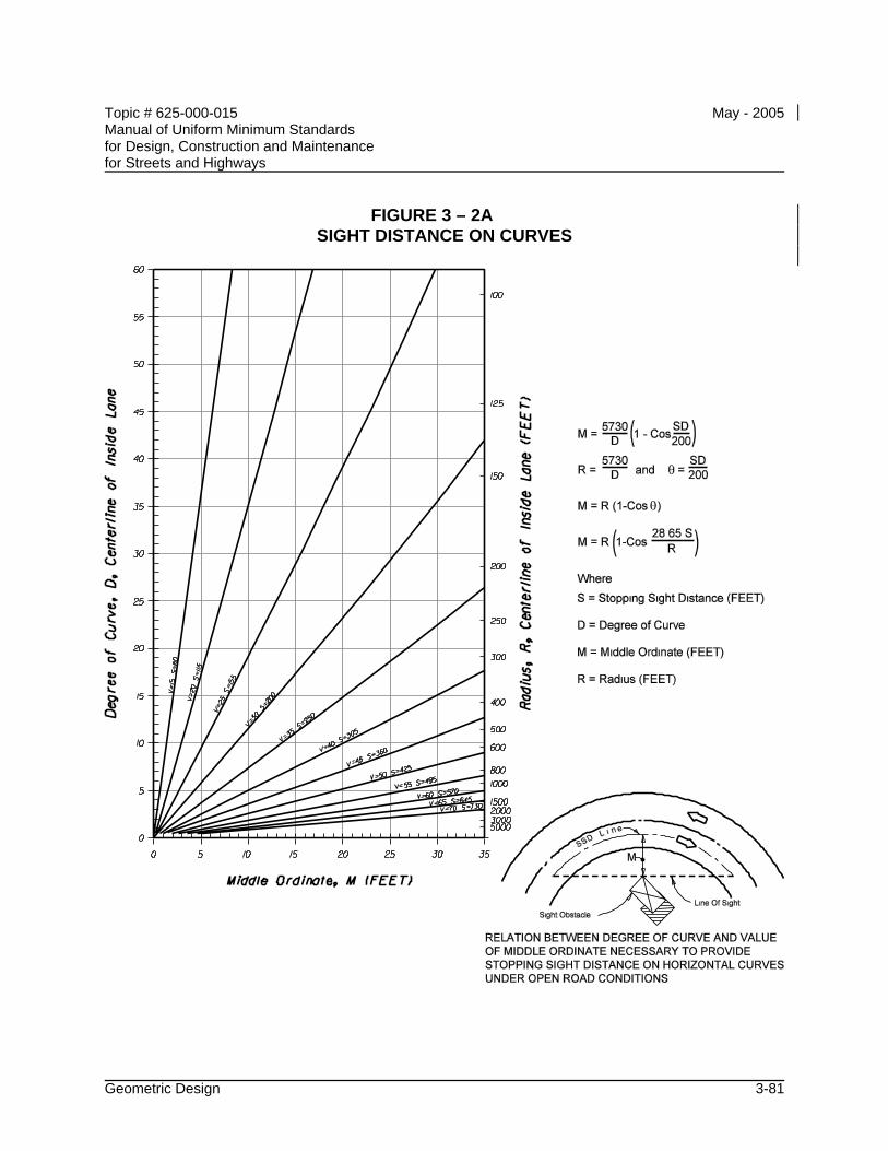
Topic # 625-000-015 May - 2005 Manual of Uniform Minimum Standards for Design, Construction and Maintenance for Streets and Highways
Geometric Design 3-81
FIGURE 3 – 2A SIGHT DISTANCE ON CURVES
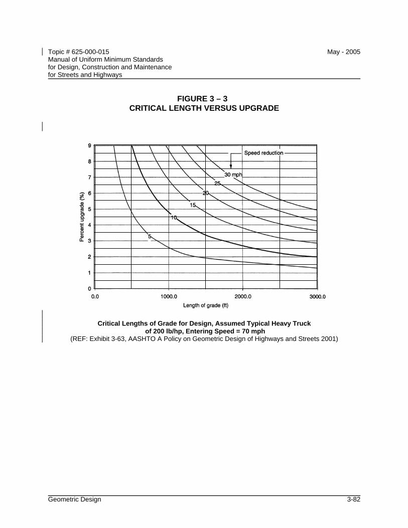
Topic # 625-000-015 May - 2005 Manual of Uniform Minimum Standards for Design, Construction and Maintenance for Streets and Highways
Geometric Design 3-82
FIGURE 3 – 3 CRITICAL LENGTH VERSUS UPGRADE
Critical Lengths of Grade for Design, Assumed Typical Heavy Truck
of 200 lb/hp, Entering Speed = 70 mph (REF: Exhibit 3-63, AASHTO A Policy on Geometric Design of Highways and Streets 2001)
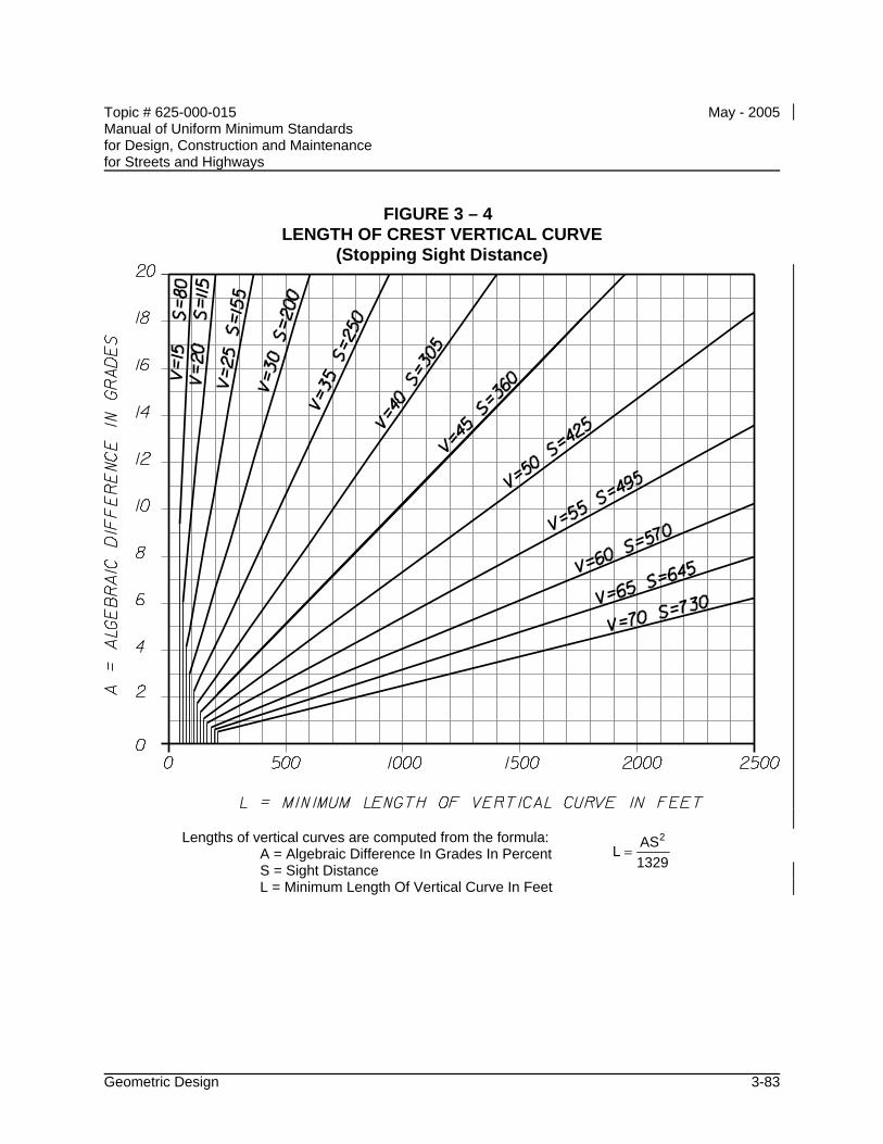
Topic # 625-000-015 May - 2005 Manual of Uniform Minimum Standards for Design, Construction and Maintenance for Streets and Highways
Geometric Design 3-83
FIGURE 3 – 4 LENGTH OF CREST VERTICAL CURVE
(Stopping Sight Distance)
Lengths of vertical curves are computed from the formula: A = Algebraic Difference In Grades In Percent S = Sight Distance L = Minimum Length Of Vertical Curve In Feet
L AS1329
2=
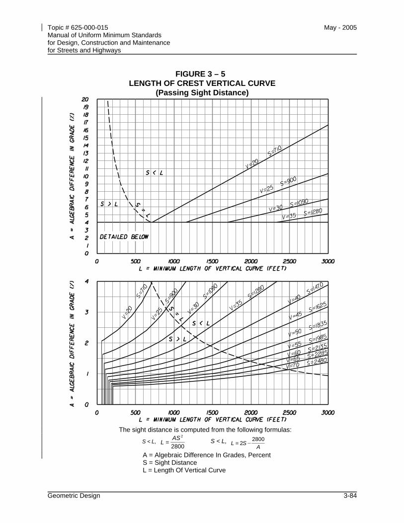
Topic # 625-000-015 May - 2005 Manual of Uniform Minimum Standards for Design, Construction and Maintenance for Streets and Highways
Geometric Design 3-84
FIGURE 3 – 5 LENGTH OF CREST VERTICAL CURVE
(Passing Sight Distance)
The sight distance is computed from the following formulas:
,< LS 2800
=2AS
L ,< LS A
SL2800
2=
A = Algebraic Difference In Grades, Percent S = Sight Distance L = Length Of Vertical Curve
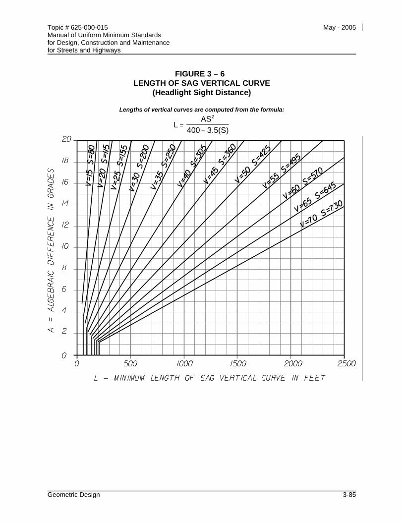
Topic # 625-000-015 May - 2005 Manual of Uniform Minimum Standards for Design, Construction and Maintenance for Streets and Highways
Geometric Design 3-85
FIGURE 3 – 6 LENGTH OF SAG VERTICAL CURVE
(Headlight Sight Distance)
Lengths of vertical curves are computed from the formula:
LAS
400 3.5(S)
2
=+
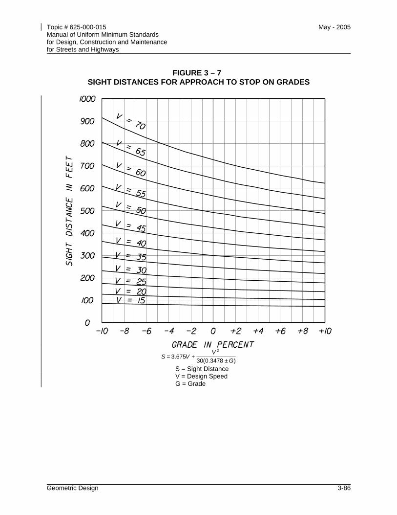
Topic # 625-000-015 May - 2005 Manual of Uniform Minimum Standards for Design, Construction and Maintenance for Streets and Highways
Geometric Design 3-86
FIGURE 3 – 7 SIGHT DISTANCES FOR APPROACH TO STOP ON GRADES
)±3478.0(30+675.3=
2
GV
VS
S = Sight Distance V = Design Speed G = Grade
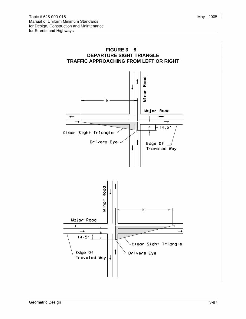
Topic # 625-000-015 May - 2005 Manual of Uniform Minimum Standards for Design, Construction and Maintenance for Streets and Highways
Geometric Design 3-87
FIGURE 3 – 8
DEPARTURE SIGHT TRIANGLE TRAFFIC APPROACHING FROM LEFT OR RIGHT
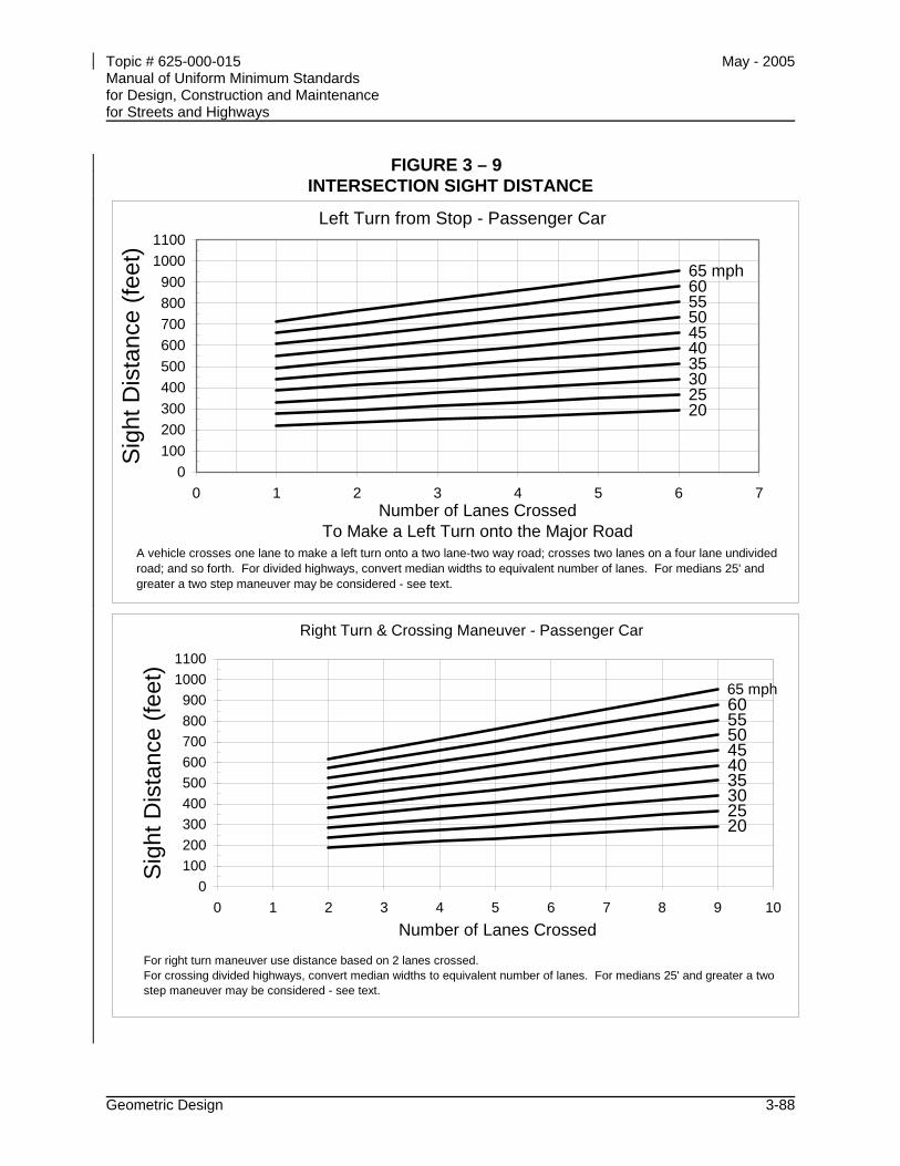
Topic # 625-000-015 May - 2005 Manual of Uniform Minimum Standards for Design, Construction and Maintenance for Streets and Highways
Geometric Design 3-88
FIGURE 3 – 9 INTERSECTION SIGHT DISTANCE
Left Turn from Stop - Passenger Car
2025303540
505560
45
65 mph
0100200300400500600700800900
10001100
0 1 2 3 4 5 6 7Number of Lanes Crossed
To Make a Left Turn onto the Major Road
Sig
ht D
ista
nce
(feet
)
A vehicle crosses one lane to make a left turn onto a two lane-two way road; crosses two lanes on a four lane undivided road; and so forth. For divided highways, convert median widths to equivalent number of lanes. For medians 25' and greater a two step maneuver may be considered - see text.
Right Turn & Crossing Maneuver - Passenger Car
20253035404550556065 mph
0100200300400500600700800900
10001100
0 1 2 3 4 5 6 7 8 9 10Number of Lanes Crossed
Sig
ht D
ista
nce
(feet
)
For right turn maneuver use distance based on 2 lanes crossed.For crossing divided highways, convert median widths to equivalent number of lanes. For medians 25' and greater a two step maneuver may be considered - see text.
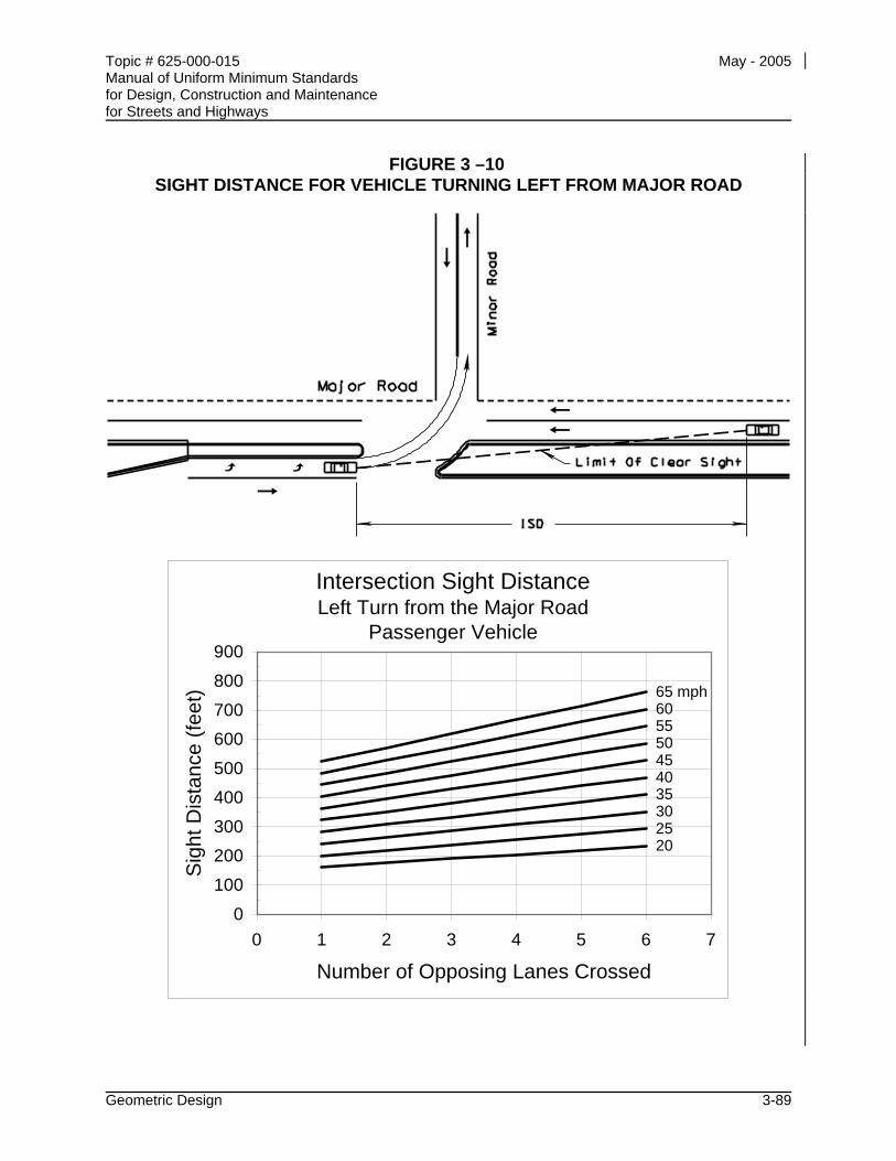
Topic # 625-000-015 May - 2005 Manual of Uniform Minimum Standards for Design, Construction and Maintenance for Streets and Highways
Geometric Design 3-89
FIGURE 3 –10 SIGHT DISTANCE FOR VEHICLE TURNING LEFT FROM MAJOR ROAD
Intersection Sight DistanceLeft Turn from the Major Road
Passenger Vehicle
20253035404550556065 mph
0100200300400500600700800900
0 1 2 3 4 5 6 7
Number of Opposing Lanes Crossed
Sig
ht D
ista
nce
(feet
)
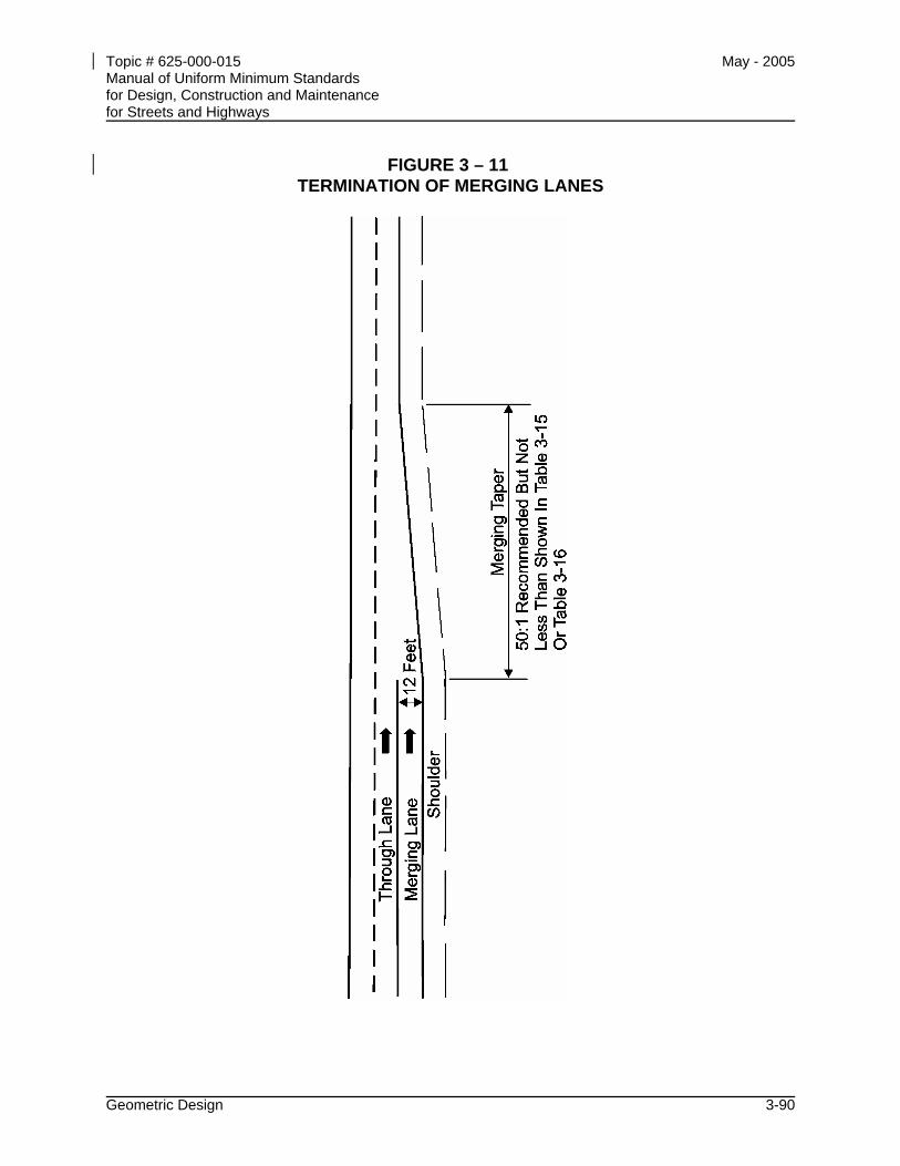
Topic # 625-000-015 May - 2005 Manual of Uniform Minimum Standards for Design, Construction and Maintenance for Streets and Highways
Geometric Design 3-90
FIGURE 3 – 11 TERMINATION OF MERGING LANES
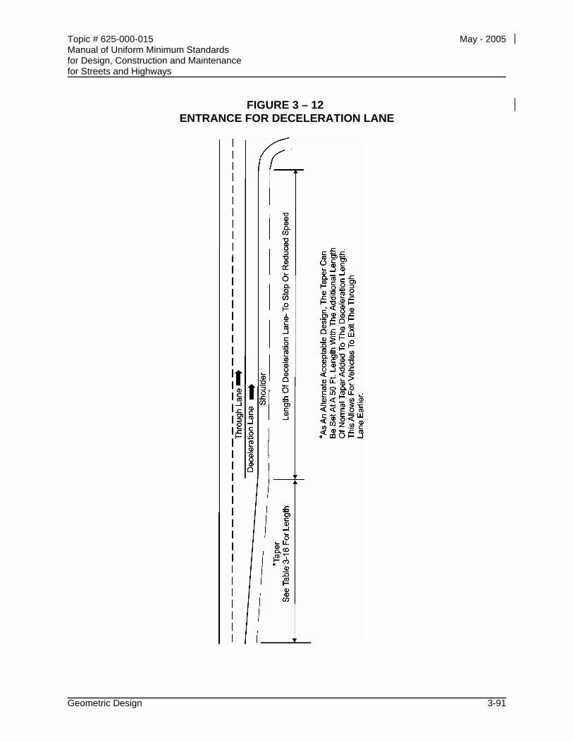
Topic # 625-000-015 May - 2005 Manual of Uniform Minimum Standards for Design, Construction and Maintenance for Streets and Highways
Geometric Design 3-91
FIGURE 3 – 12 ENTRANCE FOR DECELERATION LANE
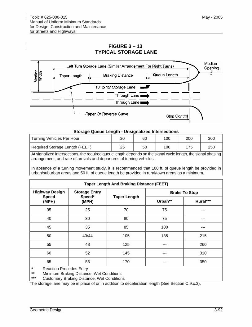
Topic # 625-000-015 May - 2005 Manual of Uniform Minimum Standards for Design, Construction and Maintenance for Streets and Highways
Geometric Design 3-92
FIGURE 3 – 13 TYPICAL STORAGE LANE
Storage Queue Length - Unsignalized Intersections Turning Vehicles Per Hour 30 60 100 200 300
Required Storage Length (FEET) 25 50 100 175 250
At signalized intersections, the required queue length depends on the signal cycle length, the signal phasing arrangement, and rate of arrivals and departures of turning vehicles. In absence of a turning movement study, it is recommended that 100 ft. of queue length be provided in urban/suburban areas and 50 ft. of queue length be provided in rural/town areas as a minimum.
Taper Length And Braking Distance (FEET)
Brake To Stop Highway Design Speed (MPH)
Storage Entry Speed* (MPH)
Taper Length Urban** Rural***
35 25 70 75 ---
40 30 80 75 ---
45 35 85 100 ---
50 40/44 105 135 215
55 48 125 --- 260
60 52 145 --- 310
65 55 170 --- 350
* Reaction Precedes Entry ** Minimum Braking Distance, Wet Conditions *** Customary Braking Distance, Wet Conditions
The storage lane may be in place of or in addition to deceleration length (See Section C.9.c.3).
Topic # 625-000-015 May - 2005 Manual of Uniform Minimum Standards for Design, Construction and Maintenance for Streets and Highways
Roadside Design 4-i
CHAPTER 4
ROADSIDE DESIGN
A INTRODUCTION............................................................................................... 4-1
B POLICY ............................................................................................................. 4-1
C OBJECTIVES .................................................................................................... 4-2
D ROADSIDE DESIGN ......................................................................................... 4-3 D.1 Geometric Changes ............................................................................. 4-3
D.1.a Horizontal Curves ................................................................ 4-3 D.1.b Vertical Curves..................................................................... 4-3 D.1.c Changes in Cross Section.................................................... 4-3 D.1.d Decision or Conflict Points ................................................... 4-4
D.2 Fills....................................................................................................... 4-4 D.3 Cuts...................................................................................................... 4-4 D.4 Roadside Canals.................................................................................. 4-4 D.5 Vegetation............................................................................................ 4-5
D.5.a Stability ................................................................................ 4-5 D.5.b Drainage .............................................................................. 4-5 D.5.c Crash Cushions ................................................................... 4-5 D.5.d Environmental and Aesthetic Considerations....................... 4-5 D.5.e Landscaping - Design Considerations.................................. 4-6
D.6 Drainage .............................................................................................. 4-6 D.6.a Inlets .................................................................................... 4-6 D.6.b Ditches................................................................................. 4-6 D.6.c Culverts................................................................................ 4-7
D.7 Curbs ................................................................................................... 4-7 D.8 Poles and Support Structures .............................................................. 4-8 D.9 Intersections......................................................................................... 4-9 D.10 Underpasses........................................................................................ 4-9 D.11 Bridges and Overpasses...................................................................... 4-9
Topic # 625-000-015 May - 2005 Manual of Uniform Minimum Standards for Design, Construction and Maintenance for Streets and Highways
Roadside Design 4-ii
D.12 Mailboxes........................................................................................... 4-10 D.13 Bus Shelters....................................................................................... 4-10
E PROTECTIVE DEVICES................................................................................. 4-11 E.1 Redirection Devices ........................................................................... 4-11
E.1.a Function ............................................................................. 4-11 E.1.b Warranting Conditions ....................................................... 4-11 E.1.c Location ............................................................................. 4-11 E.1.d Length................................................................................ 4-12 E.1.e Vehicle Containment .......................................................... 4-12 E.1.f Barrier Types ..................................................................... 4-12 E.1.g Transitions ......................................................................... 4-13 E.1.h Terminations ...................................................................... 4-13
E.2 Energy Absorbing Devices................................................................. 4-13 E.2.a Function ............................................................................. 4-13 E.2.b Warranting Conditions ....................................................... 4-14 E.2.c Design Criteria ................................................................... 4-14 E.2.d Design Details.................................................................... 4-14
Topic # 625-000-015 May - 2005 Manual of Uniform Minimum Standards for Design, Construction and Maintenance for Streets and Highways
Roadside Design 4-1
CHAPTER 4
ROADSIDE DESIGN
A INTRODUCTION
This chapter presents guidelines and standards for roadside designs intended to reduce the likelihood and/or consequences of roadside crashes. Construction and maintenance of safe medians and roadsides are of vital importance in the development of safe streets and highways.
Many of the standards presented in CHAPTER 3 - GEOMETRIC DESIGN are predicated to a large extent upon reducing the probability of vehicles leaving the proper travel path. Other standards in that chapter are directed toward a reduction in the likelihood and/or consequences of crashes by vehicles leaving the roadway. These standards contain requirements for the design of shoulders, medians, and roadsides including requirements for the use of guardrail and barriers. Design of the roadside should be considered and conducted as an integral part of the total highway design.
Due to the variety of causative factors, the designer should consider a vehicle leaving the traveled way at any location. Design of the roadside should be based upon reducing the consequences to errant vehicles and their occupants.
B POLICY
The roadside, which includes the median, shall be considered as the total environment adjacent to the roadway. The design of the roadside shall be considered as an integral part of the total highway design.
Topic # 625-000-015 May - 2005 Manual of Uniform Minimum Standards for Design, Construction and Maintenance for Streets and Highways
Roadside Design 4-2
C OBJECTIVES
General objectives to be followed in roadside design are to provide an environment that will reduce the likelihood and/or consequences of crashes by vehicles that have left the traveled way. The achievement of this general objective will be aided by the following:
• Roadside areas adequate to allow reasonable space and time for a driver to regain or retain control of the vehicle and stop or return to the traveled way.
• Shoulders, medians, and roadsides that may be traversed safely without overturning.
• Location of roadside objects and hazards as far from the travel lane as is economically feasible.
• Roadsides that, in addition to being safe, appear safe to the driver to encourage use of the roadside for necessary emergency maneuvers and for emergency parking.
• Protection of pedestrians, workers, or other persons subjected to the hazard of out-of-control vehicles.
• Adequate protective devices (where hazards are unavoidable) compatible with vehicle speeds and other design variables.
Topic # 625-000-015 May - 2005 Manual of Uniform Minimum Standards for Design, Construction and Maintenance for Streets and Highways
Roadside Design 4-3
D ROADSIDE DESIGN
The basic requirements and standards for the design of shoulders, medians, and roadsides are given in CHAPTER 3 - GEOMETRIC DESIGN. This includes specific requirements regarding widths, slopes, and changes in grade. General requirements for drainage facilities, utilities, transit, and pedestrian facilities are also included.
This chapter contains general guidelines for particular situations encountered in roadside design due to the variety and complexity of possible situations encountered. The designer should utilize the following as basic guidelines to develop a safe roadside design.
D.1 Geometric Changes
D.1.a Horizontal Curves
On horizontal curves, consideration should be given to increasing the clear zone above the minimum requirements due to the increased likelihood of vehicles leaving the traveled way. Increasing widths and decreasing slopes on curves is also important since a vehicle will probably leave the traveled way at a steeper exit angle. Increasing widths on curves is also beneficial in improving the available sight distance.
D.1.b Vertical Curves
As a vehicle comes over a crest, the driver may suddenly be presented with a situation requiring an emergency maneuver. The provision of adequate clear zones is particularly important where traffic volumes are high (i.e., urban areas) since traffic queues may form rapidly, thus tending to cause rear-end collisions.
D.1.c Changes in Cross Section
The provision of adequate clear zone is very important at exits, entrances, lane drops, or other changes in the roadway cross section. The exterior boundaries of the clear zone should extend well beyond any reductions in roadway width and then gradually reduce to provide design width for the new roadway cross section.
Topic # 625-000-015 May - 2005 Manual of Uniform Minimum Standards for Design, Construction and Maintenance for Streets and Highways
Roadside Design 4-4
D.1.d Decision or Conflict Points
Adequate clear zones should be provided at any point of traffic merging or conflicts, and at locations where the driver is confronted with making a decision regarding vehicle maneuvers.
D.2 Fills
Many roadways, for drainage purposes, are elevated somewhat above the surrounding terrain. Where feasible, the side slopes should not exceed a ratio of 1:4. On flatter slopes (1:6 or greater), care should be exercised to eliminate sharp changes in grade or other discontinuities.
If the side slope is steeper than 1:3, guardrail or another longitudinal barrier should be considered.
D.3 Cuts
A primary objective of roadside design in cut sections is to prevent conditions tending to cause rollovers or serious collisions with the cut slopes. When the material (soils) in the cut is smooth and stable, the use of an increasing backslope is a reasonable solution. The technique is also acceptable in stable rock cuts, provided that smooth fill material is utilized to affect the backslope.
The use of a rigid barrier incorporated into the cut slope is also satisfactory for rock slopes. Where the material in the cut is irregular or unstable, a guardrail or other longitudinal barrier set out from the cut face should be utilized. Placing the barrier away from the slope is necessary to prevent rocks or other materials from falling onto the roadsides.
D.4 Roadside Canals
Roadside canals or other bodies of water close to the roadway should be eliminated wherever feasible.
Where roadside bodies of water (with seasonal water depth in excess of 3 feet for 24 hours or longer) lie within the roadside clear zone, they shall be shielded using guardrail or another longitudinal barrier.
Topic # 625-000-015 May - 2005 Manual of Uniform Minimum Standards for Design, Construction and Maintenance for Streets and Highways
Roadside Design 4-5
D.5 Vegetation
The proper use of natural vegetation can provide valuable and economical assistance in developing aesthetic and safe roadsides.
D.5.a Stability
The use of grass or other easily maintained, low-growing vegetation may be used on medians and roadsides. This vegetation should be carefully maintained so vehicles can safely traverse those areas.
D.5.b Drainage
Drainage swales may be protected from hazardous scouring (alteration of safe ditch contour) by the appropriate vegetation. Grass, vines, or other plants can be beneficial in stabilizing embankments to prevent erosion of material onto adjacent roadways. The appropriate use of grass or shrubbery can also aid in retarding runoff in the vicinity of the roadway, thus benefiting the overall drainage pattern.
D.5.c Crash Cushions
Native shrubbery may also be used as an effective natural barrier or crash cushion at the outer edge of the clear roadsides. Care should be taken to use shrubbery or other vegetation that would slow an out-of-control vehicle without excessive deceleration. Vegetation that would develop large trunks or branches should be avoided.
D.5.d Environmental and Aesthetic Considerations
The use of natural grass and shrubbery for borders along roadways provides an important environmental asset. This border serves as a preserved green belt that minimizes the adverse impact (dirt, noise, etc.) of a street or highway. The use of a wide, gently flowing grassed roadside of varying width is generally an aesthetically pleasing solution to safe roadside design.
Topic # 625-000-015 May - 2005 Manual of Uniform Minimum Standards for Design, Construction and Maintenance for Streets and Highways
Roadside Design 4-6
D.5.e Landscaping - Design Considerations
The Department's Design Standards (Index Numbers 544 - Landscape Installations, and 546 - Sight Distance at Intersections), contain information on landscaping, that may be considered. Index 544 provides landscape installation details, and Index 546 provides information on landscaping in vicinities of intersections. The Department also produces the "Florida Highway Landscaping Guide" which is an excellent landscaping information source.
D.6 Drainage
Proper drainage of the pavement, shoulders, median, and roadsides is important for maintaining a safe street or highway. Techniques utilized for providing drainage should result in safe vehicle operation on or off the roadway.
D.6.a Inlets
Drainage inlets should not be placed in a bus bay, travel, or bike lane and should not be placed in a shoulder, except at the exterior edge, when drainage restrictions are severe. Drainage inlets within the median or roadsides shall be traversable. A small area around the inlet should be paved to improve drainage and to prevent local erosion. Corner radii inlets should be avoided as they hinder pedestrians, create ponding, create maintenance problems, and complicate intersection design.
D.6.b Ditches
Drainage ditches perpendicular to the roadway should not be used within the median or roadsides. All drainage ditches within the median or roadsides shall meet the requirements for slopes and changes in grade given in CHAPTER 3 - GEOMETRIC DESIGN.
Topic # 625-000-015 May - 2005 Manual of Uniform Minimum Standards for Design, Construction and Maintenance for Streets and Highways
Roadside Design 4-7
D.6.c Culverts
Where culverts are unavoidable at intersections, the entrance and exit should be flush with the adjacent ground or located beyond the clear zone. The slope and changes in grade at the structure should conform to minimum requirements for roadsides. Culvert terminations at median crossovers should be constructed in a similar fashion.
Where culverts are required perpendicular to the roadway, they should be extended to the roadsides as a minimum. Headwalls at the culvert terminations (within the clear zone) should not protrude above the ground surface in excess of 4 inches. Sloping entrances and exits generally flush with side slopes should be used wherever possible (even outside the clear zone). Proper ground contouring of the roadside approach can provide a relatively smooth surface that can be traversed with reasonable safety by an out-of-control vehicle.
D.7 Curbs
The basic criteria for prohibiting or permitting the use of curbs are given in CHAPTER 3 - GEOMETRIC DESIGN. Curbs serve any or all of the following purposes: drainage control, roadway edge delineation, right of way reduction, aesthetics, delineation of pedestrian walkways, reduction of maintenance operations, and assistance in orderly roadside development.
Curbs should not be used along freeways or other high-speed arterials, but if a curb is needed, it should not be located closer to the traveled way than the outer edge of the shoulder. In addition, sloping-end treatments should be provided.
Topic # 625-000-015 May - 2005 Manual of Uniform Minimum Standards for Design, Construction and Maintenance for Streets and Highways
Roadside Design 4-8
D.8 Poles and Support Structures
The location and design of poles or support structures for signs, signals, lighting, or other purposes is an important aspect of safe roadside design. All poles and support structures should be located outside the required clear zone when practical unless their supports are of the frangible or breakaway type. When practical, poles and sign supports should be located behind existing barriers.
The function of a breakaway support is to minimize the vehicle deceleration and the probability of injury to vehicle occupants. The design of the support should also be adequate to prevent portions of the structure from penetrating the vehicle interior.
Small signs should be designed to bend over flush with the ground upon impact. Larger signs should be designed with multiple posts with slip joints at the base and a weakened section and fuse plate intended to act as a hinge at the bottom of the sign.
Utility poles and structures not related to highway operations, should be located outside the clear zone and as close as practical to the edge of right of way, without aerial encroachment, and without violating National Electric Safety Code (NESC) clearances. New utility poles not placed at the edge of the right of way, and falling within the limits of the clear zone dimensions defined in Table 3-12 should be approved through the exception process prescribed in CHAPTER 14 - DESIGN EXCEPTIONS. Placement within sidewalk shall be such that a minimum unobstructed sidewalk width of 32" is provided.
In accordance with Section 337.403, Florida Statutes, existing utility poles must be relocated when unreasonably interfering with the "convenient, safe, or continuous use, or the maintenance, improvement, extension, or expansion" of public roads. Utility poles adjacent to road improvement projects, but not directly interfering with construction, within the limits of the Control Zones depicted in The Department's January 1999 Utility Accommodation Manual (Rule 14-46.001), Exhibit H should be considered for relocation, to the extent they can be relocated, to achieve the clear zone requirements of Table 3-12. Utility poles that cannot be relocated and will remain within the limits of a Control Zone should be approved through the exception process prescribed in CHAPTER 14 - DESIGN EXCEPTIONS.
Topic # 625-000-015 May - 2005 Manual of Uniform Minimum Standards for Design, Construction and Maintenance for Streets and Highways
Roadside Design 4-9
D.9 Intersections
All poles or other structures not absolutely essential should not be located in the vicinity of the intersection. When joint use agreements can be arranged, the various governmental agencies, transit authorities, and utilities should consider the use of joint purpose single poles as a replacement for all poles or structures serving a single purpose. Light poles, traffic signal supports and boxes, transit stop signs, and all other street furniture should be moved back as far as is practical from the boundary of the roadsides.
Energy absorbing devices should be considered for protection of lighting and traffic signal supports located within the roadsides.
D.10 Underpasses
The full median and roadside should be carried through underpasses without interruption. Where it is not feasible to eliminate the supports, guardrail or another longitudinal barrier should be used. The barrier may be a rigid barrier incorporated into the support columns or a guardrail set out from the supports. The barrier should be extended well beyond the supports.
D.11 Bridges and Overpasses
The required horizontal clearance (CHAPTER 3 - GEOMETRIC DESIGN) should be maintained on all bridges, overpasses, or other elevated roadways. The full roadway cross section, including shoulders, should be carried across without interruption. Bridge railings should be designed and constructed in compliance with the requirements for redirection barriers. Particular emphasis should be placed on the prevention of structural failure and vaulting of the railing by errant vehicles.
On all high speed roadways (design speed 50 mph or greater), the bridge railing or other barriers should be extended sufficiently (and properly terminated) to prevent vehicles from passing behind the barrier and entering the hazardous location. The transition between the bridge railing and the approach barrier should be smooth and continuous. Barrier curbs should not be placed in front of bridge railings or other barriers. Pedestrian facilities should be placed outside of the bridge railing or barrier on all high speed roadways.
It is desirable that twin bridges for nominal width median divided highways be filled
Topic # 625-000-015 May - 2005 Manual of Uniform Minimum Standards for Design, Construction and Maintenance for Streets and Highways
Roadside Design 4-10
in the dividing area, carrying the median across the bridge without interruption. The gore area between diverging elevated roadways should be bridged over for a sufficient distance to allow for the placement of any energy absorbing devices. If twin bridges are used, the median layout should conform to CHAPTER 3 - GEOMETRIC DESIGN.
See CHAPTER 17 – BRIDGES AND OTHER STRUCTURES for additional requirements for bridges and bridge railings.
D.12 Mailboxes
Guidelines for the location of mailboxes, type of support and turnout construction, given in the Department's Design Standards, Index 532 - Mailboxes or AASHTO - "A Guide for Erecting Mailboxes on Highways", should be considered.
D.13 Bus Shelters
Bus shelters should be moved back as far as practical from the roadside with pedestrian access to the bus stop pad at the roadside. Proper marking by color and surface texture is essential for convenience and safety of pedestrians.
Topic # 625-000-015 May - 2005 Manual of Uniform Minimum Standards for Design, Construction and Maintenance for Streets and Highways
Roadside Design 4-11
E PROTECTIVE DEVICES
Protective devices for roadside design may be considered as highway appurtenances intended to reduce the severity of off-the-road crashes. In those situations where the minimum safety standards for median and roadside are not feasible, protective devices should be considered. Guardrail and crash cushions should not be used indiscriminately, for at least two reasons: they are expensive to install and maintain, and they are closer to the road than the objects they are shielding. They are involved in more crashes than unshielded objects. They should be used only when they are warranted by the reduction in crash severity.
E.1 Redirection Devices
Redirection devices are longitudinal barriers (rigid or flexible) such as guardrails, median barriers, and bridge railings placed parallel to the roadway to contain and redirect out-of-control vehicles.
E.1.a Function
The primary function of a longitudinal barrier is to redirect an errant vehicle away from hazardous roadside situations. The barrier should be designed to produce a minimum of deceleration (lateral and longitudinal) to a vehicle.
E.1.b Warranting Conditions
Warranting conditions for the use of longitudinal barriers are essentially those conditions in which the overall probability of injuries and fatalities would be reduced by the use of these redirection devices.
E.1.c Location
Ideally, the barrier should be located to minimize the likelihood of being struck by an errant vehicle. The barrier should be located outside the normal shoulder width. The location and orientation of the barrier should also be selected to minimize the angle of impact and the resulting vehicle deceleration.
Flexible barriers should be set out from rigid objects or other hazards a
Topic # 625-000-015 May - 2005 Manual of Uniform Minimum Standards for Design, Construction and Maintenance for Streets and Highways
Roadside Design 4-12
sufficient distance so the barrier may deflect without interference. Reasonable deflections for guardrails with strong posts are approximately 2 to 4 feet. Weak-post/strong-post rail barriers and cable systems may deflect considerably more. The location of the barrier should be selected in close coordination with the design of its deflection characteristics.
E.1.d Length
The length of a longitudinal barrier should be sufficient to prevent a vehicle, traveling in either direction, from passing behind the barrier and striking the hazard being guarded.
E.1.e Vehicle Containment
Longitudinal barriers should have sufficient strength to prevent a vehicle from breaking through the barrier. Structural continuity and smoothness is also required to prevent rapid deceleration or penetration of the vehicle by any of the barrier components. The shape and height of the barrier should be adequate to deter overturning or vaulting of the vehicle. The surface in front of the barrier should be approximately perpendicular to the barrier and should be free from barrier curbs or other discontinuities.
E.1.f Barrier Types
Barriers may be generally classified as rigid or flexible. The recommended barriers in the following sections are intended as general guidelines only. As new types of barriers are developed and tested successfully, they may be incorporated into roadside design. They should, however, conform with the requirements previously established.
• Rigid Barrier - Rigid barriers are generally less effective in controlling lateral vehicle deceleration at locations subject to high-angle impacts. The use of this barrier is recommended for bridge railings and for use at retaining walls, rock cuts, or other rigid hazards where space limitations are severe.
• Flexible Barrier - Barriers which yield somewhat on impact are often more useful in limiting the rate of vehicle deceleration. Special care should be exercised to ensure they are
Topic # 625-000-015 May - 2005 Manual of Uniform Minimum Standards for Design, Construction and Maintenance for Streets and Highways
Roadside Design 4-13
structurally adequate and they maintain a smooth continuous surface.
This type of barrier can be expected to deflect 2 to 4 feet under impact. The post spacing may be increased when a stiffer rail is utilized. The weak post barrier and the cable barrier can be expected to deflect 8 to 12 feet or more and should be limited to locations with adequate clear space.
E.1.g Transitions
Changes in barrier types should be kept to a minimum. Transitions between two types of barriers should be smooth and continuous with no protruding components that could snag or penetrate a vehicle striking the barrier from either direction. The transition from a flexible to a rigid barrier should be stiffened gradually to prevent "pocketing" of an errant vehicle.
E.1.h Terminations
Barrier terminations or interruptions should be kept to a minimum. The barrier termination should be designed to allow for a reasonably safe traversal by a vehicle traveling in either direction.
Roadside guardrails should be flared away from the roadway. The use of energy absorbing devices as the termination of the longitudinal barrier is an effective and acceptable procedure for both roadsides and medians.
E.2 Energy Absorbing Devices
E.2.a Function
The primary function of an energy absorbing device or crash cushion is to limit the deceleration rate of a vehicle. These are utilized at locations where impact with the roadside object would produce a greater deceleration rate. The deceleration rate is controlled by providing a cushion which deforms over a large distance while bringing the vehicle gradually to a stop.
Topic # 625-000-015 May - 2005 Manual of Uniform Minimum Standards for Design, Construction and Maintenance for Streets and Highways
Roadside Design 4-14
E.2.b Warranting Conditions
Crash cushions (or other protective devices) are used for the protection of occupants of an out-of-control vehicle which might strike objects in the median or roadside that would produce serious vehicle deceleration.
Other locations or situations that should be considered for crash cushions include:
• Gore areas on elevated roadways
• Intersections
• Barrier terminations
• Bridge abutments and supports
• Retaining walls
• Any other roadside object subject to impact by an errant vehicle
E.2.c Design Criteria
The primary design criteria are the limitation of vehicle deceleration which is a function of the vehicle speed and the total crash cushion deformation.
The crash cushion should be located as far from the roadway as is practicable to reduce the likelihood of impact. Special care should be exercised in the design to reduce the probability of a vehicle overturning or vaulting the crash cushion.
E.2.d Design Details
The development and testing of crash cushions are both recent and rapid. The rapidly expanding technology in this field requires the most recent research and experience be utilized in selecting a particular type of crash cushion.
Topic # 625-000-015 May - 2005 Manual of Uniform Minimum Standards for Design, Construction and Maintenance for Streets and Highways
Pavement Design and Construction 5-i
CHAPTER 5
PAVEMENT DESIGN AND CONSTRUCTION
A INTRODUCTION............................................................................................... 5-1
B PAVEMENT DESIGN ........................................................................................ 5-2 B.1 Pavement Type Selection .................................................................... 5-2 B.2 Structural Design ................................................................................. 5-2 B.3 Skid Resistance ................................................................................... 5-2 B.4 Drainage .............................................................................................. 5-3 B.5 Shoulder Treatment ............................................................................. 5-3
C PAVEMENT CONSTRUCTION ......................................................................... 5-4

Topic # 625-000-015 May - 2005 Manual of Uniform Minimum Standards for Design, Construction and Maintenance for Streets and Highways
Pavement Design and Construction 5-ii
THIS PAGE INTENTIONALLY LEFT BLANK
Topic # 625-000-015 May - 2005 Manual of Uniform Minimum Standards for Design, Construction and Maintenance for Streets and Highways
Pavement Design and Construction 5-1
CHAPTER 5
PAVEMENT DESIGN AND CONSTRUCTION
A INTRODUCTION
The function of the pavement or roadway surface is to provide a safe and efficient travel path for vehicles using the street or highway. The pavement should provide a good riding surface with a minimum amount of distraction to the driver. The pavement friction characteristics should be such that adequate longitudinal and lateral forces between the vehicle tires and the pavement can be developed to allow a margin of safety for required vehicle maneuvers. These characteristics should be provided at the highest reasonable level for the expected pavement surface, weather conditions, and the anticipated operational characteristics of the facility.
In order for the pavement to perform its function properly, the following objectives shall be used to guide the design and construction of the pavement:
• Provide sufficient pavement structure and the proper pavement material strength to prevent pavement distress prior to the end of the design period.
• Develop and maintain adequate skid resistance qualities to allow for safe execution of braking, cornering, accelerating, and other vehicle maneuvers.
• Provide drainage to promote quick drying and to reduce the likelihood of hydroplaning and splashing.
Topic # 625-000-015 May - 2005 Manual of Uniform Minimum Standards for Design, Construction and Maintenance for Streets and Highways
Pavement Design and Construction 5-2
B PAVEMENT DESIGN
B.1 Pavement Type Selection
For new construction and major reconstruction projects, the designer should determine the type of pavement to be constructed utilizing formal analysis of existing and anticipated conditions. The Department has a documented procedure patterned after the 1986 AASHTO Guide for Design of Pavement Structures, Appendix B. This procedure may be found in Department's Flexible Pavement Design Manual.
B.2 Structural Design
The pavement shall be designed and constructed so the required surface texture is maintained and its structure retains an adequate level of serviceability for the design period. The strength of the pavement materials shall be sufficient to maintain the desired roadway cross section without the formation of ruts or other depressions which would impede drainage. Subgrade strength and subgrade drainage are major factors to be considered in pavement design.
The Department's pavement design manuals are recommended as a guide for both flexible and rigid pavement design. Other design procedures are available including the AASHTO Guide for Design of Pavement Structures, 1986; the AASHTO Interim Guide for Design of Pavement Structures, 1972; and procedures which have been developed by the Portland Cement Association, the American Concrete Pavement Association, and the Asphalt Institute. The selection of the design procedure and the development of the design data must be managed by professional personnel competent to make these evaluations.
B.3 Skid Resistance
Pavements shall be designed and constructed so as to maintain adequate skid resistance for as long a period as the available materials, technology, and economic restraints will permit, thus eliminating cost and hazardous maintenance operations.
The results of relevant experience and testing (i.e., tests conducted by the Department's Materials Office) should be used in the selection of aggregate and other materials, the pavement mix design, the method of placement, and the techniques used for finishing the pavement surface. The design mixes should be
Topic # 625-000-015 May - 2005 Manual of Uniform Minimum Standards for Design, Construction and Maintenance for Streets and Highways
Pavement Design and Construction 5-3
monitored by continuous field testing during construction. Changes to the design mix or construction procedures must be made by qualified pavement designers and laboratory personnel ONLY.
B.4 Drainage
Adequate drainage of the roadway and shoulder surfaces should be provided. Factors involved in the general pavement drainage pattern include: pavement longitudinal and cross slopes, shoulder slopes and surface texture, curb placement, and the location and design of collection structures. The selection of pavement cross slopes should receive particular attention to achieve the proper balance between drainage requirements and vehicle operating requirements. The use of curbs or other drainage controls adjacent to the roadway surface should be avoided, particularly on high speed facilities. Specific requirements for cross slopes and curb placement are given in CHAPTER 3 - GEOMETRIC DESIGN.
The use of grooving (across the roadway) in concrete pavements frequently improves the wet weather skid resistance and decreases the likelihood of hydroplaning. This technique should be considered for locations requiring frequent vehicle maneuvers (curves, intersections, etc.) or where heavy traffic volumes or high speeds will be encountered. The depth, width, and spacing of the grooves should be such that vehicle operations are not hindered.
B.5 Shoulder Treatment
The primary function of the shoulder is to provide an alternate travel path for vehicles in an emergency situation and preferred path for bicyclists. Shoulders should be capable of providing a safe path for vehicles traveling at roadway speed, and should be designed and constructed to provide a firm and uniform surface capable of supporting vehicles in distress. Particular attention should be given to providing a smooth transition from pavement to shoulder and avoiding hazardous "drop-offs."
Paved shoulders may be provided to improve drainage of the roadway, to serve bicycles and transit users, and to minimize shoulder maintenance.
Topic # 625-000-015 May - 2005 Manual of Uniform Minimum Standards for Design, Construction and Maintenance for Streets and Highways
Pavement Design and Construction 5-4
C PAVEMENT CONSTRUCTION
A regular program of inspection and evaluation should be conducted to ensure the pavement criteria are satisfied during the construction process. Any regular inspection program should include the following:
• The use of standard test procedures, such as AASHTO and the American Society for Testing and Materials (ASTM).
• The use of qualified personnel to perform testing and inspection.
• The use of an independent assurance procedure to validate the program.
After construction, the pavement surface shall be inspected to determine the required surface texture was achieved and the surface has the specified slopes. Spot checking of skid resistance by approved methods should be considered. Inspection of the roadway during wet weather conditions should be carried out as soon as possible to quickly locate drainage problems such as depressions in the pavement surface. Periodic reinspection should be undertaken in conformance with the guidelines described in CHAPTER 10 – MAINTENANCE, Section F.4 Pavement Maintenance.
Topic # 625-000-015 May - 2005 Manual of Uniform Minimum Standards for Design, Construction and Maintenance for Streets and Highways
Roadway Lighting 6-i
CHAPTER 6
ROADWAY LIGHTING
A INTRODUCTION............................................................................................... 6-1
B OBJECTIVES .................................................................................................... 6-2
C WARRANTING CONDITIONS........................................................................... 6-3 C.1 Criteria Based Upon Crash History ...................................................... 6-3 C.2 Criteria Based Upon Analysis and Investigation .................................. 6-3 C.3 General Criteria.................................................................................... 6-3
D LEVEL OF ILLUMINATION ............................................................................... 6-5
E UNIFORMITY OF ILLUMINATION .................................................................... 6-6
F UNDERPASSES ............................................................................................... 6-7 F.1 Daytime Lighting .................................................................................. 6-7 F.2 Night Lighting ....................................................................................... 6-7
G MAINTENANCE ................................................................................................ 6-7
H LIGHT POLES................................................................................................... 6-8

Topic # 625-000-015 May - 2005 Manual of Uniform Minimum Standards for Design, Construction and Maintenance for Streets and Highways
Roadway Lighting 6-ii
THIS PAGE INTENTIONALLY LEFT BLANK
Topic # 625-000-015 May - 2005 Manual of Uniform Minimum Standards for Design, Construction and Maintenance for Streets and Highways
Roadway Lighting 6-1
CHAPTER 6
ROADWAY LIGHTING
A INTRODUCTION
The major reason for lighting streets and highways is to improve safety for vehicular and pedestrian traffic. Improvements in sight distance and reduction of confusion and distraction for night time driving can reduce the hazard potential on streets and highways. There is evidence indicating that highway lighting will produce an increase in highway capacity as well as improve the economic, safety, and aesthetic characteristics of highways.
Experience and technical improvements have resulted in improved design of lighting for streets and highways. Photometric data provide a basis for calculation of the illumination at any point for various combinations of selected luminaire types, heights, and locations. Lighting engineers can develop a lighting system that will comply with the requirements for level and uniformity of illumination; however, some uncertainties preclude the adoption of rigid design standards. Among these uncertainties is the lack of understanding in the area of driver response and behavior under various lighting conditions. The design of lighting for new streets and highways, as well as improvements on existing facilities, should be accompanied by careful consideration of the variables involved in driver behavior and problems peculiar to particular locations.
Topic # 625-000-015 May - 2005 Manual of Uniform Minimum Standards for Design, Construction and Maintenance for Streets and Highways
Roadway Lighting 6-2
B OBJECTIVES
The objective for providing roadway lighting is the reduction of particular hazards confronting motorists and pedestrians on the roadway. The achievement of this objective will be aided by meeting these specific objectives:
• Provide the driver with an improved view of the general roadway geometry and the adjacent environment.
• Increase the sight distance of drivers to improve response to hazards and decision points.
• Improve the mutual view of motorists and pedestrians.
• Eliminate "blind" spots peculiar to night driving.
• Provide a clearer view of the general situation during police, emergency, maintenance, and construction operations.
• Provide assistance in roadway delineation, particularly in the presence of confusing background lighting (i.e., surrounding street and other area lighting confuses the driver on an unlighted street or highway).
• Eliminate glare that is discomforting or disabling to the driver.
• Avoid abrupt changes in light intensity.
• Provide maintenance capabilities and procedures that will minimize hazards to motorists.
• Avoid the introduction of roadside hazards resulting from improper placement of light poles (as covered under CHAPTER 3 - GEOMETRIC DESIGN and CHAPTER 4 - ROADSIDE DESIGN).
Topic # 625-000-015 May - 2005 Manual of Uniform Minimum Standards for Design, Construction and Maintenance for Streets and Highways
Roadway Lighting 6-3
C WARRANTING CONDITIONS
Although precise warrants for the provision of roadway lighting are difficult to determine, criteria for lighting is established and should be followed for construction and for improvement of existing facilities. The following locations should be considered as a basis for warranting roadway lighting:
C.1 Criteria Based Upon Crash History
• Locations where pedestrians assemble to board transits.
• Locations that, by an accident investigation program, have been shown to be hazardous due to inadequate lighting.
• Locations where the night/day ratio of serious crashes is higher than the average of similar locations.
• Specific locations that have a significant number of night time crashes and where a large percentage of these night time crashes result in injuries or fatalities.
C.2 Criteria Based Upon Analysis and Investigation
• Locations requiring a rapid sequence of decisions by the driver.
• Locations where night sight distance problems exist, with particular consideration to vehicle headlight limitations (i.e., where vertical and horizontal curvature adversely affect illumination by headlamps).
• Locations having discomforting or disabling glare.
• Locations where background lighting exists, particularly if this could be distracting or confusing to the driver.
• Locations where improved delineation of the roadway alignment is needed.
C.3 General Criteria
• Freeways, expressways, and major streets and highways in urban areas.
Topic # 625-000-015 May - 2005 Manual of Uniform Minimum Standards for Design, Construction and Maintenance for Streets and Highways
Roadway Lighting 6-4
• Freeways with frequent (½ mile from "on" ramp to "off" ramp) interchanges.
• Freeways with high volume and speed.
• Freeway interchanges including ramps and approach roadways.
• Acceleration and deceleration lanes.
• Rest areas.
• Junctions of freeways and major highways in rural areas.
• Urban collector streets, particularly with high speed, high volumes, or frequent turning movements.
• Urban streets of any category experiencing high night time volumes or speeds or that have frequent signalization or turning movements.
• Areas frequently congested with vehicular and/or pedestrian traffic.
• Pedestrian crossings, entertainment districts, sporting arenas, and other locations that attract volumes of pedestrian activity.
• Schools, churches, bus stops, or other pedestrian or bicycle generators.
• High density land use areas.
• Central business district.
Topic # 625-000-015 May - 2005 Manual of Uniform Minimum Standards for Design, Construction and Maintenance for Streets and Highways
Roadway Lighting 6-5
D LEVEL OF ILLUMINATION
It is recommended that the level of illumination for streets and highways not be less than:
• Levels consistent with need and resources.
• Guidelines established by AASHTO - An Informational Guide for Roadway Lighting.
These levels are for the purpose of highway safety and do not apply to lighting levels required for crime reduction.
Topic # 625-000-015 May - 2005 Manual of Uniform Minimum Standards for Design, Construction and Maintenance for Streets and Highways
Roadway Lighting 6-6
E UNIFORMITY OF ILLUMINATION
In order to avoid vision problems due to varying illumination, it is important to maintain illumination uniformity over the roadway. It is recommended the ratio of the average to the minimum initial illumination on the roadway be between 3:1 to 4:1.
A maximum to minimum uniformity ratio of 10:1 should not be exceeded. It is important to allow time for the driver's eye to adjust to lower light levels. The first poles should be located on the side of the incoming traffic approaching the illuminated area. The eye can more quickly adjust to increased or increasing light level. In transition from a lighted to an unlighted portion of the highways, the level should be gradually reduced from the level maintained on the lighted section. This may be accomplished by having the last pole occur on the opposite roadway. The roadway section following lighting termination should be free of hazards or decision points. Lighting should not be terminated before changes in background lighting or roadway geometry, or at the location of traffic control devices.
Topic # 625-000-015 May - 2005 Manual of Uniform Minimum Standards for Design, Construction and Maintenance for Streets and Highways
Roadway Lighting 6-7
F UNDERPASSES
One of the criteria to be followed to determine requirements for underpass lighting is the relative level between illumination on the roadway inside and outside of the underpass. The height, width, and length of the underpass determines the amount of light penetration from the exterior.
F.1 Daytime Lighting
A gradual decrease in the illumination level from day time level on the roadway to the underpass should be provided. Supplemental day time lighting is normally not needed in underpasses less than 100 feet in length.
F.2 Night Lighting
The night time illumination level in the underpass should be maintained near the night time level of the approach roadway. Due to relatively low luminaire mounting heights, care should be exercised to avoid glare.
G MAINTENANCE
A program of regular preventive maintenance should be established to ensure levels of illumination do not go below required values. The program should be coordinated with lighting design to determine the maintenance period. Factors for consideration include a decrease in lamp output, luminaire components becoming dirty, and the physical deterioration of the reflector or refractor. The maintenance of roadway lighting should be incorporated in the overall maintenance program specified in CHAPTER 10 - MAINTENANCE.
Topic # 625-000-015 May - 2005 Manual of Uniform Minimum Standards for Design, Construction and Maintenance for Streets and Highways
Roadway Lighting 6-8
H LIGHT POLES
Light poles should not be placed in the sidewalk when adequate right of way is available beyond the sidewalk.
Light poles should not be placed so as to provide a hazard to out of control vehicles. Light poles are generally not of a frangible or breakaway design and should be placed outside of the roadway recovery area. They should be as far removed from the travel lane as possible or behind adequate guardrail or other barriers. Light poles should be placed on the inside of the curves when feasible. Foundations or poles and rigid auxiliary lighting components that are not behind suitable barriers should be constructed flush with or below the ground level. Breakaway or frangible poles should not be used where there is a high probability that a falling pole may strike a pedestrian or fall on a building or the roadway and create a greater hazard.
The use of high mast lighting should be considered, particularly for lighting interchanges and other large plaza areas. This use tends to produce a more uniform illumination level, reduces glare, and allows placement of the poles farther from the roadway. Additional emphasis lighting should be considered to illuminate specific and desired pedestrian crossings.
The placement of light poles should not interfere with the driver's sight distance nor the view of signs, signals, or other traffic control devices. Further criteria regarding the placement of roadside structures, including light poles, is specified in CHAPTER 4 - ROADSIDE DESIGN.
Topic # 625-000-015 May - 2005 Manual of Uniform Minimum Standards for Design, Construction and Maintenance for Streets and Highways
Rail-Highway Grade Crossings 7-i
CHAPTER 7
RAIL-HIGHWAY GRADE CROSSINGS
A INTRODUCTION............................................................................................... 7-1
B OBJECTIVE AND PRIORITIES......................................................................... 7-2 B.1 Conflict Elimination............................................................................... 7-2 B.2 Hazard Reduction ................................................................................ 7-2
C DESIGN OF RAIL-HIGHWAY GRADE CROSSINGS ....................................... 7-3 C.1 Sight Distance...................................................................................... 7-3
C.1.a Stopping Sight Distance....................................................... 7-3 C.1.b Sight Triangle....................................................................... 7-3 C.1.c Crossing Maneuvers ............................................................ 7-4
C.2 Approach Alignment............................................................................. 7-4 C.2.a Horizontal Alignment ............................................................ 7-5 C.2.b Vertical Alignment ................................................................ 7-5
C.3 Highway Cross Section ........................................................................ 7-5 C.3.a Pavement............................................................................. 7-6 C.3.b Shoulders............................................................................. 7-6 C.3.c Medians ............................................................................... 7-6 C.3.d Roadside Clear Zone ........................................................... 7-6 C.3.e Auxiliary Lanes..................................................................... 7-7
C.4 Roadside Design.................................................................................. 7-7 C.5 Access Control ..................................................................................... 7-7 C.6 Parking................................................................................................. 7-7 C.7 Traffic Control Devices......................................................................... 7-7 C.8 Rail-Highway Grade Crossing Surface................................................. 7-8 C.9 Roadway Lighting................................................................................. 7-8 C.10 Crossing Configuration......................................................................... 7-8
D MAINTENANCE AND RECONSTRUCTION ..................................................... 7-9
Topic # 625-000-015 May - 2005 Manual of Uniform Minimum Standards for Design, Construction and Maintenance for Streets and Highways
Rail-Highway Grade Crossings 7-ii
TABLES
TABLE 7 – 1 SIGHT DISTANCE AT RAILROAD GRADE CROSSINGS ................... 7-10
FIGURES
FIGURE 7 – 1 VISIBILITY TRIANGLE AT RAILROAD CROSSINGS........................ 7-11
FIGURE 7 – 2 GRADE CROSSING CONFIGURATION............................................ 7-12
Topic # 625-000-015 May - 2005 Manual of Uniform Minimum Standards for Design, Construction and Maintenance for Streets and Highways
Rail-Highway Grade Crossings 7-1
CHAPTER 7
RAIL-HIGHWAY GRADE CROSSINGS
A INTRODUCTION
The basic design for grade crossings should be similar to that given for highway intersections in CHAPTER 3 - GEOMETRIC DESIGN. Rail-highway grade crossings should be limited in number and should, where feasible, be accomplished by grade separations. Where at-grade crossings are necessary, adequate traffic control devices and proper crossing design are required to limit the probability of crashes.
Topic # 625-000-015 May - 2005 Manual of Uniform Minimum Standards for Design, Construction and Maintenance for Streets and Highways
Rail-Highway Grade Crossings 7-2
B OBJECTIVE AND PRIORITIES
The primary objective in the design, construction, maintenance, and reconstruction of rail-highway crossings is to provide for continuous flow of traffic in a safe and efficient manner. The achievement of this objective may be realized by utilizing the following techniques in the listed sequence of priority.
B.1 Conflict Elimination
The elimination of at grade rail-highway conflicts is the most desirable procedure for promoting safe and efficient traffic operations. This may be accomplished by the closing of a crossing or by utilizing a grade separation structure.
B.2 Hazard Reduction
The design of new at-grade crossings should consider the objective of hazard reduction. In addition, an effective program of reconstruction should be directed towards reducing crash potential at existing crossings.
The regulation of intersections between railroads and all public streets and highways in Florida is vested in the Department (Rule 14-46). This rule contains minimum requirements for all new grade crossings.
The Department's rail office has other documents available that contain additional guidance for the design, reconstruction, and upgrading of existing highway railroad grade crossings, and may be contacted for further information.
Topic # 625-000-015 May - 2005 Manual of Uniform Minimum Standards for Design, Construction and Maintenance for Streets and Highways
Rail-Highway Grade Crossings 7-3
C DESIGN OF RAIL-HIGHWAY GRADE CROSSINGS
The primary requirement for the geometric design of a grade crossing is that it provide adequate sight distance for the motor vehicle operator to make an appropriate decision as to stop or proceed at the crossing.
C.1 Sight Distance
The minimum sight distance requirements for streets and highways at rail-highway grade crossings are similar to those required for highway intersections (CHAPTER 3 - GEOMETRIC DESIGN).
C.1.a Stopping Sight Distance
The approach roadways at all rail-highway grade crossings should consider stopping sight distance no less than the values given in Table 3 - 14 or Figure 3 - 7 for the approach to stop signs. This distance shall be measured to a stopping point prior to gates or stop bars at the crossing, but not less than 15 feet from the nearest track. All traffic control devices shall be visible from the driver eye height of 3.50 feet.
C.1.b Sight Triangle
At grade crossings without train activated signal devices, a sight triangle should be provided.
The provision of the capability for defensive driving is an important aspect of the design of rail-highway grade crossings. An early view of an approaching train is necessary to allow the driver time to decide to stop or to proceed through the crossing.
The size of this sight triangle, which is shown in Figure 7 - 1, is dependent upon the train speed limit, the highway design speed, and the highway approach grade. The minimum distance along the highway (dH), includes the requirements for stopping sight distance, the offset distance (D) from the edge of track to the stopped position (15 feet), and the eye offset (de) from the front of vehicles (8 feet); (Figure 7 - 1, Case A). The required distance (dT) along the track, given in Table 7 - 1, is necessary to allow a vehicle to
Topic # 625-000-015 May - 2005 Manual of Uniform Minimum Standards for Design, Construction and Maintenance for Streets and Highways
Rail-Highway Grade Crossings 7-4
stop or proceed across the track safely. Where the roadway is on a grade the lateral sight distance (dT) along the track should be increased as noted (Table 7 - 1). This lateral sight distance is desirable at all crossings. In other than flat terrain it may be necessary to rely on speed control signs and devices and to predicate sight distance on a reduced speed of operation. This reduced speed should never be less than 15 mph and preferably 20 mph.
C.1.c Crossing Maneuvers
The sight distance required for a vehicle to cross a railroad from a stop is essentially the same as that required to cross a highway intersection as given in CHAPTER 3 - GEOMETRIC DESIGN.
An adequate clear distance along the track in both directions should be provided at all crossings. This distance, when used, shall be no less than the value obtained from Figure 7 - 1 and Table 7 - 1 (Case B). Due to the greater stopping distance required for trains, this distance should be increased wherever possible.
The crossing distance to be used shall include the total width of the tracks, the length of the vehicle, and an initial vehicle offset. This offset shall be at least 10 feet back from any gates or flashing lights, but not less than 15 feet from the nearest track. The train speed used shall be equal to or greater than the established train speed limit.
The setback for determining the required clear area for sight distance (similar to that shown in Figure 3 - 11) should be at least 10 feet more than the vehicle offset. Care should be exercised to ensure signal supports and other structures at the crossing do not block the view of drivers preparing to cross the tracks.
C.2 Approach Alignment
The alignment of the approach roadways is a critical factor in developing a safe grade crossing. The horizontal and vertical alignment, and particularly any combination thereof, should be as gentle as possible.
Topic # 625-000-015 May - 2005 Manual of Uniform Minimum Standards for Design, Construction and Maintenance for Streets and Highways
Rail-Highway Grade Crossings 7-5
C.2.a Horizontal Alignment
The intersection of a highway and railroad should be made as near to the right angle (90 degrees) as possible. Intersection angles less than 70 degrees should be avoided. The highway approach should, if feasible, be on a tangent, because the use of a horizontal curve tends to distract the driver from a careful observation of the crossing. The use of superelevation at a crossing is normally not possible, since this would prevent the proper grade intersection with the railroad.
C.2.b Vertical Alignment
The vertical alignment of the roadway on a crossing is an important factor in safe vehicle operation. The intersection of the tracks and the roadway should constitute an even plane. All tracks should, preferably, be at the same elevation, thus allowing a smooth roadway through the crossing. Where the railroad is on a curve with superelevation, the vertical alignment of the roadway shall coincide with the grade established by the tracks.
Vertical curvature on the crossing should be avoided. This is necessary to limit vertical motion of the vehicle.
The vertical alignment of the approach roadway should be adjusted when rail elevations are raised to prevent abrupt changes in grade and entrapment of low clearance vehicles. See Section 316.170, Florida Statutes, for road clearance requirements
The roadway approach to crossing should also coincide with the grade established by the tracks. This profile grade, preferably zero, should be extended a reasonable distance (at least two times the design speed in feet) on each side of the crossing. Where vertical curves are required to approach this section, they should be as gentle as possible. The length of these vertical curves shall be of sufficient length to provide the required sight distance.
C.3 Highway Cross Section
Preserving the continuity of the highway cross section through a grade crossing is important to prevent distractions and to avoid hazards at an already dangerous location.
Topic # 625-000-015 May - 2005 Manual of Uniform Minimum Standards for Design, Construction and Maintenance for Streets and Highways
Rail-Highway Grade Crossings 7-6
C.3.a Pavement
The full width of all travel lanes shall be continued through grade crossings. The crown of the pavement shall be removed gradually to meet the grade of the tracks. This pavement cross slope shall be removed in conformance with the requirements for superelevation runoff. The lateral and longitudinal pavement slopes should normally be designed to direct drainage away from the tracks.
C.3.b Shoulders
All shoulders shall be carried through rail-highway grade crossings without interruption.
The use of full-width paved shoulders is required at all new crossings to maintain a stable surface for emergency maneuvers. The shoulders should be paved a minimum distance of 50 feet on each side of the crossing, measured from the outside rail. It is desirable to pave 100 feet on either side to permit bicycles to exit the vehicle lane, slow for their crossing, then make an adequate search before selecting a gap for a return to the travel lane.
C.3.c Medians
The full median width on divided highways should be continued through the crossing. The median should be contoured to provide a smooth transition on the tracks.
The use of signs and roadside delineation is recommended to discourage use of the median to cross the tracks. Signals should be installed in the median only when gate arms of 38 feet will not adequately span the approach roadway.
C.3.d Roadside Clear Zone
Although it is often not practical to maintain the full width of the roadside clear zone, the maximum clear area feasible should be provided. This clear zone shall conform to the requirements for slope and change in grade for roadside clear zones.
Topic # 625-000-015 May - 2005 Manual of Uniform Minimum Standards for Design, Construction and Maintenance for Streets and Highways
Rail-Highway Grade Crossings 7-7
C.3.e Auxiliary Lanes
Auxiliary lanes are permitted but not encouraged at signalized grade crossings that have a large volume of bus or truck traffic required to stop at all times. These additional lanes should be restricted for the use of these stopping vehicles. The approaches to these auxiliary lanes shall be designed as storage for deceleration lanes. The exits shall be designed as acceleration lanes.
C.4 Roadside Design
The general requirements for roadside design given in CHAPTER 3 - GEOMETRIC DESIGN and CHAPTER 4 - ROADSIDE DESIGN, should be followed at rail-highway grade crossings. Supports for traffic control devices may be required within the roadside recovery area. Due to the structural requirements and the necessity for continuous operation, the use of a breakaway design is not recommended. The use of a guardrail or other longitudinal barrier is also not recommended, because an out of control vehicle would tend to be directed into the crossing.
In order to reduce the hazard to errant vehicles, all support structures should be placed as far from the traveled way as practicable.
C.5 Access Control
The general criteria for access control (CHAPTER 3 - GEOMETRIC DESIGN) for streets and highways should be maintained in the vicinity of rail-highway grade crossings. Private driveways should not be permitted within 150 feet, nor intersections within 300 feet, of any grade crossing. Index No. 17882, Design Standards, should also be considered.
C.6 Parking
When feasible, no parking shall be permitted within the required clear area for the sight distance visibility triangle.
C.7 Traffic Control Devices
The proper use of adequate advance warning and traffic control devices is essential
Topic # 625-000-015 May - 2005 Manual of Uniform Minimum Standards for Design, Construction and Maintenance for Streets and Highways
Rail-Highway Grade Crossings 7-8
for all grade crossings. Advance warning should include pavement markings and two or more signs on each approach. Each new crossing should be equipped with train-activated flashing signals. Gates, when used, should ideally extend across all lanes, but shall at least block one-half of the inside travel lane. Traffic control devices shall be installed in agreement with the MUTCD for Streets and Highways. It is desirable to include crossing arms across adjacent pedestrian or shared use path facilities.
C.8 Rail-Highway Grade Crossing Surface
Each crossing surface should be compatible with highway user requirements and railroad operations at the site. When installing a new rail-highway crossing or reworking an existing at-grade crossing, welded rail should be placed the entire width from shoulder point to shoulder point. Surfaces should be selected to be as maintenance free as possible.
C.9 Roadway Lighting
The use of roadway lighting at grade crossings should be considered to provide additional awareness to the driver. Illumination of the tracks can also be a beneficial safety aid.
C.10 Crossing Configuration
A recommended layout for a simple grade crossing is shown in Figure 7 - 2. Although the design of each grade crossing must be "tailored" to fit the existing situation, the principles given in this section should be followed in the design of all crossings. The Department’s Design Standards, Index 17882, should also be considered.
Topic # 625-000-015 May - 2005 Manual of Uniform Minimum Standards for Design, Construction and Maintenance for Streets and Highways
Rail-Highway Grade Crossings 7-9
D MAINTENANCE AND RECONSTRUCTION
The inspection and maintenance of all features of rail-highway grade crossings shall be an integral part of each highway agency's and railroad company's regular maintenance program (CHAPTER 10 - MAINTENANCE). Items that should be given a high priority in this program include: pavement stability and skid resistance, clear sight distance, and all traffic control and protective devices.
The improvement of all substandard or hazardous conditions at existing grade crossings is extremely important and should be incorporated into the regular highway reconstruction program. The objective of this reconstruction program should be to upgrade each crossing to meet these standards. The priorities for reconstruction should be based upon the guidelines set forth by the Department.
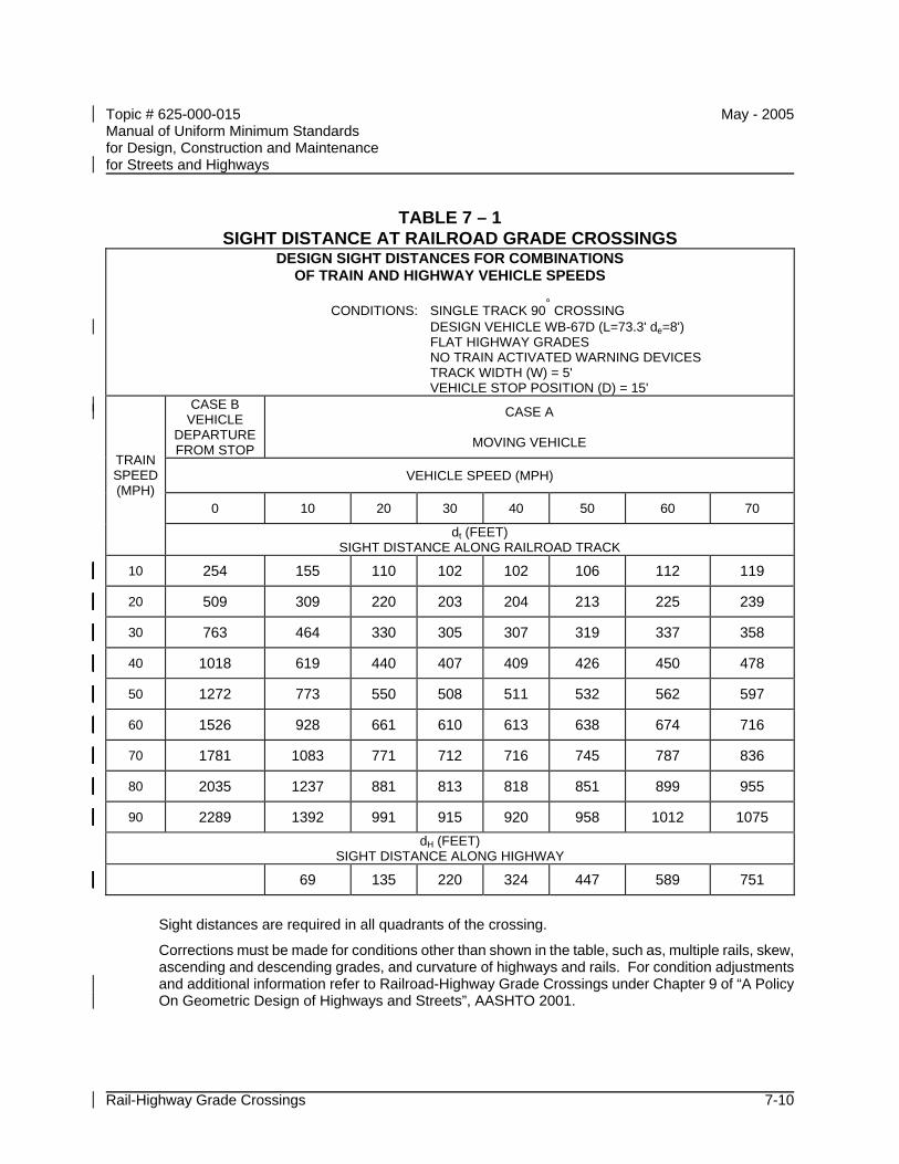
Topic # 625-000-015 May - 2005 Manual of Uniform Minimum Standards for Design, Construction and Maintenance for Streets and Highways
Rail-Highway Grade Crossings 7-10
TABLE 7 – 1 SIGHT DISTANCE AT RAILROAD GRADE CROSSINGS
DESIGN SIGHT DISTANCES FOR COMBINATIONS OF TRAIN AND HIGHWAY VEHICLE SPEEDS
CONDITIONS: SINGLE TRACK 90° CROSSING DESIGN VEHICLE WB-67D (L=73.3' de=8') FLAT HIGHWAY GRADES NO TRAIN ACTIVATED WARNING DEVICES TRACK WIDTH (W) = 5' VEHICLE STOP POSITION (D) = 15'
CASE B VEHICLE
DEPARTURE FROM STOP
CASE A
MOVING VEHICLE
VEHICLE SPEED (MPH)
0 10 20 30 40 50 60 70
TRAIN SPEED (MPH)
dt (FEET) SIGHT DISTANCE ALONG RAILROAD TRACK
10 254 155 110 102 102 106 112 119
20 509 309 220 203 204 213 225 239
30 763 464 330 305 307 319 337 358
40 1018 619 440 407 409 426 450 478
50 1272 773 550 508 511 532 562 597
60 1526 928 661 610 613 638 674 716
70 1781 1083 771 712 716 745 787 836
80 2035 1237 881 813 818 851 899 955
90 2289 1392 991 915 920 958 1012 1075 dH (FEET)
SIGHT DISTANCE ALONG HIGHWAY
69 135 220 324 447 589 751
Sight distances are required in all quadrants of the crossing.
Corrections must be made for conditions other than shown in the table, such as, multiple rails, skew, ascending and descending grades, and curvature of highways and rails. For condition adjustments and additional information refer to Railroad-Highway Grade Crossings under Chapter 9 of “A Policy On Geometric Design of Highways and Streets”, AASHTO 2001.
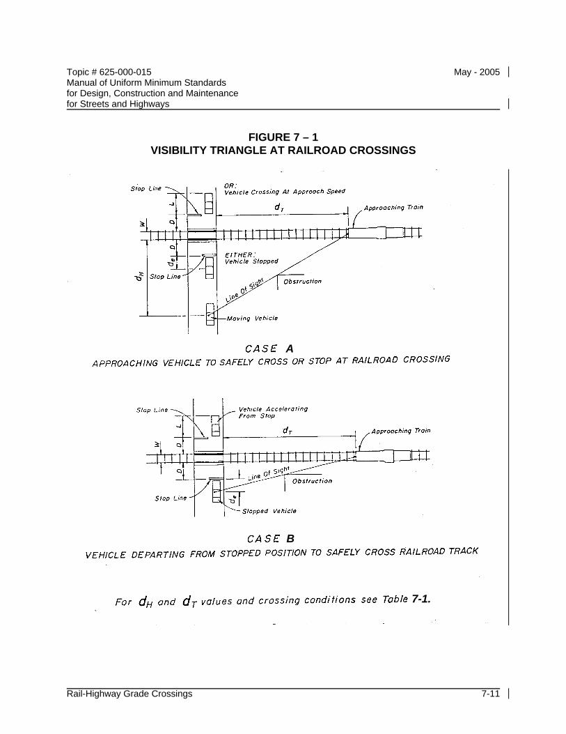
Topic # 625-000-015 May - 2005 Manual of Uniform Minimum Standards for Design, Construction and Maintenance for Streets and Highways
Rail-Highway Grade Crossings 7-11
FIGURE 7 – 1 VISIBILITY TRIANGLE AT RAILROAD CROSSINGS
7-1.
A
B
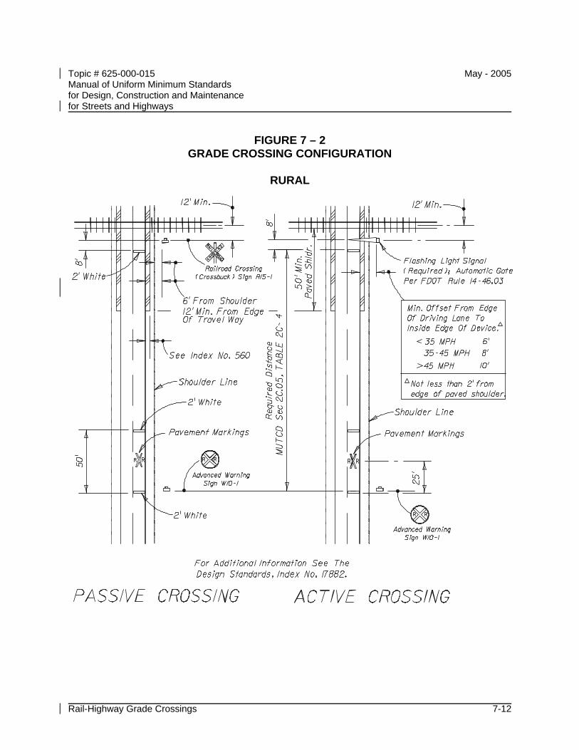
Topic # 625-000-015 May - 2005 Manual of Uniform Minimum Standards for Design, Construction and Maintenance for Streets and Highways
Rail-Highway Grade Crossings 7-12
FIGURE 7 – 2 GRADE CROSSING CONFIGURATION
RURAL
Topic # 625-000-015 May - 2005 Manual of Uniform Minimum Standards for Design, Construction and Maintenance for Streets and Highways
Pedestrian Facilities 8-i
CHAPTER 8
PEDESTRIAN FACILITIES
A INTRODUCTION............................................................................................... 8-1
B MINIMIZING CONFLICTS ................................................................................. 8-1 B.1 General Needs..................................................................................... 8-2 B.2 Independent Systems .......................................................................... 8-2 B.3 Horizontal Separation........................................................................... 8-2
B.3.a General Criteria.................................................................... 8-2 B.4 Other Considerations ........................................................................... 8-3
C Barrier Separation ............................................................................................. 8-4 C.1 Longitudinal Barriers ............................................................................ 8-4 C.2 Fencing or Landscaping....................................................................... 8-4
D VERTICAL SEPARATION................................................................................. 8-5 D.1 Overpasses.......................................................................................... 8-5 D.2 Underpasses........................................................................................ 8-5
E PROTECTION................................................................................................... 8-6 E.1 Crossings ............................................................................................. 8-6 E.2 Controls................................................................................................ 8-6 E.3 Sight Distance...................................................................................... 8-7 E.4 Lighting ................................................................................................ 8-7

Topic # 625-000-015 May - 2005 Manual of Uniform Minimum Standards for Design, Construction and Maintenance for Streets and Highways
Pedestrian Facilities 8-ii
THIS PAGE INTENTIONALLY LEFT BLANK
Topic # 625-000-015 May - 2005 Manual of Uniform Minimum Standards for Design, Construction and Maintenance for Streets and Highways
Pedestrian Facilities 8-1
CHAPTER 8
PEDESTRIAN FACILITIES
A INTRODUCTION
All new highways, except limited access highways, should be designed and constructed under the assumption they will be used by pedestrians. Provisions for pedestrian traffic should be incorporated into the original highway design.
In addition to providing pedestrian facilities on new projects, each highway agency responsible for maintaining or operating streets and urban highways should establish and maintain a program of pedestrian facilities implementation, maintenance and safety for the urban highway network.
For additional information concerning the design of sidewalks, refer to Section C.7.d of CHAPTER 3 – GEOMETRIC DESIGN.
For information concerning the design of shared use paths, refer to CHAPTER 9 - BICYCLE FACILITIES.
B MINIMIZING CONFLICTS
The planning and design of new streets and urban highways shall include provisions that minimize vehicle-pedestrian conflicts. Features requiring special attention include pedestrian crossings, center raised medians, pathways parallel to the roadway, bus stops and shelters, and other pedestrian activity adjacent to the street or highway.
In some situations it may be possible to eliminate a vehicle-pedestrian conflict. The elimination of vehicle-pedestrian conflict points requires close coordination with the planning of pedestrian pathways and activity outside of the highway right of way. Care should be exercised to ensure the elimination of a given conflict point does not merely transfer the problem to a different location. A reduction in the number of conflict points allows for economical and effective control and protection at the remaining points of conflict, thus providing an efficient method of pedestrian hazard reduction. Procedures for the elimination of vehicle-pedestrian conflicts are given in the subsequent material.
Topic # 625-000-015 May - 2005 Manual of Uniform Minimum Standards for Design, Construction and Maintenance for Streets and Highways
Pedestrian Facilities 8-2
Any effort to minimize or eliminate conflict points must consider the mobility needs of the pedestrian: desired travel path should not be severed and walking distances should not be significantly increased. Some conflict areas will have to be redesigned rather than eliminated or relocated.
B.1 General Needs
Minimizing vehicle-pedestrian conflicts can be accomplished by providing adequate horizontal, physical, or vertical (primarily for crossings) separation between the roadway and the pedestrian pathways.
B.2 Independent Systems
One ideal method for eliminating vehicle-pedestrian conflicts is to provide essentially independent systems for vehicular and pedestrian traffic. This requires adequate land use allocation and restriction (CHAPTER 2 - LAND DEVELOPMENT) and the proper layout and design of pedestrian pathways and the surface transportation network.
Where independent systems are provided, intersections between the two modes (i.e., parking areas) are still required. Due to the small number of these intersections or conflict points, they can be economically developed for safe and efficient operation.
B.3 Horizontal Separation
The development of independent systems for pedestrian and vehicular traffic is the preferred method for providing adequate horizontal separation.
B.3.a General Criteria
Pedestrian pathways should be placed at least as far from the rural roadway, particularly those with flush shoulders, as stipulated by the following criteria, which are given in a sequence of desirability:
• Outside of the highway right of way in a separately dedicated corridor.
• At or near the right of way line (ideally, 3 feet width should be provided behind the sidewalk for above ground utilities).
Topic # 625-000-015 May - 2005 Manual of Uniform Minimum Standards for Design, Construction and Maintenance for Streets and Highways
Pedestrian Facilities 8-3
• Outside of the designed roadside clear zone.
• Outside of the minimum required roadside clear zone (CHAPTER 3 - GEOMETRIC DESIGN).
• As far from the edge of the driving lane as possible.
Sidewalks which are set back from the roadway will need to be brought closer to the roadway at intersections. This will allow for proper placement of crosswalks and stop bars.
B.4 Other Considerations
When designing urban highways with substantial pedestrian-vehicle conflicts, the following are some measures that may be considered to help reduce these conflicts and may increase the efficient operation of the roadway.
• Eliminate left and/or right turns
• Prohibit free flow right turn movements
• Prohibit right turn on red
• Convert from two-way to one-way street operation
• Provide separate signal phases for pedestrians
• Eliminate selected crosswalks
• Provide pedestrian grade separations
Topic # 625-000-015 May - 2005 Manual of Uniform Minimum Standards for Design, Construction and Maintenance for Streets and Highways
Pedestrian Facilities 8-4
C Barrier Separation
Barriers may be used to assist in the separation of vehicular and pedestrian traffic.
C.1 Longitudinal Barriers
Longitudinal barriers such as guardrails, rigid barriers, and bridge railings are designed primarily to redirect errant vehicles away from roadside hazards. These barriers can also be used to provide valuable protection of pedestrian pathways from out of control vehicles.
Where adequate horizontal separation is not feasible, or where there is a significant hazard from out of control vehicles, longitudinal barriers may be utilized.
C.2 Fencing or Landscaping
The elimination of many potential vehicle-pedestrian conflicts may be accomplished by fencing or landscaping to prevent pedestrian access to the roadway and to aid in channeling pedestrian traffic to the proper crossing points. Fencing or landscaping shall not be considered a substitute for longitudinal barriers, but may be used in conjunction with redirection devices.
Fencing or landscaping may be utilized to prevent access to streets and highways at the locations described in B.1 General Needs. Fencing at the right of way line and placement of pedestrian (and bicycle) pathways in separate corridors outside of this line is a necessary procedure on limited access facilities.
Topic # 625-000-015 May - 2005 Manual of Uniform Minimum Standards for Design, Construction and Maintenance for Streets and Highways
Pedestrian Facilities 8-5
D VERTICAL SEPARATION
Vertical separation may be selectively utilized to effect the crossing of large pedestrian volumes and high speed highways particularly where the traffic volume on the roadway is at or near capacity. This method of conflict elimination is often justified at major pedestrian generators such as schools, shopping centers, sports and amusement facilities, transit centers, commercial buildings, parks and playgrounds, and parking facilities.
D.1 Overpasses
The design of pedestrian bridges or overpasses should include provisions for additional vertical clearance, as the consequences of being struck by a vehicle may be quite serious. Bridges should be covered or screened to reduce the likelihood of objects being dropped or thrown onto the roadway below. The area adjacent to overpasses may be fenced to prevent unsafe crossings and to channel pedestrians to the vertical separation structure.
D.2 Underpasses
Pedestrian underpasses or tunnels perform the same function as overpasses. Their use is often convenient when the roadway if elevated somewhat above the surrounding terrain.
Underpasses should be adequately maintained to reduce potential problems in lighting, cleaning, policing, and flooding and to maximize safety. The area adjacent to underpasses may be fenced to prevent unsafe crossings and to channel pedestrians to the vertical separation structure.
Topic # 625-000-015 May - 2005 Manual of Uniform Minimum Standards for Design, Construction and Maintenance for Streets and Highways
Pedestrian Facilities 8-6
E PROTECTION
The design of all pedestrian crossings and parallel pathways within the right of way shall be considered an integral part of the overall design of a street or urban highway.
The development of protection at any remaining crossings or conflict points must be adequate to achieve a total pedestrian transportation mode that is reasonably safe.
E.1 Crossings
Curb ramps meeting the requirements of ADA Accessibility Guidelines (as described in the Federal Register) and the Florida Accessibility Code for Building Construction (Rule 9B-7.0042), shall be constructed at crosswalks at all intersections where curbs and sidewalks are constructed in order to give persons with disabilities safe access.
The design of pedestrian crossings should be based on the following requirements:
• Crossings should be placed at locations with ample sight distances.
• At crossings, the roadway should be free from changes in alignment or cross section.
• The entire length of crosswalk shall be visible to drivers at a sufficient distance to allow a stopping maneuver.
• Stop bars shall be provided adjacent to all signalized crosswalks to inform drivers of the proper location to stop. The stop bar should be well separated from the crosswalk, but should not be closer than 4 feet.
• All crosswalks shall be easily identified and clearly delineated, in accordance with Manual on Uniform Traffic Control Devices (MUTCD) (Rule 14-15.010).
E.2 Controls
Signs, signals, and markings should be utilized to provide the necessary information and direction for pedestrians. All directions and regulations should be clear, consistent and logical and should, as a minimum, conform to the requirements given in the MUTCD. The use of audible tactile as well as visual signals should be
Topic # 625-000-015 May - 2005 Manual of Uniform Minimum Standards for Design, Construction and Maintenance for Streets and Highways
Pedestrian Facilities 8-7
considered for pedestrian traffic control and regulation.
E.3 Sight Distance
The general requirements for sight distances for the driver are given in CHAPTER 3 - GEOMETRIC DESIGN.
Stopping sight distances greater than the minimum should be provided at all pedestrian crossings. These sight distances should include a clear view of the pedestrian approach pathway for at least 15 feet from the outside travel lane. Where parallel pedestrian pathways are within the roadside recovery area, or where casual pedestrian crossings are likely, the normal required stopping sight distance should also include a clear view of the entire roadside recovery area.
Sight distances shall be based upon a driver's eye and object height as discussed in CHAPTER 3 – GEOMETRIC DESIGN. Due to the small height and diameter of pedestrians (particularly children), they are generally easy to confuse with other background objects.
Parking shall be prohibited where it would interfere with the required sight distance. Particular care should be exercised to ensure ample mutual sight distances are provided at all intersections and driveways.
E.4 Lighting
Illumination of the roadway itself is not only important for the safety of vehicular traffic, but also valuable for the protection of pedestrians. Vehicle headlamps often do not provide sufficient illumination to achieve the required stopping sight distance. Since this requirement is of vital importance at any potential pedestrian crossing point, illumination of the crossing should be considered. Lighting a street or highway is also valuable in improving the pedestrian's view of an oncoming vehicle. At intersections or other locations with vehicle turning maneuvers, the vehicle headlights may not be readily visible to the pedestrian.
The general requirements for lighting on streets and highways are given in CHAPTER 6 - ROADWAY LIGHTING. Pathways adjacent to a street or highway should not be illuminated to a level more than twice that of the roadway itself.
In general, lighting should be considered as warranted when it is necessary, at night,
Topic # 625-000-015 May - 2005 Manual of Uniform Minimum Standards for Design, Construction and Maintenance for Streets and Highways
Pedestrian Facilities 8-8
to provide the mutual sight distance capabilities described in the preceding CHAPTER 3 - GEOMETRIC DESIGN. Locations with significant night time pedestrian traffic that should be considered for lighting of the roadway and adjacent pedestrian pathways include the following:
• Any street or highway that meets the warranting criteria given in CHAPTER 6 - ROADWAY LIGHTING.
• Streets and highways with a speed limit in excess of 40 mph that do not have adequate pedestrian conflict elimination.
• Sections of highway with minimal separation of parallel pedestrian pathways.
• Intersections, access and decision points, and areas adjacent to changes in alignment or cross sections.
• Areas adjacent to pedestrian generators.
• Bus stops and other mass transit transfer locations.
• Parking facilities.
• Entertainment districts, sports/recreation complexes, schools, and other activity centers generating night travel.
• Pedestrian crossings.
• Any location where improvement of night time sight distance will reduce the hazard of vehicle-pedestrian conflicts.
Topic # 625-000-015 May - 2005 Manual of Uniform Minimum Standards for Design, Construction and Maintenance for Streets and Highways
Bicycle Facilities 9-i
CHAPTER 9
BICYCLE FACILITIES
A INTRODUCTION............................................................................................... 9-1
B ON-STREET FACILITIES.................................................................................. 9-1 B.1 Paved Shoulders.................................................................................. 9-1 B.2 Bike Lanes ........................................................................................... 9-2 B.3 Curb Lanes .......................................................................................... 9-3
C SHARED USE PATHS ...................................................................................... 9-4 C.1 Separation Between Shared Use Paths and Roadways ...................... 9-4 C.2 Width.................................................................................................... 9-6 C.3 Horizontal Clearance............................................................................ 9-6 C.4 Vertical Clearance................................................................................ 9-6 C.5 Design Speed ...................................................................................... 9-7 C.6 Structures............................................................................................. 9-7 C.7 Ramp Widths ....................................................................................... 9-7
D Railroad Crossings ............................................................................................ 9-8
Topic # 625-000-015 May - 2005 Manual of Uniform Minimum Standards for Design, Construction and Maintenance for Streets and Highways
Bicycle Facilities 9-ii
FIGURES
FIGURE 9 – 1 MINIMUM WIDTHS FOR BIKE LANES............................................. 9-9
FIGURE 9 – 2 MAJOR INTERSECTION WITH SEPARATE RIGHT TURN LANE URBAN TYPICAL SECTION (CURB AND GUTTER) ........... 9-10
FIGURE 9 – 3 MAJOR INTERSECTION NO RIGHT TURN LANE PLUS BUSBAY URBAN TYPICAL SECTION (CURB AND GUTTER) ...... 9-11
FIGURE 9 – 4 MAJOR WITH LOCAL STREET INTERSECTION NO RIGHT TURN LANE URBAN TYPICAL SECTION (CURB AND GUTTER) ........... 9-12
FIGURE 9 – 5 MAJOR WITH LOCAL STREET INTERSECTION NO RIGHT TURN LANE ON STREET PARKING URBAN TYPICAL SECTION (CURB AND GUTTER)................................................... 9-13
FIGURE 9 – 6 MAJOR INTERSECTION WITH DESIGNATED SHOULDER SEPARATE RIGHT TURN LANE RURAL TYPICAL SECTION (PAVED SHOULDER) ..................................................................... 9-14
FIGURE 9 – 7 MAJOR WITH LOCAL STREET INTERSECTION DESIGNATED SHOULDER NO RIGHT TURN LANE RURAL TYPICAL SECTION (PAVED SHOULDER) .................................................... 9-15
FIGURE 9 – 8 MAJOR INTERSECTION SEPARATE RIGHT TURN LANE 3' OR 4' UNDESIGNATED BIKE LANE URBAN TYPICAL SECTION (CURB AND GUTTER)................................................... 9-16
FIGURE 9 – 9 MAJOR INTERSECTION RIGHT TURN DROP LANE DESIGNATED OR UNDESIGNATED BIKE LANE URBAN TYPICAL SECTION (CURB AND GUTTER)................................... 9-17
FIGURE 9 – 10 "TEE" INTERSECTION SEPARATE RIGHT TURN LANE URBAN TYPICAL SECTION (CURB AND GUTTER) ..................... 9-18
FIGURE 9 – 11 "TEE" INTERSECTION RIGHT TURN DROP LANE URBAN TYPICAL SECTION (CURB AND GUTTER)................................... 9-19
FIGURE 9 – 12 INTERCHANGE RAMPS RURAL TYPICAL SECTION (PAVED SHOULDER) ................................................................................... 9-20
FIGURE 9 – 13 DETAIL OF DESIGNATED BIKE LANE AND BIKE SHOULDER MARKINGS ..................................................................................... 9-21
Topic # 625-000-015 May - 2005 Manual of Uniform Minimum Standards for Design, Construction and Maintenance for Streets and Highways
Bicycle Facilities 9-1
CHAPTER 9
BICYCLE FACILITIES
A INTRODUCTION
Bicyclists should be considered in all phases of transportation planning, design, construction and capacity improvement projects, and transit projects. All projects, particularly intersection modifications, should be designed to accommodate bicyclists. Bicycle-safe design practices, as described in this Manual, should be followed during initial roadway design to avoid costly subsequent improvements.
B ON-STREET FACILITIES
Provisions for bicycle traffic should be incorporated in the original highway design. New highways, except limited access highways, should be designed and constructed under the assumption they will be used by bicyclists. Roadway conditions should be favorable for bicycling. This requires special care in preparing the roadway surface to accommodate 1¼ inch tires. Attention needs to be given to include safe drainage grates and railroad crossings, smooth pavements, and signals responsive to bicycles. In addition, the desirability of adding facilities, such as bicycle lanes and shoulder improvements, should be included to the fullest extent feasible. Specifically, all rural arterial and collector sections within one mile of an urbanized area should be given consideration for the construction of 4 to 5 foot paved shoulders, and all urban arterial and collector sections should be given consideration for either undesignated 4 foot lanes or marked bike lanes.
Rumble strips used in a traffic lane to alert operators to conditions ahead (e.g. stop signs, traffic signals or curves) should provide clear space (free of rumble strips) for bicyclists. This clear space may be a paved shoulder or if no paved shoulder is present, a minimum of 1.5 feet of clear space at the outermost portion of the lane.
B.1 Paved Shoulders
In rural areas, or on sections without curb and gutter, adding or improving paved shoulders often can be the best way to accommodate bicyclists. Paved shoulders also benefit motor vehicle traffic.
Paved shoulders should be at least 4 feet wide to accommodate bicycle travel. The
Topic # 625-000-015 May - 2005 Manual of Uniform Minimum Standards for Design, Construction and Maintenance for Streets and Highways
Bicycle Facilities 9-2
measurement of shoulder width does not include the width of any gutter pan. Paved shoulder width of 5 feet is recommended from the face of guardrail, curb, or other roadside barrier. Additional shoulder width is desirable if motor vehicle speeds exceed 50 mph, or the percentage of trucks, buses, or recreational vehicles is high.
If paved shoulders 4 feet wide cannot be provided, consider adding 3 foot shoulders. The only practical difference in the operation of a 3 foot shoulder and wider shoulders, as they relate to bicyclists, is a slight decrease in motorist-bicyclist separation distances. Other operational characteristics, such as motorist encroachment into adjacent lanes while passing and changes in the motorist position within the lane while passing are not significantly impacted.
B.2 Bike Lanes
Bicycle lanes should be considered when it is desirable to delineate available road space for preferential use by bicyclists and motorists, and to provide for more predictable movements by each. Bicycle lane markings can increase bicyclists' confidence that motorists will not stray into their path of travel. Likewise, passing motorists are less likely to swerve to the left out of their lane to avoid bicyclists on the right.
Bicycle lanes should be one-way facilities and carry bike traffic in the same direction as the adjacent motor vehicle lane. In most cases, bike lanes will be through lanes and be located to the right of the right most through lane.
Two-way bike lanes on one side of the roadway are not recommended when they result in riding against the flow of motor vehicle traffic. Wrong-way riding is a major cause of bicycle crashes and violates the Rules of the Road as stated in the Uniform Vehicle Code and Chapter 316, Florida Statutes. Bicycle specific wrong-way signing may be used to discourage wrong-way travel. There may be special situations where a two-way bike lane for a short distance can eliminate the need for bicyclists to make a double crossing of a busy street. This should be considered after a careful evaluation of the risks.
On one-way streets, bike lanes should generally be placed on the right side of the street. Bike lanes on the left side are unfamiliar and unexpected for most motorists. This should only be considered when a bicycle lane on the left will substantially decrease the number of conflicts, such as those caused by heavy bus traffic or unusually heavy movements to the right, or if there are a significant number of left-turning bicyclists. Thus, left side bike lanes should only be considered after careful
Topic # 625-000-015 May - 2005 Manual of Uniform Minimum Standards for Design, Construction and Maintenance for Streets and Highways
Bicycle Facilities 9-3
evaluation. Similarly, two-way bike lanes on the left side of a one-way street with a suitable separation from the motor vehicle should only be considered after a complete engineering study of other alternatives and relative risks.
One-way bicycle lanes should be designed with the minimum width given in Figure 9 - 1. The 4 foot bike lane shown assumes the shoulder provides emergency maneuvering room.
B.3 Curb Lanes
In restricted urban conditions, where it is not possible to include bike lanes or paved shoulders or on lower volume collector streets, an outside lane wider than 12 feet can help accommodate both bicycles and motor vehicles in the same lane. Fourteen feet is the recommended lane width for shared use in a wide curb lane, and is the minimum width that will allow passenger cars to safely pass bicyclists within a single lane.
Topic # 625-000-015 May - 2005 Manual of Uniform Minimum Standards for Design, Construction and Maintenance for Streets and Highways
Bicycle Facilities 9-4
C SHARED USE PATHS
Shared use paths are facilities usually on exclusive right of way, with minimal cross flow by motor vehicles. Users are non-motorized and may include, but are not limited to, the following:
• Bicyclists
• In-line skaters
• Roller skaters
• Skateboarders
• Wheelchair users
• Pedestrians (walkers, runners, people with baby strollers, people walking dogs, etc.)
Shared use paths can serve a variety of purposes. They can provide users with a shortcut through a residential neighborhood. Shared use paths can also provide access to areas otherwise served only by limited access highways. For transportation purposes, they should be thought of as an extension of the roadway network for non-motorized users. The inclusion of a shared use path should not be considered as an alternative to providing in-street facilities, but, rather, as a supplement.
For a discussion of shared path design beyond what is in this chapter, refer to the Florida Bicycle Facilities Planning and Design Handbook.
C.1 Separation Between Shared Use Paths and Roadways
Shared use paths should be separated from the roadway. In some cases, paths along highways for short sections are permissible, given an appropriate level of separation between facilities. Some problems with paths located immediately adjacent to the roadways are as follows:
• Unless separated, they require one direction of bicycle traffic to ride against motor vehicle traffic, contrary to normal rules of the road.
• When paths end, bicyclists going against traffic will tend to continue to travel on the wrong side of the street. Likewise, bicyclists approaching a path often
Topic # 625-000-015 May - 2005 Manual of Uniform Minimum Standards for Design, Construction and Maintenance for Streets and Highways
Bicycle Facilities 9-5
travel on the wrong side of the street to get to the path. Wrong-way travel by bicyclists is a major cause of bicycle/automobile crashes and should be discouraged at every opportunity.
• At intersections, motorists entering or crossing the roadway often will not notice bicyclists coming from the right, as they are not expecting or looking for contra-flow vehicles. Motorists turning to exit the roadway may likewise fail to notice the bicyclists. Even bicyclists coming from the left (the expected direction) often go unnoticed, especially when sight distances are limited.
• When constructing a two-way path within a narrow right of way, sacrificing the shoulder on the adjacent roadway would be a detriment to both the motorist and the bicyclists and should be avoided if at all possible.
• Many bicyclists will use the roadway instead of the shared use path because they have found the roadway to be safer, less congested, more convenient, or better maintained. Bicyclists using the roadway are often subjected to harassment by motorists who feel that, in all cases, bicyclists should be on the path instead.
• Although the shared use path should be given the same priority through intersections as the parallel highway, motorists falsely expect bicyclists to stop or yield at all cross streets and driveways. Efforts to require or encourage bicyclists to yield or stop at each cross street and driveway are inappropriate and frequently ignored by bicyclists.
• Stopped cross street motor vehicle traffic or vehicles exiting side streets or driveways may block the path crossing.
• Because of the proximity of motor vehicle traffic to opposing bicycle traffic, barriers are often necessary to keep motor vehicles out of shared use paths and bicyclists out of traffic lanes. These barriers can represent an obstruction to bicyclists and motorists, can complicate maintenance of the facility, and cause other problems.
When the distance between the shared use path and the highway shoulder is less than 5 feet, a physical barrier is recommended. Where used, the barrier should be a minimum of 42 inches high, to prevent cyclists from toppling over it. A barrier between a shared use path and an adjacent highway should not impair sight distance at intersections, and should be designed to not be a hazard to errant motorists.
Topic # 625-000-015 May - 2005 Manual of Uniform Minimum Standards for Design, Construction and Maintenance for Streets and Highways
Bicycle Facilities 9-6
C.2 Width
The paved width and operating width required for a shared use path are primary design considerations. The minimum recommended width for a paved two-way path is 10 feet. In many cases, it is desirable to increase the minimum width to 12 feet. The width should be increased if there is expected substantial use by bicyclists, probable shared use with joggers and in-line skaters, steep grades, and locations where bicyclists are likely to ride two abreast.
In a few cases, it may be acceptable to decrease the trail width to 8 feet. This width should only be used where the following conditions prevail:
• Bicycle traffic is expected to be low, even on peak days or during peak hours.
• Pedestrian use of the facility is not expected to be more than occasional.
• There will be good horizontal and vertical alignment, providing safe and frequent passing opportunities.
• During normal maintenance activities, the path will not be subjected to maintenance vehicles causing pavement edge damage.
For further discussion of shared use path design, refer to the Florida Bicycle Facilities Planning and Design Handbook.
C.3 Horizontal Clearance
A minimum 2 foot wide graded area with a maximum 1:6 slope should be maintained adjacent to both sides of the path; however, 3 feet or more is desirable to provide clearance from trees, poles, walls, fences, guardrails or other lateral obstructions. Where the path is adjacent to canals, ditches, or slopes steeper than 1:3, a wider separation should be considered. A minimum 5 foot separation from the edge of the path pavement to the top of the slope is desirable. Depending on the height of embankment and condition at the bottom, a physical barrier, such as dense shrubbery, railing or chain link fence, may need to be provided.
C.4 Vertical Clearance
Vertical clearance to obstructions should be a minimum of 8 feet. However, vertical
Topic # 625-000-015 May - 2005 Manual of Uniform Minimum Standards for Design, Construction and Maintenance for Streets and Highways
Bicycle Facilities 9-7
clearance may need to be greater to permit passage of maintenance and emergency vehicles. In undercrossings and tunnels, 10 feet is desirable.
C.5 Design Speed
A design speed of 20 mph should be used for shared use paths.
C.6 Structures
The minimum clear width on structures should be the same as the approach shared use path, plus the minimum 2 foot wide clear areas.
Grades on structures to be used by pedestrians shall comply with the requirements of the ADA Accessibility Guidelines (as described in the Federal Register) and the Florida Accessibility Code For Building Construction as given in CHAPTER 3 – GEOMETRIC DESIGN.
C.7 Ramp Widths
Ramps for curbs at intersections should be at least the same width as the shared use path. Curb cuts and ramps should provide a smooth transition between the shared use path and the roadway. A 5 foot radius or flare may be considered to facilitate right turns for bicyclists.
Topic # 625-000-015 May - 2005 Manual of Uniform Minimum Standards for Design, Construction and Maintenance for Streets and Highways
Bicycle Facilities 9-8
D Railroad Crossings
Railroad-highway grade crossings should ideally be at a right angle to the rails. This can be accomplished either as a separate path or a widened shoulder. The greater the crossing deviated from this ideal crossing angle, the greater is the potential for a bicyclist's front wheel to be trapped in the flangeway, causing loss of steering control. If the crossing angle is less than approximately 45 degrees, an additional paved shoulder of sufficient width should be provided to permit the bicyclist to cross the track at a safer angle, preferable perpendicularly. Where this is not possible, and where train speeds are low, commercially available compressible flangeway fillers may enhance bicyclist operation. It is also important that the roadway approach be at the same elevation as the rails. For more information, see Figure 27 in the AASHTO Guide for the Development of Bicycle Facilities (1999).
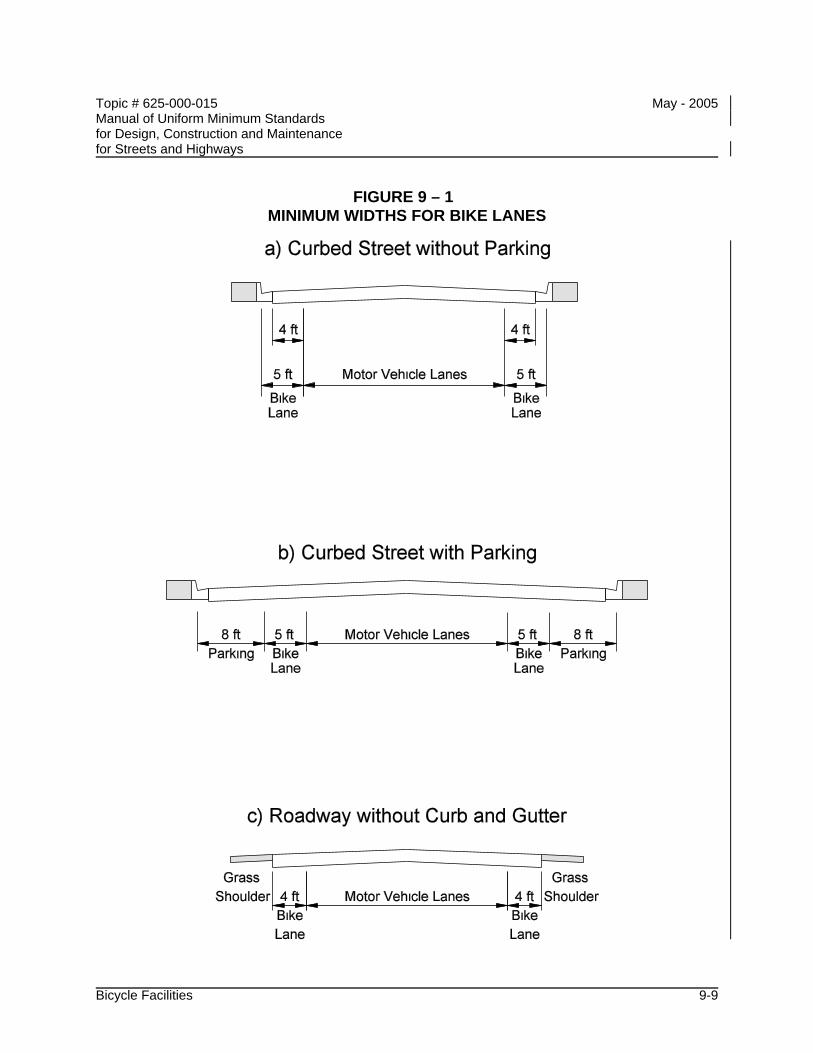
Topic # 625-000-015 May - 2005 Manual of Uniform Minimum Standards for Design, Construction and Maintenance for Streets and Highways
Bicycle Facilities 9-9
FIGURE 9 – 1 MINIMUM WIDTHS FOR BIKE LANES
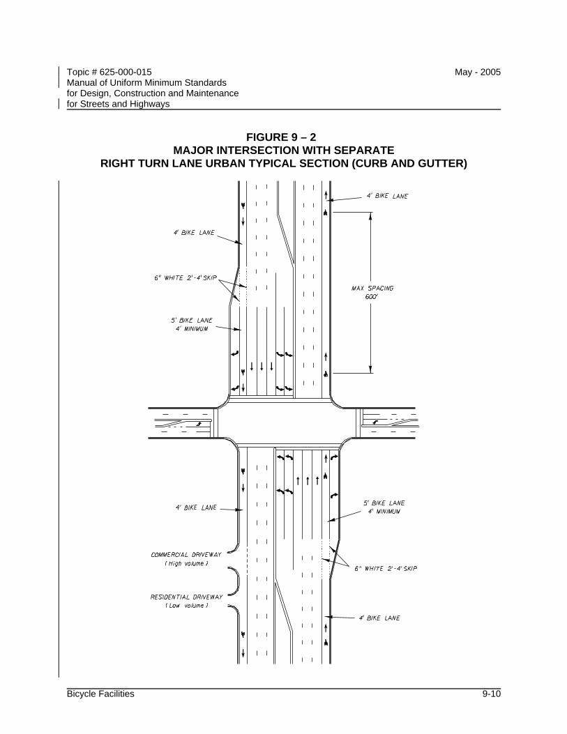
Topic # 625-000-015 May - 2005 Manual of Uniform Minimum Standards for Design, Construction and Maintenance for Streets and Highways
Bicycle Facilities 9-10
FIGURE 9 – 2 MAJOR INTERSECTION WITH SEPARATE
RIGHT TURN LANE URBAN TYPICAL SECTION (CURB AND GUTTER)
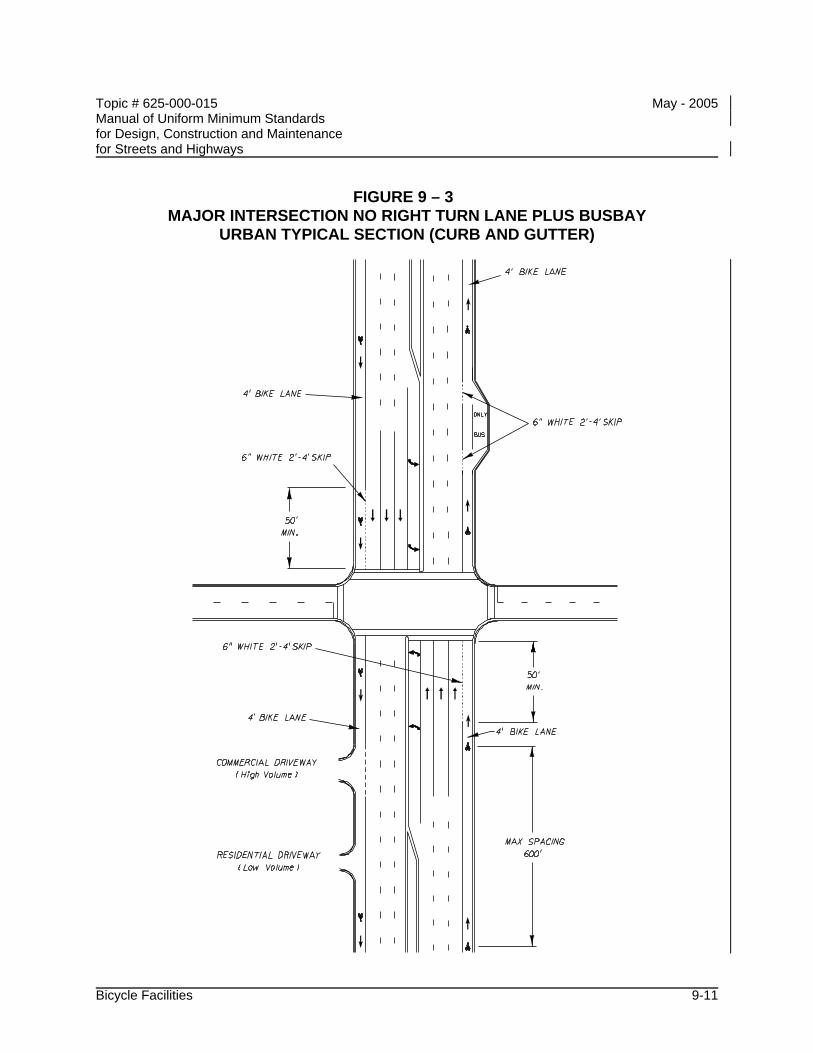
Topic # 625-000-015 May - 2005 Manual of Uniform Minimum Standards for Design, Construction and Maintenance for Streets and Highways
Bicycle Facilities 9-11
FIGURE 9 – 3 MAJOR INTERSECTION NO RIGHT TURN LANE PLUS BUSBAY
URBAN TYPICAL SECTION (CURB AND GUTTER)
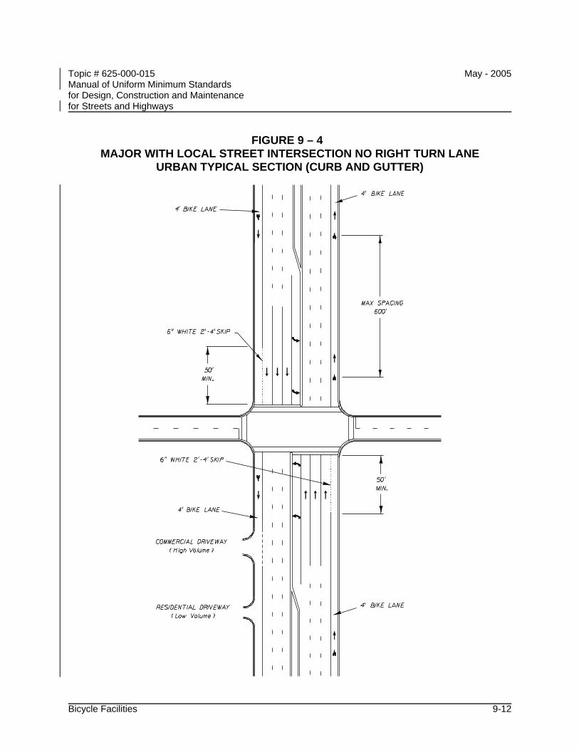
Topic # 625-000-015 May - 2005 Manual of Uniform Minimum Standards for Design, Construction and Maintenance for Streets and Highways
Bicycle Facilities 9-12
FIGURE 9 – 4 MAJOR WITH LOCAL STREET INTERSECTION NO RIGHT TURN LANE
URBAN TYPICAL SECTION (CURB AND GUTTER)
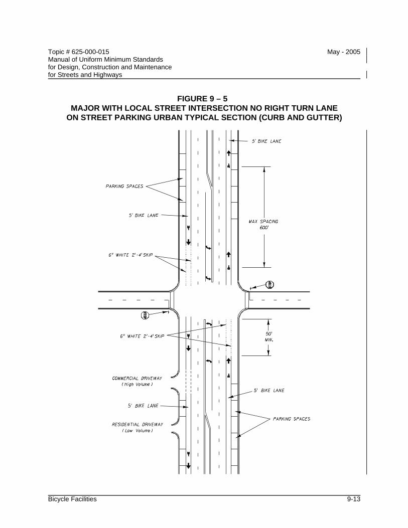
Topic # 625-000-015 May - 2005 Manual of Uniform Minimum Standards for Design, Construction and Maintenance for Streets and Highways
Bicycle Facilities 9-13
FIGURE 9 – 5 MAJOR WITH LOCAL STREET INTERSECTION NO RIGHT TURN LANE
ON STREET PARKING URBAN TYPICAL SECTION (CURB AND GUTTER)
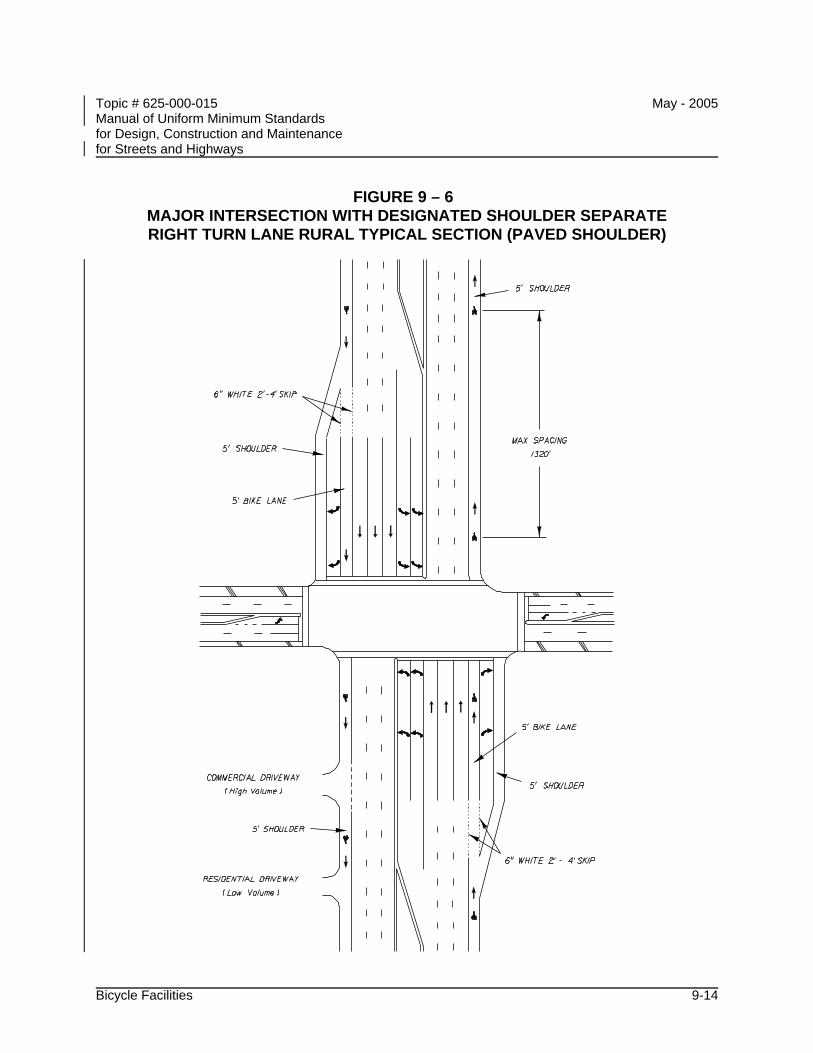
Topic # 625-000-015 May - 2005 Manual of Uniform Minimum Standards for Design, Construction and Maintenance for Streets and Highways
Bicycle Facilities 9-14
FIGURE 9 – 6 MAJOR INTERSECTION WITH DESIGNATED SHOULDER SEPARATE RIGHT TURN LANE RURAL TYPICAL SECTION (PAVED SHOULDER)
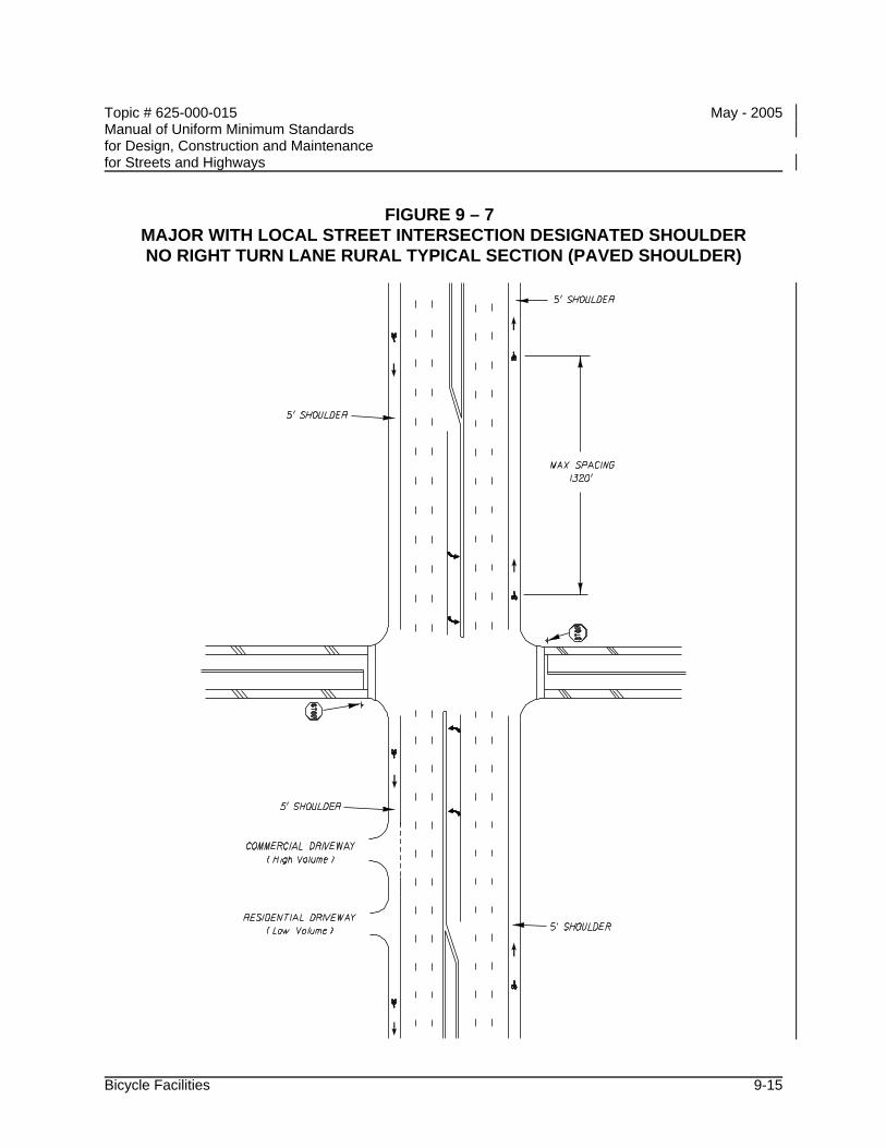
Topic # 625-000-015 May - 2005 Manual of Uniform Minimum Standards for Design, Construction and Maintenance for Streets and Highways
Bicycle Facilities 9-15
FIGURE 9 – 7 MAJOR WITH LOCAL STREET INTERSECTION DESIGNATED SHOULDER NO RIGHT TURN LANE RURAL TYPICAL SECTION (PAVED SHOULDER)
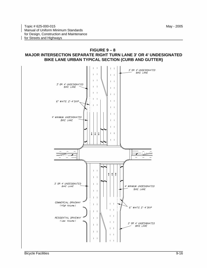
Topic # 625-000-015 May - 2005 Manual of Uniform Minimum Standards for Design, Construction and Maintenance for Streets and Highways
Bicycle Facilities 9-16
FIGURE 9 – 8 MAJOR INTERSECTION SEPARATE RIGHT TURN LANE 3' OR 4' UNDESIGNATED
BIKE LANE URBAN TYPICAL SECTION (CURB AND GUTTER)
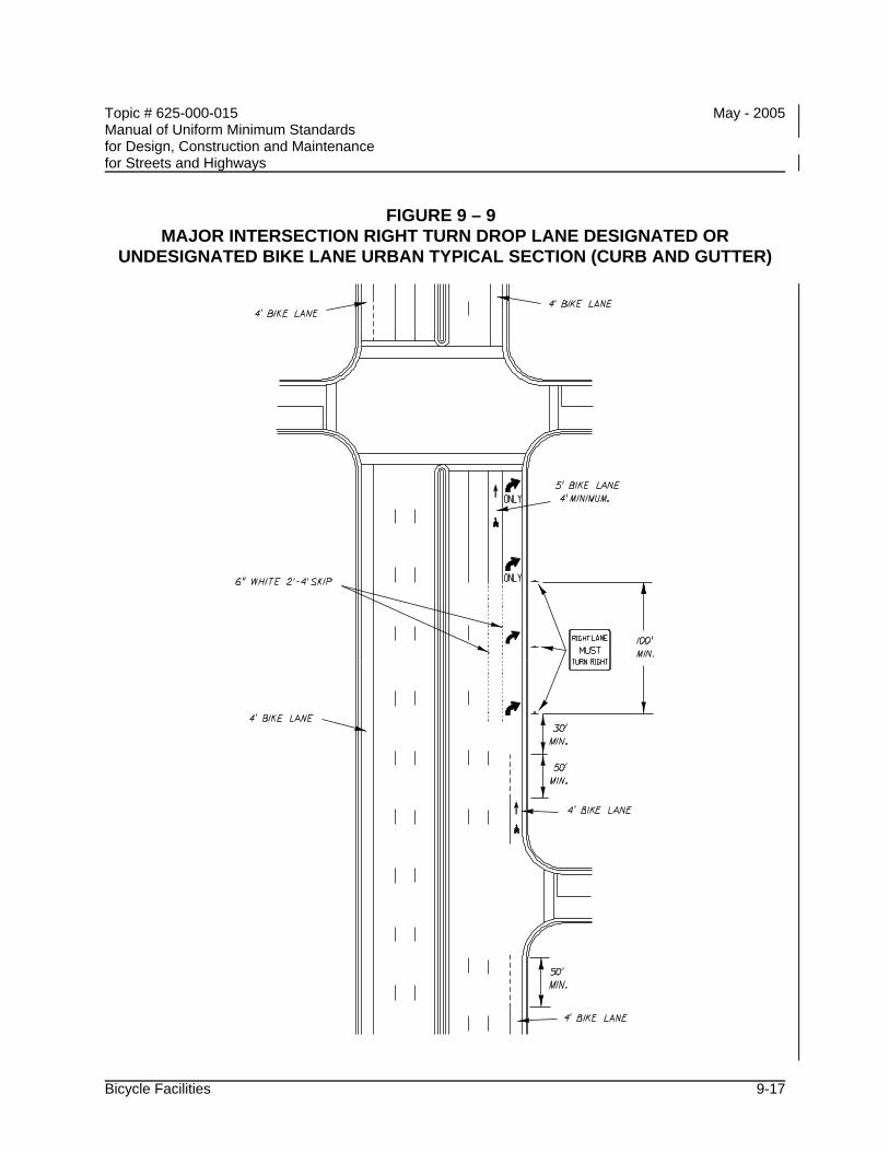
Topic # 625-000-015 May - 2005 Manual of Uniform Minimum Standards for Design, Construction and Maintenance for Streets and Highways
Bicycle Facilities 9-17
FIGURE 9 – 9 MAJOR INTERSECTION RIGHT TURN DROP LANE DESIGNATED OR
UNDESIGNATED BIKE LANE URBAN TYPICAL SECTION (CURB AND GUTTER)
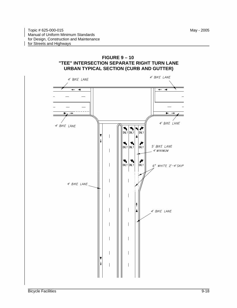
Topic # 625-000-015 May - 2005 Manual of Uniform Minimum Standards for Design, Construction and Maintenance for Streets and Highways
Bicycle Facilities 9-18
FIGURE 9 – 10 "TEE" INTERSECTION SEPARATE RIGHT TURN LANE
URBAN TYPICAL SECTION (CURB AND GUTTER)
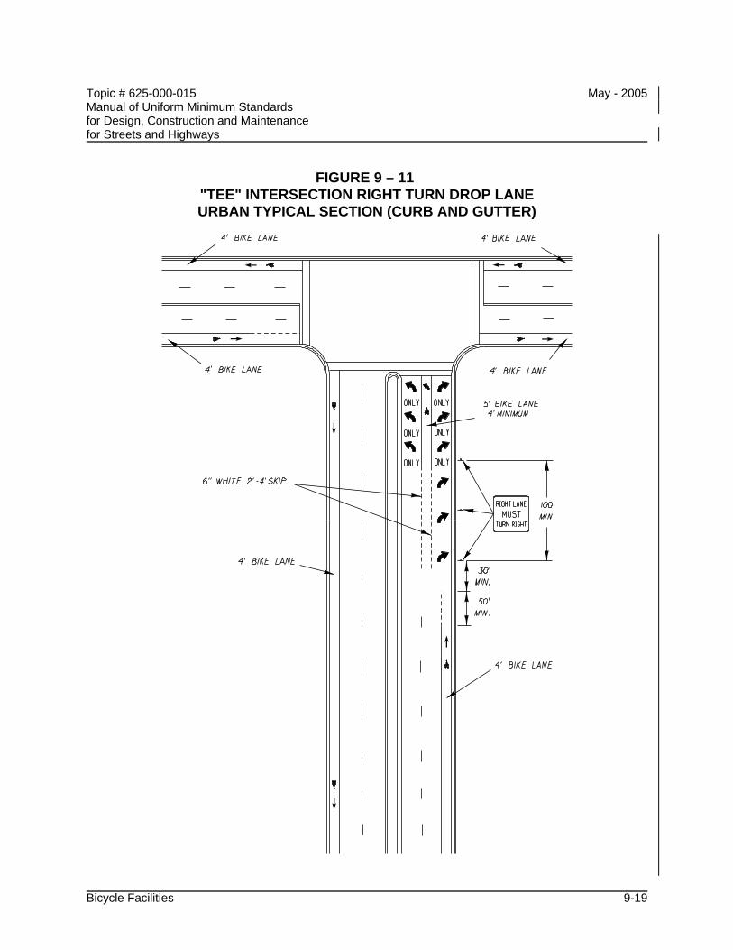
Topic # 625-000-015 May - 2005 Manual of Uniform Minimum Standards for Design, Construction and Maintenance for Streets and Highways
Bicycle Facilities 9-19
FIGURE 9 – 11 "TEE" INTERSECTION RIGHT TURN DROP LANE URBAN TYPICAL SECTION (CURB AND GUTTER)
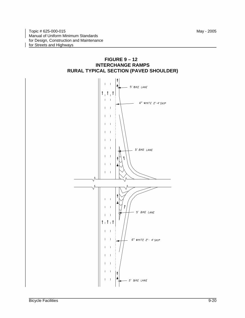
Topic # 625-000-015 May - 2005 Manual of Uniform Minimum Standards for Design, Construction and Maintenance for Streets and Highways
Bicycle Facilities 9-20
FIGURE 9 – 12 INTERCHANGE RAMPS
RURAL TYPICAL SECTION (PAVED SHOULDER)
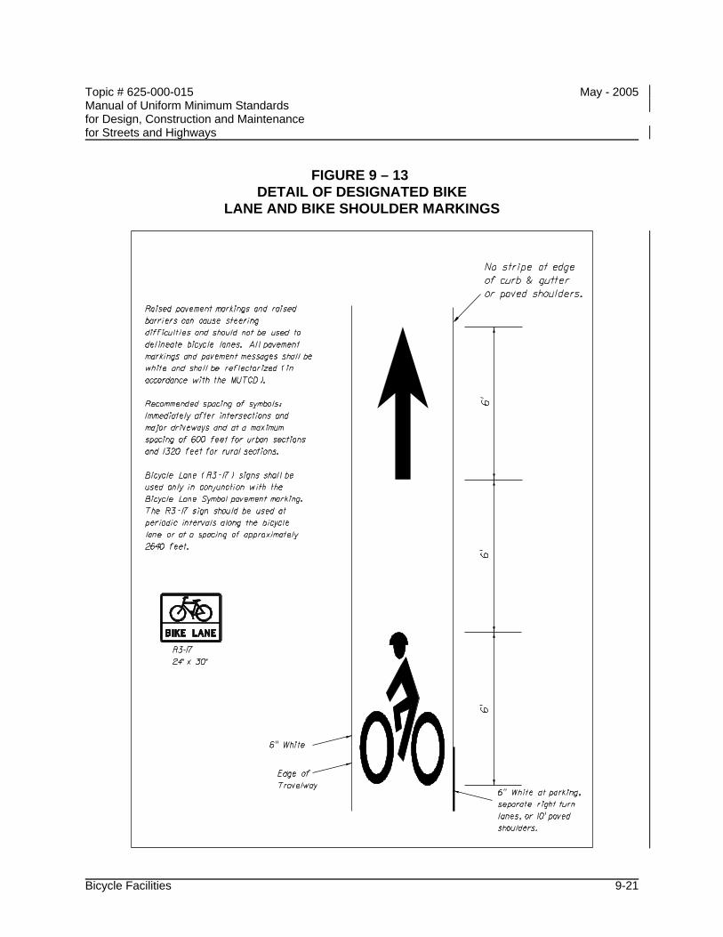
Topic # 625-000-015 May - 2005 Manual of Uniform Minimum Standards for Design, Construction and Maintenance for Streets and Highways
Bicycle Facilities 9-21
FIGURE 9 – 13 DETAIL OF DESIGNATED BIKE
LANE AND BIKE SHOULDER MARKINGS

Topic # 625-000-015 May - 2005 Manual of Uniform Minimum Standards for Design, Construction and Maintenance for Streets and Highways
Bicycle Facilities 9-22
THIS PAGE INTENTIONALLY LEFT BLANK
Topic # 625-000-015 May - 2005 Manual of Uniform Minimum Standards for Design, Construction and Maintenance for Streets and Highways
Maintenance 10-i
CHAPTER 10
MAINTENANCE
A INTRODUCTION............................................................................................. 10-1
B OBJECTIVES .................................................................................................. 10-1
C POLICY ........................................................................................................... 10-2
D IDENTIFICATION OF NEEDS......................................................................... 10-3 D.1 Inspection........................................................................................... 10-3 D.2 Crash Records ................................................................................... 10-3
E ESTABLISHMENT OF PRIORITIES ............................................................... 10-3
F ESTABLISHMENT OF PROCEDURES........................................................... 10-4 F.1 Emergency Maintenance ................................................................... 10-4 F.2 Routine Maintenance ......................................................................... 10-4 F.3 Special Maintenance.......................................................................... 10-5 F.4 Pavement Maintenance ..................................................................... 10-6

Topic # 625-000-015 May - 2005 Manual of Uniform Minimum Standards for Design, Construction and Maintenance for Streets and Highways
Maintenance 10-ii
THIS PAGE INTENTIONALLY LEFT BLANK
Topic # 625-000-015 May - 2005 Manual of Uniform Minimum Standards for Design, Construction and Maintenance for Streets and Highways
Maintenance 10-1
CHAPTER 10
MAINTENANCE
A INTRODUCTION
In order to provide for the safe and efficient movement of all modes of traffic, it is essential to maintain all aspects of the road and right of way at the highest reasonable level of safety. Improvements consistent with upgrading safety standards or accommodating changes in traffic are also required to maintain the facility in a quality condition. Maintenance is a costly operation, therefore, every effort should be made to provide the maximum safety benefit from each maintenance operation. The fact that a major portion of the maintenance effort is necessary to merely preserve the economic investment in a facility should not be considered as justification for sacrificing the requirements for maintaining or improving the safety characteristics of a street or highway.
B OBJECTIVES
The major objectives of a maintenance program include the following:
• Maintain all highway features and components in the best possible condition
• Improve sub-standard features, with the ultimate goal to at least meet minimum standards
• Provide for minimum disruptions and hazards to traffic during maintenance operations
• Location and reporting of inadequate safety features
Topic # 625-000-015 May - 2005 Manual of Uniform Minimum Standards for Design, Construction and Maintenance for Streets and Highways
Maintenance 10-2
C POLICY
Each highway agency responsible for maintenance shall develop and maintain a program of highway maintenance for the entire highway network under its jurisdiction. This program should include the following activities:
• Identify needs
• Establish priorities
• Establish procedures
• Establish and maintain a regular program of maintenance for all aspects
The program should be regularly evaluated and suitably modified to promote the maintenance of streets and highways in the best practicable condition.
Topic # 625-000-015 May - 2005 Manual of Uniform Minimum Standards for Design, Construction and Maintenance for Streets and Highways
Maintenance 10-3
D IDENTIFICATION OF NEEDS
The identification of maintenance needs is the first stage in the development of a successful maintenance program, and is required when any portion of the highway system is in a sub-standard condition. Action is also required to correct any situation which is hazardous or may become hazardous in the near future. This may be accomplished by both regular inspection of the highway network and proper analysis of crash records.
D.1 Inspection
Periodic and systematic inspection of the entire highway network under each agency's jurisdiction is required to identify situations requiring improvements, and corrections or repairs. These inspections should be conducted by maintenance or traffic operations personnel, or other qualified personnel who are trained in the aspects of highway maintenance requirements.
D.2 Crash Records
A regular program of crash investigations, record keeping, and analysis should be established to provide information for recommended highway modification and corrective maintenance requirements. Cooperation among maintenance, traffic operations, and police agencies is required, and activities of these agencies should be coordinated in accordance with the guidelines set forth in Highway Safety Program Guideline 9 Identification and Surveillance of Accident Locations. Inspection of the highway network and analysis of crash records should be utilized to provide feedback for modification of design and construction procedures.
E ESTABLISHMENT OF PRIORITIES
The maintenance activities determined to be necessary by the identification program should be carried out on a priority basis. The establishment of priorities should be based, to a large extent, upon the objective of promoting highway safety. A high priority should be given to the improvement or correction of situations that may result in fatal or serious crashes. Preservation of highway investment and promotion of efficient traffic operations are important maintenance objectives. Every effort should be made to ensure the highest safety payoff from the maintenance dollar.
Topic # 625-000-015 May - 2005 Manual of Uniform Minimum Standards for Design, Construction and Maintenance for Streets and Highways
Maintenance 10-4
F ESTABLISHMENT OF PROCEDURES
Standard procedures and methods for maintenance operations should be established for efficient, rapid, and safe completion of the required work. All maintenance work shall be conducted in accordance with the Standards set forth in CHAPTER 11 - WORK ZONE SAFETY. Each maintenance agency should develop its own Maintenance Manual or utilize the Maintenance Manuals of the Department. Such manuals should specify the methods, procedures, equipment, personnel qualifications, and other aspects of the work necessary to ensure successful completion of maintenance operations. Procedures should be developed for emergency, routine, and special operations.
F.1 Emergency Maintenance
Emergency maintenance operations are those required to immediately restore the highway to a safe condition. Emergency maintenance work should be carried out by personnel who are specially trained and qualified. Work units, which should be available on a twenty-four hour basis, should be connected with the emergency response communications system. Emergency operations would include the following:
• The removal of debris from crashes, cargo spillage, or other causes. This activity should be conducted in accordance with the guidelines set forth in Highway Safety Program Guideline 16, Debris Hazard Control and Cleanup.
• Replacement of inoperative traffic control devices
• Repair or replacement of damaged highway safety components such as lighting, traffic control devices, redirection, and energy absorbing devices
• Repair or correction of any situation that provides an immediate or unexpected hazard to the public
• Assistance in any activity during emergency response operations
F.2 Routine Maintenance
Routine maintenance operations are those that may be predicted and planned in advance. These operations, which may be preventive or corrective in nature, should be conducted on a regularly scheduled basis using standard procedures. Proper scheduling of these operations should be utilized to provide minimum disruptions and hazards to the driving public. Routine maintenance would include
Topic # 625-000-015 May - 2005 Manual of Uniform Minimum Standards for Design, Construction and Maintenance for Streets and Highways
Maintenance 10-5
operations such as:
• Cleaning and debris removal from the pavement, shoulders, and roadside clear zones
• Mowing and other vegetation control operations to provide a smooth recovery area and to maintain proper sight distance
• Cleaning and inspection of gutters, ditches, and other drainage structures
• Structural inspection and preventive maintenance on bridges and other structures
• Cleaning, replacement, and maintenance of roadway lighting fixtures
• Replacement and maintenance of traffic control devices
• Inspection and maintenance of redirection and energy absorbing devices (CHAPTER 4 - ROADSIDE DESIGN)
• Inspection and maintenance of emergency response communication systems and access facilities
• Inspection and maintenance of pavement and shoulders, with particular emphasis on maintaining shoulders flush with the pavement (CHAPTER 5 - PAVEMENT DESIGN, CONSTRUCTION AND MAINTENANCE)
• Inspection and maintenance of all highway components and safety features
• Inspection and maintenance of pedestrian pavements, crossings, etc., with particular emphasis on meeting the intent of ADA
F.3 Special Maintenance
Special maintenance operations are defined as those projects that are neither urgent or routine in nature, but are occasionally required to improve or maintain a street or highway in a quality condition. Since these projects can be planned in advance of the initiation of any work, procedures that provide for efficient, rapid, and safe operations can be developed. To avoid continuing disruptions of traffic, the quality and durability of these improvements, corrections, and repairs should be maintained at the highest practicable level. Special maintenance should include the upgrading of the highway safety features, as well as the repair or replacement of
Topic # 625-000-015 May - 2005 Manual of Uniform Minimum Standards for Design, Construction and Maintenance for Streets and Highways
Maintenance 10-6
damaged or deteriorated highway components. These operations should be designed to upgrade or maintain the street or highway in accordance with the Standards presented in this Manual.
F.4 Pavement Maintenance
The primary purpose of pavement maintenance is to ensure the pavement characteristics prescribed in CHAPTER 5 – PAVEMENT DESIGN AND CONSTRUCTION, are reasonably maintained. Each agency with responsibility for maintenance of streets and highways shall establish a meaningful pavement maintenance system (including shoulders and drainage structures) for the entire system under its jurisdiction. This program should include:
• A process that monitors the serviceability of the existing streets and highways and identifies the pavement sections that are inadequate
• A systematic plan of maintenance activities designed to correct structural deficiencies and to prevent rapid deterioration
• A preservation program, with assigned priorities, designed to resurface, reconstruct, or replace pavements when they are no longer structurally serviceable
Pavement maintenance requires a substantial portion of the total maintenance budget for streets and highways. It is necessary to ensure highway safety. A smooth-riding, skid-resistant surface must be provided at all times to allow for safe vehicle maneuvers. The reduction of hydroplaning and splashing is essential for promoting safe and efficient operation during wet weather conditions. The elimination of driving discomfort, and vehicle damage caused by deteriorated pavements, provides additional economic justification for maintaining the pavement in a fully serviceable condition.
It is recognized that a comprehensive preservation program is expensive. Adequate financing is required to successfully carry out these activities. The establishment of appropriate budget priorities and careful planning can assist in developing and conducting a pavement maintenance and preservation program that will, within a reasonable number of years, bring substandard pavements up to the required level of serviceability and will maintain the adequacy of the entire system.
Topic # 625-000-015 May - 2005 Manual of Uniform Minimum Standards for Design, Construction and Maintenance for Streets and Highways
Work Zone Safety 11-i
CHAPTER 11
WORK ZONE SAFETY
A INTRODUCTION............................................................................................. 11-1
B OBJECTIVES .................................................................................................. 11-1
C POLICY ........................................................................................................... 11-2
D PLANNING OF OPERATIONS........................................................................ 11-2 D.1 Project Requirements......................................................................... 11-2
D.1.a Type of Operation .............................................................. 11-2 D.1.a.1 Routine Operations ......................................... 11-2 D.1.a.2 Emergency Operations.................................... 11-2 D.1.a.3 Special Operations .......................................... 11-3
D.1.b Nature of Work................................................................... 11-3 D.1.c Nature of Work Zone.......................................................... 11-4
D.2 Work Scheduling................................................................................ 11-4 D.3 Traffic Control and Protection ............................................................ 11-4 D.4 Coordination with Other Agencies...................................................... 11-5
E WORK ZONE OPERATIONS.......................................................................... 11-6 E.1 Public Information .............................................................................. 11-6 E.2 Contracts and Permits........................................................................ 11-6 E.3 Inspection and Supervision ................................................................ 11-6
F EVALUATION OF PROGRAM ........................................................................ 11-6

Topic # 625-000-015 May - 2005 Manual of Uniform Minimum Standards for Design, Construction and Maintenance for Streets and Highways
Work Zone Safety 11-ii
THIS PAGE INTENTIONALLY LEFT BLANK
Topic # 625-000-015 May - 2005 Manual of Uniform Minimum Standards for Design, Construction and Maintenance for Streets and Highways
Work Zone Safety 11-1
CHAPTER 11
WORK ZONE SAFETY
A INTRODUCTION
Construction, maintenance, and utility operations produce serious highway safety problems. The changes in normal traffic flow and the unexpected conditions at many work zones provide hazardous situations and serious traffic conflicts. A comprehensive plan for work zone safety is required to minimize the effects of these construction and maintenance operations.
B OBJECTIVES
The general objective of a program of work zone safety is to protect workers, pedestrians, bicyclists, and motorists during construction and maintenance operations. This general objective may be achieved by meeting the following specific objectives:
• Provide adequate advance warning and information regarding upcoming work zones
• Provide the driver clear directions to understanding the situation he will be facing as he proceeds through or around the work zone
• Reduce the consequences of an out of control vehicle
• Provide safe access and storage for equipment and material
• Promote speedy completion of projects (including thorough cleanup of the site)
• Promote use of the appropriate traffic control and protection devices
• Provide safe passageways for pedestrians through, in, and/or around construction or maintenance work zones
Topic # 625-000-015 May - 2005 Manual of Uniform Minimum Standards for Design, Construction and Maintenance for Streets and Highways
Work Zone Safety 11-2
C POLICY
Each highway agency with responsibilities for construction, maintenance, and operation of streets and highways shall develop and maintain a program of work zone safety, as set forth in the MUTCD, (Rule 14-15.010) as published by the Federal Department of Transportation (Federal Highway Administration).
D PLANNING OF OPERATIONS
The achievement of work zone safety requires careful and complete planning prior to the initiation of any work project. The planning objective is to develop a complete operational plan which would include consideration of the following:
D.1 Project Requirements
D.1.a Type of Operation
Construction and maintenance projects may be classified as routine, emergency, or special operations.
D.1.a.1 Routine Operations
Routine operations would involve projects such as mowing, street cleaning, and preventive maintenance operations conducted on a regularly scheduled basis.
D.1.a.2 Emergency Operations
Emergency operations require prompt, efficient action to restore the roadway to a safe condition. These include operations such as clearing storm or crash debris, repairing or replacing damaged highway safety components and restoring inoperative traffic control devices.
Topic # 625-000-015 May - 2005 Manual of Uniform Minimum Standards for Design, Construction and Maintenance for Streets and Highways
Work Zone Safety 11-3
D.1.a.3 Special Operations
Special operations are defined as those projects neither routine nor emergency in nature, but are occasionally required to maintain or upgrade a street or highway. These include any construction, maintenance, utility, or other operation producing a hazard to workers, pedestrians, or motorists. Any activity involving encroachment upon the highway right of way by workers, equipment, or material storage and transfer shall be subjected to the requirements of work zone safety.
D.1.b Nature of Work
The development of the operation plan for work zone safety should include consideration of the following factors:
• Time span required
• Requirements for continuous operation or occupation of the work zone
• Capability of clearing the site during cessation of work activity
• The various construction methods, equipment, and procedures that may be utilized. Evaluation of alternate methods should be undertaken to determine the safest and most efficient procedures
• The necessity for storing equipment or material in the highway right of way
• Operations that may expose workers to hazards from through traffic
• Hazards to out of control vehicles such as excavations or unguarded structures or equipment
• Site conditions that may be confusing or distracting to the driver or produce sight distance problems
• Particular problems associated with night safety
• Equipment inspection and preventive maintenance program
Topic # 625-000-015 May - 2005 Manual of Uniform Minimum Standards for Design, Construction and Maintenance for Streets and Highways
Work Zone Safety 11-4
D.1.c Nature of Work Zone
The nature of the work zone and the prevailing traffic conditions should, to a large degree, influence the procedures incorporated into the operation plan for work zone safety. A determination of the normal vehicle speeds and traffic volumes is essential. The distribution of traffic with respect to time (hour, day, etc.) and direction is also important for establishing traffic control procedures.
D.2 Work Scheduling
Proper work scheduling and sequencing of operations will not only promote efficiency, but also improve the safety aspects of construction and maintenance operations. Where feasible, routine operations and special projects should be conducted during periods of low traffic volume to reduce conflicts. Projects that may be carried out concurrently at the same site should be scheduled simultaneously to eliminate successive disruptions of traffic. Major projects that impede or restrict traffic flow should be coordinated and sequenced with similar projects in adjacent areas, to produce a minimum of disruption to orderly traffic flow in the overall highway network. The scheduling of work at a given location should include consideration of traffic generation (including special events), as well as traffic restrictions by work activities on the surrounding highway network.
D.3 Traffic Control and Protection
Plans for traffic control around or through work zones should be developed with safety receiving a high priority. Plans should include protection at work zones when work is in progress and when operations have been halted (such as during the night). Provisions for the protection of work crews, traffic control personnel, pedestrians (in areas of high pedestrian use, construction of temporary facilities should be considered), and motorists shall be included in the operation plans. In all cases, the operation plan for traffic control and protection shall include provisions for the following:
• Advance warning
• Clear view of work zone
• Roadway delineation
• Regulatory information
Topic # 625-000-015 May - 2005 Manual of Uniform Minimum Standards for Design, Construction and Maintenance for Streets and Highways
Work Zone Safety 11-5
• Hazard warning
• Barriers
• Pedestrian and bicyclist safety
• Access
• Location of vehicles and equipment
• Night safety (CHAPTER 6 - ROADWAY LIGHTING)
• Personnel training
• Traffic control and protective devices
• Transit Stops
D.4 Coordination with Other Agencies
To ensure safe and efficient construction and maintenance operations, the operation plan should be developed and executed in cooperation with all interested individuals and agencies including the following:
• Highway agencies
• Police agencies
• Emergency agencies
• Contractors
• Utilities
• Building departments
• Mass transit agencies
• Traffic generators
• Local residents
• Neighboring jurisdictions
Topic # 625-000-015 May - 2005 Manual of Uniform Minimum Standards for Design, Construction and Maintenance for Streets and Highways
Work Zone Safety 11-6
E WORK ZONE OPERATIONS
Construction and maintenance projects should follow the operation plan and should include:
E.1 Public Information
All reasonable effort should be made to inform the public of the location, duration, and nature of impending construction of maintenance projects.
E.2 Contracts and Permits
For construction and reconstruction projects, the general work zone layout; traffic control and protection procedures; occupational safety and health requirements; and specific traffic control devices required should be incorporated in the contract plans and specifications.
New utility installations in public rights of way are prohibited unless a permit by the appropriate highway agency is issued. Permits for routine maintenance (e.g., deteriorated pole/equipment replacement), minor alterations (e.g., changes in cable, wire, or transformer size), service drops, or emergency work should generally not be required. Any construction by utility companies involving encroachment of the highway right of way by workers, equipment, material storage and transfer, or other hazardous conditions shall be conducted in accordance with the requirements for work zone safety and the Occupational Safety and Health Administration (OSHA).
E.3 Inspection and Supervision
A regular program of inspection and supervision of all construction and maintenance projects shall be established and executed.
F EVALUATION OF PROGRAM
The entire program for work zone safety should be periodically evaluated and revised to provide the safest practicable environment for workers, pedestrians, and motorists during construction and maintenance operations.
Topic # 625-000-015 May - 2005 Manual of Uniform Minimum Standards for Design, Construction and Maintenance for Streets and Highways
Construction 12-i
CHAPTER 12
CONSTRUCTION
A INTRODUCTION............................................................................................. 12-1
B OBJECTIVES .................................................................................................. 12-2
C CONTROL OF THE WORK............................................................................. 12-3 C.1 Plans and Contract Documents ......................................................... 12-3
C.1.a Plans.................................................................................. 12-3 C.1.b Alterations in Plans ............................................................ 12-3 C.1.c Working Drawings (for Structures) ..................................... 12-3
C.1.c.1 General ........................................................... 12-3 C.1.c.2 Submission of Working, Shop, and Erection
Drawings ......................................................... 12-3 C.1.c.3 Responsibility for Accuracy of Working
Drawings ......................................................... 12-4 C.2 Coordination of Plans, Specifications, and Special Provisions........... 12-4 C.3 Conformity of Work with Plans ........................................................... 12-5 C.4 Conformity of Work Shown in Regulatory Permits ............................. 12-5 C.5 Authority of the Engineer.................................................................... 12-5 C.6 Engineering and Layout ..................................................................... 12-5
C.6.a Control Points Furnished.................................................... 12-5 C.6.b Layout of Work................................................................... 12-6 C.6.c Personnel, Equipment, and Record Requirements ............ 12-6
C.7 Contractor's Supervision .................................................................... 12-6 C.7.a Prosecution of Work........................................................... 12-6 C.7.b Contractor's Superintendent .............................................. 12-6 C.7.c Supervision for Emergencies ............................................. 12-7
C.8 General Inspection Requirements...................................................... 12-7 C.8.a Cooperation by Contractor ................................................. 12-7 C.8.b Failure of Engineer to Reject Work During Construction.... 12-7
C.9 Final Construction Inspection Maintenance until Final Acceptance.... 12-7
Topic # 625-000-015 May - 2005 Manual of Uniform Minimum Standards for Design, Construction and Maintenance for Streets and Highways
Construction 12-ii
D CONTROL OF MATERIALS............................................................................ 12-8 D.1 Source of Supply and Quality Requirements ..................................... 12-8
D.1.a Only Approved Materials to be Used ................................. 12-8 D.2 Inspection and Tests at Source of Supply.......................................... 12-8
D.2.a General .............................................................................. 12-8 D.2.b Cooperation by Contractor ................................................. 12-8
D.3 Control by Samples and Tests ........................................................... 12-8 D.3.a Materials to be Tested, Samples........................................ 12-8 D.3.b Applicable Standards ......................................................... 12-9
D.4 Quality Control System ...................................................................... 12-9 D.4.a General Requirements....................................................... 12-9 D.4.b Documentation................................................................... 12-9 D.4.c Corrective Actions............................................................ 12-10
Topic # 625-000-015 May - 2005 Manual of Uniform Minimum Standards for Design, Construction and Maintenance for Streets and Highways
Construction 12-1
CHAPTER 12
CONSTRUCTION
A INTRODUCTION
The purpose of this chapter is to establish guidelines for field procedures, as they pertain to control of construction projects, supervision, and contract administration. All construction projects require an inspection process to administer the contract, to certify the project has been constructed within reasonable conformance with the plans/specifications, and the materials which were incorporated into the project were properly tested/certified.
All construction projects require:
• An inspection procedure to administer the contract
• Certification
Topic # 625-000-015 May - 2005 Manual of Uniform Minimum Standards for Design, Construction and Maintenance for Streets and Highways
Construction 12-2
B OBJECTIVES
Construction of street and highway facilities is the result of the effort, of the engineer, the contractor, and the owner. Minimum construction standards shall be followed to provide for proper implementation of the design. The following general objectives for roadway construction should be followed to ensure proper construction:
• All construction performed and all materials utilized shall be in reasonably close conformity with the construction plans and contract documents.
• The responsibilities and obligations of the owner, engineer, and contractor should be clearly defined.
• A safe working environment shall be provided in accordance with CHAPTER 11 - WORK ZONE SAFETY.
• Adequate procedures through established methods of sampling and testing shall be implemented to provide for the control and placement of materials.
Topic # 625-000-015 May - 2005 Manual of Uniform Minimum Standards for Design, Construction and Maintenance for Streets and Highways
Construction 12-3
C CONTROL OF THE WORK
C.1 Plans and Contract Documents
The Contractor will be furnished an appropriate number of copies of the plans and special provisions as required for the particular project. The Contractor shall have available at the work site, at all times, one copy each of the plans (including relevant Design Standards), Specifications, and Special Provisions.
C.1.a Plans
The plans furnished consist of general drawings showing such details which are necessary to give a comprehensive idea of the construction contemplated. Roadway plans will show, in general, alignment, profile grades, typical cross sections, and general cross sections as necessary. Structure plans, in general, will show in detail all dimensions of the work contemplated.
C.1.b Alterations in Plans
No changes shall be made on any plan or drawing after it is approved by the Engineer, except as authorized in writing by the Engineer. All authorized alterations affecting the requirements and information given on the approved plans shall be in writing.
C.1.c Working Drawings (for Structures)
C.1.c.1 General
The Contractor shall furnish such working, shop, and erection drawings, as may be required, to complete the structure in compliance with the design shown on the plans.
C.1.c.2 Submission of Working, Shop, and Erection Drawings
All working, shop, and erection drawings prepared by the Contractor or his agents (subcontractor, fabricator, supplier, etc.) shall be
Topic # 625-000-015 May - 2005 Manual of Uniform Minimum Standards for Design, Construction and Maintenance for Streets and Highways
Construction 12-4
reviewed, dated, stamped, approved, and signed by the Contractor prior to submission to the Engineer of Record for review. The Contractor's signed approval of drawings submitted shall confirm he/she has verified the work requirements, field measurements, construction criteria, sequence of assembly and erection, access and clearances, catalog numbers, and other similar data. Each series of drawings shall indicate the specification section and page or drawing number of the contract plans to which the submission applies. The Contractor shall indicate on the working, shop, and erections drawings all deviations from the contract drawings and shall itemize all deviations in his letter of transmittal.
C.1.c.3 Responsibility for Accuracy of Working Drawings
It is understood that approval by the Engineer of the Contractor's working drawings does not relieve the Contractor of any responsibility for accuracy of dimensions and details, or for conformity of dimensions and details. The Contractor shall be responsible for agreement and conformity of his working drawings with the approved plans and specifications.
C.2 Coordination of Plans, Specifications, and Special Provisions
The specifications, plans, special provisions, and all supplemental documents are integral parts of the contract, and a requirement occurring in one is as binding as though occurring in all. They are to be complementary and to describe and provide for a complete work.
In cases of discrepancy, the governing order of the documents shall be as follows:
• Special Provisions
• Plans
• Standard Drawings
• Specifications
Topic # 625-000-015 May - 2005 Manual of Uniform Minimum Standards for Design, Construction and Maintenance for Streets and Highways
Construction 12-5
C.3 Conformity of Work with Plans
All work performed and all materials furnished shall be in reasonably close conformity with the lines, grades, cross sections, dimensions, and material requirements, including tolerances, shown on the plans or indicated in the specifications.
In the event the Engineer finds the materials or the finished product in which the materials are used not within reasonably close conformity with the plans and specifications, but reasonably acceptable work has been produced, he/she shall then make a determination if the work shall be accepted and remain in place. In this event, the Engineer will document the basis of acceptance by contract modification which will provide for an appropriate adjustment in the contract price for such work or materials as he deems necessary to conform to his determination based on engineering judgment.
In the event the Engineer finds the materials, or the finished product in which the materials are used, or the work performed, are not in reasonably close conformity with the plans and specifications and have resulted in an inferior or unsatisfactory product, the work or materials shall be removed and replaced or otherwise corrected by and at the expense of the Contractor.
C.4 Conformity of Work Shown in Regulatory Permits
All work shall be accomplished in accordance with special conditions of the regulatory permits.
C.5 Authority of the Engineer
All work shall be performed to the satisfaction of the Engineer.
C.6 Engineering and Layout
C.6.a Control Points Furnished
Horizontal and vertical control points are required at appropriate intervals along the line of the project to facilitate the proper layout of the work. The Contractor shall preserve all control points furnished.
Topic # 625-000-015 May - 2005 Manual of Uniform Minimum Standards for Design, Construction and Maintenance for Streets and Highways
Construction 12-6
C.6.b Layout of Work
Utilizing the control points furnished, all horizontal and vertical controls shall be established as necessary to construct the work in conformance with the plans and specifications. The work shall include performing all calculations required and setting all stakes needed, such as grade stakes, offset stakes, reference point stakes, slope stakes, and other reference marks or points necessary to provide lines and grades for construction of all roadway, bridge, and miscellaneous items.
C.6.c Personnel, Equipment, and Record Requirements
The Contractor shall employ only competent personnel and utilize only suitable equipment in performing layout work.
Adequate field notes and records shall be kept as layout work is accomplished. These field notes and records shall be available for review by the Engineer as the work progresses and copies shall be furnished to the Engineer at the time of completion of the project. Any inspection or checking of the Contractor's field notes or layout work by the Engineer, and the acceptance of all or any part thereof, shall not relieve the Contractor of his responsibility to achieve the lines, grades, and dimensions shown in the plans and specifications.
C.7 Contractor's Supervision
C.7.a Prosecution of Work
The Contractor shall give the work the constant attention necessary to assure the scheduled progress and shall cooperate fully with the Engineer and with other contractors at work in the vicinity.
C.7.b Contractor's Superintendent
The Contractor shall at all times have on the work site, as his/her agent, a competent superintendent capable of thoroughly interpreting the plans and specifications and thoroughly experienced in the type of work being performed, and who shall receive the instructions from the Engineer or his/her authorized representatives. The superintendent shall have full authority to execute the
Topic # 625-000-015 May - 2005 Manual of Uniform Minimum Standards for Design, Construction and Maintenance for Streets and Highways
Construction 12-7
orders or directions of the Engineer and to supply promptly any materials, tools, equipment, labor, and incidentals which may be required. Such superintendence shall be furnished regardless of the amount of work sublet.
C.7.c Supervision for Emergencies
The Contractor shall have a responsible person available at or reasonably near the work site on a twenty-four hour basis, seven days a week, in order that he/she may be contacted in emergencies and in cases where immediate action must be taken to maintain traffic or to handle any other problems that might arise. The Contractor shall be responsible for initiating, installing, and maintaining all traffic control devices as described in CHAPTER 11- WORK ZONE SAFETY and in the plans.
C.8 General Inspection Requirements
C.8.a Cooperation by Contractor
No work shall be done nor materials used without suitable supervision or inspection by the Engineer. The Contractor shall furnish the Engineer with every reasonable facility for ascertaining whether the work performed and materials used are in accordance with the requirements and intent of the plans and specifications.
C.8.b Failure of Engineer to Reject Work During Construction
If, during or prior to construction operations, the Engineer should fail to reject defective work or materials, whether from lack of discovery of such defect or for any reason, such initial failure to reject shall in no way prevent his/her later rejection when such defect is discovered.
C.9 Final Construction Inspection Maintenance until Final Acceptance
The Contractor shall maintain all work in first-class condition until it has been completed as a whole and has been accepted by the Engineer. When all materials have been furnished, all work has been performed, and the construction contemplated by the contract has been satisfactorily completed, the Engineer will make the final inspection.
Topic # 625-000-015 May - 2005 Manual of Uniform Minimum Standards for Design, Construction and Maintenance for Streets and Highways
Construction 12-8
D CONTROL OF MATERIALS
D.1 Source of Supply and Quality Requirements
D.1.a Only Approved Materials to be Used
Only materials conforming to the requirements of the specifications and approved by the Engineer shall be used in the work. Any materials proposed for use may be inspected or tested at any time during their preparation and use. No material which, after approval, has in any way become unfit for use, shall be used in the work.
D.2 Inspection and Tests at Source of Supply
D.2.a General
The Engineer may undertake the inspection of materials at the source of supply.
D.2.b Cooperation by Contractor
The Contractor shall assure the Engineer has free entry at all times to such parts of the plant as concern the manufacture or production of the materials ordered, and shall bear all costs incurred in providing all reasonable facilities to assist in determining whether the material furnished complies with the requirements of the specifications.
D.3 Control by Samples and Tests
D.3.a Materials to be Tested, Samples
The Engineer may require any or all materials to be subjected to tests by means of samples or otherwise, at production points, after delivery, or both, as he/she may determine.
Topic # 625-000-015 May - 2005 Manual of Uniform Minimum Standards for Design, Construction and Maintenance for Streets and Highways
Construction 12-9
D.3.b Applicable Standards
Methods of sampling and testing materials shall conform to the Engineer's requirements and should be in accordance with Florida Sampling and Testing Methods (FSTM) so far as covered therein. Otherwise, they should be in accordance with Standards of AASHTO, ASTM, or other criteria as specifically designated by the Engineer. Where an AASHTO, ASTM, or other non-Florida Method is designated, but a Florida Method which is similar exists, sampling and testing should be in accordance with the Florida Method.
Whenever in these Specifications, FSTM, AASHTO, ASTM, or other standards are referenced without identification of the specific time of issuance, the reference should be construed to mean the most current issuance, including interims or addendums thereto, at the time of advertisement for bids for a project.
D.4 Quality Control System
D.4.a General Requirements
The Contractor shall furnish and maintain a quality control system that will provide reasonable assurance that all materials and products submitted for acceptance conform to the contract requirements, whether manufactured or processed by the Contractor or procured from suppliers or subcontractors. The Contractor shall perform or have performed the inspection and tests required to substantiate product conformance to contract requirements and shall also perform or have performed all inspections and tests otherwise required by the contract.
D.4.b Documentation
The Contractor shall maintain adequate records of all inspections and tests. The records shall indicate the nature and number of tests made, the number and type of deficiencies found, the quantities approved and rejected, and the nature of corrective action taken, as appropriate.
Topic # 625-000-015 May - 2005 Manual of Uniform Minimum Standards for Design, Construction and Maintenance for Streets and Highways
Construction 12-10
D.4.c Corrective Actions
The Contractor shall take prompt action to correct any errors, equipment malfunctions, process changes, or other assignable causes which have resulted or could result in the submission of materials, products, and completed construction which do not conform to the requirements of the specifications.
Topic # 625-000-015 May - 2005 Manual of Uniform Minimum Standards for Design, Construction and Maintenance for Streets and Highways
Public Transit 13-i
CHAPTER 13
PUBLIC TRANSIT
A INTRODUCTION............................................................................................. 13-1
B OBJECTIVE..................................................................................................... 13-2
C TRANSIT COMPONENTS............................................................................... 13-3 C.1 Stops and Station Areas .................................................................... 13-3 C.2 Shelters.............................................................................................. 13-3 C.3 Benches ............................................................................................. 13-3 C.4 Concrete Bus Stop Pads.................................................................... 13-4 C.5 Bus Bays (Pullout or Turnout Bays) ................................................... 13-4 C.6 Promote Public Transit....................................................................... 13-4

Topic # 625-000-015 May - 2005 Manual of Uniform Minimum Standards for Design, Construction and Maintenance for Streets and Highways
Public Transit 13-ii
THIS PAGE INTENTIONALLY LEFT BLANK
Topic # 625-000-015 May - 2005 Manual of Uniform Minimum Standards for Design, Construction and Maintenance for Streets and Highways
Public Transit 13-1
CHAPTER 13
PUBLIC TRANSIT
A INTRODUCTION
All usual modes of transportation (autos, trucks, transit vehicles, rails, aircraft, water craft, bikes, pedestrian) should be considered when planning, designing, and constructing the surface transportation system. Where there is a demand for highways to serve vehicles, there could also be a demand for public transit or public transportation. Public transit should be considered in all phases of a project, including planning, preliminary design and engineering, design, construction, etc. With the recent passing of various legislation, multimodalism is the ultimate goal.
Planning and designing for public transit is important because it is an integral part of the overall surface transportation system. Public transit is defined as passenger transportation service, local or regional in nature, that is available to any person. It operates on established schedules along designated routes or lines with specific stops and is designed to move relatively large numbers of people at one time. Public transit includes bus, light rail, and rapid transit. Public transportation is similar in definition because it serves the general public, it also includes non-fixed route services that are door-to-door or paratransit services.
With rising levels of congestion resulting in the use of new strategies to effectively and efficiently manage mobility, there is an increased demand for accessible and user friendly public transit. New strategies include increased emphasis on public transit and new emphasis on Transportation System Management (TSM), as well as Transportation Demand Management (TDM). TSM is the use of low cost capital improvements to increase the efficiency of roadways and transit services such as, retiming traffic signals or predesignating traffic flow. TDM focuses on people reducing the number of personal vehicle trips, especially during peak periods. TDM includes the promotion of alternatives to the single occupant vehicle, including public transportation, carpooling, vanpooling, bicycling, walking, and telecommuting, as well as other methods for reducing peak hour travel.
Federal and State legislation provide the stimulus for planning, designing, and constructing a fully integrated transportation system benefiting the traveling public and the environment. Examples of legislation include The Federal Transportation Equity Act for the 21st Century
Topic # 625-000-015 May - 2005 Manual of Uniform Minimum Standards for Design, Construction and Maintenance for Streets and Highways
Public Transit 13-2
(TEA-21), The Americans with Disabilities Act of 1990 (ADA), and The Clean Air Act Amendment of 1990 (CAAA). In response to this legislation, the surface transportation system should provide for concurrent use by automobiles, public transit and rail, and, to the extent possible, bicycles and pedestrians.
Throughout the entire process, coordination with transit as if it were a utility is essential.
B OBJECTIVE
There are a number of methods to efficiently develop a coordinated surface transportation system. Coordination among agencies is necessary during the planning and design stages to incorporate transit needs and during the construction phase for re-routing bus (and complementary pedestrian) movements and for actual transit agency specific requirements (e.g., bus stop sign replacement, shelter installations, etc.). For planning purposes, the state and local Transportation Improvement Program (TIP) should be referenced. Additionally, individual transit authorities have five year Transit Development Plans (TDPs) that are updated annually. The TDP can be used as a guide for planned transit needs along existing and new transportation corridors so transit consideration and transit enhancements can be incorporated where appropriate.
Topic # 625-000-015 May - 2005 Manual of Uniform Minimum Standards for Design, Construction and Maintenance for Streets and Highways
Public Transit 13-3
C TRANSIT COMPONENTS
C.1 Stops and Station Areas
Where new bus stop pads are constructed at bus stops, bays, or other areas where a lift or ramp is to be deployed, they shall have a firm, stable surface, minimum clear length of 96 inches (measured from the curb or vehicle roadway edge), minimum clear width of 60 inches (measured parallel to the vehicle roadway) to the maximum extent allowed by legal or site restraints, and shall be connected to streets, sidewalks, or pedestrian paths by an accessible route. The slope of the pad parallel to the roadway shall, to the extent practicable, be the same as the roadway. For water drainage, a maximum slope of 1:50 (2%) perpendicular to the roadway is allowed. In cases where there are no sidewalks or curbs, bus stop pads may be necessary to allow the wheelchair passengers to board or alight from a transit vehicle. Coordination with the Public Transportation Office and/or local public transit provider(s) is necessary.
C.2 Shelters
Every public transit system has different needs with regards to shelters and corresponding amenities (e.g., benches, information kiosks, leaning posts, trash receptacles, etc.). Shelter foundation and associated pad size vary from stop to stop based on right of way availability, line of sight, facility usage, etc. New or replaced bus shelters shall be installed or positioned as to permit a wheelchair or mobility aid user to enter from the public way and to reach a location therein having a minimum clear floor area of 30 inches by 48 inches, entirely within the perimeter of the shelter. Such shelters shall be connected by an accessible route to the boarding area provided under C.1 Stops and Station Areas, this Chapter. Coordination with the Public Transportation Office and local transit provider(s) is necessary. All shelters should provide a location for a bicycle rack. Shelters should be installed at locations where demand warrants installation.
C.3 Benches
Bench placement should be in an accessible location (i.e., not on the far side of a drainage ditch from the actual bus stop), but appropriately out of the path of travel on a sidewalk. Connection between the sidewalk and/or bus stop pad should be provided. Coordination with the Public Transportation Office and the local public transit provider(s) is necessary.
Topic # 625-000-015 May - 2005 Manual of Uniform Minimum Standards for Design, Construction and Maintenance for Streets and Highways
Public Transit 13-4
C.4 Concrete Bus Stop Pads
Although not always practical, there are situations where concrete bus stop pads should be incorporated into the pavement design of a project. Frequent stopping transit vehicles in a particular location is an example where concrete pads may be warranted.
C.5 Bus Bays (Pullout or Turnout Bays)
In some situations, turnout bays for transit vehicles are appropriate (i.e., consistent slow boarding, layover needs, safety reasons, high speed traffic, etc.). Bus bays can be designed for one or more buses. Coordination with the Public Transportation Office and/or the local public transit provider(s) will help determine the need for and justification of bus bays. When possible, bus bays should be located on the far side of a signalized intersection. The traffic signal will create the critical gap needed for bus re-entry into traffic. There are several publications available which provide additional design information for transit system applications. The Department District Public Transportation Office(s) maintains a library of these publications.
C.6 Promote Public Transit
All citizens and businesses in the State of Florida are encouraged to promote public transit. This can be done in many ways, from providing employees reduced fares to providing route maps and schedules. Work with your local transit agency to provide service to large employment areas and major attractions. Assist local transit agencies in providing such things as bus lanes, park and ride lots and easements for bus shelters and bicycle parking. Encourage businesses or neighborhoods to hold a "Commuter Choices Week" and invite your transit agencies to provide information on the advantages of using transit. "Commuter Choices Week" is a state sponsored event that promotes alternative transportation in the work place (walk, bike, bus, transit, telecommuting).
Topic # 625-000-015 May - 2005 Manual of Uniform Minimum Standards for Design, Construction and Maintenance for Streets and Highways
Design Exceptions 14-i
CHAPTER 14
DESIGN EXCEPTIONS
A GENERAL ....................................................................................................... 14-1
B DESIGN EXCEPTIONS................................................................................... 14-1
C RECOMMENDATIONS FOR AND APPROVAL OF DESIGN EXCEPTIONS... 14-2
D COORDINATION OF DESIGN EXCEPTIONS................................................ 14-2
E JUSTIFICATION AND DOCUMENTATION OF DESIGN EXCEPTIONS ........ 14-3
F FINAL PROCESSING OF DESIGN EXCEPTIONS......................................... 14-5
Topic # 625-000-015 May - 2005 Manual of Uniform Minimum Standards for Design, Construction and Maintenance for Streets and Highways
Design Exceptions 14-ii
EXHIBITS
EXHIBIT 14 – A Sample Request Letter for Design Exception .................... 14-6
Topic # 625-000-015 May - 2005 Manual of Uniform Minimum Standards for Design, Construction and Maintenance for Streets and Highways
Design Exceptions 14-1
CHAPTER 14
DESIGN EXCEPTIONS
A GENERAL
Uniform minimum standards for design, construction, and maintenance of streets and highways are contained in this Manual and meet or exceed the minimum values established by AASHTO. Consequently, the values given govern the design process. When it becomes necessary to deviate from the Manual's criteria, early documentation and approval are required. This chapter provides the process for documentation and approval of Design Exceptions. When the Manual's criteria are met, no Design Exception is required.
To expedite the approval of these deviations, it is important the correct approval process be followed. The design project file should clearly document the action taken and approval given.
B DESIGN EXCEPTIONS
Design Exceptions are required when any of the Manual's criteria for the 13 controlling Design Elements listed below cannot be met.
1. Design Speed
2. Lane Widths
3. Shoulder Widths
4. Bridge Widths
5. Structural Capacity
6. Vertical Clearance
7. Grades
8. Cross Slopes
9. Superelevation
10. Horizontal Alignment
11. Vertical Alignment
12. Stopping Sight Distance
13. Horizontal Clearance
If the county or municipality has adopted by ordinance design criteria for local subdivision roads and/or residential streets, compliance with those regulations is an approved design exception.
Topic # 625-000-015 May - 2005 Manual of Uniform Minimum Standards for Design, Construction and Maintenance for Streets and Highways
Design Exceptions 14-2
C RECOMMENDATIONS FOR AND APPROVAL OF DESIGN EXCEPTIONS
Design Exceptions are recommended by the Professional Engineer responsible for the project design elements (Responsible Professional Engineer). A public or private utility may submit to the maintaining authority a completed exception package for work designed by the utility's forces. However, if the design is by others, the package must be submitted, signed and sealed by a professional engineer licensed in the State of Florida.
All Design Exceptions require approval from the maintaining authority's (county or municipality) designated Professional Engineer representative with project oversight or general compliance responsibilities.
Any Design Exception that involves a state or federal facility must be processed through the Department's local District Design Engineer who will then follow Department processes for concurrence and approval by FHWA, if necessary.
The Department's Utility Accommodation Manual provides guidance on exceptions with respect to utilities.
D COORDINATION OF DESIGN EXCEPTIONS
In order to allow time to research alternatives and begin the analysis and documentation activities, it is critical that Design Exceptions be identified as early in the process as possible. This is preferably done during the planning phases of projects or as soon as possible in the initial design efforts.
When the need for a Design Exception has been determined, the Responsible Professional Engineer must coordinate with the maintaining authority and the Department (if applicable), to obtain conceptual concurrence providing any required documentation requested.
Topic # 625-000-015 May - 2005 Manual of Uniform Minimum Standards for Design, Construction and Maintenance for Streets and Highways
Design Exceptions 14-3
E JUSTIFICATION AND DOCUMENTATION OF DESIGN EXCEPTIONS
The objective of the justification of Design Exceptions is to demonstrate the impacts on the operation and safety of the facility are acceptable compared to the impacts and added benefits of meeting the criteria. All Design Exception requests shall include documentation sufficient to justify the request and independently evaluate the operational and safety impacts. Any request for a Design Exception should address the following issues applicable to the element in question:
Description:
a) Project description (general information, typical section, etc.)
b) Description of Design Exception (specific project conditions related to Design Exception, controlling design element, acceptable Manual value, and proposed value for project)
c) The compatibility of the design and operation with the adjacent sections
Operational Impacts:
a) Amount and character of traffic using facility
b) Effect on capacity of the deviation (proposed criteria vs. Manual using an acceptable capacity analysis procedure and calculate reduction for design year, level of service)
Safety Impacts:
a) Crash history and analysis (location, type, severity, relation to the Design Exception element)
b) Impacts associated with proposed criteria (annualized value of expected economic loss associated with crashes)
Benefit/Cost Analysis:
Calculate a benefit/cost analysis which estimates the cost effectiveness of correcting or mitigating a substandard design feature. The benefit is the expected reduction in future crash costs and the cost is the direct construction and maintenance costs associated with the design. These costs are calculated
Topic # 625-000-015 May - 2005 Manual of Uniform Minimum Standards for Design, Construction and Maintenance for Streets and Highways
Design Exceptions 14-4
and annualized so that direct comparison of alternate designs can be made.
A benefit/cost ratio equal to or greater than 1.0 indicates it may be cost effective to implement a particular design; however, the final decision is a management decision which considers all factors. The key factors in the analysis are:
a) Evaluation of crashes by type and cause
b) Estimate of crash costs (based on property damage and severity of injuries)
c) Selection of a crash reduction factor
d) Selection of a discount rate
e) Estimate of construction and maintenance costs
f) Selection of life of the improvements
g) Period of time over which the benefits will be realized
NOTE: Chapter 2 of the AASHTO Roadside Design Guide and the FHWA Technical Advisory titled "Motor Vehicle Accident Costs" dated October 31, 1994, provides guidance for the benefit/cost analysis, and may be considered.
Conclusion and Recommendation:
a) The cumulative effect of other deviations from design criteria
b) Safety mitigating measures considered and provided
c) Summarize specific course of action
Topic # 625-000-015 May - 2005 Manual of Uniform Minimum Standards for Design, Construction and Maintenance for Streets and Highways
Design Exceptions 14-5
F FINAL PROCESSING OF DESIGN EXCEPTIONS
After conceptual approval has been obtained from the maintaining authority's designee and the documentation justifying the Design Exception is signed by the Responsible Professional Engineer and forwarded as per the sample request letter EXHIBIT 14 - A to the maintaining authority's designated Professional Engineer, the Design Exception will be reviewed for completeness and adherence to the requirements of Sections D and E, this Chapter.
If the Design Exception satisfies all requirements, the approval will be signed by the maintaining authority's designated Professional Engineer; and, if applicable, forwarded to the Department's District Design Engineer for concurrence.
When all signatures are obtained, the Design Exception will be returned to the Responsible Professional Engineer. A copy will be retained by the maintaining agency and the Department, if applicable.
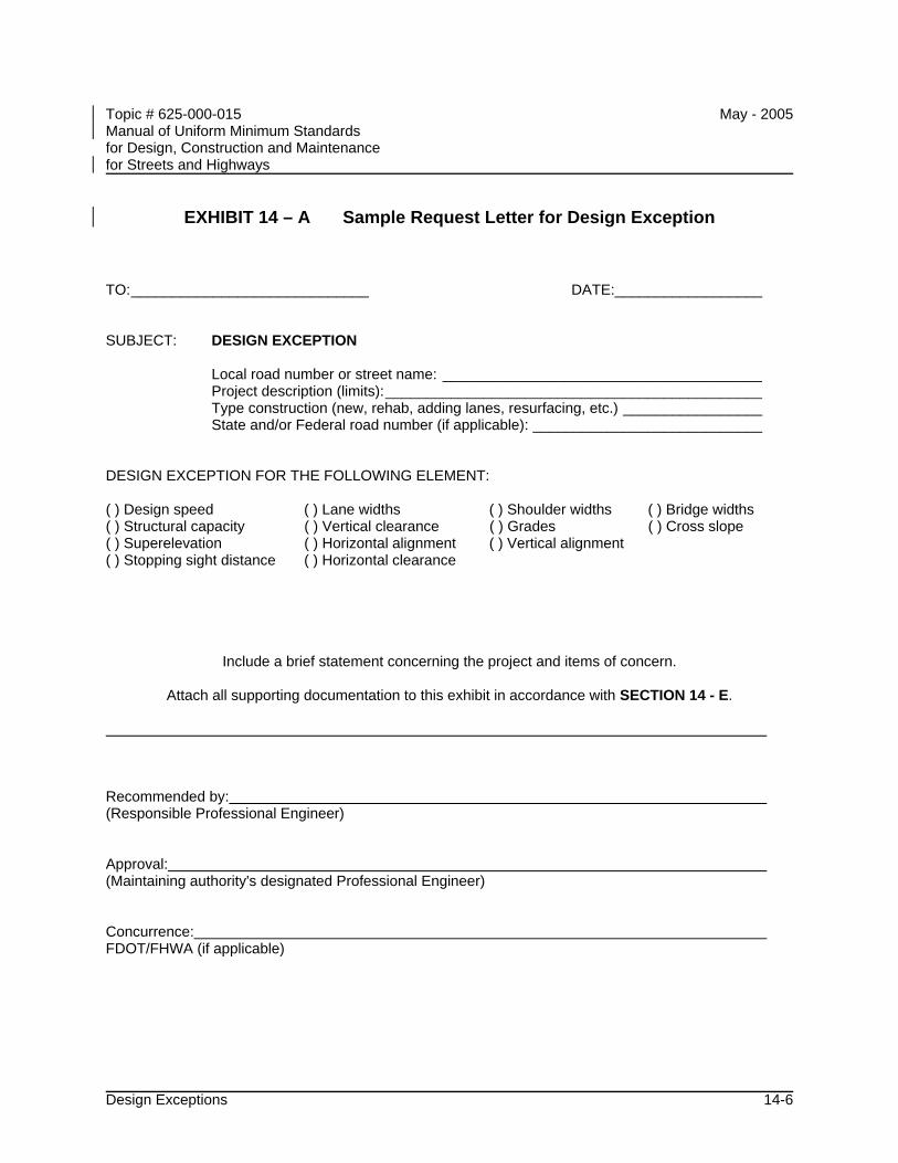
Topic # 625-000-015 May - 2005 Manual of Uniform Minimum Standards for Design, Construction and Maintenance for Streets and Highways
Design Exceptions 14-6
EXHIBIT 14 – A Sample Request Letter for Design Exception
TO:_____________________________ DATE:__________________ SUBJECT: DESIGN EXCEPTION
Local road number or street name: _______________________________________ Project description (limits):______________________________________________ Type construction (new, rehab, adding lanes, resurfacing, etc.) _________________ State and/or Federal road number (if applicable): ____________________________
DESIGN EXCEPTION FOR THE FOLLOWING ELEMENT: ( ) Design speed ( ) Lane widths ( ) Shoulder widths ( ) Bridge widths ( ) Structural capacity ( ) Vertical clearance ( ) Grades ( ) Cross slope ( ) Superelevation ( ) Horizontal alignment ( ) Vertical alignment ( ) Stopping sight distance ( ) Horizontal clearance
Include a brief statement concerning the project and items of concern.
Attach all supporting documentation to this exhibit in accordance with SECTION 14 - E. Recommended by: (Responsible Professional Engineer) Approval: (Maintaining authority's designated Professional Engineer) Concurrence: FDOT/FHWA (if applicable)
Topic # 625-000-015 May - 2005 Manual of Uniform Minimum Standards for Design, Construction and Maintenance for Streets and Highways
Traffic Calming 15-i
CHAPTER 15
TRAFFIC CALMING
A INTRODUCTION............................................................................................. 15-1
B PLANNING CRITERIA .................................................................................... 15-2
C INAPPROPRIATE TRAFFIC CALMING TREATMENTS................................. 15-6 C.1 Stop Signs.......................................................................................... 15-6 C.2 Speed Bumps .................................................................................... 15-6 C.3 Other Inappropriate Treatments......................................................... 15-6
D APPROPRIATE TRAFFIC CALMING TREATMENTS..................................... 15-7 D.1 Vertical Treatments............................................................................ 15-8 D.2 Horizontal Treatments........................................................................ 15-9 D.3 Neighborhood Entry Control............................................................. 15-10 D.4 Diverters........................................................................................... 15-11 D.5 Other Treatments............................................................................. 15-12
E OTHER SOURCES ....................................................................................... 15-13
Topic # 625-000-015 May - 2005 Manual of Uniform Minimum Standards for Design, Construction and Maintenance for Streets and Highways
Traffic Calming 15-ii
TABLES
TABLE 15-1 VERTICAL TREATMENTS ................................................................ 15-8
TABLE 15-2 HORIZONTAL TREATMENTS........................................................... 15-9
TABLE 15-3 NEIGHBORHOOD ENTRY CONTROL............................................ 15-10
TABLE 15-4 DIVERTERS .................................................................................... 15-11
TABLE 15-5 OTHER TREATMENTS ................................................................... 15-12
Topic # 625-000-015 May - 2005 Manual of Uniform Minimum Standards for Design, Construction and Maintenance for Streets and Highways
Traffic Calming 15-1
CHAPTER 15
TRAFFIC CALMING
A INTRODUCTION
As Florida continues to grow, more and more of the major highways in its communities are becoming congested. This has caused many drivers to seek less crowded local residential streets as alternatives to get to their destinations. In many cases, this has meant the use of local residential streets as bypasses. The increase in traffic intrusion, volume, and speeds on residential streets has degraded the livability standards of various neighborhoods in Florida and as a result many residents complain about their environment (noise, air pollution), livability (quality of life, traffic intrusion, excessive volume, and speed of traffic), safety (as well as safety of their children, pets, and property) and physical characteristics (absence of sidewalks, etc.) This chapter provides some guidance to Florida roadway planners, designers, and traffic engineers on how to address concerns about maintaining or enhancing the quality of life in residential neighborhoods by balancing the need for safety for all roadway users and adjacent property owners of the street network and maintaining the integrity of the highways networks as a whole.
Topic # 625-000-015 May - 2005 Manual of Uniform Minimum Standards for Design, Construction and Maintenance for Streets and Highways
Traffic Calming 15-2
B PLANNING CRITERIA
Traffic calming is the combination of mainly physical measures that reduce the negative effects of motor vehicle use, alter driver behavior, and improve conditions for non-motorized street users.
Communities undertaking a traffic calming program shall have a procedure for planning which neighborhoods and roadways qualify for participation in the program. Specifics of these methods shall be developed by the local jurisdictions. The methods will likely vary from locality to locality. However, some issues should be addressed in all communities:
• Through the public involvement process, adjacent residents and road users who are impacted by the situation should be included in identifying the concern(s).
• The need for traffic-calming measures should be confirmed by appropriate studies (license plate survey, speed, volume, crash analyses) studied.
• Once the concerns are clearly identified and confirmed by traffic studies, and documented, it will provide the focus for possible solution, prioritizing, and development of appropriate traffic calming measures. It will also help determine the best approach to address the concerns.
• When developing traffic calming measures, in addition to the affected property owners, emergency response, transit, school, and sanitation officials and any other entities impacted by the installation of such devices should be included in the review process.
Traffic calming may not be the appropriate method in all cases to address vehicle speeds, volumes, and safety. Alternative solutions or educational tools may be considered.
The application of traffic calming measures should consider possible network and access issues. A system impact analysis should be performed as part of the development process. Vehicular and pedestrian counts, speed data, and crash history of the streets under evaluation should be reviewed. Storm water and environmental impacts also need to be addressed, as well as facility type, urban and rural design factors, and driveway densities.
Design details for each traffic calming measure may vary depending on local conditions. Factors to be considered include both horizontal and vertical deflection, ease of use, emergency vehicle accessibility, ease of maintenance, and facility type. Operational
Topic # 625-000-015 May - 2005 Manual of Uniform Minimum Standards for Design, Construction and Maintenance for Streets and Highways
Traffic Calming 15-3
considerations and geometrics are critical factors to consider as well. A list of references and resources to consider in providing more detailed design factors and information can be found at the end of this section. It may be desirable to begin with less restrictive measures and progress to more restrictive ones in stages.
Listed below are some "Do's" and "Don'ts" of the planning process for traffic calming which may be helpful in working through the design process.
Do's and Don’ts of the Planning Process
Do the following:
• Install temporary traffic calming features and monitor them for a period of time before installing the permanent features. Testing features on site prior to permanent installation will relieve resident anxiety about the impact on their own driving patters and driving behaviors will adjust to the new route circumstances.
• Have an organized program including public involvement with plans and policies approved and supported by the local government. Emphasize the selected treatments(s) will be initially in a “test” mode, with permanency pending the outcome measurement. Be able to describe what is being done to keep traffic off residential streets.
• Channel public resources by prioritizing traffic calming request according to documentable criteria, setting thresholds of volume, speed, etc., to merit treatment.
• Involve the local service agencies, including fire, police, and emergency medical services personnel, from the start.
• Consult with fire department and EMS personnel to develop the preferred design, particularly with speed humps and traffic circles. Set up traffic circles with cones and have fire trucks and other emergency vehicles drive around them; this will help determine what radius is best for the vehicles used in a given area. The same process can be used in the design of speed humps.
• Review traffic patterns in the neighborhood as a whole. Avoid solving the problem on one neighborhood street by just shifting the traffic to another neighborhood street.
• Make certain that all signing, pavement markings, and channelization is in accordance with the Manual on Uniform Traffic Control Devices (MUTCD), the
Topic # 625-000-015 May - 2005 Manual of Uniform Minimum Standards for Design, Construction and Maintenance for Streets and Highways
Traffic Calming 15-4
AASHTO Policy on Geometric Design of Highways and Streets, and the Florida Roundabout Guide.
• Check sight distances for vehicles, pedestrians, and bicyclists. Sight distance should be consistent with the dimensions shown in CHAPTER 3 – GEOMETRIC DESIGN or CHAPTER 16 – RESIDENTIAL STREET DESIGN.
• Become familiar with the traffic calming features used in other communities and assemble references so that residents can be directed where to see them.
• Decide on a safe design speed beforehand and in consultation with neighborhood residents.
• Check sight distances by visiting the site before and after installation. Do parked cars obstruct sight distances? Do landscaping or other features obstruct sight distance?
• Review the illumination at night. Are additional street lights needed? Does landscaping block the light? Is there a shadow on one side of a median or traffic circle that might hide pedestrians from view?
• Review the channelization during the day and night. Is it a clear approach from all directions? Can it be seen at night? Watch the traffic: Is the driving public confused by the signing and channelization? Make adjustments as needed.
• Review the site for utility conflicts. Is there a fire hydrant? Does it need to be moved? Are there existing utilities in the way?
• Check the storm water drainage. Will the storm drain system need to be moved or revised? Can the runoff flow through or around the device?
• Review on-street parking. Will parked cars block the access of emergency vehicles through or around the proposed neighborhood traffic control devices? Add additional no parking zones where needed. Additional enforcement of parking restrictions may be required to keep the traveled path clear.
• Include weekends in traffic counts, as residential streets may have unique travel patterns and high use periods.
Topic # 625-000-015 May - 2005 Manual of Uniform Minimum Standards for Design, Construction and Maintenance for Streets and Highways
Traffic Calming 15-5
Don't do the following:
• Install neighborhood traffic calming features without a well-engineered program supported by the local government and public.
• Install neighborhood traffic calming features on arterial streets (See Section 1.C.2 for a discussion of roadway classifications). Typically, physical devices are not installed on streets with volumes greater than 3,000 vehicles per day, or with posted or operating speeds of greater than 30 MPH.
• Install neighborhood traffic calming features on streets without curbs unless supplemental features or other design considerations are included to keep vehicles within the traveled way.
• Install neighborhood traffic calming features on street with grades of greater than 10 percent.
• Install neighborhood traffic calming features on major truck routes.
• Install neighborhood traffic calming features on primary emergency routes. Contact local fire, emergency service, and police departments to determine these routes. Secondary access routes should be considered on a case-by-case basis.
• Install neighborhood traffic calming features on curving or winding roads with limited sight distance, unless reduced speed limits and adequate warning signs are used in conjunction with the devices.
• Place neighborhood traffic calming features in front of driveways.
• Neglect to check for conflicting utilities or drainage considerations.
• Install physical features on adjacent parallel routes, unless feasible design alternatives have been agreed upon, as this prevents or hinders emergency response.
Topic # 625-000-015 May - 2005 Manual of Uniform Minimum Standards for Design, Construction and Maintenance for Streets and Highways
Traffic Calming 15-6
C INAPPROPRIATE TRAFFIC CALMING TREATMENTS
C.1 Stop Signs
When used for traffic calming, stop signs often do one or more of the following:
• Increase midblock speeds along the street because of drivers trying to make up for lost time
• Increase noise because of quick accelerations and decelerations
• Increase pollution
• Reduce drivers’ expectation of a uniform flow
• Relocate the problem
• Cause disrespect for stop signs by drivers and bicyclists
For these reasons, stop signs should not be used for traffic calming.
C.2 Speed Bumps
Speed bumps shall not be used on public streets. Speed bumps are severe treatments 3 to 6 inches high and 1 to 2 feet wide that slow drivers to speeds of less than 10 mph. Due to their abrupt rise and required low speed they can be a hazard to motorists and bicyclists. Speed humps, as described in Section D under vertical deflection, should not be confused with speed bumps.
C.3 Other Inappropriate Treatments
There are some other treatments that have been shown to be ineffective at reducing the speed and volume of traffic on local roadways. While a temporary improvement may result, long-term improvement is not likely; consequently, their use is discouraged. These treatments include the following:
• Novelty signs -While signs such as CHILDREN AT PLAY, SENIORS CROSS HERE, SLOW DEAF CHILD, and DEAR CROSSING (meaning loved one)
Topic # 625-000-015 May - 2005 Manual of Uniform Minimum Standards for Design, Construction and Maintenance for Streets and Highways
Traffic Calming 15-7
may make an infrequent roadway user aware of a specific local population, most regular users of the roadway are unaffected by the signs.
• Odd speed limit - NEIGHBORHOOD SPEED LIMIT 23 MPH and other odd speed limit signs place a high dependence on police to monitor speeders and are not consistent with the national practice required by the MUTCD of posting speeds limits in 5 mph increments.
• Crosswalks – Standard crosswalks marked only with signs and pavement markings do not affect motorists’ speeds and should not be used by themselves as traffic calming treatments.
• Bike lanes – Standard bike lanes are not traffic calming treatments. They can be used to provide additional space between the sidewalk and motor vehicle traffic but should not be used by themselves for traffic calming.
• Speed trailers – While speed trailers can be used as part of a traffic calming program for educational awareness, they have no lasting effect on motorists’ behavior.
• Reduced speed limit signs – Reduced speed limits without physical traffic calming measures do not slow drivers and should not be used for traffic calming.
• Rumble strips – These applications have high maintenance requirements and can cause severe noise problems. Also, they can be an obstacle to bicyclists.
D APPROPRIATE TRAFFIC CALMING TREATMENTS
The following sections describe some of the available traffic calming strategies. This list is not exhaustive, nor do the treatments necessarily fall exclusively into only one category.
In a typical traffic calming plan various types of treatments will be used. These plans will be based upon neighborhood preferences combined with engineering judgment.
Design details for traffic calming treatments will vary with application. Specific designs will need to be determined based upon the objective of the installations.

Topic # 625-000-015 May - 2005 Manual of Uniform Minimum Standards for Design, Construction and Maintenance for Streets and Highways
Traffic Calming 15-8
D.1 Vertical Treatments
Vertical treatments are those that depend upon a change in vertical alignment to cause drivers to slow down. When properly used, these treatments can be effective in reducing speeds and crashes. However, consideration should be given to impacts on emergency responders, buses, and, to some extent, bicyclists and motorcyclists.
Traffic calming features that alter the vertical alignment should not be installed near fire hydrants or mailboxes.
Information on signing and pavement markings for vertical deflections can be found in the Manual on Uniform Traffic Control Devices (MUTCD).
TABLE 15-1 VERTICAL TREATMENTS
Treatment Description Effect Concerns Cost Raised Intersection
A raised plateau where roads intersect. Plateau is generally 4 inches above surrounding street.
Slows vehicles entering intersection and improves pedestrian safety.
Increases difficulty of making a turn.
Medium to High
Raised Crosswalk
Raised pedestrian crossing used in mid-block locations. Crosswalks installed on flat-top portion of speed table.
Reduces speed and is an effective pedestrian amenity makes pedestrians more visible.
May be a problem for emergency vehicles and vehicles with trailers.
Low to Medium
Speed Humps
Speed humps are parabolic, curved, or sinusoidal in profile, 3 to 4 inches in height and 12 to 14 feet long. Comfortable speeds limited to 15 to 20 mph.
Reduces speed.
May cause delays for emergency vehicles and impact patient comfort. May have greater impacts on longer wheelbase cars.
Low
Speed Tables
Speed tables are flat-topped speed humps, also 3 to 4 inches high but with a sloped approach taper on each side of a flat top. They are generally 20 to 24 feet wide. Comfortable speed limited to 20 to 25 mph.
Reduces speed.
May cause delays for emergency vehicles and impact patient comfort.
Low
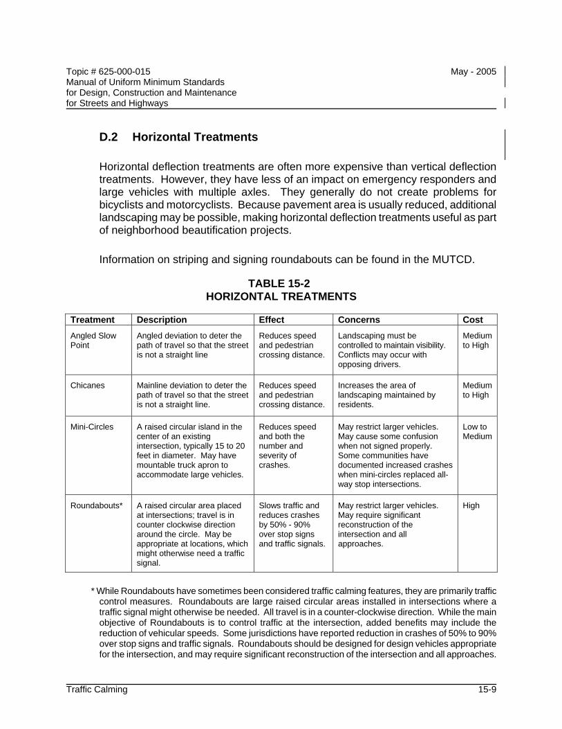
Topic # 625-000-015 May - 2005 Manual of Uniform Minimum Standards for Design, Construction and Maintenance for Streets and Highways
Traffic Calming 15-9
D.2 Horizontal Treatments
Horizontal deflection treatments are often more expensive than vertical deflection treatments. However, they have less of an impact on emergency responders and large vehicles with multiple axles. They generally do not create problems for bicyclists and motorcyclists. Because pavement area is usually reduced, additional landscaping may be possible, making horizontal deflection treatments useful as part of neighborhood beautification projects.
Information on striping and signing roundabouts can be found in the MUTCD.
TABLE 15-2 HORIZONTAL TREATMENTS
Treatment Description Effect Concerns Cost Angled Slow Point
Angled deviation to deter the path of travel so that the street is not a straight line
Reduces speed and pedestrian crossing distance.
Landscaping must be controlled to maintain visibility. Conflicts may occur with opposing drivers.
Medium to High
Chicanes
Mainline deviation to deter the path of travel so that the street is not a straight line.
Reduces speed and pedestrian crossing distance.
Increases the area of landscaping maintained by residents.
Medium to High
Mini-Circles
A raised circular island in the center of an existing intersection, typically 15 to 20 feet in diameter. May have mountable truck apron to accommodate large vehicles.
Reduces speed and both the number and severity of crashes.
May restrict larger vehicles. May cause some confusion when not signed properly. Some communities have documented increased crashes when mini-circles replaced all-way stop intersections.
Low to Medium
Roundabouts*
A raised circular area placed at intersections; travel is in counter clockwise direction around the circle. May be appropriate at locations, which might otherwise need a traffic signal.
Slows traffic and reduces crashes by 50% - 90% over stop signs and traffic signals.
May restrict larger vehicles. May require significant reconstruction of the intersection and all approaches.
High
* While Roundabouts have sometimes been considered traffic calming features, they are primarily traffic
control measures. Roundabouts are large raised circular areas installed in intersections where a traffic signal might otherwise be needed. All travel is in a counter-clockwise direction. While the main objective of Roundabouts is to control traffic at the intersection, added benefits may include the reduction of vehicular speeds. Some jurisdictions have reported reduction in crashes of 50% to 90% over stop signs and traffic signals. Roundabouts should be designed for design vehicles appropriate for the intersection, and may require significant reconstruction of the intersection and all approaches.
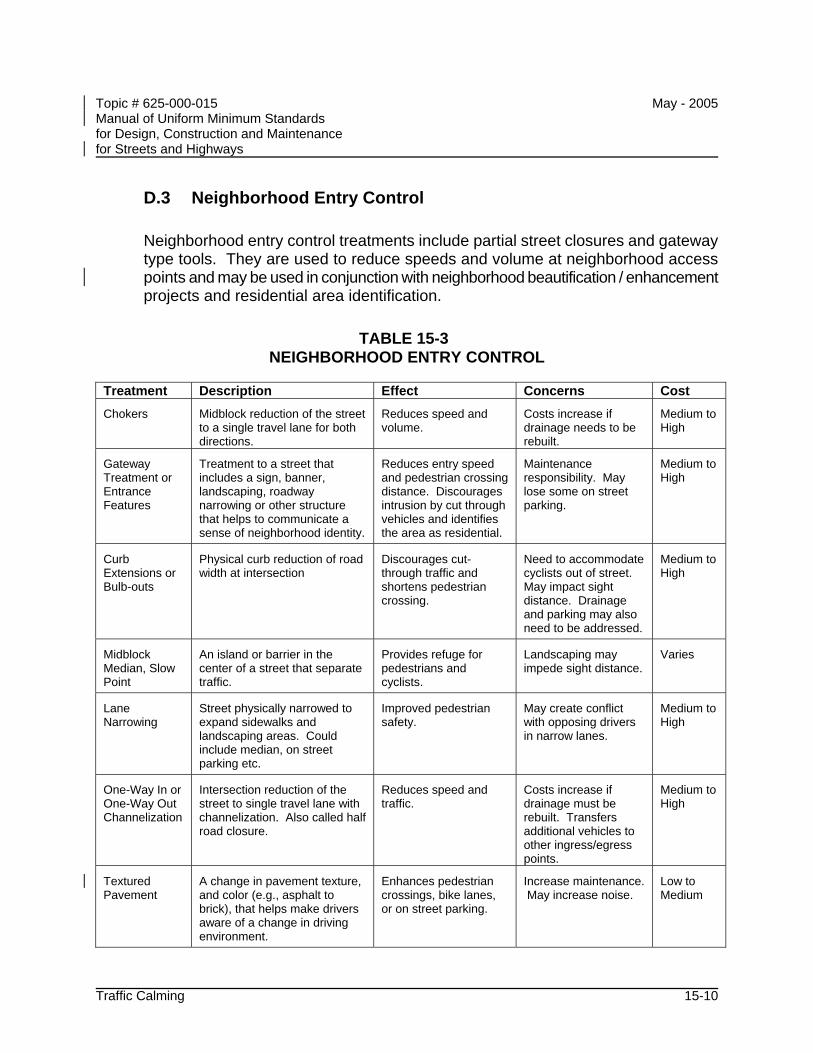
Topic # 625-000-015 May - 2005 Manual of Uniform Minimum Standards for Design, Construction and Maintenance for Streets and Highways
Traffic Calming 15-10
D.3 Neighborhood Entry Control
Neighborhood entry control treatments include partial street closures and gateway type tools. They are used to reduce speeds and volume at neighborhood access points and may be used in conjunction with neighborhood beautification / enhancement projects and residential area identification.
TABLE 15-3 NEIGHBORHOOD ENTRY CONTROL
Treatment Description Effect Concerns Cost Chokers
Midblock reduction of the street to a single travel lane for both directions.
Reduces speed and volume.
Costs increase if drainage needs to be rebuilt.
Medium to High
Gateway Treatment or Entrance Features
Treatment to a street that includes a sign, banner, landscaping, roadway narrowing or other structure that helps to communicate a sense of neighborhood identity.
Reduces entry speed and pedestrian crossing distance. Discourages intrusion by cut through vehicles and identifies the area as residential.
Maintenance responsibility. May lose some on street parking.
Medium to High
Curb Extensions or Bulb-outs
Physical curb reduction of road width at intersection
Discourages cut-through traffic and shortens pedestrian crossing.
Need to accommodate cyclists out of street. May impact sight distance. Drainage and parking may also need to be addressed.
Medium to High
Midblock Median, Slow Point
An island or barrier in the center of a street that separate traffic.
Provides refuge for pedestrians and cyclists.
Landscaping may impede sight distance.
Varies
Lane Narrowing
Street physically narrowed to expand sidewalks and landscaping areas. Could include median, on street parking etc.
Improved pedestrian safety.
May create conflict with opposing drivers in narrow lanes.
Medium to High
One-Way In or One-Way Out Channelization
Intersection reduction of the street to single travel lane with channelization. Also called half road closure.
Reduces speed and traffic.
Costs increase if drainage must be rebuilt. Transfers additional vehicles to other ingress/egress points.
Medium to High
Textured Pavement
A change in pavement texture, and color (e.g., asphalt to brick), that helps make drivers aware of a change in driving environment.
Enhances pedestrian crossings, bike lanes, or on street parking.
Increase maintenance. May increase noise.
Low to Medium
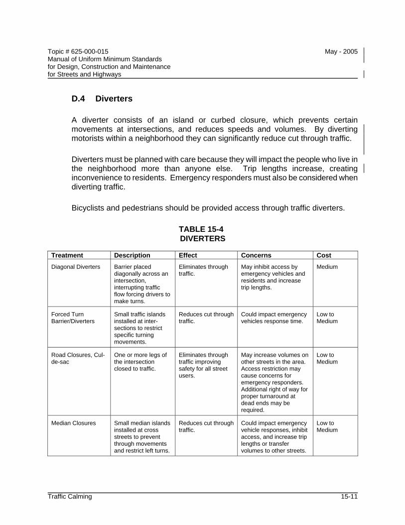
Topic # 625-000-015 May - 2005 Manual of Uniform Minimum Standards for Design, Construction and Maintenance for Streets and Highways
Traffic Calming 15-11
D.4 Diverters
A diverter consists of an island or curbed closure, which prevents certain movements at intersections, and reduces speeds and volumes. By diverting motorists within a neighborhood they can significantly reduce cut through traffic.
Diverters must be planned with care because they will impact the people who live in the neighborhood more than anyone else. Trip lengths increase, creating inconvenience to residents. Emergency responders must also be considered when diverting traffic.
Bicyclists and pedestrians should be provided access through traffic diverters.
TABLE 15-4 DIVERTERS
Treatment Description Effect Concerns Cost Diagonal Diverters
Barrier placed diagonally across an intersection, interrupting traffic flow forcing drivers to make turns.
Eliminates through traffic.
May inhibit access by emergency vehicles and residents and increase trip lengths.
Medium
Forced Turn Barrier/Diverters
Small traffic islands installed at inter-sections to restrict specific turning movements.
Reduces cut through traffic.
Could impact emergency vehicles response time.
Low to Medium
Road Closures, Cul-de-sac
One or more legs of the intersection closed to traffic.
Eliminates through traffic improving safety for all street users.
May increase volumes on other streets in the area. Access restriction may cause concerns for emergency responders. Additional right of way for proper turnaround at dead ends may be required.
Low to Medium
Median Closures
Small median islands installed at cross streets to prevent through movements and restrict left turns.
Reduces cut through traffic.
Could impact emergency vehicle responses, inhibit access, and increase trip lengths or transfer volumes to other streets.
Low to Medium
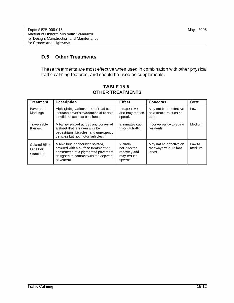
Topic # 625-000-015 May - 2005 Manual of Uniform Minimum Standards for Design, Construction and Maintenance for Streets and Highways
Traffic Calming 15-12
D.5 Other Treatments
These treatments are most effective when used in combination with other physical traffic calming features, and should be used as supplements.
TABLE 15-5 OTHER TREATMENTS
Treatment Description Effect Concerns Cost Pavement Markings
Highlighting various area of road to increase driver’s awareness of certain conditions such as bike lanes.
Inexpensive and may reduce speed.
May not be as effective as a structure such as curb.
Low
Traversable Barriers
A barrier placed across any portion of a street that is traversable by pedestrians, bicycles, and emergency vehicles but not motor vehicles.
Eliminates cut-through traffic.
Inconvenience to some residents.
Medium
Colored Bike Lanes or Shoulders
A bike lane or shoulder painted, covered with a surface treatment or constructed of a pigmented pavement designed to contrast with the adjacent pavement.
Visually narrows the roadway and may reduce speeds.
May not be effective on roadways with 12 foot lanes.
Low to medium
Topic # 625-000-015 May - 2005 Manual of Uniform Minimum Standards for Design, Construction and Maintenance for Streets and Highways
Traffic Calming 15-13
E OTHER SOURCES
The publications listed below are additional sources, of information related to topics presented in this chapter. Search the Internet Web for up-to-date resources using "traffic+calming" as key words.
1. Civilizing Traffic, City of Honolulu Traffic Calming Training Manual, Dan Burden, DRAFT.
2. Code of Practice for the Installation of Traffic Control Devices in South Australia, July 1996. Traffic and Operational Standards Section, Department Transportation, P.O. Box. 1, Walkerville, South Australia, 5081.
3. The Florida Roundabout Guide. Florida Department of Transportation, Maps & Publications Sales, Mail Station 12, 605 Suwannee Street, Tallahassee, Florida 32399-0450.
4. Guidelines for the Design and Application of Speed Humps - A Recommended Practice of the Institute of Transportation Engineers, 1997. Institute of Transportation Engineers, 525 School Street, SW, Suite 410, Washington, DC, 20024-2729.
5. Manual of Uniform Traffic Control Devices, 2000. Transportation Planning, Highway Safety, and Traffic Engineering Division, New York State Department of Transportation, 1220 Washington Avenue, Albany, NY 12232-0204.
6. Modern Roundabout Practice in the United States, National Cooperative Highway Research Program Synthesis off Highway Practice 264, 1998, Jacquernart, G. Transportation Research Board, National Research Council, 2101 Constitution Avenue, NW, Washington, DC, 20418.
7. New York State Vehicle & Traffic Law, (latest edition). New York State Department of Motor Vehicles, Swan Street Building, Empire State Plaza, Albany, NY, 12228.
8. Roundabout Design Guidelines. Maryland Department of Transportation, State Highway Administration, P.O. Box 717, Baltimore, MD, 21203-0717.
9. Traffic Control Systems Handbook FHWA-SA-95-032, 1996, Gordon, R.L., R.A. Reiss, H. Haenel, E.R. French, A. Mochaddes, R. Wolcott. Federal Highway Administration, Office of Technology Applications, 400 Seventh Street, SW, Washington, DC 20590.
10. Traffic Control Systems Handbook, Revised Edition, 1985, FHWA-IP-85-1 1, Wilshire, R., R. Black, R. Grachoske, J. Higanbotham. Federal Highway Administration, Office of Implementation, 400 Seventh Street, SW, Washington, DC 20590.
Topic # 625-000-015 May - 2005 Manual of Uniform Minimum Standards for Design, Construction and Maintenance for Streets and Highways
Traffic Calming 15-14
11. Manual on Uniform Traffic Control Devices, 2000. US Department of Transportation, Federal Highway Administration, 400 7th Street, Washington D.C., 20509.
12. Roundabouts: An Informational Guide, 2000. US Department of Transportation, Federal Highway Administration, 400 7th Street, Washington D.C., 20509.
REFERENCES
The following is a list of the publications that were used in the preparation of this chapter.
1. A Guidebook for Residential Traffic Management WA\RD 368-1, Final Report, December 1994, Savage, J.P. Jr., R.D. MacDonal, J. Ewell. Washington State Department of Transportation, Engineering Publications Room SD3, PO Box 47300, Olympia, WA 98504-7300.
2. Florida Pedestrian Planning and Design Handbook, March 1997, University of North Carolina, Highway Safety Research Center. Florida Department of Transportation, Safety Office, 605 Suwannee Street, Mail Station 82, Tallahassee, Florida 32399-0450.
3. Highway Design Manual. Plan Sales Unit, Support Services Bureau, New York State Department of Transportation, 1220 Washington Avenue, Albany, NY, 12232-0204.
4. ITE Traffic Calming Definition, Lockwood, I.M. In ITE Journal, Volume 67, Number 7, July 1997. Institute of Transportation Engineers, 525 School Street, SW, Suite 410, Washington, DC, 20024-2729.
5. Neighborhood Traffic Management and Calming Program, City of San Buenaventura, Department of Community Services, Engineering Division, 501 Poli Street, Ventura, C.A, 93001.
6. Supplementary Pedestrian Crossing channelization Devices. TC Werner memo to Regional Traffic Engineers, July 15, 1997, Transportation Planning, Highway Safety and Traffic Engineering Division, NYS Department of Transportation, 1220 Washington Avenue, Albany, N`Y, 12232.
7. Traffic Calming, July 1995, Hoyle, C.L., Planning Advisory Service Report Number 456 American Planning Association, Publications Office, 122 S. Michigan Avenue, Suite 1600, Chicago, IL, 60603.
8. Traffic Calming Guidelines, 1992, Devon County Council, Engineering and Planning Department, Devon County, Great Britain.
9. The Traffic Calming Program: Simplification and Enhancement of the Neighborhood Traffic Management and Arterial Traffic Calming Programs September 30, 1994. City of Portland, Office of Transportation, Bureau of Traffic Management, Neighborhood Traffic Management, 1120 SW. 5th Avenue, Room 730, Portland, OR, 97204-1914.
10. Traffic Calming: State of Practice, 1999. FHWA-RD-99-135. R. Ewing. Institute of Transportation Engineers, Washington, D.C.
11. Boulder, Colorado, Neighborhood Traffic Mitigation Program. Transportation Division oat (303) 441-3266. http://www.ci.boulder.co.us/publicworks/depts/trans/ntmp/information.htm#Policies
12. Neighborhood Traffic Management Dade County, Florida’s street closure experience, Anthony J. Castellone and Muhammed M. Hasan, I.T.E. Journal, Volume 68, Number 1.
13. Traffic Flow Modification / Street Closure Procedure. Miami-Dade County Public Works Department and Metropolitan Planning Organization, Florida.
Topic # 625-000-015 May - 2005 Manual of Uniform Minimum Standards for Design, Construction and Maintenance for Streets and Highways
Residential Street Design 16-i
CHAPTER 16
RESIDENTIAL STREET DESIGN
A INTRODUCTION............................................................................................. 16-1
B OBJECTIVES .................................................................................................. 16-2
C DESIGN ELEMENTS ...................................................................................... 16-4 C.1 Design Speed .................................................................................... 16-4 C.2 Sight Distance.................................................................................... 16-4
C.2.a Stopping Sight Distance..................................................... 16-4 C.2.b Passing Sight Distance ...................................................... 16-4 C.2.c Intersection Sight Distance ................................................ 16-5
C.3 Horizontal Alignment .......................................................................... 16-6 C.3.a Minimum Centerline Radius ............................................... 16-6 C.3.b Minimum Curb Return Radius............................................ 16-6
C.4 Vertical Alignment .............................................................................. 16-6 C.4.a Vertical Curves................................................................... 16-6
C.5 Cross Section Elements..................................................................... 16-7 C.5.a Width of Roadway.............................................................. 16-7 C.5.b Medians ............................................................................. 16-7
C.6 Cul-de-sacs and Turnarounds............................................................ 16-7 C.6.a Turning Area ...................................................................... 16-7
C.7 Pedestrian Considerations ................................................................. 16-8 C.7.a Sidewalks........................................................................... 16-8
C.8 Bicyclist Considerations ..................................................................... 16-8 C.8.a Bicycle Facilities................................................................. 16-8 C.8.b Shared Use Paths.............................................................. 16-8
C.9 Clear Zone ......................................................................................... 16-9
Topic # 625-000-015 May - 2005 Manual of Uniform Minimum Standards for Design, Construction and Maintenance for Streets and Highways
Residential Street Design 16-ii
TABLES
TABLE 16 - 1 MINIMUM STOPPING SIGHT DISTANCE FOR RESIDENTIAL STREETS........................................................................................... 16-4
TABLE 16 - 2 MINIMUM CORNER INTERSECTION SIGHT DISTANCE FOR RESIDENTIAL STREETS .................................................................. 16-5
TABLE 16 - 3 MINIMUM CENTERLINE RADII FOR RESIDENTIAL STREETS ...... 16-6
Topic # 625-000-015 May - 2005 Manual of Uniform Minimum Standards for Design, Construction and Maintenance for Streets and Highways
Residential Street Design 16-1
CHAPTER 16
RESIDENTIAL STREET DESIGN
A INTRODUCTION
The street is a public way designed for the purposes of serving motor vehicles, bicycles, pedestrians, and transit vehicles. The primary function of residential streets is to provide access to homes that front those streets. The primary consideration, therefore, of residential street design should be to foster a safe and pleasant environment for the residents that live along the street, and safe traveling conditions for motorists and pedestrians. The convenience of motorists is a secondary consideration.
The street design should create an environment that cautions drivers that they are in a residential area where they must safely share the traveling space with pedestrians and bicyclists, both child and adult. Visual cues such as meandering streets, sidewalks, landscaping, signage, narrowed streets, changes in pavement texture (such as brick), and raised crosswalks all serve to heighten drivers’ awareness for the need to maintain lower speeds. Incorporating such features into residential street design at inception will reduce or eliminate the need for traffic calming retrofits.
Section B of this chapter discusses the primary objectives of Residential Street Design in more detail, to aid the designer in the selection of proper criteria. Section C sets forth specific design criteria for residential streets.
Topic # 625-000-015 May - 2005 Manual of Uniform Minimum Standards for Design, Construction and Maintenance for Streets and Highways
Residential Street Design 16-2
B OBJECTIVES
The basic principles of residential street design are based on four factors:
1. SAFETY
2. EFFICIENCY OF SERVICE
3. LIVABILITY AND AMENITIES
4. ECONOMY OF LAND USE, CONSTRUCTION, AND MAINTENANCE
The following 17 principles incorporate these factors. These principles are not intended as absolute criteria, since instances may occur where certain principles conflict. The principles should therefore be used as concepts for layout of proper street systems.
1. Adequate vehicular and pedestrian access should be provided to all parcels.
2. Local street systems should be designed to minimize through traffic movements.
3. Street patterns should minimize excessive vehicular travel.
4. Local street systems should be logical and comprehensible, and systems of street names and house numbers should be simple, consistent, and understandable.
5. Local circulation systems and land-development patterns should not detract from the efficiency of bordering major streets.
6. Elements in the local circulation system should not have to rely on extensive traffic regulations and enforcement in order to function efficiently and safety.
7. Traffic generators within residential areas should be considered in the local circulation pattern.
8. The planning and construction of residential streets should clearly indicate their local function. The street's residential nature should be obvious to those driving on them.
Topic # 625-000-015 May - 2005 Manual of Uniform Minimum Standards for Design, Construction and Maintenance for Streets and Highways
Residential Street Design 16-3
9. The street system should be designed for a relatively uniform low volume of traffic.
10. Local streets should be designed to discourage excessive speeds.
11. Pedestrian-vehicular conflict points should be minimized.
12. The amount of space in the land development devoted to motor vehicle uses should be minimized.
13. There should be a limited number of intersections.
14. The arrangement of local streets should permit economical and practical patterns, shapes, and sizes of development parcels.
15. Local streets should consider and utilize topography from the standpoint of both economics and amenities.
16. Appropriate provisions for transit service within residential areas should be included.
17. Street design should consider horizontal and vertical compatibility and connectivity with sidewalks, bicycle lanes, and pedestrian walkways.
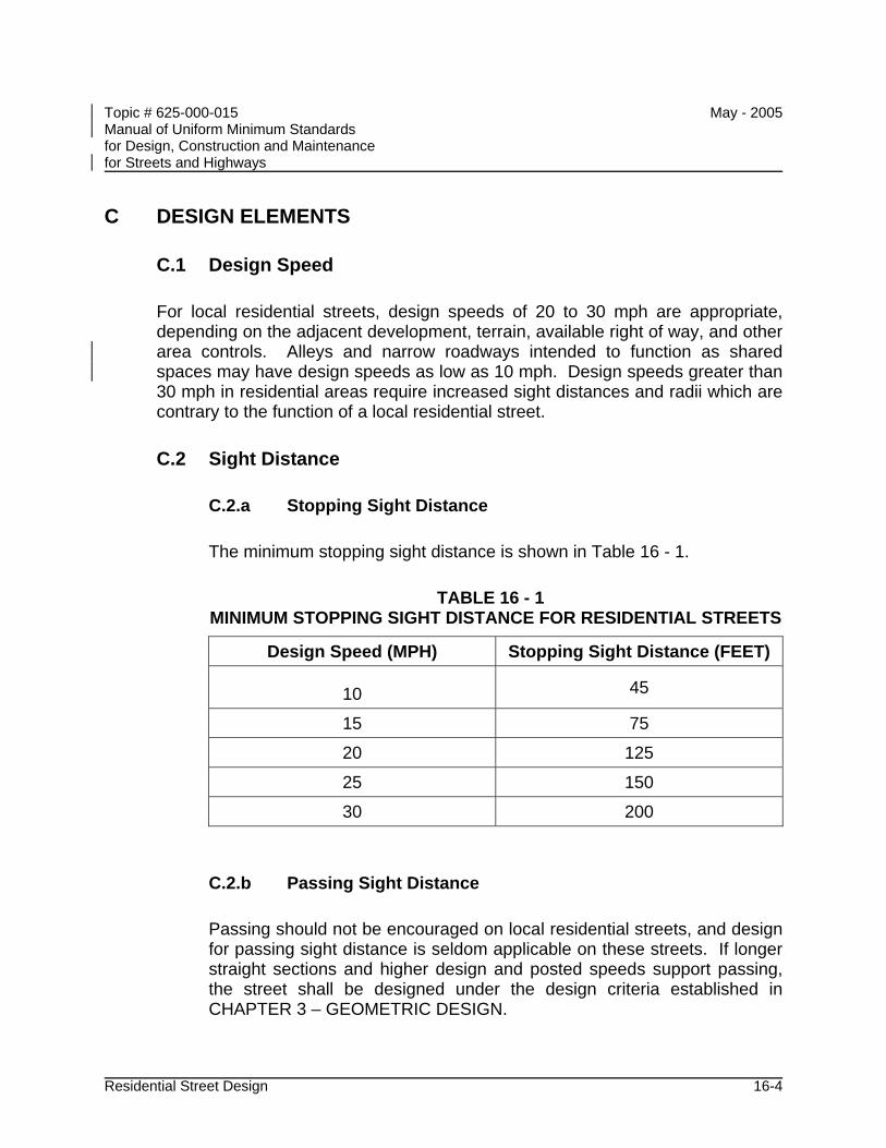
Topic # 625-000-015 May - 2005 Manual of Uniform Minimum Standards for Design, Construction and Maintenance for Streets and Highways
Residential Street Design 16-4
C DESIGN ELEMENTS
C.1 Design Speed
For local residential streets, design speeds of 20 to 30 mph are appropriate, depending on the adjacent development, terrain, available right of way, and other area controls. Alleys and narrow roadways intended to function as shared spaces may have design speeds as low as 10 mph. Design speeds greater than 30 mph in residential areas require increased sight distances and radii which are contrary to the function of a local residential street.
C.2 Sight Distance
C.2.a Stopping Sight Distance
The minimum stopping sight distance is shown in Table 16 - 1.
TABLE 16 - 1 MINIMUM STOPPING SIGHT DISTANCE FOR RESIDENTIAL STREETS
Design Speed (MPH) Stopping Sight Distance (FEET)
10 45
15 75
20 125
25 150
30 200
C.2.b Passing Sight Distance
Passing should not be encouraged on local residential streets, and design for passing sight distance is seldom applicable on these streets. If longer straight sections and higher design and posted speeds support passing, the street shall be designed under the design criteria established in CHAPTER 3 – GEOMETRIC DESIGN.
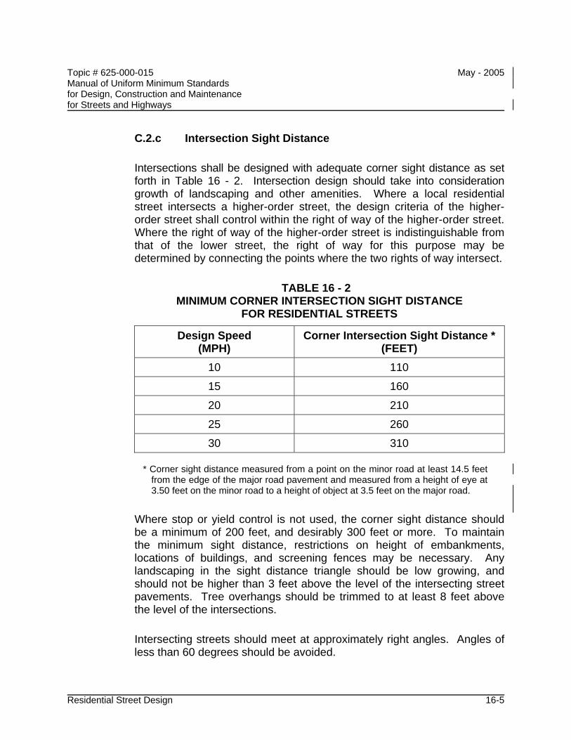
Topic # 625-000-015 May - 2005 Manual of Uniform Minimum Standards for Design, Construction and Maintenance for Streets and Highways
Residential Street Design 16-5
C.2.c Intersection Sight Distance
Intersections shall be designed with adequate corner sight distance as set forth in Table 16 - 2. Intersection design should take into consideration growth of landscaping and other amenities. Where a local residential street intersects a higher-order street, the design criteria of the higher-order street shall control within the right of way of the higher-order street. Where the right of way of the higher-order street is indistinguishable from that of the lower street, the right of way for this purpose may be determined by connecting the points where the two rights of way intersect.
TABLE 16 - 2 MINIMUM CORNER INTERSECTION SIGHT DISTANCE
FOR RESIDENTIAL STREETS
Design Speed (MPH)
Corner Intersection Sight Distance * (FEET)
10 110
15 160
20 210
25 260
30 310
* Corner sight distance measured from a point on the minor road at least 14.5 feet from the edge of the major road pavement and measured from a height of eye at 3.50 feet on the minor road to a height of object at 3.5 feet on the major road.
Where stop or yield control is not used, the corner sight distance should be a minimum of 200 feet, and desirably 300 feet or more. To maintain the minimum sight distance, restrictions on height of embankments, locations of buildings, and screening fences may be necessary. Any landscaping in the sight distance triangle should be low growing, and should not be higher than 3 feet above the level of the intersecting street pavements. Tree overhangs should be trimmed to at least 8 feet above the level of the intersections.
Intersecting streets should meet at approximately right angles. Angles of less than 60 degrees should be avoided.
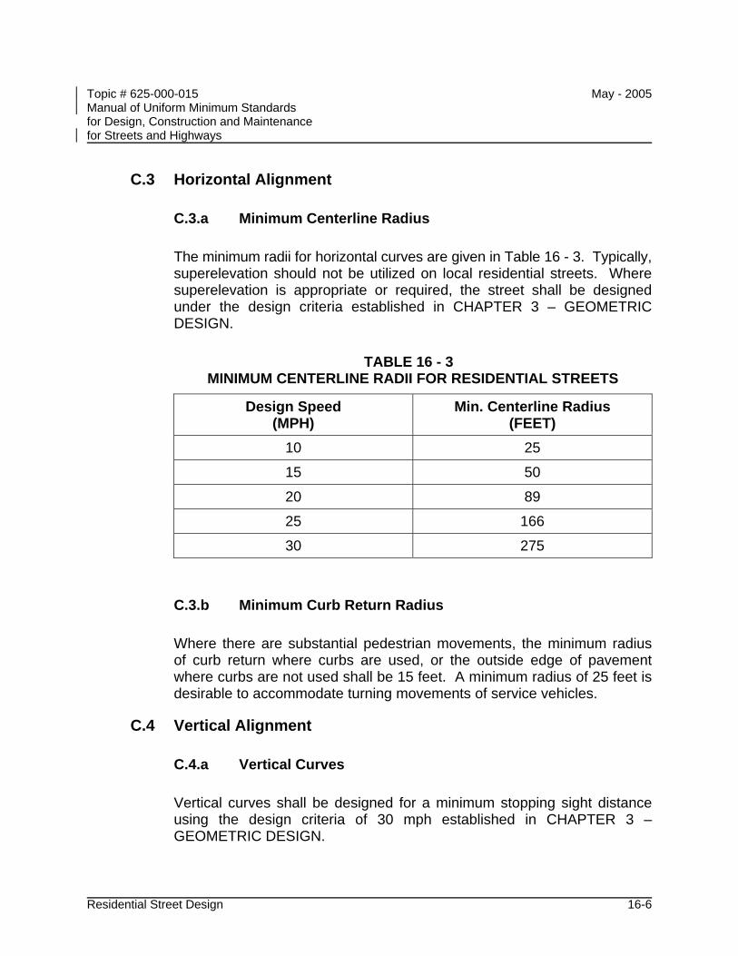
Topic # 625-000-015 May - 2005 Manual of Uniform Minimum Standards for Design, Construction and Maintenance for Streets and Highways
Residential Street Design 16-6
C.3 Horizontal Alignment
C.3.a Minimum Centerline Radius
The minimum radii for horizontal curves are given in Table 16 - 3. Typically, superelevation should not be utilized on local residential streets. Where superelevation is appropriate or required, the street shall be designed under the design criteria established in CHAPTER 3 – GEOMETRIC DESIGN.
TABLE 16 - 3 MINIMUM CENTERLINE RADII FOR RESIDENTIAL STREETS
Design Speed (MPH)
Min. Centerline Radius (FEET)
10 25
15 50
20 89
25 166
30 275
C.3.b Minimum Curb Return Radius
Where there are substantial pedestrian movements, the minimum radius of curb return where curbs are used, or the outside edge of pavement where curbs are not used shall be 15 feet. A minimum radius of 25 feet is desirable to accommodate turning movements of service vehicles.
C.4 Vertical Alignment
C.4.a Vertical Curves
Vertical curves shall be designed for a minimum stopping sight distance using the design criteria of 30 mph established in CHAPTER 3 – GEOMETRIC DESIGN.
Topic # 625-000-015 May - 2005 Manual of Uniform Minimum Standards for Design, Construction and Maintenance for Streets and Highways
Residential Street Design 16-7
C.5 Cross Section Elements
C.5.a Width of Roadway
The minimum width of a two-way residential roadway shall be 18 feet from edge-of-pavement to edge-of-pavement (excluding curbs and gutters). Travel lanes should be a minimum of 10 feet wide, and wider where practicable. Under constrained conditions 9 feet may be used. Lanes narrower than 9 feet are prohibited in the absence of a Design Exception as provided for in CHAPTER 14 – DESIGN EXCEPTIONS.
When parking lanes are provided on one or both sides of the roadway, they shall be at least 7 feet wide including the gutter section where applicable.
Where curb and gutter sections are used, the roadway may be narrowed to the travel lane width at intersections. This will prevent parking close to the intersection, reduce crossing distances for pedestrians, provide space for curb ramps, and reduce turning speeds. By providing occasional midblock curb extensions, as well as intersection curb extensions, the visual width of the roadway can be reduced.
C.5.b Medians
The minimum width for a median is 4 feet. When median openings are provided to allow turns across the roadway, median opening length shall be adequate to accommodate the design vehicle’s turning radius requirements.
C.6 Cul-de-sacs and Turnarounds
C.6.a Turning Area
A residential street open at one end only should have a special turning area at the closed end, and a residential street more than 100 feet long and open at one end only shall have a special turning area at the closed end. This turning area should be circular and have a radius appropriate to the types of vehicle expected. The minimum outside radius of a cul-de-sac shall be 30 feet. In constrained circumstances, other turning configurations such as a “hammerhead” may be considered.
Topic # 625-000-015 May - 2005 Manual of Uniform Minimum Standards for Design, Construction and Maintenance for Streets and Highways
Residential Street Design 16-8
C.7 Pedestrian Considerations
C.7.a Sidewalks
In residential areas, sidewalks should be provided on both sides of the street. The sidewalks should be located as far as practicable from the traffic lanes and usually close to the right of way line. In certain circumstances, such as where the adjacent lots are very large, sidewalk on only one side may be considered.
Pedestrian access should be provided to schools, parks, shopping areas, and transit stops within or adjacent to the residential development. Pedestrian access to these destinations from each house in the development should be as direct as practicable. With careful design, direct pedestrian access can be provided to these destinations without requiring pedestrians to walk along high volume, high speed roadways. Mid-block crossings between houses, for sidewalks or shared use paths, may be used where necessary to provide direct access. Sidewalks shall be constructed under the criteria set forth in Section C.7.d of CHAPTER 3 – GEOMETRIC DESIGN, and CHAPTER 8 – PEDESTRIAN FACILITIES.
C.8 Bicyclist Considerations
C.8.a Bicycle Facilities
Residential roadways are generally sufficient to accommodate bicycle traffic; however, when special facilities are desired, they should be designed in accordance with CHAPTER 3 – GEOMETRIC DESIGN and CHAPTER 9 – BICYCLE FACILITIES.
C.8.b Shared Use Paths
Connections to schools, parks, shopping areas, and transit stops within or adjacent to the residential development should be provided. Bike lanes along collector and arterial roadways may be used to provide these connections. However, when designated bike lanes are not available, shared use paths may be utilized to provide direct access. A shared use path is a hard-surfaced pathway physically separated from motorized vehicular traffic by an open space or barrier. Shared use paths may be
Topic # 625-000-015 May - 2005 Manual of Uniform Minimum Standards for Design, Construction and Maintenance for Streets and Highways
Residential Street Design 16-9
used by bicyclists, pedestrians, skaters, wheelchair users, and joggers.
When shared use paths are desired, they should be designed in accordance with Section C of CHAPTER 9 – BICYCLE FACILITIES.
C.9 Clear Zone
Clear zone requirements shall be based on CHAPTER 3 - GEOMETRIC DESIGN, Table 3 - 12.

Topic # 625-000-015 May - 2005 Manual of Uniform Minimum Standards for Design, Construction and Maintenance for Streets and Highways
Residential Street Design 16-10
THIS PAGE INTENTIONALLY LEFT BLANK
Topic # 625-000-015 May - 2005 Manual of Uniform Minimum Standards for Design, Construction and Maintenance for Streets and Highways
Bridges and Other Structures 17-i
CHAPTER 17
BRIDGES AND OTHER STRUCTURES
A INTRODUCTION............................................................................................. 17-1
B OBJECTIVES .................................................................................................. 17-1
C DESIGN........................................................................................................... 17-2 C.1 General .............................................................................................. 17-2 C.2 Bridge Live Loads .............................................................................. 17-3 C.3 Bridge Superstructure ........................................................................ 17-4
C.3.a Vertical Clearance.............................................................. 17-4 C.3.b Railings .............................................................................. 17-5 C.3.c Expansion Joints................................................................ 17-5 C.3.d Drainage ............................................................................ 17-6 C.3.e ADA ................................................................................... 17-6 C.3.f End Treatments ................................................................. 17-6
C.4 Bridge Substructure ........................................................................... 17-6 C.4.a Scour ................................................................................. 17-6 C.4.b Vessel Impact .................................................................... 17-7 C.4.c Pier Locations .................................................................... 17-8 C.4.d Bearings............................................................................. 17-8
D CONSTRUCTION............................................................................................ 17-9
E ROUTINE INSPECTION AND MAINTENANCE............................................ 17-10
F RECONSTRUCTION..................................................................................... 17-11
G BRIDGE LOAD RATING, PERMITTING, AND POSTING............................. 17-11
H OTHER STRUCTURES ................................................................................ 17-12 H.1 Walls (Retaining and Sound) ........................................................... 17-12 H.2 Sign, Lighting, and Traffic Signal Supports ...................................... 17-12
I RECOMMENDATIONS ................................................................................. 17-14
J REFERENCES.............................................................................................. 17-15
Topic # 625-000-015 May - 2005 Manual of Uniform Minimum Standards for Design, Construction and Maintenance for Streets and Highways
Bridges and Other Structures 17-ii
FIGURES
FIGURE 17 – 1 STANDARD HS20-44 TRUCKS................................................. 17-3
FIGURE 17 – 2 HS20-44 LANE LOADING ......................................................... 17-4
Topic # 625-000-015 May - 2005 Manual of Uniform Minimum Standards for Design, Construction and Maintenance for Streets and Highways
Bridges and Other Structures 17-1
CHAPTER 17
BRIDGES AND OTHER STRUCTURES
A INTRODUCTION
Bridges provide safe passage for multimodal traffic over various obstacles along a road or path. This chapter presents guidelines and standards for designing, constructing, inspecting, and maintaining bridges as well as other structures such as walls and supports for signs, lights, and traffic signals. These standards and criteria are necessary due to the critical function these structures serve to communities throughout their lifespan. This chapter establishes uniform minimum standards and criteria for all bridges used by the public for vehicular and/or pedestrian traffic as well as other structures such as walls and supports for signs, lights, and traffic signals. The geometry of structures shall follow the standards and criteria set forth in Chapters 3, 8, 9, and 13. Exceptions to these standards and criteria must be processed in accordance with the procedures described in Chapter 14.
All bridges constructed on and over the Department’s system, as well as all bridges constructed that the Department will maintain, must comply with all Department policies, procedures, standards and specifications, and this Manual does not apply.
B OBJECTIVES
The objectives of this chapter are as follows:
• To prescribe uniform criteria with respect to bridge design loads, design methodology, and geometric layout.
• To alert owners to the various federal and state mandated considerations to be included in the design, construction, maintenance, and inspection of their bridges.
• To provide practical suggestions specific to Florida on prudent bridge engineering based on past experience with statutes, standards, and criteria.
Topic # 625-000-015 May - 2005 Manual of Uniform Minimum Standards for Design, Construction and Maintenance for Streets and Highways
Bridges and Other Structures 17-2
C DESIGN
The design of bridges and other structures shall be led by a licensed professional engineer who shall assume responsible charge of the work. The standards and criteria included herein are directed only toward specific considerations that shall be followed. Other considerations, not specifically addressed herein, are necessary to create a comprehensive bridge design so as to permit owners and their engineers flexibility in design.
C.1 General
All bridges and other structures shall be designed in accordance with specifications (including guide specifications) published by the American Association of State Highway and Transportation Officials (AASHTO). Currently, as a minimum, the AASHTO Standard Specifications for Highway Bridges, 17th Edition (2002) shall be used. However, the AASHTO LRFD Bridge Design Specifications may be used, and effective January 1, 2007, all bridges nationwide shall be designed with AASHTO’s LRFD Bridge Design Specifications.
For bridges designed with AASHTO’s Standard Specifications for Highway Bridges, options exist for the engineer to select design methodology. In these instances, the owner shall specify the design methodology to be used by the engineer.
For bridges designed with AASHTO’s LRFD Bridge Design Specifications, options are not available regarding the design methodology and vehicular live loads used. The engineer shall not be permitted to revise these specifications because load and resistance have been calibrated to achieve a uniform reliability index.
The design of all bridge facilities shall consider both economic use of materials and judicious application of aesthetic principles. According to Section 336.045, Florida Statutes:
“In developing such standards and criteria, the department shall consider design approaches which provide for the compatibility of such facilities with the surrounding natural and manmade environment; …and the appropriate aesthetics based upon scale, color, and architectural style, materials used to construct the facility, and the landscape design and landscape materials around the facility…”
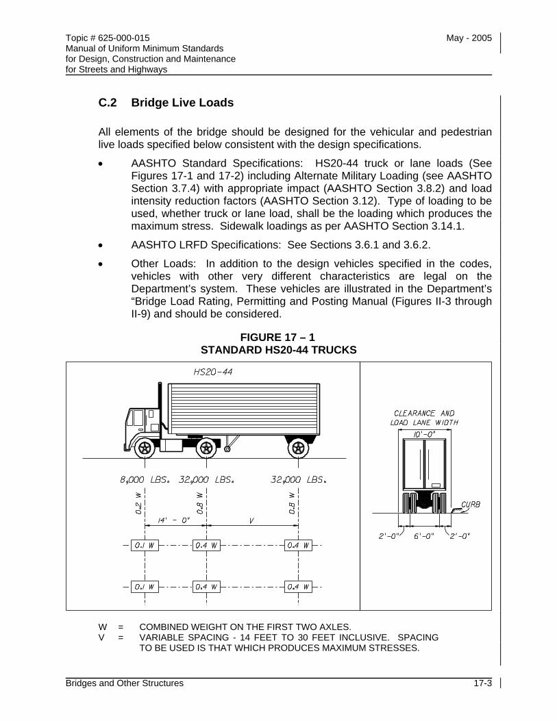
Topic # 625-000-015 May - 2005 Manual of Uniform Minimum Standards for Design, Construction and Maintenance for Streets and Highways
Bridges and Other Structures 17-3
C.2 Bridge Live Loads
All elements of the bridge should be designed for the vehicular and pedestrian live loads specified below consistent with the design specifications.
• AASHTO Standard Specifications: HS20-44 truck or lane loads (See Figures 17-1 and 17-2) including Alternate Military Loading (see AASHTO Section 3.7.4) with appropriate impact (AASHTO Section 3.8.2) and load intensity reduction factors (AASHTO Section 3.12). Type of loading to be used, whether truck or lane load, shall be the loading which produces the maximum stress. Sidewalk loadings as per AASHTO Section 3.14.1.
• AASHTO LRFD Specifications: See Sections 3.6.1 and 3.6.2.
• Other Loads: In addition to the design vehicles specified in the codes, vehicles with other very different characteristics are legal on the Department’s system. These vehicles are illustrated in the Department’s “Bridge Load Rating, Permitting and Posting Manual (Figures II-3 through II-9) and should be considered.
FIGURE 17 – 1 STANDARD HS20-44 TRUCKS
W = COMBINED WEIGHT ON THE FIRST TWO AXLES. V = VARIABLE SPACING - 14 FEET TO 30 FEET INCLUSIVE. SPACING
TO BE USED IS THAT WHICH PRODUCES MAXIMUM STRESSES.
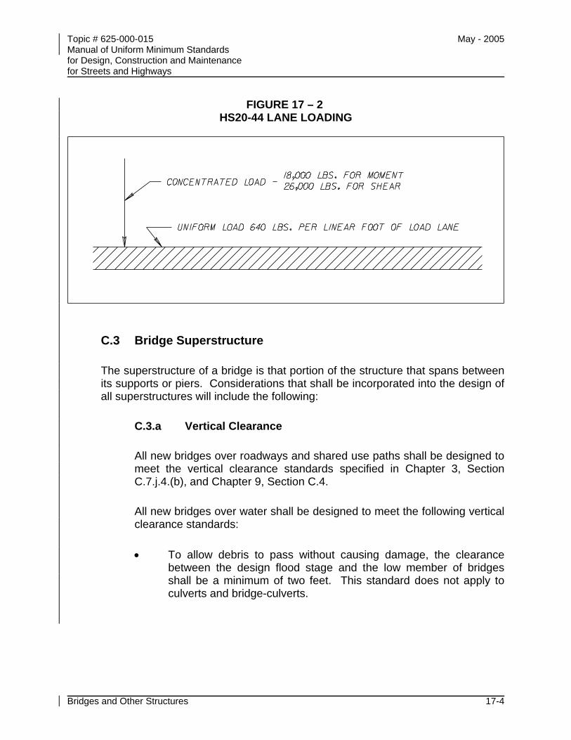
Topic # 625-000-015 May - 2005 Manual of Uniform Minimum Standards for Design, Construction and Maintenance for Streets and Highways
Bridges and Other Structures 17-4
FIGURE 17 – 2 HS20-44 LANE LOADING
C.3 Bridge Superstructure
The superstructure of a bridge is that portion of the structure that spans between its supports or piers. Considerations that shall be incorporated into the design of all superstructures will include the following:
C.3.a Vertical Clearance
All new bridges over roadways and shared use paths shall be designed to meet the vertical clearance standards specified in Chapter 3, Section C.7.j.4.(b), and Chapter 9, Section C.4.
All new bridges over water shall be designed to meet the following vertical clearance standards:
• To allow debris to pass without causing damage, the clearance between the design flood stage and the low member of bridges shall be a minimum of two feet. This standard does not apply to culverts and bridge-culverts.
Topic # 625-000-015 May - 2005 Manual of Uniform Minimum Standards for Design, Construction and Maintenance for Streets and Highways
Bridges and Other Structures 17-5
• For crossings subject to boat traffic, the minimum vertical navigation clearance should be:
Tidewater bays and streams 6 feet above Mean High Water *
Freshwater rivers, streams, non-regulated/controlled canals, and lakes
6 feet above Normal High Water
Regulated/controlled lakes and canals 6 feet above control elevation
* For locations subject to tidal salt / brackish water splashing, a 12 foot vertical clearance above Mean High Water should be considered for bridge durability reasons.
Higher clearances apply for crossings over legislated channels under the control of the U.S. Coast Guard (USCG). Designers should also consider future navigation demands and future shared use path demands in setting the vertical clearance of a bridge.
C.3.b Railings
All traffic, pedestrian, and bicycle railings shall comply with the requirements in Section 13 of AASHTO’s LRFD Bridge Design Specifications, 3rd edition, 2004. Traffic railings shall meet the crash requirements of at least Test Level (TL)-3 for bridges with design speeds greater than 45 mph and at least TL-2 for design speeds less than or equal to 45 mph.
For pedestrian/bicycle railings, two-pipe guiderails and details (similar to the Department’s Design Standards, Index 870) shall not be mounted on walls or other structures where drop-off hazards exceed 2’-6”. Instead, concrete, aluminum, steel, or composite picket railing and details (similar in strength and geometry to the Department’s Design Standards, Indexes 820, 850 or 860) should be used (or modified to suit environmental runoff concerns).
C.3.c Expansion Joints
The number of joints should be minimized to reduce inspection and maintenance needs of the bridge.
Topic # 625-000-015 May - 2005 Manual of Uniform Minimum Standards for Design, Construction and Maintenance for Streets and Highways
Bridges and Other Structures 17-6
C.3.d Drainage
All bridge designs shall include a drainage design that is specific to its site. Conveyance of drainage off the bridge roadway should be designed to meet spread standards contained in the Department’s Drainage Manual, Chapter 3 and may include open systems (i.e., scuppers) or closed systems (i.e., inlets and pipes) based on environmental permitting restrictions. Drainage from the bridge should not drop onto traffic below. Longitudinal conveyance piping attached to bridges is expensive and maintenance-intensive, and should be avoided whenever possible. Conveyance of drainage off pedestrian facilities shall meet the provisions of the Americans with Disabilities Act (ADA). Further guidance on the design of bridge deck drainage may be found in the current version of FHWA Publication HEC-21, “Bridge Deck Drainage Systems.”
C.3.e ADA
All bridges that include provisions for pedestrians shall provide pedestrian accommodations and design considerations that meet the provisions of the ADA. Significant ADA design considerations exist for all facilities with grades that exceed 5%.
C.3.f End Treatments
Requirements for end treatments of structures are given in CHAPTER 4 – ROADSIDE DESIGN. Bridge barriers shall be designed to accommodate connection of a guardrail transition or energy absorbing system.
C.4 Bridge Substructure
The substructure of a bridge consists of all elements below the superstructure including its bearings, piers, and foundations. Considerations that shall be incorporated into the design of all substructures include the following:
C.4.a Scour
A hydrologic/hydraulic analysis shall be performed to quantify expected stages and flows at the bridge site. Anticipated substructure scour shall be developed for the following:
• Worst case scour condition up through the 100-year frequency flood event (Scour Design Flood Event).
Topic # 625-000-015 May - 2005 Manual of Uniform Minimum Standards for Design, Construction and Maintenance for Streets and Highways
Bridges and Other Structures 17-7
• Worst case scour condition up through the 500-year frequency flood event (Scour Check Flood Event).
Any exceptions to the standards above hydrologic/hydraulic and scour analysis requirements shall be approved in writing by the local Department District Structures and Facilities Engineer. Methodology for computing bridge hydrology/hydraulics and bridge scour should follow the guidelines set forth in the most recent versions of the Department’s “Drainage Manual” and “Bridge Hydraulics Handbook.” Further guidance and training may be obtained through FHWA Hydraulic Engineering Circulars (HEC) “HEC-18” and “HEC-20” and the Department’s training courses on these topics. Additionally, for larger bridges (>120,000 sq. ft.), hydraulic designers may wish to consult with the local Department District Drainage Engineer for case-specific guidance. Scour load combinations with other loads shall be as per the Department’s “Structures Design Guidelines” (SDG), Section 2.12 (and subsequently Section 2.11 of the SDG, the Department’s Drainage Manual, Chapter 4, and the AASHTO LRFD Bridge Design Specifications, Sections 3.3.2, 3.14.1 and Table 3.4.1-1 as applicable).
C.4.b Vessel Impact
All bridges over USCG designated navigable waterways shall include consideration for potential vessel collision. Such collisions generally occur from barges or oceangoing ships. The engineer shall conduct a vessel risk analysis to determine the most economical method for protecting the bridge. This shall include either designing the bridge to withstand the vessel collision, or protecting it with dolphin cells. Fender systems should only be used to designate the channel width and not for pier protection. The above risk analysis may be conducted utilizing the Department’s computer program “Vessel Impact Risk Analysis.” For load combinations, use Load Combination “Extreme Event II” as follows:
(Permanent Dead Loads) + WA+FR+CV With all load factors equal to 1.0 where WA are water loads, FR are friction forces and CV are the vessel collision loads. Nonlinear structural effects must be included and can be significant. It is anticipated that the entire substructure (including piles) may have to be replaced and the superstructure repaired if a bridge is subjected to this design impact load; however, the superstructure must not collapse. Note: Further refinement or complication of this load case is unwarranted.
Topic # 625-000-015 May - 2005 Manual of Uniform Minimum Standards for Design, Construction and Maintenance for Streets and Highways
Bridges and Other Structures 17-8
Further guidance and training may be obtained from the SDG, Section 2.11 and AASHTO’s LRFD Bridge Design Specifications, Section 3.14.
C.4.c Pier Locations
All bridges over roadways shall have substructures supports set back from vehicular traffic lanes in accordance with Chapter 3, Section C.7.j.4.(a).
All bridges over water shall have substructure supports located with horizontal clearance requirements as listed below. In this case, horizontal clearance is defined as the clear distance between piers, fender systems, culvert walls, etc., projected by the bridge normal to the flow.
• For crossings subject to boat traffic a minimum horizontal clearance of 10 feet shall be provided.
• Where no boat traffic is anticipated, horizontal clearance shall be provided consistent with debris conveyance needs and structure economy.
C.4.d Bearings
The bridge superstructure and substructure should be designed for the complete replacement of the interfacing bearings.
Topic # 625-000-015 May - 2005 Manual of Uniform Minimum Standards for Design, Construction and Maintenance for Streets and Highways
Bridges and Other Structures 17-9
D CONSTRUCTION
During the construction of a bridge or any structure at, over, or near a public facility, safety awareness is necessary and precautions shall be taken to protect the public. Provisions for protecting the public during construction shall be in accordance with the MUTCD work zone traffic control procedures and the standards and criteria described in Chapter 11. Worker safety is the responsibility of the contractor. Temporary barriers shall be installed on all bridges being widened or whose new construction is phased. Spread of stormwater on the bridge deck should be considered in planning temporary traffic routing.
During the construction of a bridge or any structure, records to be kept and maintained throughout its life shall include foundation construction records (pile driving records, shaft tip elevations, borings) and as-built plans. These records provide critical information necessary for future inspection, maintenance, emergency management, enhancement, reconstruction, and/or demolition of these structures. These records shall be delivered to the Department’s local District Structures and Facilities Engineer.
Any proposed changes to the construction details or specifications shall be signed, sealed, and dated by a professional engineer licensed in the State of Florida.
Topic # 625-000-015 May - 2005 Manual of Uniform Minimum Standards for Design, Construction and Maintenance for Streets and Highways
Bridges and Other Structures 17-10
E ROUTINE INSPECTION AND MAINTENANCE
Title 23, Code of Federal Regulations, Part 650, Subpart C, sets forth the National Bridge Inspection Standards (NBIS) for bridges on all public roads. Section 650.3 defines bridges, specifies inspection procedures and frequencies, and indicates minimum qualifications for personnel. Each state is permitted to modify its bridge inspection standards to deviate from the NBIS standards but only following approval from the FHWA.
Section 335.074, Florida Statutes, mandates safety inspection of bridges as follows: “At regular intervals not to exceed 2 years, each bridge on a public transportation facility shall be inspected for structural soundness and safety for the passage of traffic on such bridge. The thoroughness with which bridges are to be inspected shall depend on such factors as age, traffic characteristics, state of maintenance, and known deficiencies. The governmental entity having maintenance responsibility for any such bridge shall be responsible for having inspections performed and reports prepared in accordance with the provisions contained herein.”
This statute also defines the minimum dimensions of bridge structures that must be inspected as follows: “Those bridges having an opening measured along the center of the roadway of more than 20 feet between undercopings of abutments or spring lines of arches or extreme ends of openings for multiple boxes and those bridges consisting of multiple pipes where the clear distance between openings is less than half of the smaller contiguous opening…”
Bridge inspectors shall be certified in accordance with Rule Chapter 14-48, F.A.C. Safety inspection of bridges shall be conducted in accordance with Rule Chapter 14-48, F.A.C..
The Department inspects all bridges in the State of Florida both on-system and off-system. The Department provides each local government with copies of its inspection reports. Each local government should maintain these reports to be responsive to Metropolitan Planning Organization (MPO) requests for bridge rehabilitation, replacement, or enhancement designations.
All on-system and off-system bridges are assigned a Bridge Number by the Department. Local agencies shall contact the Department’s local District Structures and Facilities Engineer to have a number assigned.
Topic # 625-000-015 May - 2005 Manual of Uniform Minimum Standards for Design, Construction and Maintenance for Streets and Highways
Bridges and Other Structures 17-11
F RECONSTRUCTION
Any reconstruction (i.e., lengthening, widening, and/or major component replacement) shall be designed as specified in Section C of this chapter. Record of such reconstruction shall be maintained as specified in Section D of this chapter. The remaining design life should be considered in the design of a repair on the project.
G BRIDGE LOAD RATING, PERMITTING, AND POSTING
Section 335.07, Florida Statutes, mandates a sufficiency rating system for roads on the State Highway System. By inference, this statute also applies to bridges. This rating system considers the structural adequacy, safety, and serviceability of the road/bridge. The Department provides the posting information, if required, to the local agency owner and requires the owner to provide the appropriate signage that is to be promptly installed in accordance with the MUTCD. In particular, for bridges, the determination of this rating should be accomplished using procedures in the Department’s “Bridge Load Rating, Permitting and Posting Manual.” The Department shall post all bridges in the National Bridge Inventory (NBI) within 90 and 180 days of opening or a change in load rating for on-system and off-system bridges, respectively.
Topic # 625-000-015 May - 2005 Manual of Uniform Minimum Standards for Design, Construction and Maintenance for Streets and Highways
Bridges and Other Structures 17-12
H OTHER STRUCTURES
H.1 Walls (Retaining and Sound)
The design of conventional, anchored, mechanically stabilized, and prefabricated modular retaining wall structures shall meet the requirements of Section 5 of AASHTO’s Standard Specifications for Highway Bridges, 17th Edition (2002) (or LRFD Bridge Design Specifications, Section 11). Local agencies should consider using only wall types approved by the Department. These are described in Section 3.12 of the Department’s Structures Design Guidelines (SDG). Local agencies should also follow the design criteria for retaining walls found in Section 3.13 of the SDG.
The design of sound walls shall meet the requirements of AASHTO’s Guide Specifications for Structural Design of Sound Barriers (1989) with the 2002 Interim to Guide Specifications for Structural Design of Sound Barriers. For sound walls within the clear zone, their design and/or protection shall comply with the following:
• Do not attach sound barriers to the top of traffic railings unless the system has been crash tested consistent with the design speed of the facility. The Department has standards for TL-4 systems that meet the requirements of NCHRP Report 350.
• Non-crash tested sound barriers may be attached to structures if located behind an approved traffic railing and mounted at least five feet from the face of the traffic railing at deck level.
Potential existing off-site stormwater inflows through the proposed wall location should be verified in the field and considered in the wall design. Additional considerations for the design of sound barrier walls may be found in Volume 1, Chapter 32 of the Department's Plans Preparation Manual (PPM). For railings on top of walls, see Section C.3.b.
H.2 Sign, Lighting, and Traffic Signal Supports
The design of these structures shall meet the requirements of AASHTO’s Standard Specifications for Structural Supports for Highway Signs, Luminaires and Traffic Signals, 2001, with the following exceptions:
• Section 3.4, Table 3-1: Group Load II, Percent of Allowable Stress shall be 140.
• Section 3.8, Wind Load: Wind pressures shall be computed in accordance with Appendix C of this specification.
Topic # 625-000-015 May - 2005 Manual of Uniform Minimum Standards for Design, Construction and Maintenance for Streets and Highways
Bridges and Other Structures 17-13
• Section 11, Fatigue Design: The specifications of this section are optional.
The Department maintains a list of vendors, the Qualified Products List (QPL), it has prequalified to supply these supports (light poles, strain poles, monotube assemblies, and mast arm assemblies) on the State Highway System.
Topic # 625-000-015 May - 2005 Manual of Uniform Minimum Standards for Design, Construction and Maintenance for Streets and Highways
Bridges and Other Structures 17-14
I RECOMMENDATIONS
• Involve the public in determining “the appropriate aesthetics based upon scale, color, and architectural style, materials used to construct the facility, and the landscape design and landscape materials around the facility…” (Florida Statute 336.045).
• Resist the temptation to enhance the aesthetics of a bridge with non-structural appurtenances and features that are novel and therefore may have safety challenges (otherwise, consult with the Department on these safety issues).
• Consider the potential for future expansion of a bridge’s capacity (vehicular transit and pedestrian) in its layout and bridge-type selection.
• Use the Department’s objective construction unit prices (contained in the Structures Design Guidelines, Sections 9.2 and 9.3) to select bridge type(s) to consider for final design.
• Consider the use of alternative designs (i.e., steel superstructures vs. concrete superstructures) to increase bidding competition on very large bridge construction projects.
• Consider factors other than economics in decisions on a bridge’s basic design and its discretionary features.
• Invest in a comprehensive subsurface investigation of the site before any significant design of the bridge occurs (which will also help avoid unforeseen conditions during construction).
• Consult with other local officials on experiences relating to construction of other bridges in the area.
• Consider using the Department’s Standard Specifications for Road and Bridge Construction with notes on the plans referencing the Owner as the local governmental agency and the Engineer as the owner’s engineer.
• Consider the constructability, inspectability, and maintainability of all bridge components before they are incorporated into the project’s final design.
• Include drainage pass-throughs in wall designs. • Preclude contractors without company or individual bridge experience from
bidding on a bridge construction project. • Provide qualified construction inspection personnel for all phases of bridge
construction. • Maintain all design and construction records in a safe, protected, and secure
location throughout the life of the bridge.
Topic # 625-000-015 May - 2005 Manual of Uniform Minimum Standards for Design, Construction and Maintenance for Streets and Highways
Bridges and Other Structures 17-15
J REFERENCES
The following is a list of publications used in the preparation of this chapter.
• AASHTO, all publications may be ordered from: www.transportation.org/publications/bookstore.nsf
• FDOT “Bridge Hydraulics Handbook” to be published and on-line in 2005
• FDOT “Bridge Load Rating, Permitting and Posting Manual” may be ordered from: https://www.fldotmpubs.com/pls/orbit/orbit.show_page?version=FLDOT
• FDOT “Bridge Maintenance and Repair Manual” contact the State Maintenance Office - 2740 Centerview Drive, Tallahassee, Florida 32399; 850-410-5757
• FDOT “Bridge and Other Structures Inspection and Reporting Procedures Manual” may be ordered from: https://www.fldotmpubs.com/pls/orbit/orbit.show_page?version=FLDOT
• FDOT “Design Standards”: http://www.dot.state.fl.us/rddesign/Design%20Standards/Standards.htm
• FDOT “Drainage Manual”: http://www.dot.state.fl.us/rddesign/dr/Manuals%20and%20handbooks.htm
• FDOT “Plans Preparation Manual”: www.dot.state.fl.us/rddesign/PPM%20Manual/PPM.htm
• FDOT “Qualified Products List”: www.dot.state.fl.us/specificationsoffice/QPLindex.htm
• FDOT “Standard Specifications for Road and Bridge Construction” www.dot.state.fl.us/specificationsoffice/2004BK/toc.htm
• FDOT “Structures Design Guidelines”: www.dot.state.fl.us/structures/StructuresManual/CurrentRelease/Structures_Manual.htm
• FDOT "Structures Standard Drawings": www.dot.state.fl.us/structures/CADD/Standards/CurrentStandards/standardspreface.htm
• FHWA “HEC-18” and “HEC-20” may be ordered from: http://www.fhwa.dot.gov/engineering/hydraulics/library_listing.cfm

Topic # 625-000-015 May - 2005 Manual of Uniform Minimum Standards for Design, Construction and Maintenance for Streets and Highways
Bridges and Other Structures 17-16
THIS PAGE INTENTIONALLY LEFT BLANK
Topic # 625-000-015
MANUAL OF UNIFORM MINIMUM STANDARDS FOR DESIGN, CONSTRUCTION AND MAINTENANCE
FOR STREETS AND HIGHWAYS (Commonly known as the "Florida Greenbook")
State of Florida Department of Transportation
MAY 2005 EDITION
Any updates to the Florida Greenbook will be posted on the FDOT Web Site at:
http://www.dot.state.fl.us/rddesign/Publications/pub.htm

MA
NU
AL O
F UN
IFOR
M M
INIM
UM
STAN
DA
RD
S FOR
DESIG
N, C
ON
STRU
CTIO
N
AN
D M
AIN
TENA
NC
E FOR
STREETS A
ND
HIG
HW
AYS
MAY 2005 EDITION