Embed Size (px)
Citation preview
s
SINAMICS G120C
Parameter Manual · 01/2011
SINAMICS

01/2011
SINAMICS
SINAMICS G120C
Parameter Manual
Valid for Firmware version
SINAMICS G120C 4.4
A5E03052632B AA
s
Parameters1
Function diagrams2
Faults and Alarms3
AppendixA
List of AbbreviationsB
IndexC
Copyright Siemens AG 2011 All Rights Reserved
The distribution and duplication of this document or the utilization and transmission of its contents are not permitted without express written permission. Offenders will be liable for damages. All rights, including rights created by patent grant or registration of a utility model or design, are reserved.
Siemens AGIndustry SectorPostfach 484890327 NUREMBERGGERMANY
Disclaimer of Liability
We have reviewed the contents of this publication to ensure consistency with the hardware and software described. Since variance cannot be precluded entirely, we cannot guarantee full consistency. However, the information in this publication is reviewed regularly and any necessary corrections are included in subsequent editions.
© Siemens AG 2011Technical data subject to change.
Safety Guidelines
This manual contains notices you have to observe in order to ensure your personal safety, as well as to prevent damage to property. The notices referring to your personal safety are highlighted in the manual by a safety alert symbol, notices referring only to property damage have no safety alert symbol. These notices shown below are graded according to the degree of danger.
If more than one degree of danger is present, the warning notice representing the highest degree of dan-ger will be used. A notice warning of injury to persons with a safety alert symbol may also include a warning relating to property damage.
Qualified Personnel
The device/system may only be set up and used in conjunction with this documentation. Commissioning and operation of a device/system may only be performed by qualified personnel. Within the context of the safety notes in this documentation qualified persons are defined as persons who are authorized to commission, ground and label devices, systems and circuits in accordance with established safety prac-tices and standards.
Prescribed Usage of Siemens Products
Note the following:
Trademarks
All names identified by ® are registered trademarks of the Siemens AG. The remaining trademarks in this publication may be trademarks whose use by third parties for their own purposes could violate the rights of the owner.
Danger
indicates that death or severe personal injury will result if proper precautions are not taken.
Warning
indicates that death or severe personal injury may result if proper precautions are not taken.
Caution
with a safety alert symbol, indicates that minor personal injury can result if proper precautions are not taken.
Caution
without a safety alert symbol, indicates that property damage can result if proper precautions are not taken.
Notice
indicates that an unintended result or situation can occur if the corresponding information is not taken into account.
Warning
This device may only be used for the applications described in the catalog or the technical description and only in connection with devices or components from other manufacturers which have been approved or recommended by Siemens.
Correct, reliable operation of the product requires proper transport, storage, positioning and assembly as well as careful operation and maintenance.
Siemens Aktiengesellschaft SINAMICS G120C Parameter Manual (LH13)
Inhalt-5© Siemens AG 2011 All Rights ReservedSINAMICS G120C Parameter Manual (LH13), 01/2011, A5E03052632B AA
Contents
1 Parameters . . . . . . . . . . . . . . . . . . . . . . . . . . . . . . . . . . . . . . . . . . . . . . . . . . . . . 1-7
1.1 Introduction to Parameters . . . . . . . . . . . . . . . . . . . . . . . . . . . . . . . . . . 1-81.1.1 Explanation of list of parameters . . . . . . . . . . . . . . . . . . . . . . . . . . . . . . 1-81.1.2 Numerical ranges of parameters . . . . . . . . . . . . . . . . . . . . . . . . . . . . . . 1-15
1.2 List of Parameters . . . . . . . . . . . . . . . . . . . . . . . . . . . . . . . . . . . . . . . . . 1-16
1.3 Command and Drive Data Sets – Overview . . . . . . . . . . . . . . . . . . . . . 1-2641.3.1 Command Data Sets (CDS) . . . . . . . . . . . . . . . . . . . . . . . . . . . . . . . . . 1-2641.3.2 Drive Data Sets (DDS) . . . . . . . . . . . . . . . . . . . . . . . . . . . . . . . . . . . . . 1-2651.3.3 Motor Data Sets (MDS) . . . . . . . . . . . . . . . . . . . . . . . . . . . . . . . . . . . . . 1-2681.3.4 Power unit Data Set (PDS) . . . . . . . . . . . . . . . . . . . . . . . . . . . . . . . . . . 1-269
1.4 Connector/Binector (BICO)-Parameters . . . . . . . . . . . . . . . . . . . . . . . . 1-2701.4.1 Binector Input Parameters. . . . . . . . . . . . . . . . . . . . . . . . . . . . . . . . . . . 1-2701.4.2 Connector Input Parameters . . . . . . . . . . . . . . . . . . . . . . . . . . . . . . . . . 1-2711.4.3 Binector Output Parameters . . . . . . . . . . . . . . . . . . . . . . . . . . . . . . . . . 1-2711.4.4 Connector Output Parameters . . . . . . . . . . . . . . . . . . . . . . . . . . . . . . . 1-2721.4.5 Connector/Binector Output Parameters . . . . . . . . . . . . . . . . . . . . . . . . 1-274
1.5 Quick commissioning (p0010 = 1) . . . . . . . . . . . . . . . . . . . . . . . . . . . . . 1-276
2 Function diagrams . . . . . . . . . . . . . . . . . . . . . . . . . . . . . . . . . . . . . . . . . . . . . . . 2-279
2.1 Contents: function diagrams . . . . . . . . . . . . . . . . . . . . . . . . . . . . . . . . . 2-280
2.2 Explanations for the function diagrams . . . . . . . . . . . . . . . . . . . . . . . . . 2-284
2.3 Overview . . . . . . . . . . . . . . . . . . . . . . . . . . . . . . . . . . . . . . . . . . . . . . . . 2-289
2.4 Input/Output Terminals . . . . . . . . . . . . . . . . . . . . . . . . . . . . . . . . . . . . . 2-297
2.5 Communication . . . . . . . . . . . . . . . . . . . . . . . . . . . . . . . . . . . . . . . . . . . 2-3032.5.1 Fieldbus Interface (USS, Modbus) (G120C USS/MB). . . . . . . . . . . . . . 2-3042.5.2 PROFIdrive / PROFIBUS (G120C DP) . . . . . . . . . . . . . . . . . . . . . . . . . 2-3102.5.3 CANopen (G120C CAN) . . . . . . . . . . . . . . . . . . . . . . . . . . . . . . . . . . . . 2-323
2.6 Internal control/status words . . . . . . . . . . . . . . . . . . . . . . . . . . . . . . . . . 2-330
2.7 Braking Control . . . . . . . . . . . . . . . . . . . . . . . . . . . . . . . . . . . . . . . . . . . 2-347
2.8 Safety Integrated . . . . . . . . . . . . . . . . . . . . . . . . . . . . . . . . . . . . . . . . . . 2-349
2.9 Setpoint channel . . . . . . . . . . . . . . . . . . . . . . . . . . . . . . . . . . . . . . . . . . 2-355
2.10 V/f control . . . . . . . . . . . . . . . . . . . . . . . . . . . . . . . . . . . . . . . . . . . . . . . 2-363
2.11 Vector control . . . . . . . . . . . . . . . . . . . . . . . . . . . . . . . . . . . . . . . . . . . . 2-367
2.12 Technology functions . . . . . . . . . . . . . . . . . . . . . . . . . . . . . . . . . . . . . . 2-383
2.13 Technology controller . . . . . . . . . . . . . . . . . . . . . . . . . . . . . . . . . . . . . . 2-385
2.14 Signals and monitoring functions . . . . . . . . . . . . . . . . . . . . . . . . . . . . . 2-390
2.15 Faults and warnings . . . . . . . . . . . . . . . . . . . . . . . . . . . . . . . . . . . . . . . 2-399
Contents
Inhalt-6 © Siemens AG 2011 All Rights ReservedSINAMICS G120C Parameter Manual (LH13), 01/2011, A5E03052632B AA
2.16 Data sets . . . . . . . . . . . . . . . . . . . . . . . . . . . . . . . . . . . . . . . . . . . . . . . . 2-404
3 Faults and Alarms. . . . . . . . . . . . . . . . . . . . . . . . . . . . . . . . . . . . . . . . . . . . . . . . 3-407
3.1 Faults and Alarms – Overview . . . . . . . . . . . . . . . . . . . . . . . . . . . . . . . 3-4083.1.1 General information. . . . . . . . . . . . . . . . . . . . . . . . . . . . . . . . . . . . . . . . 3-4083.1.2 Fault reactions. . . . . . . . . . . . . . . . . . . . . . . . . . . . . . . . . . . . . . . . . . . . 3-4103.1.3 Acknowledgement of faults . . . . . . . . . . . . . . . . . . . . . . . . . . . . . . . . . . 3-411
3.2 List of Faults and Alarms. . . . . . . . . . . . . . . . . . . . . . . . . . . . . . . . . . . . 3-412
A Appendix . . . . . . . . . . . . . . . . . . . . . . . . . . . . . . . . . . . . . . . . . . . . . . . . . . . . . . . A-471
A.1 ASCII Table (excerpt) . . . . . . . . . . . . . . . . . . . . . . . . . . . . . . . . . . . . . . A-472
B List of Abbreviations . . . . . . . . . . . . . . . . . . . . . . . . . . . . . . . . . . . . . . . . . . . . . B-473
C Index . . . . . . . . . . . . . . . . . . . . . . . . . . . . . . . . . . . . . . . . . . . . . . . . . . . . . . . . . . C-477
1-7© Siemens AG 2011 All Rights ReservedSINAMICS G120C Parameter Manual (LH13), 01/2011, A5E03052632B AA
Parameters 1Contents
1.1 Introduction to Parameters 1-8
1.2 List of Parameters 1-16
1.3 Command and Drive Data Sets – Overview 1-264
1.4 Connector/Binector (BICO)-Parameters 1-270
1.5 Quick commissioning (p0010 = 1) 1-276
Parameters
Introduction to Parameters
1-8 © Siemens AG 2011 All Rights ReservedSINAMICS G120C Parameter Manual (LH13), 01/2011, A5E03052632B AA
1.1 Introduction to Parameters
1.1.1 Explanation of list of parameters
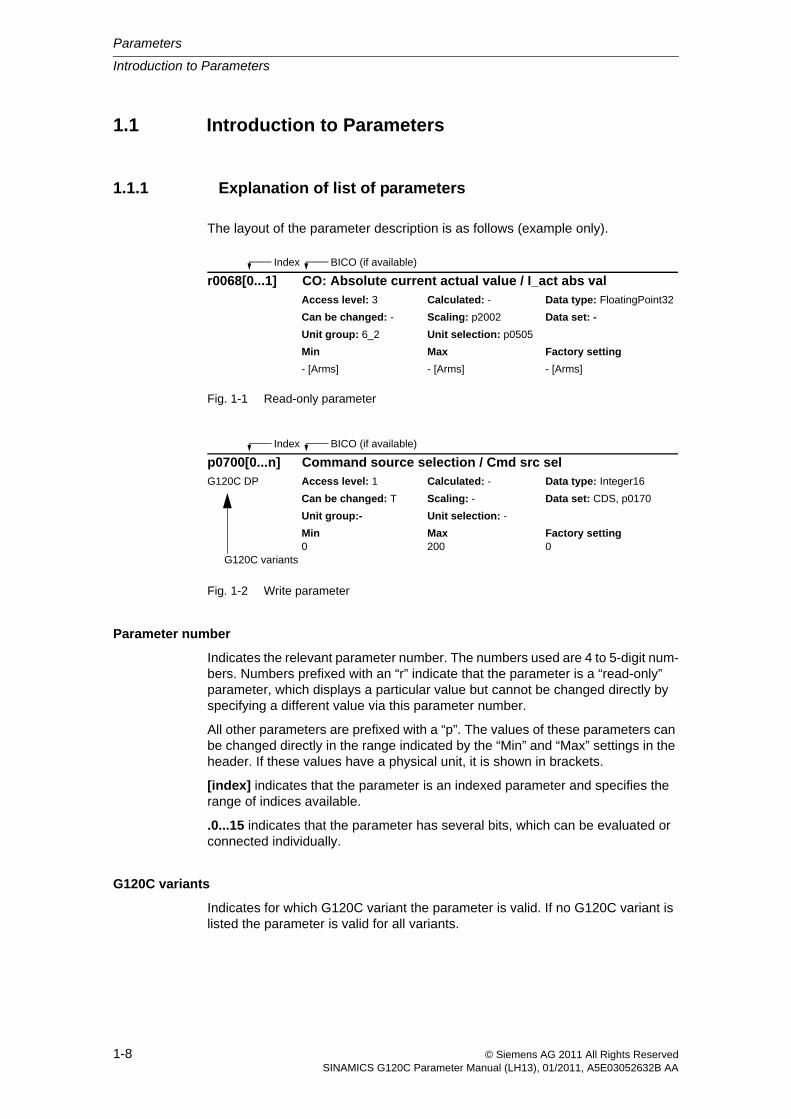
The layout of the parameter description is as follows (example only).
Fig. 1-1 Read-only parameter
Fig. 1-2 Write parameter
Parameter number
Indicates the relevant parameter number. The numbers used are 4 to 5-digit num-bers. Numbers prefixed with an “r” indicate that the parameter is a “read-only” parameter, which displays a particular value but cannot be changed directly by specifying a different value via this parameter number.
All other parameters are prefixed with a “p”. The values of these parameters can be changed directly in the range indicated by the “Min” and “Max” settings in the header. If these values have a physical unit, it is shown in brackets.
[index] indicates that the parameter is an indexed parameter and specifies the range of indices available.
.0...15 indicates that the parameter has several bits, which can be evaluated or connected individually.
G120C variants
Indicates for which G120C variant the parameter is valid. If no G120C variant is listed the parameter is valid for all variants.
r0068[0...1] CO: Absolute current actual value / I_act abs valAccess level: 3 Calculated: - Data type: FloatingPoint32
Can be changed: - Scaling: p2002 Data set: -
Unit group: 6_2 Unit selection: p0505
Min Max Factory setting
- [Arms] - [Arms] - [Arms]
Index BICO (if available)
p0700[0...n] Command source selection / Cmd src selG120C DP Access level: 1 Calculated: - Data type: Integer16
Can be changed: T Scaling: - Data set: CDS, p0170
Unit group:- Unit selection: -
Min Max Factory setting0 200 0
G120C variants
Index BICO (if available)
Introduction to Parameters
Parameters
1-9© Siemens AG 2011 All Rights ReservedSINAMICS G120C Parameter Manual (LH13), 01/2011, A5E03052632B AA
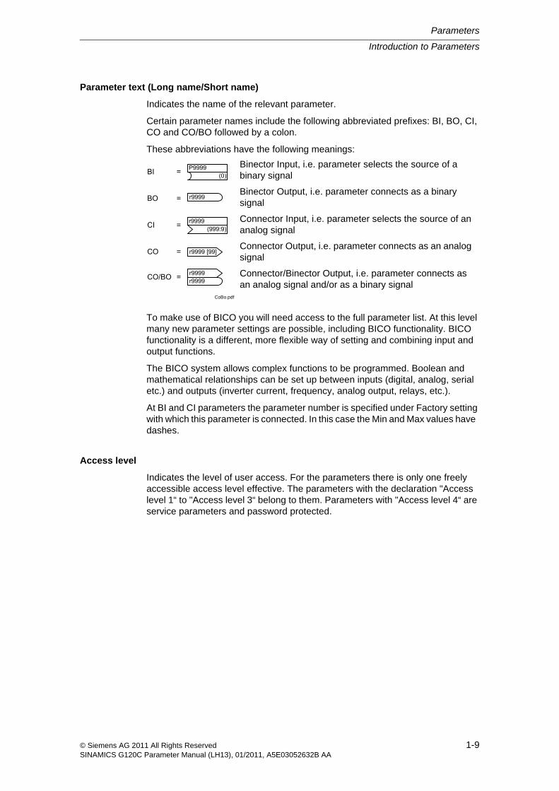
Parameter text (Long name/Short name)
Indicates the name of the relevant parameter.
Certain parameter names include the following abbreviated prefixes: BI, BO, CI, CO and CO/BO followed by a colon.
These abbreviations have the following meanings:
To make use of BICO you will need access to the full parameter list. At this level many new parameter settings are possible, including BICO functionality. BICO functionality is a different, more flexible way of setting and combining input and output functions.
The BICO system allows complex functions to be programmed. Boolean and mathematical relationships can be set up between inputs (digital, analog, serial etc.) and outputs (inverter current, frequency, analog output, relays, etc.).
At BI and CI parameters the parameter number is specified under Factory setting with which this parameter is connected. In this case the Min and Max values have dashes.
Access level
Indicates the level of user access. For the parameters there is only one freely accessible access level effective. The parameters with the declaration "Access level 1“ to "Access level 3“ belong to them. Parameters with "Access level 4“ are service parameters and password protected.
CoBo.pdf
Binector Input, i.e. parameter selects the source of a binary signal
Binector Output, i.e. parameter connects as a binary signal
Connector Input, i.e. parameter selects the source of an analog signal
Connector Output, i.e. parameter connects as an analog signal
Connector/Binector Output, i.e. parameter connects as an analog signal and/or as a binary signal
(0)P9999
r9999
(999:9)r9999
r9999 [99]
r9999r9999CO/BO =
CO =
CI =
BO =
BI =
Parameters
Introduction to Parameters
1-10 © Siemens AG 2011 All Rights ReservedSINAMICS G120C Parameter Manual (LH13), 01/2011, A5E03052632B AA
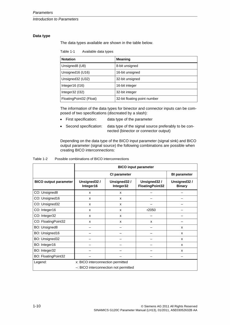
Data type
The data types available are shown in the table below.
The information of the data types for binector and connector inputs can be com-posed of two specifications (discreated by a slash):
Depending on the data type of the BICO input parameter (signal sink) and BICO output parameter (signal source) the following combinations are possible when creating BICO interconnections:
Table 1-1 Available data types
Notation Meaning
Unsigned8 (U8) 8-bit unsigned
Unsigned16 (U16) 16-bit unsigned
Unsigned32 (U32) 32-bit unsigned
Integer16 (I16) 16-bit integer
Integer32 (I32) 32-bit integer
FloatingPoint32 (Float) 32-bit floating point number
First specification: data type of the parameter
Second specification: data type of the signal source preferably to be con-nected (binector or connector output)
Table 1-2 Possible combinations of BICO interconnections
BICO input parameter
CI parameter BI parameter
BICO output parameter Unsigned32 / Integer16
Unsigned32 / Integer32
Unsigned32 / FloatingPoint32
Unsigned32 / Binary
CO: Unsigned8 x x – –
CO: Unsigned16 x x – –
CO: Unsigned32 x x – –
CO: Integer16 x x r2050 –
CO: Integer32 x x – –
CO: FloatingPoint32 x x x –
BO: Unsigned8 – – – x
BO: Unsigned16 – – – x
BO: Unsigned32 – – – x
BO: Integer16 – – – x
BO: Integer32 – – – x
BO: FloatingPoint32 – – – –
Legend: x: BICO interconnection permitted
–: BICO interconnection not permitted
Introduction to Parameters
Parameters
1-11© Siemens AG 2011 All Rights ReservedSINAMICS G120C Parameter Manual (LH13), 01/2011, A5E03052632B AA
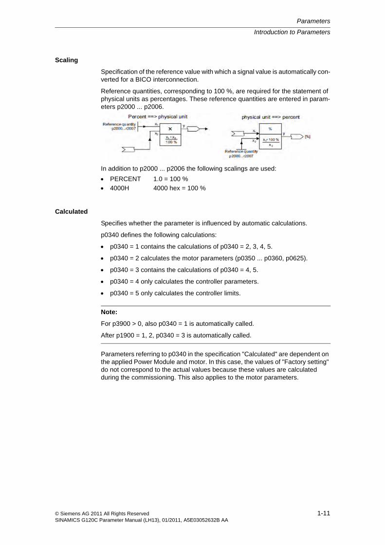
Scaling
Specification of the reference value with which a signal value is automatically con-verted for a BICO interconnection.
Reference quantities, corresponding to 100 %, are required for the statement of physical units as percentages. These reference quantities are entered in param-eters p2000 ... p2006.
In addition to p2000 ... p2006 the following scalings are used:
Calculated
Specifies whether the parameter is influenced by automatic calculations.
p0340 defines the following calculations:
p0340 = 1 contains the calculations of p0340 = 2, 3, 4, 5.
p0340 = 2 calculates the motor parameters (p0350 ... p0360, p0625).
p0340 = 3 contains the calculations of p0340 = 4, 5.
p0340 = 4 only calculates the controller parameters.
p0340 = 5 only calculates the controller limits.
Parameters referring to p0340 in the specification "Calculated" are dependent on the applied Power Module and motor. In this case, the values of "Factory setting" do not correspond to the actual values because these values are calculated during the commissioning. This also applies to the motor parameters.
PERCENT 1.0 = 100 %
4000H 4000 hex = 100 %
Note:
For p3900 > 0, also p0340 = 1 is automatically called.
After p1900 = 1, 2, p0340 = 3 is automatically called.
Parameters
Introduction to Parameters
1-12 © Siemens AG 2011 All Rights ReservedSINAMICS G120C Parameter Manual (LH13), 01/2011, A5E03052632B AA
Can be changed
Inverter state in which the parameter is changeable. Three states are possible:
In these states the parameter can be changed. One, two or all three states may be specified. If all three states are specified, it is possible to change the parameter setting in all three inverter states. (x) shows, that the parameter is only change-able when p0010 = x.
Data Set
Parameters which are dependent on a data set are identified as follows:
CDS (Command Data Set)
They are always indexed with [0 ... n] (with n = 0 ... 1 depending on setting in p0170).
[0] = Command Data Set 0
[1] = Command Data Set 1
DDS (Drive Data Set)
They are always indexed with [0 ... n] (with n = 0).
[0] = Drive Data Set 0
MDS (Motor Data Set) and PDS (Power unit Data Set)
They are always indexed with [0 ... n] (with n = 0). The Motor Data Sets and Power unit Data Sets are allocated to the Drive Data Sets, i.e. they are automatically addressed with the selection of a Drive Data Set (e.g. Drive Data Set 0 includes Motor Data Set 0 and Power unit Data Set 0).
Data sets can only be applied and cleared when p0010 = 15 is set.
"Unit group" and "Unit selection"
For parameters where the unit can be switched, the specifications for "Unit group" and "Unit selection" determine the group to which this parameter belongs and with which parameter the unit can be switched over.
The standard unit of a parameter is specified in square parentheses after the val-ues for "Min", "Max", and "Factory setting".
MinIndicates the minimum value to which the parameter can be set.
MaxIndicates the maximum value to which the parameter can be set.
Commissioning C(x)
Run U
Ready to run T
Introduction to Parameters
Parameters
1-13© Siemens AG 2011 All Rights ReservedSINAMICS G120C Parameter Manual (LH13), 01/2011, A5E03052632B AA
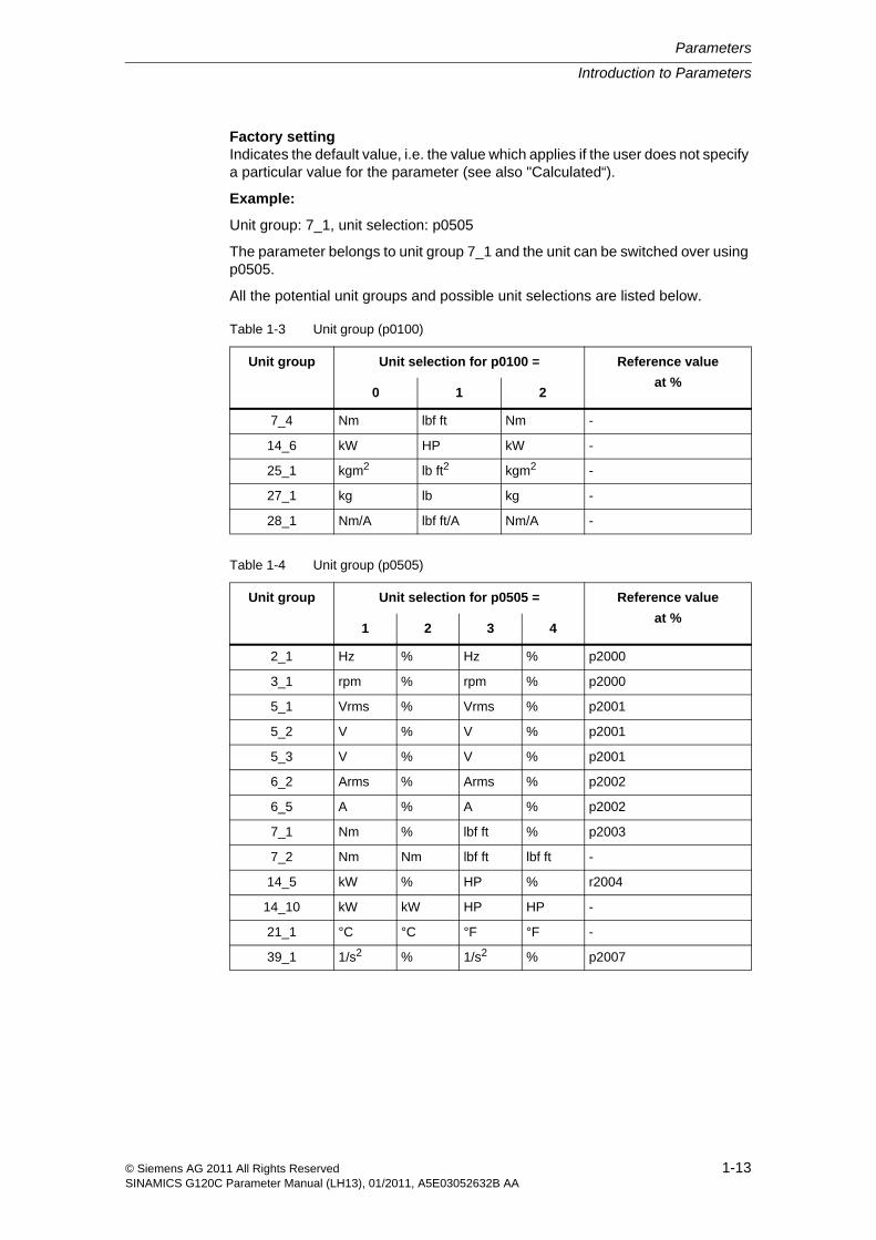
Factory settingIndicates the default value, i.e. the value which applies if the user does not specify a particular value for the parameter (see also "Calculated“).
Example:
Unit group: 7_1, unit selection: p0505
The parameter belongs to unit group 7_1 and the unit can be switched over using p0505.
All the potential unit groups and possible unit selections are listed below.
Table 1-3 Unit group (p0100)
Unit group Unit selection for p0100 = Reference value
at %0 1 2
7_4 Nm lbf ft Nm -
14_6 kW HP kW -
25_1 kgm2 lb ft2 kgm2 -
27_1 kg lb kg -
28_1 Nm/A lbf ft/A Nm/A -
Table 1-4 Unit group (p0505)
Unit group Unit selection for p0505 = Reference value
at %1 2 3 4
2_1 Hz % Hz % p2000
3_1 rpm % rpm % p2000
5_1 Vrms % Vrms % p2001
5_2 V % V % p2001
5_3 V % V % p2001
6_2 Arms % Arms % p2002
6_5 A % A % p2002
7_1 Nm % lbf ft % p2003
7_2 Nm Nm lbf ft lbf ft -
14_5 kW % HP % r2004
14_10 kW kW HP HP -
21_1 °C °C °F °F -
39_1 1/s2 % 1/s2 % p2007
Parameters
Introduction to Parameters
1-14 © Siemens AG 2011 All Rights ReservedSINAMICS G120C Parameter Manual (LH13), 01/2011, A5E03052632B AA
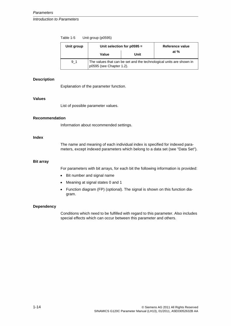
Description
Explanation of the parameter function.
Values
List of possible parameter values.
Recommendation
Information about recommended settings.
Index
The name and meaning of each individual index is specified for indexed para-meters, except indexed parameters which belong to a data set (see "Data Set").
Bit array
For parameters with bit arrays, for each bit the following information is provided:
Bit number and signal name
Meaning at signal states 0 and 1
Function diagram (FP) (optional). The signal is shown on this function dia-gram.
Dependency
Conditions which need to be fulfilled with regard to this parameter. Also includes special effects which can occur between this parameter and others.
Table 1-5 Unit group (p0595)
Unit group Unit selection for p0595 = Reference value
at %Value Unit
9_1 The values that can be set and the technological units are shown in p0595 (see Chapter 1.2).
Introduction to Parameters
Parameters
1-15© Siemens AG 2011 All Rights ReservedSINAMICS G120C Parameter Manual (LH13), 01/2011, A5E03052632B AA
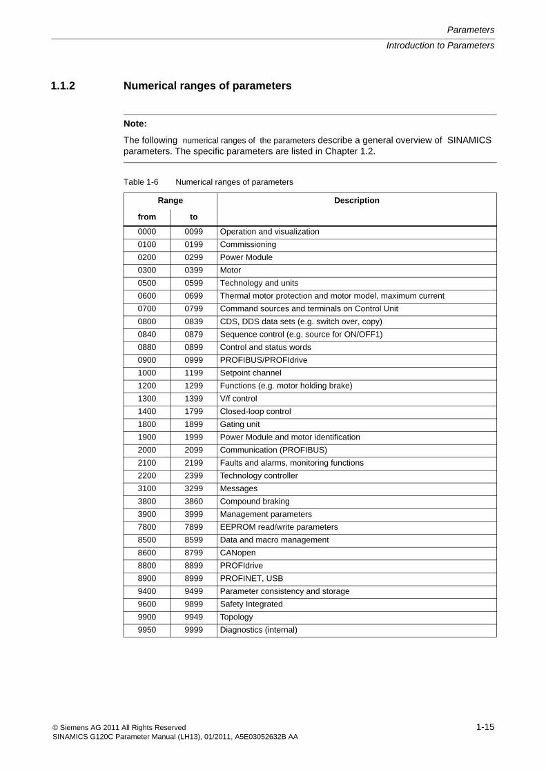
1.1.2 Numerical ranges of parameters
Note:
The following numerical ranges of the parameters describe a general overview of SINAMICS parameters. The specific parameters are listed in Chapter 1.2.
Table 1-6 Numerical ranges of parameters
Range Description
from to
0000 0099 Operation and visualization
0100 0199 Commissioning
0200 0299 Power Module
0300 0399 Motor
0500 0599 Technology and units
0600 0699 Thermal motor protection and motor model, maximum current
0700 0799 Command sources and terminals on Control Unit
0800 0839 CDS, DDS data sets (e.g. switch over, copy)
0840 0879 Sequence control (e.g. source for ON/OFF1)
0880 0899 Control and status words
0900 0999 PROFIBUS/PROFIdrive
1000 1199 Setpoint channel
1200 1299 Functions (e.g. motor holding brake)
1300 1399 V/f control
1400 1799 Closed-loop control
1800 1899 Gating unit
1900 1999 Power Module and motor identification
2000 2099 Communication (PROFIBUS)
2100 2199 Faults and alarms, monitoring functions
2200 2399 Technology controller
3100 3299 Messages
3800 3860 Compound braking
3900 3999 Management parameters
7800 7899 EEPROM read/write parameters
8500 8599 Data and macro management
8600 8799 CANopen
8800 8899 PROFIdrive
8900 8999 PROFINET, USB
9400 9499 Parameter consistency and storage
9600 9899 Safety Integrated
9900 9949 Topology
9950 9999 Diagnostics (internal)
Parameters
List of Parameters
1-16 © Siemens AG 2011 All Rights ReservedSINAMICS G120C Parameter Manual (LH13), 01/2011, A5E03052632B AA
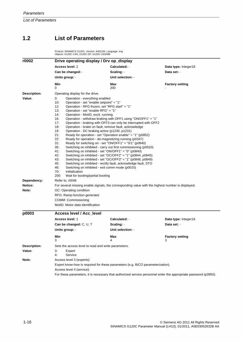
1.2 List of Parameters
Product: SINAMICS G120C, Version: 4402100, Language: engObjects: G120C CAN, G120C DP, G120C USS/MB
Description: Operating display for the drive.
Value: 0: Operation - everything enabled10: Operation - set "enable setpoint" = "1"12: Operation - RFG frozen, set "RFG start" = "1"13: Operation - set "enable RFG" = "1"14: Operation - MotID, excit. running16: Operation - withdraw braking with OFF1 using "ON/OFF1" = "1"17: Operation - braking with OFF3 can only be interrupted with OFF218: Operation - brake on fault, remove fault, acknowledge19: Operation - DC braking active (p1230, p1231)21: Ready for operation - set "Operation enable" = "1" (p0852)22: Ready for operation - de-magnetizing running (p0347)31: Ready for switching on - set "ON/OFF1" = "0/1" (p0840)35: Switching on inhibited - carry out first commissioning (p0010)41: Switching on inhibited - set "ON/OFF1" = "0" (p0840)42: Switching on inhibited - set "OC/OFF2" = "1" (p0844, p0845)43: Switching on inhibited - set "OC/OFF3" = "1" (p0848, p0849)45: Switching on inhibited - rectify fault, acknowledge fault, STO46: Switching on inhibited - exit comm mode (p0010)70: Initialization200: Wait for booting/partial booting
Dependency: Refer to: r0046
Notice: For several missing enable signals, the corresponding value with the highest number is displayed.
Note: OC: Operating condition
RFG: Ramp-function generator
COMM: Commissioning
MotID: Motor data identification
Description: Sets the access level to read and write parameters.
Value: 3: Expert4: Service
Note: Access level 3 (experts):
Expert know-how is required for these parameters (e.g. BICO parameterization).
Access level 4 (service):
For these parameters, it is necessary that authorized service personnel enter the appropriate password (p3950).
r0002 Drive operating display / Drv op_displayAccess level: 2 Calculated: - Data type: Integer16
Can be changed: - Scaling: - Data set: -
Units group: - Unit selection: -
Min Max Factory setting 0 200 -
p0003 Access level / Acc_levelAccess level: 1 Calculated: - Data type: Integer16
Can be changed: C, U, T Scaling: - Data set: -
Units group: - Unit selection: -
Min Max Factory setting 3 4 3
List of Parameters
Parameters
1-17© Siemens AG 2011 All Rights ReservedSINAMICS G120C Parameter Manual (LH13), 01/2011, A5E03052632B AA
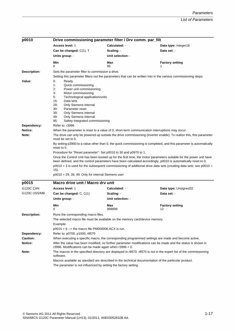
Description: Sets the parameter filter to commission a drive.
Setting this parameter filters out the parameters that can be written into in the various commissioning steps.
Value: 0: Ready1: Quick commissioning2: Power unit commissioning3: Motor commissioning5: Technological application/units15: Data sets29: Only Siemens internal30: Parameter reset39: Only Siemens internal49: Only Siemens internal95: Safety Integrated commissioning
Dependency: Refer to: r3996
Notice: When the parameter is reset to a value of 0, short-term communication interruptions may occur.
Note: The drive can only be powered up outside the drive commissioning (inverter enable). To realize this, this parameter must be set to 0.
By setting p3900 to a value other than 0, the quick commissioning is completed, and this parameter is automatically reset to 0.
Procedure for "Reset parameter": Set p0010 to 30 and p0970 to 1.
Once the Control Unit has been booted up for the first time, the motor parameters suitable for the power unit have been defined, and the control parameters have been calculated accordingly, p0010 is automatically reset to 0.
p0010 = 3 is used for the subsequent commissioning of additional drive data sets (creating data sets: see p0010 = 15).
p0010 = 29, 39, 49: Only for internal Siemens use!
Description: Runs the corresponding macro files.
The selected macro file must be available on the memory card/device memory.
Example:
p0015 = 6 --> the macro file PM000006.ACX is run.
Dependency: Refer to: p0700, p1000, r8570
Caution: When executing a specific macro, the corresponding programmed settings are made and become active.
Notice: After the value has been modified, no further parameter modifications can be made and the status is shown in r3996. Modifications can be made again when r3996 = 0.
Note: The macros in the specified directory are displayed in r8570. r8570 is not in the expert list of the commissioning software.
Macros available as standard are described in the technical documentation of the particular product.
The parameter is not influenced by setting the factory setting.
p0010 Drive commissioning parameter filter / Drv comm. par_filtAccess level: 1 Calculated: - Data type: Integer16
Can be changed: C(1), T Scaling: - Data set: -
Units group: - Unit selection: -
Min Max Factory setting 0 95 1
p0015 Macro drive unit / Macro drv unitG120C CAN
G120C USS/MB
Access level: 1 Calculated: - Data type: Unsigned32
Can be changed: C, C(1) Scaling: - Data set: -
Units group: - Unit selection: -
Min Max Factory setting 0 999999 12
Parameters
List of Parameters
1-18 © Siemens AG 2011 All Rights ReservedSINAMICS G120C Parameter Manual (LH13), 01/2011, A5E03052632B AA
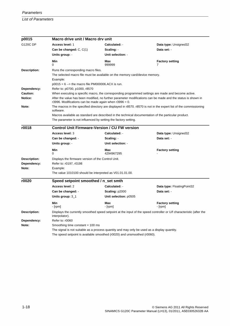
Description: Runs the corresponding macro files.
The selected macro file must be available on the memory card/device memory.
Example:
p0015 = 6 --> the macro file PM000006.ACX is run.
Dependency: Refer to: p0700, p1000, r8570
Caution: When executing a specific macro, the corresponding programmed settings are made and become active.
Notice: After the value has been modified, no further parameter modifications can be made and the status is shown in r3996. Modifications can be made again when r3996 = 0.
Note: The macros in the specified directory are displayed in r8570. r8570 is not in the expert list of the commissioning software.
Macros available as standard are described in the technical documentation of the particular product.
The parameter is not influenced by setting the factory setting.
Description: Displays the firmware version of the Control Unit.
Dependency: Refer to: r0197, r0198
Note: Example:
The value 1010100 should be interpreted as V01.01.01.00.
Description: Displays the currently smoothed speed setpoint at the input of the speed controller or U/f characteristic (after the interpolator).
Dependency: Refer to: r0060
Note: Smoothing time constant = 100 ms
The signal is not suitable as a process quantity and may only be used as a display quantity.
The speed setpoint is available smoothed (r0020) and unsmoothed (r0060).
p0015 Macro drive unit / Macro drv unitG120C DP Access level: 1 Calculated: - Data type: Unsigned32
Can be changed: C, C(1) Scaling: - Data set: -
Units group: - Unit selection: -
Min Max Factory setting 0 999999 7
r0018 Control Unit Firmware-Version / CU FW versionAccess level: 3 Calculated: - Data type: Unsigned32
Can be changed: - Scaling: - Data set: -
Units group: - Unit selection: -
Min Max Factory setting 0 4294967295 -
r0020 Speed setpoint smoothed / n_set smthAccess level: 2 Calculated: - Data type: FloatingPoint32
Can be changed: - Scaling: p2000 Data set: -
Units group: 3_1 Unit selection: p0505
Min Max Factory setting - [rpm] - [rpm] - [rpm]
List of Parameters
Parameters
1-19© Siemens AG 2011 All Rights ReservedSINAMICS G120C Parameter Manual (LH13), 01/2011, A5E03052632B AA
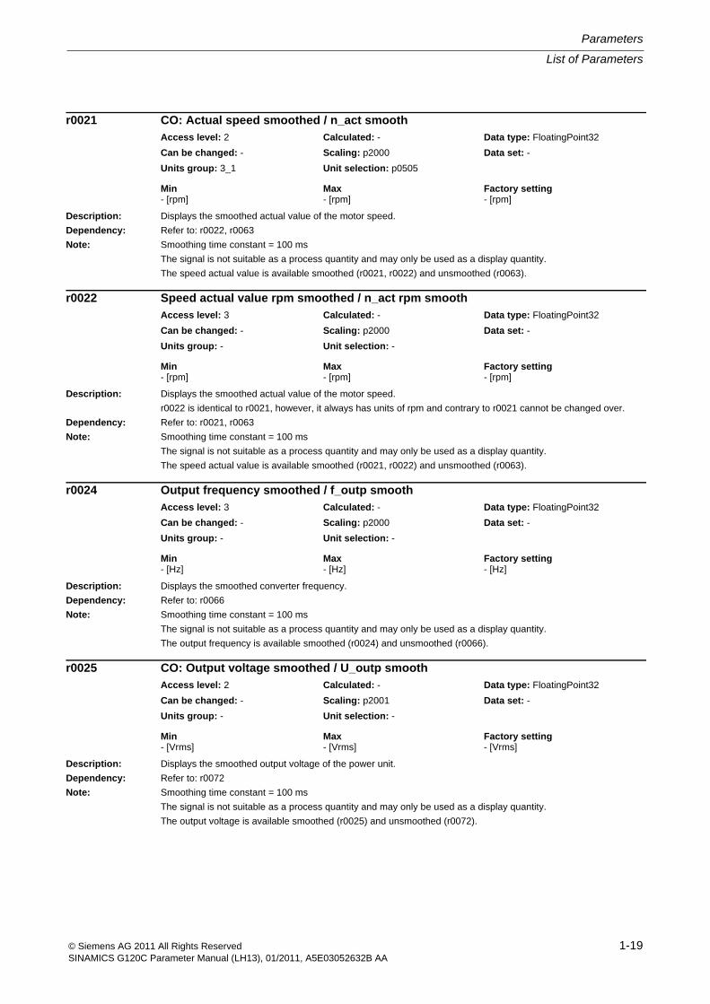
Description: Displays the smoothed actual value of the motor speed.
Dependency: Refer to: r0022, r0063
Note: Smoothing time constant = 100 ms
The signal is not suitable as a process quantity and may only be used as a display quantity.
The speed actual value is available smoothed (r0021, r0022) and unsmoothed (r0063).
Description: Displays the smoothed actual value of the motor speed.
r0022 is identical to r0021, however, it always has units of rpm and contrary to r0021 cannot be changed over.
Dependency: Refer to: r0021, r0063
Note: Smoothing time constant = 100 ms
The signal is not suitable as a process quantity and may only be used as a display quantity.
The speed actual value is available smoothed (r0021, r0022) and unsmoothed (r0063).
Description: Displays the smoothed converter frequency.
Dependency: Refer to: r0066
Note: Smoothing time constant = 100 ms
The signal is not suitable as a process quantity and may only be used as a display quantity.
The output frequency is available smoothed (r0024) and unsmoothed (r0066).
Description: Displays the smoothed output voltage of the power unit.
Dependency: Refer to: r0072
Note: Smoothing time constant = 100 ms
The signal is not suitable as a process quantity and may only be used as a display quantity.
The output voltage is available smoothed (r0025) and unsmoothed (r0072).
r0021 CO: Actual speed smoothed / n_act smoothAccess level: 2 Calculated: - Data type: FloatingPoint32
Can be changed: - Scaling: p2000 Data set: -
Units group: 3_1 Unit selection: p0505
Min Max Factory setting - [rpm] - [rpm] - [rpm]
r0022 Speed actual value rpm smoothed / n_act rpm smoothAccess level: 3 Calculated: - Data type: FloatingPoint32
Can be changed: - Scaling: p2000 Data set: -
Units group: - Unit selection: -
Min Max Factory setting - [rpm] - [rpm] - [rpm]
r0024 Output frequency smoothed / f_outp smoothAccess level: 3 Calculated: - Data type: FloatingPoint32
Can be changed: - Scaling: p2000 Data set: -
Units group: - Unit selection: -
Min Max Factory setting - [Hz] - [Hz] - [Hz]
r0025 CO: Output voltage smoothed / U_outp smoothAccess level: 2 Calculated: - Data type: FloatingPoint32
Can be changed: - Scaling: p2001 Data set: -
Units group: - Unit selection: -
Min Max Factory setting - [Vrms] - [Vrms] - [Vrms]
Parameters
List of Parameters
1-20 © Siemens AG 2011 All Rights ReservedSINAMICS G120C Parameter Manual (LH13), 01/2011, A5E03052632B AA
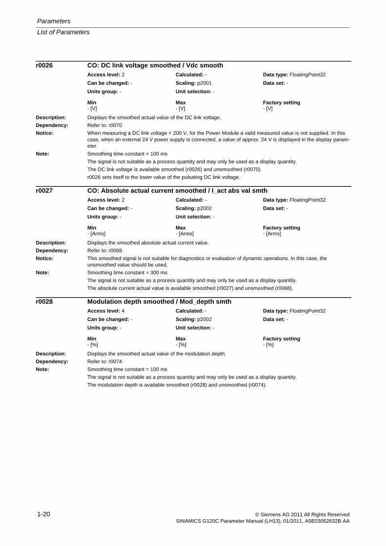
Description: Displays the smoothed actual value of the DC link voltage.
Dependency: Refer to: r0070
Notice: When measuring a DC link voltage < 200 V, for the Power Module a valid measured value is not supplied. In this case, when an external 24 V power supply is connected, a value of approx. 24 V is displayed in the display param-eter.
Note: Smoothing time constant = 100 ms
The signal is not suitable as a process quantity and may only be used as a display quantity.
The DC link voltage is available smoothed (r0026) and unsmoothed (r0070).
r0026 sets itself to the lower value of the pulsating DC link voltage.
Description: Displays the smoothed absolute actual current value.
Dependency: Refer to: r0068
Notice: This smoothed signal is not suitable for diagnostics or evaluation of dynamic operations. In this case, the unsmoothed value should be used.
Note: Smoothing time constant = 300 ms
The signal is not suitable as a process quantity and may only be used as a display quantity.
The absolute current actual value is available smoothed (r0027) and unsmoothed (r0068).
Description: Displays the smoothed actual value of the modulation depth.
Dependency: Refer to: r0074
Note: Smoothing time constant = 100 ms
The signal is not suitable as a process quantity and may only be used as a display quantity.
The modulation depth is available smoothed (r0028) and unsmoothed (r0074).
r0026 CO: DC link voltage smoothed / Vdc smoothAccess level: 2 Calculated: - Data type: FloatingPoint32
Can be changed: - Scaling: p2001 Data set: -
Units group: - Unit selection: -
Min Max Factory setting - [V] - [V] - [V]
r0027 CO: Absolute actual current smoothed / I_act abs val smthAccess level: 2 Calculated: - Data type: FloatingPoint32
Can be changed: - Scaling: p2002 Data set: -
Units group: - Unit selection: -
Min Max Factory setting - [Arms] - [Arms] - [Arms]
r0028 Modulation depth smoothed / Mod_depth smthAccess level: 4 Calculated: - Data type: FloatingPoint32
Can be changed: - Scaling: p2002 Data set: -
Units group: - Unit selection: -
Min Max Factory setting - [%] - [%] - [%]
List of Parameters
Parameters
1-21© Siemens AG 2011 All Rights ReservedSINAMICS G120C Parameter Manual (LH13), 01/2011, A5E03052632B AA
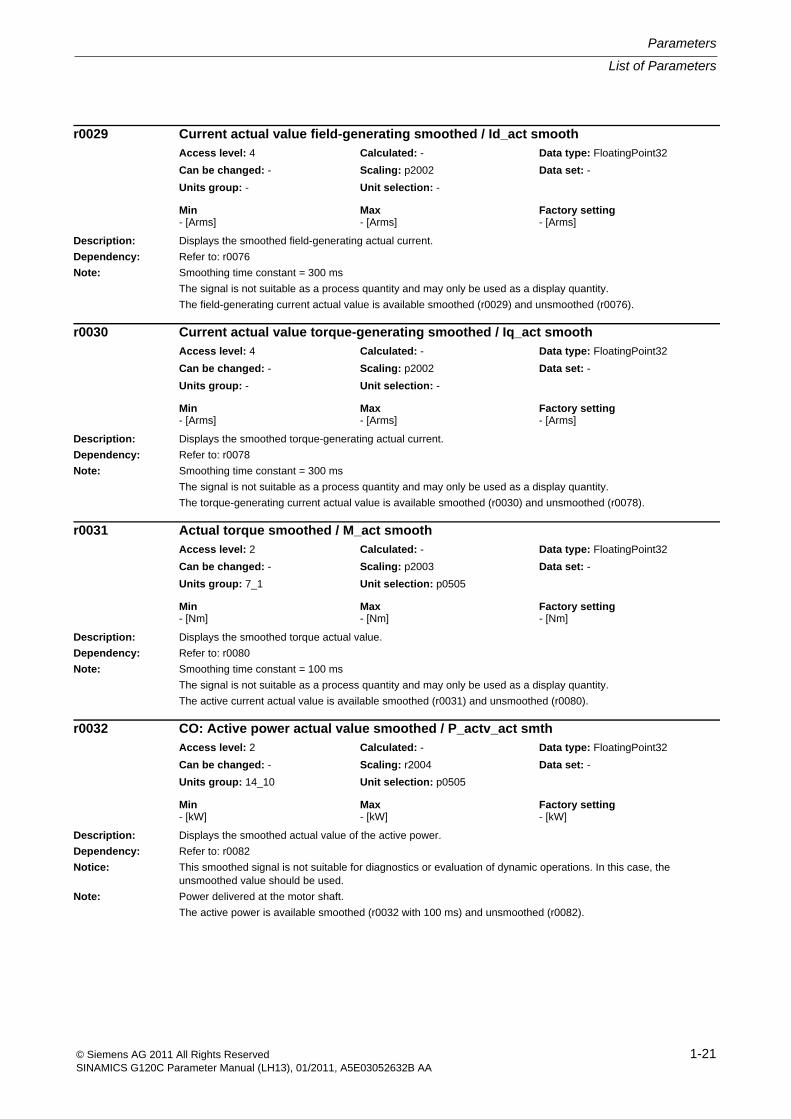
Description: Displays the smoothed field-generating actual current.
Dependency: Refer to: r0076
Note: Smoothing time constant = 300 ms
The signal is not suitable as a process quantity and may only be used as a display quantity.
The field-generating current actual value is available smoothed (r0029) and unsmoothed (r0076).
Description: Displays the smoothed torque-generating actual current.
Dependency: Refer to: r0078
Note: Smoothing time constant = 300 ms
The signal is not suitable as a process quantity and may only be used as a display quantity.
The torque-generating current actual value is available smoothed (r0030) and unsmoothed (r0078).
Description: Displays the smoothed torque actual value.
Dependency: Refer to: r0080
Note: Smoothing time constant = 100 ms
The signal is not suitable as a process quantity and may only be used as a display quantity.
The active current actual value is available smoothed (r0031) and unsmoothed (r0080).
Description: Displays the smoothed actual value of the active power.
Dependency: Refer to: r0082
Notice: This smoothed signal is not suitable for diagnostics or evaluation of dynamic operations. In this case, the unsmoothed value should be used.
Note: Power delivered at the motor shaft.
The active power is available smoothed (r0032 with 100 ms) and unsmoothed (r0082).
r0029 Current actual value field-generating smoothed / Id_act smoothAccess level: 4 Calculated: - Data type: FloatingPoint32
Can be changed: - Scaling: p2002 Data set: -
Units group: - Unit selection: -
Min Max Factory setting - [Arms] - [Arms] - [Arms]
r0030 Current actual value torque-generating smoothed / Iq_act smoothAccess level: 4 Calculated: - Data type: FloatingPoint32
Can be changed: - Scaling: p2002 Data set: -
Units group: - Unit selection: -
Min Max Factory setting - [Arms] - [Arms] - [Arms]
r0031 Actual torque smoothed / M_act smoothAccess level: 2 Calculated: - Data type: FloatingPoint32
Can be changed: - Scaling: p2003 Data set: -
Units group: 7_1 Unit selection: p0505
Min Max Factory setting - [Nm] - [Nm] - [Nm]
r0032 CO: Active power actual value smoothed / P_actv_act smthAccess level: 2 Calculated: - Data type: FloatingPoint32
Can be changed: - Scaling: r2004 Data set: -
Units group: 14_10 Unit selection: p0505
Min Max Factory setting - [kW] - [kW] - [kW]
Parameters
List of Parameters
1-22 © Siemens AG 2011 All Rights ReservedSINAMICS G120C Parameter Manual (LH13), 01/2011, A5E03052632B AA
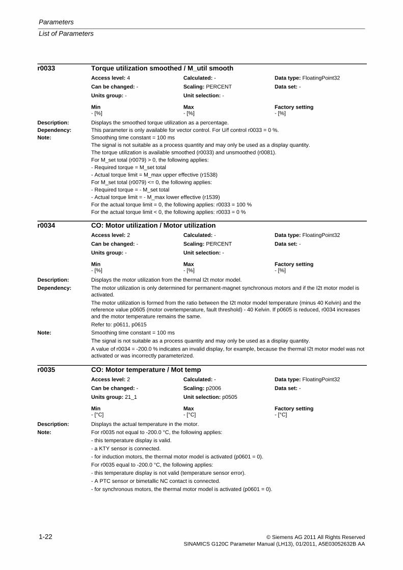
Description: Displays the smoothed torque utilization as a percentage.Dependency: This parameter is only available for vector control. For U/f control r0033 = 0 %.Note: Smoothing time constant = 100 ms
The signal is not suitable as a process quantity and may only be used as a display quantity.The torque utilization is available smoothed (r0033) and unsmoothed (r0081).For M_set total (r0079) > 0, the following applies:- Required torque = M_set total- Actual torque limit = M_max upper effective (r1538)For M_set total (r0079) <= 0, the following applies:- Required torque = - M_set total- Actual torque limit = - M_max lower effective (r1539)For the actual torque limit = 0, the following applies: r0033 = 100 %For the actual torque limit < 0, the following applies: r0033 = 0 %
Description: Displays the motor utilization from the thermal I2t motor model.
Dependency: The motor utilization is only determined for permanent-magnet synchronous motors and if the I2t motor model is activated.
The motor utilization is formed from the ratio between the I2t motor model temperature (minus 40 Kelvin) and the reference value p0605 (motor overtemperature, fault threshold) - 40 Kelvin. If p0605 is reduced, r0034 increases and the motor temperature remains the same.
Refer to: p0611, p0615
Note: Smoothing time constant = 100 ms
The signal is not suitable as a process quantity and may only be used as a display quantity.
A value of r0034 = -200.0 % indicates an invalid display, for example, because the thermal I2t motor model was not activated or was incorrectly parameterized.
Description: Displays the actual temperature in the motor.
Note: For r0035 not equal to -200.0 °C, the following applies:
- this temperature display is valid.
- a KTY sensor is connected.
- for induction motors, the thermal motor model is activated (p0601 = 0).
For r0035 equal to -200.0 °C, the following applies:
- this temperature display is not valid (temperature sensor error).
- A PTC sensor or bimetallic NC contact is connected.
- for synchronous motors, the thermal motor model is activated (p0601 = 0).
r0033 Torque utilization smoothed / M_util smoothAccess level: 4 Calculated: - Data type: FloatingPoint32
Can be changed: - Scaling: PERCENT Data set: -
Units group: - Unit selection: -
Min Max Factory setting - [%] - [%] - [%]
r0034 CO: Motor utilization / Motor utilizationAccess level: 2 Calculated: - Data type: FloatingPoint32
Can be changed: - Scaling: PERCENT Data set: -
Units group: - Unit selection: -
Min Max Factory setting - [%] - [%] - [%]
r0035 CO: Motor temperature / Mot tempAccess level: 2 Calculated: - Data type: FloatingPoint32
Can be changed: - Scaling: p2006 Data set: -
Units group: 21_1 Unit selection: p0505
Min Max Factory setting - [°C] - [°C] - [°C]
List of Parameters
Parameters
1-23© Siemens AG 2011 All Rights ReservedSINAMICS G120C Parameter Manual (LH13), 01/2011, A5E03052632B AA
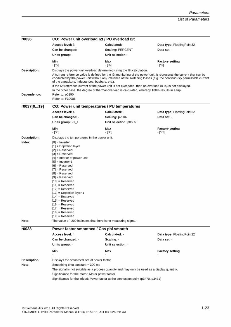
Description: Displays the power unit overload determined using the I2t calculation.A current reference value is defined for the I2t monitoring of the power unit. It represents the current that can be conducted by the power unit without any influence of the switching losses (e.g. the continuously permissible current of the capacitors, inductances, busbars, etc.).If the I2t reference current of the power unit is not exceeded, then an overload (0 %) is not displayed.In the other case, the degree of thermal overload is calculated, whereby 100% results in a trip.
Dependency: Refer to: p0290Refer to: F30005
Description: Displays the temperatures in the power unit.
Index: [0] = Inverter[1] = Depletion layer[2] = Reserved[3] = Reserved[4] = Interior of power unit[5] = Inverter 1[6] = Reserved[7] = Reserved[8] = Reserved[9] = Reserved[10] = Reserved[11] = Reserved[12] = Reserved[13] = Depletion layer 1[14] = Reserved[15] = Reserved[16] = Reserved[17] = Reserved[18] = Reserved[19] = Reserved
Note: The value of -200 indicates that there is no measuring signal.
Description: Displays the smoothed actual power factor.
Note: Smoothing time constant = 300 ms
The signal is not suitable as a process quantity and may only be used as a display quantity.
Significance for the motor: Motor power factor
Significance for the infeed: Power factor at the connection point (p3470, p3471)
r0036 CO: Power unit overload I2t / PU overload I2tAccess level: 3 Calculated: - Data type: FloatingPoint32
Can be changed: - Scaling: PERCENT Data set: -
Units group: - Unit selection: -
Min Max Factory setting - [%] - [%] - [%]
r0037[0...19] CO: Power unit temperatures / PU temperaturesAccess level: 4 Calculated: - Data type: FloatingPoint32
Can be changed: - Scaling: p2006 Data set: -
Units group: 21_1 Unit selection: p0505
Min Max Factory setting - [°C] - [°C] - [°C]
r0038 Power factor smoothed / Cos phi smoothAccess level: 4 Calculated: - Data type: FloatingPoint32
Can be changed: - Scaling: - Data set: -
Units group: - Unit selection: -
Min Max Factory setting - - -
Parameters
List of Parameters
1-24 © Siemens AG 2011 All Rights ReservedSINAMICS G120C Parameter Manual (LH13), 01/2011, A5E03052632B AA
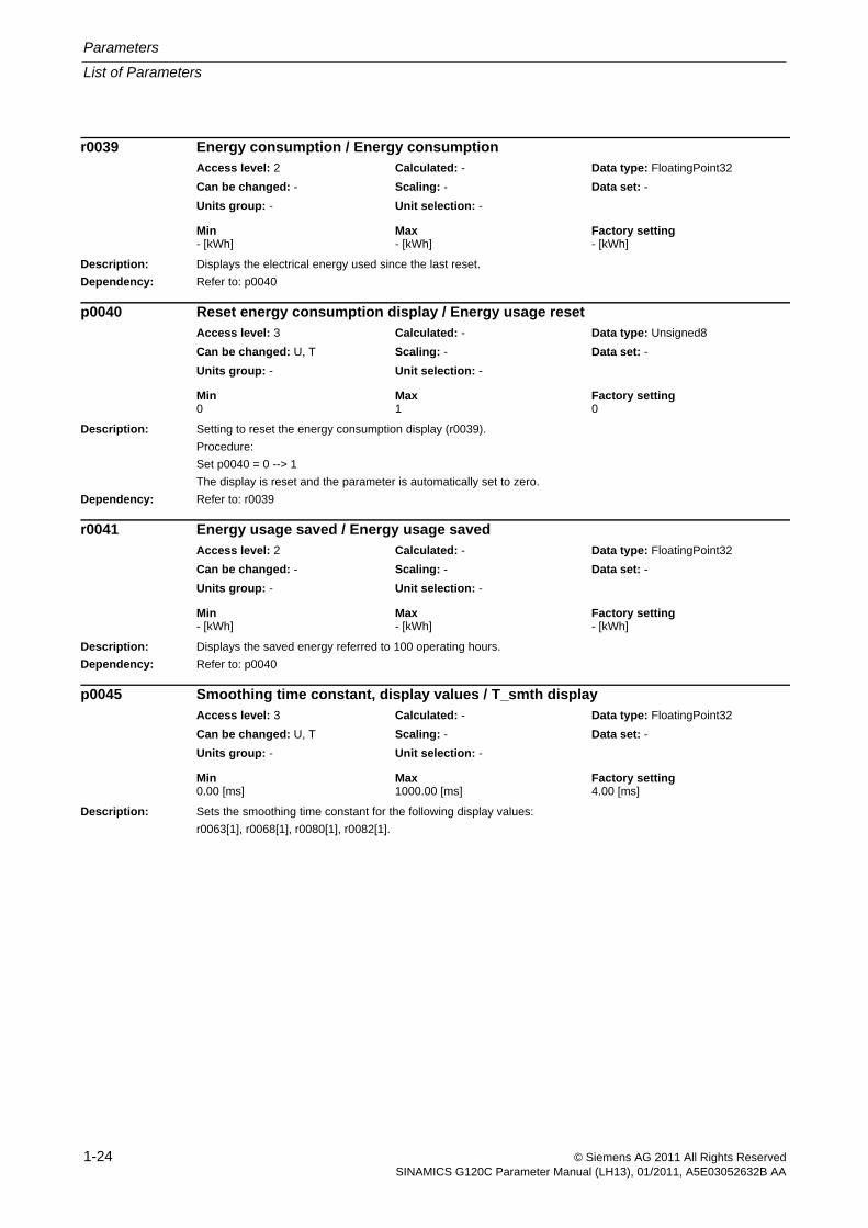
Description: Displays the electrical energy used since the last reset.
Dependency: Refer to: p0040
Description: Setting to reset the energy consumption display (r0039).
Procedure:
Set p0040 = 0 --> 1
The display is reset and the parameter is automatically set to zero.
Dependency: Refer to: r0039
Description: Displays the saved energy referred to 100 operating hours.
Dependency: Refer to: p0040
Description: Sets the smoothing time constant for the following display values:
r0063[1], r0068[1], r0080[1], r0082[1].
r0039 Energy consumption / Energy consumptionAccess level: 2 Calculated: - Data type: FloatingPoint32
Can be changed: - Scaling: - Data set: -
Units group: - Unit selection: -
Min Max Factory setting - [kWh] - [kWh] - [kWh]
p0040 Reset energy consumption display / Energy usage resetAccess level: 3 Calculated: - Data type: Unsigned8
Can be changed: U, T Scaling: - Data set: -
Units group: - Unit selection: -
Min Max Factory setting 0 1 0
r0041 Energy usage saved / Energy usage savedAccess level: 2 Calculated: - Data type: FloatingPoint32
Can be changed: - Scaling: - Data set: -
Units group: - Unit selection: -
Min Max Factory setting - [kWh] - [kWh] - [kWh]
p0045 Smoothing time constant, display values / T_smth displayAccess level: 3 Calculated: - Data type: FloatingPoint32
Can be changed: U, T Scaling: - Data set: -
Units group: - Unit selection: -
Min Max Factory setting 0.00 [ms] 1000.00 [ms] 4.00 [ms]
List of Parameters
Parameters
1-25© Siemens AG 2011 All Rights ReservedSINAMICS G120C Parameter Manual (LH13), 01/2011, A5E03052632B AA
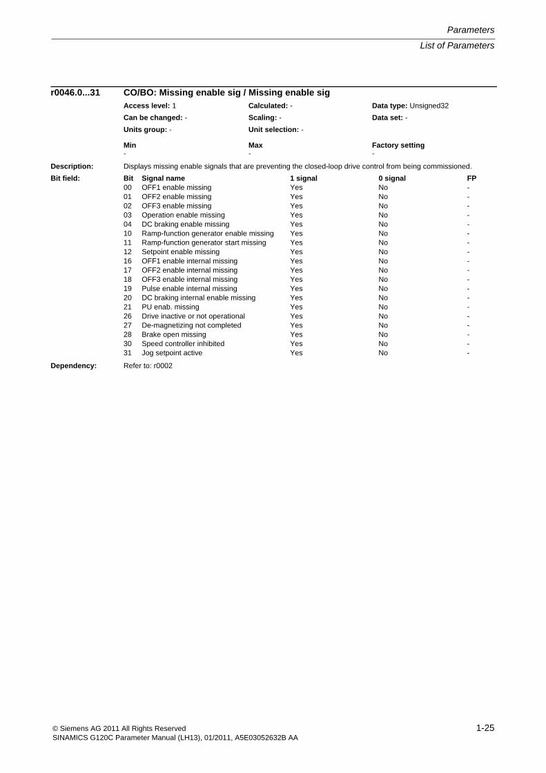
Description: Displays missing enable signals that are preventing the closed-loop drive control from being commissioned.
Dependency: Refer to: r0002
r0046.0...31 CO/BO: Missing enable sig / Missing enable sigAccess level: 1 Calculated: - Data type: Unsigned32
Can be changed: - Scaling: - Data set: -
Units group: - Unit selection: -
Min Max Factory setting - - -
Bit field: Bit Signal name 1 signal 0 signal FP00 OFF1 enable missing Yes No -01 OFF2 enable missing Yes No -02 OFF3 enable missing Yes No -03 Operation enable missing Yes No -04 DC braking enable missing Yes No -10 Ramp-function generator enable missing Yes No -11 Ramp-function generator start missing Yes No -12 Setpoint enable missing Yes No -16 OFF1 enable internal missing Yes No -17 OFF2 enable internal missing Yes No -18 OFF3 enable internal missing Yes No -19 Pulse enable internal missing Yes No -20 DC braking internal enable missing Yes No -21 PU enab. missing Yes No -26 Drive inactive or not operational Yes No -27 De-magnetizing not completed Yes No -28 Brake open missing Yes No -30 Speed controller inhibited Yes No -31 Jog setpoint active Yes No -
Parameters
List of Parameters
1-26 © Siemens AG 2011 All Rights ReservedSINAMICS G120C Parameter Manual (LH13), 01/2011, A5E03052632B AA
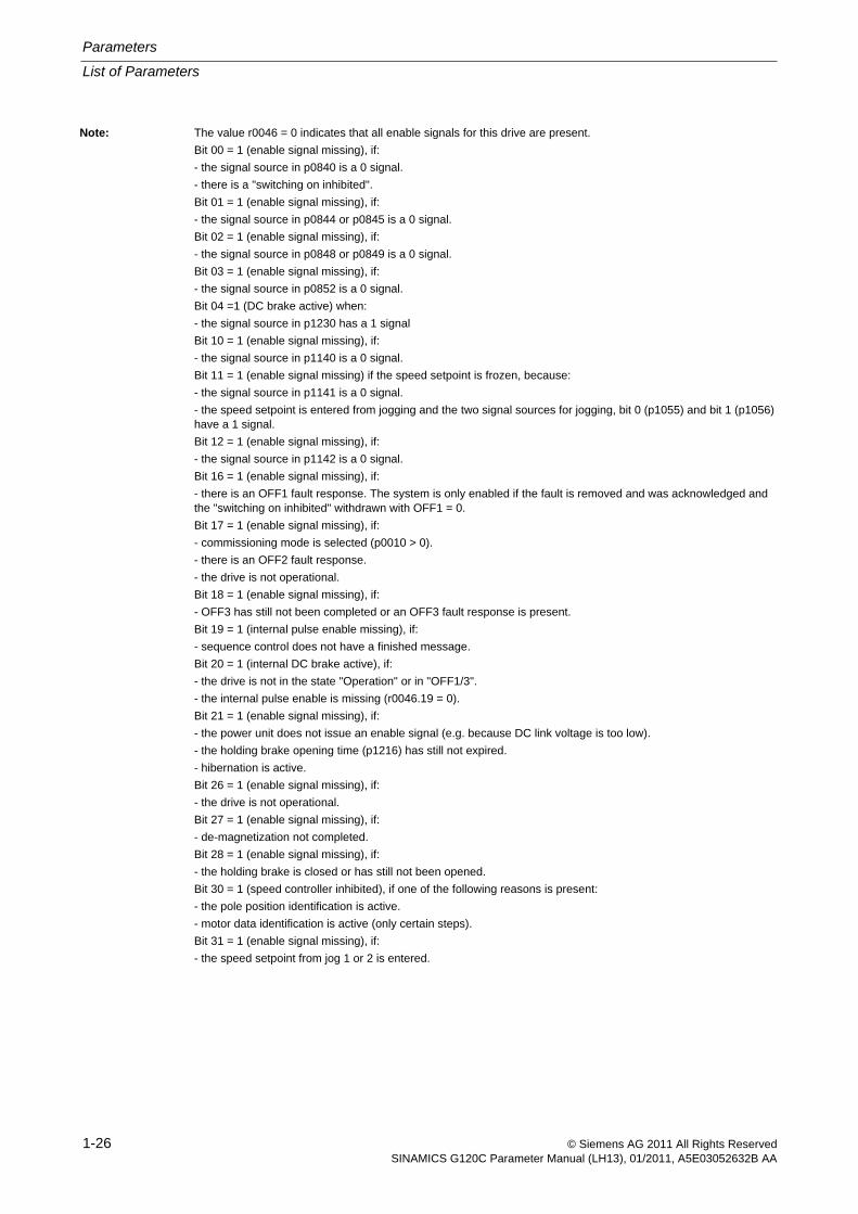
Note: The value r0046 = 0 indicates that all enable signals for this drive are present.
Bit 00 = 1 (enable signal missing), if:
- the signal source in p0840 is a 0 signal.
- there is a "switching on inhibited".
Bit 01 = 1 (enable signal missing), if:
- the signal source in p0844 or p0845 is a 0 signal.
Bit 02 = 1 (enable signal missing), if:
- the signal source in p0848 or p0849 is a 0 signal.
Bit 03 = 1 (enable signal missing), if:
- the signal source in p0852 is a 0 signal.
Bit 04 =1 (DC brake active) when:
- the signal source in p1230 has a 1 signal
Bit 10 = 1 (enable signal missing), if:
- the signal source in p1140 is a 0 signal.
Bit 11 = 1 (enable signal missing) if the speed setpoint is frozen, because:
- the signal source in p1141 is a 0 signal.
- the speed setpoint is entered from jogging and the two signal sources for jogging, bit 0 (p1055) and bit 1 (p1056) have a 1 signal.
Bit 12 = 1 (enable signal missing), if:
- the signal source in p1142 is a 0 signal.
Bit 16 = 1 (enable signal missing), if:
- there is an OFF1 fault response. The system is only enabled if the fault is removed and was acknowledged and the "switching on inhibited" withdrawn with OFF1 = 0.
Bit 17 = 1 (enable signal missing), if:
- commissioning mode is selected (p0010 > 0).
- there is an OFF2 fault response.
- the drive is not operational.
Bit 18 = 1 (enable signal missing), if:
- OFF3 has still not been completed or an OFF3 fault response is present.
Bit 19 = 1 (internal pulse enable missing), if:
- sequence control does not have a finished message.
Bit 20 = 1 (internal DC brake active), if:
- the drive is not in the state "Operation" or in "OFF1/3".
- the internal pulse enable is missing (r0046.19 = 0).
Bit 21 = 1 (enable signal missing), if:
- the power unit does not issue an enable signal (e.g. because DC link voltage is too low).
- the holding brake opening time (p1216) has still not expired.
- hibernation is active.
Bit 26 = 1 (enable signal missing), if:
- the drive is not operational.
Bit 27 = 1 (enable signal missing), if:
- de-magnetization not completed.
Bit 28 = 1 (enable signal missing), if:
- the holding brake is closed or has still not been opened.
Bit 30 = 1 (speed controller inhibited), if one of the following reasons is present:
- the pole position identification is active.
- motor data identification is active (only certain steps).
Bit 31 = 1 (enable signal missing), if:
- the speed setpoint from jog 1 or 2 is entered.
List of Parameters
Parameters
1-27© Siemens AG 2011 All Rights ReservedSINAMICS G120C Parameter Manual (LH13), 01/2011, A5E03052632B AA
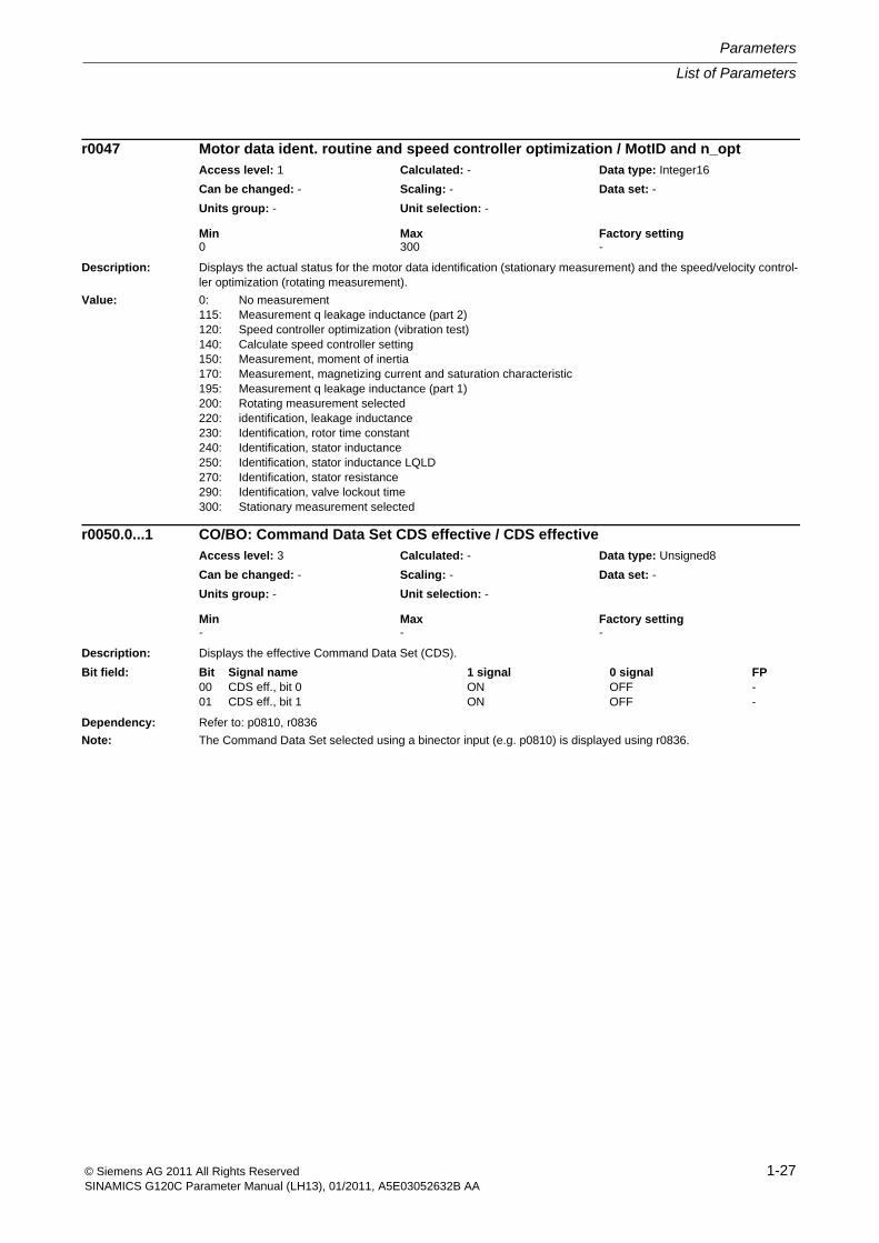
Description: Displays the actual status for the motor data identification (stationary measurement) and the speed/velocity control-ler optimization (rotating measurement).
Value: 0: No measurement115: Measurement q leakage inductance (part 2)120: Speed controller optimization (vibration test)140: Calculate speed controller setting150: Measurement, moment of inertia170: Measurement, magnetizing current and saturation characteristic195: Measurement q leakage inductance (part 1)200: Rotating measurement selected220: identification, leakage inductance230: Identification, rotor time constant240: Identification, stator inductance250: Identification, stator inductance LQLD270: Identification, stator resistance290: Identification, valve lockout time300: Stationary measurement selected
Description: Displays the effective Command Data Set (CDS).
Dependency: Refer to: p0810, r0836
Note: The Command Data Set selected using a binector input (e.g. p0810) is displayed using r0836.
r0047 Motor data ident. routine and speed controller optimization / MotID and n_optAccess level: 1 Calculated: - Data type: Integer16
Can be changed: - Scaling: - Data set: -
Units group: - Unit selection: -
Min Max Factory setting 0 300 -
r0050.0...1 CO/BO: Command Data Set CDS effective / CDS effectiveAccess level: 3 Calculated: - Data type: Unsigned8
Can be changed: - Scaling: - Data set: -
Units group: - Unit selection: -
Min Max Factory setting - - -
Bit field: Bit Signal name 1 signal 0 signal FP00 CDS eff., bit 0 ON OFF -01 CDS eff., bit 1 ON OFF -
Parameters
List of Parameters
1-28 © Siemens AG 2011 All Rights ReservedSINAMICS G120C Parameter Manual (LH13), 01/2011, A5E03052632B AA
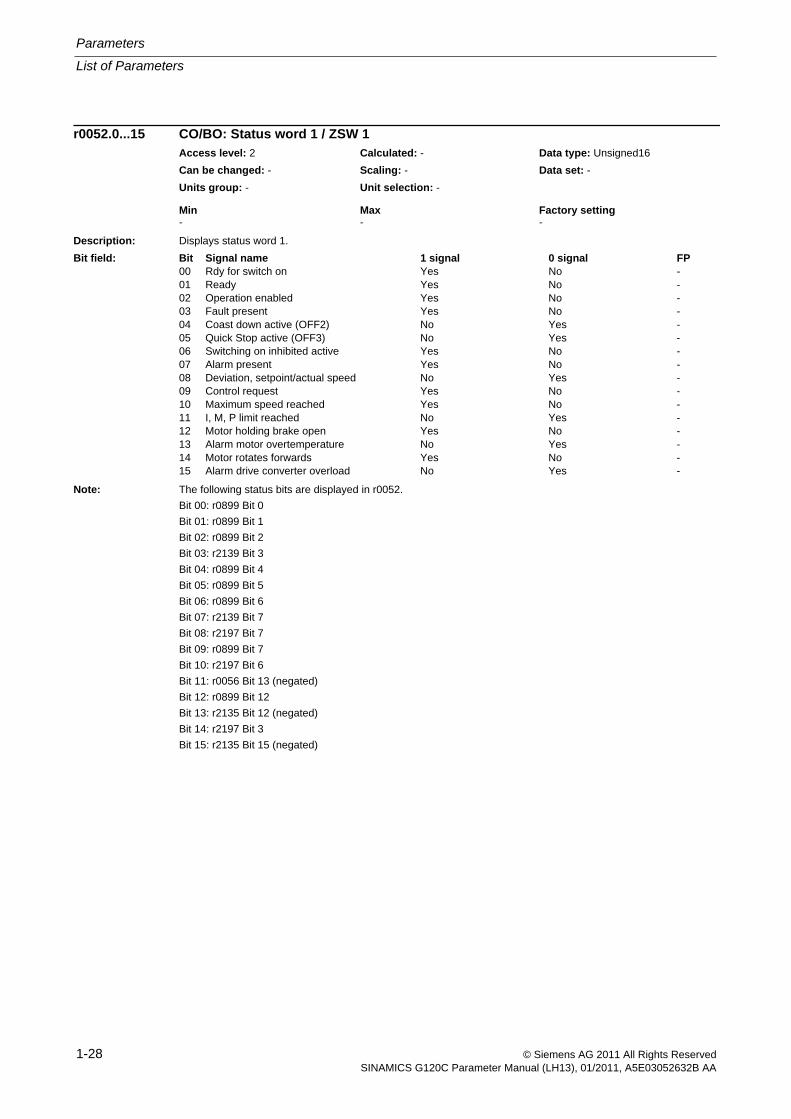
Description: Displays status word 1.
Note: The following status bits are displayed in r0052.
Bit 00: r0899 Bit 0
Bit 01: r0899 Bit 1
Bit 02: r0899 Bit 2
Bit 03: r2139 Bit 3
Bit 04: r0899 Bit 4
Bit 05: r0899 Bit 5
Bit 06: r0899 Bit 6
Bit 07: r2139 Bit 7
Bit 08: r2197 Bit 7
Bit 09: r0899 Bit 7
Bit 10: r2197 Bit 6
Bit 11: r0056 Bit 13 (negated)
Bit 12: r0899 Bit 12
Bit 13: r2135 Bit 12 (negated)
Bit 14: r2197 Bit 3
Bit 15: r2135 Bit 15 (negated)
r0052.0...15 CO/BO: Status word 1 / ZSW 1Access level: 2 Calculated: - Data type: Unsigned16
Can be changed: - Scaling: - Data set: -
Units group: - Unit selection: -
Min Max Factory setting - - -
Bit field: Bit Signal name 1 signal 0 signal FP00 Rdy for switch on Yes No -01 Ready Yes No -02 Operation enabled Yes No -03 Fault present Yes No -04 Coast down active (OFF2) No Yes -05 Quick Stop active (OFF3) No Yes -06 Switching on inhibited active Yes No -07 Alarm present Yes No -08 Deviation, setpoint/actual speed No Yes -09 Control request Yes No -10 Maximum speed reached Yes No -11 I, M, P limit reached No Yes -12 Motor holding brake open Yes No -13 Alarm motor overtemperature No Yes -14 Motor rotates forwards Yes No -15 Alarm drive converter overload No Yes -
List of Parameters
Parameters
1-29© Siemens AG 2011 All Rights ReservedSINAMICS G120C Parameter Manual (LH13), 01/2011, A5E03052632B AA
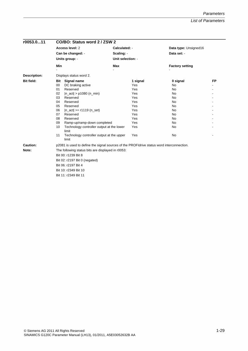
Description: Displays status word 2.
Caution: p2081 is used to define the signal sources of the PROFIdrive status word interconnection.
Note: The following status bits are displayed in r0053:
Bit 00: r1239 Bit 8
Bit 02: r2197 Bit 0 (negated)
Bit 06: r2197 Bit 4
Bit 10: r2349 Bit 10
Bit 11: r2349 Bit 11
r0053.0...11 CO/BO: Status word 2 / ZSW 2Access level: 2 Calculated: - Data type: Unsigned16
Can be changed: - Scaling: - Data set: -
Units group: - Unit selection: -
Min Max Factory setting - - -
Bit field: Bit Signal name 1 signal 0 signal FP00 DC braking active Yes No -01 Reserved Yes No -02 |n_act| > p1080 (n_min) Yes No -03 Reserved Yes No -04 Reserved Yes No -05 Reserved Yes No -06 |n_act| >= r1119 (n_set) Yes No -07 Reserved Yes No -08 Reserved Yes No -09 Ramp-up/ramp-down completed Yes No -10 Technology controller output at the lower
limitYes No -
11 Technology controller output at the upper limit
Yes No -
Parameters
List of Parameters
1-30 © Siemens AG 2011 All Rights ReservedSINAMICS G120C Parameter Manual (LH13), 01/2011, A5E03052632B AA
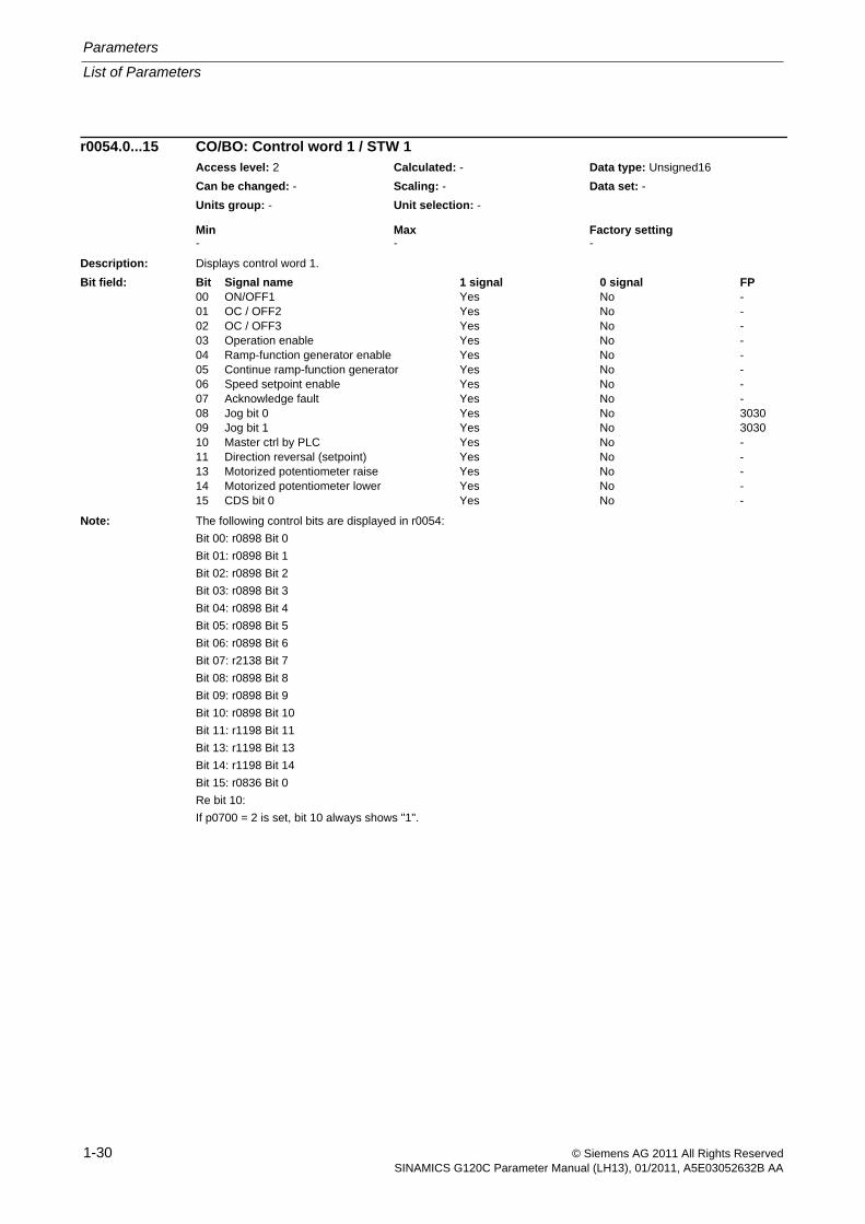
Description: Displays control word 1.
Note: The following control bits are displayed in r0054:
Bit 00: r0898 Bit 0
Bit 01: r0898 Bit 1
Bit 02: r0898 Bit 2
Bit 03: r0898 Bit 3
Bit 04: r0898 Bit 4
Bit 05: r0898 Bit 5
Bit 06: r0898 Bit 6
Bit 07: r2138 Bit 7
Bit 08: r0898 Bit 8
Bit 09: r0898 Bit 9
Bit 10: r0898 Bit 10
Bit 11: r1198 Bit 11
Bit 13: r1198 Bit 13
Bit 14: r1198 Bit 14
Bit 15: r0836 Bit 0
Re bit 10:
If p0700 = 2 is set, bit 10 always shows "1".
r0054.0...15 CO/BO: Control word 1 / STW 1Access level: 2 Calculated: - Data type: Unsigned16
Can be changed: - Scaling: - Data set: -
Units group: - Unit selection: -
Min Max Factory setting - - -
Bit field: Bit Signal name 1 signal 0 signal FP00 ON/OFF1 Yes No -01 OC / OFF2 Yes No -02 OC / OFF3 Yes No -03 Operation enable Yes No -04 Ramp-function generator enable Yes No -05 Continue ramp-function generator Yes No -06 Speed setpoint enable Yes No -07 Acknowledge fault Yes No -08 Jog bit 0 Yes No 303009 Jog bit 1 Yes No 303010 Master ctrl by PLC Yes No -11 Direction reversal (setpoint) Yes No -13 Motorized potentiometer raise Yes No -14 Motorized potentiometer lower Yes No -15 CDS bit 0 Yes No -
List of Parameters
Parameters
1-31© Siemens AG 2011 All Rights ReservedSINAMICS G120C Parameter Manual (LH13), 01/2011, A5E03052632B AA
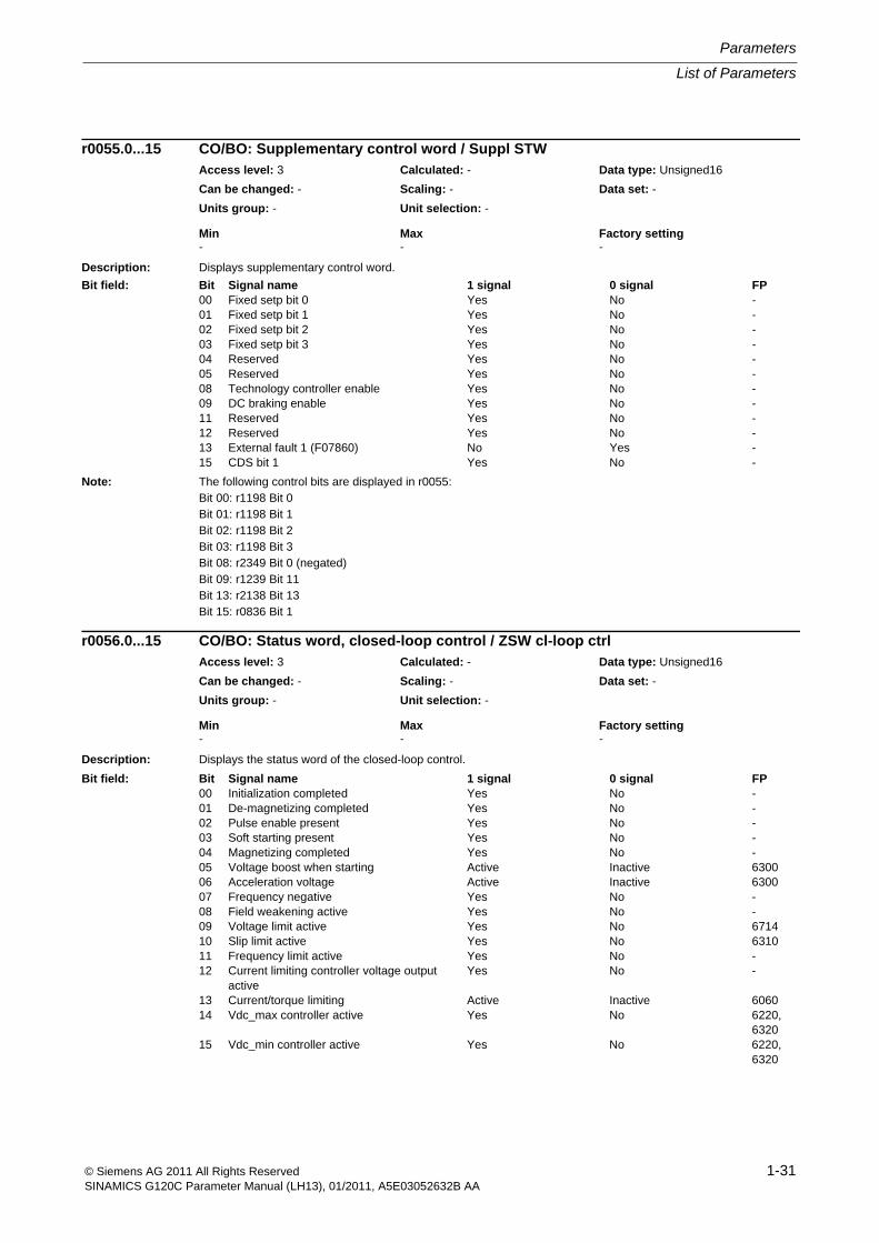
Description: Displays supplementary control word.
Note: The following control bits are displayed in r0055:Bit 00: r1198 Bit 0Bit 01: r1198 Bit 1Bit 02: r1198 Bit 2Bit 03: r1198 Bit 3Bit 08: r2349 Bit 0 (negated)Bit 09: r1239 Bit 11Bit 13: r2138 Bit 13Bit 15: r0836 Bit 1
Description: Displays the status word of the closed-loop control.
r0055.0...15 CO/BO: Supplementary control word / Suppl STWAccess level: 3 Calculated: - Data type: Unsigned16
Can be changed: - Scaling: - Data set: -
Units group: - Unit selection: -
Min Max Factory setting - - -
Bit field: Bit Signal name 1 signal 0 signal FP00 Fixed setp bit 0 Yes No -01 Fixed setp bit 1 Yes No -02 Fixed setp bit 2 Yes No -03 Fixed setp bit 3 Yes No -04 Reserved Yes No -05 Reserved Yes No -08 Technology controller enable Yes No -09 DC braking enable Yes No -11 Reserved Yes No -12 Reserved Yes No -13 External fault 1 (F07860) No Yes -15 CDS bit 1 Yes No -
r0056.0...15 CO/BO: Status word, closed-loop control / ZSW cl-loop ctrlAccess level: 3 Calculated: - Data type: Unsigned16
Can be changed: - Scaling: - Data set: -
Units group: - Unit selection: -
Min Max Factory setting - - -
Bit field: Bit Signal name 1 signal 0 signal FP00 Initialization completed Yes No -01 De-magnetizing completed Yes No -02 Pulse enable present Yes No -03 Soft starting present Yes No -04 Magnetizing completed Yes No -05 Voltage boost when starting Active Inactive 630006 Acceleration voltage Active Inactive 630007 Frequency negative Yes No -08 Field weakening active Yes No -09 Voltage limit active Yes No 671410 Slip limit active Yes No 631011 Frequency limit active Yes No -12 Current limiting controller voltage output
activeYes No -
13 Current/torque limiting Active Inactive 606014 Vdc_max controller active Yes No 6220,
632015 Vdc_min controller active Yes No 6220,
6320
Parameters
List of Parameters
1-32 © Siemens AG 2011 All Rights ReservedSINAMICS G120C Parameter Manual (LH13), 01/2011, A5E03052632B AA
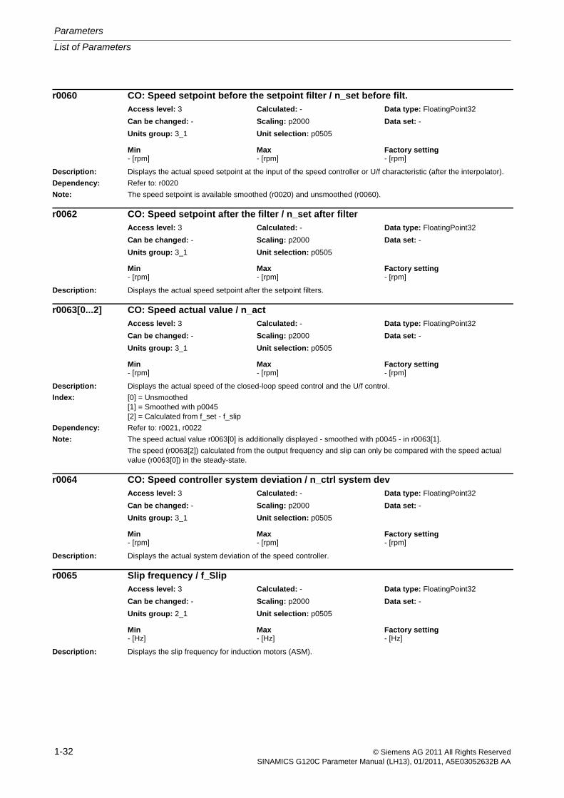
Description: Displays the actual speed setpoint at the input of the speed controller or U/f characteristic (after the interpolator).
Dependency: Refer to: r0020
Note: The speed setpoint is available smoothed (r0020) and unsmoothed (r0060).
Description: Displays the actual speed setpoint after the setpoint filters.
Description: Displays the actual speed of the closed-loop speed control and the U/f control.
Index: [0] = Unsmoothed[1] = Smoothed with p0045[2] = Calculated from f_set - f_slip
Dependency: Refer to: r0021, r0022
Note: The speed actual value r0063[0] is additionally displayed - smoothed with p0045 - in r0063[1].
The speed (r0063[2]) calculated from the output frequency and slip can only be compared with the speed actual value (r0063[0]) in the steady-state.
Description: Displays the actual system deviation of the speed controller.
Description: Displays the slip frequency for induction motors (ASM).
r0060 CO: Speed setpoint before the setpoint filter / n_set before filt.Access level: 3 Calculated: - Data type: FloatingPoint32
Can be changed: - Scaling: p2000 Data set: -
Units group: 3_1 Unit selection: p0505
Min Max Factory setting - [rpm] - [rpm] - [rpm]
r0062 CO: Speed setpoint after the filter / n_set after filterAccess level: 3 Calculated: - Data type: FloatingPoint32
Can be changed: - Scaling: p2000 Data set: -
Units group: 3_1 Unit selection: p0505
Min Max Factory setting - [rpm] - [rpm] - [rpm]
r0063[0...2] CO: Speed actual value / n_actAccess level: 3 Calculated: - Data type: FloatingPoint32
Can be changed: - Scaling: p2000 Data set: -
Units group: 3_1 Unit selection: p0505
Min Max Factory setting - [rpm] - [rpm] - [rpm]
r0064 CO: Speed controller system deviation / n_ctrl system devAccess level: 3 Calculated: - Data type: FloatingPoint32
Can be changed: - Scaling: p2000 Data set: -
Units group: 3_1 Unit selection: p0505
Min Max Factory setting - [rpm] - [rpm] - [rpm]
r0065 Slip frequency / f_SlipAccess level: 3 Calculated: - Data type: FloatingPoint32
Can be changed: - Scaling: p2000 Data set: -
Units group: 2_1 Unit selection: p0505
Min Max Factory setting - [Hz] - [Hz] - [Hz]
List of Parameters
Parameters
1-33© Siemens AG 2011 All Rights ReservedSINAMICS G120C Parameter Manual (LH13), 01/2011, A5E03052632B AA
Description: Displays the output frequency of the power unit.
Dependency: Refer to: r0024
Note: The output frequency is available smoothed (r0024) and unsmoothed (r0066).
Description: Displays the maximum output current of the power unit.
Dependency: The maximum output current is determined by the parameterized current limit and the motor and converter thermal protection.
Refer to: p0290, p0640
Description: Displays actual absolute current.
Index: [0] = Unsmoothed[1] = Smoothed with p0045
Dependency: Refer to: r0027
Notice: The value is updated with the current controller sampling time.
Note: Absolute current value = sqrt(Iq^2 + Id^2)
The absolute value of the current actual value is available smoothed (r0027 with 300 ms, r0068[1] with p0045) and unsmoothed (r0068[0]).
Description: Displays the measured actual phase currents as peak value.
Index: [0] = Phase U[1] = Phase V[2] = Phase W[3] = Phase U offset[4] = Phase V offset[5] = Phase W offset[6] = Total U, V, W
Note: In indices 3 ... 5, the offset currents of the 3 phases, which are added to correct the phase currents, are displayed.
The sum of the 3 corrected phase currents is displayed in index 6.
r0066 CO: Output frequency / f_outpAccess level: 3 Calculated: - Data type: FloatingPoint32
Can be changed: - Scaling: p2000 Data set: -
Units group: 2_1 Unit selection: p0505
Min Max Factory setting - [Hz] - [Hz] - [Hz]
r0067 CO: Output current, maximum / I_outp maxAccess level: 3 Calculated: - Data type: FloatingPoint32
Can be changed: - Scaling: p2002 Data set: -
Units group: 6_2 Unit selection: p0505
Min Max Factory setting - [Arms] - [Arms] - [Arms]
r0068[0...1] CO: Absolute current actual value / I_act abs valAccess level: 3 Calculated: - Data type: FloatingPoint32
Can be changed: - Scaling: p2002 Data set: -
Units group: 6_2 Unit selection: p0505
Min Max Factory setting - [Arms] - [Arms] - [Arms]
r0069[0...6] CO: Phase current actual value / I_phase act valueAccess level: 4 Calculated: - Data type: FloatingPoint32
Can be changed: - Scaling: p2002 Data set: -
Units group: 6_5 Unit selection: p0505
Min Max Factory setting - [A] - [A] - [A]
Parameters
List of Parameters
1-34 © Siemens AG 2011 All Rights ReservedSINAMICS G120C Parameter Manual (LH13), 01/2011, A5E03052632B AA
Description: Displays the measured actual value of the DC link voltage.
Dependency: Refer to: r0026
Notice: When measuring a DC link voltage < 200 V, for the Power Module a valid measured value is not supplied. In this case, when an external 24 V power supply is connected, a value of approx. 24 V is displayed in the display param-eter.
Note: The DC link voltage is available smoothed (r0026) and unsmoothed (r0070).
Description: Displays the maximum output voltage.
Dependency: The maximum output voltage depends on the actual DC link voltage (r0070) and the maximum modulation depth (p1803).
Note: As the (driven) motor load increases, the maximum output voltage drops as a result of the reduction in DC link volt-age.
Description: Displays the actual output voltage of the power unit.
Dependency: Refer to: r0025
Note: The output voltage is available smoothed (r0025) and unsmoothed (r0072).
Description: Displays the maximum modulation depth.
Dependency: Refer to: p1803
r0070 CO: Actual DC link voltage / Vdc act valAccess level: 3 Calculated: - Data type: FloatingPoint32
Can be changed: - Scaling: p2001 Data set: -
Units group: 5_2 Unit selection: p0505
Min Max Factory setting - [V] - [V] - [V]
r0071 Maximum output voltage / U_output maxAccess level: 3 Calculated: - Data type: FloatingPoint32
Can be changed: - Scaling: p2001 Data set: -
Units group: 5_1 Unit selection: p0505
Min Max Factory setting - [Vrms] - [Vrms] - [Vrms]
r0072 CO: Output voltage / U_outputAccess level: 3 Calculated: - Data type: FloatingPoint32
Can be changed: - Scaling: p2001 Data set: -
Units group: 5_1 Unit selection: p0505
Min Max Factory setting - [Vrms] - [Vrms] - [Vrms]
r0073 Maximum modulation depth / Modulat_depth maxAccess level: 4 Calculated: - Data type: FloatingPoint32
Can be changed: - Scaling: PERCENT Data set: -
Units group: - Unit selection: -
Min Max Factory setting - [%] - [%] - [%]
List of Parameters
Parameters
1-35© Siemens AG 2011 All Rights ReservedSINAMICS G120C Parameter Manual (LH13), 01/2011, A5E03052632B AA
Description: Displays the actual modulation depth.Dependency: Refer to: r0028Note: For space vector modulation, 100% corresponds to the maximum output voltage without overcontrol.
Values above 100 % indicate an overcontrol condition - values below 100% have no overcontrol.The phase voltage (phase-to-phase, rms) is calculated as follows:(r0074 x r0070) / (sqrt(2) x 100 %).The modulation depth is available smoothed (r0028) and unsmoothed (r0074).
Description: Displays the field-generating current setpoint (Id_set).Note: This value is irrelevant for the U/f control mode.
Description: Displays the field-generating current actual value (Id_act).Dependency: Refer to: r0029Note: This value is irrelevant for the U/f control mode.
The field-generating current actual value is available smoothed (r0029) and unsmoothed (r0076).
Description: Displays the torque/force generating current setpoint.Note: This value is irrelevant for the U/f control mode.
Description: Displays the torque-generating current actual value (Iq_act).Dependency: Refer to: r0030Note: This value is irrelevant for the U/f control mode.
The torque-generating current actual value is available smoothed (r0030 with 300 ms) and unsmoothed (r0078).
r0074 CO: Modulat_depth / Modulat_depthAccess level: 4 Calculated: - Data type: FloatingPoint32
Can be changed: - Scaling: PERCENT Data set: -
Units group: - Unit selection: -
Min Max Factory setting - [%] - [%] - [%]
r0075 CO: Current setpoint field-generating / Id_setAccess level: 3 Calculated: - Data type: FloatingPoint32
Can be changed: - Scaling: p2002 Data set: -
Units group: 6_2 Unit selection: p0505
Min Max Factory setting - [Arms] - [Arms] - [Arms]
r0076 CO: Current actual value field-generating / Id_actAccess level: 3 Calculated: - Data type: FloatingPoint32
Can be changed: - Scaling: p2002 Data set: -
Units group: 6_2 Unit selection: p0505
Min Max Factory setting - [Arms] - [Arms] - [Arms]
r0077 CO: Current setpoint torque-generating / Iq_setAccess level: 3 Calculated: - Data type: FloatingPoint32
Can be changed: - Scaling: p2002 Data set: -
Units group: 6_2 Unit selection: p0505
Min Max Factory setting - [Arms] - [Arms] - [Arms]
r0078 CO: Current actual value torque-generating / Iq_actAccess level: 3 Calculated: - Data type: FloatingPoint32
Can be changed: - Scaling: p2002 Data set: -
Units group: 6_2 Unit selection: p0505
Min Max Factory setting - [Arms] - [Arms] - [Arms]
Parameters
List of Parameters
1-36 © Siemens AG 2011 All Rights ReservedSINAMICS G120C Parameter Manual (LH13), 01/2011, A5E03052632B AA
Description: Displays the torque setpoint at the output of the speed controller.
Description: Displays the actual torque value.
Index: [0] = Unsmoothed[1] = Smoothed with p0045
Dependency: Refer to: r0031
Note: The torque actual value is available smoothed (r0031 with 100 ms, r0080[1] with p0045) and unsmoothed (r0080[0]).
Description: Displays the torque utilization as a percentage.
The torque utilization is obtained from the required smoothed torque referred to the torque limit.
Dependency: This parameter is only available for vector control. For U/f control r0081 = 0 %.
Refer to: r0033
Note: The torque utilization is available smoothed (r0033) and unsmoothed (r0081).
The torque utilization is obtained from the required torque referred to the torque limit as follows:
- Positive torque: r0081 = (r0079 / r1538) * 100 %
- Negative torque: r0081 = (-r0079 / -r1539) * 100 %
Description: Displays the instantaneous active power.
Index: [0] = Unsmoothed[1] = Smoothed with p0045[2] = Electric power
Dependency: Refer to: r0032
Note: The mechanical active power is available smoothed (r0032 with 100 ms, r0082[1] with p0045) and unsmoothed (r0082[0]).
r0079 CO: Torque setpoint / M_set totalAccess level: 3 Calculated: - Data type: FloatingPoint32
Can be changed: - Scaling: p2003 Data set: -
Units group: 7_1 Unit selection: p0505
Min Max Factory setting - [Nm] - [Nm] - [Nm]
r0080[0...1] CO: Torque actual value / M_actAccess level: 4 Calculated: - Data type: FloatingPoint32
Can be changed: - Scaling: p2003 Data set: -
Units group: 7_1 Unit selection: p0505
Min Max Factory setting - [Nm] - [Nm] - [Nm]
r0081 CO: Torque utilization / M_UtilizationAccess level: 4 Calculated: - Data type: FloatingPoint32
Can be changed: - Scaling: PERCENT Data set: -
Units group: - Unit selection: -
Min Max Factory setting - [%] - [%] - [%]
r0082[0...2] CO: Active power actual value / P_actAccess level: 4 Calculated: - Data type: FloatingPoint32
Can be changed: - Scaling: r2004 Data set: -
Units group: 14_5 Unit selection: p0505
Min Max Factory setting - [kW] - [kW] - [kW]
List of Parameters
Parameters
1-37© Siemens AG 2011 All Rights ReservedSINAMICS G120C Parameter Manual (LH13), 01/2011, A5E03052632B AA
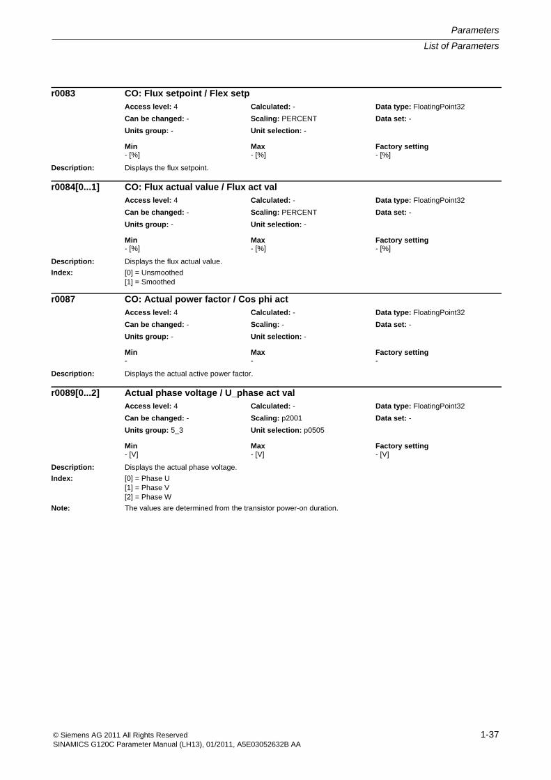
Description: Displays the flux setpoint.
Description: Displays the flux actual value.
Index: [0] = Unsmoothed[1] = Smoothed
Description: Displays the actual active power factor.
Description: Displays the actual phase voltage.
Index: [0] = Phase U[1] = Phase V[2] = Phase W
Note: The values are determined from the transistor power-on duration.
r0083 CO: Flux setpoint / Flex setpAccess level: 4 Calculated: - Data type: FloatingPoint32
Can be changed: - Scaling: PERCENT Data set: -
Units group: - Unit selection: -
Min Max Factory setting - [%] - [%] - [%]
r0084[0...1] CO: Flux actual value / Flux act valAccess level: 4 Calculated: - Data type: FloatingPoint32
Can be changed: - Scaling: PERCENT Data set: -
Units group: - Unit selection: -
Min Max Factory setting - [%] - [%] - [%]
r0087 CO: Actual power factor / Cos phi actAccess level: 4 Calculated: - Data type: FloatingPoint32
Can be changed: - Scaling: - Data set: -
Units group: - Unit selection: -
Min Max Factory setting - - -
r0089[0...2] Actual phase voltage / U_phase act valAccess level: 4 Calculated: - Data type: FloatingPoint32
Can be changed: - Scaling: p2001 Data set: -
Units group: 5_3 Unit selection: p0505
Min Max Factory setting - [V] - [V] - [V]
Parameters
List of Parameters
1-38 © Siemens AG 2011 All Rights ReservedSINAMICS G120C Parameter Manual (LH13), 01/2011, A5E03052632B AA
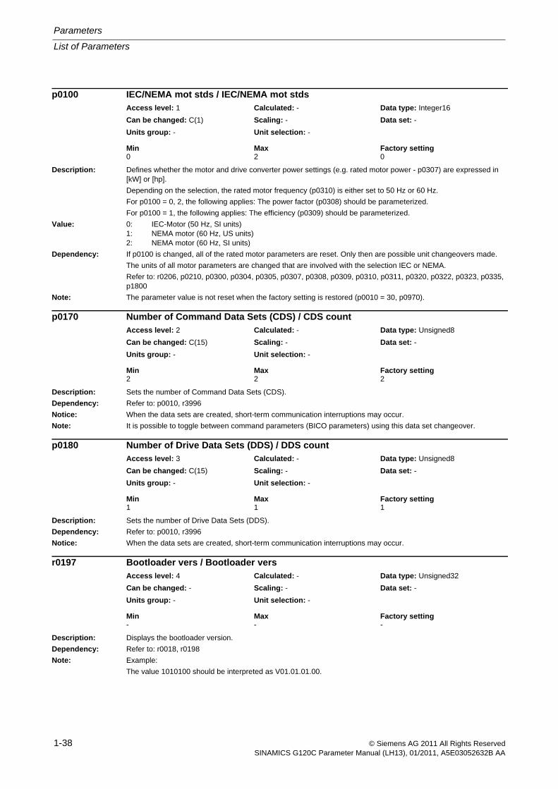
Description: Defines whether the motor and drive converter power settings (e.g. rated motor power - p0307) are expressed in [kW] or [hp].
Depending on the selection, the rated motor frequency (p0310) is either set to 50 Hz or 60 Hz.
For p0100 = 0, 2, the following applies: The power factor (p0308) should be parameterized.
For p0100 = 1, the following applies: The efficiency (p0309) should be parameterized.
Value: 0: IEC-Motor (50 Hz, SI units)1: NEMA motor (60 Hz, US units)2: NEMA motor (60 Hz, SI units)
Dependency: If p0100 is changed, all of the rated motor parameters are reset. Only then are possible unit changeovers made.
The units of all motor parameters are changed that are involved with the selection IEC or NEMA.
Refer to: r0206, p0210, p0300, p0304, p0305, p0307, p0308, p0309, p0310, p0311, p0320, p0322, p0323, p0335, p1800
Note: The parameter value is not reset when the factory setting is restored (p0010 = 30, p0970).
Description: Sets the number of Command Data Sets (CDS).
Dependency: Refer to: p0010, r3996
Notice: When the data sets are created, short-term communication interruptions may occur.
Note: It is possible to toggle between command parameters (BICO parameters) using this data set changeover.
Description: Sets the number of Drive Data Sets (DDS).
Dependency: Refer to: p0010, r3996
Notice: When the data sets are created, short-term communication interruptions may occur.
Description: Displays the bootloader version.
Dependency: Refer to: r0018, r0198
Note: Example:
The value 1010100 should be interpreted as V01.01.01.00.
p0100 IEC/NEMA mot stds / IEC/NEMA mot stdsAccess level: 1 Calculated: - Data type: Integer16
Can be changed: C(1) Scaling: - Data set: -
Units group: - Unit selection: -
Min Max Factory setting 0 2 0
p0170 Number of Command Data Sets (CDS) / CDS countAccess level: 2 Calculated: - Data type: Unsigned8
Can be changed: C(15) Scaling: - Data set: -
Units group: - Unit selection: -
Min Max Factory setting 2 2 2
p0180 Number of Drive Data Sets (DDS) / DDS countAccess level: 3 Calculated: - Data type: Unsigned8
Can be changed: C(15) Scaling: - Data set: -
Units group: - Unit selection: -
Min Max Factory setting 1 1 1
r0197 Bootloader vers / Bootloader versAccess level: 4 Calculated: - Data type: Unsigned32
Can be changed: - Scaling: - Data set: -
Units group: - Unit selection: -
Min Max Factory setting - - -
List of Parameters
Parameters
1-39© Siemens AG 2011 All Rights ReservedSINAMICS G120C Parameter Manual (LH13), 01/2011, A5E03052632B AA
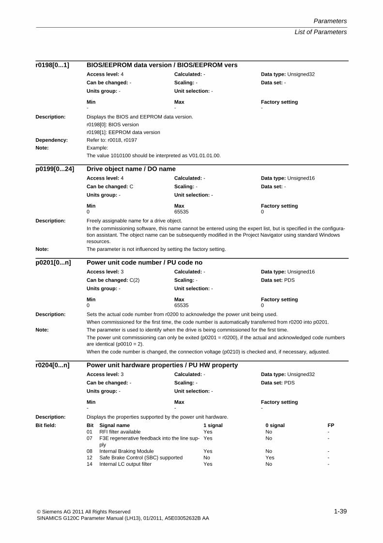
Description: Displays the BIOS and EEPROM data version.
r0198[0]: BIOS version
r0198[1]: EEPROM data version
Dependency: Refer to: r0018, r0197
Note: Example:
The value 1010100 should be interpreted as V01.01.01.00.
Description: Freely assignable name for a drive object.
In the commissioning software, this name cannot be entered using the expert list, but is specified in the configura-tion assistant. The object name can be subsequently modified in the Project Navigator using standard Windows resources.
Note: The parameter is not influenced by setting the factory setting.
Description: Sets the actual code number from r0200 to acknowledge the power unit being used.
When commissioned for the first time, the code number is automatically transferred from r0200 into p0201.
Note: The parameter is used to identify when the drive is being commissioned for the first time.
The power unit commissioning can only be exited (p0201 = r0200), if the actual and acknowledged code numbers are identical (p0010 = 2).
When the code number is changed, the connection voltage (p0210) is checked and, if necessary, adjusted.
Description: Displays the properties supported by the power unit hardware.
r0198[0...1] BIOS/EEPROM data version / BIOS/EEPROM versAccess level: 4 Calculated: - Data type: Unsigned32
Can be changed: - Scaling: - Data set: -
Units group: - Unit selection: -
Min Max Factory setting - - -
p0199[0...24] Drive object name / DO nameAccess level: 4 Calculated: - Data type: Unsigned16
Can be changed: C Scaling: - Data set: -
Units group: - Unit selection: -
Min Max Factory setting 0 65535 0
p0201[0...n] Power unit code number / PU code noAccess level: 3 Calculated: - Data type: Unsigned16
Can be changed: C(2) Scaling: - Data set: PDS
Units group: - Unit selection: -
Min Max Factory setting 0 65535 0
r0204[0...n] Power unit hardware properties / PU HW propertyAccess level: 3 Calculated: - Data type: Unsigned32
Can be changed: - Scaling: - Data set: PDS
Units group: - Unit selection: -
Min Max Factory setting - - -
Bit field: Bit Signal name 1 signal 0 signal FP01 RFI filter available Yes No -07 F3E regenerative feedback into the line sup-
plyYes No -
08 Internal Braking Module Yes No -12 Safe Brake Control (SBC) supported No Yes -14 Internal LC output filter Yes No -
Parameters
List of Parameters
1-40 © Siemens AG 2011 All Rights ReservedSINAMICS G120C Parameter Manual (LH13), 01/2011, A5E03052632B AA
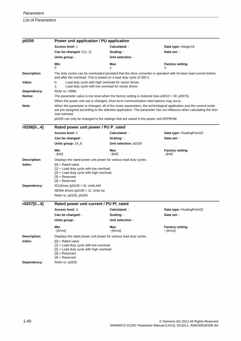
Description: The duty cycles can be overloaded provided that the drive converter is operated with its base load current before and after the overload. This is based on a load duty cycle of 300 s.
Value: 0: Load duty cycle with high overload for vector drives1: Load duty cycle with low overload for vector drives
Dependency: Refer to: r3996
Notice: The parameter value is not reset when the factory setting is restored (see p0010 = 30, p0970).
When the power unit use is changed, short-term communication interruptions may occur.
Note: When the parameter is changed, all of the motor parameters, the technological application and the control mode are pre-assigned according to the selected application. The parameter has not influence when calculating the ther-mal overload.
p0205 can only be changed to the settings that are saved in the power unit EEPROM.
Description: Displays the rated power unit power for various load duty cycles.
Index: [0] = Rated value[1] = Load duty cycle with low overload[2] = Load duty cycle with high overload[3] = Reserved[4] = Reserved
Dependency: IECdrives (p0100 = 0): Units kW
NEMA drives (p0100 = 1): Units hp
Refer to: p0100, p0205
Description: Displays the rated power unit power for various load duty cycles.
Index: [0] = Rated value[1] = Load duty cycle with low overload[2] = Load duty cycle with high overload[3] = Reserved[4] = Reserved
Dependency: Refer to: p0205
p0205 Power unit application / PU applicationAccess level: 1 Calculated: - Data type: Integer16
Can be changed: C(1, 2) Scaling: - Data set: -
Units group: - Unit selection: -
Min Max Factory setting 0 1 0
r0206[0...4] Rated power unit power / PU P_ratedAccess level: 2 Calculated: - Data type: FloatingPoint32
Can be changed: - Scaling: - Data set: -
Units group: 14_6 Unit selection: p0100
Min Max Factory setting - [kW] - [kW] - [kW]
r0207[0...4] Rated power unit current / PU PI_ratedAccess level: 3 Calculated: - Data type: FloatingPoint32
Can be changed: - Scaling: - Data set: -
Units group: - Unit selection: -
Min Max Factory setting - [Arms] - [Arms] - [Arms]
List of Parameters
Parameters
1-41© Siemens AG 2011 All Rights ReservedSINAMICS G120C Parameter Manual (LH13), 01/2011, A5E03052632B AA
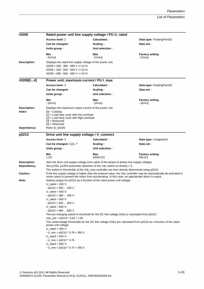
Description: Displays the rated line supply voltage of the power unit.r0208 = 400 : 380 - 480 V +/-10 %r0208 = 500 : 500 - 600 V +/-10 %r0208 = 690 : 660 - 690 V +/-10 %
Description: Displays the maximum output current of the power unit.Index: [0] = Catalog
[1] = Load duty cycle with low overload[2] = Load duty cycle with high overload[3] = Reserved[4] = Reserved
Dependency: Refer to: p0205
Description: Sets the drive unit supply voltage (rms value of the phase-to-phase line supply voltage).Dependency: Set p1254, p1294 (automatic detection of the Vdc switch-on levels) = 0.
The switch-in thresholds of the Vdc_max controller are then directly determined using p0210.Caution: If the line supply voltage is higher than the entered value, the Vdc controller may be automatically de-activated in
some cases to prevent the motor from accelerating. In this case, an appropriate alarm is output.Note: Setting ranges for p0210 as a function of the rated power unit voltage:
U_rated = 230 V:- p0210 = 200 ... 240 VU_rated = 400 V:- p0210 = 380 ... 480 VU_rated = 500 V:- p0210 = 500 ... 600 VU_rated = 690 V:- p0210 = 660 ... 690 VThe pre-charging switch-in threshold for the DC link voltage (Vdc) is calculated from p0210:Vdc_pre = p0210 * 0.82 * 1.35The undervoltage thresholds for the DC link voltage (Vdc) are calculated from p0210 as a function of the rated power unit voltage:U_rated = 400 V:- U_min = p0210 * 0.78 > 360 VU_rated = 500 V:- U_min = p0210 * 0.76U_rated = 690 V:- U_min = p0210 * 0.74 > 450 V
r0208 Rated power unit line supply voltage / PU U_ratedAccess level: 2 Calculated: - Data type: FloatingPoint32
Can be changed: - Scaling: - Data set: -
Units group: - Unit selection: -
Min Max Factory setting - [Vrms] - [Vrms] - [Vrms]
r0209[0...4] Power unit, maximum current / PU I_maxAccess level: 3 Calculated: - Data type: FloatingPoint32
Can be changed: - Scaling: - Data set: -
Units group: - Unit selection: -
Min Max Factory setting - [Arms] - [Arms] - [Arms]
p0210 Drive unit line supply voltage / V_connectAccess level: 3 Calculated: - Data type: Unsigned16
Can be changed: C(2), T Scaling: - Data set: -
Units group: - Unit selection: -
Min Max Factory setting 1 [V] 63000 [V] 400 [V]
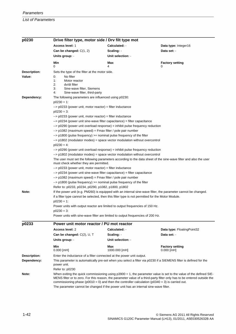
Parameters
List of Parameters
1-42 © Siemens AG 2011 All Rights ReservedSINAMICS G120C Parameter Manual (LH13), 01/2011, A5E03052632B AA
Description: Sets the type of the filter at the motor side.
Value: 0: No filter1: Motor reactor2: dv/dt filter3: Sine-wave filter, Siemens4: Sine-wave filter, third-party
Dependency: The following parameters are influenced using p0230:
p0230 = 1:
--> p0233 (power unit, motor reactor) = filter inductance
p0230 = 3:
--> p0233 (power unit, motor reactor) = filter inductance
--> p0234 (power unit sine-wave filter capacitance) = filter capacitance
--> p0290 (power unit overload response) = inhibit pulse frequency reduction
--> p1082 (maximum speed) = Fmax filter / pole pair number
--> p1800 (pulse frequency) >= nominal pulse frequency of the filter
--> p1802 (modulator modes) = space vector modulation without overcontrol
p0230 = 4:
--> p0290 (power unit overload response) = inhibit pulse frequency reduction
--> p1802 (modulator modes) = space vector modulation without overcontrol
The user must set the following parameters according to the data sheet of the sine-wave filter and also the user must check whether they are permitted.
--> p0233 (power unit, motor reactor) = filter inductance
--> p0234 (power unit sine-wave filter capacitance) = filter capacitance
--> p1082 (maximum speed) = Fmax filter / pole pair number
--> p1800 (pulse frequency) >= nominal pulse frequency of the filter
Refer to: p0233, p0234, p0290, p1082, p1800, p1802
Note: If the power unit (e.g. PM260) is equipped with an internal sine-wave filter, the parameter cannot be changed.
if a filter type cannot be selected, then this filter type is not permitted for the Motor Module.
p0230 = 1:
Power units with output reactor are limited to output frequencies of 150 Hz.
p0230 = 3:
Power units with sine-wave filter are limited to output frequencies of 200 Hz.
Description: Enter the inductance of a filter connected at the power unit output.
Dependency: This parameter is automatically pre-set when you select a filter via p0230 if a SIEMENS filter is defined for the power unit.
Refer to: p0230
Note: When exiting the quick commissioning using p3900 = 1, the parameter value is set to the value of the defined SIE-MENS filter or to zero. For this reason, the parameter value of a third-party filter only has to be entered outside the commissioning phase (p0010 = 0) and then the controller calculation (p0340 = 3) is carried out.
The parameter cannot be changed if the power unit has an internal sine-wave filter.
p0230 Drive filter type, motor side / Drv filt type motAccess level: 1 Calculated: - Data type: Integer16
Can be changed: C(1, 2) Scaling: - Data set: -
Units group: - Unit selection: -
Min Max Factory setting 0 4 0
p0233 Power unit motor reactor / PU mot reactorAccess level: 2 Calculated: - Data type: FloatingPoint32
Can be changed: C(2), U, T Scaling: - Data set: -
Units group: - Unit selection: -
Min Max Factory setting 0.000 [mH] 1000.000 [mH] 0.000 [mH]
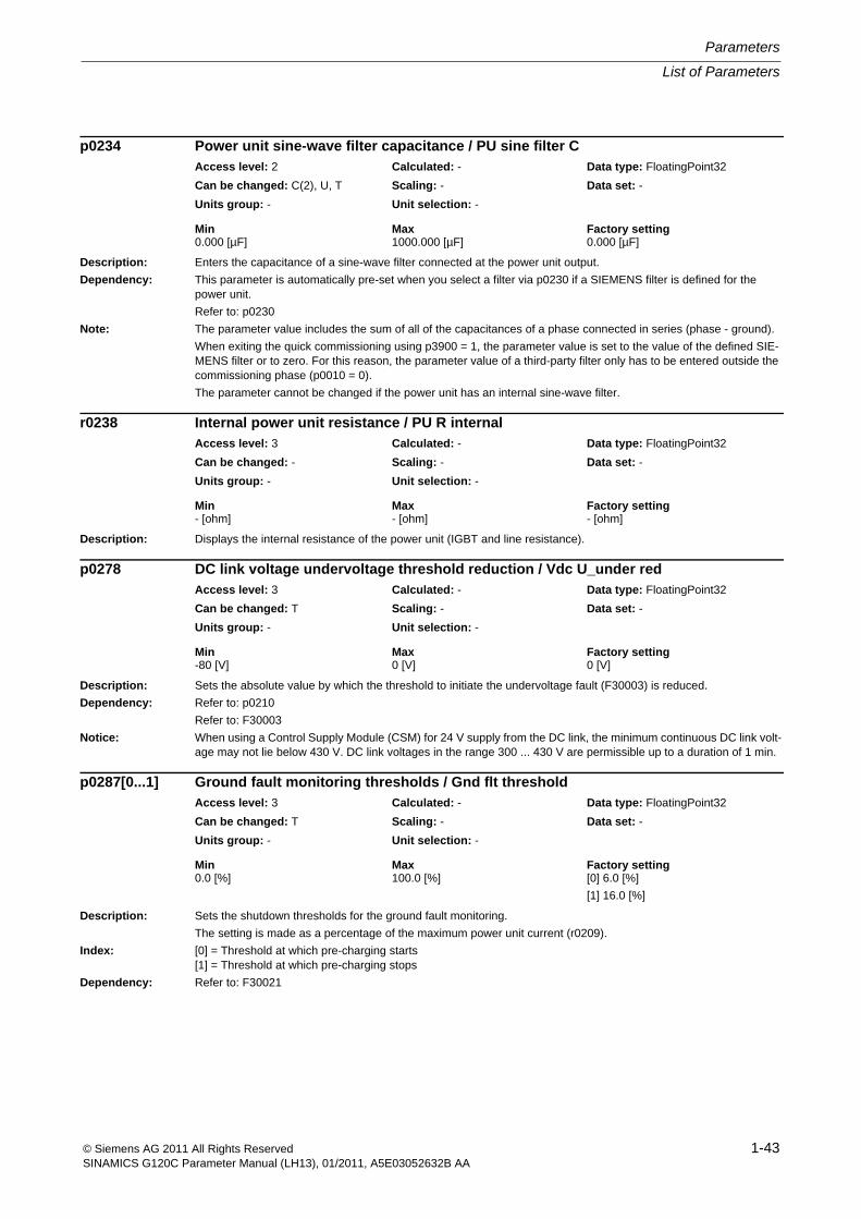
List of Parameters
Parameters
1-43© Siemens AG 2011 All Rights ReservedSINAMICS G120C Parameter Manual (LH13), 01/2011, A5E03052632B AA
Description: Enters the capacitance of a sine-wave filter connected at the power unit output.
Dependency: This parameter is automatically pre-set when you select a filter via p0230 if a SIEMENS filter is defined for the power unit.
Refer to: p0230
Note: The parameter value includes the sum of all of the capacitances of a phase connected in series (phase - ground).
When exiting the quick commissioning using p3900 = 1, the parameter value is set to the value of the defined SIE-MENS filter or to zero. For this reason, the parameter value of a third-party filter only has to be entered outside the commissioning phase (p0010 = 0).
The parameter cannot be changed if the power unit has an internal sine-wave filter.
Description: Displays the internal resistance of the power unit (IGBT and line resistance).
Description: Sets the absolute value by which the threshold to initiate the undervoltage fault (F30003) is reduced.
Dependency: Refer to: p0210
Refer to: F30003
Notice: When using a Control Supply Module (CSM) for 24 V supply from the DC link, the minimum continuous DC link volt-age may not lie below 430 V. DC link voltages in the range 300 ... 430 V are permissible up to a duration of 1 min.
Description: Sets the shutdown thresholds for the ground fault monitoring.
The setting is made as a percentage of the maximum power unit current (r0209).
Index: [0] = Threshold at which pre-charging starts[1] = Threshold at which pre-charging stops
Dependency: Refer to: F30021
p0234 Power unit sine-wave filter capacitance / PU sine filter CAccess level: 2 Calculated: - Data type: FloatingPoint32
Can be changed: C(2), U, T Scaling: - Data set: -
Units group: - Unit selection: -
Min Max Factory setting 0.000 [µF] 1000.000 [µF] 0.000 [µF]
r0238 Internal power unit resistance / PU R internalAccess level: 3 Calculated: - Data type: FloatingPoint32
Can be changed: - Scaling: - Data set: -
Units group: - Unit selection: -
Min Max Factory setting - [ohm] - [ohm] - [ohm]
p0278 DC link voltage undervoltage threshold reduction / Vdc U_under redAccess level: 3 Calculated: - Data type: FloatingPoint32
Can be changed: T Scaling: - Data set: -
Units group: - Unit selection: -
Min Max Factory setting -80 [V] 0 [V] 0 [V]
p0287[0...1] Ground fault monitoring thresholds / Gnd flt thresholdAccess level: 3 Calculated: - Data type: FloatingPoint32
Can be changed: T Scaling: - Data set: -
Units group: - Unit selection: -
Min Max Factory setting 0.0 [%] 100.0 [%] [0] 6.0 [%]
[1] 16.0 [%]
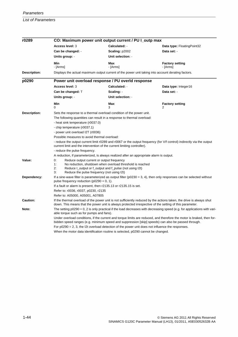
Parameters
List of Parameters
1-44 © Siemens AG 2011 All Rights ReservedSINAMICS G120C Parameter Manual (LH13), 01/2011, A5E03052632B AA
Description: Displays the actual maximum output current of the power unit taking into account derating factors.
Description: Sets the response to a thermal overload condition of the power unit.
The following quantities can result in a response to thermal overload:
- heat sink temperature (r0037.0)
- chip temperature (r0037.1)
- power unit overload I2T (r0036)
Possible measures to avoid thermal overload:
- reduce the output current limit r0289 and r0067 or the output frequency (for V/f control) indirectly via the output current limit and the intervention of the current limiting controller).
- reduce the pulse frequency.
A reduction, if parameterized, is always realized after an appropriate alarm is output.
Value: 0: Reduce output current or output frequency1: No reduction, shutdown when overload threshold is reached2: Reduce I_output or f_output and f_pulse (not using I2t)3: Reduce the pulse frequency (not using I2t)
Dependency: If a sine-wave filter is parameterized as output filter (p0230 = 3, 4), then only responses can be selected without pulse frequency reduction (p0290 = 0, 1).
If a fault or alarm is present, then r2135.13 or r2135.15 is set.
Refer to: r0036, r0037, p0230, r2135
Refer to: A05000, A05001, A07805
Caution: If the thermal overload of the power unit is not sufficiently reduced by the actions taken, the drive is always shut down. This means that the power unit is always protected irrespective of the setting of this parameter.
Note: The setting p0290 = 0, 2 is only practical if the load decreases with decreasing speed (e.g. for applications with vari-able torque such as for pumps and fans).
Under overload conditions, if the current and torque limits are reduced, and therefore the motor is braked, then for-bidden speed ranges (e.g. minimum speed and suppression [skip] speeds) can also be passed through.
For p0290 = 2, 3, the I2t overload detection of the power unit does not influence the responses.
When the motor data identification routine is selected, p0290 cannot be changed.
r0289 CO: Maximum power unit output current / PU I_outp maxAccess level: 3 Calculated: - Data type: FloatingPoint32
Can be changed: - Scaling: p2002 Data set: -
Units group: - Unit selection: -
Min Max Factory setting - [Arms] - [Arms] - [Arms]
p0290 Power unit overload response / PU overld responseAccess level: 3 Calculated: - Data type: Integer16
Can be changed: T Scaling: - Data set: -
Units group: - Unit selection: -
Min Max Factory setting 0 3 2
List of Parameters
Parameters
1-45© Siemens AG 2011 All Rights ReservedSINAMICS G120C Parameter Manual (LH13), 01/2011, A5E03052632B AA
Description: Sets the alarm threshold for power unit overtemperatures. The value is set as a difference to the tripping (shut-down) temperature.
Drive:
If this threshold is exceeded, an overload alarm is generated and the system responds as parameterized in p0290.
Infeed:
When the threshold value is exceeded, only an overload alarm is output.
Index: [0] = Heat sink temperature[1] = Power semiconductor (chip) temperature
Dependency: Refer to: r0037, p0290
Refer to: A05000
Description: Sets the fan run-on time after the pulses for the power unit have been canceled.
Note: - Under certain circumstances, the fan can continue to run for longer than was set (e.g. as a result of the exces-sively high heat sink temperature).
- For values less than 1 s, a 1 s run on time for the fan is active.
- for a PM230 power unit, sizes D - F the parameter is ineffective.
Description: Selecting the motor type.
The first digit of the parameter value always defines the general motor type and corresponds to the third-party motor belonging to a motor list:
1 = Rotating induction motor
2 = Rotating synchronous motor
The type information must be entered to filter motor-specific parameters and to optimize the operating characteris-tics and behavior. For example, for synchronous motors, power factor (p0308) is neither used nor displayed (in the BOP/IOP).
Value: 0: No motor1: Induction motor (rotating)2: Synchronous motor (rotating, permanent-magnet)17: 1LA7 standard induction motor
Dependency: When selecting a motor type from the 1LA7 series, parameters of the thermal motor model are pre-assigned as a function of p0307 and p0311.
Note: Once the Control Unit has been powered up for the first time or if the factory settings have been defined accord-ingly, the motor type is pre-configured to induction motor (p0300 = 1).
If a motor type has not been selected (p0300 = 0), then the drive commissioning routine cannot be exited.
p0292[0...1] Power unit temperature alarm threshold / PU T_alrm threshAccess level: 3 Calculated: - Data type: FloatingPoint32
Can be changed: U, T Scaling: - Data set: -
Units group: - Unit selection: -
Min Max Factory setting 0 [°C] 25 [°C] [0] 5 [°C]
[1] 15 [°C]
p0295 Fan run-on time / Fan run-on timeAccess level: 3 Calculated: - Data type: FloatingPoint32
Can be changed: U, T Scaling: - Data set: -
Units group: - Unit selection: -
Min Max Factory setting 0 [s] 600 [s] 0 [s]
p0300[0...n] Motor type selection / Mot type selAccess level: 2 Calculated: - Data type: Integer16
Can be changed: C(1, 3) Scaling: - Data set: MDS
Units group: - Unit selection: -
Min Max Factory setting 0 17 0
Parameters
List of Parameters
1-46 © Siemens AG 2011 All Rights ReservedSINAMICS G120C Parameter Manual (LH13), 01/2011, A5E03052632B AA
Description: The parameter is used to select a motor from a motor parameter list.
When changing the code number (with the exception to the value 0), all of the motor parameters are pre-assigned from the internally available parameter lists.
Dependency: Code numbers can only be selected for motor types that correspond to the motor type selected in p0300.
Refer to: p0300
Note: The motor code number can only be changed if the matching catalog motor was first selected in p0300.
When selecting a catalog motor (p0300 >= 100), drive commissioning can only be exited if a code number is selected.
Description: Sets the rated motor voltage (rating plate).
Caution: When selecting a catalog motor (p0301), this parameter is automatically pre-assigned and is write protected. Infor-mation in p0300 should be carefully observed when removing write protection.
Note: When the parameter value is entered the connection type of the motor (star-delta) must be taken into account.
Once the Control Unit has booted for the first time or if the factory settings have been restored, the parameter is pre-assigned to match the power unit.
Description: Sets the rated motor current (rating plate).
Caution: When selecting a catalog motor (p0301), this parameter is automatically pre-assigned and is write protected. Infor-mation in p0300 should be carefully observed when removing write protection.
Notice: If p0305 is changed during quick commissioning (p0010 = 1), then the maximum current p0640 is pre-assigned accordingly.
Note: When the parameter value is entered the connection type of the motor (star-delta) must be taken into account.
Once the Control Unit has booted for the first time or if the factory settings have been restored, the parameter is pre-assigned to match the power unit.
p0301[0...n] Motor code number selection / Mot code No. selAccess level: 2 Calculated: - Data type: Unsigned16
Can be changed: C(1, 3) Scaling: - Data set: MDS
Units group: - Unit selection: -
Min Max Factory setting 0 65535 0
p0304[0...n] Rated motor voltage / Mot U_ratedAccess level: 1 Calculated: - Data type: FloatingPoint32
Can be changed: C(1, 3) Scaling: - Data set: MDS
Units group: - Unit selection: -
Min Max Factory setting 0 [Vrms] 20000 [Vrms] 0 [Vrms]
p0305[0...n] Rated motor current / Mot I_ratedAccess level: 1 Calculated: - Data type: FloatingPoint32
Can be changed: C(1, 3) Scaling: - Data set: MDS
Units group: - Unit selection: -
Min Max Factory setting 0.00 [Arms] 10000.00 [Arms] 0.00 [Arms]
List of Parameters
Parameters
1-47© Siemens AG 2011 All Rights ReservedSINAMICS G120C Parameter Manual (LH13), 01/2011, A5E03052632B AA
Description: Sets the rated motor power (rating plate).
Dependency: IECdrives (p0100 = 0): Units kW
NEMA drives (p0100 = 1): Units hp
NEMA drives (p0100 = 2): Unit kW
Refer to: p0100
Caution: When selecting a catalog motor (p0301), this parameter is automatically pre-assigned and is write protected. Infor-mation in p0300 should be carefully observed when removing write protection.
Note: Once the Control Unit has booted for the first time or if the factory settings have been restored, the parameter is pre-assigned to match the power unit.
Description: Sets the rated motor power factor (cos phi, rating plate).
For a parameter value of 0.000, the power factor is internally calculated.
Dependency: This parameter is only available for p0100 = 0, 2.
Refer to: p0100, p0309
Caution: When selecting a catalog motor (p0301), this parameter is automatically pre-assigned and is write protected. Infor-mation in p0300 should be carefully observed when removing write protection.
Note: The parameter is not used for synchronous motors (p0300 = 2xx).
Once the Control Unit has booted for the first time or if the factory settings have been restored, the parameter is pre-assigned to match the power unit.
Description: Sets the rated motor efficiency (rating plate).
For a parameter value of 0.0, the power factor is internally calculated.
Dependency: This parameter is only available for NEMA motors (p0100 = 1).
Refer to: p0100, p0308
Note: The parameter is not used for synchronous motors.
p0307[0...n] Rated motor power / Mot P_ratedAccess level: 1 Calculated: - Data type: FloatingPoint32
Can be changed: C(1, 3) Scaling: - Data set: MDS
Units group: 14_6 Unit selection: p0100
Min Max Factory setting 0.00 [kW] 100000.00 [kW] 0.00 [kW]
p0308[0...n] Rated motor power factor / Mot cos_phi_ratedAccess level: 1 Calculated: - Data type: FloatingPoint32
Can be changed: C(1, 3) Scaling: - Data set: MDS
Units group: - Unit selection: -
Min Max Factory setting 0.000 1.000 0.000
p0309[0...n] Rated motor efficiency / Mot eta_ratedAccess level: 1 Calculated: - Data type: FloatingPoint32
Can be changed: C(1, 3) Scaling: - Data set: MDS
Units group: - Unit selection: -
Min Max Factory setting 0.0 [%] 99.9 [%] 0.0 [%]
Parameters
List of Parameters
1-48 © Siemens AG 2011 All Rights ReservedSINAMICS G120C Parameter Manual (LH13), 01/2011, A5E03052632B AA
Description: Sets the rated motor frequency (rating plate).
Dependency: The number of pole pairs is automatically re-calculated when the parameter is changed (together with p0311), if p0314 = 0.
The rated frequency is restricted to values between 1.00 Hz and 650.00 Hz.
Refer to: p0311
Caution: When selecting a catalog motor (p0301), this parameter is automatically pre-assigned and is write protected. Infor-mation in p0300 should be carefully observed when removing write protection.
Notice: If p0310 is changed during quick commissioning (p0010 = 1), the maximum speed p1082, which is also associated with quick commissioning, is pre-assigned accordingly. This is not the case when commissioning the motor (p0010 = 3).
Note: Once the Control Unit has been booted up for the first time or if the factory settings have been defined accordingly, the parameter is defined in accordance with the power unit.
Description: Sets the rated motor speed (rating plate).
For p0311 = 0, the rated motor slip of induction motors is internally calculated and displayed in r0330.
It is especially important to correctly enter the rated motor speed for vector control and slip compensation for U/f control.
Dependency: If p0311 is changed and for p0314 = 0, the pole pair is re-calculated automatically.
Refer to: p0310
Caution: When selecting a catalog motor (p0301), this parameter is automatically pre-assigned and is write protected. Infor-mation in p0300 should be carefully observed when removing write protection.
Notice: If p0311 is changed during quick commissioning (p0010 = 1), the maximum speed p1082, which is also associated with quick commissioning, is pre-assigned accordingly. This is not the case when commissioning the motor (p0010 = 3).
Note: Once the Control Unit has been booted up for the first time or if the factory settings have been defined accordingly, the parameter is defined in accordance with the power unit.
Description: Sets the torque constant of the synchronous motor.
p0316 = 0: The torque constant is calculated from the motor data.
p0316 > 0: The selected value is used as torque constant.
Caution: When selecting a catalog motor (p0301), this parameter is automatically pre-assigned and is write protected. Infor-mation in p0300 should be carefully observed when removing write protection.
Note: This parameter is not used for induction motors (p0300 = 1xx).
p0310[0...n] Rated motor frequency / Mot f_ratedAccess level: 1 Calculated: - Data type: FloatingPoint32
Can be changed: C(1, 3) Scaling: - Data set: MDS
Units group: - Unit selection: -
Min Max Factory setting 0.00 [Hz] 650.00 [Hz] 0.00 [Hz]
p0311[0...n] Rated motor speed / Mot n_ratedAccess level: 1 Calculated: - Data type: FloatingPoint32
Can be changed: C(1, 3) Scaling: - Data set: MDS
Units group: - Unit selection: -
Min Max Factory setting 0.0 [rpm] 210000.0 [rpm] 0.0 [rpm]
p0316[0...n] Motor torque constant / Mot kTAccess level: 4 Calculated: - Data type: FloatingPoint32
Can be changed: C(1, 3), U, T Scaling: - Data set: MDS
Units group: 28_1 Unit selection: p0100
Min Max Factory setting 0.00 [Nm/A] 400.00 [Nm/A] 0.00 [Nm/A]
List of Parameters
Parameters
1-49© Siemens AG 2011 All Rights ReservedSINAMICS G120C Parameter Manual (LH13), 01/2011, A5E03052632B AA
Description: Induction motors:
Sets the rated motor magnetizing current.
For p0320 = 0.000 the magnetizing current is internally calculated and displayed in r0331.
Synchronous motors:
Sets the rated motor short-circuit current.
Caution: When selecting a catalog motor (p0301), this parameter is automatically pre-assigned and is write protected. Infor-mation in p0300 should be carefully observed when removing write protection.
Note: The magnetizing current p0320 for induction motors is reset when quick commissioning is exited with p3900 > 0.
If, for induction motors, the magnetizing current p0320 is changed outside the commissioning phase (p0010 > 0), then the magnetizing inductance p0360 is changed so that the EMF remains constant.
Description: Sets the maximum motor speed.
Dependency: Refer to: p1082
Caution: When selecting a catalog motor (p0301), this parameter is automatically pre-assigned and is write protected. Infor-mation in p0300 should be carefully observed when removing write protection.
Notice: If p0322 is changed during quick commissioning (p0010 = 1), the maximum speed p1082, which is also associated with quick commissioning, is pre-assigned accordingly.
Description: Sets the maximum permissible motor current (e.g. de-magnetizing current for synchronous motors).
Caution: When selecting a catalog motor (p0301), this parameter is automatically pre-assigned and is write protected. Infor-mation in p0300 should be carefully observed when removing write protection.
Notice: If p0323 is changed during quick commissioning (p0010 = 1), then the maximum current p0640 is pre-assigned accordingly.
Note: The parameter has no effect for induction motors.
The parameter has not effect for synchronous motors if a value of 0.0 is entered. The user-selectable current limit is entered into p0640.
p0320[0...n] Motor rated magnetizing current/short-circuit current / Mot I_mag_ratedAccess level: 3 Calculated: - Data type: FloatingPoint32
Can be changed: C(3), U, T Scaling: - Data set: MDS
Units group: - Unit selection: -
Min Max Factory setting 0.000 [Arms] 5000.000 [Arms] 0.000 [Arms]
p0322[0...n] Maximum motor speed / Mot n_maxAccess level: 1 Calculated: - Data type: FloatingPoint32
Can be changed: C(1, 3) Scaling: - Data set: MDS
Units group: - Unit selection: -
Min Max Factory setting 0.0 [rpm] 210000.0 [rpm] 0.0 [rpm]
p0323[0...n] Maximum motor current / Mot I_maxAccess level: 1 Calculated: - Data type: FloatingPoint32
Can be changed: C(1, 3) Scaling: - Data set: MDS
Units group: - Unit selection: -
Min Max Factory setting 0.00 [Arms] 20000.00 [Arms] 0.00 [Arms]
Parameters
List of Parameters
1-50 © Siemens AG 2011 All Rights ReservedSINAMICS G120C Parameter Manual (LH13), 01/2011, A5E03052632B AA
Description: Displays the rated motor slip.
Dependency: The rated slip is calculated from the rated frequency, rated speed and number of pole pairs.
Refer to: p0310, p0311
Note: The parameter is not used for synchronous motors (p0300 = 2xx).
Description: Induction motor:
Displays the rated magnetizing current from p0320.
For p0320 = 0, the internally calculated magnetizing current is displayed.
Synchronous motor:
Displays the rated short-circuit current from p0320.
Dependency: If p0320 was not entered, then the parameter is calculated from the rating plate parameters.
Description: Displays the rated motor torque.
Dependency: IEC drives (p0100 = 0): unit Nm
NEMA drives (p0100 = 1): unit lbf ft
Note: For induction motors, r0333 is calculated from p0307 and p0311.
For synchronous motors, r0333 is calculated from p0305, p0316, p0327 and p0328.
Description: Sets the motor cooling system used.Value: 0: Non-ventilated
1: Forced cooling2: Liquid cooling128: No fan
Dependency: For 1LA7 motors (refer to p0300), the parameter is pre-set as a function of p0307 and p0311.Caution: When selecting a catalog motor (p0301), this parameter is automatically pre-assigned and is write protected. Infor-
mation in p0300 should be carefully observed when removing write protection.Note: The parameter influences the thermal 3-mass motor model.
1LA7 motors, frame size 56 are operated without fan.
r0330[0...n] Rated motor slip / Mot slip_ratedAccess level: 3 Calculated: - Data type: FloatingPoint32
Can be changed: - Scaling: - Data set: MDS
Units group: - Unit selection: -
Min Max Factory setting - [Hz] - [Hz] - [Hz]
r0331[0...n] Actual motor magnetizing current/short-circuit current / Mot I_mag_rtd actAccess level: 3 Calculated: - Data type: FloatingPoint32
Can be changed: - Scaling: - Data set: MDS
Units group: - Unit selection: -
Min Max Factory setting - [Arms] - [Arms] - [Arms]
r0333[0...n] Rated motor torque / Mot M_ratedAccess level: 3 Calculated: - Data type: FloatingPoint32
Can be changed: - Scaling: - Data set: MDS
Units group: 7_4 Unit selection: p0100
Min Max Factory setting - [Nm] - [Nm] - [Nm]
p0335[0...n] Motor cooling type / Motor cooling typeAccess level: 2 Calculated: - Data type: Integer16
Can be changed: C(1, 3), T Scaling: - Data set: MDS
Units group: - Unit selection: -
Min Max Factory setting 0 128 0
List of Parameters
Parameters
1-51© Siemens AG 2011 All Rights ReservedSINAMICS G120C Parameter Manual (LH13), 01/2011, A5E03052632B AA
Description: Setting to automatically calculate motor parameters and U/f open-loop and closed-loop control parameters from the rating plate data.
Value: 0: No calculation1: Complete calculation2: Calculation of equivalent circuit diagram parameters3: Calculation of closed-loop control parameters4: Calculation of controller parameters5: Calculation of technological limits and threshold values
Notice: After the value has been modified, no further parameter modifications can be made and the status is shown in r3996. Modifications can be made again when r3996 = 0.The following parameters are influenced using p0340:p0340 = 1:--> All of the parameters influenced for p0340 = 2, 3, 4, 5--> p0341, p0342, p0344, p0640, p1082, p1231, p1232, p1349, p1611, p1726, p1909, p1959, p2000, p2001, p2002, p2003, p3927, p3928p0340 = 2:--> p0350, p0354 ... p0360--> p0625 (matching p0350)p0340 = 3:--> All of the parameters influenced for p0340 = 4, 5--> p0346, p0347, p0622, p1320 ... p1327, p1582, p1755p0340 = 4:--> p1290, p1292, p1338, p1340, p1341, p1345, p1346, p1470, p1472, p1764, p1767p0340 = 5:--> p1037, p1038, p1520, p1521, p1530, p1531, p1802, p1803, p2390, p2392, p2393
Note: p0340 = 1 contains the calculations of p0340 = 2, 3, 4, 5.p0340 = 2 calculates the motor parameters (p0350 ... p0360).p0340 = 3 contains the calculations of p0340 = 4, 5.p0340 = 4 only calculates the controller parameters.p0340 = 5 only calculates the controller limits.When quick commissioning is exited using p3900 > 0, p0340 is automatically set to 1.At the end of the calculations, p0340 is automatically set to 0.
Description: Sets the motor moment of inertia (without load).
Dependency: IEC drives (p0100 = 0): unit kg m^2
NEMA drives (p0100 = 1): unit lb ft^2
The parameter value is included, together with p0342, in the rated starting time of the motor.
Refer to: p0342, r0345
Caution: When selecting a catalog motor (p0301), this parameter is automatically pre-assigned and is write protected. Infor-mation in p0300 should be carefully observed when removing write protection.
Note: The product of p0341 * p0342 is used when the speed controller (p0340 = 4) is calculated automatically.
p0340[0...n] Automatic calculation, motor/control parameters / Calc auto parAccess level: 2 Calculated: - Data type: Integer16
Can be changed: C(3), T Scaling: - Data set: DDS, p0180
Units group: - Unit selection: -
Min Max Factory setting 0 5 0
p0341[0...n] Motor moment of inertia / Mot M_mom of inertAccess level: 3 Calculated: p0340 = 1 Data type: FloatingPoint32
Can be changed: C(3), U, T Scaling: - Data set: MDS
Units group: 25_1 Unit selection: p0100
Min Max Factory setting 0.000000 [kgm²] 100000.000000 [kgm²] 0.000000 [kgm²]
Parameters
List of Parameters
1-52 © Siemens AG 2011 All Rights ReservedSINAMICS G120C Parameter Manual (LH13), 01/2011, A5E03052632B AA
Description: Sets the ratio between the total moment of inertia/mass (load + motor) and the intrinsic motor moment of iner-tia/mass (no load).
Dependency: This means that together with p0341, the rated starting (accelerating time) of the motor is calculated for a vector drive.
Refer to: p0341, r0345
Note: The product of p0341 * p0342 is used when the speed controller (p0340 = 4) is calculated automatically.
Description: Sets the motor weight.
Dependency: IEC drives (p0100 = 0): unit kg
NEMA drives (p0100 = 1): unit lb
Caution: When selecting a catalog motor (p0301), this parameter is automatically pre-assigned and is write protected. Infor-mation in p0300 should be carefully observed when removing write protection.
Note: The parameter influences the thermal 3 mass model of the induction motor.
The parameter is not used for synchronous motors (p0300 = 2xx).
Description: Displays the rated motor starting time. This time corresponds to the time from standstill up to reaching the motor rated speed and the acceleration with motor rated torque.
Dependency: Refer to: r0333, p0341, p0342
p0342[0...n] Ratio between the total and motor moment of inertia / Mot MomInert RatioAccess level: 3 Calculated: p0340 = 1 Data type: FloatingPoint32
Can be changed: C(3), U, T Scaling: - Data set: MDS
Units group: - Unit selection: -
Min Max Factory setting 1.000 10000.000 1.000
p0344[0...n] Motor weight (for the thermal motor model) / Mot weight th modAccess level: 4 Calculated: p0340 = 1 Data type: FloatingPoint32
Can be changed: C(3), T Scaling: - Data set: MDS
Units group: 27_1 Unit selection: p0100
Min Max Factory setting 0.0 [kg] 50000.0 [kg] 0.0 [kg]
r0345[0...n] Nominal motor starting time / Mot t_start_ratedAccess level: 3 Calculated: - Data type: FloatingPoint32
Can be changed: - Scaling: - Data set: MDS
Units group: - Unit selection: -
Min Max Factory setting - [s] - [s] - [s]
List of Parameters
Parameters
1-53© Siemens AG 2011 All Rights ReservedSINAMICS G120C Parameter Manual (LH13), 01/2011, A5E03052632B AA
Description: Sets the excitation build-up time of the motor.
This involves the delay time between enabling the pulses and enabling the ramp-function generator. The induction motor is magnetized during this time.
Caution: If there is insufficient magnetization under load or if the acceleration rate is too high, then an induction motor can stall (refer to the note).
Note: The parameter is calculated using p0340 = 1, 3.
For induction motors, the result depends on the rotor time constant (r0384). If this time is excessively reduced, this can result in an inadequate magnetizing of the induction motor. This is the case if the current limit is reached while building up magnetizing. For induction motors, the parameter cannot be set to 0 s (internal limit: 0.1 * r0384).
For permanent-magnet synchronous motors and vector control, the value depends on the stator time constant (r0386). Here, it defines the time to establish the current for encoderless operation immediately after the pulses have been enabled.
Description: Sets the de-magnetizing time (for induction motors) after the inverter pulses have been canceled.
The inverter pulses cannot be switched in (enabled) within this delay time.
Note: The parameter is calculated using p0340 = 1, 3.
For induction motors, the result depends on the rotor time constant (r0384).
if this time is shortened too much, then this can result in an inadequate de-magnetizing of the induction motor and in an overcurrent condition when the pulses are subsequently enabled (only when the flying restart function is acti-vated and the motor is rotating).
Description: Sets the stator resistance of the motor at ambient temperature p0625.
Dependency: Refer to: p0625
Caution: When selecting a catalog motor (p0301), this parameter is automatically pre-assigned and is write protected. Infor-mation in p0300 should be carefully observed when removing write protection.
Note: The motor identification routine determines the stator resistance from the total stator resistance minus the cable resistance (p0352).
p0346[0...n] Motor excitation build-up time / Mot t_excitationAccess level: 3 Calculated: p0340 = 1,3 Data type: FloatingPoint32
Can be changed: C(3), U, T Scaling: - Data set: MDS
Units group: - Unit selection: -
Min Max Factory setting 0.000 [s] 20.000 [s] 0.000 [s]
p0347[0...n] Motor de-excitation time / Mot t_de-excitat.Access level: 3 Calculated: p0340 = 1,3 Data type: FloatingPoint32
Can be changed: C(3), U, T Scaling: - Data set: MDS
Units group: - Unit selection: -
Min Max Factory setting 0.000 [s] 20.000 [s] 0.000 [s]
p0350[0...n] Motor stator resistance, cold / Mot R_stator coldAccess level: 3 Calculated: p0340 = 1,2 Data type: FloatingPoint32
Can be changed: C(3), U, T Scaling: - Data set: MDS
Units group: - Unit selection: -
Min Max Factory setting 0.00000 [ohm] 2000.00000 [ohm] 0.00000 [ohm]
Parameters
List of Parameters
1-54 © Siemens AG 2011 All Rights ReservedSINAMICS G120C Parameter Manual (LH13), 01/2011, A5E03052632B AA
Description: Resistance of the power cable between the power unit and motor.
Caution: The cable resistance should be entered prior to motor data identification. If it is used subsequently, the difference by which p0352 was changed must be subtracted from the stator resistance p0350 or motor data identification must be repeated.
Note: The parameter influences the temperature adaptation of the stator resistance.
The motor identification sets the cable resistance to 20% of the measured total resistance if p0352 is zero at the time that the measurement is made. If p0352 is not zero, then the value is subtracted from the measured total stator resistance to calculate stator resistance p0350. In this case, p0350 is a minimum of 10% of the measured value.
The cable resistance is reset when quick commissioning is exited with p3900 > 0.
Description: Sets the rotor/secondary section resistance of the motor at the ambient temperature p0625.
This parameter value is automatically calculated using the motor model (p0340 = 1, 2) or using the motor data iden-tification routine (p1910).
Dependency: Refer to: p0625
Caution: When selecting a catalog motor (p0301), this parameter is automatically pre-assigned and is write protected. Infor-mation in p0300 should be carefully observed when removing write protection.
Note: The parameter is not used for synchronous motors (p0300 = 2).
Description: Induction machine: sets the stator leakage inductance of the motor.
Synchronous motor: Sets the stator quadrature axis inductance of the motor.
This parameter value is automatically calculated using the motor model (p0340 = 1, 2) or using the motor identifica-tion routine (p1910).
Caution: When selecting a catalog motor (p0301), this parameter is automatically pre-assigned and is write protected. Infor-mation in p0300 should be carefully observed when removing write protection.
Note: If the stator leakage inductance (p0356) for induction motors is changed outside the commissioning phase (p0010 > 0), the magnetizing inductance (p0360) is automatically adapted to the new EMF. You are then advised to repeat the measurement for the saturation characteristic (p1960).
For permanent-magnet synchronous motors (p0300 = 2), this is the non-saturated value and is, therefore, ideal for a low current.
p0352[0...n] Cable resistance / Mot R_cable coldAccess level: 3 Calculated: - Data type: FloatingPoint32
Can be changed: C(3), U, T Scaling: - Data set: MDS
Units group: - Unit selection: -
Min Max Factory setting 0.00000 [ohm] 120.00000 [ohm] 0.00000 [ohm]
p0354[0...n] Motor rotor resistance cold / Mot R_r coldAccess level: 4 Calculated: p0340 = 1,2 Data type: FloatingPoint32
Can be changed: C(3), U, T Scaling: - Data set: MDS
Units group: - Unit selection: -
Min Max Factory setting 0.00000 [ohm] 300.00000 [ohm] 0.00000 [ohm]
p0356[0...n] Motor stator leakage inductance / Mot L_stator leak.Access level: 4 Calculated: p0340 = 1,2 Data type: FloatingPoint32
Can be changed: C(3), U, T Scaling: - Data set: MDS
Units group: - Unit selection: -
Min Max Factory setting 0.00000 [mH] 1000.00000 [mH] 0.00000 [mH]
List of Parameters
Parameters
1-55© Siemens AG 2011 All Rights ReservedSINAMICS G120C Parameter Manual (LH13), 01/2011, A5E03052632B AA
Description: Sets the stator direct-axis inductance of the synchronous motor.
This parameter value is automatically calculated using the motor model (p0340 = 1, 2) or using the motor identifica-tion routine (p1910).
Note: For permanent-magnet synchronous motors (p0300 = 2), this is the non-saturated value and is ideal for a low cur-rent.
Description: Sets the rotor/secondary section leakage inductance of the motor.
The value is automatically calculated using the motor model (p0340 = 1, 2) or using the motor identification routine (p1910).
Caution: When selecting a catalog motor (p0301), this parameter is automatically pre-assigned and is write protected. Infor-mation in p0300 should be carefully observed when removing write protection.
Note: If the rotor leakage inductance (p0358) for induction motors is changed outside the commissioning phase (p0010 > 0), the magnetizing inductance (p0360) is automatically adapted to the new EMF. You are then advised to repeat the measurement for the saturation characteristic (p1960).
Description: Sets the magnetizing inductance of the motor.
This parameter value is automatically calculated using the motor model (p0340 = 1, 2) or using the motor identifica-tion routine (p1910).
Caution: When selecting a catalog motor (p0301), this parameter is automatically pre-assigned and is write protected. Infor-mation in p0300 should be carefully observed when removing write protection.
Note: The parameter is not used for synchronous motors (p0300 = 2).
p0357[0...n] Motor stator inductance, d axis / Mot L_stator dAccess level: 4 Calculated: p0340 = 1,2 Data type: FloatingPoint32
Can be changed: C(3), U, T Scaling: - Data set: MDS
Units group: - Unit selection: -
Min Max Factory setting 0.00000 [mH] 1000.00000 [mH] 0.00000 [mH]
p0358[0...n] Motor rotor leakage inductance / Mot L_rot leakAccess level: 4 Calculated: p0340 = 1,2 Data type: FloatingPoint32
Can be changed: C(3), U, T Scaling: - Data set: MDS
Units group: - Unit selection: -
Min Max Factory setting 0.00000 [mH] 1000.00000 [mH] 0.00000 [mH]
p0360[0...n] Motor magnetizing inductance / Mot LhAccess level: 4 Calculated: p0340 = 1,2 Data type: FloatingPoint32
Can be changed: C(3), U, T Scaling: - Data set: MDS
Units group: - Unit selection: -
Min Max Factory setting 0.00000 [mH] 10000.00000 [mH] 0.00000 [mH]
Parameters
List of Parameters
1-56 © Siemens AG 2011 All Rights ReservedSINAMICS G120C Parameter Manual (LH13), 01/2011, A5E03052632B AA
Description: The saturation characteristics (flux as a function of the magnetizing current) is defined using 4 points.This parameter specifies the y coordinate (flux) for the 1st value pair of the characteristic.Sets the first flux value of the saturation characteristic as a [%] referred to the rated motor flux (100 %).
Dependency: The following applies for the flux values:p0362 < p0363 < p0364 < p0365Refer to: p0366
Note: For induction motors, p0362 = 100 % corresponds to the rated motor flux.When quick commissioning is exited with p3900 > 0, then the parameter is reset if a catalog motor has not been selected (refer to p0300).
Description: The saturation characteristics (flux as a function of the magnetizing current) is defined using 4 points.
This parameter specifies the y coordinate (flux) for the 2nd value pair of the characteristic.
Sets the second flux value of the saturation characteristic as a [%] referred to the rated motor flux (100 %).
Dependency: The following applies for the flux values:
p0362 < p0363 < p0364 < p0365
Refer to: p0367
Note: For induction motors, p0363 = 100 % corresponds to the rated motor flux.
When quick commissioning is exited with p3900 > 0, then the parameter is reset if a catalog motor has not been selected (refer to p0300).
Description: The saturation characteristics (flux as a function of the magnetizing current) is defined using 4 points.
This parameter specifies the y coordinate (flux) for the 3rd value pair of the characteristic.
Sets the third flux value of the saturation characteristic as a [%] referred to the rated motor flux (100 %).
Dependency: The following applies for the flux values:
p0362 < p0363 < p0364 < p0365
Refer to: p0368
Note: For induction motors, p0364 = 100 % corresponds to the rated motor flux.
When quick commissioning is exited with p3900 > 0, then the parameter is reset if a catalog motor has not been selected (refer to p0300).
p0362[0...n] Motor saturation characteristic flux 1 / Mot saturat.flux 1Access level: 4 Calculated: - Data type: FloatingPoint32
Can be changed: C(3), U, T Scaling: - Data set: MDS
Units group: - Unit selection: -
Min Max Factory setting 10.0 [%] 300.0 [%] 60.0 [%]
p0363[0...n] Motor saturation characteristic flux 2 / Mot saturat.flux 2Access level: 4 Calculated: - Data type: FloatingPoint32
Can be changed: C(3), U, T Scaling: - Data set: MDS
Units group: - Unit selection: -
Min Max Factory setting 10.0 [%] 300.0 [%] 85.0 [%]
p0364[0...n] Motor saturation characteristic flux 3 / Mot saturat.flux 3Access level: 4 Calculated: - Data type: FloatingPoint32
Can be changed: C(3), U, T Scaling: - Data set: MDS
Units group: - Unit selection: -
Min Max Factory setting 10.0 [%] 300.0 [%] 115.0 [%]
List of Parameters
Parameters
1-57© Siemens AG 2011 All Rights ReservedSINAMICS G120C Parameter Manual (LH13), 01/2011, A5E03052632B AA
Description: The saturation characteristics (flux as a function of the magnetizing current) is defined using 4 points.
This parameter specifies the y coordinate (flux) for the 4th value pair of the characteristic.
Sets the fourth flux value of the saturation characteristic as a [%] referred to the rated motor flux (100 %).
Dependency: The following applies for the flux values:
p0362 < p0363 < p0364 < p0365
Refer to: p0369
Note: For induction motors, p0365 = 100 % corresponds to the rated motor flux.
When quick commissioning is exited with p3900 > 0, then the parameter is reset if a catalog motor has not been selected (refer to p0300).
Description: The saturation characteristics (flux as a function of the magnetizing current) is defined using 4 points.
This parameter specifies the x coordinate (magnetizing current) for the 1st value pair of the characteristic.
Sets the first magnetization current of the saturation characteristic in [%] with reference to the rated magnetization current (r0331).
Dependency: The following applies for the magnetizing currents:
p0366 < p0367 < p0368 < p0369
Refer to: p0362
Note: When quick commissioning is exited with p3900 > 0, then the parameter is reset if a catalog motor has not been selected (refer to p0300).
Description: The saturation characteristics (flux as a function of the magnetizing current) is defined using 4 points.
This parameter specifies the x coordinate (magnetizing current) for the 2nd value pair of the characteristic.
Sets the second magnetization current of the saturation characteristic in [%] with reference to the rated magnetiza-tion current (r0331).
Dependency: The following applies for the magnetizing currents:
p0366 < p0367 < p0368 < p0369
Refer to: p0363
Note: When quick commissioning is exited with p3900 > 0, then the parameter is reset if a catalog motor has not been selected (refer to p0300).
p0365[0...n] Motor saturation characteristic flux 4 / Mot saturat.flux 4Access level: 4 Calculated: - Data type: FloatingPoint32
Can be changed: C(3), U, T Scaling: - Data set: MDS
Units group: - Unit selection: -
Min Max Factory setting 10.0 [%] 300.0 [%] 125.0 [%]
p0366[0...n] Motor saturation characteristic I_mag 1 / Mot sat. I_mag 1Access level: 4 Calculated: - Data type: FloatingPoint32
Can be changed: C(3), U, T Scaling: - Data set: MDS
Units group: - Unit selection: -
Min Max Factory setting 5.0 [%] 800.0 [%] 50.0 [%]
p0367[0...n] Motor saturation characteristic I_mag 2 / Mot sat. I_mag 2Access level: 4 Calculated: - Data type: FloatingPoint32
Can be changed: C(3), U, T Scaling: - Data set: MDS
Units group: - Unit selection: -
Min Max Factory setting 5.0 [%] 800.0 [%] 75.0 [%]
Parameters
List of Parameters
1-58 © Siemens AG 2011 All Rights ReservedSINAMICS G120C Parameter Manual (LH13), 01/2011, A5E03052632B AA
Description: The saturation characteristics (flux as a function of the magnetizing current) is defined using 4 points.
This parameter specifies the x coordinate (magnetizing current) for the 3rd value pair of the characteristic.
Sets the third magnetization current of the saturation characteristic in [%] with reference to the rated magnetization current (r0331).
Dependency: The following applies for the magnetizing currents:
p0366 < p0367 < p0368 < p0369
Refer to: p0364
Note: When quick commissioning is exited with p3900 > 0, then the parameter is reset if a catalog motor has not been selected (refer to p0300).
Description: The saturation characteristics (flux as a function of the magnetizing current) is defined using 4 points.
This parameter specifies the x coordinate (magnetizing current) for the 4th value pair of the characteristic.
Sets the fourth magnetization current of the saturation characteristic in [%] with reference to the rated magnetiza-tion current (r0331).
Dependency: The following applies for the magnetizing currents:
p0366 < p0367 < p0368 < p0369
Refer to: p0365
Note: When quick commissioning is exited with p3900 > 0, then the parameter is reset if a catalog motor has not been selected (refer to p0300).
Description: Displays the magnetizing inductance of the motor.
Note: The parameter is not used for synchronous motors (p0300 = 2xx).
p0368[0...n] Motor saturation characteristic I_mag 3 / Mot sat. I_mag 3Access level: 4 Calculated: - Data type: FloatingPoint32
Can be changed: C(3), U, T Scaling: - Data set: MDS
Units group: - Unit selection: -
Min Max Factory setting 5.0 [%] 800.0 [%] 150.0 [%]
p0369[0...n] Motor saturation characteristic I_mag 4 / Mot sat. I_mag 4Access level: 4 Calculated: - Data type: FloatingPoint32
Can be changed: C(3), U, T Scaling: - Data set: MDS
Units group: - Unit selection: -
Min Max Factory setting 5.0 [%] 800.0 [%] 210.0 [%]
r0382[0...n] Motor magnetizing inductance transformed / Mot L_magn transfAccess level: 4 Calculated: - Data type: FloatingPoint32
Can be changed: - Scaling: - Data set: MDS
Units group: - Unit selection: -
Min Max Factory setting - [mH] - [mH] - [mH]
List of Parameters
Parameters
1-59© Siemens AG 2011 All Rights ReservedSINAMICS G120C Parameter Manual (LH13), 01/2011, A5E03052632B AA
Description: Displays the rotor time constant.
Note: The parameter is not used for synchronous motors.
The value is calculated from the total of the inductances on the rotor side (p0358, p0360) divided by the rotor resis-tance (p0354). The temperature adaptation of the rotor resistance for induction motors is not taken into account.
Description: Displays the stator leakage time constant.
Note: The value is calculated from the total of all leakage inductances (p0233, p0356, p0358) divided by the total of all motor resistances (p0350, p0352, p0354). The temperature adaptation of the resistances is not taken into account.
Description: Displays the actual stator resistance (phase value).
The parameter value also contains the temperature-independent cable resistance.
Dependency: In the case of induction motors the parameter is also affected by the motor temperature model.
Refer to: p0350, p0352, p0620
Note: In each case, only the stator resistance of the active Motor Data Set is included with the stator temperature of the thermal motor model.
Description: Displays the actual rotor resistance (phase value).
The parameter is affected by the motor temperature model.
Dependency: Refer to: p0354, p0620
Note: In each case, only the rotor resistance of the active Motor Data Set is included with the rotor temperature of the thermal motor model.
This parameter is not used for synchronous motors (p0300 = 2xx).
r0384[0...n] Motor rotor time constant / damping time constant d axis / Mot T_rotor/T_DdAccess level: 4 Calculated: - Data type: FloatingPoint32
Can be changed: - Scaling: - Data set: MDS
Units group: - Unit selection: -
Min Max Factory setting - [ms] - [ms] - [ms]
r0386[0...n] Motor stator leakage time constant / Mot T_stator leakAccess level: 4 Calculated: - Data type: FloatingPoint32
Can be changed: - Scaling: - Data set: MDS
Units group: - Unit selection: -
Min Max Factory setting - [ms] - [ms] - [ms]
r0395[0...n] Actual stator resistance / R_stator actAccess level: 3 Calculated: - Data type: FloatingPoint32
Can be changed: - Scaling: - Data set: MDS
Units group: - Unit selection: -
Min Max Factory setting - [ohm] - [ohm] - [ohm]
r0396[0...n] Actual rotor resistance / R_rotor actAccess level: 3 Calculated: - Data type: FloatingPoint32
Can be changed: - Scaling: - Data set: MDS
Units group: - Unit selection: -
Min Max Factory setting - [ohm] - [ohm] - [ohm]
Parameters
List of Parameters
1-60 © Siemens AG 2011 All Rights ReservedSINAMICS G120C Parameter Manual (LH13), 01/2011, A5E03052632B AA
Description: Sets the technology application.
The parameter influences the calculation of open-loop and closed-loop control parameters that is e.g. initiated using p0340 = 5.
Value: 0: Standard drive1: Pumps and fans2: Sensorless closed-loop control down to f = 0 (passive loads)3: Pumps and fans, efficiency optimization
Notice: If the technological application is set to p0500 = 0 ... 3 during commissioning (p0010 = 1, 5, 30), the operating mode (p1300) is pre-set accordingly.
Note: The calculation of parameters dependent on the technology application can be called up as follows:
- when exiting quick commissioning using p3900 > 0
- when writing p0340 = 1, 3, 5
For p0500 = 0 and when the calculation is initiated, the following parameters are set:
- p1802 = 0 (automatic changeover SVM/FLB)
- p1803 = 106 %
For p0500 = 1 and when the calculation is initiated, the following parameters are set:
- p1802 = 0 (automatic changeover SVM/FLB)
- p1803 = 106 %
For p0500 = 2 and when the calculation is initiated, the following parameters are set:
- p1802 = 0 (automatic changeover SVM/FLB)
- p1803 = 106 %
For p0500 = 3 and when the calculation is initiated, the following parameters are set:
- p1802 = 0 (automatic changeover SVM/FLB)
- p1803 = 106 %
Re p1750:
Re p1802 / p1803:
p1802 and p1803 are only changed, in all cases, if a sine-wave output filter (p0230 = 3, 4) has not been selected.
Description: Adjustable parameter of the actual system of units.
Value: 1: SI system of units2: System of units, referred/SI3: US system of units4: System of units, referred/US
Dependency: The parameter cannot be changed if the master control was fetched.
Caution: If a per unit representation is selected and if the reference parameters (e.g. p2000) are subsequently changed, then the physical significance of several control parameters is also adapted at the same time. The control behavior can change as a consequence.
Note: Reference parameter for the unit system % are, for example, p2000 ... p2004. Depending on what has been selected, these are displayed using either SI or US units.
p0500 Technology application / Tec applicationAccess level: 2 Calculated: - Data type: Integer16
Can be changed: C(1, 5), T Scaling: - Data set: -
Units group: - Unit selection: -
Min Max Factory setting 0 3 0
p0505 Selecting the system of units / Unit sys selectAccess level: 1 Calculated: - Data type: Integer16
Can be changed: C(5) Scaling: - Data set: -
Units group: - Unit selection: -
Min Max Factory setting 1 4 1
List of Parameters
Parameters
1-61© Siemens AG 2011 All Rights ReservedSINAMICS G120C Parameter Manual (LH13), 01/2011, A5E03052632B AA
Description: Setting to inhibit the calculation of reference parameters (e.g. p2000) when automatically calculating the motor and closed-loop control parameters (p0340, p3900).
Value: 0: No1: Yes
Notice: The inhibit for the reference value calculation is canceled when new motor parameters (e.g. p0305) are entered and only one drive data set exists (p0180 = 1). This is the case during initial commissioning.
Once the motor and control parameters have been calculated (p0340, p3900), the inhibit for the reference value calculation is automatically re-activated.
Note: If value = 0:
The automatic calculation (p0340, p3900) overwrites the reference parameters.
If value = 1:
The automatic calculation (p0340, p3900) does not overwrite the reference parameters.
p0573 Inhibit automatic reference value calculation / Inhibit calcAccess level: 3 Calculated: - Data type: Integer16
Can be changed: U, T Scaling: - Data set: -
Units group: - Unit selection: -
Min Max Factory setting 0 1 0
Parameters
List of Parameters
1-62 © Siemens AG 2011 All Rights ReservedSINAMICS G120C Parameter Manual (LH13), 01/2011, A5E03052632B AA
Description: Selects the units for the parameters of the technology controller.
Value: 1: %2: 1 referred, no dimensions3: bar4: °C5: Pa6: ltr/s7: m³/s8: ltr/min9: m³/min10: ltr/h11: m³/h12: kg/s13: kg/min14: kg/h15: t/min16: t/h17: N18: kN19: Nm20: psi21: °F22: gallon/s23: inch³/s24: gallon/min25: inch³/min26: gallon/h27: inch³/h28: lb/s29: lb/min30: lb/h31: lbf32: lbf ft33: K34: rpm35: parts/min36: m/s37: ft³/s38: ft³/min39: BTU/min40: BTU/h41: mbar42: inch wg43: ft wg44: m wg45: % r.h.46: g/kg
Dependency: Only units of parameters with unit group 9_1 can be changed over using this parameter.
Refer to: p0596
p0595 Selecting technological units / Select tech unitsAccess level: 1 Calculated: - Data type: Integer16
Can be changed: C(5) Scaling: - Data set: -
Units group: - Unit selection: -
Min Max Factory setting 1 46 1
List of Parameters
Parameters
1-63© Siemens AG 2011 All Rights ReservedSINAMICS G120C Parameter Manual (LH13), 01/2011, A5E03052632B AA
Description: Sets the reference quantity for the technological units. When changing over using changeover parameter 595 to absolute units, all of the parameters involved refer to the reference quantity.
Dependency: Refer to: p0595
Description: Sets the sensor type for the motor temperature monitoring.
Value: 0: No sensor1: PTC alarm & timer2: KTY844: Bimetallic NC contact alarm & timer
Caution: If, for a selected KTY temperature sensor (p0601 = 2), the motor temperature sensor is not connected but another encoder, then the temperature adaptation of the motor resistances must be switched out (p0620 = 0). Otherwise, in controlled-loop operation, torque errors will occur that will mean that the drive will not be able to be stopped.
Note: PTC thermistor (p0601 = 1): Tripping resistance = 1650 Ohm.
Description: Sets the alarm threshold for monitoring the motor temperature.
Caution: When selecting a catalog motor (p0301), this parameter is automatically pre-assigned and is write protected. Infor-mation in p0300 should be carefully observed when removing write protection.
Note: The hysteresis for canceling the alarm is 2 Kelvin.
When quick commissioning is exited with p3900 > 0, then the parameter is reset if a catalog motor has not been selected (refer to p0300).
Description: Sets the fault threshold for monitoring the motor temperature.
Caution: When selecting a catalog motor (p0301), this parameter is automatically pre-assigned and is write protected. Infor-mation in p0300 should be carefully observed when removing write protection.
Note: The hysteresis for canceling the fault is 2 Kelvin.
When quick commissioning is exited with p3900 > 0, then the parameter is reset if a catalog motor has not been selected (refer to p0300).
p0596 Reference quantity, technological units / Ref tech unitsAccess level: 1 Calculated: - Data type: FloatingPoint32
Can be changed: T Scaling: - Data set: -
Units group: - Unit selection: -
Min Max Factory setting 0.01 340.28235E36 1.00
p0601[0...n] Motor temperature sensor type / Mot_temp_sens typeAccess level: 2 Calculated: - Data type: Integer16
Can be changed: C(3), U, T Scaling: - Data set: MDS
Units group: - Unit selection: -
Min Max Factory setting 0 4 0
p0604[0...n] Motor temperature alarm threshold / Mot_temp al thrAccess level: 2 Calculated: - Data type: FloatingPoint32
Can be changed: C(3), U, T Scaling: - Data set: MDS
Units group: 21_1 Unit selection: p0505
Min Max Factory setting 0.0 [°C] 240.0 [°C] 130.0 [°C]
p0605[0...n] Motor temperature fault threshold / Mot_temp flt thrAccess level: 3 Calculated: - Data type: FloatingPoint32
Can be changed: C(3), U, T Scaling: - Data set: MDS
Units group: 21_1 Unit selection: p0505
Min Max Factory setting 0.0 [°C] 240.0 [°C] 145.0 [°C]
Parameters
List of Parameters
1-64 © Siemens AG 2011 All Rights ReservedSINAMICS G120C Parameter Manual (LH13), 01/2011, A5E03052632B AA
Description: Sets the system response when the motor temperature reaches the alarm threshold.Value: 0: No response only alarm no reduction of I_max
1: Alarm with reduction of I_max and fault2: Alarm and fault no reduction of I_max
Dependency: Refer to: p0601, p0604, p0605Refer to: F07011, A07910
Note: The I_max reduction is not executed for PTC (p0601 = 1) or bimetallic NC contact (p0601 = 4).The I_max reduction results in a lower output frequency.If value = 0:Timer is not started, therefore only alarm A07910 is output.If value = 1:PTC: Same as value = 2 because there is no reduction in I_max.KTY84: Alarm A07910 is output, I_max is reduced and a timer is started. After the timer has elapsed, fault F0711 is set.If value = 2:Alarm A07910 is output and a timer is started. After the timer has elapsed, fault F0711 is set.
Description: Sets the winding time constant.The time constant specifies the warm-up time of the cold stator winding when loaded with the motor standstill cur-rent up until a temperature rise of 63 % of the continuously permissible winding temperature has been reached.
Dependency: This parameter is only used for synchronous motors (p0300 = 2xx).Refer to: r0034, p0615Refer to: F07011, A07012, A07910
Caution: This parameter is automatically pre-set from the motor database for motors from the motor list (p0301).When selecting a catalog motor, this parameter cannot be changed (write protection). Information in p0300 should be carefully observed when removing write protection.
Note: When parameter p0611 is reset to 0, then this switches out the thermal I2t motor model.If no temperature sensor is parameterized, then the ambient temperature for the thermal motor model is referred to p0625.
Description: Sets the fault threshold for monitoring using the thermal I2t motor model.
Dependency: The parameter is only used for permanent-magnet synchronous motors (p0300 = 2xx).
Refer to: r0034, p0611
Refer to: F07011, A07012
Caution: When selecting a catalog motor (p0301), this parameter is automatically pre-assigned and is write protected. Infor-mation in p0300 should be carefully observed when removing write protection.
p0610[0...n] Motor overtemperature response / Mot temp responseAccess level: 3 Calculated: - Data type: Integer16
Can be changed: C(3), T Scaling: - Data set: MDS
Units group: - Unit selection: -
Min Max Factory setting 0 2 1
p0611[0...n] I2t motor model thermal time constant / I2t mot_mod TAccess level: 3 Calculated: - Data type: FloatingPoint32
Can be changed: C(3), U, T Scaling: - Data set: MDS
Units group: - Unit selection: -
Min Max Factory setting 0 [s] 20000 [s] 0 [s]
p0615[0...n] I2t motor model fault threshold / I2t mot_mod threshAccess level: 3 Calculated: - Data type: FloatingPoint32
Can be changed: C(3), U, T Scaling: - Data set: MDS
Units group: 21_1 Unit selection: p0505
Min Max Factory setting 0.0 [°C] 220.0 [°C] 180.0 [°C]
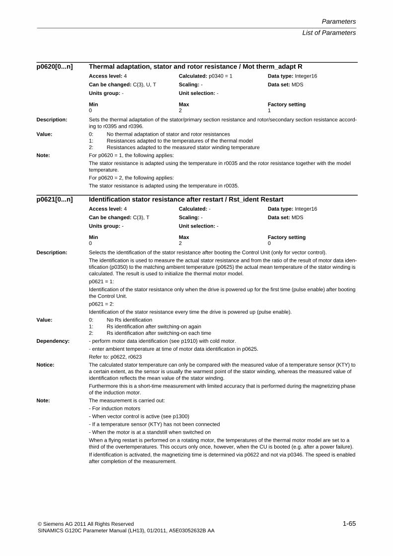
List of Parameters
Parameters
1-65© Siemens AG 2011 All Rights ReservedSINAMICS G120C Parameter Manual (LH13), 01/2011, A5E03052632B AA
Description: Sets the thermal adaptation of the stator/primary section resistance and rotor/secondary section resistance accord-ing to r0395 and r0396.
Value: 0: No thermal adaptation of stator and rotor resistances1: Resistances adapted to the temperatures of the thermal model2: Resistances adapted to the measured stator winding temperature
Note: For p0620 = 1, the following applies:
The stator resistance is adapted using the temperature in r0035 and the rotor resistance together with the model temperature.
For p0620 = 2, the following applies:
The stator resistance is adapted using the temperature in r0035.
Description: Selects the identification of the stator resistance after booting the Control Unit (only for vector control).
The identification is used to measure the actual stator resistance and from the ratio of the result of motor data iden-tification (p0350) to the matching ambient temperature (p0625) the actual mean temperature of the stator winding is calculated. The result is used to initialize the thermal motor model.
p0621 = 1:
Identification of the stator resistance only when the drive is powered up for the first time (pulse enable) after booting the Control Unit.
p0621 = 2:
Identification of the stator resistance every time the drive is powered up (pulse enable).
Value: 0: No Rs identification1: Rs identification after switching-on again2: Rs identification after switching-on each time
Dependency: - perform motor data identification (see p1910) with cold motor.
- enter ambient temperature at time of motor data identification in p0625.
Refer to: p0622, r0623
Notice: The calculated stator temperature can only be compared with the measured value of a temperature sensor (KTY) to a certain extent, as the sensor is usually the warmest point of the stator winding, whereas the measured value of identification reflects the mean value of the stator winding.
Furthermore this is a short-time measurement with limited accuracy that is performed during the magnetizing phase of the induction motor.
Note: The measurement is carried out:
- For induction motors
- When vector control is active (see p1300)
- If a temperature sensor (KTY) has not been connected
- When the motor is at a standstill when switched on
When a flying restart is performed on a rotating motor, the temperatures of the thermal motor model are set to a third of the overtemperatures. This occurs only once, however, when the CU is booted (e.g. after a power failure).
If identification is activated, the magnetizing time is determined via p0622 and not via p0346. The speed is enabled after completion of the measurement.
p0620[0...n] Thermal adaptation, stator and rotor resistance / Mot therm_adapt RAccess level: 4 Calculated: p0340 = 1 Data type: Integer16
Can be changed: C(3), U, T Scaling: - Data set: MDS
Units group: - Unit selection: -
Min Max Factory setting 0 2 1
p0621[0...n] Identification stator resistance after restart / Rst_ident RestartAccess level: 4 Calculated: - Data type: Integer16
Can be changed: C(3), T Scaling: - Data set: MDS
Units group: - Unit selection: -
Min Max Factory setting 0 2 0
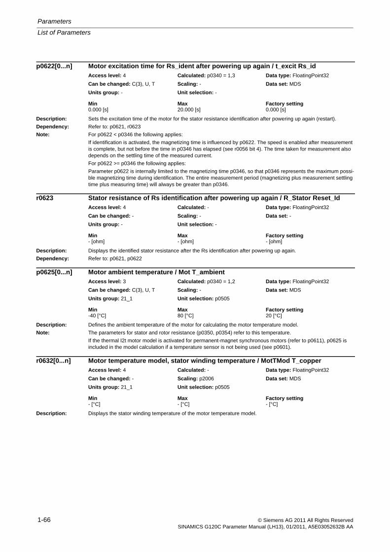
Parameters
List of Parameters
1-66 © Siemens AG 2011 All Rights ReservedSINAMICS G120C Parameter Manual (LH13), 01/2011, A5E03052632B AA
Description: Sets the excitation time of the motor for the stator resistance identification after powering up again (restart).
Dependency: Refer to: p0621, r0623
Note: For p0622 < p0346 the following applies:
If identification is activated, the magnetizing time is influenced by p0622. The speed is enabled after measurement is complete, but not before the time in p0346 has elapsed (see r0056 bit 4). The time taken for measurement also depends on the settling time of the measured current.
For p0622 >= p0346 the following applies:
Parameter p0622 is internally limited to the magnetizing time p0346, so that p0346 represents the maximum possi-ble magnetizing time during identification. The entire measurement period (magnetizing plus measurement settling time plus measuring time) will always be greater than p0346.
Description: Displays the identified stator resistance after the Rs identification after powering up again.
Dependency: Refer to: p0621, p0622
Description: Defines the ambient temperature of the motor for calculating the motor temperature model.
Note: The parameters for stator and rotor resistance (p0350, p0354) refer to this temperature.
If the thermal I2t motor model is activated for permanent-magnet synchronous motors (refer to p0611), p0625 is included in the model calculation if a temperature sensor is not being used (see p0601).
Description: Displays the stator winding temperature of the motor temperature model.
p0622[0...n] Motor excitation time for Rs_ident after powering up again / t_excit Rs_idAccess level: 4 Calculated: p0340 = 1,3 Data type: FloatingPoint32
Can be changed: C(3), U, T Scaling: - Data set: MDS
Units group: - Unit selection: -
Min Max Factory setting 0.000 [s] 20.000 [s] 0.000 [s]
r0623 Stator resistance of Rs identification after powering up again / R_Stator Reset_IdAccess level: 4 Calculated: - Data type: FloatingPoint32
Can be changed: - Scaling: - Data set: -
Units group: - Unit selection: -
Min Max Factory setting - [ohm] - [ohm] - [ohm]
p0625[0...n] Motor ambient temperature / Mot T_ambientAccess level: 3 Calculated: p0340 = 1,2 Data type: FloatingPoint32
Can be changed: C(3), U, T Scaling: - Data set: MDS
Units group: 21_1 Unit selection: p0505
Min Max Factory setting -40 [°C] 80 [°C] 20 [°C]
r0632[0...n] Motor temperature model, stator winding temperature / MotTMod T_copperAccess level: 4 Calculated: - Data type: FloatingPoint32
Can be changed: - Scaling: p2006 Data set: MDS
Units group: 21_1 Unit selection: p0505
Min Max Factory setting - [°C] - [°C] - [°C]
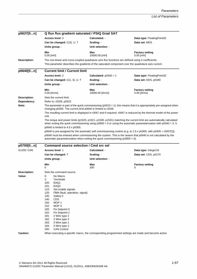
List of Parameters
Parameters
1-67© Siemens AG 2011 All Rights ReservedSINAMICS G120C Parameter Manual (LH13), 01/2011, A5E03052632B AA
Description: The non-linear and cross-coupled quadrature axis flux functions are defined using 4 coefficients.
This parameter describes the gradients of the saturated component over the quadrature axis current.
Description: Sets the current limit.
Dependency: Refer to: r0209, p0323
Note: The parameter is part of the quick commissioning (p0010 = 1); this means that it is appropriately pre-assigned when changing p0305. The current limit p0640 is limited to r0209.
The resulting current limit is displayed in r0067 and if required, r0067 is reduced by the thermal model of the power unit.
The torque and power limits (p1520, p1521, p1530, p1531) matching the current limit are automatically calculated when exiting the quick commissioning using p3900 > 0 or using the automatic parameterization with p0340 = 3, 5.
p0640 is limited to 4.0 x p0305.
p0640 is pre-assigned for the automatic self commissioning routine (e.g. to 1.5 x p0305, with p0305 = r0207[1]).
p0640 must be entered when commissioning the system. This is the reason that p0640 is not calculated by the automatic parameterization when exiting the quick commissioning (p3900 > 0).
Description: Sets the command source.
Value: 0: No Macro2: Terminals100: EAQ1101: EAQ2110: Set enable signals120: FBM (fault, operation, signal)130: Safety 0140: CDS150: MOP 1152: MOP 3160: Fix Setpoint 0162: Fix Setpoint 2181: 2 Wire type 2182: 2 Wire type 3183: 3 Wire type 1184: 3 Wire type 2200: CAN Control
Caution: When executing a specific macro, the corresponding programmed settings are made and become active.
p0637[0...n] Q flux flux gradient saturated / PSIQ Grad SATAccess level: 3 Calculated: - Data type: FloatingPoint32
Can be changed: C(3), U, T Scaling: - Data set: MDS
Units group: - Unit selection: -
Min Max Factory setting 0.00 [mH] 10000.00 [mH] 0.00 [mH]
p0640[0...n] Current limit / Current limitAccess level: 2 Calculated: p0340 = 1 Data type: FloatingPoint32
Can be changed: C(1, 3), U, T Scaling: - Data set: DDS, p0180
Units group: - Unit selection: -
Min Max Factory setting 0.00 [Arms] 10000.00 [Arms] 0.00 [Arms]
p0700[0...n] Command source selection / Cmd src selG120C CAN Access level: 1 Calculated: - Data type: Integer16
Can be changed: T Scaling: - Data set: CDS, p0170
Units group: - Unit selection: -
Min Max Factory setting 0 200 0
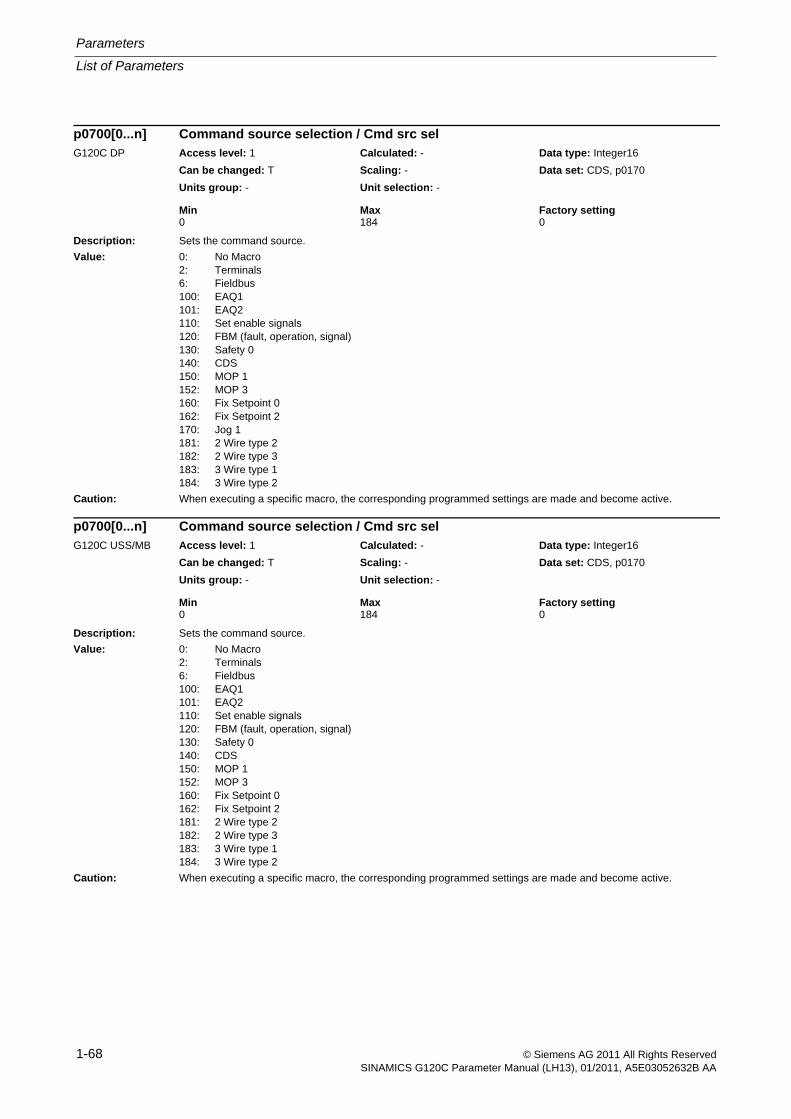
Parameters
List of Parameters
1-68 © Siemens AG 2011 All Rights ReservedSINAMICS G120C Parameter Manual (LH13), 01/2011, A5E03052632B AA
Description: Sets the command source.
Value: 0: No Macro2: Terminals6: Fieldbus100: EAQ1101: EAQ2110: Set enable signals120: FBM (fault, operation, signal)130: Safety 0140: CDS150: MOP 1152: MOP 3160: Fix Setpoint 0162: Fix Setpoint 2170: Jog 1181: 2 Wire type 2182: 2 Wire type 3183: 3 Wire type 1184: 3 Wire type 2
Caution: When executing a specific macro, the corresponding programmed settings are made and become active.
Description: Sets the command source.
Value: 0: No Macro2: Terminals6: Fieldbus100: EAQ1101: EAQ2110: Set enable signals120: FBM (fault, operation, signal)130: Safety 0140: CDS150: MOP 1152: MOP 3160: Fix Setpoint 0162: Fix Setpoint 2181: 2 Wire type 2182: 2 Wire type 3183: 3 Wire type 1184: 3 Wire type 2
Caution: When executing a specific macro, the corresponding programmed settings are made and become active.
p0700[0...n] Command source selection / Cmd src selG120C DP Access level: 1 Calculated: - Data type: Integer16
Can be changed: T Scaling: - Data set: CDS, p0170
Units group: - Unit selection: -
Min Max Factory setting 0 184 0
p0700[0...n] Command source selection / Cmd src selG120C USS/MB Access level: 1 Calculated: - Data type: Integer16
Can be changed: T Scaling: - Data set: CDS, p0170
Units group: - Unit selection: -
Min Max Factory setting 0 184 0
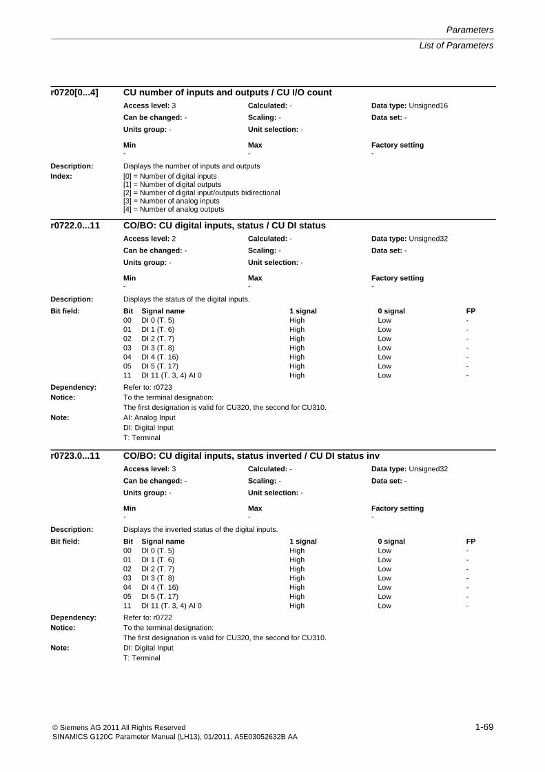
List of Parameters
Parameters
1-69© Siemens AG 2011 All Rights ReservedSINAMICS G120C Parameter Manual (LH13), 01/2011, A5E03052632B AA
Description: Displays the number of inputs and outputsIndex: [0] = Number of digital inputs
[1] = Number of digital outputs[2] = Number of digital input/outputs bidirectional[3] = Number of analog inputs[4] = Number of analog outputs
Description: Displays the status of the digital inputs.
Dependency: Refer to: r0723Notice: To the terminal designation:
The first designation is valid for CU320, the second for CU310.Note: AI: Analog Input
DI: Digital InputT: Terminal
Description: Displays the inverted status of the digital inputs.
Dependency: Refer to: r0722Notice: To the terminal designation:
The first designation is valid for CU320, the second for CU310.Note: DI: Digital Input
T: Terminal
r0720[0...4] CU number of inputs and outputs / CU I/O countAccess level: 3 Calculated: - Data type: Unsigned16
Can be changed: - Scaling: - Data set: -
Units group: - Unit selection: -
Min Max Factory setting - - -
r0722.0...11 CO/BO: CU digital inputs, status / CU DI statusAccess level: 2 Calculated: - Data type: Unsigned32
Can be changed: - Scaling: - Data set: -
Units group: - Unit selection: -
Min Max Factory setting - - -
Bit field: Bit Signal name 1 signal 0 signal FP00 DI 0 (T. 5) High Low -01 DI 1 (T. 6) High Low -02 DI 2 (T. 7) High Low -03 DI 3 (T. 8) High Low -04 DI 4 (T. 16) High Low -05 DI 5 (T. 17) High Low -11 DI 11 (T. 3, 4) AI 0 High Low -
r0723.0...11 CO/BO: CU digital inputs, status inverted / CU DI status invAccess level: 3 Calculated: - Data type: Unsigned32
Can be changed: - Scaling: - Data set: -
Units group: - Unit selection: -
Min Max Factory setting - - -
Bit field: Bit Signal name 1 signal 0 signal FP00 DI 0 (T. 5) High Low -01 DI 1 (T. 6) High Low -02 DI 2 (T. 7) High Low -03 DI 3 (T. 8) High Low -04 DI 4 (T. 16) High Low -05 DI 5 (T. 17) High Low -11 DI 11 (T. 3, 4) AI 0 High Low -
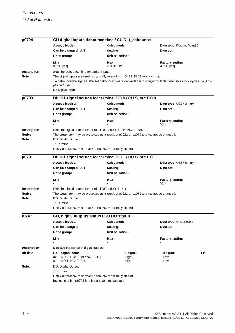
Parameters
List of Parameters
1-70 © Siemens AG 2011 All Rights ReservedSINAMICS G120C Parameter Manual (LH13), 01/2011, A5E03052632B AA
Description: Sets the debounce time for digital inputs.
Note: The digital inputs are read in cyclically every 2 ms (DI 11, DI 12 every 4 ms).
To debounce the signals, the set debounce time is converted into integer multiple debounce clock cycles Tp (Tp = p0724 / 2 ms).
DI: Digital Input
Description: Sets the signal source for terminal DO 0 (NO: T. 19 / NC: T. 18).
Notice: The parameter may be protected as a result of p0922 or p2079 and cannot be changed.
Note: DO: Digital Output
T: Terminal
Relay output: NO = normally open, NC = normally closed
Description: Sets the signal source for terminal DO 1 (NO: T. 21).
Notice: The parameter may be protected as a result of p0922 or p2079 and cannot be changed.
Note: DO: Digital Output
T: Terminal
Relay output: NO = normally open, NC = normally closed
Description: Displays the status of digital outputs.
Note: DO: Digital Output
T: Terminal
Relay output: NO = normally open, NC = normally closed
Inversion using p0748 has been taken into account.
p0724 CU digital inputs debounce time / CU DI t_debounceAccess level: 4 Calculated: - Data type: FloatingPoint32
Can be changed: U, T Scaling: - Data set: -
Units group: - Unit selection: -
Min Max Factory setting 0.000 [ms] 20.000 [ms] 4.000 [ms]
p0730 BI: CU signal source for terminal DO 0 / CU S_src DO 0Access level: 2 Calculated: - Data type: U32 / Binary
Can be changed: U, T Scaling: - Data set: -
Units group: - Unit selection: -
Min Max Factory setting - - 52.3
p0731 BI: CU signal source for terminal DO 1 / CU S_src DO 1Access level: 2 Calculated: - Data type: U32 / Binary
Can be changed: U, T Scaling: - Data set: -
Units group: - Unit selection: -
Min Max Factory setting - - 52.7
r0747 CU, digital outputs status / CU DO statusAccess level: 3 Calculated: - Data type: Unsigned32
Can be changed: - Scaling: - Data set: -
Units group: - Unit selection: -
Min Max Factory setting - - -
Bit field: Bit Signal name 1 signal 0 signal FP00 DO 0 (NO: T. 19 / NC: T. 18) High Low -01 DO 1 (NO: T. 21) High Low -
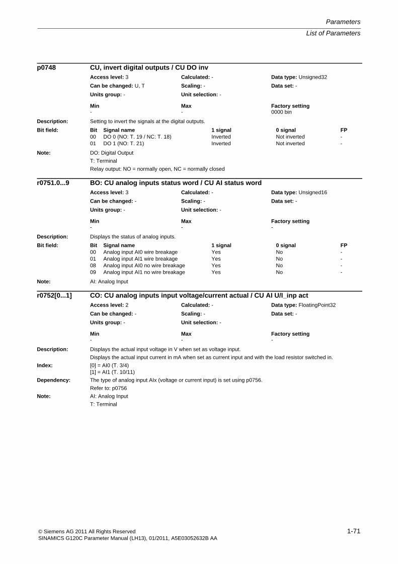
List of Parameters
Parameters
1-71© Siemens AG 2011 All Rights ReservedSINAMICS G120C Parameter Manual (LH13), 01/2011, A5E03052632B AA
Description: Setting to invert the signals at the digital outputs.
Note: DO: Digital Output
T: Terminal
Relay output: NO = normally open, NC = normally closed
Description: Displays the status of analog inputs.
Note: AI: Analog Input
Description: Displays the actual input voltage in V when set as voltage input.
Displays the actual input current in mA when set as current input and with the load resistor switched in.
Index: [0] = AI0 (T. 3/4)[1] = AI1 (T. 10/11)
Dependency: The type of analog input AIx (voltage or current input) is set using p0756.
Refer to: p0756
Note: AI: Analog Input
T: Terminal
p0748 CU, invert digital outputs / CU DO invAccess level: 3 Calculated: - Data type: Unsigned32
Can be changed: U, T Scaling: - Data set: -
Units group: - Unit selection: -
Min Max Factory setting - - 0000 bin
Bit field: Bit Signal name 1 signal 0 signal FP00 DO 0 (NO: T. 19 / NC: T. 18) Inverted Not inverted -01 DO 1 (NO: T. 21) Inverted Not inverted -
r0751.0...9 BO: CU analog inputs status word / CU AI status wordAccess level: 3 Calculated: - Data type: Unsigned16
Can be changed: - Scaling: - Data set: -
Units group: - Unit selection: -
Min Max Factory setting - - -
Bit field: Bit Signal name 1 signal 0 signal FP00 Analog input AI0 wire breakage Yes No -01 Analog input AI1 wire breakage Yes No -08 Analog input AI0 no wire breakage Yes No -09 Analog input AI1 no wire breakage Yes No -
r0752[0...1] CO: CU analog inputs input voltage/current actual / CU AI U/I_inp actAccess level: 2 Calculated: - Data type: FloatingPoint32
Can be changed: - Scaling: - Data set: -
Units group: - Unit selection: -
Min Max Factory setting - - -
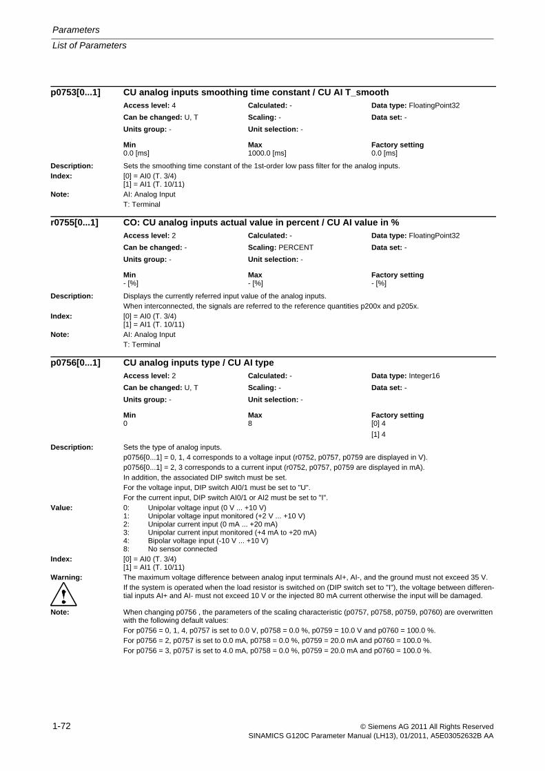
Parameters
List of Parameters
1-72 © Siemens AG 2011 All Rights ReservedSINAMICS G120C Parameter Manual (LH13), 01/2011, A5E03052632B AA
Description: Sets the smoothing time constant of the 1st-order low pass filter for the analog inputs.Index: [0] = AI0 (T. 3/4)
[1] = AI1 (T. 10/11)Note: AI: Analog Input
T: Terminal
Description: Displays the currently referred input value of the analog inputs.When interconnected, the signals are referred to the reference quantities p200x and p205x.
Index: [0] = AI0 (T. 3/4)[1] = AI1 (T. 10/11)
Note: AI: Analog InputT: Terminal
Description: Sets the type of analog inputs.p0756[0...1] = 0, 1, 4 corresponds to a voltage input (r0752, p0757, p0759 are displayed in V).p0756[0...1] = 2, 3 corresponds to a current input (r0752, p0757, p0759 are displayed in mA).In addition, the associated DIP switch must be set.For the voltage input, DIP switch AI0/1 must be set to "U".For the current input, DIP switch AI0/1 or AI2 must be set to "I".
Value: 0: Unipolar voltage input (0 V ... +10 V)1: Unipolar voltage input monitored (+2 V ... +10 V)2: Unipolar current input (0 mA ... +20 mA)3: Unipolar current input monitored (+4 mA to +20 mA)4: Bipolar voltage input (-10 V ... +10 V)8: No sensor connected
Index: [0] = AI0 (T. 3/4)[1] = AI1 (T. 10/11)
Warning: The maximum voltage difference between analog input terminals AI+, AI-, and the ground must not exceed 35 V.If the system is operated when the load resistor is switched on (DIP switch set to "I"), the voltage between differen-tial inputs AI+ and AI- must not exceed 10 V or the injected 80 mA current otherwise the input will be damaged.
Note: When changing p0756 , the parameters of the scaling characteristic (p0757, p0758, p0759, p0760) are overwritten with the following default values:For p0756 = 0, 1, 4, p0757 is set to 0.0 V, p0758 = 0.0 %, p0759 = 10.0 V and p0760 = 100.0 %.For p0756 = 2, p0757 is set to 0.0 mA, p0758 = 0.0 %, p0759 = 20.0 mA and p0760 = 100.0 %.For p0756 = 3, p0757 is set to 4.0 mA, p0758 = 0.0 %, p0759 = 20.0 mA and p0760 = 100.0 %.
p0753[0...1] CU analog inputs smoothing time constant / CU AI T_smoothAccess level: 4 Calculated: - Data type: FloatingPoint32
Can be changed: U, T Scaling: - Data set: -
Units group: - Unit selection: -
Min Max Factory setting 0.0 [ms] 1000.0 [ms] 0.0 [ms]
r0755[0...1] CO: CU analog inputs actual value in percent / CU AI value in %Access level: 2 Calculated: - Data type: FloatingPoint32
Can be changed: - Scaling: PERCENT Data set: -
Units group: - Unit selection: -
Min Max Factory setting - [%] - [%] - [%]
p0756[0...1] CU analog inputs type / CU AI typeAccess level: 2 Calculated: - Data type: Integer16
Can be changed: U, T Scaling: - Data set: -
Units group: - Unit selection: -
Min Max Factory setting 0 8 [0] 4
[1] 4
List of Parameters
Parameters
1-73© Siemens AG 2011 All Rights ReservedSINAMICS G120C Parameter Manual (LH13), 01/2011, A5E03052632B AA
Description: Sets the scaling characteristic for the analog inputs.
The scaling characteristic for the analog inputs is defined using 2 points.
This parameter specifies the x coordinate (V, mA) of the 1st value pair of the characteristic.
Index: [0] = AI0 (T. 3/4)[1] = AI1 (T. 10/11)
Note: The parameters for the characteristic do not have a limiting effect.
Description: Sets the scaling characteristic for the analog inputs.
The scaling characteristic for the analog inputs is defined using 2 points.
This parameter specifies the y coordinate (percentage) of the 1st value pair of the characteristic.
Index: [0] = AI0 (T. 3/4)[1] = AI1 (T. 10/11)
Note: The parameters for the characteristic do not have a limiting effect.
Description: Sets the scaling characteristic for the analog inputs.
The scaling characteristic for the analog inputs is defined using 2 points.
This parameter specifies the x coordinate (V, mA) of the 2nd value pair of the characteristic.
Index: [0] = AI0 (T. 3/4)[1] = AI1 (T. 10/11)
Note: The parameters for the characteristic do not have a limiting effect.
Description: Sets the scaling characteristic for the analog inputs.
The scaling characteristic for the analog inputs is defined using 2 points.
This parameter specifies the y coordinate (percentage) of the 2nd value pair of the characteristic.
Index: [0] = AI0 (T. 3/4)[1] = AI1 (T. 10/11)
Note: The parameters for the characteristic do not have a limiting effect.
p0757[0...1] CU analog inputs characteristic value x1 / CU AI char x1Access level: 2 Calculated: - Data type: FloatingPoint32
Can be changed: U, T Scaling: - Data set: -
Units group: - Unit selection: -
Min Max Factory setting -50.000 160.000 0.000
p0758[0...1] CU analog inputs characteristic value y1 / CU AI char y1Access level: 2 Calculated: - Data type: FloatingPoint32
Can be changed: U, T Scaling: - Data set: -
Units group: - Unit selection: -
Min Max Factory setting -1000.00 [%] 1000.00 [%] 0.00 [%]
p0759[0...1] CU analog inputs characteristic value x2 / CU AI char x2Access level: 2 Calculated: - Data type: FloatingPoint32
Can be changed: U, T Scaling: - Data set: -
Units group: - Unit selection: -
Min Max Factory setting -50.000 160.000 10.000
p0760[0...1] CU analog inputs characteristic value y2 / CU AI char y2Access level: 2 Calculated: - Data type: FloatingPoint32
Can be changed: U, T Scaling: - Data set: -
Units group: - Unit selection: -
Min Max Factory setting -1000.00 [%] 1000.00 [%] 100.00 [%]
Parameters
List of Parameters
1-74 © Siemens AG 2011 All Rights ReservedSINAMICS G120C Parameter Manual (LH13), 01/2011, A5E03052632B AA
Description: Sets the response threshold for the wire breakage monitoring of the analog inputs.The unit for the parameter value depends on the set analog input type.
Index: [0] = AI0 (T. 3/4)[1] = AI1 (T. 10/11)
Dependency: For the following analog input type, the wire breakage monitoring is active:p0756[0...1] = 1 (unipolar voltage input monitored (+2 V ... +10 V)), unit [V]p0756[0...1] = 3 (unipolar current input monitored (+4 mA ... +20 mA)), unit [mA]Refer to: p0756
Note: AI: Analog InputWhen p0761 = 0, wire breakage monitoring is not carried out.
Description: Sets the signal source for the analog outputs.Index: [0] = AO0 (T 12/13)
[1] = AO1 (T 26/27)Note: AO: Analog Output
T: Terminal
Description: Displays the actual referred output value of the analog outputs.Index: [0] = AO0 (T 12/13)
[1] = AO1 (T 26/27)Note: AO: Analog Output
T: Terminal
Description: Displays the actual output voltage or output current at the analog outputs.Index: [0] = AO0 (T 12/13)
[1] = AO1 (T 26/27)Dependency: Refer to: p0776Note: AO: Analog Output
T: Terminal
p0761[0...1] CU analog inputs wire breakage monitoring response threshold / CU WireBrkThreshAccess level: 2 Calculated: - Data type: FloatingPoint32
Can be changed: U, T Scaling: - Data set: -
Units group: - Unit selection: -
Min Max Factory setting 0.00 20.00 2.00
p0771[0...1] CI: CU analog outputs signal source / CU AO S_srcAccess level: 2 Calculated: - Data type: U32 / FloatingPoint32
Can be changed: U, T Scaling: PERCENT Data set: -
Units group: - Unit selection: -
Min Max Factory setting - - [0] 21[0]
[1] 27[0]
r0772[0...1] CU analog outputs, output value currently referred / CU AO outp_valAccess level: 3 Calculated: - Data type: FloatingPoint32
Can be changed: - Scaling: - Data set: -
Units group: - Unit selection: -
Min Max Factory setting - [%] - [%] - [%]
r0774[0...1] CU analog outputs output voltage/current actual / CU AO U/I_outpAccess level: 2 Calculated: - Data type: FloatingPoint32
Can be changed: - Scaling: p2001 Data set: -
Units group: - Unit selection: -
Min Max Factory setting - - -
List of Parameters
Parameters
1-75© Siemens AG 2011 All Rights ReservedSINAMICS G120C Parameter Manual (LH13), 01/2011, A5E03052632B AA
Description: Activates the absolute value generation for the analog outputs.
Value: 0: No absolute value generation1: Absolute value generation switched in
Index: [0] = AO0 (T 12/13)[1] = AO1 (T 26/27)
Note: AO: Analog Output
T: Terminal
Description: Sets the analog output type.
p0776[x] = 1 corresponds to a voltage output (p0774, p0778, p0780 are displayed in V).
p0776[x] = 0, 2 corresponds to a current output (p0774, p0778, p0780 are displayed in mA).
Value: 0: Current output (0 mA ... +20 mA)1: Voltage output (0 V ... +10 V)2: Current output (+4 mA ... +20 mA)
Index: [0] = AO0 (T 12/13)[1] = AO1 (T 26/27)
Note: When changing p0776, the parameters of the scaling characteristic (p0777, p0778, p0779, p0780) are overwritten with the following default values:
For p0776 = 0, p0777 is set to 0.0 %, p0778 = 0.0 mA, p0779 = 100.0 % and p0780 to 20.0 mA.
For p0776 = 1, p0777 is set to 0.0 %, p0778 = 0.0 V, p0779 = 100.0 % and p0780 to 10.0 V.
For p0776 = 2, p0777 is set to 0.0 %, p0778 = 4.0 mA, p0779 = 100.0 % and p0780 to 20.0 mA.
Description: Sets the scaling characteristic for the analog outputs.
The scaling characteristic for the analog outputs is defined using 2 points.
This parameter specifies the x coordinate (percentage) of the 1st value pair of the characteristic.
Index: [0] = AO0 (T 12/13)[1] = AO1 (T 26/27)
Dependency: Refer to: p0776
Notice: This parameter is automatically overwritten when the analog output type is changed (p0776).
Note: This parameter is automatically overwritten if p0776 (type of analog output) is changed.
The parameters for the characteristic do not have a limiting effect.
p0775[0...1] CU analog outputs activate absolute value generation / CU AO absVal actAccess level: 2 Calculated: - Data type: Integer16
Can be changed: T Scaling: - Data set: -
Units group: - Unit selection: -
Min Max Factory setting 0 1 0
p0776[0...1] CU analog outputs type / CU AO typeAccess level: 2 Calculated: - Data type: Integer16
Can be changed: U, T Scaling: - Data set: -
Units group: - Unit selection: -
Min Max Factory setting 0 2 0
p0777[0...1] CU analog outputs characteristic value x1 / CU AO char x1Access level: 2 Calculated: - Data type: FloatingPoint32
Can be changed: U, T Scaling: - Data set: -
Units group: - Unit selection: -
Min Max Factory setting -1000.00 [%] 1000.00 [%] 0.00 [%]
Parameters
List of Parameters
1-76 © Siemens AG 2011 All Rights ReservedSINAMICS G120C Parameter Manual (LH13), 01/2011, A5E03052632B AA
Description: Sets the scaling characteristic for the analog outputs.
The scaling characteristic for the analog outputs is defined using 2 points.
This parameter specifies the y coordinate (output voltage in V or output current in mA) of the 1st value pair of the characteristic.
Index: [0] = AO0 (T 12/13)[1] = AO1 (T 26/27)
Dependency: The unit of this parameter (V or mA) depends on the analog input type.
Refer to: p0776
Notice: This parameter is automatically overwritten when the analog output type is changed (p0776).
Note: This parameter is automatically overwritten if p0776 (type of analog output) is changed.
The parameters for the characteristic do not have a limiting effect.
Description: Sets the scaling characteristic for the analog outputs.
The scaling characteristic for the analog outputs is defined using 2 points.
This parameter specifies the x coordinate (percentage) of the 2nd value pair of the characteristic.
Index: [0] = AO0 (T 12/13)[1] = AO1 (T 26/27)
Dependency: Refer to: p0776
Notice: This parameter is automatically overwritten when the analog output type is changed (p0776).
Note: This parameter is automatically overwritten if p0776 (type of analog output) is changed.
The parameters for the characteristic do not have a limiting effect.
Description: Sets the scaling characteristic for the analog outputs.
The scaling characteristic for the analog outputs is defined using 2 points.
This parameter specifies the y coordinate (output voltage in V or output current in mA) of the 2nd value pair of the characteristic.
Index: [0] = AO0 (T 12/13)[1] = AO1 (T 26/27)
Dependency: The unit of this parameter (V or mA) depends on the analog input type.
Refer to: p0776
Notice: This parameter is automatically overwritten when the analog output type is changed (p0776).
Note: This parameter is automatically overwritten if p0776 (type of analog output) is changed.
The parameters for the characteristic do not have a limiting effect.
p0778[0...1] CU analog outputs characteristic value y1 / CU char y1Access level: 2 Calculated: - Data type: FloatingPoint32
Can be changed: U, T Scaling: - Data set: -
Units group: - Unit selection: -
Min Max Factory setting -20.000 [V] 20.000 [V] 0.000 [V]
p0779[0...1] CU analog outputs characteristic value x2 / CU char x2Access level: 2 Calculated: - Data type: FloatingPoint32
Can be changed: U, T Scaling: - Data set: -
Units group: - Unit selection: -
Min Max Factory setting -1000.00 [%] 1000.00 [%] 100.00 [%]
p0780[0...1] CU analog outputs characteristic value y2 / CU char y2Access level: 2 Calculated: - Data type: FloatingPoint32
Can be changed: U, T Scaling: - Data set: -
Units group: - Unit selection: -
Min Max Factory setting -20.000 [V] 20.000 [V] 20.000 [V]
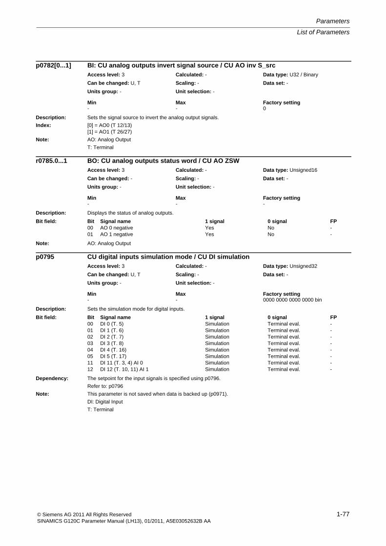
List of Parameters
Parameters
1-77© Siemens AG 2011 All Rights ReservedSINAMICS G120C Parameter Manual (LH13), 01/2011, A5E03052632B AA
Description: Sets the signal source to invert the analog output signals.
Index: [0] = AO0 (T 12/13)[1] = AO1 (T 26/27)
Note: AO: Analog Output
T: Terminal
Description: Displays the status of analog outputs.
Note: AO: Analog Output
Description: Sets the simulation mode for digital inputs.
Dependency: The setpoint for the input signals is specified using p0796.
Refer to: p0796
Note: This parameter is not saved when data is backed up (p0971).
DI: Digital Input
T: Terminal
p0782[0...1] BI: CU analog outputs invert signal source / CU AO inv S_srcAccess level: 3 Calculated: - Data type: U32 / Binary
Can be changed: U, T Scaling: - Data set: -
Units group: - Unit selection: -
Min Max Factory setting - - 0
r0785.0...1 BO: CU analog outputs status word / CU AO ZSWAccess level: 3 Calculated: - Data type: Unsigned16
Can be changed: - Scaling: - Data set: -
Units group: - Unit selection: -
Min Max Factory setting - - -
Bit field: Bit Signal name 1 signal 0 signal FP00 AO 0 negative Yes No -01 AO 1 negative Yes No -
p0795 CU digital inputs simulation mode / CU DI simulationAccess level: 3 Calculated: - Data type: Unsigned32
Can be changed: U, T Scaling: - Data set: -
Units group: - Unit selection: -
Min Max Factory setting - - 0000 0000 0000 0000 bin
Bit field: Bit Signal name 1 signal 0 signal FP00 DI 0 (T. 5) Simulation Terminal eval. -01 DI 1 (T. 6) Simulation Terminal eval. -02 DI 2 (T. 7) Simulation Terminal eval. -03 DI 3 (T. 8) Simulation Terminal eval. -04 DI 4 (T. 16) Simulation Terminal eval. -05 DI 5 (T. 17) Simulation Terminal eval. -11 DI 11 (T. 3, 4) AI 0 Simulation Terminal eval. -12 DI 12 (T. 10, 11) AI 1 Simulation Terminal eval. -
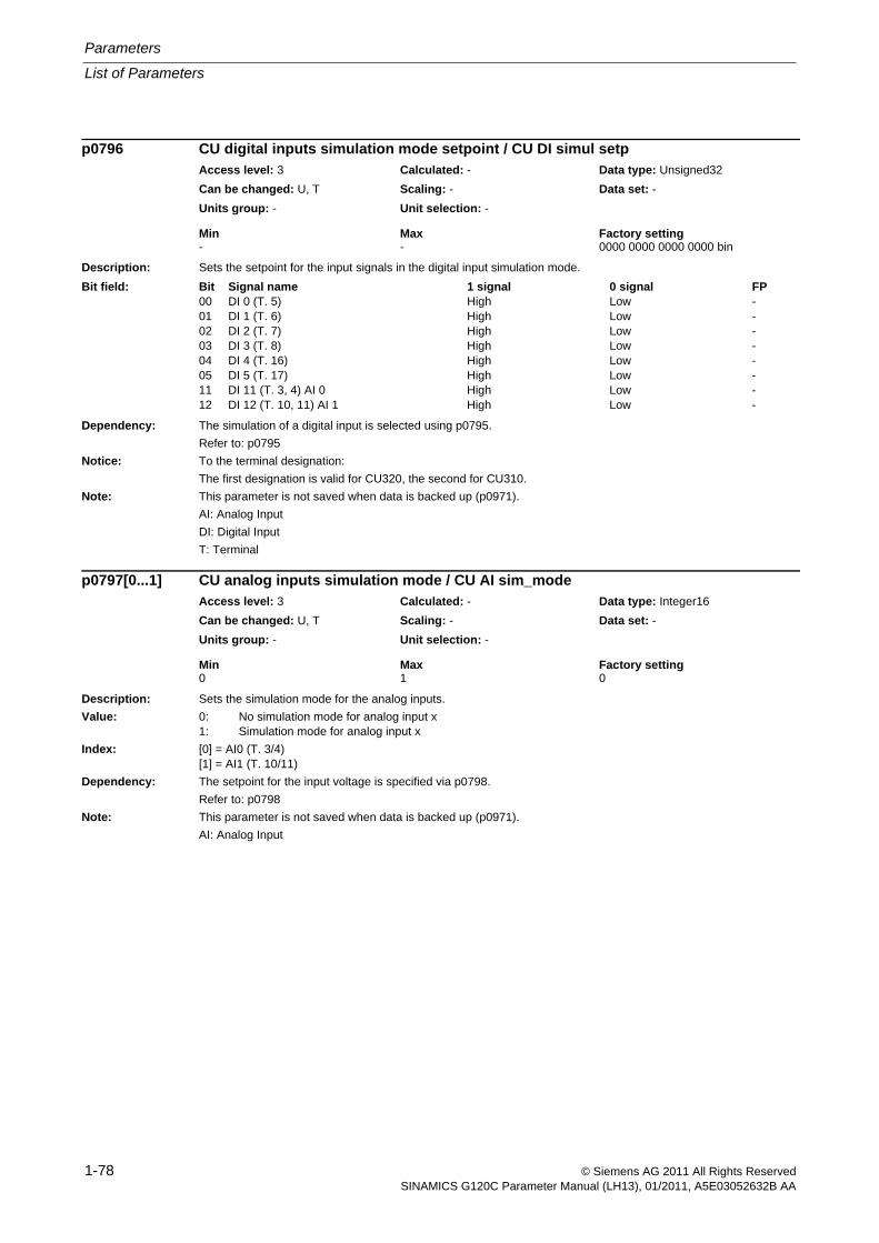
Parameters
List of Parameters
1-78 © Siemens AG 2011 All Rights ReservedSINAMICS G120C Parameter Manual (LH13), 01/2011, A5E03052632B AA
Description: Sets the setpoint for the input signals in the digital input simulation mode.
Dependency: The simulation of a digital input is selected using p0795.
Refer to: p0795
Notice: To the terminal designation:
The first designation is valid for CU320, the second for CU310.
Note: This parameter is not saved when data is backed up (p0971).
AI: Analog Input
DI: Digital Input
T: Terminal
Description: Sets the simulation mode for the analog inputs.
Value: 0: No simulation mode for analog input x1: Simulation mode for analog input x
Index: [0] = AI0 (T. 3/4)[1] = AI1 (T. 10/11)
Dependency: The setpoint for the input voltage is specified via p0798.
Refer to: p0798
Note: This parameter is not saved when data is backed up (p0971).
AI: Analog Input
p0796 CU digital inputs simulation mode setpoint / CU DI simul setpAccess level: 3 Calculated: - Data type: Unsigned32
Can be changed: U, T Scaling: - Data set: -
Units group: - Unit selection: -
Min Max Factory setting - - 0000 0000 0000 0000 bin
Bit field: Bit Signal name 1 signal 0 signal FP00 DI 0 (T. 5) High Low -01 DI 1 (T. 6) High Low -02 DI 2 (T. 7) High Low -03 DI 3 (T. 8) High Low -04 DI 4 (T. 16) High Low -05 DI 5 (T. 17) High Low -11 DI 11 (T. 3, 4) AI 0 High Low -12 DI 12 (T. 10, 11) AI 1 High Low -
p0797[0...1] CU analog inputs simulation mode / CU AI sim_modeAccess level: 3 Calculated: - Data type: Integer16
Can be changed: U, T Scaling: - Data set: -
Units group: - Unit selection: -
Min Max Factory setting 0 1 0
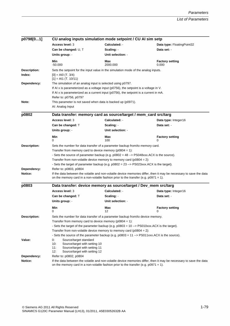
List of Parameters
Parameters
1-79© Siemens AG 2011 All Rights ReservedSINAMICS G120C Parameter Manual (LH13), 01/2011, A5E03052632B AA
Description: Sets the setpoint for the input value in the simulation mode of the analog inputs.
Index: [0] = AI0 (T. 3/4)[1] = AI1 (T. 10/11)
Dependency: The simulation of an analog input is selected using p0797.
If AI x is parameterized as a voltage input (p0756), the setpoint is a voltage in V.
If AI x is parameterized as a current input (p0756), the setpoint is a current in mA.
Refer to: p0756, p0797
Note: This parameter is not saved when data is backed up (p0971).
AI: Analog Input
Description: Sets the number for data transfer of a parameter backup from/to memory card.
Transfer from memory card to device memory (p0804 = 1):
- Sets the source of parameter backup (e.g. p0802 = 48 --> PS048xxx.ACX is the source).
Transfer from non-volatile device memory to memory card (p0804 = 2):
- Sets the target of parameter backup (e.g. p0802 = 23 --> PS023xxx.ACX is the target).
Dependency: Refer to: p0803, p0804
Notice: If the data between the volatile and non-volatile device memories differ, then it may be necessary to save the data on the memory card in a non-volatile fashion prior to the transfer (e.g. p0971 = 1).
Description: Sets the number for data transfer of a parameter backup from/to device memory.
Transfer from memory card to device memory (p0804 = 1):
- Sets the target of the parameter backup (e.g. p0803 = 10 --> PS010xxx.ACX is the target).
Transfer from non-volatile device memory to memory card (p0804 = 2):
- Sets the source of the parameter backup (e.g. p0803 = 11 --> PS011xxx.ACX is the source).
Value: 0: Source/target standard10: Source/target with setting 1011: Source/target with setting 1112: Source/target with setting 12
Dependency: Refer to: p0802, p0804
Notice: If the data between the volatile and non-volatile device memories differ, then it may be necessary to save the data on the memory card in a non-volatile fashion prior to the transfer (e.g. p0971 = 1).
p0798[0...1] CU analog inputs simulation mode setpoint / CU AI sim setpAccess level: 3 Calculated: - Data type: FloatingPoint32
Can be changed: U, T Scaling: - Data set: -
Units group: - Unit selection: -
Min Max Factory setting -50.000 2000.000 0.000
p0802 Data transfer: memory card as source/target / mem_card src/targAccess level: 3 Calculated: - Data type: Integer16
Can be changed: T Scaling: - Data set: -
Units group: - Unit selection: -
Min Max Factory setting 0 100 0
p0803 Data transfer: device memory as source/target / Dev_mem src/targAccess level: 3 Calculated: - Data type: Integer16
Can be changed: T Scaling: - Data set: -
Units group: - Unit selection: -
Min Max Factory setting 0 12 0
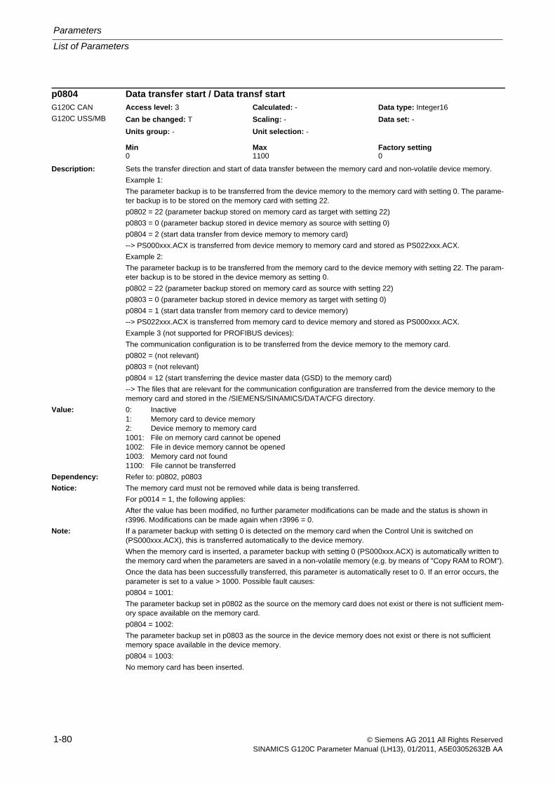
Parameters
List of Parameters
1-80 © Siemens AG 2011 All Rights ReservedSINAMICS G120C Parameter Manual (LH13), 01/2011, A5E03052632B AA
Description: Sets the transfer direction and start of data transfer between the memory card and non-volatile device memory.
Example 1:
The parameter backup is to be transferred from the device memory to the memory card with setting 0. The parame-ter backup is to be stored on the memory card with setting 22.
p0802 = 22 (parameter backup stored on memory card as target with setting 22)
p0803 = 0 (parameter backup stored in device memory as source with setting 0)
p0804 = 2 (start data transfer from device memory to memory card)
--> PS000xxx.ACX is transferred from device memory to memory card and stored as PS022xxx.ACX.
Example 2:
The parameter backup is to be transferred from the memory card to the device memory with setting 22. The param-eter backup is to be stored in the device memory as setting 0.
p0802 = 22 (parameter backup stored on memory card as source with setting 22)
p0803 = 0 (parameter backup stored in device memory as target with setting 0)
p0804 = 1 (start data transfer from memory card to device memory)
--> PS022xxx.ACX is transferred from memory card to device memory and stored as PS000xxx.ACX.
Example 3 (not supported for PROFIBUS devices):
The communication configuration is to be transferred from the device memory to the memory card.
p0802 = (not relevant)
p0803 = (not relevant)
p0804 = 12 (start transferring the device master data (GSD) to the memory card)
--> The files that are relevant for the communication configuration are transferred from the device memory to the memory card and stored in the /SIEMENS/SINAMICS/DATA/CFG directory.
Value: 0: Inactive1: Memory card to device memory2: Device memory to memory card1001: File on memory card cannot be opened1002: File in device memory cannot be opened1003: Memory card not found1100: File cannot be transferred
Dependency: Refer to: p0802, p0803
Notice: The memory card must not be removed while data is being transferred.
For p0014 = 1, the following applies:
After the value has been modified, no further parameter modifications can be made and the status is shown in r3996. Modifications can be made again when r3996 = 0.
Note: If a parameter backup with setting 0 is detected on the memory card when the Control Unit is switched on (PS000xxx.ACX), this is transferred automatically to the device memory.
When the memory card is inserted, a parameter backup with setting 0 (PS000xxx.ACX) is automatically written to the memory card when the parameters are saved in a non-volatile memory (e.g. by means of "Copy RAM to ROM").
Once the data has been successfully transferred, this parameter is automatically reset to 0. If an error occurs, the parameter is set to a value > 1000. Possible fault causes:
p0804 = 1001:
The parameter backup set in p0802 as the source on the memory card does not exist or there is not sufficient mem-ory space available on the memory card.
p0804 = 1002:
The parameter backup set in p0803 as the source in the device memory does not exist or there is not sufficient memory space available in the device memory.
p0804 = 1003:
No memory card has been inserted.
p0804 Data transfer start / Data transf startG120C CAN
G120C USS/MB
Access level: 3 Calculated: - Data type: Integer16
Can be changed: T Scaling: - Data set: -
Units group: - Unit selection: -
Min Max Factory setting 0 1100 0
List of Parameters
Parameters
1-81© Siemens AG 2011 All Rights ReservedSINAMICS G120C Parameter Manual (LH13), 01/2011, A5E03052632B AA
Description: Sets the transfer direction and start of data transfer between the memory card and non-volatile device memory.Example 1:The parameter backup is to be transferred from the device memory to the memory card with setting 0. The parame-ter backup is to be stored on the memory card with setting 22.p0802 = 22 (parameter backup stored on memory card as target with setting 22)p0803 = 0 (parameter backup stored in device memory as source with setting 0)p0804 = 2 (start data transfer from device memory to memory card)--> PS000xxx.ACX is transferred from device memory to memory card and stored as PS022xxx.ACX.Example 2:The parameter backup is to be transferred from the memory card to the device memory with setting 22. The param-eter backup is to be stored in the device memory as setting 0.p0802 = 22 (parameter backup stored on memory card as source with setting 22)p0803 = 0 (parameter backup stored in device memory as target with setting 0)p0804 = 1 (start data transfer from memory card to device memory)--> PS022xxx.ACX is transferred from memory card to device memory and stored as PS000xxx.ACX.Example 3 (not supported for PROFIBUS devices):The communication configuration is to be transferred from the device memory to the memory card.p0802 = (not relevant)p0803 = (not relevant)p0804 = 12 (start transferring the device master data (GSD) to the memory card)--> The files that are relevant for the communication configuration are transferred from the device memory to the memory card and stored in the /SIEMENS/SINAMICS/DATA/CFG directory.
Value: 0: Inactive1: Memory card to device memory2: Device memory to memory card12: Device memory (communication configuration) to memory card1001: File on memory card cannot be opened1002: File in device memory cannot be opened1003: Memory card not found1100: File cannot be transferred
Dependency: Refer to: p0802, p0803Notice: The memory card must not be removed while data is being transferred.
For p0014 = 1, the following applies:After the value has been modified, no further parameter modifications can be made and the status is shown in r3996. Modifications can be made again when r3996 = 0.
Note: If a parameter backup with setting 0 is detected on the memory card when the Control Unit is switched on (PS000xxx.ACX), this is transferred automatically to the device memory.When the memory card is inserted, a parameter backup with setting 0 (PS000xxx.ACX) is automatically written to the memory card when the parameters are saved in a non-volatile memory (e.g. by means of "Copy RAM to ROM").Once the data has been successfully transferred, this parameter is automatically reset to 0. If an error occurs, the parameter is set to a value > 1000. Possible fault causes:p0804 = 1001:The parameter backup set in p0802 as the source on the memory card does not exist or there is not sufficient mem-ory space available on the memory card.p0804 = 1002:The parameter backup set in p0803 as the source in the device memory does not exist or there is not sufficient memory space available in the device memory.p0804 = 1003:No memory card has been inserted.
p0804 Data transfer start / Data transf startG120C DP Access level: 3 Calculated: - Data type: Integer16
Can be changed: T Scaling: - Data set: -
Units group: - Unit selection: -
Min Max Factory setting 0 1100 0
Parameters
List of Parameters
1-82 © Siemens AG 2011 All Rights ReservedSINAMICS G120C Parameter Manual (LH13), 01/2011, A5E03052632B AA
Description: Sets the signal source to block the master control.
Dependency: Refer to: r0807
Note: The commissioning software (drive control panel) uses the master control.
Description: Displays what has the master control.
The drive can be controlled via the BICO interconnection or from external (e.g. the commissioning software).
Dependency: Refer to: p0806
Notice: The master control only influences control word 1 and speed setpoint 1. Other control words/setpoints can be trans-ferred from another automation device.
Note: Bit 0 = 0: BICO interconnection active
Bit 0 = 1: Master control for PC/OP
The master control is used from the commissioning software (drive control panel) and from the Operator Panel (OP, LOCAL mode).
Description: Copies one Command Data Set (CDS) into another.
Index: [0] = Source Command Data Set[1] = Target Command Data Set[2] = Start copying procedure
Dependency: Refer to: r3996
Notice: When the command data sets are copied, short-term communication interruptions may occur.
Note: Procedure:
1. In Index 0, enter which command data set should be copied.
2. In Index 1, enter the command data set that is to be copied into.
3. Start copying: Set index 2 from 0 to 1.
p0809[2] is automatically set to 0 when copying is completed.
p0806 BI: Inhibit master control / PcCtrl inhibitAccess level: 3 Calculated: - Data type: U32 / Binary
Can be changed: T Scaling: - Data set: -
Units group: - Unit selection: -
Min Max Factory setting - - 0
r0807.0 BO: Master control active / PcCtrl activeAccess level: 3 Calculated: - Data type: Unsigned8
Can be changed: - Scaling: - Data set: -
Units group: - Unit selection: -
Min Max Factory setting - - -
Bit field: Bit Signal name 1 signal 0 signal FP00 Master control active Yes No 5030,
6031
p0809[0...2] Copy Command Data Set CDS / Copy CDSAccess level: 2 Calculated: - Data type: Unsigned8
Can be changed: T Scaling: - Data set: -
Units group: - Unit selection: -
Min Max Factory setting 0 3 0
List of Parameters
Parameters
1-83© Siemens AG 2011 All Rights ReservedSINAMICS G120C Parameter Manual (LH13), 01/2011, A5E03052632B AA
Description: Sets the signal source to select the Command Data Set bit 0 (CDS bit 0).
Dependency: Refer to: r0050, r0836
Notice: The parameter may be protected as a result of p0922 or p2079 and cannot be changed.
Note: The Command Data Set selected using the binector inputs is displayed in r0836.
The currently effective command data set is displayed in r0050.
A Command Data Set can be copied using p0809.
Description: Displays the status word for the drive data set changeover.
Note: Re bit 02:
A data set changeover is delayed by the time required for the internal parameter calculation.
Re bit 04:
A data set changeover is only carried out when the armature short circuit is not activated.
Re bit 05:
A data set changeover is only carried out when pole position identification is not running.
Re bit 07:
A data set changeover is only carried out when rotating measurement is not running.
Re bit 08:
A data set changeover is only carried out when motor data identification is not running.
p0810 BI: Command data set selection CDS bit 0 / CDS select., bit 0G120C CAN
G120C USS/MB
Access level: 2 Calculated: - Data type: U32 / Binary
Can be changed: T Scaling: - Data set: -
Units group: - Unit selection: -
Min Max Factory setting - - 0
p0810 BI: Command data set selection CDS bit 0 / CDS select., bit 0G120C DP Access level: 2 Calculated: - Data type: U32 / Binary
Can be changed: T Scaling: - Data set: -
Units group: - Unit selection: -
Min Max Factory setting - - 722.3
r0835.2...8 CO/BO: Data set changeover status word / DDS_ZSWAccess level: 2 Calculated: - Data type: Unsigned16
Can be changed: - Scaling: - Data set: -
Units group: - Unit selection: -
Min Max Factory setting - - -
Bit field: Bit Signal name 1 signal 0 signal FP02 Internal parameter calculation active Yes No -04 Armature short circuit active Yes No -05 Identification running Yes No -07 Rotating measurement running Yes No -08 Motor data identification running Yes No -
Parameters
List of Parameters
1-84 © Siemens AG 2011 All Rights ReservedSINAMICS G120C Parameter Manual (LH13), 01/2011, A5E03052632B AA
Description: Displays the command data set (CDS) selected via the binector input.
Dependency: Refer to: r0050, p0810
Note: Command data sets are selected via binector input p0810 and following.
The currently effective command data set is displayed in r0050.
Description: Sets the signal source for the command "ON/OFF (OFF1)".
For the PROFIdrive profile, this command corresponds to control word 1 bit 0 (STW1.0).
Dependency: Refer to: p1055, p1056
Caution: When "master control from PC" is activated, this binector input is ineffective.
Notice: For binector input p0840 = 0 signal, the motor can be moved, jogging using binector input p1055 or p1056.
The command "ON/OFF (OFF1)" can be issued using binector input p0840 or p1055/p1056.
For binector input p0840 = 0 signal, the switch-on inhibit is acknowledged.
Only the signal source that originally powered up can also power down again.
The parameter may be protected as a result of p0922 or p2079 and cannot be changed.
Note: For drives with closed-loop speed control (p1300 = 20), the following applies:
- BI: p0840 = 0 signal: OFF1 (braking with the ramp-function generator, then pulse suppression and switch-on inhibit)
- BI: p0840 = 0/1 signal: ON (pulses can be enabled)
r0836.0...1 CO/BO: Command Data Set CDS selected / CDS selectedAccess level: 3 Calculated: - Data type: Unsigned8
Can be changed: - Scaling: - Data set: -
Units group: - Unit selection: -
Min Max Factory setting - - -
Bit field: Bit Signal name 1 signal 0 signal FP00 CDS select. bit 0 ON OFF -01 CDS select. bit 1 ON OFF -
p0840[0...n] BI: ON / OFF (OFF1) / ON / OFF (OFF1)G120C CAN
G120C USS/MB
Access level: 3 Calculated: - Data type: U32 / Binary
Can be changed: T Scaling: - Data set: CDS, p0170
Units group: - Unit selection: -
Min Max Factory setting - - [0] 722.0
[1] 0
List of Parameters
Parameters
1-85© Siemens AG 2011 All Rights ReservedSINAMICS G120C Parameter Manual (LH13), 01/2011, A5E03052632B AA
Description: Sets the signal source for the command "ON/OFF (OFF1)".
For the PROFIdrive profile, this command corresponds to control word 1 bit 0 (STW1.0).
Dependency: Refer to: p1055, p1056
Caution: When "master control from PC" is activated, this binector input is ineffective.
Notice: For binector input p0840 = 0 signal, the motor can be moved, jogging using binector input p1055 or p1056.
The command "ON/OFF (OFF1)" can be issued using binector input p0840 or p1055/p1056.
For binector input p0840 = 0 signal, the switch-on inhibit is acknowledged.
Only the signal source that originally powered up can also power down again.
The parameter may be protected as a result of p0922 or p2079 and cannot be changed.
Note: For drives with closed-loop speed control (p1300 = 20), the following applies:
- BI: p0840 = 0 signal: OFF1 (braking with the ramp-function generator, then pulse suppression and switch-on inhibit)
- BI: p0840 = 0/1 signal: ON (pulses can be enabled)
Description: Sets the first signal source for the command "No coast down/coast down (OFF2)".
The following signals are AND'ed:
- BI: p0844 "No coast-down / coast-down (OFF2) signal source 1"
- BI: p0845 "No coast-down / coast-down (OFF2) signal source 2"
For the PROFIdrive profile, the result of the AND logic operation corresponds to control word 1 bit 1 (STW1.1).
BI: p0844 = 0 signal or BI: p0845 = 0 signal
- OFF2 (immediate pulse suppression and switch on inhibit)
BI: p0844 = 1 signal and BI: p0845 = 1 signal
- No OFF2 (enable is possible)
Caution: When "master control from PC" is activated, this binector input is ineffective.
Notice: The parameter may be protected as a result of p0922 or p2079 and cannot be changed.
p0840[0...n] BI: ON / OFF (OFF1) / ON / OFF (OFF1)G120C DP Access level: 3 Calculated: - Data type: U32 / Binary
Can be changed: T Scaling: - Data set: CDS, p0170
Units group: - Unit selection: -
Min Max Factory setting - - [0] 2090.0
[1] 0
p0844[0...n] BI: No coast-down / coast-down (OFF2) signal source 1 / OFF2 S_src 1G120C CAN
G120C USS/MB
Access level: 3 Calculated: - Data type: U32 / Binary
Can be changed: T Scaling: - Data set: CDS, p0170
Units group: - Unit selection: -
Min Max Factory setting - - 1
Parameters
List of Parameters
1-86 © Siemens AG 2011 All Rights ReservedSINAMICS G120C Parameter Manual (LH13), 01/2011, A5E03052632B AA
Description: Sets the first signal source for the command "No coast down/coast down (OFF2)".
The following signals are AND'ed:
- BI: p0844 "No coast-down / coast-down (OFF2) signal source 1"
- BI: p0845 "No coast-down / coast-down (OFF2) signal source 2"
For the PROFIdrive profile, the result of the AND logic operation corresponds to control word 1 bit 1 (STW1.1).
BI: p0844 = 0 signal or BI: p0845 = 0 signal
- OFF2 (immediate pulse suppression and switch on inhibit)
BI: p0844 = 1 signal and BI: p0845 = 1 signal
- No OFF2 (enable is possible)
Caution: When "master control from PC" is activated, this binector input is ineffective.
Notice: The parameter may be protected as a result of p0922 or p2079 and cannot be changed.
Description: Sets the second signal source for the command "No coast down/coast down (OFF2)".
The following signals are AND'ed:
- BI: p0844 "No coast-down / coast-down (OFF2) signal source 1"
- BI: p0845 "No coast-down / coast-down (OFF2) signal source 2"
For the PROFIdrive profile, the result of the AND logic operation corresponds to control word 1 bit 1 (STW1.1).
BI: p0844 = 0 signal or BI: p0845 = 0 signal
- OFF2 (immediate pulse suppression and switch on inhibit)
BI: p0844 = 1 signal and BI: p0845 = 1 signal
- No OFF2 (enable is possible)
Caution: When "master control from PC" is activated, this binector input is effective.
p0844[0...n] BI: No coast-down / coast-down (OFF2) signal source 1 / OFF2 S_src 1G120C DP Access level: 3 Calculated: - Data type: U32 / Binary
Can be changed: T Scaling: - Data set: CDS, p0170
Units group: - Unit selection: -
Min Max Factory setting - - [0] 2090.1
[1] 1
p0845[0...n] BI: No coast-down / coast-down (OFF2) signal source 2 / OFF2 S_src 2Access level: 3 Calculated: - Data type: U32 / Binary
Can be changed: T Scaling: - Data set: CDS, p0170
Units group: - Unit selection: -
Min Max Factory setting - - 1
List of Parameters
Parameters
1-87© Siemens AG 2011 All Rights ReservedSINAMICS G120C Parameter Manual (LH13), 01/2011, A5E03052632B AA
Description: Sets the first signal source for the command "No quick stop/quick stop (OFF3)".
The following signals are AND'ed:
- BI: p0848 "No quick stop / quick stop (OFF3) signal source 1"
- BI: p0849 "No quick stop / quick stop (OFF3) signal source 2"
For the PROFIdrive profile, the result of the AND logic operation corresponds to control word 1 bit 2 (STW1.2).
BI: p0848 = 0 signal or BI: p0849 = 0 signal
- OFF3 (braking along the OFF3 ramp (p1135), then pulse suppression and switch on inhibit)
BI: p0848 = 1 signal and BI: p0849 = 1 signal
- No OFF3 (enable is possible)
Caution: When "master control from PC" is activated, this binector input is ineffective.
Notice: The parameter may be protected as a result of p0922 or p2079 and cannot be changed.
p0848[0...n] BI: No Quick Stop / Quick Stop (OFF3) signal source 1 / OFF3 S_src 1G120C CAN
G120C USS/MB
Access level: 3 Calculated: - Data type: U32 / Binary
Can be changed: T Scaling: - Data set: CDS, p0170
Units group: - Unit selection: -
Min Max Factory setting - - 1
p0848[0...n] BI: No Quick Stop / Quick Stop (OFF3) signal source 1 / OFF3 S_src 1G120C DP Access level: 3 Calculated: - Data type: U32 / Binary
Can be changed: T Scaling: - Data set: CDS, p0170
Units group: - Unit selection: -
Min Max Factory setting - - [0] 2090.2
[1] 1
Parameters
List of Parameters
1-88 © Siemens AG 2011 All Rights ReservedSINAMICS G120C Parameter Manual (LH13), 01/2011, A5E03052632B AA
Description: Sets the second signal source for the command "No quick stop/quick stop (OFF3)".The following signals are AND'ed:- BI: p0848 "No quick stop / quick stop (OFF3) signal source 1"- BI: p0849 "No quick stop / quick stop (OFF3) signal source 2"For the PROFIdrive profile, the result of the AND logic operation corresponds to control word 1 bit 2 (STW1.2).BI: p0848 = 0 signal or BI: p0849 = 0 signal- OFF3 (braking along the OFF3 ramp (p1135), then pulse suppression and switch on inhibit)BI: p0848 = 1 signal and BI: p0849 = 1 signal- No OFF3 (enable is possible)
Caution: When "master control from PC" is activated, this binector input is effective.
Description: Sets the signal source for the command "enable operation/inhibit operation".For the PROFIdrive profile, this command corresponds to control word 1 bit 3 (STW1.3).BI: p0852 = 0 signalInhibit operation (suppress pulses).BI: p0852 = 1 signalEnable operation (pulses can be enabled).
Caution: When "master control from PC" is activated, this binector input is ineffective.
Notice: The parameter may be protected as a result of p0922 or p2079 and cannot be changed.
p0849[0...n] BI: No Quick Stop / Quick Stop (OFF3) signal source 2 / OFF3 S_src 2Access level: 3 Calculated: - Data type: U32 / Binary
Can be changed: T Scaling: - Data set: CDS, p0170
Units group: - Unit selection: -
Min Max Factory setting - - 1
p0852[0...n] BI: Enable operation/inhibit operation / Operation enableG120C CAN
G120C USS/MB
Access level: 3 Calculated: - Data type: U32 / Binary
Can be changed: T Scaling: - Data set: CDS, p0170
Units group: - Unit selection: -
Min Max Factory setting - - 1
p0852[0...n] BI: Enable operation/inhibit operation / Operation enableG120C DP Access level: 3 Calculated: - Data type: U32 / Binary
Can be changed: T Scaling: - Data set: CDS, p0170
Units group: - Unit selection: -
Min Max Factory setting - - [0] 2090.3
[1] 1
List of Parameters
Parameters
1-89© Siemens AG 2011 All Rights ReservedSINAMICS G120C Parameter Manual (LH13), 01/2011, A5E03052632B AA
Description: Sets the signal source for the command "control by PLC/no control by PLC".
For the PROFIdrive profile, this command corresponds to control word 1 bit 10 (STW1.10).
BI: p0854 = 0 signal
No control by PLC
BI: p0852 = 1 signal
Control by PLC.
Caution: When "master control from PC" is activated, this binector input is ineffective.
Notice: The parameter may be protected as a result of p0922 or p2079 and cannot be changed.
Note: This bit is used to initiate a response for the drives when the control fails (F07220). If there is no control available, then binector input p0854 should be set to 1.
If a control is available, then STW1.10 must be set to 1 (PZD1) so that the received data is updated. This applies regardless of the setting in p0854 and even in the case of free telegram configuration (p0922 = 999).
p0854[0...n] BI: Control by PLC/no control by PLC / Master ctrl by PLCG120C CAN
G120C USS/MB
Access level: 3 Calculated: - Data type: U32 / Binary
Can be changed: T Scaling: - Data set: CDS, p0170
Units group: - Unit selection: -
Min Max Factory setting - - 1
p0854[0...n] BI: Control by PLC/no control by PLC / Master ctrl by PLCG120C DP Access level: 3 Calculated: - Data type: U32 / Binary
Can be changed: T Scaling: - Data set: CDS, p0170
Units group: - Unit selection: -
Min Max Factory setting - - [0] 2090.10
[1] 1
Parameters
List of Parameters
1-90 © Siemens AG 2011 All Rights ReservedSINAMICS G120C Parameter Manual (LH13), 01/2011, A5E03052632B AA
Description: Sets the signal source for the command "unconditionally open holding brake".
Dependency: Refer to: p0858
Notice: The parameter may be protected as a result of p0922 or p2079 and cannot be changed.
Note: The signal via BI: p0858 (unconditionally close holding brake) has a higher priority than via BI: p0855 (uncondition-ally open holding brake).
Description: Sets the signal source for the command "enable speed controller" (r0898.12).
0 signal: Set the I component and speed controller output to zero.
1 signal: Enable speed controller.
Dependency: Refer to: r0898
Note: If "enable speed controller" is withdrawn, then an existing brake will be closed.
If "speed controller enable" is withdrawn, the pulses are not suppressed.
Description: Sets the signal source for the command "unconditionally close holding brake".
Dependency: Refer to: p0855
Note: The signal via BI: p0858 (unconditionally close holding brake) has a higher priority than via BI: p0855 (uncondition-ally open holding brake).
For a 1 signal via BI: p0858, the command "unconditionally close the holding brake" is executed and internally a zero setpoint is entered.
p0855[0...n] BI: Unconditionally release holding brake / Uncond open brakeAccess level: 3 Calculated: - Data type: U32 / Binary
Can be changed: T Scaling: - Data set: CDS, p0170
Units group: - Unit selection: -
Min Max Factory setting - - 0
p0856[0...n] BI: Speed controller enable / n_ctrl enableAccess level: 3 Calculated: - Data type: U32 / Binary
Can be changed: T Scaling: - Data set: CDS, p0170
Units group: - Unit selection: -
Min Max Factory setting - - 1
p0858[0...n] BI: Unconditionally close holding brake / Uncond close brakeAccess level: 3 Calculated: - Data type: U32 / Binary
Can be changed: T Scaling: - Data set: CDS, p0170
Units group: - Unit selection: -
Min Max Factory setting - - 0
List of Parameters
Parameters
1-91© Siemens AG 2011 All Rights ReservedSINAMICS G120C Parameter Manual (LH13), 01/2011, A5E03052632B AA
Description: Displays the control word of the sequence control.
Note: OC: Operating condition
Re bit 10:
If p0700 = 2 is set, bit 10 always shows "1".
Description: Displays the status word of the sequence control.
Note: Re bits 00, 01, 02, 04, 05, 06, 09:
For PROFIdrive, these signals are used for status word 1.
r0898.0...14 CO/BO: Control word sequence control / STW seq_ctrlAccess level: 2 Calculated: - Data type: Unsigned16
Can be changed: - Scaling: - Data set: -
Units group: - Unit selection: -
Min Max Factory setting - - -
Bit field: Bit Signal name 1 signal 0 signal FP00 ON/OFF1 Yes No -01 OC / OFF2 Yes No -02 OC / OFF3 Yes No -03 Operation enable Yes No -04 Ramp-function generator enable Yes No -05 Continue ramp-function generator Yes No -06 Speed setpoint enable Yes No -07 Command open brake Yes No -08 Jog 1 Yes No -09 Jog 2 Yes No -10 Master ctrl by PLC Yes No -12 Speed controller enable Yes No -14 Command close brake Yes No -
r0899.0...13 CO/BO: Status word sequence control / ZSW seq_ctrlAccess level: 2 Calculated: - Data type: Unsigned16
Can be changed: - Scaling: - Data set: -
Units group: - Unit selection: -
Min Max Factory setting - - -
Bit field: Bit Signal name 1 signal 0 signal FP00 Rdy for switch on Yes No -01 Ready Yes No -02 Operation enabled Yes No -03 Jog active Yes No -04 No coasting active OFF2 inactive OFF2 active -05 No Quick Stop active OFF3 inactive OFF3 active -06 Switching on inhibited active Yes No -07 Drive ready Yes No -08 Controller enable Yes No -09 Control request Yes No -11 Pulses enabled Yes No -12 Open holding brake Yes No -13 Command close holding brake Yes No -
Parameters
List of Parameters
1-92 © Siemens AG 2011 All Rights ReservedSINAMICS G120C Parameter Manual (LH13), 01/2011, A5E03052632B AA
Description: Displays or sets the PROFIBUS address for PROFIBUS interface on the Control Unit.
The address can be set as follows:
1) Using the DIP switch on the Control Unit.
--> p0918 can then only be read and displays the selected address.
--> A change only becomes effective after a POWER ON.
2) Using p0918
--> Only if all of the DIP switches are set to ON or OFF.
--> The address is saved in a non-volatile fashion using the function "copy from RAM to ROM".
--> A change only becomes effective after a POWER ON.
Notice: For p0014 = 1, the following applies:
After the value has been modified, no further parameter modifications can be made and the status is shown in r3996. Modifications can be made again when r3996 = 0.
For p0014 = 0, the following applies:
Before a changed setting becomes permanently effective, a non-volatile RAM to ROM data save is required. To do this, set p0971 = 1 or p0014 = 1.
Note: Permissible PROFIBUS addresses: 1 ... 126
Address 126 is used for commissioning.
Every PROFIBUS address change only becomes effective after a POWER ON.
Description: Sets the send and receive telegram.
Value: 1: Standard telegram 1, PZD-2/220: Standard telegram 20, PZD-2/6350: SIEMENS telegram 350, PZD-4/4352: SIEMENS telegram 352, PZD-6/6353: SIEMENS telegram 353, PZD-2/2, PKW-4/4354: SIEMENS telegram 354, PZD-6/6, PKW-4/4999: Free telegram configuration with BICO
Dependency: Refer to: F01505
Note: If a value is not equal to 999, a telegram is set and the automatically set interconnections in the telegram are inhib-ited.
The inhibited interconnections can only be changed again after setting value 999.
Description: Displays fault buffer changes. This counter is incremented every time the fault buffer changes.
Dependency: Refer to: r0945, r0947, r0948, r0949, r2109
p0918 PROFIBUS address / PB addressG120C DP Access level: 2 Calculated: - Data type: Unsigned16
Can be changed: T Scaling: - Data set: -
Units group: - Unit selection: -
Min Max Factory setting 1 126 126
p0922 PROFIdrive telegram selection / PD Telegr_selG120C DP Access level: 1 Calculated: - Data type: Unsigned16
Can be changed: C(1), T Scaling: - Data set: -
Units group: - Unit selection: -
Min Max Factory setting 1 999 1
r0944 CO: Counter for fault buffer changes / Fault buff changeAccess level: 3 Calculated: - Data type: Unsigned16
Can be changed: - Scaling: - Data set: -
Units group: - Unit selection: -
Min Max Factory setting - - -
List of Parameters
Parameters
1-93© Siemens AG 2011 All Rights ReservedSINAMICS G120C Parameter Manual (LH13), 01/2011, A5E03052632B AA
Description: Displays the numbers of faults that have occurred.
Dependency: Refer to: r0947, r0948, r0949, r2109, r2130, r2133, r2136
Note: The buffer parameters are cyclically updated in the background (refer to status signal in r2139).
Fault buffer structure (general principle):
r0945[0], r0949[0], r0948[0], r2109[0] --> actual fault case, fault 1
. . .
r0945[7], r0949[7], r0948[7], r2109[7] --> actual fault case, fault 8
r0945[8], r0949[8], r0948[8], r2109[8] --> 1st acknowledged fault case, fault 1
. . .
r0945[15], r0949[15], r0948[15], r2109[15] --> 1st acknowledged fault case, fault 8
. . .
r0945[56], r0949[56], r0948[56], r2109[56] --> 7th acknowledged fault case, fault 1
. . .
r0945[63], r0949[63], r0948[63], r2109[63] --> 7th acknowledged fault case, fault 8
Description: Lists the fault codes stored in the drive unit.
The indices can only be accessed with a valid fault code.
Dependency: The parameter assigned to the fault code is entered in r0951 under the same index.
Description: This parameter is identical to r0945.
Description: Displays the system runtime in milliseconds when the fault occurred.Dependency: Refer to: r0945, r0947, r0949, r2109, r2130, r2133, r2136Notice: The time comprises r2130 (days) and r0948 (milliseconds).Note: The buffer parameters are cyclically updated in the background (refer to status signal in r2139).
The structure of the fault buffer and the assignment of the indices is shown in r0945.When the parameter is read via PROFIdrive, the TimeDifference data type applies.
r0945[0...63] Fault code / Fault codeAccess level: 3 Calculated: - Data type: Unsigned16
Can be changed: - Scaling: - Data set: -
Units group: - Unit selection: -
Min Max Factory setting - - -
r0946[0...65534] Fault code list / Fault code listAccess level: 3 Calculated: - Data type: Unsigned16
Can be changed: - Scaling: - Data set: -
Units group: - Unit selection: -
Min Max Factory setting - - -
r0947[0...63] Fault number / Fault numberAccess level: 2 Calculated: - Data type: Unsigned16
Can be changed: - Scaling: - Data set: -
Units group: - Unit selection: -
Min Max Factory setting - - -
r0948[0...63] Fault time received in milliseconds / t_fault recv msAccess level: 3 Calculated: - Data type: Unsigned32
Can be changed: - Scaling: - Data set: -
Units group: - Unit selection: -
Min Max Factory setting - [ms] - [ms] - [ms]
Parameters
List of Parameters
1-94 © Siemens AG 2011 All Rights ReservedSINAMICS G120C Parameter Manual (LH13), 01/2011, A5E03052632B AA
Description: Displays additional information about the fault that occurred (as integer number).Dependency: Refer to: r0945, r0947, r0948, r2109, r2130, r2133, r2136Note: The buffer parameters are cyclically updated in the background (refer to status signal in r2139).
The structure of the fault buffer and the assignment of the indices is shown in r0945.
Description: Number of fault situations that have occurred since the last reset.Dependency: The fault buffer is deleted (cleared) by setting p0952 to 0.
Refer to: r0945, r0947, r0948, r0949, r2109, r2130, r2133, r2136
Description: Displays the corresponding value for the PROFIBUS baud rate.
Value: 0: 9.6 kbit/s1: 19.2 kbit/s2: 93.75 kbit/s3: 187.5 kbit/s4: 500 kbit/s6: 1.5 Mbit/s7: 3 Mbit/s8: 6 Mbit/s9: 12 Mbit/s10: 31.25 kbit/s11: 45.45 kbit/s255: Baud rate unknown
r0949[0...63] Fault value / Fault valueAccess level: 3 Calculated: - Data type: Integer32
Can be changed: - Scaling: - Data set: -
Units group: - Unit selection: -
Min Max Factory setting - - -
p0952 Fault cases, counter / Fault cases qtyAccess level: 3 Calculated: - Data type: Unsigned16
Can be changed: U, T Scaling: - Data set: -
Units group: - Unit selection: -
Min Max Factory setting 0 65535 0
r0963 PROFIBUS baud rate / PB baud rateG120C DP Access level: 3 Calculated: - Data type: Unsigned16
Can be changed: - Scaling: - Data set: -
Units group: - Unit selection: -
Min Max Factory setting 0 255 -
List of Parameters
Parameters
1-95© Siemens AG 2011 All Rights ReservedSINAMICS G120C Parameter Manual (LH13), 01/2011, A5E03052632B AA
Description: Displays the device identification.
Index: [0] = Company (Siemens = 42)[1] = Device type[2] = Firmware version[3] = Firmware date (year)[4] = Firmware date (day/month)[5] = Number of drive objects[6] = Firmware patch/hot fix
Note: Example:
r0964[0] = 42 --> SIEMENS
r0964[1] = device type, see below
r0964[2] = 403 --> first part of the firmware version V04.03 (for second part, refer to index 6)
r0964[3] = 2010 --> year 2010
r0964[4] = 1705 --> 17th of May
r0964[5] = 1 --> 1 drive object
r0964[6] = 200 --> second part, firmware version (complete version: V04.03.02.00)
Device type:
r0964[1] = 6510 --> SINAMICS G120C DP
r0964[1] = 6512 --> SINAMICS G120C CAN
r0964[1] = 6513 --> SINAMICS G120C USS/MB
Description: Displays the PROFIdrive profile number and profile version.Constant value = 0329 hex.Byte 1: Profile number = 03 hex = PROFIdrive profileByte 2: Profile version = 29 hex = Version 4.1
Note: When the parameter is read via PROFIdrive, the Octet String 2 data type applies.
Description: Displays the system runtime in ms since the last POWER ON.Note: The value in p0969 can only be reset to 0.
The value overflows after approx. 49 days.When the parameter is read via PROFIdrive, the TimeDifference data type applies.
r0964[0...6] Device identification / Device ident.Access level: 3 Calculated: - Data type: Unsigned16
Can be changed: - Scaling: - Data set: -
Units group: - Unit selection: -
Min Max Factory setting - - -
r0965 PROFIdrive profile number / PD profile numberG120C DP Access level: 3 Calculated: - Data type: Unsigned16
Can be changed: - Scaling: - Data set: -
Units group: - Unit selection: -
Min Max Factory setting - - -
p0969 System runtime relative / t_System relativeAccess level: 3 Calculated: - Data type: Unsigned32
Can be changed: T Scaling: - Data set: -
Units group: - Unit selection: -
Min Max Factory setting 0 [ms] 4294967295 [ms] 0 [ms]
Parameters
List of Parameters
1-96 © Siemens AG 2011 All Rights ReservedSINAMICS G120C Parameter Manual (LH13), 01/2011, A5E03052632B AA
Description: The parameter is used to initiate the reset of the drive parameters.Parameters p0100, p0205 are not reset.The following motor parameters are defined in accordance with the power unit: p0300 ... p0311.When downloading settings 10, 11, 12, the buffer memory mode is automatically deactivated (p0014 = 0).
Value: 0: Inactive1: Start a parameter reset5: Starts a safety parameter reset10: Starts to download setting 1011: Starts to download setting 1112: Starts to download setting 12100: Start a BICO interconnection reset300: Only Siemens internal
Dependency: Refer to: F01659Caution: When the buffer memory is active (see p0014), the actual parameters are backed up from RAM to ROM when a
parameter set is loaded (p0970 = 10, 11, 12).Notice: After the value has been modified, no further parameter modifications can be made and the status is shown in
r3996. Modifications can be made again when r3996 = 0.Peculiarities of communication via PROFIBUS DP:- Communication with Class 1 masters (e.g. S7 controllers) is interrupted.- Communication with Class 2 masters (e.g. STARTER) is retained.
Note: A factory setting run can only be started if p0010 was first set to 30 (parameter reset).At the end of the calculations, p0970 is automatically set to 0. Parameter reset has been completed if p0970 and p0010 have been set to 0.For p0970 = 1 the following applies:If a Safety Integrated function is parameterized (p9601), then the safety parameters are not reset. In this case, an error message (F01659) is output with fault value 2.The following generally applies:One index of parameters p2100, p2101, p2126, p2127 is not reset, if a parameterized message is precisely active in this index.
Description: Setting to save parameters in the non-volatile memory.
Value: 0: Inactive1: Save drive object10: Save in non-volatile memory as setting 1011: Save in non-volatile memory as setting 1112: Save in non-volatile memory as setting 12
Dependency: Refer to: p1960, r3996
Caution: If a memory card (optional) is inserted, the following applies:
The parameters are also saved on the card and therefore overwrite any existing data!
Caution: The Control Unit power supply may only be powered down after data has been saved (i.e. after data save has been started, wait until the parameter again has the value 0).
Notice: Writing to parameters is inhibited while saving.
The progress while saving is displayed in r3996.
p0970 Reset drive parameters / Drive par resetAccess level: 1 Calculated: - Data type: Unsigned16
Can be changed: C(1, 30) Scaling: - Data set: -
Units group: - Unit selection: -
Min Max Factory setting 0 300 0
p0971 Save parameters / Save parAccess level: 1 Calculated: - Data type: Unsigned16
Can be changed: U, T Scaling: - Data set: -
Units group: - Unit selection: -
Min Max Factory setting 0 12 0
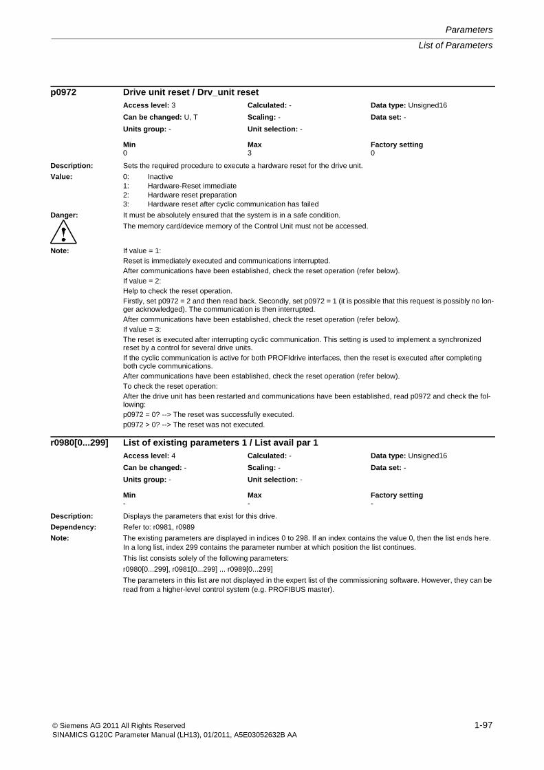
List of Parameters
Parameters
1-97© Siemens AG 2011 All Rights ReservedSINAMICS G120C Parameter Manual (LH13), 01/2011, A5E03052632B AA
Description: Sets the required procedure to execute a hardware reset for the drive unit.
Value: 0: Inactive1: Hardware-Reset immediate2: Hardware reset preparation3: Hardware reset after cyclic communication has failed
Danger: It must be absolutely ensured that the system is in a safe condition.
The memory card/device memory of the Control Unit must not be accessed.
Note: If value = 1:Reset is immediately executed and communications interrupted.After communications have been established, check the reset operation (refer below).If value = 2:Help to check the reset operation.Firstly, set p0972 = 2 and then read back. Secondly, set p0972 = 1 (it is possible that this request is possibly no lon-ger acknowledged). The communication is then interrupted.After communications have been established, check the reset operation (refer below).If value = 3:The reset is executed after interrupting cyclic communication. This setting is used to implement a synchronized reset by a control for several drive units.If the cyclic communication is active for both PROFIdrive interfaces, then the reset is executed after completing both cycle communications.After communications have been established, check the reset operation (refer below).To check the reset operation:After the drive unit has been restarted and communications have been established, read p0972 and check the fol-lowing:p0972 = 0? --> The reset was successfully executed.p0972 > 0? --> The reset was not executed.
Description: Displays the parameters that exist for this drive.
Dependency: Refer to: r0981, r0989
Note: The existing parameters are displayed in indices 0 to 298. If an index contains the value 0, then the list ends here. In a long list, index 299 contains the parameter number at which position the list continues.
This list consists solely of the following parameters:
r0980[0...299], r0981[0...299] ... r0989[0...299]
The parameters in this list are not displayed in the expert list of the commissioning software. However, they can be read from a higher-level control system (e.g. PROFIBUS master).
p0972 Drive unit reset / Drv_unit resetAccess level: 3 Calculated: - Data type: Unsigned16
Can be changed: U, T Scaling: - Data set: -
Units group: - Unit selection: -
Min Max Factory setting 0 3 0
r0980[0...299] List of existing parameters 1 / List avail par 1Access level: 4 Calculated: - Data type: Unsigned16
Can be changed: - Scaling: - Data set: -
Units group: - Unit selection: -
Min Max Factory setting - - -
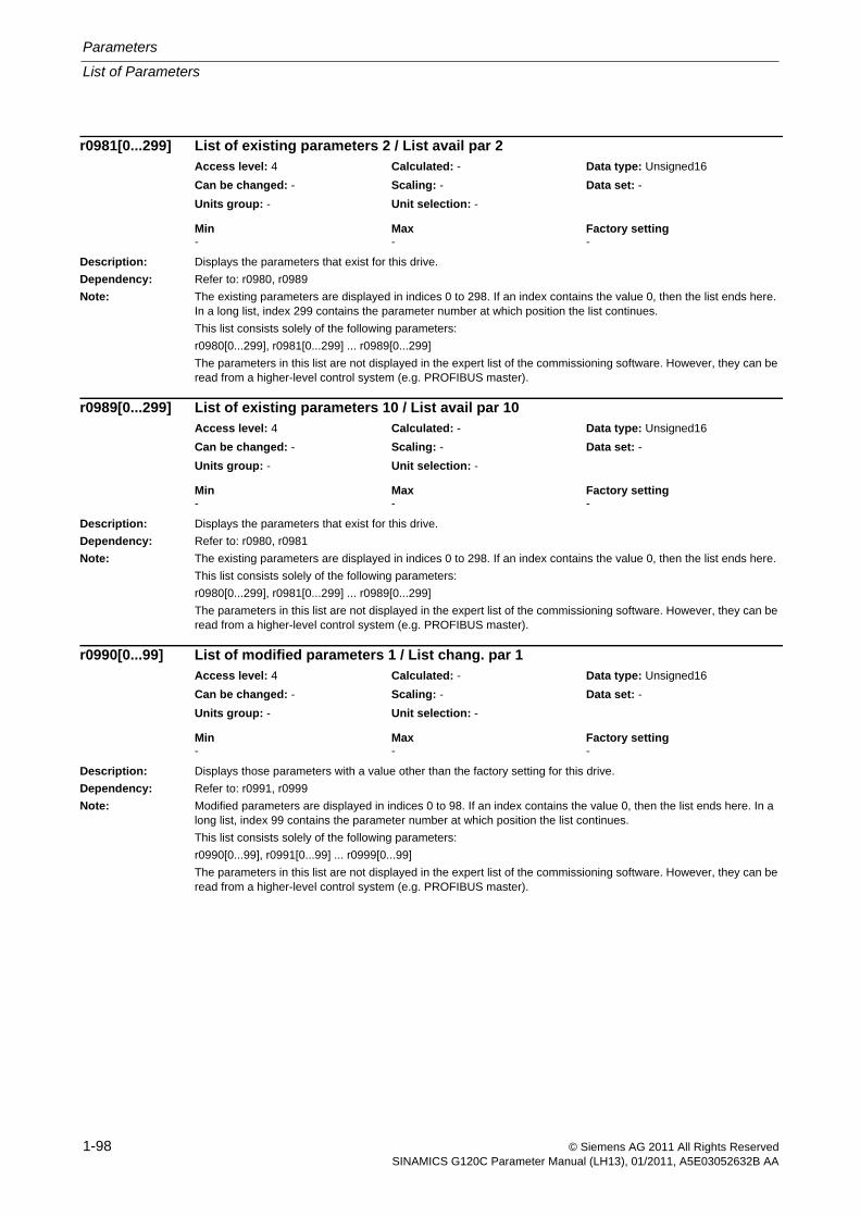
Parameters
List of Parameters
1-98 © Siemens AG 2011 All Rights ReservedSINAMICS G120C Parameter Manual (LH13), 01/2011, A5E03052632B AA
Description: Displays the parameters that exist for this drive.
Dependency: Refer to: r0980, r0989
Note: The existing parameters are displayed in indices 0 to 298. If an index contains the value 0, then the list ends here. In a long list, index 299 contains the parameter number at which position the list continues.
This list consists solely of the following parameters:
r0980[0...299], r0981[0...299] ... r0989[0...299]
The parameters in this list are not displayed in the expert list of the commissioning software. However, they can be read from a higher-level control system (e.g. PROFIBUS master).
Description: Displays the parameters that exist for this drive.
Dependency: Refer to: r0980, r0981
Note: The existing parameters are displayed in indices 0 to 298. If an index contains the value 0, then the list ends here.
This list consists solely of the following parameters:
r0980[0...299], r0981[0...299] ... r0989[0...299]
The parameters in this list are not displayed in the expert list of the commissioning software. However, they can be read from a higher-level control system (e.g. PROFIBUS master).
Description: Displays those parameters with a value other than the factory setting for this drive.
Dependency: Refer to: r0991, r0999
Note: Modified parameters are displayed in indices 0 to 98. If an index contains the value 0, then the list ends here. In a long list, index 99 contains the parameter number at which position the list continues.
This list consists solely of the following parameters:
r0990[0...99], r0991[0...99] ... r0999[0...99]
The parameters in this list are not displayed in the expert list of the commissioning software. However, they can be read from a higher-level control system (e.g. PROFIBUS master).
r0981[0...299] List of existing parameters 2 / List avail par 2Access level: 4 Calculated: - Data type: Unsigned16
Can be changed: - Scaling: - Data set: -
Units group: - Unit selection: -
Min Max Factory setting - - -
r0989[0...299] List of existing parameters 10 / List avail par 10Access level: 4 Calculated: - Data type: Unsigned16
Can be changed: - Scaling: - Data set: -
Units group: - Unit selection: -
Min Max Factory setting - - -
r0990[0...99] List of modified parameters 1 / List chang. par 1Access level: 4 Calculated: - Data type: Unsigned16
Can be changed: - Scaling: - Data set: -
Units group: - Unit selection: -
Min Max Factory setting - - -
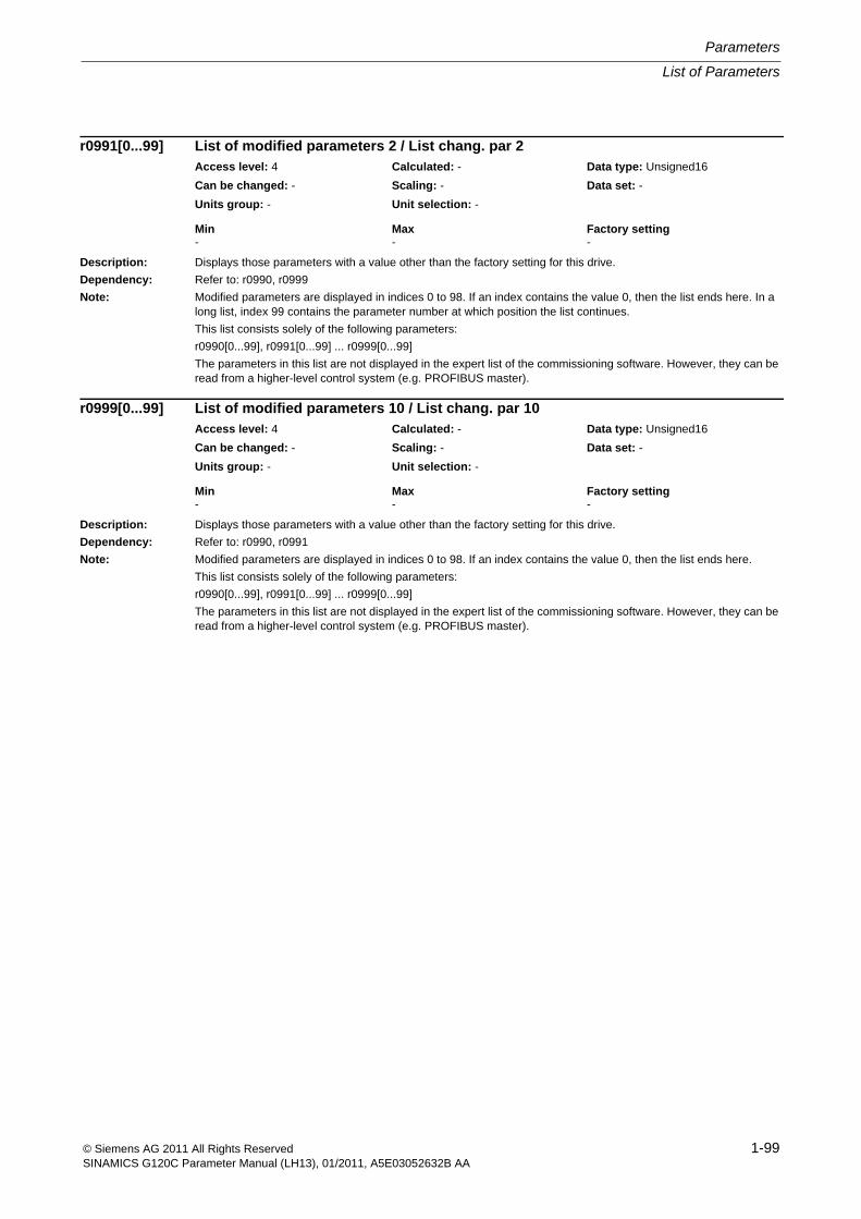
List of Parameters
Parameters
1-99© Siemens AG 2011 All Rights ReservedSINAMICS G120C Parameter Manual (LH13), 01/2011, A5E03052632B AA
Description: Displays those parameters with a value other than the factory setting for this drive.
Dependency: Refer to: r0990, r0999
Note: Modified parameters are displayed in indices 0 to 98. If an index contains the value 0, then the list ends here. In a long list, index 99 contains the parameter number at which position the list continues.
This list consists solely of the following parameters:
r0990[0...99], r0991[0...99] ... r0999[0...99]
The parameters in this list are not displayed in the expert list of the commissioning software. However, they can be read from a higher-level control system (e.g. PROFIBUS master).
Description: Displays those parameters with a value other than the factory setting for this drive.
Dependency: Refer to: r0990, r0991
Note: Modified parameters are displayed in indices 0 to 98. If an index contains the value 0, then the list ends here.
This list consists solely of the following parameters:
r0990[0...99], r0991[0...99] ... r0999[0...99]
The parameters in this list are not displayed in the expert list of the commissioning software. However, they can be read from a higher-level control system (e.g. PROFIBUS master).
r0991[0...99] List of modified parameters 2 / List chang. par 2Access level: 4 Calculated: - Data type: Unsigned16
Can be changed: - Scaling: - Data set: -
Units group: - Unit selection: -
Min Max Factory setting - - -
r0999[0...99] List of modified parameters 10 / List chang. par 10Access level: 4 Calculated: - Data type: Unsigned16
Can be changed: - Scaling: - Data set: -
Units group: - Unit selection: -
Min Max Factory setting - - -
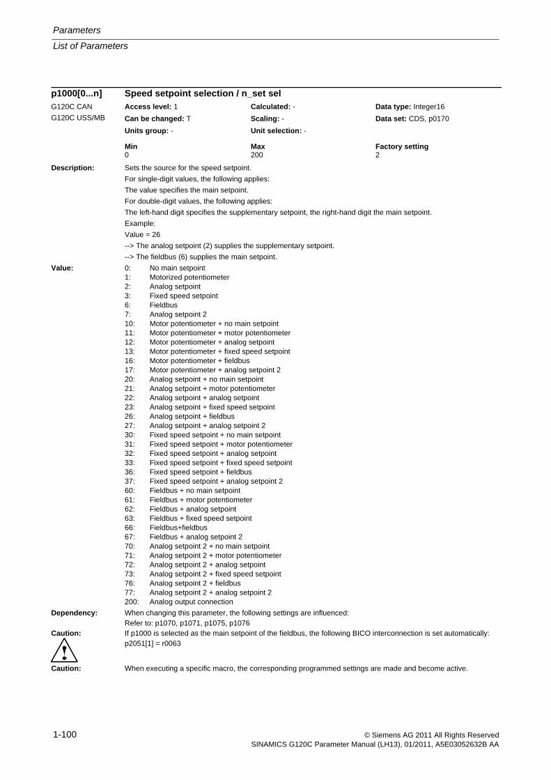
Parameters
List of Parameters
1-100 © Siemens AG 2011 All Rights ReservedSINAMICS G120C Parameter Manual (LH13), 01/2011, A5E03052632B AA
Description: Sets the source for the speed setpoint.
For single-digit values, the following applies:
The value specifies the main setpoint.
For double-digit values, the following applies:
The left-hand digit specifies the supplementary setpoint, the right-hand digit the main setpoint.
Example:
Value = 26
--> The analog setpoint (2) supplies the supplementary setpoint.
--> The fieldbus (6) supplies the main setpoint.
Value: 0: No main setpoint1: Motorized potentiometer2: Analog setpoint3: Fixed speed setpoint6: Fieldbus7: Analog setpoint 210: Motor potentiometer + no main setpoint11: Motor potentiometer + motor potentiometer12: Motor potentiometer + analog setpoint13: Motor potentiometer + fixed speed setpoint16: Motor potentiometer + fieldbus17: Motor potentiometer + analog setpoint 220: Analog setpoint + no main setpoint21: Analog setpoint + motor potentiometer22: Analog setpoint + analog setpoint23: Analog setpoint + fixed speed setpoint26: Analog setpoint + fieldbus27: Analog setpoint + analog setpoint 230: Fixed speed setpoint + no main setpoint31: Fixed speed setpoint + motor potentiometer32: Fixed speed setpoint + analog setpoint33: Fixed speed setpoint + fixed speed setpoint36: Fixed speed setpoint + fieldbus37: Fixed speed setpoint + analog setpoint 260: Fieldbus + no main setpoint61: Fieldbus + motor potentiometer62: Fieldbus + analog setpoint63: Fieldbus + fixed speed setpoint66: Fieldbus+fieldbus67: Fieldbus + analog setpoint 270: Analog setpoint 2 + no main setpoint71: Analog setpoint 2 + motor potentiometer72: Analog setpoint 2 + analog setpoint73: Analog setpoint 2 + fixed speed setpoint76: Analog setpoint 2 + fieldbus77: Analog setpoint 2 + analog setpoint 2200: Analog output connection
Dependency: When changing this parameter, the following settings are influenced:Refer to: p1070, p1071, p1075, p1076
Caution: If p1000 is selected as the main setpoint of the fieldbus, the following BICO interconnection is set automatically:p2051[1] = r0063
Caution: When executing a specific macro, the corresponding programmed settings are made and become active.
p1000[0...n] Speed setpoint selection / n_set selG120C CAN
G120C USS/MB
Access level: 1 Calculated: - Data type: Integer16
Can be changed: T Scaling: - Data set: CDS, p0170
Units group: - Unit selection: -
Min Max Factory setting 0 200 2
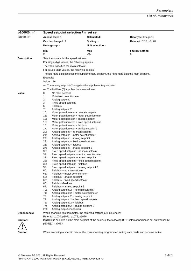
List of Parameters
Parameters
1-101© Siemens AG 2011 All Rights ReservedSINAMICS G120C Parameter Manual (LH13), 01/2011, A5E03052632B AA
Description: Sets the source for the speed setpoint.
For single-digit values, the following applies:
The value specifies the main setpoint.
For double-digit values, the following applies:
The left-hand digit specifies the supplementary setpoint, the right-hand digit the main setpoint.
Example:
Value = 26
--> The analog setpoint (2) supplies the supplementary setpoint.
--> The fieldbus (6) supplies the main setpoint.
Value: 0: No main setpoint1: Motorized potentiometer2: Analog setpoint3: Fixed speed setpoint6: Fieldbus7: Analog setpoint 210: Motor potentiometer + no main setpoint11: Motor potentiometer + motor potentiometer12: Motor potentiometer + analog setpoint13: Motor potentiometer + fixed speed setpoint16: Motor potentiometer + fieldbus17: Motor potentiometer + analog setpoint 220: Analog setpoint + no main setpoint21: Analog setpoint + motor potentiometer22: Analog setpoint + analog setpoint23: Analog setpoint + fixed speed setpoint26: Analog setpoint + fieldbus27: Analog setpoint + analog setpoint 230: Fixed speed setpoint + no main setpoint31: Fixed speed setpoint + motor potentiometer32: Fixed speed setpoint + analog setpoint33: Fixed speed setpoint + fixed speed setpoint36: Fixed speed setpoint + fieldbus37: Fixed speed setpoint + analog setpoint 260: Fieldbus + no main setpoint61: Fieldbus + motor potentiometer62: Fieldbus + analog setpoint63: Fieldbus + fixed speed setpoint66: Fieldbus+fieldbus67: Fieldbus + analog setpoint 270: Analog setpoint 2 + no main setpoint71: Analog setpoint 2 + motor potentiometer72: Analog setpoint 2 + analog setpoint73: Analog setpoint 2 + fixed speed setpoint76: Analog setpoint 2 + fieldbus77: Analog setpoint 2 + analog setpoint 2200: Analog output connection
Dependency: When changing this parameter, the following settings are influenced:Refer to: p1070, p1071, p1075, p1076
Caution: If p1000 is selected as the main setpoint of the fieldbus, the following BICO interconnection is set automatically:p2051[1] = r0063
Caution: When executing a specific macro, the corresponding programmed settings are made and become active.
p1000[0...n] Speed setpoint selection / n_set selG120C DP Access level: 1 Calculated: - Data type: Integer16
Can be changed: T Scaling: - Data set: CDS, p0170
Units group: - Unit selection: -
Min Max Factory setting 0 200 6

Parameters
List of Parameters
1-102 © Siemens AG 2011 All Rights ReservedSINAMICS G120C Parameter Manual (LH13), 01/2011, A5E03052632B AA
Description: Sets a value for the fixed speed / velocity setpoint 1.
Dependency: Refer to: p1020, p1021, p1022, p1023, r1024
Notice: A BICO interconnection to a parameter that belongs to a drive data set always acts on the effective data set.
Description: Sets a value for the fixed speed / velocity setpoint 2.
Dependency: Refer to: p1020, p1021, p1022, p1023, r1024
Notice: A BICO interconnection to a parameter that belongs to a drive data set always acts on the effective data set.
Description: Sets a value for the fixed speed / velocity setpoint 3.
Dependency: Refer to: p1020, p1021, p1022, p1023, r1024
Notice: A BICO interconnection to a parameter that belongs to a drive data set always acts on the effective data set.
Description: Sets a value for the fixed speed / velocity setpoint 4.
Dependency: Refer to: p1020, p1021, p1022, p1023, r1024
Notice: A BICO interconnection to a parameter that belongs to a drive data set always acts on the effective data set.
p1001[0...n] CO: Fixed speed setpoint 1 / n_set_fixed 1Access level: 2 Calculated: - Data type: FloatingPoint32
Can be changed: U, T Scaling: p2000 Data set: DDS, p0180
Units group: 3_1 Unit selection: p0505
Min Max Factory setting -210000.000 [rpm] 210000.000 [rpm] 0.000 [rpm]
p1002[0...n] CO: Fixed speed setpoint 2 / n_set_fixed 2Access level: 2 Calculated: - Data type: FloatingPoint32
Can be changed: U, T Scaling: p2000 Data set: DDS, p0180
Units group: 3_1 Unit selection: p0505
Min Max Factory setting -210000.000 [rpm] 210000.000 [rpm] 0.000 [rpm]
p1003[0...n] CO: Fixed speed setpoint 3 / n_set_fixed 3Access level: 2 Calculated: - Data type: FloatingPoint32
Can be changed: U, T Scaling: p2000 Data set: DDS, p0180
Units group: 3_1 Unit selection: p0505
Min Max Factory setting -210000.000 [rpm] 210000.000 [rpm] 0.000 [rpm]
p1004[0...n] CO: Fixed speed setpoint 4 / n_set_fixed 4Access level: 2 Calculated: - Data type: FloatingPoint32
Can be changed: U, T Scaling: p2000 Data set: DDS, p0180
Units group: 3_1 Unit selection: p0505
Min Max Factory setting -210000.000 [rpm] 210000.000 [rpm] 0.000 [rpm]
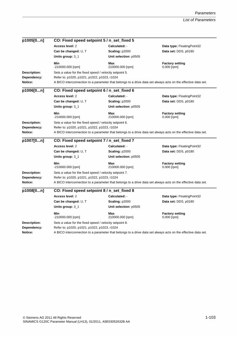
List of Parameters
Parameters
1-103© Siemens AG 2011 All Rights ReservedSINAMICS G120C Parameter Manual (LH13), 01/2011, A5E03052632B AA
Description: Sets a value for the fixed speed / velocity setpoint 5.
Dependency: Refer to: p1020, p1021, p1022, p1023, r1024
Notice: A BICO interconnection to a parameter that belongs to a drive data set always acts on the effective data set.
Description: Sets a value for the fixed speed / velocity setpoint 6.
Dependency: Refer to: p1020, p1021, p1022, p1023, r1024
Notice: A BICO interconnection to a parameter that belongs to a drive data set always acts on the effective data set.
Description: Sets a value for the fixed speed / velocity setpoint 7.
Dependency: Refer to: p1020, p1021, p1022, p1023, r1024
Notice: A BICO interconnection to a parameter that belongs to a drive data set always acts on the effective data set.
Description: Sets a value for the fixed speed / velocity setpoint 8.
Dependency: Refer to: p1020, p1021, p1022, p1023, r1024
Notice: A BICO interconnection to a parameter that belongs to a drive data set always acts on the effective data set.
p1005[0...n] CO: Fixed speed setpoint 5 / n_set_fixed 5Access level: 2 Calculated: - Data type: FloatingPoint32
Can be changed: U, T Scaling: p2000 Data set: DDS, p0180
Units group: 3_1 Unit selection: p0505
Min Max Factory setting -210000.000 [rpm] 210000.000 [rpm] 0.000 [rpm]
p1006[0...n] CO: Fixed speed setpoint 6 / n_set_fixed 6Access level: 2 Calculated: - Data type: FloatingPoint32
Can be changed: U, T Scaling: p2000 Data set: DDS, p0180
Units group: 3_1 Unit selection: p0505
Min Max Factory setting -210000.000 [rpm] 210000.000 [rpm] 0.000 [rpm]
p1007[0...n] CO: Fixed speed setpoint 7 / n_set_fixed 7Access level: 2 Calculated: - Data type: FloatingPoint32
Can be changed: U, T Scaling: p2000 Data set: DDS, p0180
Units group: 3_1 Unit selection: p0505
Min Max Factory setting -210000.000 [rpm] 210000.000 [rpm] 0.000 [rpm]
p1008[0...n] CO: Fixed speed setpoint 8 / n_set_fixed 8Access level: 2 Calculated: - Data type: FloatingPoint32
Can be changed: U, T Scaling: p2000 Data set: DDS, p0180
Units group: 3_1 Unit selection: p0505
Min Max Factory setting -210000.000 [rpm] 210000.000 [rpm] 0.000 [rpm]
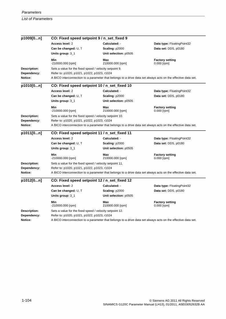
Parameters
List of Parameters
1-104 © Siemens AG 2011 All Rights ReservedSINAMICS G120C Parameter Manual (LH13), 01/2011, A5E03052632B AA
Description: Sets a value for the fixed speed / velocity setpoint 9.
Dependency: Refer to: p1020, p1021, p1022, p1023, r1024
Notice: A BICO interconnection to a parameter that belongs to a drive data set always acts on the effective data set.
Description: Sets a value for the fixed speed / velocity setpoint 10.
Dependency: Refer to: p1020, p1021, p1022, p1023, r1024
Notice: A BICO interconnection to a parameter that belongs to a drive data set always acts on the effective data set.
Description: Sets a value for the fixed speed / velocity setpoint 11.
Dependency: Refer to: p1020, p1021, p1022, p1023, r1024
Notice: A BICO interconnection to a parameter that belongs to a drive data set always acts on the effective data set.
Description: Sets a value for the fixed speed / velocity setpoint 12.
Dependency: Refer to: p1020, p1021, p1022, p1023, r1024
Notice: A BICO interconnection to a parameter that belongs to a drive data set always acts on the effective data set.
p1009[0...n] CO: Fixed speed setpoint 9 / n_set_fixed 9Access level: 2 Calculated: - Data type: FloatingPoint32
Can be changed: U, T Scaling: p2000 Data set: DDS, p0180
Units group: 3_1 Unit selection: p0505
Min Max Factory setting -210000.000 [rpm] 210000.000 [rpm] 0.000 [rpm]
p1010[0...n] CO: Fixed speed setpoint 10 / n_set_fixed 10Access level: 2 Calculated: - Data type: FloatingPoint32
Can be changed: U, T Scaling: p2000 Data set: DDS, p0180
Units group: 3_1 Unit selection: p0505
Min Max Factory setting -210000.000 [rpm] 210000.000 [rpm] 0.000 [rpm]
p1011[0...n] CO: Fixed speed setpoint 11 / n_set_fixed 11Access level: 2 Calculated: - Data type: FloatingPoint32
Can be changed: U, T Scaling: p2000 Data set: DDS, p0180
Units group: 3_1 Unit selection: p0505
Min Max Factory setting -210000.000 [rpm] 210000.000 [rpm] 0.000 [rpm]
p1012[0...n] CO: Fixed speed setpoint 12 / n_set_fixed 12Access level: 2 Calculated: - Data type: FloatingPoint32
Can be changed: U, T Scaling: p2000 Data set: DDS, p0180
Units group: 3_1 Unit selection: p0505
Min Max Factory setting -210000.000 [rpm] 210000.000 [rpm] 0.000 [rpm]
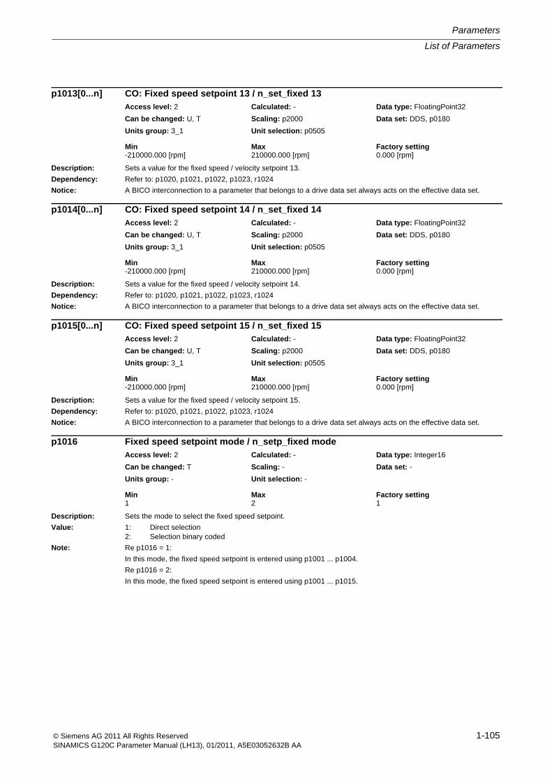
List of Parameters
Parameters
1-105© Siemens AG 2011 All Rights ReservedSINAMICS G120C Parameter Manual (LH13), 01/2011, A5E03052632B AA
Description: Sets a value for the fixed speed / velocity setpoint 13.
Dependency: Refer to: p1020, p1021, p1022, p1023, r1024
Notice: A BICO interconnection to a parameter that belongs to a drive data set always acts on the effective data set.
Description: Sets a value for the fixed speed / velocity setpoint 14.
Dependency: Refer to: p1020, p1021, p1022, p1023, r1024
Notice: A BICO interconnection to a parameter that belongs to a drive data set always acts on the effective data set.
Description: Sets a value for the fixed speed / velocity setpoint 15.
Dependency: Refer to: p1020, p1021, p1022, p1023, r1024
Notice: A BICO interconnection to a parameter that belongs to a drive data set always acts on the effective data set.
Description: Sets the mode to select the fixed speed setpoint.
Value: 1: Direct selection2: Selection binary coded
Note: Re p1016 = 1:
In this mode, the fixed speed setpoint is entered using p1001 ... p1004.
Re p1016 = 2:
In this mode, the fixed speed setpoint is entered using p1001 ... p1015.
p1013[0...n] CO: Fixed speed setpoint 13 / n_set_fixed 13Access level: 2 Calculated: - Data type: FloatingPoint32
Can be changed: U, T Scaling: p2000 Data set: DDS, p0180
Units group: 3_1 Unit selection: p0505
Min Max Factory setting -210000.000 [rpm] 210000.000 [rpm] 0.000 [rpm]
p1014[0...n] CO: Fixed speed setpoint 14 / n_set_fixed 14Access level: 2 Calculated: - Data type: FloatingPoint32
Can be changed: U, T Scaling: p2000 Data set: DDS, p0180
Units group: 3_1 Unit selection: p0505
Min Max Factory setting -210000.000 [rpm] 210000.000 [rpm] 0.000 [rpm]
p1015[0...n] CO: Fixed speed setpoint 15 / n_set_fixed 15Access level: 2 Calculated: - Data type: FloatingPoint32
Can be changed: U, T Scaling: p2000 Data set: DDS, p0180
Units group: 3_1 Unit selection: p0505
Min Max Factory setting -210000.000 [rpm] 210000.000 [rpm] 0.000 [rpm]
p1016 Fixed speed setpoint mode / n_setp_fixed modeAccess level: 2 Calculated: - Data type: Integer16
Can be changed: T Scaling: - Data set: -
Units group: - Unit selection: -
Min Max Factory setting 1 2 1
Parameters
List of Parameters
1-106 © Siemens AG 2011 All Rights ReservedSINAMICS G120C Parameter Manual (LH13), 01/2011, A5E03052632B AA
Description: Sets the signal source for selecting the fixed speed setpoint.
Dependency: Selects the required fixed speed setpoint using p1020 ... p1023.
Sets the values for the fixed speed setpoints 1 ... 15 using p1001 ... p1015.
Refer to: p1021, p1022, p1023
Note: If a fixed speed setpoint has not been selected (p1020 ... p1023 = 0), then r1024 = 0 (setpoint = 0).
Description: Sets the signal source for selecting the fixed speed setpoint.
Dependency: Selects the required fixed speed setpoint using p1020 ... p1023.
Sets the values for the fixed speed setpoints 1 ... 15 using p1001 ... p1015.
Refer to: p1020, p1022, p1023
Note: If a fixed speed setpoint has not been selected (p1020 ... p1023 = 0), then r1024 = 0 (setpoint = 0).
Description: Sets the signal source for selecting the fixed speed setpoint.
Dependency: Selects the required fixed speed setpoint using p1020 ... p1023.
Sets the values for the fixed speed setpoints 1 ... 15 using p1001 ... p1015.
Refer to: p1020, p1021, p1023
Note: If a fixed speed setpoint has not been selected (p1020 ... p1023 = 0), then r1024 = 0 (setpoint = 0).
Description: Sets the signal source for selecting the fixed speed setpoint.
Dependency: Selects the required fixed speed setpoint using p1020 ... p1023.
Sets the values for the fixed speed setpoints 1 ... 15 using p1001 ... p1015.
Refer to: p1020, p1021, p1022
Note: If a fixed speed setpoint has not been selected (p1020 ... p1023 = 0), then r1024 = 0 (setpoint = 0).
p1020[0...n] BI: Fixed speed setpoint selection Bit 0 / n_set_fixed Bit 0Access level: 3 Calculated: - Data type: U32 / Binary
Can be changed: T Scaling: - Data set: CDS, p0170
Units group: - Unit selection: -
Min Max Factory setting - - 0
p1021[0...n] BI: Fixed speed setpoint selection Bit 1 / n_set_fixed Bit 1Access level: 3 Calculated: - Data type: U32 / Binary
Can be changed: T Scaling: - Data set: CDS, p0170
Units group: - Unit selection: -
Min Max Factory setting - - 0
p1022[0...n] BI: Fixed speed setpoint selection Bit 2 / n_set_fixed Bit 2Access level: 3 Calculated: - Data type: U32 / Binary
Can be changed: T Scaling: - Data set: CDS, p0170
Units group: - Unit selection: -
Min Max Factory setting - - 0
p1023[0...n] BI: Fixed speed setpoint selection Bit 3 / n_set_fixed Bit 3Access level: 3 Calculated: - Data type: U32 / Binary
Can be changed: T Scaling: - Data set: CDS, p0170
Units group: - Unit selection: -
Min Max Factory setting - - 0
List of Parameters
Parameters
1-107© Siemens AG 2011 All Rights ReservedSINAMICS G120C Parameter Manual (LH13), 01/2011, A5E03052632B AA
Description: Displays the selected and effective fixed speed setpoint.
This setpoint is the output value for the fixed speed setpoints and must be appropriately interconnected (e.g. with the main setpoint).
Dependency: Selects the required fixed speed setpoint using p1020 ... p1023.
Sets the values for the fixed speed setpoints 1 ... 15 using p1001 ... p1015.
Refer to: p1070
Note: If a fixed speed setpoint has not been selected (p1020 ... p1023 = 0), then r1024 = 0 (setpoint = 0).
Description: Displays the status when selecting the fixed speed setpoints.
Dependency: Refer to: p1016
Note: Re bit 00:
When the fixed speed setpoints are directly selected (p1016 = 1), this bit is set if at least 1 fixed speed setpoint is selected.
r1024 CO: Fixed speed setpoint effective / n_set_fixed effAccess level: 3 Calculated: - Data type: FloatingPoint32
Can be changed: - Scaling: p2000 Data set: -
Units group: 3_1 Unit selection: p0505
Min Max Factory setting - [rpm] - [rpm] - [rpm]
r1025.0 BO: Fixed speed setpoint status / n_setp_fix statusAccess level: 3 Calculated: - Data type: Unsigned8
Can be changed: - Scaling: - Data set: -
Units group: - Unit selection: -
Min Max Factory setting - - -
Bit field: Bit Signal name 1 signal 0 signal FP00 Fixed speed setpoint selected Yes No -
Parameters
List of Parameters
1-108 © Siemens AG 2011 All Rights ReservedSINAMICS G120C Parameter Manual (LH13), 01/2011, A5E03052632B AA
Description: Sets the configuration for the motorized potentiometer.
Notice: For p0014 = 1, the following applies:
After the value has been modified, no further parameter modifications can be made and the status is shown in r3996. Modifications can be made again when r3996 = 0.
Note: Re bit 00:
0: The setpoint for the motorized potentiometer is not saved and after ON is entered using p1040.
1: The setpoint for the motorized potentiometer is saved after OFF and after ON set to the saved value. In order to save in a non-volatile fashion, bit 03 should be set to 1.
Re bit 01:
0: Without ramp-function generator in the automatic mode (ramp-up/ramp-down time = 0).
1: With ramp-function generator in the automatic mode.
For manual operation, the ramp-function generator is always active.
Re bit 02:
0: Without initial rounding-off
1: With initial rounding-off. The selected ramp-up/down time is correspondingly exceeded. The initial rounding-off is a sensitive way of specifying small changes (progressive reaction when keys are pressed).
The jerk for the initial rounding-off is independent of the ramp-up time and only depends on the selected maximum speed (p1082). It is calculated as follows:
r = 0.01 % * p1082 [1/s] / 0.13^2 [s^2]
The jerk acts up until the maximum acceleration is reached (a_max = p1082 [1/s] / p1047 [s]), and then the drive continues to run linearly with a constant rate of acceleration. The higher the maximum acceleration (the lower that p1047 is), the longer the ramp-up time increases with respect to the set ramp-up time.
Re bit 03:
0: Non-volatile data save de-activated.
1: The setpoint for the motorized potentiometer is saved in a non-volatile fashion (for bit 00 = 1).
Re bit 04:
When the bit is set, the ramp-function generator is computed independent of the pulse enable. The actual output value of the motorized potentiometer is always in r1050.
Description: Sets the signal source to continually increase the setpoint for the motorized potentiometer.
The setpoint change (CO: r1050) depends on the set ramp-up time (p1047) and the duration of the signal that is present (BI: p1035).
Dependency: Refer to: p1036
Notice: The parameter may be protected as a result of p0922 or p2079 and cannot be changed.
p1030[0...n] Motorized potentiometer configuration / Mop configurationAccess level: 3 Calculated: - Data type: Unsigned16
Can be changed: U, T Scaling: - Data set: DDS, p0180
Units group: - Unit selection: -
Min Max Factory setting - - 0000 0110 bin
Bit field: Bit Signal name 1 signal 0 signal FP00 Data save active Yes No -01 Automatic mode, ramp-function generator
activeYes No -
02 Initial rounding-off active Yes No -03 Save in NVRAM active Yes No -04 Ramp-function generator always active Yes No -
p1035[0...n] BI: Motorized potentiometer setpoint raise / Mop raiseG120C CAN
G120C USS/MB
Access level: 3 Calculated: - Data type: U32 / Binary
Can be changed: T Scaling: - Data set: CDS, p0170
Units group: - Unit selection: -
Min Max Factory setting - - 0
List of Parameters
Parameters
1-109© Siemens AG 2011 All Rights ReservedSINAMICS G120C Parameter Manual (LH13), 01/2011, A5E03052632B AA
Description: Sets the signal source to continually increase the setpoint for the motorized potentiometer.
The setpoint change (CO: r1050) depends on the set ramp-up time (p1047) and the duration of the signal that is present (BI: p1035).
Dependency: Refer to: p1036
Notice: The parameter may be protected as a result of p0922 or p2079 and cannot be changed.
Description: Sets the signal source to continuously lower the setpoint for the motorized potentiometer.
The setpoint change (CO: r1050) depends on the set ramp-down time (p1048) and the duration of the signal that is present (BI: p1036).
Dependency: Refer to: p1035
Notice: The parameter may be protected as a result of p0922 or p2079 and cannot be changed.
Description: Sets the maximum speed/velocity for the motorized potentiometer.
Note: This parameter is automatically pre-assigned in the commissioning phase.
The setpoint output from the motorized potentiometer is limited to this value (see function diagram 3020).
p1035[0...n] BI: Motorized potentiometer setpoint raise / Mop raiseG120C DP Access level: 3 Calculated: - Data type: U32 / Binary
Can be changed: T Scaling: - Data set: CDS, p0170
Units group: - Unit selection: -
Min Max Factory setting - - [0] 2090.13
[1] 0
p1036[0...n] BI: Motorized potentiometer lower setpoint / Mop lowerG120C CAN
G120C USS/MB
Access level: 3 Calculated: - Data type: U32 / Binary
Can be changed: T Scaling: - Data set: CDS, p0170
Units group: - Unit selection: -
Min Max Factory setting - - 0
p1036[0...n] BI: Motorized potentiometer lower setpoint / Mop lowerG120C DP Access level: 3 Calculated: - Data type: U32 / Binary
Can be changed: T Scaling: - Data set: CDS, p0170
Units group: - Unit selection: -
Min Max Factory setting - - [0] 2090.14
[1] 0
p1037[0...n] Motorized potentiometer maximum speed / MotP n_maxAccess level: 3 Calculated: p0340 = 1,3,5 Data type: FloatingPoint32
Can be changed: U, T Scaling: - Data set: DDS, p0180
Units group: 3_1 Unit selection: p0505
Min Max Factory setting -210000.000 [rpm] 210000.000 [rpm] 0.000 [rpm]
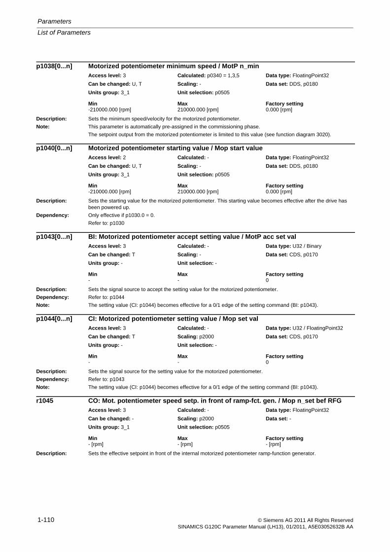
Parameters
List of Parameters
1-110 © Siemens AG 2011 All Rights ReservedSINAMICS G120C Parameter Manual (LH13), 01/2011, A5E03052632B AA
Description: Sets the minimum speed/velocity for the motorized potentiometer.
Note: This parameter is automatically pre-assigned in the commissioning phase.
The setpoint output from the motorized potentiometer is limited to this value (see function diagram 3020).
Description: Sets the starting value for the motorized potentiometer. This starting value becomes effective after the drive has been powered up.
Dependency: Only effective if p1030.0 = 0.
Refer to: p1030
Description: Sets the signal source to accept the setting value for the motorized potentiometer.
Dependency: Refer to: p1044
Note: The setting value (CI: p1044) becomes effective for a 0/1 edge of the setting command (BI: p1043).
Description: Sets the signal source for the setting value for the motorized potentiometer.
Dependency: Refer to: p1043
Note: The setting value (CI: p1044) becomes effective for a 0/1 edge of the setting command (BI: p1043).
Description: Sets the effective setpoint in front of the internal motorized potentiometer ramp-function generator.
p1038[0...n] Motorized potentiometer minimum speed / MotP n_minAccess level: 3 Calculated: p0340 = 1,3,5 Data type: FloatingPoint32
Can be changed: U, T Scaling: - Data set: DDS, p0180
Units group: 3_1 Unit selection: p0505
Min Max Factory setting -210000.000 [rpm] 210000.000 [rpm] 0.000 [rpm]
p1040[0...n] Motorized potentiometer starting value / Mop start valueAccess level: 2 Calculated: - Data type: FloatingPoint32
Can be changed: U, T Scaling: - Data set: DDS, p0180
Units group: 3_1 Unit selection: p0505
Min Max Factory setting -210000.000 [rpm] 210000.000 [rpm] 0.000 [rpm]
p1043[0...n] BI: Motorized potentiometer accept setting value / MotP acc set valAccess level: 3 Calculated: - Data type: U32 / Binary
Can be changed: T Scaling: - Data set: CDS, p0170
Units group: - Unit selection: -
Min Max Factory setting - - 0
p1044[0...n] CI: Motorized potentiometer setting value / Mop set valAccess level: 3 Calculated: - Data type: U32 / FloatingPoint32
Can be changed: T Scaling: p2000 Data set: CDS, p0170
Units group: - Unit selection: -
Min Max Factory setting - - 0
r1045 CO: Mot. potentiometer speed setp. in front of ramp-fct. gen. / Mop n_set bef RFGAccess level: 3 Calculated: - Data type: FloatingPoint32
Can be changed: - Scaling: p2000 Data set: -
Units group: 3_1 Unit selection: p0505
Min Max Factory setting - [rpm] - [rpm] - [rpm]
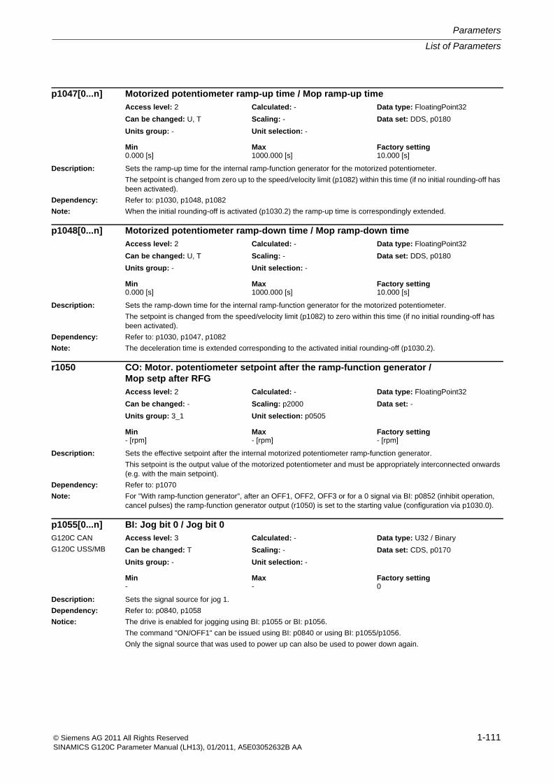
List of Parameters
Parameters
1-111© Siemens AG 2011 All Rights ReservedSINAMICS G120C Parameter Manual (LH13), 01/2011, A5E03052632B AA
Description: Sets the ramp-up time for the internal ramp-function generator for the motorized potentiometer.
The setpoint is changed from zero up to the speed/velocity limit (p1082) within this time (if no initial rounding-off has been activated).
Dependency: Refer to: p1030, p1048, p1082
Note: When the initial rounding-off is activated (p1030.2) the ramp-up time is correspondingly extended.
Description: Sets the ramp-down time for the internal ramp-function generator for the motorized potentiometer.
The setpoint is changed from the speed/velocity limit (p1082) to zero within this time (if no initial rounding-off has been activated).
Dependency: Refer to: p1030, p1047, p1082
Note: The deceleration time is extended corresponding to the activated initial rounding-off (p1030.2).
Description: Sets the effective setpoint after the internal motorized potentiometer ramp-function generator.
This setpoint is the output value of the motorized potentiometer and must be appropriately interconnected onwards (e.g. with the main setpoint).
Dependency: Refer to: p1070
Note: For "With ramp-function generator", after an OFF1, OFF2, OFF3 or for a 0 signal via BI: p0852 (inhibit operation, cancel pulses) the ramp-function generator output (r1050) is set to the starting value (configuration via p1030.0).
Description: Sets the signal source for jog 1.
Dependency: Refer to: p0840, p1058
Notice: The drive is enabled for jogging using BI: p1055 or BI: p1056.
The command "ON/OFF1" can be issued using BI: p0840 or using BI: p1055/p1056.
Only the signal source that was used to power up can also be used to power down again.
p1047[0...n] Motorized potentiometer ramp-up time / Mop ramp-up timeAccess level: 2 Calculated: - Data type: FloatingPoint32
Can be changed: U, T Scaling: - Data set: DDS, p0180
Units group: - Unit selection: -
Min Max Factory setting 0.000 [s] 1000.000 [s] 10.000 [s]
p1048[0...n] Motorized potentiometer ramp-down time / Mop ramp-down timeAccess level: 2 Calculated: - Data type: FloatingPoint32
Can be changed: U, T Scaling: - Data set: DDS, p0180
Units group: - Unit selection: -
Min Max Factory setting 0.000 [s] 1000.000 [s] 10.000 [s]
r1050 CO: Motor. potentiometer setpoint after the ramp-function generator / Mop setp after RFGAccess level: 2 Calculated: - Data type: FloatingPoint32
Can be changed: - Scaling: p2000 Data set: -
Units group: 3_1 Unit selection: p0505
Min Max Factory setting - [rpm] - [rpm] - [rpm]
p1055[0...n] BI: Jog bit 0 / Jog bit 0G120C CAN
G120C USS/MB
Access level: 3 Calculated: - Data type: U32 / Binary
Can be changed: T Scaling: - Data set: CDS, p0170
Units group: - Unit selection: -
Min Max Factory setting - - 0
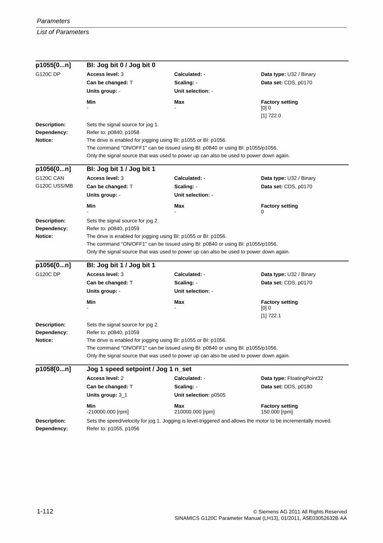
Parameters
List of Parameters
1-112 © Siemens AG 2011 All Rights ReservedSINAMICS G120C Parameter Manual (LH13), 01/2011, A5E03052632B AA
Description: Sets the signal source for jog 1.
Dependency: Refer to: p0840, p1058
Notice: The drive is enabled for jogging using BI: p1055 or BI: p1056.
The command "ON/OFF1" can be issued using BI: p0840 or using BI: p1055/p1056.
Only the signal source that was used to power up can also be used to power down again.
Description: Sets the signal source for jog 2.
Dependency: Refer to: p0840, p1059
Notice: The drive is enabled for jogging using BI: p1055 or BI: p1056.
The command "ON/OFF1" can be issued using BI: p0840 or using BI: p1055/p1056.
Only the signal source that was used to power up can also be used to power down again.
Description: Sets the speed/velocity for jog 1. Jogging is level-triggered and allows the motor to be incrementally moved.
Dependency: Refer to: p1055, p1056
p1055[0...n] BI: Jog bit 0 / Jog bit 0G120C DP Access level: 3 Calculated: - Data type: U32 / Binary
Can be changed: T Scaling: - Data set: CDS, p0170
Units group: - Unit selection: -
Min Max Factory setting - - [0] 0
[1] 722.0
p1056[0...n] BI: Jog bit 1 / Jog bit 1G120C CAN
G120C USS/MB
Access level: 3 Calculated: - Data type: U32 / Binary
Can be changed: T Scaling: - Data set: CDS, p0170
Units group: - Unit selection: -
Min Max Factory setting - - 0
p1056[0...n] BI: Jog bit 1 / Jog bit 1G120C DP Access level: 3 Calculated: - Data type: U32 / Binary
Can be changed: T Scaling: - Data set: CDS, p0170
Units group: - Unit selection: -
Min Max Factory setting - - [0] 0
[1] 722.1
p1058[0...n] Jog 1 speed setpoint / Jog 1 n_setAccess level: 2 Calculated: - Data type: FloatingPoint32
Can be changed: T Scaling: - Data set: DDS, p0180
Units group: 3_1 Unit selection: p0505
Min Max Factory setting -210000.000 [rpm] 210000.000 [rpm] 150.000 [rpm]
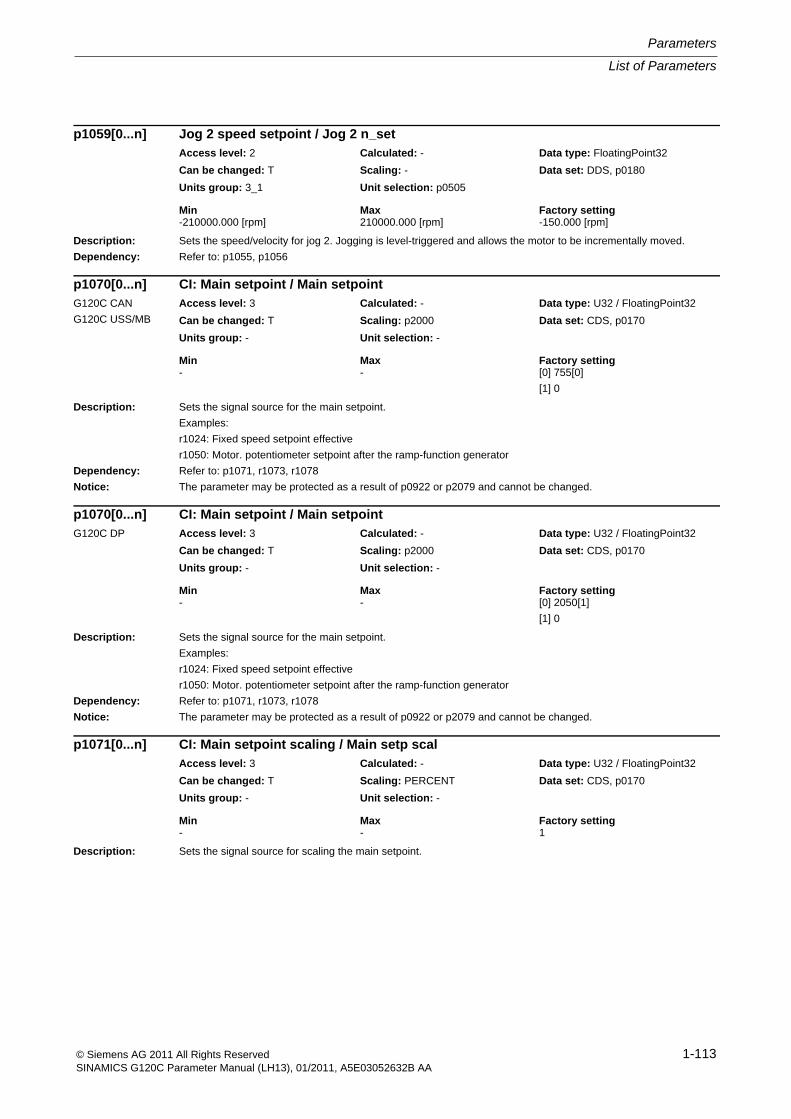
List of Parameters
Parameters
1-113© Siemens AG 2011 All Rights ReservedSINAMICS G120C Parameter Manual (LH13), 01/2011, A5E03052632B AA
Description: Sets the speed/velocity for jog 2. Jogging is level-triggered and allows the motor to be incrementally moved.
Dependency: Refer to: p1055, p1056
Description: Sets the signal source for the main setpoint.
Examples:
r1024: Fixed speed setpoint effective
r1050: Motor. potentiometer setpoint after the ramp-function generator
Dependency: Refer to: p1071, r1073, r1078
Notice: The parameter may be protected as a result of p0922 or p2079 and cannot be changed.
Description: Sets the signal source for scaling the main setpoint.
p1059[0...n] Jog 2 speed setpoint / Jog 2 n_setAccess level: 2 Calculated: - Data type: FloatingPoint32
Can be changed: T Scaling: - Data set: DDS, p0180
Units group: 3_1 Unit selection: p0505
Min Max Factory setting -210000.000 [rpm] 210000.000 [rpm] -150.000 [rpm]
p1070[0...n] CI: Main setpoint / Main setpointG120C CAN
G120C USS/MB
Access level: 3 Calculated: - Data type: U32 / FloatingPoint32
Can be changed: T Scaling: p2000 Data set: CDS, p0170
Units group: - Unit selection: -
Min Max Factory setting - - [0] 755[0]
[1] 0
p1070[0...n] CI: Main setpoint / Main setpointG120C DP Access level: 3 Calculated: - Data type: U32 / FloatingPoint32
Can be changed: T Scaling: p2000 Data set: CDS, p0170
Units group: - Unit selection: -
Min Max Factory setting - - [0] 2050[1]
[1] 0
p1071[0...n] CI: Main setpoint scaling / Main setp scalAccess level: 3 Calculated: - Data type: U32 / FloatingPoint32
Can be changed: T Scaling: PERCENT Data set: CDS, p0170
Units group: - Unit selection: -
Min Max Factory setting - - 1
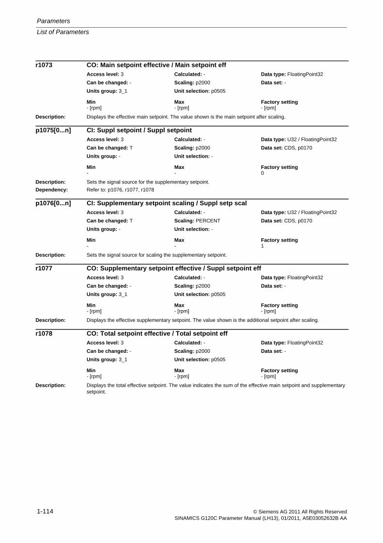
Parameters
List of Parameters
1-114 © Siemens AG 2011 All Rights ReservedSINAMICS G120C Parameter Manual (LH13), 01/2011, A5E03052632B AA
Description: Displays the effective main setpoint. The value shown is the main setpoint after scaling.
Description: Sets the signal source for the supplementary setpoint.
Dependency: Refer to: p1076, r1077, r1078
Description: Sets the signal source for scaling the supplementary setpoint.
Description: Displays the effective supplementary setpoint. The value shown is the additional setpoint after scaling.
Description: Displays the total effective setpoint. The value indicates the sum of the effective main setpoint and supplementary setpoint.
r1073 CO: Main setpoint effective / Main setpoint effAccess level: 3 Calculated: - Data type: FloatingPoint32
Can be changed: - Scaling: p2000 Data set: -
Units group: 3_1 Unit selection: p0505
Min Max Factory setting - [rpm] - [rpm] - [rpm]
p1075[0...n] CI: Suppl setpoint / Suppl setpointAccess level: 3 Calculated: - Data type: U32 / FloatingPoint32
Can be changed: T Scaling: p2000 Data set: CDS, p0170
Units group: - Unit selection: -
Min Max Factory setting - - 0
p1076[0...n] CI: Supplementary setpoint scaling / Suppl setp scalAccess level: 3 Calculated: - Data type: U32 / FloatingPoint32
Can be changed: T Scaling: PERCENT Data set: CDS, p0170
Units group: - Unit selection: -
Min Max Factory setting - - 1
r1077 CO: Supplementary setpoint effective / Suppl setpoint effAccess level: 3 Calculated: - Data type: FloatingPoint32
Can be changed: - Scaling: p2000 Data set: -
Units group: 3_1 Unit selection: p0505
Min Max Factory setting - [rpm] - [rpm] - [rpm]
r1078 CO: Total setpoint effective / Total setpoint effAccess level: 3 Calculated: - Data type: FloatingPoint32
Can be changed: - Scaling: p2000 Data set: -
Units group: 3_1 Unit selection: p0505
Min Max Factory setting - [rpm] - [rpm] - [rpm]
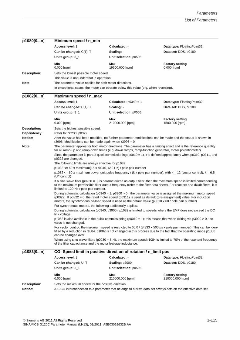
List of Parameters
Parameters
1-115© Siemens AG 2011 All Rights ReservedSINAMICS G120C Parameter Manual (LH13), 01/2011, A5E03052632B AA
Description: Sets the lowest possible motor speed.
This value is not undershot in operation.
Note: The parameter value applies for both motor directions.
In exceptional cases, the motor can operate below this value (e.g. when reversing).
Description: Sets the highest possible speed.
Dependency: Refer to: p0230, p0322
Notice: After the value has been modified, no further parameter modifications can be made and the status is shown in r3996. Modifications can be made again when r3996 = 0.
Note: The parameter applies for both motor directions. The parameter has a limiting effect and is the reference quantity for all ramp-up and ramp-down times (e.g. down ramps, ramp-function generator, motor potentiometer).
Since the parameter is part of quick commissioning (p0010 = 1), it is defined appropriately when p0310, p0311, and p0322 are changed.
The following limits are always effective for p1082:
p1082 <= 60 x maximum(15 x r0310, 650 Hz) / pole pair number
p1082 <= 60 x maximum power unit pulse frequency / (k x pole pair number), with k = 12 (vector control), k = 6.5 (U/f control)
If a sine-wave filter (p0230 = 3) is parameterized as output filter, then the maximum speed is limited corresponding to the maximum permissible filter output frequency (refer to the filter data sheet). For reactors and dU/dt filters, it is limited to 120 Hz / pole pair number.
During automatic calculation (p0340 = 1, p3900 > 0), the parameter value is assigned the maximum motor speed (p0322). If p0322 = 0, the rated motor speed (p0311) is used as default (pre-assignment) value. For induction motors, the synchronous no-load speed is used as the default value (p0310 x 60 / pole pair number).
For synchronous motors, the following additionally applies:
During automatic calculation (p0340, p3900), p1082 is limited to speeds where the EMF does not exceed the DC link voltage.
p1082 is also available in the quick commissioning (p0010 = 1); this means that when exiting via p3900 > 0, the value is not changed.
For vector control, the maximum speed is restricted to 60.0 / (8.333 x 500 µs x pole pair number). This can be iden-tified by a reduction in r1084. p1082 is not changed in this process due to the fact that the operating mode p1300 can be changed over.
When using sine-wave filters (p0230 = 3, 4), the maximum speed r1084 is limited to 70% of the resonant frequency of the filter capacitance and the motor leakage inductance.
Description: Sets the maximum speed for the positive direction.
Notice: A BICO interconnection to a parameter that belongs to a drive data set always acts on the effective data set.
p1080[0...n] Minimum speed / n_minAccess level: 1 Calculated: - Data type: FloatingPoint32
Can be changed: C(1), T Scaling: - Data set: DDS, p0180
Units group: 3_1 Unit selection: p0505
Min Max Factory setting 0.000 [rpm] 19500.000 [rpm] 0.000 [rpm]
p1082[0...n] Maximum speed / n_maxAccess level: 1 Calculated: p0340 = 1 Data type: FloatingPoint32
Can be changed: C(1), T Scaling: - Data set: DDS, p0180
Units group: 3_1 Unit selection: p0505
Min Max Factory setting 0.000 [rpm] 210000.000 [rpm] 1500.000 [rpm]
p1083[0...n] CO: Speed limit in positive direction of rotation / n_limit posAccess level: 3 Calculated: - Data type: FloatingPoint32
Can be changed: U, T Scaling: p2000 Data set: DDS, p0180
Units group: 3_1 Unit selection: p0505
Min Max Factory setting 0.000 [rpm] 210000.000 [rpm] 210000.000 [rpm]
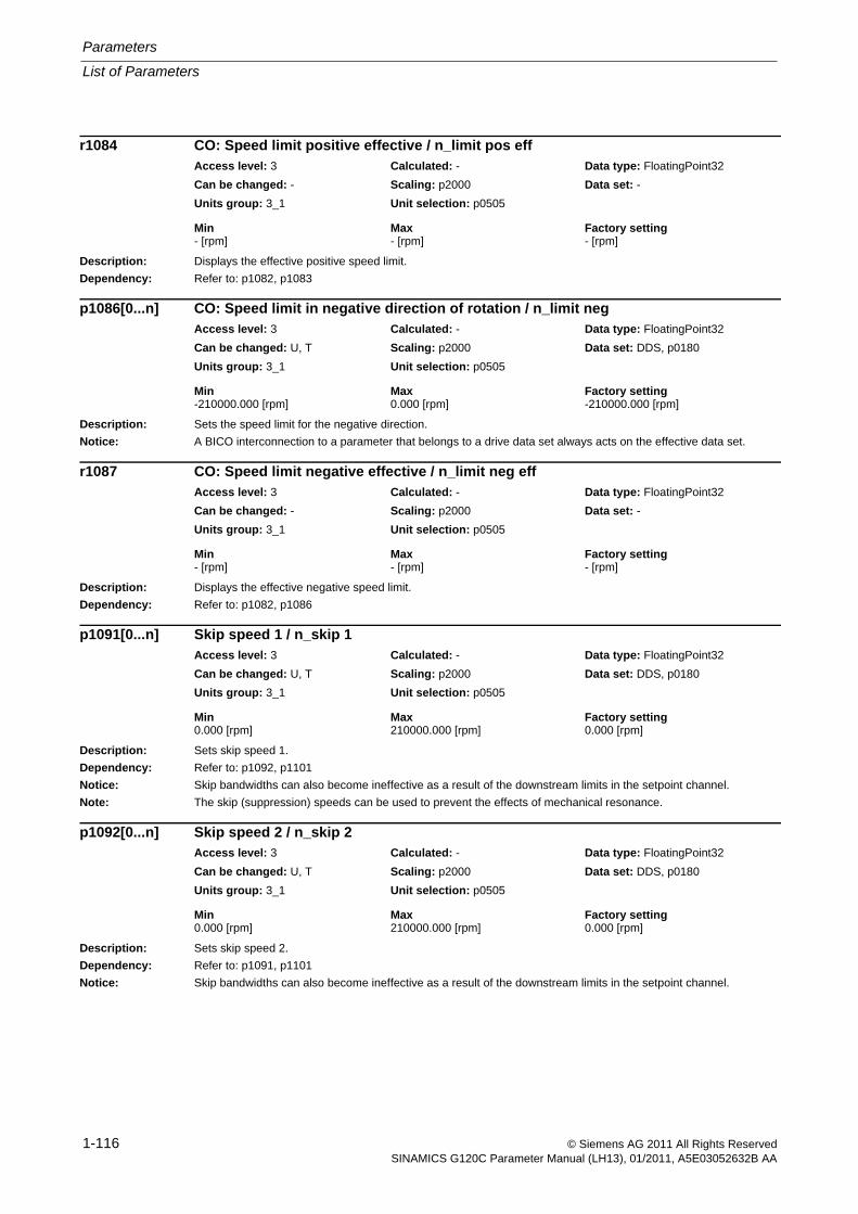
Parameters
List of Parameters
1-116 © Siemens AG 2011 All Rights ReservedSINAMICS G120C Parameter Manual (LH13), 01/2011, A5E03052632B AA
Description: Displays the effective positive speed limit.
Dependency: Refer to: p1082, p1083
Description: Sets the speed limit for the negative direction.
Notice: A BICO interconnection to a parameter that belongs to a drive data set always acts on the effective data set.
Description: Displays the effective negative speed limit.
Dependency: Refer to: p1082, p1086
Description: Sets skip speed 1.
Dependency: Refer to: p1092, p1101
Notice: Skip bandwidths can also become ineffective as a result of the downstream limits in the setpoint channel.
Note: The skip (suppression) speeds can be used to prevent the effects of mechanical resonance.
Description: Sets skip speed 2.
Dependency: Refer to: p1091, p1101
Notice: Skip bandwidths can also become ineffective as a result of the downstream limits in the setpoint channel.
r1084 CO: Speed limit positive effective / n_limit pos effAccess level: 3 Calculated: - Data type: FloatingPoint32
Can be changed: - Scaling: p2000 Data set: -
Units group: 3_1 Unit selection: p0505
Min Max Factory setting - [rpm] - [rpm] - [rpm]
p1086[0...n] CO: Speed limit in negative direction of rotation / n_limit negAccess level: 3 Calculated: - Data type: FloatingPoint32
Can be changed: U, T Scaling: p2000 Data set: DDS, p0180
Units group: 3_1 Unit selection: p0505
Min Max Factory setting -210000.000 [rpm] 0.000 [rpm] -210000.000 [rpm]
r1087 CO: Speed limit negative effective / n_limit neg effAccess level: 3 Calculated: - Data type: FloatingPoint32
Can be changed: - Scaling: p2000 Data set: -
Units group: 3_1 Unit selection: p0505
Min Max Factory setting - [rpm] - [rpm] - [rpm]
p1091[0...n] Skip speed 1 / n_skip 1Access level: 3 Calculated: - Data type: FloatingPoint32
Can be changed: U, T Scaling: p2000 Data set: DDS, p0180
Units group: 3_1 Unit selection: p0505
Min Max Factory setting 0.000 [rpm] 210000.000 [rpm] 0.000 [rpm]
p1092[0...n] Skip speed 2 / n_skip 2Access level: 3 Calculated: - Data type: FloatingPoint32
Can be changed: U, T Scaling: p2000 Data set: DDS, p0180
Units group: 3_1 Unit selection: p0505
Min Max Factory setting 0.000 [rpm] 210000.000 [rpm] 0.000 [rpm]
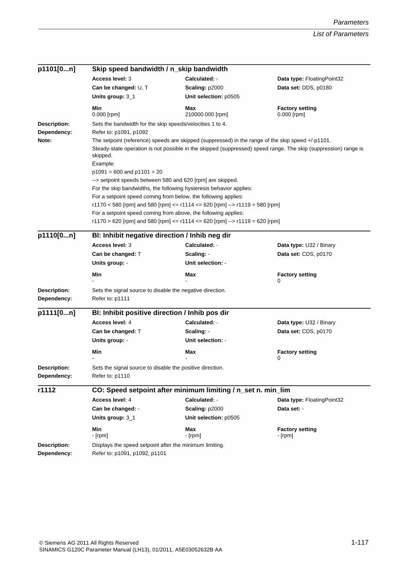
List of Parameters
Parameters
1-117© Siemens AG 2011 All Rights ReservedSINAMICS G120C Parameter Manual (LH13), 01/2011, A5E03052632B AA
Description: Sets the bandwidth for the skip speeds/velocities 1 to 4.
Dependency: Refer to: p1091, p1092
Note: The setpoint (reference) speeds are skipped (suppressed) in the range of the skip speed +/-p1101.
Steady-state operation is not possible in the skipped (suppressed) speed range. The skip (suppression) range is skipped.
Example:
p1091 = 600 and p1101 = 20
--> setpoint speeds between 580 and 620 [rpm] are skipped.
For the skip bandwidths, the following hysteresis behavior applies:
For a setpoint speed coming from below, the following applies:
r1170 < 580 [rpm] and 580 [rpm] <= r1114 <= 620 [rpm] --> r1119 = 580 [rpm]
For a setpoint speed coming from above, the following applies:
r1170 > 620 [rpm] and 580 [rpm] <= r1114 <= 620 [rpm] --> r1119 = 620 [rpm]
Description: Sets the signal source to disable the negative direction.
Dependency: Refer to: p1111
Description: Sets the signal source to disable the positive direction.
Dependency: Refer to: p1110
Description: Displays the speed setpoint after the minimum limiting.
Dependency: Refer to: p1091, p1092, p1101
p1101[0...n] Skip speed bandwidth / n_skip bandwidthAccess level: 3 Calculated: - Data type: FloatingPoint32
Can be changed: U, T Scaling: p2000 Data set: DDS, p0180
Units group: 3_1 Unit selection: p0505
Min Max Factory setting 0.000 [rpm] 210000.000 [rpm] 0.000 [rpm]
p1110[0...n] BI: Inhibit negative direction / Inhib neg dirAccess level: 3 Calculated: - Data type: U32 / Binary
Can be changed: T Scaling: - Data set: CDS, p0170
Units group: - Unit selection: -
Min Max Factory setting - - 0
p1111[0...n] BI: Inhibit positive direction / Inhib pos dirAccess level: 4 Calculated: - Data type: U32 / Binary
Can be changed: T Scaling: - Data set: CDS, p0170
Units group: - Unit selection: -
Min Max Factory setting - - 0
r1112 CO: Speed setpoint after minimum limiting / n_set n. min_limAccess level: 4 Calculated: - Data type: FloatingPoint32
Can be changed: - Scaling: p2000 Data set: -
Units group: 3_1 Unit selection: p0505
Min Max Factory setting - [rpm] - [rpm] - [rpm]

Parameters
List of Parameters
1-118 © Siemens AG 2011 All Rights ReservedSINAMICS G120C Parameter Manual (LH13), 01/2011, A5E03052632B AA
Description: Sets the signal source to invert the setpoint.
Dependency: Refer to: r1198
Caution: If the technology controller is being used as the speed main setpoint (p2251 = 0), do not invert the setpoint using p1113 when the technology controller is enabled because this can cause the speed to change suddenly and lead to positive couplings in the control loop.
Notice: The parameter may be protected as a result of p0922 or p2079 and cannot be changed.
Description: Displays the speed/velocity setpoint after the changeover and limiting the direction.
Description: Displays the setpoint at the input of the ramp-function generator.
Notice: The parameter may be protected as a result of p0922 or p2079 and cannot be changed.
Note: The setpoint is influenced by other functions, e.g. skip (suppressed) speeds, minimum and maximum limits.
p1113[0...n] BI: Setpoint inversion / Setp invG120C CAN
G120C USS/MB
Access level: 3 Calculated: - Data type: U32 / Binary
Can be changed: T Scaling: - Data set: CDS, p0170
Units group: - Unit selection: -
Min Max Factory setting - - [0] 722.1
[1] 0
p1113[0...n] BI: Setpoint inversion / Setp invG120C DP Access level: 3 Calculated: - Data type: U32 / Binary
Can be changed: T Scaling: - Data set: CDS, p0170
Units group: - Unit selection: -
Min Max Factory setting - - [0] 2090.11
[1] 0
r1114 CO: Setpoint after the direction limiting / Setp after limitAccess level: 3 Calculated: - Data type: FloatingPoint32
Can be changed: - Scaling: p2000 Data set: -
Units group: 3_1 Unit selection: p0505
Min Max Factory setting - [rpm] - [rpm] - [rpm]
r1119 CO: Ramp-function generator setpoint at the input / RFG setp at inpAccess level: 3 Calculated: - Data type: FloatingPoint32
Can be changed: - Scaling: p2000 Data set: -
Units group: 3_1 Unit selection: p0505
Min Max Factory setting - [rpm] - [rpm] - [rpm]
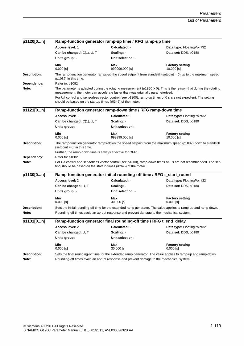
List of Parameters
Parameters
1-119© Siemens AG 2011 All Rights ReservedSINAMICS G120C Parameter Manual (LH13), 01/2011, A5E03052632B AA
Description: The ramp-function generator ramps-up the speed setpoint from standstill (setpoint = 0) up to the maximum speed (p1082) in this time.
Dependency: Refer to: p1082
Note: The parameter is adapted during the rotating measurement (p1960 > 0). This is the reason that during the rotating measurement, the motor can accelerate faster than was originally parameterized.
For U/f control and sensorless vector control (see p1300), ramp-up times of 0 s are not expedient. The setting should be based on the startup times (r0345) of the motor.
Description: The ramp-function generator ramps-down the speed setpoint from the maximum speed (p1082) down to standstill (setpoint = 0) in this time.
Further, the ramp-down time is always effective for OFF1.
Dependency: Refer to: p1082
Note: For U/f control and sensorless vector control (see p1300), ramp-down times of 0 s are not recommended. The set-ting should be based on the startup times (r0345) of the motor.
Description: Sets the initial rounding-off time for the extended ramp generator. The value applies to ramp-up and ramp-down.
Note: Rounding-off times avoid an abrupt response and prevent damage to the mechanical system.
Description: Sets the final rounding-off time for the extended ramp generator. The value applies to ramp-up and ramp-down.
Note: Rounding-off times avoid an abrupt response and prevent damage to the mechanical system.
p1120[0...n] Ramp-function generator ramp-up time / RFG ramp-up timeAccess level: 1 Calculated: - Data type: FloatingPoint32
Can be changed: C(1), U, T Scaling: - Data set: DDS, p0180
Units group: - Unit selection: -
Min Max Factory setting 0.000 [s] 999999.000 [s] 10.000 [s]
p1121[0...n] Ramp-function generator ramp-down time / RFG ramp-down timeAccess level: 1 Calculated: - Data type: FloatingPoint32
Can be changed: C(1), U, T Scaling: - Data set: DDS, p0180
Units group: - Unit selection: -
Min Max Factory setting 0.000 [s] 999999.000 [s] 10.000 [s]
p1130[0...n] Ramp-function generator initial rounding-off time / RFG t_start_roundAccess level: 2 Calculated: - Data type: FloatingPoint32
Can be changed: U, T Scaling: - Data set: DDS, p0180
Units group: - Unit selection: -
Min Max Factory setting 0.000 [s] 30.000 [s] 0.000 [s]
p1131[0...n] Ramp-function generator final rounding-off time / RFG t_end_delayAccess level: 2 Calculated: - Data type: FloatingPoint32
Can be changed: U, T Scaling: - Data set: DDS, p0180
Units group: - Unit selection: -
Min Max Factory setting 0.000 [s] 30.000 [s] 0.000 [s]
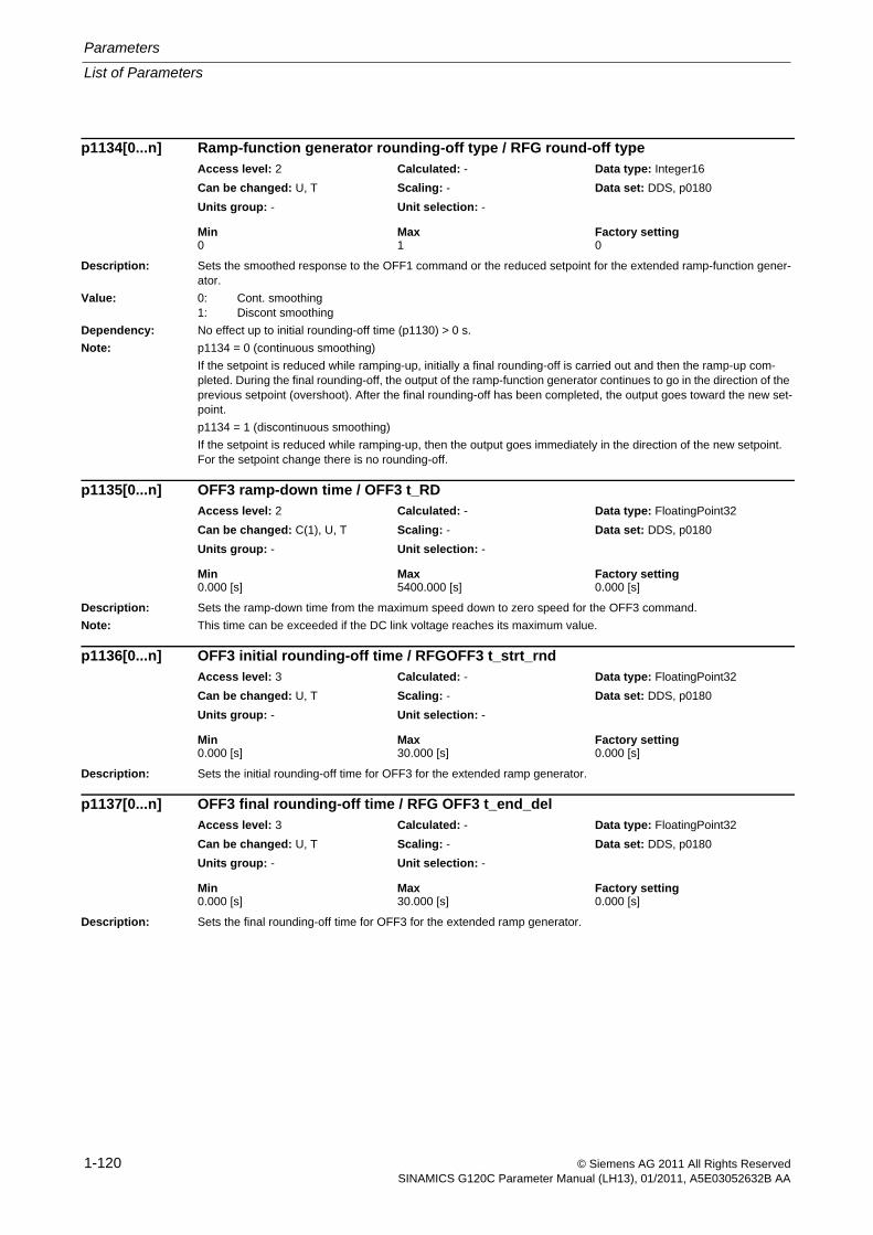
Parameters
List of Parameters
1-120 © Siemens AG 2011 All Rights ReservedSINAMICS G120C Parameter Manual (LH13), 01/2011, A5E03052632B AA
Description: Sets the smoothed response to the OFF1 command or the reduced setpoint for the extended ramp-function gener-ator.
Value: 0: Cont. smoothing1: Discont smoothing
Dependency: No effect up to initial rounding-off time (p1130) > 0 s.
Note: p1134 = 0 (continuous smoothing)
If the setpoint is reduced while ramping-up, initially a final rounding-off is carried out and then the ramp-up com-pleted. During the final rounding-off, the output of the ramp-function generator continues to go in the direction of the previous setpoint (overshoot). After the final rounding-off has been completed, the output goes toward the new set-point.
p1134 = 1 (discontinuous smoothing)
If the setpoint is reduced while ramping-up, then the output goes immediately in the direction of the new setpoint. For the setpoint change there is no rounding-off.
Description: Sets the ramp-down time from the maximum speed down to zero speed for the OFF3 command.
Note: This time can be exceeded if the DC link voltage reaches its maximum value.
Description: Sets the initial rounding-off time for OFF3 for the extended ramp generator.
Description: Sets the final rounding-off time for OFF3 for the extended ramp generator.
p1134[0...n] Ramp-function generator rounding-off type / RFG round-off typeAccess level: 2 Calculated: - Data type: Integer16
Can be changed: U, T Scaling: - Data set: DDS, p0180
Units group: - Unit selection: -
Min Max Factory setting 0 1 0
p1135[0...n] OFF3 ramp-down time / OFF3 t_RDAccess level: 2 Calculated: - Data type: FloatingPoint32
Can be changed: C(1), U, T Scaling: - Data set: DDS, p0180
Units group: - Unit selection: -
Min Max Factory setting 0.000 [s] 5400.000 [s] 0.000 [s]
p1136[0...n] OFF3 initial rounding-off time / RFGOFF3 t_strt_rndAccess level: 3 Calculated: - Data type: FloatingPoint32
Can be changed: U, T Scaling: - Data set: DDS, p0180
Units group: - Unit selection: -
Min Max Factory setting 0.000 [s] 30.000 [s] 0.000 [s]
p1137[0...n] OFF3 final rounding-off time / RFG OFF3 t_end_delAccess level: 3 Calculated: - Data type: FloatingPoint32
Can be changed: U, T Scaling: - Data set: DDS, p0180
Units group: - Unit selection: -
Min Max Factory setting 0.000 [s] 30.000 [s] 0.000 [s]
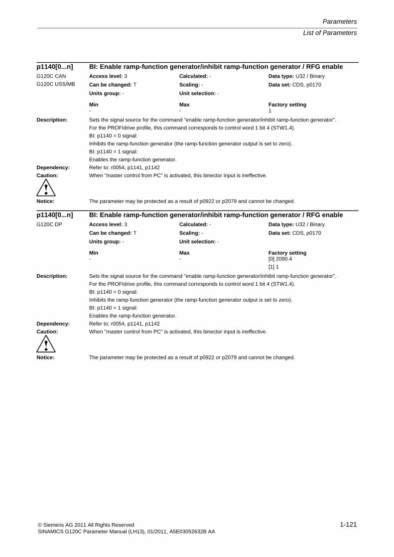
List of Parameters
Parameters
1-121© Siemens AG 2011 All Rights ReservedSINAMICS G120C Parameter Manual (LH13), 01/2011, A5E03052632B AA
Description: Sets the signal source for the command "enable ramp-function generator/inhibit ramp-function generator".
For the PROFIdrive profile, this command corresponds to control word 1 bit 4 (STW1.4).
BI: p1140 = 0 signal:
Inhibits the ramp-function generator (the ramp-function generator output is set to zero).
BI: p1140 = 1 signal:
Enables the ramp-function generator.
Dependency: Refer to: r0054, p1141, p1142
Caution: When "master control from PC" is activated, this binector input is ineffective.
Notice: The parameter may be protected as a result of p0922 or p2079 and cannot be changed.
p1140[0...n] BI: Enable ramp-function generator/inhibit ramp-function generator / RFG enableG120C CAN
G120C USS/MB
Access level: 3 Calculated: - Data type: U32 / Binary
Can be changed: T Scaling: - Data set: CDS, p0170
Units group: - Unit selection: -
Min Max Factory setting - - 1
p1140[0...n] BI: Enable ramp-function generator/inhibit ramp-function generator / RFG enableG120C DP Access level: 3 Calculated: - Data type: U32 / Binary
Can be changed: T Scaling: - Data set: CDS, p0170
Units group: - Unit selection: -
Min Max Factory setting - - [0] 2090.4
[1] 1
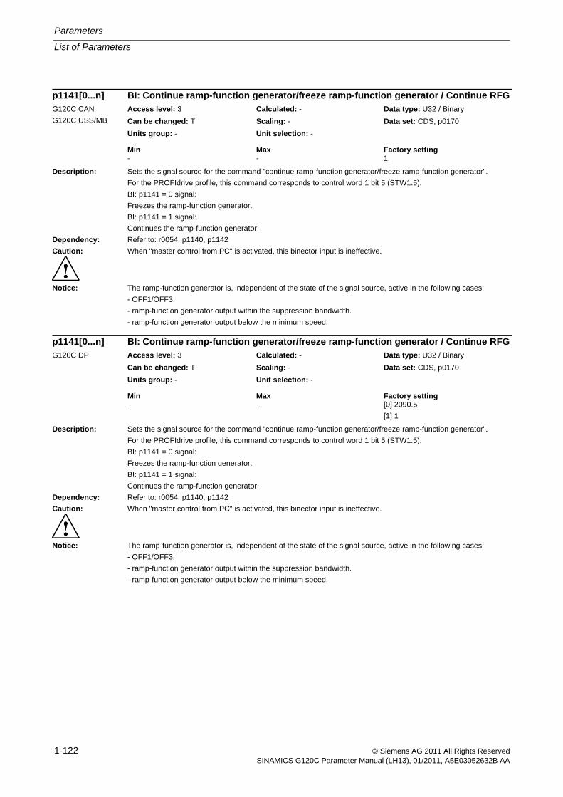
Parameters
List of Parameters
1-122 © Siemens AG 2011 All Rights ReservedSINAMICS G120C Parameter Manual (LH13), 01/2011, A5E03052632B AA
Description: Sets the signal source for the command "continue ramp-function generator/freeze ramp-function generator".
For the PROFIdrive profile, this command corresponds to control word 1 bit 5 (STW1.5).
BI: p1141 = 0 signal:
Freezes the ramp-function generator.
BI: p1141 = 1 signal:
Continues the ramp-function generator.
Dependency: Refer to: r0054, p1140, p1142
Caution: When "master control from PC" is activated, this binector input is ineffective.
Notice: The ramp-function generator is, independent of the state of the signal source, active in the following cases:
- OFF1/OFF3.
- ramp-function generator output within the suppression bandwidth.
- ramp-function generator output below the minimum speed.
p1141[0...n] BI: Continue ramp-function generator/freeze ramp-function generator / Continue RFGG120C CAN
G120C USS/MB
Access level: 3 Calculated: - Data type: U32 / Binary
Can be changed: T Scaling: - Data set: CDS, p0170
Units group: - Unit selection: -
Min Max Factory setting - - 1
p1141[0...n] BI: Continue ramp-function generator/freeze ramp-function generator / Continue RFGG120C DP Access level: 3 Calculated: - Data type: U32 / Binary
Can be changed: T Scaling: - Data set: CDS, p0170
Units group: - Unit selection: -
Min Max Factory setting - - [0] 2090.5
[1] 1
List of Parameters
Parameters
1-123© Siemens AG 2011 All Rights ReservedSINAMICS G120C Parameter Manual (LH13), 01/2011, A5E03052632B AA
Description: Sets the signal source for the command "enable setpoint/inhibit setpoint".
For the PROFIdrive profile, this command corresponds to control word 1 bit 6 (STW1.6).
BI: p1142 = 0 signal
Inhibits the setpoint (the ramp-function generator input is set to zero).
BI: p1142 = 1 signal
Enables the setpoint.
Dependency: Refer to: p1140, p1141
Caution: When "master control from PC" is activated, this binector input is ineffective.
Notice: The parameter may be protected as a result of p0922 or p2079 and cannot be changed.
Description: Displays the acceleration of the ramp-function generator.
p1142[0...n] BI: Enable setpoint/inhibit setpoint / Setpoint enableG120C CAN
G120C USS/MB
Access level: 3 Calculated: - Data type: U32 / Binary
Can be changed: T Scaling: - Data set: CDS, p0170
Units group: - Unit selection: -
Min Max Factory setting - - 1
p1142[0...n] BI: Enable setpoint/inhibit setpoint / Setpoint enableG120C DP Access level: 3 Calculated: - Data type: U32 / Binary
Can be changed: T Scaling: - Data set: CDS, p0170
Units group: - Unit selection: -
Min Max Factory setting - - [0] 2090.6
[1] 1
r1149 CO: Ramp-function generator, acceleration / RFG accelerationAccess level: 3 Calculated: - Data type: FloatingPoint32
Can be changed: - Scaling: p2007 Data set: -
Units group: 39_1 Unit selection: p0505
Min Max Factory setting - [rev/s²] - [rev/s²] - [rev/s²]
Parameters
List of Parameters
1-124 © Siemens AG 2011 All Rights ReservedSINAMICS G120C Parameter Manual (LH13), 01/2011, A5E03052632B AA
Description: Displays the setpoint at the output of the ramp-function generator.
Description: Displays the speed setpoint.
Dependency: Refer to: r1150
Description: Displays the control word for the setpoint channel.
r1150 CO: Ramp-function generator speed setpoint at the output / RFG n_set at outpAccess level: 4 Calculated: - Data type: FloatingPoint32
Can be changed: - Scaling: p2000 Data set: -
Units group: 3_1 Unit selection: p0505
Min Max Factory setting - [rpm] - [rpm] - [rpm]
r1170 CO: Speed controller, setpoint sum / n_ctrl setp sumAccess level: 3 Calculated: - Data type: FloatingPoint32
Can be changed: - Scaling: p2000 Data set: -
Units group: 3_1 Unit selection: p0505
Min Max Factory setting - [rpm] - [rpm] - [rpm]
r1198.0...15 CO/BO: Control word setpoint channel / STW setpoint chanAccess level: 3 Calculated: - Data type: Unsigned16
Can be changed: - Scaling: - Data set: -
Units group: - Unit selection: -
Min Max Factory setting - - -
Bit field: Bit Signal name 1 signal 0 signal FP00 Fixed setp bit 0 Yes No 301001 Fixed setp bit 1 Yes No 301002 Fixed setp bit 2 Yes No 301003 Fixed setp bit 3 Yes No 301005 Inhibit negative direction Yes No 304006 Inhibit positive direction Yes No 304011 Setpoint inversion Yes No 304013 Motorized potentiometer raise Yes No 302014 Motorized potentiometer lower Yes No 302015 Bypass ramp-function generator Yes No 3060,
3070
List of Parameters
Parameters
1-125© Siemens AG 2011 All Rights ReservedSINAMICS G120C Parameter Manual (LH13), 01/2011, A5E03052632B AA
Description: Sets the operating mode for flying restart.
The flying restart allows the drive converter to be powered up while the motor is still rotating. In so doing, the drive converter output frequency is changed until the actual motor speed/velocity is found. The motor then accelerates up to the setpoint at the ramp-function generator setting.
Value: 0: Flying restart inactive1: Flying restart always active (start in setpoint direction)4: Flying restart always active (start only in setpoint direction)
Dependency: For synchronous motors, flying restart cannot be activated.
Refer to: p1201
Refer to: F07330, F07331
Notice: The "flying restart" function must be used in cases where the motor may still be running (e.g. after a brief line supply interruption) or is being driven by the load. The system might otherwise shut down as a result of overcurrent.
Note: When p1200 = 1, 4: Flying restart is active after faults, OFF1, OFF2, OFF3.
When p1200 = 1: The search is made in both directions.
When p1200 = 4: The search is only made in the setpoint direction.
For U/f control (p1300 < 20), the following applies:
The speed can only be sensed for values above approx. 5 % of the rated motor speed. For lower speeds, it is assumed that the motor is at a standstill.
If p1200 is changed during commissioning (p0010 > 0), then it is possible that the old value will no longer be able to be set. The reason for this is that the dynamic limits of p1200 have been changed by a parameter that was set when the drive was commissioned (e.g. p0300).
Description: Sets the signal source to enable the "flying restart" function.
Dependency: Refer to: p1200
Note: Withdrawing the enable signal has the same effect as setting p1200 = 0.
p1200[0...n] FlyRest oper mode / FlyRest op_modeAccess level: 2 Calculated: - Data type: Integer16
Can be changed: U, T Scaling: - Data set: DDS, p0180
Units group: - Unit selection: -
Min Max Factory setting 0 4 0
p1201[0...n] BI: Flying restart enable signal source / Fly_res enab S_srcAccess level: 3 Calculated: - Data type: U32 / Binary
Can be changed: T Scaling: - Data set: CDS, p0170
Units group: - Unit selection: -
Min Max Factory setting - - 1
Parameters
List of Parameters
1-126 © Siemens AG 2011 All Rights ReservedSINAMICS G120C Parameter Manual (LH13), 01/2011, A5E03052632B AA
Description: Sets the search current for the "flying restart" function.
The value is referred to the motor magnetizing current.
Dependency: Refer to: r0331
Caution: An unfavorable parameter value can result in the motor behaving in an uncontrollable fashion.
Note: In U/f control mode, the parameter serves as a threshold value for establishing the current at the beginning of the flying restart function. When the threshold value is reached, the prevailing search current is set dependent upon the frequency on the basis of voltage inputs.
Reducing the search current can also improve flying restart performance (if the system moment of inertia is not very high, for example).
Description: The value influences the rate at which the output frequency is changed during a flying restart . A higher value results in a longer search time.
Caution: An unfavorable parameter value can result in the motor behaving in an uncontrollable fashion.
For vector control, a value that is too low or too high can cause flying restart to become unstable.
Note: The parameter factory setting is selected so that standard induction motors that are rotating can be found and restarted as quickly as possible (fast flying restart).
With this pre-setting, if the motor is not found (e.g. for motors that are accelerated as a result of active loads or with U/f control and low speeds), we recommend that the search rate is reduced (by increasing p1203).
Description: Selects the faults for which automatic restart should not be effective.
Dependency: The setting is only effective for p1210 = 6, 16.
Refer to: p1210
p1202[0...n] FlyRest srch curr / FlyRest I_srchAccess level: 3 Calculated: - Data type: FloatingPoint32
Can be changed: U, T Scaling: - Data set: DDS, p0180
Units group: - Unit selection: -
Min Max Factory setting 10 [%] 400 [%] 100 [%]
p1203[0...n] Flying restart search rate factor / FlyRst v_Srch FactAccess level: 3 Calculated: - Data type: FloatingPoint32
Can be changed: U, T Scaling: - Data set: DDS, p0180
Units group: - Unit selection: -
Min Max Factory setting 10 [%] 4000 [%] 100 [%]
p1206[0...9] Set the fault number without automatic restart / Fault_No w/o ARAccess level: 3 Calculated: - Data type: Unsigned16
Can be changed: U, T Scaling: - Data set: -
Units group: - Unit selection: -
Min Max Factory setting 0 65535 0
List of Parameters
Parameters
1-127© Siemens AG 2011 All Rights ReservedSINAMICS G120C Parameter Manual (LH13), 01/2011, A5E03052632B AA
Description: Sets the automatic restart mode (AR).
The parameters must be saved in the non-volatile memory p0971 = 1 in order that the setting becomes effective.
Value: 0: Inhibit automatic restart1: Acknowledge all faults without restarting4: Restart after line supply failure w/o additional start attempts6: Restart after fault with additional start attempts14: Restart after line supply failure following man. acknowledgment16: Restart after fault following manual acknowledgment26: Acknowledging all faults and reclosing for an ON command
Dependency: The automatic restart requires an active ON command (e.g., via a digital input). If, for p1210 > 1, there is no active ON command, then the automatic restart is interrupted.
When using an Operator Panel in the LOCAL mode, then there is no automatic start.
For p1210 = 14, 16, a manual acknowledgement is required for an automatic restart.
For p1210 = 26, the ON command can also be entered with a delay. After the line supply returns or acknowledging a fault, the restart waits for an ON command. The maximum wait time is specified using p1213[0].
Refer to: p0840
Refer to: F30003
Danger: If the automatic restart is activated (p1210 > 1) if there is an ON command (refer to p0840), the drive is powered up as soon as any fault messages that are present can be acknowledged. This also occurs after the line supply returns or the Control Unit boots if the DC link voltage is present again. This automatic power-up sequence can only be interrupted by withdrawing the ON command.
Caution: A change is only accepted and made in the state "initialization" and "wait for alarm". When faults are present, there-fore, the parameter cannot be changed.
For p1210 > 1, the motor is automatically started.
Note: Re p1210 = 1:
Faults that are present are automatically acknowledged. If new faults occur after a successful fault acknowledg-ment, then these are also automatically acknowledged again. p1211 has no influence on the number of acknowl-edgment attempts.
Re p1210 = 4:
An automatic restart is only performed if fault F30003 has occurred on the power unit. If additional faults are pres-ent, then these faults are also acknowledged and when successful, starting continues. If the 24 V Control Unit power supply fails, then this is interpreted as a line supply failure.
Re p1210 = 6:
An automatic restart is carried out if any fault has occurred.
Re p1210 = 14:
As for p1210 = 4. However, faults that are present must be manually acknowledged.
Re p1210 = 16:
As for p1210 = 6. However, faults that are present must be manually acknowledged.
Re p1210 = 26:
As for p1210 = 6. However, at the time that the fault is acknowledged or at power on, a switch-on command is not necessary. This can be set with a time delay. The drive is switched-on again as soon as the switch-on command is set. The restart can be interrupted with either OFF2 or OFF3.
p1210 Automatic restart, mode / AR modeAccess level: 2 Calculated: - Data type: Integer16
Can be changed: U, T Scaling: - Data set: -
Units group: - Unit selection: -
Min Max Factory setting 0 26 0
Parameters
List of Parameters
1-128 © Siemens AG 2011 All Rights ReservedSINAMICS G120C Parameter Manual (LH13), 01/2011, A5E03052632B AA
Description: Sets the start attempts of the automatic restart function for p1210 = 4, 6, 14, 16, 26.
Dependency: Refer to: p1210
Refer to: F07320
Caution: A change is only accepted and made in the state "initialization" and "wait for alarm".
Notice: After fault F07320 occurs, the power-on command must be withdrawn and all of the faults acknowledged so that the automatic restart function is re-activated.
After a complete power failure the start counter always starts with the counter value that applied before the power failure, and decrements this start attempt by 1. If a further attempt to acknowledge is started by the automatic restart function prior to power failure, e.g. when the CU remains active on power failure longer than the time p1212 / 2, the fault counter will already have been decremented once. In this case, the start counter is thus decreased by the value 2.
Note: A start attempt starts immediately when a fault occurs. The start attempt is considered to been completed if the motor was magnetized (r0056.4 = 1) and an additional delay time of 1 s has expired.
As long as a fault is present, an acknowledge command is generated in the time intervals of p1212 / 2. When suc-cessfully acknowledged, the start counter is decremented. If, after this, a fault re-occurs before a restart has been completed, then acknowledgement starts again from the beginning.
Fault F07320 is output if, after several faults occur, the number of parameterized start attempts has been reached. After a successful start attempt, i.e. a fault/error has no longer occurred up to the end of the magnetizing phase, the start counter is again reset to the parameter value after 1 s. If a fault re-occurs - the parameterized number of start attempts is again available.
At least one start attempt is always carried out.
After a line supply failure, acknowledgement is immediate and when the line supply returns, the system is powered up. If, between successfully acknowledging the line fault and the line supply returning, another fault occurs, then its acknowledgement also causes the start counter to be decremented.
For p1210 = 26, the start counter is decremented if after a successful fault acknowledgement, the on command is present.
Description: Sets the delay time up to restart.
Dependency: This parameter setting is active for p1210 = 4, 6, 26.
For p1210 = 1, the following applies: Faults are only automatically acknowledged in half of the delay time, no restart.
Refer to: p1210
Caution: A change is only accepted and made in the state "initialization" and "wait for alarm".
Note: The faults are automatically acknowledged after half of the delay time has expired and the full delay time.
If the cause of a fault is not removed in the first half of the delay time, then it is no longer possible to acknowledge in the delay time.
p1211 Automatic restart, start attempts / AR start attemptsAccess level: 3 Calculated: - Data type: Unsigned16
Can be changed: U, T Scaling: - Data set: -
Units group: - Unit selection: -
Min Max Factory setting 0 10 3
p1212 Automatic restart, delay time start attempts / AR t_wait startAccess level: 3 Calculated: - Data type: FloatingPoint32
Can be changed: U, T Scaling: - Data set: -
Units group: - Unit selection: -
Min Max Factory setting 0.1 [s] 1000.0 [s] 1.0 [s]
List of Parameters
Parameters
1-129© Siemens AG 2011 All Rights ReservedSINAMICS G120C Parameter Manual (LH13), 01/2011, A5E03052632B AA
Description: Sets the monitoring time of the automatic restart (AR).
Index: [0] = For restart[1] = To reset the start counter
Dependency: Refer to: p1210
Caution: A change is only accepted and made in the state "initialization" and "wait for alarm".
Notice: After fault F07320 occurs, the power-on command must be withdrawn and all of the faults acknowledged so that the automatic restart function is re-activated.
Note: Index 0:
The monitoring time starts when the faults are detected. If the automatic acknowledgements are not successful, the monitoring time runs again. If, after the monitoring time has expired, the drive has still not successfully started again (flying restart and magnetizing of the motor must have been completed: r0056.4 = 1), then fault F07320 is output.
The monitoring is de-activated with p1213 = 0. If p1213 is set lower than the sum of p1212, the magnetizing time p0346 and the additional delay time due to the flying restart, then fault F07320 is generated at each restart. If, for p1210 = 1, the time in p1213 is set lower than in p1212, then fault F07320 is also generated at each restart.
The monitoring time must be extended if the faults that occur cannot be immediately and successfully acknowl-edged (e.g. for faults that are permanently present).
In the case of p1210 = 14, 16, the faults which are present must be acknowledged manually within the time in p1213 index 0. Otherwise, fault F07320 is generated after the set time.
Index 1:
The start counter is only reset to the starting value p1211 if, after successful restart, the time in p1213 index 1 has expired. The delay time is not effective for fault acknowledgement without automatic restart (p1210 = 1). After a power failure (blackout) the delay time only starts after the line supply returns and the Control Unit boots. The start counter is set to p1211, if F07320 occurred, the power-on command is withdrawn and the fault is acknowledged.
The start counter is immediately updated if the starting value p1211 or the mode p1210 is changed.
For p1210 = 26, the fault must have been successfully acknowledged and the switch-on command issued within the time in p1213, index 0. Otherwise, fault F07320 is generated after the set time.
Description: Sets the holding brake configuration.
Value: 0: No motor holding brake being used3: Motor holding brake like sequence control, connection via BICO
Dependency: Refer to: p1216, p1217
Caution: For the setting p1215 = 0, if a brake is used, it remains closed. If the motor moves, this will destroy the brake.
Notice: If p1215 was set to 1 or if p1215 was set to 3, then when the pulses are suppressed, the brake is closed even if the motor is still rotating. Pulse suppression can either be caused by a 0 signal at p0844, p0845 or p0852 or as a result of a fault with OFF2 response. If this is not desirable (e.g. for a flying restart), then the brake can be kept open using a 1 signal at p0855.
Note: If a holding brake integrated in the motor is used, then it is not permissible that p1215 is set to 3.
if an external motor holding brake is being used, then p1215 should be set to 3 and r0899.12 should be intercon-nected as control signal.
The parameter can only be set to zero when the pulses are inhibited.
p1213[0...1] Automatic restart, monitoring time / AR t_monitoringAccess level: 3 Calculated: - Data type: FloatingPoint32
Can be changed: U, T Scaling: - Data set: -
Units group: - Unit selection: -
Min Max Factory setting 0.0 [s] 10000.0 [s] [0] 60.0 [s]
[1] 0.0 [s]
p1215 Motor holding brake configuration / Brake configAccess level: 2 Calculated: - Data type: Integer16
Can be changed: T Scaling: - Data set: -
Units group: - Unit selection: -
Min Max Factory setting 0 3 0
Parameters
List of Parameters
1-130 © Siemens AG 2011 All Rights ReservedSINAMICS G120C Parameter Manual (LH13), 01/2011, A5E03052632B AA
Description: Sets the time to open the motor holding brake.
After the holding brake has been controlled (opened), the speed setpoint remains at zero for this time. After this, the speed setpoint is enabled.
Dependency: Refer to: p1215, p1217
Description: Sets the time to apply the motor holding brake.
After OFF1 or OFF3 and the controlling (closing) of the holding brake, the drive remains stationary under closed-loop control for this time with a speed setpoint of zero. The pulses are suppressed when the time expires.
Dependency: Refer to: p1215, p1216
Notice: If the selected closing time is too short with respect to the actual closing time of the brake, then the load can sag.
If the closing time is selected to be too long with respect to the actual closing time of the brake, the control works against the brake and therefore reduces its lifetime.
Description: Sets the signal source to activate DC braking.
Dependency: Refer to: p1231, p1232, p1233, p1234, r1239
Note: 1 signal: DC braking activated.
0 signal: DC braking de-activated.
p1216 Motor holding brake, opening time / Brake t_openAccess level: 2 Calculated: - Data type: FloatingPoint32
Can be changed: U, T Scaling: - Data set: -
Units group: - Unit selection: -
Min Max Factory setting 0 [ms] 10000 [ms] 100 [ms]
p1217 Motor holding brake closing time / Brake t_closeAccess level: 2 Calculated: - Data type: FloatingPoint32
Can be changed: U, T Scaling: - Data set: -
Units group: - Unit selection: -
Min Max Factory setting 0 [ms] 10000 [ms] 100 [ms]
p1230[0...n] BI: DC braking activation / DC brake actAccess level: 2 Calculated: - Data type: U32 / Binary
Can be changed: U, T Scaling: - Data set: CDS, p0170
Units group: - Unit selection: -
Min Max Factory setting - - 0
List of Parameters
Parameters
1-131© Siemens AG 2011 All Rights ReservedSINAMICS G120C Parameter Manual (LH13), 01/2011, A5E03052632B AA
Description: Setting to activate DC braking.
Value: 0: No function4: DC braking5: DC braking for OFF1/OFF314: DC braking below starting speed
Dependency: Refer to: p0300, p1232, p1233, p1234, r1239
Note: The function is activated as soon as the activation criterion is fulfilled.
- the function can be initiated by an OFF2 response.
Activation criterion (one of the following criteria is fulfilled):
- binector input p1230 = 1 signal (DC braking activation).
- the drive is not in the state "S4: Operation" or in "S5x" (refer to function chart 2610).
- the internal pulse enable is missing (r0046.19 = 0).
The function can only be used for induction motors (p0300 = 1).
DC braking can only be withdrawn (p1231 = 0) if it is not being used as a fault response in p2101.
Re p1231 = 5:
DC braking can only be set for induction motors.
DC braking is activated if the OFF1 or OFF3 command is present. Binector input p1230 is ineffective. If the drive speed still lies above the speed threshold p1234, then initially, the drive is ramped-down to this threshold, demag-netized (see p0347) and is then switched into DC braking for the time set in p1233. After this, the drive is switched-off. If, at OFF1, the drive speed is below p1234, then it is immediately demagnetized and switched into DC braking. A change is made into normal operation if the OFF1 command is withdrawn prematurely. Flying restart must be activated if the motor is still rotating.
DC braking by means of fault response continues to be possible.
Re p1231 = 14:
In addition to the function for p1231 = 5, binector input p1230 is evaluated.
DC braking is only automatically activated when the speed threshold p1234 is fallen below if binector input p1230 = 1 signal.
Notice:
This is also the case, if no OFF command is present. After demagnetization and after the time in p1233 has expired, the drive changes back into normal operation or is switched-off (for OFF1/OFF3).
If a 0 signal is applied to binector input p1230, for OFF1 and OFF3 no DC braking is executed.
Note:
DCBRK: DC Braking
p1231[0...n] DC braking configuration / DCBRK configAccess level: 2 Calculated: - Data type: Integer16
Can be changed: U, T Scaling: - Data set: MDS
Units group: - Unit selection: -
Min Max Factory setting 0 14 0
Parameters
List of Parameters
1-132 © Siemens AG 2011 All Rights ReservedSINAMICS G120C Parameter Manual (LH13), 01/2011, A5E03052632B AA
Description: Sets the braking current for DC braking.
Dependency: Refer to: p1230, p1231, p1233, p1234, r1239, p1345, p1346
Note: A change to the braking current becomes effective the next time that DC braking is switched-on.
The value for p1232 is specified as an rms value in the 3-phase system. The magnitude of the braking current is the same as that of an identical output current at frequency zero (see r0067, r0068, p0640). The braking current is internally limited to r0067.
For vector control, a current value of 1.4142 x p1232 is obtained in the output phase U. For U/f control, the phase angle is offset by -30 degrees to obtain a current measurement of 1.2247 x p1232 in output phase U.
For the current controller, the settings of parameters p1345 and p1346 (I_max limiting controller) are used.
Description: Sets the DC braking time (as fault response).
Dependency: Refer to: p1230, p1231, p1232, p1234, r1239
Description: Sets the starting speed for DC braking.
If the actual speed falls below this threshold, then DC braking is activated.
Dependency: Refer to: p1230, p1231, p1232, p1233, r1239
Description: Status word of the DC braking.
Dependency: Refer to: p1231, p1232, p1233, p1234
Note: Re bit 12, 13:
Only effective for p1231 = 14.
p1232[0...n] DC braking, braking current / DCBRK I_brakeAccess level: 2 Calculated: p0340 = 1 Data type: FloatingPoint32
Can be changed: U, T Scaling: - Data set: MDS
Units group: - Unit selection: -
Min Max Factory setting 0.00 [Arms] 10000.00 [Arms] 0.00 [Arms]
p1233[0...n] DC braking time / DCBRK timeAccess level: 2 Calculated: - Data type: FloatingPoint32
Can be changed: U, T Scaling: - Data set: MDS
Units group: - Unit selection: -
Min Max Factory setting 0.0 [s] 3600.0 [s] 1.0 [s]
p1234[0...n] Speed at the start of DC braking / DCBRK n_startAccess level: 2 Calculated: - Data type: FloatingPoint32
Can be changed: U, T Scaling: - Data set: MDS
Units group: - Unit selection: -
Min Max Factory setting 0.00 [rpm] 210000.00 [rpm] 210000.00 [rpm]
r1239.8...13 CO/BO: DC braking status word / DCBRK ZSWAccess level: 2 Calculated: - Data type: Unsigned32
Can be changed: - Scaling: - Data set: -
Units group: - Unit selection: -
Min Max Factory setting - - -
Bit field: Bit Signal name 1 signal 0 signal FP08 DC braking active Yes No 701710 DC braking ready Yes No 701711 DC braking selected Yes No -12 DC braking selection internally inhibited Yes No -13 DC braking for OFF1/OFF3 Yes No -
List of Parameters
Parameters
1-133© Siemens AG 2011 All Rights ReservedSINAMICS G120C Parameter Manual (LH13), 01/2011, A5E03052632B AA
Description: Sets the controller configuration of the DC link voltage (Vdc controller) in the closed-loop control mode. For U/f con-trol: see p1280.
Value: 0: Inhib Vdc ctrl1: Vdc_max controller enable2: Vdc_min controller (kinetic buffering) enable3: Vdc_min controller and Vdc_max controller enable
Dependency: Refer to: p1245
Refer to: A07400, A07401, A07402, F07405, F07406
Notice: An excessively high value in p1245 can possibly negatively influence the normal operation of the drive.
Note: p1240 = 1, 3:
When the DC link voltage limit specified for the power unit is reached the following applies:
- the Vdc_max controller limits the regenerative energy in order that the DC link voltage is kept below the maximum DC link voltage when braking.
- the ramp-down times are automatically increased.
p1240 = 2, 3:
When the switch-in threshold of the Vdc_min controller is reached (p1245), the following applies:
- the Vdc_min controller limits the energy taken from the DC link in order to keep the DC link voltage above the min-imum DC link voltage when accelerating.
- the motor is braked in order to use its kinetic energy to buffer the DC link.
Description: Displays the switch-in level for the Vdc_max controller.
If p1254 = 0 (automatic sensing of the switch-in level = off), then the following applies:
r1242 = 1.15 * sqrt(2) * V_mains = 1.15 * sqrt(2) * p0210 (supply voltage)
If p1254 = 1 (automatic sensing of the switch-in level = on), then the following applies:
r1242 = Vdc_max - 50.0 V (Vdc_max: Overvoltage threshold of the power unit)
Note: The Vdc_max controller is not switched back off until the DC-link voltage falls below the threshold 0.95 * p1242 and the controller output is zero.
Description: Sets the dynamic factor for the DC link voltage controller (Vdc_max controller).
100% means that p1250, p1251, and p1252 (gain, integral time, and rate time) are used corresponding to their basic settings and based on a theoretical controller optimization.
If subsequent optimization is required, this can be carried out using the dynamic factor. In this case p1250, p1251, p1252 are weighted with the dynamic factor p1243.
p1240[0...n] Vdc controller or Vdc monitoring configuration (vector control) / Vdc_ctr config vecAccess level: 3 Calculated: - Data type: Integer16
Can be changed: U, T Scaling: - Data set: DDS, p0180
Units group: - Unit selection: -
Min Max Factory setting 0 3 1
r1242 Vdc_max controller switch-in level / Vdc_max on_levelAccess level: 3 Calculated: - Data type: FloatingPoint32
Can be changed: - Scaling: p2001 Data set: -
Units group: - Unit selection: -
Min Max Factory setting - [V] - [V] - [V]
p1243[0...n] Vdc_max controller dynamic factor / Vdc_max dyn_factorAccess level: 3 Calculated: p0340 = 1,3,4 Data type: FloatingPoint32
Can be changed: U, T Scaling: - Data set: DDS, p0180
Units group: - Unit selection: -
Min Max Factory setting 1 [%] 10000 [%] 100 [%]
Parameters
List of Parameters
1-134 © Siemens AG 2011 All Rights ReservedSINAMICS G120C Parameter Manual (LH13), 01/2011, A5E03052632B AA
Description: Sets the switch-in level for the Vdc-min controller (kinetic buffering).
The value is obtained as follows:
r1246[V] = p1245[%] * sqrt(2) * p0210
Dependency: Refer to: p0210
Warning: An excessively high value may adversely affect normal drive operation.
Description: Displays the switch-in level for the Vdc_min controller (kinetic buffering).
Note: The Vdc_min controller is not switched back off until the DC-link voltage rises above the threshold 1.05 * p1246 and the controller output is zero.
Description: Sets the dynamic factor for the Vdc_min controller (kinetic buffering).
100% means that p1250, p1251, and p1252 (gain, integral time, and rate time) are used corresponding to their basic settings and based on a theoretical controller optimization.
If subsequent optimization is required, this can be carried out using the dynamic factor. In this case p1250, p1251, p1252 are weighted with the dynamic factor p1247.
Description: Sets the lower speed threshold for the Vdc_max controller. When this speed threshold is undershot, the Vdc_max control is switched out and the speed is controlled using the ramp-function generator.
Note: For fast braking where the ramp-function generator tracking was active, it is possible to prevent the drive rotating in the opposite direction by increasing the speed threshold and setting a final rounding-off time in the ramp-function generator (p1131). This is supported using a dynamic setting of the speed controller.
p1245[0...n] Vdc_min controller switch-in level (kinetic buffering) / Vdc_min on_levelAccess level: 3 Calculated: - Data type: FloatingPoint32
Can be changed: U, T Scaling: - Data set: DDS, p0180
Units group: - Unit selection: -
Min Max Factory setting 65 [%] 150 [%] 76 [%]
r1246 Vdc_min controller switch-in level (kinetic buffering) / Vdc_min on_levelAccess level: 3 Calculated: - Data type: FloatingPoint32
Can be changed: - Scaling: p2001 Data set: -
Units group: - Unit selection: -
Min Max Factory setting - [V] - [V] - [V]
p1247[0...n] Vdc_min controller dynamic factor (kinetic buffering) / Vdc_min dyn_factorAccess level: 3 Calculated: p0340 = 1,3,4 Data type: FloatingPoint32
Can be changed: U, T Scaling: - Data set: DDS, p0180
Units group: - Unit selection: -
Min Max Factory setting 1 [%] 10000 [%] 300 [%]
p1249[0...n] Vdc_max controller speed threshold / Vdc_max n_threshAccess level: 3 Calculated: p0340 = 1 Data type: FloatingPoint32
Can be changed: U, T Scaling: - Data set: DDS, p0180
Units group: 3_1 Unit selection: p0505
Min Max Factory setting 0.00 [rpm] 210000.00 [rpm] 10.00 [rpm]
List of Parameters
Parameters
1-135© Siemens AG 2011 All Rights ReservedSINAMICS G120C Parameter Manual (LH13), 01/2011, A5E03052632B AA
Description: Sets the proportional gain for the DC-link voltage controller (Vdc_min controller, Vdc_max controller).
Dependency: The effective proportional gain is obtained taking into account p1243 (Vdc_max controller dynamic factor) and the DC link capacitance of the power unit.
Description: Sets the integral time for the DC-link voltage controller (Vdc_min controller, Vdc_max controller).
Dependency: The effective integral time is obtained taking into account p1243 (Vdc_max controller dynamic factor).
Note: p1251 = 0: The integral component is de-activated.
Description: Sets the rate time constant for the DC-link voltage controller (Vdc_min controller, Vdc_max controller).
Dependency: The effective rate time is obtained taking into account p1243 (Vdc_max controller dynamic factor).
Description: Activates/de-activates the automatic sensing of the switch-in level for the Vdc_max controller.
Value: 0: Automatic detection inhibited1: Automatic detection enabled
p1250[0...n] Vdc controller proportional gain / Vdc_ctrl KpAccess level: 4 Calculated: - Data type: FloatingPoint32
Can be changed: U, T Scaling: - Data set: DDS, p0180
Units group: - Unit selection: -
Min Max Factory setting 0.00 100.00 1.00
p1251[0...n] Vdc controller integral time / Vdc_ctrl TnAccess level: 4 Calculated: - Data type: FloatingPoint32
Can be changed: U, T Scaling: - Data set: DDS, p0180
Units group: - Unit selection: -
Min Max Factory setting 0 [ms] 10000 [ms] 0 [ms]
p1252[0...n] Vdc controller rate time / Vdc_ctrl t_rateAccess level: 4 Calculated: - Data type: FloatingPoint32
Can be changed: U, T Scaling: - Data set: DDS, p0180
Units group: - Unit selection: -
Min Max Factory setting 0 [ms] 1000 [ms] 0 [ms]
p1254 Vdc_max controller automatic ON level detection / Vdc_max SenseOnLevAccess level: 3 Calculated: - Data type: Integer16
Can be changed: U, T Scaling: - Data set: -
Units group: - Unit selection: -
Min Max Factory setting 0 1 1
Parameters
List of Parameters
1-136 © Siemens AG 2011 All Rights ReservedSINAMICS G120C Parameter Manual (LH13), 01/2011, A5E03052632B AA
Description: Sets the time threshold for the Vdc_min controller (kinetic buffering).
If this value is exceeded a fault is output; the required response can be parameterized.
Prerequisite: p1256 = 1
Dependency: Refer to: F07406
Notice: If a time threshold has been parameterized, the Vdc_max controller should also be activated (p1240 = 3) so that the drive does not shut down with overvoltage when Vdc_min control is exited (due to the time violation) and in the event of fault response OFF3. It is also possible to increase the OFF3 ramp-down time p1135.
Description: Sets the response for the Vdc_min controller (kinetic buffering).
Value: 0: Buffer Vdc until undervoltage, n<p1257 -> F074051: Buff. Vdc until undervolt., n<p1257 -> F07405, t>p1255 -> F07406
Dependency: Refer to: F07405, F07406
Description: Sets the speed threshold for the Vdc-min controller (kinetic buffering).
If this value is exceeded a fault is output; the required response can be parameterized .
Description: Displays the actual output of the Vdc controller (DC link voltage controller)
Note: The regenerative power limit p1531 is used for vector control to pre-control the Vdc_max controller. The lower the power limit is set, the lower the correction signals of the controller when the voltage limit is reached.
p1255[0...n] Vdc_min controller time threshold / Vdc_min t_threshAccess level: 3 Calculated: - Data type: FloatingPoint32
Can be changed: U, T Scaling: - Data set: DDS, p0180
Units group: - Unit selection: -
Min Max Factory setting 0.000 [s] 1800.000 [s] 0.000 [s]
p1256[0...n] Vdc_min controller response (kinetic buffering) / Vdc_min responseAccess level: 3 Calculated: - Data type: Integer16
Can be changed: U, T Scaling: - Data set: DDS, p0180
Units group: - Unit selection: -
Min Max Factory setting 0 1 0
p1257[0...n] Vdc_min controller speed threshold / Vdc_min n_threshAccess level: 3 Calculated: p0340 = 1 Data type: FloatingPoint32
Can be changed: U, T Scaling: - Data set: DDS, p0180
Units group: 3_1 Unit selection: p0505
Min Max Factory setting 0.00 [rpm] 210000.00 [rpm] 50.00 [rpm]
r1258 CO: Vdc controller output / Vdc_ctrl outputAccess level: 4 Calculated: - Data type: FloatingPoint32
Can be changed: - Scaling: p2002 Data set: -
Units group: 6_2 Unit selection: p0505
Min Max Factory setting - [Arms] - [Arms] - [Arms]
List of Parameters
Parameters
1-137© Siemens AG 2011 All Rights ReservedSINAMICS G120C Parameter Manual (LH13), 01/2011, A5E03052632B AA
Description: Sets the configuration of the controller for the DC link voltage (Vdc controller) in the U/f operating mode.
Value: 0: Inhib Vdc ctrl1: Vdc_max controller enable
Note: For high input voltages (see p0210), the following settings can improve the degree of ruggedness of the Vdc_max controller:
- Set the input voltage p0210 as low as possible (in so doing avoid A07401).
- Set the rounding times (p1130, p1136).
- Increase the ramp-down times (p1121).
- Reduce the integral time of the controller (p1291) (factor 0.5).
- Reduce the rate time of the controller (p1292) (factor 0.5).
In this case, we generally recommend to use vector control (p1300 = 20) (Vdc controller, see p1240).
The following measures are suitable to improve the Vdc_min controller:
- Optimize the Vdc_min controller (see p1287).
Description: Displays the switch-in level for the Vdc_max controller.
If p1294 = 0 (automatic sensing of the switch-in level = off), then the following applies:
r1282 = 1.15 * sqrt(2) * V_mains = 1.15 * sqrt(2) * p0210 (supply voltage)
If p1294 = 1 (automatic sensing of the switch-in level = on), then the following applies:
r1282 = Vdc_max - 50.0 V (Vdc_max: Overvoltage threshold of the power unit)
Note: The Vdc_max controller is not switched back off until the DC-link voltage falls below the threshold 0.95 * p1282 and the controller output is zero.
Description: Sets the dynamic factor for the DC link voltage controller (Vdc_max controller).
100% means that p1290, p1291, and p1292 (gain, integral time, and rate time) are used in accordance with their basic settings and on the basis of a theoretical controller optimization.
If subsequent optimization is required, this can be carried out using the dynamic factor. In this case, p1290, p1291, and p1292 are weighted with the dynamic factor p1283.
p1280[0...n] Vdc controller or Vdc monitoring configuration (U/f) / Vdc_ctr config U/fAccess level: 3 Calculated: - Data type: Integer16
Can be changed: U, T Scaling: - Data set: DDS, p0180
Units group: - Unit selection: -
Min Max Factory setting 0 1 1
r1282 Vdc_max controller switch-in level (U/f) / Vdc_max on_levelAccess level: 3 Calculated: - Data type: FloatingPoint32
Can be changed: - Scaling: p2001 Data set: -
Units group: - Unit selection: -
Min Max Factory setting - [V] - [V] - [V]
p1283[0...n] Vdc_max controller dynamic factor (U/f) / Vdc_max dyn_factorAccess level: 3 Calculated: p0340 = 1,3,4 Data type: FloatingPoint32
Can be changed: U, T Scaling: - Data set: DDS, p0180
Units group: - Unit selection: -
Min Max Factory setting 1 [%] 10000 [%] 100 [%]
Parameters
List of Parameters
1-138 © Siemens AG 2011 All Rights ReservedSINAMICS G120C Parameter Manual (LH13), 01/2011, A5E03052632B AA
Description: Sets the proportional gain for the Vdc controller (DC link voltage controller).
Note: The gain factor is proportional to the capacitance of the DC link. The parameter is pre-set to a value that is optimally adapted to the capacitance of the power unit.
Description: Sets the integral time for the Vdc controller (DC link voltage controller).
Description: Sets the rate time constant for the Vdc controller (DC link voltage controller).
Description: Displays the actual output of the Vdc controller (DC link voltage controller)
p1290[0...n] Vdc controller proportional gain (U/f) / Vdc_ctrl KpAccess level: 4 Calculated: p0340 = 1,3,4 Data type: FloatingPoint32
Can be changed: U, T Scaling: - Data set: DDS, p0180
Units group: - Unit selection: -
Min Max Factory setting 0.00 100.00 1.00
p1291[0...n] Vdc controller integral time (U/f) / Vdc_ctrl TnAccess level: 4 Calculated: - Data type: FloatingPoint32
Can be changed: U, T Scaling: - Data set: DDS, p0180
Units group: - Unit selection: -
Min Max Factory setting 0 [ms] 10000 [ms] 40 [ms]
p1292[0...n] Vdc controller rate time (U/f) / Vdc_ctrl t_rateAccess level: 4 Calculated: p0340 = 1,3,4 Data type: FloatingPoint32
Can be changed: U, T Scaling: - Data set: DDS, p0180
Units group: - Unit selection: -
Min Max Factory setting 0 [ms] 1000 [ms] 10 [ms]
r1298 CO: Vdc controller output (U/f) / Vdc_ctrl outputAccess level: 4 Calculated: - Data type: FloatingPoint32
Can be changed: - Scaling: p2000 Data set: -
Units group: 3_1 Unit selection: p0505
Min Max Factory setting - [rpm] - [rpm] - [rpm]
List of Parameters
Parameters
1-139© Siemens AG 2011 All Rights ReservedSINAMICS G120C Parameter Manual (LH13), 01/2011, A5E03052632B AA
Description: Sets the open and closed-loop control mode of a drive.Value: 0: U/f control with linear characteristic
1: U/f control with linear characteristic and FCC2: U/f control with parabolic characteristic3: U/f control with parameterizable characteristic4: U/f control with linear characteristic and ECO5: U/f control for drives requiring a precise freq. (e.g. textiles)6: U/f control for drives requiring a precise frequency and FCC7: U/f control for a parabolic characteristic and ECO19: U/f control with independent voltage setpoint20: Speed control (encoderless)
Dependency: Only operation with U/f characteristic is possible if the rated motor speed is not entered (p0311).Operation with a U/f characteristic is not supported for 1LE4 synchronous motors.Refer to: p0300, p0311, p0500
Notice: Active slip compensation is required in the U/f control types with Eco mode (p1300 = 4, 7). The scaling of the slip compensation (p1335) should be set so that the slip is completely compensated (generally 100%).The Eco mode is only effective in steady-state operation and when the ramp-function generator is not bypassed.
Note: For the open-loop control modes p1300 = 5 and 6 (textile sector), slip compensation p1335, resonance damping p1338, and the Imax frequency controller are switched off internally so that the output frequency can be set pre-cisely. The Imax voltage controller remains active.During operation (the pulses enabled) the open-loop/closed-loop control mode cannot be changed by changing over drive data sets.
Description: Defines the voltage boost as a [%] referred to the rated motor current (p0305).The magnitude of the permanent voltage boost is reduced with increasing frequency so that at the rated motor fre-quency, the rated motor voltage is present.The magnitude of the boost in Volt at a frequency of zero is defined as follows:Voltage boost [V] = 1.732 x p0305 (rated motor current [A]) x r0395 (stator/primary section resistance [ohm]) x p1310 (permanent voltage boost [%]) / 100 %At low output frequencies, there is only a low output voltage in order to maintain the motor flux. However, the output voltage can be too low in order to achieve the following:- magnetize the induction motor.- hold the load.- compensate for losses in the system.This is the reason that the output voltage can be increased using p1310.The voltage boost can be used for both linear as well as square-law U/f characteristics.
Dependency: The current limit p0640 limits the boost.For vector control, the permanent voltage boost (p1310) has no effect as the drive converter automatically sets the optimum operating conditions.Refer to: p1300, p1311, p1312, r1315
Notice: The voltage boost increases the motor temperature (particularly at zero speed).Note: The voltage boost is only effective for U/f control (p1300).
The boost values are combined with one another if the permanent voltage boost (p1310) is used in conjunction with other boost parameters (acceleration boost (p1311), voltage boost for starting (p1312)).However, these parameters are assigned the following priorities: p1310 > p1311, p1312
p1300[0...n] Open-loop/closed-loop control operating mode / Op/cl-lp ctrl_modeAccess level: 2 Calculated: - Data type: Integer16
Can be changed: C(1), T Scaling: - Data set: DDS, p0180
Units group: - Unit selection: -
Min Max Factory setting 0 20 0
p1310[0...n] Voltage boost permanent / U_boost permAccess level: 2 Calculated: - Data type: FloatingPoint32
Can be changed: U, T Scaling: - Data set: DDS, p0180
Units group: - Unit selection: -
Min Max Factory setting 0.0 [%] 250.0 [%] 50.0 [%]
Parameters
List of Parameters
1-140 © Siemens AG 2011 All Rights ReservedSINAMICS G120C Parameter Manual (LH13), 01/2011, A5E03052632B AA
Description: p1311 only results in a voltage boost when accelerating and generates a supplementary torque to accelerate the load.
The voltage boost becomes effective for a positive setpoint increase and disappears as soon as the setpoint has been reached. The build-up and withdrawal of the voltage boost are smoothed.
The magnitude of the boost in Volt at a frequency of zero is defined as follows:
Voltage boost [V] = 1.732 * p0305 (rated motor current [A]) x r0395 (stator/primary section resistance [ohm]) x p1311 (voltage boost when accelerating [%]) / 100 %
Dependency: The current limit p0640 limits the boost.
Refer to: p1300, p1310, p1312, r1315
Notice: The voltage boost results in a higher motor temperature increase.
Note: The voltage boost when accelerating can improve the response to small, positive setpoint changes.
Assigning priorities for the voltage boosts: refer to p1310
Description: Setting for an additional voltage boost when powering-up, however, only for the first acceleration phase.
The voltage boost becomes effective for a positive setpoint increase and disappears as soon as the setpoint has been reached. The build-up and withdrawal of the voltage boost are smoothed.
Dependency: The current limit p0640 limits the boost.
Refer to: p1300, p1310, p1311, r1315
Notice: The voltage boost results in a higher motor temperature increase.
Note: The voltage boost when accelerating can improve the response to small, positive setpoint changes.
Assigning priorities for the voltage boosts: refer to p1310
Description: Displays the total resulting voltage boost in volt.
r1315 = p1310 + p1311 + p1312
Dependency: Refer to: p1310, p1311, p1312
p1311[0...n] Voltage boost at acceleration / U_boost accelerateAccess level: 2 Calculated: - Data type: FloatingPoint32
Can be changed: U, T Scaling: - Data set: DDS, p0180
Units group: - Unit selection: -
Min Max Factory setting 0.0 [%] 250.0 [%] 0.0 [%]
p1312[0...n] Voltage boost when starting / U_boost startingAccess level: 2 Calculated: - Data type: FloatingPoint32
Can be changed: U, T Scaling: - Data set: DDS, p0180
Units group: - Unit selection: -
Min Max Factory setting 0.0 [%] 250.0 [%] 0.0 [%]
r1315 Voltage boost total / U_boost totalAccess level: 3 Calculated: - Data type: FloatingPoint32
Can be changed: - Scaling: p2001 Data set: -
Units group: - Unit selection: -
Min Max Factory setting - [Vrms] - [Vrms] - [Vrms]
List of Parameters
Parameters
1-141© Siemens AG 2011 All Rights ReservedSINAMICS G120C Parameter Manual (LH13), 01/2011, A5E03052632B AA
Description: The programmable characteristic for the U/f control is defined using 4 points and 0 Hz/p1310.
This parameter specifies the voltage of the first point along the characteristic.
Dependency: Selects the freely programmable characteristic using p1300 = 3.
The following applies to the frequency values: p1320 <= p1322 <= p1324 <= p1326. Otherwise, a standard charac-teristic is used that contains the rated motor operating point.
Refer to: p1300, p1310, p1311, p1321, p1322, p1323, p1324, p1325, p1326, p1327
Note: Linear interpolation is carried out between the points 0 Hz/p1310, p1320/p1321 ... p1326/p1327.
The voltage boost when accelerating (p1311) is also applied to the freely programmable U/f characteristic.
Description: The programmable characteristic for the U/f control is defined using 4 points and 0 Hz/p1310.
This parameter specifies the voltage of the first point along the characteristic.
Dependency: Selects the freely programmable characteristic using p1300 = 3.
Refer to: p1310, p1311, p1320, p1322, p1323, p1324, p1325, p1326, p1327
Note: Linear interpolation is carried out between the points 0 Hz/p1310, p1320/p1321 ... p1326/p1327.
The voltage boost when accelerating (p1311) is also applied to the freely programmable U/f characteristic.
Description: The programmable characteristic for the U/f control is defined using 4 points and 0 Hz/p1310.
This parameter specifies the voltage of the second point along the characteristic.
Dependency: The following applies to the frequency values: p1320 <= p1322 <= p1324 <= p1326. Otherwise, a standard charac-teristic is used that contains the rated motor operating point.
Refer to: p1310, p1311, p1320, p1321, p1323, p1324, p1325, p1326, p1327
Description: The programmable characteristic for the U/f control is defined using 4 points and 0 Hz/p1310.
This parameter specifies the voltage of the second point along the characteristic.
Dependency: Refer to: p1310, p1311, p1320, p1321, p1322, p1324, p1325, p1326, p1327
p1320[0...n] U/f control programmable characteristic frequency 1 / Uf char f1Access level: 3 Calculated: p0340 = 1 Data type: FloatingPoint32
Can be changed: U, T Scaling: - Data set: DDS, p0180
Units group: - Unit selection: -
Min Max Factory setting 0.00 [Hz] 3000.00 [Hz] 0.00 [Hz]
p1321[0...n] U/f control programmable characteristic voltage 1 / Uf char U1Access level: 3 Calculated: p0340 = 1 Data type: FloatingPoint32
Can be changed: U, T Scaling: - Data set: DDS, p0180
Units group: - Unit selection: -
Min Max Factory setting 0.0 [Vrms] 10000.0 [Vrms] 0.0 [Vrms]
p1322[0...n] U/f control programmable characteristic frequency 2 / Uf char f2Access level: 3 Calculated: p0340 = 1 Data type: FloatingPoint32
Can be changed: U, T Scaling: - Data set: DDS, p0180
Units group: - Unit selection: -
Min Max Factory setting 0.00 [Hz] 3000.00 [Hz] 0.00 [Hz]
p1323[0...n] U/f control programmable characteristic voltage 2 / Uf char U2Access level: 3 Calculated: p0340 = 1 Data type: FloatingPoint32
Can be changed: U, T Scaling: - Data set: DDS, p0180
Units group: - Unit selection: -
Min Max Factory setting 0.0 [Vrms] 10000.0 [Vrms] 0.0 [Vrms]
Parameters
List of Parameters
1-142 © Siemens AG 2011 All Rights ReservedSINAMICS G120C Parameter Manual (LH13), 01/2011, A5E03052632B AA
Description: The programmable characteristic for the U/f control is defined using 4 points and 0 Hz/p1310.
This parameter specifies the voltage of the third point along the characteristic.
Dependency: The following applies to the frequency values: p1320 <= p1322 <= p1324 <= p1326. Otherwise, a standard charac-teristic is used that contains the rated motor operating point.
Refer to: p1310, p1311, p1320, p1321, p1322, p1323, p1325, p1326, p1327
Description: The programmable characteristic for the U/f control is defined using 4 points and 0 Hz/p1310.
This parameter specifies the voltage of the third point along the characteristic.
Dependency: Refer to: p1310, p1311, p1320, p1321, p1322, p1323, p1324, p1326, p1327
Description: The programmable characteristic for the U/f control is defined using 4 points and 0 Hz/p1310.This parameter specifies the frequency of the fourth point along the characteristic.
Dependency: Selects the freely programmable characteristic using p1300 = 3.The following applies for the frequency values:p1320 <= p1322 <= p1324 <= p1326Otherwise, a standard characteristic is used that contains the rated motor operating point.Refer to: p1310, p1311, p1320, p1321, p1322, p1323, p1324, p1325, p1327
Note: Linear interpolation is carried out between the points 0 Hz/p1310, p1320/p1321 ... p1326/p1327. For output fre-quencies above p1326, the characteristic is extrapolated with the gradient between the characteristic points p1324/p1325 and p1326/p1327.The voltage boost when accelerating (p1311) is also applied to the freely programmable U/f characteristic.
Description: The programmable characteristic for the U/f control is defined using 4 points and 0 Hz/p1310.This parameter specifies the voltage of the fourth point along the characteristic.
Dependency: Selects the freely programmable characteristic using p1300 = 3.Refer to: p1310, p1311, p1320, p1321, p1322, p1323, p1324, p1325, p1326
Note: Linear interpolation is carried out between the points 0 Hz/p1310, p1320/p1321 ... p1326/p1327.The voltage boost when accelerating (p1311) is also applied to the freely programmable U/f characteristic.
p1324[0...n] U/f control programmable characteristic frequency 3 / Uf char f3Access level: 3 Calculated: p0340 = 1 Data type: FloatingPoint32
Can be changed: U, T Scaling: - Data set: DDS, p0180
Units group: - Unit selection: -
Min Max Factory setting 0.00 [Hz] 3000.00 [Hz] 0.00 [Hz]
p1325[0...n] U/f control programmable characteristic voltage 3 / Uf char U3Access level: 3 Calculated: p0340 = 1 Data type: FloatingPoint32
Can be changed: U, T Scaling: - Data set: DDS, p0180
Units group: - Unit selection: -
Min Max Factory setting 0.0 [Vrms] 10000.0 [Vrms] 0.0 [Vrms]
p1326[0...n] U/f control programmable characteristic frequency 4 / Uf char f4Access level: 3 Calculated: p0340 = 1,3 Data type: FloatingPoint32
Can be changed: U, T Scaling: - Data set: DDS, p0180
Units group: - Unit selection: -
Min Max Factory setting 0.00 [Hz] 10000.00 [Hz] 0.00 [Hz]
p1327[0...n] U/f control programmable characteristic voltage 4 / Uf char U4Access level: 3 Calculated: p0340 = 1,3 Data type: FloatingPoint32
Can be changed: U, T Scaling: - Data set: DDS, p0180
Units group: - Unit selection: -
Min Max Factory setting 0.0 [Vrms] 10000.0 [Vrms] 0.0 [Vrms]
List of Parameters
Parameters
1-143© Siemens AG 2011 All Rights ReservedSINAMICS G120C Parameter Manual (LH13), 01/2011, A5E03052632B AA
Description: Sets the signal source for the voltage setpoint for U/f control with an independent voltage setpoint (p1300 = 19).
Dependency: Selects the U/f control with independent voltage setpoint via p1300 = 19.
Refer to: p1300
Description: Sets the starting frequency of the slip compensation.
Note: For p1334 = 0, the starting frequency of the slip compensation is automatically set to 6 % of the rated motor fre-quency.
Description: Sets the setpoint for slip compensation in [%] referred to r0330 (motor rated slip).
p1335 = 0.0 %: Slip compensation de-activated.
p1335 = 100.0 %: The slip is completely compensated.
Dependency: Prerequisite for a precise slip compensation for p1335 = 100 % are the precise motor parameters (p0350 ... p0360).
If the parameters are not precisely known, a precise compensation can be achieved by varying p1335.
For U/f control types with Eco optimization (4 and 7), the slip compensation must be activated in order to guarantee correct operation.
Note: The purpose of slip compensation is to maintain a constant motor speed regardless of the applied load. The fact that the motor speed decreases with increasing load is a typical characteristic of induction motors.
For synchronous motors, this effect does not occur and the parameter has no effect in this case.
For the open-loop control modes p1300 = 5 and 6 (textile sector), the slip compensation is internally disabled in order to be able to precisely set the output frequency.
If p1335 is changed during commissioning (p0010 > 0), then it is possible that the old value will no longer be able to be set. The reason for this is that the dynamic limits of p1335 have been changed by a parameter that was set when the drive was commissioned (e.g. p0300).
Description: Sets the limit value for slip compensation in [%] referred to r0330 (motor rated slip).
p1330[0...n] CI: U/f control independent voltage setpoint / Uf U_set independ.Access level: 3 Calculated: - Data type: U32 / FloatingPoint32
Can be changed: T Scaling: p2001 Data set: CDS, p0170
Units group: - Unit selection: -
Min Max Factory setting - - 0
p1334[0...n] U/f control slip compensation starting frequency / Slip comp startAccess level: 3 Calculated: p0340 = 1 Data type: FloatingPoint32
Can be changed: U, T Scaling: - Data set: DDS, p0180
Units group: - Unit selection: -
Min Max Factory setting 0.00 [Hz] 3000.00 [Hz] 0.00 [Hz]
p1335[0...n] Slip compensation, scaling / Slip comp scalAccess level: 3 Calculated: - Data type: FloatingPoint32
Can be changed: U, T Scaling: - Data set: DDS, p0180
Units group: - Unit selection: -
Min Max Factory setting 0.0 [%] 600.0 [%] 0.0 [%]
p1336[0...n] Slip compensation limit value / Slip comp lim valAccess level: 3 Calculated: - Data type: FloatingPoint32
Can be changed: U, T Scaling: - Data set: DDS, p0180
Units group: - Unit selection: -
Min Max Factory setting 0.00 [%] 600.00 [%] 250.00 [%]
Parameters
List of Parameters
1-144 © Siemens AG 2011 All Rights ReservedSINAMICS G120C Parameter Manual (LH13), 01/2011, A5E03052632B AA
Description: Displays the actual compensated slip [%] referred to r0330 (rated motor slip).
Dependency: p1335 > 0 %: Slip compensation active.
Refer to: p1335
Description: Sets the gain for resonance damping for U/f control.
Dependency: Refer to: p1300, p1349
Note: The resonance damping function dampens active current oscillations that frequency occur under no-load condi-tions.
The resonance damping is active in a range of approximately 5 ... 90 % of the rated motor frequency (p0310), but up to a maximum of 45 Hz.
For the open-loop control modes p1300 = 5 and 6 (textile sectors), the resonance damping is internally disabled in order that the output frequency can be precisely set.
Description: Sets the proportional gain of the I_max voltage controller.
The I_max controller reduces the drive converter output current if the maximum current (r0067) is exceeded.
In the U/f operating modes (p1300) for the I_max control, one controller is used that acts on the output frequency and one controller that acts on the output voltage. The frequency controller reduces the current by decreasing the converter output frequency. The frequency is reduced down to a minimum value (equaling twice rated slip). If the overcurrent condition cannot be successfully resolved using this measure, then the drive converter output voltage is reduced using the I_max voltage controller. Once the overcurrent condition has been resolved, the drive is acceler-ated along the ramp set in p1120 (ramp-up time).
Dependency: In the U/f modes (p1300) for textile applications and for external voltage setpoints, only the I_max voltage controller is used.
Notice: When de-activating the I_max controller, the following must be carefully observed:
When the maximum current (r0067) is exceeded, the output current is no longer reduced, however, overcurrent alarm messages are generated. The drive is shut down if the overcurrent limit (r0209) is exceeded.
Note: p1341 = 0: I_max frequency controller de-activated and I_max voltage controller activated over the complete speed range.
r1337 CO: Actual slip compensation / Slip comp act valAccess level: 3 Calculated: - Data type: FloatingPoint32
Can be changed: - Scaling: PERCENT Data set: -
Units group: - Unit selection: -
Min Max Factory setting - [%] - [%] - [%]
p1338[0...n] U/f mode resonance damping gain / Uf Res_damp gainAccess level: 3 Calculated: p0340 = 1,3,4 Data type: FloatingPoint32
Can be changed: U, T Scaling: - Data set: DDS, p0180
Units group: - Unit selection: -
Min Max Factory setting 0.00 100.00 0.00
p1340[0...n] I_max frequency controller proportional gain / I_max_ctrl KpAccess level: 3 Calculated: p0340 = 1,3,4 Data type: FloatingPoint32
Can be changed: U, T Scaling: - Data set: DDS, p0180
Units group: - Unit selection: -
Min Max Factory setting 0.000 0.500 0.000
List of Parameters
Parameters
1-145© Siemens AG 2011 All Rights ReservedSINAMICS G120C Parameter Manual (LH13), 01/2011, A5E03052632B AA
Description: Sets the integral time for the I_max frequency controller.
Dependency: Refer to: p1340
Note: When p1341 = 0, the current limiting controller influencing the frequency is de-activated and only the current limiting controller influencing the output voltage remains active (p1345, p1346).
This current limiting function is de-activated with p1340 = p1341 = 0.
Description: Displays the effective frequency limit.
Dependency: Refer to: p1340
Description: Displays the amount by which the converter output voltage is reduced.
Dependency: Refer to: p1340
Description: Sets the proportional gain for the I_max voltage controller.
Dependency: Refer to: p1340
Note: The controller settings are also used in the current controller of the DC braking (refer to p1232).
Description: Sets the integral time for the I_max voltage controller.
Dependency: Refer to: p1340
Note: p1346 = 0: Integral time of the I_max voltage controller de-activated.
The controller settings are also used in the current controller of the DC braking (refer to p1232).
p1341[0...n] I_max frequency controller integral time / I_max_ctrl TnAccess level: 4 Calculated: p0340 = 1,3,4 Data type: FloatingPoint32
Can be changed: U, T Scaling: - Data set: DDS, p0180
Units group: - Unit selection: -
Min Max Factory setting 0.000 [s] 50.000 [s] 0.300 [s]
r1343 CO: I_max controller frequency output / I_max_ctrl f_outpAccess level: 3 Calculated: - Data type: FloatingPoint32
Can be changed: - Scaling: p2000 Data set: -
Units group: 3_1 Unit selection: p0505
Min Max Factory setting - [rpm] - [rpm] - [rpm]
r1344 I_max controller voltage output / I_max_ctrl U_outpAccess level: 4 Calculated: - Data type: FloatingPoint32
Can be changed: - Scaling: p2001 Data set: -
Units group: 5_1 Unit selection: p0505
Min Max Factory setting - [Vrms] - [Vrms] - [Vrms]
p1345[0...n] I_max voltage controller proportional gain / I_max_U_ctrl KpAccess level: 4 Calculated: p0340 = 1,3,4 Data type: FloatingPoint32
Can be changed: U, T Scaling: - Data set: DDS, p0180
Units group: - Unit selection: -
Min Max Factory setting 0.000 100000.000 0.000
p1346[0...n] I_max voltage controller integral time / I_max_U_ctrl TnAccess level: 4 Calculated: p0340 = 1,3,4 Data type: FloatingPoint32
Can be changed: U, T Scaling: - Data set: DDS, p0180
Units group: - Unit selection: -
Min Max Factory setting 0.000 [s] 50.000 [s] 0.030 [s]
Parameters
List of Parameters
1-146 © Siemens AG 2011 All Rights ReservedSINAMICS G120C Parameter Manual (LH13), 01/2011, A5E03052632B AA
Description: Displays the economic factor determined for optimizing motor consumption.
Dependency: Refer to: p1335
Note: The value is only determined for operating modes with Economic (p1300 = 4, 7).
Description: Sets the maximum output frequency for resonance damping for U/f control.
Resonance damping is inactive above this output frequency.
Dependency: Refer to: p1338
Note: For p1349 = 0, the changeover limit is automatically set to 95 % of the rated motor frequency - however, to a max. of 45 Hz.
Description: Sets the frequency setting value at the slip compensation output for starting up with motor holding brake.
Dependency: When setting p1351 > 0, then slip compensation is automatically activated (p1335 = 100 %).
Refer to: p1352
Notice: A BICO interconnection to a parameter that belongs to a drive data set always acts on the effective data set.
Note: Connected with p1352 a value of 100% corresponds to the motor rated slip (r0330).
Description: Sets the signal source for the frequency setting value at the slip compensation output for starting up with motor holding brake.
Dependency: Refer to: p1216
Note: A value of 100% corresponds to the motor rated slip (r0330).
The setting of the starting frequency begins after magnetizing (see p0346, r0056.4) and ends once the brake open-ing time (p1216) has elapsed and the starting frequency (p1334) has been reached.
A setting value of zero means that no setting procedure will take place.
r1348 CO: U/f control Eco factor actual value / U/f Eco fac act vAccess level: 4 Calculated: - Data type: FloatingPoint32
Can be changed: - Scaling: PERCENT Data set: -
Units group: - Unit selection: -
Min Max Factory setting - [%] - [%] - [%]
p1349[0...n] U/f mode resonance damping maximum frequency / Uf res_damp f_maxAccess level: 4 Calculated: p0340 = 1 Data type: FloatingPoint32
Can be changed: U, T Scaling: - Data set: DDS, p0180
Units group: - Unit selection: -
Min Max Factory setting 0.00 [Hz] 3000.00 [Hz] 0.00 [Hz]
p1351[0...n] CO: Motor holding brake starting frequency / Brake f_startAccess level: 3 Calculated: - Data type: FloatingPoint32
Can be changed: U, T Scaling: PERCENT Data set: DDS, p0180
Units group: - Unit selection: -
Min Max Factory setting -300.00 [%] 300.00 [%] 0.00 [%]
p1352[0...n] CI: Motor holding brake starting frequency signal source / Brake f_startAccess level: 3 Calculated: - Data type: U32 / FloatingPoint32
Can be changed: T Scaling: PERCENT Data set: CDS, p0170
Units group: - Unit selection: -
Min Max Factory setting - - 1351[0]
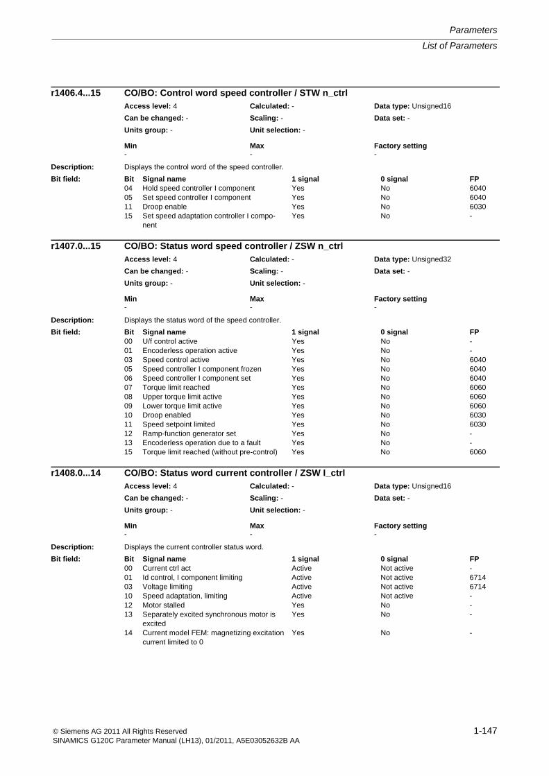
List of Parameters
Parameters
1-147© Siemens AG 2011 All Rights ReservedSINAMICS G120C Parameter Manual (LH13), 01/2011, A5E03052632B AA
Description: Displays the control word of the speed controller.
Description: Displays the status word of the speed controller.
Description: Displays the current controller status word.
r1406.4...15 CO/BO: Control word speed controller / STW n_ctrlAccess level: 4 Calculated: - Data type: Unsigned16
Can be changed: - Scaling: - Data set: -
Units group: - Unit selection: -
Min Max Factory setting - - -
Bit field: Bit Signal name 1 signal 0 signal FP04 Hold speed controller I component Yes No 604005 Set speed controller I component Yes No 604011 Droop enable Yes No 603015 Set speed adaptation controller I compo-
nentYes No -
r1407.0...15 CO/BO: Status word speed controller / ZSW n_ctrlAccess level: 4 Calculated: - Data type: Unsigned32
Can be changed: - Scaling: - Data set: -
Units group: - Unit selection: -
Min Max Factory setting - - -
Bit field: Bit Signal name 1 signal 0 signal FP00 U/f control active Yes No -01 Encoderless operation active Yes No -03 Speed control active Yes No 604005 Speed controller I component frozen Yes No 604006 Speed controller I component set Yes No 604007 Torque limit reached Yes No 606008 Upper torque limit active Yes No 606009 Lower torque limit active Yes No 606010 Droop enabled Yes No 603011 Speed setpoint limited Yes No 603012 Ramp-function generator set Yes No -13 Encoderless operation due to a fault Yes No -15 Torque limit reached (without pre-control) Yes No 6060
r1408.0...14 CO/BO: Status word current controller / ZSW I_ctrlAccess level: 4 Calculated: - Data type: Unsigned16
Can be changed: - Scaling: - Data set: -
Units group: - Unit selection: -
Min Max Factory setting - - -
Bit field: Bit Signal name 1 signal 0 signal FP00 Current ctrl act Active Not active -01 Id control, I component limiting Active Not active 671403 Voltage limiting Active Not active 671410 Speed adaptation, limiting Active Not active -12 Motor stalled Yes No -13 Separately excited synchronous motor is
excitedYes No -
14 Current model FEM: magnetizing excitation current limited to 0
Yes No -
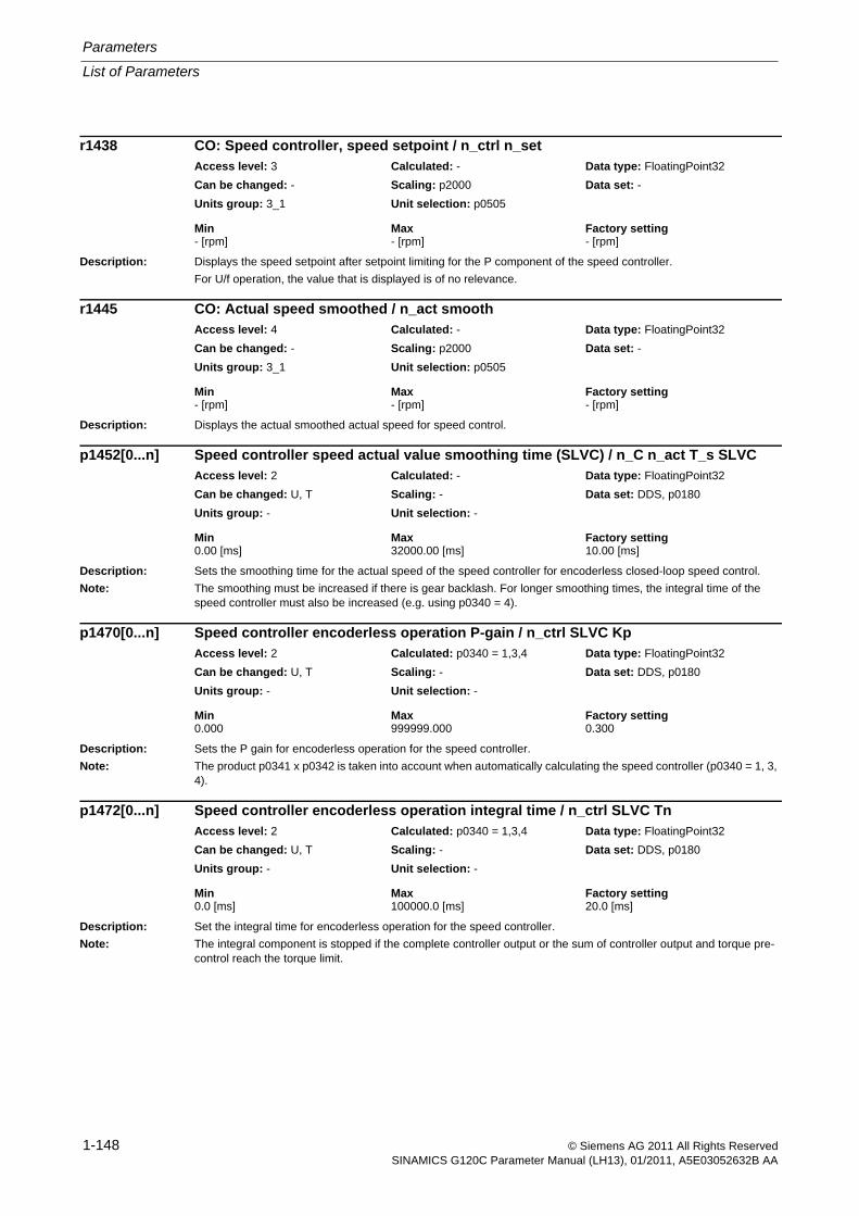
Parameters
List of Parameters
1-148 © Siemens AG 2011 All Rights ReservedSINAMICS G120C Parameter Manual (LH13), 01/2011, A5E03052632B AA
Description: Displays the speed setpoint after setpoint limiting for the P component of the speed controller.
For U/f operation, the value that is displayed is of no relevance.
Description: Displays the actual smoothed actual speed for speed control.
Description: Sets the smoothing time for the actual speed of the speed controller for encoderless closed-loop speed control.
Note: The smoothing must be increased if there is gear backlash. For longer smoothing times, the integral time of the speed controller must also be increased (e.g. using p0340 = 4).
Description: Sets the P gain for encoderless operation for the speed controller.
Note: The product p0341 x p0342 is taken into account when automatically calculating the speed controller (p0340 = 1, 3, 4).
Description: Set the integral time for encoderless operation for the speed controller.
Note: The integral component is stopped if the complete controller output or the sum of controller output and torque pre-control reach the torque limit.
r1438 CO: Speed controller, speed setpoint / n_ctrl n_setAccess level: 3 Calculated: - Data type: FloatingPoint32
Can be changed: - Scaling: p2000 Data set: -
Units group: 3_1 Unit selection: p0505
Min Max Factory setting - [rpm] - [rpm] - [rpm]
r1445 CO: Actual speed smoothed / n_act smoothAccess level: 4 Calculated: - Data type: FloatingPoint32
Can be changed: - Scaling: p2000 Data set: -
Units group: 3_1 Unit selection: p0505
Min Max Factory setting - [rpm] - [rpm] - [rpm]
p1452[0...n] Speed controller speed actual value smoothing time (SLVC) / n_C n_act T_s SLVCAccess level: 2 Calculated: - Data type: FloatingPoint32
Can be changed: U, T Scaling: - Data set: DDS, p0180
Units group: - Unit selection: -
Min Max Factory setting 0.00 [ms] 32000.00 [ms] 10.00 [ms]
p1470[0...n] Speed controller encoderless operation P-gain / n_ctrl SLVC KpAccess level: 2 Calculated: p0340 = 1,3,4 Data type: FloatingPoint32
Can be changed: U, T Scaling: - Data set: DDS, p0180
Units group: - Unit selection: -
Min Max Factory setting 0.000 999999.000 0.300
p1472[0...n] Speed controller encoderless operation integral time / n_ctrl SLVC TnAccess level: 2 Calculated: p0340 = 1,3,4 Data type: FloatingPoint32
Can be changed: U, T Scaling: - Data set: DDS, p0180
Units group: - Unit selection: -
Min Max Factory setting 0.0 [ms] 100000.0 [ms] 20.0 [ms]

List of Parameters
Parameters
1-149© Siemens AG 2011 All Rights ReservedSINAMICS G120C Parameter Manual (LH13), 01/2011, A5E03052632B AA
Description: Sets the signal source for the torque setting value when starting up with motor holding brake.
Dependency: .
Note: The setting of the integral output of the speed controller begins after magnetizing (see p0346, r0056 bit 4) and ends at the end of the brake control opening time p1216. A setting value of zero means that no setting procedure will take place.
If p1351 is used as a signal source for the torque setting value, the percentage value is interpreted in relation to the rated torque (p2003).
Description: Displays the torque setpoint at the output of the I speed controller.
Description: Displays the parameterized total moment of inertia ((p0341 * p0342) * p1496).
Description: Sets the scaling for the acceleration pre-control of the speed/velocity controller.
Dependency: Refer to: p0341, p0342
Note: The parameter is set to 100% by the rotating measurement (refer to p1960).
The acceleration pre-control may not be used if the speed setpoint manifests significant ripple (e.g. analog setpoint) and the rounding-off in the speed ramp-function generator is disabled.
We also recommend that the pre-control mode is not used if there is gearbox backlash.
Description: Displays the torque setpoint before entering the supplementary torque.
For closed-loop speed control, r1508 corresponds to the speed controller output.
p1475[0...n] CI: Speed controller torque setting value for motor holding brake / n_ctrl M_sv MHBAccess level: 3 Calculated: - Data type: U32 / FloatingPoint32
Can be changed: T Scaling: p2003 Data set: CDS, p0170
Units group: - Unit selection: -
Min Max Factory setting - - 0
r1482 CO: Speed controller I torque output / n_ctrl I-M_outputAccess level: 3 Calculated: - Data type: FloatingPoint32
Can be changed: - Scaling: p2003 Data set: -
Units group: 7_1 Unit selection: p0505
Min Max Factory setting - [Nm] - [Nm] - [Nm]
r1493 CO: Moment of inertia, total / M_inertia totalAccess level: 3 Calculated: - Data type: FloatingPoint32
Can be changed: - Scaling: - Data set: -
Units group: 25_1 Unit selection: p0100
Min Max Factory setting - [kgm²] - [kgm²] - [kgm²]
p1496[0...n] Acceleration pre-control scaling / a_before scalingAccess level: 3 Calculated: - Data type: FloatingPoint32
Can be changed: U, T Scaling: - Data set: DDS, p0180
Units group: - Unit selection: -
Min Max Factory setting 0.0 [%] 10000.0 [%] 0.0 [%]
r1508 CO: Torque setpoint before supplementary torque / M_set bef. M_supplAccess level: 4 Calculated: - Data type: FloatingPoint32
Can be changed: - Scaling: p2003 Data set: -
Units group: 7_1 Unit selection: p0505
Min Max Factory setting - [Nm] - [Nm] - [Nm]
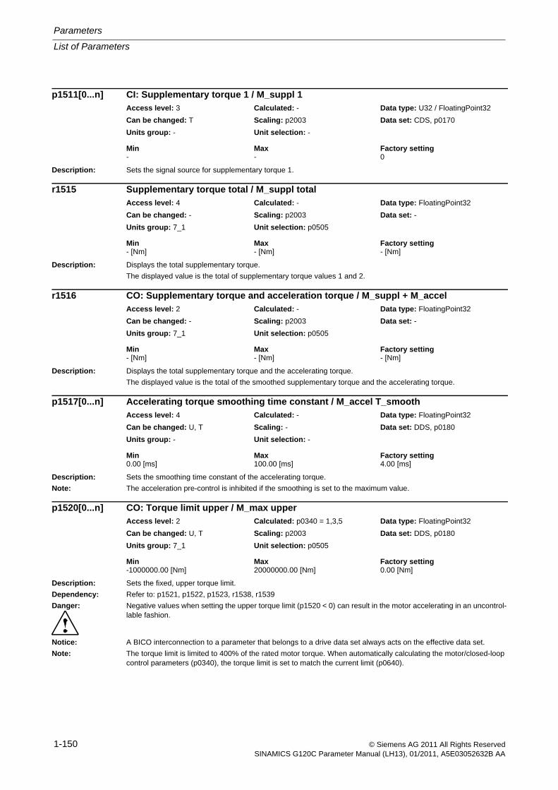
Parameters
List of Parameters
1-150 © Siemens AG 2011 All Rights ReservedSINAMICS G120C Parameter Manual (LH13), 01/2011, A5E03052632B AA
Description: Sets the signal source for supplementary torque 1.
Description: Displays the total supplementary torque.
The displayed value is the total of supplementary torque values 1 and 2.
Description: Displays the total supplementary torque and the accelerating torque.
The displayed value is the total of the smoothed supplementary torque and the accelerating torque.
Description: Sets the smoothing time constant of the accelerating torque.
Note: The acceleration pre-control is inhibited if the smoothing is set to the maximum value.
Description: Sets the fixed, upper torque limit.
Dependency: Refer to: p1521, p1522, p1523, r1538, r1539
Danger: Negative values when setting the upper torque limit (p1520 < 0) can result in the motor accelerating in an uncontrol-lable fashion.
Notice: A BICO interconnection to a parameter that belongs to a drive data set always acts on the effective data set.
Note: The torque limit is limited to 400% of the rated motor torque. When automatically calculating the motor/closed-loop control parameters (p0340), the torque limit is set to match the current limit (p0640).
p1511[0...n] CI: Supplementary torque 1 / M_suppl 1Access level: 3 Calculated: - Data type: U32 / FloatingPoint32
Can be changed: T Scaling: p2003 Data set: CDS, p0170
Units group: - Unit selection: -
Min Max Factory setting - - 0
r1515 Supplementary torque total / M_suppl totalAccess level: 4 Calculated: - Data type: FloatingPoint32
Can be changed: - Scaling: p2003 Data set: -
Units group: 7_1 Unit selection: p0505
Min Max Factory setting - [Nm] - [Nm] - [Nm]
r1516 CO: Supplementary torque and acceleration torque / M_suppl + M_accelAccess level: 2 Calculated: - Data type: FloatingPoint32
Can be changed: - Scaling: p2003 Data set: -
Units group: 7_1 Unit selection: p0505
Min Max Factory setting - [Nm] - [Nm] - [Nm]
p1517[0...n] Accelerating torque smoothing time constant / M_accel T_smoothAccess level: 4 Calculated: - Data type: FloatingPoint32
Can be changed: U, T Scaling: - Data set: DDS, p0180
Units group: - Unit selection: -
Min Max Factory setting 0.00 [ms] 100.00 [ms] 4.00 [ms]
p1520[0...n] CO: Torque limit upper / M_max upperAccess level: 2 Calculated: p0340 = 1,3,5 Data type: FloatingPoint32
Can be changed: U, T Scaling: p2003 Data set: DDS, p0180
Units group: 7_1 Unit selection: p0505
Min Max Factory setting -1000000.00 [Nm] 20000000.00 [Nm] 0.00 [Nm]
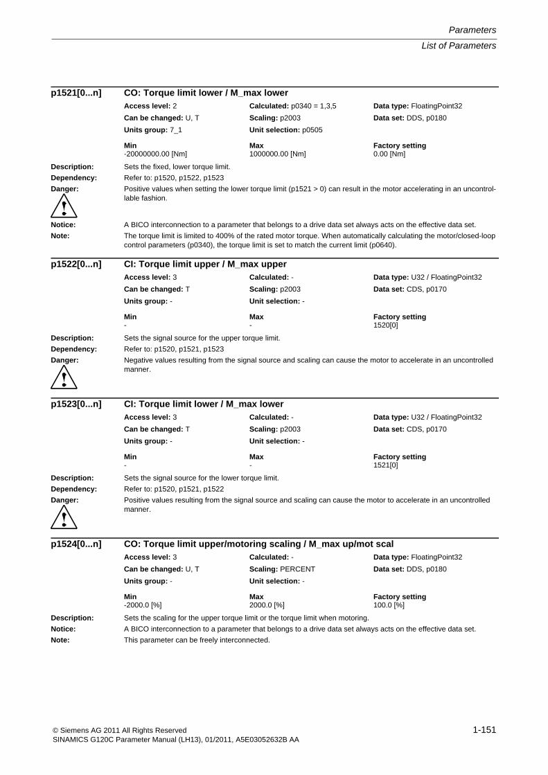
List of Parameters
Parameters
1-151© Siemens AG 2011 All Rights ReservedSINAMICS G120C Parameter Manual (LH13), 01/2011, A5E03052632B AA
Description: Sets the fixed, lower torque limit.
Dependency: Refer to: p1520, p1522, p1523
Danger: Positive values when setting the lower torque limit (p1521 > 0) can result in the motor accelerating in an uncontrol-lable fashion.
Notice: A BICO interconnection to a parameter that belongs to a drive data set always acts on the effective data set.
Note: The torque limit is limited to 400% of the rated motor torque. When automatically calculating the motor/closed-loop control parameters (p0340), the torque limit is set to match the current limit (p0640).
Description: Sets the signal source for the upper torque limit.
Dependency: Refer to: p1520, p1521, p1523
Danger: Negative values resulting from the signal source and scaling can cause the motor to accelerate in an uncontrolled manner.
Description: Sets the signal source for the lower torque limit.
Dependency: Refer to: p1520, p1521, p1522
Danger: Positive values resulting from the signal source and scaling can cause the motor to accelerate in an uncontrolled manner.
Description: Sets the scaling for the upper torque limit or the torque limit when motoring.
Notice: A BICO interconnection to a parameter that belongs to a drive data set always acts on the effective data set.
Note: This parameter can be freely interconnected.
p1521[0...n] CO: Torque limit lower / M_max lowerAccess level: 2 Calculated: p0340 = 1,3,5 Data type: FloatingPoint32
Can be changed: U, T Scaling: p2003 Data set: DDS, p0180
Units group: 7_1 Unit selection: p0505
Min Max Factory setting -20000000.00 [Nm] 1000000.00 [Nm] 0.00 [Nm]
p1522[0...n] CI: Torque limit upper / M_max upperAccess level: 3 Calculated: - Data type: U32 / FloatingPoint32
Can be changed: T Scaling: p2003 Data set: CDS, p0170
Units group: - Unit selection: -
Min Max Factory setting - - 1520[0]
p1523[0...n] CI: Torque limit lower / M_max lowerAccess level: 3 Calculated: - Data type: U32 / FloatingPoint32
Can be changed: T Scaling: p2003 Data set: CDS, p0170
Units group: - Unit selection: -
Min Max Factory setting - - 1521[0]
p1524[0...n] CO: Torque limit upper/motoring scaling / M_max up/mot scalAccess level: 3 Calculated: - Data type: FloatingPoint32
Can be changed: U, T Scaling: PERCENT Data set: DDS, p0180
Units group: - Unit selection: -
Min Max Factory setting -2000.0 [%] 2000.0 [%] 100.0 [%]
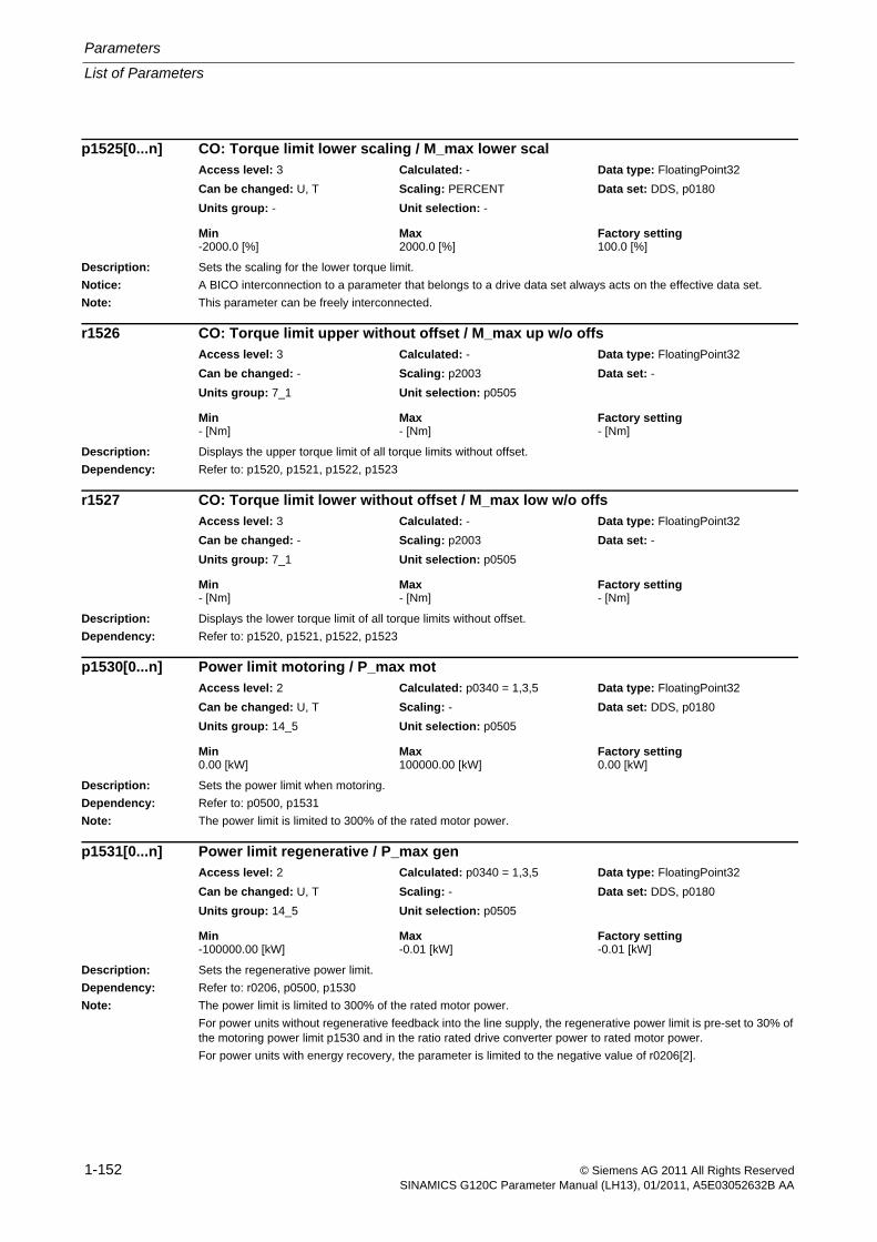
Parameters
List of Parameters
1-152 © Siemens AG 2011 All Rights ReservedSINAMICS G120C Parameter Manual (LH13), 01/2011, A5E03052632B AA
Description: Sets the scaling for the lower torque limit.
Notice: A BICO interconnection to a parameter that belongs to a drive data set always acts on the effective data set.
Note: This parameter can be freely interconnected.
Description: Displays the upper torque limit of all torque limits without offset.
Dependency: Refer to: p1520, p1521, p1522, p1523
Description: Displays the lower torque limit of all torque limits without offset.
Dependency: Refer to: p1520, p1521, p1522, p1523
Description: Sets the power limit when motoring.
Dependency: Refer to: p0500, p1531
Note: The power limit is limited to 300% of the rated motor power.
Description: Sets the regenerative power limit.
Dependency: Refer to: r0206, p0500, p1530
Note: The power limit is limited to 300% of the rated motor power.
For power units without regenerative feedback into the line supply, the regenerative power limit is pre-set to 30% of the motoring power limit p1530 and in the ratio rated drive converter power to rated motor power.
For power units with energy recovery, the parameter is limited to the negative value of r0206[2].
p1525[0...n] CO: Torque limit lower scaling / M_max lower scalAccess level: 3 Calculated: - Data type: FloatingPoint32
Can be changed: U, T Scaling: PERCENT Data set: DDS, p0180
Units group: - Unit selection: -
Min Max Factory setting -2000.0 [%] 2000.0 [%] 100.0 [%]
r1526 CO: Torque limit upper without offset / M_max up w/o offsAccess level: 3 Calculated: - Data type: FloatingPoint32
Can be changed: - Scaling: p2003 Data set: -
Units group: 7_1 Unit selection: p0505
Min Max Factory setting - [Nm] - [Nm] - [Nm]
r1527 CO: Torque limit lower without offset / M_max low w/o offsAccess level: 3 Calculated: - Data type: FloatingPoint32
Can be changed: - Scaling: p2003 Data set: -
Units group: 7_1 Unit selection: p0505
Min Max Factory setting - [Nm] - [Nm] - [Nm]
p1530[0...n] Power limit motoring / P_max motAccess level: 2 Calculated: p0340 = 1,3,5 Data type: FloatingPoint32
Can be changed: U, T Scaling: - Data set: DDS, p0180
Units group: 14_5 Unit selection: p0505
Min Max Factory setting 0.00 [kW] 100000.00 [kW] 0.00 [kW]
p1531[0...n] Power limit regenerative / P_max genAccess level: 2 Calculated: p0340 = 1,3,5 Data type: FloatingPoint32
Can be changed: U, T Scaling: - Data set: DDS, p0180
Units group: 14_5 Unit selection: p0505
Min Max Factory setting -100000.00 [kW] -0.01 [kW] -0.01 [kW]
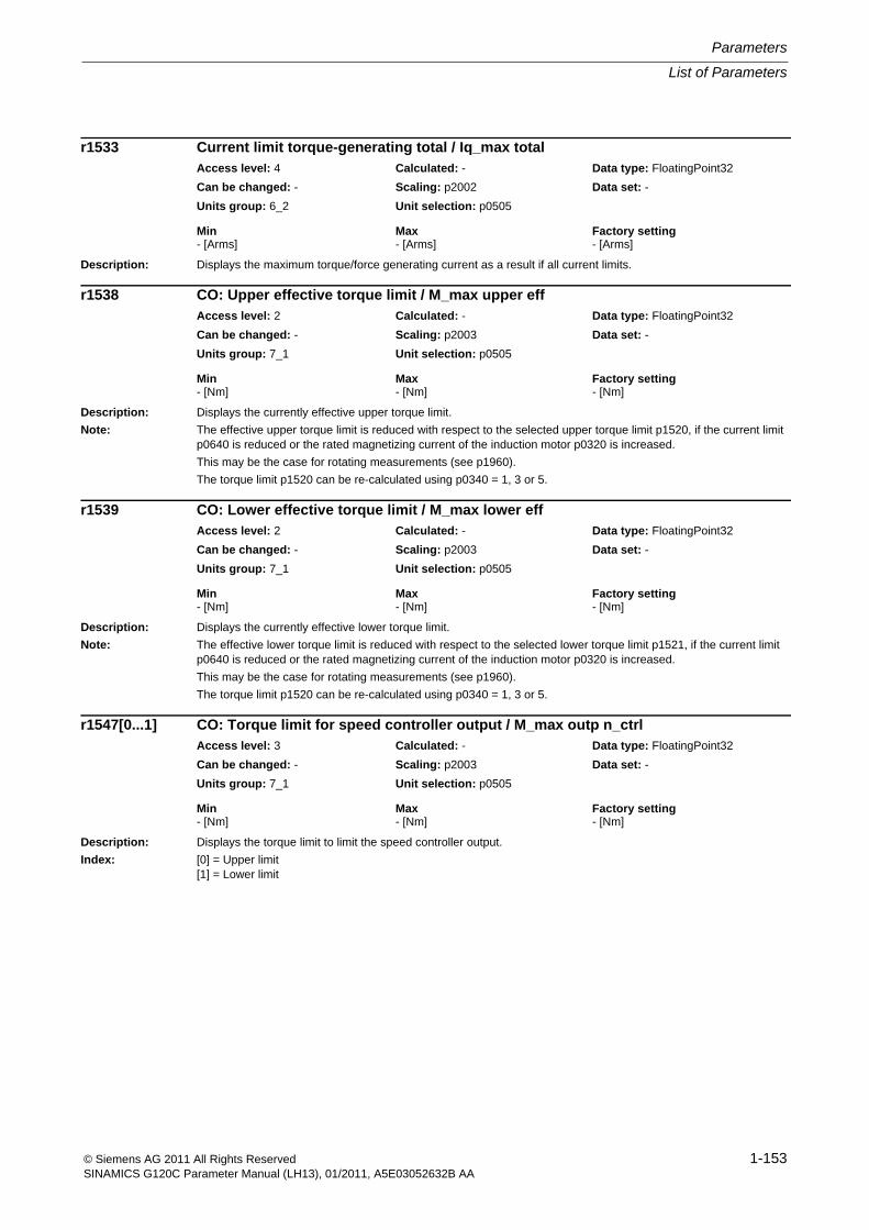
List of Parameters
Parameters
1-153© Siemens AG 2011 All Rights ReservedSINAMICS G120C Parameter Manual (LH13), 01/2011, A5E03052632B AA
Description: Displays the maximum torque/force generating current as a result if all current limits.
Description: Displays the currently effective upper torque limit.
Note: The effective upper torque limit is reduced with respect to the selected upper torque limit p1520, if the current limit p0640 is reduced or the rated magnetizing current of the induction motor p0320 is increased.
This may be the case for rotating measurements (see p1960).
The torque limit p1520 can be re-calculated using p0340 = 1, 3 or 5.
Description: Displays the currently effective lower torque limit.
Note: The effective lower torque limit is reduced with respect to the selected lower torque limit p1521, if the current limit p0640 is reduced or the rated magnetizing current of the induction motor p0320 is increased.
This may be the case for rotating measurements (see p1960).
The torque limit p1520 can be re-calculated using p0340 = 1, 3 or 5.
Description: Displays the torque limit to limit the speed controller output.
Index: [0] = Upper limit[1] = Lower limit
r1533 Current limit torque-generating total / Iq_max totalAccess level: 4 Calculated: - Data type: FloatingPoint32
Can be changed: - Scaling: p2002 Data set: -
Units group: 6_2 Unit selection: p0505
Min Max Factory setting - [Arms] - [Arms] - [Arms]
r1538 CO: Upper effective torque limit / M_max upper effAccess level: 2 Calculated: - Data type: FloatingPoint32
Can be changed: - Scaling: p2003 Data set: -
Units group: 7_1 Unit selection: p0505
Min Max Factory setting - [Nm] - [Nm] - [Nm]
r1539 CO: Lower effective torque limit / M_max lower effAccess level: 2 Calculated: - Data type: FloatingPoint32
Can be changed: - Scaling: p2003 Data set: -
Units group: 7_1 Unit selection: p0505
Min Max Factory setting - [Nm] - [Nm] - [Nm]
r1547[0...1] CO: Torque limit for speed controller output / M_max outp n_ctrlAccess level: 3 Calculated: - Data type: FloatingPoint32
Can be changed: - Scaling: p2003 Data set: -
Units group: 7_1 Unit selection: p0505
Min Max Factory setting - [Nm] - [Nm] - [Nm]
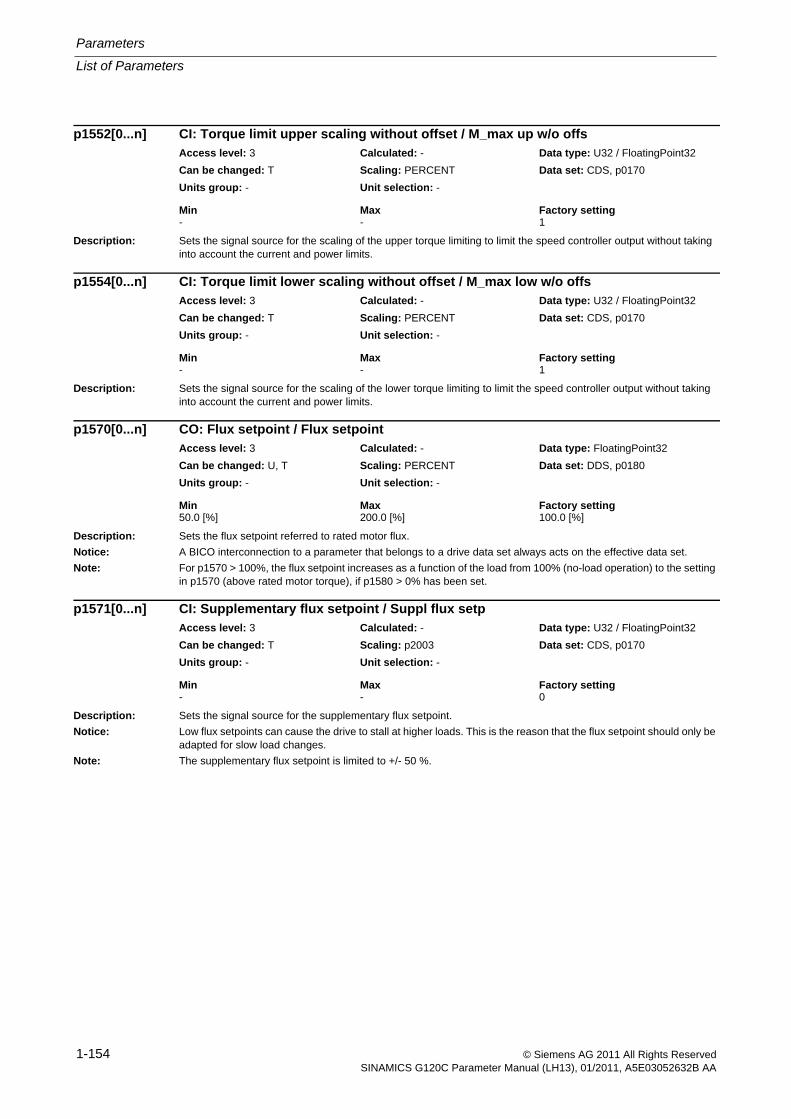
Parameters
List of Parameters
1-154 © Siemens AG 2011 All Rights ReservedSINAMICS G120C Parameter Manual (LH13), 01/2011, A5E03052632B AA
Description: Sets the signal source for the scaling of the upper torque limiting to limit the speed controller output without taking into account the current and power limits.
Description: Sets the signal source for the scaling of the lower torque limiting to limit the speed controller output without taking into account the current and power limits.
Description: Sets the flux setpoint referred to rated motor flux.
Notice: A BICO interconnection to a parameter that belongs to a drive data set always acts on the effective data set.
Note: For p1570 > 100%, the flux setpoint increases as a function of the load from 100% (no-load operation) to the setting in p1570 (above rated motor torque), if p1580 > 0% has been set.
Description: Sets the signal source for the supplementary flux setpoint.
Notice: Low flux setpoints can cause the drive to stall at higher loads. This is the reason that the flux setpoint should only be adapted for slow load changes.
Note: The supplementary flux setpoint is limited to +/- 50 %.
p1552[0...n] CI: Torque limit upper scaling without offset / M_max up w/o offsAccess level: 3 Calculated: - Data type: U32 / FloatingPoint32
Can be changed: T Scaling: PERCENT Data set: CDS, p0170
Units group: - Unit selection: -
Min Max Factory setting - - 1
p1554[0...n] CI: Torque limit lower scaling without offset / M_max low w/o offsAccess level: 3 Calculated: - Data type: U32 / FloatingPoint32
Can be changed: T Scaling: PERCENT Data set: CDS, p0170
Units group: - Unit selection: -
Min Max Factory setting - - 1
p1570[0...n] CO: Flux setpoint / Flux setpointAccess level: 3 Calculated: - Data type: FloatingPoint32
Can be changed: U, T Scaling: PERCENT Data set: DDS, p0180
Units group: - Unit selection: -
Min Max Factory setting 50.0 [%] 200.0 [%] 100.0 [%]
p1571[0...n] CI: Supplementary flux setpoint / Suppl flux setpAccess level: 3 Calculated: - Data type: U32 / FloatingPoint32
Can be changed: T Scaling: p2003 Data set: CDS, p0170
Units group: - Unit selection: -
Min Max Factory setting - - 0
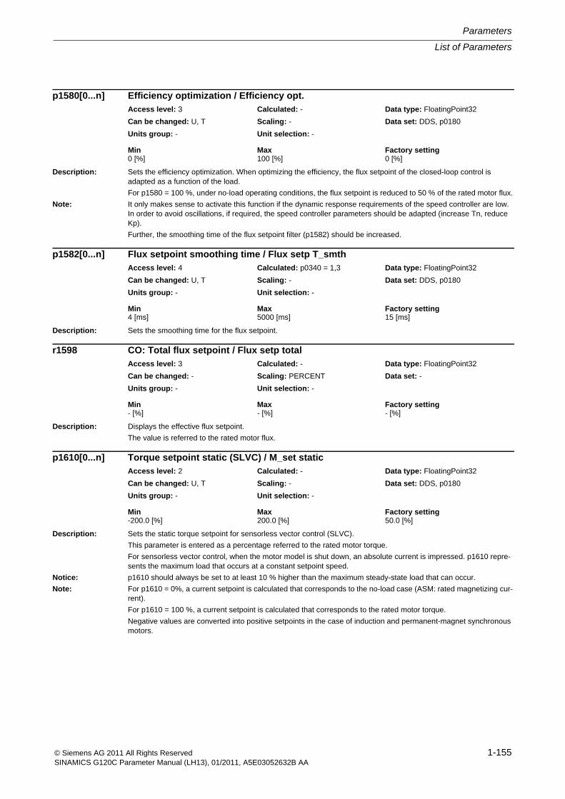
List of Parameters
Parameters
1-155© Siemens AG 2011 All Rights ReservedSINAMICS G120C Parameter Manual (LH13), 01/2011, A5E03052632B AA
Description: Sets the efficiency optimization. When optimizing the efficiency, the flux setpoint of the closed-loop control is adapted as a function of the load.
For p1580 = 100 %, under no-load operating conditions, the flux setpoint is reduced to 50 % of the rated motor flux.
Note: It only makes sense to activate this function if the dynamic response requirements of the speed controller are low. In order to avoid oscillations, if required, the speed controller parameters should be adapted (increase Tn, reduce Kp).
Further, the smoothing time of the flux setpoint filter (p1582) should be increased.
Description: Sets the smoothing time for the flux setpoint.
Description: Displays the effective flux setpoint.
The value is referred to the rated motor flux.
Description: Sets the static torque setpoint for sensorless vector control (SLVC).
This parameter is entered as a percentage referred to the rated motor torque.
For sensorless vector control, when the motor model is shut down, an absolute current is impressed. p1610 repre-sents the maximum load that occurs at a constant setpoint speed.
Notice: p1610 should always be set to at least 10 % higher than the maximum steady-state load that can occur.
Note: For p1610 = 0%, a current setpoint is calculated that corresponds to the no-load case (ASM: rated magnetizing cur-rent).
For p1610 = 100 %, a current setpoint is calculated that corresponds to the rated motor torque.
Negative values are converted into positive setpoints in the case of induction and permanent-magnet synchronous motors.
p1580[0...n] Efficiency optimization / Efficiency opt.Access level: 3 Calculated: - Data type: FloatingPoint32
Can be changed: U, T Scaling: - Data set: DDS, p0180
Units group: - Unit selection: -
Min Max Factory setting 0 [%] 100 [%] 0 [%]
p1582[0...n] Flux setpoint smoothing time / Flux setp T_smthAccess level: 4 Calculated: p0340 = 1,3 Data type: FloatingPoint32
Can be changed: U, T Scaling: - Data set: DDS, p0180
Units group: - Unit selection: -
Min Max Factory setting 4 [ms] 5000 [ms] 15 [ms]
r1598 CO: Total flux setpoint / Flux setp totalAccess level: 3 Calculated: - Data type: FloatingPoint32
Can be changed: - Scaling: PERCENT Data set: -
Units group: - Unit selection: -
Min Max Factory setting - [%] - [%] - [%]
p1610[0...n] Torque setpoint static (SLVC) / M_set staticAccess level: 2 Calculated: - Data type: FloatingPoint32
Can be changed: U, T Scaling: - Data set: DDS, p0180
Units group: - Unit selection: -
Min Max Factory setting -200.0 [%] 200.0 [%] 50.0 [%]
Parameters
List of Parameters
1-156 © Siemens AG 2011 All Rights ReservedSINAMICS G120C Parameter Manual (LH13), 01/2011, A5E03052632B AA
Description: Enters the dynamic torque setpoint for the low-speed range for sensorless vector control (SLVC). This parameter is entered as a percentage referred to the rated motor torque.
Note: When accelerating and braking p1611 is added to p1610 and the resulting total torque is converted into an appro-priate current setpoint and controlled.
For pure accelerating torques, it is always favorable to use the torque pre-control of the speed controller (p1496).
Description: Displays the limited field-generating current setpoint (Id_set).
This value comprises the steady-state field-generating current setpoint and a dynamic component that is only set when changes are made to the flux setpoint.
Description: Sets the speed activation threshold (referred to the synchronous speed) for pure quadrature branch operation of the closed-loop current control.
The d current controller is only effective as P controller for speeds greater than the threshold value.
Warning: For settings above 80%, the d current controller is active up to the field weakening limit (maximum voltage)
This can result in unstable behavior as the closed-loop control at the maximum voltage is based on pure quadrature branch operation.
Setting values as high as this should not be selected; they are only intended for test purposes.
Note: The parameter is only effective for induction motor operation without an encoder.
Description: Displays the direct-axis voltage setpoint Ud.
Index: [0] = Unsmoothed[1] = Smoothed with p0045
p1611[0...n] Supplementary accelerating torque (SLVC) / M_suppl_accelAccess level: 2 Calculated: p0340 = 1 Data type: FloatingPoint32
Can be changed: U, T Scaling: - Data set: DDS, p0180
Units group: - Unit selection: -
Min Max Factory setting 0.0 [%] 200.0 [%] 30.0 [%]
r1624 Field-generating current setpoint, total / Id_setp totalAccess level: 4 Calculated: - Data type: FloatingPoint32
Can be changed: - Scaling: p2002 Data set: -
Units group: 6_2 Unit selection: p0505
Min Max Factory setting - [Arms] - [Arms] - [Arms]
p1730[0...n] Isd controller integral component shutdown threshold / Isd_ctrl I_threshAccess level: 4 Calculated: p0340 = 1,3,4 Data type: FloatingPoint32
Can be changed: U, T Scaling: - Data set: DDS, p0180
Units group: - Unit selection: -
Min Max Factory setting 30 [%] 150 [%] 30 [%]
r1732[0...1] CO: Direct-axis voltage setpoint / Direct U setAccess level: 3 Calculated: - Data type: FloatingPoint32
Can be changed: - Scaling: p2001 Data set: -
Units group: 5_1 Unit selection: p0505
Min Max Factory setting - [Vrms] - [Vrms] - [Vrms]
List of Parameters
Parameters
1-157© Siemens AG 2011 All Rights ReservedSINAMICS G120C Parameter Manual (LH13), 01/2011, A5E03052632B AA
Description: Displays the quadrature-axis component of voltage setpoint Uq.
Index: [0] = Unsmoothed[1] = Smoothed with p0045
Description: Sets the fault threshold in order to detect a motor that has stalled.
If the error signal (r1746) exceeds the parameterized error threshold, then status signal r1408.12 is set to 1.
Dependency: If a stalled drive is detected (r1408.12 = 1), fault F07902 is output after the delay time.
Note: Monitoring is only effective in the low speed range.
Description: Signal to initiate stall detection
Note: The signal is not calculated while magnetizing and only calculated in the low speed range.
Description: Sets the speed to change over the motor model to encoderless operation.
Notice: The changeover speed represents the steady-state minimum speed up to which the motor model can be used
in steady-state operation without encoder.
If the stability is not adequate close to the changeover speed, it may make sense to increase the parameter value.
Note: The changeover speed applies for the changeover between open-loop and closed-loop control mode.
Description: Sets the proportional gain of the controller for speed adaptation without encoder.
r1733[0...1] CO: Quadrature-axis voltage setpoint / Quad U setAccess level: 3 Calculated: - Data type: FloatingPoint32
Can be changed: - Scaling: p2001 Data set: -
Units group: 5_1 Unit selection: p0505
Min Max Factory setting - [Vrms] - [Vrms] - [Vrms]
p1745[0...n] Motor model error threshold stall detection / MotMod ThreshStallAccess level: 3 Calculated: p0340 = 1,3 Data type: FloatingPoint32
Can be changed: U, T Scaling: - Data set: DDS, p0180
Units group: - Unit selection: -
Min Max Factory setting 0.0 [%] 1000.0 [%] 5.0 [%]
r1746 Motor model error signal stall detection / MotMod sig stallAccess level: 4 Calculated: - Data type: FloatingPoint32
Can be changed: - Scaling: - Data set: -
Units group: - Unit selection: -
Min Max Factory setting - [%] - [%] - [%]
p1755[0...n] Motor model changeover speed encoderless operation / MotMod n_chgSnsorlAccess level: 4 Calculated: p0340 = 1,3 Data type: FloatingPoint32
Can be changed: U, T Scaling: - Data set: DDS, p0180
Units group: 3_1 Unit selection: p0505
Min Max Factory setting 0.00 [rpm] 210000.00 [rpm] 210000.00 [rpm]
p1764[0...n] Motor model without encoder speed adaptation Kp / MotMod woE n_adaKpAccess level: 4 Calculated: p0340 = 1,3,4 Data type: FloatingPoint32
Can be changed: U, T Scaling: - Data set: DDS, p0180
Units group: - Unit selection: -
Min Max Factory setting 0.000 100000.000 1000.000
Parameters
List of Parameters
1-158 © Siemens AG 2011 All Rights ReservedSINAMICS G120C Parameter Manual (LH13), 01/2011, A5E03052632B AA
Description: Sets the integral time of the controller for speed adaptation without encoder
Description: Sets the configuration for the adaptation circuit of the motor model.Induction motor (ASM): Rs, Lh, and offset compensation.Permanent magnet synchronous motor (PEM): kT
Note: ASM: Induction motorPEM: Permanent magnet synchronous motorWhen selecting the compensation of the valve interlocking via Rs (bit 7), the compensation in the gating unit is de-activated and is instead taken into account in the motor model.In order that the correction values of the Rs, Lh and kT adaptation (selected using bit 0 ... bit 2) are correctly accepted when changing over the drive data set, a dedicated motor number must be entered for each different motor.
Description: Sets the scaling for model fault feedback.Note: Feeding back the measured model fault to the model states increases the control stability and makes the motor
model rugged against parameter errors.The model feedback is only effective for encoderless operation of the ASM.When feedback is selected (p1784 > 0), Lh adaptation is not effective.
Description: Displays the corrective value for the Lh adaptation of the motor model for an induction motor (ASM).Dependency: Refer to: p1780Note: The adaptation result is reset if the magnetizing inductance of the induction motor is changed (p0360, r0382).
p1767[0...n] Motor model without encoder speed adaptation Tn / MotMod woE n_adaTnAccess level: 4 Calculated: p0340 = 1,3,4 Data type: FloatingPoint32
Can be changed: U, T Scaling: - Data set: DDS, p0180
Units group: - Unit selection: -
Min Max Factory setting 1 [ms] 200 [ms] 4 [ms]
p1780[0...n] Motor model adaptation configuration / MotMod adapt confAccess level: 4 Calculated: - Data type: Unsigned16
Can be changed: U, T Scaling: - Data set: DDS, p0180
Units group: - Unit selection: -
Min Max Factory setting - - 0101 1100 bin
Bit field: Bit Signal name 1 signal 0 signal FP01 Select motor model ASM Rs adaptation Yes No -02 Select motor model ASM Lh adaptation Yes No -03 Select motor model PEM kT adaptation Yes No -04 Select motor model offset adaptation Yes No -06 Select pole position identification PEM
encoderlessYes No -
07 Select T(valve) with Rs adaptation Yes No -
p1784[0...n] Motor model feedback scaling / Mod_FB_scalAccess level: 3 Calculated: p0340 = 1,3,4 Data type: FloatingPoint32
Can be changed: U, T Scaling: - Data set: DDS, p0180
Units group: - Unit selection: -
Min Max Factory setting 0.0 [%] 1000.0 [%] 0.0 [%]
r1787[0...n] Motor model Lh adaptation corrective value / MotMod Lh corrAccess level: 4 Calculated: - Data type: FloatingPoint32
Can be changed: - Scaling: - Data set: DDS, p0180
Units group: - Unit selection: -
Min Max Factory setting - [mH] - [mH] - [mH]
List of Parameters
Parameters
1-159© Siemens AG 2011 All Rights ReservedSINAMICS G120C Parameter Manual (LH13), 01/2011, A5E03052632B AA
Description: Sets the pulse frequency for the converter.
This parameter is pre-set to the rated converter value when the drive is first commissioned.
Dependency: Refer to: p0230
Note: The maximum possible pulse frequency is also determined by the power unit being used.
When the pulse frequency is increased, depending on the particular power unit, the maximum output current can be reduced (derating, refer to r0067).
If a sine-wave filter is parameterized as output filter (p0230 = 3), then the pulse frequency cannot be set below the minimum value required for the filter.
For operation with output reactors, the pulse frequency is limited to 4 kHz (see p0230).
If p1800 is changed during commissioning (p0010 > 0), then it is possible that the old value will no longer be able to be set. The reason for this is that the dynamic limits of p1800 have been changed by a parameter that was set when the drive was commissioned (e.g. p1082).
Description: Display and connector output for the actual converter switching frequency.
Index: [0] = Actual[1] = Modulator minimum value
Note: The selected pulse frequency (p1800) may be reduced if the drive converter has an overload condition (p0290).
Description: Sets the modulator mode.
Value: 0: Automatic changeover SVM/FLB2: Space vector modulation (SVM)3: SVM without overcontrol4: SVM/FLB without overcontrol10: SVM/FLB with modulation depth reduction
Dependency: If a sine-wave filter is parameterized as output filter (p0230 = 3, 4), then only space vector modulation without over-control can be selected as modulation type (p1802 = 3).
Refer to: p0230, p0500
Note: When modulation modes are enabled that could lead to overmodulation (p1802 = 0, 2,10), the modulation depth must be limited using p1803 (default p1803 < 100 %). The higher the overmodulation, the greater the current ripple and torque ripple.
When changing p1802[x], the values for all of the other existing indices are also changed.
p1800[0...n] Pulse frequency setpoint / Pulse freq setpAccess level: 2 Calculated: - Data type: FloatingPoint32
Can be changed: U, T Scaling: - Data set: DDS, p0180
Units group: - Unit selection: -
Min Max Factory setting 2.000 [kHz] 16.000 [kHz] 4.000 [kHz]
r1801[0...1] CO: Pulse frequency / Pulse frequencyAccess level: 2 Calculated: - Data type: FloatingPoint32
Can be changed: - Scaling: p2000 Data set: -
Units group: - Unit selection: -
Min Max Factory setting - [kHz] - [kHz] - [kHz]
p1802[0...n] Modulator mode / Modulator modeAccess level: 4 Calculated: p0340 = 1,3,5 Data type: Integer16
Can be changed: T Scaling: - Data set: DDS, p0180
Units group: - Unit selection: -
Min Max Factory setting 0 10 0
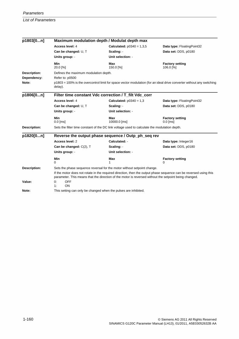
Parameters
List of Parameters
1-160 © Siemens AG 2011 All Rights ReservedSINAMICS G120C Parameter Manual (LH13), 01/2011, A5E03052632B AA
Description: Defines the maximum modulation depth.
Dependency: Refer to: p0500
Note: p1803 = 100% is the overcontrol limit for space vector modulation (for an ideal drive converter without any switching delay).
Description: Sets the filter time constant of the DC link voltage used to calculate the modulation depth.
Description: Sets the phase sequence reversal for the motor without setpoint change.
If the motor does not rotate in the required direction, then the output phase sequence can be reversed using this parameter. This means that the direction of the motor is reversed without the setpoint being changed.
Value: 0: OFF1: ON
Note: This setting can only be changed when the pulses are inhibited.
p1803[0...n] Maximum modulation depth / Modulat depth maxAccess level: 4 Calculated: p0340 = 1,3,5 Data type: FloatingPoint32
Can be changed: U, T Scaling: - Data set: DDS, p0180
Units group: - Unit selection: -
Min Max Factory setting 20.0 [%] 150.0 [%] 106.0 [%]
p1806[0...n] Filter time constant Vdc correction / T_filt Vdc_corrAccess level: 4 Calculated: p0340 = 1,3 Data type: FloatingPoint32
Can be changed: U, T Scaling: - Data set: DDS, p0180
Units group: - Unit selection: -
Min Max Factory setting 0.0 [ms] 10000.0 [ms] 0.0 [ms]
p1820[0...n] Reverse the output phase sequence / Outp_ph_seq revAccess level: 2 Calculated: - Data type: Integer16
Can be changed: C(2), T Scaling: - Data set: DDS, p0180
Units group: - Unit selection: -
Min Max Factory setting 0 1 0
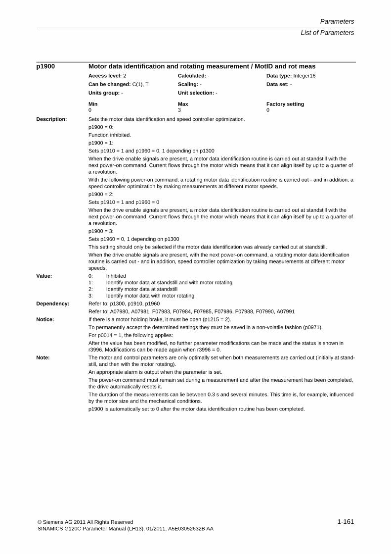
List of Parameters
Parameters
1-161© Siemens AG 2011 All Rights ReservedSINAMICS G120C Parameter Manual (LH13), 01/2011, A5E03052632B AA
Description: Sets the motor data identification and speed controller optimization.
p1900 = 0:
Function inhibited.
p1900 = 1:
Sets p1910 = 1 and p1960 = 0, 1 depending on p1300
When the drive enable signals are present, a motor data identification routine is carried out at standstill with the next power-on command. Current flows through the motor which means that it can align itself by up to a quarter of a revolution.
With the following power-on command, a rotating motor data identification routine is carried out - and in addition, a speed controller optimization by making measurements at different motor speeds.
p1900 = 2:
Sets p1910 = 1 and p1960 = 0
When the drive enable signals are present, a motor data identification routine is carried out at standstill with the next power-on command. Current flows through the motor which means that it can align itself by up to a quarter of a revolution.
p1900 = 3:
Sets p1960 = 0, 1 depending on p1300
This setting should only be selected if the motor data identification was already carried out at standstill.
When the drive enable signals are present, with the next power-on command, a rotating motor data identification routine is carried out - and in addition, speed controller optimization by taking measurements at different motor speeds.
Value: 0: Inhibited1: Identify motor data at standstill and with motor rotating2: Identify motor data at standstill3: Identify motor data with motor rotating
Dependency: Refer to: p1300, p1910, p1960
Refer to: A07980, A07981, F07983, F07984, F07985, F07986, F07988, F07990, A07991
Notice: If there is a motor holding brake, it must be open (p1215 = 2).
To permanently accept the determined settings they must be saved in a non-volatile fashion (p0971).
For p0014 = 1, the following applies:
After the value has been modified, no further parameter modifications can be made and the status is shown in r3996. Modifications can be made again when r3996 = 0.
Note: The motor and control parameters are only optimally set when both measurements are carried out (initially at stand-still, and then with the motor rotating).
An appropriate alarm is output when the parameter is set.
The power-on command must remain set during a measurement and after the measurement has been completed, the drive automatically resets it.
The duration of the measurements can lie between 0.3 s and several minutes. This time is, for example, influenced by the motor size and the mechanical conditions.
p1900 is automatically set to 0 after the motor data identification routine has been completed.
p1900 Motor data identification and rotating measurement / MotID and rot measAccess level: 2 Calculated: - Data type: Integer16
Can be changed: C(1), T Scaling: - Data set: -
Units group: - Unit selection: -
Min Max Factory setting 0 3 0
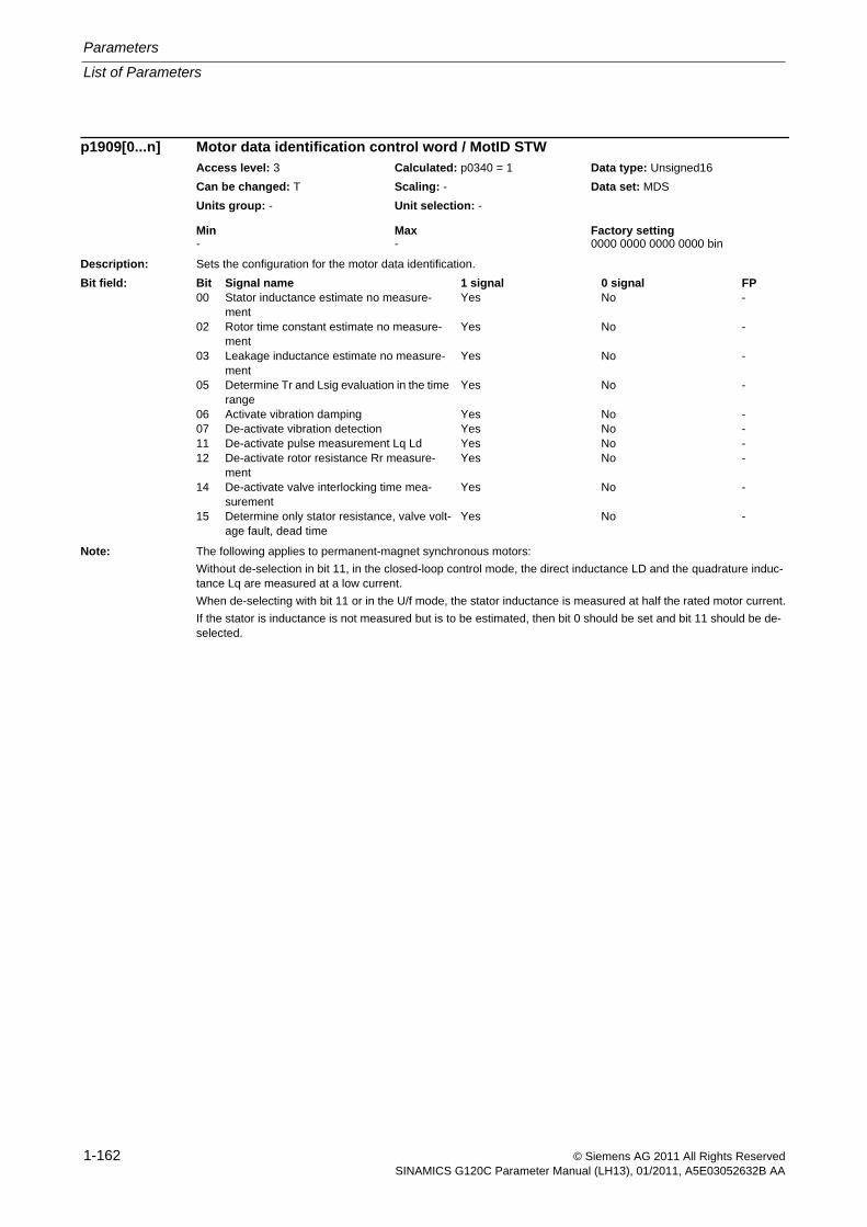
Parameters
List of Parameters
1-162 © Siemens AG 2011 All Rights ReservedSINAMICS G120C Parameter Manual (LH13), 01/2011, A5E03052632B AA
Description: Sets the configuration for the motor data identification.
Note: The following applies to permanent-magnet synchronous motors:
Without de-selection in bit 11, in the closed-loop control mode, the direct inductance LD and the quadrature induc-tance Lq are measured at a low current.
When de-selecting with bit 11 or in the U/f mode, the stator inductance is measured at half the rated motor current.
If the stator is inductance is not measured but is to be estimated, then bit 0 should be set and bit 11 should be de-selected.
p1909[0...n] Motor data identification control word / MotID STWAccess level: 3 Calculated: p0340 = 1 Data type: Unsigned16
Can be changed: T Scaling: - Data set: MDS
Units group: - Unit selection: -
Min Max Factory setting - - 0000 0000 0000 0000 bin
Bit field: Bit Signal name 1 signal 0 signal FP00 Stator inductance estimate no measure-
mentYes No -
02 Rotor time constant estimate no measure-ment
Yes No -
03 Leakage inductance estimate no measure-ment
Yes No -
05 Determine Tr and Lsig evaluation in the time range
Yes No -
06 Activate vibration damping Yes No -07 De-activate vibration detection Yes No -11 De-activate pulse measurement Lq Ld Yes No -12 De-activate rotor resistance Rr measure-
mentYes No -
14 De-activate valve interlocking time mea-surement
Yes No -
15 Determine only stator resistance, valve volt-age fault, dead time
Yes No -
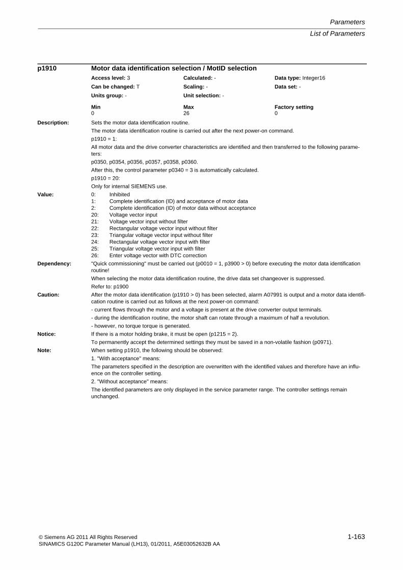
List of Parameters
Parameters
1-163© Siemens AG 2011 All Rights ReservedSINAMICS G120C Parameter Manual (LH13), 01/2011, A5E03052632B AA
Description: Sets the motor data identification routine.
The motor data identification routine is carried out after the next power-on command.
p1910 = 1:
All motor data and the drive converter characteristics are identified and then transferred to the following parame-ters:
p0350, p0354, p0356, p0357, p0358, p0360.
After this, the control parameter p0340 = 3 is automatically calculated.
p1910 = 20:
Only for internal SIEMENS use.
Value: 0: Inhibited1: Complete identification (ID) and acceptance of motor data2: Complete identification (ID) of motor data without acceptance20: Voltage vector input21: Voltage vector input without filter22: Rectangular voltage vector input without filter23: Triangular voltage vector input without filter24: Rectangular voltage vector input with filter25: Triangular voltage vector input with filter26: Enter voltage vector with DTC correction
Dependency: "Quick commissioning" must be carried out (p0010 = 1, p3900 > 0) before executing the motor data identification routine!
When selecting the motor data identification routine, the drive data set changeover is suppressed.
Refer to: p1900
Caution: After the motor data identification (p1910 > 0) has been selected, alarm A07991 is output and a motor data identifi-cation routine is carried out as follows at the next power-on command:
- current flows through the motor and a voltage is present at the drive converter output terminals.
- during the identification routine, the motor shaft can rotate through a maximum of half a revolution.
- however, no torque torque is generated.
Notice: If there is a motor holding brake, it must be open (p1215 = 2).
To permanently accept the determined settings they must be saved in a non-volatile fashion (p0971).
Note: When setting p1910, the following should be observed:
1. "With acceptance" means:
The parameters specified in the description are overwritten with the identified values and therefore have an influ-ence on the controller setting.
2. "Without acceptance" means:
The identified parameters are only displayed in the service parameter range. The controller settings remain unchanged.
p1910 Motor data identification selection / MotID selectionAccess level: 3 Calculated: - Data type: Integer16
Can be changed: T Scaling: - Data set: -
Units group: - Unit selection: -
Min Max Factory setting 0 26 0
Parameters
List of Parameters
1-164 © Siemens AG 2011 All Rights ReservedSINAMICS G120C Parameter Manual (LH13), 01/2011, A5E03052632B AA
Description: Sets the configuration of the rotating measurement.
Dependency: Refer to: F07988
Note: The following parameters are influenced for the individual optimization steps:
Bit 01: p0320, p0360, p0362 ... p0369
Bit 02: p0341, p0342
Bit 03: p1470, p1472, p1496
Bit 04: Dependent on p1960
p1960 = 1, 3: p1470, p1472, p1496
Description: Sets the rotating measurement.
The rotating measurement is carried out after the next power-on command.
The setting possibilities of the parameter depend on the open-loop/closed-loop control mode (p1300).
p1300 < 20 (U/f open-loop control):
It is not possible to select rotating measurement or speed controller optimization.
p1300 = 20, 22 (encoderless operation):
Only rotating measurement or speed controller optimization can be selected in the encoderless mode.
Value: 0: Inhibited1: Rotating measurement in encoderless operation3: Speed controller optimization in encoderless operation
Dependency: Before the rotating measurement is carried out, the motor data identification routine (p1900, p1910, r3925) should have already been done.
When selecting the rotating measurement, the drive data set changeover is suppressed.
Refer to: p1300, p1900, p1959
Danger: For drives with a mechanical system that limits the distance moved, it must be ensured that this is not reached dur-ing the rotating measurement. If this is not the case, then it is not permissible that the measurement is carried out.
Notice: If there is a motor holding brake, it must be open (p1215 = 2).
To permanently accept the determined settings they must be saved in a non-volatile fashion (p0971).
Note: When the rotating measurement is activated, it is not possible to save the parameters (p0971).
Parameter changes are automatically made for the rotating measurement (e.g. p1120); this is the reason that up to the end of the measurement, and if no faults are present, no manual changes should be made.
The ramp-up and ramp-down times (p1120, p1121) are limited, for the rotating measurement, to 900 s.
p1959[0...n] Rotating measurement configuration / Rot meas configAccess level: 3 Calculated: p0340 = 1 Data type: Unsigned16
Can be changed: T Scaling: - Data set: DDS, p0180
Units group: - Unit selection: -
Min Max Factory setting - - 0001 1110 bin
Bit field: Bit Signal name 1 signal 0 signal FP01 Saturation characteristic identification Yes No -02 Moment of inertia identification Yes No -03 Re-calculates the speed controller parame-
tersYes No -
04 Speed controller optimization (vibration test) Yes No -
p1960 Rotating measurement selection / Rot meas selAccess level: 3 Calculated: - Data type: Integer16
Can be changed: T Scaling: - Data set: -
Units group: - Unit selection: -
Min Max Factory setting 0 3 0
List of Parameters
Parameters
1-165© Siemens AG 2011 All Rights ReservedSINAMICS G120C Parameter Manual (LH13), 01/2011, A5E03052632B AA
Description: Sets the speed to determine the saturation characteristic.
The percentage value is referred to p0310 (rated motor frequency).
Dependency: Refer to: p0310, p1959
Refer to: F07983
Note: The saturation characteristics should be determined at an operating point with the lowest possible load.
Description: Sets the speed for the identification of the moment of inertia and the vibration test.
Induction motor:
The percentage value is referred to p0310 (rated motor frequency).
Synchronous motor:
The percentage value is referred to the minimum from p0310 (rated motor frequency) and p1082 (maximum speed).
Dependency: Refer to: p0310, p1959
Refer to: F07984, F07985
Note: In order to calculate the inertia, sudden speed changes are carried out - the specified value corresponds to the lower speed setpoint. This value is increased by 20 % for the upper speed value. The q leakage inductance (refer to p1959 bit 5) is determined at zero speed and at 50% of p1965 - however, with a maximum output frequency of 15 Hz and at a minimum of 10% of the rated motor speed.
Description: Sets the dynamic response factor for speed controller optimization.
Dependency: Refer to: p1959
Refer to: F07985
Note: For a rotating measurement, this parameter can be used to optimize the speed controller.
p1967 = 100 % --> speed controller optimization according to a symmetric optimum.
p1967 > 100 % --> optimization with a higher dynamic response (Kp higher, Tn lower).
p1961 Saturation characteristic speed to determine / Sat_char n determAccess level: 3 Calculated: - Data type: FloatingPoint32
Can be changed: U, T Scaling: - Data set: -
Units group: - Unit selection: -
Min Max Factory setting 26 [%] 75 [%] 40 [%]
p1965 Speed_ctrl_opt speed / n_opt speedAccess level: 3 Calculated: - Data type: FloatingPoint32
Can be changed: U, T Scaling: - Data set: -
Units group: - Unit selection: -
Min Max Factory setting 10 [%] 75 [%] 40 [%]
p1967 Speed_ctrl_opt dynamic factor / n_opt dyn_factorAccess level: 3 Calculated: p0340 = 1 Data type: FloatingPoint32
Can be changed: U, T Scaling: - Data set: -
Units group: - Unit selection: -
Min Max Factory setting 1 [%] 400 [%] 100 [%]
Parameters
List of Parameters
1-166 © Siemens AG 2011 All Rights ReservedSINAMICS G120C Parameter Manual (LH13), 01/2011, A5E03052632B AA
Description: Displays the dynamic factor which is actually achieved for the vibration test
Dependency: Refer to: p1959, p1967
Refer to: F07985
Note: This dynamic factor only refers to the control mode of the speed controller set in p1960.
Description: Sets the reference quantity for speed and frequency.
All speeds or frequencies specified as relative value are referred to this reference quantity.
The reference quantity in this parameter corresponds to 100% or 4000 hex or 4000 0000 hex.
The following applies: Reference frequency (in Hz) = reference speed (in ((rpm) / 60) x pole pair number).
Dependency: This parameter is only updated during the automatic calculation (p0340 = 1, p3900 > 0) if motor commissioning was carried out beforehand for drive data set zero. This means that the parameter is not locked against overwriting using p0573 = 1.
Refer to: p2001, p2002, p2003, r2004, r3996
Notice: When the reference speed / reference frequency is changed, short-term communication interruptions may occur.
Note: If a BICO interconnection is established between different physical quantities, then the particular reference quanti-ties are used as internal conversion factor.
Example 1:
The signal of an analog input (e.g. r0755[0]) is connected to a speed setpoint (e.g. p1070[0]). The actual percent-age input value is cyclically converted into the absolute speed setpoint using the reference speed (p2000).
Example 2:
The setpoint from PROFIBUS (r2050[1]) is connected to a speed setpoint (e.g. p1070[0]). The actual input value is cyclically converted into a percentage value via the pre-specified scaling 4000 hex. This percentage value is con-verted to the absolute speed setpoint via reference speed (p2000).
r1968 Speed_ctrl_opt dynamic factor actual / n_opt dyn_fact actAccess level: 4 Calculated: - Data type: FloatingPoint32
Can be changed: - Scaling: - Data set: -
Units group: - Unit selection: -
Min Max Factory setting - [%] - [%] - [%]
p2000 Reference speed reference frequency / n_ref f_refAccess level: 2 Calculated: p0340 = 1 Data type: FloatingPoint32
Can be changed: T Scaling: - Data set: -
Units group: - Unit selection: -
Min Max Factory setting 6.00 [rpm] 210000.00 [rpm] 1500.00 [rpm]
List of Parameters
Parameters
1-167© Siemens AG 2011 All Rights ReservedSINAMICS G120C Parameter Manual (LH13), 01/2011, A5E03052632B AA
Description: Sets the reference quantity for voltages.
All voltages specified as relative value are referred to this reference quantity. This also applies for direct voltage val-ues (= rms value) like the DC-link voltage.
The reference quantity in this parameter corresponds to 100% or 4000 hex or 4000 0000 hex.
Dependency: p2001 is only updated during automatic calculation (p0340 = 1, p3900 > 0) if motor commissioning has been carried out first for drive data set zero and as a result overwriting of the parameter has not been blocked by setting p0573 = 1.
Refer to: r3996
Notice: When the reference voltage is changed, short-term communication interruptions may occur.
Note: If a BICO interconnection is established between different physical quantities, then the particular reference quanti-ties are used as internal conversion factor.
For infeed units, the parameterized device supply voltage (p0210) is pre-assigned as the reference quantity.
Example:
The actual value of the DC link voltage (r0070) is connected to a test socket (e.g. p0771[0]). The actual voltage value is cyclically converted into a percentage of the reference voltage (p2001) and output according to the param-eterized scaling.
Description: Sets the reference quantity for currents.All currents specified as relative value are referred to this reference quantity.The reference quantity in this parameter corresponds to 100% or 4000 hex or 4000 0000 hex.
Dependency: This parameter is only updated during the automatic calculation (p0340 = 1, p3900 > 0) if motor commissioning was carried out beforehand for drive data set zero. This means that the parameter is not locked against overwriting using p0573 = 1.Refer to: r3996
Notice: If various DDS are used with different motor data, then the reference quantities remain the same as these are not changed over with the DDS. The resulting conversion factor must be taken into account.Example:p2002 = 100 AReference quantity 100 A corresponds to 100 %p305[0] = 100 ARated motor current 100 A for MDS0 in DDS0 --> 100 % corresponds to 100 % of the rated motor currentp305[1] = 50 ARated motor current 50 A for MDS1 in DDS1 --> 100 % corresponds to 200 % of the rated motor currentWhen the reference current is changed, short-term communication interruptions may occur.
Note: If a BICO interconnection is established between different physical quantities, then the particular reference quanti-ties are used as internal conversion factor.For infeed units, the rated line current, which is obtained from the rated power and parameterized rated line supply voltage (p2002 = r0206 / p0210 / 1.73) is pre-assigned as the reference quantity.Example:The actual value of a phase current (r0069[0]) is connected to a test socket (e.g. p0771[0]). The actual current value is cyclically converted into a percentage of the reference current (p2002) and output according to the param-eterized scaling.
p2001 Reference voltage / Reference voltageAccess level: 3 Calculated: p0340 = 1 Data type: FloatingPoint32
Can be changed: T Scaling: - Data set: -
Units group: - Unit selection: -
Min Max Factory setting 10 [Vrms] 100000 [Vrms] 1000 [Vrms]
p2002 Reference current / I_refAccess level: 3 Calculated: p0340 = 1 Data type: FloatingPoint32
Can be changed: T Scaling: - Data set: -
Units group: - Unit selection: -
Min Max Factory setting 0.10 [Arms] 100000.00 [Arms] 100.00 [Arms]
Parameters
List of Parameters
1-168 © Siemens AG 2011 All Rights ReservedSINAMICS G120C Parameter Manual (LH13), 01/2011, A5E03052632B AA
Description: Sets the reference quantity for torque.
All torques specified as relative value are referred to this reference quantity.
The reference quantity in this parameter corresponds to 100% or 4000 hex or 4000 0000 hex.
Dependency: This parameter is only updated during the automatic calculation (p0340 = 1, p3900 > 0) if motor commissioning was carried out beforehand for drive data set zero. This means that the parameter is not locked against overwriting using p0573 = 1.
Refer to: r3996
Notice: When the reference torque is changed, short-term communication interruptions may occur.
Note: If a BICO interconnection is established between different physical quantities, then the particular reference quanti-ties are used as internal conversion factor.
Example:
The actual value of the total torque (r0079) is connected to a test socket (e.g. p0771[0]). The actual torque is cycli-cally converted into a percentage of the reference torque (p2003) and output according to the parameterized scal-ing.
Description: Displays the reference quantity for power.
All power ratings specified as relative value are referred to this reference quantity.
The reference quantity in this parameter corresponds to 100% or 4000 hex or 4000 0000 hex.
Dependency: This value is calculated as follows:
Infeed: Calculated from voltage times current.
Closed-loop control: Calculated from torque times speed.
Refer to: p2000, p2001, p2002, p2003
Note: If a BICO interconnection is established between different physical quantities, then the particular reference quanti-ties are used as internal conversion factor.
The reference power is calculated as follows:
- 2 * Pi * reference speed / 60 * reference torque (motor)
- reference voltage * reference current * root(3) (infeed)
p2003 Reference torque / M_refAccess level: 3 Calculated: p0340 = 1 Data type: FloatingPoint32
Can be changed: T Scaling: - Data set: -
Units group: 7_2 Unit selection: p0505
Min Max Factory setting 0.01 [Nm] 20000000.00 [Nm] 1.00 [Nm]
r2004 Reference power / P_refAccess level: 3 Calculated: - Data type: FloatingPoint32
Can be changed: - Scaling: - Data set: -
Units group: 14_10 Unit selection: p0505
Min Max Factory setting - [kW] - [kW] - [kW]
List of Parameters
Parameters
1-169© Siemens AG 2011 All Rights ReservedSINAMICS G120C Parameter Manual (LH13), 01/2011, A5E03052632B AA
Description: Sets the reference quantity for temperature.
All temperatures specified as relative value are referred to this reference quantity.
The reference quantity in this parameter corresponds to 100% or 4000 hex or 4000 0000 hex.
Description: Sets the baud rate for the commissioning interface (USS, RS232).
Value: 4: 2400 baud5: 4800 baud6: 9600 baud7: 19200 baud8: 38400 baud9: 57600 baud10: 76800 baud11: 93750 baud12: 115200 baud
Note: Commissioning interface
The parameter is not influenced by setting the factory setting.
Description: Sets the address for the commissioning interface (USS, RS232).
Note: The parameter is not influenced by setting the factory setting.
Description: Selects the PZD (actual values) to be sent via the commissioning interface USS.
The actual values are displayed on an intelligent operator panel (IOP).
Index: [0] = PZD 1[1] = PZD 2[2] = PZD 3[3] = PZD 4
p2006 Reference temp / Ref tempAccess level: 3 Calculated: p0340 = 1 Data type: FloatingPoint32
Can be changed: T Scaling: - Data set: -
Units group: - Unit selection: -
Min Max Factory setting 50.00 [°C] 300.00 [°C] 100.00 [°C]
p2010 Comm interface baud rate / Comm baudAccess level: 3 Calculated: - Data type: Integer16
Can be changed: T Scaling: - Data set: -
Units group: - Unit selection: -
Min Max Factory setting 4 12 12
p2011 Comm int address / Comm addAccess level: 3 Calculated: - Data type: Unsigned16
Can be changed: T Scaling: - Data set: -
Units group: - Unit selection: -
Min Max Factory setting 0 31 2
p2016[0...3] CI: Comm IF USS PZD send word / Comm USS send wordAccess level: 3 Calculated: - Data type: U32 / Integer16
Can be changed: U, T Scaling: 4000H Data set: -
Units group: - Unit selection: -
Min Max Factory setting - - 0
Parameters
List of Parameters
1-170 © Siemens AG 2011 All Rights ReservedSINAMICS G120C Parameter Manual (LH13), 01/2011, A5E03052632B AA
Description: Sets the baud rate for the field bus interface (RS485).
Value: 4: 2400 baud5: 4800 baud6: 9600 baud7: 19200 baud8: 38400 baud9: 57600 baud10: 76800 baud11: 93750 baud12: 115200 baud13: 187500 baud
Notice: For p0014 = 1, the following applies:
After the value has been modified, no further parameter modifications can be made and the status is shown in r3996. Modifications can be made again when r3996 = 0.
For p0014 = 0, the following applies:
Before a changed setting becomes permanently effective, a non-volatile RAM to ROM data save is required. To do this, set p0971 = 1 or p0014 = 1.
Note: Fieldbus SS: Fieldbus interface
Changes only become effective after POWER ON.
The parameter is not influenced by setting the factory setting.
The parameter is set to the factory setting when the protocol is reselected.
When p2030 = 1 (USS), the following applies:
Min./max./factory setting: 4/13/8
When p2030 = 2 (MODBUS), the following applies:
Min./max./factory setting: 5/13/7
p2020 Field bus interface baud rate / Field bus baudG120C USS/MB Access level: 2 Calculated: - Data type: Integer16
Can be changed: T Scaling: - Data set: -
Units group: - Unit selection: -
Min Max Factory setting 4 13 8
List of Parameters
Parameters
1-171© Siemens AG 2011 All Rights ReservedSINAMICS G120C Parameter Manual (LH13), 01/2011, A5E03052632B AA
Description: Displays or sets the address for the fieldbus interface (RS485).The address can be set as follows:1) Using the address switch on the Control Unit.--> p2021 displays the address setting.--> A change only becomes effective after a POWER ON.2) Using p2021--> Only if an address of 0 or an address which is invalid for the fieldbus selected in p2030 has been set using the address switch.--> The address is saved in a non-volatile fashion using the function "copy from RAM to ROM".--> A change only becomes effective after a POWER ON.
Dependency: Refer to: p2030Notice: For p0014 = 1, the following applies:
After the value has been modified, no further parameter modifications can be made and the status is shown in r3996. Modifications can be made again when r3996 = 0.For p0014 = 0, the following applies:Before a changed setting becomes permanently effective, a non-volatile RAM to ROM data save is required. To do this, set p0971 = 1 or p0014 = 1.
Note: Changes only become effective after POWER ON.The parameter is not influenced by setting the factory setting.The parameter is set to the factory setting when the protocol is reselected.When p2030 = 1 (USS), the following applies:Min./max./factory setting: 0/30/0When p2030 = 2 (MODBUS), the following applies:Min./max./factory setting: 1/247/1
Description: Sets the number of 16-bit words in the PZD part of the USS telegram for the field bus interface.
Dependency: Refer to: p2030
Note: The parameter is not influenced by setting the factory setting.
Description: Sets the number of 16-bit words in the PKW part of the USS telegram for the field bus interface.Value: 0: PKW 0 words
3: PKW 3 words4: PKW 4 words127: PKW variable
Dependency: Refer to: p2030Note: The parameter is not influenced by setting the factory setting.
p2021 Field bus interface address / Field bus addressG120C USS/MB Access level: 2 Calculated: - Data type: Unsigned16
Can be changed: T Scaling: - Data set: -
Units group: - Unit selection: -
Min Max Factory setting 0 247 0
p2022 Field bus int USS PZD no. / Field bus USS PZDG120C USS/MB Access level: 2 Calculated: - Data type: Unsigned16
Can be changed: T Scaling: - Data set: -
Units group: - Unit selection: -
Min Max Factory setting 0 8 2
p2023 Field bus int USS PKW no. / Field bus USS PKWG120C USS/MB Access level: 2 Calculated: - Data type: Integer16
Can be changed: T Scaling: - Data set: -
Units group: - Unit selection: -
Min Max Factory setting 0 127 127
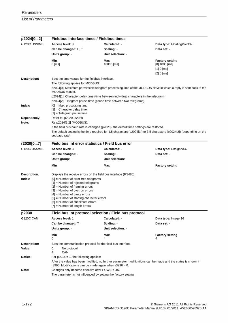
Parameters
List of Parameters
1-172 © Siemens AG 2011 All Rights ReservedSINAMICS G120C Parameter Manual (LH13), 01/2011, A5E03052632B AA
Description: Sets the time values for the fieldbus interface.
The following applies for MODBUS:
p2024[0]: Maximum permissible telegram processing time of the MODBUS slave in which a reply is sent back to the MODBUS master.
p2024[1]: Character delay time (time between individual characters in the telegram).
p2024[2]: Telegram pause time (pause time between two telegrams).
Index: [0] = Max. processing time[1] = Character delay time[2] = Telegram pause time
Dependency: Refer to: p2020, p2030
Note: Re p2024[1,2] (MODBUS):
If the field bus baud rate is changed (p2020), the default time settings are restored.
The default setting is the time required for 1.5 characters (p2024[1]) or 3.5 characters (p2024[2]) (depending on the set baud rate).
Description: Displays the receive errors on the field bus interface (RS485).
Index: [0] = Number of error-free telegrams[1] = Number of rejected telegrams[2] = Number of framing errors[3] = Number of overrun errors[4] = Number of parity errors[5] = Number of starting character errors[6] = Number of checksum errors[7] = Number of length errors
Description: Sets the communication protocol for the field bus interface.
Value: 0: No protocol4: CAN
Notice: For p0014 = 1, the following applies:
After the value has been modified, no further parameter modifications can be made and the status is shown in r3996. Modifications can be made again when r3996 = 0.
Note: Changes only become effective after POWER ON.
The parameter is not influenced by setting the factory setting.
p2024[0...2] Fieldbus interface times / Fieldbus timesG120C USS/MB Access level: 3 Calculated: - Data type: FloatingPoint32
Can be changed: U, T Scaling: - Data set: -
Units group: - Unit selection: -
Min Max Factory setting 0 [ms] 10000 [ms] [0] 1000 [ms]
[1] 0 [ms]
[2] 0 [ms]
r2029[0...7] Field bus int error statistics / Field bus errorG120C USS/MB Access level: 3 Calculated: - Data type: Unsigned32
Can be changed: - Scaling: - Data set: -
Units group: - Unit selection: -
Min Max Factory setting - - -
p2030 Field bus int protocol selection / Field bus protocolG120C CAN Access level: 1 Calculated: - Data type: Integer16
Can be changed: T Scaling: - Data set: -
Units group: - Unit selection: -
Min Max Factory setting 0 4 4
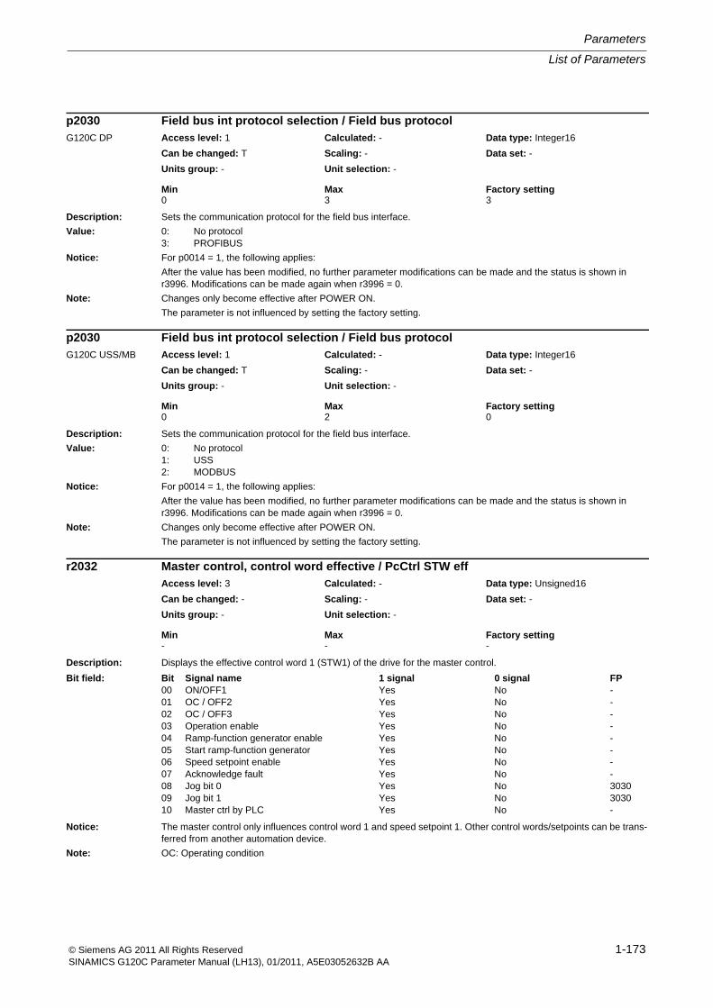
List of Parameters
Parameters
1-173© Siemens AG 2011 All Rights ReservedSINAMICS G120C Parameter Manual (LH13), 01/2011, A5E03052632B AA
Description: Sets the communication protocol for the field bus interface.
Value: 0: No protocol3: PROFIBUS
Notice: For p0014 = 1, the following applies:
After the value has been modified, no further parameter modifications can be made and the status is shown in r3996. Modifications can be made again when r3996 = 0.
Note: Changes only become effective after POWER ON.
The parameter is not influenced by setting the factory setting.
Description: Sets the communication protocol for the field bus interface.
Value: 0: No protocol1: USS2: MODBUS
Notice: For p0014 = 1, the following applies:
After the value has been modified, no further parameter modifications can be made and the status is shown in r3996. Modifications can be made again when r3996 = 0.
Note: Changes only become effective after POWER ON.
The parameter is not influenced by setting the factory setting.
Description: Displays the effective control word 1 (STW1) of the drive for the master control.
Notice: The master control only influences control word 1 and speed setpoint 1. Other control words/setpoints can be trans-ferred from another automation device.
Note: OC: Operating condition
p2030 Field bus int protocol selection / Field bus protocolG120C DP Access level: 1 Calculated: - Data type: Integer16
Can be changed: T Scaling: - Data set: -
Units group: - Unit selection: -
Min Max Factory setting 0 3 3
p2030 Field bus int protocol selection / Field bus protocolG120C USS/MB Access level: 1 Calculated: - Data type: Integer16
Can be changed: T Scaling: - Data set: -
Units group: - Unit selection: -
Min Max Factory setting 0 2 0
r2032 Master control, control word effective / PcCtrl STW effAccess level: 3 Calculated: - Data type: Unsigned16
Can be changed: - Scaling: - Data set: -
Units group: - Unit selection: -
Min Max Factory setting - - -
Bit field: Bit Signal name 1 signal 0 signal FP00 ON/OFF1 Yes No -01 OC / OFF2 Yes No -02 OC / OFF3 Yes No -03 Operation enable Yes No -04 Ramp-function generator enable Yes No -05 Start ramp-function generator Yes No -06 Speed setpoint enable Yes No -07 Acknowledge fault Yes No -08 Jog bit 0 Yes No 303009 Jog bit 1 Yes No 303010 Master ctrl by PLC Yes No -

Parameters
List of Parameters
1-174 © Siemens AG 2011 All Rights ReservedSINAMICS G120C Parameter Manual (LH13), 01/2011, A5E03052632B AA
Description: Sets the processing mode for PROFIdrive STW1.10 "master control by PLC".
Generally, control world 1 is received with the first receive word (PZD1) (this is in conformance to the PROFIdrive profile). The behavior of STW1.10 = 0 corresponds to that of the PROFIdrive profile. For other applications that deviate from this, the behavior can be adapted using this particular parameter.
Value: 0: Freeze setpoints and continue to process sign-of-life1: Freeze setpoints and sign-of-life2: Setpoints are not frozen
Note: If the STW1 is not transferred according to the PROFIdrive with PZD1 (with bit 10 "master control by PLC"), then p2037 should be set to 2.
Description: Sets the interface mode of the PROFIdrive control words and status words.
When selecting a telegram via p0922 (p2079), this parameter influences the device-specific assignment of the bits in the control and status words.
Value: 0: SINAMICS2: VIK-NAMUR
Dependency: Refer to: p0922, p2079
Notice: The parameter may be protected as a result of p0922 or p2079 and cannot be changed.
Note: - For p0922 (p2079) = 1, 350 ... 999, p2038 is automatically set to 0.
- For p0922 (p2079) = 20, p2038 is automatically set to 2.
It is not then possible to change p2038.
Description: The serial interface for the debug monitor is COM1 (commissioning interface, RS232) or COM2 (fieldbus interface, RS485).
Value = 0: De-activated
Value = 1: COM1, commissioning protocol is de-activated
Value = 2: COM2, field bus is de-activated
Value = 3: Reserved
Note: Value = 2 is only possible for Control Units with RS485 as a field bus interface.
p2037 PROFIdrive STW1.10 = 0 mode / PD STW1.10=0G120C DP Access level: 3 Calculated: - Data type: Integer16
Can be changed: T Scaling: - Data set: -
Units group: - Unit selection: -
Min Max Factory setting 0 2 0
p2038 PROFIdrive STW/ZSW interface mode / PD STW/ZSW IF modeG120C DP Access level: 3 Calculated: - Data type: Integer16
Can be changed: T Scaling: - Data set: -
Units group: - Unit selection: -
Min Max Factory setting 0 2 0
p2039 Select debug monitor interface / Debug monit selectAccess level: 4 Calculated: - Data type: Unsigned16
Can be changed: U, T Scaling: - Data set: -
Units group: - Unit selection: -
Min Max Factory setting 0 3 0
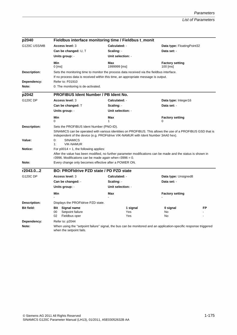
List of Parameters
Parameters
1-175© Siemens AG 2011 All Rights ReservedSINAMICS G120C Parameter Manual (LH13), 01/2011, A5E03052632B AA
Description: Sets the monitoring time to monitor the process data received via the fieldbus interface.
If no process data is received within this time, an appropriate message is output.
Dependency: Refer to: F01910
Note: 0: The monitoring is de-activated.
Description: Sets the PROFIBUS Ident Number (PNO-ID).
SINAMICS can be operated with various identities on PROFIBUS. This allows the use of a PROFIBUS GSD that is independent of the device (e.g. PROFIdrive VIK-NAMUR with Ident Number 3AA0 hex).
Value: 0: SINAMICS1: VIK-NAMUR
Notice: For p0014 = 1, the following applies:
After the value has been modified, no further parameter modifications can be made and the status is shown in r3996. Modifications can be made again when r3996 = 0.
Note: Every change only becomes effective after a POWER ON.
Description: Displays the PROFIdrive PZD state.
Dependency: Refer to: p2044
Note: When using the "setpoint failure" signal, the bus can be monitored and an application-specific response triggered when the setpoint fails.
p2040 Fieldbus interface monitoring time / Fieldbus t_monitG120C USS/MB Access level: 3 Calculated: - Data type: FloatingPoint32
Can be changed: U, T Scaling: - Data set: -
Units group: - Unit selection: -
Min Max Factory setting 0 [ms] 1999999 [ms] 100 [ms]
p2042 PROFIBUS Ident Number / PB Ident No.G120C DP Access level: 3 Calculated: - Data type: Integer16
Can be changed: T Scaling: - Data set: -
Units group: - Unit selection: -
Min Max Factory setting 0 1 0
r2043.0...2 BO: PROFIdrive PZD state / PD PZD stateG120C DP Access level: 3 Calculated: - Data type: Unsigned8
Can be changed: - Scaling: - Data set: -
Units group: - Unit selection: -
Min Max Factory setting - - -
Bit field: Bit Signal name 1 signal 0 signal FP00 Setpoint failure Yes No -02 Fieldbus oper Yes No -
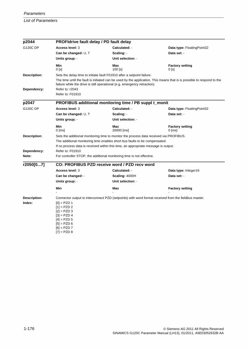
Parameters
List of Parameters
1-176 © Siemens AG 2011 All Rights ReservedSINAMICS G120C Parameter Manual (LH13), 01/2011, A5E03052632B AA
Description: Sets the delay time to initiate fault F01910 after a setpoint failure.
The time until the fault is initiated can be used by the application. This means that is is possible to respond to the failure while the drive is still operational (e.g. emergency retraction).
Dependency: Refer to: r2043
Refer to: F01910
Description: Sets the additional monitoring time to monitor the process data received via PROFIBUS.
The additional monitoring time enables short bus faults to be compensated.
If no process data is received within this time, an appropriate message is output.
Dependency: Refer to: F01910
Note: For controller STOP, the additional monitoring time is not effective.
Description: Connector output to interconnect PZD (setpoints) with word format received from the fieldbus master.
Index: [0] = PZD 1[1] = PZD 2[2] = PZD 3[3] = PZD 4[4] = PZD 5[5] = PZD 6[6] = PZD 7[7] = PZD 8
p2044 PROFIdrive fault delay / PD fault delayG120C DP Access level: 3 Calculated: - Data type: FloatingPoint32
Can be changed: U, T Scaling: - Data set: -
Units group: - Unit selection: -
Min Max Factory setting 0 [s] 100 [s] 0 [s]
p2047 PROFIBUS additional monitoring time / PB suppl t_monitG120C DP Access level: 3 Calculated: - Data type: FloatingPoint32
Can be changed: U, T Scaling: - Data set: -
Units group: - Unit selection: -
Min Max Factory setting 0 [ms] 20000 [ms] 0 [ms]
r2050[0...7] CO: PROFIBUS PZD receive word / PZD recv wordAccess level: 3 Calculated: - Data type: Integer16
Can be changed: - Scaling: 4000H Data set: -
Units group: - Unit selection: -
Min Max Factory setting - - -
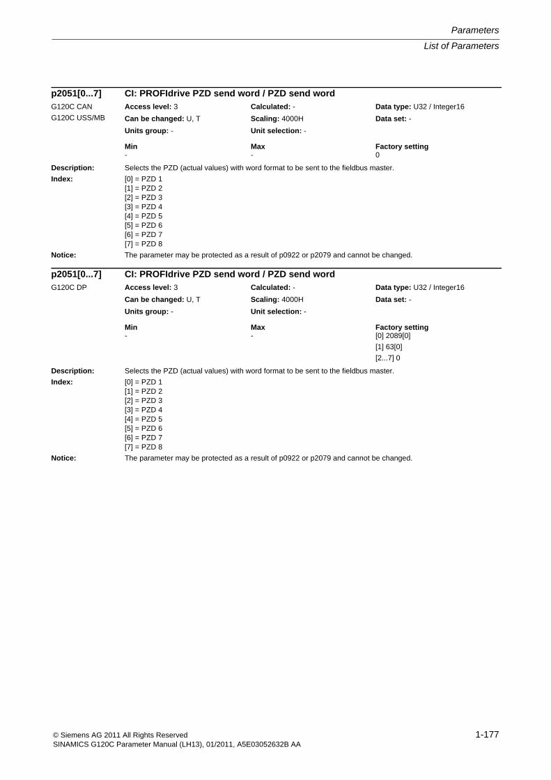
List of Parameters
Parameters
1-177© Siemens AG 2011 All Rights ReservedSINAMICS G120C Parameter Manual (LH13), 01/2011, A5E03052632B AA
Description: Selects the PZD (actual values) with word format to be sent to the fieldbus master.
Index: [0] = PZD 1[1] = PZD 2[2] = PZD 3[3] = PZD 4[4] = PZD 5[5] = PZD 6[6] = PZD 7[7] = PZD 8
Notice: The parameter may be protected as a result of p0922 or p2079 and cannot be changed.
Description: Selects the PZD (actual values) with word format to be sent to the fieldbus master.
Index: [0] = PZD 1[1] = PZD 2[2] = PZD 3[3] = PZD 4[4] = PZD 5[5] = PZD 6[6] = PZD 7[7] = PZD 8
Notice: The parameter may be protected as a result of p0922 or p2079 and cannot be changed.
p2051[0...7] CI: PROFIdrive PZD send word / PZD send wordG120C CAN
G120C USS/MB
Access level: 3 Calculated: - Data type: U32 / Integer16
Can be changed: U, T Scaling: 4000H Data set: -
Units group: - Unit selection: -
Min Max Factory setting - - 0
p2051[0...7] CI: PROFIdrive PZD send word / PZD send wordG120C DP Access level: 3 Calculated: - Data type: U32 / Integer16
Can be changed: U, T Scaling: 4000H Data set: -
Units group: - Unit selection: -
Min Max Factory setting - - [0] 2089[0]
[1] 63[0]
[2...7] 0
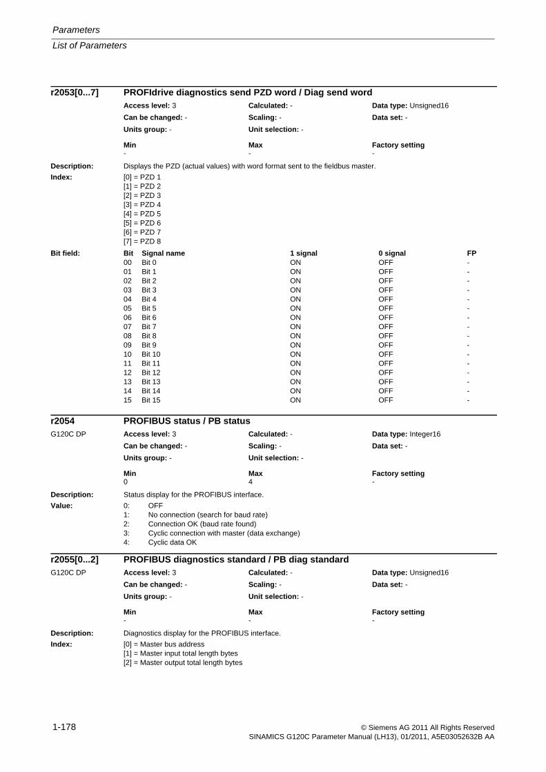
Parameters
List of Parameters
1-178 © Siemens AG 2011 All Rights ReservedSINAMICS G120C Parameter Manual (LH13), 01/2011, A5E03052632B AA
Description: Displays the PZD (actual values) with word format sent to the fieldbus master.
Index: [0] = PZD 1[1] = PZD 2[2] = PZD 3[3] = PZD 4[4] = PZD 5[5] = PZD 6[6] = PZD 7[7] = PZD 8
Description: Status display for the PROFIBUS interface.
Value: 0: OFF1: No connection (search for baud rate)2: Connection OK (baud rate found)3: Cyclic connection with master (data exchange)4: Cyclic data OK
Description: Diagnostics display for the PROFIBUS interface.
Index: [0] = Master bus address[1] = Master input total length bytes[2] = Master output total length bytes
r2053[0...7] PROFIdrive diagnostics send PZD word / Diag send wordAccess level: 3 Calculated: - Data type: Unsigned16
Can be changed: - Scaling: - Data set: -
Units group: - Unit selection: -
Min Max Factory setting - - -
Bit field: Bit Signal name 1 signal 0 signal FP00 Bit 0 ON OFF -01 Bit 1 ON OFF -02 Bit 2 ON OFF -03 Bit 3 ON OFF -04 Bit 4 ON OFF -05 Bit 5 ON OFF -06 Bit 6 ON OFF -07 Bit 7 ON OFF -08 Bit 8 ON OFF -09 Bit 9 ON OFF -10 Bit 10 ON OFF -11 Bit 11 ON OFF -12 Bit 12 ON OFF -13 Bit 13 ON OFF -14 Bit 14 ON OFF -15 Bit 15 ON OFF -
r2054 PROFIBUS status / PB statusG120C DP Access level: 3 Calculated: - Data type: Integer16
Can be changed: - Scaling: - Data set: -
Units group: - Unit selection: -
Min Max Factory setting 0 4 -
r2055[0...2] PROFIBUS diagnostics standard / PB diag standardG120C DP Access level: 3 Calculated: - Data type: Unsigned16
Can be changed: - Scaling: - Data set: -
Units group: - Unit selection: -
Min Max Factory setting - - -
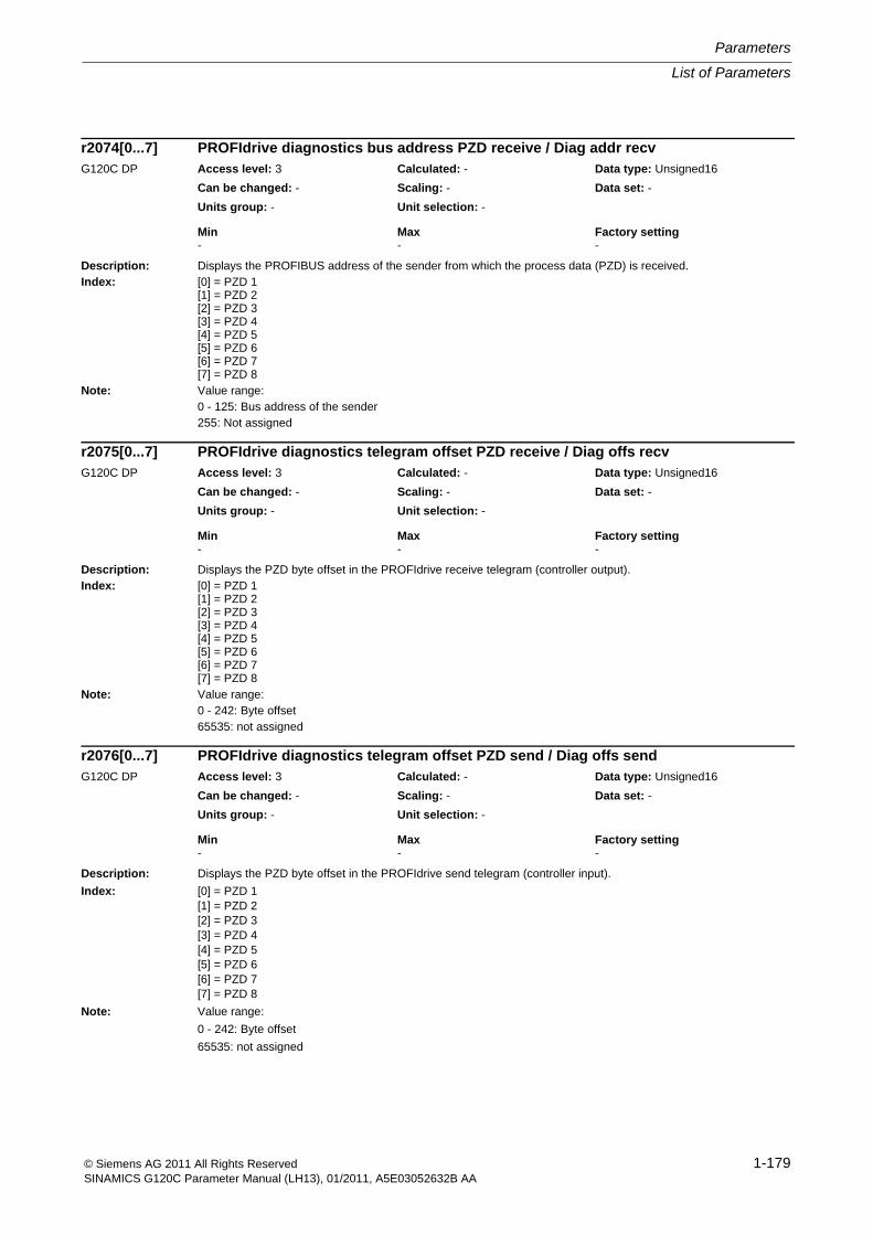
List of Parameters
Parameters
1-179© Siemens AG 2011 All Rights ReservedSINAMICS G120C Parameter Manual (LH13), 01/2011, A5E03052632B AA
Description: Displays the PROFIBUS address of the sender from which the process data (PZD) is received.Index: [0] = PZD 1
[1] = PZD 2[2] = PZD 3[3] = PZD 4[4] = PZD 5[5] = PZD 6[6] = PZD 7[7] = PZD 8
Note: Value range:0 - 125: Bus address of the sender255: Not assigned
Description: Displays the PZD byte offset in the PROFIdrive receive telegram (controller output).Index: [0] = PZD 1
[1] = PZD 2[2] = PZD 3[3] = PZD 4[4] = PZD 5[5] = PZD 6[6] = PZD 7[7] = PZD 8
Note: Value range:0 - 242: Byte offset65535: not assigned
Description: Displays the PZD byte offset in the PROFIdrive send telegram (controller input).
Index: [0] = PZD 1[1] = PZD 2[2] = PZD 3[3] = PZD 4[4] = PZD 5[5] = PZD 6[6] = PZD 7[7] = PZD 8
Note: Value range:
0 - 242: Byte offset
65535: not assigned
r2074[0...7] PROFIdrive diagnostics bus address PZD receive / Diag addr recvG120C DP Access level: 3 Calculated: - Data type: Unsigned16
Can be changed: - Scaling: - Data set: -
Units group: - Unit selection: -
Min Max Factory setting - - -
r2075[0...7] PROFIdrive diagnostics telegram offset PZD receive / Diag offs recvG120C DP Access level: 3 Calculated: - Data type: Unsigned16
Can be changed: - Scaling: - Data set: -
Units group: - Unit selection: -
Min Max Factory setting - - -
r2076[0...7] PROFIdrive diagnostics telegram offset PZD send / Diag offs sendG120C DP Access level: 3 Calculated: - Data type: Unsigned16
Can be changed: - Scaling: - Data set: -
Units group: - Unit selection: -
Min Max Factory setting - - -
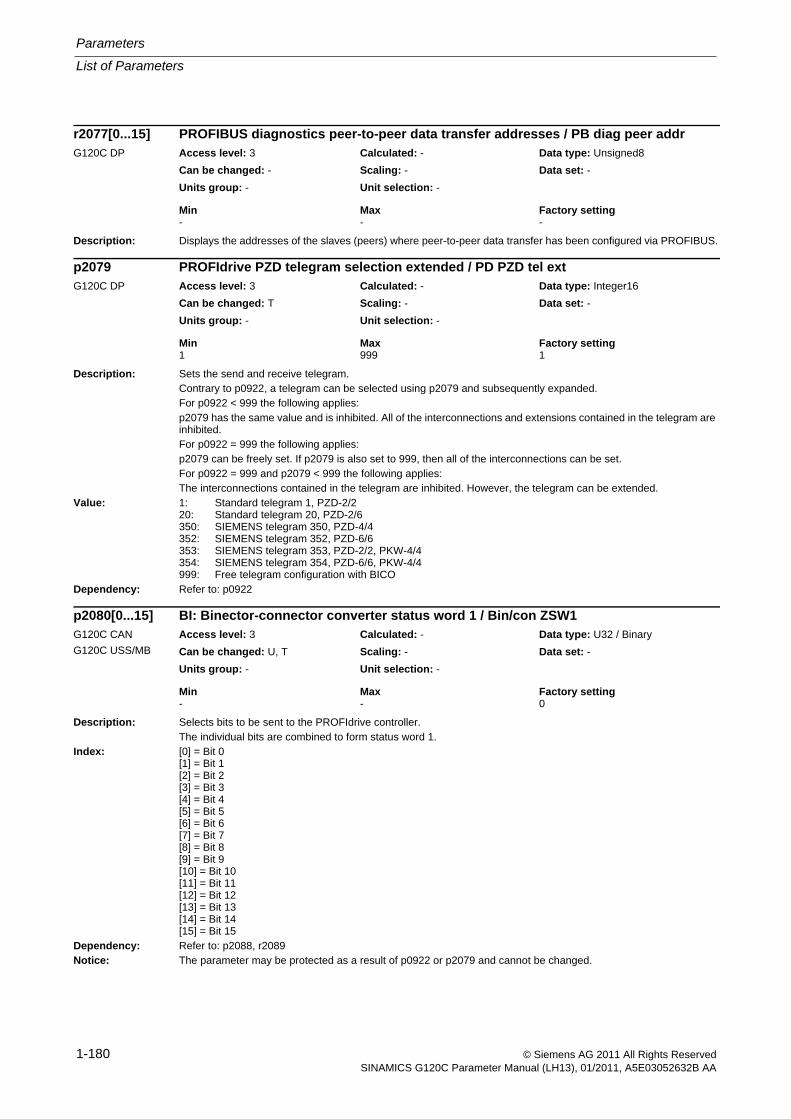
Parameters
List of Parameters
1-180 © Siemens AG 2011 All Rights ReservedSINAMICS G120C Parameter Manual (LH13), 01/2011, A5E03052632B AA
Description: Displays the addresses of the slaves (peers) where peer-to-peer data transfer has been configured via PROFIBUS.
Description: Sets the send and receive telegram.Contrary to p0922, a telegram can be selected using p2079 and subsequently expanded.For p0922 < 999 the following applies:p2079 has the same value and is inhibited. All of the interconnections and extensions contained in the telegram are inhibited.For p0922 = 999 the following applies:p2079 can be freely set. If p2079 is also set to 999, then all of the interconnections can be set.For p0922 = 999 and p2079 < 999 the following applies:The interconnections contained in the telegram are inhibited. However, the telegram can be extended.
Value: 1: Standard telegram 1, PZD-2/220: Standard telegram 20, PZD-2/6350: SIEMENS telegram 350, PZD-4/4352: SIEMENS telegram 352, PZD-6/6353: SIEMENS telegram 353, PZD-2/2, PKW-4/4354: SIEMENS telegram 354, PZD-6/6, PKW-4/4999: Free telegram configuration with BICO
Dependency: Refer to: p0922
Description: Selects bits to be sent to the PROFIdrive controller.The individual bits are combined to form status word 1.
Index: [0] = Bit 0[1] = Bit 1[2] = Bit 2[3] = Bit 3[4] = Bit 4[5] = Bit 5[6] = Bit 6[7] = Bit 7[8] = Bit 8[9] = Bit 9[10] = Bit 10[11] = Bit 11[12] = Bit 12[13] = Bit 13[14] = Bit 14[15] = Bit 15
Dependency: Refer to: p2088, r2089Notice: The parameter may be protected as a result of p0922 or p2079 and cannot be changed.
r2077[0...15] PROFIBUS diagnostics peer-to-peer data transfer addresses / PB diag peer addrG120C DP Access level: 3 Calculated: - Data type: Unsigned8
Can be changed: - Scaling: - Data set: -
Units group: - Unit selection: -
Min Max Factory setting - - -
p2079 PROFIdrive PZD telegram selection extended / PD PZD tel extG120C DP Access level: 3 Calculated: - Data type: Integer16
Can be changed: T Scaling: - Data set: -
Units group: - Unit selection: -
Min Max Factory setting 1 999 1
p2080[0...15] BI: Binector-connector converter status word 1 / Bin/con ZSW1G120C CAN
G120C USS/MB
Access level: 3 Calculated: - Data type: U32 / Binary
Can be changed: U, T Scaling: - Data set: -
Units group: - Unit selection: -
Min Max Factory setting - - 0
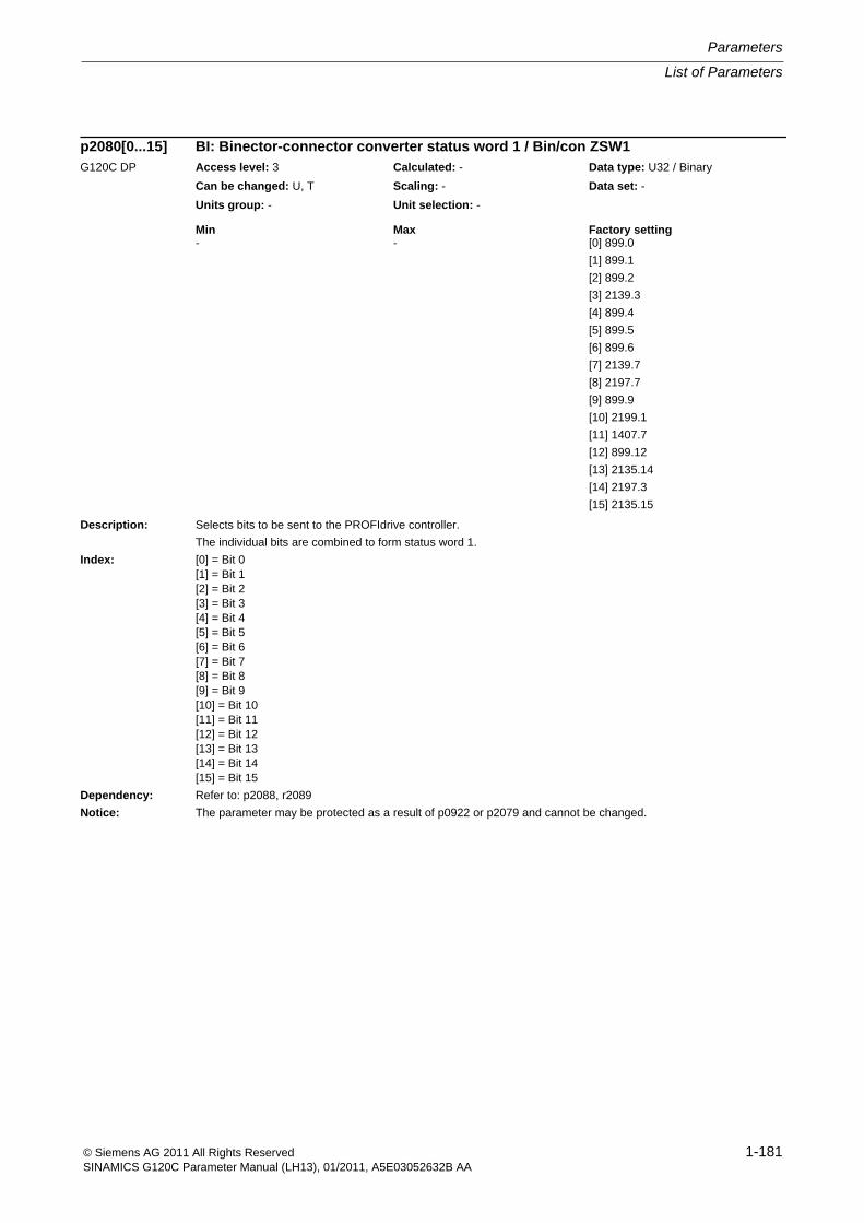
List of Parameters
Parameters
1-181© Siemens AG 2011 All Rights ReservedSINAMICS G120C Parameter Manual (LH13), 01/2011, A5E03052632B AA
Description: Selects bits to be sent to the PROFIdrive controller.
The individual bits are combined to form status word 1.
Index: [0] = Bit 0[1] = Bit 1[2] = Bit 2[3] = Bit 3[4] = Bit 4[5] = Bit 5[6] = Bit 6[7] = Bit 7[8] = Bit 8[9] = Bit 9[10] = Bit 10[11] = Bit 11[12] = Bit 12[13] = Bit 13[14] = Bit 14[15] = Bit 15
Dependency: Refer to: p2088, r2089
Notice: The parameter may be protected as a result of p0922 or p2079 and cannot be changed.
p2080[0...15] BI: Binector-connector converter status word 1 / Bin/con ZSW1G120C DP Access level: 3 Calculated: - Data type: U32 / Binary
Can be changed: U, T Scaling: - Data set: -
Units group: - Unit selection: -
Min Max Factory setting - - [0] 899.0
[1] 899.1
[2] 899.2
[3] 2139.3
[4] 899.4
[5] 899.5
[6] 899.6
[7] 2139.7
[8] 2197.7
[9] 899.9
[10] 2199.1
[11] 1407.7
[12] 899.12
[13] 2135.14
[14] 2197.3
[15] 2135.15
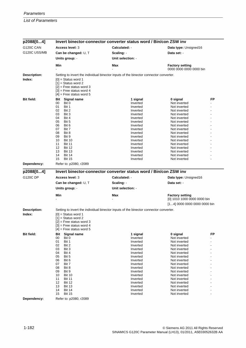
Parameters
List of Parameters
1-182 © Siemens AG 2011 All Rights ReservedSINAMICS G120C Parameter Manual (LH13), 01/2011, A5E03052632B AA
Description: Setting to invert the individual binector inputs of the binector connector converter.Index: [0] = Status word 1
[1] = Status word 2[2] = Free status word 3[3] = Free status word 4[4] = Free status word 5
Dependency: Refer to: p2080, r2089
Description: Setting to invert the individual binector inputs of the binector connector converter.Index: [0] = Status word 1
[1] = Status word 2[2] = Free status word 3[3] = Free status word 4[4] = Free status word 5
Dependency: Refer to: p2080, r2089
p2088[0...4] Invert binector-connector converter status word / Bin/con ZSW invG120C CAN
G120C USS/MB
Access level: 3 Calculated: - Data type: Unsigned16
Can be changed: U, T Scaling: - Data set: -
Units group: - Unit selection: -
Min Max Factory setting - - 0000 0000 0000 0000 bin
Bit field: Bit Signal name 1 signal 0 signal FP00 Bit 0 Inverted Not inverted -01 Bit 1 Inverted Not inverted -02 Bit 2 Inverted Not inverted -03 Bit 3 Inverted Not inverted -04 Bit 4 Inverted Not inverted -05 Bit 5 Inverted Not inverted -06 Bit 6 Inverted Not inverted -07 Bit 7 Inverted Not inverted -08 Bit 8 Inverted Not inverted -09 Bit 9 Inverted Not inverted -10 Bit 10 Inverted Not inverted -11 Bit 11 Inverted Not inverted -12 Bit 12 Inverted Not inverted -13 Bit 13 Inverted Not inverted -14 Bit 14 Inverted Not inverted -15 Bit 15 Inverted Not inverted -
p2088[0...4] Invert binector-connector converter status word / Bin/con ZSW invG120C DP Access level: 3 Calculated: - Data type: Unsigned16
Can be changed: U, T Scaling: - Data set: -
Units group: - Unit selection: -
Min Max Factory setting - - [0] 1010 1000 0000 0000 bin
[1...4] 0000 0000 0000 0000 bin
Bit field: Bit Signal name 1 signal 0 signal FP00 Bit 0 Inverted Not inverted -01 Bit 1 Inverted Not inverted -02 Bit 2 Inverted Not inverted -03 Bit 3 Inverted Not inverted -04 Bit 4 Inverted Not inverted -05 Bit 5 Inverted Not inverted -06 Bit 6 Inverted Not inverted -07 Bit 7 Inverted Not inverted -08 Bit 8 Inverted Not inverted -09 Bit 9 Inverted Not inverted -10 Bit 10 Inverted Not inverted -11 Bit 11 Inverted Not inverted -12 Bit 12 Inverted Not inverted -13 Bit 13 Inverted Not inverted -14 Bit 14 Inverted Not inverted -15 Bit 15 Inverted Not inverted -
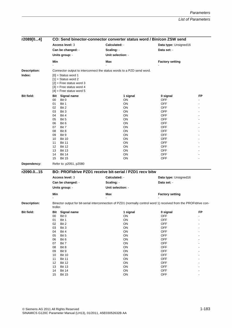
List of Parameters
Parameters
1-183© Siemens AG 2011 All Rights ReservedSINAMICS G120C Parameter Manual (LH13), 01/2011, A5E03052632B AA
Description: Connector output to interconnect the status words to a PZD send word.
Index: [0] = Status word 1[1] = Status word 2[2] = Free status word 3[3] = Free status word 4[4] = Free status word 5
Dependency: Refer to: p2051, p2080
Description: Binector output for bit-serial interconnection of PZD1 (normally control word 1) received from the PROFIdrive con-troller.
r2089[0...4] CO: Send binector-connector converter status word / Bin/con ZSW sendAccess level: 3 Calculated: - Data type: Unsigned16
Can be changed: - Scaling: - Data set: -
Units group: - Unit selection: -
Min Max Factory setting - - -
Bit field: Bit Signal name 1 signal 0 signal FP00 Bit 0 ON OFF -01 Bit 1 ON OFF -02 Bit 2 ON OFF -03 Bit 3 ON OFF -04 Bit 4 ON OFF -05 Bit 5 ON OFF -06 Bit 6 ON OFF -07 Bit 7 ON OFF -08 Bit 8 ON OFF -09 Bit 9 ON OFF -10 Bit 10 ON OFF -11 Bit 11 ON OFF -12 Bit 12 ON OFF -13 Bit 13 ON OFF -14 Bit 14 ON OFF -15 Bit 15 ON OFF -
r2090.0...15 BO: PROFIdrive PZD1 receive bit-serial / PZD1 recv bitwAccess level: 3 Calculated: - Data type: Unsigned16
Can be changed: - Scaling: - Data set: -
Units group: - Unit selection: -
Min Max Factory setting - - -
Bit field: Bit Signal name 1 signal 0 signal FP00 Bit 0 ON OFF -01 Bit 1 ON OFF -02 Bit 2 ON OFF -03 Bit 3 ON OFF -04 Bit 4 ON OFF -05 Bit 5 ON OFF -06 Bit 6 ON OFF -07 Bit 7 ON OFF -08 Bit 8 ON OFF -09 Bit 9 ON OFF -10 Bit 10 ON OFF -11 Bit 11 ON OFF -12 Bit 12 ON OFF -13 Bit 13 ON OFF -14 Bit 14 ON OFF -15 Bit 15 ON OFF -
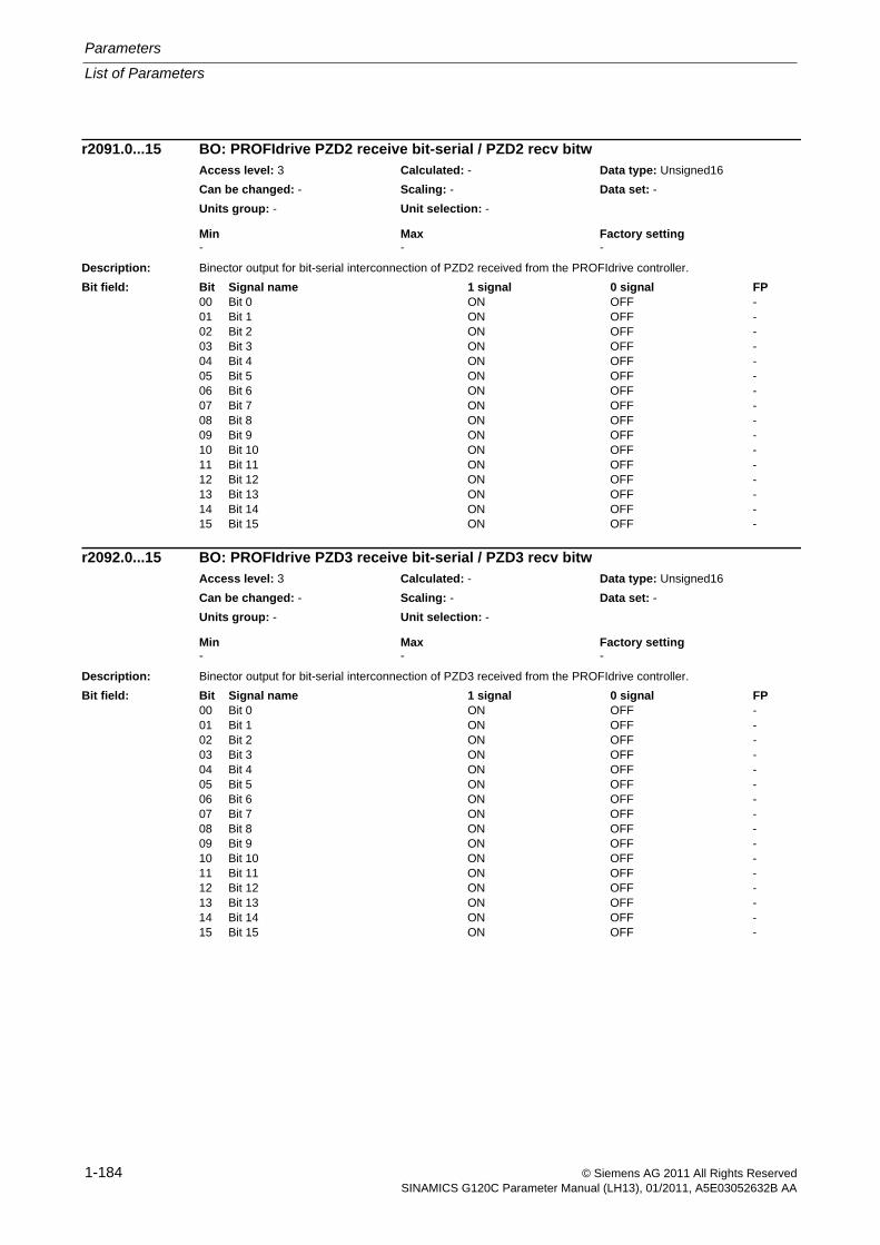
Parameters
List of Parameters
1-184 © Siemens AG 2011 All Rights ReservedSINAMICS G120C Parameter Manual (LH13), 01/2011, A5E03052632B AA
Description: Binector output for bit-serial interconnection of PZD2 received from the PROFIdrive controller.
Description: Binector output for bit-serial interconnection of PZD3 received from the PROFIdrive controller.
r2091.0...15 BO: PROFIdrive PZD2 receive bit-serial / PZD2 recv bitwAccess level: 3 Calculated: - Data type: Unsigned16
Can be changed: - Scaling: - Data set: -
Units group: - Unit selection: -
Min Max Factory setting - - -
Bit field: Bit Signal name 1 signal 0 signal FP00 Bit 0 ON OFF -01 Bit 1 ON OFF -02 Bit 2 ON OFF -03 Bit 3 ON OFF -04 Bit 4 ON OFF -05 Bit 5 ON OFF -06 Bit 6 ON OFF -07 Bit 7 ON OFF -08 Bit 8 ON OFF -09 Bit 9 ON OFF -10 Bit 10 ON OFF -11 Bit 11 ON OFF -12 Bit 12 ON OFF -13 Bit 13 ON OFF -14 Bit 14 ON OFF -15 Bit 15 ON OFF -
r2092.0...15 BO: PROFIdrive PZD3 receive bit-serial / PZD3 recv bitwAccess level: 3 Calculated: - Data type: Unsigned16
Can be changed: - Scaling: - Data set: -
Units group: - Unit selection: -
Min Max Factory setting - - -
Bit field: Bit Signal name 1 signal 0 signal FP00 Bit 0 ON OFF -01 Bit 1 ON OFF -02 Bit 2 ON OFF -03 Bit 3 ON OFF -04 Bit 4 ON OFF -05 Bit 5 ON OFF -06 Bit 6 ON OFF -07 Bit 7 ON OFF -08 Bit 8 ON OFF -09 Bit 9 ON OFF -10 Bit 10 ON OFF -11 Bit 11 ON OFF -12 Bit 12 ON OFF -13 Bit 13 ON OFF -14 Bit 14 ON OFF -15 Bit 15 ON OFF -
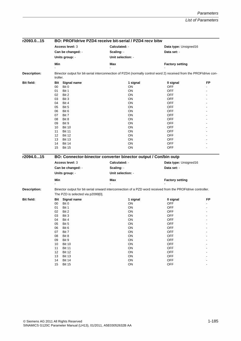
List of Parameters
Parameters
1-185© Siemens AG 2011 All Rights ReservedSINAMICS G120C Parameter Manual (LH13), 01/2011, A5E03052632B AA
Description: Binector output for bit-serial interconnection of PZD4 (normally control word 2) received from the PROFIdrive con-troller.
Description: Binector output for bit-serial onward interconnection of a PZD word received from the PROFIdrive controller.
The PZD is selected via p2099[0].
r2093.0...15 BO: PROFIdrive PZD4 receive bit-serial / PZD4 recv bitwAccess level: 3 Calculated: - Data type: Unsigned16
Can be changed: - Scaling: - Data set: -
Units group: - Unit selection: -
Min Max Factory setting - - -
Bit field: Bit Signal name 1 signal 0 signal FP00 Bit 0 ON OFF -01 Bit 1 ON OFF -02 Bit 2 ON OFF -03 Bit 3 ON OFF -04 Bit 4 ON OFF -05 Bit 5 ON OFF -06 Bit 6 ON OFF -07 Bit 7 ON OFF -08 Bit 8 ON OFF -09 Bit 9 ON OFF -10 Bit 10 ON OFF -11 Bit 11 ON OFF -12 Bit 12 ON OFF -13 Bit 13 ON OFF -14 Bit 14 ON OFF -15 Bit 15 ON OFF -
r2094.0...15 BO: Connector-binector converter binector output / Con/bin outpAccess level: 3 Calculated: - Data type: Unsigned16
Can be changed: - Scaling: - Data set: -
Units group: - Unit selection: -
Min Max Factory setting - - -
Bit field: Bit Signal name 1 signal 0 signal FP00 Bit 0 ON OFF -01 Bit 1 ON OFF -02 Bit 2 ON OFF -03 Bit 3 ON OFF -04 Bit 4 ON OFF -05 Bit 5 ON OFF -06 Bit 6 ON OFF -07 Bit 7 ON OFF -08 Bit 8 ON OFF -09 Bit 9 ON OFF -10 Bit 10 ON OFF -11 Bit 11 ON OFF -12 Bit 12 ON OFF -13 Bit 13 ON OFF -14 Bit 14 ON OFF -15 Bit 15 ON OFF -
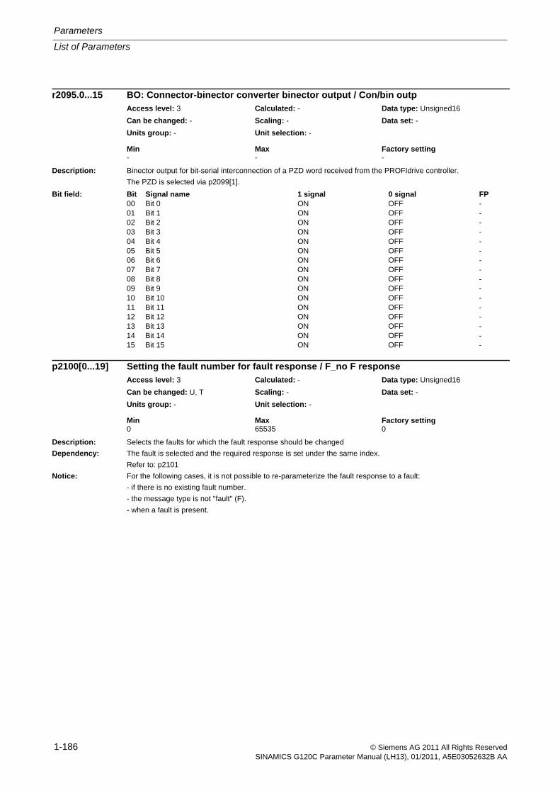
Parameters
List of Parameters
1-186 © Siemens AG 2011 All Rights ReservedSINAMICS G120C Parameter Manual (LH13), 01/2011, A5E03052632B AA
Description: Binector output for bit-serial interconnection of a PZD word received from the PROFIdrive controller.
The PZD is selected via p2099[1].
Description: Selects the faults for which the fault response should be changed
Dependency: The fault is selected and the required response is set under the same index.
Refer to: p2101
Notice: For the following cases, it is not possible to re-parameterize the fault response to a fault:
- if there is no existing fault number.
- the message type is not "fault" (F).
- when a fault is present.
r2095.0...15 BO: Connector-binector converter binector output / Con/bin outpAccess level: 3 Calculated: - Data type: Unsigned16
Can be changed: - Scaling: - Data set: -
Units group: - Unit selection: -
Min Max Factory setting - - -
Bit field: Bit Signal name 1 signal 0 signal FP00 Bit 0 ON OFF -01 Bit 1 ON OFF -02 Bit 2 ON OFF -03 Bit 3 ON OFF -04 Bit 4 ON OFF -05 Bit 5 ON OFF -06 Bit 6 ON OFF -07 Bit 7 ON OFF -08 Bit 8 ON OFF -09 Bit 9 ON OFF -10 Bit 10 ON OFF -11 Bit 11 ON OFF -12 Bit 12 ON OFF -13 Bit 13 ON OFF -14 Bit 14 ON OFF -15 Bit 15 ON OFF -
p2100[0...19] Setting the fault number for fault response / F_no F responseAccess level: 3 Calculated: - Data type: Unsigned16
Can be changed: U, T Scaling: - Data set: -
Units group: - Unit selection: -
Min Max Factory setting 0 65535 0
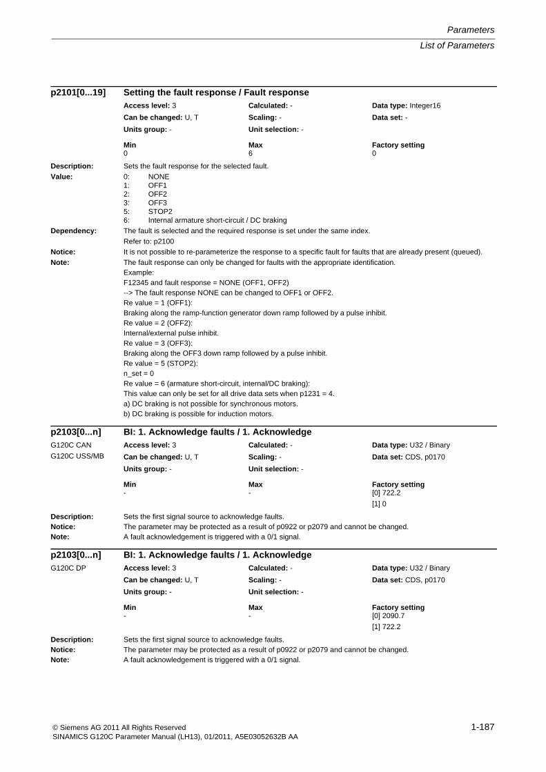
List of Parameters
Parameters
1-187© Siemens AG 2011 All Rights ReservedSINAMICS G120C Parameter Manual (LH13), 01/2011, A5E03052632B AA
Description: Sets the fault response for the selected fault.
Value: 0: NONE1: OFF12: OFF23: OFF35: STOP26: Internal armature short-circuit / DC braking
Dependency: The fault is selected and the required response is set under the same index.
Refer to: p2100
Notice: It is not possible to re-parameterize the response to a specific fault for faults that are already present (queued).
Note: The fault response can only be changed for faults with the appropriate identification.Example:F12345 and fault response = NONE (OFF1, OFF2)--> The fault response NONE can be changed to OFF1 or OFF2.Re value = 1 (OFF1):Braking along the ramp-function generator down ramp followed by a pulse inhibit.Re value = 2 (OFF2):Internal/external pulse inhibit.Re value = 3 (OFF3):Braking along the OFF3 down ramp followed by a pulse inhibit.Re value = 5 (STOP2):n_set = 0Re value = 6 (armature short-circuit, internal/DC braking):This value can only be set for all drive data sets when p1231 = 4.a) DC braking is not possible for synchronous motors.b) DC braking is possible for induction motors.
Description: Sets the first signal source to acknowledge faults.Notice: The parameter may be protected as a result of p0922 or p2079 and cannot be changed.Note: A fault acknowledgement is triggered with a 0/1 signal.
Description: Sets the first signal source to acknowledge faults.Notice: The parameter may be protected as a result of p0922 or p2079 and cannot be changed.Note: A fault acknowledgement is triggered with a 0/1 signal.
p2101[0...19] Setting the fault response / Fault responseAccess level: 3 Calculated: - Data type: Integer16
Can be changed: U, T Scaling: - Data set: -
Units group: - Unit selection: -
Min Max Factory setting 0 6 0
p2103[0...n] BI: 1. Acknowledge faults / 1. AcknowledgeG120C CAN
G120C USS/MB
Access level: 3 Calculated: - Data type: U32 / Binary
Can be changed: U, T Scaling: - Data set: CDS, p0170
Units group: - Unit selection: -
Min Max Factory setting - - [0] 722.2
[1] 0
p2103[0...n] BI: 1. Acknowledge faults / 1. AcknowledgeG120C DP Access level: 3 Calculated: - Data type: U32 / Binary
Can be changed: U, T Scaling: - Data set: CDS, p0170
Units group: - Unit selection: -
Min Max Factory setting - - [0] 2090.7
[1] 722.2
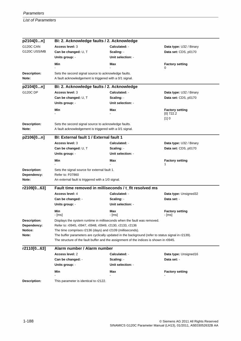
Parameters
List of Parameters
1-188 © Siemens AG 2011 All Rights ReservedSINAMICS G120C Parameter Manual (LH13), 01/2011, A5E03052632B AA
Description: Sets the second signal source to acknowledge faults.
Note: A fault acknowledgement is triggered with a 0/1 signal.
Description: Sets the second signal source to acknowledge faults.
Note: A fault acknowledgement is triggered with a 0/1 signal.
Description: Sets the signal source for external fault 1.
Dependency: Refer to: F07860
Note: An external fault is triggered with a 1/0 signal.
Description: Displays the system runtime in milliseconds when the fault was removed.
Dependency: Refer to: r0945, r0947, r0948, r0949, r2130, r2133, r2136
Notice: The time comprises r2136 (days) and r2109 (milliseconds).
Note: The buffer parameters are cyclically updated in the background (refer to status signal in r2139).
The structure of the fault buffer and the assignment of the indices is shown in r0945.
Description: This parameter is identical to r2122.
p2104[0...n] BI: 2. Acknowledge faults / 2. AcknowledgeG120C CAN
G120C USS/MB
Access level: 3 Calculated: - Data type: U32 / Binary
Can be changed: U, T Scaling: - Data set: CDS, p0170
Units group: - Unit selection: -
Min Max Factory setting - - 0
p2104[0...n] BI: 2. Acknowledge faults / 2. AcknowledgeG120C DP Access level: 3 Calculated: - Data type: U32 / Binary
Can be changed: U, T Scaling: - Data set: CDS, p0170
Units group: - Unit selection: -
Min Max Factory setting - - [0] 722.2
[1] 0
p2106[0...n] BI: External fault 1 / External fault 1Access level: 3 Calculated: - Data type: U32 / Binary
Can be changed: U, T Scaling: - Data set: CDS, p0170
Units group: - Unit selection: -
Min Max Factory setting - - 1
r2109[0...63] Fault time removed in milliseconds / t_flt resolved msAccess level: 4 Calculated: - Data type: Unsigned32
Can be changed: - Scaling: - Data set: -
Units group: - Unit selection: -
Min Max Factory setting - [ms] - [ms] - [ms]
r2110[0...63] Alarm number / Alarm numberAccess level: 2 Calculated: - Data type: Unsigned16
Can be changed: - Scaling: - Data set: -
Units group: - Unit selection: -
Min Max Factory setting - - -
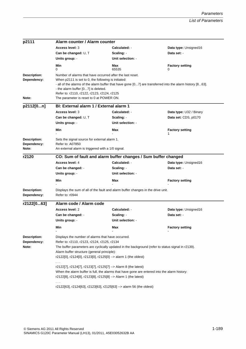
List of Parameters
Parameters
1-189© Siemens AG 2011 All Rights ReservedSINAMICS G120C Parameter Manual (LH13), 01/2011, A5E03052632B AA
Description: Number of alarms that have occurred after the last reset.Dependency: When p2111 is set to 0, the following is initiated:
- all of the alarms of the alarm buffer that have gone [0...7] are transferred into the alarm history [8...63].- the alarm buffer [0...7] is deleted.Refer to: r2110, r2122, r2123, r2124, r2125
Note: The parameter is reset to 0 at POWER ON.
Description: Sets the signal source for external alarm 1.Dependency: Refer to: A07850Note: An external alarm is triggered with a 1/0 signal.
Description: Displays the sum of all of the fault and alarm buffer changes in the drive unit.
Dependency: Refer to: r0944
Description: Displays the number of alarms that have occurred.
Dependency: Refer to: r2110, r2123, r2124, r2125, r2134
Note: The buffer parameters are cyclically updated in the background (refer to status signal in r2139).
Alarm buffer structure (general principle):
r2122[0], r2124[0], r2123[0], r2125[0] --> alarm 1 (the oldest)
. . .
r2122[7], r2124[7], r2123[7], r2125[7] --> Alarm 8 (the latest)
When the alarm buffer is full, the alarms that have gone are entered into the alarm history:
r2122[8], r2124[8], r2123[8], r2125[8] --> Alarm 1 (the latest)
. . .
r2122[63], r2124[63], r2123[63], r2125[63] --> alarm 56 (the oldest)
p2111 Alarm counter / Alarm counterAccess level: 3 Calculated: - Data type: Unsigned16
Can be changed: U, T Scaling: - Data set: -
Units group: - Unit selection: -
Min Max Factory setting 0 65535 0
p2112[0...n] BI: External alarm 1 / External alarm 1Access level: 3 Calculated: - Data type: U32 / Binary
Can be changed: U, T Scaling: - Data set: CDS, p0170
Units group: - Unit selection: -
Min Max Factory setting - - 1
r2120 CO: Sum of fault and alarm buffer changes / Sum buffer changedAccess level: 4 Calculated: - Data type: Unsigned16
Can be changed: - Scaling: - Data set: -
Units group: - Unit selection: -
Min Max Factory setting - - -
r2122[0...63] Alarm code / Alarm codeAccess level: 2 Calculated: - Data type: Unsigned16
Can be changed: - Scaling: - Data set: -
Units group: - Unit selection: -
Min Max Factory setting - - -
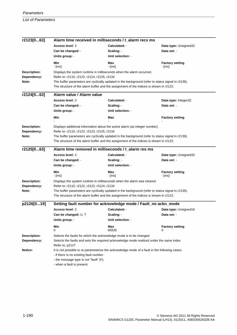
Parameters
List of Parameters
1-190 © Siemens AG 2011 All Rights ReservedSINAMICS G120C Parameter Manual (LH13), 01/2011, A5E03052632B AA
Description: Displays the system runtime in milliseconds when the alarm occurred.
Dependency: Refer to: r2110, r2122, r2124, r2125, r2134
Note: The buffer parameters are cyclically updated in the background (refer to status signal in r2139).
The structure of the alarm buffer and the assignment of the indices is shown in r2122.
Description: Displays additional information about the active alarm (as integer number).
Dependency: Refer to: r2110, r2122, r2123, r2125, r2134
Note: The buffer parameters are cyclically updated in the background (refer to status signal in r2139).
The structure of the alarm buffer and the assignment of the indices is shown in r2122.
Description: Displays the system runtime in milliseconds when the alarm was cleared.
Dependency: Refer to: r2110, r2122, r2123, r2124, r2134
Note: The buffer parameters are cyclically updated in the background (refer to status signal in r2139).
The structure of the alarm buffer and the assignment of the indices is shown in r2122.
Description: Selects the faults for which the acknowledge mode is to be changed
Dependency: Selects the faults and sets the required acknowledge mode realized under the same index
Refer to: p2127
Notice: It is not possible to re-parameterize the acknowledge mode of a fault in the following cases:
- if there is no existing fault number.
- the message type is not "fault" (F).
- when a fault is present.
r2123[0...63] Alarm time received in milliseconds / t_alarm recv msAccess level: 3 Calculated: - Data type: Unsigned32
Can be changed: - Scaling: - Data set: -
Units group: - Unit selection: -
Min Max Factory setting - [ms] - [ms] - [ms]
r2124[0...63] Alarm value / Alarm valueAccess level: 3 Calculated: - Data type: Integer32
Can be changed: - Scaling: - Data set: -
Units group: - Unit selection: -
Min Max Factory setting - - -
r2125[0...63] Alarm time removed in milliseconds / t_alarm res msAccess level: 3 Calculated: - Data type: Unsigned32
Can be changed: - Scaling: - Data set: -
Units group: - Unit selection: -
Min Max Factory setting - [ms] - [ms] - [ms]
p2126[0...19] Setting fault number for acknowledge mode / Fault_no ackn_modeAccess level: 3 Calculated: - Data type: Unsigned16
Can be changed: U, T Scaling: - Data set: -
Units group: - Unit selection: -
Min Max Factory setting 0 65535 0
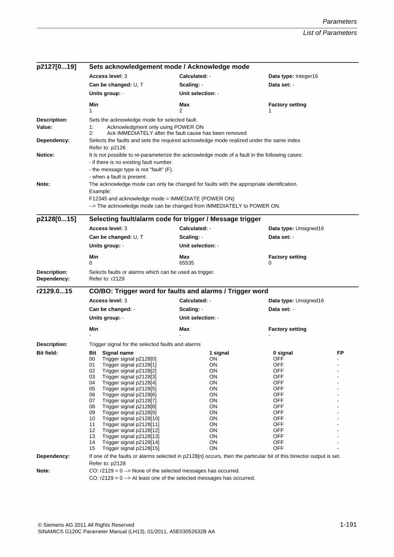
List of Parameters
Parameters
1-191© Siemens AG 2011 All Rights ReservedSINAMICS G120C Parameter Manual (LH13), 01/2011, A5E03052632B AA
Description: Sets the acknowledge mode for selected fault.Value: 1: Acknowledgment only using POWER ON
2: Ack IMMEDIATELY after the fault cause has been removedDependency: Selects the faults and sets the required acknowledge mode realized under the same index
Refer to: p2126Notice: It is not possible to re-parameterize the acknowledge mode of a fault in the following cases:
- if there is no existing fault number.- the message type is not "fault" (F).- when a fault is present.
Note: The acknowledge mode can only be changed for faults with the appropriate identification.Example:F12345 and acknowledge mode = IMMEDIATE (POWER ON)--> The acknowledge mode can be changed from IMMEDIATELY to POWER ON.
Description: Selects faults or alarms which can be used as trigger.Dependency: Refer to: r2129
Description: Trigger signal for the selected faults and alarms
Dependency: If one of the faults or alarms selected in p2128[n] occurs, then the particular bit of this binector output is set.Refer to: p2128
Note: CO: r2129 = 0 --> None of the selected messages has occurred.CO: r2129 > 0 --> At least one of the selected messages has occurred.
p2127[0...19] Sets acknowledgement mode / Acknowledge modeAccess level: 3 Calculated: - Data type: Integer16
Can be changed: U, T Scaling: - Data set: -
Units group: - Unit selection: -
Min Max Factory setting 1 2 1
p2128[0...15] Selecting fault/alarm code for trigger / Message triggerAccess level: 3 Calculated: - Data type: Unsigned16
Can be changed: U, T Scaling: - Data set: -
Units group: - Unit selection: -
Min Max Factory setting 0 65535 0
r2129.0...15 CO/BO: Trigger word for faults and alarms / Trigger wordAccess level: 3 Calculated: - Data type: Unsigned16
Can be changed: - Scaling: - Data set: -
Units group: - Unit selection: -
Min Max Factory setting - - -
Bit field: Bit Signal name 1 signal 0 signal FP00 Trigger signal p2128[0] ON OFF -01 Trigger signal p2128[1] ON OFF -02 Trigger signal p2128[2] ON OFF -03 Trigger signal p2128[3] ON OFF -04 Trigger signal p2128[4] ON OFF -05 Trigger signal p2128[5] ON OFF -06 Trigger signal p2128[6] ON OFF -07 Trigger signal p2128[7] ON OFF -08 Trigger signal p2128[8] ON OFF -09 Trigger signal p2128[9] ON OFF -10 Trigger signal p2128[10] ON OFF -11 Trigger signal p2128[11] ON OFF -12 Trigger signal p2128[12] ON OFF -13 Trigger signal p2128[13] ON OFF -14 Trigger signal p2128[14] ON OFF -15 Trigger signal p2128[15] ON OFF -
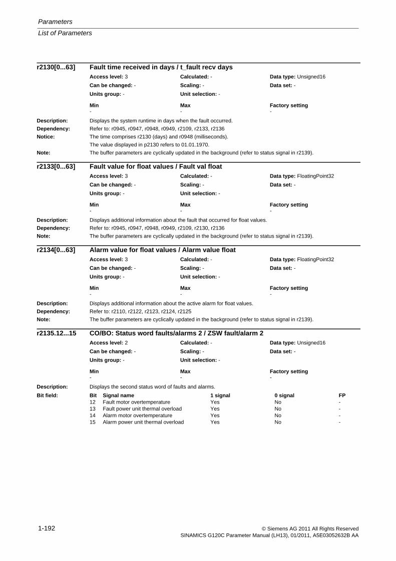
Parameters
List of Parameters
1-192 © Siemens AG 2011 All Rights ReservedSINAMICS G120C Parameter Manual (LH13), 01/2011, A5E03052632B AA
Description: Displays the system runtime in days when the fault occurred.
Dependency: Refer to: r0945, r0947, r0948, r0949, r2109, r2133, r2136
Notice: The time comprises r2130 (days) and r0948 (milliseconds).
The value displayed in p2130 refers to 01.01.1970.
Note: The buffer parameters are cyclically updated in the background (refer to status signal in r2139).
Description: Displays additional information about the fault that occurred for float values.
Dependency: Refer to: r0945, r0947, r0948, r0949, r2109, r2130, r2136
Note: The buffer parameters are cyclically updated in the background (refer to status signal in r2139).
Description: Displays additional information about the active alarm for float values.
Dependency: Refer to: r2110, r2122, r2123, r2124, r2125
Note: The buffer parameters are cyclically updated in the background (refer to status signal in r2139).
Description: Displays the second status word of faults and alarms.
r2130[0...63] Fault time received in days / t_fault recv daysAccess level: 3 Calculated: - Data type: Unsigned16
Can be changed: - Scaling: - Data set: -
Units group: - Unit selection: -
Min Max Factory setting - - -
r2133[0...63] Fault value for float values / Fault val floatAccess level: 3 Calculated: - Data type: FloatingPoint32
Can be changed: - Scaling: - Data set: -
Units group: - Unit selection: -
Min Max Factory setting - - -
r2134[0...63] Alarm value for float values / Alarm value floatAccess level: 3 Calculated: - Data type: FloatingPoint32
Can be changed: - Scaling: - Data set: -
Units group: - Unit selection: -
Min Max Factory setting - - -
r2135.12...15 CO/BO: Status word faults/alarms 2 / ZSW fault/alarm 2Access level: 2 Calculated: - Data type: Unsigned16
Can be changed: - Scaling: - Data set: -
Units group: - Unit selection: -
Min Max Factory setting - - -
Bit field: Bit Signal name 1 signal 0 signal FP12 Fault motor overtemperature Yes No -13 Fault power unit thermal overload Yes No -14 Alarm motor overtemperature Yes No -15 Alarm power unit thermal overload Yes No -
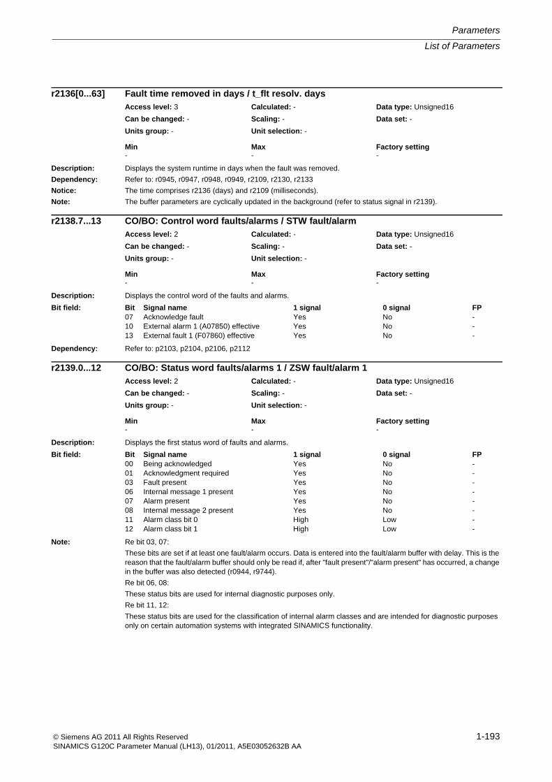
List of Parameters
Parameters
1-193© Siemens AG 2011 All Rights ReservedSINAMICS G120C Parameter Manual (LH13), 01/2011, A5E03052632B AA
Description: Displays the system runtime in days when the fault was removed.
Dependency: Refer to: r0945, r0947, r0948, r0949, r2109, r2130, r2133
Notice: The time comprises r2136 (days) and r2109 (milliseconds).
Note: The buffer parameters are cyclically updated in the background (refer to status signal in r2139).
Description: Displays the control word of the faults and alarms.
Dependency: Refer to: p2103, p2104, p2106, p2112
Description: Displays the first status word of faults and alarms.
Note: Re bit 03, 07:
These bits are set if at least one fault/alarm occurs. Data is entered into the fault/alarm buffer with delay. This is the reason that the fault/alarm buffer should only be read if, after "fault present"/"alarm present" has occurred, a change in the buffer was also detected (r0944, r9744).
Re bit 06, 08:
These status bits are used for internal diagnostic purposes only.
Re bit 11, 12:
These status bits are used for the classification of internal alarm classes and are intended for diagnostic purposes only on certain automation systems with integrated SINAMICS functionality.
r2136[0...63] Fault time removed in days / t_flt resolv. daysAccess level: 3 Calculated: - Data type: Unsigned16
Can be changed: - Scaling: - Data set: -
Units group: - Unit selection: -
Min Max Factory setting - - -
r2138.7...13 CO/BO: Control word faults/alarms / STW fault/alarmAccess level: 2 Calculated: - Data type: Unsigned16
Can be changed: - Scaling: - Data set: -
Units group: - Unit selection: -
Min Max Factory setting - - -
Bit field: Bit Signal name 1 signal 0 signal FP07 Acknowledge fault Yes No -10 External alarm 1 (A07850) effective Yes No -13 External fault 1 (F07860) effective Yes No -
r2139.0...12 CO/BO: Status word faults/alarms 1 / ZSW fault/alarm 1Access level: 2 Calculated: - Data type: Unsigned16
Can be changed: - Scaling: - Data set: -
Units group: - Unit selection: -
Min Max Factory setting - - -
Bit field: Bit Signal name 1 signal 0 signal FP00 Being acknowledged Yes No -01 Acknowledgment required Yes No -03 Fault present Yes No -06 Internal message 1 present Yes No -07 Alarm present Yes No -08 Internal message 2 present Yes No -11 Alarm class bit 0 High Low -12 Alarm class bit 1 High Low -
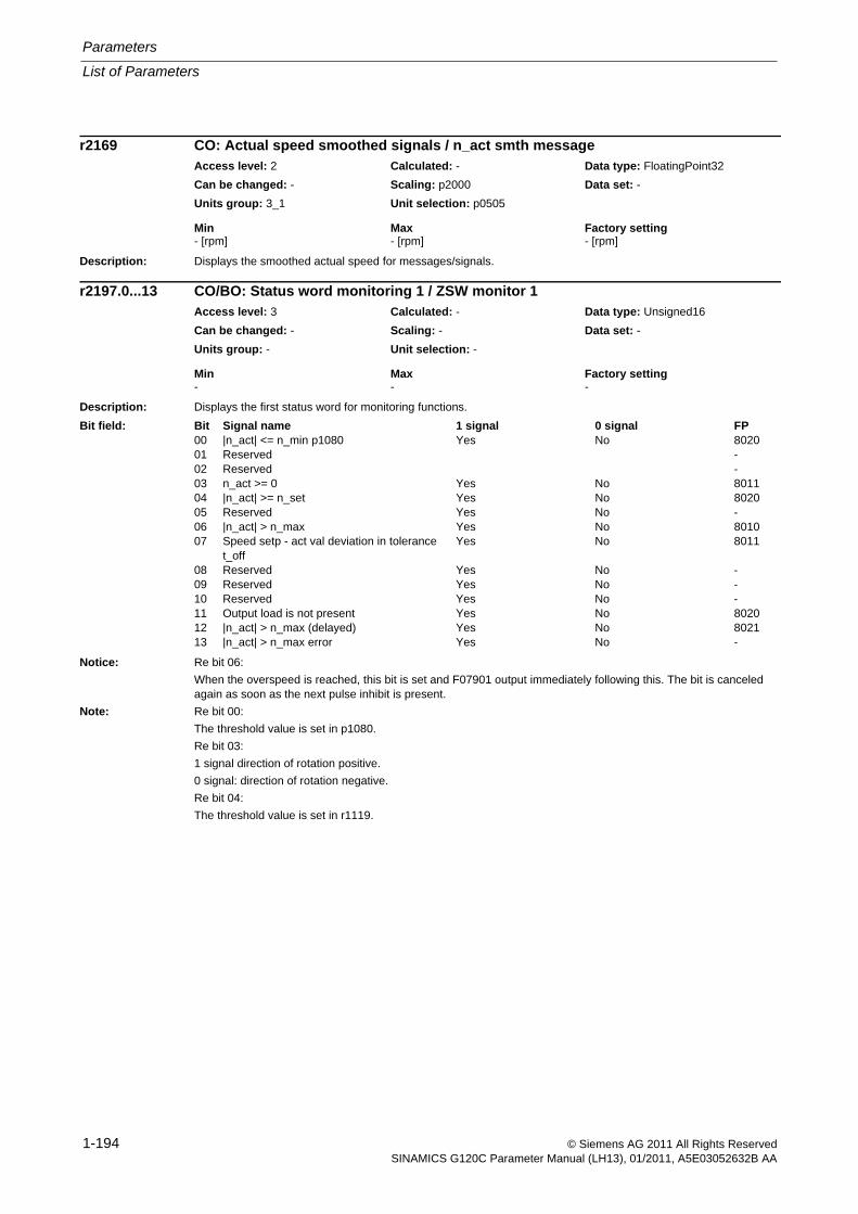
Parameters
List of Parameters
1-194 © Siemens AG 2011 All Rights ReservedSINAMICS G120C Parameter Manual (LH13), 01/2011, A5E03052632B AA
Description: Displays the smoothed actual speed for messages/signals.
Description: Displays the first status word for monitoring functions.
Notice: Re bit 06:
When the overspeed is reached, this bit is set and F07901 output immediately following this. The bit is canceled again as soon as the next pulse inhibit is present.
Note: Re bit 00:
The threshold value is set in p1080.
Re bit 03:
1 signal direction of rotation positive.
0 signal: direction of rotation negative.
Re bit 04:
The threshold value is set in r1119.
r2169 CO: Actual speed smoothed signals / n_act smth messageAccess level: 2 Calculated: - Data type: FloatingPoint32
Can be changed: - Scaling: p2000 Data set: -
Units group: 3_1 Unit selection: p0505
Min Max Factory setting - [rpm] - [rpm] - [rpm]
r2197.0...13 CO/BO: Status word monitoring 1 / ZSW monitor 1Access level: 3 Calculated: - Data type: Unsigned16
Can be changed: - Scaling: - Data set: -
Units group: - Unit selection: -
Min Max Factory setting - - -
Bit field: Bit Signal name 1 signal 0 signal FP00 |n_act| <= n_min p1080 Yes No 802001 Reserved -02 Reserved -03 n_act >= 0 Yes No 801104 |n_act| >= n_set Yes No 802005 Reserved Yes No -06 |n_act| > n_max Yes No 801007 Speed setp - act val deviation in tolerance
t_offYes No 8011
08 Reserved Yes No -09 Reserved Yes No -10 Reserved Yes No -11 Output load is not present Yes No 802012 |n_act| > n_max (delayed) Yes No 802113 |n_act| > n_max error Yes No -
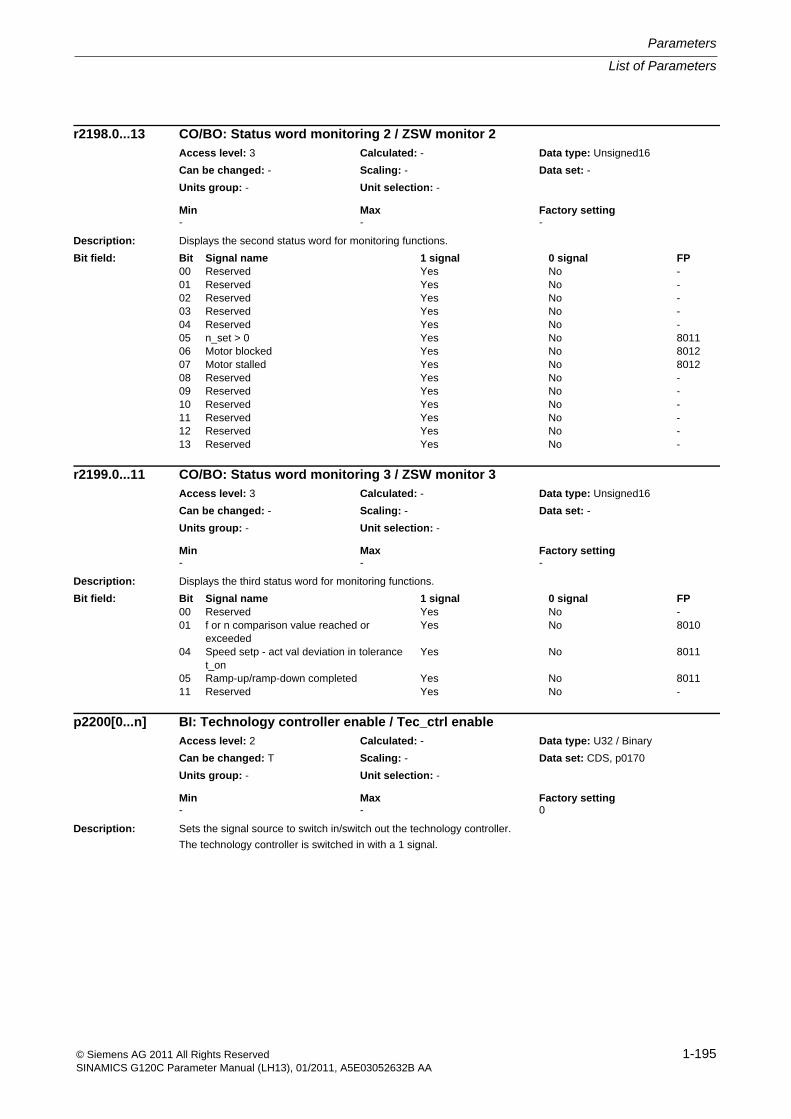
List of Parameters
Parameters
1-195© Siemens AG 2011 All Rights ReservedSINAMICS G120C Parameter Manual (LH13), 01/2011, A5E03052632B AA
Description: Displays the second status word for monitoring functions.
Description: Displays the third status word for monitoring functions.
Description: Sets the signal source to switch in/switch out the technology controller.
The technology controller is switched in with a 1 signal.
r2198.0...13 CO/BO: Status word monitoring 2 / ZSW monitor 2Access level: 3 Calculated: - Data type: Unsigned16
Can be changed: - Scaling: - Data set: -
Units group: - Unit selection: -
Min Max Factory setting - - -
Bit field: Bit Signal name 1 signal 0 signal FP00 Reserved Yes No -01 Reserved Yes No -02 Reserved Yes No -03 Reserved Yes No -04 Reserved Yes No -05 n_set > 0 Yes No 801106 Motor blocked Yes No 801207 Motor stalled Yes No 801208 Reserved Yes No -09 Reserved Yes No -10 Reserved Yes No -11 Reserved Yes No -12 Reserved Yes No -13 Reserved Yes No -
r2199.0...11 CO/BO: Status word monitoring 3 / ZSW monitor 3Access level: 3 Calculated: - Data type: Unsigned16
Can be changed: - Scaling: - Data set: -
Units group: - Unit selection: -
Min Max Factory setting - - -
Bit field: Bit Signal name 1 signal 0 signal FP00 Reserved Yes No -01 f or n comparison value reached or
exceededYes No 8010
04 Speed setp - act val deviation in tolerance t_on
Yes No 8011
05 Ramp-up/ramp-down completed Yes No 801111 Reserved Yes No -
p2200[0...n] BI: Technology controller enable / Tec_ctrl enableAccess level: 2 Calculated: - Data type: U32 / Binary
Can be changed: T Scaling: - Data set: CDS, p0170
Units group: - Unit selection: -
Min Max Factory setting - - 0
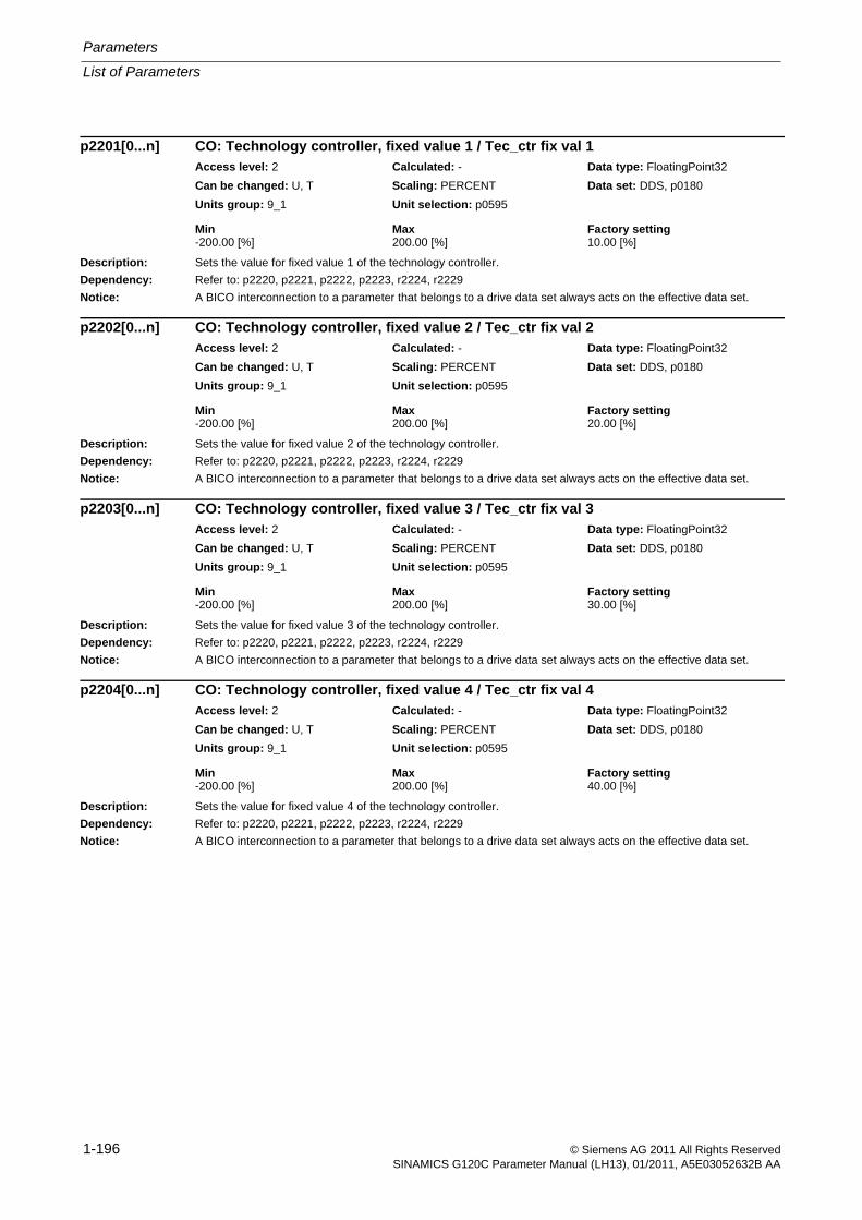
Parameters
List of Parameters
1-196 © Siemens AG 2011 All Rights ReservedSINAMICS G120C Parameter Manual (LH13), 01/2011, A5E03052632B AA
Description: Sets the value for fixed value 1 of the technology controller.
Dependency: Refer to: p2220, p2221, p2222, p2223, r2224, r2229
Notice: A BICO interconnection to a parameter that belongs to a drive data set always acts on the effective data set.
Description: Sets the value for fixed value 2 of the technology controller.
Dependency: Refer to: p2220, p2221, p2222, p2223, r2224, r2229
Notice: A BICO interconnection to a parameter that belongs to a drive data set always acts on the effective data set.
Description: Sets the value for fixed value 3 of the technology controller.
Dependency: Refer to: p2220, p2221, p2222, p2223, r2224, r2229
Notice: A BICO interconnection to a parameter that belongs to a drive data set always acts on the effective data set.
Description: Sets the value for fixed value 4 of the technology controller.
Dependency: Refer to: p2220, p2221, p2222, p2223, r2224, r2229
Notice: A BICO interconnection to a parameter that belongs to a drive data set always acts on the effective data set.
p2201[0...n] CO: Technology controller, fixed value 1 / Tec_ctr fix val 1Access level: 2 Calculated: - Data type: FloatingPoint32
Can be changed: U, T Scaling: PERCENT Data set: DDS, p0180
Units group: 9_1 Unit selection: p0595
Min Max Factory setting -200.00 [%] 200.00 [%] 10.00 [%]
p2202[0...n] CO: Technology controller, fixed value 2 / Tec_ctr fix val 2Access level: 2 Calculated: - Data type: FloatingPoint32
Can be changed: U, T Scaling: PERCENT Data set: DDS, p0180
Units group: 9_1 Unit selection: p0595
Min Max Factory setting -200.00 [%] 200.00 [%] 20.00 [%]
p2203[0...n] CO: Technology controller, fixed value 3 / Tec_ctr fix val 3Access level: 2 Calculated: - Data type: FloatingPoint32
Can be changed: U, T Scaling: PERCENT Data set: DDS, p0180
Units group: 9_1 Unit selection: p0595
Min Max Factory setting -200.00 [%] 200.00 [%] 30.00 [%]
p2204[0...n] CO: Technology controller, fixed value 4 / Tec_ctr fix val 4Access level: 2 Calculated: - Data type: FloatingPoint32
Can be changed: U, T Scaling: PERCENT Data set: DDS, p0180
Units group: 9_1 Unit selection: p0595
Min Max Factory setting -200.00 [%] 200.00 [%] 40.00 [%]
List of Parameters
Parameters
1-197© Siemens AG 2011 All Rights ReservedSINAMICS G120C Parameter Manual (LH13), 01/2011, A5E03052632B AA
Description: Sets the value for fixed value 5 of the technology controller.
Dependency: Refer to: p2220, p2221, p2222, p2223, r2224, r2229
Notice: A BICO interconnection to a parameter that belongs to a drive data set always acts on the effective data set.
Description: Sets the value for fixed value 6 of the technology controller.
Dependency: Refer to: p2220, p2221, p2222, p2223, r2224, r2229
Notice: A BICO interconnection to a parameter that belongs to a drive data set always acts on the effective data set.
Description: Sets the value for fixed value 7 of the technology controller.
Dependency: Refer to: p2220, p2221, p2222, p2223, r2224, r2229
Notice: A BICO interconnection to a parameter that belongs to a drive data set always acts on the effective data set.
Description: Sets the value for fixed value 8 of the technology controller.
Dependency: Refer to: p2220, p2221, p2222, p2223, r2224, r2229
Notice: A BICO interconnection to a parameter that belongs to a drive data set always acts on the effective data set.
p2205[0...n] CO: Technology controller, fixed value 5 / Tec_ctr fix val 5Access level: 2 Calculated: - Data type: FloatingPoint32
Can be changed: U, T Scaling: PERCENT Data set: DDS, p0180
Units group: 9_1 Unit selection: p0595
Min Max Factory setting -200.00 [%] 200.00 [%] 50.00 [%]
p2206[0...n] CO: Technology controller, fixed value 6 / Tec_ctr fix val 6Access level: 2 Calculated: - Data type: FloatingPoint32
Can be changed: U, T Scaling: PERCENT Data set: DDS, p0180
Units group: 9_1 Unit selection: p0595
Min Max Factory setting -200.00 [%] 200.00 [%] 60.00 [%]
p2207[0...n] CO: Technology controller, fixed value 7 / Tec_ctr fix val 7Access level: 2 Calculated: - Data type: FloatingPoint32
Can be changed: U, T Scaling: PERCENT Data set: DDS, p0180
Units group: 9_1 Unit selection: p0595
Min Max Factory setting -200.00 [%] 200.00 [%] 70.00 [%]
p2208[0...n] CO: Technology controller, fixed value 8 / Tec_ctr fix val 8Access level: 2 Calculated: - Data type: FloatingPoint32
Can be changed: U, T Scaling: PERCENT Data set: DDS, p0180
Units group: 9_1 Unit selection: p0595
Min Max Factory setting -200.00 [%] 200.00 [%] 80.00 [%]

Parameters
List of Parameters
1-198 © Siemens AG 2011 All Rights ReservedSINAMICS G120C Parameter Manual (LH13), 01/2011, A5E03052632B AA
Description: Sets the value for fixed value 9 of the technology controller.
Dependency: Refer to: p2220, p2221, p2222, p2223, r2224, r2229
Notice: A BICO interconnection to a parameter that belongs to a drive data set always acts on the effective data set.
Description: Sets the value for fixed value 10 of the technology controller.
Dependency: Refer to: p2220, p2221, p2222, p2223, r2224, r2229
Notice: A BICO interconnection to a parameter that belongs to a drive data set always acts on the effective data set.
Description: Sets the value for fixed value 11 of the technology controller.
Dependency: Refer to: p2220, p2221, p2222, p2223, r2224, r2229
Notice: A BICO interconnection to a parameter that belongs to a drive data set always acts on the effective data set.
Description: Sets the value for fixed value 12 of the technology controller.
Dependency: Refer to: p2220, p2221, p2222, p2223, r2224, r2229
Notice: A BICO interconnection to a parameter that belongs to a drive data set always acts on the effective data set.
p2209[0...n] CO: Technology controller, fixed value 9 / Tec_ctr fix val 9Access level: 2 Calculated: - Data type: FloatingPoint32
Can be changed: U, T Scaling: PERCENT Data set: DDS, p0180
Units group: 9_1 Unit selection: p0595
Min Max Factory setting -200.00 [%] 200.00 [%] 90.00 [%]
p2210[0...n] CO: Technology controller, fixed value 10 / Tec_ctr fix val 10Access level: 2 Calculated: - Data type: FloatingPoint32
Can be changed: U, T Scaling: PERCENT Data set: DDS, p0180
Units group: 9_1 Unit selection: p0595
Min Max Factory setting -200.00 [%] 200.00 [%] 100.00 [%]
p2211[0...n] CO: Technology controller, fixed value 11 / Tec_ctr fix val 11Access level: 2 Calculated: - Data type: FloatingPoint32
Can be changed: U, T Scaling: PERCENT Data set: DDS, p0180
Units group: 9_1 Unit selection: p0595
Min Max Factory setting -200.00 [%] 200.00 [%] 110.00 [%]
p2212[0...n] CO: Technology controller, fixed value 12 / Tec_ctr fix val 12Access level: 2 Calculated: - Data type: FloatingPoint32
Can be changed: U, T Scaling: PERCENT Data set: DDS, p0180
Units group: 9_1 Unit selection: p0595
Min Max Factory setting -200.00 [%] 200.00 [%] 120.00 [%]
List of Parameters
Parameters
1-199© Siemens AG 2011 All Rights ReservedSINAMICS G120C Parameter Manual (LH13), 01/2011, A5E03052632B AA
Description: Sets the value for fixed value 13 of the technology controller.
Dependency: Refer to: p2220, p2221, p2222, p2223, r2224, r2229
Notice: A BICO interconnection to a parameter that belongs to a drive data set always acts on the effective data set.
Description: Sets the value for fixed value 14 of the technology controller.
Dependency: Refer to: p2220, p2221, p2222, p2223, r2224, r2229
Notice: A BICO interconnection to a parameter that belongs to a drive data set always acts on the effective data set.
Description: Sets the value for fixed value 15 of the technology controller.
Dependency: Refer to: p2220, p2221, p2222, p2223, r2224, r2229
Notice: A BICO interconnection to a parameter that belongs to a drive data set always acts on the effective data set.
Description: Selects the method that can be used to select the fixed setpoints.
Value: 1: Fixed value selection direct2: Fixed value selection binary
Description: Sets the signal source to select the fixed value of the technology controller.
Dependency: Refer to: p2221, p2222, p2223
p2213[0...n] CO: Technology controller, fixed value 13 / Tec_ctr fix val 13Access level: 2 Calculated: - Data type: FloatingPoint32
Can be changed: U, T Scaling: PERCENT Data set: DDS, p0180
Units group: 9_1 Unit selection: p0595
Min Max Factory setting -200.00 [%] 200.00 [%] 130.00 [%]
p2214[0...n] CO: Technology controller, fixed value 14 / Tec_ctr fix val 14Access level: 2 Calculated: - Data type: FloatingPoint32
Can be changed: U, T Scaling: PERCENT Data set: DDS, p0180
Units group: 9_1 Unit selection: p0595
Min Max Factory setting -200.00 [%] 200.00 [%] 140.00 [%]
p2215[0...n] CO: Technology controller, fixed value 15 / Tec_ctr fix val 15Access level: 2 Calculated: - Data type: FloatingPoint32
Can be changed: U, T Scaling: PERCENT Data set: DDS, p0180
Units group: 9_1 Unit selection: p0595
Min Max Factory setting -200.00 [%] 200.00 [%] 150.00 [%]
p2216[0...n] Technology controller fixed value selection method / Tec_ctr FixVal selAccess level: 2 Calculated: - Data type: Integer16
Can be changed: T Scaling: - Data set: DDS, p0180
Units group: - Unit selection: -
Min Max Factory setting 1 2 1
p2220[0...n] BI: Technology controller fixed value selection bit 0 / Tec_ctrl sel bit 0Access level: 3 Calculated: - Data type: U32 / Binary
Can be changed: T Scaling: - Data set: CDS, p0170
Units group: - Unit selection: -
Min Max Factory setting - - 0
Parameters
List of Parameters
1-200 © Siemens AG 2011 All Rights ReservedSINAMICS G120C Parameter Manual (LH13), 01/2011, A5E03052632B AA
Description: Sets the signal source to select the fixed value of the technology controller.
Dependency: Refer to: p2220, p2222, p2223
Description: Sets the signal source to select the fixed value of the technology controller.
Dependency: Refer to: p2220, p2221, p2223
Description: Sets the signal source to select the fixed value of the technology controller.
Dependency: Refer to: p2220, p2221, p2222
Description: Displays the selected and effective fixed value of the technology controller.
Dependency: Refer to: r2229
Description: Displays the status word for the fixed value selection of the technology controller.
p2221[0...n] BI: Technology controller fixed value selection bit 1 / Tec_ctrl sel bit 1Access level: 3 Calculated: - Data type: U32 / Binary
Can be changed: T Scaling: - Data set: CDS, p0170
Units group: - Unit selection: -
Min Max Factory setting - - 0
p2222[0...n] BI: Technology controller fixed value selection bit 2 / Tec_ctrl sel bit 2Access level: 3 Calculated: - Data type: U32 / Binary
Can be changed: T Scaling: - Data set: CDS, p0170
Units group: - Unit selection: -
Min Max Factory setting - - 0
p2223[0...n] BI: Technology controller fixed value selection bit 3 / Tec_ctrl sel bit 3Access level: 3 Calculated: - Data type: U32 / Binary
Can be changed: T Scaling: - Data set: CDS, p0170
Units group: - Unit selection: -
Min Max Factory setting - - 0
r2224 CO: Technology controller, fixed value effective / Tec_ctr FixVal effAccess level: 3 Calculated: - Data type: FloatingPoint32
Can be changed: - Scaling: PERCENT Data set: -
Units group: 9_1 Unit selection: p0595
Min Max Factory setting - [%] - [%] - [%]
r2225.0 CO/BO: Technology controller fixed value selection status word / Tec_ctr FixVal ZSWAccess level: 3 Calculated: - Data type: Unsigned16
Can be changed: - Scaling: - Data set: -
Units group: - Unit selection: -
Min Max Factory setting - - -
Bit field: Bit Signal name 1 signal 0 signal FP00 Technology controller fixed value selected Yes No 7950,
7951
List of Parameters
Parameters
1-201© Siemens AG 2011 All Rights ReservedSINAMICS G120C Parameter Manual (LH13), 01/2011, A5E03052632B AA
Description: Displays the number of the selected fixed setpoint of the technology controller.Dependency: Refer to: r2224
Description: Sets the configuration for the motorized potentiometer of the technology controller.
Dependency: Refer to: r2231, p2240Notice: For p0014 = 1, the following applies:
After the value has been modified, no further parameter modifications can be made and the status is shown in r3996. Modifications can be made again when r3996 = 0.
Note: Re bit 00:0: The setpoint for the motorized potentiometer is not saved and after ON is entered using p2240.1: The setpoint for the motorized potentiometer is saved and after ON is entered using r2231. In order to save in a non-volatile fashion, bit 03 should be set to 1.Re bit 02:0: Without initial rounding-off1: With initial rounding-off.The selected ramp-up/down time is correspondingly exceeded. The initial rounding-off is a sensitive way of specify-ing small changes (progressive reaction when keys are pressed). The jerk for initial rounding is independent of the ramp-up time and only depends on the selected maximum value (p2237).It is calculated as follows:r = 0.0001 x max(p2237, |p2238| ) [%] / 0.13^2 [s^2]The jerk is effective until the maximum acceleration is reached (a_max = p2237 [%] / p2247 [s] or a_max = p2238 [%] / p2248 [s]), after which the drive continues to run linearly with constant acceleration. The higher the maximum acceleration (the lower that p2247 is), the longer the ramp-up time increases with respect to the set ramp-up time.Re bit 03:0: Non-volatile data save de-activated.1. The setpoint for the motorized potentiometer is saved in a non-volatile fashion (for p2230.0 = 1).Re bit 04:When the bit is set, the ramp-function generator is computed independent of the pulse enable. The actual output value of the motorized potentiometer is always in r2250.
Description: Displays the setpoint memory for the motorized potentiometer of the technology controller.For p2230.0 = 1, the last setpoint that was saved is entered after ON.
Dependency: Refer to: p2230
r2229 Technology controller number actual / Tec_ctrl No. actAccess level: 3 Calculated: - Data type: Unsigned32
Can be changed: - Scaling: - Data set: -
Units group: - Unit selection: -
Min Max Factory setting - - -
p2230[0...n] Technology controller motorized potentiometer configuration / Tec_ctr mop configAccess level: 3 Calculated: - Data type: Unsigned32
Can be changed: U, T Scaling: - Data set: DDS, p0180
Units group: - Unit selection: -
Min Max Factory setting - - 0000 0100 bin
Bit field: Bit Signal name 1 signal 0 signal FP00 Data save active Yes No -02 Initial rounding-off active Yes No -03 Non-volatile data save active for p2230.0 = 1 Yes No -04 Ramp-function generator always active Yes No -
r2231 Technology controller motorized potentiometer setpoint memory / Tec_ctrl mop memAccess level: 3 Calculated: - Data type: FloatingPoint32
Can be changed: - Scaling: - Data set: -
Units group: 9_1 Unit selection: p0595
Min Max Factory setting - [%] - [%] - [%]
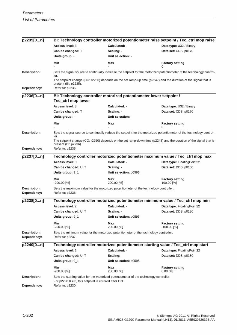
Parameters
List of Parameters
1-202 © Siemens AG 2011 All Rights ReservedSINAMICS G120C Parameter Manual (LH13), 01/2011, A5E03052632B AA
Description: Sets the signal source to continually increase the setpoint for the motorized potentiometer of the technology control-ler.The setpoint change (CO: r2250) depends on the set ramp-up time (p2247) and the duration of the signal that is present (BI: p2235).
Dependency: Refer to: p2236
Description: Sets the signal source to continually reduce the setpoint for the motorized potentiometer of the technology control-ler.The setpoint change (CO: r2250) depends on the set ramp-down time (p2248) and the duration of the signal that is present (BI: p2236).
Dependency: Refer to: p2235
Description: Sets the maximum value for the motorized potentiometer of the technology controller.Dependency: Refer to: p2238
Description: Sets the minimum value for the motorized potentiometer of the technology controller.Dependency: Refer to: p2237
Description: Sets the starting value for the motorized potentiometer of the technology controller.For p2230.0 = 0, this setpoint is entered after ON.
Dependency: Refer to: p2230
p2235[0...n] BI: Technology controller motorized potentiometer raise setpoint / Tec_ctrl mop raiseAccess level: 3 Calculated: - Data type: U32 / Binary
Can be changed: T Scaling: - Data set: CDS, p0170
Units group: - Unit selection: -
Min Max Factory setting - - 0
p2236[0...n] BI: Technology controller motorized potentiometer lower setpoint / Tec_ctrl mop lowerAccess level: 3 Calculated: - Data type: U32 / Binary
Can be changed: T Scaling: - Data set: CDS, p0170
Units group: - Unit selection: -
Min Max Factory setting - - 0
p2237[0...n] Technology controller motorized potentiometer maximum value / Tec_ctrl mop maxAccess level: 3 Calculated: - Data type: FloatingPoint32
Can be changed: U, T Scaling: - Data set: DDS, p0180
Units group: 9_1 Unit selection: p0595
Min Max Factory setting -200.00 [%] 200.00 [%] 100.00 [%]
p2238[0...n] Technology controller motorized potentiometer minimum value / Tec_ctrl mop minAccess level: 2 Calculated: - Data type: FloatingPoint32
Can be changed: U, T Scaling: - Data set: DDS, p0180
Units group: 9_1 Unit selection: p0595
Min Max Factory setting -200.00 [%] 200.00 [%] -100.00 [%]
p2240[0...n] Technology controller motorized potentiometer starting value / Tec_ctrl mop startAccess level: 2 Calculated: - Data type: FloatingPoint32
Can be changed: U, T Scaling: - Data set: DDS, p0180
Units group: 9_1 Unit selection: p0595
Min Max Factory setting -200.00 [%] 200.00 [%] 0.00 [%]
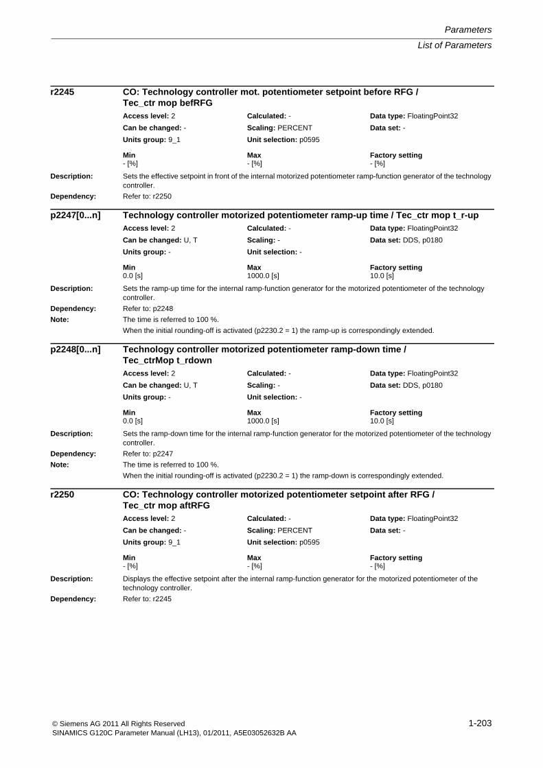
List of Parameters
Parameters
1-203© Siemens AG 2011 All Rights ReservedSINAMICS G120C Parameter Manual (LH13), 01/2011, A5E03052632B AA
Description: Sets the effective setpoint in front of the internal motorized potentiometer ramp-function generator of the technology controller.
Dependency: Refer to: r2250
Description: Sets the ramp-up time for the internal ramp-function generator for the motorized potentiometer of the technology controller.
Dependency: Refer to: p2248
Note: The time is referred to 100 %.
When the initial rounding-off is activated (p2230.2 = 1) the ramp-up is correspondingly extended.
Description: Sets the ramp-down time for the internal ramp-function generator for the motorized potentiometer of the technology controller.
Dependency: Refer to: p2247
Note: The time is referred to 100 %.
When the initial rounding-off is activated (p2230.2 = 1) the ramp-down is correspondingly extended.
Description: Displays the effective setpoint after the internal ramp-function generator for the motorized potentiometer of the technology controller.
Dependency: Refer to: r2245
r2245 CO: Technology controller mot. potentiometer setpoint before RFG / Tec_ctr mop befRFGAccess level: 2 Calculated: - Data type: FloatingPoint32
Can be changed: - Scaling: PERCENT Data set: -
Units group: 9_1 Unit selection: p0595
Min Max Factory setting - [%] - [%] - [%]
p2247[0...n] Technology controller motorized potentiometer ramp-up time / Tec_ctr mop t_r-upAccess level: 2 Calculated: - Data type: FloatingPoint32
Can be changed: U, T Scaling: - Data set: DDS, p0180
Units group: - Unit selection: -
Min Max Factory setting 0.0 [s] 1000.0 [s] 10.0 [s]
p2248[0...n] Technology controller motorized potentiometer ramp-down time / Tec_ctrMop t_rdownAccess level: 2 Calculated: - Data type: FloatingPoint32
Can be changed: U, T Scaling: - Data set: DDS, p0180
Units group: - Unit selection: -
Min Max Factory setting 0.0 [s] 1000.0 [s] 10.0 [s]
r2250 CO: Technology controller motorized potentiometer setpoint after RFG / Tec_ctr mop aftRFGAccess level: 2 Calculated: - Data type: FloatingPoint32
Can be changed: - Scaling: PERCENT Data set: -
Units group: 9_1 Unit selection: p0595
Min Max Factory setting - [%] - [%] - [%]
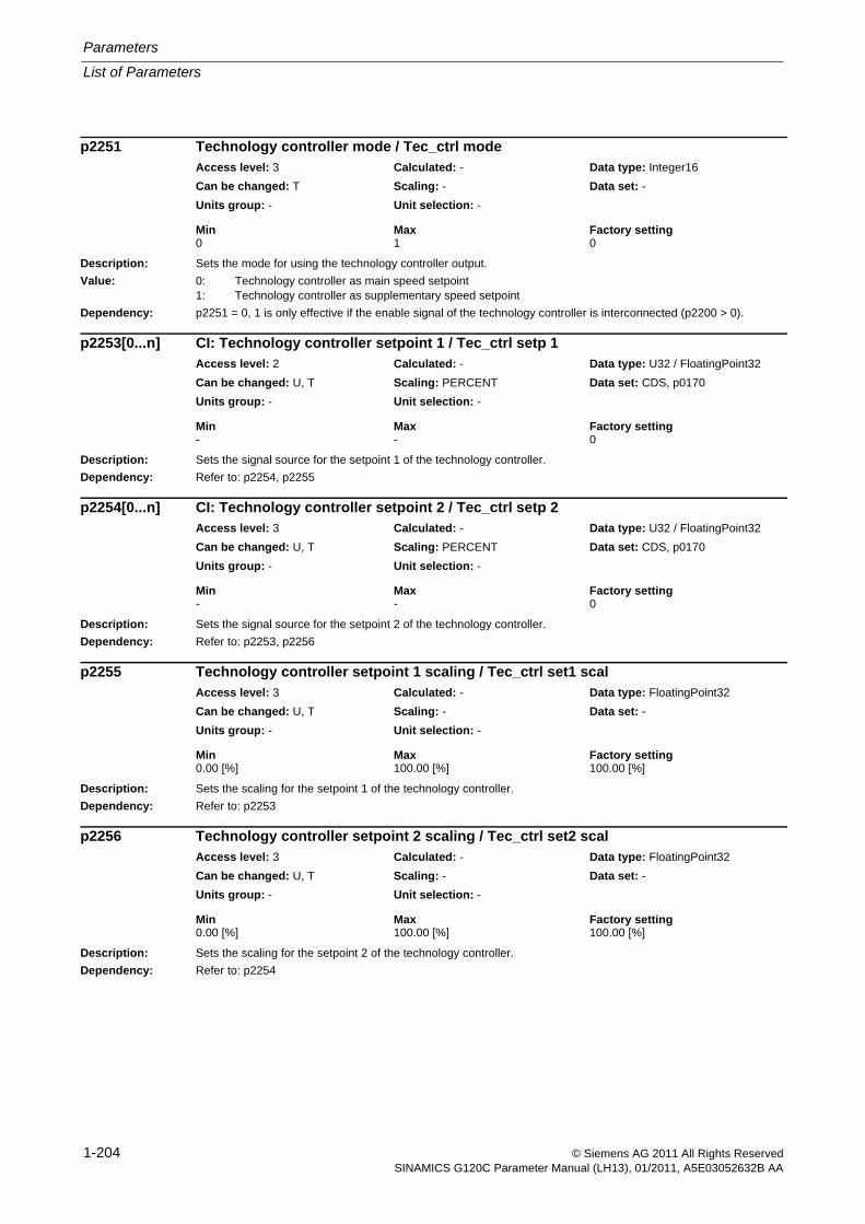
Parameters
List of Parameters
1-204 © Siemens AG 2011 All Rights ReservedSINAMICS G120C Parameter Manual (LH13), 01/2011, A5E03052632B AA
Description: Sets the mode for using the technology controller output.
Value: 0: Technology controller as main speed setpoint1: Technology controller as supplementary speed setpoint
Dependency: p2251 = 0, 1 is only effective if the enable signal of the technology controller is interconnected (p2200 > 0).
Description: Sets the signal source for the setpoint 1 of the technology controller.
Dependency: Refer to: p2254, p2255
Description: Sets the signal source for the setpoint 2 of the technology controller.
Dependency: Refer to: p2253, p2256
Description: Sets the scaling for the setpoint 1 of the technology controller.
Dependency: Refer to: p2253
Description: Sets the scaling for the setpoint 2 of the technology controller.
Dependency: Refer to: p2254
p2251 Technology controller mode / Tec_ctrl modeAccess level: 3 Calculated: - Data type: Integer16
Can be changed: T Scaling: - Data set: -
Units group: - Unit selection: -
Min Max Factory setting 0 1 0
p2253[0...n] CI: Technology controller setpoint 1 / Tec_ctrl setp 1Access level: 2 Calculated: - Data type: U32 / FloatingPoint32
Can be changed: U, T Scaling: PERCENT Data set: CDS, p0170
Units group: - Unit selection: -
Min Max Factory setting - - 0
p2254[0...n] CI: Technology controller setpoint 2 / Tec_ctrl setp 2Access level: 3 Calculated: - Data type: U32 / FloatingPoint32
Can be changed: U, T Scaling: PERCENT Data set: CDS, p0170
Units group: - Unit selection: -
Min Max Factory setting - - 0
p2255 Technology controller setpoint 1 scaling / Tec_ctrl set1 scalAccess level: 3 Calculated: - Data type: FloatingPoint32
Can be changed: U, T Scaling: - Data set: -
Units group: - Unit selection: -
Min Max Factory setting 0.00 [%] 100.00 [%] 100.00 [%]
p2256 Technology controller setpoint 2 scaling / Tec_ctrl set2 scalAccess level: 3 Calculated: - Data type: FloatingPoint32
Can be changed: U, T Scaling: - Data set: -
Units group: - Unit selection: -
Min Max Factory setting 0.00 [%] 100.00 [%] 100.00 [%]
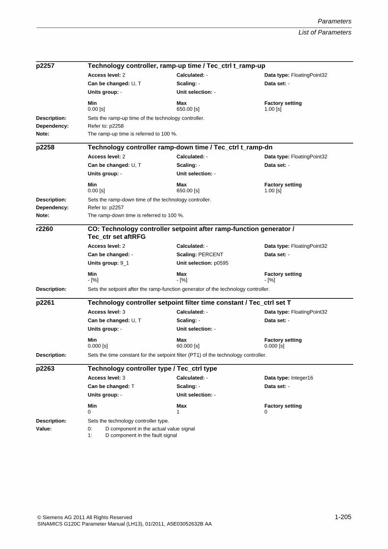
List of Parameters
Parameters
1-205© Siemens AG 2011 All Rights ReservedSINAMICS G120C Parameter Manual (LH13), 01/2011, A5E03052632B AA
Description: Sets the ramp-up time of the technology controller.
Dependency: Refer to: p2258
Note: The ramp-up time is referred to 100 %.
Description: Sets the ramp-down time of the technology controller.
Dependency: Refer to: p2257
Note: The ramp-down time is referred to 100 %.
Description: Sets the setpoint after the ramp-function generator of the technology controller.
Description: Sets the time constant for the setpoint filter (PT1) of the technology controller.
Description: Sets the technology controller type.
Value: 0: D component in the actual value signal1: D component in the fault signal
p2257 Technology controller, ramp-up time / Tec_ctrl t_ramp-upAccess level: 2 Calculated: - Data type: FloatingPoint32
Can be changed: U, T Scaling: - Data set: -
Units group: - Unit selection: -
Min Max Factory setting 0.00 [s] 650.00 [s] 1.00 [s]
p2258 Technology controller ramp-down time / Tec_ctrl t_ramp-dnAccess level: 2 Calculated: - Data type: FloatingPoint32
Can be changed: U, T Scaling: - Data set: -
Units group: - Unit selection: -
Min Max Factory setting 0.00 [s] 650.00 [s] 1.00 [s]
r2260 CO: Technology controller setpoint after ramp-function generator / Tec_ctr set aftRFGAccess level: 2 Calculated: - Data type: FloatingPoint32
Can be changed: - Scaling: PERCENT Data set: -
Units group: 9_1 Unit selection: p0595
Min Max Factory setting - [%] - [%] - [%]
p2261 Technology controller setpoint filter time constant / Tec_ctrl set TAccess level: 3 Calculated: - Data type: FloatingPoint32
Can be changed: U, T Scaling: - Data set: -
Units group: - Unit selection: -
Min Max Factory setting 0.000 [s] 60.000 [s] 0.000 [s]
p2263 Technology controller type / Tec_ctrl typeAccess level: 3 Calculated: - Data type: Integer16
Can be changed: T Scaling: - Data set: -
Units group: - Unit selection: -
Min Max Factory setting 0 1 0
Parameters
List of Parameters
1-206 © Siemens AG 2011 All Rights ReservedSINAMICS G120C Parameter Manual (LH13), 01/2011, A5E03052632B AA
Description: Sets the signal source for the actual value of the technology controller.
Description: Sets the time constant for the actual value filter (PT1) of the technology controller.
Description: Displays the smoothed actual value after the filter (PT1) of the technology controller
Description: Sets the upper limit for the actual value signal of the technology controller.
Dependency: Refer to: p2264, p2265, p2271
Refer to: F07426
Notice: If the actual value exceeds this upper limit, this results in fault F07426.
Description: Sets the lower limit for the actual value signal of the technology controller.
Dependency: Refer to: p2264, p2265, p2271
Refer to: F07426
Notice: If the actual value falls below this lower limit, this results in fault F07426.
p2264[0...n] CI: Technology controller actual value / Tec_ctrl act valAccess level: 2 Calculated: - Data type: U32 / FloatingPoint32
Can be changed: U, T Scaling: PERCENT Data set: CDS, p0170
Units group: - Unit selection: -
Min Max Factory setting - - 0
p2265 Technology controller actual value filter time constant / Tec_ctrl act TAccess level: 2 Calculated: - Data type: FloatingPoint32
Can be changed: U, T Scaling: - Data set: -
Units group: - Unit selection: -
Min Max Factory setting 0.000 [s] 60.000 [s] 0.000 [s]
r2266 CO: Technology controller actual value after filter / Tec_ctr act aftFltAccess level: 3 Calculated: - Data type: FloatingPoint32
Can be changed: - Scaling: PERCENT Data set: -
Units group: 9_1 Unit selection: p0595
Min Max Factory setting - [%] - [%] - [%]
p2267 Technology controller upper limit actual value / Tec_ctrl u_lim actAccess level: 3 Calculated: - Data type: FloatingPoint32
Can be changed: U, T Scaling: PERCENT Data set: -
Units group: 9_1 Unit selection: p0595
Min Max Factory setting -200.00 [%] 200.00 [%] 100.00 [%]
p2268 Technology controller lower limit actual value / Tec_ctrl l_lim actAccess level: 3 Calculated: - Data type: FloatingPoint32
Can be changed: U, T Scaling: PERCENT Data set: -
Units group: 9_1 Unit selection: p0595
Min Max Factory setting -200.00 [%] 200.00 [%] -100.00 [%]
List of Parameters
Parameters
1-207© Siemens AG 2011 All Rights ReservedSINAMICS G120C Parameter Manual (LH13), 01/2011, A5E03052632B AA
Description: Scaling factor for the actual value of the technology controller.
Dependency: Refer to: p2264, p2265, p2267, p2268, p2271
Note: For 100%, the actual value is not changed.
Description: Setting to use an arithmetic function for the actual value signal of the technology controller.
Value: 0: No function1: Root function (root from x)2: Square function (x * x)3: Cube function (x * x * x)
Dependency: Refer to: p2264, p2265, p2267, p2268, p2269, p2271
Description: Setting to invert the actual value signal of the technology controller.
The inversion depends on the sensor type for the actual value signal.
Value: 0: No inversion1: Inversion actual value signal
Caution: If the actual value inversion is incorrectly selected, then the closed-loop control with the technology controller can become unstable and can oscillate!
Note: The correct setting can be determined as follows:
- inhibit the technology controller (p2200 = 0).
- increase the motor speed and in so doing, measure the actual value signal of the technology controller.
--> If the actual value increases as the motor speed increases, then p2271 should be set to 0 (no inversion).
--> If the actual value decreases as the motor speed increases, then p2271 should be set to 1 (the actual value sig-nal is inverted).
Description: Displays the scaled actual value signal of the technology controller.
Dependency: Refer to: p2264, p2265, r2266, p2267, p2268, p2269, p2270, p2271
p2269 Technology controller gain actual value / Tech_ctrl gain actAccess level: 3 Calculated: - Data type: FloatingPoint32
Can be changed: U, T Scaling: - Data set: -
Units group: - Unit selection: -
Min Max Factory setting 0.00 [%] 500.00 [%] 100.00 [%]
p2270 Technology controller actual value function / Tec_ctr ActVal fctAccess level: 3 Calculated: - Data type: Integer16
Can be changed: U, T Scaling: - Data set: -
Units group: - Unit selection: -
Min Max Factory setting 0 3 0
p2271 Technology controller actual value inversion (sensor type) / Tech_ctrl act invAccess level: 3 Calculated: - Data type: Integer16
Can be changed: T Scaling: - Data set: -
Units group: - Unit selection: -
Min Max Factory setting 0 1 0
r2272 CO: Technology controller actual value scaled / Tech_ctrl act scalAccess level: 2 Calculated: - Data type: FloatingPoint32
Can be changed: - Scaling: PERCENT Data set: -
Units group: 9_1 Unit selection: p0595
Min Max Factory setting - [%] - [%] - [%]
Parameters
List of Parameters
1-208 © Siemens AG 2011 All Rights ReservedSINAMICS G120C Parameter Manual (LH13), 01/2011, A5E03052632B AA
Description: Displays the error (system deviation) between the setpoint and actual value of the technology controller.
Dependency: Refer to: p2263
Description: Sets the time constant for the differentiation (D component) of the technology controller.
Note: p2274 = 0: Differentiation is disabled.
Description: Sets the proportional gain (P component) of the technology controller.
Note: p2280 = 0: The proportional gain is disabled.
Description: Sets the integral time (I component, integrating time constant) of the technology controller.
Notice: The following applies for p2251 = 0:
If the output of the technology controller lies within the range of a suppression (skip) bandwidth (p1091 ... p1092, p1101) or below the minimum speed (p1080), the integral component of the controller is held so that the controller temporarily works as a P controller. This is necessary in order to prevent the controller from behaving in an unstable manner, as the ramp-function generator switches to the parameterized up and down ramps (p1120, p1121) at the same time in order to avoid setpoint steps. This state can be exited or avoided by changing the controller setpoint or by using the start speed (= minimum speed).
Note: When the controller output reaches the limit, the I component of the controller is held.
p2285 = 0:
The integral time is disabled and the I component of the controller is reset.
r2273 CO: Technology controller error / Tec_ctrl errorAccess level: 2 Calculated: - Data type: FloatingPoint32
Can be changed: - Scaling: PERCENT Data set: -
Units group: 9_1 Unit selection: p0595
Min Max Factory setting - [%] - [%] - [%]
p2274 Technology controller differentiation, time constant / Tec_ctrl D comp TAccess level: 2 Calculated: - Data type: FloatingPoint32
Can be changed: U, T Scaling: - Data set: -
Units group: - Unit selection: -
Min Max Factory setting 0.000 [s] 60.000 [s] 0.000 [s]
p2280 Technology controller proportional gain / Tec_ctrl KpAccess level: 2 Calculated: - Data type: FloatingPoint32
Can be changed: U, T Scaling: - Data set: -
Units group: - Unit selection: -
Min Max Factory setting 0.000 1000.000 1.000
p2285 Technology controller integral time / Tec_ctrl TnAccess level: 2 Calculated: - Data type: FloatingPoint32
Can be changed: U, T Scaling: - Data set: -
Units group: - Unit selection: -
Min Max Factory setting 0.000 [s] 10000.000 [s] 30.000 [s]
List of Parameters
Parameters
1-209© Siemens AG 2011 All Rights ReservedSINAMICS G120C Parameter Manual (LH13), 01/2011, A5E03052632B AA
Description: Sets the signal source to hold the integrator for the technology controller.
Description: Sets the signal source for the pre-control signal of the technology controller.
Description: Sets the maximum limit of the technology controller.
Dependency: Refer to: p2292
Caution: The maximum limit must always be greater than the minimum limit (p2291 > p2292).
Description: Sets the minimum limit of the technology controller.
Dependency: Refer to: p2291
Caution: The maximum limit must always be greater than the minimum limit (p2291 > p2292).
Description: Sets the ramping time for the output signal of the technology controller.
Dependency: Refer to: p2291, p2292
Note: The time refers to the set maximum and minimum limits (p2291, p2292).
p2286[0...n] BI: Hold technology controller integrator / Tec_ctr integ stopAccess level: 3 Calculated: - Data type: U32 / Binary
Can be changed: T Scaling: - Data set: CDS, p0170
Units group: - Unit selection: -
Min Max Factory setting - - 56.13
p2289[0...n] CI: Technology controller pre-control signal / Tec_ctrl prectrlAccess level: 3 Calculated: - Data type: U32 / FloatingPoint32
Can be changed: U, T Scaling: PERCENT Data set: CDS, p0170
Units group: - Unit selection: -
Min Max Factory setting - - 0
p2291 CO: Technology controller maximum limiting / Tec_ctrl max_limitAccess level: 3 Calculated: - Data type: FloatingPoint32
Can be changed: U, T Scaling: PERCENT Data set: -
Units group: - Unit selection: -
Min Max Factory setting -200.00 [%] 200.00 [%] 100.00 [%]
p2292 CO: Technology controller minimum limiting / Tec_ctrl min_limAccess level: 3 Calculated: - Data type: FloatingPoint32
Can be changed: U, T Scaling: PERCENT Data set: -
Units group: - Unit selection: -
Min Max Factory setting -200.00 [%] 200.00 [%] 0.00 [%]
p2293 Technology controller ramp-up/ramp-down time / Tec_ctr ramp up/dnAccess level: 3 Calculated: - Data type: FloatingPoint32
Can be changed: U, T Scaling: - Data set: -
Units group: - Unit selection: -
Min Max Factory setting 0.00 [s] 100.00 [s] 1.00 [s]
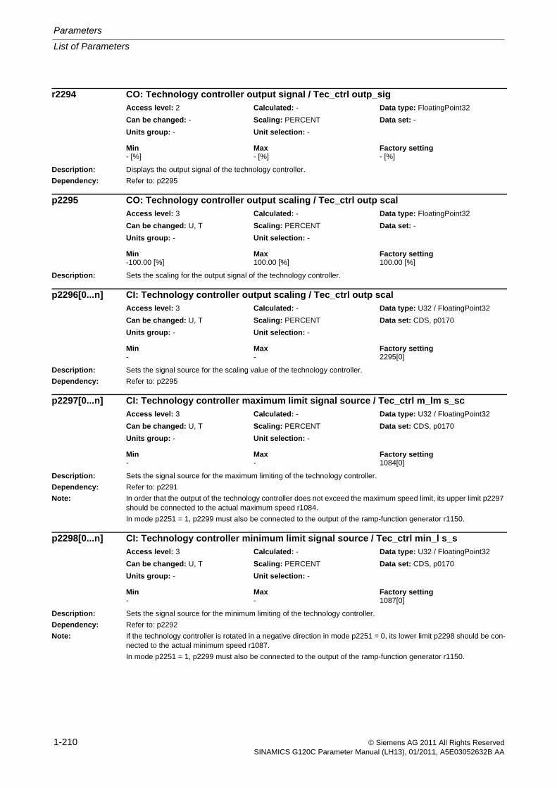
Parameters
List of Parameters
1-210 © Siemens AG 2011 All Rights ReservedSINAMICS G120C Parameter Manual (LH13), 01/2011, A5E03052632B AA
Description: Displays the output signal of the technology controller.
Dependency: Refer to: p2295
Description: Sets the scaling for the output signal of the technology controller.
Description: Sets the signal source for the scaling value of the technology controller.
Dependency: Refer to: p2295
Description: Sets the signal source for the maximum limiting of the technology controller.
Dependency: Refer to: p2291
Note: In order that the output of the technology controller does not exceed the maximum speed limit, its upper limit p2297 should be connected to the actual maximum speed r1084.
In mode p2251 = 1, p2299 must also be connected to the output of the ramp-function generator r1150.
Description: Sets the signal source for the minimum limiting of the technology controller.
Dependency: Refer to: p2292
Note: If the technology controller is rotated in a negative direction in mode p2251 = 0, its lower limit p2298 should be con-nected to the actual minimum speed r1087.
In mode p2251 = 1, p2299 must also be connected to the output of the ramp-function generator r1150.
r2294 CO: Technology controller output signal / Tec_ctrl outp_sigAccess level: 2 Calculated: - Data type: FloatingPoint32
Can be changed: - Scaling: PERCENT Data set: -
Units group: - Unit selection: -
Min Max Factory setting - [%] - [%] - [%]
p2295 CO: Technology controller output scaling / Tec_ctrl outp scalAccess level: 3 Calculated: - Data type: FloatingPoint32
Can be changed: U, T Scaling: PERCENT Data set: -
Units group: - Unit selection: -
Min Max Factory setting -100.00 [%] 100.00 [%] 100.00 [%]
p2296[0...n] CI: Technology controller output scaling / Tec_ctrl outp scalAccess level: 3 Calculated: - Data type: U32 / FloatingPoint32
Can be changed: U, T Scaling: PERCENT Data set: CDS, p0170
Units group: - Unit selection: -
Min Max Factory setting - - 2295[0]
p2297[0...n] CI: Technology controller maximum limit signal source / Tec_ctrl m_lm s_scAccess level: 3 Calculated: - Data type: U32 / FloatingPoint32
Can be changed: U, T Scaling: PERCENT Data set: CDS, p0170
Units group: - Unit selection: -
Min Max Factory setting - - 1084[0]
p2298[0...n] CI: Technology controller minimum limit signal source / Tec_ctrl min_l s_sAccess level: 3 Calculated: - Data type: U32 / FloatingPoint32
Can be changed: U, T Scaling: PERCENT Data set: CDS, p0170
Units group: - Unit selection: -
Min Max Factory setting - - 1087[0]
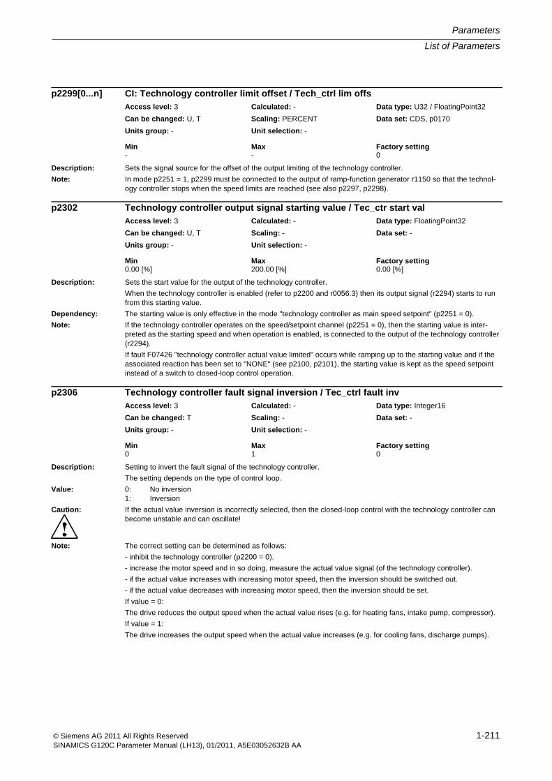
List of Parameters
Parameters
1-211© Siemens AG 2011 All Rights ReservedSINAMICS G120C Parameter Manual (LH13), 01/2011, A5E03052632B AA
Description: Sets the signal source for the offset of the output limiting of the technology controller.
Note: In mode p2251 = 1, p2299 must be connected to the output of ramp-function generator r1150 so that the technol-ogy controller stops when the speed limits are reached (see also p2297, p2298).
Description: Sets the start value for the output of the technology controller.
When the technology controller is enabled (refer to p2200 and r0056.3) then its output signal (r2294) starts to run from this starting value.
Dependency: The starting value is only effective in the mode "technology controller as main speed setpoint" (p2251 = 0).
Note: If the technology controller operates on the speed/setpoint channel (p2251 = 0), then the starting value is inter-preted as the starting speed and when operation is enabled, is connected to the output of the technology controller (r2294).
If fault F07426 "technology controller actual value limited" occurs while ramping up to the starting value and if the associated reaction has been set to "NONE" (see p2100, p2101), the starting value is kept as the speed setpoint instead of a switch to closed-loop control operation.
Description: Setting to invert the fault signal of the technology controller.
The setting depends on the type of control loop.
Value: 0: No inversion1: Inversion
Caution: If the actual value inversion is incorrectly selected, then the closed-loop control with the technology controller can become unstable and can oscillate!
Note: The correct setting can be determined as follows:
- inhibit the technology controller (p2200 = 0).
- increase the motor speed and in so doing, measure the actual value signal (of the technology controller).
- if the actual value increases with increasing motor speed, then the inversion should be switched out.
- if the actual value decreases with increasing motor speed, then the inversion should be set.
If value = 0:
The drive reduces the output speed when the actual value rises (e.g. for heating fans, intake pump, compressor).
If value = 1:
The drive increases the output speed when the actual value increases (e.g. for cooling fans, discharge pumps).
p2299[0...n] CI: Technology controller limit offset / Tech_ctrl lim offsAccess level: 3 Calculated: - Data type: U32 / FloatingPoint32
Can be changed: U, T Scaling: PERCENT Data set: CDS, p0170
Units group: - Unit selection: -
Min Max Factory setting - - 0
p2302 Technology controller output signal starting value / Tec_ctr start valAccess level: 3 Calculated: - Data type: FloatingPoint32
Can be changed: U, T Scaling: - Data set: -
Units group: - Unit selection: -
Min Max Factory setting 0.00 [%] 200.00 [%] 0.00 [%]
p2306 Technology controller fault signal inversion / Tec_ctrl fault invAccess level: 3 Calculated: - Data type: Integer16
Can be changed: T Scaling: - Data set: -
Units group: - Unit selection: -
Min Max Factory setting 0 1 0
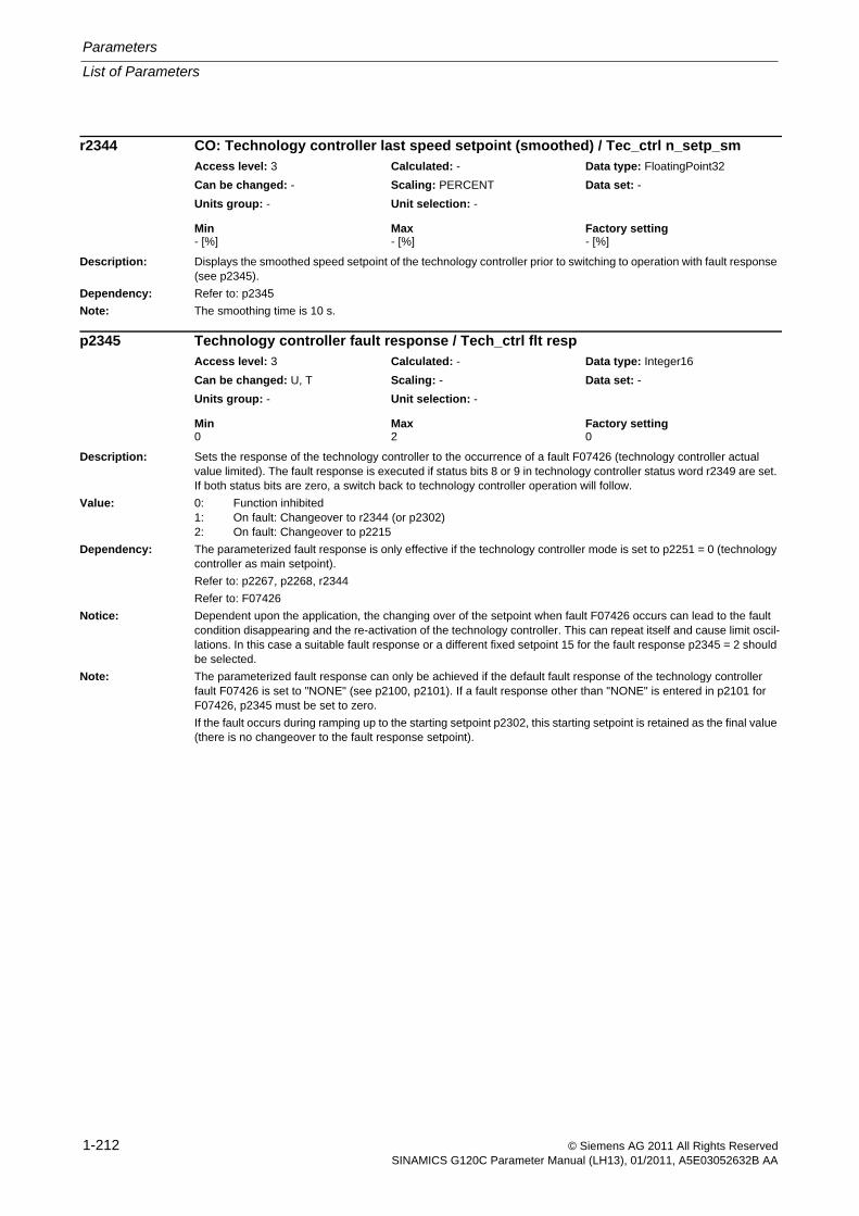
Parameters
List of Parameters
1-212 © Siemens AG 2011 All Rights ReservedSINAMICS G120C Parameter Manual (LH13), 01/2011, A5E03052632B AA
Description: Displays the smoothed speed setpoint of the technology controller prior to switching to operation with fault response (see p2345).
Dependency: Refer to: p2345
Note: The smoothing time is 10 s.
Description: Sets the response of the technology controller to the occurrence of a fault F07426 (technology controller actual value limited). The fault response is executed if status bits 8 or 9 in technology controller status word r2349 are set. If both status bits are zero, a switch back to technology controller operation will follow.
Value: 0: Function inhibited1: On fault: Changeover to r2344 (or p2302)2: On fault: Changeover to p2215
Dependency: The parameterized fault response is only effective if the technology controller mode is set to p2251 = 0 (technology controller as main setpoint).
Refer to: p2267, p2268, r2344
Refer to: F07426
Notice: Dependent upon the application, the changing over of the setpoint when fault F07426 occurs can lead to the fault condition disappearing and the re-activation of the technology controller. This can repeat itself and cause limit oscil-lations. In this case a suitable fault response or a different fixed setpoint 15 for the fault response p2345 = 2 should be selected.
Note: The parameterized fault response can only be achieved if the default fault response of the technology controller fault F07426 is set to "NONE" (see p2100, p2101). If a fault response other than "NONE" is entered in p2101 for F07426, p2345 must be set to zero.
If the fault occurs during ramping up to the starting setpoint p2302, this starting setpoint is retained as the final value (there is no changeover to the fault response setpoint).
r2344 CO: Technology controller last speed setpoint (smoothed) / Tec_ctrl n_setp_smAccess level: 3 Calculated: - Data type: FloatingPoint32
Can be changed: - Scaling: PERCENT Data set: -
Units group: - Unit selection: -
Min Max Factory setting - [%] - [%] - [%]
p2345 Technology controller fault response / Tech_ctrl flt respAccess level: 3 Calculated: - Data type: Integer16
Can be changed: U, T Scaling: - Data set: -
Units group: - Unit selection: -
Min Max Factory setting 0 2 0
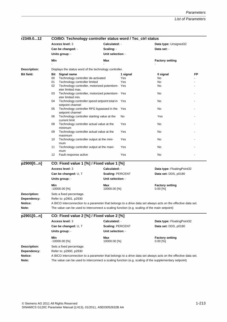
List of Parameters
Parameters
1-213© Siemens AG 2011 All Rights ReservedSINAMICS G120C Parameter Manual (LH13), 01/2011, A5E03052632B AA
Description: Displays the status word of the technology controller.
Description: Sets a fixed percentage.
Dependency: Refer to: p2901, p2930
Notice: A BICO interconnection to a parameter that belongs to a drive data set always acts on the effective data set.
Note: The value can be used to interconnect a scaling function (e.g. scaling of the main setpoint)
Description: Sets a fixed percentage.
Dependency: Refer to: p2900, p2930
Notice: A BICO interconnection to a parameter that belongs to a drive data set always acts on the effective data set.
Note: The value can be used to interconnect a scaling function (e.g. scaling of the supplementary setpoint)
r2349.0...12 CO/BO: Technology controller status word / Tec_ctrl statusAccess level: 3 Calculated: - Data type: Unsigned32
Can be changed: - Scaling: - Data set: -
Units group: - Unit selection: -
Min Max Factory setting - - -
Bit field: Bit Signal name 1 signal 0 signal FP00 Technology controller de-activated Yes No -01 Technology controller limited Yes No -02 Technology controller, motorized potentiom-
eter limited max.Yes No -
03 Technology controller, motorized potentiom-eter limited min.
Yes No -
04 Technology controller speed setpoint total in setpoint channel
Yes No -
05 Technology controller RFG bypassed in the setpoint channel
Yes No -
06 Technology controller starting value at the current limit
No Yes -
08 Technology controller actual value at the minimum
Yes No -
09 Technology controller actual value at the maximum
Yes No -
10 Technology controller output at the mini-mum
Yes No -
11 Technology controller output at the maxi-mum
Yes No -
12 Fault response active Yes No -
p2900[0...n] CO: Fixed value 1 [%] / Fixed value 1 [%]Access level: 3 Calculated: - Data type: FloatingPoint32
Can be changed: U, T Scaling: PERCENT Data set: DDS, p0180
Units group: - Unit selection: -
Min Max Factory setting -10000.00 [%] 10000.00 [%] 0.00 [%]
p2901[0...n] CO: Fixed value 2 [%] / Fixed value 2 [%]Access level: 3 Calculated: - Data type: FloatingPoint32
Can be changed: U, T Scaling: PERCENT Data set: DDS, p0180
Units group: - Unit selection: -
Min Max Factory setting -10000.00 [%] 10000.00 [%] 0.00 [%]
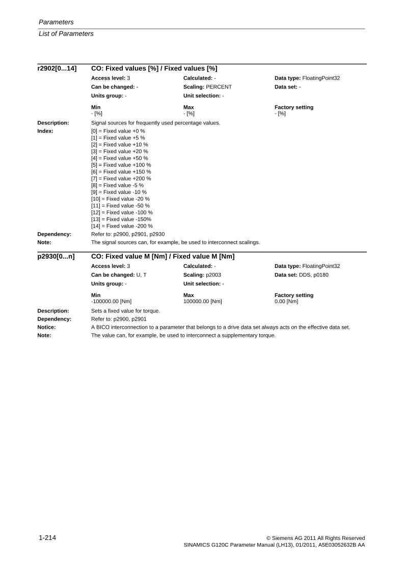
Parameters
List of Parameters
1-214 © Siemens AG 2011 All Rights ReservedSINAMICS G120C Parameter Manual (LH13), 01/2011, A5E03052632B AA
Description: Signal sources for frequently used percentage values.
Index: [0] = Fixed value +0 %[1] = Fixed value +5 %[2] = Fixed value +10 %[3] = Fixed value +20 %[4] = Fixed value +50 %[5] = Fixed value +100 %[6] = Fixed value +150 %[7] = Fixed value +200 %[8] = Fixed value -5 %[9] = Fixed value -10 %[10] = Fixed value -20 %[11] = Fixed value -50 %[12] = Fixed value -100 %[13] = Fixed value -150%[14] = Fixed value -200 %
Dependency: Refer to: p2900, p2901, p2930
Note: The signal sources can, for example, be used to interconnect scalings.
Description: Sets a fixed value for torque.
Dependency: Refer to: p2900, p2901
Notice: A BICO interconnection to a parameter that belongs to a drive data set always acts on the effective data set.
Note: The value can, for example, be used to interconnect a supplementary torque.
r2902[0...14] CO: Fixed values [%] / Fixed values [%]Access level: 3 Calculated: - Data type: FloatingPoint32
Can be changed: - Scaling: PERCENT Data set: -
Units group: - Unit selection: -
Min Max Factory setting - [%] - [%] - [%]
p2930[0...n] CO: Fixed value M [Nm] / Fixed value M [Nm]Access level: 3 Calculated: - Data type: FloatingPoint32
Can be changed: U, T Scaling: p2003 Data set: DDS, p0180
Units group: - Unit selection: -
Min Max Factory setting -100000.00 [Nm] 100000.00 [Nm] 0.00 [Nm]
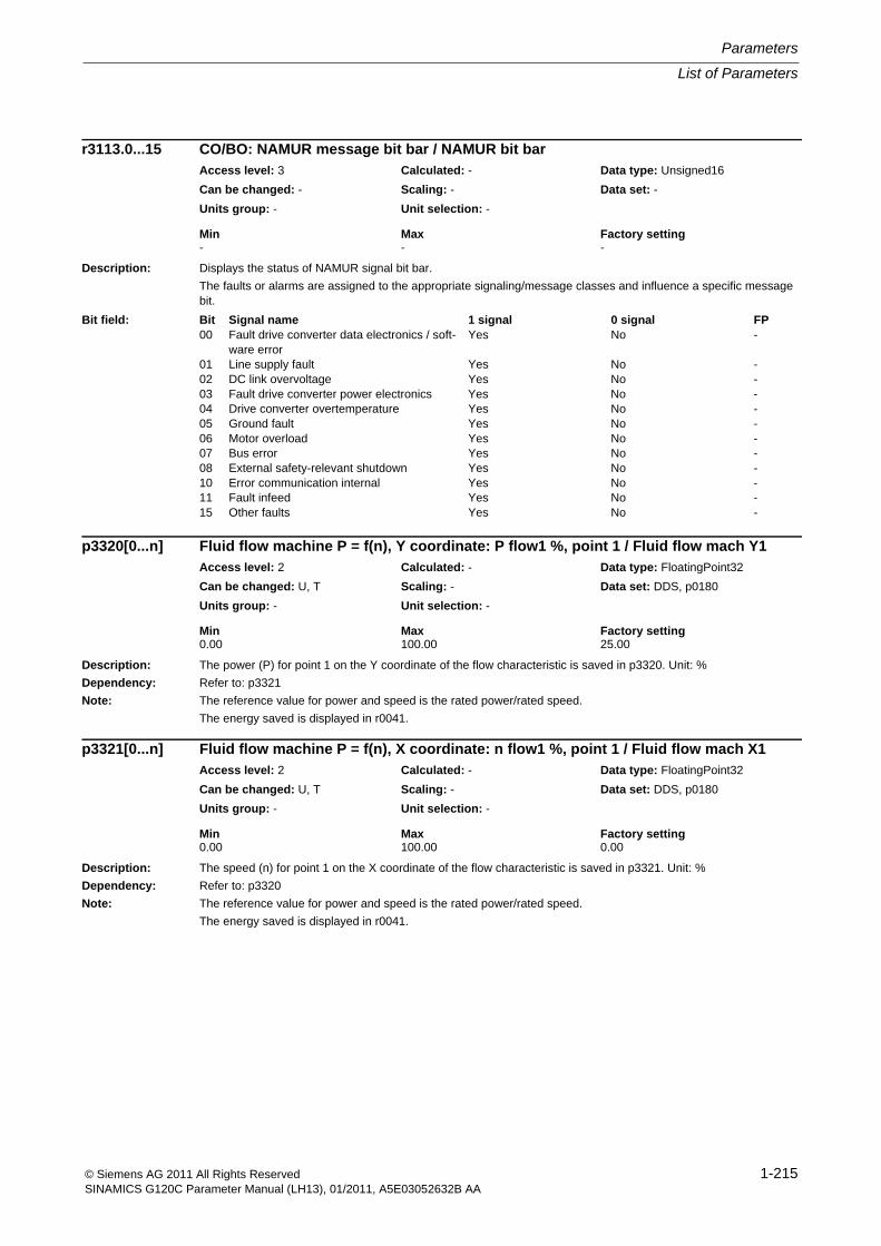
List of Parameters
Parameters
1-215© Siemens AG 2011 All Rights ReservedSINAMICS G120C Parameter Manual (LH13), 01/2011, A5E03052632B AA
Description: Displays the status of NAMUR signal bit bar.
The faults or alarms are assigned to the appropriate signaling/message classes and influence a specific message bit.
Description: The power (P) for point 1 on the Y coordinate of the flow characteristic is saved in p3320. Unit: %
Dependency: Refer to: p3321
Note: The reference value for power and speed is the rated power/rated speed.
The energy saved is displayed in r0041.
Description: The speed (n) for point 1 on the X coordinate of the flow characteristic is saved in p3321. Unit: %
Dependency: Refer to: p3320
Note: The reference value for power and speed is the rated power/rated speed.
The energy saved is displayed in r0041.
r3113.0...15 CO/BO: NAMUR message bit bar / NAMUR bit barAccess level: 3 Calculated: - Data type: Unsigned16
Can be changed: - Scaling: - Data set: -
Units group: - Unit selection: -
Min Max Factory setting - - -
Bit field: Bit Signal name 1 signal 0 signal FP00 Fault drive converter data electronics / soft-
ware errorYes No -
01 Line supply fault Yes No -02 DC link overvoltage Yes No -03 Fault drive converter power electronics Yes No -04 Drive converter overtemperature Yes No -05 Ground fault Yes No -06 Motor overload Yes No -07 Bus error Yes No -08 External safety-relevant shutdown Yes No -10 Error communication internal Yes No -11 Fault infeed Yes No -15 Other faults Yes No -
p3320[0...n] Fluid flow machine P = f(n), Y coordinate: P flow1 %, point 1 / Fluid flow mach Y1Access level: 2 Calculated: - Data type: FloatingPoint32
Can be changed: U, T Scaling: - Data set: DDS, p0180
Units group: - Unit selection: -
Min Max Factory setting 0.00 100.00 25.00
p3321[0...n] Fluid flow machine P = f(n), X coordinate: n flow1 %, point 1 / Fluid flow mach X1Access level: 2 Calculated: - Data type: FloatingPoint32
Can be changed: U, T Scaling: - Data set: DDS, p0180
Units group: - Unit selection: -
Min Max Factory setting 0.00 100.00 0.00
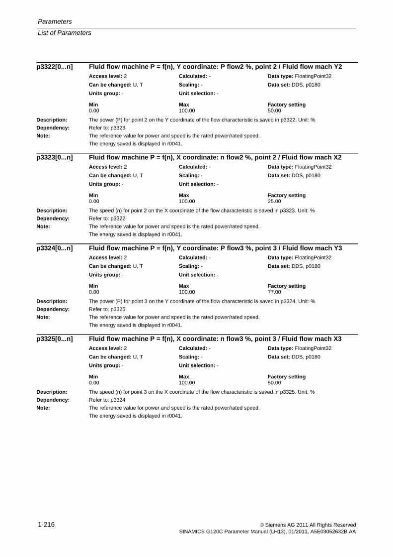
Parameters
List of Parameters
1-216 © Siemens AG 2011 All Rights ReservedSINAMICS G120C Parameter Manual (LH13), 01/2011, A5E03052632B AA
Description: The power (P) for point 2 on the Y coordinate of the flow characteristic is saved in p3322. Unit: %
Dependency: Refer to: p3323
Note: The reference value for power and speed is the rated power/rated speed.
The energy saved is displayed in r0041.
Description: The speed (n) for point 2 on the X coordinate of the flow characteristic is saved in p3323. Unit: %
Dependency: Refer to: p3322
Note: The reference value for power and speed is the rated power/rated speed.
The energy saved is displayed in r0041.
Description: The power (P) for point 3 on the Y coordinate of the flow characteristic is saved in p3324. Unit: %
Dependency: Refer to: p3325
Note: The reference value for power and speed is the rated power/rated speed.
The energy saved is displayed in r0041.
Description: The speed (n) for point 3 on the X coordinate of the flow characteristic is saved in p3325. Unit: %
Dependency: Refer to: p3324
Note: The reference value for power and speed is the rated power/rated speed.
The energy saved is displayed in r0041.
p3322[0...n] Fluid flow machine P = f(n), Y coordinate: P flow2 %, point 2 / Fluid flow mach Y2Access level: 2 Calculated: - Data type: FloatingPoint32
Can be changed: U, T Scaling: - Data set: DDS, p0180
Units group: - Unit selection: -
Min Max Factory setting 0.00 100.00 50.00
p3323[0...n] Fluid flow machine P = f(n), X coordinate: n flow2 %, point 2 / Fluid flow mach X2Access level: 2 Calculated: - Data type: FloatingPoint32
Can be changed: U, T Scaling: - Data set: DDS, p0180
Units group: - Unit selection: -
Min Max Factory setting 0.00 100.00 25.00
p3324[0...n] Fluid flow machine P = f(n), Y coordinate: P flow3 %, point 3 / Fluid flow mach Y3Access level: 2 Calculated: - Data type: FloatingPoint32
Can be changed: U, T Scaling: - Data set: DDS, p0180
Units group: - Unit selection: -
Min Max Factory setting 0.00 100.00 77.00
p3325[0...n] Fluid flow machine P = f(n), X coordinate: n flow3 %, point 3 / Fluid flow mach X3Access level: 2 Calculated: - Data type: FloatingPoint32
Can be changed: U, T Scaling: - Data set: DDS, p0180
Units group: - Unit selection: -
Min Max Factory setting 0.00 100.00 50.00
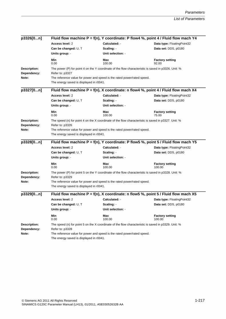
List of Parameters
Parameters
1-217© Siemens AG 2011 All Rights ReservedSINAMICS G120C Parameter Manual (LH13), 01/2011, A5E03052632B AA
Description: The power (P) for point 4 on the Y coordinate of the flow characteristic is saved in p3326. Unit: %
Dependency: Refer to: p3327
Note: The reference value for power and speed is the rated power/rated speed.
The energy saved is displayed in r0041.
Description: The speed (n) for point 4 on the X coordinate of the flow characteristic is saved in p3327. Unit: %
Dependency: Refer to: p3326
Note: The reference value for power and speed is the rated power/rated speed.
The energy saved is displayed in r0041.
Description: The power (P) for point 5 on the Y coordinate of the flow characteristic is saved in p3328. Unit: %
Dependency: Refer to: p3329
Note: The reference value for power and speed is the rated power/rated speed.
The energy saved is displayed in r0041.
Description: The speed (n) for point 5 on the X coordinate of the flow characteristic is saved in p3329. Unit: %
Dependency: Refer to: p3328
Note: The reference value for power and speed is the rated power/rated speed.
The energy saved is displayed in r0041.
p3326[0...n] Fluid flow machine P = f(n), Y coordinate: P flow4 %, point 4 / Fluid flow mach Y4Access level: 2 Calculated: - Data type: FloatingPoint32
Can be changed: U, T Scaling: - Data set: DDS, p0180
Units group: - Unit selection: -
Min Max Factory setting 0.00 100.00 92.00
p3327[0...n] Fluid flow machine P = f(n), X coordinate: n flow4 %, point 4 / Fluid flow mach X4Access level: 2 Calculated: - Data type: FloatingPoint32
Can be changed: U, T Scaling: - Data set: DDS, p0180
Units group: - Unit selection: -
Min Max Factory setting 0.00 100.00 75.00
p3328[0...n] Fluid flow machine P = f(n), Y coordinate: P flow5 %, point 5 / Fluid flow mach Y5Access level: 2 Calculated: - Data type: FloatingPoint32
Can be changed: U, T Scaling: - Data set: DDS, p0180
Units group: - Unit selection: -
Min Max Factory setting 0.00 100.00 100.00
p3329[0...n] Fluid flow machine P = f(n), X coordinate: n flow5 %, point 5 / Fluid flow mach X5Access level: 2 Calculated: - Data type: FloatingPoint32
Can be changed: U, T Scaling: - Data set: DDS, p0180
Units group: - Unit selection: -
Min Max Factory setting 0.00 100.00 100.00
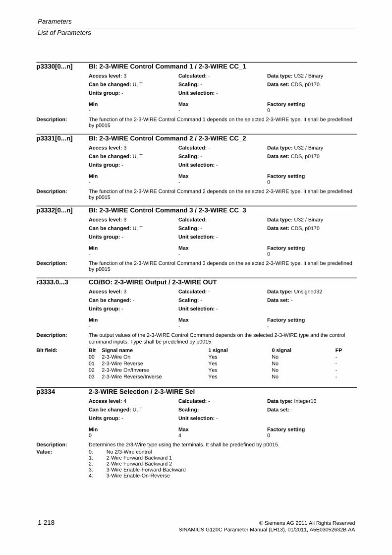
Parameters
List of Parameters
1-218 © Siemens AG 2011 All Rights ReservedSINAMICS G120C Parameter Manual (LH13), 01/2011, A5E03052632B AA
Description: The function of the 2-3-WIRE Control Command 1 depends on the selected 2-3-WIRE type. It shall be predefined by p0015
Description: The function of the 2-3-WIRE Control Command 2 depends on the selected 2-3-WIRE type. It shall be predefined by p0015
Description: The function of the 2-3-WIRE Control Command 3 depends on the selected 2-3-WIRE type. It shall be predefined by p0015
Description: The output values of the 2-3-WIRE Control Command depends on the selected 2-3-WIRE type and the control command inputs. Type shall be predefined by p0015
Description: Determines the 2/3-Wire type using the terminals. It shall be predefined by p0015.Value: 0: No 2/3-Wire control
1: 2-Wire Forward-Backward 12: 2-Wire Forward-Backward 23: 3-Wire Enable-Forward-Backward4: 3-Wire Enable-On-Reverse
p3330[0...n] BI: 2-3-WIRE Control Command 1 / 2-3-WIRE CC_1Access level: 3 Calculated: - Data type: U32 / Binary
Can be changed: U, T Scaling: - Data set: CDS, p0170
Units group: - Unit selection: -
Min Max Factory setting - - 0
p3331[0...n] BI: 2-3-WIRE Control Command 2 / 2-3-WIRE CC_2Access level: 3 Calculated: - Data type: U32 / Binary
Can be changed: U, T Scaling: - Data set: CDS, p0170
Units group: - Unit selection: -
Min Max Factory setting - - 0
p3332[0...n] BI: 2-3-WIRE Control Command 3 / 2-3-WIRE CC_3Access level: 3 Calculated: - Data type: U32 / Binary
Can be changed: U, T Scaling: - Data set: CDS, p0170
Units group: - Unit selection: -
Min Max Factory setting - - 0
r3333.0...3 CO/BO: 2-3-WIRE Output / 2-3-WIRE OUTAccess level: 3 Calculated: - Data type: Unsigned32
Can be changed: - Scaling: - Data set: -
Units group: - Unit selection: -
Min Max Factory setting - - -
Bit field: Bit Signal name 1 signal 0 signal FP00 2-3-Wire On Yes No -01 2-3-Wire Reverse Yes No -02 2-3-Wire On/Inverse Yes No -03 2-3-Wire Reverse/Inverse Yes No -
p3334 2-3-WIRE Selection / 2-3-WIRE SelAccess level: 4 Calculated: - Data type: Integer16
Can be changed: U, T Scaling: - Data set: -
Units group: - Unit selection: -
Min Max Factory setting 0 4 0
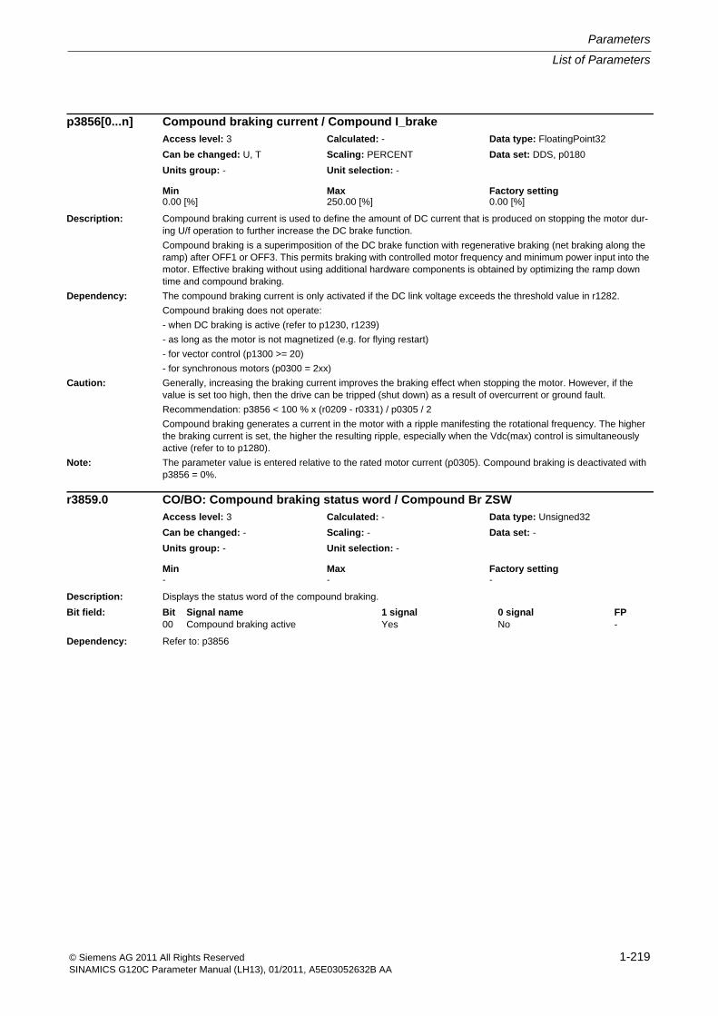
List of Parameters
Parameters
1-219© Siemens AG 2011 All Rights ReservedSINAMICS G120C Parameter Manual (LH13), 01/2011, A5E03052632B AA
Description: Compound braking current is used to define the amount of DC current that is produced on stopping the motor dur-ing U/f operation to further increase the DC brake function.
Compound braking is a superimposition of the DC brake function with regenerative braking (net braking along the ramp) after OFF1 or OFF3. This permits braking with controlled motor frequency and minimum power input into the motor. Effective braking without using additional hardware components is obtained by optimizing the ramp down time and compound braking.
Dependency: The compound braking current is only activated if the DC link voltage exceeds the threshold value in r1282.
Compound braking does not operate:
- when DC braking is active (refer to p1230, r1239)
- as long as the motor is not magnetized (e.g. for flying restart)
- for vector control (p1300 >= 20)
- for synchronous motors (p0300 = 2xx)
Caution: Generally, increasing the braking current improves the braking effect when stopping the motor. However, if the value is set too high, then the drive can be tripped (shut down) as a result of overcurrent or ground fault.
Recommendation: p3856 < 100 % x (r0209 - r0331) / p0305 / 2
Compound braking generates a current in the motor with a ripple manifesting the rotational frequency. The higher the braking current is set, the higher the resulting ripple, especially when the Vdc(max) control is simultaneously active (refer to to p1280).
Note: The parameter value is entered relative to the rated motor current (p0305). Compound braking is deactivated with p3856 = 0%.
Description: Displays the status word of the compound braking.
Dependency: Refer to: p3856
p3856[0...n] Compound braking current / Compound I_brakeAccess level: 3 Calculated: - Data type: FloatingPoint32
Can be changed: U, T Scaling: PERCENT Data set: DDS, p0180
Units group: - Unit selection: -
Min Max Factory setting 0.00 [%] 250.00 [%] 0.00 [%]
r3859.0 CO/BO: Compound braking status word / Compound Br ZSWAccess level: 3 Calculated: - Data type: Unsigned32
Can be changed: - Scaling: - Data set: -
Units group: - Unit selection: -
Min Max Factory setting - - -
Bit field: Bit Signal name 1 signal 0 signal FP00 Compound braking active Yes No -
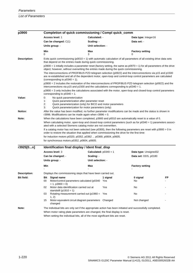
Parameters
List of Parameters
1-220 © Siemens AG 2011 All Rights ReservedSINAMICS G120C Parameter Manual (LH13), 01/2011, A5E03052632B AA
Description: Exits quick commissioning (p0010 = 1) with automatic calculation of all parameters of all existing drive data sets that depend on the entries made during quick commissioning.
p3900 = 1 initially includes a parameter reset (factory setting, the same as p0970 = 1) for all parameters of the drive object; however, without overwriting the entries made during the quick commissioning.
The interconnections of PROFIBUS PZD telegram selection (p0922) and the interconnections via p15 and p1500 are re-established and all of the dependent motor, open-loop and control-loop control parameters are calculated (corresponding to p0340 = 1).
p3900 = 2 includes the restoration of the interconnections of PROFIBUS PZD telegram selection (p0922) and the interconnections via p15 and p1500 and the calculations corresponding to p0340 = 1.
p3900 = 3 only includes the calculations associated with the motor, open-loop and closed-loop control parameters corresponding to p0340 = 1.
Value: 0: No quick parameterization1: Quick parameterization after parameter reset2: Quick parameterization (only) for BICO and motor parameters3: Quick parameterization for motor parameters (only)
Notice: After the value has been modified, no further parameter modifications can be made and the status is shown in r3996. Modifications can be made again when r3996 = 0.
Note: When the calculations have been completed, p3900 and p0010 are automatically reset to a value of 0.
When calculating motor, open-loop and closed-loop control parameters (such as for p0340 = 1) parameters associ-ated with a selected Siemens catalog motor are not overwritten.
If a catalog motor has not been selected (see p0300), then the following parameters are reset with p3900 > 0 in order to restore the situation that applied when commissioning the drive for the first time:
for induction motors p0320, p0352, p0362 ... p0369, p0604, p0605.
for synchronous motors p0352, p0604, p0605.
Description: Displays the commissioning steps that have been carried out.
Note: The individual bits are only set if the appropriate action has been initiated and successfully completed.
When motor rating plate parameters are changed, the final display is reset.
When setting the individual bits, all of the most significant bits are reset.
p3900 Completion of quick commissioning / Compl quick_commAccess level: 1 Calculated: - Data type: Integer16
Can be changed: C(1) Scaling: - Data set: -
Units group: - Unit selection: -
Min Max Factory setting 0 3 0
r3925[0...n] Identification final display / Ident final_dispAccess level: 3 Calculated: p0340 = 1 Data type: Unsigned32
Can be changed: - Scaling: - Data set: DDS, p0180
Units group: - Unit selection: -
Min Max Factory setting - - -
Bit field: Bit Signal name 1 signal 0 signal FP00 Motor/control parameters calculated (p0340
= 1, p3900 > 0)Yes No -
02 Motor data identification carried out at standstill (p1910 = 1)
Yes No -
03 Rotating measurement carried out (p1960 = 1, 2)
Yes No -
15 Motor equivalent circuit diagram parameters changed
Changed Not changed -
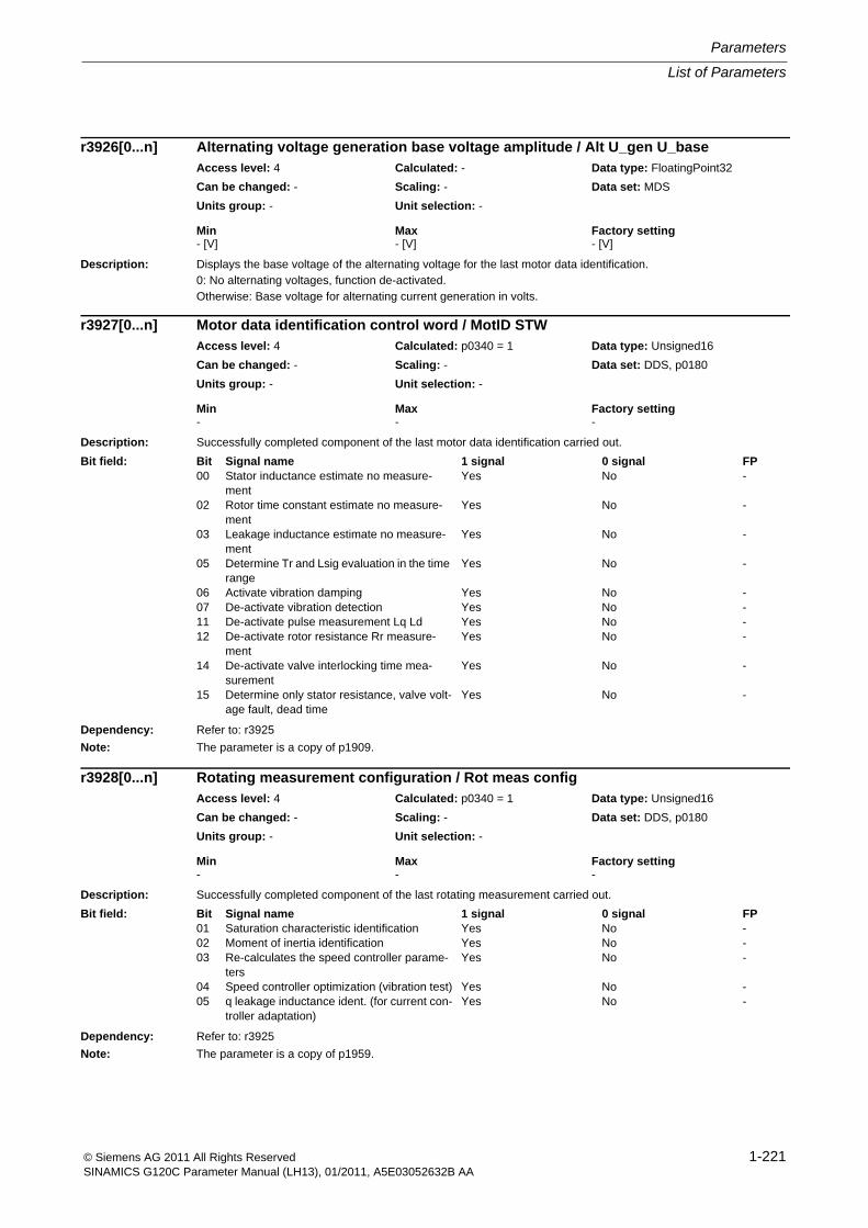
List of Parameters
Parameters
1-221© Siemens AG 2011 All Rights ReservedSINAMICS G120C Parameter Manual (LH13), 01/2011, A5E03052632B AA
Description: Displays the base voltage of the alternating voltage for the last motor data identification.0: No alternating voltages, function de-activated.Otherwise: Base voltage for alternating current generation in volts.
Description: Successfully completed component of the last motor data identification carried out.
Dependency: Refer to: r3925
Note: The parameter is a copy of p1909.
Description: Successfully completed component of the last rotating measurement carried out.
Dependency: Refer to: r3925
Note: The parameter is a copy of p1959.
r3926[0...n] Alternating voltage generation base voltage amplitude / Alt U_gen U_baseAccess level: 4 Calculated: - Data type: FloatingPoint32
Can be changed: - Scaling: - Data set: MDS
Units group: - Unit selection: -
Min Max Factory setting - [V] - [V] - [V]
r3927[0...n] Motor data identification control word / MotID STWAccess level: 4 Calculated: p0340 = 1 Data type: Unsigned16
Can be changed: - Scaling: - Data set: DDS, p0180
Units group: - Unit selection: -
Min Max Factory setting - - -
Bit field: Bit Signal name 1 signal 0 signal FP00 Stator inductance estimate no measure-
mentYes No -
02 Rotor time constant estimate no measure-ment
Yes No -
03 Leakage inductance estimate no measure-ment
Yes No -
05 Determine Tr and Lsig evaluation in the time range
Yes No -
06 Activate vibration damping Yes No -07 De-activate vibration detection Yes No -11 De-activate pulse measurement Lq Ld Yes No -12 De-activate rotor resistance Rr measure-
mentYes No -
14 De-activate valve interlocking time mea-surement
Yes No -
15 Determine only stator resistance, valve volt-age fault, dead time
Yes No -
r3928[0...n] Rotating measurement configuration / Rot meas configAccess level: 4 Calculated: p0340 = 1 Data type: Unsigned16
Can be changed: - Scaling: - Data set: DDS, p0180
Units group: - Unit selection: -
Min Max Factory setting - - -
Bit field: Bit Signal name 1 signal 0 signal FP01 Saturation characteristic identification Yes No -02 Moment of inertia identification Yes No -03 Re-calculates the speed controller parame-
tersYes No -
04 Speed controller optimization (vibration test) Yes No -05 q leakage inductance ident. (for current con-
troller adaptation)Yes No -
Parameters
List of Parameters
1-222 © Siemens AG 2011 All Rights ReservedSINAMICS G120C Parameter Manual (LH13), 01/2011, A5E03052632B AA
Description: Configuration of voltage generation for the various MotID sections in the case of the most recent successful MotID.
Description: For service personnel only.
Description: Setting to acknowledge all active faults of a drive object.
Note: Parameter should be set from 0 to 1 to acknowledge.
After acknowledgement, the parameter is automatically reset to 0.
r3929[0...n] Motor data identification modulated voltage generation / MotID U_gen modAccess level: 4 Calculated: p0340 = 1 Data type: Unsigned32
Can be changed: - Scaling: - Data set: DDS, p0180
Units group: - Unit selection: -
Min Max Factory setting - - -
Bit field: Bit Signal name 1 signal 0 signal FP00 Wobble U_generate to determine dead-time
correctionYes No -
01 Wobble U_generate to determine stator resistance
Yes No -
02 Wobble U_generate to determine rotor time constant
Yes No -
03 Wobble U_generate to determine leakage inductance
Yes No -
04 Wobble U_generate to determine dyn. leak-age inductance
Yes No -
05 Wobble U_generate to determine magnetiz-ing inductance
Yes No -
08 Alternating U_generate to determine dead-time correction
Yes No -
09 Alternating U_generate to determine stator resistance
Yes No -
10 Alternating U_generate to determine rotor time constant
Yes No -
11 Alternating U_generate to determine leak-age inductance
Yes No -
12 Alternating U_generate to determine dyn. leakage inductance
Yes No -
13 Alternating U_generate to determine mag-netizing inductance
Yes No -
p3950 Service parameter / Serv. par.Access level: 3 Calculated: - Data type: Unsigned16
Can be changed: C, U, T Scaling: - Data set: -
Units group: - Unit selection: -
Min Max Factory setting - - -
p3981 Faults, acknowledge drive object / Faults ackn DOAccess level: 3 Calculated: - Data type: Unsigned8
Can be changed: U, T Scaling: - Data set: -
Units group: - Unit selection: -
Min Max Factory setting 0 1 0
List of Parameters
Parameters
1-223© Siemens AG 2011 All Rights ReservedSINAMICS G120C Parameter Manual (LH13), 01/2011, A5E03052632B AA
Description: Sets the mode to change over the master control / LOCAL mode.Value: 0: Change master control for STW1.0 = 0
1: Change master control in operationDanger: When changing the master control in operation, the drive can manifest undesirable behavior - e.g. it can accelerate
up to another setpoint.
Description: Displays whether writing to parameters is inhibited.r3996 = 0:Parameter write not inhibited.0 < r3996 < 100:Parameter write inhibited. The value shows how the calculations are progressing.
Description: Displays the status for write protection of adjustable parameters.
Note: Write protection can be activated/deactivated via p7760 on the Control Unit.
Description: Setting for activating/de-activating the write protection for adjustable parameters.Value: 0: Inactive
1: ActiveNote: The following parameters are excluded from the write protection:
- p0003 (BOP access level)- p0971 (drive object save parameters)- p0977 (save all parameters)- p3950 (service parameters)- p3981 (acknowledge fault, drive object)- p7760 (adjustable parameters write protection)
p3985 Master control mode selection / PcCtrl mode selectAccess level: 3 Calculated: - Data type: Integer16
Can be changed: U, T Scaling: - Data set: -
Units group: - Unit selection: -
Min Max Factory setting 0 1 0
r3996 Parameter write inhibit status / Par_write inhib stAccess level: 3 Calculated: - Data type: Unsigned8
Can be changed: - Scaling: - Data set: -
Units group: - Unit selection: -
Min Max Factory setting - - -
r7760 Write protection status / Write prot statAccess level: 3 Calculated: - Data type: Unsigned16
Can be changed: - Scaling: - Data set: -
Units group: - Unit selection: -
Min Max Factory setting - - -
Bit field: Bit Signal name 1 signal 0 signal FP00 Write protection active -
p7761 Write protection / Write protectionAccess level: 3 Calculated: - Data type: Integer16
Can be changed: U, T Scaling: - Data set: -
Units group: - Unit selection: -
Min Max Factory setting 0 1 0
Parameters
List of Parameters
1-224 © Siemens AG 2011 All Rights ReservedSINAMICS G120C Parameter Manual (LH13), 01/2011, A5E03052632B AA
Description: Displays the macro file saved in the appropriate directory on the memory card/device memory.
Dependency: Refer to: p0015
Note: For a value = 9999999, the following applies: The read operation is still running.
Description: Displays all of the devices connected to the CAN bus after run-up.
r8600
= 00000000 hex: No drive recognized.
= 02010192 hex: 1 Vector drive
Note: Corresponds to the CANopen object 1000 hex.
For each detected drive, the device type is displayed in object 67FF hex.
Description: Displays the error register for CANopen.
Bit 0: Generic error
0 signal: No error present.
1 signal: Generic error present.
Bit 1 ... 3: Not supported (always a 0 signal)
Bit 4: Communications error
0 signal: There is no message in the range 8700 ... 8799.
1 signal: There is at least one message (fault or alarm) in the range 8700 ... 8799.
Bit 5 ... 6: Not supported (always a 0 signal)
Bit 7:; Fault outside the range 8700 ... 8799
0 signal: There is no fault outside the range 8700 ... 8799.
1 signal: There is at least one fault outside the range 8700 ... 8799.
Note: Corresponds to the CANopen object 1001 hex.
r8570[0...39] Macro drive object / Macro DOAccess level: 1 Calculated: - Data type: Unsigned32
Can be changed: - Scaling: - Data set: -
Units group: - Unit selection: -
Min Max Factory setting - - -
r8600 CAN device type / Device typeG120C CAN Access level: 3 Calculated: - Data type: Unsigned32
Can be changed: - Scaling: - Data set: -
Units group: - Unit selection: -
Min Max Factory setting - - -
r8601 CAN error register / Error registerG120C CAN Access level: 3 Calculated: - Data type: Unsigned8
Can be changed: - Scaling: - Data set: -
Units group: - Unit selection: -
Min Max Factory setting - - -
List of Parameters
Parameters
1-225© Siemens AG 2011 All Rights ReservedSINAMICS G120C Parameter Manual (LH13), 01/2011, A5E03052632B AA
Description: Sets the SYNC object parameter for the following CANopen objects:
- 1005 hex: COB-ID
Note: SINAMICS operates as SYNC load.
COB-ID: CAN object identification
Description: Sets the COB-ID for the emergency message (error telegram).
It corresponds to the CANopen objects:
- 1014 hex: COB-ID
Note: If, when downloading, the pre-set value 0 is downloaded, then the CANopen pre-set value 80 hex + Node-ID is automatically set.
Online, the value 0 is rejected as, according to the CANopen Standard, COB-ID 0 is not permitted here.
The changeover of the node ID using the hardware switch at the Control Unit or per software has no effect on the COB-ID EMCY. The saved value remains effective.
Description: Sets the node guarding parameter for the following CANopen objects:
- 100C hex: Guard Time
- 100D hex: Life Time Factor
The life time is derived by multiplying guard time by the life time factor.
Index: [0] = Time interval [ms] for new node guarding telegram[1] = Factor for failure of the node guarding telegram
Dependency: Only adjustable if heartbeat time = 0 (heartbeat is disabled).
Refer to: p8606
Note: For p8604[0] = 0 and/or p8604[1] = 0, the node guarding protocol is not used.
Either node guarding or heartbeat can be used.
p8602 CAN SYNC object / SYNC objectG120C CAN Access level: 3 Calculated: - Data type: Unsigned32
Can be changed: T Scaling: - Data set: -
Units group: - Unit selection: -
Min Max Factory setting 0000 hex FFFF FFFF hex 0080 hex
p8603 CAN COB-ID Emergency Message / COB-ID EMCY MsgG120C CAN Access level: 3 Calculated: - Data type: Unsigned32
Can be changed: T Scaling: - Data set: -
Units group: - Unit selection: -
Min Max Factory setting 0000 hex FFFF FFFF hex 0000 hex
p8604[0...1] CAN node guarding / Node guardingG120C CAN Access level: 3 Calculated: - Data type: Unsigned16
Can be changed: T Scaling: - Data set: -
Units group: - Unit selection: -
Min Max Factory setting 0 65535 0
Parameters
List of Parameters
1-226 © Siemens AG 2011 All Rights ReservedSINAMICS G120C Parameter Manual (LH13), 01/2011, A5E03052632B AA
Description: Sets the time [ms] to cyclically send heartbeat telegrams.
The smallest cycle time is 100 ms.
When a 0 is written, then heartbeat telegrams are not sent.
Dependency: Only adjustable if guard time = 0 (node guarding disabled).
Refer to: p8604
Note: Corresponds to the CANopen object 1017 hex.
Either node guarding or heartbeat can be used.
Description: General device information display.
Index: [0] = Vendor ID[1] = Product code[2] = Revision number[3] = Serial number
Note: Corresponds to the CANopen object 1018 hex.
Re index 3:
The SINAMICS serial number comprises 60 bits. Of these bits, the following are displayed in this index:
Bits 0 ... 19: Consecutive number
Bits 20 ... 23: Production ID
- 0 hex: Development
- 1 hex: P1 unique number
- 2 hex: P2 unique number
- 3 hex: WA unique number
- 9 hex: Pattern
- F hex: All others
Bits 24 ... 27: Month of manufacture (0 means January, B means December)
Bits 28 ... 31: Year of manufacture (0 means 2002)
p8606 CAN Producer Heartbeat Time / Prod Heartb TimeG120C CAN Access level: 3 Calculated: - Data type: Unsigned16
Can be changed: T Scaling: - Data set: -
Units group: - Unit selection: -
Min Max Factory setting 0 [ms] 65535 [ms] 0 [ms]
r8607[0...3] CAN Identity Object / Identity objectG120C CAN Access level: 3 Calculated: - Data type: Unsigned32
Can be changed: - Scaling: - Data set: -
Units group: - Unit selection: -
Min Max Factory setting - - -
List of Parameters
Parameters
1-227© Siemens AG 2011 All Rights ReservedSINAMICS G120C Parameter Manual (LH13), 01/2011, A5E03052632B AA
Description: As a result of a Bus Off error, the CAN controller is set into the initialization state.
Index 0:
The CAN controller is manually started after resolving the cause of the error with p8608[0] = 1
Index 1:
The automatic CAN bus start function is activated using p8608[1] = 1.
At 2 second intervals, the CAN controller is automatically restarted until the cause of the error has been resolved and a CAN connection has been established.
Value: 0: Inactive1: Start CAN controller
Index: [0] = Manual controller start function[1] = Activating the automatic controller start function
Note: Index 0:
This parameter is automatically reset to 0 after start.
Description: Sets the behavior of the CAN node referred to the communications error or equipment fault.
Value: 0: Pre-operational1: No change2: Stopped
Index: [0] = Behavior for communication errors[1] = Behavior for device faults
Note: Corresponds to the CANopen object 1029 hex.
Description: Displays the identifier (client/server and server/client) of the SDO channel.
Index: [0] = Displays the COB ID from client to server[1] = Displays the COB ID from server to client
Note: Corresponds to the CANopen object 1200 hex.
SDO: Service Data Object
p8608[0...1] CAN Clear Bus Off Error / Clear bus off errG120C CAN Access level: 3 Calculated: - Data type: Integer16
Can be changed: U, T Scaling: - Data set: -
Units group: - Unit selection: -
Min Max Factory setting 0 1 0
p8609[0...1] CAN Error Behavior / Error behaviorG120C CAN Access level: 3 Calculated: - Data type: Integer16
Can be changed: T Scaling: - Data set: -
Units group: - Unit selection: -
Min Max Factory setting 0 2 1
r8610[0...1] CAN First Server SDO / First server SDOG120C CAN Access level: 3 Calculated: - Data type: Unsigned32
Can be changed: - Scaling: - Data set: -
Units group: - Unit selection: -
Min Max Factory setting - - -
Parameters
List of Parameters
1-228 © Siemens AG 2011 All Rights ReservedSINAMICS G120C Parameter Manual (LH13), 01/2011, A5E03052632B AA
Description: Displays the Pre-defined Error Field of the CAN node.
It includes the number of all errors that have occurred, the number of errors that have occurred for each drive and the errors according to their history.
The first 16 bits represent the CANopen error code and the second 16 bits the SINAMICS error code.
Index 1 has the same structure - however, the drive object ID is in the second 16 bits instead of the SINAMICS error code.
CANopen error code:
0000 hex: No error present
8110 hex: Alarm A08751 present
8120 hex: Alarm A08752 present
8130 hex: Alarm A08700(F) with alarm value = 2 present
1000 hex: Generic error 1 present (there is at least one fault outside the range 8700 ... 8799)
1001 hex: Generic error 2 present (there is at least one alarm in the range 8700 ... 8799 with the exception of A08751, A08752, A08700)
All drive objects are acknowledged by writing the value 0 to the index 0. As soon as a fault has been acknowledged or an alarm cleared, then it is also cleared from the fault list.
Index: [0] = Number of all faults in the drive unit[1] = Most recent drive number / fault number[2] = Number of faults drive 1[3] = Fault 1/ drive 1[4] = Fault 2/ drive 1[5] = Fault 3/ drive 1[6] = Fault 4/ drive 1[7] = Fault 5/ drive 1[8] = Fault 6/ drive 1
Note: Corresponds to the CANopen object 1003 hex.
p8611[0...82] CAN Pre-defined Error Field / Pre_def err fieldG120C CAN Access level: 3 Calculated: - Data type: Unsigned32
Can be changed: U, T Scaling: - Data set: -
Units group: - Unit selection: -
Min Max Factory setting 0000 hex FFFF 1000 hex 0000 hex
List of Parameters
Parameters
1-229© Siemens AG 2011 All Rights ReservedSINAMICS G120C Parameter Manual (LH13), 01/2011, A5E03052632B AA
Description: Display or setting of the CANopen Node ID.
The Node ID can be set as follows:
1) Using the address switch on the Control Unit.
--> p8620 can then only be read and displays the selected Node ID.
--> A change only becomes effective after a POWER ON.
--> CANopen Node ID and PROFIBUS address are identical.
2) Using p8620
--> Only if address 0 is set using the address switch.
--> the Node ID is set as standard to 126.
--> A change only becomes effective after save and POWER ON.
Dependency: Refer to: r8621
Notice: For p0014 = 1, the following applies:
After the value has been modified, no further parameter modifications can be made and the status is shown in r3996. Modifications can be made again when r3996 = 0.
For p0014 = 0, the following applies:
Before a changed setting becomes permanently effective, a non-volatile RAM to ROM data save is required. To do this, set p0971 = 1 or p0014 = 1.
Note: Every node ID change only becomes effective after a POWER ON.
The active node ID is displayed in r8621.
The parameter is not influenced by setting the factory setting.
It is only possible to independently set CANopen node ID and the PROFIBUS address using p0918 and p8620 (pre-requisite: the address 0 is set for the address switch).
Description: Displays the active CANopen Node ID.
Dependency: Refer to: p8620
p8620 CAN Node-ID / Node IDG120C CAN Access level: 2 Calculated: - Data type: Unsigned8
Can be changed: T Scaling: - Data set: -
Units group: - Unit selection: -
Min Max Factory setting 1 127 126
r8621 CAN Node-ID active / Node ID activeG120C CAN Access level: 3 Calculated: - Data type: Unsigned8
Can be changed: - Scaling: - Data set: -
Units group: - Unit selection: -
Min Max Factory setting - - -
Parameters
List of Parameters
1-230 © Siemens AG 2011 All Rights ReservedSINAMICS G120C Parameter Manual (LH13), 01/2011, A5E03052632B AA
Description: Setting the bit rate for the CAN bus.
The appropriate bit timings are selected that are defined in p8623 in the associated sub-index.
Example:
Bit rate = 20 kbit/s --> p8622 = 6 --> associated bit timing is in p8623[6].
Value: 0: 1 Mbit/s1: 800 kbit/s2: 500 kbit/s3: 250 kbit/s4: 125 kbit/s5: 50 kbit/s6: 20 kbit/s7: 10 kbit/s
Dependency: Refer to: p8623
Notice: For p0014 = 1, the following applies:
After the value has been modified, no further parameter modifications can be made and the status is shown in r3996. Modifications can be made again when r3996 = 0.
For p0014 = 0, the following applies:
Before a changed setting becomes permanently effective, a non-volatile RAM to ROM data save is required. To do this, set p0971 = 1 or p0014 = 1.
Note: The parameter is not influenced by setting the factory setting.
p8622 CAN bit rate / Bit rateG120C CAN Access level: 3 Calculated: - Data type: Integer16
Can be changed: T Scaling: - Data set: -
Units group: - Unit selection: -
Min Max Factory setting 0 7 6
List of Parameters
Parameters
1-231© Siemens AG 2011 All Rights ReservedSINAMICS G120C Parameter Manual (LH13), 01/2011, A5E03052632B AA
Description: Sets the bit timing for the C_CAN controller to the associated and selected bit rate (p8622).
Bits are distributed to the following parameters of the C_CAN controller in p8623[0...7]:
Bit 0 ... 5: BRP (Baud Rate Prescaler)
Bit 6 ... 7: SJW (Synchronization Jump Width)
Bit 8 ... 11: TSEG1 (Time Segment 1, before the sampling point)
Bit 12 ... 14: TSEG2 (Time Segment 2, after the sampling point)
Bit 15: Reserved
Bit 16 ... 19: BRPE (Baud Rate Prescaler Extension)
Bit 20 ... 31: Reserved
Example:
Bit rate = 20 kbit/s --> p8622 = 6 --> associated bit timing is in p8623[6] --> 0001 2FB6
Index: [0] = 1 Mbit/s[1] = 800 kbit/s[2] = 500 kbit/s[3] = 250 kbit/s[4] = 125 kbit/s[5] = 50 kbit/s[6] = 20 kbit/s[7] = 10 kbit/s
Dependency: Refer to: p8622
Note: The parameter is not influenced by setting the factory setting.
p8623[0...7] CAN Bit Timing selection / Bit timing selectG120C CAN Access level: 3 Calculated: - Data type: Unsigned32
Can be changed: T Scaling: - Data set: -
Units group: - Unit selection: -
Min Max Factory setting 0000 hex 000F 7FFF hex [0] 1405 hex
[1] 1605 hex
[2] 1C05 hex
[3] 1C0B hex
[4] 1C17 hex
[5] 1C3B hex
[6] 0002 1C15 hex
[7] 0004 1C2B hex

Parameters
List of Parameters
1-232 © Siemens AG 2011 All Rights ReservedSINAMICS G120C Parameter Manual (LH13), 01/2011, A5E03052632B AA
Description: Activating access to parameters via manufacturer-specific CANopen objects and setting for the subindex area (index 1) and the parameter area (index 2) when using virtual objects.
This means that it is possible to access all SINAMICS parameters via CAN.
Index 0:
0: Not possible to access virtual CANopen objects
1: Possible to access virtual CANopen objects
Index 1 (sub-index area):
0: 0 ... 255
1: 256 ... 511
2: 512 ... 767
3: 768 ... 1023
Index 2 (parameter area):
0: 1 ... 9999
1: 10000 ... 19999
2: 20000 ... 29999
3: 30000 ... 39999
Index: [0] = Drive object number[1] = Sub-index range[2] = Parameter range
Description: Sets the drive behavior if a CAN communication error occurs.
Value: 0: No response1: OFF12: OFF23: OFF3
Dependency: Refer to: F08700
p8630[0...2] CAN virtual objects / Virtual objectsG120C CAN Access level: 3 Calculated: - Data type: Unsigned16
Can be changed: U, T Scaling: - Data set: -
Units group: - Unit selection: -
Min Max Factory setting 0 65535 0
p8641 CAN Abort Connection Option Code / Abort con opt codeG120C CAN Access level: 3 Calculated: - Data type: Integer16
Can be changed: T Scaling: - Data set: -
Units group: - Unit selection: -
Min Max Factory setting 0 3 3
List of Parameters
Parameters
1-233© Siemens AG 2011 All Rights ReservedSINAMICS G120C Parameter Manual (LH13), 01/2011, A5E03052632B AA
Description: Displays the register of the CAN controller C_CAN:
Register, Message Interface Register and Message Handler Register - referred to the CAN protocol.
Index: [0] = Control register[1] = Status register[2] = Error counter[3] = Bit timing register[4] = Interrupt register[5] = Test register[6] = Baud rate prescaler extension register[7] = Interface 1 command request register[8] = Interface 1 command mask register
Note: A description of the individual registers of the C_CAN controller can be taken from "C_CAN User's Manual".
Description: Sets the CANopen NMT state that is effective after booting.
Value: 4: Stopped5: Operational127: Pre-operational
Dependency: Refer to: p8685
Note: Booting in the NMT state pre-operational corresponds to the CANopen standard
Description: Sets and displays the CANopen NMT state.
Value: 0: Initializing4: Stopped5: Operational127: Pre-operational128: Reset node129: Reset Communication
Note: The value 0 (initialization) is only displayed and cannot be set.
r8680[0...36] CAN Diagnosis Hardware / Diagnostics HWG120C CAN Access level: 3 Calculated: - Data type: Unsigned16
Can be changed: - Scaling: - Data set: -
Units group: - Unit selection: -
Min Max Factory setting - - -
p8684 CAN NMT state after booting / NMT state aft bootG120C CAN Access level: 3 Calculated: - Data type: Integer16
Can be changed: T Scaling: - Data set: -
Units group: - Unit selection: -
Min Max Factory setting 4 127 127
p8685 CAN NMT states / NMT statesG120C CAN Access level: 3 Calculated: - Data type: Integer16
Can be changed: U, T Scaling: - Data set: -
Units group: - Unit selection: -
Min Max Factory setting 0 129 127
Parameters
List of Parameters
1-234 © Siemens AG 2011 All Rights ReservedSINAMICS G120C Parameter Manual (LH13), 01/2011, A5E03052632B AA
Description: Sets the monitoring time to monitor the process data received via the CAN bus.
A value that is not a multiple integer of the CANopen sampling time is rounded-off.
If no process data is received within this time, fault F08702 is output.
Dependency: Refer to: F08702
Note: 0: The monitoring is de-activated.
Description: Sets the communication parameters for CANopen Receive Process Data Object 1 (RPDO 1).
Index: [0] = PDO COB-ID[1] = PDO transmission type
Dependency: A valid COB-ID can only be set for the available (existing) channel.
Refer to: p8741
Note: Corresponds to the CANopen object 1400 hex + 40 hex * x (x: Drive number 0 ... 7).
Transmission types 0, 1, FE and FF can be set.
PDO: Process Data Object
Description: Sets the communication parameters for CANopen Receive Process Data Object 2 (RPDO 2).
Index: [0] = PDO COB-ID[1] = PDO transmission type
Dependency: A valid COB-ID can only be set for the available (existing) channel.
Refer to: p8741
Note: Corresponds to the CANopen object 1401 hex + 40 hex * x (x: Drive number 0 ... 7).
Transmission types 0, 1, FE and FF can be set.
PDO: Process Data Object
p8699 CAN: RPDO monitoring time / RPDO t_monitG120C CAN Access level: 3 Calculated: - Data type: FloatingPoint32
Can be changed: U, T Scaling: - Data set: -
Units group: - Unit selection: -
Min Max Factory setting 0 [ms] 65535000 [ms] 0 [ms]
p8700[0...1] CAN Receive PDO 1 / Receive PDO 1G120C CAN Access level: 3 Calculated: - Data type: Unsigned32
Can be changed: C(3), T Scaling: - Data set: -
Units group: - Unit selection: -
Min Max Factory setting 0000 hex 8000 06DF hex [0] 8000 06DF hex
[1] 00FE hex
p8701[0...1] CAN Receive PDO 2 / Receive PDO 2G120C CAN Access level: 3 Calculated: - Data type: Unsigned32
Can be changed: C(3), T Scaling: - Data set: -
Units group: - Unit selection: -
Min Max Factory setting 0000 hex 8000 06DF hex [0] 8000 06DF hex
[1] 00FE hex
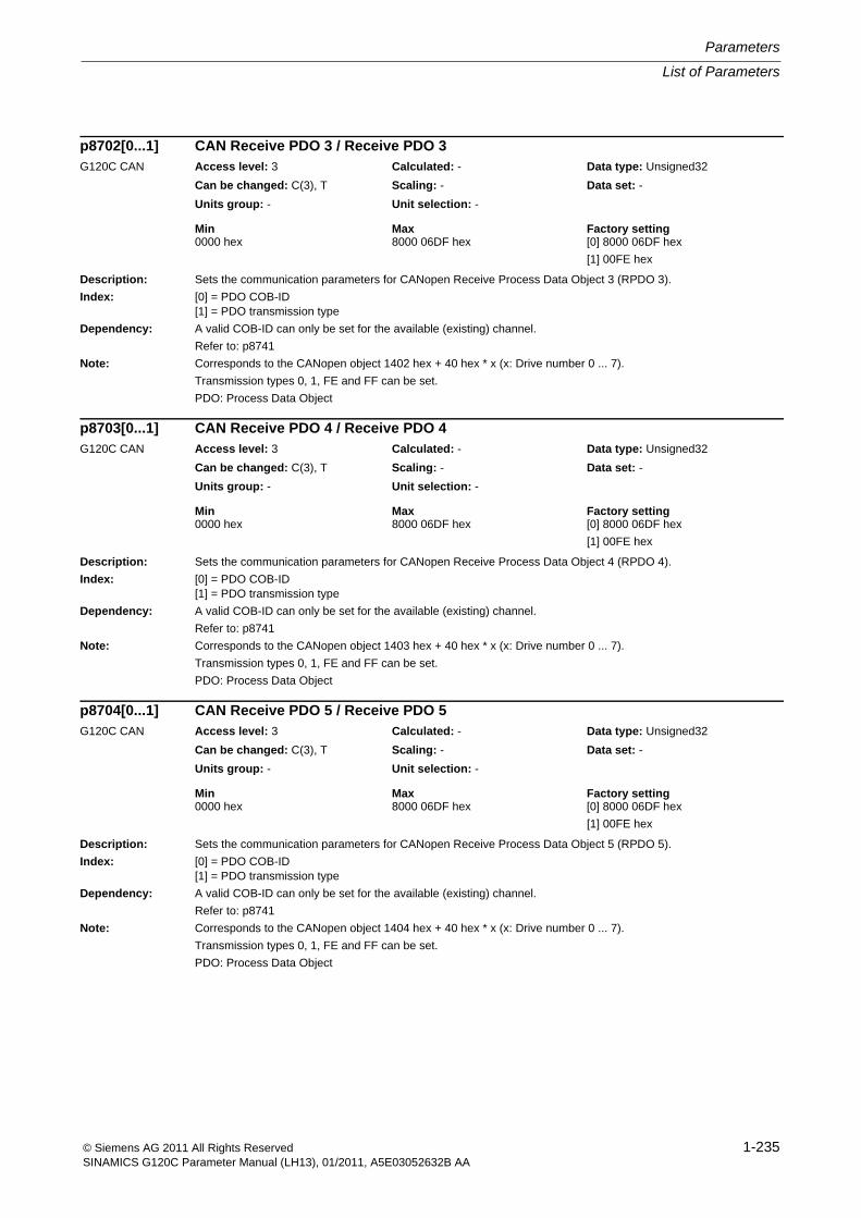
List of Parameters
Parameters
1-235© Siemens AG 2011 All Rights ReservedSINAMICS G120C Parameter Manual (LH13), 01/2011, A5E03052632B AA
Description: Sets the communication parameters for CANopen Receive Process Data Object 3 (RPDO 3).
Index: [0] = PDO COB-ID[1] = PDO transmission type
Dependency: A valid COB-ID can only be set for the available (existing) channel.
Refer to: p8741
Note: Corresponds to the CANopen object 1402 hex + 40 hex * x (x: Drive number 0 ... 7).
Transmission types 0, 1, FE and FF can be set.
PDO: Process Data Object
Description: Sets the communication parameters for CANopen Receive Process Data Object 4 (RPDO 4).
Index: [0] = PDO COB-ID[1] = PDO transmission type
Dependency: A valid COB-ID can only be set for the available (existing) channel.
Refer to: p8741
Note: Corresponds to the CANopen object 1403 hex + 40 hex * x (x: Drive number 0 ... 7).
Transmission types 0, 1, FE and FF can be set.
PDO: Process Data Object
Description: Sets the communication parameters for CANopen Receive Process Data Object 5 (RPDO 5).
Index: [0] = PDO COB-ID[1] = PDO transmission type
Dependency: A valid COB-ID can only be set for the available (existing) channel.
Refer to: p8741
Note: Corresponds to the CANopen object 1404 hex + 40 hex * x (x: Drive number 0 ... 7).
Transmission types 0, 1, FE and FF can be set.
PDO: Process Data Object
p8702[0...1] CAN Receive PDO 3 / Receive PDO 3G120C CAN Access level: 3 Calculated: - Data type: Unsigned32
Can be changed: C(3), T Scaling: - Data set: -
Units group: - Unit selection: -
Min Max Factory setting 0000 hex 8000 06DF hex [0] 8000 06DF hex
[1] 00FE hex
p8703[0...1] CAN Receive PDO 4 / Receive PDO 4G120C CAN Access level: 3 Calculated: - Data type: Unsigned32
Can be changed: C(3), T Scaling: - Data set: -
Units group: - Unit selection: -
Min Max Factory setting 0000 hex 8000 06DF hex [0] 8000 06DF hex
[1] 00FE hex
p8704[0...1] CAN Receive PDO 5 / Receive PDO 5G120C CAN Access level: 3 Calculated: - Data type: Unsigned32
Can be changed: C(3), T Scaling: - Data set: -
Units group: - Unit selection: -
Min Max Factory setting 0000 hex 8000 06DF hex [0] 8000 06DF hex
[1] 00FE hex
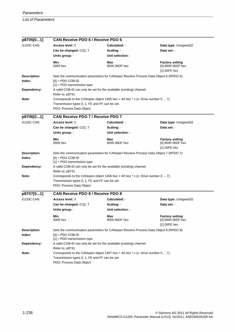
Parameters
List of Parameters
1-236 © Siemens AG 2011 All Rights ReservedSINAMICS G120C Parameter Manual (LH13), 01/2011, A5E03052632B AA
Description: Sets the communication parameters for CANopen Receive Process Data Object 6 (RPDO 6).
Index: [0] = PDO COB-ID[1] = PDO transmission type
Dependency: A valid COB-ID can only be set for the available (existing) channel.
Refer to: p8741
Note: Corresponds to the CANopen object 1405 hex + 40 hex * x (x: Drive number 0 ... 7).
Transmission types 0, 1, FE and FF can be set.
PDO: Process Data Object
Description: Sets the communication parameters for CANopen Receive Process Data Object 7 (RPDO 7).
Index: [0] = PDO COB-ID[1] = PDO transmission type
Dependency: A valid COB-ID can only be set for the available (existing) channel.
Refer to: p8741
Note: Corresponds to the CANopen object 1406 hex + 40 hex * x (x: Drive number 0 ... 7).
Transmission types 0, 1, FE and FF can be set.
PDO: Process Data Object
Description: Sets the communication parameters for CANopen Receive Process Data Object 8 (RPDO 8).
Index: [0] = PDO COB-ID[1] = PDO transmission type
Dependency: A valid COB-ID can only be set for the available (existing) channel.
Refer to: p8741
Note: Corresponds to the CANopen object 1407 hex + 40 hex * x (x: Drive number 0 ... 7).
Transmission types 0, 1, FE and FF can be set.
PDO: Process Data Object
p8705[0...1] CAN Receive PDO 6 / Receive PDO 6G120C CAN Access level: 3 Calculated: - Data type: Unsigned32
Can be changed: C(3), T Scaling: - Data set: -
Units group: - Unit selection: -
Min Max Factory setting 0000 hex 8000 06DF hex [0] 8000 06DF hex
[1] 00FE hex
p8706[0...1] CAN Receive PDO 7 / Receive PDO 7G120C CAN Access level: 3 Calculated: - Data type: Unsigned32
Can be changed: C(3), T Scaling: - Data set: -
Units group: - Unit selection: -
Min Max Factory setting 0000 hex 8000 06DF hex [0] 8000 06DF hex
[1] 00FE hex
p8707[0...1] CAN Receive PDO 8 / Receive PDO 8G120C CAN Access level: 3 Calculated: - Data type: Unsigned32
Can be changed: C(3), T Scaling: - Data set: -
Units group: - Unit selection: -
Min Max Factory setting 0000 hex 8000 06DF hex [0] 8000 06DF hex
[1] 00FE hex
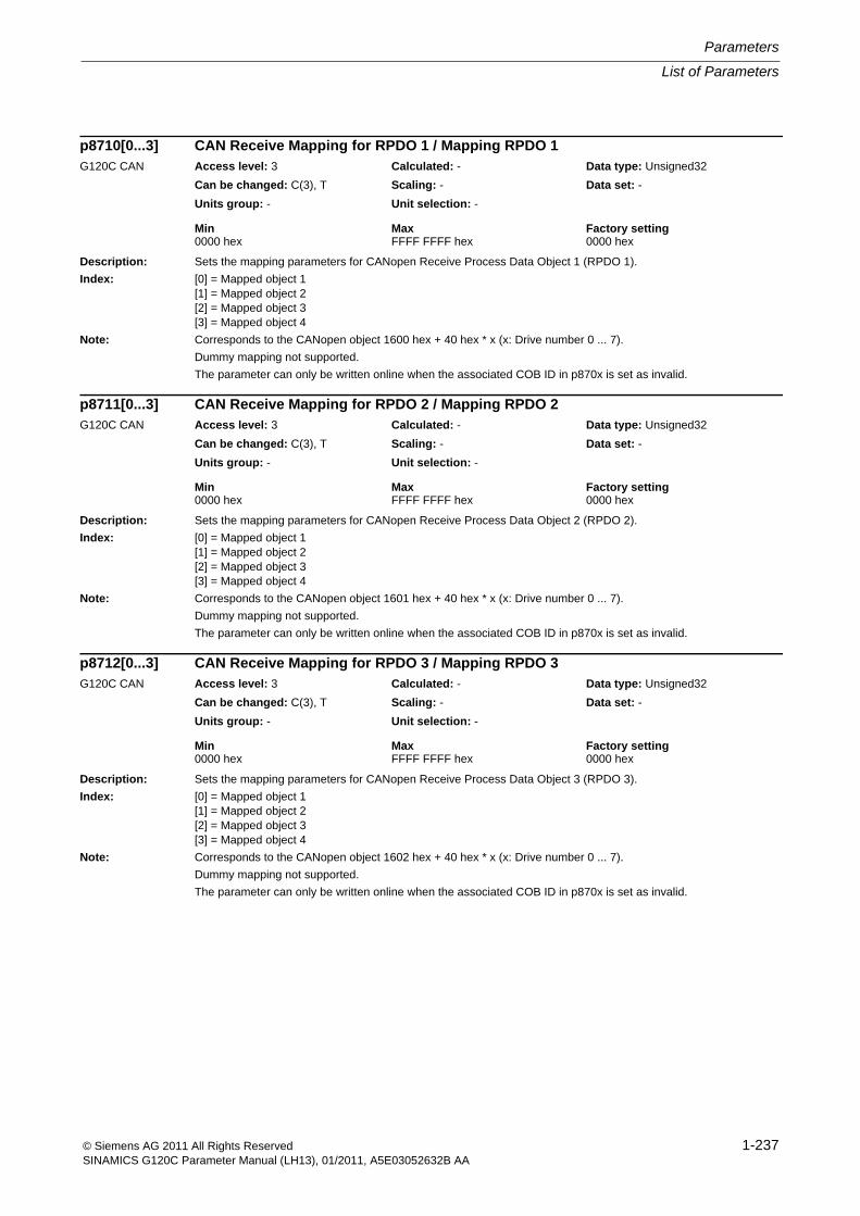
List of Parameters
Parameters
1-237© Siemens AG 2011 All Rights ReservedSINAMICS G120C Parameter Manual (LH13), 01/2011, A5E03052632B AA
Description: Sets the mapping parameters for CANopen Receive Process Data Object 1 (RPDO 1).
Index: [0] = Mapped object 1[1] = Mapped object 2[2] = Mapped object 3[3] = Mapped object 4
Note: Corresponds to the CANopen object 1600 hex + 40 hex * x (x: Drive number 0 ... 7).
Dummy mapping not supported.
The parameter can only be written online when the associated COB ID in p870x is set as invalid.
Description: Sets the mapping parameters for CANopen Receive Process Data Object 2 (RPDO 2).
Index: [0] = Mapped object 1[1] = Mapped object 2[2] = Mapped object 3[3] = Mapped object 4
Note: Corresponds to the CANopen object 1601 hex + 40 hex * x (x: Drive number 0 ... 7).
Dummy mapping not supported.
The parameter can only be written online when the associated COB ID in p870x is set as invalid.
Description: Sets the mapping parameters for CANopen Receive Process Data Object 3 (RPDO 3).
Index: [0] = Mapped object 1[1] = Mapped object 2[2] = Mapped object 3[3] = Mapped object 4
Note: Corresponds to the CANopen object 1602 hex + 40 hex * x (x: Drive number 0 ... 7).
Dummy mapping not supported.
The parameter can only be written online when the associated COB ID in p870x is set as invalid.
p8710[0...3] CAN Receive Mapping for RPDO 1 / Mapping RPDO 1G120C CAN Access level: 3 Calculated: - Data type: Unsigned32
Can be changed: C(3), T Scaling: - Data set: -
Units group: - Unit selection: -
Min Max Factory setting 0000 hex FFFF FFFF hex 0000 hex
p8711[0...3] CAN Receive Mapping for RPDO 2 / Mapping RPDO 2G120C CAN Access level: 3 Calculated: - Data type: Unsigned32
Can be changed: C(3), T Scaling: - Data set: -
Units group: - Unit selection: -
Min Max Factory setting 0000 hex FFFF FFFF hex 0000 hex
p8712[0...3] CAN Receive Mapping for RPDO 3 / Mapping RPDO 3G120C CAN Access level: 3 Calculated: - Data type: Unsigned32
Can be changed: C(3), T Scaling: - Data set: -
Units group: - Unit selection: -
Min Max Factory setting 0000 hex FFFF FFFF hex 0000 hex
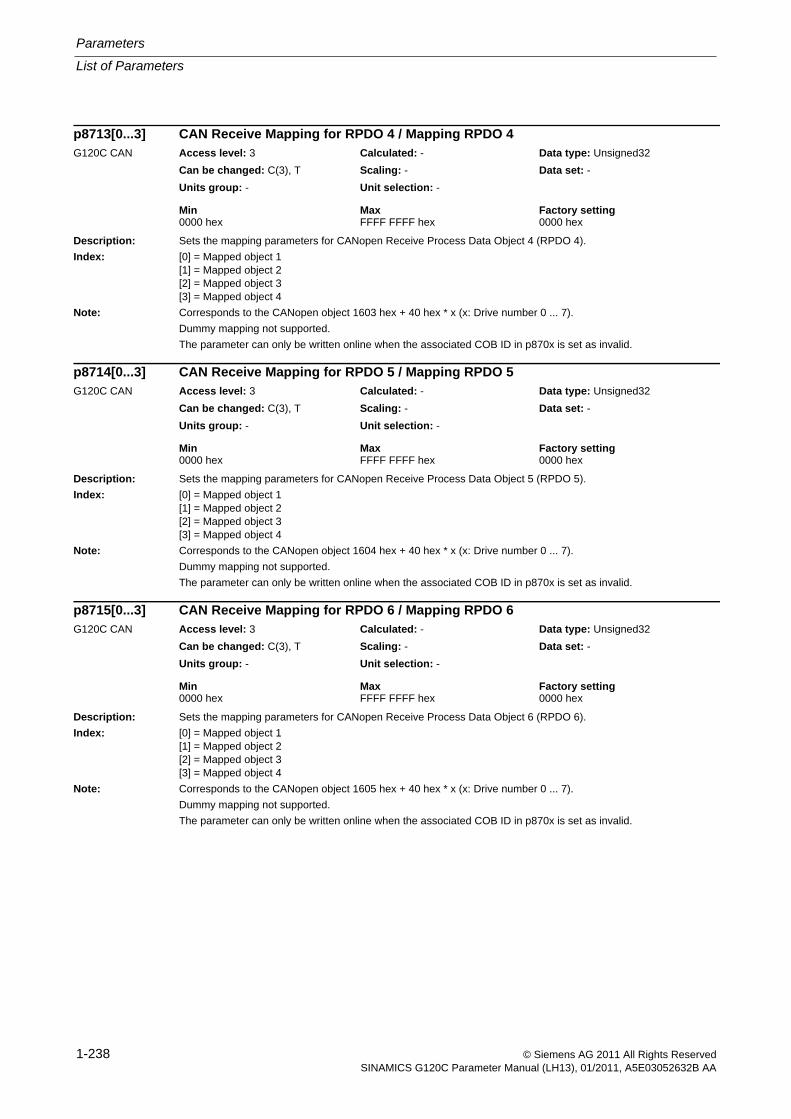
Parameters
List of Parameters
1-238 © Siemens AG 2011 All Rights ReservedSINAMICS G120C Parameter Manual (LH13), 01/2011, A5E03052632B AA
Description: Sets the mapping parameters for CANopen Receive Process Data Object 4 (RPDO 4).
Index: [0] = Mapped object 1[1] = Mapped object 2[2] = Mapped object 3[3] = Mapped object 4
Note: Corresponds to the CANopen object 1603 hex + 40 hex * x (x: Drive number 0 ... 7).
Dummy mapping not supported.
The parameter can only be written online when the associated COB ID in p870x is set as invalid.
Description: Sets the mapping parameters for CANopen Receive Process Data Object 5 (RPDO 5).
Index: [0] = Mapped object 1[1] = Mapped object 2[2] = Mapped object 3[3] = Mapped object 4
Note: Corresponds to the CANopen object 1604 hex + 40 hex * x (x: Drive number 0 ... 7).
Dummy mapping not supported.
The parameter can only be written online when the associated COB ID in p870x is set as invalid.
Description: Sets the mapping parameters for CANopen Receive Process Data Object 6 (RPDO 6).
Index: [0] = Mapped object 1[1] = Mapped object 2[2] = Mapped object 3[3] = Mapped object 4
Note: Corresponds to the CANopen object 1605 hex + 40 hex * x (x: Drive number 0 ... 7).
Dummy mapping not supported.
The parameter can only be written online when the associated COB ID in p870x is set as invalid.
p8713[0...3] CAN Receive Mapping for RPDO 4 / Mapping RPDO 4G120C CAN Access level: 3 Calculated: - Data type: Unsigned32
Can be changed: C(3), T Scaling: - Data set: -
Units group: - Unit selection: -
Min Max Factory setting 0000 hex FFFF FFFF hex 0000 hex
p8714[0...3] CAN Receive Mapping for RPDO 5 / Mapping RPDO 5G120C CAN Access level: 3 Calculated: - Data type: Unsigned32
Can be changed: C(3), T Scaling: - Data set: -
Units group: - Unit selection: -
Min Max Factory setting 0000 hex FFFF FFFF hex 0000 hex
p8715[0...3] CAN Receive Mapping for RPDO 6 / Mapping RPDO 6G120C CAN Access level: 3 Calculated: - Data type: Unsigned32
Can be changed: C(3), T Scaling: - Data set: -
Units group: - Unit selection: -
Min Max Factory setting 0000 hex FFFF FFFF hex 0000 hex
List of Parameters
Parameters
1-239© Siemens AG 2011 All Rights ReservedSINAMICS G120C Parameter Manual (LH13), 01/2011, A5E03052632B AA
Description: Sets the mapping parameters for CANopen Receive Process Data Object 7 (RPDO 7).
Index: [0] = Mapped object 1[1] = Mapped object 2[2] = Mapped object 3[3] = Mapped object 4
Note: Corresponds to the CANopen object 1606 hex + 40 hex * x (x: Drive number 0 ... 7).
Dummy mapping not supported.
The parameter can only be written online when the associated COB ID in p870x is set as invalid.
Description: Sets the mapping parameters for CANopen Receive Process Data Object 8 (RPDO 8).
Index: [0] = Mapped object 1[1] = Mapped object 2[2] = Mapped object 3[3] = Mapped object 4
Note: Corresponds to the CANopen object 1607 hex + 40 hex * x (x: Drive number 0 ... 7).
Dummy mapping not supported.
The parameter can only be written online when the associated COB ID in p870x is set as invalid.
Description: Sets the communication parameters for CANopen Transmit Process Data Object 1 (TPDO 1).Index: [0] = PDO COB-ID
[1] = PDO transmission type[2] = Inhibit time (in 100 µs)[3] = Reserved[4] = Event timer (in ms)
Dependency: A valid COB-ID can only be set for the available (existing) channel.Refer to: p8741
Notice: For inhibit time and even timer, the following apply:A value that is not a multiple integer of CANopen (4 ms) is rounded-off.
Note: Corresponds to the CANopen object 1800 hex + 40 hex * x (x: Drive number 0 ... 7).Transmission types 0, 1 ... F0, FE and FF can be set.PDO: Process Data Object
p8716[0...3] CAN Receive Mapping for RPDO 7 / Mapping RPDO 7G120C CAN Access level: 3 Calculated: - Data type: Unsigned32
Can be changed: C(3), T Scaling: - Data set: -
Units group: - Unit selection: -
Min Max Factory setting 0000 hex FFFF FFFF hex 0000 hex
p8717[0...3] CAN Receive Mapping for RPDO 8 / Mapping RPDO 8G120C CAN Access level: 3 Calculated: - Data type: Unsigned32
Can be changed: C(3), T Scaling: - Data set: -
Units group: - Unit selection: -
Min Max Factory setting 0000 hex FFFF FFFF hex 0000 hex
p8720[0...4] CAN Transmit PDO 1 / Transmit PDO 1G120C CAN Access level: 3 Calculated: - Data type: Unsigned32
Can be changed: C(3), T Scaling: - Data set: -
Units group: - Unit selection: -
Min Max Factory setting 0000 hex C000 06DF hex [0] C000 06DF hex
[1] 00FE hex
[2] 0000 hex
[3] 0000 hex
[4] 0000 hex

Parameters
List of Parameters
1-240 © Siemens AG 2011 All Rights ReservedSINAMICS G120C Parameter Manual (LH13), 01/2011, A5E03052632B AA
Description: Sets the communication parameters for CANopen Transmit Process Data Object 2 (TPDO 2).
Index: [0] = PDO COB-ID[1] = PDO transmission type[2] = Inhibit time (in 100 µs)[3] = Reserved[4] = Event timer (in ms)
Dependency: A valid COB-ID can only be set for the available (existing) channel.
Refer to: p8741
Notice: For inhibit time and even timer, the following apply:
A value that is not a multiple integer of CANopen (4 ms) is rounded-off.
Note: Corresponds to the CANopen object 1801 hex + 40 hex * x (x: Drive number 0 ... 7).
Transmission types 0, 1 ... F0, FE and FF can be set.
PDO: Process Data Object
Description: Sets the communication parameters for CANopen Transmit Process Data Object 3 (TPDO 3).
Index: [0] = PDO COB-ID[1] = PDO transmission type[2] = Inhibit time (in 100 µs)[3] = Reserved[4] = Event timer (in ms)
Dependency: A valid COB-ID can only be set for the available (existing) channel.
Refer to: p8741
Notice: For inhibit time and even timer, the following apply:
A value that is not a multiple integer of CANopen (4 ms) is rounded-off.
Note: Corresponds to the CANopen object 1802 hex + 40 hex * x (x: Drive number 0 ... 7).
Transmission types 0, 1 ... F0, FE and FF can be set.
PDO: Process Data Object
p8721[0...4] CAN Transmit PDO 2 / Transmit PDO 2G120C CAN Access level: 3 Calculated: - Data type: Unsigned32
Can be changed: C(3), T Scaling: - Data set: -
Units group: - Unit selection: -
Min Max Factory setting 0000 hex C000 06DF hex [0] C000 06DF hex
[1] 00FE hex
[2] 0000 hex
[3] 0000 hex
[4] 0000 hex
p8722[0...4] CAN Transmit PDO 3 / Transmit PDO 3G120C CAN Access level: 3 Calculated: - Data type: Unsigned32
Can be changed: C(3), T Scaling: - Data set: -
Units group: - Unit selection: -
Min Max Factory setting 0000 hex C000 06DF hex [0] C000 06DF hex
[1] 00FE hex
[2] 0000 hex
[3] 0000 hex
[4] 0000 hex
List of Parameters
Parameters
1-241© Siemens AG 2011 All Rights ReservedSINAMICS G120C Parameter Manual (LH13), 01/2011, A5E03052632B AA
Description: Sets the communication parameters for CANopen Transmit Process Data Object 4 (TPDO 4).
Index: [0] = PDO COB-ID[1] = PDO transmission type[2] = Inhibit time (in 100 µs)[3] = Reserved[4] = Event timer (in ms)
Dependency: A valid COB-ID can only be set for the available (existing) channel.
Refer to: p8741
Notice: For inhibit time and even timer, the following apply:
A value that is not a multiple integer of CANopen (4 ms) is rounded-off.
Note: Corresponds to the CANopen object 1803 hex + 40 hex * x (x: Drive number 0 ... 7).
Transmission types 0, 1 ... F0, FE and FF can be set.
PDO: Process Data Object
Description: Sets the communication parameters for CANopen Transmit Process Data Object 5 (TPDO 5).
Index: [0] = PDO COB-ID[1] = PDO transmission type[2] = Inhibit time (in 100 µs)[3] = Reserved[4] = Event timer (in ms)
Dependency: A valid COB-ID can only be set for the available (existing) channel.
Refer to: p8741
Notice: For inhibit time and even timer, the following apply:
A value that is not a multiple integer of CANopen (4 ms) is rounded-off.
Note: Corresponds to the CANopen object 1804 hex + 40 hex * x (x: Drive number 0 ... 7).
Transmission types 0, 1 ... F0, FE and FF can be set.
PDO: Process Data Object
p8723[0...4] CAN Transmit PDO 4 / Transmit PDO 4G120C CAN Access level: 3 Calculated: - Data type: Unsigned32
Can be changed: C(3), T Scaling: - Data set: -
Units group: - Unit selection: -
Min Max Factory setting 0000 hex C000 06DF hex [0] C000 06DF hex
[1] 00FE hex
[2] 0000 hex
[3] 0000 hex
[4] 0000 hex
p8724[0...4] CAN Transmit PDO 5 / Transmit PDO 5G120C CAN Access level: 3 Calculated: - Data type: Unsigned32
Can be changed: C(3), T Scaling: - Data set: -
Units group: - Unit selection: -
Min Max Factory setting 0000 hex C000 06DF hex [0] C000 06DF hex
[1] 00FE hex
[2] 0000 hex
[3] 0000 hex
[4] 0000 hex
Parameters
List of Parameters
1-242 © Siemens AG 2011 All Rights ReservedSINAMICS G120C Parameter Manual (LH13), 01/2011, A5E03052632B AA
Description: Sets the communication parameters for CANopen Transmit Process Data Object 6 (TPDO 6).
Index: [0] = PDO COB-ID[1] = PDO transmission type[2] = Inhibit time (in 100 µs)[3] = Reserved[4] = Event timer (in ms)
Dependency: A valid COB-ID can only be set for the available (existing) channel.
Refer to: p8741
Notice: For inhibit time and even timer, the following apply:
A value that is not a multiple integer of CANopen (4 ms) is rounded-off.
Note: Corresponds to the CANopen object 1805 hex + 40 hex * x (x: Drive number 0 ... 7).
Transmission types 0, 1 ... F0, FE and FF can be set.
PDO: Process Data Object
Description: Sets the communication parameters for CANopen Transmit Process Data Object 7 (TPDO 7).
Index: [0] = PDO COB-ID[1] = PDO transmission type[2] = Inhibit time (in 100 µs)[3] = Reserved[4] = Event timer (in ms)
Dependency: A valid COB-ID can only be set for the available (existing) channel.
Refer to: p8741
Notice: For inhibit time and even timer, the following apply:
A value that is not a multiple integer of CANopen (4 ms) is rounded-off.
Note: Corresponds to the CANopen object 1806 hex + 40 hex * x (x: Drive number 0 ... 7).
Transmission types 0, 1 ... F0, FE and FF can be set.
PDO: Process Data Object
p8725[0...4] CAN Transmit PDO 6 / Transmit PDO 6G120C CAN Access level: 3 Calculated: - Data type: Unsigned32
Can be changed: C(3), T Scaling: - Data set: -
Units group: - Unit selection: -
Min Max Factory setting 0000 hex C000 06DF hex [0] C000 06DF hex
[1] 00FE hex
[2] 0000 hex
[3] 0000 hex
[4] 0000 hex
p8726[0...4] CAN Transmit PDO 7 / Transmit PDO 7G120C CAN Access level: 3 Calculated: - Data type: Unsigned32
Can be changed: C(3), T Scaling: - Data set: -
Units group: - Unit selection: -
Min Max Factory setting 0000 hex C000 06DF hex [0] C000 06DF hex
[1] 00FE hex
[2] 0000 hex
[3] 0000 hex
[4] 0000 hex
List of Parameters
Parameters
1-243© Siemens AG 2011 All Rights ReservedSINAMICS G120C Parameter Manual (LH13), 01/2011, A5E03052632B AA
Description: Sets the communication parameters for CANopen Transmit Process Data Object 8 (TPDO 8).
Index: [0] = PDO COB-ID[1] = PDO transmission type[2] = Inhibit time (in 100 µs)[3] = Reserved[4] = Event timer (in ms)
Dependency: A valid COB-ID can only be set for the available (existing) channel.
Refer to: p8741
Notice: For inhibit time and even timer, the following apply:
A value that is not a multiple integer of CANopen (4 ms) is rounded-off.
Note: Corresponds to the CANopen object 1807 hex + 40 hex * x (x: Drive number 0 ... 7).
Transmission types 0, 1 ... F0, FE and FF can be set.
PDO: Process Data Object
Description: Sets the mapping parameters for CANopen Transmit Process Data Object 1 (TPDO 1).
Index: [0] = Mapped object 1[1] = Mapped object 2[2] = Mapped object 3[3] = Mapped object 4
Note: Corresponds to the CANopen object 1A00 hex + 40 hex * x (x: Drive number 0 ... 7).
The parameter can only be written online when the associated COB ID in p872x is set as invalid.
Description: Sets the mapping parameters for CANopen Transmit Process Data Object 2 (TPDO 2).
Index: [0] = Mapped object 1[1] = Mapped object 2[2] = Mapped object 3[3] = Mapped object 4
Note: Corresponds to the CANopen object 1A01 hex + 40 hex * x (x: Drive number 0 ... 7).
The parameter can only be written online when the associated COB ID in p872x is set as invalid.
p8727[0...4] CAN Transmit PDO 8 / Transmit PDO 8G120C CAN Access level: 3 Calculated: - Data type: Unsigned32
Can be changed: C(3), T Scaling: - Data set: -
Units group: - Unit selection: -
Min Max Factory setting 0000 hex C000 06DF hex [0] C000 06DF hex
[1] 00FE hex
[2] 0000 hex
[3] 0000 hex
[4] 0000 hex
p8730[0...3] CAN Transmit Mapping for TPDO 1 / Mapping TPDO 1G120C CAN Access level: 3 Calculated: - Data type: Unsigned32
Can be changed: C(3), T Scaling: - Data set: -
Units group: - Unit selection: -
Min Max Factory setting 0000 hex FFFF FFFF hex 0000 hex
p8731[0...3] CAN Transmit Mapping for TPDO 2 / Mapping TPDO 2G120C CAN Access level: 3 Calculated: - Data type: Unsigned32
Can be changed: C(3), T Scaling: - Data set: -
Units group: - Unit selection: -
Min Max Factory setting 0000 hex FFFF FFFF hex 0000 hex
Parameters
List of Parameters
1-244 © Siemens AG 2011 All Rights ReservedSINAMICS G120C Parameter Manual (LH13), 01/2011, A5E03052632B AA
Description: Sets the mapping parameters for CANopen Transmit Process Data Object 3 (TPDO 3).Index: [0] = Mapped object 1
[1] = Mapped object 2[2] = Mapped object 3[3] = Mapped object 4
Note: Corresponds to the CANopen object 1A02 hex + 40 hex * x (x: Drive number 0 ... 7).The parameter can only be written online when the associated COB ID in p872x is set as invalid.
Description: Sets the mapping parameters for CANopen Transmit Process Data Object 4 (TPDO 4).Index: [0] = Mapped object 1
[1] = Mapped object 2[2] = Mapped object 3[3] = Mapped object 4
Note: Corresponds to the CANopen object 1A03 hex + 40 hex * x (x: Drive number 0 ... 7).The parameter can only be written online when the associated COB ID in p872x is set as invalid.
Description: Sets the mapping parameters for CANopen Transmit Process Data Object 5 (TPDO 5).Index: [0] = Mapped object 1
[1] = Mapped object 2[2] = Mapped object 3[3] = Mapped object 4
Note: Corresponds to the CANopen object 1A04 hex + 40 hex * x (x: Drive number 0 ... 7).The parameter can only be written online when the associated COB ID in p872x is set as invalid.
Description: Sets the mapping parameters for CANopen Transmit Process Data Object 6 (TPDO 6).Index: [0] = Mapped object 1
[1] = Mapped object 2[2] = Mapped object 3[3] = Mapped object 4
Note: Corresponds to the CANopen object 1A05 hex + 40 hex * x (x: Drive number 0 ... 7).The parameter can only be written online when the associated COB ID in p872x is set as invalid.
p8732[0...3] CAN Transmit Mapping for TPDO 3 / Mapping TPDO 3G120C CAN Access level: 3 Calculated: - Data type: Unsigned32
Can be changed: C(3), T Scaling: - Data set: -
Units group: - Unit selection: -
Min Max Factory setting 0000 hex FFFF FFFF hex 0000 hex
p8733[0...3] CAN Transmit Mapping for TPDO 4 / Mapping TPDO 4G120C CAN Access level: 3 Calculated: - Data type: Unsigned32
Can be changed: C(3), T Scaling: - Data set: -
Units group: - Unit selection: -
Min Max Factory setting 0000 hex FFFF FFFF hex 0000 hex
p8734[0...3] CAN Transmit Mapping for TPDO 5 / Mapping TPDO 5G120C CAN Access level: 3 Calculated: - Data type: Unsigned32
Can be changed: C(3), T Scaling: - Data set: -
Units group: - Unit selection: -
Min Max Factory setting 0000 hex FFFF FFFF hex 0000 hex
p8735[0...3] CAN Transmit Mapping for TPDO 6 / Mapping TPDO 6G120C CAN Access level: 3 Calculated: - Data type: Unsigned32
Can be changed: C(3), T Scaling: - Data set: -
Units group: - Unit selection: -
Min Max Factory setting 0000 hex FFFF FFFF hex 0000 hex
List of Parameters
Parameters
1-245© Siemens AG 2011 All Rights ReservedSINAMICS G120C Parameter Manual (LH13), 01/2011, A5E03052632B AA
Description: Sets the mapping parameters for CANopen Transmit Process Data Object 7 (TPDO 7).
Index: [0] = Mapped object 1[1] = Mapped object 2[2] = Mapped object 3[3] = Mapped object 4
Note: Corresponds to the CANopen object 1A06 hex + 40 hex * x (x: Drive number 0 ... 7).
The parameter can only be written online when the associated COB ID in p872x is set as invalid.
Description: Sets the mapping parameters for CANopen Transmit Process Data Object 8 (TPDO 8).
Index: [0] = Mapped object 1[1] = Mapped object 2[2] = Mapped object 3[3] = Mapped object 4
Note: Corresponds to the CANopen object 1A07 hex + 40 hex * x (x: Drive number 0 ... 7).
The parameter can only be written online when the associated COB ID in p872x is set as invalid.
Description: Acknowledges the setting of the Predefined Connection Sets (p8744).
Value: 0: Inactive1: Acknowledge configuration
Dependency: Refer to: p8744
Description: Selector switch for the PDO mapping.
Sets the mapping for download or in the online mode after acknowledging with p8741.
Value: 1: Predefined Connection Set2: Free PDO Mapping
p8736[0...3] CAN Transmit Mapping for TPDO 7 / Mapping TPDO 7G120C CAN Access level: 3 Calculated: - Data type: Unsigned32
Can be changed: C(3), T Scaling: - Data set: -
Units group: - Unit selection: -
Min Max Factory setting 0000 hex FFFF FFFF hex 0000 hex
p8737[0...3] CAN Transmit Mapping for TPDO 8 / Mapping TPDO 8G120C CAN Access level: 3 Calculated: - Data type: Unsigned32
Can be changed: C(3), T Scaling: - Data set: -
Units group: - Unit selection: -
Min Max Factory setting 0000 hex FFFF FFFF hex 0000 hex
p8741 CAN PDO configuration acknowledgement / PDO config acknG120C CAN Access level: 3 Calculated: - Data type: Integer16
Can be changed: T Scaling: - Data set: -
Units group: - Unit selection: -
Min Max Factory setting 0 1 0
p8744 CAN PDO mapping configuration / PDO Mapping conf.G120C CAN Access level: 2 Calculated: - Data type: Integer16
Can be changed: C, T Scaling: - Data set: -
Units group: - Unit selection: -
Min Max Factory setting 1 2 2
Parameters
List of Parameters
1-246 © Siemens AG 2011 All Rights ReservedSINAMICS G120C Parameter Manual (LH13), 01/2011, A5E03052632B AA
Description: Displays the mapped 16-bit receive CANopen objects in the process data buffer.
Example:
If, e.g. the control word is mapped in an RPDO, then r8750 indicates the position of the control word in the process data buffer.
Index: [0] = PZD 1[1] = PZD 2[2] = PZD 3[3] = PZD 4[4] = PZD 5[5] = PZD 6[6] = PZD 7[7] = PZD 8[8] = PZD 9[9] = PZD 10[10] = PZD 11[11] = PZD 12[12] = PZD 13[13] = PZD 14[14] = PZD 15[15] = PZD 16
Description: Displays mapped 16-bit transmit CANopen objects in the process data buffer.
Index: [0] = PZD 1[1] = PZD 2[2] = PZD 3[3] = PZD 4[4] = PZD 5[5] = PZD 6[6] = PZD 7[7] = PZD 8[8] = PZD 9[9] = PZD 10[10] = PZD 11[11] = PZD 12[12] = PZD 13[13] = PZD 14[14] = PZD 15[15] = PZD 16
Dependency: Refer to: r8750
r8750[0...15] CAN mapped 16-bit receive objects / RPDO 16 mappedG120C CAN Access level: 3 Calculated: - Data type: Unsigned16
Can be changed: - Scaling: - Data set: -
Units group: - Unit selection: -
Min Max Factory setting - - -
r8751[0...15] CAN mapped 16-bit transmit objects / TPDO 16 mappedG120C CAN Access level: 3 Calculated: - Data type: Unsigned16
Can be changed: - Scaling: - Data set: -
Units group: - Unit selection: -
Min Max Factory setting - - -
List of Parameters
Parameters
1-247© Siemens AG 2011 All Rights ReservedSINAMICS G120C Parameter Manual (LH13), 01/2011, A5E03052632B AA
Description: Displays the CANopen status word.
Note: Corresponds to the CANopen object 6041 hex + 800 hex * x (x: Drive number 0 ... 7).
Description: Binector input for CANopen status word bit 8.
Dependency: Refer to: r8784
Description: Binector input for CANopen status word bit 14.
Dependency: Refer to: r8784
Description: Binector input for CANopen status word bit 15.
Dependency: Refer to: r8784
r8784 CO: CAN status word / Status wordG120C CAN Access level: 3 Calculated: - Data type: Unsigned16
Can be changed: - Scaling: - Data set: -
Units group: - Unit selection: -
Min Max Factory setting - - -
Bit field: Bit Signal name 1 signal 0 signal FP00 Rdy for switch on Yes No -01 Ready Yes No -02 Operation enabled Yes No -03 Fault present Yes No -04 No coasting active Yes No -05 No Quick Stop active Yes No -06 Switching on inhibited active Yes No -07 Alarm present Yes No -08 Can be freely interconnected (BI: p8785) High Low -09 Control request Yes No -10 Target reached Yes No -11 Torque limit reached Yes No -12 Velocity equal to zero Yes No -14 Can be freely interconnected (BI: p8786) High Low -15 Can be freely interconnected (BI: p8787) High Low -
p8785 BI: CAN status word bit 8 / Status word bit 8G120C CAN Access level: 3 Calculated: - Data type: U32 / Binary
Can be changed: T Scaling: - Data set: -
Units group: - Unit selection: -
Min Max Factory setting - - 0
p8786 BI: CAN status word bit 14 / Status word bit 14G120C CAN Access level: 3 Calculated: - Data type: U32 / Binary
Can be changed: T Scaling: - Data set: -
Units group: - Unit selection: -
Min Max Factory setting - - 0
p8787 BI: CAN status word bit 15 / Status word bit 15G120C CAN Access level: 3 Calculated: - Data type: U32 / Binary
Can be changed: T Scaling: - Data set: -
Units group: - Unit selection: -
Min Max Factory setting - - 0
Parameters
List of Parameters
1-248 © Siemens AG 2011 All Rights ReservedSINAMICS G120C Parameter Manual (LH13), 01/2011, A5E03052632B AA
Description: Sets the automatic BICO interconnection of the CANopen control word.
Value: 0: No interconn1: Interconnection
Dependency: Refer to: r2050, r2090, r2091, r2092, r2093, r8750, r8795
Note: The following BICO interconnections are automatically established if the CANopen control word is mapped at one of the locations x = 0 ... 3 in the receive process data buffer.
BI: p0840.0 = r209x.0
BI: p0844.0 = r209x.1
BI: p0848.0 = r209x.2
BI: p0852.0 = r209x.3
BI: p2103.0 = r209x.7
The write access is rejected if a CANopen control word is not mapped at one of these locations.
This also causes the project download of the commissioning software to be canceled.
Description: Access to the CANopen control word using SDO transfer.
Dependency: Refer to: p8790
Note: Corresponds to the CANopen object 6040 hex + 800 hex * x (x: Drive number 0 ... 7).
Description: Access to the CANopen object target torque using SDO transfer.
The value is displayed as per mille (1/1000) as standard.
Note: Corresponds to the CANopen object 6071 hex + 800 hex * x (x: Drive number 0 ... 7).
The displayed value is calculated as follows:
r8797 [per mille] = M_set [Nm] / p0333 [Nm] * 1000
p8790 CAN control word - auto interconnection / STW interc autoG120C CAN Access level: 3 Calculated: - Data type: Integer16
Can be changed: C(3), T Scaling: - Data set: -
Units group: - Unit selection: -
Min Max Factory setting 0 1 0
r8795 CAN control word / Control wordG120C CAN Access level: 3 Calculated: - Data type: Unsigned16
Can be changed: - Scaling: - Data set: -
Units group: - Unit selection: -
Min Max Factory setting - - -
Bit field: Bit Signal name 1 signal 0 signal FP00 ON/OFF1 Yes No -01 Do not activate coast down Yes No -02 Do not activate a Quick Stop Yes No -03 Operation enable Yes No -07 Acknowledge fault Yes No -11 Freely interconn High Low -12 Freely interconn High Low -13 Freely interconn High Low -14 Freely interconn High Low -15 Freely interconn High Low -
r8797 CAN Target Torque / Target torqueG120C CAN Access level: 3 Calculated: - Data type: Integer16
Can be changed: - Scaling: - Data set: -
Units group: - Unit selection: -
Min Max Factory setting - - -
List of Parameters
Parameters
1-249© Siemens AG 2011 All Rights ReservedSINAMICS G120C Parameter Manual (LH13), 01/2011, A5E03052632B AA
Description: Selects the storage medium for access via the USB mass storage.
Value: 1: Memory card2: Flash r/w internal
Note: A change only becomes effective after a POWER ON.
The parameter is not influenced by setting the factory setting.
Description: Selecting the USB functionality.
Value: 1: USS commissioning via the virtual COM port2: Only memory access3: USB commissioning and memory access
Note: COMM: Commissioning.
A change only becomes effective after a POWER ON.
The parameter is not influenced by setting the factory setting.
Description: Setting and display when memory card is "removed safely".
Procedure:
Setting p9400 = 2 results in a value of 3
--> The memory card can be removed safely. After removal the value sets itself to 0 automatically.
Setting p9400 = 2 results in a value of 100
--> The memory card cannot be removed safely. Removal may destroy the file system on the memory card. It may be necessary to set p9400 = 2 again.
Value: 0: No memory card inserted1: Memory card inserted2: Request "safe removal" of the memory card3: "Safe removal" possible100: "Safe removal" not possible due to access
Dependency: Refer to: r9401
Caution: Removing the memory card without a request (p9400 = 2) and confirmation (p9400 = 3) may destroy the file system on the memory card. The memory card will then no longer work properly and must be repaired.
Note: The status when the memory card is being "removed safely" is shown in r9401.
Re value = 0, 1, 3, 100:
These values can only be displayed, not set.
p8991 USB memory access / USB memoryAccess level: 3 Calculated: - Data type: Integer16
Can be changed: T Scaling: - Data set: -
Units group: - Unit selection: -
Min Max Factory setting 1 2 1
p8999 USB functionality / USB functionalityAccess level: 4 Calculated: - Data type: Integer16
Can be changed: T Scaling: - Data set: -
Units group: - Unit selection: -
Min Max Factory setting 1 3 3
p9400 Safely remove memory card / Mem_card remAccess level: 2 Calculated: - Data type: Integer16
Can be changed: T Scaling: - Data set: -
Units group: - Unit selection: -
Min Max Factory setting 0 100 0
Parameters
List of Parameters
1-250 © Siemens AG 2011 All Rights ReservedSINAMICS G120C Parameter Manual (LH13), 01/2011, A5E03052632B AA
Description: Displays the status of the memory card.
Dependency: Refer to: p9400
Note: Re bit 00 and bit 01:
Bit 1/0 = 0/0: No memory card inserted (corresponds to p9400 = 0).
Bit 1/0 = 0/1: "Safe removal" possible (corresponds to p9400 = 3).
Bit 1/0 = 1/0: Status not possible.
Bit 1/0 = 1/1: Memory card inserted (corresponds to p9400 = 1, 2, 100).
Description: Displays the valid macro.
A value of 0 is displayed if a parameter set by a macro is changed.
Description: Sets the signal source (BO/CO parameter, BICO coded) to search in the signal sinks.
The signal source to be searched for is set in p9484 (BICO-coded) and the search result is specified using the num-ber (r9485) and the first index (r9486).
Dependency: Refer to: r9485, r9486
Description: Displays the number of BICO interconnections to the signal sink being searched for.
Dependency: Refer to: p9484, r9486
Note: The signal source to be searched is set in p9484 (BICO-coded).
The search result is contained in r9482 and r9483 and is specified by the count (r9485) and the first index (r9486).
r9401 Safely remove memory card status / Mem_card rem statAccess level: 2 Calculated: - Data type: Unsigned16
Can be changed: - Scaling: - Data set: -
Units group: - Unit selection: -
Min Max Factory setting - - -
Bit field: Bit Signal name 1 signal 0 signal FP00 Memory card inserted Yes No -01 Memory card activated Yes No -
r9463 Set valid macro / Access level: 3 Calculated: - Data type: Unsigned32
Can be changed: - Scaling: - Data set: -
Units group: - Unit selection: -
Min Max Factory setting 0 999999 -
p9484 BICO interconnections search signal source / BICO S_src srchAccess level: 3 Calculated: - Data type: Unsigned32
Can be changed: U, T Scaling: - Data set: -
Units group: - Unit selection: -
Min Max Factory setting 0 4294967295 0
r9485 BICO interconnections signal source search count / BICO S_src srchQtyAccess level: 3 Calculated: - Data type: Unsigned16
Can be changed: - Scaling: - Data set: -
Units group: - Unit selection: -
Min Max Factory setting - - -
List of Parameters
Parameters
1-251© Siemens AG 2011 All Rights ReservedSINAMICS G120C Parameter Manual (LH13), 01/2011, A5E03052632B AA
Description: Displays the first index of the signal source being searched for.
The signal source to be searched for is set in p9484 (BICO-coded) and the search result is specified using the num-ber (r9485) and the first index (r9486).
Dependency: Refer to: p9484, r9485
Note: The signal source to be searched is set in p9484 (BICO-coded).
The search result is contained in r9482 and r9483 and is specified by the count (r9485) and the first index (r9486).
Description: Sets the enable signals for safety functions on processor 1 that are integrated in the drive.
Not all of the settings listed below will be permissible, depending on the Control Unit being used:
- p9601 = 0: Safety functions integrated in the drive disabled.
- p9601 = 1: STO enabled via terminals. Permissible if r9771.0 = 1.
- p9601 = 4: Motion monitoring functions integrated in the drive enabled via an integrated F-DI. Permissible if r9771.5 = 1.
- p9601 = 8: STO enabled via PROFIsafe. Permissible if r9771.6 = 1.
- p9601 = 9: STO enabled via PROFIsafe and STO via terminals. Permissible if r9771.6 = 1.
- p9601 = 12: Motion monitoring functions integrated in the drive enabled via PROFIsafe. Permissible if r9771.4 = 1.
- p9601 = 13: Motion monitoring functions integrated in the drive enabled via PROFIsafe and STO via terminals. Permissible if r9771.4 = 1.
Dependency: Refer to: r9771, p9801
Note: A change only becomes effective after a POWER ON.
F-DI: Failsafe Digital Input.
STO: Safe Torque Off
r9486 BICO interconnections signal source search first index / BICO S_src srchIdxAccess level: 3 Calculated: - Data type: Unsigned16
Can be changed: - Scaling: - Data set: -
Units group: - Unit selection: -
Min Max Factory setting - - -
p9601 SI enable, functions integrated in the drive (processor 1) / SI enable fct P1G120C CAN
G120C USS/MB
Access level: 3 Calculated: - Data type: Unsigned32
Can be changed: C(95) Scaling: - Data set: -
Units group: - Unit selection: -
Min Max Factory setting - - 0000 bin
Bit field: Bit Signal name 1 signal 0 signal FP00 Enable STO via terminals (processor 1) Enable Inhibit 2810
Parameters
List of Parameters
1-252 © Siemens AG 2011 All Rights ReservedSINAMICS G120C Parameter Manual (LH13), 01/2011, A5E03052632B AA
Description: Sets the enable signals for safety functions on processor 1 that are integrated in the drive.
Not all of the settings listed below will be permissible, depending on the Control Unit being used:
- p9601 = 0: Safety functions integrated in the drive disabled.
- p9601 = 1: STO enabled via terminals. Permissible if r9771.0 = 1.
- p9601 = 4: Motion monitoring functions integrated in the drive enabled via an integrated F-DI. Permissible if r9771.5 = 1.
- p9601 = 8: STO enabled via PROFIsafe. Permissible if r9771.6 = 1.
- p9601 = 9: STO enabled via PROFIsafe and STO via terminals. Permissible if r9771.6 = 1.
- p9601 = 12: Motion monitoring functions integrated in the drive enabled via PROFIsafe. Permissible if r9771.4 = 1.
- p9601 = 13: Motion monitoring functions integrated in the drive enabled via PROFIsafe and STO via terminals. Permissible if r9771.4 = 1.
Dependency: Refer to: r9771, p9801
Note: A change only becomes effective after a POWER ON.
F-DI: Failsafe Digital Input.
STO: Safe Torque Off
Description: Sets the PROFIsafe address for processor 1.
Dependency: Refer to: p9810
Description: Sets the tolerance time for the changeover of the failsafe digital input for STO on processor 1.
An F-DI changeover is not effective simultaneously due to the different runtimes in the two monitoring channels. After an F-DI changeover, dynamic data is not subject to a crosswise data comparison during this tolerance time.
Dependency: Refer to: p9850
Note: For a crosswise data comparison between p9650 and p9850, a difference of one Safety monitoring clock cycle is tolerated.
The parameterized time is internally rounded-off to an integer multiple of the monitoring clock cycle.
F-DI: Failsafe Digital Input
p9601 SI enable, functions integrated in the drive (processor 1) / SI enable fct P1G120C DP Access level: 3 Calculated: - Data type: Unsigned32
Can be changed: C(95) Scaling: - Data set: -
Units group: - Unit selection: -
Min Max Factory setting - - 0000 bin
Bit field: Bit Signal name 1 signal 0 signal FP00 Enable STO via terminals (processor 1) Enable Inhibit 281003 Enable PROFIsafe (processor 1) Enable Inhibit -
p9610 SI PROFIsafe address (processor 1) / SI PROFIsafe P1G120C DP Access level: 3 Calculated: - Data type: Unsigned16
Can be changed: C(95) Scaling: - Data set: -
Units group: - Unit selection: -
Min Max Factory setting 0000 hex FFFE hex 0000 hex
p9650 SI F-DI changeover tolerance time (processor 1) / SI F-DI_chg tol P1Access level: 3 Calculated: - Data type: FloatingPoint32
Can be changed: C(95) Scaling: - Data set: -
Units group: - Unit selection: -
Min Max Factory setting 0.00 [ms] 2000.00 [ms] 500.00 [ms]
List of Parameters
Parameters
1-253© Siemens AG 2011 All Rights ReservedSINAMICS G120C Parameter Manual (LH13), 01/2011, A5E03052632B AA
Description: Sets the debounce time for the failsafe digital inputs used to control the "STO" function.
The debounce time is rounded to whole milliseconds.
Note: The debounce time is rounded to whole milliseconds. It specifies the maximum duration of a fault pulse at the fail-safe digital inputs with no reaction/influence on the selection or deselection of the Safety Basic Functions.
Example:
Debounce time = 1 ms: Fault pulses of 1 ms are filtered; only pulses longer than 2 ms are processed.
Debounce time = 3 ms: Fault pulses of 3 ms are filtered; only pulses longer than 4 ms are processed.
Description: Sets the time interval for carrying out the forced checking procedure and testing the Safety shutdown paths.
Within the parameterized time, STO must have been de-selected at least once. The monitoring time is reset each time that STO is de-selected.
Dependency: Refer to: A01699
Note: STO: Safe Torque Off
Description: Displays the time remaining before dynamization and testing of the safety shutdown paths (forced checking proce-dure).
Dependency: Refer to: A01699
p9651 SI STO debounce time (processor 1) / SI STO t_debou P1Access level: 3 Calculated: - Data type: FloatingPoint32
Can be changed: C(95) Scaling: - Data set: -
Units group: - Unit selection: -
Min Max Factory setting 0.00 [ms] 100.00 [ms] 1.00 [ms]
p9659 SI forced checking procedure timer / SI FrcdCkProcTimerAccess level: 3 Calculated: - Data type: FloatingPoint32
Can be changed: C(95) Scaling: - Data set: -
Units group: - Unit selection: -
Min Max Factory setting 0.00 [h] 9000.00 [h] 8.00 [h]
r9660 SI forced checking procedure remaining time / SI frc chk remainAccess level: 3 Calculated: - Data type: FloatingPoint32
Can be changed: - Scaling: - Data set: -
Units group: - Unit selection: -
Min Max Factory setting - [h] - [h] - [h]
Parameters
List of Parameters
1-254 © Siemens AG 2011 All Rights ReservedSINAMICS G120C Parameter Manual (LH13), 01/2011, A5E03052632B AA
Description: Setting to start the required copy function.
After starting, the corresponding parameters are copied from processor 1 to processor 2.
Once copying is complete, the parameter is automatically reset to zero.
Value: 0: [00 hex] Copy function ended29: [1D hex] Start copy function node identifier87: [57 hex] Start copy function SI parameters208: [D0 hex] Start copy function SI basic parameters
Dependency: Refer to: r3996
Notice: When the parameters are copied, short-term communication interruptions may occur.
Note: Re value = 57 hex and D0 hex:
The value can only be set if the safety commissioning mode is set and the Safety Integrated password was entered.
Re value = D0 hex:
The following parameters are copied after starting the copy function:
p9601 --> p9801, p9610 --> 9810, p9650 --> p9850, p9651 --> p9851
Description: Setting to transfer the reference checksums from the associated actual checksums after changes (SI parameters, hardware).
After transferring the reference checksums, parameters are automatically reset to zero.
Value: 0: [00 hex] Data unchanged172: [AC hex] Acknowledge data change complete220: [DC hex] Acknowledge SI basic parameter change236: [EC hex] Acknowledge hardware CRC
Dependency: Refer to: r9798, p9799, r9898, p9899
Note: Re value = AC and DC hex:
These values can only be set if the safety commissioning mode is set and the Safety Integrated password was entered.
Description: Enters the Safety Integrated password.
Dependency: Refer to: F01659
Note: It is not possible to change Safety Integrated parameters until the Safety Integrated password has been entered.
p9700 SI copy function / SI copy functionAccess level: 3 Calculated: - Data type: Integer16
Can be changed: C(95), U, T Scaling: - Data set: -
Units group: - Unit selection: -
Min Max Factory setting 0000 hex 00D0 hex 0000 hex
p9701 Acknowledge SI data change / Ackn SI dataAccess level: 3 Calculated: - Data type: Integer16
Can be changed: C(95), U, T Scaling: - Data set: -
Units group: - Unit selection: -
Min Max Factory setting 0000 hex 00EC hex 0000 hex
p9761 SI password input / SI password inpAccess level: 3 Calculated: - Data type: Unsigned32
Can be changed: C, T Scaling: - Data set: -
Units group: - Unit selection: -
Min Max Factory setting 0000 hex FFFF FFFF hex 0000 hex
List of Parameters
Parameters
1-255© Siemens AG 2011 All Rights ReservedSINAMICS G120C Parameter Manual (LH13), 01/2011, A5E03052632B AA
Description: Enters a new Safety Integrated password.
Dependency: A change made to the Safety Integrated password must be acknowledged in the following parameter:
Refer to: p9763
Description: Acknowledges the new Safety Integrated password.
Dependency: Refer to: p9762
Note: The new password entered into p9762 must be re-entered in order to acknowledge.
p9762 = p9763 = 0 is automatically set after the new Safety Integrated password has been successfully acknowl-edged.
Description: Displays the Safety Integrated version for the drive-integrated safety functions on processor 1.
Index: [0] = Safety Version (major release)[1] = Safety Version (minor release)[2] = Safety Version (baselevel or patch)[3] = Safety Version (hotfix)
Note: Example:
r9770[0] = 2, r9770[1] = 60, r9770[2] = 1, r9770[3] = 0 --> Safety version V02.60.01.00
Description: Displays the supported Safety Integrated monitoring functions.
Processor 1 determines this display.
Dependency: Refer to: r9871
Note: STO: Safe Torque Off
p9762 SI password new / SI password newAccess level: 3 Calculated: - Data type: Unsigned32
Can be changed: C(95) Scaling: - Data set: -
Units group: - Unit selection: -
Min Max Factory setting 0000 hex FFFF FFFF hex 0000 hex
p9763 SI password acknowledgement / SI ackn passwordAccess level: 3 Calculated: - Data type: Unsigned32
Can be changed: C(95) Scaling: - Data set: -
Units group: - Unit selection: -
Min Max Factory setting 0000 hex FFFF FFFF hex 0000 hex
r9770[0...3] SI version drive-integrated safety function (processor 1) / SI version Drv P1Access level: 3 Calculated: - Data type: Unsigned16
Can be changed: - Scaling: - Data set: -
Units group: - Unit selection: -
Min Max Factory setting - - -
r9771 SI common functions (processor 1) / SI general fct P1G120C CAN
G120C USS/MB
Access level: 3 Calculated: - Data type: Unsigned32
Can be changed: - Scaling: - Data set: -
Units group: - Unit selection: -
Min Max Factory setting - - -
Bit field: Bit Signal name 1 signal 0 signal FP00 STO supported via terminals Yes No 2804
Parameters
List of Parameters
1-256 © Siemens AG 2011 All Rights ReservedSINAMICS G120C Parameter Manual (LH13), 01/2011, A5E03052632B AA
Description: Displays the supported Safety Integrated monitoring functions.
Processor 1 determines this display.
Dependency: Refer to: r9871
Note: STO: Safe Torque Off
Description: Displays the Safety Integrated status on processor 1.
Dependency: Refer to: r9872
Note: Re bit 00:
When STO is selected, the cause is displayed in bits 16 ... 20.
Re bit 18:
When the bit is set, STO is selected via PROFIsafe.
Re bit 19:
For the drive-integrated motion monitoring functions, due to OFF2, no actual value sensing possible.
r9771 SI common functions (processor 1) / SI general fct P1G120C DP Access level: 3 Calculated: - Data type: Unsigned32
Can be changed: - Scaling: - Data set: -
Units group: - Unit selection: -
Min Max Factory setting - - -
Bit field: Bit Signal name 1 signal 0 signal FP00 STO supported via terminals Yes No 280406 Basic Functions PROFIsafe supported Yes No -
r9772.0...20 CO/BO: SI status (processor 1) / SI status P1Access level: 2 Calculated: - Data type: Unsigned32
Can be changed: - Scaling: - Data set: -
Units group: - Unit selection: -
Min Max Factory setting - - -
Bit field: Bit Signal name 1 signal 0 signal FP00 STO selected on processor 1 Yes No 281001 STO active on processor 1 Yes No 281009 STOP A cannot be acknowledged, active Yes No 280210 STOP A active Yes No 280215 STOP F active Yes No 280216 STO cse: Safety comm. mode Yes No -17 STO cause selection via terminal (Basic
Functions)Yes No -
18 STO cause: Selection via motion monitoring functions
Yes No -
19 STO cause actual value missing Yes No -20 STO cause selection PROFIsafe (Basic
Functions)Yes No -
List of Parameters
Parameters
1-257© Siemens AG 2011 All Rights ReservedSINAMICS G120C Parameter Manual (LH13), 01/2011, A5E03052632B AA
Description: Displays the Safety Integrated status on the drive (processor 1 + processor 2).
Note: This status is formed from the AND operation of the relevant status of the two monitoring channels.
Description: The parameter is used for diagnostics.
Note: Re bit 00 = 1:
At least one Safety parameter has been changed that will only take effect after a POWER ON.
Description: Displays the clock cycle time for the Safety Integrated Basic Functions on processor 1.
Description: Displays the checksum for tracking changes for Safety Integrated.
These are additional checksums that are created to track changes (fingerprint for the "safety logbook" functionality) to safety parameters (that are relevant for checksums).
Index: [0] = SI checksum to track functional changes[1] = SI checksum to track hardware-specific changes
Dependency: Refer to: p9601, p9799
r9773.0...31 CO/BO: SI status (processor 1 + processor 2) / SI status P1+P2Access level: 2 Calculated: - Data type: Unsigned32
Can be changed: - Scaling: - Data set: -
Units group: - Unit selection: -
Min Max Factory setting - - -
Bit field: Bit Signal name 1 signal 0 signal FP00 STO selected in drive Yes No 280401 STO active in drive Yes No 280431 Shutdown paths must be tested Yes No 2810
r9776 SI diagnostics / SI diagnosticsAccess level: 4 Calculated: - Data type: Unsigned32
Can be changed: - Scaling: - Data set: -
Units group: - Unit selection: -
Min Max Factory setting - - -
Bit field: Bit Signal name 1 signal 0 signal FP00 Safety parameter changed POWER ON
requiredYes No -
r9780 SI monitoring clock cycle (processor 1) / SI mon_clk cyc P1Access level: 3 Calculated: - Data type: FloatingPoint32
Can be changed: - Scaling: - Data set: -
Units group: - Unit selection: -
Min Max Factory setting - [ms] - [ms] - [ms]
r9781[0...1] SI checksum to check changes (processor 1) / SI chg chksm P1Access level: 3 Calculated: - Data type: Unsigned32
Can be changed: - Scaling: - Data set: -
Units group: - Unit selection: -
Min Max Factory setting - - -
Parameters
List of Parameters
1-258 © Siemens AG 2011 All Rights ReservedSINAMICS G120C Parameter Manual (LH13), 01/2011, A5E03052632B AA
Description: Displays the time stamps for the checksums for tracking changes for Safety Integrated.
The time stamps for the checksums for tracking changes (fingerprint for the "safety logbook" functionality) made to safety parameters are saved in parameters p9781[0] and p9781[1].
Index: [0] = SI time stamp for checksum to track functional changes[1] = SI time stamp for checksum to track hardware-specific changes
Dependency: Refer to: p9601, p9799
Description: Displays the numbers of the data items that are currently being compared crosswise on processor 1.
The content of the list of crosswise-compared data is dependent upon the particular application.
Note: Example:
r9794[0] = 1 (monitoring clock cycle)
r9794[1] = 2 (enable safety functions)
r9794[2] = 3 (F-DI changeover, tolerance time)
...
A complete list of numbers for crosswise-compared data items appears in fault F01611.
Description: Displays the number of the cross-checked data item which caused STOP F on processor 1.
Dependency: Refer to: F01611
Note: A complete list of numbers for crosswise-compared data items appears in fault F01611.
Description: Displays the checksum for the Safety Integrated parameters checked using checksums on processor 1 (actual checksum).
Dependency: Refer to: p9799, r9898
r9782[0...1] SI time stamp to check changes (processor 1) / SI chg t P1Access level: 3 Calculated: - Data type: FloatingPoint32
Can be changed: - Scaling: - Data set: -
Units group: - Unit selection: -
Min Max Factory setting - [h] - [h] - [h]
r9794[0...19] SI crosswise comparison list (processor 1) / SI CDC_list P1Access level: 3 Calculated: - Data type: Unsigned16
Can be changed: - Scaling: - Data set: -
Units group: - Unit selection: -
Min Max Factory setting - - -
r9795 SI diagnostics STOP F (processor 1) / SI diag STOP F P1Access level: 2 Calculated: - Data type: Unsigned32
Can be changed: - Scaling: - Data set: -
Units group: - Unit selection: -
Min Max Factory setting - - -
r9798 SI actual checksum SI parameters (processor 1) / SI act chksm P1Access level: 3 Calculated: - Data type: Unsigned32
Can be changed: - Scaling: - Data set: -
Units group: - Unit selection: -
Min Max Factory setting - - -
List of Parameters
Parameters
1-259© Siemens AG 2011 All Rights ReservedSINAMICS G120C Parameter Manual (LH13), 01/2011, A5E03052632B AA
Description: Sets the checksum for the Safety Integrated parameters checked using checksums on processor 1 (setpoint check-sum).
Dependency: Refer to: r9798, p9899
Description: Sets the enable signals for safety functions on processor 2 that are integrated in the drive.
Not all of the settings listed below will be permissible, depending on the Control Unit being used:
- p9801 = 0: Safety functions integrated in the drive disabled.
- p9801 = 1: STO enabled via terminals. Permissible if r9871.0 = 1.
- p9801 = 4: Motion monitoring functions integrated in the drive enabled via an integrated F-DI. Permissible if r9871.5 = 1.
- p9801 = 8: STO enabled via PROFIsafe. Permissible if r9871.6 = 1.
- p9801 = 9: STO enabled via PROFIsafe and STO via terminals. Permissible if r9871.6 = 1.
- p9801 = 12: Motion monitoring functions integrated in the drive enabled via PROFIsafe. Permissible if r9871.4 = 1.
- p9801 = 13: Motion monitoring functions integrated in the drive enabled via PROFIsafe and STO via terminals. Permissible if r9871.4 = 1.
Dependency: Refer to: p9601, r9871
Notice: This parameter is overwritten by the copy function of the safety functions integrated in the drive.
Note: A change only becomes effective after a POWER ON.
F-DI: Failsafe Digital Input.
STO: Safe Torque Off
p9799 SI setpoint checksum SI parameters (processor 1) / SI setp_chksm P1Access level: 3 Calculated: - Data type: Unsigned32
Can be changed: C(95) Scaling: - Data set: -
Units group: - Unit selection: -
Min Max Factory setting 0000 hex FFFF FFFF hex 0000 hex
p9801 SI enable, functions integrated in the drive (processor 2) / SI enable fct P2G120C CAN
G120C USS/MB
Access level: 3 Calculated: - Data type: Unsigned16
Can be changed: C(95) Scaling: - Data set: -
Units group: - Unit selection: -
Min Max Factory setting - - 0000 bin
Bit field: Bit Signal name 1 signal 0 signal FP00 Enable STO via terminals (processor 2) Enable Inhibit 2810
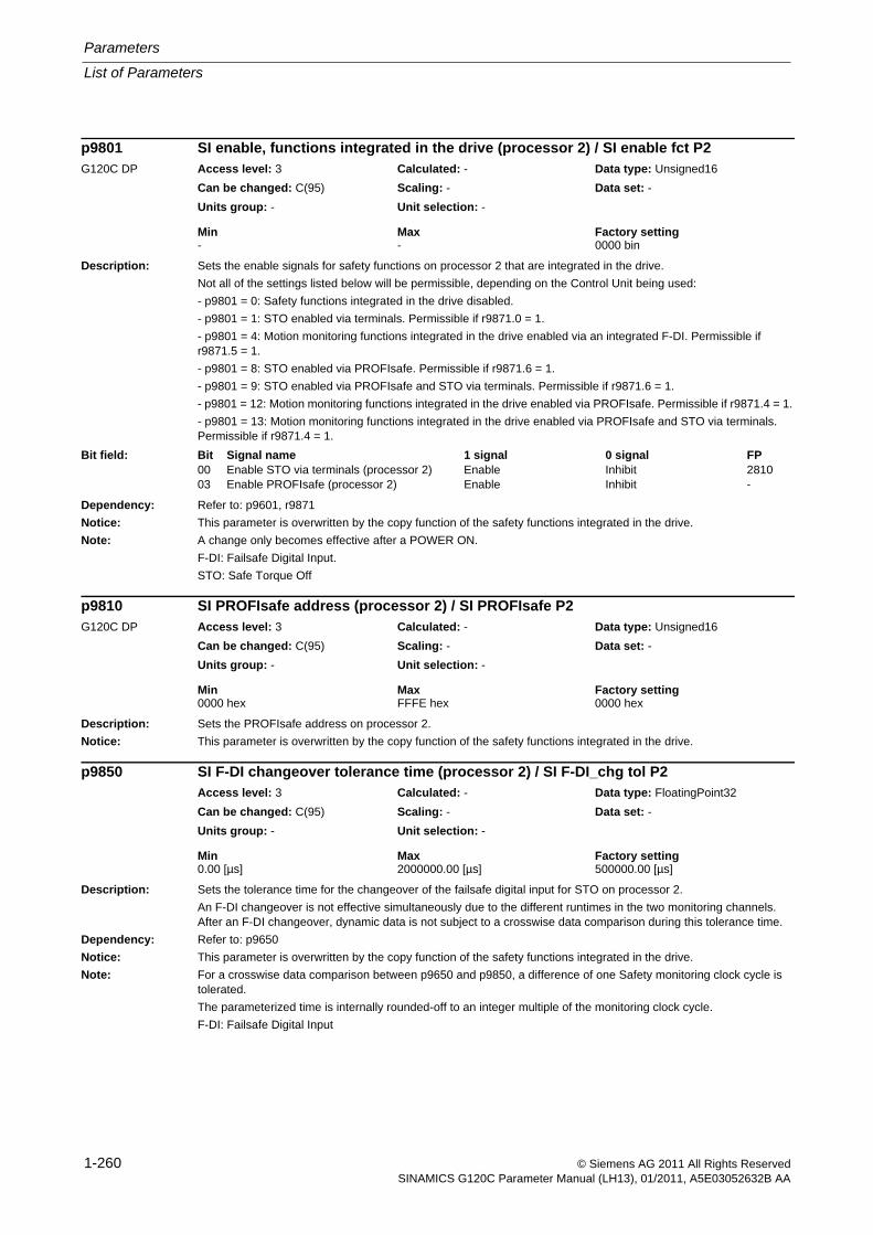
Parameters
List of Parameters
1-260 © Siemens AG 2011 All Rights ReservedSINAMICS G120C Parameter Manual (LH13), 01/2011, A5E03052632B AA
Description: Sets the enable signals for safety functions on processor 2 that are integrated in the drive.
Not all of the settings listed below will be permissible, depending on the Control Unit being used:
- p9801 = 0: Safety functions integrated in the drive disabled.
- p9801 = 1: STO enabled via terminals. Permissible if r9871.0 = 1.
- p9801 = 4: Motion monitoring functions integrated in the drive enabled via an integrated F-DI. Permissible if r9871.5 = 1.
- p9801 = 8: STO enabled via PROFIsafe. Permissible if r9871.6 = 1.
- p9801 = 9: STO enabled via PROFIsafe and STO via terminals. Permissible if r9871.6 = 1.
- p9801 = 12: Motion monitoring functions integrated in the drive enabled via PROFIsafe. Permissible if r9871.4 = 1.
- p9801 = 13: Motion monitoring functions integrated in the drive enabled via PROFIsafe and STO via terminals. Permissible if r9871.4 = 1.
Dependency: Refer to: p9601, r9871
Notice: This parameter is overwritten by the copy function of the safety functions integrated in the drive.
Note: A change only becomes effective after a POWER ON.
F-DI: Failsafe Digital Input.
STO: Safe Torque Off
Description: Sets the PROFIsafe address on processor 2.
Notice: This parameter is overwritten by the copy function of the safety functions integrated in the drive.
Description: Sets the tolerance time for the changeover of the failsafe digital input for STO on processor 2.
An F-DI changeover is not effective simultaneously due to the different runtimes in the two monitoring channels. After an F-DI changeover, dynamic data is not subject to a crosswise data comparison during this tolerance time.
Dependency: Refer to: p9650
Notice: This parameter is overwritten by the copy function of the safety functions integrated in the drive.
Note: For a crosswise data comparison between p9650 and p9850, a difference of one Safety monitoring clock cycle is tolerated.
The parameterized time is internally rounded-off to an integer multiple of the monitoring clock cycle.
F-DI: Failsafe Digital Input
p9801 SI enable, functions integrated in the drive (processor 2) / SI enable fct P2G120C DP Access level: 3 Calculated: - Data type: Unsigned16
Can be changed: C(95) Scaling: - Data set: -
Units group: - Unit selection: -
Min Max Factory setting - - 0000 bin
Bit field: Bit Signal name 1 signal 0 signal FP00 Enable STO via terminals (processor 2) Enable Inhibit 281003 Enable PROFIsafe (processor 2) Enable Inhibit -
p9810 SI PROFIsafe address (processor 2) / SI PROFIsafe P2G120C DP Access level: 3 Calculated: - Data type: Unsigned16
Can be changed: C(95) Scaling: - Data set: -
Units group: - Unit selection: -
Min Max Factory setting 0000 hex FFFE hex 0000 hex
p9850 SI F-DI changeover tolerance time (processor 2) / SI F-DI_chg tol P2Access level: 3 Calculated: - Data type: FloatingPoint32
Can be changed: C(95) Scaling: - Data set: -
Units group: - Unit selection: -
Min Max Factory setting 0.00 [µs] 2000000.00 [µs] 500000.00 [µs]
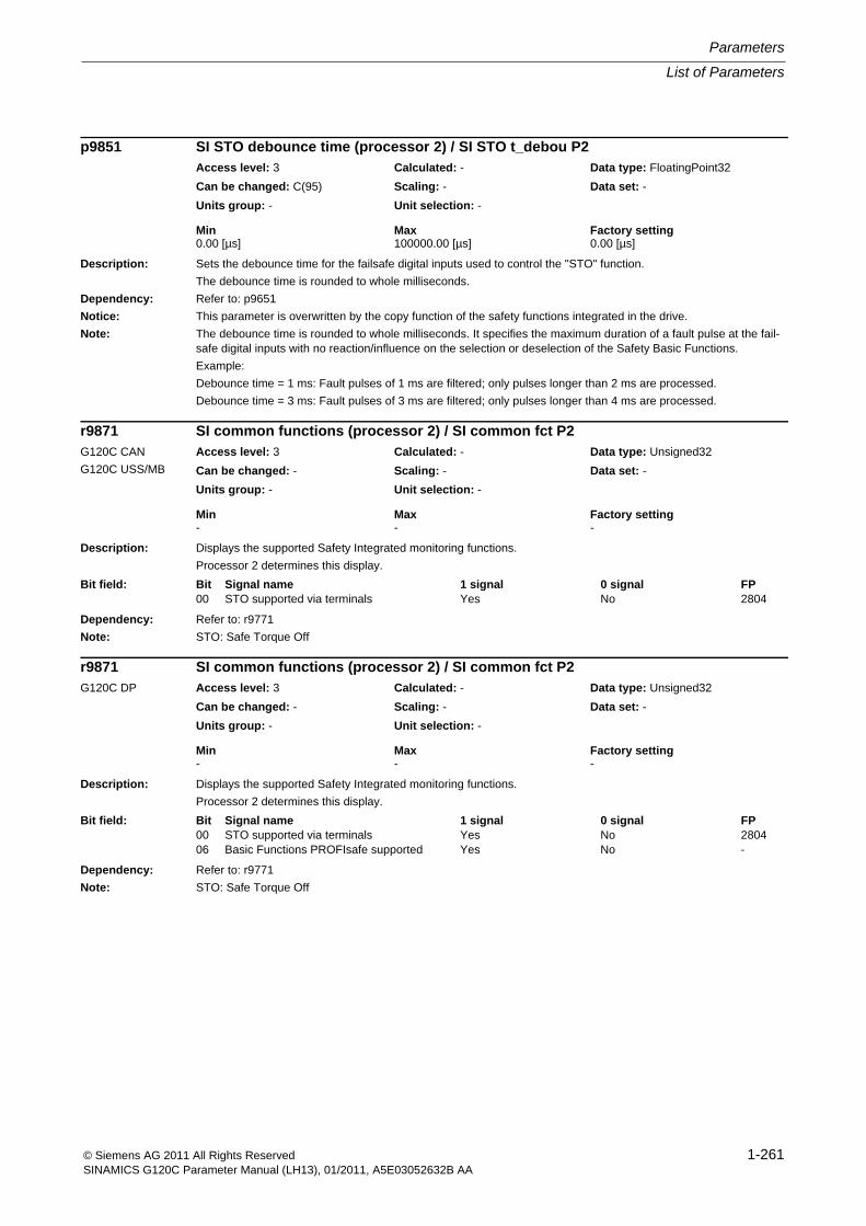
List of Parameters
Parameters
1-261© Siemens AG 2011 All Rights ReservedSINAMICS G120C Parameter Manual (LH13), 01/2011, A5E03052632B AA
Description: Sets the debounce time for the failsafe digital inputs used to control the "STO" function.
The debounce time is rounded to whole milliseconds.
Dependency: Refer to: p9651
Notice: This parameter is overwritten by the copy function of the safety functions integrated in the drive.
Note: The debounce time is rounded to whole milliseconds. It specifies the maximum duration of a fault pulse at the fail-safe digital inputs with no reaction/influence on the selection or deselection of the Safety Basic Functions.
Example:
Debounce time = 1 ms: Fault pulses of 1 ms are filtered; only pulses longer than 2 ms are processed.
Debounce time = 3 ms: Fault pulses of 3 ms are filtered; only pulses longer than 4 ms are processed.
Description: Displays the supported Safety Integrated monitoring functions.
Processor 2 determines this display.
Dependency: Refer to: r9771
Note: STO: Safe Torque Off
Description: Displays the supported Safety Integrated monitoring functions.
Processor 2 determines this display.
Dependency: Refer to: r9771
Note: STO: Safe Torque Off
p9851 SI STO debounce time (processor 2) / SI STO t_debou P2Access level: 3 Calculated: - Data type: FloatingPoint32
Can be changed: C(95) Scaling: - Data set: -
Units group: - Unit selection: -
Min Max Factory setting 0.00 [µs] 100000.00 [µs] 0.00 [µs]
r9871 SI common functions (processor 2) / SI common fct P2G120C CAN
G120C USS/MB
Access level: 3 Calculated: - Data type: Unsigned32
Can be changed: - Scaling: - Data set: -
Units group: - Unit selection: -
Min Max Factory setting - - -
Bit field: Bit Signal name 1 signal 0 signal FP00 STO supported via terminals Yes No 2804
r9871 SI common functions (processor 2) / SI common fct P2G120C DP Access level: 3 Calculated: - Data type: Unsigned32
Can be changed: - Scaling: - Data set: -
Units group: - Unit selection: -
Min Max Factory setting - - -
Bit field: Bit Signal name 1 signal 0 signal FP00 STO supported via terminals Yes No 280406 Basic Functions PROFIsafe supported Yes No -
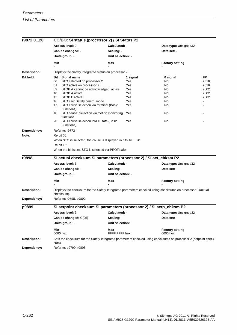
Parameters
List of Parameters
1-262 © Siemens AG 2011 All Rights ReservedSINAMICS G120C Parameter Manual (LH13), 01/2011, A5E03052632B AA
Description: Displays the Safety Integrated status on processor 2.
Dependency: Refer to: r9772
Note: Re bit 00:
When STO is selected, the cause is displayed in bits 16 ... 20.
Re bit 18:
When the bit is set, STO is selected via PROFIsafe.
Description: Displays the checksum for the Safety Integrated parameters checked using checksums on processor 2 (actual checksum).
Dependency: Refer to: r9798, p9899
Description: Sets the checksum for the Safety Integrated parameters checked using checksums on processor 2 (setpoint check-sum).
Dependency: Refer to: p9799, r9898
r9872.0...20 CO/BO: SI status (processor 2) / SI Status P2Access level: 2 Calculated: - Data type: Unsigned32
Can be changed: - Scaling: - Data set: -
Units group: - Unit selection: -
Min Max Factory setting - - -
Bit field: Bit Signal name 1 signal 0 signal FP00 STO selected on processor 2 Yes No 281001 STO active on processor 2 Yes No 281009 STOP A cannot be acknowledged, active Yes No 280210 STOP A active Yes No 280215 STOP F active Yes No 280216 STO cse: Safety comm. mode Yes No -17 STO cause selection via terminal (Basic
Functions)Yes No -
18 STO cause: Selection via motion monitoring functions
Yes No -
20 STO cause selection PROFIsafe (Basic Functions)
Yes No -
r9898 SI actual checksum SI parameters (processor 2) / SI act_chksm P2Access level: 3 Calculated: - Data type: Unsigned32
Can be changed: - Scaling: - Data set: -
Units group: - Unit selection: -
Min Max Factory setting - - -
p9899 SI setpoint checksum SI parameters (processor 2) / SI setp_chksm P2Access level: 3 Calculated: - Data type: Unsigned32
Can be changed: C(95) Scaling: - Data set: -
Units group: - Unit selection: -
Min Max Factory setting 0000 hex FFFF FFFF hex 0000 hex
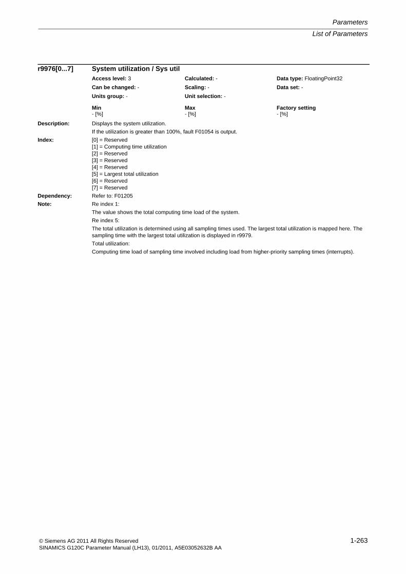
List of Parameters
Parameters
1-263© Siemens AG 2011 All Rights ReservedSINAMICS G120C Parameter Manual (LH13), 01/2011, A5E03052632B AA
Description: Displays the system utilization.
If the utilization is greater than 100%, fault F01054 is output.
Index: [0] = Reserved[1] = Computing time utilization[2] = Reserved[3] = Reserved[4] = Reserved[5] = Largest total utilization[6] = Reserved[7] = Reserved
Dependency: Refer to: F01205
Note: Re index 1:
The value shows the total computing time load of the system.
Re index 5:
The total utilization is determined using all sampling times used. The largest total utilization is mapped here. The sampling time with the largest total utilization is displayed in r9979.
Total utilization:
Computing time load of sampling time involved including load from higher-priority sampling times (interrupts).
r9976[0...7] System utilization / Sys utilAccess level: 3 Calculated: - Data type: FloatingPoint32
Can be changed: - Scaling: - Data set: -
Units group: - Unit selection: -
Min Max Factory setting - [%] - [%] - [%]
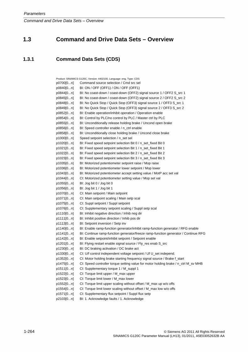
Parameters
Command and Drive Data Sets – Overview
1-264 © Siemens AG 2011 All Rights ReservedSINAMICS G120C Parameter Manual (LH13), 01/2011, A5E03052632B AA
1.3 Command and Drive Data Sets – Overview
1.3.1 Command Data Sets (CDS)
Product: SINAMICS G120C, Version: 4402100, Language: eng, Type: CDS
p0700[0...n] Command source selection / Cmd src sel
p0840[0...n] BI: ON / OFF (OFF1) / ON / OFF (OFF1)
p0844[0...n] BI: No coast-down / coast-down (OFF2) signal source 1 / OFF2 S_src 1
p0845[0...n] BI: No coast-down / coast-down (OFF2) signal source 2 / OFF2 S_src 2
p0848[0...n] BI: No Quick Stop / Quick Stop (OFF3) signal source 1 / OFF3 S_src 1
p0849[0...n] BI: No Quick Stop / Quick Stop (OFF3) signal source 2 / OFF3 S_src 2
p0852[0...n] BI: Enable operation/inhibit operation / Operation enable
p0854[0...n] BI: Control by PLC/no control by PLC / Master ctrl by PLC
p0855[0...n] BI: Unconditionally release holding brake / Uncond open brake
p0856[0...n] BI: Speed controller enable / n_ctrl enable
p0858[0...n] BI: Unconditionally close holding brake / Uncond close brake
p1000[0...n] Speed setpoint selection / n_set sel
p1020[0...n] BI: Fixed speed setpoint selection Bit 0 / n_set_fixed Bit 0
p1021[0...n] BI: Fixed speed setpoint selection Bit 1 / n_set_fixed Bit 1
p1022[0...n] BI: Fixed speed setpoint selection Bit 2 / n_set_fixed Bit 2
p1023[0...n] BI: Fixed speed setpoint selection Bit 3 / n_set_fixed Bit 3
p1035[0...n] BI: Motorized potentiometer setpoint raise / Mop raise
p1036[0...n] BI: Motorized potentiometer lower setpoint / Mop lower
p1043[0...n] BI: Motorized potentiometer accept setting value / MotP acc set val
p1044[0...n] CI: Motorized potentiometer setting value / Mop set val
p1055[0...n] BI: Jog bit 0 / Jog bit 0
p1056[0...n] BI: Jog bit 1 / Jog bit 1
p1070[0...n] CI: Main setpoint / Main setpoint
p1071[0...n] CI: Main setpoint scaling / Main setp scal
p1075[0...n] CI: Suppl setpoint / Suppl setpoint
p1076[0...n] CI: Supplementary setpoint scaling / Suppl setp scal
p1110[0...n] BI: Inhibit negative direction / Inhib neg dir
p1111[0...n] BI: Inhibit positive direction / Inhib pos dir
p1113[0...n] BI: Setpoint inversion / Setp inv
p1140[0...n] BI: Enable ramp-function generator/inhibit ramp-function generator / RFG enable
p1141[0...n] BI: Continue ramp-function generator/freeze ramp-function generator / Continue RFG
p1142[0...n] BI: Enable setpoint/inhibit setpoint / Setpoint enable
p1201[0...n] BI: Flying restart enable signal source / Fly_res enab S_src
p1230[0...n] BI: DC braking activation / DC brake act
p1330[0...n] CI: U/f control independent voltage setpoint / Uf U_set independ.
p1352[0...n] CI: Motor holding brake starting frequency signal source / Brake f_start
p1475[0...n] CI: Speed controller torque setting value for motor holding brake / n_ctrl M_sv MHB
p1511[0...n] CI: Supplementary torque 1 / M_suppl 1
p1522[0...n] CI: Torque limit upper / M_max upper
p1523[0...n] CI: Torque limit lower / M_max lower
p1552[0...n] CI: Torque limit upper scaling without offset / M_max up w/o offs
p1554[0...n] CI: Torque limit lower scaling without offset / M_max low w/o offs
p1571[0...n] CI: Supplementary flux setpoint / Suppl flux setp
p2103[0...n] BI: 1. Acknowledge faults / 1. Acknowledge
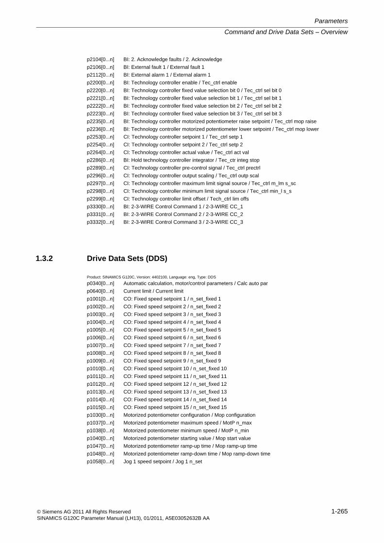
Command and Drive Data Sets – Overview
Parameters
1-265© Siemens AG 2011 All Rights ReservedSINAMICS G120C Parameter Manual (LH13), 01/2011, A5E03052632B AA
p2104[0...n] BI: 2. Acknowledge faults / 2. Acknowledge
p2106[0...n] BI: External fault 1 / External fault 1
p2112[0...n] BI: External alarm 1 / External alarm 1
p2200[0...n] BI: Technology controller enable / Tec_ctrl enable
p2220[0...n] BI: Technology controller fixed value selection bit 0 / Tec_ctrl sel bit 0
p2221[0...n] BI: Technology controller fixed value selection bit 1 / Tec_ctrl sel bit 1
p2222[0...n] BI: Technology controller fixed value selection bit 2 / Tec_ctrl sel bit 2
p2223[0...n] BI: Technology controller fixed value selection bit 3 / Tec_ctrl sel bit 3
p2235[0...n] BI: Technology controller motorized potentiometer raise setpoint / Tec_ctrl mop raise
p2236[0...n] BI: Technology controller motorized potentiometer lower setpoint / Tec_ctrl mop lower
p2253[0...n] CI: Technology controller setpoint 1 / Tec_ctrl setp 1
p2254[0...n] CI: Technology controller setpoint 2 / Tec_ctrl setp 2
p2264[0...n] CI: Technology controller actual value / Tec_ctrl act val
p2286[0...n] BI: Hold technology controller integrator / Tec_ctr integ stop
p2289[0...n] CI: Technology controller pre-control signal / Tec_ctrl prectrl
p2296[0...n] CI: Technology controller output scaling / Tec_ctrl outp scal
p2297[0...n] CI: Technology controller maximum limit signal source / Tec_ctrl m_lm s_sc
p2298[0...n] CI: Technology controller minimum limit signal source / Tec_ctrl min_l s_s
p2299[0...n] CI: Technology controller limit offset / Tech_ctrl lim offs
p3330[0...n] BI: 2-3-WIRE Control Command 1 / 2-3-WIRE CC_1
p3331[0...n] BI: 2-3-WIRE Control Command 2 / 2-3-WIRE CC_2
p3332[0...n] BI: 2-3-WIRE Control Command 3 / 2-3-WIRE CC_3
1.3.2 Drive Data Sets (DDS)
Product: SINAMICS G120C, Version: 4402100, Language: eng, Type: DDS
p0340[0...n] Automatic calculation, motor/control parameters / Calc auto par
p0640[0...n] Current limit / Current limit
p1001[0...n] CO: Fixed speed setpoint 1 / n_set_fixed 1
p1002[0...n] CO: Fixed speed setpoint 2 / n_set_fixed 2
p1003[0...n] CO: Fixed speed setpoint 3 / n_set_fixed 3
p1004[0...n] CO: Fixed speed setpoint 4 / n_set_fixed 4
p1005[0...n] CO: Fixed speed setpoint 5 / n_set_fixed 5
p1006[0...n] CO: Fixed speed setpoint 6 / n_set_fixed 6
p1007[0...n] CO: Fixed speed setpoint 7 / n_set_fixed 7
p1008[0...n] CO: Fixed speed setpoint 8 / n_set_fixed 8
p1009[0...n] CO: Fixed speed setpoint 9 / n_set_fixed 9
p1010[0...n] CO: Fixed speed setpoint 10 / n_set_fixed 10
p1011[0...n] CO: Fixed speed setpoint 11 / n_set_fixed 11
p1012[0...n] CO: Fixed speed setpoint 12 / n_set_fixed 12
p1013[0...n] CO: Fixed speed setpoint 13 / n_set_fixed 13
p1014[0...n] CO: Fixed speed setpoint 14 / n_set_fixed 14
p1015[0...n] CO: Fixed speed setpoint 15 / n_set_fixed 15
p1030[0...n] Motorized potentiometer configuration / Mop configuration
p1037[0...n] Motorized potentiometer maximum speed / MotP n_max
p1038[0...n] Motorized potentiometer minimum speed / MotP n_min
p1040[0...n] Motorized potentiometer starting value / Mop start value
p1047[0...n] Motorized potentiometer ramp-up time / Mop ramp-up time
p1048[0...n] Motorized potentiometer ramp-down time / Mop ramp-down time
p1058[0...n] Jog 1 speed setpoint / Jog 1 n_set
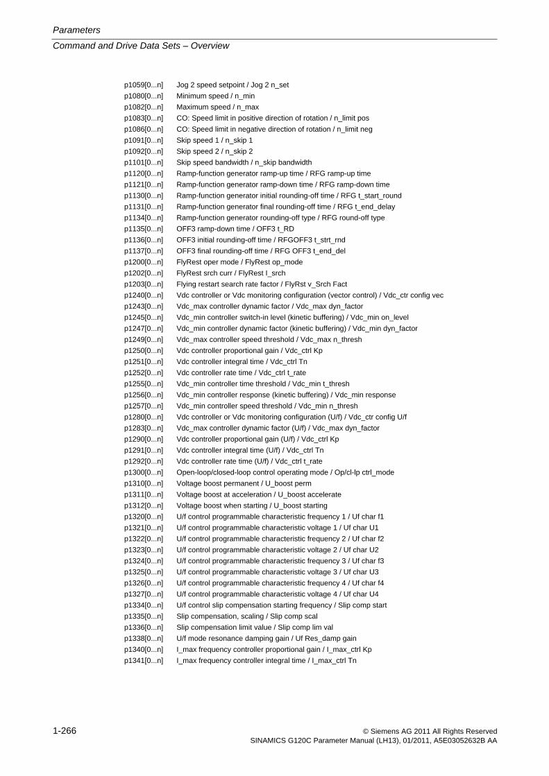
Parameters
Command and Drive Data Sets – Overview
1-266 © Siemens AG 2011 All Rights ReservedSINAMICS G120C Parameter Manual (LH13), 01/2011, A5E03052632B AA
p1059[0...n] Jog 2 speed setpoint / Jog 2 n_set
p1080[0...n] Minimum speed / n_min
p1082[0...n] Maximum speed / n_max
p1083[0...n] CO: Speed limit in positive direction of rotation / n_limit pos
p1086[0...n] CO: Speed limit in negative direction of rotation / n_limit neg
p1091[0...n] Skip speed 1 / n_skip 1
p1092[0...n] Skip speed 2 / n_skip 2
p1101[0...n] Skip speed bandwidth / n_skip bandwidth
p1120[0...n] Ramp-function generator ramp-up time / RFG ramp-up time
p1121[0...n] Ramp-function generator ramp-down time / RFG ramp-down time
p1130[0...n] Ramp-function generator initial rounding-off time / RFG t_start_round
p1131[0...n] Ramp-function generator final rounding-off time / RFG t_end_delay
p1134[0...n] Ramp-function generator rounding-off type / RFG round-off type
p1135[0...n] OFF3 ramp-down time / OFF3 t_RD
p1136[0...n] OFF3 initial rounding-off time / RFGOFF3 t_strt_rnd
p1137[0...n] OFF3 final rounding-off time / RFG OFF3 t_end_del
p1200[0...n] FlyRest oper mode / FlyRest op_mode
p1202[0...n] FlyRest srch curr / FlyRest I_srch
p1203[0...n] Flying restart search rate factor / FlyRst v_Srch Fact
p1240[0...n] Vdc controller or Vdc monitoring configuration (vector control) / Vdc_ctr config vec
p1243[0...n] Vdc_max controller dynamic factor / Vdc_max dyn_factor
p1245[0...n] Vdc_min controller switch-in level (kinetic buffering) / Vdc_min on_level
p1247[0...n] Vdc_min controller dynamic factor (kinetic buffering) / Vdc_min dyn_factor
p1249[0...n] Vdc_max controller speed threshold / Vdc_max n_thresh
p1250[0...n] Vdc controller proportional gain / Vdc_ctrl Kp
p1251[0...n] Vdc controller integral time / Vdc_ctrl Tn
p1252[0...n] Vdc controller rate time / Vdc_ctrl t_rate
p1255[0...n] Vdc_min controller time threshold / Vdc_min t_thresh
p1256[0...n] Vdc_min controller response (kinetic buffering) / Vdc_min response
p1257[0...n] Vdc_min controller speed threshold / Vdc_min n_thresh
p1280[0...n] Vdc controller or Vdc monitoring configuration (U/f) / Vdc_ctr config U/f
p1283[0...n] Vdc_max controller dynamic factor (U/f) / Vdc_max dyn_factor
p1290[0...n] Vdc controller proportional gain (U/f) / Vdc_ctrl Kp
p1291[0...n] Vdc controller integral time (U/f) / Vdc_ctrl Tn
p1292[0...n] Vdc controller rate time (U/f) / Vdc_ctrl t_rate
p1300[0...n] Open-loop/closed-loop control operating mode / Op/cl-lp ctrl_mode
p1310[0...n] Voltage boost permanent / U_boost perm
p1311[0...n] Voltage boost at acceleration / U_boost accelerate
p1312[0...n] Voltage boost when starting / U_boost starting
p1320[0...n] U/f control programmable characteristic frequency 1 / Uf char f1
p1321[0...n] U/f control programmable characteristic voltage 1 / Uf char U1
p1322[0...n] U/f control programmable characteristic frequency 2 / Uf char f2
p1323[0...n] U/f control programmable characteristic voltage 2 / Uf char U2
p1324[0...n] U/f control programmable characteristic frequency 3 / Uf char f3
p1325[0...n] U/f control programmable characteristic voltage 3 / Uf char U3
p1326[0...n] U/f control programmable characteristic frequency 4 / Uf char f4
p1327[0...n] U/f control programmable characteristic voltage 4 / Uf char U4
p1334[0...n] U/f control slip compensation starting frequency / Slip comp start
p1335[0...n] Slip compensation, scaling / Slip comp scal
p1336[0...n] Slip compensation limit value / Slip comp lim val
p1338[0...n] U/f mode resonance damping gain / Uf Res_damp gain
p1340[0...n] I_max frequency controller proportional gain / I_max_ctrl Kp
p1341[0...n] I_max frequency controller integral time / I_max_ctrl Tn
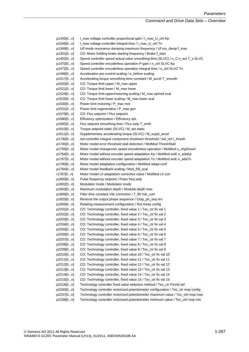
Command and Drive Data Sets – Overview
Parameters
1-267© Siemens AG 2011 All Rights ReservedSINAMICS G120C Parameter Manual (LH13), 01/2011, A5E03052632B AA
p1345[0...n] I_max voltage controller proportional gain / I_max_U_ctrl Kp
p1346[0...n] I_max voltage controller integral time / I_max_U_ctrl Tn
p1349[0...n] U/f mode resonance damping maximum frequency / Uf res_damp f_max
p1351[0...n] CO: Motor holding brake starting frequency / Brake f_start
p1452[0...n] Speed controller speed actual value smoothing time (SLVC) / n_C n_act T_s SLVC
p1470[0...n] Speed controller encoderless operation P-gain / n_ctrl SLVC Kp
p1472[0...n] Speed controller encoderless operation integral time / n_ctrl SLVC Tn
p1496[0...n] Acceleration pre-control scaling / a_before scaling
p1517[0...n] Accelerating torque smoothing time constant / M_accel T_smooth
p1520[0...n] CO: Torque limit upper / M_max upper
p1521[0...n] CO: Torque limit lower / M_max lower
p1524[0...n] CO: Torque limit upper/motoring scaling / M_max up/mot scal
p1525[0...n] CO: Torque limit lower scaling / M_max lower scal
p1530[0...n] Power limit motoring / P_max mot
p1531[0...n] Power limit regenerative / P_max gen
p1570[0...n] CO: Flux setpoint / Flux setpoint
p1580[0...n] Efficiency optimization / Efficiency opt.
p1582[0...n] Flux setpoint smoothing time / Flux setp T_smth
p1610[0...n] Torque setpoint static (SLVC) / M_set static
p1611[0...n] Supplementary accelerating torque (SLVC) / M_suppl_accel
p1730[0...n] Isd controller integral component shutdown threshold / Isd_ctrl I_thresh
p1745[0...n] Motor model error threshold stall detection / MotMod ThreshStall
p1755[0...n] Motor model changeover speed encoderless operation / MotMod n_chgSnsorl
p1764[0...n] Motor model without encoder speed adaptation Kp / MotMod woE n_adaKp
p1767[0...n] Motor model without encoder speed adaptation Tn / MotMod woE n_adaTn
p1780[0...n] Motor model adaptation configuration / MotMod adapt conf
p1784[0...n] Motor model feedback scaling / Mod_FB_scal
r1787[0...n] Motor model Lh adaptation corrective value / MotMod Lh corr
p1800[0...n] Pulse frequency setpoint / Pulse freq setp
p1802[0...n] Modulator mode / Modulator mode
p1803[0...n] Maximum modulation depth / Modulat depth max
p1806[0...n] Filter time constant Vdc correction / T_filt Vdc_corr
p1820[0...n] Reverse the output phase sequence / Outp_ph_seq rev
p1959[0...n] Rotating measurement configuration / Rot meas config
p2201[0...n] CO: Technology controller, fixed value 1 / Tec_ctr fix val 1
p2202[0...n] CO: Technology controller, fixed value 2 / Tec_ctr fix val 2
p2203[0...n] CO: Technology controller, fixed value 3 / Tec_ctr fix val 3
p2204[0...n] CO: Technology controller, fixed value 4 / Tec_ctr fix val 4
p2205[0...n] CO: Technology controller, fixed value 5 / Tec_ctr fix val 5
p2206[0...n] CO: Technology controller, fixed value 6 / Tec_ctr fix val 6
p2207[0...n] CO: Technology controller, fixed value 7 / Tec_ctr fix val 7
p2208[0...n] CO: Technology controller, fixed value 8 / Tec_ctr fix val 8
p2209[0...n] CO: Technology controller, fixed value 9 / Tec_ctr fix val 9
p2210[0...n] CO: Technology controller, fixed value 10 / Tec_ctr fix val 10
p2211[0...n] CO: Technology controller, fixed value 11 / Tec_ctr fix val 11
p2212[0...n] CO: Technology controller, fixed value 12 / Tec_ctr fix val 12
p2213[0...n] CO: Technology controller, fixed value 13 / Tec_ctr fix val 13
p2214[0...n] CO: Technology controller, fixed value 14 / Tec_ctr fix val 14
p2215[0...n] CO: Technology controller, fixed value 15 / Tec_ctr fix val 15
p2216[0...n] Technology controller fixed value selection method / Tec_ctr FixVal sel
p2230[0...n] Technology controller motorized potentiometer configuration / Tec_ctr mop config
p2237[0...n] Technology controller motorized potentiometer maximum value / Tec_ctrl mop max
p2238[0...n] Technology controller motorized potentiometer minimum value / Tec_ctrl mop min
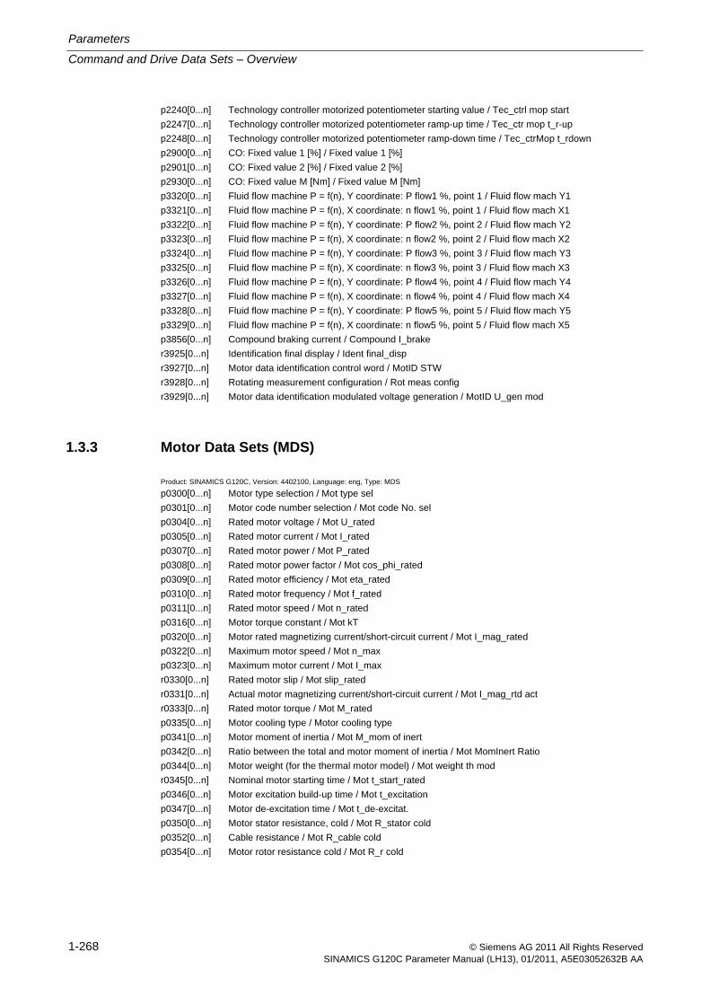
Parameters
Command and Drive Data Sets – Overview
1-268 © Siemens AG 2011 All Rights ReservedSINAMICS G120C Parameter Manual (LH13), 01/2011, A5E03052632B AA
p2240[0...n] Technology controller motorized potentiometer starting value / Tec_ctrl mop start
p2247[0...n] Technology controller motorized potentiometer ramp-up time / Tec_ctr mop t_r-up
p2248[0...n] Technology controller motorized potentiometer ramp-down time / Tec_ctrMop t_rdown
p2900[0...n] CO: Fixed value 1 [%] / Fixed value 1 [%]
p2901[0...n] CO: Fixed value 2 [%] / Fixed value 2 [%]
p2930[0...n] CO: Fixed value M [Nm] / Fixed value M [Nm]
p3320[0...n] Fluid flow machine P = f(n), Y coordinate: P flow1 %, point 1 / Fluid flow mach Y1
p3321[0...n] Fluid flow machine P = f(n), X coordinate: n flow1 %, point 1 / Fluid flow mach X1
p3322[0...n] Fluid flow machine P = f(n), Y coordinate: P flow2 %, point 2 / Fluid flow mach Y2
p3323[0...n] Fluid flow machine P = f(n), X coordinate: n flow2 %, point 2 / Fluid flow mach X2
p3324[0...n] Fluid flow machine P = f(n), Y coordinate: P flow3 %, point 3 / Fluid flow mach Y3
p3325[0...n] Fluid flow machine P = f(n), X coordinate: n flow3 %, point 3 / Fluid flow mach X3
p3326[0...n] Fluid flow machine P = f(n), Y coordinate: P flow4 %, point 4 / Fluid flow mach Y4
p3327[0...n] Fluid flow machine P = f(n), X coordinate: n flow4 %, point 4 / Fluid flow mach X4
p3328[0...n] Fluid flow machine P = f(n), Y coordinate: P flow5 %, point 5 / Fluid flow mach Y5
p3329[0...n] Fluid flow machine P = f(n), X coordinate: n flow5 %, point 5 / Fluid flow mach X5
p3856[0...n] Compound braking current / Compound I_brake
r3925[0...n] Identification final display / Ident final_disp
r3927[0...n] Motor data identification control word / MotID STW
r3928[0...n] Rotating measurement configuration / Rot meas config
r3929[0...n] Motor data identification modulated voltage generation / MotID U_gen mod
1.3.3 Motor Data Sets (MDS)
Product: SINAMICS G120C, Version: 4402100, Language: eng, Type: MDS
p0300[0...n] Motor type selection / Mot type sel
p0301[0...n] Motor code number selection / Mot code No. sel
p0304[0...n] Rated motor voltage / Mot U_rated
p0305[0...n] Rated motor current / Mot I_rated
p0307[0...n] Rated motor power / Mot P_rated
p0308[0...n] Rated motor power factor / Mot cos_phi_rated
p0309[0...n] Rated motor efficiency / Mot eta_rated
p0310[0...n] Rated motor frequency / Mot f_rated
p0311[0...n] Rated motor speed / Mot n_rated
p0316[0...n] Motor torque constant / Mot kT
p0320[0...n] Motor rated magnetizing current/short-circuit current / Mot I_mag_rated
p0322[0...n] Maximum motor speed / Mot n_max
p0323[0...n] Maximum motor current / Mot I_max
r0330[0...n] Rated motor slip / Mot slip_rated
r0331[0...n] Actual motor magnetizing current/short-circuit current / Mot I_mag_rtd act
r0333[0...n] Rated motor torque / Mot M_rated
p0335[0...n] Motor cooling type / Motor cooling type
p0341[0...n] Motor moment of inertia / Mot M_mom of inert
p0342[0...n] Ratio between the total and motor moment of inertia / Mot MomInert Ratio
p0344[0...n] Motor weight (for the thermal motor model) / Mot weight th mod
r0345[0...n] Nominal motor starting time / Mot t_start_rated
p0346[0...n] Motor excitation build-up time / Mot t_excitation
p0347[0...n] Motor de-excitation time / Mot t_de-excitat.
p0350[0...n] Motor stator resistance, cold / Mot R_stator cold
p0352[0...n] Cable resistance / Mot R_cable cold
p0354[0...n] Motor rotor resistance cold / Mot R_r cold
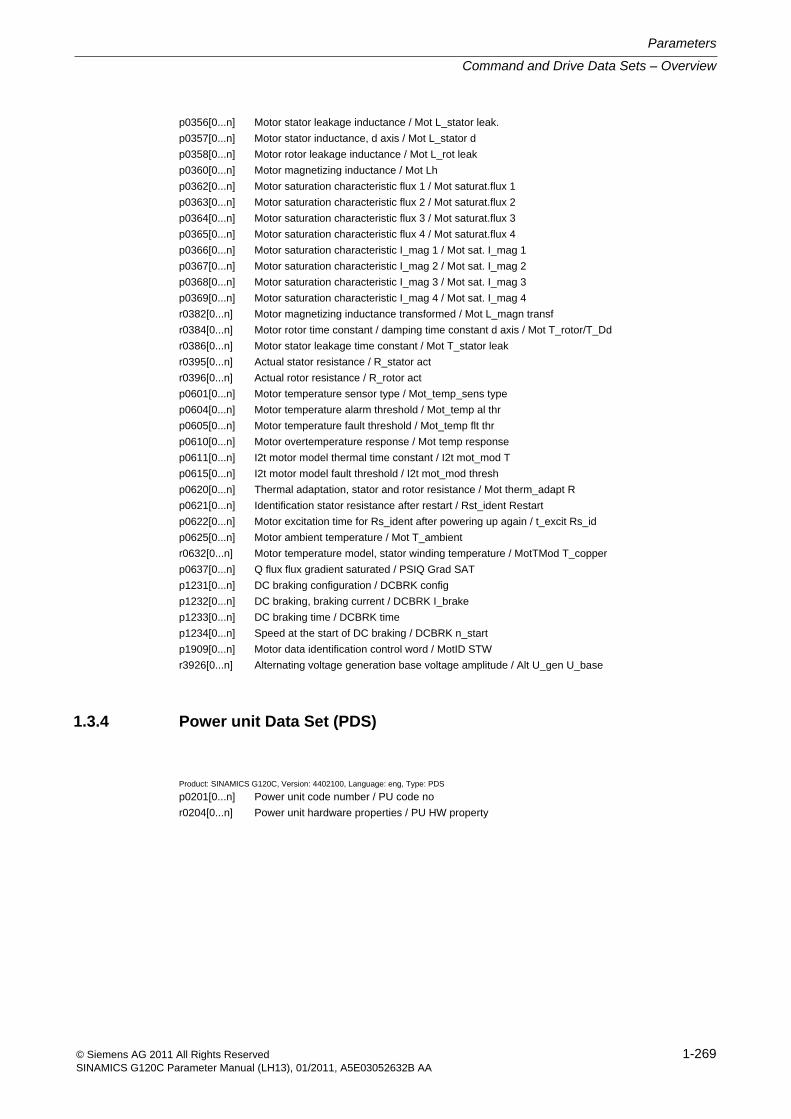
Command and Drive Data Sets – Overview
Parameters
1-269© Siemens AG 2011 All Rights ReservedSINAMICS G120C Parameter Manual (LH13), 01/2011, A5E03052632B AA
p0356[0...n] Motor stator leakage inductance / Mot L_stator leak.
p0357[0...n] Motor stator inductance, d axis / Mot L_stator d
p0358[0...n] Motor rotor leakage inductance / Mot L_rot leak
p0360[0...n] Motor magnetizing inductance / Mot Lh
p0362[0...n] Motor saturation characteristic flux 1 / Mot saturat.flux 1
p0363[0...n] Motor saturation characteristic flux 2 / Mot saturat.flux 2
p0364[0...n] Motor saturation characteristic flux 3 / Mot saturat.flux 3
p0365[0...n] Motor saturation characteristic flux 4 / Mot saturat.flux 4
p0366[0...n] Motor saturation characteristic I_mag 1 / Mot sat. I_mag 1
p0367[0...n] Motor saturation characteristic I_mag 2 / Mot sat. I_mag 2
p0368[0...n] Motor saturation characteristic I_mag 3 / Mot sat. I_mag 3
p0369[0...n] Motor saturation characteristic I_mag 4 / Mot sat. I_mag 4
r0382[0...n] Motor magnetizing inductance transformed / Mot L_magn transf
r0384[0...n] Motor rotor time constant / damping time constant d axis / Mot T_rotor/T_Dd
r0386[0...n] Motor stator leakage time constant / Mot T_stator leak
r0395[0...n] Actual stator resistance / R_stator act
r0396[0...n] Actual rotor resistance / R_rotor act
p0601[0...n] Motor temperature sensor type / Mot_temp_sens type
p0604[0...n] Motor temperature alarm threshold / Mot_temp al thr
p0605[0...n] Motor temperature fault threshold / Mot_temp flt thr
p0610[0...n] Motor overtemperature response / Mot temp response
p0611[0...n] I2t motor model thermal time constant / I2t mot_mod T
p0615[0...n] I2t motor model fault threshold / I2t mot_mod thresh
p0620[0...n] Thermal adaptation, stator and rotor resistance / Mot therm_adapt R
p0621[0...n] Identification stator resistance after restart / Rst_ident Restart
p0622[0...n] Motor excitation time for Rs_ident after powering up again / t_excit Rs_id
p0625[0...n] Motor ambient temperature / Mot T_ambient
r0632[0...n] Motor temperature model, stator winding temperature / MotTMod T_copper
p0637[0...n] Q flux flux gradient saturated / PSIQ Grad SAT
p1231[0...n] DC braking configuration / DCBRK config
p1232[0...n] DC braking, braking current / DCBRK I_brake
p1233[0...n] DC braking time / DCBRK time
p1234[0...n] Speed at the start of DC braking / DCBRK n_start
p1909[0...n] Motor data identification control word / MotID STW
r3926[0...n] Alternating voltage generation base voltage amplitude / Alt U_gen U_base
1.3.4 Power unit Data Set (PDS)
Product: SINAMICS G120C, Version: 4402100, Language: eng, Type: PDS
p0201[0...n] Power unit code number / PU code no
r0204[0...n] Power unit hardware properties / PU HW property
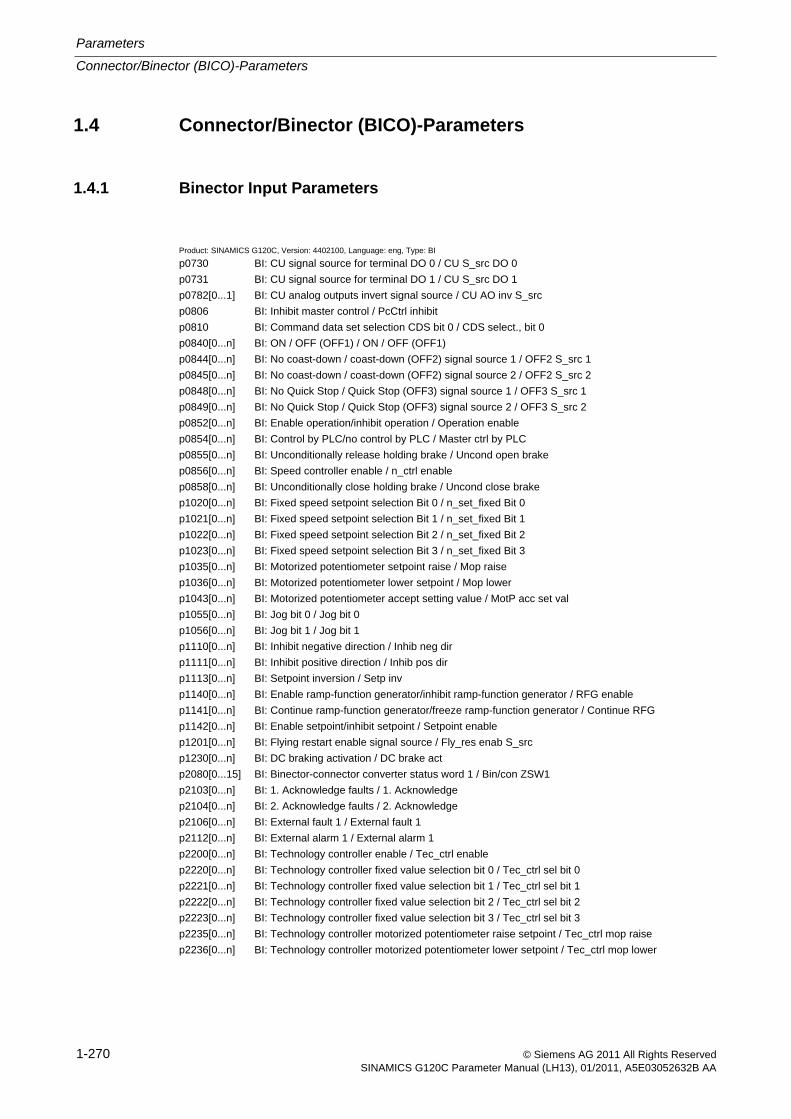
Parameters
Connector/Binector (BICO)-Parameters
1-270 © Siemens AG 2011 All Rights ReservedSINAMICS G120C Parameter Manual (LH13), 01/2011, A5E03052632B AA
1.4 Connector/Binector (BICO)-Parameters
1.4.1 Binector Input Parameters
Product: SINAMICS G120C, Version: 4402100, Language: eng, Type: BI
p0730 BI: CU signal source for terminal DO 0 / CU S_src DO 0
p0731 BI: CU signal source for terminal DO 1 / CU S_src DO 1
p0782[0...1] BI: CU analog outputs invert signal source / CU AO inv S_src
p0806 BI: Inhibit master control / PcCtrl inhibit
p0810 BI: Command data set selection CDS bit 0 / CDS select., bit 0
p0840[0...n] BI: ON / OFF (OFF1) / ON / OFF (OFF1)
p0844[0...n] BI: No coast-down / coast-down (OFF2) signal source 1 / OFF2 S_src 1
p0845[0...n] BI: No coast-down / coast-down (OFF2) signal source 2 / OFF2 S_src 2
p0848[0...n] BI: No Quick Stop / Quick Stop (OFF3) signal source 1 / OFF3 S_src 1
p0849[0...n] BI: No Quick Stop / Quick Stop (OFF3) signal source 2 / OFF3 S_src 2
p0852[0...n] BI: Enable operation/inhibit operation / Operation enable
p0854[0...n] BI: Control by PLC/no control by PLC / Master ctrl by PLC
p0855[0...n] BI: Unconditionally release holding brake / Uncond open brake
p0856[0...n] BI: Speed controller enable / n_ctrl enable
p0858[0...n] BI: Unconditionally close holding brake / Uncond close brake
p1020[0...n] BI: Fixed speed setpoint selection Bit 0 / n_set_fixed Bit 0
p1021[0...n] BI: Fixed speed setpoint selection Bit 1 / n_set_fixed Bit 1
p1022[0...n] BI: Fixed speed setpoint selection Bit 2 / n_set_fixed Bit 2
p1023[0...n] BI: Fixed speed setpoint selection Bit 3 / n_set_fixed Bit 3
p1035[0...n] BI: Motorized potentiometer setpoint raise / Mop raise
p1036[0...n] BI: Motorized potentiometer lower setpoint / Mop lower
p1043[0...n] BI: Motorized potentiometer accept setting value / MotP acc set val
p1055[0...n] BI: Jog bit 0 / Jog bit 0
p1056[0...n] BI: Jog bit 1 / Jog bit 1
p1110[0...n] BI: Inhibit negative direction / Inhib neg dir
p1111[0...n] BI: Inhibit positive direction / Inhib pos dir
p1113[0...n] BI: Setpoint inversion / Setp inv
p1140[0...n] BI: Enable ramp-function generator/inhibit ramp-function generator / RFG enable
p1141[0...n] BI: Continue ramp-function generator/freeze ramp-function generator / Continue RFG
p1142[0...n] BI: Enable setpoint/inhibit setpoint / Setpoint enable
p1201[0...n] BI: Flying restart enable signal source / Fly_res enab S_src
p1230[0...n] BI: DC braking activation / DC brake act
p2080[0...15] BI: Binector-connector converter status word 1 / Bin/con ZSW1
p2103[0...n] BI: 1. Acknowledge faults / 1. Acknowledge
p2104[0...n] BI: 2. Acknowledge faults / 2. Acknowledge
p2106[0...n] BI: External fault 1 / External fault 1
p2112[0...n] BI: External alarm 1 / External alarm 1
p2200[0...n] BI: Technology controller enable / Tec_ctrl enable
p2220[0...n] BI: Technology controller fixed value selection bit 0 / Tec_ctrl sel bit 0
p2221[0...n] BI: Technology controller fixed value selection bit 1 / Tec_ctrl sel bit 1
p2222[0...n] BI: Technology controller fixed value selection bit 2 / Tec_ctrl sel bit 2
p2223[0...n] BI: Technology controller fixed value selection bit 3 / Tec_ctrl sel bit 3
p2235[0...n] BI: Technology controller motorized potentiometer raise setpoint / Tec_ctrl mop raise
p2236[0...n] BI: Technology controller motorized potentiometer lower setpoint / Tec_ctrl mop lower
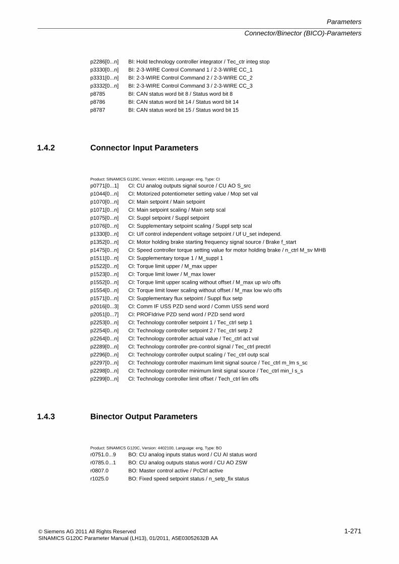
Connector/Binector (BICO)-Parameters
Parameters
1-271© Siemens AG 2011 All Rights ReservedSINAMICS G120C Parameter Manual (LH13), 01/2011, A5E03052632B AA
p2286[0...n] BI: Hold technology controller integrator / Tec_ctr integ stop
p3330[0...n] BI: 2-3-WIRE Control Command 1 / 2-3-WIRE CC_1
p3331[0...n] BI: 2-3-WIRE Control Command 2 / 2-3-WIRE CC_2
p3332[0...n] BI: 2-3-WIRE Control Command 3 / 2-3-WIRE CC_3
p8785 BI: CAN status word bit 8 / Status word bit 8
p8786 BI: CAN status word bit 14 / Status word bit 14
p8787 BI: CAN status word bit 15 / Status word bit 15
1.4.2 Connector Input Parameters
Product: SINAMICS G120C, Version: 4402100, Language: eng, Type: CI
p0771[0...1] CI: CU analog outputs signal source / CU AO S_src
p1044[0...n] CI: Motorized potentiometer setting value / Mop set val
p1070[0...n] CI: Main setpoint / Main setpoint
p1071[0...n] CI: Main setpoint scaling / Main setp scal
p1075[0...n] CI: Suppl setpoint / Suppl setpoint
p1076[0...n] CI: Supplementary setpoint scaling / Suppl setp scal
p1330[0...n] CI: U/f control independent voltage setpoint / Uf U_set independ.
p1352[0...n] CI: Motor holding brake starting frequency signal source / Brake f_start
p1475[0...n] CI: Speed controller torque setting value for motor holding brake / n_ctrl M_sv MHB
p1511[0...n] CI: Supplementary torque 1 / M_suppl 1
p1522[0...n] CI: Torque limit upper / M_max upper
p1523[0...n] CI: Torque limit lower / M_max lower
p1552[0...n] CI: Torque limit upper scaling without offset / M_max up w/o offs
p1554[0...n] CI: Torque limit lower scaling without offset / M_max low w/o offs
p1571[0...n] CI: Supplementary flux setpoint / Suppl flux setp
p2016[0...3] CI: Comm IF USS PZD send word / Comm USS send word
p2051[0...7] CI: PROFIdrive PZD send word / PZD send word
p2253[0...n] CI: Technology controller setpoint 1 / Tec_ctrl setp 1
p2254[0...n] CI: Technology controller setpoint 2 / Tec_ctrl setp 2
p2264[0...n] CI: Technology controller actual value / Tec_ctrl act val
p2289[0...n] CI: Technology controller pre-control signal / Tec_ctrl prectrl
p2296[0...n] CI: Technology controller output scaling / Tec_ctrl outp scal
p2297[0...n] CI: Technology controller maximum limit signal source / Tec_ctrl m_lm s_sc
p2298[0...n] CI: Technology controller minimum limit signal source / Tec_ctrl min_l s_s
p2299[0...n] CI: Technology controller limit offset / Tech_ctrl lim offs
1.4.3 Binector Output Parameters
Product: SINAMICS G120C, Version: 4402100, Language: eng, Type: BO
r0751.0...9 BO: CU analog inputs status word / CU AI status word
r0785.0...1 BO: CU analog outputs status word / CU AO ZSW
r0807.0 BO: Master control active / PcCtrl active
r1025.0 BO: Fixed speed setpoint status / n_setp_fix status
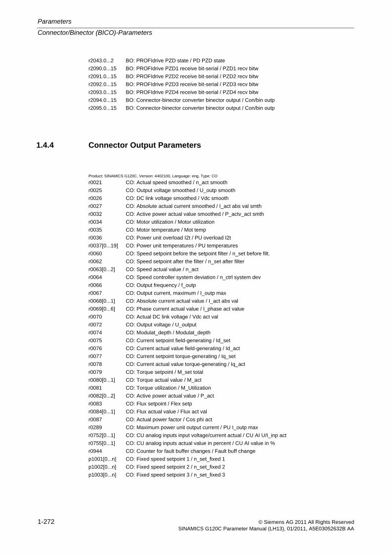
Parameters
Connector/Binector (BICO)-Parameters
1-272 © Siemens AG 2011 All Rights ReservedSINAMICS G120C Parameter Manual (LH13), 01/2011, A5E03052632B AA
r2043.0...2 BO: PROFIdrive PZD state / PD PZD state
r2090.0...15 BO: PROFIdrive PZD1 receive bit-serial / PZD1 recv bitw
r2091.0...15 BO: PROFIdrive PZD2 receive bit-serial / PZD2 recv bitw
r2092.0...15 BO: PROFIdrive PZD3 receive bit-serial / PZD3 recv bitw
r2093.0...15 BO: PROFIdrive PZD4 receive bit-serial / PZD4 recv bitw
r2094.0...15 BO: Connector-binector converter binector output / Con/bin outp
r2095.0...15 BO: Connector-binector converter binector output / Con/bin outp
1.4.4 Connector Output Parameters
Product: SINAMICS G120C, Version: 4402100, Language: eng, Type: CO
r0021 CO: Actual speed smoothed / n_act smooth
r0025 CO: Output voltage smoothed / U_outp smooth
r0026 CO: DC link voltage smoothed / Vdc smooth
r0027 CO: Absolute actual current smoothed / I_act abs val smth
r0032 CO: Active power actual value smoothed / P_actv_act smth
r0034 CO: Motor utilization / Motor utilization
r0035 CO: Motor temperature / Mot temp
r0036 CO: Power unit overload I2t / PU overload I2t
r0037[0...19] CO: Power unit temperatures / PU temperatures
r0060 CO: Speed setpoint before the setpoint filter / n_set before filt.
r0062 CO: Speed setpoint after the filter / n_set after filter
r0063[0...2] CO: Speed actual value / n_act
r0064 CO: Speed controller system deviation / n_ctrl system dev
r0066 CO: Output frequency / f_outp
r0067 CO: Output current, maximum / I_outp max
r0068[0...1] CO: Absolute current actual value / I_act abs val
r0069[0...6] CO: Phase current actual value / I_phase act value
r0070 CO: Actual DC link voltage / Vdc act val
r0072 CO: Output voltage / U_output
r0074 CO: Modulat_depth / Modulat_depth
r0075 CO: Current setpoint field-generating / Id_set
r0076 CO: Current actual value field-generating / Id_act
r0077 CO: Current setpoint torque-generating / Iq_set
r0078 CO: Current actual value torque-generating / Iq_act
r0079 CO: Torque setpoint / M_set total
r0080[0...1] CO: Torque actual value / M_act
r0081 CO: Torque utilization / M_Utilization
r0082[0...2] CO: Active power actual value / P_act
r0083 CO: Flux setpoint / Flex setp
r0084[0...1] CO: Flux actual value / Flux act val
r0087 CO: Actual power factor / Cos phi act
r0289 CO: Maximum power unit output current / PU I_outp max
r0752[0...1] CO: CU analog inputs input voltage/current actual / CU AI U/I_inp act
r0755[0...1] CO: CU analog inputs actual value in percent / CU AI value in %
r0944 CO: Counter for fault buffer changes / Fault buff change
p1001[0...n] CO: Fixed speed setpoint 1 / n_set_fixed 1
p1002[0...n] CO: Fixed speed setpoint 2 / n_set_fixed 2
p1003[0...n] CO: Fixed speed setpoint 3 / n_set_fixed 3
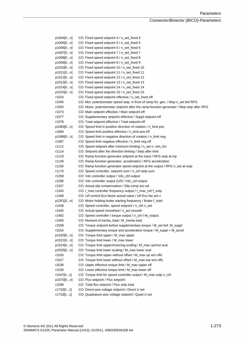
Connector/Binector (BICO)-Parameters
Parameters
1-273© Siemens AG 2011 All Rights ReservedSINAMICS G120C Parameter Manual (LH13), 01/2011, A5E03052632B AA
p1004[0...n] CO: Fixed speed setpoint 4 / n_set_fixed 4
p1005[0...n] CO: Fixed speed setpoint 5 / n_set_fixed 5
p1006[0...n] CO: Fixed speed setpoint 6 / n_set_fixed 6
p1007[0...n] CO: Fixed speed setpoint 7 / n_set_fixed 7
p1008[0...n] CO: Fixed speed setpoint 8 / n_set_fixed 8
p1009[0...n] CO: Fixed speed setpoint 9 / n_set_fixed 9
p1010[0...n] CO: Fixed speed setpoint 10 / n_set_fixed 10
p1011[0...n] CO: Fixed speed setpoint 11 / n_set_fixed 11
p1012[0...n] CO: Fixed speed setpoint 12 / n_set_fixed 12
p1013[0...n] CO: Fixed speed setpoint 13 / n_set_fixed 13
p1014[0...n] CO: Fixed speed setpoint 14 / n_set_fixed 14
p1015[0...n] CO: Fixed speed setpoint 15 / n_set_fixed 15
r1024 CO: Fixed speed setpoint effective / n_set_fixed eff
r1045 CO: Mot. potentiometer speed setp. in front of ramp-fct. gen. / Mop n_set bef RFG
r1050 CO: Motor. potentiometer setpoint after the ramp-function generator / Mop setp after RFG
r1073 CO: Main setpoint effective / Main setpoint eff
r1077 CO: Supplementary setpoint effective / Suppl setpoint eff
r1078 CO: Total setpoint effective / Total setpoint eff
p1083[0...n] CO: Speed limit in positive direction of rotation / n_limit pos
r1084 CO: Speed limit positive effective / n_limit pos eff
p1086[0...n] CO: Speed limit in negative direction of rotation / n_limit neg
r1087 CO: Speed limit negative effective / n_limit neg eff
r1112 CO: Speed setpoint after minimum limiting / n_set n. min_lim
r1114 CO: Setpoint after the direction limiting / Setp after limit
r1119 CO: Ramp-function generator setpoint at the input / RFG setp at inp
r1149 CO: Ramp-function generator, acceleration / RFG acceleration
r1150 CO: Ramp-function generator speed setpoint at the output / RFG n_set at outp
r1170 CO: Speed controller, setpoint sum / n_ctrl setp sum
r1258 CO: Vdc controller output / Vdc_ctrl output
r1298 CO: Vdc controller output (U/f) / Vdc_ctrl output
r1337 CO: Actual slip compensation / Slip comp act val
r1343 CO: I_max controller frequency output / I_max_ctrl f_outp
r1348 CO: U/f control Eco factor actual value / U/f Eco fac act v
p1351[0...n] CO: Motor holding brake starting frequency / Brake f_start
r1438 CO: Speed controller, speed setpoint / n_ctrl n_set
r1445 CO: Actual speed smoothed / n_act smooth
r1482 CO: Speed controller I torque output / n_ctrl I-M_output
r1493 CO: Moment of inertia, total / M_inertia total
r1508 CO: Torque setpoint before supplementary torque / M_set bef. M_suppl
r1516 CO: Supplementary torque and acceleration torque / M_suppl + M_accel
p1520[0...n] CO: Torque limit upper / M_max upper
p1521[0...n] CO: Torque limit lower / M_max lower
p1524[0...n] CO: Torque limit upper/motoring scaling / M_max up/mot scal
p1525[0...n] CO: Torque limit lower scaling / M_max lower scal
r1526 CO: Torque limit upper without offset / M_max up w/o offs
r1527 CO: Torque limit lower without offset / M_max low w/o offs
r1538 CO: Upper effective torque limit / M_max upper eff
r1539 CO: Lower effective torque limit / M_max lower eff
r1547[0...1] CO: Torque limit for speed controller output / M_max outp n_ctrl
p1570[0...n] CO: Flux setpoint / Flux setpoint
r1598 CO: Total flux setpoint / Flux setp total
r1732[0...1] CO: Direct-axis voltage setpoint / Direct U set
r1733[0...1] CO: Quadrature-axis voltage setpoint / Quad U set
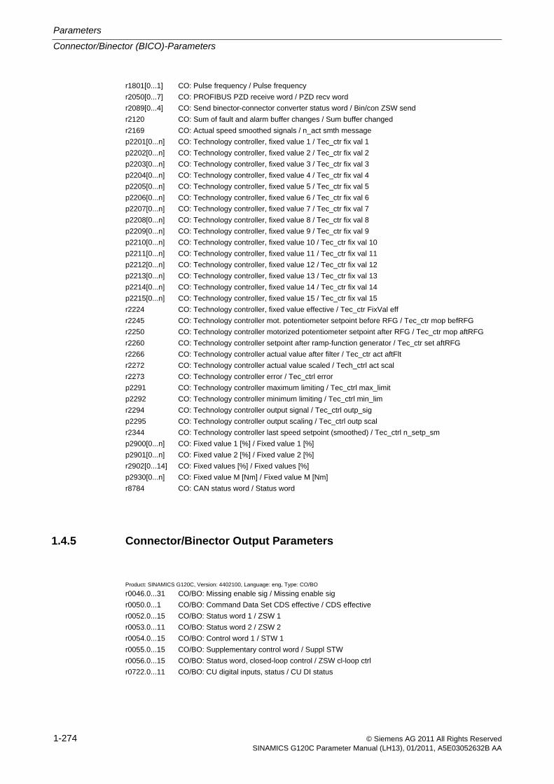
Parameters
Connector/Binector (BICO)-Parameters
1-274 © Siemens AG 2011 All Rights ReservedSINAMICS G120C Parameter Manual (LH13), 01/2011, A5E03052632B AA
r1801[0...1] CO: Pulse frequency / Pulse frequency
r2050[0...7] CO: PROFIBUS PZD receive word / PZD recv word
r2089[0...4] CO: Send binector-connector converter status word / Bin/con ZSW send
r2120 CO: Sum of fault and alarm buffer changes / Sum buffer changed
r2169 CO: Actual speed smoothed signals / n_act smth message
p2201[0...n] CO: Technology controller, fixed value 1 / Tec_ctr fix val 1
p2202[0...n] CO: Technology controller, fixed value 2 / Tec_ctr fix val 2
p2203[0...n] CO: Technology controller, fixed value 3 / Tec_ctr fix val 3
p2204[0...n] CO: Technology controller, fixed value 4 / Tec_ctr fix val 4
p2205[0...n] CO: Technology controller, fixed value 5 / Tec_ctr fix val 5
p2206[0...n] CO: Technology controller, fixed value 6 / Tec_ctr fix val 6
p2207[0...n] CO: Technology controller, fixed value 7 / Tec_ctr fix val 7
p2208[0...n] CO: Technology controller, fixed value 8 / Tec_ctr fix val 8
p2209[0...n] CO: Technology controller, fixed value 9 / Tec_ctr fix val 9
p2210[0...n] CO: Technology controller, fixed value 10 / Tec_ctr fix val 10
p2211[0...n] CO: Technology controller, fixed value 11 / Tec_ctr fix val 11
p2212[0...n] CO: Technology controller, fixed value 12 / Tec_ctr fix val 12
p2213[0...n] CO: Technology controller, fixed value 13 / Tec_ctr fix val 13
p2214[0...n] CO: Technology controller, fixed value 14 / Tec_ctr fix val 14
p2215[0...n] CO: Technology controller, fixed value 15 / Tec_ctr fix val 15
r2224 CO: Technology controller, fixed value effective / Tec_ctr FixVal eff
r2245 CO: Technology controller mot. potentiometer setpoint before RFG / Tec_ctr mop befRFG
r2250 CO: Technology controller motorized potentiometer setpoint after RFG / Tec_ctr mop aftRFG
r2260 CO: Technology controller setpoint after ramp-function generator / Tec_ctr set aftRFG
r2266 CO: Technology controller actual value after filter / Tec_ctr act aftFlt
r2272 CO: Technology controller actual value scaled / Tech_ctrl act scal
r2273 CO: Technology controller error / Tec_ctrl error
p2291 CO: Technology controller maximum limiting / Tec_ctrl max_limit
p2292 CO: Technology controller minimum limiting / Tec_ctrl min_lim
r2294 CO: Technology controller output signal / Tec_ctrl outp_sig
p2295 CO: Technology controller output scaling / Tec_ctrl outp scal
r2344 CO: Technology controller last speed setpoint (smoothed) / Tec_ctrl n_setp_sm
p2900[0...n] CO: Fixed value 1 [%] / Fixed value 1 [%]
p2901[0...n] CO: Fixed value 2 [%] / Fixed value 2 [%]
r2902[0...14] CO: Fixed values [%] / Fixed values [%]
p2930[0...n] CO: Fixed value M [Nm] / Fixed value M [Nm]
r8784 CO: CAN status word / Status word
1.4.5 Connector/Binector Output Parameters
Product: SINAMICS G120C, Version: 4402100, Language: eng, Type: CO/BO
r0046.0...31 CO/BO: Missing enable sig / Missing enable sig
r0050.0...1 CO/BO: Command Data Set CDS effective / CDS effective
r0052.0...15 CO/BO: Status word 1 / ZSW 1
r0053.0...11 CO/BO: Status word 2 / ZSW 2
r0054.0...15 CO/BO: Control word 1 / STW 1
r0055.0...15 CO/BO: Supplementary control word / Suppl STW
r0056.0...15 CO/BO: Status word, closed-loop control / ZSW cl-loop ctrl
r0722.0...11 CO/BO: CU digital inputs, status / CU DI status
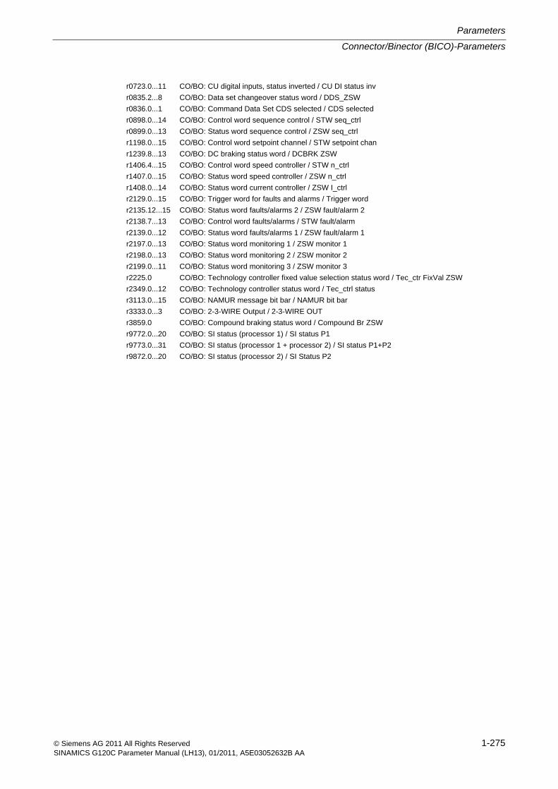
Connector/Binector (BICO)-Parameters
Parameters
1-275© Siemens AG 2011 All Rights ReservedSINAMICS G120C Parameter Manual (LH13), 01/2011, A5E03052632B AA
r0723.0...11 CO/BO: CU digital inputs, status inverted / CU DI status inv
r0835.2...8 CO/BO: Data set changeover status word / DDS_ZSW
r0836.0...1 CO/BO: Command Data Set CDS selected / CDS selected
r0898.0...14 CO/BO: Control word sequence control / STW seq_ctrl
r0899.0...13 CO/BO: Status word sequence control / ZSW seq_ctrl
r1198.0...15 CO/BO: Control word setpoint channel / STW setpoint chan
r1239.8...13 CO/BO: DC braking status word / DCBRK ZSW
r1406.4...15 CO/BO: Control word speed controller / STW n_ctrl
r1407.0...15 CO/BO: Status word speed controller / ZSW n_ctrl
r1408.0...14 CO/BO: Status word current controller / ZSW I_ctrl
r2129.0...15 CO/BO: Trigger word for faults and alarms / Trigger word
r2135.12...15 CO/BO: Status word faults/alarms 2 / ZSW fault/alarm 2
r2138.7...13 CO/BO: Control word faults/alarms / STW fault/alarm
r2139.0...12 CO/BO: Status word faults/alarms 1 / ZSW fault/alarm 1
r2197.0...13 CO/BO: Status word monitoring 1 / ZSW monitor 1
r2198.0...13 CO/BO: Status word monitoring 2 / ZSW monitor 2
r2199.0...11 CO/BO: Status word monitoring 3 / ZSW monitor 3
r2225.0 CO/BO: Technology controller fixed value selection status word / Tec_ctr FixVal ZSW
r2349.0...12 CO/BO: Technology controller status word / Tec_ctrl status
r3113.0...15 CO/BO: NAMUR message bit bar / NAMUR bit bar
r3333.0...3 CO/BO: 2-3-WIRE Output / 2-3-WIRE OUT
r3859.0 CO/BO: Compound braking status word / Compound Br ZSW
r9772.0...20 CO/BO: SI status (processor 1) / SI status P1
r9773.0...31 CO/BO: SI status (processor 1 + processor 2) / SI status P1+P2
r9872.0...20 CO/BO: SI status (processor 2) / SI Status P2
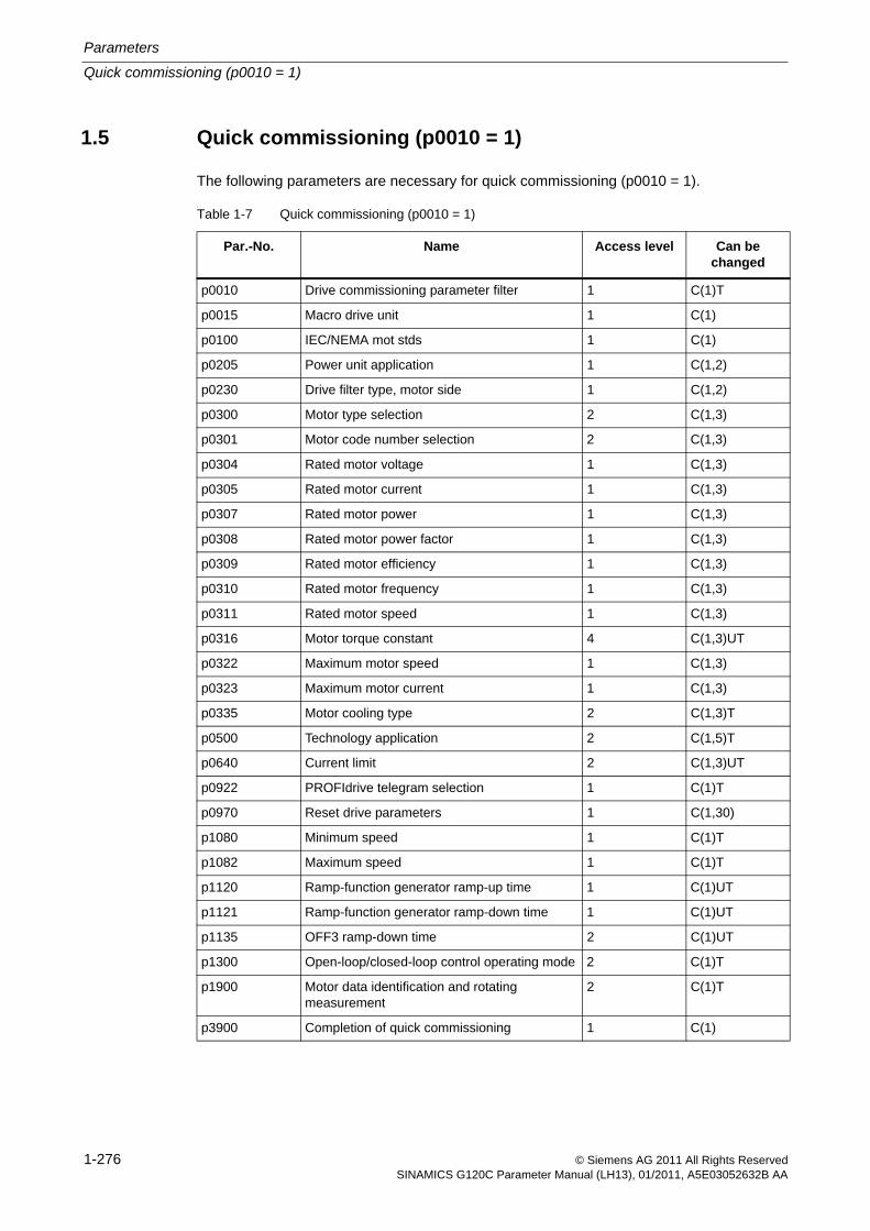
Parameters
Quick commissioning (p0010 = 1)
1-276 © Siemens AG 2011 All Rights ReservedSINAMICS G120C Parameter Manual (LH13), 01/2011, A5E03052632B AA
1.5 Quick commissioning (p0010 = 1)
The following parameters are necessary for quick commissioning (p0010 = 1).
.
Table 1-7 Quick commissioning (p0010 = 1)
Par.-No. Name Access level Can be changed
p0010 Drive commissioning parameter filter 1 C(1)T
p0015 Macro drive unit 1 C(1)
p0100 IEC/NEMA mot stds 1 C(1)
p0205 Power unit application 1 C(1,2)
p0230 Drive filter type, motor side 1 C(1,2)
p0300 Motor type selection 2 C(1,3)
p0301 Motor code number selection 2 C(1,3)
p0304 Rated motor voltage 1 C(1,3)
p0305 Rated motor current 1 C(1,3)
p0307 Rated motor power 1 C(1,3)
p0308 Rated motor power factor 1 C(1,3)
p0309 Rated motor efficiency 1 C(1,3)
p0310 Rated motor frequency 1 C(1,3)
p0311 Rated motor speed 1 C(1,3)
p0316 Motor torque constant 4 C(1,3)UT
p0322 Maximum motor speed 1 C(1,3)
p0323 Maximum motor current 1 C(1,3)
p0335 Motor cooling type 2 C(1,3)T
p0500 Technology application 2 C(1,5)T
p0640 Current limit 2 C(1,3)UT
p0922 PROFIdrive telegram selection 1 C(1)T
p0970 Reset drive parameters 1 C(1,30)
p1080 Minimum speed 1 C(1)T
p1082 Maximum speed 1 C(1)T
p1120 Ramp-function generator ramp-up time 1 C(1)UT
p1121 Ramp-function generator ramp-down time 1 C(1)UT
p1135 OFF3 ramp-down time 2 C(1)UT
p1300 Open-loop/closed-loop control operating mode 2 C(1)T
p1900 Motor data identification and rotating measurement
2 C(1)T
p3900 Completion of quick commissioning 1 C(1)
Quick commissioning (p0010 = 1)
Parameters
1-277© Siemens AG 2011 All Rights ReservedSINAMICS G120C Parameter Manual (LH13), 01/2011, A5E03052632B AA
When p0010 = 1 is chosen, p0003 (user access level) can be used to select the parameters to be accessed.
At the end of the quick commissioning sequence, set p3900 = 1 to carry out the necessary motor calculations and clear all other parameters (not included in p0010 = 1) to their default settings.
Note
This applies only in Quick Commissioning mode.

1-278 © Siemens AG 2011 All Rights ReservedSINAMICS G120C Parameter Manual (LH13), 01/2011, A5E03052632B AA
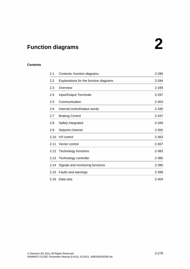
2-279© Siemens AG 2011 All Rights ReservedSINAMICS G120C Parameter Manual (LH13), 01/2011, A5E03052632B AA
Function diagrams 2Contents
2.1 Contents: function diagrams 2-280
2.2 Explanations for the function diagrams 2-284
2.3 Overview 2-289
2.4 Input/Output Terminals 2-297
2.5 Communication 2-303
2.6 Internal control/status words 2-330
2.7 Braking Control 2-347
2.8 Safety Integrated 2-349
2.9 Setpoint channel 2-355
2.10 V/f control 2-363
2.11 Vector control 2-367
2.12 Technology functions 2-383
2.13 Technology controller 2-385
2.14 Signals and monitoring functions 2-390
2.15 Faults and warnings 2-399
2.16 Data sets 2-404
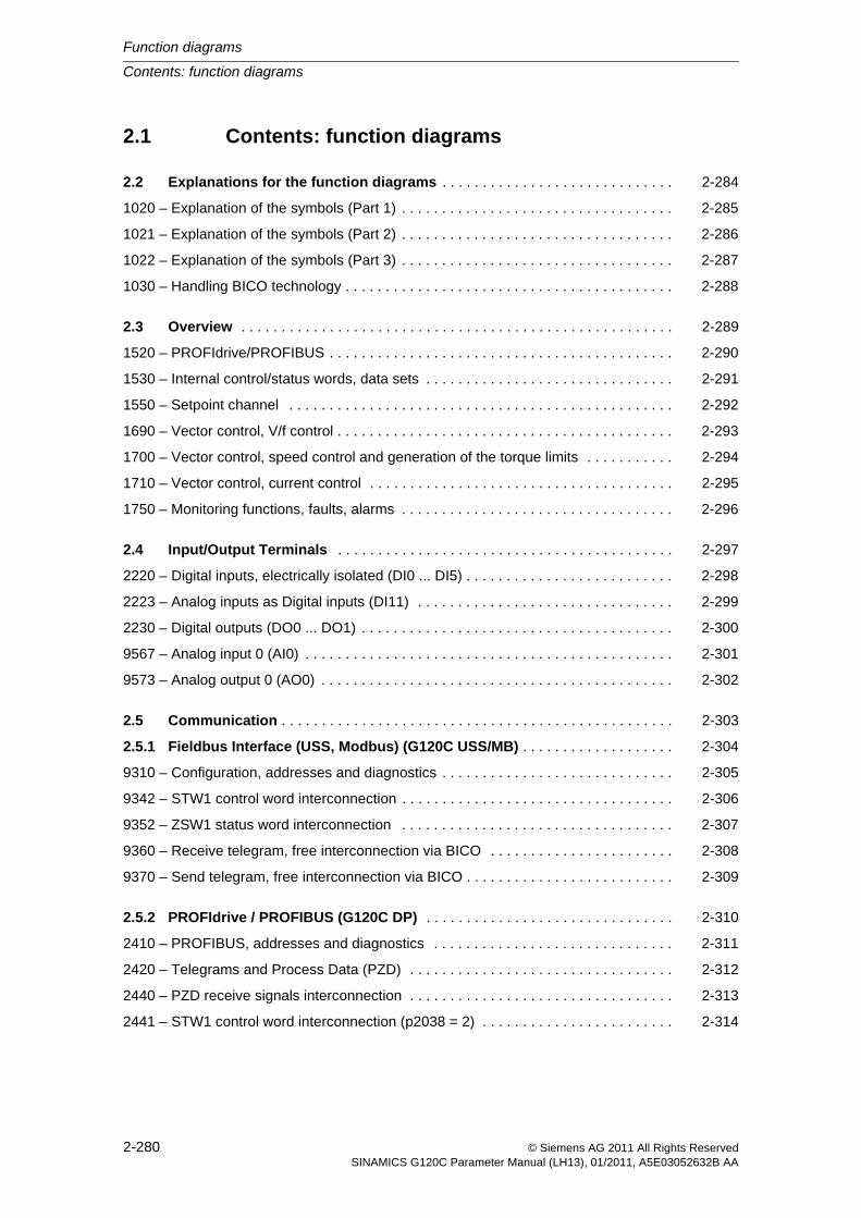
Function diagrams
Contents: function diagrams
2-280 © Siemens AG 2011 All Rights ReservedSINAMICS G120C Parameter Manual (LH13), 01/2011, A5E03052632B AA
2.1 Contents: function diagrams
2.2 Explanations for the function diagrams . . . . . . . . . . . . . . . . . . . . . . . . . . . . . 2-284
1020 – Explanation of the symbols (Part 1) . . . . . . . . . . . . . . . . . . . . . . . . . . . . . . . . . . 2-285
1021 – Explanation of the symbols (Part 2) . . . . . . . . . . . . . . . . . . . . . . . . . . . . . . . . . . 2-286
1022 – Explanation of the symbols (Part 3) . . . . . . . . . . . . . . . . . . . . . . . . . . . . . . . . . . 2-287
1030 – Handling BICO technology . . . . . . . . . . . . . . . . . . . . . . . . . . . . . . . . . . . . . . . . . 2-288
2.3 Overview . . . . . . . . . . . . . . . . . . . . . . . . . . . . . . . . . . . . . . . . . . . . . . . . . . . . . . 2-289
1520 – PROFIdrive/PROFIBUS . . . . . . . . . . . . . . . . . . . . . . . . . . . . . . . . . . . . . . . . . . . 2-290
1530 – Internal control/status words, data sets . . . . . . . . . . . . . . . . . . . . . . . . . . . . . . . 2-291
1550 – Setpoint channel . . . . . . . . . . . . . . . . . . . . . . . . . . . . . . . . . . . . . . . . . . . . . . . . 2-292
1690 – Vector control, V/f control . . . . . . . . . . . . . . . . . . . . . . . . . . . . . . . . . . . . . . . . . . 2-293
1700 – Vector control, speed control and generation of the torque limits . . . . . . . . . . . 2-294
1710 – Vector control, current control . . . . . . . . . . . . . . . . . . . . . . . . . . . . . . . . . . . . . . 2-295
1750 – Monitoring functions, faults, alarms . . . . . . . . . . . . . . . . . . . . . . . . . . . . . . . . . . 2-296
2.4 Input/Output Terminals . . . . . . . . . . . . . . . . . . . . . . . . . . . . . . . . . . . . . . . . . . 2-297
2220 – Digital inputs, electrically isolated (DI0 ... DI5) . . . . . . . . . . . . . . . . . . . . . . . . . . 2-298
2223 – Analog inputs as Digital inputs (DI11) . . . . . . . . . . . . . . . . . . . . . . . . . . . . . . . . 2-299
2230 – Digital outputs (DO0 ... DO1) . . . . . . . . . . . . . . . . . . . . . . . . . . . . . . . . . . . . . . . 2-300
9567 – Analog input 0 (AI0) . . . . . . . . . . . . . . . . . . . . . . . . . . . . . . . . . . . . . . . . . . . . . . 2-301
9573 – Analog output 0 (AO0) . . . . . . . . . . . . . . . . . . . . . . . . . . . . . . . . . . . . . . . . . . . . 2-302
2.5 Communication . . . . . . . . . . . . . . . . . . . . . . . . . . . . . . . . . . . . . . . . . . . . . . . . . 2-303
2.5.1 Fieldbus Interface (USS, Modbus) (G120C USS/MB) . . . . . . . . . . . . . . . . . . . 2-304
9310 – Configuration, addresses and diagnostics . . . . . . . . . . . . . . . . . . . . . . . . . . . . . 2-305
9342 – STW1 control word interconnection . . . . . . . . . . . . . . . . . . . . . . . . . . . . . . . . . . 2-306
9352 – ZSW1 status word interconnection . . . . . . . . . . . . . . . . . . . . . . . . . . . . . . . . . . 2-307
9360 – Receive telegram, free interconnection via BICO . . . . . . . . . . . . . . . . . . . . . . . 2-308
9370 – Send telegram, free interconnection via BICO . . . . . . . . . . . . . . . . . . . . . . . . . . 2-309
2.5.2 PROFIdrive / PROFIBUS (G120C DP) . . . . . . . . . . . . . . . . . . . . . . . . . . . . . . . 2-310
2410 – PROFIBUS, addresses and diagnostics . . . . . . . . . . . . . . . . . . . . . . . . . . . . . . 2-311
2420 – Telegrams and Process Data (PZD) . . . . . . . . . . . . . . . . . . . . . . . . . . . . . . . . . 2-312
2440 – PZD receive signals interconnection . . . . . . . . . . . . . . . . . . . . . . . . . . . . . . . . . 2-313
2441 – STW1 control word interconnection (p2038 = 2) . . . . . . . . . . . . . . . . . . . . . . . . 2-314
Contents: function diagrams
Function diagrams
2-281© Siemens AG 2011 All Rights ReservedSINAMICS G120C Parameter Manual (LH13), 01/2011, A5E03052632B AA
2442 – STW1 control word interconnection (p2038 = 0) . . . . . . . . . . . . . . . . . . . . . . . . 2-315
2444 – STW3 control word interconnection (p2038 = 0) . . . . . . . . . . . . . . . . . . . . . . . . 2-316
2450 – PZD send signals interconnection . . . . . . . . . . . . . . . . . . . . . . . . . . . . . . . . . . . 2-317
2451 – ZSW1 status word interconnection (p2038 = 2) . . . . . . . . . . . . . . . . . . . . . . . . . 2-318
2452 – ZSW1 status word interconnection (p2038 = 0) . . . . . . . . . . . . . . . . . . . . . . . . . 2-319
2454 – ZSW3 status word interconnection (p2038 = 0) . . . . . . . . . . . . . . . . . . . . . . . . . 2-320
2468 – Receive telegram, free interconnection via BICO (p0922 = 999) . . . . . . . . . . . 2-321
2470 – Send telegram, free interconnection via BICO (p0922 = 999) . . . . . . . . . . . . . . 2-322
2.5.3 CANopen (G120C CAN) . . . . . . . . . . . . . . . . . . . . . . . . . . . . . . . . . . . . . . . . . . 2-323
9204 – Receive telegram, free PDO mapping (p8744 = 2) . . . . . . . . . . . . . . . . . . . . . . 2-324
9206 – Receive telegram, Predefined Connection Set (p8744 = 1) . . . . . . . . . . . . . . . 2-325
9208 – Send telegram, free PDO mapping (p8744 = 2) . . . . . . . . . . . . . . . . . . . . . . . . 2-326
9210 – Send telegram, Predefined Connection Set (p8744 = 1) . . . . . . . . . . . . . . . . . . 2-327
9220 – Control word, CANopen . . . . . . . . . . . . . . . . . . . . . . . . . . . . . . . . . . . . . . . . . . . 2-328
9226 – Status word, CANopen . . . . . . . . . . . . . . . . . . . . . . . . . . . . . . . . . . . . . . . . . . . 2-329
2.6 Internal control/status words . . . . . . . . . . . . . . . . . . . . . . . . . . . . . . . . . . . . . 2-330
2501 – Control word, sequence control . . . . . . . . . . . . . . . . . . . . . . . . . . . . . . . . . . . . . 2-331
2503 – Status word, sequence control . . . . . . . . . . . . . . . . . . . . . . . . . . . . . . . . . . . . . . 2-332
2505 – Control word, setpoint channel . . . . . . . . . . . . . . . . . . . . . . . . . . . . . . . . . . . . . 2-333
2510 – Status word 1 (r0052) . . . . . . . . . . . . . . . . . . . . . . . . . . . . . . . . . . . . . . . . . . . . 2-334
2511 – Status word 2 (r0053) . . . . . . . . . . . . . . . . . . . . . . . . . . . . . . . . . . . . . . . . . . . . 2-335
2512 – Control word 1 (r0054) . . . . . . . . . . . . . . . . . . . . . . . . . . . . . . . . . . . . . . . . . . . . 2-336
2513 – Control word 2 (r0055) . . . . . . . . . . . . . . . . . . . . . . . . . . . . . . . . . . . . . . . . . . . . 2-337
2522 – Status word, speed controller . . . . . . . . . . . . . . . . . . . . . . . . . . . . . . . . . . . . . . 2-338
2526 – Status word, closed-loop control . . . . . . . . . . . . . . . . . . . . . . . . . . . . . . . . . . . . 2-339
2530 – Status word, current control . . . . . . . . . . . . . . . . . . . . . . . . . . . . . . . . . . . . . . . . 2-340
2534 – Status word, monitoring functions 1 . . . . . . . . . . . . . . . . . . . . . . . . . . . . . . . . . . 2-341
2536 – Status word, monitoring functions 2 . . . . . . . . . . . . . . . . . . . . . . . . . . . . . . . . . . 2-342
2537 – Status word, monitoring functions 3 . . . . . . . . . . . . . . . . . . . . . . . . . . . . . . . . . . 2-343
2546 – Control word, faults/alarms . . . . . . . . . . . . . . . . . . . . . . . . . . . . . . . . . . . . . . . . 2-344
2548 – Status word, faults/alarms 1 and 2 . . . . . . . . . . . . . . . . . . . . . . . . . . . . . . . . . . . 2-345
2634 – Sequence control - Missing enable signals . . . . . . . . . . . . . . . . . . . . . . . . . . . . 2-346
2.7 Braking Control . . . . . . . . . . . . . . . . . . . . . . . . . . . . . . . . . . . . . . . . . . . . . . . . . 2-347
2701 – Basic braking control . . . . . . . . . . . . . . . . . . . . . . . . . . . . . . . . . . . . . . . . . . . . . 2-348
Function diagrams
Contents: function diagrams
2-282 © Siemens AG 2011 All Rights ReservedSINAMICS G120C Parameter Manual (LH13), 01/2011, A5E03052632B AA
2.8 Safety Integrated . . . . . . . . . . . . . . . . . . . . . . . . . . . . . . . . . . . . . . . . . . . . . . . . 2-349
2800 – Basic Functions, Parameter Manager . . . . . . . . . . . . . . . . . . . . . . . . . . . . . . . . 2-350
2802 – Basic Functions, Monitoring functions and faults/alarms . . . . . . . . . . . . . . . . . . 2-351
2804 – Basic Functions, Status words . . . . . . . . . . . . . . . . . . . . . . . . . . . . . . . . . . . . . . 2-352
2810 – Basic Functions, STO: Safe Torque Off . . . . . . . . . . . . . . . . . . . . . . . . . . . . . . . 2-353
2812 – Basic Functions, F-DI: Fail-safe Digital Input . . . . . . . . . . . . . . . . . . . . . . . . . . . 2-354
2.9 Setpoint channel . . . . . . . . . . . . . . . . . . . . . . . . . . . . . . . . . . . . . . . . . . . . . . . . 2-355
3010 – Fixed speed setpoints, binary selection (p1016 = 2) . . . . . . . . . . . . . . . . . . . . . 2-356
3011 – Fixed speed setpoints, direct selection (p1016 = 1) . . . . . . . . . . . . . . . . . . . . . 2-357
3020 – Motorized potentiometer . . . . . . . . . . . . . . . . . . . . . . . . . . . . . . . . . . . . . . . . . . 2-358
3030 – Main/supplementary setpoint, setpoint scaling, jogging . . . . . . . . . . . . . . . . . . . 2-359
3040 – Direction limitation and direction reversal . . . . . . . . . . . . . . . . . . . . . . . . . . . . . 2-360
3050 – Skip frequency bands and frequency limitations . . . . . . . . . . . . . . . . . . . . . . . . 2-361
3070 – Extended ramp-function generator . . . . . . . . . . . . . . . . . . . . . . . . . . . . . . . . . . 2-362
2.10 V/f control . . . . . . . . . . . . . . . . . . . . . . . . . . . . . . . . . . . . . . . . . . . . . . . . . . . . . 2-363
6300 – V/f characteristic and voltage boost . . . . . . . . . . . . . . . . . . . . . . . . . . . . . . . . . . 2-364
6310 – Resonance damping and slip compensation . . . . . . . . . . . . . . . . . . . . . . . . . . . 2-365
6320 – Vdc_max controller and Vdc_min controller (V7f control) . . . . . . . . . . . . . . . . . 2-366
2.11 Vector control . . . . . . . . . . . . . . . . . . . . . . . . . . . . . . . . . . . . . . . . . . . . . . . . . . 2-367
6030 – Speed setpoint, droop . . . . . . . . . . . . . . . . . . . . . . . . . . . . . . . . . . . . . . . . . . . . 2-368
6040 – Speed controller . . . . . . . . . . . . . . . . . . . . . . . . . . . . . . . . . . . . . . . . . . . . . . . . . 2-369
6060 – Torque setpoint . . . . . . . . . . . . . . . . . . . . . . . . . . . . . . . . . . . . . . . . . . . . . . . . . 2-370
6220 – Vdc_max controller and Vdc_min controller (Vector control) . . . . . . . . . . . . . . . 2-371
6630 – Upper/lower torque limit . . . . . . . . . . . . . . . . . . . . . . . . . . . . . . . . . . . . . . . . . . . 2-372
6640 – Current/power/torque limits . . . . . . . . . . . . . . . . . . . . . . . . . . . . . . . . . . . . . . . . 2-373
6710 – Current setpoint filter . . . . . . . . . . . . . . . . . . . . . . . . . . . . . . . . . . . . . . . . . . . . . 2-374
6714 – Iq and Id controllers . . . . . . . . . . . . . . . . . . . . . . . . . . . . . . . . . . . . . . . . . . . . . . 2-375
6721 – Id setpoint (PEM, p0300 = 2xx) . . . . . . . . . . . . . . . . . . . . . . . . . . . . . . . . . . . . . 2-376
6722 – Field weakening characteristic, Id setpoint (ASM, p0300 = 1) . . . . . . . . . . . . . . 2-377
6723 – Field weakening controller, flux controller (ASM, p0300 = 1) . . . . . . . . . . . . . . 2-378
6724 – Field weakening controller (PEM, p0300 = 2) . . . . . . . . . . . . . . . . . . . . . . . . . . 2-379
6730 – Interface of the Power Module (ASM, p0300 = 1) . . . . . . . . . . . . . . . . . . . . . . . 2-380
6731 – Interface of the Power Module (PEM, p0300 = 2) . . . . . . . . . . . . . . . . . . . . . . . 2-381
6799 – Display signals . . . . . . . . . . . . . . . . . . . . . . . . . . . . . . . . . . . . . . . . . . . . . . . . . . 2-382
Contents: function diagrams
Function diagrams
2-283© Siemens AG 2011 All Rights ReservedSINAMICS G120C Parameter Manual (LH13), 01/2011, A5E03052632B AA
2.12 Technology functions . . . . . . . . . . . . . . . . . . . . . . . . . . . . . . . . . . . . . . . . . . . 2-383
7017 – DC brake (p0300 = 1) . . . . . . . . . . . . . . . . . . . . . . . . . . . . . . . . . . . . . . . . . . . . 2-384
2.13 Technology controller . . . . . . . . . . . . . . . . . . . . . . . . . . . . . . . . . . . . . . . . . . . 2-385
7950 – Fixed values, binary selection (p2216 = 2) . . . . . . . . . . . . . . . . . . . . . . . . . . . . 2-386
7951 – Fixed values, direct selection (p2216 = 1) . . . . . . . . . . . . . . . . . . . . . . . . . . . . . 2-387
7954 – Motorized potentiometer . . . . . . . . . . . . . . . . . . . . . . . . . . . . . . . . . . . . . . . . . . 2-388
7958 – Closed-loop control . . . . . . . . . . . . . . . . . . . . . . . . . . . . . . . . . . . . . . . . . . . . . . 2-389
2.14 Signals and monitoring functions . . . . . . . . . . . . . . . . . . . . . . . . . . . . . . . . . . 2-390
8010 – Speed signals 1 . . . . . . . . . . . . . . . . . . . . . . . . . . . . . . . . . . . . . . . . . . . . . . . . . 2-391
8011 – Speed signals 2 . . . . . . . . . . . . . . . . . . . . . . . . . . . . . . . . . . . . . . . . . . . . . . . . . 2-392
8012 – Torque signals, motor locked/stalled . . . . . . . . . . . . . . . . . . . . . . . . . . . . . . . . . 2-393
8014 – Thermal monitoring, power module . . . . . . . . . . . . . . . . . . . . . . . . . . . . . . . . . . 2-394
8016 – Thermal monitoring, motor . . . . . . . . . . . . . . . . . . . . . . . . . . . . . . . . . . . . . . . . . 2-395
8017 – Thermal I2t motor model (PEM, p0300 = 2xx) . . . . . . . . . . . . . . . . . . . . . . . . . . 2-396
8020 – Monitoring functions 1 . . . . . . . . . . . . . . . . . . . . . . . . . . . . . . . . . . . . . . . . . . . . 2-397
8021 – Monitoring functions 2 . . . . . . . . . . . . . . . . . . . . . . . . . . . . . . . . . . . . . . . . . . . . 2-398
2.15 Faults and warnings . . . . . . . . . . . . . . . . . . . . . . . . . . . . . . . . . . . . . . . . . . . . . 2-399
8060 – Fault buffer . . . . . . . . . . . . . . . . . . . . . . . . . . . . . . . . . . . . . . . . . . . . . . . . . . . . . 2-400
8065 – Warning buffer . . . . . . . . . . . . . . . . . . . . . . . . . . . . . . . . . . . . . . . . . . . . . . . . . . 2-401
8070 – Fault/warning trigger word (r2129) . . . . . . . . . . . . . . . . . . . . . . . . . . . . . . . . . . . 2-402
8075 – Fault/warning configuration . . . . . . . . . . . . . . . . . . . . . . . . . . . . . . . . . . . . . . . . 2-403
2.16 Data sets . . . . . . . . . . . . . . . . . . . . . . . . . . . . . . . . . . . . . . . . . . . . . . . . . . . . . . 2-404
8560 – Command Data Sets (CDS) . . . . . . . . . . . . . . . . . . . . . . . . . . . . . . . . . . . . . . . . 2-405
Function diagrams
Explanations for the function diagrams
2-284 © Siemens AG 2011 All Rights ReservedSINAMICS G120C Parameter Manual (LH13), 01/2011, A5E03052632B AA
2.2 Explanations for the function diagrams
Function diagrams
1020 – Explanation of the symbols (Part 1) 2-285
1021 – Explanation of the symbols (Part 2) 2-286
1022 – Explanation of the symbols (Part 3) 2-287
1030 – Handling BICO technology 2-288
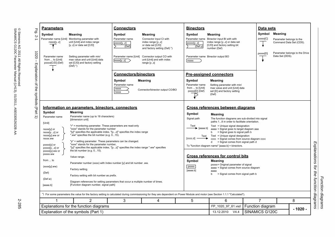
Expla
natio
ns for th
e fu
nction dia
grams
Fu
nction dia
grams
2-285
© S
ieme
ns AG
2011 All R
ights Re
servedS
INA
MIC
SG
120C P
aram
eterM
anual (LH
13), 01/2011, A5E
03052632B
AA
Fig. 2
-1102
0 – Exp
lanation of the
symbols (P
art1)
- 1020 -Function diagram
87654321FP_1020_97_61.vsdExplanations for the function diagrams
SINAMICS G120C13.12.2010 V4.4Explanation of the symbols (Part 1)
(Def)pxxxx[y..z]
rxxxx[y..z]
(Def.y)pxxxx[y..z]
rxxxx
rxxxxrxxxx
[aaaa.b]
[cccc.d]
[aaaa.b]pxxxx
[aaaa.b]
pxxxx[D]
pxxxx[C] Monitoring parameter with unit [Unit] and index range [y..z] or data set [C/D]
Setting parameter with min/max value and unit [Unit] data set [C/D] and factory setting (Def) *)
Connector input CI with index range [y..z] or data set [C/D] and factory setting (Def) *)
Connector output CO with unit [Unit] and with index range [y..z]
Binector input BI with with index range [y..z] or data set [C/D] and factory setting.bit number (Def)
Binector output BO
Connector/binector output CO/BO
The function diagrams are sub-divided into signal paths 1...8 in order to facilitate orientation.Text = Unique signal designation aaaa = Signal goes to target diagram aaa b = Signal goes to signal path bText = Unique signal designation cccc = Signal comes from source diagram cccc d = Signal comes from signal path d
pxxxx= Original parameter of signal aaaa = Signal comes from source diagram aaaa b = Signal comes from signal path b
Parameter belongs to the Command Data Set (CDS).
Parameter belongs to the Drive Data Set (DDS).
Parameter name
[Unit]
rxxxx[y] or rxxxx[y...z] or rxxxx[y].ww or rxxxx.ww
pxxxx[y] or pxxxx[y...z] or pxxxx[y].ww or pxxxx.ww
from ... to
(xxxx[y].ww)
(Def)
(Def.w)
Parameter name (up to 18 characters)[dimension unit]
"r" = monitoring parameter. These parameters are read-only"xxxx" stands for the parameter number"[y]" specifies the applicable index, "[y...z]" specifies the index range ".ww" specifies the bit number (e.g. 0...15).
"p" = setting parameter. These parameters can be changed. "xxxx" stands for the parameter number, "[y]" specifies the applicable index, "[y...z]" specifies the index range ".ww" specifies the bit number (e.g. 0...15).
Value range.
Parameter number (xxxx) with Index number [y] and bit number .ww.
Factory setting.
Factory setting with bit number as prefix.
Diagram references for setting parameters that occur a multiple number of times. [Function diagram number, signal path]
ParametersSymbol Symbol Symbol
Symbol
Symbol
Symbol
Symbol
SymbolMeaning Meaning Meaning
Meaning
Meaning
Meaning
Meaning
MeaningConnectors Binectors
Connectors/binectors
Cross references between diagrams
Cross references for control bits
Information on parameters, binectors, connectors
Data sets
Parameter name
Parameter name [Unit]
Parameter name
Parameter name
Parameter name
Signal path
To "function diagram name" [aaaa.b] = binectors.
Text
Text
Parameter name [Unit]rxxxx[y..z]
Parameter namefrom ... to [Unit]pxxxx[C/D] (Def)
Pre-assigned connectors
Parameter namefrom ... to [Unit]pxxxx[D] (Def)
Setting parameter with min/max value and unit [Unit] data set [D] and factory setting (Def)
Symbol Meaning
For some parameters the value for the factory setting is calculated during commissioning for they are dependent on Power Module and motor (see Section 1.1.1 "Calculated").*)
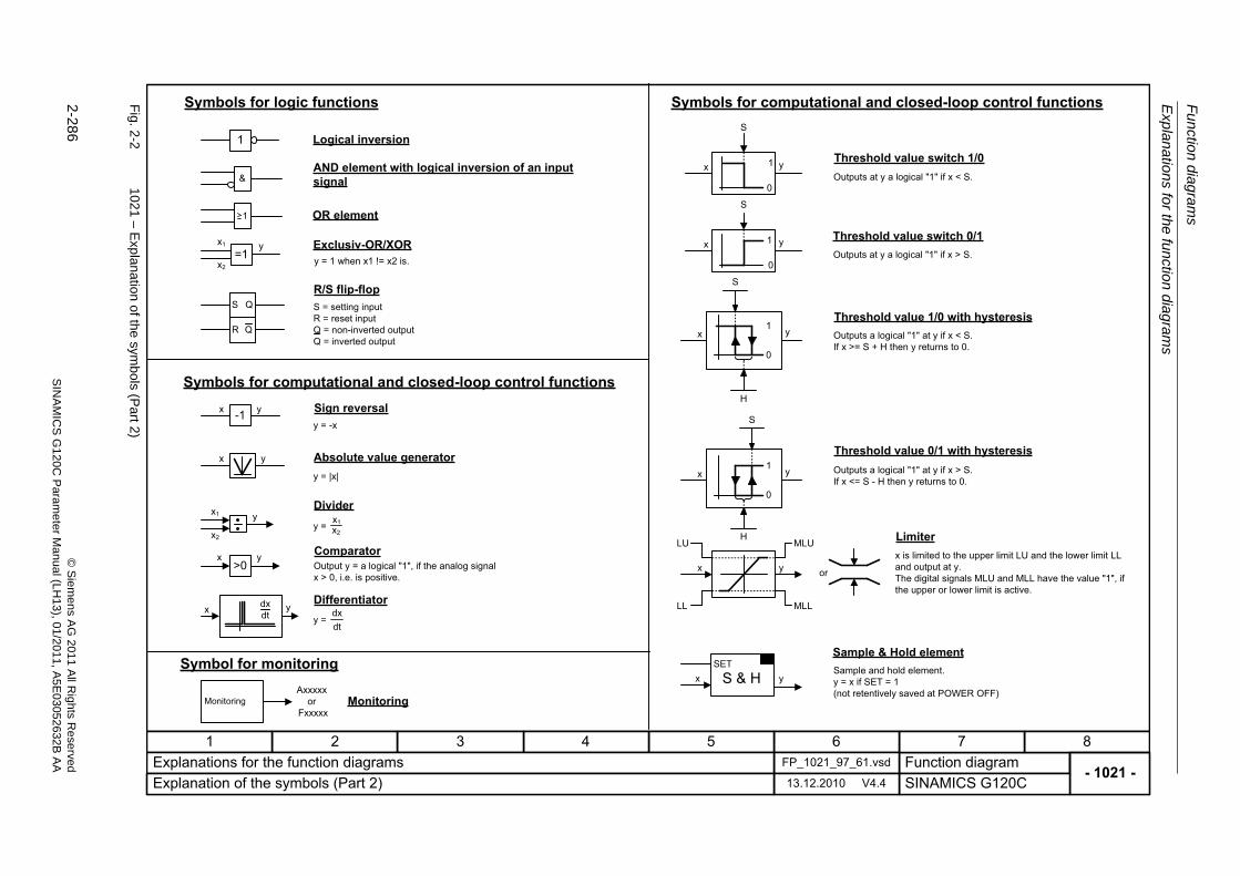
Fu
nctio
n diag
ram
s
Exp
lanation
s for the
fun
ction
diag
ram
s
2-286
© S
iem
ens AG
2011 All R
ights R
eservedS
INA
MIC
SG
120C
Param
eter
Manual (L
H13), 0
1/2011, A5E
03052632B
AA
Fig. 2
-2102
1 – Exp
lanation of the
symbols (P
art2)
- 1021 -Function diagram
87654321FP_1021_97_61.vsdExplanations for the function diagrams
SINAMICS G120C13.12.2010 V4.4Explanation of the symbols (Part 2)
y = -x
y = |x|
y =
1
&
x y
x y>0
-1x y
x2
x1 y
S Q
R Q
S
yx 1
0
0
1
y
x
S
y =dtdx
LU
LL MLL
MLU
x y
SET
S & Hx y
dxdtx y
0
1
S
H
y
x
0
1
H
S
yx
Symbols for logic functions
Logical inversion
AND element with logical inversion of an input signal
R/S flip-flopS = setting inputR = reset input Q = non-inverted outputQ = inverted output
Symbols for computational and closed-loop control functions
Threshold value switch 1/0Outputs at y a logical "1" if x < S.
Threshold value switch 0/1Outputs at y a logical "1" if x > S.
Threshold value 1/0 with hysteresisOutputs a logical "1" at y if x < S. If x >= S + H then y returns to 0.
Threshold value 0/1 with hysteresisOutputs a logical "1" at y if x > S. If x <= S - H then y returns to 0.
Limiterx is limited to the upper limit LU and the lower limit LL and output at y.The digital signals MLU and MLL have the value "1", if the upper or lower limit is active.
Sample & Hold elementSample and hold element.y = x if SET = 1(not retentively saved at POWER OFF)
Symbols for computational and closed-loop control functionsSign reversal
Absolute value generator
Divider
ComparatorOutput y = a logical "1", if the analog signal x > 0, i.e. is positive.
Differentiator
Symbol for monitoring
MonitoringMonitoringAxxxxx
orFxxxxx
1 OR element
=1x1 y
x2
Exclusiv-OR/XORy = 1 when x1 != x2 is.
or
x1x2
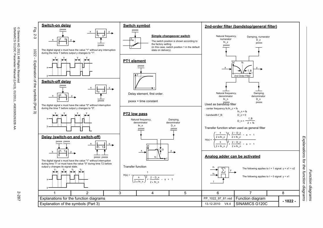
Expla
natio
ns for th
e fu
nction dia
grams
Fu
nction dia
grams
2-287
© S
ieme
ns AG
2011 All R
ights Re
servedS
INA
MIC
SG
120C P
aram
eterM
anual (LH
13), 01/2011, A5E
03052632B
AA
Fig. 2
-3102
2 – Exp
lanation of the
symbols (P
art3)
- 1022 -Function diagram
87654321FP_1022_97_61.vsdExplanations for the function diagrams
SINAMICS G120C13.12.2010 V4.4Explanation of the symbols (Part 3)
T 0x y
pxxxx
yx
H(s) =
s
2 fn_z 2 fn_zs+
+s
2 fn_n
.
.2 fn_n
D_n s
+
+
1
12 .
D_z 2 .2
2
f2nd Order Filter
|y| fs
f_B
t
y
pxxxx
H(s) =
+s
2 fn_n.
2 fn_n
D_n s + 1
2 .2
1
yx
f
|y|
fn
D
0 Tx y
pxxxx
T1 T2
T 0
pxxxx
0 T
pxxxx
x y
x y
x y
T1 T2
x ypxxxx pxxxx
pxxxx pxxxx
x
T T TT
y
TT
x
y
x
T T
y
T1 T1 T2 T2 yx1
I
x2
2
f_B
� fs
Switch-on delay
The digital signal x must have the value "1" without any interruption during the time T before output y changes to "1".
Switch-off delay
The digital signal x must have the value "0" without interruption during the time T before output y changes to "0".
Delay (switch-on and switch-off)
PT1 element
Delay element, first order.
pxxxx = time constant
PT2 low passDamping,
denominator D_n pxxxx
Natural frequency, denominator
fn_n pxxxx
Damping, denominator
D_n pxxxx
Natural frequency, denominator
fn_n pxxxx
Transfer function
2nd-order filter (bandstop/general filter)
Natural frequency, numerator
fn_z pxxxx
Damping, numerator D_z pxxxx
Used as bandstop filter- center frequency fs:fn_z = fs
fn_n = fs- bandwidth f_B: D_z = 0
D_n =
Transfer function when used as general filter
Analog adder can be activated
The following applies to I = 1 signal: y = x1 + x2
The following applies to I = 0 signal: y = x1
1
0
pxxxxSwitch symbol
Simple changeover switchThe switch position is shown according to the factory setting(in this case, switch position 1 in the default state on delivery).
The digital signal x must have the value "1" without interruption during time T1 or must have the value "0" during time T2 before output y changes its signal state.
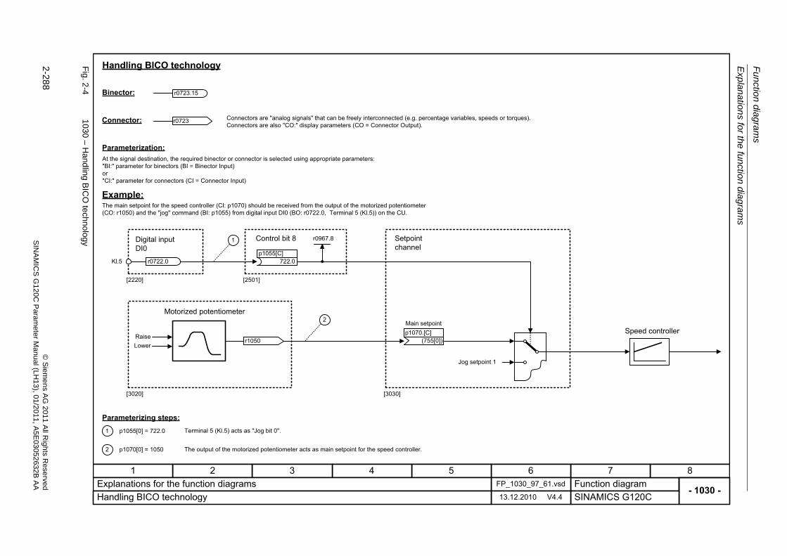
Fu
nctio
n diag
ram
s
Exp
lanation
s for the
fun
ction
diag
ram
s
2-288
© S
iem
ens AG
2011 All R
ights R
eservedS
INA
MIC
SG
120C
Param
eter
Manual (L
H13), 0
1/2011, A5E
03052632B
AA
Fig. 2
-4103
0 – Hand
ling B
ICO
technolog
y
- 1030 -Function diagram
87654321FP_1030_97_61.vsdExplanations for the function diagrams
SINAMICS G120C13.12.2010 V4.4Handling BICO technology
r0723.15
r0723
r0722.0
1
2
722.0p1055[C]
Kl.5
r0967.8
[2220] [2501]
[3020]
r1050
[3030]
2
1 p1055[0] = 722.0
p1070[0] = 1050
Main setpoint
(755[0])p1070.[C]
Handling BICO technology
Binector:
Connector:
Raise
Connectors are "analog signals" that can be freely interconnected (e.g. percentage variables, speeds or torques).Connectors are also "CO:" display parameters (CO = Connector Output).
Parameterization:At the signal destination, the required binector or connector is selected using appropriate parameters: "BI:" parameter for binectors (BI = Binector Input)or"CI:" parameter for connectors (CI = Connector Input)
Example:The main setpoint for the speed controller (CI: p1070) should be received from the output of the motorized potentiometer (CO: r1050) and the "jog" command (BI: p1055) from digital input DI0 (BO: r0722.0, Terminal 5 (Kl.5)) on the CU.
Control bit 8Digital input DI0
Setpoint channel
Motorized potentiometer
Jog setpoint 1
Speed controller
Parameterizing steps:Terminal 5 (Kl.5) acts as "Jog bit 0".
The output of the motorized potentiometer acts as main setpoint for the speed controller.
Lower
Overview
Function diagrams
2-289© Siemens AG 2011 All Rights ReservedSINAMICS G120C Parameter Manual (LH13), 01/2011, A5E03052632B AA
2.3 Overview
Function diagrams
1520 – PROFIdrive/PROFIBUS 2-290
1530 – Internal control/status words, data sets 2-291
1550 – Setpoint channel 2-292
1690 – Vector control, V/f control 2-293
1700 – Vector control, speed control and generation of the torque limits 2-294
1710 – Vector control, current control 2-295
1750 – Monitoring functions, faults, alarms 2-296
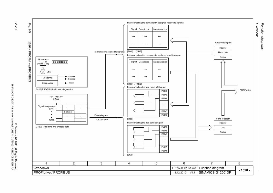
Fu
nctio
n diag
ram
s
Overview
2-290
© S
iem
ens AG
2011 All R
ights R
eservedS
INA
MIC
SG
120C
Param
eter
Manual (L
H13), 0
1/2011, A5E
03052632B
AA
Fig. 2
-5152
0 – PR
OF
Idrive/P
RO
FIB
US
- 1520 -Function diagram
87654321FP_1520_97_61.vsdOverviews
SINAMICS G120C DP13.12.2010 V4.4PROFIdrive / PROFIBUS
AxxxxxFxxxxx
rxxxx
LED
[2468]
[2440] ... [2442]
[2450] ... [2452]
PROFIdrive
.........
... ... ...
.........
... ... ...
PZD3
PZD2
PZD1
...
PZD3
PZD1
PZD2
PZD1
PZD8
Monitoring
Diagnostics
[2410] PROFIBUS address, diagnostics
Permanently assigned telegrams
Signal assignment
Signal x
[2420] Telegrams and process data
Free telegram
Interconnecting the permanently assigned receive telegrams.
Signal
Signal
Description
Description
Interconnection
Interconnection
Interconnecting the permanently assigned send telegrams
Interconnecting the free receive telegram
Interconnecting the free send telegram
Receive telegram
Send telegram
PB address1 ... 126
p0918 (126)
PD Telegr_selp0922
p0922 = 999Header
Data
Trailer
Header
Netto data
Trailer
PZD8
PZD7
PZD7
PZD8
...
[2470]
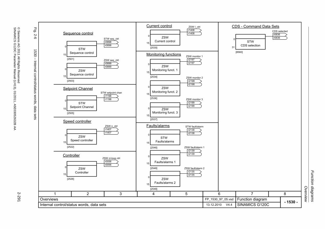
Ove
rview
Fu
nction dia
grams
2-291
© S
ieme
ns AG
2011 All R
ights Re
servedS
INA
MIC
SG
120C P
aram
eterM
anual (LH
13), 01/2011, A5E
03052632B
AA
Fig. 2
-6153
0 – Internal control/sta
tus w
ords, da
ta sets
- 1530 -Function diagram
87654321FP_1530_97_05.vsdOverviews
SINAMICS G120C13.12.2010 V4.4Internal control/status words, data sets
0
15
[2503]
STW3
0
15
[2501]
STW
ZSW
0
15
[2505]
STW
0
15
[2522]
ZSW
0
15
[2536]
0
15
[2534]
ZSW
ZSW
0
15[2537]
ZSW
0
15
[2548]
0
15
[2546]
0
15
[2548]
0
31
[8560]
STW
0
15
[2526]
ZSW
0
15
[2530]
ZSWSequence control
Sequence control
Sequence control
Setpoint Channel
Setpoint Channel
Speed controller
Speed controller
Controller
Controller
Current control
Current control
Monitoring functions
Monitoring funct. 1
Monitoring funct. 2
Monitoring funct. 3
Faults/alarms
STW Faults/alarms
ZSWFaults/alarms 1
ZSWFaults/alarms 2
CDS - Command Data Sets
CDS selection
STW seq_ctrl
r0898r0898
ZSW seq_ctrl
r0899r0899
STW setpoint chan
r1198r1198
ZSW n_ctrl
r1407r1407
ZSW cl-loop ctrl
r0056r0056
ZSW I_ctrl
r1408r1408
ZSW monitor 1
r2197r2197
ZSW monitor 2
r2198r2198
ZSW monitor 3
r2199r2199
STW fault/alarm
r2138r2138
ZSW fault/alarm 1
r2139r2139
ZSW fault/alarm 2
r2135r2135
CDS selected
r0836r0836
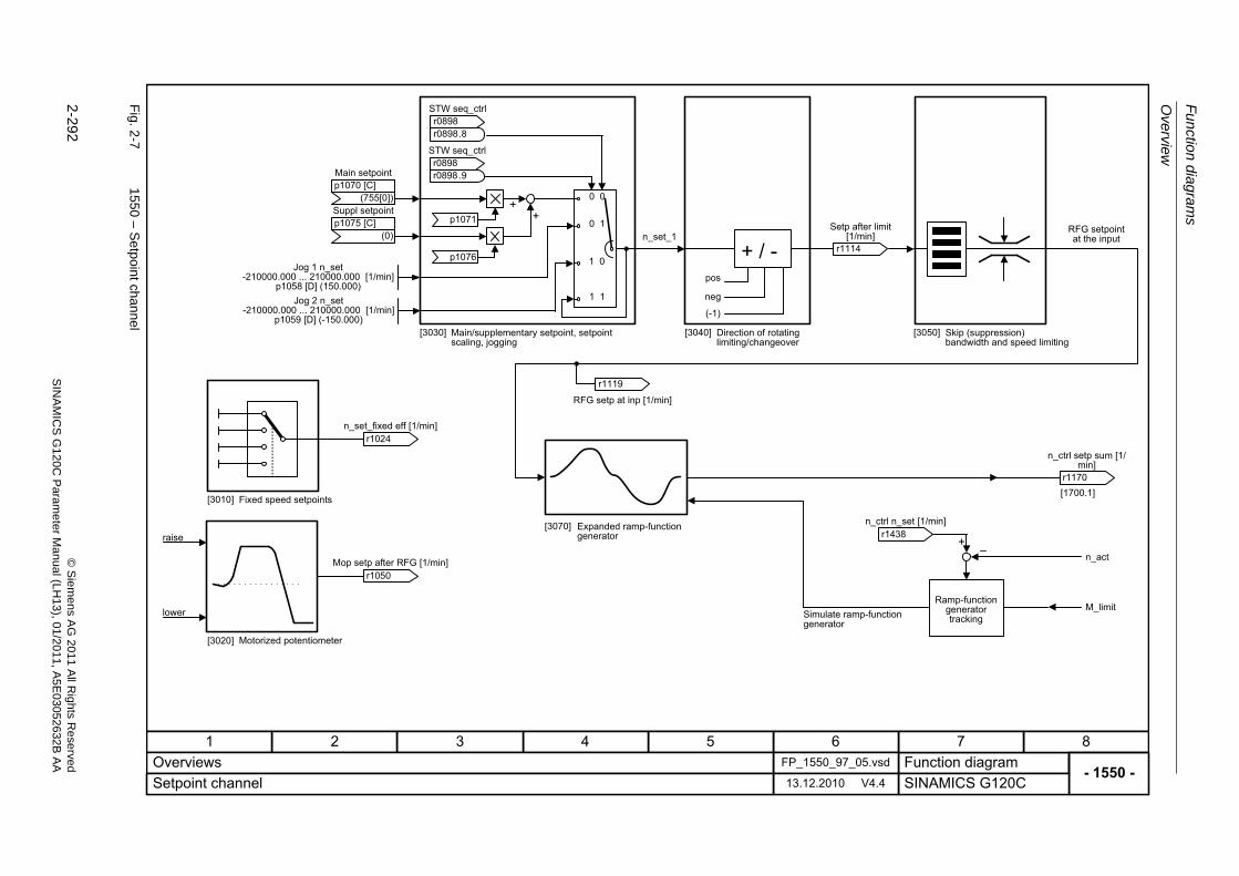
Fu
nctio
n diag
ram
s
Overview
2-292
© S
iem
ens AG
2011 All R
ights R
eservedS
INA
MIC
SG
120C
Param
eter
Manual (L
H13), 0
1/2011, A5E
03052632B
AA
Fig. 2
-7155
0 – Se
tpoin
t channel
- 1550 -Function diagram
87654321FP_1550_97_05.vsdOverviews
SINAMICS G120C13.12.2010 V4.4Setpoint channel
++
+ / -
+�
p1076
p1071
pos
neg
(-1)
[1700.1]
0 0
0 1
1 0
1 1
Main setpoint
(755[0])p1070 [C]
Suppl setpoint
(0)p1075 [C]
r1024 n_set_fixed eff [1/min]
Jog 1 n_set-210000.000 ... 210000.000 [1/min]
p1058 [D] (150.000)Jog 2 n_set
-210000.000 ... 210000.000 [1/min]p1059 [D] (-150.000)
raise
Main/supplementary setpoint, setpoint scaling, jogging
r1050 Mop setp after RFG [1/min]
Motorized potentiometer
Fixed speed setpoints
Expanded ramp-function generator
n_set_1
Simulate ramp-function generator
Direction of rotating limiting/changeover
Skip (suppression) bandwidth and speed limiting
Ramp-function generator tracking
RFG setpoint at the input
STW seq_ctrl
r0898r0898
.8
STW seq_ctrl
r0898r0898
.9
n_act
M_limit
r1438 n_ctrl n_set [1/min]
lower
r1119
RFG setp at inp [1/min]
[3010]
[3030] [3040] [3050]
[3070]
[3020]
r1114
Setp after limit [1/min]
r1170
n_ctrl setp sum [1/min]
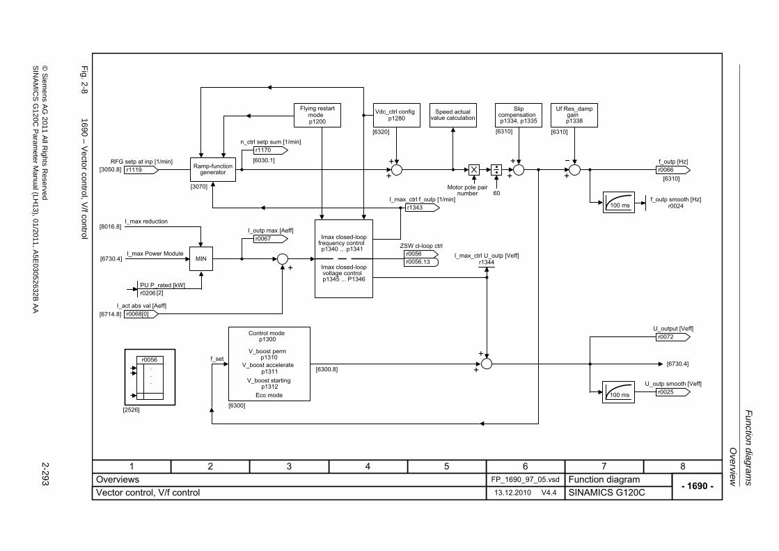
Ove
rview
Fu
nction dia
grams
2-293
© S
ieme
ns AG
2011 All R
ights Re
servedS
INA
MIC
SG
120C P
aram
eterM
anual (LH
13), 01/2011, A5E
03052632B
AA
Fig. 2
-8169
0 – Ve
ctor con
trol, V/f control Imax closed-loop
frequency control p1340 ... p1341
Imax closed-loop voltage control p1345 ... P1346
- 1690 -Function diagram
87654321FP_1690_97_05.vsdOverviews
SINAMICS G120C13.12.2010 V4.4Vector control, V/f control
+
++
+
++ [6310]
[6320] [6310] [6310]
[3050.8]
[8016.8]
[6730.4]
[6714.8]
[6730.4]
+
60
[6300.8]
100 ms
100 ms
[6030.1]
[3070]
MIN
r0056...
[2526]
Ramp-function generator
I_max reduction
I_max Power Module
f_set
r1119 RFG setp at inp [1/min]
r1170 n_ctrl setp sum [1/min]
I_max_ctrl U_outp [Veff]r1344
r0066 f_outp [Hz]
f_outp smooth [Hz]r0024
r0025 U_outp smooth [Veff]
r0072 U_output [Veff]
Vdc_ctrl config p1280
Flying restart mode p1200
Speed actual value calculation
Slip compensation p1334, p1335
Uf Res_damp gain p1338
Control mode p1300
V_boost perm p1310
[6300]
ZSW cl-loop ctrl
r0056r0056
.13
PU P_rated [kW]r0206 [2]
r1343 I_max_ctrl f_outp [1/min]
r0067 I_outp max [Aeff]
r0068 I_act abs val [Aeff]
[0]
+V_boost accelerate
p1311V_boost starting
p1312
Motor pole pair number
Eco mode
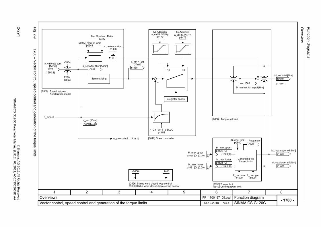
Fu
nctio
n diag
ram
s
Overview
2-294
© S
iem
ens AG
2011 All R
ights R
eservedS
INA
MIC
SG
120C
Param
eter
Manual (L
H13), 0
1/2011, A5E
03052632B
AA
Fig. 2
-9170
0 – Ve
ctor con
trol, speed control and
genera
tion of the torqu
e limits
- 1700 -Function diagram
87654321FP_1700_97_05.vsdOverviews
SINAMICS G120C13.12.2010 V4.4Vector control, speed control and generation of the torque limits
r0056 r1408
r0067I_Ausg max
Kp-Adaption Tn-Adaption
n_modell
�
[1550.8]
[1710.1]
Symmetrizing
Acceleration model
Speed controller
Torque setpoint
Generating the torque limits
[6630] Torque limit [6640] Current-power limit
[[2526] Status word closed-loop control [2530] Status word closed-loop current control
Speed setpoint
r0062 n_set after filter [1/min]
n_C n_act T_s SLVCp1452
Mot M_mom of inertp0341
Mot MomInert Ratiop0342
n_ctrl SLVC Kpp1470
n_ctrl SLVC Tnp1472
r1508
M_set bef. M_suppl [Nm]
r0079 M_set total [Nm]
r1538 M_max upper eff [Nm]
r1539 M_max lower eff [Nm]
M_max upper
(1520[0])p1522 [C]
M_max lower
(1521[0])p1523 [C]
P_max motp1530
P_max genp1531
Current limitp0640
M_max upperp1520 [D] (0.00)
M_max lowerp1521 [D] (0.00)
a_before scalingp1496
[6030]
[6040]
[6060]
r0063[0..2]n_act [1/min]
Integrator control
Kp Tnr1170
n_ctrl setp sum [1/min] r1438
n_ctrl n_set [1/min]
r1084
r1087[3050]
[1710.1]n_pre-control
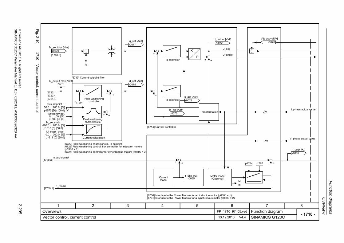
Ove
rview
Fu
nction dia
grams
2-295
© S
ieme
ns AG
2011 All R
ights Re
servedS
INA
MIC
SG
120C P
aram
eterM
anual (LH
13), 01/2011, A5E
03052632B
AA
Fig. 2
-10
1710 – V
ecto
r control, current control
- 1710 -Function diagram
87654321FP_1710_97_05.vsdOverviews
SINAMICS G120C13.12.2010 V4.4Vector control, current control
IqM
�+
+�
+ +
�
IqM
�
K
P
p1764 p1767+ +
+ +
+[1700.3]
[1700.1]
[1700.8]
[6722.1][6723.4][6724.4]
[6710] Current setpoint filter
Field weakening controller
Field weakening characteristic
Current calculation
[6722] Field weakening characteristic, Id setpoint [6723] Field weakening control, flux controller for induction motors (p0300 = 1) [6724] Field weakening controller for synchronous motors (p0300 = 2)
n_pre-control
n_model
iq controller
id controller
[6714] Current controller
Transformation
Current model
Motor model (Observer)
[6730] Interface to the Power Module for an induction motor (p0300 = 1) [6731] Interface to the Power Module for a synchronous motor (p0300 = 2)
I_phase actual value
V_phase actual value
r0079 M_set total [Nm]
U_output max [Veff]r0071 r0075
Id_set [Aeff]
r0078 Iq_act [Aeff]
r0076 Id_act [Aeff]
r0072 U_output [Veff]
r0070 Vdc act val [V]
r0066 f_outp [Hz]
r0077 Iq_set [Aeff]
f_Slip [Hz]r0065
Flux setpoint50.0 ... 200.0 [%]p1570 [D] (100.0)
V_set
Efficiency opt.0 ... 100 [%]p1580 [D] (0)
M_set static-200.0 ... 200.0 [%]
p1610 [D] (50.0)M_suppl_accel
0.0 ... 200.0 [%]p1611 [D] (30.0)
U_angle
U_set
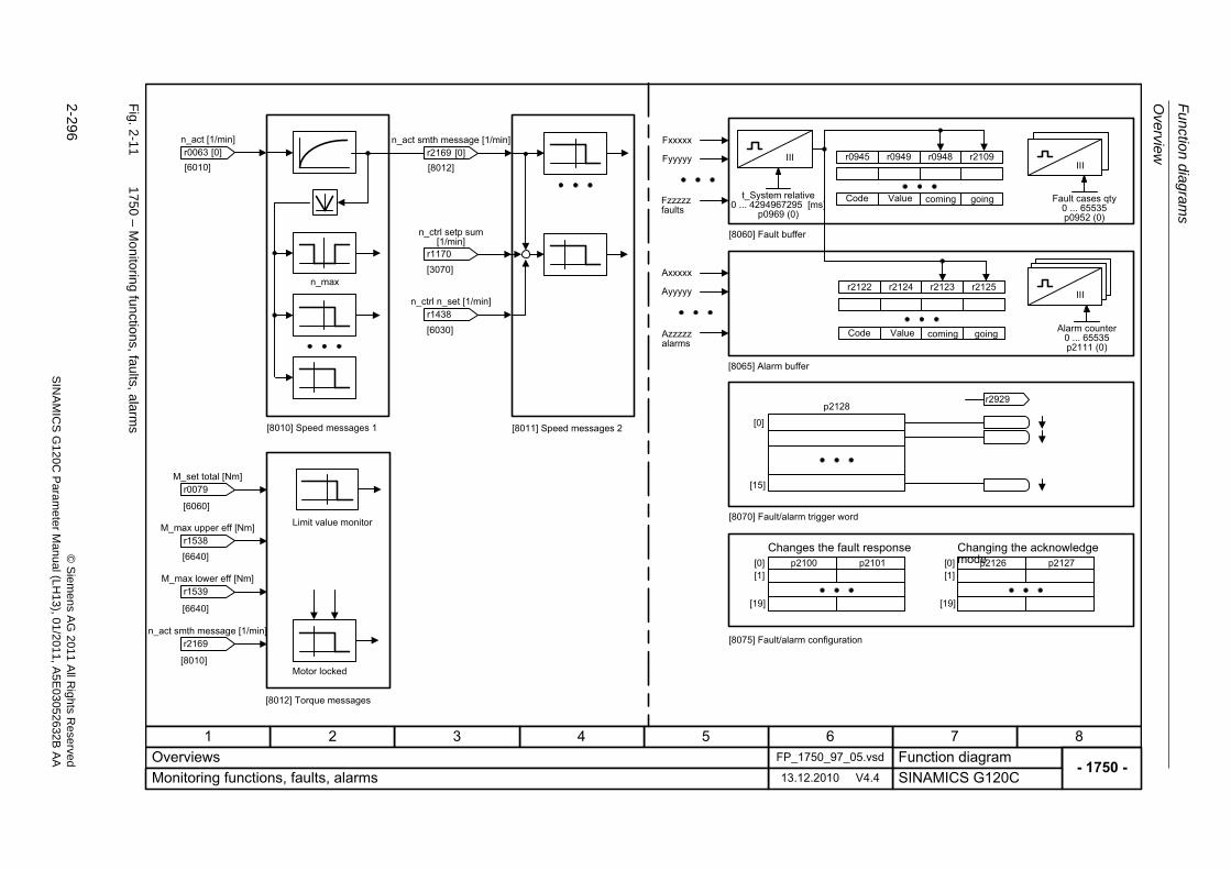
Fu
nctio
n diag
ram
s
Overview
2-296
© S
iem
ens AG
2011 All R
ights R
eservedS
INA
MIC
SG
120C
Param
eter
Manual (L
H13), 0
1/2011, A5E
03052632B
AA
Fig. 2
-11
1750 – M
onitorin
g functio
ns, faults, alarms
- 1750 -Function diagram
87654321FP_1750_97_05.vsdOverviews
SINAMICS G120C13.12.2010 V4.4Monitoring functions, faults, alarms
r2109r0948r0949r0945 IIIIIIIII
r2125r2123r2124r2122 IIIIII
Fxxxxx
Fyyyyy
Axxxxx
Ayyyyy
[0]
[15]
p2128r2929
p2100[0]
[19]
[1]p2101 p2126[0]
[19]
[1]p2127
[3070]
[6010]
[6640]
[6640]
[8010]
[6060]
n_max
[8010] Speed messages 1
[8012] Torque messages
Motor locked
Limit value monitor
Fzzzzzfaults
Azzzzz alarms
[8060] Fault buffer
[8065] Alarm buffer
Code Value coming going
Code Value coming going
[8070] Fault/alarm trigger word
Changes the fault response Changing the acknowledge mode
[8075] Fault/alarm configurationr2169 n_act smth message [1/min]
r1539 M_max lower eff [Nm]
r1538 M_max upper eff [Nm]
r0079 M_set total [Nm]
t_System relative0 ... 4294967295 [ms]
p0969 (0)Fault cases qty
0 ... 65535p0952 (0)
Alarm counter0 ... 65535p2111 (0)
r0063 n_act [1/min]
[0][8012]
[8011] Speed messages 2
r2169 n_act smth message [1/min]
[0]
[6030]r1438
n_ctrl n_set [1/min]
r1170
n_ctrl setp sum [1/min]
Input/Output Terminals
Function diagrams
2-297© Siemens AG 2011 All Rights ReservedSINAMICS G120C Parameter Manual (LH13), 01/2011, A5E03052632B AA
2.4 Input/Output Terminals
Function diagrams
2220 – Digital inputs, electrically isolated (DI0 ... DI5) 2-298
2223 – Analog inputs as Digital inputs (DI11) 2-299
2230 – Digital outputs (DO0 ... DO1) 2-300
9567 – Analog input 0 (AI0) 2-301
9573 – Analog output 0 (AO0) 2-302
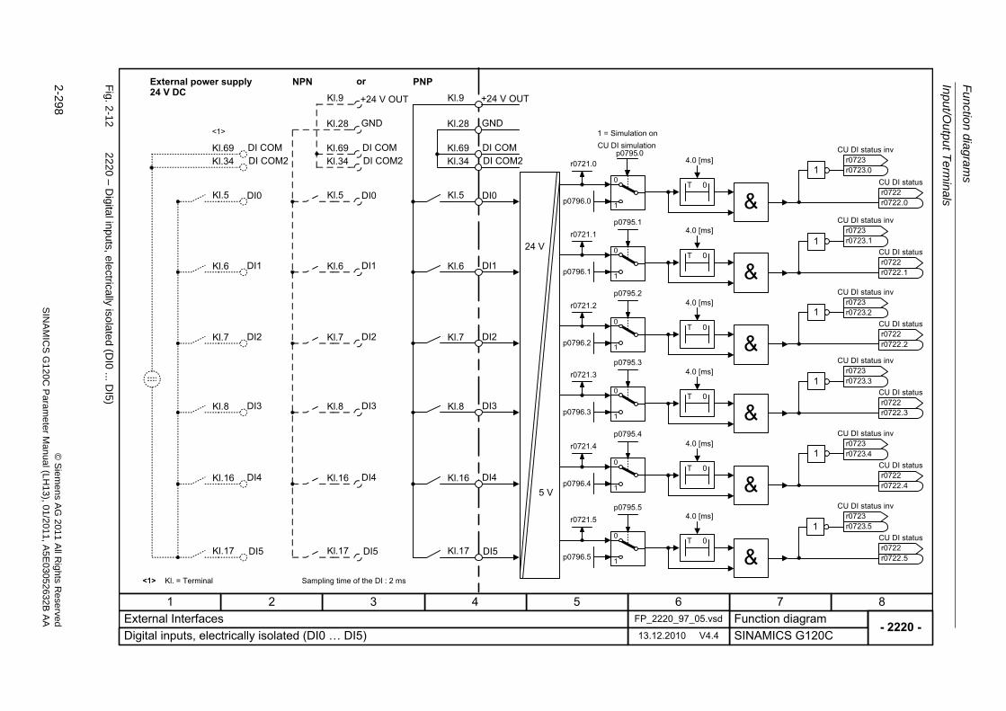
Fu
nctio
n diag
ram
s
Input/Output T
erminals
2-298
© S
iem
ens AG
2011 All R
ights R
eservedS
INA
MIC
SG
120C
Param
eter
Manual (L
H13), 0
1/2011, A5E
03052632B
AA
Fig. 2
-12
2220 – D
igital inputs, electrically isolated (D
I0...D
I5)
- 2220 -Function diagram
87654321FP_2220_97_05.vsdExternal Interfaces
SINAMICS G120C13.12.2010 V4.4Digital inputs, electrically isolated (DI0 � DI5)
+24 V OUTKl.9
Kl.5
Kl.6
Kl.7
Kl.17
p0795.1
p0795.2
p0795.5
Kl.28 GND
24 V
5 V
<1>
1
0
1
0
1
0
1
01
1
1
1
DI5
DI2
DI1
DI0
r0721.0
r0721.1
r0721.2
r0721.5
p0796.5
p0796.2
p0796.1
p0796.0
Kl. = Terminal
CU DI status inv
r0723r0723
CU DI status
r0722r0722
Kl.8
p0795.3
1
01
DI3
r0721.3
p0796.3
Kl.16
p0795.4
1
01
DI4
r0721.4
p0796.4
CU DI simulationp0795
1 = Simulation on
.0
.0
CU DI status inv
r0723r0723
CU DI status
r0722r0722
.1
.1
CU DI status inv
r0723r0723
CU DI status
r0722r0722
.2
.2
CU DI status inv
r0723r0723
CU DI status
r0722r0722
.3
.3
CU DI status inv
r0723r0723
CU DI status
r0722r0722
.4
.4
CU DI status inv
r0723r0723
CU DI status
r0722r0722
.5
.5
T 0
T 0
T 0
T 0
T 0
T 0
.0
External power supply24 V DC
Kl.69 DI COM
PNPKl.9
Kl.5
Kl.6
Kl.7
Kl.17
Kl.28 GND
DI5
DI2
DI1
DI0
Kl.8 DI3
Kl.16 DI4
Kl.69
NPN
+24 V OUT
DI COM
Kl.5
Kl.6
Kl.7
Kl.17 DI5
DI2
DI1
DI0
Kl.8 DI3
Kl.16 DI4
Kl.69 DI COM
or
<1>
<1>
Sampling time of the DI : 2 ms
Kl.34 DI COM2Kl.34 DI COM2Kl.34 DI COM2 4.0 [ms]
4.0 [ms]
4.0 [ms]
4.0 [ms]
4.0 [ms]
4.0 [ms]
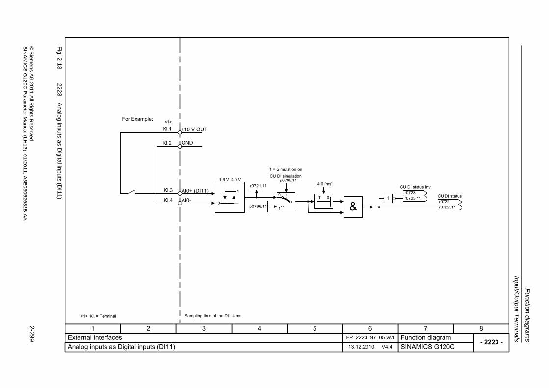
Input/O
utput T
erm
inals
Fu
nction dia
grams
2-299
© S
ieme
ns AG
2011 All R
ights Re
servedS
INA
MIC
SG
120C P
aram
eterM
anual (LH
13), 01/2011, A5E
03052632B
AA
Fig. 2
-13
2223 – A
nalo
g inputs as D
igital inpu
ts (DI1
1)
- 2223 -Function diagram
87654321FP_2223_97_05.vsdExternal Interfaces
SINAMICS G120C13.12.2010 V4.4Analog inputs as Digital inputs (DI11)
1
01
r0721.11
p0796.11
CU DI status inv
r0723r0723
CU DI status
r0722r0722
CU DI simulationp0795
1 = Simulation on
.11
.11T 0
.11
0
1
1.6 V 4.0 V
<1> Kl. = Terminal
<1>
Kl.3 AI0+ (DI11)
Kl.4
+10 V OUTKl.1
Kl.2 GND
For Example:
Sampling time of the DI : 4 ms
AI0-
4.0 [ms]
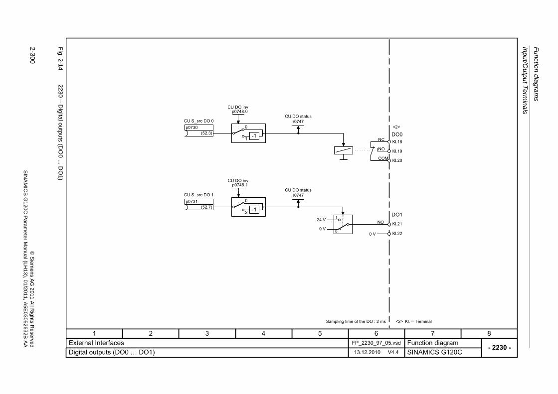
Fu
nctio
n diag
ram
s
Input/Output T
erminals
2-300
© S
iem
ens AG
2011 All R
ights R
eservedS
INA
MIC
SG
120C
Param
eter
Manual (L
H13), 0
1/2011, A5E
03052632B
AA
Fig. 2
-14
2230 – D
igital outputs (D
O0
...DO
1)
- 2230 -Function diagram
87654321FP_2230_97_05.vsdExternal Interfaces
SINAMICS G120C13.12.2010 V4.4Digital outputs (DO0 � DO1)
-1
0
1
-1
0
2
(52.3)
CU S_src DO 0p0730
(52.7)
CU S_src DO 1p0731
CU DO invp0748
CU DO invp0748
NO
COM
NC
Kl.20
Kl.19
Kl.18
NO
Kl.22
Kl.21
DO0
DO1
<2> Kl. = Terminal
<2>
Sampling time of the DO : 2 ms
CU DO statusr0747
CU DO statusr0747
.1
.0
1
0
24 V
0 V0 V
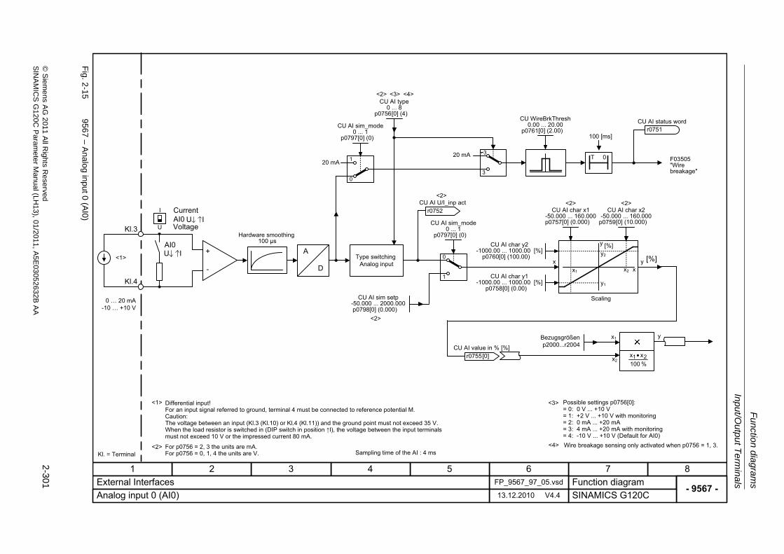
Input/O
utput T
erm
inals
Fu
nction dia
grams
2-301
© S
ieme
ns AG
2011 All R
ights Re
servedS
INA
MIC
SG
120C P
aram
eterM
anual (LH
13), 01/2011, A5E
03052632B
AA
Fig. 2
-15
9567 – A
nalo
g input0 (A
I0)
- 9567 -Function diagram
87654321FP_9567_97_05.vsdExternal Interfaces
SINAMICS G120C13.12.2010 V4.4Analog input 0 (AI0)
3
320 mA T 0
<2>
0 � 20 mA-10 � +10 V
Kl.3
[%]x y
<2> <2>
A
D
+
-
<1>
<1>
x1
y2
x2
y1
y
x
[%]
Bezugsgrößenp2000...r2004
y
x2
x1
<2> <3>
% 100xx 21•
<3>
I
1
0
20 mA 1
0
Voltage
Current
Hardware smoothing100 μs
Scaling
Differential input!For an input signal referred to ground, terminal 4 must be connected to reference potential M.Caution:The voltage between an input (Kl.3 (Kl.10) or Kl.4 (Kl.11)) and the ground point must not exceed 35 V.When the load resistor is switched in (DIP switch in position �I), the voltage between the input terminals must not exceed 10 V or the impressed current 80 mA.
For p0756 = 2, 3 the units are mA.For p0756 = 0, 1, 4 the units are V.
Possible settings p0756[0]:= 0: 0 V ... +10 V= 1: +2 V ... +10 V with monitoring= 2: 0 mA ... +20 mA= 3: 4 mA ... +20 mA with monitoring= 4: -10 V ... +10 V (Default for AI0)
F03505 "Wire breakage"
r0752 CU AI U/I_inp act
Kl.4
<4> Wire breakage sensing only activated when p0756 = 1, 3.Kl. = Terminal Sampling time of the AI : 4 ms
r0755 CU AI value in % [%]
[0]
<2>
<4>
<2>
Type switchingAnalog input
U IU
AI0
U IAI0
CU AI status wordr0751
CU WireBrkThresh0.00 ... 20.00
p0761[0..1] (2.00)
CU AI sim_mode0 ... 1
p0797[0..1] (0)
CU AI sim setp-50.000 ... 2000.000p0798[0..1] (0.000)
CU AI char y1-1000.00 ... 1000.00 [%]
p0758[0..1] (0.00)
CU AI char y2-1000.00 ... 1000.00 [%]
p0760[0..1] (100.00)
CU AI char x1-50.000 ... 160.000p0757[0..1] (0.000)
CU AI char x2-50.000 ... 160.000
p0759[0..1] (10.000)
[0] (0)
[0] (2.00)
[0] (10.000)[0] (0.000)
[0] (0.00)
[0] (100.00)
[0] (0.000)
CU AI type0 ... 8
p0756[0..1] (4)[0] (4)
CU AI sim_mode0 ... 1
p0797[0..1] (0)[0] (0) 100 [ms]
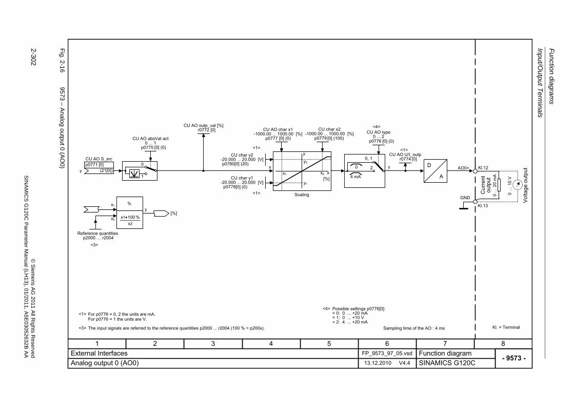
Fu
nctio
n diag
ram
s
Input/Output T
erminals
2-302
© S
iem
ens AG
2011 All R
ights R
eservedS
INA
MIC
SG
120C
Param
eter
Manual (L
H13), 0
1/2011, A5E
03052632B
AA
Fig. 2
-16
9573 – A
nalo
g output 0 (AO
0)
- 9573 -Function diagram
87654321FP_9573_97_05.vsdExternal Interfaces
SINAMICS G120C13.12.2010 V4.4Analog output 0 (AO0)
Kl.12
Kl.13
D
A
x yy
<1>
<1>
<3>
<4>
0 �
10
V
0 �
20
mAx1
y2
x2
y1
y
x[%]
<1>
<3>
<4>
y
x2
x1
[%]
21
x% 100x •
%
0
1
AO0+2
0, 1
4 mA
0
Scaling
Volta
ge o
utpu
t
Cur
rent
ou
tput
For p0776 = 0, 2 the units are mA.For p0776 = 1 the units are V.
The input signals are referred to the reference quantities p2000 ... r2004 (100 % = p200x).
Possible settings p0776[0]:= 0: 0 ... +20 mA= 1: 0 ... +10 V= 2: 4 ... +20 mA
Reference quantitiesp2000 � r2004
CU AO absVal act0 ... 1
p0775 (0)
CU AO S_src
(21[0])p0771
CU AO char x1-1000.00 ... 1000.00 [%]
p0777 (0.00)
CU char x2-1000.00 ... 1000.00 [%]
p0779 (100.00)CU AO type
0 ... 2p0776 (0)
CU AO U/I_outpr0774
Sampling time of the AO : 4 ms Kl. = Terminal
GND
<1>
CU AO outp_val [%]r0772
[0]
[0] (0)
[0]
[0] (0) [0] (100) [0] (0)
[0]
CU char y1-20.000 ... 20.000 [V]
p0778[0..1] (0.000)[0] (0)
CU char y2-20.000 ... 20.000 [V]p0780[0..1] (20.000)[0] (20)
Communication
Function diagrams
2-303© Siemens AG 2011 All Rights ReservedSINAMICS G120C Parameter Manual (LH13), 01/2011, A5E03052632B AA
2.5 Communication
2.5.1 Fieldbus Interface (USS, Modbus) (G120C USS/MB) 2-304
2.5.2 PROFIdrive / PROFIBUS (G120C DP) 2-310
2.5.3 CANopen (G120C CAN) 2-323
Function diagrams
Communication
2-304 © Siemens AG 2011 All Rights ReservedSINAMICS G120C Parameter Manual (LH13), 01/2011, A5E03052632B AA
2.5.1 Fieldbus Interface (USS, Modbus) (G120C USS/MB)
Function diagrams
9310 – Configuration, addresses and diagnostics 2-305
9342 – STW1 control word interconnection 2-306
9352 – ZSW1 status word interconnection 2-307
9360 – Receive telegram, free interconnection via BICO 2-308
9370 – Send telegram, free interconnection via BICO 2-309
9370 – Send telegram, free interconnection via BICO 2-309
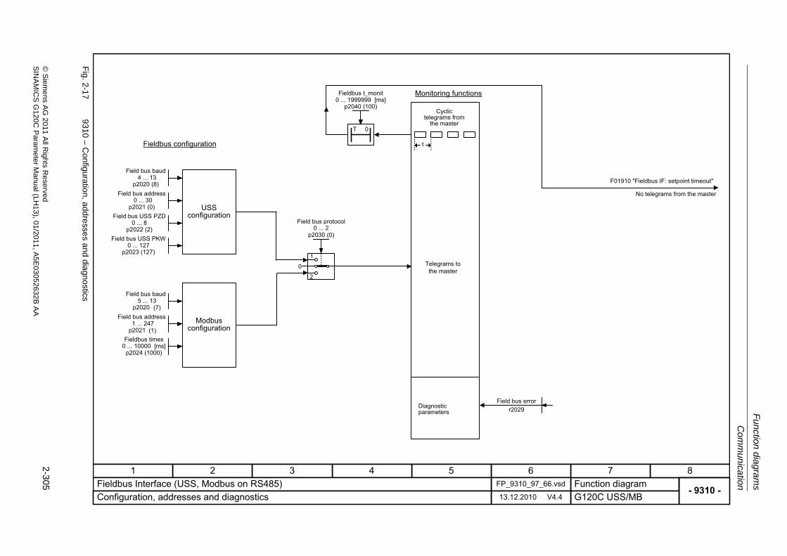
Com
mu
nicatio
n
Fu
nction dia
grams
2-305
© S
ieme
ns AG
2011 All R
ights Re
servedS
INA
MIC
SG
120C P
aram
eterM
anual (LH
13), 01/2011, A5E
03052632B
AA
Fig. 2
-17
9310 – C
onfiguration, add
resse
s and dia
gnostics
- 9310 -Function diagram
87654321FP_9310_97_66.vsdFieldbus Interface (USS, Modbus on RS485)
G120C USS/MB13.12.2010 V4.4Configuration, addresses and diagnostics
t
T 0
Fieldbus configuration
Monitoring functions
Cyclic telegrams from
the master
F01910 "Fieldbus IF: setpoint timeout"
No telegrams from the master
Diagnostic parameters
Field bus baud4 ... 13
p2020 (8)
Fieldbus t_monit0 ... 1999999 [ms]
p2040 (100)
1
Field bus protocol0 ... 4
p2030 (4)
0
2
Field bus errorr2029
USS configuration
Field bus address0 ... 247
p2021 (0)Field bus USS PZD
0 ... 8p2022 (2)
Field bus USS PKW0 ... 127
p2023 (127)
Field bus baud4 ... 13
p2020 (8)
Modbus configuration
Field bus address0 ... 247
p2021 (0)Fieldbus times
0 ... 10000 [ms]p2024 (1000)
Telegrams to the master
4 ... 13
0 ... 30
5 ... 13
1 ... 247
(7)
(1)
0 ... 2(0)
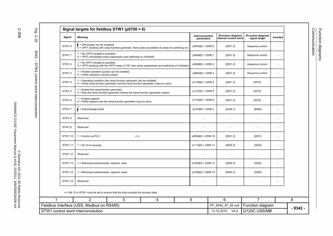
Fu
nctio
n diag
ram
s
Com
munication
2-306
© S
iem
ens AG
2011 All R
ights R
eservedS
INA
MIC
SG
120C
Param
eter
Manual (L
H13), 0
1/2011, A5E
03052632B
AA
Fig. 2
-18
9342 – S
TW
1 co
ntrol w
ord interconnection
- 9342 -Function diagram
87654321FP_9342_97_62.vsdFieldbus Interface (USS, Modbus on RS485)
G120C USS/MB13.12.2010 V4.4STW1 control word interconnection
STW1.0
STW1.1
STW1.2
STW1.3
STW1.4
STW1.5
STW1.6
STW1.8
STW1.9
STW1.11
STW1.12
STW1.13
STW1.14
STW1.15
STW1.7
STW1.10
p0848[0] = r2090.2
p0852[0] = r2090.3
p2103[0] = r2090.7
-
-
p0854[0] = r2090.10
p1113[0] = r2090.11
-
p1035[0] = r2090.13
p1036[0] = r2090.14
-
p0840[0] = r2090.0
p0844[0] = r2090.1
[2501.3]
[2501.3]
[2501.3]
[2501.3]
[2501.3]
[2546.1]
-
-
[2501.3]
[2505.3]
-
[2505.3]
[2505.3]
-
[2501.3]
[2501.3]
[8060]
-
-
[2501]
[3040]
-
[3020]
[3020]
-
-
-
-
-
-
-
-
-
-
-
-
-
-
-
-
-
<1>
<1>
Signal targets for fieldbus STW1 (p0700 = 6)
Signal Meaning Interconnection parameters
[Function diagram] internal control word
[Function diagram] signal target Inverted
0 = OFF1 (braking with ramp-function generator, then pulse cancellation & ready for switching on)= ON (pulses can be enabled)
1 = No OFF2 (enable is possible)0 = OFF2 (immediate pulse suppression and switching on inhibited)
1 = No OFF3 (enable is possible)0 = OFF3 (braking with the OFF3 ramp p1135, then pulse suppression and switching on inhibited)
1 = Enable operation (pulses can be enabled)0 = Inhibit operation (cancel pulses)
1 = Operating condition (the ramp-function generator can be enabled)0 = Inhibit ramp-function generator (set the ramp-function generator output to zero)
1 = Enable the ramp-function generator0 = Stop the ramp-function generator (freeze the ramp-function generator output)
1 = Enable setpoint0 = Inhibit setpoint (set the ramp-function generator input to zero)
= Acknowledge faults
Reserved
Reserved
1 = Control via PLC
1 = Dir of rot reversal
Reserved
1 = Motorized potentiometer, setpoint, raise
1 = Motorized potentiometer, setpoint, lower
Reserved
Bit 10 in STW1 must be set to ensure that the drive accepts the process data.
Sequence control
Sequence control
Sequence control
Sequence control
[3070]
[3070]
[3070]
p1140[0] = r2090.4
p1141[0] = r2090.5
p1142[0] = r2090.6
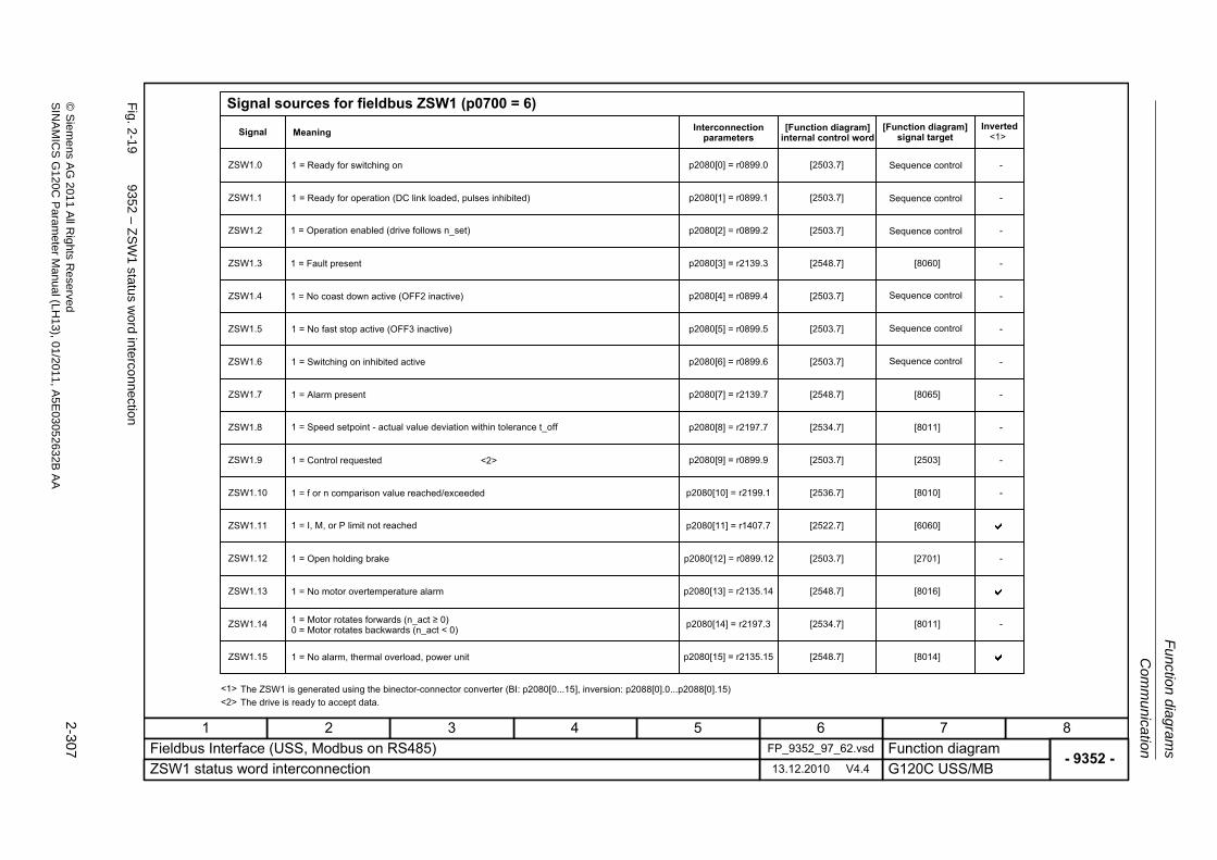
Com
mu
nicatio
n
Fu
nction dia
grams
2-307
© S
ieme
ns AG
2011 All R
ights Re
servedS
INA
MIC
SG
120C P
aram
eterM
anual (LH
13), 01/2011, A5E
03052632B
AA
Fig. 2
-19
9352 – Z
SW
1 status w
ord interconnection
- 9352 -Function diagram
87654321FP_9352_97_62.vsdFieldbus Interface (USS, Modbus on RS485)
G120C USS/MB13.12.2010 V4.4ZSW1 status word interconnection
<1>
ZSW1.0
ZSW1.1
ZSW1.2
ZSW1.3
ZSW1.4
ZSW1.5
ZSW1.6
ZSW1.8
ZSW1.9
ZSW1.11
ZSW1.12
ZSW1.13
ZSW1.14
ZSW1.15
ZSW1.7
ZSW1.10
<2>
p2080[2] = r0899.2
p2080[3] = r2139.3
p2080[4] = r0899.4
p2080[5] = r0899.5
p2080[6] = r0899.6
p2080[7] = r2139.7
p2080[8] = r2197.7
p2080[9] = r0899.9
p2080[10] = r2199.1
p2080[11] = r1407.7
p2080[13] = r2135.14
p2080[15] = r2135.15
p2080[0] = r0899.0
p2080[1] = r0899.1
p2080[14] = r2197.3
[2503.7]
[2548.7]
[2503.7]
[2503.7]
[2503.7]
[2548.7]
[2534.7]
[2503.7]
[2536.7]
[2522.7]
[2548.7]
[2548.7]
[2503.7]
[2503.7]
[2534.7]
[8060]
[8065]
[8011]
[2503]
[8010]
[6060]
[8016]
[8014]
[8011]
-
-
-
-
-
-
-
-
-
-
-
-
-
<1>
Signal sources for fieldbus ZSW1 (p0700 = 6)
Signal Meaning Interconnection parameters
[Function diagram] internal control word
[Function diagram] signal target
Inverted
1 = Ready for switching on
1 = Ready for operation (DC link loaded, pulses inhibited)
1 = Operation enabled (drive follows n_set)
1 = Fault present
1 = No coast down active (OFF2 inactive)
1 = No fast stop active (OFF3 inactive)
1 = Switching on inhibited active
1 = Alarm present
1 = Speed setpoint - actual value deviation within tolerance t_off
1 = Control requested
1 = f or n comparison value reached/exceeded
1 = I, M, or P limit not reached
1 = Open holding brake
1 = No motor overtemperature alarm
1 = Motor rotates forwards (n_act � 0)0 = Motor rotates backwards (n_act < 0)
1 = No alarm, thermal overload, power unit
The ZSW1 is generated using the binector-connector converter (BI: p2080[0...15], inversion: p2088[0].0...p2088[0].15)The drive is ready to accept data.
Sequence control
Sequence control
Sequence control
Sequence control
Sequence control
Sequence control
<2>
p2080[12] = r0899.12 [2503.7] [2701]
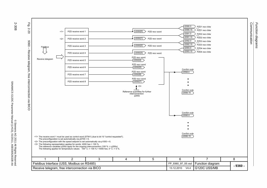
Fu
nctio
n diag
ram
s
Com
munication
2-308
© S
iem
ens AG
2011 All R
ights R
eservedS
INA
MIC
SG
120C
Param
eter
Manual (L
H13), 0
1/2011, A5E
03052632B
AA
Fig. 2
-20
9360 – R
eceive tele
gram, free in
terconnection
via BIC
O
- 9360 -Function diagram
87654321FP_9360_97_05.vsdFieldbus Interface (USS, Modbus on RS485)
G120C USS/MB13.12.2010 V4.4Receive telegram, free interconnection via BICO
<3>
<1>
Receive telegram
PZD receive word 1
PZD receive word 2
PZD receive word 3
PZD receive word 4
PZD receive word 5
PZD receive word 6
The following representation applies for words: 4000 hex = 100 %.The reference variables p200x apply for the ongoing interconnection (100 % -> p200x).The following applies for temperature values: 100° C -> 100 % = 4000 hex, 0° C -> 0 %.
Reference quantities for further interconnection
p200x
Con/bin outpr2094
r2050 PZD recv word
[4]
r2050 PZD recv word
[5]
Con/bin outpr2094.15
Con/bin outpr2095.0
Con/bin outpr2095.15
.0PZD receive word 7
PZD receive word 8
r2050 PZD recv word
[6]
r2050 PZD recv word
[7]
Fieldbus
<3>
<1>
<2>
The receive word 1 must be used as control word (STW1) (due to bit 10 "control requested"). The preconfiguration is set automatically via p0700 = 6.The preconfiguration with the speed setpoint is set automatically via p1000 = 6.
<2>
...
...r2050 PZD recv word [0]
r2050 PZD recv word [1]
r2050 PZD recv word [2]
r2050 PZD recv word [3]
PZD1 recv bitwr2090.0
PZD1 recv bitwr2090.15
PZD2 recv bitwr2091.0
PZD2 recv bitwr2091.15
...PZD3 recv bitwr2092.0
PZD3 recv bitwr2092.15
...PZD4 recv bitwr2093.0
PZD4 recv bitwr2093.15
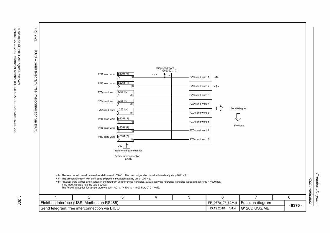
Com
mu
nicatio
n
Fu
nction dia
grams
2-309
© S
ieme
ns AG
2011 All R
ights Re
servedS
INA
MIC
SG
120C P
aram
eterM
anual (LH
13), 01/2011, A5E
03052632B
AA
Fig. 2
-21
9370 – S
end teleg
ram, fre
e interconnection via
BIC
O
- 9370 -Function diagram
87654321FP_9370_97_62.vsdFieldbus Interface (USS, Modbus on RS485)
G120C USS/MB13.12.2010 V4.4Send telegram, free interconnection via BICO
<1>
...
<3>
<1><1>
Reference quantities for
further interconnection p200x
The send word 1 must be used as status word (ZSW1). The preconfiguration is set automatically via p0700 = 6.
Physical word values are inserted in the telegram as referenced variables. p200x apply as reference variables (telegram contents = 4000 hex, if the input variable has the value p200x).The following applies for temperature values: 100° C -> 100 % = 4000 hex; 0° C -> 0%.
PZD send word 1
PZD send word 2
PZD send word 3
PZD send word 4
PZD send word 5
PZD send word 6
PZD send word 7
PZD send word 8
Send telegram
Diag send wordr2053 [0 � 7]
PZD send word(0)
p2051 [0]
PZD send word(0)
p2051 [1]
PZD send word(0)
p2051 [2]
PZD send word(0)
p2051 [3]
PZD send word(0)
p2051 [4]
PZD send word(0)
p2051 [5]
PZD send word(0)
p2051 [6]
PZD send word(0)
p2051 [7]
Fieldbus
<2>
The preconfiguration with the speed setpoint is set automatically via p1000 = 6.<2><3>
Function diagrams
Communication
2-310 © Siemens AG 2011 All Rights ReservedSINAMICS G120C Parameter Manual (LH13), 01/2011, A5E03052632B AA
2.5.2 PROFIdrive / PROFIBUS (G120C DP)
Function diagrams
2410 – PROFIBUS, addresses and diagnostics 2-311
2420 – Telegrams and Process Data (PZD) 2-312
2440 – PZD receive signals interconnection 2-313
2441 – STW1 control word interconnection (p2038 = 2) 2-314
2442 – STW1 control word interconnection (p2038 = 0) 2-315
2450 – PZD send signals interconnection 2-317
2451 – ZSW1 status word interconnection (p2038 = 2) 2-318
2452 – ZSW1 status word interconnection (p2038 = 0) 2-319
2468 – Receive telegram, free interconnection via BICO (p0922 = 999) 2-321
2470 – Send telegram, free interconnection via BICO (p0922 = 999) 2-322
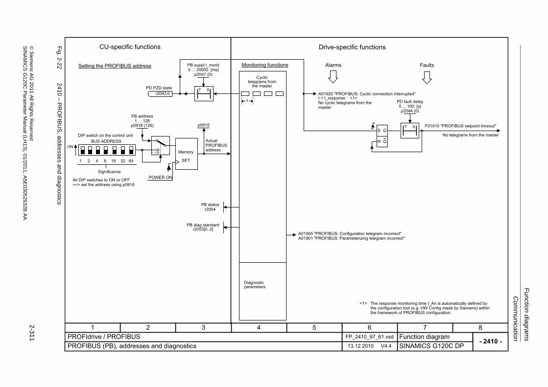
Com
mu
nicatio
n
Fu
nction dia
grams
2-311
© S
ieme
ns AG
2011 All R
ights Re
servedS
INA
MIC
SG
120C P
aram
eterM
anual (LH
13), 01/2011, A5E
03052632B
AA
Fig. 2
-22
2410 – P
RO
FIB
US
, addresse
s and dia
gnostics
- 2410 -Function diagram
87654321FP_2410_97_61.vsdPROFIdrive / PROFIBUS
SINAMICS G120C DP13.12.2010 V4.4PROFIBUS (PB), addresses and diagnostics
<1>
t
S Q
R Q
T 0
ON
1 2 4 8 16 32 64
1..126
T 0
CU-specific functions
Setting the PROFIBUS address
DIP switch on the control unit
Significance
All DIP switches to ON or OFF ==> set the address using p0918
POWER ON
Actual PROFIBUS addressMemory
SET
Drive-specific functions
Monitoring functions
Cyclic telegrams from
the master
Alarms
A01920 "PROFIBUS: Cyclic connection interrupted"t > t_response <1>No cyclic telegrams from the master
Faults
F01910 "PROFIBUS setpoint timeout"
No telegrams from the master
A01900 "PROFIBUS: Configuration telegram incorrect" A01901 "PROFIBUS: Parameterizing telegram incorrect"
The response monitoring time t_An is automatically defined by the configuration tool (e.g. HW Config made by Siemens) within the framework of PROFIBUS configuration.
Diagnostic parameters
PD PZD stater2043.0
PB address1 ... 126
p0918 (126)
PB statusr2054
PD fault delay0 ... 100 [s]p2044 (0)
PB suppl t_monit 0 ... 20000 [ms]
p2047 (0)
p0918
BUS ADDRESS
PB diag standardr2055[0..2]
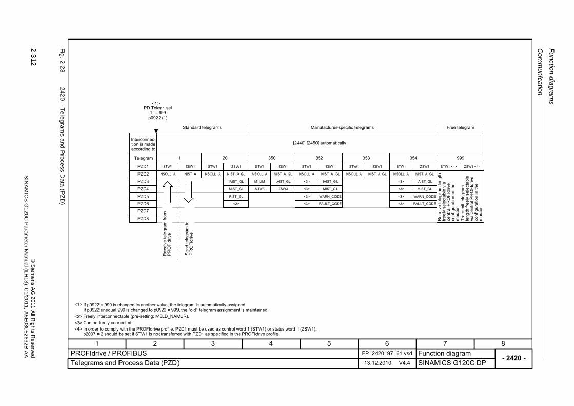
Fu
nctio
n diag
ram
s
Com
munication
2-312
© S
iem
ens AG
2011 All R
ights R
eservedS
INA
MIC
SG
120C
Param
eter
Manual (L
H13), 0
1/2011, A5E
03052632B
AA
Fig. 2
-23
2420 – T
elegrams and
Process D
ata (PZ
D)
- 2420 -Function diagram
87654321FP_2420_97_61.vsdPROFIdrive / PROFIBUS
SINAMICS G120C DP13.12.2010 V4.4Telegrams and Process Data (PZD)
<1>
<2>
If p0922 = 999 is changed to another value, the telegram is automatically assigned.If p0922 unequal 999 is changed to p0922 = 999, the "old" telegram assignment is maintained!Freely interconnectable (pre-setting: MELD_NAMUR).
<1>
1 20
PZD6PZD5
PZD4
PZD1
PZD2
PZD3
STW1 ZSW1
NSOLL_A NIST_A
STW1 ZSW1
MIST_GL
PIST_GL
<2>
NIST_A_GL
IAIST_GL
NSOLL_A
PD Telegr_sel1 ... 999
p0922 (1)
Interconnec-tion is made according to
Telegram
[2440] [2450] automatically
PZD8
PZD7
350
STW1 ZSW1
ZSW3
NIST_A_GL
IAIST_GL
NSOLL_A
STW3
M_LIM
<3> Can be freely connected.
999
STW1 <4> ZSW1 <4>
Rec
eive
tele
gram
leng
th
freel
y se
lect
able
via
ce
ntra
l PR
OFI
driv
e co
nfig
urat
ion
in th
e m
aste
rTr
ansm
it te
legr
am
leng
th fr
eely
sel
ecta
ble
via
cent
ral P
RO
FIdr
ive
conf
igur
atio
n in
the
mas
ter
<4> In order to comply with the PROFIdrive profile, PZD1 must be used as control word 1 (STW1) or status word 1 (ZSW1).p2037 = 2 should be set if STW1 is not transferred with PZD1 as specified in the PROFIdrive profile.
Rec
eive
tele
gram
from
PR
OFI
driv
e
Sen
d te
legr
am to
PR
OFI
driv
e
352
STW1 ZSW1
MIST_GL
WARN_CODE
FAULT_CODE
NIST_A_GL
IAIST_GL
NSOLL_A
<3>
<3>
<3>
<3>
353
STW1 ZSW1
NIST_A_GLNSOLL_A
354
STW1 ZSW1
MIST_GL
WARN_CODE
FAULT_CODE
NIST_A_GL
IAIST_GL
NSOLL_A
<3>
<3>
<3>
<3>
Standard telegrams Manufacturer-specific telegrams Free telegram
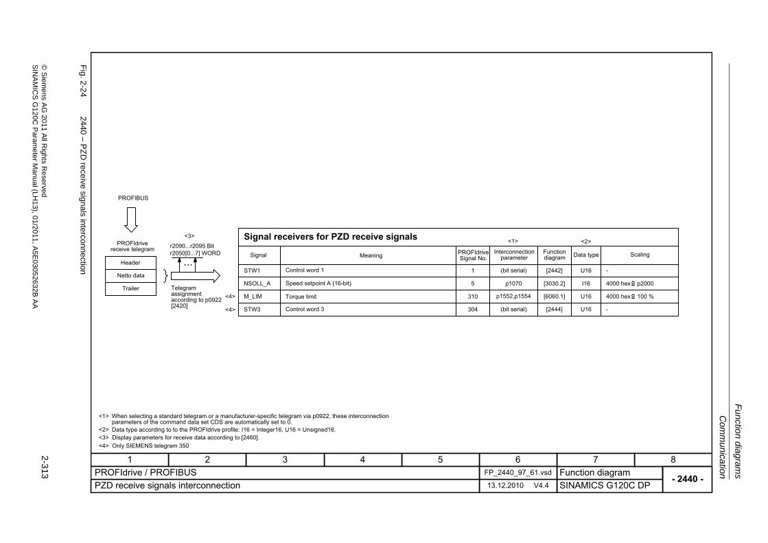
Com
mu
nicatio
n
Fu
nction dia
grams
2-313
© S
ieme
ns AG
2011 All R
ights Re
servedS
INA
MIC
SG
120C P
aram
eterM
anual (LH
13), 01/2011, A5E
03052632B
AA
Fig. 2
-24
2440 – P
ZD
receive sig
nals interco
nnection
- 2440 -Function diagram
87654321FP_2440_97_61.vsdPROFIdrive / PROFIBUS
SINAMICS G120C DP13.12.2010 V4.4PZD receive signals interconnection
r2090...r2095 Bitr2050[0...7] WORD
...
PROFIBUS
STW1
NSOLL_A
<2><3>
1
5 p1070
<1>
[2442]
[3030.2]
U16
I16
-
4000 hex p2000
PROFIdrive receive telegram
Header
Netto data
Trailer Telegram assignment according to p0922 [2420]
Signal receivers for PZD receive signals
Signal Meaning PROFIdrive Signal No.
Interconnection parameter
Function diagram Data type Scaling
Control word 1
Speed setpoint A (16-bit)
(bit serial)
When selecting a standard telegram or a manufacturer-specific telegram via p0922, these interconnection parameters of the command data set CDS are automatically set to 0.Data type according to to the PROFIdrive profile: I16 = Integer16, U16 = Unsigned16.Display parameters for receive data according to [2460].
<1>
<2><3>
M_LIM
STW3
310
304
p1552,p1554 [6060.1]
[2444]
U16
U16
4000 hex 100 %Torque limit
Control word 3 (bit serial) -
Only SIEMENS telegram 350<4>
<4>
<4>
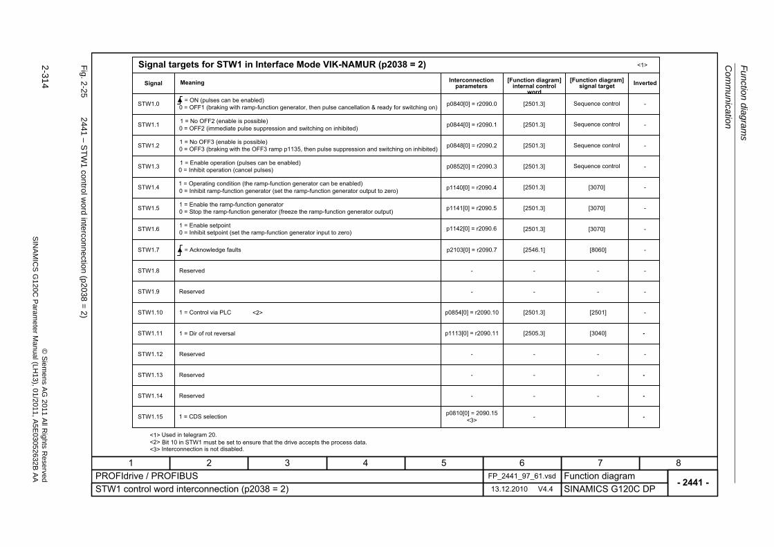
Fu
nctio
n diag
ram
s
Com
munication
2-314
© S
iem
ens AG
2011 All R
ights R
eservedS
INA
MIC
SG
120C
Param
eter
Manual (L
H13), 0
1/2011, A5E
03052632B
AA
Fig. 2
-25
2441 – S
TW
1 co
ntrol w
ord interconnection
(p2038
=2
)
- 2441 -Function diagram
87654321FP_2441_97_61.vsdPROFIdrive / PROFIBUS
SINAMICS G120C DP13.12.2010 V4.4STW1 control word interconnection (p2038 = 2)
<1>
STW1.0
STW1.1
STW1.2
STW1.3
STW1.4
STW1.5
STW1.6
STW1.8
STW1.9
STW1.11
STW1.12
STW1.13
STW1.14
STW1.15
STW1.7
STW1.10
p0848[0] = r2090.2
p0852[0] = r2090.3
p2103[0] = r2090.7
-
-
p0854[0] = r2090.10
p1113[0] = r2090.11
-
-
-
p0810[0] = 2090.15<3>
p0840[0] = r2090.0
p0844[0] = r2090.1
[2501.3]
[2501.3]
[2501.3]
[2501.3]
[2501.3]
[2546.1]
-
-
[2501.3]
[2505.3]
-
-
-
-
[2501.3]
[2501.3]
[8060]
-
-
[2501]
[3040]
-
-
-
-
-
-
-
-
-
-
-
-
-
-
-
-
-
-
-
<2>
<2>
<1>Signal targets for STW1 in Interface Mode VIK-NAMUR (p2038 = 2)
Signal Meaning Interconnection parameters
[Function diagram] internal control
word
[Function diagram] signal target Inverted
= ON (pulses can be enabled)0 = OFF1 (braking with ramp-function generator, then pulse cancellation & ready for switching on)
1 = No OFF2 (enable is possible)0 = OFF2 (immediate pulse suppression and switching on inhibited)
1 = No OFF3 (enable is possible)0 = OFF3 (braking with the OFF3 ramp p1135, then pulse suppression and switching on inhibited)
1 = Enable operation (pulses can be enabled)0 = Inhibit operation (cancel pulses)
1 = Operating condition (the ramp-function generator can be enabled)0 = Inhibit ramp-function generator (set the ramp-function generator output to zero)
1 = Enable the ramp-function generator0 = Stop the ramp-function generator (freeze the ramp-function generator output)
1 = Enable setpoint0 = Inhibit setpoint (set the ramp-function generator input to zero)
= Acknowledge faults
Reserved
Reserved
Reserved
Reserved
Reserved
1 = Control via PLC
1 = Dir of rot reversal
1 = CDS selection
Used in telegram 20.Bit 10 in STW1 must be set to ensure that the drive accepts the process data.
Sequence control
Sequence control
Sequence control
Sequence control
<3> Interconnection is not disabled.
[3070]
[3070]
[3070]
p1140[0] = r2090.4
p1141[0] = r2090.5
p1142[0] = r2090.6
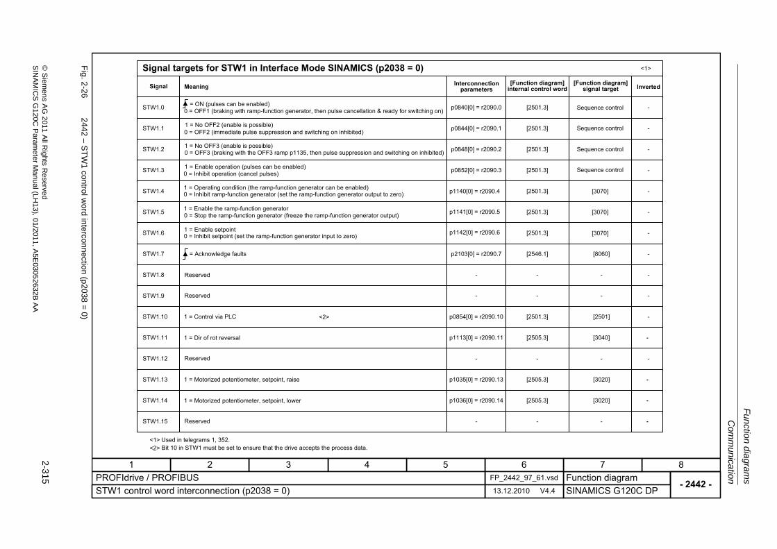
Com
mu
nicatio
n
Fu
nction dia
grams
2-315
© S
ieme
ns AG
2011 All R
ights Re
servedS
INA
MIC
SG
120C P
aram
eterM
anual (LH
13), 01/2011, A5E
03052632B
AA
Fig. 2
-26
2442 – S
TW
1 co
ntrol w
ord interconnection
(p2038
=0
)
- 2442 -Function diagram
87654321FP_2442_97_61.vsdPROFIdrive / PROFIBUS
SINAMICS G120C DP13.12.2010 V4.4STW1 control word interconnection (p2038 = 0)
<1>
STW1.0
STW1.1
STW1.2
STW1.3
STW1.4
STW1.5
STW1.6
STW1.8
STW1.9
STW1.11
STW1.12
STW1.13
STW1.14
STW1.15
STW1.7
STW1.10
p0848[0] = r2090.2
p0852[0] = r2090.3
p2103[0] = r2090.7
-
-
p0854[0] = r2090.10
p1113[0] = r2090.11
-
p1035[0] = r2090.13
p1036[0] = r2090.14
-
p0840[0] = r2090.0
p0844[0] = r2090.1
[2501.3]
[2501.3]
[2501.3]
[2501.3]
[2501.3]
[2546.1]
-
-
[2501.3]
[2505.3]
-
[2505.3]
[2505.3]
-
[2501.3]
[2501.3]
[8060]
-
-
[2501]
[3040]
-
[3020]
[3020]
-
-
-
-
-
-
-
-
-
-
-
-
-
-
-
-
-
<2>
<2>
<1>Signal targets for STW1 in Interface Mode SINAMICS (p2038 = 0)
Signal Meaning Interconnection parameters
[Function diagram] internal control word
[Function diagram] signal target Inverted
0 = OFF1 (braking with ramp-function generator, then pulse cancellation & ready for switching on)= ON (pulses can be enabled)
1 = No OFF2 (enable is possible)0 = OFF2 (immediate pulse suppression and switching on inhibited)
1 = No OFF3 (enable is possible)0 = OFF3 (braking with the OFF3 ramp p1135, then pulse suppression and switching on inhibited)
1 = Enable operation (pulses can be enabled)0 = Inhibit operation (cancel pulses)
1 = Operating condition (the ramp-function generator can be enabled)0 = Inhibit ramp-function generator (set the ramp-function generator output to zero)
1 = Enable the ramp-function generator0 = Stop the ramp-function generator (freeze the ramp-function generator output)
1 = Enable setpoint0 = Inhibit setpoint (set the ramp-function generator input to zero)
= Acknowledge faults
Reserved
Reserved
1 = Control via PLC
1 = Dir of rot reversal
Reserved
1 = Motorized potentiometer, setpoint, raise
1 = Motorized potentiometer, setpoint, lower
Reserved
Used in telegrams 1, 352.Bit 10 in STW1 must be set to ensure that the drive accepts the process data.
Sequence control
Sequence control
Sequence control
Sequence control
[3070]
[3070]
[3070]
p1140[0] = r2090.4
p1141[0] = r2090.5
p1142[0] = r2090.6

Fu
nctio
n diag
ram
s
Com
munication
2-316
© S
iem
ens AG
2011 All R
ights R
eservedS
INA
MIC
SG
120C
Param
eter
Manual (L
H13), 0
1/2011, A5E
03052632B
AA
Fig. 2
-27
2444 – S
TW
3 co
ntrol w
ord interconnection
(p2038
=0
)
- 2444 -Function diagram
87654321FP_2444_97_05.vsdPROFIdrive / PROFIBUS
SINAMICS G120C DP13.12.2010 V4.4STW3 control word interconnection (p2038 = 0)
<1>
STW3.0
STW3.1
STW3.2
STW3.3
STW3.4
STW3.5
STW3.6
STW3.8
STW3.9
STW3.11
STW3.12
STW3.13
STW3.14
STW3.15
STW3.7
STW3.10
p1022[0] = r2093.2
p1023[0] = r2093.3
-
-
-
-
p2200[0] = r2093.8
p1230[0] = r2093.9
-
-
-
p2106[0] = r2093.13
-
-
p1020[0] = r2093.0
p1021[0] = r2093.1
[2513.2]
[2513.2]
-
-
-
-
[2513.2]
[2513.2]
-
-
-
[2513.2]
-
-
[3010.2]
[2513.2]
[3010.2]
[3010.2]
-
-
-
-
[7958.4]
[7017.1]
-
-
-
[8060.1]
-
-
[3010.2]
[3010.2]
-
-
-
-
-
-
-
-
-
-
-
-
-
-
-
-
<1>Signal targets for STW3 in Interface Mode SINAMICS (p2038 = 0)
Signal Meaning Interconnection parameters
[Function diagram] internal control word
[Function diagram] signal target Inverted
Used in telegrams 350.
1 = Fixed setp bit 0
1 = Fixed setp bit 1
1 = Fixed setp bit 2
1 = Fixed setp bit 3
Reserved
Reserved
1 = Technology controller enable
1 = DC brake enable
Reserved
0 = External fault 1 (F07860)
Reserved
Reserved
Reserved
Reserved
Reserved
Reserved
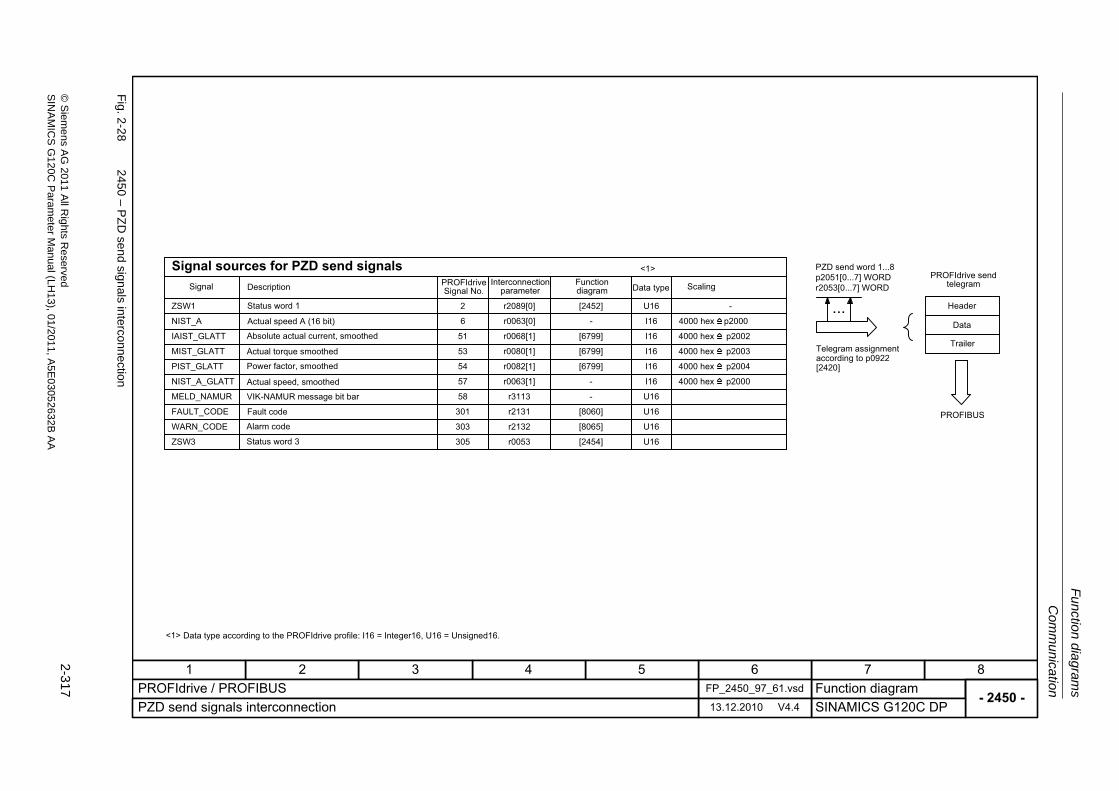
Com
mu
nicatio
n
Fu
nction dia
grams
2-317
© S
ieme
ns AG
2011 All R
ights Re
servedS
INA
MIC
SG
120C P
aram
eterM
anual (LH
13), 01/2011, A5E
03052632B
AA
Fig. 2
-28
2450 – P
ZD
send sig
nals interco
nnection
- 2450 -Function diagram
87654321FP_2450_97_61.vsdPROFIdrive / PROFIBUS
SINAMICS G120C DP13.12.2010 V4.4PZD send signals interconnection
<1>
PZD send word 1...8p2051[0...7] WORDr2053[0...7] WORD
...
<1>
U16 -r2089[0]2 [2452]ZSW1
I16 4000 hex p2000r0063[0]6 -NIST_A
FAULT_CODE
U16
r2131301 [8060] U16
r2132303 [8065]WARN_CODE
U16r311358MELD_NAMUR -
4000 hex p2004I16r0082[1]54 [6799]PIST_GLATT
4000 hex p2003I16r0080[1]53 [6799]MIST_GLATT
4000 hex p2002I16r0068[1]51 [6799]IAIST_GLATT
4000 hex p2000I16r0063[1]57 -NIST_A_GLATT
PROFIBUS
Signal sources for PZD send signalsSignal PROFIdrive
Signal No.Interconnection
parameterFunction diagram Data type Scaling
Status word 1
Actual speed A (16 bit)
Absolute actual current, smoothed
Actual torque smoothed
Power factor, smoothed
Actual speed, smoothed
VIK-NAMUR message bit bar
Fault code
Alarm code
PROFIdrive send telegram
Header
Data
Telegram assignment according to p0922 [2420]
Trailer
Data type according to the PROFIdrive profile: I16 = Integer16, U16 = Unsigned16.
Description
U16r0053305 [2454]ZSW3 Status word 3
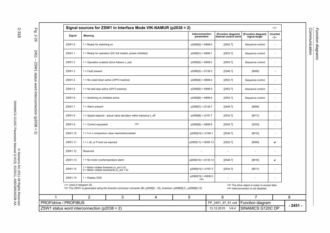
Fu
nctio
n diag
ram
s
Com
munication
2-318
© S
iem
ens AG
2011 All R
ights R
eservedS
INA
MIC
SG
120C
Param
eter
Manual (L
H13), 0
1/2011, A5E
03052632B
AA
Fig. 2
-29
2451 – Z
SW
1 status w
ord interconnection
(p2038
=2
)
- 2451 -Function diagram
87654321FP_2451_97_61.vsdPROFIdrive / PROFIBUS
SINAMICS G120C DP13.12.2010 V4.4ZSW1 status word interconnection (p2038 = 2)
<1><2>
<3>
ZSW1.0
ZSW1.1
ZSW1.2
ZSW1.3
ZSW1.4
ZSW1.5
ZSW1.6
ZSW1.8
ZSW1.9
ZSW1.11
ZSW1.12
ZSW1.13
ZSW1.14
ZSW1.15
ZSW1.7
ZSW1.10
<3>
p2080[2] = r0899.2
p2080[3] = r2139.3
p2080[4] = r0899.4
p2080[5] = r0899.5
p2080[6] = r0899.6
p2080[7] = r2139.7
p2080[8] = r2197.7
p2080[9] = r0899.9
p2080[10] = r2199.1
p2080[11] = r0056.13
-
p2080[13] = r2135.14
p2080[0] = r0899.0
p2080[1] = r0899.1
p2080[14] = r2197.3
[2503.7]
[2548.7]
[2503.7]
[2503.7]
[2503.7]
[2548.7]
[2534.7]
[2503.7]
[2536.7]
[2522.7]
-
[2548.7]
-
[2503.7]
[2503.7]
[2534.7]
[8060]
[8065]
[8011]
[2503]
[8010]
[6060]
-
[8016]
-
[8011]
<1>
-
-
-
-
-
-
-
-
-
-
-
-
-
-
<2>
p2080[15] = r0836.0<4>
Signal sources for ZSW1 in Interface Mode VIK-NAMUR (p2038 = 2)
Signal Meaning Interconnection parameters
[Function diagram] internal control word
[Function diagram] signal target
Inverted
1 = Ready for switching on
1 = Ready for operation (DC link loaded, pulses inhibited)
1 = Operation enabled (drive follows n_set)
1 = Fault present
1 = No coast down active (OFF2 inactive)
1 = No fast stop active (OFF3 inactive)
1 = Switching on inhibited active
1 = Alarm present
1 = Speed setpoint - actual value deviation within tolerance t_off
1 = Control requested
1 = f or n comparison value reached/exceeded
1 = I, M, or P limit not reached
1 = No motor overtemperature alarm
1 = Motor rotates forwards (n_act � 0)0 = Motor rotates backwards (n_act < 0)
1 = Display CDS
Reserved
Used in telegram 20.The ZSW1 is generated using the binector-connector converter (BI: p2080[0...15], inversion: p2088[0].0...p2088[0].15)
The drive object is ready to accept data.
Sequence control
Sequence control
Sequence control
Sequence control
Sequence control
Sequence control
<4> Interconnection is not disabled.

Com
mu
nicatio
n
Fu
nction dia
grams
2-319
© S
ieme
ns AG
2011 All R
ights Re
servedS
INA
MIC
SG
120C P
aram
eterM
anual (LH
13), 01/2011, A5E
03052632B
AA
Fig. 2
-30
2452 – Z
SW
1 status w
ord interconnection
(p2038
=0
)
- 2452 -Function diagram
87654321FP_2452_97_61.vsdPROFIdrive / PROFIBUS
SINAMICS G120C DP13.12.2010 V4.4ZSW1 status word interconnection (p2038 = 0)
<1> <2> <3>
ZSW1.0
ZSW1.1
ZSW1.2
ZSW1.3
ZSW1.4
ZSW1.5
ZSW1.6
ZSW1.8
ZSW1.9
ZSW1.11
ZSW1.12
ZSW1.13
ZSW1.14
ZSW1.15
ZSW1.7
ZSW1.10
<3>
p2080[2] = r0899.2
p2080[3] = r2139.3
p2080[4] = r0899.4
p2080[5] = r0899.5
p2080[6] = r0899.6
p2080[7] = r2139.7
p2080[8] = r2197.7
p2080[9] = r0899.9
p2080[10] = r2199.1
p2080[11] = r1407.7
p2080[13] = r2135.14
p2080[15] = r2135.15
p2080[0] = r0899.0
p2080[1] = r0899.1
p2080[14] = r2197.3
[2503.7]
[2548.7]
[2503.7]
[2503.7]
[2503.7]
[2548.7]
[2534.7]
[2503.7]
[2536.7]
[2522.7]
[2548.7]
[2548.7]
[2503.7]
[2503.7]
[2534.7]
[8060]
[8065]
[8011]
[2503]
[8010]
[6060]
[8016]
[8014]
[8011]
<1>
-
-
-
-
-
-
-
-
-
-
-
-
-
<2>
Signal sources for ZSW1 im Interface Mode SINAMICS (p2038 = 0)
Signal Meaning Interconnection parameters
[Function diagram] internal control word
[Function diagram] signal target
Inverted
1 = Ready for switching on
1 = Ready for operation (DC link loaded, pulses inhibited)
1 = Operation enabled (drive follows n_set)
1 = Fault present
1 = No coast down active (OFF2 inactive)
1 = No fast stop active (OFF3 inactive)
1 = Switching on inhibited active
1 = Alarm present
1 = Speed setpoint - actual value deviation within tolerance t_off
1 = Control requested
1 = f or n comparison value reached/exceeded
1 = I, M, or P limit not reached
1 = Open holding brake
1 = No motor overtemperature alarm
1 = Motor rotates forwards (n_act � 0)0 = Motor rotates backwards (n_act < 0)
1 = No alarm, thermal overload, power unit
Used in telegrams 1, 352.The ZSW1 is generated using the binector-connector converter (BI: p2080[0...15], inversion: p2088[0].0...p2088[0].15)The drive is ready to accept data.
Sequence control
Sequence control
Sequence control
Sequence control
Sequence control
Sequence control
[2701][2503.7]p2080[12] = r0899.12
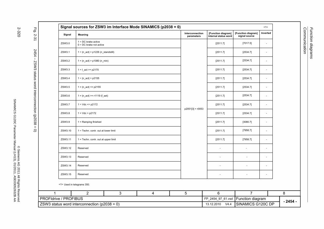
Fu
nctio
n diag
ram
s
Com
munication
2-320
© S
iem
ens AG
2011 All R
ights R
eservedS
INA
MIC
SG
120C
Param
eter
Manual (L
H13), 0
1/2011, A5E
03052632B
AA
Fig. 2
-31
2454 – Z
SW
3 status w
ord interconnection
(p2038
=0
)
- 2454 -Function diagram
87654321FP_2454_97_61.vsdPROFIdrive / PROFIBUS
SINAMICS G120C DP13.12.2010 V4.4ZSW3 status word interconnection (p2038 = 0)
<1>
ZSW3.0
ZSW3.1
ZSW3.2
ZSW3.3
ZSW3.4
ZSW3.5
ZSW3.6
ZSW3.8
ZSW3.9
ZSW3.11
ZSW3.12
ZSW3.13
ZSW3.14
ZSW3.15
ZSW3.7
ZSW3.10
p2051[3] = r0053
[2511.7]
[2511.7]
[2511.7]
[2511.7]
[2511.7]
[2511.7]
[2511.7]
[2511.7]
[2511.7]
[2511.7]
-
-
-
[2511.7]
[2511.7]
-
-
-
-
-
<1>
-
-
-
-
-
-
-
-
-
-
-
-
-
-
-
-
Signal sources for ZSW3 im Interface Mode SINAMICS (p2038 = 0)
Signal Meaning Interconnection parameters
[Function diagram] internal status word
[Function diagram] signal source
Inverted
Used in telegrams 350.
1 = DC brake active0 = DC brake not active
1 = |n_act| > p1226 (n_standstill)
1 = |n_act| > p1080 (n_min)
1 = I_act >= p2170
1 = |n_act| > p2155
1 = |n_act| <= p2155
1 = |n_act| >= r1119 (f_set)
1 = Vdc <= p2172
1 = Vdc > p2172
1 = Ramping finished
1 = Techn. contr. out at lower limit
1 = Techn. contr. out at upper limit
Reserved
Reserved
Reserved
Reserved
[7017.5]
[2534.7]
[2534.7]
[2534.7]
[2534.7]
[2534.7]
[2534.7]
[2534.7]
[2534.7]
[3080.7]
[7958.7]
[7958.7]
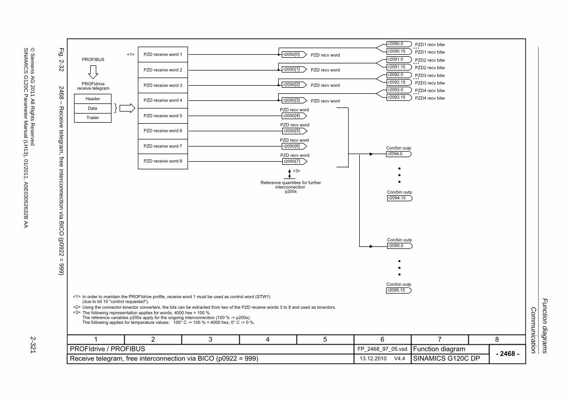
Com
mu
nicatio
n
Fu
nction dia
grams
2-321
© S
ieme
ns AG
2011 All R
ights Re
servedS
INA
MIC
SG
120C P
aram
eterM
anual (LH
13), 01/2011, A5E
03052632B
AA
Fig. 2
-32
2468 – R
eceive tele
gram, free in
terconnection
via BIC
O (p
0922=
999)
- 2468 -Function diagram
87654321FP_2468_97_05.vsdPROFIdrive / PROFIBUS
SINAMICS G120C DP13.12.2010 V4.4Receive telegram, free interconnection via BICO (p0922 = 999)
...
...
<3>
<1>
<2><3>
<1>PROFIBUS
PROFIdrive receive telegram
Header
Data
Trailer
PZD receive word 1
PZD receive word 2
PZD receive word 3
PZD receive word 4
PZD receive word 5
PZD receive word 6
In order to maintain the PROFIdrive profile, receive word 1 must be used as control word (STW1) (due to bit 10 "control requested").Using the connector-binector converters, the bits can be extracted from two of the PZD receive words 3 to 8 and used as binectors.The following representation applies for words: 4000 hex = 100 %.The reference variables p200x apply for the ongoing interconnection (100 % -> p200x).The following applies for temperature values: 100° C -> 100 % = 4000 hex, 0° C -> 0 %.
Reference quantities for further interconnection
p200x
Con/bin outpr2094
r2050 PZD recv word [0]
r2050 PZD recv word [1]
r2050 PZD recv word [2]
r2050 PZD recv word [3]
r2050 PZD recv word
[4]
r2050 PZD recv word
[5]
Con/bin outpr2094.15
Con/bin outpr2095.0
Con/bin outpr2095.15
.0
PZD1 recv bitwr2090.0
PZD1 recv bitwr2090.15
PZD2 recv bitwr2091.0
PZD2 recv bitwr2091.15
PZD receive word 7
PZD receive word 8
r2050 PZD recv word
[6]
r2050 PZD recv word
[7]
...PZD3 recv bitwr2092.0
PZD3 recv bitwr2092.15
...PZD4 recv bitwr2093.0
PZD4 recv bitwr2093.15
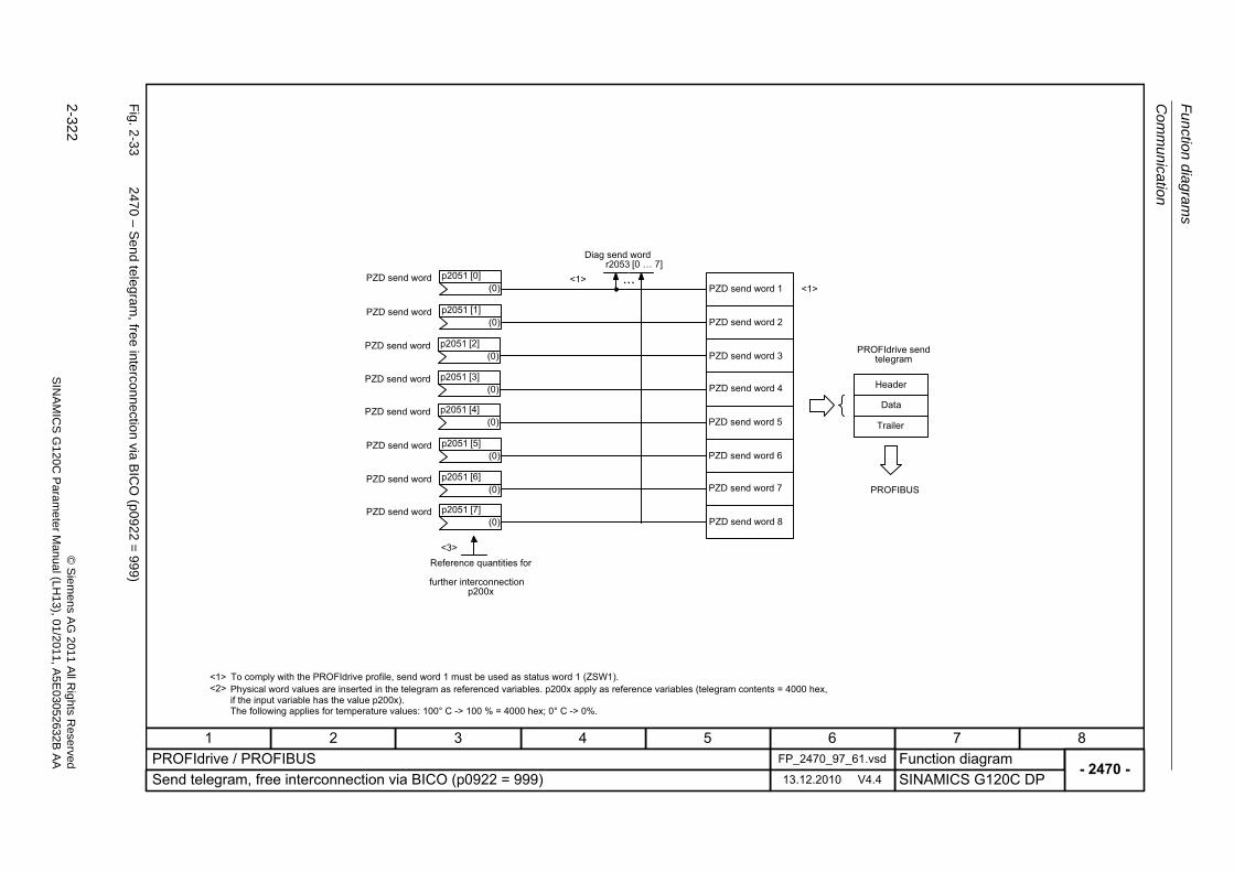
Fu
nctio
n diag
ram
s
Com
munication
2-322
© S
iem
ens AG
2011 All R
ights R
eservedS
INA
MIC
SG
120C
Param
eter
Manual (L
H13), 0
1/2011, A5E
03052632B
AA
Fig. 2
-33
2470 – S
end teleg
ram, fre
e interconnection via
BIC
O (p0
922=
999)
- 2470 -Function diagram
87654321FP_2470_97_61.vsdPROFIdrive / PROFIBUS
SINAMICS G120C DP13.12.2010 V4.4Send telegram, free interconnection via BICO (p0922 = 999)
<1><2>
...
<3>
<1>
PROFIBUS
<1>
Reference quantities for
further interconnection p200x
To comply with the PROFIdrive profile, send word 1 must be used as status word 1 (ZSW1).Physical word values are inserted in the telegram as referenced variables. p200x apply as reference variables (telegram contents = 4000 hex, if the input variable has the value p200x).The following applies for temperature values: 100° C -> 100 % = 4000 hex; 0° C -> 0%.
PZD send word 1
PZD send word 2
PZD send word 3
PZD send word 4
PZD send word 5
PZD send word 6
PZD send word 7
PZD send word 8
PROFIdrive send telegram
Header
Data
Trailer
Diag send wordr2053 [0 � 7]
PZD send word(0)
p2051 [0]
PZD send word(0)
p2051 [1]
PZD send word(0)
p2051 [2]
PZD send word(0)
p2051 [3]
PZD send word(0)
p2051 [4]
PZD send word(0)
p2051 [5]
PZD send word(0)
p2051 [6]
PZD send word(0)
p2051 [7]
Communication
Function diagrams
2-323© Siemens AG 2011 All Rights ReservedSINAMICS G120C Parameter Manual (LH13), 01/2011, A5E03052632B AA
2.5.3 CANopen (G120C CAN)
Function diagrams
9204 – Receive telegram, free PDO mapping (p8744 = 2) 2-324
9206 – Receive telegram, Predefined Connection Set (p8744 = 1) 2-325
9208 – Send telegram, free PDO mapping (p8744 = 2) 2-326
9210 – Send telegram, Predefined Connection Set (p8744 = 1) 2-327
9220 – Control word, CANopen 2-328
9226 – Status word, CANopen 2-329
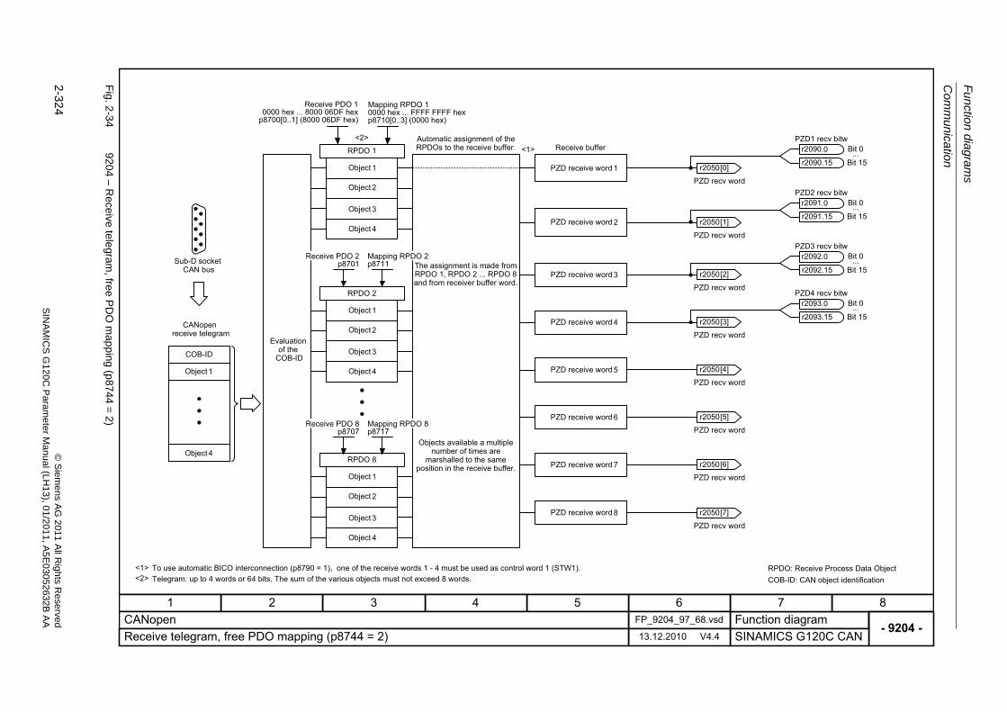
Fu
nctio
n diag
ram
s
Com
munication
2-324
© S
iem
ens AG
2011 All R
ights R
eservedS
INA
MIC
SG
120C
Param
eter
Manual (L
H13), 0
1/2011, A5E
03052632B
AA
Fig. 2
-34
9204 – R
eceive tele
gram, free P
DO
map
ping (p
8744=
2)
- 9204 -Function diagram
87654321FP_9204_97_68.vsdCANopen
SINAMICS G120C CAN13.12.2010 V4.4Receive telegram, free PDO mapping (p8744 = 2)
Bit 15r2090.15
Bit 0...
COB-ID
<1>
<1><2>
<2>
RPDO 1
RPDO 2
RPDO 8
Object 1
Object 2
Object 3
Object 4
Receive PDO 2p8701
Mapping RPDO 2p8711
Object 1
Object 2
Object 3
Object 4
Object 1
Object 2
Object 3
Object 4
Object 1
Object 4
Sub-D socketCAN bus
CANopenreceive telegram
Automatic assignment of the RPDOs to the receive buffer.
The assignment is made from RPDO 1, RPDO 2 ... RPDO 8 and from receiver buffer word.
Objects available a multiple number of times are
marshalled to the same position in the receive buffer.
Evaluationof the
COB-ID
Receive PDO 8p8707
Mapping RPDO 8p8717
PZD receive word 1
Receive buffer
PZD receive word 2
PZD receive word 3
PZD receive word 4
PZD receive word 5
PZD receive word 6
PZD receive word 7
PZD receive word 8
To use automatic BICO interconnection (p8790 = 1), one of the receive words 1 - 4 must be used as control word 1 (STW1).Telegram: up to 4 words or 64 bits. The sum of the various objects must not exceed 8 words.
RPDO: Receive Process Data ObjectCOB-ID: CAN object identification
PZD1 recv bitwr2090.0
Bit 15r2091.15
Bit 0...
PZD2 recv bitwr2091.0
Bit 15r2092.15
Bit 0...
PZD3 recv bitwr2092.0
Bit 15r2093.15
Bit 0...
PZD4 recv bitwr2093.0
r2050
PZD recv word
[1]
r2050
PZD recv word
[2]
r2050
PZD recv word
[3]
r2050
PZD recv word
[4]
r2050
PZD recv word
[5]
r2050
PZD recv word
[6]
r2050
PZD recv word
[7]
r2050
PZD recv word
[0]
Receive PDO 10000 hex ... 8000 06DF hex
p8700[0..1] (8000 06DF hex)
Mapping RPDO 10000 hex ... FFFF FFFF hexp8710[0..3] (0000 hex)
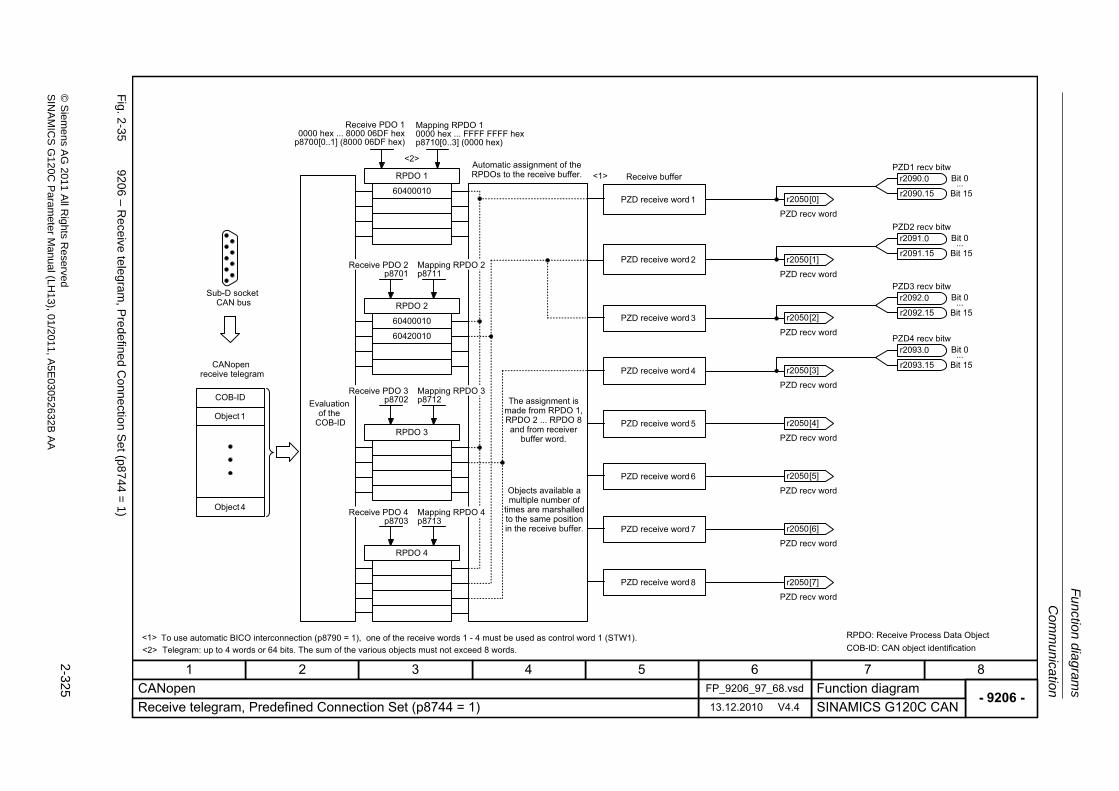
Com
mu
nicatio
n
Fu
nction dia
grams
2-325
© S
ieme
ns AG
2011 All R
ights Re
servedS
INA
MIC
SG
120C P
aram
eterM
anual (LH
13), 01/2011, A5E
03052632B
AA
Fig. 2
-35
9206 – R
eceive tele
gram, P
redefined
Co
nnectio
n Set (p8
744=
1)
- 9206 -Function diagram
87654321FP_9206_97_68.vsdCANopen
SINAMICS G120C CAN13.12.2010 V4.4Receive telegram, Predefined Connection Set (p8744 = 1)
COB-ID
<2>
<2>
Object 1
Object 4
Sub-D socketCAN bus
CANopenreceive telegram
Automatic assignment of the RPDOs to the receive buffer.
The assignment is made from RPDO 1, RPDO 2 ... RPDO 8 and from receiver
buffer word.
Objects available a multiple number of
times are marshalled to the same position in the receive buffer.
Evaluationof the
COB-ID
Telegram: up to 4 words or 64 bits. The sum of the various objects must not exceed 8 words.
RPDO: Receive Process Data ObjectCOB-ID: CAN object identification
60400010
60400010
60420010
RPDO 1
RPDO 2
RPDO 3
RPDO 4
Receive PDO 2p8701
Mapping RPDO 2p8711
Receive PDO 3p8702
Mapping RPDO 3p8712
Receive PDO 4p8703
Mapping RPDO 4p8713
<1> To use automatic BICO interconnection (p8790 = 1), one of the receive words 1 - 4 must be used as control word 1 (STW1).
Bit 15r2090.15
Bit 0...
PZD receive word 1
Receive buffer
PZD receive word 2
PZD receive word 3
PZD receive word 4
PZD receive word 5
PZD receive word 6
PZD receive word 7
PZD receive word 8
PZD1 recv bitwr2090.0
Bit 15r2091.15
Bit 0...
PZD2 recv bitwr2091.0
Bit 15r2092.15
Bit 0...
PZD3 recv bitwr2092.0
Bit 15r2093.15
Bit 0...
PZD4 recv bitwr2093.0
r2050
PZD recv word
[1]
r2050
PZD recv word
[2]
r2050
PZD recv word
[3]
r2050
PZD recv word
[4]
r2050
PZD recv word
[5]
r2050
PZD recv word
[6]
r2050
PZD recv word
[7]
r2050
PZD recv word
[0]
<1>
Receive PDO 10000 hex ... 8000 06DF hex
p8700[0..1] (8000 06DF hex)
Mapping RPDO 10000 hex ... FFFF FFFF hexp8710[0..3] (0000 hex)
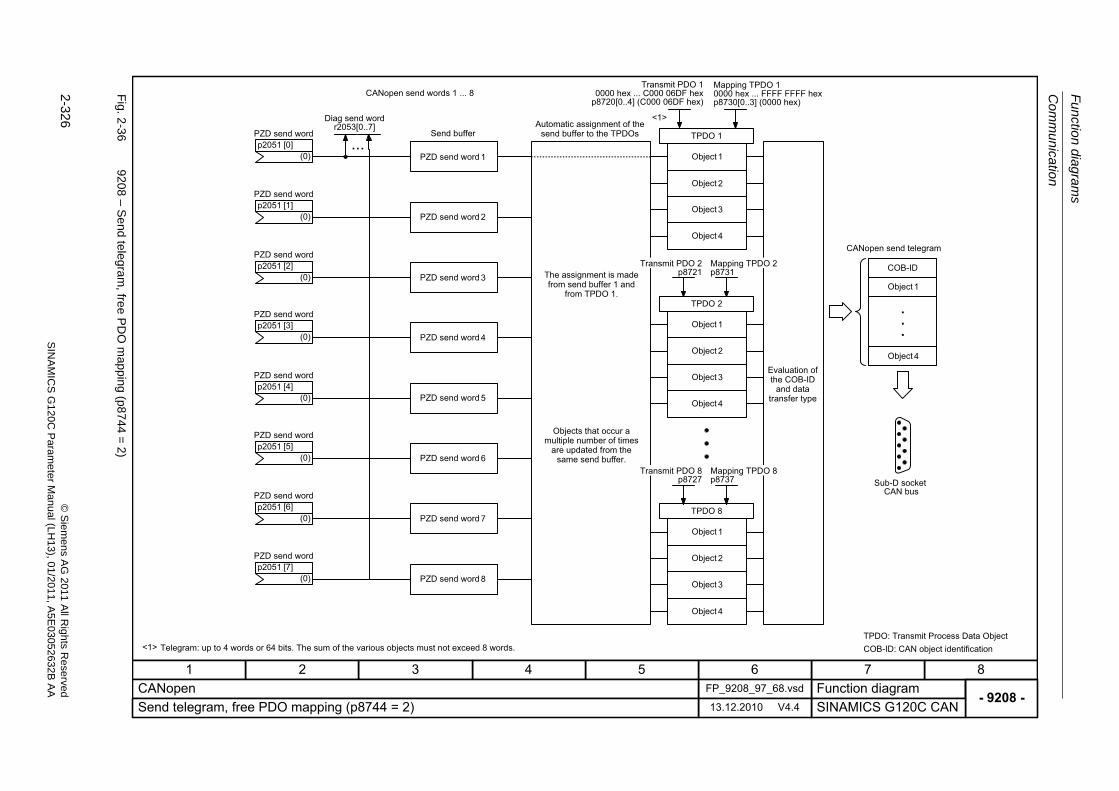
Fu
nctio
n diag
ram
s
Com
munication
2-326
© S
iem
ens AG
2011 All R
ights R
eservedS
INA
MIC
SG
120C
Param
eter
Manual (L
H13), 0
1/2011, A5E
03052632B
AA
Fig. 2
-36
9208 – S
end teleg
ram, fre
e PD
O m
apping (p8
744=
2)
- 9208 -Function diagram
87654321FP_9208_97_68.vsdCANopen
SINAMICS G120C CAN13.12.2010 V4.4Send telegram, free PDO mapping (p8744 = 2)
...
<1>
..
.
COB-ID
<1>
TPDO 1
TPDO 2
TPDO 8
CANopen send words 1 ... 8
Send buffer
PZD send word 1
PZD send word 2
PZD send word 3
PZD send word 4
PZD send word 5
PZD send word 6
PZD send word 7
PZD send word 8
Automatic assignment of the send buffer to the TPDOs
The assignment is made from send buffer 1 and
from TPDO 1.
Objects that occur a multiple number of times
are updated from the same send buffer.
Object 1
Object 2
Object 3
Object 4
Object 1
Object 2
Object 3
Object 4
Object 1
Object 2
Object 3
Object 4
Transmit PDO 2p8721
Mapping TPDO 2p8731
Transmit PDO 8p8727
Mapping TPDO 8p8737
Object 1
Object 4
Sub-D socketCAN bus
TPDO: Transmit Process Data ObjectCOB-ID: CAN object identificationTelegram: up to 4 words or 64 bits. The sum of the various objects must not exceed 8 words.
Evaluation of the COB-ID
and data transfer type
CANopen send telegram
PZD send word
(0)p2051 [0]
PZD send word
(0)p2051 [1]
PZD send word
(0)p2051 [2]
PZD send word
(0)p2051 [3]
PZD send word
(0)p2051 [4]
PZD send word
(0)p2051 [5]
PZD send word
(0)p2051 [6]
PZD send word
(0)p2051 [7]
Transmit PDO 10000 hex ... C000 06DF hex
p8720[0..4] (C000 06DF hex)
Mapping TPDO 10000 hex ... FFFF FFFF hexp8730[0..3] (0000 hex)
Diag send wordr2053[0..7]
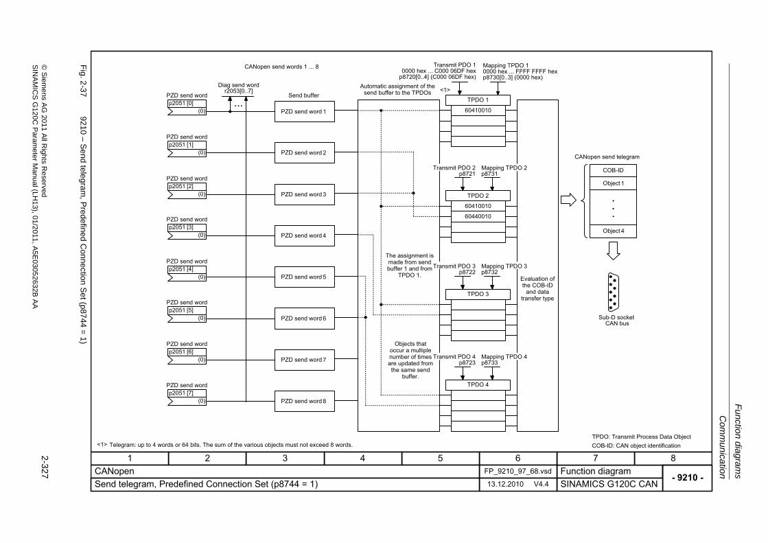
Com
mu
nicatio
n
Fu
nction dia
grams
2-327
© S
ieme
ns AG
2011 All R
ights Re
servedS
INA
MIC
SG
120C P
aram
eterM
anual (LH
13), 01/2011, A5E
03052632B
AA
Fig. 2
-37
9210 – S
end teleg
ram, P
redefined C
onnection
Se
t (p8744
=1)
- 9210 -Function diagram
87654321FP_9210_97_68.vsdCANopen
SINAMICS G120C CAN13.12.2010 V4.4Send telegram, Predefined Connection Set (p8744 = 1)
<1>
60410010
60410010
60440010
TPDO 1
TPDO 2
TPDO 3
TPDO 4
CANopen send words 1 ... 8
Automatic assignment of the send buffer to the TPDOs
Transmit PDO 2p8721
Mapping TPDO 2p8731
Transmit PDO 4p8723
Mapping TPDO 4p8733
Mapping TPDO 3p8732
Transmit PDO 3p8722
Evaluation of the COB-ID
and data transfer type
..
.
COB-ID
Object 1
Object 4
Sub-D socketCAN bus
CANopen send telegram
<1> TPDO: Transmit Process Data ObjectCOB-ID: CAN object identificationTelegram: up to 4 words or 64 bits. The sum of the various objects must not exceed 8 words.
...Send buffer
PZD send word 1
PZD send word 2
PZD send word 3
PZD send word 4
PZD send word 5
PZD send word 6
PZD send word 7
PZD send word 8
PZD send word
(0)p2051 [0]
PZD send word
(0)p2051 [1]
PZD send word
(0)p2051 [2]
PZD send word
(0)p2051 [3]
PZD send word
(0)p2051 [4]
PZD send word
(0)p2051 [5]
PZD send word
(0)p2051 [6]
PZD send word
(0)p2051 [7]
Objects that occur a multiple number of times are updated from the same send
buffer.
The assignment is made from send buffer 1 and from
TPDO 1.
Transmit PDO 10000 hex ... C000 06DF hex
p8720[0..4] (C000 06DF hex)
Mapping TPDO 10000 hex ... FFFF FFFF hexp8730[0..3] (0000 hex)
Diag send wordr2053[0..7]
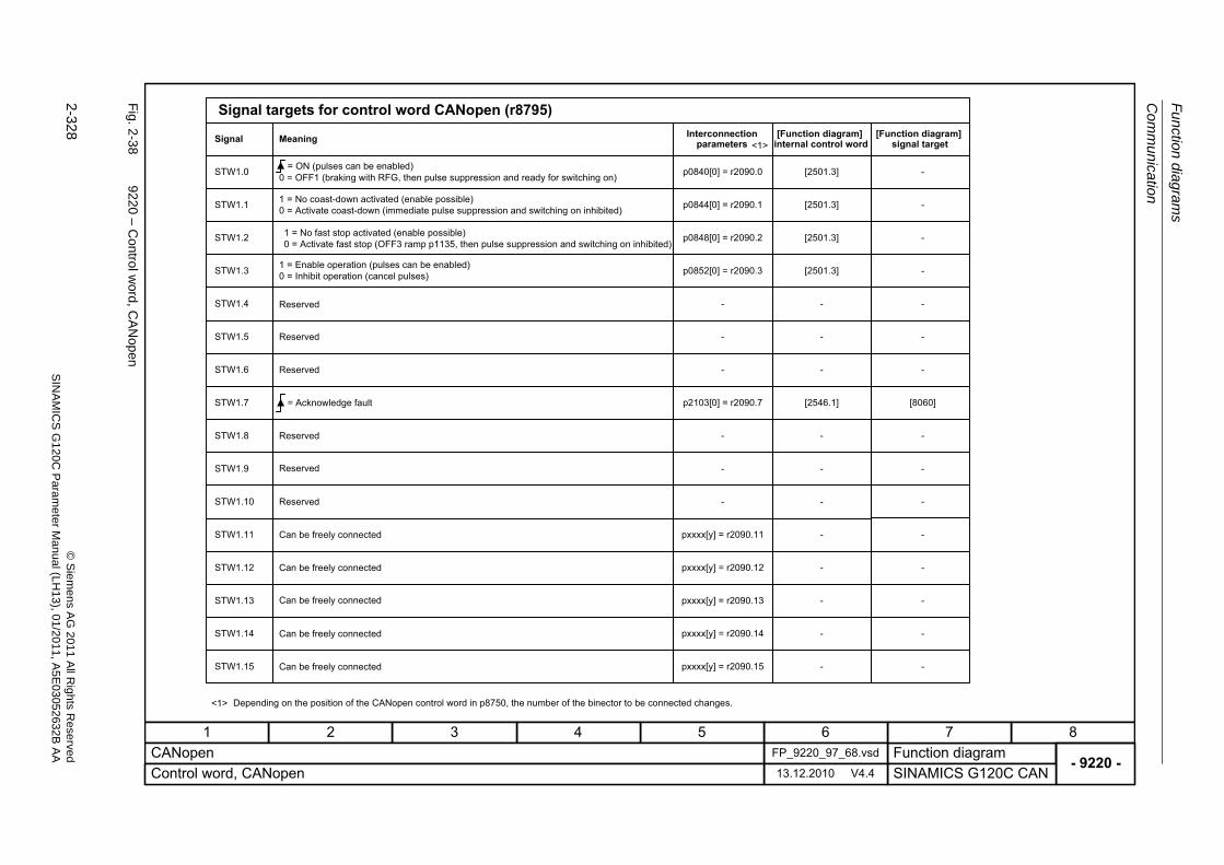
Fu
nctio
n diag
ram
s
Com
munication
2-328
© S
iem
ens AG
2011 All R
ights R
eservedS
INA
MIC
SG
120C
Param
eter
Manual (L
H13), 0
1/2011, A5E
03052632B
AA
Fig. 2
-38
9220 – C
ontrol word
, CA
Nop
en
- 9220 -Function diagram
87654321FP_9220_97_68.vsdCANopen
SINAMICS G120C CAN13.12.2010 V4.4Control word, CANopen
STW1.0
STW1.1
STW1.2
STW1.3
STW1.4
STW1.5
STW1.6
STW1.8
STW1.9
STW1.11
STW1.12
STW1.13
STW1.14
STW1.15
STW1.7
STW1.10
p0848[0] = r2090.2
p0852[0] = r2090.3
-
-
-
p2103[0] = r2090.7
-
-
-
pxxxx[y] = r2090.11
pxxxx[y] = r2090.12
pxxxx[y] = r2090.13
pxxxx[y] = r2090.14
pxxxx[y] = r2090.15
p0840[0] = r2090.0
p0844[0] = r2090.1
[2501.3]
[2501.3]
-
-
-
[2546.1]
-
-
-
-
-
-
-
-
[2501.3]
[2501.3]
-
-
-
-
-
[8060]
-
-
-
-
-
-
-
-
-
<1>
<1>
-
Signal targets for control word CANopen (r8795)
Signal
= ON (pulses can be enabled)
Interconnection parameters
[Function diagram]internal control word
[Function diagram]signal target
0 = OFF1 (braking with RFG, then pulse suppression and ready for switching on)
1 = No coast-down activated (enable possible) 0 = Activate coast-down (immediate pulse suppression and switching on inhibited)
1 = No fast stop activated (enable possible)0 = Activate fast stop (OFF3 ramp p1135, then pulse suppression and switching on inhibited)
1 = Enable operation (pulses can be enabled)0 = Inhibit operation (cancel pulses)
Reserved
Reserved
Reserved
= Acknowledge fault
Reserved
Reserved
Reserved
Can be freely connected
Can be freely connected
Can be freely connected
Can be freely connected
Can be freely connected
Depending on the position of the CANopen control word in p8750, the number of the binector to be connected changes.
Meaning
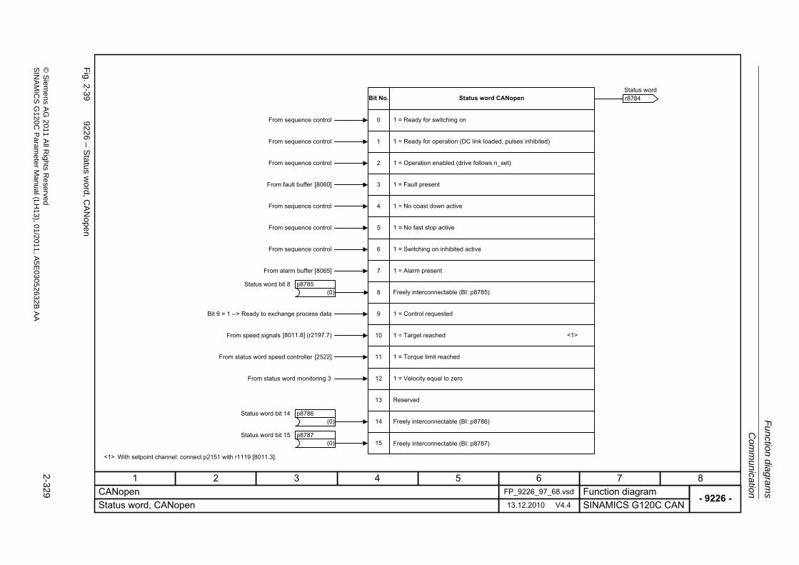
Com
mu
nicatio
n
Fu
nction dia
grams
2-329
© S
ieme
ns AG
2011 All R
ights Re
servedS
INA
MIC
SG
120C P
aram
eterM
anual (LH
13), 01/2011, A5E
03052632B
AA
Fig. 2
-39
9226 – S
tatus word, C
AN
open
- 9226 -Function diagram
87654321FP_9226_97_68.vsdCANopen
SINAMICS G120C CAN13.12.2010 V4.4Status word, CANopen
11
12
13
14
15
<1>10
9
8
7
6
5
4
3
0
1
2
(0)Status word bit 8 p8785
(0)Status word bit 14 p8786
(0)Status word bit 15 p8787
r8784 Status word
Bit No. Status word CANopen
1 = Ready for switching onFrom sequence control
From sequence control
From sequence control
From sequence control
From fault buffer
From sequence control
From sequence control
From alarm buffer
Bit 9 = 1 --> Ready to exchange process data
From speed signals
From status word speed controller
From status word monitoring 3
1 = Ready for operation (DC link loaded, pulses inhibited)
1 = Operation enabled (drive follows n_set)
1 = Fault present
1 = No coast down active
1 = No fast stop active
1 = Switching on inhibited active
1 = Alarm present
Freely interconnectable (BI: p8785)
1 = Control requested
1 = Target reached
1 = Torque limit reached
1 = Velocity equal to zero
Reserved
Freely interconnectable (BI: p8786)
Freely interconnectable (BI: p8787)
With setpoint channel: connect p2151 with r1119 [8011.3].<1>
[8060]
[8065]
[8011.8] (r2197.7)
[2522]
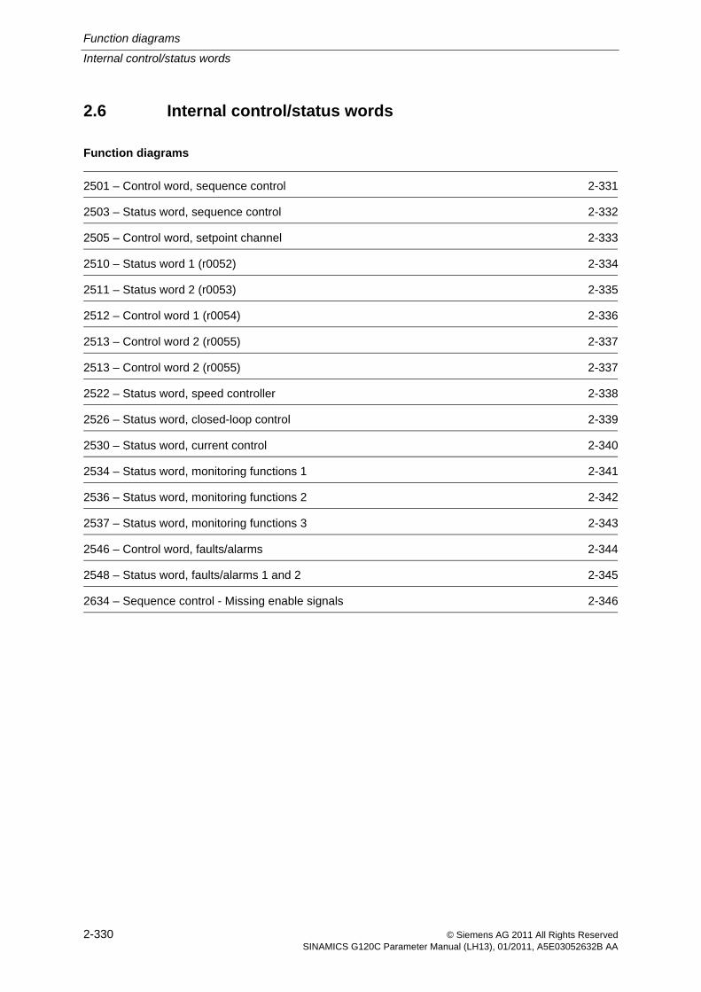
Function diagrams
Internal control/status words
2-330 © Siemens AG 2011 All Rights ReservedSINAMICS G120C Parameter Manual (LH13), 01/2011, A5E03052632B AA
2.6 Internal control/status words
Function diagrams
2501 – Control word, sequence control 2-331
2503 – Status word, sequence control 2-332
2505 – Control word, setpoint channel 2-333
2510 – Status word 1 (r0052) 2-334
2511 – Status word 2 (r0053) 2-335
2512 – Control word 1 (r0054) 2-336
2513 – Control word 2 (r0055) 2-337
2513 – Control word 2 (r0055) 2-337
2522 – Status word, speed controller 2-338
2526 – Status word, closed-loop control 2-339
2530 – Status word, current control 2-340
2534 – Status word, monitoring functions 1 2-341
2536 – Status word, monitoring functions 2 2-342
2537 – Status word, monitoring functions 3 2-343
2546 – Control word, faults/alarms 2-344
2548 – Status word, faults/alarms 1 and 2 2-345
2634 – Sequence control - Missing enable signals 2-346
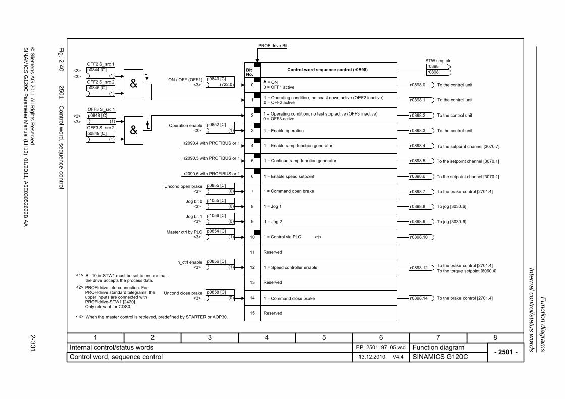
Internal con
trol/statu
s words
Fu
nction dia
grams
2-331
© S
ieme
ns AG
2011 All R
ights Re
servedS
INA
MIC
SG
120C P
aram
eterM
anual (LH
13), 01/2011, A5E
03052632B
AA
Fig. 2
-40
2501 – C
ontrol word
, sequence con
trol
- 2501 -Function diagram
87654321FP_2501_97_05.vsdInternal control/status words
SINAMICS G120C13.12.2010 V4.4Control word, sequence control
11
12
13
14
15
PROFIdrive-Bit
<1>
10
7
6
5
4
3
2
1
0
<2>
<2>
<2>
r0898.0
r0898.1
r0898.2
r0898.3
r0898.10
9
8 r0898.8
r0898.9
<3>
<3>
<3>
<3>
<3>
<3>
<3>
<3>
<1>
(1)
OFF2 S_src 1p0844 [C]
(1)
OFF2 S_src 2p0845 [C]
(1)
OFF3 S_src 1p0848 [C]
(1)
OFF3 S_src 2p0849 [C]
Bit 10 in STW1 must be set to ensure that the drive accepts the process data.PROFIdrive interconnection: For PROFIdrive standard telegrams, the upper inputs are connected with PROFIdrive-STW1 [2420].Only relevant for CDS0.
When the master control is retrieved, predefined by STARTER or AOP30.
Control word sequence control (r0898)
= ON0 = OFF1 active
1 = Operating condition, no coast down active (OFF2 inactive)0 = OFF2 active
1 = Enable operation
1 = Operating condition, no fast stop active (OFF3 inactive)0 = OFF3 active
1 = Enable ramp-function generator
1 = Continue ramp-function generator
1 = Enable speed setpoint
1 = Jog 1
1 = Jog 2
1 = Control via PLC
Reserved
Reserved
Reserved
1 = Speed controller enable
To the control unit
To the control unit
To the control unit
To the control unit
To jog [3030.6]
To jog [3030.6]
STW seq_ctrl
r0898r0898
Bit No.
(722.0)ON / OFF (OFF1) p0840 [C]
(1)Operation enable p0852 [C]
(1)Master ctrl by PLC p0854 [C]
(0)Jog bit 0 p1055 [C]
(0)Jog bit 1 p1056 [C]
1 = Command open brake
1 = Command close brake
r0898.7 To the brake control [2701.4]
r0898.14 To the brake control [2701.4]
r0898.12 To the brake control [2701.4]To the torque setpoint [6060.4]
<3> (0)Uncond open brake p0855 [C]
<3> (0)Uncond close brake p0858 [C]
<3> (1)n_ctrl enable p0856 [C]
r2090.4 with PROFIBUS or 1
r2090.5 with PROFIBUS or 1
r2090.6 with PROFIBUS or 1
r0898.4
r0898.5
r0898.6
To the setpoint channel [3070.7]
To the setpoint channel [3070.1]
To the setpoint channel [3070.1]
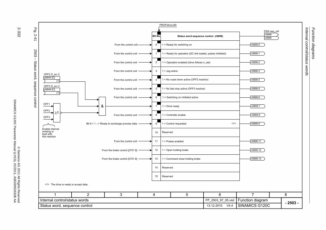
Fu
nctio
n diag
ram
s
Intern
al control/sta
tus w
ords
2-332
© S
iem
ens AG
2011 All R
ights R
eservedS
INA
MIC
SG
120C
Param
eter
Manual (L
H13), 0
1/2011, A5E
03052632B
AA
Fig. 2
-41
2503 – S
tatus word, sequ
ence control
- 2503 -Function diagram
87654321FP_2503_97_05.vsdInternal control/status words
SINAMICS G120C13.12.2010 V4.4Status word, sequence control
11
12
13
14
15
PROFIdrive-Bit
10
9
8
7
6
5
4
3
0
1
2
r0899.0
r0899.1
r0899.4
r0899.5
r0899.11
r0899.2
r0899.6
r0899.9
r0899.3
r0899.7
r0899.81
&
(1)
OFF2 S_src 2p0845 [C]
(1)
OFF3 S_src 2p0849 [C]
OFF1
OFF2
OFF3
Enable internal missing or fault with this reaction
From the control unit
From the control unit
From the control unit
From the control unit
From the control unit
From the control unit
From the control unit
From the control unit
Bit 9 = 1 --> Ready to exchange process data
From the control unit
The drive is ready to accept data.
Status word sequence control (r0899)
1 = Ready for switching on
1 = Ready for operation (DC link loaded, pulses inhibited)
1 = Operation enabled (drive follows n_set)
1 = Jog active
1 = No coast down active (OFF2 inactive)
1 = No fast stop active (OFF3 inactive)
1 = Switching on inhibited active
1 = Drive ready
1 = Controller enable
1 = Control requested
Reserved
1 = Pulses enabled
Reserved
Reserved
ZSW seq_ctrl
r0899r0899Bit No.
<1>
1 = Command close holding brake
1 = Open holding brake
<1>
From the brake control [2701.8]
From the brake control [2701.8]
r0899.12
r0899.13
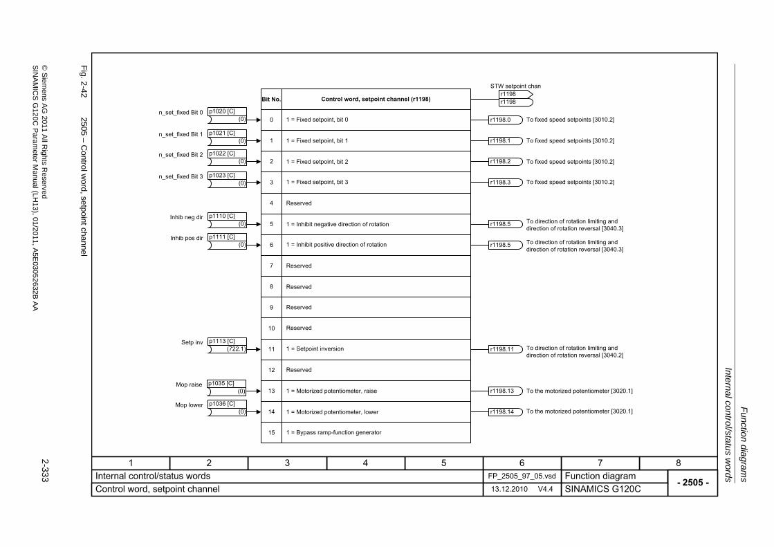
Internal con
trol/statu
s words
Fu
nction dia
grams
2-333
© S
ieme
ns AG
2011 All R
ights Re
servedS
INA
MIC
SG
120C P
aram
eterM
anual (LH
13), 01/2011, A5E
03052632B
AA
Fig. 2
-42
2505 – C
ontrol word
, setpoint channel
- 2505 -Function diagram
87654321FP_2505_97_05.vsdInternal control/status words
SINAMICS G120C13.12.2010 V4.4Control word, setpoint channel
11
12
13
14
15
9
10
8
7
6
5
4
3
2
1
0
r1198.3
r1198.5
r1198.11
r1198.13
r1198.14
r1198.2
r1198.1
r1198.0(0)n_set_fixed Bit 0 p1020 [C]
(0)n_set_fixed Bit 1 p1021 [C]
(0)n_set_fixed Bit 2 p1022 [C]
(0)n_set_fixed Bit 3 p1023 [C]
(0)Mop raise p1035 [C]
(0)Mop lower p1036 [C]
Control word, setpoint channel (r1198)
1 = Fixed setpoint, bit 0
1 = Fixed setpoint, bit 1
1 = Fixed setpoint, bit 2
1 = Fixed setpoint, bit 3
Reserved
1 = Inhibit negative direction of rotation
1 = Inhibit positive direction of rotation
Reserved
Reserved
Reserved
Reserved
1 = Setpoint inversion
Reserved
1 = Motorized potentiometer, raise
1 = Motorized potentiometer, lower
1 = Bypass ramp-function generator
To fixed speed setpoints [3010.2]
To fixed speed setpoints [3010.2]
To fixed speed setpoints [3010.2]
To fixed speed setpoints [3010.2]
To direction of rotation limiting and direction of rotation reversal [3040.3]
To direction of rotation limiting and direction of rotation reversal [3040.2]
To the motorized potentiometer [3020.1]
To the motorized potentiometer [3020.1]
STW setpoint chan
r1198r1198
Bit No.
(0)Inhib neg dir p1110 [C]
(722.1)Setp inv p1113 [C]
r1198.5 To direction of rotation limiting and direction of rotation reversal [3040.3]
(0)Inhib pos dir p1111 [C]
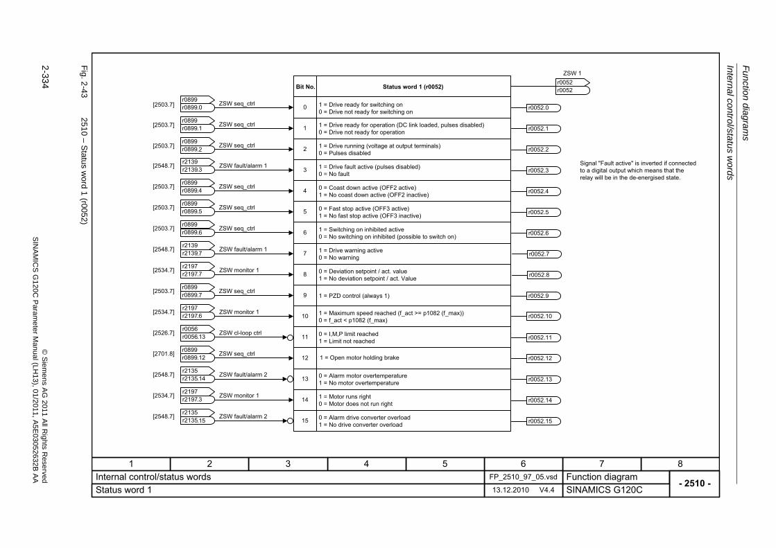
Fu
nctio
n diag
ram
s
Intern
al control/sta
tus w
ords
2-334
© S
iem
ens AG
2011 All R
ights R
eservedS
INA
MIC
SG
120C
Param
eter
Manual (L
H13), 0
1/2011, A5E
03052632B
AA
Fig. 2
-43
2510 – S
tatus word
1 (r0052)
- 2510 -Function diagram
87654321FP_2510_97_05.vsdInternal control/status words
SINAMICS G120C13.12.2010 V4.4Status word 1
1
2
3
4
5
6
7
8
9
10
11
12
13
14
15
0
ZSW 1
r0052r0052
1 = Drive ready for switching on0 = Drive not ready for switching on
1 = Drive ready for operation (DC link loaded, pulses disabled)0 = Drive not ready for operation
1 = Drive running (voltage at output terminals)0 = Pulses disabled
1 = Drive fault active (pulses disabled)0 = No fault
0 = Coast down active (OFF2 active)1 = No coast down active (OFF2 inactive)
0 = Fast stop active (OFF3 active)1 = No fast stop active (OFF3 inactive)
1 = Switching on inhibited active0 = No switching on inhibited (possible to switch on)
1 = Drive warning active0 = No warning
0 = Deviation setpoint / act. value1 = No deviation setpoint / act. Value
1 = PZD control (always 1)
1 = Maximum speed reached (f_act >= p1082 (f_max))0 = f_act < p1082 (f_max)
0 = I,M,P limit reached1 = Limit not reached
0 = Alarm motor overtemperature1 = No motor overtemperature
1 = Motor runs right0 = Motor does not run right
0 = Alarm drive converter overload1 = No drive converter overload
Signal "Fault active" is inverted if connected to a digital output which means that the relay will be in the de-energised state.
Bit No. Status word 1 (r0052)
ZSW seq_ctrlr0899r0899
.0
ZSW fault/alarm 1r2139r2139
ZSW seq_ctrlr0899r0899
ZSW seq_ctrlr0899r0899
ZSW seq_ctrlr0899r0899
ZSW seq_ctrlr0899r0899
ZSW seq_ctrlr0899r0899
ZSW fault/alarm 1r2139r2139
ZSW monitor 1r2197r2197
ZSW seq_ctrlr0899r0899
ZSW monitor 1r2197r2197
ZSW cl-loop ctrlr0056r0056
ZSW fault/alarm 2r2135r2135
ZSW monitor 1r2197r2197
ZSW fault/alarm 2r2135r2135
.1
.2
.3
.4
.5
.6
.7
.7
.7
.6
.13
.14
.3
.15
r0052.0
r0052.1
r0052.4
r0052.5
r0052.11
r0052.2
r0052.6
r0052.9
r0052.13
r0052.14
r0052.15
r0052.3
r0052.7
r0052.8
r0052.10
[2503.7]
[2503.7]
[2503.7]
[2548.7]
[2503.7]
[2503.7]
[2503.7]
[2548.7]
[2534.7]
[2503.7]
[2534.7]
[2526.7]
[2548.7]
[2534.7]
[2548.7]
1 = Open motor holding brakeZSW seq_ctrlr0899r0899
.12[2701.8]r0052.12
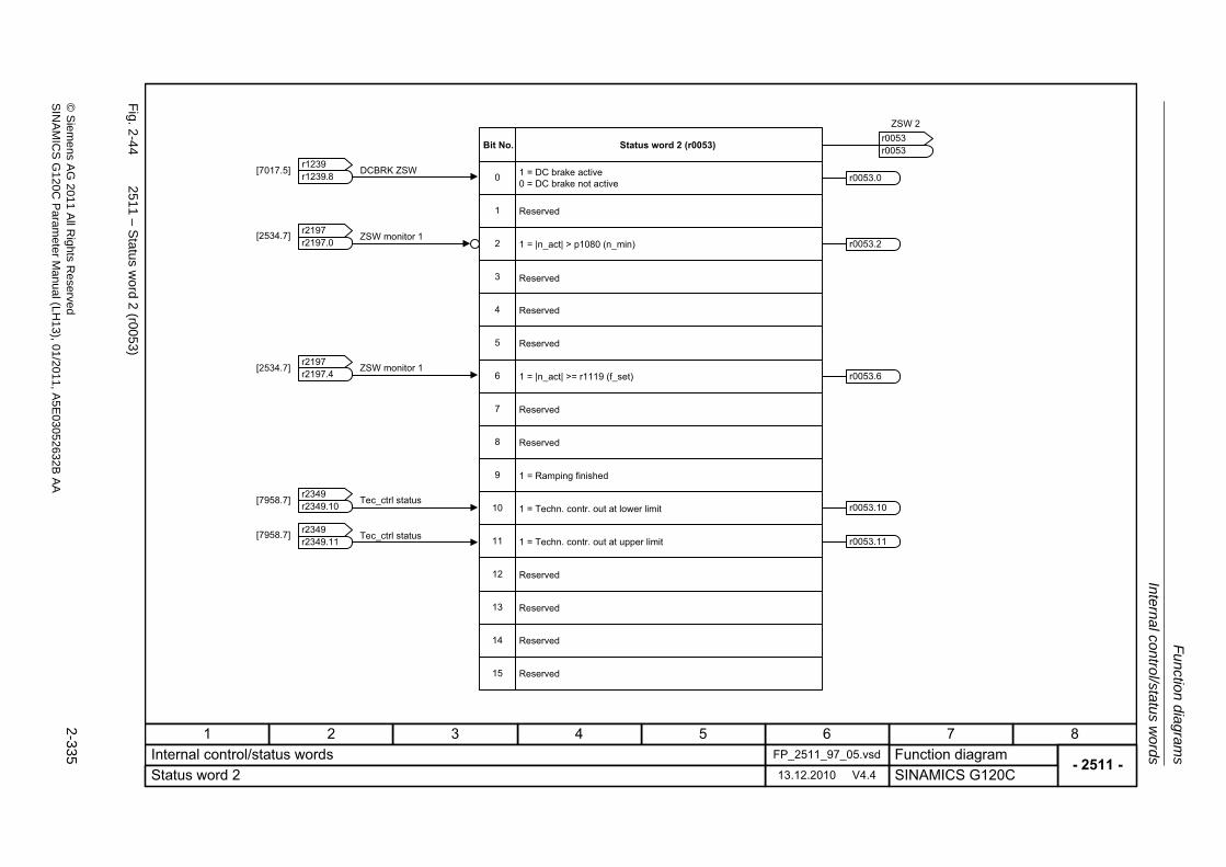
Internal con
trol/statu
s words
Fu
nction dia
grams
2-335
© S
ieme
ns AG
2011 All R
ights Re
servedS
INA
MIC
SG
120C P
aram
eterM
anual (LH
13), 01/2011, A5E
03052632B
AA
Fig. 2
-44
2511 – S
tatus word
2 (r0053)
- 2511 -Function diagram
87654321FP_2511_97_05.vsdInternal control/status words
SINAMICS G120C13.12.2010 V4.4Status word 2
1
2
3
4
5
6
7
8
9
10
11
12
13
14
15
0
ZSW 2
r0053r0053
1 = DC brake active0 = DC brake not active
Bit No. Status word 2 (r0053)
Reserved
1 = |n_act| > p1080 (n_min)
Reserved
Reserved
Reserved
1 = |n_act| >= r1119 (f_set)
Reserved
Reserved
1 = Ramping finished
1 = Techn. contr. out at lower limit
1 = Techn. contr. out at upper limit
Reserved
Reserved
DCBRK ZSWr1239r1239
Reserved
Reserved
ZSW monitor 1r2197r2197
ZSW monitor 1r2197r2197
.8
.0
.4
Tec_ctrl statusr2349r2349
Tec_ctrl statusr2349r2349
.10
.11
r0053.0
r0053.11
r0053.2
r0053.6
r0053.10
[7017.5]
[2534.7]
[2534.7]
[7958.7]
[7958.7]
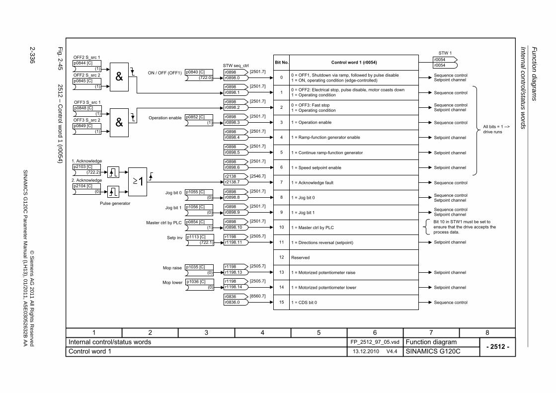
Fu
nctio
n diag
ram
s
Intern
al control/sta
tus w
ords
2-336
© S
iem
ens AG
2011 All R
ights R
eservedS
INA
MIC
SG
120C
Param
eter
Manual (L
H13), 0
1/2011, A5E
03052632B
AA
Fig. 2
-45
2512 – C
ontrol word
1 (r00
54)
- 2512 -Function diagram
87654321FP_2512_97_05.vsdInternal control/status words
SINAMICS G120C13.12.2010 V4.4Control word 1
1
2
3
4
5
6
7
8
9
10
11
12
13
14
15
0
Sequence control
Setpoint channel
Setpoint channel
Setpoint channel
Setpoint channelSequence control
Setpoint channelSequence control
Sequence control
Setpoint channel
Setpoint channel
Setpoint channel
Sequence control
Sequence controlSetpoint channel
Sequence control
Sequence controlSetpoint channel
All bits = 1 --> drive runs
Bit 10 in STW1 must be set to ensure that the drive accepts the process data.
Bit No. Control word 1 (r0054)
0 = OFF1, Shutdown via ramp, followed by pulse disable 1 = ON, operating condition (edge-controlled)
0 = OFF2: Electrical stop, pulse disable, motor coasts down1 = Operating condition
0 = OFF3: Fast stop1 = Operating condition
1 = Operation enable
1 = Ramp-function generator enable
1 = Continue ramp-function generator
1 = Speed setpoint enable
1 = Acknowledge fault
1 = Jog bit 0
1 = Jog bit 1
1 = Master ctrl by PLC
1 = Directions reversal (setpoint)
Reserved
1 = Motorized potentiometer raise
1 = Motorized potentiometer lower
1 = CDS bit 0
STW 1
r0054r0054
STW seq_ctrl
r0898r0898
.0[2501.7]
[2501.7]
[2501.7]
[2501.7]
[2501.7]
[2501.7]
[2501.7]
[2546.7]
[2501.7]
[2501.7]
[2501.7]
[2505.7]
[2505.7]
[2505.7]
[8560.7]
(1)
OFF2 S_src 1p0844 [C]
(1)
OFF2 S_src 2p0845 [C]
(1)
OFF3 S_src 1p0848 [C]
(1)
OFF3 S_src 2p0849 [C]
(722.0)ON / OFF (OFF1) p0840 [C]
(1)Operation enable p0852 [C]
(1)Master ctrl by PLC p0854 [C]
(0)Jog bit 0 p1055 [C]
(0)Jog bit 1 p1056 [C]
r0898.1r0898
r0898.2r0898
r0898.3r0898
r0898.4r0898
r0898.5r0898
r0898.6r0898
r2138.7r2138
r0898.8r0898
r0898.9r0898
r0898.10r0898
r1198.11r1198
r1198.13r1198
r1198.14r1198
r0836.0r0836
(0)Mop raise p1035 [C]
(0)Mop lower p1036 [C]
(722.1)Setp inv p1113 [C]
Pulse generator
(722.2)
1. Acknowledgep2103 [C]
(0)
2. Acknowledgep2104 [C]
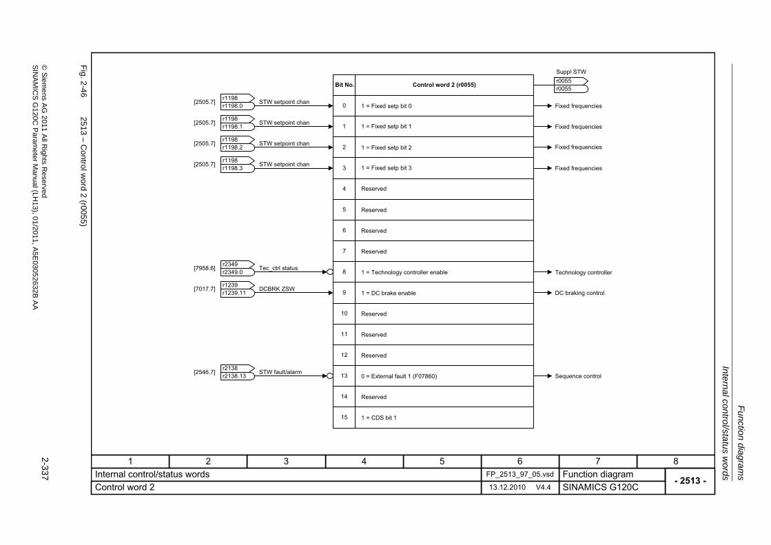
Internal con
trol/statu
s words
Fu
nction dia
grams
2-337
© S
ieme
ns AG
2011 All R
ights Re
servedS
INA
MIC
SG
120C P
aram
eterM
anual (LH
13), 01/2011, A5E
03052632B
AA
Fig. 2
-46
2513 – C
ontrol word
2 (r00
55)
- 2513 -Function diagram
87654321FP_2513_97_05.vsdInternal control/status words
SINAMICS G120C13.12.2010 V4.4Control word 2
1
2
3
4
5
6
7
8
9
10
11
12
13
14
15
0
Bit No. Control word 2 (r0055)
1 = Fixed setp bit 0
1 = Fixed setp bit 1
1 = Fixed setp bit 2
1 = Fixed setp bit 3
Reserved
Reserved
1 = Technology controller enable
1 = DC brake enable
Reserved
Reserved
Reserved
0 = External fault 1 (F07860)
Reserved
1 = CDS bit 1
Suppl STW
r0055r0055
Sequence control
DC braking control
Technology controller
Fixed frequencies
Fixed frequencies
Fixed frequencies
Fixed frequencies
STW setpoint chanr1198r1198
.0[2505.7]
STW setpoint chanr1198r1198
.1[2505.7]
STW setpoint chanr1198r1198
.2[2505.7]
STW setpoint chanr1198r1198
.3[2505.7]
Tec_ctrl statusr2349r2349
.0[7958.6]
DCBRK ZSWr1239r1239
.11[7017.7]
STW fault/alarmr2138r2138
.13[2546.7]
Reserved
Reserved
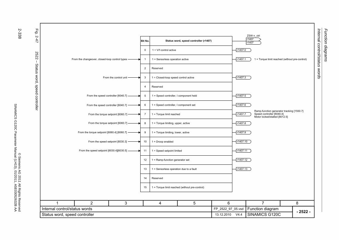
Fu
nctio
n diag
ram
s
Intern
al control/sta
tus w
ords
2-338
© S
iem
ens AG
2011 All R
ights R
eservedS
INA
MIC
SG
120C
Param
eter
Manual (L
H13), 0
1/2011, A5E
03052632B
AA
Fig. 2
-47
2522 – S
tatus word, spee
d contro
ller
- 2522 -Function diagram
87654321FP_2522_97_05.vsdInternal control/status words
SINAMICS G120C13.12.2010 V4.4Status word, speed controller
1
2
3
4
5
6
7
8
9
10
11
0
12
13
14
15
r1407.8
r1407.9
r1407.11
r1407.1
r1407.7
r1407.10
r1407.11
r1407.5
r1407.6
r1407.3
r1407.12
r1407.13
r1407.0
From the changeover, closed-loop control types
From the control unit
Status word, speed controller (r1407)Bit No.
1 = V/f control active
1 = Sensorless operation active
1 = Closed-loop speed control active
1 = Speed controller, I component held
1 = Speed controller, I component set
1 = Torque limit reached
1 = Torque limiting, upper, active
1 = Torque limiting, lower, active
1 = Droop enabled
1 = Speed setpoint limited
1 = Ramp-function generator set
1 = Sensorless operation due to a fault
Reserved
1 = Torque limit reached (without pre-control)
Ramp-function generator tracking [1550.7]Speed controller [6040.4] Motor locked/stalled [8012.5]
From the speed setpoint [6030.4][6030.5]
From the speed setpoint [6030.3]
From the torque setpoint [6060.4] [6060.7]
From the torque setpoint [6060.7]
From the speed controller [6040.7]
From the speed controller [6040.7]
ZSW n_ctrl
r1407r1407
Reserved
From the torque setpoint [6060.7]
1 = Torque limit reached (without pre-control)
Reserved
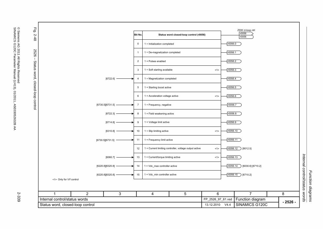
Internal con
trol/statu
s words
Fu
nction dia
grams
2-339
© S
ieme
ns AG
2011 All R
ights Re
servedS
INA
MIC
SG
120C P
aram
eterM
anual (LH
13), 01/2011, A5E
03052632B
AA
Fig. 2
-48
2526 – S
tatus word, closed
-loop con
trol
- 2526 -Function diagram
87654321FP_2526_97_61.vsdInternal control/status words
SINAMICS G120C13.12.2010 V4.4Status word, closed-loop control
1
2
4
0
7
8
9
11
14
15
[6722.6]
[6722.3]
[6714.8]
[6220.8][6320.8]
[6220.8][6320.8]
3
5
6
12
13
10[6310.8]
<1>
<1>
<1>
<1>
<1>[6060.7]
[6710.2]
[8012.5]
Only for V/f control
Status word closed-loop control (r0056)Bit No.
1 = Initialization completed
1 = De-magnetization completed
1 = Pulses enabled
1 = Soft starting available
1 = Magnetization completed
1 = Acceleration voltage active
1 = Frequency, negative
1 = Field weakening active
1 = Voltage limit active
1 = Slip limiting active
1 = Frequency limit active
1 = Current limiting controller, voltage output active
1 = Current/torque limiting active
1 = Vdc_max controller active
1 = Vdc_min controller active
ZSW cl-loop ctrl
r0056r0056
1 = Starting boost active
r0056.0
r0056.1
r0056.4
r0056.5
r0056.11
r0056.12
r0056.2
r0056.6
r0056.9
r0056.13
r0056.14
r0056.15
r0056.3
r0056.7
r0056.8
r0056.10
<1>
[6030.6] [6710.2]
[6730.5][6731.5]
[6730.5][6731.5]
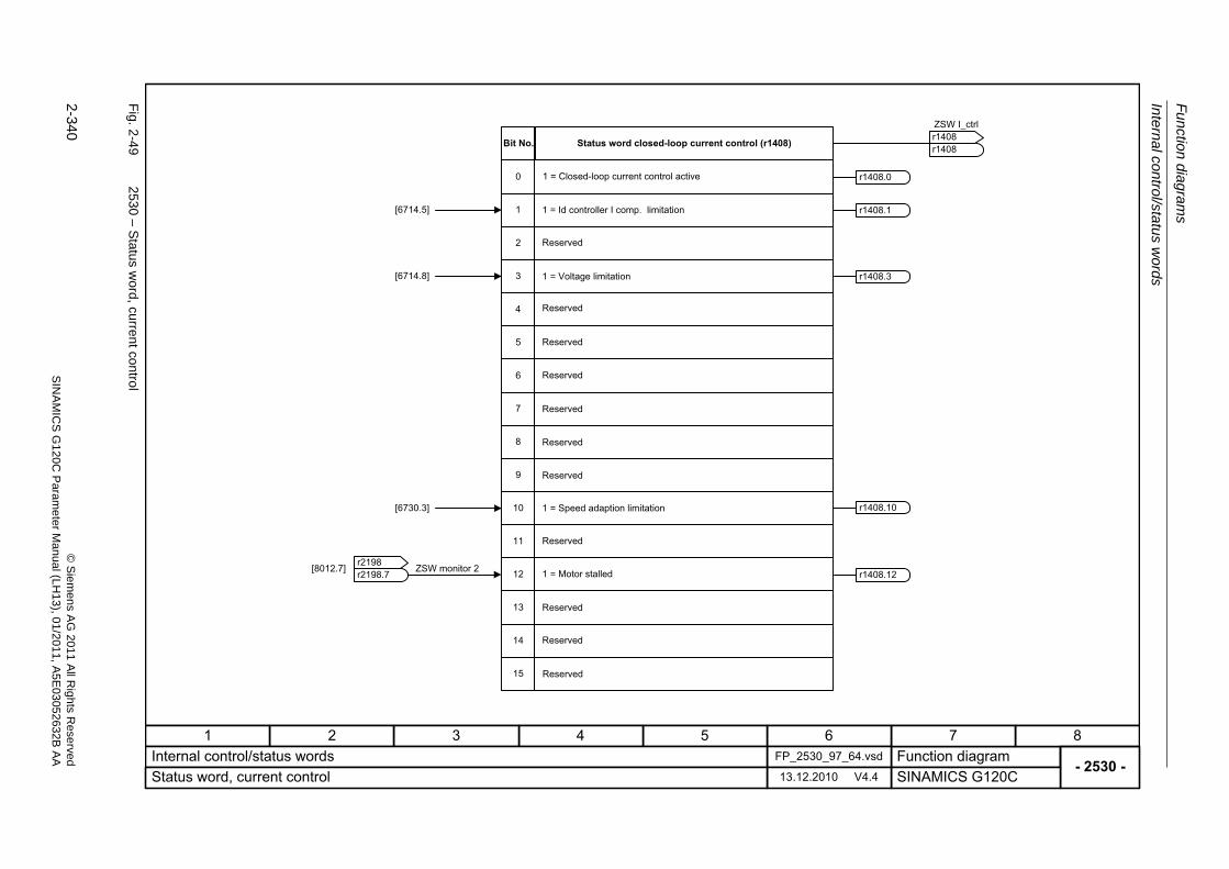
Fu
nctio
n diag
ram
s
Intern
al control/sta
tus w
ords
2-340
© S
iem
ens AG
2011 All R
ights R
eservedS
INA
MIC
SG
120C
Param
eter
Manual (L
H13), 0
1/2011, A5E
03052632B
AA
Fig. 2
-49
2530 – S
tatus word, current co
ntrol
- 2530 -Function diagram
87654321FP_2530_97_64.vsdInternal control/status words
SINAMICS G120C13.12.2010 V4.4Status word, current control
1
2
0
[6714.5]
[6714.8] 3
4
5
6
7
8
9
10
11
12
13
14
15
[6730.3]
Status word closed-loop current control (r1408)Bit No.
1 = Closed-loop current control active
1 = Id controller I comp. limitation
Reserved
1 = Voltage limitation
1 = Speed adaption limitation
1 = Motor stalled
Reserved
Reserved
Reserved
ZSW I_ctrl
r1408r1408
Reserved
Reserved
Reserved
Reserved
Reserved
Reserved
Reserved
r1408.0
r1408.1
r1408.12
r1408.3
r1408.10
ZSW monitor 2r2198r2198
.7[8012.7]
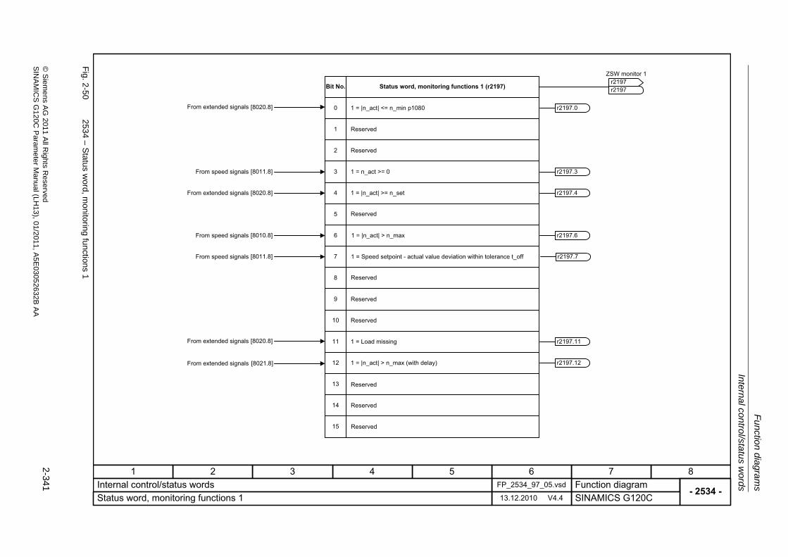
Internal con
trol/statu
s words
Fu
nction dia
grams
2-341
© S
ieme
ns AG
2011 All R
ights Re
servedS
INA
MIC
SG
120C P
aram
eterM
anual (LH
13), 01/2011, A5E
03052632B
AA
Fig. 2
-50
2534 – S
tatus word, m
onitoring fu
nctions1
- 2534 -Function diagram
87654321FP_2534_97_05.vsdInternal control/status words
SINAMICS G120C13.12.2010 V4.4Status word, monitoring functions 1
9
10
8
7
6
5
4
3
2
1
0
ZSW monitor 1
r2197r2197
From speed signals
From speed signals
From speed signals
Status word, monitoring functions 1 (r2197)Bit No.
1 = |n_act| <= n_min p1080
1 = |n_act| >= n_set
Reserved
Reserved
Reserved
Reserved
Reserved
Reserved
1 = n_act >= 0
1 = |n_act| > n_max
1 = Speed setpoint - actual value deviation within tolerance t_off
11
12
1 = Load missing
1 = |n_act| > n_max (with delay)
From extended signals
From extended signals
From extended signals
From extended signals
13
14
15
Reserved
Reserved
Reserved
r2197.0
r2197.4
r2197.11
r2197.12
r2197.6
r2197.3
r2197.7
[8020.8]
[8011.8]
[8020.8]
[8010.8]
[8011.8]
[8020.8]
[8021.8]
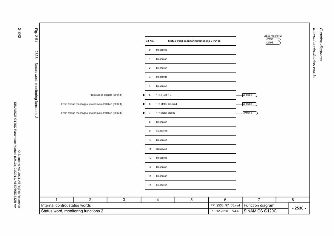
Fu
nctio
n diag
ram
s
Intern
al control/sta
tus w
ords
2-342
© S
iem
ens AG
2011 All R
ights R
eservedS
INA
MIC
SG
120C
Param
eter
Manual (L
H13), 0
1/2011, A5E
03052632B
AA
Fig. 2
-51
2536 – S
tatus word, m
onitoring fu
nctions2
- 2536 -Function diagram
87654321FP_2536_97_05.vsdInternal control/status words
SINAMICS G120C13.12.2010 V4.4Status word, monitoring functions 2
11
12
13
9
10
8
6
5
4
3
2
1
0
7
From speed signals
From torque messages, motor locked/stalled
From torque messages, motor locked/stalled
Status word, monitoring functions 2 (r2198)Bit No.
Reserved
Reserved
Reserved
Reserved
Reserved
Reserved
Reserved
Reserved
1 = n_set > 0
1 = Motor blocked
1 = Motor stalled
Reserved
Reserved
Reserved
ZSW monitor 2
r2198r2198
r2198.5
r2198.6
r2198.7
[8011.8]
[8012.8]
[8012.8]
14
15
Reserved
Reserved
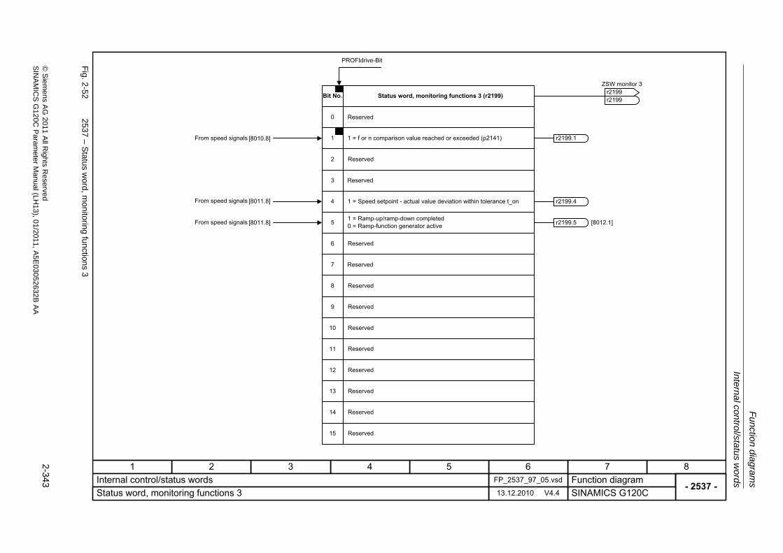
Internal con
trol/statu
s words
Fu
nction dia
grams
2-343
© S
ieme
ns AG
2011 All R
ights Re
servedS
INA
MIC
SG
120C P
aram
eterM
anual (LH
13), 01/2011, A5E
03052632B
AA
Fig. 2
-52
2537 – S
tatus word, m
onitoring fu
nctions3
- 2537 -Function diagram
87654321FP_2537_97_05.vsdInternal control/status words
SINAMICS G120C13.12.2010 V4.4Status word, monitoring functions 3
11
12
13
14
15
PROFIdrive-Bit
9
10
8
7
6
5
4
3
2
1
0
r2199.5
r2199.1
[8012.1]
r2199.4
From speed signals
Status word, monitoring functions 3 (r2199)Bit No.
Reserved
1 = f or n comparison value reached or exceeded (p2141)
1 = Speed setpoint - actual value deviation within tolerance t_on
1 = Ramp-up/ramp-down completed
Reserved
Reserved
0 = Ramp-function generator active
ZSW monitor 3
r2199r2199
Reserved
Reserved
Reserved
Reserved
Reserved
Reserved
Reserved
Reserved
Reserved
Reserved
[8010.8]
From speed signals [8011.8]
From speed signals [8011.8]
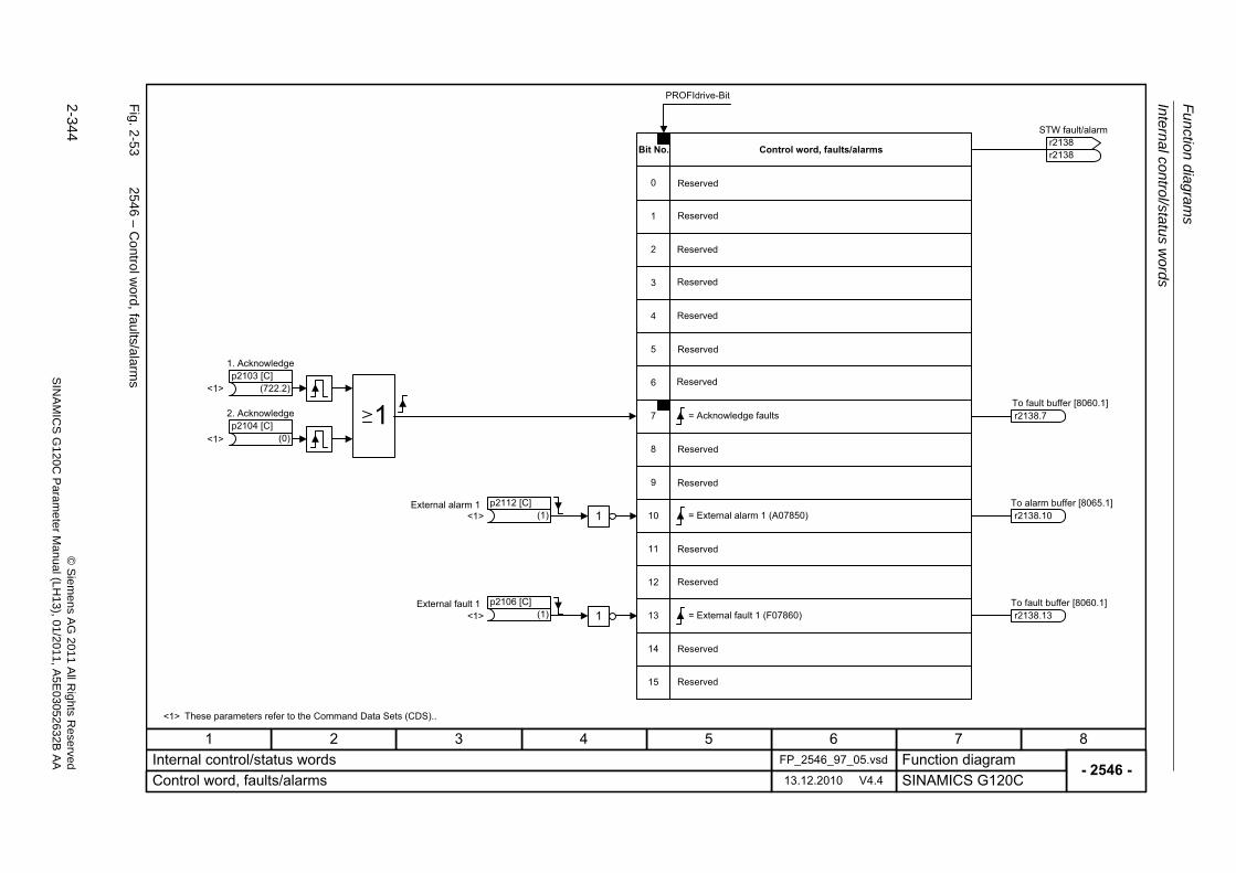
Fu
nctio
n diag
ram
s
Intern
al control/sta
tus w
ords
2-344
© S
iem
ens AG
2011 All R
ights R
eservedS
INA
MIC
SG
120C
Param
eter
Manual (L
H13), 0
1/2011, A5E
03052632B
AA
Fig. 2
-53
2546 – C
ontrol word
, faults/alarms
- 2546 -Function diagram
87654321FP_2546_97_05.vsdInternal control/status words
SINAMICS G120C13.12.2010 V4.4Control word, faults/alarms
11
12
13
14
15
PROFIdrive-Bit
9
10
8
7
6
5
4
3
2
1
0
r2138.13
r2138.10
r2138.7
<1>
<1>
<1>
<1>
<1>
These parameters refer to the Command Data Sets (CDS)..
Control word, faults/alarmsBit No.
Reserved
Reserved
Reserved
Reserved
Reserved
Reserved
Reserved
Reserved
Reserved
= External alarm 1 (A07850)
= Acknowledge faults
Reserved
= External fault 1 (F07860)
To alarm buffer [8065.1]
To fault buffer [8060.1]
To fault buffer [8060.1]
STW fault/alarm
r2138r2138
(722.2)
1. Acknowledgep2103 [C]
(0)
2. Acknowledgep2104 [C]
(1)External alarm 1 p2112 [C]
(1)External fault 1 p2106 [C]
1
1
Reserved
Reserved
Reserved
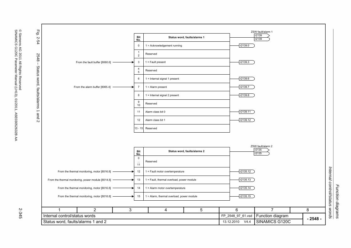
Internal con
trol/statu
s words
Fu
nction dia
grams
2-345
© S
ieme
ns AG
2011 All R
ights Re
servedS
INA
MIC
SG
120C P
aram
eterM
anual (LH
13), 01/2011, A5E
03052632B
AA
Fig. 2
-54
2548 – S
tatus word, fa
ults/alarm
s1
and
2
- 2548 -Function diagram
87654321FP_2548_97_61.vsdInternal control/status words
SINAMICS G120C13.12.2010 V4.4Status word, faults/alarms 1 and 2
0...11
0
r2139.3
r2139.7
r2135.14
r2135.15
r2135.13
r2135.12
12
r2139.0
r2139.6
r2139.8
45
6
7
8
12
13
14
15
910
3From the fault buffer [8060.6]
From the alarm buffer [8065.4]
From the thermal monitoring, motor [8016.8]
From the thermal monitoring, power module [8014.8]
From the thermal monitoring, motor [8016.8]
From the thermal monitoring, motor [8016.8]
Status word, faults/alarms 1Bit No.
1 = Acknowledgement running
1 = Fault present
1 = Internal signal 1 present
1 = Alarm present
1 = Internal signal 2 present
Reserved
Reserved
Reserved
Reserved
Status word, faults/alarms 2Bit No.
1 = Fault motor overtemperature
1 = Fault, thermal overload, power module
1 = Alarm motor overtemperature
1 = Alarm, thermal overload, power module
ZSW fault/alarm 1
r2139r2139
ZSW fault/alarm 2
r2135r2135
Reserved
r2139.1111 Alarm class bit 0
r2139.1212 Alarm class bit 1
13 - 15
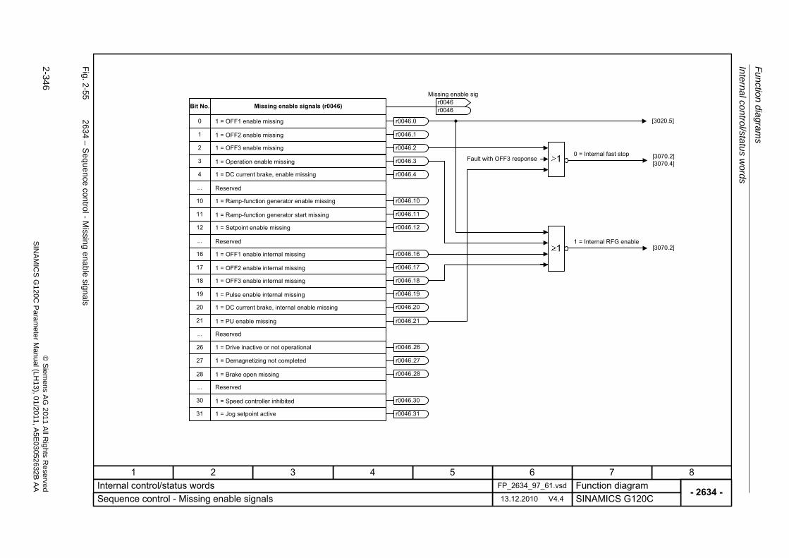
Fu
nctio
n diag
ram
s
Intern
al control/sta
tus w
ords
2-346
© S
iem
ens AG
2011 All R
ights R
eservedS
INA
MIC
SG
120C
Param
eter
Manual (L
H13), 0
1/2011, A5E
03052632B
AA
Fig. 2
-55
2634 – S
eque
nce control - Missing ena
ble signals
- 2634 -Function diagram
87654321FP_2634_97_61.vsdInternal control/status words
SINAMICS G120C13.12.2010 V4.4Sequence control - Missing enable signals
1
0
2
3
4
...
10
11
12
...
16
17
18
19
20
21
...
...
30
31
r0046.0
r0046.1
r0046.2
r0046.3
r0046.4
r0046.10
r0046.11
r0046.12
r0046.16
r0046.17
r0046.18
r0046.19
r0046.20
r0046.
r0046.
r0046.
r0046.30
r0046.31
1
1
Missing enable signals (r0046)Bit No.
Missing enable sig
r0046r0046
1 = OFF1 enable missing
1 = OFF2 enable missing
1 = OFF3 enable missing
1 = Operation enable missing
1 = DC current brake, enable missing
1 = Ramp-function generator enable missing
Reserved
1 = Ramp-function generator start missing
1 = Setpoint enable missing
Reserved
1 = OFF1 enable internal missing
1 = OFF2 enable internal missing
1 = OFF3 enable internal missing
1 = Pulse enable internal missing
1 = DC current brake, internal enable missing
1 = PU enable missing
1 = Drive inactive or not operational
1 = Demagnetizing not completed
1 = Brake open missing
1 = Speed controller inhibited
1 = Jog setpoint active
Reserved
Reserved
r0046.21
26
27
28
26
27
28
[3020.5]
0 = Internal fast stop
1 = Internal RFG enable
Fault with OFF3 response [3070.2] [3070.4]
[3070.2]
Braking Control
Function diagrams
2-347© Siemens AG 2011 All Rights ReservedSINAMICS G120C Parameter Manual (LH13), 01/2011, A5E03052632B AA
2.7 Braking Control
Function diagrams
2701 – Basic braking control 2-348
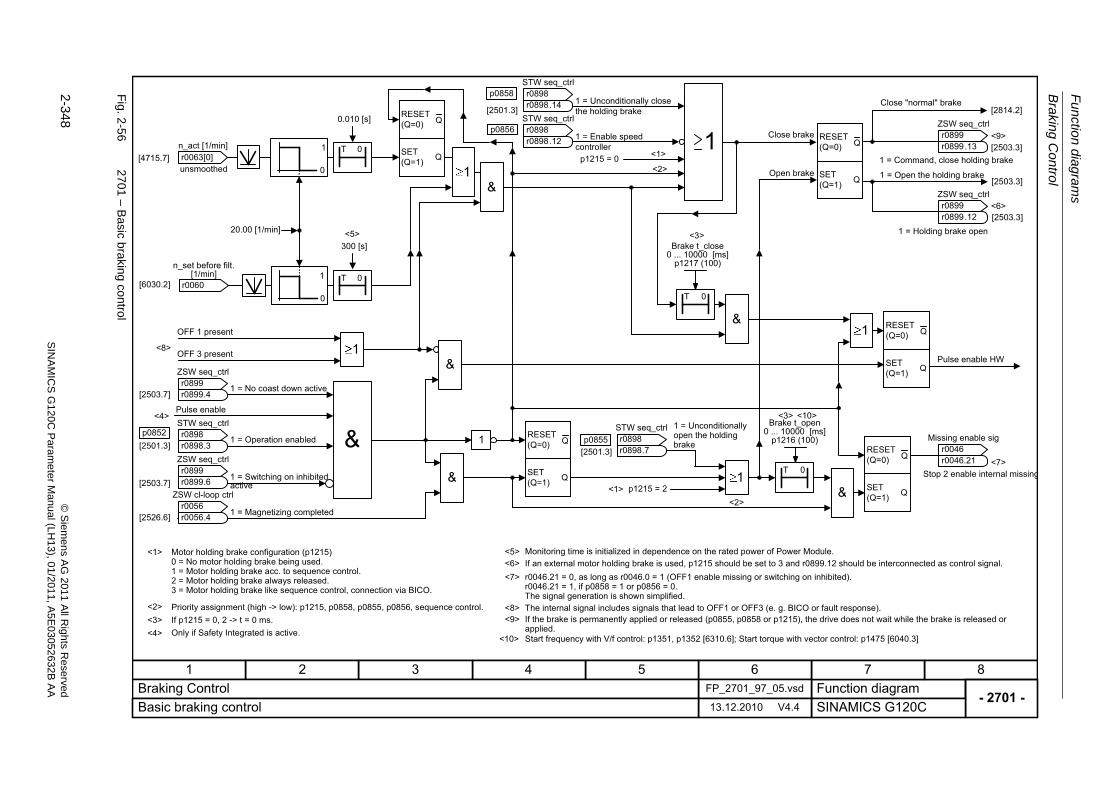
Fu
nctio
n diag
ram
s
Braking C
ontrol
2-348
© S
iem
ens AG
2011 All R
ights R
eservedS
INA
MIC
SG
120C
Param
eter
Manual (L
H13), 0
1/2011, A5E
03052632B
AA
Fig. 2
-56
2701 – B
asic b
raking con
trol
- 2701 -Function diagram
87654321FP_2701_97_05.vsdBraking Control
SINAMICS G120C13.12.2010 V4.4Basic braking control
1
T 0
T 0
p1215 = 2
1
0
1
0
T 0
1
1
1
<3>
<1>
<4>
<4>
T 0
[2814.2]
[2503.3]
[2503.3]
&
<5>
<5>
<1>
<2>
<2>
<2>
[2501.3]p0855
<6>
<6>
[2503.3]
<3>
<7>
<9>
<8>
[2501.3]
p0858
[2501.3]p0852
[2503.7]
[2503.7]
[4715.7]
<7>
Q
QRESET(Q=0)
SET(Q=1)
Q
QRESET(Q=0)
SET(Q=1)
Q
QRESET(Q=0)
SET(Q=1)
Q
QRESET(Q=0)
SET(Q=1)
Q
QRESET(Q=0)
SET(Q=1)
<1>
<3>
p1215 = 0
p0856
&
&
&1
&
<9>
ZSW seq_ctrl
r0899r0899
.4
r0063 n_act [1/min]
[0]
OFF 1 present
OFF 3 present
1 = No coast down active
Pulse enable
1 = Operation enabled
1 = Switching on inhibited active
1 = Magnetizing completed
STW seq_ctrl
r0898r0898
.3ZSW seq_ctrl
r0899r0899
.6
Missing enable sig
r0046r0046
.21
unsmoothed
Brake t_close0 ... 10000 [ms]
p1217 (100)
1 = Enable speed controller
STW seq_ctrl
r0898r0898
.12
1 = Unconditionally close the holding brake
STW seq_ctrl
r0898r0898
.14
Brake t_open0 ... 10000 [ms]
p1216 (100)
1 = Unconditionally open the holding brake
STW seq_ctrl
r0898r0898
.7
1 = Command, close holding brake
Stop 2 enable internal missing
Pulse enable HW
1 = Holding brake open
ZSW seq_ctrl
r0899r0899
.12
ZSW seq_ctrl
r0899r0899
.13
1 = Open the holding brake
Close "normal" brake
Close brake
Open brake
<8>
Motor holding brake configuration (p1215)0 = No motor holding brake being used.1 = Motor holding brake acc. to sequence control.2 = Motor holding brake always released.3 = Motor holding brake like sequence control, connection via BICO.
Priority assignment (high -> low): p1215, p0858, p0855, p0856, sequence control.If p1215 = 0, 2 -> t = 0 ms.Only if Safety Integrated is active.
Monitoring time is initialized in dependence on the rated power of Power Module.If an external motor holding brake is used, p1215 should be set to 3 and r0899.12 should be interconnected as control signal.r0046.21 = 0, as long as r0046.0 = 1 (OFF1 enable missing or switching on inhibited).r0046.21 = 1, if p0858 = 1 or p0856 = 0.The signal generation is shown simplified.The internal signal includes signals that lead to OFF1 or OFF3 (e. g. BICO or fault response).If the brake is permanently applied or released (p0855, p0858 or p1215), the drive does not wait while the brake is released or applied.
ZSW cl-loop ctrl
r0056r0056
.4[2526.6]
[6030.2]
<10> Start frequency with V/f control: p1351, p1352 [6310.6]; Start torque with vector control: p1475 [6040.3]
<10>
r0060
n_set before filt. [1/min]
300 [s]
0.010 [s]
20.00 [1/min]
Safety Integrated
Function diagrams
2-349© Siemens AG 2011 All Rights ReservedSINAMICS G120C Parameter Manual (LH13), 01/2011, A5E03052632B AA
2.8 Safety Integrated
Function diagrams
2800 – Basic Functions, Parameter Manager 2-350
2802 – Basic Functions, Monitoring functions and faults/alarms 2-351
2804 – Basic Functions, Status words 2-352
2810 – Basic Functions, STO: Safe Torque Off 2-353
2812 – Basic Functions, F-DI: Fail-safe Digital Input 2-354
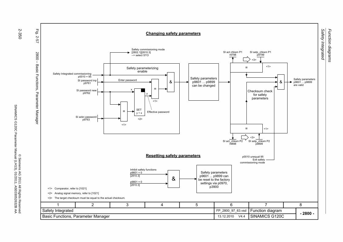
Fu
nctio
n diag
ram
s
Safety In
teg
rate
d
2-350
© S
iem
ens AG
2011 All R
ights R
eservedS
INA
MIC
SG
120C
Param
eter
Manual (L
H13), 0
1/2011, A5E
03052632B
AA
Fig. 2
-57
2800 – B
asic F
unctio
ns, Param
eter M
anager
- 2800 -Function diagram
87654321FP_2800_97_63.vsdSafety Integrated
SINAMICS G120C13.12.2010 V4.4Basic Functions, Parameter Manager
p9601 = 0[2810.3]
x
p9801 = 0[2810.3]
y
<1>
<1>
=
= SETy = x
= <1>
<1>
<1>
<2>
<3>
<3>
=
&
& &
<2>
<3>
SI act chksm P1r9798
Changing safety parameters
Resetting safety parameters
Safety parameterizing enable
Checksum check for safety
parameters
Safety parameters p9601 ... p9899 can
be reset to the factory settings via p0970,
p3900
Safety parameters p9601 ... p9899 can be changed
Safety commissioning mode [2802.1][2810.3]--> select STO
Effective password
Enter password
Safety Integrated commissioning p0010 = 95
Safety parameters p9601 ... p9899 are valid
p0010 unequal 95 Exit safety
commissioning mode
Inhibit safety functions
Comparator, refer to [1021]
Analog signal memory, refer to [1021]
The target checksum must be equal to the actual checksum.
SI password inpp9761
SI password newp9762
SI ackn passwordp9763
SI setp_chksm P1p9799
SI act_chksm P2r9898
SI setp_chksm P2p9899
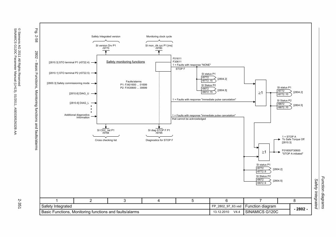
Sa
fety Integ
rate
d
Fu
nction dia
grams
2-351
© S
ieme
ns AG
2011 All R
ights Re
servedS
INA
MIC
SG
120C P
aram
eterM
anual (LH
13), 01/2011, A5E
03052632B
AA
Fig. 2
-58
2802 – B
asic F
unctio
ns, Monito
ring functions an
d faults/a
larms
- 2802 -Function diagram
87654321FP_2802_97_63.vsdSafety Integrated
SINAMICS G120C13.12.2010 V4.4Basic Functions, Monitoring functions and faults/alarms
[2810.6] DIAG_U
[2810.6] DIAG_L
P1: F/A01600 ... 01699P2: F/A30600 ... 30699
F01611F30611
STOP F
[2810.3]
F01600/F306001
1
SI version Drv P1r9770
SI status P1
r9772r9772 [2804.2]
.15
SI status P1
r9772r9772 [2804.2]
.10
Safety monitoring functions
Faults/alarms
Cross checking list
SI status P1
r9772r9772 [2804.2]
.9
[2810.3] STO terminal P1 (r0722.4)
[2810.1] STO terminal P2 (r0722.5)
[2800.3] Safety commissioning mode
Additional diagnosticsInformation
1 = Faults with response "NONE"
1 = Faults with response "immediate pulse cancelation"
1 = Faults with response "immediate pulse cancelation" that cannot be acknowledged
1 = STOP A To Safe Torque Off
"STOP A initiated"
Diagnostics for STOP F
SI Status P2
r9872r9872 [2804.5]
.15
SI Status P2
r9872r9872 [2804.5]
.10
SI Status P2
r9872r9872 [2804.5]
.9
SI mon_clk cyc P1 [ms]r9780
Monitoring clock cycleSafety Integrated version
SI CDC_list P1r9794
SI diag STOP F P1r9795
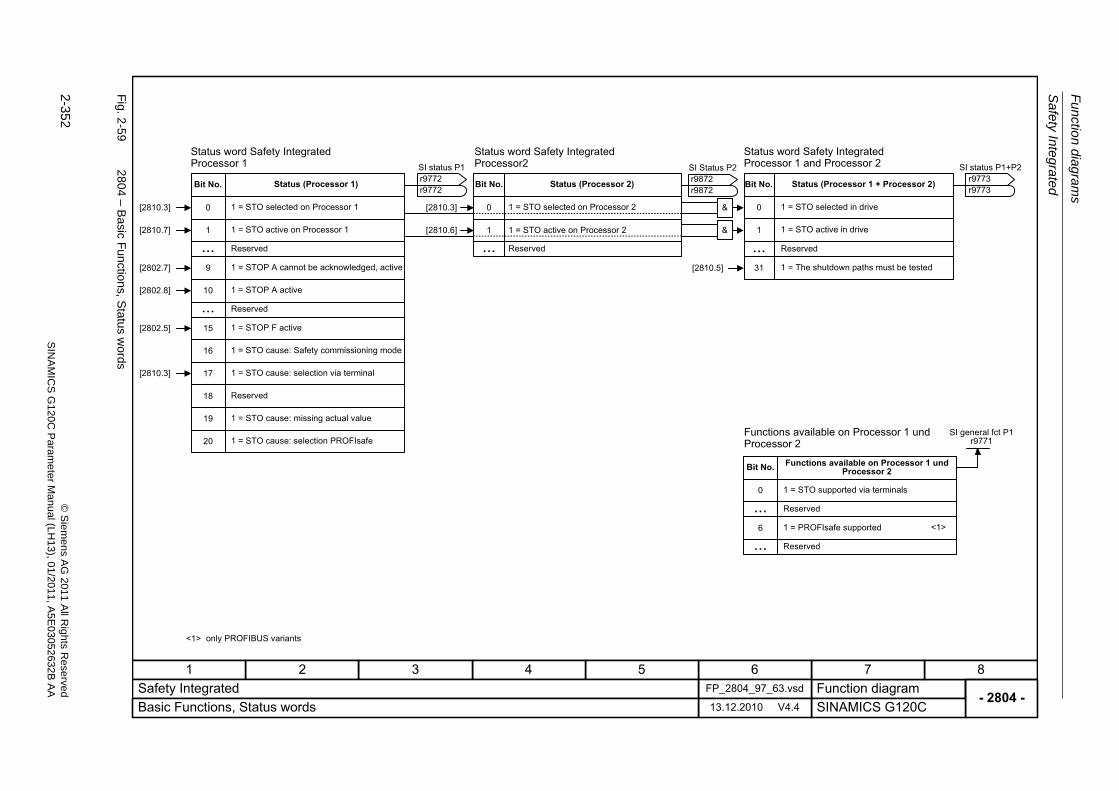
Fu
nctio
n diag
ram
s
Safety In
teg
rate
d
2-352
© S
iem
ens AG
2011 All R
ights R
eservedS
INA
MIC
SG
120C
Param
eter
Manual (L
H13), 0
1/2011, A5E
03052632B
AA
Fig. 2
-59
2804 – B
asic F
unctio
ns, Status w
ords
- 2804 -Function diagram
87654321FP_2804_97_63.vsdSafety Integrated
SINAMICS G120C13.12.2010 V4.4Basic Functions, Status words
1
9
10
...15
0[2810.3]
[2810.7]
[2802.5]
[2802.8]
1
0
0
31[2810.5][2802.7]
... ...
SI status P1
r9772r9772
SI general fct P1r9771
Status word Safety Integrated Processor 1
Bit No.
1 = STO selected on Processor 1
1 = STO active on Processor 1
Reserved
1 = STOP A cannot be acknowledged, active
Functions available on Processor 1 und Processor 2
1 = STOP A active
Reserved
1 = STOP F active
Bit No.
Bit No.
Reserved
Status word Safety Integrated Processor 1 and Processor 2
Functions available on Processor 1 und Processor 2
1 = STO supported via terminals
1 = STO selected in drive
1 = STO active in drive
1 = The shutdown paths must be tested
17
18
16
19
20
1 = STO cause: Safety commissioning mode
1 = STO cause: selection via terminal
Reserved
1 = STO cause: missing actual value
1 = STO cause: selection PROFIsafe
SI status P1+P2
r9773r9773
6 1 = PROFIsafe supported
... Reserved
... Reserved
[2810.3]
1
...
0[2810.3] &
&[2810.6]
SI Status P2
r9872r9872Bit No.
Reserved
Status word Safety Integrated Processor2
1 = STO selected on Processor 2
1 = STO active on Processor 2
Status (Processor 1 + Processor 2)Status (Processor 2)Status (Processor 1)
<1>
only PROFIBUS variants<1>
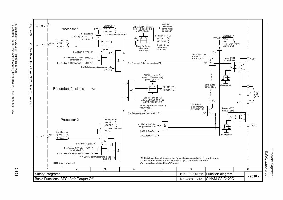
Sa
fety Integ
rate
d
Fu
nction dia
grams
2-353
© S
ieme
ns AG
2011 All R
ights Re
servedS
INA
MIC
SG
120C P
aram
eterM
anual (LH
13), 01/2011, A5E
03052632B
AA
Fig. 2
-60
2810 – B
asic F
unctio
ns, ST
O: S
afe T
orque O
ff
- 2810 -Function diagram
87654321FP_2810_97_05.vsdSafety Integrated
SINAMICS G120C13.12.2010 V4.4Basic Functions, STO: Safe Torque Off
T 0
F01611 (P1)F30611 (P2)
1
1 = STOP A [2802.8] &
1
<2>
1
1 = STOP A [2802.8] &
1
Kl.17
M~
U
V
W
+ Vdc
- Vdc
1
&
+5 V
+5 V
+24 V
<1>
[2802.1] DIAG_L
[2802.1] DIAG_U
<3>
<3>
[2802.2]
&
1p9601.0
&
=1T 0
<1> <2><3>
SI FrcdCkProcTimer0.00 ... 9000.00 [h]
p9659 (8.00)
SI F-DI_chg tol P10.00 ... 2000.00 [ms]
p9650 (500.00)
Redundant functions
Timer for forced checking procedure
A01699"Shutdown paths mustbe tested"
Upper IGBT bridge halve
Safe pulsecancelation
Gating unit
Lower IGBT bridge halve
Gating unit
Shutdown path from P20 = STO_P2
Monitoring for simultaneous occurrence
0 = Request pulse cancelation P2
Switch-on delay starts when the "request pulse cancelation P1" is withdrawn.Redundant functions in the Processor 1 (P1) and Processor 2 (P2).Transistors inhibited for a "0" signal.STO: Safe Torque Off
1 = Safety commissioning mode [2800.3]
1 = Safety commissioning mode [2800.3]
1 = "STO active" forsequence control
CU DI status
r0722r0722
.4
1 = STO selected on P1
1 = Enable STO via terminals (P1)
Shutdown pathfromP10 = STO_P1
0 = Request Pulse cancelation P1
1 = STO selected on P2
SI F-DI_chg tol P20.00 ... 2000000.00 [μs]
p9850 (500000.00)
CU DI status
r0722r0722
.5
Kl.16
SI status P1
r9772r9772
.0[2804.1]
1 = STO active on Control Unit
SI status P1
r9772r9772
.1[2804.2]
Processor 1
Processor 2
1 = Shutdownpaths mustbe tested
SI status P1+P2
r9773r9773
.31
p9601.31 = Enable PROFIsafe (P1)
1p9601.01 = Enable STO via
terminals (P2)p9601.31 = Enable PROFIsafe (P2)
SI status P1
r9772r9772
.17[2804.1]
SI Status P2
r9872r9872
.0
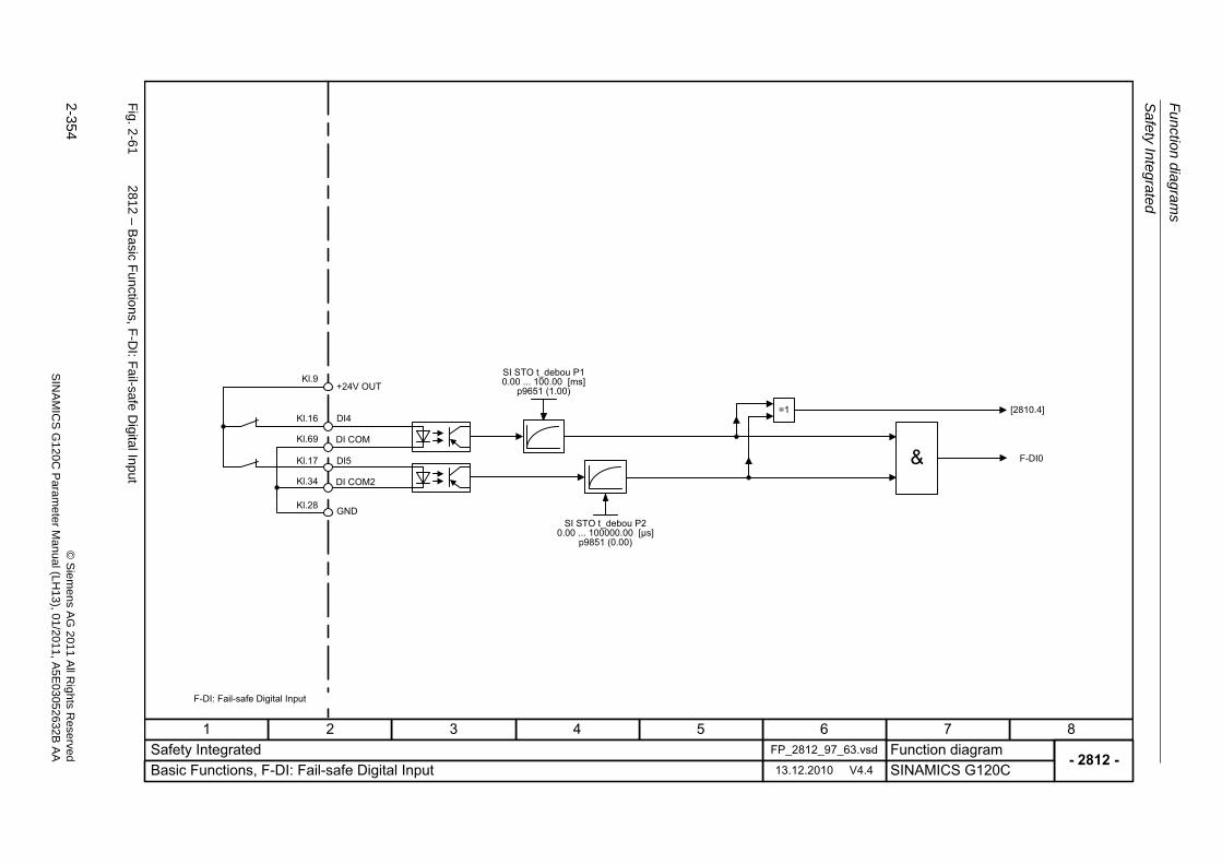
Fu
nctio
n diag
ram
s
Safety In
teg
rate
d
2-354
© S
iem
ens AG
2011 All R
ights R
eservedS
INA
MIC
SG
120C
Param
eter
Manual (L
H13), 0
1/2011, A5E
03052632B
AA
Fig. 2
-61
2812 – B
asic F
unctio
ns, F-D
I: Fail-safe D
igital Input
- 2812 -Function diagram
87654321FP_2812_97_63.vsdSafety Integrated
SINAMICS G120C13.12.2010 V4.4Basic Functions, F-DI: Fail-safe Digital Input
+24V OUTKl.9
DI5Kl.17
GNDKl.28
DI4Kl.16
&DI COM2Kl.34
F-DI0
=1
SI STO t_debou P10.00 ... 100.00 [ms]
p9651 (1.00)
SI STO t_debou P20.00 ... 100000.00 [μs]
p9851 (0.00)
[2810.4]
DI COMKl.69
F-DI: Fail-safe Digital Input
Setpoint channel
Function diagrams
2-355© Siemens AG 2011 All Rights ReservedSINAMICS G120C Parameter Manual (LH13), 01/2011, A5E03052632B AA
2.9 Setpoint channel
Function diagrams
3010 – Fixed speed setpoints, binary selection (p1016 = 2) 2-356
3011 – Fixed speed setpoints, direct selection (p1016 = 1) 2-357
3020 – Motorized potentiometer 2-358
3030 – Main/supplementary setpoint, setpoint scaling, jogging 2-359
3040 – Direction limitation and direction reversal 2-360
3050 – Skip frequency bands and frequency limitations 2-361
3070 – Extended ramp-function generator 2-362
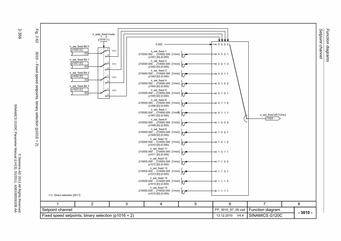
Fu
nctio
n diag
ram
s
Setpo
int cha
nne
l
2-356
© S
iem
ens AG
2011 All R
ights R
eservedS
INA
MIC
SG
120C
Param
eter
Manual (L
H13), 0
1/2011, A5E
03052632B
AA
Fig. 2
-62
3010 – F
ixed sp
eed setpoints, bin
ary selection
(p1016
=2
)
- 3010 -
0
Function diagram87654321
FP_3010_97_05.vsdSetpoint channelSINAMICS G120C13.12.2010 V4.4Fixed speed setpoints, binary selection (p1016 = 2)
0 0 1 1
0 1 0 1
0 1 1 0
0 1 1 1
1 0 0 1
1 0 1 0
1 0 1 1
1 1 0 0
1 1 0 1
1 1 1 0
1 1 1 1
0 0 0 1
0 0 1 0
0.000 0 0 0 0
0 1 0 0
1 0 0 0
n_set_fixed 1-210000.000 ... 210000.000 [1/min]
p1001 [D] (0.000)n_set_fixed 2
-210000.000 ... 210000.000 [1/min]p1002 [D] (0.000)
r1024 n_set_fixed eff [1/min]
n_set_fixed 3-210000.000 ... 210000.000 [1/min]
p1003 [D] (0.000)n_set_fixed 4
-210000.000 ... 210000.000 [1/min]p1004 [D] (0.000)
n_set_fixed 5-210000.000 ... 210000.000 [1/min]
p1005 [D] (0.000)n_set_fixed 6
-210000.000 ... 210000.000 [1/min]p1006 [D] (0.000)
n_set_fixed 7-210000.000 ... 210000.000 [1/min]
p1007 [D] (0.000)n_set_fixed 8
-210000.000 ... 210000.000 [1/min]p1008 [D] (0.000)
n_set_fixed 9-210000.000 ... 210000.000 [1/min]
p1009 [D] (0.000)n_set_fixed 10
-210000.000 ... 210000.000 [1/min]p1010 [D] (0.000)
n_set_fixed 11-210000.000 ... 210000.000 [1/min]
p1011 [D] (0.000)n_set_fixed 12
-210000.000 ... 210000.000 [1/min]p1012 [D] (0.000)
n_set_fixed 13-210000.000 ... 210000.000 [1/min]
p1013 [D] (0.000)n_set_fixed 14
-210000.000 ... 210000.000 [1/min]p1014 [D] (0.000)
n_set_fixed 15-210000.000 ... 210000.000 [1/min]
p1015 [D] (0.000)
(0)
n_set_fixed Bit 0p1020 [C]
(0)
n_set_fixed Bit 1p1021 [C]
(0)
n_set_fixed Bit 2p1022 [C]
(0)
n_set_fixed Bit 3p1023 [C]
1
1
1
1
2
2
2
2
n_setp_fixed mode1 ... 2
p1016 (1)
<1> Direct selection [3011]
<1>
<1>
<1>
<1>
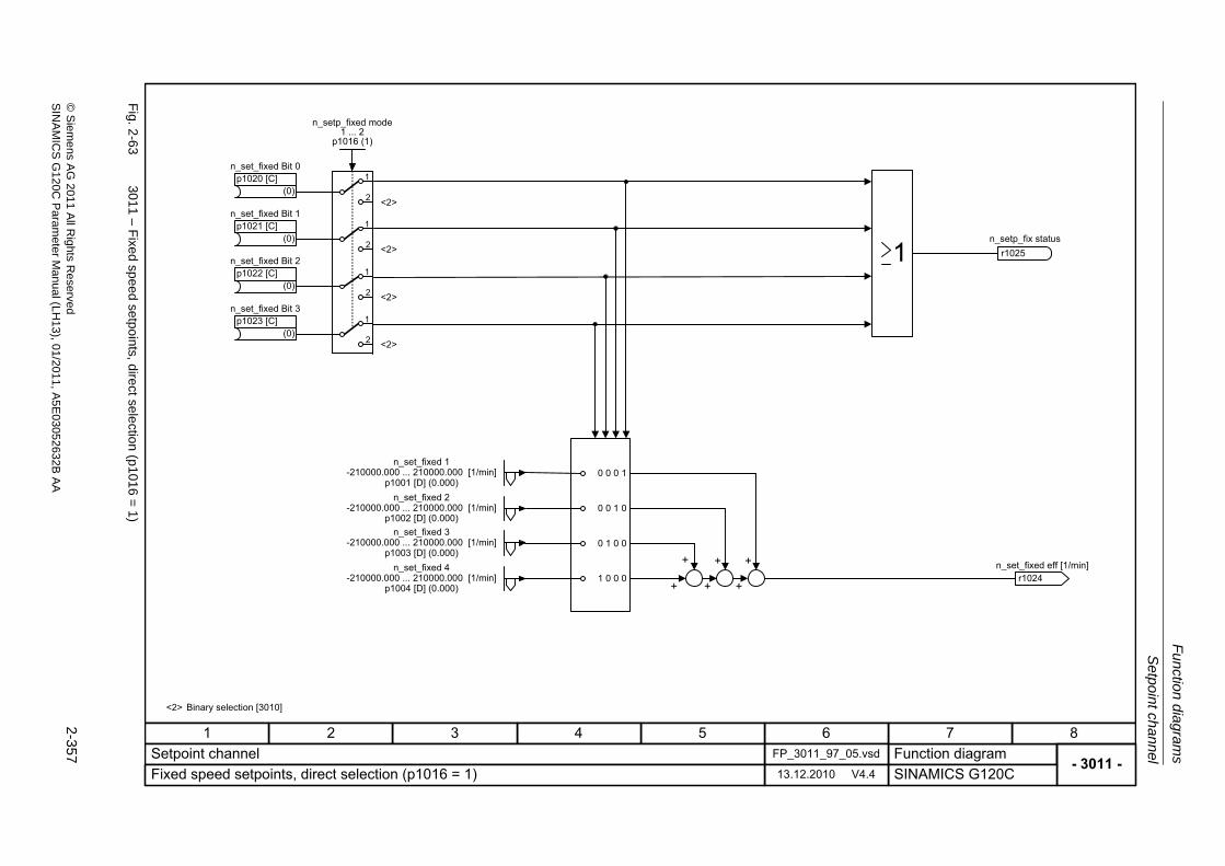
Setpo
int ch
ann
el
Fu
nction dia
grams
2-357
© S
ieme
ns AG
2011 All R
ights Re
servedS
INA
MIC
SG
120C P
aram
eterM
anual (LH
13), 01/2011, A5E
03052632B
AA
Fig. 2
-63
3011 – F
ixed sp
eed setpoints, dire
ct selectio
n (p101
6=
1)
- 3011 -Function diagram
87654321FP_3011_97_05.vsdSetpoint channel
SINAMICS G120C13.12.2010 V4.4Fixed speed setpoints, direct selection (p1016 = 1)
+ + +
0 0 0 1
0 0 1 0
1 0 0 0
0 1 0 0
+ + +
n_set_fixed 1-210000.000 ... 210000.000 [1/min]
p1001 [D] (0.000)
r1024 n_set_fixed eff [1/min]
n_setp_fix statusr1025
n_set_fixed 2-210000.000 ... 210000.000 [1/min]
p1002 [D] (0.000)n_set_fixed 3
-210000.000 ... 210000.000 [1/min]p1003 [D] (0.000)
n_set_fixed 4-210000.000 ... 210000.000 [1/min]
p1004 [D] (0.000)
(0)
n_set_fixed Bit 0p1020 [C]
(0)
n_set_fixed Bit 1p1021 [C]
(0)
n_set_fixed Bit 2p1022 [C]
(0)
n_set_fixed Bit 3p1023 [C]
1
1
1
1
2
2
2
2
n_setp_fixed mode1 ... 2
p1016 (1)
<2> Binary selection [3010]
<2>
<2>
<2>
<2>
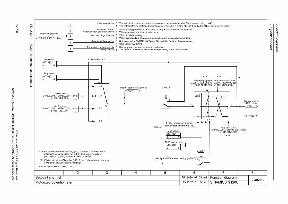
Fu
nctio
n diag
ram
s
Setpo
int cha
nne
l
2-358
© S
iem
ens AG
2011 All R
ights R
eservedS
INA
MIC
SG
120C
Param
eter
Manual (L
H13), 0
1/2011, A5E
03052632B
AA
Fig. 2
-64
3020 – M
oto
rized potentio
mete
r
- 3020 -Function diagram
87654321FP_3020_97_05.vsdSetpoint channel
SINAMICS G120C13.12.2010 V4.4Motorized potentiometer
<1>
<1>
0 0
0 1
1 0
1 1
<1>
<3>
<3>
[3050.5]
x y
yp1082
-p1082
x
y = 0
<2>
<2> <2>
0
1
Old value is kept
f_max (reference value forramp-function generator p1082)
For automatic commissioning, p1037 and p1038 are set to the maximum motor frequency or to the rated motor frequency, provided that f_max_mot has not been specified.
If initial rounding-off is active (p1025.2 = 1), the selected ramp-up/down times are exceeded accordingly.
Only effective if p1025.0 = 0.
MotP n_max-210000.000 ... 210000.000 [1/min]
p1037 [D] (0.000)
MotP n_min-210000.000 ... 210000.000 [1/min]
p1038 [D] (0.000)
(0)
Mop raisep1035 [C]
(0)
Mop lowerp1036 [C]
r1045 Mop n_set bef RFG [1/min]
Mop set val
(0)p1044 [C]
(0)
MotP acc set valp1043 [C]
Mop start value-210000.000 ... 210000.000 [1/min]
p1040 [D] (0.000)
Mop ramp-down time0.000 ... 1000.000 [s]p1048 [D] (10.000)
Mop ramp-up time0.000 ... 1000.000 [s]
p1047 [D] (10.000)
e.g. to [3030.1]
r1050
Mop setp after RFG [1/min]
p1030.1
01010101
0
1
2
3
Data save active
Automatic modeRamp-function generator active
Initial rounding-off active
Save in NVRAM active
The setpoint for the motorized potentiometer is not saved and after ON is entered using p1040.The setpoint for the motorized potentiometer is saved in a ashion after OFF and after ON set to the saved value.Without ramp generator in automatic mode (ramp-up/ramp-down time = 0).With ramp generator in automatic mode.Without initial rounding.With initial rounding. The ramp-up/down time set is exceeded accordingly.Not saved in the NVRAM (NVRAM = Non Volatile Random Access Memory).Save in NVRAM active.
4
Mop configuration- ... -
p1030 [D] (0000 0110 bin)
[2634.8] 1: OFF1 enable missing (r0046.0) 0
1
p1030.4
0:
01
Ramp-function generator is always active
Ramp-up encoder inactive with pulse disable.The ramp-up encoder is calculated independently of the pulse enable.
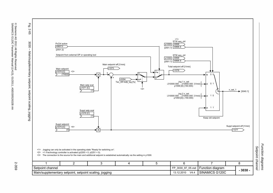
Setpo
int ch
ann
el
Fu
nction dia
grams
2-359
© S
ieme
ns AG
2011 All R
ights Re
servedS
INA
MIC
SG
120C P
aram
eterM
anual (LH
13), 01/2011, A5E
03052632B
AA
Fig. 2
-65
3030 – M
ain/supp
lementary setpoin
t, setpoint scaling, jogging
- 3030 -Function diagram
87654321FP_3030_97_05.vsdSetpoint channel
SINAMICS G120C13.12.2010 V4.4Main/supplementary setpoint, setpoint scaling, jogging
+
+
[2501.7]p1055
[2501.7]p1056
[2501.2]
0
1
<1>
0 0
0 1
1 0
1 1
[3040.1]
<1> Jogging can only be activated in the operating state �Ready for switching on�.
Keep old setpoint
n_set_1
Main setpoint
(755[0])p1070 [C]
Main setp scal
(1)p1071 [C]
Suppl setp scal
(1)p1076 [C]
Suppl setpoint
(0)p1075 [C]
PcCtrl activer0807.0
STW seq_ctrl
r0898r0898
.8
STW seq_ctrl
r0898r0898
.9
Jog 1 n_set-210000.000 ... 210000.000 [1/min]
p1058 [D] (150.000)
Jog 2 n_set-210000.000 ... 210000.000 [1/min]
p1059 [D] (-150.000)
r1078
Total setpoint eff [1/min]
1
0
Setpoint from external OP or operating tool
<2> =1 if technology controller is activated (p2200 > 0, p2251 = 0).<3> The connection to the source for the main and additional setpoint is estabished automatically via the setting in p1000.
<4>
<3>
r2294 Tec_ctrl outp_sig [%]
<2>
r1073
Main setpoint eff [1/min]
r1077
Suppl setpoint eff [1/min]
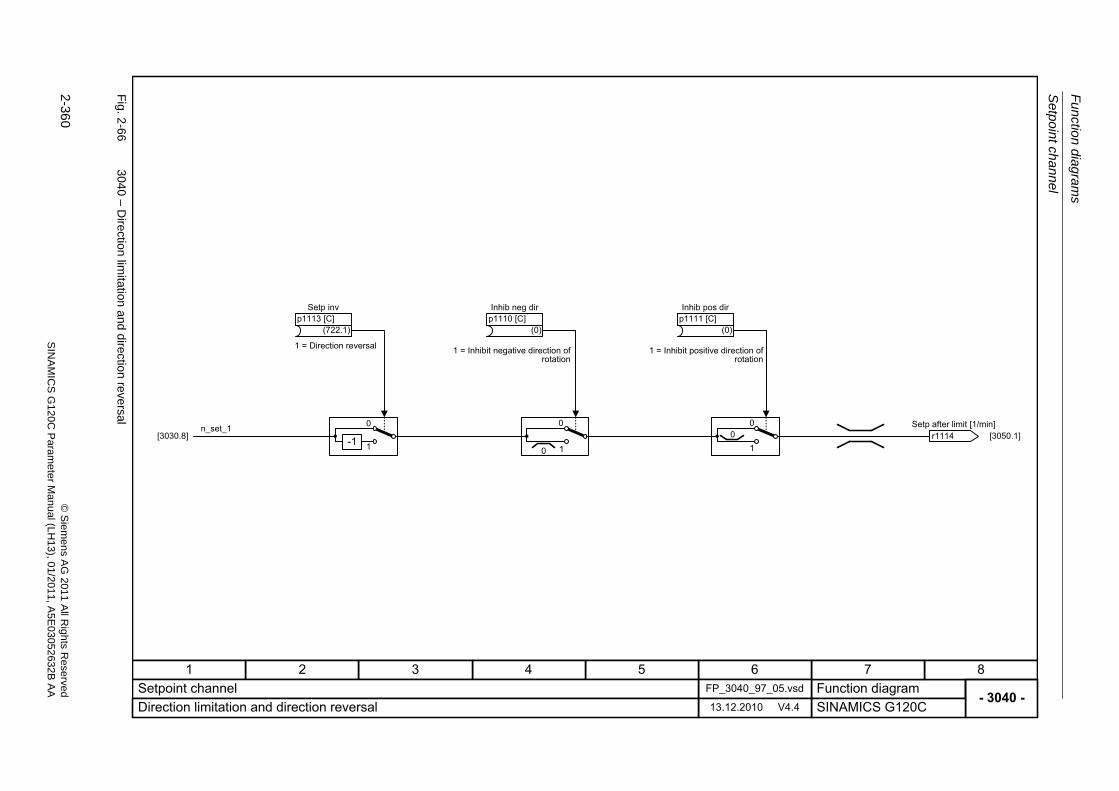
Fu
nctio
n diag
ram
s
Setpo
int cha
nne
l
2-360
© S
iem
ens AG
2011 All R
ights R
eservedS
INA
MIC
SG
120C
Param
eter
Manual (L
H13), 0
1/2011, A5E
03052632B
AA
Fig. 2
-66
3040 – D
irection limita
tion and d
irection reversal
- 3040 -Function diagram
87654321FP_3040_97_05.vsdSetpoint channel
SINAMICS G120C13.12.2010 V4.4Direction limitation and direction reversal
[3030.8] [3050.1]-1
0
1
0
10
0
10
n_set_1
1 = Direction reversal 1 = Inhibit negative direction of rotation
1 = Inhibit positive direction of rotation
r1114 Setp after limit [1/min]
(722.1)
Setp invp1113 [C]
(0)
Inhib neg dirp1110 [C]
(0)
Inhib pos dirp1111 [C]
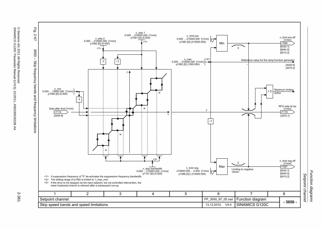
Setpo
int ch
ann
el
Fu
nction dia
grams
2-361
© S
ieme
ns AG
2011 All R
ights Re
servedS
INA
MIC
SG
120C P
aram
eterM
anual (LH
13), 01/2011, A5E
03052632B
AA
Fig. 2
-67
3050 – S
kip frequency ba
nds and frequency lim
itations
- 3050 -Function diagram
87654321FP_3050_97_05.vsdSetpoint channel
SINAMICS G120C13.12.2010 V4.4Skip speed bands and speed limitations
[3020.6][3070.4]
[3040.8]
y
[3070.1]
Max
-1
Min
<2>
1
[6030.1][6640.5][8010.2]
[6030.1][6640.5][8010.2]
0
0
Reference value for the ramp-function generator
Limiting to negative values
Maximum limiting active
A suppression frequency of "0" de-activates the suppression frequency bandwidth.
r1114 Setp after limit [1/min]
n_skip 10.000 ... 210000.000 [1/min]
p1091 [D] (0.000)n_limit pos
0.000 ... 210000.000 [1/min]p1083 [D] (210000.000)
<1>
<1>
<3>
w
-1 -1
y
x
-1
n_min0.000 ... 19500.000 [1/min]
p1080 [D] (0.000)
n_skip 20.000 ... 210000.000 [1/min]
p1092 [D] (0.000)
<1>The setting range of p1082 is limited to f_max_mot.If the drive is not stopped via the input setpoint, but via controlled intervention, the lower hysteresis branch is relevant after a subsequent run-up.
<2><3>
n_skip bandwidth0.000 ... 210000.000 [1/min]
p1101 [D] (0.000)
n_limit neg-210000.000 ... 0.000 [1/min]
p1086 [D] (-210000.000)
n_max0.000 ... 210000.000 [1/min]
p1082 [D] (1500.000)
r1119
RFG setp at inp [1/min]
w
w
w
r1084
n_limit pos eff [1/min]
r1087
n_limit neg eff [1/min]
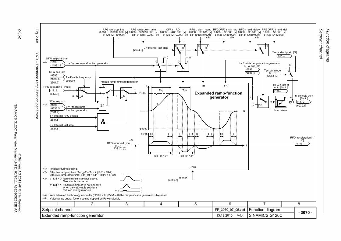
Fu
nctio
n diag
ram
s
Setpo
int cha
nne
l
2-362
© S
iem
ens AG
2011 All R
ights R
eservedS
INA
MIC
SG
120C
Param
eter
Manual (L
H13), 0
1/2011, A5E
03052632B
AA
Fig. 2
-68
3070 – E
xtended ram
p-function g
enera
tor
- 3070 -Function diagram
87654321FP_3070_97_05.vsdSetpoint channel
SINAMICS G120C13.12.2010 V4.4Extended ramp-function generator
0
Tup
FRIRFRIRFRIRFRIR
Tdnp1082
Tup_eff <2> Tdn_eff <2>
-p1082
IR FR
[3050.8]
0
p1082
x
y
<3>
[3050.5]n_max
x
t
y
dy/dt
y
0 1 0 1 0 1
1
0
1
0
0
1
10 10
[6030.1]
0
1
0
1
0 0
<1>
tnsollt
t
<2>
<3> p1134 = 0:
p1134 = 1:
1 = Bypass ramp-function generator
STW setpoint chan
r1198r1198
.15
STW seq_ctrl
r0898r0898
.6 1 = Enable frequency setpoint
r1119 RFG setp at inp [1/min]
STW seq_ctrl
r0898r0898
.5 0 = Freeze ramp-function generator
1 = Internal RFG enable
0 = Internal fast stop
RFG round-off type0 ... 1
p1134 [D] (0)
Freeze ramp-function generator
RFG ramp-up time0.000 ... 999999.000 [s]
p1120 [D] (10.000)
0 = Internal fast stop
RFG OFF3 t_end_del0.000 ... 30.000 [s]p1137 [D] (0.000)
STW seq_ctrl
r0898r0898
.4
1 = Enable ramp-function generator
Effective ramp-up time: Tup_eff = Tup + (IR/2 + FR/2)Effective ramp-down time: Tdn_eff = Tdn + (IR/2 + FR/2)
Rounding-off is always active.Overshoots can occur.Final rounding-off is not effectivewhen the setpoint is suddenlyreduced during ramp-up.
Expanded ramp-functiongenerator
<4> With activated Technology controller (p2200 > 0, p2251 = 0) the ramp-function generator is bypassed.
<4>
[2634.8]
[2634.8]
[2634.8]
<5>
Value range and/or factory setting depend on Power Module
<1> Inhibited during jogging.
<5><5> <5> <5>
<5>
[2501.7]
[2501.7]
r1170
n_ctrl setp sum [1/min]
tInterpolator
+
+
RFG ramp-down time0.000 ... 999999.000 [s]
p1121 [D] (10.000)
OFF3 t_RD0.000 ... 5400.000 [s]
p1135 [D] (0.000)
RFG t_start_round0.000 ... 30.000 [s]p1130 [D] (0.000)
RFGOFF3 t_strt_rnd0.000 ... 30.000 [s]p1136 [D] (0.000)
RFG t_end_delay0.000 ... 30.000 [s]p1131 [D] (0.000)
r1150
RFG n_set at outp [1/min]
0 1Tec_ctrl mode0 ... 1
p2251 (0)
r2294 Tec_ctrl outp_sig [%]
0
r1149
RFG acceleration [1/s²]
V/f control
Function diagrams
2-363© Siemens AG 2011 All Rights ReservedSINAMICS G120C Parameter Manual (LH13), 01/2011, A5E03052632B AA
2.10 V/f control
Function diagrams
6300 – V/f characteristic and voltage boost 2-364
6310 – Resonance damping and slip compensation 2-365
6320 – Vdc_max controller and Vdc_min controller (V7f control) 2-366
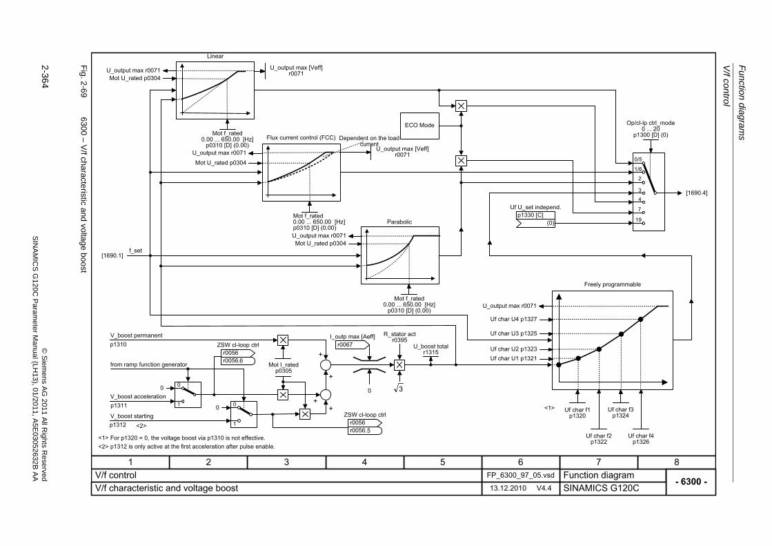
Fu
nctio
n diag
ram
s
V/f control
2-364
© S
iem
ens AG
2011 All R
ights R
eservedS
INA
MIC
SG
120C
Param
eter
Manual (L
H13), 0
1/2011, A5E
03052632B
AA
Fig. 2
-69
6300 – V
/f characteristic a
nd voltage b
oost
- 6300 -Function diagram
87654321FP_6300_97_05.vsdV/f control
SINAMICS G120C13.12.2010 V4.4V/f characteristic and voltage boost
[1690.4]
0
1
00
p1311
p1310
+
+
[1690.1]
1/6
2
3
7
19
<1>
<1>
1
00
<2>
++
p1312
0/5
4
Linear
Flux current control (FCC) Dependent on the load current
ECO Mode
Parabolic
f_set
V_boost permanent
V_boost acceleration
V_boost starting
For p1320 = 0, the voltage boost via p1310 is not effective.p1312 is only active at the first acceleration after pulse enable.
Freely programmable
U_output max [Veff]r0071
Mot f_rated0.00 ... 650.00 [Hz]
p0310 [D] (0.00)
Mot f_rated0.00 ... 650.00 [Hz]p0310 [D] (0.00)
U_output max [Veff]r0071
Mot f_rated0.00 ... 650.00 [Hz]
p0310 [D] (0.00)
Uf U_set independ.
(0)p1330 [C]
Op/cl-lp ctrl_mode0 ... 20
p1300 [D] (0)
ZSW cl-loop ctrl
r0056r0056
.6Mot I_rated
p0305
ZSW cl-loop ctrl
r0056r0056
.5
U_boost totalr1315
R_stator actr0395
Uf char U4 p1327
Uf char U3 p1325
Uf char U1 p1321Uf char U2 p1323
Uf char f1p1320
Uf char f2p1322
Uf char f4p1326
Uf char f3p1324
U_output max r0071Mot U_rated p0304
U_output max r0071
U_output max r0071
Mot U_rated p0304
U_output max r0071Mot U_rated p0304
3
r0067 I_outp max [Aeff]
<2>
from ramp function generator
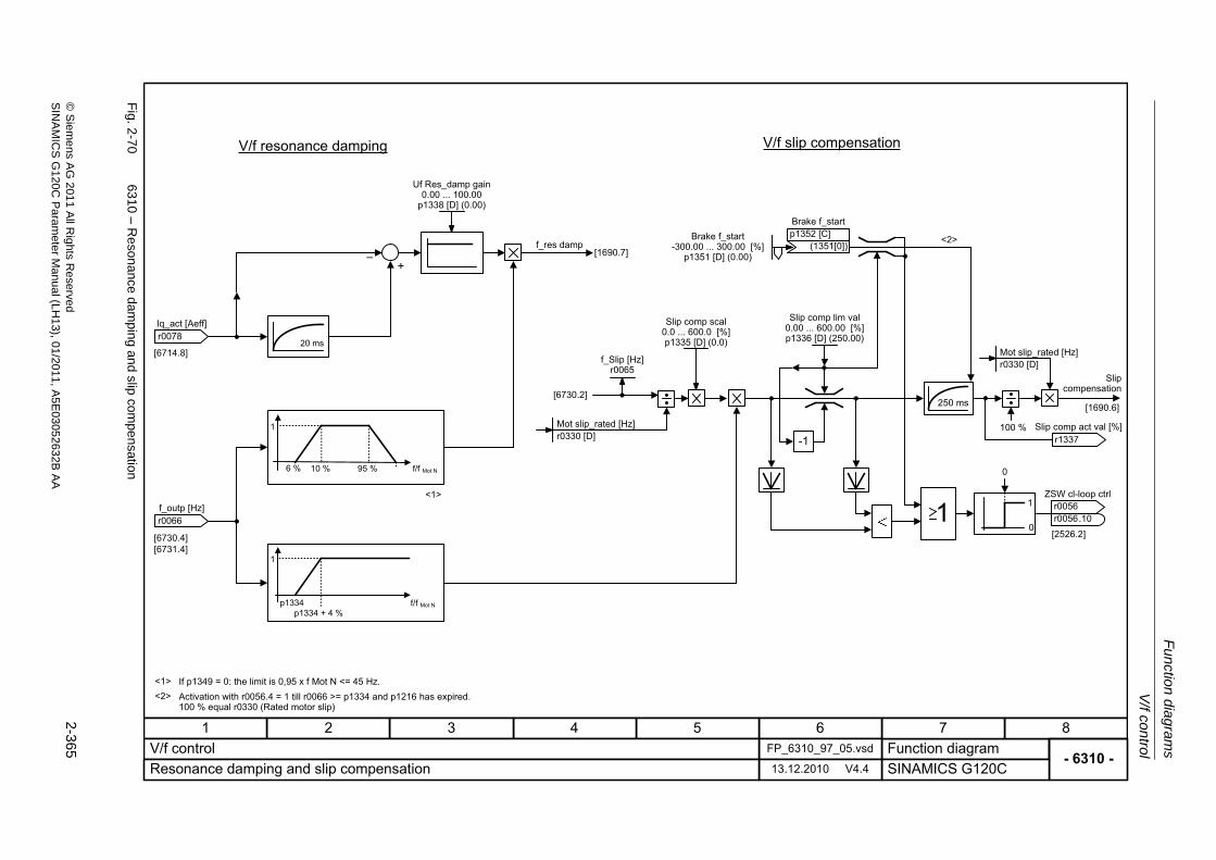
V/f control
Fu
nction dia
grams
2-365
© S
ieme
ns AG
2011 All R
ights Re
servedS
INA
MIC
SG
120C P
aram
eterM
anual (LH
13), 01/2011, A5E
03052632B
AA
Fig. 2
-70
6310 – R
esonance dam
ping and slip com
pensation
- 6310 -Function diagram
87654321FP_6310_97_05.vsdV/f control
SINAMICS G120C13.12.2010 V4.4Resonance damping and slip compensation
�+
[6730.4][6731.4]
[6714.8]
-1
0
1
[1690.7]
250 ms
6 % 10 % 95 %
1
[2526.2]
<1>
<1>
0
p1334 f/f Mot N
1
p1334 + 4 %
f/f Mot N
V/f resonance damping V/f slip compensation
If p1349 = 0: the limit is 0,95 x f Mot N <= 45 Hz.
r0078 Iq_act [Aeff]
Uf Res_damp gain0.00 ... 100.00
p1338 [D] (0.00)
f_res damp
r0066 f_outp [Hz]
Slip comp lim val0.00 ... 600.00 [%]p1336 [D] (250.00)
ZSW cl-loop ctrl
r0056r0056
.10
Brake f_start-300.00 ... 300.00 [%]
p1351 [D] (0.00)
Brake f_start
(1351[0])p1352 [C]
<2> Activation with r0056.4 = 1 till r0066 >= p1334 and p1216 has expired.100 % equal r0330 (Rated motor slip)
<2>
20 ms
Slip compensation
[6730.2]
f_Slip [Hz]r0065
Slip comp scal0.0 ... 600.0 [%]p1335 [D] (0.0)
Mot slip_rated [Hz]r0330 [D]
[1690.6]
Mot slip_rated [Hz]r0330 [D]
100 %r1337
Slip comp act val [%]
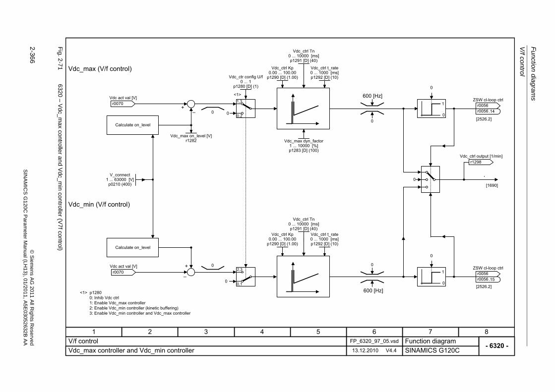
Fu
nctio
n diag
ram
s
V/f control
2-366
© S
iem
ens AG
2011 All R
ights R
eservedS
INA
MIC
SG
120C
Param
eter
Manual (L
H13), 0
1/2011, A5E
03052632B
AA
Fig. 2
-71
6320 – V
dc_m
ax controlle
r and V
dc_min controller (V
7fcontrol)
- 6320 -Function diagram
87654321FP_6320_97_05.vsdV/f control
SINAMICS G120C13.12.2010 V4.4Vdc_max controller and Vdc_min controller
0
11,3
0,2�
+
0
1�
+
0
0
02,3
0,1
[2526.2]
[2526.2]
0
0
0
0
Calculate on_level
r0070 Vdc act val [V]
V_connect1 ... 63000 [V]
p0210 (400)
r0070 Vdc act val [V]
Vdc_max dyn_factor1 ... 10000 [%]p1283 [D] (100)
r1298 Vdc_ctrl output [1/min]
ZSW cl-loop ctrl
r0056r0056
.14
ZSW cl-loop ctrl
r0056r0056
.15
Calculate on_level
<1> p1280
<1>
0: Inhib Vdc ctrl1: Enable Vdc_max controller2: Enable Vdc_min controller (kinetic buffering)3: Enable Vdc_min controller and Vdc_max controller
[1690]
Vdc_max (V/f control)
Vdc_min (V/f control)
0
0
Vdc_ctr config U/f0 ... 1
p1280 [D] (1)
600 [Hz]
600 [Hz]
Vdc_max on_level [V]r1282
Vdc_ctrl Kp0.00 ... 100.00
p1290 [D] (1.00)
Vdc_ctrl Tn0 ... 10000 [ms]p1291 [D] (40)
Vdc_ctrl t_rate0 ... 1000 [ms]p1292 [D] (10)
Vdc_ctrl Kp0.00 ... 100.00
p1290 [D] (1.00)
Vdc_ctrl Tn0 ... 10000 [ms]p1291 [D] (40)
Vdc_ctrl t_rate0 ... 1000 [ms]p1292 [D] (10)
Vector control
Function diagrams
2-367© Siemens AG 2011 All Rights ReservedSINAMICS G120C Parameter Manual (LH13), 01/2011, A5E03052632B AA
2.11 Vector control
Function diagrams
6030 – Speed setpoint, droop 2-368
6040 – Speed controller 2-369
6060 – Torque setpoint 2-370
6220 – Vdc_max controller and Vdc_min controller (Vector control) 2-371
6630 – Upper/lower torque limit 2-372
6640 – Current/power/torque limits 2-373
6710 – Current setpoint filter 2-374
6714 – Iq and Id controllers 2-375
6721 – Id setpoint (PEM, p0300 = 2xx) 2-376
6722 – Field weakening characteristic, Id setpoint (ASM, p0300 = 1) 2-377
6723 – Field weakening controller, flux controller (ASM, p0300 = 1) 2-378
6724 – Field weakening controller (PEM, p0300 = 2) 2-379
6730 – Interface of the Power Module (ASM, p0300 = 1) 2-380
6731 – Interface of the Power Module (PEM, p0300 = 2) 2-381
6799 – Display signals 2-382
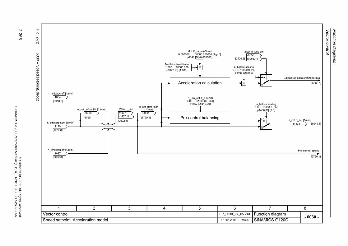
Fu
nctio
n diag
ram
s
Vecto
r control
2-368
© S
iem
ens AG
2011 All R
ights R
eservedS
INA
MIC
SG
120C
Param
eter
Manual (L
H13), 0
1/2011, A5E
03052632B
AA
Fig. 2
-72
6030 – S
peed
setpoint, dro
op
- 6030 -Function diagram
87654321FP_6030_97_05.vsdVector control
SINAMICS G120C13.12.2010 V4.4Speed setpoint, Acceleration model
[3050.8]
[3050.8]
[3070.8]
[6730.1]
[2522.3][6799.1]
r0060 n_set before filt. [1/min]
r1170 n_ctrl setp sum [1/min]
ZSW n_ctrl
r1407r1407
.11
Pre-control speed
r1084 n_limit pos eff [1/min]
r1087 n_limit neg eff [1/min]
[6060.1]
0
0
1
[2526.6]
[6040.1]0
>0
Mot MomInert Ratio1.000 ... 10000.000p0342 [D] (1.000)
Mot M_mom of inert0.000000 ... 100000.000000 [kgm²]
p0341 [D] (0.000000)
a_before scaling0.0 ... 10000.0 [%]
p1496 [D] (0.0)
Acceleration calculation
ZSW cl-loop ctrl
r0056r0056
.14
Calculated accelerating torque
r1438 n_ctrl n_set [1/min]
Pre-control balancing
n_C n_act T_s SLVC0.00 ... 32000.00 [ms]
p1452 [D] (10.00) a_before scaling0.0 ... 10000.0 [%]
p1496 [D] (0.0)
[6799.1]
r0062
n_set after filter [1/min]
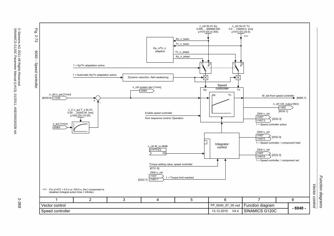
Vector control
Fu
nction dia
grams
2-369
© S
ieme
ns AG
2011 All R
ights Re
servedS
INA
MIC
SG
120C P
aram
eterM
anual (LH
13), 01/2011, A5E
03052632B
AA
Fig. 2
-73
6040 – S
peed
contro
ller
ZSW n_ctrl
r1407r1407
- 6040 -Function diagram
87654321FP_6040_97_05.vsdVector control
SINAMICS G120C13.12.2010 V4.4Speed controller
[6030.8]+ -
[6060.1]
[6030.1]
Kp_n_basic
Tn_n_basic
Tn_n_adapt
1 01 0
Kp_n_adapt
[2522.7]
[2522.3]
[2522.3]
Kp
<1>
Tn
[2522.3]
<1>
1 = Kp/Tn adaptation active
1 = Automatic Kp/Tn adaptation activeDynamic reduction, field weakening
r0064 n_ctrl system dev [1/min]
r1438 n_ctrl n_set [1/min]
r0063 n_act [1/min]
n_C n_act T_s SLVC0.00 ... 32000.00 [ms]
p1452 [D] (10.00)Enable speed controller
from sequence control: Operation
.7
For p1472 = 0.0 s or 100.0 s, the I component is disabled (integral action time = infinite).
1 = Torque limit reached
Integrator control
Speed controller
n_ctrl SLVC Kp0.000 ... 999999.000
p1470 [D] (0.300)
M_set from speed controller
1 = Speed controller active
ZSW n_ctrl
r1407r1407
.5
1 = Speed controller, I component set
ZSW n_ctrl
r1407r1407
.6
ZSW n_ctrl
r1407r1407
.3
r1482 n_ctrl I-M_output [Nm]
n_ctrl SLVC Tn0.0 ... 100000.0 [ms]
p1472 [D] (20.0)
[6721.8]Torque setting value, speed controller
n_ctrl M_sv MHB
(0)p1475 [C]
Kp_n/Tn_nadaption
Kp Tn
1 = Speed controller, I component held
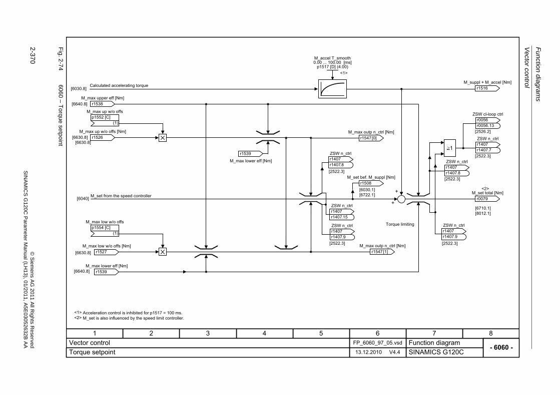
Fu
nctio
n diag
ram
s
Vecto
r control
2-370
© S
iem
ens AG
2011 All R
ights R
eservedS
INA
MIC
SG
120C
Param
eter
Manual (L
H13), 0
1/2011, A5E
03052632B
AA
Fig. 2
-74
6060 – T
orque setpoin
t
- 6060 -Function diagram
87654321FP_6060_97_05.vsdVector control
SINAMICS G120C13.12.2010 V4.4Torque setpoint
[6640.8]
[6710.1][8012.1]
[2522.3]
[2522.3]
[6640.8]
[2522.3][2522.3]
[2522.3]
+
+[6030.1][6722.1]
[6630.8]
[6630.8]
[6030.8]
1
[2526.2]
<1>
Calculated accelerating torque
r1538 M_max upper eff [Nm]
M_set from the speed controller
r1539 M_max lower eff [Nm]
Acceleration control is inhibited for p1517 = 100 ms.
M_accel T_smooth0.00 ... 100.00 [ms]
p1517 [D] (4.00)
ZSW n_ctrl
r1407r1407
.8
r1508 M_set bef. M_suppl [Nm]
ZSW n_ctrl
r1407r1407
.9
r1516 M_suppl + M_accel [Nm]
ZSW cl-loop ctrl
r0056r0056
.13
ZSW n_ctrl
r1407r1407
.7
ZSW n_ctrl
r1407r1407
.8
r0079 M_set total [Nm]
ZSW n_ctrl
r1407r1407
.9
Torque limiting
r1539
M_max lower eff [Nm]
<2>
<1> M_set is also influenced by the speed limit controller.<2>
r1526 M_max up w/o offs [Nm]
r1527 M_max low w/o offs [Nm]
r1547 M_max outp n_ctrl [Nm]
[0]
r1547 M_max outp n_ctrl [Nm]
[1]
ZSW n_ctrl
r1407r1407
.15M_max low w/o offs
(1)p1554 [C]
[6630.8]
M_max up w/o offs
(1)p1552 [C]
[6040]
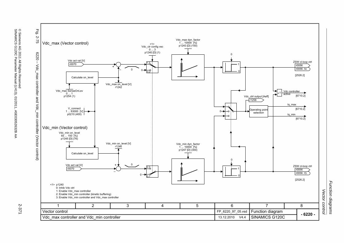
Vector control
Fu
nction dia
grams
2-371
© S
ieme
ns AG
2011 All R
ights Re
servedS
INA
MIC
SG
120C P
aram
eterM
anual (LH
13), 01/2011, A5E
03052632B
AA
Fig. 2
-75
6220 – V
dc_m
ax controlle
r and V
dc_min controller (V
ecto
r control)
- 6220 -Function diagram
87654321FP_6220_97_05.vsdVector control
SINAMICS G120C13.12.2010 V4.4Vdc_max controller and Vdc_min controller
0
11,3
0,2�
+
0
1�
+
0
Iq_max
[6710.2]
Iq_min
[6710.2]
[6710.2]
1
0
02,3
0,1
[2526.2]
[2526.2]
0
0
0
0
Calculate on_level
r0070 Vdc act val [V]
Vdc_max on_level [V]r1242
V_connect1 ... 63000 [V]
p0210 (400)
Vdc_min on_level [V]r1246
r0070 Vdc act val [V]
Vdc_max dyn_factor1 ... 10000 [%]p1243 [D] (100)
Vdc_min dyn_factor1 ... 10000 [%]p1247 [D] (300)
r1258 Vdc_ctrl output [Aeff]
Operating point selection
Vdc controller active
ZSW cl-loop ctrl
r0056r0056
.14
ZSW cl-loop ctrl
r0056r0056
.15
Calculate on_level
<1> p12400: Inhib Vdc ctrl1: Enable Vdc_max controller2: Enable Vdc_min controller (kinetic buffering)3: Enable Vdc_min controller and Vdc_max controller
<1>Vdc_max (Vector control)
Vdc_min (Vector control)
Vdc_ctr config vec0 ... 3
p1240 [D] (1)
Vdc_min on_level65 ... 150 [%]p1245 [D] (76)
Vdc_max SenseOnLev0 ... 1
p1254 (1)
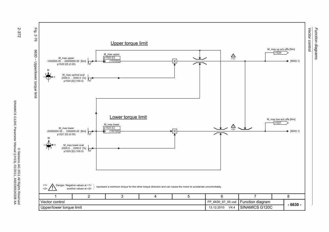
Fu
nctio
n diag
ram
s
Vecto
r control
2-372
© S
iem
ens AG
2011 All R
ights R
eservedS
INA
MIC
SG
120C
Param
eter
Manual (L
H13), 0
1/2011, A5E
03052632B
AA
Fig. 2
-76
6630 – U
pper/lo
wer to
rque lim
it
- 6630 -Function diagram
87654321FP_6630_97_05.vsdVector control
SINAMICS G120C13.12.2010 V4.4Upper/lower torque limit
M
n43
M
n2 1
[6640.1]
[6640.1]
<1>
<1> !
Upper torque limit
Lower torque limit
Danger: Negative values at <1>positive values at <2>
represent a minimum torque for the other torque direction and can cause the motor to accelerate uncontrollably.
M_max upper-1000000.00 ... 20000000.00 [Nm]
p1520 [D] (0.00)
M_max upper
(1520[0])p1522 [C]
M_max lower
(1521[0])p1523 [C]
<2>
<2>!
!
M_max lower-20000000.00 ... 1000000.00 [Nm]
p1521 [D] (0.00)
M_max lower scal-2000.0 ... 2000.0 [%]
p1525 [D] (100.0)
M_max up/mot scal-2000.0 ... 2000.0 [%]
p1524 [D] (100.0)
r1526 M_max up w/o offs [Nm]
r1527 M_max low w/o offs [Nm]
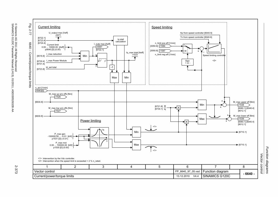
Vector control
Fu
nction dia
grams
2-373
© S
ieme
ns AG
2011 All R
ights Re
servedS
INA
MIC
SG
120C P
aram
eterM
anual (LH
13), 01/2011, A5E
03052632B
AA
Fig. 2
-77
6640 – C
urrent/powe
r/torque lim
its
- 6640 -Function diagram
87654321FP_6640_97_05.vsdVector control
SINAMICS G120C13.12.2010 V4.4Current/power/torque limits
<1>
IqM
22 yx
-1
Min
Max Min
Min
Min
Max
+
-
+
+
+
[6722.1][6723.4][6724.4]
[6630.8]
[6630.8]
[6721.8][6730.1] [6060.1] [6040.4]
[8012.1]
[6710.1]
[3050.8] �
<1><2>
[8016.8]
[6730.4][6731.4]
[6723.8]
[6722.1]
x
y
[6060.1] [6040.4][8012.1]
+
+
<2>
<1>
Max [6710.1]
[3050.8]
n
Iq
Current limiting
I_max reduction
I_max Power Module
Id_set total
Power limiting
Iq stall calculation
Intervention by the Vdc controller.Intervention when the speed limit is exceeded + 2 % n_rated.
Speed limitingKp from speed controller [6040.5]
Tn from speed controller [6040.6]
Speed limiting controller
U_output max [Veff]r0071
Iq_max total [Aeff]r1533
Current limit0.00 ... 10000.00 [Aeff]
p0640 [D] (0.00)
P_max gen-100000.00 ... -0.01 [kW]
p1531 [D] (-0.01)
P_max mot0.00 ... 100000.00 [kW]
p1530 [D] (0.00)
r1538 M_max upper eff [Nm]
r1539 M_max lower eff [Nm]
r1084 n_limit pos eff [1/min]
r1087
n_limit neg eff [1/min]
r1527 M_max low w/o offs [Nm]
r1526 M_max up w/o offs [Nm]
r0067 I_outp max [Aeff]
r0063 n_act [1/min]
[0]
Sign+ or -
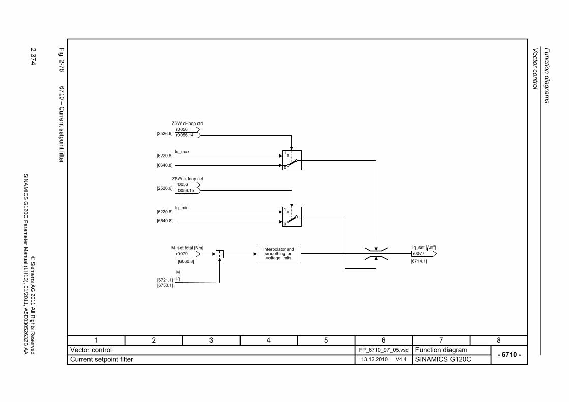
Fu
nctio
n diag
ram
s
Vecto
r control
2-374
© S
iem
ens AG
2011 All R
ights R
eservedS
INA
MIC
SG
120C
Param
eter
Manual (L
H13), 0
1/2011, A5E
03052632B
AA
Fig. 2
-78
6710 – C
urrent setpoin
t filter
- 6710 -Function diagram
87654321FP_6710_97_05.vsdVector control
SINAMICS G120C13.12.2010 V4.4Current setpoint filter
IqM
Iq_max
Iq_min
[6060.8]
[6640.8]
[6220.8]
[6220.8]
[2526.6]
[6640.8]
[6721.1][6730.1]
[6714.1]
0
1
0
1
[2526.6]
ZSW cl-loop ctrl
r0056r0056
.14
ZSW cl-loop ctrl
r0056r0056
.15
r0079 M_set total [Nm]
r0077 Iq_set [Aeff]Interpolator and
smoothing forvoltage limits
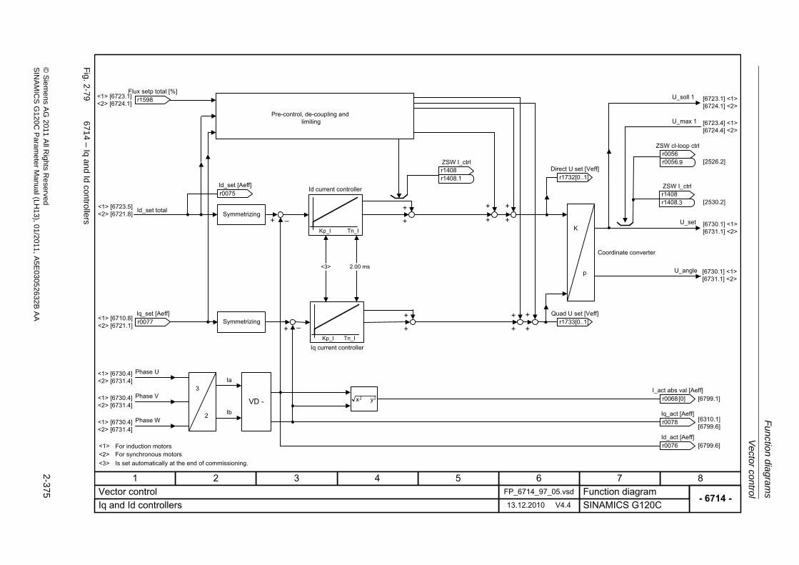
Vector control
Fu
nction dia
grams
2-375
© S
ieme
ns AG
2011 All R
ights Re
servedS
INA
MIC
SG
120C P
aram
eterM
anual (LH
13), 01/2011, A5E
03052632B
AA
Fig. 2
-79
6714 – Iq an
d Id con
trollers
- 6714 -Function diagram
87654321FP_6714_97_05.vsdVector control
SINAMICS G120C13.12.2010 V4.4Iq and Id controllers
Kp_I Tn_I
�
22 yx
Kp_I Tn_I
�
Ia
Ib
VD -
U_max 1
U_soll 1
2
3
[6730.1] <1> [6731.1] <2>
[6730.1] <1> [6731.1] <2>
[6723.1] <1> [6724.1] <2>
[6723.4] <1> [6724.4] <2>
<1> [6730.4]<2> [6731.4]
<1> [6710.8]<2> [6721.1]
<1> [6723.1]<2> [6724.1]
+
+
+
++ +
+
+
+
+ +
+
<1> [6723.5]<2> [6721.8]
<1> [6730.4]<2> [6731.4]
<1> [6730.4]<2> [6731.4]
[6310.1][6799.6]
<1> <2>
p
K
[6799.6]
[2526.2]
+
+
Pre-control, de-coupling andlimiting
Id_set total Symmetrizing
Id current controller
Phase U
Phase V
Phase W
For induction motorsFor synchronous motors
Iq current controller
U_set
U_angle
Coordinate converter
r1598 Flux setp total [%]
ZSW I_ctrl
r1408r1408
.1
r0075 Id_set [Aeff]
r0077 Iq_set [Aeff]
r0076 Id_act [Aeff]
r0078 Iq_act [Aeff]
ZSW I_ctrl
r1408r1408
.3
ZSW cl-loop ctrl
r0056r0056
.9
r0068 I_act abs val [Aeff]
Symmetrizing
[0]
r1733[0..1]Quad U set [Veff]
r1732[0..1]Direct U set [Veff]
[6799.1]
[2530.2]
2.00 ms<3>
<3> Is set automatically at the end of commissioning.
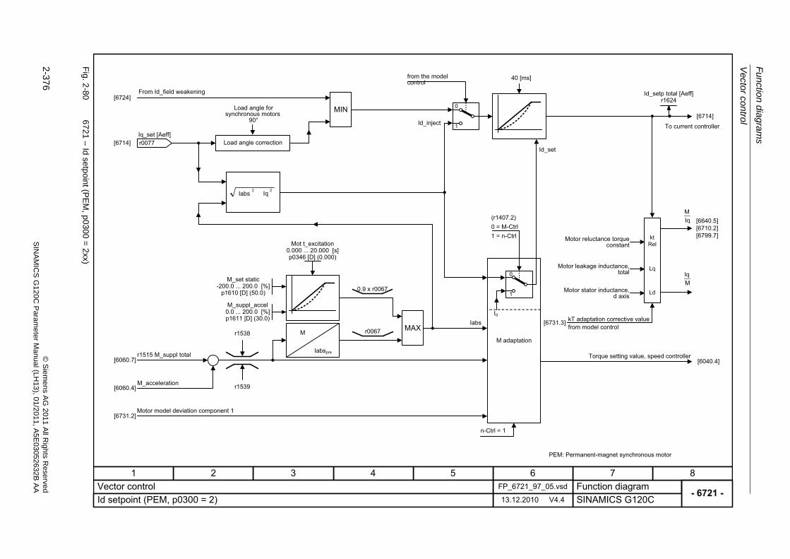
Fu
nctio
n diag
ram
s
Vecto
r control
2-376
© S
iem
ens AG
2011 All R
ights R
eservedS
INA
MIC
SG
120C
Param
eter
Manual (L
H13), 0
1/2011, A5E
03052632B
AA
Fig. 2
-80
6721 – Id setpo
int (PE
M, p0
300=
2xx)
- 6721 -Function diagram
87654321FP_6721_97_05.vsdVector control
SINAMICS G120C13.12.2010 V4.4Id setpoint (PEM, p0300 = 2)
1
0
[6060.7]
[6714]
MAX
MIN
22 IqIabs
[6724]
MIq
[6640.5][6710.2][6799.7]
[6714]
Ld
Lq
kt Rel
[6731.2]
[6040.4]
[6731.3]
[6060.4]
0.9 x r0067
r1538
r1539
r0067
n-Ctrl = 1
Iabspre
M
1
0
Iabs
(r1407.2)0 = M-Ctrl1 = n-Ctrl
Id
Id_inject
IqM
From Id_field weakening
r1515 M_suppl total
M_acceleration
Motor model deviation component 1
Load angle correction
from the model control
M adaptation
To current controller
kT adaptation corrective valuefrom model control
Torque setting value, speed controller
Id_set
Mot t_excitation0.000 ... 20.000 [s]p0346 [D] (0.000)
Id_setp total [Aeff]r1624
PEM: Permanent-magnet synchronous motor
Load angle for synchronous motors
90°
r0077 Iq_set [Aeff]
40 [ms]
Motor reluctance torque constant
Motor leakage inductance, total
Motor stator inductance, d axis
M_set static-200.0 ... 200.0 [%]
p1610 [D] (50.0)
M_suppl_accel0.0 ... 200.0 [%]p1611 [D] (30.0)
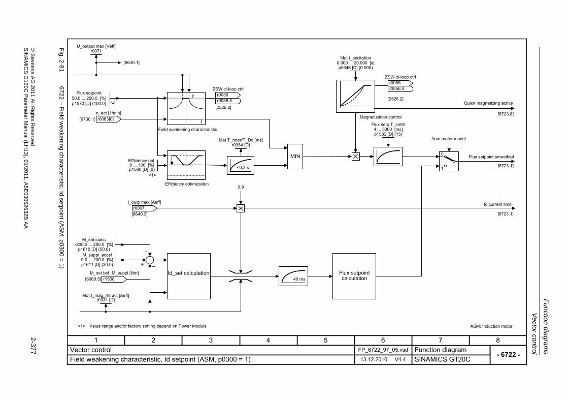
Vector control
Fu
nction dia
grams
2-377
© S
ieme
ns AG
2011 All R
ights Re
servedS
INA
MIC
SG
120C P
aram
eterM
anual (LH
13), 01/2011, A5E
03052632B
AA
Fig. 2
-81
6722 – F
ield w
eake
ning ch
aracteristic, Id setpoin
t (AS
M, p030
0=
1)
- 6722 -Function diagram
87654321FP_6722_97_05.vsdVector control
SINAMICS G120C13.12.2010 V4.4Field weakening characteristic, Id setpoint (ASM, p0300 = 1)
�
0,9
1
0MIN
<0,3 s
f
y
[6060.5]
[6723.1]
[6640.3] [6723.1]
[6730.1]
[6640.1]
+
+
[2526.2]
[2526.2]
U_output max [Veff]r0071
Flux setpoint50.0 ... 200.0 [%]p1570 [D] (100.0)
ZSW cl-loop ctrl
r0056r0056
.8
Mot T_rotor/T_Dd [ms]r0384 [D]
r1508 M_set bef. M_suppl [Nm]
Mot I_mag_rtd act [Aeff]r0331 [D]
ZSW cl-loop ctrl
r0056r0056
.4
Flux setp T_smth4 ... 5000 [ms]p1582 [D] (15)
Field weakening characteristic
Efficiency optimization
Id_set calculation Flux setpoint calculation
Magnetization control
Id current limit
ASM: Induction motor
Mot t_excitation0.000 ... 20.000 [s]p0346 [D] (0.000)
r0067 I_outp max [Aeff]
r0063 n_act [1/min]
[0]
Quick magnetizing active
[6723.8]
Value range and/or factory setting depend on Power Module<1>
<1>
40 ms
Flux setpoint smoothed
from motor model
Efficiency opt.0 ... 100 [%]p1580 [D] (0)
M_set static-200.0 ... 200.0 [%]
p1610 [D] (50.0)M_suppl_accel
0.0 ... 200.0 [%]p1611 [D] (30.0)
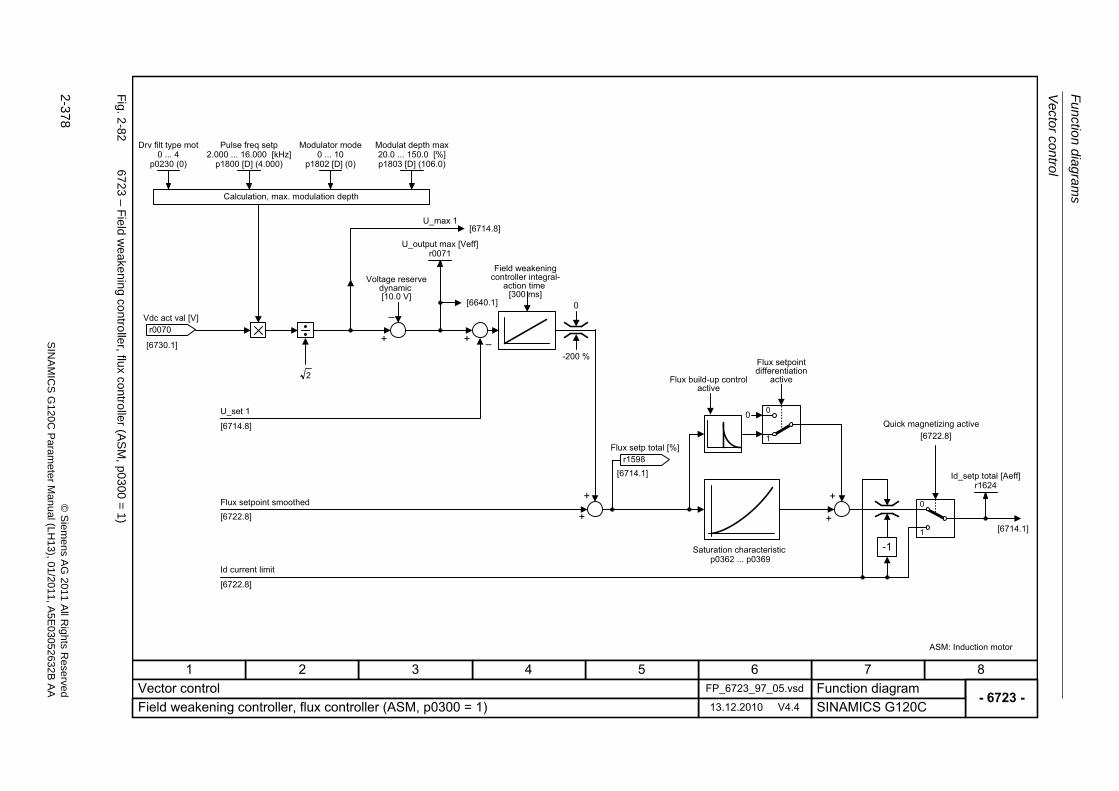
Fu
nctio
n diag
ram
s
Vecto
r control
2-378
© S
iem
ens AG
2011 All R
ights R
eservedS
INA
MIC
SG
120C
Param
eter
Manual (L
H13), 0
1/2011, A5E
03052632B
AA
Fig. 2
-82
6723 – F
ield w
eake
ning co
ntrolle
r, flux contro
ller (A
SM
, p0300
=1)
- 6723 -Function diagram
87654321FP_6723_97_05.vsdVector control
SINAMICS G120C13.12.2010 V4.4Field weakening controller, flux controller (ASM, p0300 = 1)
�
2
-1
1
00
U_max 1
[6722.8]
++
+
+
[6714.8]
[6730.1]
[6714.8]
+
+
�
[6714.1]
0
-200 %
[6722.8]
[6640.1]
Calculation, max. modulation depth
U_set 1
Id current limit
Saturation characteristicp0362 ... p0369
ASM: Induction motor
r0070 Vdc act val [V]
U_output max [Veff]r0071
r1598 Flux setp total [%]
Drv filt type mot0 ... 4
p0230 (0)
Pulse freq setp2.000 ... 16.000 [kHz]
p1800 [D] (4.000)
1
0
[6722.8]
[6714.1]
Quick magnetizing active
Flux setpoint smoothed
Id_setp total [Aeff]r1624
Voltage reserve dynamic[10.0 V]
Field weakening controller integral-
action time[300 ms]
Flux build-up control active
Flux setpoint differentiation
active
Modulator mode0 ... 10
p1802 [D] (0)
Modulat depth max20.0 ... 150.0 [%]p1803 [D] (106.0)
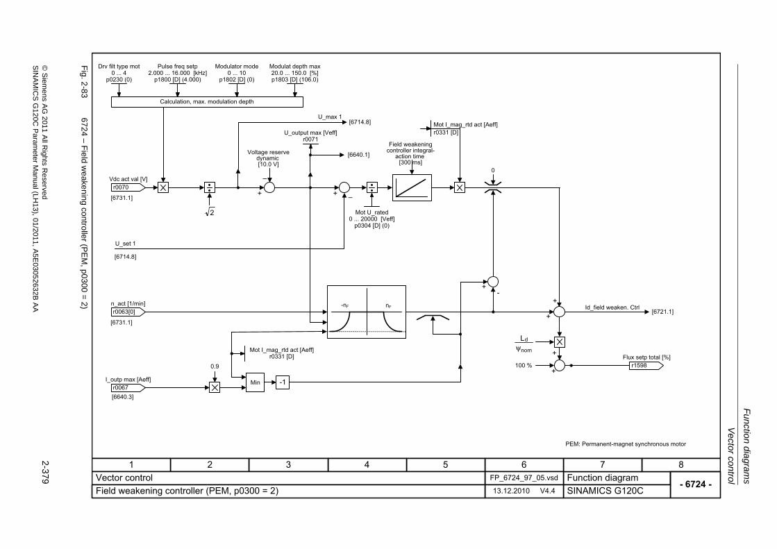
Vector control
Fu
nction dia
grams
2-379
© S
ieme
ns AG
2011 All R
ights Re
servedS
INA
MIC
SG
120C P
aram
eterM
anual (LH
13), 01/2011, A5E
03052632B
AA
Fig. 2
-83
6724 – F
ield w
eake
ning co
ntrolle
r (PE
M, p03
00=
2)
- 6724 -Function diagram
87654321FP_6724_97_05.vsdVector control
SINAMICS G120C13.12.2010 V4.4Field weakening controller (PEM, p0300 = 2)
�
2
U_max 1
[6640.3]
++
+
[6640.1]
[6714.8]
[6731.1]
[6714.8]
�
[6731.1]
0
+-
+
0.9
Min -1
-nF nF[6721.1]
+
+100 %
nom
dLψ
U_set 1
Id_field weaken. Ctrl
PEM: Permanent-magnet synchronous motor
r0070 Vdc act val [V]
U_output max [Veff]r0071
Mot U_rated0 ... 20000 [Veff]
p0304 [D] (0)
Mot I_mag_rtd act [Aeff]r0331 [D]
r1598 Flux setp total [%]
Drv filt type mot0 ... 4
p0230 (0)
Pulse freq setp2.000 ... 16.000 [kHz]
p1800 [D] (4.000)
Calculation, max. modulation depth
Mot I_mag_rtd act [Aeff]r0331 [D]
r0067 I_outp max [Aeff]
r0063 n_act [1/min]
[0]
Voltage reserve dynamic[10.0 V]
Field weakening controller integral-
action time[300 ms]
Modulator mode0 ... 10
p1802 [D] (0)
Modulat depth max20.0 ... 150.0 [%]p1803 [D] (106.0)
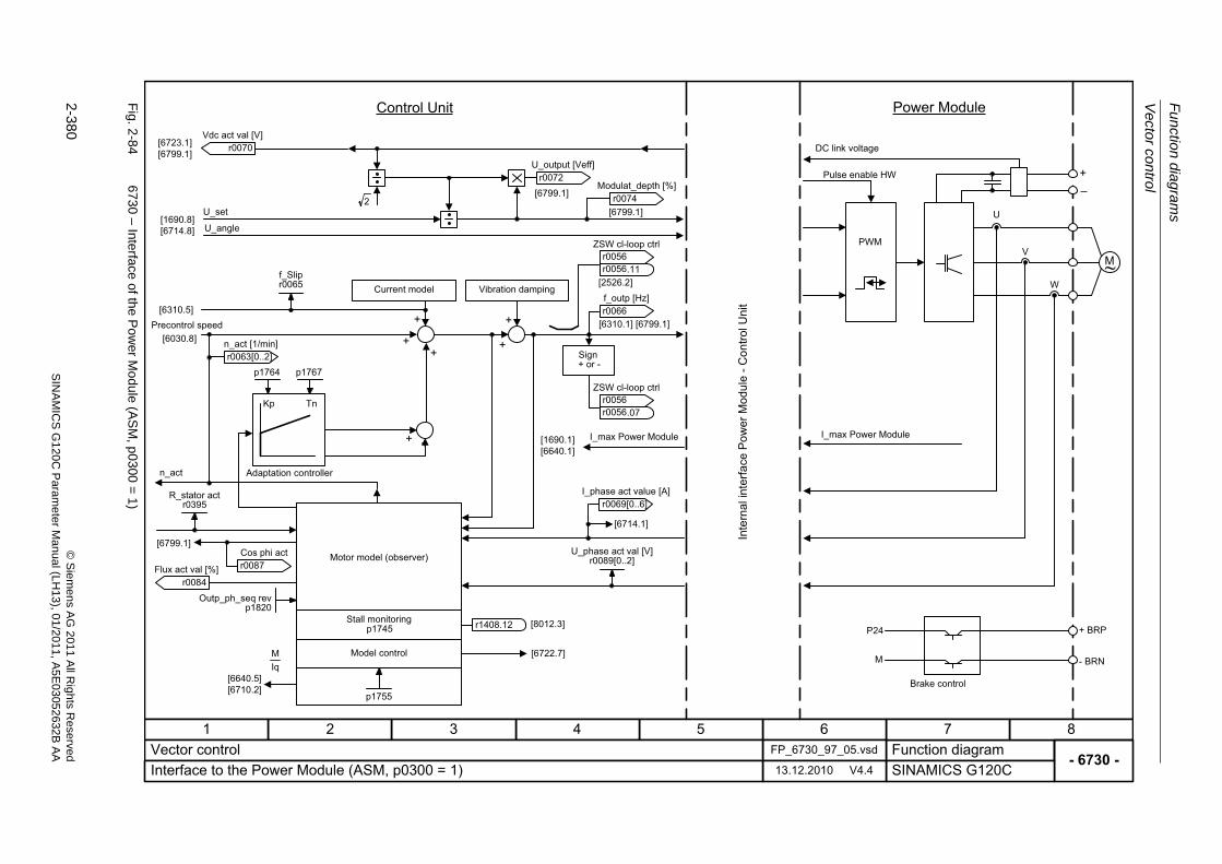
Fu
nctio
n diag
ram
s
Vecto
r control
2-380
© S
iem
ens AG
2011 All R
ights R
eservedS
INA
MIC
SG
120C
Param
eter
Manual (L
H13), 0
1/2011, A5E
03052632B
AA
Fig. 2
-84
6730 – Interface of th
e Po
wer M
odule (A
SM
, p0300
=1
)
- 6730 -Function diagram
87654321FP_6730_97_05.vsdVector control
SINAMICS G120C13.12.2010 V4.4Interface to the Power Module (ASM, p0300 = 1)
[6723.1][6799.1]
PWM
M~
+�
U
V
W
+ BRP
- BRN
P24
M
p1755
Kp Tn
p1764
2
[1690.1][6640.1]
IqM [6722.7]
r1408.12
[6310.5]
[6640.5][6710.2]
[6714.1]
+ +
+
+
++
+
[8012.3]
[1690.8][6714.8]
[6799.1]
[6799.1]
[6799.1]
[2526.2]
Precontrol speed
n_act Adaptation controller
Motor model (observer)
Stall monitoring
Model control
Vibration damping
Sign+ or -
I_max Power Module
Brake control
I_max Power Module
Pulse enable HW
DC link voltage
Power ModuleControl Unit
U_set
U_angle
r0070 Vdc act val [V]
r0072 U_output [Veff]
r0074 Modulat_depth [%]
f_Slipr0065
ZSW cl-loop ctrl
r0056r0056
.11
r0066 f_outp [Hz]
ZSW cl-loop ctrl
r0056r0056
.07
R_stator actr0395
r0087 Cos phi act
r0084 Flux act val [%]
[6030.8][6310.1] [6799.1]
Current model
Outp_ph_seq revp1820
p1767
U_phase act val [V]r0089[0..2]
r0069[0..6]I_phase act value [A]
r0063[0..2]n_act [1/min]
p1745
Inte
rnal
inte
rface
Pow
er M
odul
e -C
ontro
l Uni
t
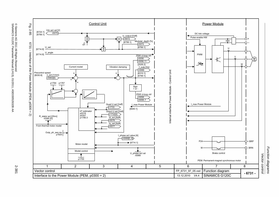
Vector control
Fu
nction dia
grams
2-381
© S
ieme
ns AG
2011 All R
ights Re
servedS
INA
MIC
SG
120C P
aram
eterM
anual (LH
13), 01/2011, A5E
03052632B
AA
Fig. 2
-85
6731 – Interface of th
e Po
wer M
odule (P
EM
, p0300
=2
)
- 6731 -Function diagram
87654321FP_6731_97_05.vsdVector control
SINAMICS G120C13.12.2010 V4.4Interface to the Power Module (PEM, p0300 = 2)
PWM
M~
+�
U
V
W
+ BRP
- BRN
P24
M
2
I_max Power Module
[6640.1]
[6310.1][6799.1]
[6714.8]
[6714.8]
[6799.1]
[6799.1]
[6724.1][6799.1]
[6714.1]
p1764 p1767
+ +
++
[2526.2]
Precontrol speed
Brake control
I_max Power Module
Pulse enable HW
DC link voltage
Power ModuleControl Unit
U_set
U_angle
Motor model
Model control
kT estimatorp0316p0357p1780.3
PEM: Permanent-magnet synchronous motor
r0070 Vdc act val [V]
r0072 U_output [Veff]
r0074 Modulat_depth [%]
ZSW cl-loop ctrl
r0056r0056
.11
r0066 f_outp [Hz]
ZSW cl-loop ctrl
r0056r0056
.7
U_phase act valr0089
r1733 Quad U set [Veff]
r0077 Iq_set [Aeff]r0076 Id_act [Aeff]R_stator act [Ohm]
r0395 [D]
From thermal motor model
Vibration damping
Sign+ or -
Current model
[6030.8]
p1755
Outp_ph_seq revp1820
r0063 n_act [1/min]
[0]
r1732 Direct U set [Veff]
[0]
r0069[0..6]I_phase act value [A]
Inte
rnal
inte
rface
Pow
er M
odul
e -C
ontro
l Uni
t
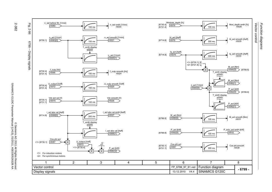
Fu
nctio
n diag
ram
s
Vecto
r control
2-382
© S
iem
ens AG
2011 All R
ights R
eservedS
INA
MIC
SG
120C
Param
eter
Manual (L
H13), 0
1/2011, A5E
03052632B
AA
Fig. 2
-86
6799 – D
isplay sig
nals
- 6799 -Function diagram
87654321FP_6799_97_61.vsdVector control
SINAMICS G120C13.12.2010 V4.4Display signals
100 ms
[6730.1]
[6714.8]
[6714.8]
[6799.8]
300 ms100 ms
100 ms
100 ms
100 ms
300 ms
100 ms
300 ms
100 ms
[6730.4][6731.4]
[6730.4][6731.4]
[6730.1][6731.1]
[6730.4][6731.4]r0060
n_set before filt. [1/min]
r0066 f_outp [Hz]
r0072 U_output [Veff]
r0070 Vdc act val [V]
r0074 Modulat_depth [%]
r0076 Id_act [Aeff]
r0078 Iq_act [Aeff]
n_set smth [1/min]r0020
r0021 n_act smooth [1/min]
f_outp smooth [Hz]r0024
r0025 U_outp smooth [Veff]
r0026 Vdc smooth [V]
r0027 I_act abs val smth [Aeff]
Mod_depth smth [%]r0028
Id_act smooth [Aeff]r0029
Iq_act smooth [Aeff]r0030
M_act smooth [Nm]r0031
T_smth displayp0045
r0063[1]n_act [1/min]
300 ms[6730.1][6731.1] r0087
Cos phi act Cos phi smooth
r0038
[6799.8] 100 ms r0032 P_actv_act smth [kW]
r0063 n_act [1/min]
[0]
r0068 I_act abs val [Aeff]
[0]r0080 M_act [Nm]
[0]
r0082 P_act [kW]
[0]
T_smth displayp0045
r0068 I_act abs val [Aeff]
[1]
3<1> [6730.4]
r0072 U_output [Veff]<1> [6730.1] r0087
Cos phi act
r0082 P_act [kW]
[2]
IqM<1> [6730.1]
<2> [6721.8]
r0080 M_act [Nm]
[0]
r0080 M_act [Nm]
[1]
T_smth displayp0045
r0082 P_act [kW]
[0]
r0082 P_act [kW]
[1]
T_smth displayp0045
r0063 n_act [1/min]
[0]
<1> <2>
For induction motorsFor synchronous motors
[6714.8]
[6799.6]
[6799.6]
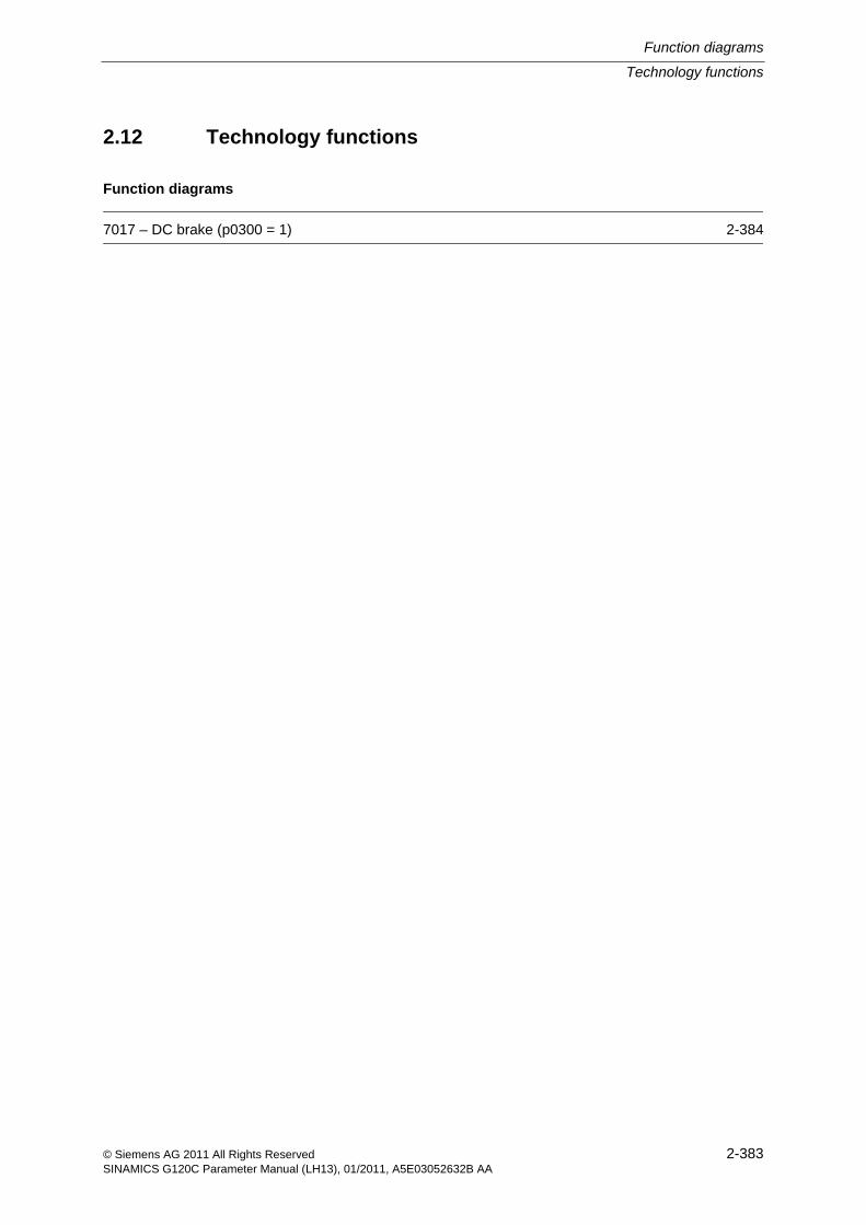
Technology functions
Function diagrams
2-383© Siemens AG 2011 All Rights ReservedSINAMICS G120C Parameter Manual (LH13), 01/2011, A5E03052632B AA
2.12 Technology functions
Function diagrams
7017 – DC brake (p0300 = 1) 2-384
Fu
nctio
n diag
ram
s
Te
chn
ology fu
nctio
ns
2-384
© S
iem
ens AG
2011 All R
ights R
eservedS
INA
MIC
SG
120C
Param
eter
Manual (L
H13), 0
1/2011, A5E
03052632B
AA
Fig. 2
-87
7017 – D
C b
rake (p0300
=1)
- 7017 -Function diagram
87654321FP_7017_97_05.vsdTechnology functions
SINAMICS G120C13.12.2010 V4.4DC brake (p0300 = 1)
MIN
�
[6714]
Kp Tn
Current actual values
To control [6730]To V/f characteristic [6300]
r0072 U_output [Veff]
r0068[0..1]I_act abs val [Aeff]
p0347
p1234
p1233
p1232
p0347
p1232
<1> <2><3>
<1> <2>
0
4
t
t
t
t
OFF
p1231 = 5 (OFF1/OFF3)
Pulse disable
Pulse disable
n_actn_set
|I_set|
n_actn_set
Braking response
|I_set|
|I_act|
The DC braking current is determined during automatic calculation (p0340 = 1).The de-magnetization time is determined during automatic calculation (p0340 = 1, 3).
To pulse disableTo sequencer
From I²t control [8014]
|I_set|
(0)
DCBRK Aktp1230 [C]
DCBRK config0 ... 14
p1231 [D] (0)
DCBRK I_brake0.00 ... 10000.00 [Aeff]
p1232 [D] (0.00)
DCBRK time0.0 ... 3600.0 [s]p1233 [D] (1.0)
DCBRK n_start0.00 ... 210000.00 [1/min]
p1234 [D] (210000.00)
DCBRK ZSW
r1239r1239
.10
DCBRK ZSW
r1239r1239
.8
DCBRK ZSW
r1239r1239
Mot t_de-excitat.0.000 ... 20.000 [s]p0347 [D] (0.000)
14
To pulse disableTo sequencer
To pulse disableTo sequencer
|I_act|
p1234
p1233
p1232
p0347
t
t
Pulse disablen_actn_set
|I_set|
|I_act|
DC brake fault response
p1231 = 4 (control command)
DCBRK ZSW
r1239r1239
DCBRK ZSW
r1239r1239
DC braking when starting speed for DC braking (p1234) is fallen below.
<3>
Technology controller
Function diagrams
2-385© Siemens AG 2011 All Rights ReservedSINAMICS G120C Parameter Manual (LH13), 01/2011, A5E03052632B AA
2.13 Technology controller
Function diagrams
7950 – Fixed values, binary selection (p2216 = 2) 2-386
7951 – Fixed values, direct selection (p2216 = 1) 2-387
7954 – Motorized potentiometer 2-388
7958 – Closed-loop control 2-389
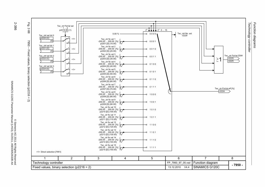
Fu
nctio
n diag
ram
s
Te
chn
ology co
ntro
ller
2-386
© S
iem
ens AG
2011 All R
ights R
eservedS
INA
MIC
SG
120C
Param
eter
Manual (L
H13), 0
1/2011, A5E
03052632B
AA
Fig. 2
-88
7950 – F
ixed va
lues, binary selection (p22
16=
2)
- 7950 -Function diagram
87654321FP_7950_97_05.vsdTechnology controller
SINAMICS G120C13.12.2010 V4.4Fixed values, binary selection (p2216 = 2)
0 1 1 0
1 0 1 0
1 1 0 0
1 1 1 0
0 0 0 1
0 0 1 0
0 0 0 0
0 1 0 0
1 0 0 0
0.00 %
0 1 1 1
1 1 1 1
1 1 0 1
1 0 1 1
0 0 1 1
0 1 0 1
1 0 0 1
0 ... 152023
Tec_ctrl No. actr2229
r2224 Tec_ctr FixVal eff [%]
Tec_ctr fix val 1-200.00 ... 200.00 [%]
p2201 [D] (10.00)Tec_ctr fix val 2
-200.00 ... 200.00 [%]p2202 [D] (20.00)Tec_ctr fix val 3
-200.00 ... 200.00 [%]p2203 [D] (30.00)Tec_ctr fix val 4
-200.00 ... 200.00 [%]p2204 [D] (40.00)Tec_ctr fix val 5
-200.00 ... 200.00 [%]p2205 [D] (50.00)Tec_ctr fix val 6
-200.00 ... 200.00 [%]p2206 [D] (60.00)Tec_ctr fix val 7
-200.00 ... 200.00 [%]p2207 [D] (70.00)Tec_ctr fix val 8
-200.00 ... 200.00 [%]p2208 [D] (80.00)Tec_ctr fix val 9
-200.00 ... 200.00 [%]p2209 [D] (90.00)Tec_ctr fix val 10
-200.00 ... 200.00 [%]p2210 [D] (100.00)Tec_ctr fix val 11
-200.00 ... 200.00 [%]p2211 [D] (110.00)Tec_ctr fix val 12
-200.00 ... 200.00 [%]p2212 [D] (120.00)Tec_ctr fix val 13
-200.00 ... 200.00 [%]p2213 [D] (130.00)Tec_ctr fix val 14
-200.00 ... 200.00 [%]p2214 [D] (140.00)Tec_ctr fix val 15
-200.00 ... 200.00 [%]p2215 [D] (150.00)
Tec_ctr FixVal ZSW
r2225r2225
(0)
Tec_ctrl sel bit 0p2220 [C]
(0)
Tec_ctrl sel bit 1p2221 [C]
(0)
Tec_ctrl sel bit 2p2222 [C]
(0)
Tec_ctrl sel bit 3p2223 [C]
1
1
1
1
2
2
2
2
Tec_ctr FixVal sel1 ... 2
p2216 [D] (1)
<1> Direct selection [7951]
<1>
<1>
<1>
<1>
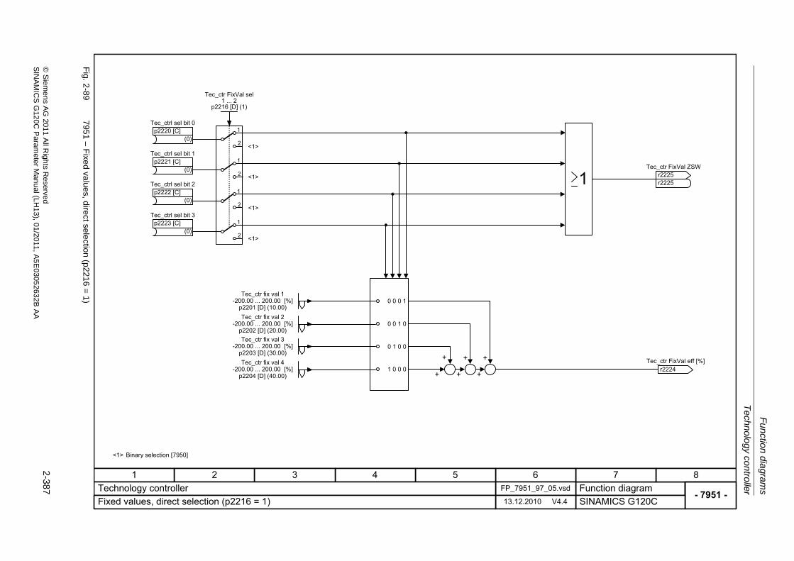
Technology controller
Fu
nction dia
grams
2-387
© S
ieme
ns AG
2011 All R
ights Re
servedS
INA
MIC
SG
120C P
aram
eterM
anual (LH
13), 01/2011, A5E
03052632B
AA
Fig. 2
-89
7951 – F
ixed va
lues, direct selection
(p2216
=1
)
- 7951 -Function diagram
87654321FP_7951_97_05.vsdTechnology controller
SINAMICS G120C13.12.2010 V4.4Fixed values, direct selection (p2216 = 1)
+ + +
0 0 0 1
0 0 1 0
1 0 0 0
0 1 0 0
+ + +r2224
Tec_ctr FixVal eff [%]
Tec_ctr fix val 1-200.00 ... 200.00 [%]
p2201 [D] (10.00)Tec_ctr fix val 2
-200.00 ... 200.00 [%]p2202 [D] (20.00)Tec_ctr fix val 3
-200.00 ... 200.00 [%]p2203 [D] (30.00)Tec_ctr fix val 4
-200.00 ... 200.00 [%]p2204 [D] (40.00)
Tec_ctr FixVal ZSW
r2225r2225
(0)
Tec_ctrl sel bit 0p2220 [C]
(0)
Tec_ctrl sel bit 1p2221 [C]
(0)
Tec_ctrl sel bit 2p2222 [C]
(0)
Tec_ctrl sel bit 3p2223 [C]
1
1
1
1
2
2
2
2
Tec_ctr FixVal sel1 ... 2
p2216 [D] (1)
<1> Binary selection [7950]
<1>
<1>
<1>
<1>
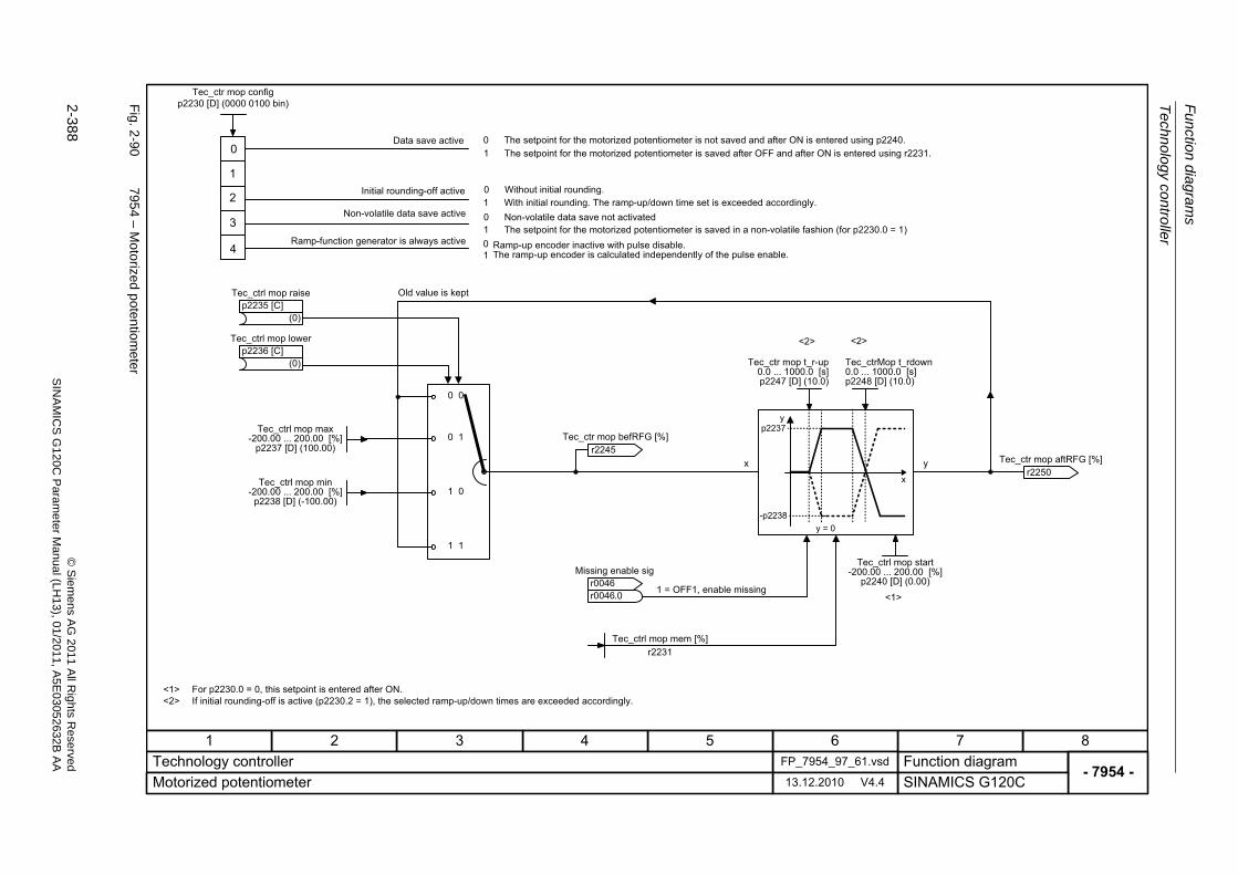
Fu
nctio
n diag
ram
s
Te
chn
ology co
ntro
ller
2-388
© S
iem
ens AG
2011 All R
ights R
eservedS
INA
MIC
SG
120C
Param
eter
Manual (L
H13), 0
1/2011, A5E
03052632B
AA
Fig. 2
-90
7954 – M
oto
rized potentio
mete
r
- 7954 -Function diagram
87654321FP_7954_97_61.vsdTechnology controller
SINAMICS G120C13.12.2010 V4.4Motorized potentiometer
<1><2>
<1>
<2> <2>
x y
0 0
0 1
1 0
1 1
yp2237
-p2238
x
y = 0
0
1
2
3
Data save active
Initial rounding-off active
Non-volatile data save active
0 The setpoint for the motorized potentiometer is not saved and after ON is entered using p2240.1 The setpoint for the motorized potentiometer is saved after OFF and after ON is entered using r2231.
0 Without initial rounding.1 With initial rounding. The ramp-up/down time set is exceeded accordingly.0 Non-volatile data save not activated1 The setpoint for the motorized potentiometer is saved in a non-volatile fashion (for p2230.0 = 1)
Old value is kept
1 = OFF1, enable missing
For p2230.0 = 0, this setpoint is entered after ON.If initial rounding-off is active (p2230.2 = 1), the selected ramp-up/down times are exceeded accordingly.
(0)
Tec_ctrl mop raisep2235 [C]
(0)
Tec_ctrl mop lowerp2236 [C]
Tec_ctrl mop max-200.00 ... 200.00 [%]
p2237 [D] (100.00)
Tec_ctrl mop min-200.00 ... 200.00 [%]
p2238 [D] (-100.00)
r2245 Tec_ctr mop befRFG [%]
Tec_ctr mop t_r-up0.0 ... 1000.0 [s]p2247 [D] (10.0)
Tec_ctrMop t_rdown0.0 ... 1000.0 [s]p2248 [D] (10.0)
Tec_ctrl mop start-200.00 ... 200.00 [%]
p2240 [D] (0.00)
Tec_ctrl mop mem [%]r2231
Missing enable sig
r0046r0046
r2250 Tec_ctr mop aftRFG [%]
Tec_ctr mop configp2230 [D] (0000 0100 bin)
.0
4 01
Ramp-function generator is always active Ramp-up encoder inactive with pulse disable.The ramp-up encoder is calculated independently of the pulse enable.
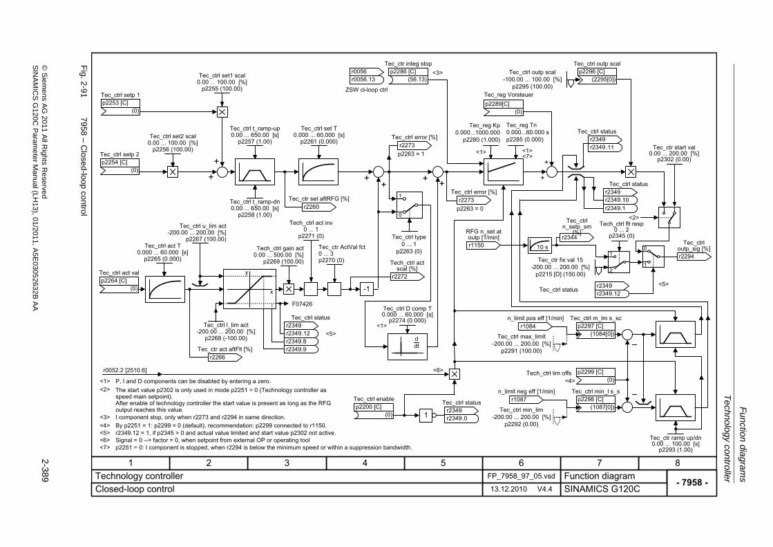
Technology controller
Fu
nction dia
grams
2-389
© S
ieme
ns AG
2011 All R
ights Re
servedS
INA
MIC
SG
120C P
aram
eterM
anual (LH
13), 01/2011, A5E
03052632B
AA
Fig. 2
-91
7958 – C
losed-loop
contro
l
- 7958 -Function diagram
87654321FP_7958_97_05.vsdTechnology controller
SINAMICS G120C13.12.2010 V4.4Closed-loop control
+
+
++
<1>
<1>
<1>
+
ddt
Tec_reg Kp0.000...1000.000
p2280 (1.000)
<1>
Tec_reg Tn0.000...60.000 sp2285 (0.000)
+
+
Tec_reg Vorsteuer
(0)p2289[C]
1
+
p2263 = 1
p2263 = 0
x
y
F07426
-1
P, I and D components can be disabled by entering a zero.
Tec_ctrl set1 scal0.00 ... 100.00 [%]
p2255 (100.00)Tec_ctrl setp 1
(0)p2253 [C]
Tec_ctrl setp 2
(0)p2254 [C]
Tec_ctrl set2 scal0.00 ... 100.00 [%]
p2256 (100.00)
Tec_ctrl t_ramp-up0.00 ... 650.00 [s]
p2257 (1.00)
Tec_ctrl t_ramp-dn0.00 ... 650.00 [s]
p2258 (1.00)
Tec_ctrl set T0.000 ... 60.000 [s]
p2261 (0.000)
r2260 Tec_ctr set aftRFG [%]
r2273 Tec_ctrl error [%]
r2273 Tec_ctrl error [%]
Tec_ctrl outp scal
(2295[0])p2296 [C]
Tec_ctrl m_lm s_sc
(1084[0])p2297 [C]
Tec_ctrl min_l s_s
(1087[0])p2298 [C]
Tec_ctr ramp up/dn0.00 ... 100.00 [s]
p2293 (1.00)
Tec_ctrl status
r2349r2349
.0(0)
Tec_ctrl enablep2200 [C]
Tec_ctrl D comp T0.000 ... 60.000 [s]
p2274 (0.000)
Tec_ctrl type0 ... 1
p2263 (0)
Tec_ctrl l_lim act-200.00 ... 200.00 [%]
p2268 (-100.00)
r2266 Tec_ctr act aftFlt [%]
Tech_ctrl gain act0.00 ... 500.00 [%]
p2269 (100.00)
Tec_ctrl act T0.000 ... 60.000 [s]
p2265 (0.000)
Tec_ctr ActVal fct0 ... 3p2270 (0)
Tec_ctrl outp scal-100.00 ... 100.00 [%]
p2295 (100.00)
<4>
Tec_ctrl status
r2349r2349
.10
Tec_ctrl status
r2349r2349
.11
r0052.2 [2510.6]
Tec_ctr start val0.00 ... 200.00 [%]
p2302 (0.00)
ZSW cl-loop ctrl
r0056r0056
.13<3>
<2> The start value p2302 is only used in mode p2251 = 0 (Technology controller as speed main setpoint).After enable of technology controller the start value is present as long as the RFG output reaches this value.
<3> I component stop, only when r2273 and r2294 in same direction.<4> By p2251 = 1: p2299 = 0 (default), recommendation: p2299 connected to r1150.
Tec_ctrl u_lim act-200.00 ... 200.00 [%]
p2267 (100.00)
Tech_ctrl lim offs(0)
p2299 [C]
(56.13)
Tec_ctr integ stopp2286 [C]
Tech_ctrl act inv0 ... 1
p2271 (0)
Tec_ctrl status
r2349r2349
.12r2349.8r2349.9
<5> r2349.12 = 1, if p2345 > 0 and actual value limited and start value p2302 not active.
Tec_ctrl act val
(0)p2264 [C]
1
0r2349.1
0
1
Tec_ctrl status r2349r2349
.12
Tec_ctr fix val 15-200.00 ... 200.00 [%]
p2215 [D] (150.00)
10 s1
2
<2>Tech_ctrl flt resp
0 ... 2p2345 (0)
<5>
<5>
r1150
RFG n_set at outp [1/min]
r2272
Tech_ctrl act scal [%]
r2294
Tec_ctrl outp_sig [%]
Tec_ctrl max_limit-200.00 ... 200.00 [%]
p2291 (100.00)
r1084 n_limit pos eff [1/min]
Tec_ctrl min_lim-200.00 ... 200.00 [%]
p2292 (0.00)
r1087 n_limit neg eff [1/min]
<6> Signal = 0 --> factor = 0, when setpoint from external OP or operating tool
<6>
r2344
Tec_ctrl n_setp_sm
[%]
<7> p2251 = 0: I component is stopped, when r2294 is below the minimum speed or within a suppression bandwidth.
<7>
Function diagrams
Signals and monitoring functions
2-390 © Siemens AG 2011 All Rights ReservedSINAMICS G120C Parameter Manual (LH13), 01/2011, A5E03052632B AA
2.14 Signals and monitoring functions
Function diagrams
8010 – Speed signals 1 2-391
8011 – Speed signals 2 2-392
8012 – Torque signals, motor locked/stalled 2-393
8014 – Thermal monitoring, power module 2-394
8016 – Thermal monitoring, motor 2-395
8017 – Thermal I2t motor model (PEM, p0300 = 2xx) 2-396
8020 – Monitoring functions 1 2-397
8021 – Monitoring functions 2 2-398
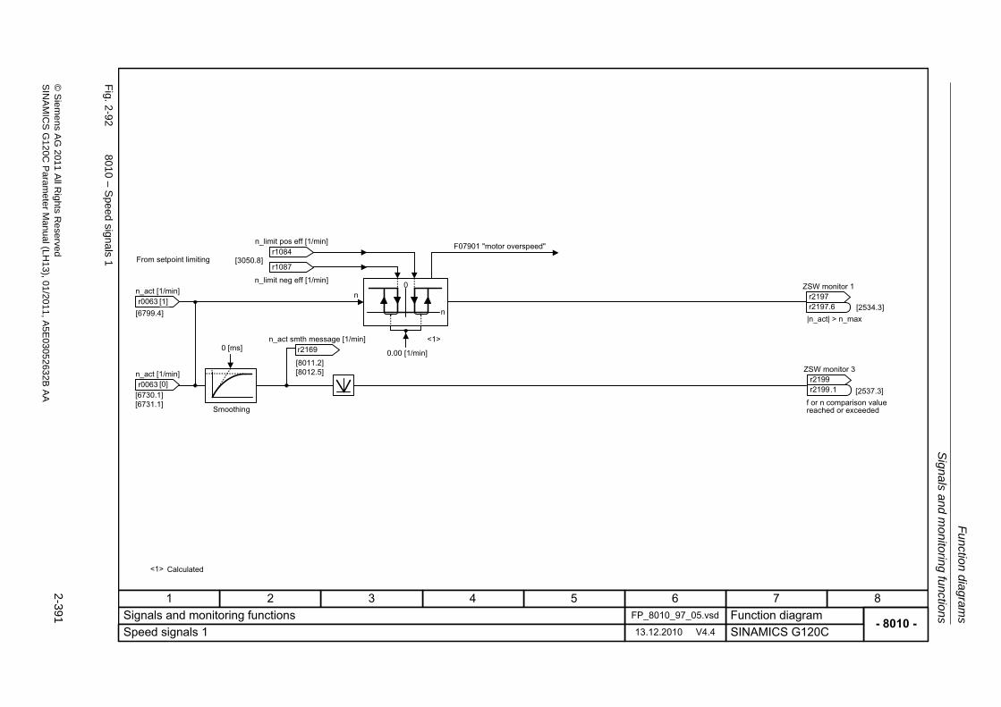
Sig
nals an
d m
onito
ring
functio
ns
Fu
nction dia
grams
2-391
© S
ieme
ns AG
2011 All R
ights Re
servedS
INA
MIC
SG
120C P
aram
eterM
anual (LH
13), 01/2011, A5E
03052632B
AA
Fig. 2
-92
8010
– S
peed sign
als1
- 8010 -Function diagram
87654321FP_8010_97_05.vsdSignals and monitoring functions
SINAMICS G120C13.12.2010 V4.4Speed signals 1
[8011.2][8012.5]
[6730.1][6731.1]
[3050.8]
[2534.3]
<1>
n
n0
From setpoint limiting
F07901 "motor overspeed"
Smoothing
Calculated
r0063 n_act [1/min]
r0063 n_act [1/min]
r2169 n_act smth message [1/min]
ZSW monitor 1
r2197r2197
.6
ZSW monitor 3
r2199r2199
.1
r1084 n_limit pos eff [1/min]
r1087
n_limit neg eff [1/min]
[0]
[1][6799.4]
f or n comparison value reached or exceeded
|n_act| > n_max
[2537.3]
0 [ms]0.00 [1/min]
<1>
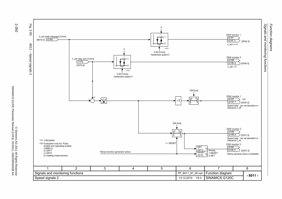
Fu
nctio
n diag
ram
s
Sign
als a
nd m
onitoring
functio
ns
2-392
© S
iem
ens AG
2011 All R
ights R
eservedS
INA
MIC
SG
120C
Param
eter
Manual (L
H13), 0
1/2011, A5E
03052632B
AA
Fig. 2
-93
8011
– S
peed sign
als2
- 8011 -Function diagram
87654321FP_8011_97_05.vsdSignals and monitoring functions
SINAMICS G120C13.12.2010 V4.4Speed signals 2
[8010.2]
<1> CalculatedEvaluation only for: Pulse enable and operating enable (r0899.2)or OFF1 or OFF3 or rotating measurement.
r2169 n_act smth message [1/min]
ZSW monitor 2
r2198r2198
.5
ZSW monitor 1
r2197r2197
.7
ZSW monitor 1
r2197r2197
.3
[2534.3]
n_act >= 0
n_set > 0
Speed setp - act val deviation in tolerance t_off
[2536.3]
0
1
[2534.3]
<1>
[3070.8] 0
1
+� 0 T1
T 0ZSW monitor 3
r2199r2199
.4 [2537.3]Speed setp - act val deviation in tolerance t_on
Priority1 RESET2 SET
[2537.3]SET(Q=1)RESET(Q=0)
Q
Q
ZSW monitor 3
r2199r2199
.5
1 = RESET
Ramp-up/ramp-down completed
<1>
<2>
<2>
0
0
r1170 n_ctrl setp sum [1/min]
2.00 [1/min]Hysteresis speed 3
2.00 [1/min]Hysteresis speed 3
200 [ms]
200 [ms]
Ramp-function generator active
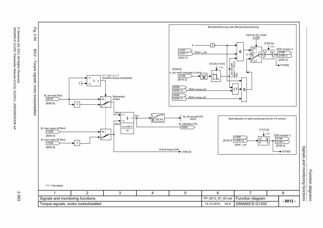
Sig
nals an
d m
onito
ring
functio
ns
Fu
nction dia
grams
2-393
© S
ieme
ns AG
2011 All R
ights Re
servedS
INA
MIC
SG
120C P
aram
eterM
anual (LH
13), 01/2011, A5E
03052632B
AA
Fig. 2
-94
8012 – T
orque signa
ls, motor locked
/stalled
- 8012 -Function diagram
87654321FP_8012_97_05.vsdSignals and monitoring functions
SINAMICS G120C13.12.2010 V4.4Torque signals, motor locked/stalled
[6640.8]
[6640.8]0
1
x1
x2
y [%][Nm]
0
1
21
x% 100x •
[Nm]
[1550.8]
100 ms
T 0
F07902
[2536.3]
[6730.3]
T 0
[8010.2]
F07900
[2522.7][2536.3]
[6060.8]
x1
x2
y
&
&
[2526.6]
x1 > x2 = y = 1 (positive torque requested)
Requested torque
Actual torque limit
Blockiererkennung oder Blockierüberwachung
n_ac
t sm
ooth
sign
al <
120
[1/
min
]
Stall detection or stall monitoring (not for V/f control)
r0079 M_set total [Nm]
r1538 M_max upper eff [Nm]
r1539 M_max lower eff [Nm]
M_util smooth [%]r0033
r0081 M_Utilization [%]
ZSW n_ctrlr1407r1407
.7
r2169 n_act smth message [1/min]
ZSW cl-loop ctrlr0056r0056
.13
Op/cl-lp ctrl_modep1300
ZSW monitor 2
r2198r2198
.6
ZSW I_ctrl
r1408r1408
.12
ZSW monitor 2
r2198r2198
.7
ZSW cl-loop ctrlr0056r0056
.12
1
0..4,7
20
5,6,190
-1
0
-1
1
3.000 [s]0
120.00 [1/min]
0.010 [s]
<1> Calculated
<1>
<1>
<1>
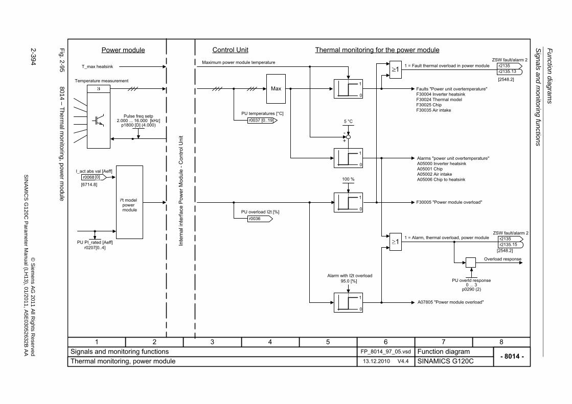
Fu
nctio
n diag
ram
s
Sign
als a
nd m
onitoring
functio
ns
2-394
© S
iem
ens AG
2011 All R
ights R
eservedS
INA
MIC
SG
120C
Param
eter
Manual (L
H13), 0
1/2011, A5E
03052632B
AA
Fig. 2
-95
8014 – T
herm
al m
onitoring
, pow
er mo
dule
- 8014 -Function diagram
87654321FP_8014_97_05.vsdSignals and monitoring functions
SINAMICS G120C13.12.2010 V4.4Thermal monitoring, power module
Control Unit
Max0
1
0
1
5 °C
+-
0
1
[2548.2]
0
1
100 %
1
1
[2548.2]
[6714.8]
Power module
T_max heatsink
Temperature measurement
i²t model power module
Maximum power module temperature
Thermal monitoring for the power module
1 = Fault thermal overload in power module
Faults "Power unit overtemperature"F30004 Inverter heatsinkF30024 Thermal modelF30025 ChipF30035 Air intake
Alarms "power unit overtemperature"A05000 Inverter heatsinkA05001 ChipA05002 Air intakeA05006 Chip to heatsink
F30005 "Power module overload"
1 = Alarm, thermal overload, power module
Overload response
A07805 "Power module overload"
Pulse freq setp2.000 ... 16.000 [kHz]
p1800 [D] (4.000)
ZSW fault/alarm 2
r2135r2135
.13
ZSW fault/alarm 2
r2135r2135
.15
PU overld response0 ... 3
p0290 (2)
r0036 PU overload I2t [%]
r0068 I_act abs val [Aeff]
[0]
PU PI_rated [Aeff]r0207[0..4]
r0037 [0..19]PU temperatures [°C]
95.0 [%]Alarm with I2t overload
Inte
rnal
inte
rface
Pow
er M
odul
e -C
ontro
l Uni
t
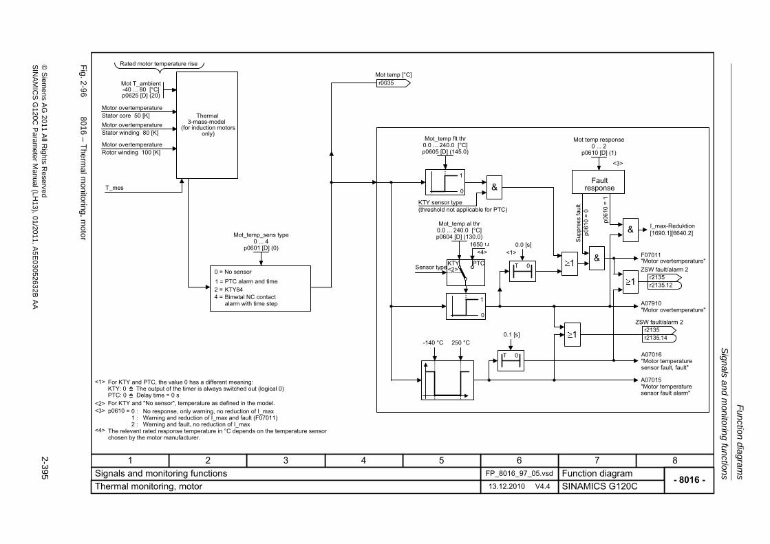
Sig
nals an
d m
onito
ring
functio
ns
Fu
nction dia
grams
2-395
© S
ieme
ns AG
2011 All R
ights Re
servedS
INA
MIC
SG
120C P
aram
eterM
anual (LH
13), 01/2011, A5E
03052632B
AA
Fig. 2
-96
8016 – T
herm
al m
onitoring
, motor
- 8016 -Function diagram
87654321FP_8016_97_05.vsdSignals and monitoring functions
SINAMICS G120C13.12.2010 V4.4Thermal monitoring, motor
1 = 2 =
T 0
&
&1<1>
I_max-Reduktion[1690.1][6640.2]
p061
0 =
1
-140 °C 250 °C
0
1
&
1
1
T 0
KTY PTC
0
1
<2>
<4>1650
4 =
Rated motor temperature rise
Thermal3-mass-model
(for induction motors only)
For KTY and PTC, the value 0 has a different meaning:KTY: 0 The output of the timer is always switched out (logical 0)PTC: 0 Delay time = 0 sFor KTY and "No sensor", temperature as defined in the model.
The relevant rated response temperature in °C depends on the temperature sensor chosen by the motor manufacturer.
0 = No sensorPTC alarm and timeKTY84Bimetal NC contact alarm with time step
KTY sensor type(threshold not applicable for PTC)
Sensor type
Fault response
Sup
pres
s fa
ult
p061
0 =
0
F07011 "Motor overtemperature"
A07910 "Motor overtemperature"
A07016"Motor temperaturesensor fault, fault"
A07015"Motor temperaturesensor fault alarm"
r0035 Mot temp [°C]
ZSW fault/alarm 2
r2135r2135
.12
ZSW fault/alarm 2
r2135r2135
.14
Mot temp response0 ... 2
p0610 [D] (1)
0 : No response, only warning, no reduction of I_max1 : Warning and reduction of I_max and fault (F07011)2 : Warning and fault, no reduction of I_max
p0610 =
<4>
<3>
T_mes
Mot_temp_sens type0 ... 4
p0601 [D] (0)
Mot T_ambient-40 ... 80 [°C]p0625 [D] (20)
Mot_temp flt thr0.0 ... 240.0 [°C]p0605 [D] (145.0)
Mot_temp al thr0.0 ... 240.0 [°C]p0604 [D] (130.0)
Motor overtemperatureStator core 50 [K]Motor overtemperatureStator winding 80 [K]
Motor overtemperatureRotor winding 100 [K]
0.1 [s]
0.0 [s]
<1>
<2><3>
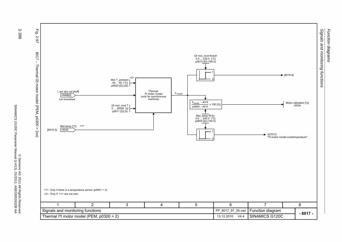
Fu
nctio
n diag
ram
s
Sign
als a
nd m
onitoring
functio
ns
2-396
© S
iem
ens AG
2011 All R
ights R
eservedS
INA
MIC
SG
120C
Param
eter
Manual (L
H13), 0
1/2011, A5E
03052632B
AA
Fig. 2
-97
8017 – T
herm
al I2t m
oto
r mod
el (PE
M, p030
0=
2xx)
- 8017 -Function diagram
87654321FP_8017_97_05.vsdSignals and monitoring functions
SINAMICS G120C13.12.2010 V4.4Thermal I²t motor model (PEM, p0300 = 2)
<1>
0
1
0
1
[8016.5]<1>
[8016.6]<2>
<2>
ThermalI²t motor model
(only for synchronous machine)
A07012 "I²t-motor model overtemperature"
Only if there is a temperature sensor (p0601 = 2).Only if <1> are not met.
I2t mot_mod T0 ... 20000 [s]p0611 [D] (0)
r0035 Mot temp [°C]
Motor utilization [%]r0034
Mot_temp flt thr0.0 ... 240.0 [°C]p0605 [D] (145.0)
model
I2t mot_mod thresh0.0 ... 220.0 [°C]p0615 [D] (180.0)
not smoothedr0068
I_act abs val [Aeff][0]
� 40 K
p0605 � 40 Kx 100 [%]model
Mot T_ambient-40 ... 80 [°C]p0625 [D] (20)
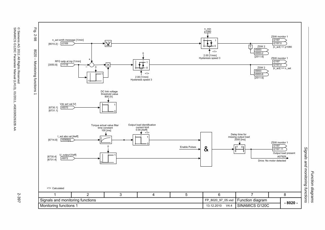
Sig
nals an
d m
onito
ring
functio
ns
Fu
nction dia
grams
2-397
© S
ieme
ns AG
2011 All R
ights Re
servedS
INA
MIC
SG
120C P
aram
eterM
anual (LH
13), 01/2011, A5E
03052632B
AA
Fig. 2
-98
8020 – M
onitorin
g functio
ns1
- 8020 -Function diagram
87654321FP_8020_97_05.vsdSignals and monitoring functions
SINAMICS G120C13.12.2010 V4.4Monitoring functions 1
0
1[8010.2]
+
�[3050.8]
1
0[6730.1][6731.1]
[6714.8]
[6730.4][6731.4]
0
1
0 T 0
1
0
0
0
1
n_minp1080
ZSW monitor 1
r2197r2197
.0r2169 n_act smth message [1/min]
r1119 RFG setp at inp [1/min]
r0070 Vdc act val [V]
r0068 I_act abs val [Aeff]
r0072 U_output [Veff]
ZSW 2
r0053r0053
.2[2511.6] ZSW monitor 1
r2197r2197
.4ZSW 2
r0053r0053
.6[2511.6]
ZSW monitor 1
r2197r2197
.11Enable Pulses
|n_act| <= p1080
|n_act| >= n_set
Output load present
Drive: No motor detectedA07929
-1
1
0
[0]
1
2.00 [1/min]Hysteresis speed 3
2.00 [1/min]Hysteresis speed 3
800 [V]
DC link voltagethreshold value
0.00 [Aeff]
Output load identificationcurrent limit
2000 [ms]
Delay time formissing output load
100 [ms]
Torque actual value filtertime constant
<1> Calculated
<1>
<1>
<1>
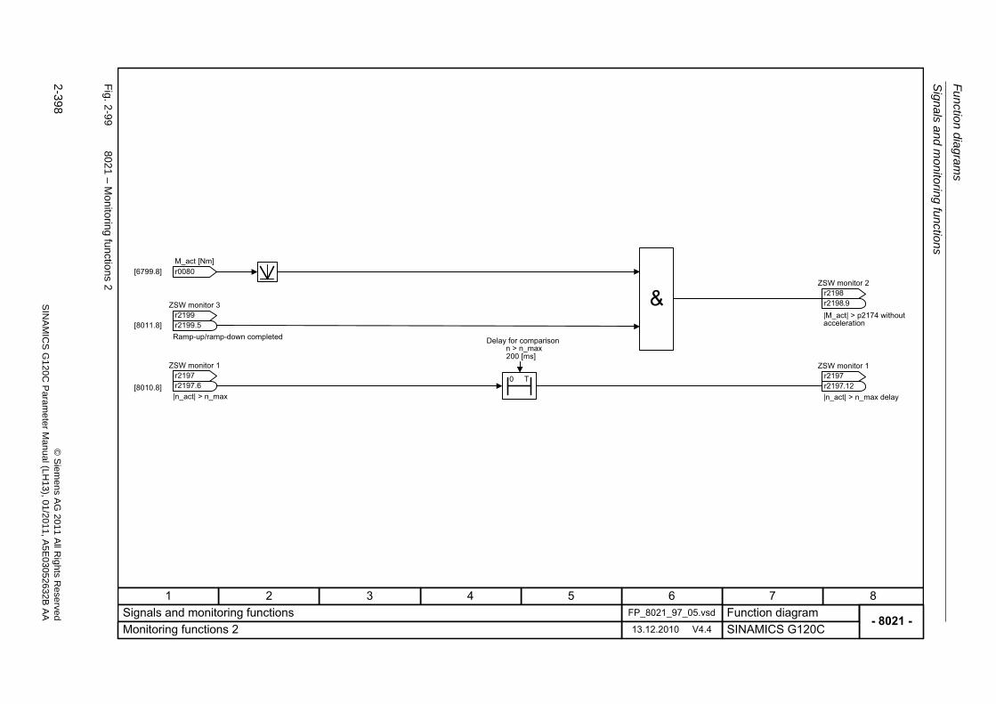
Fu
nctio
n diag
ram
s
Sign
als a
nd m
onitoring
functio
ns
2-398
© S
iem
ens AG
2011 All R
ights R
eservedS
INA
MIC
SG
120C
Param
eter
Manual (L
H13), 0
1/2011, A5E
03052632B
AA
Fig. 2
-99
8021 – M
onitorin
g functio
ns2
- 8021 -Function diagram
87654321FP_8021_97_05.vsdSignals and monitoring functions
SINAMICS G120C13.12.2010 V4.4Monitoring functions 2
[6799.8]
[8010.8]0 T
[8011.8]
r0080 M_act [Nm]
ZSW monitor 3
r2199r2199
.5
ZSW monitor 1
r2197r2197
.6
ZSW monitor 2
r2198r2198
.9|M_act| > p2174 without acceleration
ZSW monitor 1
r2197r2197
.12|n_act| > n_max delay
Ramp-up/ramp-down completed
|n_act| > n_max
200 [ms]
Delay for comparisonn > n_max
Faults and warnings
Function diagrams
2-399© Siemens AG 2011 All Rights ReservedSINAMICS G120C Parameter Manual (LH13), 01/2011, A5E03052632B AA
2.15 Faults and warnings
Function diagrams
8060 – Fault buffer 2-400
8065 – Warning buffer 2-401
8070 – Fault/warning trigger word (r2129) 2-402
8075 – Fault/warning configuration 2-403
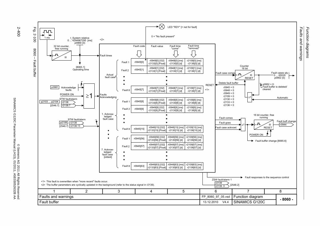
Fu
nctio
n diag
ram
s
Fa
ults an
d wa
rning
s
2-400
© S
iem
ens AG
2011 All R
ights R
eservedS
INA
MIC
SG
120C
Param
eter
Manual (L
H13), 0
1/2011, A5E
03052632B
AA
Fig. 2
-100
8060 – F
ault bu
ffer
- 8060 -Function diagram
87654321FP_8060_97_05.vsdFaults and warnings
SINAMICS G120C13.12.2010 V4.4Fault buffer
<1>
1
RESETr0945 = 0r0948 = 0r0949 = 0r2109 = 0r2130 = 0r2133 = 0r2136 = 0
IIIRESET
IIIRESET
III
1 ms
POWER ON
<1>
1
[2546.7]p2103 ... p2104
[2546.7]p2106
[2548.2]
p3981
r0949[63] [I32]r2133[63] [Float]
r0945[0]
r0945[1]
r0945[7]
r0945[56]
r0945[57]
r0945[63]
r0945[8]
r0945[9]
r0945[15]
r0949[0] [I32]r2133[0] [Float]
r0949[1] [I32]r2133[1] [Float]
r0949[7] [I32]r2133[7] [Float]
r0949[56] [I32]r2133[56] [Float]
r0949[57] [I32]r2133[57] [Float]
r0949[8] [I32]r2133[8] [Float]
r0949[9] [I32]r2133[9] [Float]
r0949[15] [I32]r2133[15] [Float]
r0948[0] [ms]r2130[0] [d]
r0948[1] [ms]r2130[1] [d]
r0948[7] [ms]r2130[7] [d]
r0948[56] [ms]r2130[56] [d]
r0948[57] [ms]r2130[57] [d]
r0948[63] [ms]r2130[63] [d]
r0948[8] [ms]r2130[8] [d]
r0948[9] [ms]r2130[9] [d]
r0948[15] [ms]r2130[15] [d]
r2109[0] [ms]r2136[0] [d]
r2109[1] [ms]r2136[1] [d]
r2109[7] [ms]r2136[7] [d]
r2109[56] [ms]r2136[56] [d]
r2109[57] [ms]r2136[57] [d]
r2109[63] [ms]r2136[63] [d]
r2109[8] [ms]r2136[8] [d]
r2109[9] [ms]r2136[9] [d]
r2109[15] [ms]r2136[15] [d]
1
<2>
<2>
32 bit counter, free running
[8065.1]Operating time
Acknowledge faults
POWER ON
This fault is overwritten when "more recent" faults occur.The buffer parameters are cyclically updated in the background (refer to the status signal in r2139).
Fault times
Actualfault case
FaultsAcknowledging
1. Acknow-ledged
fault case
7. Acknow-ledged
fault case[oldest]
Fault
Fault 2
Fault 8
1Fault
Fault 2
Fault 8
1Fault
Fault 2
Fault 8
Fault code Fault value Fault time "come"
Fault time "removed"
0 = "No fault present"
Fault case comes
Delete fault buffer
Fault goes
Fault comes
LED "RDY" [= red for fault]
Fault case acknowl.
Counter16 bit
p0952 = 0:Fault buffer is deleted/cleared
Automatic
16 bit counter, free running
Fault buffer change [8065.6]
Fault responses to the sequence control
t_System relative0 ... 4294967295 [ms]
p0969 (0)
STW fault/alarm
r2138r2138
.7
STW fault/alarm
r2138r2138
.13
ZSW fault/alarm 1
r2139r2139
.3
Fault cases qty0 ... 65535p0952 (0)
r0944 Fault buff change
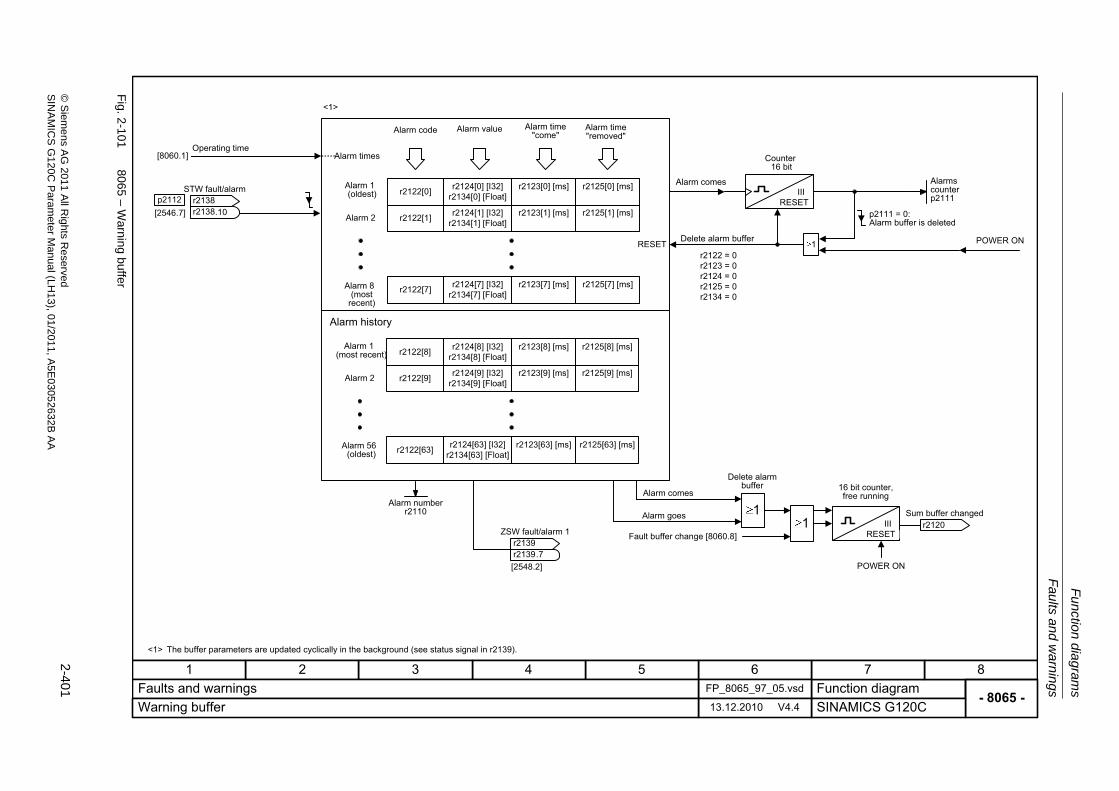
Fau
lts and
wa
rnin
gs
Fu
nction dia
grams
2-401
© S
ieme
ns AG
2011 All R
ights Re
servedS
INA
MIC
SG
120C P
aram
eterM
anual (LH
13), 01/2011, A5E
03052632B
AA
Fig. 2
-101
8065 – W
arning buffer
- 8065 -Function diagram
87654321FP_8065_97_05.vsdFaults and warnings
SINAMICS G120C13.12.2010 V4.4Warning buffer
RESET 1r2122 = 0r2123 = 0r2124 = 0r2125 = 0r2134 = 0
1
IIIRESET
IIIRESET
1
POWER ON[2548.2]
[2546.7]p2112
r2122[0]
r2122[1]
r2122[7]
r2124[0] [I32]r2134[0] [Float]
r2124[1] [I32]r2134[1] [Float]
r2124[7] [I32]r2134[7] [Float]
r2123[0] [ms]
r2123[1] [ms]
r2123[7] [ms]
r2125[0] [ms]
r2125[1] [ms]
r2125[7] [ms]
[8060.1]
POWER ON
r2122[8]
r2122[9]
r2122[63]
r2124[8] [I32]r2134[8] [Float]
r2124[9] [I32]r2134[9] [Float]
r2124[63] [I32]r2134[63] [Float]
r2123[8] [ms]
r2123[9] [ms]
r2123[63] [ms]
r2125[8] [ms]
r2125[9] [ms]
r2125[63] [ms]
<1>
<1>
Operating time
The buffer parameters are updated cyclically in the background (see status signal in r2139).
Alarm times
Alarm 1 (oldest)
Alarm 2
Alarm 8 (most
recent)
Alarm history
Alarm 1 (most recent)
Alarm 2
Alarm 56 (oldest)
Alarm code Alarm value Alarm time "come"
Alarm time "removed"
Fault buffer change [8060.8]
Alarm comes
Alarm goes
Delete alarm buffer
Alarms counter p2111
p2111 = 0: Alarm buffer is deleted
16 bit counter, free running
Alarm comes
Delete alarm buffer
Counter16 bit
STW fault/alarm
r2138r2138
.10
ZSW fault/alarm 1
r2139r2139
.7
Alarm numberr2110
r2120 Sum buffer changed
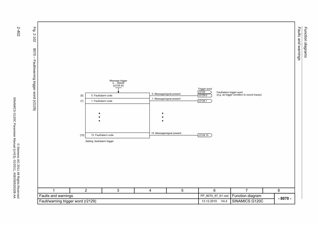
Fu
nctio
n diag
ram
s
Fa
ults an
d wa
rning
s
2-402
© S
iem
ens AG
2011 All R
ights R
eservedS
INA
MIC
SG
120C
Param
eter
Manual (L
H13), 0
1/2011, A5E
03052632B
AA
Fig. 2
-102
8070 – F
ault/w
arning
trigger w
ord (r2129
)
- 8070 -Function diagram
87654321FP_8070_97_61.vsdFaults and warnings
SINAMICS G120C13.12.2010 V4.4Fault/warning trigger word (r2129)
[0]
[1]
[15] r2129.15
r2129.1
0. Fault/alarm code
1. Fault/alarm code
15. Fault/alarm code
Setting, fault/alarm trigger
1. Message/signal present
0. Message/signal present
15. Message/signal present
Fault/alarm trigger word(e.g. as trigger condition to record traces)
Message trigger0 ... 65535p2128 (0)
Trigger word
r2129r2129r2129.0
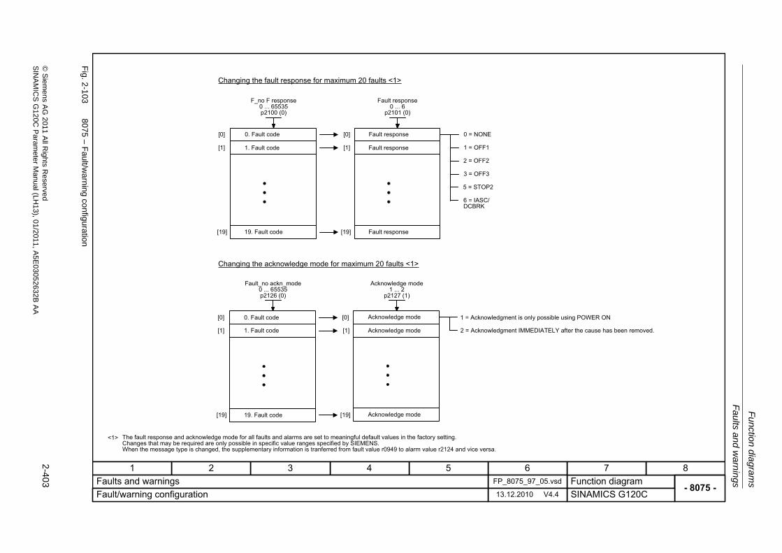
Fau
lts and
wa
rnin
gs
Fu
nction dia
grams
2-403
© S
ieme
ns AG
2011 All R
ights Re
servedS
INA
MIC
SG
120C P
aram
eterM
anual (LH
13), 01/2011, A5E
03052632B
AA
Fig. 2
-103
8075 – F
ault/w
arning
configuratio
n
- 8075 -Function diagram
87654321FP_8075_97_05.vsdFaults and warnings
SINAMICS G120C13.12.2010 V4.4Fault/warning configuration
[0]
[1]
[19]
[0]
[1]
[19]
[0]
[1]
[19]
[0]
[1]
[19]
<1>
Changing the fault response for maximum 20 faults <1>
Changing the acknowledge mode for maximum 20 faults <1>
0. Fault code
1. Fault code
19. Fault code
Fault response
Fault response
Fault response
0. Fault code
1. Fault code
19. Fault code
0 = NONE
1 = OFF1
2 = OFF2
3 = OFF3
5 = STOP2
6 = IASC/DCBRK
Acknowledge mode
Acknowledge mode
Acknowledge mode
1 = Acknowledgment is only possible using POWER ON
2 = Acknowledgment IMMEDIATELY after the cause has been removed.
The fault response and acknowledge mode for all faults and alarms are set to meaningful default values in the factory setting.Changes that may be required are only possible in specific value ranges specified by SIEMENS. When the message type is changed, the supplementary information is tranferred from fault value r0949 to alarm value r2124 and vice versa.
F_no F response0 ... 65535p2100 (0)
Fault response0 ... 6
p2101 (0)
Fault_no ackn_mode0 ... 65535p2126 (0)
Acknowledge mode1 ... 2
p2127 (1)
Function diagrams
Data sets
2-404 © Siemens AG 2011 All Rights ReservedSINAMICS G120C Parameter Manual (LH13), 01/2011, A5E03052632B AA
2.16 Data sets
Function diagrams
8560 – Command Data Sets (CDS) 2-405
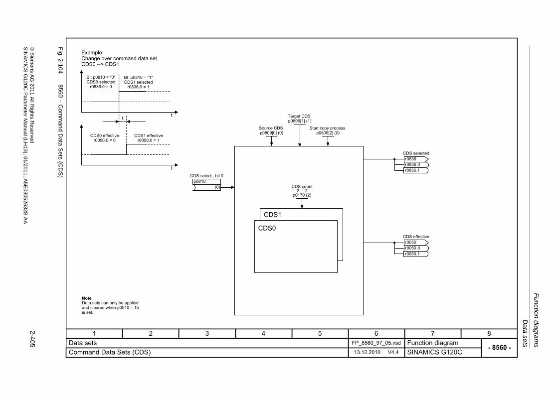
Data sets
Fu
nction dia
grams
2-405
© S
ieme
ns AG
2011 All R
ights Re
servedS
INA
MIC
SG
120C P
aram
eterM
anual (LH
13), 01/2011, A5E
03052632B
AA
Fig. 2
-104
8560 – C
omm
and Data S
ets (CD
S)
- 8560 -Function diagram
87654321FP_8560_97_05.vsdData sets
SINAMICS G120C13.12.2010 V4.4Command Data Sets (CDS)
r0836.1
r0050.1
t
t
t
CDS1
CDS0
Example: Change over command data set CDS0 --> CDS1
BI: p0810 = "0" CDS0 selected
r0836.0 = 0
BI: p0810 = "1" CDS1 selected
r0836.0 = 1
CDS0 effective r0050.0 = 0
CDS1 effective r0050.0 = 1
(0)
CDS select., bit 0p0810
CDS selected
r0836r0836
.0
CDS effective
r0050r0050
.0
CDS count2 ... 2
p0170 (2)
Source CDSp0809[0] (0)
Start copy processp0809[2] (0)
Target CDSp0809[1] (1)
NoteData sets can only be applied and cleared when p0010 = 15 is set.

2-406 © Siemens AG 2011 All Rights ReservedSINAMICS G120C Parameter Manual (LH13), 01/2011, A5E03052632B AA
3-407© Siemens AG 2011 All Rights ReservedSINAMICS G120C Parameter Manual (LH13), 01/2011, A5E03052632B AA
Faults and Alarms 3Contents
3.1 Faults and Alarms – Overview 3-408
3.2 List of Faults and Alarms 3-412
Faults and Alarms
Faults and Alarms – Overview
3-408 © Siemens AG 2011 All Rights ReservedSINAMICS G120C Parameter Manual (LH13), 01/2011, A5E03052632B AA
3.1 Faults and Alarms – Overview
3.1.1 General information
Indicating fault and alarm messages (faults and alarms)
A message comprises a letter followed by the relevant number.
The letter characterizes the message type and has the following meaning:
A means "Alarm"
F means "Fault"
N means "No Report" or "Internal Report"
C means Safety message
Brackets including the letters A, F, or N indicate that the message type can be changed, e.g. A01016 (F) means that the alarm A01016 can be parameterized as a fault. This function is not enabled for SINAMICS G120C.
Faults are stored in parameter r0945/r0947, under their code number (e.g. F01003 = 1003). The associated fault value can be found in parameter r0949. The value 0 is entered if a fault has no fault value. It is furthermore possible to read out the point in time that a fault occurred (r0948) and the number of faults (p0952).
Alarms are stored in parameter r2110/r2122, under their code number (e.g. A01503 = 1503) and can be read out from there. The associated alarm value can be found in parameter r2124 and the time of alarm occurence in r2123.
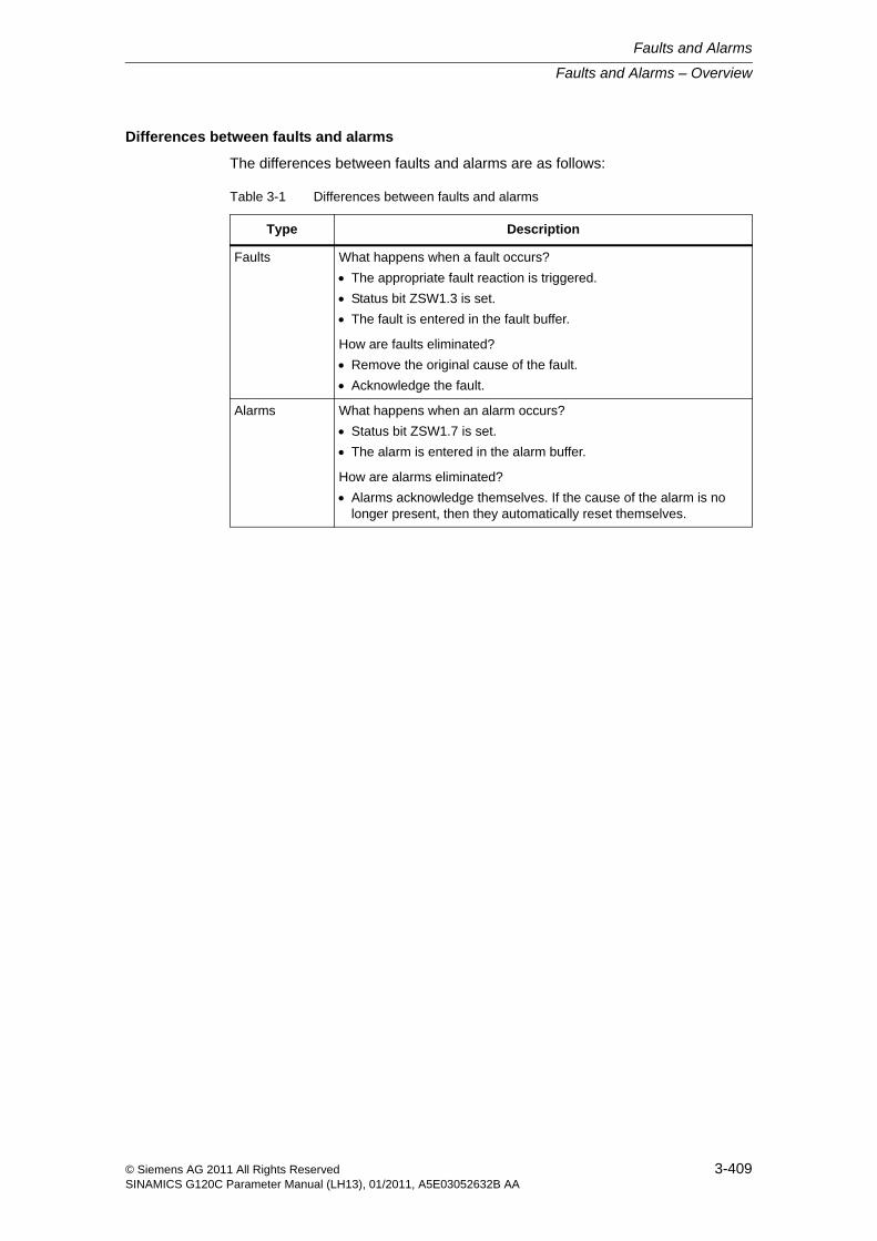
Faults and Alarms – Overview
Faults and Alarms
3-409© Siemens AG 2011 All Rights ReservedSINAMICS G120C Parameter Manual (LH13), 01/2011, A5E03052632B AA
Differences between faults and alarms
The differences between faults and alarms are as follows:
Table 3-1 Differences between faults and alarms
Type Description
Faults What happens when a fault occurs?
The appropriate fault reaction is triggered.
Status bit ZSW1.3 is set.
The fault is entered in the fault buffer.
How are faults eliminated?
Remove the original cause of the fault.
Acknowledge the fault.
Alarms What happens when an alarm occurs?
Status bit ZSW1.7 is set.
The alarm is entered in the alarm buffer.
How are alarms eliminated?
Alarms acknowledge themselves. If the cause of the alarm is no longer present, then they automatically reset themselves.
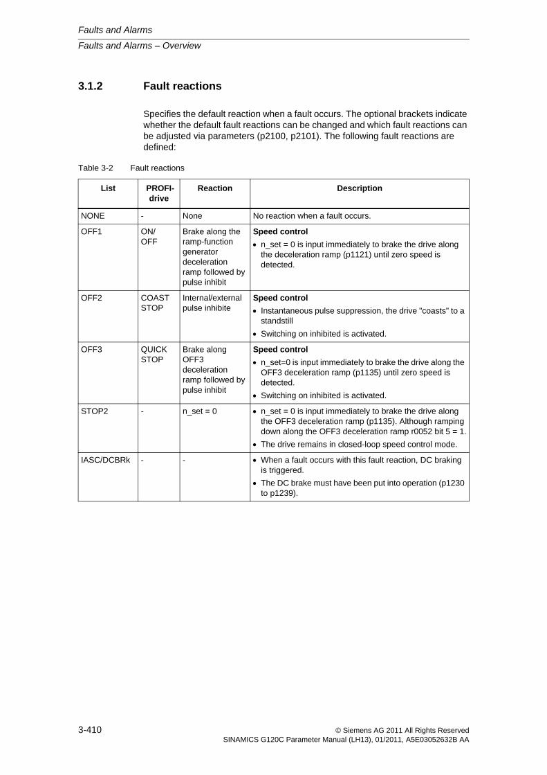
Faults and Alarms
Faults and Alarms – Overview
3-410 © Siemens AG 2011 All Rights ReservedSINAMICS G120C Parameter Manual (LH13), 01/2011, A5E03052632B AA
3.1.2 Fault reactions
Specifies the default reaction when a fault occurs. The optional brackets indicate whether the default fault reactions can be changed and which fault reactions can be adjusted via parameters (p2100, p2101). The following fault reactions are defined:
Table 3-2 Fault reactions
List PROFI-drive
Reaction Description
NONE - None No reaction when a fault occurs.
OFF1 ON/OFF
Brake along the ramp-function generator deceleration ramp followed by pulse inhibit
Speed control
n_set = 0 is input immediately to brake the drive along the deceleration ramp (p1121) until zero speed is detected.
OFF2 COAST STOP
Internal/external pulse inhibite
Speed control
Instantaneous pulse suppression, the drive "coasts" to a standstill
Switching on inhibited is activated.
OFF3 QUICK STOP
Brake along OFF3 deceleration ramp followed by pulse inhibit
Speed control
n_set=0 is input immediately to brake the drive along the OFF3 deceleration ramp (p1135) until zero speed is detected.
Switching on inhibited is activated.
STOP2 - n_set = 0 n_set = 0 is input immediately to brake the drive along the OFF3 deceleration ramp (p1135). Although ramping down along the OFF3 deceleration ramp r0052 bit 5 = 1.
The drive remains in closed-loop speed control mode.
IASC/DCBRk - - When a fault occurs with this fault reaction, DC braking is triggered.
The DC brake must have been put into operation (p1230 to p1239).
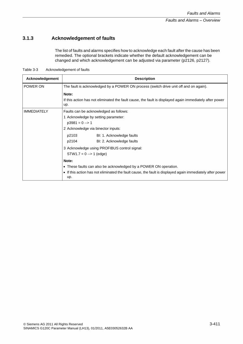
Faults and Alarms – Overview
Faults and Alarms
3-411© Siemens AG 2011 All Rights ReservedSINAMICS G120C Parameter Manual (LH13), 01/2011, A5E03052632B AA
3.1.3 Acknowledgement of faults
The list of faults and alarms specifies how to acknowledge each fault after the cause has been remedied. The optional brackets indicate whether the default acknowledgement can be changed and which acknowledgement can be adjusted via parameter (p2126, p2127).
Table 3-3 Acknowledgement of faults
Acknowledgement Description
POWER ON The fault is acknowledged by a POWER ON process (switch drive unit off and on again).
Note:
If this action has not eliminated the fault cause, the fault is displayed again immediately after power up.
IMMEDIATELY Faults can be acknowledged as follows:
1 Acknowledge by setting parameter:
p3981 = 0 --> 1
2 Acknowledge via binector inputs:
p2103
p2104
BI: 1. Acknowledge faults
BI: 2. Acknowledge faults
3 Acknowledge using PROFIBUS control signal:
STW1.7 = 0 --> 1 (edge)
Note:
These faults can also be acknowledged by a POWER ON operation.
If this action has not eliminated the fault cause, the fault is displayed again immediately after power up.
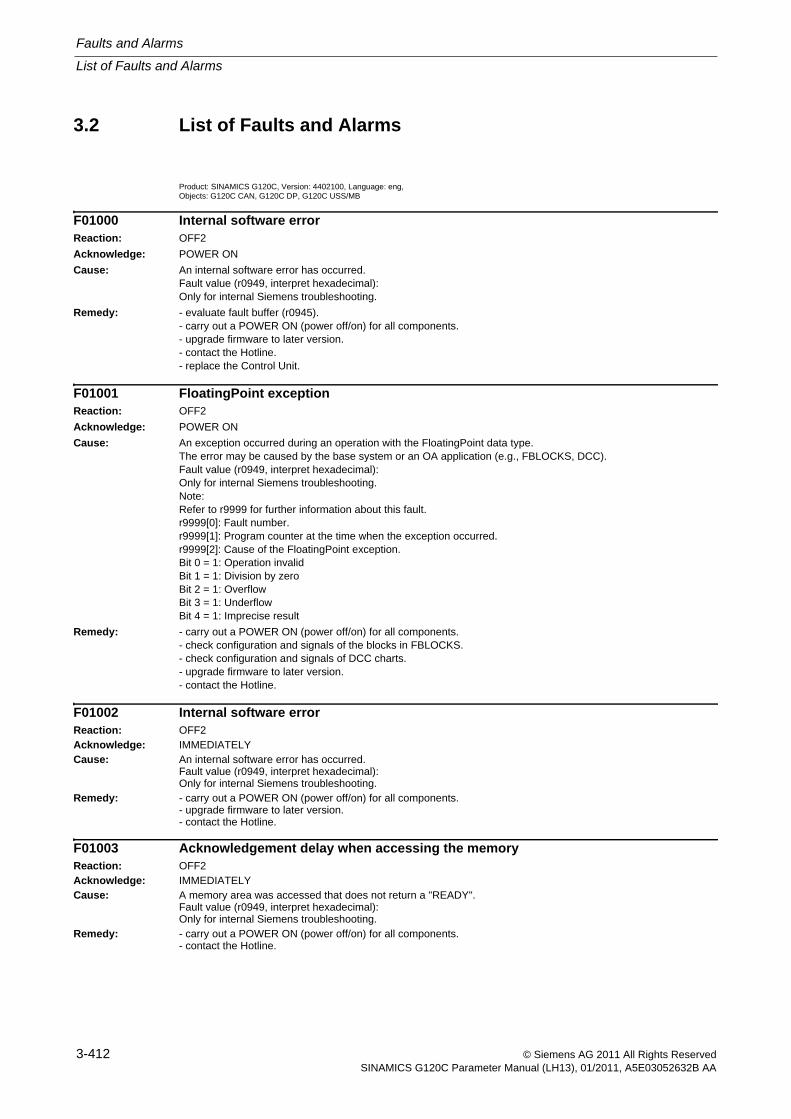
Faults and Alarms
List of Faults and Alarms
3-412 © Siemens AG 2011 All Rights ReservedSINAMICS G120C Parameter Manual (LH13), 01/2011, A5E03052632B AA
3.2 List of Faults and Alarms
Product: SINAMICS G120C, Version: 4402100, Language: eng, Objects: G120C CAN, G120C DP, G120C USS/MB
F01000 Internal software errorReaction: OFF2
Acknowledge: POWER ON
Cause: An internal software error has occurred.Fault value (r0949, interpret hexadecimal):Only for internal Siemens troubleshooting.
Remedy: - evaluate fault buffer (r0945).- carry out a POWER ON (power off/on) for all components.- upgrade firmware to later version.- contact the Hotline.- replace the Control Unit.
F01001 FloatingPoint exceptionReaction: OFF2
Acknowledge: POWER ON
Cause: An exception occurred during an operation with the FloatingPoint data type.The error may be caused by the base system or an OA application (e.g., FBLOCKS, DCC).Fault value (r0949, interpret hexadecimal):Only for internal Siemens troubleshooting.Note:Refer to r9999 for further information about this fault.r9999[0]: Fault number.r9999[1]: Program counter at the time when the exception occurred.r9999[2]: Cause of the FloatingPoint exception.Bit 0 = 1: Operation invalidBit 1 = 1: Division by zeroBit 2 = 1: OverflowBit 3 = 1: UnderflowBit 4 = 1: Imprecise result
Remedy: - carry out a POWER ON (power off/on) for all components.- check configuration and signals of the blocks in FBLOCKS.- check configuration and signals of DCC charts.- upgrade firmware to later version.- contact the Hotline.
F01002 Internal software errorReaction: OFF2Acknowledge: IMMEDIATELYCause: An internal software error has occurred.
Fault value (r0949, interpret hexadecimal):Only for internal Siemens troubleshooting.
Remedy: - carry out a POWER ON (power off/on) for all components.- upgrade firmware to later version.- contact the Hotline.
F01003 Acknowledgement delay when accessing the memoryReaction: OFF2Acknowledge: IMMEDIATELYCause: A memory area was accessed that does not return a "READY".
Fault value (r0949, interpret hexadecimal):Only for internal Siemens troubleshooting.
Remedy: - carry out a POWER ON (power off/on) for all components.- contact the Hotline.
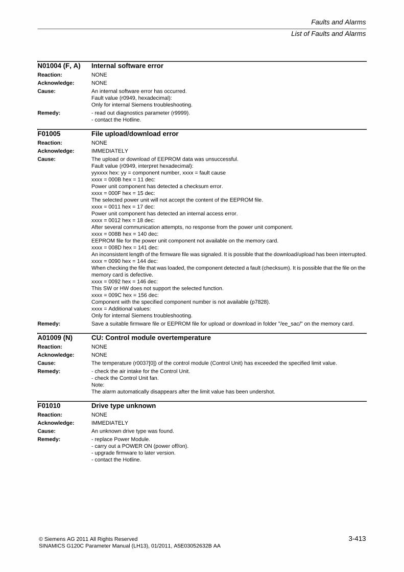
List of Faults and Alarms
Faults and Alarms
3-413© Siemens AG 2011 All Rights ReservedSINAMICS G120C Parameter Manual (LH13), 01/2011, A5E03052632B AA
N01004 (F, A) Internal software errorReaction: NONE
Acknowledge: NONE
Cause: An internal software error has occurred.Fault value (r0949, hexadecimal):Only for internal Siemens troubleshooting.
Remedy: - read out diagnostics parameter (r9999).- contact the Hotline.
F01005 File upload/download errorReaction: NONE
Acknowledge: IMMEDIATELY
Cause: The upload or download of EEPROM data was unsuccessful.Fault value (r0949, interpret hexadecimal):yyxxxx hex: yy = component number, xxxx = fault causexxxx = 000B hex = 11 dec:Power unit component has detected a checksum error.xxxx = 000F hex = 15 dec:The selected power unit will not accept the content of the EEPROM file.xxxx = 0011 hex = 17 dec:Power unit component has detected an internal access error.xxxx = 0012 hex = 18 dec:After several communication attempts, no response from the power unit component.xxxx = 008B hex = 140 dec:EEPROM file for the power unit component not available on the memory card.xxxx = 008D hex = 141 dec:An inconsistent length of the firmware file was signaled. It is possible that the download/upload has been interrupted.xxxx = 0090 hex = 144 dec:When checking the file that was loaded, the component detected a fault (checksum). It is possible that the file on the memory card is defective.xxxx = 0092 hex = 146 dec:This SW or HW does not support the selected function.xxxx = 009C hex = 156 dec:Component with the specified component number is not available (p7828).xxxx = Additional values:Only for internal Siemens troubleshooting.
Remedy: Save a suitable firmware file or EEPROM file for upload or download in folder "/ee_sac/" on the memory card.
A01009 (N) CU: Control module overtemperatureReaction: NONE
Acknowledge: NONE
Cause: The temperature (r0037[0]) of the control module (Control Unit) has exceeded the specified limit value.
Remedy: - check the air intake for the Control Unit.- check the Control Unit fan.Note:The alarm automatically disappears after the limit value has been undershot.
F01010 Drive type unknownReaction: NONE
Acknowledge: IMMEDIATELY
Cause: An unknown drive type was found.
Remedy: - replace Power Module.- carry out a POWER ON (power off/on).- upgrade firmware to later version.- contact the Hotline.
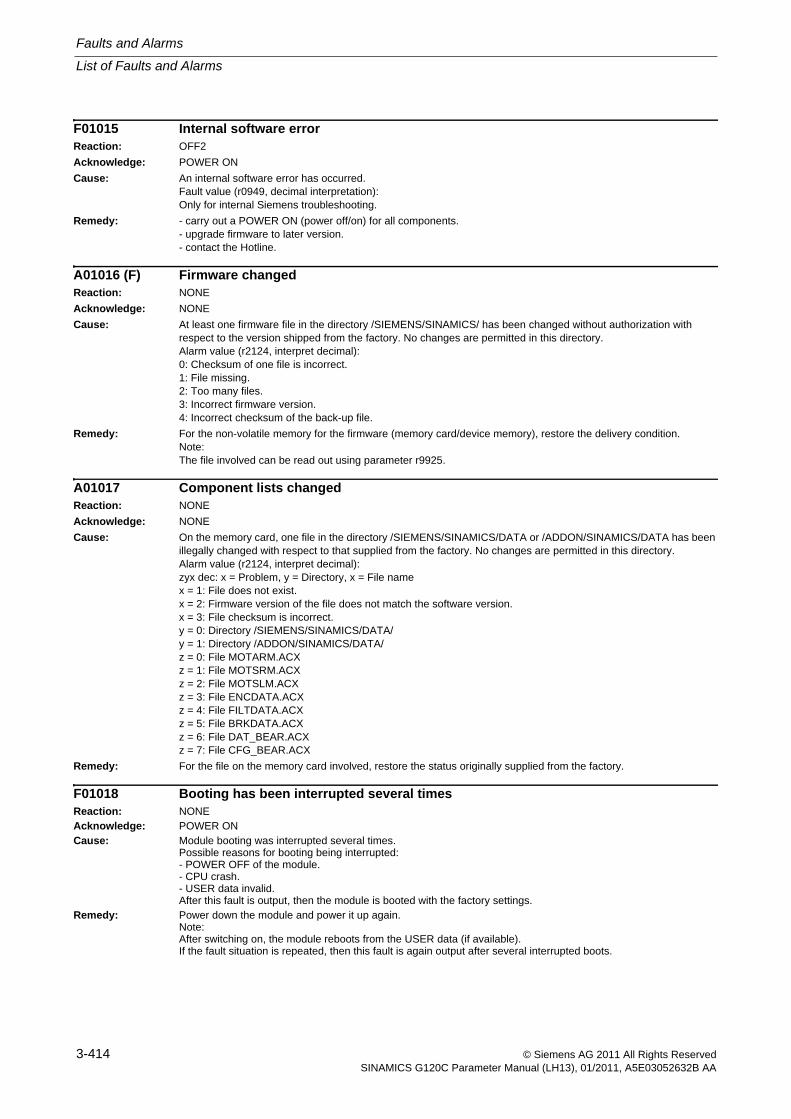
Faults and Alarms
List of Faults and Alarms
3-414 © Siemens AG 2011 All Rights ReservedSINAMICS G120C Parameter Manual (LH13), 01/2011, A5E03052632B AA
F01015 Internal software errorReaction: OFF2
Acknowledge: POWER ON
Cause: An internal software error has occurred.Fault value (r0949, decimal interpretation):Only for internal Siemens troubleshooting.
Remedy: - carry out a POWER ON (power off/on) for all components.- upgrade firmware to later version.- contact the Hotline.
A01016 (F) Firmware changedReaction: NONE
Acknowledge: NONE
Cause: At least one firmware file in the directory /SIEMENS/SINAMICS/ has been changed without authorization with respect to the version shipped from the factory. No changes are permitted in this directory.Alarm value (r2124, interpret decimal):0: Checksum of one file is incorrect.1: File missing.2: Too many files.3: Incorrect firmware version.4: Incorrect checksum of the back-up file.
Remedy: For the non-volatile memory for the firmware (memory card/device memory), restore the delivery condition.Note:The file involved can be read out using parameter r9925.
A01017 Component lists changedReaction: NONE
Acknowledge: NONE
Cause: On the memory card, one file in the directory /SIEMENS/SINAMICS/DATA or /ADDON/SINAMICS/DATA has been illegally changed with respect to that supplied from the factory. No changes are permitted in this directory.Alarm value (r2124, interpret decimal):zyx dec: x = Problem, y = Directory, x = File namex = 1: File does not exist.x = 2: Firmware version of the file does not match the software version.x = 3: File checksum is incorrect.y = 0: Directory /SIEMENS/SINAMICS/DATA/y = 1: Directory /ADDON/SINAMICS/DATA/z = 0: File MOTARM.ACXz = 1: File MOTSRM.ACXz = 2: File MOTSLM.ACXz = 3: File ENCDATA.ACXz = 4: File FILTDATA.ACXz = 5: File BRKDATA.ACXz = 6: File DAT_BEAR.ACXz = 7: File CFG_BEAR.ACX
Remedy: For the file on the memory card involved, restore the status originally supplied from the factory.
F01018 Booting has been interrupted several timesReaction: NONEAcknowledge: POWER ONCause: Module booting was interrupted several times.
Possible reasons for booting being interrupted:- POWER OFF of the module.- CPU crash.- USER data invalid.After this fault is output, then the module is booted with the factory settings.
Remedy: Power down the module and power it up again.Note:After switching on, the module reboots from the USER data (if available).If the fault situation is repeated, then this fault is again output after several interrupted boots.
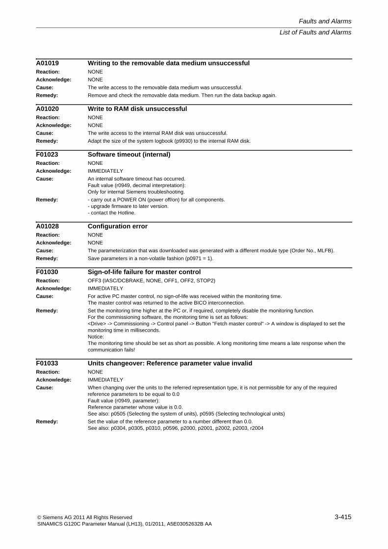
List of Faults and Alarms
Faults and Alarms
3-415© Siemens AG 2011 All Rights ReservedSINAMICS G120C Parameter Manual (LH13), 01/2011, A5E03052632B AA
A01019 Writing to the removable data medium unsuccessfulReaction: NONE
Acknowledge: NONE
Cause: The write access to the removable data medium was unsuccessful.
Remedy: Remove and check the removable data medium. Then run the data backup again.
A01020 Write to RAM disk unsuccessfulReaction: NONE
Acknowledge: NONE
Cause: The write access to the internal RAM disk was unsuccessful.
Remedy: Adapt the size of the system logbook (p9930) to the internal RAM disk.
F01023 Software timeout (internal)Reaction: NONE
Acknowledge: IMMEDIATELY
Cause: An internal software timeout has occurred.Fault value (r0949, decimal interpretation):Only for internal Siemens troubleshooting.
Remedy: - carry out a POWER ON (power off/on) for all components.- upgrade firmware to later version.- contact the Hotline.
A01028 Configuration errorReaction: NONE
Acknowledge: NONE
Cause: The parameterization that was downloaded was generated with a different module type (Order No., MLFB).
Remedy: Save parameters in a non-volatile fashion (p0971 = 1).
F01030 Sign-of-life failure for master controlReaction: OFF3 (IASC/DCBRAKE, NONE, OFF1, OFF2, STOP2)
Acknowledge: IMMEDIATELY
Cause: For active PC master control, no sign-of-life was received within the monitoring time.The master control was returned to the active BICO interconnection.
Remedy: Set the monitoring time higher at the PC or, if required, completely disable the monitoring function.For the commissioning software, the monitoring time is set as follows:<Drive> -> Commissioning -> Control panel -> Button "Fetch master control" -> A window is displayed to set the monitoring time in milliseconds.Notice:The monitoring time should be set as short as possible. A long monitoring time means a late response when the communication fails!
F01033 Units changeover: Reference parameter value invalidReaction: NONE
Acknowledge: IMMEDIATELY
Cause: When changing over the units to the referred representation type, it is not permissible for any of the required reference parameters to be equal to 0.0Fault value (r0949, parameter):Reference parameter whose value is 0.0.See also: p0505 (Selecting the system of units), p0595 (Selecting technological units)
Remedy: Set the value of the reference parameter to a number different than 0.0.See also: p0304, p0305, p0310, p0596, p2000, p2001, p2002, p2003, r2004
Faults and Alarms
List of Faults and Alarms
3-416 © Siemens AG 2011 All Rights ReservedSINAMICS G120C Parameter Manual (LH13), 01/2011, A5E03052632B AA
F01034 Units changeover: Calculation parameter values after reference value change unsuccessful
Reaction: NONE
Acknowledge: IMMEDIATELY
Cause: The change of a reference parameter meant that for an involved parameter the selected value was not able to be re-calculated in the per unit representation. The change was rejected and the original parameter value restored.Fault value (r0949, parameter):Parameter whose value was not able to be re-calculated.See also: p0304, p0305, p0310, p0596, p2000, p2001, p2002, p2003, r2004
Remedy: Select the value of the reference parameter such that the parameter involved can be calculated in the per unit representation.See also: p0304, p0305, p0310, p0596, p2000, p2001, p2002, p2003, r2004
A01035 (F) ACX: Boot from the back-up parameter back-up filesReaction: NONE
Acknowledge: NONE
Cause: When the Control Unit is booted, no complete data set was found from the parameter back-up files. The last time that the parameterization was saved, it was not completely carried out. Instead, a back-up data set or a back-up parameter back-up file is downloaded.Alarm value (r2124, interpret hexadecimal):Only for internal Siemens troubleshooting.
Remedy: If you have saved the project using the commissioning software, carry out a new download for your project. Save using the function "Copy RAM to ROM" or with p0971 = 1 so that all of the parameter files are again completely written to the non-volatile memory.
F01036 (A) ACX: Parameter back-up file missingReaction: NONE (OFF1, OFF2, OFF3)
Acknowledge: IMMEDIATELY
Cause: When downloading the device parameterization, a parameter back-up file associated with a drive object cannot be found. Neither a PSxxxyyy.ACX, a PSxxxyyy.NEW nor a PSxxxyyy.BAK parameter back-up file exists in the non-volatile memory for this drive object.Fault value (r0949, interpret hexadecimal):Byte 1: yyy in the file name PSxxxyyy.ACXyyy = 000 --> consistency back-up fileyyy = 001 ... 062 --> drive object numberyyy = 099 --> PROFIBUS parameter back-up fileByte 2, 3, 4:Only for internal Siemens troubleshooting.
Remedy: If you have saved the project data using the commissioning software, carry out a new download for your project. Save using the function "Copy RAM to ROM" or with p0971 = 1 so that all of the parameter files are again completely written to the non-volatile memory.If you have not saved the project data, then first commissioning of the system has to be carried out again.
List of Faults and Alarms
Faults and Alarms
3-417© Siemens AG 2011 All Rights ReservedSINAMICS G120C Parameter Manual (LH13), 01/2011, A5E03052632B AA
F01037 (A) ACX: Re-naming the parameter back-up file unsuccessfulReaction: NONE (OFF1, OFF2, OFF3)
Acknowledge: IMMEDIATELY
Cause: Re-naming after saving a parameter back-up file in the non-volatile memory was unsuccessful.One of the parameter back-up files to be re-named had the "read only" attribute. The parameter back-up files are saved in the directory \USER\SINAMICS\DATA.It is possible that the non-volatile memory is defective.Fault value (r0949, interpret hexadecimal):Byte 1: yyy in the file names PSxxxyyy.* or CAxxxyyy.* or CCxxxyyy.*yyy = 000 --> consistency back-up fileyyy = 099 --> PROFIBUS parameter back-up file PSxxx099.*Byte 2: xxx in the file name PSxxxyyy.*xxx = 000 --> data save started with p0971 = 1xxx = 010 --> data save started with p0971 = 10xxx = 011 --> data save started with p0971 = 11xxx = 012 --> data save started with p0971 = 12Byte 4, 3:Only for internal Siemens troubleshooting.
Remedy: - check whether one of the files to be overwritten has the attribute "read only" and change this file attribute to "writable". Check all of the files (PSxxxyyy.*, CCxxxyyy.*, CAxxxyyy.*) that belong to drive yyy designated in the fault value.- replace the memory card or Control Unit.
F01038 (A) ACX: Loading the parameter back-up file unsuccessfulReaction: NONE (OFF1, OFF2, OFF3)
Acknowledge: IMMEDIATELY
Cause: An error has occurred when downloading PSxxxyyy.ACX or PTxxxyyy.ACX files from the non-volatile memory.Fault value (r0949, interpret hexadecimal):Byte 1: yyy in the file name PSxxxyyy.ACXyyy = 000 --> consistency back-up fileyyy = 001 ... 062 --> drive object numberyyy = 099 --> PROFIBUS parameter back-up fileByte 2:255 = incorrect drive object type254 = topology comparison unsuccessful -> drive object type was not able to be identifiedReasons could be:- incorrect component type in the actual topology- component does not exist in the actual topology- component not activeOtherwise for internal Siemens troubleshooting.Byte 4, 3:Only for internal Siemens troubleshooting.
Remedy: - If you have saved the project data using the commissioning software, carry out a new download for your project. Save using the function "Copy RAM to ROM" or with p0971 = 1 so that all of the parameter files are again completely written to the non-volatile memory.- replace the memory card or Control Unit.

Faults and Alarms
List of Faults and Alarms
3-418 © Siemens AG 2011 All Rights ReservedSINAMICS G120C Parameter Manual (LH13), 01/2011, A5E03052632B AA
F01039 (A) ACX: Writing to the parameter back-up file was unsuccessfulReaction: NONE (OFF1, OFF2, OFF3)
Acknowledge: IMMEDIATELY
Cause: Writing to at least one parameter back-up file PSxxxyyy.*** in the non-volatile memory was unsuccessful.- In the directory /USER/SINAMICS/DATA/ at least one parameter back-up file PSxxxyyy.*** has the "read only" file attribute and cannot be overwritten.- There is not sufficient free memory space available.- The non-volatile memory is defective and cannot be written to.Fault value (r0949, interpret hexadecimal):dcba hexa = yyy in the file names PSxxxyyy.***a = 000 --> consistency back-up filea = 001 ... 062 --> drive object numbera = 099 --> PROFIBUS parameter back-up fileb = xxx in the file names PSxxxyyy.***b = 000 --> data save started with p0971 = 1b = 010 --> data save started with p0971 = 10b = 011 --> data save started with p0971 = 11b = 012 --> data save started with p0971 = 12d, c:Only for internal Siemens troubleshooting.
Remedy: - check the file attribute of the files (PSxxxyyy.***, CAxxxyyy.***, CCxxxyyy.***) and, if required, change from "read only" to "writeable".- check the free memory space in the non-volatile memory. Approx. 80 kbyte of free memory space is required for every drive object in the system.- replace the memory card or Control Unit.
F01040 Save parameter settings and carry out a POWER ONReaction: OFF2
Acknowledge: POWER ON
Cause: A parameter has been changed that requires the parameters to be backed up and the Control Unit to be switched OFF and ON again.
Remedy: - Save parameters (p0971).- Switch Control Unit OFF/ON (POWER ON).
List of Faults and Alarms
Faults and Alarms
3-419© Siemens AG 2011 All Rights ReservedSINAMICS G120C Parameter Manual (LH13), 01/2011, A5E03052632B AA
F01042 Parameter error during project downloadReaction: OFF2 (NONE, OFF1, OFF3)
Acknowledge: IMMEDIATELY
Cause: An error was detected when downloading a project using the commissioning software (e.g. incorrect parameter value).For the specified parameter, it was detected that dynamic limits were exceeded that may possibly depend on other parameters.Fault value (r0949, interpret hexadecimal):ccbbaaaa hexaaaa = Parameterbb = Indexcc = fault cause0: Parameter number illegal.1: Parameter value cannot be changed.2: Lower or upper value limit exceeded.3: Sub-index incorrect.4: No array, no sub-index.5: Data type incorrect.6: Setting not permitted (only resetting).7: Descriptive element cannot be changed.9: Descriptive data not available.11: No master control.15: No text array available.17: Task cannot be executed due to operating state.20: Illegal value.21: Response too long.22: Parameter address illegal.23: Format illegal.24: Number of values not consistent.108: Unit unknown.Additional values:Only for internal Siemens troubleshooting.
Remedy: - enter the correct value in the specified parameter.- identify the parameter that restricts the limits of the specified parameter.
F01043 Fatal error at project downloadReaction: OFF2 (OFF1, OFF3)
Acknowledge: IMMEDIATELY
Cause: A fatal error was detected when downloading a project using the commissioning software.Fault value (r0949, decimal interpretation):1: Device status cannot be changed to Device Download (drive object ON?).2: Incorrect drive object number.8: Maximum number of drive objects that can be generated exceeded.11: Error while generating a drive object (global component).12: Error while generating a drive object (drive component).13: Unknown drive object type.14: Drive status cannot be changed to "ready for operation" (p0947 and p0949).15: Drive status cannot be changed to drive download.16: Device status cannot be changed to "ready for operation".18: A new download is only possible if the factory settings are restored for the drive unit.20: The configuration is inconsistent.Additional values: only for internal Siemens troubleshooting.
Remedy: - use the current version of the commissioning software.- modify the offline project and download again (e.g. compare the motor and Power Module in the offline project and on the drive).- change the drive state (is a drive rotating or is there a message/signal?).- carefully note any other messages/signals and remove their cause.
Faults and Alarms
List of Faults and Alarms
3-420 © Siemens AG 2011 All Rights ReservedSINAMICS G120C Parameter Manual (LH13), 01/2011, A5E03052632B AA
F01044 CU: Descriptive data errorReaction: OFF2
Acknowledge: POWER ON
Cause: An error was detected when loading the descriptive data saved in the non-volatile memory.
Remedy: Replace the memory card or Control Unit.
A01045 Configuring data invalidReaction: NONE
Acknowledge: NONE
Cause: An error was detected when evaluating the parameter files PSxxxyyy.ACX, PTxxxyyy.ACX, CAxxxyyy.ACX, or CCxxxyyy.ACX saved in the non-volatile memory.Alarm value (r2124, interpret hexadecimal):Only for internal Siemens troubleshooting.
Remedy: Restore the factory setting using (p0970 = 1) and re-load the project to the drive unit. Operation without any restrictions is then possible.After downloading the project, save the parameters in STARTER using "Copy RAM to ROM" or with p0971 = 1. This overwrites the incorrect parameter files in the non-volatile memory.
A01049 It is not possible to write to fileReaction: NONE
Acknowledge: NONE
Cause: It is not possible to write into a write-protected file (PSxxxxxx.acx). The write request was interrupted.Alarm value (r2124, interpret decimal):Drive object number.
Remedy: Check whether the "write protected" attribute has been set for the files in the non-volatile memory under .../USER/SINAMICS/DATA/... When required, remove write protection and save again (e.g. set p0971 to 1).
A01064 (F) CU: Internal error (CRC)Reaction: NONE
Acknowledge: NONE
Cause: CRC error in the Control Unit program memory
Remedy: - carry out a POWER ON (power off/on) for all components.- upgrade firmware to later version.- contact the Hotline.
A01066 Buffer memory: 70% fill level reached or exceededReaction: NONE
Acknowledge: NONE
Cause: The non-volatile buffer memory for parameter changes is filled to at least 70%.This can also occur if the buffer memory is active (p0014 = 1) and parameters are continually changed via a fieldbus system.
Remedy: If required, de-activate and clear the buffer memory (p0014 = 0).If required, clear the buffer memory (p0014 = 2).In the following cases, the entries in the buffer memory are transferred into the ROM and then the buffer memory is cleared:- p0971 = 1- power down/power up the Control Unit
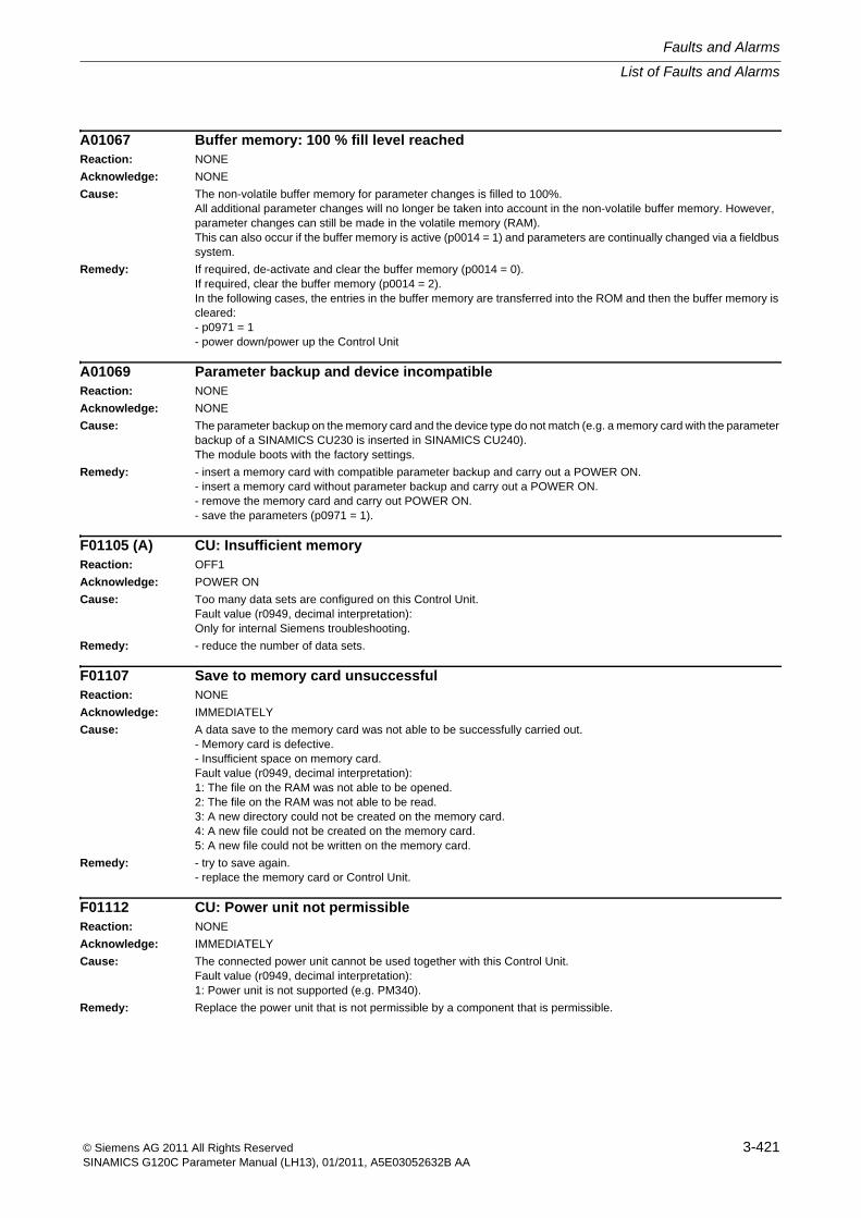
List of Faults and Alarms
Faults and Alarms
3-421© Siemens AG 2011 All Rights ReservedSINAMICS G120C Parameter Manual (LH13), 01/2011, A5E03052632B AA
A01067 Buffer memory: 100 % fill level reachedReaction: NONE
Acknowledge: NONE
Cause: The non-volatile buffer memory for parameter changes is filled to 100%.All additional parameter changes will no longer be taken into account in the non-volatile buffer memory. However, parameter changes can still be made in the volatile memory (RAM).This can also occur if the buffer memory is active (p0014 = 1) and parameters are continually changed via a fieldbus system.
Remedy: If required, de-activate and clear the buffer memory (p0014 = 0).If required, clear the buffer memory (p0014 = 2).In the following cases, the entries in the buffer memory are transferred into the ROM and then the buffer memory is cleared:- p0971 = 1- power down/power up the Control Unit
A01069 Parameter backup and device incompatibleReaction: NONE
Acknowledge: NONE
Cause: The parameter backup on the memory card and the device type do not match (e.g. a memory card with the parameter backup of a SINAMICS CU230 is inserted in SINAMICS CU240).The module boots with the factory settings.
Remedy: - insert a memory card with compatible parameter backup and carry out a POWER ON.- insert a memory card without parameter backup and carry out a POWER ON.- remove the memory card and carry out POWER ON.- save the parameters (p0971 = 1).
F01105 (A) CU: Insufficient memoryReaction: OFF1
Acknowledge: POWER ON
Cause: Too many data sets are configured on this Control Unit.Fault value (r0949, decimal interpretation):Only for internal Siemens troubleshooting.
Remedy: - reduce the number of data sets.
F01107 Save to memory card unsuccessfulReaction: NONE
Acknowledge: IMMEDIATELY
Cause: A data save to the memory card was not able to be successfully carried out.- Memory card is defective.- Insufficient space on memory card.Fault value (r0949, decimal interpretation):1: The file on the RAM was not able to be opened.2: The file on the RAM was not able to be read.3: A new directory could not be created on the memory card.4: A new file could not be created on the memory card.5: A new file could not be written on the memory card.
Remedy: - try to save again.- replace the memory card or Control Unit.
F01112 CU: Power unit not permissibleReaction: NONE
Acknowledge: IMMEDIATELY
Cause: The connected power unit cannot be used together with this Control Unit.Fault value (r0949, decimal interpretation):1: Power unit is not supported (e.g. PM340).
Remedy: Replace the power unit that is not permissible by a component that is permissible.
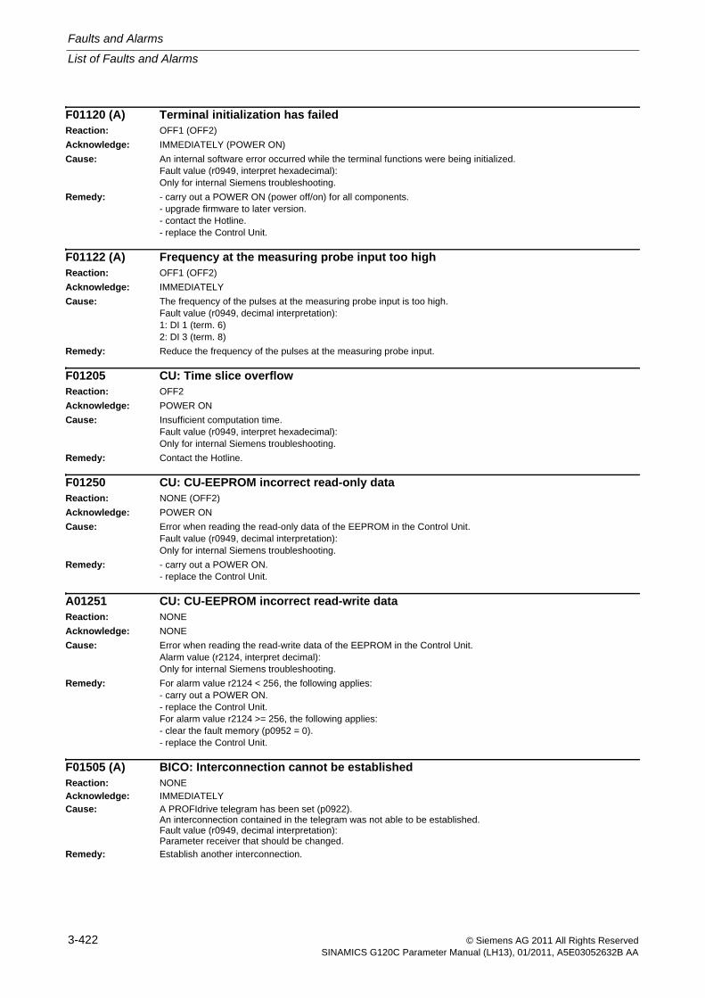
Faults and Alarms
List of Faults and Alarms
3-422 © Siemens AG 2011 All Rights ReservedSINAMICS G120C Parameter Manual (LH13), 01/2011, A5E03052632B AA
F01120 (A) Terminal initialization has failedReaction: OFF1 (OFF2)
Acknowledge: IMMEDIATELY (POWER ON)
Cause: An internal software error occurred while the terminal functions were being initialized.Fault value (r0949, interpret hexadecimal):Only for internal Siemens troubleshooting.
Remedy: - carry out a POWER ON (power off/on) for all components.- upgrade firmware to later version.- contact the Hotline.- replace the Control Unit.
F01122 (A) Frequency at the measuring probe input too highReaction: OFF1 (OFF2)
Acknowledge: IMMEDIATELY
Cause: The frequency of the pulses at the measuring probe input is too high.Fault value (r0949, decimal interpretation):1: DI 1 (term. 6)2: DI 3 (term. 8)
Remedy: Reduce the frequency of the pulses at the measuring probe input.
F01205 CU: Time slice overflowReaction: OFF2
Acknowledge: POWER ON
Cause: Insufficient computation time.Fault value (r0949, interpret hexadecimal):Only for internal Siemens troubleshooting.
Remedy: Contact the Hotline.
F01250 CU: CU-EEPROM incorrect read-only dataReaction: NONE (OFF2)
Acknowledge: POWER ON
Cause: Error when reading the read-only data of the EEPROM in the Control Unit.Fault value (r0949, decimal interpretation):Only for internal Siemens troubleshooting.
Remedy: - carry out a POWER ON.- replace the Control Unit.
A01251 CU: CU-EEPROM incorrect read-write dataReaction: NONE
Acknowledge: NONE
Cause: Error when reading the read-write data of the EEPROM in the Control Unit.Alarm value (r2124, interpret decimal):Only for internal Siemens troubleshooting.
Remedy: For alarm value r2124 < 256, the following applies:- carry out a POWER ON.- replace the Control Unit.For alarm value r2124 >= 256, the following applies:- clear the fault memory (p0952 = 0).- replace the Control Unit.
F01505 (A) BICO: Interconnection cannot be establishedReaction: NONEAcknowledge: IMMEDIATELYCause: A PROFIdrive telegram has been set (p0922).
An interconnection contained in the telegram was not able to be established.Fault value (r0949, decimal interpretation):Parameter receiver that should be changed.
Remedy: Establish another interconnection.
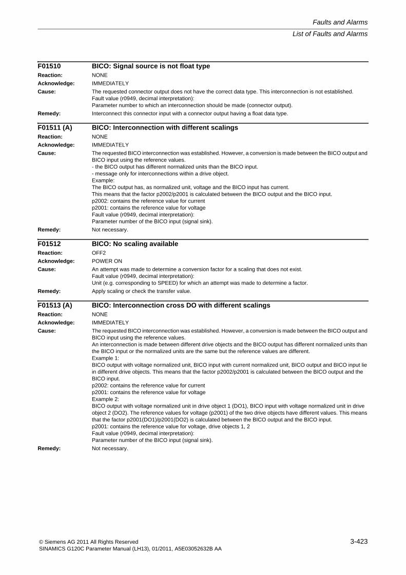
List of Faults and Alarms
Faults and Alarms
3-423© Siemens AG 2011 All Rights ReservedSINAMICS G120C Parameter Manual (LH13), 01/2011, A5E03052632B AA
F01510 BICO: Signal source is not float typeReaction: NONE
Acknowledge: IMMEDIATELY
Cause: The requested connector output does not have the correct data type. This interconnection is not established.Fault value (r0949, decimal interpretation):Parameter number to which an interconnection should be made (connector output).
Remedy: Interconnect this connector input with a connector output having a float data type.
F01511 (A) BICO: Interconnection with different scalingsReaction: NONE
Acknowledge: IMMEDIATELY
Cause: The requested BICO interconnection was established. However, a conversion is made between the BICO output and BICO input using the reference values.- the BICO output has different normalized units than the BICO input.- message only for interconnections within a drive object.Example:The BICO output has, as normalized unit, voltage and the BICO input has current.This means that the factor p2002/p2001 is calculated between the BICO output and the BICO input.p2002: contains the reference value for currentp2001: contains the reference value for voltageFault value (r0949, decimal interpretation):Parameter number of the BICO input (signal sink).
Remedy: Not necessary.
F01512 BICO: No scaling availableReaction: OFF2
Acknowledge: POWER ON
Cause: An attempt was made to determine a conversion factor for a scaling that does not exist.Fault value (r0949, decimal interpretation):Unit (e.g. corresponding to SPEED) for which an attempt was made to determine a factor.
Remedy: Apply scaling or check the transfer value.
F01513 (A) BICO: Interconnection cross DO with different scalingsReaction: NONE
Acknowledge: IMMEDIATELY
Cause: The requested BICO interconnection was established. However, a conversion is made between the BICO output and BICO input using the reference values.An interconnection is made between different drive objects and the BICO output has different normalized units than the BICO input or the normalized units are the same but the reference values are different.Example 1:BICO output with voltage normalized unit, BICO input with current normalized unit, BICO output and BICO input lie in different drive objects. This means that the factor p2002/p2001 is calculated between the BICO output and the BICO input.p2002: contains the reference value for currentp2001: contains the reference value for voltageExample 2:BICO output with voltage normalized unit in drive object 1 (DO1), BICO input with voltage normalized unit in drive object 2 (DO2). The reference values for voltage (p2001) of the two drive objects have different values. This means that the factor p2001(DO1)/p2001(DO2) is calculated between the BICO output and the BICO input.p2001: contains the reference value for voltage, drive objects 1, 2Fault value (r0949, decimal interpretation):Parameter number of the BICO input (signal sink).
Remedy: Not necessary.
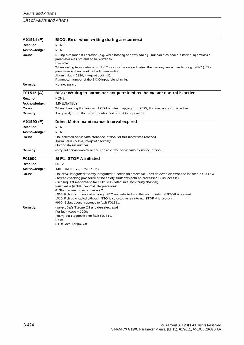
Faults and Alarms
List of Faults and Alarms
3-424 © Siemens AG 2011 All Rights ReservedSINAMICS G120C Parameter Manual (LH13), 01/2011, A5E03052632B AA
A01514 (F) BICO: Error when writing during a reconnectReaction: NONE
Acknowledge: NONE
Cause: During a reconnect operation (e.g. while booting or downloading - but can also occur in normal operation) a parameter was not able to be written to.Example:When writing to a double word BICO input in the second index, the memory areas overlap (e.g. p8861). The parameter is then reset to the factory setting.Alarm value (r2124, interpret decimal):Parameter number of the BICO input (signal sink).
Remedy: Not necessary.
F01515 (A) BICO: Writing to parameter not permitted as the master control is activeReaction: NONE
Acknowledge: IMMEDIATELY
Cause: When changing the number of CDS or when copying from CDS, the master control is active.
Remedy: If required, return the master control and repeat the operation.
A01590 (F) Drive: Motor maintenance interval expiredReaction: NONE
Acknowledge: NONE
Cause: The selected service/maintenance interval for this motor was reached.Alarm value (r2124, interpret decimal):Motor data set number.
Remedy: carry out service/maintenance and reset the service/maintenance interval.
F01600 SI P1: STOP A initiatedReaction: OFF2
Acknowledge: IMMEDIATELY (POWER ON)
Cause: The drive-integrated "Safety Integrated" function on processor 1 has detected an error and initiated a STOP A.- forced checking procedure of the safety shutdown path on processor 1 unsuccessful.- subsequent response to fault F01611 (defect in a monitoring channel).Fault value (r0949, decimal interpretation):0: Stop request from processor 2.1005: Pulses suppressed although STO not selected and there is no internal STOP A present.1010: Pulses enabled although STO is selected or an internal STOP A is present.9999: Subsequent response to fault F01611.
Remedy: - select Safe Torque Off and de-select again.For fault value = 9999:- carry out diagnostics for fault F01611.Note:STO: Safe Torque Off

List of Faults and Alarms
Faults and Alarms
3-425© Siemens AG 2011 All Rights ReservedSINAMICS G120C Parameter Manual (LH13), 01/2011, A5E03052632B AA
F01611 SI P1: Defect in a monitoring channelReaction: NONE (OFF1, OFF2, OFF3)
Acknowledge: IMMEDIATELY (POWER ON)
Cause: The drive-integrated "Safety Integrated" function on processor 1 has detected a fault in the crosswise data comparison between the two monitoring channels and has initiated a STOP F.Fault F01600 (SI P1: STOP A initiated) is output as a consequence of this fault.Fault value (r0949, decimal interpretation):0: Stop request from processor 2.1 ... 999:Number of the cross-checked data that resulted in this fault. This number is also displayed in r9795.2: SI enable safety functions (p9601, p9801). Crosswise data comparison is only carried out for the supported bits.3: SI F-DI changeover tolerance time (p9650, p9850).8: SI PROFIsafe address (p9610, p9810).9: SI debounce time for STO (p9651, p9851).1000: Watchdog timer has expired. Within a time of approx. 5 x p9650, too many switching operations have occurred at F-DI, or STO (also as subsequent response) was initiated too frequently via PROFIsafe.1001, 1002: Initialization error, change timer / check timer.2000: Status of the STO selection for both monitoring channels are different.2001: Feedback of the safe pulse suppression on the two monitoring channels are different.6000 ... 6999:Error in the PROFIsafe control.For these fault values, the failsafe control signals (failsafe values) are transferred to the safety functions.The significance of the individual message values is described in safety message C01711.
Remedy: Re fault values 1 ... 999 described in "Cause":- check the cross-checked data that resulted in a STOP F.- carry out a POWER ON (power off/on).For fault value = 1000:- check the wiring of the F-DI (contact problems).- PROFIsafe: Remove contact problems/faults at the PROFIBUS master/PROFINET controller.Re fault value = 1001, 1002:- carry out a POWER ON (power off/on).Re fault value = 2000, 2001, 2002, 2004, 2005:- check the tolerance time F-DI changeover and if required, increase the value (p9650/p9850).- check the wiring of the F-DI (contact problems).- check the causes of the STO selection in r9772. When the SI Motion functions are active (p9501 = 1), STO can also be selected using these functions.Re fault value = 6000 ... 6999:Refer to the description of the message values in safety message C01711.Re fault values that are described in "Cause":- carry out a POWER ON (power off/on).- contact the Hotline- replace Control Unit.Note:F-DI: Failsafe Digital InputSTO: Safe Torque Off
N01620 (F, A) SI P1: Safe Torque Off activeReaction: NONE
Acknowledge: NONE
Cause: The "Safe Torque Off" (STO) function has been selected on processor 1 using the input terminal and is active.Note:This message does not result in a safety stop response.
Remedy: Not necessary.Note:STO: Safe Torque Off
Faults and Alarms
List of Faults and Alarms
3-426 © Siemens AG 2011 All Rights ReservedSINAMICS G120C Parameter Manual (LH13), 01/2011, A5E03052632B AA
F01625 SI P1: Sign-of-life error in safety dataReaction: OFF2
Acknowledge: IMMEDIATELY (POWER ON)
Cause: The drive-integrated "Safety Integrated" function on processor 1 has detected an error in the sign-of-life of the safety data and initiated a STOP A.- there is a communication error between processor 1 and processor 2 or communication has failed.- a time slice overflow of the safety software has occurred.Fault value (r0949, decimal interpretation):Only for internal Siemens troubleshooting.
Remedy: - select Safe Torque Off and de-select again.- carry out a POWER ON (power off/on).- check whether additional faults are present and if required, perform diagnostics.- check the electrical cabinet design and cable routing for EMC compliance
F01649 SI P1: Internal software errorReaction: OFF2
Acknowledge: IMMEDIATELY (POWER ON)
Cause: An internal error in the Safety Integrated software on processor 1 has occurred.Note:This fault results in a STOP A that cannot be acknowledged.Fault value (r0949, interpret hexadecimal):Only for internal Siemens troubleshooting.
Remedy: - carry out a POWER ON (power off/on).- re-commission the "Safety Integrated" function and carry out a POWER ON.- contact the Hotline.- replace Control Unit.
List of Faults and Alarms
Faults and Alarms
3-427© Siemens AG 2011 All Rights ReservedSINAMICS G120C Parameter Manual (LH13), 01/2011, A5E03052632B AA
F01650 SI P1: Acceptance test requiredReaction: OFF2
Acknowledge: IMMEDIATELY (POWER ON)
Cause: The drive-integrated "Safety Integrated" function on processor 1 requires an acceptance test.Note:This fault results in a STOP A that can be acknowledged.Fault value (r0949, decimal interpretation):130: Safety parameters for processor 2 not available.Note:This fault value is always output when Safety Integrated is commissioned for the first time.1000: Reference and actual checksum on processor 1 are not identical (booting).- at least one checksum-checked piece of data is defective.2000: Reference and actual checksum on processor 1 are not identical (commissioning mode).- reference checksum incorrectly entered on processor 1 (p9799 not equal to r9798).2001: Reference and actual checksum on processor 2 are not identical (commissioning mode).- reference checksum incorrectly entered on processor 2 (p9899 not equal to r9898).2002: Enable of safety-related functions between the processor 1 and processor 2 differ (p9601 not equal to p9801).2003: Acceptance test is required as a safety parameter has been changed.2004: An acceptance test is required because a project with enabled safety-functions has been downloaded.2005: The Safety logbook has identified that a functional safety checksum has changed. An acceptance test is required.2020: Error when saving the safety parameters for the processor 2.9999: Subsequent response of another safety-related fault that occurred when booting that requires an acceptance test.
Remedy: For fault value = 130:- carry out safety commissioning routine.For fault value = 1000:- again carry out safety commissioning routine.- replace the memory card or Control Unit.For fault value = 2000:- check the safety parameters on processor 1 and adapt the reference checksum (p9799).For fault value = 2001:- check the safety parameters on processor 2 and adapt the reference checksum (p9899).For fault value = 2002:- enable the safety-related functions on processor 1 and check processor 2 (p9601 = p9801).Re fault value = 2003, 2004, 2005:- Carry out an acceptance test and generate an acceptance report.The fault with fault value 2005 can only be acknowledged when the "STO" function is de-selected.For fault value = 2020:- again carry out safety commissioning routine.- replace the memory card or Control Unit.For fault value = 9999:- carry out diagnostics for the other safety-related fault that is present.Note:STO: Safe Torque OffSee also: p9799 (SI setpoint checksum SI parameters (processor 1)), p9899 (SI setpoint checksum SI parameters (processor 2))
F01651 SI P1: Synchronization safety time slices unsuccessfulReaction: OFF2
Acknowledge: IMMEDIATELY (POWER ON)
Cause: The "Safety Integrated" function requires synchronization of the safety time slices between processor 1 and processor 2. This synchronization was unsuccessful.Note:This fault results in a STOP A that cannot be acknowledged.Fault value (r0949, decimal interpretation):Only for internal Siemens troubleshooting.
Remedy: - carry out a POWER ON (power off/on).
Faults and Alarms
List of Faults and Alarms
3-428 © Siemens AG 2011 All Rights ReservedSINAMICS G120C Parameter Manual (LH13), 01/2011, A5E03052632B AA
F01653 SI P1: PROFIBUS configuration errorReaction: NONE (OFF1, OFF2, OFF3)
Acknowledge: IMMEDIATELY (POWER ON)
Cause: There is a PROFIBUS configuration error for using Safety Integrated monitoring functions with a higher-level control.Note:For safety functions that have been enabled, this fault results in a STOP A that cannot be acknowledged.Fault value (r0949, decimal interpretation):200: A safety slot for receive data from the control has not been configured.210, 220: The configured safety slot for the receive data from the control has an unknown format.230: The configured safety slot for the receive data from the F-PLC has the incorrect length.231: The configured safety slot for the receive data from the F-PLC has the incorrect length.250: A PROFIsafe slot is configured in the higher-level F control, however PROFIsafe is not enabled in the drive.300: A safety slot for the send data to the control has not been configured.310, 320: The configured safety slot for the send data to the control has an unknown format.330: The configured safety slot for the send data to the F-PLC has the incorrect length.331: The configured safety slot for the send data to the F-PLC has the incorrect length.
Remedy: The following generally applies:- check and, if necessary, correct the PROFIBUS configuration of the safety slot on the master side.- upgrade the Control Unit software.For fault value = 250:- remove the PROFIsafe configuring in the higher-level F control or enable PROFIsafe in the drive.Re fault value = 231, 331:- configure the PROFIsafe telegram matching the parameterization in the F-PLC.If F-DI is enabled via PROFIsafe the following applies: PROFIsafe telegram 900 must be configured.If F-DI is not enabled via PROFIsafe the following applies: PROFIsafe telegram 30 must be configured.
F01655 SI P1: Align monitoring functionsReaction: OFF2Acknowledge: IMMEDIATELY (POWER ON)Cause: An error has occurred when aligning the Safety Integrated monitoring functions on processor 1 and processor 2. No
common set of supported SI monitoring functions was able to be determined.- there is a communication error between processor 1 and processor 2 or communication has failed.Note:This fault results in a STOP A that cannot be acknowledged.Fault value (r0949, interpret hexadecimal):Only for internal Siemens troubleshooting.
Remedy: - carry out a POWER ON (power off/on).- check the electrical cabinet design and cable routing for EMC compliance
F01656 SI P1: Parameter processor 2 parameter errorReaction: OFF2Acknowledge: IMMEDIATELY (POWER ON)Cause: When accessing the Safety Integrated parameters for the processor 2 in the non-volatile memory, an error has
occurred.Note:This fault results in a STOP A that can be acknowledged.Fault value (r0949, decimal interpretation):129: Safety parameters for processor 2 corrupted.131: Internal software error132: Communication errors when uploading or downloading the safety parameters.255: Internal software error on the Control Unit.
Remedy: - re-commission the safety functions.- replace the memory card or Control Unit.For fault value = 129:- activate the safety commissioning mode (p0010 = 95).- adapt the PROFIsafe address (p9610).- start the copy function for SI parameters (p9700 = D0 hex).- acknowledge data change (p9701 = DC hex).- exit the safety commissioning mode (p0010 = 0).- save all parameters (p0971 = 1 or "copy RAM to ROM").- carry out a POWER ON (power off/on) for the Control Unit.For fault value = 132:- check the electrical cabinet design and cable routing for EMC compliance
List of Faults and Alarms
Faults and Alarms
3-429© Siemens AG 2011 All Rights ReservedSINAMICS G120C Parameter Manual (LH13), 01/2011, A5E03052632B AA
F01659 SI P1: Write request for parameter rejectedReaction: OFF2
Acknowledge: IMMEDIATELY (POWER ON)
Cause: The write request for one or several Safety Integrated parameters on processor 1 was rejected.Note:This fault does not result in a safety stop response.Fault value (r0949, decimal interpretation):1: The Safety Integrated password is not set.2: A reset of the drive parameters was selected. However, the Safety Integrated parameters were not reset, as Safety Integrated is presently enabled.3: The interconnected STO input is in the simulation mode.10: An attempt was made to enable the STO function although this cannot be supported.14: An attempt was made to enable the PROFIsafe communications although this cannot be supported.15: An attempt was made to enable the motion monitoring functions integrated in the drive although these cannot be supported.18: An attempt was made to enable the PROFIsafe function for Basic Functions although this cannot be supported.20: An attempt was made to simultaneously enable both the drive-integrated motion monitoring functions via integrated F-DI and STO via terminals, even though these cannot be supported at the same time.21: An attempt was made to enable the Safety Integrated functions although these cannot be supported by the connected Power Module.See also: p0970 (Reset drive parameters), p3900 (Completion of quick commissioning), r9771 (SI common functions (processor 1)), r9871 (SI common functions (processor 2))
Remedy: For fault value = 1:- set the Safety Integrated password (p9761).For fault value = 2:- Inhibit Safety Integrated (p9501, p9601) or reset safety parameters (p0970 = 5), then reset the drive parameters again.For fault value = 3:- end the simulation mode for the digital input (p0795).Re fault value = 10, 14, 15, 18, 20:- check whether there are faults in the safety function alignment (F01655, F30655) and if required, carry out diagnostics for the faults involved.- use a Control Unit that supports the required function.For fault value = 21:- use a Power Module that supports the Safety Integrated functions.Note:STO: Safe Torque OffSee also: p9601 (SI enable, functions integrated in the drive (processor 1)), p9761 (SI password input), p9801 (SI enable, functions integrated in the drive (processor 2))
F01660 SI P1: Safety-related functions not supportedReaction: OFF2
Acknowledge: IMMEDIATELY (POWER ON)
Cause: The Power Module does not support the safety-related functions. Safety Integrated cannot be commissioned.Note:This fault does not result in a safety stop response.
Remedy: - use a Power Module that supports the safety-related functions.
F01662 Error internal communicationsReaction: OFF2
Acknowledge: POWER ON
Cause: A module-internal communication error has occurred.Fault value (r0949, interpret hexadecimal):Only for internal Siemens troubleshooting.
Remedy: - carry out a POWER ON (power off/on).- upgrade firmware to later version.- contact the Hotline.
Faults and Alarms
List of Faults and Alarms
3-430 © Siemens AG 2011 All Rights ReservedSINAMICS G120C Parameter Manual (LH13), 01/2011, A5E03052632B AA
F01663 SI P1: Copying the SI parameters rejectedReaction: OFF2
Acknowledge: IMMEDIATELY (POWER ON)
Cause: One of the following values is saved in p9700 or was entered offline: 87 or 208.This is the reason that when booting, an attempt is made to copy SI parameters from processor 1 to processor 2. However, no safety-relevant function has been selected on processor 1 (p9501 = 0, p9601 = 0). This is the reason that copying is not possible.Note:This fault does not result in a safety stop response.See also: p9700 (SI copy function)
Remedy: - Set p9700 to 0.- Check p9501 and/or p9601 and if required, correct.- Restart the copying function by entering the corresponding value into p9700.
F01665 SI P1: System is defectiveReaction: OFF2
Acknowledge: IMMEDIATELY
Cause: A system defect was detected before the last boot or in the actual one. The system might have been rebooted (reset).Fault value (r0949, interpret hexadecimal):200000 hex, 400000 hex, 8000yy hex (yy any):- Fault in the actual booting/operation.800004 hex:- Parameters p9500/p9300 are, under certain circumstances, not the same. In addition, Safety message C01711/C30711 is displayed.Additional values:- defect before the last time that the system booted.
Remedy: - carry out a POWER ON (power off/on).- upgrade firmware to later version.- contact the Hotline.Re fault value = 200000 hex, 400000 hex, 8000yy hex (yy any):- ensure that the Control Unit is connected to the Power Module.Re fault value = 800004 hex:- Check that parameters p9500/p9300 are the same.
A01669 (F, N) SI Motion: Unfavorable combination of motor and power unitReaction: NONE
Acknowledge: NONE
Cause: The combination of motor and power unit used is not suitable for using safe motion monitoring functions without an encoder.Alarm value (r2124, interpret decimal):Number of the motor data set, which caused the fault.
Remedy: Use a suitable power unit with a lower power rating or a motor with a higher power rating.
A01698 (F) SI P1: Commissioning mode activeReaction: NONE
Acknowledge: NONE
Cause: The commissioning of the "Safety Integrated" function is selected.This message is withdrawn after the safety functions have been commissioned.Note:This message does not result in a safety stop response.See also: p0010 (Drive commissioning parameter filter)
Remedy: Not necessary.
List of Faults and Alarms
Faults and Alarms
3-431© Siemens AG 2011 All Rights ReservedSINAMICS G120C Parameter Manual (LH13), 01/2011, A5E03052632B AA
A01699 (F) SI P1: Shutdown path must be testedReaction: NONE
Acknowledge: NONE
Cause: The time set in p9659 for the forced checking procedure of the safety shutdown paths has been exceeded. The safety shutdown paths must be re-tested.After the next time the "STO" function is de-selected, the message is withdrawn and the monitoring time is reset.Note:This message does not result in a safety stop response.See also: p9659 (SI forced checking procedure timer)
Remedy: Select STO and then de-select again.Note:STO: Safe Torque Off
A01900 (F) PROFIBUS: Configuration telegram errorReaction: NONE
Acknowledge: NONE
Cause: A PROFIBUS master attempts to establish a connection using an incorrect configuring telegram.Alarm value (r2124, interpret decimal):2: Too many PZD data words for output or input. The number of possible PZD is specified by the number of indices in r2050/p2051.3: Uneven number of bytes for input or output.501: PROFIsafe parameter error (e.g. F_dest).
Remedy: Check the bus configuration on the master and slave sides.Re alarm value = 2:Check the number of data words for output and input.Re alarm value = 501:Check the set PROFIsafe address (p9610).
F01910 (N, A) Fieldbus interface setpoint timeoutReaction: OFF3 (IASC/DCBRAKE, NONE, OFF1, OFF2, STOP2)
Acknowledge: IMMEDIATELY
Cause: The reception of setpoints from the fieldbus interface has been interrupted.- bus connection interrupted.- communication partner switched off.For PROFIBUS:- PROFIBUS master set into the STOP state.See also: p2040 (Fieldbus interface monitoring time), p2047 (PROFIBUS additional monitoring time)
Remedy: Ensure bus connection has been established and switch on communication peer.- if required, adapt p2040.For PROFIBUS:- set the PROFIBUS master to the RUN state.- slave redundancy: For operation on a Y link, it must be ensured that "DP alarm mode = DPV1" is set in the slave parameterization.See also: p2040 (Fieldbus interface monitoring time), p2047 (PROFIBUS additional monitoring time)
A01920 (F) PROFIBUS: Interruption cyclic connectionReaction: NONE
Acknowledge: NONE
Cause: The cyclic connection to the PROFIBUS master is interrupted.
Remedy: Establish the PROFIBUS connection and activate the PROFIBUS master in the cyclic mode.
Faults and Alarms
List of Faults and Alarms
3-432 © Siemens AG 2011 All Rights ReservedSINAMICS G120C Parameter Manual (LH13), 01/2011, A5E03052632B AA
A01945 PROFIBUS: Connection to the Publisher failedReaction: NONE
Acknowledge: NONE
Cause: For PROFIBUS peer-to-peer data transfer, the connection to at least one Publisher has failed.Alarm value (r2124, binary interpretation):Bit 0 = 1: Publisher with address in r2077[0], connection failed....Bit 15 = 1: Publisher with address in r2077[15], connection failed.
Remedy: Check the PROFIBUS cables.See also: r2077 (PROFIBUS diagnostics peer-to-peer data transfer addresses)
F01946 (A) PROFIBUS: Connection to the Publisher abortedReaction: OFF1 (NONE, OFF2, OFF3)
Acknowledge: IMMEDIATELY (POWER ON)
Cause: The connection to at least one Publisher for PROFIBUS peer-to-peer data transfer in cyclic operation has been aborted.Fault value (r0949, interpret binary):Bit 0 = 1: Publisher with address in r2077[0], connection aborted....Bit 15 = 1: Publisher with address in r2077[15], connection aborted.
Remedy: - check the PROFIBUS cables.- check the state of the Publisher that has the aborted connection.See also: r2077 (PROFIBUS diagnostics peer-to-peer data transfer addresses)
F01951 CU SYNC: Synchronization application clock cycle missingReaction: OFF2 (NONE)
Acknowledge: IMMEDIATELY (POWER ON)
Cause: Internal synchronization of the application cycles unsuccessful.Fault value (r0949, decimal interpretation):Only for internal Siemens troubleshooting.
Remedy: - carry out a POWER ON (power off/on) for all components.- upgrade the Control Unit software.
A01953 CU SYNC: Synchronization not completedReaction: NONE
Acknowledge: NONE
Cause: After the drive system was powered up, synchronization between the basic clock cycle and application clock cycle was started but was not completed within the selected time tolerance.Alarm value (r2124, interpret decimal):Only for internal Siemens troubleshooting.
Remedy: Carry out a POWER ON (power off/on).
F02080 Trace: Parameterization deleted due to unit changeoverReaction: NONE
Acknowledge: IMMEDIATELY
Cause: The trace parameterization in the drive unit was deleted due to a unit changeover or a change in the reference parameters.
Remedy: Restart trace.
List of Faults and Alarms
Faults and Alarms
3-433© Siemens AG 2011 All Rights ReservedSINAMICS G120C Parameter Manual (LH13), 01/2011, A5E03052632B AA
A02150 OA: Application cannot be loadedReaction: NONE
Acknowledge: NONE
Cause: The system was not able to load an OA application.Alarm value (r2124, interpret hexadecimal):Only for internal Siemens troubleshooting.
Remedy: - carry out a POWER ON (power off/on) for all components.- upgrade firmware to later version.- contact the Hotline.Note:OA: Open Architecture
F02151 (A) OA: Internal software errorReaction: OFF2 (NONE, OFF1, OFF3)
Acknowledge: IMMEDIATELY (POWER ON)
Cause: An internal software error has occurred within an OA application.Fault value (r0949, interpret hexadecimal):Only for internal Siemens troubleshooting.
Remedy: - carry out a POWER ON (power off/on) for all components.- upgrade firmware to later version.- contact the Hotline.- replace the Control Unit.Note:OA: Open Architecture
F02152 (A) OA: Insufficient memoryReaction: OFF1
Acknowledge: IMMEDIATELY (POWER ON)
Cause: Too many functions have been configured on this Control Unit (e.g. too many drives, function modules, data sets, OA applications, blocks, etc).Fault value (r0949, decimal interpretation):Only for internal Siemens troubleshooting.
Remedy: - change the configuration on this Control Unit (e.g. fewer drives, function modules, data sets, OA applications, blocks, etc).- use an additional Control Unit.Note:OA: Open Architecture
F03000 NVRAM fault on actionReaction: NONE
Acknowledge: IMMEDIATELY
Cause: A fault occurred during execution of action p7770 = 1, 2 for the NVRAM data.Fault value (r0949, interpret hexadecimal):yyxx hex: yy = fault cause, xx = application IDyy = 1:The action p7770 = 1 is not supported by this version if Drive Control Chart (DCC) is activated for the drive object concerned.yy = 2:The data length of the specified application is not the same in the NVRAM and the backup.yy = 3:The data checksum in p7774 is not correct.yy = 4:No data available to load.
Remedy: Perform the remedy according to the results of the troubleshooting.If necessary, start the action again.
Faults and Alarms
List of Faults and Alarms
3-434 © Siemens AG 2011 All Rights ReservedSINAMICS G120C Parameter Manual (LH13), 01/2011, A5E03052632B AA
F03001 NVRAM checksum incorrectReaction: NONE
Acknowledge: IMMEDIATELY
Cause: A checksum error occurred when evaluating the non-volatile data (NVRAM) on the Control Unit.The NVRAM data affected was deleted.
Remedy: POWER ON all components (switch the power off and then back on again).
F03505 (N, A) CU: Analog input wire breakageReaction: OFF1 (NONE, OFF2)
Acknowledge: IMMEDIATELY (POWER ON)
Cause: The input current of the analog input has undershot the threshold value parameterized in p0761[0...3].This fault only occurs when p0756[0...1] = 1 (2 ... 10 V with monitoring) or p0756[0...2] = 3 (4 ... 20 mA with monitoring) is set.p0756[0]: Analog input 0p0756[1]: Analog input 1p0756[2]: Analog input 2Fault value (r0949, decimal interpretation):The component number (p0151) of the component involved is specified at the units, tens and hundreds digit.The thousands digit specifies the relevant analog input: 0: analog input 0 (AI 0), 1: analog input 1 (AI 1), 2: analog input 2 (AI 2)
Remedy: Check the connection to the signal source for interruptions.Check the magnitude of the injected current - it is possible that the infed signal is too low.The input current measured by the analog input can be read in r0752[x].
A03510 (F, N) CU: Calibration data not plausibleReaction: NONE
Acknowledge: NONE
Cause: During booting, the calibration data for the analog inputs is read and checked with respect to plausibility.At least one calibration data point was determined to be invalid.
Remedy: - power down/power up the power supply for the Control Unit.If it reoccurs, replace the module.In principle, operation could continue.The analog channel involved possibly does not achieve the specified accuracy.
A05000 (N) Power unit: Overtemperature heat sink AC inverterReaction: NONE
Acknowledge: NONE
Cause: The alarm threshold for overtemperature at the inverter heat sink has been reached. The response is set using p0290.If the temperature of the heat sink increases by an additional 5 K, then fault F30004 is initiated.
Remedy: Check the following:- is the ambient temperature within the defined limit values?- have the load conditions and the load duty cycle been appropriately dimensioned?- has the cooling failed?
A05001 (N) Power unit: Overtemperature depletion layer chipReaction: NONE
Acknowledge: NONE
Cause: Alarm threshold for overtemperature of the power semiconductor in the AC converter has been reached.Note:- The response is set using p0290.- If the depletion layer temperature increases by an additional 15 K, then fault F30025 is triggered.
Remedy: Check the following:- is the ambient temperature within the defined limit values?- have the load conditions and the load duty cycle been appropriately dimensioned?- has the cooling failed?- pulse frequency too high?See also: r0037 (Power unit temperatures), p0290 (Power unit overload response)
List of Faults and Alarms
Faults and Alarms
3-435© Siemens AG 2011 All Rights ReservedSINAMICS G120C Parameter Manual (LH13), 01/2011, A5E03052632B AA
A05002 (N) Power unit: Air intake overtemperatureReaction: NONE
Acknowledge: NONE
Cause: For chassis power units, the following applies:The alarm threshold for the air intake overtemperature has been reached. For air-cooled power units, the threshold is 42 °C (hysteresis 2 K). The response is set using p0290.If the air intake temperature increases by an additional 13 K, then fault F30035 is output.
Remedy: Check the following:- is the ambient temperature within the defined limit values?- has the fan failed? Check the direction of rotation.
A05004 (N) Power unit: Rectifier overtemperatureReaction: NONE
Acknowledge: NONE
Cause: The alarm threshold for the overtemperature of the rectifier has been reached. The response is set using p0290.If the temperature of the rectifier increases by an additional 5 K, then fault F30037 is triggered.
Remedy: Check the following:- is the ambient temperature within the defined limit values?- have the load conditions and the load duty cycle been appropriately dimensioned?- has the fan failed? Check the direction of rotation.- has a phase of the line supply failed?- is an arm of the supply (incoming) rectifier defective?
A05006 (N) Power unit: Overtemperature thermal modelReaction: NONE
Acknowledge: NONE
Cause: The temperature difference between the chip and heat sink has exceeded the permissible limit value (blocksize power units only).Depending on p0290, an appropriate overload response is initiated.See also: r0037 (Power unit temperatures)
Remedy: Not necessary.The alarm disappears automatically once the limit value is undershot.Note:If the alarm does not disappear automatically and the temperature continues to rise, this can result in fault F30024.See also: p0290 (Power unit overload response)
F06310 (A) Supply voltage (p0210) incorrectly parameterizedReaction: NONE (OFF1, OFF2)
Acknowledge: IMMEDIATELY (POWER ON)
Cause: The measured DC voltage lies outside the tolerance range after pre-charging has been completed: 1.16 * p0210 < r0070 < 1.6 * p0210.The fault can only be acknowledged when the drive is powered down.See also: p0210 (Drive unit line supply voltage)
Remedy: - check the parameterized supply voltage and if required change (p0210).- check the line supply voltage.See also: p0210 (Drive unit line supply voltage)
A06921 (N) Braking resistor phase unsymmetryReaction: NONE
Acknowledge: NONE
Cause: The three resistors of the braking chopper are not symmetrical.
Remedy: - check the feeder cables to the braking resistors.- increase p1364.
Faults and Alarms
List of Faults and Alarms
3-436 © Siemens AG 2011 All Rights ReservedSINAMICS G120C Parameter Manual (LH13), 01/2011, A5E03052632B AA
F06922 Braking resistor phase failureReaction: NONE
Acknowledge: IMMEDIATELY
Cause: Phase failure of a braking resistor detected.Fault values:11 = phase U12 = phase V13 = phase W
Remedy: Check the feeder cables to the braking resistors.
F07011 Drive: Motor overtemperatureReaction: OFF2 (NONE, OFF1, OFF3, STOP2)
Acknowledge: IMMEDIATELY
Cause: KTY:The motor temperature has exceeded the fault threshold (p0605). The response parameterized in p0610 becomes active.PTC or bimetallic NC contact:The response threshold of 1650 Ohm was exceeded or the NC contact opened. The response parameterized in p0610 becomes active.Possible causes:- Motor is overloaded- motor ambient temperature too high.- Wire break or sensor not connectedFault value (r0949, decimal interpretation):See also: p0604 (Motor temperature alarm threshold), p0605 (Motor temperature fault threshold), p0610 (Motor overtemperature response)
Remedy: - Reduce the motor load.- check the ambient temperature and the motor ventilation.- check the wiring and the connection of the PTC or bimetallic NC contact.See also: p0604 (Motor temperature alarm threshold), p0605 (Motor temperature fault threshold)
A07012 (N) Drive: I2t motor model overtemperatureReaction: NONE
Acknowledge: NONE
Cause: The thermal I2t motor model (for synchronous motors) identified that the temperature alarm threshold was exceeded.See also: r0034 (Motor utilization), p0605 (Motor temperature fault threshold), p0611 (I2t motor model thermal time constant)
Remedy: - check the motor load and if required, reduce.- check the motor ambient temperature.- check the thermal time constant p0611.- check the overtemperature fault threshold p0605 (= alarm threshold for the I2t motor model).
A07015 Drive: Motor temperature sensor alarmReaction: NONE
Acknowledge: NONE
Cause: An error was detected when evaluating the temperature sensor set in p0601.A timer is started with the error. If the fault is still present after this time has expired, then fault F07016 is output; however, at the earliest, 0.2 s after alarm A07015.Possible causes:- wire breakage or sensor not connected (KTY: R > 2120 Ohm).- measured resistance too low (PTC: R < 20 Ohm, KTY: R < 50 Ohm).
Remedy: - make sure that the sensor is connected correctly.- check the parameterization (p0601).See also: r0035 (Motor temperature), p0601 (Motor temperature sensor type)
List of Faults and Alarms
Faults and Alarms
3-437© Siemens AG 2011 All Rights ReservedSINAMICS G120C Parameter Manual (LH13), 01/2011, A5E03052632B AA
F07016 Drive: Motor temperature sensor faultReaction: OFF1 (NONE, OFF2, OFF3, STOP2)
Acknowledge: IMMEDIATELY
Cause: An error was detected when evaluating the temperature sensor set in p0601.Possible causes:- wire breakage or sensor not connected (KTY: R > 2120 Ohm).- measured resistance too low (PTC: R < 20 Ohm, KTY: R < 50 Ohm).Note:If alarm A07015 is present, a timer is started. If the fault is still present after this time has expired, then fault F07016 is output; however, at the earliest, 0.2 s after alarm A07015.
Remedy: - make sure that the sensor is connected correctly.- check the parameterization (p0601).See also: r0035 (Motor temperature), p0601 (Motor temperature sensor type)
F07080 Drive: Incorrect control parameterReaction: NONE
Acknowledge: IMMEDIATELY (POWER ON)
Cause: The closed-loop control parameters have been parameterized incorrectly (e.g. p0356 = L_spread = 0).Fault value (r0949, decimal interpretation):The fault value includes the parameter number involved.The following parameter numbers only occur as fault values for vector drives:p0310, for synchronous motors: p0341, p0344, p0350, p0357The following parameter numbers do not occur as fault values for synchronous motors:p0354, p0358, p0360See also: p0310, p0311, p0341, p0344, p0350, p0354, p0356, p0357, p0358, p0360, p0640, p1082, p1300
Remedy: Modify the parameter indicated in the fault value (r0949) (e.g. p0640 = current limit > 0).See also: p0311, p0341, p0344, p0350, p0354, p0356, p0358, p0360, p0640, p1082
F07082 Macro: Execution not possibleReaction: NONEAcknowledge: IMMEDIATELYCause: The macro cannot be executed.
Fault value (r0949, interpret hexadecimal):ccccbbaa hex:cccc = preliminary parameter number, bb = supplementary information, aa = fault causeFault causes for the trigger parameter itself:19: Called file is not valid for the trigger parameter.20: Called file is not valid for parameter 15.21: Called file is not valid for parameter 700.22: Called file is not valid for parameter 1000.23: Called file is not valid for parameter 1500.24: Data type of a TAG is incorrect (e.g. Index, number or bit is not U16).Fault causes for the parameters to be set:25: Error level has an undefined value.26: Mode has an undefined value.27: A value was entered as string in the tag value that is not "DEFAULT".31: Entered drive object type unknown.32: A device was not able to be found for the determined drive object number.34: A trigger parameter was recursively called.35: It is not permissible to write to the parameter via macro.36: Check, writing to a parameter unsuccessful, parameter can only be read, not available, incorrect data type, value range or assignment incorrect.37: Source parameter for a BICO interconnection was not able to be determined.38: An index was set for a non-indexed (or CDS-dependent) parameter.39: No index was set for an indexed parameter.41: A bit operation is only permissible for parameters with the parameter format DISPLAY_BIN.42: A value not equal to 0 or 1 was set for a BitOperation.43: Reading the parameter to be changed by the BitOperation was unsuccessful.51: Factory setting for DEVICE may only be executed on the DEVICE.61: The setting of a value was unsuccessful.
Remedy: - check the parameter involved.- check the macro file and BICO interconnection.See also: p0015, p0700, p1000
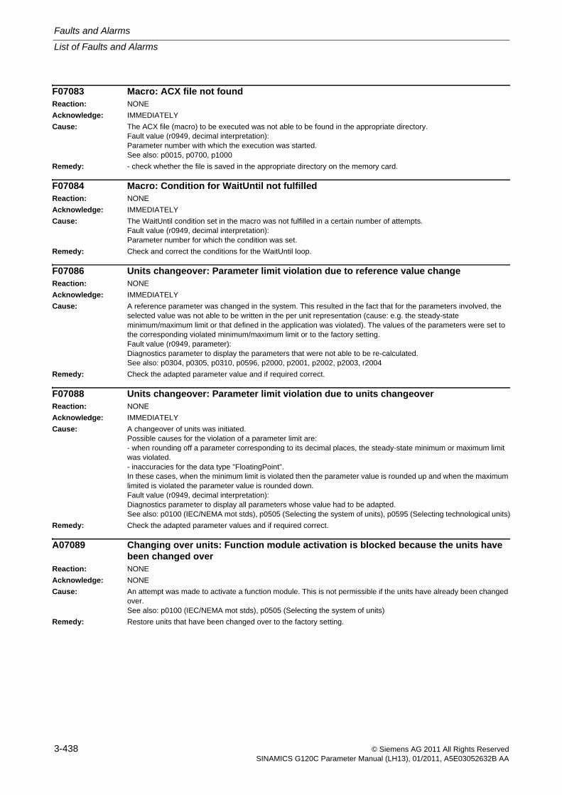
Faults and Alarms
List of Faults and Alarms
3-438 © Siemens AG 2011 All Rights ReservedSINAMICS G120C Parameter Manual (LH13), 01/2011, A5E03052632B AA
F07083 Macro: ACX file not foundReaction: NONE
Acknowledge: IMMEDIATELY
Cause: The ACX file (macro) to be executed was not able to be found in the appropriate directory.Fault value (r0949, decimal interpretation):Parameter number with which the execution was started.See also: p0015, p0700, p1000
Remedy: - check whether the file is saved in the appropriate directory on the memory card.
F07084 Macro: Condition for WaitUntil not fulfilledReaction: NONE
Acknowledge: IMMEDIATELY
Cause: The WaitUntil condition set in the macro was not fulfilled in a certain number of attempts.Fault value (r0949, decimal interpretation):Parameter number for which the condition was set.
Remedy: Check and correct the conditions for the WaitUntil loop.
F07086 Units changeover: Parameter limit violation due to reference value changeReaction: NONE
Acknowledge: IMMEDIATELY
Cause: A reference parameter was changed in the system. This resulted in the fact that for the parameters involved, the selected value was not able to be written in the per unit representation (cause: e.g. the steady-state minimum/maximum limit or that defined in the application was violated). The values of the parameters were set to the corresponding violated minimum/maximum limit or to the factory setting.Fault value (r0949, parameter):Diagnostics parameter to display the parameters that were not able to be re-calculated.See also: p0304, p0305, p0310, p0596, p2000, p2001, p2002, p2003, r2004
Remedy: Check the adapted parameter value and if required correct.
F07088 Units changeover: Parameter limit violation due to units changeoverReaction: NONE
Acknowledge: IMMEDIATELY
Cause: A changeover of units was initiated.Possible causes for the violation of a parameter limit are:- when rounding off a parameter corresponding to its decimal places, the steady-state minimum or maximum limit was violated.- inaccuracies for the data type "FloatingPoint".In these cases, when the minimum limit is violated then the parameter value is rounded up and when the maximum limited is violated the parameter value is rounded down.Fault value (r0949, decimal interpretation):Diagnostics parameter to display all parameters whose value had to be adapted.See also: p0100 (IEC/NEMA mot stds), p0505 (Selecting the system of units), p0595 (Selecting technological units)
Remedy: Check the adapted parameter values and if required correct.
A07089 Changing over units: Function module activation is blocked because the units have been changed over
Reaction: NONE
Acknowledge: NONE
Cause: An attempt was made to activate a function module. This is not permissible if the units have already been changed over.See also: p0100 (IEC/NEMA mot stds), p0505 (Selecting the system of units)
Remedy: Restore units that have been changed over to the factory setting.
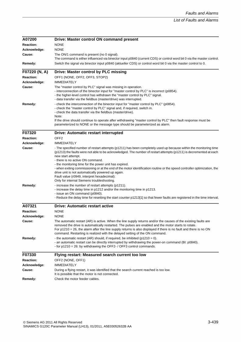
List of Faults and Alarms
Faults and Alarms
3-439© Siemens AG 2011 All Rights ReservedSINAMICS G120C Parameter Manual (LH13), 01/2011, A5E03052632B AA
A07200 Drive: Master control ON command presentReaction: NONE
Acknowledge: NONE
Cause: The ON/1 command is present (no 0 signal).The command is either influenced via binector input p0840 (current CDS) or control word bit 0 via the master control.
Remedy: Switch the signal via binector input p0840 (aktueller CDS) or control word bit 0 via the master control to 0.
F07220 (N, A) Drive: Master control by PLC missingReaction: OFF1 (NONE, OFF2, OFF3, STOP2)
Acknowledge: IMMEDIATELY
Cause: The "master control by PLC" signal was missing in operation.- interconnection of the binector input for "master control by PLC" is incorrect (p0854).- the higher-level control has withdrawn the "master control by PLC" signal.- data transfer via the fieldbus (master/drive) was interrupted.
Remedy: - check the interconnection of the binector input for "master control by PLC" (p0854).- check the "master control by PLC" signal and, if required, switch in.- check the data transfer via the fieldbus (master/drive).Note:If the drive should continue to operate after withdrawing "master control by PLC" then fault response must be parameterized to NONE or the message type should be parameterized as alarm.
F07320 Drive: Automatic restart interruptedReaction: OFF2
Acknowledge: IMMEDIATELY
Cause: - The specified number of restart attempts (p1211) has been completely used up because within the monitoring time (p1213) the faults were not able to be acknowledged. The number of restart attempts (p1211) is decremented at each new start attempt.- there is no active ON command.- the monitoring time for the power unit has expired.- when exiting commissioning or at the end of the motor identification routine or the speed controller optimization, the drive unit is not automatically powered up again.Fault value (r0949, interpret hexadecimal):Only for internal Siemens troubleshooting.
Remedy: - increase the number of restart attempts (p1211).- increase the delay time in p1212 and/or the monitoring time in p1213.- issue an ON command (p0840).- Reduce the delay time for resetting the start counter p1213[1] so that fewer faults are registered in the time interval.
A07321 Drive: Automatic restart activeReaction: NONE
Acknowledge: NONE
Cause: The automatic restart (AR) is active. When the line supply returns and/or the causes of the existing faults are removed the drive is automatically restarted. The pulses are enabled and the motor starts to rotate.For p1210 = 26, the alarm after the line supply returns is also displayed if there is no fault and there is no ON command. Restarting is realized with the delayed setting of the ON command.
Remedy: - the automatic restart (AR) should, if required, be inhibited (p1210 = 0).- an automatic restart can be directly interrupted by withdrawing the power-on command (BI: p0840).- for p1210 = 26: by withdrawing the OFF2- / OFF3 control commands.
F07330 Flying restart: Measured search current too lowReaction: OFF2 (NONE, OFF1)
Acknowledge: IMMEDIATELY
Cause: During a flying restart, it was identified that the search current reached is too low.It is possible that the motor is not connected.
Remedy: Check the motor feeder cables.
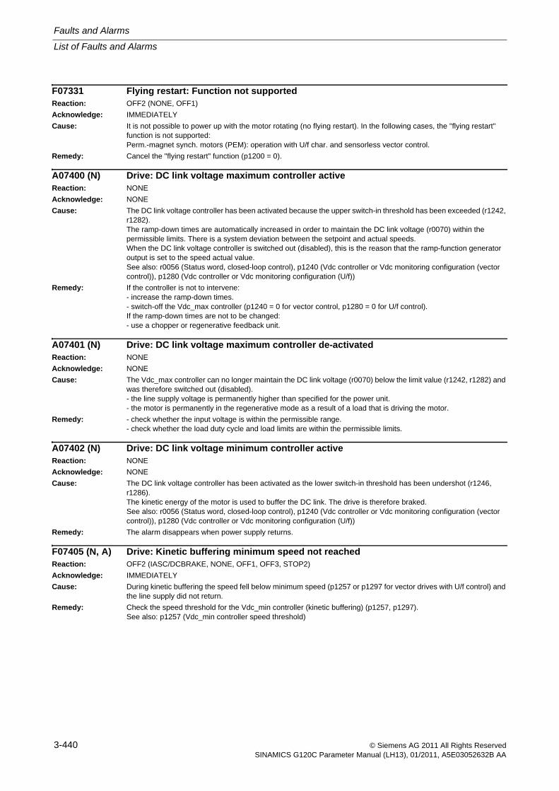
Faults and Alarms
List of Faults and Alarms
3-440 © Siemens AG 2011 All Rights ReservedSINAMICS G120C Parameter Manual (LH13), 01/2011, A5E03052632B AA
F07331 Flying restart: Function not supportedReaction: OFF2 (NONE, OFF1)
Acknowledge: IMMEDIATELY
Cause: It is not possible to power up with the motor rotating (no flying restart). In the following cases, the "flying restart" function is not supported:Perm.-magnet synch. motors (PEM): operation with U/f char. and sensorless vector control.
Remedy: Cancel the "flying restart" function (p1200 = 0).
A07400 (N) Drive: DC link voltage maximum controller activeReaction: NONE
Acknowledge: NONE
Cause: The DC link voltage controller has been activated because the upper switch-in threshold has been exceeded (r1242, r1282).The ramp-down times are automatically increased in order to maintain the DC link voltage (r0070) within the permissible limits. There is a system deviation between the setpoint and actual speeds.When the DC link voltage controller is switched out (disabled), this is the reason that the ramp-function generator output is set to the speed actual value.See also: r0056 (Status word, closed-loop control), p1240 (Vdc controller or Vdc monitoring configuration (vector control)), p1280 (Vdc controller or Vdc monitoring configuration (U/f))
Remedy: If the controller is not to intervene:- increase the ramp-down times.- switch-off the Vdc_max controller (p1240 = 0 for vector control, p1280 = 0 for U/f control).If the ramp-down times are not to be changed:- use a chopper or regenerative feedback unit.
A07401 (N) Drive: DC link voltage maximum controller de-activatedReaction: NONE
Acknowledge: NONE
Cause: The Vdc_max controller can no longer maintain the DC link voltage (r0070) below the limit value (r1242, r1282) and was therefore switched out (disabled).- the line supply voltage is permanently higher than specified for the power unit.- the motor is permanently in the regenerative mode as a result of a load that is driving the motor.
Remedy: - check whether the input voltage is within the permissible range.- check whether the load duty cycle and load limits are within the permissible limits.
A07402 (N) Drive: DC link voltage minimum controller activeReaction: NONE
Acknowledge: NONE
Cause: The DC link voltage controller has been activated as the lower switch-in threshold has been undershot (r1246, r1286).The kinetic energy of the motor is used to buffer the DC link. The drive is therefore braked.See also: r0056 (Status word, closed-loop control), p1240 (Vdc controller or Vdc monitoring configuration (vector control)), p1280 (Vdc controller or Vdc monitoring configuration (U/f))
Remedy: The alarm disappears when power supply returns.
F07405 (N, A) Drive: Kinetic buffering minimum speed not reachedReaction: OFF2 (IASC/DCBRAKE, NONE, OFF1, OFF3, STOP2)
Acknowledge: IMMEDIATELY
Cause: During kinetic buffering the speed fell below minimum speed (p1257 or p1297 for vector drives with U/f control) and the line supply did not return.
Remedy: Check the speed threshold for the Vdc_min controller (kinetic buffering) (p1257, p1297).See also: p1257 (Vdc_min controller speed threshold)
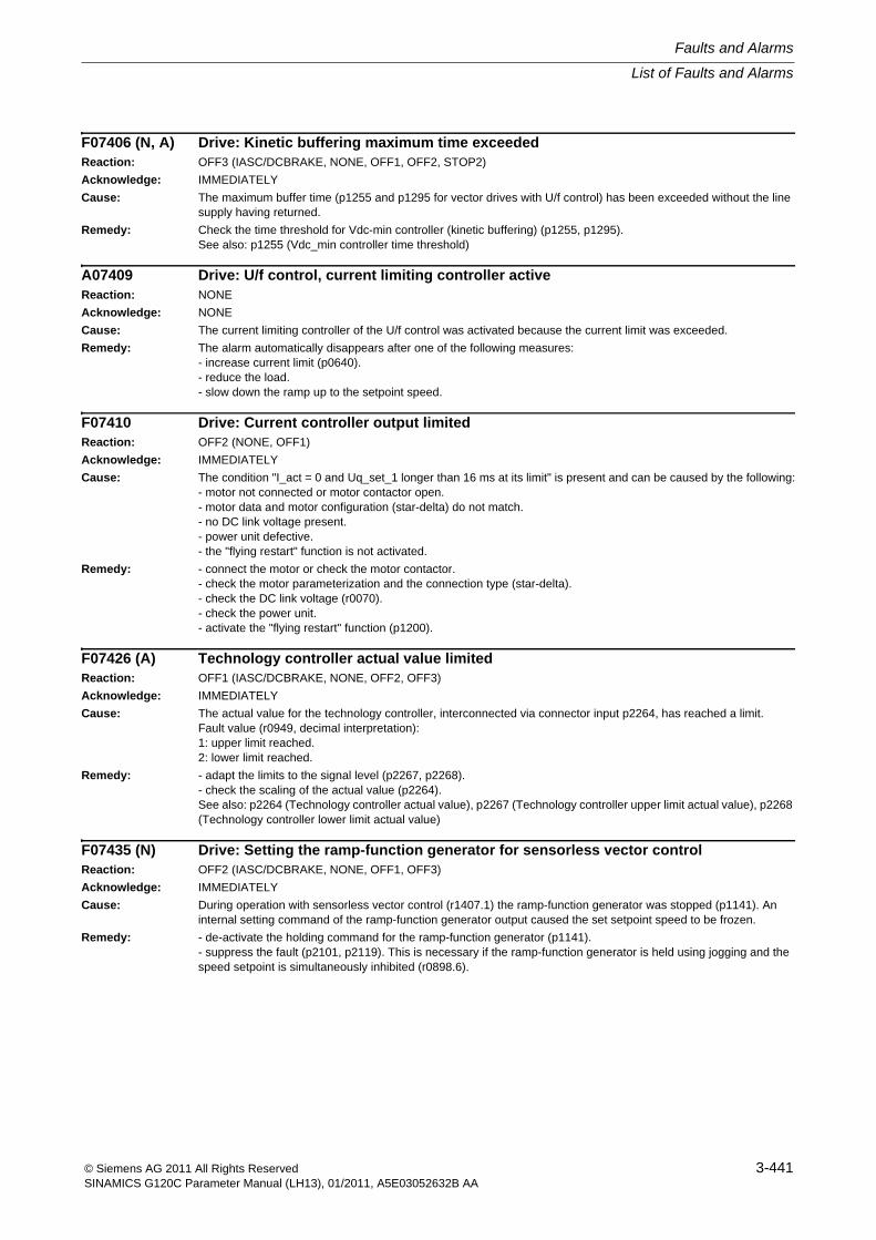
List of Faults and Alarms
Faults and Alarms
3-441© Siemens AG 2011 All Rights ReservedSINAMICS G120C Parameter Manual (LH13), 01/2011, A5E03052632B AA
F07406 (N, A) Drive: Kinetic buffering maximum time exceededReaction: OFF3 (IASC/DCBRAKE, NONE, OFF1, OFF2, STOP2)
Acknowledge: IMMEDIATELY
Cause: The maximum buffer time (p1255 and p1295 for vector drives with U/f control) has been exceeded without the line supply having returned.
Remedy: Check the time threshold for Vdc-min controller (kinetic buffering) (p1255, p1295).See also: p1255 (Vdc_min controller time threshold)
A07409 Drive: U/f control, current limiting controller activeReaction: NONE
Acknowledge: NONE
Cause: The current limiting controller of the U/f control was activated because the current limit was exceeded.
Remedy: The alarm automatically disappears after one of the following measures:- increase current limit (p0640).- reduce the load.- slow down the ramp up to the setpoint speed.
F07410 Drive: Current controller output limitedReaction: OFF2 (NONE, OFF1)
Acknowledge: IMMEDIATELY
Cause: The condition "I_act = 0 and Uq_set_1 longer than 16 ms at its limit" is present and can be caused by the following:- motor not connected or motor contactor open.- motor data and motor configuration (star-delta) do not match.- no DC link voltage present.- power unit defective.- the "flying restart" function is not activated.
Remedy: - connect the motor or check the motor contactor.- check the motor parameterization and the connection type (star-delta).- check the DC link voltage (r0070).- check the power unit.- activate the "flying restart" function (p1200).
F07426 (A) Technology controller actual value limitedReaction: OFF1 (IASC/DCBRAKE, NONE, OFF2, OFF3)
Acknowledge: IMMEDIATELY
Cause: The actual value for the technology controller, interconnected via connector input p2264, has reached a limit.Fault value (r0949, decimal interpretation):1: upper limit reached.2: lower limit reached.
Remedy: - adapt the limits to the signal level (p2267, p2268).- check the scaling of the actual value (p2264).See also: p2264 (Technology controller actual value), p2267 (Technology controller upper limit actual value), p2268 (Technology controller lower limit actual value)
F07435 (N) Drive: Setting the ramp-function generator for sensorless vector controlReaction: OFF2 (IASC/DCBRAKE, NONE, OFF1, OFF3)
Acknowledge: IMMEDIATELY
Cause: During operation with sensorless vector control (r1407.1) the ramp-function generator was stopped (p1141). An internal setting command of the ramp-function generator output caused the set setpoint speed to be frozen.
Remedy: - de-activate the holding command for the ramp-function generator (p1141).- suppress the fault (p2101, p2119). This is necessary if the ramp-function generator is held using jogging and the speed setpoint is simultaneously inhibited (r0898.6).
Faults and Alarms
List of Faults and Alarms
3-442 © Siemens AG 2011 All Rights ReservedSINAMICS G120C Parameter Manual (LH13), 01/2011, A5E03052632B AA
F07439 Drive: Higher current controller dynamic performance not possibleReaction: OFF2 (NONE)
Acknowledge: IMMEDIATELY
Cause: The function "Current controller dynamics higher" (p1810.11 = 1) is selected, however is not supported by the power unit (r0192.27 = 0) or by the safety technology without encoder (9506 = 1).Fault value (r0949, decimal interpretation):1:- firmware of the booksize power unit is not up-to-date.- blocksize or S120 combi power unit was used.2:- a sine-cosine encoder with encoderless safety technology is used.
Remedy: In general:- Deselect the function "Current controller dynamics higher" (p1810.11 = 0) and if required, set the current, speed and position controller again or calculate (p0340 = 4).For fault value = 1:- If necessary, upgrade the firmware of the booksize power unit to a later version (version >= 4.4).- Use a booksize power unit (version >= 4.4).For fault value = 2:- Re-parameterize encoderless safety technology (9506 = 1) to safety technology with an encoder (p9506 = 0).
A07530 Drive: Drive Data Set DDS not presentReaction: NONE
Acknowledge: NONE
Cause: The selected drive data set is not available. The drive data set was not changed over.See also: p0180 (Number of Drive Data Sets (DDS))
Remedy: - select the existing drive data set.- set up additional drive data sets.
A07531 Drive: Command Data Set CDS not presentReaction: NONE
Acknowledge: NONE
Cause: The selected command data set is not available (p0836 > p0170). The command data set was not changed over.See also: p0810 (Command data set selection CDS bit 0), r0836 (Command Data Set CDS selected)
Remedy: - select the existing command data set.- set up additional command data sets.
F07800 Drive: No power unit presentReaction: NONE
Acknowledge: IMMEDIATELY
Cause: The power unit parameters cannot be read or no parameters are stored in the power unit.Connection between Control Unit and power unit was interrupted or is defective.Note:This fault also occurs if an incorrect topology was selected in the commissioning software and this parameterization is then downloaded to the Control Unit.
Remedy: - connect the data line to power unit and restart the CU (POWER ON).- check or replace the CU.- Check the cable between the CU and power unit.- after correcting the topology, the parameters must be again downloaded using the commissioning software.
List of Faults and Alarms
Faults and Alarms
3-443© Siemens AG 2011 All Rights ReservedSINAMICS G120C Parameter Manual (LH13), 01/2011, A5E03052632B AA
F07801 Drive: Motor overcurrentReaction: OFF2 (NONE, OFF1, OFF3)
Acknowledge: IMMEDIATELY
Cause: The permissible motor limit current was exceeded.- effective current limit set too low.- current controller not correctly set.- U/f operation: Up ramp was set too short or the load is too high.- U/f operation: Short-circuit in the motor cable or ground fault.- U/f operation: Motor current does not match current of power unit.- Switch to rotating motor without flying restart function (p1200).Note:Limit current = 2 x minimum (p0640, 4 x p0305 x p0306) >= 2 x p0305 x p0306
Remedy: - check the current limits (p0640).- U/f control: Check the current limiting controller (p1340 ... p1346).- increase the up ramp (p1120) or reduce the load.- check the motor and motor cables for short-circuit and ground fault.- check the motor for the star-delta configuration and rating plate parameterization.- check the power unit and motor combination.- Choose "flying restart" function (p1200) if switched to rotating motor.
F07802 Drive: Infeed or power unit not readyReaction: OFF2 (NONE)
Acknowledge: IMMEDIATELY
Cause: After an internal power-on command, the infeed or drive does not signal ready.- monitoring time is too short.- DC link voltage is not present.- associated infeed or drive of the signaling component is defective.- supply voltage incorrectly set.
Remedy: - ensure that there is a DC link voltage. Check the DC link busbar. Enable the infeed.- replace the associated infeed or drive of the signaling component.- check the line supply voltage setting (p0210).
A07805 (N) Drive: Power unit overload I2tReaction: NONE
Acknowledge: NONE
Cause: Alarm threshold for I2t overload of the power unit exceeded.The response parameterized in p0290 becomes active.See also: p0290 (Power unit overload response)
Remedy: - reduce the continuous load.- adapt the load duty cycle.- check the assignment of the motor and power unit rated currents.
F07806 Drive: Regenerative power limit exceeded (F3E)Reaction: OFF2 (IASC/DCBRAKE)
Acknowledge: IMMEDIATELY
Cause: For blocksize power units, types PM250 and PM260, the regenerative rated power r0206[2] was exceeded for more than 10 s.See also: r0206 (Rated power unit power), p1531 (Power limit regenerative)
Remedy: - increase the down ramp.- reduce the driving load.- use a power unit with a higher regenerative feedback capability.- for vector control, the regenerative power limit in p1531 can be reduced so that the fault is no longer triggered.
Faults and Alarms
List of Faults and Alarms
3-444 © Siemens AG 2011 All Rights ReservedSINAMICS G120C Parameter Manual (LH13), 01/2011, A5E03052632B AA
F07807 Drive: Short-circuit detectedReaction: OFF2 (NONE)
Acknowledge: IMMEDIATELY
Cause: A phase-phase short-circuit was detected at the motor-side output terminals of the converter.Note:Also when interchanging the line and motor cables is identified as a motor-side short circuit.
Remedy: - check the motor-side converter connection for a phase-phase short-circuit.- rule-out interchanged line and motor cables.
F07808 (A) HF damping module: damping not readyReaction: OFF2 (NONE, OFF1, OFF3)
Acknowledge: IMMEDIATELY
F07810 Drive: Power unit EEPROM without rated dataReaction: NONE
Acknowledge: IMMEDIATELY
Cause: No rated data are stored in the power unit EEPROM.See also: p0205 (Power unit application), r0206 (Rated power unit power), r0207 (Rated power unit current), r0208 (Rated power unit line supply voltage), r0209 (Power unit, maximum current)
Remedy: Replace the power unit or inform Siemens Customer Service.
A07850 (F) External alarm 1Reaction: NONE
Acknowledge: NONE
Cause: The BICO signal for "external alarm 1" was triggered.The condition for this external alarm is fulfilled.See also: p2112 (External alarm 1)
Remedy: Eliminate the causes of this alarm.
F07860 (A) External fault 1Reaction: OFF2 (IASC/DCBRAKE, NONE, OFF1, OFF3, STOP2)
Acknowledge: IMMEDIATELY (POWER ON)
Cause: The BICO signal "external fault 1" was triggered.See also: p2106 (External fault 1)
Remedy: Eliminate the causes of this fault.
F07900 (N, A) Drive: Motor blockedReaction: OFF2 (NONE, OFF1, OFF3, STOP2)
Acknowledge: IMMEDIATELY
Cause: Motor has been operating at the torque limit at a low speed for a longer period of time and below the set speed threshold.This signal can also be triggered if the speed is oscillating and the speed controller output repeatedly goes to its limit.It may also be the case that thermal monitoring of the power unit reduces the current limit (see p0290), thereby causing the motor to decelerate.
Remedy: - check that the motor can rotate freely.- check the torque limit: For a positive direction of rotation r1538, for a negative direction of rotation r1539.
List of Faults and Alarms
Faults and Alarms
3-445© Siemens AG 2011 All Rights ReservedSINAMICS G120C Parameter Manual (LH13), 01/2011, A5E03052632B AA
F07901 Drive: Motor overspeedReaction: OFF2 (IASC/DCBRAKE)
Acknowledge: IMMEDIATELY
Cause: The maximum permissible speed was either positively or negatively exceeded.The maximum permissible positive speed is formed as follows: Minimum (p1082)The maximum permissible negative speed is formed as follows: Maximum (-p1082)
Remedy: The following applies for a positive direction of rotation:- check r1084 and if required, correct p1082.The following applies for a negative direction of rotation:- check r1087 and if required, correct p1082.Activate pre-control of the speed limiting controller (bit 7 = 1).Increase the hysteresis for the overspeed signal. This upper limit is dependent upon the maximum motor speed p0322 and the maximum speed p1082 of the setpoint channel.
F07902 (N, A) Drive: Motor stalledReaction: OFF2 (IASC/DCBRAKE, NONE, OFF1, OFF3, STOP2)
Acknowledge: IMMEDIATELY
Cause: For a vector drive the system has identified that the motor has stalled for a time longer than is set.Fault value (r0949, decimal interpretation):1: Reserved.2: Stall detection using r1408.12 (p1745).
Remedy: Steps should always be taken to ensure that both motor data identification and the rotating measurement were carried out (see p1900, r3925).- check whether the drive stalls solely due to the load in controlled mode or when the speed setpoint is still zero. If yes, then increase the current setpoint using p1610.- if the motor excitation time (p0346) was significantly reduced and the drive stalls when it is switched on and run immediately, p0346 should be increased again.- check the current limits (p0640, r0067, r0289). If the current limits are too low, then the drive cannot be magnetized.- check whether the motor cables are disconnected (see A07929).If there is no fault, then the fault tolerance can be increased (p1745).
A07910 (N) Drive: Motor overtemperatureReaction: NONE
Acknowledge: NONE
Cause: KTY or no sensor:The measured motor temperature or the temperature of the thermal model has exceeded the alarm threshold (p0604). The response parameterized in p0610 becomes active.PTC or bimetallic NC contact:The response threshold of 1650 Ohm was exceeded or the NC contact opened.Alarm value (r2124, interpret decimal):11: No output current reduction.12: Output current reduction active.See also: p0604 (Motor temperature alarm threshold), p0610 (Motor overtemperature response)
Remedy: - check the motor load.- check the motor ambient temperature.- check KTY84.- check overtemperatures of the thermal model.
A07927 DC braking activeReaction: NONEAcknowledge: NONECause: The motor is braked with DC current. DC braking is active.
1)A message with response DCBRK is active. The motor is braked with the braking current set in p1232 for the duration set in in p1233. If the standstill threshold is fallen below, then braking is prematurely canceled.2)DC braking has been activated at binector input p1230 with the DC braking set (p1230 = 4). Braking current p1232 is injected until this binector input becomes inactive.
Remedy: Not necessary.The alarm automatically disappears once DC braking has been executed.
Faults and Alarms
List of Faults and Alarms
3-446 © Siemens AG 2011 All Rights ReservedSINAMICS G120C Parameter Manual (LH13), 01/2011, A5E03052632B AA
A07929 (F) Drive: No motor detectedReaction: NONE
Acknowledge: NONE
Cause: The absolute current value is so small after enabling the inverter pulses that no motor is detected.Note:In the case of vector control and an induction motor, this alarm is followed by the fault F07902.
Remedy: - check the motor feeder cables.- check the voltage boost of the U/f control (p1310).- carry out a standstill measurement to set the stator resistance (p0350).
F07935 (N) Drv: Motor holding brake detectedReaction: NONE (OFF1, OFF2, OFF3)
Acknowledge: IMMEDIATELY
Cause: A motor holding brake was detected where the brake control has not been configured (p1215 = 0).Fault value (r0949, decimal interpretation):0:The brake control configuration was set to "motor holding brake the same as sequence control" (p1215 = 1) (only when commissioning for the first time).1:The brake control configuration was left at "No motor holding brake available" (p1215 = 0).
Remedy: For fault value = 0:- No remedy required.For fault value = 1:- If required change the motor holding brake configuration (p1215 = 1, 2).- If this fault value unexpectedly occurs, then the motor connections should be checked in order to rule out that they have been interchanged.See also: p1215 (Motor holding brake configuration)
F07950 (A) Motor parameter incorrectReaction: NONE
Acknowledge: IMMEDIATELY
Cause: The motor parameters were incorrectly entered while commissioning (e.g. p0300 = 0, no motor)Fault value (r0949, decimal interpretation):Parameter number involved.See also: p0300, p0301, p0304, p0305, p0307, p0310, p0311, p0316, p0320, p0322, p0323
Remedy: Compare the motor data with the rating plate data and if required, correct.See also: p0300, p0301, p0304, p0305, p0307, p0310, p0311, p0316, p0320, p0322, p0323
F07967 Drive: Pole position identification internal faultReaction: OFF2 (NONE, OFF1)
Acknowledge: IMMEDIATELY
Cause: A fault has occurred during the pole position identification routine.Only for internal Siemens troubleshooting.
Remedy: Carry out a POWER ON.
List of Faults and Alarms
Faults and Alarms
3-447© Siemens AG 2011 All Rights ReservedSINAMICS G120C Parameter Manual (LH13), 01/2011, A5E03052632B AA
F07968 Drive: Lq-Ld measurement incorrectReaction: OFF2
Acknowledge: IMMEDIATELY
Cause: A fault has occurred during the Lq-Ld measurement.Fault value (r0949, decimal interpretation):10: Stage 1: The ratio between the measured current and zero current is too low.12: Stage 1: The maximum current was exceeded.15: Second harmonic too low.16: Drive converter too small for the measuring technique.17: Abort due to pulse inhibit.
Remedy: For fault value = 10:Check whether the motor is correctly connected.Replace the power unit involved.De-activate technique (p1909).For fault value = 12:Check whether motor data have been correctly entered.De-activate technique (p1909).For fault value = 16:De-activate technique (p1909).For fault value = 17:Repeat technique.
F07969 Drive: Incorrect pole position identificationReaction: OFF2
Acknowledge: IMMEDIATELY
Cause: A fault has occurred during the pole position identification routine.Fault value (r0949, decimal interpretation):1: Current controller limited2: Motor shaft locked.10: Stage 1: The ratio between the measured current and zero current is too low.11: Stage 2: The ratio between the measured current and zero current is too low.12: Stage 1: The maximum current was exceeded.13: Stage 2: The maximum current was exceeded.14: Current difference to determine the +d axis too low.15: Second harmonic too low.16: Drive converter too small for the measuring technique.17: Abort due to pulse inhibit.18: First harmonic too low.20: Pole position identification requested with the motor shaft rotating and activated flying restart function.
Remedy: For fault value = 1:Check whether the motor is correctly connected.Check whether motor data have been correctly entered.Replace the power unit involved.For fault value = 2:Bring the motor into a no-load condition.For fault value = 10:Check whether the motor is correctly connected.Replace the power unit involved.For fault value = 11:Check whether the motor is correctly connected.Replace the power unit involved.For fault value = 12:Check whether motor data have been correctly entered.For fault value = 13:Check whether motor data have been correctly entered.For fault value = 17:Repeat technique.For fault value = 20:Before carrying out a pole position identification routine ensure that the motor shaft is absolutely stationary (zero speed).
Faults and Alarms
List of Faults and Alarms
3-448 © Siemens AG 2011 All Rights ReservedSINAMICS G120C Parameter Manual (LH13), 01/2011, A5E03052632B AA
A07980 Drive: Rotating measurement activatedReaction: NONE
Acknowledge: NONE
Cause: The rotating measurement (automatic speed controller optimization) is activated.The rotating measurement is carried out at the next power-on command.See also: p1960 (Rotating measurement selection)
Remedy: Not necessary.The alarm disappears automatically after the speed controller optimization has been successfully completed or for the setting p1900 = 0.
A07981 Drive: Enable signals for the rotating measurement missingReaction: NONE
Acknowledge: NONE
Cause: The rotating measurement cannot be started due to missing enable signals.
Remedy: - acknowledge faults that are present.- establish missing enable signals.See also: r0002 (Drive operating display), r0046 (Missing enable sig)
F07983 Drive: Rotating measurement saturation characteristicReaction: OFF1 (NONE, OFF2)
Acknowledge: IMMEDIATELY
Cause: A fault has occurred while determining the saturation characteristic.Fault value (r0949, decimal interpretation):1: The speed did not reach a steady-state condition.2: The rotor flux did not reach a steady-state condition.3: The adaptation circuit did not reach a steady-state condition.4: The adaptation circuit was not enabled.5: Field weakening active.6: The speed setpoint was not able to be approached as the minimum limiting is active.7: The speed setpoint was not able to be approached as the suppression (skip) bandwidth is active.8: The speed setpoint was not able to be approached as the maximum limiting is active.9: Several values of the determined saturation characteristic are not plausible.10: Saturation characteristic could not be sensibly determined because load torque too high.
Remedy: For fault value = 1:- the total drive moment of inertia is far higher than that of the motor (p0341, p0342).De-select rotating measurement (p1960), enter the moment of inertia p0342, re-calculate the speed controller p0340 = 4 and repeat the measurement.Re fault value = 1 ... 2:- increase the measuring speed (p1961) and repeat the measurement.Re fault value = 1 ... 4:- check the motor parameters (rating plate data). After the change: Calculate p0340 = 3.- check the moment of inertia (p0341, p0342). After the change: Calculate p0340 = 3.- carry out a motor data identification routine (p1910).- if required, reduce the dynamic factor (p1967 < 25 %).For fault value = 5:- the speed setpoint (p1961) is too high. Reduce the speed.For fault value = 6:- adapt the speed setpoint (p1961) or minimum limiting (p1080).For fault value = 7:- adapt the speed setpoint (p1961) or suppression (skip) bandwidths (p1091 ... p1092, p1101).For fault value = 8:- adapt the speed setpoint (p1961) or maximum limit (p1082, p1083 and p1086).Re fault value = 9, 10:- the measurement was carried out at an operating point where the load torque is too high. Select a more suitable operating point, either by changing the speed setpoint (p1961) or by reducing the load torque. The load torque may not be varied while making measurements.Note:The saturation characteristic identification routine can be disabled using p1959.1.See also: p1959 (Rotating measurement configuration)
List of Faults and Alarms
Faults and Alarms
3-449© Siemens AG 2011 All Rights ReservedSINAMICS G120C Parameter Manual (LH13), 01/2011, A5E03052632B AA
F07984 Drive: Speed controller optimization, moment of inertiaReaction: OFF1 (NONE, OFF2)
Acknowledge: IMMEDIATELY
Cause: A fault has occurred while identifying the moment of inertia.Fault value (r0949, decimal interpretation):1: The speed did not reach a steady-state condition.2: The speed setpoint was not able to be approached as the minimum limiting is active.3. The speed setpoint was not able to be approached as the suppression (skip) bandwidth is active.4. The speed setpoint was not able to be approached as the maximum limiting is active.5: It is not possible to increase the speed by 10% as the minimum limiting is active.6: It is not possible to increase the speed by 10% as the suppression (skip) bandwidth is active.7: It is not possible to increase the speed by 10% as the maximum limiting is active.8: The torque difference after the speed setpoint step is too low in order to be able to still reliably identify the moment of inertia.9: Too few data to be able to reliably identify the moment of inertia.10: After the setpoint step, the speed either changed too little or in the incorrect direction.11: The identified moment of inertia is not plausible.
Remedy: For fault value = 1:- check the motor parameters (rating plate data). After the change: Calculate p0340 = 3.- check the moment of inertia (p0341, p0342). After the change: Calculate p0340 = 3.- carry out a motor data identification routine (p1910).- if required, reduce the dynamic factor (p1967 < 25 %).Re fault value = 2, 5:- adapt the speed setpoint (p1965) or adapt the minimum limit (p1080).Re fault value = 3, 6:- adapt the speed setpoint (p1965) or suppression (skip) bandwidths (p1091 ... p1092, p1101).Re fault value = 4, 7:- adapt the speed setpoint (p1965) or maximum limit (p1082, p1083 and p1086).For fault value = 8:- the total drive moment of inertia is far higher than that of the motor (refer to p0341, p0342). De-select rotating measurement (p1960), enter the moment of inertia p0342, re-calculate the speed controller p0340 = 4 and repeat the measurement.For fault value = 9:- check the moment of inertia (p0341, p0342). After the change, re-calculate (p0340 = 3 or 4).For fault value = 10:- check the moment of inertia (p0341, p0342). After the change: Calculate p0340 = 3.Note:The moment of inertia identification routine can be disabled using p1959.2.See also: p1959 (Rotating measurement configuration)
Faults and Alarms
List of Faults and Alarms
3-450 © Siemens AG 2011 All Rights ReservedSINAMICS G120C Parameter Manual (LH13), 01/2011, A5E03052632B AA
F07985 Drive: Speed controller optimization (oscillation test)Reaction: OFF1 (NONE, OFF2)
Acknowledge: IMMEDIATELY
Cause: A fault has occurred during the vibration test.Fault value (r0949, decimal interpretation):1: The speed did not reach a steady-state condition.2: The speed setpoint was not able to be approached as the minimum limiting is active.3: The speed setpoint was not able to be approached as the suppression (skip) bandwidth is active.4: The speed setpoint was not able to be approached as the maximum limiting is active.5: Torque limits too low for a torque step.6: No suitable speed controller setting was found.
Remedy: For fault value = 1:- check the motor parameters (rating plate data). After the change: Calculate p0340 = 3.- check the moment of inertia (p0341, p0342). After the change: Calculate p0340 = 3.- carry out a motor data identification routine (p1910).- if required, reduce the dynamic factor (p1967 < 25 %).For fault value = 2:- adapt the speed setpoint (p1965) or adapt the minimum limit (p1080).For fault value = 3:- adapt the speed setpoint (p1965) or suppression (skip) bandwidths (p1091 ... p1092, p1101).For fault value = 4:- adapt the speed setpoint (p1965) or maximum limit (p1082, p1083 and p1086).For fault value = 5:- increase the torque limits (e.g. p1520, p1521).For fault value = 6:- reduce the dynamic factor (p1967).- disable the vibration test (p1959.4 = 0) and repeat the rotating measurement.See also: p1959 (Rotating measurement configuration)
F07986 Drive: Rotating measurement ramp-function generatorReaction: OFF1 (NONE, OFF2)
Acknowledge: IMMEDIATELY
Cause: During the rotating measurements, problems with the ramp-function generator occurred.Fault value (r0949, decimal interpretation):1: The positive and negative directions are inhibited.
Remedy: For fault value = 1:Enable the direction (p1110 or p1111).
F07988 Drive: Rotating measurement, no configuration selectedReaction: OFF2 (NONE, OFF1)
Acknowledge: IMMEDIATELY
Cause: When configuring the rotating measurement (p1959), no function was selected.
Remedy: Select at least one function for automatic optimization of the speed controller (p1959).See also: p1959 (Rotating measurement configuration)
List of Faults and Alarms
Faults and Alarms
3-451© Siemens AG 2011 All Rights ReservedSINAMICS G120C Parameter Manual (LH13), 01/2011, A5E03052632B AA
F07990 Drive: Incorrect motor data identificationReaction: OFF2 (NONE, OFF1)
Acknowledge: IMMEDIATELY
Cause: A fault has occurred during the identification routine.Fault value (r0949, decimal interpretation):1: Current limit value reached.2: Identified stator resistance lies outside the expected range 0.1 ... 100% of Zn.3: Identified rotor resistance lies outside the expected range 0.1 ... 100% of Zn.4: Identified stator reactance lies outside the expected range 50 ... 500% of Zn.5: Identified magnetizing reactance lies outside the expected range 50 ... 500% of Zn.6: Identified rotor time constant lies outside the expected range 10 ms ... 5 s.7: Identified total leakage reactance lies outside the expected range 4 ... 50% of Zn.8: Identified stator leakage reactance lies outside the expected range 2 ... 50% of Zn.9: Identified rotor leakage reactance lies outside the expected range 2 ... 50% of Zn.10: Motor has been incorrectly connected.11: Motor shaft rotates.20: Identified threshold voltage of the semiconductor devices lies outside the expected range 0 ... 10 V.30: Current controller in voltage limiting.40: At least one identification contains errors. The identified parameters are not saved to prevent inconsistencies.
Remedy: For fault value = 0:- check whether the motor is correctly connected. Observe configuration (star-delta).Re fault value = 1 ... 40:- check whether motor data have been correctly entered in p0300, p0304 ... p0311.- is there an appropriate relationship between the motor power rating and that of the power unit? The ratio of the power unit to the rated motor current should not be less than 0.5 and not be greater than 4.- check configuration (star-delta).Re fault value = 4, 7:- check whether inductances are correctly entered in p0233.- check whether motor has been correctly connected (star-delta).
A07991 (N) Drive: Motor data identification activatedReaction: NONE
Acknowledge: NONE
Cause: The motor data ident. routine is activated.The motor data identification routine is carried out at the next power-on command.If rotating measurement is selected (see p1900, p1960), it will not be possible to save the parameter assignment. Once motor data identification has been completed or de-activated, the option to save the parameter assignment will be made available again.See also: p1910 (Motor data identification selection)
Remedy: Not necessary.The alarm automatically disappears after the motor data identification routine has been successfully completed or for the setting p1900 = 0.
A07994 (N) Drive: motor data identification not performedReaction: NONE
Acknowledge: NONE
Cause: Motor data identification has not yet been performed with the actual data set.The alarm is only initiated when changing the data set (see r0051) in the following cases:- vector control is parameterized in the data set that has been newly selected (p1300 >= 20).- a motor data identification run has still not been performed in the newly selected data set (see r3925).
Remedy: - Perform motor data identification (see p1900).- Return data set.- Parameterize U/f control (p1300 < 20).
F08010 (N, A) CU: Analog-to-digital converterReaction: OFF1 (IASC/DCBRAKE, NONE, OFF2, OFF3, STOP1, STOP2)Acknowledge: IMMEDIATELY (POWER ON)Cause: The analog-to-digital converter on the Control Unit has not supplied any converted data.Remedy: - check the power supply.
- replace Control Unit.
Faults and Alarms
List of Faults and Alarms
3-452 © Siemens AG 2011 All Rights ReservedSINAMICS G120C Parameter Manual (LH13), 01/2011, A5E03052632B AA
F08700 (A) CAN: Communications errorReaction: OFF3 (NONE, OFF1, OFF2)
Acknowledge: IMMEDIATELY
Cause: A CAN communications error has occurred.Fault value (r0949, decimal interpretation):1: The error counter for the send telegrams has exceeded the BUS OFF value 255. The bus disables the CAN controller.- bus cable short circuit.- incorrect baud rate.- incorrect bit timing.2: The master no longer interrogated the CAN node status longer than for its "life time". The "life time" is obtained from the "guard time" (p8604[0]) multiplied by the "life time factor" (p8604[1]).- bus cable interrupted.- bus cable not connected.- incorrect baud rate.- incorrect bit timing.- master fault.Note:The fault response can be set as required using p8641.See also: p8604 (CAN node guarding), p8641 (CAN Abort Connection Option Code)
Remedy: - check the bus cable- check the baud rate (p8622).- check the bit timing (p8623).- check the master.The CAN controller must be manually restarted with p8608 = 1 after the cause of the fault has been resolved!See also: p8608 (CAN Clear Bus Off Error), p8622 (CAN bit rate), p8623 (CAN Bit Timing selection)
F08701 CAN: NMT state changeReaction: OFF3
Acknowledge: IMMEDIATELY
Cause: A CANopen NMT state transition from "operational" to "pre-operational" or after "stopped".Fault value (r0949, decimal interpretation):1: CANopen NMT state transition from "operational" to "pre-operational".2: CANopen NMT state transition from "operational" to "stopped".Note:In the NMT state "pre-operational", process data cannot be transferred and in the NMT state "stopped", no process data and no service data can be transferred.
Remedy: Not necessary.Acknowledge the fault and continue operation.
F08702 (A) CAN: RPDO TimeoutReaction: OFF3 (NONE, OFF1, OFF2)
Acknowledge: IMMEDIATELY
Cause: The monitoring time of the CANopen RPDO telegram has expired because the bus connection was either interrupted or the CANopen Master was switched-off.See also: p8699 (CAN: RPDO monitoring time)
Remedy: - check the bus cable- check the master.- If required, increase the monitoring time (p8699).
A08751 CAN: Telegram lossReaction: NONE
Acknowledge: NONE
Cause: The CAN controller has lost a receive message (telegram).
Remedy: Reduce the cycle times of the receive messages.
List of Faults and Alarms
Faults and Alarms
3-453© Siemens AG 2011 All Rights ReservedSINAMICS G120C Parameter Manual (LH13), 01/2011, A5E03052632B AA
A08752 CAN: Error counter for error passive exceededReaction: NONE
Acknowledge: NONE
Cause: The error counter for the send or receive telegrams has exceeded the value 127.
Remedy: - check the bus cable- set a higher baud rate (p8622).- check the bit timing and if required optimize (p8623).See also: p8622 (CAN bit rate), p8623 (CAN Bit Timing selection)
A08753 CAN: Message buffer overflowReaction: NONE
Acknowledge: NONE
Cause: A message buffer overflow.Alarm value (r2124, interpret decimal):1: Non-cyclic send buffer (SDO response buffer) overflow.2: Non-cyclic receive buffer (SDO receive buffer) overflow.3: Cyclic send buffer (PDO send buffer) overflow.
Remedy: - check the bus cable.- set a higher baud rate (p8622).- check the bit timing and if required optimize (p8623).Re alarm value = 2:- reduce the cycle times of the SDO receive messages.- SDO request from master only after SDO feedback for previous SDO request.See also: p8622 (CAN bit rate), p8623 (CAN Bit Timing selection)
A08754 CAN: Incorrect communications modeReaction: NONE
Acknowledge: NONE
Cause: In the "operational" mode, an attempt was made to change parameters p8700 ... p8737.
Remedy: Change to the "pre-operational" or "stopped" mode.
A08755 CAN: Obj cannot be mappedReaction: NONE
Acknowledge: NONE
Cause: The CANopen object is not provided for the Process Data Object (PDO) Mapping.
Remedy: Use a CANopen object intended for the PDO mapping or enter 0.The following objects can be mapped in the Receive Process Data Object (RPDO) or Transmit Process Data Object (TPDO):- RPDO: 6040 hex, 6060 hex, 60FF hex, 6071 hex; 5800 hex - 580F hex; 5820 hex - 5827 hex- TPDO: 6041 hex, 6061 hex, 6063 hex, 6069 hex, 606B hex, 606C hex, 6074 hex; 5810 hex - 581F hex; 5830 hex - 5837 hexOnly sub-index 0 of the specified objects can be mapped.Note:As long as A08755 is present, the COB-ID cannot be set to valid.
A08757 CAN: Set COB-ID invalidReaction: NONE
Acknowledge: NONE
Cause: For online operation, the appropriate COB-ID must be set invalid before mapping.Example:Mapping for RPDO 1 should be changed (p8710[0]).--> set p8700[0] = C00006E0 hex (invalid COB-ID)--> set p8710[0] as required.--> p8700[0] enter a valid COB-ID
Remedy: Set the COB-ID to invalid.
Faults and Alarms
List of Faults and Alarms
3-454 © Siemens AG 2011 All Rights ReservedSINAMICS G120C Parameter Manual (LH13), 01/2011, A5E03052632B AA
A08759 CAN: PDO COB-ID already availableReaction: NONE
Acknowledge: NONE
Cause: An existing PDO COB-ID was allocated.
Remedy: Select another PDO COB-ID.
F30001 Power unit: OvercurrentReaction: OFF2
Acknowledge: IMMEDIATELY
Cause: The power unit has detected an overcurrent condition.- closed-loop control is incorrectly parameterized.- motor has a short-circuit or fault to ground (frame).- U/f operation: Up ramp set too low.- U/f operation: rated current of motor much greater than that of power unit.- High discharge and post-charging current for line supply voltage interruptions.- High post-charging currents for overload when motoring and DC link voltage dip.- Short-circuit currents at power-on due to the missing line reactor.- power cables are not correctly connected.- power cables exceed the maximum permissible length.- power unit defective.- line phase interrupted.Fault value (r0949, interpret bitwise binary):Bit 0: Phase U.Bit 1: Phase V.Bit 2: Phase W.Bit 3: Overcurrent in the DC link.Note:Fault value = 0 means that the phase with overcurrent is not recognized.
Remedy: - check the motor data - if required, carry out commissioning.- check the motor circuit configuration (star-delta)- U/f operation: Increase up ramp.- U/f operation: Check assignment of rated currents of motor and power unit.- check the line supply quality.- Reduce motor load.- Correct connection of line reactor.- check the power cable connections.- check the power cables for short-circuit or ground fault.- check the length of the power cables.- replace power unit.- check the line supply phases.
List of Faults and Alarms
Faults and Alarms
3-455© Siemens AG 2011 All Rights ReservedSINAMICS G120C Parameter Manual (LH13), 01/2011, A5E03052632B AA
F30002 Power unit: DC link voltage, overvoltageReaction: OFF2
Acknowledge: IMMEDIATELY
Cause: The power unit has detected an overvoltage condition in the DC link.- motor regenerates too much energy.- line supply voltage too high.- line phase interrupted.- DC-link voltage control switched off.- dynamic response of DC-link voltage controller excessive or insufficient.Fault value (r0949, decimal interpretation):DC link voltage at the time of trip [0.1 V].
Remedy: -increase the ramp-down time (p1121).- set the rounding times (p1130, p1136). This is particularly recommended in U/f operation to relieve the DC link voltage controller with rapid ramp-down times of the ramp-function generator.- Activate the DC link voltage controller (p1240, p1280).- adapt the dynamic response of the DC-link voltage controller (p1243, p1247, p1283, p1287).- check the line supply voltage and setting in p0210.- check and correct the phase assignment at the power unit.- check the line supply phases.See also: p0210 (Drive unit line supply voltage), p1240 (Vdc controller or Vdc monitoring configuration (vector control))
F30003 Power unit: DC link voltage, undervoltageReaction: OFF2
Acknowledge: IMMEDIATELY
Cause: The power unit has detected an undervoltage condition in the DC link.- line supply failure- line supply voltage below the permissible value.- line phase interrupted.Note:The monitoring threshold for the DC link undervoltage is the minimum of the following values:- for a calculation, refer to p0210.
Remedy: - check the line supply voltage- check the line supply phases.See also: p0210 (Drive unit line supply voltage)
F30004 Power unit: Overtemperature heat sink AC inverterReaction: OFF2
Acknowledge: IMMEDIATELY
Cause: The temperature of the power unit heat sink has exceeded the permissible limit value.- insufficient cooling, fan failure.- overload.- ambient temperature too high.- pulse frequency too high.Fault value (r0949):Temperature [1 bit = 0.01 °C].
Remedy: - check whether the fan is running.- check the fan elements.- check whether the ambient temperature is in the permissible range.- check the motor load.- reduce the pulse frequency if this is higher than the rated pulse frequency.Notice:This fault can only be acknowledged after this alarm threshold for alarm A05000 has been undershot.See also: p1800 (Pulse frequency setpoint)
Faults and Alarms
List of Faults and Alarms
3-456 © Siemens AG 2011 All Rights ReservedSINAMICS G120C Parameter Manual (LH13), 01/2011, A5E03052632B AA
F30005 Power unit: Overload I2tReaction: OFF2
Acknowledge: IMMEDIATELY
Cause: The power unit was overloaded (r0036 = 100 %).- the permissible rated power unit current was exceeded for an inadmissibly long time.- the permissible load duty cycle was not maintained.Fault value (r0949, decimal interpretation):I2t [100 % = 16384].
Remedy: - reduce the continuous load.- adapt the load duty cycle.- check the motor and power unit rated currents.- reduce the current limit (p0640).- during operation with U/f characteristic: reduce the integral time of the current limiting controller (p1341).See also: r0036 (Power unit overload I2t), r0206 (Rated power unit power), p0307 (Rated motor power)
F30011 Power unit: Line phase failure in main circuitReaction: OFF2 (OFF1)
Acknowledge: IMMEDIATELY
Cause: A line phase failure was detected at the power unit.- the fuse of a phase of a main circuit has ruptured.- the DC link voltage ripple has exceeded the permissible limit value.Note:The cause may also be a phase failure in the motor feeder cable.
Remedy: - check the main circuit fuses.- check the motor feeder cables.
F30012 Power unit: Temperature sensor heat sink wire breakageReaction: OFF1 (OFF2)
Acknowledge: IMMEDIATELY
Cause: The connection to a heat sink temperature sensor in the power unit is interrupted.Fault value (r0949, interpret hexadecimal):Bit 0: Module slot (electronics slot)Bit 1: Air intakeBit 2: Inverter 1Bit 3: Inverter 2Bit 4: Inverter 3Bit 5: Inverter 4Bit 6: Inverter 5Bit 7: Inverter 6Bit 8: Rectifier 1Bit 9: Rectifier 2
Remedy: Contact the manufacturer.
F30013 Power unit: Temperature sensor heat sink short-circuitReaction: OFF1 (OFF2)
Acknowledge: IMMEDIATELY
Cause: The heat sink temperature sensor in the power unit is short-circuited.Fault value (r0949, interpret hexadecimal):Bit 0: Module slot (electronics slot)Bit 1: Air intakeBit 2: Inverter 1Bit 3: Inverter 2Bit 4: Inverter 3Bit 5: Inverter 4Bit 6: Inverter 5Bit 7: Inverter 6Bit 8: Rectifier 1Bit 9: Rectifier 2
Remedy: Contact the manufacturer.
List of Faults and Alarms
Faults and Alarms
3-457© Siemens AG 2011 All Rights ReservedSINAMICS G120C Parameter Manual (LH13), 01/2011, A5E03052632B AA
F30015 (N, A) Power unit: Phase failure motor cableReaction: OFF2 (NONE, OFF1, OFF3)
Acknowledge: IMMEDIATELY
Cause: A phase failure in the motor feeder cable was detected.The signal can also be output in the following cases:- The motor is correctly connected, but the drive has stalled in V/f control. In this case, a current of 0 A is possibly measured in one phase due to asymmetry of the currents.- the motor is correctly connected, however the closed-speed control is instable and therefore an oscillating torque is generated.Note:Chassis power units do not feature phase failure monitoring.
Remedy: - check the motor feeder cables.- increase the ramp-up or ramp-down time (p1120) if the drive has stalled in V/f control.- check the speed controller settings.
A30016 (N) Power unit: Load supply switched outReaction: NONE
Acknowledge: NONE
Cause: The DC link voltage is too low.Alarm value (r2124, interpret decimal):DC link voltage at the time of trip [0.1 V].
Remedy: Under certain circumstances, the AC line supply is not switched on.
F30017 Power unit: Hardware current limit has responded too oftenReaction: OFF2
Acknowledge: IMMEDIATELY
Cause: The hardware current limitation in the relevant phase (see A30031, A30032, A30033) has responded too often. The number of times the limit has been exceeded depends on the design and type of power unit.- closed-loop control is incorrectly parameterized.- fault in the motor or in the power cables.- the power cables exceed the maximum permissible length.- motor load too high- power unit defective.Fault value (r0949, interpret binary):Bit 0: Phase UBit 1: Phase VBit 2: Phase W
Remedy: - check the motor data.- check the motor circuit configuration (star-delta).- check the motor load.- check the power cable connections.- check the power cables for short-circuit or ground fault.- check the length of the power cables.- replace power unit.
F30021 Power unit: Ground faultReaction: OFF2Acknowledge: IMMEDIATELYCause: Power unit has detected a ground fault.
- ground fault in the power cables.- winding fault or ground fault at the motor.- CT defective.- when the brake is applied, this causes the hardware DC current monitoring to respond.Fault value (r0949, decimal interpretation):Absolute value, summation current [32767 = 271 % rated current].
Remedy: - check the power cable connections.- check the motor.- check the CT.- check the cables and contacts of the brake connection (a wire is possibly broken).See also: p0287 (Ground fault monitoring thresholds)
Faults and Alarms
List of Faults and Alarms
3-458 © Siemens AG 2011 All Rights ReservedSINAMICS G120C Parameter Manual (LH13), 01/2011, A5E03052632B AA
F30022 Power unit: Monitoring U_ceReaction: OFF2
Acknowledge: POWER ON
Cause: In the power unit, the monitoring of the collector-emitter voltage (U_ce) of the semiconductor has responded.Possible causes:- fiber-optic cable interrupted.- power supply of the IGBT gating module missing.- short-circuit at the power unit output.- defective semiconductor in the power unit.Fault value (r0949, interpret binary):Bit 0: Short-circuit in phase UBit 1: Short circuit in phase VBit 2: Short-circuit in phase WBit 3: Light transmitter enable defectiveBit 4: U_ce group fault signal interruptedSee also: r0949 (Fault value)
Remedy: - check the fiber-optic cable and if required, replace.- check the power supply of the IGBT gating module (24 V).- check the power cable connections.- select the defective semiconductor and replace.
F30024 Power unit: Overtemperature thermal modelReaction: OFF2
Acknowledge: IMMEDIATELY
Cause: The temperature difference between the heat sink and chip has exceeded the permissible limit value.- the permissible load duty cycle was not maintained.- insufficient cooling, fan failure.- overload.- ambient temperature too high.- pulse frequency too high.See also: r0037 (Power unit temperatures)
Remedy: - adapt the load duty cycle.- check whether the fan is running.- check the fan elements.- check whether the ambient temperature is in the permissible range.- check the motor load.- reduce the pulse frequency if this is higher than the rated pulse frequency.- if DC braking is active: reduce braking current (p1232).
F30025 Power unit: Chip overtemperatureReaction: OFF2
Acknowledge: IMMEDIATELY
Cause: Chip temperature of the semiconductor has exceeded the permissible limit value.- the permissible load duty cycle was not maintained.- insufficient cooling, fan failure.- overload.- ambient temperature too high.- pulse frequency too high.Fault value (r0949):Temperature difference between the heat sink and chip [1 Bit = 0.01 °C].
Remedy: - adapt the load duty cycle.- check whether the fan is running.- check the fan elements.- check whether the ambient temperature is in the permissible range.- check the motor load.- reduce the pulse frequency if this is higher than the rated pulse frequency.Notice:This fault can only be acknowledged after this alarm threshold for alarm A05001 has been undershot.See also: r0037 (Power unit temperatures)
List of Faults and Alarms
Faults and Alarms
3-459© Siemens AG 2011 All Rights ReservedSINAMICS G120C Parameter Manual (LH13), 01/2011, A5E03052632B AA
F30027 Power unit: Precharging DC link time monitoringReaction: OFF2
Acknowledge: IMMEDIATELY
Cause: The power unit DC link was not able to be pre-charged within the expected time.1) There is no line supply voltage connected.2) The line contactor/line side switch has not been closed.3) The line supply voltage is too low.4) Line supply voltage incorrectly set (p0210).5) The pre-charging resistors are overheated as there were too many pre-charging operations per time unit.6) The pre-charging resistors are overheated as the DC link capacitance is too high.7) The DC link has either a ground fault or a short-circuit.8) Pre-charging circuit may be defective.Fault value (r0949, interpret binary):yyyyxxxx hex:yyyy = power unit state0: Fault status (wait for OFF and fault acknowledgement).1: Restart inhibit (wait for OFF).2: Overvoltage condition detected -> change into the fault state.3: Undervoltage condition detected -> change into the fault state.4: Wait for bypass contactor to open -> change into the fault state.5: Wait for bypass contactor to open -> change into restart inhibit.6: Commissioning.7: Ready for pre-charging.8: Pre-charging started, DC link voltage less than the minimum switch-on voltage.9: Pre-charging, DC link voltage end of pre-charging still not detected.10: Wait for the end of the de-bounce time of the main contactor after pre-charging has been completed.11: Pre-charging completed, ready for pulse enable.12: Reserved.xxxx = Missing internal enable signals, power unit (inverted bit-coded, FFFF hex -> all internal enable signals available)Bit 0: Power supply of the IGBT gating shut down.Bit 1: Ground fault detected.Bit 2: Peak current intervention.Bit 3: I2t exceeded.Bit 4. Thermal model overtemperature calculated.Bit 5: (heat sink, gating module, power unit) overtemperature measured.Bit 6: Reserved.Bit 7: Overvoltage detected.Bit 8: Power unit has completed pre-charging, ready for pulse enable.Bit 9: Reserved.Bit 10: Overcurrent detected.Bit 11: Reserved.Bit 12: Reserved.Bit 13: Vce fault detected, transistor de-saturated due to overcurrent/short-circuit.Bit 14: Undervoltage detected.See also: p0210 (Drive unit line supply voltage)
Remedy: In general:- check the line supply voltage at the input terminals.- check the line supply voltage setting (p0210).- wait until the pre-charging resistors have cooled down. For this purpose, preferably disconnect the infeed unit from the line supply.Re 5):- carefully observe the permissible pre-charging frequency (refer to the appropriate Equipment Manual).Re 6):- check the capacitance of the DC link and, if necessary, reduce it in accordance with the maximum permissible DC link capacitance (see relevant Equipment Manual).Re 7):- check the DC link for a ground fault or short circuit.See also: p0210 (Drive unit line supply voltage)
Faults and Alarms
List of Faults and Alarms
3-460 © Siemens AG 2011 All Rights ReservedSINAMICS G120C Parameter Manual (LH13), 01/2011, A5E03052632B AA
A30031 Power unit: Hardware current limiting, phase UReaction: NONE
Acknowledge: NONE
Cause: Hardware current limit for phase U responded. The pulsing in this phase is inhibited for one pulse period.- closed-loop control is incorrectly parameterized.- fault in the motor or in the power cables.- the power cables exceed the maximum permissible length.- motor load too high- power unit defective.Note:Alarm A30031 is always output if, for a Power Module, the hardware current limiting of phase U, V or W responds.
Remedy: - check the motor data and if required, recalculate the controller parameters (p0340 = 3). As an alternative, run a motor data identification (p1910 = 1, p1960 = 1).- check the motor circuit configuration (star-delta)- check the motor load.- check the power cable connections.- check the power cables for short-circuit or ground fault.- check the length of the power cables.
A30032 Power unit: Hardware current limiting, phase VReaction: NONE
Acknowledge: NONE
Cause: Hardware current limit for phase V responded. The pulsing in this phase is inhibited for one pulse period.- closed-loop control is incorrectly parameterized.- fault in the motor or in the power cables.- the power cables exceed the maximum permissible length.- motor load too high- power unit defective.Note:Alarm A30031 is always output if, for a Power Module, the hardware current limiting of phase U, V or W responds.
Remedy: Check the motor data and if required, recalculate the controller parameters (p0340 = 3). As an alternative, run a motor data identification (p1910 = 1, p1960 = 1).- check the motor circuit configuration (star-delta)- check the motor load.- check the power cable connections.- check the power cables for short-circuit or ground fault.- check the length of the power cables.
A30033 Power unit: Hardware current limiting, phase WReaction: NONE
Acknowledge: NONE
Cause: Hardware current limit for phase W responded. The pulsing in this phase is inhibited for one pulse period.- closed-loop control is incorrectly parameterized.- fault in the motor or in the power cables.- the power cables exceed the maximum permissible length.- motor load too high- power unit defective.Note:Alarm A30031 is always output if, for a Power Module, the hardware current limiting of phase U, V or W responds.
Remedy: - check the motor data and if required, recalculate the controller parameters (p0340 = 3). As an alternative, run a motor data identification (p1910 = 1, p1960 = 1).- check the motor circuit configuration (star-delta)- check the motor load.- check the power cable connections.- check the power cables for short-circuit or ground fault.- check the length of the power cables.
List of Faults and Alarms
Faults and Alarms
3-461© Siemens AG 2011 All Rights ReservedSINAMICS G120C Parameter Manual (LH13), 01/2011, A5E03052632B AA
A30034 Power unit: Internal overtemperatureReaction: NONE
Acknowledge: NONE
Cause: The alarm threshold for internal overtemperature has been reached.If the temperature inside the unit continues to increase, fault F30036 may be triggered.- ambient temperature might be too high.- insufficient cooling, fan failure.Fault value (r0949, interpret binary):Bit 0 = 1: Control electronics range.Bit 1 = 1: Power electronics range.
Remedy: - check the ambient temperature.- check the fan for the inside of the unit.
F30035 Power unit: Air intake overtemperatureReaction: OFF1 (OFF2)
Acknowledge: IMMEDIATELY
Cause: The air intake in the power unit has exceeded the permissible temperature limit.For air-cooled power units, the temperature limit is at 55 °C.- ambient temperature too high.- insufficient cooling, fan failure.Fault value (r0949, decimal interpretation):Temperature [0.01 °C].
Remedy: - check whether the fan is running.- check the fan elements.- check whether the ambient temperature is in the permissible range.Notice:This fault can only be acknowledged after this alarm threshold for alarm A05002 has been undershot.
F30036 Power unit: Internal overtemperatureReaction: OFF2Acknowledge: IMMEDIATELYCause: For chassis power units, the following applies:
The temperature inside the drive converter has exceeded the permissible temperature limit.- insufficient cooling, fan failure.- overload.- ambient temperature too high.Fault value (r0949, interpret binary):Bit 0 = 1: Overtemperature in the control electronics range.Bit 1 = 1: Overtemperature in the power electronics range.
Remedy: - check whether the fan is running.- check the fan elements.- check whether the ambient temperature is in the permissible range.Notice:This fault can only be acknowledged once the permissible temperature limit minus 5 K has been fallen below.
F30037 Power unit: Rectifier overtemperatureReaction: OFF2Acknowledge: IMMEDIATELYCause: The temperature in the rectifier of the power unit has exceeded the permissible temperature limit.
- insufficient cooling, fan failure.- overload.- ambient temperature too high.- line supply phase failure.Fault value (r0949, decimal interpretation):Temperature [0.01 °C].
Remedy: - check whether the fan is running.- check the fan elements.- check whether the ambient temperature is in the permissible range.- check the motor load.- check the line supply phases.Notice:This fault can only be acknowledged after this alarm threshold for alarm A05004 has been undershot.
Faults and Alarms
List of Faults and Alarms
3-462 © Siemens AG 2011 All Rights ReservedSINAMICS G120C Parameter Manual (LH13), 01/2011, A5E03052632B AA
A30042 Power unit: Fan operating time reached or exceededReaction: NONE
Acknowledge: NONE
Cause: The maximum operating time of the fan in the power unit is set in p0252.This message indicates the following:Fault value (r0949, decimal interpretation):0: The maximum fan operating time is 500 hours.1: The maximum fan operating time has been exceeded.
Remedy: Replace the fan in the power unit and reset the operating hours counter to 0 (p0251 = 0).
A30049 Power unit: Internal fan faultyReaction: NONE
Acknowledge: NONE
Cause: The internal fan has failed.
Remedy: Check the internal fan and replace if necessary.
F30052 EEPROM data errorReaction: NONE
Acknowledge: POWER ON
Cause: EEPROM data error of the power unit module.Fault value (r0949, interpret hexadecimal):0: The EEPROM data read in from the power unit module is inconsistent.1: The EEPROM data is not compatible with the CU firmware.
Remedy: For fault value = 0:Replace power unit module.For fault value = 1:Replace power unit module.
A30054 (F) Power unit: Undervoltage when opening the brakeReaction: NONE
Acknowledge: NONE
Cause: When the brake is being opened, it is detected that the power supply voltage is less than 24 V - 10% = 21.6V.Alarm value (r2124, interpret decimal):Supply voltage fault [0.1 V].Example:Alarm value = 212 --> voltage = 21.2 V
Remedy: Check the 24V power supply for stability and value.
F30055 Power unit: Braking chopper overcurrentReaction: OFF2
Acknowledge: IMMEDIATELY
Cause: An overcurrent condition has occurred in the braking chopper.
Remedy: - check whether the braking resistor has a short circuit.- for an external braking resistor, check whether the resistor may have been dimensioned too small.Note:The braking chopper is only enabled again at pulse enable after the fault has been acknowledged.
F30059 Power unit: Internal fan faultyReaction: OFF2
Acknowledge: IMMEDIATELY
Cause: The internal power unit fan has failed and is possibly defective.
Remedy: Check the internal fan and replace if necessary.
List of Faults and Alarms
Faults and Alarms
3-463© Siemens AG 2011 All Rights ReservedSINAMICS G120C Parameter Manual (LH13), 01/2011, A5E03052632B AA
F30071 No new actual values received from the Power ModuleReaction: OFF2
Acknowledge: IMMEDIATELY
Cause: More than one actual value telegram from the power unit module has failed.
Remedy: Check the interface (adjustment and locking) to the power unit module.
F30072 Setpoints can no longer be transferred to the Power ModuleReaction: OFF2
Acknowledge: IMMEDIATELY
Cause: More than one setpoint telegram was not able to be transferred to the power unit module.
Remedy: Check the interface (adjustment and locking) to the power unit module.
F30074 (A) Communication error between the Control Unit and Power ModuleReaction: NONE
Acknowledge: IMMEDIATELY
Cause: Communications between the Control Unit and Power Module via the interface no longer possible. The Control Unit may have been withdrawn or is incorrectly inserted.Fault value (r0949, interpret hexadecimal):0 hex:The Control Unit was withdrawn from the Power Module during operation.1 hex:The Control Unit was withdrawn from the Power Module during operation, although the encoderless safe motion monitoring functions are enabled. This is not supported. After re-inserting the Control Unit in operation, communications to the Power Module no longer possible.20A hex:The Control Unit was inserted on a Power Module, which has another code number.20B hex:The Control Unit was inserted on a Power Module, which although it has the same code number, has a different serial number. The Control Unit executes an automatic warm restart to accept the new calibration data.
Remedy: For fault value = 0 and 20A hex:Insert the Control Unit on an appropriate Power Module and continue operation. If required, carry out a POWER ON of the Control Unit.For fault value = 1 hex:Carry out a POWER ON of the Control Unit.
F30080 Power unit: Current increasing too quicklyReaction: OFF2
Acknowledge: IMMEDIATELY
Cause: The power unit has detected an excessive rate of rise in the overvoltage range.- closed-loop control is incorrectly parameterized.- motor has a short-circuit or fault to ground (frame).- U/f operation: Up ramp set too low.- U/f operation: rated current of motor much greater than that of power unit.- power cables are not correctly connected.- power cables exceed the maximum permissible length.- power unit defective.Fault value (r0949, interpret bitwise binary):Bit 0: Phase U.Bit 1: Phase V.Bit 2: Phase W.
Remedy: - check the motor data - if required, carry out commissioning.- check the motor circuit configuration (star-delta)- U/f operation: Increase up ramp.- U/f operation: Check assignment of rated currents of motor and power unit.- check the power cable connections.- check the power cables for short-circuit or ground fault.- check the length of the power cables.- replace power unit.
Faults and Alarms
List of Faults and Alarms
3-464 © Siemens AG 2011 All Rights ReservedSINAMICS G120C Parameter Manual (LH13), 01/2011, A5E03052632B AA
F30081 Power unit: Switching operations too frequentReaction: OFF2
Acknowledge: IMMEDIATELY
Cause: The power unit has executed too many switching operations for current limitation.- closed-loop control is incorrectly parameterized.- motor has a short-circuit or fault to ground (frame).- U/f operation: Up ramp set too low.- U/f operation: rated current of motor much greater than that of power unit.- power cables are not correctly connected.- power cables exceed the maximum permissible length.- power unit defective.Fault value (r0949, interpret bitwise binary):Bit 0: Phase U.Bit 1: Phase V.Bit 2: Phase W.
Remedy: - check the motor data - if required, carry out commissioning.- check the motor circuit configuration (star-delta)- U/f operation: Increase up ramp.- U/f operation: Check assignment of rated currents of motor and power unit.- check the power cable connections.- check the power cables for short-circuit or ground fault.- check the length of the power cables.- replace power unit.
F30105 PU: Actual value sensing faultReaction: OFF2
Acknowledge: IMMEDIATELY
Cause: At least one incorrect actual value channel was detected on the Power Stack Adapter (PSA).The incorrect actual value channels are displayed in the following diagnostic parameters.
Remedy: Evaluate the diagnostic parameters.If the actual value channel is incorrect, check the components and if required, replace.
A30502 Power unit: DC link overvoltageReaction: NONE
Acknowledge: NONE
Cause: The power unit has detected overvoltage in the DC link on a pulse inhibit.- device connection voltage too high.- line reactor incorrectly dimensioned.Fault value (r0949, decimal interpretation):DC link voltage [1 bit = 100 mV].See also: r0070 (Actual DC link voltage)
Remedy: - check the device supply voltage (p0210).- check the dimensioning of the line reactor.See also: p0210 (Drive unit line supply voltage)
F30600 SI P2: STOP A initiatedReaction: OFF2Acknowledge: IMMEDIATELY (POWER ON)Cause: The drive-integrated "Safety Integrated" function on processor 2 has detected an error and initiated a STOP A.
- forced checking procedure of the safety shutdown path via processor 2 unsuccessful.- subsequent response to fault F30611 (defect in a monitoring channel).Fault value (r0949, decimal interpretation):0: Stop request from processor 1.1005: Pulses suppressed although STO not selected and there is no internal STOP A present.1010: Pulses enabled although STO is selected or an internal STOP A is present.9999: Subsequent response to fault F30611.
Remedy: Select Safe Torque Off and de-select again.For fault value = 9999:- carry out diagnostics for fault F30611.Note:STO: Safe Torque Off
List of Faults and Alarms
Faults and Alarms
3-465© Siemens AG 2011 All Rights ReservedSINAMICS G120C Parameter Manual (LH13), 01/2011, A5E03052632B AA
F30611 SI P2: Defect in a monitoring channelReaction: NONE (OFF1, OFF2, OFF3)
Acknowledge: IMMEDIATELY (POWER ON)
Cause: The drive-integrated "Safety Integrated" function on processor 2 has detected a fault in the crosswise data comparison between the two monitoring channels and has initiated a STOP F.As a consequence of this fault, fault F30600 (SI P2: STOP A initiated) is output.Fault value (r0949, decimal interpretation):0: Stop request from processor 1.1 ... 999:Number of the cross-checked data that resulted in this fault. This number is also displayed in r9795.2: SI enable safety functions (p9601, p9801). Crosswise data comparison is only carried out for the supported bits.3: SI F-DI changeover tolerance time (p9650, p9850).8: SI PROFIsafe address (p9610, p9810).9: SI debounce time for STO (p9651, p9851).1000: Watchdog timer has expired. Within a time of approx. 5 x p9850, too many switching operations have occurred at F-DI, or STO (also as subsequent response) was initiated too frequently via PROFIsafe.1001, 1002: Initialization error, change timer / check timer.2000: Status of the STO selection for both monitoring channels are different.2001: Feedback of the safe pulse suppression on the two monitoring channels are different.6000 ... 6999:Error in the PROFIsafe control.For these fault values, the failsafe control signals (failsafe values) are transferred to the safety functions.The significance of the individual message values is described in safety message C01711.
Remedy: Re fault values 1 ... 999 described in "Cause":- check the cross-checked data that resulted in a STOP F.- carry out a POWER ON (power off/on).For fault value = 1000:- check the wiring of the F-DI (contact problems).- PROFIsafe: Remove contact problems/faults at the PROFIBUS master/PROFINET controller.Re fault value = 1001, 1002:- carry out a POWER ON (power off/on).Re fault value = 2000, 2001, 2002, 2004, 2005:- check the tolerance time F-DI changeover and if required, increase the value (p9650/p9850).- check the wiring of the F-DI (contact problems).- check the causes of the STO selection in r9772. When the SI Motion functions are active (p9501 = 1), STO can also be selected using these functions.Re fault value = 6000 ... 6999:Refer to the description of the message values in safety message C01711.Re fault values that are described in "Cause":- carry out a POWER ON (power off/on).- contact the Hotline- replace Control Unit.Note:F-DI: Failsafe Digital InputSTO: Safe Torque Off
N30620 (F, A) SI P2: Safe Torque Off activeReaction: NONE
Acknowledge: NONE
Cause: The "Safe Torque Off" (STO) function has been selected on processor 2 using the input terminal and is active.Note:This message does not result in a safety stop response.
Remedy: Not necessary.Note:STO: Safe Torque Off
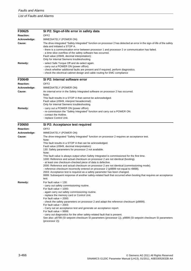
Faults and Alarms
List of Faults and Alarms
3-466 © Siemens AG 2011 All Rights ReservedSINAMICS G120C Parameter Manual (LH13), 01/2011, A5E03052632B AA
F30625 SI P2: Sign-of-life error in safety dataReaction: OFF2
Acknowledge: IMMEDIATELY (POWER ON)
Cause: The drive-integrated "Safety Integrated" function on processor 2 has detected an error in the sign-of-life of the safety data and initiated a STOP A.- there is a communication error between processor 1 and processor 2 or communication has failed.- a time slice overflow of the safety software has occurred.Fault value (r0949, decimal interpretation):Only for internal Siemens troubleshooting.
Remedy: - select Safe Torque Off and de-select again.- carry out a POWER ON (power off/on).- check whether additional faults are present and if required, perform diagnostics.- check the electrical cabinet design and cable routing for EMC compliance
F30649 SI P2: Internal software errorReaction: OFF2
Acknowledge: IMMEDIATELY (POWER ON)
Cause: An internal error in the Safety Integrated software on processor 2 has occurred.Note:This fault results in a STOP A that cannot be acknowledged.Fault value (r0949, interpret hexadecimal):Only for internal Siemens troubleshooting.
Remedy: - carry out a POWER ON (power off/on).- re-commission the "Safety Integrated" function and carry out a POWER ON.- contact the Hotline.- replace Control Unit.
F30650 SI P2: Acceptance test requiredReaction: OFF2
Acknowledge: IMMEDIATELY (POWER ON)
Cause: The drive-integrated "Safety Integrated" function on processor 2 requires an acceptance test.Note:This fault results in a STOP A that can be acknowledged.Fault value (r0949, decimal interpretation):130: Safety parameters for processor 2 not available.Note:This fault value is always output when Safety Integrated is commissioned for the first time.1000: Reference and actual checksum on processor 2 are not identical (booting).- at least one checksum-checked piece of data is defective.2000: Reference and actual checksum on processor 2 are not identical (commissioning mode).- reference checksum incorrectly entered on processor 2 (p9899 not equal to r9898).2003: Acceptance test is required as a safety parameter has been changed.9999: Subsequent response of another safety-related fault that occurred when booting that requires an acceptance test.
Remedy: For fault value = 130:- carry out safety commissioning routine.For fault value = 1000:- again carry out safety commissioning routine.- replace the memory card or Control Unit.For fault value = 2000:- check the safety parameters on processor 2 and adapt the reference checksum (p9899).For fault value = 2003:- Carry out an acceptance test and generate an acceptance report.For fault value = 9999:- carry out diagnostics for the other safety-related fault that is present.See also: p9799 (SI setpoint checksum SI parameters (processor 1)), p9899 (SI setpoint checksum SI parameters (processor 2))
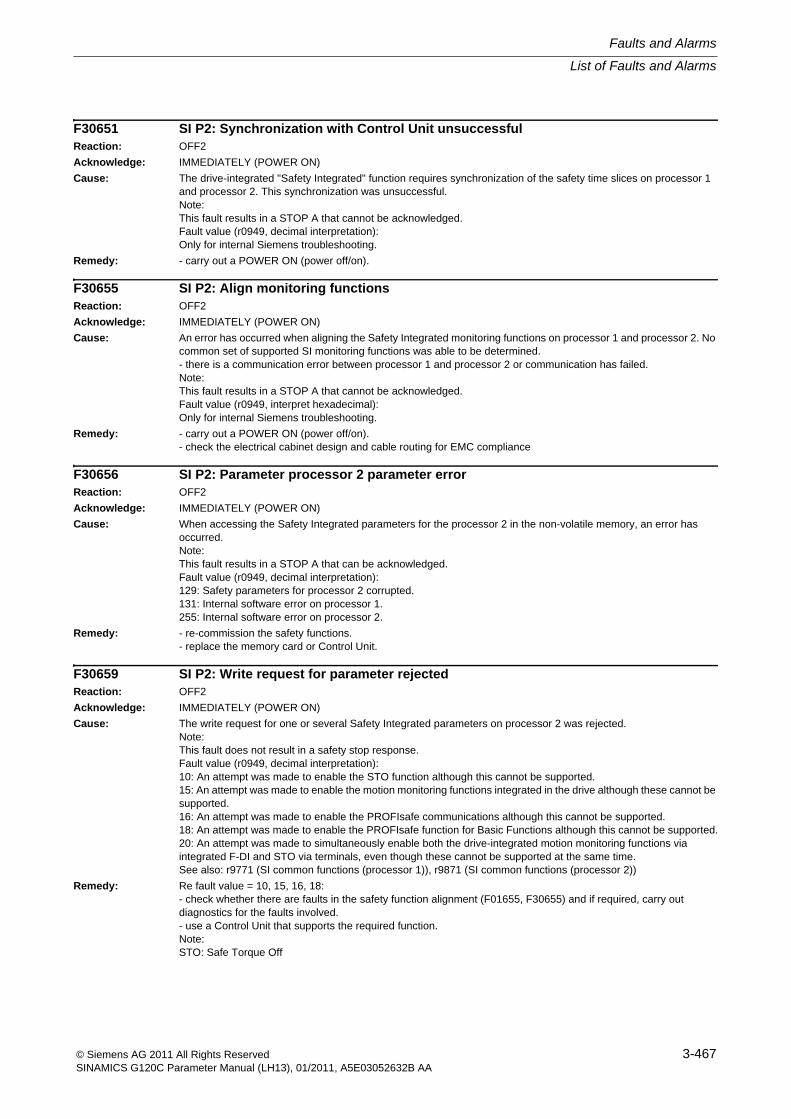
List of Faults and Alarms
Faults and Alarms
3-467© Siemens AG 2011 All Rights ReservedSINAMICS G120C Parameter Manual (LH13), 01/2011, A5E03052632B AA
F30651 SI P2: Synchronization with Control Unit unsuccessfulReaction: OFF2
Acknowledge: IMMEDIATELY (POWER ON)
Cause: The drive-integrated "Safety Integrated" function requires synchronization of the safety time slices on processor 1 and processor 2. This synchronization was unsuccessful.Note:This fault results in a STOP A that cannot be acknowledged.Fault value (r0949, decimal interpretation):Only for internal Siemens troubleshooting.
Remedy: - carry out a POWER ON (power off/on).
F30655 SI P2: Align monitoring functionsReaction: OFF2
Acknowledge: IMMEDIATELY (POWER ON)
Cause: An error has occurred when aligning the Safety Integrated monitoring functions on processor 1 and processor 2. No common set of supported SI monitoring functions was able to be determined.- there is a communication error between processor 1 and processor 2 or communication has failed.Note:This fault results in a STOP A that cannot be acknowledged.Fault value (r0949, interpret hexadecimal):Only for internal Siemens troubleshooting.
Remedy: - carry out a POWER ON (power off/on).- check the electrical cabinet design and cable routing for EMC compliance
F30656 SI P2: Parameter processor 2 parameter errorReaction: OFF2
Acknowledge: IMMEDIATELY (POWER ON)
Cause: When accessing the Safety Integrated parameters for the processor 2 in the non-volatile memory, an error has occurred.Note:This fault results in a STOP A that can be acknowledged.Fault value (r0949, decimal interpretation):129: Safety parameters for processor 2 corrupted.131: Internal software error on processor 1.255: Internal software error on processor 2.
Remedy: - re-commission the safety functions.- replace the memory card or Control Unit.
F30659 SI P2: Write request for parameter rejectedReaction: OFF2
Acknowledge: IMMEDIATELY (POWER ON)
Cause: The write request for one or several Safety Integrated parameters on processor 2 was rejected.Note:This fault does not result in a safety stop response.Fault value (r0949, decimal interpretation):10: An attempt was made to enable the STO function although this cannot be supported.15: An attempt was made to enable the motion monitoring functions integrated in the drive although these cannot be supported.16: An attempt was made to enable the PROFIsafe communications although this cannot be supported.18: An attempt was made to enable the PROFIsafe function for Basic Functions although this cannot be supported.20: An attempt was made to simultaneously enable both the drive-integrated motion monitoring functions via integrated F-DI and STO via terminals, even though these cannot be supported at the same time.See also: r9771 (SI common functions (processor 1)), r9871 (SI common functions (processor 2))
Remedy: Re fault value = 10, 15, 16, 18:- check whether there are faults in the safety function alignment (F01655, F30655) and if required, carry out diagnostics for the faults involved.- use a Control Unit that supports the required function.Note:STO: Safe Torque Off
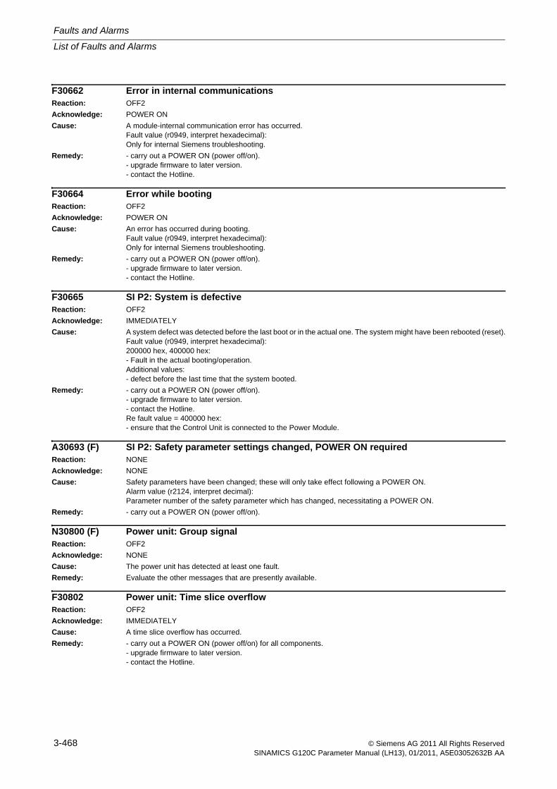
Faults and Alarms
List of Faults and Alarms
3-468 © Siemens AG 2011 All Rights ReservedSINAMICS G120C Parameter Manual (LH13), 01/2011, A5E03052632B AA
F30662 Error in internal communicationsReaction: OFF2
Acknowledge: POWER ON
Cause: A module-internal communication error has occurred.Fault value (r0949, interpret hexadecimal):Only for internal Siemens troubleshooting.
Remedy: - carry out a POWER ON (power off/on).- upgrade firmware to later version.- contact the Hotline.
F30664 Error while bootingReaction: OFF2
Acknowledge: POWER ON
Cause: An error has occurred during booting.Fault value (r0949, interpret hexadecimal):Only for internal Siemens troubleshooting.
Remedy: - carry out a POWER ON (power off/on).- upgrade firmware to later version.- contact the Hotline.
F30665 SI P2: System is defectiveReaction: OFF2
Acknowledge: IMMEDIATELY
Cause: A system defect was detected before the last boot or in the actual one. The system might have been rebooted (reset).Fault value (r0949, interpret hexadecimal):200000 hex, 400000 hex:- Fault in the actual booting/operation.Additional values:- defect before the last time that the system booted.
Remedy: - carry out a POWER ON (power off/on).- upgrade firmware to later version.- contact the Hotline.Re fault value = 400000 hex:- ensure that the Control Unit is connected to the Power Module.
A30693 (F) SI P2: Safety parameter settings changed, POWER ON requiredReaction: NONE
Acknowledge: NONE
Cause: Safety parameters have been changed; these will only take effect following a POWER ON.Alarm value (r2124, interpret decimal):Parameter number of the safety parameter which has changed, necessitating a POWER ON.
Remedy: - carry out a POWER ON (power off/on).
N30800 (F) Power unit: Group signalReaction: OFF2
Acknowledge: NONE
Cause: The power unit has detected at least one fault.
Remedy: Evaluate the other messages that are presently available.
F30802 Power unit: Time slice overflowReaction: OFF2
Acknowledge: IMMEDIATELY
Cause: A time slice overflow has occurred.
Remedy: - carry out a POWER ON (power off/on) for all components.- upgrade firmware to later version.- contact the Hotline.
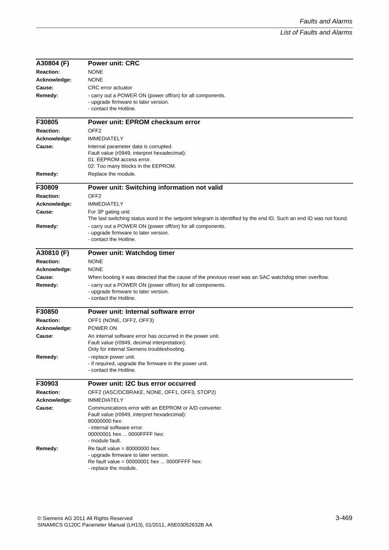
List of Faults and Alarms
Faults and Alarms
3-469© Siemens AG 2011 All Rights ReservedSINAMICS G120C Parameter Manual (LH13), 01/2011, A5E03052632B AA
A30804 (F) Power unit: CRCReaction: NONE
Acknowledge: NONE
Cause: CRC error actuator
Remedy: - carry out a POWER ON (power off/on) for all components.- upgrade firmware to later version.- contact the Hotline.
F30805 Power unit: EPROM checksum errorReaction: OFF2
Acknowledge: IMMEDIATELY
Cause: Internal parameter data is corrupted.Fault value (r0949, interpret hexadecimal):01: EEPROM access error.02: Too many blocks in the EEPROM.
Remedy: Replace the module.
F30809 Power unit: Switching information not validReaction: OFF2
Acknowledge: IMMEDIATELY
Cause: For 3P gating unit:The last switching status word in the setpoint telegram is identified by the end ID. Such an end ID was not found.
Remedy: - carry out a POWER ON (power off/on) for all components.- upgrade firmware to later version.- contact the Hotline.
A30810 (F) Power unit: Watchdog timerReaction: NONE
Acknowledge: NONE
Cause: When booting it was detected that the cause of the previous reset was an SAC watchdog timer overflow.
Remedy: - carry out a POWER ON (power off/on) for all components.- upgrade firmware to later version.- contact the Hotline.
F30850 Power unit: Internal software errorReaction: OFF1 (NONE, OFF2, OFF3)
Acknowledge: POWER ON
Cause: An internal software error has occurred in the power unit.Fault value (r0949, decimal interpretation):Only for internal Siemens troubleshooting.
Remedy: - replace power unit.- if required, upgrade the firmware in the power unit.- contact the Hotline.
F30903 Power unit: I2C bus error occurredReaction: OFF2 (IASC/DCBRAKE, NONE, OFF1, OFF3, STOP2)
Acknowledge: IMMEDIATELY
Cause: Communications error with an EEPROM or A/D converter.Fault value (r0949, interpret hexadecimal):80000000 hex:- internal software error.00000001 hex ... 0000FFFF hex:- module fault.
Remedy: Re fault value = 80000000 hex:- upgrade firmware to later version.Re fault value = 00000001 hex ... 0000FFFF hex:- replace the module.
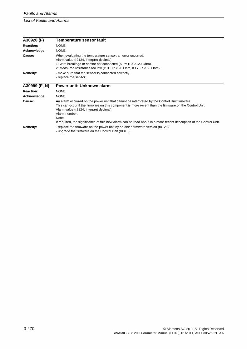
Faults and Alarms
List of Faults and Alarms
3-470 © Siemens AG 2011 All Rights ReservedSINAMICS G120C Parameter Manual (LH13), 01/2011, A5E03052632B AA
A30920 (F) Temperature sensor faultReaction: NONE
Acknowledge: NONE
Cause: When evaluating the temperature sensor, an error occurred.Alarm value (r2124, interpret decimal):1: Wire breakage or sensor not connected (KTY: R > 2120 Ohm).2: Measured resistance too low (PTC: R < 20 Ohm, KTY: R < 50 Ohm).
Remedy: - make sure that the sensor is connected correctly.- replace the sensor.
A30999 (F, N) Power unit: Unknown alarmReaction: NONE
Acknowledge: NONE
Cause: An alarm occurred on the power unit that cannot be interpreted by the Control Unit firmware.This can occur if the firmware on this component is more recent than the firmware on the Control Unit.Alarm value (r2124, interpret decimal):Alarm number.Note:If required, the significance of this new alarm can be read about in a more recent description of the Control Unit.
Remedy: - replace the firmware on the power unit by an older firmware version (r0128).- upgrade the firmware on the Control Unit (r0018).
A-471© Siemens AG 2011 All Rights ReservedSINAMICS G120C Parameter Manual (LH13), 01/2011, A5E03052632B AA
Appendix AContents
A.1 ASCII Table (excerpt) A-472
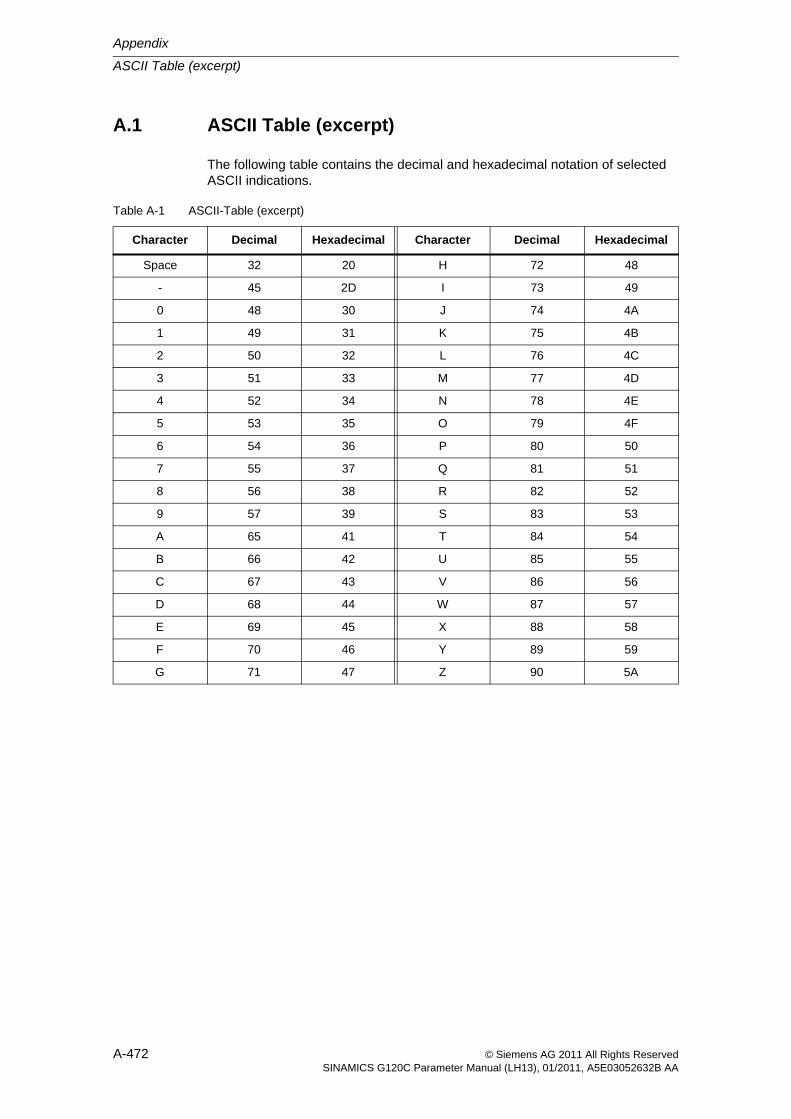
Appendix
ASCII Table (excerpt)
A-472 © Siemens AG 2011 All Rights ReservedSINAMICS G120C Parameter Manual (LH13), 01/2011, A5E03052632B AA
A.1 ASCII Table (excerpt)
The following table contains the decimal and hexadecimal notation of selected ASCII indications.
Table A-1 ASCII-Table (excerpt)
Character Decimal Hexadecimal Character Decimal Hexadecimal
Space 32 20 H 72 48
- 45 2D I 73 49
0 48 30 J 74 4A
1 49 31 K 75 4B
2 50 32 L 76 4C
3 51 33 M 77 4D
4 52 34 N 78 4E
5 53 35 O 79 4F
6 54 36 P 80 50
7 55 37 Q 81 51
8 56 38 R 82 52
9 57 39 S 83 53
A 65 41 T 84 54
B 66 42 U 85 55
C 67 43 V 86 56
D 68 44 W 87 57
E 69 45 X 88 58
F 70 46 Y 89 59
G 71 47 Z 90 5A
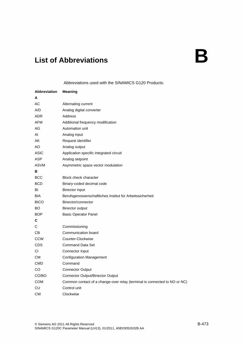
B-473© Siemens AG 2011 All Rights ReservedSINAMICS G120C Parameter Manual (LH13), 01/2011, A5E03052632B AA
List of Abbreviations BAbbreviations used with the SINAMICS G120 Products:
Abbreviation Meaning
A
AC Alternating current
A/D Analog digital converter
ADR Address
AFM Additional frequency modification
AG Automation unit
AI Analog input
AK Request identifier
AO Analog output
ASIC Application specific integrated circuit
ASP Analog setpoint
ASVM Asymmetric space vector modulation
B
BCC Block check character
BCD Binary-coded decimal code
BI Binector input
BIA Berufsgenossenschaftliches Institut für Arbeitssicherheit
BICO Binector/connector
BO Binector output
BOP Basic Operator Panel
C
C Commissioning
CB Communication board
CCW Counter-Clockwise
CDS Command Data Set
CI Connector Input
CM Configuration Management
CMD Command
CO Connector Output
CO/BO Connector Output/Binector Output
COM Common contact of a change-over relay (terminal is connected to NO or NC)
CU Control unit
CW Clockwise
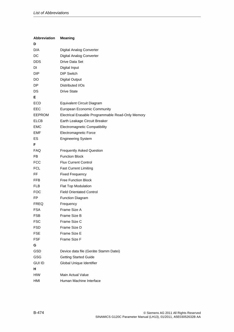
List of Abbreviations
B-474 © Siemens AG 2011 All Rights ReservedSINAMICS G120C Parameter Manual (LH13), 01/2011, A5E03052632B AA
D
D/A Digital Analog Converter
DC Digital Analog Converter
DDS Drive Data Set
DI Digital Input
DIP DIP Switch
DO Digital Output
DP Distributed I/Os
DS Drive State
E
ECD Equivalent Circuit Diagram
EEC European Economic Community
EEPROM Electrical Erasable Programmable Read-Only Memory
ELCB Earth Leakage Circuit Breaker
EMC Electromagnetic Compatibility
EMF Electromagnetic Force
ES Engineering System
F
FAQ Frequently Asked Question
FB Function Block
FCC Flux Current Control
FCL Fast Current Limiting
FF Fixed Frequency
FFB Free Function Block
FLB Flat Top Modulation
FOC Field Orientated Control
FP Function Diagram
FREQ Frequency
FSA Frame Size A
FSB Frame Size B
FSC Frame Size C
FSD Frame Size D
FSE Frame Size E
FSF Frame Size F
G
GSD Device data file (Geräte Stamm Datei)
GSG Getting Started Guide
GUI ID Global Unique Identifier
H
HIW Main Actual Value
HMI Human Machine Interface
Abbreviation Meaning
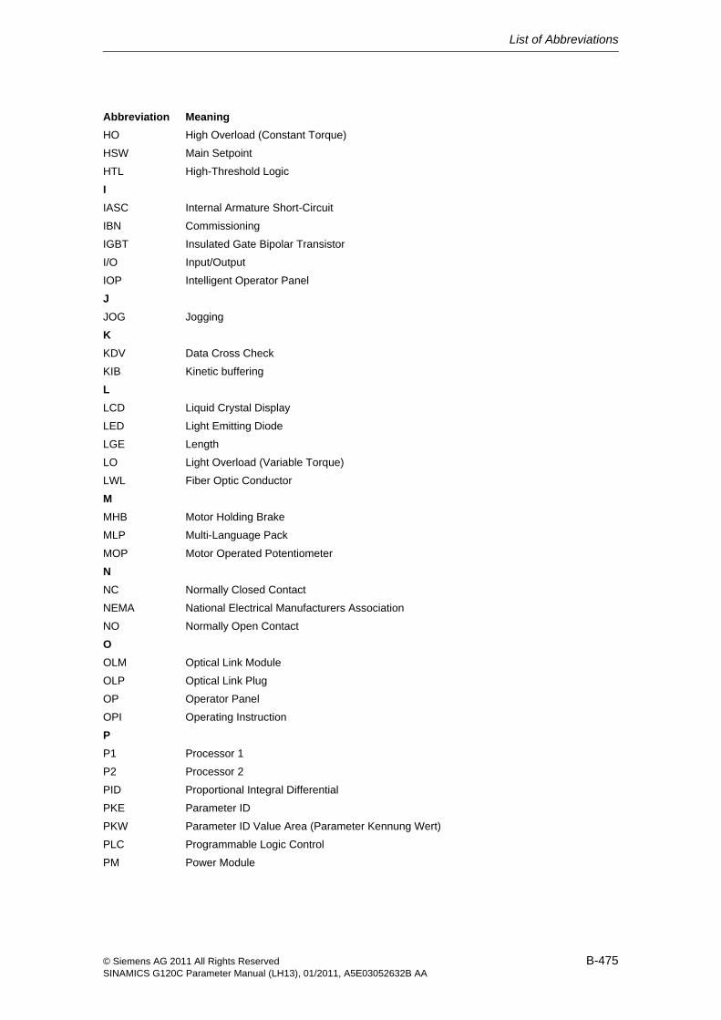
List of Abbreviations
B-475© Siemens AG 2011 All Rights ReservedSINAMICS G120C Parameter Manual (LH13), 01/2011, A5E03052632B AA
HO High Overload (Constant Torque)
HSW Main Setpoint
HTL High-Threshold Logic
I
IASC Internal Armature Short-Circuit
IBN Commissioning
IGBT Insulated Gate Bipolar Transistor
I/O Input/Output
IOP Intelligent Operator Panel
J
JOG Jogging
K
KDV Data Cross Check
KIB Kinetic buffering
L
LCD Liquid Crystal Display
LED Light Emitting Diode
LGE Length
LO Light Overload (Variable Torque)
LWL Fiber Optic Conductor
M
MHB Motor Holding Brake
MLP Multi-Language Pack
MOP Motor Operated Potentiometer
N
NC Normally Closed Contact
NEMA National Electrical Manufacturers Association
NO Normally Open Contact
O
OLM Optical Link Module
OLP Optical Link Plug
OP Operator Panel
OPI Operating Instruction
P
P1 Processor 1
P2 Processor 2
PID Proportional Integral Differential
PKE Parameter ID
PKW Parameter ID Value Area (Parameter Kennung Wert)
PLC Programmable Logic Control
PM Power Module
Abbreviation Meaning
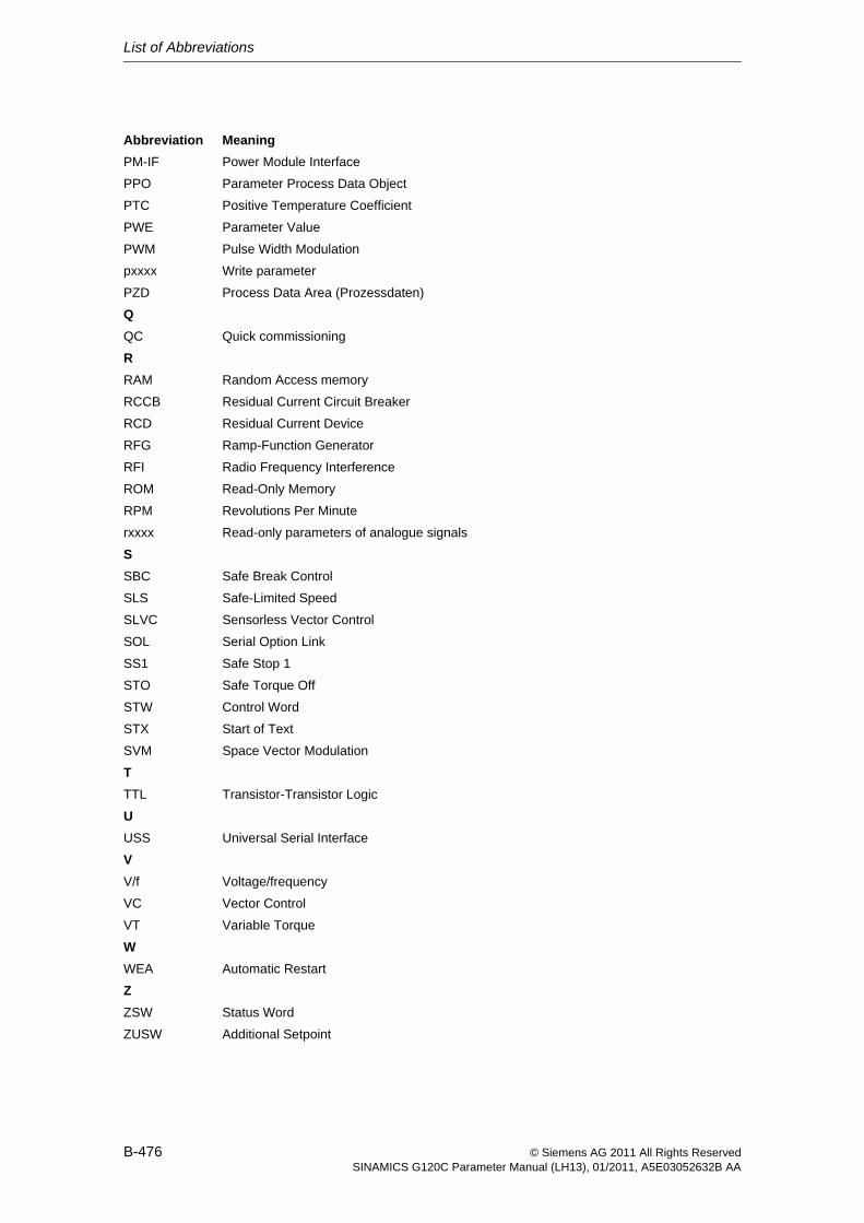
List of Abbreviations
B-476 © Siemens AG 2011 All Rights ReservedSINAMICS G120C Parameter Manual (LH13), 01/2011, A5E03052632B AA
PM-IF Power Module Interface
PPO Parameter Process Data Object
PTC Positive Temperature Coefficient
PWE Parameter Value
PWM Pulse Width Modulation
pxxxx Write parameter
PZD Process Data Area (Prozessdaten)
Q
QC Quick commissioning
R
RAM Random Access memory
RCCB Residual Current Circuit Breaker
RCD Residual Current Device
RFG Ramp-Function Generator
RFI Radio Frequency Interference
ROM Read-Only Memory
RPM Revolutions Per Minute
rxxxx Read-only parameters of analogue signals
S
SBC Safe Break Control
SLS Safe-Limited Speed
SLVC Sensorless Vector Control
SOL Serial Option Link
SS1 Safe Stop 1
STO Safe Torque Off
STW Control Word
STX Start of Text
SVM Space Vector Modulation
T
TTL Transistor-Transistor Logic
U
USS Universal Serial Interface
V
V/f Voltage/frequency
VC Vector Control
VT Variable Torque
W
WEA Automatic Restart
Z
ZSW Status Word
ZUSW Additional Setpoint
Abbreviation Meaning
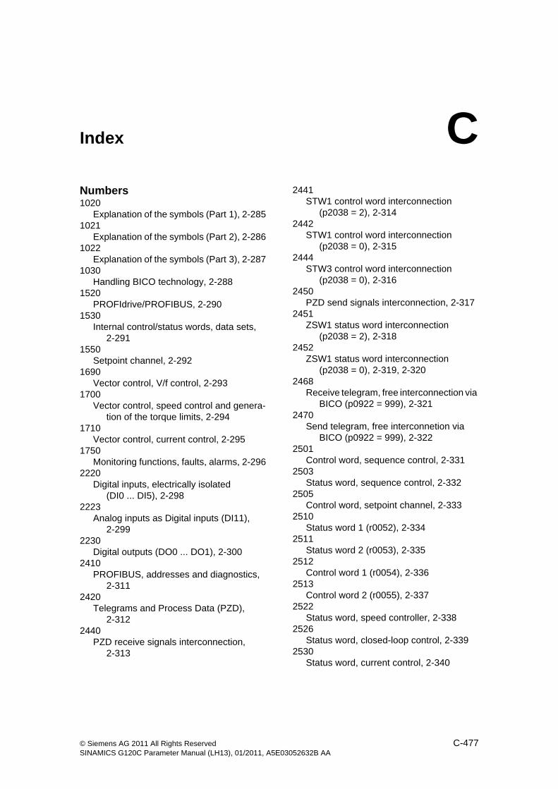
C-477© Siemens AG 2011 All Rights ReservedSINAMICS G120C Parameter Manual (LH13), 01/2011, A5E03052632B AA
Index CNumbers1020
Explanation of the symbols (Part 1), 2-2851021
Explanation of the symbols (Part 2), 2-2861022
Explanation of the symbols (Part 3), 2-2871030
Handling BICO technology, 2-2881520
PROFIdrive/PROFIBUS, 2-2901530
Internal control/status words, data sets, 2-291
1550Setpoint channel, 2-292
1690Vector control, V/f control, 2-293
1700Vector control, speed control and genera-
tion of the torque limits, 2-2941710
Vector control, current control, 2-2951750
Monitoring functions, faults, alarms, 2-2962220
Digital inputs, electrically isolated (DI0 ... DI5), 2-298
2223Analog inputs as Digital inputs (DI11),
2-2992230
Digital outputs (DO0 ... DO1), 2-3002410
PROFIBUS, addresses and diagnostics, 2-311
2420Telegrams and Process Data (PZD),
2-3122440
PZD receive signals interconnection, 2-313
2441STW1 control word interconnection
(p2038 = 2), 2-3142442
STW1 control word interconnection (p2038 = 0), 2-315
2444STW3 control word interconnection
(p2038 = 0), 2-3162450
PZD send signals interconnection, 2-3172451
ZSW1 status word interconnection (p2038 = 2), 2-318
2452ZSW1 status word interconnection
(p2038 = 0), 2-319, 2-3202468
Receive telegram, free interconnection via BICO (p0922 = 999), 2-321
2470Send telegram, free interconnetion via
BICO (p0922 = 999), 2-3222501
Control word, sequence control, 2-3312503
Status word, sequence control, 2-3322505
Control word, setpoint channel, 2-3332510
Status word 1 (r0052), 2-3342511
Status word 2 (r0053), 2-3352512
Control word 1 (r0054), 2-3362513
Control word 2 (r0055), 2-3372522
Status word, speed controller, 2-3382526
Status word, closed-loop control, 2-3392530
Status word, current control, 2-340
Index
C-478 © Siemens AG 2011 All Rights ReservedSINAMICS G120C Parameter Manual (LH13), 01/2011, A5E03052632B AA
2534Status word, monitoring functions 1,
2-3412536
Status word, monitoring functions 2, 2-342
2537Status word, monitoring functions 3,
2-3432546
Control word, faults/alarms, 2-3442548
Status word, faults/alarms 1 and 2, 2-3452634
Sequence control - Missing enable sig-nals, 2-346
2701Basic braking control, 2-348
2800Basic Functions, Parameter Manager,
2-3502802
Basic Functions, Monitoring functions and faults/alarms, 2-351
2804Basic Functions, Status words, 2-352
2810Basic Functions, STO Safe Torque Off,
2-3532812
Basic Functions, F-DI Fail-safe Digital In-put, 2-354
3010Fixed speed setpoints, binary selection
(p1016 = 2), 2-3563011
Fixed speed setpoints, direct selection (p1016 = 1), 2-357
3020Motorized potentiometer, 2-358
3030Main/supplementary setpoint, setpoint
scaling, jogging, 2-3593040
Direction limitation and direction reversal, 2-360
3050Skip frequency bands and frequency limi-
tations, 2-3613070
Extended ramp-function generator, 2-3626030
Speed setpoint, droop, 2-368
6040Speed controller, 2-369
6060Torque setpoint, 2-370
6220Vdc_max controller and
Vdc_min controller (Vector control), 2-371
6300V/f characteristic and voltage boost, 2-364
6310Resonance damping and slip compensa-
tion, 2-3656320
Vdc_max controller and Vdc_min controller (V/f control), 2-366
6630Upper/lower torque limit, 2-372
6640Current/power/torque limits, 2-373
6710Current setpoint filter, 2-374
6714Iq and Id controllers, 2-375
6721Id setpoint (PEM, p0300 = 2xx), 2-376
6722Field weakening characteristic, Id setpoint
(ASM, p0300 = 1), 2-3776723
Field weakening controller, flux controller (ASM, p0300 = 1), 2-378
6724Field weakening controller
(PEM, p0300 = 2), 2-3796730
Interface of the Power Module (ASM, p0300 = 1), 2-380
6731Interface of the Power Module
(PEM, p0300 = 2), 2-3816799
Display signals, 2-3827017
DC brake (p0300 = 1), 2-3847950
Fixed values, binary selection (p2216 = 2), 2-386
7951Fixed values, direct selection (p2216 = 1),
2-3877954
Motorized potentiometer, 2-388
Index
C-479© Siemens AG 2011 All Rights ReservedSINAMICS G120C Parameter Manual (LH13), 01/2011, A5E03052632B AA
7958Closed-loop control, 2-389
8010Speed signals 1, 2-391
8011Speed signals 2, 2-392
8012Torque signals, motor locked/stalled,
2-3938014
Thermal monitoring, power module, 2-3948016
Thermal monitoring, motor, 2-3958017
Thermal I2t motor model (PEM, p0300 = 2xx), 2-396
8020Monitoring functions 1, 2-397
8021Monitoring functions 2, 2-398
8060Fault buffer, 2-400
8065Warning buffer, 2-401
8070Fault/warning trigger word (r2129), 2-402
8075Fault/warning configuration, 2-403
8560Command Data Sets (CDS), 2-405
9204Receive telegram, free PDO mapping
(p8744 = 2), 2-3249206
Receive telegram, Predefined Connection Set (p8744 = 1), 2-325
9208Send telegram, free PDO mapping
(p8744 = 2), 2-3269210
Send telegram, Predefined Connection Set (p8744 = 1), 2-327
9220Control word, CANopen, 2-328
9226Status word, CANopen, 2-329
9310Configuration, addresses and diagnostics,
2-3059342
STW1 control word interconnection, 2-306
9352ZSW1 status word interconnection, 2-307
9360Receive telegram, free interconnection via
BICO, 2-3089370
Send telegram, free interconnection via BICO, 2-309
9567Analog input 0 (AI0), 2-301
9573Analog outputs 0 (AO0), 2-302
AAcknowledgement
IMMEDIATELY, 3-411POWER ON, 3-411
Adjustable parameters, 1-8Alarm
Display, 3-408General, 3-408How to distinguish from a fault, 3-409List of Alarm messages, 3-412
Analog inputs, 2-297Analog outputs, 2-297ASCII Table, A-472
BBit field (Parameters), 1-14Braking control, 2-347
CCalculated (Parameters), 1-11Can be changed (Parameters), 1-12Command Data Set, 2-404Contents
Contents overview, Inhalt-5List of Abbreviations, B-473
DData set (Parameters), 1-12Data sets, 2-404Data type (Parameters), 1-10DCBRK, 3-410Dependency (Parameters), 1-14Description (Parameters), 1-14Digital inputs, 2-297Digital outputs, 2-297Display
Alarms, 3-408Faults, 3-408
Drive Data Set, 2-404
Index
C-480 © Siemens AG 2011 All Rights ReservedSINAMICS G120C Parameter Manual (LH13), 01/2011, A5E03052632B AA
FFault
Acknowledgement, 3-411Display, 3-408Fault reactions, 3-410General, 3-408How to distinguish from an alarm, 3-409
Fault messagesList of all Fault messages, 3-412
Fault reactions, 3-410Fixed values, 2-386, 2-387Function diagrams Braking control
Basic braking control, 2-348Function diagrams CANopen
Control word, CANopen, 2-328Receive telegram, free PDO mapping
(p8744 = 2), 2-324Receive telegram, Predefined Connection
Set (p8744 = 1), 2-325Send telegram, free PDO mapping
(p8744 = 2), 2-326Send telegram, Predefined Connection
Set (p8744 = 1), 2-327Status word, CANopen, 2-329
Function diagrams Data setsCommand Data Sets (CDS), 2-405
Function diagrams Faults and warningsFault buffer, 2-400Fault/warning configuration, 2-403Fault/warning trigger word (r2129), 2-402Warning buffer, 2-401
Function diagrams Fieldbus InterfaceConfiguration, addresses and diagnostics,
2-305Receive telegram, free interconnection via
BICO, 2-308Send telegram, free interconnection via
BICO, 2-309STW1 control word interconnection,
2-306ZSW1 status word interconnection, 2-307
Function diagrams GeneralExplanation of the symbols (Part 1), 2-285Explanation of the symbols (Part 2), 2-286Explanation of the symbols (Part 3), 2-287Handling BICO technology, 2-288
Function diagrams Input/Output TerminalsAnalog input 0 (AI0), 2-301Analog inputs as Digital inputs (DI11),
2-299Analog output 0 (AO0), 2-302Digital inputs, electrically isolated
(DI0 ... DI5), 2-298Digital outputs (DO0 ... DO1), 2-300
Function diagrams Internal control/status wordsControl word 1 (r0054), 2-336Control word 2 (r0055), 2-337Control word, faults/alarms, 2-344Control word, sequence control, 2-331Control word, setpoint channel, 2-333Sequence control - Missing enable sig-
nals, 2-346Status word 1 (r0052), 2-334Status word 2 (r0053), 2-335Status word, closed-loop control, 2-339Status word, current control, 2-340Status word, faults/alarms 1 and 2, 2-345Status word, monitoring functions 1,
2-341Status word, monitoring functions 2,
2-342Status word, monitoring functions 3,
2-343Status word, sequence control, 2-332Status word, speed controller, 2-338
Function diagrams OverviewInternal control/status words, data sets,
2-291Monitoring functions, faults, alarms, 2-296PROFIdrive/PROFIBUS, 2-290Setpoint channel, 2-292Vector control, current control, 2-295Vector control, speed control and genera-
tion of the torque limits, 2-294Vectorcontrol, V/f control, 2-293
Index
C-481 © Siemens AG 2011 All Rights ReservedSINAMICS G120C Parameter Manual (LH13), 01/2011, A5E03052632B AA
Function diagrams PROFIdrivePROFIBUS, addresses and diagnostics,
2-311PZD receive signals interconnection,
2-313PZD send signals interconnection, 2-317Receive telegram, free interconnection via
BICO (p0922 = 999), 2-321Send telegram, free interconnetion via
BICO (p0922 = 999), 2-322STW1 control word interconnection
(p2038 = 0), 2-315STW1 control word interconnection
(p2038 = 2), 2-314STW3 control word interconnection
(p2038 = 0), 2-316Telegrams and Process Data (PZD),
2-312ZSW1 status word interconnection
(p2038 = 0), 2-319, 2-320ZSW1 status word interconnection
(p2038 = 2), 2-318Function diagrams Safety Integrated
Basic Functions, F-DI Fail-safe Digital In-put, 2-354
Basic Functions, Monitoring functions and faults/alarms, 2-351
Basic Functions, Parameter Manager, 2-350
Basic Functions, Status words, 2-352Basic Functions, STO Safe Torque Off,
2-353Function diagrams Setpoint channel
Direction limitation and direction reversal, 2-360
Extended ramp-function generator, 2-362Fixed speed setpoints, binary selection
(p1016 = 2), 2-356Fixed speed setpoints, direct selection
(p1016 = 1), 2-357Main/supplementary setpoint, setpoint
scaling, jogging, 2-359Motorized potentiometer, 2-358Skip frequency bands and frequency limi-
tations, 2-361
Function diagrams Signals and monitoring functionsMonitoring functions 1, 2-397Monitoring functions 2, 2-398Speed signals 1, 2-391Speed signals 2, 2-392Thermal I2t motor model
(PEM, p0300 = 2xx), 2-396Thermal monitoring, motor, 2-395Thermal monitoring, power module, 2-394Torque signals, motor locked/stalled,
2-393Function diagrams Technology controller
Closed-loop control, 2-389Fixed values, binary selection
(p2216 = 2), 2-386Fixed values, direct selection (p2216 = 1),
2-387Motorized potentiometer, 2-388
Function diagrams Technology functionsDC brake (p0300 = 1), 2-384
Function diagrams V/f controlResonance damping and slip compensa-
tion, 2-365V/f characteristic and voltage boost, 2-364Vdc_max controller and
Vdc_min controller (V/f control), 2-366Function diagrams Vector control
Current setpoint filter, 2-374Current/power/torque limits, 2-373Display signals, 2-382Field weakening characteristic, Id setpoint
(ASM, p0300 = 1), 2-377Field weakening controller
(PEM, p0300 = 2), 2-379Field weakening controller, flux controller
(ASM, p0300 = 1), 2-378Id setpoint (PEM, p0300 = 2xx), 2-376Interface of the Power Module
(ASM, p0300 = 1), 2-380Interface of the Power Module
(PEM, p0300 = 2), 2-381Iq and Id controllers, 2-375Speed controller, 2-369Speed setpoint, droop, 2-368Torque setpoint, 2-370Upper/lower torque limit, 2-372Vdc_max controller and
Vdc_min controller (Vector control), 2-371
Index
C-482 © Siemens AG 2011 All Rights ReservedSINAMICS G120C Parameter Manual (LH13), 01/2011, A5E03052632B AA
GGeneral
faults and alarms, 3-408Function Diagrams, 2-284Parameters, 1-8
IIASC, 3-410Index
Parameters, 1-8, 1-14Input/Output Terminals
Analog inputs, 2-297Analog outputs, 2-297Digital inputs, 2-297Digital outputs, 2-297
LList of Abbreviations, B-473Lists
Abbreviations, B-473ASCII Table, A-472Binector Input Parameters, 1-270Binector Output Parameters, 1-271Command Data Sets, 1-264Connector Input Parameters, 1-271Connector Output Parameters, 1-272Connector/Binector Output Parameters,
1-274Drive Data Sets, 1-265Fault- and Alarm messages, 3-412Motor Data Sets, 1-268Parameters all, 1-16Power module Data Sets, 1-270Quick commissioning, 1-276
MMotorized potentiometer, 2-388
NName
Parameters, 1-9Number
Parameters, 1-8
OOFF1, 3-410OFF2, 3-410OFF3, 3-410
PParameters
Binector Input Parameters, 1-270Binector Output, 1-271Bit field, 1-14Calculated, 1-11Can be changed, 1-12Command Data Sets, 1-264Connector Input, 1-271Connector Output, 1-272Connector/Binector Output, 1-274Data set, 1-12Data type, 1-10Dependency, 1-14Description, 1-14Drive Data Sets, 1-265Index, 1-8, 1-14List of all Parameters, 1-16Long name, 1-9Motor Data Sets, 1-268Name, 1-9Number, 1-8Power module Data Sets, 1-270Quick commissioning, 1-276Recommendation, 1-14Scaling, 1-11Short name, 1-9Text, 1-9Unit, 1-12Unit group, 1-12Unit selection, 1-12Values, 1-14
RRecommendation (Parameters), 1-14
SSafety Integrated
Basic Functions, 2-349Extendet Functions, 2-349
Scaling (Parameters), 1-11STOP2, 3-410
UUnit (Parameters), 1-12Unit group (Parameters), 1-12Unit selection (Parameters), 1-12
VValues (Parameters), 1-14Visualization parameters, 1-8


Siemens AGIndustry SectorDrive TechnologiesMotion Control SystemsPostfach 318091050 ERLANGENGERMANY
Subject to change without prior notice
© Siemens AG 2011
www.siemens.com/sinamics-g120