Embed Size (px)
DESCRIPTION
manual usuario nissan xtrail
Citation preview
Foreword
Welcome to the growing family of new NISSANowners. This vehicle is delivered to you withconfidence. It was produced using the latesttechniques and strict quality control.
This manual was prepared to help you under-stand the operation and maintenance of yourvehicle so that you may enjoy many miles ofdriving pleasure. Please read through thismanual before operating your vehicle.
A separate Warranty Information Bookletexplains details about the warranties cov-ering your vehicle. The NISSAN Serviceand Maintenance Guide explains detailsabout maintaining and servicing your ve-hicle. Additionally, a separate CustomerCare booklet will explain how to resolveany concerns you may have with your ve-hicle.
A NISSAN dealer knows your vehicle best.When you require any service or have anyquestions, we will be glad to assist you with theextensive resources available for you.
READ FIRST — THEN DRIVESAFELYBefore driving your vehicle please readyour Owner’s Manual carefully. This willensure familiarity with controls and main-tenance requirements, assisting you in thesafe operation of your vehicle.
WARNING
IMPORTANT SAFETY INFORMA-TIONREMINDERS FOR SAFETY!
Follow these important driving rules tohelp ensure a safe and comfortable tripfor you and your passengers!
� Never drive under the influence ofalcohol or drugs.
� Always observe posted speed limitsand never drive too fast for condi-tions.
� Always use your seat belts. Refer to“Child safety” and “Child restraints”in the “ Safety — Seats, seat belts andsupplemental restraint system” sec-tion for precautions regarding chil-dren.
� Always provide information about theproper use of vehicle safety featuresto all occupants of the vehicle.
� Always review this Owner’s Manualfor important safety information.
MODIFICATION OF YOUR VEHICLEThis vehicle should not be modified. Modi-fication could affect its performance,safety or durability, and may even violategovernmental regulations. In addition,damage or performance problems result-ing from modification may not be coveredunder NISSAN warranties.
WHEN READING THE MANUALThis manual includes information for alloptions available on this model. There-fore, you may find some information thatdoes not apply to your vehicle.
All information, specifications and illustrations inthis manual are those in effect at the time ofprinting. NISSAN reserves the right to changespecifications or design at any time withoutnotice.
� 05.8.23/T30-J/V5.0 �Downloaded from www.Manualslib.com manuals search engine
IMPORTANT INFORMATIONABOUT THIS MANUALYou will see various symbols in this manual.They are used in the following ways:
WARNING
This is used to indicate the presence of ahazard that could cause death or seriouspersonal injury. To avoid or reduce therisk, the procedures must be followedprecisely.
CAUTION
This is used to indicate the presence of ahazard that could cause minor or moder-ate personal injury or damage to yourvehicle. To avoid or reduce the risk, theprocedures must be followed carefully.
If you see this symbol, it means Do not do thisor Do not let this happen.
If you see a symbol similar to these in anillustration, it means the arrow points to the frontof the vehicle.
Arrows in an illustration that are similar to theseindicate movement or action.
Arrows in an illustration that are similar to thesecall attention to an item in the illustration.
© 2005 NISSAN MOTOR CO., LTD.TOKYO, JAPAN
All rights reserved. No part of this Owner’s Manual may bereproduced or stored in a retrieval system, or transmittedin any form, or by any means, electronic, mechanical,photocopying, recording or otherwise, without the priorwritten permission of Nissan Motor Co., Ltd.
SIC0697
� 05.8.23/T30-J/V5.0 �Downloaded from www.Manualslib.com manuals search engine
NISSAN CUSTOMER CARE PROGRAM
NISSAN CARES ...
Both NISSAN and a NISSAN dealer are dedicated to serving all your automotive needs. Your satisfaction with your vehicle and a NISSAN dealer are ourprimary concerns. A NISSAN dealer is always available to assist you with all your automobile sales and service needs.
However, if there is something that a NISSANdealer cannot assist you with or you would liketo provide NISSAN directly with comments orquestions, please contact our (NISSAN’s) Con-sumer Affairs Department using our toll-freenumber:
1-800-387-0122
The Consumer Affairs Department will ask forthe following information:— Your name, address, and telephone
number— Vehicle identification number (on dash panel)— Date of purchase— Current odometer reading— A NISSAN dealer’s name— Your comments or questionsOR
You can write to NISSAN with the informationon the left at:
Nissan Canada Inc.5290 Orbitor DriveMississauga, Ontario L4W 4Z5
We appreciate your interest in NISSAN and thank you for buying a quality NISSAN vehicle.
� 05.8.23/T30-J/V5.0 �Downloaded from www.Manualslib.com manuals search engine
Table ofContents
Illustrated table of contents
Safety — Seats, seat belts and supplementalrestraint system
Instruments and controls
Pre-driving checks and adjustments
Display screen, heater, air conditioner and audiosystems
Starting and driving
In case of emergency
Appearance and care
Maintenance and do-it-yourself
Technical and consumer information
Index
� 05.8.23/T30-J/V5.0 �Downloaded from www.Manualslib.com manuals search engine

� 05.8.23/T30-J/V5.0 �Downloaded from www.Manualslib.com manuals search engine
0 Illustrated table of contents
Exterior front ........................................................................... 0-2Exterior rear ............................................................................. 0-3Passenger compartment ..................................................... 0-4Instrument panel ................................................................... 0-5Meters and gauges .............................................................. 0-7Engine compartment check locations ............................. 0-8
� 05.8.23/T30-J/V5.0 �Downloaded from www.Manualslib.com manuals search engine
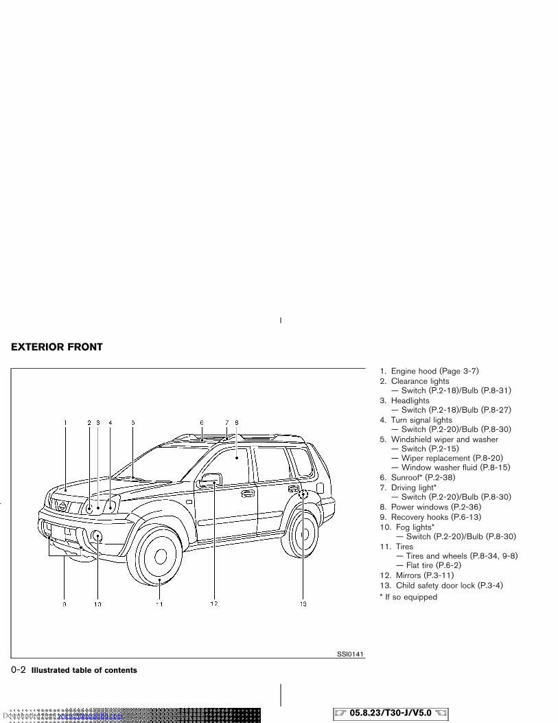
1. Engine hood (Page 3-7)2. Clearance lights
— Switch (P.2-18)/Bulb (P.8-31)3. Headlights
— Switch (P.2-18)/Bulb (P.8-27)4. Turn signal lights
— Switch (P.2-20)/Bulb (P.8-30)5. Windshield wiper and washer
— Switch (P.2-15)— Wiper replacement (P.8-20)— Window washer fluid (P.8-15)
6. Sunroof* (P.2-38)7. Driving light*
— Switch (P.2-20)/Bulb (P.8-30)8. Power windows (P.2-36)9. Recovery hooks (P.6-13)10. Fog lights*
— Switch (P.2-20)/Bulb (P.8-30)11. Tires
— Tires and wheels (P.8-34, 9-8)— Flat tire (P.6-2)
12. Mirrors (P.3-11)13. Child safety door lock (P.3-4)* If so equipped
SSI0141
EXTERIOR FRONT
0-2 Illustrated table of contents
� 05.8.23/T30-J/V5.0 �Downloaded from www.Manualslib.com manuals search engine
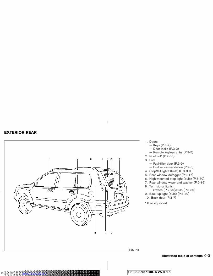
1. Doors— Keys (P.3-2)— Door locks (P.3-3)— Remote keyless entry (P.3-5)
2. Roof rail* (P.2-35)3. Fuel
— Fuel-filler door (P.3-9)— Fuel recommendation (P.9-3)
4. Stop/tail lights (bulb) (P.8-30)5. Rear window defogger (P.2-17)6. High-mounted stop light (bulb) (P.8-30)7. Rear window wiper and washer (P.2-16)8. Turn signal lights
— Switch (P.2-20)/Bulb (P.8-30)9. Back-up light (bulb) (P.8-30)10. Back door (P.3-7)
* If so equipped
SSI0142
EXTERIOR REAR
Illustrated table of contents 0-3
� 05.8.23/T30-J/V5.0 �Downloaded from www.Manualslib.com manuals search engine
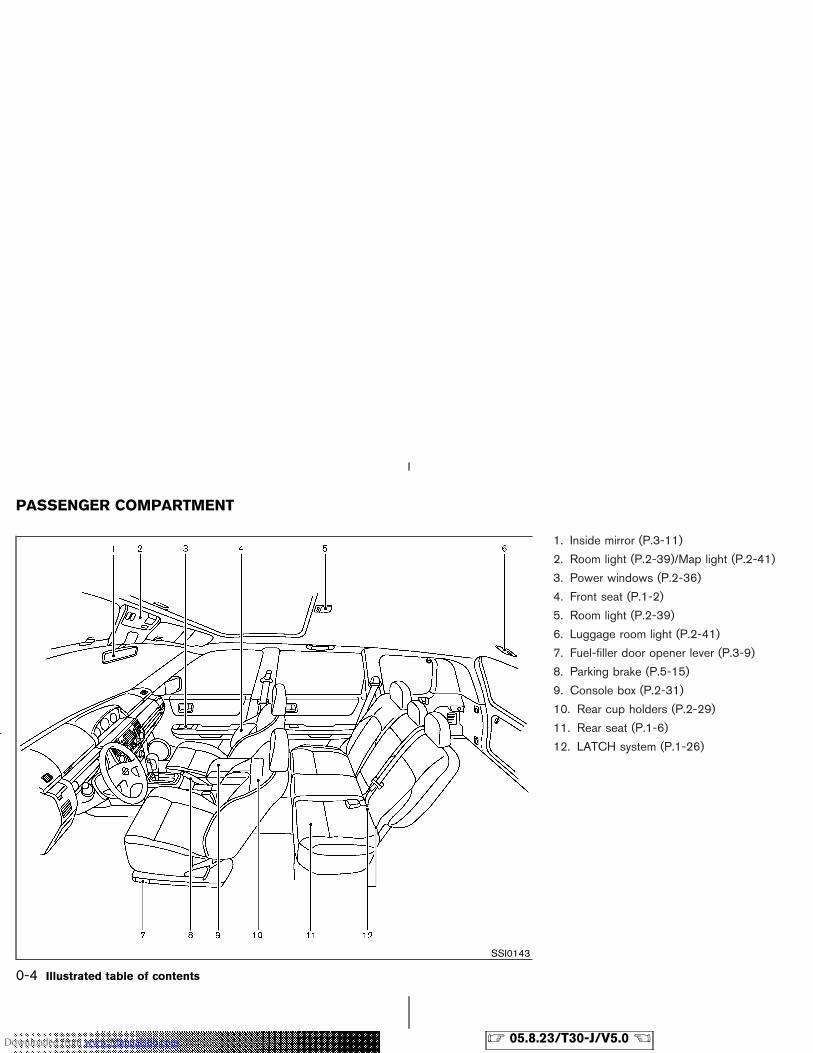
1. Inside mirror (P.3-11)
2. Room light (P.2-39)/Map light (P.2-41)
3. Power windows (P.2-36)
4. Front seat (P.1-2)
5. Room light (P.2-39)
6. Luggage room light (P.2-41)
7. Fuel-filler door opener lever (P.3-9)
8. Parking brake (P.5-15)
9. Console box (P.2-31)
10. Rear cup holders (P.2-29)
11. Rear seat (P.1-6)
12. LATCH system (P.1-26)
SSI0143
PASSENGER COMPARTMENT
0-4 Illustrated table of contents
� 05.8.23/T30-J/V5.0 �Downloaded from www.Manualslib.com manuals search engine
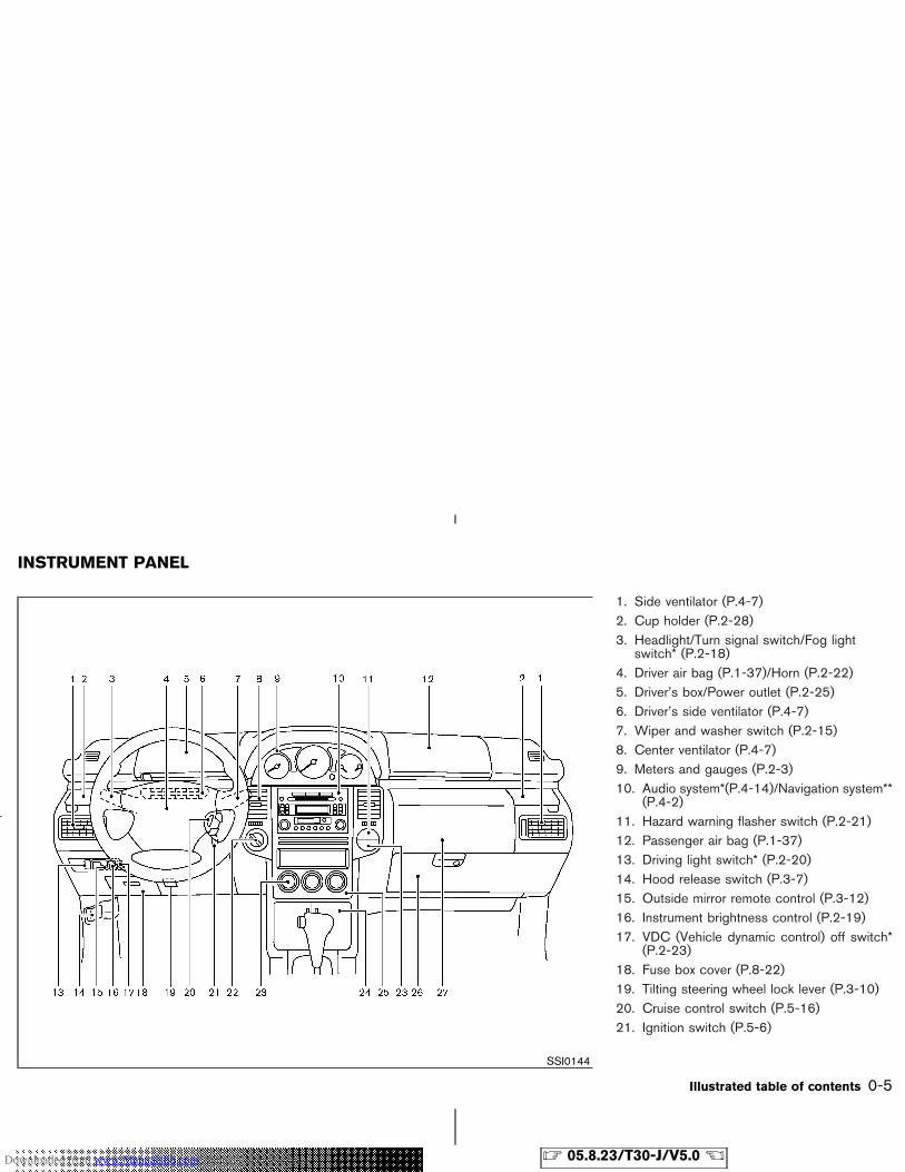
1. Side ventilator (P.4-7)2. Cup holder (P.2-28)3. Headlight/Turn signal switch/Fog light
switch* (P.2-18)4. Driver air bag (P.1-37)/Horn (P.2-22)5. Driver’s box/Power outlet (P.2-25)6. Driver’s side ventilator (P.4-7)7. Wiper and washer switch (P.2-15)8. Center ventilator (P.4-7)9. Meters and gauges (P.2-3)10. Audio system*(P.4-14)/Navigation system**
(P.4-2)11. Hazard warning flasher switch (P.2-21)12. Passenger air bag (P.1-37)13. Driving light switch* (P.2-20)14. Hood release switch (P.3-7)15. Outside mirror remote control (P.3-12)16. Instrument brightness control (P.2-19)17. VDC (Vehicle dynamic control) off switch*
(P.2-23)18. Fuse box cover (P.8-22)19. Tilting steering wheel lock lever (P.3-10)20. Cruise control switch (P.5-16)21. Ignition switch (P.5-6)
SSI0144
INSTRUMENT PANEL
Illustrated table of contents 0-5
� 05.8.23/T30-J/V5.0 �Downloaded from www.Manualslib.com manuals search engine
22. 4WD mode switch* (P.5-19)/SNOWmode switch* (P.2-23)
23. Rear window/outside mirror defrosterswitch (P.2-17)
24. Multi box (P.2-27)25. Heater/air conditioner control (P.4-8)26. Glove box (P.2-30)27. Upper glove box (P.2-30)
* If so equipped** Refer to the separate Navigation System
Owner’s Manual
0-6 Illustrated table of contents
� 05.8.23/T30-J/V5.0 �Downloaded from www.Manualslib.com manuals search engine
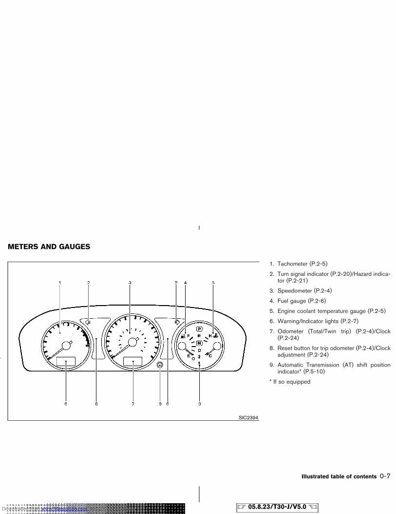
1. Tachometer (P.2-5)
2. Turn signal indicator (P.2-20)/Hazard indica-tor (P.2-21)
3. Speedometer (P.2-4)
4. Fuel gauge (P.2-6)
5. Engine coolant temperature gauge (P.2-5)
6. Warning/Indicator lights (P.2-7)
7. Odometer (Total/Twin trip) (P.2-4)/Clock(P.2-24)
8. Reset button for trip odometer (P.2-4)/Clockadjustment (P.2-24)
9. Automatic Transmission (AT) shift positionindicator* (P.5-10)
* If so equipped
SIC2394
METERS AND GAUGES
Illustrated table of contents 0-7
� 05.8.23/T30-J/V5.0 �Downloaded from www.Manualslib.com manuals search engine
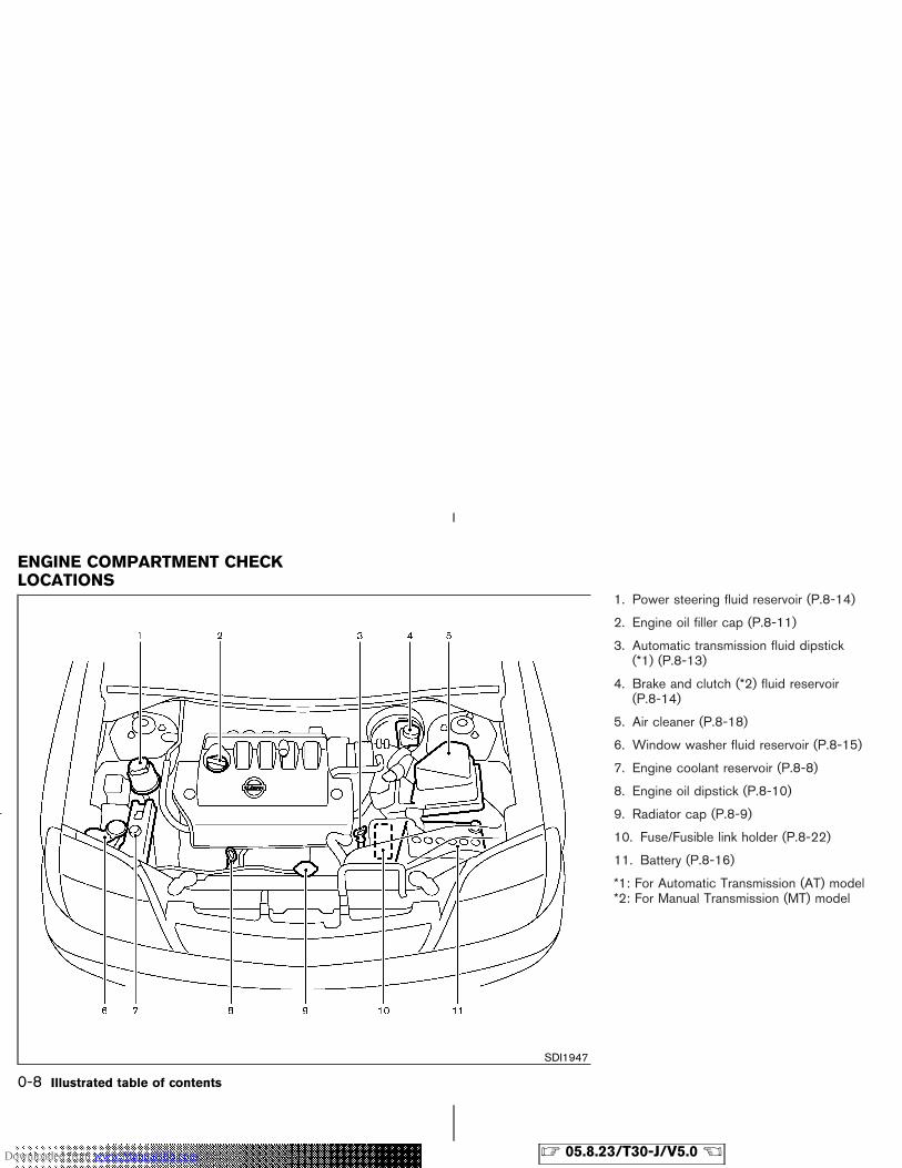
1. Power steering fluid reservoir (P.8-14)
2. Engine oil filler cap (P.8-11)
3. Automatic transmission fluid dipstick(*1) (P.8-13)
4. Brake and clutch (*2) fluid reservoir(P.8-14)
5. Air cleaner (P.8-18)
6. Window washer fluid reservoir (P.8-15)
7. Engine coolant reservoir (P.8-8)
8. Engine oil dipstick (P.8-10)
9. Radiator cap (P.8-9)
10. Fuse/Fusible link holder (P.8-22)
11. Battery (P.8-16)
*1: For Automatic Transmission (AT) model*2: For Manual Transmission (MT) model
SDI1947
ENGINE COMPARTMENT CHECKLOCATIONS
0-8 Illustrated table of contents
� 05.8.23/T30-J/V5.0 �Downloaded from www.Manualslib.com manuals search engine
1 Safety — Seats, seat belts and supple-mental restraint system
Seats ........................................................................................ 1-2Front manual seat adjustment ..................................... 1-2Lumbar support (for driver’s seat) .............................. 1-4Front power seat adjustment (if so equipped fordriver’s seat) ..................................................................... 1-4Rear seat adjustment ..................................................... 1-6Head restraint adjustment (for front seats) ............... 1-9Active head restraint (for front seats) ..................... 1-10Armrest ........................................................................... 1-10
Seat belts ............................................................................. 1-11Precautions on seat belt usage ................................ 1-11Child safety .................................................................... 1-14Pregnant women .......................................................... 1-15Injured persons ............................................................. 1-15Three-point type seat belt with retractor ............... 1-15Rear center seat belt .................................................. 1-19Seat belt extenders ...................................................... 1-19Seat belt maintenance ................................................ 1-19
Child restraints ................................................................... 1-20
Precautions on child restraints ................................. 1-20Child restraint installation on rear seat center oroutboard positions ....................................................... 1-21LATCH (Lower Anchors and Tethers forCHildren) system .......................................................... 1-26Top tether strap child restraint ................................. 1-28Child restraint installation on front passengerseat .................................................................................. 1-29
Booster seats ....................................................................... 1-32Precautions on booster seats .................................... 1-32Booster seat installation on rear seat outboardor center positions ........................................................ 1-35Booster seat installation on front passengerseat.................................................................................... 1-36
Supplemental restraint system ....................................... 1-37Precautions on supplemental restraint system ..... 1-37Supplemental air bag warning labels ...................... 1-47Supplemental air bag warning light ......................... 1-47
� 05.8.23/T30-J/V5.0 �Downloaded from www.Manualslib.com manuals search engine
WARNING
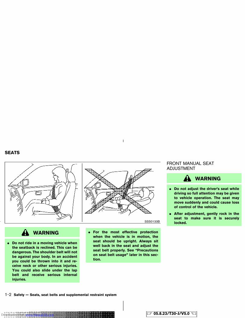
� Do not ride in a moving vehicle whenthe seatback is reclined. This can bedangerous. The shoulder belt will notbe against your body. In an accidentyou could be thrown into it and re-ceive neck or other serious injuries.You could also slide under the lapbelt and receive serious internalinjuries.
� For the most effective protectionwhen the vehicle is in motion, theseat should be upright. Always sitwell back in the seat and adjust theseat belt properly. See “Precautionson seat belt usage” later in this sec-tion.
FRONT MANUAL SEATADJUSTMENT
WARNING
� Do not adjust the driver’s seat whiledriving so full attention may be givento vehicle operation. The seat maymove suddenly and could cause lossof control of the vehicle.
� After adjustment, gently rock in theseat to make sure it is securelylocked.SSS0133B
SEATS
1-2 Safety — Seats, seat belts and supplemental restraint system
� 05.8.23/T30-J/V5.0 �Downloaded from www.Manualslib.com manuals search engine
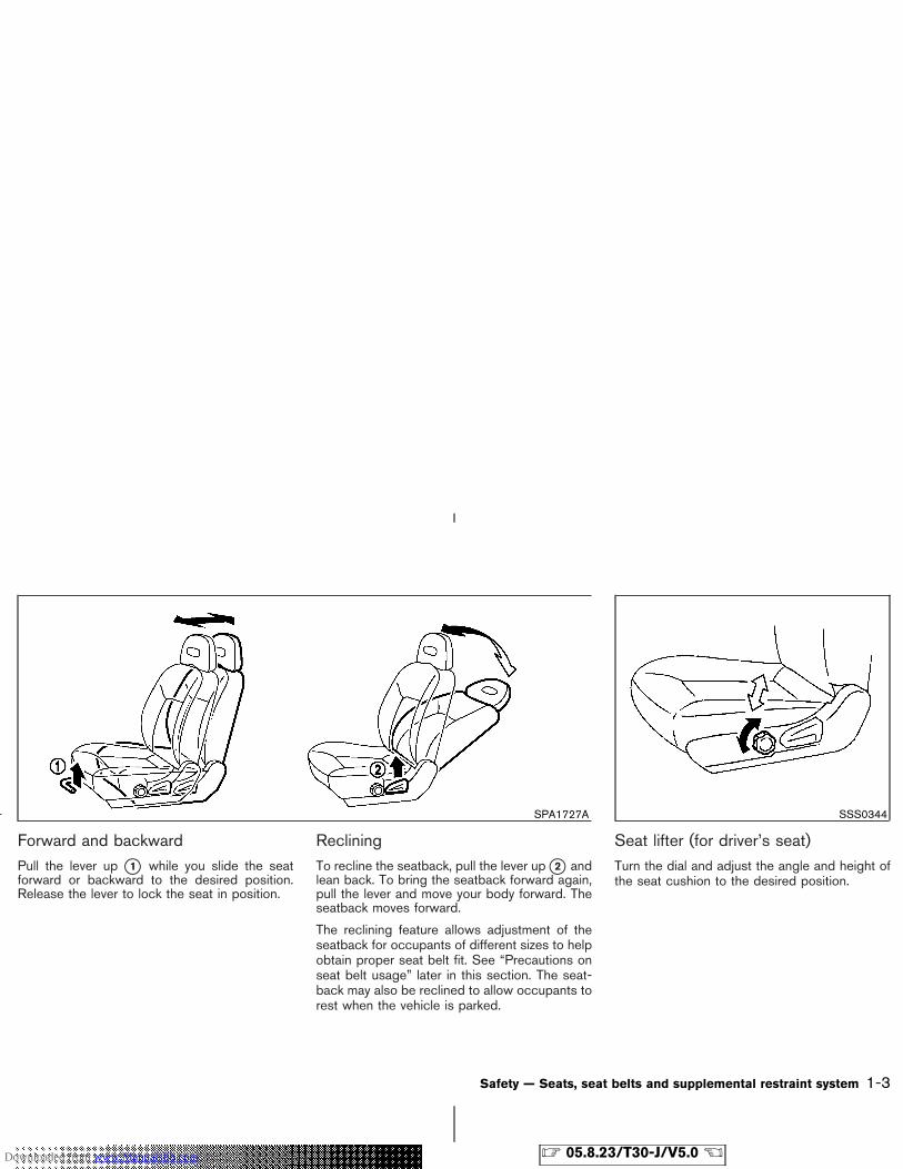
Forward and backwardPull the lever up �1 while you slide the seatforward or backward to the desired position.Release the lever to lock the seat in position.
RecliningTo recline the seatback, pull the lever up �2 andlean back. To bring the seatback forward again,pull the lever and move your body forward. Theseatback moves forward.
The reclining feature allows adjustment of theseatback for occupants of different sizes to helpobtain proper seat belt fit. See “Precautions onseat belt usage” later in this section. The seat-back may also be reclined to allow occupants torest when the vehicle is parked.
Seat lifter (for driver’s seat)Turn the dial and adjust the angle and height ofthe seat cushion to the desired position.
SPA1727A SSS0344
Safety — Seats, seat belts and supplemental restraint system 1-3
� 05.8.23/T30-J/V5.0 �Downloaded from www.Manualslib.com manuals search engine
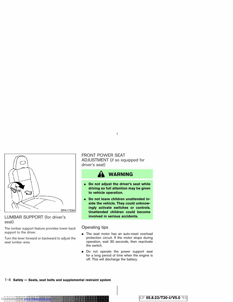
LUMBAR SUPPORT (for driver’sseat)The lumbar support feature provides lower backsupport to the driver.
Turn the lever forward or backward to adjust theseat lumbar area.
FRONT POWER SEATADJUSTMENT (if so equipped fordriver’s seat)
WARNING
� Do not adjust the driver’s seat whiledriving so full attention may be givento vehicle operation.
� Do not leave children unattended in-side the vehicle. They could unknow-ingly activate switches or controls.Unattended children could becomeinvolved in serious accidents.
Operating tips� The seat motor has an auto-reset overload
protection circuit. If the motor stops duringoperation, wait 30 seconds, then reactivatethe switch.
� Do not operate the power support seatfor a long period of time when the engine isoff. This will discharge the battery.
SPA1729A
1-4 Safety — Seats, seat belts and supplemental restraint system
� 05.8.23/T30-J/V5.0 �Downloaded from www.Manualslib.com manuals search engine
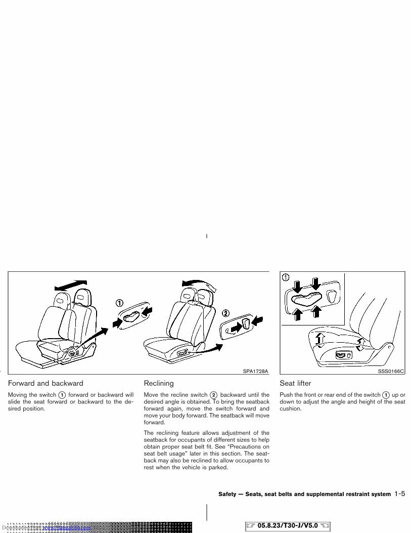
Forward and backwardMoving the switch �1 forward or backward willslide the seat forward or backward to the de-sired position.
RecliningMove the recline switch �2 backward until thedesired angle is obtained. To bring the seatbackforward again, move the switch forward andmove your body forward. The seatback will moveforward.
The reclining feature allows adjustment of theseatback for occupants of different sizes to helpobtain proper seat belt fit. See “Precautions onseat belt usage” later in this section. The seat-back may also be reclined to allow occupants torest when the vehicle is parked.
Seat lifterPush the front or rear end of the switch �1 up ordown to adjust the angle and height of the seatcushion.
SPA1728A SSS0166C
Safety — Seats, seat belts and supplemental restraint system 1-5
� 05.8.23/T30-J/V5.0 �Downloaded from www.Manualslib.com manuals search engine
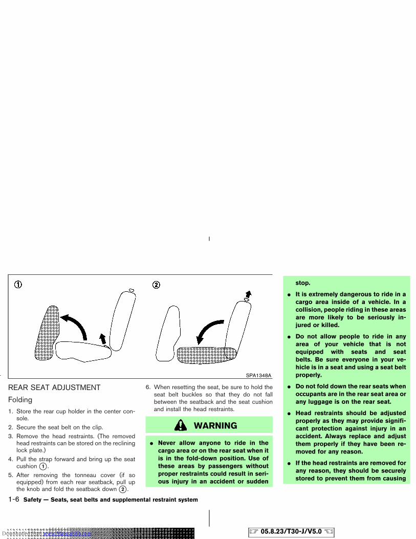
REAR SEAT ADJUSTMENT
Folding1. Store the rear cup holder in the center con-
sole.2. Secure the seat belt on the clip.3. Remove the head restraints. (The removed
head restraints can be stored on the reclininglock plate.)
4. Pull the strap forward and bring up the seatcushion �1 .
5. After removing the tonneau cover (if soequipped) from each rear seatback, pull upthe knob and fold the seatback down �2 .
6. When resetting the seat, be sure to hold theseat belt buckles so that they do not fallbetween the seatback and the seat cushionand install the head restraints.
WARNING
� Never allow anyone to ride in thecargo area or on the rear seat when itis in the fold-down position. Use ofthese areas by passengers withoutproper restraints could result in seri-ous injury in an accident or sudden
stop.
� It is extremely dangerous to ride in acargo area inside of a vehicle. In acollision, people riding in these areasare more likely to be seriously in-jured or killed.
� Do not allow people to ride in anyarea of your vehicle that is notequipped with seats and seatbelts. Be sure everyone in your ve-hicle is in a seat and using a seat beltproperly.
� Do not fold down the rear seats whenoccupants are in the rear seat area orany luggage is on the rear seat.
� Head restraints should be adjustedproperly as they may provide signifi-cant protection against injury in anaccident. Always replace and adjustthem properly if they have been re-moved for any reason.
� If the head restraints are removed forany reason, they should be securelystored to prevent them from causing
SPA1348A
1-6 Safety — Seats, seat belts and supplemental restraint system
� 05.8.23/T30-J/V5.0 �Downloaded from www.Manualslib.com manuals search engine
injury to passengers or damage tothe vehicle in case of sudden brakingor an accident.
� Properly secure all cargo to help pre-vent it from sliding or shifting. Do notplace cargo higher than the seat-backs. In a sudden stop or collision,unsecured cargo could cause per-sonal injury.
� When returning the seatbacks to theupright position, be certain they arecompletely secured in the latched po-sition. If they are not completely se-cured, passengers may be injured inan accident or sudden stop.
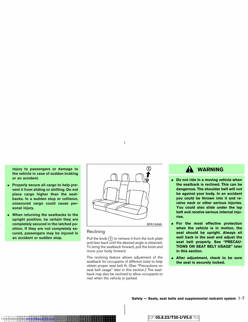
RecliningPull the knob �1 to remove it from the lock plateand lean back until the desired angle is obtained.To bring the seatback forward, pull the knob andmove your body forward.
The reclining feature allows adjustment of theseatback for occupants of different sizes to helpobtain proper seat belt fit. (See “Precautions onseat belt usage” later in this section.) The seat-back may also be reclined to allow occupants torest when the vehicle is parked.
WARNING
� Do not ride in a moving vehicle whenthe seatback is reclined. This can bedangerous. The shoulder belt will notbe against your body. In an accidentyou could be thrown into it and re-ceive neck or other serious injuries.You could also slide under the lapbelt and receive serious internal inju-ries.
� For the most effective protectionwhen the vehicle is in motion, theseat should be upright. Always sitwell back in the seat and adjust theseat belt properly. See “PRECAU-TIONS ON SEAT BELT USAGE” laterin this section.
� After adjustment, check to be surethe seat is securely locked.
SPA1349A
Safety — Seats, seat belts and supplemental restraint system 1-7
� 05.8.23/T30-J/V5.0 �Downloaded from www.Manualslib.com manuals search engine
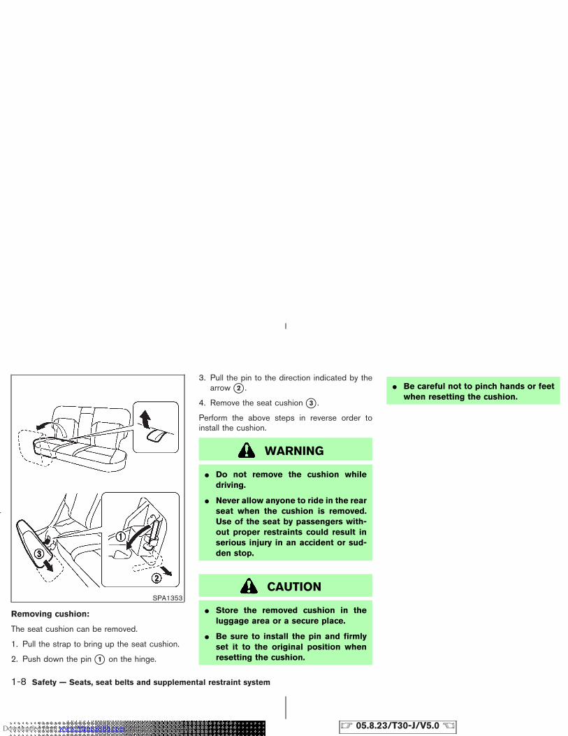
Removing cushion:
The seat cushion can be removed.
1. Pull the strap to bring up the seat cushion.
2. Push down the pin �1 on the hinge.
3. Pull the pin to the direction indicated by thearrow �2 .
4. Remove the seat cushion �3 .
Perform the above steps in reverse order toinstall the cushion.
WARNING
� Do not remove the cushion whiledriving.
� Never allow anyone to ride in the rearseat when the cushion is removed.Use of the seat by passengers with-out proper restraints could result inserious injury in an accident or sud-den stop.
CAUTION
� Store the removed cushion in theluggage area or a secure place.
� Be sure to install the pin and firmlyset it to the original position whenresetting the cushion.
� Be careful not to pinch hands or feetwhen resetting the cushion.
SPA1353
1-8 Safety — Seats, seat belts and supplemental restraint system
� 05.8.23/T30-J/V5.0 �Downloaded from www.Manualslib.com manuals search engine
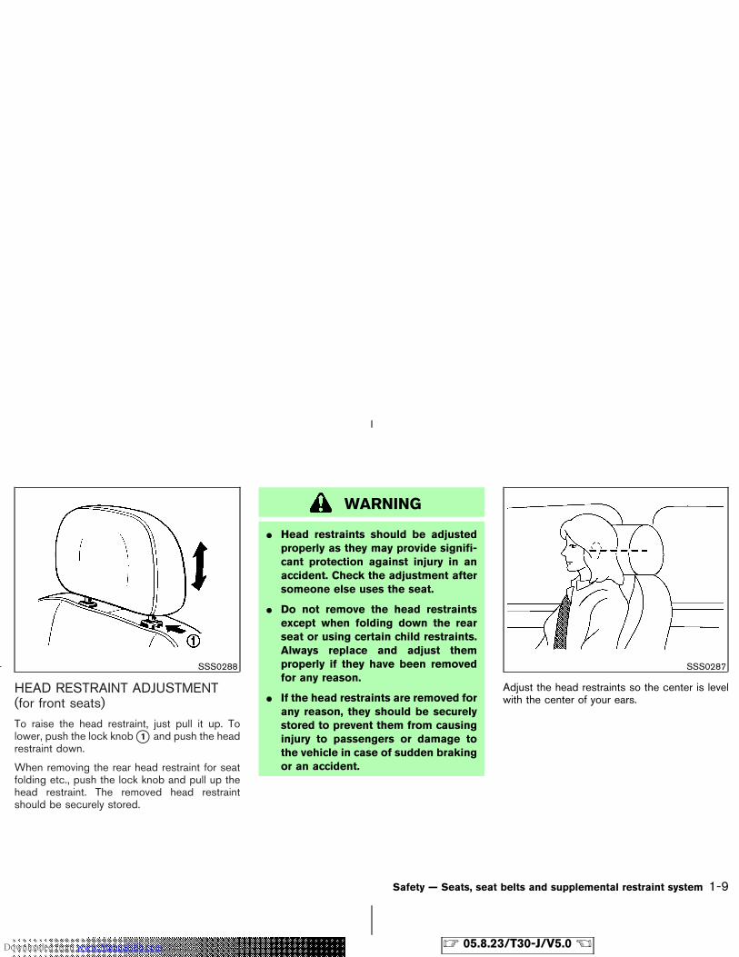
HEAD RESTRAINT ADJUSTMENT(for front seats)To raise the head restraint, just pull it up. Tolower, push the lock knob �1 and push the headrestraint down.
When removing the rear head restraint for seatfolding etc., push the lock knob and pull up thehead restraint. The removed head restraintshould be securely stored.
WARNING
� Head restraints should be adjustedproperly as they may provide signifi-cant protection against injury in anaccident. Check the adjustment aftersomeone else uses the seat.
� Do not remove the head restraintsexcept when folding down the rearseat or using certain child restraints.Always replace and adjust themproperly if they have been removedfor any reason.
� If the head restraints are removed forany reason, they should be securelystored to prevent them from causinginjury to passengers or damage tothe vehicle in case of sudden brakingor an accident.
Adjust the head restraints so the center is levelwith the center of your ears.
SSS0288 SSS0287
Safety — Seats, seat belts and supplemental restraint system 1-9
� 05.8.23/T30-J/V5.0 �Downloaded from www.Manualslib.com manuals search engine
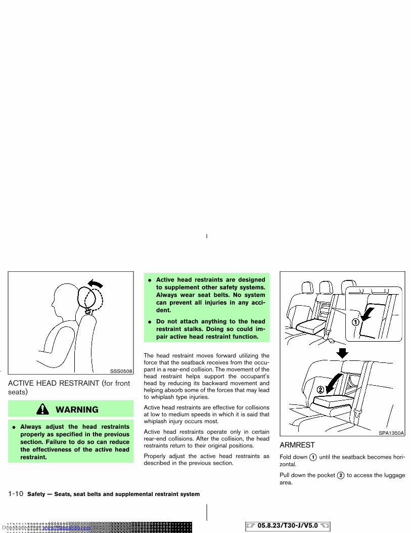
ACTIVE HEAD RESTRAINT (for frontseats)
WARNING
� Always adjust the head restraintsproperly as specified in the previoussection. Failure to do so can reducethe effectiveness of the active headrestraint.
� Active head restraints are designedto supplement other safety systems.Always wear seat belts. No systemcan prevent all injuries in any acci-dent.
� Do not attach anything to the headrestraint stalks. Doing so could im-pair active head restraint function.
The head restraint moves forward utilizing theforce that the seatback receives from the occu-pant in a rear-end collision. The movement of thehead restraint helps support the occupant’shead by reducing its backward movement andhelping absorb some of the forces that may leadto whiplash type injuries.
Active head restraints are effective for collisionsat low to medium speeds in which it is said thatwhiplash injury occurs most.
Active head restraints operate only in certainrear-end collisions. After the collision, the headrestraints return to their original positions.
Properly adjust the active head restraints asdescribed in the previous section.
ARMREST
Fold down �1 until the seatback becomes hori-zontal.
Pull down the pocket �2 to access the luggagearea.
SSS0508
SPA1350A
1-10 Safety — Seats, seat belts and supplemental restraint system
� 05.8.23/T30-J/V5.0 �Downloaded from www.Manualslib.com manuals search engine
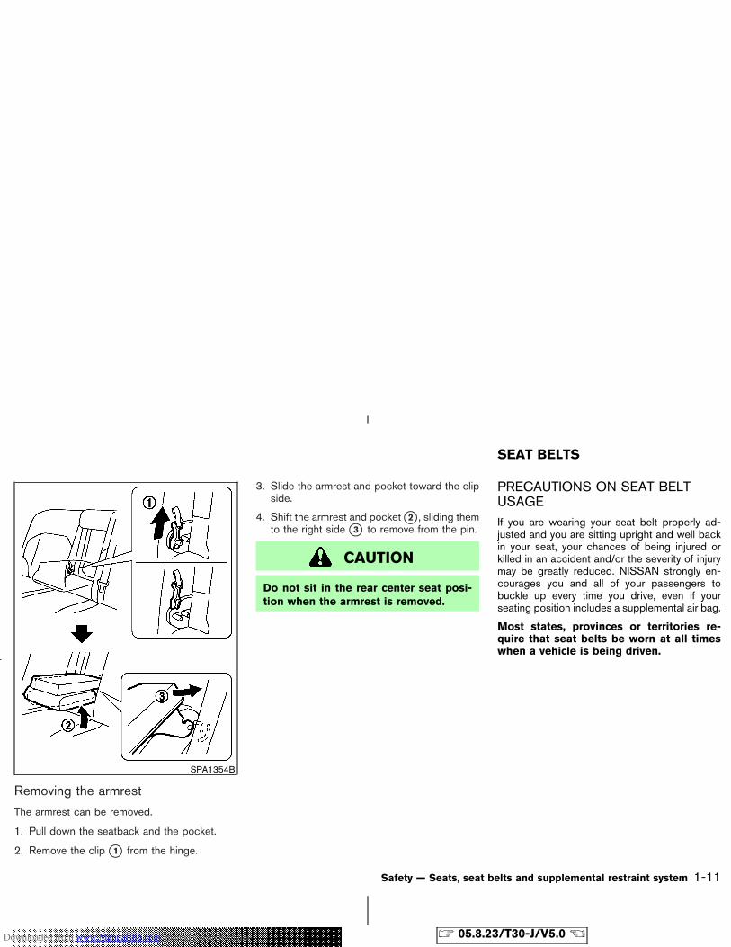
Removing the armrest
The armrest can be removed.
1. Pull down the seatback and the pocket.
2. Remove the clip �1 from the hinge.
3. Slide the armrest and pocket toward the clipside.
4. Shift the armrest and pocket �2 , sliding themto the right side �3 to remove from the pin.
CAUTION
Do not sit in the rear center seat posi-tion when the armrest is removed.
PRECAUTIONS ON SEAT BELTUSAGEIf you are wearing your seat belt properly ad-justed and you are sitting upright and well backin your seat, your chances of being injured orkilled in an accident and/or the severity of injurymay be greatly reduced. NISSAN strongly en-courages you and all of your passengers tobuckle up every time you drive, even if yourseating position includes a supplemental air bag.
Most states, provinces or territories re-quire that seat belts be worn at all timeswhen a vehicle is being driven.
SPA1354B
SEAT BELTS
Safety — Seats, seat belts and supplemental restraint system 1-11
� 05.8.23/T30-J/V5.0 �Downloaded from www.Manualslib.com manuals search engine
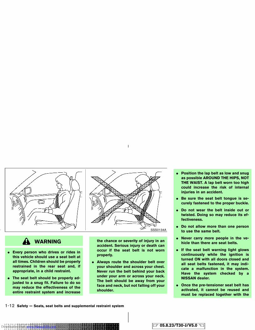
WARNING
� Every person who drives or rides inthis vehicle should use a seat belt atall times. Children should be properlyrestrained in the rear seat and, ifappropriate, in a child restraint.
� The seat belt should be properly ad-justed to a snug fit. Failure to do somay reduce the effectiveness of theentire restraint system and increase
the chance or severity of injury in anaccident. Serious injury or death canoccur if the seat belt is not wornproperly.
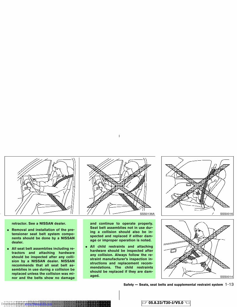
� Always route the shoulder belt overyour shoulder and across your chest.Never run the belt behind your backunder your arm or across your neck.The belt should be away from yourface and neck, but not falling off yourshoulder.
� Position the lap belt as low and snugas possible AROUND THE HIPS, NOTTHE WAIST. A lap belt worn too highcould increase the risk of internalinjuries in an accident.
� Be sure the seat belt tongue is se-curely fastened to the proper buckle.
� Do not wear the belt inside out ortwisted. Doing so may reduce its ef-fectiveness.
� Do not allow more than one personto use the same belt.
� Never carry more people in the ve-hicle than there are seat belts.
� If the seat belt warning light glowscontinuously while the ignition isturned ON with all doors closed andall seat belts fastened, it may indi-cate a malfunction in the system.Have the system checked by aNISSAN dealer.
� Once the pre-tensioner seat belt hasactivated, it cannot be reused andmust be replaced together with the
SSS0134A
1-12 Safety — Seats, seat belts and supplemental restraint system
� 05.8.23/T30-J/V5.0 �Downloaded from www.Manualslib.com manuals search engine
retractor. See a NISSAN dealer.
� Removal and installation of the pre-tensioner seat belt system compo-nents should be done by a NISSANdealer.
� All seat belt assemblies including re-tractors and attaching hardwareshould be inspected after any colli-sion by a NISSAN dealer. NISSANrecommends that all seat belt as-semblies in use during a collision bereplaced unless the collision was mi-nor and the belts show no damage
and continue to operate properly.Seat belt assemblies not in use dur-ing a collision should also be in-spected and replaced if either dam-age or improper operation is noted.
� All child restraints and attachinghardware should be inspected afterany collision. Always follow the re-straint manufacturer’s inspection in-structions and replacement recom-mendations. The child restraintsshould be replaced if they are dam-aged.
SSS0136A SSS0016
SSS0014
Safety — Seats, seat belts and supplemental restraint system 1-13
� 05.8.23/T30-J/V5.0 �Downloaded from www.Manualslib.com manuals search engine
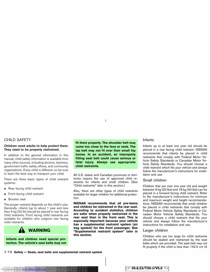
CHILD SAFETY
Children need adults to help protect them.They need to be properly restrained.
In addition to the general information in thismanual, child safety information is available frommany other sources, including doctors, teachers,government traffic safety offices, and communityorganizations. Every child is different, so be sureto learn the best way to transport your child.
There are three basic types of child restraintsystems:
� Rear facing child restraint
� Front facing child restraint
� Booster seat
The proper restraint depends on the child’s size.Generally, infants (up to about 1 year and lessthan 9 kg (20 lb) should be placed in rear facingchild restraints. Front facing child restraints areavailable for children who outgrow rear facingchild restraints.
WARNING
Infants and children need special pro-tection. The vehicle’s seat belts may not
fit them properly. The shoulder belt maycome too close to the face or neck. Thelap belt may not fit over their small hipbones. In an accident, an improperlyfitting seat belt could cause serious orfatal injury. Always use appropriatechild restraints.
All U.S. states and Canadian provinces or terri-tories require the use of approved child re-straints for infants and small children. (See“Child restraints” later in this section.)
Also, there are other types of child restraintsavailable for larger children for additional protec-tion.
NISSAN recommends that all pre-teensand children be restrained in the rear seat.According to accident statistics, childrenare safer when properly restrained in therear seat than in the front seat. This isespecially important because your vehiclehas a supplemental restraint system (airbag system) for the front passenger. See“Supplemental restraint system” later inthis section.
Infants
Infants up to at least one year old should beplaced in a rear facing child restraint. NISSANrecommends that infants be placed in childrestraints that comply with Federal Motor Ve-hicle Safety Standards or Canadian Motor Ve-hicle Safety Standards. You should choose achild restraint which fits your vehicle and alwaysfollow the manufacturer’s instructions for instal-lation and use.
Small childrenChildren that are over one year old and weightbetween 9 kg (20 lbs) and 18 kg (40 lbs) can beplaced in a forward facing child restraint. Referto the manufacturer’s instructions for minimumand maximum weight and height recommenda-tions. NISSAN recommends that small childrenbe placed in child restraints that comply withFederal Motor Vehicle Safety Standards or Ca-nadian Motor Vehicle Safety Standards. Youshould choose a child restraint that fits yourvehicle and always follow the manufacturer’sinstructions for installation and use.
Larger childrenChildren who are too large for child restraintsshould be seated and restrained by the seatbelts which are provided. The seat belt may notfit properly if the child is less than 142.5 cm (4
1-14 Safety — Seats, seat belts and supplemental restraint system
� 05.8.23/T30-J/V5.0 �Downloaded from www.Manualslib.com manuals search engine
feet 9 inches) tall and weighs between 18 kg(40 lbs) and 36 kg (80 lbs). A booster seatshould be used to obtain proper seat belt fit.
NISSAN recommends that a child be placed in acommercially available booster seat if the shoul-der belt in the child’s seating position fits closeto the face or neck or if the lap portion of the seatbelt goes across the abdomen. The booster seatshould raise the child so that the shoulder belt isproperly positioned across the top, middle por-tion of the shoulder and the lap belt is low on thehips. A booster seat can only be used in seatingpositions that have a three-point type seat belt.The booster seat should fit the vehicle seat andhave a label certifying that it complies withFederal Motor Vehicle Safety Standards or Ca-nadian Motor Vehicle Safety Standards. Oncethe child has grown so the shoulder belt is nolonger on or near the face and neck, use theshoulder belt without the booster seat.
WARNING
Never let a child stand or kneel on anyseat and do not allow a child in thecargo areas while the vehicle is moving.The child could be seriously injured orkilled in an accident or sudden stop.
PREGNANT WOMENNISSAN recommends that pregnant women useseat belts. The seat belt should be worn snug,and always position the lap belt as low aspossible around the hips, not the waist. Placethe shoulder belt over your shoulder and acrossyour chest. Never run the lap/shoulder belt overyour abdominal area. Contact your doctor forspecific recommendations.
INJURED PERSONSNISSAN recommends that injured persons useseat belts, depending on the injury. Check withyour doctor for specific recommendations.
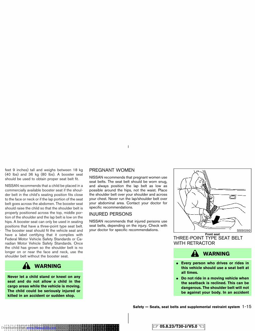
THREE-POINT TYPE SEAT BELTWITH RETRACTOR
WARNING
� Every person who drives or rides inthis vehicle should use a seat belt atall times.
� Do not ride in a moving vehicle whenthe seatback is reclined. This can bedangerous. The shoulder belt will notbe against your body. In an accident
SSS0292Front seat
Safety — Seats, seat belts and supplemental restraint system 1-15
� 05.8.23/T30-J/V5.0 �Downloaded from www.Manualslib.com manuals search engine
you could be thrown into it and re-ceive neck or other serious injuries.You could also slide under the lapbelt and receive serious internal inju-ries.
� For most effective protection whenthe vehicle is in motion, the seatshould be upright. Always sit wellback in the seat and adjust the seatbelt properly.
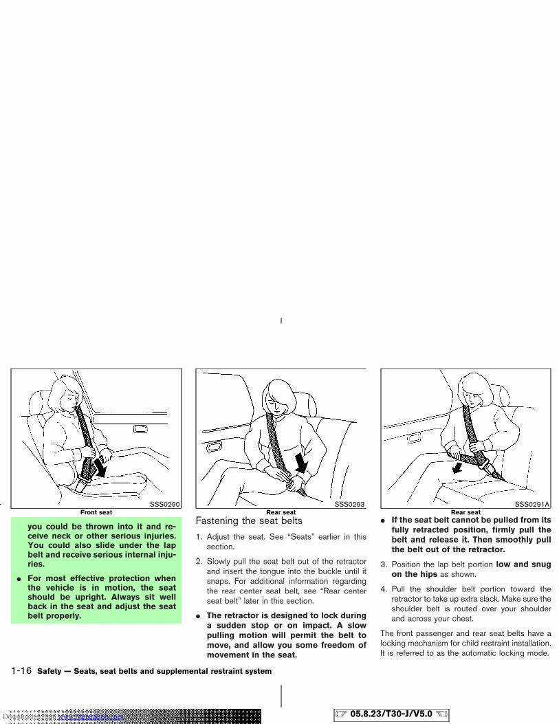
Fastening the seat belts
1. Adjust the seat. See “Seats” earlier in thissection.
2. Slowly pull the seat belt out of the retractorand insert the tongue into the buckle until itsnaps. For additional information regardingthe rear center seat belt, see “Rear centerseat belt” later in this section.
� The retractor is designed to lock duringa sudden stop or on impact. A slowpulling motion will permit the belt tomove, and allow you some freedom ofmovement in the seat.
� If the seat belt cannot be pulled from itsfully retracted position, firmly pull thebelt and release it. Then smoothly pullthe belt out of the retractor.
3. Position the lap belt portion low and snugon the hips as shown.
4. Pull the shoulder belt portion toward theretractor to take up extra slack. Make sure theshoulder belt is routed over your shoulderand across your chest.
The front passenger and rear seat belts have alocking mechanism for child restraint installation.It is referred to as the automatic locking mode.
SSS0290Front seat
SSS0293Rear seat
SSS0291ARear seat
1-16 Safety — Seats, seat belts and supplemental restraint system
� 05.8.23/T30-J/V5.0 �Downloaded from www.Manualslib.com manuals search engine
When the locking mechanism is activated theseat belt cannot be extended again until the seatbelt tongue is detached from the buckle and fullyretracted. For additional information, see “Childrestraints” later in this section.The automatic locking mode should beused only for child restraint installation.During normal seat belt use by a passen-ger, the locking mode should not be acti-vated. If it is activated it may cause uncom-fortable seat belt tension.
WARNING
When fastening the seat belts, be cer-tain that seatbacks are completely se-cured in the latched position. If they arenot completely secured, passengersmay be injured in an accident or suddenstop.
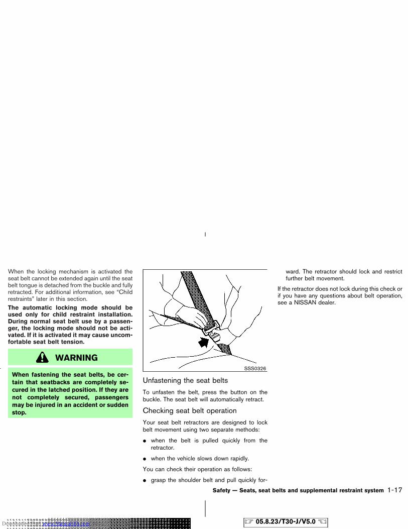
Unfastening the seat belts
To unfasten the belt, press the button on thebuckle. The seat belt will automatically retract.
Checking seat belt operation
Your seat belt retractors are designed to lockbelt movement using two separate methods:
� when the belt is pulled quickly from theretractor.
� when the vehicle slows down rapidly.
You can check their operation as follows:
� grasp the shoulder belt and pull quickly for-
ward. The retractor should lock and restrictfurther belt movement.
If the retractor does not lock during this check orif you have any questions about belt operation,see a NISSAN dealer.
SSS0326
Safety — Seats, seat belts and supplemental restraint system 1-17
� 05.8.23/T30-J/V5.0 �Downloaded from www.Manualslib.com manuals search engine
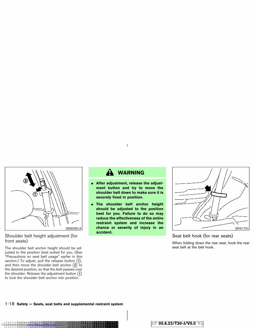
Shoulder belt height adjustment (forfront seats)The shoulder belt anchor height should be ad-justed to the position best suited for you. (See“Precautions on seat belt usage” earlier in thissection.) To adjust, pull the release button �1 ,and then move the shoulder belt anchor �2 tothe desired position, so that the belt passes overthe shoulder. Release the adjustment button �1to lock the shoulder belt anchor into position.
WARNING
� After adjustment, release the adjust-ment button and try to move theshoulder belt down to make sure it issecurely fixed in position.
� The shoulder belt anchor heightshould be adjusted to the positionbest for you. Failure to do so mayreduce the effectiveness of the entirerestraint system and increase thechance or severity of injury in anaccident.
Seat belt hook (for rear seats)When folding down the rear seat, hook the rearseat belt at the belt hook.
SSS0351A SPA1731
1-18 Safety — Seats, seat belts and supplemental restraint system
� 05.8.23/T30-J/V5.0 �Downloaded from www.Manualslib.com manuals search engine
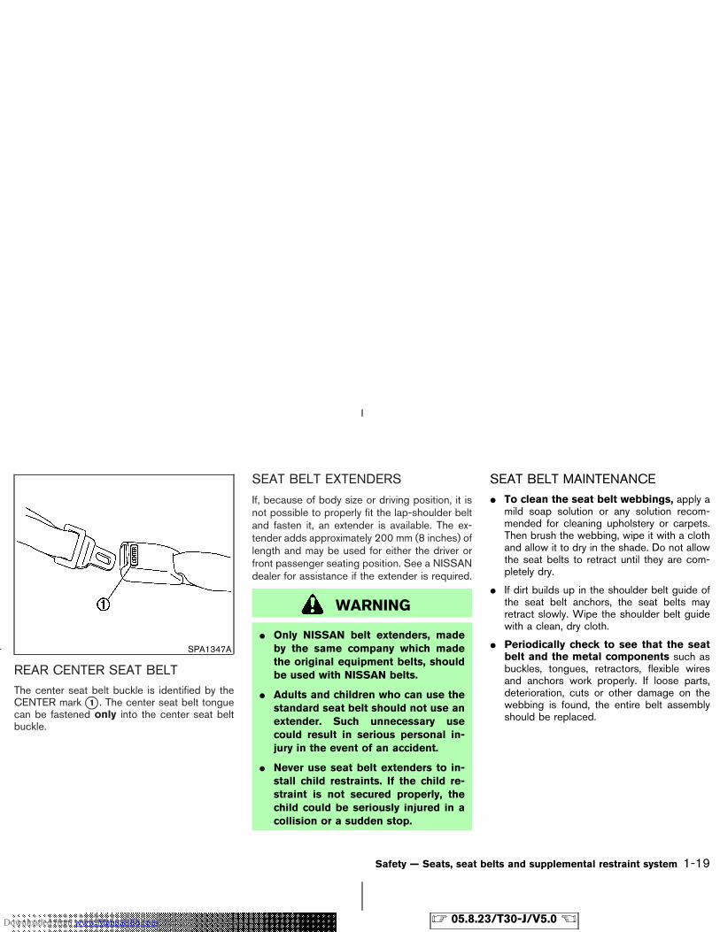
REAR CENTER SEAT BELTThe center seat belt buckle is identified by theCENTER mark �1 . The center seat belt tonguecan be fastened only into the center seat beltbuckle.
SEAT BELT EXTENDERS
If, because of body size or driving position, it isnot possible to properly fit the lap-shoulder beltand fasten it, an extender is available. The ex-tender adds approximately 200 mm (8 inches) oflength and may be used for either the driver orfront passenger seating position. See a NISSANdealer for assistance if the extender is required.
WARNING
� Only NISSAN belt extenders, madeby the same company which madethe original equipment belts, shouldbe used with NISSAN belts.
� Adults and children who can use thestandard seat belt should not use anextender. Such unnecessary usecould result in serious personal in-jury in the event of an accident.
� Never use seat belt extenders to in-stall child restraints. If the child re-straint is not secured properly, thechild could be seriously injured in acollision or a sudden stop.
SEAT BELT MAINTENANCE� To clean the seat belt webbings, apply a
mild soap solution or any solution recom-mended for cleaning upholstery or carpets.Then brush the webbing, wipe it with a clothand allow it to dry in the shade. Do not allowthe seat belts to retract until they are com-pletely dry.
� If dirt builds up in the shoulder belt guide ofthe seat belt anchors, the seat belts mayretract slowly. Wipe the shoulder belt guidewith a clean, dry cloth.
� Periodically check to see that the seatbelt and the metal components such asbuckles, tongues, retractors, flexible wiresand anchors work properly. If loose parts,deterioration, cuts or other damage on thewebbing is found, the entire belt assemblyshould be replaced.
SPA1347A
Safety — Seats, seat belts and supplemental restraint system 1-19
� 05.8.23/T30-J/V5.0 �Downloaded from www.Manualslib.com manuals search engine
PRECAUTIONS ON CHILDRESTRAINTS
WARNING
� Infants and small children should al-ways be placed in an appropriatechild restraint while riding in the ve-hicle. Failure to use a child restraintcan result in serious injury or death.
� Infants and small children shouldnever be carried on your lap. It is notpossible for even the strongest adultto resist the forces of a severe acci-dent. The child could be crushed be-tween the adult and parts of the ve-hicle. Also, do not put the same seatbelt around both your child and your-self.
� Never install a rear facing child re-straint in the front seat. An inflatingsupplemental air bag could seriouslyinjure or kill your child. A rear facingchild restraint must only be used inthe rear seat.
� NISSAN recommends that the childrestraint be installed in the rear seat.According to accident statistics, chil-dren are safer when properly re-strained in the rear seat than in thefront seat.
� An improperly installed child re-straint could lead to serious injury ordeath in an accident.
In general, child restraints are designed to beinstalled with the lap portion of a three-point typeseat belt. In addition, this vehicle is equippedwith a universal child restraint lower anchorsystem, referred to as the LATCH (Lower An-chors and Tethers for CHildren) system. Somechild restraints include two rigid or webbing-mounted attachments that can be connected tothese lower anchors. For details, see “LATCH(Lower Anchors and Tethers for CHildren) SYS-TEM” later in this section.Child restraints for infants and children of varioussizes are offered by several manufacturers.When selecting any child restraint, keep thefollowing points in mind:
� choose only a restraint with a label certifyingthat it complies with Canadian Motor Vehicle
Safety Standard 213 or Federal Motor Ve-hicle Safety Standard 213.
� check the child restraint in your vehicle to besure it is compatible with the vehicle’s seatand seat belt system.
� if the child restraint is compatible with yourvehicle, place your child in the child restraintand check the various adjustments to be surethe child restraint is compatible with yourchild. Choose a child restraint that is de-signed for your child’s height and weight.Always follow all recommended procedures.
Canadian provinces and all US states re-quire that infants and small children berestrained in approved child restraints atall times while the vehicle is being oper-ated.
WARNING
� Improper use of a child restraint canresult in increased injuries for boththe infant or child and other occu-pants in the vehicle.
� Follow all of the child restraint manu-facturer’s instructions for installation
CHILD RESTRAINTS
1-20 Safety — Seats, seat belts and supplemental restraint system
� 05.8.23/T30-J/V5.0 �Downloaded from www.Manualslib.com manuals search engine
and use. When purchasing a childrestraint, be sure to select one whichwill fit your child and vehicle. It maynot be possible to properly installsome types of child restraints in yourvehicle.
� If the child restraint is not anchoredproperly, the risk of a child beinginjured in a collision or a sudden stopgreatly increases.
� Adjustable seatbacks should be po-sitioned to fit the child restraint, butas upright as possible.
� After attaching the child restraint,test it before you place the child in it.Push it from side to side. Try to tug itforward and check to see if the beltholds the restraint in place. The childrestraint should not move more than25 mm (1 inch). If the restraint is notsecure, tighten the belt as necessary,or put the restraint in another seatand test it again. You may need to trya different child restraint. Not allchild restraints fit in all types ofvehicles.
� If you must install a front-facing childrestraint in the front seat, see “Childrestraint installation on front passen-ger seat” later in this section.
� When your child restraint is not inuse, keep it secured with a seat beltto prevent it from being thrownaround in case of a sudden stop oraccident.
CAUTION
Remember that a child restraint left in aclosed vehicle can become very hot.Check the seating surface and bucklesbefore placing your child in the childrestraint.
CHILD RESTRAINT INSTALLATIONON REAR SEAT CENTER OROUTBOARD POSITIONS
WARNING
� The three-point rear seat belts onyour vehicle are equipped with anautomatic locking mode retractorwhich must be used when installing achild restraint.
� Failure to do so will result in the childrestraint not being properly secured.It could tip over or otherwise be un-secured and cause injury to the childin a sudden stop or collision.
Safety — Seats, seat belts and supplemental restraint system 1-21
� 05.8.23/T30-J/V5.0 �Downloaded from www.Manualslib.com manuals search engine
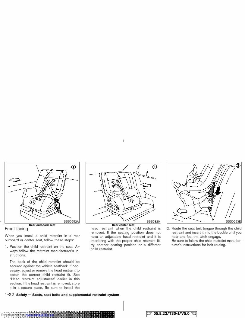
Front facing
When you install a child restraint in a rearoutboard or center seat, follow these steps:
1. Position the child restraint on the seat. Al-ways follow the restraint manufacturer’s in-structions.
The back of the child restraint should besecured against the vehicle seatback. If nec-essary, adjust or remove the head restraint toobtain the correct child restraint fit. See“Head restraint adjustment” earlier in thissection. If the head restraint is removed, storeit in a secure place. Be sure to install the
head restraint when the child restraint isremoved. If the seating position does nothave an adjustable head restraint and it isinterfering with the proper child restraint fit,try another seating position or a differentchild restraint.
2. Route the seat belt tongue through the childrestraint and insert it into the buckle until youhear and feel the latch engage.Be sure to follow the child restraint manufac-turer’s instructions for belt routing.
SSS0252ARear outboard seat
SSS0320Rear center seat
SSS0253E
1-22 Safety — Seats, seat belts and supplemental restraint system
� 05.8.23/T30-J/V5.0 �Downloaded from www.Manualslib.com manuals search engine
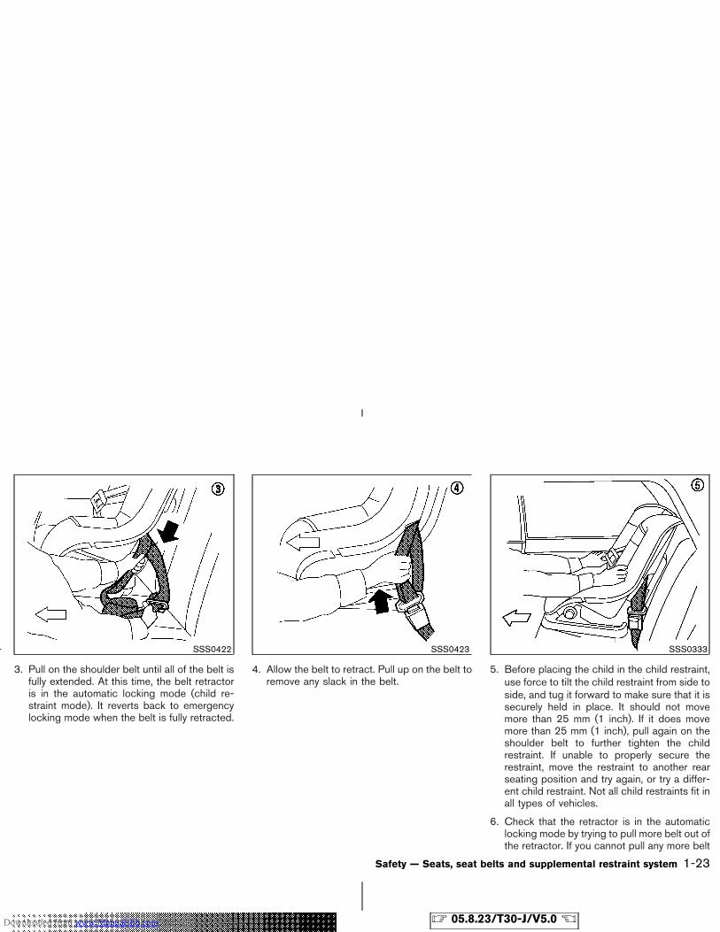
3. Pull on the shoulder belt until all of the belt isfully extended. At this time, the belt retractoris in the automatic locking mode (child re-straint mode). It reverts back to emergencylocking mode when the belt is fully retracted.
4. Allow the belt to retract. Pull up on the belt toremove any slack in the belt.
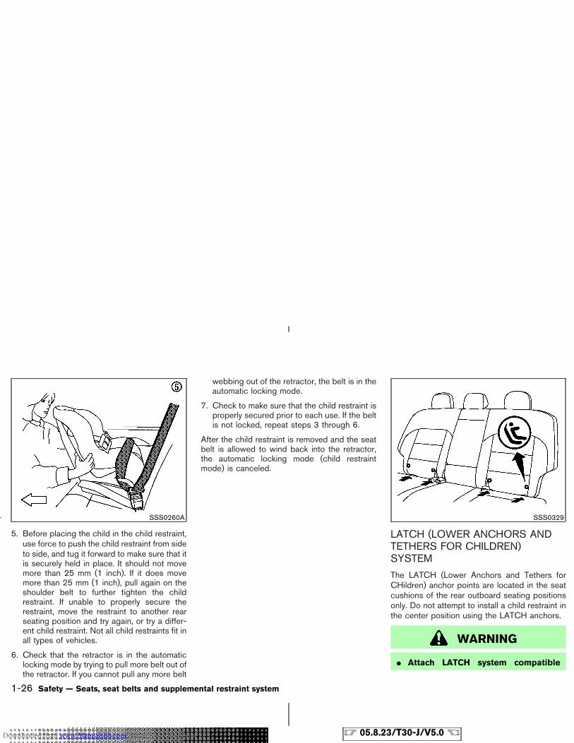
5. Before placing the child in the child restraint,use force to tilt the child restraint from side toside, and tug it forward to make sure that it issecurely held in place. It should not movemore than 25 mm (1 inch). If it does movemore than 25 mm (1 inch), pull again on theshoulder belt to further tighten the childrestraint. If unable to properly secure therestraint, move the restraint to another rearseating position and try again, or try a differ-ent child restraint. Not all child restraints fit inall types of vehicles.
6. Check that the retractor is in the automaticlocking mode by trying to pull more belt out ofthe retractor. If you cannot pull any more belt
SSS0422 SSS0423 SSS0333
Safety — Seats, seat belts and supplemental restraint system 1-23
� 05.8.23/T30-J/V5.0 �Downloaded from www.Manualslib.com manuals search engine
webbing out of the retractor, the belt is in theautomatic locking mode.
7. Check to make sure that the child restraint isproperly secured prior to each use. If the beltis not locked, repeat steps 3 through 6.
After the child restraint is removed and the seatbelt is allowed to wind back into the retractor,the automatic locking mode (child restraintmode) is canceled.
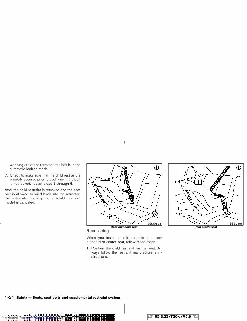
Rear facingWhen you install a child restraint in a rearoutboard or center seat, follow these steps:
1. Position the child restraint on the seat. Al-ways follow the restraint manufacturer’s in-structions.
SSS0392Rear outboard seat
SSS0358Rear center seat
1-24 Safety — Seats, seat belts and supplemental restraint system
� 05.8.23/T30-J/V5.0 �Downloaded from www.Manualslib.com manuals search engine
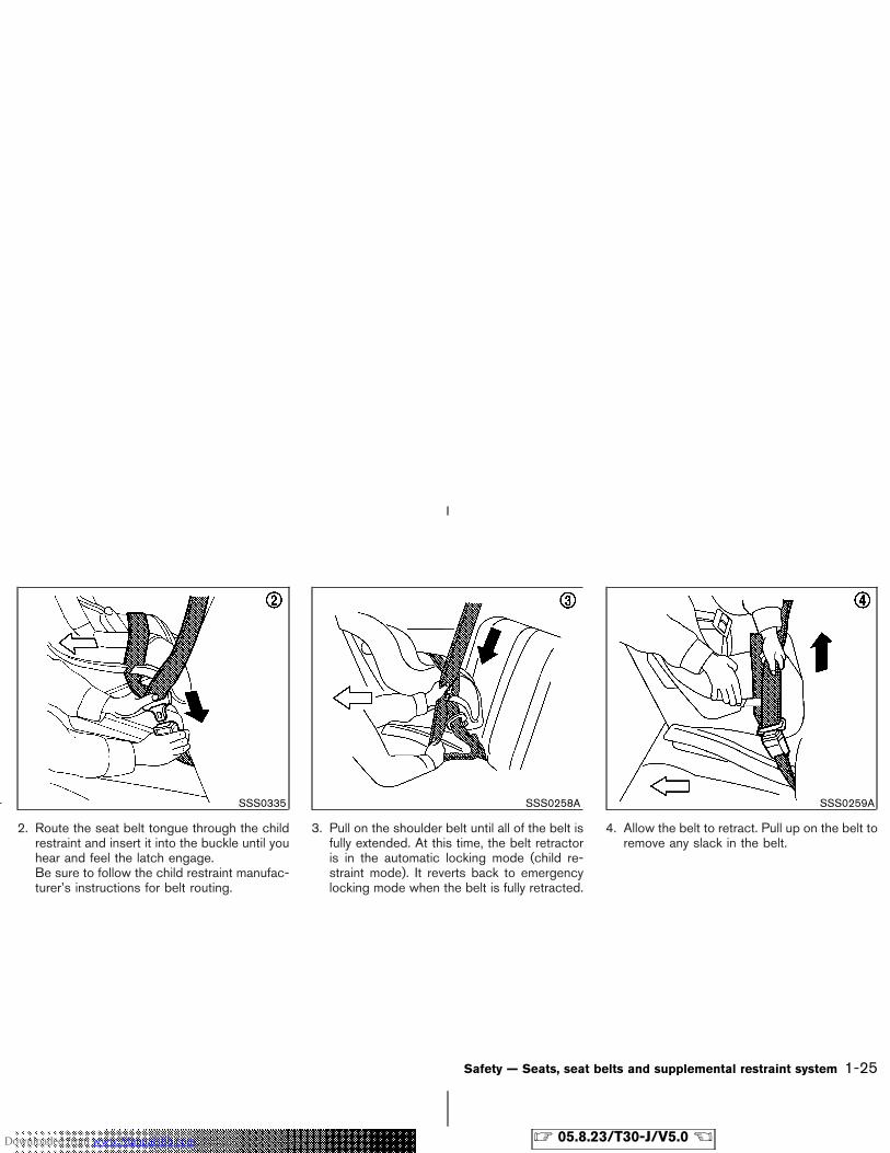
2. Route the seat belt tongue through the childrestraint and insert it into the buckle until youhear and feel the latch engage.Be sure to follow the child restraint manufac-turer’s instructions for belt routing.
3. Pull on the shoulder belt until all of the belt isfully extended. At this time, the belt retractoris in the automatic locking mode (child re-straint mode). It reverts back to emergencylocking mode when the belt is fully retracted.
4. Allow the belt to retract. Pull up on the belt toremove any slack in the belt.
SSS0335 SSS0258A SSS0259A
Safety — Seats, seat belts and supplemental restraint system 1-25
� 05.8.23/T30-J/V5.0 �Downloaded from www.Manualslib.com manuals search engine
5. Before placing the child in the child restraint,use force to push the child restraint from sideto side, and tug it forward to make sure that itis securely held in place. It should not movemore than 25 mm (1 inch). If it does movemore than 25 mm (1 inch), pull again on theshoulder belt to further tighten the childrestraint. If unable to properly secure therestraint, move the restraint to another rearseating position and try again, or try a differ-ent child restraint. Not all child restraints fit inall types of vehicles.
6. Check that the retractor is in the automaticlocking mode by trying to pull more belt out ofthe retractor. If you cannot pull any more belt
webbing out of the retractor, the belt is in theautomatic locking mode.
7. Check to make sure that the child restraint isproperly secured prior to each use. If the beltis not locked, repeat steps 3 through 6.
After the child restraint is removed and the seatbelt is allowed to wind back into the retractor,the automatic locking mode (child restraintmode) is canceled.
LATCH (LOWER ANCHORS ANDTETHERS FOR CHILDREN)SYSTEM
The LATCH (Lower Anchors and Tethers forCHildren) anchor points are located in the seatcushions of the rear outboard seating positionsonly. Do not attempt to install a child restraint inthe center position using the LATCH anchors.
WARNING
� Attach LATCH system compatible
SSS0260A SSS0329
1-26 Safety — Seats, seat belts and supplemental restraint system
� 05.8.23/T30-J/V5.0 �Downloaded from www.Manualslib.com manuals search engine
child restraints only at the locationsshown. If a child restraint is not se-cured properly, your child could beseriously injured or killed in an acci-dent.
� Do not secure a child restraint in thecenter rear seating position using theLATCH system anchors. The child re-straint will not be secured properly.
� The LATCH system anchors are de-signed to withstand only those loadsimposed by correctly fitted child re-straints. Under no circumstance arethey to be used for adult seat belts orharnesses.
Some child restraints include two rigid orwebbing-mounted attachments that can be con-nected to two anchors located at certain seatingpositions in your vehicle. This system is knownas the LATCH system. This system may also bereferred to as the ISOFIX or ISOFIX compatiblesystem. With this system, you do not have to usea vehicle seat belt to secure the child restraint.Your vehicle is equipped with special anchorpoints that are used with LATCH system com-patible child restraints. Check your child restraint
for a label stating that it is compatible with theLATCH system. This information may also be inthe child restraint owner’s manual. If you havesuch a child restraint, refer to the illustration forthe seating positions equipped with LATCHsystem anchors which can be used to secure thechild restraint.
The LATCH system anchors are located at therear of the seat cushion near the seatback. Alabel is attached to the seatback to help youlocate the LATCH system anchors.
Some child restraints may also require the use ofa top tether strap. See “Top tether strap childrestraint” later in this section for installationinstructions.
When installing a child restraint, carefully readand follow the instructions in this manual andthose supplied with the child restraint.
When you install a LATCH system compatiblechild restraint to the lower anchor attachments,follow these steps.
WARNING
Inspect the lower anchors by insertingyour fingers into the lower anchor area
and feeling to make sure there are noobstructions over the LATCH system an-chors, such as seat belt webbing or seatcushion material. The child restraint willnot be secured properly if the LATCHsystem anchors are obstructed.
1. To install the LATCH system compatible childrestraint, insert the child restraint LATCHsystem anchor attachments into the anchorpoints on the rear.
2. Insert the anchor attachments into the anchorpoints. If the child restraint is equipped with atop tether, see “Top tether strap child re-straint” later in this section for installationinstructions.
3. After attaching the child restraint and beforeplacing the child in it, use force to push thechild restraint from side to side and tug itforward to make sure that the child restraint issecurely held in place. It should not movemore than 25 mm (1 inch).
4. Check to make sure that the child restraint isproperly secured prior to each use.
Safety — Seats, seat belts and supplemental restraint system 1-27
� 05.8.23/T30-J/V5.0 �Downloaded from www.Manualslib.com manuals search engine
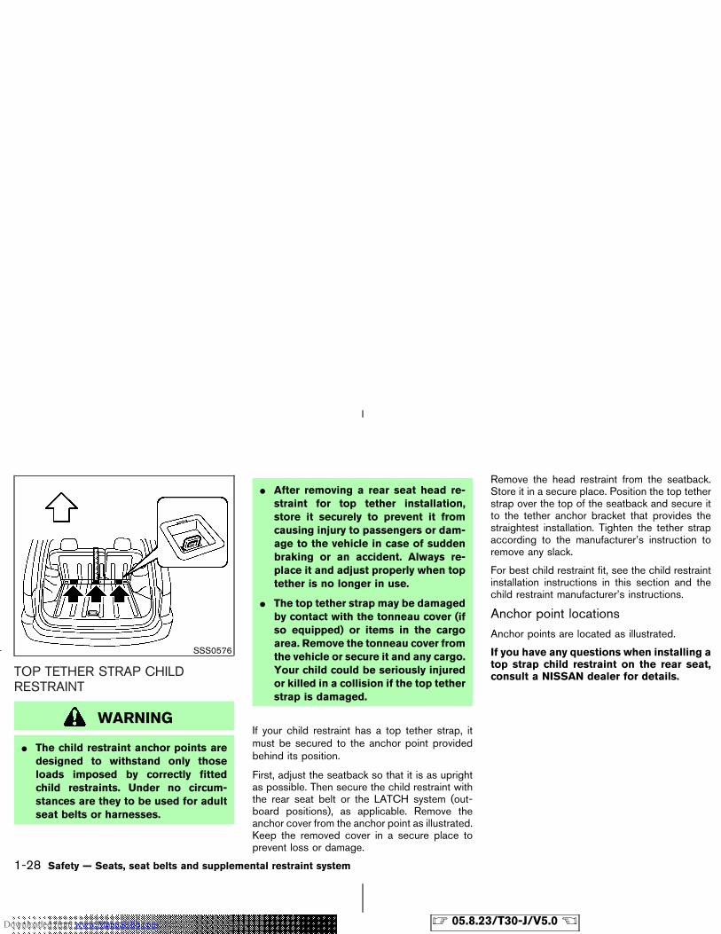
TOP TETHER STRAP CHILDRESTRAINT
WARNING
� The child restraint anchor points aredesigned to withstand only thoseloads imposed by correctly fittedchild restraints. Under no circum-stances are they to be used for adultseat belts or harnesses.
� After removing a rear seat head re-straint for top tether installation,store it securely to prevent it fromcausing injury to passengers or dam-age to the vehicle in case of suddenbraking or an accident. Always re-place it and adjust properly when toptether is no longer in use.
� The top tether strap may be damagedby contact with the tonneau cover (ifso equipped) or items in the cargoarea. Remove the tonneau cover fromthe vehicle or secure it and any cargo.Your child could be seriously injuredor killed in a collision if the top tetherstrap is damaged.
If your child restraint has a top tether strap, itmust be secured to the anchor point providedbehind its position.
First, adjust the seatback so that it is as uprightas possible. Then secure the child restraint withthe rear seat belt or the LATCH system (out-board positions), as applicable. Remove theanchor cover from the anchor point as illustrated.Keep the removed cover in a secure place toprevent loss or damage.
Remove the head restraint from the seatback.Store it in a secure place. Position the top tetherstrap over the top of the seatback and secure itto the tether anchor bracket that provides thestraightest installation. Tighten the tether strapaccording to the manufacturer’s instruction toremove any slack.
For best child restraint fit, see the child restraintinstallation instructions in this section and thechild restraint manufacturer’s instructions.
Anchor point locationsAnchor points are located as illustrated.
If you have any questions when installing atop strap child restraint on the rear seat,consult a NISSAN dealer for details.
SSS0576
1-28 Safety — Seats, seat belts and supplemental restraint system
� 05.8.23/T30-J/V5.0 �Downloaded from www.Manualslib.com manuals search engine
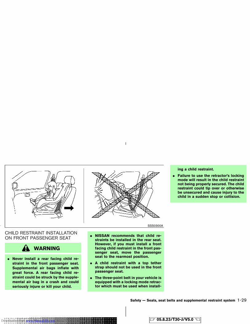
CHILD RESTRAINT INSTALLATIONON FRONT PASSENGER SEAT
WARNING
� Never install a rear facing child re-straint in the front passenger seat.Supplemental air bags inflate withgreat force. A rear facing child re-straint could be struck by the supple-mental air bag in a crash and couldseriously injure or kill your child.
� NISSAN recommends that child re-straints be installed in the rear seat.However, if you must install a frontfacing child restraint in the front pas-senger seat, move the passengerseat to the rearmost position.
� A child restraint with a top tetherstrap should not be used in the frontpassenger seat.
� The three-point belt in your vehicle isequipped with a locking mode retrac-tor which must be used when install-
ing a child restraint.
� Failure to use the retractor’s lockingmode will result in the child restraintnot being properly secured. The childrestraint could tip over or otherwisebe unsecured and cause injury to thechild in a sudden stop or collision.
SSS0300A
Safety — Seats, seat belts and supplemental restraint system 1-29
� 05.8.23/T30-J/V5.0 �Downloaded from www.Manualslib.com manuals search engine
Front facing
If you must install a child restraint in the frontseat, follow these steps:
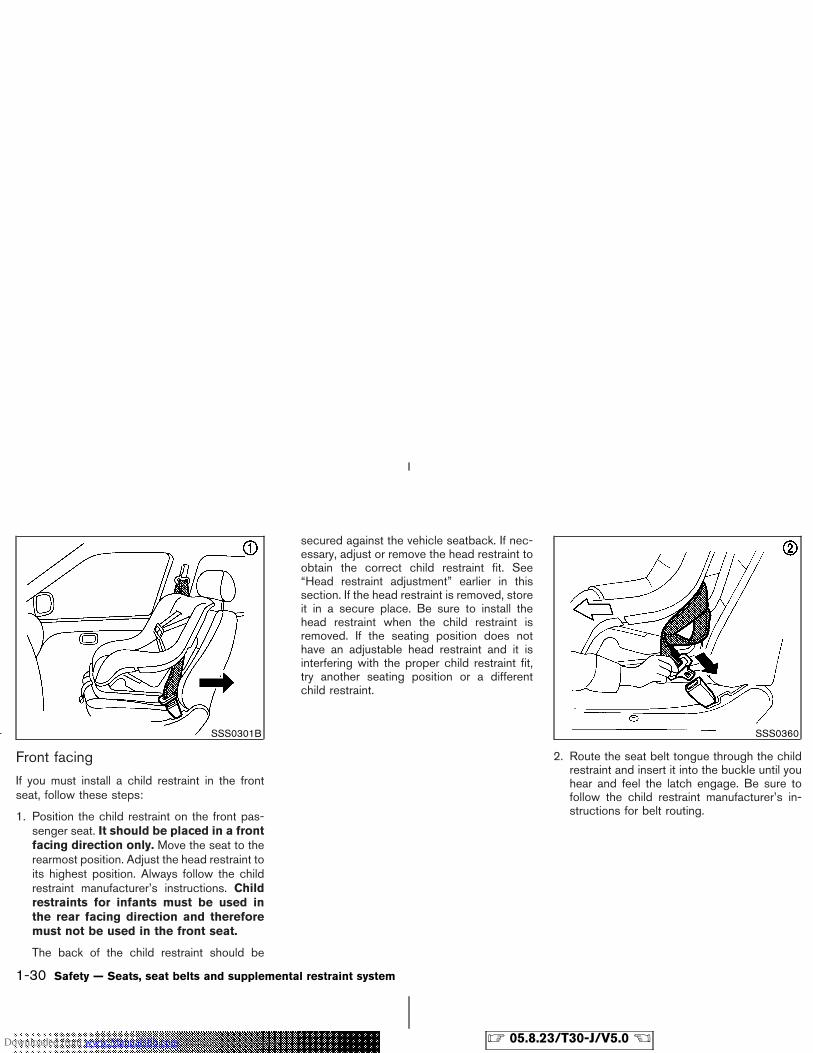
1. Position the child restraint on the front pas-senger seat. It should be placed in a frontfacing direction only. Move the seat to therearmost position. Adjust the head restraint toits highest position. Always follow the childrestraint manufacturer’s instructions. Childrestraints for infants must be used inthe rear facing direction and thereforemust not be used in the front seat.
The back of the child restraint should be
secured against the vehicle seatback. If nec-essary, adjust or remove the head restraint toobtain the correct child restraint fit. See“Head restraint adjustment” earlier in thissection. If the head restraint is removed, storeit in a secure place. Be sure to install thehead restraint when the child restraint isremoved. If the seating position does nothave an adjustable head restraint and it isinterfering with the proper child restraint fit,try another seating position or a differentchild restraint.
2. Route the seat belt tongue through the childrestraint and insert it into the buckle until youhear and feel the latch engage. Be sure tofollow the child restraint manufacturer’s in-structions for belt routing.
SSS0301B SSS0360
1-30 Safety — Seats, seat belts and supplemental restraint system
� 05.8.23/T30-J/V5.0 �Downloaded from www.Manualslib.com manuals search engine
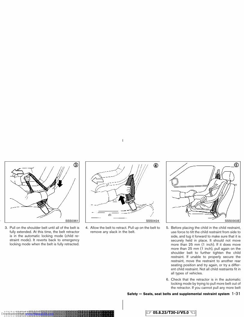
3. Pull on the shoulder belt until all of the belt isfully extended. At this time, the belt retractoris in the automatic locking mode (child re-straint mode). It reverts back to emergencylocking mode when the belt is fully retracted.
4. Allow the belt to retract. Pull up on the belt toremove any slack in the belt.
5. Before placing the child in the child restraint,use force to tilt the child restraint from side toside, and tug it forward to make sure that it issecurely held in place. It should not movemore than 25 mm (1 inch). If it does movemore than 25 mm (1 inch), pull again on theshoulder belt to further tighten the childrestraint. If unable to properly secure therestraint, move the restraint to another rearseating position and try again, or try a differ-ent child restraint. Not all child restraints fit inall types of vehicles.
6. Check that the retractor is in the automaticlocking mode by trying to pull more belt out ofthe retractor. If you cannot pull any more belt
SSS0361 SSS0424 SSS0302E
Safety — Seats, seat belts and supplemental restraint system 1-31
� 05.8.23/T30-J/V5.0 �Downloaded from www.Manualslib.com manuals search engine
webbing out of the retractor, the belt is in theautomatic locking mode.
7. Check to make sure that the child restraint isproperly secured prior to each use. If the lapbelt is not locked, repeat steps 3 through 6.
After the child restraint is removed and the seatbelt is allowed to wind back into the retractor,the automatic locking mode (child restraintmode) is canceled.
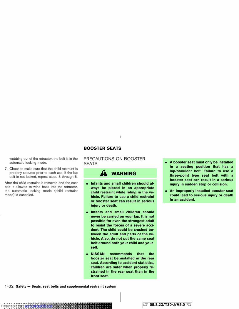
PRECAUTIONS ON BOOSTERSEATS
WARNING
� Infants and small children should al-ways be placed in an appropriatechild restraint while riding in the ve-hicle. Failure to use a child restraintor booster seat can result in seriousinjury or death.
� Infants and small children shouldnever be carried on your lap. It is notpossible for even the strongest adultto resist the forces of a severe acci-dent. The child could be crushed be-tween the adult and parts of the ve-hicle. Also, do not put the same seatbelt around both your child and your-self.
� NISSAN recommends that thebooster seat be installed in the rearseat. According to accident statistics,children are safer when properly re-strained in the rear seat than in thefront seat.
� A booster seat must only be installedin a seating position that has alap/shoulder belt. Failure to use athree-point type seat belt with abooster seat can result in a seriousinjury in sudden stop or collision.
� An improperly installed booster seatcould lead to serious injury or deathin an accident.
BOOSTER SEATS
1-32 Safety — Seats, seat belts and supplemental restraint system
� 05.8.23/T30-J/V5.0 �Downloaded from www.Manualslib.com manuals search engine
WARNING
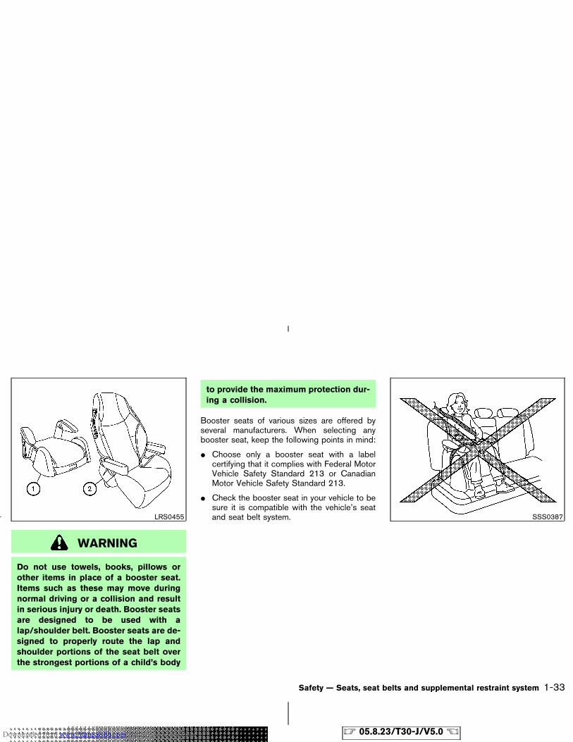
Do not use towels, books, pillows orother items in place of a booster seat.Items such as these may move duringnormal driving or a collision and resultin serious injury or death. Booster seatsare designed to be used with alap/shoulder belt. Booster seats are de-signed to properly route the lap andshoulder portions of the seat belt overthe strongest portions of a child’s body
to provide the maximum protection dur-ing a collision.
Booster seats of various sizes are offered byseveral manufacturers. When selecting anybooster seat, keep the following points in mind:
� Choose only a booster seat with a labelcertifying that it complies with Federal MotorVehicle Safety Standard 213 or CanadianMotor Vehicle Safety Standard 213.
� Check the booster seat in your vehicle to besure it is compatible with the vehicle’s seatand seat belt system.LRS0455 SSS0387
Safety — Seats, seat belts and supplemental restraint system 1-33
� 05.8.23/T30-J/V5.0 �Downloaded from www.Manualslib.com manuals search engine
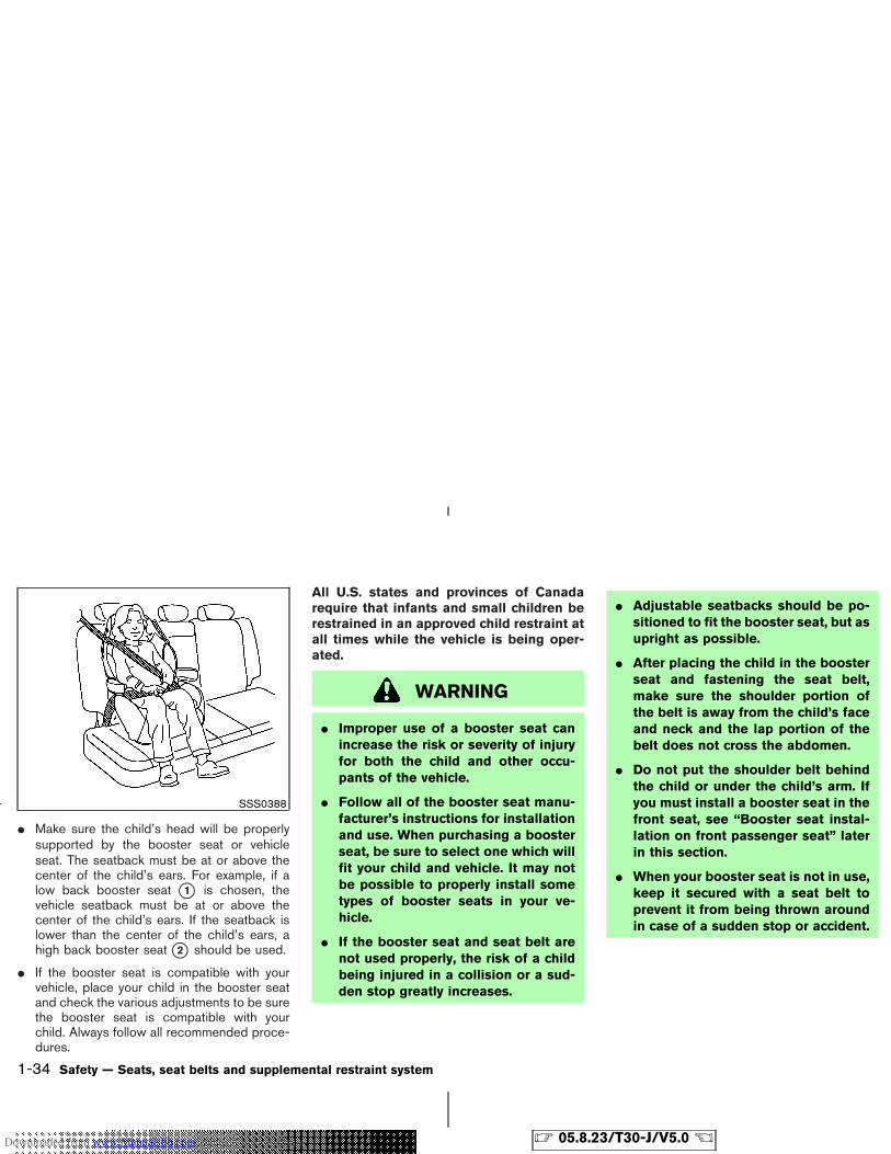
� Make sure the child’s head will be properlysupported by the booster seat or vehicleseat. The seatback must be at or above thecenter of the child’s ears. For example, if alow back booster seat �1 is chosen, thevehicle seatback must be at or above thecenter of the child’s ears. If the seatback islower than the center of the child’s ears, ahigh back booster seat �2 should be used.
� If the booster seat is compatible with yourvehicle, place your child in the booster seatand check the various adjustments to be surethe booster seat is compatible with yourchild. Always follow all recommended proce-dures.
All U.S. states and provinces of Canadarequire that infants and small children berestrained in an approved child restraint atall times while the vehicle is being oper-ated.
WARNING
� Improper use of a booster seat canincrease the risk or severity of injuryfor both the child and other occu-pants of the vehicle.
� Follow all of the booster seat manu-facturer’s instructions for installationand use. When purchasing a boosterseat, be sure to select one which willfit your child and vehicle. It may notbe possible to properly install sometypes of booster seats in your ve-hicle.
� If the booster seat and seat belt arenot used properly, the risk of a childbeing injured in a collision or a sud-den stop greatly increases.
� Adjustable seatbacks should be po-sitioned to fit the booster seat, but asupright as possible.
� After placing the child in the boosterseat and fastening the seat belt,make sure the shoulder portion ofthe belt is away from the child’s faceand neck and the lap portion of thebelt does not cross the abdomen.
� Do not put the shoulder belt behindthe child or under the child’s arm. Ifyou must install a booster seat in thefront seat, see “Booster seat instal-lation on front passenger seat” laterin this section.
� When your booster seat is not in use,keep it secured with a seat belt toprevent it from being thrown aroundin case of a sudden stop or accident.
SSS0388
1-34 Safety — Seats, seat belts and supplemental restraint system
� 05.8.23/T30-J/V5.0 �Downloaded from www.Manualslib.com manuals search engine
CAUTION
Remember that a booster seat left in aclosed vehicle can become very hot.Check the seating surface and bucklesbefore placing your child in the boosterseat.
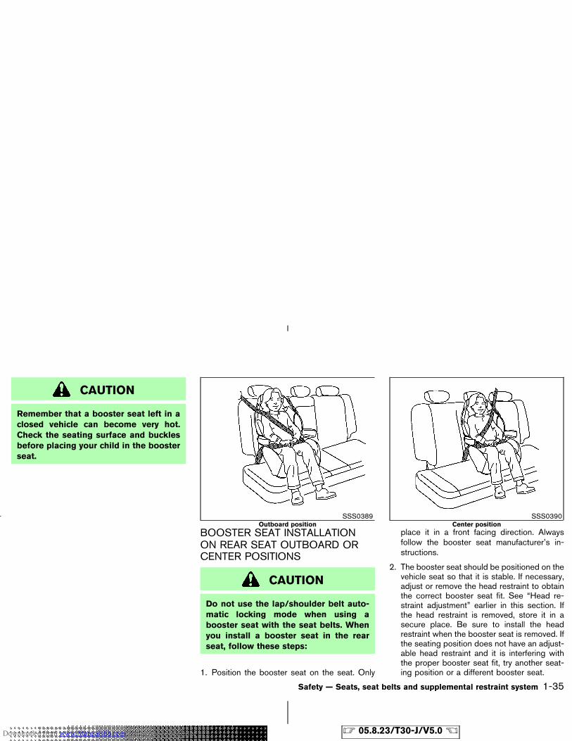
BOOSTER SEAT INSTALLATIONON REAR SEAT OUTBOARD ORCENTER POSITIONS
CAUTION
Do not use the lap/shoulder belt auto-matic locking mode when using abooster seat with the seat belts. Whenyou install a booster seat in the rearseat, follow these steps:
1. Position the booster seat on the seat. Only
place it in a front facing direction. Alwaysfollow the booster seat manufacturer’s in-structions.
2. The booster seat should be positioned on thevehicle seat so that it is stable. If necessary,adjust or remove the head restraint to obtainthe correct booster seat fit. See “Head re-straint adjustment” earlier in this section. Ifthe head restraint is removed, store it in asecure place. Be sure to install the headrestraint when the booster seat is removed. Ifthe seating position does not have an adjust-able head restraint and it is interfering withthe proper booster seat fit, try another seat-ing position or a different booster seat.
SSS0389Outboard position
SSS0390Center position
Safety — Seats, seat belts and supplemental restraint system 1-35
� 05.8.23/T30-J/V5.0 �Downloaded from www.Manualslib.com manuals search engine
3. Position the lap portion of the seat belt lowand snug on the child’s hips. Be sure tofollow the booster seat manufacturer’s in-structions for adjusting the belt routing.
4. Pull the shoulder belt portion of the seat belttoward the retractor to take up extra slack. Besure the shoulder belt is positioned acrossthe top, middle portion of the child’s shoul-der. Be sure to follow the booster seat manu-facturer’s instructions for adjusting the beltrouting.
5. Follow the warnings, cautions and instruc-tions for properly fastening a seat belt shownin the “Three-point type seat belt with retrac-tor” earlier in this section.
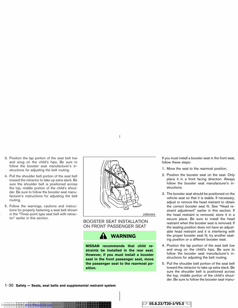
BOOSTER SEAT INSTALLATIONON FRONT PASSENGER SEAT
WARNING
NISSAN recommends that child re-straints be installed in the rear seat.However, if you must install a boosterseat in the front passenger seat, movethe passenger seat to the rearmost po-sition.
If you must install a booster seat in the front seat,follow these steps:
1. Move the seat to the rearmost position.
2. Position the booster seat on the seat. Onlyplace it in a front facing direction. Alwaysfollow the booster seat manufacturer’s in-structions.
3. The booster seat should be positioned on thevehicle seat so that it is stable. If necessary,adjust or remove the head restraint to obtainthe correct booster seat fit. See “Head re-straint adjustment” earlier in this section. Ifthe head restraint is removed, store it in asecure place. Be sure to install the headrestraint when the booster seat is removed. Ifthe seating position does not have an adjust-able head restraint and it is interfering withthe proper booster seat fit, try another seat-ing position or a different booster seat.
4. Position the lap portion of the seat belt lowand snug on the child’s hips. Be sure tofollow the booster seat manufacturer’s in-structions for adjusting the belt routing.
5. Pull the shoulder belt portion of the seat belttoward the retractor to take up extra slack. Besure the shoulder belt is positioned acrossthe top, middle portion of the child’s shoul-der. Be sure to follow the booster seat manu-
LRS0454
1-36 Safety — Seats, seat belts and supplemental restraint system
� 05.8.23/T30-J/V5.0 �Downloaded from www.Manualslib.com manuals search engine
facturer’s instructions for adjusting the beltrouting.
6. Follow the warnings, cautions and instruc-tions for properly fastening a seat belt shownin the “Three-point type seat belt with retrac-tor” earlier in this section.
PRECAUTIONS ONSUPPLEMENTAL RESTRAINTSYSTEM
This Supplemental Restraint System (SRS) sec-tion contains important information concerningthe driver and passenger front impact supple-mental air bags, front seat side-impact supple-mental air bags and front seat pre-tensioner seatbelts.Supplemental front impact air bag system:This system can help cushion the impact force tothe face and chest of the driver and frontpassenger in certain frontal collisions.Supplemental side-impact air bag system(if so equipped): This system can help cushionthe impact force to the chest area of the driverand front passenger in certain side impact colli-sions. The front seat side-impact supplementalair bags are designed to inflate on the sidewhere the vehicle is impacted.
These supplemental restraint systems are de-signed to supplement the crash protectionprovided by the driver and passenger seat beltsand are not a substitute for them. Seat beltsshould always be correctly worn and the occu-pant seated a suitable distance away from thesteering wheel, instrument panel, door finishers.(See “Seat belts” earlier in this section forinstructions and precautions on seat belt usage.)
After turning the ignition key to the ONposition, the supplemental air bag warninglight illuminates. The supplemental air bagwarning light will turn off after about 7seconds if the systems are operational.
SUPPLEMENTAL RESTRAINTSYSTEM
Safety — Seats, seat belts and supplemental restraint system 1-37
� 05.8.23/T30-J/V5.0 �Downloaded from www.Manualslib.com manuals search engine
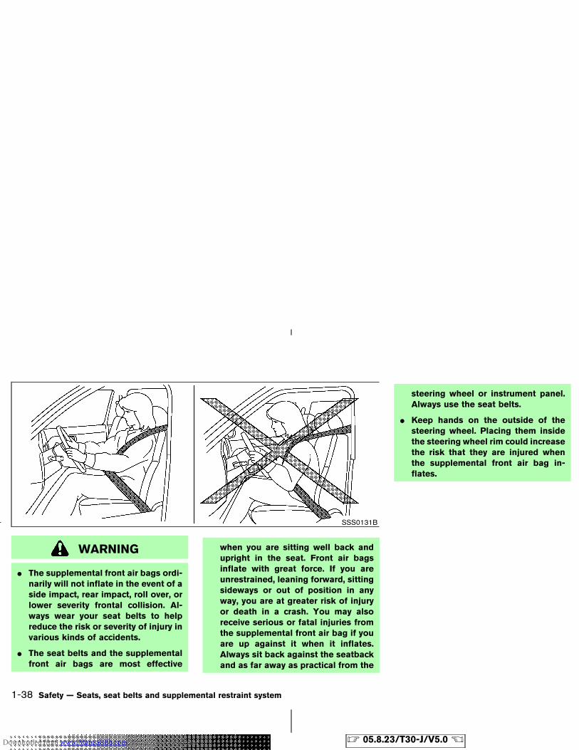
WARNING
� The supplemental front air bags ordi-narily will not inflate in the event of aside impact, rear impact, roll over, orlower severity frontal collision. Al-ways wear your seat belts to helpreduce the risk or severity of injury invarious kinds of accidents.
� The seat belts and the supplementalfront air bags are most effective
when you are sitting well back andupright in the seat. Front air bagsinflate with great force. If you areunrestrained, leaning forward, sittingsideways or out of position in anyway, you are at greater risk of injuryor death in a crash. You may alsoreceive serious or fatal injuries fromthe supplemental front air bag if youare up against it when it inflates.Always sit back against the seatbackand as far away as practical from the
steering wheel or instrument panel.Always use the seat belts.
� Keep hands on the outside of thesteering wheel. Placing them insidethe steering wheel rim could increasethe risk that they are injured whenthe supplemental front air bag in-flates.
SSS0131B
1-38 Safety — Seats, seat belts and supplemental restraint system
� 05.8.23/T30-J/V5.0 �Downloaded from www.Manualslib.com manuals search engine
SSS0132B SSS0006
SSS0007
Safety — Seats, seat belts and supplemental restraint system 1-39
� 05.8.23/T30-J/V5.0 �Downloaded from www.Manualslib.com manuals search engine
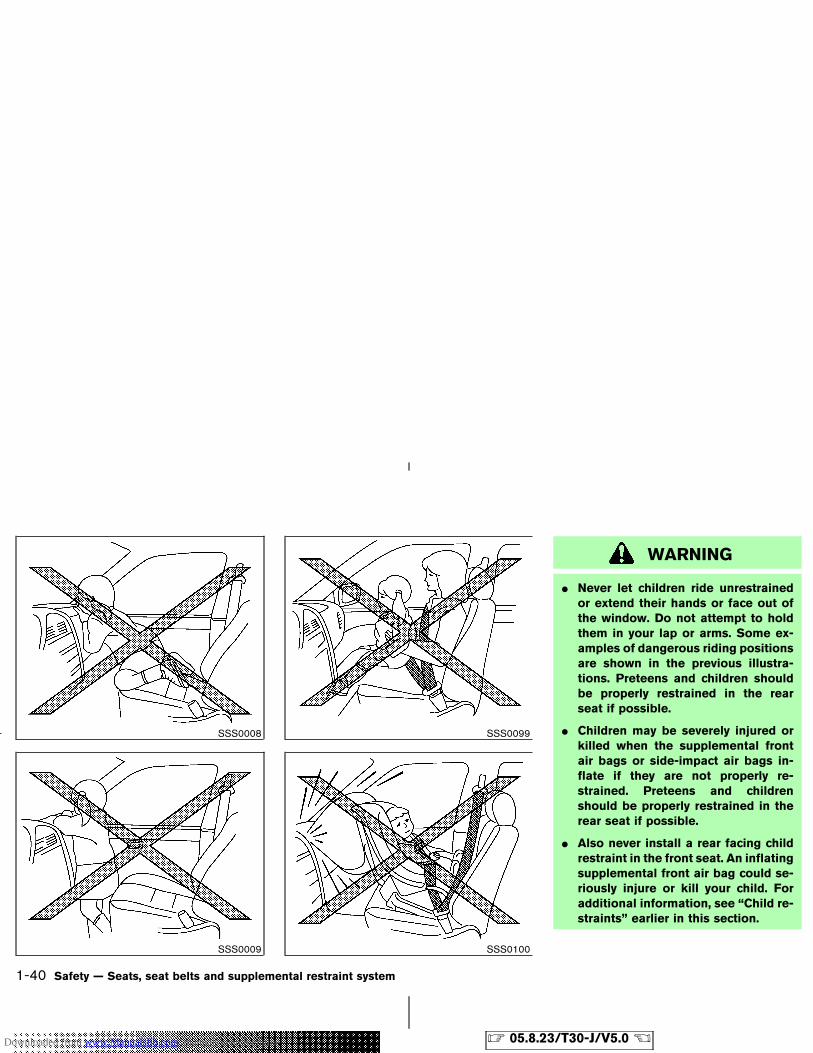
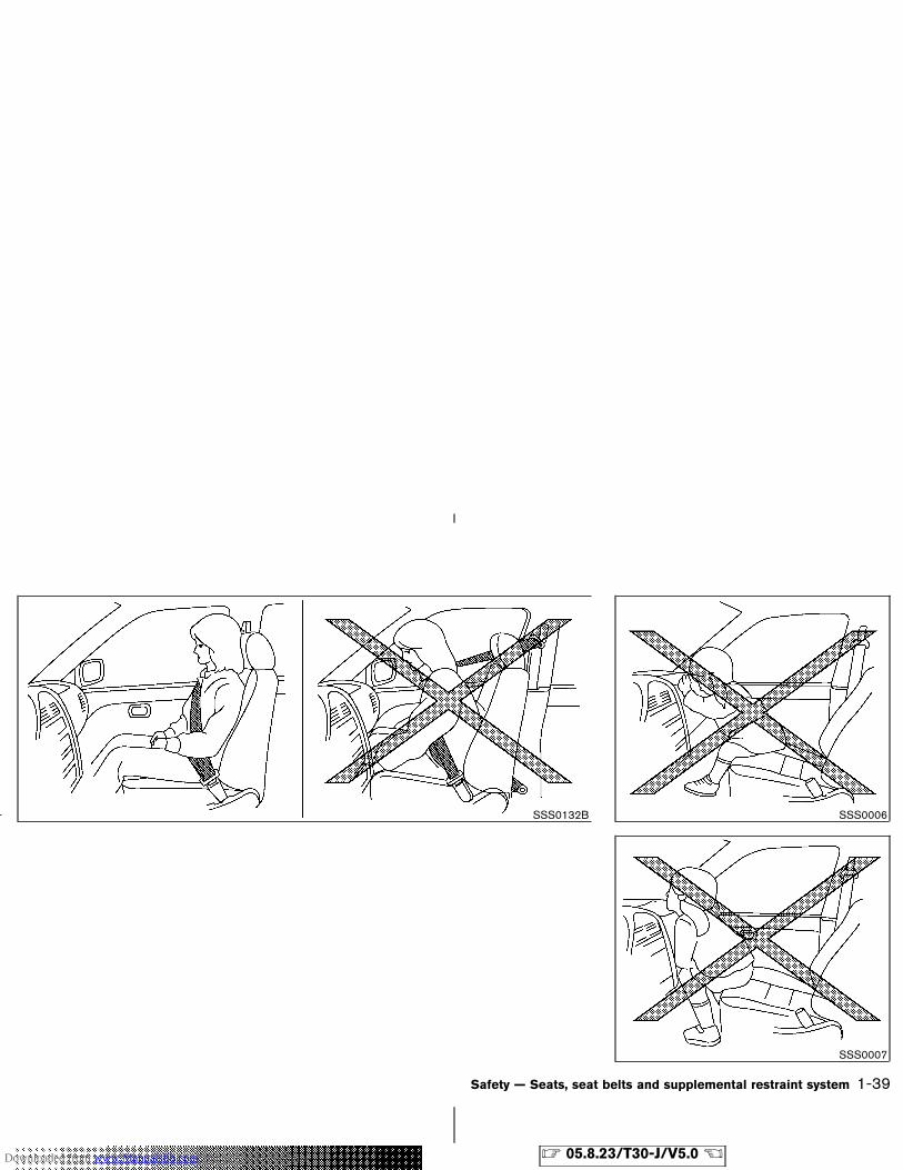
WARNING
� Never let children ride unrestrainedor extend their hands or face out ofthe window. Do not attempt to holdthem in your lap or arms. Some ex-amples of dangerous riding positionsare shown in the previous illustra-tions. Preteens and children shouldbe properly restrained in the rearseat if possible.
� Children may be severely injured orkilled when the supplemental frontair bags or side-impact air bags in-flate if they are not properly re-strained. Preteens and childrenshould be properly restrained in therear seat if possible.
� Also never install a rear facing childrestraint in the front seat. An inflatingsupplemental front air bag could se-riously injure or kill your child. Foradditional information, see “Child re-straints” earlier in this section.
SSS0008
SSS0009
SSS0099
SSS0100
1-40 Safety — Seats, seat belts and supplemental restraint system
� 05.8.23/T30-J/V5.0 �Downloaded from www.Manualslib.com manuals search engine
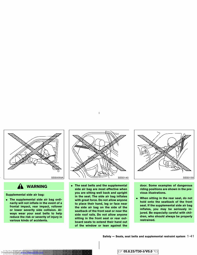
WARNING
Supplemental side air bag:
� The supplemental side air bag ordi-narily will not inflate in the event of afrontal impact, rear impact, rolloveror lower severity side collision. Al-ways wear your seat belts to helpreduce the risk or severity of injury invarious kinds of accidents.
� The seat belts and the supplementalside air bag are most effective whenyou are sitting well back and uprightin the seat. The side air bag inflateswith great force. Do not allow anyoneto place their hand, leg or face nearthe side air bag on the side of theseatback of the front seat or near theside roof rails. Do not allow anyonesitting in the front seat or rear out-board seats to extend their hand outof the window or lean against the
door. Some examples of dangerousriding positions are shown in the pre-vious illustrations.
� When sitting in the rear seat, do nothold onto the seatback of the frontseat. If the supplemental side air baginflates, you may be seriously in-jured. Be especially careful with chil-dren, who should always be properlyrestrained.
SSS0059A SSS0140 SSS0159
Safety — Seats, seat belts and supplemental restraint system 1-41
� 05.8.23/T30-J/V5.0 �Downloaded from www.Manualslib.com manuals search engine
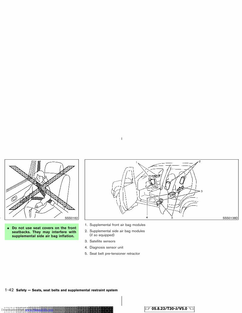
� Do not use seat covers on the frontseatbacks. They may interfere withsupplemental side air bag inflation.
1. Supplemental front air bag modules
2. Supplemental side air bag modules(if so equipped)
3. Satellite sensors
4. Diagnosis sensor unit
5. Seat belt pre-tensioner retractor
SSS0162 SSS0138D
1-42 Safety — Seats, seat belts and supplemental restraint system
� 05.8.23/T30-J/V5.0 �Downloaded from www.Manualslib.com manuals search engine
Supplemental front air bag system
The driver supplemental air bag is located in thecenter of the steering wheel; the front passengersupplemental air bag is mounted in the instru-ment panel above the glove box. These systemsare designed to meet certification requirementsunder Canadian regulations. All of the infor-mation, cautions and warnings in thismanual still apply and must be followed.The supplemental front air bags are designed toinflate in higher severity frontal collisions, al-though they may inflate if the forces in anothertype of collision are similar to those of a higherseverity frontal impact. They may not inflate incertain frontal collisions. Vehicle damage (or lackof it) is not always an indication of propersupplemental air bag operation.
When the supplemental front air bag inflates, afairly loud noise may be heard, followed byrelease of smoke. This smoke is not harmful anddoes not indicate a fire. Care should be takennot to inhale it, as it may cause irritation andchoking. Those with a history of a breathingcondition should get fresh air promptly.
Supplemental front air bags, along with the useof seat belts, helps to cushion the impact forceon the face and chest of the front occupants.They can help save lives and reduce seriousinjuries. However, an inflating front air bag may
cause facial abrasions or other injuries. Front airbags do not provide restraint to the lower body.
The seat belts should be correctly worn and thedriver and passenger seated upright as far aspractical away from the steering wheel or instru-ment panel. The supplemental front air bagsinflate quickly in order to help protect the frontoccupants. Because of this, the force of the frontair bag inflating can increase the risk of injury ifthe occupant is too close to, or is against the airbag module during inflation. The air bag willdeflate quickly after the collision is over.
After turning the ignition key to the ONposition, the supplemental air bag warninglight illuminates. The supplemental air bagwarning light will turn off after about 7seconds if the system is operational.
WARNING
� Do not place any objects on thesteering wheel pad or on the instru-ment panel. Also, do not place anyobjects between any occupant andthe steering wheel or instrumentpanel. Such objects may becomedangerous projectiles and cause in-
jury if the supplemental front air baginflates.
� Immediately after inflation, severalair bag system components will behot. Do not touch them; you mayseverely burn yourself.
� No unauthorized changes should bemade to any components or wiring ofthe supplemental front air bag sys-tem. This is to prevent accidental in-flation of the air bag or damage tothe air bag system.
� Do not make unauthorized changesto your vehicle’s electrical system,suspension system or front endstructure. This could affect properoperation of the supplemental airbag system.
� Tampering with the supplementalfront air bag system may result inserious personal injury. Tamperingincludes changes to the steeringwheel and the instrument panel as-sembly by placing material over thesteering wheel pad, above the dash-
Safety — Seats, seat belts and supplemental restraint system 1-43
� 05.8.23/T30-J/V5.0 �Downloaded from www.Manualslib.com manuals search engine
board, or by installing additional trimmaterial around the air bag system.
� Work around and on the supplemen-tal front air bag system should bedone by a NISSAN dealer. Installa-tion of electrical equipment shouldalso be done by a NISSAN dealer.The yellow and orange SupplementalRestrain System (SRS) wiring andconnectors should not be modified ordisconnected. Unauthorized electri-cal test equipment and probing devices should not be used on the airbag system.
� A cracked windshield should be re-placed immediately by a qualified re-pair facility. A cracked windshieldcould affect the function of thesupplemental air bag system.
� The SRS wiring harness connectorsare yellow and orange for easy iden-tification.
When selling your vehicle, we request that youinform the buyer about the supplemental front airbag system and guide the buyer to the appro-priate sections in this Owner’s Manual.
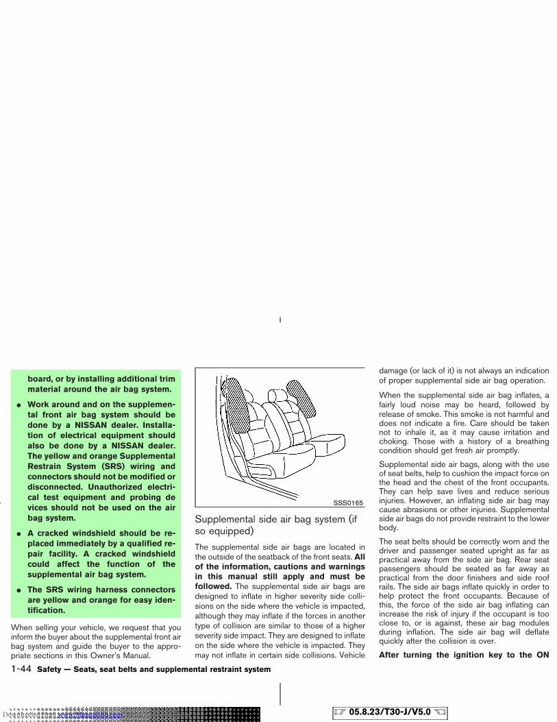
Supplemental side air bag system (ifso equipped)
The supplemental side air bags are located inthe outside of the seatback of the front seats. Allof the information, cautions and warningsin this manual still apply and must befollowed. The supplemental side air bags aredesigned to inflate in higher severity side colli-sions on the side where the vehicle is impacted,although they may inflate if the forces in anothertype of collision are similar to those of a higherseverity side impact. They are designed to inflateon the side where the vehicle is impacted. Theymay not inflate in certain side collisions. Vehicle
damage (or lack of it) is not always an indicationof proper supplemental side air bag operation.
When the supplemental side air bag inflates, afairly loud noise may be heard, followed byrelease of smoke. This smoke is not harmful anddoes not indicate a fire. Care should be takennot to inhale it, as it may cause irritation andchoking. Those with a history of a breathingcondition should get fresh air promptly.
Supplemental side air bags, along with the useof seat belts, help to cushion the impact force onthe head and the chest of the front occupants.They can help save lives and reduce seriousinjuries. However, an inflating side air bag maycause abrasions or other injuries. Supplementalside air bags do not provide restraint to the lowerbody.
The seat belts should be correctly worn and thedriver and passenger seated upright as far aspractical away from the side air bag. Rear seatpassengers should be seated as far away aspractical from the door finishers and side roofrails. The side air bags inflate quickly in order tohelp protect the front occupants. Because ofthis, the force of the side air bag inflating canincrease the risk of injury if the occupant is tooclose to, or is against, these air bag modulesduring inflation. The side air bag will deflatequickly after the collision is over.
After turning the ignition key to the ON
SSS0165
1-44 Safety — Seats, seat belts and supplemental restraint system
� 05.8.23/T30-J/V5.0 �Downloaded from www.Manualslib.com manuals search engine
position, the supplemental air bag warninglight illuminates. The air bag warning lightwill turn off after about 7 seconds if thesystems are operational.
WARNING
� Do not place any objects near theseatback of the front seats. Also, donot place any objects (an umbrella,bag, etc.) between the front door fin-isher and the front seat. Such objectsmay become dangerous projectilesand cause injury if the side air baginflates.
� Immediately after inflation, severalside air bag system components willbe hot. Do not touch them; you mayseverely burn yourself.
� No unauthorized changes should bemade to any components or wiring ofthis side air bag system. This is toprevent accidental inflation of theside air bag or damage to the side air
bag system.
� Do not make unauthorized changesto your vehicle’s electrical system,suspension system or side panel.This could affect proper operation ofthe supplemental side air bag sys-tem.
� Tampering with the supplementalsystem may result in serious per-sonal injury. For example, do notchange the front seat by placing ma-terial near the seatback or by install-ing additional trim material, such asseat covers, around the side air bag.
� Work around and on the side air bagsystem should be done by a NISSANdealer. Installation of electricalequipment should also be done by aNISSAN dealer. The SRS wiring har-nesses* should not be modified ordisconnected. Unauthorized electri-cal test equipment and probing de-vices should not be used on the sideair bag system.
* The SRS wiring harnesses are cov-ered with yellow and orange insula-tion either just before the harnessconnectors or over the complete har-ness for easy identification.
When selling your vehicle, we request that youinform the buyer about the side air bag systemand guide the buyer to the appropriate sectionsin this Owner’s Manual.
Pre-tensioner seat belt system (Forfront seats)
WARNING
� The pre-tensioner seat belt cannot bereused after activation. It must bereplaced together with the retractoras a unit.
� If the vehicle becomes involved in afrontal collision but the pre-tensioneris not activated, be sure to have thepre-tensioner system checked and, ifnecessary, replaced by a NISSANdealer.
Safety — Seats, seat belts and supplemental restraint system 1-45
� 05.8.23/T30-J/V5.0 �Downloaded from www.Manualslib.com manuals search engine
� No unauthorized changes should bemade to any components or wiring ofthe pre-tensioner seat belt system.This is to prevent accidental activa-tion of the pre-tensioner seat belt ordamage to the pre-tensioner seatbelt operation. Tampering with thepre-tensioner seat belt system mayresult in serious personal injury.
� Work around and on the preten-sioner seat belt system should bedone by a NISSAN dealer. Installa-tion of electrical equipment shouldalso be done by a NISSAN dealer.Unauthorized electrical test equip-ment and probing devices should notbe used on the pretensioner seat beltsystem.
� If you need to dispose of the pre-tensioner or scrap the vehicle, con-tact a NISSAN dealer. Correct pre-tensioner disposal procedures areset forth in the appropriate NISSANService Manual. Incorrect disposalprocedures could cause personalinjury.
The front seat pre-tensioner seat belt systemactivates in conjunction with the supplementalair bag systems. Working with the seat beltretractor, it helps tighten the seat belt when thevehicle becomes involved in certain types ofcollisions, helping to restrain front seat occu-pants.
The pre-tensioner is encased with the seat belt’sretractor. These seat belts are used the same asconventional seat belts.
When the pre-tensioner seat belt activates,smoke is released and a loud noise may beheard. The smoke is not harmful, but care shouldbe taken not to inhale it as it may cause irritationand choking. Those with a history of a breathingcondition should get fresh air promptly.
If any abnormality occurs in the pre-tensionerseat belt system, the supplemental air bag warn-ing light will not come on, will flash inter-mittently or will turn on for 7 seconds and remainon after the ignition key has been turned to theON or START position. In this case, the pre-tensioner seat belt may not function properly.They must be checked and repaired. Take yourvehicle to the nearest NISSAN dealer.
When selling your vehicle, we request that youinform the buyer about the pre-tensioner seatbelt system and guide the buyer to the appro-priate sections in this Owner’s Manual.
1-46 Safety — Seats, seat belts and supplemental restraint system
� 05.8.23/T30-J/V5.0 �Downloaded from www.Manualslib.com manuals search engine
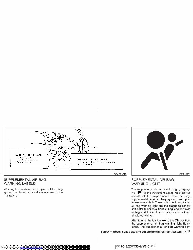
SUPPLEMENTAL AIR BAGWARNING LABELSWarning labels about the supplemental air bagsystem are placed in the vehicle as shown in theillustration.
SUPPLEMENTAL AIR BAGWARNING LIGHT
The supplemental air bag warning light, display-ing in the instrument panel, monitors thecircuits of the supplemental front air bag,supplemental side air bag system, and pre-tensioner seat belt. The circuits monitored by theair bag warning light are the diagnosis sensorunit, satellite sensors, front air bag modules, sideair bag modules, and pre-tensioner seat belt andall related wiring.
After turning the ignition key to the ON position,the supplemental air bag warning light illumi-nates. The supplemental air bag warning light
SPA0945B SPA1097
Safety — Seats, seat belts and supplemental restraint system 1-47
� 05.8.23/T30-J/V5.0 �Downloaded from www.Manualslib.com manuals search engine
will turn off after about 7 seconds if the system isoperational.
If any of the following conditions occur, thesupplemental front air bag, supplemental side airbag system, and pre-tensioner seat belt needservicing:
� The supplemental air bag warning light re-mains on after approximately 7 seconds.
� The supplemental air bag warning lightflashes intermittently.
� The supplemental air bag warning light doesnot come on at all.
Under these conditions, the supplemental frontair bags, supplemental side air bags, and/orpre-tensioner seat belt may not operate properly.They must be checked and repaired. Take yourvehicle to the nearest NISSAN dealer.
WARNING
If the supplemental air bag warninglight is on, it could mean that thesupplemental front air bag, supplemen-tal side air bag systems and/or pre-tensioner seat belt will not operate in anaccident. To help avoid injury to yourself
or others, have your vehicle checked bya NISSAN dealer as soon as possible.
Repair and replacement procedure
The supplemental front air bags, supplementalside air bags, and pre-tensioner seat belt aredesigned to activate on a one-time-only basis.As a reminder, unless it is damaged, the supple-mental air bag warning light will remain illumi-nated after inflation has occurred. Repair andreplacement of these systems should be doneonly by a NISSAN dealer.
When maintenance work is required on thevehicle, the supplemental front air bags, side airbags, related parts and pre-tensioner seat beltshould be pointed out to the person conductingthe maintenance. The ignition key should alwaysbe in the LOCK position when working under thehood or inside the vehicle.
WARNING
� Once the supplemental front air bagor side air bag has inflated, the airbag module will not function againand must be replaced. Additionally, if
any of the supplemental front airbags inflate, the activated preten-sioner seat belt must also be re-placed. The air bag module and pre-tensioner seat belt system should bereplaced by a NISSAN dealer. The airbag modules and pre-tensioner seatbelt system cannot be repaired.
� The supplemental front air bag andside air bag systems and pre-tensioner seat belt system should beinspected by a NISSAN dealer if thereis any damage to the front end orside portion of the vehicle.
� If you need to dispose of thesesupplemental systems or scrap thevehicle, contact a NISSAN dealer.Correct disposal procedures are setforth in the appropriate NISSAN Ser-vice Manual. Incorrect disposal pro-cedures could cause personal injury.
1-48 Safety — Seats, seat belts and supplemental restraint system
� 05.8.23/T30-J/V5.0 �Downloaded from www.Manualslib.com manuals search engine
MEMO
Safety — Seats, seat belts and supplemental restraint system 1-49
� 05.8.23/T30-J/V5.0 �Downloaded from www.Manualslib.com manuals search engine

MEMO
1-50 Safety — Seats, seat belts and supplemental restraint system
� 05.8.23/T30-J/V5.0 �Downloaded from www.Manualslib.com manuals search engine
2 Instruments and controls
Instrument panel ................................................................... 2-2Meters and gauges .............................................................. 2-3
Speedometer and odometer ........................................ 2-4Tachometer ....................................................................... 2-5Engine coolant temperature gauge ............................ 2-5Fuel gauge ........................................................................ 2-6
Warning/indicator lights and audible reminders ........... 2-7Checking bulbs ............................................................... 2-7Warning lights ................................................................. 2-7Indicator lights ............................................................... 2-10Audible reminders ........................................................ 2-12
Security systems ................................................................ 2-13Vehicle security system .............................................. 2-13NISSAN Vehicle Immobilizer System ...................... 2-14
Windshield wiper and washer switch ........................... 2-15Rear window wiper and washer switch ....................... 2-16Rear window and outside mirror defroster switch .... 2-17Headlight and turn signal switch ................................... 2-18
Headlight switch ........................................................... 2-18Daytime running light system .................................... 2-19Instrument brightness control ................................... 2-19Turn signal switch ........................................................ 2-20Fog light switch (if so equipped) ............................. 2-20
Driving light switch (if so equipped) .............................. 2-20Hazard warning flasher switch ....................................... 2-21Horn ....................................................................................... 2-22Heated seats (if so equipped) ........................................ 2-22
SNOW mode switch (if so equipped) ......................... 2-23Vehicle dynamic control (VDC) off switch(if so equipped) .................................................................. 2-23Clock ..................................................................................... 2-24
Adjusting the time ........................................................ 2-24Power outlet ........................................................................ 2-25Storage ................................................................................. 2-26
Driver’s box .................................................................... 2-26Multi box ......................................................................... 2-27Cup holders ................................................................... 2-28Glove box ....................................................................... 2-30Upper glove box ........................................................... 2-30Console box .................................................................. 2-31
Luggage floor board ........................................................... 2-32Luggage side box................................................................ 2-32Luggage hooks .............................................................. 2-33
Cargo net ....................................................................... 2-33Tonneau cover (if so equipped) ............................... 2-34
Roof rail ................................................................................ 2-35Windows .............................................................................. 2-36
Power windows ............................................................ 2-36Sunroof (if so equipped) .................................................. 2-38Interior lights ........................................................................ 2-39
Room light ...................................................................... 2-39Map light ......................................................................... 2-41Luggage room light ..................................................... 2-41
� 05.8.23/T30-J/V5.0 �Downloaded from www.Manualslib.com manuals search engine
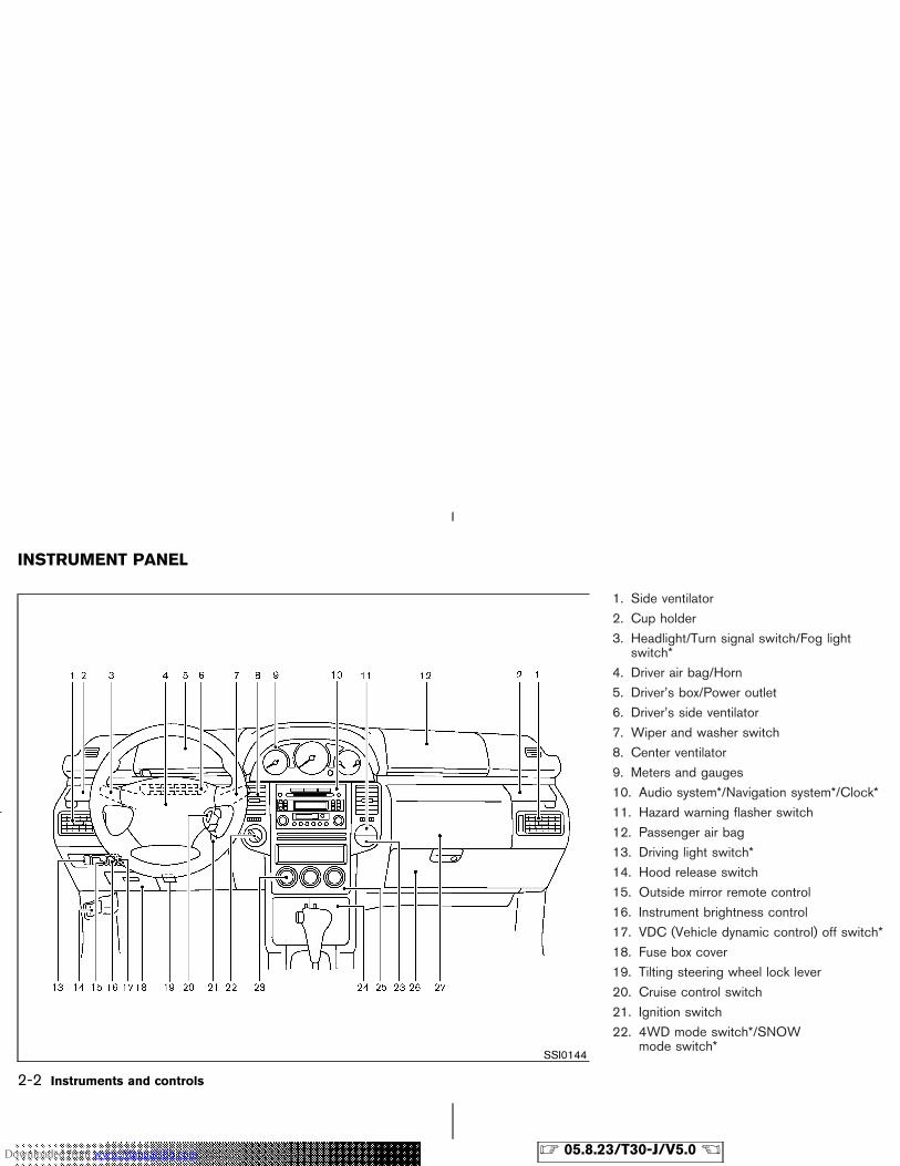
1. Side ventilator
2. Cup holder
3. Headlight/Turn signal switch/Fog lightswitch*
4. Driver air bag/Horn
5. Driver’s box/Power outlet
6. Driver’s side ventilator
7. Wiper and washer switch
8. Center ventilator
9. Meters and gauges
10. Audio system*/Navigation system*/Clock*
11. Hazard warning flasher switch
12. Passenger air bag
13. Driving light switch*
14. Hood release switch
15. Outside mirror remote control
16. Instrument brightness control
17. VDC (Vehicle dynamic control) off switch*
18. Fuse box cover
19. Tilting steering wheel lock lever
20. Cruise control switch
21. Ignition switch
22. 4WD mode switch*/SNOWmode switch*
SSI0144
INSTRUMENT PANEL
2-2 Instruments and controls
� 05.8.23/T30-J/V5.0 �Downloaded from www.Manualslib.com manuals search engine
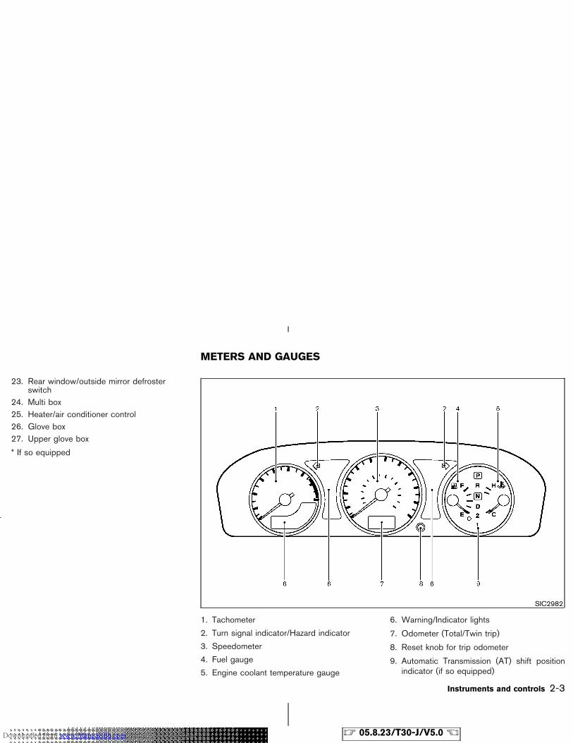
23. Rear window/outside mirror defrosterswitch
24. Multi box25. Heater/air conditioner control26. Glove box27. Upper glove box
* If so equipped
1. Tachometer
2. Turn signal indicator/Hazard indicator
3. Speedometer
4. Fuel gauge
5. Engine coolant temperature gauge
6. Warning/Indicator lights
7. Odometer (Total/Twin trip)
8. Reset knob for trip odometer
9. Automatic Transmission (AT) shift positionindicator (if so equipped)
SIC2982
METERS AND GAUGES
Instruments and controls 2-3
� 05.8.23/T30-J/V5.0 �Downloaded from www.Manualslib.com manuals search engine
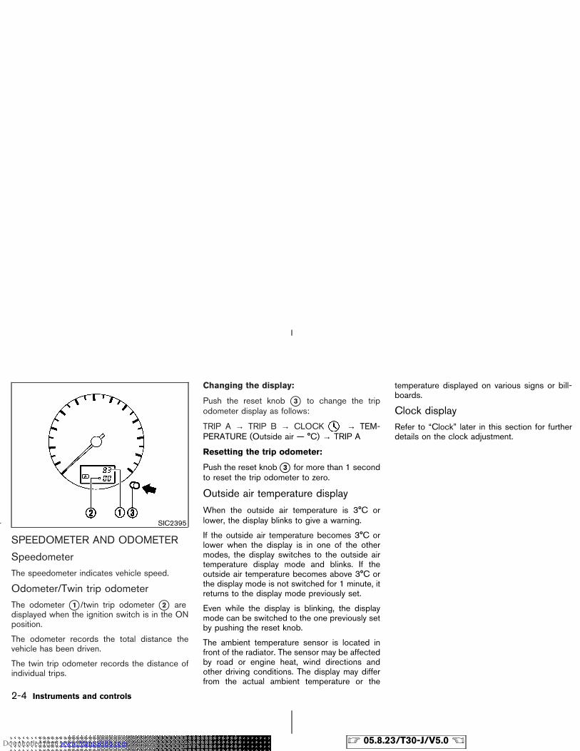
SPEEDOMETER AND ODOMETER
SpeedometerThe speedometer indicates vehicle speed.
Odometer/Twin trip odometerThe odometer �1 /twin trip odometer �2 aredisplayed when the ignition switch is in the ONposition.
The odometer records the total distance thevehicle has been driven.
The twin trip odometer records the distance ofindividual trips.
Changing the display:
Push the reset knob �3 to change the tripodometer display as follows:
TRIP A → TRIP B → CLOCK → TEM-PERATURE (Outside air — °C) → TRIP A
Resetting the trip odometer:
Push the reset knob �3 for more than 1 secondto reset the trip odometer to zero.
Outside air temperature display
When the outside air temperature is 3°C orlower, the display blinks to give a warning.
If the outside air temperature becomes 3°C orlower when the display is in one of the othermodes, the display switches to the outside airtemperature display mode and blinks. If theoutside air temperature becomes above 3°C orthe display mode is not switched for 1 minute, itreturns to the display mode previously set.
Even while the display is blinking, the displaymode can be switched to the one previously setby pushing the reset knob.
The ambient temperature sensor is located infront of the radiator. The sensor may be affectedby road or engine heat, wind directions andother driving conditions. The display may differfrom the actual ambient temperature or the
temperature displayed on various signs or bill-boards.
Clock displayRefer to “Clock” later in this section for furtherdetails on the clock adjustment.
SIC2395
2-4 Instruments and controls
� 05.8.23/T30-J/V5.0 �Downloaded from www.Manualslib.com manuals search engine
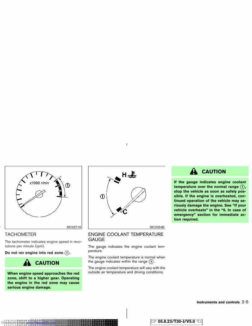
TACHOMETER
The tachometer indicates engine speed in revo-lutions per minute (rpm).
Do not rev engine into red zone �1 .
CAUTION
When engine speed approaches the redzone, shift to a higher gear. Operatingthe engine in the red zone may causeserious engine damage.
ENGINE COOLANT TEMPERATUREGAUGEThe gauge indicates the engine coolant tem-perature.
The engine coolant temperature is normal whenthe gauge indicates within the range �1 .
The engine coolant temperature will vary with theoutside air temperature and driving conditions.
CAUTION
If the gauge indicates engine coolanttemperature over the normal range �1 ,stop the vehicle as soon as safely pos-sible. If the engine is overheated, con-tinued operation of the vehicle may se-riously damage the engine. See “If yourvehicle overheats” in the “6. In case ofemergency” section for immediate ac-tion required.
SIC2271A SIC2354B
Instruments and controls 2-5
� 05.8.23/T30-J/V5.0 �Downloaded from www.Manualslib.com manuals search engine

FUEL GAUGEThe gauge indicates the approximate fuel level inthe tank.
The gauge may move slightly during braking,turning, acceleration, or going up or down hill.
The gauge needle is designed to move to the E(Empty) position when the ignition key is turnedto the OFF position.
Refill the fuel tank before the gauge regis-ters Empty.
The low fuel warning light �1 comes onwhen the fuel tank is getting low. Refuel assoon as it is convenient, preferably beforethe gauge reaches E. There will be a smallreserve of fuel in the tank when the fuelgauge needle reaches E.
The indicates that the fuel-filler door islocated on the driver’s side of the vehicle.
CAUTION
� If the vehicle runs out of fuel, themalfunction indicator lamp
(MIL) may come on. Refuel as soonas possible. After a few driving trips,the lamp should turn off. If thelamp remains on after a few drivingtrips, have the vehicle inspected by aNISSAN dealer.
� For additional information, see the“Malfunction indicator lamp (MIL)”later in this section.
SIC2438
2-6 Instruments and controls
� 05.8.23/T30-J/V5.0 �Downloaded from www.Manualslib.com manuals search engine
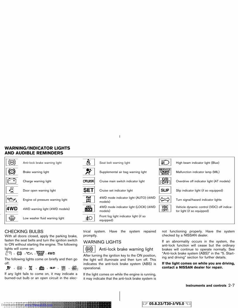
Anti-lock brake warning light Seat belt warning light High beam indicator light (Blue)
Brake warning light Supplemental air bag warning light Malfunction indicator lamp (MIL)
Charge warning light Cruise main switch indicator light Overdrive off indicator light (AT models)
Door open warning light Cruise set indicator light Slip indicator light (if so equipped)
Engine oil pressure warning light4WD mode indicator light (AUTO) (4WDmodels)
Turn signal/hazard indicator lights
4WD warning light (4WD models)4WD mode indicator light (LOCK) (4WDmodels)
Vehicle dynamic control (VDC) off indica-tor light (if so equipped)
Low washer fluid warning lightFront fog light indicator light (if soequipped)
CHECKING BULBSWith all doors closed, apply the parking brake,fasten the seat belts and turn the ignition switchto ON without starting the engine. The followinglights will come on:
, , , ,
The following lights come on briefly and then gooff:
, , , , , ,
If any light fails to come on, it may indicate aburned-out bulb or an open circuit in the elec-
trical system. Have the system repairedpromptly.
WARNING LIGHTS
Anti-lock brake warning lightAfter turning the ignition key to the ON position,the light will illuminate and then turn off. Thisindicates the anti-lock brake system (ABS) isoperational.
If the light comes on while the engine is running,it may indicate that the anti-lock brake system is
not functioning properly. Have the systemchecked by a NISSAN dealer.
If an abnormality occurs in the system, theanti-lock function will cease but the ordinarybrakes will continue to operate normally. See“Anti-lock brake system (ABS)” in the “5. Start-ing and driving” section for further details.
If the light comes on while you are driving,contact a NISSAN dealer for repair.
WARNING/INDICATOR LIGHTSAND AUDIBLE REMINDERS
Instruments and controls 2-7
� 05.8.23/T30-J/V5.0 �Downloaded from www.Manualslib.com manuals search engine
Brake warning light
This light functions for both the parking brakeand the foot brake systems.
Parking brake indicator:
When the ignition key is in the ON position, thelight comes on when the parking brake is ap-plied.
Low brake fluid warning light:
The light warns of a low brake fluid level. If thelight comes on while the engine is running withthe parking brake not applied, stop the vehicleand perform the following:
1. Check the brake fluid level. Add brake fluid asnecessary. See “Brake and clutch fluid” in the“8. Maintenance and do-it-yourself” section.
WARNING
� Your brake system may not be work-ing properly if the warning light is on.Driving could be dangerous. If youjudge it to be safe, drive carefully tothe nearest service station for re-pairs. Otherwise, have your vehicletowed because driving it could be
dangerous.
� Pressing the brake pedal with theengine stopped and/or low brakefluid level may increase your stop-ping distance and braking will re-quire greater pedal effort as well asgreater pedal travel.
� If the brake fluid level is below theMIN mark on the brake fluid reser-voir, do not drive until the brake sys-tem has been checked at a NISSANdealer.
2. If the brake fluid level is correct, have thewarning system checked by a NISSANdealer. Avoid high speed driving and abruptbraking.
Anti-lock brake system warning light:
When the parking brake is released and thebrake fluid level is sufficient, if both the brakewarning light and the anti-lock brake warninglight illuminate, it may indicate the anti-lock brakesystem is not functioning properly. Have thebrake system checked by a NISSAN dealer. See“Anti-lock brake warning light” earlier in thissection.
Charge warning light
If the light comes on while the engine is running,it may indicate that the charging system is notfunctioning properly. Turn the engine off andcheck the alternator belt. If the belt is loose,broken, missing or if the light remains on, see aNISSAN dealer immediately.
CAUTION
Do not continue driving if the belt isloose, broken or missing.
Door open warning light
This light comes on when any of the doors arenot closed securely while the ignition key is ON.
Engine oil pressure warninglight
This light warns of low engine oil pressure. If thelight blinks or comes on during normal driving,pull off the road in a safe area, stop the engineimmediately and call a NISSAN dealer or otherauthorized repair shop.
The engine oil pressure warning light is notdesigned to indicate a low oil level. Use thedipstick to check the oil level. See “Engine
2-8 Instruments and controls
� 05.8.23/T30-J/V5.0 �Downloaded from www.Manualslib.com manuals search engine
oil” in the “8. Maintenance and do-it-yourself”section.
CAUTION
Running the engine with the oil pres-sure warning light on could cause seri-ous damage to the engine almost imme-diately. Turn off the engine as soon as itis safe to do so.
4WD warning light (4WDmodels)
The 4WD warning light comes on when the keyswitch is turned to ON. It turns off soon after theengine is started.
If the 4WD system malfunctions or the revolu-tion, or radius of the front and the rear wheeldiffers, the warning light will either remain illumi-nated or blink. See “Using four-wheel drive(4WD)” in the “5. Starting and driving” section.
CAUTION
� If the warning light comes on whiledriving, 4WD mode will change to2WDmode. Reduce the vehicle speedand have your vehicle checked by aNISSAN dealer as soon as possible.
� Do not drive on dry hard surfaceroads in the LOCK mode.
� If the 4WD warning light blinks whenyou are driving:
• blinks rapidly (about twice a sec-ond):Pull off the road in a safe area, andidle the engine. The driving modewill change to 2WD to prevent the4WD system from malfunctioning.If the warning light turns off, youcan drive again.
• blinks slowly (about once every 2seconds):Pull off the road in a safe area, andidle the engine. Check that all tiresizes are the same, tire pressure is
correct and tires are not worn.
If the warning light is still on after theabove operation, have your vehiclechecked by a NISSAN dealer as soon aspossible.
Low washer fluid warning lightThis light comes on when the washer tank fluid isat a low level. Add washer fluid as necessary.See “Window washer fluid” in the “8. Mainte-nance and do-it-yourself” section.
Seat belt warning lightThe light and chime remind you to fasten seatbelts. The light illuminates whenever the ignitionkey is turned to ON, and will remain illuminateduntil the driver’s seat belt is fastened. At thesame time, the chime will sound for about 6seconds unless the driver’s seat belt is securelyfastened.
See “Seat belts” in the “1. Safety — Seats, seatbelt and supplemental restraint system” sectionfor precautions on seat belt usage.
Instruments and controls 2-9
� 05.8.23/T30-J/V5.0 �Downloaded from www.Manualslib.com manuals search engine
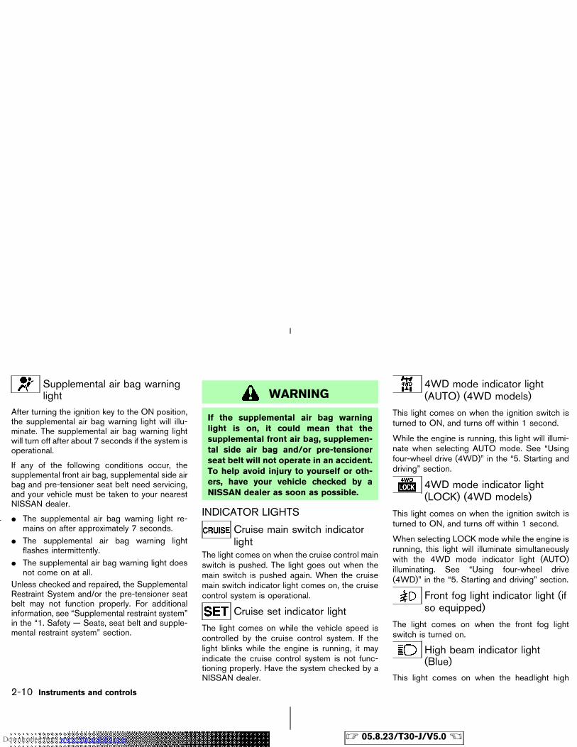
Supplemental air bag warninglight
After turning the ignition key to the ON position,the supplemental air bag warning light will illu-minate. The supplemental air bag warning lightwill turn off after about 7 seconds if the system isoperational.
If any of the following conditions occur, thesupplemental front air bag, supplemental side airbag and pre-tensioner seat belt need servicing,and your vehicle must be taken to your nearestNISSAN dealer.
� The supplemental air bag warning light re-mains on after approximately 7 seconds.
� The supplemental air bag warning lightflashes intermittently.
� The supplemental air bag warning light doesnot come on at all.
Unless checked and repaired, the SupplementalRestraint System and/or the pre-tensioner seatbelt may not function properly. For additionalinformation, see “Supplemental restraint system”in the “1. Safety — Seats, seat belt and supple-mental restraint system” section.
WARNING
If the supplemental air bag warninglight is on, it could mean that thesupplemental front air bag, supplemen-tal side air bag and/or pre-tensionerseat belt will not operate in an accident.To help avoid injury to yourself or oth-ers, have your vehicle checked by aNISSAN dealer as soon as possible.
INDICATOR LIGHTS
Cruise main switch indicatorlight
The light comes on when the cruise control mainswitch is pushed. The light goes out when themain switch is pushed again. When the cruisemain switch indicator light comes on, the cruisecontrol system is operational.
Cruise set indicator light
The light comes on while the vehicle speed iscontrolled by the cruise control system. If thelight blinks while the engine is running, it mayindicate the cruise control system is not func-tioning properly. Have the system checked by aNISSAN dealer.
4WD mode indicator light(AUTO) (4WD models)
This light comes on when the ignition switch isturned to ON, and turns off within 1 second.
While the engine is running, this light will illumi-nate when selecting AUTO mode. See “Usingfour-wheel drive (4WD)” in the “5. Starting anddriving” section.
4WD mode indicator light(LOCK) (4WD models)
This light comes on when the ignition switch isturned to ON, and turns off within 1 second.
When selecting LOCK mode while the engine isrunning, this light will illuminate simultaneouslywith the 4WD mode indicator light (AUTO)illuminating. See “Using four-wheel drive(4WD)” in the “5. Starting and driving” section.
Front fog light indicator light (ifso equipped)
The light comes on when the front fog lightswitch is turned on.
High beam indicator light(Blue)
This light comes on when the headlight high
2-10 Instruments and controls
� 05.8.23/T30-J/V5.0 �Downloaded from www.Manualslib.com manuals search engine
beam is on and goes out when the low beam isselected.
Malfunction indicator lamp(MIL)
If the malfunction indicator lamp comes onsteady or blinks while the engine is running, itmay indicate a potential emission control mal-function.
The malfunction indicator lamp may also comeon steady if the fuel filler cap is loose or missing,or if the vehicle runs out of fuel. Check to makesure the fuel filler cap is installed and closedtightly, and that the vehicle has at least 14 liters(3 US gallons, 2.5 Imp gallons) of fuel in the fueltank.
After a few driving trips, the lamp shouldturn off if no other potential emission controlsystem malfunction exists.
If this indicator lamp comes on steady for 20seconds and then blinks for 10 seconds whenthe engine is not running, it indicates that thevehicle is not ready for an emission controlsystem inspection/maintenance test. See“Readiness for inspection/maintenance (I/M)test” in the “9. Technical and consumer informa-tion” section of this manual.
Operation
The malfunction indicator lamp will come on inone of two ways:
� Malfunction indicator lamp on steady — Anemission control system malfunction hasbeen detected. Turn the ignition key to OFFand check the fuel filler cap. If the fuel fillercap is loose or missing, tighten or install thecap and continue to drive the vehicle. The
lamp should turn off after a few drivingtrips. If the lamp does not turn off aftera few driving trips, have the vehicle inspectedby a NISSAN dealer. You do not need to haveyour vehicle towed to the dealer.
� Malfunction indicator lamp blinking — Anengine misfire has been detected which maydamage the emission control system. To re-duce or avoid emission control system dam-age:
a) Do not drive at speeds above 72 km/h (45MPH).
b) Avoid hard acceleration or deceleration.c) Avoid steep uphill grades.d) If possible, reduce the amount of cargo
being hauled or towed.
The malfunction indicator lamp may stopblinking and come on steady.
Have the vehicle inspected by a NISSAN
dealer. You do not need to have your vehicletowed to the dealer.
CAUTION
Continued vehicle operation withouthaving the emission control systemchecked and repaired as necessarycould lead to poor driveability, reducedfuel economy, and possible damage tothe emission control system.
Overdrive off indicator light (ATmodels)
This light comes on when the overdrive functionis OFF.
The automatic transmission overdrive function iscontrolled by the overdrive switch.
See “Driving the vehicle” in the “5. Starting anddriving” section.
Instruments and controls 2-11
� 05.8.23/T30-J/V5.0 �Downloaded from www.Manualslib.com manuals search engine
Slip indicator light (if soequipped)
This indicator will blink when the VDC system orthe traction control system is operating, thusalerting the driver to the fact that the roadsurface is slippery and the vehicle is nearing itstraction limits.
You may feel or hear the system working, but thisis normal.
The light will blink on for a few seconds after theVDC system stops limiting wheel spin.
The slip indicator light also comes on when youturn the ignition key to ON. The light will turn offafter about 1 second if the system is operational.If the light does not come on or go off, have thetraction control system checked by a NISSANdealer.
Turn signal/hazard indicatorlights
The light flashes when the turn signal switchlever or hazard switch is turned on.
Vehicle dynamic control (VDC)off indicator light (if soequipped)
After turning the ignition key to the ON position,the light will illuminate and then turn off. Thisindicates the vehicle dynamic control (VDC)system is operational.
The light comes on when the vehicle dynamiccontrol (VDC) off switch is pushed to OFF. Thisindicates the vehicle dynamic control systemand traction control system are not operating.When the vehicle dynamic control off indicatorlight and slip indicator light come on with thevehicle dynamic control system turned on, thislight alerts the driver to the fact that the vehicledynamic control system’s fail-safe mode is op-erating, that is the system may not be functioningproperly. Have the system checked by aNISSAN dealer. If an abnormality occurs in thesystem, the vehicle dynamic control systemfunction will be canceled but the vehicle is stilldriveable. For additional information, see “Ve-hicle dynamic control (VDC) system” in the “5.Starting and driving” section of this manual.
AUDIBLE REMINDERS
Key reminder chimeThe chime will sound if the driver’s side door isopened while the key is left in the ignition switch(ignition switch is turned to OFF or ACC).Remove the key and take it with you whenleaving the vehicle.
Light reminder chimeThe chime will sound when the driver’s door isopened with the headlight switch on unless theignition key is in the ON position.
Make sure to turn the light switch off when youleave the vehicle.
Brake pad wear warningThe disc brake pads have audible wear warn-ings. When a brake pad requires replacement, itwill make a high pitched scraping sound whenthe vehicle is in motion whether or not the brakepedal is depressed. Have the brakes checked assoon as possible if the warning sound is heard.
2-12 Instruments and controls
� 05.8.23/T30-J/V5.0 �Downloaded from www.Manualslib.com manuals search engine
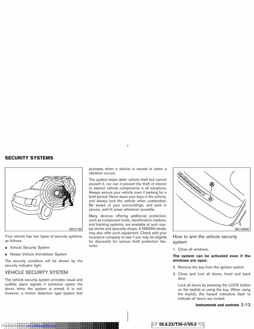
Your vehicle has two types of security systems,as follows:
� Vehicle Security System
� Nissan Vehicle Immobilizer System
The security condition will be shown by thesecurity indicator light.
VEHICLE SECURITY SYSTEM
The vehicle security system provides visual andaudible alarm signals if someone opens thedoors when the system is armed. It is not,however, a motion detection type system that
activates when a vehicle is moved or when avibration occurs.
The system helps deter vehicle theft but cannotprevent it, nor can it prevent the theft of interioror exterior vehicle components in all situations.Always secure your vehicle even if parking for abrief period. Never leave your keys in the vehicle,and always lock the vehicle when unattended.Be aware of your surroundings, and park insecure, well-lit areas whenever possible.
Many devices offering additional protection,such as component locks, identification markers,and tracking systems, are available at auto sup-ply stores and specialty shops. A NISSAN dealermay also offer such equipment. Check with yourinsurance company to see if you may be eligiblefor discounts for various theft protection fea-tures.
How to arm the vehicle securitysystem
1. Close all windows.
The system can be activated even if thewindows are open.
2. Remove the key from the ignition switch.
3. Close and lock all doors, hood and backdoor.
Lock all doors by pressing the LOCK buttonon the keyfob or using the key. When usingthe keyfob, the hazard indicators flash toindicate all doors are locked.
SIC2133 SIC1699C
SECURITY SYSTEMS
Instruments and controls 2-13
� 05.8.23/T30-J/V5.0 �Downloaded from www.Manualslib.com manuals search engine
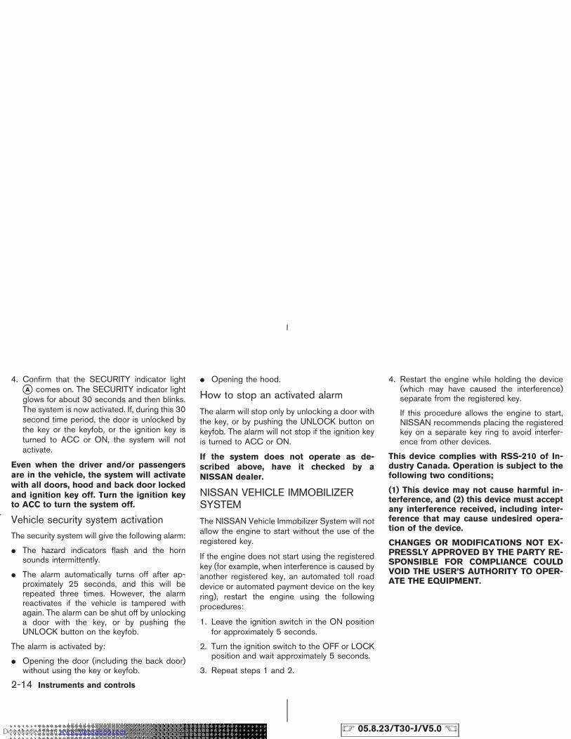
4. Confirm that the SECURITY indicator light�A comes on. The SECURITY indicator lightglows for about 30 seconds and then blinks.The system is now activated. If, during this 30second time period, the door is unlocked bythe key or the keyfob, or the ignition key isturned to ACC or ON, the system will notactivate.
Even when the driver and/or passengersare in the vehicle, the system will activatewith all doors, hood and back door lockedand ignition key off. Turn the ignition keyto ACC to turn the system off.
Vehicle security system activationThe security system will give the following alarm:
� The hazard indicators flash and the hornsounds intermittently.
� The alarm automatically turns off after ap-proximately 25 seconds, and this will berepeated three times. However, the alarmreactivates if the vehicle is tampered withagain. The alarm can be shut off by unlockinga door with the key, or by pushing theUNLOCK button on the keyfob.
The alarm is activated by:
� Opening the door (including the back door)without using the key or keyfob.
� Opening the hood.
How to stop an activated alarm
The alarm will stop only by unlocking a door withthe key, or by pushing the UNLOCK button onkeyfob. The alarm will not stop if the ignition keyis turned to ACC or ON.
If the system does not operate as de-scribed above, have it checked by aNISSAN dealer.
NISSAN VEHICLE IMMOBILIZERSYSTEM
The NISSAN Vehicle Immobilizer System will notallow the engine to start without the use of theregistered key.
If the engine does not start using the registeredkey (for example, when interference is caused byanother registered key, an automated toll roaddevice or automated payment device on the keyring), restart the engine using the followingprocedures:
1. Leave the ignition switch in the ON positionfor approximately 5 seconds.
2. Turn the ignition switch to the OFF or LOCKposition and wait approximately 5 seconds.
3. Repeat steps 1 and 2.
4. Restart the engine while holding the device(which may have caused the interference)separate from the registered key.
If this procedure allows the engine to start,NISSAN recommends placing the registeredkey on a separate key ring to avoid interfer-ence from other devices.
This device complies with RSS-210 of In-dustry Canada. Operation is subject to thefollowing two conditions;
(1) This device may not cause harmful in-terference, and (2) this device must acceptany interference received, including inter-ference that may cause undesired opera-tion of the device.
CHANGES OR MODIFICATIONS NOT EX-PRESSLY APPROVED BY THE PARTY RE-SPONSIBLE FOR COMPLIANCE COULDVOID THE USER’S AUTHORITY TO OPER-ATE THE EQUIPMENT.
2-14 Instruments and controls
� 05.8.23/T30-J/V5.0 �Downloaded from www.Manualslib.com manuals search engine
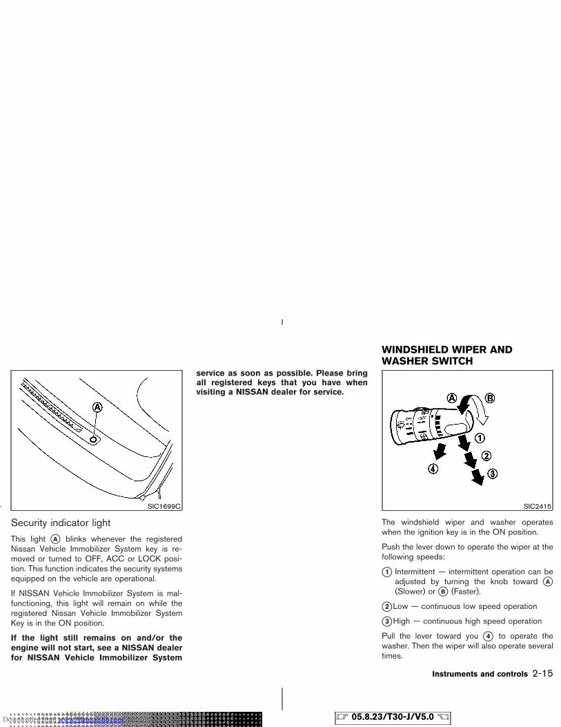
Security indicator light
This light �A blinks whenever the registeredNissan Vehicle Immobilizer System key is re-moved or turned to OFF, ACC or LOCK posi-tion. This function indicates the security systemsequipped on the vehicle are operational.
If NISSAN Vehicle Immobilizer System is mal-functioning, this light will remain on while theregistered Nissan Vehicle Immobilizer SystemKey is in the ON position.
If the light still remains on and/or theengine will not start, see a NISSAN dealerfor NISSAN Vehicle Immobilizer System
service as soon as possible. Please bringall registered keys that you have whenvisiting a NISSAN dealer for service.
The windshield wiper and washer operateswhen the ignition key is in the ON position.
Push the lever down to operate the wiper at thefollowing speeds:
�1 Intermittent — intermittent operation can beadjusted by turning the knob toward �A(Slower) or �B (Faster).
�2 Low — continuous low speed operation
�3 High — continuous high speed operation
Pull the lever toward you �4 to operate thewasher. Then the wiper will also operate severaltimes.
SIC1699C SIC2415
WINDSHIELD WIPER ANDWASHER SWITCH
Instruments and controls 2-15
� 05.8.23/T30-J/V5.0 �Downloaded from www.Manualslib.com manuals search engine
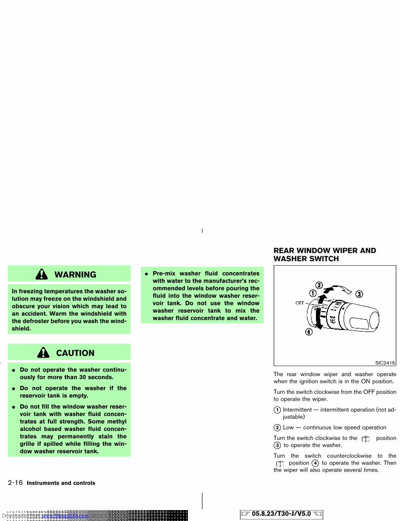
WARNING
In freezing temperatures the washer so-lution may freeze on the windshield andobscure your vision which may lead toan accident. Warm the windshield withthe defroster before you wash the wind-shield.
CAUTION
� Do not operate the washer continu-ously for more than 30 seconds.
� Do not operate the washer if thereservoir tank is empty.
� Do not fill the window washer reser-voir tank with washer fluid concen-trates at full strength. Some methylalcohol based washer fluid concen-trates may permanently stain thegrille if spilled while filling the win-dow washer reservoir tank.
� Pre-mix washer fluid concentrateswith water to the manufacturer’s rec-ommended levels before pouring thefluid into the window washer reser-voir tank. Do not use the windowwasher reservoir tank to mix thewasher fluid concentrate and water.
The rear window wiper and washer operatewhen the ignition switch is in the ON position.
Turn the switch clockwise from the OFF positionto operate the wiper.
�1 Intermittent — intermittent operation (not ad-justable)
�2 Low — continuous low speed operation
Turn the switch clockwise to the position�3 to operate the washer.
Turn the switch counterclockwise to theposition �4 to operate the washer. Then
the wiper will also operate several times.
SIC2416
REAR WINDOW WIPER ANDWASHER SWITCH
2-16 Instruments and controls
� 05.8.23/T30-J/V5.0 �Downloaded from www.Manualslib.com manuals search engine
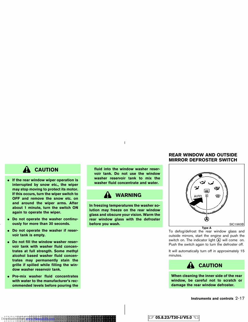
CAUTION
� If the rear window wiper operation isinterrupted by snow etc., the wipermay stop moving to protect its motor.If this occurs, turn the wiper switch toOFF and remove the snow etc. onand around the wiper arms. Afterabout 1 minute, turn the switch ONagain to operate the wiper.
� Do not operate the washer continu-ously for more than 30 seconds.
� Do not operate the washer if reser-voir tank is empty.
� Do not fill the window washer reser-voir tank with washer fluid concen-trates at full strength. Some methylalcohol based washer fluid concen-trates may permanently stain thegrille if spilled while filling the win-dow washer reservoir tank.
� Pre-mix washer fluid concentrateswith water to the manufacturer’s rec-ommended levels before pouring the
fluid into the window washer reser-voir tank. Do not use the windowwasher reservoir tank to mix thewasher fluid concentrate and water.
WARNING
In freezing temperatures the washer so-lution may freeze on the rear windowglass and obscure your vision. Warm therear window glass with the defrosterbefore you wash.
To defog/defrost the rear window glass andoutside mirrors, start the engine and push theswitch on. The indicator light �A will come on.Push the switch again to turn the defroster off.
It will automatically turn off in approximately 15minutes.
CAUTION
When cleaning the inner side of the rearwindow, be careful not to scratch ordamage the rear window defroster.
SIC1960BType A
REAR WINDOW AND OUTSIDEMIRROR DEFROSTER SWITCH
Instruments and controls 2-17
� 05.8.23/T30-J/V5.0 �Downloaded from www.Manualslib.com manuals search engine
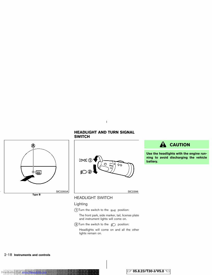
HEADLIGHT SWITCH
Lighting
�1 Turn the switch to the position:
The front park, side marker, tail, license plateand instrument lights will come on.
�2 Turn the switch to the position:
Headlights will come on and all the otherlights remain on.
CAUTION
Use the headlights with the engine run-ning to avoid discharging the vehiclebattery.
SIC2350AType B
SIC2396
HEADLIGHT AND TURN SIGNALSWITCH
2-18 Instruments and controls
� 05.8.23/T30-J/V5.0 �Downloaded from www.Manualslib.com manuals search engine
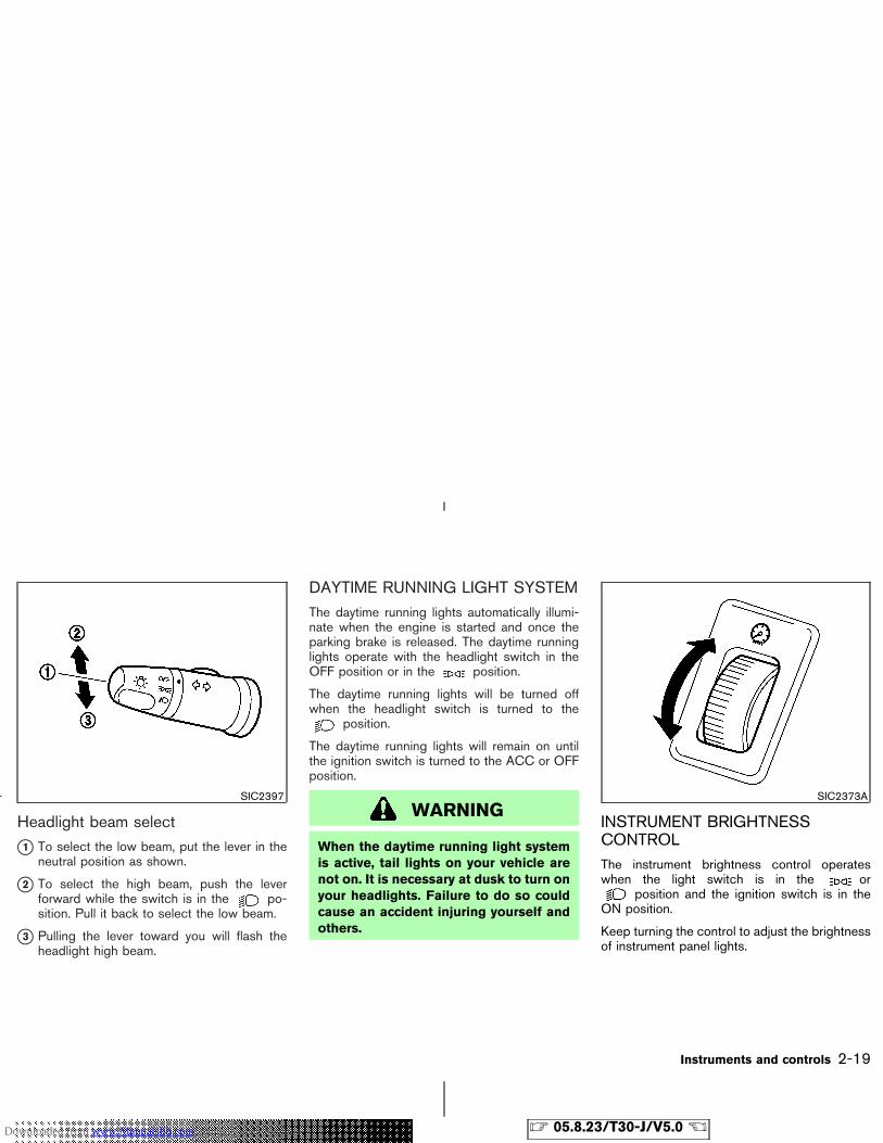
Headlight beam select
�1 To select the low beam, put the lever in theneutral position as shown.
�2 To select the high beam, push the leverforward while the switch is in the po-sition. Pull it back to select the low beam.
�3 Pulling the lever toward you will flash theheadlight high beam.
DAYTIME RUNNING LIGHT SYSTEMThe daytime running lights automatically illumi-nate when the engine is started and once theparking brake is released. The daytime runninglights operate with the headlight switch in theOFF position or in the position.
The daytime running lights will be turned offwhen the headlight switch is turned to the
position.
The daytime running lights will remain on untilthe ignition switch is turned to the ACC or OFFposition.
WARNING
When the daytime running light systemis active, tail lights on your vehicle arenot on. It is necessary at dusk to turn onyour headlights. Failure to do so couldcause an accident injuring yourself andothers.
INSTRUMENT BRIGHTNESSCONTROLThe instrument brightness control operateswhen the light switch is in the or
position and the ignition switch is in theON position.
Keep turning the control to adjust the brightnessof instrument panel lights.
SIC2397 SIC2373A
Instruments and controls 2-19
� 05.8.23/T30-J/V5.0 �Downloaded from www.Manualslib.com manuals search engine
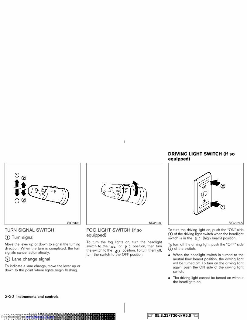
TURN SIGNAL SWITCH
�1 Turn signalMove the lever up or down to signal the turningdirection. When the turn is completed, the turnsignals cancel automatically.
�2 Lane change signalTo indicate a lane change, move the lever up ordown to the point where lights begin flashing.
FOG LIGHT SWITCH (if soequipped)To turn the fog lights on, turn the headlightswitch to the or position, then turnthe switch to the position. To turn them off,turn the switch to the OFF position.
To turn the driving light on, push the “ON” side�1 of the driving light switch when the headlightswitch is in the (high beam) position.
To turn off the driving light, push the “OFF” side�2 of the switch.
� When the headlight switch is turned to theneutral (low beam) position, the driving lightwill be turned off. To turn on the driving lightagain, push the ON side of the driving lightswitch.
� The driving light cannot be turned on withoutthe headlights on.
SIC2398 SIC2399 SIC2274A
DRIVING LIGHT SWITCH (if soequipped)
2-20 Instruments and controls
� 05.8.23/T30-J/V5.0 �Downloaded from www.Manualslib.com manuals search engine
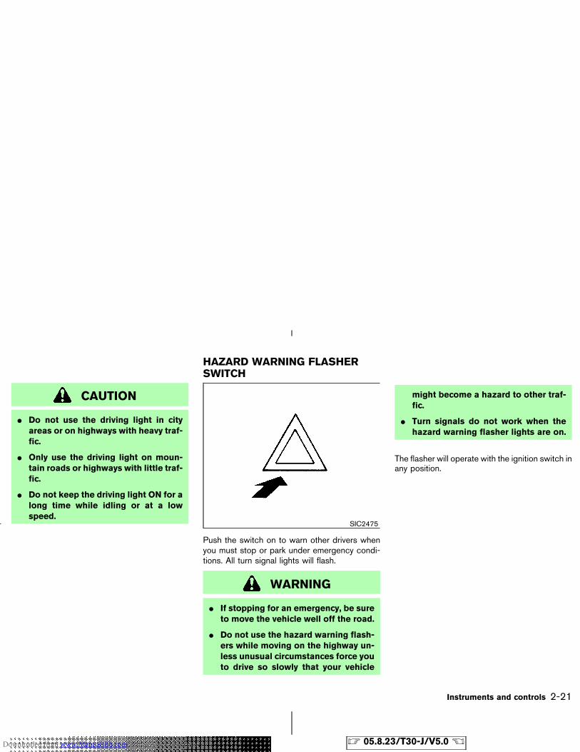
CAUTION
� Do not use the driving light in cityareas or on highways with heavy traf-fic.
� Only use the driving light on moun-tain roads or highways with little traf-fic.
� Do not keep the driving light ON for along time while idling or at a lowspeed.
Push the switch on to warn other drivers whenyou must stop or park under emergency condi-tions. All turn signal lights will flash.
WARNING
� If stopping for an emergency, be sureto move the vehicle well off the road.
� Do not use the hazard warning flash-ers while moving on the highway un-less unusual circumstances force youto drive so slowly that your vehicle
might become a hazard to other traf-fic.
� Turn signals do not work when thehazard warning flasher lights are on.
The flasher will operate with the ignition switch inany position.
SIC2475
HAZARD WARNING FLASHERSWITCH
Instruments and controls 2-21
� 05.8.23/T30-J/V5.0 �Downloaded from www.Manualslib.com manuals search engine
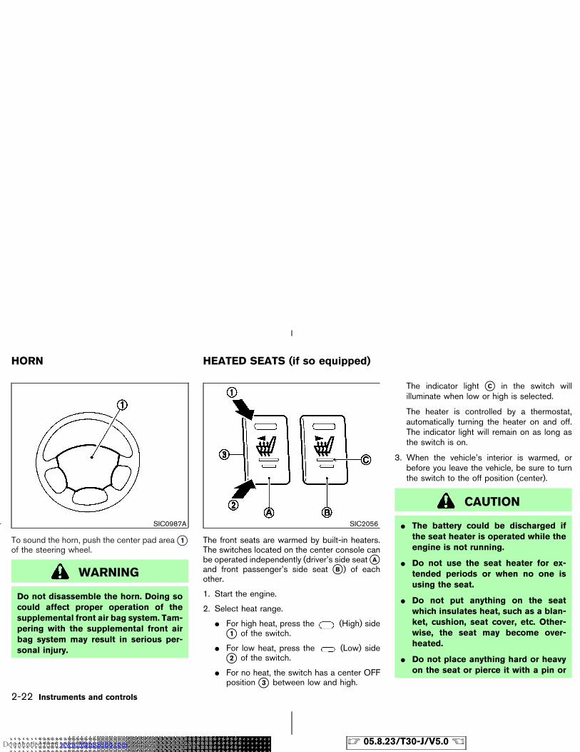
To sound the horn, push the center pad area �1of the steering wheel.
WARNING
Do not disassemble the horn. Doing socould affect proper operation of thesupplemental front air bag system. Tam-pering with the supplemental front airbag system may result in serious per-sonal injury.
The front seats are warmed by built-in heaters.The switches located on the center console canbe operated independently (driver’s side seat �Aand front passenger’s side seat �B ) of eachother.
1. Start the engine.
2. Select heat range.
� For high heat, press the (High) side�1 of the switch.
� For low heat, press the (Low) side�2 of the switch.
� For no heat, the switch has a center OFFposition �3 between low and high.
The indicator light �C in the switch willilluminate when low or high is selected.
The heater is controlled by a thermostat,automatically turning the heater on and off.The indicator light will remain on as long asthe switch is on.
3. When the vehicle’s interior is warmed, orbefore you leave the vehicle, be sure to turnthe switch to the off position (center).
CAUTION
� The battery could be discharged ifthe seat heater is operated while theengine is not running.
� Do not use the seat heater for ex-tended periods or when no one isusing the seat.
� Do not put anything on the seatwhich insulates heat, such as a blan-ket, cushion, seat cover, etc. Other-wise, the seat may become over-heated.
� Do not place anything hard or heavyon the seat or pierce it with a pin or
SIC0987A SIC2056
HORN HEATED SEATS (if so equipped)
2-22 Instruments and controls
� 05.8.23/T30-J/V5.0 �Downloaded from www.Manualslib.com manuals search engine
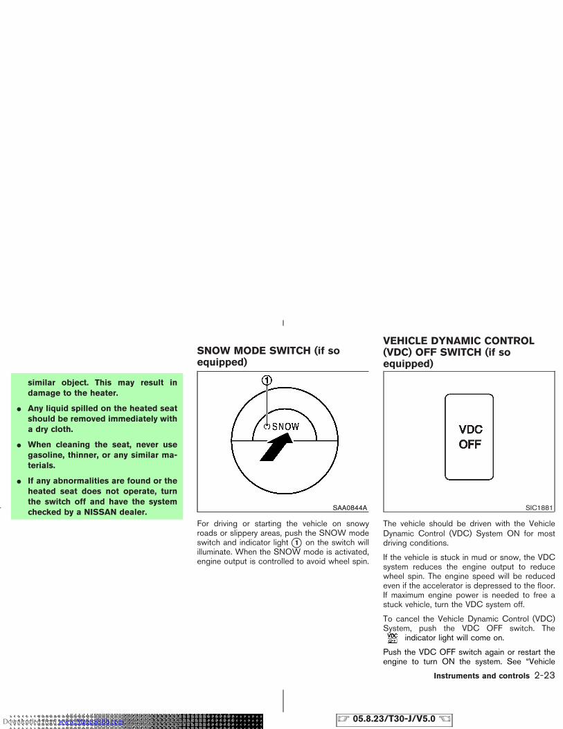
similar object. This may result indamage to the heater.
� Any liquid spilled on the heated seatshould be removed immediately witha dry cloth.
� When cleaning the seat, never usegasoline, thinner, or any similar ma-terials.
� If any abnormalities are found or theheated seat does not operate, turnthe switch off and have the systemchecked by a NISSAN dealer.
For driving or starting the vehicle on snowyroads or slippery areas, push the SNOW modeswitch and indicator light �1 on the switch willilluminate. When the SNOW mode is activated,engine output is controlled to avoid wheel spin.
The vehicle should be driven with the VehicleDynamic Control (VDC) System ON for mostdriving conditions.
If the vehicle is stuck in mud or snow, the VDCsystem reduces the engine output to reducewheel spin. The engine speed will be reducedeven if the accelerator is depressed to the floor.If maximum engine power is needed to free astuck vehicle, turn the VDC system off.
To cancel the Vehicle Dynamic Control (VDC)System, push the VDC OFF switch. The
indicator light will come on.
Push the VDC OFF switch again or restart theengine to turn ON the system. See “Vehicle
SAA0844A SIC1881
SNOW MODE SWITCH (if soequipped)
VEHICLE DYNAMIC CONTROL(VDC) OFF SWITCH (if soequipped)
Instruments and controls 2-23
� 05.8.23/T30-J/V5.0 �Downloaded from www.Manualslib.com manuals search engine
dynamic control (VDC) system” in the “5. Start-ing and driving” section.
The digital clock �1 displays time when theignition key is in the ON position.
If the power supply is disconnected, theclock will not indicate the correct time.Readjust the time.
ADJUSTING THE TIME
Speedometer display modelYou can adjust the clock when it is displayed.
To display the clock, push the adjusting knob�2 . The following is the order of the display:
TRIP A → TRIP B → CLOCK → TEM-PERATURE (Outside air — °C) → TRIP A
Turn the adjusting knob left to adjust the hour.
Turn the adjusting knob right to adjust theminutes.
SIC2983
CLOCK
2-24 Instruments and controls
� 05.8.23/T30-J/V5.0 �Downloaded from www.Manualslib.com manuals search engine
Audio display model
1. Turn the audio unit on by pushing the “PWR”button �1 .
2. Push the “MENU” button �2 until the displayindicates the clock adjustment mode.
If the “CLOCK OFF” is indicated on the display,push the “TUNE” button �3 to change the modeto “CLOCK ON”. Then push the “MENU” button�2 .
The time indicator will flash.
3. Push the “SEEK TRACK” button �4 to adjustthe hour.
Push the “TUNE” button �3 to adjust theminute.
Pushing the , buttons will ad-vance and , buttons will turn backthe time.
4. Push the “MENU” button �2 to finish theadjustment.
The power outlet is for powering electrical ac-cessories such as cellular telephones.
SIC2981 SIC2276AFront
POWER OUTLET
Instruments and controls 2-25
� 05.8.23/T30-J/V5.0 �Downloaded from www.Manualslib.com manuals search engine
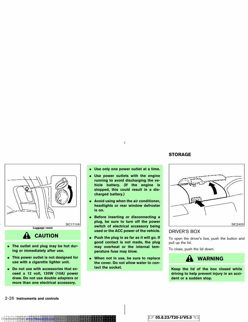
CAUTION
� The outlet and plug may be hot dur-ing or immediately after use.
� This power outlet is not designed foruse with a cigarette lighter unit.
� Do not use with accessories that ex-ceed a 12 volt, 120W (10A) powerdraw. Do not use double adapters ormore than one electrical accessory.
� Use only one power outlet at a time.
� Use power outlets with the enginerunning to avoid discharging the ve-hicle battery. (If the engine isstopped, this could result in a dis-charged battery.)
� Avoid using when the air conditioner,headlights or rear window defrosteris on.
� Before inserting or disconnecting aplug, be sure to turn off the powerswitch of electrical accessory beingused or the ACC power of the vehicle.
� Push the plug in as far as it will go. Ifgood contact is not made, the plugmay overheat or the internal tem-perature fuse may blow.
� When not in use, be sure to replacethe cover. Do not allow water to con-tact the socket.
DRIVER’S BOXTo open the driver’s box, push the button andpull up the lid.
To close, push the lid down.
WARNING
Keep the lid of the box closed whiledriving to help prevent injury in an acci-dent or a sudden stop.
SIC1710ALuggage room
SIC2400
STORAGE
2-26 Instruments and controls
� 05.8.23/T30-J/V5.0 �Downloaded from www.Manualslib.com manuals search engine
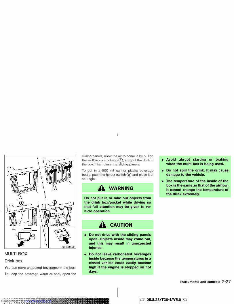
MULTI BOX
Drink box
You can store unopened beverages in the box.
To keep the beverage warm or cool, open the
sliding panels, allow the air to come in by pullingthe air flow control knob �1 , and put the drink inthe box. Then close the sliding panels.
To put in a 500 m� can or plastic beveragebottle, push the holder switch �2 and place it atan angle.
WARNING
Do not put in or take out objects fromthe drink box/pocket while driving sothat full attention may be given to ve-hicle operation.
CAUTION
� Do not drive with the sliding panelsopen. Objects inside may come out,and this may result in unexpectedinjuries.
� Do not leave carbonated beveragesinside because the temperatures in aclosed vehicle could easily becomehigh if the engine is stopped on hotdays.
� Avoid abrupt starting or brakingwhen the multi box is being used.
� Do not spill the drink. It may causedamage to the vehicle.
� The temperature of the inside of thebox is the same as that of the airflow.It cannot change the temperature ofthe drink extremely.
SIC2357B
Instruments and controls 2-27
� 05.8.23/T30-J/V5.0 �Downloaded from www.Manualslib.com manuals search engine
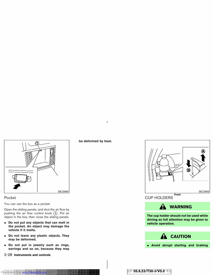
You can use the box as a pocket.
Open the sliding panels, and shut the air flow bypushing the air flow control knob �1 . Put anobject in the box, then close the sliding panels.
� Do not put any objects that can melt inthe pocket. An object may damage thevehicle if it melts.
� Do not leave any plastic objects. Theymay be deformed.
� Do not put in jewelry such as rings,earrings and so on, because they may
be deformed by heat.
CUP HOLDERS
WARNING
The cup holder should not be used whiledriving so full attention may be given tovehicle operation.
CAUTION
� Avoid abrupt starting and braking
SIC2995 SIC2955Front
2-28 Instruments and controls
� 05.8.23/T30-J/V5.0 �Downloaded from www.Manualslib.com manuals search engine
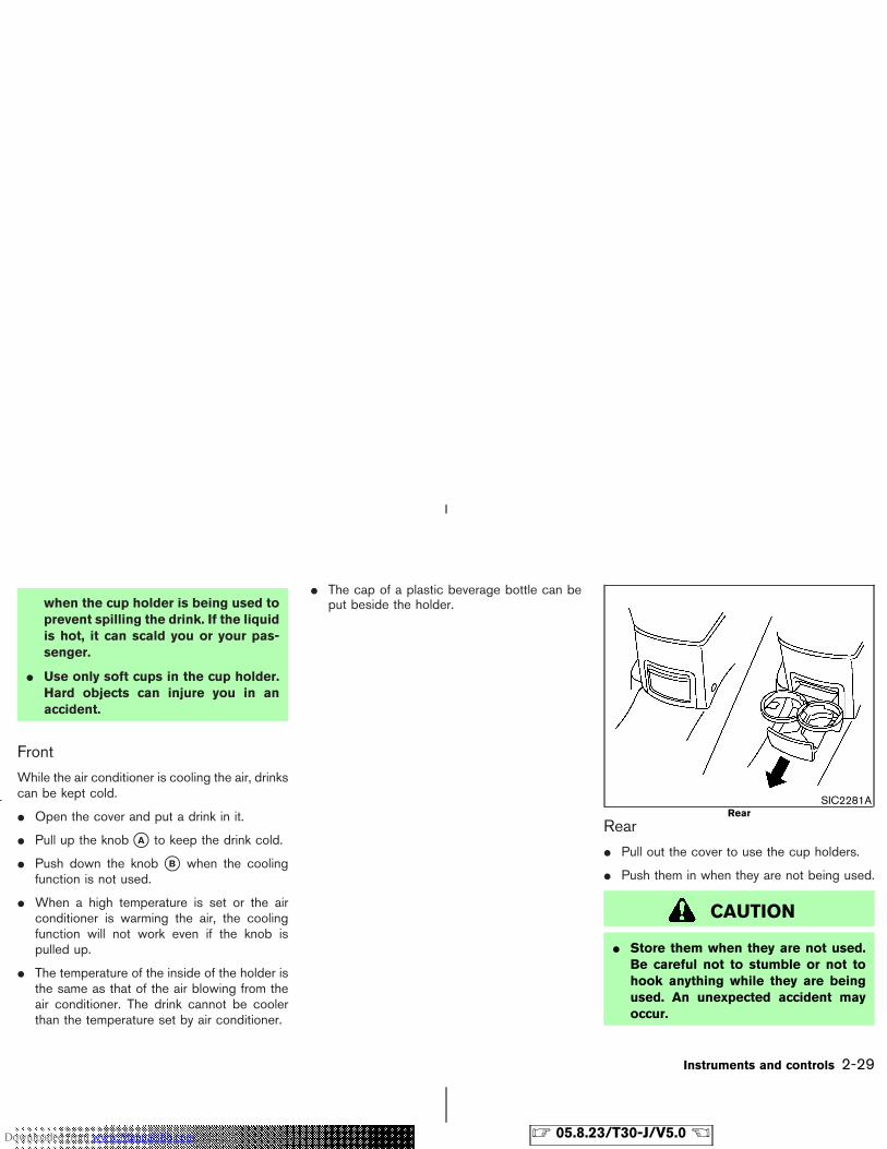
when the cup holder is being used toprevent spilling the drink. If the liquidis hot, it can scald you or your pas-senger.
� Use only soft cups in the cup holder.Hard objects can injure you in anaccident.
Front
While the air conditioner is cooling the air, drinkscan be kept cold.
� Open the cover and put a drink in it.
� Pull up the knob �A to keep the drink cold.
� Push down the knob �B when the coolingfunction is not used.
� When a high temperature is set or the airconditioner is warming the air, the coolingfunction will not work even if the knob ispulled up.
� The temperature of the inside of the holder isthe same as that of the air blowing from theair conditioner. The drink cannot be coolerthan the temperature set by air conditioner.
� The cap of a plastic beverage bottle can beput beside the holder.
Rear
� Pull out the cover to use the cup holders.
� Push them in when they are not being used.
CAUTION
� Store them when they are not used.Be careful not to stumble or not tohook anything while they are beingused. An unexpected accident mayoccur.
SIC2281ARear
Instruments and controls 2-29
� 05.8.23/T30-J/V5.0 �Downloaded from www.Manualslib.com manuals search engine
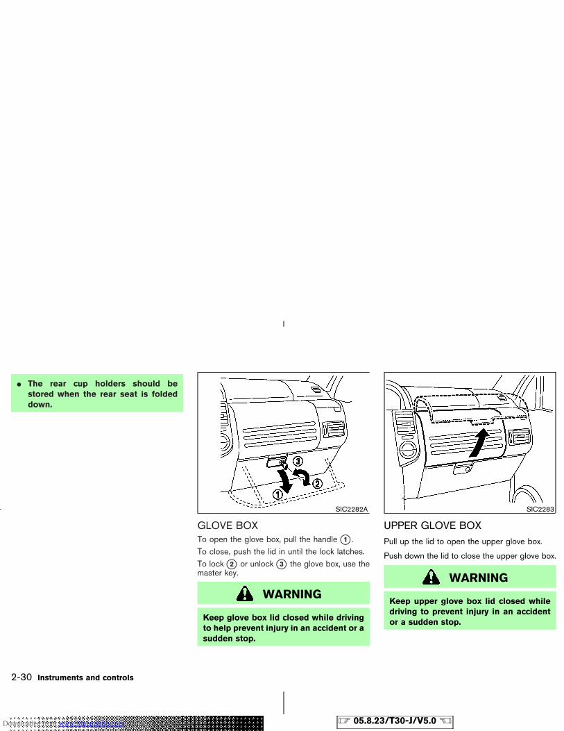
� The rear cup holders should bestored when the rear seat is foldeddown.
GLOVE BOXTo open the glove box, pull the handle �1 .To close, push the lid in until the lock latches.To lock �2 or unlock �3 the glove box, use themaster key.
WARNING
Keep glove box lid closed while drivingto help prevent injury in an accident or asudden stop.
UPPER GLOVE BOXPull up the lid to open the upper glove box.
Push down the lid to close the upper glove box.
WARNING
Keep upper glove box lid closed whiledriving to prevent injury in an accidentor a sudden stop.
SIC2282A SIC2283
2-30 Instruments and controls
� 05.8.23/T30-J/V5.0 �Downloaded from www.Manualslib.com manuals search engine
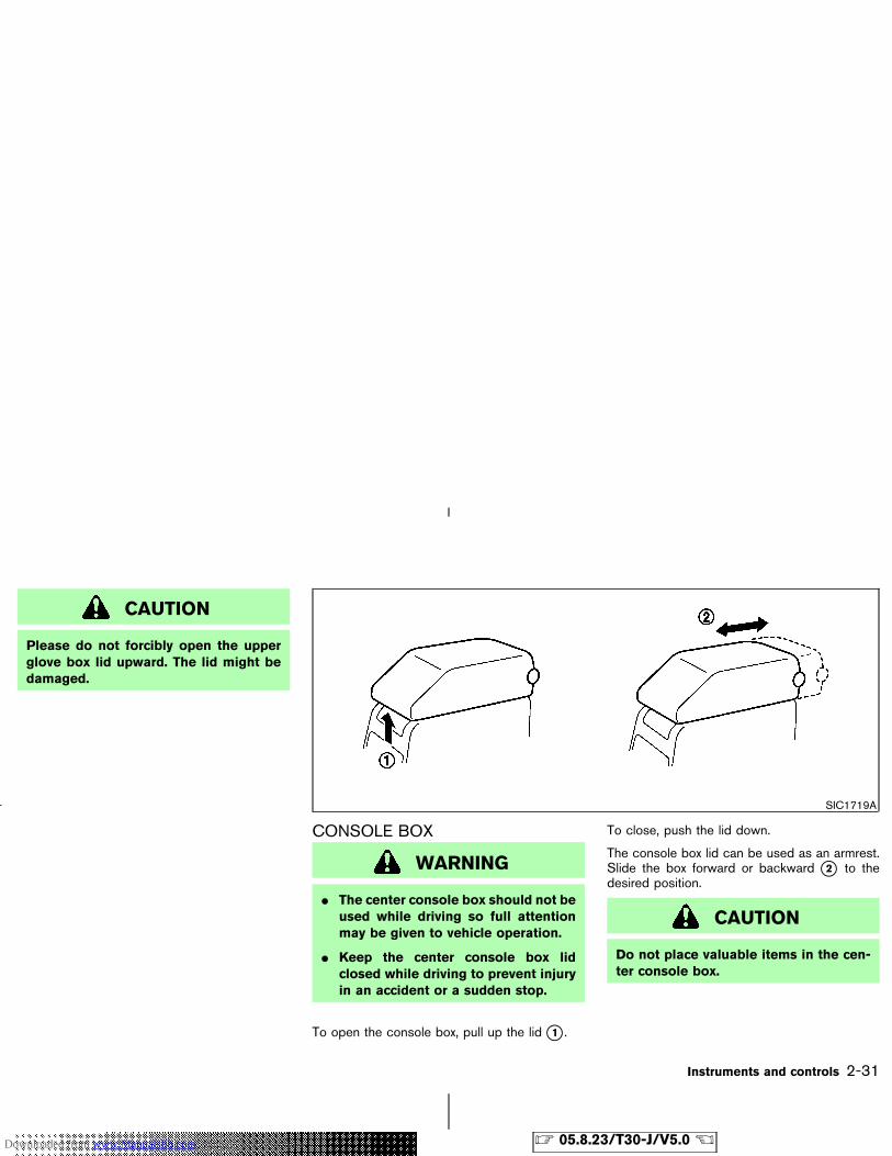
CAUTION
Please do not forcibly open the upperglove box lid upward. The lid might bedamaged.
CONSOLE BOX
WARNING
� The center console box should not beused while driving so full attentionmay be given to vehicle operation.
� Keep the center console box lidclosed while driving to prevent injuryin an accident or a sudden stop.
To open the console box, pull up the lid �1 .
To close, push the lid down.
The console box lid can be used as an armrest.Slide the box forward or backward �2 to thedesired position.
CAUTION
Do not place valuable items in the cen-ter console box.
SIC1719A
Instruments and controls 2-31
� 05.8.23/T30-J/V5.0 �Downloaded from www.Manualslib.com manuals search engine
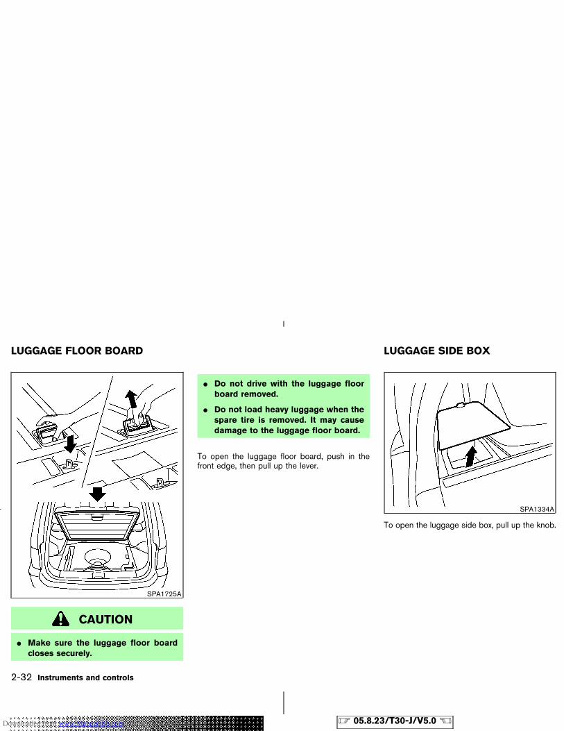
CAUTION
� Make sure the luggage floor boardcloses securely.
� Do not drive with the luggage floorboard removed.
� Do not load heavy luggage when thespare tire is removed. It may causedamage to the luggage floor board.
To open the luggage floor board, push in thefront edge, then pull up the lever.
To open the luggage side box, pull up the knob.
SPA1725A
SPA1334A
LUGGAGE FLOOR BOARD LUGGAGE SIDE BOX
2-32 Instruments and controls
� 05.8.23/T30-J/V5.0 �Downloaded from www.Manualslib.com manuals search engine
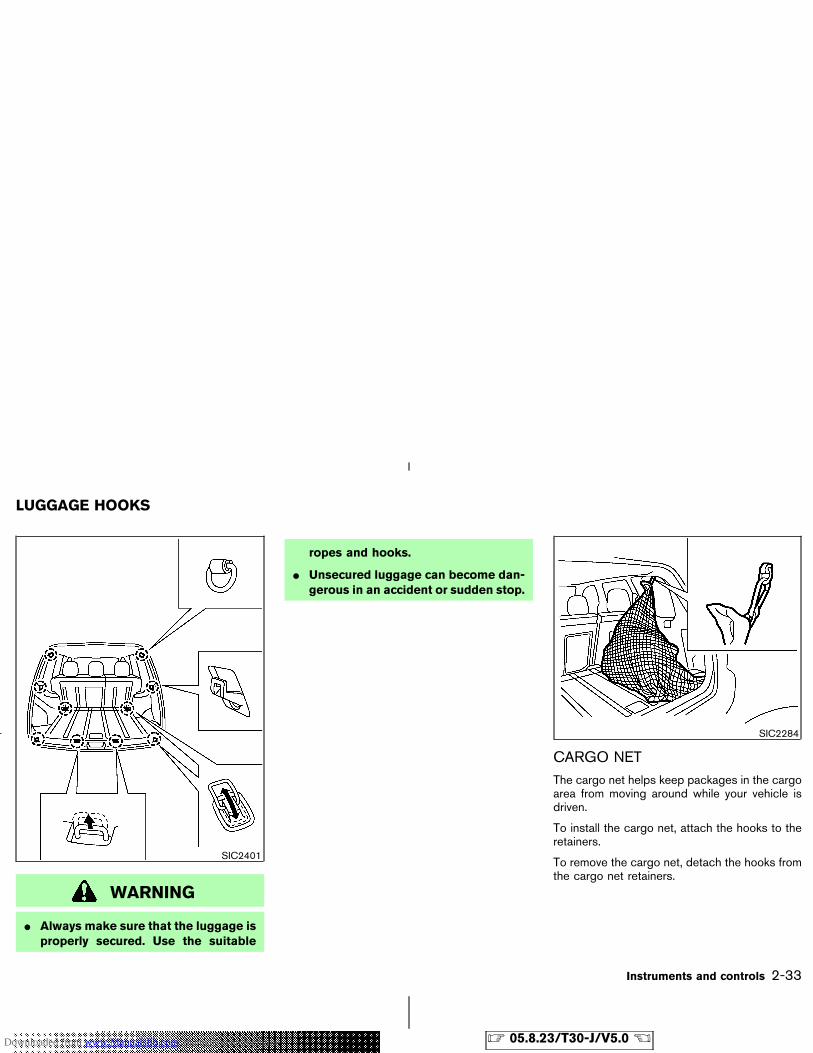
WARNING
� Always make sure that the luggage isproperly secured. Use the suitable
ropes and hooks.
� Unsecured luggage can become dan-gerous in an accident or sudden stop.
CARGO NETThe cargo net helps keep packages in the cargoarea from moving around while your vehicle isdriven.
To install the cargo net, attach the hooks to theretainers.
To remove the cargo net, detach the hooks fromthe cargo net retainers.
SIC2401
SIC2284
LUGGAGE HOOKS
Instruments and controls 2-33
� 05.8.23/T30-J/V5.0 �Downloaded from www.Manualslib.com manuals search engine
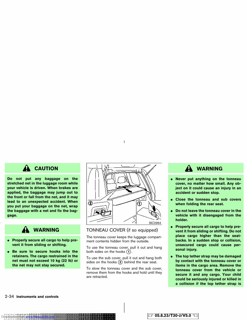
CAUTION
Do not put any baggage on thestretched net in the luggage room whileyour vehicle is driven. When brakes areapplied, the baggage may jump out tothe front or fall from the net, and it maylead to an unexpected accident. Whenyou put your baggage on the net, wrapthe baggage with a net and fix the bag-gage.
WARNING
� Properly secure all cargo to help pre-vent it from sliding or shifting.
� Be sure to secure hooks into theretainers. The cargo restrained in thenet must not exceed 10 kg (22 lb) orthe net may not stay secured.
TONNEAU COVER (if so equipped)The tonneau cover keeps the luggage compart-ment contents hidden from the outside.
To use the tonneau cover, pull it out and hangboth sides on the hooks �1 .
To use the sub cover, pull it out and hang bothsides on the hooks �2 behind the rear seat.
To stow the tonneau cover and the sub cover,remove them from the hooks and hold until theyare retracted.
WARNING
� Never put anything on the tonneaucover, no matter how small. Any ob-ject on it could cause an injury in anaccident or sudden stop.
� Close the tonneau and sub coverswhen folding the rear seat.
� Do not leave the tonneau cover in thevehicle with it disengaged from theholder.
� Properly secure all cargo to help pre-vent it from sliding or shifting. Do notplace cargo higher than the seat-backs. In a sudden stop or collision,unsecured cargo could cause per-sonal injury.
� The top tether strap may be damagedby contact with the tonneau cover oritems in the cargo area. Remove thetonneau cover from the vehicle orsecure it and any cargo. Your childcould be seriously injured or killed ina collision if the top tether strap is
SIC2964
2-34 Instruments and controls
� 05.8.23/T30-J/V5.0 �Downloaded from www.Manualslib.com manuals search engine
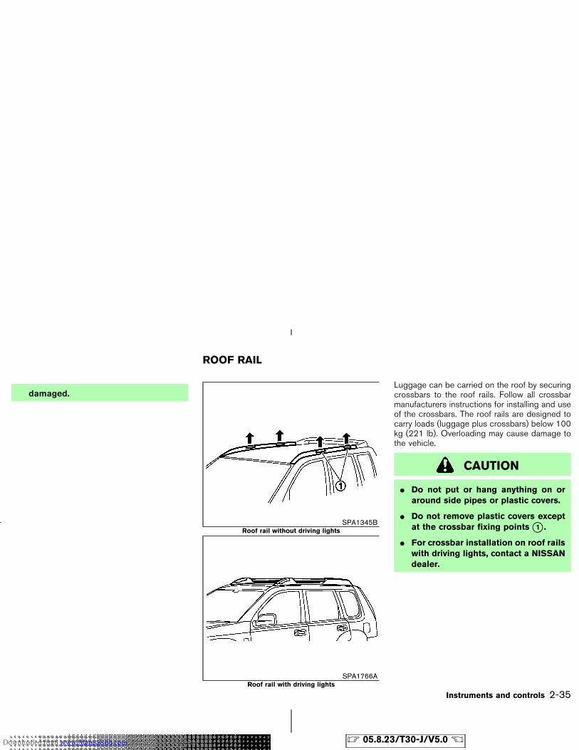
damaged.Luggage can be carried on the roof by securingcrossbars to the roof rails. Follow all crossbarmanufacturers instructions for installing and useof the crossbars. The roof rails are designed tocarry loads (luggage plus crossbars) below 100kg (221 lb). Overloading may cause damage tothe vehicle.
CAUTION
� Do not put or hang anything on oraround side pipes or plastic covers.
� Do not remove plastic covers exceptat the crossbar fixing points �1 .
� For crossbar installation on roof railswith driving lights, contact a NISSANdealer.
SPA1345BRoof rail without driving lights
SPA1766ARoof rail with driving lights
ROOF RAIL
Instruments and controls 2-35
� 05.8.23/T30-J/V5.0 �Downloaded from www.Manualslib.com manuals search engine
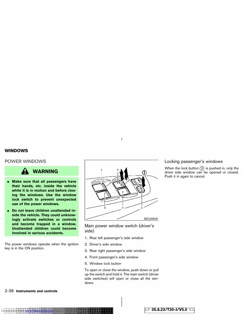
POWER WINDOWS
WARNING
� Make sure that all passengers havetheir hands, etc. inside the vehiclewhile it is in motion and before clos-ing the windows. Use the windowlock switch to prevent unexpecteduse of the power windows.
� Do not leave children unattended in-side the vehicle. They could unknow-ingly activate switches or controlsand become trapped in a window.Unattended children could becomeinvolved in serious accidents.
The power windows operate when the ignitionkey is in the ON position.
Main power window switch (driver’sside)
1. Rear left passenger’s side window
2. Driver’s side window
3. Rear right passenger’s side window
4. Front passenger’s side window
5. Window lock button
To open or close the window, push down or pullup the switch and hold it. The main switch (driverside switches) will open or close all the win-dows.
Locking passenger’s windowsWhen the lock button �1 is pushed in, only thedriver side window can be opened or closed.Push it in again to cancel.
SIC2484A
WINDOWS
2-36 Instruments and controls
� 05.8.23/T30-J/V5.0 �Downloaded from www.Manualslib.com manuals search engine
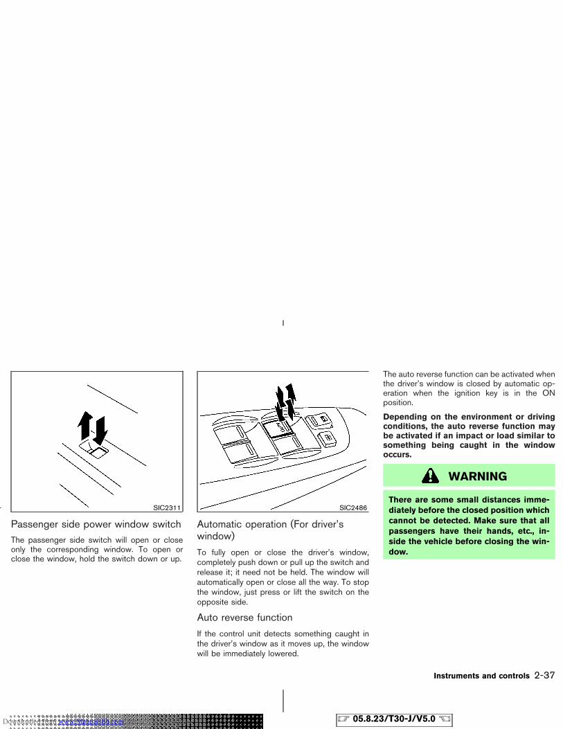
Passenger side power window switchThe passenger side switch will open or closeonly the corresponding window. To open orclose the window, hold the switch down or up.
Automatic operation (For driver’swindow)
To fully open or close the driver’s window,completely push down or pull up the switch andrelease it; it need not be held. The window willautomatically open or close all the way. To stopthe window, just press or lift the switch on theopposite side.
Auto reverse function
If the control unit detects something caught inthe driver’s window as it moves up, the windowwill be immediately lowered.
The auto reverse function can be activated whenthe driver’s window is closed by automatic op-eration when the ignition key is in the ONposition.
Depending on the environment or drivingconditions, the auto reverse function maybe activated if an impact or load similar tosomething being caught in the windowoccurs.
WARNING
There are some small distances imme-diately before the closed position whichcannot be detected. Make sure that allpassengers have their hands, etc., in-side the vehicle before closing the win-dow.
SIC2311 SIC2486
Instruments and controls 2-37
� 05.8.23/T30-J/V5.0 �Downloaded from www.Manualslib.com manuals search engine
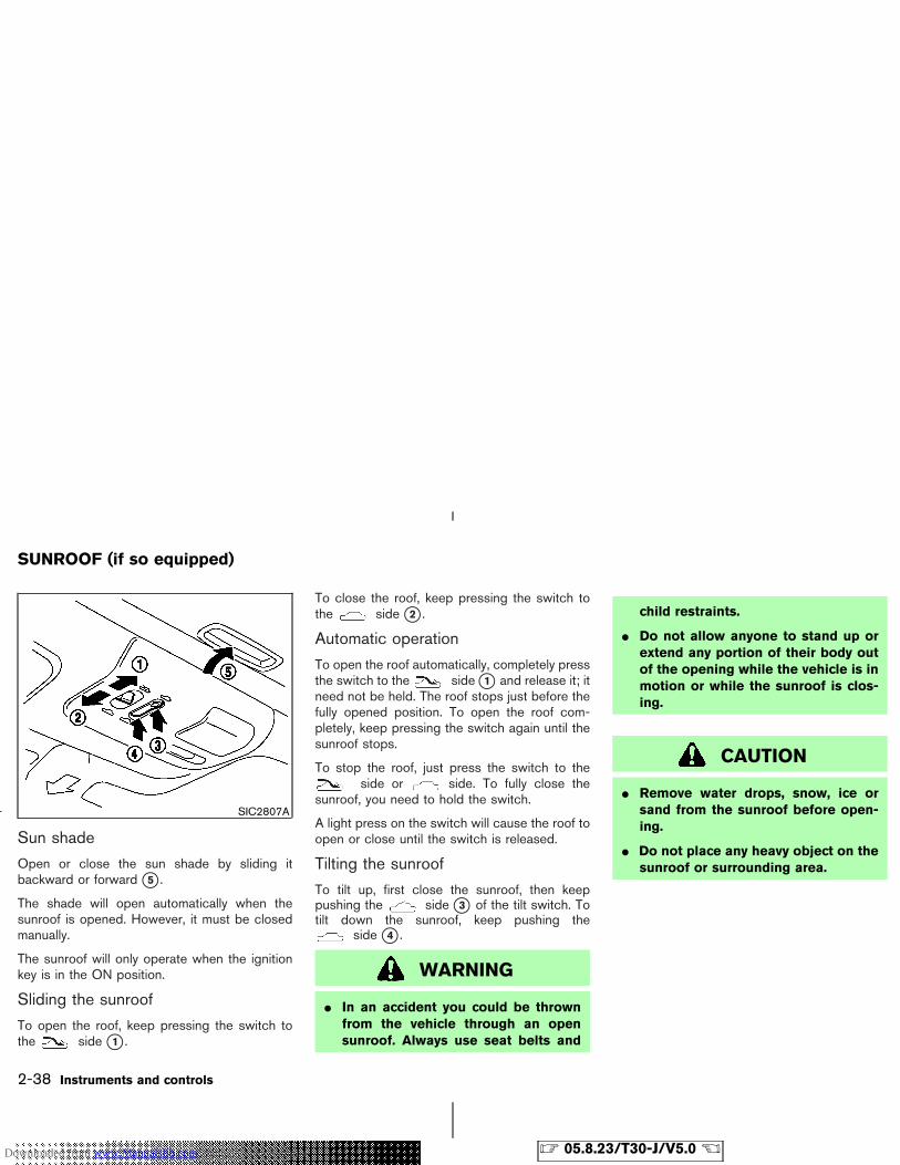
Sun shade
Open or close the sun shade by sliding itbackward or forward �5 .
The shade will open automatically when thesunroof is opened. However, it must be closedmanually.
The sunroof will only operate when the ignitionkey is in the ON position.
Sliding the sunroof
To open the roof, keep pressing the switch tothe side �1 .
To close the roof, keep pressing the switch tothe side �2 .
Automatic operation
To open the roof automatically, completely pressthe switch to the side �1 and release it; itneed not be held. The roof stops just before thefully opened position. To open the roof com-pletely, keep pressing the switch again until thesunroof stops.
To stop the roof, just press the switch to theside or side. To fully close the
sunroof, you need to hold the switch.
A light press on the switch will cause the roof toopen or close until the switch is released.
Tilting the sunroof
To tilt up, first close the sunroof, then keeppushing the side �3 of the tilt switch. Totilt down the sunroof, keep pushing the
side �4 .
WARNING
� In an accident you could be thrownfrom the vehicle through an opensunroof. Always use seat belts and
child restraints.
� Do not allow anyone to stand up orextend any portion of their body outof the opening while the vehicle is inmotion or while the sunroof is clos-ing.
CAUTION
� Remove water drops, snow, ice orsand from the sunroof before open-ing.
� Do not place any heavy object on thesunroof or surrounding area.
SIC2807A
SUNROOF (if so equipped)
2-38 Instruments and controls
� 05.8.23/T30-J/V5.0 �Downloaded from www.Manualslib.com manuals search engine
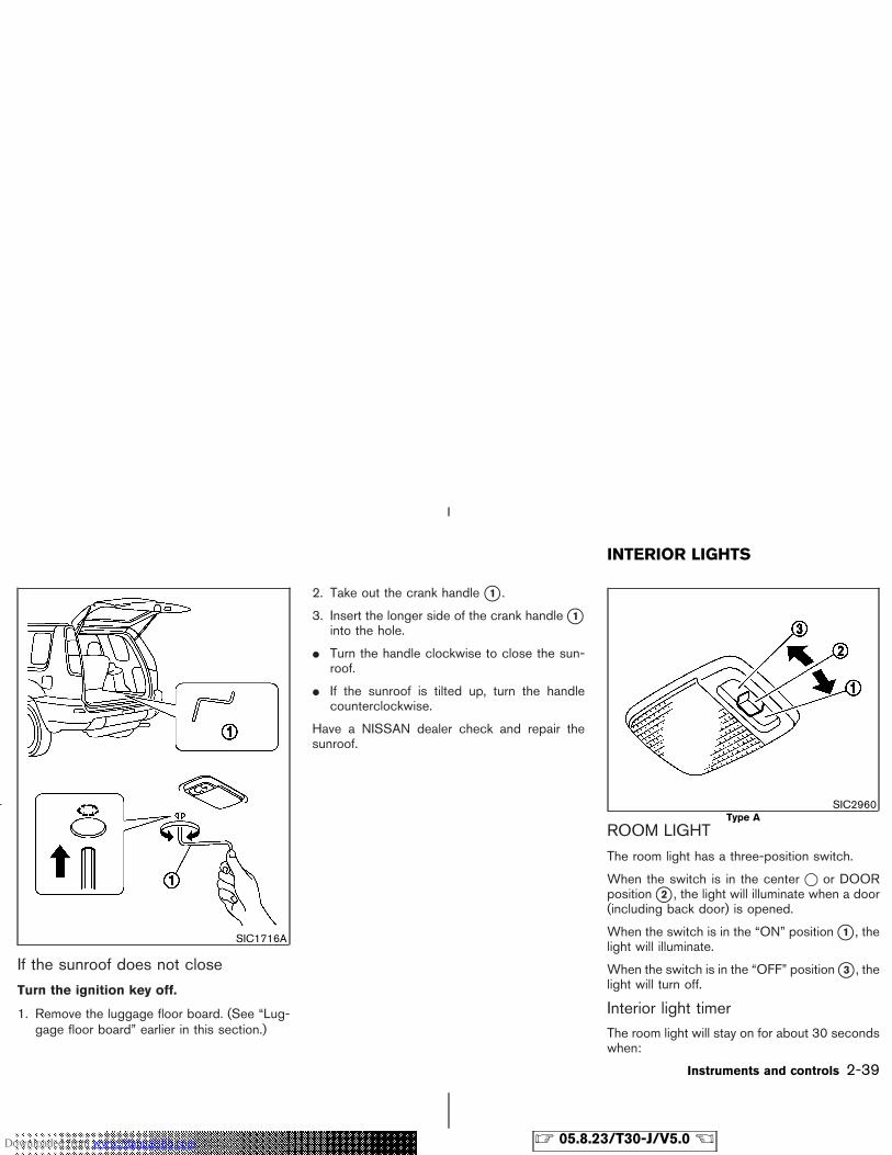
If the sunroof does not close
Turn the ignition key off.
1. Remove the luggage floor board. (See “Lug-gage floor board” earlier in this section.)
2. Take out the crank handle �1 .
3. Insert the longer side of the crank handle �1into the hole.
� Turn the handle clockwise to close the sun-roof.
� If the sunroof is tilted up, turn the handlecounterclockwise.
Have a NISSAN dealer check and repair thesunroof.
ROOM LIGHT
The room light has a three-position switch.
When the switch is in the center � or DOORposition �2 , the light will illuminate when a door(including back door) is opened.
When the switch is in the “ON” position �1 , thelight will illuminate.
When the switch is in the “OFF” position �3 , thelight will turn off.
Interior light timerThe room light will stay on for about 30 secondswhen:
SIC1716A
SIC2960Type A
INTERIOR LIGHTS
Instruments and controls 2-39
� 05.8.23/T30-J/V5.0 �Downloaded from www.Manualslib.com manuals search engine
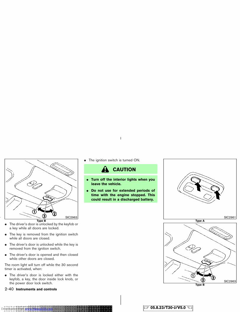
� The driver’s door is unlocked by the keyfob ora key while all doors are locked.
� The key is removed from the ignition switchwhile all doors are closed.
� The driver’s door is unlocked while the key isremoved from the ignition switch.
� The driver’s door is opened and then closedwhile other doors are closed.
The room light will turn off while the 30 secondtimer is activated, when:
� The driver’s door is locked either with thekeyfob, a key, the door inside lock knob, orthe power door lock switch.
� The ignition switch is turned ON.
CAUTION
� Turn off the interior lights when youleave the vehicle.
� Do not use for extended periods oftime with the engine stopped. Thiscould result in a discharged battery.
SIC2963Type B
SIC2961Type A
SIC2963Type B
2-40 Instruments and controls
� 05.8.23/T30-J/V5.0 �Downloaded from www.Manualslib.com manuals search engine
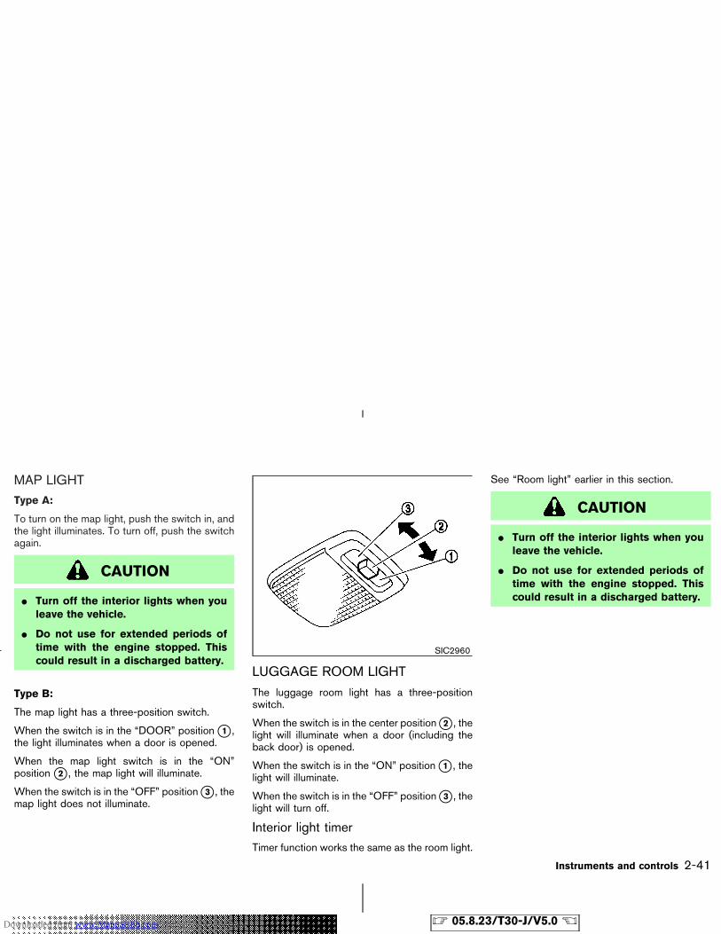
MAP LIGHTType A:
To turn on the map light, push the switch in, andthe light illuminates. To turn off, push the switchagain.
CAUTION
� Turn off the interior lights when youleave the vehicle.
� Do not use for extended periods oftime with the engine stopped. Thiscould result in a discharged battery.
Type B:
The map light has a three-position switch.
When the switch is in the “DOOR” position �1 ,the light illuminates when a door is opened.
When the map light switch is in the “ON”position �2 , the map light will illuminate.
When the switch is in the “OFF” position �3 , themap light does not illuminate.
LUGGAGE ROOM LIGHT
The luggage room light has a three-positionswitch.
When the switch is in the center position �2 , thelight will illuminate when a door (including theback door) is opened.
When the switch is in the “ON” position �1 , thelight will illuminate.
When the switch is in the “OFF” position �3 , thelight will turn off.
Interior light timerTimer function works the same as the room light.
See “Room light” earlier in this section.
CAUTION
� Turn off the interior lights when youleave the vehicle.
� Do not use for extended periods oftime with the engine stopped. Thiscould result in a discharged battery.
SIC2960
Instruments and controls 2-41
� 05.8.23/T30-J/V5.0 �Downloaded from www.Manualslib.com manuals search engine

MEMO
2-42 Instruments and controls
� 05.8.23/T30-J/V5.0 �Downloaded from www.Manualslib.com manuals search engine
3 Pre-driving checks and adjustments
Keys ......................................................................................... 3-2NISSAN Vehicle Immobilizer System keys ............... 3-2
Door locks .............................................................................. 3-3Locking with key ............................................................. 3-3Locking with inside lock knob ..................................... 3-3Locking with power door lock switch ....................... 3-4Child safety rear door lock ........................................... 3-4
Remote keyless entry system ............................................ 3-5How to use remote keyless entry system ................ 3-5Battery replacement ....................................................... 3-6
Hood ........................................................................................ 3-7
Back door ............................................................................... 3-7Fuel-filler door ....................................................................... 3-9
Opening fuel-filler door ................................................. 3-9Fuel-filler cap ................................................................... 3-9
Steering wheel .................................................................... 3-10Tilt operation .................................................................. 3-10
Mirrors ................................................................................... 3-11Inside rearview mirror .................................................. 3-11Outside rearview mirrors ............................................ 3-12Vanity mirror ................................................................... 3-13
� 05.8.23/T30-J/V5.0 �Downloaded from www.Manualslib.com manuals search engine
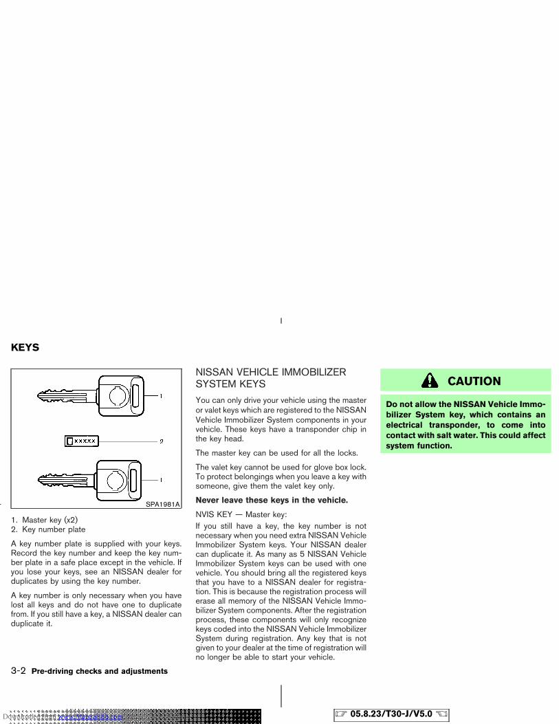
1. Master key (x2)2. Key number plate
A key number plate is supplied with your keys.Record the key number and keep the key num-ber plate in a safe place except in the vehicle. Ifyou lose your keys, see an NISSAN dealer forduplicates by using the key number.
A key number is only necessary when you havelost all keys and do not have one to duplicatefrom. If you still have a key, a NISSAN dealer canduplicate it.
NISSAN VEHICLE IMMOBILIZERSYSTEM KEYS
You can only drive your vehicle using the masteror valet keys which are registered to the NISSANVehicle Immobilizer System components in yourvehicle. These keys have a transponder chip inthe key head.
The master key can be used for all the locks.
The valet key cannot be used for glove box lock.To protect belongings when you leave a key withsomeone, give them the valet key only.
Never leave these keys in the vehicle.
NVIS KEY — Master key:If you still have a key, the key number is notnecessary when you need extra NISSAN VehicleImmobilizer System keys. Your NISSAN dealercan duplicate it. As many as 5 NISSAN VehicleImmobilizer System keys can be used with onevehicle. You should bring all the registered keysthat you have to a NISSAN dealer for registra-tion. This is because the registration process willerase all memory of the NISSAN Vehicle Immo-bilizer System components. After the registrationprocess, these components will only recognizekeys coded into the NISSAN Vehicle ImmobilizerSystem during registration. Any key that is notgiven to your dealer at the time of registration willno longer be able to start your vehicle.
CAUTION
Do not allow the NISSAN Vehicle Immo-bilizer System key, which contains anelectrical transponder, to come intocontact with salt water. This could affectsystem function.
SPA1981A
KEYS
3-2 Pre-driving checks and adjustments
� 05.8.23/T30-J/V5.0 �Downloaded from www.Manualslib.com manuals search engine
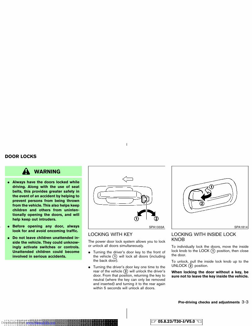
WARNING
� Always have the doors locked whiledriving. Along with the use of seatbelts, this provides greater safety inthe event of an accident by helping toprevent persons from being thrownfrom the vehicle. This also helps keepchildren and others from uninten-tionally opening the doors, and willhelp keep out intruders.
� Before opening any door, alwayslook for and avoid oncoming traffic.
� Do not leave children unattended in-side the vehicle. They could unknow-ingly activate switches or controls.Unattended children could becomeinvolved in serious accidents.
LOCKING WITH KEYThe power door lock system allows you to lockor unlock all doors simultaneously.
� Turning the driver’s door key to the front ofthe vehicle �1 will lock all doors (includingthe back door).
� Turning the driver’s door key one time to therear of the vehicle �2 will unlock the driver’sdoor. From that position, returning the key toneutral (where the key can only be removedand inserted) and turning it to the rear againwithin 5 seconds will unlock all doors.
LOCKING WITH INSIDE LOCKKNOBTo individually lock the doors, move the insidelock knob to the LOCK �1 position, then closethe door.
To unlock, pull the inside lock knob up to theUNLOCK �2 position.
When locking the door without a key, besure not to leave the key inside the vehicle.
SPA1333A SPA1814
DOOR LOCKS
Pre-driving checks and adjustments 3-3
� 05.8.23/T30-J/V5.0 �Downloaded from www.Manualslib.com manuals search engine
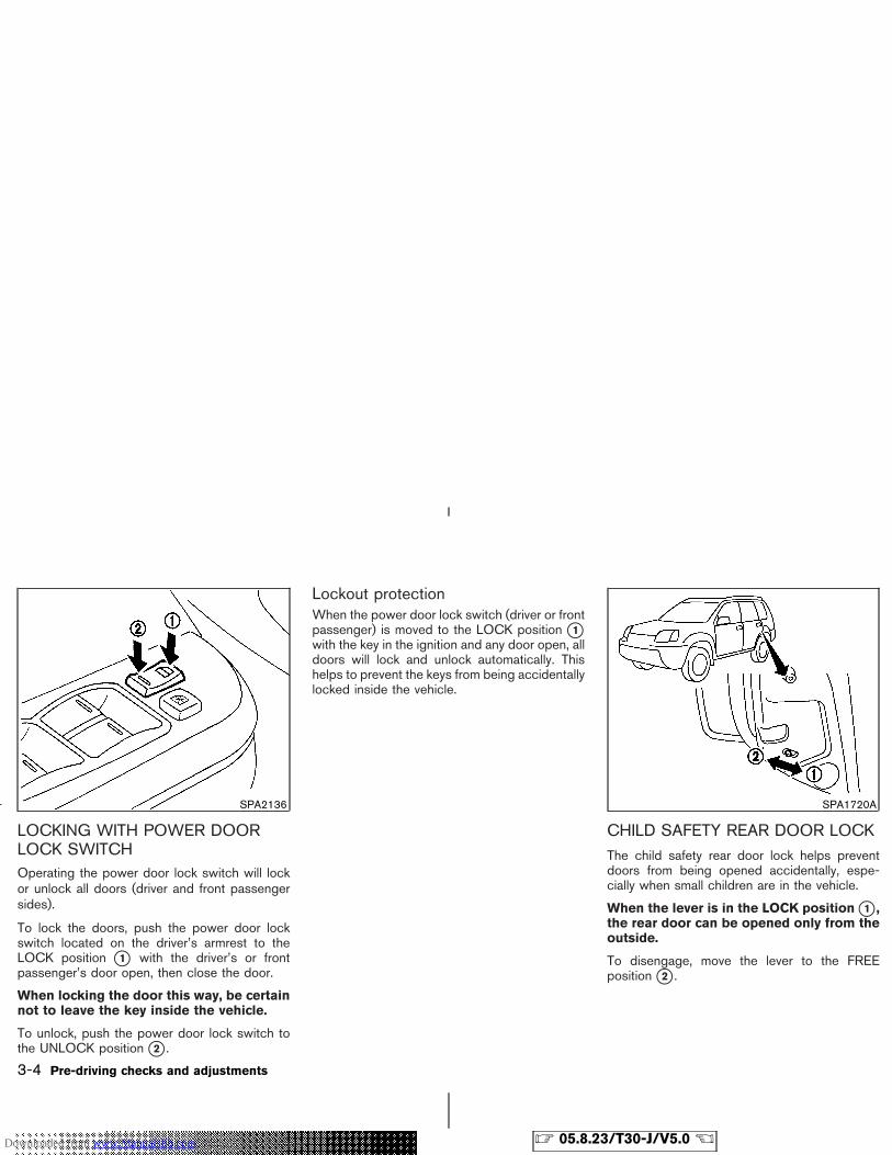
LOCKING WITH POWER DOORLOCK SWITCHOperating the power door lock switch will lockor unlock all doors (driver and front passengersides).
To lock the doors, push the power door lockswitch located on the driver’s armrest to theLOCK position �1 with the driver’s or frontpassenger’s door open, then close the door.
When locking the door this way, be certainnot to leave the key inside the vehicle.
To unlock, push the power door lock switch tothe UNLOCK position �2 .
Lockout protectionWhen the power door lock switch (driver or frontpassenger) is moved to the LOCK position �1with the key in the ignition and any door open, alldoors will lock and unlock automatically. Thishelps to prevent the keys from being accidentallylocked inside the vehicle.
CHILD SAFETY REAR DOOR LOCKThe child safety rear door lock helps preventdoors from being opened accidentally, espe-cially when small children are in the vehicle.
When the lever is in the LOCK position �1 ,the rear door can be opened only from theoutside.
To disengage, move the lever to the FREEposition �2 .
SPA2136 SPA1720A
3-4 Pre-driving checks and adjustments
� 05.8.23/T30-J/V5.0 �Downloaded from www.Manualslib.com manuals search engine
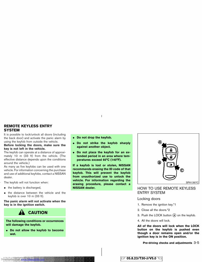
It is possible to lock/unlock all doors (includingthe back door) and activate the panic alarm byusing the keyfob from outside the vehicle.Before locking the doors, make sure thekey is not left in the vehicle.The keyfob can operate at a distance of approxi-mately 10 m (33 ft) from the vehicle. (Theeffective distance depends upon the conditionsaround the vehicle.)As many as five keyfobs can be used with onevehicle. For information concerning the purchaseand use of additional keyfobs, contact a NISSANdealer.
The keyfob will not function when:
� the battery is discharged,
� the distance between the vehicle and thekeyfob is over 10 m (33 ft).
The panic alarm will not activate when thekey is in the ignition switch.
CAUTION
The following conditions or occurrenceswill damage the keyfob.
� Do not allow the keyfob to becomewet.
� Do not drop the keyfob.
� Do not strike the keyfob sharplyagainst another object.
� Do not place the keyfob for an ex-tended period in an area where tem-peratures exceed 60°C (140°F).
If a keyfob is lost or stolen, NISSANrecommends erasing the ID code of thatkeyfob. This will prevent the keyfobfrom unauthorized use to unlock thevehicle. For information regarding theerasing procedure, please contact aNISSAN dealer. HOW TO USE REMOTE KEYLESS
ENTRY SYSTEM
Locking doors
1. Remove the ignition key.*1
2. Close all the doors.*2
3. Push the LOCK button �A on the keyfob.
4. All the doors will lock.
All of the doors will lock when the LOCKbutton on the keyfob is pushed eventhough a door remains open and/or theignition key is in the ON position.
SPA1397C
REMOTE KEYLESS ENTRYSYSTEM
Pre-driving checks and adjustments 3-5
� 05.8.23/T30-J/V5.0 �Downloaded from www.Manualslib.com manuals search engine
5. The hazard indicator flashes twice.
� When the LOCK button is pushed with alldoors locked, the hazard indicator flashestwice as a reminder that the doors are alreadylocked.
*1: Doors lock with the keyfob while a key is inthe ignition switch. However, the panicalarm will not activate when the key is in theignition switch.
*2: Doors lock with the keyfob while any door isopen. However, hazard indicator and hornmode will not function.
Unlocking doors1. Push the UNLOCK button �B on the keyfob
once.
� The driver’s door unlocks
� The hazard indicator flashes once if all doorsare completely closed with the ignition key inany position except the ON position.
� The interior light turns on and the light timeractivates for 30 seconds when the switch isin the DOOR or center � position with theignition key in any position except the ONposition.
2. Push the UNLOCK button �B on the keyfobagain within 5 seconds.
� All doors unlock
� The hazard indicator flashes once if all doorsare completely closed.
If the following operation is not carried outwithin 5 minutes after pressing theUNLOCK button, all doors will be lockedautomatically.
� any door is opened.
� the ignition key is turned to the ONposition
The interior light can be turned off withoutwaiting for 30 seconds by turning the ignitionswitch to the ON position or by locking thedoors with the keyfob.
Using the panic alarm
If you are near your vehicle and feel threatened,you may activate the alarm to call attention asfollows:
1. Push the PANIC button �C on the keyfob forlonger than 0.5 seconds.
2. The theft warning alarm and headlights willstay on for 30 seconds.
3. The panic alarm stops when:
� It has run for 30 seconds, or
� The LOCK or the UNLOCK button ispressed, or
� The PANIC button is pushed on the keyfobfor more than 0.5 seconds.
BATTERY REPLACEMENTSee the “8. Maintenance and do-it-yourself”section for battery replacement.
3-6 Pre-driving checks and adjustments
� 05.8.23/T30-J/V5.0 �Downloaded from www.Manualslib.com manuals search engine
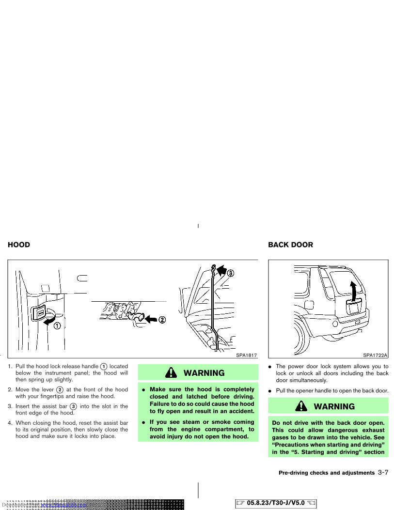
1. Pull the hood lock release handle �1 locatedbelow the instrument panel; the hood willthen spring up slightly.
2. Move the lever �2 at the front of the hoodwith your fingertips and raise the hood.
3. Insert the assist bar �3 into the slot in thefront edge of the hood.
4. When closing the hood, reset the assist barto its original position, then slowly close thehood and make sure it locks into place.
WARNING
� Make sure the hood is completelyclosed and latched before driving.Failure to do so could cause the hoodto fly open and result in an accident.
� If you see steam or smoke comingfrom the engine compartment, toavoid injury do not open the hood.
� The power door lock system allows you tolock or unlock all doors including the backdoor simultaneously.
� Pull the opener handle to open the back door.
WARNING
Do not drive with the back door open.This could allow dangerous exhaustgases to be drawn into the vehicle. See“Precautions when starting and driving”in the “5. Starting and driving” section
SPA1817 SPA1722A
HOOD BACK DOOR
Pre-driving checks and adjustments 3-7
� 05.8.23/T30-J/V5.0 �Downloaded from www.Manualslib.com manuals search engine
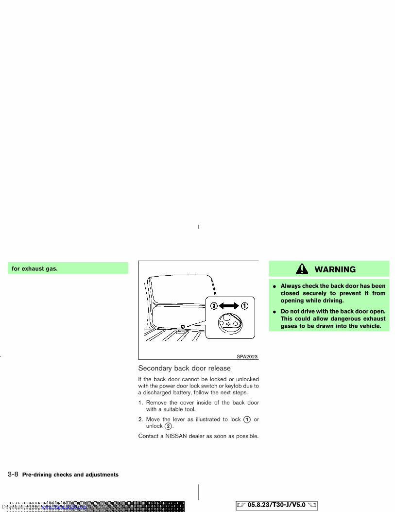
for exhaust gas.
Secondary back door releaseIf the back door cannot be locked or unlockedwith the power door lock switch or keyfob due toa discharged battery, follow the next steps.
1. Remove the cover inside of the back doorwith a suitable tool.
2. Move the lever as illustrated to lock �1 orunlock �2 .
Contact a NISSAN dealer as soon as possible.
WARNING
� Always check the back door has beenclosed securely to prevent it fromopening while driving.
� Do not drive with the back door open.This could allow dangerous exhaustgases to be drawn into the vehicle.
SPA2023
3-8 Pre-driving checks and adjustments
� 05.8.23/T30-J/V5.0 �Downloaded from www.Manualslib.com manuals search engine
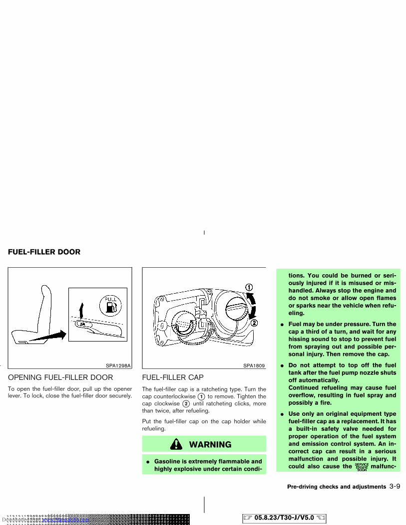
OPENING FUEL-FILLER DOORTo open the fuel-filler door, pull up the openerlever. To lock, close the fuel-filler door securely.
FUEL-FILLER CAP
The fuel-filler cap is a ratcheting type. Turn thecap counterlockwise �1 to remove. Tighten thecap clockwise �2 until ratcheting clicks, morethan twice, after refueling.
Put the fuel-filler cap on the cap holder whilerefueling.
WARNING
� Gasoline is extremely flammable andhighly explosive under certain condi-
tions. You could be burned or seri-ously injured if it is misused or mis-handled. Always stop the engine anddo not smoke or allow open flamesor sparks near the vehicle when refu-eling.
� Fuel may be under pressure. Turn thecap a third of a turn, and wait for anyhissing sound to stop to prevent fuelfrom spraying out and possible per-sonal injury. Then remove the cap.
� Do not attempt to top off the fueltank after the fuel pump nozzle shutsoff automatically.Continued refueling may cause fueloverflow, resulting in fuel spray andpossibly a fire.
� Use only an original equipment typefuel-filler cap as a replacement. It hasa built-in safety valve needed forproper operation of the fuel systemand emission control system. An in-correct cap can result in a seriousmalfunction and possible injury. Itcould also cause the malfunc-
SPA1298A SPA1809
FUEL-FILLER DOOR
Pre-driving checks and adjustments 3-9
� 05.8.23/T30-J/V5.0 �Downloaded from www.Manualslib.com manuals search engine
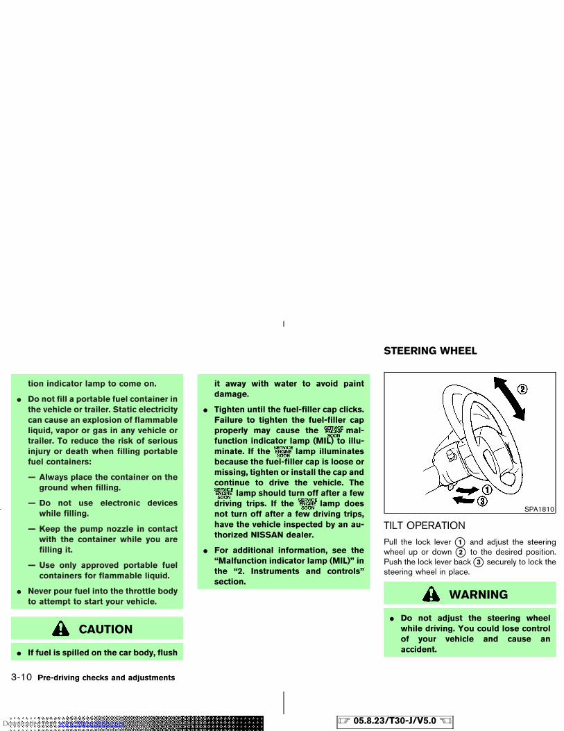
tion indicator lamp to come on.
� Do not fill a portable fuel container inthe vehicle or trailer. Static electricitycan cause an explosion of flammableliquid, vapor or gas in any vehicle ortrailer. To reduce the risk of seriousinjury or death when filling portablefuel containers:
— Always place the container on theground when filling.
— Do not use electronic deviceswhile filling.
— Keep the pump nozzle in contactwith the container while you arefilling it.
— Use only approved portable fuelcontainers for flammable liquid.
� Never pour fuel into the throttle bodyto attempt to start your vehicle.
CAUTION
� If fuel is spilled on the car body, flush
it away with water to avoid paintdamage.
� Tighten until the fuel-filler cap clicks.Failure to tighten the fuel-filler capproperly may cause the mal-function indicator lamp (MIL) to illu-minate. If the lamp illuminatesbecause the fuel-filler cap is loose ormissing, tighten or install the cap andcontinue to drive the vehicle. The
lamp should turn off after a fewdriving trips. If the lamp doesnot turn off after a few driving trips,have the vehicle inspected by an au-thorized NISSAN dealer.
� For additional information, see the“Malfunction indicator lamp (MIL)” inthe “2. Instruments and controls”section.
TILT OPERATION
Pull the lock lever �1 and adjust the steeringwheel up or down �2 to the desired position.Push the lock lever back �3 securely to lock thesteering wheel in place.
WARNING
� Do not adjust the steering wheelwhile driving. You could lose controlof your vehicle and cause anaccident.
SPA1810
STEERING WHEEL
3-10 Pre-driving checks and adjustments
� 05.8.23/T30-J/V5.0 �Downloaded from www.Manualslib.com manuals search engine
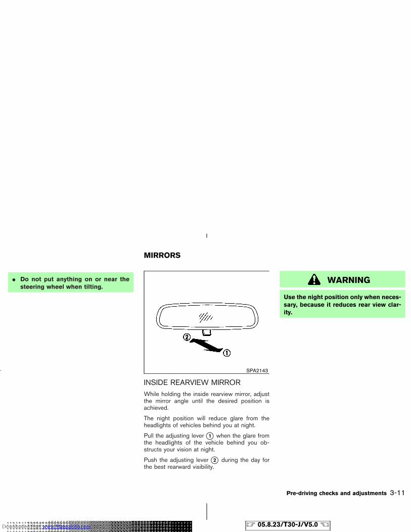
� Do not put anything on or near thesteering wheel when tilting.
INSIDE REARVIEW MIRRORWhile holding the inside rearview mirror, adjustthe mirror angle until the desired position isachieved.
The night position will reduce glare from theheadlights of vehicles behind you at night.
Pull the adjusting lever �1 when the glare fromthe headlights of the vehicle behind you ob-structs your vision at night.
Push the adjusting lever �2 during the day forthe best rearward visibility.
WARNING
Use the night position only when neces-sary, because it reduces rear view clar-ity.
SPA2143
MIRRORS
Pre-driving checks and adjustments 3-11
� 05.8.23/T30-J/V5.0 �Downloaded from www.Manualslib.com manuals search engine
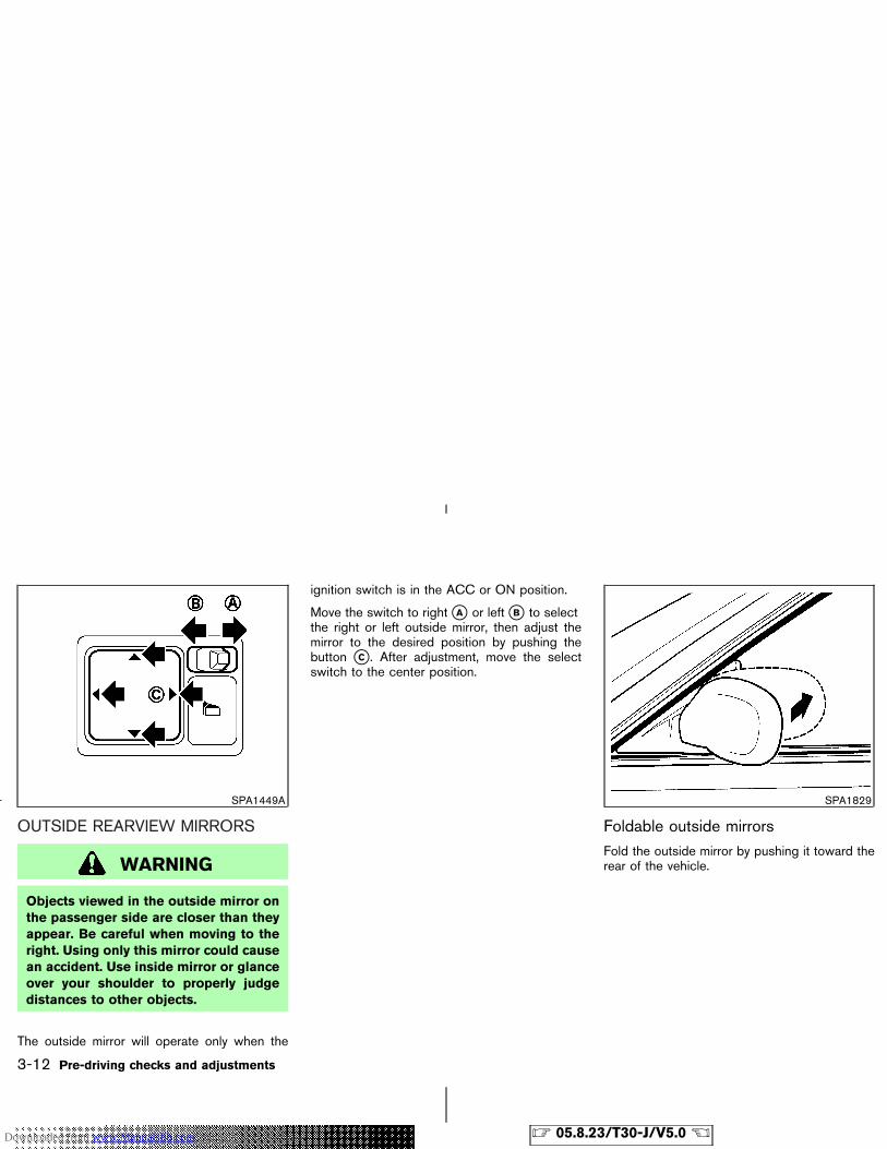
OUTSIDE REARVIEW MIRRORS
WARNING
Objects viewed in the outside mirror onthe passenger side are closer than theyappear. Be careful when moving to theright. Using only this mirror could causean accident. Use inside mirror or glanceover your shoulder to properly judgedistances to other objects.
The outside mirror will operate only when the
ignition switch is in the ACC or ON position.
Move the switch to right �A or left �B to selectthe right or left outside mirror, then adjust themirror to the desired position by pushing thebutton �C . After adjustment, move the selectswitch to the center position.
Foldable outside mirrorsFold the outside mirror by pushing it toward therear of the vehicle.
SPA1449A SPA1829
3-12 Pre-driving checks and adjustments
� 05.8.23/T30-J/V5.0 �Downloaded from www.Manualslib.com manuals search engine
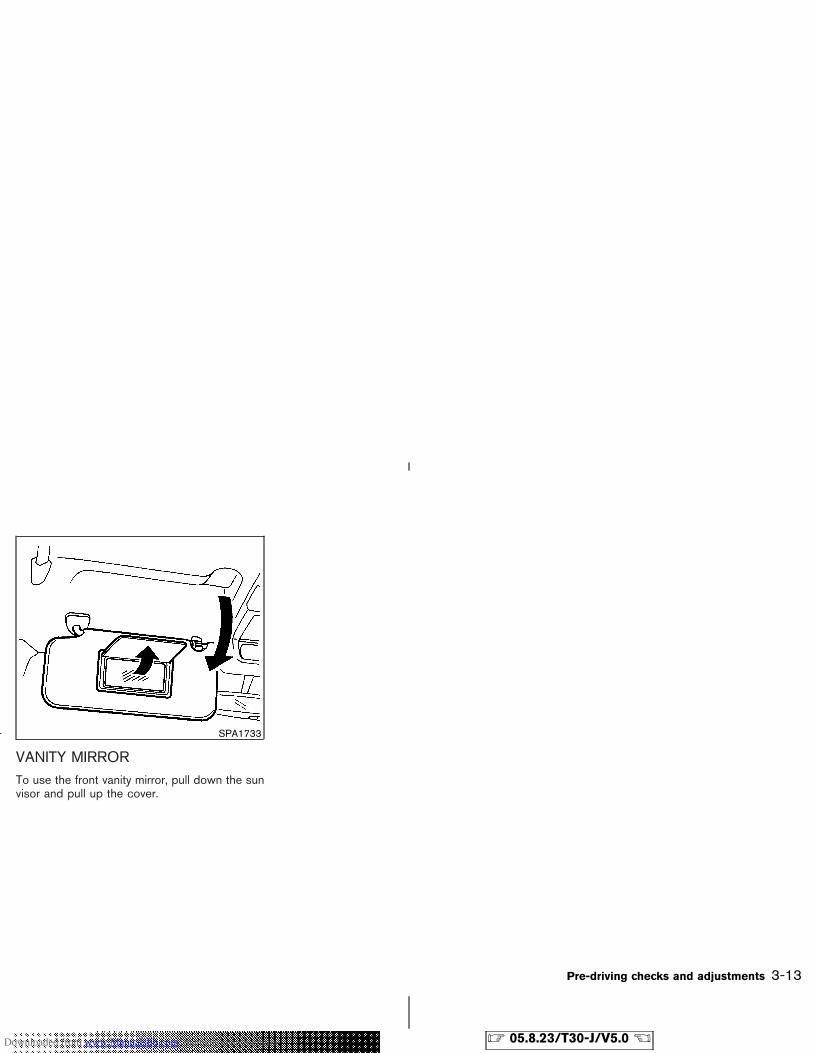
VANITY MIRRORTo use the front vanity mirror, pull down the sunvisor and pull up the cover.
SPA1733
Pre-driving checks and adjustments 3-13
� 05.8.23/T30-J/V5.0 �Downloaded from www.Manualslib.com manuals search engine

MEMO
3-14 Pre-driving checks and adjustments
� 05.8.23/T30-J/V5.0 �Downloaded from www.Manualslib.com manuals search engine
4 Heater, air conditioner and audio systems
Safety note .............................................................................. 4-2Control panel buttons — with navigation system.......... 4-2
Names of the components ............................................ 4-2How to use JOYSTICK and “ENTER” button .......... 4-3How to use “PREVIOUS” button................................. 4-3Setting up the start-up screen ..................................... 4-3How to use the “INFO” button..................................... 4-3How to use the “SETTING” button............................. 4-5How to use the “ ” button.................................... 4-7
Ventilators ............................................................................... 4-7Heater and air conditioner ................................................. 4-8
Manual type ...................................................................... 4-8
Automatic type .............................................................. 4-11Servicing air conditioner .................................................. 4-14Audio system ....................................................................... 4-14
Audio operation precautions ..................................... 4-14Antenna ........................................................................... 4-16FM-AM radio with cassette player and compactdisc (CD) changer ....................................................... 4-19FM-AM radio with compact disc (CD) player ...... 4-25FM-AM radio with compact disc (CD) player ...... 4-29CD care and cleaning ................................................. 4-32
Car phone or CB radio .................................................... 4-32
� 05.8.23/T30-J/V5.0 �Downloaded from www.Manualslib.com manuals search engine
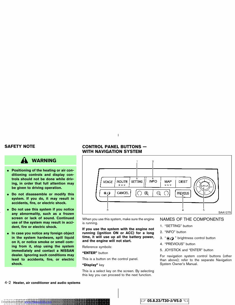
WARNING
� Positioning of the heating or air con-ditioning controls and display con-trols should not be done while driv-ing, in order that full attention maybe given to driving operation.
� Do not disassemble or modify thissystem. If you do, it may result inaccidents, fire, or electric shock.
� Do not use this system if you noticeany abnormality, such as a frozenscreen or lack of sound. Continueduse of the system may result in acci-dent, fire or electric shock.
� In case you notice any foreign objectin the system hardware, spill liquidon it, or notice smoke or smell com-ing from it, stop using the systemimmediately and contact a NISSANdealer. Ignoring such conditions maylead to accidents, fire, or electricshock.
When you use this system, make sure the engineis running.
If you use the system with the engine notrunning (ignition ON or ACC) for a longtime, it will use up all the battery power,and the engine will not start.
Reference symbols:
“ENTER” button
This is a button on the control panel.
“Display” key
This is a select key on the screen. By selectingthis key you can proceed to the next function.
NAMES OF THE COMPONENTS1. “SETTING” button
2. “INFO” button
3. “ ” brightness control button
4. “PREVIOUS” button
5. JOYSTICK and “ENTER” button
For navigation system control buttons (otherthan above); refer to the separate NavigationSystem Owner’s Manual.
SAA1275
SAFETY NOTE CONTROL PANEL BUTTONS —WITH NAVIGATION SYSTEM
4-2 Heater, air conditioner and audio systems
� 05.8.23/T30-J/V5.0 �Downloaded from www.Manualslib.com manuals search engine
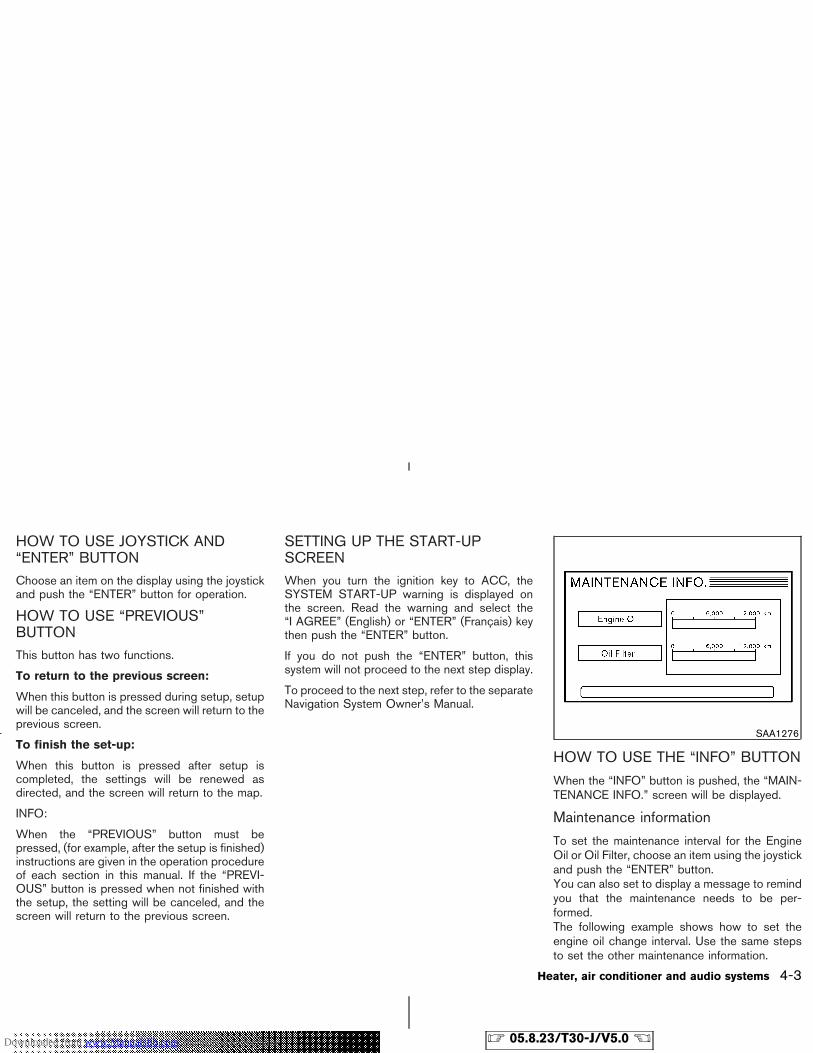
HOW TO USE JOYSTICK AND“ENTER” BUTTONChoose an item on the display using the joystickand push the “ENTER” button for operation.
HOW TO USE “PREVIOUS”BUTTONThis button has two functions.
To return to the previous screen:
When this button is pressed during setup, setupwill be canceled, and the screen will return to theprevious screen.
To finish the set-up:
When this button is pressed after setup iscompleted, the settings will be renewed asdirected, and the screen will return to the map.
INFO:
When the “PREVIOUS” button must bepressed, (for example, after the setup is finished)instructions are given in the operation procedureof each section in this manual. If the “PREVI-OUS” button is pressed when not finished withthe setup, the setting will be canceled, and thescreen will return to the previous screen.
SETTING UP THE START-UPSCREENWhen you turn the ignition key to ACC, theSYSTEM START-UP warning is displayed onthe screen. Read the warning and select the“I AGREE” (English) or “ENTER” (Francais) keythen push the “ENTER” button.
If you do not push the “ENTER” button, thissystem will not proceed to the next step display.
To proceed to the next step, refer to the separateNavigation System Owner’s Manual.
HOW TO USE THE “INFO” BUTTON
When the “INFO” button is pushed, the “MAIN-TENANCE INFO.” screen will be displayed.
Maintenance information
To set the maintenance interval for the EngineOil or Oil Filter, choose an item using the joystickand push the “ENTER” button.You can also set to display a message to remindyou that the maintenance needs to be per-formed.The following example shows how to set theengine oil change interval. Use the same stepsto set the other maintenance information.
SAA1276
Heater, air conditioner and audio systems 4-3
� 05.8.23/T30-J/V5.0 �Downloaded from www.Manualslib.com manuals search engine
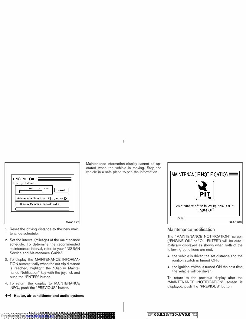
1. Reset the driving distance to the new main-tenance schedule.
2. Set the interval (mileage) of the maintenanceschedule. To determine the recommendedmaintenance interval, refer to your “NISSANService and Maintenance Guide”.
3. To display the MAINTENANCE INFORMA-TION automatically when the set trip distanceis reached, highlight the “Display Mainte-nance Notification” key with the joystick andpush the “ENTER” button.
4. To return the display to MAINTENANCEINFO., push the “PREVIOUS” button.
Maintenance information display cannot be op-erated when the vehicle is moving. Stop thevehicle in a safe place to see the information.
Maintenance notification
The “MAINTENANCE NOTIFICATION” screen(“ENGINE OIL” or “OIL FILTER”) will be auto-matically displayed as shown when both of thefollowing conditions are met:
� the vehicle is driven the set distance and theignition switch is turned OFF.
� the ignition switch is turned ON the next timethe vehicle will be driven.
To return to the previous display after the“MAINTENANCE NOTIFICATION” screen isdisplayed, push the “PREVIOUS” button.
SAA1277 SAA0968
4-4 Heater, air conditioner and audio systems
� 05.8.23/T30-J/V5.0 �Downloaded from www.Manualslib.com manuals search engine
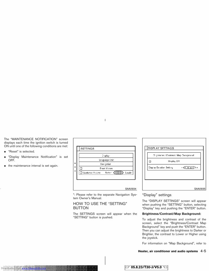
The “MAINTENANCE NOTIFICATION” screendisplays each time the ignition switch is turnedON until one of the following conditions are met:
� “Reset” is selected.
� “Display Maintenance Notification” is setOFF.
� the maintenance interval is set again.
*: Please refer to the separate Navigation Sys-tem Owner’s Manual.
HOW TO USE THE “SETTING”BUTTONThe SETTINGS screen will appear when the“SETTING” button is pushed.
“Display” settings
The “DISPLAY SETTINGS” screen will appearwhen pushing the “SETTING” button, selecting“Display” key and pushing the “ENTER” button.
Brightness/Contrast/Map Background:
To adjust the brightness and contrast of thescreen, select the “Brightness/Contrast MapBackground” key and push the “ENTER” button.Then you can adjust the brightness to Darker orBrighter, the contrast to Lower or Higher usingthe joystick.
For information on “Map Background”, refer to
SAA0934 SAA0935
Heater, air conditioner and audio systems 4-5
� 05.8.23/T30-J/V5.0 �Downloaded from www.Manualslib.com manuals search engine
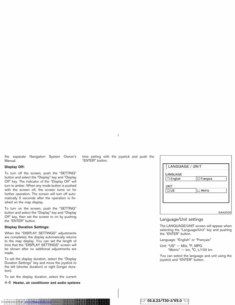
the separate Navigation System Owner’sManual.
Display Off:
To turn off the screen, push the “SETTING”button and select the “Display” key and “DisplayOff” key. The indicator of the “Display Off” willturn to amber. When any mode button is pushedwith the screen off, the screen turns on forfurther operation. The screen will turn off auto-matically 5 seconds after the operation is fin-ished on the map display.
To turn on the screen, push the “SETTING”button and select the “Display” key and “DisplayOff” key, then set the screen to on by pushingthe “ENTER” button.
Display Duration Settings:
When the “DISPLAY SETTINGS” adjustmentsare completed, the display automatically returnsto the map display. You can set the length oftime that the “DISPLAY SETTINGS” screen willbe shown after no additional adjustments aremade.
To set the display duration, select the “DisplayDuration Settings” key and move the joystick tothe left (shorter duration) or right (longer dura-tion).
To set the display duration, select the current
time setting with the joystick and push the“ENTER” button.
Language/Unit settingsThe LANGUAGE/UNIT screen will appear whenselecting the “Language/Unit” key and pushingthe “ENTER” button.
Language: “English” or “Français”
Unit: “US” — Mile, °F, MPG“Metric” — km, °C, L/100 km
You can select the language and unit using thejoystick and “ENTER” button.
SAA0506
4-6 Heater, air conditioner and audio systems
� 05.8.23/T30-J/V5.0 �Downloaded from www.Manualslib.com manuals search engine
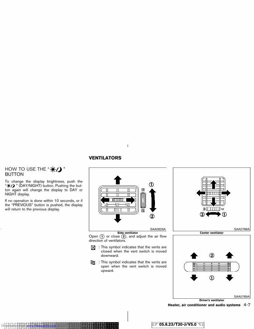
HOW TO USE THE “ ”BUTTONTo change the display brightness, push the“ ” (DAY/NIGHT) button. Pushing the but-ton again will change the display to DAY orNIGHT display.
If no operation is done within 10 seconds, or ifthe “PREVIOUS” button is pushed, the displaywill return to the previous display.
Open �1 or close �2 , and adjust the air flowdirection of ventilators.
: This symbol indicates that the vents areclosed when the vent switch is moveddownward.
: This symbol indicates that the vents areopen when the vent switch is movedupward.
SAA0829ASide ventilator
SAA0788ACenter ventilator
SAA0789ADriver’s ventilator
VENTILATORS
Heater, air conditioner and audio systems 4-7
� 05.8.23/T30-J/V5.0 �Downloaded from www.Manualslib.com manuals search engine
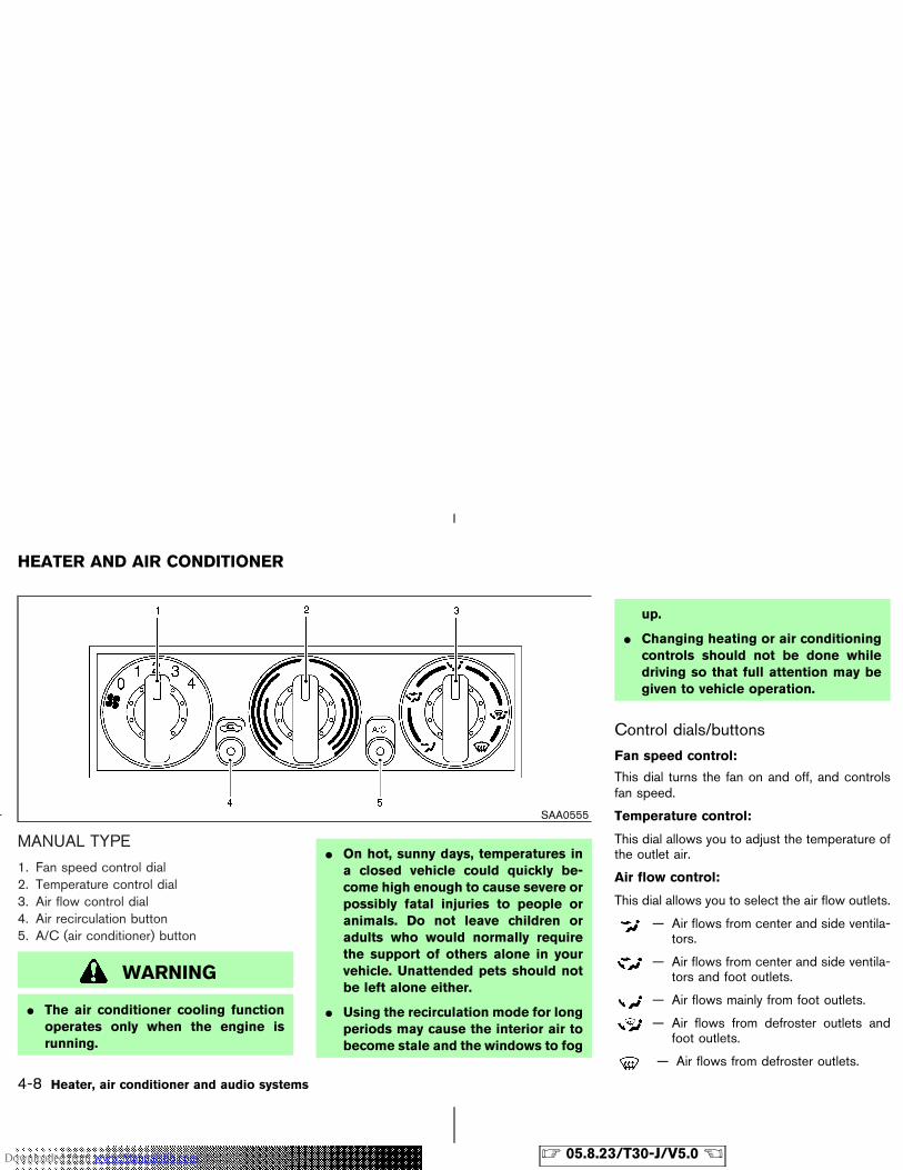
MANUAL TYPE
1. Fan speed control dial2. Temperature control dial3. Air flow control dial4. Air recirculation button5. A/C (air conditioner) button
WARNING
� The air conditioner cooling functionoperates only when the engine isrunning.
� On hot, sunny days, temperatures ina closed vehicle could quickly be-come high enough to cause severe orpossibly fatal injuries to people oranimals. Do not leave children oradults who would normally requirethe support of others alone in yourvehicle. Unattended pets should notbe left alone either.
� Using the recirculation mode for longperiods may cause the interior air tobecome stale and the windows to fog
up.
� Changing heating or air conditioningcontrols should not be done whiledriving so that full attention may begiven to vehicle operation.
Control dials/buttons
Fan speed control:
This dial turns the fan on and off, and controlsfan speed.
Temperature control:
This dial allows you to adjust the temperature ofthe outlet air.
Air flow control:
This dial allows you to select the air flow outlets.
— Air flows from center and side ventila-tors.
— Air flows from center and side ventila-tors and foot outlets.
— Air flows mainly from foot outlets.
— Air flows from defroster outlets andfoot outlets.
— Air flows from defroster outlets.
SAA0555
HEATER AND AIR CONDITIONER
4-8 Heater, air conditioner and audio systems
� 05.8.23/T30-J/V5.0 �Downloaded from www.Manualslib.com manuals search engine
Air recirculation button:
Off position:
Outside air is drawn into the passenger com-partment.
Use the off position for normal heater, or airconditioner operation.
If dust is not raised in front of the vehicle, thisposition is effective to prevent dust entry.
On position (Indicator light on):
Interior air is recirculated inside the vehicle.
Push the air recirculation button to the on posi-tion when driving on a dust raised road or toavoid traffic fumes.
Air conditioner button:
Start the engine, move the fan speed control dialto the desired (1 to 4) position and push the airconditioner button to turn on the air conditioner.The indicator light will come on when the airconditioner button is on. To stop the air condi-tioner, push the switch again to return it to theoriginal position.
The air conditioner cooling function oper-ates only when the engine is running.
Heater operation
Heating:
This mode is used to direct hot air from the flooroutlets.
1. Push the air recirculation button to the OFFposition for normal heating.
2. Turn the air control dial to the position.
3. Turn on the fan speed control dial.
4. Turn the temperature control dial to the de-sired position between the middle and thehot position.
� For quick heating, move the air recirculationbutton to the ON position. Be sure to returnthe air recirculation button to the OFF posi-tion for normal heating.
Ventilation:
This mode directs outside air from the side andcenter vents.
1. Push the air recirculation button to the OFFposition.
2. Turn the air control dial to the position.
3. Turn on the fan speed control dial.
4. Turn the temperature control dial to the de-sired position.
Defrosting or defogging:
This mode is used to defrost/defog the windows.
1. Push the air recirculation button to the OFFposition.
2. Turn the air control dial to the position.
3. Turn on the fan speed control dial.
4. Turn the temperature control dial to the de-sired position between the middle and thehot position.
� To quickly remove ice from the windows,push the air recirculation button to the ONposition, the fan speed control dial to 4 andthe temperature control dial to the full hotposition. As soon as possible after the win-dow is clear, push the air recirculation buttonto the off position.
Bi-level heating:
This mode directs outside air from the side andcenter vents and hot air from the floor outlets.
1. Push the air recirculation button to the OFFposition.
2. Turn the air control dial to the position.
3. Turn on the fan speed control dial.
4. Normally turn the temperature control dial tothe midpoint between hot and cold.
Heater, air conditioner and audio systems 4-9
� 05.8.23/T30-J/V5.0 �Downloaded from www.Manualslib.com manuals search engine
Heating and defogging:
This mode heats the interior and defogs thewindshield.
1. Push the air recirculation button to the OFFposition.
2. Turn the air control dial to the position.
3. Turn on the fan speed control dial.
4. Turn the temperature control dial to the de-sired position between the middle and thehot position.
Operating tips:
Clear snow and ice from the wiper bladeand air inlet in front of the windshield. Thiswill improve heater operation.
Air conditioner operationStart the engine, move the fan speed control dialto the desired (1 to 4) position and push in theair conditioner button to activate the air condi-tioner. When the air conditioner is on, coolingand dehumidifying functions will be added to theheater operation.
The air conditioner cooling function oper-ates only when the engine is running.
Cooling:
This mode is used to cool and dehumidify.
1. Push the air recirculation button to the OFFposition.
2. Turn the air control dial to the position.
3. Turn on the fan speed control dial.
4. Push on the air conditioner button. The indi-cator light will come on.
5. Turn the temperature control dial to the de-sired position.
� For quick cooling when the outside tempera-ture is high, push the air recirculation buttonto the ON position. Be sure to return the airrecirculation button to the OFF position fornormal cooling.
Dehumidified heating:
This mode is used to heat and dehumidify.
1. Push the air recirculation button to the OFFposition.
2. Turn the air control dial to the position.
3. Turn on the fan speed control dial.
4. Push on the air conditioner button. The indi-cator light will come on.
5. Turn the temperature control dial to the de-sired position.
Dehumidified defogging:
This mode is used to defog the windows anddehumidify.
1. Push the air recirculation button to the OFFposition.
2. Turn the air control dial to the position.
3. Turn on the fan speed control dial.
4. Push on the air conditioner button. The indi-cator light will come on.
5. Turn the temperature control dial to the de-sired position.
Operating tips:
� Keep windows closed while the air condi-tioner is in operation.
� After parking in the sun, drive for two or threeminutes with the windows open to vent hot airfrom the passenger compartment. Then,close the windows. This will allow the airconditioner to cool the interior more quickly.
� The air conditioning system should beoperated for about ten minutes at leastonce a month. This helps prevent dam-age to the system due to lack of lubri-cation.
� If the coolant temperature gauge exceeds the
4-10 Heater, air conditioner and audio systems
� 05.8.23/T30-J/V5.0 �Downloaded from www.Manualslib.com manuals search engine
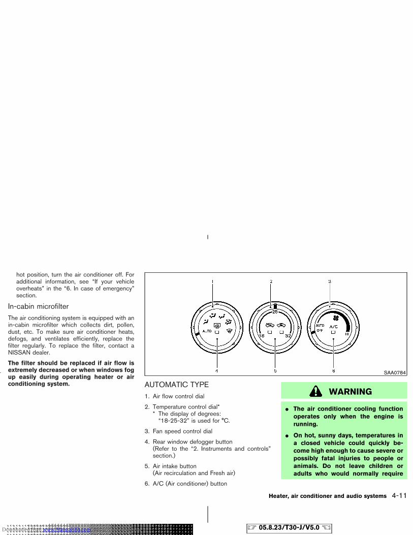
hot position, turn the air conditioner off. Foradditional information, see “If your vehicleoverheats” in the “6. In case of emergency”section.
In-cabin microfilterThe air conditioning system is equipped with anin-cabin microfilter which collects dirt, pollen,dust, etc. To make sure air conditioner heats,defogs, and ventilates efficiently, replace thefilter regularly. To replace the filter, contact aNISSAN dealer.
The filter should be replaced if air flow isextremely decreased or when windows fogup easily during operating heater or airconditioning system. AUTOMATIC TYPE
1. Air flow control dial
2. Temperature control dial** The display of degrees:“18-25-32” is used for °C.
3. Fan speed control dial
4. Rear window defogger button(Refer to the “2. Instruments and controls”section.)
5. Air intake button(Air recirculation and Fresh air)
6. A/C (Air conditioner) button
WARNING
� The air conditioner cooling functionoperates only when the engine isrunning.
� On hot, sunny days, temperatures ina closed vehicle could quickly be-come high enough to cause severe orpossibly fatal injuries to people oranimals. Do not leave children oradults who would normally require
SAA0784
Heater, air conditioner and audio systems 4-11
� 05.8.23/T30-J/V5.0 �Downloaded from www.Manualslib.com manuals search engine
the support of others alone in yourvehicle. Unattended pets should notbe left alone either.
� Using the recirculation mode for longperiods may cause the interior air tobecome stale and the windows to fogup.
� Changing heating or air conditioningcontrols should not be done whiledriving so that full attention may begiven to vehicle operation.
Automatic operation (AUTO)
Start the engine and operate the controls toactivate the air conditioner.
Cooling and/or dehumidified heating:
This mode may be normally used all year roundas the system automatically works to keep aconstant temperature. Air flow distribution andfan speed are also controlled automatically.
1. Turn the fan speed control dial and air flowcontrol dial to the AUTO position.Then push the A/C button on. (The indicatorlight will come on.)
2. Turn the temperature control dial to set thedesired temperature.
� Adjust the temperature set dial to about 24°C(75°F) for normal operation.
� The temperature of the passenger compart-ment will be maintained automatically. Airflow distribution and fan speed are also con-trolled automatically.
Heating (A/C OFF):
The air conditioner does not activate. When youneed to heat only, use this mode.
1. Turn the fan speed control dial and air flowcontrol dial to the AUTO position.Then push the A/C button off. (The A/Cbutton indicator light will go off.)
2. Turn the temperature control dial to set thedesired temperature.
� The temperature of the passenger compart-ment will be maintained automatically. Airflow distribution and fan speed are also con-trolled automatically.
� Do not set the temperature lower than theoutside air temperature. Otherwise the sys-tem may not work properly.
� Not recommended if windows fog up.
Dehumidified defrosting or defogging:
1. Turn the fan speed control dial to the desiredposition.
2. Turn the air flow control dial to the(DEF) position.
3. Turn the temperature control dial to set thedesired temperature.
� To quickly remove ice from the outside of thewindows, turn the fan speed control dial tothe maximum position.
� As soon as possible after the windshield isclean, turn the air flow control dial to theAUTO position to return to the auto mode.
� When the air flow control dial is turned to theor position, the air conditioner
will automatically be turned on at outsidetemperatures above −5°C (23°F) to defogthe windshield, and the air recirculation modewill automatically be turned off.
Outside air is drawn into the passengercompartment to improve the defogging per-formance.
Manual operationFan speed control:
Turn the fan speed control dial to manuallycontrol the fan speed.
4-12 Heater, air conditioner and audio systems
� 05.8.23/T30-J/V5.0 �Downloaded from www.Manualslib.com manuals search engine
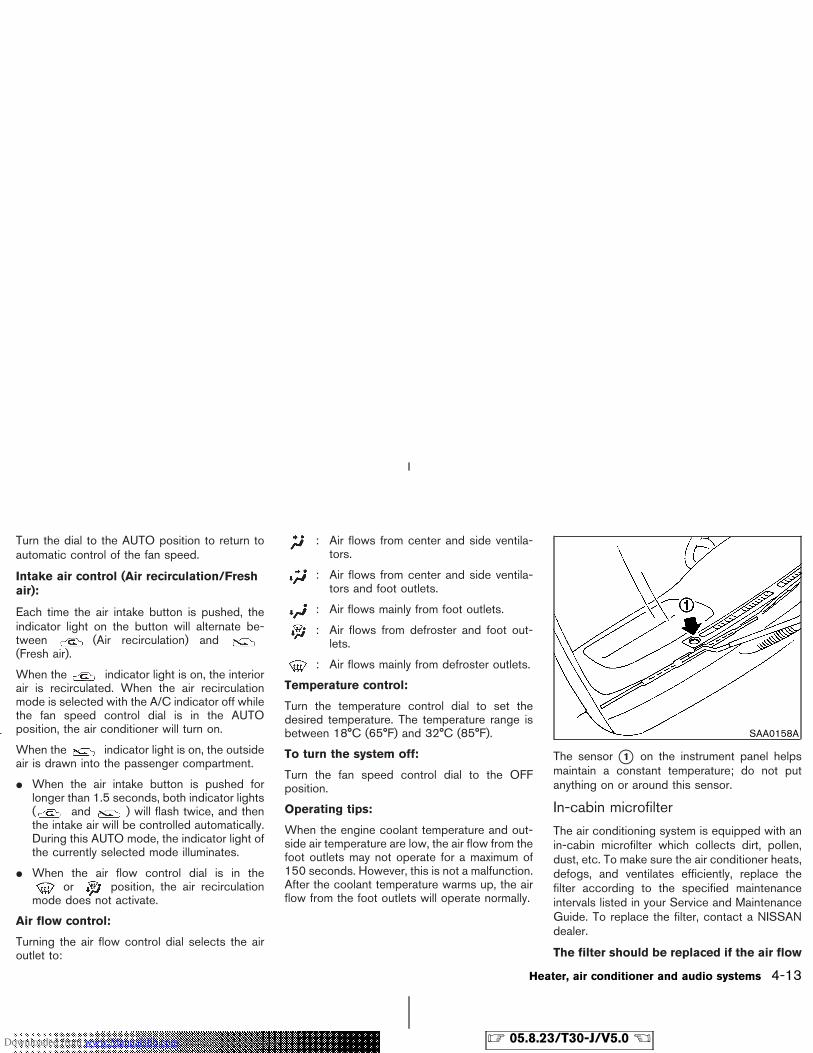
Turn the dial to the AUTO position to return toautomatic control of the fan speed.
Intake air control (Air recirculation/Freshair):
Each time the air intake button is pushed, theindicator light on the button will alternate be-tween (Air recirculation) and(Fresh air).
When the indicator light is on, the interiorair is recirculated. When the air recirculationmode is selected with the A/C indicator off whilethe fan speed control dial is in the AUTOposition, the air conditioner will turn on.
When the indicator light is on, the outsideair is drawn into the passenger compartment.
� When the air intake button is pushed forlonger than 1.5 seconds, both indicator lights( and ) will flash twice, and thenthe intake air will be controlled automatically.During this AUTO mode, the indicator light ofthe currently selected mode illuminates.
� When the air flow control dial is in theor position, the air recirculation
mode does not activate.
Air flow control:
Turning the air flow control dial selects the airoutlet to:
: Air flows from center and side ventila-tors.
: Air flows from center and side ventila-tors and foot outlets.
: Air flows mainly from foot outlets.
: Air flows from defroster and foot out-lets.
: Air flows mainly from defroster outlets.
Temperature control:
Turn the temperature control dial to set thedesired temperature. The temperature range isbetween 18°C (65°F) and 32°C (85°F).
To turn the system off:
Turn the fan speed control dial to the OFFposition.
Operating tips:
When the engine coolant temperature and out-side air temperature are low, the air flow from thefoot outlets may not operate for a maximum of150 seconds. However, this is not a malfunction.After the coolant temperature warms up, the airflow from the foot outlets will operate normally.
The sensor �1 on the instrument panel helpsmaintain a constant temperature; do not putanything on or around this sensor.
In-cabin microfilter
The air conditioning system is equipped with anin-cabin microfilter which collects dirt, pollen,dust, etc. To make sure the air conditioner heats,defogs, and ventilates efficiently, replace thefilter according to the specified maintenanceintervals listed in your Service and MaintenanceGuide. To replace the filter, contact a NISSANdealer.
The filter should be replaced if the air flow
SAA0158A
Heater, air conditioner and audio systems 4-13
� 05.8.23/T30-J/V5.0 �Downloaded from www.Manualslib.com manuals search engine
decreases significantly or if windows fogup easily when operating the heater or airconditioning system.
The air conditioning system in your NISSANvehicle is charged with a refrigerant designedwith the environment in mind. This refrigerantwill not harm the earth’s ozone layer. How-ever, special charging equipment and lubricantsare required when servicing your NISSAN airconditioner. Using improper refrigerants or lubri-cants will cause severe damage to your airconditioning system. See “Capacities and rec-ommended fuel/lubricants” in the “9. Technicaland consumer information” section for air con-ditioning system refrigerant and lubricant recom-mendations.
A NISSAN dealer will be able to service yourenvironmentally friendly air conditioning system.
WARNING
The air conditioner system contains re-frigerant under high pressure. To avoidpersonal injury, any air conditioner ser-vice should be done only by an experi-enced technician with proper equip-ment.
AUDIO OPERATION PRECAUTIONS
Cassette player
� To maintain good quality sound,NISSAN recommends using cassettetapes of 60 minutes or shorter in length.
� Cassette tapes should be removed fromthe player when not in use. Store cas-settes in their protective cases andaway from direct sunlight, heat, dust,moisture and magnetic sources.
� Direct sunlight can cause the cassette tobecome deformed. The use of deformedcassettes may cause the cassette to jamin the player.
� Do not use cassettes with labels whichare peeling and loose. If used, the labelcould jam in the player.
� If a cassette has loose tape, insert apencil through one of the cassette hubsand rewind the tape firmly around thehubs. Loose tape may cause tape jam-ming and wavering sound quality.
� Over a period of time, the playbackhead, capstan and pinch roller may col-lect a tape coating residue as the tape isplayed. This residue accumulation cancause weak or wavering sound, and
SERVICING AIR CONDITIONER AUDIO SYSTEM
4-14 Heater, air conditioner and audio systems
� 05.8.23/T30-J/V5.0 �Downloaded from www.Manualslib.com manuals search engine
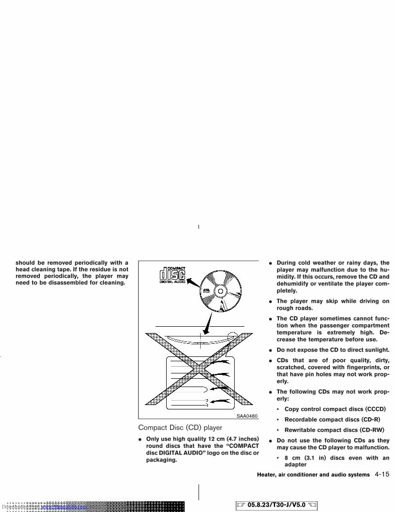
should be removed periodically with ahead cleaning tape. If the residue is notremoved periodically, the player mayneed to be disassembled for cleaning.
Compact Disc (CD) player
� Only use high quality 12 cm (4.7 inches)round discs that have the “COMPACTdisc DIGITAL AUDIO” logo on the disc orpackaging.
� During cold weather or rainy days, theplayer may malfunction due to the hu-midity. If this occurs, remove the CD anddehumidify or ventilate the player com-pletely.
� The player may skip while driving onrough roads.
� The CD player sometimes cannot func-tion when the passenger compartmenttemperature is extremely high. De-crease the temperature before use.
� Do not expose the CD to direct sunlight.
� CDs that are of poor quality, dirty,scratched, covered with fingerprints, orthat have pin holes may not work prop-erly.
� The following CDs may not work prop-erly:
• Copy control compact discs (CCCD)
• Recordable compact discs (CD-R)
• Rewritable compact discs (CD-RW)
� Do not use the following CDs as theymay cause the CD player to malfunction.
• 8 cm (3.1 in) discs even with anadapter
SAA0480
Heater, air conditioner and audio systems 4-15
� 05.8.23/T30-J/V5.0 �Downloaded from www.Manualslib.com manuals search engine
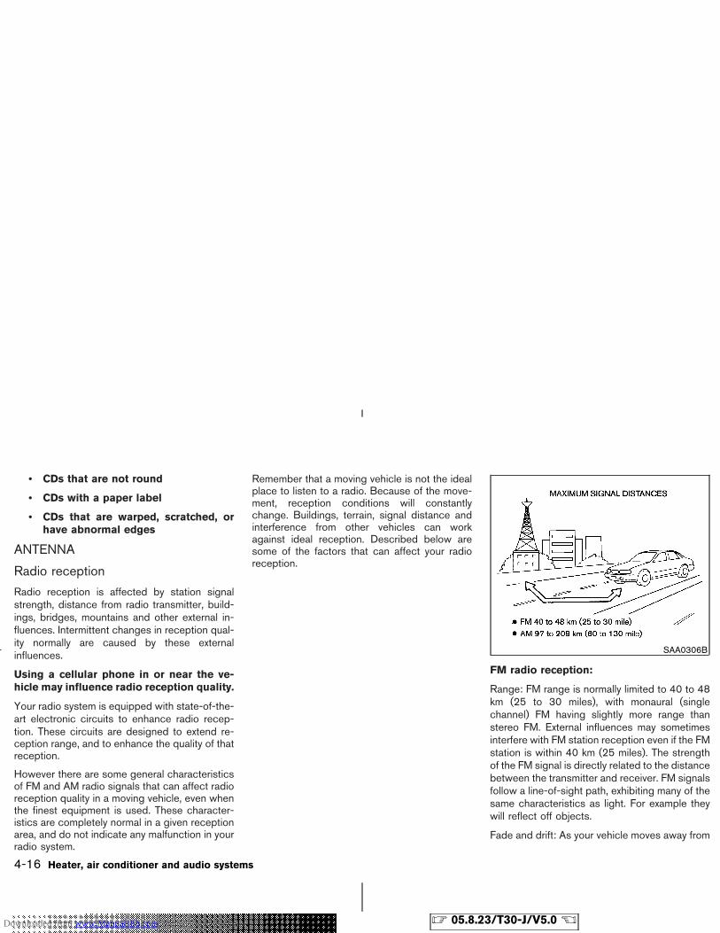
• CDs that are not round
• CDs with a paper label
• CDs that are warped, scratched, orhave abnormal edges
ANTENNA
Radio reception
Radio reception is affected by station signalstrength, distance from radio transmitter, build-ings, bridges, mountains and other external in-fluences. Intermittent changes in reception qual-ity normally are caused by these externalinfluences.
Using a cellular phone in or near the ve-hicle may influence radio reception quality.
Your radio system is equipped with state-of-the-art electronic circuits to enhance radio recep-tion. These circuits are designed to extend re-ception range, and to enhance the quality of thatreception.
However there are some general characteristicsof FM and AM radio signals that can affect radioreception quality in a moving vehicle, even whenthe finest equipment is used. These character-istics are completely normal in a given receptionarea, and do not indicate any malfunction in yourradio system.
Remember that a moving vehicle is not the idealplace to listen to a radio. Because of the move-ment, reception conditions will constantlychange. Buildings, terrain, signal distance andinterference from other vehicles can workagainst ideal reception. Described below aresome of the factors that can affect your radioreception.
FM radio reception:
Range: FM range is normally limited to 40 to 48km (25 to 30 miles), with monaural (singlechannel) FM having slightly more range thanstereo FM. External influences may sometimesinterfere with FM station reception even if the FMstation is within 40 km (25 miles). The strengthof the FM signal is directly related to the distancebetween the transmitter and receiver. FM signalsfollow a line-of-sight path, exhibiting many of thesame characteristics as light. For example theywill reflect off objects.
Fade and drift: As your vehicle moves away from
SAA0306B
4-16 Heater, air conditioner and audio systems
� 05.8.23/T30-J/V5.0 �Downloaded from www.Manualslib.com manuals search engine
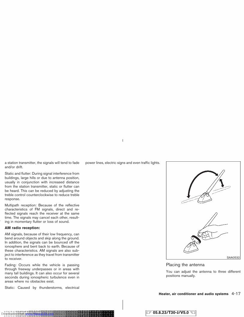
a station transmitter, the signals will tend to fadeand/or drift.
Static and flutter: During signal interference frombuildings, large hills or due to antenna position,usually in conjunction with increased distancefrom the station transmitter, static or flutter canbe heard. This can be reduced by adjusting thetreble control counterclockwise to reduce trebleresponse.
Multipath reception: Because of the reflectivecharacteristics of FM signals, direct and re-flected signals reach the receiver at the sametime. The signals may cancel each other, result-ing in momentary flutter or loss of sound.
AM radio reception:
AM signals, because of their low frequency, canbend around objects and skip along the ground.In addition, the signals can be bounced off theionosphere and bent back to earth. Because ofthese characteristics. AM signals are also sub-ject to interference as they travel from transmitterto receiver.
Fading: Occurs while the vehicle is passingthrough freeway underpasses or in areas withmany tall buildings. It can also occur for severalseconds during ionospheric turbulence even inareas where no obstacles exist.
Static: Caused by thunderstorms, electrical
power lines, electric signs and even traffic lights.
Placing the antennaYou can adjust the antenna to three differentpositions manually.
SAA0532
Heater, air conditioner and audio systems 4-17
� 05.8.23/T30-J/V5.0 �Downloaded from www.Manualslib.com manuals search engine
Removing the antennaYou can remove the antenna if necessary.
Hold the bottom of the antenna and remove byturning counterclockwise.
CAUTION
� Be sure that antenna is removed be-fore the vehicle enters an automaticcar wash.
� Be sure to fold down the antennabefore the vehicle enters a garagewith a low ceiling.
4-18 Heater, air conditioner and audio systems
� 05.8.23/T30-J/V5.0 �Downloaded from www.Manualslib.com manuals search engine
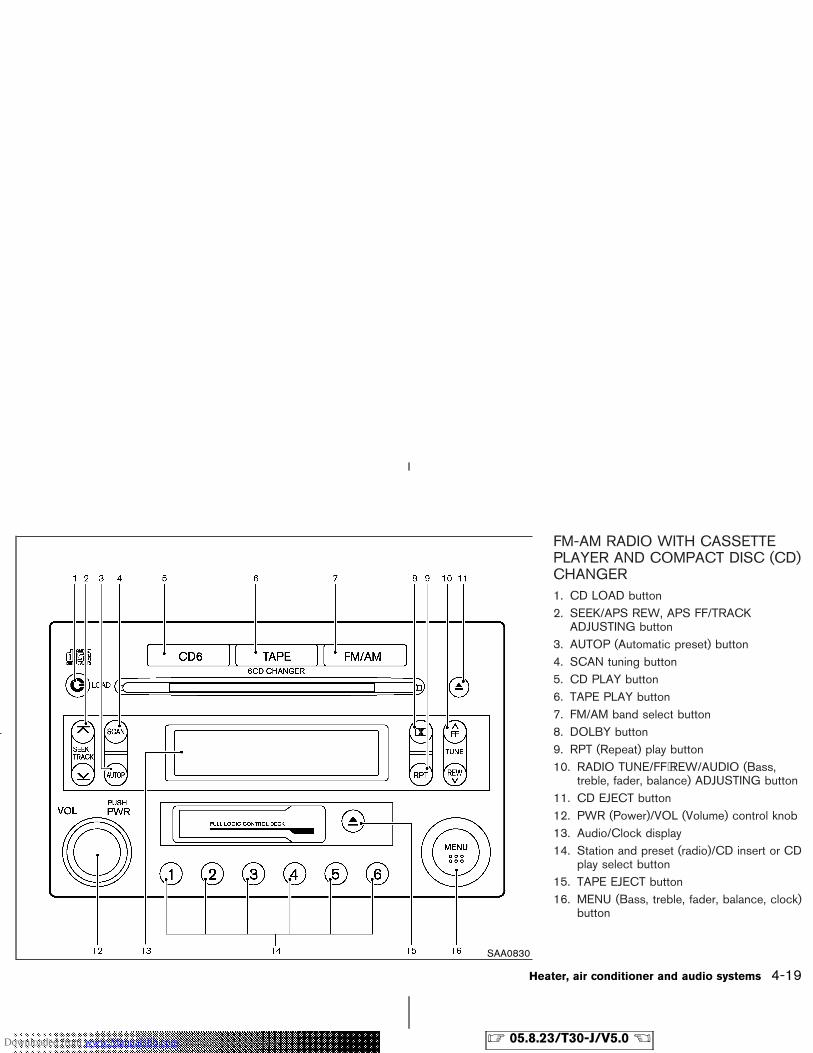
FM-AM RADIO WITH CASSETTEPLAYER AND COMPACT DISC (CD)CHANGER1. CD LOAD button2. SEEK/APS REW, APS FF/TRACK
ADJUSTING button3. AUTOP (Automatic preset) button4. SCAN tuning button5. CD PLAY button6. TAPE PLAY button7. FM/AM band select button8. DOLBY button9. RPT (Repeat) play button10. RADIO TUNE/FF⋅REW/AUDIO (Bass,
treble, fader, balance) ADJUSTING button11. CD EJECT button12. PWR (Power)/VOL (Volume) control knob13. Audio/Clock display14. Station and preset (radio)/CD insert or CD
play select button15. TAPE EJECT button16. MENU (Bass, treble, fader, balance, clock)
button
SAA0830
Heater, air conditioner and audio systems 4-19
� 05.8.23/T30-J/V5.0 �Downloaded from www.Manualslib.com manuals search engine
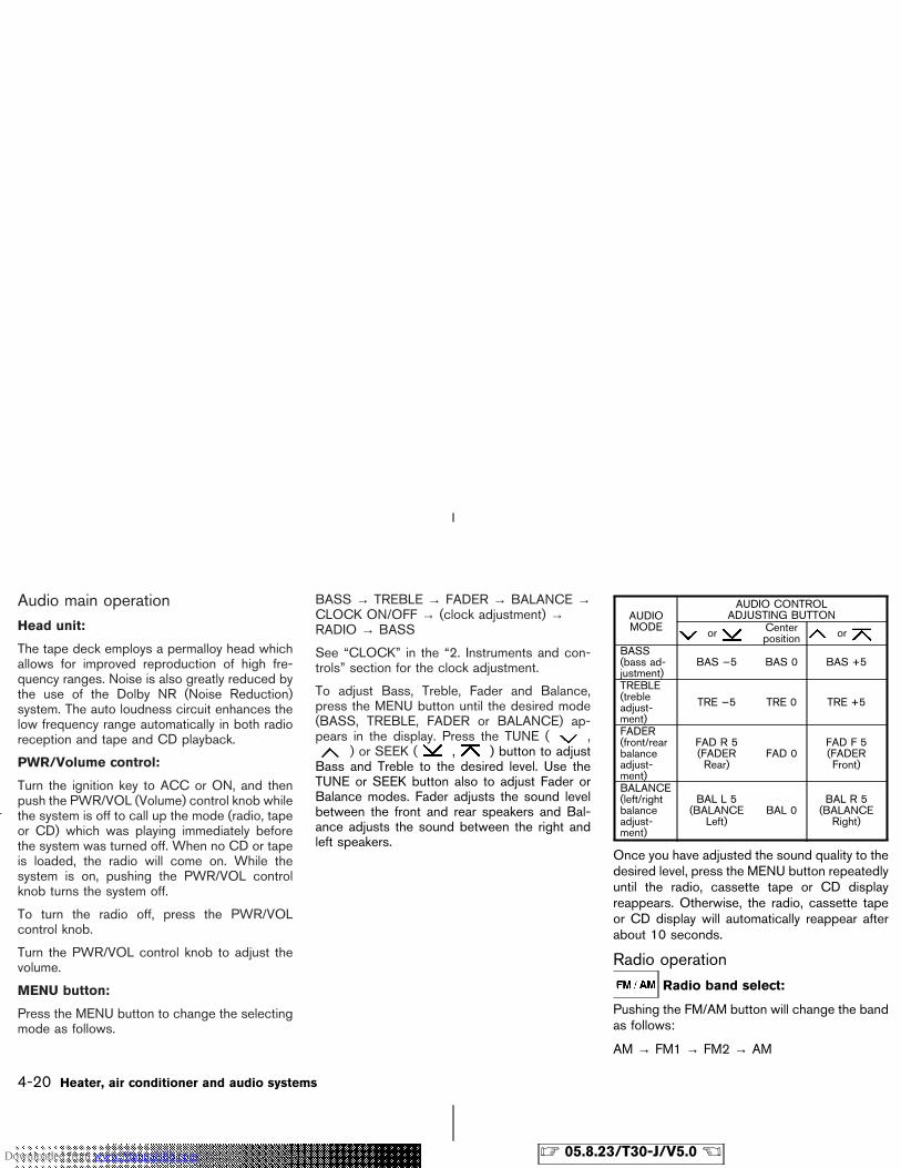
Audio main operationHead unit:
The tape deck employs a permalloy head whichallows for improved reproduction of high fre-quency ranges. Noise is also greatly reduced bythe use of the Dolby NR (Noise Reduction)system. The auto loudness circuit enhances thelow frequency range automatically in both radioreception and tape and CD playback.
PWR/Volume control:
Turn the ignition key to ACC or ON, and thenpush the PWR/VOL (Volume) control knob whilethe system is off to call up the mode (radio, tapeor CD) which was playing immediately beforethe system was turned off. When no CD or tapeis loaded, the radio will come on. While thesystem is on, pushing the PWR/VOL controlknob turns the system off.
To turn the radio off, press the PWR/VOLcontrol knob.
Turn the PWR/VOL control knob to adjust thevolume.
MENU button:
Press the MENU button to change the selectingmode as follows.
BASS → TREBLE → FADER → BALANCE →CLOCK ON/OFF → (clock adjustment) →RADIO → BASS
See “CLOCK” in the “2. Instruments and con-trols” section for the clock adjustment.
To adjust Bass, Treble, Fader and Balance,press the MENU button until the desired mode(BASS, TREBLE, FADER or BALANCE) ap-pears in the display. Press the TUNE ( ,
) or SEEK ( , ) button to adjustBass and Treble to the desired level. Use theTUNE or SEEK button also to adjust Fader orBalance modes. Fader adjusts the sound levelbetween the front and rear speakers and Bal-ance adjusts the sound between the right andleft speakers.
AUDIOMODE
AUDIO CONTROLADJUSTING BUTTON
or Centerposition or
BASS(bass ad-justment)
BAS −5 BAS 0 BAS +5
TREBLE(trebleadjust-ment)
TRE −5 TRE 0 TRE +5
FADER(front/rearbalanceadjust-ment)
FAD R 5(FADERRear)
FAD 0FAD F 5(FADERFront)
BALANCE(left/rightbalanceadjust-ment)
BAL L 5(BALANCE
Left)BAL 0
BAL R 5(BALANCE
Right)
Once you have adjusted the sound quality to thedesired level, press the MENU button repeatedlyuntil the radio, cassette tape or CD displayreappears. Otherwise, the radio, cassette tapeor CD display will automatically reappear afterabout 10 seconds.
Radio operation
Radio band select:
Pushing the FM/AM button will change the bandas follows:
AM → FM1 → FM2 → AM
4-20 Heater, air conditioner and audio systems
� 05.8.23/T30-J/V5.0 �Downloaded from www.Manualslib.com manuals search engine
When FM/AM button is pushed while the igni-tion switch is in the ACC or ON position, theradio will come on at the station last played.
The last station played will also come on whenthe PWR/VOL control knob is pushed to ON.
If a compact disc or tape is playing when theFM/AM button is turned to ON, the compactdisc or tape will automatically be turned off andthe last radio station played will come on.
TUNE (Tuning):
WARNING
The radio should not be tuned whiledriving so full attention may be given tovehicle operation.
Use the TUNE button or for manualtuning. To move quickly through the channels,hold either side of the TUNE button down formore than 0.5 seconds.
SEEK tuning:
Pushing the SEEK button or tunesfrom high to low or low to high frequencies andstops at the next broadcasting station.
SCAN tuning:
Pushing the SCAN tuning button tunes from lowto high frequencies and stops at each broad-casting station for 5 seconds. Pushing the but-ton again during this 5 second period will stopSCAN tuning and the radio will remain tuned tothat station.
If the SCAN tuning button is not pushed within 5seconds, SCAN tuning moves to the next sta-tion.
Station memory operations:
Twelve stations can be set for the FM band (sixfor FM1, six for FM2) and six stations can be setfor both the AM bands.
1. Tune to the desired station using the SEEK,SCAN or TUNE button.
2. Select the desired station and keep pushingany of the desired station/preset buttons (1to 6) until a beep sound is heard. (The radiomutes when the station/preset button ispushed.)
3. The channel indicator will then come on andthe sound will resume. Memorizing is nowcomplete.
4. Other buttons can be set in the same manner.
If the battery cable is disconnected, or if
the fuse blows, the radio memory will beerased. In that case, reset the desired sta-tions.
AUTOP (Automatic preset) button:
To select the preset FM or AM, push the AUTOPbutton for less than 1.5 seconds.
To preset the FM or AM, push the AUTOPbutton for more than 1.5 seconds.
Cassette tape player operation
Turn the ignition key to the ACC or ON position,and then lightly insert the cassette tape into thetape door. The cassette tape will be automati-cally pulled into the player.
The radio or CD will turn off (if it is on) and thecassette tape will begin to play.
CAUTION
Do not force the cassette tape into thetape door. This could cause playerdamage.
If the system is turned off by pushing thePWR/VOL control knob with the cassette tapestill in the player, the tape will resume playingwhen the system is turned back on.
Heater, air conditioner and audio systems 4-21
� 05.8.23/T30-J/V5.0 �Downloaded from www.Manualslib.com manuals search engine
PLAY:
� When the TAPE button is pushed with thesystem turned off and a tape loaded, thesystem will come on and the tape will play.
� When the TAPE button is pushed with eitherthe radio or compact disc turned on and thetape loaded, the compact disc or the radiowill automatically be turned off and the tapewill play.
� When the TAPE button is pushed with theTAPE playing, the tape will play the programrecorded on the reverse side.
FF (Fast Forward), REW(Rewind):
Push the (fast forward) button to fastforward the tape. To rewind the tape, push the
(rewind) button. Either the FF or REWsymbol illuminates on the right side of the displaywindow. To stop the FF or REW function, pressthe (fast forward) or (rewind) again,or the TAPE button.
APS (AutomaticProgram Search) FF,APS REW:
When the (APS FF) button is pushedwhile the tape is being played, the next programwill start to play from the beginning. Push the
(APS FF) button several times to skipthrough programs. The tape will advance thenumber of times the button is pushed (up to nineprograms).
When the (APS REW) button is pushedonce, the program being played starts over fromthe beginning. Push the (APS REW) but-ton several times to skip back several selections.The tape will go back the number of times thebutton is pushed. Either the FF or REW symbolflashes on the display window while searchingfor the selection.
This system searches for the blank intervalsbetween selections. If there is a blank intervalwithin one program or there is no interval be-tween programs, the system may not stop in thedesired or expected location.
SCAN tuning:
Push the SCAN tuning button while playing atape, and it stops at the next tape program for 5seconds. Pushing the button again during this 5second period will stop SCAN tuning and thetape program is continued. If the SCAN tuningbutton is not pushed within 5 seconds, SCANtuning moves to the next tape program.
Dolby NR (Noise Reduction):
Push the Dolby NR button for Dolby NRencoded tapes to reduce high frequency tape
noise. The indicator will come on.Dolby noise reduction is manufactured underlicense from Dolby Laboratories Licensing Cor-poration. Dolby NR and the double-D symbol
are trademarks of Dolby Laboratories Li-censing Corporation.
Metal or chrome tape usage:The cassette player will be automatically set tohigh performance play when playing a metal orchrome cassette tape.
TAPE EJECT:
When this button is pushed with the tapeloaded, the tape will be ejected.When the tape is ejected while it is being played,the system will be turned off.
Compact disc (CD) changeroperationTurn the ignition key to the ACC or ON position,push the LOAD button and insert the compactdisc into the slot with the label side facing up.The compact disc will be guided automaticallyinto the slot and will start playing.After loading the disc, the number of tracks onthe disc will appear on the display.If the radio or tape is already operating, it willautomatically turn off and the compact disc willplay.
4-22 Heater, air conditioner and audio systems
� 05.8.23/T30-J/V5.0 �Downloaded from www.Manualslib.com manuals search engine
CAUTION
� Do not force the compact disc intothe slot. This could damage theplayer.
� Do not use 8 cm (3.1 in) discs.
If the system has been turned off while thecompact disc was playing, pushing thePWR/VOL control knob will start the compactdisc.
CD LOAD:
To insert a CD in the CD changer, push theLOAD button for less than 1.5 seconds. Selectthe loading slot by pushing the CD insert selectbutton (1 to 6), then insert the CD.
To insert 6 CDs to the CD changer in succes-sion, push the LOAD button for more than 1.5seconds.
The inserted slot numbers will illuminate on thedisplay.
CD PLAY:
When the CD6 (CD play) button is pushed withthe system off and the compact disc loaded, the
system will turn on and the compact disc willstart to play.
When the CD6 button is pushed with the com-pact disc loaded with the tape or the radioplaying, the tape or radio will automatically beturned off and the compact disc will start to play.
FF (Fast Forward), REW(Rewind):
When the (fast forward) or (rewind)button is pushed while the compact disc isbeing played, the compact disc will play whilefast forwarding or rewinding. When the button isreleased, the compact disc will return to normalplay speed.
APS (Automatic ProgramSearch) FF, APS REW:
When the (APS FF) button is pushedwhile the compact disc is being played, the nextprogram from the present one will start to playfrom its beginning. Push several times to skipthrough programs. The compact disc will ad-vance the number of times the button is pushed.(When the last program on the compact disc isskipped through, the first program will beplayed.) When the (APS REW) button ispushed, the program being played returns to itsbeginning. Push several times to skip backthrough programs. The compact disc will goback the number of times the button is pushed.
CD PLAY select button:
To change CD, push the CD play select button(1 to 6).
SCAN tuning:
When the SCAN tuning button is pushed forless than 1.5 seconds while the CD is beingplayed, the beginning of all the CD programs ineach track will be played for 10 seconds insequence.
When the SCAN tuning button is pushed formore than 1.5 seconds while the CD is beingplayed, the first program in all the CDs will beplayed for 10 seconds.
Pushing the button again during this 10 secondperiod will stop SCAN tuning.
If the SCAN tuning button is not pushed within10 seconds, SCAN tuning moves to the nextdisc program.
REPEAT (RPT):
When the RPT play button is pushed while thecompact disc is being played, the play patterncan be changed as follows:
The display shows the following symbols.
Heater, air conditioner and audio systems 4-23
� 05.8.23/T30-J/V5.0 �Downloaded from www.Manualslib.com manuals search engine
(no mark): ALL RPT (Repeat)
1DISC: 1 CD RPT
1: 1 TR (Track) RPT
MIX: ALL MIX
1DISC MIX: 1 CD MIX
CD EJECT:
When the CD EJECT button is pushed with thecompact disc loaded, the compact disc will beejected.
To eject the disc selected by the CD selectbutton, push the EJECT button for less than 1.5seconds.
To eject all the discs in succession, push theEJECT button for more than 1.5 seconds.
When this button is pushed while the compactdisc is being played, the compact disc will comeout and the system will turn off.
If the compact disc comes out and is notremoved, it will be pulled back into the slotto protect it.
CD IN indicator:
CD IN indicator (inserted slot number) appearson the display when the CD is loaded with thesystem on.
4-24 Heater, air conditioner and audio systems
� 05.8.23/T30-J/V5.0 �Downloaded from www.Manualslib.com manuals search engine
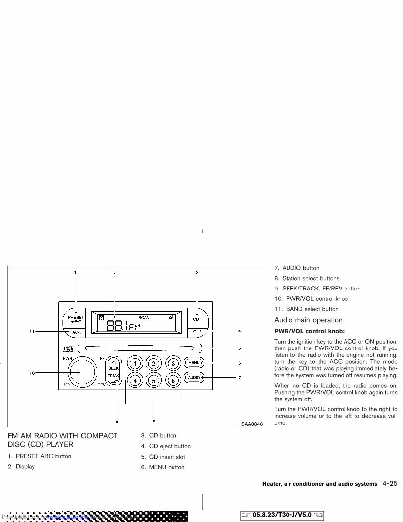
FM-AM RADIO WITH COMPACTDISC (CD) PLAYER
1. PRESET ABC button
2. Display
3. CD button
4. CD eject button
5. CD insert slot
6. MENU button
7. AUDIO button
8. Station select buttons
9. SEEK/TRACK, FF/REV button
10. PWR/VOL control knob
11. BAND select button
Audio main operationPWR/VOL control knob:
Turn the ignition key to the ACC or ON position,then push the PWR/VOL control knob. If youlisten to the radio with the engine not running,turn the key to the ACC position. The mode(radio or CD) that was playing immediately be-fore the system was turned off resumes playing.
When no CD is loaded, the radio comes on.Pushing the PWR/VOL control knob again turnsthe system off.
Turn the PWR/VOL control knob to the right toincrease volume or to the left to decrease vol-ume.SAA0840
Heater, air conditioner and audio systems 4-25
� 05.8.23/T30-J/V5.0 �Downloaded from www.Manualslib.com manuals search engine
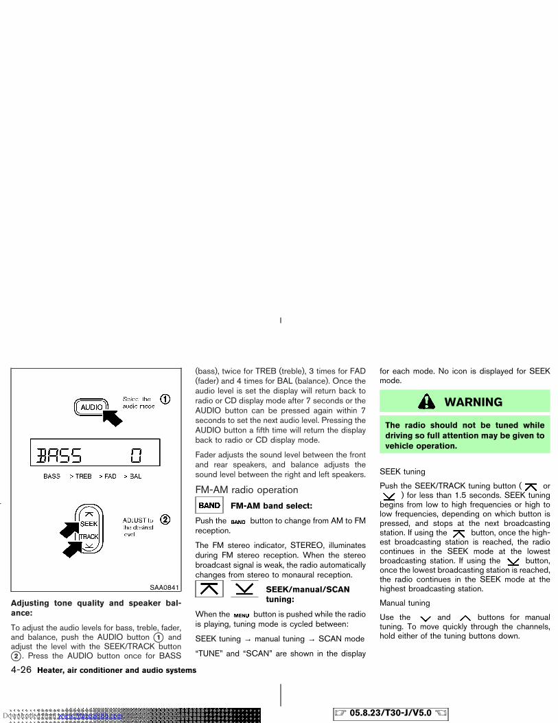
Adjusting tone quality and speaker bal-ance:
To adjust the audio levels for bass, treble, fader,and balance, push the AUDIO button �1 andadjust the level with the SEEK/TRACK button�2 . Press the AUDIO button once for BASS
(bass), twice for TREB (treble), 3 times for FAD(fader) and 4 times for BAL (balance). Once theaudio level is set the display will return back toradio or CD display mode after 7 seconds or theAUDIO button can be pressed again within 7seconds to set the next audio level. Pressing theAUDIO button a fifth time will return the displayback to radio or CD display mode.
Fader adjusts the sound level between the frontand rear speakers, and balance adjusts thesound level between the right and left speakers.
FM-AM radio operation
FM-AM band select:
Push the button to change from AM to FMreception.
The FM stereo indicator, STEREO, illuminatesduring FM stereo reception. When the stereobroadcast signal is weak, the radio automaticallychanges from stereo to monaural reception.
SEEK/manual/SCANtuning:
When the button is pushed while the radiois playing, tuning mode is cycled between:
SEEK tuning → manual tuning → SCAN mode
“TUNE” and “SCAN” are shown in the display
for each mode. No icon is displayed for SEEKmode.
WARNING
The radio should not be tuned whiledriving so full attention may be given tovehicle operation.
SEEK tuning
Push the SEEK/TRACK tuning button ( or) for less than 1.5 seconds. SEEK tuning
begins from low to high frequencies or high tolow frequencies, depending on which button ispressed, and stops at the next broadcastingstation. If using the button, once the high-est broadcasting station is reached, the radiocontinues in the SEEK mode at the lowestbroadcasting station. If using the button,once the lowest broadcasting station is reached,the radio continues in the SEEK mode at thehighest broadcasting station.
Manual tuning
Use the and buttons for manualtuning. To move quickly through the channels,hold either of the tuning buttons down.
SAA0841
4-26 Heater, air conditioner and audio systems
� 05.8.23/T30-J/V5.0 �Downloaded from www.Manualslib.com manuals search engine
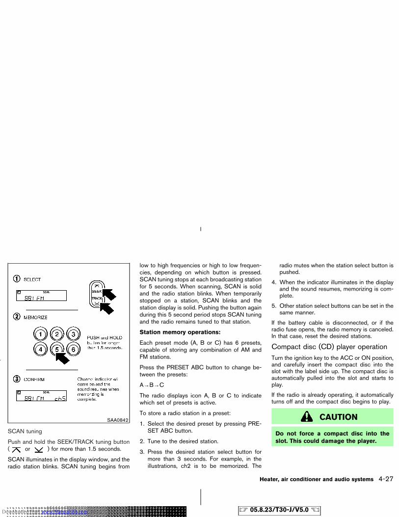
SCAN tuning
Push and hold the SEEK/TRACK tuning button( or ) for more than 1.5 seconds.
SCAN illuminates in the display window, and theradio station blinks. SCAN tuning begins from
low to high frequencies or high to low frequen-cies, depending on which button is pressed.SCAN tuning stops at each broadcasting stationfor 5 seconds. When scanning, SCAN is solidand the radio station blinks. When temporarilystopped on a station, SCAN blinks and thestation display is solid. Pushing the button againduring this 5 second period stops SCAN tuningand the radio remains tuned to that station.
Station memory operations:
Each preset mode (A, B or C) has 6 presets,capable of storing any combination of AM andFM stations.
Press the PRESET ABC button to change be-tween the presets:
A→B→C
The radio displays icon A, B or C to indicatewhich set of presets is active.
To store a radio station in a preset:
1. Select the desired preset by pressing PRE-SET ABC button.
2. Tune to the desired station.
3. Press the desired station select button formore than 3 seconds. For example, in theillustrations, ch2 is to be memorized. The
radio mutes when the station select button ispushed.
4. When the indicator illuminates in the displayand the sound resumes, memorizing is com-plete.
5. Other station select buttons can be set in thesame manner.
If the battery cable is disconnected, or if theradio fuse opens, the radio memory is canceled.In that case, reset the desired stations.
Compact disc (CD) player operationTurn the ignition key to the ACC or ON position,and carefully insert the compact disc into theslot with the label side up. The compact disc isautomatically pulled into the slot and starts toplay.
If the radio is already operating, it automaticallyturns off and the compact disc begins to play.
CAUTION
Do not force a compact disc into theslot. This could damage the player.
SAA0842
Heater, air conditioner and audio systems 4-27
� 05.8.23/T30-J/V5.0 �Downloaded from www.Manualslib.com manuals search engine
CD button:
When the CD button is pushed with a compactdisc loaded and the radio playing, the radio turnsoff and the compact disc starts to play.
Track up/down, FF (FastForward)/REV (Rewind)buttons:
Track up/down
When the button is pushed and releasedwhile the compact disc is playing, the selectionfollowing the present one starts to play from thebeginning. Push the button several timesto skip several selections. Each time the buttonis pushed, the CD advances 1 additional selec-tion. The number appears in the display window.(When the last selection on the compact disc isskipped, the first selection is played.)
When the button is pushed and released,the selection being played returns to the begin-ning. Push the button several times to skipback several selections. Each time the button ispushed, the CD moves back 1 selection.
If the play pattern is in MIX mode when theor button is pushed the next selec-
tion will be chosen at random.
FF (Fast Forward)/REV (Rewind)
When the or button is pushed andheld while the compact disc is playing, thecompact disc plays at an increased speed whilefast forwarding or rewinding. When the button isreleased, the compact disc returns to normalplay speed.
MENU:
When the button is pushed while thecompact disc is playing, the play patternchanges as follows:
RPT: The current selection is repeated.
MIX: Selections are played at random, notfollowing the sequence on the compact disc.The same program may be repeated twice. If the
button is pushed in the MIX mode, selec-tions will be chosen at random.
Blank (no symbol): All selections are playedrepeatedly in sequence.
When a new compact disc is inserted, theplay pattern automatically changes to ALL.
CD EJECT button:
When the button is pushed with a com-pact disc loaded, the compact disc ejects.
When the button is pushed while thecompact disc is playing, the compact disc ejects
and the system turns off.
DISC indicator light:
This light comes on when a compact discis loaded into the player.
4-28 Heater, air conditioner and audio systems
� 05.8.23/T30-J/V5.0 �Downloaded from www.Manualslib.com manuals search engine
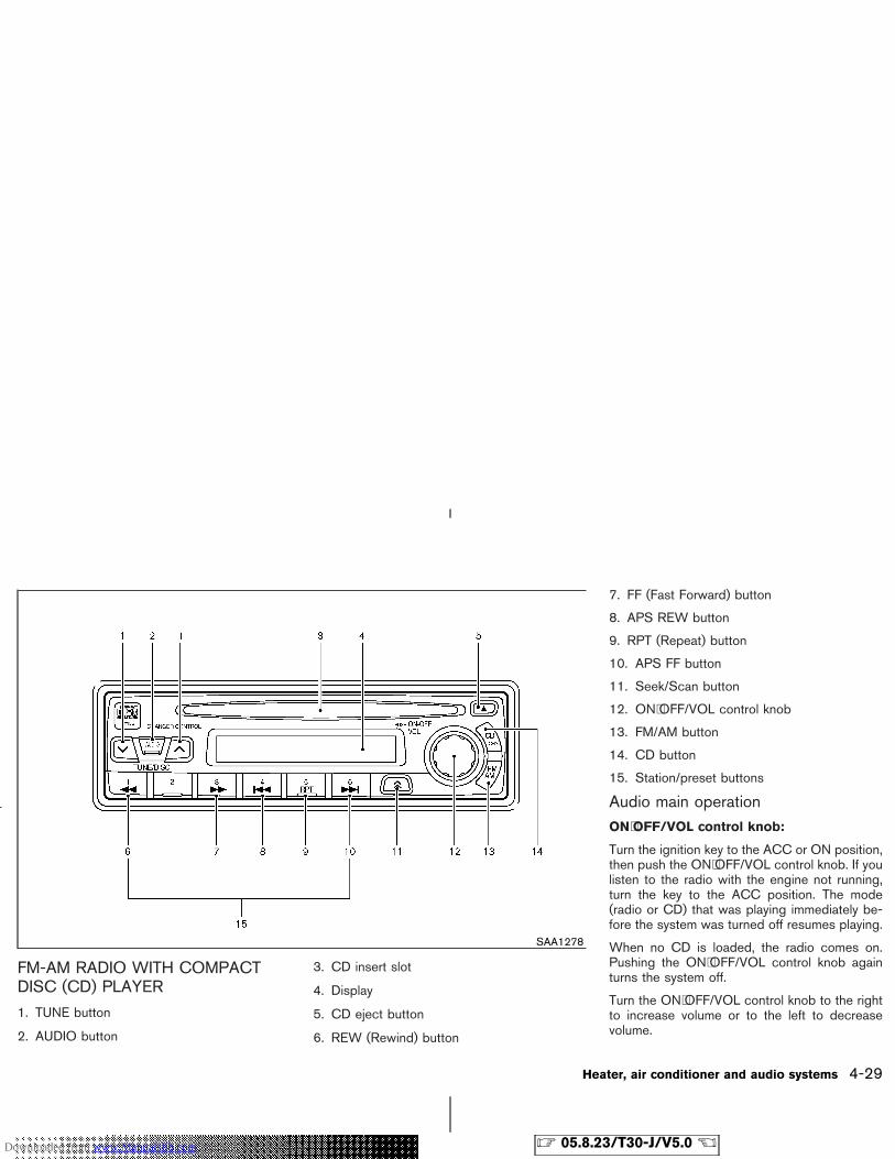
FM-AM RADIO WITH COMPACTDISC (CD) PLAYER
1. TUNE button
2. AUDIO button
3. CD insert slot
4. Display
5. CD eject button
6. REW (Rewind) button
7. FF (Fast Forward) button
8. APS REW button
9. RPT (Repeat) button
10. APS FF button
11. Seek/Scan button
12. ON⋅OFF/VOL control knob
13. FM/AM button
14. CD button
15. Station/preset buttons
Audio main operationON⋅OFF/VOL control knob:
Turn the ignition key to the ACC or ON position,then push the ON⋅OFF/VOL control knob. If youlisten to the radio with the engine not running,turn the key to the ACC position. The mode(radio or CD) that was playing immediately be-fore the system was turned off resumes playing.
When no CD is loaded, the radio comes on.Pushing the ON⋅OFF/VOL control knob againturns the system off.
Turn the ON⋅OFF/VOL control knob to the rightto increase volume or to the left to decreasevolume.
SAA1278
Heater, air conditioner and audio systems 4-29
� 05.8.23/T30-J/V5.0 �Downloaded from www.Manualslib.com manuals search engine
AUDIO button:
Press the AUDIO button to change the selectingmode as follows.
BAS (Bass) → TRE (Treble) → FAD (Fader) →BAL (Balance) → CD or radio mode
To adjust Bass, Treble, Fader and Balance,press the AUDIO button until the desired mode(BASS, TREBLE, FADER or BALANCE) ap-pears in the display. Press the TUNE ( ,
) button to adjust Bass and Treble to thedesired level. Use the TUNE button also toadjust Fader and Balance modes. Fader adjuststhe sound level between the front and rearspeakers and Balance adjusts the sound be-tween the right and left speakers.
Once you have adjusted the sound quality to thedesired level, press the AUDIO button repeat-edly until the radio or CD display reappears.Otherwise, the radio or CD display will automati-cally reappear after about 10 seconds.
Radio operationRadio band select:
Pushing the FM/AM button will change the bandas follows:
AM → FM1 → FM2 → AM
When FM/AM button is pushed while the igni-
tion switch is in the ACC or ON position, theradio will come on at the station last played.
The last station played will also come on whenthe ON⋅OFF/VOL control knob is pushed to ON.
If a compact disc is playing when the FM/AMbutton is turned to ON, the compact disc willautomatically be turned off and the last radiostation played will come on.
TUNE (Tuning):
WARNING
The radio should not be tuned whiledriving so full attention may be given tovehicle operation.
Use the TUNE button or for manualtuning. For automatic tuning, hold either side ofthe TUNE button down for more than 0.5 sec-ond.
Seek tuning:
Pushing the seek button tunes from highto low or low to high frequencies and stops atthe next broadcasting station.
Station memory operations:
Twelve stations can be set for the FM band (sixfor FM1, six for FM2) and six stations can be setfor both the AM bands.
1. Tune to the desired station using the seek orTUNE button.
2. Select the desired station and keep pushingany of the desired station/preset buttons (1to 6) until a beep sound is heard. (The radiomutes when the station/preset button ispushed.)
3. The channel indicator will then come on andthe sound will resume. Memorizing is nowcomplete.
4. Other buttons can be set in the same manner.
If the battery cable is disconnected, or ifthe fuse blows, the radio memory will beerased. In that case, reset the desired sta-tions.
Compact disc (CD) player operationTurn the ignition key to the ACC or ON position,and carefully insert the compact disc into theslot with the label side up. The compact disc isautomatically pulled into the slot and starts toplay.
If the radio is already operating, it automatically
4-30 Heater, air conditioner and audio systems
� 05.8.23/T30-J/V5.0 �Downloaded from www.Manualslib.com manuals search engine
turns off and the compact disc begins to play.
CAUTION
� Do not force a compact disc into theslot. This could damage the player.
� Do not use 8 cm (3.1 in) discs.
CD button:
When the CD button is pushed with a compactdisc loaded and the radio playing, the radio turnsoff and the compact disc starts to play.
FF (Fast Forward), REW(Rewind):
When the (fast forward) or (rewind)button is pushed while the compact disc isbeing played, the compact disc will play whilefast forwarding or rewinding. When the button isreleased, the compact disc will return to normalplay speed.
APS (Automatic ProgramSearch) FF, APS REW:
When the (APS FF) button is pushedwhile the compact disc is being played, the nextprogram from the present one will start to playfrom its beginning. Push several times to skip
through programs. The compact disc will ad-vance the number of times the button is pushed.(When the last program on the compact disc isskipped through, the first program will beplayed.) When the (APS REW) button ispushed, the program being played returns to itsbeginning. Push several times to skip backthrough programs. The compact disc will goback the number of times the button is pushed.
Scan tuning:
When the scan tuning button is pushed for lessthan 1.5 seconds while the CD is being played,the beginning of all the CD programs in eachtrack will be played for 10 seconds in sequence.
Pushing the button again during this 10 secondperiod will stop scan tuning.
If the scan tuning button is not pushed within 10seconds, scan tuning moves to the next pro-gram.
REPEAT (RPT):
When the RPT play button is pushed while thecompact disc is being played, the play patterncan be changed as follows:
The display shows the following symbols.
(no mark): ALL RPT (Repeat)
1: 1 TR (Track) RPT
RANDOM: ALL MIX
CD EJECT:
When the CD EJECT button is pushed with thecompact disc loaded, the compact disc will beejected.
To eject the disc, push the EJECT button.
When this button is pushed while the compactdisc is being played, the compact disc will comeout and the system will turn off.
If the compact disc comes out and is notremoved, it will be pulled back into the slotto protect it.
CD IN indicator:
CD IN indicator (inserted slot number) appearson the display when the CD is loaded with thesystem on.
Heater, air conditioner and audio systems 4-31
� 05.8.23/T30-J/V5.0 �Downloaded from www.Manualslib.com manuals search engine
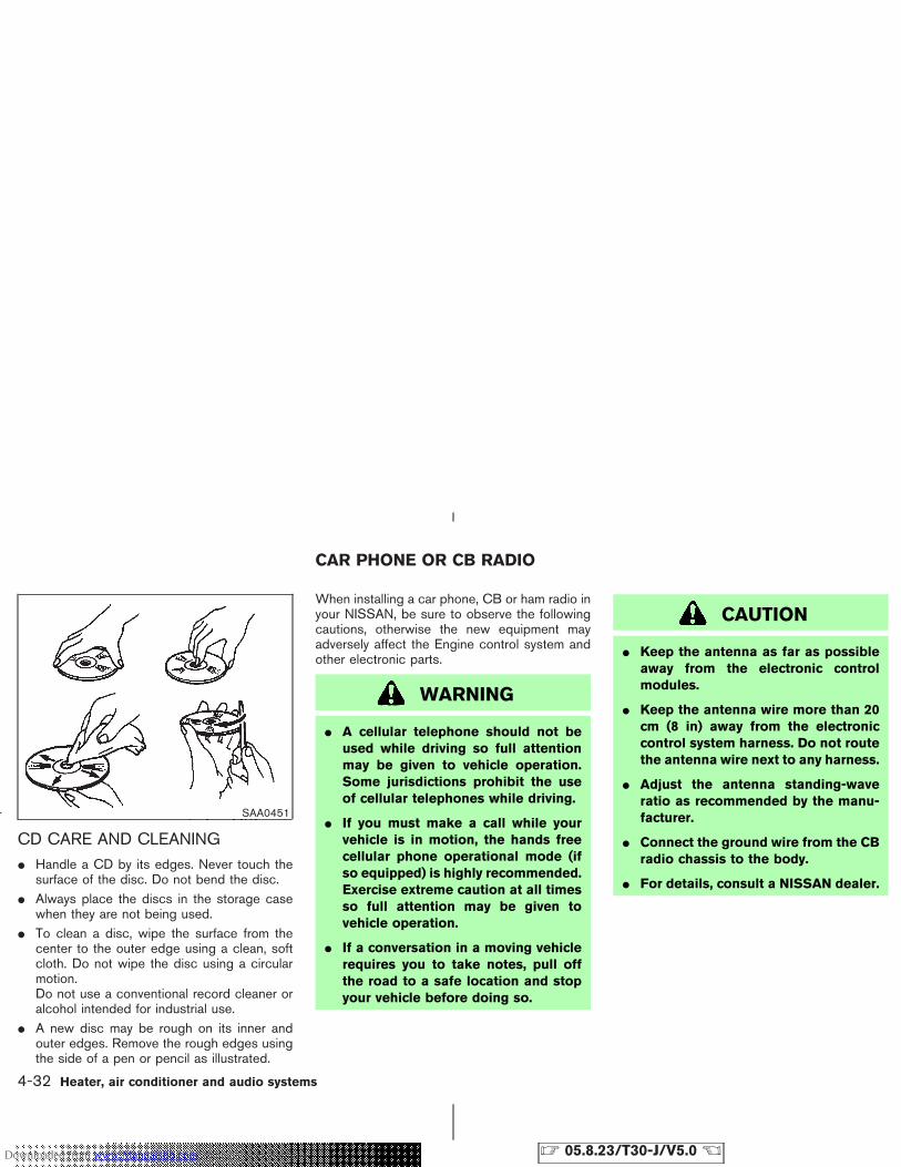
CD CARE AND CLEANING� Handle a CD by its edges. Never touch the
surface of the disc. Do not bend the disc.� Always place the discs in the storage case
when they are not being used.� To clean a disc, wipe the surface from the
center to the outer edge using a clean, softcloth. Do not wipe the disc using a circularmotion.Do not use a conventional record cleaner oralcohol intended for industrial use.
� A new disc may be rough on its inner andouter edges. Remove the rough edges usingthe side of a pen or pencil as illustrated.
When installing a car phone, CB or ham radio inyour NISSAN, be sure to observe the followingcautions, otherwise the new equipment mayadversely affect the Engine control system andother electronic parts.
WARNING
� A cellular telephone should not beused while driving so full attentionmay be given to vehicle operation.Some jurisdictions prohibit the useof cellular telephones while driving.
� If you must make a call while yourvehicle is in motion, the hands freecellular phone operational mode (ifso equipped) is highly recommended.Exercise extreme caution at all timesso full attention may be given tovehicle operation.
� If a conversation in a moving vehiclerequires you to take notes, pull offthe road to a safe location and stopyour vehicle before doing so.
CAUTION
� Keep the antenna as far as possibleaway from the electronic controlmodules.
� Keep the antenna wire more than 20cm (8 in) away from the electroniccontrol system harness. Do not routethe antenna wire next to any harness.
� Adjust the antenna standing-waveratio as recommended by the manu-facturer.
� Connect the ground wire from the CBradio chassis to the body.
� For details, consult a NISSAN dealer.
SAA0451
CAR PHONE OR CB RADIO
4-32 Heater, air conditioner and audio systems
� 05.8.23/T30-J/V5.0 �Downloaded from www.Manualslib.com manuals search engine

MEMO
Heater, air conditioner and audio systems 4-33
� 05.8.23/T30-J/V5.0 �Downloaded from www.Manualslib.com manuals search engine

MEMO
4-34 Heater, air conditioner and audio systems
� 05.8.23/T30-J/V5.0 �Downloaded from www.Manualslib.com manuals search engine
5 Starting and driving
Precautions when starting and driving ............................ 5-2Exhaust gas (Carbon monoxide) ................................. 5-2Three way catalyst .......................................................... 5-3Avoiding collision and rollover ..................................... 5-3On-pavement and offroad driving precautions ....... 5-4Drinking alcohol/drugs and driving ............................ 5-4Driving safety precautions ............................................ 5-4
Ignition switch ....................................................................... 5-6Automatic transmission (AT) ........................................ 5-6Manual transmission (MT) ............................................ 5-7Key positions ................................................................... 5-8NISSAN Vehicle Immobilizer System ........................ 5-8
Before starting the engine ................................................. 5-9Starting the engine ............................................................... 5-9Driving the vehicle ............................................................. 5-10
Automatic transmission ............................................... 5-10Manual transmission .................................................... 5-14
Parking brake ...................................................................... 5-15Cruise control ..................................................................... 5-16
Precautions on cruise control ................................... 5-16Cruise control operations ........................................... 5-17
Break-in schedule .............................................................. 5-18Increasing fuel economy .................................................. 5-18Using four-wheel drive (4WD) (if so equipped) ........ 5-19
4WD mode switch operations .................................. 5-204WD warning light ....................................................... 5-21
Parking/parking on hills .................................................... 5-23Power steering .................................................................... 5-24Brake system ....................................................................... 5-24
Braking precautions ..................................................... 5-24Anti-lock brake system (ABS) .................................. 5-25
Vehicle dynamic control (VDC) system(if so equipped) .................................................................. 5-26Cold weather driving ......................................................... 5-28
Freeing a frozen door lock ......................................... 5-28Antifreeze ........................................................................ 5-28Battery ............................................................................. 5-28Draining of coolant water ........................................... 5-28Tire equipment .............................................................. 5-28Special winter equipment .......................................... 5-29Driving on snow or ice ................................................ 5-29Engine block heater ..................................................... 5-30
� 05.8.23/T30-J/V5.0 �Downloaded from www.Manualslib.com manuals search engine
WARNING
� Do not leave children or adults whowould normally require the supportof others alone in your vehicle. Petsshould not be left alone either. Theycould accidentally injure themselvesor others through inadvertent opera-tion of the vehicle. Also, on hot,sunny days, temperatures in a closedvehicle could quickly become highenough to cause severe or possiblyfatal injuries to people or animals.
� Properly secure all cargo to help pre-vent it from sliding or shifting. Do notplace cargo higher than the seat-backs. In a sudden stop or collision,unsecured cargo could cause per-sonal injury.
EXHAUST GAS (Carbon monoxide)
WARNING
Do not breathe exhaust gases; they con-
tain colorless and odorless carbon mon-oxide. Carbon monoxide is dangerous.It can cause unconsciousness or death.
� If you suspect that exhaust fumes areentering the vehicle, drive with allwindows fully open, and have thevehicle inspected immediately.
� Do not run the engine in closedspaces such as a garage.
� Do not park the vehicle with the en-gine running for any extended lengthof time.
� Keep the back door closed while driv-ing, otherwise exhaust gases couldbe drawn into the passenger com-partment. If you must drive with theback door open, follow these precau-tions:
1. Open all the windows.
2. Set the air recirculation button offand the fan control at the highestposition to circulate the air.
� If electrical wiring or other cable con-
nections must pass to a trailerthrough the seal on the back door orthe body, follow the manufacturer’srecommendation to prevent carbonmonoxide entry into the vehicle.
� If a special body or other equipmentis added for recreational or otherusage, follow the manufacturer’s rec-ommendation to prevent carbonmonoxide entry into the vehicle.(Some recreational vehicle appli-ances such as stoves, refrigerator,heaters, etc. may also generate car-bon monoxide.)
� The exhaust system and body shouldbe inspected by a qualified mechanicwhenever:
a. The vehicle is raised for service.
b. You suspect that exhaust fumesare entering into the passengercompartment.
c. You notice a change in the soundof the exhaust system.
PRECAUTIONS WHEN STARTINGAND DRIVING
5-2 Starting and driving
� 05.8.23/T30-J/V5.0 �Downloaded from www.Manualslib.com manuals search engine
d. You have had an accident involv-ing damage to the exhaust system,underbody, or rear of the vehicle.
THREE WAY CATALYSTThe three way catalyst is an emission controldevice installed in the exhaust system. Exhaustgases in the converter are burned at high tem-peratures to help reduce pollutants.
WARNING
� The exhaust gas and the exhaust sys-tem are very hot. Keep people, ani-mals or flammable materials awayfrom the exhaust system compo-nents.
� Do not stop or park the vehicle overflammable materials such as drygrass, waste paper or rags. They mayignite and cause a fire.
CAUTION
� Do not use leaded gasoline. Depositsfrom leaded gasoline seriously re-duce the three way catalyst’s abilityto help reduce exhaust pollutants.
� Keep your engine tuned up. Malfunc-tions in the ignition, fuel injection, orelectrical systems can cause overrichfuel flow into the three way catalyst,causing it to overheat. Do not keepdriving if the engine misfires, or ifnoticeable loss of performance orother unusual operating conditionsare detected. Have the vehicle in-spected promptly by a NISSANdealer.
� Avoid driving with an extremely lowfuel level. Running out of fuel couldcause the engine to misfire, damag-ing the three way catalyst.
� Do not race the engine while warm-ing it up.
� Do not push or tow your vehicle tostart the engine.
AVOIDING COLLISION ANDROLLOVER
WARNING
Failure to operate this vehicle in a safeand prudent manner may result in lossof control or an accident.
Be alert and drive defensively at all times. Obeyall traffic regulations. Avoid excessive speed,high speed cornering, or sudden steering ma-neuvers, because these driving practices couldcause you to lose control of your vehicle. Aswith any vehicle, a loss of control couldresult in a collision with other vehicles orobjects, or cause the vehicle to rollover,particularly if the loss of control causes thevehicle to slide sideways. Be attentive at alltimes, and avoid driving when tired. Never drivewhen under the influence of alcohol or drugs(including prescription or over-the-counterdrugs which may cause drowsiness). Alwayswear your seat belt. See “Seat belts” in the “1.Safety — Seats, seat belts and supplementalrestraint system” section. Also instruct your pas-sengers to do so.
Seat belts help reduce the risk of injury incollisions and rollovers. In a rollover crash, an
Starting and driving 5-3
� 05.8.23/T30-J/V5.0 �Downloaded from www.Manualslib.com manuals search engine
unbelted or improperly belted person issignificantly more likely to be injured orkilled than a person properly wearing aseat belt.
ON-PAVEMENT AND OFFROADDRIVING PRECAUTIONSUtility vehicles have a significantly higherrollover rate than other types of vehicles.
Utility vehicle have a higher ground clearancethan passenger vehicles to make them capableof performing in a variety of on-pavement andoffroad applications. Higher ground clearancegives the utility vehicle a higher center of gravitythan passenger vehicles. An advantage of higherground clearance is a better view of the road,allowing you to anticipate problems. However,utility vehicles are not designed for cornering atthe same speeds as passenger two-wheel drivevehicles any more than low-slung sports cars aredesigned to perform satisfactorily under offroadconditions. If at all possible, avoid sharp turns orabrupt maneuvers, particularly at high speeds.As with other vehicles of this type, failure tooperate this vehicle correctly may result in lossof control or vehicle rollover.
Be sure to read the driving safety precautionslater in this section.
DRINKING ALCOHOL/DRUGS ANDDRIVING
WARNING
Never drive under the influence of alco-hol or drugs. Alcohol in the bloodstreamreduces coordination, delays reactiontime and impairs judgment. Driving afterdrinking alcohol increases the likeli-hood of being involved in an accidentinjuring yourself and others. Addition-ally, if you are injured in the accident,alcohol can increase the severity of theinjury.
NISSAN is committed to safe driving. You mustnot drive under the influence of alcohol. Everyyear thousands of people are injured or killed inalcohol related accidents. Although the locallaws vary on what is considered to be legallyintoxicated, the fact is that alcohol affects allpeople differently and most people underesti-mate the effects of alcohol.
Remember, drinking and driving don’t mix!
And that’s true for drugs too (over the counter,prescription, and illegal drugs). Don’t drive if
your ability to operate your vehicle is impaired byalcohol, drugs, or some other physical condition.
DRIVING SAFETY PRECAUTIONS
Please observe the following precautions:
WARNING
� Drive carefully when off the road andavoid dangerous areas. Every personwho drives or rides in this vehicleshould be seated with their seat beltfastened. This will keep you and yourpassengers in position when drivingover rough terrain.
� Before driving up or down grades,check the road surface for bumps orpotholes. Be sure to climb a gentleslope and descend a gentle slope.
� Do not drive across steep slopes.Instead drive either straight up orstraight down the slopes. Off-roadvehicles can tip over sideways muchmore easily than they can forward orbackward.
5-4 Starting and driving
� 05.8.23/T30-J/V5.0 �Downloaded from www.Manualslib.com manuals search engine
� Many hills are too steep for any ve-hicle. If you drive up them, you maystall. If you drive down them, you maynot be able to control your speed. Ifyou drive across them, you may rollover.
� Do not shift gears while driving ondownhill grades as this could causeloss of control of the vehicle.
� Be sure to use the engine brake. Thefoot brake performance may be re-duced, resulting in a possible acci-dent.
� Stay alert when driving to the top of ahill. At the top there could be a drop-off or other hazard that could causean accident.
� If your engine stalls or you cannotmake it to the top of a steep hill,never attempt to turn around. Yourvehicle could tip or roll over. Alwaysback straight down in R (Reverse)gear. Never back down in N (Neutral)or with the clutch depressed (manualtransmission vehicles), using only the
brake, as this could cause loss ofcontrol.
� Heavy braking going down a hillcould cause your brakes to overheatand fade, resulting in loss of controland an accident. Apply brakes lightlyand use a low range to control yourspeed.
� Unsecured cargo can be thrownaround when driving over rough ter-rain. Properly secure all cargo so itwill not be thrown forward and causeinjury to you or your passengers.
� To avoid raising the center of gravityexcessively, do not exceed the ratedcapacity of the roof rack (if soequipped) and evenly distribute theload. Secure heavy loads in the cargoarea as far forward and as low aspossible. Do not equip the vehiclewith tires larger than specified in thismanual. This could cause your ve-hicle to roll over.
� Do not grip the inside or spokes ofthe steering wheel when driving off-
road. The steering wheel could movesuddenly and injure your hands. In-stead drive with your fingers andthumbs on the outside of the rim.
� Before operating the vehicle, ensurethat the driver and all passengershave their seat belts fastened.
� Always drive with the floor mats inplace as the floor may become hot.
� Lower your speed when encounteringstrong crosswinds. With a highercenter of gravity, your NISSAN ismore affected by strong side winds.Slower speeds ensure better vehiclecontrol.
� Do not drive beyond the performanceof the tires, even with 4WD engaged.
Accelerating quickly, sharp steeringmaneuvers or sudden braking maycause loss of control.
� If at all possible, avoid sharp turningmaneuvers, particularly at highspeeds. Your NISSAN four wheeldrive vehicle has a higher center of
Starting and driving 5-5
� 05.8.23/T30-J/V5.0 �Downloaded from www.Manualslib.com manuals search engine
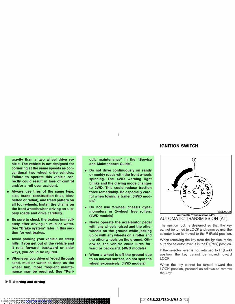
gravity than a two wheel drive ve-hicle. The vehicle is not designed forcornering at the same speeds as con-ventional two wheel drive vehicles.Failure to operate this vehicle cor-rectly could result in loss of controland/or a roll over accident.
� Always use tires of the same type,size, brand, construction (bias, bias-belted or radial), and tread pattern onall four wheels. Install tire chains onthe front wheels when driving on slip-pery roads and drive carefully.
� Be sure to check the brakes immedi-ately after driving in mud or water.See “Brake system” later in this sec-tion for wet brakes.
� Avoid parking your vehicle on steephills. If you get out of the vehicle andit rolls forward, backward or side-ways, you could be injured.
� Whenever you drive off-road throughsand, mud or water as deep as thewheel hub, more frequent mainte-nance may be required. See “Peri-
odic maintenance” in the “Serviceand Maintenance Guide”.
� Do not drive continuously on sandyor muddy roads with the front wheelsspinning. The 4WD warning lightblinks and the driving mode changesto 2WD. This could reduce tractionforce remarkably. Be especially care-ful when towing a trailer. (4WD mod-els)
� Do not use 2-wheel chassis dyna-mometers or 2-wheel free rollers.(4WD models)
� Never operate the accelerator pedalwith any wheels raised and the otherwheels on the ground while jackingup or with any wheels on a roller andthe other wheels on the ground. Oth-erwise, the vehicle could lurch for-ward or backward. (4WD models)
� When a wheel is off the ground dueto an unlevel surface, do not spin thewheel excessively. (4WD models)
AUTOMATIC TRANSMISSION (AT)
The ignition lock is designed so that the keycannot be turned to LOCK and removed until theselector lever is moved to the P (Park) position.
When removing the key from the ignition, makesure the selector lever is in the P (Park) position.
If the selector lever is not returned to P (Park)position, the key cannot be moved towardLOCK.
When the key cannot be turned toward theLOCK position, proceed as follows to removethe key:
SSD0392Automatic Transmission (AT)
IGNITION SWITCH
5-6 Starting and driving
� 05.8.23/T30-J/V5.0 �Downloaded from www.Manualslib.com manuals search engine
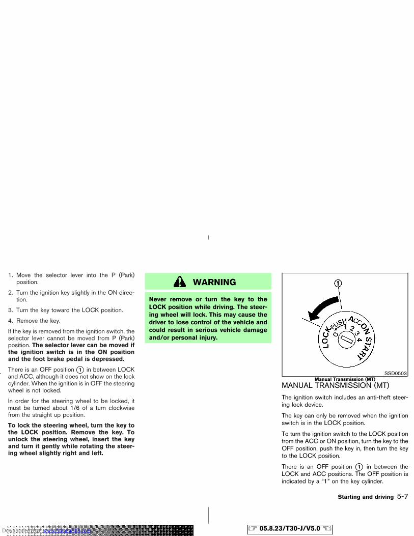
1. Move the selector lever into the P (Park)position.
2. Turn the ignition key slightly in the ON direc-tion.
3. Turn the key toward the LOCK position.
4. Remove the key.
If the key is removed from the ignition switch, theselector lever cannot be moved from P (Park)position. The selector lever can be moved ifthe ignition switch is in the ON positionand the foot brake pedal is depressed.
There is an OFF position �1 in between LOCKand ACC, although it does not show on the lockcylinder. When the ignition is in OFF the steeringwheel is not locked.
In order for the steering wheel to be locked, itmust be turned about 1/6 of a turn clockwisefrom the straight up position.
To lock the steering wheel, turn the key tothe LOCK position. Remove the key. Tounlock the steering wheel, insert the keyand turn it gently while rotating the steer-ing wheel slightly right and left.
WARNING
Never remove or turn the key to theLOCK position while driving. The steer-ing wheel will lock. This may cause thedriver to lose control of the vehicle andcould result in serious vehicle damageand/or personal injury.
MANUAL TRANSMISSION (MT)
The ignition switch includes an anti-theft steer-ing lock device.
The key can only be removed when the ignitionswitch is in the LOCK position.
To turn the ignition switch to the LOCK positionfrom the ACC or ON position, turn the key to theOFF position, push the key in, then turn the keyto the LOCK position.
There is an OFF position �1 in between theLOCK and ACC positions. The OFF position isindicated by a “1” on the key cylinder.
SSD0503Manual Transmission (MT)
Starting and driving 5-7
� 05.8.23/T30-J/V5.0 �Downloaded from www.Manualslib.com manuals search engine
In order for the steering wheel to be locked, itmust be turned about 1/6 of a turn clockwisefrom the straight up position.
To lock the steering wheel, turn the key tothe LOCK position. Remove the key.
To unlock the steering wheel, insert thekey and turn it gently while rotating thesteering wheel slightly right and left.
WARNING
Never remove or turn the key to theLOCK position while driving. The steer-ing wheel will lock. This may cause thedriver to lose control of the vehicle andcould result in serious vehicle damageand/or personal injury.
KEY POSITIONSThe switch includes an anti-theft steering lockdevice.
LOCK (Normal parking position) (0)
The ignition key can only be removed when theswitch is in this position.
OFF (1)
The engine can be turned off without locking thesteering wheel.
ACC (Accessories) (2)
This position activates electrical accessoriessuch as the radio when the engine is not running.
ON (Normal operating position) (3)
This position turns on the ignition system and theelectrical accessories.
START (4)
This position activates the starter motor, startingthe engine.
NISSAN VEHICLE IMMOBILIZERSYSTEMThe Nissan Vehicle Immobilizer System will notallow the engine to start without the use of theregistered key.
If the engine does not start using a registeredkey (for example, when interference is caused byanother registered key, an automated toll roaddevice or automated payment device on the keyring), restart the engine using the followingprocedures:
1. Leave the ignition switch in the ON positionfor approximately 5 seconds.
2. Turn the ignition switch to the OFF or LOCKposition and wait approximately 10 seconds.
3. Repeat steps 1 and 2.
4. Restart the engine while holding the device(which may have caused the interference)separate from the registered key.
If this procedure allows the engine to start,NISSAN recommends placing the registered keyon a separate key ring to avoid interference fromother devices.
5-8 Starting and driving
� 05.8.23/T30-J/V5.0 �Downloaded from www.Manualslib.com manuals search engine
� Make sure the area around the vehicle isclear.
� Maintenance items should be checked peri-odically, for example, each time you checkengine oil.
� Check that all windows and lights are clean.
� Visually inspect tires for their appearance andcondition. Also, check tires for proper infla-tion.
� Lock all doors.
� Position seat and adjust head restraints.
� Adjust inside and outside mirrors.
� Fasten seat belts and ask all passengers todo likewise.
� Check the operation of warning lights whenkey is turned to the ON (3) position.
1. Apply the parking brake.
2. Automatic transmission:
Move the selector lever to P or N. (P ispreferred.)
The starter is designed so that the starterdoes not operate unless the selector lever isin either one of the above positions.
Manual transmission:
Move the shift lever to the N position. De-press the clutch pedal fully to the floor.
The starter is designed so that it does notoperate unless the clutch pedal is fully de-pressed.
3. Turn the ignition switch to START (4) tocrank the engine with your foot off theaccelerator pedal. Release the key whenthe engine starts.
If the engine starts, but fails to run, repeat theabove procedure.
� If the engine is very hard to start in extremelycold weather or when restarting, depress theaccelerator pedal a little (approximately 1/3to the floor) and hold it then crank the engine.Release the key and the accelerator pedalwhen the engine starts.
� If the engine is very hard to start because it is
flooded, depress the accelerator pedal all theway to the floor and hold it. Crank the enginefor 5 to 6 seconds. After cranking the engine,release the accelerator pedal. Crank the en-gine with your foot off the acceleratorpedal by turning the ignition key to START.Release the key when the engine starts. If theengine starts, but fails to run, repeat theabove procedure.
CAUTION
Do not operate the starter for more than15 seconds at a time. If the engine doesnot start, turn the key off and wait 10seconds before cranking again, other-wise the starter could be damaged.
4. Warm-up
Allow the engine to idle for at least 30seconds after starting. Do not race the en-gine while warming it up. Drive at moderatespeed for a short distance first, especially incold weather.
In cold weather, keep the engine running fora minimum of 2 - 3 minutes before shutting itoff. Starting and stopping the engine over a
BEFORE STARTING THE ENGINE STARTING THE ENGINE
Starting and driving 5-9
� 05.8.23/T30-J/V5.0 �Downloaded from www.Manualslib.com manuals search engine
short period of time may make the vehiclemore difficult to start.
AUTOMATIC TRANSMISSION
The automatic transmission in your vehicle iselectronically controlled by a transmission con-trol module to produce maximum efficiency andsmooth operation.
Shown on the following pages are the recom-mended operating procedures for this transmis-sion. Follow these procedures for maximum ve-hicle performance and driving enjoyment.
Starting the vehicle
After starting the engine, fully depress the footbrake pedal and push the selector lever buttonbefore shifting the selector lever to the R (Re-verse), N (Neutral), D (Drive), 2 (Second) or 1(Low) position. Be sure the vehicle is fullystopped before attempting to shift the selectorlever.
This automatic transmission model is de-signed so that the foot brake pedal mustbe depressed before shifting from P (Park)to any drive position while the ignitionswitch is ON.
The selector lever cannot be moved out ofthe P (Park) position and into any of theother gear positions if the ignition key isturned to the LOCK, OFF or ACC positionor if the key is removed from the switch.
1. Keep the foot brake pedal depressed andpush the selector lever button to shift into adriving gear.
2. Release the parking brake and foot brake,then gradually start the vehicle in motion.
WARNING
� Do not depress the accelerator pedalwhile shifting from P (Park) or N(Neutral) to R (Reverse) or D (Drive).Always depress the brake pedal untilshifting is complete. Failure to do socould cause you to lose control andhave an accident.
� Cold engine idle speed is high, so usecaution when shifting into a forwardor reverse gear before the engine haswarmed up.
� On slippery roads, do not downshift.This may cause a loss of control.
� Never shift to P (Park) or R (Reverse)while vehicle is moving forward.Never shift to P (Park) or D (Drive)while vehicle is moving rearward.
DRIVING THE VEHICLE
5-10 Starting and driving
� 05.8.23/T30-J/V5.0 �Downloaded from www.Manualslib.com manuals search engine
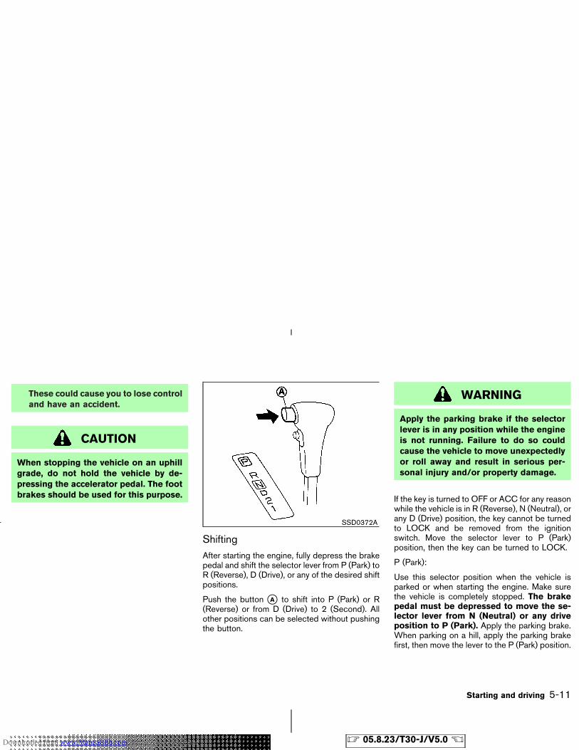
These could cause you to lose controland have an accident.
CAUTION
When stopping the vehicle on an uphillgrade, do not hold the vehicle by de-pressing the accelerator pedal. The footbrakes should be used for this purpose.
ShiftingAfter starting the engine, fully depress the brakepedal and shift the selector lever from P (Park) toR (Reverse), D (Drive), or any of the desired shiftpositions.
Push the button �A to shift into P (Park) or R(Reverse) or from D (Drive) to 2 (Second). Allother positions can be selected without pushingthe button.
WARNING
Apply the parking brake if the selectorlever is in any position while the engineis not running. Failure to do so couldcause the vehicle to move unexpectedlyor roll away and result in serious per-sonal injury and/or property damage.
If the key is turned to OFF or ACC for any reasonwhile the vehicle is in R (Reverse), N (Neutral), orany D (Drive) position, the key cannot be turnedto LOCK and be removed from the ignitionswitch. Move the selector lever to P (Park)position, then the key can be turned to LOCK.
P (Park):
Use this selector position when the vehicle isparked or when starting the engine. Make surethe vehicle is completely stopped. The brakepedal must be depressed to move the se-lector lever from N (Neutral) or any driveposition to P (Park). Apply the parking brake.When parking on a hill, apply the parking brakefirst, then move the lever to the P (Park) position.
SSD0372A
Starting and driving 5-11
� 05.8.23/T30-J/V5.0 �Downloaded from www.Manualslib.com manuals search engine
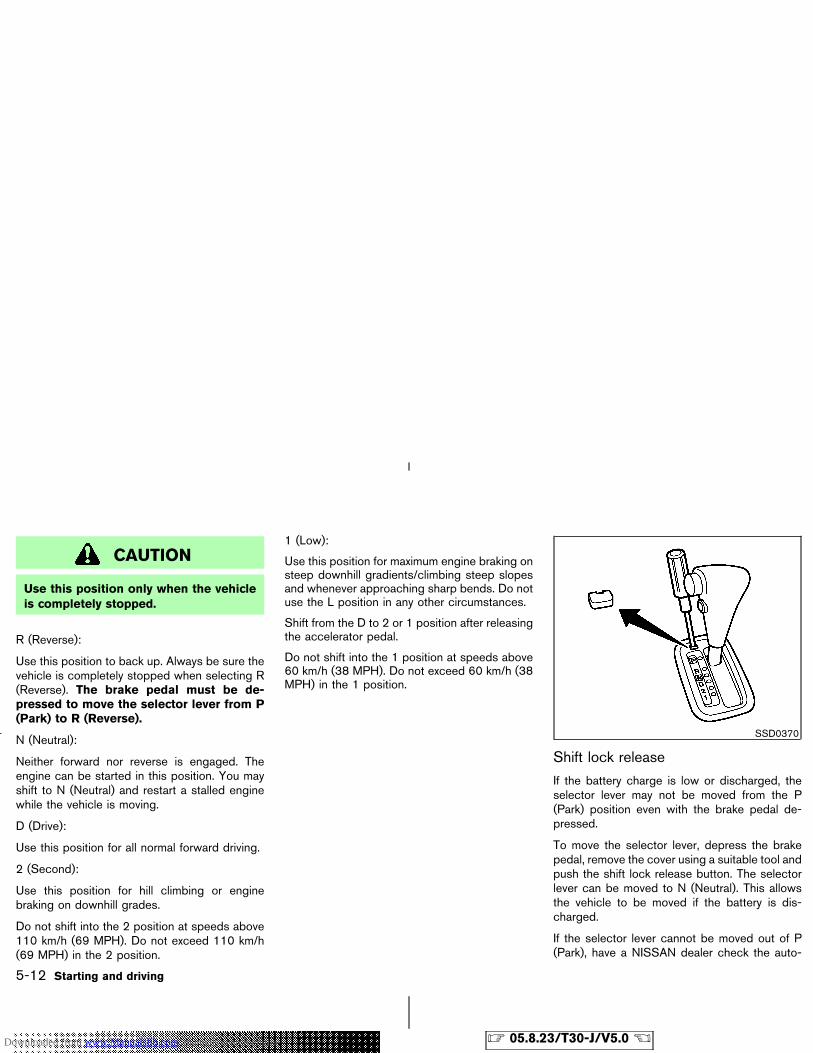
CAUTION
Use this position only when the vehicleis completely stopped.
R (Reverse):
Use this position to back up. Always be sure thevehicle is completely stopped when selecting R(Reverse). The brake pedal must be de-pressed to move the selector lever from P(Park) to R (Reverse).
N (Neutral):
Neither forward nor reverse is engaged. Theengine can be started in this position. You mayshift to N (Neutral) and restart a stalled enginewhile the vehicle is moving.
D (Drive):
Use this position for all normal forward driving.
2 (Second):
Use this position for hill climbing or enginebraking on downhill grades.
Do not shift into the 2 position at speeds above110 km/h (69 MPH). Do not exceed 110 km/h(69 MPH) in the 2 position.
1 (Low):
Use this position for maximum engine braking onsteep downhill gradients/climbing steep slopesand whenever approaching sharp bends. Do notuse the L position in any other circumstances.
Shift from the D to 2 or 1 position after releasingthe accelerator pedal.
Do not shift into the 1 position at speeds above60 km/h (38 MPH). Do not exceed 60 km/h (38MPH) in the 1 position.
Shift lock release
If the battery charge is low or discharged, theselector lever may not be moved from the P(Park) position even with the brake pedal de-pressed.
To move the selector lever, depress the brakepedal, remove the cover using a suitable tool andpush the shift lock release button. The selectorlever can be moved to N (Neutral). This allowsthe vehicle to be moved if the battery is dis-charged.
If the selector lever cannot be moved out of P(Park), have a NISSAN dealer check the auto-
SSD0370
5-12 Starting and driving
� 05.8.23/T30-J/V5.0 �Downloaded from www.Manualslib.com manuals search engine
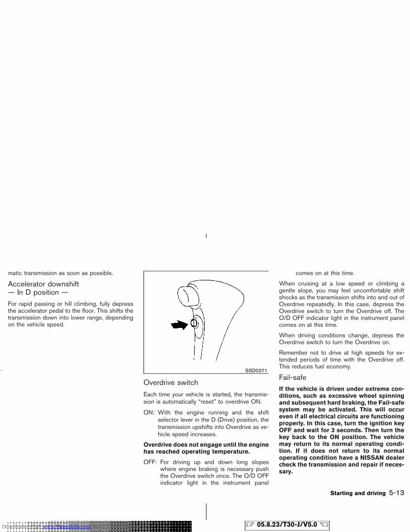
matic transmission as soon as possible.
Accelerator downshift— In D position —For rapid passing or hill climbing, fully depressthe accelerator pedal to the floor. This shifts thetransmission down into lower range, dependingon the vehicle speed.
Overdrive switch
Each time your vehicle is started, the transmis-sion is automatically “reset” to overdrive ON.
ON: With the engine running and the shiftselector lever in the D (Drive) position, thetransmission upshifts into Overdrive as ve-hicle speed increases.
Overdrive does not engage until the enginehas reached operating temperature.
OFF: For driving up and down long slopeswhere engine braking is necessary pushthe Overdrive switch once. The O/D OFFindicator light in the instrument panel
comes on at this time.
When cruising at a low speed or climbing agentle slope, you may feel uncomfortable shiftshocks as the transmission shifts into and out ofOverdrive repeatedly. In this case, depress theOverdrive switch to turn the Overdrive off. TheO/D OFF indicator light in the instrument panelcomes on at this time.
When driving conditions change, depress theOverdrive switch to turn the Overdrive on.
Remember not to drive at high speeds for ex-tended periods of time with the Overdrive off.This reduces fuel economy.
Fail-safeIf the vehicle is driven under extreme con-ditions, such as excessive wheel spinningand subsequent hard braking, the Fail-safesystem may be activated. This will occureven if all electrical circuits are functioningproperly. In this case, turn the ignition keyOFF and wait for 3 seconds. Then turn thekey back to the ON position. The vehiclemay return to its normal operating condi-tion. If it does not return to its normaloperating condition have a NISSAN dealercheck the transmission and repair if neces-sary.
SSD0371
Starting and driving 5-13
� 05.8.23/T30-J/V5.0 �Downloaded from www.Manualslib.com manuals search engine
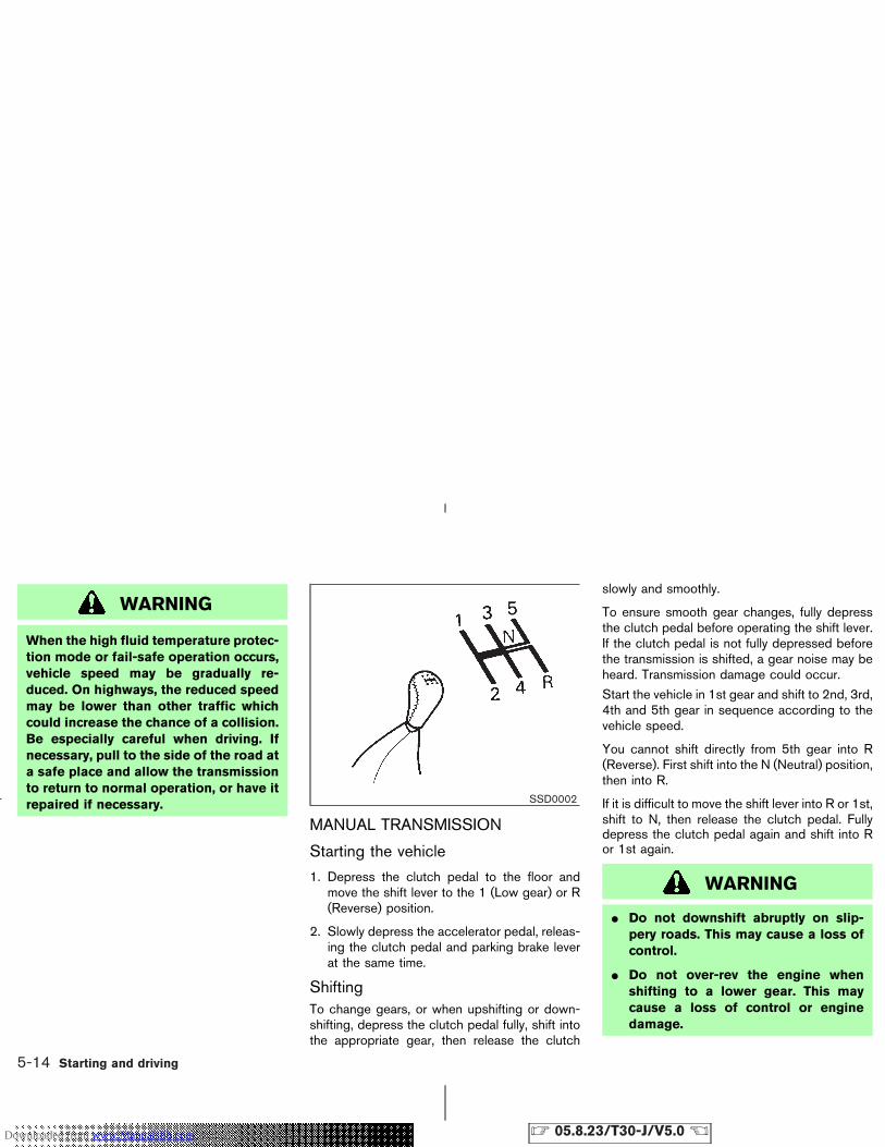
WARNING
When the high fluid temperature protec-tion mode or fail-safe operation occurs,vehicle speed may be gradually re-duced. On highways, the reduced speedmay be lower than other traffic whichcould increase the chance of a collision.Be especially careful when driving. Ifnecessary, pull to the side of the road ata safe place and allow the transmissionto return to normal operation, or have itrepaired if necessary.
MANUAL TRANSMISSION
Starting the vehicle
1. Depress the clutch pedal to the floor andmove the shift lever to the 1 (Low gear) or R(Reverse) position.
2. Slowly depress the accelerator pedal, releas-ing the clutch pedal and parking brake leverat the same time.
ShiftingTo change gears, or when upshifting or down-shifting, depress the clutch pedal fully, shift intothe appropriate gear, then release the clutch
slowly and smoothly.
To ensure smooth gear changes, fully depressthe clutch pedal before operating the shift lever.If the clutch pedal is not fully depressed beforethe transmission is shifted, a gear noise may beheard. Transmission damage could occur.
Start the vehicle in 1st gear and shift to 2nd, 3rd,4th and 5th gear in sequence according to thevehicle speed.
You cannot shift directly from 5th gear into R(Reverse). First shift into the N (Neutral) position,then into R.
If it is difficult to move the shift lever into R or 1st,shift to N, then release the clutch pedal. Fullydepress the clutch pedal again and shift into Ror 1st again.
WARNING
� Do not downshift abruptly on slip-pery roads. This may cause a loss ofcontrol.
� Do not over-rev the engine whenshifting to a lower gear. This maycause a loss of control or enginedamage.
SSD0002
5-14 Starting and driving
� 05.8.23/T30-J/V5.0 �Downloaded from www.Manualslib.com manuals search engine
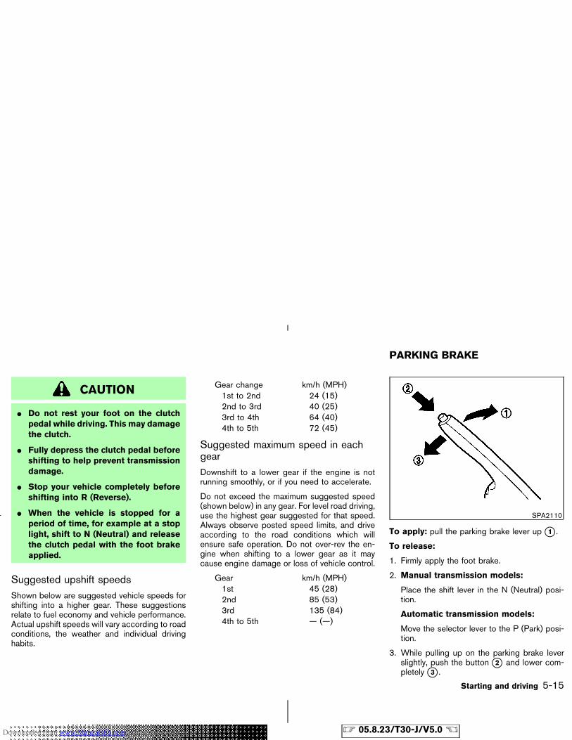
CAUTION
� Do not rest your foot on the clutchpedal while driving. This may damagethe clutch.
� Fully depress the clutch pedal beforeshifting to help prevent transmissiondamage.
� Stop your vehicle completely beforeshifting into R (Reverse).
� When the vehicle is stopped for aperiod of time, for example at a stoplight, shift to N (Neutral) and releasethe clutch pedal with the foot brakeapplied.
Suggested upshift speedsShown below are suggested vehicle speeds forshifting into a higher gear. These suggestionsrelate to fuel economy and vehicle performance.Actual upshift speeds will vary according to roadconditions, the weather and individual drivinghabits.
Gear change km/h (MPH)1st to 2nd 24 (15)2nd to 3rd 40 (25)3rd to 4th 64 (40)4th to 5th 72 (45)
Suggested maximum speed in eachgearDownshift to a lower gear if the engine is notrunning smoothly, or if you need to accelerate.
Do not exceed the maximum suggested speed(shown below) in any gear. For level road driving,use the highest gear suggested for that speed.Always observe posted speed limits, and driveaccording to the road conditions which willensure safe operation. Do not over-rev the en-gine when shifting to a lower gear as it maycause engine damage or loss of vehicle control.
Gear km/h (MPH)1st 45 (28)2nd 85 (53)3rd 135 (84)4th to 5th — (—)
To apply: pull the parking brake lever up �1 .
To release:
1. Firmly apply the foot brake.
2. Manual transmission models:
Place the shift lever in the N (Neutral) posi-tion.
Automatic transmission models:
Move the selector lever to the P (Park) posi-tion.
3. While pulling up on the parking brake leverslightly, push the button �2 and lower com-pletely �3 .
SPA2110
PARKING BRAKE
Starting and driving 5-15
� 05.8.23/T30-J/V5.0 �Downloaded from www.Manualslib.com manuals search engine
4. Before driving, be sure the brake warninglight goes out.
WARNING
� Be sure the parking brake is fullyreleased before driving. Failure to doso can cause brake failure and leadto an accident.
� Do not release the parking brakefrom outside the vehicle.
� Do not use the gear shift in place ofthe parking brake. When parking, besure the parking brake is fully en-gaged.
� Do not leave children unattended in avehicle. They could release the park-ing brake and cause an accident.
WARNING
Do not use the cruise control when driv-ing under the following conditions:
� it is not possible to keep the vehicleat a set speed.
� in heavy traffic or in traffic that variesin speed.
� on winding or hilly roads.
� on slippery roads (rain, snow, ice,etc.).
� in very windy areas.
Doing so could cause a loss of vehiclecontrol and result in an accident.
CAUTION
On manual transmission models, do notshift into N (Neutral) without depressingthe clutch pedal when the cruise controlis set. Should this occur, depress theclutch pedal and turn the main switchoff immediately. Failure to do so may
cause engine damage.
PRECAUTIONS ON CRUISECONTROL� If the cruise control system malfunctions, it
cancels automatically. The SET indicator lighton the meter panel then blinks to warn thedriver.
� If the SET indicator light blinks, turn thecruise control main switch off and have thesystem checked by a NISSAN dealer.
� The SET indicator light may blink when thecruise control main switch is turned on whilepushing the ACCEL/RES, SET/COAST, orCANCEL switch (located on the steeringwheel). To properly set the cruise controlsystem, perform the preceding steps in theorder indicated.
CRUISE CONTROL
5-16 Starting and driving
� 05.8.23/T30-J/V5.0 �Downloaded from www.Manualslib.com manuals search engine
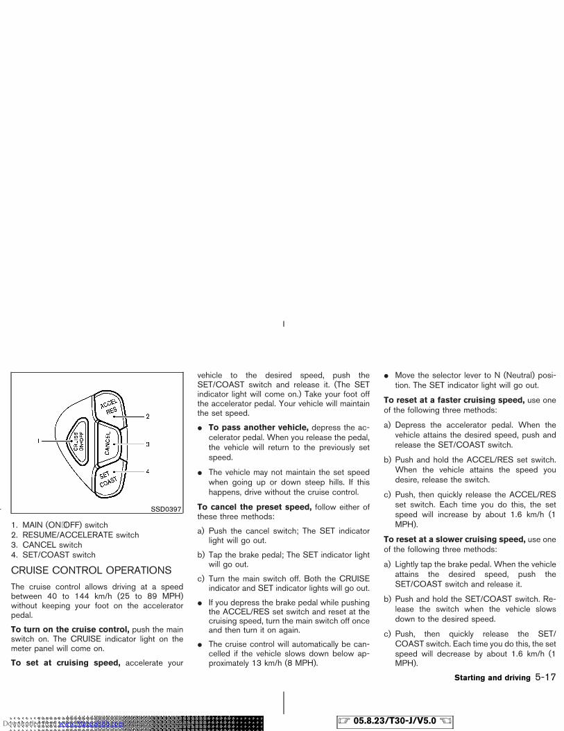
1. MAIN (ON⋅OFF) switch2. RESUME/ACCELERATE switch3. CANCEL switch4. SET/COAST switch
CRUISE CONTROL OPERATIONS
The cruise control allows driving at a speedbetween 40 to 144 km/h (25 to 89 MPH)without keeping your foot on the acceleratorpedal.
To turn on the cruise control, push the mainswitch on. The CRUISE indicator light on themeter panel will come on.
To set at cruising speed, accelerate your
vehicle to the desired speed, push theSET/COAST switch and release it. (The SETindicator light will come on.) Take your foot offthe accelerator pedal. Your vehicle will maintainthe set speed.
� To pass another vehicle, depress the ac-celerator pedal. When you release the pedal,the vehicle will return to the previously setspeed.
� The vehicle may not maintain the set speedwhen going up or down steep hills. If thishappens, drive without the cruise control.
To cancel the preset speed, follow either ofthese three methods:
a) Push the cancel switch; The SET indicatorlight will go out.
b) Tap the brake pedal; The SET indicator lightwill go out.
c) Turn the main switch off. Both the CRUISEindicator and SET indicator lights will go out.
� If you depress the brake pedal while pushingthe ACCEL/RES set switch and reset at thecruising speed, turn the main switch off onceand then turn it on again.
� The cruise control will automatically be can-celled if the vehicle slows down below ap-proximately 13 km/h (8 MPH).
� Move the selector lever to N (Neutral) posi-tion. The SET indicator light will go out.
To reset at a faster cruising speed, use oneof the following three methods:
a) Depress the accelerator pedal. When thevehicle attains the desired speed, push andrelease the SET/COAST switch.
b) Push and hold the ACCEL/RES set switch.When the vehicle attains the speed youdesire, release the switch.
c) Push, then quickly release the ACCEL/RESset switch. Each time you do this, the setspeed will increase by about 1.6 km/h (1MPH).
To reset at a slower cruising speed, use oneof the following three methods:
a) Lightly tap the brake pedal. When the vehicleattains the desired speed, push theSET/COAST switch and release it.
b) Push and hold the SET/COAST switch. Re-lease the switch when the vehicle slowsdown to the desired speed.
c) Push, then quickly release the SET/COAST switch. Each time you do this, the setspeed will decrease by about 1.6 km/h (1MPH).
SSD0397
Starting and driving 5-17
� 05.8.23/T30-J/V5.0 �Downloaded from www.Manualslib.com manuals search engine
To resume the preset speed, push and re-lease the ACCEL/RES set switch. The vehiclewill resume the last set cruising speed when thevehicle speed is over 40 km/h (25 MPH).
CAUTION
During the first 2,000 km (1,200 miles),follow these recommendations to ob-tain maximum engine performance andensure the future reliability andeconomy of your new vehicle. Failure tofollow these recommendations may re-sult in shortened engine life and re-duced engine performance.
� Avoid driving for long periods at constantspeed, either fast or slow. Do not run theengine over 4,000 rpm.
� Do not accelerate at full throttle in any gear.
� Avoid quick starts.
� Avoid hard braking as much as possible.
� Do not tow a trailer for the first 800 km (500miles).
� Accelerate slowly and smoothly. Maintaincruising speeds with a constant acceleratorposition.
� Drive at moderate speeds on the highway.Driving at high speed will lower fuel economy.
� Avoid unnecessary stopping and braking.Maintain a safe distance behind other ve-hicles.
� Use a proper gear range which suits roadconditions. On level roads, shift into high gearas soon as possible.
� Avoid unnecessary engine idling.
� Keep your engine tuned up.
� Follow the recommended periodic mainte-nance schedule.
� Keep the tires inflated at the correct pres-sure. Low pressure will increase tire wear andwaste fuel.
� Keep the front wheels in correct alignment.Improper alignment will cause not only tirewear but also lower fuel economy.
� Air conditioner operation lowers fueleconomy. Use the air conditioner only whennecessary.
� When cruising at highway speeds, it is moreeconomical to use the air conditioner and
BREAK-IN SCHEDULE INCREASING FUEL ECONOMY
5-18 Starting and driving
� 05.8.23/T30-J/V5.0 �Downloaded from www.Manualslib.com manuals search engine
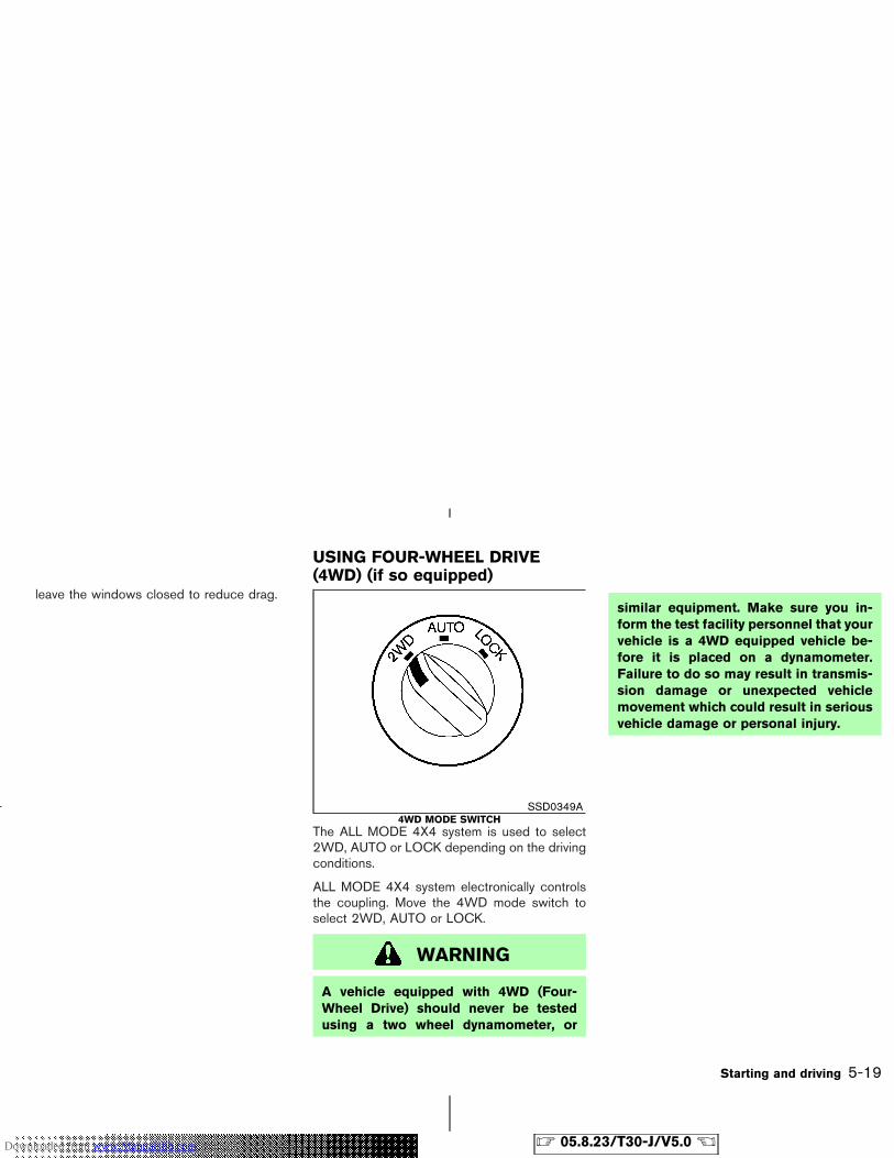
leave the windows closed to reduce drag.
The ALL MODE 4X4 system is used to select2WD, AUTO or LOCK depending on the drivingconditions.
ALL MODE 4X4 system electronically controlsthe coupling. Move the 4WD mode switch toselect 2WD, AUTO or LOCK.
WARNING
A vehicle equipped with 4WD (Four-Wheel Drive) should never be testedusing a two wheel dynamometer, or
similar equipment. Make sure you in-form the test facility personnel that yourvehicle is a 4WD equipped vehicle be-fore it is placed on a dynamometer.Failure to do so may result in transmis-sion damage or unexpected vehiclemovement which could result in seriousvehicle damage or personal injury.
SSD0349A4WD MODE SWITCH
USING FOUR-WHEEL DRIVE(4WD) (if so equipped)
Starting and driving 5-19
� 05.8.23/T30-J/V5.0 �Downloaded from www.Manualslib.com manuals search engine
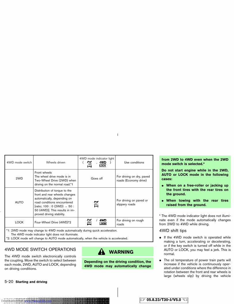
4WD mode switch Wheels driven4WD mode indicator light( , ) Use conditions
2WD
Front wheelsThe wheel drive mode is inTwo-Wheel Drive (2WD) whendriving on the normal road.*1
Goes offFor driving on dry, pavedroads (Economy drive)
AUTO
Distribution of torque to thefront and rear wheels changesautomatically, depending onroad conditions encountered[ratio; 100 : 0 (2WD) → 50 :50 (4WD)]. This results in im-proved driving stability.
For driving on paved orslippery roads
LOCK Four-Wheel Drive (4WD)*2/ For driving on rough
roads
*1: 2WD mode may change to 4WD mode automatically during quick acceleration.The 4WD mode indicator light does not illuminate.
*2: LOCK mode will change to AUTO mode automatically, when the vehicle is accelerated.
4WD MODE SWITCH OPERATIONS
The 4WD mode switch electronically controlsthe coupling. Move the switch to select betweeneach mode, 2WD, AUTO and LOCK, dependingon driving conditions.
WARNING
Depending on the driving condition, the4WD mode may automatically change
from 2WD to 4WD even when the 2WDmode switch is selected.*
Do not start engine while in the 2WD,AUTO or LOCK mode in the followingcases:
� When on a free-roller or jacking upthe front tires with the rear tires onthe ground.
� When towing with the rear tiresraised from the ground.
* The 4WD mode indicator light does not illumi-nate even if the mode automatically changesfrom 2WD to 4WD while driving.
4WD shift tips
� If the 4WD mode switch is operated whilemaking a turn, accelerating or decelerating,or if the key switch is turned off while in theAUTO or LOCK, you may feel a jerk. This isnormal.
� The oil temperature of power train parts willincrease if the vehicle is continuously oper-ated under conditions where the difference inrotation between the front and rear wheels islarge (wheels slip) by driving the vehicle
5-20 Starting and driving
� 05.8.23/T30-J/V5.0 �Downloaded from www.Manualslib.com manuals search engine
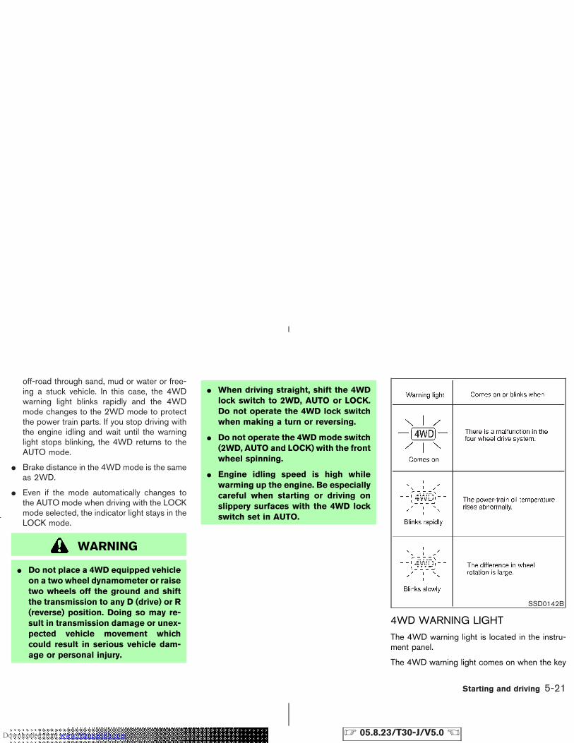
off-road through sand, mud or water or free-ing a stuck vehicle. In this case, the 4WDwarning light blinks rapidly and the 4WDmode changes to the 2WD mode to protectthe power train parts. If you stop driving withthe engine idling and wait until the warninglight stops blinking, the 4WD returns to theAUTO mode.
� Brake distance in the 4WD mode is the sameas 2WD.
� Even if the mode automatically changes tothe AUTO mode when driving with the LOCKmode selected, the indicator light stays in theLOCK mode.
WARNING
� Do not place a 4WD equipped vehicleon a two wheel dynamometer or raisetwo wheels off the ground and shiftthe transmission to any D (drive) or R(reverse) position. Doing so may re-sult in transmission damage or unex-pected vehicle movement whichcould result in serious vehicle dam-age or personal injury.
� When driving straight, shift the 4WDlock switch to 2WD, AUTO or LOCK.Do not operate the 4WD lock switchwhen making a turn or reversing.
� Do not operate the 4WD mode switch(2WD, AUTO and LOCK) with the frontwheel spinning.
� Engine idling speed is high whilewarming up the engine. Be especiallycareful when starting or driving onslippery surfaces with the 4WD lockswitch set in AUTO.
4WD WARNING LIGHT
The 4WD warning light is located in the instru-ment panel.
The 4WD warning light comes on when the key
SSD0142B
Starting and driving 5-21
� 05.8.23/T30-J/V5.0 �Downloaded from www.Manualslib.com manuals search engine
switch is turned to ON. It turns off soon after theengine is started.
If any malfunction occurs in the 4WD systemwhen the key switch is ON, the warning light willeither remain illuminated or blink.
High-temperature power-train oil makes thewarning light blink rapidly (about twice per sec-ond). The driving mode will change to 2WD.AUTO mode may change to LOCK mode beforethe warning light blinks. This is normal. If thewarning light blinks rapidly during operation,stop the vehicle in a safe place immediately.Then if the light goes off after a while, you cancontinue driving.
A large difference between the diameters offront and rear wheels will make the warning lightblink slowly (about once per two seconds). Pulloff the road in a safe area, and idle the engine.Check that all tire sizes are the same, tirepressure is correct and tires are not worn.Change the 4WD mode switch into 2WD anddo not drive fast.
WARNING
Do not attempt to test a 4WD equippedvehicle with two wheels on a two wheel
dynamometer and the other two wheelsraised. Doing so may result in transmis-sion damage or unexpected vehiclemovement which could result in seriousvehicle damage or personal injury.
CAUTION
� If the 4WD warning light comes onwhile driving, AUTO or LOCK modewill be changed to two-wheel drivecondition. Reduce the vehicle speedand be especially careful when driv-ing. Have your vehicle checked by aNISSAN dealer as soon as possible.
� Never drive on dry hard surface roadsin the LOCK mode, as this will over-load the power-train and may cause aserious malfunction.
� The power-train may be damaged ifyou continue driving with the warninglight blinking rapidly.
5-22 Starting and driving
� 05.8.23/T30-J/V5.0 �Downloaded from www.Manualslib.com manuals search engine
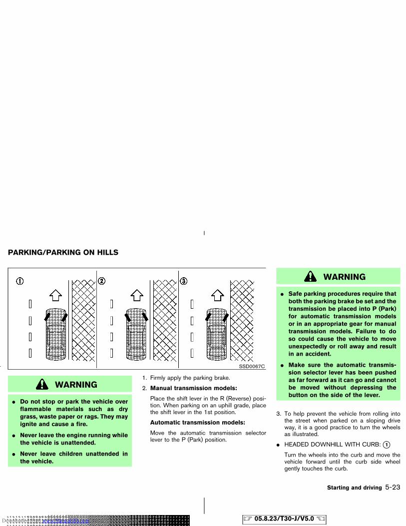
WARNING
� Do not stop or park the vehicle overflammable materials such as drygrass, waste paper or rags. They mayignite and cause a fire.
� Never leave the engine running whilethe vehicle is unattended.
� Never leave children unattended inthe vehicle.
1. Firmly apply the parking brake.
2. Manual transmission models:
Place the shift lever in the R (Reverse) posi-tion. When parking on an uphill grade, placethe shift lever in the 1st position.
Automatic transmission models:
Move the automatic transmission selectorlever to the P (Park) position.
WARNING
� Safe parking procedures require thatboth the parking brake be set and thetransmission be placed into P (Park)for automatic transmission modelsor in an appropriate gear for manualtransmission models. Failure to doso could cause the vehicle to moveunexpectedly or roll away and resultin an accident.
� Make sure the automatic transmis-sion selector lever has been pushedas far forward as it can go and cannotbe moved without depressing thebutton on the side of the lever.
3. To help prevent the vehicle from rolling intothe street when parked on a sloping driveway, it is a good practice to turn the wheelsas illustrated.
� HEADED DOWNHILL WITH CURB: �1Turn the wheels into the curb and move thevehicle forward until the curb side wheelgently touches the curb.
SSD0067C
PARKING/PARKING ON HILLS
Starting and driving 5-23
� 05.8.23/T30-J/V5.0 �Downloaded from www.Manualslib.com manuals search engine
� HEADED UPHILL WITH CURB: �2Turn the wheels away from the curb andmove the vehicle back until the curb sidewheel gently touches the curb.
� HEADED UPHILL OR DOWNHILL, NOCURB: �3Turn the wheels toward the side of the roadso the vehicle will move away from the centerof the road if it moves.
4. Turn the ignition key to the LOCK positionand remove the key.
The power assisted steering uses a hydraulicpump, driven by the engine, to assist steering.
If the engine stops or drive belt breaks, you willstill have control of the vehicle. However, muchgreater steering effort is needed, especially insharp turns or at low speeds.
WARNING
If the engine is not running or is turnedoff while driving, the power assist forthe steering will not work. Steering willbe much harder to operate.
BRAKING PRECAUTIONS
The brake system has two separate hydrauliccircuits. If one circuit malfunctions, you will stillhave braking at two wheels.
Vacuum assisted brake
The brake booster aids braking by using enginevacuum. If the engine stops, you can stop thevehicle by depressing the brake pedal. However,greater foot pressure on the brake pedal will berequired to stop the vehicle and the stoppingdistance will be longer.
Wet brakes
When the vehicle is washed or driven throughwater, the brakes may get wet. As a result, yourbraking distance will be longer and the vehiclemay pull to one side during braking.
To dry brakes, drive the vehicle at a safe speedwhile lightly tapping the brake pedal to heat-upthe brakes. Do this until the brakes return tonormal. Avoid driving the vehicle at high speedsuntil the brakes function correctly.
Parking brake break-in
Break in the parking brake shoes whenever thestopping effect of the parking brake is weakenedor whenever the parking brake shoes and/ordrums/rotors are replaced, in order to assure thebest braking performance.
POWER STEERING BRAKE SYSTEM
5-24 Starting and driving
� 05.8.23/T30-J/V5.0 �Downloaded from www.Manualslib.com manuals search engine
This procedure is described in the vehicle ser-vice manual and can be performed by a NISSANdealer.
Using the brakes
Avoid resting your foot on the brake pedal whiledriving. This will cause overheating of the brakes,increases wear on the brakes and pads, andreduces gas mileage.
To help save the brakes and to prevent thebrakes from overheating, reduce speed anddownshift to a lower gear before going down aslope or long grade. Overheated brakes mayreduce braking performance and could result inloss of vehicle control.
WARNING
� While driving on a slippery surface,be careful when braking, accelerat-ing or downshifting. Abrupt brakingor accelerating could cause thewheels to skid and result in an acci-dent.
� If the engine is not running or isturned off while driving, the powerassist for the brakes will not work.
Braking will be harder.
ANTI-LOCK BRAKE SYSTEM (ABS)
The anti-lock brake system controls the brakesso the wheels will not lock when braking abruptlyor when braking on slippery surfaces. The sys-tem detects the rotation speed at each wheeland varies the brake fluid pressure to preventeach wheel from locking and sliding. By prevent-ing wheel lockup, the system helps the drivermaintain steering control and helps to minimizeswerving and spinning on slippery surfaces.
Using the systemDepress the brake pedal and hold it down.
WARNING
Do not pump the brake pedal. Doing somay result in increased stopping dis-tances.
Normal operationThe anti-lock brake system will not operate atspeeds below 5 to 10 km/h (3 to 6 MPH) tocompletely stop the vehicle. (The speeds will
vary according to road conditions.) When theanti-lock system senses that one or more wheelsare close to locking up, the actuator (under thehood) rapidly applies and releases hydraulicpressure (like pumping the brakes very quickly).While the actuator is working, you may feel apulsation in the brake pedal and hear a noise orvibration from the actuator under the hood. Thisis normal and indicates that the anti-lock systemis working properly. However, the ABS operationmay indicate that road conditions are hazardousand extra care is required while driving.
Self-test feature
The anti-lock brake system consists of electronicsensors, electric pumps, and hydraulic solenoidscontrolled by a computer. The computer has abuilt-in diagnostic feature that tests the systemeach time you start the engine and move thevehicle at a low speed in forward or reverse.When the self-test occurs, you may hear a clunknoise and/or feel a pulsation in the brake pedal.This is normal and is not an indication of anymalfunction. If the computer senses any mal-function, it switches the anti-lock brake systemOFF and turns on the ABS warning light in themeter. The brake system will then behave nor-mally, but without anti-lock assistance.
If the light comes on during the self check, orwhile you are driving, you should take your
Starting and driving 5-25
� 05.8.23/T30-J/V5.0 �Downloaded from www.Manualslib.com manuals search engine
vehicle to a NISSAN dealer for repair at yourearliest convenience.
WARNING
The anti-lock brake system is a sophis-ticated device, but it cannot prevent ac-cidents resulting from careless or dan-gerous driving techniques. It can helpmaintain vehicle control during brakingon slippery surfaces, but remember thatthe stopping distance on slippery sur-faces will be longer than on normalsurfaces, even with the anti-lock sys-tem. Stopping distances may also belonger on rough, gravel or snow coveredroads, or if you are using tire chains.Always maintain a safe distance fromthe vehicle in front of you. Ultimately,the responsibility for safety of self andothers rests in the hands of the driver.
Tire type and condition of tires may alsoaffect braking effectiveness.
� When replacing tires, install thespecified size of tires on all four
wheels.
� When installing a spare tire, makesure it is the proper size and type asspecified on the tire placard. See“Vehicle identification” in the “9.Technical and consumer informa-tion” section for tire placard location.
When accelerating or driving on a slippery sur-faces, the tires may spin or slide. With theVehicle Dynamic Control (VDC) system, sensorsdetect these movements and control the brakingand engine output to help improve vehicle sta-bility.
� When the VDC system is operating, the“SLIP” indicator in the instrument panelblinks.
� When only the Traction Control System(TCS) portion of the VDC system is operat-ing, the “SLIP” indicator in the instrumentpanel blinks.
� If the “SLIP” indicator blinks, the road condi-tions are slippery. Be sure to adjust yourspeed and driving to these conditions. Besure to drive carefully. See “Slip indicatorlight”, and “Vehicle Dynamic Control (VDC)OFF indicator light” in the “2. Instruments andcontrols” section.
� Indicator lightIf a malfunction occurs in the system, the“SLIP” and “VDC OFF” indicator lights illumi-nate in the instrument panel. As long as theseindicators are illuminated, the VDC systemfunction is canceled.
The VDC system uses an Active Brake LimitedSlip (ABLS) system to improve vehicle traction.
VEHICLE DYNAMIC CONTROL(VDC) SYSTEM (if so equipped)
5-26 Starting and driving
� 05.8.23/T30-J/V5.0 �Downloaded from www.Manualslib.com manuals search engine
The ABLS system works when one of the drivingwheels is spinning on a slippery surface. TheABLS system brakes the spinning wheel, whichdistributes the driving power to the other drivingwheel. If the vehicle is operated with the VDCsystem turned off, all VDC system functions andTCS functions will be turned off. The ABLSsystem and ABS will still operate with the VDCsystem off. When the ABLS system is activated,the “SLIP” indicator light will blink and you mayhear a clunk noise and/or feel a pulsation in thebrake pedal. This is normal and is not an indica-tion of a malfunction.
While the VDC system is operating, you may feela pulsation in the brake pedal and hear a noise orfeel a vibration from under the hood. This isnormal and indicates that the VDC system isworking properly.
The VDC system computer has a built-in diag-nostic feature that tests the system each timeyou start the engine and move the vehicle for-ward or backward. When the self-test occurs,you may hear a clunk noise and/or feel a pulsa-tion in the brake pedal. This is normal and is notan indication of a malfunction.
WARNING
� The VDC system is designed to helpimprove driving stability but does notprevent accidents due to abruptsteering operation at high speeds ordue to careless or dangerous drivingtechniques. Reduce vehicle speedand be especially careful when driv-ing and cornering on slippery sur-faces and always drive carefully.
� If engine related parts such as a muf-fler are not standard equipment orare extremely deteriorated, the “VDCOFF” indicator or “SLIP” indicator orboth indicator lights may illuminate.
� Do not modify the vehicle’s suspen-sion. If suspension parts such asshock absorbers, struts, springs, sta-bilizer bars and bushings are notNISSAN-approved or are extremelydeteriorated the VDC system may notoperate properly. This could ad-versely affect vehicle handling per-formance, and the “VDC OFF” indica-
tor or “SLIP” indicator or both indica-tor lights may illuminate.
� If brake related parts such as brakepads, rotors and calipers are notstandard equipment or are extremelydeteriorated, the “VDC OFF” indica-tor or “SLIP” indicator or both indica-tor lights may illuminate.
� When driving on extremely inclinedsurfaces such as higher banked cor-ners, the VDC system may not oper-ate properly and the “VDC OFF” indi-cator or “SLIP” indicator or bothindicator lights may illuminate. Donot drive on these types of roads.
� When driving on an unstable surfacesuch as a turntable, ferry, elevator orramp, the “VDC OFF” indicator or“SLIP” indicator or both indicatorlights may illuminate. This is not amalfunction. Restart the engine afterdriving onto a stable surface.
� If wheels or tires other than thoserecommended are used, the VDC sys-
Starting and driving 5-27
� 05.8.23/T30-J/V5.0 �Downloaded from www.Manualslib.com manuals search engine
temmay not operate properly and the“VDC OFF” indicator or “SLIP” indi-cator or both indicator lights mayilluminate.
� The VDC system is not a substitutefor winter tires or tire chains on asnow-covered road.
FREEING A FROZEN DOOR LOCKTo prevent a door lock from freezing, applyde-icer or glycerin to it through the key hole. Ifthe lock becomes frozen, heat the key beforeinserting it into the key hole.
ANTIFREEZEIn the winter when it is anticipated that thetemperature will drop below 0°C (32°F), checkantifreeze to assure proper winter protection. Foradditional information, see “Engine cooling sys-tem” in the “8. Maintenance and do-it-yourself”section.
BATTERYIf the battery is not fully charged during extremelycold weather conditions, the battery fluid mayfreeze and damage the battery. To maintainmaximum efficiency, the battery should bechecked regularly. For additional information,see “Battery” in the “8. Maintenance and do-it-yourself” section.
DRAINING OF COOLANT WATERIf the vehicle is to be left outside without anti-freeze, drain the cooling system by opening thedrain plug located under the radiator. Refillbefore operating the vehicle. See “Engine cool-ing system” in the “8. Maintenance and do-it-yourself” section for changing engine coolant.
TIRE EQUIPMENT
1. SUMMER tires are of a tread design toprovide superior performance on dry pave-ment. However, the performance of thesetires will be substantially reduced in snowyand icy conditions. If you operate your vehicleon snowy or icy roads, NISSAN recommendsthe use of MUD & SNOW or ALL SEASONtires on all four wheels. Please consult aNISSAN dealer for the tire type, size, speedrating and availability information.
2. For additional traction on icy roads, studdedtires may be used. However, some provincesprohibit their use. Check local, state andprovincial laws before installing studded tires.
Skid and traction capabilities of stud-ded snow tires, on wet or dry surfaces,may be poorer than that of non-studdedsnow tires.
3. Tire chains may be used if desired. Make surethey are of proper size for the tires on yourvehicle and are installed according to thechain manufacturer’s suggestions. Use of tirechains may be prohibited according to loca-tion. Check the local laws before installingtire chains. Use only SAE Class S chains.Class “S” chains are used on vehicles withrestricted tire to vehicle clearance. Vehiclesthat can use Class “S” chains are designed
COLD WEATHER DRIVING
5-28 Starting and driving
� 05.8.23/T30-J/V5.0 �Downloaded from www.Manualslib.com manuals search engine
to meet the SAE standard minimum clear-ances between the tire and the closest ve-hicle suspension or body component re-quired to accommodate the use of a wintertraction device (tire chains or cables). Theminimum clearances are determined usingthe factory equipped tire size. Other typesmay damage your vehicle. Use chain tension-ers when recommended by the tire chainmanufacturer to ensure a tight fit. Loose endlinks of the tire chain must be secured orremoved to prevent the possibility of whip-ping action damage to the fenders or under-body. If possible, avoid fully loading yourvehicle when using tire chains. In addition,drive at a reduced speed. Otherwise, yourvehicle may be damaged and/or vehicle han-dling and performance may be adverselyaffected.
� Do not use tire chains on dry roads.
Tire chains must be installed only on thefront wheels and not on the rear wheels.
Do not drive with tire chains on paved roadswhich are clear of snow. Driving with chains insuch conditions can cause damage to the vari-ous mechanisms of the vehicle due to someoverstress.
4. For all wheel drive:If you install snow tires, they must also be the
same size, brand, construction and treadpattern on all four wheels.
SPECIAL WINTER EQUIPMENT
It is recommended that the following items becarried in the vehicle during winter:
� a scraper and stiff-bristled brush to removeice and snow from the windows and wiperblades.
� a sturdy, flat board to be placed under thejack to give it firm support.
� a shovel to dig the vehicle out of snow-drifts.
� extra window washer fluid to refill the reser-voir tank.
DRIVING ON SNOW OR ICE
WARNING
� Wet ice (32°F, 0°C and freezing rain),very cold snow or ice can be slick andvery hard to drive on. The vehicle willhave a lot less traction or grip underthese conditions. Try to avoid drivingon wet ice until the road is salted orsanded.
� Whatever the condition, drive withcaution. Accelerate and slow downwith care. If accelerating or down-shifting too fast, the drive wheels willlose even more traction.
� Allow more stopping distance underthese conditions. Braking should bestarted sooner than on dry pavement.
� Allow greater following distances onslippery roads.
� Watch for slippery spots (glare ice).These may appear on an otherwiseclear road in shaded areas. If a patchof ice is seen ahead, brake beforereaching it. Try not to brake whileactually on the ice, and avoid anysudden steering maneuvers.
� Do not use cruise control on slipperyroads.
� Snow can trap dangerous exhaustgases under your vehicle. Keep snowclear of the exhaust pipe and fromaround your vehicle.
Starting and driving 5-29
� 05.8.23/T30-J/V5.0 �Downloaded from www.Manualslib.com manuals search engine
ENGINE BLOCK HEATERAn engine block heater to assist extreme coldtemperature starting is available through aNISSAN dealer.
WARNING
Do not use your heater with an un-grounded electrical system or two-pronged (cheater) adapters. You can beinjured by an electrical shock if you usean ungrounded connection.
5-30 Starting and driving
� 05.8.23/T30-J/V5.0 �Downloaded from www.Manualslib.com manuals search engine
6 In case of emergency
Flat tire .................................................................................... 6-2Stopping the vehicle ...................................................... 6-2Preparing the tools and spare tire ............................. 6-3Blocking wheels .............................................................. 6-3Removing the tire ............................................................ 6-4Installing the spare tire .................................................. 6-6
Jump starting ......................................................................... 6-7Push starting .......................................................................... 6-9If your vehicle overheats ..................................................... 6-9Towing your vehicle ........................................................... 6-10
Towing recommended by NISSAN ......................... 6-11Vehicle recovery (Freeing a stuck vehicle) ............ 6-13
� 05.8.23/T30-J/V5.0 �Downloaded from www.Manualslib.com manuals search engine
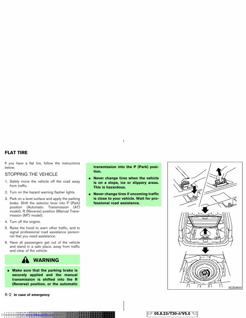
If you have a flat tire, follow the instructionsbelow.
STOPPING THE VEHICLE
1. Safely move the vehicle off the road awayfrom traffic.
2. Turn on the hazard warning flasher lights.
3. Park on a level surface and apply the parkingbrake. Shift the selector lever into P (Park)position (Automatic Transmission (AT)model), R (Reverse) position (Manual Trans-mission (MT) model).
4. Turn off the engine.
5. Raise the hood to warn other traffic, and tosignal professional road assistance person-nel that you need assistance.
6. Have all passengers get out of the vehicleand stand in a safe place, away from trafficand clear of the vehicle.
WARNING
� Make sure that the parking brake issecurely applied and the manualtransmission is shifted into the R(Reverse) position, or the automatic
transmission into the P (Park) posi-tion.
� Never change tires when the vehicleis on a slope, ice or slippery areas.This is hazardous.
� Never change tires if oncoming trafficis close to your vehicle. Wait for pro-fessional road assistance.
SCE0600
FLAT TIRE
6-2 In case of emergency
� 05.8.23/T30-J/V5.0 �Downloaded from www.Manualslib.com manuals search engine
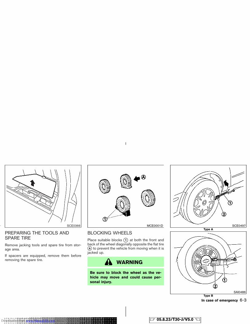
PREPARING THE TOOLS ANDSPARE TIRERemove jacking tools and spare tire from stor-age area.
If spacers are equipped, remove them beforeremoving the spare tire.
BLOCKING WHEELSPlace suitable blocks �1 at both the front andback of the wheel diagonally opposite the flat tire�A to prevent the vehicle from moving when it isjacked up.
WARNING
Be sure to block the wheel as the ve-hicle may move and could cause per-sonal injury.
SCE0366 MCE0001D SCE0497Type A
SAI0486Type B
In case of emergency 6-3
� 05.8.23/T30-J/V5.0 �Downloaded from www.Manualslib.com manuals search engine
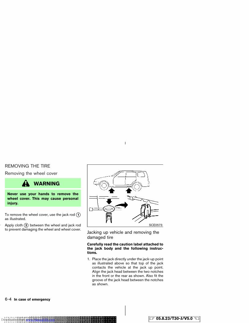
REMOVING THE TIRE
Removing the wheel cover
WARNING
Never use your hands to remove thewheel cover. This may cause personalinjury.
To remove the wheel cover, use the jack rod �1as illustrated.
Apply cloth �2 between the wheel and jack rodto prevent damaging the wheel and wheel cover.
Jacking up vehicle and removing thedamaged tireCarefully read the caution label attached tothe jack body and the following instruc-tions.
1. Place the jack directly under the jack-up pointas illustrated above so that top of the jackcontacts the vehicle at the jack up point.Align the jack head between the two notchesin the front or the rear as shown. Also fit thegroove of the jack head between the notchesas shown.
SCE0573
6-4 In case of emergency
� 05.8.23/T30-J/V5.0 �Downloaded from www.Manualslib.com manuals search engine
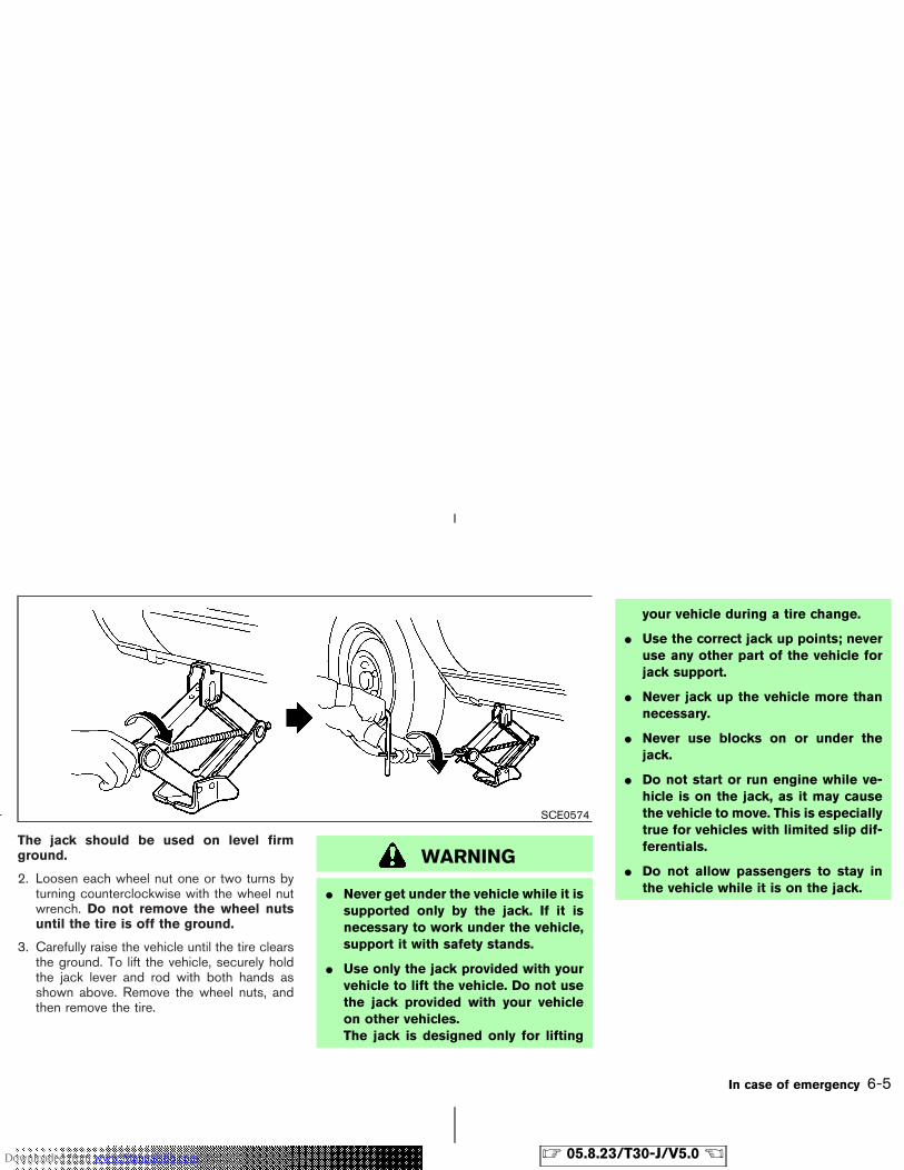
The jack should be used on level firmground.
2. Loosen each wheel nut one or two turns byturning counterclockwise with the wheel nutwrench. Do not remove the wheel nutsuntil the tire is off the ground.
3. Carefully raise the vehicle until the tire clearsthe ground. To lift the vehicle, securely holdthe jack lever and rod with both hands asshown above. Remove the wheel nuts, andthen remove the tire.
WARNING
� Never get under the vehicle while it issupported only by the jack. If it isnecessary to work under the vehicle,support it with safety stands.
� Use only the jack provided with yourvehicle to lift the vehicle. Do not usethe jack provided with your vehicleon other vehicles.The jack is designed only for lifting
your vehicle during a tire change.
� Use the correct jack up points; neveruse any other part of the vehicle forjack support.
� Never jack up the vehicle more thannecessary.
� Never use blocks on or under thejack.
� Do not start or run engine while ve-hicle is on the jack, as it may causethe vehicle to move. This is especiallytrue for vehicles with limited slip dif-ferentials.
� Do not allow passengers to stay inthe vehicle while it is on the jack.
SCE0574
In case of emergency 6-5
� 05.8.23/T30-J/V5.0 �Downloaded from www.Manualslib.com manuals search engine
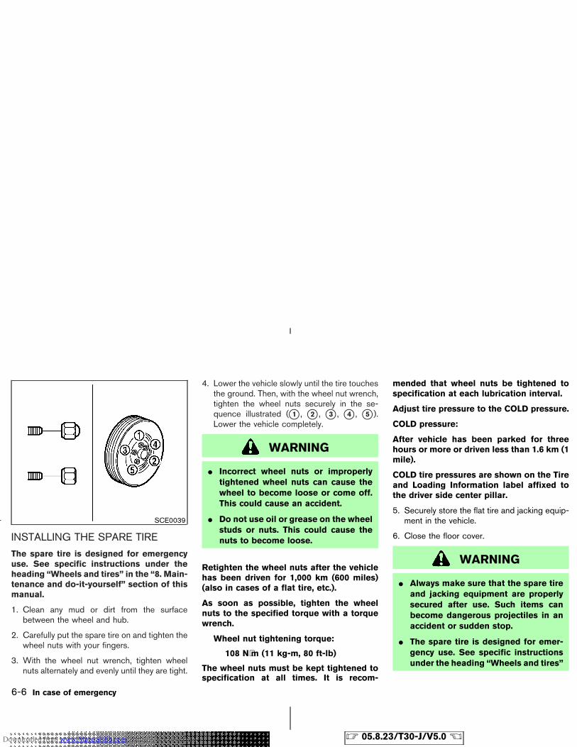
INSTALLING THE SPARE TIRE
The spare tire is designed for emergencyuse. See specific instructions under theheading “Wheels and tires” in the “8. Main-tenance and do-it-yourself” section of thismanual.
1. Clean any mud or dirt from the surfacebetween the wheel and hub.
2. Carefully put the spare tire on and tighten thewheel nuts with your fingers.
3. With the wheel nut wrench, tighten wheelnuts alternately and evenly until they are tight.
4. Lower the vehicle slowly until the tire touchesthe ground. Then, with the wheel nut wrench,tighten the wheel nuts securely in the se-quence illustrated (�1 , �2 , �3 , �4 , �5 ).Lower the vehicle completely.
WARNING
� Incorrect wheel nuts or improperlytightened wheel nuts can cause thewheel to become loose or come off.This could cause an accident.
� Do not use oil or grease on the wheelstuds or nuts. This could cause thenuts to become loose.
Retighten the wheel nuts after the vehiclehas been driven for 1,000 km (600 miles)(also in cases of a flat tire, etc.).
As soon as possible, tighten the wheelnuts to the specified torque with a torquewrench.
Wheel nut tightening torque:
108 N⋅m (11 kg-m, 80 ft-lb)
The wheel nuts must be kept tightened tospecification at all times. It is recom-
mended that wheel nuts be tightened tospecification at each lubrication interval.
Adjust tire pressure to the COLD pressure.
COLD pressure:
After vehicle has been parked for threehours or more or driven less than 1.6 km (1mile).
COLD tire pressures are shown on the Tireand Loading Information label affixed tothe driver side center pillar.
5. Securely store the flat tire and jacking equip-ment in the vehicle.
6. Close the floor cover.
WARNING
� Always make sure that the spare tireand jacking equipment are properlysecured after use. Such items canbecome dangerous projectiles in anaccident or sudden stop.
� The spare tire is designed for emer-gency use. See specific instructionsunder the heading “Wheels and tires”
SCE0039
6-6 In case of emergency
� 05.8.23/T30-J/V5.0 �Downloaded from www.Manualslib.com manuals search engine
in the “8. Maintenance and do-it-yourself” section of this manual.
To start your engine with a booster battery, theinstructions and precautions below must befollowed.
WARNING
� If done incorrectly, jump starting canlead to a battery explosion, resultingin severe injury or death. It could alsodamage your vehicle.
� Explosive hydrogen gas is alwayspresent in the vicinity of the battery.Keep all sparks and flames awayfrom the battery.
� Do not allow battery fluid to comeinto contact with eyes, skin, cloth orpainted surfaces. Battery fluid is acorrosive sulphuric acid solutionwhich can cause severe burns. If thefluid should come into contact withanything, immediately flush the con-tacted area with water.
� Keep battery out of the reach ofchildren.
� The booster battery must be rated at12 volts. Use of an improperly ratedbattery can damage your vehicle.
� Whenever working on or near a bat-tery, always wear suitable eye protec-tors (for example, goggles or indus-trial safety spectacles) and removerings, metal bands, or any other jew-elry. Do not lean over the batterywhen jump starting.
� Do not attempt to jump start a frozenbattery. It could explode and causeserious injury.
� Your vehicle has an automatic en-gine cooling fan. It could come on atany time. Keep hands and other ob-jects away from it.
JUMP STARTING
In case of emergency 6-7
� 05.8.23/T30-J/V5.0 �Downloaded from www.Manualslib.com manuals search engine
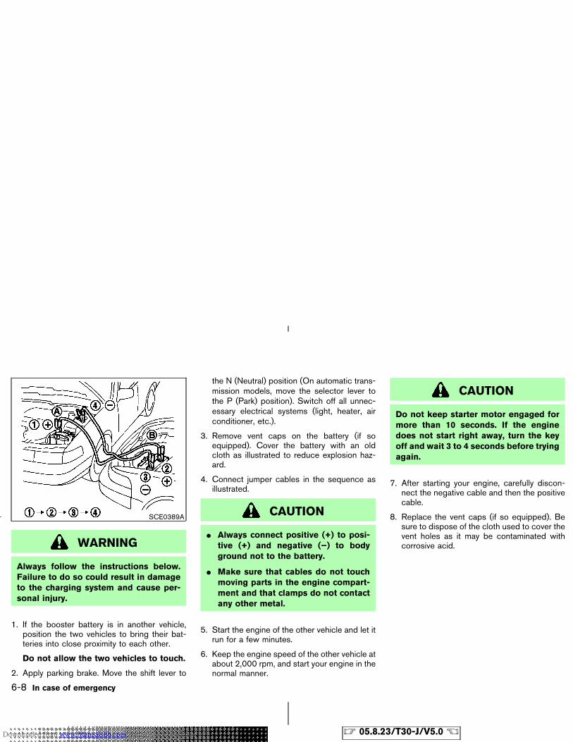
WARNING
Always follow the instructions below.Failure to do so could result in damageto the charging system and cause per-sonal injury.
1. If the booster battery is in another vehicle,position the two vehicles to bring their bat-teries into close proximity to each other.
Do not allow the two vehicles to touch.
2. Apply parking brake. Move the shift lever to
the N (Neutral) position (On automatic trans-mission models, move the selector lever tothe P (Park) position). Switch off all unnec-essary electrical systems (light, heater, airconditioner, etc.).
3. Remove vent caps on the battery (if soequipped). Cover the battery with an oldcloth as illustrated to reduce explosion haz-ard.
4. Connect jumper cables in the sequence asillustrated.
CAUTION
� Always connect positive (+) to posi-tive (+) and negative (−) to bodyground not to the battery.
� Make sure that cables do not touchmoving parts in the engine compart-ment and that clamps do not contactany other metal.
5. Start the engine of the other vehicle and let itrun for a few minutes.
6. Keep the engine speed of the other vehicle atabout 2,000 rpm, and start your engine in thenormal manner.
CAUTION
Do not keep starter motor engaged formore than 10 seconds. If the enginedoes not start right away, turn the keyoff and wait 3 to 4 seconds before tryingagain.
7. After starting your engine, carefully discon-nect the negative cable and then the positivecable.
8. Replace the vent caps (if so equipped). Besure to dispose of the cloth used to cover thevent holes as it may be contaminated withcorrosive acid.
SCE0389A
6-8 In case of emergency
� 05.8.23/T30-J/V5.0 �Downloaded from www.Manualslib.com manuals search engine
Do not attempt to start the engine by pushingthe vehicle.
CAUTION
� Automatic transmission models can-not be push started. Attempting to doso may cause transmission damage.
� Three way catalyst equipped modelsshould not be started by pushingsince the three way catalyst may bedamaged.
� Never try to start the vehicle by tow-ing it; when the engine starts, theforward surge could cause the ve-hicle to collide with the tow vehicle.
WARNING
� Do not continue to drive if your ve-hicle overheats. Doing so couldcause a vehicle fire.
� To avoid the danger of being scalded,never remove the radiator cap whilethe engine is still hot. When the ra-diator cap is removed, pressurizedhot water will spurt out, possiblycausing serious injury.
� Do not open the hood if steam iscoming out.
If your vehicle is overheating (indicated by anextremely high temperature gauge reading), or ifyou feel a lack of engine power, detect abnormalnoise, etc., take the following steps:
1. Move the vehicle safely off the road, apply theparking brake and move the shift lever to theN (Neutral) position (automatic transmissionto the P (Park) position).
Do not stop the engine.
2. Turn off the air conditioner switch. Open allthe windows, move the heater or air condi-
tioner temperature control to maximum hotand fan control to high speed.
3. If engine overheating is caused by climbing along hill on a hot day, run the engine at a fastidle (approximately 1,500 rpm) until the tem-perature gauge indication returns to normal.
4. Get out of the vehicle. Look and listen forsteam or coolant escaping from the radiatorbefore opening the hood. (If steam or coolantis escaping, turn off the engine.) Do not openthe hood further until no steam or coolant canbe seen.
5. Open the engine hood.
WARNING
If steam or water is coming from theengine, stand clear to prevent gettingburned.
6. Visually check if the cooling fan is running.The radiator hoses and radiator should notleak water.
If coolant is leaking or the cooling fan doesnot run, stop the engine.
PUSH STARTING IF YOUR VEHICLE OVERHEATS
In case of emergency 6-9
� 05.8.23/T30-J/V5.0 �Downloaded from www.Manualslib.com manuals search engine

WARNING
� Be careful not to allow your hands,hair, jewelry or clothing to come intocontact with, or to get caught in thecooling fan, or drive belt.
� The engine cooling fan can start atany time when the coolant tempera-ture is high.
7. After the engine cools down, check the cool-ant level in the reservoir tank with the enginerunning. Add coolant to the reservoir tank ifnecessary. Have your vehicle repaired at thenearest NISSAN dealer.
When towing your vehicle, all provincial andlocal regulations for towing must be followed.Incorrect towing equipment could damage yourvehicle. Towing instructions are available from aNISSAN dealer. Local service operators aregenerally familiar with the applicable laws andprocedures for towing. To assure proper towingand to prevent accidental damage to your ve-hicle, NISSAN recommends having a serviceoperator tow your vehicle. It is advisable to havethe service operator carefully read the followingprecautions.
WARNING
� Never ride in a vehicle that is beingtowed.
� Never get under your vehicle after ithas been lifted by a tow truck.
CAUTION
� When towing, make sure that thetransmission, axles, steering systemand powertrain are in working condi-tion. If any unit is damaged, dollies
must be used.
� Always attach safety chains beforetowing.
TOWING YOUR VEHICLE
6-10 In case of emergency
� 05.8.23/T30-J/V5.0 �Downloaded from www.Manualslib.com manuals search engine
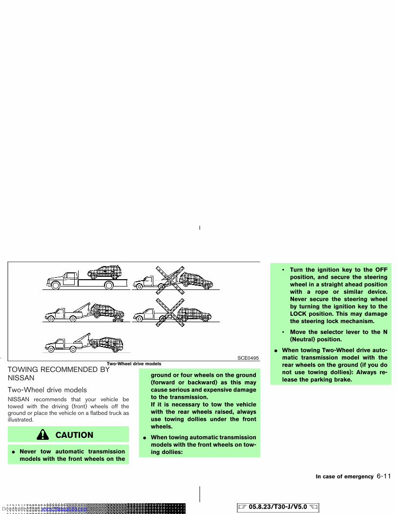
TOWING RECOMMENDED BYNISSAN
Two-Wheel drive modelsNISSAN recommends that your vehicle betowed with the driving (front) wheels off theground or place the vehicle on a flatbed truck asillustrated.
CAUTION
� Never tow automatic transmissionmodels with the front wheels on the
ground or four wheels on the ground(forward or backward) as this maycause serious and expensive damageto the transmission.If it is necessary to tow the vehiclewith the rear wheels raised, alwaysuse towing dollies under the frontwheels.
� When towing automatic transmissionmodels with the front wheels on tow-ing dollies:
• Turn the ignition key to the OFFposition, and secure the steeringwheel in a straight ahead positionwith a rope or similar device.Never secure the steering wheelby turning the ignition key to theLOCK position. This may damagethe steering lock mechanism.
• Move the selector lever to the N(Neutral) position.
� When towing Two-Wheel drive auto-matic transmission model with therear wheels on the ground (if you donot use towing dollies): Always re-lease the parking brake.
SCE0495Two-Wheel drive models
In case of emergency 6-11
� 05.8.23/T30-J/V5.0 �Downloaded from www.Manualslib.com manuals search engine
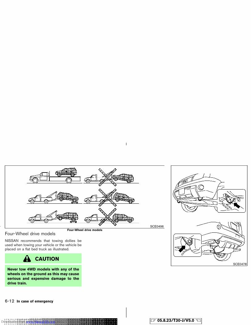
Four-Wheel drive modelsNISSAN recommends that towing dollies beused when towing your vehicle or the vehicle beplaced on a flat bed truck as illustrated.
CAUTION
Never tow 4WD models with any of thewheels on the ground as this may causeserious and expensive damage to thedrive train.
SCE0496Four-Wheel drive models
SCE0478
6-12 In case of emergency
� 05.8.23/T30-J/V5.0 �Downloaded from www.Manualslib.com manuals search engine
VEHICLE RECOVERY (Freeing astuck vehicle)
WARNING
� Stand clear of a stuck vehicle.
� Do not spin the tires at a high speed.This could cause them to explodeand result in serious injury. Parts ofyour vehicle could also overheat andbe damaged.
CAUTION
� Tow chains or cables must be at-tached only to the vehicle recoveryhooks or main structural members ofthe vehicle. Otherwise, the vehiclebody will be damaged.
� Do not use the vehicle tie downs to freea vehicle stuck in sand, snow, mud, etc.Never tow the vehicle using the vehicletie downs or recovery hooks.
� Always pull the cable straight out
from the front of the vehicle. Neverpull on the hook at an angle.
� Pulling devices should be routed sothey do not touch any part of thesuspension, steering, brake or cool-ing systems.
� Pulling devices such as ropes or can-vas straps are not recommended foruse in vehicle towing or recovery.
If your vehicle is stuck in sand, snow, mud, etc.,use the following procedure:
1. Turn off the Vehicle Dynamic Control (VDC)system.
2. Make sure the area in front and behind thevehicle is clear of obstructions.
3. Turn the steering wheel right and left to clearan area around the front tires.
4. Slowly rock the vehicle forward and back-ward.
� Shift back and forth between R (reverse) andD (drive).
� Apply the accelerator as little as possible tomaintain the rocking motion.
� Release the accelerator pedal before shiftingbetween R and D.
� Do not spin the tires above 55 km/h (35MPH).
5. If the vehicle can not be freed after a fewtries, contact a professional towing service toremove the vehicle.
In case of emergency 6-13
� 05.8.23/T30-J/V5.0 �Downloaded from www.Manualslib.com manuals search engine

MEMO
6-14 In case of emergency
� 05.8.23/T30-J/V5.0 �Downloaded from www.Manualslib.com manuals search engine
7 Appearance and care
Cleaning exterior ................................................................... 7-2Washing ............................................................................ 7-2Removing spots .............................................................. 7-2Waxing ............................................................................... 7-2Glass .................................................................................. 7-3Underbody ........................................................................ 7-3Aluminum alloy wheels .................................................. 7-3Chrome parts ................................................................... 7-3Tire dressing .................................................................... 7-3Plastic parts ..................................................................... 7-3
Cleaning interior .................................................................... 7-4
Floor mats ......................................................................... 7-4Glass .................................................................................. 7-5Seat belts ......................................................................... 7-5Luggage floor board........................................................ 7-5
Corrosion protection ............................................................ 7-5Most common factors contributing to vehiclecorrosion ........................................................................... 7-5Environmental factors influence the rate ofcorrosion ........................................................................... 7-5To protect your vehicle from corrosion ..................... 7-6
� 05.8.23/T30-J/V5.0 �Downloaded from www.Manualslib.com manuals search engine
In order to maintain the appearance of yourvehicle, it is important to take proper care of it.
In the following cases, please wash your vehicleas soon as possible to protect the paint surface.
� After a rainfall to prevent possible damagefrom acid rain
� After driving on coastal roads
� When contaminants such as soot, bird drop-pings, tree sap, metal particles or bugs get onthe paint surface
� When dust or mud builds up on the surface
Whenever possible, store or park your vehicleinside a garage or in a covered area.
When it is necessary to park outside, park in ashady area or protect the vehicle with a bodycover.
Be careful not to scratch the paint surfacewhen putting on or removing the bodycover.
WASHINGWash dirt off the vehicle with a wet sponge andplenty of water. Clean the vehicle thoroughlyusing a mild soap, a special vehicle soap or ageneral purpose dishwashing liquid mixed withclean, lukewarm (never hot) water.
CAUTION
� Do not use strong household soap,strong chemical detergents, gasolineor solvents.
� Do not wash the vehicle in directsunlight or while the vehicle body ishot, as the surface may becomewater-spotted.
� Avoid using tight-napped or roughcloths, such as washing mitts. Caremust be taken when removingcaked-on dirt or other foreign sub-stances so that the paint surface isnot scratched or damaged.
Rinse the vehicle again with plenty of cleanwater.
Inside flanges, seams and folds on the doors,hatches and hood are particularly vulnerable tothe effects of road salt. Therefore, these areasmust be regularly cleaned. Make sure that thedrain holes in the lower edge of the door areopen. Spray water under the body and in thewheel wells to loosen the dirt and wash awayroad salt.
Avoid leaving water spots on the paint surfaceby using a damp chamois to dry the vehicle.
REMOVING SPOTSRemove tar and oil spots, industrial dust, insects,and tree sap as quickly as possible from thesurface of the paint to avoid lasting damage orstaining. Special cleaning products are availableat a NISSAN dealer or any automotive accessorystore.
WAXINGRegular waxing protects the paint surface andhelps retain new vehicle appearance. After wax-ing, polishing is recommended to removebuilt-up residue and to avoid a weathered ap-pearance.
If you wish to wax your vehicle, only use a waxspecified for use over clear coats, such asNISSAN Liquid or Spray Wax. A NISSAN dealercan assist you in choosing the proper product.
� Wax your vehicle only after a thorough wash-ing. Follow the instructions supplied with thewax.
� Do not use a wax containing any abrasives,cutting compounds or cleaners that maydamage the vehicle finish.
CLEANING EXTERIOR
7-2 Appearance and care
� 05.8.23/T30-J/V5.0 �Downloaded from www.Manualslib.com manuals search engine
Machine compounding or aggressive pol-ishing on a base coat/clear coat paintfinish may dull the finish or leave swirlmarks.
GLASSUse glass cleaner to remove smoke and dust filmfrom the glass surfaces. It is normal for glass tobecome coated with a film after the vehicle isparked in the hot sun. Glass cleaner and a softcloth will easily remove this film.
UNDERBODYIn areas where road salt is used in winter, theunderbody must be cleaned regularly. This willprevent dirt and salt from building up and caus-ing underbody and suspension corrosion. Be-fore the winter period and again in the spring, theunderseal must be checked and, if necessary,re-treated.
ALUMINUM ALLOY WHEELSWash regularly, especially during winter monthsin areas where road salt is used. Salt coulddiscolor the wheel if not removed.
CHROME PARTSClean all chrome parts regularly with a non-abrasive chrome polish to maintain the finish.
TIRE DRESSINGNISSAN does not recommend the use of tiredressings. Tire manufacturers apply a coating tothe tires to help reduce discoloration of therubber. If a tire dressing is applied to the tires, itmay react with the coating and form a com-pound. This compound may come off the tirewhile driving and stain the vehicle paint.
If you choose to use a tire dressing, take thefollowing precautions:
� Use a water-based tire dressing. The coatingon the tire dissolves more easily with anoil-based tire dressing.
� Apply a light coat of tire dressing to helpprevent it from entering the tire tread/grooves(where it would be difficult to remove).
� Wipe off excess tire dressing using a drytowel. Make sure the tire dressing is com-pletely removed from the tire tread/grooves.
� Allow the tire dressing to dry as recom-mended by tire dressing manufacturer.
PLASTIC PARTSPlastic parts can be cleaned with a mild soapsolution. If the dirt cannot be easily removed, usea plastic cleaner. Do not use any solvents.
Appearance and care 7-3
� 05.8.23/T30-J/V5.0 �Downloaded from www.Manualslib.com manuals search engine
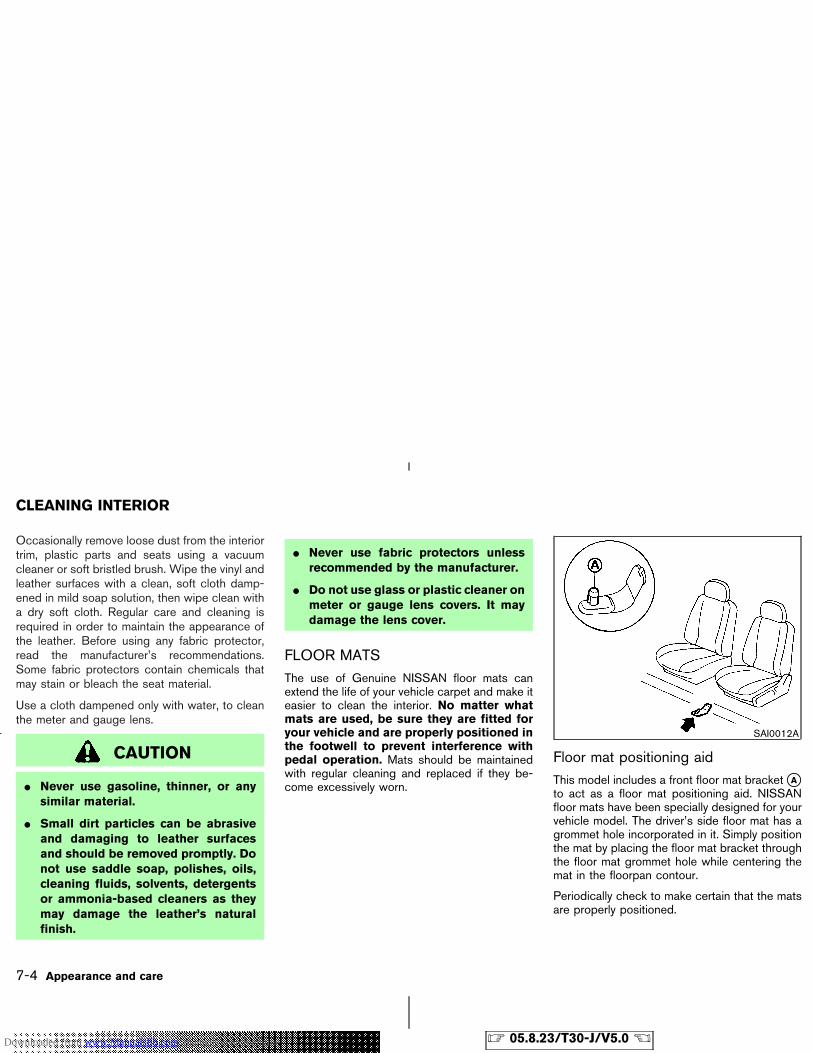
Occasionally remove loose dust from the interiortrim, plastic parts and seats using a vacuumcleaner or soft bristled brush. Wipe the vinyl andleather surfaces with a clean, soft cloth damp-ened in mild soap solution, then wipe clean witha dry soft cloth. Regular care and cleaning isrequired in order to maintain the appearance ofthe leather. Before using any fabric protector,read the manufacturer’s recommendations.Some fabric protectors contain chemicals thatmay stain or bleach the seat material.
Use a cloth dampened only with water, to cleanthe meter and gauge lens.
CAUTION
� Never use gasoline, thinner, or anysimilar material.
� Small dirt particles can be abrasiveand damaging to leather surfacesand should be removed promptly. Donot use saddle soap, polishes, oils,cleaning fluids, solvents, detergentsor ammonia-based cleaners as theymay damage the leather’s naturalfinish.
� Never use fabric protectors unlessrecommended by the manufacturer.
� Do not use glass or plastic cleaner onmeter or gauge lens covers. It maydamage the lens cover.
FLOOR MATSThe use of Genuine NISSAN floor mats canextend the life of your vehicle carpet and make iteasier to clean the interior. No matter whatmats are used, be sure they are fitted foryour vehicle and are properly positioned inthe footwell to prevent interference withpedal operation. Mats should be maintainedwith regular cleaning and replaced if they be-come excessively worn.
Floor mat positioning aidThis model includes a front floor mat bracket �Ato act as a floor mat positioning aid. NISSANfloor mats have been specially designed for yourvehicle model. The driver’s side floor mat has agrommet hole incorporated in it. Simply positionthe mat by placing the floor mat bracket throughthe floor mat grommet hole while centering themat in the floorpan contour.
Periodically check to make certain that the matsare properly positioned.
SAI0012A
CLEANING INTERIOR
7-4 Appearance and care
� 05.8.23/T30-J/V5.0 �Downloaded from www.Manualslib.com manuals search engine
GLASSUse glass cleaner to remove smoke and dust filmfrom the glass surfaces. It is normal for glass tobecome coated with a film after the vehicle isparked in the hot sun. Glass cleaner and a softcloth will easily remove this film.
CAUTION
When cleaning the inside of the win-dows, do not use sharp-edged tools,abrasive cleaners or chlorine-based dis-infectant cleaners. They could damagethe electrical conductors, such as radioantenna elements or rear window de-froster elements.
SEAT BELTSThe seat belts can be cleaned by wiping themwith a sponge dampened in a mild soap solution.Allow the belts to dry completely before usingthem.
WARNING
Do not allow wet belts to roll up in the
retractor. NEVER use bleach, dye, orchemical solvents since these may se-verely weaken the seat belt webbing.
LUGGAGE FLOOR BOARDThe luggage floor board can be washed. Towash the luggage floor board, remove it from theluggage area. (See “LUGGAGE FLOORBOARD” in the “2. Instruments and controls”section.)
CAUTION
� Never use benzine, thinner or anysimilar material for washing the lug-gage floor board.
� Wipe the luggage floor board drybefore putting it back in the vehicle.
MOST COMMON FACTORSCONTRIBUTING TO VEHICLECORROSION� The accumulation of moisture-retaining dirt
and debris in body panel sections, cavities,and other areas.
� Damage to paint and other protective coat-ings caused by gravel and stone chips orminor traffic accidents.
ENVIRONMENTAL FACTORSINFLUENCE THE RATE OFCORROSION
MoistureAccumulation of sand, dirt and water on thevehicle body underside can accelerate corro-sion. Wet floor coverings will not dry completelyinside the vehicle, and should be removed fordrying to avoid floor panel corrosion.
Relative humidityCorrosion will be accelerated in areas of highrelative humidity, especially those areas wherethe temperatures stay above freezing and whereatmospheric pollution exists and road salt isused.
CORROSION PROTECTION
Appearance and care 7-5
� 05.8.23/T30-J/V5.0 �Downloaded from www.Manualslib.com manuals search engine
TemperatureA temperature increase will accelerate the rateof corrosion to those parts which are not wellventilated.
Air pollutionIndustrial pollution, the presence of salt in the airin coastal areas, or heavy road salt use willaccelerate the corrosion process. Road salt willalso accelerate the disintegration of paint sur-faces.
TO PROTECT YOUR VEHICLEFROM CORROSION� Wash and wax your vehicle often to keep the
vehicle clean.
� Always check for minor damage to the paintand repair it as soon as possible.
� Keep drain holes at the bottom of the doorsopen to avoid water accumulation.
� Check the underbody for accumulation ofsand, dirt or salt. If present, wash with wateras soon as possible.
CAUTION
� NEVER remove dirt, sand or otherdebris from the passenger compart-ment by washing it out with a hose.Remove dirt with a vacuum cleaner orbroom.
� Never allow water or other liquids tocome in contact with electronic com-ponents inside the vehicle as thismay damage them.
Chemicals used for road surface de-icing areextremely corrosive. They accelerate corrosionand deterioration of underbody componentssuch as the exhaust system, fuel and brake lines,brake cables, floor pan and fenders.
In winter, the underbody must be cleanedperiodically.
For additional protection against rust and corro-sion, which may be required in some areas,consult a NISSAN dealer.
7-6 Appearance and care
� 05.8.23/T30-J/V5.0 �Downloaded from www.Manualslib.com manuals search engine
8 Maintenance and do-it-yourself
Maintenance requirements ................................................. 8-2Scheduled maintenance ............................................... 8-2General maintenance ..................................................... 8-2Where to go for service ................................................ 8-2
General maintenance ........................................................... 8-2Explanation of general maintenance items ............... 8-2Maintenance precautions .............................................. 8-5
Engine compartment check locations ............................. 8-7Engine cooling system ........................................................ 8-8
Checking engine coolant level .................................... 8-8Changing engine coolant ............................................. 8-9
Engine oil ............................................................................. 8-10Checking engine oil level ........................................... 8-10Changing engine oil .................................................... 8-11Changing engine oil filter ........................................... 8-12
Automatic transmission fluid ........................................... 8-13Power steering fluid .......................................................... 8-14Brake and clutch fluid ....................................................... 8-14Window washer fluid ........................................................ 8-15Battery ................................................................................... 8-16
Jump starting ................................................................. 8-17Drive belts ............................................................................ 8-17Spark plugs ......................................................................... 8-18
Replacing spark plugs ................................................ 8-18Air cleaner ............................................................................ 8-18Windshield wiper blades ................................................. 8-19
Cleaning ......................................................................... 8-19Replacing ....................................................................... 8-20
Parking brake and brake pedal ...................................... 8-21Checking parking brake ............................................. 8-21Checking brake pedal ................................................. 8-21Brake booster ................................................................ 8-22
Fuses ..................................................................................... 8-22Engine compartment ................................................... 8-23Passenger compartment ............................................ 8-24
Keyfob battery replacement ............................................ 8-24Lights ..................................................................................... 8-26
Headlights ...................................................................... 8-27Headlight aim ................................................................ 8-28Exterior and interior lights .......................................... 8-30
Wheels and tires ................................................................ 8-34Tire pressure ................................................................. 8-34Tire labeling ................................................................... 8-37Types of tires ................................................................. 8-39Tire chains ...................................................................... 8-40Changing wheels and tires ........................................ 8-41
� 05.8.23/T30-J/V5.0 �Downloaded from www.Manualslib.com manuals search engine
Your new NISSAN has been designed to haveminimum maintenance requirements with longerservice intervals to save you both time andmoney. However, some day-to-day and regularmaintenance is essential to maintain yourNISSAN’s good mechanical condition, as wellas its emission and engine performance.
It is the owner’s responsibility to make sure thatscheduled maintenance, as well as generalmaintenance, is performed.
As the vehicle owner, you are the only one whocan ensure that your vehicle receives the propermaintenance care. You are a vital link in themaintenance chain.
SCHEDULED MAINTENANCE
For your convenience, both required and op-tional scheduled maintenance items are de-scribed and listed in your “Service and Mainte-nance Guide”. You must refer to that guide toensure that necessary maintenance is performedon your NISSAN at regular intervals.
GENERAL MAINTENANCE
General maintenance includes those itemswhich should be checked during normal day-to-day operation. They are essential for propervehicle operation. It is your responsibility to
perform these procedures regularly as pre-scribed.
Performing general maintenance checks requireminimal mechanical skill and only a few generalautomotive tools.
These checks or inspections can be done byyourself, a qualified technician or, if you prefer, aNISSAN dealer.
WHERE TO GO FOR SERVICEIf maintenance service is required or your vehicleappears to malfunction, have the systemschecked and tuned by a NISSAN dealer.
NISSAN technicians are well-trained specialistsand are kept up to date with the latest serviceinformation through technical bulletins, servicetips, and in-dealership training programs. Theyare completely qualified to work on NISSANvehicles before they work on your vehicle,rather than after they have worked on it.
You can be confident that a NISSAN dealer’sservice department performs the best job tomeet the maintenance requirements of your ve-hicle — in a reliable and economic way.
During the normal day-to-day operation of thevehicle, general maintenance should be per-formed regularly as prescribed in this section. Ifyou detect any unusual sounds, vibrations orsmell, be sure to check for the cause or have aNISSAN dealer check it promptly. In addition,you should notify a NISSAN dealer if you thinkthat repairs are required.
When performing any checks or maintenancework, closely observe the “Maintenance precau-tions” later in this section.
EXPLANATION OF GENERALMAINTENANCE ITEMSAdditional information on the followingitems with “*” is found later in this section.
Outside the vehicleThe maintenance items listed here should beperformed from time to time, unless otherwisespecified.
Doors and engine hood:
Check that all doors and the engine hood oper-ate smoothly. Also make sure that all latches locksecurely. Lubricate if necessary. Make sure thatthe secondary latch keeps the hood from open-ing when the primary latch is released.
When driving in areas using road salt or other
MAINTENANCE REQUIREMENTS GENERAL MAINTENANCE
8-2 Maintenance and do-it-yourself
� 05.8.23/T30-J/V5.0 �Downloaded from www.Manualslib.com manuals search engine
corrosive materials, check lubrication frequently.
Lights*:
Clean the headlights on a regular basis. Makesure that the headlights, stop lights, tail lights,turn signal lights, and other lights are all operat-ing properly and installed securely. Also checkheadlight aim.
Road wheel nuts (lug nuts)*:
When checking the tires, make sure no wheelnuts are missing, and check for any loose wheelnuts. Tighten if necessary.
Tire rotation*:
Tires should be rotated every 7,500 miles(12,000 km). However, the timing for tire rotationmay vary according to your driving habits androad surface conditions.
Tires*:
Check the pressure with a gauge often andalways prior to long distance trips. If necessary,adjust the pressure in all tires, including thespare, to the pressure specified. Check carefullyfor damage, cuts or excessive wear.
Tire, wheel alignment and balance:
If the vehicle should pull to either side whiledriving on a straight and level road, or if youdetect uneven or abnormal tire wear, there may
be a need for wheel alignment.
If the steering wheel or seat vibrates at normalhighway speeds, wheel balancing may beneeded.
For additional information regarding tires, refer to“Tire Safety Information” in the Warranty Infor-mation Booklet (Canada).
Windshield:
Clean the windshield on a regular basis. Checkthe windshield at least every six months forcracks or other damage. Have a damaged wind-shield repaired by a qualified repair facility.
Windshield wiper blades*:
Check for cracks or wear if they do not wipeproperly.
Inside the vehicleThe maintenance items listed here should bechecked on a regular basis, such as whenperforming periodic maintenance, cleaning thevehicle, etc.
Accelerator pedal:
Check the pedal for smooth operation and makesure the pedal does not catch or require uneveneffort. Keep the floor mats away from the pedal.
Brake pedal and booster*:
Check the pedal for smooth operation and makesure it has the proper distance under it whendepressed fully. Check the brake booster func-tion. Be sure to keep floor mats away from thepedal.
Brakes:
Check that the brakes do not pull the vehicle toone side when applied.
Parking brake*:
Check that the lever has the proper travel andmake sure that the vehicle is held securely on afairly steep hill when only the parking brake isapplied.
Seat belts:
Check that all parts of the seat belt system (forexample, buckles, anchors, adjusters and retrac-tors) operate properly and smoothly, and areinstalled securely. Check the belt webbing forcuts, fraying, wear or damage.
Seats:
Check seat position controls such as seat ad-justers, seatback recliner, etc. to ensure theyoperate smoothly and that all latches lock se-curely in every position. Check that the headrestraints move up and down smoothly and that
Maintenance and do-it-yourself 8-3
� 05.8.23/T30-J/V5.0 �Downloaded from www.Manualslib.com manuals search engine
the locks hold securely in all latched positions.
Steering wheel:
Check for changes in the steering conditions,such as excessive free play, hard steering orstrange noises.
Warning lights and chimes:
Make sure that all warning lights and chimes areoperating properly.
Windshield defroster:
Check that the air comes out of the defrosteroutlets properly and in good quantity whenoperating the heater or air conditioner.
Windshield wiper and washer*:
Check that the wipers and washer operateproperly and that the wipers do not streak.
Under the hood and the vehicleThe maintenance items listed here should bechecked periodically (for example, each time youcheck the engine oil or refuel).
Battery*:
Check the fluid level in each cell. It should bebetween the upper level and lower level lines.Vehicles operated in high temperatures or undersevere conditions require frequent checks of thebattery fluid level.
Brake and clutch fluid level*:
Make sure that the brake and clutch fluid level isbetween the MAX and MIN lines on the reservoir.
Engine coolant level*:
Check the coolant level when the engine is cold.
Engine drive belts*:
Make sure that no belt is frayed, worn, crackedor oily.
Engine oil level*:
Check the level on the dipstick after parking thevehicle on a level spot and turning off the engine.
Exhaust system:
Make sure there are no loose supports, cracks orholes. If the sound of the exhaust seems unusualor there is a smell of exhaust fumes, immediatelylocate the trouble and correct it. (See “Precau-tions when starting and driving” in the “5. Start-ing and driving” section for exhaust gas (carbonmonoxide).)
Fluid leaks:
Check under the vehicle for fuel, oil, water orother fluid leaks after the vehicle has beenparked for a while. Water dripping from the airconditioner after use is normal. If you shouldnotice any leaks or if gasoline fumes are evident,
check for the cause and have it corrected imme-diately.
Power steering fluid level* and lines:
Check the level in the reservoir tank with theengine off. Check the lines for proper attach-ment, leaks, cracks, etc.
Radiator and hoses:
Check the front of the radiator and clean off anydirt, insects, leaves, etc., that may have accumu-lated. Make sure the hoses have no cracks,deformation, deterioration or loose connections.
Underbody:
The underbody is frequently exposed to corro-sive substances such as those used on icy roadsor to control dust. It is very important to removethese substances, otherwise rust will form on thefloor pan, frame, fuel lines and around the ex-haust system. At the end of winter, the under-body should be thoroughly flushed with plainwater, being careful to clean those areas wheremud and dirt may accumulate. For additionalinformation, see “Cleaning exterior” in the “7.Appearance and care” section.
Windshield washer fluid*:
Check that there is adequate fluid in the tank.
8-4 Maintenance and do-it-yourself
� 05.8.23/T30-J/V5.0 �Downloaded from www.Manualslib.com manuals search engine
MAINTENANCE PRECAUTIONS
When performing any inspection or maintenancework on your vehicle, always take care to preventserious accidental injury to yourself or damage tothe vehicle. The following are general precau-tions which should be closely observed.
WARNING
� Park the vehicle on a level surface,apply the parking brake securely andblock the wheels to prevent the ve-hicle from moving. For a manualtransmission, move the shift lever tothe N (Neutral) position. For an auto-matic transmission, move the selec-tor lever to the P (Park) position.
� Be sure the ignition key is in the OFFor LOCK position when performingany parts replacement or repairs.
� Your vehicle is equipped with an au-tomatic engine cooling fan. It maycome on at any time without warning,even if the ignition key is in the OFFposition and the engine is not run-ning. To avoid injury, always discon-
nect the negative battery cable be-fore working near the fan.
� If you must work with the enginerunning, keep your hands, clothing,hair and tools away from movingfans, belts and any other movingparts.
� It is advisable to secure or removeany loose clothing and any jewelry,such as rings, watches, etc. beforeworking on your vehicle.
� Always wear eye protection when-ever you work on your vehicle.
� If you must run the engine in anenclosed space such as a garage, besure there is proper ventilation forexhaust gases to escape.
� Never get under the vehicle while it issupported only by a jack. If it is nec-essary to work under the vehicle,support it with safety stands.
� Keep smoking materials, flame andsparks away from fuel and thebattery.
� On gasoline engine models with theMultiport Fuel Injection (MFI) Sys-tem, the fuel filter or fuel lines shouldbe serviced by a NISSAN dealer be-cause the fuel lines are under highpressure even when the engine is off.
CAUTION
� Do not work under the hood whilethe engine is hot. Turn off the engineand wait until it cools down.
� Never connect or disconnect eitherthe battery or any transistorizedcomponent connector while the igni-tion key is on.
� Never leave any engine or automatictransmission related component har-ness connectors disconnected whilethe ignition key is on.
� Avoid direct contact with used engineoil and coolant. Improperly disposedengine oil, engine coolant and/orother vehicle fluids can hurt the envi-
Maintenance and do-it-yourself 8-5
� 05.8.23/T30-J/V5.0 �Downloaded from www.Manualslib.com manuals search engine
ronment. Always conform to localregulations for disposal of vehiclefluid.
This “8. Maintenance and do-it-yourself” sectiongives instructions regarding only those itemswhich are relatively easy for an owner to perform.
A genuine NISSAN Service Manual is also avail-able. See “Owner’s Manual/Service Manual or-der information” in the “9. Technical and con-sumer information” section.
You should be aware that incomplete or im-proper servicing may result in operating difficul-ties or excessive emissions, and could affectyour warranty coverage. If in doubt about anyservicing, have it done by a NISSAN dealer.
8-6 Maintenance and do-it-yourself
� 05.8.23/T30-J/V5.0 �Downloaded from www.Manualslib.com manuals search engine
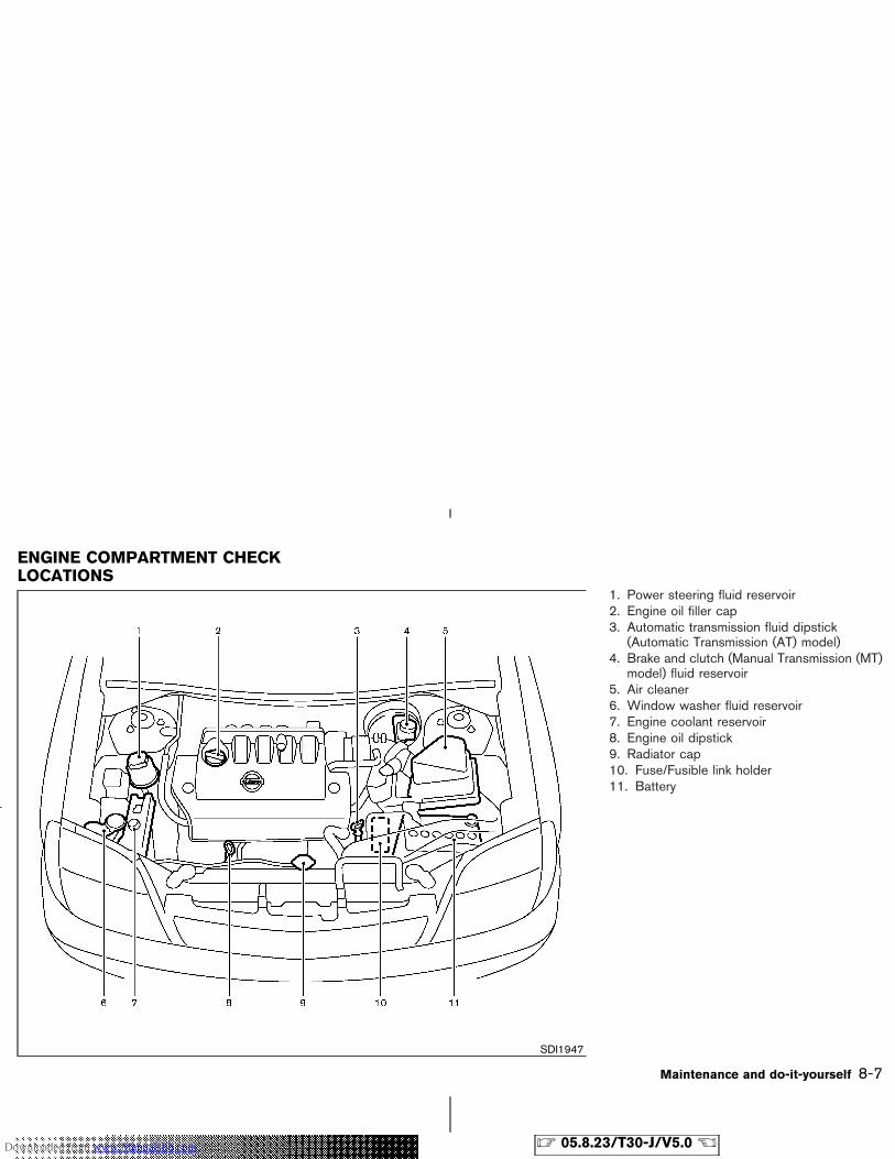
1. Power steering fluid reservoir2. Engine oil filler cap3. Automatic transmission fluid dipstick
(Automatic Transmission (AT) model)4. Brake and clutch (Manual Transmission (MT)
model) fluid reservoir5. Air cleaner6. Window washer fluid reservoir7. Engine coolant reservoir8. Engine oil dipstick9. Radiator cap10. Fuse/Fusible link holder11. Battery
SDI1947
ENGINE COMPARTMENT CHECKLOCATIONS
Maintenance and do-it-yourself 8-7
� 05.8.23/T30-J/V5.0 �Downloaded from www.Manualslib.com manuals search engine
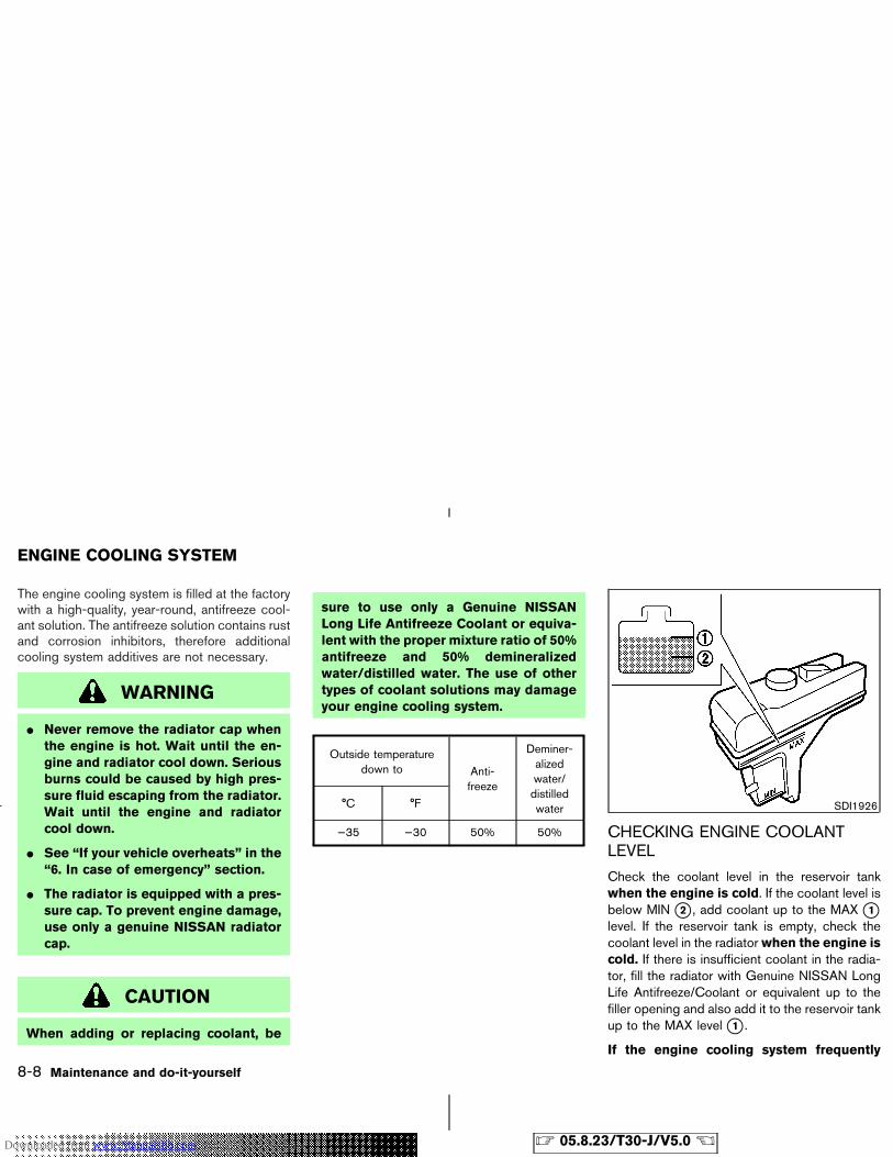
The engine cooling system is filled at the factorywith a high-quality, year-round, antifreeze cool-ant solution. The antifreeze solution contains rustand corrosion inhibitors, therefore additionalcooling system additives are not necessary.
WARNING
� Never remove the radiator cap whenthe engine is hot. Wait until the en-gine and radiator cool down. Seriousburns could be caused by high pres-sure fluid escaping from the radiator.Wait until the engine and radiatorcool down.
� See “If your vehicle overheats” in the“6. In case of emergency” section.
� The radiator is equipped with a pres-sure cap. To prevent engine damage,use only a genuine NISSAN radiatorcap.
CAUTION
When adding or replacing coolant, be
sure to use only a Genuine NISSANLong Life Antifreeze Coolant or equiva-lent with the proper mixture ratio of 50%antifreeze and 50% demineralizedwater/distilled water. The use of othertypes of coolant solutions may damageyour engine cooling system.
Outside temperaturedown to Anti-
freeze
Deminer-alizedwater/distilledwater°C °F
−35 −30 50% 50% CHECKING ENGINE COOLANTLEVEL
Check the coolant level in the reservoir tankwhen the engine is cold. If the coolant level isbelow MIN �2 , add coolant up to the MAX �1level. If the reservoir tank is empty, check thecoolant level in the radiatorwhen the engine iscold. If there is insufficient coolant in the radia-tor, fill the radiator with Genuine NISSAN LongLife Antifreeze/Coolant or equivalent up to thefiller opening and also add it to the reservoir tankup to the MAX level �1 .
If the engine cooling system frequently
SDI1926
ENGINE COOLING SYSTEM
8-8 Maintenance and do-it-yourself
� 05.8.23/T30-J/V5.0 �Downloaded from www.Manualslib.com manuals search engine
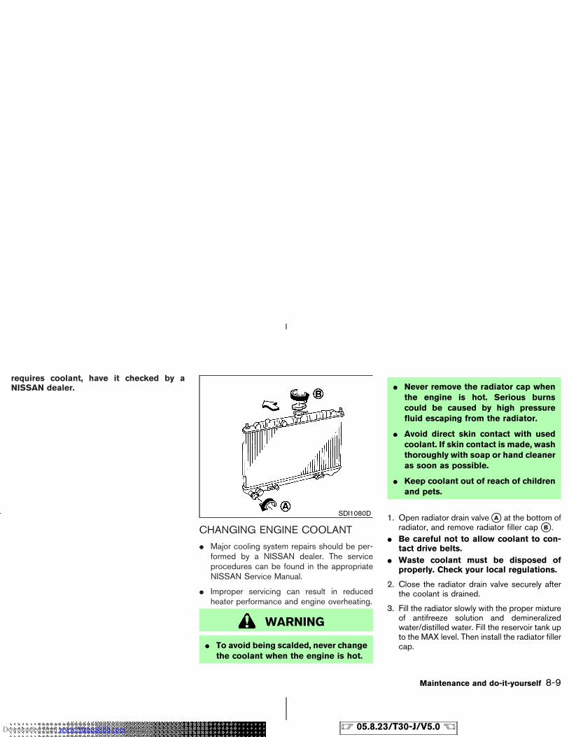
requires coolant, have it checked by aNISSAN dealer.
CHANGING ENGINE COOLANT
� Major cooling system repairs should be per-formed by a NISSAN dealer. The serviceprocedures can be found in the appropriateNISSAN Service Manual.
� Improper servicing can result in reducedheater performance and engine overheating.
WARNING
� To avoid being scalded, never changethe coolant when the engine is hot.
� Never remove the radiator cap whenthe engine is hot. Serious burnscould be caused by high pressurefluid escaping from the radiator.
� Avoid direct skin contact with usedcoolant. If skin contact is made, washthoroughly with soap or hand cleaneras soon as possible.
� Keep coolant out of reach of childrenand pets.
1. Open radiator drain valve �A at the bottom ofradiator, and remove radiator filler cap �B .
� Be careful not to allow coolant to con-tact drive belts.
� Waste coolant must be disposed ofproperly. Check your local regulations.
2. Close the radiator drain valve securely afterthe coolant is drained.
3. Fill the radiator slowly with the proper mixtureof antifreeze solution and demineralizedwater/distilled water. Fill the reservoir tank upto the MAX level. Then install the radiator fillercap.
SDI1080D
Maintenance and do-it-yourself 8-9
� 05.8.23/T30-J/V5.0 �Downloaded from www.Manualslib.com manuals search engine
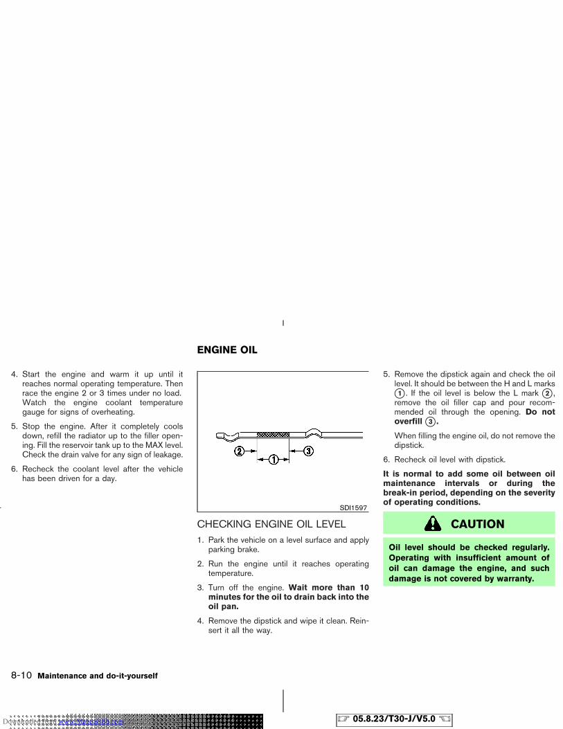
4. Start the engine and warm it up until itreaches normal operating temperature. Thenrace the engine 2 or 3 times under no load.Watch the engine coolant temperaturegauge for signs of overheating.
5. Stop the engine. After it completely coolsdown, refill the radiator up to the filler open-ing. Fill the reservoir tank up to the MAX level.Check the drain valve for any sign of leakage.
6. Recheck the coolant level after the vehiclehas been driven for a day.
CHECKING ENGINE OIL LEVEL1. Park the vehicle on a level surface and apply
parking brake.
2. Run the engine until it reaches operatingtemperature.
3. Turn off the engine. Wait more than 10minutes for the oil to drain back into theoil pan.
4. Remove the dipstick and wipe it clean. Rein-sert it all the way.
5. Remove the dipstick again and check the oillevel. It should be between the H and L marks�1 . If the oil level is below the L mark �2 ,remove the oil filler cap and pour recom-mended oil through the opening. Do notoverfill �3 .When filling the engine oil, do not remove thedipstick.
6. Recheck oil level with dipstick.
It is normal to add some oil between oilmaintenance intervals or during thebreak-in period, depending on the severityof operating conditions.
CAUTION
Oil level should be checked regularly.Operating with insufficient amount ofoil can damage the engine, and suchdamage is not covered by warranty.
SDI1597
ENGINE OIL
8-10 Maintenance and do-it-yourself
� 05.8.23/T30-J/V5.0 �Downloaded from www.Manualslib.com manuals search engine
CHANGING ENGINE OIL
Change the engine oil and filter according to themaintenance log shown in the Service and Main-tenance Guide.
1. Park the vehicle on a level surface and applythe parking brake.
2. Run the engine until it reaches operatingtemperature.
3. Turn the engine off and wait more than 10minutes.
4. Place a large drain pan under the drain plug�1 .
5. Remove the oil filler cap �2 .
6. Remove the drain plug �1 with a wrench andcompletely drain the oil.
If oil filter is to be changed, remove andreplace it at this time. See later in this sectionfor changing engine oil filter.
WARNING
Be careful not to burn yourself, as theengine oil is hot.
� Waste oil must be disposed of properly.
� Check your local regulations.
7. Clean and re-install the drain plug �1 with anew washer. Securely tighten the drain plugwith a wrench.
Drain plug tightening torque:
29 to 39 N⋅m (3.0 to 4.0 kg-m, 22 to 29ft-lb)
Do not use excessive force.
8. Refill engine with recommended oil and in-stall the cap securely.
CAUTION
Never pull out the oil level gauge whilefilling engine oil.
See “Capacities and recommendedfuel/lubricants” in the “9. Technical and con-sumer information” section for drain and refillcapacity. The drain and refill capacity de-pends on the oil temperature and drain time.Use these specifications for reference only.Always use the dipstick to determine theproper amount of oil in the engine.
9. Start the engine.
Check for leakage around the drain plug.Correct as required.
10. Turn the engine off and wait more than 10minutes. Check the oil level with the dip-stick. Add engine oil if necessary.
11. Dispose of waste oil properly.
WARNING
� Prolonged and repeated contact with
SDI1318B
Maintenance and do-it-yourself 8-11
� 05.8.23/T30-J/V5.0 �Downloaded from www.Manualslib.com manuals search engine
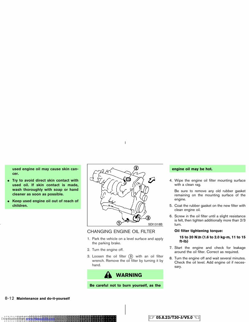
used engine oil may cause skin can-cer.
� Try to avoid direct skin contact withused oil. If skin contact is made,wash thoroughly with soap or handcleaner as soon as possible.
� Keep used engine oil out of reach ofchildren.
CHANGING ENGINE OIL FILTER
1. Park the vehicle on a level surface and applythe parking brake.
2. Turn the engine off.
3. Loosen the oil filter �3 with an oil filterwrench. Remove the oil filter by turning it byhand.
WARNING
Be careful not to burn yourself, as the
engine oil may be hot.
4. Wipe the engine oil filter mounting surfacewith a clean rag.
Be sure to remove any old rubber gasketremaining on the mounting surface of theengine.
5. Coat the rubber gasket on the new filter withclean engine oil.
6. Screw in the oil filter until a slight resistanceis felt, then tighten additionally more than 2/3turn.
Oil filter tightening torque:
15 to 20 N⋅m (1.6 to 2.0 kg-m, 11 to 15ft-lb)
7. Start the engine and check for leakagearound the oil filter. Correct as required.
8. Turn the engine off and wait several minutes.Check the oil level. Add engine oil if neces-sary.
SDI1318B
8-12 Maintenance and do-it-yourself
� 05.8.23/T30-J/V5.0 �Downloaded from www.Manualslib.com manuals search engine
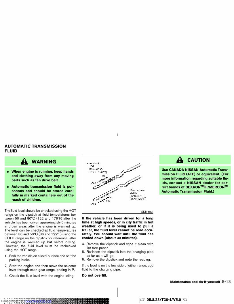
WARNING
� When engine is running, keep handsand clothing away from any movingparts such as fan drive belt.
� Automatic transmission fluid is poi-sonous and should be stored care-fully in marked containers out of thereach of children.
The fluid level should be checked using the HOTrange on the dipstick at fluid temperatures be-tween 50 and 80°C (122 and 176°F) after thevehicle has been driven approximately 5 minutesin urban areas after the engine is warmed up.The level can be checked at fluid temperaturesbetween 30 and 50°C (86 and 122°F) using theCOLD range on the dipstick for reference, afterthe engine is warmed up but before driving.However, the fluid level must be recheckedusing the HOT range.
1. Park the vehicle on a level surface and set theparking brake.
2. Start the engine and then move the selectorlever through each gear range, ending in P.
3. Check the fluid level with the engine idling.
If the vehicle has been driven for a longtime at high speeds, or in city traffic in hotweather, or if it is being used to pull atrailer, the fluid level cannot be read accu-rately. You should wait until the fluid hascooled down (about 30 minutes).
4. Remove the dipstick and wipe it clean withlint-free paper.
5. Re-insert the dipstick into the charging pipeas far as it will go.
6. Remove the dipstick and note the reading.
If the level is on the low side of either range, addfluid to the charging pipe.
Do not overfill.
CAUTION
Use CANADA NISSAN Automatic Trans-mission Fluid (ATF) or equivalent. (Formore information regarding suitable flu-ids, contact a NISSAN dealer for cor-rect brands of DEXRONTMIII/MERCONTM
Automatic Transmission Fluid.)
SDI1583
AUTOMATIC TRANSMISSIONFLUID
Maintenance and do-it-yourself 8-13
� 05.8.23/T30-J/V5.0 �Downloaded from www.Manualslib.com manuals search engine
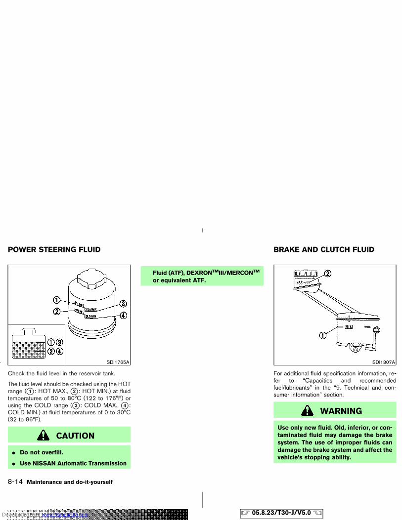
Check the fluid level in the reservoir tank.
The fluid level should be checked using the HOTrange (�1 : HOT MAX., �2 : HOT MIN.) at fluidtemperatures of 50 to 80°C (122 to 176°F) orusing the COLD range (�3 : COLD MAX., �4 :COLD MIN.) at fluid temperatures of 0 to 30°C(32 to 86°F).
CAUTION
� Do not overfill.
� Use NISSAN Automatic Transmission
Fluid (ATF), DEXRONTMIII/MERCONTM
or equivalent ATF.
For additional fluid specification information, re-fer to “Capacities and recommendedfuel/lubricants” in the “9. Technical and con-sumer information” section.
WARNING
Use only new fluid. Old, inferior, or con-taminated fluid may damage the brakesystem. The use of improper fluids candamage the brake system and affect thevehicle’s stopping ability.
SDI1765A SDI1307A
POWER STEERING FLUID BRAKE AND CLUTCH FLUID
8-14 Maintenance and do-it-yourself
� 05.8.23/T30-J/V5.0 �Downloaded from www.Manualslib.com manuals search engine
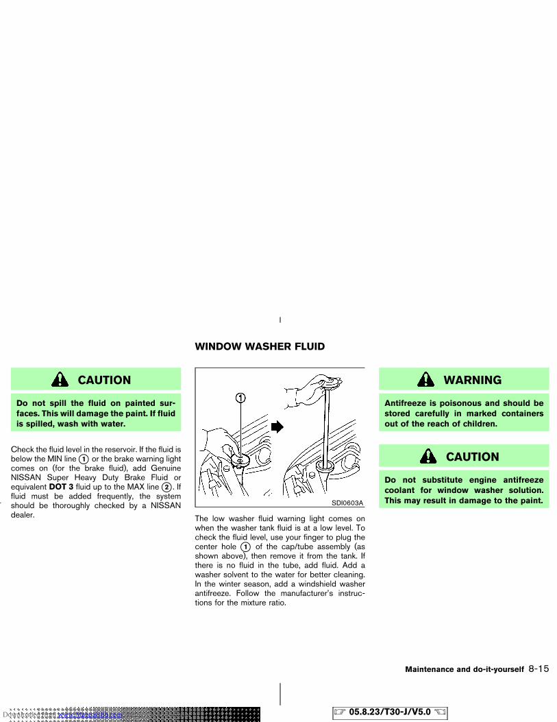
CAUTION
Do not spill the fluid on painted sur-faces. This will damage the paint. If fluidis spilled, wash with water.
Check the fluid level in the reservoir. If the fluid isbelow the MIN line �1 or the brake warning lightcomes on (for the brake fluid), add GenuineNISSAN Super Heavy Duty Brake Fluid orequivalent DOT 3 fluid up to the MAX line �2 . Iffluid must be added frequently, the systemshould be thoroughly checked by a NISSANdealer. The low washer fluid warning light comes on
when the washer tank fluid is at a low level. Tocheck the fluid level, use your finger to plug thecenter hole �1 of the cap/tube assembly (asshown above), then remove it from the tank. Ifthere is no fluid in the tube, add fluid. Add awasher solvent to the water for better cleaning.In the winter season, add a windshield washerantifreeze. Follow the manufacturer’s instruc-tions for the mixture ratio.
WARNING
Antifreeze is poisonous and should bestored carefully in marked containersout of the reach of children.
CAUTION
Do not substitute engine antifreezecoolant for window washer solution.This may result in damage to the paint.SDI0603A
WINDOW WASHER FLUID
Maintenance and do-it-yourself 8-15
� 05.8.23/T30-J/V5.0 �Downloaded from www.Manualslib.com manuals search engine
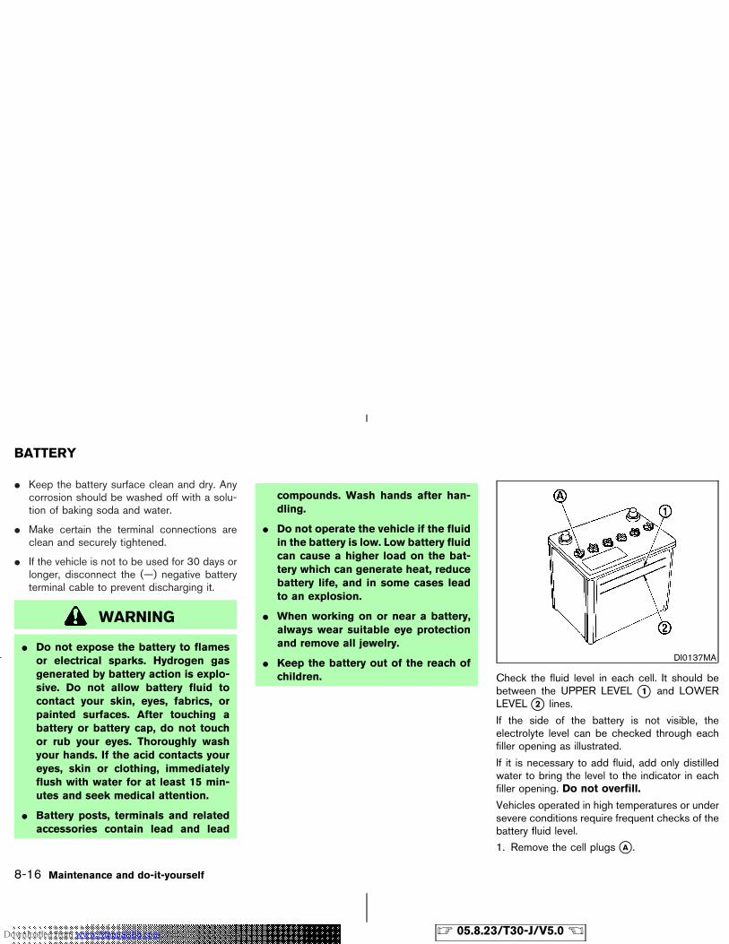
� Keep the battery surface clean and dry. Anycorrosion should be washed off with a solu-tion of baking soda and water.
� Make certain the terminal connections areclean and securely tightened.
� If the vehicle is not to be used for 30 days orlonger, disconnect the (—) negative batteryterminal cable to prevent discharging it.
WARNING
� Do not expose the battery to flamesor electrical sparks. Hydrogen gasgenerated by battery action is explo-sive. Do not allow battery fluid tocontact your skin, eyes, fabrics, orpainted surfaces. After touching abattery or battery cap, do not touchor rub your eyes. Thoroughly washyour hands. If the acid contacts youreyes, skin or clothing, immediatelyflush with water for at least 15 min-utes and seek medical attention.
� Battery posts, terminals and relatedaccessories contain lead and lead
compounds. Wash hands after han-dling.
� Do not operate the vehicle if the fluidin the battery is low. Low battery fluidcan cause a higher load on the bat-tery which can generate heat, reducebattery life, and in some cases leadto an explosion.
� When working on or near a battery,always wear suitable eye protectionand remove all jewelry.
� Keep the battery out of the reach ofchildren. Check the fluid level in each cell. It should be
between the UPPER LEVEL �1 and LOWERLEVEL �2 lines.
If the side of the battery is not visible, theelectrolyte level can be checked through eachfiller opening as illustrated.
If it is necessary to add fluid, add only distilledwater to bring the level to the indicator in eachfiller opening. Do not overfill.
Vehicles operated in high temperatures or undersevere conditions require frequent checks of thebattery fluid level.
1. Remove the cell plugs �A .
DI0137MA
BATTERY
8-16 Maintenance and do-it-yourself
� 05.8.23/T30-J/V5.0 �Downloaded from www.Manualslib.com manuals search engine
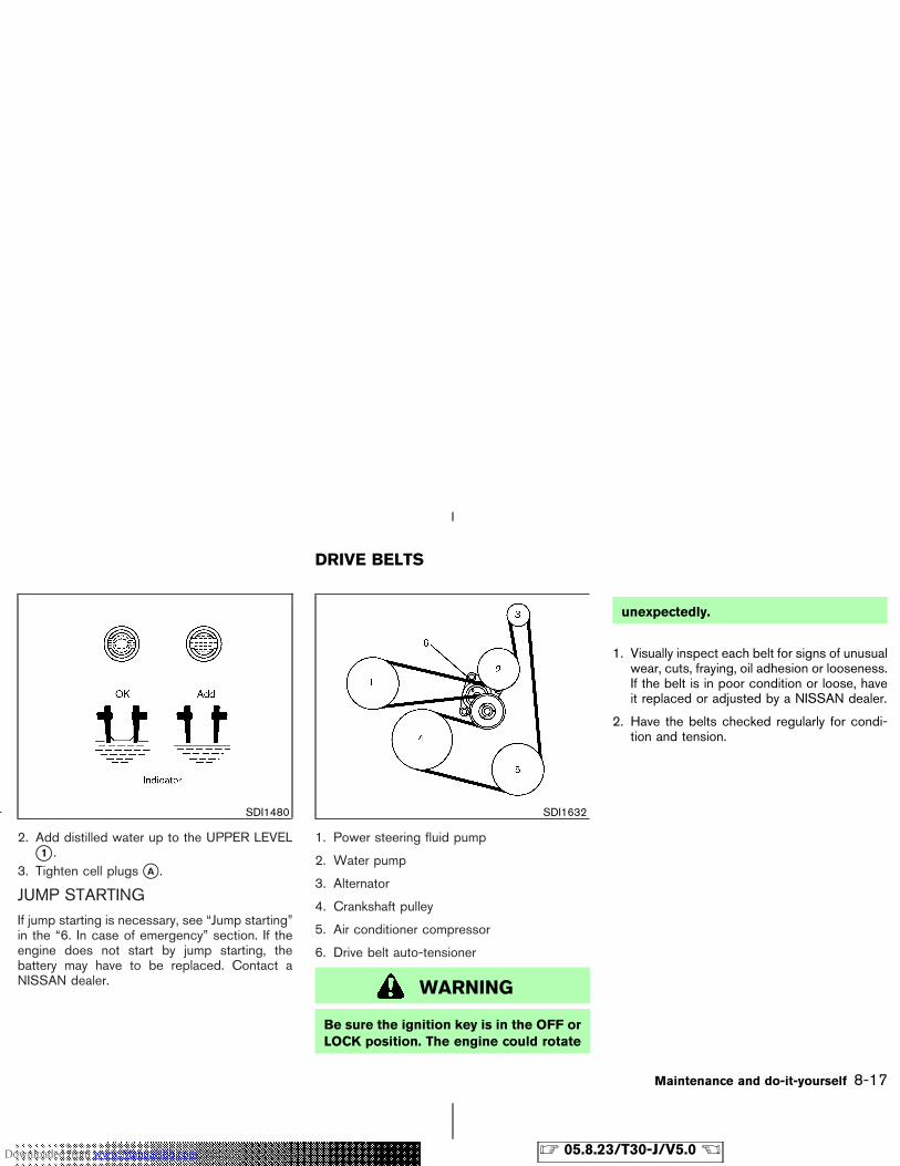
2. Add distilled water up to the UPPER LEVEL�1 .
3. Tighten cell plugs �A .
JUMP STARTINGIf jump starting is necessary, see “Jump starting”in the “6. In case of emergency” section. If theengine does not start by jump starting, thebattery may have to be replaced. Contact aNISSAN dealer.
1. Power steering fluid pump
2. Water pump
3. Alternator
4. Crankshaft pulley
5. Air conditioner compressor
6. Drive belt auto-tensioner
WARNING
Be sure the ignition key is in the OFF orLOCK position. The engine could rotate
unexpectedly.
1. Visually inspect each belt for signs of unusualwear, cuts, fraying, oil adhesion or looseness.If the belt is in poor condition or loose, haveit replaced or adjusted by a NISSAN dealer.
2. Have the belts checked regularly for condi-tion and tension.
SDI1480 SDI1632
DRIVE BELTS
Maintenance and do-it-yourself 8-17
� 05.8.23/T30-J/V5.0 �Downloaded from www.Manualslib.com manuals search engine
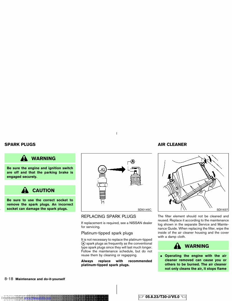
WARNING
Be sure the engine and ignition switchare off and that the parking brake isengaged securely.
CAUTION
Be sure to use the correct socket toremove the spark plugs. An incorrectsocket can damage the spark plugs.
REPLACING SPARK PLUGSIf replacement is required, see a NISSAN dealerfor servicing.
Platinum-tipped spark plugsIt is not necessary to replace the platinum-tipped�A spark plugs as frequently as the conventionaltype spark plugs since they will last much longer.Follow the maintenance schedule, but do notreuse them by cleaning or regapping.
Always replace with recommendedplatinum-tipped spark plugs.
The filter element should not be cleaned andreused. Replace it according to the maintenancelog shown in the separate Service and Mainte-nance Guide. When replacing the filter, wipe theinside of the air cleaner housing and the coverwith a damp cloth.
WARNING
� Operating the engine with the aircleaner removed can cause you orothers to be burned. The air cleanernot only cleans the air, it stops flame
SDI0145C SDI1637
SPARK PLUGS AIR CLEANER
8-18 Maintenance and do-it-yourself
� 05.8.23/T30-J/V5.0 �Downloaded from www.Manualslib.com manuals search engine
if the engine backfires. If it is notthere, and the engine backfires, youcould be burned. Do not drive withthe air cleaner removed and be care-ful when working on the engine withthe air cleaner removed.
� Never pour fuel into the throttle bodyor attempt to start the engine withthe air cleaner removed. Doing socould result in serious injury.
CAUTION
� After wiper blade replacement, returnthe wiper arm to its original position.Otherwise it may be damaged whenthe engine hood is opened.
� Make sure the wiper blades contactthe glass, otherwise the arm may bedamaged from wind pressure.
� Worn windshield wiper blades candamage the windshield and impairdriver vision.
CLEANING
If your windshield is not clear after using thewindshield washer or if a wiper blade chatterswhen running, wax or other material may be onthe blade or windshield.
Clean the outside of the windshield with awasher solution or a mild detergent. Your wind-shield is clean if beads do not form when rinsingwith clear water.
Clean the blade by wiping it with a cloth soakedin a washer solution or a mild detergent. Thenrinse the blade with clear water. If your wind-
shield is still not clear after cleaning the bladesand using the wiper, replace the blades.
WINDSHIELD WIPER BLADES
Maintenance and do-it-yourself 8-19
� 05.8.23/T30-J/V5.0 �Downloaded from www.Manualslib.com manuals search engine
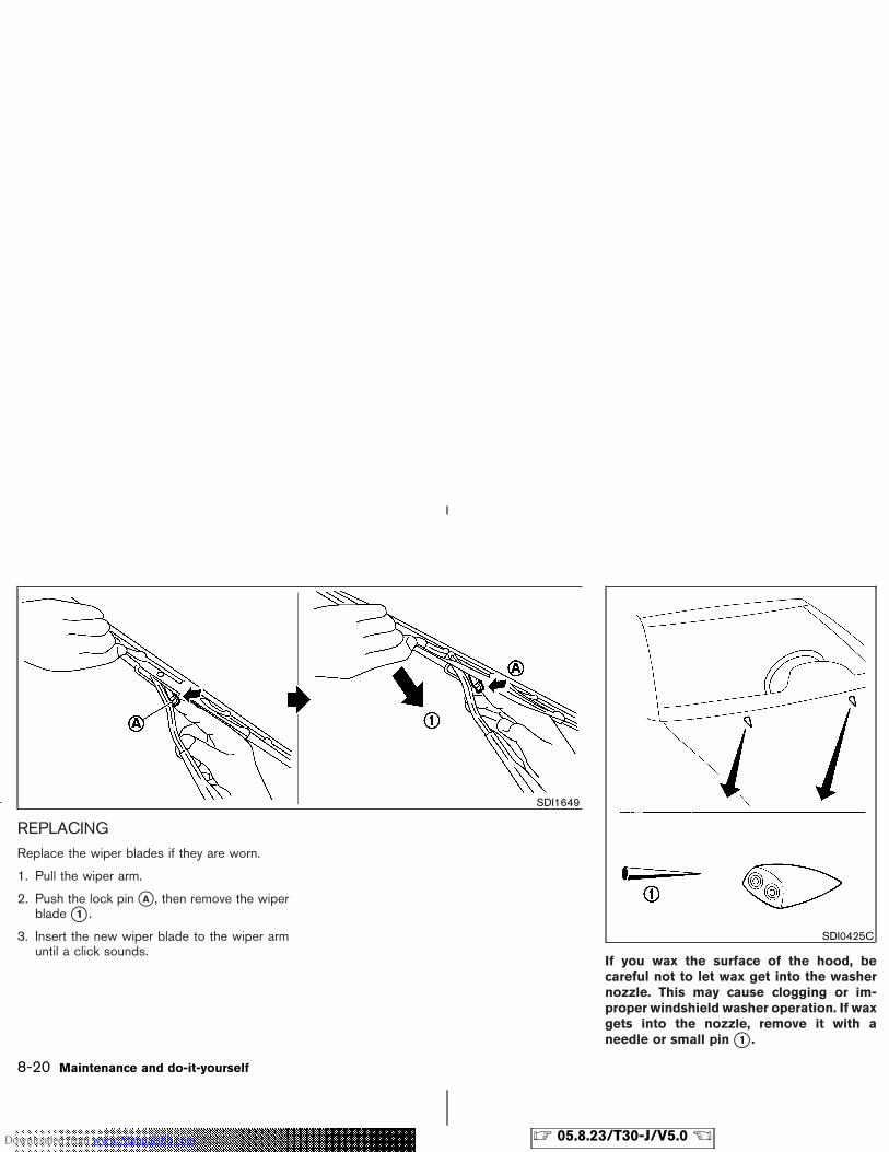
REPLACINGReplace the wiper blades if they are worn.
1. Pull the wiper arm.
2. Push the lock pin �A , then remove the wiperblade �1 .
3. Insert the new wiper blade to the wiper armuntil a click sounds.
If you wax the surface of the hood, becareful not to let wax get into the washernozzle. This may cause clogging or im-proper windshield washer operation. If waxgets into the nozzle, remove it with aneedle or small pin �1 .
SDI1649
SDI0425C
8-20 Maintenance and do-it-yourself
� 05.8.23/T30-J/V5.0 �Downloaded from www.Manualslib.com manuals search engine
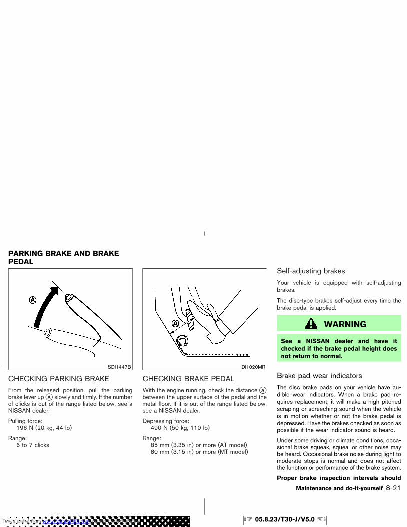
CHECKING PARKING BRAKEFrom the released position, pull the parkingbrake lever up �A slowly and firmly. If the numberof clicks is out of the range listed below, see aNISSAN dealer.
Pulling force:196 N (20 kg, 44 lb)
Range:6 to 7 clicks
CHECKING BRAKE PEDALWith the engine running, check the distance �Abetween the upper surface of the pedal and themetal floor. If it is out of the range listed below,see a NISSAN dealer.
Depressing force:490 N (50 kg, 110 lb)
Range:85 mm (3.35 in) or more (AT model)80 mm (3.15 in) or more (MT model)
Self-adjusting brakes
Your vehicle is equipped with self-adjustingbrakes.
The disc-type brakes self-adjust every time thebrake pedal is applied.
WARNING
See a NISSAN dealer and have itchecked if the brake pedal height doesnot return to normal.
Brake pad wear indicators
The disc brake pads on your vehicle have au-dible wear indicators. When a brake pad re-quires replacement, it will make a high pitchedscraping or screeching sound when the vehicleis in motion whether or not the brake pedal isdepressed. Have the brakes checked as soon aspossible if the wear indicator sound is heard.
Under some driving or climate conditions, occa-sional brake squeak, squeal or other noise maybe heard. Occasional brake noise during light tomoderate stops is normal and does not affectthe function or performance of the brake system.
Proper brake inspection intervals should
SDI1447B DI1020MR
PARKING BRAKE AND BRAKEPEDAL
Maintenance and do-it-yourself 8-21
� 05.8.23/T30-J/V5.0 �Downloaded from www.Manualslib.com manuals search engine
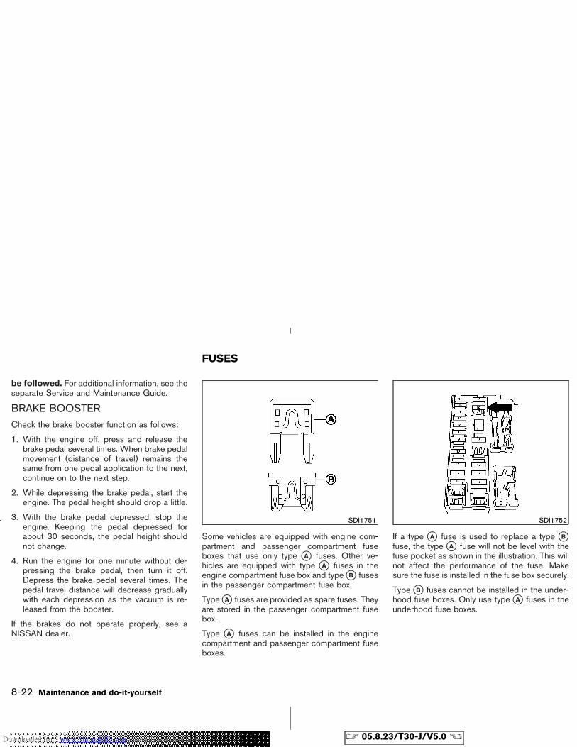
be followed. For additional information, see theseparate Service and Maintenance Guide.
BRAKE BOOSTERCheck the brake booster function as follows:
1. With the engine off, press and release thebrake pedal several times. When brake pedalmovement (distance of travel) remains thesame from one pedal application to the next,continue on to the next step.
2. While depressing the brake pedal, start theengine. The pedal height should drop a little.
3. With the brake pedal depressed, stop theengine. Keeping the pedal depressed forabout 30 seconds, the pedal height shouldnot change.
4. Run the engine for one minute without de-pressing the brake pedal, then turn it off.Depress the brake pedal several times. Thepedal travel distance will decrease graduallywith each depression as the vacuum is re-leased from the booster.
If the brakes do not operate properly, see aNISSAN dealer.
Some vehicles are equipped with engine com-partment and passenger compartment fuseboxes that use only type �A fuses. Other ve-hicles are equipped with type �A fuses in theengine compartment fuse box and type �B fusesin the passenger compartment fuse box.
Type �A fuses are provided as spare fuses. Theyare stored in the passenger compartment fusebox.
Type �A fuses can be installed in the enginecompartment and passenger compartment fuseboxes.
If a type �A fuse is used to replace a type �Bfuse, the type �A fuse will not be level with thefuse pocket as shown in the illustration. This willnot affect the performance of the fuse. Makesure the fuse is installed in the fuse box securely.
Type �B fuses cannot be installed in the under-hood fuse boxes. Only use type �A fuses in theunderhood fuse boxes.
SDI1751 SDI1752
FUSES
8-22 Maintenance and do-it-yourself
� 05.8.23/T30-J/V5.0 �Downloaded from www.Manualslib.com manuals search engine

ENGINE COMPARTMENT
CAUTION
Never use a fuse of higher or loweramperage rating than that specified onthe fuse box cover. This could damagethe electrical system or cause a fire.
If any electrical equipment does not operate,check for an open fuse.
1. Be sure the ignition switch and headlightswitch are OFF.
2. Open the engine hood.
3. Remove the fusible link cover.
4. Remove the fuse with the fuse puller.
5. If the fuse is open �A , replace it with a newfuse �B .
6. If a new fuse also opens, have the electricalsystem checked and repaired by a NISSANdealer.
Fusible linksIf any electrical equipment does not operate andfuses are in good condition, check the fusiblelinks. If any of these fusible links are melted,replace only with genuine NISSAN parts.
SDI1928 SDI1753Type A
SDI1754Type B
Maintenance and do-it-yourself 8-23
� 05.8.23/T30-J/V5.0 �Downloaded from www.Manualslib.com manuals search engine
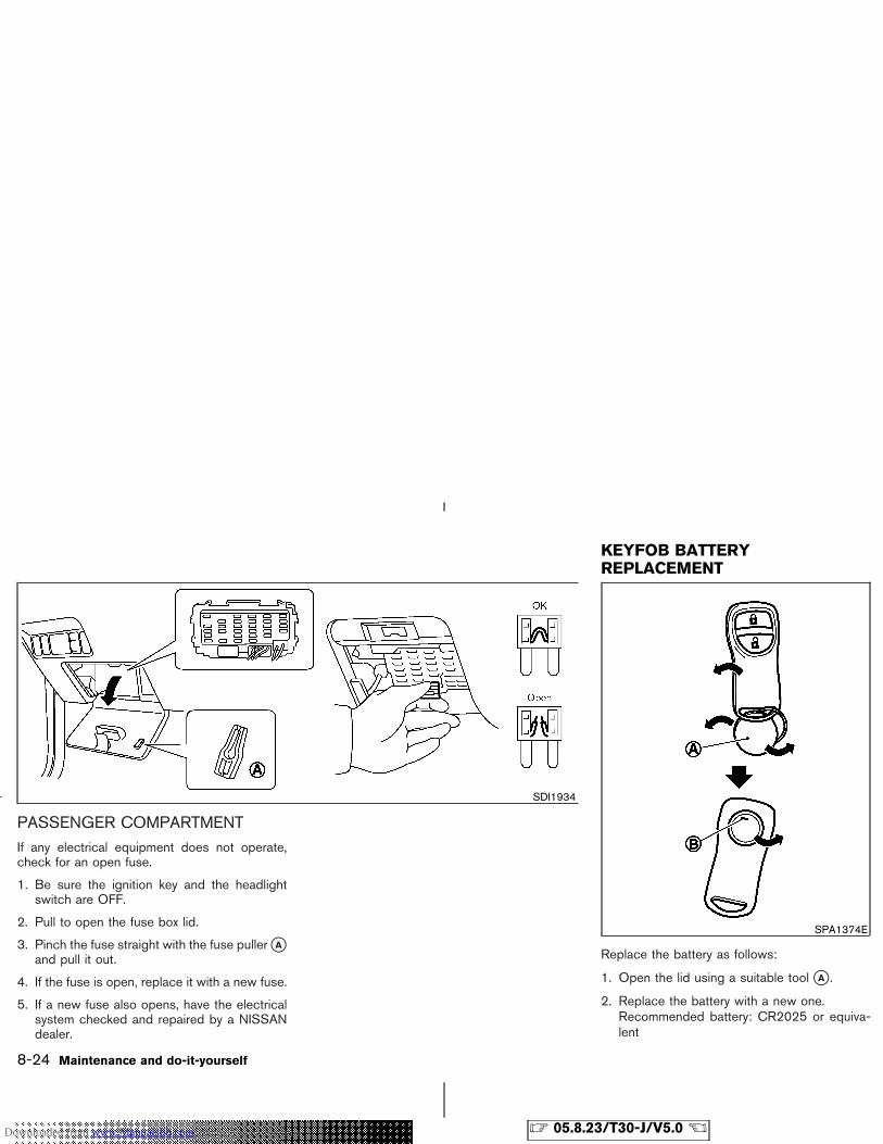
PASSENGER COMPARTMENTIf any electrical equipment does not operate,check for an open fuse.
1. Be sure the ignition key and the headlightswitch are OFF.
2. Pull to open the fuse box lid.
3. Pinch the fuse straight with the fuse puller �Aand pull it out.
4. If the fuse is open, replace it with a new fuse.
5. If a new fuse also opens, have the electricalsystem checked and repaired by a NISSANdealer.
Replace the battery as follows:
1. Open the lid using a suitable tool �A .
2. Replace the battery with a new one.Recommended battery: CR2025 or equiva-lent
SDI1934
SPA1374E
KEYFOB BATTERYREPLACEMENT
8-24 Maintenance and do-it-yourself
� 05.8.23/T30-J/V5.0 �Downloaded from www.Manualslib.com manuals search engine
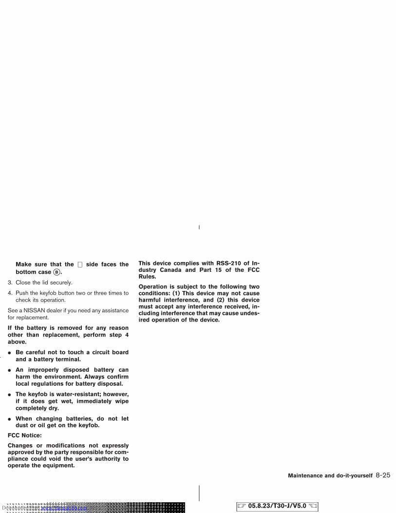
Make sure that the ⊕ side faces thebottom case �B .
3. Close the lid securely.
4. Push the keyfob button two or three times tocheck its operation.
See a NISSAN dealer if you need any assistancefor replacement.
If the battery is removed for any reasonother than replacement, perform step 4above.
� Be careful not to touch a circuit boardand a battery terminal.
� An improperly disposed battery canharm the environment. Always confirmlocal regulations for battery disposal.
� The keyfob is water-resistant; however,if it does get wet, immediately wipecompletely dry.
� When changing batteries, do not letdust or oil get on the keyfob.
FCC Notice:
Changes or modifications not expresslyapproved by the party responsible for com-pliance could void the user’s authority tooperate the equipment.
This device complies with RSS-210 of In-dustry Canada and Part 15 of the FCCRules.
Operation is subject to the following twoconditions: (1) This device may not causeharmful interference, and (2) this devicemust accept any interference received, in-cluding interference that may cause undes-ired operation of the device.
Maintenance and do-it-yourself 8-25
� 05.8.23/T30-J/V5.0 �Downloaded from www.Manualslib.com manuals search engine
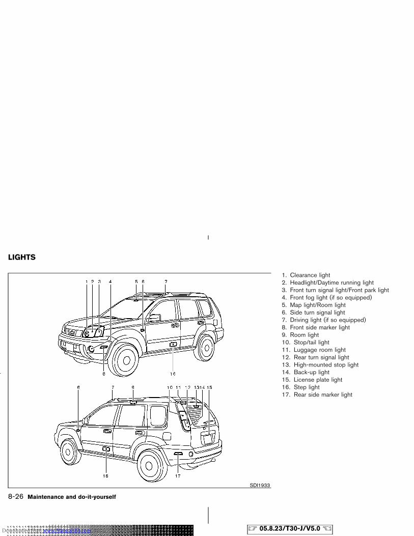
1. Clearance light2. Headlight/Daytime running light3. Front turn signal light/Front park light4. Front fog light (if so equipped)5. Map light/Room light6. Side turn signal light7. Driving light (if so equipped)8. Front side marker light9. Room light10. Stop/tail light11. Luggage room light12. Rear turn signal light13. High-mounted stop light14. Back-up light15. License plate light16. Step light17. Rear side marker light
SDI1933
LIGHTS
8-26 Maintenance and do-it-yourself
� 05.8.23/T30-J/V5.0 �Downloaded from www.Manualslib.com manuals search engine
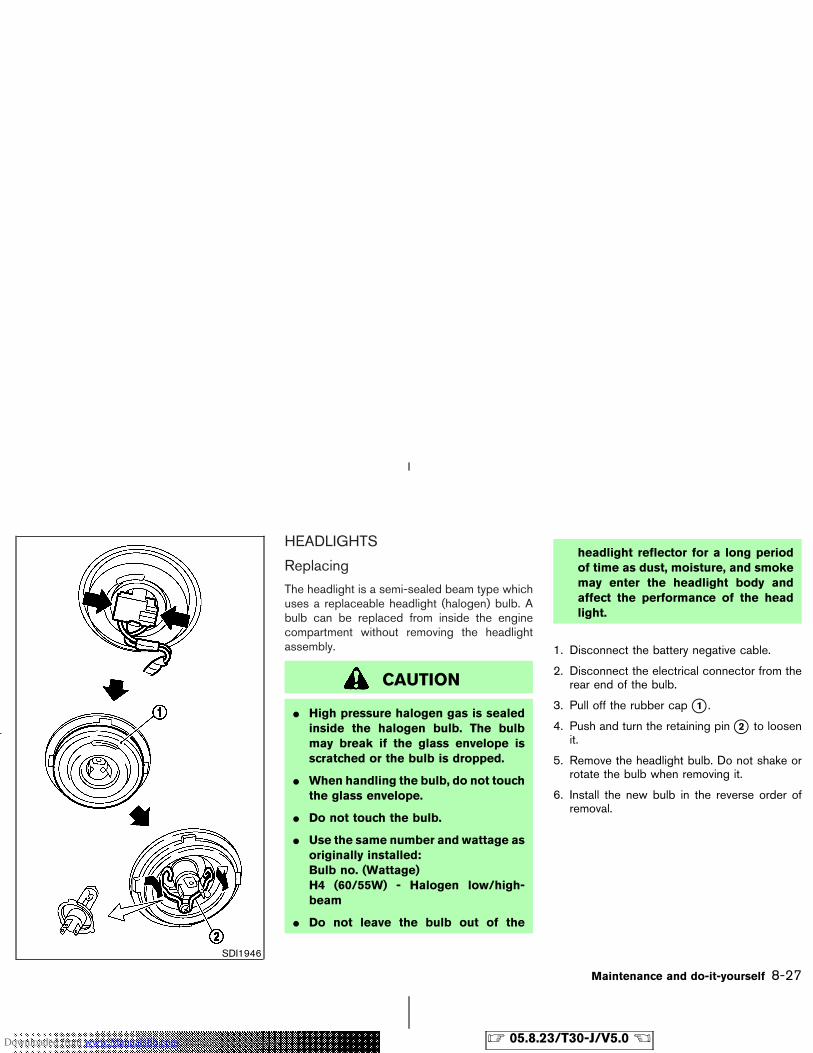
HEADLIGHTS
Replacing
The headlight is a semi-sealed beam type whichuses a replaceable headlight (halogen) bulb. Abulb can be replaced from inside the enginecompartment without removing the headlightassembly.
CAUTION
� High pressure halogen gas is sealedinside the halogen bulb. The bulbmay break if the glass envelope isscratched or the bulb is dropped.
� When handling the bulb, do not touchthe glass envelope.
� Do not touch the bulb.
� Use the same number and wattage asoriginally installed:Bulb no. (Wattage)H4 (60/55W) - Halogen low/high-beam
� Do not leave the bulb out of the
headlight reflector for a long periodof time as dust, moisture, and smokemay enter the headlight body andaffect the performance of the headlight.
1. Disconnect the battery negative cable.
2. Disconnect the electrical connector from therear end of the bulb.
3. Pull off the rubber cap �1 .
4. Push and turn the retaining pin �2 to loosenit.
5. Remove the headlight bulb. Do not shake orrotate the bulb when removing it.
6. Install the new bulb in the reverse order ofremoval.
SDI1946
Maintenance and do-it-yourself 8-27
� 05.8.23/T30-J/V5.0 �Downloaded from www.Manualslib.com manuals search engine
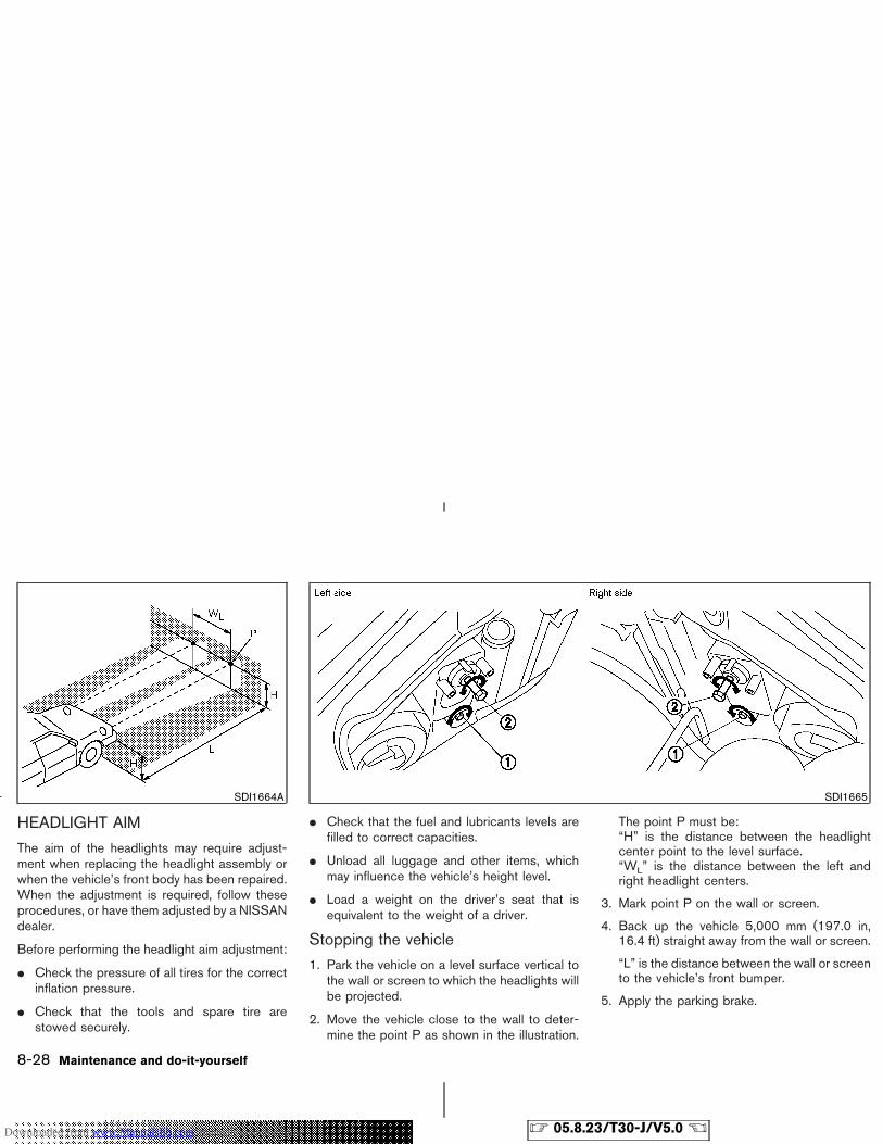
HEADLIGHT AIM
The aim of the headlights may require adjust-ment when replacing the headlight assembly orwhen the vehicle’s front body has been repaired.When the adjustment is required, follow theseprocedures, or have them adjusted by a NISSANdealer.
Before performing the headlight aim adjustment:
� Check the pressure of all tires for the correctinflation pressure.
� Check that the tools and spare tire arestowed securely.
� Check that the fuel and lubricants levels arefilled to correct capacities.
� Unload all luggage and other items, whichmay influence the vehicle’s height level.
� Load a weight on the driver’s seat that isequivalent to the weight of a driver.
Stopping the vehicle
1. Park the vehicle on a level surface vertical tothe wall or screen to which the headlights willbe projected.
2. Move the vehicle close to the wall to deter-mine the point P as shown in the illustration.
The point P must be:“H” is the distance between the headlightcenter point to the level surface.“WL” is the distance between the left andright headlight centers.
3. Mark point P on the wall or screen.
4. Back up the vehicle 5,000 mm (197.0 in,16.4 ft) straight away from the wall or screen.
“L” is the distance between the wall or screento the vehicle’s front bumper.
5. Apply the parking brake.
SDI1664A SDI1665
8-28 Maintenance and do-it-yourself
� 05.8.23/T30-J/V5.0 �Downloaded from www.Manualslib.com manuals search engine
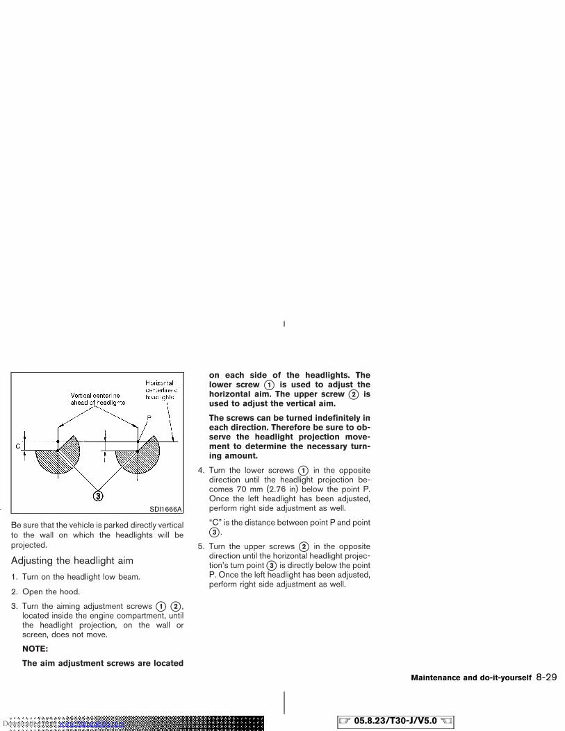
Be sure that the vehicle is parked directly verticalto the wall on which the headlights will beprojected.
Adjusting the headlight aim
1. Turn on the headlight low beam.
2. Open the hood.
3. Turn the aiming adjustment screws �1 �2 ,located inside the engine compartment, untilthe headlight projection, on the wall orscreen, does not move.
NOTE:
The aim adjustment screws are located
on each side of the headlights. Thelower screw �1 is used to adjust thehorizontal aim. The upper screw �2 isused to adjust the vertical aim.
The screws can be turned indefinitely ineach direction. Therefore be sure to ob-serve the headlight projection move-ment to determine the necessary turn-ing amount.
4. Turn the lower screws �1 in the oppositedirection until the headlight projection be-comes 70 mm (2.76 in) below the point P.Once the left headlight has been adjusted,perform right side adjustment as well.
“C” is the distance between point P and point�3 .
5. Turn the upper screws �2 in the oppositedirection until the horizontal headlight projec-tion’s turn point �3 is directly below the pointP. Once the left headlight has been adjusted,perform right side adjustment as well.
SDI1666A
Maintenance and do-it-yourself 8-29
� 05.8.23/T30-J/V5.0 �Downloaded from www.Manualslib.com manuals search engine
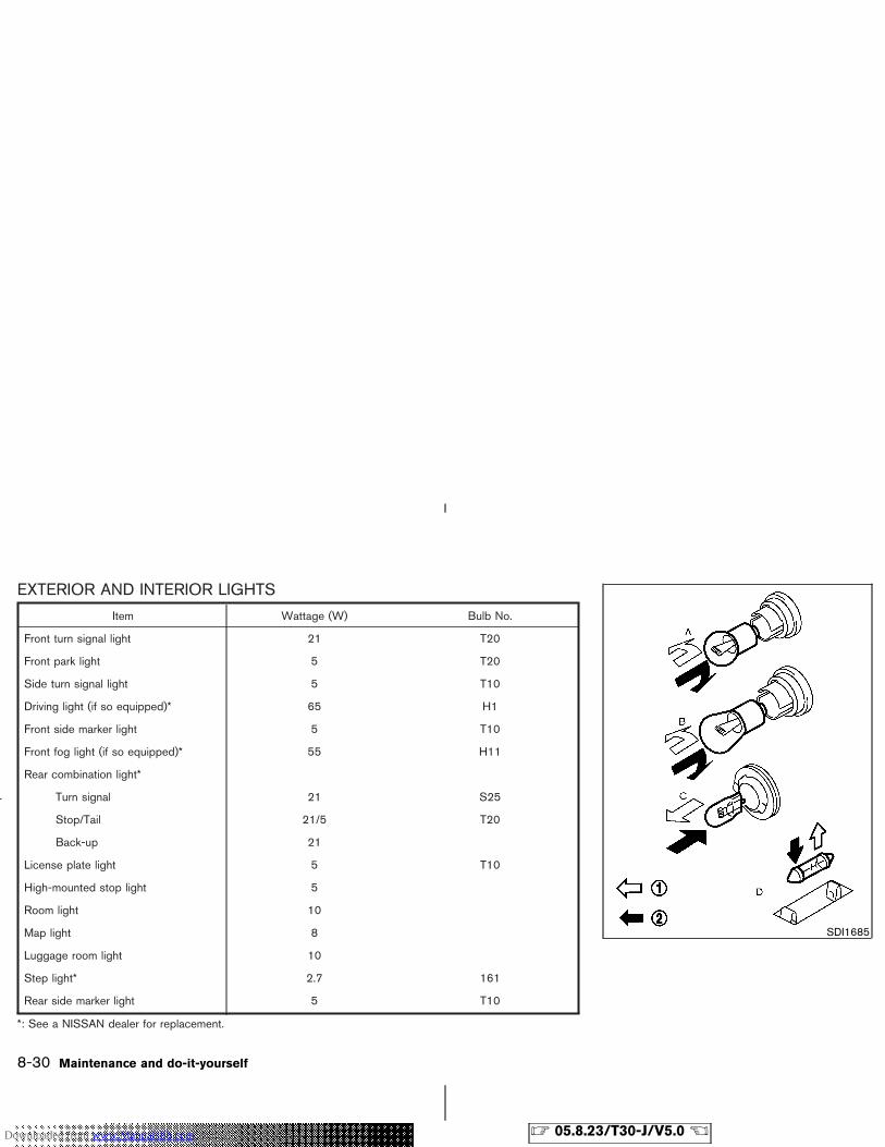
EXTERIOR AND INTERIOR LIGHTS
Item Wattage (W) Bulb No.
Front turn signal light 21 T20
Front park light 5 T20
Side turn signal light 5 T10
Driving light (if so equipped)* 65 H1
Front side marker light 5 T10
Front fog light (if so equipped)* 55 H11
Rear combination light*
Turn signal 21 S25
Stop/Tail 21/5 T20
Back-up 21
License plate light 5 T10
High-mounted stop light 5
Room light 10
Map light 8
Luggage room light 10
Step light* 2.7 161
Rear side marker light 5 T10
*: See a NISSAN dealer for replacement.
SDI1685
8-30 Maintenance and do-it-yourself
� 05.8.23/T30-J/V5.0 �Downloaded from www.Manualslib.com manuals search engine
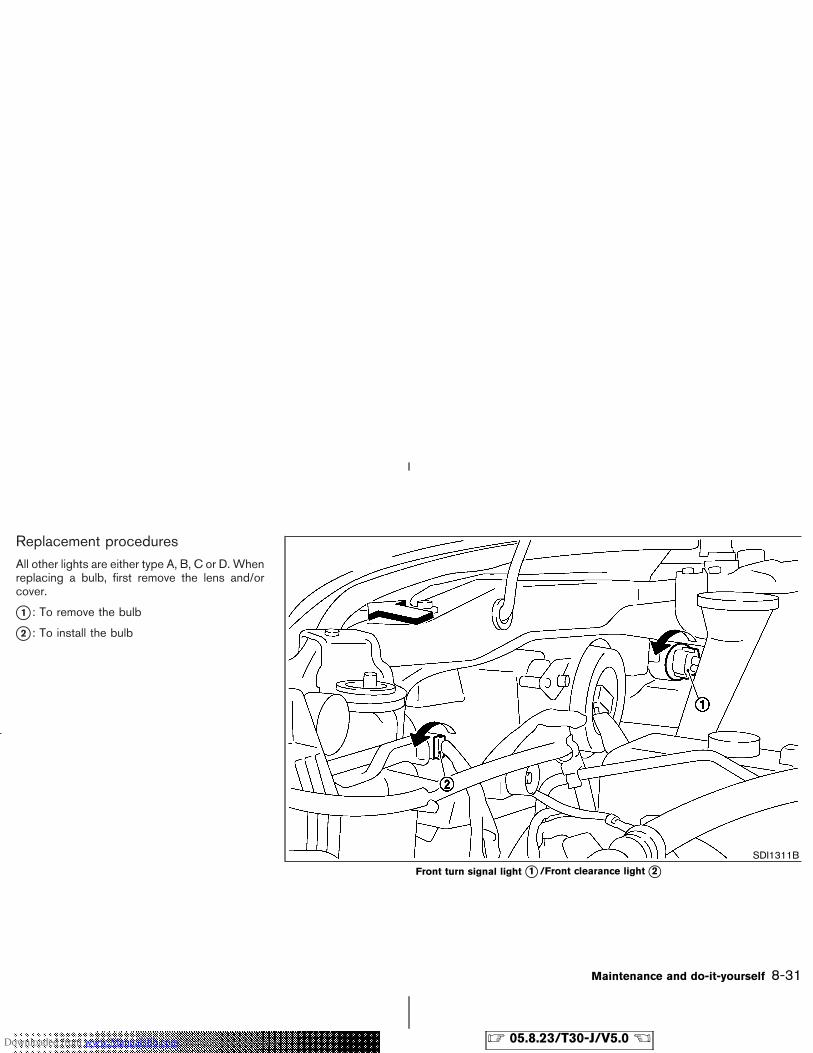
Replacement proceduresAll other lights are either type A, B, C or D. Whenreplacing a bulb, first remove the lens and/orcover.
�1 : To remove the bulb
�2 : To install the bulb
SDI1311B
Front turn signal light �1 /Front clearance light �2
Maintenance and do-it-yourself 8-31
� 05.8.23/T30-J/V5.0 �Downloaded from www.Manualslib.com manuals search engine
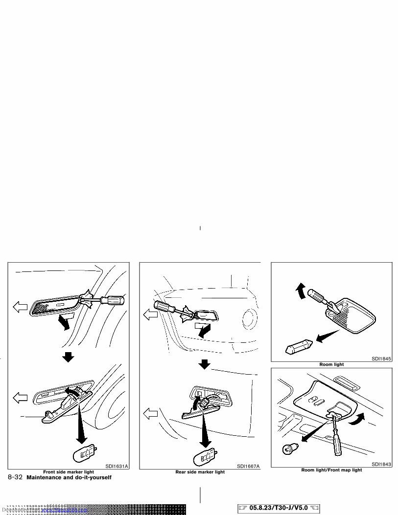
SDI1631AFront side marker light
SDI1667ARear side marker light
SDI1845Room light
SDI1843Room light/Front map light
8-32 Maintenance and do-it-yourself
� 05.8.23/T30-J/V5.0 �Downloaded from www.Manualslib.com manuals search engine
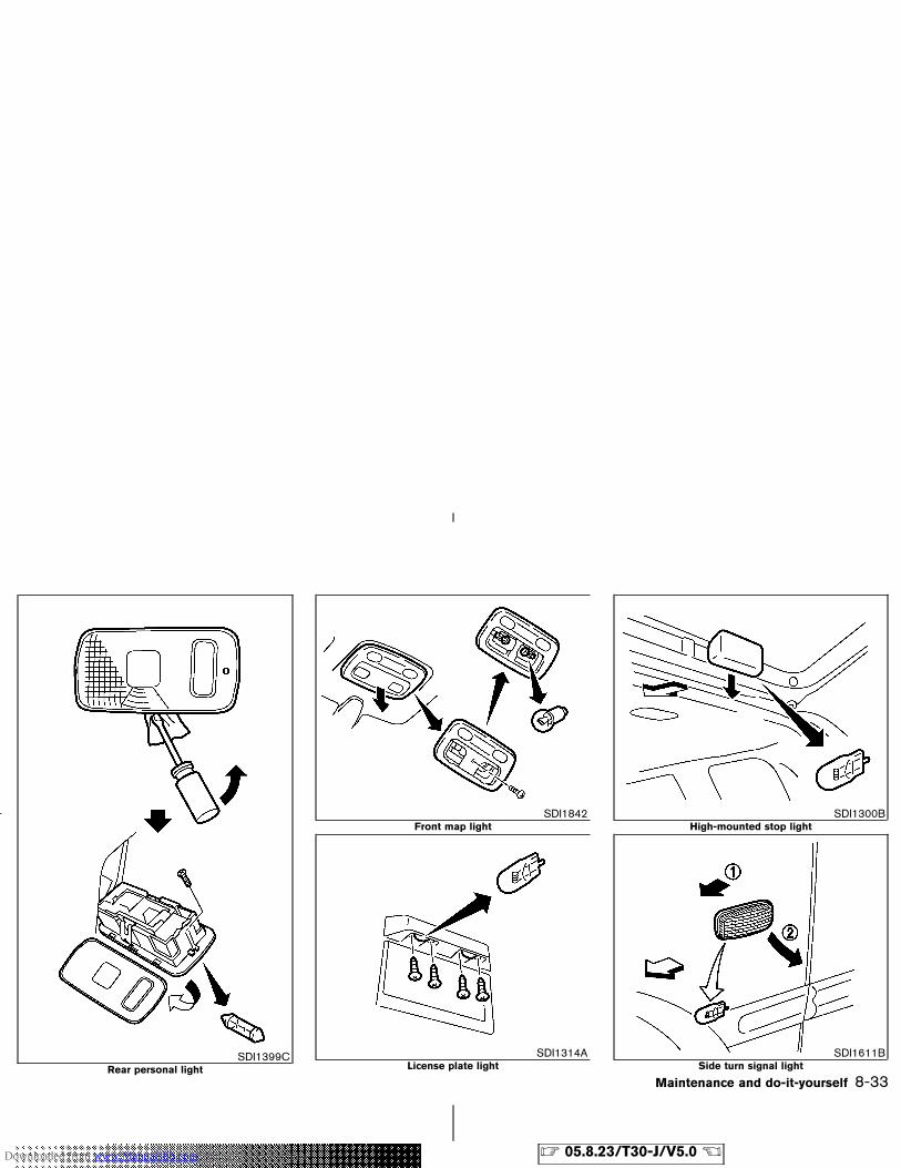
SDI1399CRear personal light
SDI1842Front map light
SDI1314ALicense plate light
SDI1300BHigh-mounted stop light
SDI1611BSide turn signal light
Maintenance and do-it-yourself 8-33
� 05.8.23/T30-J/V5.0 �Downloaded from www.Manualslib.com manuals search engine
TIRE PRESSURETire inflation pressureCheck the tire pressures (including thespare) often and always prior to longdistance trips. The recommended tirepressure specifications are shown on theCMVSS label and/or the Tire and Load-ing Information label under the “Cold TirePressure” heading. The Tire and LoadingInformation label is affixed to the driverside center pillar. Tire pressures shouldbe checked regularly because:
� Most tires naturally lose air over time.
� Tires can lose air suddenly whendriven over potholes or other objectsor if the vehicle strikes a curb whileparking.
The tire pressures should be checkedwhen the tires are cold. The tires areconsidered COLD after the vehicle hasbeen parked for 3 or more hours, ordriven less than 1.6 km (1 mile) at mod-erate speeds.
Incorrect tire pressure, including un-
der inflation, may adversely affecttire life and vehicle handling.
WARNING
� Improperly inflated tires can failsuddenly and cause an acci-dent.
� The Gross Vehicle Weight Rat-ing is located on the CMVSSlabel. The vehicle weight capac-ity is indicated on the Tire andLoading Information label. Donot load your vehicle beyondthis capacity. Overloading yourvehicle may result in reducedtire life, unsafe operating con-ditions due to premature tirefailure, or unfavorable handlingcharacteristics and could alsolead to a serious accident.Loading beyond the specifiedcapacity may also result in fail-ure of other vehicle
components.
� Before taking a long trip, orwhenever you heavily load yourvehicle, use a tire pressuregauge to ensure that the tirepressures are at the specifiedlevel.
� Do not drive your vehicle over137 km/h (85 MPH) unless it isequipped with high speed ratedtires. Driving faster than 137km/h (85 MPH) may result intire failure, loss of control andpossible injury.
� For additional information re-garding tires, refer to “TireSafety Information” in the War-ranty Information Booklet.
WHEELS AND TIRES
8-34 Maintenance and do-it-yourself
� 05.8.23/T30-J/V5.0 �Downloaded from www.Manualslib.com manuals search engine
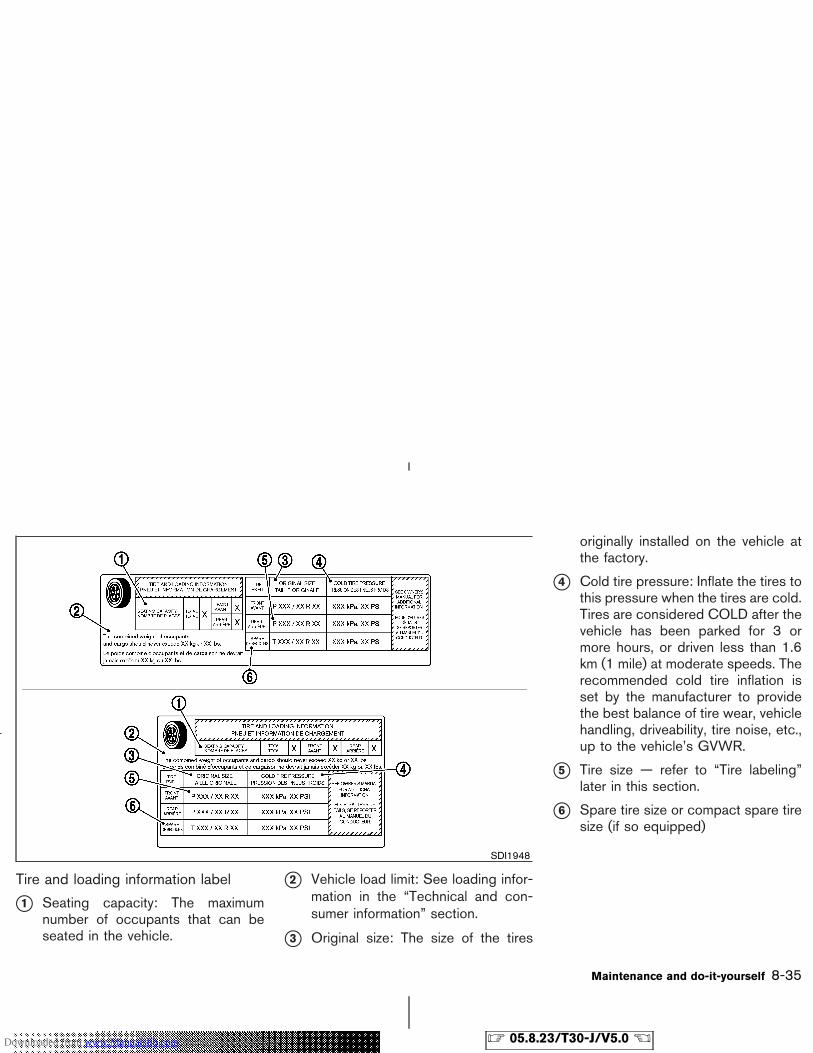
Tire and loading information label
�1 Seating capacity: The maximumnumber of occupants that can beseated in the vehicle.
�2 Vehicle load limit: See loading infor-mation in the “Technical and con-sumer information” section.
�3 Original size: The size of the tires
originally installed on the vehicle atthe factory.
�4 Cold tire pressure: Inflate the tires tothis pressure when the tires are cold.Tires are considered COLD after thevehicle has been parked for 3 ormore hours, or driven less than 1.6km (1 mile) at moderate speeds. Therecommended cold tire inflation isset by the manufacturer to providethe best balance of tire wear, vehiclehandling, driveability, tire noise, etc.,up to the vehicle’s GVWR.
�5 Tire size — refer to “Tire labeling”later in this section.
�6 Spare tire size or compact spare tiresize (if so equipped)
SDI1948
Maintenance and do-it-yourself 8-35
� 05.8.23/T30-J/V5.0 �Downloaded from www.Manualslib.com manuals search engine
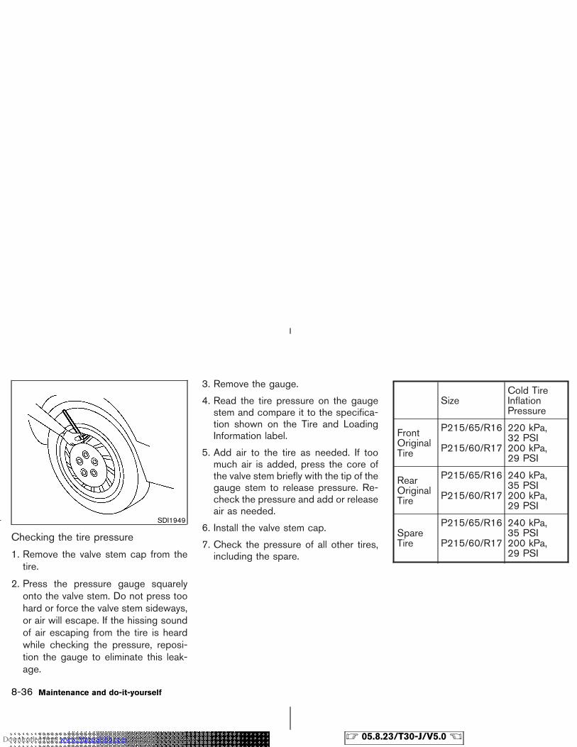
Checking the tire pressure
1. Remove the valve stem cap from thetire.
2. Press the pressure gauge squarelyonto the valve stem. Do not press toohard or force the valve stem sideways,or air will escape. If the hissing soundof air escaping from the tire is heardwhile checking the pressure, reposi-tion the gauge to eliminate this leak-age.
3. Remove the gauge.
4. Read the tire pressure on the gaugestem and compare it to the specifica-tion shown on the Tire and LoadingInformation label.
5. Add air to the tire as needed. If toomuch air is added, press the core ofthe valve stem briefly with the tip of thegauge stem to release pressure. Re-check the pressure and add or releaseair as needed.
6. Install the valve stem cap.
7. Check the pressure of all other tires,including the spare.
SizeCold TireInflationPressure
FrontOriginalTire
P215/65/R16
P215/60/R17
220 kPa,32 PSI200 kPa,29 PSI
RearOriginalTire
P215/65/R16
P215/60/R17
240 kPa,35 PSI200 kPa,29 PSI
SpareTire
P215/65/R16
P215/60/R17
240 kPa,35 PSI200 kPa,29 PSI
SDI1949
8-36 Maintenance and do-it-yourself
� 05.8.23/T30-J/V5.0 �Downloaded from www.Manualslib.com manuals search engine
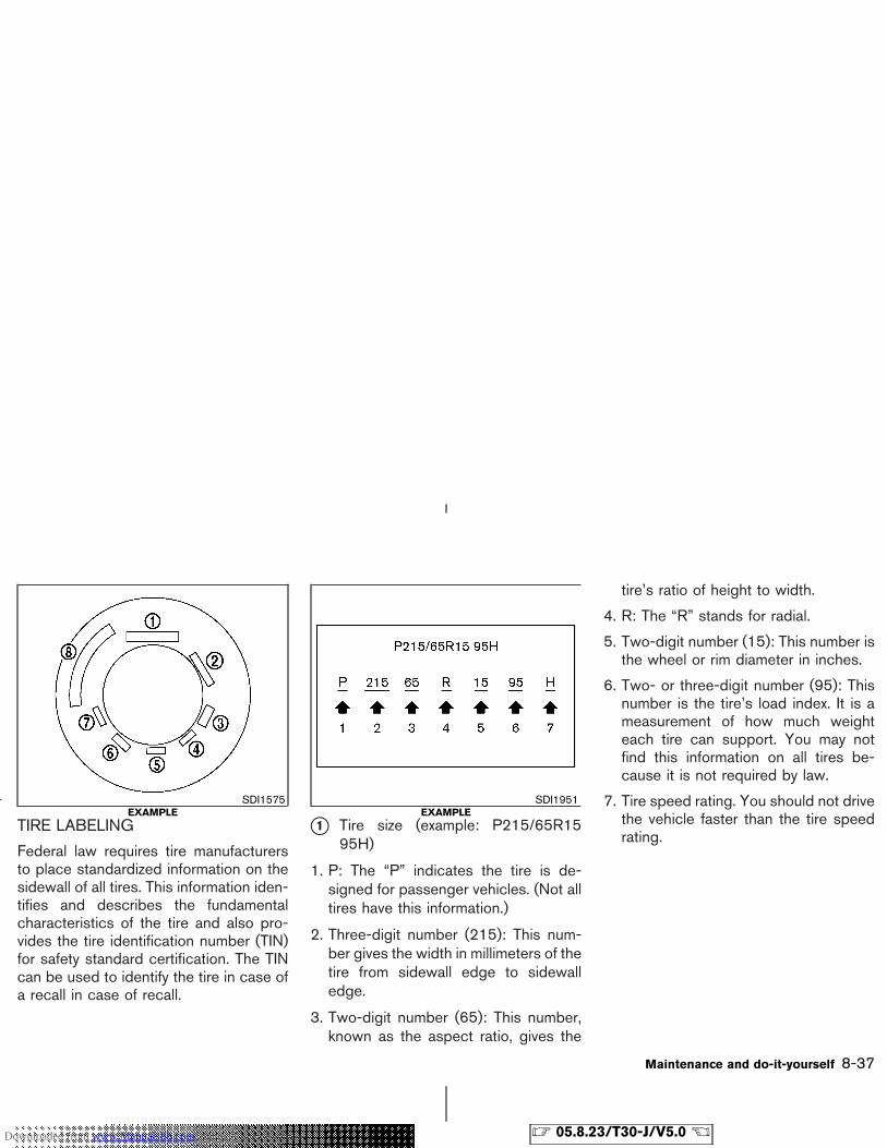
TIRE LABELING
Federal law requires tire manufacturersto place standardized information on thesidewall of all tires. This information iden-tifies and describes the fundamentalcharacteristics of the tire and also pro-vides the tire identification number (TIN)for safety standard certification. The TINcan be used to identify the tire in case ofa recall in case of recall.
�1 Tire size (example: P215/65R1595H)
1. P: The “P” indicates the tire is de-signed for passenger vehicles. (Not alltires have this information.)
2. Three-digit number (215): This num-ber gives the width in millimeters of thetire from sidewall edge to sidewalledge.
3. Two-digit number (65): This number,known as the aspect ratio, gives the
tire’s ratio of height to width.
4. R: The “R” stands for radial.
5. Two-digit number (15): This number isthe wheel or rim diameter in inches.
6. Two- or three-digit number (95): Thisnumber is the tire’s load index. It is ameasurement of how much weighteach tire can support. You may notfind this information on all tires be-cause it is not required by law.
7. Tire speed rating. You should not drivethe vehicle faster than the tire speedrating.
SDI1575EXAMPLE
SDI1951EXAMPLE
Maintenance and do-it-yourself 8-37
� 05.8.23/T30-J/V5.0 �Downloaded from www.Manualslib.com manuals search engine
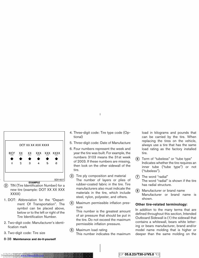
�2 TIN (Tire Identification Number) for anew tire (example: DOT XX XX XXXXXXX)
1. DOT: Abbreviation for the “Depart-ment Of Transportation”. Thesymbol can be placed above,below or to the left or right of theTire Identification Number.
2. Two-digit code: Manufacturer’s identi-fication mark
3. Two-digit code: Tire size
4. Three-digit code: Tire type code (Op-tional)
5. Three-digit code: Date of Manufacture
6. Four numbers represent the week andyear the tire was built. For example, thenumbers 3103 means the 31st weekof 2003. If these numbers are missing,then look on the other sidewall of thetire.
�3 Tire ply composition and materialThe number of layers or plies ofrubber-coated fabric in the tire. Tiremanufacturers also must indicate thematerials in the tire, which includesteel, nylon, polyester, and others.
�4 Maximum permissible inflation pres-sureThis number is the greatest amountof air pressure that should be put inthe tire. Do not exceed the maximumpermissible inflation pressure.
�5 Maximum load ratingThis number indicates the maximum
load in kilograms and pounds thatcan be carried by the tire. Whenreplacing the tires on the vehicle,always use a tire that has the sameload rating as the factory installedtire.
�6 Term of “tubeless” or “tube type”Indicates whether the tire requires aninner tube (“tube type”) or not(“tubeless”).
�7 The word “radial”The word “radial” is shown if the tirehas radial structure.
�8 Manufacturer or brand nameManufacturer or brand name isshown.
Other tire-related terminology:
In addition to the many terms that aredefined throughout this section, IntendedOutboard Sidewall is (1) the sidewall thatcontains a whitewall, bears white letter-ing or bears manufacturer, brand and/ormodel name molding that is higher ordeeper than the same molding on the
SDI1607EXAMPLE
8-38 Maintenance and do-it-yourself
� 05.8.23/T30-J/V5.0 �Downloaded from www.Manualslib.com manuals search engine
other sidewall of the tire, or (2) theoutward facing sidewall of an asymmetri-cal tire that has a particular side that mustalways face outward when mounted on avehicle.
TYPES OF TIRES
WARNING
� When changing or replacing tires, besure all four tires are of the sametype (for example, Summer, All Sea-son or Snow) and construction. ANISSAN dealer may be able to helpyou with information about tire type,size, speed rating and availability.
� Replacement tires may have a lowerspeed rating than the factoryequipped tires, and may not matchthe potential maximum vehiclespeed. Never exceed the maximumspeed rating of the tire.
� For additional information regardingtires, refer to “Tire Safety Informa-tion” in the Warranty Information
Booklet.
All season tires
NISSAN specifies All Season tires on somemodels to provide good performance for use allyear, including snowy and icy road conditions.All Season tires are identified by ALL SEASONand/or M&S on the tire sidewall. Snow tires havebetter snow traction than All Season tires andmay be more appropriate in some areas.
Summer tires
NISSAN specifies summer tires on some modelsto provide superior performance on dry roads.Summer tire performance is substantially re-duced in snow and ice. Summer tires do nothave the tire traction rating “M&S” on the tiresidewall.
If you plan to operate your vehicle in snowy or icyconditions, NISSAN recommends the use ofSNOW tires or ALL SEASON tires on all fourwheels.
Snow tires
If snow tires are needed, it is necessary to selecttires equivalent in size and load rating to theoriginal equipment tires. If you do not, it can
adversely affect the safety and handling of yourvehicle.
Generally, snow tires will have lower speedratings than factory equipped tires and may notmatch the potential maximum vehicle speed.Never exceed the maximum speed rating of thetire.
If you operate your vehicle in snowy or icyconditions, NISSAN recommends the use ofsnow or all season tires on all four wheels.
For additional traction on icy roads, studded tiresmay be used. However, some provinces andstates prohibit their use. Check local, state andprovincial laws before installing studded tires.Skid and traction capabilities of studded snowtires on wet or dry surfaces may be poorer thanthat of non-studded snow tires.
Four-wheel drive models
CAUTION
� Always use tires of the same size,brand, construction (bias, bias-beltedor radial), and tread pattern on allfour wheels. Failure to do so mayresult in a circumference difference
Maintenance and do-it-yourself 8-39
� 05.8.23/T30-J/V5.0 �Downloaded from www.Manualslib.com manuals search engine
between tires on the front and rearaxles which will cause excessive tirewear and may damage the transmis-sion, transfer case and differentialgears.
� ONLY use spare tires specified foreach 4-wheel drive model.
If excessive tire wear is found, it is recommendedthat all four tires be replaced with tires of thesame size, brand, construction and tread pat-tern. The tire pressure and wheel alignmentshould also be checked and corrected as nec-essary. Contact a NISSAN dealer.
Tire chains must be installed only on thefront wheels and not on the rear wheels.
Do not drive with tire chains on paved roadswhich are clear of snow. Driving with chains insuch conditions can cause damage to the vari-ous mechanisms of the vehicle due to someoverstress.
TIRE CHAINSUse of tire chains may be prohibited accordingto location. Check the local laws before installingtire chains. When installing tire chains, makesure they are of proper size for the tires on your
vehicle and are installed according to the chainmanufacturer’s suggestions. Use only SAEclass S chains. Class “S” chains are used onvehicles with restricted tire to vehicle clearance.Vehicles that can use Class “S” chains aredesigned to meet the SAE standard minimumclearances between the tire and the closestvehicle suspension or body component requiredto accommodate the use of a winter tractiondevice (tire chains or cables). The minimumclearances are determined using the factoryequipped tire size. Other types may damageyour vehicle. Use chain tensioners when recom-mended by the tire chain manufacturer to ensurea tight fit. Loose end links of the tire chain mustbe secured or removed to prevent the possibilityof whipping action damage to the fenders orundercarriage. If possible, avoid fully loadingyour vehicle when using tire chains. In addition,drive at a reduced speed. Otherwise, your ve-hicle may be damaged and/or vehicle handlingand performance may be adversely affected.
� Do not use the chains on dry roads.
Tire chains must be installed only on thefront wheels and not on the rear wheels.
Do not drive with tire chains on paved roadswhich are clear of snow. Driving with chains insuch conditions can cause damage to the vari-ous mechanisms of the vehicle due to some
overstress.
8-40 Maintenance and do-it-yourself
� 05.8.23/T30-J/V5.0 �Downloaded from www.Manualslib.com manuals search engine
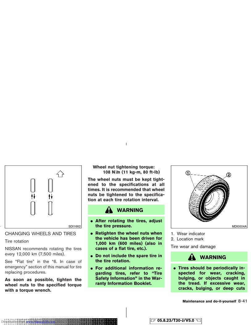
CHANGING WHEELS AND TIRES
Tire rotation
NISSAN recommends rotating the tiresevery 12,000 km (7,500 miles).
See “Flat tire” in the “6. In case ofemergency” section of this manual for tirereplacing procedures.
As soon as possible, tighten thewheel nuts to the specified torquewith a torque wrench.
Wheel nut tightening torque:108 N⋅m (11 kg-m, 80 ft-lb)
The wheel nuts must be kept tight-ened to the specifications at alltimes. It is recommended that wheelnuts be tightened to the specifica-tion at each tire rotation interval.
WARNING
� After rotating the tires, adjustthe tire pressure.
� Retighten the wheel nuts whenthe vehicle has been driven for1,000 km (600 miles) (also incases of a flat tire, etc.).
� Do not include the spare tire inthe tire rotation.
� For additional information re-garding tires, refer to “TireSafety Information” in the War-ranty Information Booklet.
1. Wear indicator2. Location mark
Tire wear and damage
WARNING
� Tires should be periodically in-spected for wear, cracking,bulging, or objects caught inthe tread. If excessive wear,cracks, bulging, or deep cuts
SDI1662 MDI0004A
Maintenance and do-it-yourself 8-41
� 05.8.23/T30-J/V5.0 �Downloaded from www.Manualslib.com manuals search engine
are found, the tire(s) should bereplaced.
� The original tires have a built-intread wear indicator. When thewear indicator is visible, the tireshould be replaced.
� Improper service for a spare tiremay result in serious personalinjury. If it is necessary to repairthe spare tire, contact aNISSAN dealer.
� For additional information re-garding tires, refer to “TireSafety Information” in the War-ranty Information Booklet.
Replacing wheels and tires
When replacing a tire, use the same size, treaddesign, speed rating and load carrying capacityas originally equipped. Recommended types andsizes are shown in “Wheels and tires” in the“Technical and consumer information” section ofthis manual.
WARNING
� The use of tires other than thoserecommended or the mixed use oftires of different brands, construction(bias, bias-belted or radial), or treadpatterns can adversely affect the ride,braking, handling, ground clearance,body-to-tire clearance, tire chainclearance, speedometer calibration,headlight aim and bumper height.Some of these effects may lead toaccidents and could result in seriouspersonal injury.
� If the wheels are changed for anyreason, always replace with wheelswhich have the same offset dimen-sion. Wheels of a different offsetcould cause premature tire wear, de-grade vehicle handling characteris-tics and/or interference with thebrake discs/drums. Such interfer-ence can lead to decreased brakingefficiency and/or early brakepad/shoe wear. Refer to “Wheels and
Tires” in the “Technical and con-sumer information” section of thismanual for wheel offset dimensions.
� Do not install a deformed wheel ortire even if it has been repaired. Suchwheels or tires could have structuraldamage and could fail without warn-ing.
� The use of retread tire is not recom-mended.
� For additional information regardingtires, refer to “Tire Safety Informa-tion” in the Warranty InformationBooklet.
Wheel balance
Unbalanced wheels may affect vehicle handlingand tire life. Even with regular use, wheels canget out of balance. Therefore, they should bebalanced as required.
Wheel balance service should be per-formed with the wheels off the vehicle.Spin balancing the wheels on the vehiclecould lead to mechanical damage.
For additional information regarding tires, refer to
8-42 Maintenance and do-it-yourself
� 05.8.23/T30-J/V5.0 �Downloaded from www.Manualslib.com manuals search engine
“Tire Safety Information” in the Warranty Infor-mation Booklet.
Care of wheels� Wash the wheels when washing the vehicle
to maintain their appearance.
� Clean the inner side of the wheels when thewheel is changed or the underside of thevehicle is washed.
� Do not use abrasive cleaners when washingthe wheels.
� Inspect wheel rims regularly for dents orcorrosion. Such damage may cause loss ofpressure or poor seal at the tire bead.
� NISSAN recommends waxing the road wheelsidewalls to protect against road salt in areaswhere it is used during winter.
Maintenance and do-it-yourself 8-43
� 05.8.23/T30-J/V5.0 �Downloaded from www.Manualslib.com manuals search engine

MEMO
8-44 Maintenance and do-it-yourself
� 05.8.23/T30-J/V5.0 �Downloaded from www.Manualslib.com manuals search engine
9 Technical and consumer information
Capacities and recommended fuel/lubricants .............. 9-2Fuel recommendation .................................................... 9-3Engine oil and oil filter recommendation .................. 9-5Recommended SAE viscosity number ...................... 9-6Air conditioning system refrigerant and lubricantrecommendations ........................................................... 9-6
Specifications ........................................................................ 9-7Engine ................................................................................ 9-7Wheels and tires ............................................................. 9-8Dimensions and weights ............................................... 9-8
When traveling or registering your vehicle in anothercountry ..................................................................................... 9-9Vehicle identification ............................................................ 9-9
Vehicle identification number (VIN) plate ................. 9-9Vehicle identification number (Chassis number) .... 9-9Engine serial number ................................................... 9-10C.M.V.S.S. certification label ..................................... 9-10Emission control information label ........................... 9-10Tire and loading information label ............................ 9-11
Air conditioner specification label ............................ 9-11Vehicle loading information ............................................. 9-11
Terms ............................................................................... 9-11Vehicle load capacity .................................................. 9-12Loading tips ................................................................... 9-14Payload weight capacity ............................................. 9-14Measurement of weights ............................................ 9-15
Towing a trailer ................................................................... 9-15Maximum load limits .................................................... 9-16Towing load/specification chart ............................... 9-18Towing safety ................................................................ 9-18Flat towing....................................................................... 9-21
Uniform tire quality grading ............................................. 9-22Emission control system warranty ................................. 9-23Readiness for inspection/maintenance (I/M) test ...... 9-23Event data recorders ......................................................... 9-24Owner’s manual/service manual order information ... 9-25
In the event of a collision ........................................... 9-25
� 05.8.23/T30-J/V5.0 �Downloaded from www.Manualslib.com manuals search engine
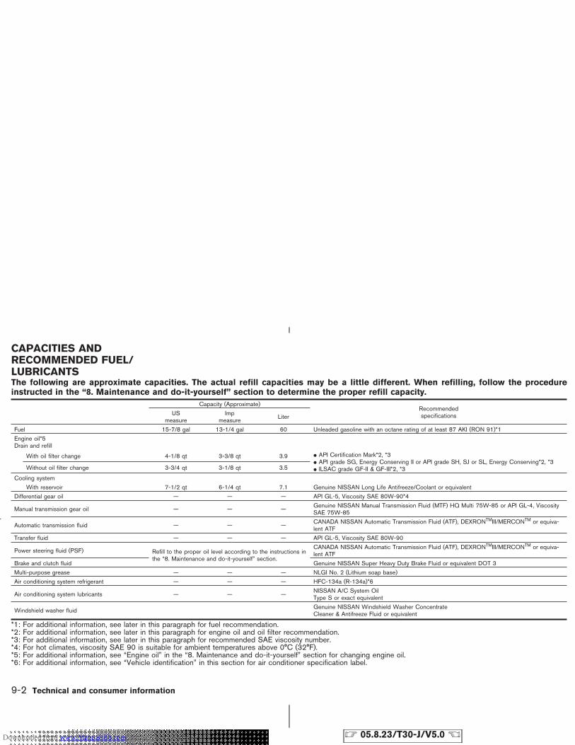
The following are approximate capacities. The actual refill capacities may be a little different. When refilling, follow the procedureinstructed in the “8. Maintenance and do-it-yourself” section to determine the proper refill capacity.
Capacity (Approximate)RecommendedspecificationsUS
measureImp
measure Liter
Fuel 15-7/8 gal 13-1/4 gal 60 Unleaded gasoline with an octane rating of at least 87 AKI (RON 91)*1
Engine oil*5Drain and refill
With oil filter change 4-1/8 qt 3-3/8 qt 3.9 � API Certification Mark*2, *3� API grade SG, Energy Conserving II or API grade SH, SJ or SL, Energy Conserving*2, *3� ILSAC grade GF-II & GF-III*2, *3Without oil filter change 3-3/4 qt 3-1/8 qt 3.5
Cooling system
With reservoir 7-1/2 qt 6-1/4 qt 7.1 Genuine NISSAN Long Life Antifreeze/Coolant or equivalent
Differential gear oil — — — API GL-5, Viscosity SAE 80W-90*4
Manual transmission gear oil — — — Genuine NISSAN Manual Transmission Fluid (MTF) HQ Multi 75W-85 or API GL-4, ViscositySAE 75W-85
Automatic transmission fluid — — — CANADA NISSAN Automatic Transmission Fluid (ATF), DEXRONTMIII/MERCONTM or equiva-lent ATF
Transfer fluid — — — API GL-5, Viscosity SAE 80W-90
Power steering fluid (PSF) Refill to the proper oil level according to the instructions inthe “8. Maintenance and do-it-yourself” section.
CANADA NISSAN Automatic Transmission Fluid (ATF), DEXRONTMIII/MERCONTM or equiva-lent ATF
Brake and clutch fluid Genuine NISSAN Super Heavy Duty Brake Fluid or equivalent DOT 3
Multi-purpose grease — — — NLGI No. 2 (Lithium soap base)
Air conditioning system refrigerant — — — HFC-134a (R-134a)*6
Air conditioning system lubricants — — — NISSAN A/C System OilType S or exact equivalent
Windshield washer fluid Genuine NISSAN Windshield Washer ConcentrateCleaner & Antifreeze Fluid or equivalent
*1: For additional information, see later in this paragraph for fuel recommendation.*2: For additional information, see later in this paragraph for engine oil and oil filter recommendation.*3: For additional information, see later in this paragraph for recommended SAE viscosity number.*4: For hot climates, viscosity SAE 90 is suitable for ambient temperatures above 0°C (32°F).*5: For additional information, see “Engine oil” in the “8. Maintenance and do-it-yourself” section for changing engine oil.*6: For additional information, see “Vehicle identification” in this section for air conditioner specification label.
CAPACITIES ANDRECOMMENDED FUEL/LUBRICANTS
9-2 Technical and consumer information
� 05.8.23/T30-J/V5.0 �Downloaded from www.Manualslib.com manuals search engine
FUEL RECOMMENDATION
Use unleaded regular gasoline with an oc-tane rating of at least 87 AKI (Anti-KnockIndex) number (Research octane number91).
CAUTION
� Using a fuel other than that specifiedcould adversely affect the emissioncontrol devices and systems, andcould also affect the warranty cover-age.
� Under no circumstances should aleaded gasoline be used, since thiswill damage the three-way catalyst.
� Do not use E-85 fuel in your vehicle.Your vehicle is not designed to runon E-85 fuel. Using E-85 fuel candamage the fuel system componentsand is not covered by the NISSANvehicle limited warranty.
Gasoline specificationsNISSAN recommends using gasoline that meetsthe World-Wide Fuel Charter (WWFC) specifi-
cations where it is available. Many of the auto-mobile manufacturers developed this specifica-tion to improve the emission control system andvehicle performance. Ask your service stationmanager if the gasoline meets the WWFCspecifications.
Reformulated gasolineSome fuel suppliers are now producing reformu-lated gasolines. These gasolines are speciallydesigned to reduce vehicle emissions. NISSANsupports efforts towards cleaner air and sug-gests that you use reformulated gasoline whenavailable.
Gasoline containing oxygenatesSome fuel suppliers sell gasoline containingoxygenates such as ethanol, MTBE and metha-nol with or without advertising their presence.NISSAN does not recommend the use of fuels ofwhich the oxygenate content and the fuel com-patibility for your NISSAN cannot be readilydetermined. If in doubt, ask your service stationmanager.
If you use oxygenate-blend gasoline, please takethe following precautions as the usage of suchfuels may cause vehicle performance problemsand/or fuel system damage.
� The fuel should be unleaded and havean octane rating no lower than that
recommended for unleaded gasoline.
� If an oxygenate-blend, excepting amethanol blend, is used, it should con-tain no more than 10% oxygenate.(MTBE may, however, be added up to15%.)
� If a methanol blend is used, it shouldcontain no more than 5% methanol (me-thyl alcohol, wood alcohol). It shouldalso contain a suitable amount of ap-propriate cosolvents and corrosion in-hibitors. If not properly formulated withappropriate cosolvents and corrosioninhibitors, such methanol blends maycause fuel system damage and/or ve-hicle performance problems. At thistime, sufficient data is not available toensure that all methanol blends aresuitable for use in NISSAN vehicles.
If any undesirable driveability problems such asengine stalling and hard hot starting are experi-enced after using oxygenate-blend fuels, imme-diately change to a non-oxygenate fuel or a fuelwith a low blend of MTBE.
Take care not to spill gasoline during refu-eling. Gasoline containing oxygenates cancause paint damage.
Technical and consumer information 9-3
� 05.8.23/T30-J/V5.0 �Downloaded from www.Manualslib.com manuals search engine
E-85 fuel
E-85 fuel is a mixture of approximately 85% fuelethanol and 15% unleaded gasoline. E-85 canonly be used in a Flexible Fuel Vehicle (FFV). Donot use E-85 fuel in your vehicle. U.S. govern-ment regulations require fuel ethanol dispensingpumps to be identified by a small, square, or-ange and black label with the common abbre-viation or the appropriate percentage for thatregion.
Aftermarket fuel additivesNISSAN does not recommend the use of anyaftermarket fuel additives (for example, fuel in-jector cleaner, octane booster, intake valve de-posit removers, etc.) which are sold commer-cially. Many of these additives intended for gum,varnish or deposit removal may contain activesolvent or similar ingredients that can be harmfulto the fuel system and engine.
Octane rating tipsUsing unleaded gasoline with an octanerating lower than recommended can causepersistent, heavy spark knock. (Sparkknock is a metallic rapping noise.) If se-vere, this can lead to engine damage. If youdetect a persistent heavy spark knock evenwhen using gasoline of the stated octanerating, or if you hear steady spark knock
while holding a steady speed on levelroads, have your dealer correct the condi-tion. Failure to correct the condition ismisuse of the vehicle, for which NISSAN isnot responsible.
Incorrect ignition timing will result in knocking,after-run or overheating. This in turn may causeexcessive fuel consumption or damage to theengine. If any of the above symptoms are en-countered, have your vehicle checked at aNISSAN dealer or other competent service fa-cility.
However, now and then you may noticelight spark knock for a short time whileaccelerating or driving up hills. This is nocause for concern, because you get thegreatest fuel benefit when there is lightspark knock for a short time under heavyengine load.
9-4 Technical and consumer information
� 05.8.23/T30-J/V5.0 �Downloaded from www.Manualslib.com manuals search engine
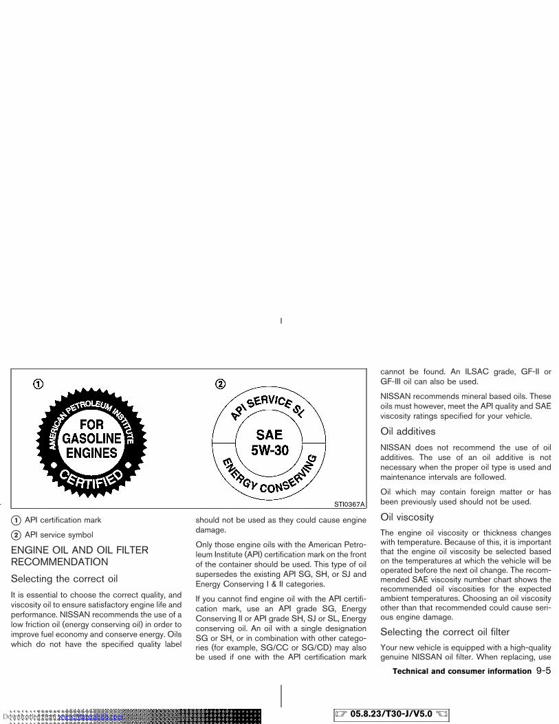
�1 API certification mark
�2 API service symbol
ENGINE OIL AND OIL FILTERRECOMMENDATION
Selecting the correct oil
It is essential to choose the correct quality, andviscosity oil to ensure satisfactory engine life andperformance. NISSAN recommends the use of alow friction oil (energy conserving oil) in order toimprove fuel economy and conserve energy. Oilswhich do not have the specified quality label
should not be used as they could cause enginedamage.
Only those engine oils with the American Petro-leum Institute (API) certification mark on the frontof the container should be used. This type of oilsupersedes the existing API SG, SH, or SJ andEnergy Conserving I & II categories.
If you cannot find engine oil with the API certifi-cation mark, use an API grade SG, EnergyConserving II or API grade SH, SJ or SL, Energyconserving oil. An oil with a single designationSG or SH, or in combination with other catego-ries (for example, SG/CC or SG/CD) may alsobe used if one with the API certification mark
cannot be found. An ILSAC grade, GF-II orGF-III oil can also be used.
NISSAN recommends mineral based oils. Theseoils must however, meet the API quality and SAEviscosity ratings specified for your vehicle.
Oil additives
NISSAN does not recommend the use of oiladditives. The use of an oil additive is notnecessary when the proper oil type is used andmaintenance intervals are followed.
Oil which may contain foreign matter or hasbeen previously used should not be used.
Oil viscosityThe engine oil viscosity or thickness changeswith temperature. Because of this, it is importantthat the engine oil viscosity be selected basedon the temperatures at which the vehicle will beoperated before the next oil change. The recom-mended SAE viscosity number chart shows therecommended oil viscosities for the expectedambient temperatures. Choosing an oil viscosityother than that recommended could cause seri-ous engine damage.
Selecting the correct oil filterYour new vehicle is equipped with a high-qualitygenuine NISSAN oil filter. When replacing, use
STI0367A
Technical and consumer information 9-5
� 05.8.23/T30-J/V5.0 �Downloaded from www.Manualslib.com manuals search engine
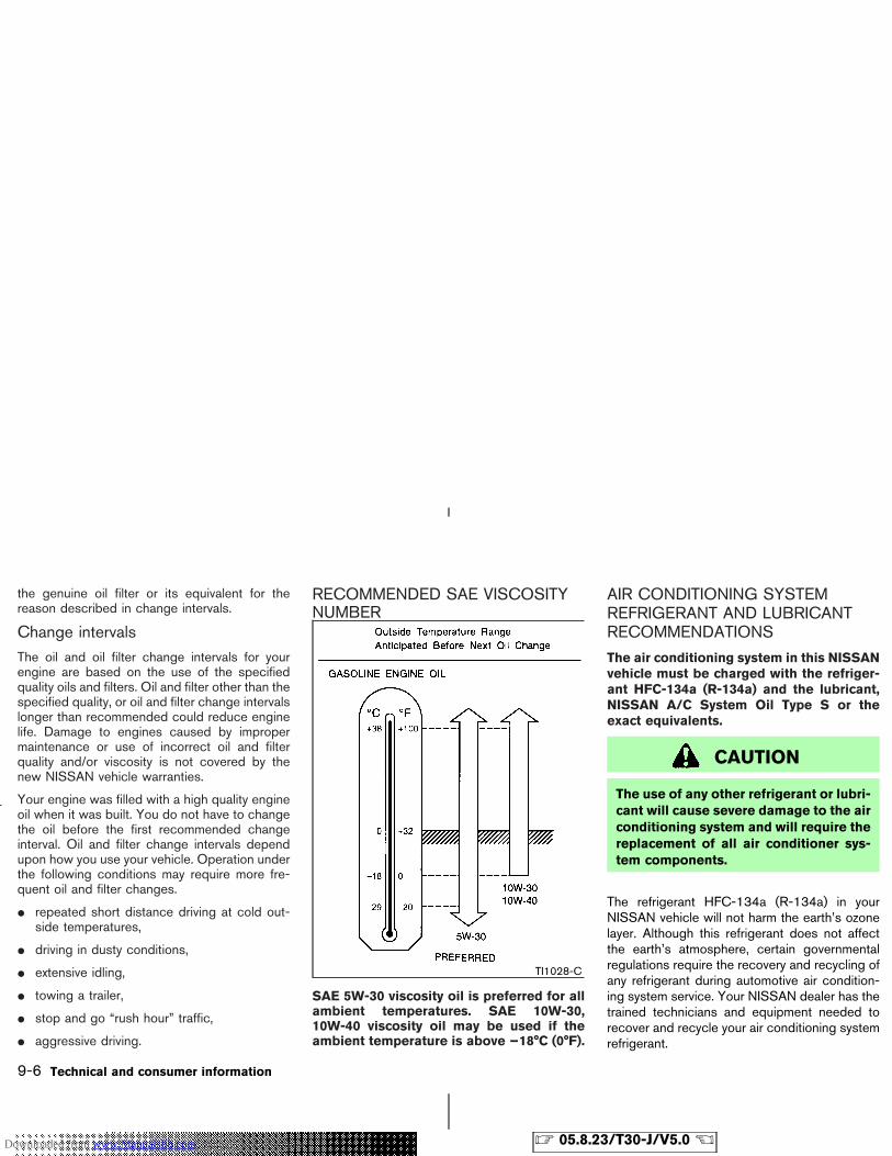
the genuine oil filter or its equivalent for thereason described in change intervals.
Change intervalsThe oil and oil filter change intervals for yourengine are based on the use of the specifiedquality oils and filters. Oil and filter other than thespecified quality, or oil and filter change intervalslonger than recommended could reduce enginelife. Damage to engines caused by impropermaintenance or use of incorrect oil and filterquality and/or viscosity is not covered by thenew NISSAN vehicle warranties.
Your engine was filled with a high quality engineoil when it was built. You do not have to changethe oil before the first recommended changeinterval. Oil and filter change intervals dependupon how you use your vehicle. Operation underthe following conditions may require more fre-quent oil and filter changes.
� repeated short distance driving at cold out-side temperatures,
� driving in dusty conditions,
� extensive idling,
� towing a trailer,
� stop and go “rush hour” traffic,
� aggressive driving.
RECOMMENDED SAE VISCOSITYNUMBER
SAE 5W-30 viscosity oil is preferred for allambient temperatures. SAE 10W-30,10W-40 viscosity oil may be used if theambient temperature is above −18°C (0°F).
AIR CONDITIONING SYSTEMREFRIGERANT AND LUBRICANTRECOMMENDATIONS
The air conditioning system in this NISSANvehicle must be charged with the refriger-ant HFC-134a (R-134a) and the lubricant,NISSAN A/C System Oil Type S or theexact equivalents.
CAUTION
The use of any other refrigerant or lubri-cant will cause severe damage to the airconditioning system and will require thereplacement of all air conditioner sys-tem components.
The refrigerant HFC-134a (R-134a) in yourNISSAN vehicle will not harm the earth’s ozonelayer. Although this refrigerant does not affectthe earth’s atmosphere, certain governmentalregulations require the recovery and recycling ofany refrigerant during automotive air condition-ing system service. Your NISSAN dealer has thetrained technicians and equipment needed torecover and recycle your air conditioning systemrefrigerant.
TI1028-C
9-6 Technical and consumer information
� 05.8.23/T30-J/V5.0 �Downloaded from www.Manualslib.com manuals search engine
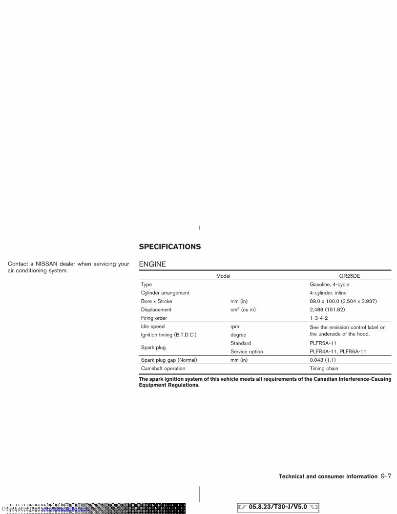
Contact a NISSAN dealer when servicing yourair conditioning system.
ENGINE
Model QR25DE
Type Gasoline, 4-cycle
Cylinder arrangement 4-cylinder, inline
Bore x Stroke mm (in) 89.0 x 100.0 (3.504 x 3.937)
Displacement cm3 (cu in) 2,488 (151.82)
Firing order 1-3-4-2
Idle speed rpm See the emission control label onthe underside of the hood.Ignition timing (B.T.D.C.) degree
Spark plugStandard PLFR5A-11
Service option PLFR4A-11, PLFR6A-11
Spark plug gap (Normal) mm (in) 0.043 (1.1)
Camshaft operation Timing chain
The spark ignition system of this vehicle meets all requirements of the Canadian Interference-CausingEquipment Regulations.
SPECIFICATIONS
Technical and consumer information 9-7
� 05.8.23/T30-J/V5.0 �Downloaded from www.Manualslib.com manuals search engine
WHEELS AND TIRES
Road wheel
Type Size Offset mm (in)
Steel 16 x 6-1/2JJ 40 (1.57)
Aluminum16 x 6-1/2JJ 40 (1.57)
17 x 6-1/2JJ 40 (1.57)
Tire
Type Size Pressure (COLD)
ConventionalP215/65R16 220 kPa (32 psi)
P215/60R17 200 kPa (29 psi)
Spare Conventional —
DIMENSIONS AND WEIGHTS
Overall length mm (in) 4,455 (175.4)
Overall width mm (in) 1,765 (69.5)
Overall heightmm (in) 1,675 (65.9)
mm (in) 1,750 (68.9)*
Front tread mm (in) 1,530 (60.2)
Rear tread mm (in) 1,530 (60.2)
Wheelbase mm (in) 2,625 (103.3)
Gross vehicle weight rating kg (lb)
See the C.M.V.S.S. certifica-tion label on the driver’s sidelock pillar.
Gross axle weight rating
Front kg (lb)
Rear kg (lb)
*: Rear air spoiler or roof rail with driving lights equipped model
9-8 Technical and consumer information
� 05.8.23/T30-J/V5.0 �Downloaded from www.Manualslib.com manuals search engine
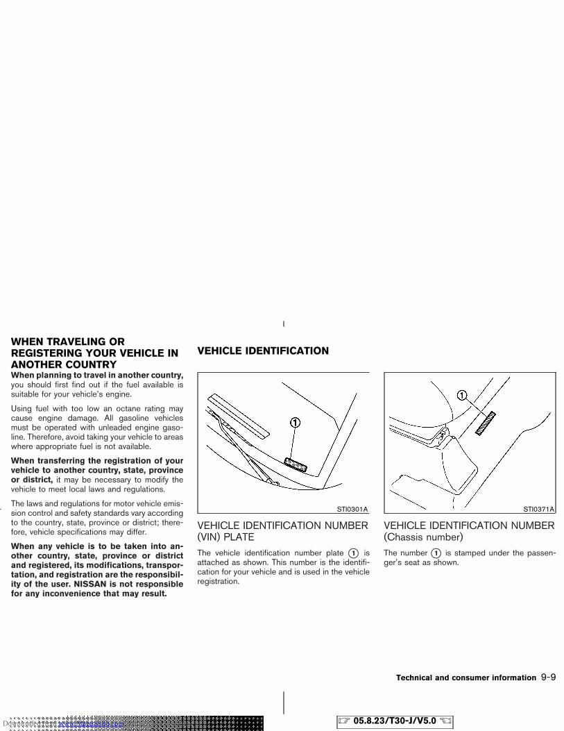
When planning to travel in another country,you should first find out if the fuel available issuitable for your vehicle’s engine.
Using fuel with too low an octane rating maycause engine damage. All gasoline vehiclesmust be operated with unleaded engine gaso-line. Therefore, avoid taking your vehicle to areaswhere appropriate fuel is not available.
When transferring the registration of yourvehicle to another country, state, provinceor district, it may be necessary to modify thevehicle to meet local laws and regulations.
The laws and regulations for motor vehicle emis-sion control and safety standards vary accordingto the country, state, province or district; there-fore, vehicle specifications may differ.
When any vehicle is to be taken into an-other country, state, province or districtand registered, its modifications, transpor-tation, and registration are the responsibil-ity of the user. NISSAN is not responsiblefor any inconvenience that may result.
VEHICLE IDENTIFICATION NUMBER(VIN) PLATEThe vehicle identification number plate �1 isattached as shown. This number is the identifi-cation for your vehicle and is used in the vehicleregistration.
VEHICLE IDENTIFICATION NUMBER(Chassis number)The number �1 is stamped under the passen-ger’s seat as shown.
STI0301A STI0371A
WHEN TRAVELING ORREGISTERING YOUR VEHICLE INANOTHER COUNTRY
VEHICLE IDENTIFICATION
Technical and consumer information 9-9
� 05.8.23/T30-J/V5.0 �Downloaded from www.Manualslib.com manuals search engine
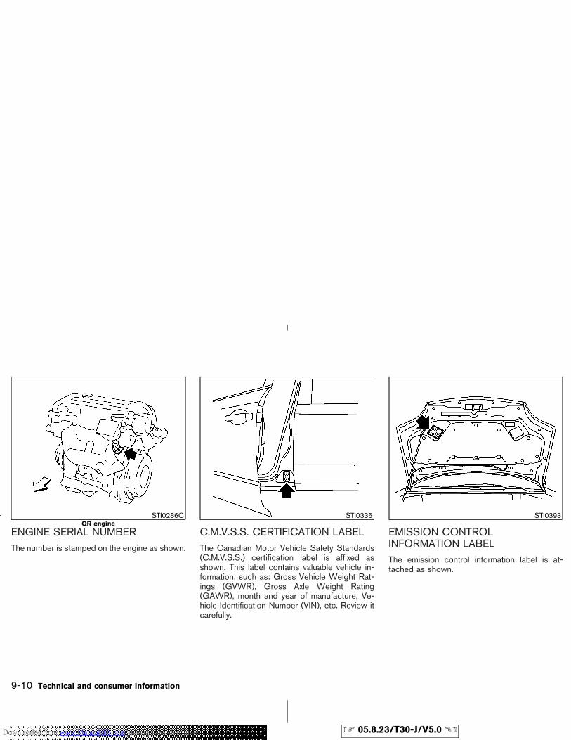
ENGINE SERIAL NUMBERThe number is stamped on the engine as shown.
C.M.V.S.S. CERTIFICATION LABELThe Canadian Motor Vehicle Safety Standards(C.M.V.S.S.) certification label is affixed asshown. This label contains valuable vehicle in-formation, such as: Gross Vehicle Weight Rat-ings (GVWR), Gross Axle Weight Rating(GAWR), month and year of manufacture, Ve-hicle Identification Number (VIN), etc. Review itcarefully.
EMISSION CONTROLINFORMATION LABELThe emission control information label is at-tached as shown.
STI0286CQR engine
STI0336 STI0393
9-10 Technical and consumer information
� 05.8.23/T30-J/V5.0 �Downloaded from www.Manualslib.com manuals search engine
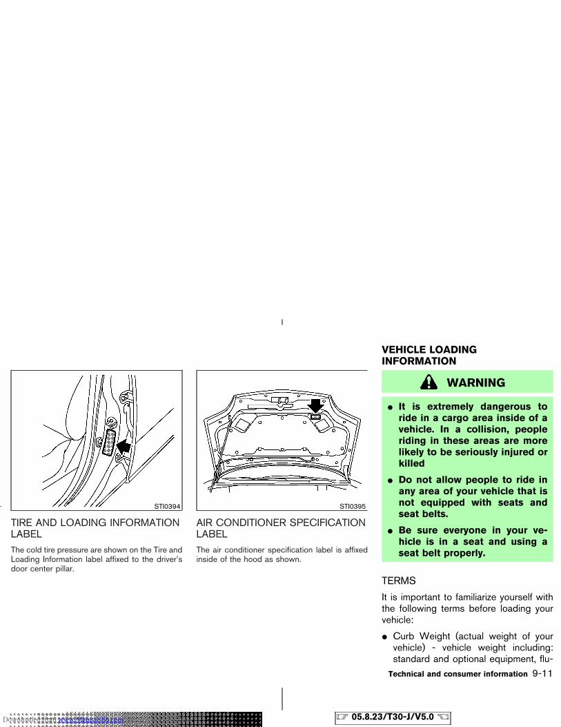
TIRE AND LOADING INFORMATIONLABELThe cold tire pressure are shown on the Tire andLoading Information label affixed to the driver’sdoor center pillar.
AIR CONDITIONER SPECIFICATIONLABELThe air conditioner specification label is affixedinside of the hood as shown.
WARNING
� It is extremely dangerous toride in a cargo area inside of avehicle. In a collision, peopleriding in these areas are morelikely to be seriously injured orkilled
� Do not allow people to ride inany area of your vehicle that isnot equipped with seats andseat belts.
� Be sure everyone in your ve-hicle is in a seat and using aseat belt properly.
TERMS
It is important to familiarize yourself withthe following terms before loading yourvehicle:
� Curb Weight (actual weight of yourvehicle) - vehicle weight including:standard and optional equipment, flu-
STI0394 STI0395
VEHICLE LOADINGINFORMATION
Technical and consumer information 9-11
� 05.8.23/T30-J/V5.0 �Downloaded from www.Manualslib.com manuals search engine
ids, emergency tools, and spare tireassembly. This weight does not in-clude passengers and cargo.
� GVW (Gross Vehicle Weight) - curbweight plus the combined weight ofpassengers and cargo.
� GVWR (Gross Vehicle Weight Rat-ing) - maximum total weight (load) limitspecified for the vehicle.
� GAWR (Gross Axle Weight Rating) -maximum weight (load) limit specifiedfor the front or rear axle.
� GCWR (Gross Combined WeightRating) - maximum total weight ratingof the vehicle, passengers, cargo, andtrailer.
� Vehicle Capacity Weight, Load limit,Total load capacity - maximum totalweight limit specified of the load (pas-sengers and cargo) for the vehicle.This is the maximum combined weightof occupants and cargo that can beloaded into the vehicle. If the vehicle is
used to tow a trailer, the trailer tongueweight must be included as part of thecargo load. This information is locatedon the Tire and Loading Informationlabel.
� Cargo capacity - permissible weight ofcargo, the subtracted weight of occu-pants from the load limit.
VEHICLE LOAD CAPACITY
Do not exceed the load limit of yourvehicle shown as “The combined weightof occupants and cargo” on the Tire andLoading Information label. Do not exceedthe number of occupants shown as“Seating Capacity” on the Tire and Load-ing Information label.
To get “the combined weight of occu-pants and cargo”, add the weight of alloccupants, then add the total luggageweight. Examples are shown below.
9-12 Technical and consumer information
� 05.8.23/T30-J/V5.0 �Downloaded from www.Manualslib.com manuals search engine
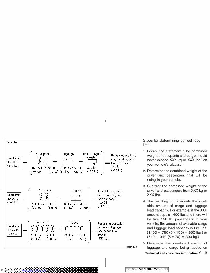
Steps for determining correct loadlimit
1. Locate the statement “The combinedweight of occupants and cargo shouldnever exceed XXX kg or XXX lbs” onyour vehicle’s placard.
2. Determine the combined weight of thedriver and passengers that will beriding in your vehicle.
3. Subtract the combined weight of thedriver and passengers from XXX kg orXXX lbs.
4. The resulting figure equals the avail-able amount of cargo and luggageload capacity. For example, if the XXXamount equals 1400 lbs. and there willbe five 150 lb. passengers in yourvehicle, the amount of available cargoand luggage load capacity is 650 lbs.(1400 − 750 (5 x 150) = 650 lbs.) or(640 − 340 (5 x 70) = 300 kg.)
5. Determine the combined weight ofluggage and cargo being loaded onSTI0445
Technical and consumer information 9-13
� 05.8.23/T30-J/V5.0 �Downloaded from www.Manualslib.com manuals search engine
the vehicle. That weight may not safelyexceed the available cargo and lug-gage load capacity calculated in Step4.
6. If your vehicle will be towing a trailer,load from your trailer will be trans-ferred to your vehicle. Consult thismanual to determine how this reducesthe available cargo and luggage loadcapacity of your vehicle.
Before driving a loaded vehicle, confirmthe you do not exceed the Gross VehicleWeight Rating (GVWR) or the GrossAxle Weight Rating (GAWR) for yourvehicle. See “Measurement of Weights”later in this section.
Also check tires for proper inflation pres-sures. See the Tire and Loading Informa-tion label.
LOADING TIPS
There are luggage hooks located in thecargo area. The luggage hooks can be
used to secure cargo with ropes or othertypes of straps.
� The GVW must not exceed GVWR orGAWR as specified on the C.M.V.S.S.certification label.
� Do not load the front and rear axle tothe GAWR. Doing so will exceed theGVWR.
WARNING
� Properly secure all cargo withropes or straps to help preventit from sliding or shifting. Donot place cargo higher than theseatbacks. In a sudden stop orcollision, unsecured cargocould cause personal injury.
� Do not load your vehicle anyheavier than the GVWR or themaximum front and rearGAWRs. If you do, parts of yourvehicle can break, tire damage
could occur, or it can changethe way your vehicle handles.This could result in loss of con-trol and cause personal injury.
� Overloading not only canshorten the life of your vehicleand the tire, but can also causeunsafe vehicle handling andlonger braking distances. Thismay cause a premature tire fail-ure which could result in a seri-ous accident and personal in-jury. Failures caused byoverloading are not covered bythe vehicle’s warranty.
PAYLOAD WEIGHT CAPACITY
The payload weight capacity is the maxi-mum total weight of passengers, optionalequipment (air conditioning, trailer hitch,etc.) and cargo that your vehicle is de-signed to carry.
Before driving a loaded vehicle, confirm
9-14 Technical and consumer information
� 05.8.23/T30-J/V5.0 �Downloaded from www.Manualslib.com manuals search engine
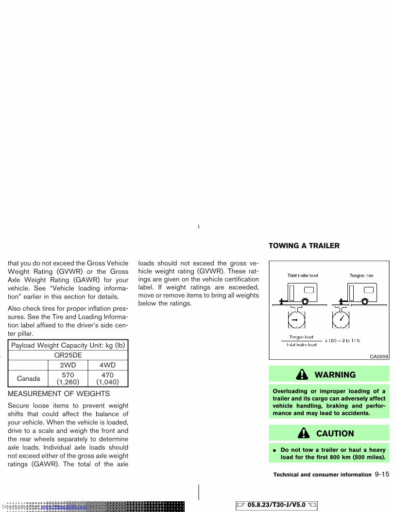
that you do not exceed the Gross VehicleWeight Rating (GVWR) or the GrossAxle Weight Rating (GAWR) for yourvehicle. See “Vehicle loading informa-tion” earlier in this section for details.
Also check tires for proper inflation pres-sures. See the Tire and Loading Informa-tion label affixed to the driver’s side cen-ter pillar.
Payload Weight Capacity Unit: kg (lb)QR25DE2WD 4WD
Canada 570(1,260)
470(1,040)
MEASUREMENT OF WEIGHTS
Secure loose items to prevent weightshifts that could affect the balance ofyour vehicle. When the vehicle is loaded,drive to a scale and weigh the front andthe rear wheels separately to determineaxle loads. Individual axle loads shouldnot exceed either of the gross axle weightratings (GAWR). The total of the axle
loads should not exceed the gross ve-hicle weight rating (GVWR). These rat-ings are given on the vehicle certificationlabel. If weight ratings are exceeded,move or remove items to bring all weightsbelow the ratings.
WARNING
Overloading or improper loading of atrailer and its cargo can adversely affectvehicle handling, braking and perfor-mance and may lead to accidents.
CAUTION
� Do not tow a trailer or haul a heavyload for the first 800 km (500 miles).
CA0009
TOWING A TRAILER
Technical and consumer information 9-15
� 05.8.23/T30-J/V5.0 �Downloaded from www.Manualslib.com manuals search engine
Your engine, axle or other partscould be damaged.
� For the first 800 km (500 miles) thatyou tow a trailer, do not drive over 80km/h (50 mph) and do not makestarts at full throttle. This helps theengine and other parts of your ve-hicle wear in at the heavier loads.
Your new vehicle was designed to be usedprimarily to carry passengers and cargo. Re-member that towing a trailer will place additionalloads on your vehicle’s engine, drive train, steer-ing, braking and other systems.
WARNING
Vehicle damage resulting from im-proper towing procedures is not cov-ered by NISSAN warranties.
MAXIMUM LOAD LIMITS
Maximum trailer loads
Never allow the total trailer load to exceed thevalue specified in the Towing Load/SpecificationChart found later in this section. The total trailerload equals trailer weight plus its cargo weight.
� When towing a trailer load of 454 kg (1,000lbs.) or more, trailers with a brake systemMUST be used.
The maximum GCWR (Gross CombinedWeightRating) should not exceed the value specified inthe following Towing Load/Specification Chart.
The GCWR equals the combined weight of thetowing vehicle (including passengers and cargo)plus the total trailer load. Towing loads greaterthan these or using improper towing equipmentcould adversely affect vehicle handling, brakingand performance.
Towing loads greater than specified or usingimproper towing equipment could adversely af-fect vehicle handling, braking and performance.The ability of your vehicle to tow a trailer is notonly related to the maximum trailer loads, butalso the places you plan to tow. Tow weightsappropriate for level highway driving may have tobe reduced on very steep grades or in low
traction situations (for example, on slippery boatramps).
Temperature conditions also can affect towing.For example, towing a heavy trailer in highoutside temperatures on graded roads can af-fect engine performance and cause overheating.The transmission high fluid temperature protec-tion mode, which helps reduce the chance oftransmission damage, could activate and auto-matically decrease engine power. Vehicle speedmay decrease to 65 to 80 km/h (40 to 50 MPH)under high load. Plan your trip carefully to ac-count for trailer and vehicle load, weather, androad conditions.
WARNING
Overheating can result in reduced en-gine power and vehicle speed. Also,when the high temperature mode oper-ates, vehicle speed may be graduallyreduced. The reduced speed may belower than other traffic, which couldincrease the chance of a collision. Beespecially careful when driving. If nec-essary, pull to the side of the road at asafe place and allow the engine to coolor the transmission to return to normal
9-16 Technical and consumer information
� 05.8.23/T30-J/V5.0 �Downloaded from www.Manualslib.com manuals search engine
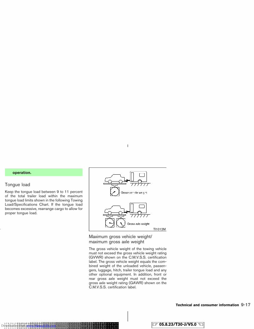
operation.
Tongue loadKeep the tongue load between 9 to 11 percentof the total trailer load within the maximumtongue load limits shown in the following TowingLoad/Specifications Chart. If the tongue loadbecomes excessive, rearrange cargo to allow forproper tongue load.
Maximum gross vehicle weight/maximum gross axle weightThe gross vehicle weight of the towing vehiclemust not exceed the gross vehicle weight rating(GVWR) shown on the C.M.V.S.S. certificationlabel. The gross vehicle weight equals the com-bined weight of the unloaded vehicle, passen-gers, luggage, hitch, trailer tongue load and anyother optional equipment. In addition, front orrear gross axle weight must not exceed thegross axle weight rating (GAWR) shown on theC.M.V.S.S. certification label.
TI1012M
Technical and consumer information 9-17
� 05.8.23/T30-J/V5.0 �Downloaded from www.Manualslib.com manuals search engine
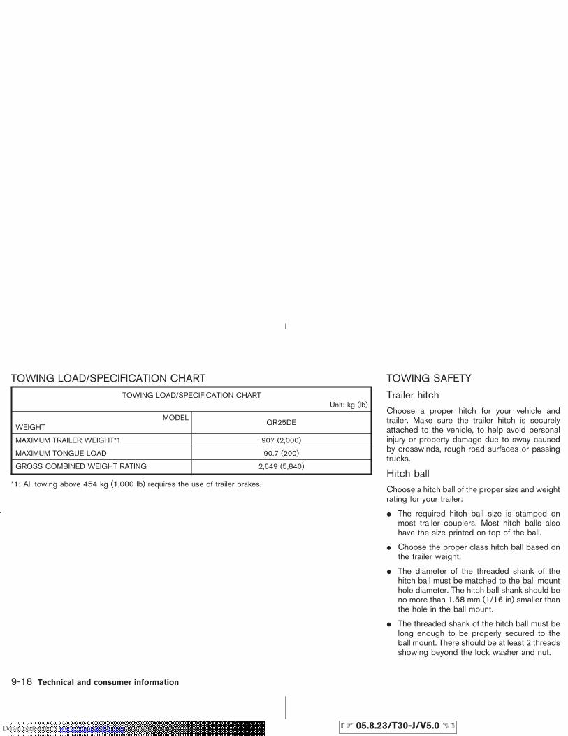
TOWING LOAD/SPECIFICATION CHART
TOWING LOAD/SPECIFICATION CHARTUnit: kg (lb)
MODELWEIGHT
QR25DE
MAXIMUM TRAILER WEIGHT*1 907 (2,000)
MAXIMUM TONGUE LOAD 90.7 (200)
GROSS COMBINED WEIGHT RATING 2,649 (5,840)
*1: All towing above 454 kg (1,000 lb) requires the use of trailer brakes.
TOWING SAFETY
Trailer hitchChoose a proper hitch for your vehicle andtrailer. Make sure the trailer hitch is securelyattached to the vehicle, to help avoid personalinjury or property damage due to sway causedby crosswinds, rough road surfaces or passingtrucks.
Hitch ballChoose a hitch ball of the proper size and weightrating for your trailer:
� The required hitch ball size is stamped onmost trailer couplers. Most hitch balls alsohave the size printed on top of the ball.
� Choose the proper class hitch ball based onthe trailer weight.
� The diameter of the threaded shank of thehitch ball must be matched to the ball mounthole diameter. The hitch ball shank should beno more than 1.58 mm (1/16 in) smaller thanthe hole in the ball mount.
� The threaded shank of the hitch ball must belong enough to be properly secured to theball mount. There should be at least 2 threadsshowing beyond the lock washer and nut.
9-18 Technical and consumer information
� 05.8.23/T30-J/V5.0 �Downloaded from www.Manualslib.com manuals search engine
Class I hitch
Class I trailer hitch equipment (receiver, ballmount and hitch ball) can be used to tow trailersof a maximum weight of 909 kg (2,000 lb).
You may add Class I trailer hitch equipment tothe vehicle that has a 909 kg (2,000 lb) maxi-mum weight rating, but your vehicle is onlycapable of towing the maximum trailer weightsshown in the Towing Load/Specification Chartearlier in this section.
CAUTION
� Special hitches which include framereinforcements are required for tow-ing above 907 kg (2,000 lb). Suitablegenuine NISSAN hitches for pickuptrucks and sport utility vehicles areavailable at a NISSAN dealer.
� Do not use axle-mounted hitches.
� The hitch should not be attached toor affect the operation of the impactabsorbing bumper.
� Do not modify the vehicle exhaustsystem, brake system, etc. to install a
trailer hitch.
� After the hitch is removed, seal thebolt holes to prevent exhaust fumes,water or dust from entering the pas-senger compartment.
� Regularly check all trailer hitchmounting bolts are securelymounted.
� To reduce the possibility of addi-tional damage if your vehicle isstruck from the rear, where practical,remove the hitch and/or receiverwhen not in use.
Tire pressures
� When towing a trailer, inflate the ve-hicle tires to the recommended coldtire pressure indicated on the Tire andLoading Information label.
� Trailer tire condition, size, load ratingand proper inflation pressure shouldbe in accordance with the trailer andtire manufacturers’ specifications.
Safety chain
Always use a suitable chains between yourvehicle and the trailer. The safety chains shouldbe crossed and should be attached to the hitch,not to the vehicle bumper or axle. Be sure toleave enough slack in the chain to permit turningcorners.
Trailer lights
CAUTION
When splicing into the vehicle electricalsystem, a commercially availablepower-type module/converter must beused to provide power for all trailerlighting. This unit uses the vehicle bat-tery as a direct power source for alltrailer lights while using the vehicle taillight, stoplight and turn signal circuitsas a signal source. The module/converter must draw no more than 15milliamps from the stop and tail lampcircuits. Using a module/converter thatexceeds these power requirements maydamage the vehicle’s electrical system.See a reputable trailer dealer to obtain
Technical and consumer information 9-19
� 05.8.23/T30-J/V5.0 �Downloaded from www.Manualslib.com manuals search engine
the proper equipment and to have itinstalled.
Trailer lights should comply with federal and/orlocal regulations. For assistance in hooking uptrailer lights, contact a NISSAN dealer or repu-table trailer dealer.
Trailer brakes
If your trailer is equipped with a braking system,make sure it conforms to federal and/or localregulations and that it is properly installed.
WARNING
Never connect a trailer brake systemdirectly to the vehicle brake system.
Pre-towing tips
� Be certain your vehicle maintains a levelposition when a loaded and/or unloadedtrailer is hitched. Do not drive the vehicle if ithas an abnormal nose-up or nose-down con-dition; check for improper tongue load, over-load, worn suspension or other possiblecauses of either condition.
� Always secure items in the trailer to preventload shifts while driving.
� Load the trailer so approximately 60% of thetrailer load is in the front half and 40% is inthe back half.
� Check your hitch, trailer tire pressure, vehicletire pressure, trailer light operation, and trailerwheel lug nuts every time you attach a trailerto the vehicle.
� Be certain your rear view mirrors conform toall federal, state or local regulations. If not,install any mirrors required for towing beforedriving the vehicle.
Trailer towing tipsIn order to gain skill and an understanding of thevehicle’s behavior, you should practice turning,stopping and backing up in an area which is freefrom traffic. Steering stability, and braking per-formance will be somewhat different than undernormal driving conditions.
� Always secure items in the trailer to preventload shift while driving.
� Avoid abrupt starts, acceleration or stops.
� Avoid sharp turns or lane changes.
� Always drive your vehicle at a moderatespeed. Some states or provinces have spe-
cific speed limits for vehicles that are towingtrailers. Obey the local speed limits.
� When backing up, hold the bottom of thesteering wheel with one hand. Move yourhand in the direction in which you want thetrailer to go. Make small corrections and backup slowly. If possible, have someone guideyou when you are backing up.
� Always block the wheels on both vehicle andtrailer when parking. Parking on a slope is notrecommended; however, if you must do so,and if your vehicle is equipped with automatictransmission, first block the wheels and applythe parking brake, and then move the selectorlever into the P (Park) position. If you movethe selector lever to the P (Park) positionbefore blocking the wheels and applying theparking brake, transmission damage couldoccur.
� When going down a hill, shift into a lowergear and use the engine braking effect.When going up a long grade, downshift thetransmission to a lower gear and reducespeed to reduce chances of engine overload-ing and/or overheating.
� If the engine coolant rises to an extremelyhigh temperature when the air conditioningsystem is on, turn off the air conditioner.Coolant heat can be additionally vented by
9-20 Technical and consumer information
� 05.8.23/T30-J/V5.0 �Downloaded from www.Manualslib.com manuals search engine
opening the windows, switching the fan con-trol to high and setting the temperature con-trol to the HOT position.
� Trailer towing requires more fuel than normalcircumstances.
� Avoid towing a trailer for the first 805 km(500 miles).
� Have your vehicle serviced more often than atintervals specified in the recommended main-tenance schedule.
� When making a turn, your trailer wheels willbe closer to the inside of the turn than yourvehicle wheels. To compensate for this, makea larger than normal turning radius during theturn.
� Crosswinds and rough roads will adverselyaffect vehicle/trailer handling, possibly caus-ing vehicle sway. When being passed bylarger vehicles, be prepared for possiblechanges in crosswinds that could affect ve-hicle handling. If swaying does occur, firmlygrip the steering wheel, steer straight ahead,and immediately (but gradually) reduce ve-hicle speed. This combination will help stabi-lize the vehicle. Never increase speed.
� Be careful when passing other vehicles.Passing while towing a trailer requires con-siderably more distance than normal passing.
Remember the length of the trailer must alsopass the other vehicle before you can safelychange lanes.
� Avoid holding the brake pedal down too longor too frequently. This could cause the brakesto overheat, resulting in reduced braking ef-ficiency.
� Increase your following distance to allow forgreater stopping distances while towing atrailer. Anticipate stops and brake gradually.
� Do not use cruise control while towing atrailer.
� Check your hitch, trailer wiring harness con-nections, and trailer wheel lug nuts after 80km (50 miles) of travel and at every break.
� When stopped in traffic for long periods oftime in hot weather, put the vehicle in the P(Park) position.
When towing a trailer, the transmissionoil/fluid should be changed more fre-quently. For additional information, seethe “8. Maintenance and do-it-yourself”section earlier in this manual.
FLAT TOWINGTowing your vehicle with all four wheels on theground is sometimes called flat towing. Thismethod is sometimes used when towing a ve-
hicle behind a recreational vehicle, such as amotor home.
CAUTION
� Failure to follow these guidelinescan result in severe transmissiondamage.
� Whenever flat towing your vehicle,always tow forward, never backward.
� DO NOT tow any automatic transmis-sion vehicle with all four wheels onthe ground (flat towing). Doing soWILL DAMAGE internal transmissionparts due to lack of transmission lu-brication.
� For emergency towing procedures re-fer to “Towing Recommended byNISSAN” in the “6. In case of emer-gency” section of this manual.
Automatic transmissionTo tow a vehicle equipped with an automatictransmission, an appropriate vehicle dollyMUSTbe placed under the towed vehicle’s drivewheels. Always follow the dolly manufacturer’s
Technical and consumer information 9-21
� 05.8.23/T30-J/V5.0 �Downloaded from www.Manualslib.com manuals search engine
recommendations when using their product.
Manual transmissionAll mode 4WD (four-wheel drive) models:
Never tow All mode 4WD models with any of thewheels on the ground.
DOT (Department Of Transportation) QualityGrades: All passenger car tires must conform tofederal safety requirements in addition to thesegrades.
Quality grades can be found where applicableon the tire sidewall between tread shoulder andmaximum section width. For example:
Treadwear 200 Traction AA Temperature A
Treadwear
Treadwear grade is a comparative rating basedon tire wear rate when tested under controlledconditions on specified government testcourses. For example, a tire graded 150 wouldwear one and a half (1-1/2) times as well on thegovernment course as a tire graded 100. How-ever, relative tire performance depends on actualdriving conditions, and may vary significantlyfrom the norm due to variations in driving habits,service practices and differences in road char-acteristics and climate.
Traction AA, A, B and C
The traction grades, from highest to lowest, areAA, A, B, and C. Those grades represent thetire’s ability to stop on wet pavement as mea-sured under controlled conditions on specifiedgovernment test surfaces of asphalt and con-
crete. A tire marked C may have poor tractionperformance.
WARNING
The traction grade assigned to your ve-hicle tires is based on straight-aheadbraking traction tests, and does not in-clude acceleration, cornering, hydro-planing, or peak traction characteristics.
Temperature A, B and CTemperature grades are A (the highest), B, andC. They represent a tire’s resistance to heatbuild-up, and its ability to dissipate heat whentested under controlled conditions on a speci-fied indoor laboratory test wheel. Sustained hightemperature can cause tire material to degener-ate, reducing tire life. Excessive temperaturescan lead to sudden tire failure. Grade C corre-sponds to a performance level which all passen-ger car tires must meet under the Federal MotorVehicle Safety Standard No. 109. Grades A andB represent higher levels of performance onlaboratory test wheels than the minimum re-quired by law.
UNIFORM TIRE QUALITYGRADING
9-22 Technical and consumer information
� 05.8.23/T30-J/V5.0 �Downloaded from www.Manualslib.com manuals search engine
WARNING
The temperature grade for this tire isestablished for a tire that is properlyinflated and not overloaded. Excessivespeed, underinflation, or excessiveloading, either separately or in combi-nation, can cause heat buildup and pos-sible tire failure.
Your NISSAN is covered by the following emis-sion warranties.
Emission Control System Warranty
Details of these warranties may be found withother vehicle warranties in your Warranty Infor-mation Booklet that comes with your NISSANvehicle. If you did not receive a Warranty Infor-mation Booklet or it has become lost, you mayobtain a replacement by writing to:
� Nissan Canada Inc.5290 Orbitor DriveMississauga, Ontario,L4W 4Z5
WARNING
A vehicle equipped with 4WD shouldnever be tested using a two wheel dy-namometer, similar to the dynamom-eters used by some states for emissionstesting, or similar equipment. Make sureyou inform the test facility personnelthat your vehicle is a 4WD equippedvehicle before it is placed on a dyna-mometer. Failure to do so may result intransmission damage or unexpected ve-hicle movement which could result inserious vehicle damage or personal in-jury.
Due to legal requirements in some statesand Canadian provinces, your vehicle may berequired to be in what is called the “readycondition” for an Inspection/Maintenance (I/M)test of the emission control system.
The vehicle is set to the “ready condition” whenit is driven through certain driving patterns.Usually, the “ready condition” can be obtainedby ordinary usage of the vehicle.
If a powertrain system component is repaired or
EMISSION CONTROL SYSTEMWARRANTY
READINESS FOR INSPECTION/MAINTENANCE (I/M) TEST
Technical and consumer information 9-23
� 05.8.23/T30-J/V5.0 �Downloaded from www.Manualslib.com manuals search engine
the battery is disconnected, the vehicle may bereset to a not “ready condition”. Before takingthe I/M test, check the vehicle’s inspection/maintenance test readiness condition. Turn theignition switch ON without starting the engine. Ifthe Malfunction Indicator Lamp (MIL) comes onsteady for 20 seconds and then blinks for 10seconds, the I/M test condition is “not ready”. Ifthe MIL does not blink after 20 seconds, the I/Mtest condition is “ready”.
If the MIL indicates the vehicle is in a “not ready”condition, drive the vehicle through the followingpattern to set the vehicle to the ready condition.If you cannot or do not want to perform thedriving pattern, a NISSAN dealer can conduct itfor you.
WARNING
Always drive the vehicle in a safe andprudent manner according to trafficconditions, and obey all traffic laws.
1. Start the engine. Allow the engine to idle untilthe engine coolant temperature gauge needlepoints between the C and H (normal operat-ing temperature).
2. Accelerate the vehicle to 88 km/h (55 MPH),
then quickly release the accelerator pedalcompletely and keep it released for at least10 seconds.
3. Quickly depress the accelerator pedal for amoment, then drive the vehicle at a speed of86 to 96 km/h (53 to 60 MPH) for at least 9minutes.
4. Stop the vehicle. Leave the engine running.
5. Accelerate the vehicle to 55 km/h (35 MPH)and maintain the speed for 20 seconds.
6. Repeat steps 4 and 5 at least 10 times.
7. Accelerate the vehicle to 88 km/h (55 MPH)and maintain the speed for at least 3 minutes.
8. Stop the vehicle. Place the transmission se-lector lever in the “P” or “N” position.
9. Turn the engine off.
10. Repeat steps 1 through 8 at least one moretime.
If step 1 through 7 is interrupted, repeat thepreceding step. Any safe driving mode is ac-ceptable between steps. Do not stop the engineuntil step 7 is completed.
Your vehicle is equipped with a variety of com-puters that monitor and control a number ofsystems to optimize performance and help ser-vice technicians with diagnosis and repair. De-pending on the equipment on your vehicle, someof the computers monitor emission control sys-tems, braking systems, engine systems, trans-mission systems, tire pressure systems, and airbag systems, just to name a few. Some dataabout vehicle operation may be stored in thecomputers for use during servicing. Other datamay be stored if a crash event occurs. Forexample, air bag readiness, air bag performance,and seat belt use by the driver or passenger maybe recorded, depending on vehicle equipment.These types of systems are sometimes calledEvent Data Recorders.
Special equipment can be used to access theelectronic data that may be stored in the vehi-cle’s computers (sounds are not recorded).NISSAN and NISSAN dealers have equipmentto access some of this data; others may alsohave this equipment. The data may be retrievedduring routine vehicle servicing or for specialresearch. It might also be accessed with theconsent of the vehicle owner or lessee, in re-sponse to a request by law enforcement, or asotherwise required or permitted by law.
EVENT DATA RECORDERS
9-24 Technical and consumer information
� 05.8.23/T30-J/V5.0 �Downloaded from www.Manualslib.com manuals search engine
A genuine NISSAN Service Manual is the bestsource of service and repair information for yourvehicle. Filled with wiring diagrams, illustrationsand step-by-step diagnostic and adjustmentprocedures, this manual is the same one used bythe factory trained technicians working at autho-rized NISSAN dealerships. Also available aregenuine NISSAN Owner’s Manuals, and genu-ine NISSAN Service and Owner’s Manuals forolder NISSAN models.
To purchase a copy of a genuine NISSANService Manual or Owner’s Manual please con-tact your nearest NISSAN dealer. For the phonenumber and location of a NISSAN Dealer in yourarea call the NISSAN Satisfaction Center at1-800-387-0122 and a bilingual NISSAN rep-resentative will assist you.
IN THE EVENT OF A COLLISIONUnfortunately, accidents do occur. In this unlikelyevent, there is some important information youshould know. Many insurance companies rou-tinely authorize the use of non-genuine collisionparts in order to cut costs, among other reasons.
Insist on the use of Genuine NISSANCollision Parts!If you want your vehicle to be restored usingparts made to NISSAN’s original exacting speci-fications — if you want to help it to last and hold
its resale value, the solution is simple. Tell yourinsurance agent and your repair shop toonly use Genuine NISSAN Collision Parts.NISSAN does not warrant non-NISSAN parts,nor does NISSAN’s warranty apply to damagecaused by a non-genuine part.
Using Genuine NISSAN Parts can help protectyour personal safety, preserve your warrantyprotection and maintain the resale value of yourvehicle. And if your vehicle was leased, usingGenuine NISSAN Parts may prevent or limitunnecessary excess wear and tear expenses atthe end of your lease.
NISSAN designs its hoods with crumple zonesto minimize the risk that the hood will penetratethe windshield of your vehicle in an accident.Non-genuine (imitation) parts may not providesuch built in safeguards. Also, non-genuineparts often show premature wear, rust and cor-rosion.
Why should you take a chance?
In over 40 states and certain territories/provinces, the law says you must be advised ifnon-genuine parts are used to repair your ve-hicle. And some states and provinces haveenacted laws that restrict insurance companiesfrom authorizing the use of non-genuine collisionparts during the new vehicle warranty. These
laws help protect you, so you can take action toprotect yourself.
It’s your right!If you should need further information visit us at:www.nissancanada.com.
OWNER’S MANUAL/SERVICEMANUAL ORDER INFORMATION
Technical and consumer information 9-25
� 05.8.23/T30-J/V5.0 �Downloaded from www.Manualslib.com manuals search engine

MEMO
9-26 Technical and consumer information
� 05.8.23/T30-J/V5.0 �Downloaded from www.Manualslib.com manuals search engine
10 Index
A
ABS (Anti-lock brake system)................................ 5-25Air bag warning labels ............................................. 1-47Air bag warning light ....................................... 1-47, 2-9Air cleaner housing filter.......................................... 8-18Air conditioner
Air conditioner service....................................... 4-14Air conditioner specification label .................. 9-11Air conditioning system refrigerant andlubricant recommendations..................... 4-14, 9-6Heater and air conditioner (automatic) ......... 4-11Heater and air conditioner (manual)................. 4-8In-cabin microfilter .................................. 4-11, 4-13
Alcohol, drugs and driving......................................... 5-4Anchor point locations
Top tether strap .................................................. 1-28Antenna........................................................................ 4-16Anti-lock Brake System (ABS) .............................. 5-25Anti-lock brake warning light .................................... 2-7Appearance care
Exterior appearance care .................................... 7-2Interior appearance care ..................................... 7-4
Armrest......................................................................... 1-10Audible reminders ..................................................... 2-12Audio operation precautions .................................. 4-14Audio system.............................................................. 4-14Autochanger, Compact Disc (CD) ....................... 4-22
AutomaticAutomatic transmission fluid (ATF) ................ 8-13Driving with automatic transmission ..... 5-6, 5-10Transmission selector lever lock release...... 5-12
Avoiding collision and rollover.................................. 5-3
B
Back door ...................................................................... 3-7Battery.......................................................................... 8-16Battery replacement
Remote keyless entry system.......................... 8-24Before starting the engine......................................... 5-9Belts (See drive belts) ............................................. 8-17Booster seats ............................................................ 1-32Brake
Anti-lock brake system (ABS)......................... 5-25Brake and clutch fluid ....................................... 8-14Brake booster ...................................................... 8-22Brake pedal .......................................................... 8-21Brake pedal check ............................................. 8-21Brake system ....................................................... 5-24Parking brake check............................... 5-15, 8-21Parking brake operation.................................... 5-15Warning light.......................................................... 2-8
Break-in schedule ..................................................... 5-18Brightness control, Instrument panel ................... 2-19Bulb check/instrument panel .................................... 2-7Bulb replacement ...................................................... 8-26
C
Cabin air filter ................................................. 4-11, 4-13Capacities and recommended fuel/lubricants...... 9-2Car phone or CB radio............................................ 4-32Cargo (See vehicle loading information)............. 2-33Cargo net .................................................................... 2-33Cassette player (See audio system) .................... 4-21Catalytic converter, Three way catalyst ................. 5-3CD care and cleaning.............................................. 4-32Child restraints........................................................... 1-20
Installation on front passenger seat............... 1-21Installation on rear center or outboardpositions................................................................ 1-35Precautions on child restraints........................ 1-20Top tether strap anchor point locations ....... 1-28With top tether strap ......................................... 1-28
Child safety ................................................................. 1-14Child safety rear door lock........................................ 3-4Chimes
Audible reminders............................................... 2-12Seat belt warning light and chime.................... 2-9
Circuit breaker, Fusible link .................................... 8-23Cleaning exterior and interior .......................... 7-2, 7-4Clock ............................................................................ 2-24Clutch fluid.................................................................. 8-14C.M.V.S.S. certification label.................................. 9-10Cold weather driving ................................................ 5-28Compact Disc (CD) changer operation .............. 4-22
� 05.8.23/T30-J/V5.0 �Downloaded from www.Manualslib.com manuals search engine
Compact Disc (CD) player (See audiosystem) ............................................................. 4-27, 4-30Console box................................................................ 2-31Control panel buttons (models with navigationsystem) ........................................................................... 4-2Controls
Control panel buttons (display with navigationsystem)..................................................................... 4-2Heater and air conditioner controls(automatic) .............................................................. 4-8
CoolantCapacities and recommended fuel/lubricants ................................................................. 9-2Changing engine coolant .................................... 8-9Checking engine coolant level........................... 8-8
Corrosion protection ................................................... 7-5Cover, Tonneau cover.............................................. 2-34Cruise control............................................................. 5-16Cup holders ................................................................ 2-28
D
Daytime running light system ................................. 2-19Defroster switch, Rear window and outsidemirror defroster switch............................................. 2-17Dimensions and weights............................................ 9-8Display controls (See control panel buttons),With navigation system .............................................. 4-2Door open warning light ............................................ 2-8Drive belts ................................................................... 8-17Driving
Cold weather driving ......................................... 5-28Driving with automatic transmission .............. 5-10Driving with manual transmission ................... 5-14
On-pavement and offroad driving..................... 5-4Precautions when starting and driving ............ 5-2Safety precautions ................................................ 5-4
E
Economy, Fuel............................................................ 5-18Emission control information label ........................ 9-10Emission control system warranty......................... 9-23Engine
Before starting the engine .................................. 5-9Break-in schedule............................................... 5-18Capacities and recommended fuel/lubricants ................................................................. 9-2Changing engine coolant .................................... 8-9Changing engine oil ........................................... 8-11Changing engine oil filter ................................. 8-12Checking engine coolant level........................... 8-8Checking engine oil level ................................. 8-10Coolant temperature gauge ............................... 2-5Engine block heater ........................................... 5-30Engine compartment check locations.............. 8-7Engine cooling system......................................... 8-8Engine oil .............................................................. 8-10Engine oil and oil filter recommendation......... 9-5Engine oil viscosity ............................................... 9-5Engine serial number ......................................... 9-10Engine specifications ........................................... 9-7If your vehicle overheats...................................... 6-9Starting the engine ............................................... 5-9
Event data recorders................................................ 9-24Exhaust gas (Carbon monoxide).............................. 5-2
F
FilterAir cleaner housing filter ................................... 8-18Changing engine oil filter ................................. 8-12
Flashers (See hazard warning flasher switch)... 2-21Flat tire............................................................................ 6-2Floor mat cleaning ....................................................... 7-4Fluid
Automatic transmission fluid (ATF) ................ 8-13Brake and clutch fluid ....................................... 8-14Capacities and recommended fuel/lubricants ................................................................. 9-2Engine coolant ....................................................... 8-8Engine oil .............................................................. 8-10Power steering fluid ........................................... 8-14Window washer fluid......................................... 8-15
FM-AM radio with cassette player andCompact Disc (CD) changer ................................. 4-19FM-AM radio with Compact Disc (CD)player ................................................................ 4-25, 4-29Fog light switch ......................................................... 2-20Four-wheel drive (4WD).......................................... 5-19Four-wheel drive (4WD), 4WD mode switchoperations.................................................................... 5-20Front manual seat adjustment .................................. 1-2Front power seat adjustment.................................... 1-4Fuel
Capacities and recommended fuel/lubricants ................................................................. 9-2Fuel economy ...................................................... 5-18Fuel octane rating ................................................. 9-3Fuel recommendation........................................... 9-3Gauge ...................................................................... 2-6
� 05.8.23/T30-J/V5.0 �
10-2
Downloaded from www.Manualslib.com manuals search engine
Fuses ............................................................................ 8-22Fusible links ................................................................ 8-23
G
Gas cap....................................................................... 3-10Gauge............................................................................. 2-3
Engine coolant temperature gauge .................. 2-5Fuel gauge .............................................................. 2-6Odometer ................................................................ 2-4Speedometer.......................................................... 2-4Tachometer ............................................................. 2-5
General maintenance.................................................. 8-2Glove box .................................................................... 2-30Glove box lock ........................................................... 2-30
H
Hazard warning flasher switch............................... 2-21Head restraints ............................................................. 1-9Headlights
Bulb replacement ............................................... 8-27Headlight switch ................................................. 2-18
Heated seats .............................................................. 2-22Heater, Engine block heater................................... 5-30Hood release ................................................................ 3-7Hook, Luggage hook................................................ 2-33Horn.............................................................................. 2-22How to stop alarm, Vehicle security .................... 2-14
I
Ignition switch............................................................... 5-6
Automatic transmission models ............. 5-6, 5-10Key positions .......................................................... 5-8Manual transmission models .................. 5-7, 5-14
Immobilizer system.................................................... 2-14In-cabin microfilter......................................... 4-11, 4-13Indicator lights............................................................ 2-10Instrument brightness control ................................ 2-19Instrument panel........................................................... 2-2Interior light replacement......................................... 8-30Interior lights ............................................................... 2-39
J
Jump starting................................................................. 6-7
K
Keyless entry (See remote keyless entrysystem) ........................................................................... 3-5Keys................................................................................. 3-2
L
Label, Air conditioner specification label ............ 9-11Label, C.M.V.S.S. certification label ..................... 9-10Label, Emission control information label............ 9-10Labels
Air bag warning labels ...................................... 1-47Engine serial number ......................................... 9-10Vehicle identification number (VIN) .................. 9-9
LATCH (Lower Anchors and Tethers forCHildren) system....................................................... 1-26
LightAir bag warning light ......................................... 1-47Bulb replacement ............................................... 8-26Fog light switch................................................... 2-20Headlight switch ................................................. 2-18Headlights Bulb replacement .......................... 8-27Interior lights ........................................................ 2-39Luggage room light ............................................ 2-41Map light ............................................................... 2-41Replacement ........................................................ 8-26Warning/indicator lights and audiblereminders ..................................................... 2-7, 2-10
Lights, Exterior and interior light replacement ... 8-30Loading information (See vehicle loadinginformation) ................................................................. 9-11Lock
Back door lock....................................................... 3-7Door locks............................................................... 3-3Glove box lock..................................................... 2-30
Luggage floor board................................................. 2-32Luggage hooks .......................................................... 2-33Luggage room light................................................... 2-41
M
MaintenanceBattery ................................................................... 8-16General maintenance ........................................... 8-2Inside the vehicle................................................... 8-3Maintenance information (display) .................... 4-3Maintenance precautions .................................... 8-5Maintenance requirements.................................. 8-2Outside the vehicle............................................... 8-2Seat belt maintenance ...................................... 1-19
� 05.8.23/T30-J/V5.0 �
10-3
Downloaded from www.Manualslib.com manuals search engine
Under the hood and vehicle............................... 8-4Malfunction indicator lamp (MIL)........................... 2-10Manual front seat adjustment ................................... 1-2Map light...................................................................... 2-40Meters and gauges ..................................................... 2-3Meters and gauges, Instrument brightnesscontrol .......................................................................... 2-19Mirror
Inside rearview mirror ........................................ 3-11Outside rearview mirrors .................................. 3-12Vanity mirror ......................................................... 3-13
N
Net, Cargo net ........................................................... 2-33New vehicle break-in................................................ 5-18NISSAN Vehicle Immobilizer System................... 2-14
Engine start............................................................. 5-8
O
Odometer....................................................................... 2-4Oil
Capacities and recommended fuel/lubricants ................................................................. 9-2Changing engine oil ........................................... 8-11Checking engine oil level ................................. 8-10Engine oil .............................................................. 8-10Engine oil viscosity ............................................... 9-5
Outside rearview mirrors ......................................... 3-12Overdrive switch........................................................ 5-13Overheat, If your vehicle overheats......................... 6-9Owner’s Manual/Service Manual orderinformation................................................................... 9-25
P
ParkingBrake check ......................................................... 8-21Parking brake check .......................................... 5-15Parking brake operation.................................... 5-15Parking on hills .................................................... 5-15
Parking/parking on hills ........................................... 5-23Phone, Car phone or CB radio ............................. 4-32Power
Front seat adjustment .......................................... 1-4Power outlet......................................................... 2-25Power steering fluid ........................................... 8-14Power steering system...................................... 5-24Power windows................................................... 2-35
Pre-tensioner seat belt system.............................. 1-45Precautions
Audio operation................................................... 4-14Braking precautions ........................................... 5-24Child restraints .................................................... 1-20Cruise control ...................................................... 5-16Driving safety.......................................................... 5-4Maintenance ........................................................... 8-5On-pavement and offroad driving..................... 5-4Seat belt usage................................................... 1-11Supplemental restraint system........................ 1-37When starting and driving .................................. 5-2
Push starting ................................................................. 6-9
R
RadioCar phone or CB radio..................................... 4-32
FM-AM radio with cassette player andCompact Disc (CD) changer .......................... 4-19FM-AM radio with Compact Disc(CD) player ............................................... 4-25, 4-29
Rear center seat belt................................................ 1-19Rear door lock, Child safety rear door lock.......... 3-4Rear power point....................................................... 2-25Rear seat adjustment.................................................. 1-6Rear window and outside mirror defrosterswitch ........................................................................... 2-17Rear window wiper and washer switch .............. 2-16Registering your vehicle in another country.......... 9-9Remote keyless entry system ................................... 3-5Rollover........................................................................... 5-3
S
SafetyChild seat belts ................................................... 1-14Towing safety....................................................... 9-18
Seat belt warning chime ............................................ 2-9Seat belt warning light............................................. 1-11Seat adjustment
Front manual seat adjustment............................ 1-2Front power seat adjustment ............................. 1-4Rear seat adjustment ........................................... 1-6
Seat belt(s)Child safety .......................................................... 1-14Injured persons.................................................... 1-15Larger children .................................................... 1-14Pre-tensioner seat belt system ....................... 1-45Precautions on seat belt usage ...................... 1-11Pregnant women................................................. 1-15Rear center seat belt ......................................... 1-19
� 05.8.23/T30-J/V5.0 �
10-4
Downloaded from www.Manualslib.com manuals search engine
Seat belt cleaning ................................................. 7-5Seat belt extenders ............................................ 1-19Seat belt maintenance ...................................... 1-19Seat belts ............................................................. 1-11Shoulder belt height adjustment..................... 1-18Three-point type with retractor ....................... 1-15
Seat(s)Heated seats........................................................ 2-22Seats ........................................................................ 1-2
Security system, Vehicle security system ........... 2-13Security systems (Nissan Vehicle ImmobilizerSystem), Engine start ............................................... 2-14Security systems (See vehicle securitysystem)......................................................................... 2-13Servicing air conditioner.......................................... 4-14Shift lock release....................................................... 5-12Shifting
Automatic transmission............................ 5-6, 5-10Manual transmission ................................. 5-7, 5-14
Shoulder belt height adjustment, For frontseats ............................................................................. 1-18SNOW mode switch................................................ 2-23Spark plugs................................................................. 8-18Speedometer ................................................................ 2-4Starting
Before starting the engine .................................. 5-9Jump starting .......................................................... 6-7Precautions when starting and driving ............ 5-2Push starting .......................................................... 6-9Starting the engine ............................................... 5-9
SteeringPower steering fluid ........................................... 8-14Power steering system...................................... 5-24Tilting steering wheel......................................... 3-10
Storage ........................................................................ 2-26Sun shade................................................................... 2-38Sunroof ........................................................................ 2-38Supplemental air bag warning labels................... 1-47Supplemental air bag warning light............. 1-47, 2-9Supplemental restraint system............................... 1-37
Precautions on supplemental restraintsystem.................................................................... 1-37
SwitchFog light switch................................................... 2-20Hazard warning flasher switch ........................ 2-21Headlight switch ................................................. 2-18Ignition switch ........................................................ 5-6Ignition switch automatic transmissionmodels.......................................................... 5-6, 5-10Ignition switch manual transmissionmodels.......................................................... 5-7, 5-14Overdrive switch ................................................. 5-13Power door lock switch....................................... 3-4Rear window and outside mirror defrosterswitch..................................................................... 2-17Turn signal switch .............................................. 2-20Vehicle dynamic control (VDC) off switch... 2-23
T
Tachometer.................................................................... 2-5Temperature gauge, Engine coolanttemperature gauge ...................................................... 2-5Theft (Nissan Vehicle Immobilizer System),Engine start................................................................. 2-14Three way catalyst....................................................... 5-3Tilting steering wheel ............................................... 3-10
TireFlat tire ..................................................................... 6-2Uniform tire quality grading.............................. 9-22
TiresTire and loading information label ...... 8-35, 9-11Tire chains ............................................................ 8-40Tire pressure........................................................ 8-34Tire rotation .......................................................... 8-41Types of tires ....................................................... 8-39Wheel/tire size ....................................................... 9-8Wheels and tires ................................................ 8-34
Tonneau cover ........................................................... 2-34Top tether strap child restraints ............................ 1-28Towing
Tow truck towing ................................................ 6-10Towing a trailer.................................................... 9-15Towing load/specification chart ...................... 9-15Towing safety....................................................... 9-18
Trailer towing.............................................................. 9-15Transmission
Automatic transmission fluid (ATF) ................ 8-13Driving with automatic transmission ..... 5-6, 5-10Driving with manual transmission .......... 5-7, 5-14Transmission selector lever lock release...... 5-12
Transmitter (See remote keyless entry system)... 3-5Traveling or registering your vehicle in anothercountry ............................................................................ 9-9Turn signal switch ..................................................... 2-20
U
Underbody cleaning .................................................... 7-3Uniform tire quality grading .................................... 9-22
� 05.8.23/T30-J/V5.0 �
10-5
Downloaded from www.Manualslib.com manuals search engine
V
Vanity mirror................................................................ 3-13Vehicle
Dimensions and weights ..................................... 9-8Identification number (VIN) ................................. 9-9Loading information............................................ 9-11Recovery (freeing a stuck vehicle) ................. 6-13Security system................................................... 2-12Vehicle dynamic control (VDC) off switch... 2-23Vehicle dynamic control (VDC) system ........ 5-26
Ventilators ...................................................................... 4-7
W
Warning labels, Air bag warning labels .............. 1-47Warning light
4WD warning light.................................... 2-9, 5-21Air bag warning light.............................. 1-47, 2-10Anti-lock brake warning light ............................. 2-7Brake warning light............................................... 2-8Door open warning light...................................... 2-8Seat belt warning light and chime.................... 2-9
Warning lights .............................................................. 2-7Warning, Hazard warning flasher switch ............ 2-21Warning, Warning/indicator lights and audiblereminders ....................................................................... 2-7Warranty, Emission control system warranty ..... 9-23Washer switch
Rear window wiper and washer switch........ 2-16Windshield wiper and washer switch ........... 2-15
Washing ......................................................................... 7-2Waxing............................................................................ 7-2
Weights (See dimensions and weights) ............... 9-8Wheel/tire size.............................................................. 9-8Wheels and tires ....................................................... 8-34
Cleaning aluminum alloy wheels ....................... 7-3Window washer fluid ............................................... 8-15Window(s)
Cleaning ......................................................... 7-3, 7-5Power windows................................................... 2-36
Windshield wiper and washer switch.................. 2-15Wiper
Rear window wiper and washer switch........ 2-16Windshield wiper and washer switch ........... 2-15Wiper blades ....................................................... 8-19
� 05.8.23/T30-J/V5.0 �
10-6
Downloaded from www.Manualslib.com manuals search engine
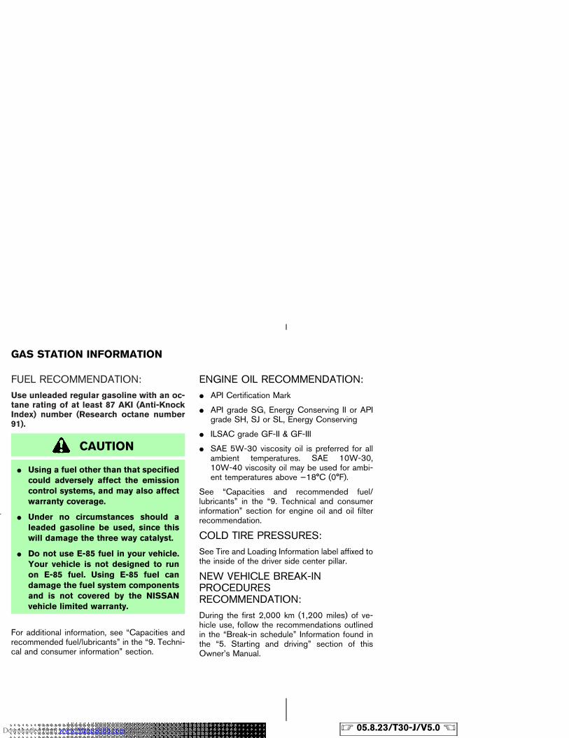
FUEL RECOMMENDATION:Use unleaded regular gasoline with an oc-tane rating of at least 87 AKI (Anti-KnockIndex) number (Research octane number91).
CAUTION
� Using a fuel other than that specifiedcould adversely affect the emissioncontrol systems, and may also affectwarranty coverage.
� Under no circumstances should aleaded gasoline be used, since thiswill damage the three way catalyst.
� Do not use E-85 fuel in your vehicle.Your vehicle is not designed to runon E-85 fuel. Using E-85 fuel candamage the fuel system componentsand is not covered by the NISSANvehicle limited warranty.
For additional information, see “Capacities andrecommended fuel/lubricants” in the “9. Techni-cal and consumer information” section.
ENGINE OIL RECOMMENDATION:� API Certification Mark
� API grade SG, Energy Conserving II or APIgrade SH, SJ or SL, Energy Conserving
� ILSAC grade GF-II & GF-III
� SAE 5W-30 viscosity oil is preferred for allambient temperatures. SAE 10W-30,10W-40 viscosity oil may be used for ambi-ent temperatures above −18°C (0°F).
See “Capacities and recommended fuel/lubricants” in the “9. Technical and consumerinformation” section for engine oil and oil filterrecommendation.
COLD TIRE PRESSURES:See Tire and Loading Information label affixed tothe inside of the driver side center pillar.
NEW VEHICLE BREAK-INPROCEDURESRECOMMENDATION:During the first 2,000 km (1,200 miles) of ve-hicle use, follow the recommendations outlinedin the “Break-in schedule” Information found inthe “5. Starting and driving” section of thisOwner’s Manual.
GAS STATION INFORMATION
� 05.8.23/T30-J/V5.0 �Downloaded from www.Manualslib.com manuals search engine
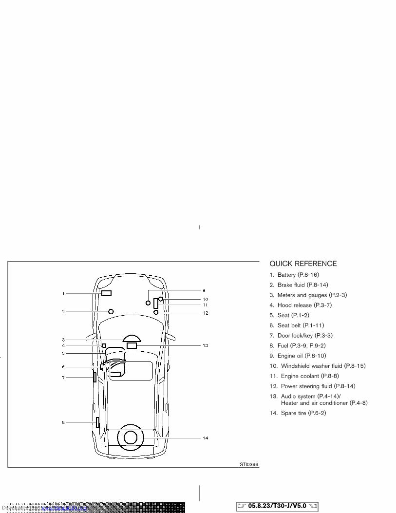
QUICK REFERENCE1. Battery (P.8-16)
2. Brake fluid (P.8-14)
3. Meters and gauges (P.2-3)
4. Hood release (P.3-7)
5. Seat (P.1-2)
6. Seat belt (P.1-11)
7. Door lock/key (P.3-3)
8. Fuel (P.3-9, P.9-2)
9. Engine oil (P.8-10)
10. Windshield washer fluid (P.8-15)
11. Engine coolant (P.8-8)
12. Power steering fluid (P.8-14)
13. Audio system (P.4-14)/Heater and air conditioner (P.4-8)
14. Spare tire (P.6-2)
STI0396
� 05.8.23/T30-J/V5.0 �Downloaded from www.Manualslib.com manuals search engine