Embed Size (px)
Citation preview

1
Manufacturing Simulation of Composites Compression Molding in Abaqus/Explicit
Anthony J. Favaloro, Drew E. Sommer, and R. Byron Pipes
Composites Manufacturing and Simulation Center, Purdue University, West Lafayette, IN, US
Abstract: In composite materials, as anisotropic systems, the orientation state of parts highly
impacts the resulting performance characteristics. In high rate processes of discontinuous
material systems, the final orientation state is often dictated by molding flows rather than direct
prescription. In this work, we address flow simulation of the compression molding process for
prepreg platelet molding systems with the purpose of predicting orientation state. Such systems
are formed by cutting and slitting prepreg composite tape into rectangular platelets of prescribed
length and width. Typical molding simulation approaches have been previously developed for
injection molding processes in which the fiber scale to part scale dictates relatively smooth spatial
variation in orientation state. However, parts produced with platelet systems retain heterogeneity
scales associated with the platelet; thus, the platelet scale to part scale dictates a spatially non-
smooth variation in orientation state. Additionally, the viscous behavior of the resulting
suspension is highly anisotropic. So, proper molding simulation of platelet molding systems
requires a framework which will not smooth orientation state representation and will allow for
highly anisotropic viscous behavior to be captures. To this end, we have implemented a fully
coupled anisotropic viscosity and orientation evolution model in a VUMAT which is combined
with the smoothed particle hydrodynamics method in Abaqus/Explicit. As a Lagrangian method,
SPH is particularly suited for maintaining orientation state variation. This modelling method has
been used in simulating the filling of an example bracket part and has been validated versus
orientation state measurements using CT scans.
Keywords: Composites, Constitutive Model, Experimental Verification, Fiber Suspensions.
1. Introduction
Prepreg platelet based molding compounds (PPMCs) are formed by slitting and cutting pre-
impregnated composite tape to a prescribed width and length while the platelets inherit the
thickness of the parent tape. Parts are then manufactured in compression molding, transfer
molding, or a combination of both. In Figure 1.1, we show a diagram of this process in which a
bracket is manufactured. When this process is used for the production of small parts or parts with
small thicknesses, the scale of the platelet compared to that of the part can become similar. This
scale similarity motivates the computational approaches presented in this work utilizing
Abaqus/Explicit as compared to commercially available plastics molding software.
2
Figure 1.1 Prepreg Platelet Molding System Diagram
The scale similarity between the platelets in the PPMC and the final part requires at least two
computational considerations absent in typical injection molding simulations. First, the orientation
state throughout the part cannot be considered a smoothly varying function; and, second, without a
smoothly varying field describing orientation state, Lagrangian methods must be used to preserve
spatial variability. Thus, in this work we utilize Abaqus/Explicit with the Smoothed Particle
Hydrodynamics Method (SPH) and a VUMAT such that the required rheological constitutive
model is implemented and large deformations can be simulated while preserving spatially non-
smooth mesostructure descriptors (orientation state). In the following, we present the development
of this methodology, model initialization techniques, and a qualitative comparison to a
manufactured part that has been CT scanned to determine its orientation state.
2. Theory: Suspension Rheology
Platelet molding systems represent an orthotropic suspension in that each heterogeneity possesses
orthotropic symmetries. However, initial micromechanical investigations (Favaloro, 2017;
Sommer, 2016) indicate that the flow behavior is approximated well treating the heterogeneity as
transversely isotropic while strength properties in performance simulation must be treated as
orthotropic (Kravchenko, 2017). Thus, we can borrow from the established literature for fiber
suspensions. For a complete constitutive model we require: an orientation state representation
method, an orientation state evolution method, and an orientation state dependent constitutive
model.
To address orientation state representation, we are primarily concerned with a descriptor that is
appropriate considering the modeling scale as compared to the heterogeneity scale. The orientation
of a single fiber is referred to as 𝑝𝑖 and is simply a unit vector. In typical injection molding
simulations, the scale of individual fibers compared to part scales dictates statistical methods in
which the orientation state is represented with an orientation distribution function, 𝜓(𝑝𝑖) (Advani
& Tucker, 1987; Folgar & Tucker, 1984). However, in Figure 1.1 we show an example bracket
part which contains between 1,000 and 8,000 platelet depending on platelet dimensions. For parts
of this scale, which can easily be simulated with more than 100,000 integration points, it is clear
that in contrast to representing many orientations at one integration point, we must represent a
single orientation with many integration points. In Section 4, we will discuss how such an
orientation state is initialized on an SPH mesh. However, to not limit the development, rather than
consider a material point (integration point) to contain a single orientation, we will consider each
3
material point to contain a set of 𝑁 volume fractions, 𝒱 = {𝑣1, 𝑣2, … , 𝑣𝑁} and fiber direction
vectors,
𝒫 = {𝑝𝑖1, 𝑝𝑖
2, … , 𝑝𝑖𝑁}. Orientation state evolution is the process of updating the orientation state in
response to deformation. Jeffery’s equation (Hinch & Leal, 1976; Jeffery, 1922), (1), describes the
response of fiber orientation not only to rotational deformation, 𝜔𝑖𝑗 =1
2(�̇�𝑖,𝑗 − �̇�𝑗,𝑖) but also in
response to straining, 𝜖�̇�𝑗 =1
2(�̇�𝑖,𝑗 + �̇�𝑗,𝑖), where 𝜉 is a shape factor which approaches unity as the
fiber aspect ratio increases. For long fibers as 𝜉 → 1, Jeffery’s equation becomes identical to
affine motion of lines (Altan & Rao, 1995; Ericsson, 1997) and can be written as in (2) for a finite
time step where 𝐹Δ𝑡 is the incremental deformation gradient from time 𝑡 to time 𝑡 + Δ𝑡. While the
chosen orientation state representation is appropriate for the system considered, it does offer a
numerical difficulty. Volume averaging of vectors directly is not well defined; therefore, advection
of vector components tracked as state variables in a simulation is not well defined. Thus, we limit
ourselves to Lagrangian solutions making Abaqus/Explicit coupled with the SPH method a
suitable choice of numerical framework.
�̇�𝑖 = 𝜔𝑖𝑗𝑝𝑗 + 𝜉(𝜖�̇�𝑗𝑝𝑗 − 𝜖�̇�𝑙𝑝𝑘𝑝𝑙𝑝𝑖) (1)
𝑝𝑡+Δ𝑡 =𝐹Δ𝑡 ∙ 𝑝𝑡
‖𝐹Δ𝑡 ∙ 𝑝𝑡‖ (2)
Having established an orientation state representation and an orientation state evolution method,
we now complete the coupled constitutive model using an orientation state dependent viscosity
tensor. The orientation averaged transversely isotropic viscosity tensor (Beaussart, Hearle, &
Pipes, 1993; Hinch & Leal, 1972; Pipes, Coffin, Simacek, Shuler, & Okine, 1994) is shown in (4)
where 𝜂23 is the transverse shearing viscosity, 𝑅𝜂 = 𝜂11 𝜂22⁄ is the anisotropy ratio representing
the relative difficulty of extension along fiber direction as compared to transverse to fiber
directions (Favaloro, 2017), and 𝐴𝑖𝑗 and 𝔸𝑖𝑗𝑘𝑙 are the second and fourth order orientation tensors
defined as volume averages of the second and fourth order dyadic products of 𝑝𝑖 (Advani &
Tucker, 1987). This expression serves the dual purpose of resolving the transversely isotropic
constitutive relationship associated with each 𝑝𝑖𝑛 in the global coordinate system and volume
averaging the transformed expressions.
𝜏𝑖𝑗 = ⟨𝜂𝑖𝑗𝑘𝑙⟩𝜖�̇�𝑙
⟨𝜂⟩𝑖𝑗𝑘𝑙
2𝜂23= 2(𝑅𝜂 − 1) [𝔸𝑖𝑗𝑘𝑙 −
1
3(𝐴𝑖𝑗𝛿𝑘𝑙 + 𝐴𝑘𝑙𝛿𝑖𝑗 −
1
3𝛿𝑖𝑗𝛿𝑘𝑙)] + [
1
2(𝛿𝑖𝑘𝛿𝑗𝑙 + 𝛿𝑖𝑙𝛿𝑗𝑘) −
1
3(𝛿𝑖𝑗𝛿𝑘𝑙)]
(3)

4
As a simplification, we will considering isothermal and linear viscous behavior. In this way, the
magnitude of 𝜂23 is unimportant moving forward for the prediction of final orientation state.
Additionally, we note that for fiber suspensions 𝑅𝜂 tends to scale with the square of the fiber
aspect ratio, 𝐿𝑓 𝐷𝑓⁄ , (Batchelor, 1971; Dinh & Armstrong, 1984; Pipes et al., 1994; Shaqfeh &
Fredrickson, 1990) and for platelet suspensions 𝑅𝜂 scales with the square platelets length to
thickness (Favaloro, 2017; Sommer, 2016). Thus, 𝑅𝜂 behaves similarly to a penalty multiplier
enforcing the relative inextensibility of fibers.
Additional sophistication beyond Jeffery’s equation has been developed to implement diffusion
behavior (Advani & Tucker, 1987; Folgar & Tucker, 1984; Phelps & Tucker, 2009; Tseng, Chang,
& Hsu, 2016, 2018) or reduced orientation kinetics (Tseng, Chang, & Hsu, 2013; Wang, O’Gara,
& Tucker, 2008). However, these features are not included in the present model as only limited
studies have been performed using fully coupled constitutive behavior, and it is likely that the
assumptions resulting in such models require adjustment when considering large heterogeneities.
3. Implementation: VUMAT and Verification
In Section 2, we briefly presented a fully coupled platelet orientation and viscosity relationship.
This relationship is inherently incompressible. For implementation in Abaqus/Explicit, we relax
this constraint to approximate the stress update expression required for writing a VUMAT as:
𝜎𝑖𝑗1 = ⟨𝜂⟩𝑖𝑗𝑘𝑙
1Δ𝜖𝑘𝑙Δ𝑡
+ 𝐾[det 𝐹1 − 1]𝛿𝑖𝑗 (4)
where 𝐾 is a penalizing bulk modulus used to control volumetric distortion but allow a finite wave
speed so that explicit analyses can be performed. To investigate the behavior of this modified
model, we consider uniaxial extension along the fiber direction of a collimated suspension. We
determine the differential equation:
𝐹11𝐹222 − 1 =
2
9(𝜂11𝐾)(
�̇�11𝐹11
−�̇�22𝐹22
) (5)
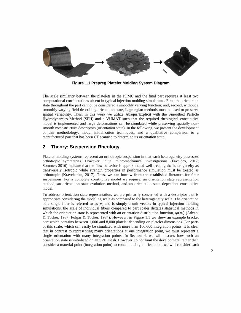
which for an input history 𝐹11(𝑡) can be used to determine the pressure lag in the system
introduced by the bulk modulus. We investigate this effect by changing the scaling of 𝜂11 and 𝐾
both in a single element and analytically. From this investigation we see that for minimal pressure
lag, the bulk modulus should be scaled so that 𝐾 ≥ 10𝜂11�̇� where �̇� is an expected level of strain
rate in the model. Additional verification checks have been performed by subjecting single
elements to various canonical deformation modes with varying orientation states. Orientation state
5
(i.e. 𝑝𝑖 vectors) is tracked as user defined state variables and is updated every time increment
using (2).
Figure 3.1 VUMAT Verification of Pressure Lag
4. Results: Bracket Molding Simulation
In this section we will present an example molding simulation of a simple bracket part shown in
Figure 1.1. Before discussing simulation results, we must first discuss model initialization.
Molding charges are typically prepared by pouring a measured amount of platelets into a mold
cavity, see Figure 4.1. Thus, we must initialize the orientation state on our model in a similar
fashion both capturing platelet dimensions and capturing boundary limitations on possible
orientation. To perform initialization, a Python script has been prepared that performs the
following process until every element has been associated with a platelet element set:
1. Begin at a randomly chosen element that has not been captured in an element set.
2. Generate a random angle to be the fiber direction of the platelet. If the initial element is
near the mold boundary, limit the possible angles so that the platelet cannot extend
beyond the boundary.
3. Find all elements which fit in a rectangle drawn around the initial element with a given
length in the fiber direction and width transverse to the fiber direction.
4. If all elements can be placed into an element set, form an element set. Otherwise, start
over.
6
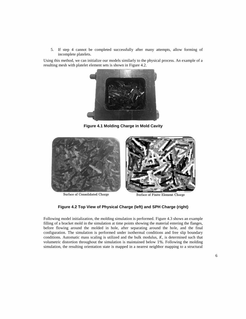
5. If step 4 cannot be completed successfully after many attempts, allow forming of
incomplete platelets.
Using this method, we can initialize our models similarly to the physical process. An example of a
resulting mesh with platelet element sets is shown in Figure 4.2.
Figure 4.1 Molding Charge in Mold Cavity
Figure 4.2 Top View of Physical Charge (left) and SPH Charge (right)
Following model initialization, the molding simulation is performed. Figure 4.3 shows an example
filling of a bracket mold in the simulation at time points showing the material entering the flanges,
before flowing around the molded in hole, after separating around the hole, and the final
configuration. The simulation is performed under isothermal conditions and free slip boundary
conditions. Automatic mass scaling is utilized and the bulk modulus, 𝐾, is determined such that
volumetric distortion throughout the simulation is maintained below 1%. Following the molding
simulation, the resulting orientation state is mapped in a nearest neighbor mapping to a structural
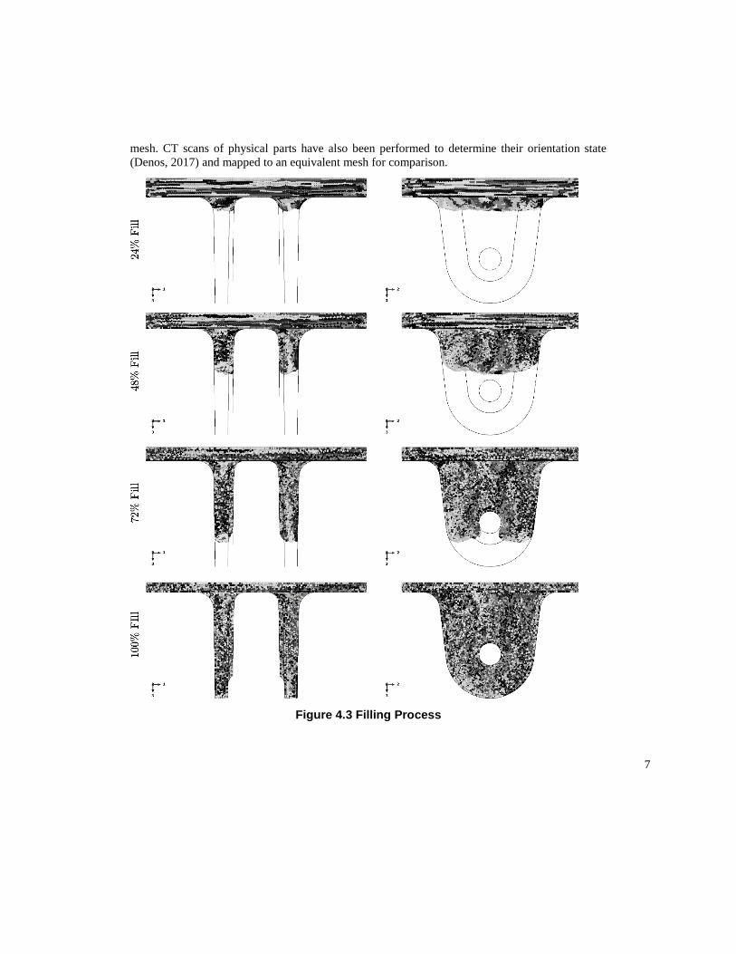
7
mesh. CT scans of physical parts have also been performed to determine their orientation state
(Denos, 2017) and mapped to an equivalent mesh for comparison.
Figure 4.3 Filling Process
8
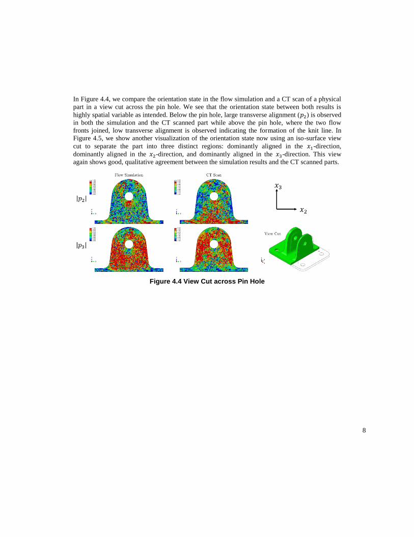
In Figure 4.4, we compare the orientation state in the flow simulation and a CT scan of a physical
part in a view cut across the pin hole. We see that the orientation state between both results is
highly spatial variable as intended. Below the pin hole, large transverse alignment (𝑝2) is observed
in both the simulation and the CT scanned part while above the pin hole, where the two flow
fronts joined, low transverse alignment is observed indicating the formation of the knit line. In
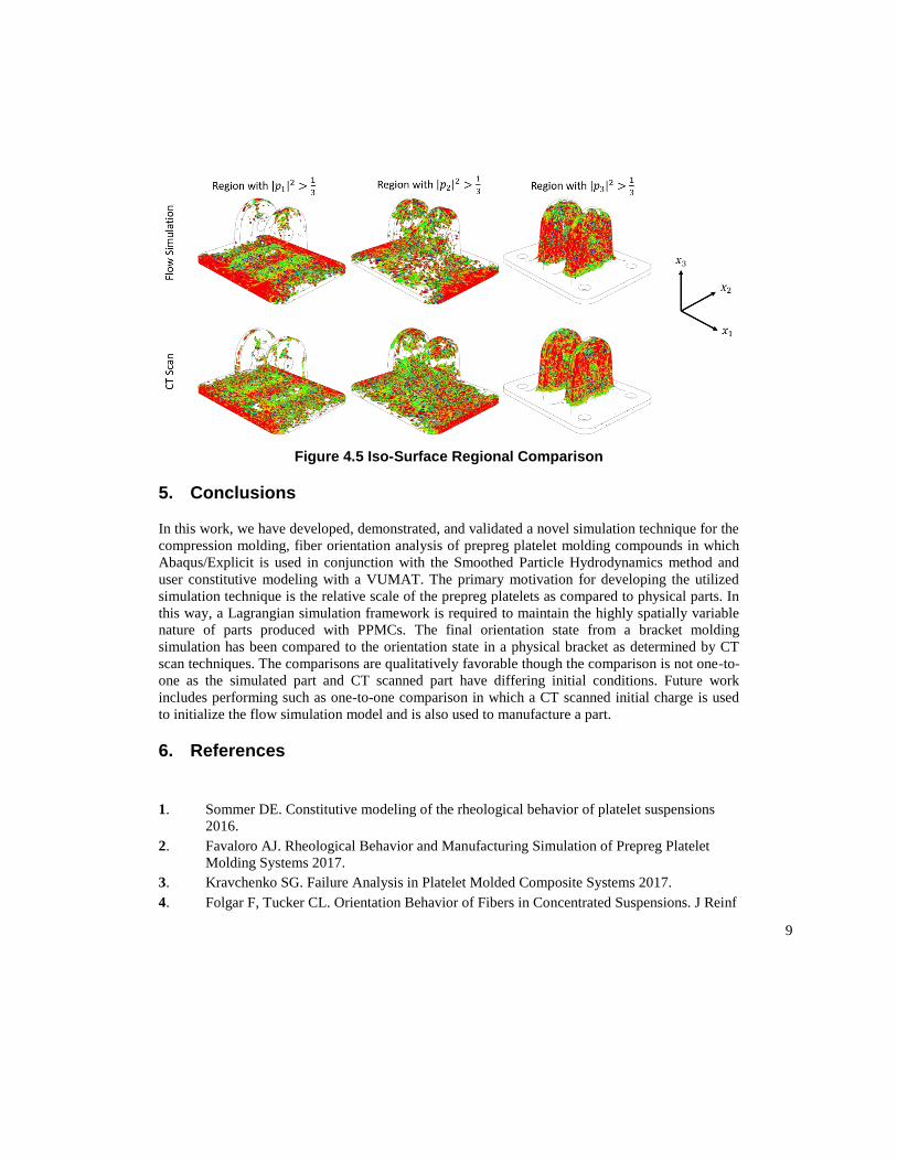
Figure 4.5, we show another visualization of the orientation state now using an iso-surface view
cut to separate the part into three distinct regions: dominantly aligned in the 𝑥1-direction,
dominantly aligned in the 𝑥2-direction, and dominantly aligned in the 𝑥3-direction. This view
again shows good, qualitative agreement between the simulation results and the CT scanned parts.
Figure 4.4 View Cut across Pin Hole
9
Figure 4.5 Iso-Surface Regional Comparison
5. Conclusions
In this work, we have developed, demonstrated, and validated a novel simulation technique for the
compression molding, fiber orientation analysis of prepreg platelet molding compounds in which
Abaqus/Explicit is used in conjunction with the Smoothed Particle Hydrodynamics method and
user constitutive modeling with a VUMAT. The primary motivation for developing the utilized
simulation technique is the relative scale of the prepreg platelets as compared to physical parts. In
this way, a Lagrangian simulation framework is required to maintain the highly spatially variable
nature of parts produced with PPMCs. The final orientation state from a bracket molding
simulation has been compared to the orientation state in a physical bracket as determined by CT
scan techniques. The comparisons are qualitatively favorable though the comparison is not one-to-
one as the simulated part and CT scanned part have differing initial conditions. Future work
includes performing such as one-to-one comparison in which a CT scanned initial charge is used
to initialize the flow simulation model and is also used to manufacture a part.
6. References
1. Sommer DE. Constitutive modeling of the rheological behavior of platelet suspensions
2016.
2. Favaloro AJ. Rheological Behavior and Manufacturing Simulation of Prepreg Platelet
Molding Systems 2017.
3. Kravchenko SG. Failure Analysis in Platelet Molded Composite Systems 2017.
4. Folgar F, Tucker CL. Orientation Behavior of Fibers in Concentrated Suspensions. J Reinf
10
Plast Compos 1984;3:98–119. doi:10.1177/073168448400300201.
5. Advani SG, Tucker CL. The Use of Tensors to Describe and Predict Fiber Orientation in
Short Fiber Composites. J Rheol (N Y N Y) 1987;31:751–84. doi:10.1122/1.549945.
6. Jeffery GB. The Motion of Ellipsoidal Particles Immersed in a Viscous Fluid. Proc R Soc
London A Math Phys Eng Sci 1922;102.
7. Hinch EJ, Leal LG. Constitutive equations in suspension mechanics. Part 2. Approximate
forms for a suspension of rigid particles affected by Brownian rotations. J Fluid Mech
1976;76:187. doi:10.1017/S0022112076003200.
8. Ericsson KA. The two-way interaction between anisotropic flow and fiber orientation in
squeeze flow. J Rheol (N Y N Y) 1997;41:491. doi:10.1122/1.550833.
9. Altan MC, Rao BN. Closed‐form solution for the orientation field in a center‐gated disk. J
Rheol (N Y N Y) 1995;39:581–99. doi:10.1122/1.550714.
10. Beaussart AJ, Hearle JWS, Pipes RB. Constitutive relationships for anisotropic viscous
materials. Compos Sci Technol 1993;49:335–9. doi:10.1016/0266-3538(93)90064-N.
11. Pipes RB, Coffin DW, Simacek P, Shuler SF, Okine RK. Rheological Behavior of
Collimated Fiber Thermoplastic Composite Materials. Flow Phenom. Polym. Compos.,
1994, p. 85–125.
12. Hinch EJ, Leal LG. The effect of Brownian motion on the rheological properties of a
suspension of non-spherical particles. J Fluid Mech 1972;52:683.
doi:10.1017/S002211207200271X.
13. Batchelor GK. The stress generated in a non-dilute suspension of elongated particles by
pure straining motion. J Fluid Mech 1971;46:813. doi:10.1017/S0022112071000879.
14. Dinh SM, Armstrong RC. A rheological equation of state for semiconcentrated fiber
suspensions. J Rheol 1984;28:207--227. doi:10.1122/1.549748.
15. Shaqfeh ESG, Fredrickson GH. The hydrodynamic stress in a suspension of rods. Phys
Fluids A Fluid Dyn 1990;2:7–24. doi:10.1063/1.857683.
16. Phelps JH, Tucker CL. An anisotropic rotary diffusion model for fiber orientation in short-
and long-fiber thermoplastics. J Nonnewton Fluid Mech 2009;156:165–76.
doi:10.1016/j.jnnfm.2008.08.002.
17. Tseng H-C, Chang R-Y, Hsu C-H. An objective tensor to predict anisotropic fiber
orientation in concentrated suspensions. J Rheol (N Y N Y) 2016;60:215–24.
doi:10.1122/1.4939098.
18. Tseng H-C, Chang R-Y, Hsu C-H. The use of principal spatial tensor to predict
anisotropic fiber orientation in concentrated fiber suspensions. J Rheol (N Y N Y)
2018;62:313–20. doi:10.1122/1.4998520.
19. Tseng H-C, Chang R-Y, Hsu C-H. Phenomenological improvements to predictive models
of fiber orientation in concentrated suspensions. J Rheol (N Y N Y) 2013;57:1597–631.
doi:10.1122/1.4821038.
20. Wang J, O’Gara JF, Tucker CL. An objective model for slow orientation kinetics in
concentrated fiber suspensions: Theory and rheological evidence. J Rheol (N Y N Y)
2008;52:1179–200. doi:10.1122/1.2946437.

11
21. Denos BR. Fiber Orientation Measurements in Platelet-Based Compsoites via Computed
Tomography Analysis 2017.