Embed Size (px)
Citation preview
March 20-21, 2000 ARIES-AT Blanket and Divertor Design, ARIES Project Meeting/ARR
Status ARIES-AT Blanket and Divertor Design
The ARIES Team
Presented by A. René Raffray and Xueren Wang
ARIES Project Meeting
University of California, San Diego
March 20-21, 2000
March 20-21, 2000 ARIES-AT Blanket and Divertor Design, ARIES Project Meeting/ARR
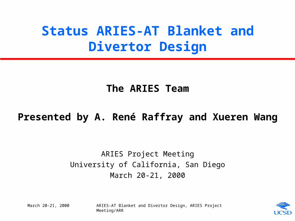
Presentation Outline
• Blanket– Geometry and coolant routing
– Analysis• MHD flow considerations
• Temperature and thermal stress
• Pressure stress
• Divertor– Configuration with LiPb as coolant
– Preliminary flow analysis
• Future Work
March 20-21, 2000 ARIES-AT Blanket and Divertor Design, ARIES Project Meeting/ARR
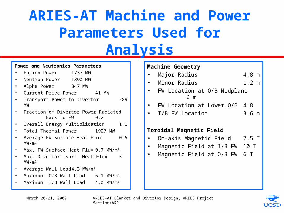
ARIES-AT Machine and Power Parameters Used for Analysis
Power and Neutronics Parameters
• Fusion Power 1737 MW
• Neutron Power 1390 MW
• Alpha Power 347 MW
• Current Drive Power 41 MW
• Transport Power to Divertor 289 MW
• Fraction of Divertor Power Radiated Back to FW 0.2
• Overall Energy Multiplication 1.1
• Total Thermal Power 1927 MW
• Average FW Surface Heat Flux 0.5 MW/m2
• Max. FW Surface Heat Flux 0.7 MW/m2
• Max. Divertor Surf. Heat Flux 5 MW/m2
• Average Wall Load 4.3 MW/m2
• Maximum O/B Wall Load 6.1 MW/m2
• Maximum I/B Wall Load 4.0 MW/m2
Machine Geometry
• Major Radius 4.8 m
• Minor Radius 1.2 m
• FW Location at O/B Midplane 6 m
• FW Location at Lower O/B 4.8
• I/B FW Location 3.6 m
Toroidal Magnetic Field
• On-axis Magnetic Field 7.5 T
• Magnetic Field at I/B FW 10 T
• Magnetic Field at O/B FW 6 T
March 20-21, 2000 ARIES-AT Blanket and Divertor Design, ARIES Project Meeting/ARR
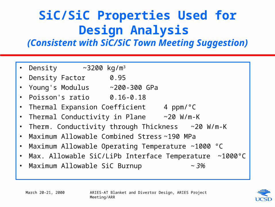
SiC/SiC Properties Used for Design Analysis
(Consistent with SiC/SiC Town Meeting Suggestion)
• Density ~3200 kg/m3
• Density Factor 0.95
• Young's Modulus ~200-300 GPa
• Poisson's ratio 0.16-0.18
• Thermal Expansion Coefficient 4 ppm/°C
• Thermal Conductivity in Plane ~20 W/m-K
• Therm. Conductivity through Thickness ~20 W/m-K
• Maximum Allowable Combined Stress ~190 MPa
• Maximum Allowable Operating Temperature ~1000 °C
• Max. Allowable SiC/LiPb Interface Temperature ~1000°C
• Maximum Allowable SiC Burnup ~ 3%
March 20-21, 2000 ARIES-AT Blanket and Divertor Design, ARIES Project Meeting/ARR
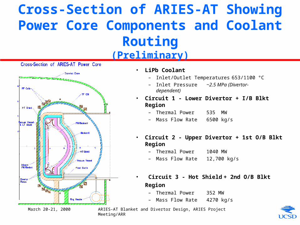
Cross-Section of ARIES-AT Showing Power Core Components and Coolant Routing
(Preliminary)
• LiPb Coolant– Inlet/Outlet Temperatures 653/1100 °C
– Inlet Pressure ~2.5 MPa (Divertor- dependent)
• Circuit 1 - Lower Divertor + I/B Blkt Region– Thermal Power 535 MW
– Mass Flow Rate 6500 kg/s
• Circuit 2 - Upper Divertor + 1st O/B Blkt Region– Thermal Power 1040 MW
– Mass Flow Rate 12,700 kg/s
• Circuit 3 - Hot Shield + 2nd O/B Blkt Region – Thermal Power 352 MW
– Mass Flow Rate 4270 kg/s
March 20-21, 2000 ARIES-AT Blanket and Divertor Design, ARIES Project Meeting/ARR
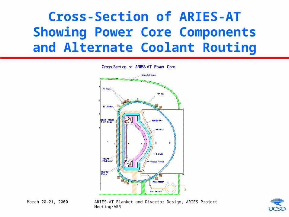
Cross-Section of ARIES-AT Showing Power Core Components and Alternate
Coolant Routing
March 20-21, 2000 ARIES-AT Blanket and Divertor Design, ARIES Project Meeting/ARR
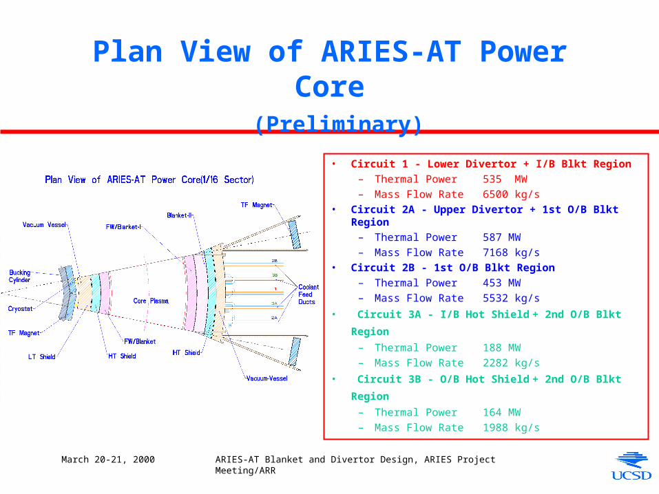
Plan View of ARIES-AT Power Core (Preliminary)
• Circuit 1 - Lower Divertor + I/B Blkt Region– Thermal Power 535 MW – Mass Flow Rate 6500 kg/s
• Circuit 2A - Upper Divertor + 1st O/B Blkt Region– Thermal Power 587 MW – Mass Flow Rate 7168 kg/s
• Circuit 2B - 1st O/B Blkt Region– Thermal Power 453 MW – Mass Flow Rate 5532 kg/s
• Circuit 3A - I/B Hot Shield + 2nd O/B Blkt Region – Thermal Power 188 MW – Mass Flow Rate 2282 kg/s
• Circuit 3B - O/B Hot Shield + 2nd O/B Blkt Region – Thermal Power 164 MW – Mass Flow Rate 1988 kg/s
March 20-21, 2000 ARIES-AT Blanket and Divertor Design, ARIES Project Meeting/ARR
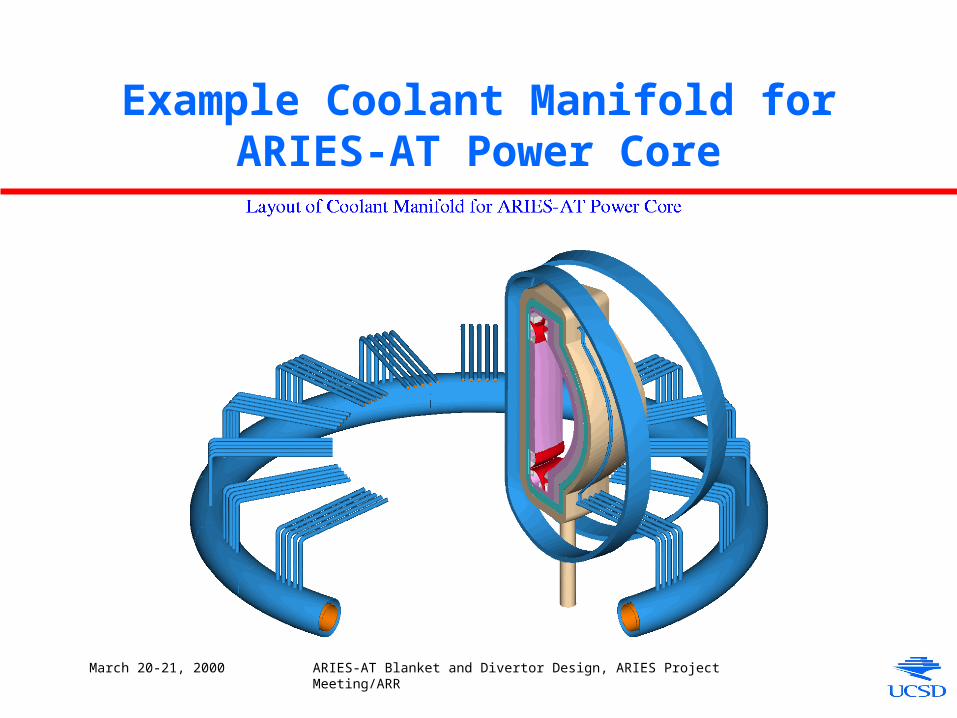
Example Coolant Manifold for ARIES-AT Power Core
March 20-21, 2000 ARIES-AT Blanket and Divertor Design, ARIES Project Meeting/ARR
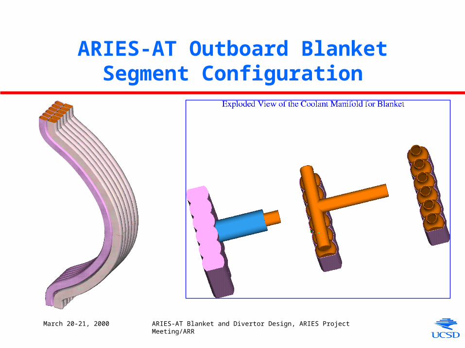
ARIES-AT Outboard Blanket Segment Configuration
March 20-21, 2000 ARIES-AT Blanket and Divertor Design, ARIES Project Meeting/ARR
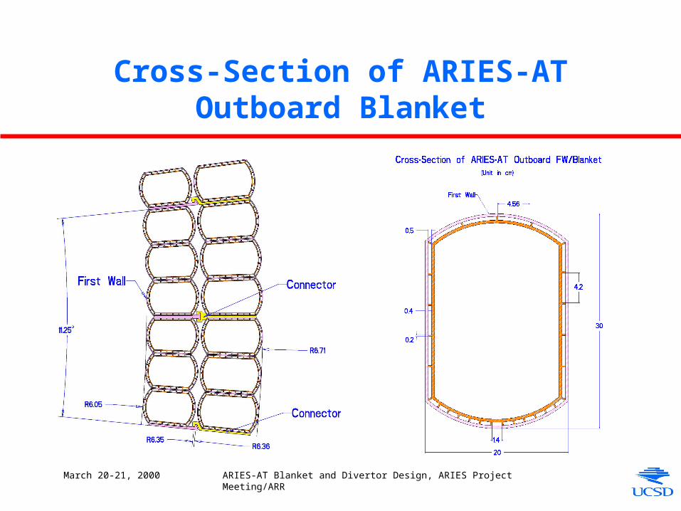
Cross-Section of ARIES-AT Outboard Blanket
March 20-21, 2000 ARIES-AT Blanket and Divertor Design, ARIES Project Meeting/ARR
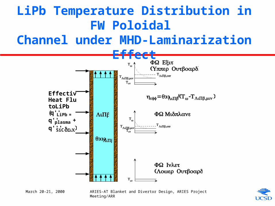
LiPb Temperature Distribution in FW Poloidal
Channel under MHD-Laminarization Effect
EffectiveHeat Fluxto LiPb(q''LiPb =q''plasma +q'''SiC δSiC)
LiPb
Tin
Tw
Tw
T ,LiPb minTin
Tin
FW Exit( )Upper Outboard
FW Midplane
FW Inlet( )Lower Outboard
q'''LiPb
heff = q''LiPb/(Tw-T ,LiPb min)
T ,LiPb avg
T ,LiPb avgT ,LiPb min

March 20-21, 2000 ARIES-AT Blanket and Divertor Design, ARIES Project Meeting/ARR
2-D Moving Coordinate Analysis of FW
• Transient analysis of 2-D FW geometry over LiPb residence time to simulate 3-D situation under the assumption of conduction only in LiPb• Heat flux and heat generation varied over time to reflect poloidal variation
Toroidal-Radial Plan View of Blanket Outboard Region 1
March 20-21, 2000 ARIES-AT Blanket and Divertor Design, ARIES Project Meeting/ARR
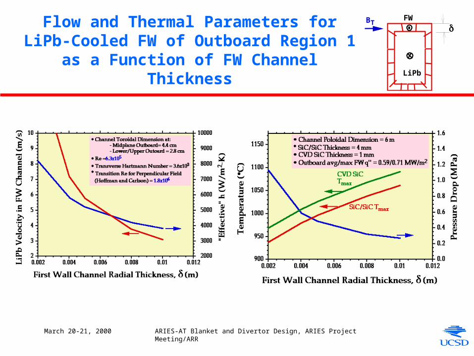
Flow and Thermal Parameters for LiPb-Cooled FW of Outboard Region 1 as a Function of FW
Channel Thickness
δBT
FW
LiPb

March 20-21, 2000 ARIES-AT Blanket and Divertor Design, ARIES Project Meeting/ARR
3-D Thermal Analysis of Toroidal Half of Outboard Blanket Region 1
Thermal StressTemperature
March 20-21, 2000 ARIES-AT Blanket and Divertor Design, ARIES Project Meeting/ARR
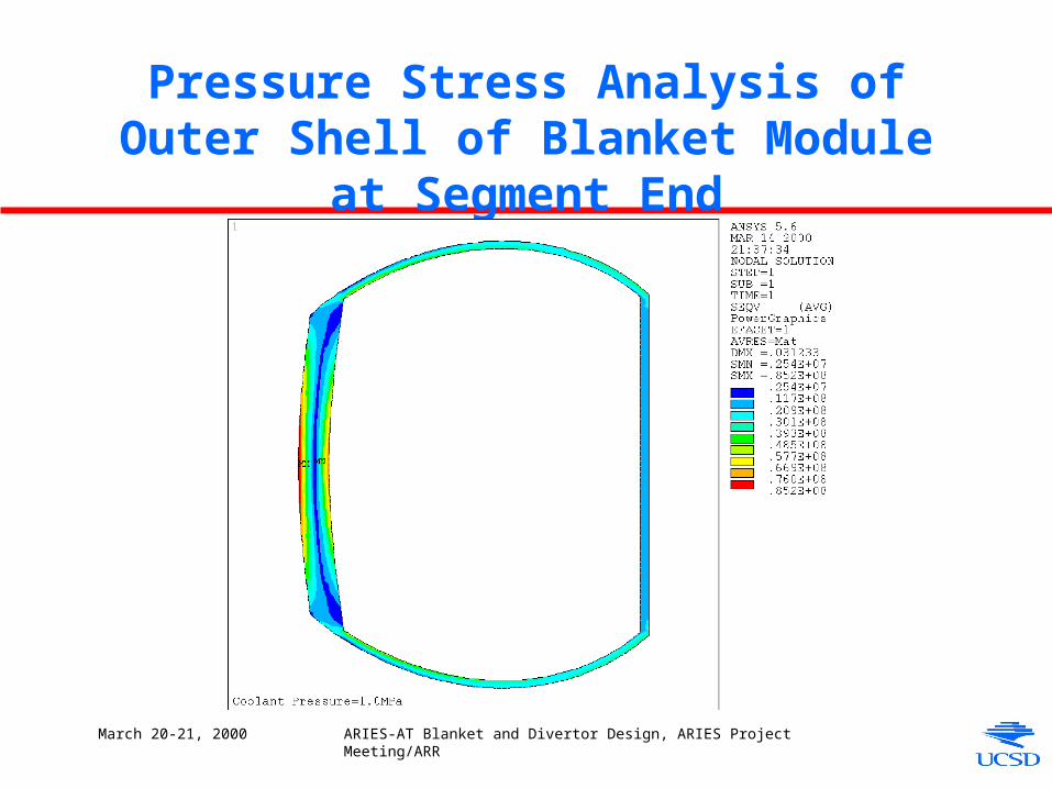
Pressure Stress Analysis of Outer Shell of Blanket Module at Segment End
March 20-21, 2000 ARIES-AT Blanket and Divertor Design, ARIES Project Meeting/ARR
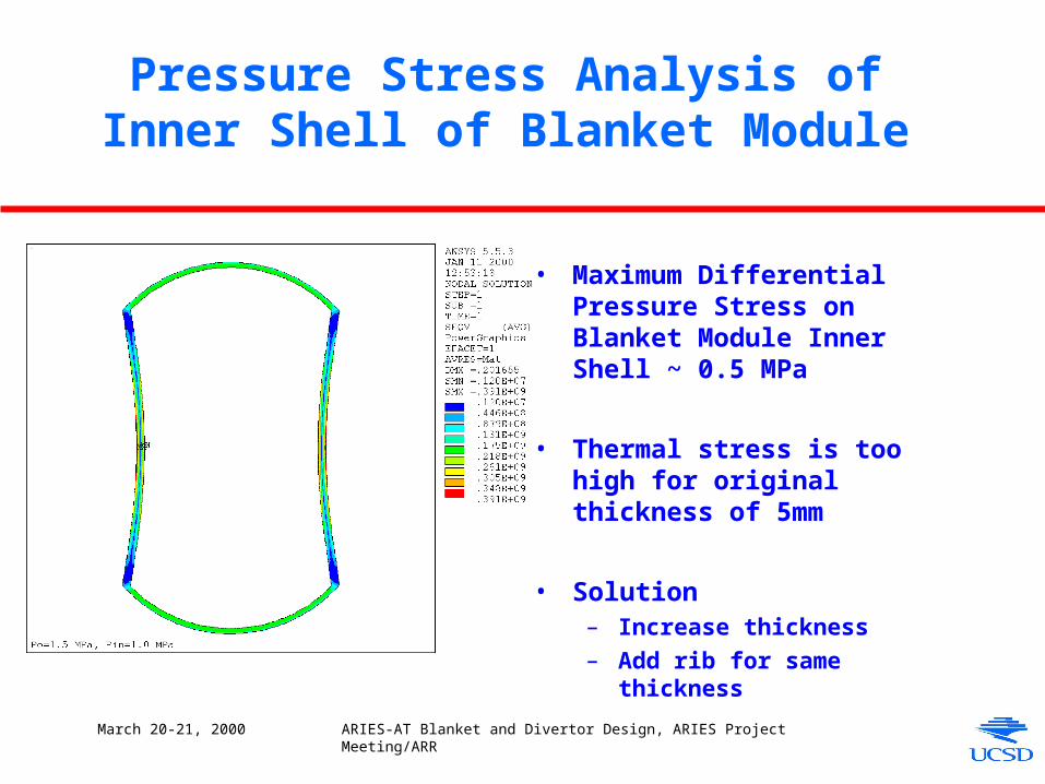
Pressure Stress Analysis of Inner Shell of Blanket Module
• Maximum Differential Pressure Stress on Blanket Module Inner Shell ~ 0.5 MPa
• Thermal stress is too high for original thickness of 5mm
• Solution– Increase thickness
– Add rib for same thickness
March 20-21, 2000 ARIES-AT Blanket and Divertor Design, ARIES Project Meeting/ARR
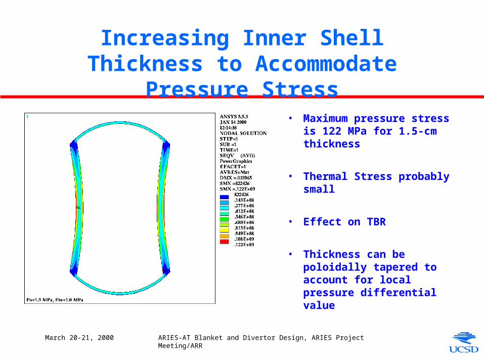
Increasing Inner Shell Thickness to Accommodate Pressure Stress
• Maximum pressure stress is 122 MPa for 1.5-cm thickness
• Thermal Stress probably small
• Effect on TBR
• Thickness can be poloidally tapered to account for local pressure differential value
March 20-21, 2000 ARIES-AT Blanket and Divertor Design, ARIES Project Meeting/ARR
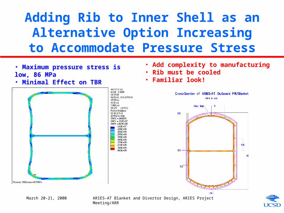
Adding Rib to Inner Shell as an Alternative Option Increasing to Accommodate
Pressure Stress• Maximum pressure stress is low, 86 MPa• Minimal Effect on TBR
• Add complexity to manufacturing• Rib must be cooled• Familiar look!
March 20-21, 2000 ARIES-AT Blanket and Divertor Design, ARIES Project Meeting/ARR
Divertor Design Considerations
• Compatibility with Blanket Configuration and Coolant
• Structural Material
• SiC/SiC thickness < 1mm (th ~ 235 MPa and TSiC = 250°C for q’’= 5 MW/m2)
• W with thin SiC insert with or without structural function
• Possible Concepts
• Dry Wall– LiPb as coolant (Preferable to avoid in-reactor high pressure He but needs
innovative scheme because of poor heat transfer removal capabilities)
– Porous W HX concept with He coolant as in ARIES-ST
– Phase-change liquid metal (Li)
• Liquid Wall (Sn-Li)
March 20-21, 2000 ARIES-AT Blanket and Divertor Design, ARIES Project Meeting/ARR
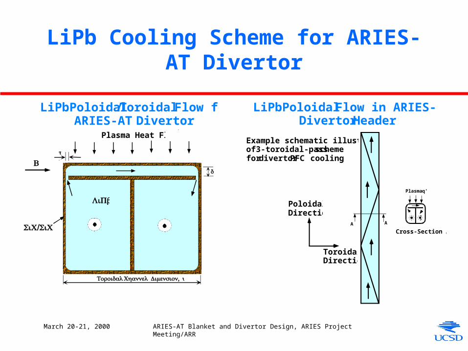
LiPb Cooling Scheme for ARIES-AT Divertor
LiPb Poloidal Flow in ARIES-ATDivertor Header
PoloidalDirection
ToroidalDirection
Example schematic illustrationof 3-toroidal-pass schemefor divertor PFC cooling
Plasma q''
A A
Cross-Section A-A
LiPb Poloidal/Toroidal Flow forARIES-AT Divertor
Plasma Heat Flux
δ
t
LiPb
B
SiC/SiC
Toroidal , Channel Dimension y
March 20-21, 2000 ARIES-AT Blanket and Divertor Design, ARIES Project Meeting/ARR
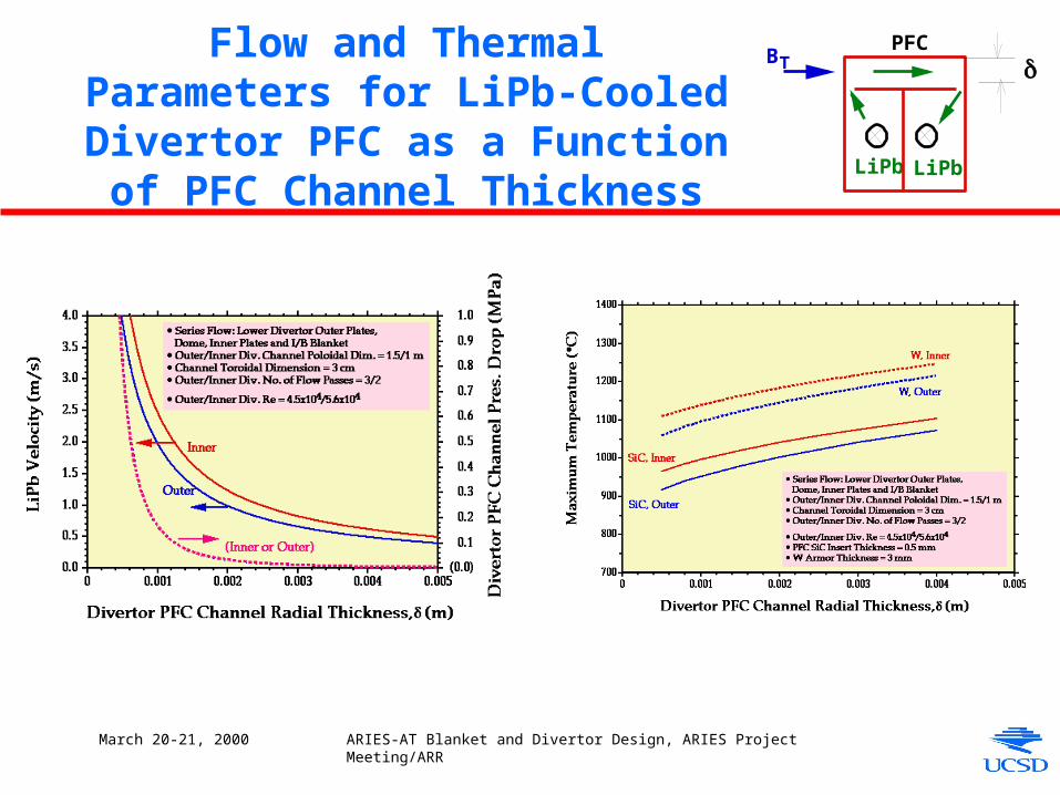
Flow and Thermal Parameters for LiPb-Cooled Divertor PFC as a
Function of PFC Channel Thickness
δBTPFC
LiPb LiPb
March 20-21, 2000 ARIES-AT Blanket and Divertor Design, ARIES Project Meeting/ARR
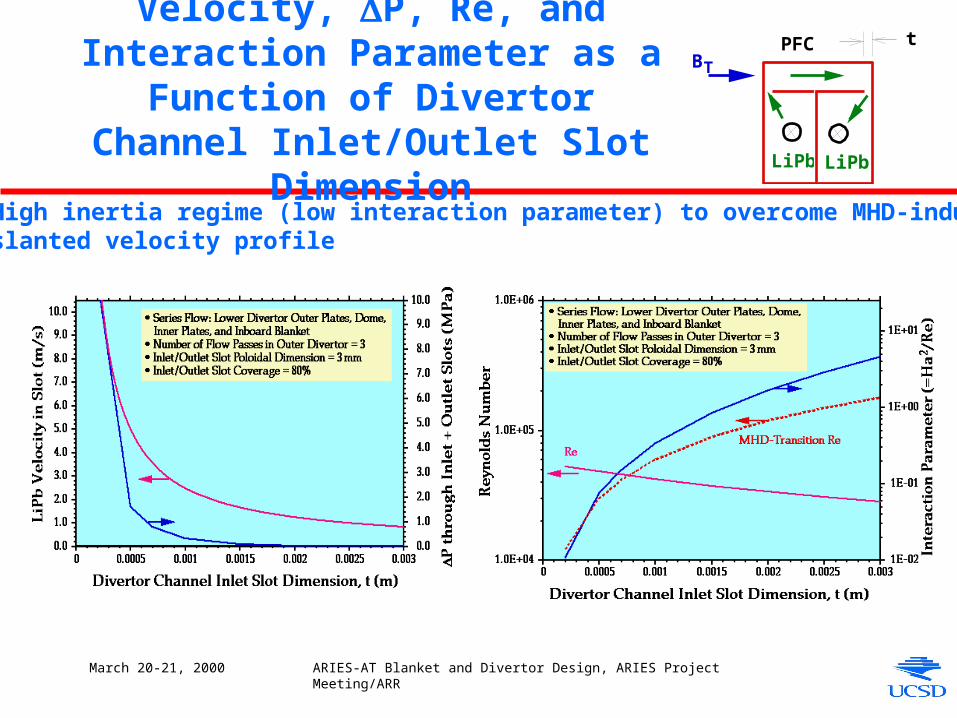
Velocity, P, Re, and Interaction Parameter as a Function of Divertor Channel Inlet/Outlet Slot Dimension
• High inertia regime (low interaction parameter) to overcome MHD-induced slanted velocity profile
BTPFC
LiPb LiPb
t
March 20-21, 2000 ARIES-AT Blanket and Divertor Design, ARIES Project Meeting/ARR
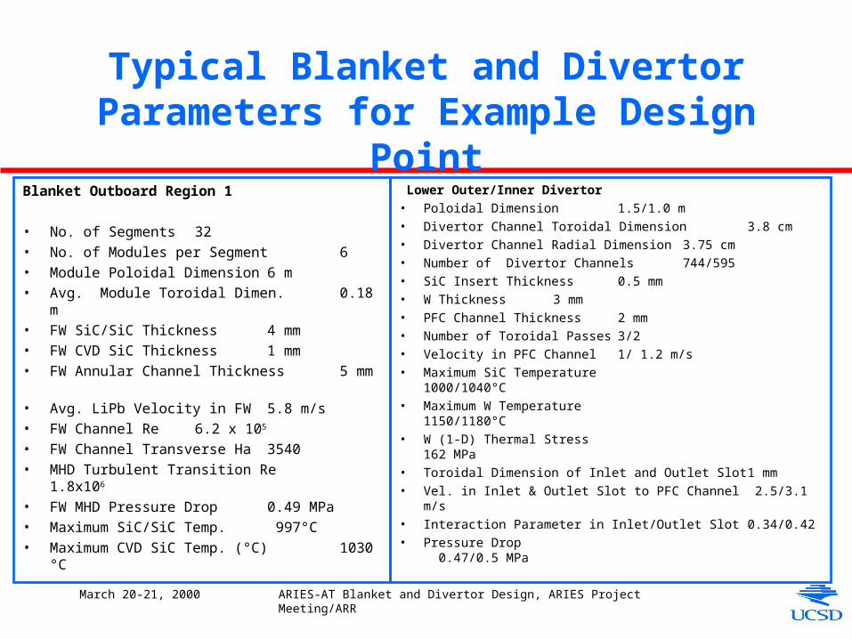
Typical Blanket and Divertor Parameters for Example Design Point
Blanket Outboard Region 1
• No. of Segments 32• No. of Modules per Segment 6• Module Poloidal Dimension 6 m• Avg. Module Toroidal Dimen. 0.18 m • FW SiC/SiC Thickness 4 mm• FW CVD SiC Thickness 1 mm• FW Annular Channel Thickness 5 mm• Avg. LiPb Velocity in FW 5.8 m/s• FW Channel Re 6.2 x 10⁵
• FW Channel Transverse Ha 3540• MHD Turbulent Transition Re 1.8x10⁶
• FW MHD Pressure Drop 0.49 MPa• Maximum SiC/SiC Temp. 997°C• Maximum CVD SiC Temp. (°C) 1030 °C
Lower Outer/Inner Divertor• Poloidal Dimension 1.5/1.0 m• Divertor Channel Toroidal Dimension3.8 cm• Divertor Channel Radial Dimension 3.75 cm• Number of Divertor Channels 744/595• SiC Insert Thickness 0.5 mm• W Thickness 3 mm• PFC Channel Thickness 2 mm• Number of Toroidal Passes 3/2• Velocity in PFC Channel 1/ 1.2 m/s• Maximum SiC Temperature 1000/1040°C• Maximum W Temperature 1150/1180°C• W (1-D) Thermal Stress 162 MPa• Toroidal Dimension of Inlet and Outlet Slot 1 mm• Vel. in Inlet & Outlet Slot to PFC Channel 2.5/3.1 m/s• Interaction Parameter in Inlet/Outlet Slot 0.34/0.42• Pressure Drop 0.47/0.5 MPa
March 20-21, 2000 ARIES-AT Blanket and Divertor Design, ARIES Project Meeting/ARR
Future Work Includes:
• Converge on coolant routing scheme
• Converge of maintenance scheme
• Tabulated list of parameters (LiPb volume and mass in different components, etc..)
• Blanket fabrication flow diagram
• Power cycle: Better characterization of heat exchanger
• Divertor – Recommend using LiPb as reference coolant and He as back-up option
- Inlet and toroidal flow in PFC channel under low interaction parameter must be verifiedby detailed MHD analysis and testing
– Detailed thermal and stress analysis