Embed Size (px)
Citation preview
ROLLED PRODUCTS
M A S T E R I N G THE P R O D U C T I O N OF C H A N N E L S WITH PARALLEL FLA N G ES
I . V. G u n i n , N. F . G r i t s u k , K. K. D ' y a c h e n k o , V. I . S v e t l a n o v , Yu . M. Y u k h n o v s k i i , A. N. N e s m a c h n y i ,
I . K. D o r o z h k o , V. S. F o m i n , V. P. S u d ' y a , a n d N. M. K h o r o s h i l o v
UDC 821.771.251
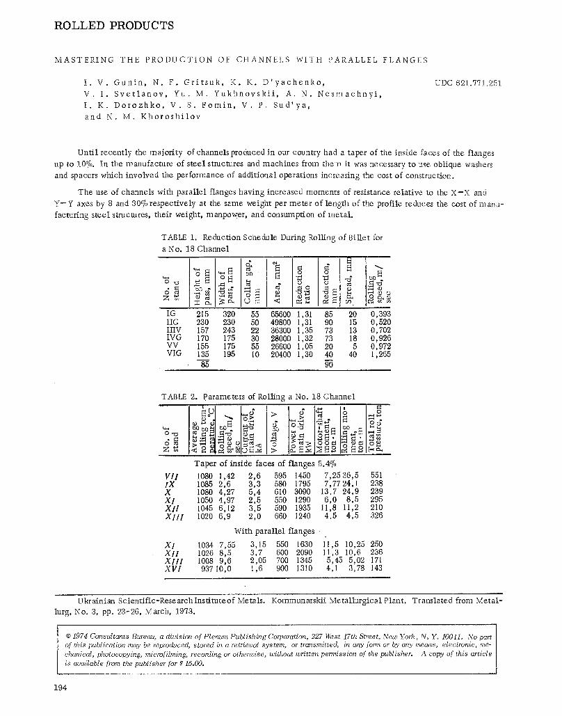
Until recently the majority of channels produced in our country had a taper of the inside faces of the flanges up to 10%. In the manufacture of steel structures and machines from them it was necessary to use oblique washers and spacers which involved the perfon-nance of additional operations increasing the cost of construction.
The use of channels with parallel flanges having increased moments of resistance relative to the X--X and Y - Y axes by 8 and 30% respectively at the same weight per meter of length of the profile reduces the cost of manu- facturing steel structures, their weight, manpower, and consumption of metal.
TABLE 1.
a No. 18 Channel
�9 = ~ e - ~ g ~ o ~ ~
Reduction Schedule During Rolling of Billet for
X" "
" ~ r O
IG 215 320 55 65600 1,31 85 20 0,393 IIG 230 230 50 49800 1,31 90 15 0,520 IIIV 157 243 22 36300 1,35 73 13 0,702 IVG 170 175 30 28000 1,32 73 18 0,926 VV 155 175 55 26600 1,05 20 5 0,972 VIG t35 195 10 20400 1,30 40 40 1,265
85 90
TABLE 2.
O"o
Z ~
parameters of Roiling a No. 18 Channel
I . . > O~
o 7 ~ o
Taper of inside faces of flanges
V I I 1080 1,42 2,6 595 1450 I X 1085 2,6 3,3 580 1795 X 1080 4,27 5,4 610 3090 X I 1050 4,97 2,5 550 1290 X I I 1045 6,12 3,5 590 1935 X I I I 1020 6,9 2,0 660 I240
With parallel flanges
X I 1034 7,55 3,15 550 1630 X I I 1026 8,5 3,7 600 2090 X I I I I008 9,6 2,05 700 1345 X V I 93710,0 1,6 900 1310
5.4o/0 7,2536,5 7,77 24, 1
13,7 24,9 6,0 8,5
11,8 11,2 4,5 4,5
551 238 239 295 210 326
"i'I,5 I0,25 250 i i , 3 10,6 236 5,45 5,02 171 4,1 3,78 143
Ukrainian Scientific-Researchlnstituteof Metals. Kommunarskii Metallurgical Plant. Translated from Metal- lurg, No. 3, pp. 23-26, March, 1973.
�9 1974 Consultants Bureau, a division of Plenum Publishing Corporation, 227 West 17th Street, New York. N~ Yo 10011. No part of this publication may be reproduced, stored in a retrieval system, or transmitted, in any form or by any means, electronic, me- chanical, photocopying, microfilming, recording or otherwise, without written permission of the publisher. A copy of this article is available from the publisher for $15.00.
194
Common passes ~rstand
740"
h 7 ~ ggstand.. ~g2
NLPSI ~ / ~ i
s t a n d I stand
' :wo - 9 . , . . . .
290 290
8 ~ alO ~-} e 7,f,75 7~7s ~! 8
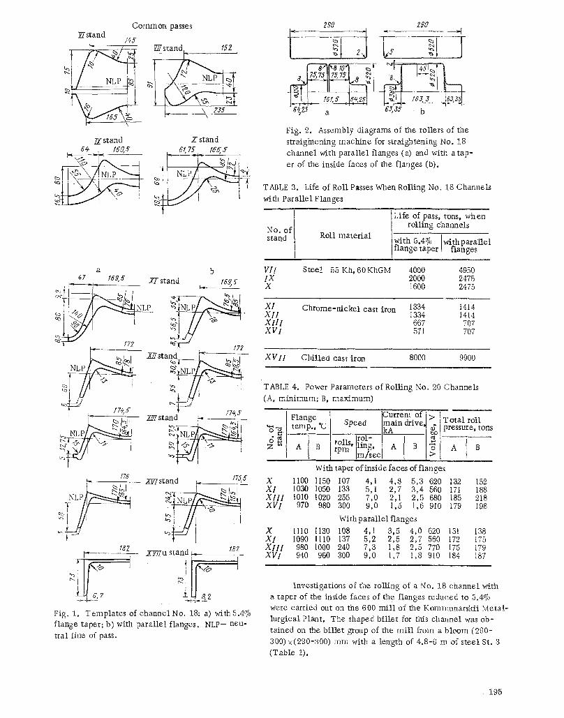
Fig. 2. Assembly diagrams of the rollers of the straightening machine for straightening No. 18 channel with parallel flanges (a) and with a tap- er of the inside faces of the flanges (b).
TABLE 3. Life of Roll Passes When Roiling No. 18 Channels with Parallel Flanges
l No. of i stand I
a b VII Steel , 47 f6g ~" 27 stand l#g s 1X
~, , % - - ~ ~
~ N L p h" " XI
XII I XVI
g ' ~ ' / szz /7z . . . . Zgstand ~ _ , - -
~ ~ _ _ •74,5 174,,Y i ~ Z ~ r s t a n d ~ . . . . ~ o ' ~
> r - - - C . /~-!, "~
~ 7 ,,~ I "~J / . "%" :, Z " A B
/76 /7s.s ~- - - ZEr stand ~_ : X
~ ~ X l l l XVI
XI t82 laz XIII
U XYffu stand ~ XV1
Fig. 1. Templates of channel No. 18: a) with5.4% flange taper; b) with parallel flanges. NLP-- neu- tral line of pass.
Roll material
Life of pass, tons, when I rolling channels
Iwith 5.4070 with parallel /flange taper I flanges
55 Kh, 60 KhGM 4000 4950 2000 2475 1600 2475
Chrome-nickel cast iron 1334 14t4 1334 1414 667 707 571 707
XVII Chilled cast iron 8000 9900
TABLE 4. Power Parameters of Rolling No. 20 Channels (A, minimum; B, maximum)
Flange temp., *C
ICurrent of I> I �9 - T o t a l roll f~177 I nf7 o,
ro rol- [ ~ ' " - rn l~ ~ ' ling, [ A B ~ A B "~-" Im/secl >
With taper ofinsidefaces offlanges
1100 1150 107 4,1 4,8 5,3 620 1030 1050 133 5,1 2,7 3,4 560 1010 1020 255 7,0 2,1 2,5 680 970 980 300 9,0 1,5 1,6 910
Withparallel flanges
i i i0 II30 108 4,1 3,5 4,0 620 1090 IllO 137 5,2 2,5 2,7 560 980 lO00 240 7,3 1,8 2,5 770 940 960 300 9,0 1,7 1,8 910
132 152 171 188 185 218 179 198
131 138 172 175 175 179 184 187
Investigations of the rolling of a No. 18 channel with a taper of the inside faces of the flanges reduced to 5.4~ were carried out on the 600 mill of the Kommunarskii Metal- lurgical Plant. The shaped billet for this channel was ob- tained on the billet group of the mill from a bloom (290- 300) • mm with a length of 4.8-6 m of steel St. 3 (Table I),
�9 1 9 5
stand
I5 r
I.~ !~ J
a-! J
,~o
zza
stand
X
175,
8,
g
stand
gE
~ 15
s
2Go
NLP
stand
2~f
s 7
Y7f
: sta
nd 27
sta
nd X
Lr
189,4
,
f76,
l
~,_
/84,
~;
.~
~N
LP
~ -
~
1]-
stand
XT/T
IS3, 6
sta
nd X
:Kr /9
4,8
~,
= I
I
.~
NL
P
stand
xw7 u
200
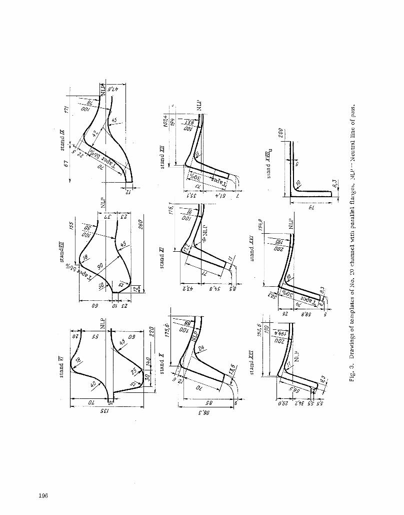
Fig.
3. D
raw
ings
of te
mpl
ates
of N
o. 20
cha
nnel
with
para
llel f
lang
es. N
LP--N
eutra
l line
of pa
ss.
The ro l l pass design, which was based on a system of butterfly passes with an increased (to 50%) taper in the
roughing pass and gradually decreasing (25%) in the finishing pass, made i t possible to produce the channel in eight
passes (Fig. 1). Straightening of the flanges was accomplished in stand XII and control of their height in standXlII .
The radius of bending of the 'web in stands VII-XII was 85 mm and in stands XIII-XVI i t was 1~/0 ram. The to ta l
reduction ratio in the f lange passes was 104 and the average per pass 1.214. The max imum reduction (1.62) was
in stand VII and the min imum (1.143) in the finishing stand. Uniform distribution of reduction over the elements
was provided in the finishing flange passes and intense deformation of the l ive flanges with respect to thickness and of the counter flanges with respect to height was provided in a l l passes. The temperature of the m e t a l var ied from 1060-1a80~ after stand VII to 900-940~ before the universal stand; the roiling speed var ied from 1.42 m / s e c in stand VII to 8 m / s e c in the finishing stand. The shape was bent in the finishing universal m i l l in a hot state and straightened on the ro l ler -s t ra ightening machines in a cold state.
The power parameters were measured in stands VII and IX-XII[ (T able 2) and the roi l ing moments determined
by ca lcula t ion . An analysis of the measurements showed the need for a more uniform distribution by stands of the reduction ratios in order to unload stand VII. Subsequently the thickness of the web of the shape from stand VI was decreased and height reduction in stands IX and X was redistributed, reducing it in stand X by 1.5-2.0 ram. About 15,000 tons of No. 18 channels with a decreased taper of the flanges were roiled in two campaigns according to the
technology developed. The quali ty of the rol led channels met the requirements of GOST 8240-56 .
Favorable results obtained on roll ing the channel with a 5.4% taper of the inside faces made i t possible to start master ing the No. 18 channel with para l le l flanges (works on the mastering of the production of channels with pa ra l l e l f lange s were performed with the par t ic ipat ion of the Dnepropetrovsk Meta l lu rg ica l Institute). The reduction
schedule and rol l pass design of the b i l l e t group were lef t unehanged. The roughing passes of stands VI-X-were also used as before.
To great ly reduce the t ime of reconstructing the stands for changing to roiling of No. 18 channels with para l le l
flanges, one new pass was grooved in the roils of stands XI-XIII and XVi. They differed from the previously used
ones (Fig. 1) by the smaller thickness of the flanges at the base (by 1.7-2.5 ram) and smal ler height (by 1-2 ram).
The temperature of the m e t a l after the first roughing stand was about 1190~ and after the first continuous
group 1091-1120~ Then the b i l le t was heated in a ro l ler -hear th continuous furnace, the temperature in the zones of which var ied from 1280 to 1310~ After the reheat ing furnace the tempera ture of the m e t a l varied from 1110- 1140~ after stand VII to 900-915~ after stand XVII (with respect to the flange). The roil ing speed was about i0 m/ sec .
After the rods were cut to length, they were coeled on the cooling bed. Owing to nonuniformity of cooling
of the e lements of the shape as a consequence of the different mass of me ta l in the web and in the flanges, thestr ip was bent toward the web. The def lect ion reached 150 ram, which hampered del ivery of the strips into the s traight-
ening machine . To e l im ina t e this shortcoming, supports (author's cer t i f ica te No. 259807) were p laced under the carrying chains of the first section of the transporter. As a resuk the strips began to sag under the ef fec t of their own
weight. They leve led out on the next sections of the transporter and entered the straightening machine satisfactori ly. The new design of the rollers of the straightening machine (Fig. 2) provides a good quali ty of straightening. This is
achieved owing to the increased coverage of the lower rollers by the flanges of the shape and absence on them of a taper which promotes d isp lacement of the shape.
The rol l pass design was analyzed against templa tes to study the character of f i l l ing of the passes with me ta l
and deformation of the e lements of the shape. It was established that the results of t empla te measurements agreed with the rol l pass design and confirmed the normal f i l l ing of the passes with meta l .
An analysis of the measurements of the power parameters showed that the rol l pressure and roll ing moments in
stands XI-XVI are p rac t i ca l ly the same as when roil ing No. 18 channels with a 5.4% flange taper, do not exceed the al lowable , and do not cause compl ica t ions during operation of the working stands. During the invest igat ion 9900 tons of No. 18 channels with para l le l flanges were roiled. The l i fe of the passes in this case proved to be sl ightly greater than in the case of rolling the usual channels (T able 3).
After comple t ing this work the production of No. 20 channels with pa ra l l e l flanges, the templa tes of which are shown in Fig. 3, was mastered. The roll pass design of this channel provided for intense reduction of the base of the flanges and web in stands IX-XVI. Paral le l ism of the flanges was achieved by decreasing in the passes the thicknesses of the bases of the flanges by 10-3.85 mm and by increasing the thicknesses of their ends by 4.5-3.5 ram. The height of the flanges was reduced by 3.0-1.5 ram. The taper of the passes of stands XI-XVI was increased by 5-10% and of stand X decreased by 5%. The passes of stands X and XI were made without unbending the flanges.
197
During test roiling of the No. 20 channel with parallel flanges the roll pressure in stands X, XI, XlIt, XVI and the roiling temperature and speed parameters were measured and compared with the analogous roiling parameters of the usual channel (Table 4). The quality of the rolled Nos. 18 and 20 channels with parallel flanges met the re- quirements of GOST 8240-56.
The investigations established the possibility of mass production of channel with parallel flanges on the 600 large-section mill. The Use of such channels in the manufacture of various steel structures will reduce the weight of the latter owing to an increase of stiffness and more rational shape of the channel.
198