Embed Size (px)
Citation preview
Ia
Ja
b
a
ARRAA
KFIAMU
1
soMDdidnt[bmdrKpt
pt
0h
Materials Science and Engineering A 550 (2012) 279– 285
Contents lists available at SciVerse ScienceDirect
Materials Science and Engineering A
jo ur n al hom epage: www.elsev ier .com/ locate /msea
n situ synthesizing Al3Ni for fabrication of intermetallic-reinforced aluminumlloy composites by friction stir processing
inwen Qiana,b, Jinglong Lib,∗, Jiangtao Xiongb, Fusheng Zhangb, Xin Lina
State Key Laboratory of Solidification Processing, Northwestern Polytechnical University, Xi’an 710072, PR ChinaShaanxi Key Laboratory of Friction Welding Technologies, Northwestern Polytechnical University, Xi’an 710072, PR China
r t i c l e i n f o
rticle history:eceived 2 December 2011eceived in revised form 31 March 2012ccepted 23 April 2012vailable online 28 April 2012
a b s t r a c t
Ultrafine-grained in situ synthesized Al3Ni particulate-reinforced composites were fabricated by fric-tion stir processing (FSP) introduced Ni powder into the stirred zone of 1100-H14 aluminum alloy. Themicrostructures and the compositions of the composites were analyzed by SEM, EDS and XRD. The micro-hardness and ultimate tensile strength (UTS) were measured. The XRD and EDS analyses showed thatthe Al–Ni in situ synthesizing product was Al3Ni. When the specimen was stirred 2 passes, the formed
eywords:riction stir processingn situ synthesisl3Niicrohardnessltimate tensile strength
Al3Ni was tiny to be detected. Al3Ni subsequently became apparent when stirring 4 and 6 passes and thefine Al3Ni particles were dispersed homogeneously in the composites, which caused significant increasesof the microhardness and UTS of the composites. The effective Gibbs free energy change of formationmodel was proposed to predict the Al–Ni compound formation at solid-state interface and the calcula-tion combined with kinetic factors showed that Al3Ni was the product, which supports the experimentalobservation.
. Introduction
Based on the principles of Friction Stir Welding (FSW), a solid-tate welding technique invented by The Welding Institute (TWI)f UK in 1991 [1], friction stir processing (FSP) was developed byishra et al. [2] for the microstructural modification of materials.uring this process, an unconsumed tool with a concentric shoul-er and pin is plunged into a monolithic workpiece and then travels
n the expected direction. After thermal exposure and severe plasticeformation, the microstructure of the stirred zone normally is sig-ificantly refined and homogenized. Therefore, FSP has been usedo form ultrafine-grained structure of Al alloys [3–5] and Mg alloys6], to homogenize the microstructures of aluminum alloys formedy powder metallurgy [7], and to enhance the properties of cast alu-inum alloys [8,9]. Furthermore, by adding second phase particles
uring FSP, particulate-reinforced surface composites could be fab-icated on Al alloy [10–13] or Mg alloy [14–16] substrate. Recently,ao et al. obtained the intermetallics particulate-reinforced com-osites composed of Al–Al2Cu [17], Al–Al3Ti [18] or Al–Al13Fe4 [19]hose were in situ synthesized during FSP.
It is widely recognized that the mechanical properties ofarticulate-reinforced metal matrix composites (MMCs) are con-rolled by the size and volume fraction of the reinforcements as
∗ Corresponding author. Tel.: +86 29 88460673; fax: +86 29 88491426.E-mail address: [email protected] (J. Li).
921-5093/$ – see front matter © 2012 Elsevier B.V. All rights reserved.ttp://dx.doi.org/10.1016/j.msea.2012.04.070
© 2012 Elsevier B.V. All rights reserved.
well as the nature of the matrix/reinforcement interface [20]. Inthe case of the reinforcing particles formed prior to their addi-tion to the matrix metal, the original size of reinforcing particlesis commonly limited on the order of several to tens of micrometersand rarely below 1 �m. However, the adopted reinforcing particleswith high strength and high hardness are difficult to cleave apart toform finer particles even under the severely thermal–mechanicalcoupling process of FSP. In order to improve the strengtheningeffect, submicron-scale [10] or nano-scale [11,12,15] reinforcingparticles were applied during FSP. However, difficulties remainedas the agglomerated nano-particles are hard to disperse in themetal matrix, which would increase the cost and make the pro-cess more complicated. By FSP, ultrafine and stable reinforcementswith good interfacial bonding dispersed uniformly in the matrixwere in situ synthesized, as reported by Kao et al. [17–19]. Whereas,during the processing adopted by Kao to fabricate the composites,the billets of these powder mixtures should be prepared by theuse of conventional hot-pressing and sintering routines before FSP.There are also many processes to fabricate Al3Ni–Al composites, forexample, mechanical alloying [21], equal-channel angular pressing[22], directionally solidification [23], and electromagnetic separa-tion method [24], but these processes are complicated and the costof economy and time is very high.
The objective of the work reported in this paper was to developa method with simple processing and low cost to in situ synthesizeultrafine-grained aluminide particulate-reinforced composites inaluminum alloy by FSP. As compared to most other aluminum-rich
280 J. Qian et al. / Materials Science and Engineering A 550 (2012) 279– 285
Fs
iF[moatBoatp
2
pcgwdwstMistmahp
cles (white) are not uniformly distributed in Al matrix (dark), in
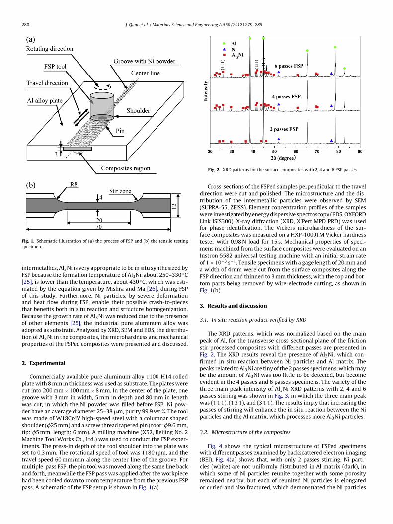
ig. 1. Schematic illustration of (a) the process of FSP and (b) the tensile testingpecimen.
ntermetallics, Al3Ni is very appropriate to be in situ synthesized bySP because the formation temperature of Al3Ni, about 250–330 ◦C25], is lower than the temperature, about 430 ◦C, which was esti-
ated by the equation given by Mishra and Ma [26], during FSPf this study. Furthermore, Ni particles, by severe deformationnd heat flow during FSP, enable their possible crash-to-pieceshat benefits both in situ reaction and structure homogenization.ecause the growth rate of Al3Ni was reduced due to the presencef other elements [25], the industrial pure aluminum alloy wasdopted as substrate. Analyzed by XRD, SEM and EDS, the distribu-ion of Al3Ni in the composites, the microhardness and mechanicalroperties of the FSPed composites were presented and discussed.
. Experimental
Commercially available pure aluminum alloy 1100-H14 rolledlate with 8 mm in thickness was used as substrate. The plates wereut into 200 mm × 100 mm × 8 mm. In the center of the plate, oneroove with 3 mm in width, 5 mm in depth and 80 mm in lengthas cut, in which the Ni powder was filled before FSP. Ni pow-er have an average diameter 25–38 �m, purity 99.9 wt.%. The toolas made of W18Cr4V high-speed steel with a columnar shaped
houlder (�25 mm) and a screw thread tapered pin (root: �9.6 mm,ip: �5 mm, length: 6 mm). A milling machine (X52, Beijing No. 2
achine Tool Works Co., Ltd.) was used to conduct the FSP exper-ments. The press-in depth of the tool shoulder into the plate waset to 0.3 mm. The rotational speed of tool was 1180 rpm, and theravel speed 60 mm/min along the center line of the groove. For
ultiple-pass FSP, the pin tool was moved along the same line back
nd forth, meanwhile the FSP pass was applied after the workpiecead been cooled down to room temperature from the previous FSPass. A schematic of the FSP setup is shown in Fig. 1(a).Fig. 2. XRD patterns for the surface composites with 2, 4 and 6 FSP passes.
Cross-sections of the FSPed samples perpendicular to the traveldirection were cut and polished. The microstructure and the dis-tribution of the intermetallic particles were observed by SEM(SUPRA-55, ZEISS). Element concentration profiles of the sampleswere investigated by energy dispersive spectroscopy (EDS, OXFORDLink ISIS300). X-ray diffraction (XRD, X’Pert MPD PRD) was usedfor phase identification. The Vickers microhardness of the sur-face composites was measured on a HXP-1000TM Vicker hardnesstester with 0.98 N load for 15 s. Mechanical properties of speci-mens machined from the surface composites were evaluated on anInstron 5582 universal testing machine with an initial strain rateof 1 × 10⁻³ s−1. Tensile specimens with a gage length of 20 mm anda width of 4 mm were cut from the surface composites along theFSP direction and thinned to 3 mm thickness, with the top and bot-tom parts being removed by wire-electrode cutting, as shown inFig. 1(b).
3. Results and discussion
3.1. In situ reaction product verified by XRD
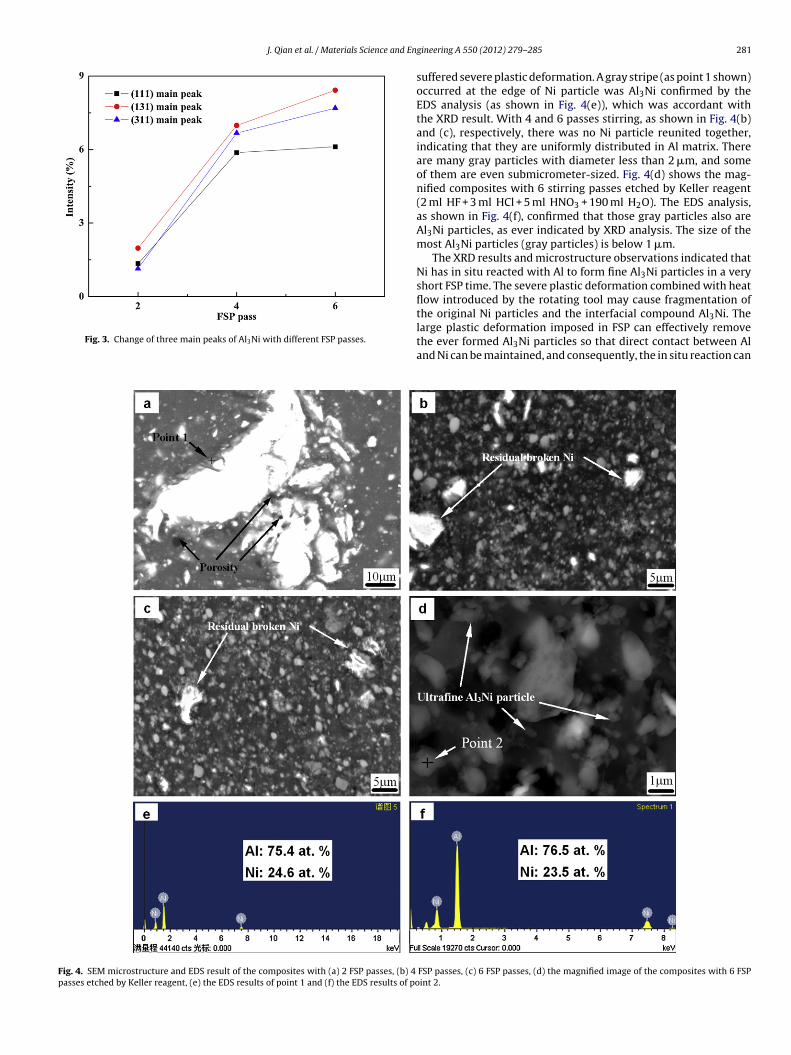
The XRD patterns, which was normalized based on the mainpeak of Al, for the transverse cross-sectional plane of the frictionstir processed composites with different passes are presented inFig. 2. The XRD results reveal the presence of Al3Ni, which con-firmed in situ reaction between Ni particles and Al matrix. Thepeaks related to Al3Ni are tiny of the 2 passes specimens, which maybe the amount of Al3Ni was too little to be detected, but becomeevident in the 4 passes and 6 passes specimens. The variety of thethree main peak intensity of Al3Ni XRD patterns with 2, 4 and 6passes stirring was shown in Fig. 3, in which the three main peakwas (1 1 1), (1 3 1), and (3 1 1). The results imply that increasing thepasses of stirring will enhance the in situ reaction between the Niparticles and the Al matrix, which processes more Al3Ni particles.
3.2. Microstructure of the composites
Fig. 4 shows the typical microstructure of FSPed specimenswith different passes examined by backscattered electron imaging(BEI). Fig. 4(a) shows that, with only 2 passes stirring, Ni parti-
which some of Ni particles reunite together with some porosityremained nearby, but each of reunited Ni particles is elongatedor curled and also fractured, which demonstrated the Ni particles
J. Qian et al. / Materials Science and En
Fig. 3. Change of three main peaks of Al3Ni with different FSP passes.
Fig. 4. SEM microstructure and EDS result of the composites with (a) 2 FSP passes, (b) 4
passes etched by Keller reagent, (e) the EDS results of point 1 and (f) the EDS results of po
gineering A 550 (2012) 279– 285 281
suffered severe plastic deformation. A gray stripe (as point 1 shown)occurred at the edge of Ni particle was Al3Ni confirmed by theEDS analysis (as shown in Fig. 4(e)), which was accordant withthe XRD result. With 4 and 6 passes stirring, as shown in Fig. 4(b)and (c), respectively, there was no Ni particle reunited together,indicating that they are uniformly distributed in Al matrix. Thereare many gray particles with diameter less than 2 �m, and someof them are even submicrometer-sized. Fig. 4(d) shows the mag-nified composites with 6 stirring passes etched by Keller reagent(2 ml HF + 3 ml HCl + 5 ml HNO3 + 190 ml H2O). The EDS analysis,as shown in Fig. 4(f), confirmed that those gray particles also areAl3Ni particles, as ever indicated by XRD analysis. The size of themost Al3Ni particles (gray particles) is below 1 �m.
The XRD results and microstructure observations indicated thatNi has in situ reacted with Al to form fine Al3Ni particles in a veryshort FSP time. The severe plastic deformation combined with heatflow introduced by the rotating tool may cause fragmentation of
the original Ni particles and the interfacial compound Al3Ni. Thelarge plastic deformation imposed in FSP can effectively removethe ever formed Al3Ni particles so that direct contact between Aland Ni can be maintained, and consequently, the in situ reaction canFSP passes, (c) 6 FSP passes, (d) the magnified image of the composites with 6 FSPint 2.
282 J. Qian et al. / Materials Science and Engineering A 550 (2012) 279– 285
Fp
phoctpew
3
smoddtmsgfow
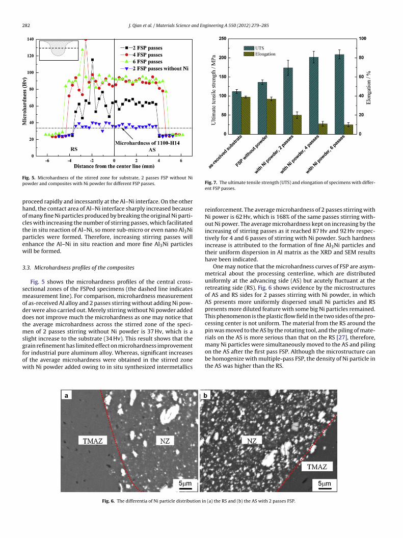
ig. 5. Microhardness of the stirred zone for substrate, 2 passes FSP without Niowder and composites with Ni powder for different FSP passes.
roceed rapidly and incessantly at the Al–Ni interface. On the otherand, the contact area of Al–Ni interface sharply increased becausef many fine Ni particles produced by breaking the original Ni parti-les with increasing the number of stirring passes, which facilitatedhe in situ reaction of Al–Ni, so more sub-micro or even nano Al3Niarticles were formed. Therefore, increasing stirring passes willnhance the Al–Ni in situ reaction and more fine Al3Ni particlesill be formed.
.3. Microhardness profiles of the composites
Fig. 5 shows the microhardness profiles of the central cross-ectional zones of the FSPed specimens (the dashed line indicateseasurement line). For comparison, microhardness measurement
f as-received Al alloy and 2 passes stirring without adding Ni pow-er were also carried out. Merely stirring without Ni powder addedoes not improve much the microhardness as one may notice thathe average microhardness across the stirred zone of the speci-
en of 2 passes stirring without Ni powder is 37 Hv, which is alight increase to the substrate (34 Hv). This result shows that the
rain refinement has limited effect on microhardness improvementor industrial pure aluminum alloy. Whereas, significant increasesf the average microhardness were obtained in the stirred zoneith Ni powder added owing to in situ synthesized intermetallicsFig. 6. The differentia of Ni particle distribution in
Fig. 7. The ultimate tensile strength (UTS) and elongation of specimens with differ-ent FSP passes.
reinforcement. The average microhardness of 2 passes stirring withNi power is 62 Hv, which is 168% of the same passes stirring with-out Ni power. The average microhardness kept on increasing by theincreasing of stirring passes as it reached 87 Hv and 92 Hv respec-tively for 4 and 6 passes of stirring with Ni powder. Such hardnessincrease is attributed to the formation of fine Al3Ni particles andtheir uniform dispersion in Al matrix as the XRD and SEM resultshave been indicated.
One may notice that the microhardness curves of FSP are asym-metrical about the processing centerline, which are distributeduniformly at the advancing side (AS) but acutely fluctuant at theretreating side (RS). Fig. 6 shows evidence by the microstructuresof AS and RS sides for 2 passes stirring with Ni powder, in whichAS presents more uniformly dispersed small Ni particles and RSpresents more diluted feature with some big Ni particles remained.This phenomenon is the plastic flow field in the two sides of the pro-cessing center is not uniform. The material from the RS around thepin was moved to the AS by the rotating tool, and the piling of mate-rials on the AS is more serious than that on the RS [27], therefore,many Ni particles were simultaneously moved to the AS and piling
on the AS after the first pass FSP. Although the microstructure canbe homogenize with multiple-pass FSP, the density of Ni particle inthe AS was higher than the RS.(a) the RS and (b) the AS with 2 passes FSP.
J. Qian et al. / Materials Science and Engineering A 550 (2012) 279– 285 283
F wderF
3
oTwiNwHteg
tssd(l
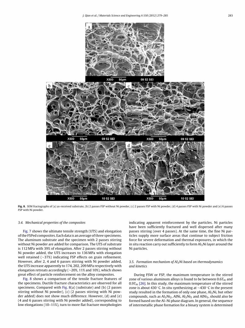
ig. 8. SEM fractographs of (a) as-received substrate, (b) 2 passes FSP without Ni poSP with Ni powder.
.4. Mechanical properties of the composites
Fig. 7 shows the ultimate tensile strength (UTS) and elongationf the FSPed composites. Each data is an average of three specimens.he aluminum substrate and the specimen with 2 passes stirringithout Ni powder are added for comparison. The UTS of substrate
s 112 MPa with 39% of elongation. After 2 passes stirring withouti powder added, the UTS increases to 136 MPa with elongationell retained (∼37%) indicating FSP effects on grain refinement.owever, after 2, 4 and 6 passes stirring with Ni powder added,
he UTS increase apparently to 174, 202, 209 MPa respectively withlongation retreats accordingly (∼20%, 11% and 10%), which showsreat effect of particle reinforcement on the alloy composites.
Fig. 8 shows a comparison of the tensile fracture features ofhe specimens. Ductile fracture characteristics are observed for allpecimens. Compared with Fig. 8(a) (substrate) and (b) (2 passes
tirring without Ni powder), (c) (2 passes stirring with Ni pow-er added) does not show much difference. However, (d) and (e)4 and 6 passes stirring with Ni powder added), corresponding toow elongations (10–11%), turn to more flat fracture morphologies, (c) 2 passes FSP with Ni powder, (d) 4 passes FSP with Ni powder and (e) 6 passes
indicating apparent reinforcement by the particles. Ni particleshave been sufficiently fractured and well dispersed after manypasses stirring (over 4 passes). At the same time, the fine Ni par-ticles supply more surface areas that continue to subject frictionforce for severe deformation and thermal exposures, in which thein situ reaction carry out sufficiently to form Al3Ni layer around theNi particles.
3.5. Formation mechanism of Al3Ni based on thermodynamicsand kinetics
During FSW or FSP, the maximum temperature in the stirredzone of various aluminum alloys is found to be between 0.6Tm and0.9Tm [26]. In this study, the maximum temperature of the stirredzone is about 430 ◦C. In situ synthesizing at ∼430 ◦C in the present
study resulted in the formation of only one phase, Al3Ni, but othercompounds, such as Al3Ni2, AlNi, Al3Ni5 and AlNi3, should also beformed based on the Al–Ni phase diagram. In general, the sequenceof intermetallic phase formation for a binary system is determined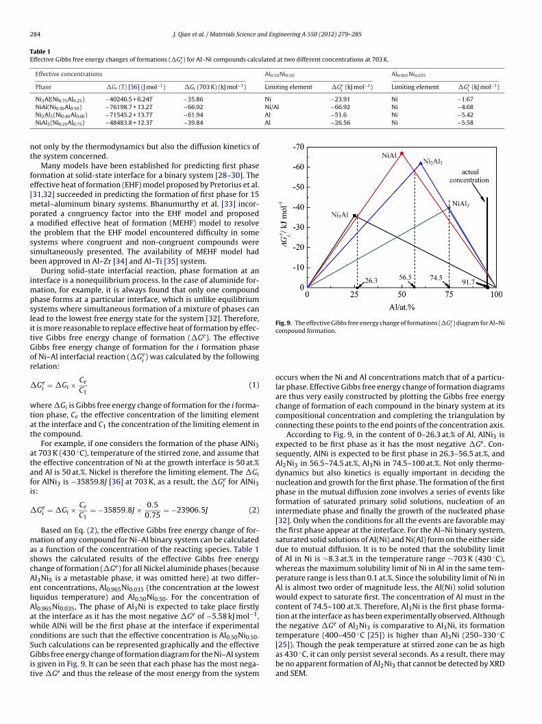
284 J. Qian et al. / Materials Science and Engineering A 550 (2012) 279– 285
Table 1Effective Gibbs free energy changes of formations (�Ge
i) for Al–Ni compounds calculated at two different concentrations at 703 K.
Effective concentrations Al0.50Ni0.50 Al0.965Ni0.035
Phase �Gi (T) [36] (J mol−1) �Gi (703 K) (kJ mol−1) Limiting element �Gei
(kJ mol−1) Limiting element �Gei
(kJ mol−1)
Ni3Al(Ni0.75Al0.25) −40246.5 + 6.24T −35.86 Ni −23.91 Ni −1.67Ni/Al −66.92 Ni −4.68Al −51.6 Ni −5.42Al −26.56 Ni −5.58
nt
fe[mpatssb
impslitGor
�
wtat
atafi
�
mascAelAawcSGit
Fig. 9. The effective Gibbs free energy change of formations (�Gei) diagram for Al–Ni
compound formation.
NiAl(Ni0.50Al0.50) −76198.7 + 13.2T −66.92
Ni2Al3(Ni0.40Al0.60) −71545.2 + 13.7T −61.94
NiAl3(Ni0.25Al0.75) −48483.8 + 12.3T −39.84
ot only by the thermodynamics but also the diffusion kinetics ofhe system concerned.
Many models have been established for predicting first phaseormation at solid-state interface for a binary system [28–30]. Theffective heat of formation (EHF) model proposed by Pretorius et al.31,32] succeeded in predicting the formation of first phase for 15
etal–aluminum binary systems. Bhanumurthy et al. [33] incor-orated a congruency factor into the EHF model and proposed
modified effective heat of formation (MEHF) model to resolvehe problem that the EHF model encountered difficulty in someystems where congruent and non-congruent compounds wereimultaneously presented. The availability of MEHF model hadeen approved in Al–Zr [34] and Al–Ti [35] system.
During solid-state interfacial reaction, phase formation at annterface is a nonequilibrium process. In the case of aluminide for-
ation, for example, it is always found that only one compoundhase forms at a particular interface, which is unlike equilibriumystems where simultaneous formation of a mixture of phases canead to the lowest free energy state for the system [32]. Therefore,t is more reasonable to replace effective heat of formation by effec-ive Gibbs free energy change of formation (�Ge). The effectiveibbs free energy change of formation for the i formation phasef Ni–Al interfacial reaction (�Ge
i) was calculated by the following
elation:
Gei = �Gi × Ce
C1(1)
here �Gi is Gibbs free energy change of formation for the i forma-ion phase, Ce the effective concentration of the limiting elementt the interface and C1 the concentration of the limiting element inhe compound.
For example, if one considers the formation of the phase AlNi3t 703 K (430 ◦C), temperature of the stirred zone, and assume thathe effective concentration of Ni at the growth interface is 50 at.%nd Al is 50 at.%. Nickel is therefore the limiting element. The �Gior AlNi3 is −35859.8J [36] at 703 K, as a result, the �Ge
ifor AlNi3
s:
Gei = �Gi × Ce
C1= −35859.8J × 0.5
0.75= −23906.5J (2)
Based on Eq. (2), the effective Gibbs free energy change of for-ation of any compound for Ni–Al binary system can be calculated
s a function of the concentration of the reacting species. Table 1hows the calculated results of the effective Gibbs free energyhange of formation (�Ge) for all Nickel aluminide phases (becausel3Ni5 is a metastable phase, it was omitted here) at two differ-nt concentrations, Al0.965Ni0.035 (the concentration at the lowestiquidus temperature) and Al0.50Ni0.50. For the concentration ofl0.965Ni0.035, The phase of Al3Ni is expected to take place firstlyt the interface as it has the most negative �Ge of −5.58 kJ mol−1,hile AlNi will be the first phase at the interface if experimental
onditions are such that the effective concentration is Al0.50Ni0.50.
uch calculations can be represented graphically and the effectiveibbs free energy change of formation diagram for the Ni–Al systems given in Fig. 9. It can be seen that each phase has the most nega-ive �Ge and thus the release of the most energy from the system
occurs when the Ni and Al concentrations match that of a particu-lar phase. Effective Gibbs free energy change of formation diagramsare thus very easily constructed by plotting the Gibbs free energychange of formation of each compound in the binary system at itscompositional concentration and completing the triangulation byconnecting these points to the end points of the concentration axis.
According to Fig. 9, in the content of 0–26.3 at.% of Al, AlNi3 isexpected to be first phase as it has the most negative �Ge. Con-sequently, AlNi is expected to be first phase in 26.3–56.5 at.%, andAl2Ni3 in 56.5–74.5 at.%, Al3Ni in 74.5–100 at.%. Not only thermo-dynamics but also kinetics is equally important in deciding thenucleation and growth for the first phase. The formation of the firstphase in the mutual diffusion zone involves a series of events likeformation of saturated primary solid solutions, nucleation of anintermediate phase and finally the growth of the nucleated phase[32]. Only when the conditions for all the events are favorable maythe first phase appear at the interface. For the Al–Ni binary system,saturated solid solutions of Al(Ni) and Ni(Al) form on the either sidedue to mutual diffusion. It is to be noted that the solubility limitof Al in Ni is ∼8.3 at.% in the temperature range ∼703 K (430 ◦C),whereas the maximum solubility limit of Ni in Al in the same tem-perature range is less than 0.1 at.%. Since the solubility limit of Ni inAl is almost two order of magnitude less, the Al(Ni) solid solutionwould expect to saturate first. The concentration of Al must in thecontent of 74.5–100 at.%. Therefore, Al3Ni is the first phase forma-tion at the interface as has been experimentally observed. Althoughthe negative �Ge of Al2Ni3 is comparative to Al3Ni, its formationtemperature (400–450 ◦C [25]) is higher than Al3Ni (250–330 ◦C[25]). Though the peak temperature at stirred zone can be as highas 430 ◦C, it can only persist several seconds. As a result, there maybe no apparent formation of Al Ni that cannot be detected by XRD
2 3and SEM.
nd En
4
fp
(
(
(
(
A
FS2
[[
[
[[
[[
[[[[[
[
[[[[[[[
[[[
J. Qian et al. / Materials Science a
. Conclusions
The Al3Ni particulate-reinforced composites was fabricated viariction stir processing on 1100-H14 Al alloy substrate by adding Niowder into the stirred zone. The following conclusions are drawn:
1) During the process of FSP, the Ni particles and Al matrix in situsynthesized Al3Ni, which was confirmed by XRD and EDS anal-ysis.
2) With 2 passes stirring with Ni powder added, the residualNi particles were unevenly dispersed in the composites, andfew Al3Ni particles occurred at the peripheries of Ni particles.However, after 4 passes stirring, the amount of Al3Ni particlesincreased markedly and the particles were well dispersed in thesubstrate. Further repeating the stirring to 6 passes, the amountof Al3Ni particle hardly increased but the particles were betterdispersed compared to 4 passes, the average size of which wasin micron-scale.
3) Because of the formation of ultrafine Al3Ni particles and uni-form dispersion in the composites, the microhardness and theultimate tensile strength of the composites have significantincreases after 4 and 6 passes stirring with Ni powder added.The average microhardness and UTS of the composites after 6passes stirring are 92 Hv and 209 MPa, which are 271% and 187%respectively of the 1100-H14 substrate.
4) The effective Gibbs free energy change of formation model hasbeen proposed to predict the Al–Ni compound formation atsolid-state interface. Coupling the thermodynamics and kinet-ics factors under experimental condition, the calculation showsthe Al3Ni phase is the product at the Al–Ni solid-state interface,which confirms the experimental observation.
cknowledgements
This work has been supported by the National Natural Scienceoundation of China (51071123 and 51101126), the fund of thetate Key Laboratory of Solidification Processing in NWPU (31-TP-009 and 43-QP-2009) and the 111 Project (B08040).
[[[
[
gineering A 550 (2012) 279– 285 285
References
[1] W.M. Thomas, E.D. Nicholas, J.C. Needham, M.G. Murch, P. Templesmith, C.J.Dawes, G B Patent Application No. 9125978.8, December 1991.
[2] R.S. Mishra, M.W. Mahoney, S.X. McFaden, N.A. Mara, A.K. Mukherjee, ScriptaMater. 42 (1999) 163–168.
[3] Y.J. Kwon, I. Shigematsu, N. Saito, Scripta Mater. 49 (2003) 785–789.[4] C.G. Rhodes, M.W. Mahoney, W.H. Bingel, M. Calabrese, Scripta Mater. 48 (2003)
1451–1455.[5] J.Q. Su, T.W. Nelson, C.J. Sterling, Scripta Mater. 52 (2005) 135–140.[6] C.I. Chang, C.J. Lee, J.C. Huang, Scripta Mater. 51 (2004) 509–514.[7] P.B. Berbon, W.H. Bingel, R.S. Mishra, C.C. Bampton, M.W. Mahoney, Scripta
Mater. 44 (2001) 61–66.[8] Z.Y. Ma, R.S. Mishra, M.W. Mahoney, Scripta Mater. 50 (2004) 931–935.[9] S.R. Sharma, Z.Y. Ma, R.S. Mishra, Scripta Mater. 51 (2004) 237–241.10] R.S. Mishra, Z.Y. Ma, I. Charit, Mater. Sci. Eng. A 341 (2003) 307–310.11] Y. Morisada, H. Fujii, T. Nagaoka, K. Nogi, M. Fukusumi, Compos. Part A 38 (2007)
2097–2101.12] Y. Morisada, H. Fujii, T. Nagaoka, M. Fukusumi, Mater. Sci. Eng. A 419 (2006)
344–348.13] M. Dixit, J.W. Newkir, R.S. Mishra, Scripta Mater. 56 (2007) 541–544.14] Y. Morisada, H. Fujii, T. Nagaoka, M. Fukusumi, Mater. Sci. Eng. A 433 (2006)
50–54.15] C.J. Lee, J.C. Huang, P.J. Hsieh, Scripta Mater. 54 (2006) 1415–1420.16] Y. Morisada, H. Fujii, T. Nagaoka, M. Fukusumi, Scripta Mater. 55 (2006)
1067–1070.17] C.J. Hsu, P.W. Kao, N.J. Ho, Scripta Mater. 53 (2005) 341–345.18] C.J. Hsu, P.W. Kao, N.J. Ho, Acta Mater. 54 (2006) 5241–5249.19] I.S. Lee, P.W. Kao, N.J. Ho, Intermetallics 16 (2008) 1104–1108.20] S.C. Tjong, Z.Y. Ma, Mater. Sci. Eng. R 29 (2000) 49–113.21] G. Gonzalez, A. Sagarzazu, D. Bonyuet, L.D. Angelo, R. Villalba, J. Alloys Compd.
483 (2009) 289–297.22] Z.G. Zhang, E. Akiyama, Y. Watanabe, Y. Katada, K. Tsuzaki, Corrosion Sci. 49
(2007) 2962–2972.23] J.Y. Uan, L.H. Chen, T.S. Lui, Acta Mater. 49 (2001) 313–320.24] C.J. Song, Z.M. Xu, J.G. Li, Mater. Sci. Eng. A 445–446 (2007) 148–154.25] E.G. Colgan, Mater. Sci. Rep. 5 (1990) 1–44.26] R.S. Mishra, Z.Y. Ma, Mater. Sci. Eng. R 50 (2005) 1–78.27] K. Colligan, Weld. J. 78 (1999) 14–16.28] R.M. Walser, R.W. Bené, Appl. Phys. Lett. 28 (1976) 624–625.29] B.Y. Tsaur, S.S. Lau, J.W. Mayer, M.A. Nicolet, Appl. Phys. Lett. 38 (1981)
922–924.30] M. Ronay, Appl. Phys. Lett. 42 (1983) 577–579.31] R. Pretorius, R.D. Reus, A.M. Vredenberg, Mater. Lett. 9 (1990) 494–499.32] R. Pretorius, A.M. Vredenberg, F.W. Saris, J. Appl. Phys. 70 (1991) 3636–3646.
33] K. Bhanumurthy, G.B. Kale, S.P. Garg, Trans. Indian Inst. Met. 48 (1995) 193–196.34] A. Laik, K. Bhanumurthy, G.B. Kale, Intermetallics 12 (2004) 69–74.35] L. Xu, Y.Y. Cui, Y.L. Hao, R. Yang, Mater. Sci. Eng. A 435–436 (2006) 638–647.36] W. Huang, Y.A. Chang, Intermetallics 6 (1998) 487–498.


![Journal of Inorganic Biochemistry - or.nsfc.gov.cnor.nsfc.gov.cn/bitstream/00001903-5/439248/1/1000008889503.pdf · appreciated [21,22]. Liriodenine is a representative oxoaporphine](https://img.pdfslide.net/doc/110x75/5b63e89d7f8b9a6c178c99a3/journal-of-inorganic-biochemistry-ornsfcgovcnornsfcgovcnbitstream00001903-54392481.jpg)


![Materials Science & Engineering Aor.nsfc.gov.cn/bitstream/00001903-5/309746/1/... · · 2016-12-08tor, attained the ... deformation of boron steel. Liu [9] built the flow stress](https://img.pdfslide.net/doc/110x75/5aad34447f8b9a693f8e118c/materials-science-engineering-aornsfcgovcnbitstream00001903-530974612016-12-08tor.jpg)