Embed Size (px)
Citation preview

Maximum Power Point Tracking System for Solar Racing Team
Andrew MattesonIngrid RodriguezTravis Seagert
Giancarlo Valentin
School of Electrical and Computer Engineering
GT Solar Jackets
March 14, 2011
Georgia Institute of Technology
Project Overview
• Customized smart switching power system to charge car batteries with solar energy
• Intended for use by the Solar Jackets in the World Solar Challenge 2011
• Estimated material cost: $194 per unit
Prior Work: Fall 2010
• Initial design adaptable to varying sunlight variations
• Designed for different battery and array specifications
• Contained one power switching circuit per board
Design Objectives: Spring 2011
• Minimized PCB layout area
• Efficiency > 90%
• Implement RS-485 communication interface
• Comply with solar challenge regulations
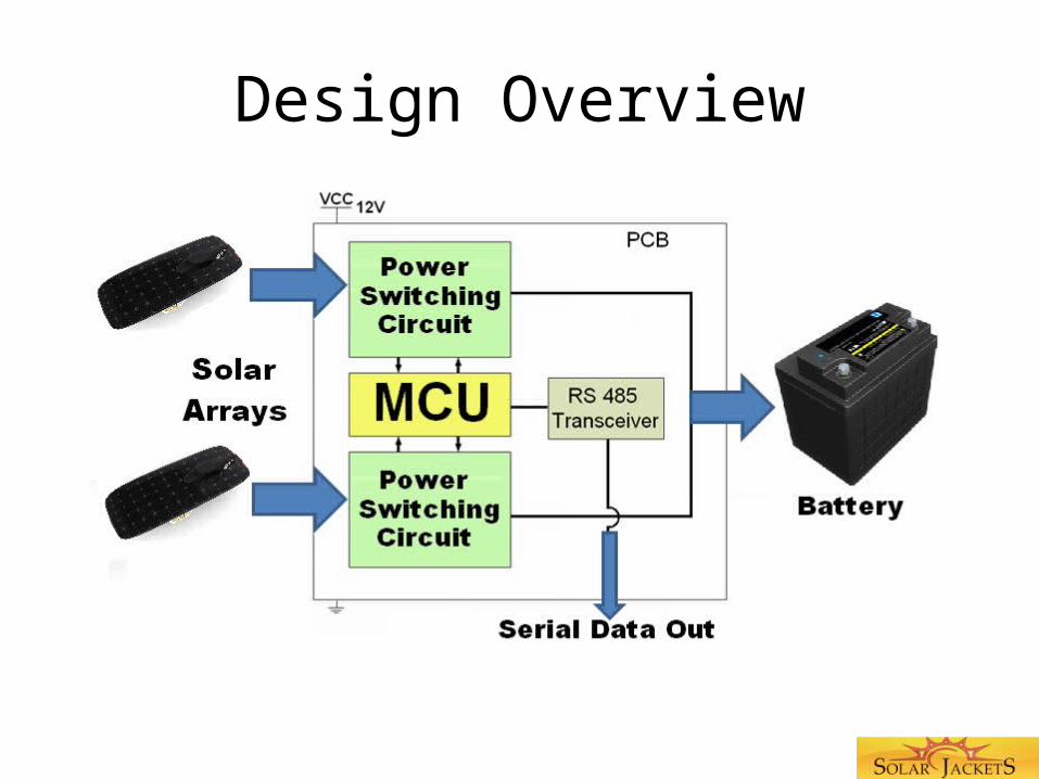
Design Overview
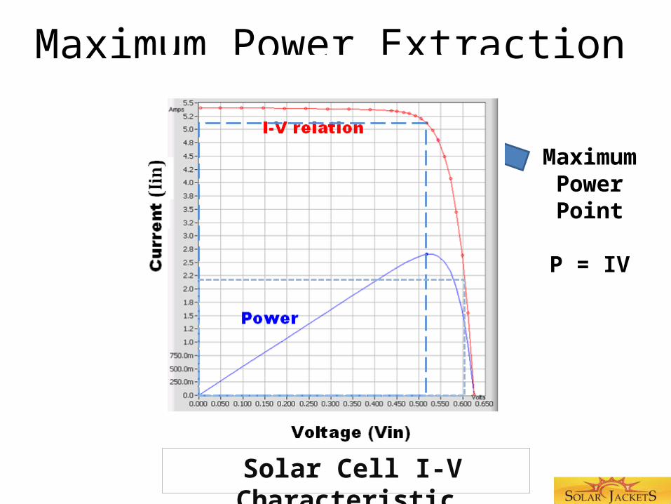
Maximum Power Extraction
Solar Cell I-V Characteristic
MaximumPowerPoint
P = IV
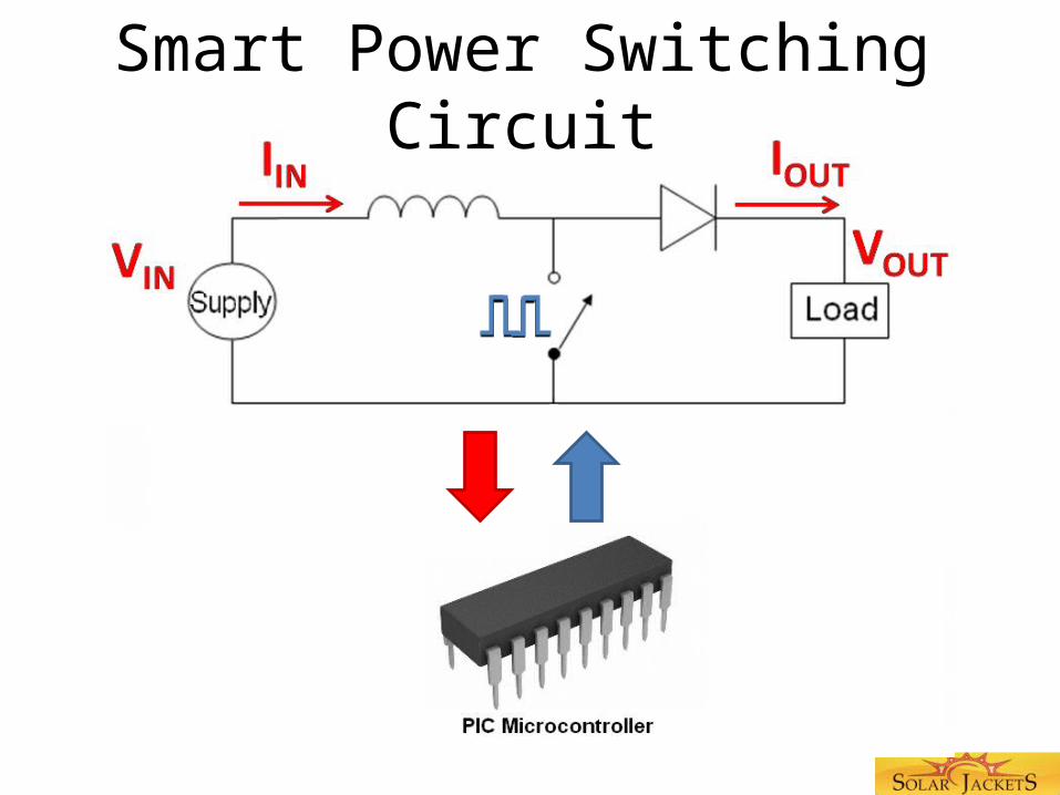
Smart Power Switching Circuit
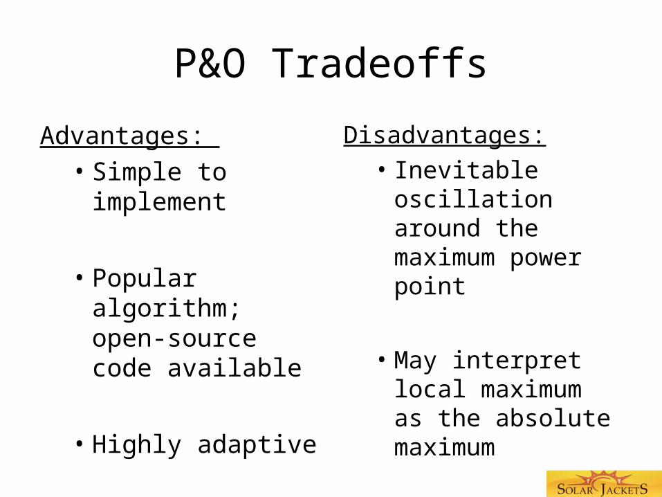
P&O Tradeoffs
Advantages: • Simple to
implement
• Popular algorithm; open-source code available
• Highly adaptive
Disadvantages:• Inevitable
oscillation around the maximum power point
• May interpret local maximum as the absolute maximum
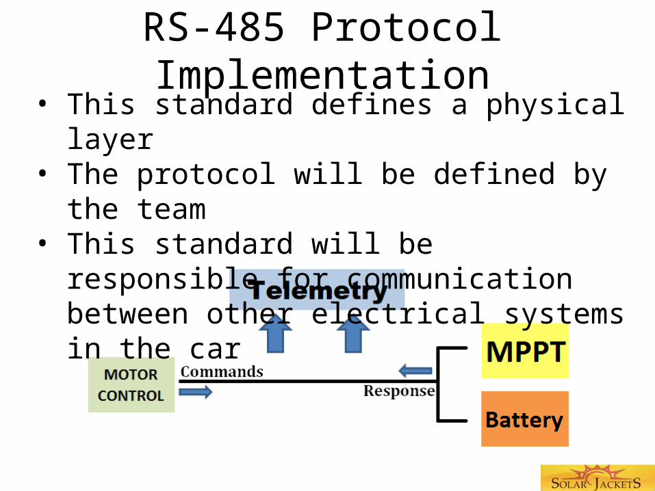
RS-485 Protocol Implementation• This standard defines a physical layer• The protocol will be defined by the team • This standard will be responsible for
communication between other electrical systems in the car
Operational Safety Precautions
• Gradual shutdown by intentionally deviating from maximum power point
• Maximum voltage • Input: 18V• Output: 105V
• Maximum current• Input: 8.5A• Output: 3.5A
Safety Precautions:Fuses and Connectors
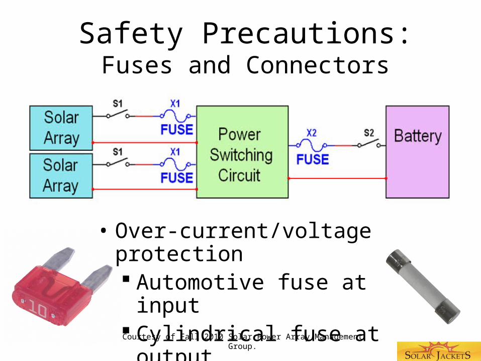
• Over-current/voltage protection Automotive fuse at input Cylindrical fuse at output
• Touch-safe connectorsCourtesy of Fall 2010 Solar Power Array Management Group.
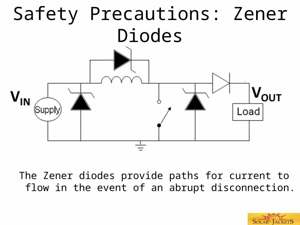
Safety Precautions: Zener Diodes
The Zener diodes provide paths for current to flow in the event of an abrupt disconnection.
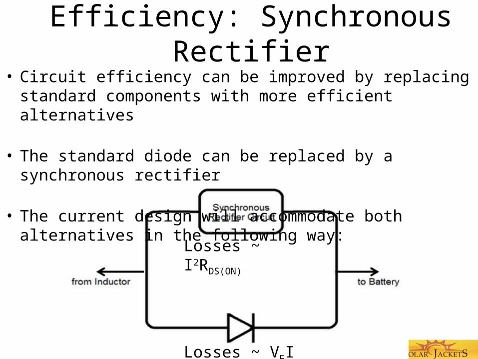
Efficiency: Synchronous Rectifier• Circuit efficiency can be improved by replacing standard
components with more efficient alternatives
• The standard diode can be replaced by a synchronous rectifier
• The current design will accommodate both alternatives in the following way:
Losses ~ I2RDS(ON)
Losses ~ VFI

Design Challenges and TradeoffsGeorgia Tech PCB Machine
• Dimensions (10.5 in x 7.5 in )
• This constraint dictates how many MPPT circuits can fit onto a single board (currently two)
• Using a different machine would introduce significant additional costs.
Design Challenges and TradeoffsBounding Simulation Parameters
• Exhaustive circuit simulations cannot be performed for the full range of variable parameters
• As a result, the circuit’s values are only approximations of the ideal optimal components
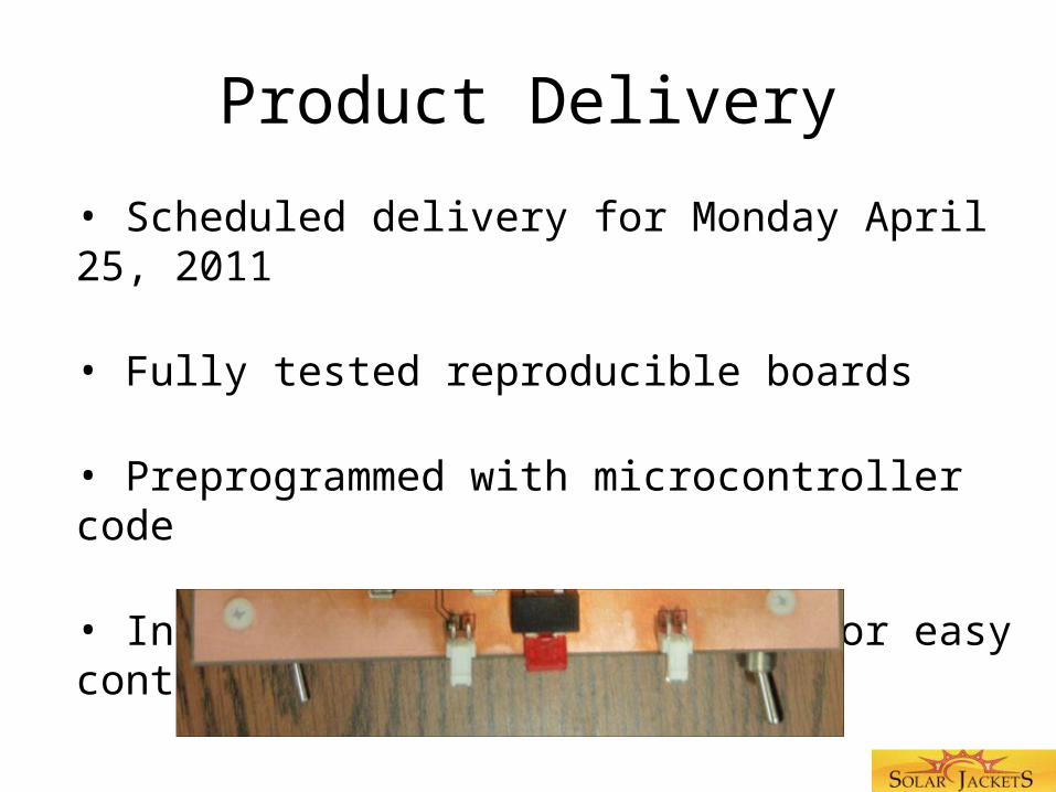
Product Delivery
• Scheduled delivery for Monday April 25, 2011
• Fully tested reproducible boards
• Preprogrammed with microcontroller code
• Include mechanical switches for easy control
Future Work Schedule
• March 18, 2011 – First Prototype
• April 01, 2011 – Design Tests for Prototype
• April 15, 2011 – PCB Re-Design
• April 20, 2011 – Final Build
• April 22, 2011 – Final Design Tests
• April 25, 2011 – Deliver Completed Board
RS-485 Demonstration

Questions