Embed Size (px)
Citation preview
Hide Text1
A Pressure Vessel
Hide Text2
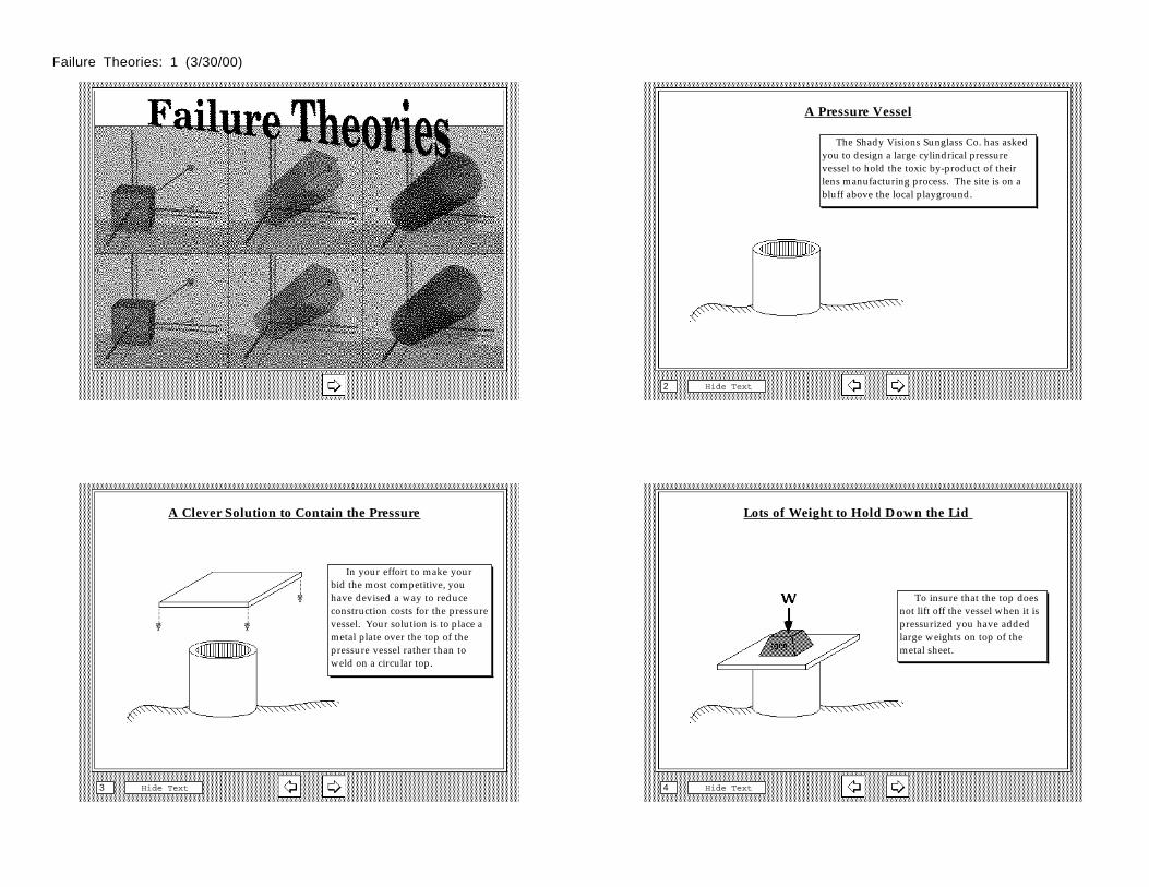
The Shady Visions Sunglass Co. has asked you to design a large cylindrical pressure vessel to hold the toxic by-product of their lens manufacturing process. The site is on a bluff above the local playground.
A Clever Solution to Contain the Pressure
Hide Text3
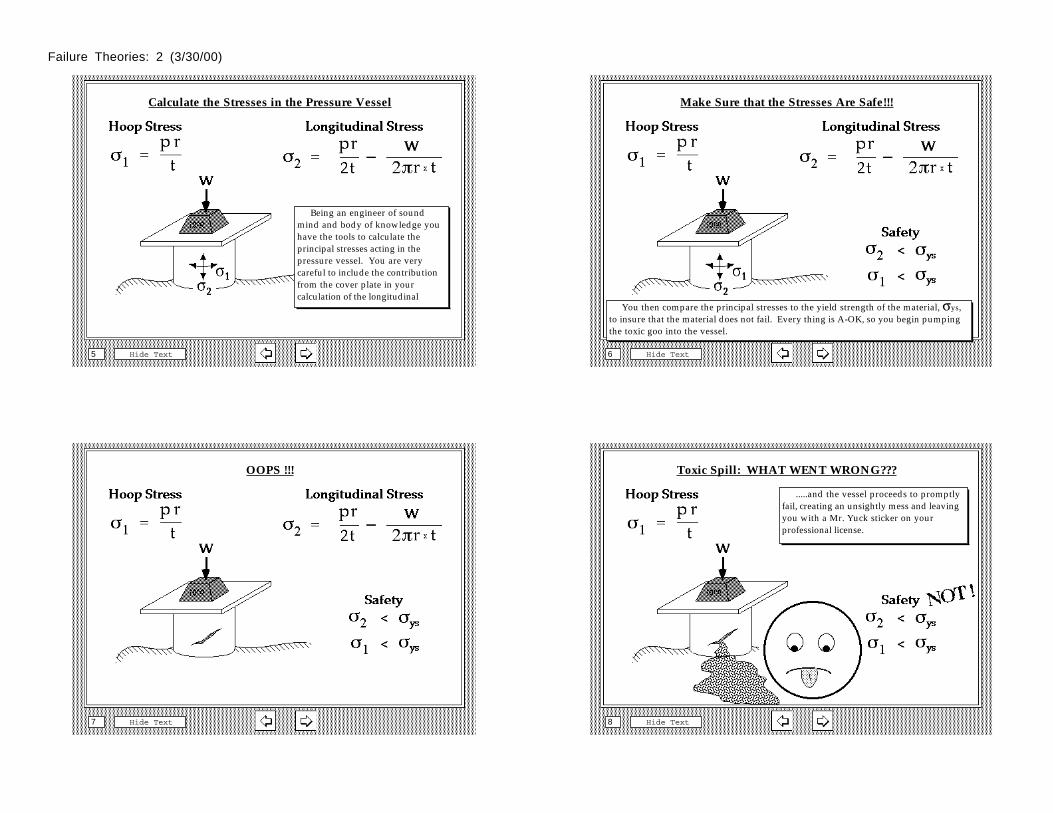
In your effort to make your bid the most competitive, you have devised a way to reduce construction costs for the pressure vessel. Your solution is to place a metal plate over the top of the pressure vessel rather than to weld on a circular top.
Lots of Weight to Hold Down the Lid
Hide Text4
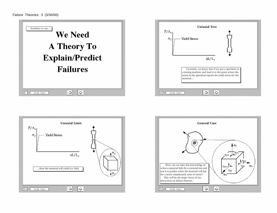
To insure that the top does not lift off the vessel when it is pressurized you have added large weights on top of the metal sheet.
Failure Theories: 1 (3/30/00)
Calculate the Stresses in the Pressure Vessel
Hide Text5
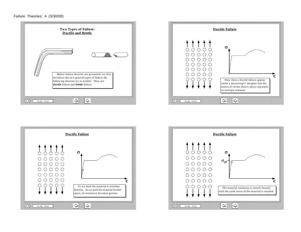
Being an engineer of sound mind and body of knowledge you have the tools to calculate the principal stresses acting in the pressure vessel. You are very careful to include the contribution from the cover plate in your calculation of the longitudinal
Make Sure that the Stresses Are Safe!!!
Hide Text6
You then compare the principal stresses to the yield strength of the material, σys, to insure that the material does not fail. Every thing is A-OK, so you begin pumping the toxic goo into the vessel.
OOPS !!!
Hide Text7
Toxic Spill: WHAT WENT WRONG???
Hide Text8
.....and the vessel proceeds to promptly fail, creating an unsightly mess and leaving you with a Mr. Yuck sticker on your professional license.
Failure Theories: 2 (3/30/00)
Hide Text9
Needless to say..... Uniaxial Test
Hide Text1 0
Currently, we know that if we put a specimen in a testing machine and load it to the point where the stress in the specimen equals the yield stress for the material....
Uniaxial Limit
Hide Text1 1
...then the material will yield (i.e. fail).
General Case
Hide Text1 2
How can we take this knowledge of when a material fails for a uniaxial test and use it to predict when the material will fail for a more complicated state of stress? This will be the major focus of our discussion on failure theories.
Failure Theories: 3 (3/30/00)
Two Types of Failure:Ductile and Brittle
Hide Text1 3
Before failure theories are presented, we first introduce the two general types of failure the following theories try to predict. They are ductile failure and brittle failure.
Ductile Failure
Hide Text1 4
How does a ductile failure appear under a microscope? Imagine that the matrix of circles shown above represent an isotropic material.
Ductile Failure
Hide Text1 5
As we load the material it stretches linearly. As we pull the material further apart, its resistance becomes greater.
Ductile Failure
Hide Text1 6
The material continues to stretch linearly until the yield stress of the material is reached.
Failure Theories: 4 (3/30/00)
Ductile Failure
Hide Text1 7
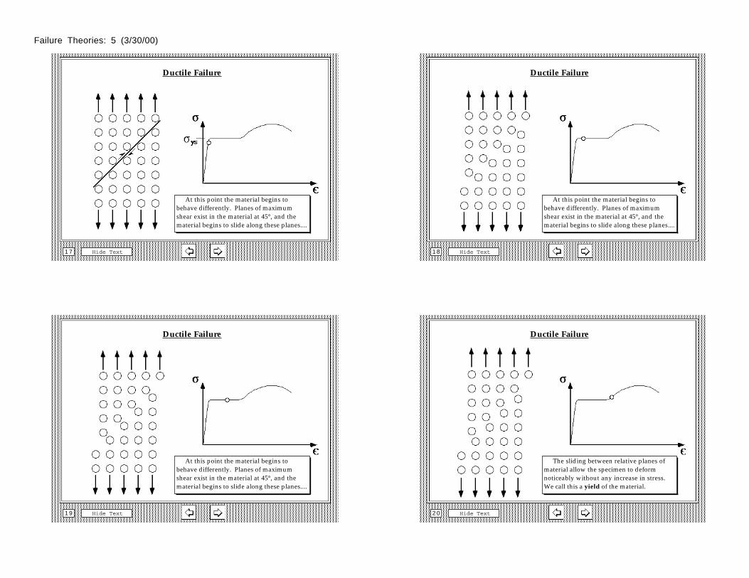
At this point the material begins to behave differently. Planes of maximum shear exist in the material at 45°, and the material begins to slide along these planes....
Ductile Failure
Hide Text1 8
At this point the material begins to behave differently. Planes of maximum shear exist in the material at 45°, and the material begins to slide along these planes....
Ductile Failure
Hide Text1 9
At this point the material begins to behave differently. Planes of maximum shear exist in the material at 45°, and the material begins to slide along these planes....
Ductile Failure
Hide Text2 0
The sliding between relative planes of material allow the specimen to deform noticeably without any increase in stress. We call this a yield of the material.
Failure Theories: 5 (3/30/00)
Brittle Failure
Hide Text2 1
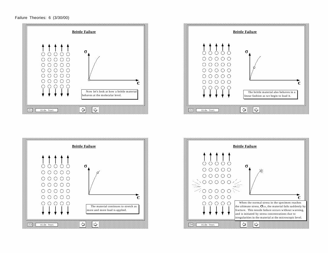
Now let's look at how a brittle material behaves at the molecular level.
Brittle Failure
Hide Text2 2
The brittle material also behaves in a linear fashion as we begin to load it.
Brittle Failure
Hide Text2 3
The material continues to stretch as more and more load is applied.
Brittle Failure
Hide Text2 4
When the normal stress in the specimen reaches the ultimate stress, σult, the material fails suddenly by fracture. This tensile failure occurs without warning, and is initiated by stress concentrations due to irregularities in the material at the microscopic level.
Failure Theories: 6 (3/30/00)
Ductile vs Brittle
Hide Text2 5
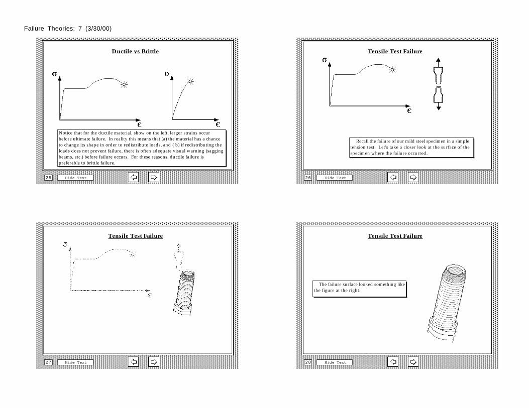
Notice that for the ductile material, show on the left, larger strains occur before ultimate failure. In reality this means that (a) the material has a chance to change its shape in order to redistribute loads, and ( b) if redistributing the loads does not prevent failure, there is often adequate visual warning (sagging beams, etc.) before failure occurs. For these reasons, ductile failure is preferable to brittle failure.
Tensile Test Failure
Hide Text2 6
Recall the failure of our mild steel specimen in a simple tension test. Let's take a closer look at the surface of the specimen where the failure occurred.
Tensile Test Failure
Hide Text2 7
Tensile Test Failure
Hide Text2 8
The failure surface looked something like the figure at the right.
Failure Theories: 7 (3/30/00)
Cross-Section of Failure Surface
Hide Text2 9
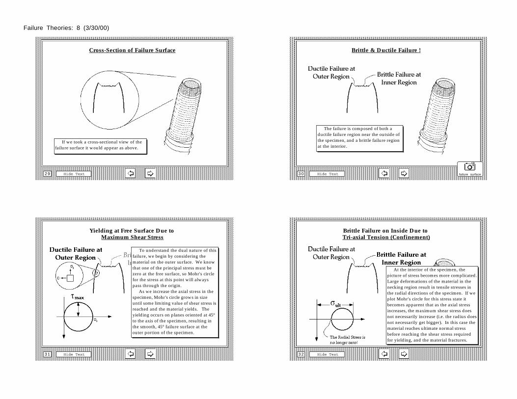
If we took a cross-sectional view of the failure surface it would appear as above.
Brittle & Ductile Failure !
Hide Text3 0
The failure is composed of both a ductile failure region near the outside of the specimen, and a brittle failure region at the interior.
failure surface
Yielding at Free Surface Due to Maximum Shear Stress
Hide Text3 1
To understand the dual nature of this failure, we begin by considering the material on the outer surface. We know that one of the principal stress must be zero at the free surface, so Mohr's circle for the stress at this point will always pass through the origin. As we increase the axial stress in the specimen, Mohr's circle grows in size until some limiting value of shear stress is reached and the material yields. The yielding occurs on planes oriented at 45° to the axis of the specimen, resulting in the smooth, 45° failure surface at the outer portion of the specimen.
Brittle Failure on Inside Due to Tri-axial Tension (Confinement)
Hide Text3 2
At the interior of the specimen, the picture of stress becomes more complicated. Large deformations of the material in the necking region result in tensile stresses in the radial directions of the specimen. If we plot Mohr's circle for this stress state it becomes apparent that as the axial stress increases, the maximum shear stress does not necessarily increase (i.e. the radius does not necessarily get bigger). In this case the material reaches ultimate normal stress before reaching the shear stress required for yielding, and the material fractures.
Failure Theories: 8 (3/30/00)
Temperature Effects
Hide Text3 3
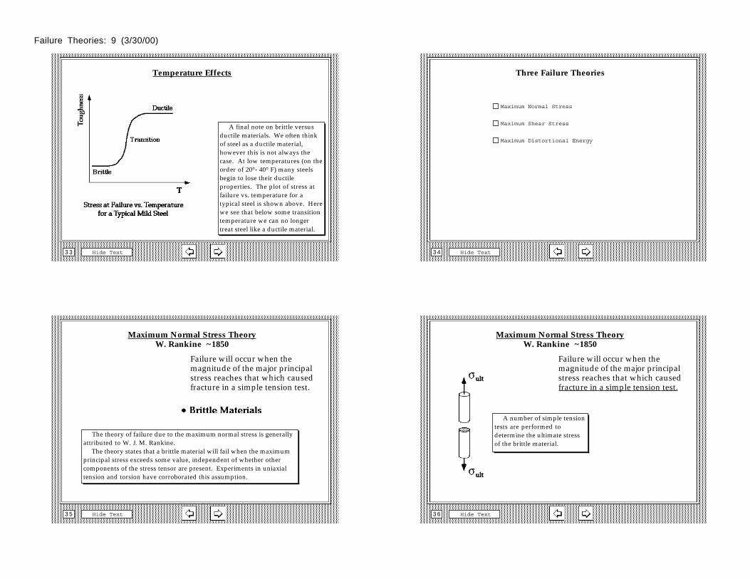
A final note on brittle versus ductile materials. We often think of steel as a ductile material, however this is not always the case. At low temperatures (on the order of 20°- 40° F) many steels begin to lose their ductile properties. The plot of stress at failure vs. temperature for a typical steel is shown above. Here we see that below some transition temperature we can no longer treat steel like a ductile material.
Three Failure Theories
Hide Text3 4
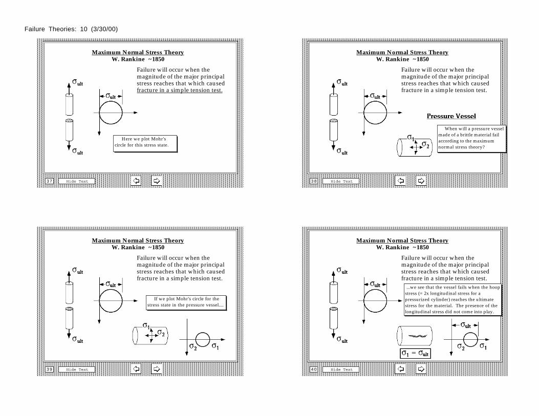
Maximum Normal Stress
Maximum Shear Stress
Maximum Distortional Energy
Maximum Normal Stress TheoryW. Rankine ~1850
Hide Text3 5
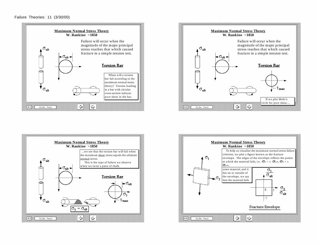
Failure will occur when the magnitude of the major principal stress reaches that which caused fracture in a simple tension test.
The theory of failure due to the maximum normal stress is generally attributed to W. J. M. Rankine. The theory states that a brittle material will fail when the maximum principal stress exceeds some value, independent of whether other components of the stress tensor are present. Experiments in uniaxial tension and torsion have corroborated this assumption.
Maximum Normal Stress TheoryW. Rankine ~1850
Hide Text3 6
Failure will occur when the magnitude of the major principal stress reaches that which caused fracture in a simple tension test.
A number of simple tension tests are performed to determine the ultimate stress of the brittle material.
Failure Theories: 9 (3/30/00)
Maximum Normal Stress TheoryW. Rankine ~1850
Hide Text3 7
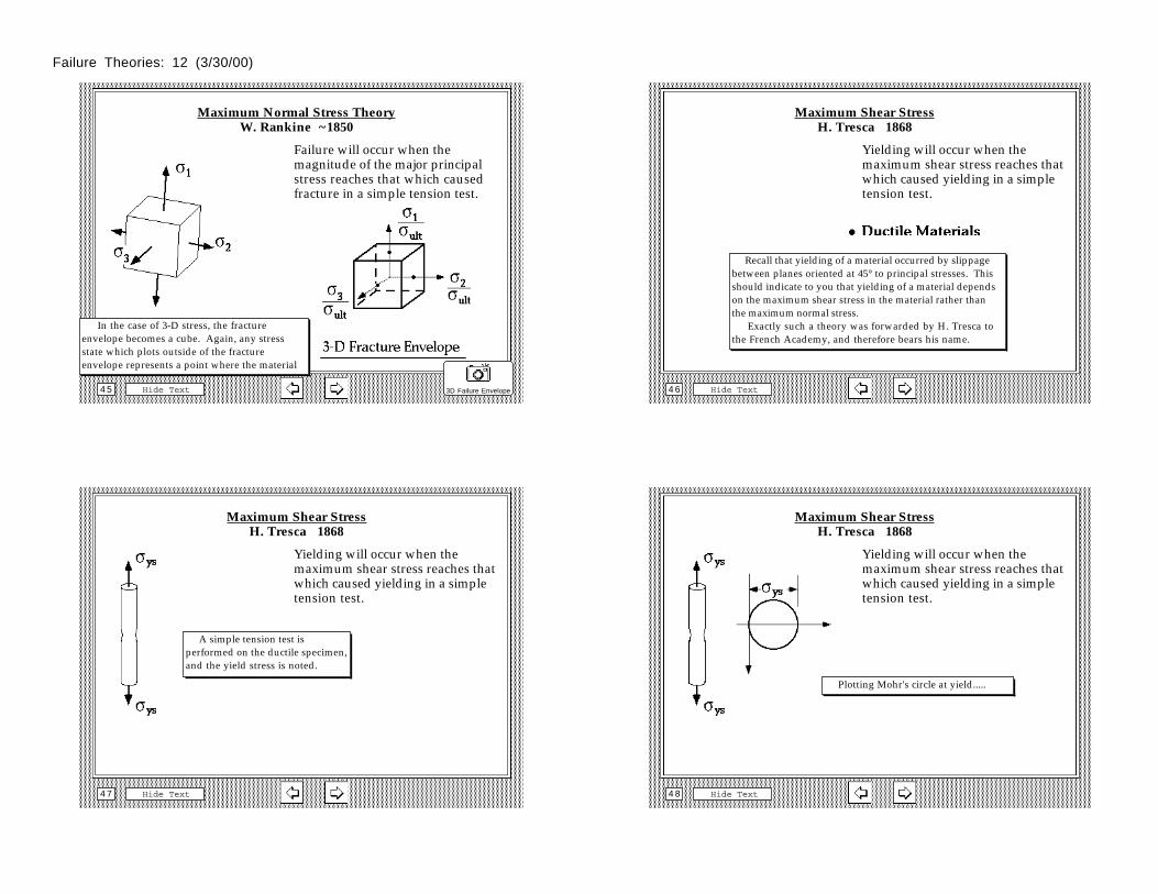
Failure will occur when the magnitude of the major principal stress reaches that which caused fracture in a simple tension test.
Here we plot Mohr's circle for this stress state.
Maximum Normal Stress TheoryW. Rankine ~1850
Hide Text3 8
Failure will occur when the magnitude of the major principal stress reaches that which caused fracture in a simple tension test.
When will a pressure vessel made of a brittle material fail according to the maximum normal stress theory?
Maximum Normal Stress TheoryW. Rankine ~1850
Hide Text3 9
Failure will occur when the magnitude of the major principal stress reaches that which caused fracture in a simple tension test.
If we plot Mohr's circle for the stress state in the pressure vessel....
Maximum Normal Stress TheoryW. Rankine ~1850
Hide Text4 0
Failure will occur when the magnitude of the major principal stress reaches that which caused fracture in a simple tension test.
...we see that the vessel fails when the hoop stress (= 2x longitudinal stress for a pressurized cylinder) reaches the ultimate stress for the material. The presence of the longitudinal stress did not come into play.
Failure Theories: 10 (3/30/00)
Maximum Normal Stress TheoryW. Rankine ~1850
Hide Text4 1
Failure will occur when the magnitude of the major principal stress reaches that which caused fracture in a simple tension test.
When will a torsion bar fail according to the maximum normal stress theory? Torsion loading in a bar with circular cross-section induces pure shear in the bar.
Maximum Normal Stress TheoryW. Rankine ~1850
Hide Text4 2
Failure will occur when the magnitude of the major principal stress reaches that which caused fracture in a simple tension test.
If we plot Mohr's circle for pure shear....
Maximum Normal Stress TheoryW. Rankine ~1850
Hide Text4 3
Failure will occur when the magnitude of the major principal stress reaches that which caused fracture in a simple tension test.
...we see that the torsion bar will fail when the maximum shear stress equals the ultimate normal stress. This is the type of failure we observe when we twist a piece of chalk.
Maximum Normal Stress TheoryW. Rankine ~1850
Hide Text4 4
Failure will occur when the magnitude of the major principal stress reaches that which caused fracture in a simple tension test.
To help us visualize the maximum normal stress failure criterion, we plot a figure known as the fracture envelope. The edges of the envelope reflects the points at which the material fails, i.e. σ1 = ± σult, σ2 = ± σult.some material, and it lies on or outside of the envelope, we say that the material fails.
Failure Theories: 11 (3/30/00)
Maximum Normal Stress TheoryW. Rankine ~1850
Hide Text4 5
Failure will occur when the magnitude of the major principal stress reaches that which caused fracture in a simple tension test.
In the case of 3-D stress, the fracture envelope becomes a cube. Again, any stress state which plots outside of the fracture envelope represents a point where the material
3D Failure Envelope
Maximum Shear StressH. Tresca 1868
Hide Text4 6
Yielding will occur when the maximum shear stress reaches that which caused yielding in a simple tension test.
Recall that yielding of a material occurred by slippage between planes oriented at 45° to principal stresses. This should indicate to you that yielding of a material depends on the maximum shear stress in the material rather than the maximum normal stress. Exactly such a theory was forwarded by H. Tresca to the French Academy, and therefore bears his name.
Maximum Shear StressH. Tresca 1868
Hide Text4 7
Yielding will occur when the maximum shear stress reaches that which caused yielding in a simple tension test.
A simple tension test is performed on the ductile specimen, and the yield stress is noted.
Maximum Shear StressH. Tresca 1868
Hide Text4 8
Yielding will occur when the maximum shear stress reaches that which caused yielding in a simple tension test.
Plotting Mohr's circle at yield.....
Failure Theories: 12 (3/30/00)
Maximum Shear StressH. Tresca 1868
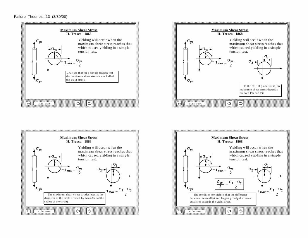
Hide Text4 9
Yielding will occur when the maximum shear stress reaches that which caused yielding in a simple tension test.
...we see that for a simple tension test the maximum shear stress is one half of the yield stress.
Maximum Shear StressH. Tresca 1868
Hide Text5 0
Yielding will occur when the maximum shear stress reaches that which caused yielding in a simple tension test.
In the case of plane stress, the maximum shear stress depends on both σ1 and σ2.
Maximum Shear StressH. Tresca 1868
Hide Text5 1
Yielding will occur when the maximum shear stress reaches that which caused yielding in a simple tension test.
The maximum shear stress is calculated as the diameter of the circle divided by two (Ah ha! the radius of the circle).
Maximum Shear StressH. Tresca 1868
Hide Text5 2
Yielding will occur when the maximum shear stress reaches that which caused yielding in a simple tension test.
The condition for yield is that the difference between the smallest and largest principal stresses equals or exceeds the yield stress.
Failure Theories: 13 (3/30/00)
Maximum Shear StressH. Tresca 1868
Hide Text5 3
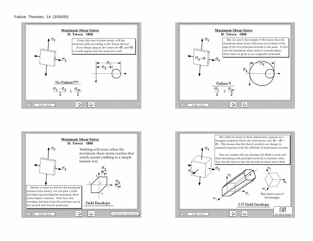
Yielding will occur when the maximum shear stress reaches that which caused yielding in a simple tension test.
Given this case of plane strain, will the material yield according to the Tresca theory? If we simply plug in the values for σ1 and σ2 it would appear that the material is safe.
Maximum Shear StressH. Tresca 1868
Hide Text5 4
Yielding will occur when the maximum shear stress reaches that which caused yielding in a simple tension test.
But we aren't that simple !!! We know that the maximum shear stress will occur out of plane if the sign of the two principal stresses is the same. In this case the maximum shear stress is actually about three times as great as we originally estimated.
Maximum Shear StressH. Tresca 1868
Hide Text5 5
Yielding will occur when the maximum shear stress reaches that which caused yielding in a simple tension test.
Similar to what we did for the maximum normal stress theory, we can plot a yield envelope representing the maximum shear stress failure criterion. Note how this envelope deviates from the previous one in the second and fourth quadrants.
Previous Envelope
Maximum Shear StressH. Tresca 1868
Hide Text5 6
Yielding will occur when the maximum shear stress reaches that which caused yielding in a simple tension test.
The yield envelope in three dimensions appears as a hexagon projected down the hydrostatic axis, σ1 = σ2 = σ3. This means that the theory predicts no change in material response with the addition of hydrostatic stresses.
You can confirm this by plotting 3-D Mohr's circle and then increasing each principal stress by a constant value. You should observe that the maximum shear stress does
3D Yield Envelope
Failure Theories: 14 (3/30/00)
Maximum Distortional Energy(R. von Mises, 1913)
Hide Text5 7
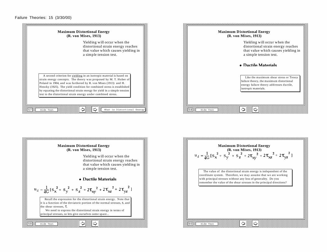
Yielding will occur when the distortional strain energy reaches that value which causes yielding in a simple tension test.
A second criterion for yielding in an isotropic material is based on strain energy concepts. The theory was proposed by M. T. Huber of Poland in 1904, and was furthered by R. von Mises (1913) and H. Hencky (1925). The yield condition for combined stress is established by equating the distortional strain energy for yield in a simple tension test to the distortional strain energy under combined stress.
What is Distortional Energy?
Maximum Distortional Energy(R. von Mises, 1913)
Hide Text5 8
Yielding will occur when the distortional strain energy reaches that value which causes yielding in a simple tension test.
Like the maximum shear stress or Tresca failure theory, the maximum distortional energy failure theory addresses ductile, isotropic materials.
Maximum Distortional Energy(R. von Mises, 1913)
Hide Text5 9
Yielding will occur when the distortional strain energy reaches that value which causes yielding in a simple tension test.
Recall the expression for the distortional strain energy. Note that it is a function of the deviatoric portion of the normal stresses, s, and the shear stresses, τ. We need to express the distortional strain energy in terms of principal stresses, so lets give ourselves some space...
Maximum Distortional Energy(R. von Mises, 1913)
Hide Text6 0
The value of the distortional strain energy is independent of the coordinate system. Therefore, we may assume that we are working with principal stresses without any loss of generality. Do you remember the value of the shear stresses in the principal directions?
Failure Theories: 15 (3/30/00)
Maximum Distortional Energy(R. von Mises, 1913)
Hide Text6 1
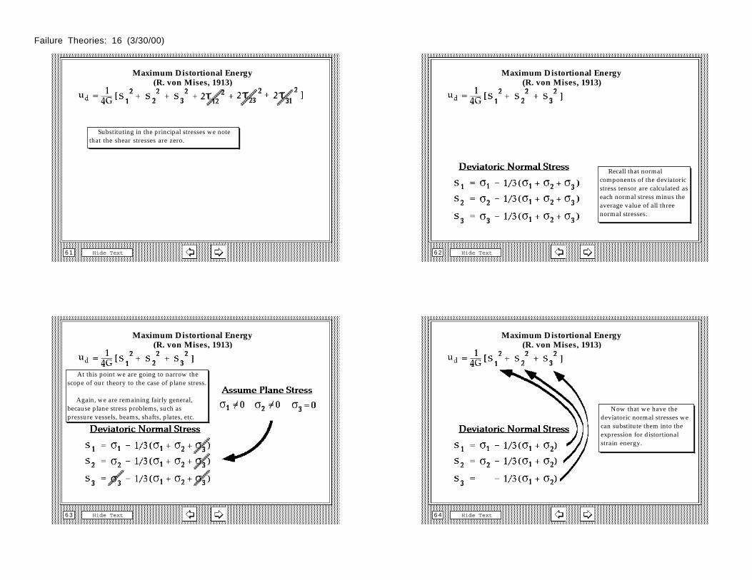
Substituting in the principal stresses we note that the shear stresses are zero.
Maximum Distortional Energy(R. von Mises, 1913)
Hide Text6 2
Recall that normal components of the deviatoric stress tensor are calculated as each normal stress minus the average value of all three normal stresses.
Maximum Distortional Energy(R. von Mises, 1913)
Hide Text6 3
At this point we are going to narrow the scope of our theory to the case of plane stress.
Again, we are remaining fairly general, because plane stress problems, such as pressure vessels, beams, shafts, plates, etc.
Maximum Distortional Energy(R. von Mises, 1913)
Hide Text6 4
Now that we have the deviatoric normal stresses we can substitute them into the expression for distortional strain energy.
Failure Theories: 16 (3/30/00)
Maximum Distortional Energy(R. von Mises, 1913)
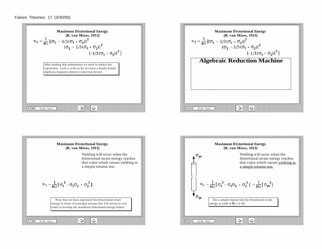
Hide Text6 5
After making this substitution we need to reduce the expression. Luck is with us for we have a handy-dandy algebraic inspector-detector reduction device.
Maximum Distortional Energy(R. von Mises, 1913)
Hide Text6 6
Algebraic Reduction Machine
Maximum Distortional Energy(R. von Mises, 1913)
Hide Text6 7
Yielding will occur when the distortional strain energy reaches that value which causes yielding in a simple tension test.
Now that we have expressed the distortional strain energy in terms of principal stresses (for 2-D stress) we are ready to develop the maximum distortional energy failure
Maximum Distortional Energy(R. von Mises, 1913)
Hide Text6 8
Yielding will occur when the distortional strain energy reaches that value which causes yielding in a simple tension test.
For a simple tension test the distortional strain energy at yield is σys^2/6G.
Failure Theories: 17 (3/30/00)
Maximum Distortional Energy(R. von Mises, 1913)
Hide Text6 9
Yielding will occur when the distortional strain energy reaches that value which causes yielding in a simple tension test.
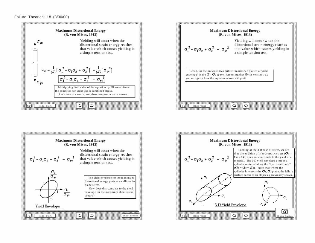
Multiplying both sides of the equation by 6G we arrive at the condition for yield under combined stress. Let's save this result, and then interpret what it means.
Hide Text7 0
Maximum Distortional Energy(R. von Mises, 1913)
Yielding will occur when the distortional strain energy reaches that value which causes yielding in a simple tension test.
Recall, for the previous two failure theories we plotted a "yield envelope" in the σ1, σ2 space. Assuming that σys is constant, do you recognize how the equation above will plot?
Hide Text7 1
Maximum Distortional Energy(R. von Mises, 1913)
Yielding will occur when the distortional strain energy reaches that value which causes yielding in a simple tension test.
The yield envelope for the maximum distortional energy plots as an ellipse for plane stress. How does this compare to the yield envelope for the maximum shear stress theory?
Show Tresca Hide Text7 2
Maximum Distortional Energy(R. von Mises, 1913)
Yielding will occur when the distortional strain energy reaches that value which causes yielding in a simple tension test.
Looking at the 3-D case of stress, we see that the addition of a hydrostatic stress (σ1 = σ2 = σ3) does not contribute to the yield of a material. The 3-D yield envelope plots as a cylinder centered along the "hydrostatic axis" (σ1 = σ2 = σ3). Note that where the cylinder intersects the σ1, σ2 plane, the failure surface becomes an ellipse as previously shown.
3D Yield Envelope
Failure Theories: 18 (3/30/00)
Maximum-Shear vs Maximum Distortional Energyfor Plane Stress
Hide Text7 3
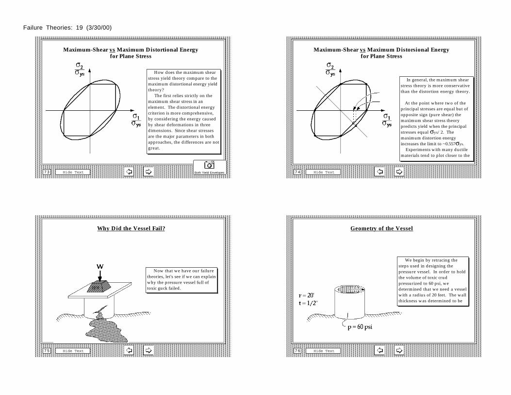
How does the maximum shear stress yield theory compare to the maximum distortional energy yield theory? The first relies strictly on the maximum shear stress in an element. The distortional energy criterion is more comprehensive, by considering the energy caused by shear deformations in three dimensions. Since shear stresses are the major parameters in both approaches, the differences are not great.
Both Yield Envelopes
Maximum-Shear vs Maximum Distorsional Energyfor Plane Stress
Hide Text7 4
In general, the maximum shear stress theory is more conservative than the distortion energy theory.
At the point where two of the principal stresses are equal but of opposite sign (pure shear) the maximum shear stress theory predicts yield when the principal stresses equal σys/2. The maximum distortion energy increases the limit to ~0.557σys. Experiments with many ductile materials tend to plot closer to the
Why Did the Vessel Fail?
Hide Text7 5
Now that we have our failure theories, let's see if we can explain why the pressure vessel full of toxic guck failed.
Geometry of the Vessel
Hide Text7 6
We begin by retracing the steps used in designing the pressure vessel. In order to hold the volume of toxic crud pressurized to 60 psi, we determined that we need a vessel with a radius of 20 feet. The wall thickness was determined to be
Failure Theories: 19 (3/30/00)
Area of Open Top
Hide Text7 7
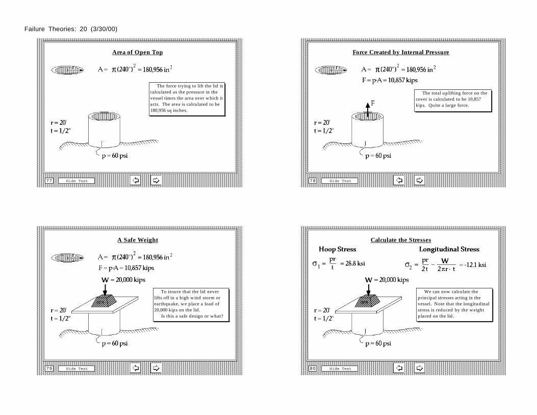
The force trying to lift the lid is calculated as the pressure in the vessel times the area over which it acts. The area is calculated to be 180,956 sq inches.
Force Created by Internal Pressure
Hide Text7 8
The total uplifting force on the cover is calculated to be 10,857 kips. Quite a large force.
A Safe Weight
Hide Text7 9
To insure that the lid never lifts off in a high wind storm or earthquake, we place a load of 20,000 kips on the lid. Is this a safe design or what?
Calculate the Stresses
Hide Text8 0
We can now calculate the principal stresses acting in the vessel. Note that the longitudinal stress is reduced by the weight placed on the lid.
Failure Theories: 20 (3/30/00)
Normalize by the Yield Stress
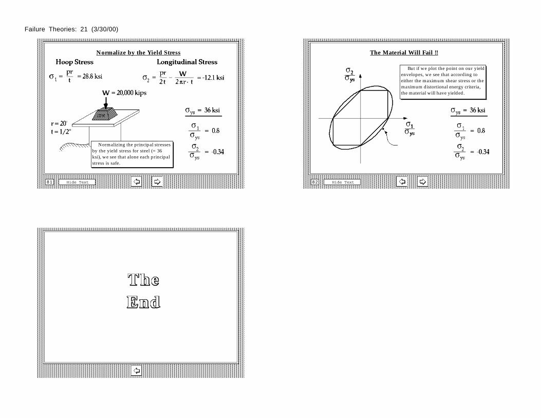
Hide Text8 1
Normalizing the principal stresses by the yield stress for steel (= 36 ksi), we see that alone each principal stress is safe.
The Material Will Fail !!
Hide Text8 2
But if we plot the point on our yield envelopes, we see that according to either the maximum shear stress or the maximum distortional energy criteria, the material will have yielded.
Hide Text8 3
Failure Theories: 21 (3/30/00)