Embed Size (px)
Citation preview
MECH 4240 Midterm Design Review: Variable Volume Pressure Vessel
Corp 11 – AMRDEC
Summer 2016
July 5th, 2016
Industrial Sponsors – Taylor Owens and Matt Triplett
Technical Advisor – Dr. David Beale
Manager – Savanna Earnest
Scribe – Jake Hamlett
Chris Boehme
Ryan Ebbinga
Daniel Cape
Bo Buchanan
2
ABSTRACT The Aviation and Missile Research, Development and Engineering Center (AMRDEC) has a hydrostatic pressure testing system that uses a PI controller to control the amount of water inside the test subject and therefore control the pressure. This PI controller is not operating to the standards required by AMRDEC and needs to be adjusted. To calculate what the ideal values for the constants in the controller are, data for many sizes of pressure vessels is needed. A design for a variable volume pressure vessel was then requested. The design process and the final design for this vessel are outlined in this report. The final design operates on the method of water displacement. Nine concentric cylinders will displace water inside the vessel, allowing volumes starting at half a gallon and stepping up by half a gallon up to 25 gallons. There will be spaces in between the cylinders to allow the water to flow between them, equalizing the pressure on all sides of the cylinders. The end caps of the pressure vessel will be removable to allow the cylinders to be arranged as needed. The body of the vessel will be constructed of 7075-T6 aluminum, with an outer radius of 14”, an inner radius of 10” and 6.5’ long. This will weigh roughly 650 lb. with the end caps.
3
TABLE OF CONTENTS
Introduction ...................................................................................................................................... ……..4 Design Discussion ...................................................................................................................................... 5
Mission Objective ......................................................................................................................... 5 Architectural Design Development .............................................................................................. 5 Brainstorming ....................................................................................................................... 5 Design Decision ...................................................................................................................... 6 Requirements ................................................................................................................................ 7 Concept of Operations .................................................................................................................. 8 System Verification and Validation ............................................................................................... 8 Interfaces ...................................................................................................................................... 8 Mission Environment .................................................................................................................... 9 Risk Management ......................................................................................................................... 9 Configuration Management and Documentation ........................................................................ 9
Subsystems Design Engineering ................................................................................................................. 9 Displacement Mechanism……………………………………………………………………………………………………….. 9 End Cap ...................................................................................................................................... 10 Vessel Material and Size ............................................................................................................ 10 Project Management............................................................................................................................... 12 Conclusions.............................................................................................................................................. 13 Table of Figures
Figure 1: Basic Intensifier Schematic Figure 2: PI Block Diagram .......................................................... 4 Figure 3: System Schematic .......................................................................................................................... 4 Figure 4: Brainstorming Designs ................................................................................................................... 5 Figure 5: Cylinder Deformation ..................................................................................................................... 6 Figure 7: 15 Gallon Volume ........................................................................................................................... 7 Figure 9: 25 Gallon Volume ........................................................................................................................... 7 Figure 8: 10 Gallon Volume ........................................................................................................................... 7 Figure 10: Assembly ...................................................................................................................................... 7 Figure 6: Cylinder Sizes .................................................................................. Error! Bookmark not defined. Figure 11: Initial End Cap Design................................................................................................................. 10 Figure 12: 6061 Aluminum Results ................................................................ Error! Bookmark not defined. Figure 13: A36 Steel Results ........................................................................... Error! Bookmark not defined. Figure 14: 7075-T6 Aluminum Results ........................................................... Error! Bookmark not defined. Table of Tables
Table 1: Design Requirements ...................................................................................................................... 5 Table 2: Decision Matrix ............................................................................................................................... 7 Table 3: Project Milestone Outline ............................................................................................................. 12 Table 4: Preliminary Budget ........................................................................................................................ 13
4
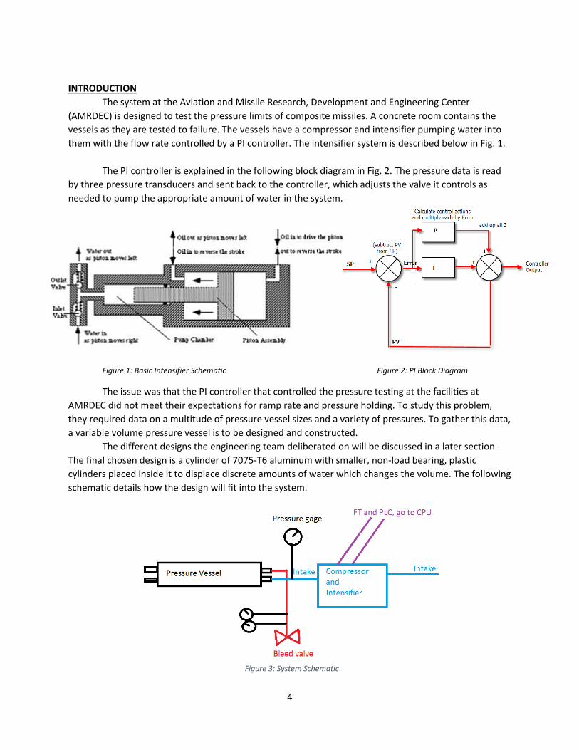
INTRODUCTION The system at the Aviation and Missile Research, Development and Engineering Center (AMRDEC) is designed to test the pressure limits of composite missiles. A concrete room contains the vessels as they are tested to failure. The vessels have a compressor and intensifier pumping water into them with the flow rate controlled by a PI controller. The intensifier system is described below in Fig. 1.
The PI controller is explained in the following block diagram in Fig. 2. The pressure data is read by three pressure transducers and sent back to the controller, which adjusts the valve it controls as needed to pump the appropriate amount of water in the system.
Figure 1: Basic Intensifier Schematic Figure 2: PI Block Diagram
The issue was that the PI controller that controlled the pressure testing at the facilities at AMRDEC did not meet their expectations for ramp rate and pressure holding. To study this problem, they required data on a multitude of pressure vessel sizes and a variety of pressures. To gather this data, a variable volume pressure vessel is to be designed and constructed.
The different designs the engineering team deliberated on will be discussed in a later section. The final chosen design is a cylinder of 7075-T6 aluminum with smaller, non-load bearing, plastic cylinders placed inside it to displace discrete amounts of water which changes the volume. The following schematic details how the design will fit into the system.
Figure 3: System Schematic
5
DESIGN DISCUSSION Mission Objective The overall objective of this project is to create a variable volume pressure vessel to perform hydrostatic pressure tests on and gather the test data to refine the existing pressure testing controls. Architectural Design Development Brainstorming The first step the engineering team took to create a working design was to look at the desired requirements for the system. The requirements are listed below in Table 1.
Table 1: Design Requirements
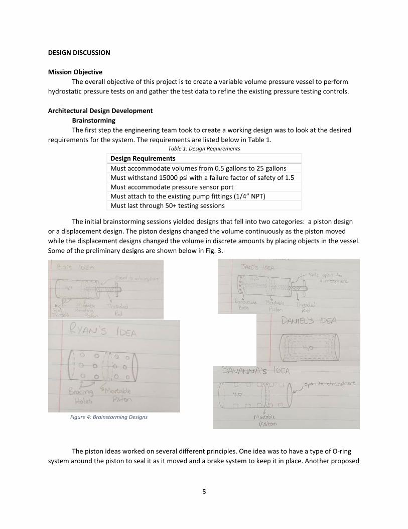
The initial brainstorming sessions yielded designs that fell into two categories: a piston design or a displacement design. The piston designs changed the volume continuously as the piston moved while the displacement designs changed the volume in discrete amounts by placing objects in the vessel. Some of the preliminary designs are shown below in Fig. 3.
The piston ideas worked on several different principles. One idea was to have a type of O-ring
system around the piston to seal it as it moved and a brake system to keep it in place. Another proposed
Design Requirements Must accommodate volumes from 0.5 gallons to 25 gallons Must withstand 15000 psi with a failure factor of safety of 1.5 Must accommodate pressure sensor port Must attach to the existing pump fittings (1/4” NPT) Must last through 50+ testing sessions
Figure 4: Brainstorming Designs
6
threading the inside of the cylinder and threading the outside of the piston so that the piston moved like a screw. The displacement idea was to place several concentric cylinders inside the outer cylindrical pressure vessel to displace water. The cylinders themselves would not attach to the pressure vessel, allowing the water to move throughout the vessel. This would mean that the cylinders are experiencing balanced pressure on all sides and therefore very little stress besides compression. Design Decision During further discussion, the piston ideas were narrowed to a threaded design idea, as a braking system seemed unnecessarily complicated and would take more time to design and execute than a threaded system. Basic analysis was done on each design to determine if either could be easily eliminated. The shear force on the threads was analyzed using an estimated radius of 5 inches and the following formula (Eqn. (1)) from Machinery’s Handbooks and it was determined that a 5-2 Acme thread would not result in any shearing failure, i.e. stripping, of the threads.
(1)
The main issue with the threaded design was how to seal the piston to make the chamber
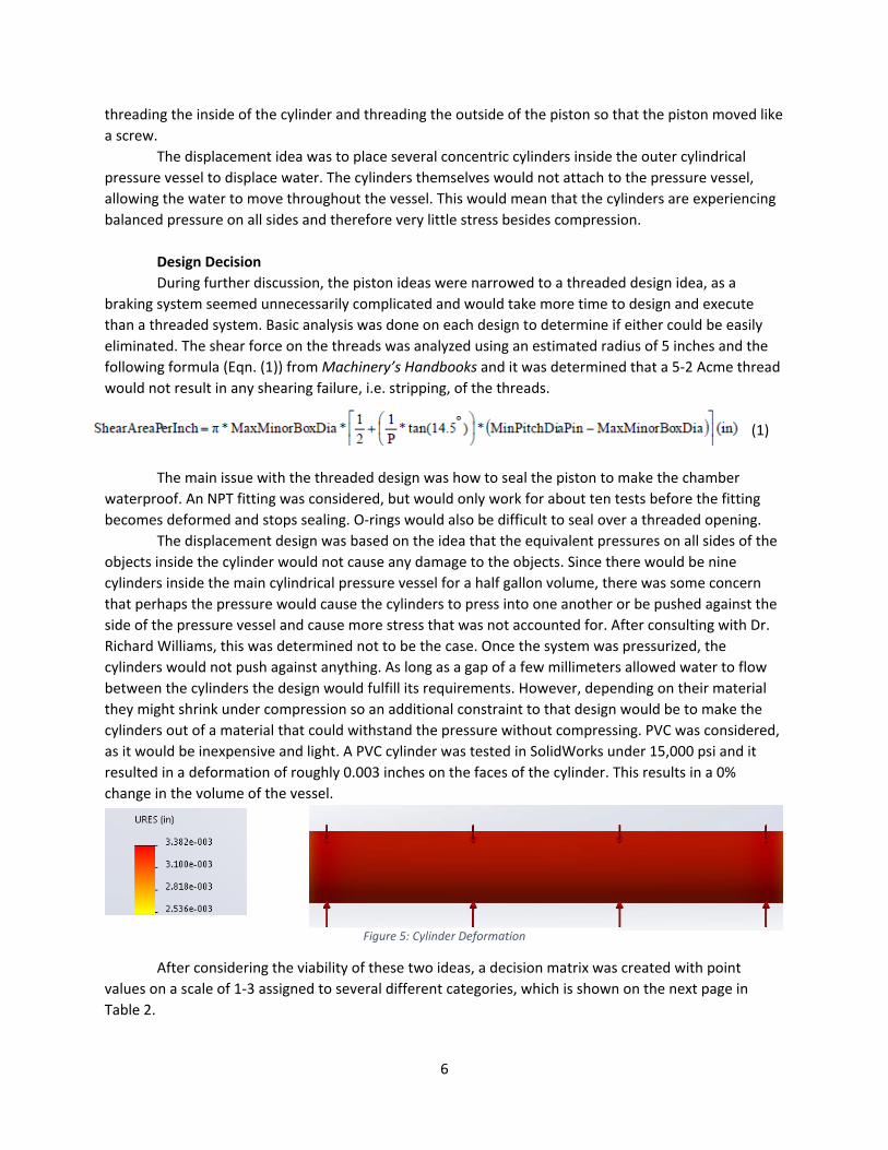
waterproof. An NPT fitting was considered, but would only work for about ten tests before the fitting becomes deformed and stops sealing. O-rings would also be difficult to seal over a threaded opening. The displacement design was based on the idea that the equivalent pressures on all sides of the objects inside the cylinder would not cause any damage to the objects. Since there would be nine cylinders inside the main cylindrical pressure vessel for a half gallon volume, there was some concern that perhaps the pressure would cause the cylinders to press into one another or be pushed against the side of the pressure vessel and cause more stress that was not accounted for. After consulting with Dr. Richard Williams, this was determined not to be the case. Once the system was pressurized, the cylinders would not push against anything. As long as a gap of a few millimeters allowed water to flow between the cylinders the design would fulfill its requirements. However, depending on their material they might shrink under compression so an additional constraint to that design would be to make the cylinders out of a material that could withstand the pressure without compressing. PVC was considered, as it would be inexpensive and light. A PVC cylinder was tested in SolidWorks under 15,000 psi and it resulted in a deformation of roughly 0.003 inches on the faces of the cylinder. This results in a 0% change in the volume of the vessel.
After considering the viability of these two ideas, a decision matrix was created with point
values on a scale of 1-3 assigned to several different categories, which is shown on the next page in Table 2.
Figure 5: Cylinder Deformation
7
Table 2: Decision Matrix
Ease of Construction
Meets Volume Requirements
Meets Pressure Requirements
Sealing Capabilities
Volume Change Speed
Weight Cost Total
Threaded 1 3 3 2 3 2 2 16 Displacement 3 2 3 3 2 3 3 19
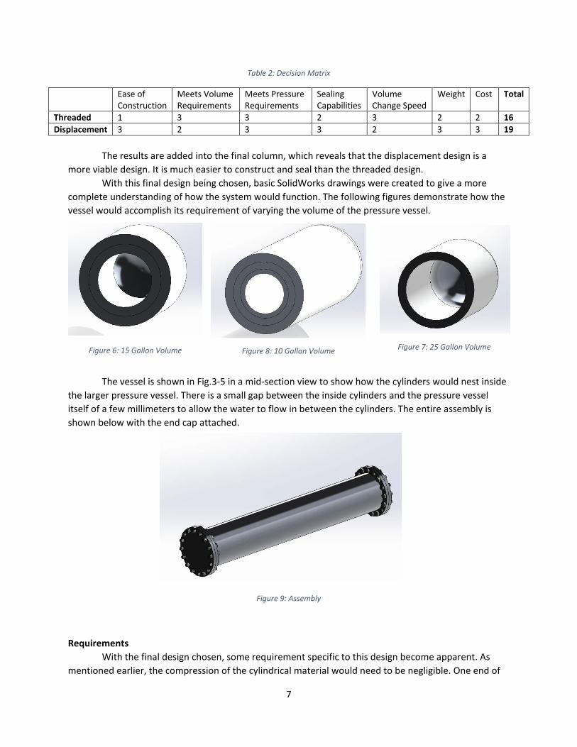
The results are added into the final column, which reveals that the displacement design is a more viable design. It is much easier to construct and seal than the threaded design. With this final design being chosen, basic SolidWorks drawings were created to give a more complete understanding of how the system would function. The following figures demonstrate how the vessel would accomplish its requirement of varying the volume of the pressure vessel.
The vessel is shown in Fig.3-5 in a mid-section view to show how the cylinders would nest inside the larger pressure vessel. There is a small gap between the inside cylinders and the pressure vessel itself of a few millimeters to allow the water to flow in between the cylinders. The entire assembly is shown below with the end cap attached.
Requirements With the final design chosen, some requirement specific to this design become apparent. As mentioned earlier, the compression of the cylindrical material would need to be negligible. One end of
Figure 8: 10 Gallon Volume Figure 6: 15 Gallon Volume Figure 7: 25 Gallon Volume
Figure 9: Assembly
8
the pressure vessel would also need to be easily removed to be able to change the volume between tests. An outline of all the requirement is shown below. System Requirements
• Must accommodate volumes from 0.5 gallons to 25 gallons o The cylinders to adjust the volume must be incompressible
The end of the pressure vessel must be removable to adjust the cylinders • Must withstand 15000 psi with a failure factor of safety of 1.5 • Must accommodate pressure sensor port
o The outermost cylinder must not interfere with the pressure sensor • Must attach to the existing pump fittings (1/4” NPT) • Must last through 50+ testing sessions
o The cylinders must also last through testing as well as the pressure vessel
Concept of Operations To fulfill these requirements, the system will follow these steps. Initially, the pressure vessel end cap will be taken off and the number of cylinders needed will be inserted. The end cap will then be bolted back on. The intake and bleed valve will be attached to the fittings on the end. The pressure vessel will then be filled with water and pressurized to the necessary pressure for that test. Once the test is finished, the system will depressurize using the bleed valve. The end cap can then be removed and the volume can be adjusted for the next test. System Verification and Validation To test the volume requirement, the cylinders can be added to a discrete volume. The same volume of water can be added to check that the calculated volumes match the amount of water that fills the system. The pressure sensor can be verified by simply installing it at the pressure sensor port and running the sensor to check that it is functioning properly. Similarly, the fittings can be checked by testing them with 1/4” NPT and seeing if they attach properly. The bolts for the end plates can be tested by subjecting them to the previously calculated force that they will be holding. To initially test the sealing of this model, the vessel can be filled with unpressurized water to check for any leaks. Once this is complete, the design can be tested at the AMRDEC facility to the maximum pressure to ensure the system does not leak. This will also ensure that the cylinders do not compress, since if the volume changed the pressure would decrease inside the vessel and this would be shown in the plot of the pressurization. Testing at the AMRDEC facility will also validate that the system functions as needed. Interfaces The mechanical interfaces of the pressure vessel are the ¼” NPT fittings where the water is pumped in and drained out. The only possible electrical component on the vessel is the pressure sensor,
9
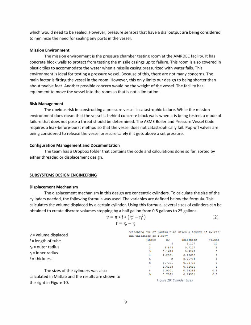
which would need to be sealed. However, pressure sensors that have a dial output are being considered to minimize the need for sealing any ports in the vessel. Mission Environment The mission environment is the pressure chamber testing room at the AMRDEC facility. It has concrete block walls to protect from testing the missile casings up to failure. This room is also covered in plastic tiles to accommodate the water when a missile casing pressurized with water fails. This environment is ideal for testing a pressure vessel. Because of this, there are not many concerns. The main factor is fitting the vessel in the room. However, this only limits our design to being shorter than about twelve feet. Another possible concern would be the weight of the vessel. The facility has equipment to move the vessel into the room so that is not a limitation. Risk Management The obvious risk in constructing a pressure vessel is catastrophic failure. While the mission environment does mean that the vessel is behind concrete block walls when it is being tested, a mode of failure that does not pose a threat should be determined. The ASME Boiler and Pressure Vessel Code requires a leak-before-burst method so that the vessel does not catastrophically fail. Pop-off valves are being considered to release the vessel pressure safely if it gets above a set pressure. Configuration Management and Documentation The team has a Dropbox folder that contains the code and calculations done so far, sorted by either threaded or displacement design. SUBSYSTEMS DESIGN ENGINEERING Displacement Mechanism The displacement mechanism in this design are concentric cylinders. To calculate the size of the cylinders needed, the following formula was used. The variables are defined below the formula. This calculates the volume displaced by a certain cylinder. Using this formula, several sizes of cylinders can be obtained to create discrete volumes stepping by a half gallon from 0.5 gallons to 25 gallons. 𝑣𝑣 = 𝜋𝜋 ∗ 𝑙𝑙 ∗ �𝑟𝑟𝑜𝑜2 − 𝑟𝑟𝑖𝑖2� (2)
𝑡𝑡 = 𝑟𝑟𝑜𝑜 − 𝑟𝑟𝑖𝑖 v = volume displaced l = length of tube ro = outer radius ri = inner radius t = thickness
The sizes of the cylinders was also calculated in Matlab and the results are shown to the right in Figure 10.
Figure 10: Cylinder Sizes
10
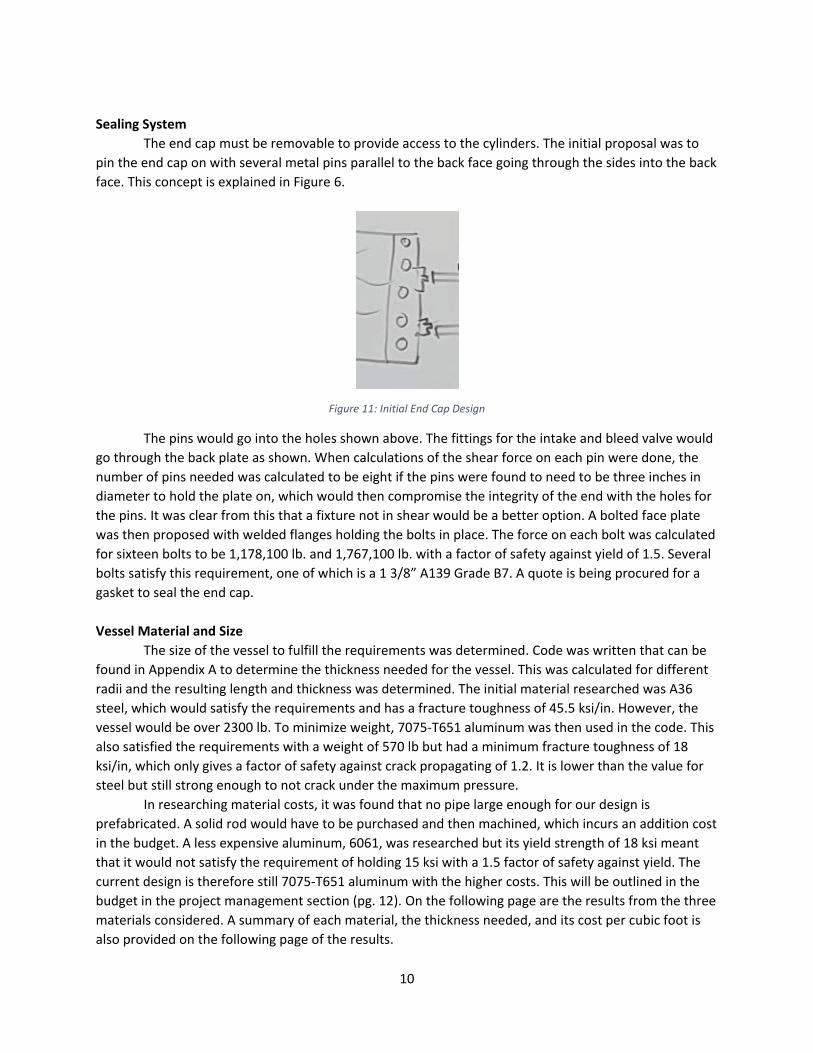
Sealing System The end cap must be removable to provide access to the cylinders. The initial proposal was to pin the end cap on with several metal pins parallel to the back face going through the sides into the back face. This concept is explained in Figure 6.
Figure 11: Initial End Cap Design
The pins would go into the holes shown above. The fittings for the intake and bleed valve would go through the back plate as shown. When calculations of the shear force on each pin were done, the number of pins needed was calculated to be eight if the pins were found to need to be three inches in diameter to hold the plate on, which would then compromise the integrity of the end with the holes for the pins. It was clear from this that a fixture not in shear would be a better option. A bolted face plate was then proposed with welded flanges holding the bolts in place. The force on each bolt was calculated for sixteen bolts to be 1,178,100 lb. and 1,767,100 lb. with a factor of safety against yield of 1.5. Several bolts satisfy this requirement, one of which is a 1 3/8” A139 Grade B7. A quote is being procured for a gasket to seal the end cap. Vessel Material and Size
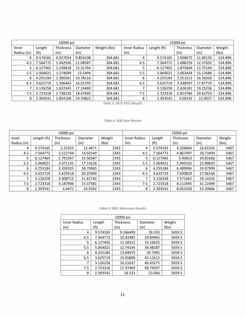
The size of the vessel to fulfill the requirements was determined. Code was written that can be found in Appendix A to determine the thickness needed for the vessel. This was calculated for different radii and the resulting length and thickness was determined. The initial material researched was A36 steel, which would satisfy the requirements and has a fracture toughness of 45.5 ksi/in. However, the vessel would be over 2300 lb. To minimize weight, 7075-T651 aluminum was then used in the code. This also satisfied the requirements with a weight of 570 lb but had a minimum fracture toughness of 18 ksi/in, which only gives a factor of safety against crack propagating of 1.2. It is lower than the value for steel but still strong enough to not crack under the maximum pressure.
In researching material costs, it was found that no pipe large enough for our design is prefabricated. A solid rod would have to be purchased and then machined, which incurs an addition cost in the budget. A less expensive aluminum, 6061, was researched but its yield strength of 18 ksi meant that it would not satisfy the requirement of holding 15 ksi with a 1.5 factor of safety against yield. The current design is therefore still 7075-T651 aluminum with the higher costs. This will be outlined in the budget in the project management section (pg. 12). On the following page are the results from the three materials considered. A summary of each material, the thickness needed, and its cost per cubic foot is also provided on the following page of the results.
11
Table 3: 7075-T651 Results
Table 4: A36 Steel Results
Table 5: 6061 Aluminum Results
10000 psi Inner Radius (in)
Length (ft)
Thickness (in)
Diameter (in)
Weight (lbs)
4 9.574165 9.266499 26.533 5659.5 4.5 7.564772 10.42481 29.84962 5659.5
5 6.127465 11.58312 33.16625 5659.5 5.5 5.064021 12.74144 36.48287 5659.5
6 4.255184 13.89975 39.7995 5659.5 6.5 3.625719 15.05806 43.11612 5659.5
7 3.126258 16.21637 46.43275 5659.5 7.5 2.723318 17.37469 49.74937 5659.5
8 2.393541 18.533 53.066 5659.5
10000 psi 15000 psi Inner Radius (in)
Length (ft)
Thickness (in)
Diameter (in)
Weight (lbs) Inner Radius (in)
Length (ft) Thickness (in)
Diameter (in)
Weight (lbs)
4 9.574165 0.927054 9.854108 304.681 4 9.574165 1.500675 11.00135 524.896 4.5 7.564772 1.042936 11.08587 304.681 4.5 7.564772 1.688259 12.37652 524.896
5 6.127465 1.158818 12.31764 304.681 5 6.127465 1.875844 13.75169 524.896 5.5 5.064021 1.274699 13.5494 304.681 5.5 5.064021 2.063428 15.12686 524.896
6 4.255184 1.390581 14.78116 304.681 6 4.255184 2.251013 16.50203 524.896 6.5 3.625719 1.506463 16.01293 304.681 6.5 3.625719 2.438597 17.87719 524.896
7 3.126258 1.622345 17.24469 304.681 7 3.126258 2.626181 19.25236 524.896 7.5 2.723318 1.738226 18.47645 304.681 7.5 2.723318 2.813766 20.62753 524.896
8 2.393541 1.854108 19.70822 304.681 8 2.393541 3.00135 22.0027 524.896
10000 psi 15000 psi Inner Radius (in)
Length (ft) Thickness (in)
Diameter (in)
Weight (lbs)
Inner Radius (in)
Length (ft)
Thickness (in)
Diameter (in)
Weight (lbs)
4 9.574165 2.23355 12.4671 2343 4 9.574165 4.326664 16.65333 5467 4.5 7.564772 2.512744 14.02549 2343 4.5 7.564772 4.867497 18.73499 5467
5 6.127465 2.791937 15.58387 2343 5 6.127465 5.40833 20.81666 5467 5.5 5.064021 3.071131 17.14226 2343 5.5 5.064021 5.949163 22.89833 5467
6 4.255184 3.350325 18.70065 2343 6 4.255184 6.489996 24.97999 5467 6.5 3.625719 3.629518 20.25904 2343 6.5 3.625719 7.030829 27.06166 5467
7 3.126258 3.908712 21.81742 2343 7 3.126258 7.571662 29.14332 5467 7.5 2.723318 4.187906 23.37581 2343 7.5 2.723318 8.112495 31.22499 5467
8 2.393541 4.4671 24.9342 2343 8 2.393541 8.653328 33.30666 5467
12
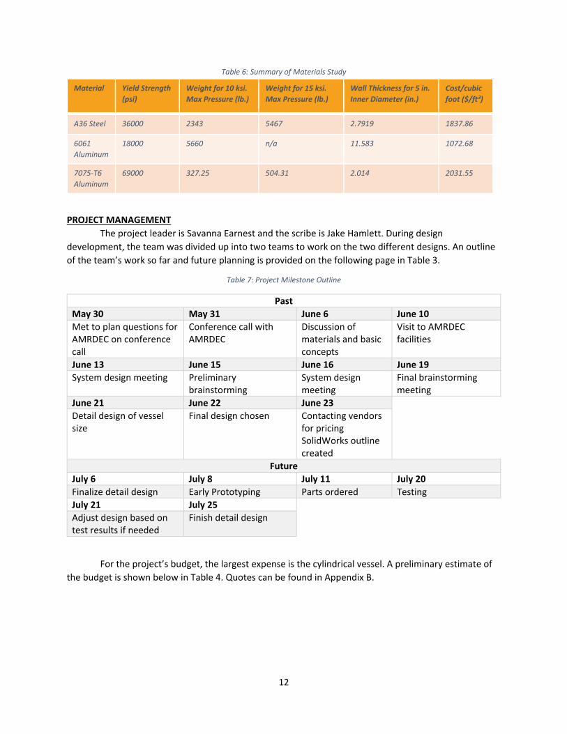
Table 6: Summary of Materials Study
PROJECT MANAGEMENT The project leader is Savanna Earnest and the scribe is Jake Hamlett. During design development, the team was divided up into two teams to work on the two different designs. An outline of the team’s work so far and future planning is provided on the following page in Table 3.
Table 7: Project Milestone Outline
Past May 30 May 31 June 6 June 10 Met to plan questions for AMRDEC on conference call
Conference call with AMRDEC
Discussion of materials and basic concepts
Visit to AMRDEC facilities
June 13 June 15 June 16 June 19 System design meeting Preliminary
brainstorming System design meeting
Final brainstorming meeting
June 21 June 22 June 23 Detail design of vessel size
Final design chosen Contacting vendors for pricing SolidWorks outline created
Future July 6 July 8 July 11 July 20 Finalize detail design Early Prototyping Parts ordered Testing July 21 July 25 Adjust design based on test results if needed
Finish detail design
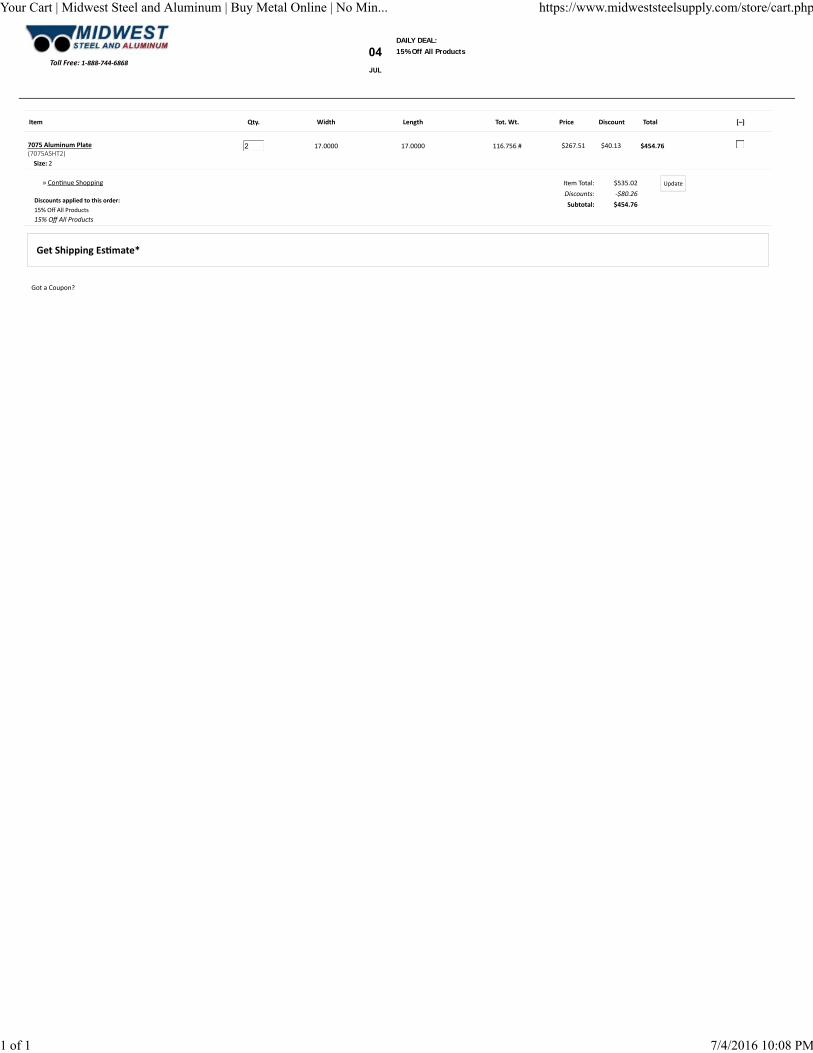
For the project’s budget, the largest expense is the cylindrical vessel. A preliminary estimate of the budget is shown below in Table 4. Quotes can be found in Appendix B.
Material Yield Strength (psi)
Weight for 10 ksi. Max Pressure (lb.)
Weight for 15 ksi. Max Pressure (lb.)
Wall Thickness for 5 in. Inner Diameter (in.)
Cost/cubic foot ($/ft³)
A36 Steel 36000 2343 5467 2.7919 1837.86
6061 Aluminum
18000 5660 n/a 11.583 1072.68
7075-T6 Aluminum
69000 327.25 504.31 2.014 2031.55
13
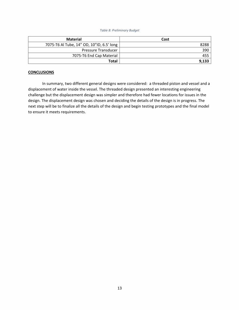
Table 8: Preliminary Budget
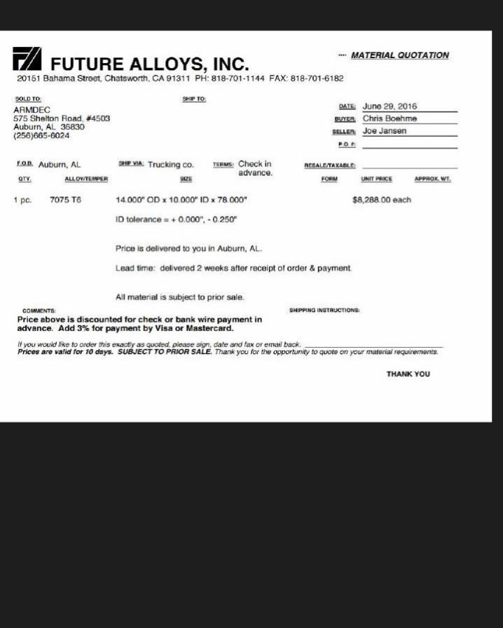
Material Cost 7075-T6 Al Tube, 14” OD, 10”ID, 6.5’ long 8288
Pressure Transducer 390 7075-T6 End Cap Material 455
Total 9,133 CONCLUSIONS In summary, two different general designs were considered: a threaded piston and vessel and a displacement of water inside the vessel. The threaded design presented an interesting engineering challenge but the displacement design was simpler and therefore had fewer locations for issues in the design. The displacement design was chosen and deciding the details of the design is in progress. The next step will be to finalize all the details of the design and begin testing prototypes and the final model to ensure it meets requirements.
14
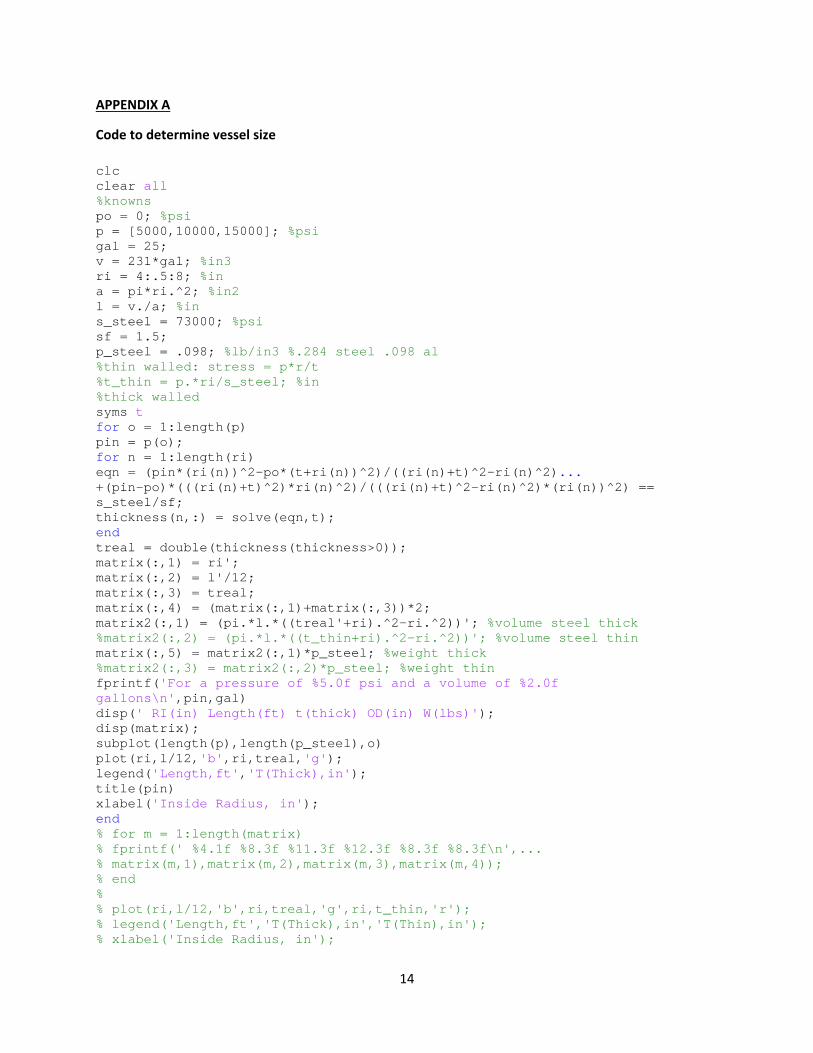
APPENDIX A
Code to determine vessel size
clc clear all %knowns po = 0; %psi p = [5000,10000,15000]; %psi gal = 25; v = 231*gal; %in3 ri = 4:.5:8; %in a = pi*ri.^2; %in2 l = v./a; %in s_steel = 73000; %psi sf = 1.5; p_steel = .098; %lb/in3 %.284 steel .098 al %thin walled: stress = p*r/t %t_thin = p.*ri/s_steel; %in %thick walled syms t for o = 1:length(p) pin = p(o); for n = 1:length(ri) eqn = (pin*(ri(n))^2-po*(t+ri(n))^2)/((ri(n)+t)^2-ri(n)^2)... +(pin-po)*(((ri(n)+t)^2)*ri(n)^2)/(((ri(n)+t)^2-ri(n)^2)*(ri(n))^2) == s_steel/sf; thickness(n,:) = solve(eqn,t); end treal = double(thickness(thickness>0)); matrix(:,1) = ri'; matrix(:,2) = l'/12; matrix(:,3) = treal; matrix(:,4) = (matrix(:,1)+matrix(:,3))*2; matrix2(:,1) = (pi.*l.*((treal'+ri).^2-ri.^2))'; %volume steel thick %matrix2(:,2) = (pi.*l.*((t_thin+ri).^2-ri.^2))'; %volume steel thin matrix(:,5) = matrix2(:,1)*p_steel; %weight thick %matrix2(:,3) = matrix2(:,2)*p_steel; %weight thin fprintf('For a pressure of %5.0f psi and a volume of %2.0f gallons\n',pin,gal) disp(' RI(in) Length(ft) t(thick) OD(in) W(lbs)'); disp(matrix); subplot(length(p),length(p_steel),o) plot(ri,l/12,'b',ri,treal,'g'); legend('Length,ft','T(Thick),in'); title(pin) xlabel('Inside Radius, in'); end % for m = 1:length(matrix) % fprintf(' %4.1f %8.3f %11.3f %12.3f %8.3f %8.3f\n',... % matrix(m,1),matrix(m,2),matrix(m,3),matrix(m,4)); % end % % plot(ri,l/12,'b',ri,treal,'g',ri,t_thin,'r'); % legend('Length,ft','T(Thick),in','T(Thin),in'); % xlabel('Inside Radius, in');
15
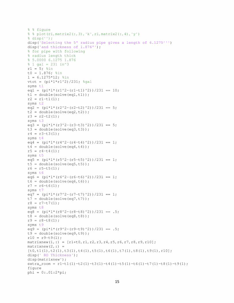
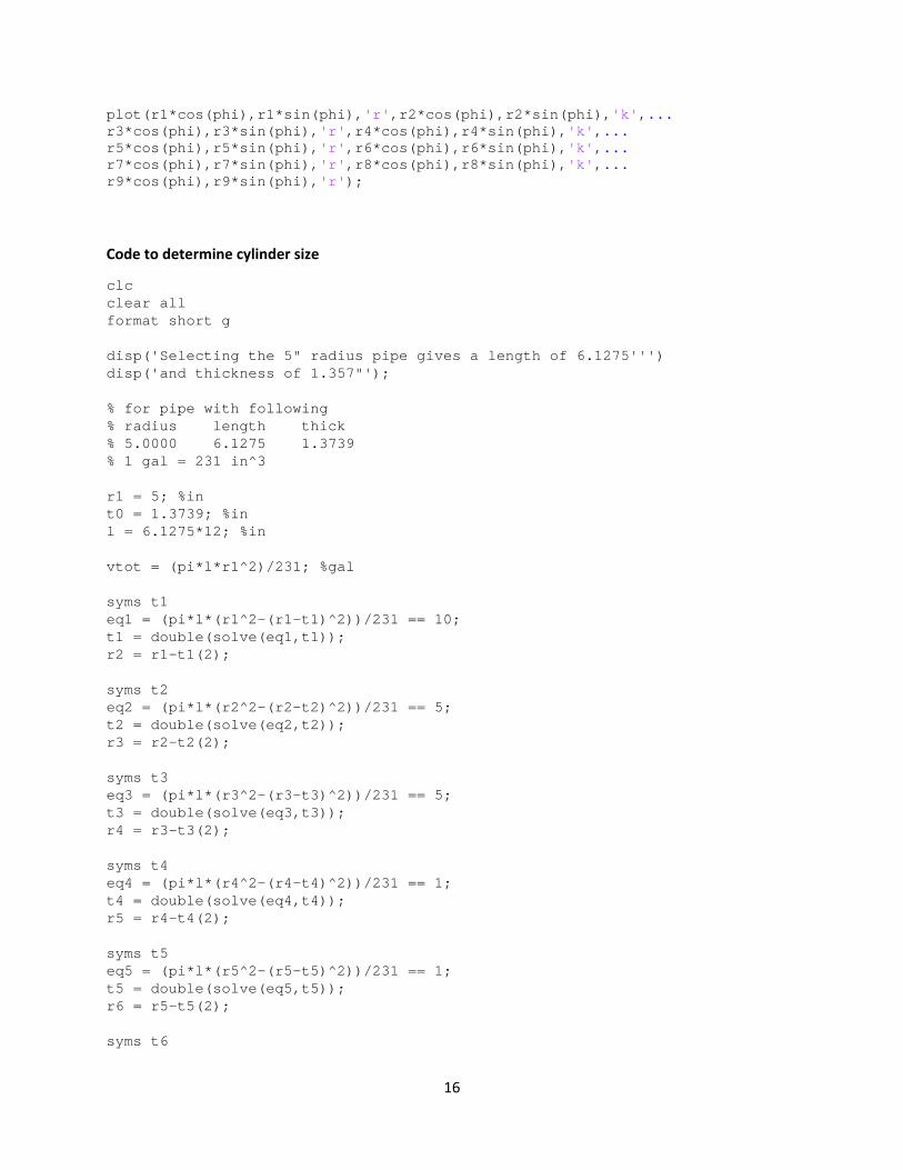
% % figure % % plot(ri,matrix2(:,3),'k',ri,matrix2(:,4),'y') % disp(''); disp('Selecting the 5" radius pipe gives a length of 6.1275''') disp('and thickness of 1.876"'); % for pipe with following % radius length thick % 5.0000 6.1275 1.876 % 1 gal = 231 in^3 r1 = 5; %in t0 = 1.876; %in l = 6.1275*12; %in vtot = (pi*l*r1^2)/231; %gal syms t1 eq1 = (pi*l*(r1^2-(r1-t1)^2))/231 == 10; t1 = double(solve(eq1,t1)); r2 = r1-t1(1); syms t2 eq2 = (pi*l*(r2^2-(r2-t2)^2))/231 == 5; t2 = double(solve(eq2,t2)); r3 = r2-t2(1); syms t3 eq3 = (pi*l*(r3^2-(r3-t3)^2))/231 == 5; t3 = double(solve(eq3,t3)); r4 = r3-t3(1); syms t4 eq4 = (pi*l*(r4^2-(r4-t4)^2))/231 == 1; t4 = double(solve(eq4,t4)); r5 = r4-t4(1); syms t5 eq5 = (pi*l*(r5^2-(r5-t5)^2))/231 == 1; t5 = double(solve(eq5,t5)); r6 = r5-t5(1); syms t6 eq6 = (pi*l*(r6^2-(r6-t6)^2))/231 == 1; t6 = double(solve(eq6,t6)); r7 = r6-t6(1); syms t7 eq7 = (pi*l*(r7^2-(r7-t7)^2))/231 == 1; t7 = double(solve(eq7,t7)); r8 = r7-t7(1); syms t8 eq8 = (pi*l*(r8^2-(r8-t8)^2))/231 == .5; t8 = double(solve(eq8,t8)); r9 = r8-t8(1); syms t9 eq9 = (pi*l*(r9^2-(r9-t9)^2))/231 == .5; t9 = double(solve(eq9,t9)); r10 = r9-t9(1); matrixnew(1,:) = [r1+t0,r1,r2,r3,r4,r5,r6,r7,r8,r9,r10]; matrixnew(2,:) = [t0,t1(1),t2(1),t3(1),t4(1),t5(1),t6(1),t7(1),t8(1),t9(1),r10]; disp(' RO Thickness'); disp(matrixnew'); extra_room = r1-t1(1)-t2(1)-t3(1)-t4(1)-t5(1)-t6(1)-t7(1)-t8(1)-t9(1); figure phi = 0:.01:2*pi;
16
plot(r1*cos(phi),r1*sin(phi),'r',r2*cos(phi),r2*sin(phi),'k',... r3*cos(phi),r3*sin(phi),'r',r4*cos(phi),r4*sin(phi),'k',... r5*cos(phi),r5*sin(phi),'r',r6*cos(phi),r6*sin(phi),'k',... r7*cos(phi),r7*sin(phi),'r',r8*cos(phi),r8*sin(phi),'k',... r9*cos(phi),r9*sin(phi),'r');
Code to determine cylinder size
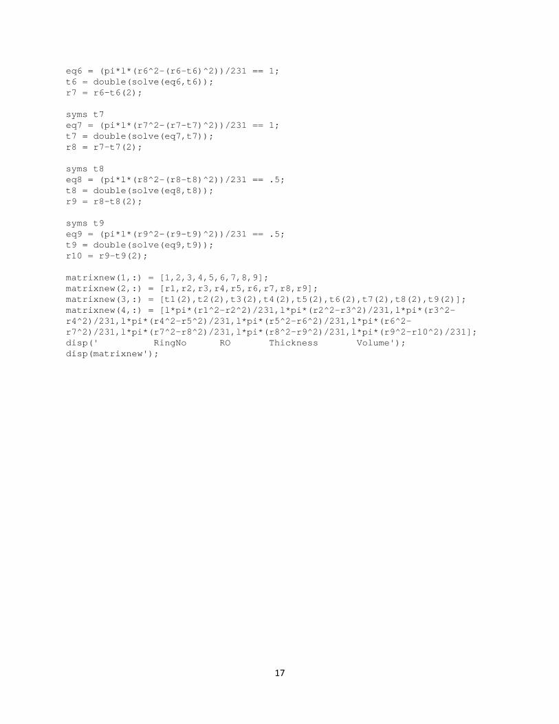
clc clear all format short g disp('Selecting the 5" radius pipe gives a length of 6.1275''') disp('and thickness of 1.357"'); % for pipe with following % radius length thick % 5.0000 6.1275 1.3739 % 1 gal = 231 in^3 r1 = 5; %in t0 = 1.3739; %in l = 6.1275*12; %in vtot = (pi*l*r1^2)/231; %gal syms t1 eq1 = (pi*l*(r1^2-(r1-t1)^2))/231 == 10; t1 = double(solve(eq1,t1)); r2 = r1-t1(2); syms t2 eq2 = (pi*l*(r2^2-(r2-t2)^2))/231 == 5; t2 = double(solve(eq2,t2)); r3 = r2-t2(2); syms t3 eq3 = (pi*l*(r3^2-(r3-t3)^2))/231 == 5; t3 = double(solve(eq3,t3)); r4 = r3-t3(2); syms t4 eq4 = (pi*l*(r4^2-(r4-t4)^2))/231 == 1; t4 = double(solve(eq4,t4)); r5 = r4-t4(2); syms t5 eq5 = (pi*l*(r5^2-(r5-t5)^2))/231 == 1; t5 = double(solve(eq5,t5)); r6 = r5-t5(2); syms t6
17
eq6 = (pi*l*(r6^2-(r6-t6)^2))/231 == 1; t6 = double(solve(eq6,t6)); r7 = r6-t6(2); syms t7 eq7 = (pi*l*(r7^2-(r7-t7)^2))/231 == 1; t7 = double(solve(eq7,t7)); r8 = r7-t7(2); syms t8 eq8 = (pi*l*(r8^2-(r8-t8)^2))/231 == .5; t8 = double(solve(eq8,t8)); r9 = r8-t8(2); syms t9 eq9 = (pi*l*(r9^2-(r9-t9)^2))/231 == .5; t9 = double(solve(eq9,t9)); r10 = r9-t9(2); matrixnew(1,:) = [1,2,3,4,5,6,7,8,9]; matrixnew(2,:) = [r1,r2,r3,r4,r5,r6,r7,r8,r9]; matrixnew(3,:) = [t1(2),t2(2),t3(2),t4(2),t5(2),t6(2),t7(2),t8(2),t9(2)]; matrixnew(4,:) = [l*pi*(r1^2-r2^2)/231,l*pi*(r2^2-r3^2)/231,l*pi*(r3^2-r4^2)/231,l*pi*(r4^2-r5^2)/231,l*pi*(r5^2-r6^2)/231,l*pi*(r6^2-r7^2)/231,l*pi*(r7^2-r8^2)/231,l*pi*(r8^2-r9^2)/231,l*pi*(r9^2-r10^2)/231]; disp(' RingNo RO Thickness Volume'); disp(matrixnew');

18
APPENDIX B
B-100
B
VO
LT
AG
E O
UT
PU
TP
RE
SS
UR
E T
RA
NS
DU
CE
RS
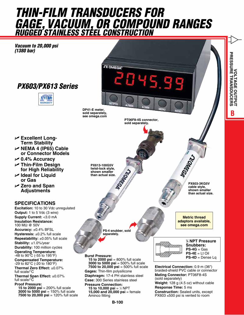
THIN-FILM TRANSduceRS FoR GAGe, VAcuuM, oR coMpouNd RANGeSRuGGed STAINLeSS STeeL coNSTRucTIoNVacuum to 20,000 psi(1380 bar)
U Excellent Long- Term Stability
U NEMA 4 (IP65) Cable or Connector Models
U 0.4% Accuracy U Thin-Film Design
for High Reliability U Ideal for Liquid
or Gas U Zero and Span
Adjustments
PX613-100G5V twist-lock style, shown smaller than actual size.
PX603-3KG5V cable style, shown smaller than actual size.
DP41-E meter, sold separately, see omega.com
PT06F8-4S connector, sold separately.
SPECIFICATIONSExcitation: 10 to 30 Vdc unregulatedOutput: 1 to 5 Vdc (3 wire)Supply Current: <3.0 mAInsulation Resistance: 100 MΩ @ 50VAccuracy: ±0.4% BFSLHysteresis: ±0.2% full scaleRepeatability: ±0.05% full scaleStability: ±1.0%/yearDurability: 100 million cyclesOperating Temperature: -48 to 90°C (-55 to 195°F)Compensated Temperature: -29 to 82°C (-20 to 180°F)Thermal Zero Effect: ±0.07% full scale/°CThermal Span Effect: ±0.07% full scale/°CProof Pressure: 15 to 2000 psi = 200% full scale 3000 to 5000 psi = 150% full scale 7500 to 20,000 psi = 120% full scale
Burst Pressure: 15 to 2000 psi = 800% full scale 3000 to 5000 psi = 500% full scale 7500 to 20,000 psi = 500% full scaleGages: Thin-film polysiliconeDiaphragm: 17-4 PH stainless steelCase: 300 Series stainless steelPressure Connection: 15 to 10,000 psi = 1⁄4 NPT 15,000 and 20,000 psi = female Aminco fitting
Electrical Connection: 0.9 m (36") braided-shield PVC cable or connectorMating Connector: PT06F8-4S (sold separately) Weight: 128 g (4.5 oz) without cableResponse Time: 5 msConstruction: Sealed units, except PX603 ≤500 psi is vented to room
PS-4 snubber, sold separately.
P-DPG500 Fig. 1
1⁄4 NPT Pressure Snubbers: PS-4G = Gas PS-4E = Lt Oil PS-4D = Dense Lq
Metric thread adaptors available,
see omega.com
pX603/pX613 Series
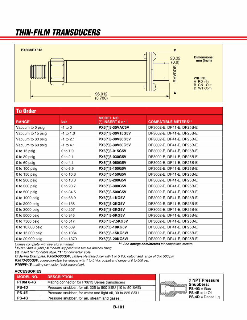
B-101
20.32(0.8)S
QU
AR
E
96.012(3.780)
ARTWORK/PRODUCT ART/ PRESSURE/P-PX602
PX603/PX613
wiriNGA rD +inB GN +OutD wT Com
Dimensions: mm (inch)
Comes complete with operator’s manual. ** See omega.com/meters for compatible meters.†15,000 and 20,000 psi models supplied with female Aminco fitting.[*] Insert “0” for cable style, “1” for connector style.Ordering Examples: PX603-500G5V, cable-style transducer with 1 to 5 Vdc output and range of 0 to 500 psi. PX613-500G5V, connector-style transducer with 1 to 5 Vdc output and range of 0 to 500 psi.PT06F8-4S, mating connector (sold separately).
ACCESSORIES
THIN-FILM TRANSduceRS
MODEL NO. DESCRIPTION PT06F8-4S Mating connector for PX613 Series transducers PS-4D Pressure snubber, for oil, 225 to 500 SSU (10 to 50 SAE) PS-4E Pressure snubber, for water and light oil, 30 to 225 SSU PS-4G Pressure snubber, for air, stream and gases
P-DPG500 Fig. 1
1⁄4 NPT Pressure Snubbers: PS-4G = Gas PS-4E = Lt Oil PS-4D = Dense Lq
To Order
RANGE† barMODEL NO. [*] INSERT 0 or 1 COMPATIBLE METERS**
Vacuum to 0 psig -1 to 0 PX6[*]3-30VAC5V DP3002-E, DP41-E, DP25B-E
Vacuum to 15 psig -1 to 1.0 PX6[*]3-30V15G5V DP3002-E, DP41-E, DP25B-E
Vacuum to 30 psig -1 to 2.1 PX6[*]3-30V30G5V DP3002-E, DP41-E, DP25B-E
Vacuum to 60 psig -1 to 4.1 PX6[*]3-30V60G5V DP3002-E, DP41-E, DP25B-E
0 to 15 psig 0 to 1.0 PX6[*]3-015G5V DP3002-E, DP41-E, DP25B-E
0 to 30 psig 0 to 2.1 PX6[*]3-030G5V DP3002-E, DP41-E, DP25B-E
0 to 60 psig 0 to 4.1 PX6[*]3-060G5V DP3002-E, DP41-E, DP25B-E
0 to 100 psig 0 to 6.9 PX6[*]3-100G5V DP3002-E, DP41-E, DP25B-E
0 to 150 psig 0 to 10.3 PX6[*]3-150G5V DP3002-E, DP41-E, DP25B-E
0 to 200 psig 0 to 13.8 PX6[*]3-200G5V DP3002-E, DP41-E, DP25B-E
0 to 300 psig 0 to 20.7 PX6[*]3-300G5V DP3002-E, DP41-E, DP25B-E
0 to 500 psig 0 to 34.5 PX6[*]3-500G5V DP3002-E, DP41-E, DP25B-E
0 to 1000 psig 0 to 68.9 PX6[*]3-1KG5V DP3002-E, DP41-E, DP25B-E
0 to 2000 psig 0 to 138 PX6[*]3-2KG5V DP3002-E, DP41-E, DP25B-E
0 to 3000 psig 0 to 207 PX6[*]3-3KG5V DP3002-E, DP41-E, DP25B-E
0 to 5000 psig 0 to 345 PX6[*]3-5KG5V DP3002-E, DP41-E, DP25B-E
0 to 7500 psig 0 to 517 PX6[*]3-7.5KG5V DP3002-E, DP41-E, DP25B-E
0 to 10,000 psig 0 to 689 PX6[*]3-10KG5V DP3002-E, DP41-E, DP25B-E
0 to 15,000 psig 0 to 1034 PX6[*]3-15KG5V† DP3002-E, DP41-E, DP25B-E
0 to 20,000 psig 0 to 1379 PX6[*]3-20KG5V† DP3002-E, DP41-E, DP25B-E
Toll Free: 1‐888‐744‐6868
DAILY DEAL:
15% Off All Products
7075 Aluminum Plate(7075ASHT2)
Size: 2
$535.02
‐$80.26
$454.76
Item Qty. Width Length Tot. Wt. Price Discount Total [–]
2 17.0000 17.0000 116.756 # $267.51 $40.13 $454.76
» Con nue Shopping
Discounts applied to this order:
15% Off All Products
15% Off All Products
Item Total:
Discounts:
Subtotal:
Update
Get Shipping Es mate*
Got a Coupon?
04JUL
Your Cart | Midwest Steel and Aluminum | Buy Metal Online | No Min... https://www.midweststeelsupply.com/store/cart.php
1 of 1 7/4/2016 10:08 PM