Embed Size (px)
Citation preview
. . . . . . . . . . . . . . . . . . . . . . . . . . . . . . . . . . . . .. . . . .
Medalist Pro Family . . . . . . . . . . . . . . . . . . . . . . . . . . . . . . . . . . . . .. . . . .
Medalist 2160N (ST52160N). . . . . . . . . . . . . . . . . . . . . . . . . . . . . . . . . . . . .. . . . .
Medalist 2160WC (ST52160WC). . . . . . . . . . . . . . . . . . . . . . . . . . . . . . . . . . . . .. . . . .
SCSI Interface Drives. . . . . . . . . . . . . . . . . . . . . . . . . . . . . . . . . . . . .. . . . .
Product Manual. . . . . . . . . . . . . . . . . . . . . . . . . . . . . . . . . . . . .. . . . .

. . . . . . . . . . . . . . . . . . . . . . . . . . . . . . . . . . . . .. . . . .
Medalist Pro Family. . . . . . . . . . . . . . . . . . . . . . . . . . . . . . . . . . . . .. . . . .
Medalist 2160N (ST52160N). . . . . . . . . . . . . . . . . . . . . . . . . . . . . . . . . . . . .. . . . .
Medalist 2160WC (ST52160WC). . . . . . . . . . . . . . . . . . . . . . . . . . . . . . . . . . . . .. . . . .
SCSI Interface Drives. . . . . . . . . . . . . . . . . . . . . . . . . . . . . . . . . . . . .. . . . .
Product Manual. . . . . . . . . . . . . . . . . . . . . . . . . . . . . . . . . . . . .. . . . .
© 1996 Seagate Technology, Inc. All rights reserved
Publication Number: 32650-001, Rev. A, December 1996
Seagate, Seagate Technology, the Seagate logo and Medalist areregistered trademarks of Seagate Technology, Inc. Other product namesare trademarks or registered trademarks of their owners.
Seagate reserves the right to change, without notice, product offeringsor specifications. No part of this publication may be reproduced in anyform without written permission from Seagate Technology, Inc.
2 Medalist Pro 2160N/ 2160WC Product Manual, Rev. A
Contents
Introduction . . . . . . . . . . . . . . . . . . . . . . . . . . . . . 1
Specifications summary table . . . . . . . . . . . . . . . . . . . 3
1.0 Specifications summary . . . . . . . . . . . . . . . . . . . . . 5
1.1 Formatted capacity . . . . . . . . . . . . . . . . . . . . . . 5
1.2 Physical geometry . . . . . . . . . . . . . . . . . . . . . . . 5
1.3 Functional specifications . . . . . . . . . . . . . . . . . . . 5
1.4 Physical dimensions . . . . . . . . . . . . . . . . . . . . . . 6
1.5 Seek time . . . . . . . . . . . . . . . . . . . . . . . . . . . 6
1.6 Read look-ahead and caching . . . . . . . . . . . . . . . . 7
1.7 Start/stop command . . . . . . . . . . . . . . . . . . . . . . 7
1.7.1 Power-up sequence . . . . . . . . . . . . . . . . . . . 7
1.7.2 Power-down sequence . . . . . . . . . . . . . . . . . . 8
1.7.3 Auto-park . . . . . . . . . . . . . . . . . . . . . . . . . 8
1.8 Power management . . . . . . . . . . . . . . . . . . . . . . 8
1.8.1 Power consumption . . . . . . . . . . . . . . . . . . . . 9
1.8.2 Voltage tolerance . . . . . . . . . . . . . . . . . . . . . 9
1.8.3 Input noise . . . . . . . . . . . . . . . . . . . . . . . 10
1.9 Environmental . . . . . . . . . . . . . . . . . . . . . . . . 10
1.9.1 Ambient temperature (HDA case) . . . . . . . . . . . 10
1.9.2 Temperature gradient . . . . . . . . . . . . . . . . . . 10
1.9.3 Altitude . . . . . . . . . . . . . . . . . . . . . . . . . 10
1.9.4 Relative humidity . . . . . . . . . . . . . . . . . . . . 11
1.10 Shock and vibration . . . . . . . . . . . . . . . . . . . . 11
1.11 Acoustics . . . . . . . . . . . . . . . . . . . . . . . . . . 12
1.12 Reliability . . . . . . . . . . . . . . . . . . . . . . . . . . 12
1.13 Agency listings . . . . . . . . . . . . . . . . . . . . . . . 12
1.14 Electromagnetic Compliance for the European Union . . . 13
1.15 FCC verification . . . . . . . . . . . . . . . . . . . . . . 13
2.0 Hardware and interface . . . . . . . . . . . . . . . . . . . . 17
Medalist Pro 2160N/ 2160WC Product Manual, Rev. A iii
2.1 SCSI-3 compatibility . . . . . . . . . . . . . . . . . . . . . 17
2.2 Handling and static-discharge precautions . . . . . . . . . 17
2.3 Electrical interface . . . . . . . . . . . . . . . . . . . . . . 18
2.4 Interface and connector configuration . . . . . . . . . . . . 19
2.5 ST52160N interface connector . . . . . . . . . . . . . . . 20
2.5.1 ST52160N interface pin assignments . . . . . . . . . 21
2.5.2 ST52160WC interface connector . . . . . . . . . . . . 22
2.5.3 ST52160WC interface pin assignments . . . . . . . . 22
2.6 Interface cable requirements . . . . . . . . . . . . . . . . 25
2.6.1 Interface cable length for asynchronous operation . . . 25
2.6.2 Interface cable for Fast SCSI operation . . . . . . . . 25
2.6.3 Interface cable for UltraSCSI operation . . . . . . . . 25
2.7 Options jumper block . . . . . . . . . . . . . . . . . . . . 26
2.7.1 SCSI address . . . . . . . . . . . . . . . . . . . . . . 26
2.8 Active Termination . . . . . . . . . . . . . . . . . . . . . . 29
2.9 Parity enable option . . . . . . . . . . . . . . . . . . . . . 29
2.9.1 Motor Start option . . . . . . . . . . . . . . . . . . . . 29
2.9.2 Remote LED connection . . . . . . . . . . . . . . . . 29
2.10 Daisy chaining . . . . . . . . . . . . . . . . . . . . . . . 29
2.11 Hot-plugging . . . . . . . . . . . . . . . . . . . . . . . . 30
2.12 Mounting the drive . . . . . . . . . . . . . . . . . . . . . 30
3.0 Command set . . . . . . . . . . . . . . . . . . . . . . . . . 35
3.1 Command descriptor block . . . . . . . . . . . . . . . . . 35
3.2 Status byte . . . . . . . . . . . . . . . . . . . . . . . . . 35
3.3 Supported commands . . . . . . . . . . . . . . . . . . . . 36
3.4 Group 0 commands . . . . . . . . . . . . . . . . . . . . . 37
3.4.1 Test Unit Ready command (00H) . . . . . . . . . . . . 37
3.4.2 Rezero Unit command (01H) . . . . . . . . . . . . . . 38
3.4.3 Request Sense command (03H) . . . . . . . . . . . . 38
3.4.4 Format Unit command (04H) . . . . . . . . . . . . . . 39
3.4.5 Reassign Blocks command (07H) . . . . . . . . . . . 43
iv Medalist Pro 2160N/ 2160WC Product Manual, Rev. A
3.4.6 Read (6) command (08H) . . . . . . . . . . . . . . . . 45
3.4.7 Write (6) command (0AH) . . . . . . . . . . . . . . . . 46
3.4.8 Seek (6) command (0BH) . . . . . . . . . . . . . . . . 47
3.4.9 Inquiry command (12H) . . . . . . . . . . . . . . . . . 47
3.4.10 Mode Select (6) command (15H) . . . . . . . . . . . 48
3.4.11 Reserve (6) command (16H) . . . . . . . . . . . . . 51
3.4.12 Release (6) command (17H) . . . . . . . . . . . . . 52
3.4.13 Mode Sense (6) command (1AH) . . . . . . . . . . . 53
3.4.14 Start/Stop Unit command (1BH) . . . . . . . . . . . . 56
3.4.15 Receive Diagnostic Results command (1CH) . . . . . 57
3.4.16 Supported Diagnostic Pages . . . . . . . . . . . . . 58
3.4.17 Translate Address Page . . . . . . . . . . . . . . . 59
3.4.18 Send Diagnostic command (1DH) . . . . . . . . . . . 61
3.5 Supported Diagnostics Page—Send Diagnostics . . . . . . 62
3.6 Translate Address Page—Send Diagnostic . . . . . . . . . 62
3.6.1 Read Capacity command (25H) . . . . . . . . . . . . 63
3.6.2 Read (10) command (28H) . . . . . . . . . . . . . . . 64
3.6.3 Write (10) command (2AH) . . . . . . . . . . . . . . . 65
3.6.4 Seek (10) command (2BH) . . . . . . . . . . . . . . . 66
3.6.5 Write and Verify command (2EH) . . . . . . . . . . . . 67
3.6.6 Verify command (2FH) . . . . . . . . . . . . . . . . . 68
3.6.7 Read Defect Data command (37H) . . . . . . . . . . . 68
3.6.8 Write Data Buffer command (3BH) . . . . . . . . . . . 70
3.6.9 Read Data Buffer command (3CH) . . . . . . . . . . . 72
3.6.10 Read Long command (3EH) . . . . . . . . . . . . . . 74
3.6.11 Write Long command (3FH) . . . . . . . . . . . . . . 74
3.7 Group 2 commands . . . . . . . . . . . . . . . . . . . . . 75
3.7.1 Log Select command (4CH) . . . . . . . . . . . . . . 75
3.8 Log Sense command (4DH) . . . . . . . . . . . . . . . . . 82
3.9 Reserve (10) command (56H) . . . . . . . . . . . . . . . . 83
3.10 Release (10) command (57H) . . . . . . . . . . . . . . . 84
Medalist Pro 2160N/ 2160WC Product Manual, Rev. A v
3.11 Group 3 and 4 commands . . . . . . . . . . . . . . . . . 85
3.12 Group 5 and 6 commands . . . . . . . . . . . . . . . . . 85
3.13 Group 7 commands . . . . . . . . . . . . . . . . . . . . 85
Appendix A. Supported messages . . . . . . . . . . . . . . . . 87
A.1 Messages . . . . . . . . . . . . . . . . . . . . . . . . . . 87
A.2 Synchronous Data Transfer Request message (01H) . . . . 88
A.2.1 Wide Data Transfer Request Message . . . . . . . . . 89
Appendix B. Sense data . . . . . . . . . . . . . . . . . . . . . . 91
B.1 Additional sense data . . . . . . . . . . . . . . . . . . . . 91
B.2 Sense key . . . . . . . . . . . . . . . . . . . . . . . . . . 93
B.3 Additional sense code and additional sense code qualifier . 94
Appendix C. Mode pages . . . . . . . . . . . . . . . . . . . . . 97
C.1 Read-Write Error Recovery page (01H) . . . . . . . . . . 98
C.2 Disconnect/Reconnect page (02H) . . . . . . . . . . . . 100
C.3 Format Device page (03H) . . . . . . . . . . . . . . . . 102
C.4 Rigid Disc Geometry page (04H) . . . . . . . . . . . . . 104
C.5 Verify error recovery page (07H) . . . . . . . . . . . . . 107
C.6 Caching page (08H) . . . . . . . . . . . . . . . . . . . . 108
C.6.1 Read look-ahead and caching . . . . . . . . . . . . 108
C.6.2 Write caching and write merging . . . . . . . . . . . 109
C.6.3 Caching page description . . . . . . . . . . . . . . 110
C.7 Control Mode page (0AH) . . . . . . . . . . . . . . . . . 113
C.7.1 Unit Attention Parameters (00H) . . . . . . . . . . . 114
Appendix D. Inquiry data . . . . . . . . . . . . . . . . . . . . 117
D.1 Inquiry data . . . . . . . . . . . . . . . . . . . . . . . . 117
D.2 Vital product data pages . . . . . . . . . . . . . . . . . 120
D.2.1 Unit Serial Number page (80H) . . . . . . . . . . . . 121
D.2.2 Implemented Operating Definition page (81H) . . . . 121
D.2.3 Firmware Numbers page (C0H) . . . . . . . . . . . 122
D.2.4 Date Code page (C1H) . . . . . . . . . . . . . . . . 123
D.2.5 Jumper Settings page (C2H) . . . . . . . . . . . . . 123
vi Medalist Pro 2160N/ 2160WC Product Manual, Rev. A
Figures
Figure 1. Typical startup current profile . . . . . . . . . . . . . . . . 7
Figure 2. Single-ended transmitter and receiver . . . . . . . . . . .18
Figure 3. Connectors . . . . . . . . . . . . . . . . . . . . . . . . 19
Figure 4. ST52160N jumper settings . . . . . . . . . . . . . . . . 27
Figure 5. ST52160WC jumper settings . . . . . . . . . . . . . . . 28
Figure 6. ST52160N Mounting dimensions . . . . . . . . . . . . . 32
Figure 7. ST52160WC Mounting dimensions . . . . . . . . . . . 33
Medalist Pro 2160N/ 2160WC Product Manual, Rev. A vii

IntroductionThis manual describes the functional, mechanical and interface specifi-cations for the Medalist Pro 2160N and Medalist Pro 2160WC SCSIhard disc drives. The Medalist Pro 2160N is referred to in this manual byits model number ST52160N. This drive comes with the standard 50-pininterface connector. The Medalist Pro 2160WC is referred to in thismanual by its model number ST52160WC. This drive comes with the80-pin blindmate single-connector attachment (SCA-2).
Seagate desktop products take a step into the future with the ST52160Nand ST52160WC. These drives feature MR heads and PRML recordingtechnology.
The Medalist Pro drives uses an UltraSCSI interface. The ST52160Nsupports a synchronous external transfer rate of up to 20 Mbytes persecond. The ST52160WC supports a synchronous external transfer rateof up to 40 Mbytes per second.
These drives have other features that ensure fast data throughput. TheST52160N uses a 128-Kbyte buffer. The ST52160WC uses a 256-Kbytebuffer. The adaptable cache aids the flow of read and write data.Embedded servo technology allows the drives to position the heads fordata retrieval efficiently and accurately while eliminating the periodicthermal recalibration that can interrupt during data transfers. Thesedrives also use a 16-bit microprocessor and an intelligent controller thatprovides data streaming: direct data transfers between the drive and thehost without microprocessor intervention. This feature allows for a sus-tained data rate that facilitates video playback and other multimediaoperations.
The drives conform to the standard 3.5-inch footprint but have a 0.75-inch(19 mm) height profile and a 5.380-inch depth profile. The lower heightand shorter depth gives the designer or integrator more room for aircirculation, other peripherals or a smaller drive bay.
The SCSI commands the drives support are listed in Section 3.3. on page 36.
Medalist Pro 2160N/ 2160WC Product Manual, Rev. A 1
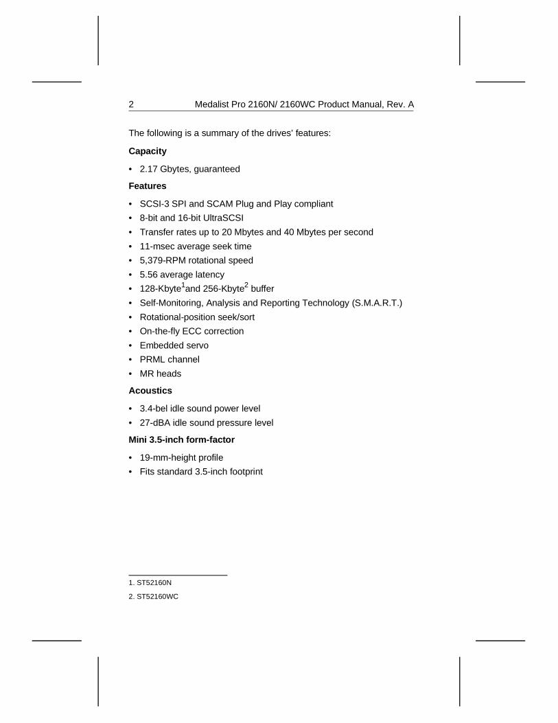
The following is a summary of the drives’ features:
Capacity
• 2.17 Gbytes, guaranteed
Features
• SCSI-3 SPI and SCAM Plug and Play compliant
• 8-bit and 16-bit UltraSCSI
• Transfer rates up to 20 Mbytes and 40 Mbytes per second
• 11-msec average seek time
• 5,379-RPM rotational speed
• 5.56 average latency
• 128-Kbyte1and 256-Kbyte2 buffer
• Self-Monitoring, Analysis and Reporting Technology (S.M.A.R.T.)
• Rotational-position seek/sort
• On-the-fly ECC correction
• Embedded servo
• PRML channel
• MR heads
Acoustics
• 3.4-bel idle sound power level
• 27-dBA idle sound pressure level
Mini 3.5-inch form-factor
• 19-mm-height profile
• Fits standard 3.5-inch footprint
1. ST52160N
2. ST52160WC
2 Medalist Pro 2160N/ 2160WC Product Manual, Rev. A
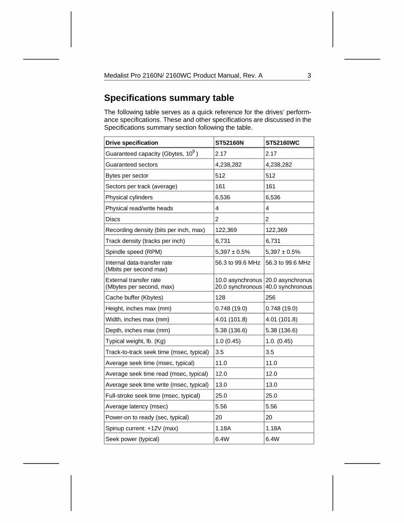
Specifications summary tableThe following table serves as a quick reference for the drives’ perform-ance specifications. These and other specifications are discussed in theSpecifications summary section following the table.
Drive specification ST52160N ST52160WC
Guaranteed capacity (Gbytes, 109 ) 2.17 2.17
Guaranteed sectors 4,238,282 4,238,282
Bytes per sector 512 512
Sectors per track (average) 161 161
Physical cylinders 6,536 6,536
Physical read/write heads 4 4
Discs 2 2
Recording density (bits per inch, max) 122,369 122,369
Track density (tracks per inch) 6,731 6,731
Spindle speed (RPM) 5,397 ± 0.5% 5,397 ± 0.5%
Internal data-transfer rate (Mbits per second max)
56.3 to 99.6 MHz 56.3 to 99.6 MHz
External transfer rate (Mbytes per second, max)
10.0 asynchronus20.0 synchronous
20.0 asynchronus40.0 synchronous
Cache buffer (Kbytes) 128 256
Height, inches max (mm) 0.748 (19.0) 0.748 (19.0)
Width, inches max (mm) 4.01 (101.8) 4.01 (101.8)
Depth, inches max (mm) 5.38 (136.6) 5.38 (136.6)
Typical weight, lb. (Kg) 1.0 (0.45) 1.0. (0.45)
Track-to-track seek time (msec, typical) 3.5 3.5
Average seek time (msec, typical) 11.0 11.0
Average seek time read (msec, typical) 12.0 12.0
Average seek time write (msec, typical) 13.0 13.0
Full-stroke seek time (msec, typical) 25.0 25.0
Average latency (msec) 5.56 5.56
Power-on to ready (sec, typical) 20 20
Spinup current: +12V (max) 1.18A 1.18A
Seek power (typical) 6.4W 6.4W
Medalist Pro 2160N/ 2160WC Product Manual, Rev. A 3
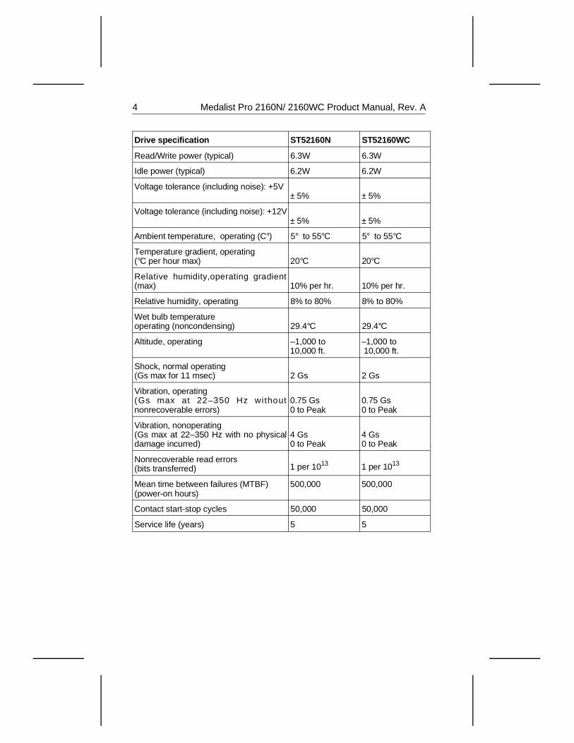
Drive specification ST52160N ST52160WC
Read/Write power (typical) 6.3W 6.3W
Idle power (typical) 6.2W 6.2W
Voltage tolerance (including noise): +5V ± 5% ± 5%
Voltage tolerance (including noise): +12V± 5% ± 5%
Ambient temperature, operating (C°) 5° to 55°C 5° to 55°C
Temperature gradient, operating (°C per hour max) 20°C 20°C
Relative humidity,operating gradient(max) 10% per hr. 10% per hr.
Relative humidity, operating 8% to 80% 8% to 80%
Wet bulb temperature operating (noncondensing) 29.4°C 29.4°C
Altitude, operating –1,000 to10,000 ft.
–1,000 to 10,000 ft.
Shock, normal operating (Gs max for 11 msec) 2 Gs 2 Gs
Vibration, operating(Gs max at 22–350 Hz withoutnonrecoverable errors)
0.75 Gs 0 to Peak
0.75 Gs 0 to Peak
Vibration, nonoperating(Gs max at 22–350 Hz with no physicaldamage incurred)
4 Gs 0 to Peak
4 Gs 0 to Peak
Nonrecoverable read errors (bits transferred) 1 per 1013 1 per 1013
Mean time between failures (MTBF)(power-on hours)
500,000 500,000
Contact start-stop cycles 50,000 50,000
Service life (years) 5 5
4 Medalist Pro 2160N/ 2160WC Product Manual, Rev. A
1.0 Specifications summary
1.1 Formatted capacity
The capacities specified here do not include spare sectors and cylinders.The media contains 2,000 spare blocks at the end of the volume.
Guaranteed capacity (Gbytes3) 2.17
Guaranteed sectors 4,238,282
1.2 Physical geometry
Discs 2
Read/write heads 4
Cylinders 6,536
Sectors per track (average) 161
1.3 Functional specifications
Interface SCSI-3 SPI Compliant
PRML recording method Code (0,4,4)
External data-transfer rate(Mbytes per sec, max)
10 asynchronous4 20 synchronous4
20 asynchronous5
40 synchronous5
Internal data-transfer rate(Mbits per sec)
56.3 - 99.6 MHz
Bytes per sector 512
Data zones 19
Areal density (Mbits/ in2) 823.7
Track density (TPI) 6,731
Recording density (BPI, max) 122,369
3. One Gbyte equals 1,000,000,000 bytes.
4. ST52160N
5. ST52160WC
Medalist Pro 2160N/ 2160WC Product Manual, Rev. A 5
1.4 Physical dimensions
Height (max) 0.748 inches (19 mm)
Width (max) 4.01 inches (101.8 mm)
Depth (max) 5.38 inches (136.6 mm)
Weight (max) 1.0 lb. (0.45 Kg)
1.5 Seek time
All seek time measurements are taken under nominal conditions oftemperature and voltage with the drive mounted horizontally. In thefollowing table:
• Track-to-track seek time is the average of all possible single-trackseeks in both directions.
• Average/typical seek time is a true statistical random average of atleast 5,000 measurements of seeks in both directions between ran-dom cylinders, less overhead.
• Full-stroke seek time is one-half the time needed to seek from logicalblock address zero (LBA 0) to the maximum LBA and back to LBA 0.
Track-to-trackseek time typ 6
Average/typicalseek time 7
Full-strokeseek time typ 8
Averagelatency
3.5 msec typ 11.0 msec typ 25.0 msec typ 5.56 msec
4.5 msec max 12.0 msec read 27.0 msec max
13.0 msec write
Note. Host overhead varies between systems and cannot be specified.Drive internal overhead is measured by issuing a no-motionseek. Drive overhead is typically less than 1.0 msec.
____________________
6. All possible one- track seeks are divided into the time required to perform these seeks.Only the mechanism time is used; interface overhead is excluded.
7. All possible seeks are divided into the time required to perform these seeks. Only themechanism time is used; interface overhead is excluded.
8. The average of 1,000 full-stroke seeks is used in this computation. Only the mechanismtime is used; interface overhead is excluded.
6 Medalist Pro 2160N/ 2160WC Product Manual, Rev. A
1.6 Read look-ahead and caching
The drives use algorithims that improve seek performance by storingdata in a buffer and processing it at a more convenient time. Threemethods are used: read look-ahead, read caching and write caching.These are described in Appendix C.6 on page 108.
1.7 Start/stop command
If the motor-start option is disabled, the drive is ready within 20 secondsafter power is applied. If the motor-start option is enabled, the drive isready within 20 seconds after it receives the Motor Start command. If thedrive receives a command to spin down or power is removed, the drivestops within 15 seconds.
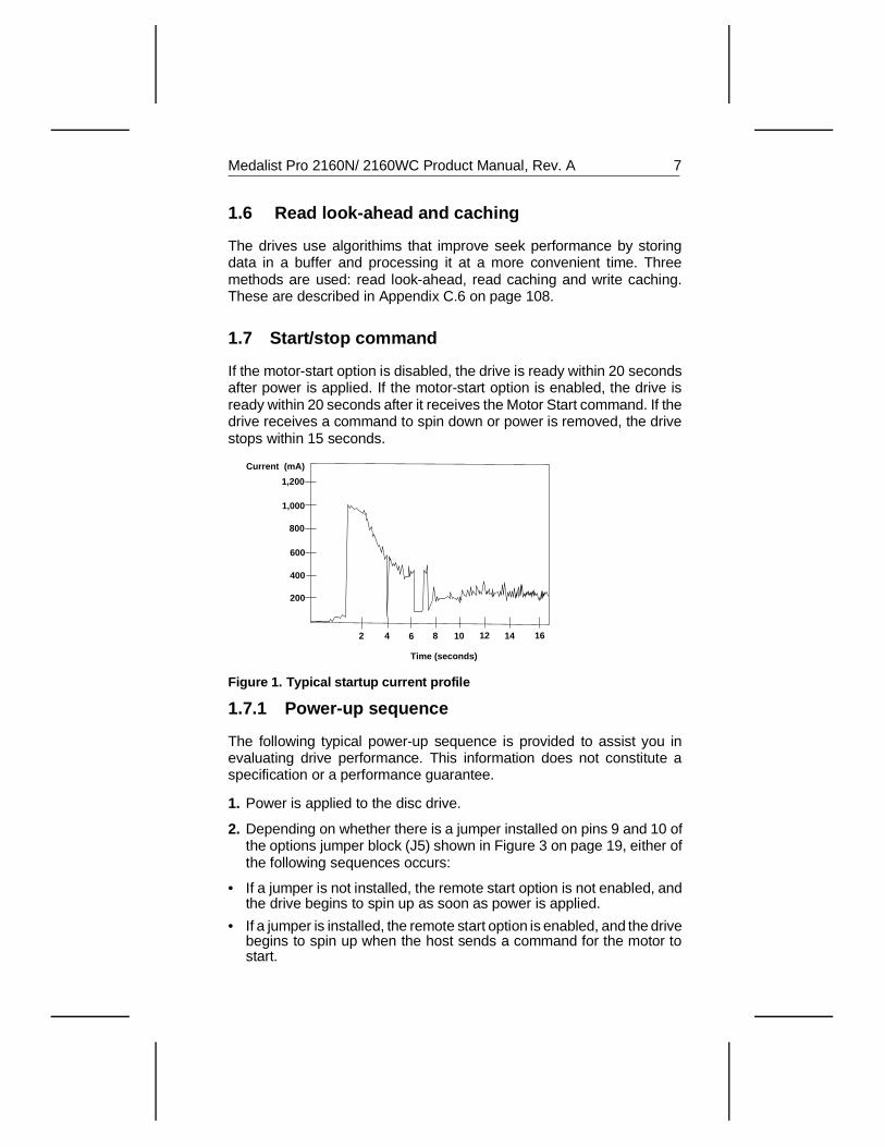
1.7.1 Power-up sequence
The following typical power-up sequence is provided to assist you inevaluating drive performance. This information does not constitute aspecification or a performance guarantee.
1. Power is applied to the disc drive.
2. Depending on whether there is a jumper installed on pins 9 and 10 ofthe options jumper block (J5) shown in Figure 3 on page 19, either ofthe following sequences occurs:
• If a jumper is not installed, the remote start option is not enabled, andthe drive begins to spin up as soon as power is applied.
• If a jumper is installed, the remote start option is enabled, and the drivebegins to spin up when the host sends a command for the motor tostart.
2 4 6 8 10 12 14 16
200
400
600
800
1,000
1,200
Time (seconds)
Current (mA)
Figure 1. Typical startup current profile
Medalist Pro 2160N/ 2160WC Product Manual, Rev. A 7
3. Within 250 msec after power is applied, the drive responds to the TestUnit Ready, Request Sense, Mode Sense and Inquiry commands.
4. The drive begins to lock in speed-control circuits.
6. The actuator lock releases the actuator.
7. The spindle motor reaches operating speed in about 5 seconds. After5 seconds, there are no speed variations.
8. The drive performs velocity-adjustment seeks.
9. The drive seeks track 0 and is then ready.
1.7.2 Power-down sequence
Caution. Do not move the drive until the motor has come to a complete stop.
1. The power is turned off.
2. Within 15 seconds, the drive spindle stops rotating.
3. The read/write heads automatically move to the landing zone, which is inside the maximum data cylinder.
4. The magnetic acuator lock mechanism locks the arm. This completes the power-down sequence.
1.7.3 Auto-park
During power-down, the read/write heads automatically move to thelanding zone. The heads park inside the maximum data cylinder and themagnetic actuator lock engages. When power is applied, the headsrecalibrate to track 0.
1.8 Power management
The drive supports power-management modes that reduce its overallpower consumption. They automatically change from one mode toanother in response to interface activity. You do not need to change anyparameters or send any special commands to make the drive changemodes. The power-management modes are described as follows:
• Spinup. Spinup is defined as the period during which the spindle iscoming up to operating speed. The power consumed in this mode isequivalent to the average power during the first 10 seconds after thedrive begins to spin up.
8 Medalist Pro 2160N/ 2160WC Product Manual, Rev. A
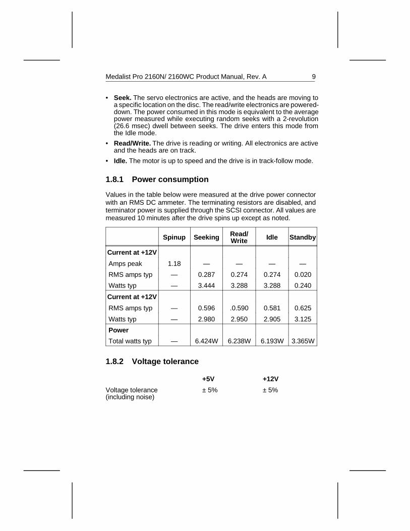
• Seek. The servo electronics are active, and the heads are moving toa specific location on the disc. The read/write electronics are powered-down. The power consumed in this mode is equivalent to the averagepower measured while executing random seeks with a 2-revolution(26.6 msec) dwell between seeks. The drive enters this mode fromthe Idle mode.
• Read/Write. The drive is reading or writing. All electronics are activeand the heads are on track.
• Idle. The motor is up to speed and the drive is in track-follow mode.
1.8.1 Power consumption
Values in the table below were measured at the drive power connectorwith an RMS DC ammeter. The terminating resistors are disabled, andterminator power is supplied through the SCSI connector. All values aremeasured 10 minutes after the drive spins up except as noted.
Spinup Seeking Read/Write Idle Standby
Current at +12V
Amps peak 1.18 — — — —
RMS amps typ — 0.287 0.274 0.274 0.020
Watts typ — 3.444 3.288 3.288 0.240
Current at +12V
RMS amps typ — 0.596 .0.590 0.581 0.625
Watts typ — 2.980 2.950 2.905 3.125
Power
Total watts typ — 6.424W 6.238W 6.193W 3.365W
1.8.2 Voltage tolerance
+5V +12V
Voltage tolerance(including noise)
± 5% ± 5%
Medalist Pro 2160N/ 2160WC Product Manual, Rev. A 9
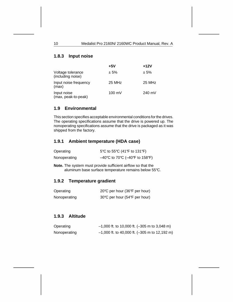
1.8.3 Input noise
+5V +12V
Voltage tolerance(including noise)
± 5% ± 5%
Input noise frequency(max)
25 MHz 25 MHz
Input noise(max, peak-to-peak)
100 mV 240 mV
1.9 Environmental
This section specifies acceptable environmental conditions for the drives.The operating specifications assume that the drive is powered up. Thenonoperating specifications assume that the drive is packaged as it wasshipped from the factory.
1.9.1 Ambient temperature (HDA case)
Operating 5°C to 55°C (41°F to 131°F)
Nonoperating –40°C to 70°C (–40°F to 158°F)
Note. The system must provide sufficient airflow so that the aluminum base surface temperature remains below 55°C.
1.9.2 Temperature gradient
Operating 20°C per hour (36°F per hour)
Nonoperating 30°C per hour (54°F per hour)
1.9.3 Altitude
Operating –1,000 ft. to 10,000 ft. (–305 m to 3,048 m)
Nonoperating –1,000 ft. to 40,000 ft. (–305 m to 12,192 m)
10 Medalist Pro 2160N/ 2160WC Product Manual, Rev. A
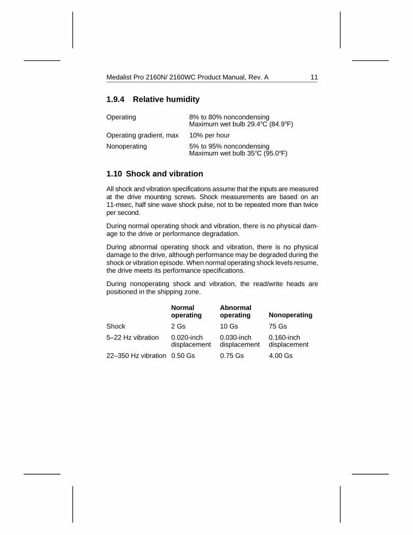
1.9.4 Relative humidity
Operating 8% to 80% noncondensingMaximum wet bulb 29.4°C (84.9°F)
Operating gradient, max 10% per hour
Nonoperating 5% to 95% noncondensingMaximum wet bulb 35°C (95.0°F)
1.10 Shock and vibration
All shock and vibration specifications assume that the inputs are measuredat the drive mounting screws. Shock measurements are based on an11-msec, half sine wave shock pulse, not to be repeated more than twiceper second.
During normal operating shock and vibration, there is no physical dam-age to the drive or performance degradation.
During abnormal operating shock and vibration, there is no physicaldamage to the drive, although performance may be degraded during theshock or vibration episode. When normal operating shock levels resume,the drive meets its performance specifications.
During nonoperating shock and vibration, the read/write heads arepositioned in the shipping zone.
Normal operating
Abnormaloperating Nonoperating
Shock 2 Gs 10 Gs 75 Gs
5–22 Hz vibration 0.020-inchdisplacement
0.030-inchdisplacement
0.160-inchdisplacement
22–350 Hz vibration 0.50 Gs 0.75 Gs 4.00 Gs
Medalist Pro 2160N/ 2160WC Product Manual, Rev. A 11
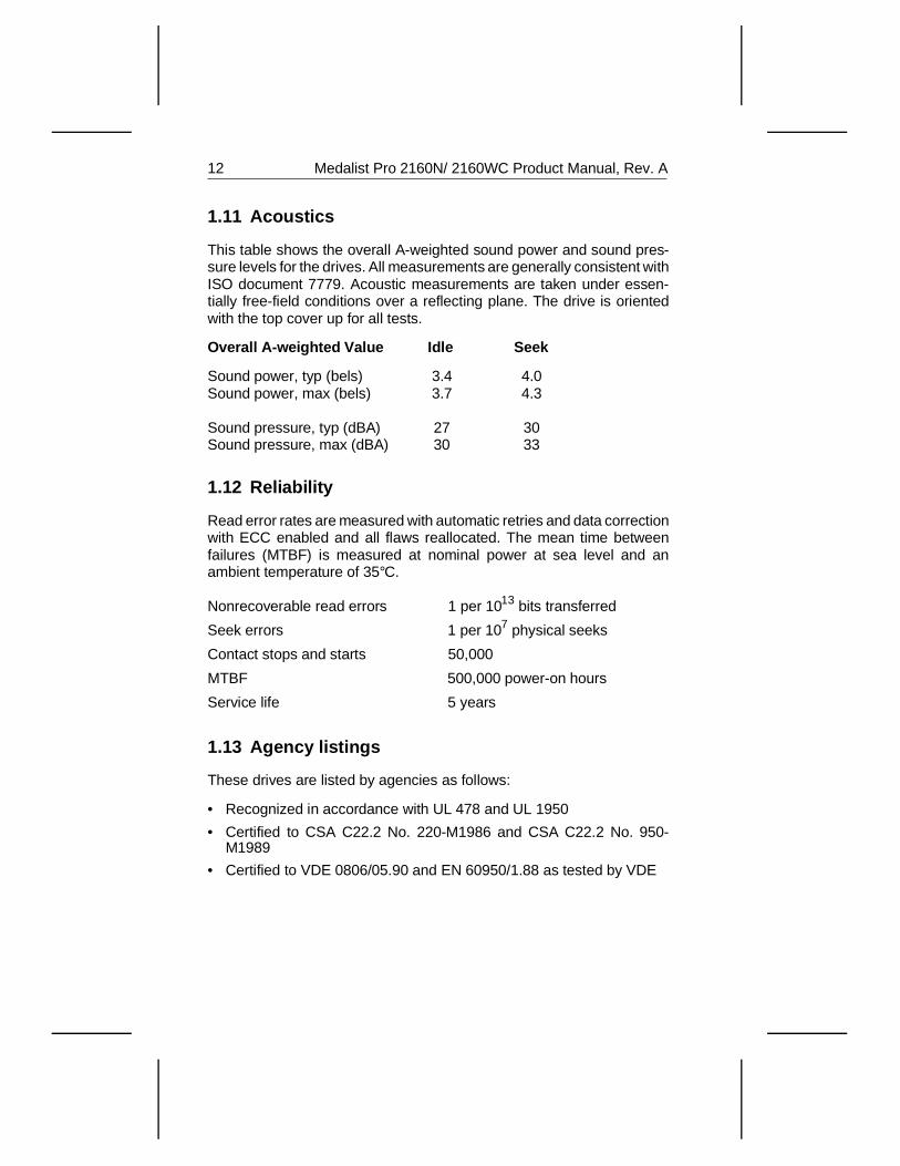
1.11 Acoustics
This table shows the overall A-weighted sound power and sound pres-sure levels for the drives. All measurements are generally consistent withISO document 7779. Acoustic measurements are taken under essen-tially free-field conditions over a reflecting plane. The drive is orientedwith the top cover up for all tests.
Overall A-weighted Value Idle Seek
Sound power, typ (bels) 3.4 4.0Sound power, max (bels) 3.7 4.3
Sound pressure, typ (dBA) 27 30Sound pressure, max (dBA) 30 33
1.12 Reliability
Read error rates are measured with automatic retries and data correctionwith ECC enabled and all flaws reallocated. The mean time betweenfailures (MTBF) is measured at nominal power at sea level and anambient temperature of 35°C.
Nonrecoverable read errors 1 per 1013 bits transferred
Seek errors 1 per 107 physical seeks
Contact stops and starts 50,000
MTBF 500,000 power-on hours
Service life 5 years
1.13 Agency listings
These drives are listed by agencies as follows:
• Recognized in accordance with UL 478 and UL 1950
• Certified to CSA C22.2 No. 220-M1986 and CSA C22.2 No. 950-M1989
• Certified to VDE 0806/05.90 and EN 60950/1.88 as tested by VDE
12 Medalist Pro 2160N/ 2160WC Product Manual, Rev. A
1.14 Electromagnetic Compliance for the EuropeanUnion
This model has the CE Marking, signifying that it complies with theEuropean Union requirements of the Electromagnetic Compatibility Di-rective 89/336/EEC of 03 May 1989 as amended by Directive 92/31/EECof 28 April 1992 and Directive 93/68/EEC of 22 July 1993.
Seagate® uses an independent laboratory to confirm compliance to theabove directives. The drive was tested in a representative system fortypical applications. The selected system represents the most popularcharacteristics for test platforms.
The system configurations include:
• 486, Pentium, and PowerPC microprocessors
• 3.5-inch floppy disc drive
• Keyboard
• Monitor/display
Although the test system with this Seagate model complies to thedirectives, we cannot guarantee that all systems will comply. The com-puter manufacturer or system integrator will confirm EMC complianceand provide CE Marking for their product. The drive is not meant forexternal uses (without properly designed enclosure, shielded I/O cable,etc.), and a terminator should be used on all unused I/O ports.
1.15 FCC verification
The Medalist Pro SCSI interface drives are intended to be containedsolely within a personal computer or similar enclosure (not attached toan external device). As such, a drive is considered to be a subassemblyeven when individually marketed to the customer. As a subassembly, noFederal Communications Commission authorization, verification or cer-tification of the device is required.
Seagate Technology, Inc. has tested the drive in an enclosure asdescribed above to ensure that the total assembly (enclosure, disc drive,motherboard, power supply, etc.) does comply with the limits for aClass B computing device, pursuant to Subpart J of Part 15 of the FCCrules. Operation with noncertified assemblies is likely to result in interfer-ence to radio and television reception.
Medalist Pro 2160N/ 2160WC Product Manual, Rev. A 13
Radio and television interference. This equipment generates and usesradio frequency energy and, if not installed and used in strict accordancewith the manufacturer’s instructions, may cause interference to radio andtelevision reception.
This equipment is designed to provide reasonable protection againstsuch interference in a residential installation. However, there is noguarantee that interference will not occur in a particular installation. If thisequipment does cause interference to radio or television, which can bedetermined by turning the equipment on and off, you are encouraged totry one or more of the following corrective measures:
• Reorient the receiving antenna.
• Move the device to one side or the other of the radio or TV.
• Move the device farther away from the radio or TV.
• Plug the equipment into a different outlet so that the receiver andcomputer are on different branch outlets.
If necessary, you should consult your dealer or an experienced radio/tele-vision technician for additional suggestions. You may find helpful thefollowing booklet prepared by the Federal Communications Commission:How to Identify and Resolve Radio-Television Interference Problems.This booklet is available from the Superintendent of Documents, USGovernment Printing Office, Washington, DC 20402. Refer to publicationnumber 004-000-00345-4.
Note. This digital apparatus does not exceed the Class B limits forradio noise emissions from computer equipment as set out in theradio interference regulations of the Canadian Department ofcommunications.
Le présent appareil numérique n′émet pas de bruits radioélec-triques dépassant les limites applicables aux appareils numéri-ques de Classe B prescrites dans le règlement sur le brouillageradioélectrique édicté par le Ministère des Communications duCanada.
14 Medalist Pro 2160N/ 2160WC Product Manual, Rev. A
Sicherheitsanleitung
1. Das Gerrät ist ein Einbaugerät, das für eine maximale Umgebung-stemperatur von 55°C vorgesehen ist.
2. Zur Befestigung des Laufwerks werden 4 Schrauben 6-32 UNC-2Abenötigt. Bei seitlicher Befestigung darf die maximale Länge derSchrauben im Chassis nicht mehr als 5,08 mm und bei Befestigungan der Unterseite nicht mehr als 5,08 mm betragen.
3. Als Versorgungsspannugen werden benötigt:+5V æ 5% 0.55A+12V æ 5% 0.35A (1,9A fur ca. 10 Sek. fur ± 10%)
4. Die Versorgungsspannung muss SELV entsprechen.
5. Alle Arbeiten an der Festplatte dürfen nur von ausgebildetem Serv-icepersonal durchgeführt werden. Bitte entfernen Sie nicht die Auf-schriftenschilder des Laufwerkes.
6. Der Einbau des Laufwerkes muss den Anforderungen gemäss DINIEC 950 VDE 0805/05.90 entsprechen.
Medalist Pro 2160N/ 2160WC Product Manual, Rev. A 15

16 Medalist Pro 2160N/ 2160WC Product Manual, Rev. A
2.0 Hardware and interfaceThe Medalist Pro drives use an UltraSCSI interface. The ST52160Nconsists of an 8-bit bidirectional data bus. The ST52160WC consists ofa 16-bit bidirectional data bus. The interface supports multiple initiators,disconnect and reconnect, self-configuring host software and logicalblock addressing.
The UltraSCSI interface uses a singled-ended driver/receiver configura-tion that uses asynchronous or synchronous communication protocols.The ST52160N supports asynchronous transfer rates up to 10 Mbytesper second and synchronous transfer rates up to 20.0 Mbytes persecond. The ST52160WC supports asynchronous transfer rates up to20 Mbytes per second and synchronous transfer rates up to 40 Mbytesper second.
2.1 SCSI-3 compatibility
The drive interface is described in the Seagate SCSI-2 /SCSI-3 InterfaceManual, publication number 77738479. The drives comply with themandatory subset of the ANSI SCSI-2 Interface. The Fast SCSI-3interface is based on the ANSI Small Computer System Interface-2(SCSI-2), document number ANSI X3.131-1994.
2.2 Handling and static-discharge precautions
The drive has static-sensitive devices. Avoid damaging the drive andthese devices by observing the following standard handling and static-discharge precautions:
• Keep the drive in its static-shielded bag until you are ready to completethe installation. Do not attach any cables to the drive while it is in itsstatic-shielded bag.
• Before handling the drive, put on a grounded wrist strap, or groundyourself frequently by touching the metal chassis of a computer thatis plugged into a grounded outlet. Wear a grounded wrist strapthroughout the entire installation procedure.
Wool and synthetic clothes, carpets, plastics and Styrofoam contrib-utes to electrostatic buildup. Static discharge may damage sensitivecomponents in your drive and computer.
• Handle the drive by its edges or frame only.
• The drive is extremely fragile—handle it with care. Do not press downon the drive’s top cover.
Medalist Pro 2160N/2160WC Product Manual, Rev. A 17
• Always rest the drive on a padded, antistatic surface until you mountit in the host system.
• Do not touch the connector pins or the printed circuit board.
• Do not remove the factory-installed labels from the drive or cover themwith additional labels. If you do, you void the warranty. Some factory-installed labels contain information needed to service the drive. Othersare used to seal out dirt and contamination.
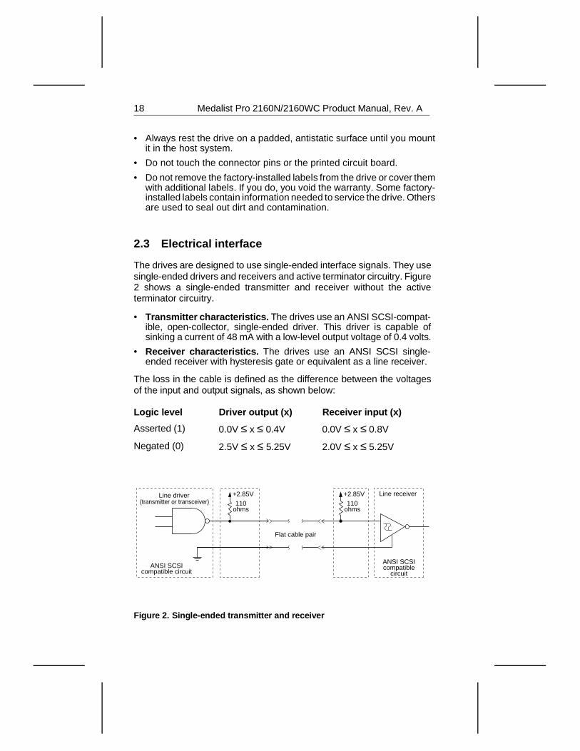
2.3 Electrical interface
The drives are designed to use single-ended interface signals. They usesingle-ended drivers and receivers and active terminator circuitry. Figure2 shows a single-ended transmitter and receiver without the activeterminator circuitry.
• Transmitter characteristics. The drives use an ANSI SCSI-compat-ible, open-collector, single-ended driver. This driver is capable ofsinking a current of 48 mA with a low-level output voltage of 0.4 volts.
• Receiver characteristics. The drives use an ANSI SCSI single-ended receiver with hysteresis gate or equivalent as a line receiver.
The loss in the cable is defined as the difference between the voltagesof the input and output signals, as shown below:
Logic level Driver output (x) Receiver input (x)
Asserted (1) 0.0V ≤ x ≤ 0.4V 0.0V ≤ x ≤ 0.8V
Negated (0) 2.5V ≤ x ≤ 5.25V 2.0V ≤ x ≤ 5.25V
Line driver(transmitter or transceiver)
+2.85V110
ohms
+2.85V110
ohms
Flat cable pair
Line receiver
ANSI SCSI compatible
circuitANSI SCSI
compatible circuit
Figure 2. Single-ended transmitter and receiver
18 Medalist Pro 2160N/2160WC Product Manual, Rev. A
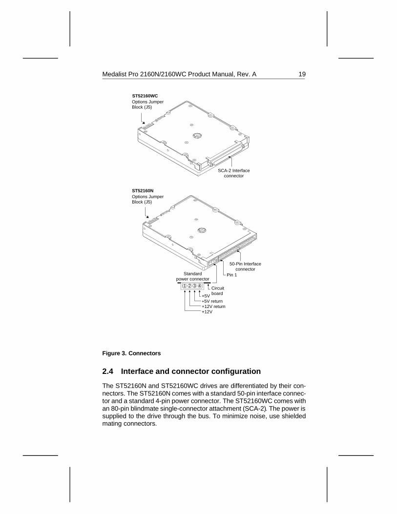
2.4 Interface and connector configuration
The ST52160N and ST52160WC drives are differentiated by their con-nectors. The ST52160N comes with a standard 50-pin interface connec-tor and a standard 4-pin power connector. The ST52160WC comes withan 80-pin blindmate single-connector attachment (SCA-2). The power issupplied to the drive through the bus. To minimize noise, use shieldedmating connectors.
Standard power connector
+5V +5V return +12V return +12V
1 2 3 4 Circuit board
50-Pin Interface connector
Pin 1
SCA-2 Interface connector
Options Jumper Block (J5)
Options Jumper Block (J5)
ST52160WC
ST52160N
Figure 3. Connectors
Medalist Pro 2160N/2160WC Product Manual, Rev. A 19
2.5 ST52160N interface connector
The ST52160N uses a standard 50-pin, nonshielded, keyed connector.The connector consists of two rows of 25 male contacts 0.100 inchesapart. Pin 1 on the connector is shown in Figure 3 on page 19. Recom-mended mating connectors and their part numbers are
listed below.
Part numbers for mating 3M connectors that are compatible with thedrives are listed below. These connectors do not have a center key andare available with or without strain relief.
Without strain reliefNo center key
With strain reliefNo center key
Closed end(for cable ends)
3M3425-7000
3M3425-7050
Open end(for daisy chain)
3M3425-6000
3M3425-6050
Part numbers for mating Molex connectors compatible with the drivesare listed below. These connectors have a center key.
Closed end(for cable ends)
Molex39-51-2504
Open end(for daisy chain)
Molex39-51-2501
Below are part numbers for strain reliefs that can be used with the Molexconnectors.
Molex strain relief,preferred versionin Europe
Molex 90170-0050
Molex strain relief,preferred versionin Japan
Molex 15-25-1503
20 Medalist Pro 2160N/2160WC Product Manual, Rev. A
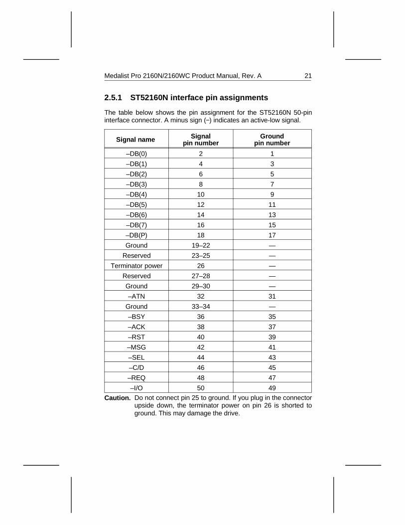
2.5.1 ST52160N interface pin assignments
The table below shows the pin assignment for the ST52160N 50-pininterface connector. A minus sign (−) indicates an active-low signal.
Signal name Signalpin number
Groundpin number
–DB(0) 2 1
–DB(1) 4 3
–DB(2) 6 5
–DB(3) 8 7
–DB(4) 10 9
–DB(5) 12 11
–DB(6) 14 13
–DB(7) 16 15
–DB(P) 18 17
Ground 19–22 —
Reserved 23–25 —
Terminator power 26 —
Reserved 27–28 —
Ground 29–30 —
–ATN 32 31
Ground 33–34 —
–BSY 36 35
–ACK 38 37
–RST 40 39
–MSG 42 41
–SEL 44 43
–C/D 46 45
–REQ 48 47
–I/O 50 49
Caution. Do not connect pin 25 to ground. If you plug in the connectorupside down, the terminator power on pin 26 is shorted toground. This may damage the drive.
Medalist Pro 2160N/2160WC Product Manual, Rev. A 21
2.5.2 ST52160WC interface connector
The ST52160WC uses an 80-pin blindmate single-connector attachment(SCA-2). It is a single-piece connector that provides power to the drivethrough the SCSI bus. The remote LED, motor start options and addi-tional binary codes are also placed on the SCSI bus. Pin 1 on theconnector is shown in Figure 3 on page 19.
We recommend the AMP blindmate receptacle assembly (part number787311-1).
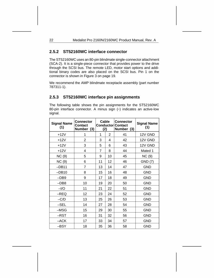
2.5.3 ST52160WC interface pin assignments
The following table shows the pin assignments for the ST52160WC80-pin interface connector. A minus sign (−) indicates an active-lowsignal.
Signal Name(1)
ConnectorContactNumber (3)
CableConductor
(2)
ConnectorContactNumber (3)
Signal Name(1)
+12V 1 1 2 41 12V GND
+12V 2 3 4 42 12V GND
+12V 3 5 6 43 12V GND
+12V 4 7 8 44 Mated 1
NC (9) 5 9 10 45 NC (9)
NC (9) 6 11 12 46 GND (7)
–DB11 7 13 14 47 GND
–DB10 8 15 16 48 GND
–DB9 9 17 18 49 GND
–DB8 10 19 20 50 GND
–I/O 11 21 22 51 GND
–REQ 12 23 24 52 GND
–C/D 13 25 26 53 GND
–SEL 14 27 28 54 GND
–MSG 15 29 30 55 GND
–RST 16 31 32 56 GND
–ACK 17 33 34 57 GND
–BSY 18 35 36 58 GND
22 Medalist Pro 2160N/2160WC Product Manual, Rev. A
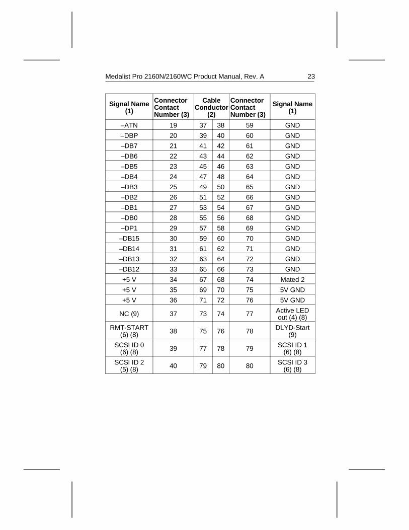
Signal Name(1)
ConnectorContactNumber (3)
CableConductor
(2)
ConnectorContactNumber (3)
Signal Name(1)
–ATN 19 37 38 59 GND
–DBP 20 39 40 60 GND
–DB7 21 41 42 61 GND
–DB6 22 43 44 62 GND
–DB5 23 45 46 63 GND
–DB4 24 47 48 64 GND
–DB3 25 49 50 65 GND
–DB2 26 51 52 66 GND
–DB1 27 53 54 67 GND
–DB0 28 55 56 68 GND
–DP1 29 57 58 69 GND
–DB15 30 59 60 70 GND
–DB14 31 61 62 71 GND
–DB13 32 63 64 72 GND
–DB12 33 65 66 73 GND
+5 V 34 67 68 74 Mated 2
+5 V 35 69 70 75 5V GND
+5 V 36 71 72 76 5V GND
NC (9) 37 73 74 77 Active LEDout (4) (8)
RMT-START(6) (8) 38 75 76 78 DLYD-Start
(9)
SCSI ID 0(6) (8) 39 77 78 79 SCSI ID 1
(6) (8)
SCSI ID 2(5) (8) 40 79 80 80 SCSI ID 3
(6) (8)
Medalist Pro 2160N/2160WC Product Manual, Rev. A 23
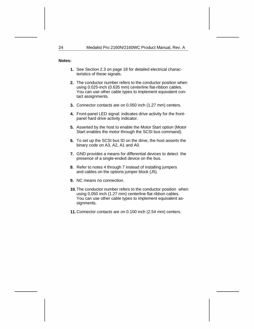
Notes:
1. See Section 2.3 on page 18 for detailed electrical charac-teristics of these signals.
2. The conductor number refers to the conductor position whenusing 0.025-inch (0.635 mm) centerline flat-ribbon cables.You can use other cable types to implement equivalent con-tact assignments.
3. Connector contacts are on 0.050 inch (1.27 mm) centers.
4. Front-panel LED signal: indicates drive activity for the front-panel hard drive activity indicator.
5. Asserted by the host to enable the Motor Start option (MotorStart enables the motor through the SCSI bus command).
6. To set up the SCSI bus ID on the drive, the host asserts thebinary code on A3, A2, A1 and A0.
7. GND provides a means for differential devices to detect thepresence of a single-ended device on the bus.
8. Refer to notes 4 through 7 instead of installing jumpersand cables on the options jumper block (J5).
9. NC means no connection.
10. The conductor number refers to the conductor position whenusing 0.050 inch (1.27 mm) centerline flat ribbon cables.You can use other cable types to implement equivalent as-signments.
11. Connector contacts are on 0.100 inch (2.54 mm) centers.
24 Medalist Pro 2160N/2160WC Product Manual, Rev. A
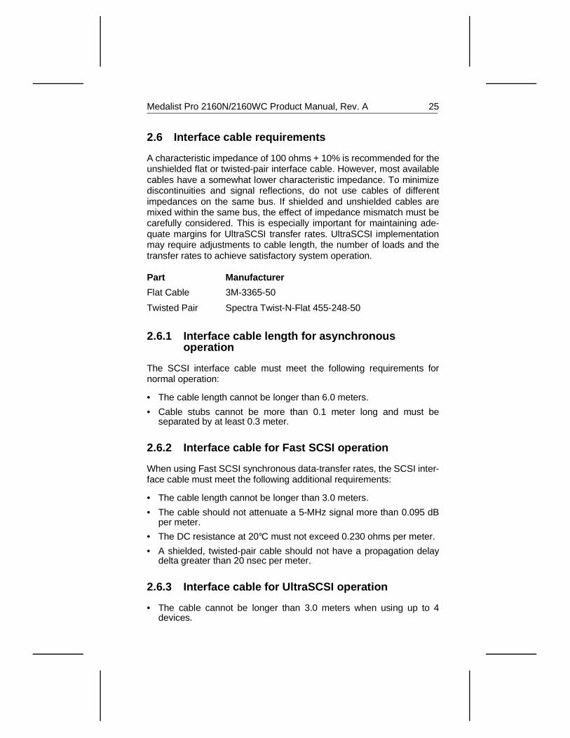
2.6 Interface cable requirements
A characteristic impedance of 100 ohms + 10% is recommended for theunshielded flat or twisted-pair interface cable. However, most availablecables have a somewhat lower characteristic impedance. To minimizediscontinuities and signal reflections, do not use cables of differentimpedances on the same bus. If shielded and unshielded cables aremixed within the same bus, the effect of impedance mismatch must becarefully considered. This is especially important for maintaining ade-quate margins for UltraSCSI transfer rates. UltraSCSI implementationmay require adjustments to cable length, the number of loads and thetransfer rates to achieve satisfactory system operation.
Part Manufacturer
Flat Cable 3M-3365-50
Twisted Pair Spectra Twist-N-Flat 455-248-50
2.6.1 Interface cable length for asynchronousoperation
The SCSI interface cable must meet the following requirements fornormal operation:
• The cable length cannot be longer than 6.0 meters.
• Cable stubs cannot be more than 0.1 meter long and must beseparated by at least 0.3 meter.
2.6.2 Interface cable for Fast SCSI operation
When using Fast SCSI synchronous data-transfer rates, the SCSI inter-face cable must meet the following additional requirements:
• The cable length cannot be longer than 3.0 meters.
• The cable should not attenuate a 5-MHz signal more than 0.095 dBper meter.
• The DC resistance at 20°C must not exceed 0.230 ohms per meter.
• A shielded, twisted-pair cable should not have a propagation delaydelta greater than 20 nsec per meter.
2.6.3 Interface cable for UltraSCSI operation
• The cable cannot be longer than 3.0 meters when using up to 4devices.
Medalist Pro 2160N/2160WC Product Manual, Rev. A 25
• The maximum cable length when using 5 to 8 devices cannot be longerthan 1.5 meters.
• Cable stubs cannot be more than 0.1 meter long and must beseparated by at least 0.3 meter.
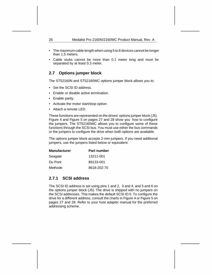
2.7 Options jumper block
The ST52160N and ST52160WC options jumper block allows you to:
• Set the SCSI ID address.
• Enable or disable active termination.
• Enable parity.
• Activate the motor start/stop option.
• Attach a remote LED.
These functions are represented on the drives’ options jumper block (J5).Figure 4 and Figure 5 on pages 27 and 28 show you how to configurethe jumpers. The ST52160WC allows you to configure some of thesefunctions through the SCSI bus. You must use either the bus commandsor the jumpers to configure the drive when both options are available.
The options jumper block accepts 2-mm jumpers. If you need additionaljumpers, use the jumpers listed below or equivalent.
Manufacturer Part number
Seagate 13211-001
Du Pont 89133-001
Methode 8618-202-70
2.7.1 SCSI address
The SCSI ID address is set using pins 1 and 2, 3 and 4, and 5 and 6 onthe options jumper block (J5). The drive is shipped with no jumpers onthe SCSI addresses. This makes the default SCSI ID 0. To configure thedrive for a different address, consult the charts in Figure 4 or Figure 5 onpages 27 and 28. Refer to your host adapter manual for the preferredaddressing scheme.
26 Medalist Pro 2160N/2160WC Product Manual, Rev. A
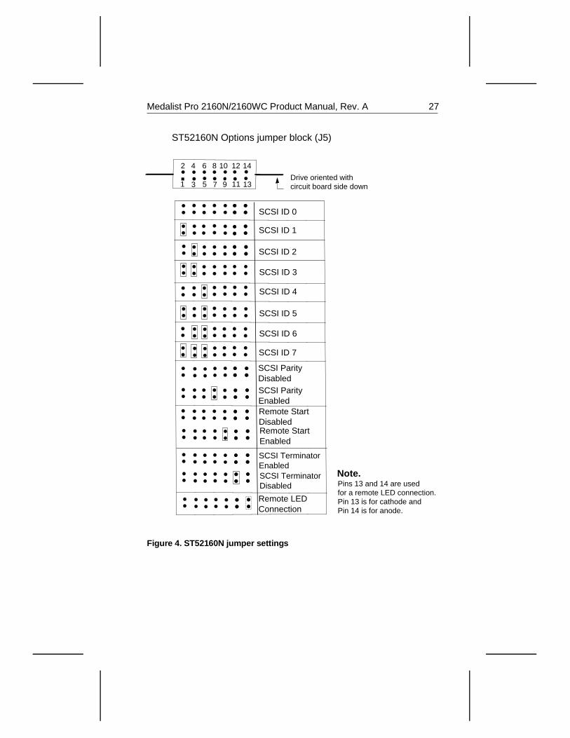
Pins 13 and 14 are used for a remote LED connection. Pin 13 is for cathode and Pin 14 is for anode.
ST52160N Options jumper block (J5)
SCSI ID 0
SCSI ID 1
SCSI ID 2
SCSI ID 3
SCSI ID 4
SCSI ID 5
SCSI ID 6
SCSI ID 7 SCSI Parity DisabledSCSI Parity EnabledRemote Start DisabledRemote Start Enabled
1
2
3
4 6 10
5 7 9 11
12
13
148
Remote LED Connection
Note.
Drive oriented with circuit board side down
SCSI Terminator EnabledSCSI Terminator Disabled
Figure 4. ST52160N jumper settings
Medalist Pro 2160N/2160WC Product Manual, Rev. A 27
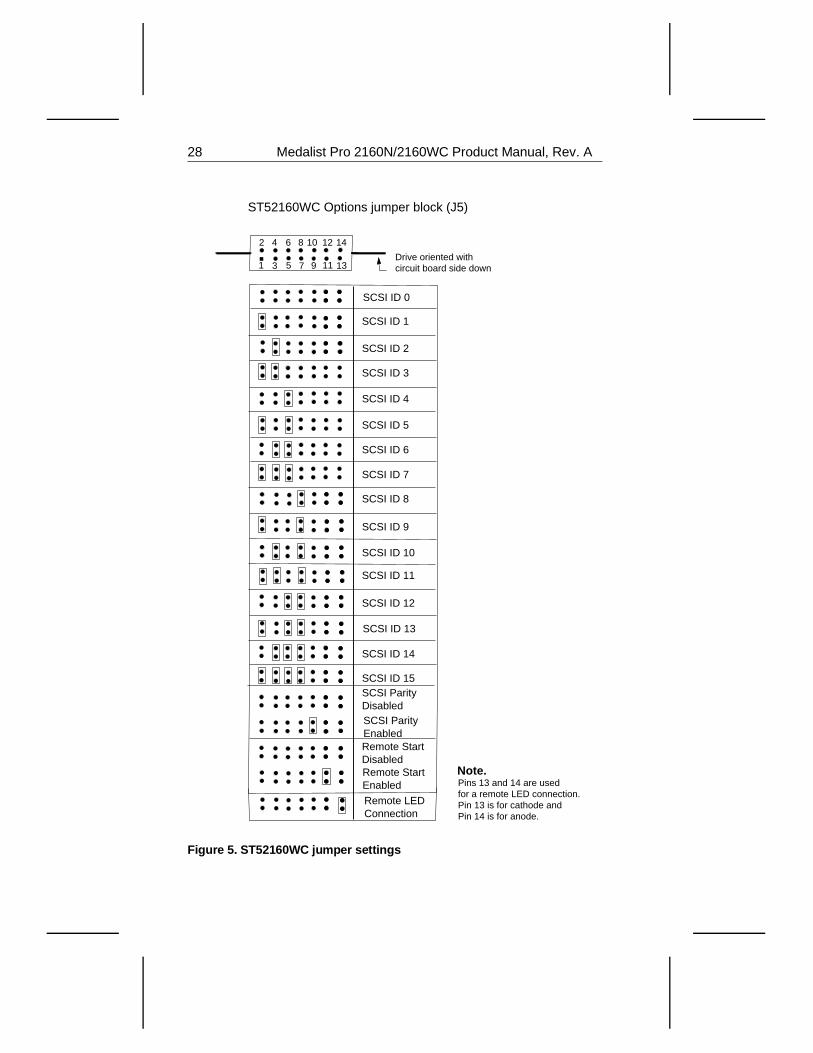
Pins 13 and 14 are used for a remote LED connection. Pin 13 is for cathode and Pin 14 is for anode.
ST52160WC Options jumper block (J5)
SCSI ID 0
SCSI ID 1
SCSI ID 2
SCSI ID 3
SCSI ID 4
SCSI ID 5
SCSI ID 6
SCSI ID 7
SCSI Parity DisabledSCSI Parity EnabledRemote Start DisabledRemote Start Enabled
SCSI ID 8
SCSI ID 9
SCSI ID 10
SCSI ID 11
SCSI ID 12
SCSI ID 13
SCSI ID 14
SCSI ID 15
1
2
3
4 6 10
5 7 9 11
12
13
148
Remote LED Connection
Note.
Drive oriented with circuit board side down
Figure 5. ST52160WC jumper settings
28 Medalist Pro 2160N/2160WC Product Manual, Rev. A
2.8 Active Termination
Active termination is configured on the ST52160N using pins 11 and 12on the J5 options jumper block. Active termination is enabled when thereis no jumper on pins 11 and 12. Active termination is disabled when ajumper is placed on pins 11 and 12. The drive provides terminationpower to the drive’s terminator chips and to the SCSI bus. No other optionis available.
Termination is not provided on the ST52160WC. You must provide yourown external termination as required.
2.9 Parity enable option
Parity is enabled on the ST52160N when a jumper is installed on pins 7and 8 of the options jumper block (J5). Parity is enabled on theST52160WC when a jumper is installed on pins 9 and 10 of the optionsjumper block (J5). Both drives are shipped with parity enabled.
2.9.1 Motor Start option
The Motor Start option causes the drive to wait for a Start/Stop Unitcommand from the host before starting or stopping the spindle motor.Motor Start is enabled on the ST52160N when a jumper is installed onpins 9 and 10 of the options jumper block (J5). Motor Start is enabled onthe ST52160WC when a jumper is installed on pins 11 and 12 of theoptions jumper block (J5).
2.9.2 Remote LED connection
Pins 13 and 14, located on the options jumper block, are reserved for aremote LED. Pin 13 is ground. The options jumper block accepts 2-mmconnectors. You may need to replace the current LED cable-connectorwith a 2-mm connector. If you are placing the drive in an array configu-ration, we recommend the LiteOn (part number LTL-3231A) LED orequivalent.
2.10 Daisy chaining
You can connect the ST52160N in a daisy-chain configuration with amaximum of eight SCSI devices (host included) that have single-endeddrivers and receivers. Each SCSI device must be set to a unique SCSIID number. SCSI ID 7 is usually used by the host adapter.
Medalist Pro 2160N/2160WC Product Manual, Rev. A 29
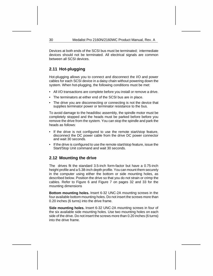
Devices at both ends of the SCSI bus must be terminated; intermediatedevices should not be terminated. All electrical signals are commonbetween all SCSI devices.
2.11 Hot-plugging
Hot-plugging allows you to connect and disconnect the I/O and powercables for each SCSI device in a daisy chain without powering down thesystem. When hot-plugging, the following conditions must be met:
• All I/O transactions are complete before you install or remove a drive.
• The terminators at either end of the SCSI bus are in place.
• The drive you are disconnecting or connecting is not the device thatsupplies terminator power or terminator resistance to the bus.
To avoid damage to the head/disc assembly, the spindle motor must becompletely stopped and the heads must be parked before before youremove the drive from the system. You can stop the spindle and park theheads as follows:
• If the drive is not configured to use the remote start/stop feature,disconnect the DC power cable from the drive DC power connectorand wait 30 seconds.
• If the drive is configured to use the remote start/stop feature, issue theStart/Stop Unit command and wait 30 seconds.
2.12 Mounting the drive
The drives fit the standard 3.5-inch form-factor but have a 0.75-inchheight profile and a 5.38-inch depth profile. You can mount them securelyin the computer using either the bottom or side mounting holes, asdescribed below. Position the drive so that you do not strain or crimp thecables. Refer to Figure 6 and Figure 7 on pages 32 and 33 for themounting dimensions
Bottom mounting holes. Insert 6-32 UNC-2A mounting screws in thefour available bottom mounting holes. Do not insert the screws more than0.20 inches (6 turns) into the drive frame.
Side mounting holes. Insert 6-32 UNC-2A mounting screws in four ofthe six available side mounting holes. Use two mounting holes on eachside of the drive. Do not insert the screws more than 0.20 inches (6 turns)into the drive frame.
30 Medalist Pro 2160N/2160WC Product Manual, Rev. A
Caution. To avoid damaging the drive:
• Use only mounting screws of the type specified.
• Gently tighten the mounting screws—do not apply more than 6 inch-lbof torque.
Medalist Pro 2160N/2160WC Product Manual, Rev. A 31
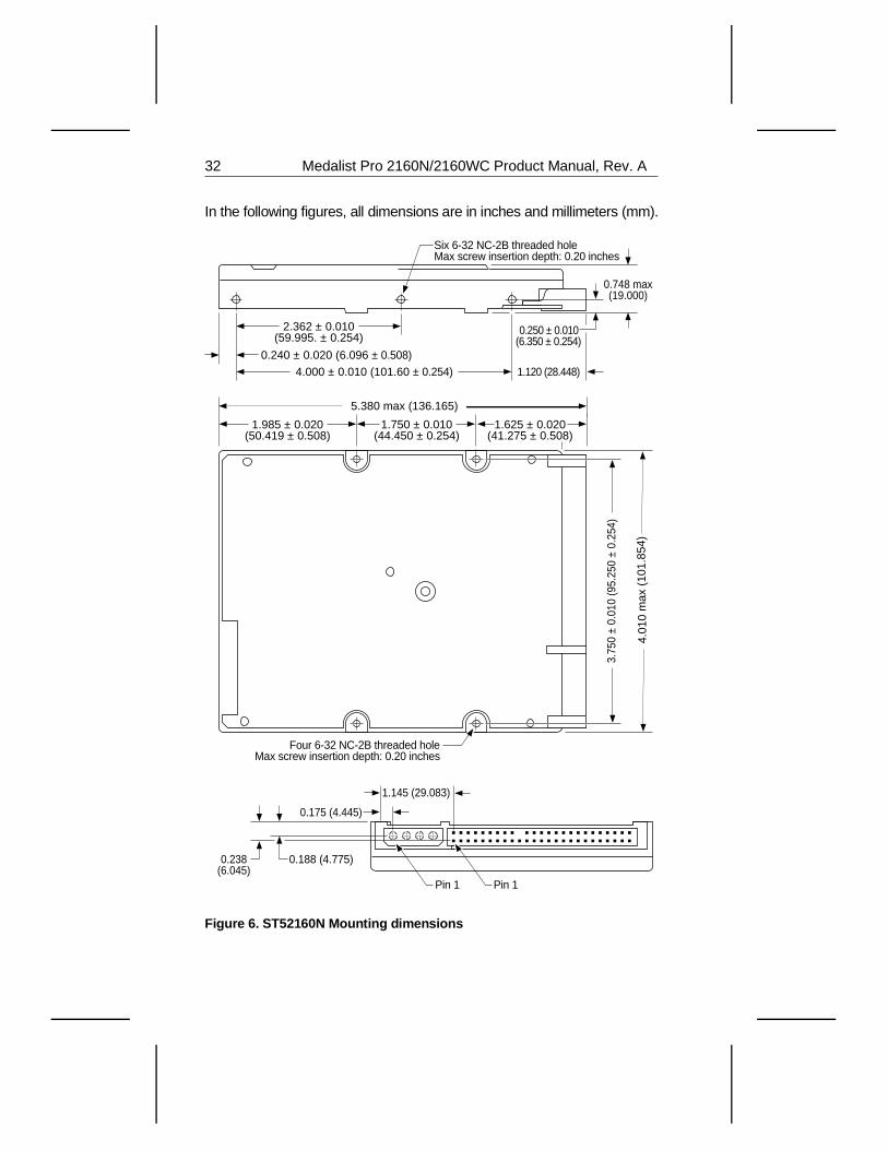
In the following figures, all dimensions are in inches and millimeters (mm).
5.380 max (136.165)
1.985 ± 0.020 (50.419 ± 0.508)
1.750 ± 0.010 (44.450 ± 0.254)
1.625 ± 0.020 (41.275 ± 0.508)
3.75
0 ±
0.01
0 (9
5.25
0 ±
0.25
4)
4.01
0 m
ax (
101.
854)
0.748 max (19.000)
2.362 ± 0.010 (59.995. ± 0.254)
0.240 ± 0.020 (6.096 ± 0.508)
4.000 ± 0.010 (101.60 ± 0.254)
0.250 ± 0.010 (6.350 ± 0.254)
1.120 (28.448)
Six 6-32 NC-2B threaded hole Max screw insertion depth: 0.20 inches
Four 6-32 NC-2B threaded hole Max screw insertion depth: 0.20 inches
Pin 1Pin 1
0.188 (4.775)
1.145 (29.083)
0.175 (4.445)
0.238 (6.045)
Figure 6. ST52160N Mounting dimensions
32 Medalist Pro 2160N/2160WC Product Manual, Rev. A
5.380 max (136.165)
1.985 ± 0.020 (50.419 ± 0.508)
1.750 ± 0.010 (44.450 ± 0.254)
1.625 ± 0.020 (41.275 ± 0.508)
3.75
0 ±
0.01
0 (9
5.25
0 ±
0.25
4)
4.01
0 m
ax (
101.
854)
1.87
5 (4
7.62
5)
0.748 max (19.000)
2.362 ± 0.010 (59.995. ± 0.254)
0.240 ± 0.020 (6.096 ± 0.508)4.000 ± 0.010 (101.60 ± 0.254)
0.250 ± 0.010 (6.350 ± 0.254)
1.120 (28.448)
Six 6-32 NC-2B threaded hole Max screw insertion depth: 0.20 inches
Four 6-32 NC-2B threaded hole Max screw insertion depth: 0.20 inches
0.181 (4.597)
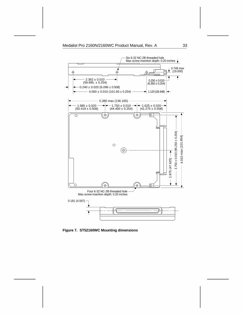
Figure 7. ST52160WC Mounting dimensions
Medalist Pro 2160N/2160WC Product Manual, Rev. A 33

34 Medalist Pro 2160N/2160WC Product Manual, Rev. A
3.0 Command setThe drives support a subset of the Group 0, Group 1 and Group 2standard SCSI commands. The commands are described in this section.
3.1 Command descriptor block
The initiator makes a request to the drive by sending a commanddescriptor block (CDB) to the drive. Each CDB has the following commoncharacteristics:
• Byte 0 always contains the operation code.
• The three most significant bits (bits 7–5) of byte 1 contain the logicalunit number (LUN). This field is ignored if an Identify Message is sent.
• The last byte is always zero.
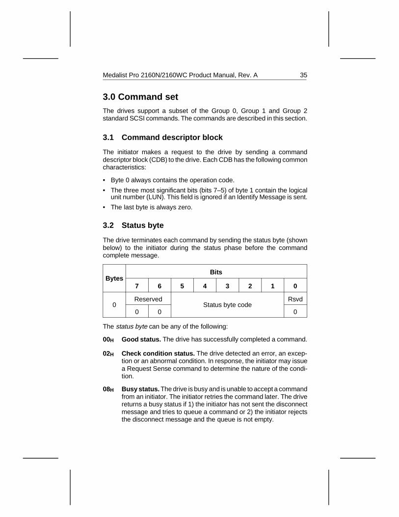
3.2 Status byte
The drive terminates each command by sending the status byte (shownbelow) to the initiator during the status phase before the commandcomplete message.
BytesBits
7 6 5 4 3 2 1 0
0Reserved
Status byte codeRsvd
0 0 0
The status byte can be any of the following:
00H Good status. The drive has successfully completed a command.
02H Check condition status. The drive detected an error, an excep-tion or an abnormal condition. In response, the initiator may issuea Request Sense command to determine the nature of the condi-tion.
08H Busy status. The drive is busy and is unable to accept a commandfrom an initiator. The initiator retries the command later. The drivereturns a busy status if 1) the initiator has not sent the disconnectmessage and tries to queue a command or 2) the initiator rejectsthe disconnect message and the queue is not empty.
Medalist Pro 2160N/2160WC Product Manual, Rev. A 35
18H Reservation conflict status. A SCSI device tried to access thedrive, but was unable to because the drive was already reservedby another SCSI device.
28H Queue full status. The drive received a command but rejected itbecause the queue was full. The drive only uses this status iftagged command queuing is implemented.
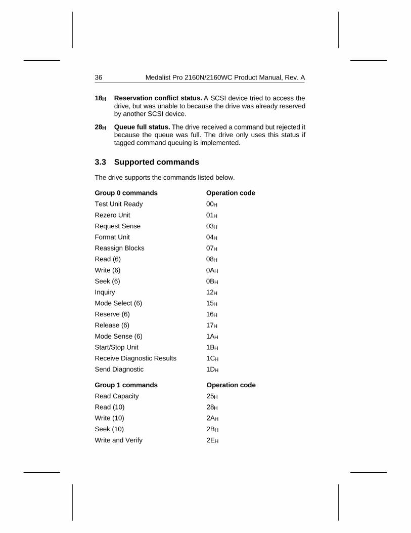
3.3 Supported commands
The drive supports the commands listed below.
Group 0 commands Operation code
Test Unit Ready 00H
Rezero Unit 01H
Request Sense 03H
Format Unit 04H
Reassign Blocks 07H
Read (6) 08H
Write (6) 0AH
Seek (6) 0BH
Inquiry 12H
Mode Select (6) 15H
Reserve (6) 16H
Release (6) 17H
Mode Sense (6) 1AH
Start/Stop Unit 1BH
Receive Diagnostic Results 1CH
Send Diagnostic 1DH
Group 1 commands Operation code
Read Capacity 25H
Read (10) 28H
Write (10) 2AH
Seek (10) 2BH
Write and Verify 2EH
36 Medalist Pro 2160N/2160WC Product Manual, Rev. A
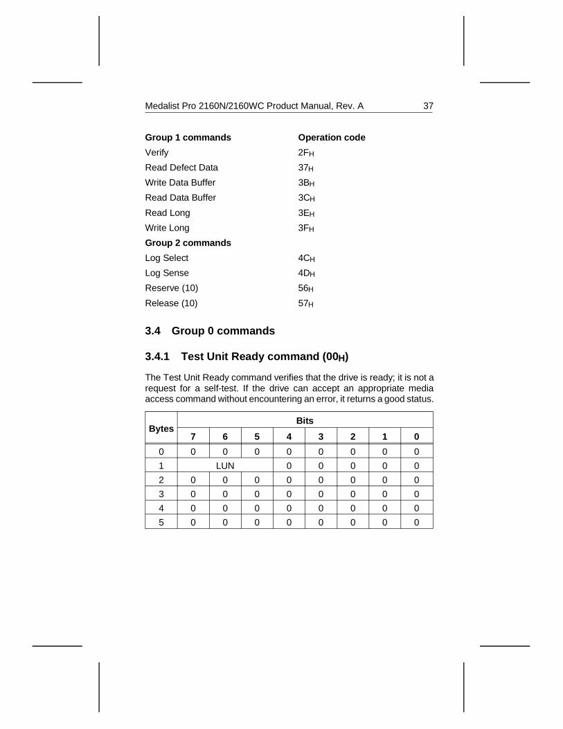
Group 1 commands Operation code
Verify 2FH
Read Defect Data 37H
Write Data Buffer 3BH
Read Data Buffer 3CH
Read Long 3EH
Write Long 3FH
Group 2 commands
Log Select 4CH
Log Sense 4DH
Reserve (10) 56H
Release (10) 57H
3.4 Group 0 commands
3.4.1 Test Unit Ready command (00 H)
The Test Unit Ready command verifies that the drive is ready; it is not arequest for a self-test. If the drive can accept an appropriate mediaaccess command without encountering an error, it returns a good status.
BytesBits
7 6 5 4 3 2 1 0
0 0 0 0 0 0 0 0 0
1 LUN 0 0 0 0 0
2 0 0 0 0 0 0 0 0
3 0 0 0 0 0 0 0 0
4 0 0 0 0 0 0 0 0
5 0 0 0 0 0 0 0 0
Medalist Pro 2160N/2160WC Product Manual, Rev. A 37
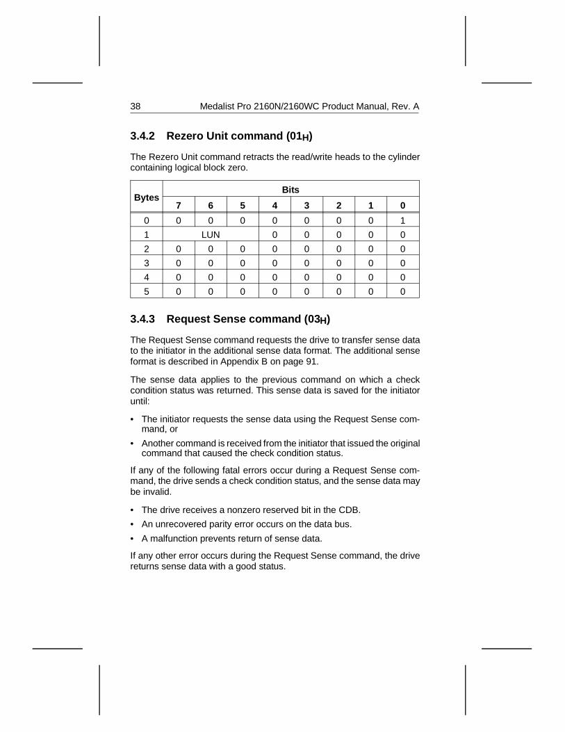
3.4.2 Rezero Unit command (01 H)
The Rezero Unit command retracts the read/write heads to the cylindercontaining logical block zero.
BytesBits
7 6 5 4 3 2 1 0
0 0 0 0 0 0 0 0 1
1 LUN 0 0 0 0 0
2 0 0 0 0 0 0 0 0
3 0 0 0 0 0 0 0 0
4 0 0 0 0 0 0 0 0
5 0 0 0 0 0 0 0 0
3.4.3 Request Sense command (03 H)
The Request Sense command requests the drive to transfer sense datato the initiator in the additional sense data format. The additional senseformat is described in Appendix B on page 91.
The sense data applies to the previous command on which a checkcondition status was returned. This sense data is saved for the initiatoruntil:
• The initiator requests the sense data using the Request Sense com-mand, or
• Another command is received from the initiator that issued the originalcommand that caused the check condition status.
If any of the following fatal errors occur during a Request Sense com-mand, the drive sends a check condition status, and the sense data maybe invalid.
• The drive receives a nonzero reserved bit in the CDB.
• An unrecovered parity error occurs on the data bus.
• A malfunction prevents return of sense data.
If any other error occurs during the Request Sense command, the drivereturns sense data with a good status.
38 Medalist Pro 2160N/2160WC Product Manual, Rev. A
BytesBits
7 6 5 4 3 2 1 0
0 0 0 0 0 0 0 1 1
1 LUN 0 0 0 0 0
2 0 0 0 0 0 0 0 0
3 0 0 0 0 0 0 0 0
4 Allocation length
5 0 0 0 0 0 0 0 0
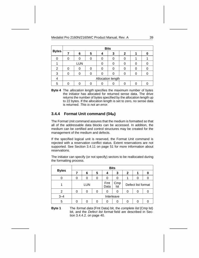
Byte 4 The allocation length specifies the maximum number of bytesthe initiator has allocated for returned sense data. The drivereturns the number of bytes specified by the allocation length upto 22 bytes. If the allocation length is set to zero, no sense datais returned. This is not an error.
3.4.4 Format Unit command (04 H)
The Format Unit command assures that the medium is formatted so thatall of the addressable data blocks can be accessed. In addition, themedium can be certified and control structures may be created for themanagement of the medium and defects.
If the specified logical unit is reserved, the Format Unit command isrejected with a reservation conflict status. Extent reservations are notsupported. See Section 3.4.11 on page 51 for more information aboutreservations.
The initiator can specify (or not specify) sectors to be reallocated duringthe formatting process.
BytesBits
7 6 5 4 3 2 1 0
0 0 0 0 0 0 1 0 0
1 LUN FmtData
Cmplst Defect list format
2 0 0 0 0 0 0 0 0
3–4 Interleave
5 0 0 0 0 0 0 0 0
Byte 1 The format data (Fmt Data) bit, the complete list (Cmp lst)bit, and the Defect list format field are described in Sec-tion 3.4.4.2. on page 40.
Medalist Pro 2160N/2160WC Product Manual, Rev. A 39
Bytes 3–4 The interleave field is not supported. It can contain anyvalue. However, the drive always formats the disc with aninterleave of 1:1.
3.4.4.1 Defect lists
When the Format Unit command is issued, media defect information canbe gathered from several sources. Four of these sources—primarydefect list, certification defect list, data defect list and grown defectlist—are defect lists written to the drive. They are defined below. Assign-ments in Byte 1 of the defect list header—described in Section 3.4.4.3on page 42, determine the use of the defect list during formatting. TheReassign Blocks and Read Defect Data commands also use these lists.
• The primary defect list (PList) is a list of media defects found whenthe drive is manufactured and written to the disc in an area that is notdirectly accessible by the user. These defects are considered perma-nent and cannot be changed.
• The certification defect list (CList) is a temporary list of unrecoverablesectors that the drive reads during the certify of the Format Unitcommand. The CList is incorporated into the GList before the end ofthe Format Unit command.
• The data defect list (DList) is a list of sectors the initiator supplies tothe drive during a data-out phase of the current Format Unit command.The drive sends the DList in the last bytes of the data-out phase(described in Section 3.4.4.3) and may add it to the GList.
• The grown defect list (GList) is a list of defects supplied by the initiatoror detected by the target but does not include defects from the PList.The GList includes defects detected by the format operation duringmedia certification, the DList, defects previously identified with aReassign Blocks command and defects previously detected by thetarget and automatically reallocated.
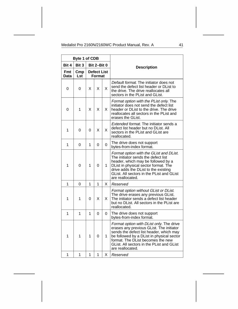
3.4.4.2 Format Unit parameters
For each format listed in the following table, except the default format,the initiator sends a defect list header. This header is described in Section3.4.4.3. The physical sector format is described in Section 3.4.4.4. onpage 43. The block format and bytes-from-index format are not sup-ported.
40 Medalist Pro 2160N/2160WC Product Manual, Rev. A
Byte 1 of CDB
DescriptionBit 4 Bit 3 Bit 2–Bit 0
FmtData
CmpLst
Defect ListFormat
0 0 X X X
Default format. The initiator does notsend the defect list header or DList tothe drive. The drive reallocates allsectors in the PList and GList.
0 1 X X X
Format option with the PList only. Theinitiator does not send the defect listheader or DList to the drive. The drivereallocates all sectors in the PList anderases the GList.
1 0 0 X X
Extended format. The initiator sends adefect list header but no DList. Allsectors in the PList and GList arereallocated.
1 0 1 0 0 The drive does not supportbytes-from-index format.
1 0 1 0 1
Format option with the GList and DList.The initiator sends the defect listheader, which may be followed by aDList in physical sector format. Thedrive adds the DList to the existingGList. All sectors in the PList and GListare reallocated.
1 0 1 1 X Reserved
1 1 0 X X
Format option without GList or DList.The drive erases any previous GList.The initiator sends a defect list headerbut no DList. All sectors in the PList arereallocated.
1 1 1 0 0 The drive does not supportbytes-from-index format.
1 1 1 0 1
Format option with DList only. The driveerases any previous GList. The initiatorsends the defect list header, which maybe followed by a DList in physical sectorformat. The DList becomes the newGList. All sectors in the PList and GListare reallocated.
1 1 1 1 X Reserved
Medalist Pro 2160N/2160WC Product Manual, Rev. A 41
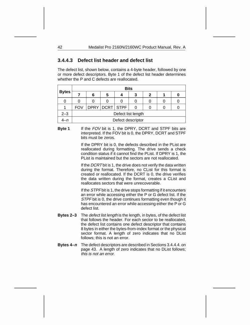
3.4.4.3 Defect list header and defect list
The defect list, shown below, contains a 4-byte header, followed by oneor more defect descriptors. Byte 1 of the defect list header determineswhether the P and C defects are reallocated.
BytesBits
7 6 5 4 3 2 1 0
0 0 0 0 0 0 0 0 0
1 FOV DPRY DCRT STPF 0 0 0 0
2–3 Defect list length
4–n Defect descriptor
Byte 1 If the FOV bit is 1, the DPRY, DCRT and STPF bits areinterpreted. If the FOV bit is 0, the DPRY, DCRT and STPFbits must be zeros.
If the DPRY bit is 0, the defects described in the PList arereallocated during formatting. The drive sends a checkcondition status if it cannot find the PList. If DPRY is 1, thePList is maintained but the sectors are not reallocated.
If the DCRT bit is 1, the drive does not verify the data writtenduring the format. Therefore, no CList for this format iscreated or reallocated. If the DCRT is 0, the drive verifiesthe data written during the format, creates a CList andreallocates sectors that were unrecoverable.
If the STPF bit is 1, the drive stops formatting if it encountersan error while accessing either the P or G defect list. If theSTPF bit is 0, the drive continues formatting even though ithas encountered an error while accessing either the P or Gdefect list.
Bytes 2–3 The defect list length is the length, in bytes, of the defect listthat follows the header. For each sector to be reallocated,the defect list contains one defect descriptor that contains8 bytes in either the bytes-from-index format or the physicalsector format. A length of zero indicates that no DListfollows; this is not an error.
Bytes 4– n The defect descriptors are described in Sections 3.4.4.4. onpage 43. A length of zero indicates that no DList follows;this is not an error.
42 Medalist Pro 2160N/2160WC Product Manual, Rev. A
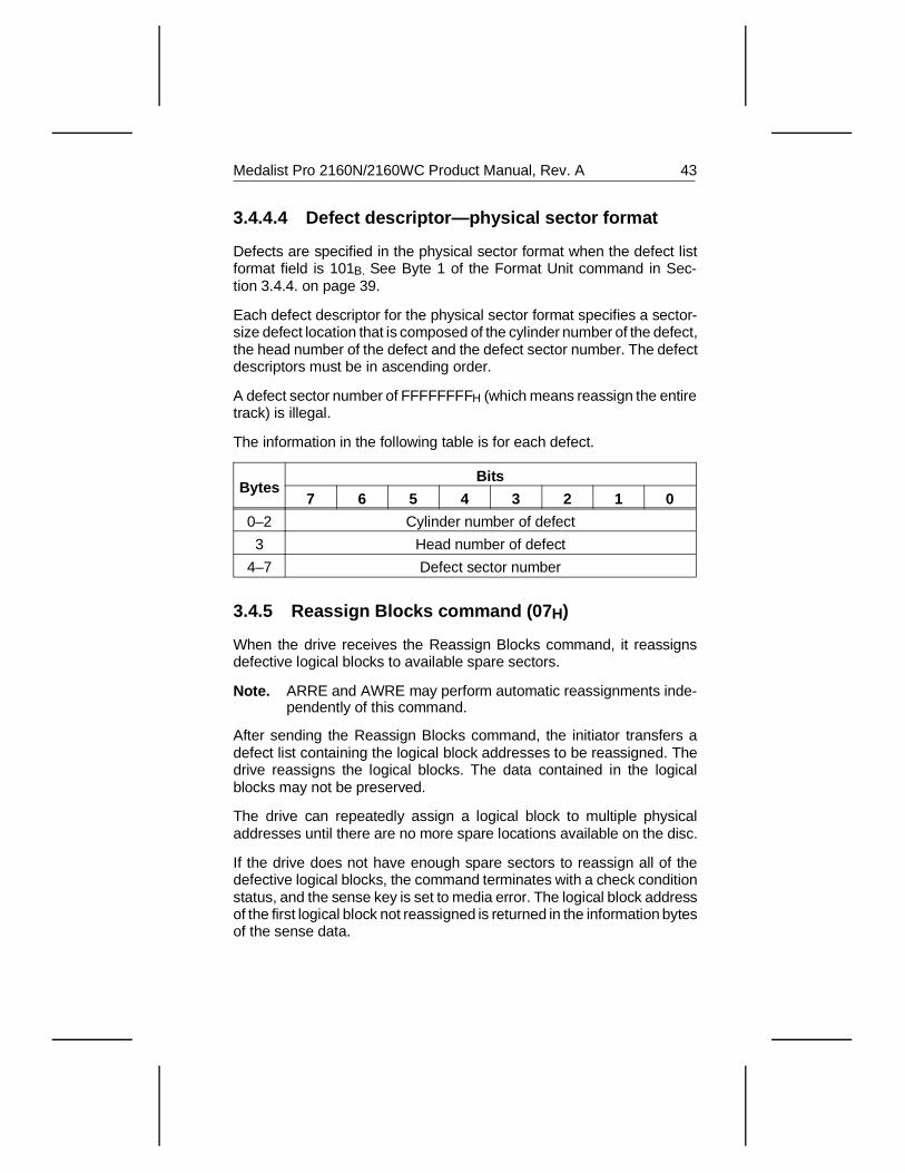
3.4.4.4 Defect descriptor—physical sector format
Defects are specified in the physical sector format when the defect listformat field is 101B. See Byte 1 of the Format Unit command in Sec-tion 3.4.4. on page 39.
Each defect descriptor for the physical sector format specifies a sector-size defect location that is composed of the cylinder number of the defect,the head number of the defect and the defect sector number. The defectdescriptors must be in ascending order.
A defect sector number of FFFFFFFFH (which means reassign the entiretrack) is illegal.
The information in the following table is for each defect.
BytesBits
7 6 5 4 3 2 1 0
0–2 Cylinder number of defect
3 Head number of defect
4–7 Defect sector number
3.4.5 Reassign Blocks command (07 H)
When the drive receives the Reassign Blocks command, it reassignsdefective logical blocks to available spare sectors.
Note. ARRE and AWRE may perform automatic reassignments inde-pendently of this command.
After sending the Reassign Blocks command, the initiator transfers adefect list containing the logical block addresses to be reassigned. Thedrive reassigns the logical blocks. The data contained in the logicalblocks may not be preserved.
The drive can repeatedly assign a logical block to multiple physicaladdresses until there are no more spare locations available on the disc.
If the drive does not have enough spare sectors to reassign all of thedefective logical blocks, the command terminates with a check conditionstatus, and the sense key is set to media error. The logical block addressof the first logical block not reassigned is returned in the information bytesof the sense data.
Medalist Pro 2160N/2160WC Product Manual, Rev. A 43
BytesBits
7 6 5 4 3 2 1 0
0 0 0 0 0 0 1 1 1
1 LUN 0 0 0 0 0
2 0 0 0 0 0 0 0 0
3 0 0 0 0 0 0 0 0
4 0 0 0 0 0 0 0 0
5 0 0 0 0 0 0 0 0
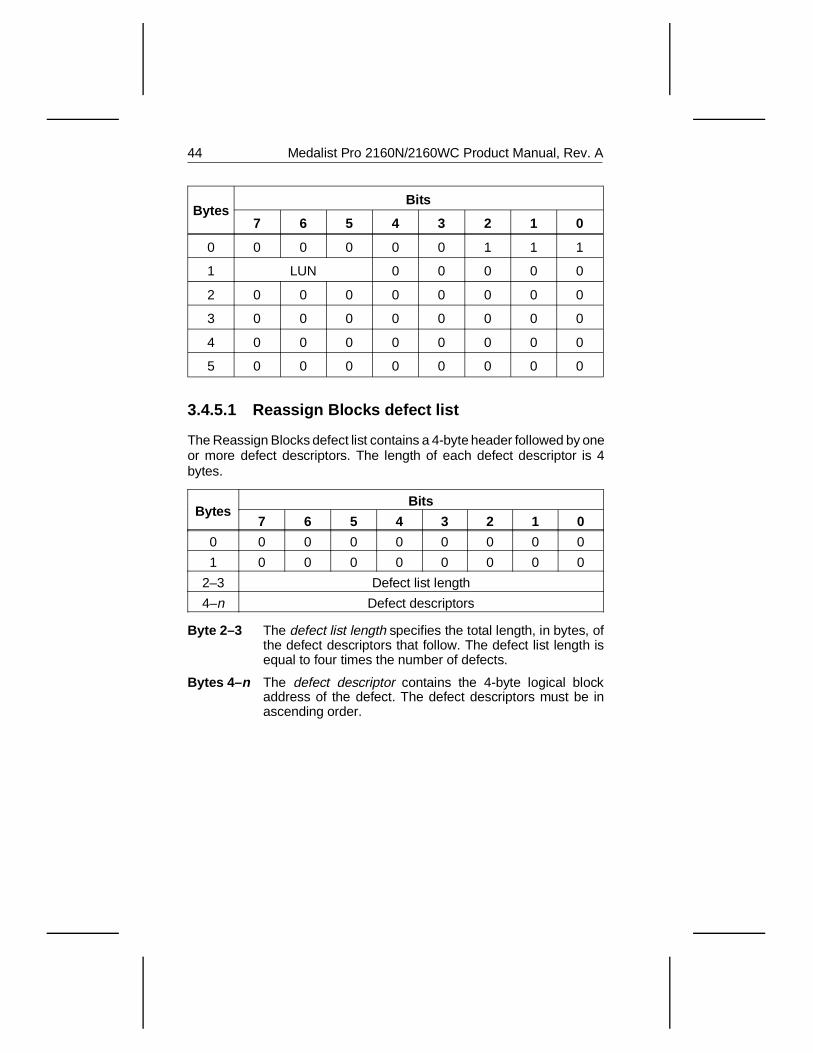
3.4.5.1 Reassign Blocks defect list
The Reassign Blocks defect list contains a 4-byte header followed by oneor more defect descriptors. The length of each defect descriptor is 4bytes.
BytesBits
7 6 5 4 3 2 1 0
0 0 0 0 0 0 0 0 0
1 0 0 0 0 0 0 0 0
2–3 Defect list length
4–n Defect descriptors
Byte 2–3 The defect list length specifies the total length, in bytes, ofthe defect descriptors that follow. The defect list length isequal to four times the number of defects.
Bytes 4– n The defect descriptor contains the 4-byte logical blockaddress of the defect. The defect descriptors must be inascending order.
44 Medalist Pro 2160N/2160WC Product Manual, Rev. A
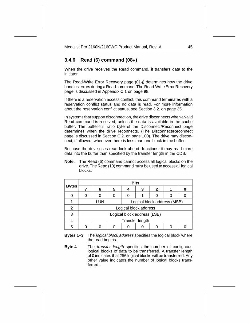
3.4.6 Read (6) command (08 H)
When the drive receives the Read command, it transfers data to theinitiator.
The Read-Write Error Recovery page (01H) determines how the drivehandles errors during a Read command. The Read-Write Error Recoverypage is discussed in Appendix C.1 on page 98.
If there is a reservation access conflict, this command terminates with areservation conflict status and no data is read. For more informationabout the reservation conflict status, see Section 3.2. on page 35.
In systems that support disconnection, the drive disconnects when a validRead command is received, unless the data is available in the cachebuffer. The buffer-full ratio byte of the Disconnect/Reconnect pagedetermines when the drive reconnects. (The Disconnect/Reconnectpage is discussed in Section C.2. on page 100). The drive may discon-nect, if allowed, whenever there is less than one block in the buffer.
Because the drive uses read look-ahead functions, it may read moredata into the buffer than specified by the transfer length in the CDB.
Note. The Read (6) command cannot access all logical blocks on thedrive. The Read (10) command must be used to access all logicalblocks.
BytesBits
7 6 5 4 3 2 1 0
0 0 0 0 0 1 0 0 0
1 LUN Logical block address (MSB)
2 Logical block address
3 Logical block address (LSB)
4 Transfer length
5 0 0 0 0 0 0 0 0
Bytes 1–3 The logical block address specifies the logical block wherethe read begins.
Byte 4 The transfer length specifies the number of contiguouslogical blocks of data to be transferred. A transfer lengthof 0 indicates that 256 logical blocks will be transferred. Anyother value indicates the number of logical blocks trans-ferred.
Medalist Pro 2160N/2160WC Product Manual, Rev. A 45
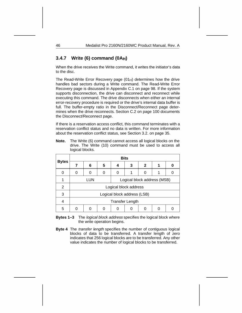
3.4.7 Write (6) command (0A H)
When the drive receives the Write command, it writes the initiator’s datato the disc.
The Read-Write Error Recovery page (01H) determines how the drivehandles bad sectors during a Write command. The Read-Write ErrorRecovery page is discussed in Appendix C.1 on page 98. If the systemsupports disconnection, the drive can disconnect and reconnect whileexecuting this command. The drive disconnects when either an internalerror-recovery procedure is required or the drive’s internal data buffer isfull. The buffer-empty ratio in the Disconnect/Reconnect page deter-mines when the drive reconnects. Section C.2 on page 100 documentsthe Disconnect/Reconnect page.
If there is a reservation access conflict, this command terminates with areservation conflict status and no data is written. For more informationabout the reservation conflict status, see Section 3.2. on page 35.
Note. The Write (6) command cannot access all logical blocks on thedrive. The Write (10) command must be used to access alllogical blocks.
BytesBits
7 6 5 4 3 2 1 0
0 0 0 0 0 1 0 1 0
1 LUN Logical block address (MSB)
2 Logical block address
3 Logical block address (LSB)
4 Transfer Length
5 0 0 0 0 0 0 0 0
Bytes 1–3 The logical block address specifies the logical block wherethe write operation begins.
Byte 4 The transfer length specifies the number of contiguous logicalblocks of data to be transferred. A transfer length of zeroindicates that 256 logical blocks are to be transferred. Any othervalue indicates the number of logical blocks to be transferred.
46 Medalist Pro 2160N/2160WC Product Manual, Rev. A
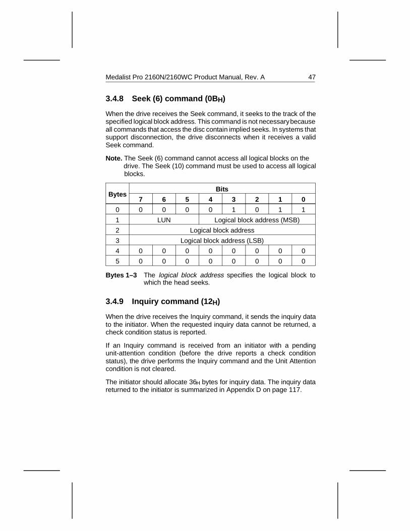
3.4.8 Seek (6) command (0B H)
When the drive receives the Seek command, it seeks to the track of thespecified logical block address. This command is not necessary becauseall commands that access the disc contain implied seeks. In systems thatsupport disconnection, the drive disconnects when it receives a validSeek command.
Note. The Seek (6) command cannot access all logical blocks on the drive. The Seek (10) command must be used to access all logical blocks.
BytesBits
7 6 5 4 3 2 1 0
0 0 0 0 0 1 0 1 1
1 LUN Logical block address (MSB)
2 Logical block address
3 Logical block address (LSB)
4 0 0 0 0 0 0 0 0
5 0 0 0 0 0 0 0 0
Bytes 1–3 The logical block address specifies the logical block towhich the head seeks.
3.4.9 Inquiry command (12 H)
When the drive receives the Inquiry command, it sends the inquiry datato the initiator. When the requested inquiry data cannot be returned, acheck condition status is reported.
If an Inquiry command is received from an initiator with a pendingunit-attention condition (before the drive reports a check conditionstatus), the drive performs the Inquiry command and the Unit Attentioncondition is not cleared.
The initiator should allocate 36H bytes for inquiry data. The inquiry datareturned to the initiator is summarized in Appendix D on page 117.
Medalist Pro 2160N/2160WC Product Manual, Rev. A 47
BytesBits
7 6 5 4 3 2 1 0
0 0 0 0 1 0 0 1 0
1 LUN Reserved EVPD
2Page code
0 0 0 0 0 0 0 0
3 0 0 0 0 0 0 0 0
4 Allocation length, in bytes
5 0 0 0 0 0 0 0 0
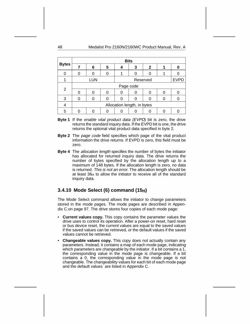
Byte 1 If the enable vital product data (EVPD) bit is zero, the drivereturns the standard inquiry data. If the EVPD bit is one, the drivereturns the optional vital product data specified in byte 2.
Byte 2 The page code field specifies which page of the vital productinformation the drive returns. If EVPD is zero, this field must bezero.
Byte 4 The allocation length specifies the number of bytes the initiatorhas allocated for returned inquiry data. The drive returns thenumber of bytes specified by the allocation length up to amaximum of 148 bytes. If the allocation length is zero, no datais returned. This is not an error. The allocation length should beat least 36H to allow the initiator to receive all of the standardinquiry data.
3.4.10 Mode Select (6) command (15 H)
The Mode Select command allows the initiator to change parametersstored in the mode pages. The mode pages are described in Appen-dix C.on page 97. The drive stores four copies of each mode page:
• Current values copy. This copy contains the parameter values thedrive uses to control its operation. After a power-on reset, hard resetor bus device reset, the current values are equal to the saved valuesif the saved values can be retrieved, or the default values if the savedvalues cannot be retrieved.
• Changeable values copy. This copy does not actually contain anyparameters. Instead, it contains a map of each mode page, indicatingwhich parameters are changeable by the initiator. If a bit contains a 1,the corresponding value in the mode page is changeable. If a bitcontains a 0, the corresponding value in the mode page is notchangeable. The changeability values for each bit of each mode pageand the default values are listed in Appendix C.
48 Medalist Pro 2160N/2160WC Product Manual, Rev. A
• Default values copy. This copy contains the parameter values thedrive used as its current values when it was manufactured. The drivedefaults to these values after a reset condition, unless valid savedvalues are available. The default values are listed in Appendix C onpage 97.
• Saved values copy. The saved values are the values the drive stores.If the parameter is changeable, these values can be set using a ModeSelect command. If the parameter is not changeable, the defaultvalues are always used.
The drive has one set of mode parameters for all of the initiators on theSCSI bus. If the initiator that issued the Mode Select command changesa parameter that applies to other initiators, the drive generates a sensekey of Unit Attention with an additional sense key of mode parameterschanged (2AH/01) for all the other initiators. The sense keys and addi-tional sense codes are discussed in Appendix B on page 91.
Before sending the Mode Select command, the initiator should send aMode Sense command requesting that the drive return the changeablevalues for all pages. The initiator uses this information to determine whichpages are supported, the proper length for those pages and whichparameters in those pages can be changed for that logical unit. Also,before sending each Mode Select command, the initiator should send aMode Sense command to request the current values.
When the drive receives the Mode Select command, it updates thesavable parameters with the current values included in the Mode Selectcommand. After the drive saves the parameters, it reports a good status.The drive verifies all Mode Select data.
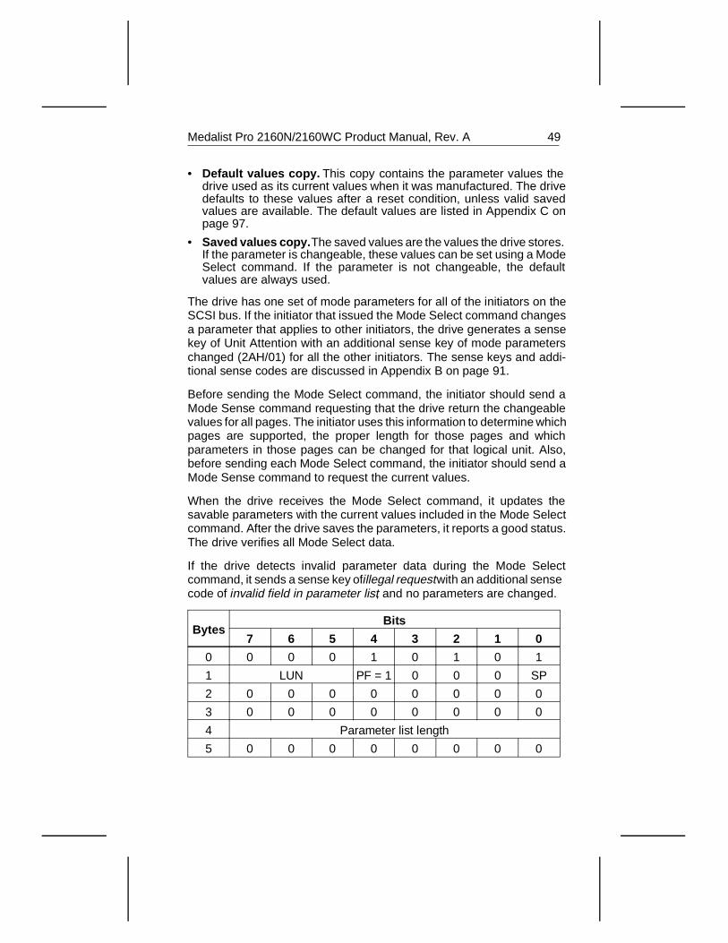
If the drive detects invalid parameter data during the Mode Selectcommand, it sends a sense key of illegal request with an additional sensecode of invalid field in parameter list, and no parameters are changed.
BytesBits
7 6 5 4 3 2 1 0
0 0 0 0 1 0 1 0 1
1 LUN PF = 1 0 0 0 SP
2 0 0 0 0 0 0 0 0
3 0 0 0 0 0 0 0 0
4 Parameter list length
5 0 0 0 0 0 0 0 0
Medalist Pro 2160N/2160WC Product Manual, Rev. A 49
Byte 1 The page format (PF) bit is always one. This means that the datasent by the initiator after the mode select header and blockdescriptors complies with the page format.
When the save pages (SP) bit is 1, the drive saves the savablepages in nonvolatile memory.
When the save pages (SP) bit is 0, the drive saves the currentpages in RAM only, which means that the parameters are lostwhen the drive is powered down.
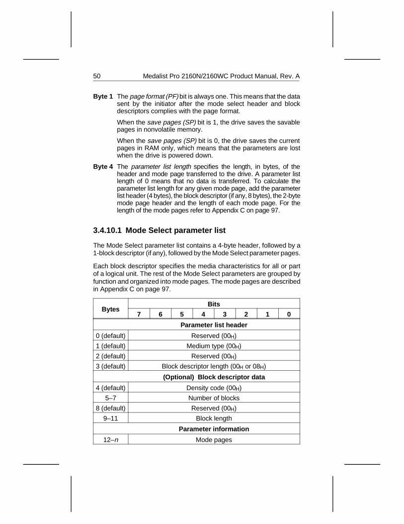
Byte 4 The parameter list length specifies the length, in bytes, of theheader and mode page transferred to the drive. A parameter listlength of 0 means that no data is transferred. To calculate theparameter list length for any given mode page, add the parameterlist header (4 bytes), the block descriptor (if any, 8 bytes), the 2-bytemode page header and the length of each mode page. For thelength of the mode pages refer to Appendix C on page 97.
3.4.10.1 Mode Select parameter list
The Mode Select parameter list contains a 4-byte header, followed by a1-block descriptor (if any), followed by the Mode Select parameter pages.
Each block descriptor specifies the media characteristics for all or partof a logical unit. The rest of the Mode Select parameters are grouped byfunction and organized into mode pages. The mode pages are describedin Appendix C on page 97.
BytesBits
7 6 5 4 3 2 1 0
Parameter list header
0 (default) Reserved (00H)
1 (default) Medium type (00H)
2 (default) Reserved (00H)
3 (default) Block descriptor length (00H or 08H)
(Optional) Block descriptor data
4 (default) Density code (00H)
5–7 Number of blocks
8 (default) Reserved (00H)
9–11 Block length
Parameter information
12–n Mode pages
50 Medalist Pro 2160N/2160WC Product Manual, Rev. A
Byte 1 The medium type field is always 00H, which means that thedrive is a direct-access device.
Byte 3 If the block descriptor length is 8 bytes, a block descriptoris sent to the drive. If the block descriptor length is 0 bytes,no block descriptor is sent to the drive.
Byte 4 The density code is always 00H and cannot be changed.
Bytes 5–7 The number of blocks is equal to the guaranteed sectors,which is listed in the formatted capacity section of theappropriate product manual.
Bytes 9–11 The block length is always 0200H and cannot be changed.
Note. Bytes 4–11 will be provided if the initiator requests the Block Descriptor.
3.4.11 Reserve (6) command (16 H)
When the initiator issues a Reserve command, it requests that the drivebe reserved for exclusive use by the initiator until the reservation is:
• Superseded by another Reserve command from the initiator thatmade the reservation. An initiator that has already reserved the drivecan modify that reservation by issuing another Reserve command.When the drive receives the superseding Reserve command, theprevious reservation is canceled.
• Released by a Release command from the same initiator. See theRelease command in Section 3.4.12 on page 52.
• Released by a bus device reset message from any initiator.
• Released by a hard reset.
After the drive honors the reservation from one initiator, it acceptsInquiry, Request Sense and Reserve and Release commands from otherinitiators; the drive rejects all other commands with a reservation conflictstatus.
Note. For the ST52160WC, the Release (6) command cannot releaseSCSI ID’s 8–15. Use the Release (10) command.
Medalist Pro 2160N/2160WC Product Manual, Rev. A 51
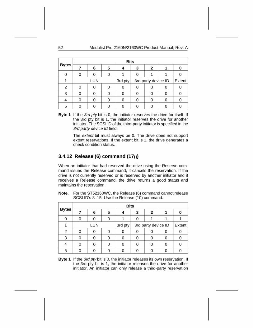
BytesBits
7 6 5 4 3 2 1 0
0 0 0 0 1 0 1 1 0
1 LUN 3rd pty 3rd party device ID Extent
2 0 0 0 0 0 0 0 0
3 0 0 0 0 0 0 0 0
4 0 0 0 0 0 0 0 0
5 0 0 0 0 0 0 0 0
Byte 1 If the 3rd pty bit is 0, the initiator reserves the drive for itself. Ifthe 3rd pty bit is 1, the initiator reserves the drive for anotherinitiator. The SCSI ID of the third-party initiator is specified in the3rd party device ID field.
The extent bit must always be 0. The drive does not supportextent reservations. If the extent bit is 1, the drive generates acheck condition status.
3.4.12 Release (6) command (17 H)
When an initiator that had reserved the drive using the Reserve com-mand issues the Release command, it cancels the reservation. If thedrive is not currently reserved or is reserved by another initiator and itreceives a Release command, the drive returns a good status andmaintains the reservation.
Note. For the ST52160WC, the Release (6) command cannot releaseSCSI ID’s 8–15. Use the Release (10) command.
BytesBits
7 6 5 4 3 2 1 0
0 0 0 0 1 0 1 1 1
1 LUN 3rd pty 3rd party device ID Extent
2 0 0 0 0 0 0 0 0
3 0 0 0 0 0 0 0 0
4 0 0 0 0 0 0 0 0
5 0 0 0 0 0 0 0 0
Byte 1 If the 3rd pty bit is 0, the initiator releases its own reservation. Ifthe 3rd pty bit is 1, the initiator releases the drive for anotherinitiator. An initiator can only release a third-party reservation
52 Medalist Pro 2160N/2160WC Product Manual, Rev. A
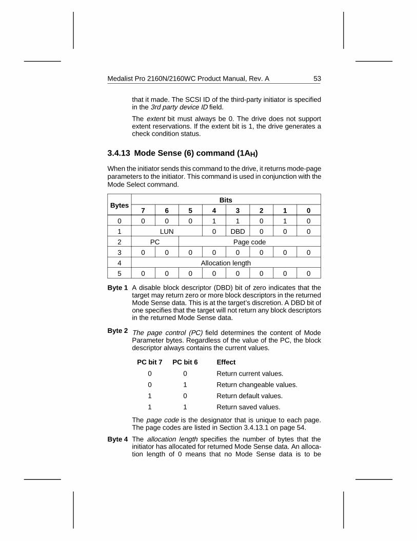
that it made. The SCSI ID of the third-party initiator is specifiedin the 3rd party device ID field.
The extent bit must always be 0. The drive does not supportextent reservations. If the extent bit is 1, the drive generates acheck condition status.
3.4.13 Mode Sense (6) command (1A H)
When the initiator sends this command to the drive, it returns mode-pageparameters to the initiator. This command is used in conjunction with theMode Select command.
BytesBits
7 6 5 4 3 2 1 0
0 0 0 0 1 1 0 1 0
1 LUN 0 DBD 0 0 0
2 PC Page code
3 0 0 0 0 0 0 0 0
4 Allocation length
5 0 0 0 0 0 0 0 0
Byte 1
Byte 2
A disable block descriptor (DBD) bit of zero indicates that thetarget may return zero or more block descriptors in the returnedMode Sense data. This is at the target’s discretion. A DBD bit ofone specifies that the target will not return any block descriptorsin the returned Mode Sense data.
The page control (PC) field determines the content of ModeParameter bytes. Regardless of the value of the PC, the blockdescriptor always contains the current values.
PC bit 7 PC bit 6 Effect
0 0 Return current values.
0 1 Return changeable values.
1 0 Return default values.
1 1 Return saved values.
The page code is the designator that is unique to each page.The page codes are listed in Section 3.4.13.1 on page 54.
Byte 4 The allocation length specifies the number of bytes that theinitiator has allocated for returned Mode Sense data. An alloca-tion length of 0 means that no Mode Sense data is to be
Medalist Pro 2160N/2160WC Product Manual, Rev. A 53
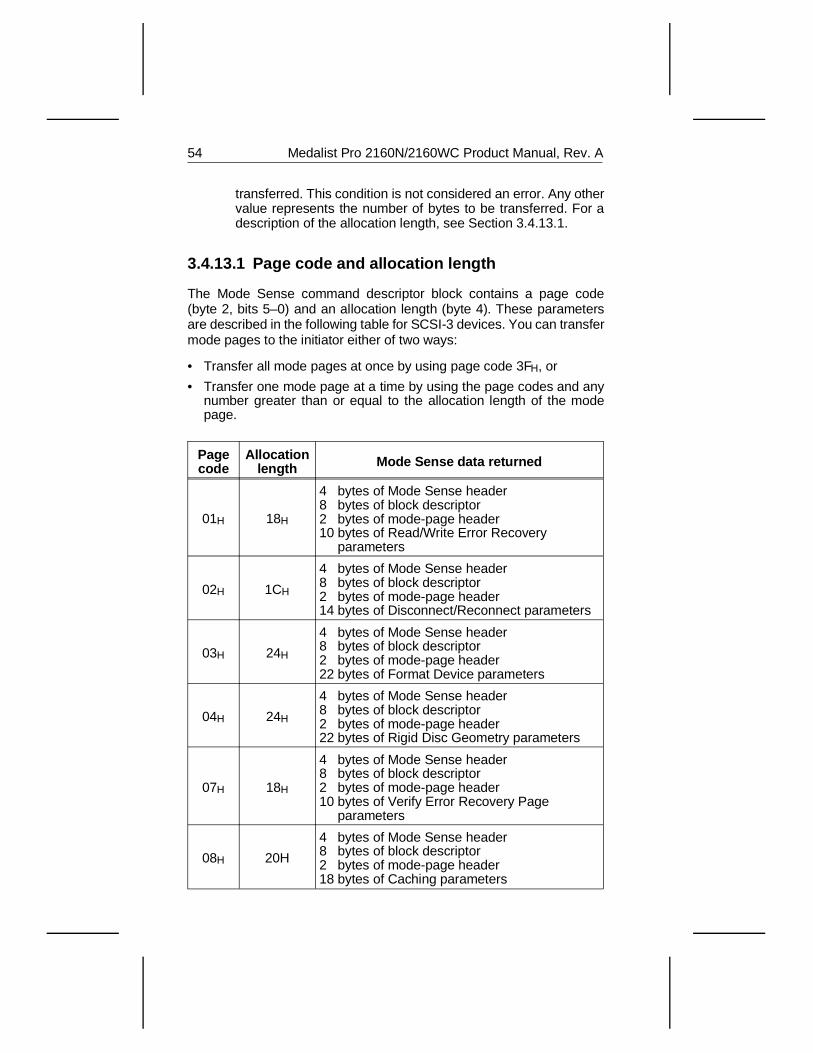
transferred. This condition is not considered an error. Any othervalue represents the number of bytes to be transferred. For adescription of the allocation length, see Section 3.4.13.1.
3.4.13.1 Page code and allocation length
The Mode Sense command descriptor block contains a page code(byte 2, bits 5–0) and an allocation length (byte 4). These parametersare described in the following table for SCSI-3 devices. You can transfermode pages to the initiator either of two ways:
• Transfer all mode pages at once by using page code 3FH, or
• Transfer one mode page at a time by using the page codes and anynumber greater than or equal to the allocation length of the modepage.
Pagecode
Allocationlength Mode Sense data returned
01H 18H
4 bytes of Mode Sense header8 bytes of block descriptor2 bytes of mode-page header10 bytes of Read/Write Error Recovery parameters
02H 1CH
4 bytes of Mode Sense header8 bytes of block descriptor2 bytes of mode-page header14 bytes of Disconnect/Reconnect parameters
03H 24H
4 bytes of Mode Sense header8 bytes of block descriptor2 bytes of mode-page header22 bytes of Format Device parameters
04H 24H
4 bytes of Mode Sense header8 bytes of block descriptor2 bytes of mode-page header22 bytes of Rigid Disc Geometry parameters
07H 18H
4 bytes of Mode Sense header8 bytes of block descriptor2 bytes of mode-page header10 bytes of Verify Error Recovery Page parameters
08H 20H
4 bytes of Mode Sense header8 bytes of block descriptor2 bytes of mode-page header18 bytes of Caching parameters
54 Medalist Pro 2160N/2160WC Product Manual, Rev. A
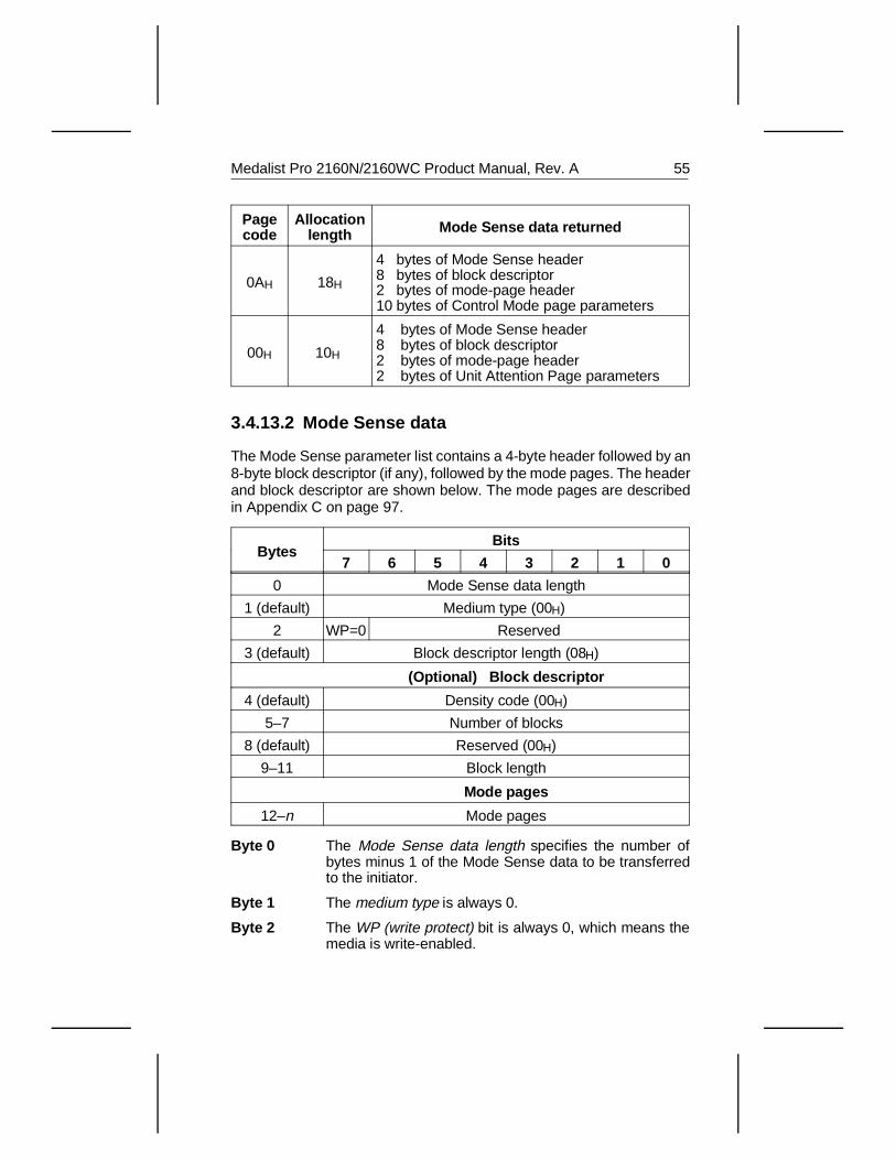
Pagecode
Allocationlength Mode Sense data returned
0AH 18H
4 bytes of Mode Sense header8 bytes of block descriptor2 bytes of mode-page header10 bytes of Control Mode page parameters
00H 10H
4 bytes of Mode Sense header 8 bytes of block descriptor2 bytes of mode-page header2 bytes of Unit Attention Page parameters
3.4.13.2 Mode Sense data
The Mode Sense parameter list contains a 4-byte header followed by an8-byte block descriptor (if any), followed by the mode pages. The headerand block descriptor are shown below. The mode pages are describedin Appendix C on page 97.
BytesBits
7 6 5 4 3 2 1 0
0 Mode Sense data length
1 (default) Medium type (00H)
2 WP=0 Reserved
3 (default) Block descriptor length (08H)
(Optional) Block descriptor
4 (default) Density code (00H)
5–7 Number of blocks
8 (default) Reserved (00H)
9–11 Block length
Mode pages
12–n Mode pages
Byte 0 The Mode Sense data length specifies the number ofbytes minus 1 of the Mode Sense data to be transferredto the initiator.
Byte 1 The medium type is always 0.
Byte 2 The WP (write protect) bit is always 0, which means themedia is write-enabled.
Medalist Pro 2160N/2160WC Product Manual, Rev. A 55
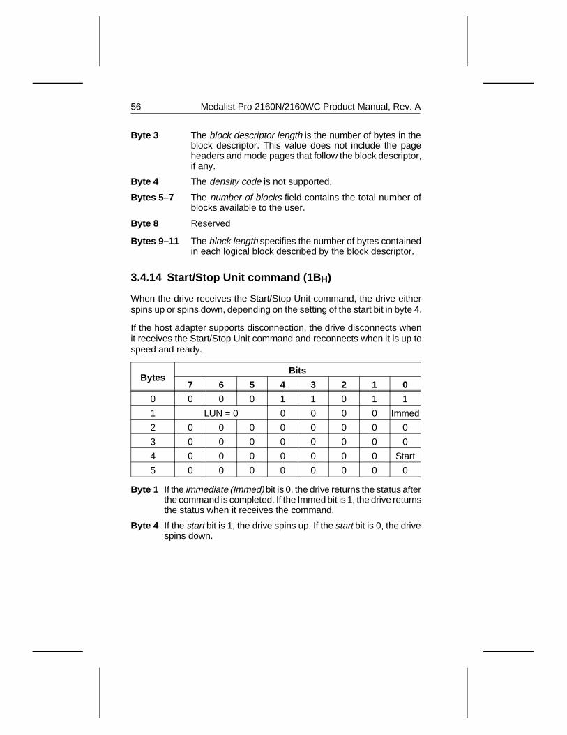
Byte 3 The block descriptor length is the number of bytes in theblock descriptor. This value does not include the pageheaders and mode pages that follow the block descriptor,if any.
Byte 4 The density code is not supported.
Bytes 5–7 The number of blocks field contains the total number ofblocks available to the user.
Byte 8 Reserved
Bytes 9–11 The block length specifies the number of bytes containedin each logical block described by the block descriptor.
3.4.14 Start/Stop Unit command (1B H)
When the drive receives the Start/Stop Unit command, the drive eitherspins up or spins down, depending on the setting of the start bit in byte 4.
If the host adapter supports disconnection, the drive disconnects whenit receives the Start/Stop Unit command and reconnects when it is up tospeed and ready.
BytesBits
7 6 5 4 3 2 1 0
0 0 0 0 1 1 0 1 1
1 LUN = 0 0 0 0 0 Immed
2 0 0 0 0 0 0 0 0
3 0 0 0 0 0 0 0 0
4 0 0 0 0 0 0 0 Start
5 0 0 0 0 0 0 0 0
Byte 1 If the immediate (Immed) bit is 0, the drive returns the status afterthe command is completed. If the Immed bit is 1, the drive returnsthe status when it receives the command.
Byte 4 If the start bit is 1, the drive spins up. If the start bit is 0, the drivespins down.
56 Medalist Pro 2160N/2160WC Product Manual, Rev. A
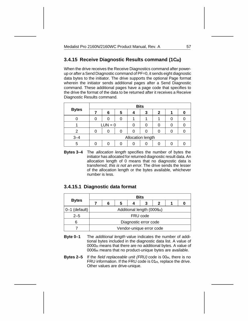
3.4.15 Receive Diagnostic Results command (1C H)
When the drive receives the Receive Diagnostics command after power-up or after a Send Diagnostic command of PF=0, it sends eight diagnosticdata bytes to the initiator. The drive supports the optional Page formatwherein the initiator sends additional pages after a Send Diagnosticcommand. These additional pages have a page code that specifies tothe drive the format of the data to be returned after it receives a ReceiveDiagnostic Results command.
BytesBits
7 6 5 4 3 2 1 0
0 0 0 0 1 1 1 0 0
1 LUN = 0 0 0 0 0 0
2 0 0 0 0 0 0 0 0
3–4 Allocation length
5 0 0 0 0 0 0 0 0
Bytes 3–4 The allocation length specifies the number of bytes theinitiator has allocated for returned diagnostic result data. Anallocation length of 0 means that no diagnostic data istransferred; this is not an error. The drive sends the lesserof the allocation length or the bytes available, whichevernumber is less.
3.4.15.1 Diagnostic data format
BytesBits
7 6 5 4 3 2 1 0
0–1 (default) Additional length (0006H)
2–5 FRU code
6 Diagnostic error code
7 Vendor-unique error code
Byte 0–1 The additional length value indicates the number of addi-tional bytes included in the diagnostic data list. A value of0000H means that there are no additional bytes. A value of0006H means that no product-unique bytes are available.
Bytes 2–5 If the field replaceable unit (FRU) code is 00H, there is noFRU information. If the FRU code is 01H, replace the drive.Other values are drive-unique.
Medalist Pro 2160N/2160WC Product Manual, Rev. A 57
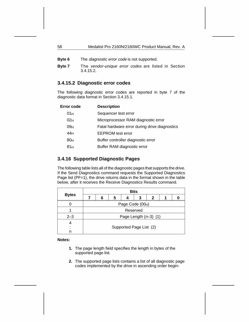
Byte 6 The diagnostic error code is not supported.
Byte 7 The vendor-unique error codes are listed in Section3.4.15.2.
3.4.15.2 Diagnostic error codes
The following diagnostic error codes are reported in byte 7 of thediagnostic data format in Section 3.4.15.1.
Error code Description
01H Sequencer test error
02H Microprocessor RAM diagnostic error
09H Fatal hardware error during drive diagnostics
44H EEPROM test error
80H Buffer controller diagnostic error
81H Buffer RAM diagnostic error
3.4.16 Supported Diagnostic Pages
The following table lists all of the diagnostic pages that supports the drive.If the Send Diagnostics command requests the Supported DiagnosticsPage list (PF=1), the drive returns data in the format shown in the tablebelow, after it receives the Receive Diagnostics Results command.
BytesBits
7 6 5 4 3 2 1 0
0 Page Code (00H)
1 Reserved
2–3 Page Length (n–3) (1)
4:n
Supported Page List (2)
Notes:
1. The page length field specifies the length in bytes of the supported page list.
2. The supported page lists contains a list of all diagnostic pagecodes implemented by the drive in ascending order begin-
58 Medalist Pro 2160N/2160WC Product Manual, Rev. A
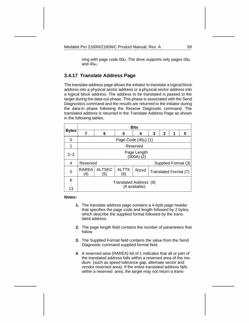
ning with page code 00H. The drive supports only pages 00Hand 40H.
3.4.17 Translate Address Page
The translate address page allows the initiator to translate a logical blockaddress into a physical sector address or a physical sector address intoa logical block address. The address to be translated is passed to thetarget during the data-out phase. This phase is associated with the SendDiagnostics command and the results are returned to the initiator duringthe data-in phase following the Receive Diagnostic command. Thetranslated address is returned in the Translate Address Page as shownin the following tables.
BytesBits
7 6 5 4 3 2 1 0
0 Page Code (40H) (1)
1 Reserved
2–3 Page Length (000A) (2)
4 Reserved Supplied Format (3)
5 RAREA(4)
ALTSEC(5)
ALTTK(6)
Rsrvd Translated Format (7)
6:
13
Translated Address (8)(if available)
Notes:
1. The translate address page contains a 4-byte page headerthat specifies the page code and length followed by 2 bytes,which describe the supplied format followed by the trans-lated address.
2. The page length field contains the number of parameters thatfollow.
3. The Supplied Format field contains the value from the SendDiagnostic command supplied format field.
4. A reserved area (RAREA) bit of 1 indicates that all or part ofthe translated address falls within a reserved area of the me-dium (such as speed tolerance gap, alternate sector andvendor-reserved area). If the entire translated address fallswithin a reserved area, the target may not return a trans-
Medalist Pro 2160N/2160WC Product Manual, Rev. A 59
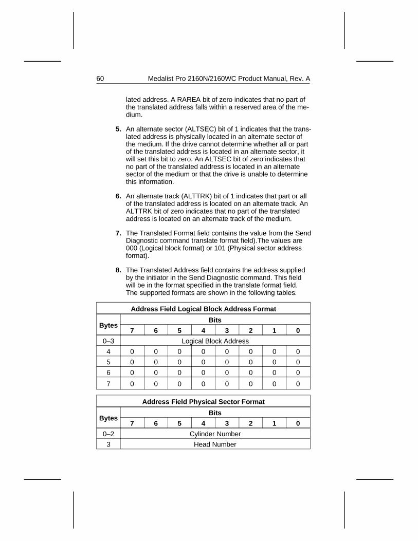
lated address. A RAREA bit of zero indicates that no part ofthe translated address falls within a reserved area of the me-dium.
5. An alternate sector (ALTSEC) bit of 1 indicates that the trans-lated address is physically located in an alternate sector ofthe medium. If the drive cannot determine whether all or partof the translated address is located in an alternate sector, itwill set this bit to zero. An ALTSEC bit of zero indicates thatno part of the translated address is located in an alternatesector of the medium or that the drive is unable to determinethis information.
6. An alternate track (ALTTRK) bit of 1 indicates that part or allof the translated address is located on an alternate track. AnALTTRK bit of zero indicates that no part of the translatedaddress is located on an alternate track of the medium.
7. The Translated Format field contains the value from the SendDiagnostic command translate format field).The values are000 (Logical block format) or 101 (Physical sector addressformat).
8. The Translated Address field contains the address suppliedby the initiator in the Send Diagnostic command. This fieldwill be in the format specified in the translate format field.The supported formats are shown in the following tables.
Address Field Logical Block Address Format
BytesBits
7 6 5 4 3 2 1 0
0–3 Logical Block Address
4 0 0 0 0 0 0 0 0
5 0 0 0 0 0 0 0 0
6 0 0 0 0 0 0 0 0
7 0 0 0 0 0 0 0 0
Address Field Physical Sector Format
BytesBits
7 6 5 4 3 2 1 0
0–2 Cylinder Number
3 Head Number
60 Medalist Pro 2160N/2160WC Product Manual, Rev. A
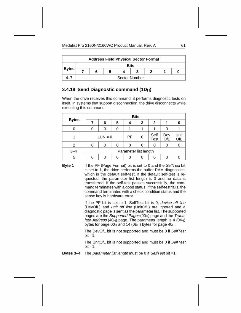
Address Field Physical Sector Format
BytesBits
7 6 5 4 3 2 1 0
4–7 Sector Number
3.4.18 Send Diagnostic command (1D H)
When the drive receives this command, it performs diagnostic tests onitself. In systems that support disconnection, the drive disconnects whileexecuting this command.
BytesBits
7 6 5 4 3 2 1 0
0 0 0 0 1 1 1 0 1
1 LUN = 0 PF 0 SelfTest
DevOfL
UnitOfL
2 0 0 0 0 0 0 0 0
3–4 Parameter list length
5 0 0 0 0 0 0 0 0
Byte 1 If the PF (Page Format) bit is set to 0 and the SelfTest bitis set to 1, the drive performs the buffer RAM diagnostics,which is the default self-test. If the default self-test is re-quested, the parameter list length is 0 and no data istransferred. If the self-test passes successfully, the com-mand terminates with a good status. If the self-test fails, thecommand terminates with a check condition status and thesense key is hardware error.
If the PF bit is set to 1, SelfTest bit is 0, device off line(DevOfL) and unit off line (UnitOfL) are ignored and adiagnostic page is sent as the parameter list. The supportedpages are the Supported Pages (00H) page and the Trans-late Address (40H) page. The parameter length is 4 (04H)bytes for page 00H and 14 (0EH) bytes for page 40H.
The DevOfL bit is not supported and must be 0 if SelfTestbit =1.
The UnitOfL bit is not supported and must be 0 if SelfTestbit =1.
Bytes 3–4 The parameter list length must be 0 if SelfTest bit =1.
Medalist Pro 2160N/2160WC Product Manual, Rev. A 61
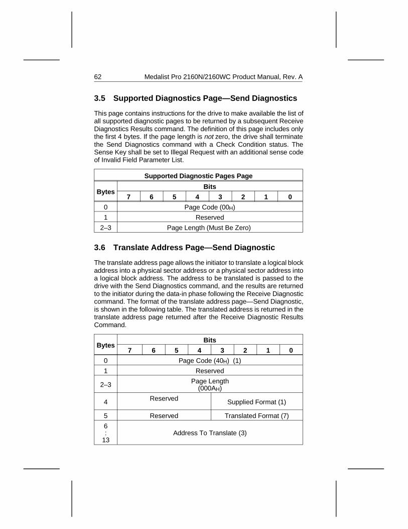
3.5 Supported Diagnostics Page—Send Diagnostics
This page contains instructions for the drive to make available the list ofall supported diagnostic pages to be returned by a subsequent ReceiveDiagnostics Results command. The definition of this page includes onlythe first 4 bytes. If the page length is not zero, the drive shall terminatethe Send Diagnostics command with a Check Condition status. TheSense Key shall be set to Illegal Request with an additional sense codeof Invalid Field Parameter List.
Supported Diagnostic Pages Page
BytesBits
7 6 5 4 3 2 1 0
0 Page Code (00H)
1 Reserved
2–3 Page Length (Must Be Zero)
3.6 Translate Address Page—Send Diagnostic
The translate address page allows the initiator to translate a logical blockaddress into a physical sector address or a physical sector address intoa logical block address. The address to be translated is passed to thedrive with the Send Diagnostics command, and the results are returnedto the initiator during the data-in phase following the Receive Diagnosticcommand. The format of the translate address page—Send Diagnostic,is shown in the following table. The translated address is returned in thetranslate address page returned after the Receive Diagnostic ResultsCommand.
BytesBits
7 6 5 4 3 2 1 0
0 Page Code (40H) (1)
1 Reserved
2–3 Page Length (000AH)
4 Reserved Supplied Format (1)
5 Reserved Translated Format (7)
6:
13Address To Translate (3)
62 Medalist Pro 2160N/2160WC Product Manual, Rev. A
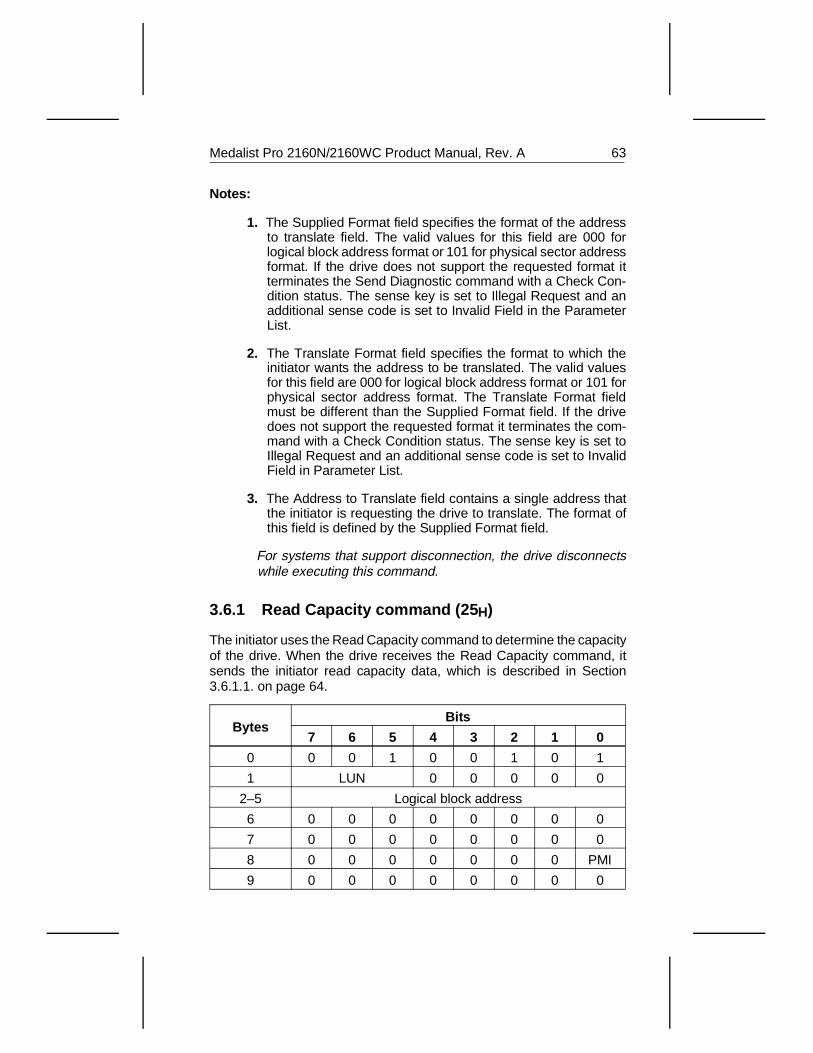
Notes:
1. The Supplied Format field specifies the format of the addressto translate field. The valid values for this field are 000 forlogical block address format or 101 for physical sector addressformat. If the drive does not support the requested format itterminates the Send Diagnostic command with a Check Con-dition status. The sense key is set to Illegal Request and anadditional sense code is set to Invalid Field in the ParameterList.
2. The Translate Format field specifies the format to which theinitiator wants the address to be translated. The valid valuesfor this field are 000 for logical block address format or 101 forphysical sector address format. The Translate Format fieldmust be different than the Supplied Format field. If the drivedoes not support the requested format it terminates the com-mand with a Check Condition status. The sense key is set toIllegal Request and an additional sense code is set to InvalidField in Parameter List.
3. The Address to Translate field contains a single address thatthe initiator is requesting the drive to translate. The format ofthis field is defined by the Supplied Format field.
For systems that support disconnection, the drive disconnectswhile executing this command.
3.6.1 Read Capacity command (25 H)
The initiator uses the Read Capacity command to determine the capacityof the drive. When the drive receives the Read Capacity command, itsends the initiator read capacity data, which is described in Section3.6.1.1. on page 64.
BytesBits
7 6 5 4 3 2 1 0
0 0 0 1 0 0 1 0 1
1 LUN 0 0 0 0 0
2–5 Logical block address
6 0 0 0 0 0 0 0 0
7 0 0 0 0 0 0 0 0
8 0 0 0 0 0 0 0 PMI
9 0 0 0 0 0 0 0 0
Medalist Pro 2160N/2160WC Product Manual, Rev. A 63
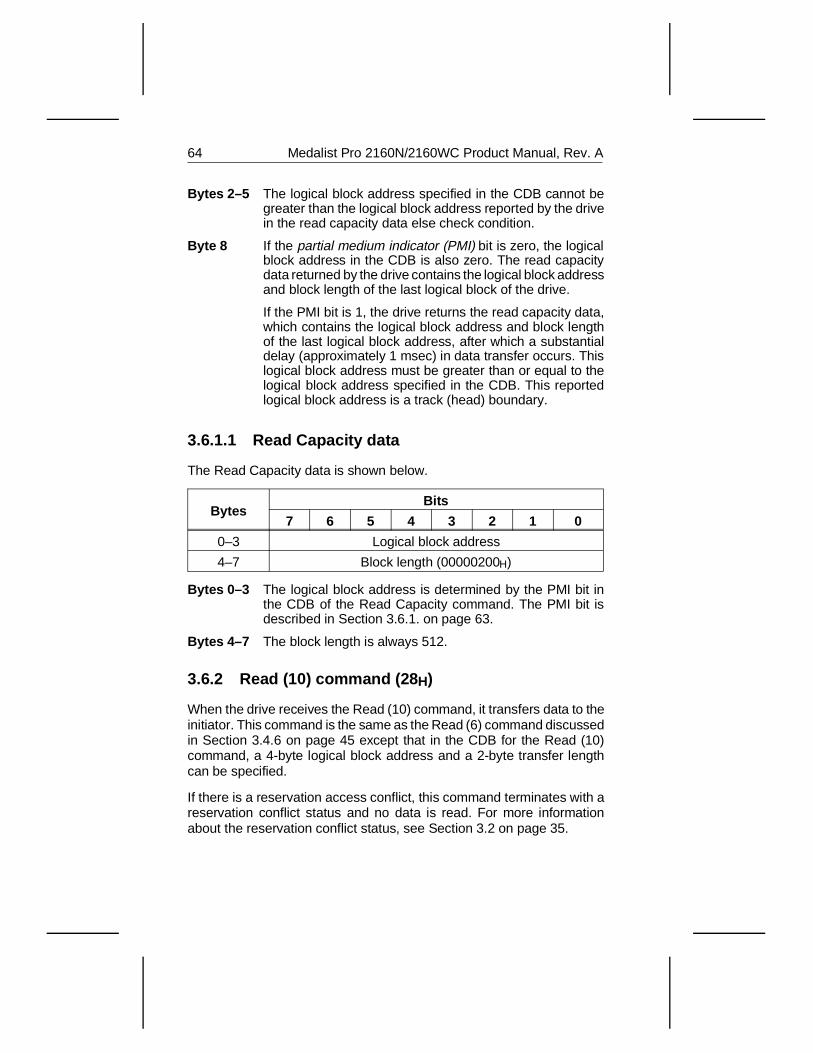
Bytes 2–5 The logical block address specified in the CDB cannot begreater than the logical block address reported by the drivein the read capacity data else check condition.
Byte 8 If the partial medium indicator (PMI) bit is zero, the logicalblock address in the CDB is also zero. The read capacitydata returned by the drive contains the logical block addressand block length of the last logical block of the drive.
If the PMI bit is 1, the drive returns the read capacity data,which contains the logical block address and block lengthof the last logical block address, after which a substantialdelay (approximately 1 msec) in data transfer occurs. Thislogical block address must be greater than or equal to thelogical block address specified in the CDB. This reportedlogical block address is a track (head) boundary.
3.6.1.1 Read Capacity data
The Read Capacity data is shown below.
BytesBits
7 6 5 4 3 2 1 0
0–3 Logical block address
4–7 Block length (00000200H)
Bytes 0–3 The logical block address is determined by the PMI bit inthe CDB of the Read Capacity command. The PMI bit isdescribed in Section 3.6.1. on page 63.
Bytes 4–7 The block length is always 512.
3.6.2 Read (10) command (28 H)
When the drive receives the Read (10) command, it transfers data to theinitiator. This command is the same as the Read (6) command discussedin Section 3.4.6 on page 45 except that in the CDB for the Read (10)command, a 4-byte logical block address and a 2-byte transfer lengthcan be specified.
If there is a reservation access conflict, this command terminates with areservation conflict status and no data is read. For more informationabout the reservation conflict status, see Section 3.2 on page 35.
64 Medalist Pro 2160N/2160WC Product Manual, Rev. A
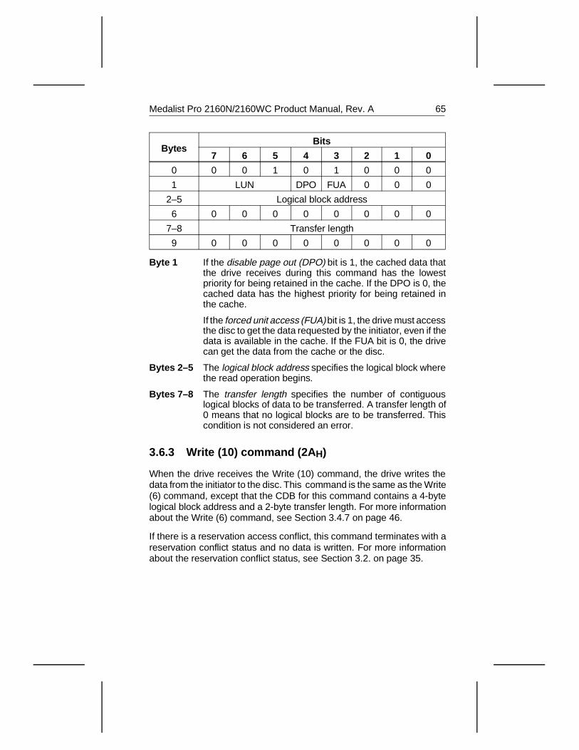
BytesBits
7 6 5 4 3 2 1 0
0 0 0 1 0 1 0 0 0
1 LUN DPO FUA 0 0 0
2–5 Logical block address
6 0 0 0 0 0 0 0 0
7–8 Transfer length
9 0 0 0 0 0 0 0 0
Byte 1 If the disable page out (DPO) bit is 1, the cached data thatthe drive receives during this command has the lowestpriority for being retained in the cache. If the DPO is 0, thecached data has the highest priority for being retained inthe cache.
If the forced unit access (FUA) bit is 1, the drive must accessthe disc to get the data requested by the initiator, even if thedata is available in the cache. If the FUA bit is 0, the drivecan get the data from the cache or the disc.
Bytes 2–5 The logical block address specifies the logical block wherethe read operation begins.
Bytes 7–8 The transfer length specifies the number of contiguouslogical blocks of data to be transferred. A transfer length of0 means that no logical blocks are to be transferred. Thiscondition is not considered an error.
3.6.3 Write (10) command (2A H)
When the drive receives the Write (10) command, the drive writes thedata from the initiator to the disc. This command is the same as the Write(6) command, except that the CDB for this command contains a 4-bytelogical block address and a 2-byte transfer length. For more informationabout the Write (6) command, see Section 3.4.7 on page 46.
If there is a reservation access conflict, this command terminates with areservation conflict status and no data is written. For more informationabout the reservation conflict status, see Section 3.2. on page 35.
Medalist Pro 2160N/2160WC Product Manual, Rev. A 65
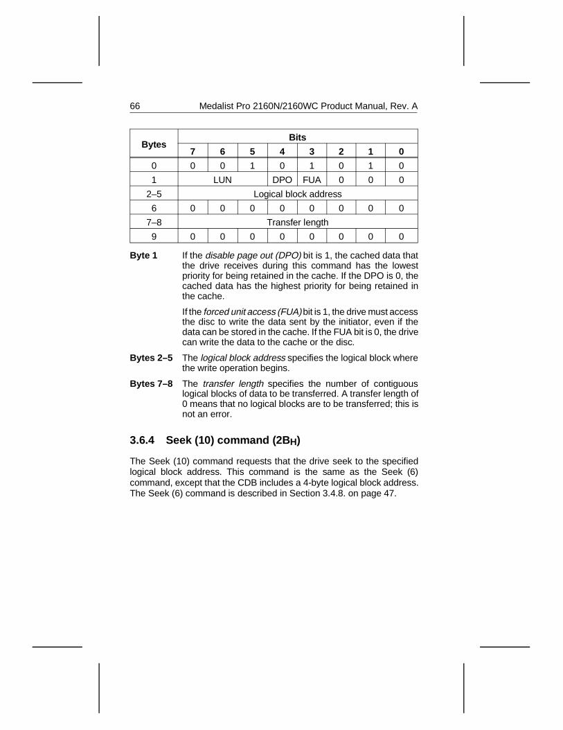
BytesBits
7 6 5 4 3 2 1 0
0 0 0 1 0 1 0 1 0
1 LUN DPO FUA 0 0 0
2–5 Logical block address
6 0 0 0 0 0 0 0 0
7–8 Transfer length
9 0 0 0 0 0 0 0 0
Byte 1 If the disable page out (DPO) bit is 1, the cached data thatthe drive receives during this command has the lowestpriority for being retained in the cache. If the DPO is 0, thecached data has the highest priority for being retained inthe cache.
If the forced unit access (FUA) bit is 1, the drive must accessthe disc to write the data sent by the initiator, even if thedata can be stored in the cache. If the FUA bit is 0, the drivecan write the data to the cache or the disc.
Bytes 2–5 The logical block address specifies the logical block wherethe write operation begins.
Bytes 7–8 The transfer length specifies the number of contiguouslogical blocks of data to be transferred. A transfer length of0 means that no logical blocks are to be transferred; this isnot an error.
3.6.4 Seek (10) command (2B H)
The Seek (10) command requests that the drive seek to the specifiedlogical block address. This command is the same as the Seek (6)command, except that the CDB includes a 4-byte logical block address.The Seek (6) command is described in Section 3.4.8. on page 47.
66 Medalist Pro 2160N/2160WC Product Manual, Rev. A
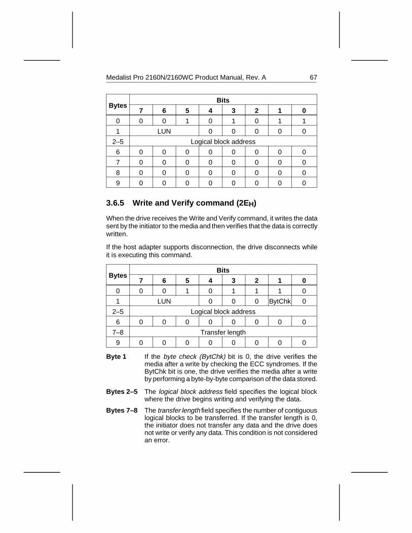
BytesBits
7 6 5 4 3 2 1 0
0 0 0 1 0 1 0 1 1
1 LUN 0 0 0 0 0
2–5 Logical block address
6 0 0 0 0 0 0 0 0
7 0 0 0 0 0 0 0 0
8 0 0 0 0 0 0 0 0
9 0 0 0 0 0 0 0 0
3.6.5 Write and Verify command (2E H)
When the drive receives the Write and Verify command, it writes the datasent by the initiator to the media and then verifies that the data is correctlywritten.
If the host adapter supports disconnection, the drive disconnects whileit is executing this command.
BytesBits
7 6 5 4 3 2 1 0
0 0 0 1 0 1 1 1 0
1 LUN 0 0 0 BytChk 0
2–5 Logical block address
6 0 0 0 0 0 0 0 0
7–8 Transfer length
9 0 0 0 0 0 0 0 0
Byte 1 If the byte check (BytChk) bit is 0, the drive verifies themedia after a write by checking the ECC syndromes. If theBytChk bit is one, the drive verifies the media after a writeby performing a byte-by-byte comparison of the data stored.
Bytes 2–5 The logical block address field specifies the logical blockwhere the drive begins writing and verifying the data.
Bytes 7–8 The transfer length field specifies the number of contiguouslogical blocks to be transferred. If the transfer length is 0,the initiator does not transfer any data and the drive doesnot write or verify any data. This condition is not consideredan error.
Medalist Pro 2160N/2160WC Product Manual, Rev. A 67
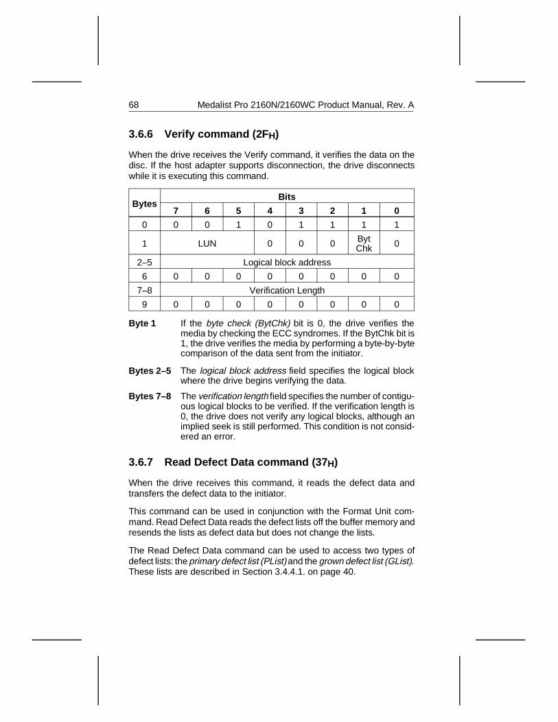
3.6.6 Verify command (2F H)
When the drive receives the Verify command, it verifies the data on thedisc. If the host adapter supports disconnection, the drive disconnectswhile it is executing this command.
BytesBits
7 6 5 4 3 2 1 0
0 0 0 1 0 1 1 1 1
1 LUN 0 0 0 BytChk 0
2–5 Logical block address
6 0 0 0 0 0 0 0 0
7–8 Verification Length
9 0 0 0 0 0 0 0 0
Byte 1 If the byte check (BytChk) bit is 0, the drive verifies themedia by checking the ECC syndromes. If the BytChk bit is1, the drive verifies the media by performing a byte-by-bytecomparison of the data sent from the initiator.
Bytes 2–5 The logical block address field specifies the logical blockwhere the drive begins verifying the data.
Bytes 7–8 The verification length field specifies the number of contigu-ous logical blocks to be verified. If the verification length is0, the drive does not verify any logical blocks, although animplied seek is still performed. This condition is not consid-ered an error.
3.6.7 Read Defect Data command (37 H)
When the drive receives this command, it reads the defect data andtransfers the defect data to the initiator.
This command can be used in conjunction with the Format Unit com-mand. Read Defect Data reads the defect lists off the buffer memory andresends the lists as defect data but does not change the lists.
The Read Defect Data command can be used to access two types ofdefect lists: the primary defect list (PList) and the grown defect list (GList).These lists are described in Section 3.4.4.1. on page 40.
68 Medalist Pro 2160N/2160WC Product Manual, Rev. A
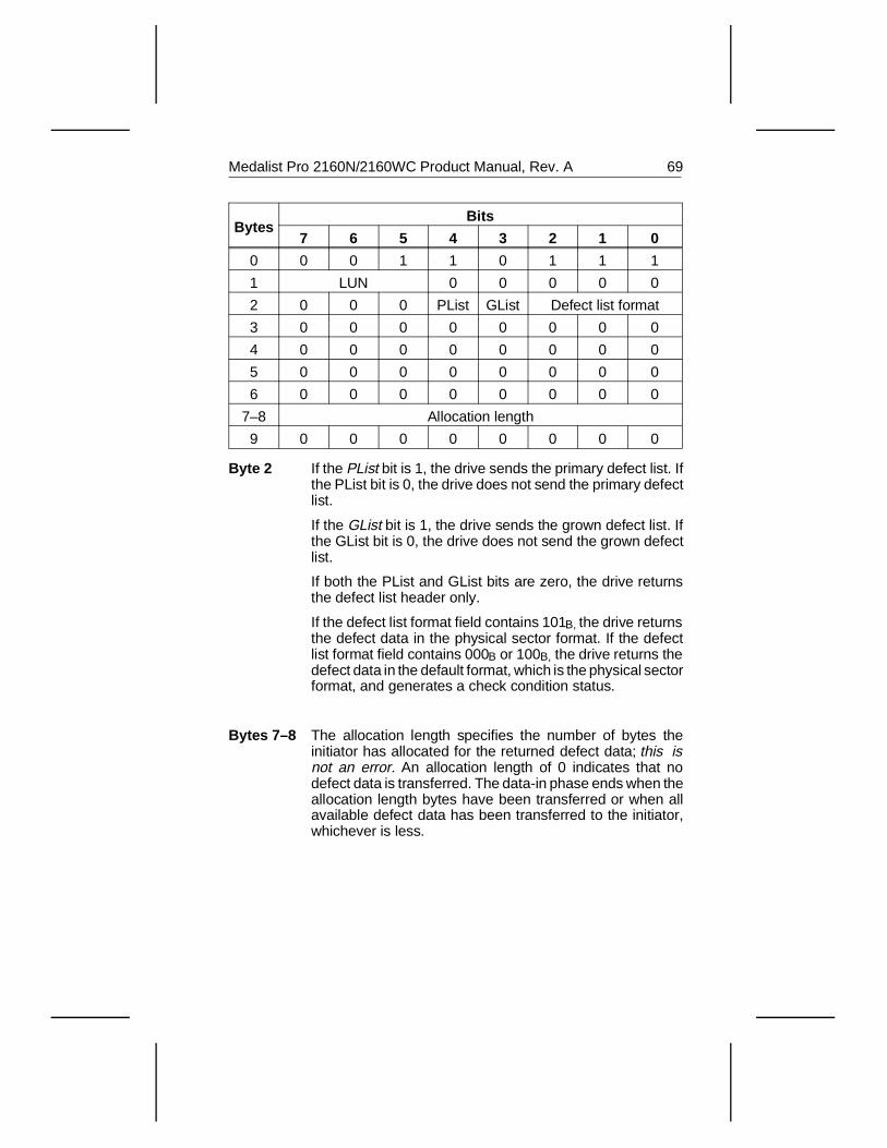
BytesBits
7 6 5 4 3 2 1 0
0 0 0 1 1 0 1 1 1
1 LUN 0 0 0 0 0
2 0 0 0 PList GList Defect list format
3 0 0 0 0 0 0 0 0
4 0 0 0 0 0 0 0 0
5 0 0 0 0 0 0 0 0
6 0 0 0 0 0 0 0 0
7–8 Allocation length
9 0 0 0 0 0 0 0 0
Byte 2 If the PList bit is 1, the drive sends the primary defect list. Ifthe PList bit is 0, the drive does not send the primary defectlist.
If the GList bit is 1, the drive sends the grown defect list. Ifthe GList bit is 0, the drive does not send the grown defectlist.
If both the PList and GList bits are zero, the drive returnsthe defect list header only.
If the defect list format field contains 101B, the drive returnsthe defect data in the physical sector format. If the defectlist format field contains 000B or 100B, the drive returns thedefect data in the default format, which is the physical sectorformat, and generates a check condition status.
Bytes 7–8 The allocation length specifies the number of bytes theinitiator has allocated for the returned defect data; this isnot an error. An allocation length of 0 indicates that nodefect data is transferred. The data-in phase ends when theallocation length bytes have been transferred or when allavailable defect data has been transferred to the initiator,whichever is less.
Medalist Pro 2160N/2160WC Product Manual, Rev. A 69
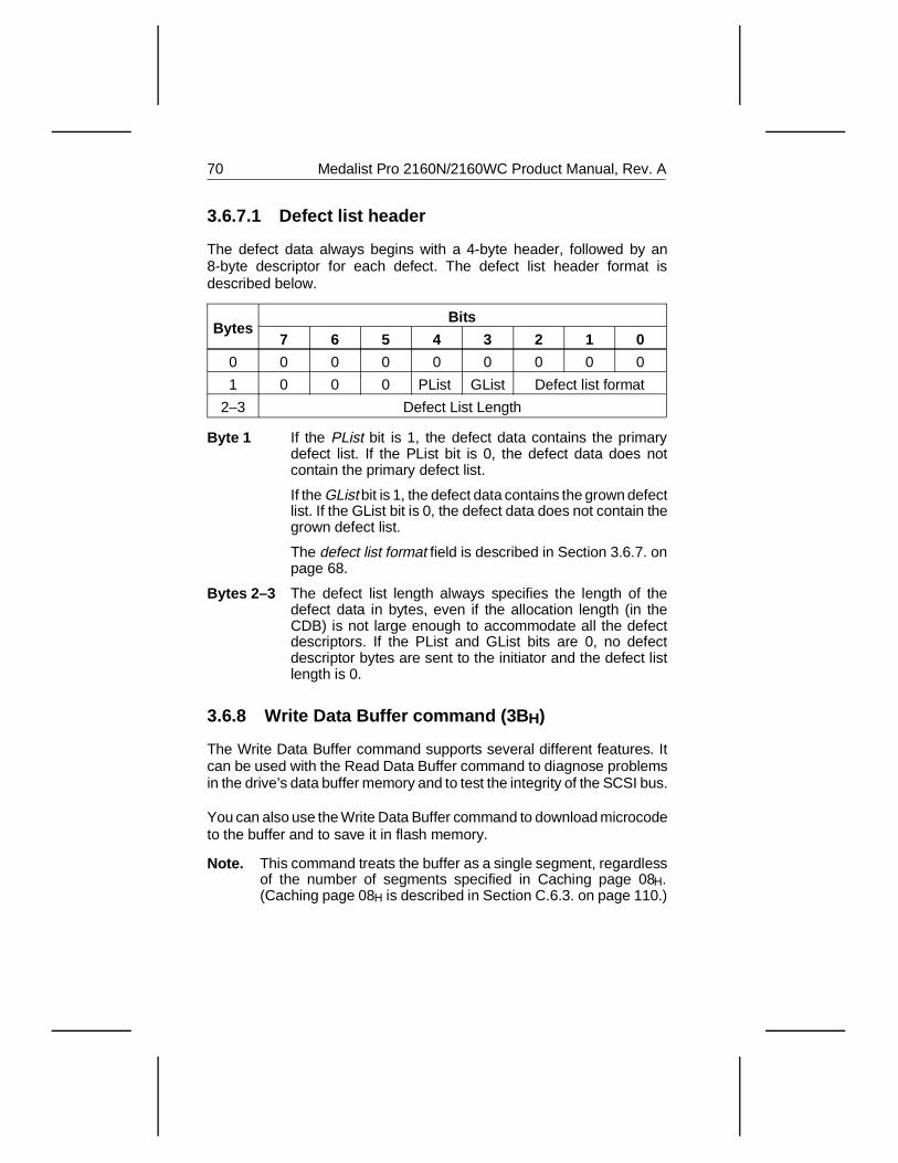
3.6.7.1 Defect list header
The defect data always begins with a 4-byte header, followed by an8-byte descriptor for each defect. The defect list header format isdescribed below.
BytesBits
7 6 5 4 3 2 1 0
0 0 0 0 0 0 0 0 0
1 0 0 0 PList GList Defect list format
2–3 Defect List Length
Byte 1 If the PList bit is 1, the defect data contains the primarydefect list. If the PList bit is 0, the defect data does notcontain the primary defect list.
If the GList bit is 1, the defect data contains the grown defectlist. If the GList bit is 0, the defect data does not contain thegrown defect list.
The defect list format field is described in Section 3.6.7. onpage 68.
Bytes 2–3 The defect list length always specifies the length of thedefect data in bytes, even if the allocation length (in theCDB) is not large enough to accommodate all the defectdescriptors. If the PList and GList bits are 0, no defectdescriptor bytes are sent to the initiator and the defect listlength is 0.
3.6.8 Write Data Buffer command (3B H)
The Write Data Buffer command supports several different features. Itcan be used with the Read Data Buffer command to diagnose problemsin the drive’s data buffer memory and to test the integrity of the SCSI bus.
You can also use the Write Data Buffer command to download microcodeto the buffer and to save it in flash memory.
Note. This command treats the buffer as a single segment, regardlessof the number of segments specified in Caching page 08H.(Caching page 08H is described in Section C.6.3. on page 110.)
70 Medalist Pro 2160N/2160WC Product Manual, Rev. A
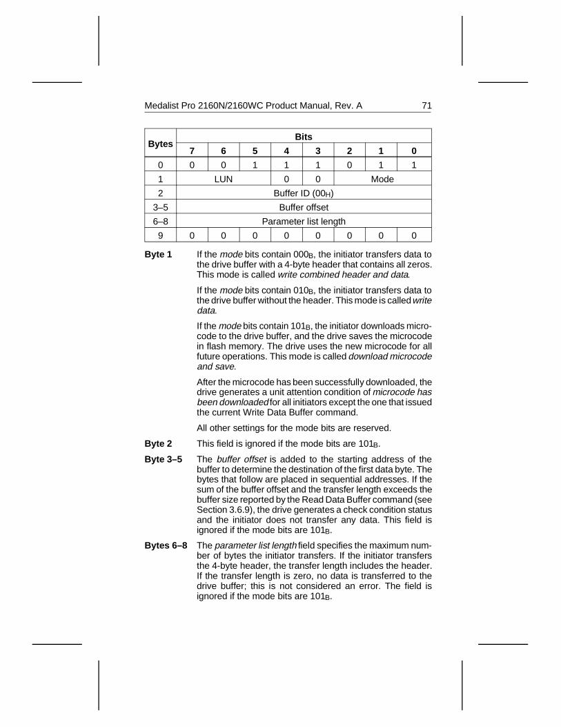
BytesBits
7 6 5 4 3 2 1 0
0 0 0 1 1 1 0 1 1
1 LUN 0 0 Mode
2 Buffer ID (00H)
3–5 Buffer offset
6–8 Parameter list length
9 0 0 0 0 0 0 0 0
Byte 1 If the mode bits contain 000B, the initiator transfers data tothe drive buffer with a 4-byte header that contains all zeros.This mode is called write combined header and data.
If the mode bits contain 010B, the initiator transfers data tothe drive buffer without the header. This mode is called writedata.
If the mode bits contain 101B, the initiator downloads micro-code to the drive buffer, and the drive saves the microcodein flash memory. The drive uses the new microcode for allfuture operations. This mode is called download microcodeand save.
After the microcode has been successfully downloaded, thedrive generates a unit attention condition of microcode hasbeen downloaded for all initiators except the one that issuedthe current Write Data Buffer command.
All other settings for the mode bits are reserved.
Byte 2 This field is ignored if the mode bits are 101B.
Byte 3–5 The buffer offset is added to the starting address of thebuffer to determine the destination of the first data byte. Thebytes that follow are placed in sequential addresses. If thesum of the buffer offset and the transfer length exceeds thebuffer size reported by the Read Data Buffer command (seeSection 3.6.9), the drive generates a check condition statusand the initiator does not transfer any data. This field isignored if the mode bits are 101B.
Bytes 6–8 The parameter list length field specifies the maximum num-ber of bytes the initiator transfers. If the initiator transfersthe 4-byte header, the transfer length includes the header.If the transfer length is zero, no data is transferred to thedrive buffer; this is not considered an error. The field isignored if the mode bits are 101B.
Medalist Pro 2160N/2160WC Product Manual, Rev. A 71

3.6.9 Read Data Buffer command (3C H)
The Read Data Buffer command supports several different features. TheRead Data Buffer command can be used along with the Write Data Buffercommand to diagnose problems in the drive’s data buffer memory andto test the integrity of the SCSI bus.
Note. This command treats the buffer as a single segment, regardless ofthe number of segments specified in mode page (08H). (Mode page(08H), the Caching page, is described in Section C.6. on page 108).
BytesBits
7 6 5 4 3 2 1 0
0 0 0 1 1 1 1 0 0
1 LUN 0 0 Mode
2 Buffer ID (00H)
3–5 Buffer offset
6–8 Allocation length
9 0 0 0 0 0 0 0 0
Byte 1 If the mode bits contain 000B, the initiator reads data fromthe drive buffer. The data is preceded by a 4-byte header.This mode is called read combined header and data.
If the mode bits contain 010B, the initiator reads data from thedrive buffer without a header. This mode is called read data.
If the mode bits contain 011B, a maximum of 4 bytes ofREAD BUFFER descriptor information is returned. Thedrive returns the descriptor information for the buffer speci-fied by the buffer ID.
If there is no buffer associated with the specified buffer ID,the drive returns all zeros in the READ BUFFER descriptor.The buffer offset is reserved in this mode. The allocationlength should be set to four or greater. The drive transfersthe lesser of the allocation length or 4 bytes of READBUFFER descriptor.
READ BUFFER Descriptor
BytesBits
7 6 5 4 3 2 1 0
0 Offset Boundary
1–3 (MSB) Buffer Capacity (LSB)
72 Medalist Pro 2160N/2160WC Product Manual, Rev. A
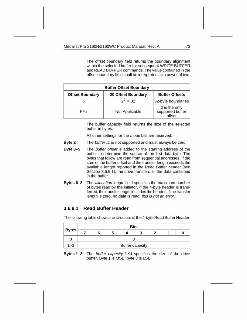
The offset boundary field returns the boundary alignmentwithin the selected buffer for subsequent WRITE BUFFERand READ BUFFER commands. The value contained in theoffset boundary field shall be interpreted as a power of two.
Buffer Offset Boundary
Offset Boundary 20 Offset Boundary Buffer Offsets
5 25 = 32 32-byte boundaries
FFH Not Applicable0 is the only
supported bufferoffset
The buffer capacity field returns the size of the selectedbuffer in bytes.
All other settings for the mode bits are reserved.
Byte 2 The buffer ID is not supported and must always be zero.
Byte 3–5 The buffer offset is added to the starting address of thebuffer to determine the source of the first data byte. Thebytes that follow are read from sequential addresses. If thesum of the buffer offset and the transfer length exceeds theavailable length reported in the Read Buffer header (seeSection 3.6.9.1), the drive transfers all the data containedin the buffer.
Bytes 6–8 The allocation length field specifies the maximum numberof bytes read by the initiator. If the 4-byte header is trans-ferred, the transfer length includes the header. If the transferlength is zero, no data is read; this is not an error.
3.6.9.1 Read Buffer Header
The following table shows the structure of the 4-byte Read Buffer Header.
BytesBits
7 6 5 4 3 2 1 0
0 0
1–3 Buffer capacity
Bytes 1–3 The buffer capacity field specifies the size of the drivebuffer. Byte 1 is MSB; byte 3 is LSB.
Medalist Pro 2160N/2160WC Product Manual, Rev. A 73
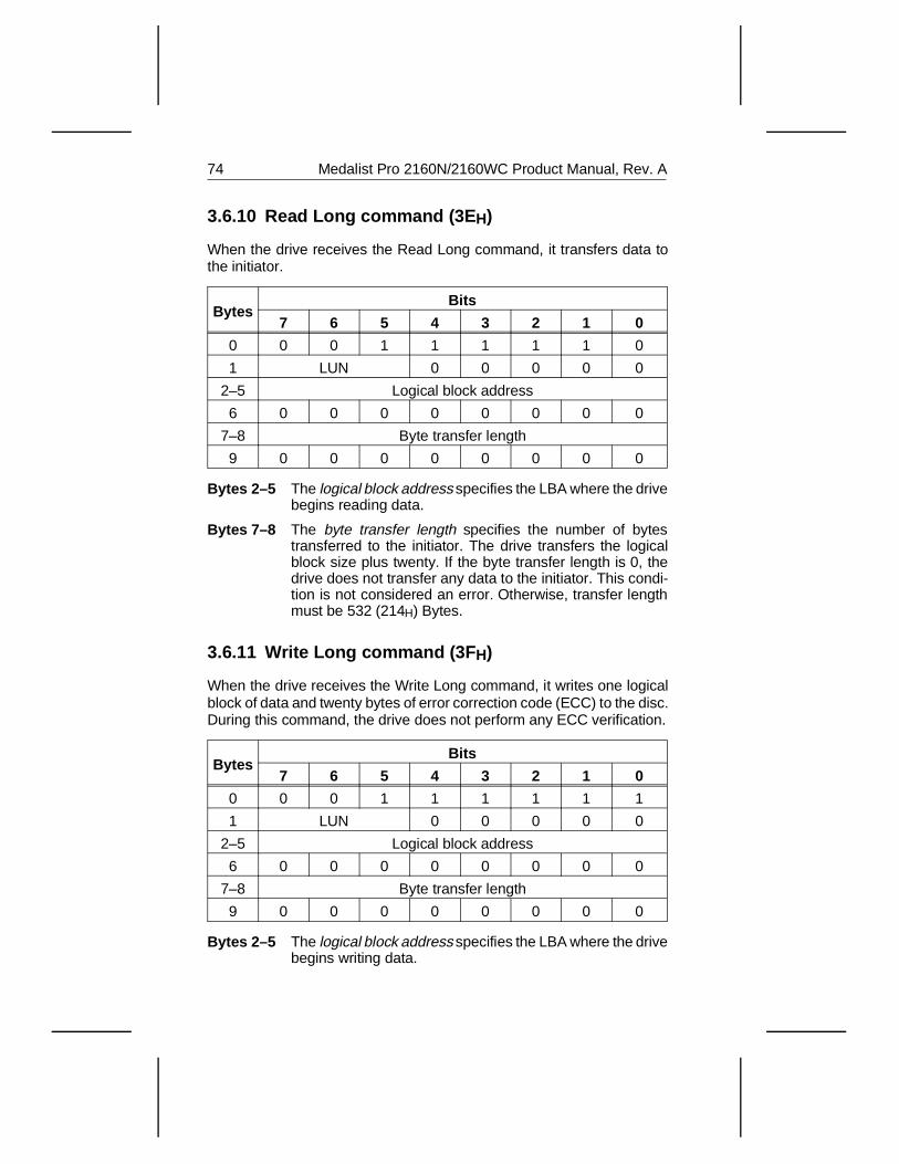
3.6.10 Read Long command (3E H)
When the drive receives the Read Long command, it transfers data tothe initiator.
BytesBits
7 6 5 4 3 2 1 0
0 0 0 1 1 1 1 1 0
1 LUN 0 0 0 0 0
2–5 Logical block address
6 0 0 0 0 0 0 0 0
7–8 Byte transfer length
9 0 0 0 0 0 0 0 0
Bytes 2–5 The logical block address specifies the LBA where the drivebegins reading data.
Bytes 7–8 The byte transfer length specifies the number of bytestransferred to the initiator. The drive transfers the logicalblock size plus twenty. If the byte transfer length is 0, thedrive does not transfer any data to the initiator. This condi-tion is not considered an error. Otherwise, transfer lengthmust be 532 (214H) Bytes.
3.6.11 Write Long command (3F H)
When the drive receives the Write Long command, it writes one logicalblock of data and twenty bytes of error correction code (ECC) to the disc.During this command, the drive does not perform any ECC verification.
BytesBits
7 6 5 4 3 2 1 0
0 0 0 1 1 1 1 1 1
1 LUN 0 0 0 0 0
2–5 Logical block address
6 0 0 0 0 0 0 0 0
7–8 Byte transfer length
9 0 0 0 0 0 0 0 0
Bytes 2–5 The logical block address specifies the LBA where the drivebegins writing data.
74 Medalist Pro 2160N/2160WC Product Manual, Rev. A
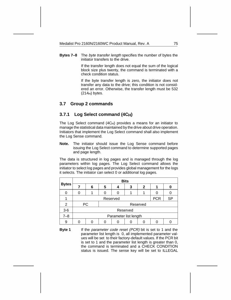
Bytes 7–8 The byte transfer length specifies the number of bytes theinitiator transfers to the drive.
If the transfer length does not equal the sum of the logicalblock size plus twenty, the command is terminated with acheck condition status.
If the byte transfer length is zero, the initiator does nottransfer any data to the drive; this condition is not consid-ered an error. Otherwise, the transfer length must be 532(214H) bytes.
3.7 Group 2 commands
3.7.1 Log Select command (4C H)
The Log Select command (4CH) provides a means for an initiator tomanage the statistical data maintained by the drive about drive operation.Initiators that implement the Log Select command shall also implementthe Log Sense command.
Note. The initiator should issue the Log Sense command beforeissuing the Log Select command to determine supported pagesand page length.
The data is structured in log pages and is managed through the logparameters within log pages. The Log Select command allows theinitiator to select log pages and provides global management for the logsit selects. The initiator can select 0 or additional log pages.
BytesBits
7 6 5 4 3 2 1 0
0 0 1 0 0 1 1 0 0
1 Reserved PCR SP
2 PC Reserved
3-6 Reserved
7–8 Parameter list length
9 0 0 0 0 0 0 0 0
Byte 1 If the parameter code reset (PCR) bit is set to 1 and theparameter list length is 0, all implemented parameter val-ues will be set to their factory-default values. If the PCR bitis set to 1 and the parameter list length is greater than 0,the command is terminated and a CHECK CONDITIONstatus is issued. The sense key will be set to ILLEGAL
Medalist Pro 2160N/2160WC Product Manual, Rev. A 75
REQUEST and the additional sense code will be set toINVALID FIELD IN CDB. If the PCR bit is set to 0, the logparameters will not be reset.
The save parameters (SP) bit determines whether the drivewill save to nonvolatile memory all parameters indentifiedas savable in the disable save (DS) bit of the log page aftera Log Select operation completes. If the bit is set to 1, theparameters are saved. If the bit is set to 0, the parametersare not saved.
If the drive does not implement saved parameters for anylog parameter and the SP bit is set to 1, the command isterminated and a CHECK CONDITION status is issued. Thesense key is set to ILLEGAL REQUEST and the additionalsense code is set to INVALID FIELD IN CDB. If the PCR bitis set to 0, the log parameters will not be reset.
It is not an error to set the SP bit to 1 and the DS bit to 1. Inthis case the parameter values are not saved.
Byte 2 The page control (PC) field defines the type of parametervalues to be selected.
The page control values for the Log Select command are:
Type Parameter values
00B Threshold value
01B Cumulative value
10B Default threshold value
11B Default cumulative value
Bytes 7–8 The parameter list length field specifies the length in bytesof the parameter list. If the parameter length is zero, nopages are transferred. This is not an error condition.
If the initiator sends page codes or parameter codes withinthe parameter list not reserved or not implemented, thedrive terminates the Log Select command and returns aCHECK CONDITION status. The sense key is set to ILLE-GAL REQUEST and the additional sense code is set toINVALID FIELD IN PARAMETER LIST.
If a parameter list length field specifies the length in thetruncation of any log parameter, the drive terminates thecommand and returns a CHECK CONDITION status. Thesense key will be set to ILLEGAL REQUEST and theadditional sense code will be set to INVALID FIELD IN CDB.
76 Medalist Pro 2160N/2160WC Product Manual, Rev. A
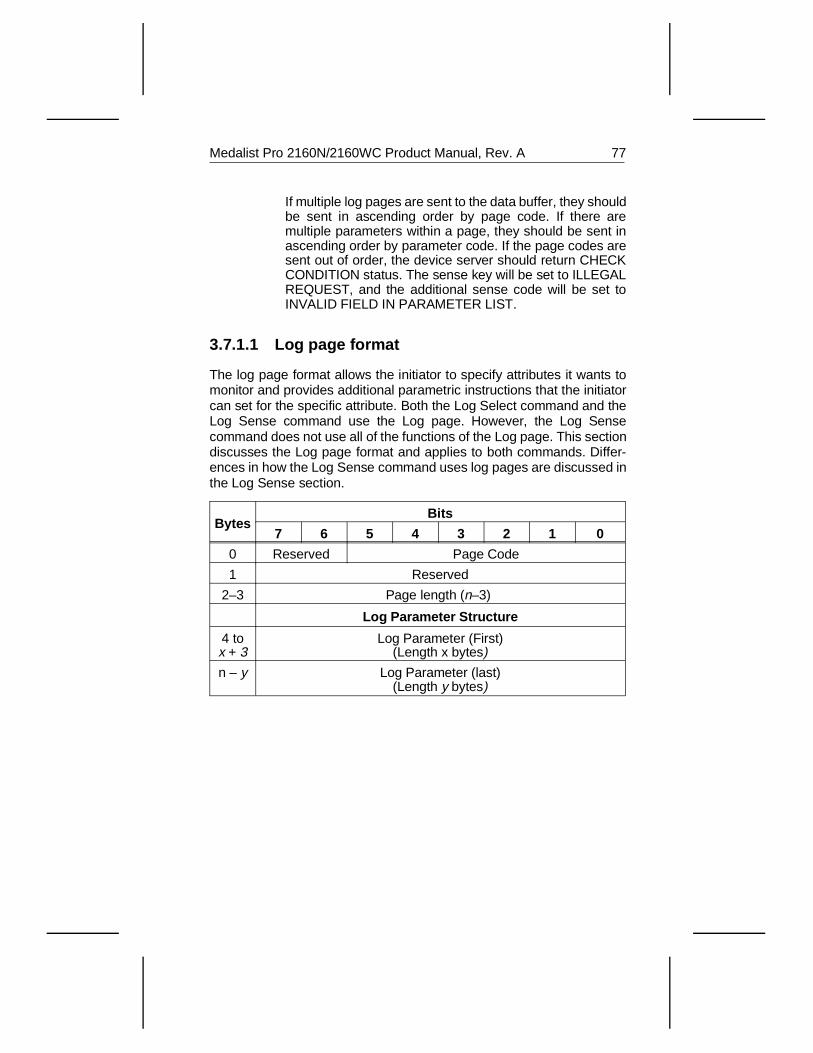
If multiple log pages are sent to the data buffer, they shouldbe sent in ascending order by page code. If there aremultiple parameters within a page, they should be sent inascending order by parameter code. If the page codes aresent out of order, the device server should return CHECKCONDITION status. The sense key will be set to ILLEGALREQUEST, and the additional sense code will be set toINVALID FIELD IN PARAMETER LIST.
3.7.1.1 Log page format
The log page format allows the initiator to specify attributes it wants tomonitor and provides additional parametric instructions that the initiatorcan set for the specific attribute. Both the Log Select command and theLog Sense command use the Log page. However, the Log Sensecommand does not use all of the functions of the Log page. This sectiondiscusses the Log page format and applies to both commands. Differ-ences in how the Log Sense command uses log pages are discussed inthe Log Sense section.
BytesBits
7 6 5 4 3 2 1 0
0 Reserved Page Code
1 Reserved
2–3 Page length (n–3)
Log Parameter Structure
4 tox + 3
Log Parameter (First)(Length x bytes)
n – y Log Parameter (last)(Length y bytes)
Medalist Pro 2160N/2160WC Product Manual, Rev. A 77
Byte 0 The page code is the code assigned to an attribute the drivemonitors. It specifies the log page that is being transferred.The page codes the drives support are listed and describedbelow:
Page Description
02H Error Counter Page (Write)
03H Error Counter Page (Read)
05H Error Counter Page (Verify)
06H Nonmedium Error page
37H Cache Statistics page
Parameter codes 00H through 06H specify six counters each for write,read and verify errors (18 counters). A description of the type (categoryof error) counters specified by codes 00H through 06H are describedbelow.
Parameter Code 00 H—Error Corrected Without Substantial Delay. Anerror correction was applied to get perfect data (also known as ECCon-the fly). Without Substantial Delay means the correction did notpostpone reading of later sectors (that is, a revolution was not lost). Thecounter is incremented once for each logical block that requires correc-tion. Two different blocks corrected during the same command arecounted as two events.
Parameter Code 01 H—Error Corrected with Possible Delays. An errorcode or algorithm (that is, ECC, checksum) is applied to get perfect datawith substantial delay. With Possible Delays means the correction tooklonger than a sector time so that reading/writing of subsequent sectorswas delayed (that is, a lost revolution). The counter is incremented oncefor each logical block that requires correction. A block with a double errorthat is correctable counts as one event and two different blocks correctedduring the same command count as two events.
Parameter Code 02H— Total (rewrites or rereads).This parameter codespecifies the counter counting the number of errors that are corrected byapplying retries. This counts errors recovered, not the number of retries.If five retries are required to recover one block of data, then one is addedto the counter, not five. The counter is increased once for each logicalblock that is recovered using retries. If an error is not recoverable whileapplying retries and is recovered by ECC, it is not counted by this counter;it is counted by the counter specified by parameter code 01H—ErrorCorrected with Possible Delay.
78 Medalist Pro 2160N/2160WC Product Manual, Rev. A
Parameter Code 03 H—Total Errors Corrected. This counter counts thetotal of all correctable errors encountered. It is the sum of the countersspecified by parameter codes 01h and 02h. There is no double countingof data errors among these two counters and all correctable data errorsare counted in one of these counters.
Parameter Code 04 H—Total Times Correction Algorithm Processed.This parameter code specifies the counter that counts the total numberof retries, or times the retry algorithm is invoked. If after five attempts acounter 02H type error is recovered, then five is added to this counter. Ifthree retries are required to get a stable ECC syndrome before a counter01H type error is corrected, then three retries are also counted. Thenumber of retries applied to unsuccessfully recover an error (counter 06Htype error) are also counted by this counter.
Parameter Code 05 H—Total Bytes Processed. This parameter codespecifies the counter that counts the total number of bytes either suc-cessfully or unsuccessfully read, written or verified (depending on the logpage) from the disc drive. If a transfer terminates early because of anunrecoverable error, only the logical blocks up to and including the onewith the unrecoverable error are counted. Data bytes transferred to theinitiator during a Mode Select, Mode Sense, Inquiry and Write DataBuffer, do not count; only user-data bytes are counted by this counter.
Parameter Code 06 H—Total Uncorrected Errors. This parametercode specifies the counter that contains the total number of blocks forwhich an unrecoverable data error has occurred.
Bytes 2–3 The page length field specifies the length of the attachedlog parameters in bytes. If the application client sends apage length that is inadequate and truncates any parame-ter, the device server terminates the command and issuesa CHECK CONDITION status. The sense key is set toILLEGAL REQUEST and the additional sense code is setto INVALID FIELD IN PARAMETER LIST.
Bytes 4– n Log parameters are the special data structure for each pagecode used in the log page. Log parameters may be datacounters that record a count of a particular event (orevents), the circumstances under which certain operationswere performed, or list parameters (strings) that contain adescription of a particular event. The log parameter formatis shown and described on the following page.
Medalist Pro 2160N/2160WC Product Manual, Rev. A 79
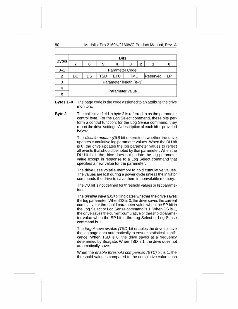
BytesBits
7 6 5 4 3 2 1 0
0–1 Parameter Code
2 DU DS TSD ETC TMC Reserved LP
3 Parameter length (n–3)
4Parameter value
n
Bytes 1–0 The page code is the code assigned to an attribute the drivemonitors.
Byte 2 The collective field in byte 2 is referred to as the parametercontrol byte. For the Log Select command, these bits per-form a control function; for the Log Sense command, theyreport the drive settings. A description of each bit is providedbelow:
The disable update (DU) bit determines whether the driveupdates cumulative log parameter values. When the DU bitis 0, the drive updates the log parameter values to reflectall events that should be noted by that parameter. When theDU bit is 1, the drive does not update the log parametervalue except in response to a Log Select command thatspecifies a new value for the parameter.
The drive uses volatile memory to hold cumulative values.The values are lost during a power cycle unless the initiatorcommands the drive to save them in nonvolatile memory.
The DU bit is not defined for threshold values or list parame-ters.
The disable save (DS) bit indicates whether the drive savesthe log parameter. When DS is 0, the drive saves the currentcumulative or threshold parameter value when the SP bit inthe Log Select or Log Sense command is 1. When DS is 1,the drive saves the current cumulative or threshold parame-ter value when the SP bit in the Log Select or Log Sensecommand is 1.
The target save disable (TSD) bit enables the drive to savethe log page data automatically to ensure statistical signifi-cance. When TSD is 0, the drive saves at a frequencydetermined by Seagate. When TSD is 1, the drive does notautomatically save.
When the enable threshold comparison (ETC) bit is 1, thethreshold value is compared to the cumulative value each
80 Medalist Pro 2160N/2160WC Product Manual, Rev. A
time the cumulative value is updated. When the ETC bit is0 no comparison is made. The ETC bit value is the samefor both the threshold and cumulative values.
The threshold met criteria (TMC) bit defines the basis forcomparison of the cumulative and threshold values. TheTMC field is valid only when ETC is 1. The codes used inthis field are listed below.
Code Basis for Comparison
00B Notify of every update of cumulative value
01B9 Cumulative value equal to threshold value
10B9 Cumulative value not equal to threshold value
11B9 Cumulative value greater than threshold value
If the ETC bit is 110 and the comparison result is true, a unitattention condition is generated for all initiators. Whenreporting the unit attention condition, the drive sets thesense key to unit attention condition and the additionalsense code to threshold condition met.
The list parameter (LP) bit indicates the log parameterformat. When the LP bit is 0, the parameter is a datacounter. When the LP bit is 1, the parameter is a listparameter (an ASCII string). The drive does not support listparameters.
Data counters are associated with one or more events andare incremented whenever one of the events occur. Thedata counter may have a maximum value assigned to it. Ifthat value is reached, the drive sets the DU bit to 1. Settingthe DU bit to 1 causes all of the other counters in the logpage to cease counting. If the data counter reaches itsmaximum value during the execution of a command, thedrive completes the command. Drive counter updates areperformed in the background. If the command completescorrectly and if the report log exception condition (RLEC)bit in Control Mode Page 0AH is set to 1, the drive issues aUnit Attention with the additional sense code set to LogCounter at Maximum. The counters do not restart automat-ically if the overflowed counter is reinitialized.
Byte 3 The parameter length field specifies the length in bytes ofthe parameter that follows. If the initiator sends a parameter
9. Comparison made at every update of cumulative value.
10. The RLEC bit in Mode Page 0AH must also be 1.
Medalist Pro 2160N/2160WC Product Manual, Rev. A 81
length value that causes the parameter value to truncate,the drive terminates the command with a Check Conditionstatus. The sense key is set to Illegal Request with addi-tional sense code set to Invalid Field Parameter List.
BByte 4 The parameter value field uses 1, 2, 4 or 8 bytes to transmitan unsigned counter value. The initiator sends counts toset values into counters in the drive, and the drive returnscounter values to the initiator. The initiator is responsible forissuing a Log Sense command to learn the parameterlength the drive has selected.
3.8 Log Sense command (4D H)
The Log Sense command (4DH) provides a means for an initiatorto manage the statistical data maintained by the drive about driveoperation. Initiators that implement the Log Select commandalso implement the Log Sense command.
82 Medalist Pro 2160N/2160WC Product Manual, Rev. A
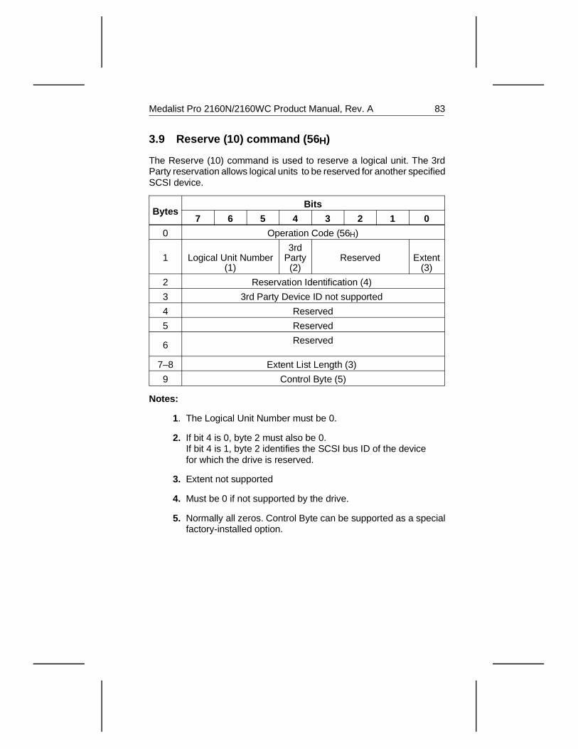
3.9 Reserve (10) command (56 H)
The Reserve (10) command is used to reserve a logical unit. The 3rdParty reservation allows logical units to be reserved for another specifiedSCSI device.
BytesBits
7 6 5 4 3 2 1 0
0 Operation Code (56H)
1 Logical Unit Number(1)
3rdParty(2)
Reserved Extent(3)
2 Reservation Identification (4)
3 3rd Party Device ID not supported
4 Reserved
5 Reserved
6 Reserved
7–8 Extent List Length (3)
9 Control Byte (5)
Notes:
1. The Logical Unit Number must be 0.
2. If bit 4 is 0, byte 2 must also be 0. If bit 4 is 1, byte 2 identifies the SCSI bus ID of the device for which the drive is reserved.
3. Extent not supported
4. Must be 0 if not supported by the drive.
5. Normally all zeros. Control Byte can be supported as a special factory-installed option.
Medalist Pro 2160N/2160WC Product Manual, Rev. A 83
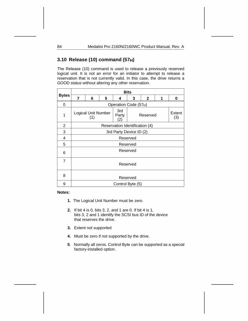
3.10 Release (10) command (57 H)
The Release (10) command is used to release a previously reservedlogical unit. It is not an error for an initiator to attempt to release areservation that is not currently valid. In this case, the drive returns aGOOD status without altering any other reservation.
BytesBits
7 6 5 4 3 2 1 0
0 Operation Code (57H)
1 Logical Unit Number(1)
3rdParty(2)
Reserved Extent(3)
2 Reservation Identification (4)
3 3rd Party Device ID (2)
4 Reserved
5 Reserved
6 Reserved
7Reserved
8 Reserved
9 Control Byte (5)
Notes:
1. The Logical Unit Number must be zero.
2. If bit 4 is 0, bits 3, 2, and 1 are 0. If bit 4 is 1, bits 3, 2 and 1 identify the SCSI bus ID of the device that reserves the drive.
3. Extent not supported
4. Must be zero if not supported by the drive.
5. Normally all zeros. Control Byte can be supported as a special factory-installed option.
84 Medalist Pro 2160N/2160WC Product Manual, Rev. A
3.11 Group 3 and 4 commands
Group 3 commands are reserved. Group 4 commands are 16-bytecommands. Group 4 commands are not supported. If the drive receivesone of these commands, it returns a check condition status.
Caution. Do not use Group 3 and 4 commands. If you do, you maydestroy data on the disc.
3.12 Group 5 and 6 commands
Group 5 and 6 commands are 12-byte commands. Group 5 commands arenot implemented. If the drive receives a Group 5 command, it returns a checkcondition status. Group 6 commands are reserved for Seagate use.
Caution. Do not use Group 6 commands. If you do, you may destroydata on the disc.
3.13 Group 7 commands
Group 7 commands are 10-byte commands. These commands are notimplemented. If the drive receives one of these commands, it returns acheck condition status.
Medalist Pro 2160N/2160WC Product Manual, Rev. A 85

86 Medalist Pro 2160N/2160WC Product Manual, Rev. A
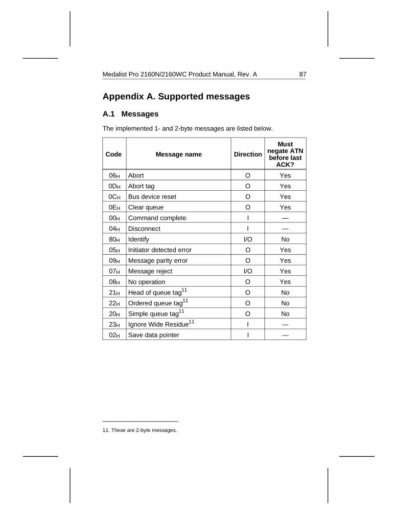
Appendix A. Supported messages
A.1 Messages
The implemented 1- and 2-byte messages are listed below.
Code Message name Direction
Mustnegate ATNbefore last
ACK?
06H Abort O Yes
0DH Abort tag O Yes
0CH Bus device reset O Yes
0EH Clear queue O Yes
00H Command complete I —
04H Disconnect I —
80H Identify I/O No
05H Initiator detected error O Yes
09H Message parity error O Yes
07H Message reject I/O Yes
08H No operation O Yes
21H Head of queue tag11 O No
22H Ordered queue tag11 O No
20H Simple queue tag11 O No
23H Ignore Wide Residue11 I —
02H Save data pointer I —
_____________________
11. These are 2-byte messages.
Medalist Pro 2160N/2160WC Product Manual, Rev. A 87
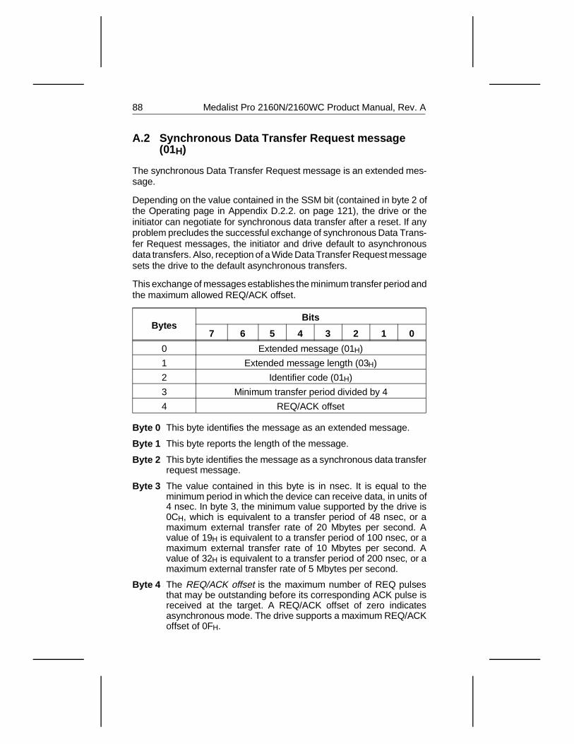
A.2 Synchronous Data Transfer Request message(01H)
The synchronous Data Transfer Request message is an extended mes-sage.
Depending on the value contained in the SSM bit (contained in byte 2 ofthe Operating page in Appendix D.2.2. on page 121), the drive or theinitiator can negotiate for synchronous data transfer after a reset. If anyproblem precludes the successful exchange of synchronous Data Trans-fer Request messages, the initiator and drive default to asynchronousdata transfers. Also, reception of a Wide Data Transfer Request messagesets the drive to the default asynchronous transfers.
This exchange of messages establishes the minimum transfer period andthe maximum allowed REQ/ACK offset.
BytesBits
7 6 5 4 3 2 1 0
0 Extended message (01H)
1 Extended message length (03H)
2 Identifier code (01H)
3 Minimum transfer period divided by 4
4 REQ/ACK offset
Byte 0 This byte identifies the message as an extended message.
Byte 1 This byte reports the length of the message.
Byte 2 This byte identifies the message as a synchronous data transferrequest message.
Byte 3 The value contained in this byte is in nsec. It is equal to theminimum period in which the device can receive data, in units of4 nsec. In byte 3, the minimum value supported by the drive is0CH, which is equivalent to a transfer period of 48 nsec, or amaximum external transfer rate of 20 Mbytes per second. Avalue of 19H is equivalent to a transfer period of 100 nsec, or amaximum external transfer rate of 10 Mbytes per second. Avalue of 32H is equivalent to a transfer period of 200 nsec, or amaximum external transfer rate of 5 Mbytes per second.
Byte 4 The REQ/ACK offset is the maximum number of REQ pulsesthat may be outstanding before its corresponding ACK pulse isreceived at the target. A REQ/ACK offset of zero indicatesasynchronous mode. The drive supports a maximum REQ/ACKoffset of 0FH.
88 Medalist Pro 2160N/2160WC Product Manual, Rev. A
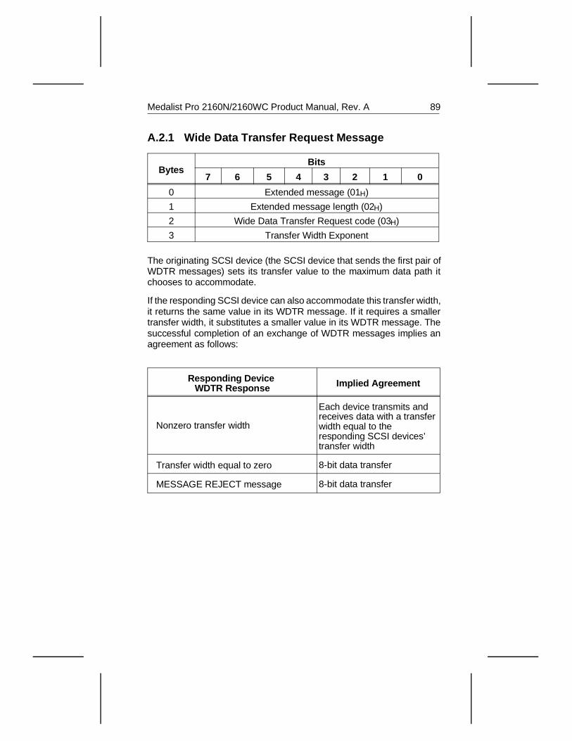
A.2.1 Wide Data Transfer Request Message
BytesBits
7 6 5 4 3 2 1 0
0 Extended message (01H)
1 Extended message length (02H)
2 Wide Data Transfer Request code (03H)
3 Transfer Width Exponent
The originating SCSI device (the SCSI device that sends the first pair ofWDTR messages) sets its transfer value to the maximum data path itchooses to accommodate.
If the responding SCSI device can also accommodate this transfer width,it returns the same value in its WDTR message. If it requires a smallertransfer width, it substitutes a smaller value in its WDTR message. Thesuccessful completion of an exchange of WDTR messages implies anagreement as follows:
Responding Device WDTR Response Implied Agreement
Nonzero transfer width
Each device transmits and receives data with a transfer width equal to theresponding SCSI devices’transfer width
Transfer width equal to zero 8-bit data transfer
MESSAGE REJECT message 8-bit data transfer
Medalist Pro 2160N/2160WC Product Manual, Rev. A 89

90 Medalist Pro 2160N/2160WC Product Manual, Rev. A
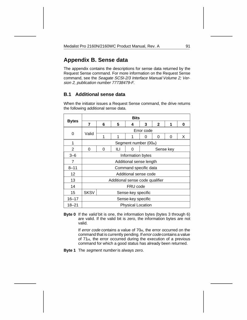
Appendix B. Sense dataThe appendix contains the descriptions for sense data returned by theRequest Sense command. For more information on the Request Sensecommand, see the Seagate SCSI-2/3 Interface Manual Volume 2; Ver-sion 2, publication number 77738479-F.
B.1 Additional sense data
When the initiator issues a Request Sense command, the drive returnsthe following additional sense data.
BytesBits
7 6 5 4 3 2 1 0
0 ValidError code
1 1 1 0 0 0 X
1 Segment number (00H)
2 0 0 ILI 0 Sense key
3–6 Information bytes
7 Additional sense length
8–11 Command specific data
12 Additional sense code
13 Additional sense code qualifier
14 FRU code
15 SKSV Sense-key specific
16–17 Sense-key specific
18–21 Physical Location
Byte 0 If the valid bit is one, the information bytes (bytes 3 through 6)are valid. If the valid bit is zero, the information bytes are notvalid.
If error code contains a value of 70H, the error occurred on thecommand that is currently pending. If error code contains a valueof 71H, the error occurred during the execution of a previouscommand for which a good status has already been returned.
Byte 1 The segment number is always zero.
Medalist Pro 2160N/2160WC Product Manual, Rev. A 91
Byte 2 If the incorrect length indicator (ILI) bit is zero, the re-quested block of data from the previous command did notmatch the logical block length of the data on the disc. Ifthe ILI bit is one, the requested block of data from theprevious command matched the logical block length of thedata on the disc.
The sense key indicates one of nine general error cate-gories. These error categories are listed in Appendix B.2on page 93.
Bytes 3–6 When the valid bit is 1, the information bytes contain thelogical block address of the current logical block associ-ated with the sense key. For example, if the sense key ismedia error, the information bytes contain the logicalblock address of the offending block.
Byte 7 The additional sense length is limited to a maximum of0EH additional bytes. If the allocation length of the com-mand descriptor block is too small to accommodate all ofthe additional sense bytes, the additional sense length isnot adjusted to reflect the truncation.
Bytes 8–11 These bytes contain command-specific data.
Bytes 12–13 The additional sense code and additional sense codequalifier provide additional details about errors. See Ap-pendix B.3 on page 94.
Byte 14 The field replaceable unit (FRU) code is used by fieldservice personnel only.
Bytes 15–17 The SHSV bit and sense-key specific bytes.
Bytes 18–19 Physical cylinder
Byte 20 Physical head
Byte 21 Sector
Note. The Physical Location bytes contain the offending cylinder, headand sector if the valid bit is 1.
92 Medalist Pro 2160N/2160WC Product Manual, Rev. A
B.2 Sense key
The sense keys in the lower-order bits of byte 2 of the sense data returnedby the Request Sense command are described in the following table.You can find a more detailed description of the error by checking theadditional sense code and the additional sense code qualifier in Sec-tion B.3 on page 94.
Sensekey Description
0H No Sense. In the case of a successful command, no specificsense key information needs to be reported for the drive.
1H Recovered error. The drive completed the last commandsuccessfully with some recovery action. When manyrecovered errors occur during one command, the drivedetermines which error to report.
2H Not ready. The addressed logical unit cannot be accessed.Operator intervention may be required to correct thiscondition.
3H Medium error. The command was terminated with anonrecoverable error condition, possibly caused by a flaw inthe media or an error in the recorded data.
4H Hardware error. The drive detected a nonrecoverablehardware failure while performing the command or during aself-test. This includes, for example, SCSI interface parityerrors, controller failures and device failures.
5H Illegal request. This indicates an illegal parameter in theCDB or in the additional parameters supplied as data forsome commands (for example, the Format Unit command,the Mode Sense command and others). If the drive detectsan invalid parameter in the CDB, it terminates the commandwithout altering the media. If the drive detects an invalidparameter in the additional parameters supplied as data, thedrive may have already altered the media.
6H Unit attention. The drive may have been reset. See theSeagate SCSI-2 Interface Manual for more details about theUnit Attention condition.
BH Aborted command. The drive aborted the command. Theinitiator may be able to recover by retrying.
EH Miscompare. The source data did not match the data readfrom the media.
Medalist Pro 2160N/2160WC Product Manual, Rev. A 93
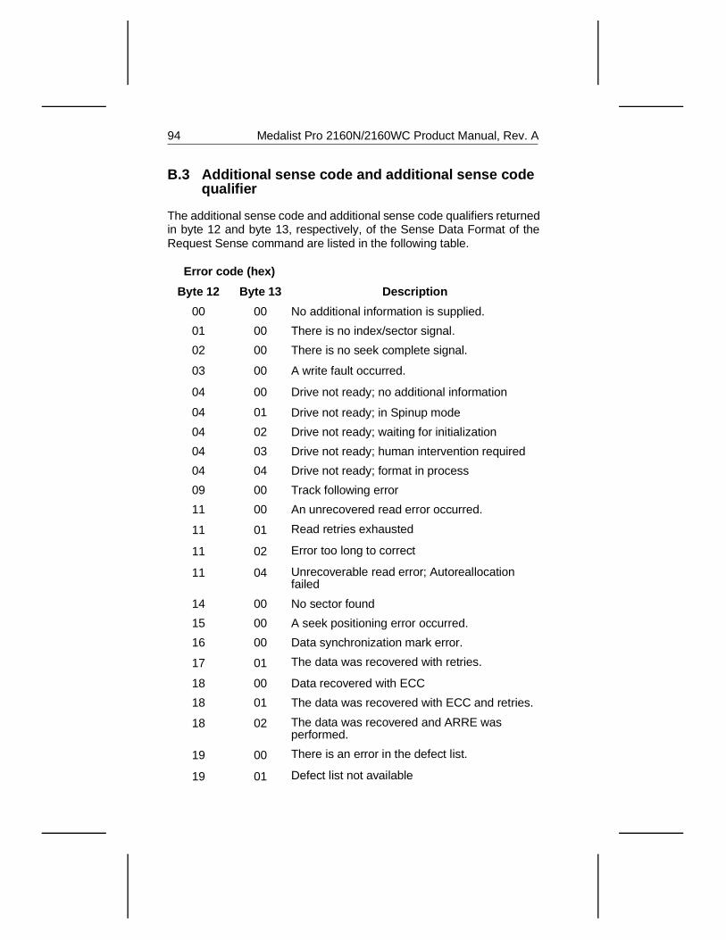
B.3 Additional sense code and additional sense codequalifier
The additional sense code and additional sense code qualifiers returnedin byte 12 and byte 13, respectively, of the Sense Data Format of theRequest Sense command are listed in the following table.
Error code (hex)
DescriptionByte 12 Byte 13
00 00 No additional information is supplied.
01 00 There is no index/sector signal.
02 00 There is no seek complete signal.
03 00 A write fault occurred.
04 00 Drive not ready; no additional information
04 01 Drive not ready; in Spinup mode
04 02 Drive not ready; waiting for initialization
04 03 Drive not ready; human intervention required
04 04 Drive not ready; format in process
09 00 Track following error
11 00 An unrecovered read error occurred.
11 01 Read retries exhausted
11 02 Error too long to correct
11 04 Unrecoverable read error; Autoreallocationfailed
14 00 No sector found
15 00 A seek positioning error occurred.
16 00 Data synchronization mark error.
17 01 The data was recovered with retries.
18 00 Data recovered with ECC
18 01 The data was recovered with ECC and retries.
18 02 The data was recovered and ARRE wasperformed.
19 00 There is an error in the defect list.
19 01 Defect list not available
94 Medalist Pro 2160N/2160WC Product Manual, Rev. A
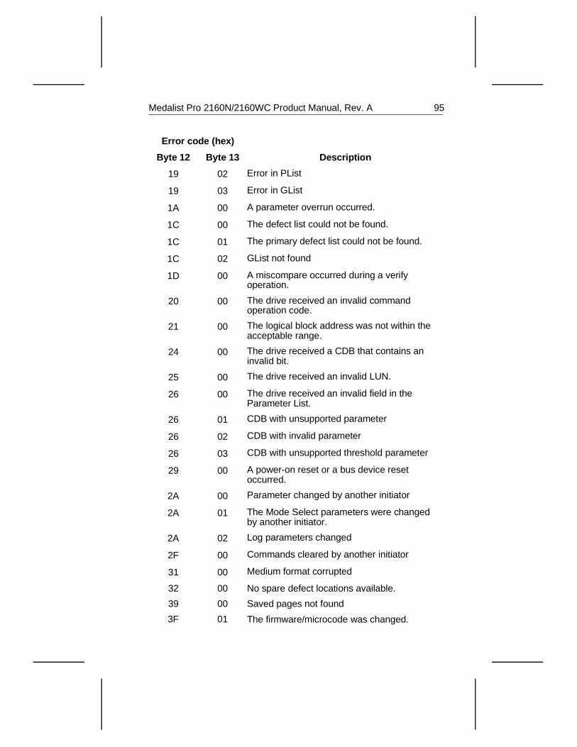
Error code (hex)
DescriptionByte 12 Byte 13
19 02 Error in PList
19 03 Error in GList
1A 00 A parameter overrun occurred.
1C 00 The defect list could not be found.
1C 01 The primary defect list could not be found.
1C 02 GList not found
1D 00 A miscompare occurred during a verifyoperation.
20 00 The drive received an invalid commandoperation code.
21 00 The logical block address was not within theacceptable range.
24 00 The drive received a CDB that contains aninvalid bit.
25 00 The drive received an invalid LUN.
26 00 The drive received an invalid field in theParameter List.
26 01 CDB with unsupported parameter
26 02 CDB with invalid parameter
26 03 CDB with unsupported threshold parameter
29 00 A power-on reset or a bus device resetoccurred.
2A 00 Parameter changed by another initiator
2A 01 The Mode Select parameters were changedby another initiator.
2A 02 Log parameters changed
2F 00 Commands cleared by another initiator
31 00 Medium format corrupted
32 00 No spare defect locations available.
39 00 Saved pages not found
3F 01 The firmware/microcode was changed.
Medalist Pro 2160N/2160WC Product Manual, Rev. A 95
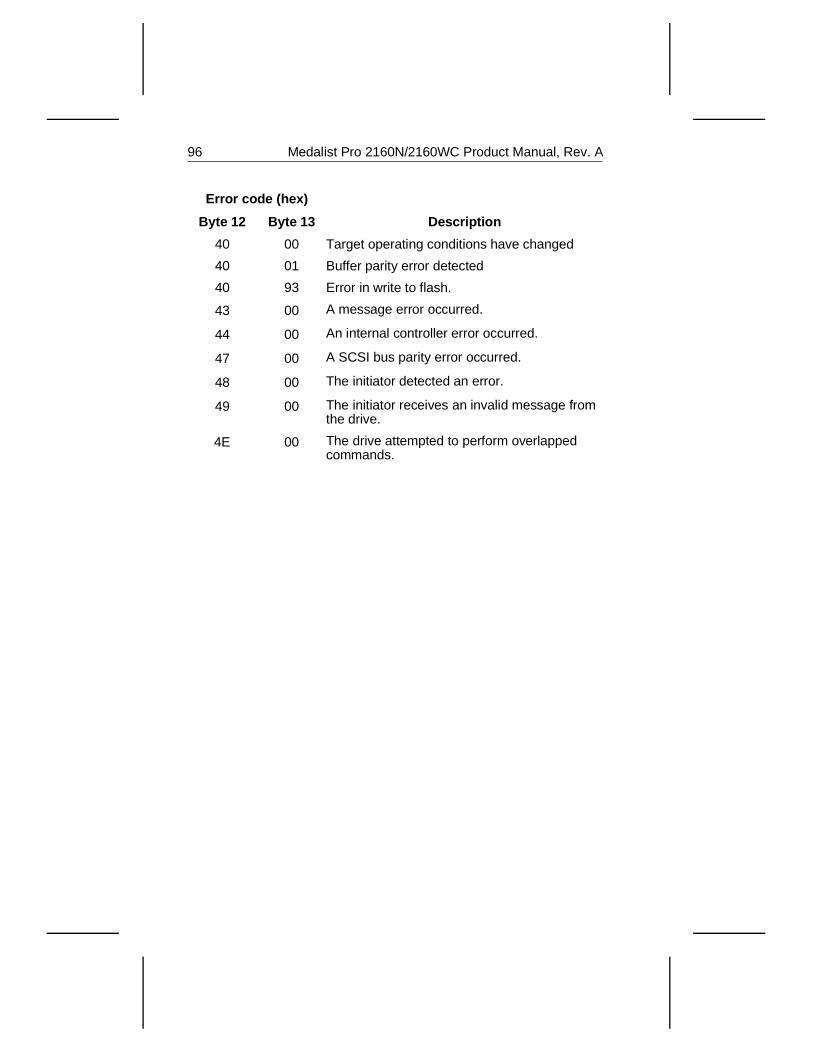
Error code (hex)
DescriptionByte 12 Byte 13
40 00 Target operating conditions have changed
40 01 Buffer parity error detected
40 93 Error in write to flash.
43 00 A message error occurred.
44 00 An internal controller error occurred.
47 00 A SCSI bus parity error occurred.
48 00 The initiator detected an error.
49 00 The initiator receives an invalid message fromthe drive.
4E 00 The drive attempted to perform overlappedcommands.
96 Medalist Pro 2160N/2160WC Product Manual, Rev. A
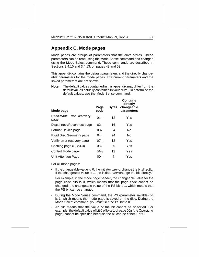
Appendix C. Mode pagesMode pages are groups of parameters that the drive stores. Theseparameters can be read using the Mode Sense command and changedusing the Mode Select command. These commands are described inSections 3.4.10 and 3.4.13. on pages 48 and 53.
This appendix contains the default parameters and the directly change-able parameters for the mode pages. The current parameters and thesaved parameters are not shown.
Note. The default values contained in this appendix may differ from thedefault values actually contained in your drive. To determine thedefault values, use the Mode Sense command.
Mode page Pagecode
Bytes
Containsdirectly
changeableparameters
Read-Write Error Recoverypage 01H 12 Yes
Disconnect/Reconnect page 02H 16 Yes
Format Device page 03H 24 No
Rigid Disc Geometry page 04H 24 No
Verify error recovery page 07H 12 Yes
Caching page (SCSI-3) 08H 20 Yes
Control Mode page 0AH 12 Yes
Unit Attention Page 00H 4 Yes
For all mode pages:
• If the changeable value is 0, the initiator cannot change the bit directly.If the changeable value is 1, the initiator can change the bit directly.
For example, in the mode page header, the changeable value for thepage code bits is 0, which means that the page code cannot bechanged; the changeable value of the PS bit is 1, which means thatthe PS bit can be changed.
• During the Mode Sense command, the PS (parameter savable) bitis 1, which means the mode page is saved on the disc. During theMode Select command, you must set the PS bit to 0.
• An “X” means that the value of the bit cannot be specified. Forexample, the default value of bit 0 of byte 1 of page 00H (the Operatingpage) cannot be specified because the bit can be either 1 or 0.
Medalist Pro 2160N/2160WC Product Manual, Rev. A 97
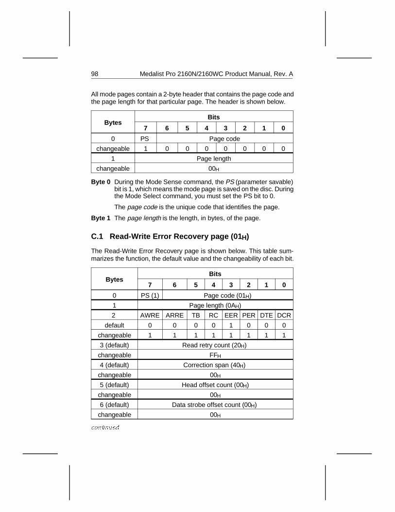
All mode pages contain a 2-byte header that contains the page code andthe page length for that particular page. The header is shown below.
BytesBits
7 6 5 4 3 2 1 0
0 PS Page code
changeable 1 0 0 0 0 0 0 0
1 Page length
changeable 00H
Byte 0 During the Mode Sense command, the PS (parameter savable)bit is 1, which means the mode page is saved on the disc. Duringthe Mode Select command, you must set the PS bit to 0.
The page code is the unique code that identifies the page.
Byte 1 The page length is the length, in bytes, of the page.
C.1 Read-Write Error Recovery page (01 H)
The Read-Write Error Recovery page is shown below. This table sum-marizes the function, the default value and the changeability of each bit.
BytesBits
7 6 5 4 3 2 1 0
0 PS (1) Page code (01H)
1 Page length (0AH)
2 AWRE ARRE TB RC EER PER DTE DCR
default 0 0 0 0 1 0 0 0
changeable 1 1 1 1 1 1 1 1
3 (default) Read retry count (20H)
changeable FFH
4 (default) Correction span (40H)
changeable 00H
5 (default) Head offset count (00H)
changeable 00H
6 (default) Data strobe offset count (00H)
changeable 00H
continued
98 Medalist Pro 2160N/2160WC Product Manual, Rev. A
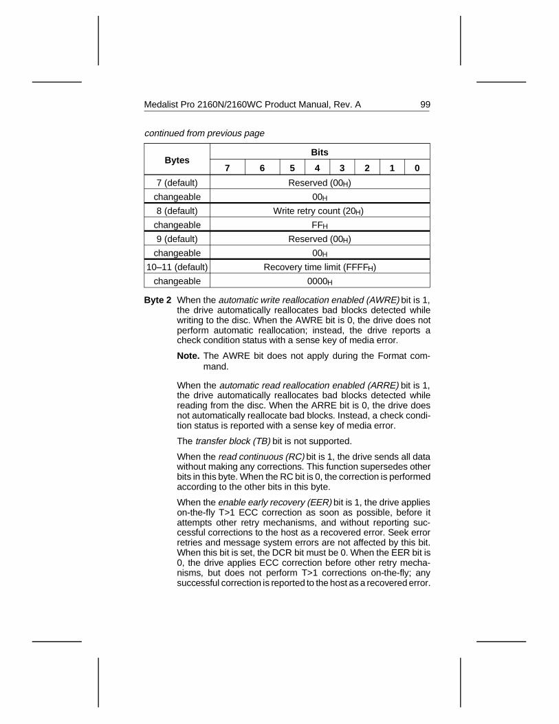
BytesBits
7 6 5 4 3 2 1 0
7 (default) Reserved (00H)
changeable 00H
8 (default) Write retry count (20H)
changeable FFH
9 (default) Reserved (00H)
changeable 00H
10–11 (default) Recovery time limit (FFFFH)
changeable 0000H
Byte 2 When the automatic write reallocation enabled (AWRE) bit is 1,the drive automatically reallocates bad blocks detected whilewriting to the disc. When the AWRE bit is 0, the drive does notperform automatic reallocation; instead, the drive reports acheck condition status with a sense key of media error.
Note. The AWRE bit does not apply during the Format com-mand.
When the automatic read reallocation enabled (ARRE) bit is 1,the drive automatically reallocates bad blocks detected whilereading from the disc. When the ARRE bit is 0, the drive doesnot automatically reallocate bad blocks. Instead, a check condi-tion status is reported with a sense key of media error.
The transfer block (TB) bit is not supported.
When the read continuous (RC) bit is 1, the drive sends all datawithout making any corrections. This function supersedes otherbits in this byte. When the RC bit is 0, the correction is performedaccording to the other bits in this byte.
When the enable early recovery (EER) bit is 1, the drive applieson-the-fly T>1 ECC correction as soon as possible, before itattempts other retry mechanisms, and without reporting suc-cessful corrections to the host as a recovered error. Seek errorretries and message system errors are not affected by this bit.When this bit is set, the DCR bit must be 0. When the EER bit is0, the drive applies ECC correction before other retry mecha-nisms, but does not perform T>1 corrections on-the-fly; anysuccessful correction is reported to the host as a recovered error.
continued from previous page
Medalist Pro 2160N/2160WC Product Manual, Rev. A 99
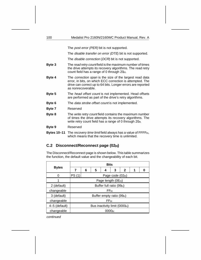
The post error (PER) bit is not supported.
The disable transfer on error (DTE) bit is not supported.
The disable correction (DCR) bit is not supported.
Byte 3 The read retry count field is the maximum number of timesthe drive attempts its recovery algorithms. The read retrycount field has a range of 0 through 20H.
Byte 4 The correction span is the size of the largest read dataerror, in bits, on which ECC correction is attempted. Thedrive can correct up to 64 bits. Longer errors are reportedas nonrecoverable.
Byte 5 The head offset count is not implemented. Head offsetsare performed as part of the drive’s retry algorithms.
Byte 6 The data strobe offset count is not implemented.
Byte 7 Reserved
Byte 8 The write retry count field contains the maximum numberof times the drive attempts its recovery algorithms. Thewrite retry count field has a range of 0 through 20H.
Byte 9 Reserved
Bytes 10–11 The recovery time limit field always has a value of FFFFH,which means that the recovery time is unlimited.
C.2 Disconnect/Reconnect page (02 H)
The Disconnect/Reconnect page is shown below. This table summarizesthe function, the default value and the changeability of each bit.
BytesBits
7 6 5 4 3 2 1 0
0 PS (1) Page code (02H)
1 Page length (0EH)
2 (default) Buffer full ratio (99H)
changeable FFH
3 (default) Buffer empty ratio (99H)
changeable FFH
4–5 (default) Bus inactivity limit (0000H)
changeable 0000H
continued
100 Medalist Pro 2160N/2160WC Product Manual, Rev. A
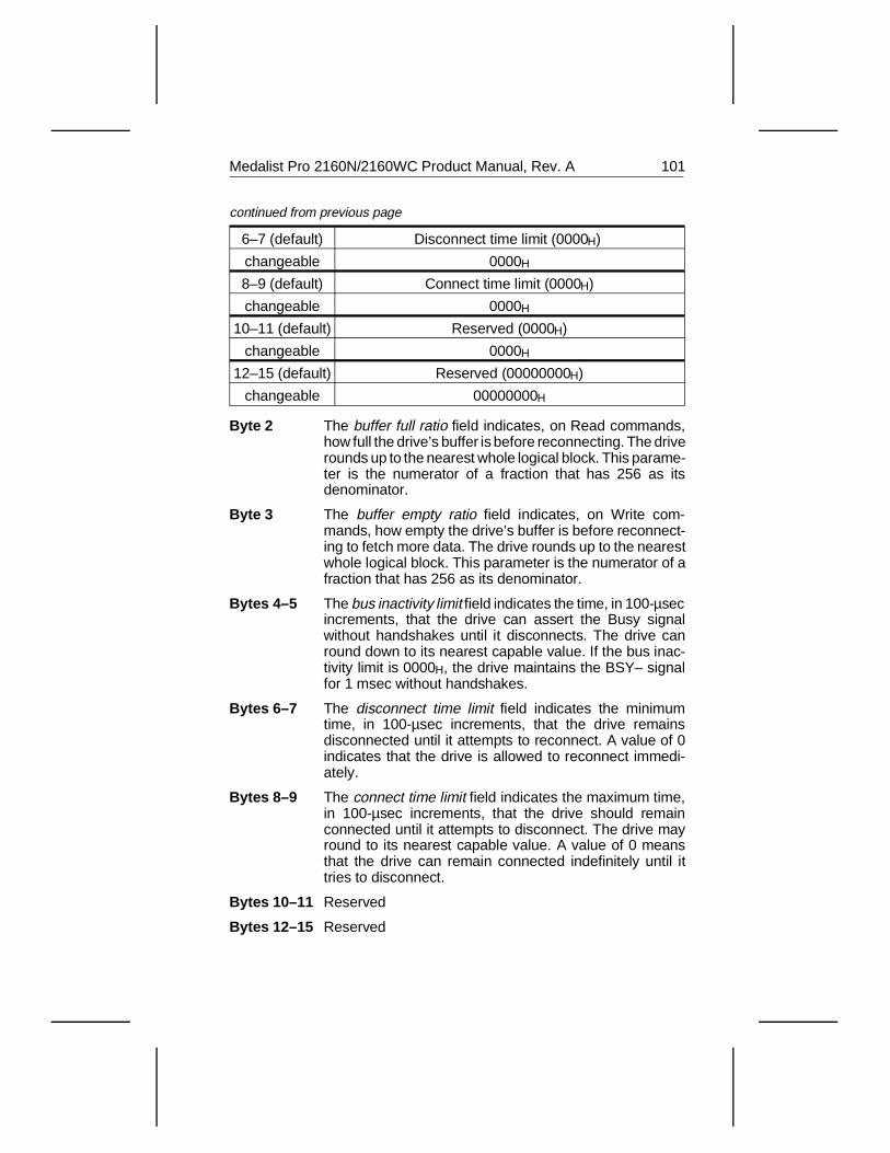
6–7 (default) Disconnect time limit (0000H)
changeable 0000H
8–9 (default) Connect time limit (0000H)
changeable 0000H
10–11 (default) Reserved (0000H)
changeable 0000H
12–15 (default) Reserved (00000000H)
changeable 00000000H
Byte 2 The buffer full ratio field indicates, on Read commands,how full the drive’s buffer is before reconnecting. The driverounds up to the nearest whole logical block. This parame-ter is the numerator of a fraction that has 256 as itsdenominator.
Byte 3 The buffer empty ratio field indicates, on Write com-mands, how empty the drive’s buffer is before reconnect-ing to fetch more data. The drive rounds up to the nearestwhole logical block. This parameter is the numerator of afraction that has 256 as its denominator.
Bytes 4–5 The bus inactivity limit field indicates the time, in 100-µsecincrements, that the drive can assert the Busy signalwithout handshakes until it disconnects. The drive canround down to its nearest capable value. If the bus inac-tivity limit is 0000H, the drive maintains the BSY– signalfor 1 msec without handshakes.
Bytes 6–7 The disconnect time limit field indicates the minimumtime, in 100-µsec increments, that the drive remainsdisconnected until it attempts to reconnect. A value of 0indicates that the drive is allowed to reconnect immedi-ately.
Bytes 8–9 The connect time limit field indicates the maximum time,in 100-µsec increments, that the drive should remainconnected until it attempts to disconnect. The drive mayround to its nearest capable value. A value of 0 meansthat the drive can remain connected indefinitely until ittries to disconnect.
Bytes 10–11 Reserved
Bytes 12–15 Reserved
continued from previous page
Medalist Pro 2160N/2160WC Product Manual, Rev. A 101
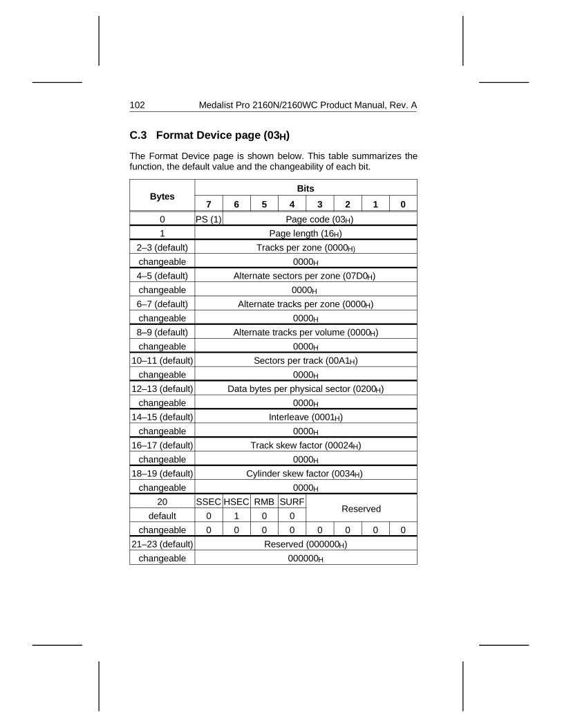
C.3 Format Device page (03 H)
The Format Device page is shown below. This table summarizes thefunction, the default value and the changeability of each bit.
BytesBits
7 6 5 4 3 2 1 0
0 PS (1) Page code (03H)
1 Page length (16H)
2–3 (default) Tracks per zone (0000H)
changeable 0000H
4–5 (default) Alternate sectors per zone (07D0H)
changeable 0000H
6–7 (default) Alternate tracks per zone (0000H)
changeable 0000H
8–9 (default) Alternate tracks per volume (0000H)
changeable 0000H
10–11 (default) Sectors per track (00A1H)
changeable 0000H
12–13 (default) Data bytes per physical sector (0200H)
changeable 0000H
14–15 (default) Interleave (0001H)
changeable 0000H
16–17 (default) Track skew factor (00024H)
changeable 0000H
18–19 (default) Cylinder skew factor (0034H)
changeable 0000H
20 SSEC HSEC RMB SURFReserved
default 0 1 0 0
changeable 0 0 0 0 0 0 0 0
21–23 (default) Reserved (000000H)
changeable 000000H
102 Medalist Pro 2160N/2160WC Product Manual, Rev. A
Bytes 2–3 The tracks per zone field indicates the number of tracks thedrive allocates to each defect-management zone. Sparesectors or tracks are placed at the end of each defect-management zone. If each zone is treated as containing onetrack, the valid value for tracks per zone is 1. If each zone istreated as containing one cylinder, the valid value is equalto the number of read/write heads. The drive supports onlyone zone for the entire drive.
Bytes 4–5 The alternate sectors per zone field indicates the numberof spare sectors to be reserved at the end of each defect-management zone. The drive defaults to 7D0H (2000)spare blocks at the end of the volume.
Bytes 6–7 The alternate tracks per zone field indicates the numberof spare tracks the drive reserves at the end of eachdefect-management zone. A value of 0 indicates that nospare tracks are reserved at the end of each zone fordefect management.
Bytes 8–9 The alternate tracks per volume field indicates the numberof spare tracks to be reserved at the end of the drive fordefect management. A value of 0 indicates that no sparetracks are reserved at the end of each zone for defectmanagement.
Bytes 10–11 The sectors per track field indicates the number of physi-cal sectors the drive allocates per track. The drive reportsthe average number of physical sectors per track becausethe number of sectors per track varies between the outerand inner tracks.
Bytes 12–13 The data bytes per physical sector field indicates thenumber of data bytes allocated per physical sector.
Bytes 14–15 The interleave field is the interleave value sent to the driveduring the last Format Unit command. This field is validonly for Mode Sense commands. The drive ignores thisfield during Mode Select commands. The interleave isalways 1:1.
Bytes 16–17 The track skew factor12 field indicates the number ofphysical sectors on the media between the last logicalblock of one track and the first logical block of the nextsequential track of the same cylinder. The actual trackskew factor that the drive uses is different for every zone.
12. The skew is actually in units of servo bursts, which are not visible through the interface. The values shown is the skew approximated to the nearest sector.
Medalist Pro 2160N/2160WC Product Manual, Rev. A 103
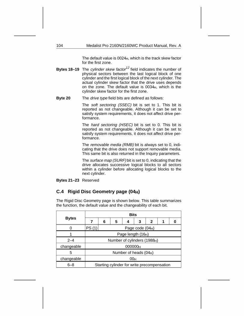
The default value is 0024H, which is the track skew factorfor the first zone.
Bytes 18–19 The cylinder skew factor12 field indicates the number ofphysical sectors between the last logical block of onecylinder and the first logical block of the next cylinder. Theactual cylinder skew factor that the drive uses dependson the zone. The default value is 0034H, which is thecylinder skew factor for the first zone.
Byte 20 The drive type field bits are defined as follows:
The soft sectoring (SSEC) bit is set to 1. This bit isreported as not changeable. Although it can be set tosatisfy system requirements, it does not affect drive per-formance.
The hard sectoring (HSEC) bit is set to 0. This bit isreported as not changeable. Although it can be set tosatisfy system requirements, it does not affect drive per-formance.
The removable media (RMB) bit is always set to 0, indi-cating that the drive does not support removable media.This same bit is also returned in the Inquiry parameters.
The surface map (SURF) bit is set to 0, indicating that thedrive allocates successive logical blocks to all sectorswithin a cylinder before allocating logical blocks to thenext cylinder.
Bytes 21–23 Reserved
C.4 Rigid Disc Geometry page (04 H)
The Rigid Disc Geometry page is shown below. This table summarizesthe function, the default value and the changeability of each bit.
BytesBits
7 6 5 4 3 2 1 0
0 PS (1) Page code (04H)
1 Page length (16H)
2–4 Number of cylinders (1988H)
changeable 000000H
5 Number of heads (04H)
changeable 00H
6–8 Starting cylinder for write precompensation
104 Medalist Pro 2160N/2160WC Product Manual, Rev. A
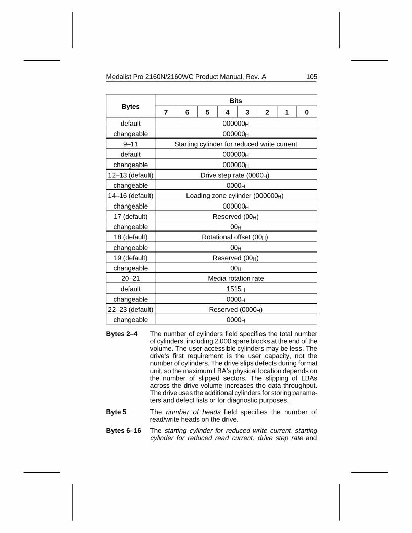
BytesBits
7 6 5 4 3 2 1 0
default 000000H
changeable 000000H
9–11 Starting cylinder for reduced write current
default 000000H
changeable 000000H
12–13 (default) Drive step rate (0000H)
changeable 0000H
14–16 (default) Loading zone cylinder (000000H)
changeable 000000H
17 (default) Reserved (00H)
changeable 00H
18 (default) Rotational offset (00H)
changeable 00H
19 (default) Reserved (00H)
changeable 00H
20–21 Media rotation rate
default 1515H
changeable 0000H
22–23 (default) Reserved (0000H)
changeable 0000H
Bytes 2–4 The number of cylinders field specifies the total numberof cylinders, including 2,000 spare blocks at the end of thevolume. The user-accessible cylinders may be less. Thedrive’s first requirement is the user capacity, not thenumber of cylinders. The drive slips defects during formatunit, so the maximum LBA’s physical location depends onthe number of slipped sectors. The slipping of LBAsacross the drive volume increases the data throughput.The drive uses the additional cylinders for storing parame-ters and defect lists or for diagnostic purposes.
Byte 5 The number of heads field specifies the number ofread/write heads on the drive.
Bytes 6–16 The starting cylinder for reduced write current, startingcylinder for reduced read current, drive step rate and
Medalist Pro 2160N/2160WC Product Manual, Rev. A 105
loading zone cylinder bytes are not supported by the drive.
Byte 17 Reserved. RPL is not supported.
Byte 18 The rotational offset is not supported.
Byte 19 Reserved
Bytes 20–21 The medium rotation rate is the spindle speed.
Bytes 22–23 Reserved
106 Medalist Pro 2160N/2160WC Product Manual, Rev. A
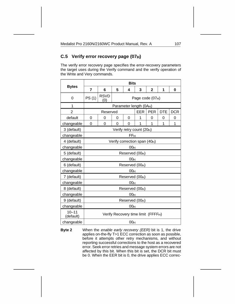
C.5 Verify error recovery page (07 H)
The verify error recovery page specifies the error-recovery parametersthe target uses during the Verify command and the verify operation ofthe Write and Very commands.
BytesBits
7 6 5 4 3 2 1 0
0 PS (1) RSVD(0) Page code (07H)
1 Parameter length (0AH)
2 Reserved EER PER DTE DCR
default 0 0 0 0 1 0 0 0
changeable 0 0 0 0 1 1 1 1
3 (default) Verify retry count (20H)
changeable FFH
4 (default) Verify correction span (40H)
changeable 00H
5 (default) Reserved (00H)
changeable 00H
6 (default) Reserved (00H)
changeable 00H
7 (default) Reserved (00H)
changeable 00H
8 (default) Reserved (00H)
changeable 00H
9 (default) Reserved (00H)
changeable 00H
10–11(default) Verify Recovery time limit (FFFFH)
changeable 00H
Byte 2 When the enable early recovery (EER) bit is 1, the driveapplies on-the-fly T>1 ECC correction as soon as possible,before it attempts other retry mechanisms, and withoutreporting successful corrections to the host as a recoverederror. Seek error retries and message system errors are notaffected by this bit. When this bit is set, the DCR bit mustbe 0. When the EER bit is 0, the drive applies ECC correc-
Medalist Pro 2160N/2160WC Product Manual, Rev. A 107
tion before other retry mechanisms, but does not performT>1 corrections on-the-fly; any successful correction isreported to the host as a recovered error.
The post error (PER) bit is not supported.
The disable transfer error (DTE) bit is not supported.
The disable correction (DCR) bit is not supported.
Byte 3 The verify retry count field specifies the number of times thetarget attempts its recovery algorithm during a verify opera-tion. The verify retry count field has a range of 0 through20H.
Byte 4 The verify correction span is the size of the largest read dataerror, in bits, on which ECC correction is attempted. Thedrive can correct up to 64 bits. Longer errors are reportedas nonrecoverable.
Byte 5–9 Reserved
Byte 10–11 The verify recovery time limit field has a value of FFFFH,which means that recovery time is unlimited.
C.6 Caching page (08 H)
The drive uses read look-ahead, read caching and write caching toimprove seek times and performance.
C.6.1 Read look-ahead and caching
The drive uses an algorithm that improves seek performance by readingthe next logical sectors after the last requested sector. These unre-quested sectors are read into a buffer and are ready to be transmitted tothe host before they are requested. Because these sectors are readbefore they are requested, access read time for the sectors is virtuallyeliminated. This process is called read look-ahead.
Read Caching is any time data read for a command is available to besent to an initiator for a subsequent command.
The buffer used for read look-ahead and caching can be divided intosegments as shown in the following table. To change the number ofsegments, use byte 13 of the Caching page, which is described inAppendix C.6.3. on page 110. The default is one 128-Kbyte segment.
108 Medalist Pro 2160N/2160WC Product Manual, Rev. A
Number of segments Size of segment (in Kbytes)
1 96
2 48
4 24
When the buffer is divided into multiple segments, each segment func-tions as an independent buffer, causing dramatically increased perform-ance in multitasking and multiuser environments at the expense of poorerperformance commands with long transfer lengths.
C.6.2 Write caching and write merging
Write caching. The drive uses a segment to store Write data. After thedrive receives the data from the initiator and caches the data, thecommand is terminated and the drive is ready to process new com-mands. The drive writes data to the disc before processing any nonwritecommand.
Write merging. Write merging uses the Write Immediate function. WriteImmediate terminates the command as soon as the initiator data is sent.Write Immediate can be performed on an isolated write command. IfWrite Immediate is used on write commands that are close enough intime that the initiator data is present from the subsequent commandbefore the original command’s data is completely written to disc, then thetwo write commands can be merged. The problem with this option is thatstatus is sent before the data is written to the disc. For disc errors, SCSIhas a function called Deferred Error reporting; the next command sentreceives a CHECK CONDITION status, and the SENSE data reports adeferred error for the Write that had the error. The command that had theCHECK CONDITION status may not be related to the Write error.
Medalist Pro 2160N/2160WC Product Manual, Rev. A 109
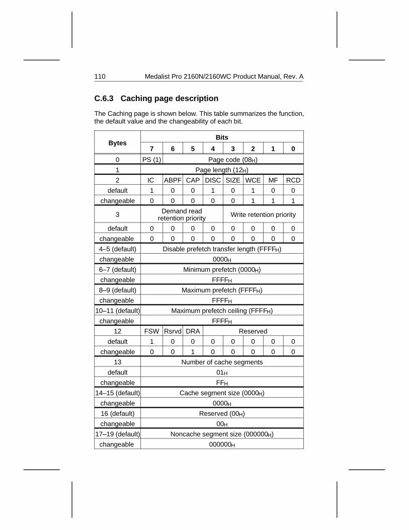
C.6.3 Caching page description
The Caching page is shown below. This table summarizes the function,the default value and the changeability of each bit.
BytesBits
7 6 5 4 3 2 1 0
0 PS (1) Page code (08H)
1 Page length (12H)
2 IC ABPF CAP DISC SIZE WCE MF RCD
default 1 0 0 1 0 1 0 0
changeable 0 0 0 0 0 1 1 1
3 Demand readretention priority Write retention priority
default 0 0 0 0 0 0 0 0
changeable 0 0 0 0 0 0 0 0
4–5 (default) Disable prefetch transfer length (FFFFH)
changeable 0000H
6–7 (default) Minimum prefetch (0000H)
changeable FFFFH
8–9 (default) Maximum prefetch (FFFFH)
changeable FFFFH
10–11 (default) Maximum prefetch ceiling (FFFFH)
changeable FFFFH
12 FSW Rsrvd DRA Reserved
default 1 0 0 0 0 0 0 0
changeable 0 0 1 0 0 0 0 0
13 Number of cache segments
default 01H
changeable FFH
14–15 (default) Cache segment size (0000H)
changeable 0000H
16 (default) Reserved (00H)
changeable 00H
17–19 (default) Noncache segment size (000000H)
changeable 000000H
110 Medalist Pro 2160N/2160WC Product Manual, Rev. A
Byte 2 The initiator control (IC) bit is not supported.
When the abort prefetch (ABPF) bit is 0, the drive controlscompletion of prefetch. See the description for the DISCbit below. This is the default value and it is not change-able.
The caching analysis permitted (CAP) bit is not sup-ported.
When the discontinuity (DISC) bit is 1, the drive mayprefetch across cylinder boundaries, where head seeksconsume additional processing time. This is the defaultvalue and it is not changeable.
The size enable (SIZE) bit is not supported.
When the write cache enable (WCE) bit is 0, the drivereturns a good status for a Write command after success-fully writing all the data to the media. When the WCE bitis 1, the drive returns a good status for a Write commandafter successfully receiving the data and usually beforewriting it to the media.
When the multiplication factor (MF) bit is 0, the driveinterprets the minimum prefetch and maximum prefetchfields as the number of logical blocks to be prefetched.When the MF bit is 1, the drive interprets the minimumprefetch and maximum prefetch fields in terms of a num-ber which, when multiplied by the transfer length of thecurrent command, yields the number of logical blocks tobe prefetched.
When the read cache disable (RCD) bit is 0, the drive mayreturn data requested by a Read command by accessingeither the cache or the media. If the RCD bit is 1, the cacheis not used.
Byte 3 The demand read retention priority field is not used. Theinitiator cannot assign any special retention priority to thedrive.
The write retention priority field is not used. The initiatorcannot assign any special retention priority to the drive.
Bytes 4–5 The disable prefetch transfer length always has a valueof FFFFH, which means that the drive attempts an antici-patory prefetch for all Read commands.
Bytes 6–7 The minimum prefetch field specifies the minimum num-ber of blocks the drive prefetches, regardless of the delaysit may cause in executing subsequent pending com-mands. When the minimum prefetch field contains 0, the
Medalist Pro 2160N/2160WC Product Manual, Rev. A 111
drive terminates prefetching whenever another commandis ready to be executed. If the minimum prefetch equalsthe maximum prefetch, the drive prefetches the samenumber of blocks regardless of whether there are com-mands pending.
Bytes 8–9 The maximum prefetch field specifies the maximum num-ber of blocks the drive prefetches during a Read com-mand if there are no other commands pending. Themaximum prefetch field represents the maximum amountof data to prefetch into the cache for any single Readcommand.
Bytes 10–11 The maximum prefetch ceiling field should be equal to themaximum prefetch field. The maximum prefetch ceilingand maximum prefetch fields are the same if the MF bitis 0.
Byte 12 The force sequential write (FSW) bit that is set to 1indicates that multiple block writes are to be transferredover the SCSI bus and written to the media in an ascend-ing, sequential, logical block order.
When the disable read-ahead (DRA) bit is 1, the drivedoes not read into the buffer any logical blocks beyondthe addressed logical blocks. When the DRA bit is 0, thedrive can continue reading logical blocks into the bufferbeyond the addressed logical blocks.
Byte 13 The number of cache segments field determines thenumber of segments into which the cache should bedivided. Valid values are 1, 2, 4, 8, 16 and 32.
Bytes 14–15 The cache segment size field indicates the segment sizein bytes. The cache segment size field is valid only whenthe SIZE bit is 1.
Byte 16 Reserved
Bytes 17–19 The noncache segment size field always contains zeros.This means that the entire buffer is available for caching.
112 Medalist Pro 2160N/2160WC Product Manual, Rev. A
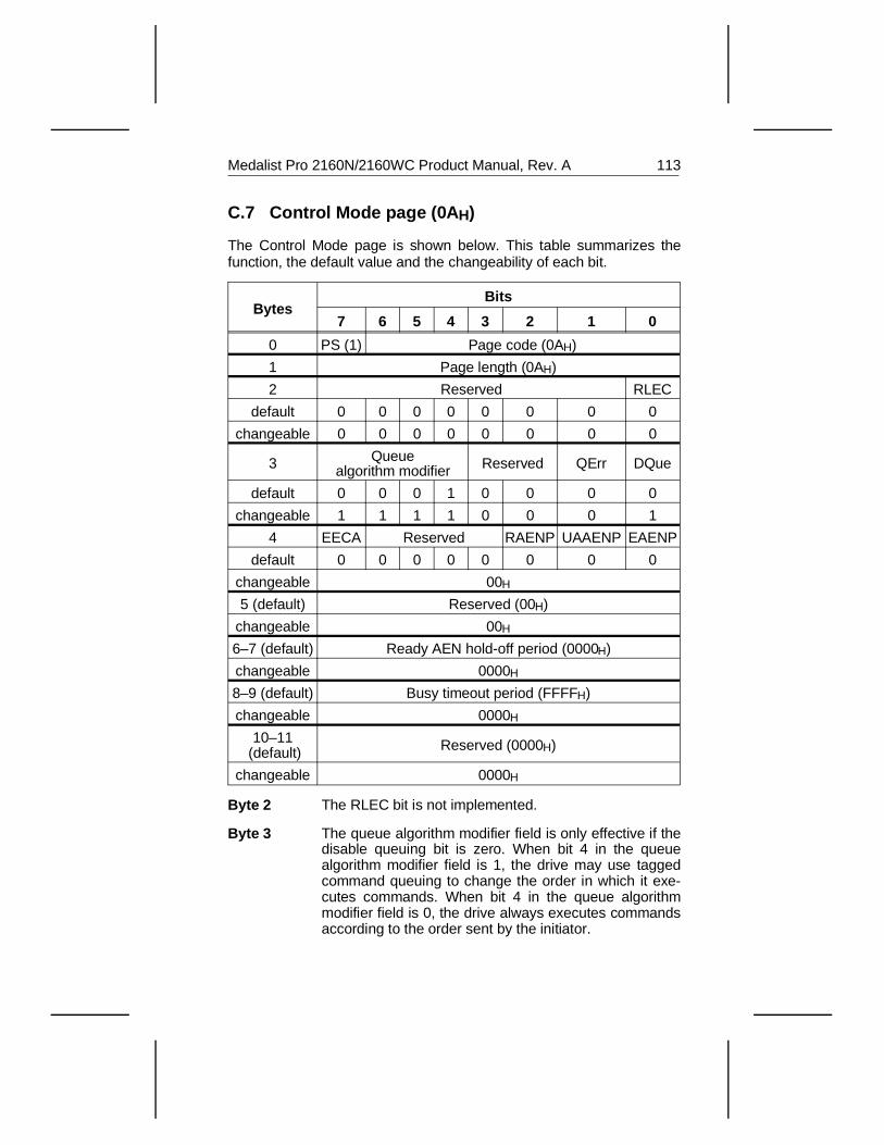
C.7 Control Mode page (0A H)
The Control Mode page is shown below. This table summarizes thefunction, the default value and the changeability of each bit.
BytesBits
7 6 5 4 3 2 1 0
0 PS (1) Page code (0AH)
1 Page length (0AH)
2 Reserved RLEC
default 0 0 0 0 0 0 0 0
changeable 0 0 0 0 0 0 0 0
3 Queuealgorithm modifier Reserved QErr DQue
default 0 0 0 1 0 0 0 0
changeable 1 1 1 1 0 0 0 1
4 EECA Reserved RAENP UAAENP EAENP
default 0 0 0 0 0 0 0 0
changeable 00H
5 (default) Reserved (00H)
changeable 00H
6–7 (default) Ready AEN hold-off period (0000H)
changeable 0000H
8–9 (default) Busy timeout period (FFFFH)
changeable 0000H
10–11 (default) Reserved (0000H)
changeable 0000H
Byte 2 The RLEC bit is not implemented.
Byte 3 The queue algorithm modifier field is only effective if thedisable queuing bit is zero. When bit 4 in the queuealgorithm modifier field is 1, the drive may use taggedcommand queuing to change the order in which it exe-cutes commands. When bit 4 in the queue algorithmmodifier field is 0, the drive always executes commandsaccording to the order sent by the initiator.
Medalist Pro 2160N/2160WC Product Manual, Rev. A 113
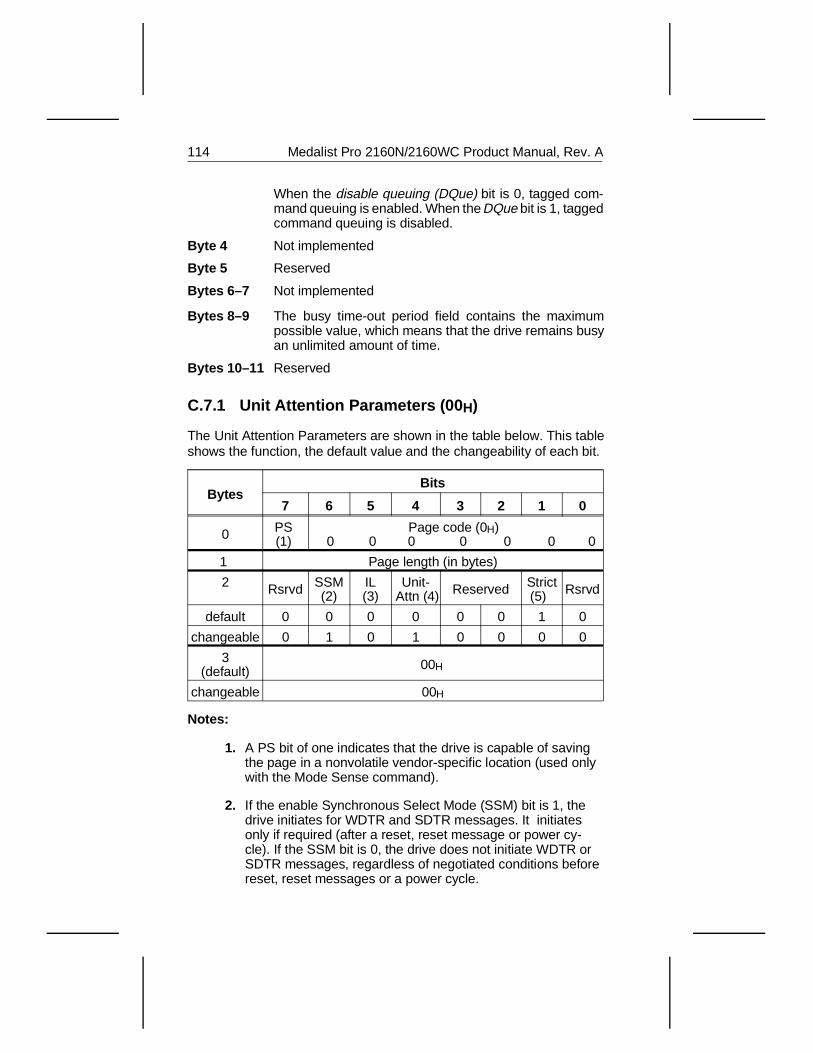
When the disable queuing (DQue) bit is 0, tagged com-mand queuing is enabled. When the DQue bit is 1, taggedcommand queuing is disabled.
Byte 4 Not implemented
Byte 5 Reserved
Bytes 6–7 Not implemented
Bytes 8–9 The busy time-out period field contains the maximumpossible value, which means that the drive remains busyan unlimited amount of time.
Bytes 10–11 Reserved
C.7.1 Unit Attention Parameters (00H)
The Unit Attention Parameters are shown in the table below. This tableshows the function, the default value and the changeability of each bit.
BytesBits
7 6 5 4 3 2 1 0
0 PS (1)
Page code (0H) 0 0 0 0 0 0 0
1 Page length (in bytes)
2 Rsrvd SSM(2)
IL(3)
Unit- Attn (4) Reserved Strict
(5) Rsrvd
default 0 0 0 0 0 0 1 0
changeable 0 1 0 1 0 0 0 0
3(default) 00H
changeable 00H
Notes:
1. A PS bit of one indicates that the drive is capable of savingthe page in a nonvolatile vendor-specific location (used onlywith the Mode Sense command).
2. If the enable Synchronous Select Mode (SSM) bit is 1, thedrive initiates for WDTR and SDTR messages. It initiatesonly if required (after a reset, reset message or power cy-cle). If the SSM bit is 0, the drive does not initiate WDTR orSDTR messages, regardless of negotiated conditions beforereset, reset messages or a power cycle.
114 Medalist Pro 2160N/2160WC Product Manual, Rev. A
3. Inquiry Length (IL) bit. The IL bit is zero; 148 bytes of stand-ard Inquiry data is available.
4. When the Unit Attention bit is 0, normal Unit Attention condi-tion is generated as per Publication 77738479 Rev F. Sec-tion 4.6 - Unit Attention Condition. If the bit is 1, the drivedoes not generate a Unit Attention Condition during powerup or after a Reset. However, if the first command is a Re-quest Sense command, the sense data will reflect a Power-on or Reset was detected.
5. The Strict bit is set to 1. The drive checks for Initiator attemptsto change unchangeable parameters. If the drive detects anattempt, it rejects the command in the standard way (suchas Check Condition Status from drive, Request Sense fromthe Initiator and Illegal Request sense key (5H), back fromthe drive.
Medalist Pro 2160N/2160WC Product Manual, Rev. A 115

116 Medalist Pro 2160N/2160WC Product Manual, Rev. A
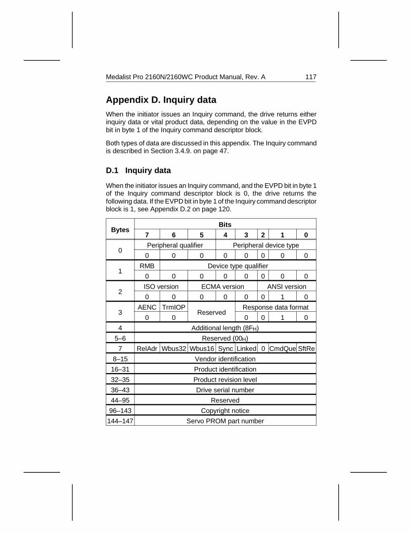
Appendix D. Inquiry dataWhen the initiator issues an Inquiry command, the drive returns eitherinquiry data or vital product data, depending on the value in the EVPDbit in byte 1 of the Inquiry command descriptor block.
Both types of data are discussed in this appendix. The Inquiry commandis described in Section 3.4.9. on page 47.
D.1 Inquiry data
When the initiator issues an Inquiry command, and the EVPD bit in byte 1of the Inquiry command descriptor block is 0, the drive returns thefollowing data. If the EVPD bit in byte 1 of the Inquiry command descriptorblock is 1, see Appendix D.2 on page 120.
BytesBits
7 6 5 4 3 2 1 0
0Peripheral qualifier Peripheral device type
0 0 0 0 0 0 0 0
1RMB Device type qualifier
0 0 0 0 0 0 0 0
2ISO version ECMA version ANSI version
0 0 0 0 0 0 1 0
3AENC TrmIOP
ReservedResponse data format
0 0 0 0 1 0
4 Additional length (8FH)
5–6 Reserved (00H)
7 RelAdr Wbus32 Wbus16 Sync Linked 0 CmdQue SftRe
8–15 Vendor identification
16–31 Product identification
32–35 Product revision level
36–43 Drive serial number
44–95 Reserved
96–143 Copyright notice
144–147 Servo PROM part number
Medalist Pro 2160N/2160WC Product Manual, Rev. A 117
Byte 0 The peripheral qualifier field contains a zero, except fornonzero LUNs, which means that the drive is currentlyconnected to the logical unit that is issuing the Inquirycommand.
The peripheral device type field contains a zero, whichmeans that the drive is a direct-access device.
Byte 1 The RMB bit is 0, which means the discs are not removable.
The device type qualifier is user-programmable.
Byte 2 The ISO version field contains a zero, which means that wedo not claim compliance with ISO 9316.
The EMCA version field contains a zero, which means thatwe do not claim compliance with EMCA-111.
The ANSI version field contains a two, which means thatthe drive complies with ANSI SCSI-2 standard X3.131-199x.
Byte 3 The asynchronous event notification (AENC) bit is zero,which means that the drive does not support asynchronousevent notification.
The terminate I/O process (TrmIOP) bit is zero, whichmeans that the drive does not support the terminate I/Oprocess message.
The response data format field contains a two, which meansthat the inquiry data is in standard SCSI-2 format.
Byte 4 The additional length field contains 143, which is the num-ber of bytes contained in the inquiry data beyond byte 4.This value represents a total inquiry data length of 148bytes. If the allocation length in the CDB of the Inquirycommand is less than 148, the inquiry data is truncated, butthe additional length does not change.
Bytes 5–6 Reserved
Byte 7 The RelAdr bit is 0, which means that the drive does notsupport the relative addressing mode.
The WBUS32 bit is 0, which means that the drive does notsupport 32-bit data transfers.
The WBUS16 bit is 0, which means that the drive does notsupport 16-bit data transfers.
The SYNC bit is 1, which means that the drive supportssynchronous data transfer.
118 Medalist Pro 2160N/2160WC Product Manual, Rev. A
The Linked bit is 0, which means that the drive does notsupport linked commands.
The CmdQue bit is 1, which means that the drive sup-ports tagged command queuing.
The Soft Re bit is 0, which means that the drive respondsto a soft reset with a hard reset.
Bytes 8–15 The vendor identification field contains SEAGATE inASCII text.
Bytes 16–31 The product identification field contains the model num-ber of the drive in ASCII text.
Bytes 32–35 The product revision level field contains the last fourdigits of the firmware release number in ASCII text.
Bytes 36–43 The drive serial number field contains the serial numberof the drive in ASCII text.
Bytes 44–95 These bytes are reserved; they contain only zeros.
Bytes 96–143 The copyright notice field contains the following ASCIIstring: “ Copyright (c) 1996 Seagate. All rights reserved.”
Bytes 144–147 This is the servo PROM part number field.
Medalist Pro 2160N/2160WC Product Manual, Rev. A 119
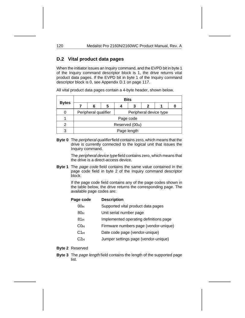
D.2 Vital product data pages
When the initiator issues an Inquiry command, and the EVPD bit in byte 1of the Inquiry command descriptor block is 1, the drive returns vitalproduct data pages. If the EVPD bit in byte 1 of the Inquiry commanddescriptor block is 0, see Appendix D.1 on page 117.
All vital product data pages contain a 4-byte header, shown below.
BytesBits
7 6 5 4 3 2 1 0
0 Peripheral qualifier Peripheral device type
1 Page code
2 Reserved (00H)
3 Page length
Byte 0 The peripheral qualifier field contains zero, which means that thedrive is currently connected to the logical unit that issues theInquiry command.
The peripheral device type field contains zero, which means thatthe drive is a direct-access device.
Byte 1 The page code field contains the same value contained in thepage code field in byte 2 of the Inquiry command descriptorblock.
If the page code field contains any of the page codes shown inthe table below, the drive returns the corresponding page. Theavailable page codes are:
Page code Description
00H Supported vital product data pages
80H Unit serial number page
81H Implemented operating definitions page
C0H Firmware numbers page (vendor-unique)
C1H Date code page (vendor-unique)
C2H Jumper settings page (vendor-unique)
Byte 2 Reserved
Byte 3 The page length field contains the length of the supported pagelist.
120 Medalist Pro 2160N/2160WC Product Manual, Rev. A
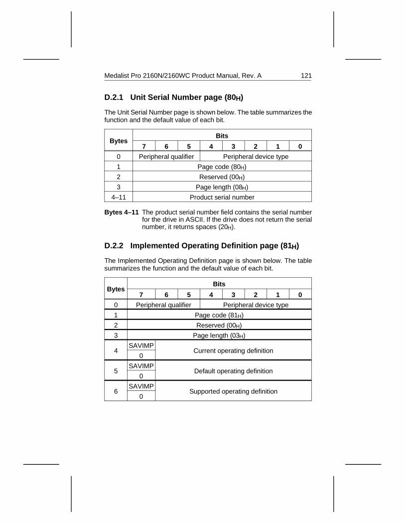
D.2.1 Unit Serial Number page (80 H)
The Unit Serial Number page is shown below. The table summarizes thefunction and the default value of each bit.
BytesBits
7 6 5 4 3 2 1 0
0 Peripheral qualifier Peripheral device type
1 Page code (80H)
2 Reserved (00H)
3 Page length (08H)
4–11 Product serial number
Bytes 4–11 The product serial number field contains the serial numberfor the drive in ASCII. If the drive does not return the serialnumber, it returns spaces (20H).
D.2.2 Implemented Operating Definition page (81 H)
The Implemented Operating Definition page is shown below. The tablesummarizes the function and the default value of each bit.
BytesBits
7 6 5 4 3 2 1 0
0 Peripheral qualifier Peripheral device type
1 Page code (81H)
2 Reserved (00H)
3 Page length (03H)
4SAVIMP
Current operating definition0
5SAVIMP
Default operating definition0
6SAVIMP
Supported operating definition0
Medalist Pro 2160N/2160WC Product Manual, Rev. A 121
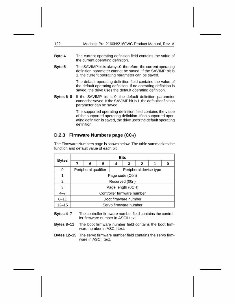
Byte 4 The current operating definition field contains the value ofthe current operating definition.
Byte 5 The SAVIMP bit is always 0; therefore, the current operatingdefinition parameter cannot be saved. If the SAVIMP bit is1, the current operating parameter can be saved.
The default operating definition field contains the value ofthe default operating definition. If no operating definition issaved, the drive uses the default operating definition.
Bytes 6–8 If the SAVIMP bit is 0, the default definition parametercannot be saved. If the SAVIMP bit is 1, the default definitionparameter can be saved.
The supported operating definition field contains the valueof the supported operating definition. If no supported oper-ating definition is saved, the drive uses the default operatingdefinition.
D.2.3 Firmware Numbers page (C0 H)
The Firmware Numbers page is shown below. The table summarizes thefunction and default value of each bit.
BytesBits
7 6 5 4 3 2 1 0
0 Peripheral qualifier Peripheral device type
1 Page code (C0H)
2 Reserved (00H)
3 Page length (0CH)
4–7 Controller firmware number
8–11 Boot firmware number
12–15 Servo firmware number
Bytes 4–7 The controller firmware number field contains the control-ler firmware number in ASCII text.
Bytes 8–11 The boot firmware number field contains the boot firm-ware number in ASCII text.
Bytes 12–15 The servo firmware number field contains the servo firm-ware in ASCII text.
122 Medalist Pro 2160N/2160WC Product Manual, Rev. A
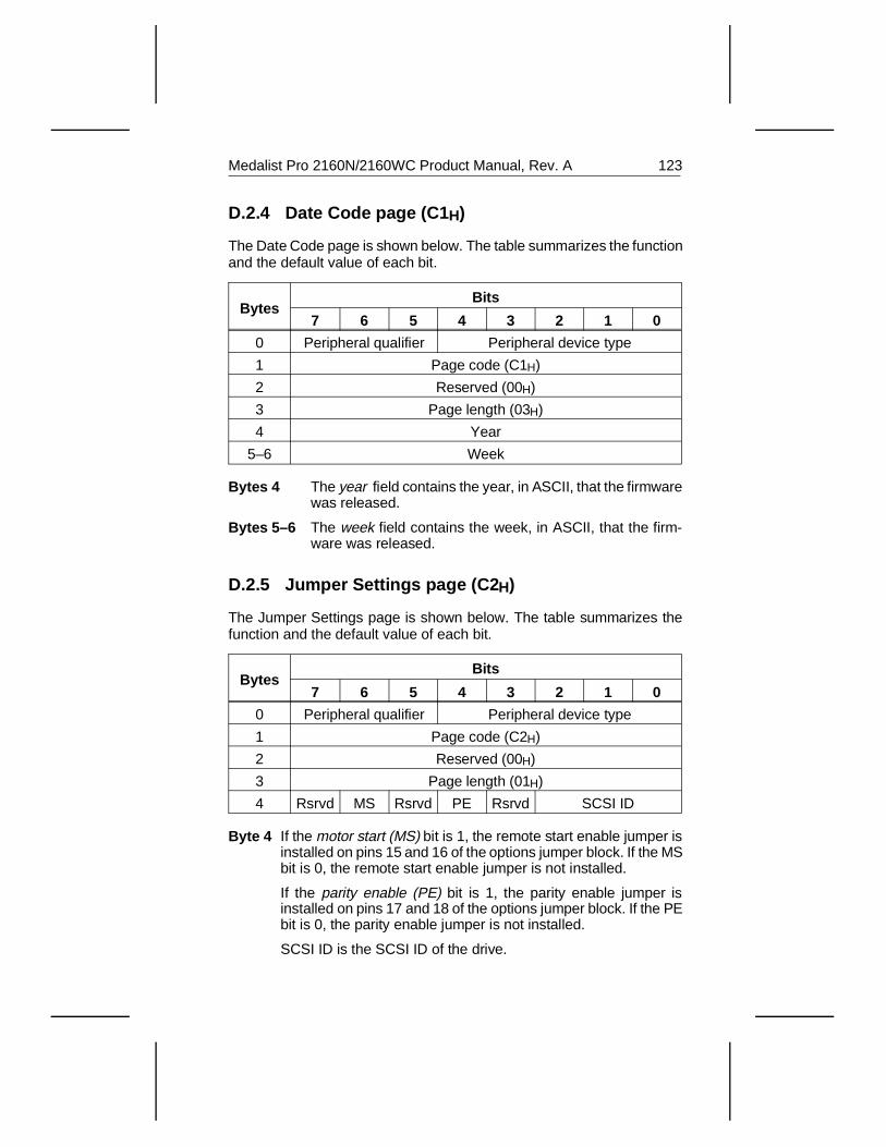
D.2.4 Date Code page (C1 H)
The Date Code page is shown below. The table summarizes the functionand the default value of each bit.
BytesBits
7 6 5 4 3 2 1 0
0 Peripheral qualifier Peripheral device type
1 Page code (C1H)
2 Reserved (00H)
3 Page length (03H)
4 Year
5–6 Week
Bytes 4 The year field contains the year, in ASCII, that the firmwarewas released.
Bytes 5–6 The week field contains the week, in ASCII, that the firm-ware was released.
D.2.5 Jumper Settings page (C2 H)
The Jumper Settings page is shown below. The table summarizes thefunction and the default value of each bit.
BytesBits
7 6 5 4 3 2 1 0
0 Peripheral qualifier Peripheral device type
1 Page code (C2H)
2 Reserved (00H)
3 Page length (01H)
4 Rsrvd MS Rsrvd PE Rsrvd SCSI ID
Byte 4 If the motor start (MS) bit is 1, the remote start enable jumper isinstalled on pins 15 and 16 of the options jumper block. If the MSbit is 0, the remote start enable jumper is not installed.
If the parity enable (PE) bit is 1, the parity enable jumper isinstalled on pins 17 and 18 of the options jumper block. If the PEbit is 0, the parity enable jumper is not installed.
SCSI ID is the SCSI ID of the drive.
Medalist Pro 2160N/2160WC Product Manual, Rev. A 123


Seagate Technology, Inc.920 Disc Drive, Scotts Valley, California 95066, USA
Publication Number: 32650-001, Rev. A, Printed in USA