Embed Size (px)
Citation preview
MELSEC iQ-FFX5 User's Manual (CC-Link IE)

SAFETY PRECAUTIONS(Read these precautions before use.)
Before using this product, please read this manual and the relevant manuals introduced in this manual carefully and pay full
attention to safety in order to handle the product correctly.
This manual classifies the safety precautions into two categories: [ WARNING] and [ CAUTION].
Depending on the circumstances, procedures indicated by [ CAUTION] may also cause severe injury.
It is important to follow all precautions for personal safety.
Store this manual in a safe place so that it can be read whenever necessary. Always forward it to the end user.
[DESIGN PRECAUTIONS]
WARNING● Make sure to set up the following safety circuits outside the PLC to ensure safe system operation
even during external power supply problems or PLC failure. Otherwise, malfunctions may cause
serious accidents.
- Most importantly, set up the following: an emergency stop circuit, a protection circuit, an interlock
circuit for opposite movements (such as normal vs. reverse rotation), and an interlock circuit to
prevent damage (to the equipment at the upper and lower positioning limits).
- Note that when the CPU module detects an error, such as a watchdog timer error, during self-
diagnosis, all outputs are turned off. Also, when an error that cannot be detected by the CPU
module occurs in an input/output control block, output control may be disabled. External circuits
and mechanisms should be designed to ensure safe machinery operation in such a case.
- Note that when an error occurs in a relay or transistor of an output circuit, the output might stay on
or off. For output signals that may lead to serious accidents, external circuits and mechanisms
should be designed to ensure safe machinery operation in such a case.
● In an output circuit, when a load current exceeding the current rating or an overcurrent caused by a
load short-circuit flows for a long time, it may cause smoke and fire. To prevent this, configure an
external safety circuit, such as a fuse.
● For the operating status of each station after a communication failure of the network, refer to relevant
manuals for the network. Incorrect output or malfunction may result in an accident.
● Construct an interlock circuit in the program so that the whole system always operates on the safe
side before executing the control (for data change) of the PLC in operation.
Read the manual thoroughly and ensure complete safety before executing other controls (for program
change, parameter change, forcible output and operation status change) of the PLC in operation.
Otherwise, the machine may be damaged and accidents may occur due to erroneous operations.
● Especially, in the case of a control from an external device to a remote programmable controller,
immediate action cannot be taken for a problem on the programmable controller due to a
communication failure. Determine the handling method as a system when communication failure
occurs along with configuration of interlock circuit on a program, by considering the external
equipment and CPU module.
WARNING Indicates that incorrect handling may cause hazardous conditions, resulting in death or severe injury.
CAUTION Indicates that incorrect handling may cause hazardous conditions, resulting in minor or moderate injury or property damage.
1
2
[DESIGN PRECAUTIONS]
[INSTALLATION PRECAUTIONS]
● Do not write any data to the "system area" and "write-protect area" of the buffer memory in the
module. Executing data writing to the "system area" or "write protect area" may cause malfunction of
the programmable controller alarm. For the "system area" or "write-protect area", refer to Page
131 Buffer Memory.
● If a communication cable is disconnected, the network may be unstable, resulting in a communication
failure of multiple stations. Construct an interlock circuit in the program so that the system always
operates on the safe side even if communications fail. Incorrect output or malfunction may result in an
accident.
● To maintain the safety of the programmable controller system against unauthorized access from
external devices via the network, take appropriate measures. To maintain the safety against
unauthorized access via the Internet, take measures such as installing a firewall.
CAUTION● Do not bundle the control line and communication cables together with or lay them close to the main
circuit or power line. As a guideline, lay the control line and communication cables at least 100 mm
away from the main circuit or power line. Failure to do so may result in malfunction due to noise.
● Simultaneously turn on and off the power supplies of the CPU module and extension modules.
WARNING● Make sure to cut off all phases of the power supply externally before attempting installation or wiring
work. Failure to do so may cause electric shock or damage to the product.
● Use the product within the generic environment specifications described in the User's Manual
(Hardware) of the CPU module used.
Never use the product in areas with excessive dust, oily smoke, conductive dusts, corrosive gas (salt
air, Cl2, H2S, SO2 or NO2), flammable gas, vibration or impacts, or expose it to high temperature,
condensation, or rain and wind.
If the product is used in such conditions, electric shock, fire, malfunctions, deterioration or damage
may occur.
WARNING
[INSTALLATION PRECAUTIONS]
[WIRING PRECAUTIONS]
CAUTION● Do not touch the conductive parts of the product directly. Doing so may cause device failures or
malfunctions.
● When drilling screw holes or wiring, make sure that cutting and wiring debris do not enter the
ventilation slits of the PLC. Failure to do so may cause fire, equipment failures or malfunctions.
● For the product supplied together with a dust proof sheet, the sheet should be affixed to the ventilation
slits before the installation and wiring work to prevent foreign objects such as cutting and wiring
debris.
However, when the installation work is completed, make sure to remove the sheet to provide
adequate ventilation. Failure to do so may cause fire, equipment failures or malfunctions.
● Install the product on a flat surface. If the mounting surface is rough, undue force will be applied to the
PC board, thereby causing nonconformities.
● Install the product securely using a DIN rail or mounting screws.
● Work carefully when using a screwdriver such as installation of the product. Failure to do so may
cause damage to the product or accidents.
● Connect the extension cables, peripheral device cables, input/output cables and battery connecting
cable securely to their designated connectors. Loose connections may cause malfunctions.
● Turn off the power to the PLC before attaching or detaching the following devices. Failure to do so
may cause device failures or malfunctions.
- Peripheral devices, expansion board, expansion adapter, and connector conversion adapter
- Extension modules, bus conversion module, and connector conversion module
- Battery
WARNING● Make sure to cut off all phases of the power supply externally before attempting installation or wiring
work. Failure to do so may cause electric shock or damage to the product.
● Make sure to attach the terminal cover, provided as an accessory, before turning on the power or
initiating operation after installation or wiring work. Failure to do so may cause electric shock.
● The temperature rating of the cable should be 80 or more.
● Make sure to wire the screw terminal block in accordance with the following precautions. Failure to do
so may cause electric shock, equipment failures, a short-circuit, wire breakage, malfunctions, or
damage to the product.
- The disposal size of the cable end should follow the dimensions described in the User's Manual
(Hardware) of the CPU module used.
- Tightening torque should follow the specifications in the User's Manual (Hardware) of the CPU
module used.
- Tighten the screws using a Phillips-head screwdriver No. 2 (shaft diameter 6 mm or less). Make
sure that the screwdriver does not touch the partition part of the terminal block.
3
4
[WIRING PRECAUTIONS]
[STARTUP AND MAINTENANCE PRECAUTIONS]
CAUTION● Perform class D grounding (grounding resistance: 100 Ω or less) of the grounding terminal on the
CPU module and extension modules with a wire 2 mm2 or thicker.
Do not use common grounding with heavy electrical systems (refer to the User's Manual (Hardware)
of the CPU module used).
● Connect the power supply wiring to the dedicated terminals described in this manual. If an AC power
supply is connected to a DC input/output terminal or DC power supply terminal, the PLC will burn out.
● Do not wire vacant terminals externally. Doing so may damage the product.
● Install module so that excessive force will not be applied to terminal blocks, power connectors, I/O
connectors, communication connectors, or communication cables. Failure to do so may result in wire
damage/breakage or PLC failure.
● Make sure to observe the following precautions in order to prevent any damage to the machinery or
accidents due to malfunction of the PLC caused by abnormal data written to the PLC due to the
effects of noise:
- Do not bundle the power line, control line and communication cables together with or lay them
close to the main circuit, high-voltage line, load line or power line. As a guideline, lay the power
line, control line and connection cables at least 100 mm away from the main circuit, high-voltage
line, load line or power line.
- Ground the shield of the shielded wire or shield cable at one point on the PLC. However, do not
use common grounding with heavy electrical systems.
WARNING● Do not touch any terminal while the PLC's power is on. Doing so may cause electric shock or
malfunctions.
● Before cleaning or retightening terminals, cut off all phases of the power supply externally. Failure to
do so in the power ON status may cause electric shock.
● Before modifying the program in operation, forcible output, running or stopping the PLC, read through
this manual carefully, and ensure complete safety. An operation error may damage the machinery or
cause accidents.
● Do not change the program in the PLC from two or more peripheral equipment devices at the same
time. (i. e. from an engineering tool and a GOT) Doing so may cause destruction or malfunction of the
PLC program.
[STARTUP AND MAINTENANCE PRECAUTIONS]
[OPERATION PRECAUTIONS]
[DISPOSAL PRECAUTIONS]
[TRANSPORTATION PRECAUTIONS]
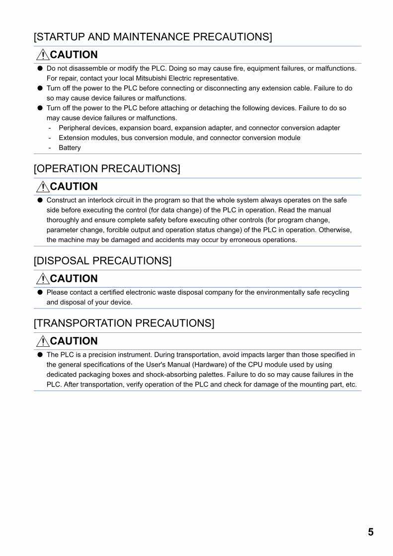
CAUTION● Do not disassemble or modify the PLC. Doing so may cause fire, equipment failures, or malfunctions.
For repair, contact your local Mitsubishi Electric representative.
● Turn off the power to the PLC before connecting or disconnecting any extension cable. Failure to do
so may cause device failures or malfunctions.
● Turn off the power to the PLC before attaching or detaching the following devices. Failure to do so
may cause device failures or malfunctions.
- Peripheral devices, expansion board, expansion adapter, and connector conversion adapter
- Extension modules, bus conversion module, and connector conversion module
- Battery
CAUTION● Construct an interlock circuit in the program so that the whole system always operates on the safe
side before executing the control (for data change) of the PLC in operation. Read the manual
thoroughly and ensure complete safety before executing other controls (for program change,
parameter change, forcible output and operation status change) of the PLC in operation. Otherwise,
the machine may be damaged and accidents may occur by erroneous operations.
CAUTION● Please contact a certified electronic waste disposal company for the environmentally safe recycling
and disposal of your device.
CAUTION● The PLC is a precision instrument. During transportation, avoid impacts larger than those specified in
the general specifications of the User's Manual (Hardware) of the CPU module used by using
dedicated packaging boxes and shock-absorbing palettes. Failure to do so may cause failures in the
PLC. After transportation, verify operation of the PLC and check for damage of the mounting part, etc.
5
6
INTRODUCTIONThis manual contains text, diagrams and explanations which will guide the reader in the correct installation, safe use and
operation of the CC-Link IE Field Network module of MELSEC iQ-F series and should be read and understood before
attempting to install or use the module.
Always forward it to the end user.
Regarding use of this product • This product has been manufactured as a general-purpose part for general industries, and has not been designed or
manufactured to be incorporated in a device or system used in purposes related to human life.
• Before using the product for special purposes such as nuclear power, electric power, aerospace, medicine or passenger
movement vehicles, consult Mitsubishi Electric.
• This product has been manufactured under strict quality control. However when installing the product where major
accidents or losses could occur if the product fails, install appropriate backup or failsafe functions in the system.
Note • If in doubt at any stage during the installation of the product, always consult a professional electrical engineer who is
qualified and trained in the local and national standards. If in doubt about the operation or use, please consult the nearest
Mitsubishi Electric representative.
• Since the examples indicated by this manual, technical bulletin, catalog, etc. are used as a reference, please use it after
confirming the function and safety of the equipment and system. Mitsubishi Electric will accept no responsibility for actual
use of the product based on these illustrative examples.
• This manual content, specification etc. may be changed, without a notice, for improvement.
• The information in this manual has been carefully checked and is believed to be accurate; however, if you notice a doubtful
point, an error, etc., please contact the nearest Mitsubishi Electric representative. When doing so, please provide the
manual number given at the end of this manual.

MEMO
7
8
CONTENTSSAFETY PRECAUTIONS . . . . . . . . . . . . . . . . . . . . . . . . . . . . . . . . . . . . . . . . . . . . . . . . . . . . . . . . . . . . . . . . . . . .1
INTRODUCTION. . . . . . . . . . . . . . . . . . . . . . . . . . . . . . . . . . . . . . . . . . . . . . . . . . . . . . . . . . . . . . . . . . . . . . . . . . .6
RELEVANT MANUALS . . . . . . . . . . . . . . . . . . . . . . . . . . . . . . . . . . . . . . . . . . . . . . . . . . . . . . . . . . . . . . . . . . . . .10
TERMS . . . . . . . . . . . . . . . . . . . . . . . . . . . . . . . . . . . . . . . . . . . . . . . . . . . . . . . . . . . . . . . . . . . . . . . . . . . . . . . . .10
CHAPTER 1 OUTLINE 12
CHAPTER 2 SPECIFICATIONS 14
2.1 General Specifications . . . . . . . . . . . . . . . . . . . . . . . . . . . . . . . . . . . . . . . . . . . . . . . . . . . . . . . . . . . . . . . . . . . 14
2.2 Power Supply Specifications . . . . . . . . . . . . . . . . . . . . . . . . . . . . . . . . . . . . . . . . . . . . . . . . . . . . . . . . . . . . . . 14
2.3 Performance Specifications . . . . . . . . . . . . . . . . . . . . . . . . . . . . . . . . . . . . . . . . . . . . . . . . . . . . . . . . . . . . . . . 14
2.4 Part Names. . . . . . . . . . . . . . . . . . . . . . . . . . . . . . . . . . . . . . . . . . . . . . . . . . . . . . . . . . . . . . . . . . . . . . . . . . . . . 15
LED display . . . . . . . . . . . . . . . . . . . . . . . . . . . . . . . . . . . . . . . . . . . . . . . . . . . . . . . . . . . . . . . . . . . . . . . . . . . . . 16
CHAPTER 3 PROCEDURES BEFORE OPERATION 17
CHAPTER 4 FUNCTIONS 18
4.1 Function List . . . . . . . . . . . . . . . . . . . . . . . . . . . . . . . . . . . . . . . . . . . . . . . . . . . . . . . . . . . . . . . . . . . . . . . . . . . 18
4.2 Cyclic Transmission . . . . . . . . . . . . . . . . . . . . . . . . . . . . . . . . . . . . . . . . . . . . . . . . . . . . . . . . . . . . . . . . . . . . . 19
Data flow and link device assignment . . . . . . . . . . . . . . . . . . . . . . . . . . . . . . . . . . . . . . . . . . . . . . . . . . . . . . . . . 19
Link refresh . . . . . . . . . . . . . . . . . . . . . . . . . . . . . . . . . . . . . . . . . . . . . . . . . . . . . . . . . . . . . . . . . . . . . . . . . . . . . 21
Cyclic data integrity assurance . . . . . . . . . . . . . . . . . . . . . . . . . . . . . . . . . . . . . . . . . . . . . . . . . . . . . . . . . . . . . . 22
Input and output status settings when failure occurs. . . . . . . . . . . . . . . . . . . . . . . . . . . . . . . . . . . . . . . . . . . . . . 26
Output status setting for CPU STOP . . . . . . . . . . . . . . . . . . . . . . . . . . . . . . . . . . . . . . . . . . . . . . . . . . . . . . . . . . 27
Output status setting for CPU stop error . . . . . . . . . . . . . . . . . . . . . . . . . . . . . . . . . . . . . . . . . . . . . . . . . . . . . . . 27
Cyclic transmission stop and restart . . . . . . . . . . . . . . . . . . . . . . . . . . . . . . . . . . . . . . . . . . . . . . . . . . . . . . . . . . 27
4.3 Transient Transmission . . . . . . . . . . . . . . . . . . . . . . . . . . . . . . . . . . . . . . . . . . . . . . . . . . . . . . . . . . . . . . . . . . 28
Communications within the same network . . . . . . . . . . . . . . . . . . . . . . . . . . . . . . . . . . . . . . . . . . . . . . . . . . . . . 28
Communications with different networks . . . . . . . . . . . . . . . . . . . . . . . . . . . . . . . . . . . . . . . . . . . . . . . . . . . . . . . 28
4.4 Interrupt Request to CPU Module . . . . . . . . . . . . . . . . . . . . . . . . . . . . . . . . . . . . . . . . . . . . . . . . . . . . . . . . . . 29
CHAPTER 5 SYSTEM CONFIGURATION 30
5.1 CC-Link IE Field Network Configuration . . . . . . . . . . . . . . . . . . . . . . . . . . . . . . . . . . . . . . . . . . . . . . . . . . . . . 30
5.2 Precautions for System Configuration . . . . . . . . . . . . . . . . . . . . . . . . . . . . . . . . . . . . . . . . . . . . . . . . . . . . . . 32
CHAPTER 6 WIRING 33
6.1 Power Supply Wiring. . . . . . . . . . . . . . . . . . . . . . . . . . . . . . . . . . . . . . . . . . . . . . . . . . . . . . . . . . . . . . . . . . . . . 33
Grounding . . . . . . . . . . . . . . . . . . . . . . . . . . . . . . . . . . . . . . . . . . . . . . . . . . . . . . . . . . . . . . . . . . . . . . . . . . . . . . 33
6.2 Wiring of CC-Link IE Field Network . . . . . . . . . . . . . . . . . . . . . . . . . . . . . . . . . . . . . . . . . . . . . . . . . . . . . . . . . 34
CHAPTER 7 PARAMETER SETTINGS 36
7.1 Setting Parameters . . . . . . . . . . . . . . . . . . . . . . . . . . . . . . . . . . . . . . . . . . . . . . . . . . . . . . . . . . . . . . . . . . . . . . 36
7.2 Required Settings . . . . . . . . . . . . . . . . . . . . . . . . . . . . . . . . . . . . . . . . . . . . . . . . . . . . . . . . . . . . . . . . . . . . . . . 36
Network Number . . . . . . . . . . . . . . . . . . . . . . . . . . . . . . . . . . . . . . . . . . . . . . . . . . . . . . . . . . . . . . . . . . . . . . . . . 37
Station Number . . . . . . . . . . . . . . . . . . . . . . . . . . . . . . . . . . . . . . . . . . . . . . . . . . . . . . . . . . . . . . . . . . . . . . . . . . 37
Parameter Setting Method. . . . . . . . . . . . . . . . . . . . . . . . . . . . . . . . . . . . . . . . . . . . . . . . . . . . . . . . . . . . . . . . . . 37
7.3 Basic Settings . . . . . . . . . . . . . . . . . . . . . . . . . . . . . . . . . . . . . . . . . . . . . . . . . . . . . . . . . . . . . . . . . . . . . . . . . . 38
Refresh setting . . . . . . . . . . . . . . . . . . . . . . . . . . . . . . . . . . . . . . . . . . . . . . . . . . . . . . . . . . . . . . . . . . . . . . . . . . 38
CO
NT
EN
TS
7.4 Application Settings . . . . . . . . . . . . . . . . . . . . . . . . . . . . . . . . . . . . . . . . . . . . . . . . . . . . . . . . . . . . . . . . . . . . . 40
Supplementary Cyclic Settings . . . . . . . . . . . . . . . . . . . . . . . . . . . . . . . . . . . . . . . . . . . . . . . . . . . . . . . . . . . . . . 40
Interrupt Settings . . . . . . . . . . . . . . . . . . . . . . . . . . . . . . . . . . . . . . . . . . . . . . . . . . . . . . . . . . . . . . . . . . . . . . . . . 41
Parameter Name . . . . . . . . . . . . . . . . . . . . . . . . . . . . . . . . . . . . . . . . . . . . . . . . . . . . . . . . . . . . . . . . . . . . . . . . . 43
Module Operation Mode . . . . . . . . . . . . . . . . . . . . . . . . . . . . . . . . . . . . . . . . . . . . . . . . . . . . . . . . . . . . . . . . . . . 43
CHAPTER 8 DEDICATED INSTRUCTION 44
8.1 Precautions for Dedicated Instructions . . . . . . . . . . . . . . . . . . . . . . . . . . . . . . . . . . . . . . . . . . . . . . . . . . . . . 46
8.2 Link Dedicated Instructions . . . . . . . . . . . . . . . . . . . . . . . . . . . . . . . . . . . . . . . . . . . . . . . . . . . . . . . . . . . . . . . 47
Reading data from the programmable controller on another station . . . . . . . . . . . . . . . . . . . . . . . . . . . . . . . . . . 47
Reading data from the programmable controller on another station (with notification) . . . . . . . . . . . . . . . . . . . . 55
Writing data to the programmable controller on another station . . . . . . . . . . . . . . . . . . . . . . . . . . . . . . . . . . . . . 61
Writing data to the programmable controller on another station (with notification) . . . . . . . . . . . . . . . . . . . . . . . 70
Sending data to the programmable controller on another station . . . . . . . . . . . . . . . . . . . . . . . . . . . . . . . . . . . . 77
Receiving data from the programmable controller on another station. . . . . . . . . . . . . . . . . . . . . . . . . . . . . . . . . 88
8.3 Other Instructions . . . . . . . . . . . . . . . . . . . . . . . . . . . . . . . . . . . . . . . . . . . . . . . . . . . . . . . . . . . . . . . . . . . . . . . 94
Setting parameters . . . . . . . . . . . . . . . . . . . . . . . . . . . . . . . . . . . . . . . . . . . . . . . . . . . . . . . . . . . . . . . . . . . . . . . 94
Setting the station number to own station . . . . . . . . . . . . . . . . . . . . . . . . . . . . . . . . . . . . . . . . . . . . . . . . . . . . . 100
CHAPTER 9 PROGRAMMING 104
9.1 Procedure for Creating Programs . . . . . . . . . . . . . . . . . . . . . . . . . . . . . . . . . . . . . . . . . . . . . . . . . . . . . . . . . 104
CHAPTER 10 TROUBLESHOOTING 109
10.1 Checking with LEDs . . . . . . . . . . . . . . . . . . . . . . . . . . . . . . . . . . . . . . . . . . . . . . . . . . . . . . . . . . . . . . . . . . . . 109
10.2 Checking the Module Status. . . . . . . . . . . . . . . . . . . . . . . . . . . . . . . . . . . . . . . . . . . . . . . . . . . . . . . . . . . . . . 112
10.3 Checking the Network Status . . . . . . . . . . . . . . . . . . . . . . . . . . . . . . . . . . . . . . . . . . . . . . . . . . . . . . . . . . . . . 113
10.4 Troubleshooting for Each Symptom . . . . . . . . . . . . . . . . . . . . . . . . . . . . . . . . . . . . . . . . . . . . . . . . . . . . . . . 117
10.5 List of Error Codes . . . . . . . . . . . . . . . . . . . . . . . . . . . . . . . . . . . . . . . . . . . . . . . . . . . . . . . . . . . . . . . . . . . . . 119
10.6 List of Parameter Numbers. . . . . . . . . . . . . . . . . . . . . . . . . . . . . . . . . . . . . . . . . . . . . . . . . . . . . . . . . . . . . . . 128
APPENDICES 129
Appendix 1 Standards . . . . . . . . . . . . . . . . . . . . . . . . . . . . . . . . . . . . . . . . . . . . . . . . . . . . . . . . . . . . . . . . . . . . . . . . 129
Certification of UL, cUL standards. . . . . . . . . . . . . . . . . . . . . . . . . . . . . . . . . . . . . . . . . . . . . . . . . . . . . . . . . . . 129
Compliance with EC directive (CE Marking) . . . . . . . . . . . . . . . . . . . . . . . . . . . . . . . . . . . . . . . . . . . . . . . . . . . 129
Requirement for compliance with EMC directive. . . . . . . . . . . . . . . . . . . . . . . . . . . . . . . . . . . . . . . . . . . . . . . . 129
Caution for compliance with EC Directive . . . . . . . . . . . . . . . . . . . . . . . . . . . . . . . . . . . . . . . . . . . . . . . . . . . . . 130
Appendix 2 Buffer Memory . . . . . . . . . . . . . . . . . . . . . . . . . . . . . . . . . . . . . . . . . . . . . . . . . . . . . . . . . . . . . . . . . . . . 131
List of buffer memory addresses . . . . . . . . . . . . . . . . . . . . . . . . . . . . . . . . . . . . . . . . . . . . . . . . . . . . . . . . . . . . 131
Details of buffer memory addresses . . . . . . . . . . . . . . . . . . . . . . . . . . . . . . . . . . . . . . . . . . . . . . . . . . . . . . . . . 132
Appendix 3 List of Link Special Relay (SB) . . . . . . . . . . . . . . . . . . . . . . . . . . . . . . . . . . . . . . . . . . . . . . . . . . . . . . . 134
Appendix 4 List of Link Special Register (SW) . . . . . . . . . . . . . . . . . . . . . . . . . . . . . . . . . . . . . . . . . . . . . . . . . . . . 138
Appendix 5 Processing Time . . . . . . . . . . . . . . . . . . . . . . . . . . . . . . . . . . . . . . . . . . . . . . . . . . . . . . . . . . . . . . . . . . 141
I/O response time . . . . . . . . . . . . . . . . . . . . . . . . . . . . . . . . . . . . . . . . . . . . . . . . . . . . . . . . . . . . . . . . . . . . . . . 141
FROM/TO processing time . . . . . . . . . . . . . . . . . . . . . . . . . . . . . . . . . . . . . . . . . . . . . . . . . . . . . . . . . . . . . . . . 141
INDEX 142
REVISIONS. . . . . . . . . . . . . . . . . . . . . . . . . . . . . . . . . . . . . . . . . . . . . . . . . . . . . . . . . . . . . . . . . . . . . . . . . . . . .144
WARRANTY . . . . . . . . . . . . . . . . . . . . . . . . . . . . . . . . . . . . . . . . . . . . . . . . . . . . . . . . . . . . . . . . . . . . . . . . . . . .145
TRADEMARKS . . . . . . . . . . . . . . . . . . . . . . . . . . . . . . . . . . . . . . . . . . . . . . . . . . . . . . . . . . . . . . . . . . . . . . . . . .146
9
10
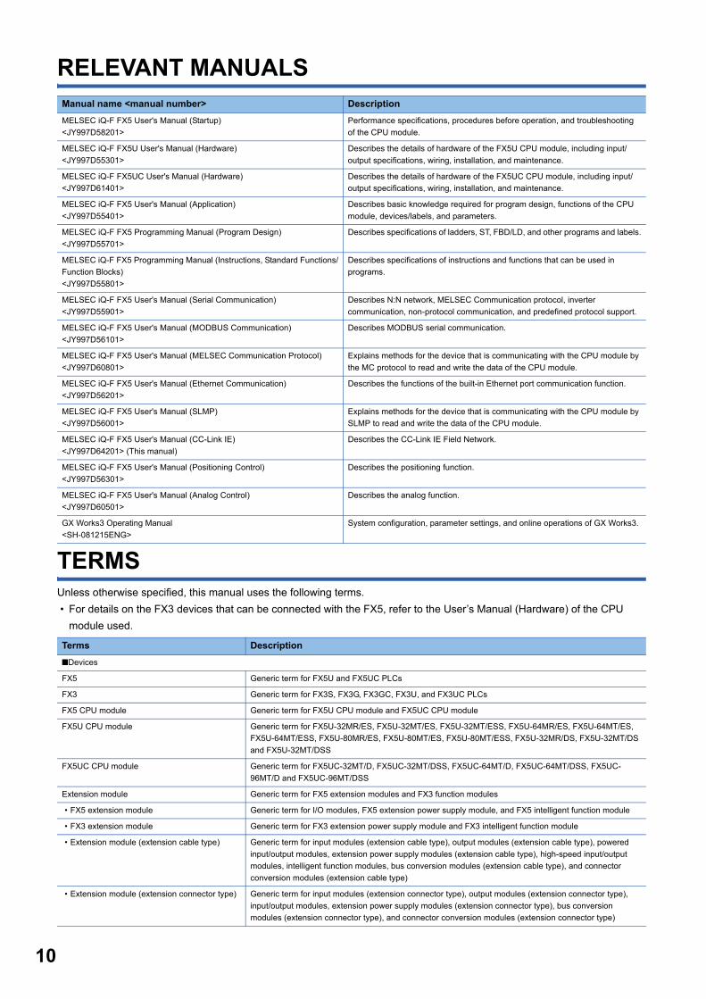
RELEVANT MANUALS
TERMSUnless otherwise specified, this manual uses the following terms.
• For details on the FX3 devices that can be connected with the FX5, refer to the User’s Manual (Hardware) of the CPU
module used.
Manual name <manual number> Description
MELSEC iQ-F FX5 User's Manual (Startup)
<JY997D58201>
Performance specifications, procedures before operation, and troubleshooting
of the CPU module.
MELSEC iQ-F FX5U User's Manual (Hardware)
<JY997D55301>
Describes the details of hardware of the FX5U CPU module, including input/
output specifications, wiring, installation, and maintenance.
MELSEC iQ-F FX5UC User's Manual (Hardware)
<JY997D61401>
Describes the details of hardware of the FX5UC CPU module, including input/
output specifications, wiring, installation, and maintenance.
MELSEC iQ-F FX5 User's Manual (Application)
<JY997D55401>
Describes basic knowledge required for program design, functions of the CPU
module, devices/labels, and parameters.
MELSEC iQ-F FX5 Programming Manual (Program Design)
<JY997D55701>
Describes specifications of ladders, ST, FBD/LD, and other programs and labels.
MELSEC iQ-F FX5 Programming Manual (Instructions, Standard Functions/
Function Blocks)
<JY997D55801>
Describes specifications of instructions and functions that can be used in
programs.
MELSEC iQ-F FX5 User's Manual (Serial Communication)
<JY997D55901>
Describes N:N network, MELSEC Communication protocol, inverter
communication, non-protocol communication, and predefined protocol support.
MELSEC iQ-F FX5 User's Manual (MODBUS Communication)
<JY997D56101>
Describes MODBUS serial communication.
MELSEC iQ-F FX5 User's Manual (MELSEC Communication Protocol)
<JY997D60801>
Explains methods for the device that is communicating with the CPU module by
the MC protocol to read and write the data of the CPU module.
MELSEC iQ-F FX5 User's Manual (Ethernet Communication)
<JY997D56201>
Describes the functions of the built-in Ethernet port communication function.
MELSEC iQ-F FX5 User's Manual (SLMP)
<JY997D56001>
Explains methods for the device that is communicating with the CPU module by
SLMP to read and write the data of the CPU module.
MELSEC iQ-F FX5 User's Manual (CC-Link IE)
<JY997D64201> (This manual)
Describes the CC-Link IE Field Network.
MELSEC iQ-F FX5 User's Manual (Positioning Control)
<JY997D56301>
Describes the positioning function.
MELSEC iQ-F FX5 User's Manual (Analog Control)
<JY997D60501>
Describes the analog function.
GX Works3 Operating Manual
<SH-081215ENG>
System configuration, parameter settings, and online operations of GX Works3.
Terms Description
■Devices
FX5 Generic term for FX5U and FX5UC PLCs
FX3 Generic term for FX3S, FX3G, FX3GC, FX3U, and FX3UC PLCs
FX5 CPU module Generic term for FX5U CPU module and FX5UC CPU module
FX5U CPU module Generic term for FX5U-32MR/ES, FX5U-32MT/ES, FX5U-32MT/ESS, FX5U-64MR/ES, FX5U-64MT/ES,
FX5U-64MT/ESS, FX5U-80MR/ES, FX5U-80MT/ES, FX5U-80MT/ESS, FX5U-32MR/DS, FX5U-32MT/DS
and FX5U-32MT/DSS
FX5UC CPU module Generic term for FX5UC-32MT/D, FX5UC-32MT/DSS, FX5UC-64MT/D, FX5UC-64MT/DSS, FX5UC-
96MT/D and FX5UC-96MT/DSS
Extension module Generic term for FX5 extension modules and FX3 function modules
• FX5 extension module Generic term for I/O modules, FX5 extension power supply module, and FX5 intelligent function module
• FX3 extension module Generic term for FX3 extension power supply module and FX3 intelligent function module
• Extension module (extension cable type) Generic term for input modules (extension cable type), output modules (extension cable type), powered
input/output modules, extension power supply modules (extension cable type), high-speed input/output
modules, intelligent function modules, bus conversion modules (extension cable type), and connector
conversion modules (extension cable type)
• Extension module (extension connector type) Generic term for input modules (extension connector type), output modules (extension connector type),
input/output modules, extension power supply modules (extension connector type), bus conversion
modules (extension connector type), and connector conversion modules (extension connector type)
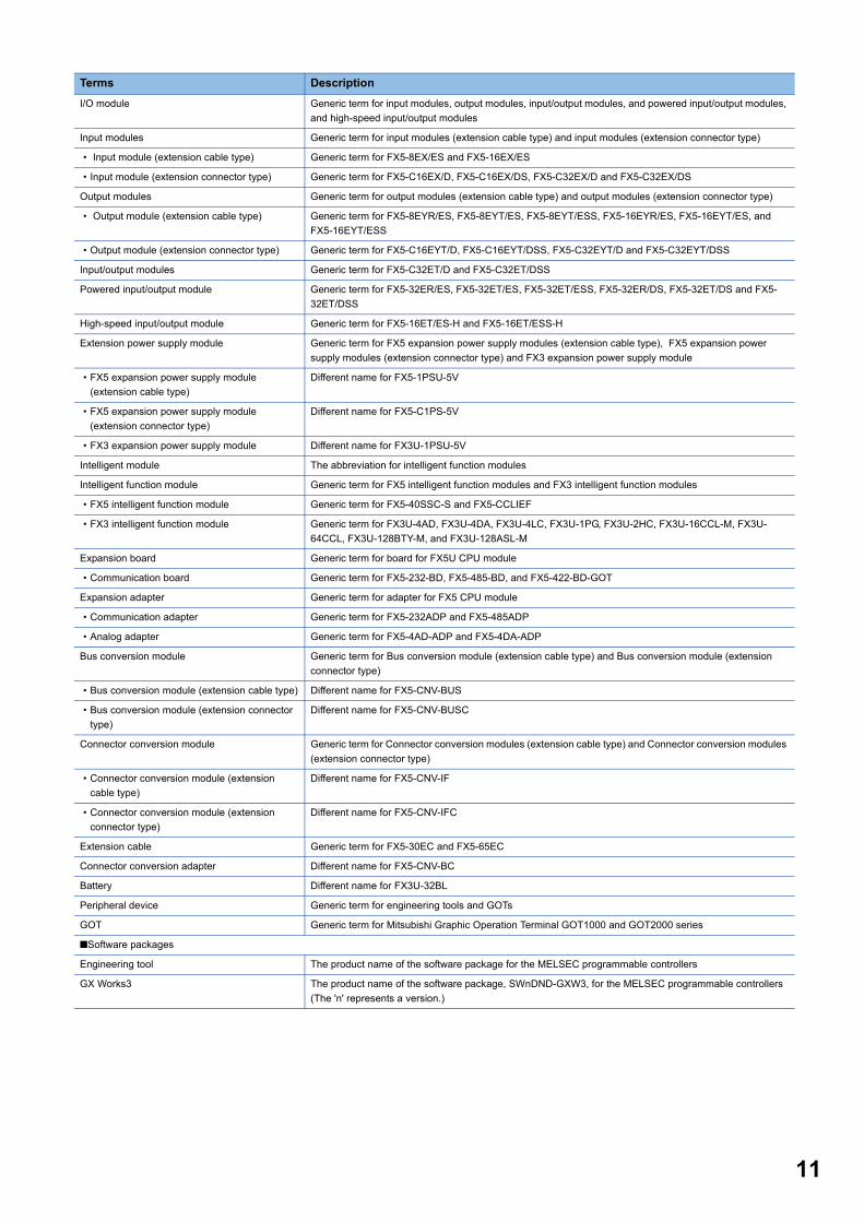
I/O module Generic term for input modules, output modules, input/output modules, and powered input/output modules,
and high-speed input/output modules
Input modules Generic term for input modules (extension cable type) and input modules (extension connector type)
• Input module (extension cable type) Generic term for FX5-8EX/ES and FX5-16EX/ES
• Input module (extension connector type) Generic term for FX5-C16EX/D, FX5-C16EX/DS, FX5-C32EX/D and FX5-C32EX/DS
Output modules Generic term for output modules (extension cable type) and output modules (extension connector type)
• Output module (extension cable type) Generic term for FX5-8EYR/ES, FX5-8EYT/ES, FX5-8EYT/ESS, FX5-16EYR/ES, FX5-16EYT/ES, and
FX5-16EYT/ESS
• Output module (extension connector type) Generic term for FX5-C16EYT/D, FX5-C16EYT/DSS, FX5-C32EYT/D and FX5-C32EYT/DSS
Input/output modules Generic term for FX5-C32ET/D and FX5-C32ET/DSS
Powered input/output module Generic term for FX5-32ER/ES, FX5-32ET/ES, FX5-32ET/ESS, FX5-32ER/DS, FX5-32ET/DS and FX5-
32ET/DSS
High-speed input/output module Generic term for FX5-16ET/ES-H and FX5-16ET/ESS-H
Extension power supply module Generic term for FX5 expansion power supply modules (extension cable type), FX5 expansion power
supply modules (extension connector type) and FX3 expansion power supply module
• FX5 expansion power supply module
(extension cable type)
Different name for FX5-1PSU-5V
• FX5 expansion power supply module
(extension connector type)
Different name for FX5-C1PS-5V
• FX3 expansion power supply module Different name for FX3U-1PSU-5V
Intelligent module The abbreviation for intelligent function modules
Intelligent function module Generic term for FX5 intelligent function modules and FX3 intelligent function modules
• FX5 intelligent function module Generic term for FX5-40SSC-S and FX5-CCLIEF
• FX3 intelligent function module Generic term for FX3U-4AD, FX3U-4DA, FX3U-4LC, FX3U-1PG, FX3U-2HC, FX3U-16CCL-M, FX3U-
64CCL, FX3U-128BTY-M, and FX3U-128ASL-M
Expansion board Generic term for board for FX5U CPU module
• Communication board Generic term for FX5-232-BD, FX5-485-BD, and FX5-422-BD-GOT
Expansion adapter Generic term for adapter for FX5 CPU module
• Communication adapter Generic term for FX5-232ADP and FX5-485ADP
• Analog adapter Generic term for FX5-4AD-ADP and FX5-4DA-ADP
Bus conversion module Generic term for Bus conversion module (extension cable type) and Bus conversion module (extension
connector type)
• Bus conversion module (extension cable type) Different name for FX5-CNV-BUS
• Bus conversion module (extension connector
type)
Different name for FX5-CNV-BUSC
Connector conversion module Generic term for Connector conversion modules (extension cable type) and Connector conversion modules
(extension connector type)
• Connector conversion module (extension
cable type)
Different name for FX5-CNV-IF
• Connector conversion module (extension
connector type)
Different name for FX5-CNV-IFC
Extension cable Generic term for FX5-30EC and FX5-65EC
Connector conversion adapter Different name for FX5-CNV-BC
Battery Different name for FX3U-32BL
Peripheral device Generic term for engineering tools and GOTs
GOT Generic term for Mitsubishi Graphic Operation Terminal GOT1000 and GOT2000 series
■Software packages
Engineering tool The product name of the software package for the MELSEC programmable controllers
GX Works3 The product name of the software package, SWnDND-GXW3, for the MELSEC programmable controllers
(The 'n' represents a version.)
Terms Description
11
12
1 OUTLINE
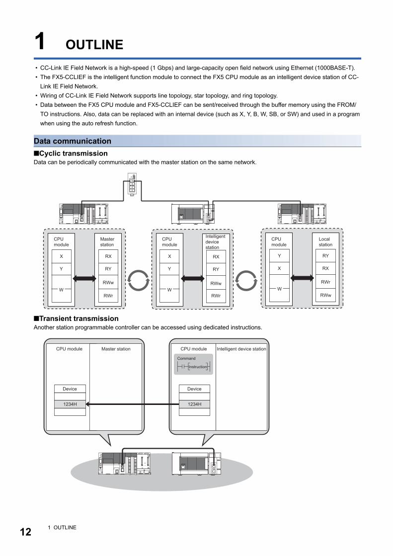
• CC-Link IE Field Network is a high-speed (1 Gbps) and large-capacity open field network using Ethernet (1000BASE-T).
• The FX5-CCLIEF is the intelligent function module to connect the FX5 CPU module as an intelligent device station of CC-
Link IE Field Network.
• Wiring of CC-Link IE Field Network supports line topology, star topology, and ring topology.
• Data between the FX5 CPU module and FX5-CCLIEF can be sent/received through the buffer memory using the FROM/
TO instructions. Also, data can be replaced with an internal device (such as X, Y, B, W, SB, or SW) and used in a program
when using the auto refresh function.
Data communication
■Cyclic transmissionData can be periodically communicated with the master station on the same network.
■Transient transmissionAnother station programmable controller can be accessed using dedicated instructions.
RX
RWw
RWr
RY
X
Y
RX
RY
Y
X
RY
RWr
RX
RWwW
X
Y
WRWw
RWrW
Master station
CPU module
CPU module
Local station
CPU module
Intelligent device station
1234H 1234H
Device Device
CPU module CPU moduleMaster station Intelligent device station
Command
Instruction
1 OUTLINE

1
MEMO
1 OUTLINE 13
14
2 SPECIFICATIONS
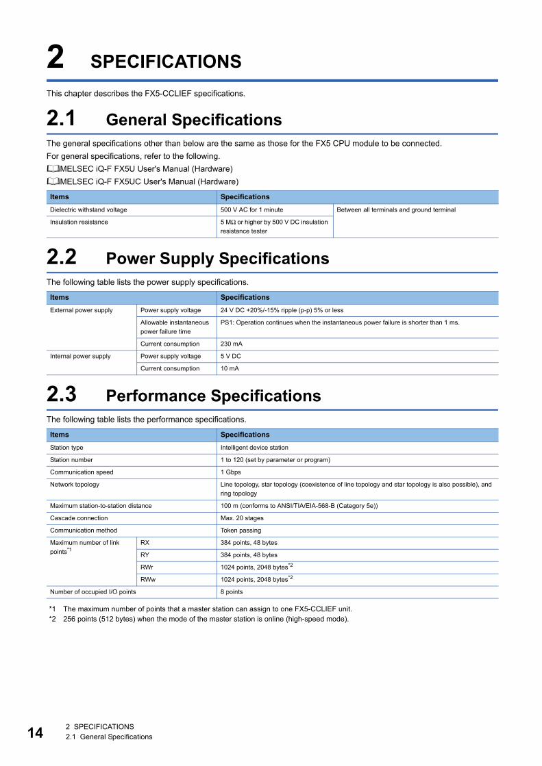
This chapter describes the FX5-CCLIEF specifications.
2.1 General SpecificationsThe general specifications other than below are the same as those for the FX5 CPU module to be connected.
For general specifications, refer to the following.
MELSEC iQ-F FX5U User's Manual (Hardware)
MELSEC iQ-F FX5UC User's Manual (Hardware)
2.2 Power Supply SpecificationsThe following table lists the power supply specifications.
2.3 Performance SpecificationsThe following table lists the performance specifications.
*1 The maximum number of points that a master station can assign to one FX5-CCLIEF unit.*2 256 points (512 bytes) when the mode of the master station is online (high-speed mode).
Items Specifications
Dielectric withstand voltage 500 V AC for 1 minute Between all terminals and ground terminal
Insulation resistance 5 MΩ or higher by 500 V DC insulation
resistance tester
Items Specifications
External power supply Power supply voltage 24 V DC +20%/-15% ripple (p-p) 5% or less
Allowable instantaneous
power failure time
PS1: Operation continues when the instantaneous power failure is shorter than 1 ms.
Current consumption 230 mA
Internal power supply Power supply voltage 5 V DC
Current consumption 10 mA
Items Specifications
Station type Intelligent device station
Station number 1 to 120 (set by parameter or program)
Communication speed 1 Gbps
Network topology Line topology, star topology (coexistence of line topology and star topology is also possible), and
ring topology
Maximum station-to-station distance 100 m (conforms to ANSI/TIA/EIA-568-B (Category 5e))
Cascade connection Max. 20 stages
Communication method Token passing
Maximum number of link
points*1RX 384 points, 48 bytes
RY 384 points, 48 bytes
RWr 1024 points, 2048 bytes*2
RWw 1024 points, 2048 bytes*2
Number of occupied I/O points 8 points
2 SPECIFICATIONS2.1 General Specifications
2
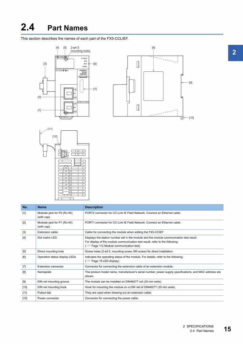
2.4 Part NamesThis section describes the names of each part of the FX5-CCLIEF.
No. Name Description
[1] Modular jack for P2 (RJ-45)
(with cap)
PORT2 connector for CC-Link IE Field Network. Connect an Ethernet cable.
[2] Modular jack for P1 (RJ-45)
(with cap)
PORT1 connector for CC-Link IE Field Network. Connect an Ethernet cable.
[3] Extension cable Cable for connecting the module when adding the FX5-CCIEF
[4] Dot matrix LED Displays the station number set in the module and the module communication test result.
For display of the module communication test result, refer to the following.
(Page 112 Module communication test)
[5] Direct mounting hole Screw holes (2-φ4.5, mounting screw: M4 screw) for direct installation
[6] Operation status display LEDs Indicates the operating status of the module. For details, refer to the following.
(Page 16 LED display)
[7] Extension connector Connector for connecting the extension cable of an extension module.
[8] Nameplate The product model name, manufacturer's serial number, power supply specifications, and MAC address are
shown.
[9] DIN rail mounting groove The module can be installed on DIN46277 rail (35 mm wide).
[10] DIN rail mounting hook Hook for mounting the module on a DIN rail of DIN46277 (35 mm wide).
[11] Pullout tab They are used when drawing out an extension cable.
[12] Power connector Connector for connecting the power cable.
[1]
[2]
[12]
[11]
[3]
[4] [5]
[9]
[8]
[10]
[7]
[6]
2-φ4.5 mounting holes
2 SPECIFICATIONS2.4 Part Names 15
16
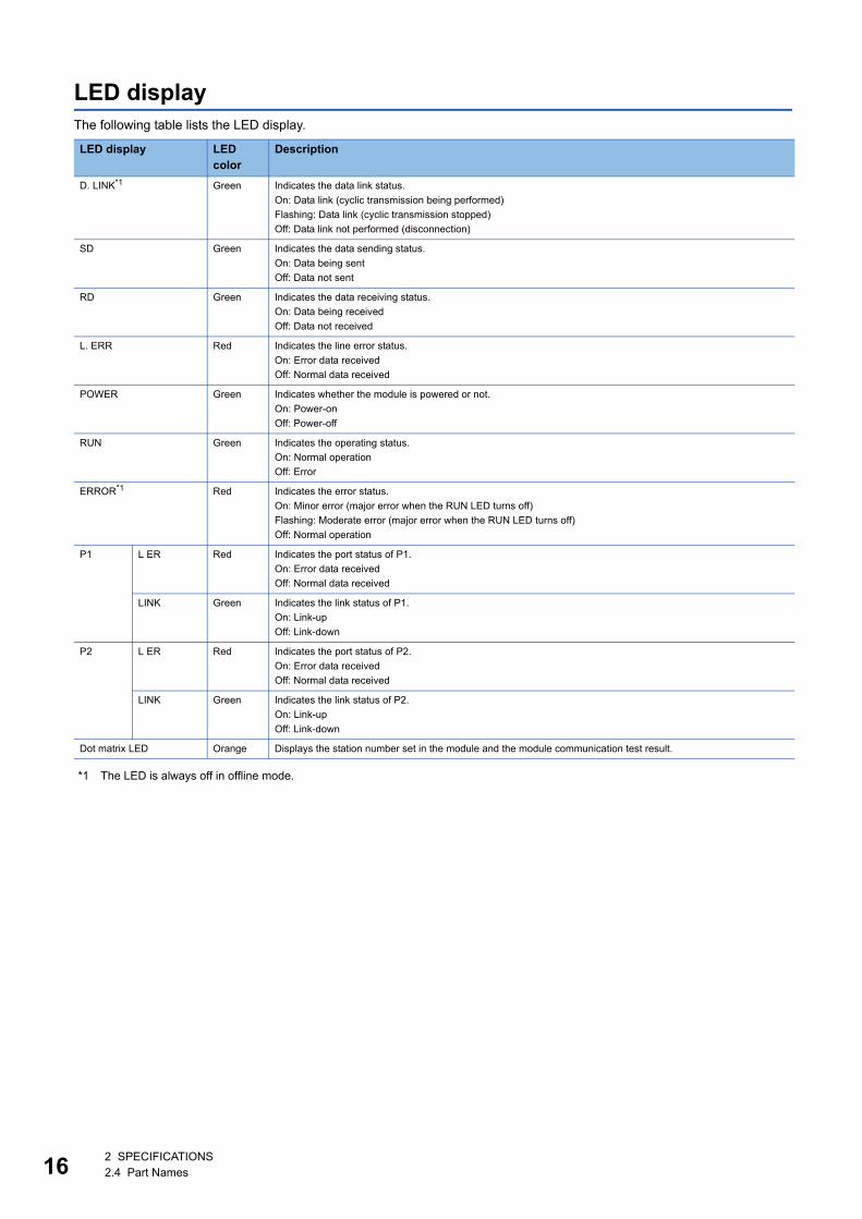
LED displayThe following table lists the LED display.
*1 The LED is always off in offline mode.
LED display LED color
Description
D. LINK*1 Green Indicates the data link status.
On: Data link (cyclic transmission being performed)
Flashing: Data link (cyclic transmission stopped)
Off: Data link not performed (disconnection)
SD Green Indicates the data sending status.
On: Data being sent
Off: Data not sent
RD Green Indicates the data receiving status.
On: Data being received
Off: Data not received
L. ERR Red Indicates the line error status.
On: Error data received
Off: Normal data received
POWER Green Indicates whether the module is powered or not.
On: Power-on
Off: Power-off
RUN Green Indicates the operating status.
On: Normal operation
Off: Error
ERROR*1 Red Indicates the error status.
On: Minor error (major error when the RUN LED turns off)
Flashing: Moderate error (major error when the RUN LED turns off)
Off: Normal operation
P1 L ER Red Indicates the port status of P1.
On: Error data received
Off: Normal data received
LINK Green Indicates the link status of P1.
On: Link-up
Off: Link-down
P2 L ER Red Indicates the port status of P2.
On: Error data received
Off: Normal data received
LINK Green Indicates the link status of P2.
On: Link-up
Off: Link-down
Dot matrix LED Orange Displays the station number set in the module and the module communication test result.
2 SPECIFICATIONS2.4 Part Names
3
3 PROCEDURES BEFORE OPERATION
This chapter describes the procedures before operation.
1. Checking the specifications of the FX5-CCLIEF
Check the specifications of the FX5-CCLIEF. (Page 14 SPECIFICATIONS)
2. Installation of the FX5-CCLIEF
Connect the FX5-CCLIEF to the FX5 CPU module. For details, refer to the following.
MELSEC iQ-F FX5U User's Manual (Hardware)
MELSEC iQ-F FX5UC User's Manual (Hardware)
3. Wiring
Connect an Ethernet cable to the FX5-CCLIEF.
4. Checking the cable
Perform a cable test on the FX5-CCLIEF.
5. Network construction
Configure the system and set the parameters which are required for start-up.
• Wiring (Page 33 WIRING)
• Parameter setting (Page 36 PARAMETER SETTINGS)
6. Network diagnostics
Using network diagnostics, check if the cables are connected properly and communication is performed normally with the
configured parameters.
For details, refer to the following.
(Page 113 Checking the Network Status)
7. Programming
Create a program. For details, refer to the following.
(Page 44 DEDICATED INSTRUCTION)
8. Debug
Debug the program by using CC-Link IE Field Network diagnostics.
3 PROCEDURES BEFORE OPERATION 17
18
4 FUNCTIONS
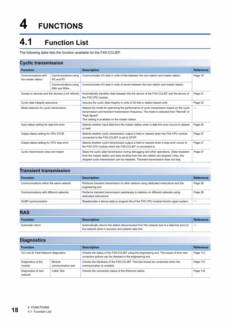
4.1 Function ListThe following table lists the function available for the FX5-CCLIEF.
Cyclic transmission
Transient transmission
RAS
Diagnostics
Function Description Reference
Communications with
the master station
Communications using
RX and RY
Communicates I/O data in units of bits between the own station and master station. Page 19
Communications using
RWr and RWw
Communicates I/O data in units of words between the own station and master station.
Access to devices and link devices (Link refresh) Automatically transfers data between the link device of the FX5-CCLIEF and the device of
the FX5 CPU module.
Page 21
Cyclic data integrity assurance Assures the cyclic data integrity in units of 32 bits or station-based units. Page 22
Mode selection for cyclic transmission Selects the mode for optimizing the performance of cyclic transmission based on the cyclic
transmission and transient transmission frequency. The mode is selected from "Normal" or
"High Speed".
This setting is available on the master station.
Input status setting for data link error Selects whether input data from the master station when a data link error occurs is cleared
or held.
Page 26
Output status setting for CPU STOP Selects whether cyclic transmission output is held or cleared when the FX5 CPU module
connected to the FX5-CCLIEF is set to STOP.
Page 27
Output status setting for CPU stop error Selects whether cyclic transmission output is held or cleared when a stop error occurs in
the FX5 CPU module which the FX5-CCLIEF is connected to.
Page 27
Cyclic transmission stop and restart Stops the cyclic data transmission during debugging and other operations. (Data reception
from the master station and data sending from the own station are stopped.) Also, the
stopped cyclic transmission can be restarted. Transient transmission does not stop.
Page 27
Function Description Reference
Communications within the same network Performs transient transmission to other stations using dedicated instructions and the
engineering tool.
Page 28
Communications with different networks Performs transient transmission seamlessly to stations on different networks using
dedicated instructions.
Page 28
SLMP communication Reads/writes a device data or program file of the FX5 CPU module from/to upper system.
Function Description Reference
Automatic return Automatically returns the station disconnected from the network due to a data link error to
the network when it recovers and restarts data link.
Function Description Reference
CC-Link IE Field Network diagnostics Checks the status of the FX5-CCLIEF using the engineering tool. The cause of error and
corrective actions can be checked in the engineering tool.
Page 113
Diagnostics of the
module
Module
communication test
Checks the hardware of the FX5-CCLIEF. This test should be conducted when the
communication is unstable.
Page 112
Diagnostics of own
network
Cable Test Checks the connection status of the Ethernet cables. Page 116
4 FUNCTIONS4.1 Function List
4
Others
4.2 Cyclic TransmissionThis function allows data to be periodically exchanged among stations on the same network using link devices.
Data flow and link device assignment
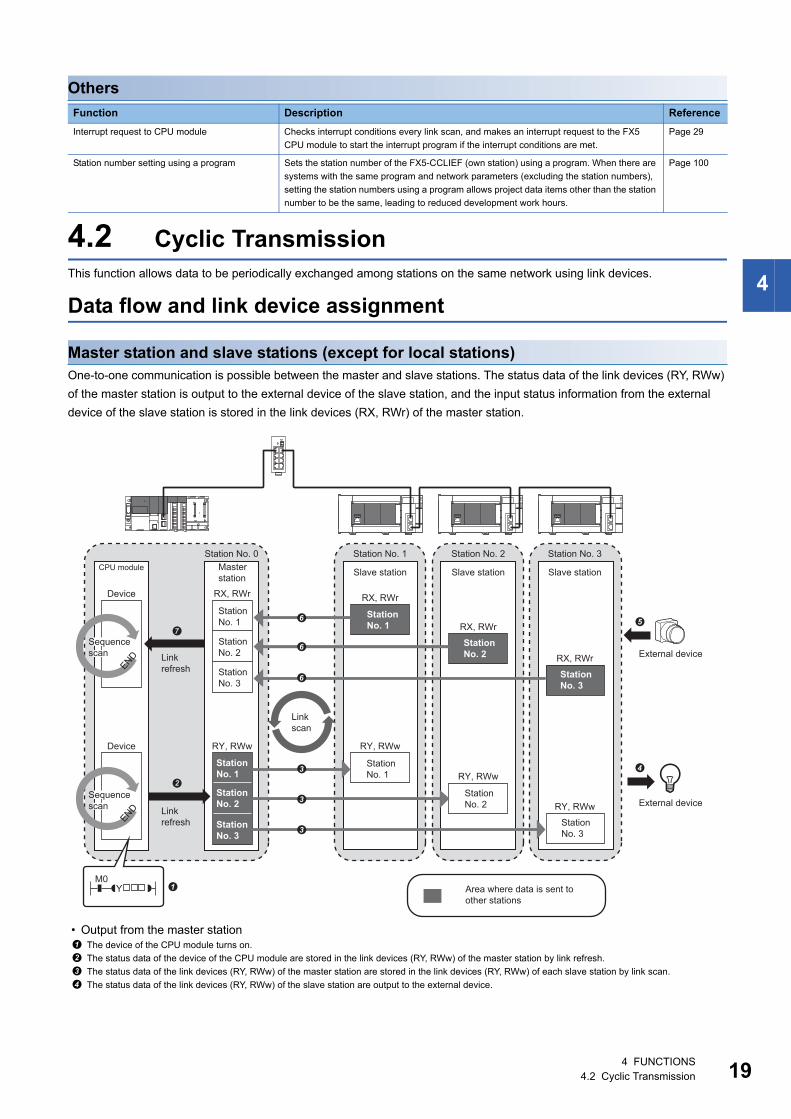
Master station and slave stations (except for local stations)One-to-one communication is possible between the master and slave stations. The status data of the link devices (RY, RWw)
of the master station is output to the external device of the slave station, and the input status information from the external
device of the slave station is stored in the link devices (RX, RWr) of the master station.
• Output from the master station
Function Description Reference
Interrupt request to CPU module Checks interrupt conditions every link scan, and makes an interrupt request to the FX5
CPU module to start the interrupt program if the interrupt conditions are met.
Page 29
Station number setting using a program Sets the station number of the FX5-CCLIEF (own station) using a program. When there are
systems with the same program and network parameters (excluding the station numbers),
setting the station numbers using a program allows project data items other than the station
number to be the same, leading to reduced development work hours.
Page 100
The device of the CPU module turns on.
The status data of the device of the CPU module are stored in the link devices (RY, RWw) of the master station by link refresh.
The status data of the link devices (RY, RWw) of the master station are stored in the link devices (RY, RWw) of each slave station by link scan.
The status data of the link devices (RY, RWw) of the slave station are output to the external device.
RX, RWr
RX, RWr
RX, RWr
END
RY, RWw
RY, RWw
RY, RWw
END
RX, RWr
RY, RWw
M0Y
Slave station
Station No. 1
Slave station
Station No. 2
Slave station
Station No. 3Master station
Station No. 1
Station No. 2
Station No. 3
External device
External device
CPU module
Device
Device
Station No. 1
Station No. 2
Station No. 3
Sequence scan
Sequence scan
Station No. 0
Area where data is sent to other stations
Station No. 1
Station No. 2
Station No. 3
Station No. 1
Station No. 2
Station No. 3
Link refresh
Link refresh
Linkscan
4 FUNCTIONS4.2 Cyclic Transmission 19
20
• Input from the slave station
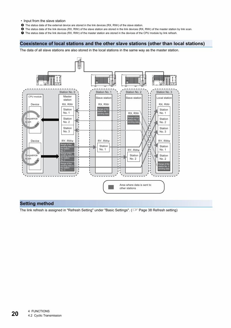
Coexistence of local stations and the other slave stations (other than local stations)The data of all slave stations are also stored in the local stations in the same way as the master station.
Setting methodThe link refresh is assigned in "Refresh Setting" under "Basic Settings". (Page 38 Refresh setting)
The status data of the external device are stored in the link devices (RX, RWr) of the slave station.
The status data of the link devices (RX, RWr) of the slave station are stored in the link devices (RX, RWr) of the master station by link scan.
The status data of the link devices (RX, RWr) of the master station are stored in the devices of the CPU module by link refresh.
RX, RWr
RY, RWw
RX, RWr
RY, RWw
RX, RWr
RY, RWw
RX, RWr
RY, RWw
Slave station
Station No. 1
Slave station
Station No. 2 Station No. 3Station No. 0
Local stationMasterstation
Area where data is sent to other stations
Range of the station No. 1 sending data
Range of the station No. 2 sending data
Range of the station No. 3 sending data
Range of the sending data to the station No. 1 Range of the sending data to the station No. 2
Range of the sending data to the station No. 3
CPU module
Station No. 1
Station No. 2
Station No. 1
Station No. 2
Station No. 1
Station No. 2
Station No. 3
Station No. 1
Station No. 2
Station No. 3
Device
Device
ENDEND
Sequence scan
Sequence scan
4 FUNCTIONS4.2 Cyclic Transmission
4
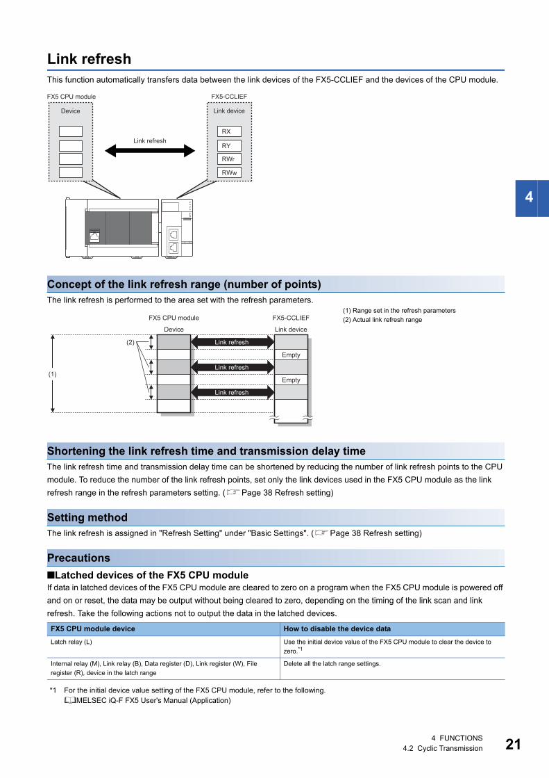
Link refreshThis function automatically transfers data between the link devices of the FX5-CCLIEF and the devices of the CPU module.
Concept of the link refresh range (number of points)The link refresh is performed to the area set with the refresh parameters.
Shortening the link refresh time and transmission delay timeThe link refresh time and transmission delay time can be shortened by reducing the number of link refresh points to the CPU
module. To reduce the number of the link refresh points, set only the link devices used in the FX5 CPU module as the link
refresh range in the refresh parameters setting. (Page 38 Refresh setting)
Setting methodThe link refresh is assigned in "Refresh Setting" under "Basic Settings". (Page 38 Refresh setting)
Precautions
■Latched devices of the FX5 CPU moduleIf data in latched devices of the FX5 CPU module are cleared to zero on a program when the FX5 CPU module is powered off
and on or reset, the data may be output without being cleared to zero, depending on the timing of the link scan and link
refresh. Take the following actions not to output the data in the latched devices.
*1 For the initial device value setting of the FX5 CPU module, refer to the following.MELSEC iQ-F FX5 User's Manual (Application)
(1) Range set in the refresh parameters
(2) Actual link refresh range
FX5 CPU module device How to disable the device data
Latch relay (L) Use the initial device value of the FX5 CPU module to clear the device to
zero.*1
Internal relay (M), Link relay (B), Data register (D), Link register (W), File
register (R), device in the latch range
Delete all the latch range settings.
RX
RY
RWr
RWw
FX5-CCLIEFFX5 CPU module
Device Link device
Link refresh
(1)
(2)
FX5-CCLIEFFX5 CPU module
Device Link device
Link refresh
Link refresh
Link refresh
Empty
Empty
4 FUNCTIONS4.2 Cyclic Transmission 21
22
Cyclic data integrity assuranceThis function assures the cyclic data integrity in units of 32 bits or station-based units.
: Assured, : Not assured
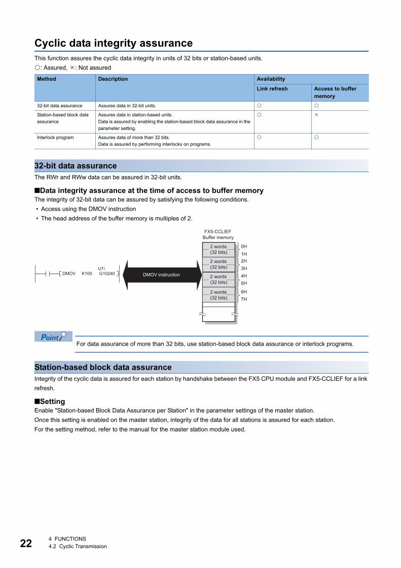
32-bit data assuranceThe RWr and RWw data can be assured in 32-bit units.
■Data integrity assurance at the time of access to buffer memoryThe integrity of 32-bit data can be assured by satisfying the following conditions.
• Access using the DMOV instruction
• The head address of the buffer memory is multiples of 2.
For data assurance of more than 32 bits, use station-based block data assurance or interlock programs.
Station-based block data assuranceIntegrity of the cyclic data is assured for each station by handshake between the FX5 CPU module and FX5-CCLIEF for a link
refresh.
■SettingEnable "Station-based Block Data Assurance per Station" in the parameter settings of the master station.
Once this setting is enabled on the master station, integrity of the data for all stations is assured for each station.
For the setting method, refer to the manual for the master station module used.
Method Description Availability
Link refresh Access to buffer memory
32-bit data assurance Assures data in 32-bit units.
Station-based block data
assurance
Assures data in station-based units.
Data is assured by enabling the station-based block data assurance in the
parameter setting.
Interlock program Assures data of more than 32 bits.
Data is assured by performing interlocks on programs.
0H1H2H3H4H5H
6H7H
FX5-CCLIEF
2 words (32 bits)
Buffer memory
2 words (32 bits)
2 words (32 bits)
2 words (32 bits)
DMOV instructionG10240U1\
DMOV K100
4 FUNCTIONS4.2 Cyclic Transmission
4
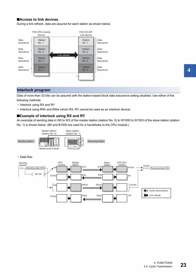
■Access to link devicesDuring a link refresh, data are assured for each station as shown below.
Interlock programData of more than 32 bits can be assured with the station-based block data assurance setting disabled. Use either of the
following methods.
• Interlock using RX and RY
• Interlock using RWr and RWw (when RX, RY cannot be used as an interlock device)
■Example of interlock using RX and RYAn example of sending data in W0 to W3 of the master station (station No. 0) to W1000 to W1003 of the slave station (station
No. 1) is shown below. (B0 and B1000 are used for a handshake to the CPU module.)
• Data flow
FX5-CCLIEF
Station No. 1
Station No. 2
Station No. 3
Station No. 4
Data assurance
Data assurance
Data assurance
Data assurance
Data assurance
Data assurance
Data assurance
Data assurance
Station No. 1
Station No. 2
Station No. 3
Station No. 4
Link deviceDeviceFX5 CPU module
Link refresh
FX5-CCLIEFMaster/local module
Receiving stationSending station
Master station (station No. 0)
Slave station(station No. 1)
SET B0B0
B1000
RX0
RY0RY0
RWw0
RWr0
RWw0
RWr0
RX0
B0
W0
W1000 W0
W1000
B1000
B1000
Sending request
Sending data (W)
CPU module
Masterstation
FX5 CPUmodule
Slave station
Cyclic transmission
Link refresh
Receiving data (W)
4 FUNCTIONS4.2 Cyclic Transmission 23
24
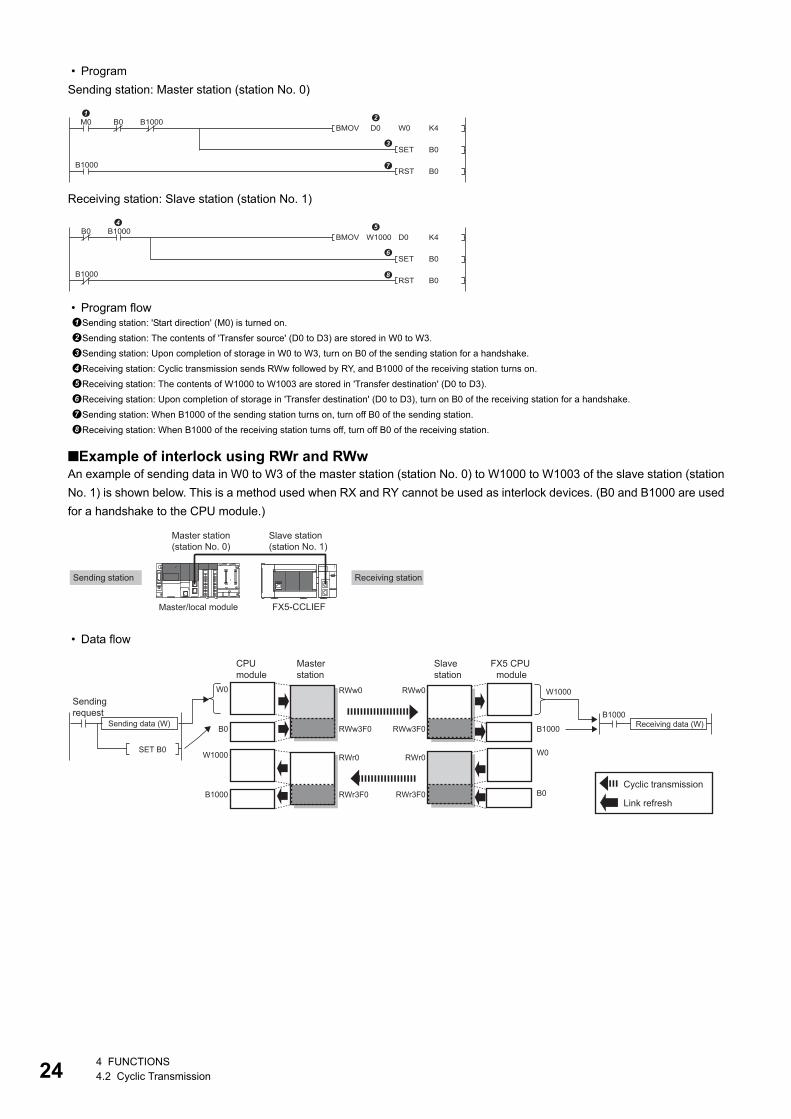
• Program
Sending station: Master station (station No. 0)
Receiving station: Slave station (station No. 1)
• Program flow
■Example of interlock using RWr and RWwAn example of sending data in W0 to W3 of the master station (station No. 0) to W1000 to W1003 of the slave station (station
No. 1) is shown below. This is a method used when RX and RY cannot be used as interlock devices. (B0 and B1000 are used
for a handshake to the CPU module.)
• Data flow
Sending station: 'Start direction' (M0) is turned on.
Sending station: The contents of 'Transfer source' (D0 to D3) are stored in W0 to W3.
Sending station: Upon completion of storage in W0 to W3, turn on B0 of the sending station for a handshake.
Receiving station: Cyclic transmission sends RWw followed by RY, and B1000 of the receiving station turns on.
Receiving station: The contents of W1000 to W1003 are stored in 'Transfer destination' (D0 to D3).
Receiving station: Upon completion of storage in 'Transfer destination' (D0 to D3), turn on B0 of the receiving station for a handshake.
Sending station: When B1000 of the sending station turns on, turn off B0 of the sending station.
Receiving station: When B1000 of the receiving station turns off, turn off B0 of the receiving station.
W0BMOV D0
SET
K4
B0
RST B0
M0 B1000B0
B1000
BMOV W1000 D0
SET
K4
B0
RST B0
B0 B1000
B1000
FX5-CCLIEFMaster/local module
Receiving stationSending station
Master station (station No. 0)
Slave station(station No. 1)
SET B0
RWw0
RWr0
RWr3F0
RWw0
RWr0
RWr3F0
RWw3F0 RWw3F0
W0
B0
B1000
W1000 W0
B1000
B0
W1000
B1000
Cyclic transmission
Link refresh
Sending request
CPU module
Master station
FX5 CPU module
Slave station
Sending data (W) Receiving data (W)
4 FUNCTIONS4.2 Cyclic Transmission
4
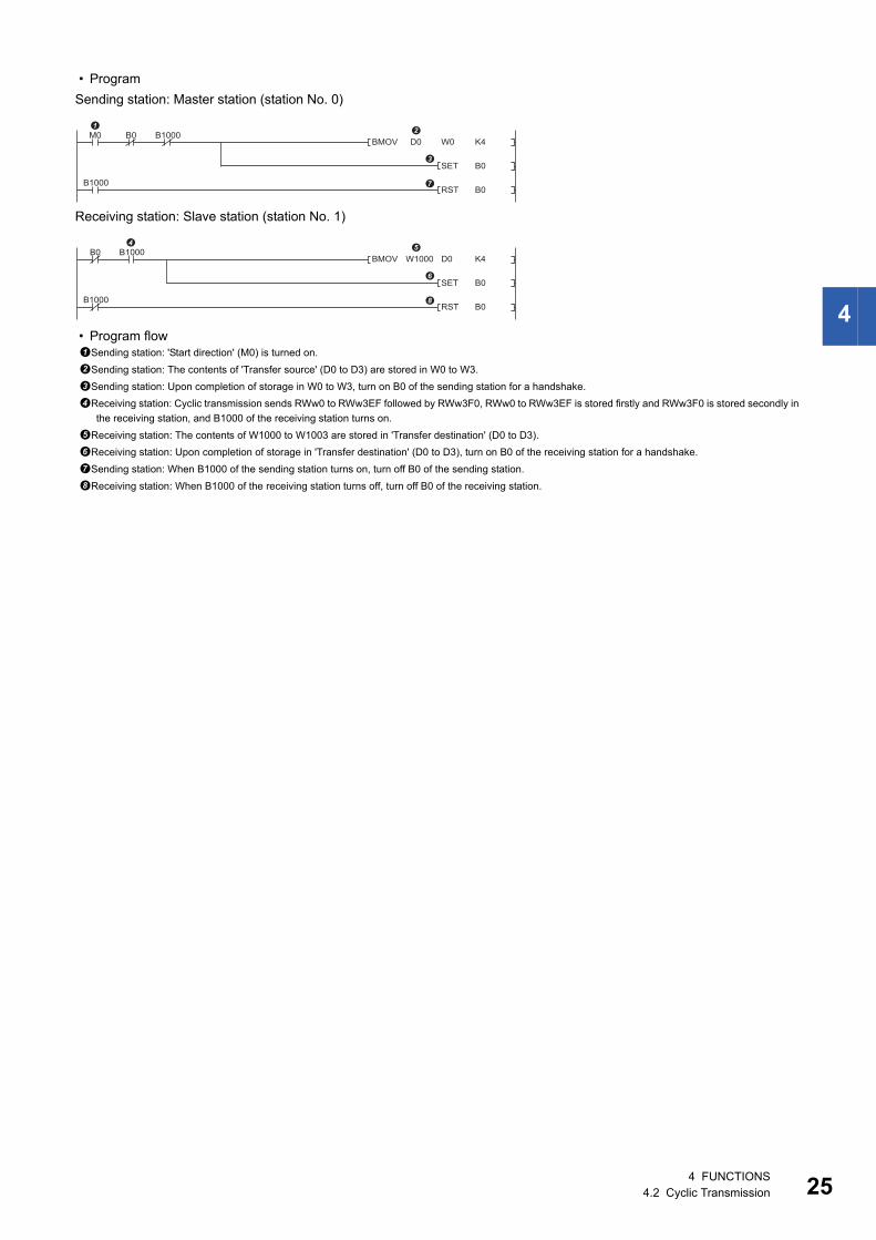
• Program
Sending station: Master station (station No. 0)
Receiving station: Slave station (station No. 1)
• Program flowSending station: 'Start direction' (M0) is turned on.
Sending station: The contents of 'Transfer source' (D0 to D3) are stored in W0 to W3.
Sending station: Upon completion of storage in W0 to W3, turn on B0 of the sending station for a handshake.
Receiving station: Cyclic transmission sends RWw0 to RWw3EF followed by RWw3F0, RWw0 to RWw3EF is stored firstly and RWw3F0 is stored secondly in
the receiving station, and B1000 of the receiving station turns on.
Receiving station: The contents of W1000 to W1003 are stored in 'Transfer destination' (D0 to D3).
Receiving station: Upon completion of storage in 'Transfer destination' (D0 to D3), turn on B0 of the receiving station for a handshake.
Sending station: When B1000 of the sending station turns on, turn off B0 of the sending station.
Receiving station: When B1000 of the receiving station turns off, turn off B0 of the receiving station.
W0BMOV D0
SET
K4
B0
RST B0
M0 B1000B0
B1000
BMOV W1000 D0
SET
K4
B0
RST B0
B0 B1000
B1000
4 FUNCTIONS4.2 Cyclic Transmission 25
26
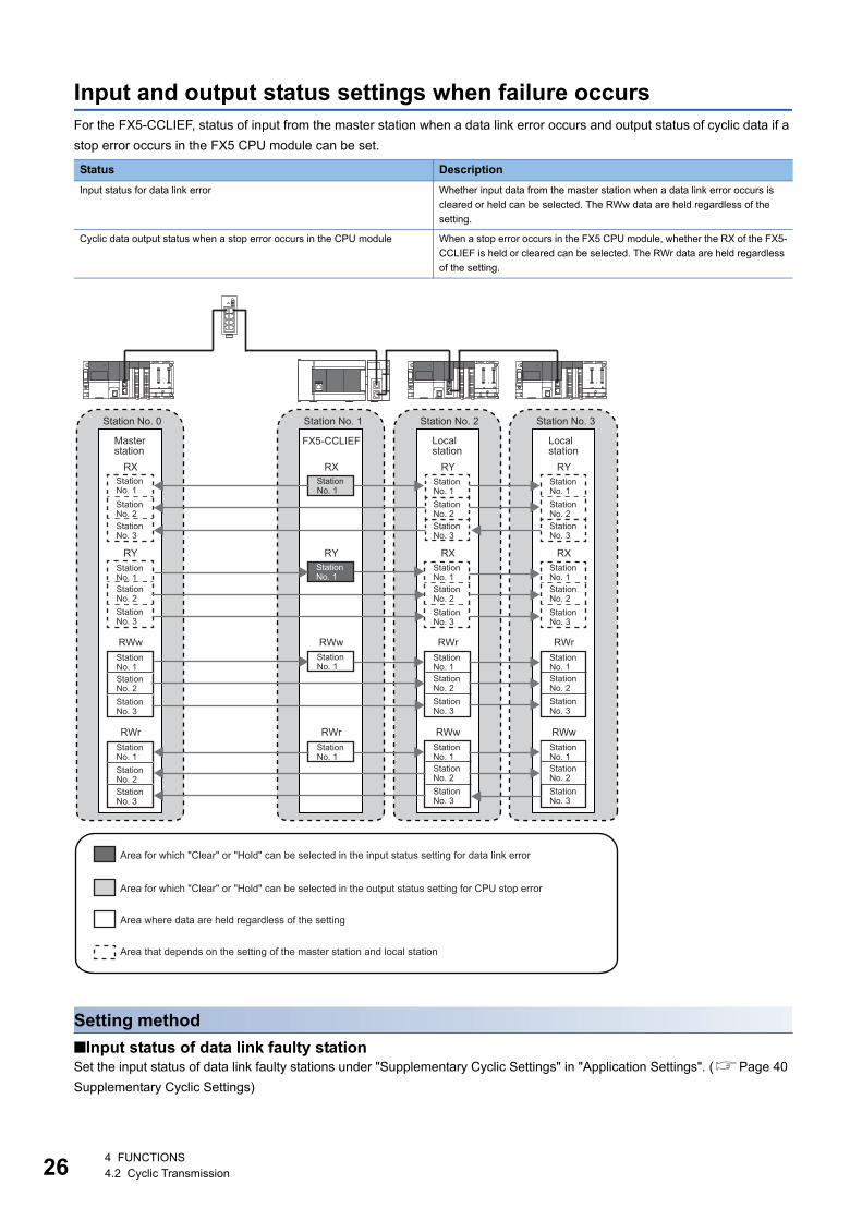
Input and output status settings when failure occursFor the FX5-CCLIEF, status of input from the master station when a data link error occurs and output status of cyclic data if a
stop error occurs in the FX5 CPU module can be set.
Setting method
■Input status of data link faulty stationSet the input status of data link faulty stations under "Supplementary Cyclic Settings" in "Application Settings". (Page 40
Supplementary Cyclic Settings)
Status Description
Input status for data link error Whether input data from the master station when a data link error occurs is
cleared or held can be selected. The RWw data are held regardless of the
setting.
Cyclic data output status when a stop error occurs in the CPU module When a stop error occurs in the FX5 CPU module, whether the RX of the FX5-
CCLIEF is held or cleared can be selected. The RWr data are held regardless
of the setting.
RX
RY
RWw
RWr
RX
RY
RWw
RWr
RY
RX
RWr
RWw
RY
RX
RWr
RWw
FX5-CCLIEFMasterstation
Station No. 0
Station No. 3
Station No. 2
Station No. 1
Station No. 3
Station No. 2
Station No. 1
Station No. 3
Station No. 2
Station No. 1
Station No. 3
Station No. 2
Station No. 2
Station No. 1
Station No. 1
Station No. 1
Station No. 1
Station No. 3
Station No. 3
Station No. 2
Station No. 1
Station No. 3
Station No. 2
Station No. 1
Station No. 3
Station No. 2
Station No. 1
Station No. 3
Station No. 2
Station No. 1
Station No. 1
Station No. 1
Localstation
Station No. 2
Localstation
Station No. 3
Station No. 3
Station No. 2
Station No. 1
Station No. 3
Station No. 1
Station No. 3
Station No. 2
Station No. 1
Station No. 2
Station No. 1
Area for which "Clear" or "Hold" can be selected in the input status setting for data link error
Area for which "Clear" or "Hold" can be selected in the output status setting for CPU stop error
Area where data are held regardless of the setting
Area that depends on the setting of the master station and local station
4 FUNCTIONS4.2 Cyclic Transmission
4
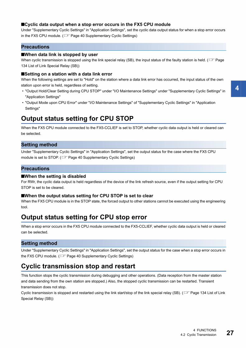
■Cyclic data output when a stop error occurs in the FX5 CPU moduleUnder "Supplementary Cyclic Settings" in "Application Settings", set the cyclic data output status for when a stop error occurs
in the FX5 CPU module. (Page 40 Supplementary Cyclic Settings)
Precautions
■When data link is stopped by userWhen cyclic transmission is stopped using the link special relay (SB), the input status of the faulty station is held. (Page
134 List of Link Special Relay (SB))
■Setting on a station with a data link errorWhen the following settings are set to "Hold" on the station where a data link error has occurred, the input status of the own
station upon error is held, regardless of setting.
• "Output Hold/Clear Setting during CPU STOP" under "I/O Maintenance Settings" under "Supplementary Cyclic Settings" in
"Application Settings"
• "Output Mode upon CPU Error" under "I/O Maintenance Settings" of "Supplementary Cyclic Settings" in "Application
Settings"
Output status setting for CPU STOPWhen the FX5 CPU module connected to the FX5-CCLIEF is set to STOP, whether cyclic data output is held or cleared can
be selected.
Setting methodUnder "Supplementary Cyclic Settings" in "Application Settings", set the output status for the case where the FX5 CPU
module is set to STOP. (Page 40 Supplementary Cyclic Settings)
Precautions
■When the setting is disabledFor RWr, the cyclic data output is held regardless of the device of the link refresh source, even if the output setting for CPU
STOP is set to be cleared.
■When the output status setting for CPU STOP is set to clearWhen the FX5 CPU module is in the STOP state, the forced output to other stations cannot be executed using the engineering
tool.
Output status setting for CPU stop errorWhen a stop error occurs in the FX5 CPU module connected to the FX5-CCLIEF, whether cyclic data output is held or cleared
can be selected.
Setting methodUnder "Supplementary Cyclic Settings" in "Application Settings", set the output status for the case when a stop error occurs in
the FX5 CPU module. (Page 40 Supplementary Cyclic Settings)
Cyclic transmission stop and restartThis function stops the cyclic transmission during debugging and other operations. (Data reception from the master station
and data sending from the own station are stopped.) Also, the stopped cyclic transmission can be restarted. Transient
transmission does not stop.
Cyclic transmission is stopped and restarted using the link start/stop of the link special relay (SB). (Page 134 List of Link
Special Relay (SB))
4 FUNCTIONS4.2 Cyclic Transmission 27
28
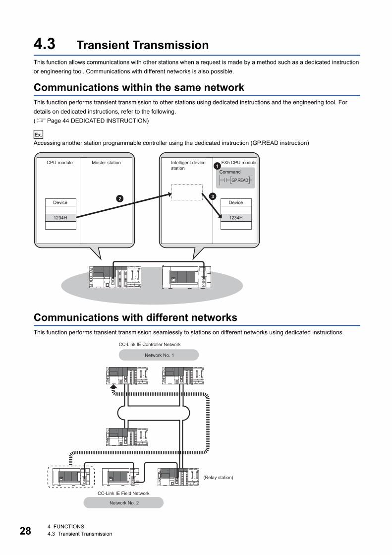
4.3 Transient TransmissionThis function allows communications with other stations when a request is made by a method such as a dedicated instruction
or engineering tool. Communications with different networks is also possible.
Communications within the same networkThis function performs transient transmission to other stations using dedicated instructions and the engineering tool. For
details on dedicated instructions, refer to the following.
(Page 44 DEDICATED INSTRUCTION)
Ex.
Accessing another station programmable controller using the dedicated instruction (GP.READ instruction)
Communications with different networksThis function performs transient transmission seamlessly to stations on different networks using dedicated instructions.
2 3
1234H 1234H
1
GP.READ
Device Device
CPU module FX5 CPU moduleMaster station Intelligent device station
Command
CC-Link IE Field Network
CC-Link IE Controller Network
Network No. 2
Network No. 1
(Relay station)
4 FUNCTIONS4.3 Transient Transmission
4
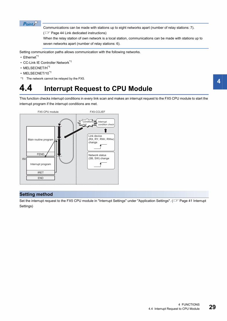
Communications can be made with stations up to eight networks apart (number of relay stations: 7).
(Page 44 Link dedicated instructions)
When the relay station of own network is a local station, communications can be made with stations up to
seven networks apart (number of relay stations: 6).
Setting communication paths allows communication with the following networks.
• Ethernet*1
• CC-Link IE Controller Network*1
• MELSECNET/H*1
• MELSECNET/10*1
*1 The network cannot be relayed by the FX5.
4.4 Interrupt Request to CPU ModuleThis function checks interrupt conditions in every link scan and makes an interrupt request to the FX5 CPU module to start the
interrupt program if the interrupt conditions are met.
Setting methodSet the interrupt request to the FX5 CPU module in "Interrupt Settings" under "Application Settings". (Page 41 Interrupt
Settings)
I50
FEND
END
IRET
FX5-CCLIEF
Main routine program
Interrupt program
FX5 CPU module
Conditionsmet
Interrupt condition check
Link device (RX, RY, RWr, RWw) change
Network status (SB, SW) change
4 FUNCTIONS4.4 Interrupt Request to CPU Module 29
30
5 SYSTEM CONFIGURATION
This chapter describes the system configuration of CC-Link IE Field Network.
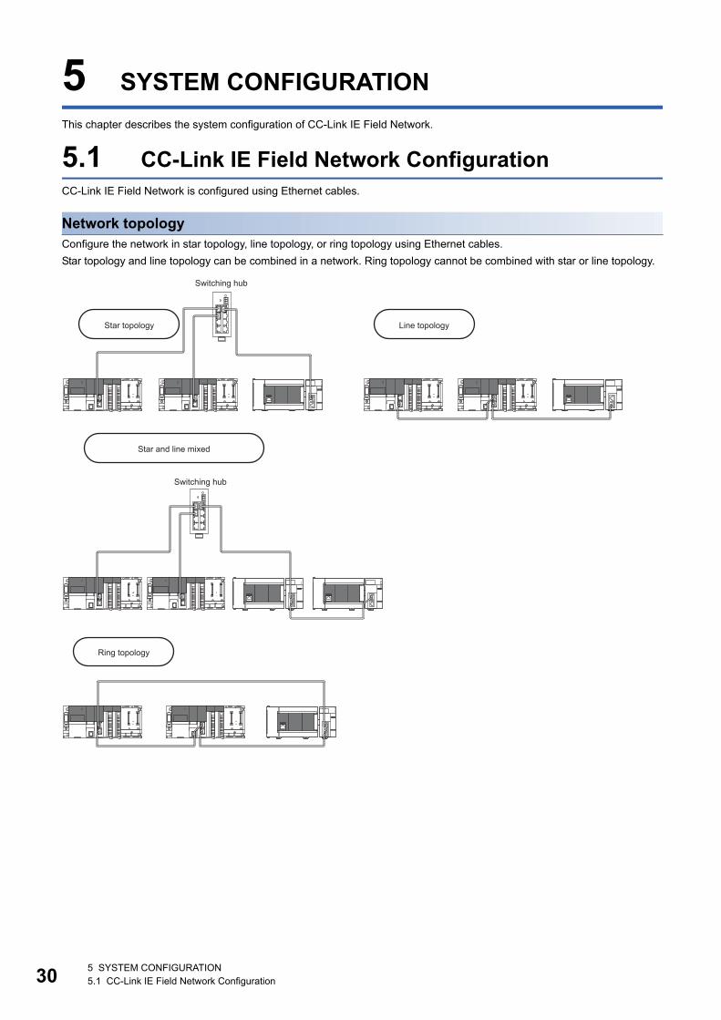
5.1 CC-Link IE Field Network ConfigurationCC-Link IE Field Network is configured using Ethernet cables.
Network topologyConfigure the network in star topology, line topology, or ring topology using Ethernet cables.
Star topology and line topology can be combined in a network. Ring topology cannot be combined with star or line topology.
Star topology Line topology
Star and line mixed
Switching hub
Switching hub
Ring topology
5 SYSTEM CONFIGURATION5.1 CC-Link IE Field Network Configuration
5
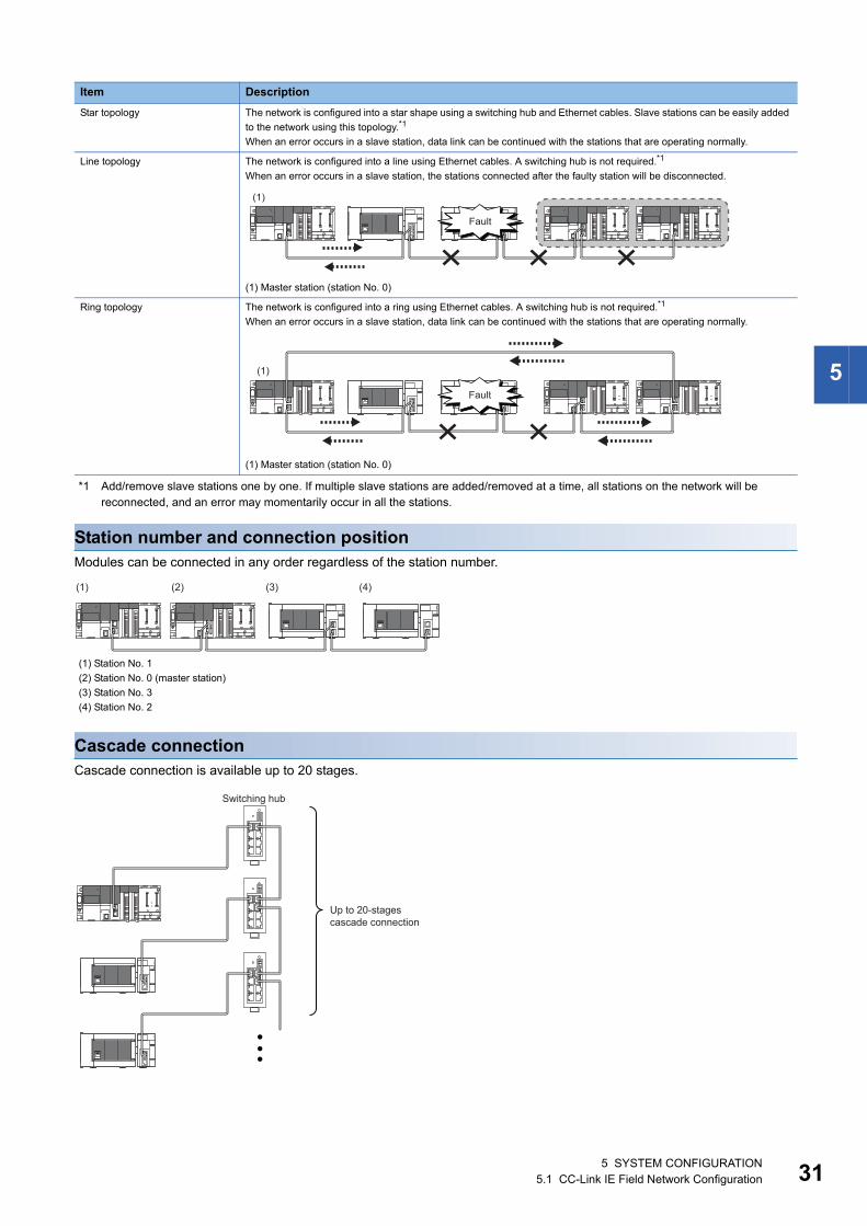
*1 Add/remove slave stations one by one. If multiple slave stations are added/removed at a time, all stations on the network will be reconnected, and an error may momentarily occur in all the stations.
Station number and connection positionModules can be connected in any order regardless of the station number.
Cascade connectionCascade connection is available up to 20 stages.
Item Description
Star topology The network is configured into a star shape using a switching hub and Ethernet cables. Slave stations can be easily added
to the network using this topology.*1
When an error occurs in a slave station, data link can be continued with the stations that are operating normally.
Line topology The network is configured into a line using Ethernet cables. A switching hub is not required.*1
When an error occurs in a slave station, the stations connected after the faulty station will be disconnected.
(1) Master station (station No. 0)
Ring topology The network is configured into a ring using Ethernet cables. A switching hub is not required.*1
When an error occurs in a slave station, data link can be continued with the stations that are operating normally.
(1) Master station (station No. 0)
(1) Station No. 1
(2) Station No. 0 (master station)
(3) Station No. 3
(4) Station No. 2
(1)
Fault
(1)
Fault
(1) (2) (3) (4)
Switching hub
Up to 20-stagescascade connection
5 SYSTEM CONFIGURATION5.1 CC-Link IE Field Network Configuration 31
32
Precautions
■Addition of slave stations (including submaster station)Do not connect 121 or more slave stations (including submaster station). If a slave station is added to a system having 120
slave stations (including submaster station), all stations will fail and data link cannot be performed.
■Configuration in which data link cannot be performed (illegal ring connection)Do not use a switching hub for ring topology.
■Ring topologyWhen using ring topology, set the network topology to "Ring" in the parameter settings for the master station.
For the setting method, refer to the manual for the master station module used.
■Connecting/disconnecting a cable and powering off/on a deviceWhen the operations listed below are performed, all stations on the network may be reconnected. At this time, a data link error
may momentarily occur in all the stations and outputs of the connected slave stations may turn off.
To hold the outputs as a measure when a data link error occurs, set the following to "Hold".
Navigation window [Parameter] [Module Information] Target module [Module Parameter] [Application
Settings] [Supplementary Cyclic Settings] [I/O Maintenance Settings] [Data Link Error Station Setting]
■Connected station numbersDo not duplicate station numbers. Data link may be stopped when the station number is duplicated.
5.2 Precautions for System Configuration
Connecting devices to the same networkFor the device connection, observe the following. Failure to do so may cause the disconnection of all stations.
• Do not connect a non CC-Link IE Field Network device in CC-Link IE Field Network. If the device is connected,
communications may not be normally performed.
• Do not connect a 100M/10M device or 1 Gbps device which does not support CC-Link IE Field Network to the switching
hub (1 Gbps) used in CC-Link IE Field Network. If the device is connected, an error may be detected in the master station
and data link may be stopped.
Network configuration Operation
Star topology • Powering off and on a slave station or switching hub
• Connecting/disconnecting an Ethernet cable connected to the switching hub
• Disconnecting an Ethernet cable from a slave station and connecting it to another slave station or a switching hub
• Disconnecting more than 9 stations, or half the number of slave stations or more in the system
• Changing the network topology when adding a slave station
Line topology, ring topology • Simultaneously powering off/on multiple stations
• Simultaneously connecting/disconnecting Ethernet cables to/from multiple stations (When a data link faulty station
returns, a data link error will occur in all the stations.)
• Disconnecting more than 9 stations, or half the number of slave stations or more in the system
• Changing the network topology when adding a slave station
5 SYSTEM CONFIGURATION5.2 Precautions for System Configuration
6
6 WIRING
This chapter describes the wiring methods, wiring products, and wiring precautions when the FX5-CCLIEF is used.
6.1 Power Supply Wiring
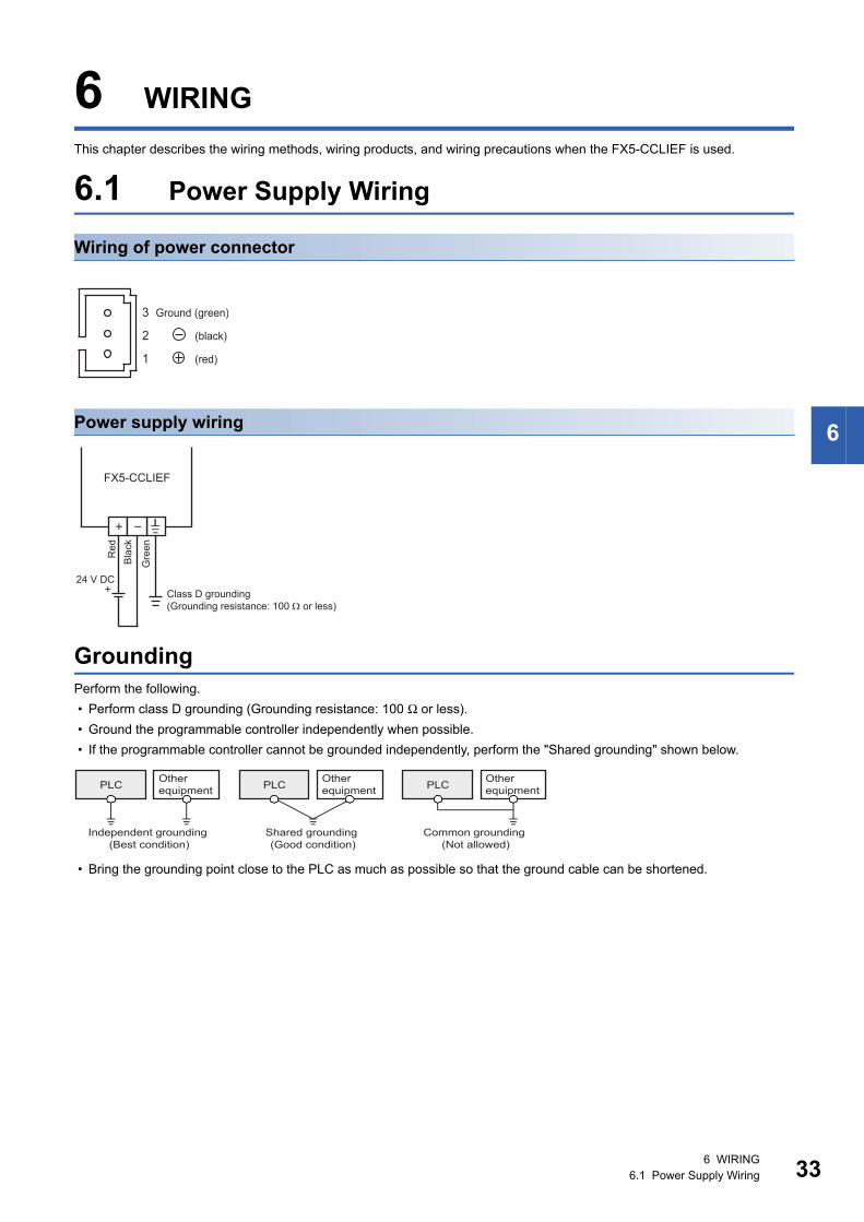
Wiring of power connector
Power supply wiring
GroundingPerform the following.
• Perform class D grounding (Grounding resistance: 100 Ω or less).
• Ground the programmable controller independently when possible.
• If the programmable controller cannot be grounded independently, perform the "Shared grounding" shown below.
• Bring the grounding point close to the PLC as much as possible so that the ground cable can be shortened.
3
2
1
Ground (green)
(black)
(red)
FX5-CCLIEF
Class D grounding(Grounding resistance: 100 or less)
Red
Bla
ck
Gre
en
24 V DC
PLC Other equipment PLC Other
equipment PLC Other equipment
Shared grounding (Good condition)
Common grounding (Not allowed)
Independent grounding (Best condition)
6 WIRING6.1 Power Supply Wiring 33
34
6.2 Wiring of CC-Link IE Field NetworkThis section describes the wiring when CC-Link IE Field Network is used.
Wiring methodsThe following describes connection and disconnection of the Ethernet cable.
■Connecting the cable
1. Power off the FX5-CCLIEF and external device.
2. Push the Ethernet cable connector into the FX5-CCLIEF until it clicks. Pay attention to the connector's direction.
3. Lightly pull it to check that it is securely connected.
4. Power on the FX5-CCLIEF and external device.
5. Check whether the LINK LED of the port connected with an Ethernet cable is on.*1
*1 The time between the cable connection and the LINK LED turning on may vary. The LINK LED usually turns on in a few seconds. Note, however, that the time may be extended further if the link-up processing is repeated depending on the status of the device on the line. If the LINK LED does not turn on, refer to the following and take corrective actions.(Page 109 TROUBLESHOOTING)
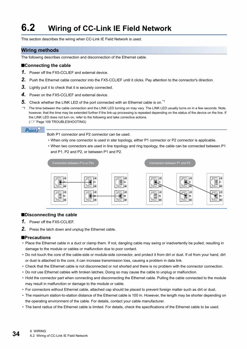
Both P1 connector and P2 connector can be used.
• When only one connector is used in star topology, either P1 connector or P2 connector is applicable.
• When two connectors are used in line topology and ring topology, the cable can be connected between P1
and P1, P2 and P2, or between P1 and P2.
■Disconnecting the cable
1. Power off the FX5-CCLIEF.
2. Press the latch down and unplug the Ethernet cable.
■Precautions • Place the Ethernet cable in a duct or clamp them. If not, dangling cable may swing or inadvertently be pulled, resulting in
damage to the module or cables or malfunction due to poor contact.
• Do not touch the core of the cable-side or module-side connector, and protect it from dirt or dust. If oil from your hand, dirt
or dust is attached to the core, it can increase transmission loss, causing a problem in data link.
• Check that the Ethernet cable is not disconnected or not shorted and there is no problem with the connector connection.
• Do not use Ethernet cables with broken latches. Doing so may cause the cable to unplug or malfunction.
• Hold the connector part when connecting and disconnecting the Ethernet cable. Pulling the cable connected to the module
may result in malfunction or damage to the module or cable.
• For connectors without Ethernet cable, attached cap should be placed to prevent foreign matter such as dirt or dust.
• The maximum station-to-station distance of the Ethernet cable is 100 m. However, the length may be shorter depending on
the operating environment of the cable. For details, contact your cable manufacturer.
• The bend radius of the Ethernet cable is limited. For details, check the specifications of the Ethernet cable to be used.
Connection between P1s or P2s Connection between P1 and P2
6 WIRING6.2 Wiring of CC-Link IE Field Network
6
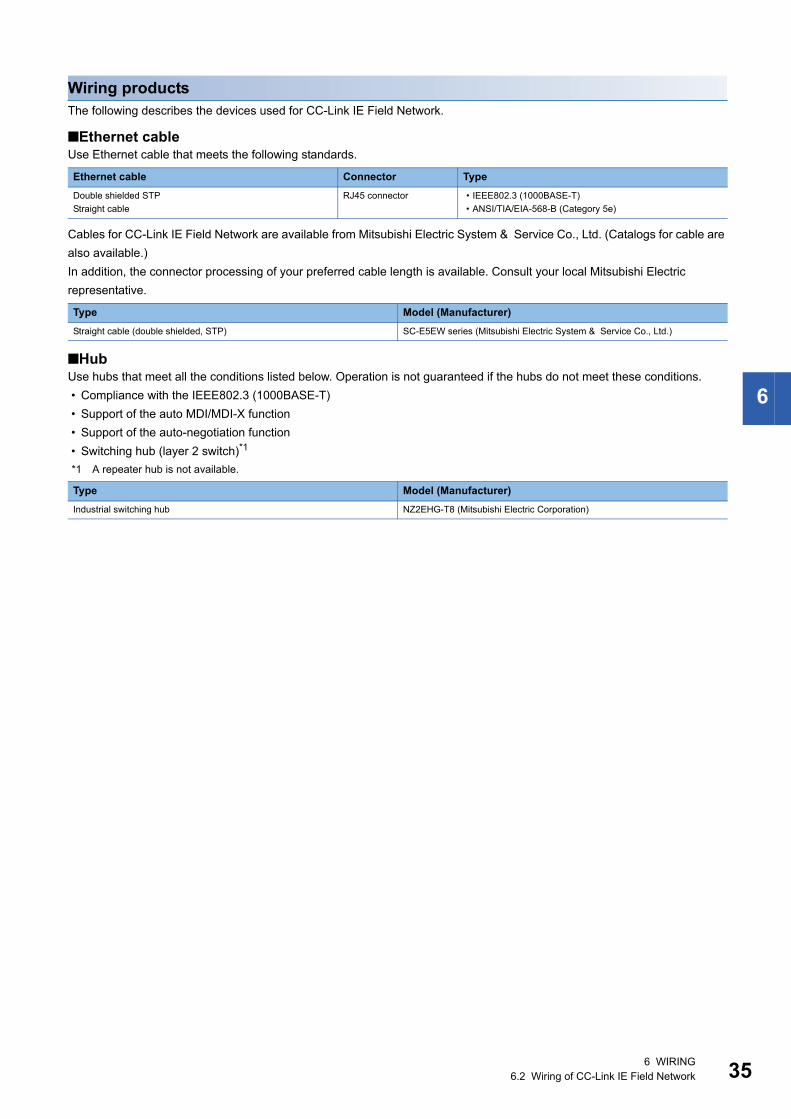
Wiring productsThe following describes the devices used for CC-Link IE Field Network.
■Ethernet cableUse Ethernet cable that meets the following standards.
Cables for CC-Link IE Field Network are available from Mitsubishi Electric System & Service Co., Ltd. (Catalogs for cable are
also available.)
In addition, the connector processing of your preferred cable length is available. Consult your local Mitsubishi Electric
representative.
■HubUse hubs that meet all the conditions listed below. Operation is not guaranteed if the hubs do not meet these conditions.
• Compliance with the IEEE802.3 (1000BASE-T)
• Support of the auto MDI/MDI-X function
• Support of the auto-negotiation function
• Switching hub (layer 2 switch)*1
*1 A repeater hub is not available.
Ethernet cable Connector Type
Double shielded STP
Straight cable
RJ45 connector • IEEE802.3 (1000BASE-T)
• ANSI/TIA/EIA-568-B (Category 5e)
Type Model (Manufacturer)
Straight cable (double shielded, STP) SC-E5EW series (Mitsubishi Electric System & Service Co., Ltd.)
Type Model (Manufacturer)
Industrial switching hub NZ2EHG-T8 (Mitsubishi Electric Corporation)
6 WIRING6.2 Wiring of CC-Link IE Field Network 35
36
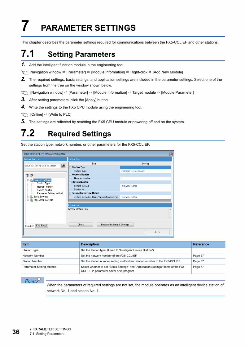
7 PARAMETER SETTINGS
This chapter describes the parameter settings required for communications between the FX5-CCLIEF and other stations.
7.1 Setting Parameters1. Add the intelligent function module in the engineering tool.
Navigation window [Parameter] [Module Information] Right-click [Add New Module]
2. The required settings, basic settings, and application settings are included in the parameter settings. Select one of the
settings from the tree on the window shown below.
[Navigation window] [Parameter] [Module Information] Target module [Module Parameter]
3. After setting parameters, click the [Apply] button.
4. Write the settings to the FX5 CPU module using the engineering tool.
[Online] [Write to PLC]
5. The settings are reflected by resetting the FX5 CPU module or powering off and on the system.
7.2 Required SettingsSet the station type, network number, or other parameters for the FX5-CCLIEF.
When the parameters of required settings are not set, the module operates as an intelligent device station of
network No. 1 and station No. 1.
Item Description Reference
Station Type Set the station type. (Fixed to "Intelligent Device Station")
Network Number Set the network number of the FX5-CCLIEF. Page 37
Station Number Set the station number setting method and station number of the FX5-CCLIEF. Page 37
Parameter Setting Method Select whether to set "Basic Settings" and "Application Settings" items of the FX5-
CCLIEF in parameter editor or in program.
Page 37
7 PARAMETER SETTINGS7.1 Setting Parameters
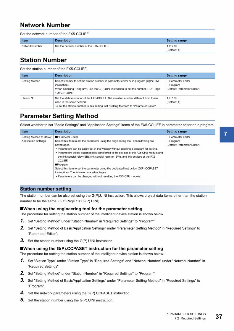
7
Network NumberSet the network number of the FX5-CCLIEF.
Station NumberSet the station number of the FX5-CCLIEF.
Parameter Setting MethodSelect whether to set "Basic Settings" and "Application Settings" items of the FX5-CCLIEF in parameter editor or in program.
Station number settingThe station number can be also set using the G(P).UINI instruction. This allows project data items other than the station
number to be the same. (Page 100 G(P).UINI)
■When using the engineering tool for the parameter settingThe procedure for setting the station number of the intelligent device station is shown below.
1. Set "Setting Method" under "Station Number" in "Required Settings" to "Program".
2. Set "Setting Method of Basic/Application Settings" under "Parameter Setting Method" in "Required Settings" to
"Parameter Editor".
3. Set the station number using the G(P).UINI instruction.
■When using the G(P).CCPASET instruction for the parameter settingThe procedure for setting the station number of the intelligent device station is shown below.
1. Set "Station Type" under "Station Type" in "Required Settings" and "Network Number" under "Network Number" in
"Required Settings".
2. Set "Setting Method" under "Station Number" in "Required Settings" to "Program".
3. Set "Setting Method of Basic/Application Settings" under "Parameter Setting Method" in "Required Settings" to
"Program".
4. Set the network parameters using the G(P).CCPASET instruction.
5. Set the station number using the G(P).UINI instruction.
Item Description Setting range
Network Number Set the network number of the FX5-CCLIEF. 1 to 239
(Default: 1)
Item Description Setting range
Setting Method Select whether to set the station number in parameter editor or in program (G(P).UINI
instruction).
When selecting "Program", use the G(P).UINI instruction to set the number. (Page
100 G(P).UINI)
• Parameter Editor
• Program
(Default: Parameter Editor)
Station No. Set the station number of the FX5-CCLIEF. Set a station number different from those
used in the same network.
To set the station number in this setting, set "Setting Method" to "Parameter Editor".
1 to 120
(Default: 1)
Item Description Setting range
Setting Method of Basic/
Application Settings
■Parameter Editor
Select this item to set the parameter using the engineering tool. The following are
advantages.
• Parameters can be easily set in the window without creating a program for setting.
• Parameters will be automatically transferred to the devices of the FX5 CPU module and
the link special relay (SB), link special register (SW), and link devices of the FX5-
CCLIEF.
■Program
Select this item to set the parameter using the dedicated instruction (G(P).CCPASET
instruction). The following are advantages.
• Parameters can be changed without resetting the FX5 CPU module.
• Parameter Editor
• Program
(Default: Parameter Editor)
7 PARAMETER SETTINGS7.2 Required Settings 37
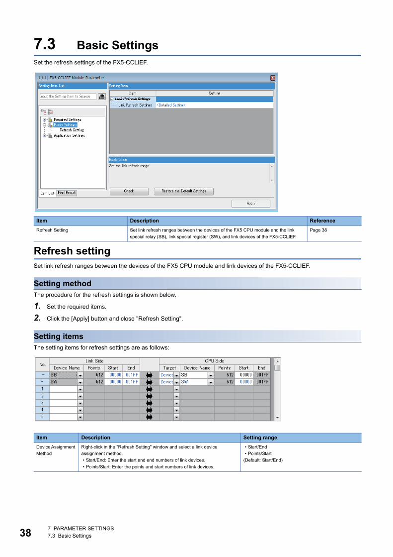
38
7.3 Basic SettingsSet the refresh settings of the FX5-CCLIEF.
Refresh settingSet link refresh ranges between the devices of the FX5 CPU module and link devices of the FX5-CCLIEF.
Setting methodThe procedure for the refresh settings is shown below.
1. Set the required items.
2. Click the [Apply] button and close "Refresh Setting".
Setting itemsThe setting items for refresh settings are as follows:
Item Description Reference
Refresh Setting Set link refresh ranges between the devices of the FX5 CPU module and the link
special relay (SB), link special register (SW), and link devices of the FX5-CCLIEF.
Page 38
Item Description Setting range
Device Assignment
Method
Right-click in the "Refresh Setting" window and select a link device
assignment method.
• Start/End: Enter the start and end numbers of link devices.
• Points/Start: Enter the points and start numbers of link devices.
• Start/End
• Points/Start
(Default: Start/End)
7 PARAMETER SETTINGS7.3 Basic Settings
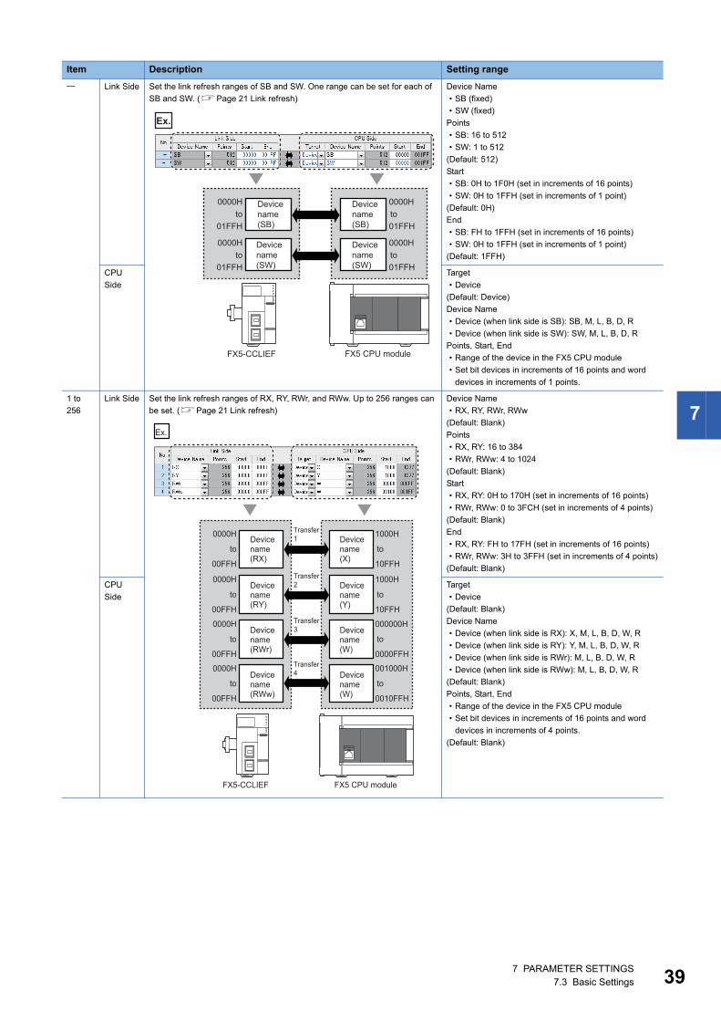
7
Link Side Set the link refresh ranges of SB and SW. One range can be set for each of
SB and SW. (Page 21 Link refresh)
Device Name
• SB (fixed)
• SW (fixed)
Points
• SB: 16 to 512
• SW: 1 to 512
(Default: 512)
Start
• SB: 0H to 1F0H (set in increments of 16 points)
• SW: 0H to 1FFH (set in increments of 1 point)
(Default: 0H)
End
• SB: FH to 1FFH (set in increments of 16 points)
• SW: 0H to 1FFH (set in increments of 1 point)
(Default: 1FFH)
CPU
Side
Target
• Device
(Default: Device)
Device Name
• Device (when link side is SB): SB, M, L, B, D, R
• Device (when link side is SW): SW, M, L, B, D, R
Points, Start, End
• Range of the device in the FX5 CPU module
• Set bit devices in increments of 16 points and word
devices in increments of 1 points.
1 to
256
Link Side Set the link refresh ranges of RX, RY, RWr, and RWw. Up to 256 ranges can
be set. (Page 21 Link refresh)
Device Name
• RX, RY, RWr, RWw
(Default: Blank)
Points
• RX, RY: 16 to 384
• RWr, RWw: 4 to 1024
(Default: Blank)
Start
• RX, RY: 0H to 170H (set in increments of 16 points)
• RWr, RWw: 0 to 3FCH (set in increments of 4 points)
(Default: Blank)
End
• RX, RY: FH to 17FH (set in increments of 16 points)
• RWr, RWw: 3H to 3FFH (set in increments of 4 points)
(Default: Blank)
CPU
Side
Target
• Device
(Default: Blank)
Device Name
• Device (when link side is RX): X, M, L, B, D, W, R
• Device (when link side is RY): Y, M, L, B, D, W, R
• Device (when link side is RWr): M, L, B, D, W, R
• Device (when link side is RWw): M, L, B, D, W, R
(Default: Blank)
Points, Start, End
• Range of the device in the FX5 CPU module
• Set bit devices in increments of 16 points and word
devices in increments of 4 points.
(Default: Blank)
Item Description Setting range
0000H
01FFH
0000H
01FFH
0000Hto
to
to
to
01FFH
0000H
01FFH
FX5-CCLIEF
Device name (SB)
FX5 CPU module
Device name (SW)
Device name (SB)
Device name (SW)
Ex.
0000H
to
to
to
to
00FFH
0000H
00FFH
1000H
to
to
to
to
10FFH
0000H
00FFH
1000H
10FFH
0000H
00FFH
000000H
0000FFH
001000H
0010FFH
FX5-CCLIEF
Ex.
Device name (RX)
Device name (RY)
Device name (RWr)
Device name (RWw)
Device name (W)
Device name (W)
Device name (Y)
Device name (X)
Transfer 1
Transfer 2
Transfer 3
Transfer 4
FX5 CPU module
7 PARAMETER SETTINGS7.3 Basic Settings 39
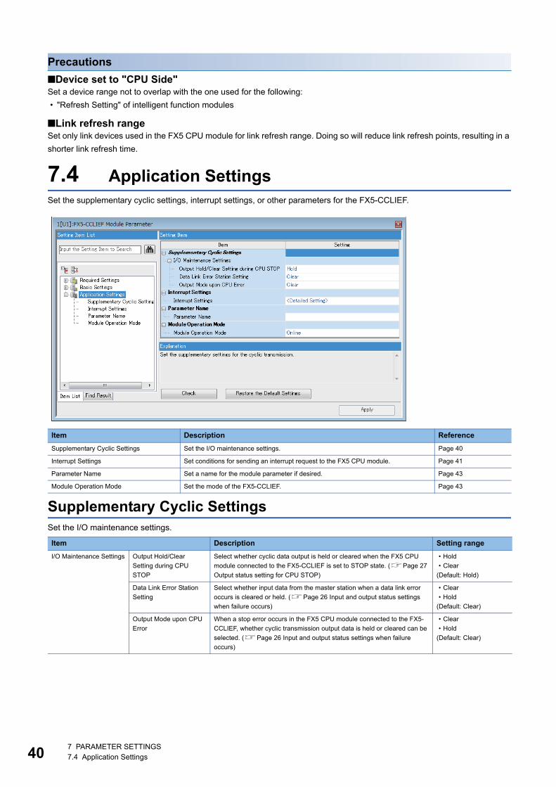
40
Precautions
■Device set to "CPU Side"Set a device range not to overlap with the one used for the following:
• "Refresh Setting" of intelligent function modules
■Link refresh rangeSet only link devices used in the FX5 CPU module for link refresh range. Doing so will reduce link refresh points, resulting in a
shorter link refresh time.
7.4 Application SettingsSet the supplementary cyclic settings, interrupt settings, or other parameters for the FX5-CCLIEF.
Supplementary Cyclic SettingsSet the I/O maintenance settings.
Item Description Reference
Supplementary Cyclic Settings Set the I/O maintenance settings. Page 40
Interrupt Settings Set conditions for sending an interrupt request to the FX5 CPU module. Page 41
Parameter Name Set a name for the module parameter if desired. Page 43
Module Operation Mode Set the mode of the FX5-CCLIEF. Page 43
Item Description Setting range
I/O Maintenance Settings Output Hold/Clear
Setting during CPU
STOP
Select whether cyclic data output is held or cleared when the FX5 CPU
module connected to the FX5-CCLIEF is set to STOP state. (Page 27
Output status setting for CPU STOP)
• Hold
• Clear
(Default: Hold)
Data Link Error Station
Setting
Select whether input data from the master station when a data link error
occurs is cleared or held. (Page 26 Input and output status settings
when failure occurs)
• Clear
• Hold
(Default: Clear)
Output Mode upon CPU
Error
When a stop error occurs in the FX5 CPU module connected to the FX5-
CCLIEF, whether cyclic transmission output data is held or cleared can be
selected. (Page 26 Input and output status settings when failure
occurs)
• Clear
• Hold
(Default: Clear)
7 PARAMETER SETTINGS7.4 Application Settings
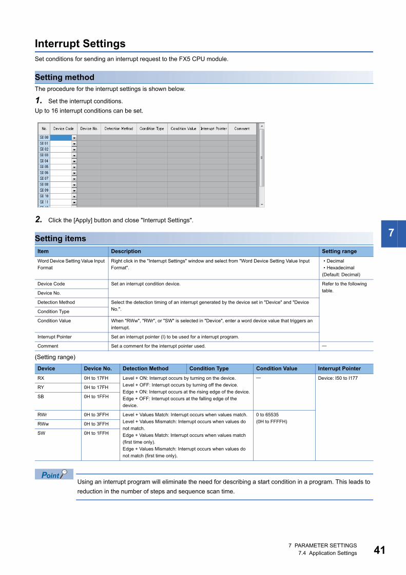
7
Interrupt SettingsSet conditions for sending an interrupt request to the FX5 CPU module.
Setting methodThe procedure for the interrupt settings is shown below.
1. Set the interrupt conditions.
Up to 16 interrupt conditions can be set.
2. Click the [Apply] button and close "Interrupt Settings".
Setting items
(Setting range)
Using an interrupt program will eliminate the need for describing a start condition in a program. This leads to
reduction in the number of steps and sequence scan time.
Item Description Setting range
Word Device Setting Value Input
Format
Right click in the "Interrupt Settings" window and select from "Word Device Setting Value Input
Format".
• Decimal
• Hexadecimal
(Default: Decimal)
Device Code Set an interrupt condition device. Refer to the following
table.Device No.
Detection Method Select the detection timing of an interrupt generated by the device set in "Device" and "Device
No.".Condition Type
Condition Value When "RWw", "RWr", or "SW" is selected in "Device", enter a word device value that triggers an
interrupt.
Interrupt Pointer Set an interrupt pointer (I) to be used for a interrupt program.
Comment Set a comment for the interrupt pointer used.
Device Device No. Detection Method Condition Type Condition Value Interrupt Pointer
RX 0H to 17FH Level + ON: Interrupt occurs by turning on the device.
Level + OFF: Interrupt occurs by turning off the device.
Edge + ON: Interrupt occurs at the rising edge of the device.
Edge + OFF: Interrupt occurs at the falling edge of the
device.
Device: I50 to I177
RY 0H to 17FH
SB 0H to 1FFH
RWr 0H to 3FFH Level + Values Match: Interrupt occurs when values match.
Level + Values Mismatch: Interrupt occurs when values do
not match.
Edge + Values Match: Interrupt occurs when values match
(first time only).
Edge + Values Mismatch: Interrupt occurs when values do
not match (first time only).
0 to 65535
(0H to FFFFH)RWw 0H to 3FFH
SW 0H to 1FFH
7 PARAMETER SETTINGS7.4 Application Settings 41
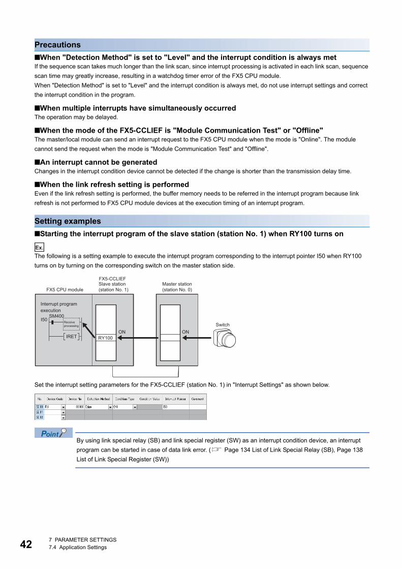
42
Precautions
■When "Detection Method" is set to "Level" and the interrupt condition is always metIf the sequence scan takes much longer than the link scan, since interrupt processing is activated in each link scan, sequence
scan time may greatly increase, resulting in a watchdog timer error of the FX5 CPU module.
When "Detection Method" is set to "Level" and the interrupt condition is always met, do not use interrupt settings and correct
the interrupt condition in the program.
■When multiple interrupts have simultaneously occurredThe operation may be delayed.
■When the mode of the FX5-CCLIEF is "Module Communication Test" or "Offline"The master/local module can send an interrupt request to the FX5 CPU module when the mode is "Online". The module
cannot send the request when the mode is "Module Communication Test" and "Offline".
■An interrupt cannot be generatedChanges in the interrupt condition device cannot be detected if the change is shorter than the transmission delay time.
■When the link refresh setting is performedEven if the link refresh setting is performed, the buffer memory needs to be referred in the interrupt program because link
refresh is not performed to FX5 CPU module devices at the execution timing of an interrupt program.
Setting examples
■Starting the interrupt program of the slave station (station No. 1) when RY100 turns on
Ex.
The following is a setting example to execute the interrupt program corresponding to the interrupt pointer I50 when RY100
turns on by turning on the corresponding switch on the master station side.
Set the interrupt setting parameters for the FX5-CCLIEF (station No. 1) in "Interrupt Settings" as shown below.
By using link special relay (SB) and link special register (SW) as an interrupt condition device, an interrupt
program can be started in case of data link error. ( Page 134 List of Link Special Relay (SB), Page 138
List of Link Special Register (SW))
RY100
I50SM400
IRETONON
FX5-CCLIEF
Interrupt programexecution
Receiveprocessing
Slave station(station No. 1)
Master station(station No. 0)
Switch
FX5 CPU module
7 PARAMETER SETTINGS7.4 Application Settings
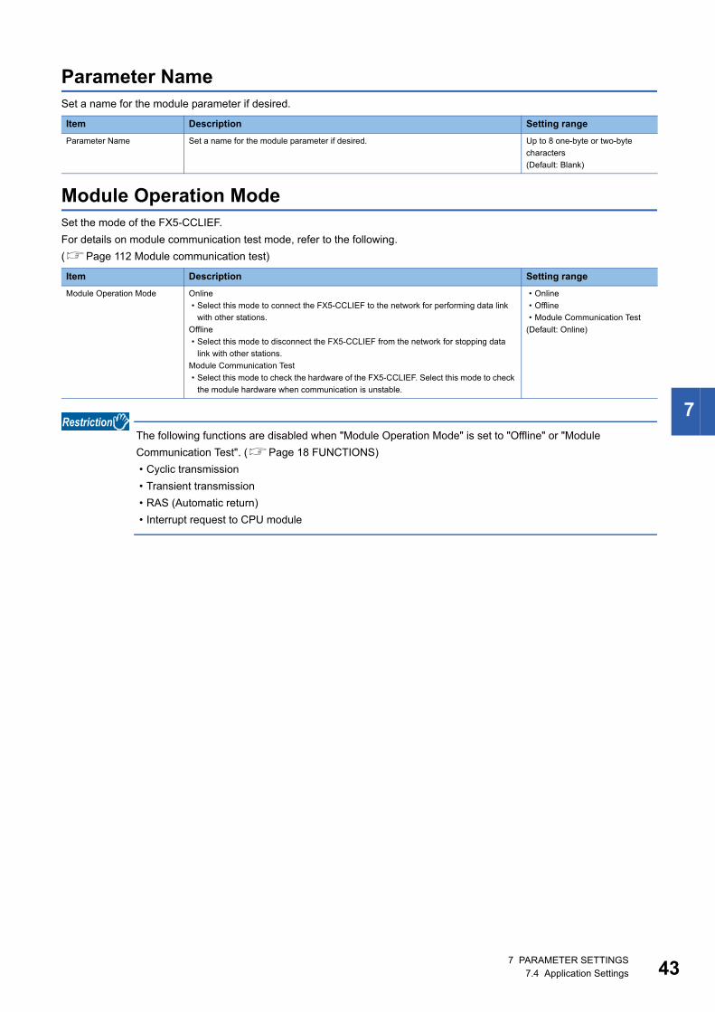
7
Parameter NameSet a name for the module parameter if desired.
Module Operation ModeSet the mode of the FX5-CCLIEF.
For details on module communication test mode, refer to the following.
(Page 112 Module communication test)
The following functions are disabled when "Module Operation Mode" is set to "Offline" or "Module
Communication Test". (Page 18 FUNCTIONS)
• Cyclic transmission
• Transient transmission
• RAS (Automatic return)
• Interrupt request to CPU module
Item Description Setting range
Parameter Name Set a name for the module parameter if desired. Up to 8 one-byte or two-byte
characters
(Default: Blank)
Item Description Setting range
Module Operation Mode Online
• Select this mode to connect the FX5-CCLIEF to the network for performing data link
with other stations.
Offline
• Select this mode to disconnect the FX5-CCLIEF from the network for stopping data
link with other stations.
Module Communication Test
• Select this mode to check the hardware of the FX5-CCLIEF. Select this mode to check
the module hardware when communication is unstable.
• Online
• Offline
• Module Communication Test
(Default: Online)
7 PARAMETER SETTINGS7.4 Application Settings 43
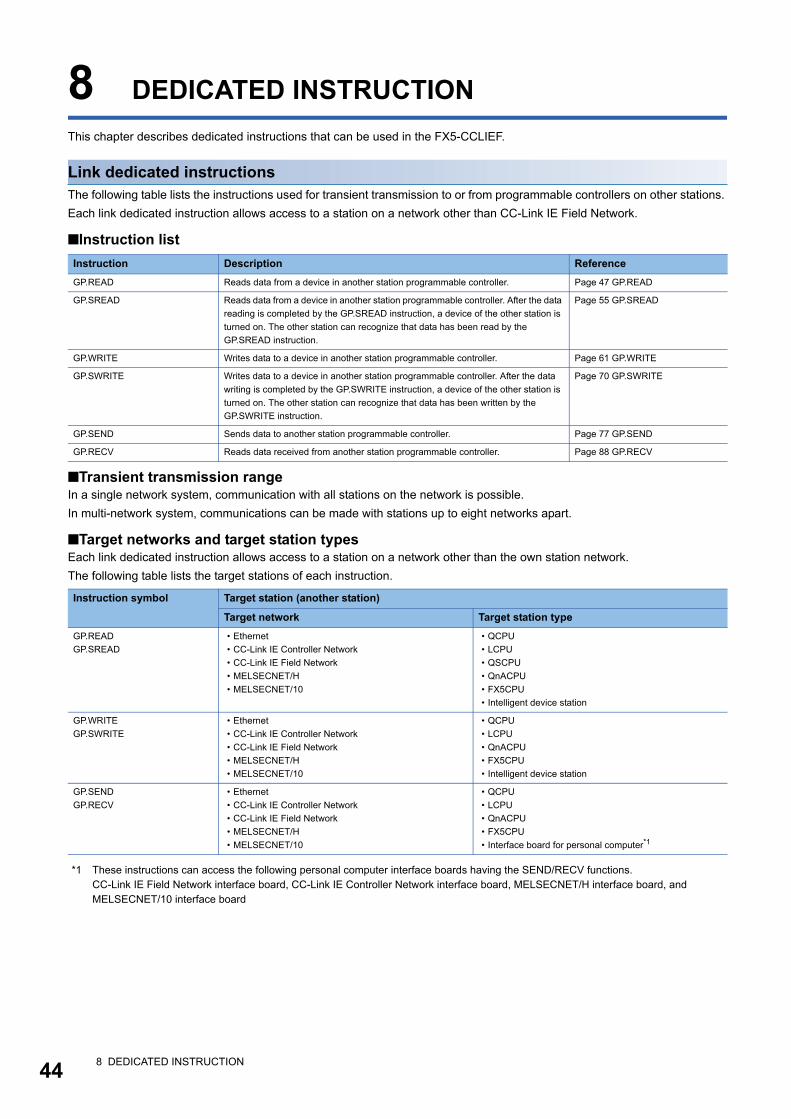
44
8 DEDICATED INSTRUCTION
This chapter describes dedicated instructions that can be used in the FX5-CCLIEF.
Link dedicated instructionsThe following table lists the instructions used for transient transmission to or from programmable controllers on other stations.
Each link dedicated instruction allows access to a station on a network other than CC-Link IE Field Network.
■Instruction list
■Transient transmission rangeIn a single network system, communication with all stations on the network is possible.
In multi-network system, communications can be made with stations up to eight networks apart.
■Target networks and target station typesEach link dedicated instruction allows access to a station on a network other than the own station network.
The following table lists the target stations of each instruction.
*1 These instructions can access the following personal computer interface boards having the SEND/RECV functions.CC-Link IE Field Network interface board, CC-Link IE Controller Network interface board, MELSECNET/H interface board, and MELSECNET/10 interface board
Instruction Description Reference
GP.READ Reads data from a device in another station programmable controller. Page 47 GP.READ
GP.SREAD Reads data from a device in another station programmable controller. After the data
reading is completed by the GP.SREAD instruction, a device of the other station is
turned on. The other station can recognize that data has been read by the
GP.SREAD instruction.
Page 55 GP.SREAD
GP.WRITE Writes data to a device in another station programmable controller. Page 61 GP.WRITE
GP.SWRITE Writes data to a device in another station programmable controller. After the data
writing is completed by the GP.SWRITE instruction, a device of the other station is
turned on. The other station can recognize that data has been written by the
GP.SWRITE instruction.
Page 70 GP.SWRITE
GP.SEND Sends data to another station programmable controller. Page 77 GP.SEND
GP.RECV Reads data received from another station programmable controller. Page 88 GP.RECV
Instruction symbol Target station (another station)
Target network Target station type
GP.READ
GP.SREAD
• Ethernet
• CC-Link IE Controller Network
• CC-Link IE Field Network
• MELSECNET/H
• MELSECNET/10
• QCPU
• LCPU
• QSCPU
• QnACPU
• FX5CPU
• Intelligent device station
GP.WRITE
GP.SWRITE
• Ethernet
• CC-Link IE Controller Network
• CC-Link IE Field Network
• MELSECNET/H
• MELSECNET/10
• QCPU
• LCPU
• QnACPU
• FX5CPU
• Intelligent device station
GP.SEND
GP.RECV
• Ethernet
• CC-Link IE Controller Network
• CC-Link IE Field Network
• MELSECNET/H
• MELSECNET/10
• QCPU
• LCPU
• QnACPU
• FX5CPU
• Interface board for personal computer*1
8 DEDICATED INSTRUCTION
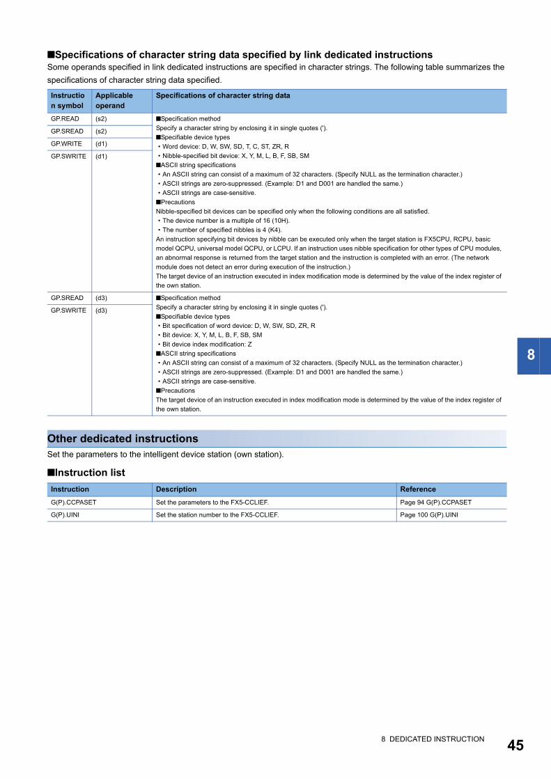
8
■Specifications of character string data specified by link dedicated instructionsSome operands specified in link dedicated instructions are specified in character strings. The following table summarizes the
specifications of character string data specified.
Other dedicated instructionsSet the parameters to the intelligent device station (own station).
■Instruction list
Instruction symbol
Applicable operand
Specifications of character string data
GP.READ (s2) ■Specification method
Specify a character string by enclosing it in single quotes (').
■Specifiable device types
• Word device: D, W, SW, SD, T, C, ST, ZR, R
• Nibble-specified bit device: X, Y, M, L, B, F, SB, SM
■ASCII string specifications
• An ASCII string can consist of a maximum of 32 characters. (Specify NULL as the termination character.)
• ASCII strings are zero-suppressed. (Example: D1 and D001 are handled the same.)
• ASCII strings are case-sensitive.
■Precautions
Nibble-specified bit devices can be specified only when the following conditions are all satisfied.
• The device number is a multiple of 16 (10H).
• The number of specified nibbles is 4 (K4).
An instruction specifying bit devices by nibble can be executed only when the target station is FX5CPU, RCPU, basic
model QCPU, universal model QCPU, or LCPU. If an instruction uses nibble specification for other types of CPU modules,
an abnormal response is returned from the target station and the instruction is completed with an error. (The network
module does not detect an error during execution of the instruction.)
The target device of an instruction executed in index modification mode is determined by the value of the index register of
the own station.
GP.SREAD (s2)
GP.WRITE (d1)
GP.SWRITE (d1)
GP.SREAD (d3) ■Specification method
Specify a character string by enclosing it in single quotes (').
■Specifiable device types
• Bit specification of word device: D, W, SW, SD, ZR, R
• Bit device: X, Y, M, L, B, F, SB, SM
• Bit device index modification: Z
■ASCII string specifications
• An ASCII string can consist of a maximum of 32 characters. (Specify NULL as the termination character.)
• ASCII strings are zero-suppressed. (Example: D1 and D001 are handled the same.)
• ASCII strings are case-sensitive.
■Precautions
The target device of an instruction executed in index modification mode is determined by the value of the index register of
the own station.
GP.SWRITE (d3)
Instruction Description Reference
G(P).CCPASET Set the parameters to the FX5-CCLIEF. Page 94 G(P).CCPASET
G(P).UINI Set the station number to the FX5-CCLIEF. Page 100 G(P).UINI
8 DEDICATED INSTRUCTION 45
46
8.1 Precautions for Dedicated InstructionsThis section describes precautions when using dedicated instructions.
Precautions for dedicated instructions (common)
■When changing data specified by dedicated instructionsDo not change any data (such as control data) until execution of the dedicated instruction is completed.
■When the dedicated instruction is not completedCheck whether the mode of the FX5-CCLIEF is online.
A dedicated instruction cannot be executed when the mode is offline or module communication test.
Precautions for link dedicated instructionsThe following describes precautions when executing multiple link dedicated instructions simultaneously.
■Channel of the link dedicated instructionsWhen executing multiple link dedicated instructions simultaneously, check that the channels for the instructions are not
duplicated. Multiple link dedicated instructions specifying the same channel cannot be used concurrently. To use the same
channel for multiple link dedicated instructions, configure an interlock so that one instruction is executed after completion of
another.
■If the link dedicated instruction is simultaneously executedIf executed, the instruction that is requested later is skipped. If skipped, the dedicated instruction skip flag (SM699) turns on.
8 DEDICATED INSTRUCTION8.1 Precautions for Dedicated Instructions
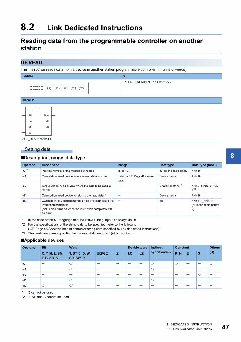
8
8.2 Link Dedicated Instructions
Reading data from the programmable controller on another station
GP.READThis instruction reads data from a device in another station programmable controller. (In units of words)
Setting data
■Description, range, data type
*1 In the case of the ST language and the FBD/LD language, U displays as Un.*2 For the specifications of the string data to be specified, refer to the following.
(Page 45 Specifications of character string data specified by link dedicated instructions)*3 The continuous area specified by the read data length (s1)+9 is required.
■Applicable devices
*1 S cannot be used.*2 T, ST, and C cannot be used.
Ladder ST
ENO:=GP_READ(EN,Un,s1,s2,d1,d2);
FBD/LD
("GP_READ" enters .)
Operand Description Range Data type Data type (label)
(U)*1 Position number of the module connected 1H to 10H 16-bit unsigned binary ANY16
(s1) Own station head device where control data is stored Refer to Page 48 Control
data.
Device name ANY16
(s2) Target station head device where the data to be read is
stored
Character string*2 ANYSTRING_SINGL
E*2
(d1) Own station head device for storing the read data*3 Device name ANY16
(d2) Own station device to be turned on for one scan when the
instruction completes.
(d2)+1 also turns on when the instruction completes with
an error.
Bit ANYBIT_ARRAY
(Number of elements:
2)
Operand Bit Word Double word Indirect specification
Constant Others(U)X, Y, M, L, SM,
F, B, SB, ST, ST, C, D, W, SD, SW, R
U\G Z LC LZ K, H E $
(U)
(s1)
(s2)
(d1)
(d2) *1 *2
(U) (s1) (s2) (d1) (d2)
EN ENO
d1
d2
Un
s1
s2
8 DEDICATED INSTRUCTION8.2 Link Dedicated Instructions 47
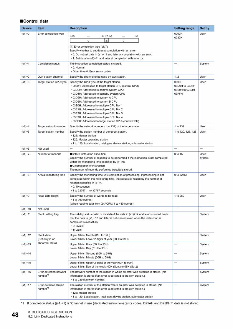
48
■Control data
*1 If completion status ((s1)+1) is "Channel in use (dedicated instruction) (error codes: D25AH and D25BH)", data is not stored.
Device Item Description Setting range Set by
(s1)+0 Error completion type
(1) Error completion type (bit 7)
Specify whether to set data at completion with an error.
• 0: Do not set data in (s1)+11 and later at completion with an error.
• 1: Set data in (s1)+11 and later at completion with an error.
0000H
0080H
User
(s1)+1 Completion status The instruction completion status is stored.
• 0: Normal
• Other than 0: Error (error code)
System
(s1)+2 Own station channel Specify the channel to be used by own station. 1, 2 User
(s1)+3 Target station CPU type Specify the CPU type of the target station.
• 0000H: Addressed to target station CPU (control CPU)
• 03D0H: Addressed to control system CPU
• 03D1H: Addressed to standby system CPU
• 03D2H: Addressed to system A CPU
• 03D3H: Addressed to system B CPU
• 03E0H: Addressed to multiple CPU No. 1
• 03E1H: Addressed to multiple CPU No. 2
• 03E2H: Addressed to multiple CPU No. 3
• 03E3H: Addressed to multiple CPU No. 4
• 03FFH: Addressed to target station CPU (control CPU)
0000H
03D0H to 03D3H
03E0H to 03E3H
03FFH
User
(s1)+4 Target network number Specify the network number (1 to 239) of the target station. 1 to 239 User
(s1)+5 Target station number Specify the station number of the target station.
• 125: Master station
• 126: Master operating station
• 1 to 120: Local station, intelligent device station, submaster station
1 to 120, 125, 126 User
(s1)+6 Not used
(s1)+7 Number of resends ■Before instruction execution
Specify the number of resends to be performed if the instruction is not completed
within the monitoring time specified by (s1)+8.
■At completion of instruction
The number of resends performed (result) is stored.
0 to 15 User/
system
(s1)+8 Arrival monitoring time Specify the monitoring time until completion of processing. If processing is not
completed within the monitoring time, the request is resent by the number of
resends specified in (s1)+7.
• 0: 10 seconds
• 1 to 32767: 1 to 32767 seconds
0 to 32767 User
(s1)+9 Read data length Specify the number of words to be read.
• 1 to 960 (words)
(When reading data from QnACPU: 1 to 480 (words))
1 to 960 User
(s1)+10 Not used
(s1)+11 Clock setting flag The validity status (valid or invalid) of the data in (s1)+12 and later is stored. Note
that the data in (s1)+12 and later is not cleared even when the instruction is
completed successfully.
• 0: Invalid
• 1: Valid
System
(s1)+12 Clock data
(Set only in an
abnormal state)
Upper 8 bits: Month (01H to 12H)
Lower 8 bits: Lower 2 digits of year (00H to 99H)
System
(s1)+13 Upper 8 bits: Hour (00H to 23H)
Lower 8 bits: Day (01H to 31H)
System
(s1)+14 Upper 8 bits: Second (00H to 59H)
Lower 8 bits: Minute (00H to 59H)
System
(s1)+15 Upper 8 bits: Upper 2 digits of the year (00H to 99H)
Lower 8 bits: Day of the week (00H (Sun.) to 06H (Sat.))
System
(s1)+16 Error detection network
number*1The network number of the station in which an error was detected is stored. (No
information is stored if an error is detected in the own station.)
• 1 to 239 (Network number)
System
(s1)+17 Error-detected station
number*1The station number of the station where an error was detected is stored. (No
information is stored if an error is detected in the own station.)
• 125: Master station
• 1 to 120: Local station, intelligent device station, submaster station
System
b150 0(1)
b7b8 b0… …b6
8 DEDICATED INSTRUCTION8.2 Link Dedicated Instructions
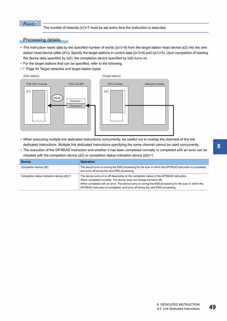
8
The number of resends (s1)+7 must be set every time the instruction is executed.
Processing details
• The instruction reads data by the specified number of words ((s1)+9) from the target station head device (s2) into the own
station head device (after (d1)). Specify the target stations in control data ((s1)+4) and ((s1)+5). Upon completion of reading
the device data specified by (s2), the completion device specified by (d2) turns on.
• For the target stations that can be specified, refer to the following.
Page 44 Target networks and target station types
• When executing multiple link dedicated instructions concurrently, be careful not to overlap the channels of the link
dedicated instructions. Multiple link dedicated instructions specifying the same channel cannot be used concurrently.
• The execution of the GP.READ instruction and whether it has been completed normally or completed with an error can be
checked with the completion device (d2) or completion status indication device (d2)+1.
Device Operation
Completion device (d2) The device turns on during the END processing for the scan in which the GP.READ instruction is completed,
and turns off during the next END processing.
Completion status indication device (d2)+1 The device turns on or off depending on the completion status of the GP.READ instruction.
When completed normally: The device does not change (remains off).
When completed with an error: The device turns on during the END processing for the scan in which the
GP.READ instruction is completed, and turns off during the next END processing.
READ
(d1) (s2)
FX5-CCLIEF
Channel 2
Channel 1
FX5 CPU module CPU module Network module
[Own station] [Target station]
8 DEDICATED INSTRUCTION8.2 Link Dedicated Instructions 49
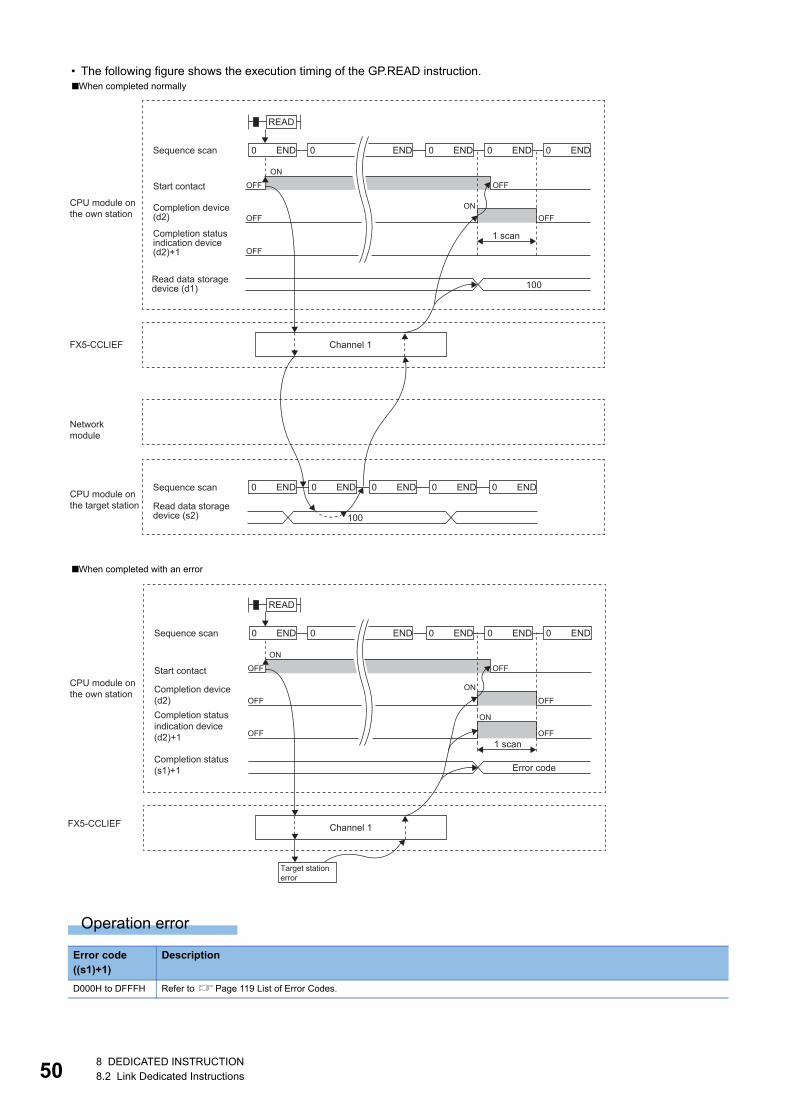
50
• The following figure shows the execution timing of the GP.READ instruction.
Operation error
■When completed normally
■When completed with an error
Error code ((s1)+1)
Description
D000H to DFFFH Refer to Page 119 List of Error Codes.
100
100
END0 END0 END0 END0 END0
END0 END0 END0 END0 END0
OFF
OFF OFF
OFF
ON
ON
OFF
READ
FX5-CCLIEF
Sequence scan
Start contact
CPU module onthe own station
Networkmodule
Completion device(d2)
Completion statusindication device(d2)+1
Read data storagedevice (d1)
Sequence scan
Read data storagedevice (s2)
Channel 1
1 scan
CPU module onthe target station
END0 END0 END0 END0 END0
OFF
OFF
OFF
OFF
OFF
ON
ON
ON
OFF
READ
FX5-CCLIEF
1 scan
Error code
Sequence scan
Start contactCPU module onthe own station Completion device
(d2)Completion statusindication device(d2)+1
Completion status(s1)+1
Channel 1
Target station error
8 DEDICATED INSTRUCTION8.2 Link Dedicated Instructions
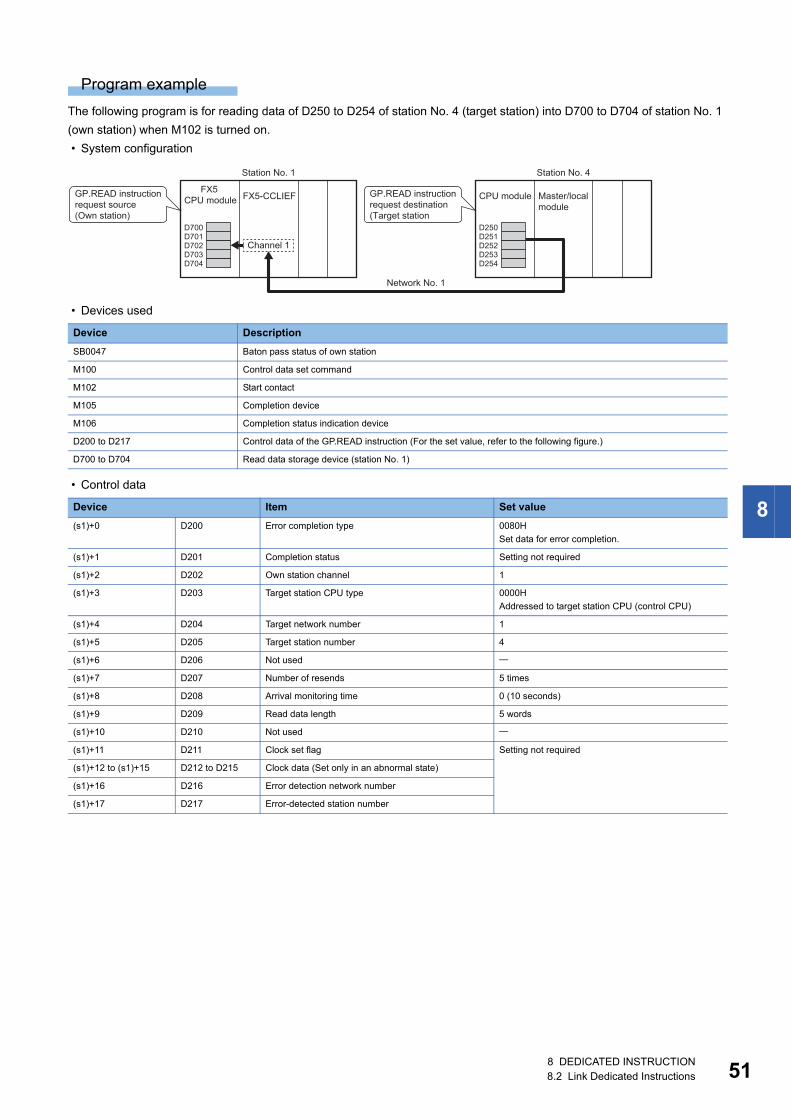
8
Program example
The following program is for reading data of D250 to D254 of station No. 4 (target station) into D700 to D704 of station No. 1
(own station) when M102 is turned on.
• System configuration
• Devices used
• Control data
Device Description
SB0047 Baton pass status of own station
M100 Control data set command
M102 Start contact
M105 Completion device
M106 Completion status indication device
D200 to D217 Control data of the GP.READ instruction (For the set value, refer to the following figure.)
D700 to D704 Read data storage device (station No. 1)
Device Item Set value
(s1)+0 D200 Error completion type 0080H
Set data for error completion.
(s1)+1 D201 Completion status Setting not required
(s1)+2 D202 Own station channel 1
(s1)+3 D203 Target station CPU type 0000H
Addressed to target station CPU (control CPU)
(s1)+4 D204 Target network number 1
(s1)+5 D205 Target station number 4
(s1)+6 D206 Not used
(s1)+7 D207 Number of resends 5 times
(s1)+8 D208 Arrival monitoring time 0 (10 seconds)
(s1)+9 D209 Read data length 5 words
(s1)+10 D210 Not used
(s1)+11 D211 Clock set flag Setting not required
(s1)+12 to (s1)+15 D212 to D215 Clock data (Set only in an abnormal state)
(s1)+16 D216 Error detection network number
(s1)+17 D217 Error-detected station number
D701D700
D703D704
D702D251D250
D253D254
D252
FX5-CCLIEF
Station No. 1 Station No. 4
Network No. 1
CPU moduleGP.READ instruction request destination(Target station
Master/local module
Channel 1\
FX5 CPU module
GP.READ instruction request source(Own station)
8 DEDICATED INSTRUCTION8.2 Link Dedicated Instructions 51
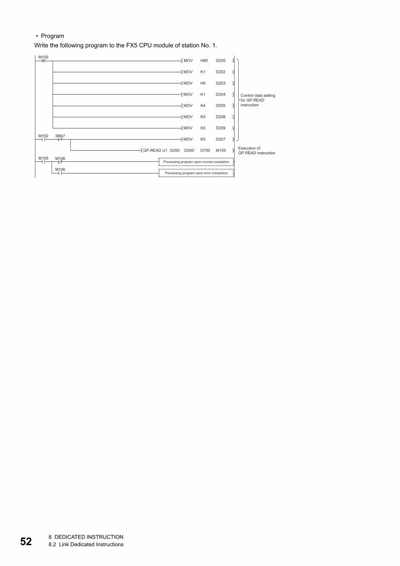
52
• Program
Write the following program to the FX5 CPU module of station No. 1.
H80MOV
MOV
D200
D202
MOV D203
M100
MOV D204
MOV D205
MOV D208
MOV D209
MOV D207M102 SB47
M106
M106
‘D250’GP.READ U1 M105
M105
K1
H0
K1
K4
K0
K5
K5
D700D200
Processing program upon normal completion
Execution of GP.READ instruction
Control data setting for GP.READ instruction
Processing program upon error completion
8 DEDICATED INSTRUCTION8.2 Link Dedicated Instructions
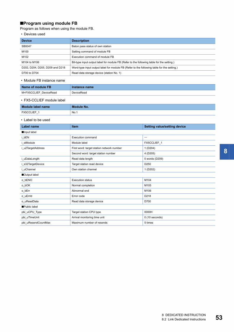
8
■Program using module FBProgram as follows when using the module FB.
• Devices used
• Module FB instance name
• FX5-CCLIEF module label
• Label to be used
Device Description
SB0047 Baton pass status of own station
M100 Setting command of module FB
M102 Execution command of module FB
M104 to M106 Bit-type input output label for module FB (Refer to the following table for the setting.)
D202, D204, D205, D209 and D218 Word-type input output label for module FB (Refer to the following table for the setting.)
D700 to D704 Read data storage device (station No. 1)
Name of module FB Instance name
M+FX5CCLIEF_DeviceRead DeviceRead
Module label name Module No.
FX5CCLIEF_1 No.1
Label name Item Setting value/setting device
■Input label
i_bEN Execution command
i_stModule Module label FX5CCLIEF_1
i_u2TargetAddress First word: target station network number 1 (D204)
Second word: target station number 4 (D205)
i_uDataLength Read data length 5 words (D209)
i_s32TargetDevice Target station read device D250
i_uChannel Own station channel 1 (D202)
■Output label
o_bENO Execution status M104
o_bOK Normal completion M105
o_bErr Abnormal end M106
o_uErrId Error code D218
o_uReadData Read data storage device D700
■Public label
pbi_uCPU_Type Target station CPU type 0000H
pbi_uTimeUnit Arrival monitoring time unit 0 (10 seconds)
pbi_uResendCountMax Maximum number of resends 5 times
8 DEDICATED INSTRUCTION8.2 Link Dedicated Instructions 53
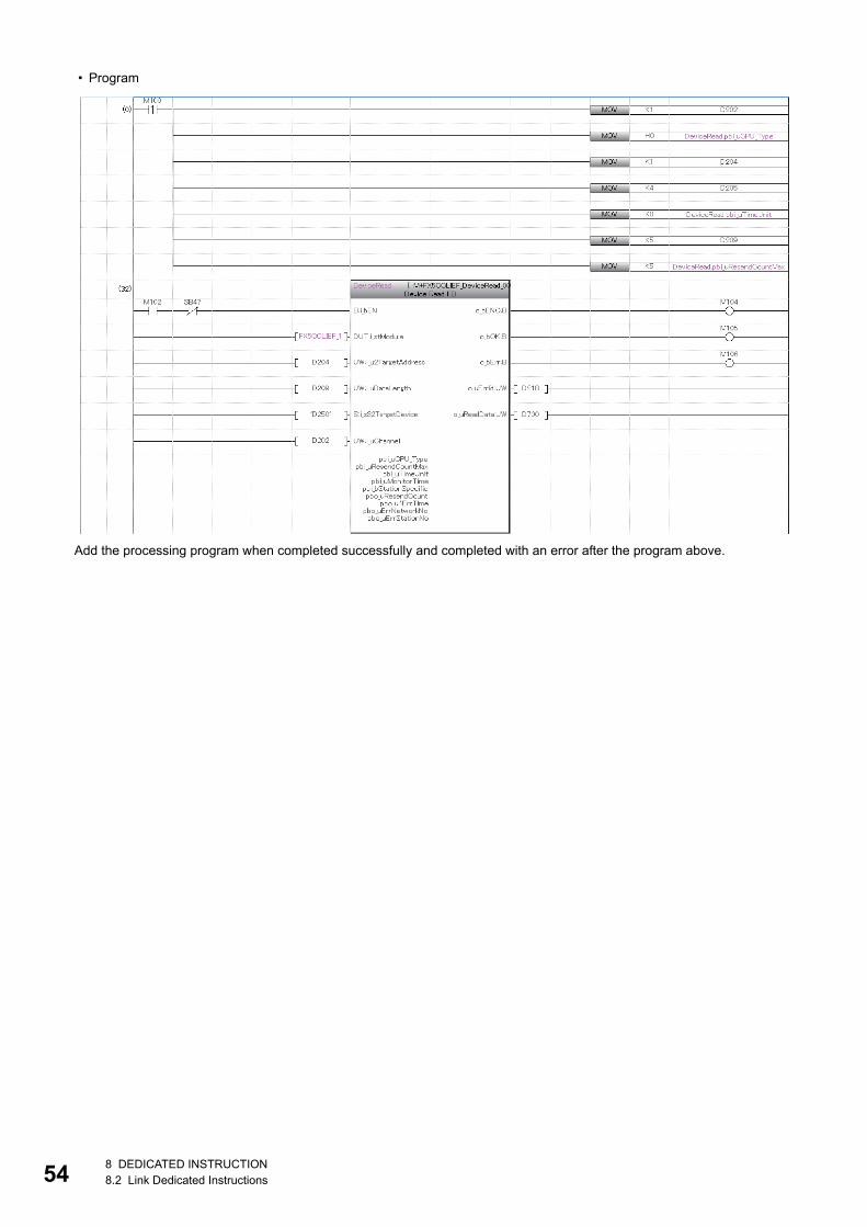
54
• Program
Add the processing program when completed successfully and completed with an error after the program above.
8 DEDICATED INSTRUCTION8.2 Link Dedicated Instructions
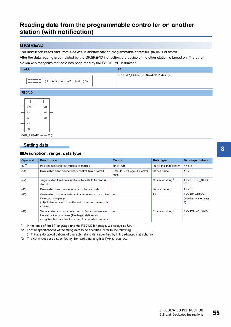
8
Reading data from the programmable controller on another station (with notification)
GP.SREADThis instruction reads data from a device in another station programmable controller. (In units of words)
After the data reading is completed by the GP.SREAD instruction, the device of the other station is turned on. The other
station can recognize that data has been read by the GP.SREAD instruction.
Setting data
■Description, range, data type
*1 In the case of the ST language and the FBD/LD language, U displays as Un.*2 For the specifications of the string data to be specified, refer to the following.
(Page 45 Specifications of character string data specified by link dedicated instructions)*3 The continuous area specified by the read data length (s1)+9 is required.
Ladder ST
ENO:=GP_SREAD(EN,Un,s1,s2,d1,d2,d3);
FBD/LD
("GP_SREAD" enters .)
Operand Description Range Data type Data type (label)
(U)*1 Position number of the module connected 1H to 10H 16-bit unsigned binary ANY16
(s1) Own station head device where control data is stored Refer to Page 56 Control
data.
Device name ANY16
(s2) Target station head device where the data to be read is
stored
Character string*2 ANYSTRING_SINGL
E*2
(d1) Own station head device for storing the read data*3 Device name ANY16
(d2) Own station device to be turned on for one scan when the
instruction completes.
(d2)+1 also turns on when the instruction completes with
an error.
Bit ANYBIT_ARRAY
(Number of elements:
2)
(d3) Target station device to be turned on for one scan when
the instruction completes (The target station can
recognize that data has been read from another station.)
Character string*2 ANYSTRING_SINGL
E*2
(s1) (s2) (d1) (d2) (d3)(U)
EN ENO
Un
s1
d1
s2
d3
d2
8 DEDICATED INSTRUCTION8.2 Link Dedicated Instructions 55
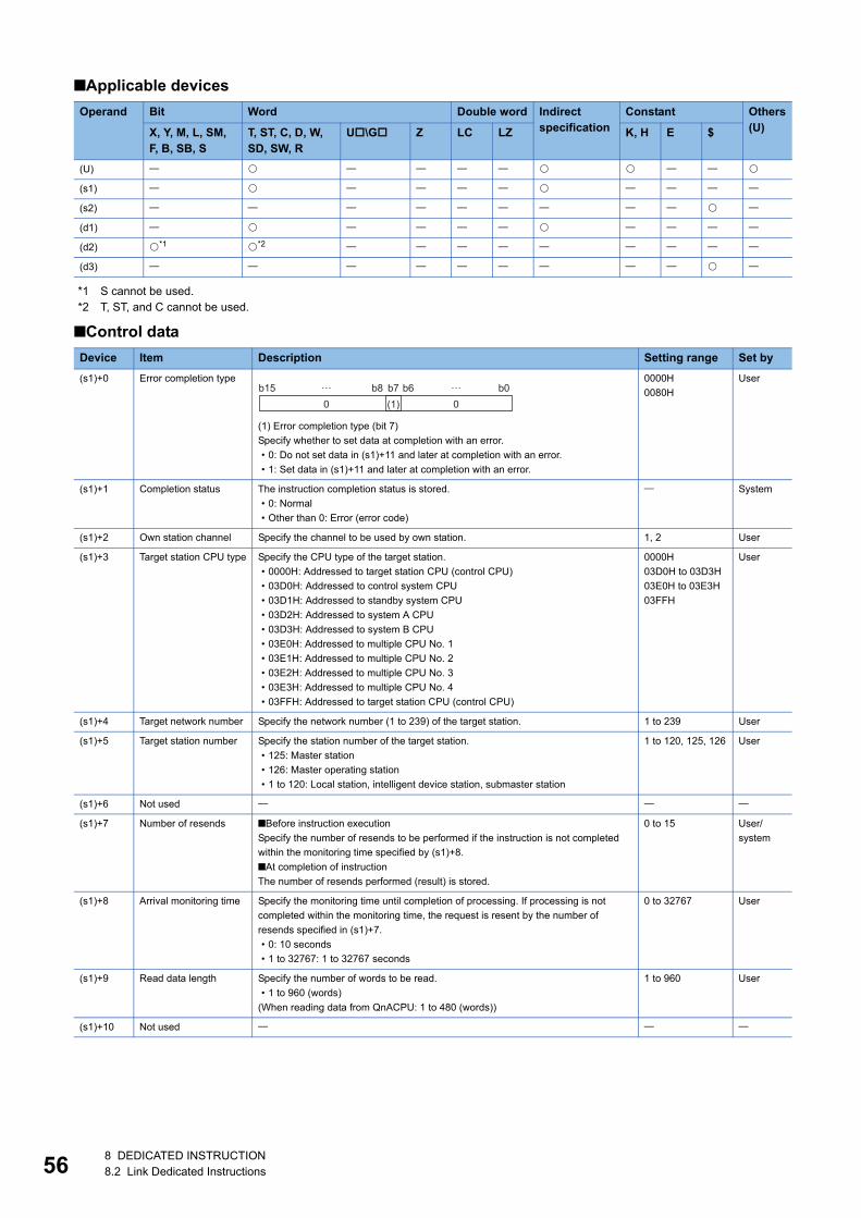
56
■Applicable devices
*1 S cannot be used.*2 T, ST, and C cannot be used.
■Control data
Operand Bit Word Double word Indirect specification
Constant Others(U)X, Y, M, L, SM,
F, B, SB, ST, ST, C, D, W, SD, SW, R
U\G Z LC LZ K, H E $
(U)
(s1)
(s2)
(d1)
(d2) *1 *2
(d3)
Device Item Description Setting range Set by
(s1)+0 Error completion type
(1) Error completion type (bit 7)
Specify whether to set data at completion with an error.
• 0: Do not set data in (s1)+11 and later at completion with an error.
• 1: Set data in (s1)+11 and later at completion with an error.
0000H
0080H
User
(s1)+1 Completion status The instruction completion status is stored.
• 0: Normal
• Other than 0: Error (error code)
System
(s1)+2 Own station channel Specify the channel to be used by own station. 1, 2 User
(s1)+3 Target station CPU type Specify the CPU type of the target station.
• 0000H: Addressed to target station CPU (control CPU)
• 03D0H: Addressed to control system CPU
• 03D1H: Addressed to standby system CPU
• 03D2H: Addressed to system A CPU
• 03D3H: Addressed to system B CPU
• 03E0H: Addressed to multiple CPU No. 1
• 03E1H: Addressed to multiple CPU No. 2
• 03E2H: Addressed to multiple CPU No. 3
• 03E3H: Addressed to multiple CPU No. 4
• 03FFH: Addressed to target station CPU (control CPU)
0000H
03D0H to 03D3H
03E0H to 03E3H
03FFH
User
(s1)+4 Target network number Specify the network number (1 to 239) of the target station. 1 to 239 User
(s1)+5 Target station number Specify the station number of the target station.
• 125: Master station
• 126: Master operating station
• 1 to 120: Local station, intelligent device station, submaster station
1 to 120, 125, 126 User
(s1)+6 Not used
(s1)+7 Number of resends ■Before instruction execution
Specify the number of resends to be performed if the instruction is not completed
within the monitoring time specified by (s1)+8.
■At completion of instruction
The number of resends performed (result) is stored.
0 to 15 User/
system
(s1)+8 Arrival monitoring time Specify the monitoring time until completion of processing. If processing is not
completed within the monitoring time, the request is resent by the number of
resends specified in (s1)+7.
• 0: 10 seconds
• 1 to 32767: 1 to 32767 seconds
0 to 32767 User
(s1)+9 Read data length Specify the number of words to be read.
• 1 to 960 (words)
(When reading data from QnACPU: 1 to 480 (words))
1 to 960 User
(s1)+10 Not used
b150 0(1)
b7b8 b0… …b6
8 DEDICATED INSTRUCTION8.2 Link Dedicated Instructions
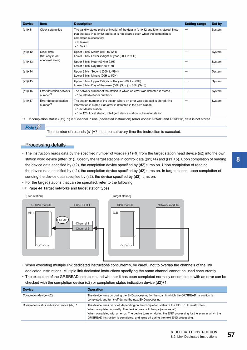
8
*1 If completion status ((s1)+1) is "Channel in use (dedicated instruction) (error codes: D25AH and D25BH)", data is not stored.
The number of resends (s1)+7 must be set every time the instruction is executed.
Processing details
• The instruction reads data by the specified number of words ((s1)+9) from the target station head device (s2) into the own
station word device (after (d1)). Specify the target stations in control data ((s1)+4) and ((s1)+5). Upon completion of reading
the device data specified by (s2), the completion device specified by (d2) turns on. Upon completion of reading
the device data specified by (s2), the completion device specified by (d2) turns on. In target station, upon completion of
sending the device data specified by (s2), the device specified by (d3) turns on.
• For the target stations that can be specified, refer to the following.
Page 44 Target networks and target station types
• When executing multiple link dedicated instructions concurrently, be careful not to overlap the channels of the link
dedicated instructions. Multiple link dedicated instructions specifying the same channel cannot be used concurrently.
• The execution of the GP.SREAD instruction and whether it has been completed normally or completed with an error can be
checked with the completion device (d2) or completion status indication device (d2)+1.
(s1)+11 Clock setting flag The validity status (valid or invalid) of the data in (s1)+12 and later is stored. Note
that the data in (s1)+12 and later is not cleared even when the instruction is
completed successfully.
• 0: Invalid
• 1: Valid
System
(s1)+12 Clock data
(Set only in an
abnormal state)
Upper 8 bits: Month (01H to 12H)
Lower 8 bits: Lower 2 digits of year (00H to 99H)
System
(s1)+13 Upper 8 bits: Hour (00H to 23H)
Lower 8 bits: Day (01H to 31H)
System
(s1)+14 Upper 8 bits: Second (00H to 59H)
Lower 8 bits: Minute (00H to 59H)
System
(s1)+15 Upper 8 bits: Upper 2 digits of the year (00H to 99H)
Lower 8 bits: Day of the week (00H (Sun.) to 06H (Sat.))
System
(s1)+16 Error detection network
number*1The network number of the station in which an error was detected is stored.
• 1 to 239 (Network number)
System
(s1)+17 Error-detected station
number*1The station number of the station where an error was detected is stored. (No
information is stored if an error is detected in the own station.)
• 125: Master station
• 1 to 120: Local station, intelligent device station, submaster station
System
Device Operation
Completion device (d2) The device turns on during the END processing for the scan in which the GP.SREAD instruction is
completed, and turns off during the next END processing.
Completion status indication device (d2)+1 The device turns on or off depending on the completion status of the GP.SREAD instruction.
When completed normally: The device does not change (remains off).
When completed with an error: The device turns on during the END processing for the scan in which the
GP.SREAD instruction is completed, and turns off during the next END processing.
Device Item Description Setting range Set by
SREAD
(d1) (s2)
FX5-CCLIEF
Channel 1
Channel 2
FX5 CPU module CPU module Network module
[Own station] [Target station]
8 DEDICATED INSTRUCTION8.2 Link Dedicated Instructions 57
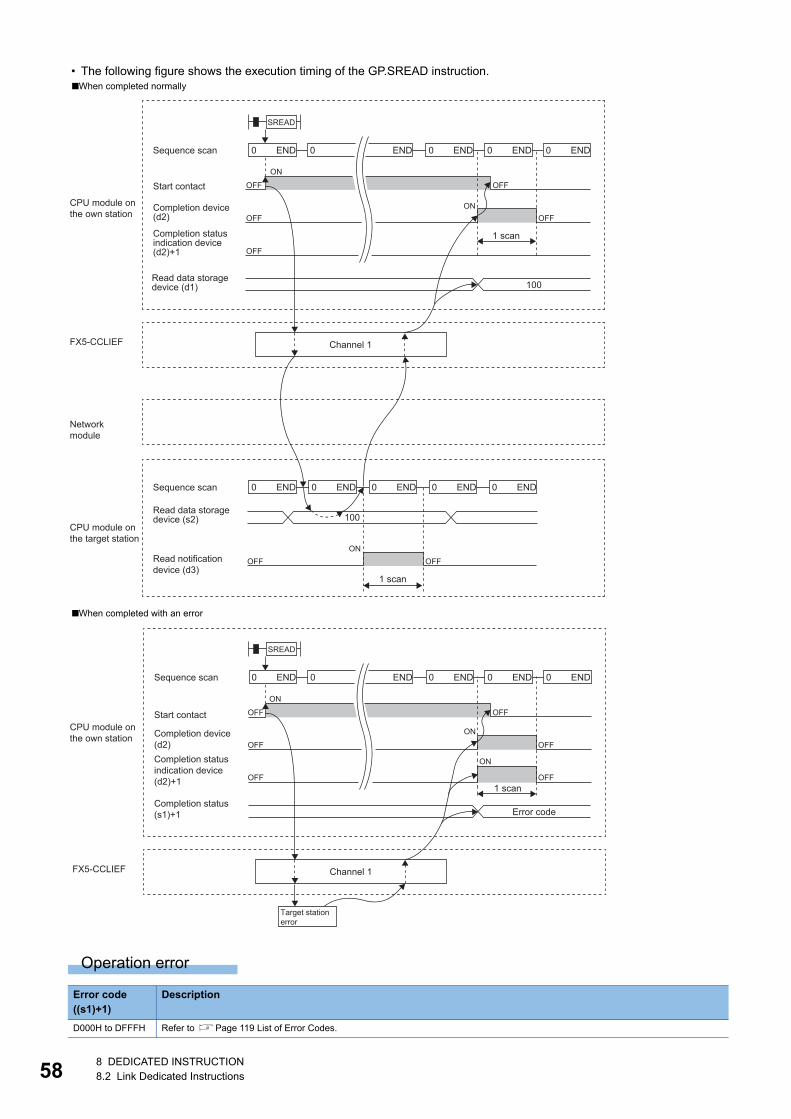
58
• The following figure shows the execution timing of the GP.SREAD instruction.
Operation error
■When completed normally
■When completed with an error
Error code ((s1)+1)
Description
D000H to DFFFH Refer to Page 119 List of Error Codes.
100
100
END0 END0 END0 END0 END0
END0 END0 END0 END0 END0
OFF
OFF OFF
OFF
ON
ON
OFF
OFFON
OFF
SREAD
FX5-CCLIEF
Sequence scan
Start contact
CPU module onthe own station
CPU module onthe target station
Networkmodule
Completion device(d2)
Completion statusindication device(d2)+1
Read data storagedevice (d1)
Sequence scan
Read data storagedevice (s2)
Channel 1
1 scan
Read notificationdevice (d3)
1 scan
END0 END0 END0 END0 END0
OFF
OFF
OFF
OFF
OFF
ON
ON
ON
OFF
SREAD
FX5-CCLIEF
1 scan
Error code
Sequence scan
Start contactCPU module onthe own station Completion device
(d2)Completion statusindication device(d2)+1
Completion status(s1)+1
Channel 1
Target station error
8 DEDICATED INSTRUCTION8.2 Link Dedicated Instructions
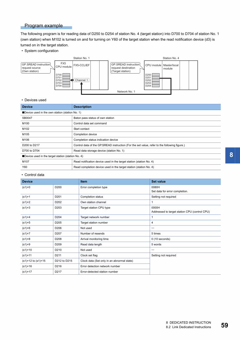
8
Program example
The following program is for reading data of D250 to D254 of station No. 4 (target station) into D700 to D704 of station No. 1
(own station) when M102 is turned on and for turning on Y60 of the target station when the read notification device (d3) is
turned on in the target station.
• System configuration
• Devices used
• Control data
Device Description
■Device used in the own station (station No. 1)
SB0047 Baton pass status of own station
M100 Control data set command
M102 Start contact
M105 Completion device
M106 Completion status indication device
D200 to D217 Control data of the GP.SREAD instruction (For the set value, refer to the following figure.)
D700 to D704 Read data storage device (station No. 1)
■Device used in the target station (station No. 4)
M107 Read notification device used in the target station (station No. 4)
Y60 Read completion device used in the target station (station No. 4)
Device Item Set value
(s1)+0 D200 Error completion type 0080H
Set data for error completion.
(s1)+1 D201 Completion status Setting not required
(s1)+2 D202 Own station channel 1
(s1)+3 D203 Target station CPU type 0000H
Addressed to target station CPU (control CPU)
(s1)+4 D204 Target network number 1
(s1)+5 D205 Target station number 4
(s1)+6 D206 Not used
(s1)+7 D207 Number of resends 5 times
(s1)+8 D208 Arrival monitoring time 0 (10 seconds)
(s1)+9 D209 Read data length 5 words
(s1)+10 D210 Not used
(s1)+11 D211 Clock set flag Setting not required
(s1)+12 to (s1)+15 D212 to D215 Clock data (Set only in an abnormal state)
(s1)+16 D216 Error detection network number
(s1)+17 D217 Error-detected station number
D701D700
D703D704
D702D251D250
D253D254
D252
FX5-CCLIEF
Station No. 1
Network No. 1
CPU moduleGP.SREAD instruction request destination(Target station)
Master/local module
Channel 1
FX5 CPU module
GP.SREAD instruction request source(Own station)
Station No. 4
8 DEDICATED INSTRUCTION8.2 Link Dedicated Instructions 59
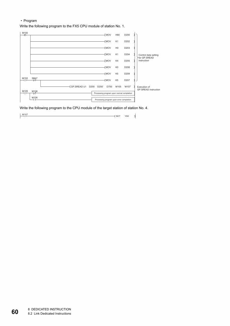
60
• Program
Write the following program to the FX5 CPU module of station No. 1.
Write the following program to the CPU module of the target station of station No. 4.
H80MOV
MOV
D200
D202
MOV D203
M100
MOV D204
MOV D205
MOV D208
MOV D209
MOV D207
‘M107’
M102 SB47
M106
M106
‘D250’GP.SREAD U1 M105
M105
K1
H0
K1
K4
K0
K5
K5
D700D200
Processing program upon normal completion
Execution of GP.SREAD instruction
Control data setting for GP.SREAD instruction
Processing program upon error completion
SET Y60M107
8 DEDICATED INSTRUCTION8.2 Link Dedicated Instructions
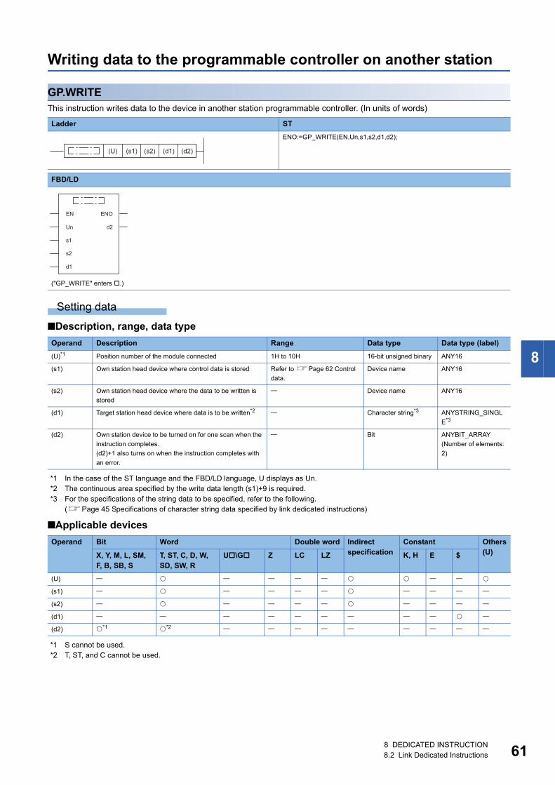
8
Writing data to the programmable controller on another station
GP.WRITEThis instruction writes data to the device in another station programmable controller. (In units of words)
Setting data
■Description, range, data type
*1 In the case of the ST language and the FBD/LD language, U displays as Un.*2 The continuous area specified by the write data length (s1)+9 is required.*3 For the specifications of the string data to be specified, refer to the following.
(Page 45 Specifications of character string data specified by link dedicated instructions)
■Applicable devices
*1 S cannot be used.*2 T, ST, and C cannot be used.
Ladder ST
ENO:=GP_WRITE(EN,Un,s1,s2,d1,d2);
FBD/LD
("GP_WRITE" enters .)
Operand Description Range Data type Data type (label)
(U)*1 Position number of the module connected 1H to 10H 16-bit unsigned binary ANY16
(s1) Own station head device where control data is stored Refer to Page 62 Control
data.
Device name ANY16
(s2) Own station head device where the data to be written is
stored
Device name ANY16
(d1) Target station head device where data is to be written*2 Character string*3 ANYSTRING_SINGL
E*3
(d2) Own station device to be turned on for one scan when the
instruction completes.
(d2)+1 also turns on when the instruction completes with
an error.
Bit ANYBIT_ARRAY
(Number of elements:
2)
Operand Bit Word Double word Indirect specification
Constant Others(U)X, Y, M, L, SM,
F, B, SB, ST, ST, C, D, W, SD, SW, R
U\G Z LC LZ K, H E $
(U)
(s1)
(s2)
(d1)
(d2) *1 *2
(U) (s1) (s2) (d1) (d2)
EN ENO
d2Un
s1
s2
d1
8 DEDICATED INSTRUCTION8.2 Link Dedicated Instructions 61
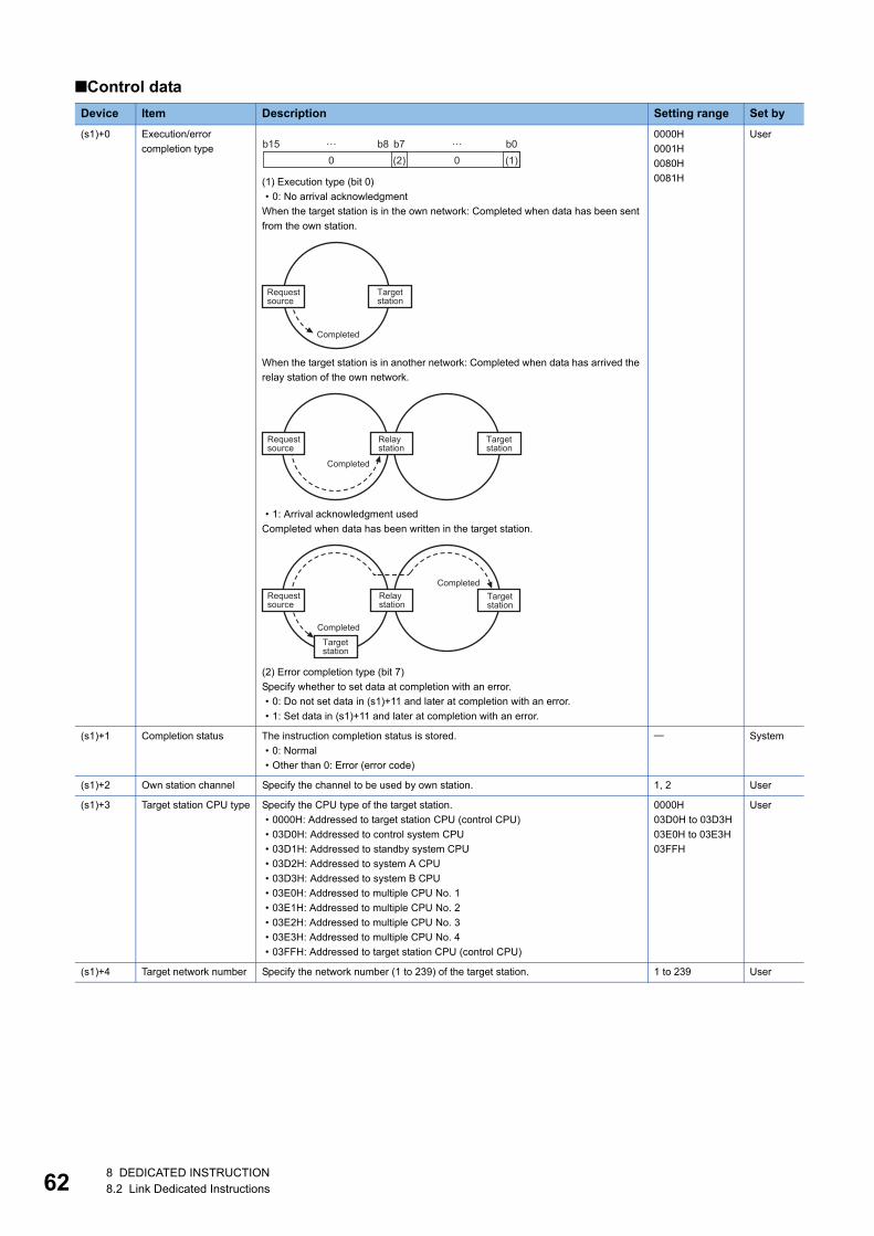
62
■Control data
Device Item Description Setting range Set by
(s1)+0 Execution/error
completion type
(1) Execution type (bit 0)
• 0: No arrival acknowledgment
When the target station is in the own network: Completed when data has been sent
from the own station.
When the target station is in another network: Completed when data has arrived the
relay station of the own network.
• 1: Arrival acknowledgment used
Completed when data has been written in the target station.
(2) Error completion type (bit 7)
Specify whether to set data at completion with an error.
• 0: Do not set data in (s1)+11 and later at completion with an error.
• 1: Set data in (s1)+11 and later at completion with an error.
0000H
0001H
0080H
0081H
User
(s1)+1 Completion status The instruction completion status is stored.
• 0: Normal
• Other than 0: Error (error code)
System
(s1)+2 Own station channel Specify the channel to be used by own station. 1, 2 User
(s1)+3 Target station CPU type Specify the CPU type of the target station.
• 0000H: Addressed to target station CPU (control CPU)
• 03D0H: Addressed to control system CPU
• 03D1H: Addressed to standby system CPU
• 03D2H: Addressed to system A CPU
• 03D3H: Addressed to system B CPU
• 03E0H: Addressed to multiple CPU No. 1
• 03E1H: Addressed to multiple CPU No. 2
• 03E2H: Addressed to multiple CPU No. 3
• 03E3H: Addressed to multiple CPU No. 4
• 03FFH: Addressed to target station CPU (control CPU)
0000H
03D0H to 03D3H
03E0H to 03E3H
03FFH
User
(s1)+4 Target network number Specify the network number (1 to 239) of the target station. 1 to 239 User
b150 0(2) (1)
b7b8 b0… …
Completed
Targetstation
Requestsource
Completed
Targetstation
Requestsource
Relaystation
Completed
Targetstation
Requestsource
Relaystation
Targetstation
Completed
8 DEDICATED INSTRUCTION8.2 Link Dedicated Instructions
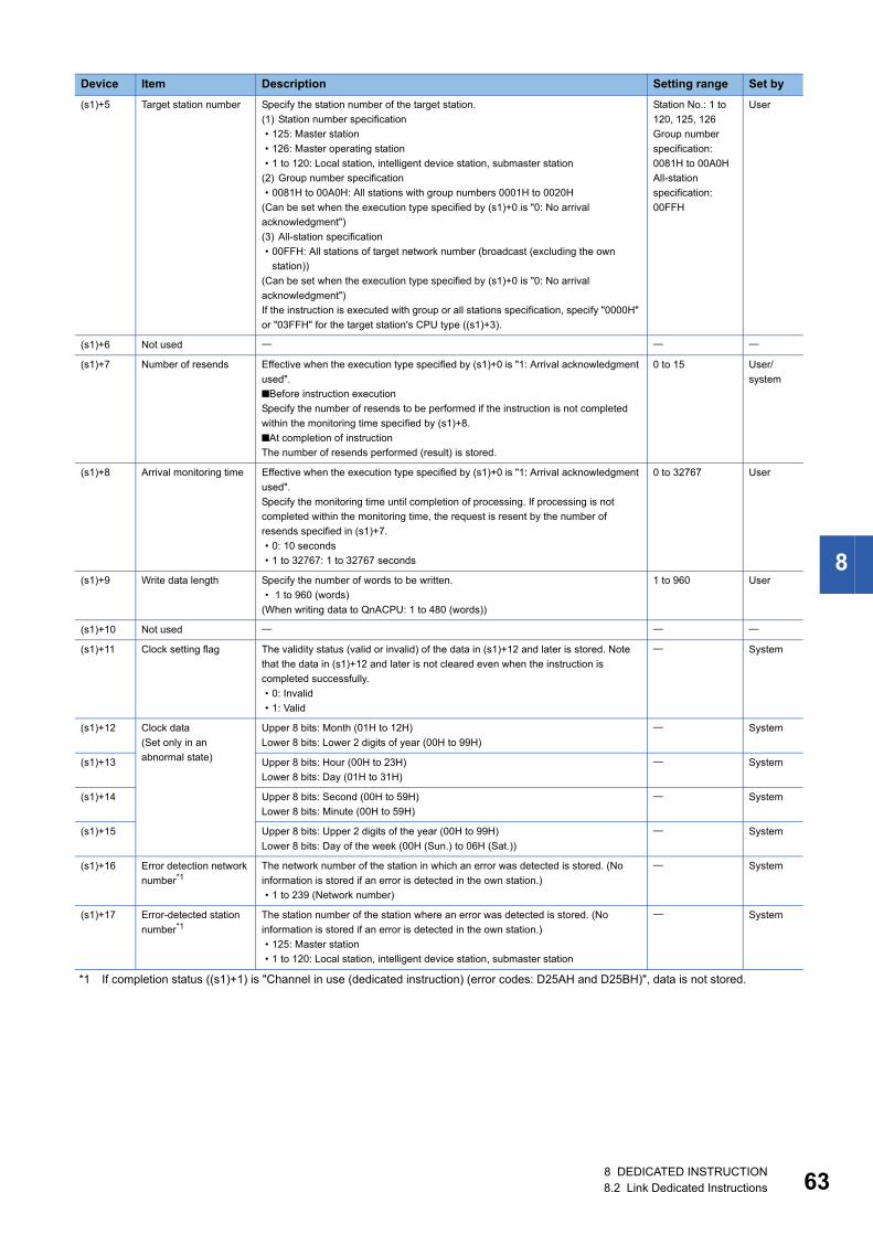
8
*1 If completion status ((s1)+1) is "Channel in use (dedicated instruction) (error codes: D25AH and D25BH)", data is not stored.
(s1)+5 Target station number Specify the station number of the target station.
(1) Station number specification
• 125: Master station
• 126: Master operating station
• 1 to 120: Local station, intelligent device station, submaster station
(2) Group number specification
• 0081H to 00A0H: All stations with group numbers 0001H to 0020H
(Can be set when the execution type specified by (s1)+0 is "0: No arrival
acknowledgment")
(3) All-station specification
• 00FFH: All stations of target network number (broadcast (excluding the own
station))
(Can be set when the execution type specified by (s1)+0 is "0: No arrival
acknowledgment")
If the instruction is executed with group or all stations specification, specify "0000H"
or "03FFH" for the target station's CPU type ((s1)+3).
Station No.: 1 to
120, 125, 126
Group number
specification:
0081H to 00A0H
All-station
specification:
00FFH
User
(s1)+6 Not used
(s1)+7 Number of resends Effective when the execution type specified by (s1)+0 is "1: Arrival acknowledgment
used".
■Before instruction execution
Specify the number of resends to be performed if the instruction is not completed
within the monitoring time specified by (s1)+8.
■At completion of instruction
The number of resends performed (result) is stored.
0 to 15 User/
system
(s1)+8 Arrival monitoring time Effective when the execution type specified by (s1)+0 is "1: Arrival acknowledgment
used".
Specify the monitoring time until completion of processing. If processing is not
completed within the monitoring time, the request is resent by the number of
resends specified in (s1)+7.
• 0: 10 seconds
• 1 to 32767: 1 to 32767 seconds
0 to 32767 User
(s1)+9 Write data length Specify the number of words to be written.
• 1 to 960 (words)
(When writing data to QnACPU: 1 to 480 (words))
1 to 960 User
(s1)+10 Not used
(s1)+11 Clock setting flag The validity status (valid or invalid) of the data in (s1)+12 and later is stored. Note
that the data in (s1)+12 and later is not cleared even when the instruction is
completed successfully.
• 0: Invalid
• 1: Valid
System
(s1)+12 Clock data
(Set only in an
abnormal state)
Upper 8 bits: Month (01H to 12H)
Lower 8 bits: Lower 2 digits of year (00H to 99H)
System
(s1)+13 Upper 8 bits: Hour (00H to 23H)
Lower 8 bits: Day (01H to 31H)
System
(s1)+14 Upper 8 bits: Second (00H to 59H)
Lower 8 bits: Minute (00H to 59H)
System
(s1)+15 Upper 8 bits: Upper 2 digits of the year (00H to 99H)
Lower 8 bits: Day of the week (00H (Sun.) to 06H (Sat.))
System
(s1)+16 Error detection network
number*1The network number of the station in which an error was detected is stored. (No
information is stored if an error is detected in the own station.)
• 1 to 239 (Network number)
System
(s1)+17 Error-detected station
number*1The station number of the station where an error was detected is stored. (No
information is stored if an error is detected in the own station.)
• 125: Master station
• 1 to 120: Local station, intelligent device station, submaster station
System
Device Item Description Setting range Set by
8 DEDICATED INSTRUCTION8.2 Link Dedicated Instructions 63
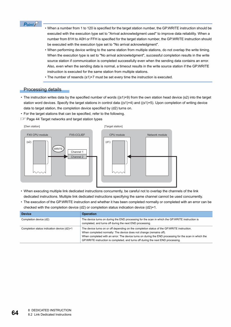
64
• When a number from 1 to 120 is specified for the target station number, the GP.WRITE instruction should be
executed with the execution type set to "Arrival acknowledgment used" to improve data reliability. When a
number from 81H to A0H or FFH is specified for the target station number, the GP.WRITE instruction should
be executed with the execution type set to "No arrival acknowledgment".
• When performing device writing to the same station from multiple stations, do not overlap the write timing.
When the execution type is set to "No arrival acknowledgment", successful completion results in the write
source station if communication is completed successfully even when the sending data contains an error.
Also, even when the sending data is normal, a timeout results in the write source station if the GP.WRITE
instruction is executed for the same station from multiple stations.
• The number of resends (s1)+7 must be set every time the instruction is executed.
Processing details
• The instruction writes data by the specified number of words ((s1)+9) from the own station head device (s2) into the target
station word devices. Specify the target stations in control data ((s1)+4) and ((s1)+5). Upon completion of writing device
data to target station, the completion device specified by (d2) turns on.
• For the target stations that can be specified, refer to the following.
Page 44 Target networks and target station types
• When executing multiple link dedicated instructions concurrently, be careful not to overlap the channels of the link
dedicated instructions. Multiple link dedicated instructions specifying the same channel cannot be used concurrently.
• The execution of the GP.WRITE instruction and whether it has been completed normally or completed with an error can be
checked with the completion device (d2) or completion status indication device (d2)+1.
Device Operation
Completion device (d2) The device turns on during the END processing for the scan in which the GP.WRITE instruction is
completed, and turns off during the next END processing.
Completion status indication device (d2)+1 The device turns on or off depending on the completion status of the GP.WRITE instruction.
When completed normally: The device does not change (remains off).
When completed with an error: The device turns on during the END processing for the scan in which the
GP.WRITE instruction is completed, and turns off during the next END processing.
WRITE
(s2) (d1)
FX5-CCLIEF
Channel 1
Channel 2
FX5 CPU module CPU module Network module
[Own station] [Target station]
8 DEDICATED INSTRUCTION8.2 Link Dedicated Instructions
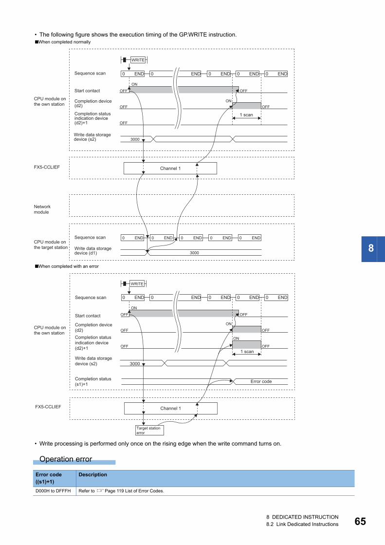
8
• The following figure shows the execution timing of the GP.WRITE instruction.
• Write processing is performed only once on the rising edge when the write command turns on.
Operation error
■When completed normally
■When completed with an error
Error code ((s1)+1)
Description
D000H to DFFFH Refer to Page 119 List of Error Codes.
END0 END0 END0 END0 END0
OFF
OFF OFF
OFF
ON
ON
OFF
3000
WRITE
3000
END0 END0 END0 END0 END0
FX5-CCLIEF Channel 1
1 scan
Sequence scan
Start contact
CPU module onthe own station
CPU module onthe target station
Networkmodule
Completion device(d2)
Completion statusindication device(d2)+1
Write data storagedevice (s2)
Sequence scan
Write data storagedevice (d1)
3000
END0 END0 END0 END0 END0
OFF
OFF
OFF
OFF
OFF
ON
ON
ON
OFF
WRITE
FX5-CCLIEF
1 scan
Error code
Sequence scan
Start contact
CPU module onthe own station
Completion device(d2)Completion statusindication device(d2)+1
Write data storagedevice (s2)
Channel 1
Target station error
Completion status (s1)+1
8 DEDICATED INSTRUCTION8.2 Link Dedicated Instructions 65
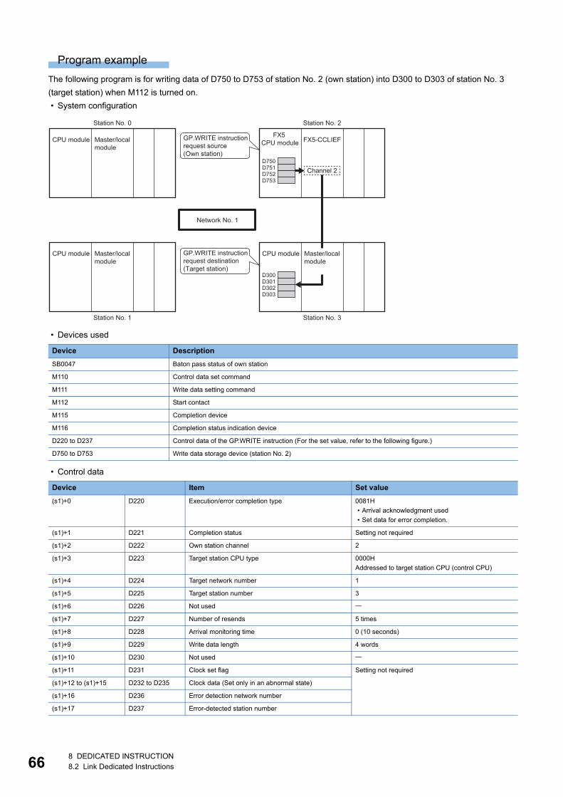
66
Program example
The following program is for writing data of D750 to D753 of station No. 2 (own station) into D300 to D303 of station No. 3
(target station) when M112 is turned on.
• System configuration
• Devices used
• Control data
Device Description
SB0047 Baton pass status of own station
M110 Control data set command
M111 Write data setting command
M112 Start contact
M115 Completion device
M116 Completion status indication device
D220 to D237 Control data of the GP.WRITE instruction (For the set value, refer to the following figure.)
D750 to D753 Write data storage device (station No. 2)
Device Item Set value
(s1)+0 D220 Execution/error completion type 0081H
• Arrival acknowledgment used
• Set data for error completion.
(s1)+1 D221 Completion status Setting not required
(s1)+2 D222 Own station channel 2
(s1)+3 D223 Target station CPU type 0000H
Addressed to target station CPU (control CPU)
(s1)+4 D224 Target network number 1
(s1)+5 D225 Target station number 3
(s1)+6 D226 Not used
(s1)+7 D227 Number of resends 5 times
(s1)+8 D228 Arrival monitoring time 0 (10 seconds)
(s1)+9 D229 Write data length 4 words
(s1)+10 D230 Not used
(s1)+11 D231 Clock set flag Setting not required
(s1)+12 to (s1)+15 D232 to D235 Clock data (Set only in an abnormal state)
(s1)+16 D236 Error detection network number
(s1)+17 D237 Error-detected station number
D301D300
D303D302
D751D750
D753D752
FX5-CCLIEF
CPU module Master/local module
CPU module Master/local module
CPU module Master/local module
Station No. 0
Station No. 1
Channel 2
FX5 CPU module
GP.WRITE instruction request source(Own station)
GP.WRITE instruction request destination(Target station)
Station No. 2
Station No. 3
Network No. 1
8 DEDICATED INSTRUCTION8.2 Link Dedicated Instructions
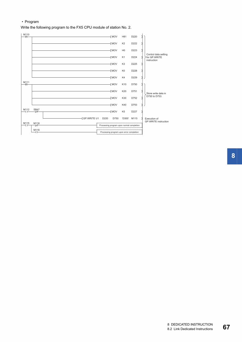
8
• Program
Write the following program to the FX5 CPU module of station No. 2.
H81MOV
MOV
D220
D222
MOV D223
M110
MOV D224
MOV D225
MOV D228
MOV D229
MOV D227
M115
M112 SB47
M116
M116
D220GP.WRITE U1 ‘D300’
M115
K2
H0
K1
K3
K0
K4
K10MOV D750M111
MOV D751
MOV D752
MOV D753
K20
K30
K40
K5
D750
Processing program upon normal completion
Execution of GP.WRITE instruction
Control data setting for GP.WRITE instruction
Store write data in D750 to D753.
Processing program upon error completion
8 DEDICATED INSTRUCTION8.2 Link Dedicated Instructions 67
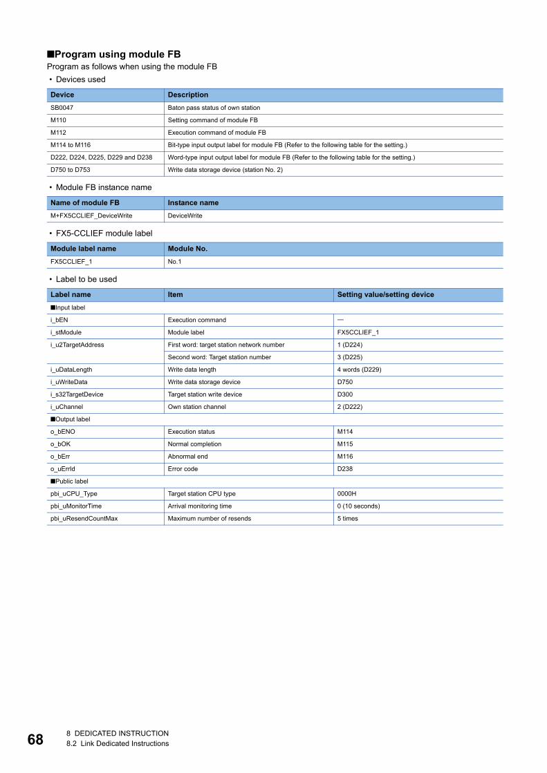
68
■Program using module FBProgram as follows when using the module FB
• Devices used
• Module FB instance name
• FX5-CCLIEF module label
• Label to be used
Device Description
SB0047 Baton pass status of own station
M110 Setting command of module FB
M112 Execution command of module FB
M114 to M116 Bit-type input output label for module FB (Refer to the following table for the setting.)
D222, D224, D225, D229 and D238 Word-type input output label for module FB (Refer to the following table for the setting.)
D750 to D753 Write data storage device (station No. 2)
Name of module FB Instance name
M+FX5CCLIEF_DeviceWrite DeviceWrite
Module label name Module No.
FX5CCLIEF_1 No.1
Label name Item Setting value/setting device
■Input label
i_bEN Execution command
i_stModule Module label FX5CCLIEF_1
i_u2TargetAddress First word: target station network number 1 (D224)
Second word: Target station number 3 (D225)
i_uDataLength Write data length 4 words (D229)
i_uWriteData Write data storage device D750
i_s32TargetDevice Target station write device D300
i_uChannel Own station channel 2 (D222)
■Output label
o_bENO Execution status M114
o_bOK Normal completion M115
o_bErr Abnormal end M116
o_uErrId Error code D238
■Public label
pbi_uCPU_Type Target station CPU type 0000H
pbi_uMonitorTime Arrival monitoring time 0 (10 seconds)
pbi_uResendCountMax Maximum number of resends 5 times
8 DEDICATED INSTRUCTION8.2 Link Dedicated Instructions
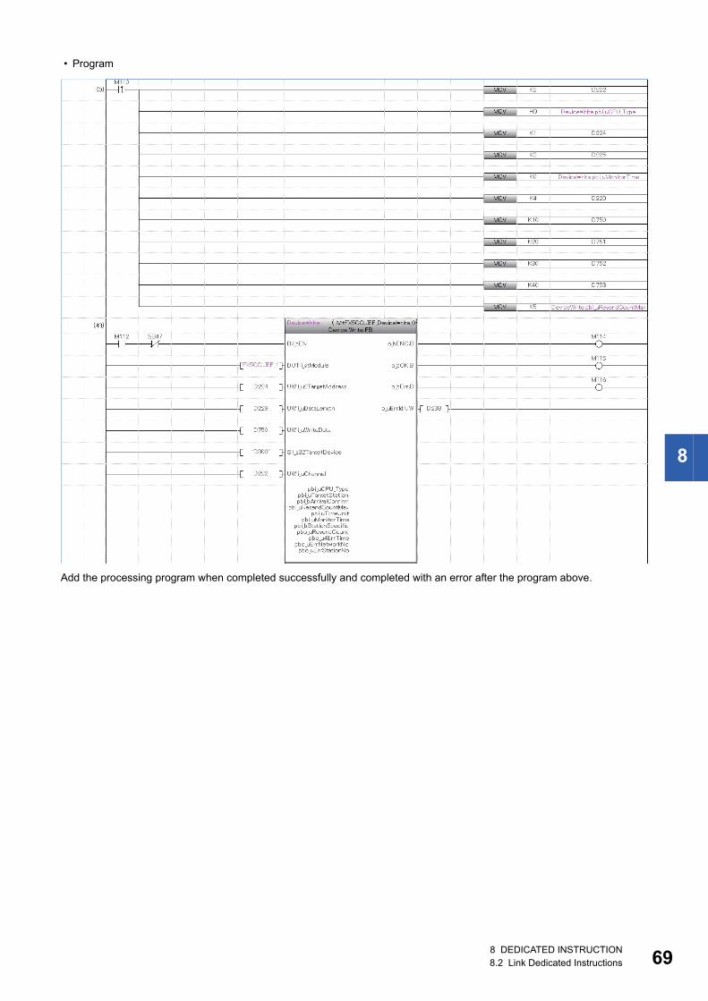
8
• Program
Add the processing program when completed successfully and completed with an error after the program above.
8 DEDICATED INSTRUCTION8.2 Link Dedicated Instructions 69
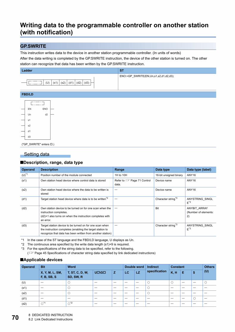
70
Writing data to the programmable controller on another station (with notification)
GP.SWRITEThis instruction writes data to the device in another station programmable controller. (In units of words)
After the data writing is completed by the GP.SWRITE instruction, the device of the other station is turned on. The other
station can recognize that data has been written by the GP.SWRITE instruction.
Setting data
■Description, range, data type
*1 In the case of the ST language and the FBD/LD language, U displays as Un.*2 The continuous area specified by the write data length (s1)+9 is required.*3 For the specifications of the string data to be specified, refer to the following.
(Page 45 Specifications of character string data specified by link dedicated instructions)
■Applicable devices
Ladder ST
ENO:=GP_SWRITE(EN,Un,s1,s2,d1,d2,d3);
FBD/LD
("GP_SWRITE" enters .)
Operand Description Range Data type Data type (label)
(U)*1 Position number of the module connected 1H to 10H 16-bit unsigned binary ANY16
(s1) Own station head device where control data is stored Refer to Page 71 Control
data.
Device name ANY16
(s2) Own station head device where the data to be written is
stored
Device name ANY16
(d1) Target station head device where data is to be written*2 Character string*3 ANYSTRING_SINGL
E*3
(d2) Own station device to be turned on for one scan when the
instruction completes.
(d2)+1 also turns on when the instruction completes with
an error.
Bit ANYBIT_ARRAY
(Number of elements:
2)
(d3) Target station device to be turned on for one scan when
the instruction completes (enabling the target station to
recognize that data has been written from another station)
Character string*3 ANYSTRING_SINGL
E*3
Operand Bit Word Double word Indirect specification
Constant Others(U)X, Y, M, L, SM,
F, B, SB, ST, ST, C, D, W, SD, SW, R
U\G Z LC LZ K, H E $
(U)
(s1)
(s2)
(d1)
(d2) *1 *2
(s1) (s2) (d1) (d2) (d3)(U)
EN ENO
d2Un
s1
s2
d1
d3
8 DEDICATED INSTRUCTION8.2 Link Dedicated Instructions
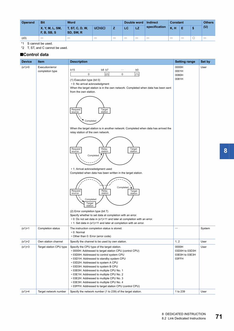
8
*1 S cannot be used.*2 T, ST, and C cannot be used.
■Control data
(d3)
Device Item Description Setting range Set by
(s1)+0 Execution/error
completion type
(1) Execution type (bit 0)
• 0: No arrival acknowledgment
When the target station is in the own network: Completed when data has been sent
from the own station.
When the target station is in another network: Completed when data has arrived the
relay station of the own network.
• 1: Arrival acknowledgment used
Completed when data has been written in the target station.
(2) Error completion type (bit 7)
Specify whether to set data at completion with an error.
• 0: Do not set data in (s1)+11 and later at completion with an error.
• 1: Set data in (s1)+11 and later at completion with an error.
0000H
0001H
0080H
0081H
User
(s1)+1 Completion status The instruction completion status is stored.
• 0: Normal
• Other than 0: Error (error code)
System
(s1)+2 Own station channel Specify the channel to be used by own station. 1, 2 User
(s1)+3 Target station CPU type Specify the CPU type of the target station.
• 0000H: Addressed to target station CPU (control CPU)
• 03D0H: Addressed to control system CPU
• 03D1H: Addressed to standby system CPU
• 03D2H: Addressed to system A CPU
• 03D3H: Addressed to system B CPU
• 03E0H: Addressed to multiple CPU No. 1
• 03E1H: Addressed to multiple CPU No. 2
• 03E2H: Addressed to multiple CPU No. 3
• 03E3H: Addressed to multiple CPU No. 4
• 03FFH: Addressed to target station CPU (control CPU)
0000H
03D0H to 03D3H
03E0H to 03E3H
03FFH
User
(s1)+4 Target network number Specify the network number (1 to 239) of the target station. 1 to 239 User
Operand Bit Word Double word Indirect specification
Constant Others(U)X, Y, M, L, SM,
F, B, SB, ST, ST, C, D, W, SD, SW, R
U\G Z LC LZ K, H E $
b150 0(2) (1)
b7b8 b0… …
Completed
Targetstation
Requestsource
Completed
Targetstation
Requestsource
Relaystation
Completed
Targetstation
Requestsource
Relaystation
Targetstation
Completed
8 DEDICATED INSTRUCTION8.2 Link Dedicated Instructions 71
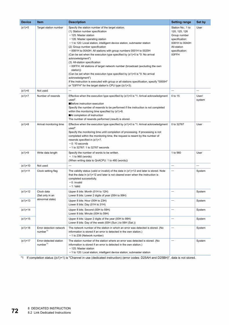
72
*1 If completion status ((s1)+1) is "Channel in use (dedicated instruction) (error codes: D25AH and D25BH)", data is not stored.
(s1)+5 Target station number Specify the station number of the target station.
(1) Station number specification
• 125: Master station
• 126: Master operating station
• 1 to 120: Local station, intelligent device station, submaster station
(2) Group number specification
• 0081H to 00A0H: All stations with group numbers 0001H to 0020H
(Can be set when the execution type specified by (s1)+0 is "0: No arrival
acknowledgment")
(3) All-station specification
• 00FFH: All stations of target network number (broadcast (excluding the own
station))
(Can be set when the execution type specified by (s1)+0 is "0: No arrival
acknowledgment")
If the instruction is executed with group or all stations specification, specify "0000H"
or "03FFH" for the target station's CPU type ((s1)+3).
Station No.: 1 to
120, 125, 126
Group number
specification:
0081H to 00A0H
All-station
specification:
00FFH
User
(s1)+6 Not used
(s1)+7 Number of resends Effective when the execution type specified by (s1)+0 is "1: Arrival acknowledgment
used".
■Before instruction execution
Specify the number of resends to be performed if the instruction is not completed
within the monitoring time specified by (s1)+8.
■At completion of instruction
The number of resends performed (result) is stored.
0 to 15 User/
system
(s1)+8 Arrival monitoring time Effective when the execution type specified by (s1)+0 is "1: Arrival acknowledgment
used".
Specify the monitoring time until completion of processing. If processing is not
completed within the monitoring time, the request is resent by the number of
resends specified in (s1)+7.
• 0: 10 seconds
• 1 to 32767: 1 to 32767 seconds
0 to 32767 User
(s1)+9 Write data length Specify the number of words to be written.
• 1 to 960 (words)
(When writing data to QnACPU: 1 to 480 (words))
1 to 960 User
(s1)+10 Not used
(s1)+11 Clock setting flag The validity status (valid or invalid) of the data in (s1)+12 and later is stored. Note
that the data in (s1)+12 and later is not cleared even when the instruction is
completed successfully.
• 0: Invalid
• 1: Valid
System
(s1)+12 Clock data
(Set only in an
abnormal state)
Upper 8 bits: Month (01H to 12H)
Lower 8 bits: Lower 2 digits of year (00H to 99H)
System
(s1)+13 Upper 8 bits: Hour (00H to 23H)
Lower 8 bits: Day (01H to 31H)
System
(s1)+14 Upper 8 bits: Second (00H to 59H)
Lower 8 bits: Minute (00H to 59H)
System
(s1)+15 Upper 8 bits: Upper 2 digits of the year (00H to 99H)
Lower 8 bits: Day of the week (00H (Sun.) to 06H (Sat.))
System
(s1)+16 Error detection network
number*1The network number of the station in which an error was detected is stored. (No
information is stored if an error is detected in the own station.)
• 1 to 239 (Network number)
System
(s1)+17 Error-detected station
number*1The station number of the station where an error was detected is stored. (No
information is stored if an error is detected in the own station.)
• 125: Master station
• 1 to 120: Local station, intelligent device station, submaster station
System
Device Item Description Setting range Set by
8 DEDICATED INSTRUCTION8.2 Link Dedicated Instructions
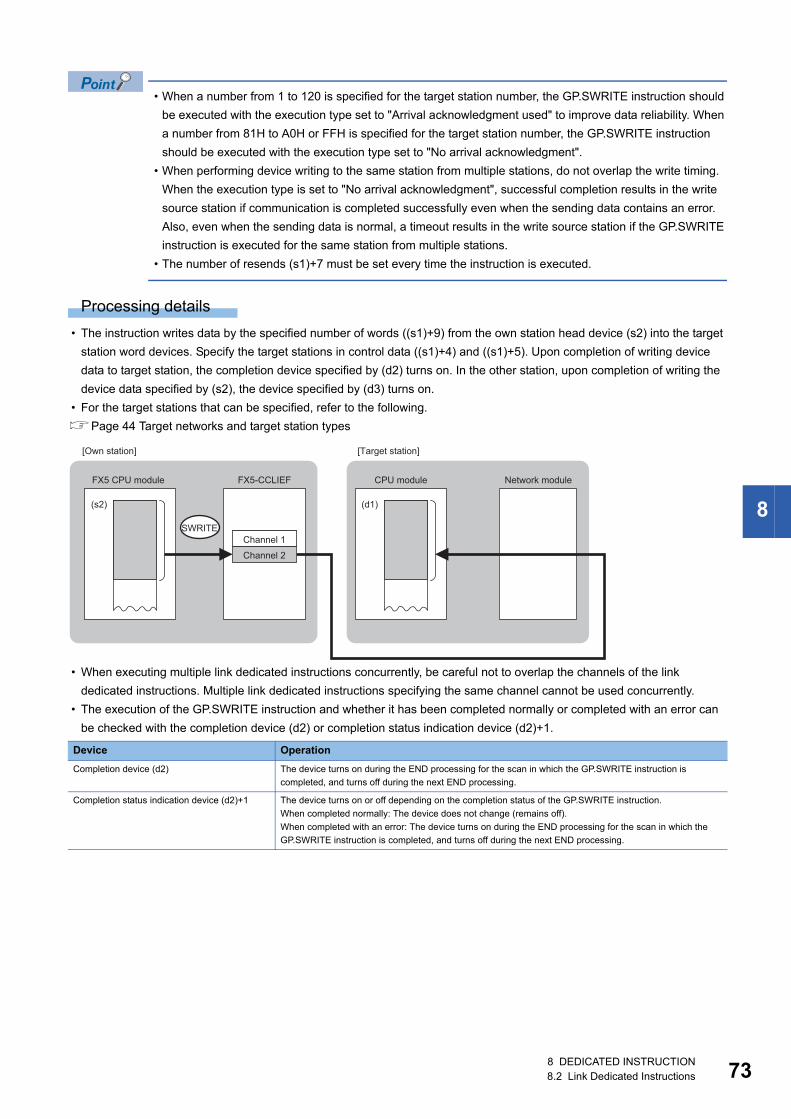
8
• When a number from 1 to 120 is specified for the target station number, the GP.SWRITE instruction should
be executed with the execution type set to "Arrival acknowledgment used" to improve data reliability. When
a number from 81H to A0H or FFH is specified for the target station number, the GP.SWRITE instruction
should be executed with the execution type set to "No arrival acknowledgment".
• When performing device writing to the same station from multiple stations, do not overlap the write timing.
When the execution type is set to "No arrival acknowledgment", successful completion results in the write
source station if communication is completed successfully even when the sending data contains an error.
Also, even when the sending data is normal, a timeout results in the write source station if the GP.SWRITE
instruction is executed for the same station from multiple stations.
• The number of resends (s1)+7 must be set every time the instruction is executed.
Processing details
• The instruction writes data by the specified number of words ((s1)+9) from the own station head device (s2) into the target
station word devices. Specify the target stations in control data ((s1)+4) and ((s1)+5). Upon completion of writing device
data to target station, the completion device specified by (d2) turns on. In the other station, upon completion of writing the
device data specified by (s2), the device specified by (d3) turns on.
• For the target stations that can be specified, refer to the following.
Page 44 Target networks and target station types
• When executing multiple link dedicated instructions concurrently, be careful not to overlap the channels of the link
dedicated instructions. Multiple link dedicated instructions specifying the same channel cannot be used concurrently.
• The execution of the GP.SWRITE instruction and whether it has been completed normally or completed with an error can
be checked with the completion device (d2) or completion status indication device (d2)+1.
Device Operation
Completion device (d2) The device turns on during the END processing for the scan in which the GP.SWRITE instruction is
completed, and turns off during the next END processing.
Completion status indication device (d2)+1 The device turns on or off depending on the completion status of the GP.SWRITE instruction.
When completed normally: The device does not change (remains off).
When completed with an error: The device turns on during the END processing for the scan in which the
GP.SWRITE instruction is completed, and turns off during the next END processing.
SWRITE
(s2) (d1)
FX5-CCLIEF
Channel 1
Channel 2
FX5 CPU module CPU module Network module
[Own station] [Target station]
8 DEDICATED INSTRUCTION8.2 Link Dedicated Instructions 73
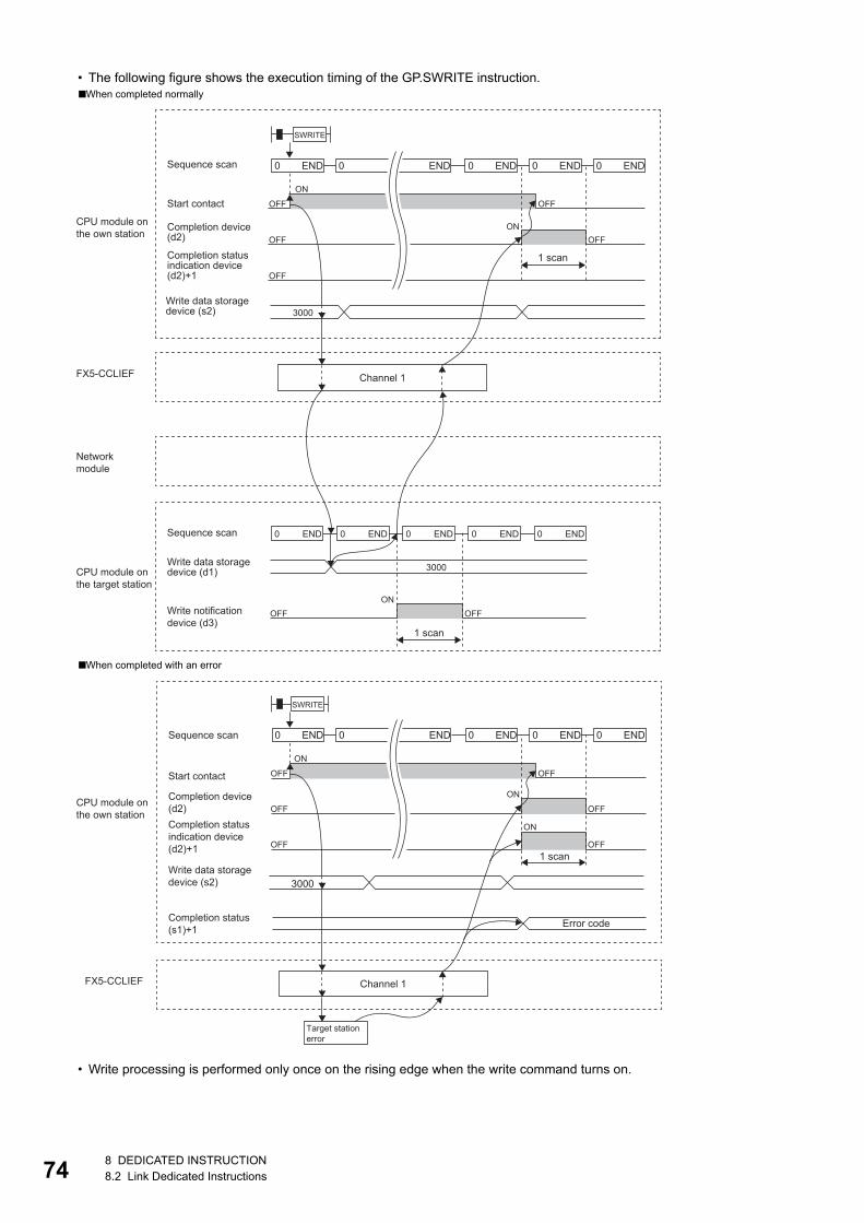
74
• The following figure shows the execution timing of the GP.SWRITE instruction.
• Write processing is performed only once on the rising edge when the write command turns on.
■When completed normally
■When completed with an error
END0 END0 END0 END0 END0
OFF
OFF OFF
OFF
ON
ON
OFF
3000
SWRITE
3000
END0 END0 END0 END0 END0
OFFON
OFF
FX5-CCLIEF Channel 1
1 scan
Sequence scan
Start contact
CPU module onthe own station
CPU module onthe target station
Networkmodule
Completion device(d2)
Completion statusindication device(d2)+1
Write data storagedevice (s2)
Sequence scan
Write data storagedevice (d1)
Write notificationdevice (d3)
1 scan
3000
END0 END0 END0 END0 END0
OFF
OFF
OFF
OFF
OFF
ON
ON
ON
OFF
SWRITE
FX5-CCLIEF
1 scan
Error code
Sequence scan
Start contact
CPU module onthe own station
Completion device(d2)Completion statusindication device(d2)+1
Write data storagedevice (s2)
Channel 1
Target station error
Completion status (s1)+1
8 DEDICATED INSTRUCTION8.2 Link Dedicated Instructions
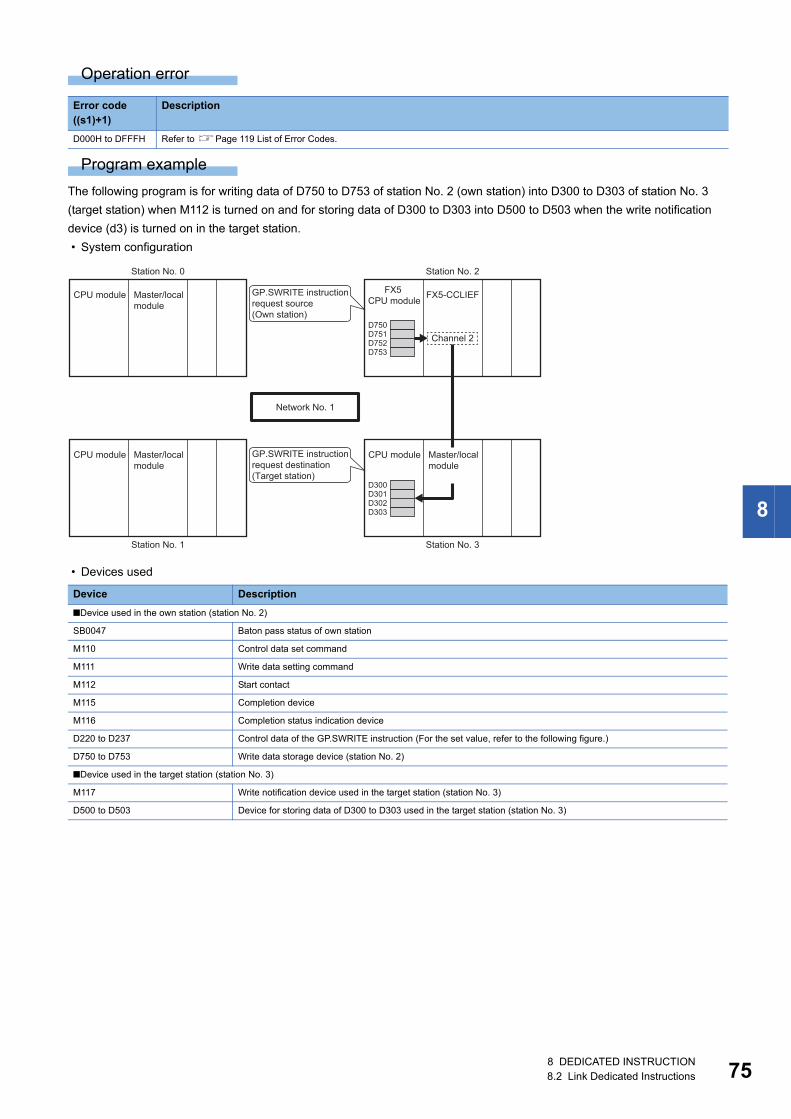
8
Operation error
Program example
The following program is for writing data of D750 to D753 of station No. 2 (own station) into D300 to D303 of station No. 3
(target station) when M112 is turned on and for storing data of D300 to D303 into D500 to D503 when the write notification
device (d3) is turned on in the target station.
• System configuration
• Devices used
Error code ((s1)+1)
Description
D000H to DFFFH Refer to Page 119 List of Error Codes.
Device Description
■Device used in the own station (station No. 2)
SB0047 Baton pass status of own station
M110 Control data set command
M111 Write data setting command
M112 Start contact
M115 Completion device
M116 Completion status indication device
D220 to D237 Control data of the GP.SWRITE instruction (For the set value, refer to the following figure.)
D750 to D753 Write data storage device (station No. 2)
■Device used in the target station (station No. 3)
M117 Write notification device used in the target station (station No. 3)
D500 to D503 Device for storing data of D300 to D303 used in the target station (station No. 3)
D301D300
D303D302
D751D750
D753D752
FX5-CCLIEF
CPU module Master/local module
CPU module Master/local module
CPU module Master/local module
Station No. 0
Station No. 1
Channel 2
FX5 CPU module
GP.SWRITE instruction request source(Own station)
GP.SWRITE instruction request destination(Target station)
Station No. 2
Station No. 3
Network No. 1
8 DEDICATED INSTRUCTION8.2 Link Dedicated Instructions 75
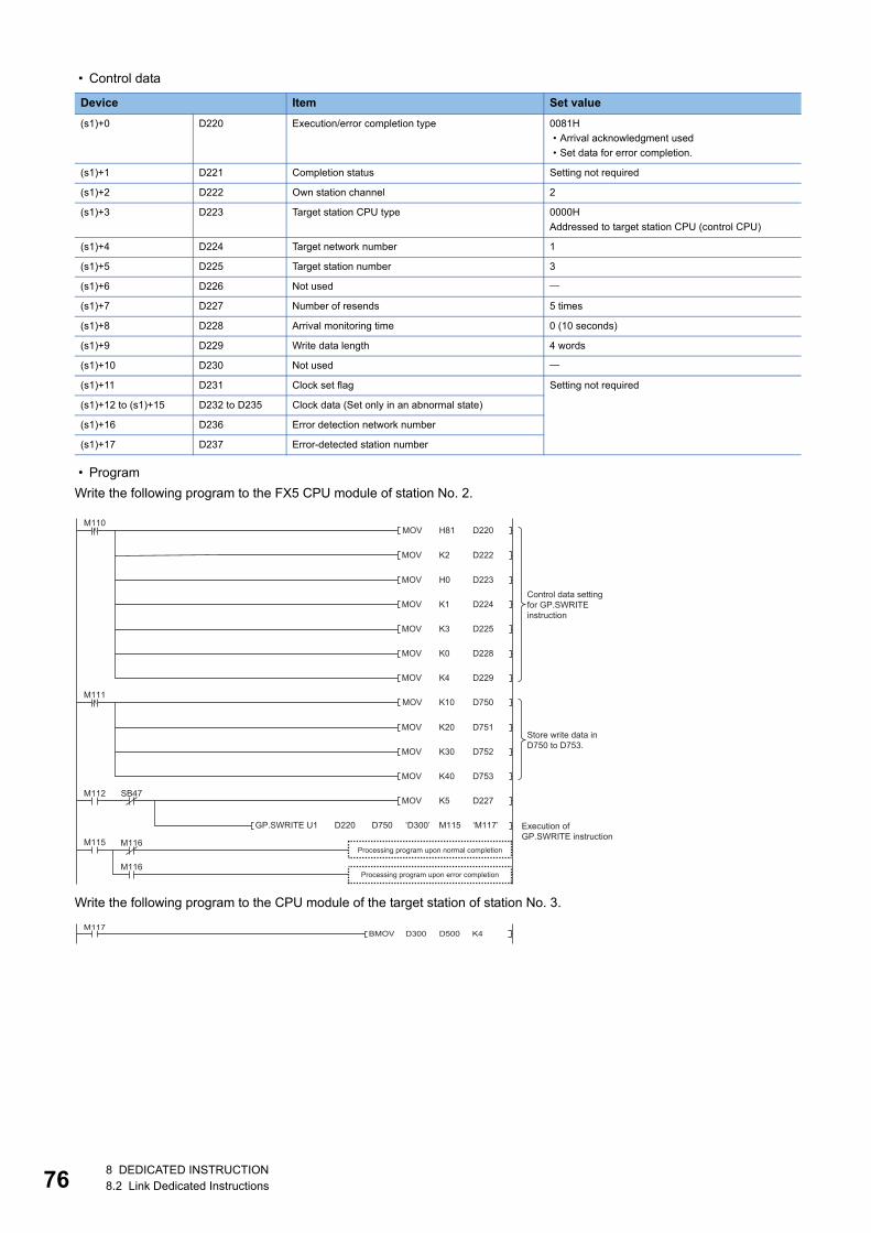
76
• Control data
• Program
Write the following program to the FX5 CPU module of station No. 2.
Write the following program to the CPU module of the target station of station No. 3.
Device Item Set value
(s1)+0 D220 Execution/error completion type 0081H
• Arrival acknowledgment used
• Set data for error completion.
(s1)+1 D221 Completion status Setting not required
(s1)+2 D222 Own station channel 2
(s1)+3 D223 Target station CPU type 0000H
Addressed to target station CPU (control CPU)
(s1)+4 D224 Target network number 1
(s1)+5 D225 Target station number 3
(s1)+6 D226 Not used
(s1)+7 D227 Number of resends 5 times
(s1)+8 D228 Arrival monitoring time 0 (10 seconds)
(s1)+9 D229 Write data length 4 words
(s1)+10 D230 Not used
(s1)+11 D231 Clock set flag Setting not required
(s1)+12 to (s1)+15 D232 to D235 Clock data (Set only in an abnormal state)
(s1)+16 D236 Error detection network number
(s1)+17 D237 Error-detected station number
H81MOV
MOV
D220
D222
MOV D223
M110
MOV D224
MOV D225
MOV D228
MOV D229
MOV D227
M115
M112 SB47
M116
M116
D220GP.SWRITE U1 ‘D300’ ‘M117’
M115
K2
H0
K1
K3
K0
K4
K10MOV D750M111
MOV D751
MOV D752
MOV D753
K20
K30
K40
K5
D750
Processing program upon normal completion
Execution of GP.SWRITE instruction
Control data setting for GP.SWRITE instruction
Store write data in D750 to D753.
Processing program upon error completion
D300BMOV D500 K4M117
8 DEDICATED INSTRUCTION8.2 Link Dedicated Instructions
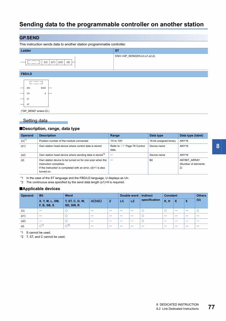
8
Sending data to the programmable controller on another station
GP.SENDThis instruction sends data to another station programmable controller.
Setting data
■Description, range, data type
*1 In the case of the ST language and the FBD/LD language, U displays as Un.*2 The continuous area specified by the send data length (s1)+9 is required.
■Applicable devices
*1 S cannot be used.*2 T, ST, and C cannot be used.
Ladder ST
ENO:=GP_SEND(EN,Un,s1,s2,d);
FBD/LD
("GP_SEND" enters .)
Operand Description Range Data type Data type (label)
(U)*1 Position number of the module connected 1H to 10H 16-bit unsigned binary ANY16
(s1) Own station head device where control data is stored Refer to Page 78 Control
data.
Device name ANY16
(s2) Own station head device where sending data is stored*2 Device name ANY16
(d) Own station device to be turned on for one scan when the
instruction completes.
If the instruction is completed with an error, (d)+1 is also
turned on.
Bit ANYBIT_ARRAY
(Number of elements:
2)
Operand Bit Word Double word Indirect specification
Constant Others(U)X, Y, M, L, SM,
F, B, SB, ST, ST, C, D, W, SD, SW, R
U\G Z LC LZ K, H E $
(U)
(s1)
(s2)
(d) *1 *2
(U) (s1) (s2) (d)
EN ENO
dUn
s1
s2
8 DEDICATED INSTRUCTION8.2 Link Dedicated Instructions 77
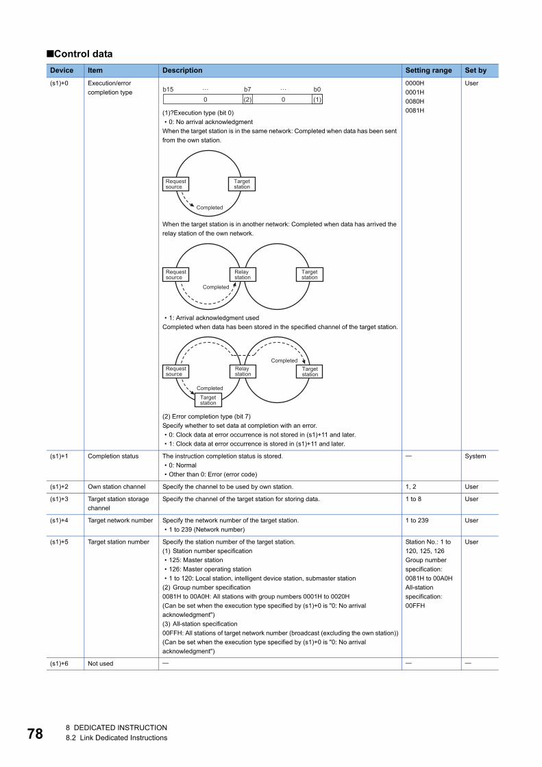
78
■Control data
Device Item Description Setting range Set by
(s1)+0 Execution/error
completion type
(1)?Execution type (bit 0)
• 0: No arrival acknowledgment
When the target station is in the same network: Completed when data has been sent
from the own station.
When the target station is in another network: Completed when data has arrived the
relay station of the own network.
• 1: Arrival acknowledgment used
Completed when data has been stored in the specified channel of the target station.
(2) Error completion type (bit 7)
Specify whether to set data at completion with an error.
• 0: Clock data at error occurrence is not stored in (s1)+11 and later.
• 1: Clock data at error occurrence is stored in (s1)+11 and later.
0000H
0001H
0080H
0081H
User
(s1)+1 Completion status The instruction completion status is stored.
• 0: Normal
• Other than 0: Error (error code)
System
(s1)+2 Own station channel Specify the channel to be used by own station. 1, 2 User
(s1)+3 Target station storage
channel
Specify the channel of the target station for storing data. 1 to 8 User
(s1)+4 Target network number Specify the network number of the target station.
• 1 to 239 (Network number)
1 to 239 User
(s1)+5 Target station number Specify the station number of the target station.
(1) Station number specification
• 125: Master station
• 126: Master operating station
• 1 to 120: Local station, intelligent device station, submaster station
(2) Group number specification
0081H to 00A0H: All stations with group numbers 0001H to 0020H
(Can be set when the execution type specified by (s1)+0 is "0: No arrival
acknowledgment")
(3) All-station specification
00FFH: All stations of target network number (broadcast (excluding the own station))
(Can be set when the execution type specified by (s1)+0 is "0: No arrival
acknowledgment")
Station No.: 1 to
120, 125, 126
Group number
specification:
0081H to 00A0H
All-station
specification:
00FFH
User
(s1)+6 Not used
b150 0(2) (1)
b7 b0… …
Completed
Targetstation
Requestsource
Completed
Targetstation
Requestsource
Relaystation
Completed
Targetstation
Requestsource
Relaystation
Targetstation
Completed
8 DEDICATED INSTRUCTION8.2 Link Dedicated Instructions
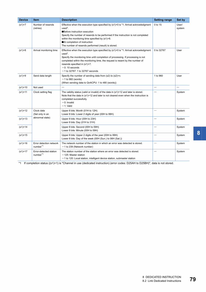
8
*1 If completion status ((s1)+1) is "Channel in use (dedicated instruction) (error codes: D25AH to D25BH)", data is not stored.
(s1)+7 Number of resends
(retries)
Effective when the execution type specified by (s1)+0 is "1: Arrival acknowledgment
used".
■Before instruction execution
Specify the number of resends to be performed if the instruction is not completed
within the monitoring time specified by (s1)+8.
■At completion of instruction
The number of resends performed (result) is stored.
0 to 15 User/
system
(s1)+8 Arrival monitoring time Effective when the execution type specified by (s1)+0 is "1: Arrival acknowledgment
used".
Specify the monitoring time until completion of processing. If processing is not
completed within the monitoring time, the request is resent by the number of
resends specified in (s1)+7.
• 0: 10 seconds
• 1 to 32767: 1 to 32767 seconds
0 to 32767 User
(s1)+9 Send data length Specify the number of sending data from (s2) to (s2)+n.
• 1 to 960 (words)
(When sending data to QnACPU: 1 to 480 (words))
1 to 960 User
(s1)+10 Not used
(s1)+11 Clock setting flag The validity status (valid or invalid) of the data in (s1)+12 and later is stored.
Note that the data in (s1)+12 and later is not cleared even when the instruction is
completed successfully.
• 0: Invalid
• 1: Valid
System
(s1)+12 Clock data
(Set only in an
abnormal state)
Upper 8 bits: Month (01H to 12H)
Lower 8 bits: Lower 2 digits of year (00H to 99H)
System
(s1)+13 Upper 8 bits: Hour (00H to 23H)
Lower 8 bits: Day (01H to 31H)
System
(s1)+14 Upper 8 bits: Second (00H to 59H)
Lower 8 bits: Minute (00H to 59H)
System
(s1)+15 Upper 8 bits: Upper 2 digits of the year (00H to 99H)
Lower 8 bits: Day of the week (00H (Sun.) to 06H (Sat.))
System
(s1)+16 Error detection network
number*1The network number of the station in which an error was detected is stored.
• 1 to 239 (Network number)
System
(s1)+17 Error-detected station
number*1The station number of the station where an error was detected is stored.
• 125: Master station
• 1 to 120: Local station, intelligent device station, submaster station
System
Device Item Description Setting range Set by
8 DEDICATED INSTRUCTION8.2 Link Dedicated Instructions 79
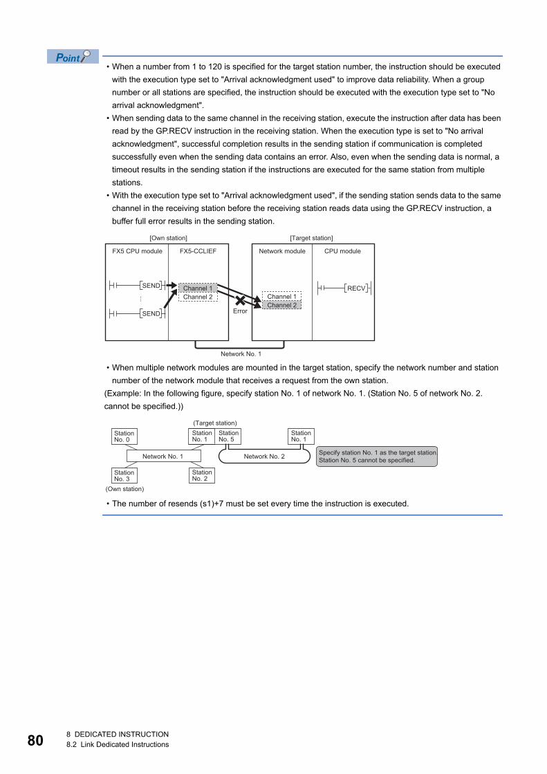
80
• When a number from 1 to 120 is specified for the target station number, the instruction should be executed
with the execution type set to "Arrival acknowledgment used" to improve data reliability. When a group
number or all stations are specified, the instruction should be executed with the execution type set to "No
arrival acknowledgment".
• When sending data to the same channel in the receiving station, execute the instruction after data has been
read by the GP.RECV instruction in the receiving station. When the execution type is set to "No arrival
acknowledgment", successful completion results in the sending station if communication is completed
successfully even when the sending data contains an error. Also, even when the sending data is normal, a
timeout results in the sending station if the instructions are executed for the same station from multiple
stations.
• With the execution type set to "Arrival acknowledgment used", if the sending station sends data to the same
channel in the receiving station before the receiving station reads data using the GP.RECV instruction, a
buffer full error results in the sending station.
• When multiple network modules are mounted in the target station, specify the network number and station
number of the network module that receives a request from the own station.
(Example: In the following figure, specify station No. 1 of network No. 1. (Station No. 5 of network No. 2.
cannot be specified.))
• The number of resends (s1)+7 must be set every time the instruction is executed.
RECVSEND
SEND
FX5-CCLIEF
[Target station]
Error
[Own station]
Network moduleFX5 CPU module CPU module
Channel 2Channel 1
Channel 2Channel 1
Network No. 1
StationNo. 0
StationNo. 1
StationNo. 2
StationNo. 3
StationNo. 5
StationNo. 1
Network No. 1 Network No. 2
(Own station)
(Target station)
Specify station No. 1 as the target station.Station No. 5 cannot be specified.
8 DEDICATED INSTRUCTION8.2 Link Dedicated Instructions
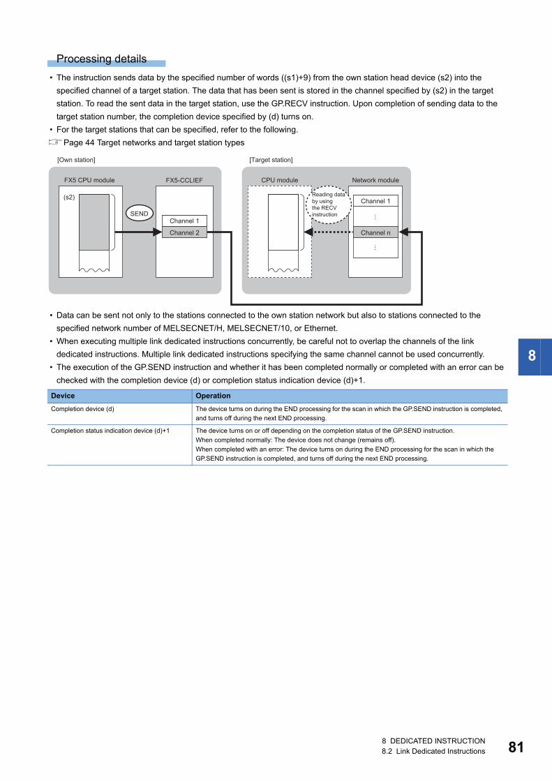
8
Processing details
• The instruction sends data by the specified number of words ((s1)+9) from the own station head device (s2) into the
specified channel of a target station. The data that has been sent is stored in the channel specified by (s2) in the target
station. To read the sent data in the target station, use the GP.RECV instruction. Upon completion of sending data to the
target station number, the completion device specified by (d) turns on.
• For the target stations that can be specified, refer to the following.
Page 44 Target networks and target station types
• Data can be sent not only to the stations connected to the own station network but also to stations connected to the
specified network number of MELSECNET/H, MELSECNET/10, or Ethernet.
• When executing multiple link dedicated instructions concurrently, be careful not to overlap the channels of the link
dedicated instructions. Multiple link dedicated instructions specifying the same channel cannot be used concurrently.
• The execution of the GP.SEND instruction and whether it has been completed normally or completed with an error can be
checked with the completion device (d) or completion status indication device (d)+1.
Device Operation
Completion device (d) The device turns on during the END processing for the scan in which the GP.SEND instruction is completed,
and turns off during the next END processing.
Completion status indication device (d)+1 The device turns on or off depending on the completion status of the GP.SEND instruction.
When completed normally: The device does not change (remains off).
When completed with an error: The device turns on during the END processing for the scan in which the
GP.SEND instruction is completed, and turns off during the next END processing.
SEND
(s2)
FX5-CCLIEF
Channel 1
Channel 2
FX5 CPU module CPU module Network module
[Own station] [Target station]
Channel 1
Channel n
Reading databy usingthe RECVinstruction
8 DEDICATED INSTRUCTION8.2 Link Dedicated Instructions 81
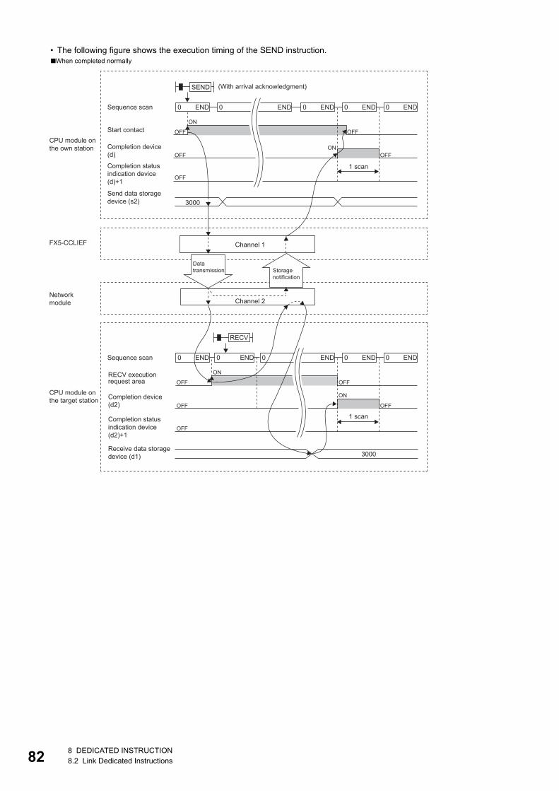
82
• The following figure shows the execution timing of the SEND instruction.■When completed normally
3000
OFF
END END0END0 END0 END0
OFF OFF
OFF
ON
ON
OFF
SEND
OFF
END0 END0 END0 END0 END0
RECV
0
3000
OFF OFF
OFF
ON
ON
OFF
FX5-CCLIEF
1 scan
(With arrival acknowledgment)
Channel 1
Datatransmission Storage
notification
1 scan
Channel 2
Sequence scan
Start contactCPU module onthe own station Completion device
(d)
Completion statusindication device(d)+1
Send data storagedevice (s2)
Networkmodule
CPU module onthe target station
Sequence scan
RECV executionrequest area
Completion device(d2)
Completion statusindication device(d2)+1
Receive data storagedevice (d1)
8 DEDICATED INSTRUCTION8.2 Link Dedicated Instructions
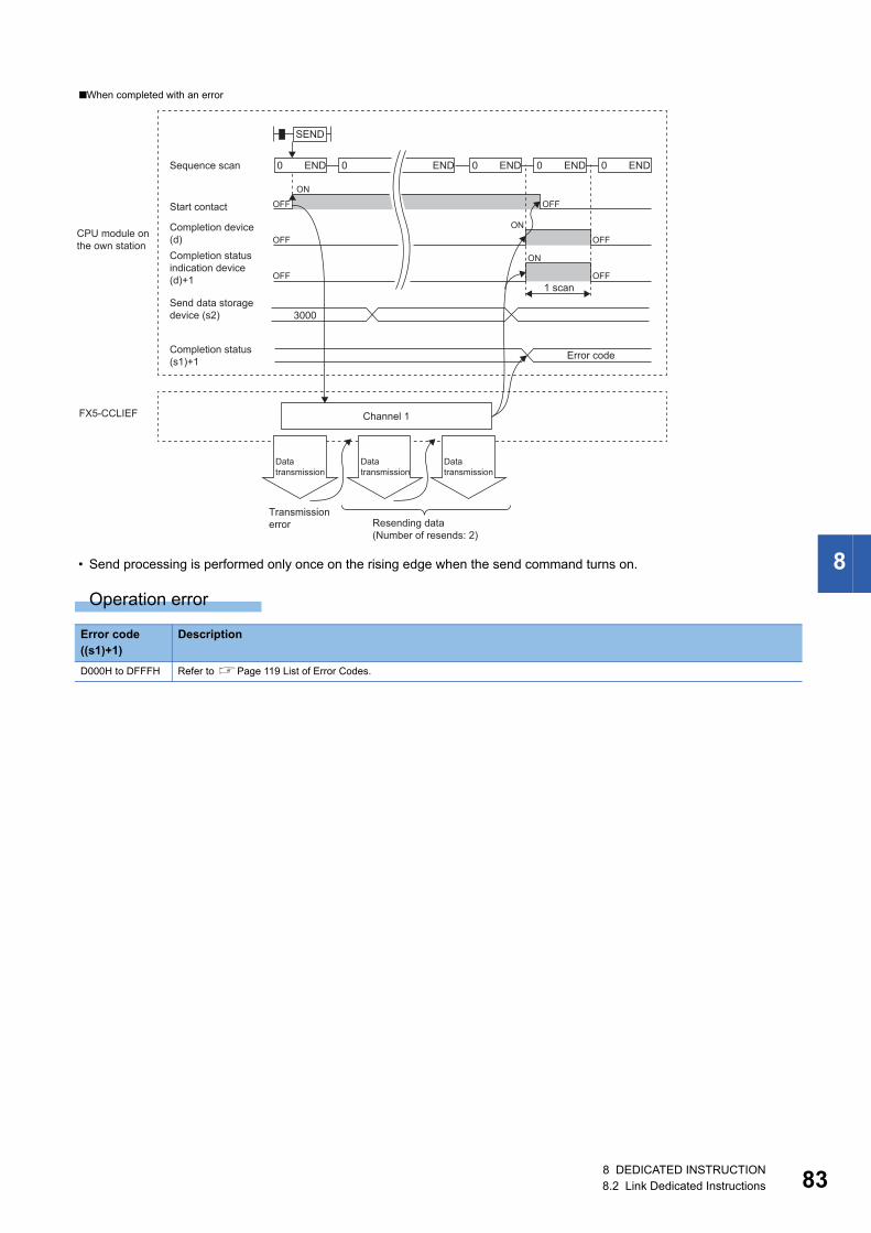
8
• Send processing is performed only once on the rising edge when the send command turns on.Operation error
■When completed with an error
Error code ((s1)+1)
Description
D000H to DFFFH Refer to Page 119 List of Error Codes.
3000
END0 END0 END0 END0 END0
OFF
OFF
OFF
OFF
OFF
ON
ON
ON
OFF
SEND
FX5-CCLIEF
1 scan
Error code
Sequence scan
Start contact
CPU module onthe own station
Completion device(d)Completion statusindication device(d)+1
Send data storagedevice (s2)
Channel 1
Completion status (s1)+1
Datatransmission
Datatransmission
Resending data(Number of resends: 2)
Transmissionerror
Datatransmission
8 DEDICATED INSTRUCTION8.2 Link Dedicated Instructions 83
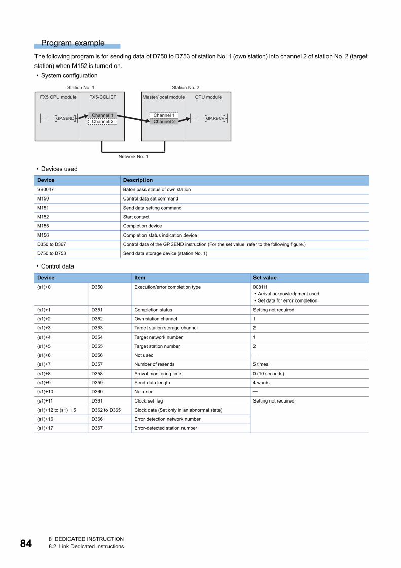
84
Program example
The following program is for sending data of D750 to D753 of station No. 1 (own station) into channel 2 of station No. 2 (target
station) when M152 is turned on.
• System configuration
• Devices used
• Control data
Device Description
SB0047 Baton pass status of own station
M150 Control data set command
M151 Send data setting command
M152 Start contact
M155 Completion device
M156 Completion status indication device
D350 to D367 Control data of the GP.SEND instruction (For the set value, refer to the following figure.)
D750 to D753 Send data storage device (station No. 1)
Device Item Set value
(s1)+0 D350 Execution/error completion type 0081H
• Arrival acknowledgment used
• Set data for error completion.
(s1)+1 D351 Completion status Setting not required
(s1)+2 D352 Own station channel 1
(s1)+3 D353 Target station storage channel 2
(s1)+4 D354 Target network number 1
(s1)+5 D355 Target station number 2
(s1)+6 D356 Not used
(s1)+7 D357 Number of resends 5 times
(s1)+8 D358 Arrival monitoring time 0 (10 seconds)
(s1)+9 D359 Send data length 4 words
(s1)+10 D360 Not used
(s1)+11 D361 Clock set flag Setting not required
(s1)+12 to (s1)+15 D362 to D365 Clock data (Set only in an abnormal state)
(s1)+16 D366 Error detection network number
(s1)+17 D367 Error-detected station number
GP.SEND GP.RECV
FX5-CCLIEF
Channel 2Channel 1
Channel 2Channel 1
Station No. 1 Station No. 2
Master/local module
Network No. 1
FX5 CPU module CPU module
8 DEDICATED INSTRUCTION8.2 Link Dedicated Instructions
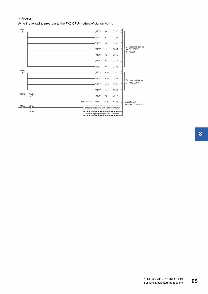
8
• Program
Write the following program to the FX5 CPU module of station No. 1.
H81MOV
MOV
D350
D352
MOV D353
M150
MOV D354
MOV D355
MOV D358
MOV D359
MOV D357
M155
M152 SB47
M156
M156
D350GP.SEND U1
M155
K1
K2
K1
K2
K0
K4
K10MOV D750M151
MOV D751
MOV D752
MOV D753
K20
K30
K40
K5
D750
Processing program upon normal completion
Execution of GP.SEND instruction
Control data setting for GP.SEND instruction
Store write data in D750 to D753.
Processing program upon error completion
8 DEDICATED INSTRUCTION8.2 Link Dedicated Instructions 85
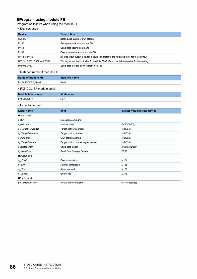
86
■Program using module FBProgram as follows when using the module FB
• Devices used
• Instance name of module FB
• FX5-CCLIEF module label
• Label to be used
Device Description
SB0047 Baton pass status of own station
M150 Setting command of module FB
M151 Send data setting command
M152 Execution command of module FB
M154 to M156 Bit-type input output label for module FB (Refer to the following table for the setting.)
D352 to D355, D359 and D368 Word-type input output label for module FB (Refer to the following table for the setting.)
D750 to D753 Send data storage device (station No. 1)
Name of module FB Instance name
M+FX5CCLIEF_Send Send
Module label name Module No.
FX5CCLIEF_1 No.1
Label name Item Setting value/setting device
■Input label
i_bEN Execution command
i_stModule Module label FX5CCLIEF_1
i_uTargetNetworkNo Target network number 1 (D354)
i_uTargetStationNo Target station number 2 (D355)
i_uChannel Own station channel 1 (D352)
i_uTargetChannel Target station data storage channel 2 (D353)
i_uDataLength Send data length 4 words (D359)
i_uSendData Send Data Storage Device D750
■Output label
o_bENO Execution status M154
o_bOK Normal completion M155
o_bErr Abnormal end M156
o_uErrId Error code D368
■Public label
pbi_uMonitorTime Arrival monitoring time 0 (10 seconds)
8 DEDICATED INSTRUCTION8.2 Link Dedicated Instructions
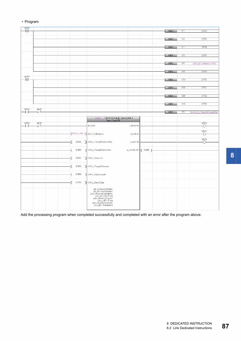
8
• Program
Add the processing program when completed successfully and completed with an error after the program above.
8 DEDICATED INSTRUCTION8.2 Link Dedicated Instructions 87
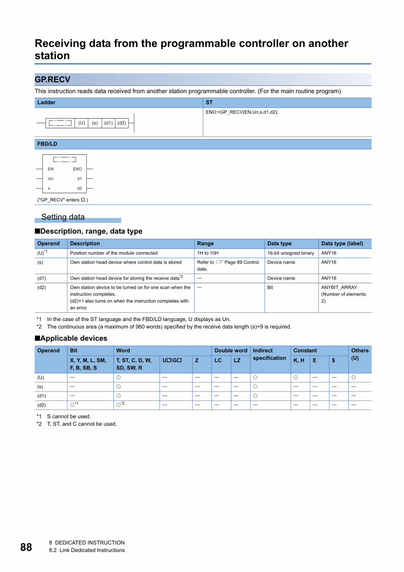
88
Receiving data from the programmable controller on another station
GP.RECVThis instruction reads data received from another station programmable controller. (For the main routine program)
Setting data
■Description, range, data type
*1 In the case of the ST language and the FBD/LD language, U displays as Un.*2 The continuous area (a maximum of 960 words) specified by the receive data length (s)+9 is required.
■Applicable devices
*1 S cannot be used.*2 T, ST, and C cannot be used.
Ladder ST
ENO:=GP_RECV(EN,Un,s,d1,d2);
FBD/LD
("GP_RECV" enters .)
Operand Description Range Data type Data type (label)
(U)*1 Position number of the module connected 1H to 10H 16-bit unsigned binary ANY16
(s) Own station head device where control data is stored Refer to Page 89 Control
data.
Device name ANY16
(d1) Own station head device for storing the receive data*2 Device name ANY16
(d2) Own station device to be turned on for one scan when the
instruction completes.
(d2)+1 also turns on when the instruction completes with
an error.
Bit ANYBIT_ARRAY
(Number of elements:
2)
Operand Bit Word Double word Indirect specification
Constant Others(U)X, Y, M, L, SM,
F, B, SB, ST, ST, C, D, W, SD, SW, R
U\G Z LC LZ K, H E $
(U)
(s)
(d1)
(d2) *1 *2
(U) (s) (d1) (d2)
EN ENO
d1
d2
Un
s
8 DEDICATED INSTRUCTION8.2 Link Dedicated Instructions
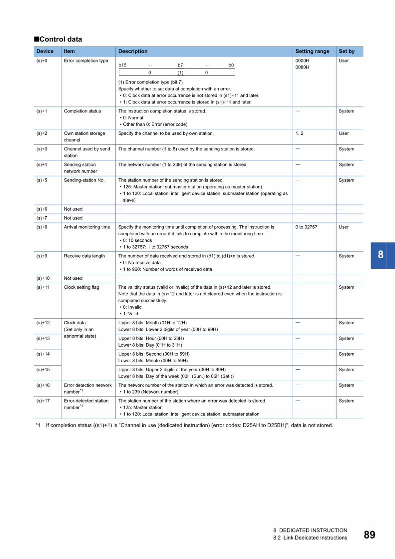
8
■Control data
*1 If completion status ((s1)+1) is "Channel in use (dedicated instruction) (error codes: D25AH to D25BH)", data is not stored.
Device Item Description Setting range Set by
(s)+0 Error completion type
(1) Error completion type (bit 7)
Specify whether to set data at completion with an error.
• 0: Clock data at error occurrence is not stored in (s1)+11 and later.
• 1: Clock data at error occurrence is stored in (s1)+11 and later.
0000H
0080H
User
(s)+1 Completion status The instruction completion status is stored.
• 0: Normal
• Other than 0: Error (error code)
System
(s)+2 Own station storage
channel
Specify the channel to be used by own station. 1, 2 User
(s)+3 Channel used by send
station
The channel number (1 to 8) used by the sending station is stored. System
(s)+4 Sending station
network number
The network number (1 to 239) of the sending station is stored. System
(s)+5 Sending-station No. The station number of the sending station is stored.
• 125: Master station, submaster station (operating as master station)
• 1 to 120: Local station, intelligent device station, submaster station (operating as
slave)
System
(s)+6 Not used
(s)+7 Not used
(s)+8 Arrival monitoring time Specify the monitoring time until completion of processing. The instruction is
completed with an error if it fails to complete within the monitoring time.
• 0: 10 seconds
• 1 to 32767: 1 to 32767 seconds
0 to 32767 User
(s)+9 Receive data length The number of data received and stored in (d1) to (d1)+n is stored.
• 0: No receive data
• 1 to 960: Number of words of received data
System
(s)+10 Not used
(s)+11 Clock setting flag The validity status (valid or invalid) of the data in (s)+12 and later is stored.
Note that the data in (s)+12 and later is not cleared even when the instruction is
completed successfully.
• 0: Invalid
• 1: Valid
System
(s)+12 Clock data
(Set only in an
abnormal state)
Upper 8 bits: Month (01H to 12H)
Lower 8 bits: Lower 2 digits of year (00H to 99H)
System
(s)+13 Upper 8 bits: Hour (00H to 23H)
Lower 8 bits: Day (01H to 31H)
System
(s)+14 Upper 8 bits: Second (00H to 59H)
Lower 8 bits: Minute (00H to 59H)
System
(s)+15 Upper 8 bits: Upper 2 digits of the year (00H to 99H)
Lower 8 bits: Day of the week (00H (Sun.) to 06H (Sat.))
System
(s)+16 Error detection network
number*1The network number of the station in which an error was detected is stored.
• 1 to 239 (Network number)
System
(s)+17 Error-detected station
number*1The station number of the station where an error was detected is stored.
• 125: Master station
• 1 to 120: Local station, intelligent device station, submaster station
System
b150 0(1)
b7 b0… …
8 DEDICATED INSTRUCTION8.2 Link Dedicated Instructions 89
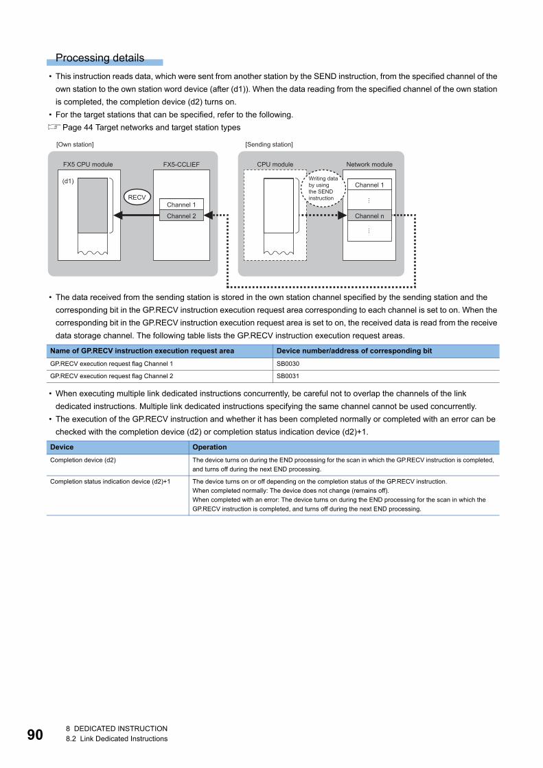
90
Processing details
• This instruction reads data, which were sent from another station by the SEND instruction, from the specified channel of the
own station to the own station word device (after (d1)). When the data reading from the specified channel of the own station
is completed, the completion device (d2) turns on.
• For the target stations that can be specified, refer to the following.
Page 44 Target networks and target station types
• The data received from the sending station is stored in the own station channel specified by the sending station and the
corresponding bit in the GP.RECV instruction execution request area corresponding to each channel is set to on. When the
corresponding bit in the GP.RECV instruction execution request area is set to on, the received data is read from the receive
data storage channel. The following table lists the GP.RECV instruction execution request areas.
• When executing multiple link dedicated instructions concurrently, be careful not to overlap the channels of the link
dedicated instructions. Multiple link dedicated instructions specifying the same channel cannot be used concurrently.
• The execution of the GP.RECV instruction and whether it has been completed normally or completed with an error can be
checked with the completion device (d2) or completion status indication device (d2)+1.
Name of GP.RECV instruction execution request area Device number/address of corresponding bit
GP.RECV execution request flag Channel 1 SB0030
GP.RECV execution request flag Channel 2 SB0031
Device Operation
Completion device (d2) The device turns on during the END processing for the scan in which the GP.RECV instruction is completed,
and turns off during the next END processing.
Completion status indication device (d2)+1 The device turns on or off depending on the completion status of the GP.RECV instruction.
When completed normally: The device does not change (remains off).
When completed with an error: The device turns on during the END processing for the scan in which the
GP.RECV instruction is completed, and turns off during the next END processing.
RECV
(d1)
FX5-CCLIEF
Channel 1
Channel 2
FX5 CPU module CPU module Network module
[Own station] [Sending station]
Channel 1
Channel n
Writing databy usingthe SENDinstruction
8 DEDICATED INSTRUCTION8.2 Link Dedicated Instructions
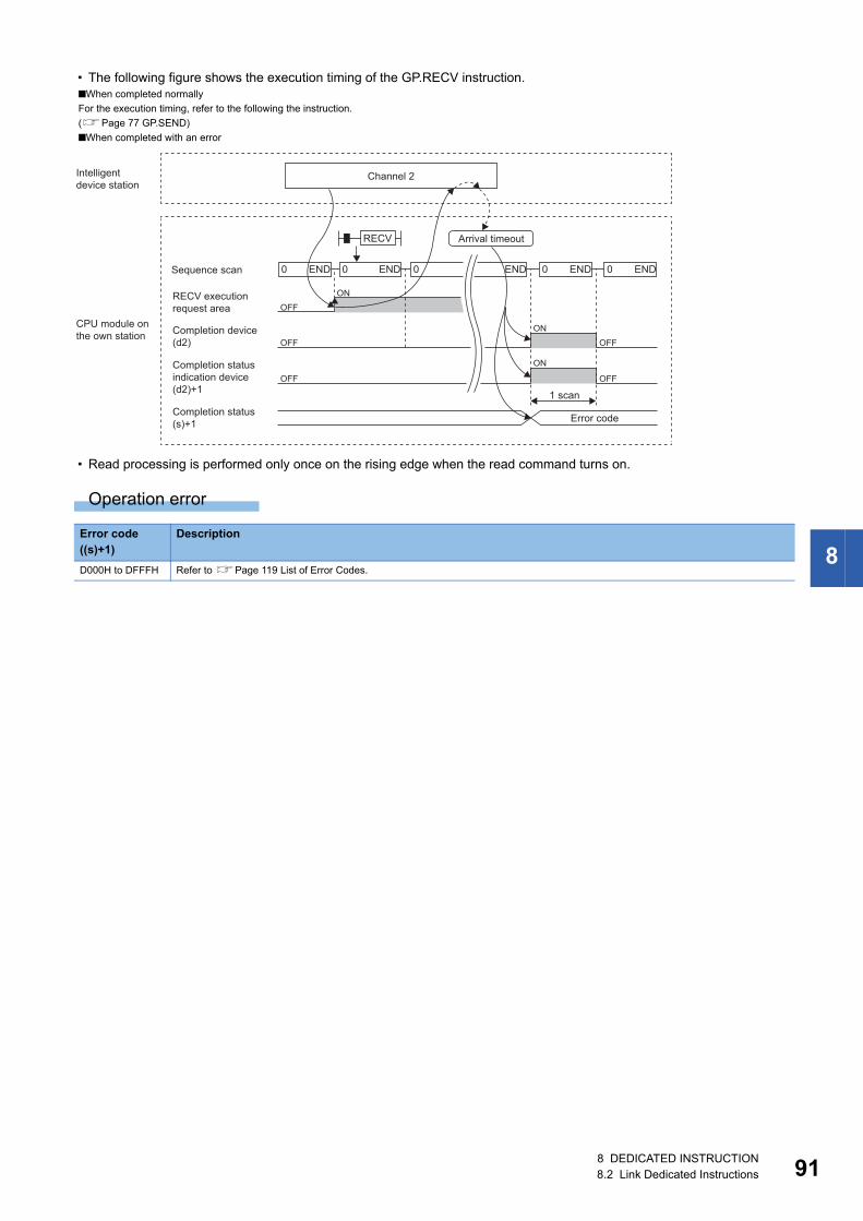
8
• The following figure shows the execution timing of the GP.RECV instruction.
• Read processing is performed only once on the rising edge when the read command turns on.
Operation error
■When completed normally
For the execution timing, refer to the following the instruction.
(Page 77 GP.SEND)
■When completed with an error
Error code ((s)+1)
Description
D000H to DFFFH Refer to Page 119 List of Error Codes.
OFF
OFF OFF
OFF
OFFON
ON
ON
RECV
END0 END0END0 END0 END0
1 scan
Error code
Arrival timeout
Channel 2Intelligent device station
CPU module onthe own station
Sequence scan
RECV executionrequest area
Completion device(d2)
Completion statusindication device(d2)+1
Completion status(s)+1
8 DEDICATED INSTRUCTION8.2 Link Dedicated Instructions 91
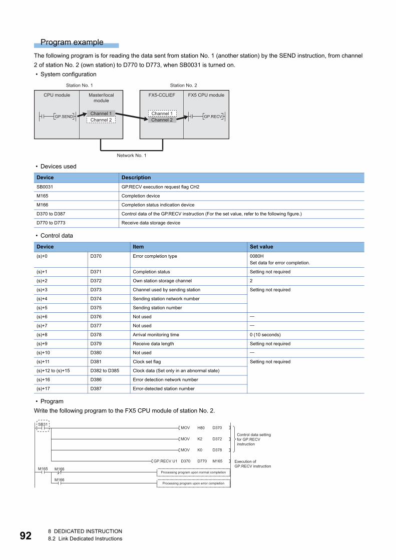
92
Program example
The following program is for reading the data sent from station No. 1 (another station) by the SEND instruction, from channel
2 of station No. 2 (own station) to D770 to D773, when SB0031 is turned on.
• System configuration
• Devices used
• Control data
• Program
Write the following program to the FX5 CPU module of station No. 2.
Device Description
SB0031 GP.RECV execution request flag CH2
M165 Completion device
M166 Completion status indication device
D370 to D387 Control data of the GP.RECV instruction (For the set value, refer to the following figure.)
D770 to D773 Receive data storage device
Device Item Set value
(s)+0 D370 Error completion type 0080H
Set data for error completion.
(s)+1 D371 Completion status Setting not required
(s)+2 D372 Own station storage channel 2
(s)+3 D373 Channel used by sending station Setting not required
(s)+4 D374 Sending station network number
(s)+5 D375 Sending station number
(s)+6 D376 Not used
(s)+7 D377 Not used
(s)+8 D378 Arrival monitoring time 0 (10 seconds)
(s)+9 D379 Receive data length Setting not required
(s)+10 D380 Not used
(s)+11 D381 Clock set flag Setting not required
(s)+12 to (s)+15 D382 to D385 Clock data (Set only in an abnormal state)
(s)+16 D386 Error detection network number
(s)+17 D387 Error-detected station number
GP.SEND GP.RECVChannel 2Channel 1
Channel 2
Master/localmodule
FX5-CCLIEF
Station No. 1 Station No. 2
Network No. 1
CPU module FX5 CPU module
Channel 1
MOV D370
MOV D372
SB31
MOV D378
GP.RECV U1 M165
M166
M166
M165
H80
K2
K0
D770D370
Processing program upon normal completion
Execution of GP.RECV instruction
Control data setting for GP.RECV instruction
Processing program upon error completion
8 DEDICATED INSTRUCTION8.2 Link Dedicated Instructions
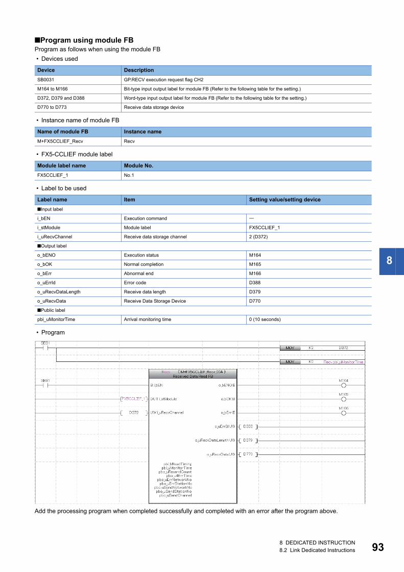
8
■Program using module FBProgram as follows when using the module FB
• Devices used
• Instance name of module FB
• FX5-CCLIEF module label
• Label to be used
• Program
Add the processing program when completed successfully and completed with an error after the program above.
Device Description
SB0031 GP.RECV execution request flag CH2
M164 to M166 Bit-type input output label for module FB (Refer to the following table for the setting.)
D372, D379 and D388 Word-type input output label for module FB (Refer to the following table for the setting.)
D770 to D773 Receive data storage device
Name of module FB Instance name
M+FX5CCLIEF_Recv Recv
Module label name Module No.
FX5CCLIEF_1 No.1
Label name Item Setting value/setting device
■Input label
i_bEN Execution command
i_stModule Module label FX5CCLIEF_1
i_uRecvChannel Receive data storage channel 2 (D372)
■Output label
o_bENO Execution status M164
o_bOK Normal completion M165
o_bErr Abnormal end M166
o_uErrId Error code D388
o_uRecvDataLength Receive data length D379
o_uRecvData Receive Data Storage Device D770
■Public label
pbi_uMonitorTime Arrival monitoring time 0 (10 seconds)
8 DEDICATED INSTRUCTION8.2 Link Dedicated Instructions 93
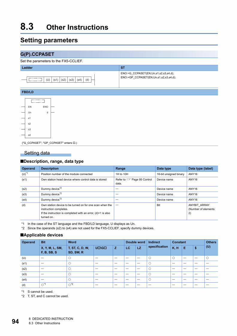
94
8.3 Other Instructions
Setting parameters
G(P).CCPASETSet the parameters to the FX5-CCLIEF.
Setting data
■Description, range, data type
*1 In the case of the ST language and the FBD/LD language, U displays as Un.*2 Since the operands (s2) to (s4) are not used for the FX5-CCLIEF, specify dummy devices.
■Applicable devices
*1 S cannot be used.*2 T, ST, and C cannot be used.
Ladder ST
ENO:=G_CCPASET(EN,Un,s1,s2,s3,s4,d);
ENO:=GP_CCPASET(EN,Un,s1,s2,s3,s4,d);
FBD/LD
("G_CCPASET", "GP_CCPASET" enters .)
Operand Description Range Data type Data type (label)
(U)*1 Position number of the module connected 1H to 10H 16-bit unsigned binary ANY16
(s1) Own station head device where control data is stored Refer to Page 95 Control
data.
Device name ANY16
(s2) Dummy device*2 Device name ANY16
(s3) Dummy device*2 Device name ANY16
(s4) Dummy device*2 Device name ANY16
(d) Own station device to be turned on for one scan when the
instruction completes.
If the instruction is completed with an error, (d)+1 is also
turned on.
Bit ANYBIT_ARRAY
(Number of elements:
2)
Operand Bit Word Double word Indirect specification
Constant Others(U)X, Y, M, L, SM,
F, B, SB, ST, ST, C, D, W, SD, SW, R
U\G Z LC LZ K, H E $
(U)
(s1)
(s2)
(s3)
(s4)
(d) *1 *2
(U) (s1) (s2) (s3) (s4) (d)
EN ENO
dUn
s1
s2
s3
s4
8 DEDICATED INSTRUCTION8.3 Other Instructions
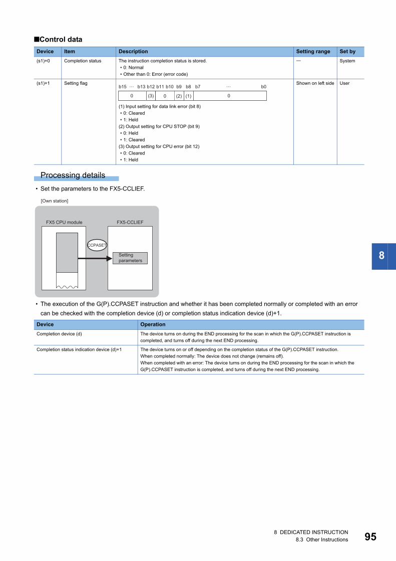
8
■Control data
Processing details
• Set the parameters to the FX5-CCLIEF.
• The execution of the G(P).CCPASET instruction and whether it has been completed normally or completed with an error
can be checked with the completion device (d) or completion status indication device (d)+1.
Device Item Description Setting range Set by
(s1)+0 Completion status The instruction completion status is stored.
• 0: Normal
• Other than 0: Error (error code)
System
(s1)+1 Setting flag
(1) Input setting for data link error (bit 8)
• 0: Cleared
• 1: Held
(2) Output setting for CPU STOP (bit 9)
• 0: Held
• 1: Cleared
(3) Output setting for CPU error (bit 12)
• 0: Cleared
• 1: Held
Shown on left side User
Device Operation
Completion device (d) The device turns on during the END processing for the scan in which the G(P).CCPASET instruction is
completed, and turns off during the next END processing.
Completion status indication device (d)+1 The device turns on or off depending on the completion status of the G(P).CCPASET instruction.
When completed normally: The device does not change (remains off).
When completed with an error: The device turns on during the END processing for the scan in which the
G(P).CCPASET instruction is completed, and turns off during the next END processing.
b15 b13 b12 b11 b10 b9 b8 b7 b0
(3) (2) (1) 000
……
CCPASET
FX5-CCLIEFFX5 CPU module
[Own station]
Settingparameters
8 DEDICATED INSTRUCTION8.3 Other Instructions 95
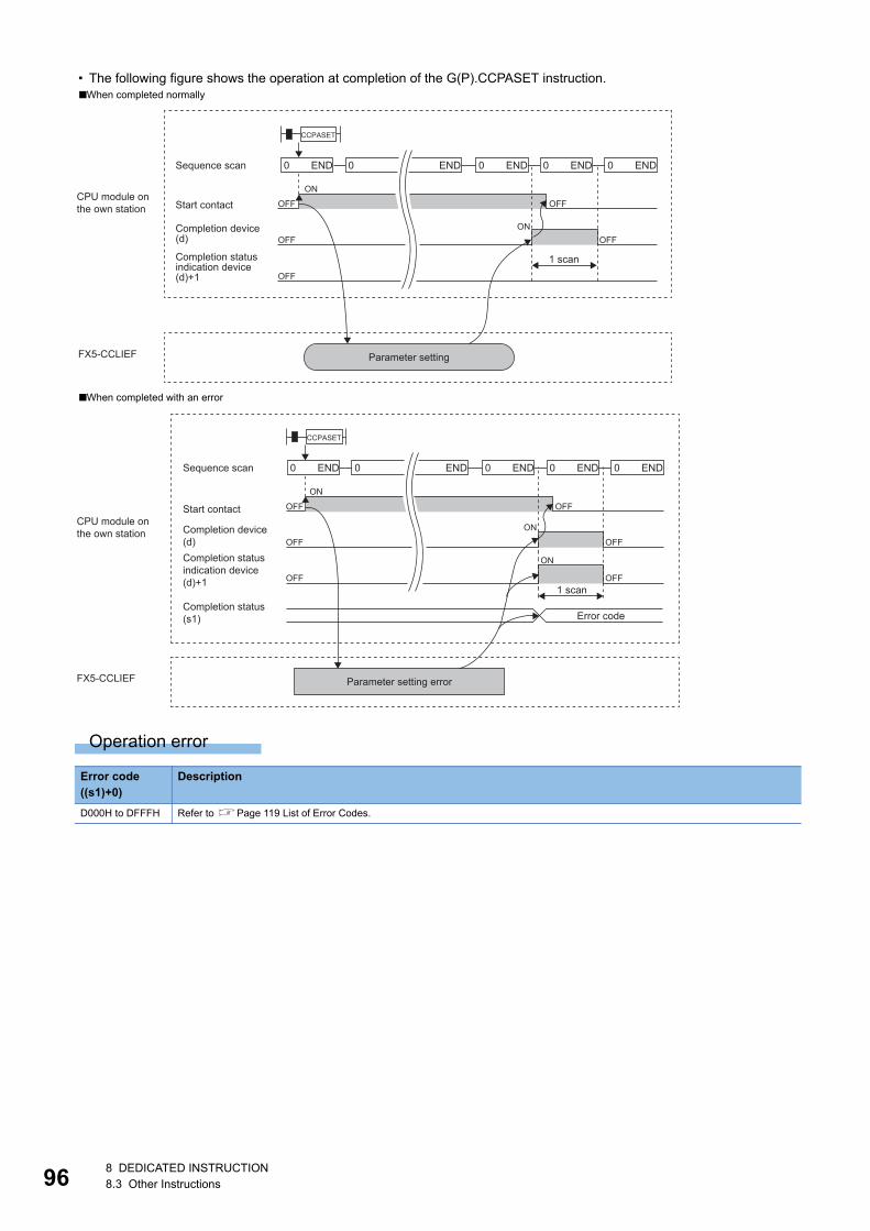
96
• The following figure shows the operation at completion of the G(P).CCPASET instruction.
Operation error
■When completed normally
■When completed with an error
Error code ((s1)+0)
Description
D000H to DFFFH Refer to Page 119 List of Error Codes.
END0 END0 END0 END0 END0
OFF
OFF OFF
OFF
ON
ON
OFF
CCPASET
FX5-CCLIEF
Sequence scan
Start contactCPU module onthe own station
Completion device(d)
Completion statusindication device(d)+1
Parameter setting
1 scan
END0 END0 END0 END0 END0
OFF
OFF
OFF
OFF
OFF
ON
ON
ON
OFF
CCPASET
FX5-CCLIEF
1 scan
Error code
Sequence scan
Start contact
Completion device(d)Completion statusindication device(d)+1
Completion status(s1)
Parameter setting error
CPU module onthe own station
8 DEDICATED INSTRUCTION8.3 Other Instructions
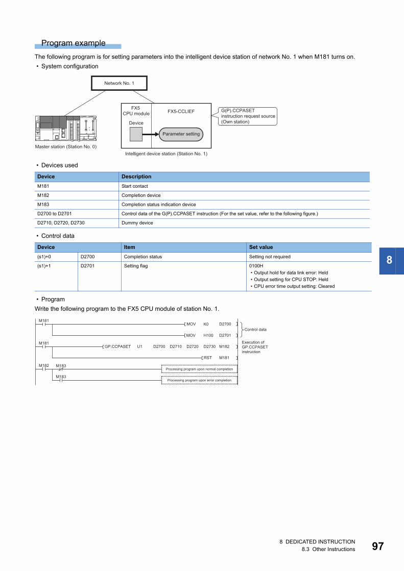
8
Program example
The following program is for setting parameters into the intelligent device station of network No. 1 when M181 turns on.
• System configuration
• Devices used
• Control data
• Program
Write the following program to the FX5 CPU module of station No. 1.
Device Description
M181 Start contact
M182 Completion device
M183 Completion status indication device
D2700 to D2701 Control data of the G(P).CCPASET instruction (For the set value, refer to the following figure.)
D2710, D2720, D2730 Dummy device
Device Item Set value
(s1)+0 D2700 Completion status Setting not required
(s1)+1 D2701 Setting flag 0100H
• Output hold for data link error: Held
• Output setting for CPU STOP: Held
• CPU error time output setting: Cleared
FX5-CCLIEFFX5
CPU module
Device
Master station (Station No. 0)
G(P).CCPASET instruction request source(Own station)
Intelligent device station (Station No. 1)
Network No. 1
Parameter setting
MOV D2700
MOV D2701
M181
M181
RST M181
GP.CCPASET M182
M183
M183
M182
K0
H100
D2730D2720D2710D2700U1
Processing program upon normal completion
Execution of GP.CCPASET instruction
Control data
Processing program upon error completion
8 DEDICATED INSTRUCTION8.3 Other Instructions 97
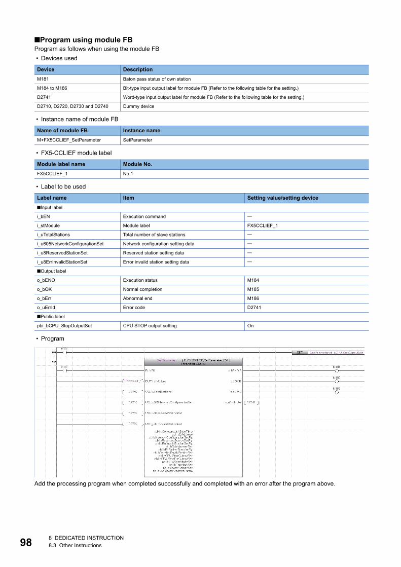
98
■Program using module FBProgram as follows when using the module FB
• Devices used
• Instance name of module FB
• FX5-CCLIEF module label
• Label to be used
• Program
Add the processing program when completed successfully and completed with an error after the program above.
Device Description
M181 Baton pass status of own station
M184 to M186 Bit-type input output label for module FB (Refer to the following table for the setting.)
D2741 Word-type input output label for module FB (Refer to the following table for the setting.)
D2710, D2720, D2730 and D2740 Dummy device
Name of module FB Instance name
M+FX5CCLIEF_SetParameter SetParameter
Module label name Module No.
FX5CCLIEF_1 No.1
Label name Item Setting value/setting device
■Input label
i_bEN Execution command
i_stModule Module label FX5CCLIEF_1
i_uTotalStations Total number of slave stations
i_u605NetworkConfigurationSet Network configuration setting data
i_u8ReservedStationSet Reserved station setting data
i_u8ErrInvalidStationSet Error invalid station setting data
■Output label
o_bENO Execution status M184
o_bOK Normal completion M185
o_bErr Abnormal end M186
o_uErrId Error code D2741
■Public label
pbi_bCPU_StopOutputSet CPU STOP output setting On
8 DEDICATED INSTRUCTION8.3 Other Instructions
8
Operating procedure
The procedure of parameter settings using the G(P).CCPASET instruction is as follows.
1. Before setting parameters using the G(P).CCPASET instruction, set the following item in the network parameters of GX
Works3.
• Network Number: Set the desired value.
• Setting Method: Set the desired value.
• Parameter Setting Method: Select "Program".
2. Create a G(P).CCPASET instruction program.
3. Write parameters and programs to the FX5 CPU module through GX Works3.
4. Execute the G(P).CCPASET instruction.
8 DEDICATED INSTRUCTION8.3 Other Instructions 99
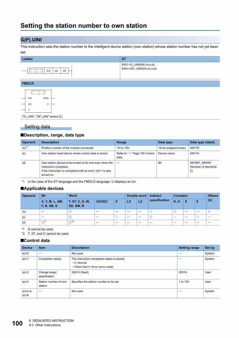
10
Setting the station number to own station
G(P).UINIThis instruction sets the station number to the intelligent device station (own station) whose station number has not yet been
set.
Setting data
■Description, range, data type
*1 In the case of the ST language and the FBD/LD language, U displays as Un.
■Applicable devices
*1 S cannot be used.*2 T, ST, and C cannot be used.
■Control data
Ladder ST
ENO:=G_UINI(EN,Un,s,d);
ENO:=GP_UINI(EN,Un,s,d);
FBD/LD
("G_UINI", "GP_UINI" enters .)
Operand Description Range Data type Data type (label)
(U)*1 Position number of the module connected 1H to 10H 16-bit unsigned binary ANY16
(s) Own station head device where control data is stored Refer to Page 100 Control
data.
Device name ANY16
(d) Own station device to be turned on for one scan when the
instruction completes.
If the instruction is completed with an error, (d)+1 is also
turned on.
Bit ANYBIT_ARRAY
(Number of elements:
2)
Operand Bit Word Double word Indirect specification
Constant Others(U)X, Y, M, L, SM,
F, B, SB, ST, ST, C, D, W, SD, SW, R
U\G Z LC LZ K, H E $
(U)
(s)
(d) *1 *2
Device Item Description Setting range Set by
(s)+0 Not used System
(s)+1 Completion status The instruction completion status is stored.
• 0: Normal
• Other than 0: Error (error code)
System
(s)+2 Change target
specification
0001H (fixed) 0001H User
(s)+3 Station number of own
station
Specifies the station number to be set. 1 to 120 User
(s)+4 to
(s)+9
Not used System
(U) (s) (d)
EN ENO
dUn
s
08 DEDICATED INSTRUCTION8.3 Other Instructions
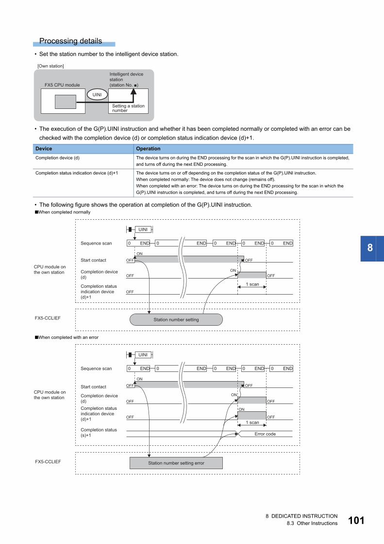
8
Processing details
• Set the station number to the intelligent device station.
• The execution of the G(P).UINI instruction and whether it has been completed normally or completed with an error can be
checked with the completion device (d) or completion status indication device (d)+1.
• The following figure shows the operation at completion of the G(P).UINI instruction.
Device Operation
Completion device (d) The device turns on during the END processing for the scan in which the G(P).UINI instruction is completed,
and turns off during the next END processing.
Completion status indication device (d)+1 The device turns on or off depending on the completion status of the G(P).UINI instruction.
When completed normally: The device does not change (remains off).
When completed with an error: The device turns on during the END processing for the scan in which the
G(P).UINI instruction is completed, and turns off during the next END processing.
■When completed normally
■When completed with an error
UINI
FX5 CPU module
Setting a stationnumber
Intelligent device station(station No. ■)
[Own station]
END0 END0 END0 END0 END0
OFF
OFF
OFF
OFF
ON
ON
OFF
UINI
FX5-CCLIEF
1 scan
Sequence scan
Start contact
Completion device (d)
Completion statusindication device(d)+1
Station number setting
CPU module onthe own station
END0 END0 END0 END0 END0
OFF
OFF
OFF
OFF
OFF
ON
ON
ON
OFF
UINI
FX5-CCLIEF
1 scan
Error code
Sequence scan
Start contact
Completion device (d)Completion statusindication device(d)+1
Completion status(s)+1
Station number setting error
CPU module onthe own station
8 DEDICATED INSTRUCTION8.3 Other Instructions 101
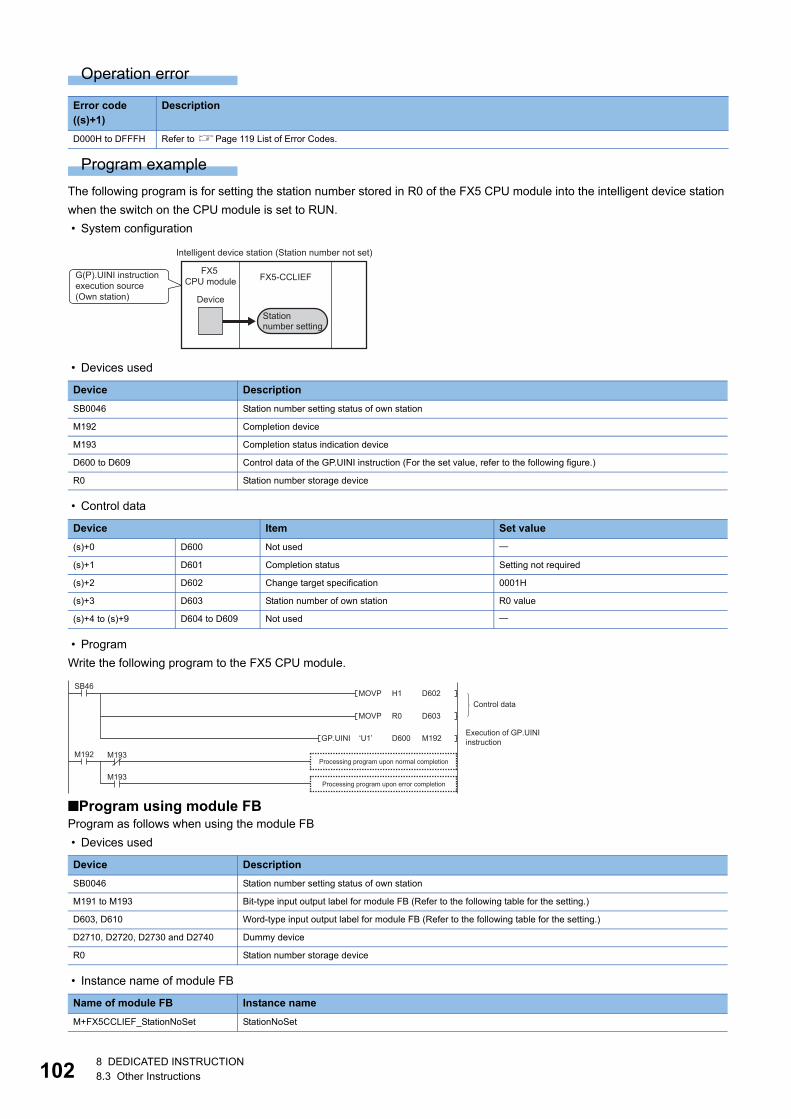
10
Operation error
Program example
The following program is for setting the station number stored in R0 of the FX5 CPU module into the intelligent device station
when the switch on the CPU module is set to RUN.
• System configuration
• Devices used
• Control data
• Program
Write the following program to the FX5 CPU module.
■Program using module FBProgram as follows when using the module FB
• Devices used
• Instance name of module FB
Error code ((s)+1)
Description
D000H to DFFFH Refer to Page 119 List of Error Codes.
Device Description
SB0046 Station number setting status of own station
M192 Completion device
M193 Completion status indication device
D600 to D609 Control data of the GP.UINI instruction (For the set value, refer to the following figure.)
R0 Station number storage device
Device Item Set value
(s)+0 D600 Not used
(s)+1 D601 Completion status Setting not required
(s)+2 D602 Change target specification 0001H
(s)+3 D603 Station number of own station R0 value
(s)+4 to (s)+9 D604 to D609 Not used
Device Description
SB0046 Station number setting status of own station
M191 to M193 Bit-type input output label for module FB (Refer to the following table for the setting.)
D603, D610 Word-type input output label for module FB (Refer to the following table for the setting.)
D2710, D2720, D2730 and D2740 Dummy device
R0 Station number storage device
Name of module FB Instance name
M+FX5CCLIEF_StationNoSet StationNoSet
FX5-CCLIEFFX5
CPU module
Device
Intelligent device station (Station number not set)
G(P).UINI instruction execution source(Own station)
Station number setting
MOVP D602SB46
M193
M193
M192
H1
MOVP D603R0
GP.UINI M192D600‘U1’
Processing program upon normal completion
Execution of GP.UINI instruction
Control data
Processing program upon error completion
28 DEDICATED INSTRUCTION8.3 Other Instructions
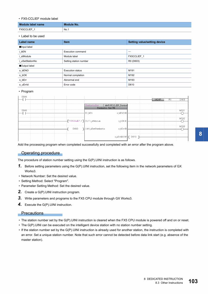
8
• FX5-CCLIEF module label
• Label to be used
• Program
Add the processing program when completed successfully and completed with an error after the program above.
Operating procedure
The procedure of station number setting using the G(P).UINI instruction is as follows.
1. Before setting parameters using the G(P).UINI instruction, set the following item in the network parameters of GX
Works3.
• Network Number: Set the desired value.
• Setting Method: Select "Program".
• Parameter Setting Method: Set the desired value.
2. Create a G(P).UINI instruction program.
3. Write parameters and programs to the FX5 CPU module through GX Works3.
4. Execute the G(P).UINI instruction.
Precautions
• The station number set by the G(P).UINI instruction is cleared when the FX5 CPU module is powered off and on or reset.
• The G(P).UINI can be executed on the intelligent device station with no station number setting.
• If the station number set by the G(P).UINI instruction is already used for another station, the instruction is completed with
an error. Set a unique station number. Note that such error cannot be detected before data link start (e.g. absence of the
master station).
Module label name Module No.
FX5CCLIEF_1 No.1
Label name Item Setting value/setting device
■Input label
i_bEN Execution command
i_stModule Module label FX5CCLIEF_1
i_uSetStationNo Setting station number R0 (D603)
■Output label
o_bENO Execution status M191
o_bOK Normal completion M192
o_bErr Abnormal end M193
o_uErrId Error code D610
8 DEDICATED INSTRUCTION8.3 Other Instructions 103
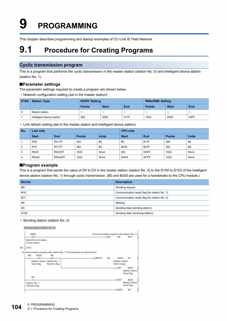
10
9 PROGRAMMING
This chapter describes programming and startup examples of CC-Link IE Field Network.
9.1 Procedure for Creating Programs
Cyclic transmission programThis is a program that performs the cyclic transmission in the master station (station No. 0) and intelligent device station
(station No. 1).
■Parameter settingsThe parameter settings required to create a program are shown below.
• Network configuration setting (set in the master station)
• Link refresh setting (set in the master station and intelligent device station)
■Program exampleThis is a program that sends the value of D0 to D3 in the master station (station No. 0) to the D100 to D103 of the intelligent
device station (station No. 1) through cyclic transmission. (B0 and B200 are used for a handshake to the CPU module.)
• Sending station (station No. 0)
STA# Station Type RX/RY Setting RWw/RWr Setting
Points Start End Points Start End
0 Master station
1 Intelligent device station 384 0000 017F 1024 0000 03FF
No. Link side CPU side
Start End Points Units Start End Points Units
1 RX0 RX17F 384 Bit B0 B17F 384 Bit
2 RY0 RY17F 384 Bit B200 B37F 384 Bit
3 RWr0 RWr3FF 1024 Word W0 W3FF 1024 Word
4 RWw0 RWw3FF 1024 Word W400 W7FF 1024 Word
Device Description
M0 Sending request
M10 Communication ready flag (for station No. 1)
M11 Communication ready flag (for station No. 0)
N0 Nesting
D0 Sending data (sending station)
D100 Sending data (receiving station)
N0MC M10SB49
M10N0
RST B200
MCR N0
BMOV D0 K4M0 B200 B0
B200
W400
SET
Data link error status of own station
Master stationSend flag
Master stationSend range
Master stationSend flag
Master stationSend flag
Station No. 1Receive flag
<Communication program with station No. 1>
<Communication program with station No. 1 (Processing to be performed)>
B0
Station No. 1Receive flag
Sending station (Station No. 0)
49 PROGRAMMING9.1 Procedure for Creating Programs
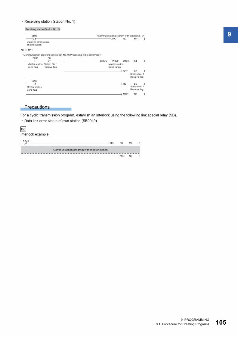
9
• Receiving station (station No. 1)
Precautions
For a cyclic transmission program, establish an interlock using the following link special relay (SB).
• Data link error status of own station (SB0049)
Ex.
Interlock example
N0MC M11SB49
M11N0
RST B0
MCR N0
B200
BMOV W400 K4B200 B0
B0
D100
SET
Data link error status of own station
Master stationSend flag
Master stationSend range
Station No. 1Receive flag
Station No. 1Receive flag
Station No. 1Receive flag
<Communication program with station No. 0>
<Communication program with station No. 0 (Processing to be performed)>
Master stationSend flag
Receiving station (Station No. 1)
MC M0
N0
SB49N0
MCR
Communication program with master station
9 PROGRAMMING9.1 Procedure for Creating Programs 105
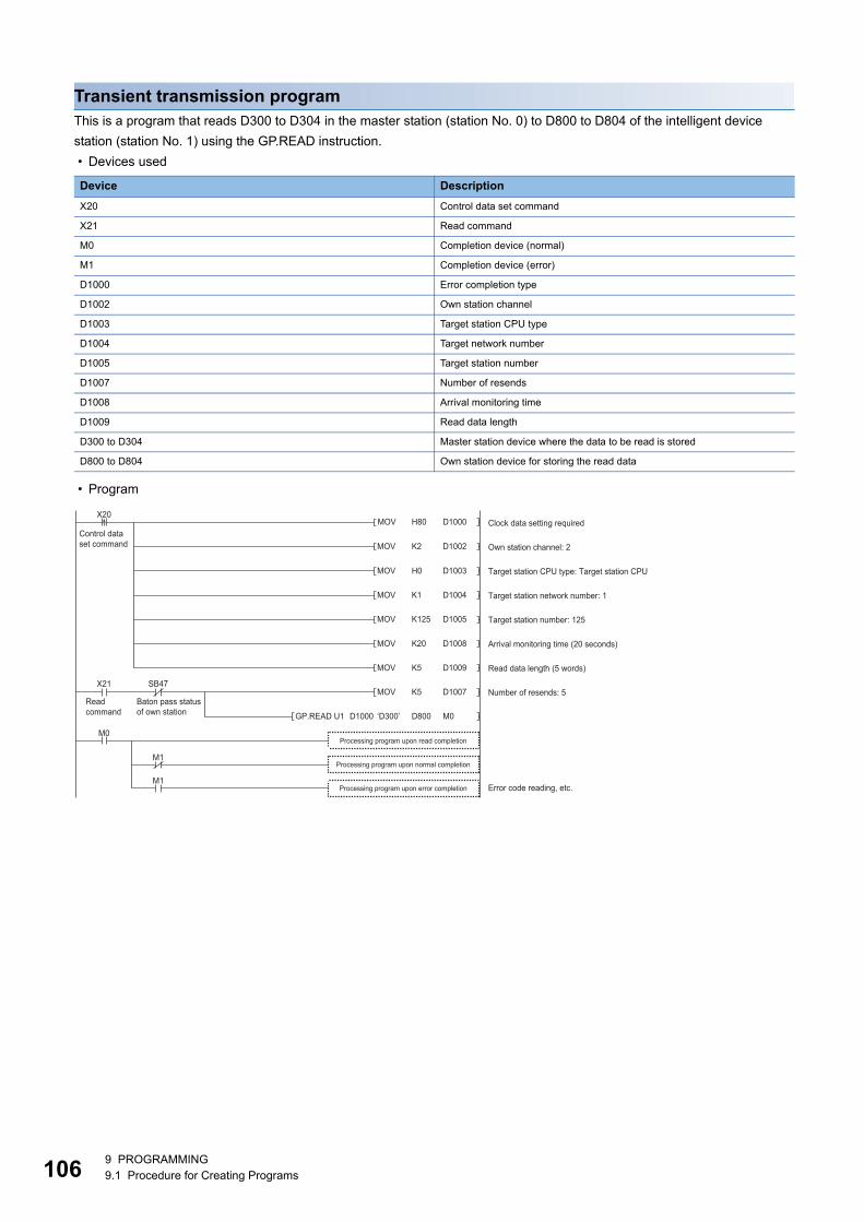
10
Transient transmission programThis is a program that reads D300 to D304 in the master station (station No. 0) to D800 to D804 of the intelligent device
station (station No. 1) using the GP.READ instruction.
• Devices used
• Program
Device Description
X20 Control data set command
X21 Read command
M0 Completion device (normal)
M1 Completion device (error)
D1000 Error completion type
D1002 Own station channel
D1003 Target station CPU type
D1004 Target network number
D1005 Target station number
D1007 Number of resends
D1008 Arrival monitoring time
D1009 Read data length
D300 to D304 Master station device where the data to be read is stored
D800 to D804 Own station device for storing the read data
H80MOV
MOV
D1000
D1002
MOV D1003
X20
MOV D1004
MOV D1005
MOV D1008
MOV D1009
MOV D1007X21
M1
‘D300’GP.READ U1 M0
M0
K2
H0
K1
K125
K20
K5
K5
D800D1000
M1
SB47
Processing program upon read completion
Clock data setting required
Own station channel: 2
Target station CPU type: Target station CPU
Target station network number: 1
Target station number: 125
Arrival monitoring time (20 seconds)
Read data length (5 words)
Number of resends: 5
Error code reading, etc.
Control data set command
Read command
Baton pass status of own station
Processing program upon error completion
Processing program upon normal completion
69 PROGRAMMING9.1 Procedure for Creating Programs
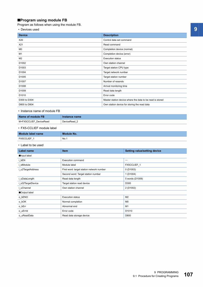
9
■Program using module FBProgram as follows when using the module FB.
• Devices used
• Instance name of module FB
• FX5-CCLIEF module label
• Label to be used
Device Description
X20 Control data set command
X21 Read command
M0 Completion device (normal)
M1 Completion device (error)
M2 Execution status
D1002 Own station channel
D1003 Target station CPU type
D1004 Target network number
D1005 Target station number
D1007 Number of resends
D1008 Arrival monitoring time
D1009 Read data length
D1010 Error code
D300 to D304 Master station device where the data to be read is stored
D800 to D804 Own station device for storing the read data
Name of module FB Instance name
M+FX5CCLIEF_DeviceRead DeviceRead_2
Module label name Module No.
FX5CCLIEF_1 No.1
Label name Item Setting value/setting device
■Input label
i_bEN Execution command
i_stModule Module label FX5CCLIEF_1
i_u2TargetAddress First word: target station network number 0 (D1003)
Second word: Target station number 1 (D1004)
i_uDataLength Read data length 5 words (D1009)
i_s32TargetDevice Target station read device D300
i_uChannel Own station channel 2 (D1002)
■Output label
o_bENO Execution status M2
o_bOK Normal completion M0
o_bErr Abnormal end M1
o_uErrId Error code D1010
o_uReadData Read data storage device D800
9 PROGRAMMING9.1 Procedure for Creating Programs 107
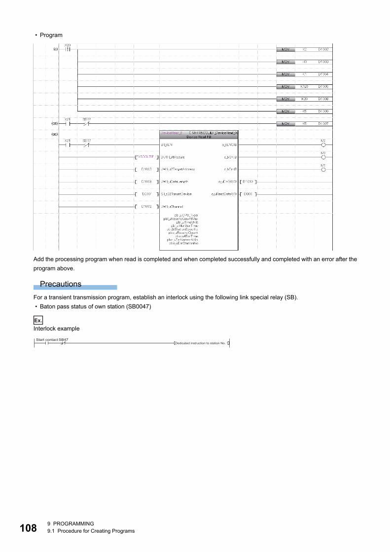
10
• Program
Add the processing program when read is completed and when completed successfully and completed with an error after the
program above.
Precautions
For a transient transmission program, establish an interlock using the following link special relay (SB).
• Baton pass status of own station (SB0047)
Ex.
Interlock example
SB47Start contactDedicated instruction to station No. 1
89 PROGRAMMING9.1 Procedure for Creating Programs
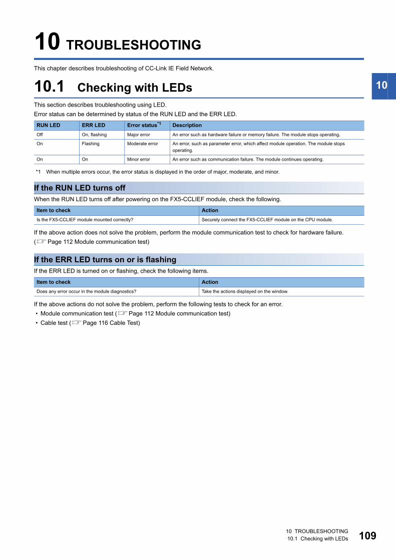
10
10 TROUBLESHOOTING
This chapter describes troubleshooting of CC-Link IE Field Network.
10.1 Checking with LEDsThis section describes troubleshooting using LED.
Error status can be determined by status of the RUN LED and the ERR LED.
*1 When multiple errors occur, the error status is displayed in the order of major, moderate, and minor.
If the RUN LED turns offWhen the RUN LED turns off after powering on the FX5-CCLIEF module, check the following.
If the above action does not solve the problem, perform the module communication test to check for hardware failure.
(Page 112 Module communication test)
If the ERR LED turns on or is flashingIf the ERR LED is turned on or flashing, check the following items.
If the above actions do not solve the problem, perform the following tests to check for an error.
• Module communication test (Page 112 Module communication test)
• Cable test (Page 116 Cable Test)
RUN LED ERR LED Error status*1 Description
Off On, flashing Major error An error such as hardware failure or memory failure. The module stops operating.
On Flashing Moderate error An error, such as parameter error, which affect module operation. The module stops
operating.
On On Minor error An error such as communication failure. The module continues operating.
Item to check Action
Is the FX5-CCLIEF module mounted correctly? Securely connect the FX5-CCLIEF module on the CPU module.
Item to check Action
Does any error occur in the module diagnostics? Take the actions displayed on the window.
10 TROUBLESHOOTING10.1 Checking with LEDs 109
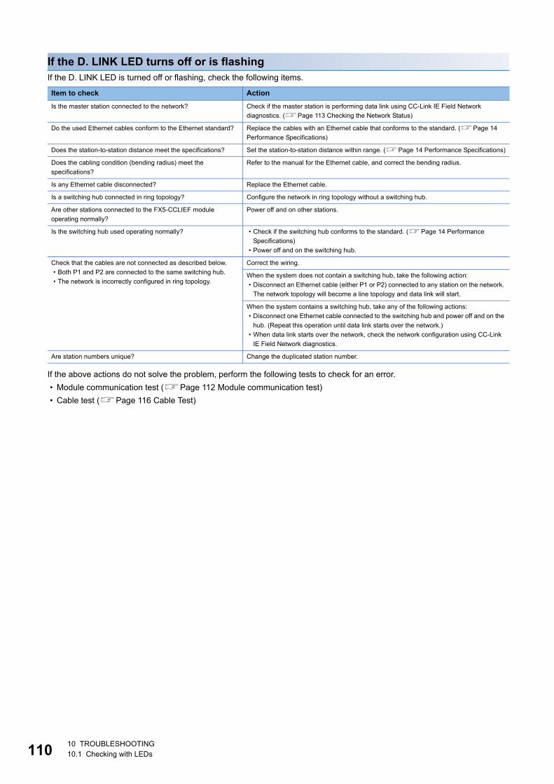
11
If the D. LINK LED turns off or is flashingIf the D. LINK LED is turned off or flashing, check the following items.
If the above actions do not solve the problem, perform the following tests to check for an error.
• Module communication test (Page 112 Module communication test)
• Cable test (Page 116 Cable Test)
Item to check Action
Is the master station connected to the network? Check if the master station is performing data link using CC-Link IE Field Network
diagnostics. (Page 113 Checking the Network Status)
Do the used Ethernet cables conform to the Ethernet standard? Replace the cables with an Ethernet cable that conforms to the standard. (Page 14
Performance Specifications)
Does the station-to-station distance meet the specifications? Set the station-to-station distance within range. (Page 14 Performance Specifications)
Does the cabling condition (bending radius) meet the
specifications?
Refer to the manual for the Ethernet cable, and correct the bending radius.
Is any Ethernet cable disconnected? Replace the Ethernet cable.
Is a switching hub connected in ring topology? Configure the network in ring topology without a switching hub.
Are other stations connected to the FX5-CCLIEF module
operating normally?
Power off and on other stations.
Is the switching hub used operating normally? • Check if the switching hub conforms to the standard. (Page 14 Performance
Specifications)
• Power off and on the switching hub.
Check that the cables are not connected as described below.
• Both P1 and P2 are connected to the same switching hub.
• The network is incorrectly configured in ring topology.
Correct the wiring.
When the system does not contain a switching hub, take the following action:
• Disconnect an Ethernet cable (either P1 or P2) connected to any station on the network.
The network topology will become a line topology and data link will start.
When the system contains a switching hub, take any of the following actions:
• Disconnect one Ethernet cable connected to the switching hub and power off and on the
hub. (Repeat this operation until data link starts over the network.)
• When data link starts over the network, check the network configuration using CC-Link
IE Field Network diagnostics.
Are station numbers unique? Change the duplicated station number.
010 TROUBLESHOOTING10.1 Checking with LEDs
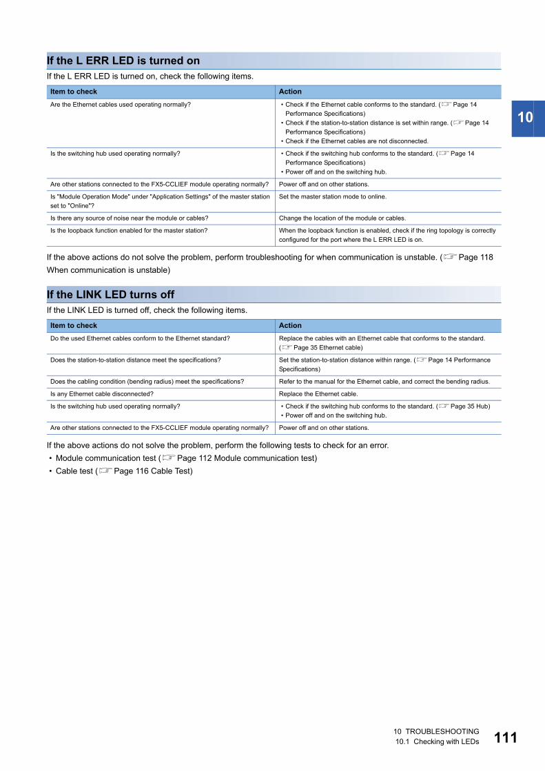
10
If the L ERR LED is turned onIf the L ERR LED is turned on, check the following items.
If the above actions do not solve the problem, perform troubleshooting for when communication is unstable. (Page 118
When communication is unstable)
If the LINK LED turns offIf the LINK LED is turned off, check the following items.
If the above actions do not solve the problem, perform the following tests to check for an error.
• Module communication test (Page 112 Module communication test)
• Cable test (Page 116 Cable Test)
Item to check Action
Are the Ethernet cables used operating normally? • Check if the Ethernet cable conforms to the standard. (Page 14
Performance Specifications)
• Check if the station-to-station distance is set within range. (Page 14
Performance Specifications)
• Check if the Ethernet cables are not disconnected.
Is the switching hub used operating normally? • Check if the switching hub conforms to the standard. (Page 14
Performance Specifications)
• Power off and on the switching hub.
Are other stations connected to the FX5-CCLIEF module operating normally? Power off and on other stations.
Is "Module Operation Mode" under "Application Settings" of the master station
set to "Online"?
Set the master station mode to online.
Is there any source of noise near the module or cables? Change the location of the module or cables.
Is the loopback function enabled for the master station? When the loopback function is enabled, check if the ring topology is correctly
configured for the port where the L ERR LED is on.
Item to check Action
Do the used Ethernet cables conform to the Ethernet standard? Replace the cables with an Ethernet cable that conforms to the standard.
(Page 35 Ethernet cable)
Does the station-to-station distance meet the specifications? Set the station-to-station distance within range. (Page 14 Performance
Specifications)
Does the cabling condition (bending radius) meet the specifications? Refer to the manual for the Ethernet cable, and correct the bending radius.
Is any Ethernet cable disconnected? Replace the Ethernet cable.
Is the switching hub used operating normally? • Check if the switching hub conforms to the standard. (Page 35 Hub)
• Power off and on the switching hub.
Are other stations connected to the FX5-CCLIEF module operating normally? Power off and on other stations.
10 TROUBLESHOOTING10.1 Checking with LEDs 111
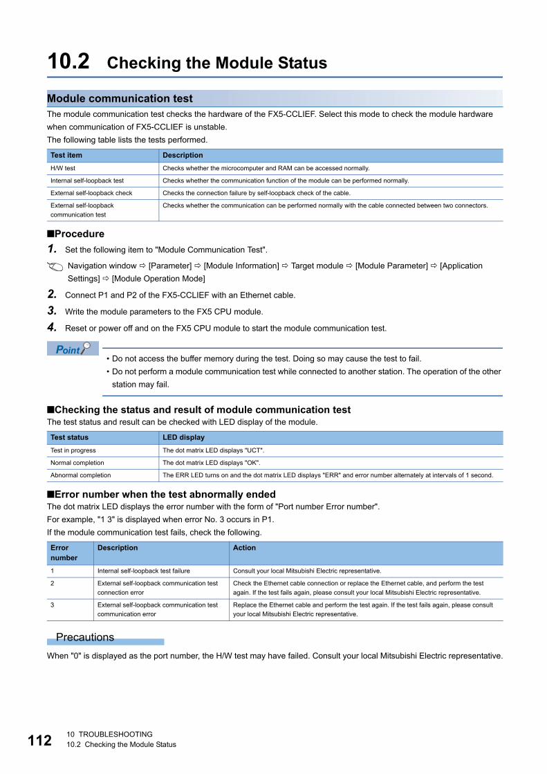
11
10.2 Checking the Module Status
Module communication testThe module communication test checks the hardware of the FX5-CCLIEF. Select this mode to check the module hardware
when communication of FX5-CCLIEF is unstable.
The following table lists the tests performed.
■Procedure
1. Set the following item to "Module Communication Test".
Navigation window [Parameter] [Module Information] Target module [Module Parameter] [Application
Settings] [Module Operation Mode]
2. Connect P1 and P2 of the FX5-CCLIEF with an Ethernet cable.
3. Write the module parameters to the FX5 CPU module.
4. Reset or power off and on the FX5 CPU module to start the module communication test.
• Do not access the buffer memory during the test. Doing so may cause the test to fail.
• Do not perform a module communication test while connected to another station. The operation of the other
station may fail.
■Checking the status and result of module communication testThe test status and result can be checked with LED display of the module.
■Error number when the test abnormally endedThe dot matrix LED displays the error number with the form of "Port number Error number".
For example, "1 3" is displayed when error No. 3 occurs in P1.
If the module communication test fails, check the following.
Precautions
When "0" is displayed as the port number, the H/W test may have failed. Consult your local Mitsubishi Electric representative.
Test item Description
H/W test Checks whether the microcomputer and RAM can be accessed normally.
Internal self-loopback test Checks whether the communication function of the module can be performed normally.
External self-loopback check Checks the connection failure by self-loopback check of the cable.
External self-loopback
communication test
Checks whether the communication can be performed normally with the cable connected between two connectors.
Test status LED display
Test in progress The dot matrix LED displays "UCT".
Normal completion The dot matrix LED displays "OK".
Abnormal completion The ERR LED turns on and the dot matrix LED displays "ERR" and error number alternately at intervals of 1 second.
Error number
Description Action
1 Internal self-loopback test failure Consult your local Mitsubishi Electric representative.
2 External self-loopback communication test
connection error
Check the Ethernet cable connection or replace the Ethernet cable, and perform the test
again. If the test fails again, please consult your local Mitsubishi Electric representative.
3 External self-loopback communication test
communication error
Replace the Ethernet cable and perform the test again. If the test fails again, please consult
your local Mitsubishi Electric representative.
210 TROUBLESHOOTING10.2 Checking the Module Status
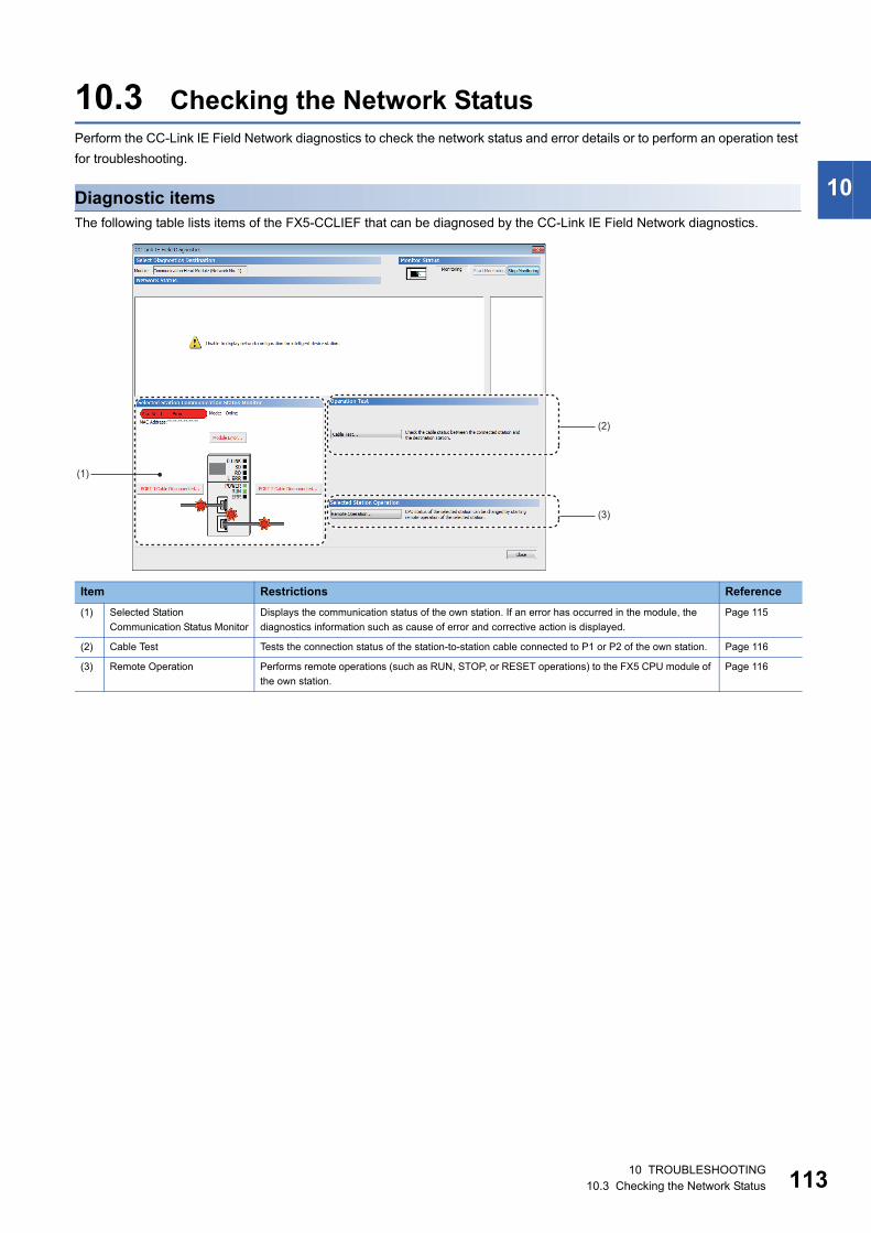
10
10.3 Checking the Network StatusPerform the CC-Link IE Field Network diagnostics to check the network status and error details or to perform an operation test
for troubleshooting.
Diagnostic itemsThe following table lists items of the FX5-CCLIEF that can be diagnosed by the CC-Link IE Field Network diagnostics.
Item Restrictions Reference
(1) Selected Station
Communication Status Monitor
Displays the communication status of the own station. If an error has occurred in the module, the
diagnostics information such as cause of error and corrective action is displayed.
Page 115
(2) Cable Test Tests the connection status of the station-to-station cable connected to P1 or P2 of the own station. Page 116
(3) Remote Operation Performs remote operations (such as RUN, STOP, or RESET operations) to the FX5 CPU module of
the own station.
Page 116
(1)
(2)
(3)
10 TROUBLESHOOTING10.3 Checking the Network Status 113
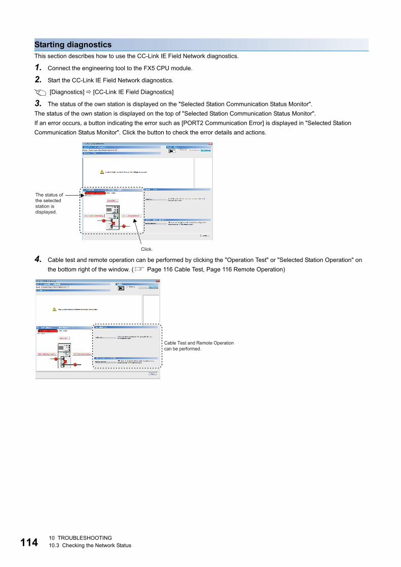
11
Starting diagnosticsThis section describes how to use the CC-Link IE Field Network diagnostics.
1. Connect the engineering tool to the FX5 CPU module.
2. Start the CC-Link IE Field Network diagnostics.
[Diagnostics] [CC-Link IE Field Diagnostics]
3. The status of the own station is displayed on the "Selected Station Communication Status Monitor".
The status of the own station is displayed on the top of "Selected Station Communication Status Monitor".
If an error occurs, a button indicating the error such as [PORT2 Communication Error] is displayed in "Selected Station
Communication Status Monitor". Click the button to check the error details and actions.
4. Cable test and remote operation can be performed by clicking the "Operation Test" or "Selected Station Operation" on
the bottom right of the window. ( Page 116 Cable Test, Page 116 Remote Operation)
Click.
The status of the selected station is displayed.
Cable Test and Remote Operation can be performed.
410 TROUBLESHOOTING10.3 Checking the Network Status
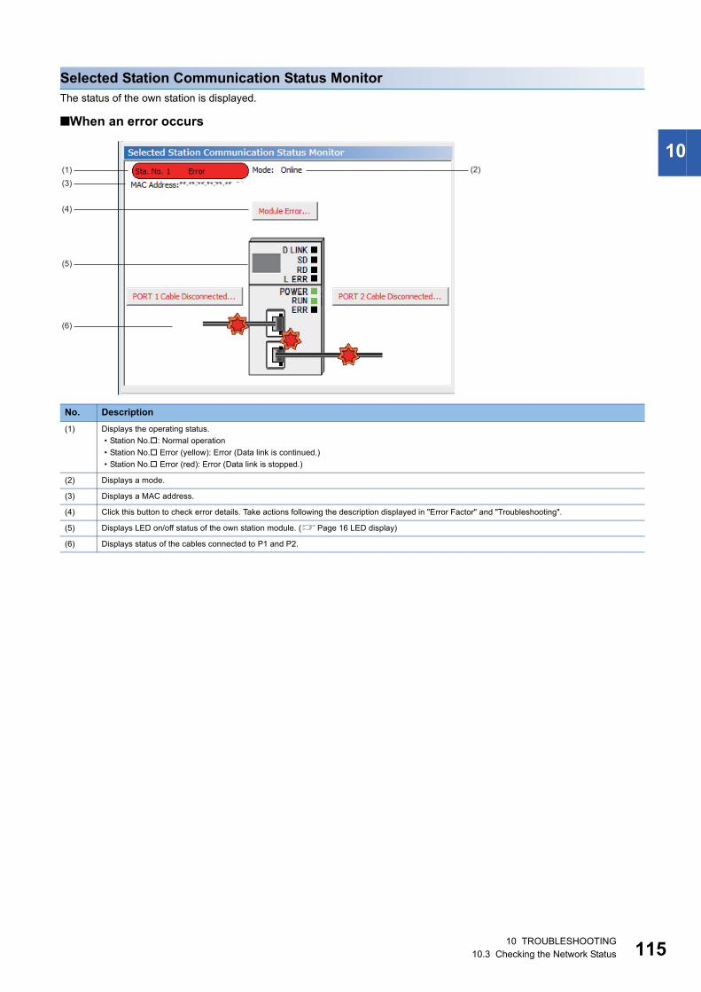
10
Selected Station Communication Status MonitorThe status of the own station is displayed.
■When an error occurs
No. Description
(1) Displays the operating status.
• Station No.: Normal operation
• Station No. Error (yellow): Error (Data link is continued.)
• Station No. Error (red): Error (Data link is stopped.)
(2) Displays a mode.
(3) Displays a MAC address.
(4) Click this button to check error details. Take actions following the description displayed in "Error Factor" and "Troubleshooting".
(5) Displays LED on/off status of the own station module. (Page 16 LED display)
(6) Displays status of the cables connected to P1 and P2.
(1)
(4)
(5)
(6)
(3)
(2)
10 TROUBLESHOOTING10.3 Checking the Network Status 115
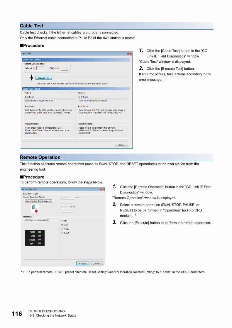
11
Cable TestCable test checks if the Ethernet cables are properly connected.
Only the Ethernet cable connected to P1 or P2 of the own station is tested.
■Procedure
Remote OperationThis function executes remote operations (such as RUN, STOP, and RESET operations) to the own station from the
engineering tool.
■ProcedureTo perform remote operations, follow the steps below.
*1 To perform remote RESET, preset "Remote Reset Setting" under "Operation Related Setting" to "Enable" in the CPU Parameters.
1. Click the [Cable Test] button in the "CC-
Link IE Field Diagnostics" window.
"Cable Test" window is displayed.
2. Click the [Execute Test] button.
If an error occurs, take actions according to the
error message.
1. Click the [Remote Operation] button in the "CC-Link IE Field
Diagnostics" window.
"Remote Operation" window is displayed.
2. Select a remote operation (RUN, STOP, PAUSE, or
RESET) to be performed in "Operation" for FX5 CPU
module. *1
3. Click the [Execute] button to perform the remote operation.
610 TROUBLESHOOTING10.3 Checking the Network Status
10
10.4 Troubleshooting for Each SymptomThis section describes troubleshooting method by symptom. Perform these troubleshooting if data link cannot be performed
even though no error is detected in the intelligent device station. If an error has occurred in the intelligent device station,
identify the cause of error using the engineering tool. (Page 113 Checking the Network Status)
When cyclic transmission cannot be performedThe following lists the actions to be taken if cyclic transmission to the master station cannot be performed.
If the above action does not solve the problem, perform the module communication test to check for hardware failure.
(Page 112 Module communication test)
When transient transmission cannot be performedThe following lists the actions to be taken if transient transmission cannot be performed with the target station, and the
engineering tool cannot perform monitoring.
If the above actions do not solve the problem, perform the following tests to check for an error.
• Module communication test (Page 112 Module communication test)
When a station is disconnected from the networkThe following is the action to be taken when a station in data link is disconnected.
If the above actions do not solve the problem, perform the following tests to check for an error.
• Module communication test (Page 112 Module communication test)
• Cable test (Page 116 Cable Test)
Item to check Action
Is the D. LINK LED of the master or intelligent device station turned off or
flashing?
Perform troubleshooting for when the D. LINK LED turns off or is flashing.
(Page 110 If the D. LINK LED turns off or is flashing)
Do the station numbers set in "Network Configuration Settings" under "Basic
Settings" of the master station match those set for corresponding slave
stations?
Correct station numbers.
Is the range set in "Refresh Setting" of "Basic Settings" correct? Correct the range setting in "Refresh Setting" of "Basic Settings". (Page
38 Refresh setting)
Is any used device in "Refresh Setting" of "Basic Settings" overlapped with
that of another module?
Correct the range setting in "Refresh Setting" of "Basic Settings". (Page
38 Refresh setting)
Is the station number of the intelligent device station duplicated with any of the
other stations?
Change the duplicated station number.
Item to check Action
Is the D. LINK LED of the master or intelligent device station turned off? Perform troubleshooting for when the D. LINK LED turns off or is flashing.
(Page 110 If the D. LINK LED turns off or is flashing)
Is the baton pass status of the destination normal? In the CC-Link IE Field Network diagnostics, identify the cause of the error
and take action. (Page 113 Checking the Network Status)
Are the following control data of the dedicated instruction correct?
• CPU type of the target module
• Target network number
• Target station number
Correct the control data of the dedicated instruction.
Is the station number of the intelligent device station duplicated with any of the
other stations?
Change the duplicated station number.
Item to check Action
Is the ambient temperature for the module within the specified range? Keep the ambient temperature within the specified range by taking action
such as removing heat source.
10 TROUBLESHOOTING10.4 Troubleshooting for Each Symptom 117
11
When a station is repeatedly disconnected and reconnectedThe following lists the actions to be taken when a station in data link is repeatedly disconnected and reconnected.
If the above actions do not solve the problem, perform the following tests to check for an error.
• Module communication test (Page 112 Module communication test)
• Cable test (Page 116 Cable Test)
When communication is unstableThe following lists the actions to be taken when link scan time or transmission delay time is long or when a transient
transmission timeout occurred.
If the above actions do not solve the problem, perform the following tests to check for an error.
• Module communication test (Page 112 Module communication test)
• Cable test (Page 116 Cable Test)
Item to check Action
Are 1000BASE-T-compliant Ethernet cable used? Replace the cables with 1000BASE-T-compliant Ethernet cables. (Page
35 Ethernet cable)
Is the station-to-station distance 100 m or less? Change the station-to-station distance to 100 m or less.
Does the cabling condition (bending radius) meet the specifications? Refer to the manual for the Ethernet cable, and correct the bending radius.
Is any Ethernet cable disconnected? Replace the Ethernet cable.
Is the switching hub used in the system operating normally? • Check if a 1000BASE-T-compliant switching hub is used. (Page 35
Hub)
• Power off and on the switching hub.
Item to check Action
Is the L ERR LED of the master or intelligent device station turned on? Perform troubleshooting for when the L ERR LED turns on. (Page 111 If
the L ERR LED is turned on)
Is the ambient temperature for the module within the specified range? Keep the ambient temperature within the specified range by taking action
such as removing heat source.
Is any error shown in "Selected Station Communication Status Monitor" of CC-
Link IE Field Network diagnostics?
If an error is identified at P1 or P2, perform a cable test and a module
communication test.
Is there any noise affecting the system? Check the wiring condition.
810 TROUBLESHOOTING10.4 Troubleshooting for Each Symptom
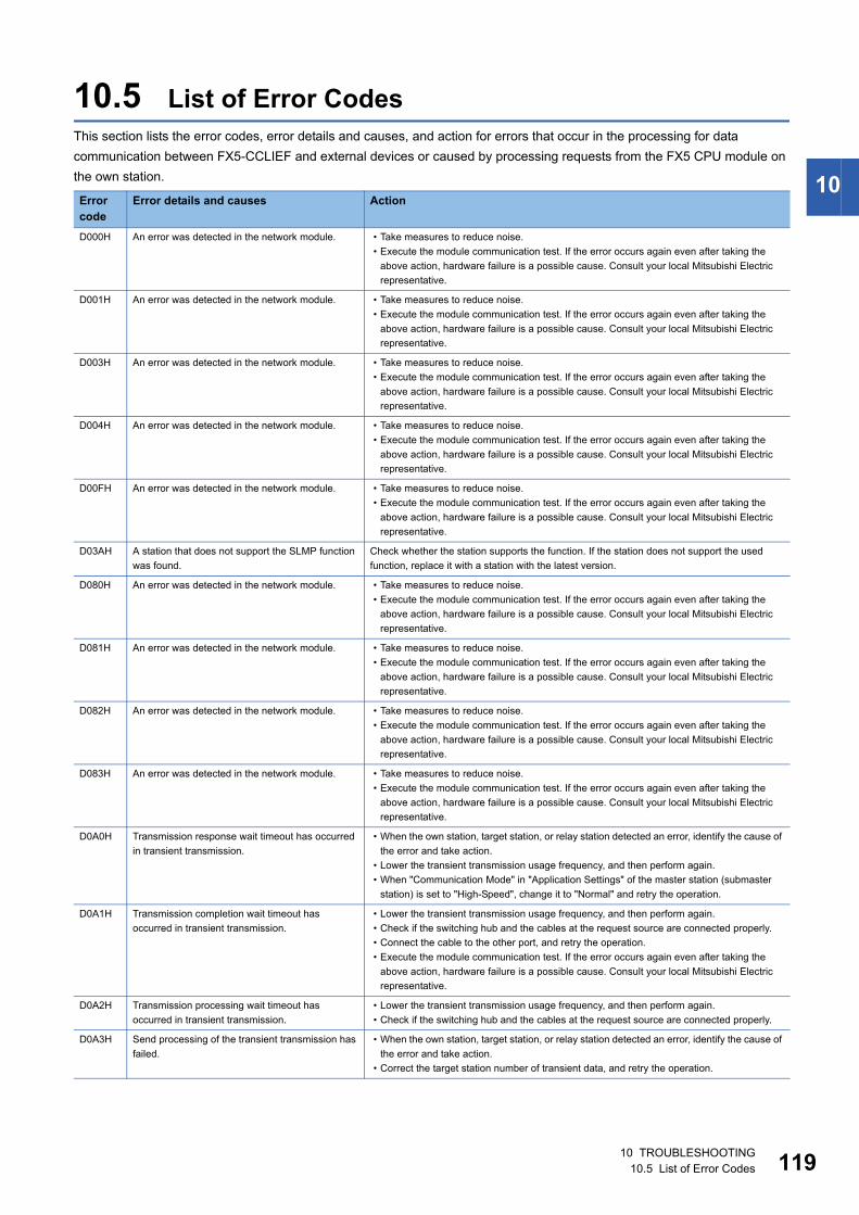
10
10.5 List of Error CodesThis section lists the error codes, error details and causes, and action for errors that occur in the processing for data
communication between FX5-CCLIEF and external devices or caused by processing requests from the FX5 CPU module on
the own station.
Error code
Error details and causes Action
D000H An error was detected in the network module. • Take measures to reduce noise.
• Execute the module communication test. If the error occurs again even after taking the
above action, hardware failure is a possible cause. Consult your local Mitsubishi Electric
representative.
D001H An error was detected in the network module. • Take measures to reduce noise.
• Execute the module communication test. If the error occurs again even after taking the
above action, hardware failure is a possible cause. Consult your local Mitsubishi Electric
representative.
D003H An error was detected in the network module. • Take measures to reduce noise.
• Execute the module communication test. If the error occurs again even after taking the
above action, hardware failure is a possible cause. Consult your local Mitsubishi Electric
representative.
D004H An error was detected in the network module. • Take measures to reduce noise.
• Execute the module communication test. If the error occurs again even after taking the
above action, hardware failure is a possible cause. Consult your local Mitsubishi Electric
representative.
D00FH An error was detected in the network module. • Take measures to reduce noise.
• Execute the module communication test. If the error occurs again even after taking the
above action, hardware failure is a possible cause. Consult your local Mitsubishi Electric
representative.
D03AH A station that does not support the SLMP function
was found.
Check whether the station supports the function. If the station does not support the used
function, replace it with a station with the latest version.
D080H An error was detected in the network module. • Take measures to reduce noise.
• Execute the module communication test. If the error occurs again even after taking the
above action, hardware failure is a possible cause. Consult your local Mitsubishi Electric
representative.
D081H An error was detected in the network module. • Take measures to reduce noise.
• Execute the module communication test. If the error occurs again even after taking the
above action, hardware failure is a possible cause. Consult your local Mitsubishi Electric
representative.
D082H An error was detected in the network module. • Take measures to reduce noise.
• Execute the module communication test. If the error occurs again even after taking the
above action, hardware failure is a possible cause. Consult your local Mitsubishi Electric
representative.
D083H An error was detected in the network module. • Take measures to reduce noise.
• Execute the module communication test. If the error occurs again even after taking the
above action, hardware failure is a possible cause. Consult your local Mitsubishi Electric
representative.
D0A0H Transmission response wait timeout has occurred
in transient transmission.
• When the own station, target station, or relay station detected an error, identify the cause of
the error and take action.
• Lower the transient transmission usage frequency, and then perform again.
• When "Communication Mode" in "Application Settings" of the master station (submaster
station) is set to "High-Speed", change it to "Normal" and retry the operation.
D0A1H Transmission completion wait timeout has
occurred in transient transmission.
• Lower the transient transmission usage frequency, and then perform again.
• Check if the switching hub and the cables at the request source are connected properly.
• Connect the cable to the other port, and retry the operation.
• Execute the module communication test. If the error occurs again even after taking the
above action, hardware failure is a possible cause. Consult your local Mitsubishi Electric
representative.
D0A2H Transmission processing wait timeout has
occurred in transient transmission.
• Lower the transient transmission usage frequency, and then perform again.
• Check if the switching hub and the cables at the request source are connected properly.
D0A3H Send processing of the transient transmission has
failed.
• When the own station, target station, or relay station detected an error, identify the cause of
the error and take action.
• Correct the target station number of transient data, and retry the operation.
10 TROUBLESHOOTING10.5 List of Error Codes 119
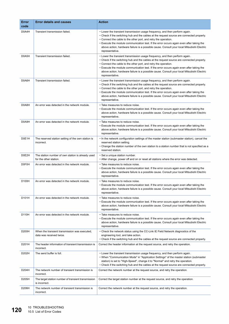
12
D0A4H Transient transmission failed. • Lower the transient transmission usage frequency, and then perform again.
• Check if the switching hub and the cables at the request source are connected properly.
• Connect the cable to the other port, and retry the operation.
• Execute the module communication test. If the error occurs again even after taking the
above action, hardware failure is a possible cause. Consult your local Mitsubishi Electric
representative.
D0A5H Transient transmission failed. • Lower the transient transmission usage frequency, and then perform again.
• Check if the switching hub and the cables at the request source are connected properly.
• Connect the cable to the other port, and retry the operation.
• Execute the module communication test. If the error occurs again even after taking the
above action, hardware failure is a possible cause. Consult your local Mitsubishi Electric
representative.
D0A6H Transient transmission failed. • Lower the transient transmission usage frequency, and then perform again.
• Check if the switching hub and the cables at the request source are connected properly.
• Connect the cable to the other port, and retry the operation.
• Execute the module communication test. If the error occurs again even after taking the
above action, hardware failure is a possible cause. Consult your local Mitsubishi Electric
representative.
D0A8H An error was detected in the network module. • Take measures to reduce noise.
• Execute the module communication test. If the error occurs again even after taking the
above action, hardware failure is a possible cause. Consult your local Mitsubishi Electric
representative.
D0A9H An error was detected in the network module. • Take measures to reduce noise.
• Execute the module communication test. If the error occurs again even after taking the
above action, hardware failure is a possible cause. Consult your local Mitsubishi Electric
representative.
D0E1H The reserved station setting of the own station is
incorrect.
• In the network configuration settings of the master station (submaster station), cancel the
reserved station setting.
• Change the station number of the own station to a station number that is not specified as a
reserved station.
D0E2H The station number of own station is already used
for the other station.
• Set a unique station number.
• After change, power off and on or reset all stations where the error was detected.
D0F0H An error was detected in the network module. • Take measures to reduce noise.
• Execute the module communication test. If the error occurs again even after taking the
above action, hardware failure is a possible cause. Consult your local Mitsubishi Electric
representative.
D100H An error was detected in the network module. • Take measures to reduce noise.
• Execute the module communication test. If the error occurs again even after taking the
above action, hardware failure is a possible cause. Consult your local Mitsubishi Electric
representative.
D101H An error was detected in the network module. • Take measures to reduce noise.
• Execute the module communication test. If the error occurs again even after taking the
above action, hardware failure is a possible cause. Consult your local Mitsubishi Electric
representative.
D110H An error was detected in the network module. • Take measures to reduce noise.
• Execute the module communication test. If the error occurs again even after taking the
above action, hardware failure is a possible cause. Consult your local Mitsubishi Electric
representative.
D200H When the transient transmission was executed,
data was received twice.
• Check the network status using the CC-Link IE Field Network diagnostics of the
engineering tool, and take action.
• Check if the switching hub and the cables at the request source are connected properly.
D201H The header information of transient transmission is
incorrect.
Correct the header information at the request source, and retry the operation.
D202H The send buffer is full. • Lower the transient transmission usage frequency, and then perform again.
• When "Communication Mode" in "Application Settings" of the master station (submaster
station) is set to "High-Speed", change it to "Normal" and retry the operation.
• Check if the switching hub and the cables at the request source are connected properly.
D204H The network number of transient transmission is
incorrect.
Correct the network number at the request source, and retry the operation.
D205H The target station number of transient transmission
is incorrect.
Correct the target station number at the request source, and retry the operation.
D206H The network number of transient transmission is
incorrect.
Correct the network number at the request source, and retry the operation.
Error code
Error details and causes Action
010 TROUBLESHOOTING10.5 List of Error Codes
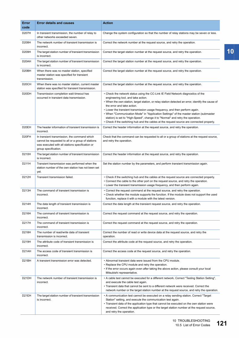
10
D207H In transient transmission, the number of relay to
other networks exceeded seven.
Change the system configuration so that the number of relay stations may be seven or less.
D208H The network number of transient transmission is
incorrect.
Correct the network number at the request source, and retry the operation.
D209H The target station number of transient transmission
is incorrect.
Correct the target station number at the request source, and retry the operation.
D20AH The target station number of transient transmission
is incorrect.
Correct the target station number at the request source, and retry the operation.
D20BH When there was no master station, specified
master station was specified for transient
transmission.
Correct the target station number at the request source, and retry the operation.
D20CH When there was no master station, current master
station was specified for transient transmission.
Correct the target station number at the request source, and retry the operation.
D20DH Transmission completion wait timeout has
occurred in transient data transmission.
• Check the network status using the CC-Link IE Field Network diagnostics of the
engineering tool, and take action.
• When the own station, target station, or relay station detected an error, identify the cause of
the error and take action.
• Lower the transient transmission usage frequency, and then perform again.
• When "Communication Mode" in "Application Settings" of the master station (submaster
station) is set to "High-Speed", change it to "Normal" and retry the operation.
• Check if the switching hub and the cables at the request source are connected properly.
D20EH The header information of transient transmission is
incorrect.
Correct the header information at the request source, and retry the operation.
D20FH In transient transmission, the command which
cannot be requested to all or a group of stations
was executed with all stations specification or
group specification.
Check that the command can be requested to all or a group of stations at the request source,
and retry the operation.
D210H The target station number of transient transmission
is incorrect.
Correct the header information at the request source, and retry the operation.
D211H Transient transmission was performed when the
station number of the own station has not been set
yet.
Set the station number by the parameters, and perform transient transmission again.
D212H Transient transmission failed. • Check if the switching hub and the cables at the request source are connected properly.
• Connect the cable to the other port on the request source, and retry the operation.
• Lower the transient transmission usage frequency, and then perform again.
D213H The command of transient transmission is
incorrect.
• Correct the request command at the request source, and retry the operation.
• Check whether the module supports the function. If the module does not support the used
function, replace it with a module with the latest version.
D214H The data length of transient transmission is
incorrect.
Correct the data length at the transient request source, and retry the operation.
D216H The command of transient transmission is
incorrect.
Correct the request command at the request source, and retry the operation.
D217H The command of transient transmission is
incorrect.
Correct the request command at the request source, and retry the operation.
D218H The number of read/write data of transient
transmission is incorrect.
Correct the number of read or write device data at the request source, and retry the
operation.
D219H The attribute code of transient transmission is
incorrect.
Correct the attribute code at the request source, and retry the operation.
D21AH The access code of transient transmission is
incorrect.
Correct the access code at the request source, and retry the operation.
D21BH A transient transmission error was detected. • Abnormal transient data were issued from the CPU module.
• Replace the CPU module and retry the operation.
• If the error occurs again even after taking the above action, please consult your local
Mitsubishi representative.
D21DH The network number of transient transmission is
incorrect.
• A cable test cannot be executed for a different network. Correct "Testing Station Setting",
and execute the cable test again.
• Transient data that cannot be sent to a different network were received. Correct the
network number or the target station number at the request source, and retry the operation.
D21EH The target station number of transient transmission
is incorrect.
• A communication test cannot be executed on a relay sending station. Correct "Target
Station" setting, and execute the communication test again.
• Transient data of the application type that cannot be executed on the own station were
received. Correct the application type or the target station number at the request source,
and retry the operation.
Error code
Error details and causes Action
10 TROUBLESHOOTING10.5 List of Error Codes 121
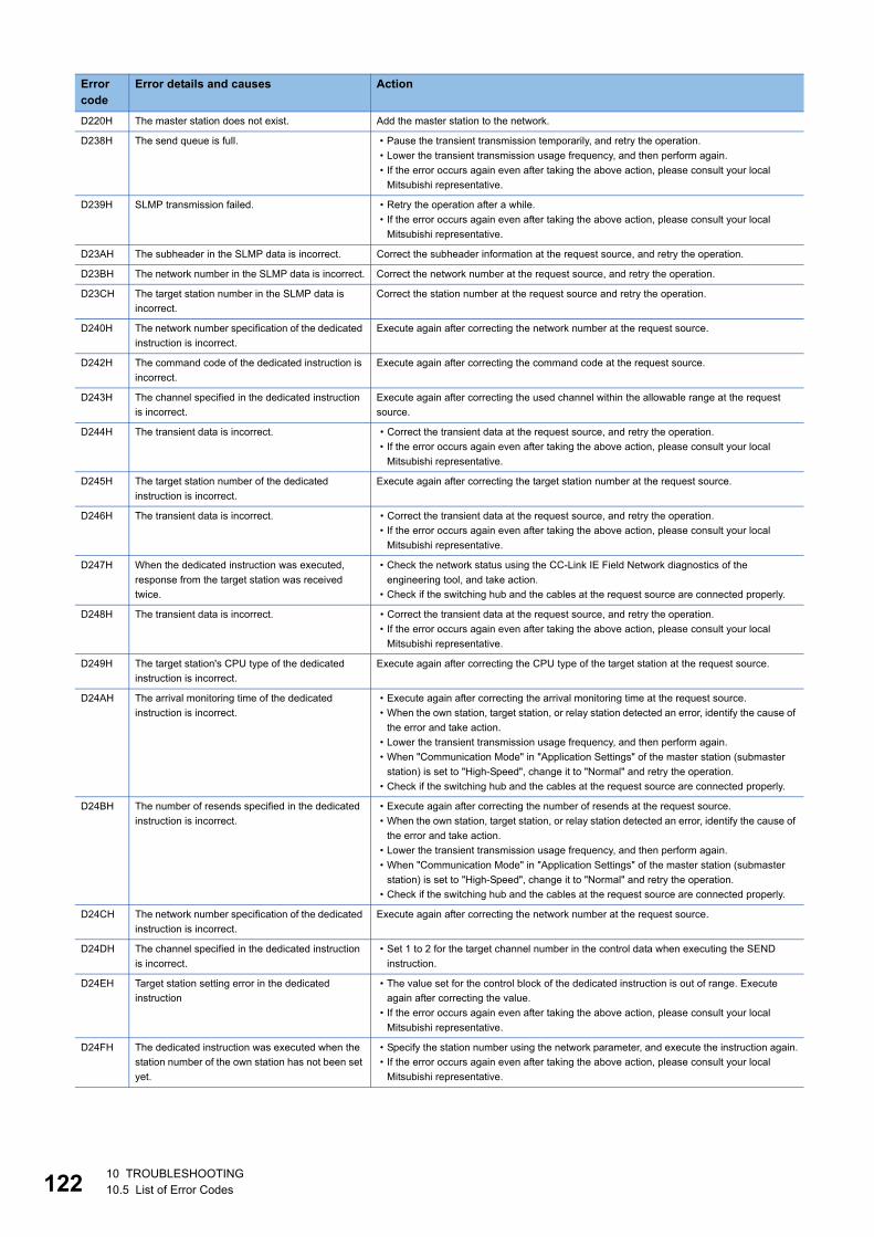
12
D220H The master station does not exist. Add the master station to the network.
D238H The send queue is full. • Pause the transient transmission temporarily, and retry the operation.
• Lower the transient transmission usage frequency, and then perform again.
• If the error occurs again even after taking the above action, please consult your local
Mitsubishi representative.
D239H SLMP transmission failed. • Retry the operation after a while.
• If the error occurs again even after taking the above action, please consult your local
Mitsubishi representative.
D23AH The subheader in the SLMP data is incorrect. Correct the subheader information at the request source, and retry the operation.
D23BH The network number in the SLMP data is incorrect. Correct the network number at the request source, and retry the operation.
D23CH The target station number in the SLMP data is
incorrect.
Correct the station number at the request source and retry the operation.
D240H The network number specification of the dedicated
instruction is incorrect.
Execute again after correcting the network number at the request source.
D242H The command code of the dedicated instruction is
incorrect.
Execute again after correcting the command code at the request source.
D243H The channel specified in the dedicated instruction
is incorrect.
Execute again after correcting the used channel within the allowable range at the request
source.
D244H The transient data is incorrect. • Correct the transient data at the request source, and retry the operation.
• If the error occurs again even after taking the above action, please consult your local
Mitsubishi representative.
D245H The target station number of the dedicated
instruction is incorrect.
Execute again after correcting the target station number at the request source.
D246H The transient data is incorrect. • Correct the transient data at the request source, and retry the operation.
• If the error occurs again even after taking the above action, please consult your local
Mitsubishi representative.
D247H When the dedicated instruction was executed,
response from the target station was received
twice.
• Check the network status using the CC-Link IE Field Network diagnostics of the
engineering tool, and take action.
• Check if the switching hub and the cables at the request source are connected properly.
D248H The transient data is incorrect. • Correct the transient data at the request source, and retry the operation.
• If the error occurs again even after taking the above action, please consult your local
Mitsubishi representative.
D249H The target station's CPU type of the dedicated
instruction is incorrect.
Execute again after correcting the CPU type of the target station at the request source.
D24AH The arrival monitoring time of the dedicated
instruction is incorrect.
• Execute again after correcting the arrival monitoring time at the request source.
• When the own station, target station, or relay station detected an error, identify the cause of
the error and take action.
• Lower the transient transmission usage frequency, and then perform again.
• When "Communication Mode" in "Application Settings" of the master station (submaster
station) is set to "High-Speed", change it to "Normal" and retry the operation.
• Check if the switching hub and the cables at the request source are connected properly.
D24BH The number of resends specified in the dedicated
instruction is incorrect.
• Execute again after correcting the number of resends at the request source.
• When the own station, target station, or relay station detected an error, identify the cause of
the error and take action.
• Lower the transient transmission usage frequency, and then perform again.
• When "Communication Mode" in "Application Settings" of the master station (submaster
station) is set to "High-Speed", change it to "Normal" and retry the operation.
• Check if the switching hub and the cables at the request source are connected properly.
D24CH The network number specification of the dedicated
instruction is incorrect.
Execute again after correcting the network number at the request source.
D24DH The channel specified in the dedicated instruction
is incorrect.
• Set 1 to 2 for the target channel number in the control data when executing the SEND
instruction.
D24EH Target station setting error in the dedicated
instruction
• The value set for the control block of the dedicated instruction is out of range. Execute
again after correcting the value.
• If the error occurs again even after taking the above action, please consult your local
Mitsubishi representative.
D24FH The dedicated instruction was executed when the
station number of the own station has not been set
yet.
• Specify the station number using the network parameter, and execute the instruction again.
• If the error occurs again even after taking the above action, please consult your local
Mitsubishi representative.
Error code
Error details and causes Action
210 TROUBLESHOOTING10.5 List of Error Codes
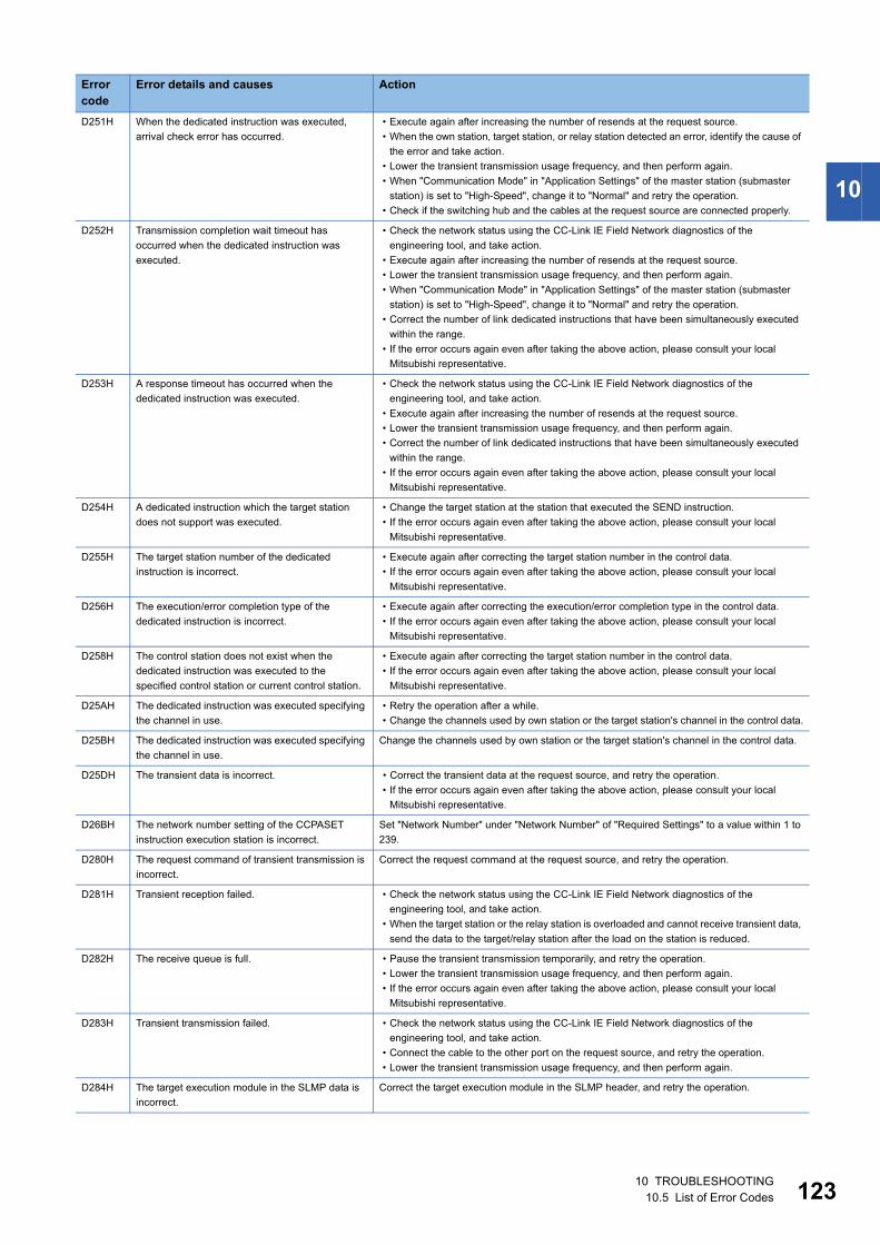
10
D251H When the dedicated instruction was executed,
arrival check error has occurred.
• Execute again after increasing the number of resends at the request source.
• When the own station, target station, or relay station detected an error, identify the cause of
the error and take action.
• Lower the transient transmission usage frequency, and then perform again.
• When "Communication Mode" in "Application Settings" of the master station (submaster
station) is set to "High-Speed", change it to "Normal" and retry the operation.
• Check if the switching hub and the cables at the request source are connected properly.
D252H Transmission completion wait timeout has
occurred when the dedicated instruction was
executed.
• Check the network status using the CC-Link IE Field Network diagnostics of the
engineering tool, and take action.
• Execute again after increasing the number of resends at the request source.
• Lower the transient transmission usage frequency, and then perform again.
• When "Communication Mode" in "Application Settings" of the master station (submaster
station) is set to "High-Speed", change it to "Normal" and retry the operation.
• Correct the number of link dedicated instructions that have been simultaneously executed
within the range.
• If the error occurs again even after taking the above action, please consult your local
Mitsubishi representative.
D253H A response timeout has occurred when the
dedicated instruction was executed.
• Check the network status using the CC-Link IE Field Network diagnostics of the
engineering tool, and take action.
• Execute again after increasing the number of resends at the request source.
• Lower the transient transmission usage frequency, and then perform again.
• Correct the number of link dedicated instructions that have been simultaneously executed
within the range.
• If the error occurs again even after taking the above action, please consult your local
Mitsubishi representative.
D254H A dedicated instruction which the target station
does not support was executed.
• Change the target station at the station that executed the SEND instruction.
• If the error occurs again even after taking the above action, please consult your local
Mitsubishi representative.
D255H The target station number of the dedicated
instruction is incorrect.
• Execute again after correcting the target station number in the control data.
• If the error occurs again even after taking the above action, please consult your local
Mitsubishi representative.
D256H The execution/error completion type of the
dedicated instruction is incorrect.
• Execute again after correcting the execution/error completion type in the control data.
• If the error occurs again even after taking the above action, please consult your local
Mitsubishi representative.
D258H The control station does not exist when the
dedicated instruction was executed to the
specified control station or current control station.
• Execute again after correcting the target station number in the control data.
• If the error occurs again even after taking the above action, please consult your local
Mitsubishi representative.
D25AH The dedicated instruction was executed specifying
the channel in use.
• Retry the operation after a while.
• Change the channels used by own station or the target station's channel in the control data.
D25BH The dedicated instruction was executed specifying
the channel in use.
Change the channels used by own station or the target station's channel in the control data.
D25DH The transient data is incorrect. • Correct the transient data at the request source, and retry the operation.
• If the error occurs again even after taking the above action, please consult your local
Mitsubishi representative.
D26BH The network number setting of the CCPASET
instruction execution station is incorrect.
Set "Network Number" under "Network Number" of "Required Settings" to a value within 1 to
239.
D280H The request command of transient transmission is
incorrect.
Correct the request command at the request source, and retry the operation.
D281H Transient reception failed. • Check the network status using the CC-Link IE Field Network diagnostics of the
engineering tool, and take action.
• When the target station or the relay station is overloaded and cannot receive transient data,
send the data to the target/relay station after the load on the station is reduced.
D282H The receive queue is full. • Pause the transient transmission temporarily, and retry the operation.
• Lower the transient transmission usage frequency, and then perform again.
• If the error occurs again even after taking the above action, please consult your local
Mitsubishi representative.
D283H Transient transmission failed. • Check the network status using the CC-Link IE Field Network diagnostics of the
engineering tool, and take action.
• Connect the cable to the other port on the request source, and retry the operation.
• Lower the transient transmission usage frequency, and then perform again.
D284H The target execution module in the SLMP data is
incorrect.
Correct the target execution module in the SLMP header, and retry the operation.
Error code
Error details and causes Action
10 TROUBLESHOOTING10.5 List of Error Codes 123
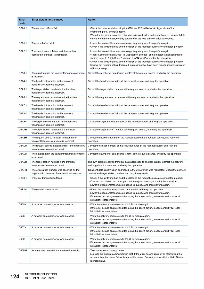
12
D2A0H The receive buffer is full. • Check the network status using the CC-Link IE Field Network diagnostics of the
engineering tool, and take action.
• When the target station or the relay station is overloaded and cannot receive transient data,
send the data to the target/relay station after the load on the station is reduced.
D2A1H The send buffer is full. • Lower the transient transmission usage frequency, and then perform again.
• Check if the switching hub and the cables at the request source are connected properly.
D2A2H Transmission completion wait timeout has
occurred in transient transmission.
• Lower the transient transmission usage frequency, and then perform again.
• When "Communication Mode" in "Application Settings" of the master station (submaster
station) is set to "High-Speed", change it to "Normal" and retry the operation.
• Check if the switching hub and the cables at the request source are connected properly.
• Correct the number of link dedicated instructions that have been simultaneously executed
within the range.
D2A3H The data length in the transient transmission frame
is incorrect.
Correct the number of data (frame length) at the request source, and retry the operation.
D2A4H The header information in the transient
transmission frame is incorrect.
Correct the header information at the request source, and retry the operation.
D2A5H The target station number in the transient
transmission frame is incorrect.
Correct the target station number at the request source, and retry the operation.
D2A6H The request source number in the transient
transmission frame is incorrect.
Correct the request source number at the request source, and retry the operation.
D2A7H The header information in the transient
transmission frame is incorrect.
Correct the header information at the request source, and retry the operation.
D2A8H The header information in the transient
transmission frame is incorrect.
Correct the header information at the request source, and retry the operation.
D2A9H The target network number in the transient
transmission frame is incorrect.
Correct the target network number at the request source, and retry the operation.
D2AAH The target station number in the transient
transmission frame is incorrect.
Correct the target station number at the request source, and retry the operation.
D2ABH The request source network number in the
transient transmission frame is incorrect.
Correct the network number of the request source at the request source, and retry the
operation.
D2ACH The request source station number in the transient
transmission frame is incorrect.
Correct the station number of the request source at the request source, and retry the
operation.
D2ADH The data length in the transient transmission frame
is incorrect.
Correct the number of data (frame length) at the request source, and retry the operation.
D2AEH The target station number in the transient
transmission frame is incorrect.
The own station received transient data addressed to another station. Correct the network
and target station numbers, and retry the operation.
D2AFH The own station number was specified as the
target station number of transient transmission.
Transient data transmission addressed to the own station was requested. Check the network
number and target station number, and retry the operation.
D2B0H Transient transmission failed. • Check if the switching hub and the cables at the request source are connected properly.
• Connect the cable to the other port on the request source, and retry the operation.
• Lower the transient transmission usage frequency, and then perform again.
D2B1H The receive queue is full. • Pause the transient transmission temporarily, and retry the operation.
• Lower the transient transmission usage frequency, and then perform again.
• If the error occurs again even after taking the above action, please consult your local
Mitsubishi representative.
D605H A network parameter error was detected. • Write the network parameters to the CPU module again.
• If the error occurs again even after taking the above action, please consult your local
Mitsubishi representative.
D606H A network parameter error was detected. • Write the network parameters to the CPU module again.
• If the error occurs again even after taking the above action, please consult your local
Mitsubishi representative.
D607H A network parameter error was detected. • Write the network parameters to the CPU module again.
• If the error occurs again even after taking the above action, please consult your local
Mitsubishi representative.
D609H A network parameter error was detected. • Write the network parameters to the CPU module again.
• If the error occurs again even after taking the above action, please consult your local
Mitsubishi representative.
D60DH An error was detected in the network module. • Take measures to reduce noise.
• Execute the module communication test. If the error occurs again even after taking the
above action, hardware failure is a possible cause. Consult your local Mitsubishi Electric
representative.
Error code
Error details and causes Action
410 TROUBLESHOOTING10.5 List of Error Codes
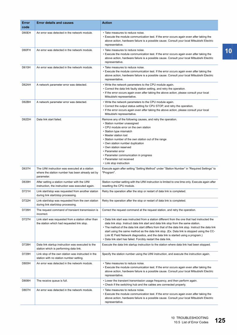
10
D60EH An error was detected in the network module. • Take measures to reduce noise.
• Execute the module communication test. If the error occurs again even after taking the
above action, hardware failure is a possible cause. Consult your local Mitsubishi Electric
representative.
D60FH An error was detected in the network module. • Take measures to reduce noise.
• Execute the module communication test. If the error occurs again even after taking the
above action, hardware failure is a possible cause. Consult your local Mitsubishi Electric
representative.
D610H An error was detected in the network module. • Take measures to reduce noise.
• Execute the module communication test. If the error occurs again even after taking the
above action, hardware failure is a possible cause. Consult your local Mitsubishi Electric
representative.
D62AH A network parameter error was detected. • Write the network parameters to the CPU module again.
• Correct the data link faulty station setting, and retry the operation.
• If the error occurs again even after taking the above action, please consult your local
Mitsubishi representative.
D62BH A network parameter error was detected. • Write the network parameters to the CPU module again.
• Correct the output status setting for CPU STOP, and retry the operation.
• If the error occurs again even after taking the above action, please consult your local
Mitsubishi representative.
D62DH Data link start failed. Remove any of the following causes, and retry the operation.
• Station number unassigned
• CPU module error on the own station
• Station type mismatch
• Master station lost
• Station number of the own station out of the range
• Own station number duplication
• Own station reserved
• Parameter error
• Parameter communication in progress
• Parameter not received
• Link stop instruction
D637H The UINI instruction was executed at a station
where the station number has been already set by
parameter.
Execute again after setting ”Setting Method” under ”Station Number” in ”Required Settings” to
"Program".
D639H After setting a station number with the UINI
instruction, the instruction was executed again.
Station number setting with the UINI instruction is limited to one time only. Execute again after
resetting the CPU module.
D721H Link start/stop was requested from another station
during link start/stop processing.
Retry the operation after the stop or restart of data link is completed.
D722H Link start/stop was requested from the own station
during link start/stop processing.
Retry the operation after the stop or restart of data link is completed.
D726H The request command of transient transmission is
incorrect.
Correct the request command at the request station, and retry the operation.
D727H Link start was requested from a station other than
the station which had requested link stop.
• Data link start was instructed from a station different from the one that had instructed the
data link stop. Instruct data link start and data link stop from the same station.
• The method of the data link start differs from that of the data link stop. Instruct the data link
start using the same method as the data link stop. (Ex. Data link is stopped using the CC-
Link IE Field Network diagnostics, and the data link is started using a program.)
• Data link start has failed. Forcibly restart the data link.
D728H Data link startup instruction was executed to the
station which is performing data link.
Execute the data link startup instruction to the station where data link had been stopped.
D729H Link stop of the own station was instructed in the
station with no station number setting.
Specify the station number using the UINI instruction, and execute the instruction again.
D800H An error was detected in the network module. • Take measures to reduce noise.
• Execute the module communication test. If the error occurs again even after taking the
above action, hardware failure is a possible cause. Consult your local Mitsubishi Electric
representative.
D806H The receive queue is full. • Lower the transient transmission usage frequency, and then perform again.
• Check if the switching hub and the cables are connected properly.
D807H An error was detected in the network module. • Take measures to reduce noise.
• Execute the module communication test. If the error occurs again even after taking the
above action, hardware failure is a possible cause. Consult your local Mitsubishi Electric
representative.
Error code
Error details and causes Action
10 TROUBLESHOOTING10.5 List of Error Codes 125
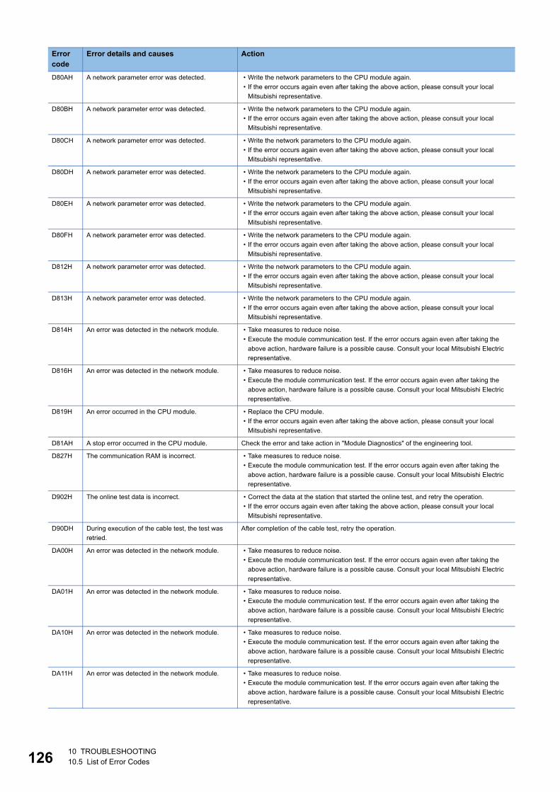
12
D80AH A network parameter error was detected. • Write the network parameters to the CPU module again.
• If the error occurs again even after taking the above action, please consult your local
Mitsubishi representative.
D80BH A network parameter error was detected. • Write the network parameters to the CPU module again.
• If the error occurs again even after taking the above action, please consult your local
Mitsubishi representative.
D80CH A network parameter error was detected. • Write the network parameters to the CPU module again.
• If the error occurs again even after taking the above action, please consult your local
Mitsubishi representative.
D80DH A network parameter error was detected. • Write the network parameters to the CPU module again.
• If the error occurs again even after taking the above action, please consult your local
Mitsubishi representative.
D80EH A network parameter error was detected. • Write the network parameters to the CPU module again.
• If the error occurs again even after taking the above action, please consult your local
Mitsubishi representative.
D80FH A network parameter error was detected. • Write the network parameters to the CPU module again.
• If the error occurs again even after taking the above action, please consult your local
Mitsubishi representative.
D812H A network parameter error was detected. • Write the network parameters to the CPU module again.
• If the error occurs again even after taking the above action, please consult your local
Mitsubishi representative.
D813H A network parameter error was detected. • Write the network parameters to the CPU module again.
• If the error occurs again even after taking the above action, please consult your local
Mitsubishi representative.
D814H An error was detected in the network module. • Take measures to reduce noise.
• Execute the module communication test. If the error occurs again even after taking the
above action, hardware failure is a possible cause. Consult your local Mitsubishi Electric
representative.
D816H An error was detected in the network module. • Take measures to reduce noise.
• Execute the module communication test. If the error occurs again even after taking the
above action, hardware failure is a possible cause. Consult your local Mitsubishi Electric
representative.
D819H An error occurred in the CPU module. • Replace the CPU module.
• If the error occurs again even after taking the above action, please consult your local
Mitsubishi representative.
D81AH A stop error occurred in the CPU module. Check the error and take action in "Module Diagnostics" of the engineering tool.
D827H The communication RAM is incorrect. • Take measures to reduce noise.
• Execute the module communication test. If the error occurs again even after taking the
above action, hardware failure is a possible cause. Consult your local Mitsubishi Electric
representative.
D902H The online test data is incorrect. • Correct the data at the station that started the online test, and retry the operation.
• If the error occurs again even after taking the above action, please consult your local
Mitsubishi representative.
D90DH During execution of the cable test, the test was
retried.
After completion of the cable test, retry the operation.
DA00H An error was detected in the network module. • Take measures to reduce noise.
• Execute the module communication test. If the error occurs again even after taking the
above action, hardware failure is a possible cause. Consult your local Mitsubishi Electric
representative.
DA01H An error was detected in the network module. • Take measures to reduce noise.
• Execute the module communication test. If the error occurs again even after taking the
above action, hardware failure is a possible cause. Consult your local Mitsubishi Electric
representative.
DA10H An error was detected in the network module. • Take measures to reduce noise.
• Execute the module communication test. If the error occurs again even after taking the
above action, hardware failure is a possible cause. Consult your local Mitsubishi Electric
representative.
DA11H An error was detected in the network module. • Take measures to reduce noise.
• Execute the module communication test. If the error occurs again even after taking the
above action, hardware failure is a possible cause. Consult your local Mitsubishi Electric
representative.
Error code
Error details and causes Action
610 TROUBLESHOOTING10.5 List of Error Codes
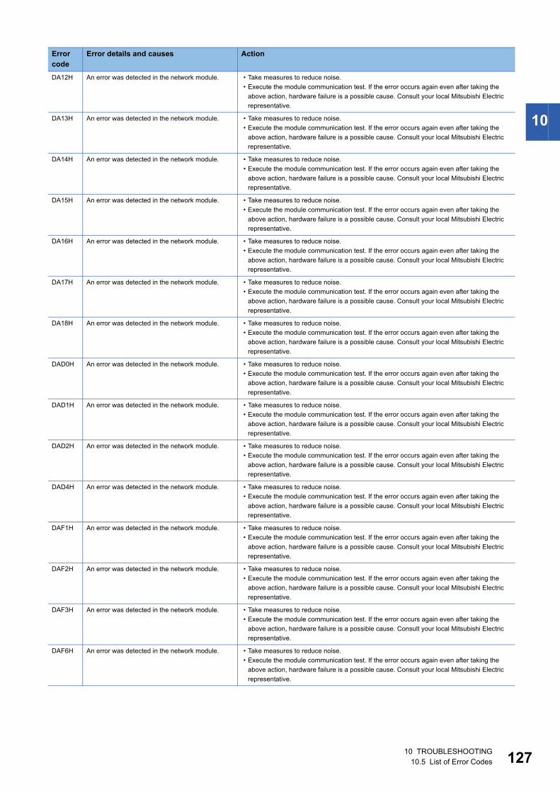
10
DA12H An error was detected in the network module. • Take measures to reduce noise.
• Execute the module communication test. If the error occurs again even after taking the
above action, hardware failure is a possible cause. Consult your local Mitsubishi Electric
representative.
DA13H An error was detected in the network module. • Take measures to reduce noise.
• Execute the module communication test. If the error occurs again even after taking the
above action, hardware failure is a possible cause. Consult your local Mitsubishi Electric
representative.
DA14H An error was detected in the network module. • Take measures to reduce noise.
• Execute the module communication test. If the error occurs again even after taking the
above action, hardware failure is a possible cause. Consult your local Mitsubishi Electric
representative.
DA15H An error was detected in the network module. • Take measures to reduce noise.
• Execute the module communication test. If the error occurs again even after taking the
above action, hardware failure is a possible cause. Consult your local Mitsubishi Electric
representative.
DA16H An error was detected in the network module. • Take measures to reduce noise.
• Execute the module communication test. If the error occurs again even after taking the
above action, hardware failure is a possible cause. Consult your local Mitsubishi Electric
representative.
DA17H An error was detected in the network module. • Take measures to reduce noise.
• Execute the module communication test. If the error occurs again even after taking the
above action, hardware failure is a possible cause. Consult your local Mitsubishi Electric
representative.
DA18H An error was detected in the network module. • Take measures to reduce noise.
• Execute the module communication test. If the error occurs again even after taking the
above action, hardware failure is a possible cause. Consult your local Mitsubishi Electric
representative.
DAD0H An error was detected in the network module. • Take measures to reduce noise.
• Execute the module communication test. If the error occurs again even after taking the
above action, hardware failure is a possible cause. Consult your local Mitsubishi Electric
representative.
DAD1H An error was detected in the network module. • Take measures to reduce noise.
• Execute the module communication test. If the error occurs again even after taking the
above action, hardware failure is a possible cause. Consult your local Mitsubishi Electric
representative.
DAD2H An error was detected in the network module. • Take measures to reduce noise.
• Execute the module communication test. If the error occurs again even after taking the
above action, hardware failure is a possible cause. Consult your local Mitsubishi Electric
representative.
DAD4H An error was detected in the network module. • Take measures to reduce noise.
• Execute the module communication test. If the error occurs again even after taking the
above action, hardware failure is a possible cause. Consult your local Mitsubishi Electric
representative.
DAF1H An error was detected in the network module. • Take measures to reduce noise.
• Execute the module communication test. If the error occurs again even after taking the
above action, hardware failure is a possible cause. Consult your local Mitsubishi Electric
representative.
DAF2H An error was detected in the network module. • Take measures to reduce noise.
• Execute the module communication test. If the error occurs again even after taking the
above action, hardware failure is a possible cause. Consult your local Mitsubishi Electric
representative.
DAF3H An error was detected in the network module. • Take measures to reduce noise.
• Execute the module communication test. If the error occurs again even after taking the
above action, hardware failure is a possible cause. Consult your local Mitsubishi Electric
representative.
DAF6H An error was detected in the network module. • Take measures to reduce noise.
• Execute the module communication test. If the error occurs again even after taking the
above action, hardware failure is a possible cause. Consult your local Mitsubishi Electric
representative.
Error code
Error details and causes Action
10 TROUBLESHOOTING10.5 List of Error Codes 127
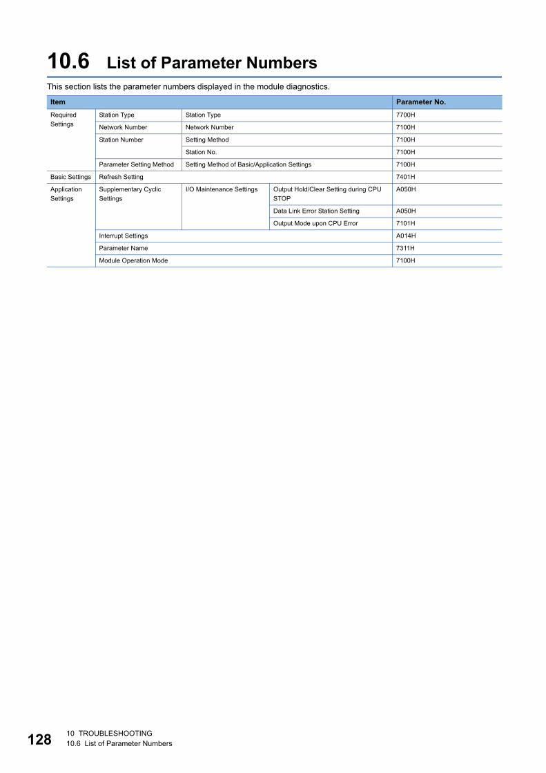
12
10.6 List of Parameter NumbersThis section lists the parameter numbers displayed in the module diagnostics.
Item Parameter No.
Required
Settings
Station Type Station Type 7700H
Network Number Network Number 7100H
Station Number Setting Method 7100H
Station No. 7100H
Parameter Setting Method Setting Method of Basic/Application Settings 7100H
Basic Settings Refresh Setting 7401H
Application
Settings
Supplementary Cyclic
Settings
I/O Maintenance Settings Output Hold/Clear Setting during CPU
STOP
A050H
Data Link Error Station Setting A050H
Output Mode upon CPU Error 7101H
Interrupt Settings A014H
Parameter Name 7311H
Module Operation Mode 7100H
810 TROUBLESHOOTING10.6 List of Parameter Numbers
A
APPENDICESAppendix 1 Standards
Certification of UL, cUL standardsThe FX5-CCLIEF supports UL (UL, cUL) standards.
For models that support UL standards, refer to the following.
UL, cUL file number: E95239
Compliance with EC directive (CE Marking)This note does not guarantee that an entire machine produced in accordance with the contents of this note will comply with
the following standards.
Compliance to EMC directive and LVD directive of the entire mechanical module should be checked by the user/
manufacturer. For more details please contact to the local Mitsubishi Electric sales site.
Requirement for compliance with EMC directiveThe following products have shown compliance through direct testing (of the identified standards below) and design analysis
(through the creation of a technical construction file) to the European Directive for Electromagnetic Compatibility (2014/30/
EU) when used as directed by the appropriate documentation.
AttentionThis product is designed for use in industrial applications.
Product compatibilityType: Programmable controller (open type equipment)
Models: FX5 manufactured
from May 1st, 2016 FX5-CCLIEF
Electromagnetic compatibility (EMC) directive Remarks
EN61131-2:2007 Programmable controllers
- Equipment requirements and tests
Compliance with all relevant aspects of the standard.
EMI
• Radiated emission
• Conducted emission
EMS
• Radiated electromagnetic field
• Fast transient burst
• Electrostatic discharge
• High-energy surge
• Voltage drops and interruptions
• Conducted RF
• Power frequency magnetic field
APPENDICESAppendix 1 Standards 129
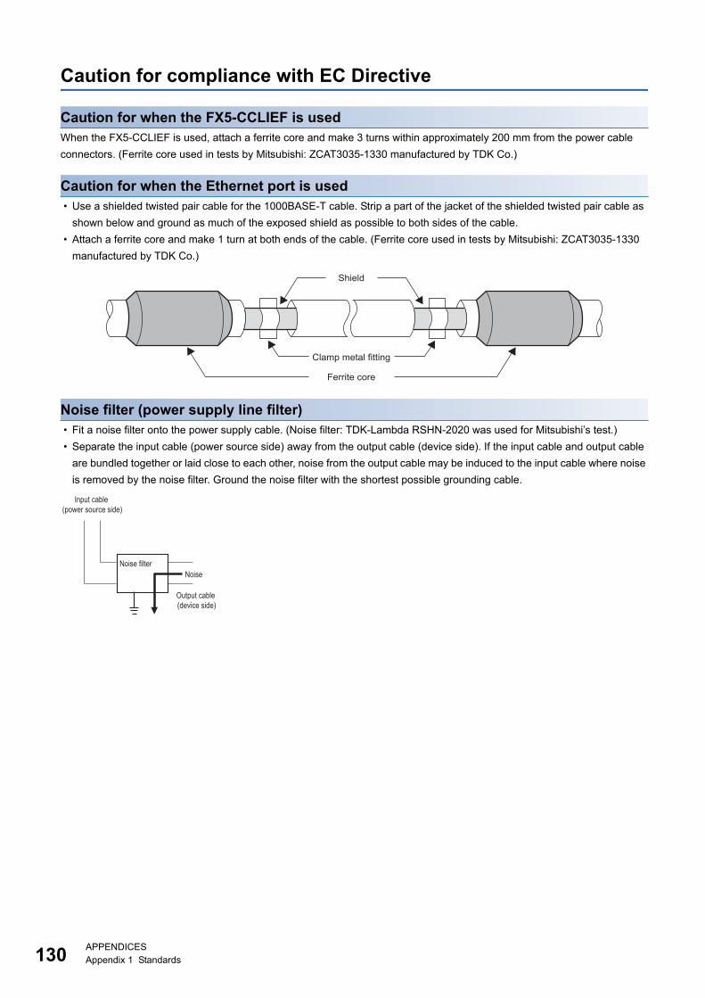
13
Caution for compliance with EC Directive
Caution for when the FX5-CCLIEF is usedWhen the FX5-CCLIEF is used, attach a ferrite core and make 3 turns within approximately 200 mm from the power cable
connectors. (Ferrite core used in tests by Mitsubishi: ZCAT3035-1330 manufactured by TDK Co.)
Caution for when the Ethernet port is used • Use a shielded twisted pair cable for the 1000BASE-T cable. Strip a part of the jacket of the shielded twisted pair cable as
shown below and ground as much of the exposed shield as possible to both sides of the cable.
• Attach a ferrite core and make 1 turn at both ends of the cable. (Ferrite core used in tests by Mitsubishi: ZCAT3035-1330
manufactured by TDK Co.)
Noise filter (power supply line filter) • Fit a noise filter onto the power supply cable. (Noise filter: TDK-Lambda RSHN-2020 was used for Mitsubishi’s test.)
• Separate the input cable (power source side) away from the output cable (device side). If the input cable and output cable
are bundled together or laid close to each other, noise from the output cable may be induced to the input cable where noise
is removed by the noise filter. Ground the noise filter with the shortest possible grounding cable.
Shield
Clamp metal fitting
Ferrite core
Noise filterNoise
Input cable(power source side)
Output cable (device side)
0APPENDICESAppendix 1 Standards
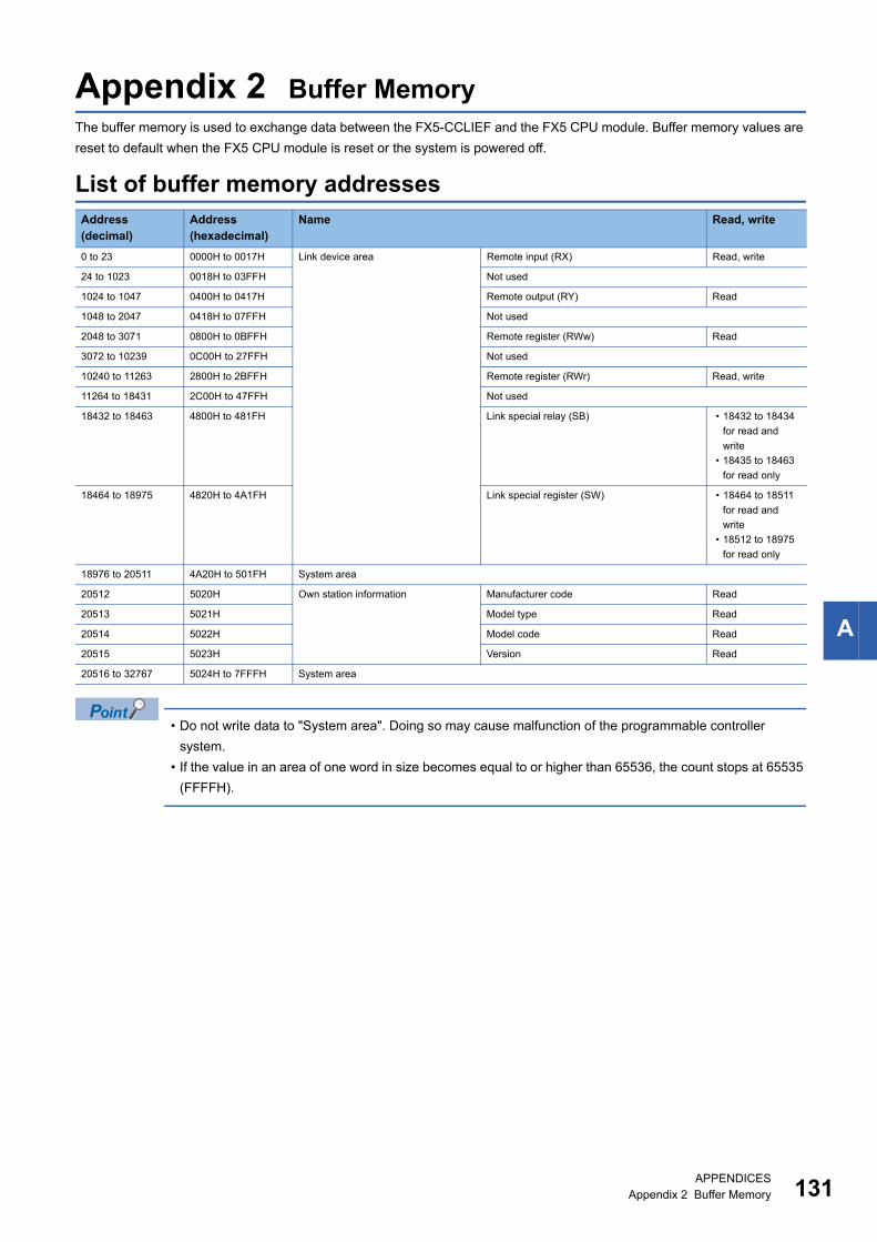
A
Appendix 2 Buffer MemoryThe buffer memory is used to exchange data between the FX5-CCLIEF and the FX5 CPU module. Buffer memory values are
reset to default when the FX5 CPU module is reset or the system is powered off.
List of buffer memory addresses
• Do not write data to "System area". Doing so may cause malfunction of the programmable controller
system.
• If the value in an area of one word in size becomes equal to or higher than 65536, the count stops at 65535
(FFFFH).
Address (decimal)
Address (hexadecimal)
Name Read, write
0 to 23 0000H to 0017H Link device area Remote input (RX) Read, write
24 to 1023 0018H to 03FFH Not used
1024 to 1047 0400H to 0417H Remote output (RY) Read
1048 to 2047 0418H to 07FFH Not used
2048 to 3071 0800H to 0BFFH Remote register (RWw) Read
3072 to 10239 0C00H to 27FFH Not used
10240 to 11263 2800H to 2BFFH Remote register (RWr) Read, write
11264 to 18431 2C00H to 47FFH Not used
18432 to 18463 4800H to 481FH Link special relay (SB) • 18432 to 18434
for read and
write
• 18435 to 18463
for read only
18464 to 18975 4820H to 4A1FH Link special register (SW) • 18464 to 18511
for read and
write
• 18512 to 18975
for read only
18976 to 20511 4A20H to 501FH System area
20512 5020H Own station information Manufacturer code Read
20513 5021H Model type Read
20514 5022H Model code Read
20515 5023H Version Read
20516 to 32767 5024H to 7FFFH System area
APPENDICESAppendix 2 Buffer Memory 131
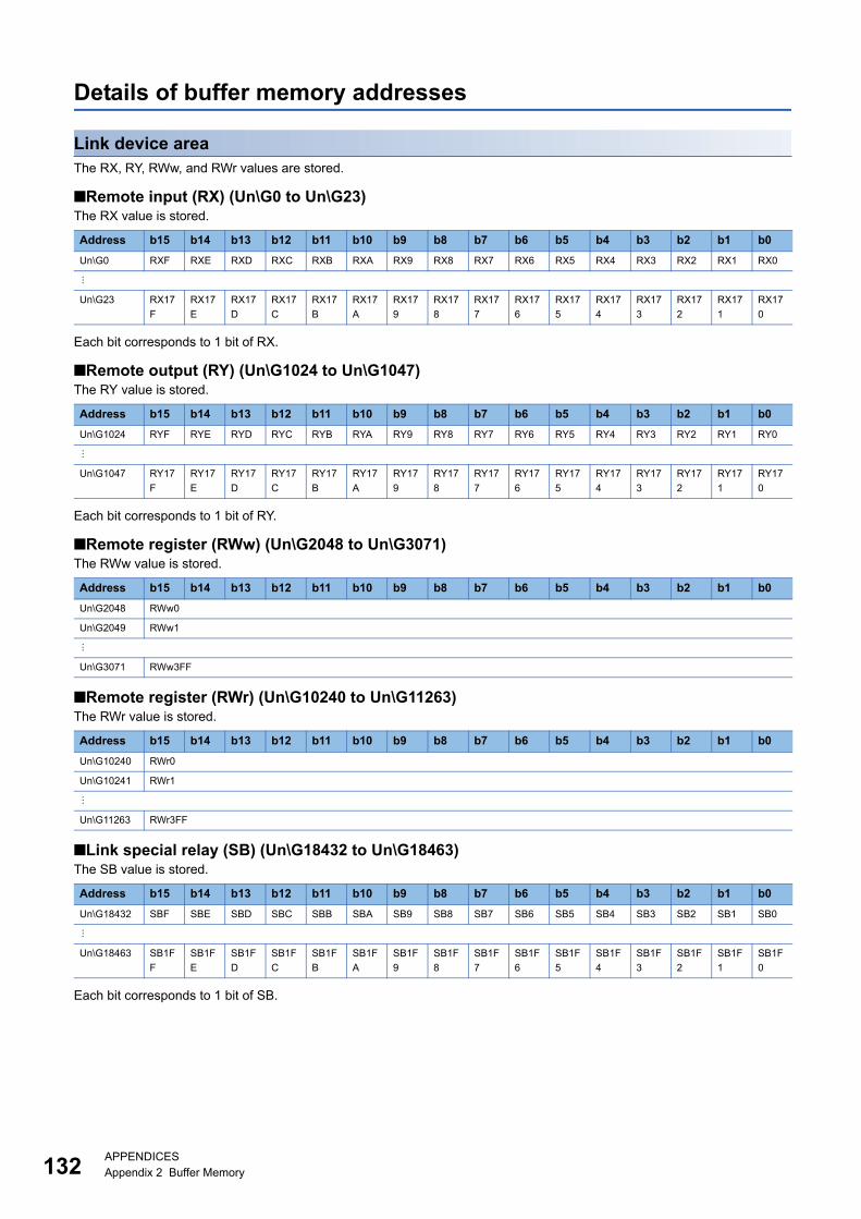
13
Details of buffer memory addresses
Link device areaThe RX, RY, RWw, and RWr values are stored.
■Remote input (RX) (Un\G0 to Un\G23)The RX value is stored.
Each bit corresponds to 1 bit of RX.
■Remote output (RY) (Un\G1024 to Un\G1047)The RY value is stored.
Each bit corresponds to 1 bit of RY.
■Remote register (RWw) (Un\G2048 to Un\G3071)The RWw value is stored.
■Remote register (RWr) (Un\G10240 to Un\G11263)The RWr value is stored.
■Link special relay (SB) (Un\G18432 to Un\G18463)The SB value is stored.
Each bit corresponds to 1 bit of SB.
Address b15 b14 b13 b12 b11 b10 b9 b8 b7 b6 b5 b4 b3 b2 b1 b0
Un\G0 RXF RXE RXD RXC RXB RXA RX9 RX8 RX7 RX6 RX5 RX4 RX3 RX2 RX1 RX0
Un\G23 RX17
F
RX17
E
RX17
D
RX17
C
RX17
B
RX17
A
RX17
9
RX17
8
RX17
7
RX17
6
RX17
5
RX17
4
RX17
3
RX17
2
RX17
1
RX17
0
Address b15 b14 b13 b12 b11 b10 b9 b8 b7 b6 b5 b4 b3 b2 b1 b0
Un\G1024 RYF RYE RYD RYC RYB RYA RY9 RY8 RY7 RY6 RY5 RY4 RY3 RY2 RY1 RY0
Un\G1047 RY17
F
RY17
E
RY17
D
RY17
C
RY17
B
RY17
A
RY17
9
RY17
8
RY17
7
RY17
6
RY17
5
RY17
4
RY17
3
RY17
2
RY17
1
RY17
0
Address b15 b14 b13 b12 b11 b10 b9 b8 b7 b6 b5 b4 b3 b2 b1 b0
Un\G2048 RWw0
Un\G2049 RWw1
Un\G3071 RWw3FF
Address b15 b14 b13 b12 b11 b10 b9 b8 b7 b6 b5 b4 b3 b2 b1 b0
Un\G10240 RWr0
Un\G10241 RWr1
Un\G11263 RWr3FF
Address b15 b14 b13 b12 b11 b10 b9 b8 b7 b6 b5 b4 b3 b2 b1 b0
Un\G18432 SBF SBE SBD SBC SBB SBA SB9 SB8 SB7 SB6 SB5 SB4 SB3 SB2 SB1 SB0
Un\G18463 SB1F
F
SB1F
E
SB1F
D
SB1F
C
SB1F
B
SB1F
A
SB1F
9
SB1F
8
SB1F
7
SB1F
6
SB1F
5
SB1F
4
SB1F
3
SB1F
2
SB1F
1
SB1F
0
2APPENDICESAppendix 2 Buffer Memory
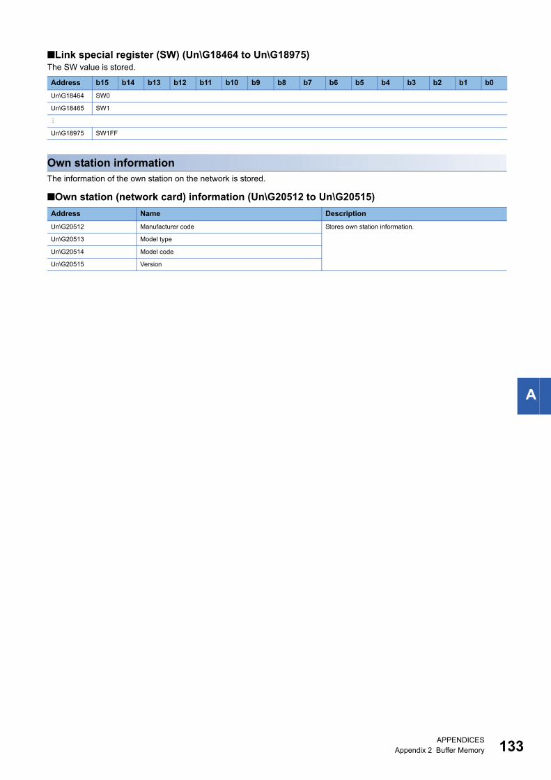
A
■Link special register (SW) (Un\G18464 to Un\G18975)The SW value is stored.
Own station informationThe information of the own station on the network is stored.
■Own station (network card) information (Un\G20512 to Un\G20515)
Address b15 b14 b13 b12 b11 b10 b9 b8 b7 b6 b5 b4 b3 b2 b1 b0
Un\G18464 SW0
Un\G18465 SW1
Un\G18975 SW1FF
Address Name Description
Un\G20512 Manufacturer code Stores own station information.
Un\G20513 Model type
Un\G20514 Model code
Un\G20515 Version
APPENDICESAppendix 2 Buffer Memory 133
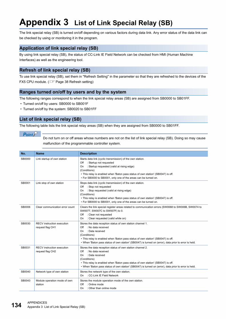
13
Appendix 3 List of Link Special Relay (SB)The link special relay (SB) is turned on/off depending on various factors during data link. Any error status of the data link can
be checked by using or monitoring it in the program.
Application of link special relay (SB)By using link special relay (SB), the status of CC-Link IE Field Network can be checked from HMI (Human Machine
Interfaces) as well as the engineering tool.
Refresh of link special relay (SB)To use link special relay (SB), set them in "Refresh Setting" in the parameter so that they are refreshed to the devices of the
FX5 CPU module. (Page 38 Refresh setting)
Ranges turned on/off by users and by the systemThe following ranges correspond to when the link special relay areas (SB) are assigned from SB0000 to SB01FF.
• Turned on/off by users: SB0000 to SB001F
• Turned on/off by the system: SB0020 to SB01FF
List of link special relay (SB)The following table lists the link special relay areas (SB) when they are assigned from SB0000 to SB01FF.
Do not turn on or off areas whose numbers are not on the list of link special relay (SB). Doing so may cause
malfunction of the programmable controller system.
No. Name Description
SB0000 Link startup of own station Starts data link (cyclic transmission) of the own station.
Off : Startup not requested
On : Startup requested (valid at rising edge)
(Conditions)
• This relay is enabled when 'Baton pass status of own station' (SB0047) is off.
• For SB0000 to SB0001, only one of the areas can be turned on.
SB0001 Link stop of own station Stops data link (cyclic transmission) of the own station.
Off : Stop not requested
On : Stop requested (valid at rising edge)
(Conditions)
• This relay is enabled when 'Baton pass status of own station' (SB0047) is off.
• For SB0000 to SB0001, only one of the areas can be turned on.
SB0006 Clear communication error count Clears the link special register areas related to communication errors (SW0068 to SW006B, SW0074 to
SW0077, SW007C to SW007F) to 0.
Off : Clear not requested
On : Clear requested (valid while on)
SB0030 RECV instruction execution
request flag CH1
Stores the data reception status of own station channel 1.
Off : No data received
On : Data received
(Conditions)
• This relay is enabled when 'Baton pass status of own station' (SB0047) is off.
• When 'Baton pass status of own station' (SB0047) is turned on (error), data prior to error is held.
SB0031 RECV instruction execution
request flag CH2
Stores the data reception status of own station channel 2.
Off : No data received
On : Data received
(Conditions)
• This relay is enabled when 'Baton pass status of own station' (SB0047) is off.
• When 'Baton pass status of own station' (SB0047) is turned on (error), data prior to error is held.
SB0040 Network type of own station Stores the network type of the own station.
On : CC-Link IE Field Network
SB0043 Module operation mode of own
station
Stores the module operation mode of the own station.
Off : Online mode
On : Other than online mode
4APPENDICESAppendix 3 List of Link Special Relay (SB)
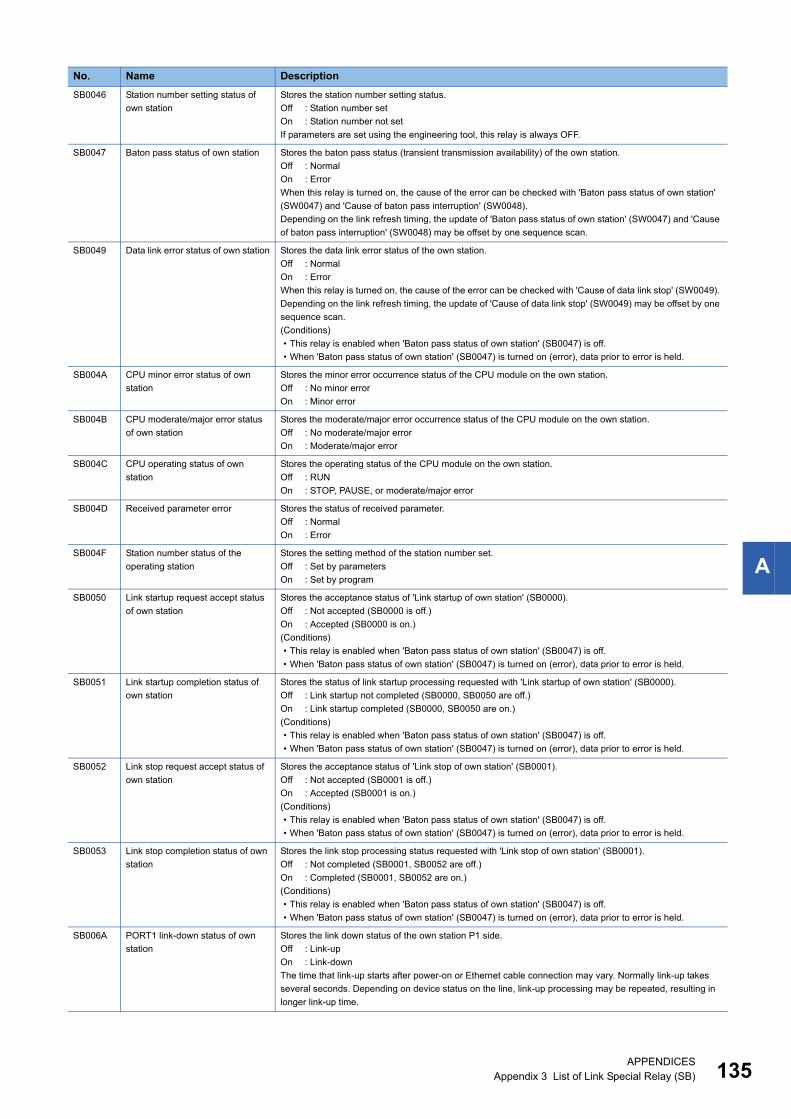
A
SB0046 Station number setting status of
own station
Stores the station number setting status.
Off : Station number set
On : Station number not set
If parameters are set using the engineering tool, this relay is always OFF.
SB0047 Baton pass status of own station Stores the baton pass status (transient transmission availability) of the own station.
Off : Normal
On : Error
When this relay is turned on, the cause of the error can be checked with 'Baton pass status of own station'
(SW0047) and 'Cause of baton pass interruption' (SW0048).
Depending on the link refresh timing, the update of 'Baton pass status of own station' (SW0047) and 'Cause
of baton pass interruption' (SW0048) may be offset by one sequence scan.
SB0049 Data link error status of own station Stores the data link error status of the own station.
Off : Normal
On : Error
When this relay is turned on, the cause of the error can be checked with 'Cause of data link stop' (SW0049).
Depending on the link refresh timing, the update of 'Cause of data link stop' (SW0049) may be offset by one
sequence scan.
(Conditions)
• This relay is enabled when 'Baton pass status of own station' (SB0047) is off.
• When 'Baton pass status of own station' (SB0047) is turned on (error), data prior to error is held.
SB004A CPU minor error status of own
station
Stores the minor error occurrence status of the CPU module on the own station.
Off : No minor error
On : Minor error
SB004B CPU moderate/major error status
of own station
Stores the moderate/major error occurrence status of the CPU module on the own station.
Off : No moderate/major error
On : Moderate/major error
SB004C CPU operating status of own
station
Stores the operating status of the CPU module on the own station.
Off : RUN
On : STOP, PAUSE, or moderate/major error
SB004D Received parameter error Stores the status of received parameter.
Off : Normal
On : Error
SB004F Station number status of the
operating station
Stores the setting method of the station number set.
Off : Set by parameters
On : Set by program
SB0050 Link startup request accept status
of own station
Stores the acceptance status of 'Link startup of own station' (SB0000).
Off : Not accepted (SB0000 is off.)
On : Accepted (SB0000 is on.)
(Conditions)
• This relay is enabled when 'Baton pass status of own station' (SB0047) is off.
• When 'Baton pass status of own station' (SB0047) is turned on (error), data prior to error is held.
SB0051 Link startup completion status of
own station
Stores the status of link startup processing requested with 'Link startup of own station' (SB0000).
Off : Link startup not completed (SB0000, SB0050 are off.)
On : Link startup completed (SB0000, SB0050 are on.)
(Conditions)
• This relay is enabled when 'Baton pass status of own station' (SB0047) is off.
• When 'Baton pass status of own station' (SB0047) is turned on (error), data prior to error is held.
SB0052 Link stop request accept status of
own station
Stores the acceptance status of 'Link stop of own station' (SB0001).
Off : Not accepted (SB0001 is off.)
On : Accepted (SB0001 is on.)
(Conditions)
• This relay is enabled when 'Baton pass status of own station' (SB0047) is off.
• When 'Baton pass status of own station' (SB0047) is turned on (error), data prior to error is held.
SB0053 Link stop completion status of own
station
Stores the link stop processing status requested with 'Link stop of own station' (SB0001).
Off : Not completed (SB0001, SB0052 are off.)
On : Completed (SB0001, SB0052 are on.)
(Conditions)
• This relay is enabled when 'Baton pass status of own station' (SB0047) is off.
• When 'Baton pass status of own station' (SB0047) is turned on (error), data prior to error is held.
SB006A PORT1 link-down status of own
station
Stores the link down status of the own station P1 side.
Off : Link-up
On : Link-down
The time that link-up starts after power-on or Ethernet cable connection may vary. Normally link-up takes
several seconds. Depending on device status on the line, link-up processing may be repeated, resulting in
longer link-up time.
No. Name Description
APPENDICESAppendix 3 List of Link Special Relay (SB) 135
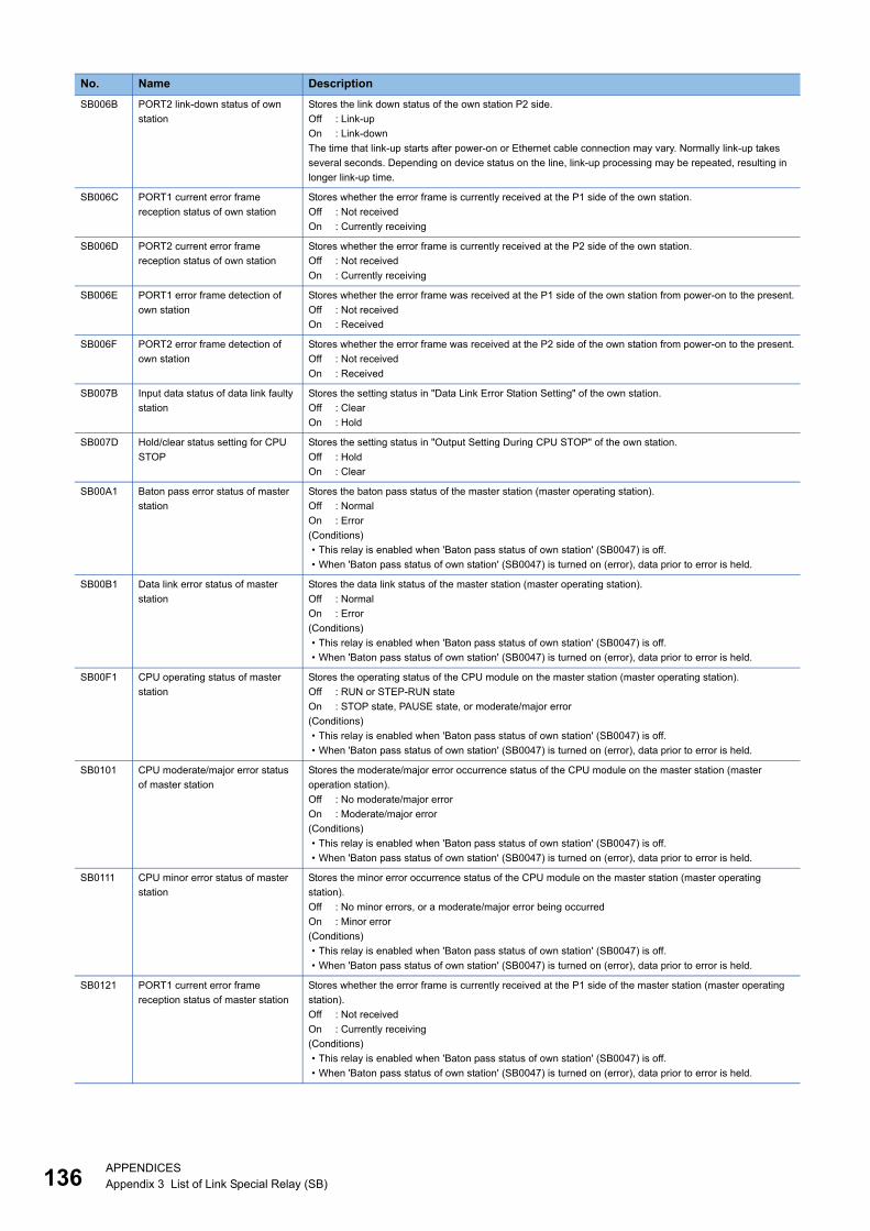
13
SB006B PORT2 link-down status of own
station
Stores the link down status of the own station P2 side.
Off : Link-up
On : Link-down
The time that link-up starts after power-on or Ethernet cable connection may vary. Normally link-up takes
several seconds. Depending on device status on the line, link-up processing may be repeated, resulting in
longer link-up time.
SB006C PORT1 current error frame
reception status of own station
Stores whether the error frame is currently received at the P1 side of the own station.
Off : Not received
On : Currently receiving
SB006D PORT2 current error frame
reception status of own station
Stores whether the error frame is currently received at the P2 side of the own station.
Off : Not received
On : Currently receiving
SB006E PORT1 error frame detection of
own station
Stores whether the error frame was received at the P1 side of the own station from power-on to the present.
Off : Not received
On : Received
SB006F PORT2 error frame detection of
own station
Stores whether the error frame was received at the P2 side of the own station from power-on to the present.
Off : Not received
On : Received
SB007B Input data status of data link faulty
station
Stores the setting status in "Data Link Error Station Setting" of the own station.
Off : Clear
On : Hold
SB007D Hold/clear status setting for CPU
STOP
Stores the setting status in "Output Setting During CPU STOP" of the own station.
Off : Hold
On : Clear
SB00A1 Baton pass error status of master
station
Stores the baton pass status of the master station (master operating station).
Off : Normal
On : Error
(Conditions)
• This relay is enabled when 'Baton pass status of own station' (SB0047) is off.
• When 'Baton pass status of own station' (SB0047) is turned on (error), data prior to error is held.
SB00B1 Data link error status of master
station
Stores the data link status of the master station (master operating station).
Off : Normal
On : Error
(Conditions)
• This relay is enabled when 'Baton pass status of own station' (SB0047) is off.
• When 'Baton pass status of own station' (SB0047) is turned on (error), data prior to error is held.
SB00F1 CPU operating status of master
station
Stores the operating status of the CPU module on the master station (master operating station).
Off : RUN or STEP-RUN state
On : STOP state, PAUSE state, or moderate/major error
(Conditions)
• This relay is enabled when 'Baton pass status of own station' (SB0047) is off.
• When 'Baton pass status of own station' (SB0047) is turned on (error), data prior to error is held.
SB0101 CPU moderate/major error status
of master station
Stores the moderate/major error occurrence status of the CPU module on the master station (master
operation station).
Off : No moderate/major error
On : Moderate/major error
(Conditions)
• This relay is enabled when 'Baton pass status of own station' (SB0047) is off.
• When 'Baton pass status of own station' (SB0047) is turned on (error), data prior to error is held.
SB0111 CPU minor error status of master
station
Stores the minor error occurrence status of the CPU module on the master station (master operating
station).
Off : No minor errors, or a moderate/major error being occurred
On : Minor error
(Conditions)
• This relay is enabled when 'Baton pass status of own station' (SB0047) is off.
• When 'Baton pass status of own station' (SB0047) is turned on (error), data prior to error is held.
SB0121 PORT1 current error frame
reception status of master station
Stores whether the error frame is currently received at the P1 side of the master station (master operating
station).
Off : Not received
On : Currently receiving
(Conditions)
• This relay is enabled when 'Baton pass status of own station' (SB0047) is off.
• When 'Baton pass status of own station' (SB0047) is turned on (error), data prior to error is held.
No. Name Description
6APPENDICESAppendix 3 List of Link Special Relay (SB)
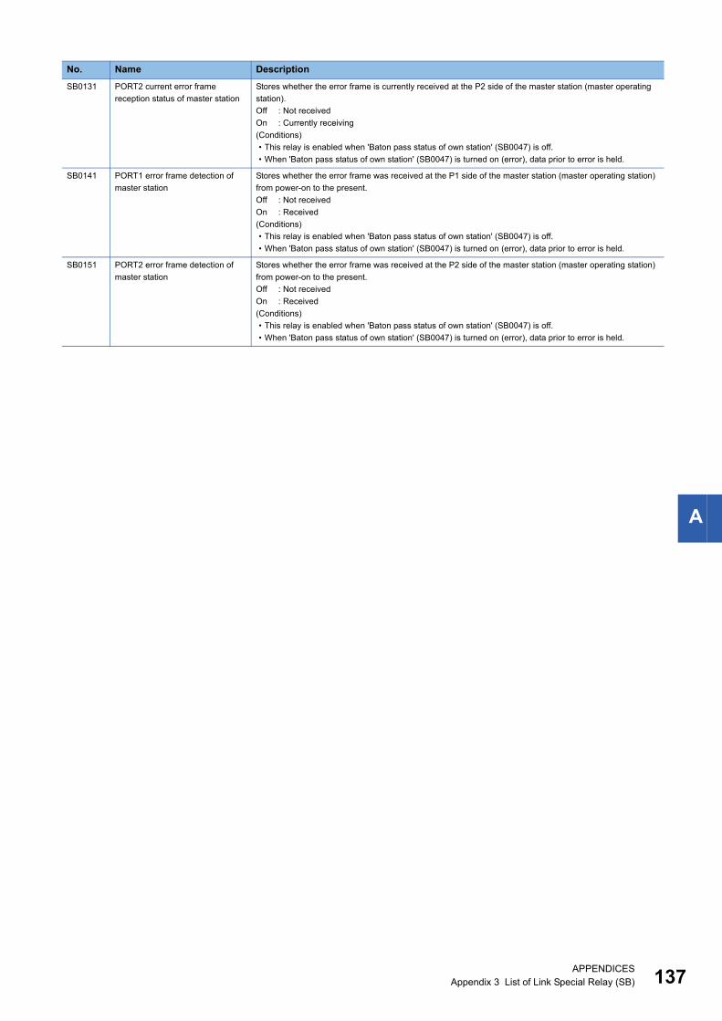
A
SB0131 PORT2 current error frame
reception status of master station
Stores whether the error frame is currently received at the P2 side of the master station (master operating
station).
Off : Not received
On : Currently receiving
(Conditions)
• This relay is enabled when 'Baton pass status of own station' (SB0047) is off.
• When 'Baton pass status of own station' (SB0047) is turned on (error), data prior to error is held.
SB0141 PORT1 error frame detection of
master station
Stores whether the error frame was received at the P1 side of the master station (master operating station)
from power-on to the present.
Off : Not received
On : Received
(Conditions)
• This relay is enabled when 'Baton pass status of own station' (SB0047) is off.
• When 'Baton pass status of own station' (SB0047) is turned on (error), data prior to error is held.
SB0151 PORT2 error frame detection of
master station
Stores whether the error frame was received at the P2 side of the master station (master operating station)
from power-on to the present.
Off : Not received
On : Received
(Conditions)
• This relay is enabled when 'Baton pass status of own station' (SB0047) is off.
• When 'Baton pass status of own station' (SB0047) is turned on (error), data prior to error is held.
No. Name Description
APPENDICESAppendix 3 List of Link Special Relay (SB) 137
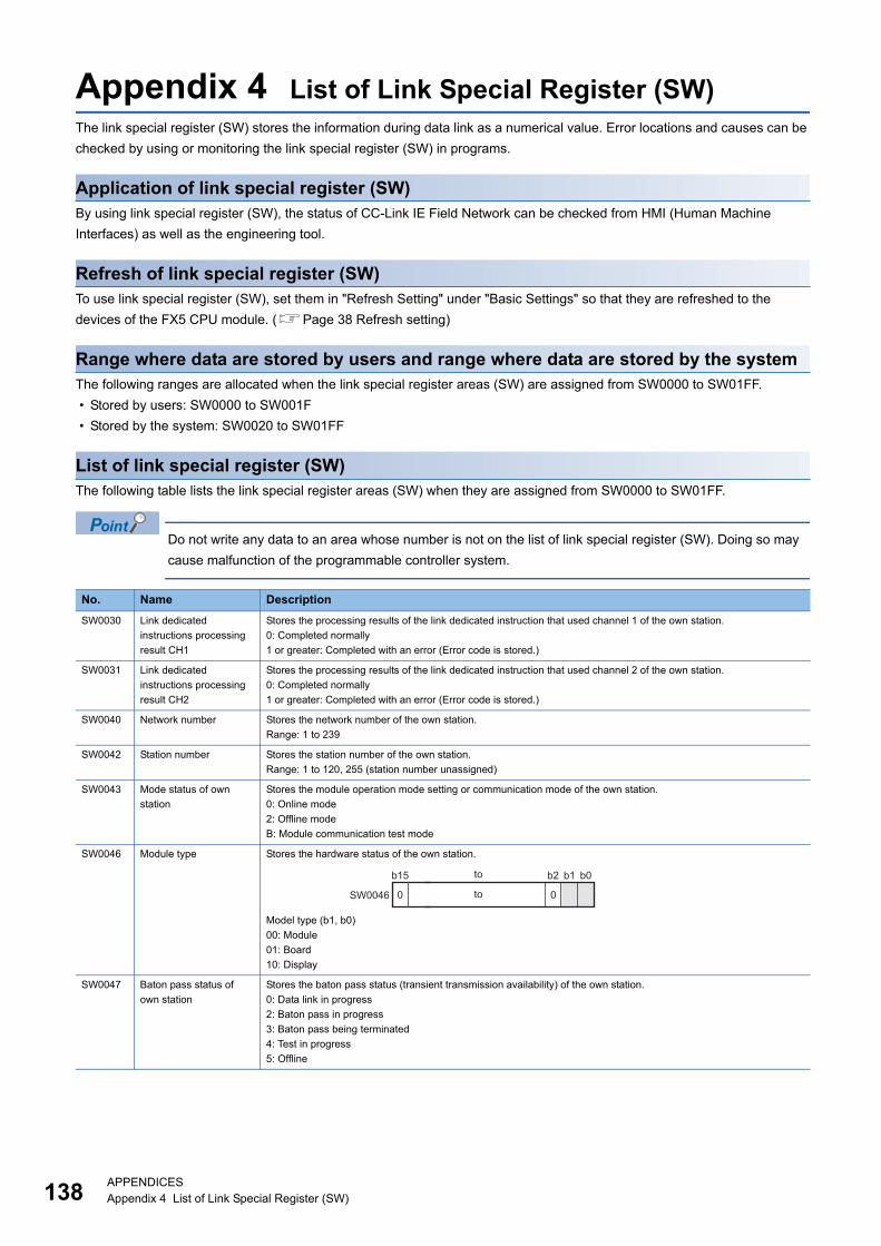
13
Appendix 4 List of Link Special Register (SW)The link special register (SW) stores the information during data link as a numerical value. Error locations and causes can be
checked by using or monitoring the link special register (SW) in programs.
Application of link special register (SW)By using link special register (SW), the status of CC-Link IE Field Network can be checked from HMI (Human Machine
Interfaces) as well as the engineering tool.
Refresh of link special register (SW)To use link special register (SW), set them in "Refresh Setting" under "Basic Settings" so that they are refreshed to the
devices of the FX5 CPU module. (Page 38 Refresh setting)
Range where data are stored by users and range where data are stored by the systemThe following ranges are allocated when the link special register areas (SW) are assigned from SW0000 to SW01FF.
• Stored by users: SW0000 to SW001F
• Stored by the system: SW0020 to SW01FF
List of link special register (SW)The following table lists the link special register areas (SW) when they are assigned from SW0000 to SW01FF.
Do not write any data to an area whose number is not on the list of link special register (SW). Doing so may
cause malfunction of the programmable controller system.
No. Name Description
SW0030 Link dedicated
instructions processing
result CH1
Stores the processing results of the link dedicated instruction that used channel 1 of the own station.
0: Completed normally
1 or greater: Completed with an error (Error code is stored.)
SW0031 Link dedicated
instructions processing
result CH2
Stores the processing results of the link dedicated instruction that used channel 2 of the own station.
0: Completed normally
1 or greater: Completed with an error (Error code is stored.)
SW0040 Network number Stores the network number of the own station.
Range: 1 to 239
SW0042 Station number Stores the station number of the own station.
Range: 1 to 120, 255 (station number unassigned)
SW0043 Mode status of own
station
Stores the module operation mode setting or communication mode of the own station.
0: Online mode
2: Offline mode
B: Module communication test mode
SW0046 Module type Stores the hardware status of the own station.
Model type (b1, b0)
00: Module
01: Board
10: Display
SW0047 Baton pass status of
own station
Stores the baton pass status (transient transmission availability) of the own station.
0: Data link in progress
2: Baton pass in progress
3: Baton pass being terminated
4: Test in progress
5: Offline
b15 b2 b1 b0
SW0046 0 0
to
to
8APPENDICESAppendix 4 List of Link Special Register (SW)
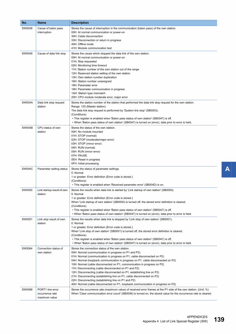
A
SW0048 Cause of baton pass
interruption
Stores the cause of interruption in the communication (baton pass) of the own station.
00H: At normal communication or power-on
30H: Cable disconnection
33H: Disconnection or return in progress
40H: Offline mode
41H: Module communication test
SW0049 Cause of data link stop Stores the cause which stopped the data link of the own station.
00H: At normal communication or power-on
01H: Stop requested
02H: Monitoring time timeout
11H: Station number of the own station out of the range
12H: Reserved station setting of the own station
13H: Own station number duplication
16H: Station number unassigned
18H: Parameter error
19H: Parameter communication in progress
1AH: Station type mismatch
20H: CPU module moderate error, major error
SW004A Data link stop request
station
Stores the station number of the station that performed the data link stop request for the own station.
Range: 125 (Master station)
The data link stop request is performed by 'System link stop' (SB0003).
(Conditions)
• This register is enabled when 'Baton pass status of own station' (SB0047) is off.
• When 'Baton pass status of own station' (SB0047) is turned on (error), data prior to error is held.
SW004B CPU status of own
station
Stores the status of the own station.
00H: No module mounted
01H: STOP (normal)
02H: STOP (moderate/major error)
03H: STOP (minor error)
04H: RUN (normal)
05H: RUN (minor error)
07H: PAUSE
0EH: Reset in progress
0FH: Initial processing
SW004C Parameter setting status Stores the status of parameter settings.
0: Normal
1 or greater: Error definition (Error code is stored.)
(Conditions)
• This register is enabled when 'Received parameter error' (SB004D) is on.
SW0050 Link startup result of own
station
Stores the results when data link is started by 'Link startup of own station' (SB0000).
0: Normal
1 or greater: Error definition (Error code is stored.)
When 'Link startup of own station' (SB0000) is turned off, the stored error definition is cleared.
(Conditions)
• This register is enabled when 'Baton pass status of own station' (SB0047) is off.
• When 'Baton pass status of own station' (SB0047) is turned on (error), data prior to error is held.
SW0051 Link stop result of own
station
Stores the results when data link is stopped by 'Link stop of own station' (SB0001).
0: Normal
1 or greater: Error definition (Error code is stored.)
When 'Link stop of own station' (SB0001) is turned off, the stored error definition is cleared.
(Conditions)
• This register is enabled when 'Baton pass status of own station' (SB0047) is off.
• When 'Baton pass status of own station' (SB0047) is turned on (error), data prior to error is held.
SW0064 Connection status of
own station
Stores the connection status of the own station.
00H: Normal (communication in progress on P1 and P2)
01H: Normal (communication in progress on P1, cable disconnected on P2)
04H: Normal (loopback communication in progress on P1, cable disconnected on P2)
10H: Normal (cable disconnected on P1, communication in progress on P2)
11H: Disconnecting (cable disconnected on P1 and P2)
12H: Disconnecting (cable disconnected on P1, establishing line on P2)
21H: Disconnecting (establishing line on P1, cable disconnected on P2)
22H: Disconnecting (establishing line on P1 and P2)
40H: Normal (cable disconnected on P1, loopback communication in progress on P2)
SW0068 PORT1 line error
occurrence rate
maximum value
Stores the occurrence rate (maximum value) of received error frames at the P1 side of the own station. (Unit: %)
When 'Clear communication error count' (SB0006) is turned on, the stored value for the occurrence rate is cleared.
No. Name Description
APPENDICESAppendix 4 List of Link Special Register (SW) 139
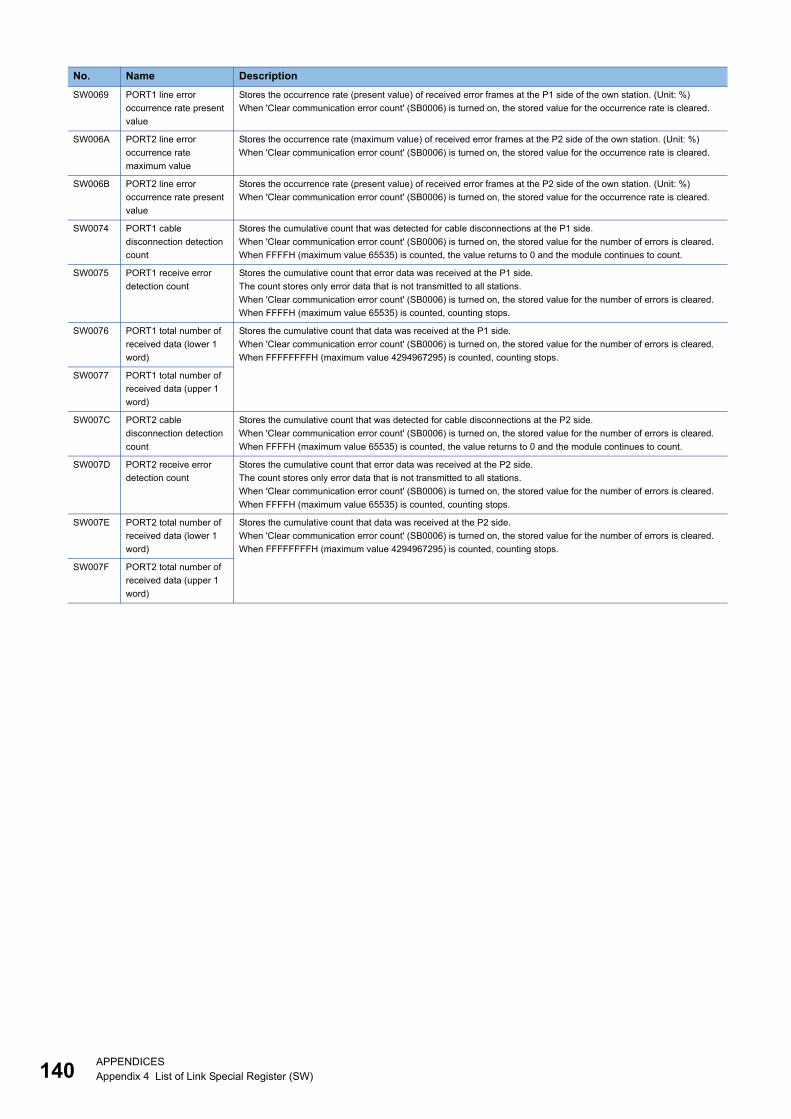
14
SW0069 PORT1 line error
occurrence rate present
value
Stores the occurrence rate (present value) of received error frames at the P1 side of the own station. (Unit: %)
When 'Clear communication error count' (SB0006) is turned on, the stored value for the occurrence rate is cleared.
SW006A PORT2 line error
occurrence rate
maximum value
Stores the occurrence rate (maximum value) of received error frames at the P2 side of the own station. (Unit: %)
When 'Clear communication error count' (SB0006) is turned on, the stored value for the occurrence rate is cleared.
SW006B PORT2 line error
occurrence rate present
value
Stores the occurrence rate (present value) of received error frames at the P2 side of the own station. (Unit: %)
When 'Clear communication error count' (SB0006) is turned on, the stored value for the occurrence rate is cleared.
SW0074 PORT1 cable
disconnection detection
count
Stores the cumulative count that was detected for cable disconnections at the P1 side.
When 'Clear communication error count' (SB0006) is turned on, the stored value for the number of errors is cleared.
When FFFFH (maximum value 65535) is counted, the value returns to 0 and the module continues to count.
SW0075 PORT1 receive error
detection count
Stores the cumulative count that error data was received at the P1 side.
The count stores only error data that is not transmitted to all stations.
When 'Clear communication error count' (SB0006) is turned on, the stored value for the number of errors is cleared.
When FFFFH (maximum value 65535) is counted, counting stops.
SW0076 PORT1 total number of
received data (lower 1
word)
Stores the cumulative count that data was received at the P1 side.
When 'Clear communication error count' (SB0006) is turned on, the stored value for the number of errors is cleared.
When FFFFFFFFH (maximum value 4294967295) is counted, counting stops.
SW0077 PORT1 total number of
received data (upper 1
word)
SW007C PORT2 cable
disconnection detection
count
Stores the cumulative count that was detected for cable disconnections at the P2 side.
When 'Clear communication error count' (SB0006) is turned on, the stored value for the number of errors is cleared.
When FFFFH (maximum value 65535) is counted, the value returns to 0 and the module continues to count.
SW007D PORT2 receive error
detection count
Stores the cumulative count that error data was received at the P2 side.
The count stores only error data that is not transmitted to all stations.
When 'Clear communication error count' (SB0006) is turned on, the stored value for the number of errors is cleared.
When FFFFH (maximum value 65535) is counted, counting stops.
SW007E PORT2 total number of
received data (lower 1
word)
Stores the cumulative count that data was received at the P2 side.
When 'Clear communication error count' (SB0006) is turned on, the stored value for the number of errors is cleared.
When FFFFFFFFH (maximum value 4294967295) is counted, counting stops.
SW007F PORT2 total number of
received data (upper 1
word)
No. Name Description
0APPENDICESAppendix 4 List of Link Special Register (SW)
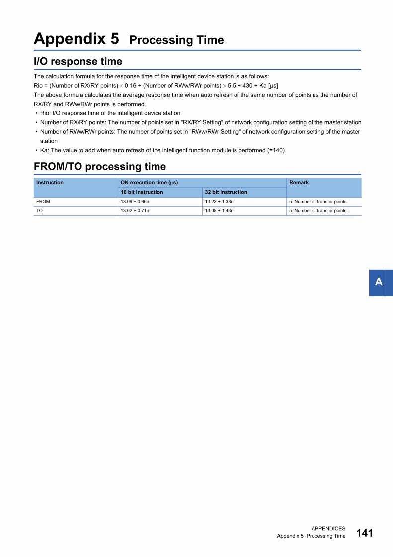
A
Appendix 5 Processing Time
I/O response timeThe calculation formula for the response time of the intelligent device station is as follows:
Rio = (Number of RX/RY points) × 0.16 + (Number of RWw/RWr points) × 5.5 + 430 + Ka [μs]
The above formula calculates the average response time when auto refresh of the same number of points as the number of
RX/RY and RWw/RWr points is performed.
• Rio: I/O response time of the intelligent device station
• Number of RX/RY points: The number of points set in "RX/RY Setting" of network configuration setting of the master station
• Number of RWw/RWr points: The number of points set in "RWw/RWr Setting" of network configuration setting of the master
station
• Ka: The value to add when auto refresh of the intelligent function module is performed (=140)
FROM/TO processing timeInstruction ON execution time (μs) Remark
16 bit instruction 32 bit instruction
FROM 13.09 + 0.66n 13.23 + 1.33n n: Number of transfer points
TO 13.02 + 0.71n 13.08 + 1.43n n: Number of transfer points
APPENDICESAppendix 5 Processing Time 141
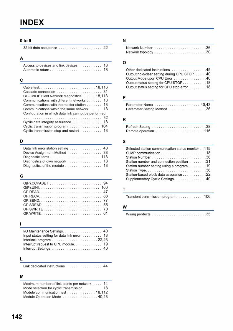
142
INDEX
0 to 9
32-bit data assurance . . . . . . . . . . . . . . . . . . . . 22
A
Access to devices and link devices . . . . . . . . . . . 18Automatic return . . . . . . . . . . . . . . . . . . . . . . . . 18
C
Cable test. . . . . . . . . . . . . . . . . . . . . . . . . . 18,116Cascade connection . . . . . . . . . . . . . . . . . . . . . 31CC-Link IE Field Network diagnostics . . . . . . 18,113Communications with different networks . . . . . . . 18Communications with the master station . . . . . . . 18Communications within the same network . . . . . . 18Configuration in which data link cannot be performed. . . . . . . . . . . . . . . . . . . . . . . . . . . . . . . . . . . . 32Cyclic data integrity assurance . . . . . . . . . . . . . . 18Cyclic transmission program . . . . . . . . . . . . . . 104Cyclic transmission stop and restart . . . . . . . . . . 18
D
Data link error station setting . . . . . . . . . . . . . . . 40Device Assignment Method . . . . . . . . . . . . . . . . 38Diagnostic items . . . . . . . . . . . . . . . . . . . . . . . 113Diagnostics of own network . . . . . . . . . . . . . . . . 18Diagnostics of the module . . . . . . . . . . . . . . . . . 18
G
G(P).CCPASET . . . . . . . . . . . . . . . . . . . . . . . . 94G(P).UINI . . . . . . . . . . . . . . . . . . . . . . . . . . . . 100GP.READ. . . . . . . . . . . . . . . . . . . . . . . . . . . . . 47GP.RECV. . . . . . . . . . . . . . . . . . . . . . . . . . . . . 88GP.SEND. . . . . . . . . . . . . . . . . . . . . . . . . . . . . 77GP.SREAD . . . . . . . . . . . . . . . . . . . . . . . . . . . 55GP.SWRITE. . . . . . . . . . . . . . . . . . . . . . . . . . . 70GP.WRITE . . . . . . . . . . . . . . . . . . . . . . . . . . . . 61
I
I/O Maintenance Settings. . . . . . . . . . . . . . . . . . 40Input status setting for data link error. . . . . . . . . . 18Interlock program . . . . . . . . . . . . . . . . . . . . . 22,23Interrupt request to CPU module. . . . . . . . . . . . . 19Interrupt Settings . . . . . . . . . . . . . . . . . . . . . . . 40
L
Link dedicated instructions . . . . . . . . . . . . . . . . . 44
M
Maximum number of link points per network. . . . . 14Mode selection for cyclic transmission. . . . . . . . . 18Module communication test . . . . . . . . . . . . . 18,112Module Operation Mode . . . . . . . . . . . . . . . . 40,43
N
Network Number . . . . . . . . . . . . . . . . . . . . . . . .36Network topology . . . . . . . . . . . . . . . . . . . . . . . .30
O
Other dedicated instructions . . . . . . . . . . . . . . . .45Output hold/clear setting during CPU STOP . . . . .40Output Mode upon CPU Error . . . . . . . . . . . . . . .40Output status setting for CPU STOP. . . . . . . . . . .18Output status setting for CPU stop error . . . . . . . .18
P
Parameter Name . . . . . . . . . . . . . . . . . . . . . 40,43Parameter Setting Method . . . . . . . . . . . . . . . . . .36
R
Refresh Setting . . . . . . . . . . . . . . . . . . . . . . . . .38Remote operation . . . . . . . . . . . . . . . . . . . . . . .116
S
Selected station communication status monitor . .115SLMP communication . . . . . . . . . . . . . . . . . . . . .18Station Number . . . . . . . . . . . . . . . . . . . . . . . . .36Station number and connection position . . . . . . . .31Station number setting using a program . . . . . . . .19Station Type. . . . . . . . . . . . . . . . . . . . . . . . . . . .36Station-based block data assurance . . . . . . . . . . .22Supplementary Cyclic Settings. . . . . . . . . . . . . . .40
T
Transient transmission program . . . . . . . . . . . . .106
W
Wiring products . . . . . . . . . . . . . . . . . . . . . . . . .35

I
MEMO
143

14
REVISIONS
2016 MITSUBISHI ELECTRIC CORPORATION
Revision date Revision Description
May 2016 A First edition
This manual confers no industrial property rights or any rights of any other kind, nor does it confer any patent licenses. Mitsubishi Electric Corporation cannot
be held responsible for any problems involving industrial property rights which may occur as a result of using the contents noted in this manual.
4
WARRANTY
1.Please confirm the following product warranty details before using this product.
[Gratis Warranty Term]
If any faults or defects (hereinafter "Failure") found to be the responsibility of Mitsubishi occurs during use of the product within the gratis warranty term, the product shall be repaired at no cost via the sales representative or Mitsubishi Service Company. However, if repairs are required onsite at domestic or overseas location, expenses to send an engineer will be solely at the customer's discretion. Mitsubishi shall not be held responsible for any re-commissioning, maintenance, or testing on-site that involves replacement of the failed module.
Overseas, repairs shall be accepted by Mitsubishi's local overseas FA Center. Note that the repair conditions at each FA Center may differ.
The gratis warranty term of the product shall be for one year after the date of purchase or delivery to a designated place. Note that after manufacture and shipment from Mitsubishi, the maximum distribution period shall be six (6) months, and the longest gratis warranty term after manufacturing shall be eighteen (18) months. The gratis warranty term of repair parts shall not exceed the gratis warranty term before repairs.
[Gratis Warranty Range] The range shall be limited to normal use within the usage state, usage methods and usage environment, etc., which follow the conditions and precautions, etc., given in the instruction manual, user's manual and caution labels on the product.
(1)
Even within the gratis warranty term, repairs shall be charged for in the following cases.
(2)
Failure occurring from inappropriate storage or handling, carelessness or negligence by the user. Failure caused by the user's hardware or software design.
1.
Failure caused by unapproved modifications, etc., to the product by the user.
2.
Mitsubishi shall accept onerous product repairs for seven (7) years after production of the product is discontinued.Discontinuation of production shall be notified with Mitsubishi Technical Bulletins, etc.
(1)
Product supply (including repair parts) is not available after production is discontinued.
(2)
In using the Mitsubishi MELSEC programmable controller, the usage conditions shall be that the application will not lead to a major accident even if any problem or fault should occur in the programmable controller device, and that backup and fail-safe functions are systematically provided outside of the device for any problem or fault.
(1)
The Mitsubishi programmable controller has been designed and manufactured for applications in general industries, etc. Thus, applications in which the public could be affected such as in nuclear power plants and other power plants operated by respective power companies, and applications in which a special quality assurance system is required, such as for railway companies or public service purposes shall be excluded from the programmable controller applications. In addition, applications in which human life or property that could be greatly affected, such as in aircraft, medical applications, incineration and fuel devices, manned transportation, equipment for recreation and amusement, and safety devices, shall also be excluded from the programmable controller range of applications. However, in certain cases, some applications may be possible, providing the user consults their local Mitsubishi representative outlining the special requirements of the project, and providing that all parties concerned agree to the special circumstances, solely at the user's discretion.
(2)
When the Mitsubishi product is assembled into a user's device, Failure that could have been avoided if functions or structures, judged as necessary in the legal safety measures the user's device is subject to or as necessary by industry standards, had been provided.
3.
Failure that could have been avoided if consumable parts (battery, backlight, fuse, etc.) designated in the instruction manual had been correctly serviced or replaced.
4.
Relay failure or output contact failure caused by usage beyond the specified life of contact (cycles).
5.
Failure caused by external irresistible forces such as fires or abnormal voltages, and failure caused by force majeure such as earthquakes, lightning, wind and water damage.
6.
Failure caused by reasons unpredictable by scientific technology standards at time of shipment from Mitsubishi.
7.
Any other failure found not to be the responsibility of Mitsubishi or that admitted not to be so by the user.
8.
2. Onerous repair term after discontinuation of production
Gratis Warranty Term and Gratis Warranty Range
4. Exclusion of loss in opportunity and secondary loss from warranty liability
3. Overseas service
The specifications given in the catalogs, manuals or technical documents are subject to change without prior notice.
5. Changes in product specifications
6. Product application
Regardless of the gratis warranty term, Mitsubishi shall not be liable for compensation to:(1) Damages caused by any cause found not to be
the responsibility of Mitsubishi.(2) Loss in opportunity, lost profits incurred to the
user by Failures of Mitsubishi products.(3) Special damages and secondary damages
whether foreseeable or not, compensation for accidents, and compensation for damages to products other than Mitsubishi products.
(4) Replacement by the user, maintenance of on-site equipment, start-up test run and other tasks.
145

14
TRADEMARKSMicrosoft and Windows are either registered trademarks or trademarks of Microsoft Corporation in the United States and/or
other countries.
Ethernet is a trademark of Xerox Corporation.
MODBUS is a registered trademark of Schneider Electric SA.
Phillips is a registered trademark of Phillips Screw Company.
The company name and the product name to be described in this manual are the registered trademarks or trademarks of
each company.
6


otice.
HEAD OFFICE: TOKYO BUILDING, 2-7-3 MARUNOUCHI, CHIYODA-KU, TOKYO 100-8310, JAPAN
Specifications are subject to change without n
When exported from Japan, this manual does not require application to the Ministry of Economy, Trade and Industry for service transaction permission.
Manual number: JY997D64201AModel: FX5-U-CCIEF-EModel code: 09R733


![MELSEC iQ-F FX5-40SSC-S Hardware Manual - Electrobit … · Hardware manual (This manual) FX5-40SSC-S 200 mm ... AX3, AX4) [5] POWER LED [6] RUN LED [7] ERROR LED [8 ... For further](https://img.pdfslide.net/doc/110x75/5ac30ef97f8b9aa0518be5dd/melsec-iq-f-fx5-40ssc-s-hardware-manual-electrobit-manual-this-manual-fx5-40ssc-s.jpg)