Embed Size (px)
Citation preview
1Memory Organization
Computer Organization Prof. H. Yoon
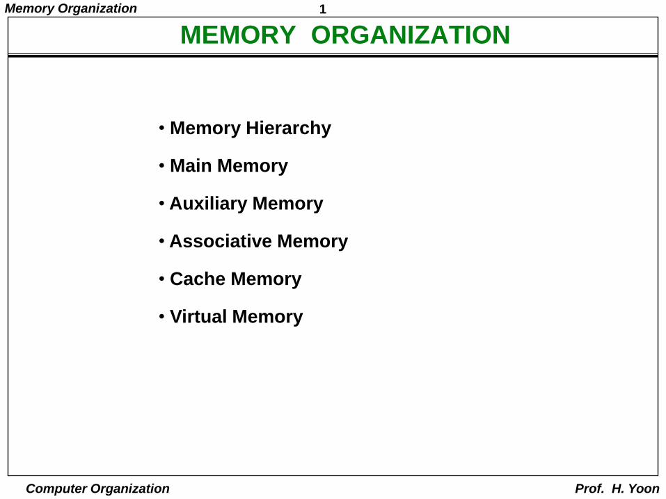
• Memory Hierarchy
• Main Memory
• Auxiliary Memory
• Associative Memory
• Cache Memory
• Virtual Memory
MEMORY ORGANIZATION
2Memory Organization
Computer Organization Prof. H. Yoon
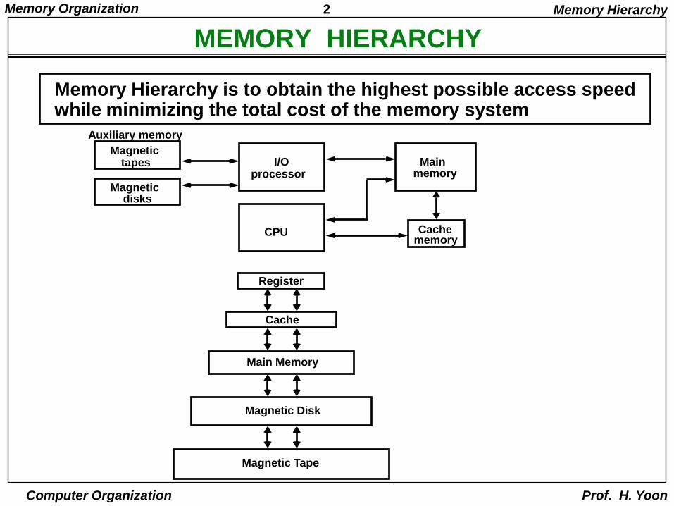
MEMORY HIERARCHY
Magnetictapes
Magneticdisks
I/Oprocessor
CPU
Mainmemory
Cachememory
Auxiliary memory
Register
Cache
Main Memory
Magnetic Disk
Magnetic Tape
Memory Hierarchy is to obtain the highest possible access speed while minimizing the total cost of the memory system
Memory Hierarchy
3Memory Organization
Computer Organization Prof. H. Yoon
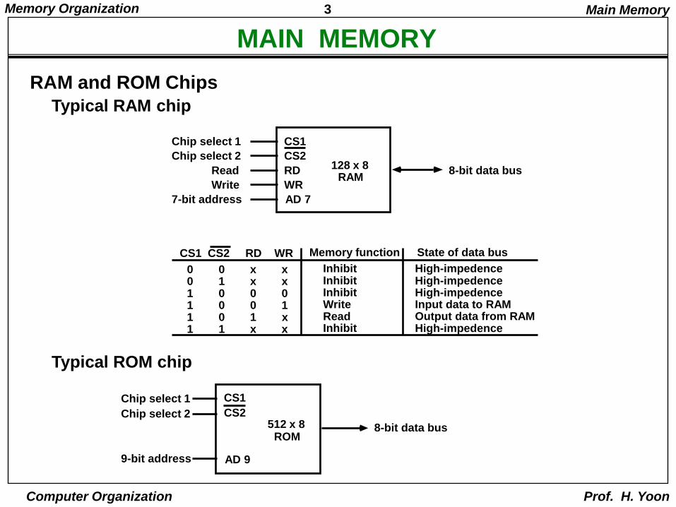
MAIN MEMORY
RAM and ROM Chips
Typical RAM chip
Typical ROM chip
Chip select 1
Chip select 2
Read
Write
7-bit address
CS1
CS2
RD
WR
AD 7
128 x 8RAM
8-bit data bus
CS1 CS2 RD WR
0 0 x x0 1 x x1 0 0 01 0 0 11 0 1 x1 1 x x
Memory function
InhibitInhibitInhibitWriteReadInhibit
State of data bus
High-impedenceHigh-impedenceHigh-impedenceInput data to RAMOutput data from RAMHigh-impedence
Chip select 1
Chip select 2
9-bit address
CS1
CS2
AD 9
512 x 8ROM
8-bit data bus
Main Memory
4Memory Organization
Computer Organization Prof. H. Yoon
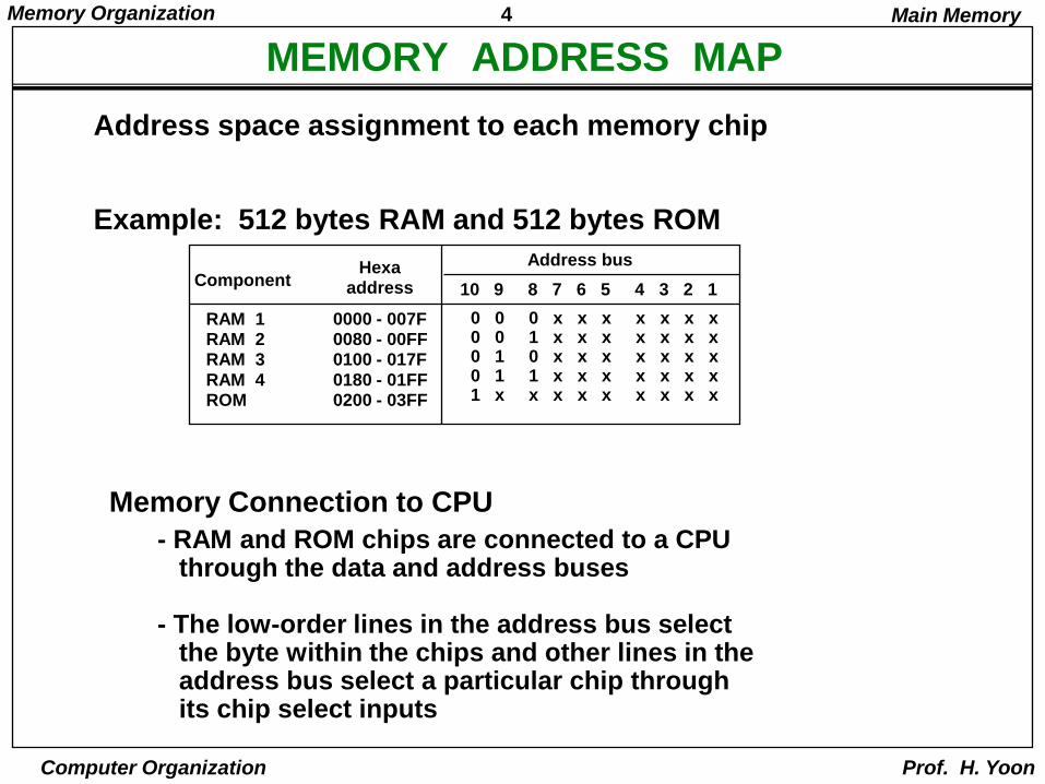
MEMORY ADDRESS MAP
RAM 1RAM 2RAM 3RAM 4ROM
0000 - 007F0080 - 00FF0100 - 017F0180 - 01FF0200 - 03FF
ComponentHexa
address
0 0 0 x x x x x x x0 0 1 x x x x x x x0 1 0 x x x x x x x0 1 1 x x x x x x x1 x x x x x x x x x
10 9 8 7 6 5 4 3 2 1
Address bus
Memory Connection to CPU
- RAM and ROM chips are connected to a CPU through the data and address buses
- The low-order lines in the address bus select the byte within the chips and other lines in the address bus select a particular chip through its chip select inputs
Address space assignment to each memory chip
Example: 512 bytes RAM and 512 bytes ROM
Main Memory
5Memory Organization
Computer Organization Prof. H. Yoon
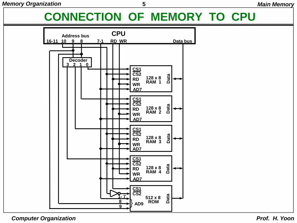
CONNECTION OF MEMORY TO CPU
Main Memory
}
CS1CS2RDWRAD7
128 x 8RAM 1
CS1CS2RDWRAD7
128 x 8RAM 2
CS1CS2RDWRAD7
128 x 8RAM 3
CS1CS2RDWRAD7
128 x 8RAM 4
Decoder3 2 1 0
WRRD9 8 7-11016-11Address bus
Data bus
CPU
CS1CS2
512 x 8ROMAD9
1- 7
98
Da
taD
ata
Da
taD
ata
Da
ta
6Memory Organization
Computer Organization Prof. H. Yoon
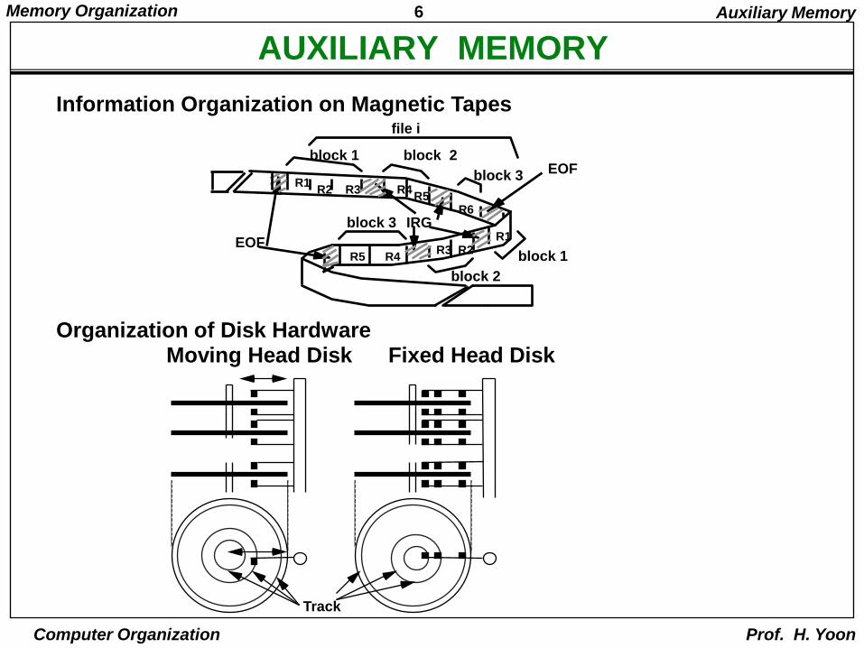
AUXILIARY MEMORY
Information Organization on Magnetic Tapes
EOF
IRG
block 1 block 2
block 3
block 1
block 2
block 3
R1R2 R3 R4
R5R6
R1R3 R2
R5 R4
file i
EOF
Organization of Disk Hardware
Track
Moving Head Disk Fixed Head Disk
Auxiliary Memory
7Memory Organization
Computer Organization Prof. H. Yoon
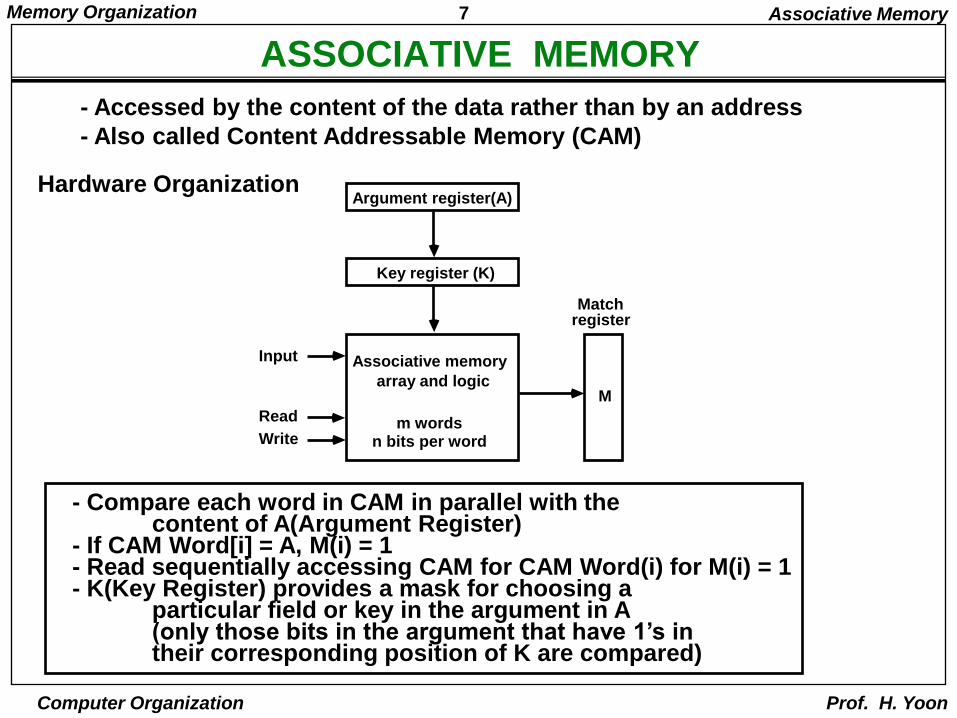
ASSOCIATIVE MEMORY
- Accessed by the content of the data rather than by an address
- Also called Content Addressable Memory (CAM)
Hardware OrganizationArgument register(A)
Key register (K)
Associative memory
array and logic
m wordsn bits per word
Matchregister
Input
Read
Write
M
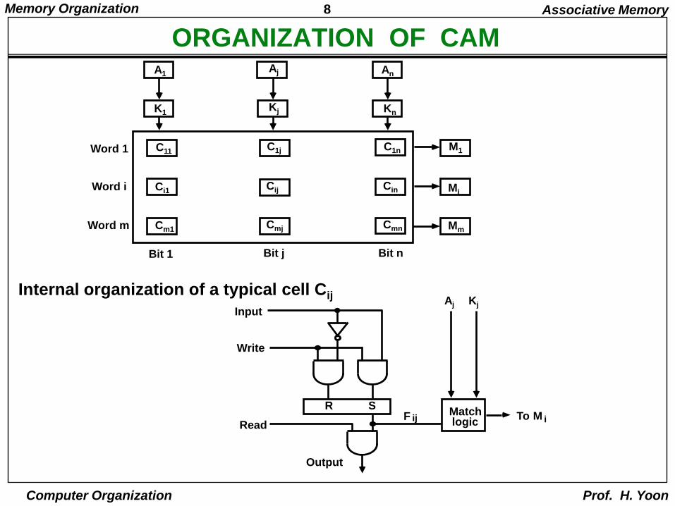
- Compare each word in CAM in parallel with the content of A(Argument Register)
- If CAM Word[i] = A, M(i) = 1 - Read sequentially accessing CAM for CAM Word(i) for M(i) = 1- K(Key Register) provides a mask for choosing a
particular field or key in the argument in A(only those bits in the argument that have 1’s intheir corresponding position of K are compared)
Associative Memory
8Memory Organization
Computer Organization Prof. H. Yoon
ORGANIZATION OF CAM
Internal organization of a typical cell Cij
C11Word 1
Word i
Word m
Bit 1 Bit j Bit n
M1
Mi
Mm
Associative Memory
Aj
R S
Output
Matchlogic
Input
Write
Read
Kj
M iToF ij
A1Aj An
K1Kj Kn
C1j C1n
Ci1 Cij Cin
Cm1 Cmj Cmn
9Memory Organization
Computer Organization Prof. H. Yoon
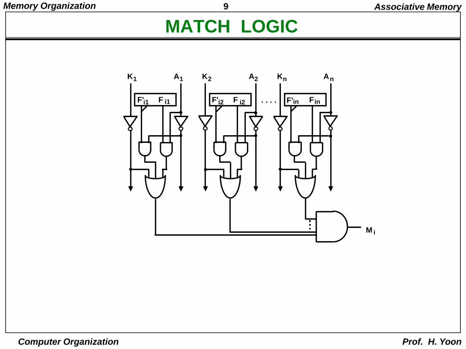
MATCH LOGIC
Associative Memory
F'i1 F i1
K1 A1
F'i2 F i2
K2 A2
F'in F in
Kn An
. . . .
M i
10Memory Organization
Computer Organization Prof. H. Yoon
CACHE MEMORY
Locality of Reference- The references to memory at any given time
interval tend to be confined within a localized areas- This area contains a set of information and
the membership changes gradually as time goes by- Temporal Locality
The information which will be used in near futureis likely to be in use already (e.g. Reuse of information in loops)
- Spatial LocalityIf a word is accessed, adjacent(near) words are likely accessed soon(e.g. Related data items (arrays) are usually stored together; instructions are executed sequentially)
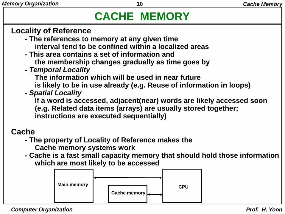
Cache- The property of Locality of Reference makes the
Cache memory systems work- Cache is a fast small capacity memory that should hold those information
which are most likely to be accessed
Cache Memory
Main memory
Cache memory
CPU
11Memory Organization
Computer Organization Prof. H. Yoon
PERFORMANCE OF CACHE
All the memory accesses are directed first to CacheIf the word is in Cache; Access cache to provide it to CPUIf the word is not in Cache; Bring a block (or a line) includingthat word to replace a block now in Cache
- How can we know if the word that is required is there ?
- If a new block is to replace one of the old blocks,which one should we choose ?
Memory Access
Performance of Cache Memory System
Hit Ratio - % of memory accesses satisfied by Cache memory systemTe: Effective memory access time in Cache memory systemTc: Cache access timeTm: Main memory access time
Te = Tc + (1 - h) Tm
Example: Tc = 0.4 s, Tm = 1.2s, h = 85%Te = 0.4 + (1 - 0.85) * 1.2 = 0.58s
Cache Memory
12Memory Organization
Computer Organization Prof. H. Yoon
MEMORY AND CACHE MAPPING - ASSOCIATIVE MAPPLING -
Associative mappingDirect mappingSet-associative mapping
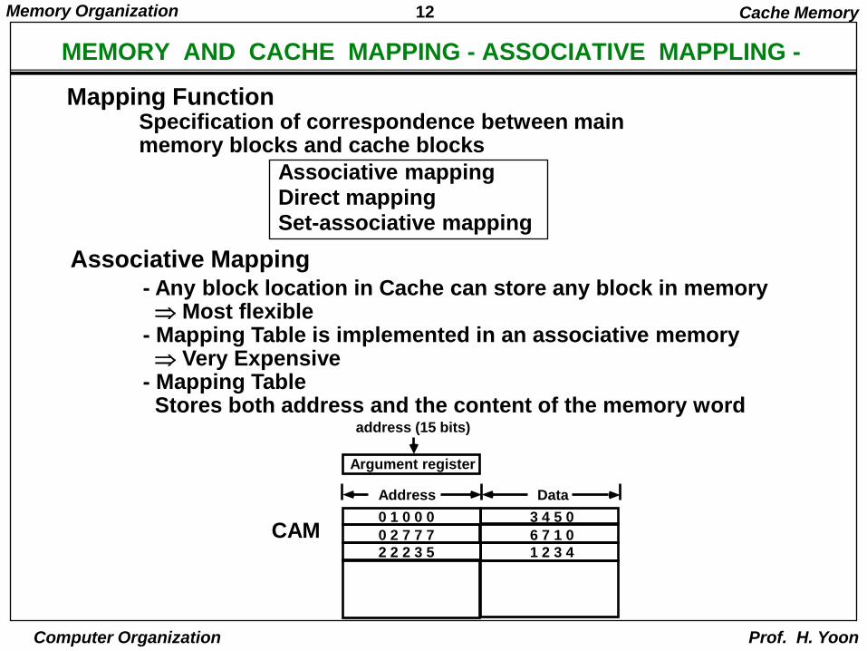
Associative Mapping
Mapping FunctionSpecification of correspondence between mainmemory blocks and cache blocks
- Any block location in Cache can store any block in memory Most flexible
- Mapping Table is implemented in an associative memory Very Expensive
- Mapping TableStores both address and the content of the memory word
address (15 bits)
Argument register
Address Data
0 1 0 0 0
0 2 7 7 7
2 2 2 3 5
3 4 5 0
6 7 1 0
1 2 3 4
CAM
Cache Memory
13Memory Organization
Computer Organization Prof. H. Yoon
MEMORY AND CACHE MAPPING - DIRECT MAPPING
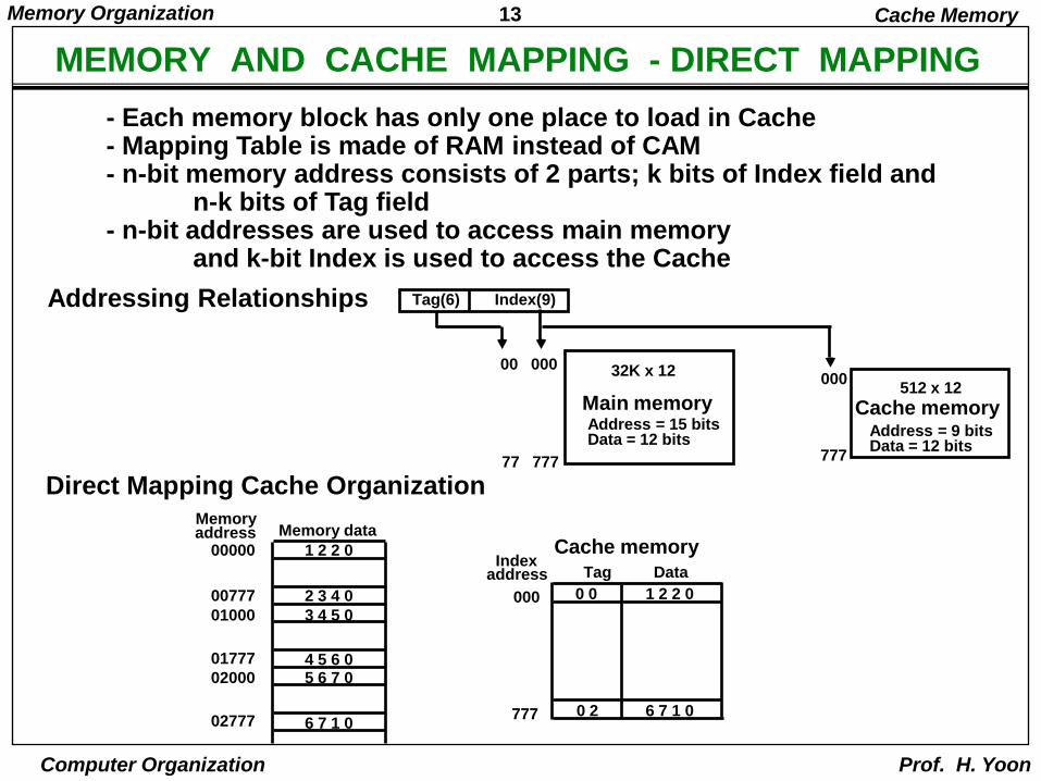
Addressing Relationships
Direct Mapping Cache OrganizationMemoryaddress Memory data
00000 1 2 2 0
00777
01000
01777
02000
02777
2 3 4 0
3 4 5 0
4 5 6 05 6 7 0
6 7 1 0
Indexaddress Tag Data
000 0 0 1 2 2 0
0 2 6 7 1 0777
Cache memory
Tag(6) Index(9)
32K x 12
Main memoryAddress = 15 bitsData = 12 bits
512 x 12
Cache memoryAddress = 9 bitsData = 12 bits
00 000
77 777
000
777
- Each memory block has only one place to load in Cache- Mapping Table is made of RAM instead of CAM- n-bit memory address consists of 2 parts; k bits of Index field and
n-k bits of Tag field- n-bit addresses are used to access main memory
and k-bit Index is used to access the Cache
Cache Memory
14Memory Organization
Computer Organization Prof. H. Yoon
DIRECT MAPPING
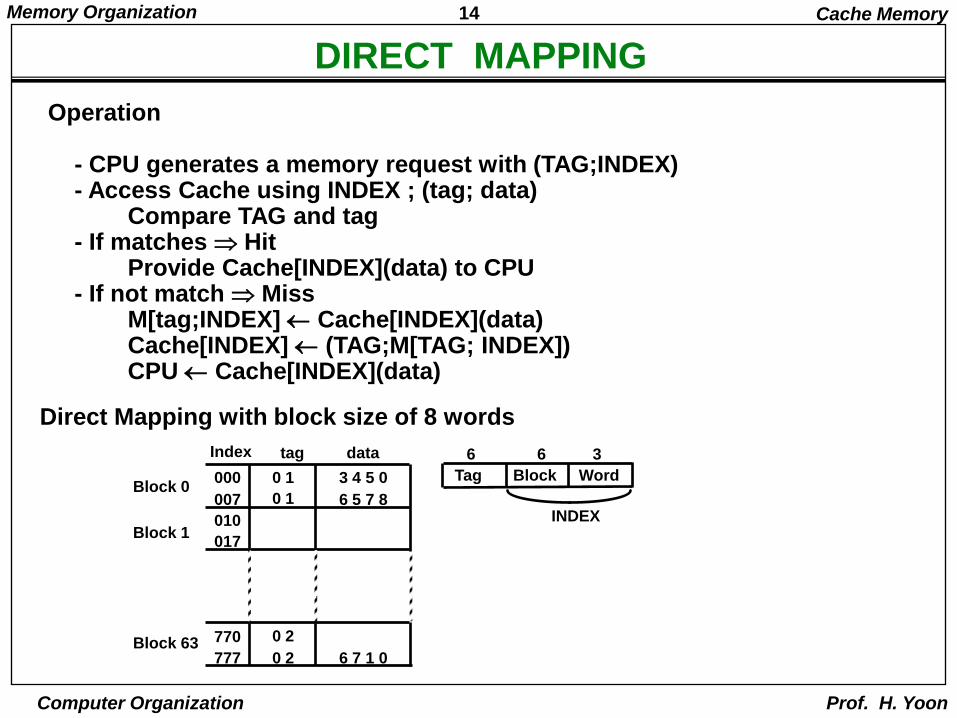
Direct Mapping with block size of 8 words
Operation
- CPU generates a memory request with (TAG;INDEX)- Access Cache using INDEX ; (tag; data)
Compare TAG and tag- If matches Hit
Provide Cache[INDEX](data) to CPU- If not match Miss
M[tag;INDEX] Cache[INDEX](data) Cache[INDEX] (TAG;M[TAG; INDEX])CPU Cache[INDEX](data)
Index tag data
000 0 1 3 4 5 0
007 0 1 6 5 7 8
010
017
770 0 2
777 0 2 6 7 1 0
Block 0
Block 1
Block 63
Tag Block Word
6 6 3
INDEX
Cache Memory
15Memory Organization
Computer Organization Prof. H. Yoon
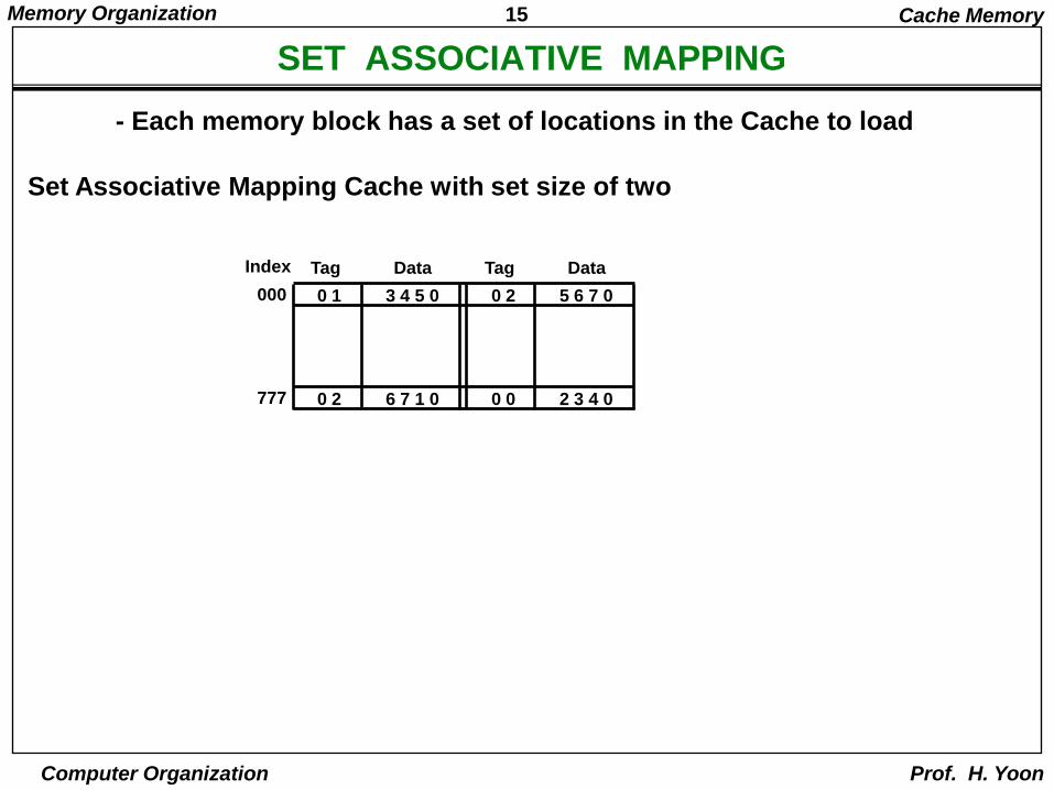
SET ASSOCIATIVE MAPPING
Set Associative Mapping Cache with set size of two
- Each memory block has a set of locations in the Cache to load
Index Tag Data
000 0 1 3 4 5 0 0 2 5 6 7 0
Tag Data
777 0 2 6 7 1 0 0 0 2 3 4 0
Cache Memory
16Memory Organization
Computer Organization Prof. H. Yoon
BLOCK REPLACEMENT POLICY
Many different block replacement policies are available
LRU(Least Recently Used) is most easy to implement
Cache word = (tag 0, data 0, U0);(tag 1, data 1, U1), Ui = 0 or 1(binary)
Cache Memory
17Memory Organization
Computer Organization Prof. H. Yoon
CACHE WRITE
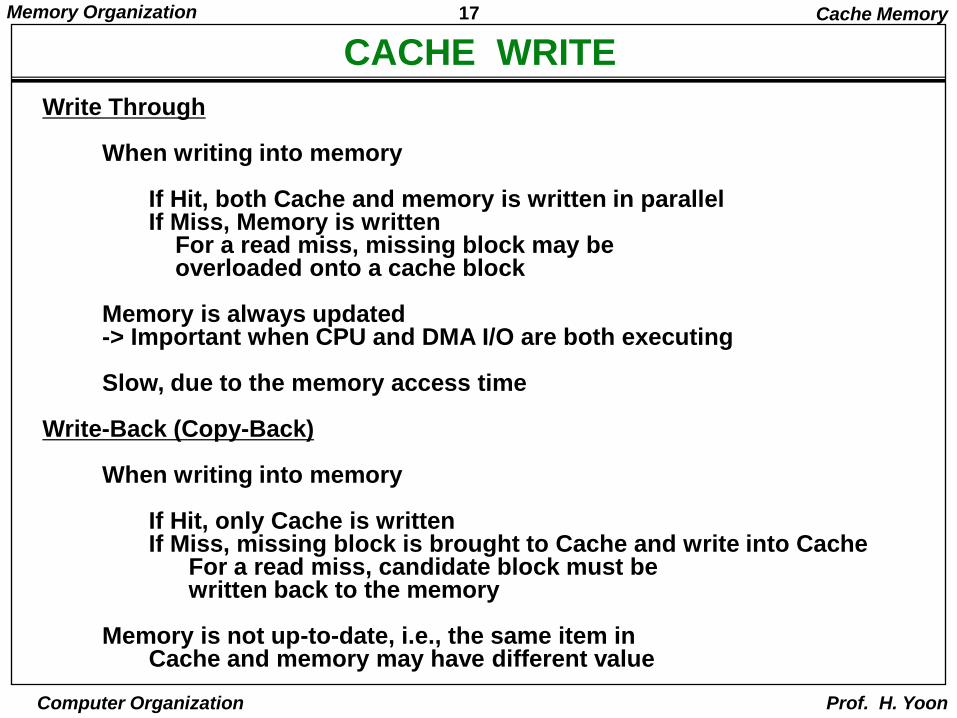
Write Through
When writing into memory
If Hit, both Cache and memory is written in parallelIf Miss, Memory is written
For a read miss, missing block may beoverloaded onto a cache block
Memory is always updated-> Important when CPU and DMA I/O are both executing
Slow, due to the memory access time
Write-Back (Copy-Back)
When writing into memory
If Hit, only Cache is writtenIf Miss, missing block is brought to Cache and write into Cache
For a read miss, candidate block must bewritten back to the memory
Memory is not up-to-date, i.e., the same item inCache and memory may have different value
Cache Memory
18Memory Organization
Computer Organization Prof. H. Yoon
VIRTUAL MEMORY
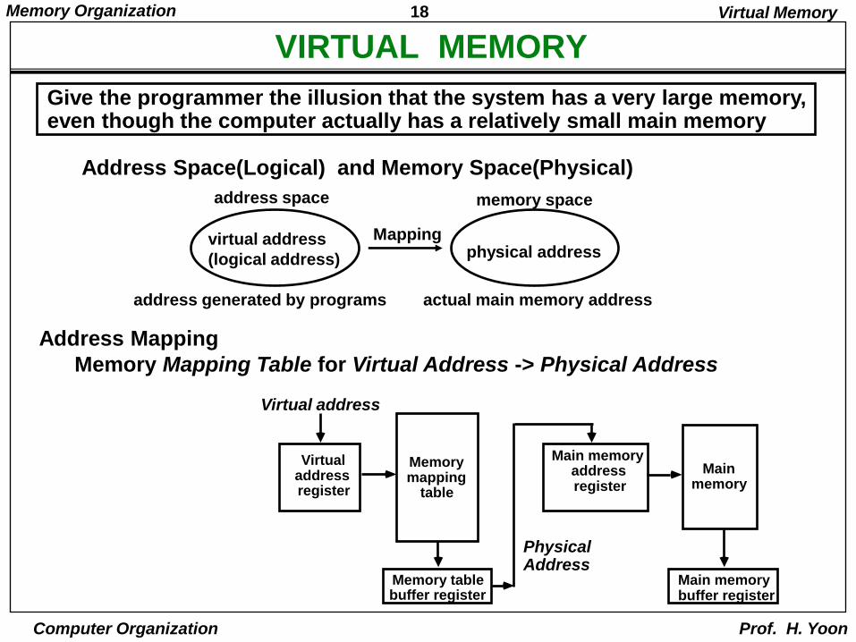
Give the programmer the illusion that the system has a very large memory, even though the computer actually has a relatively small main memory
Address Space(Logical) and Memory Space(Physical)
Address Mapping
Memory Mapping Table for Virtual Address -> Physical Address
virtual address
(logical address) physical address
address space memory space
address generated by programs actual main memory address
Mapping
Virtual address
Virtualaddressregister
Memorymapping
table
Memory tablebuffer register
Main memoryaddressregister
Mainmemory
Main memorybuffer register
Physical Address
Virtual Memory
19Memory Organization
Computer Organization Prof. H. Yoon
ADDRESS MAPPING
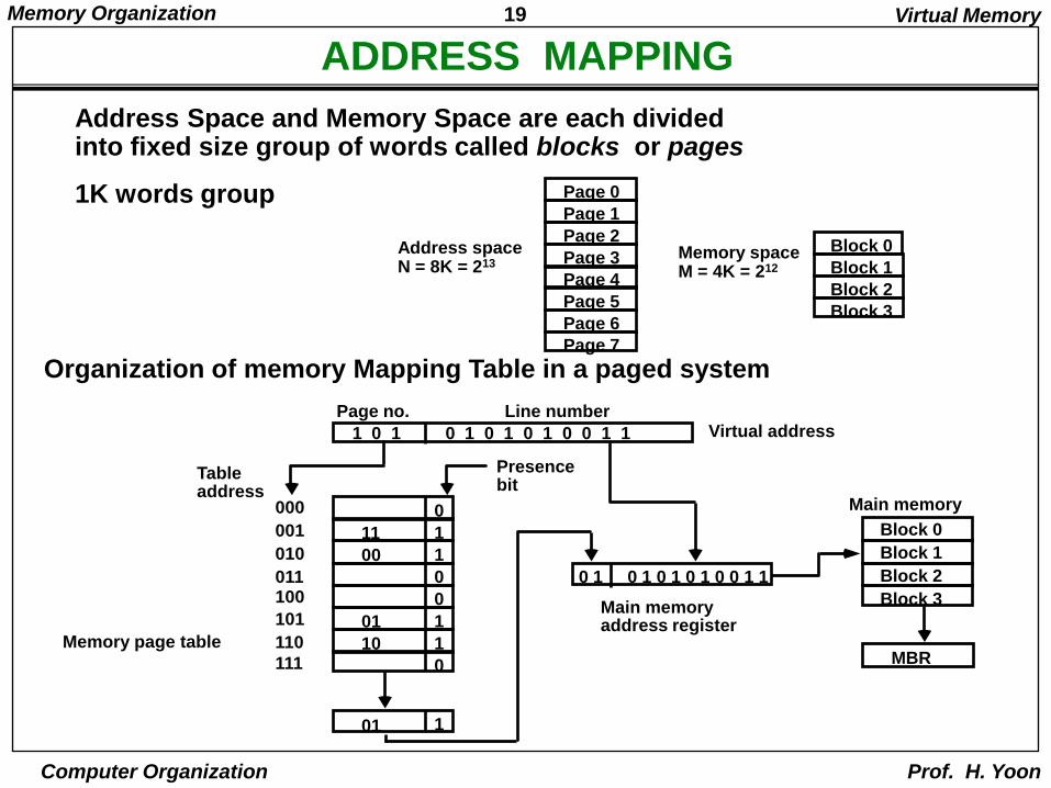
Organization of memory Mapping Table in a paged system
Address Space and Memory Space are each dividedinto fixed size group of words called blocks or pages
1K words group Page 0
Page 1
Page 2
Page 3
Page 4
Page 5
Page 6
Page 7
Block 3
Block 2
Block 1
Block 0Address spaceN = 8K = 213
Memory spaceM = 4K = 212
0000
1001
1010
0011
0100
1101
1110
0111
1
Block 0
Block 1
Block 2
Block 3
MBR
0 1 0 1 0 1 0 1 0 0 1 1
1 0 1 0 1 0 1 0 1 0 0 1 1
Tableaddress
Presencebit
Page no. Line numberVirtual address
Main memoryaddress register
Memory page table
Main memory
11
00
01
10
01
Virtual Memory
20Memory Organization
Computer Organization Prof. H. Yoon
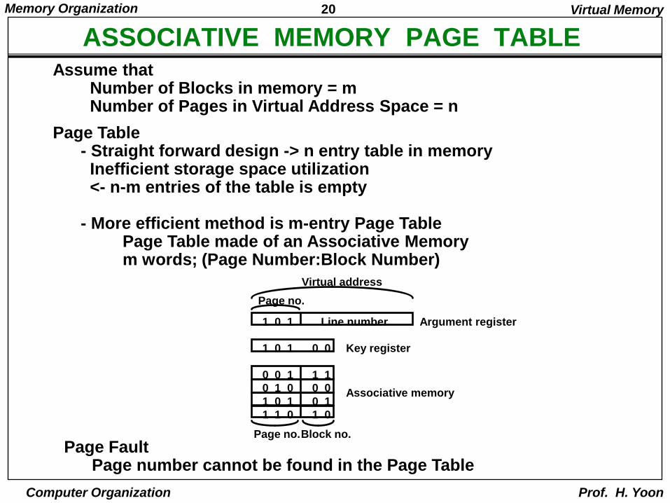
ASSOCIATIVE MEMORY PAGE TABLEAssume that
Number of Blocks in memory = mNumber of Pages in Virtual Address Space = n
Page Table- Straight forward design -> n entry table in memoryInefficient storage space utilization<- n-m entries of the table is empty
- More efficient method is m-entry Page TablePage Table made of an Associative Memorym words; (Page Number:Block Number)
1 0 1 Line number
Page no.
Argument register
1 0 1 0 0
0 0 1 1 10 1 0 0 0
1 0 1 0 1
1 1 0 1 0
Key register
Associative memory
Page no.Block no.
Virtual address
Page FaultPage number cannot be found in the Page Table
Virtual Memory
21Memory Organization
Computer Organization Prof. H. Yoon
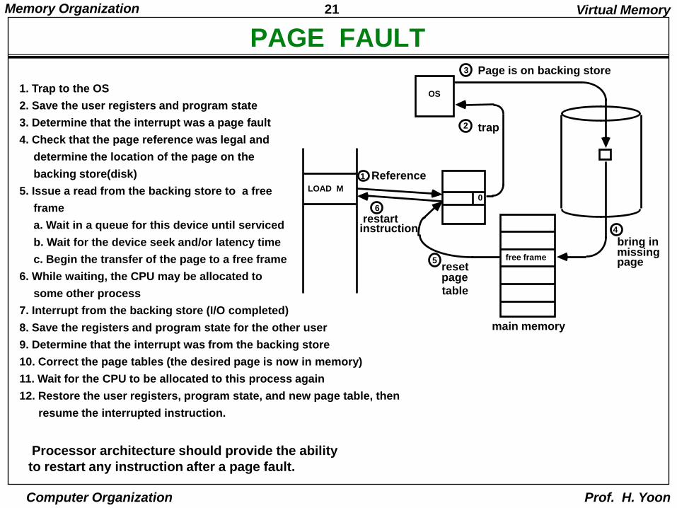
PAGE FAULT
Processor architecture should provide the ability
to restart any instruction after a page fault.
1. Trap to the OS
2. Save the user registers and program state
3. Determine that the interrupt was a page fault
4. Check that the page reference was legal and
determine the location of the page on the
backing store(disk)
5. Issue a read from the backing store to a free
frame
a. Wait in a queue for this device until serviced
b. Wait for the device seek and/or latency time
c. Begin the transfer of the page to a free frame
6. While waiting, the CPU may be allocated to
some other process
7. Interrupt from the backing store (I/O completed)
8. Save the registers and program state for the other user
9. Determine that the interrupt was from the backing store
10. Correct the page tables (the desired page is now in memory)
11. Wait for the CPU to be allocated to this process again
12. Restore the user registers, program state, and new page table, then
resume the interrupted instruction.
LOAD M0
Reference1
OS
trap2
3 Page is on backing store
free frame
main memory
4
bring inmissingpage5
resetpage
table
6
restartinstruction
Virtual Memory
22Memory Organization
Computer Organization Prof. H. Yoon
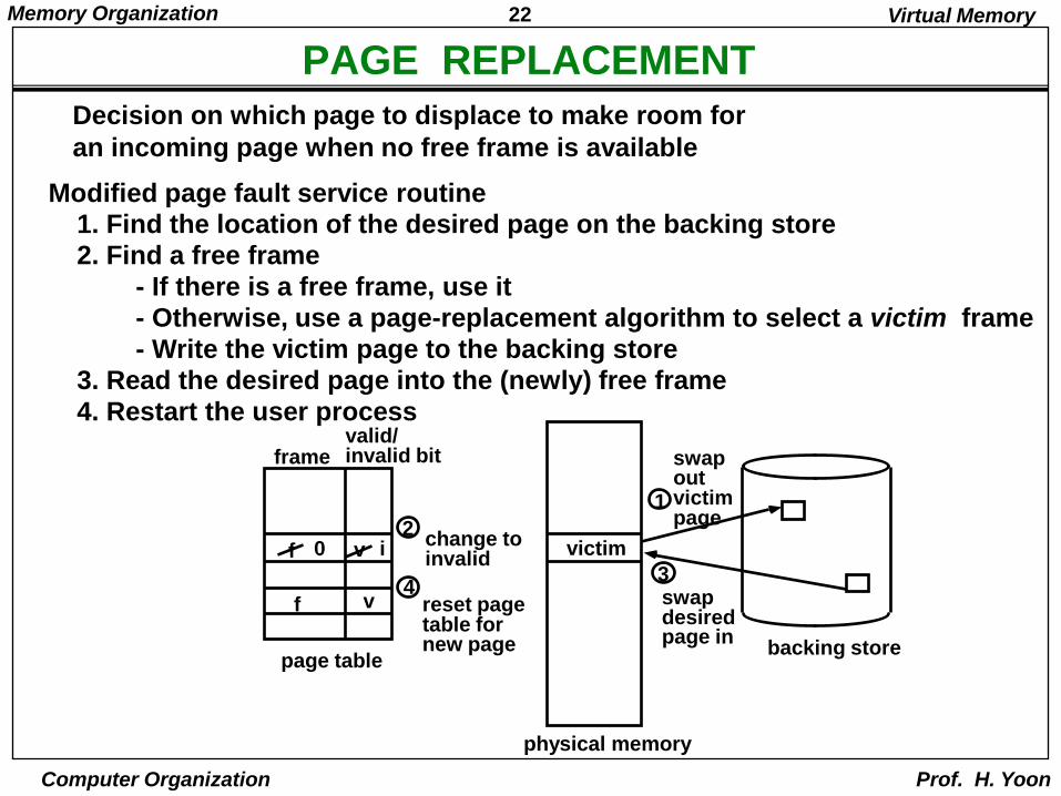
PAGE REPLACEMENT
Modified page fault service routine
Decision on which page to displace to make room for
an incoming page when no free frame is available
1. Find the location of the desired page on the backing store
2. Find a free frame
- If there is a free frame, use it
- Otherwise, use a page-replacement algorithm to select a victim frame
- Write the victim page to the backing store3. Read the desired page into the (newly) free frame
4. Restart the user process
2f 0 v i
f v
framevalid/invalid bit
page table
change toinvalid
4reset pagetable fornew page
victim
1
swapoutvictimpage
3swapdesiredpage in
backing store
physical memory
Virtual Memory
23Memory Organization
Computer Organization Prof. H. Yoon
PAGE REPLACEMENT ALGORITHMS
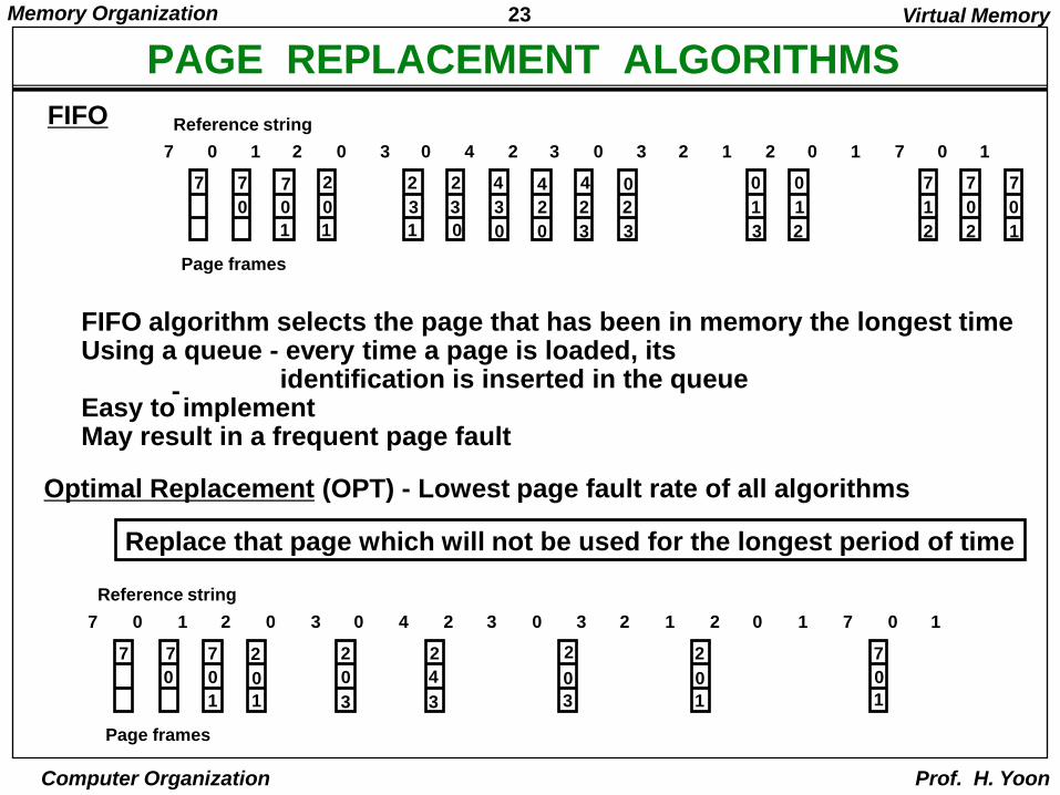
FIFO
0
7
1
7
2 0 3 0 4 2 3 0 3 2 1 2 0 1 77 0 1
0 0
7
1
2
0
1
2
3
1
2
3
0
4
3
0
4
2
0
4
2
3
0
2
3
0
1
3
0
1
2
7
1
2
7
0
2
7
0
1
Page frames
Reference string
-
FIFO algorithm selects the page that has been in memory the longest timeUsing a queue - every time a page is loaded, its
identification is inserted in the queueEasy to implementMay result in a frequent page fault
Optimal Replacement (OPT) - Lowest page fault rate of all algorithms
Replace that page which will not be used for the longest period of time
0
7
1
7
2 0 3 0 4 2 3 0 3 2 1 2 0 1 77 0 1
0 0
7
1
2
0
1
2
0
3
2
4
3
2
0
3
2
0
1
7
0
1
Page frames
Reference string
Virtual Memory
24Memory Organization
Computer Organization Prof. H. Yoon
PAGE REPLACEMENT ALGORITHMS
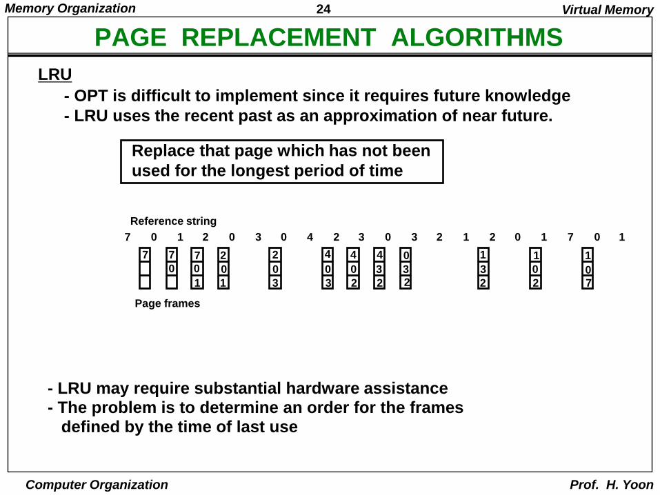
- OPT is difficult to implement since it requires future knowledge
- LRU uses the recent past as an approximation of near future.
Replace that page which has not been
used for the longest period of time
LRU
0
7
1
7
2 0 3 0 4 2 3 0 3 2 1 2 0 1 77 0 1
0 0
7
1
2
0
1
2
0
3
4
0
3
4
0
2
4
3
2
0
3
2
1
3
2
1
0
2
1
0
7
Page frames
Reference string
Virtual Memory
- LRU may require substantial hardware assistance- The problem is to determine an order for the frames
defined by the time of last use
25Memory Organization
Computer Organization Prof. H. Yoon
PAGE REPLACEMENT ALGORITHMS
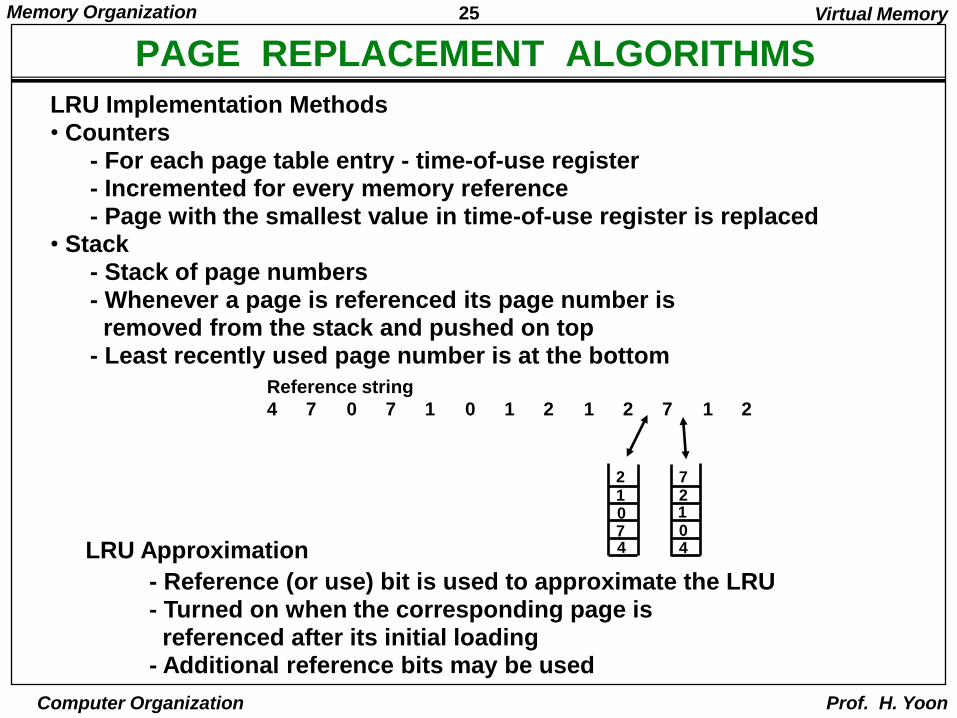
LRU Approximation
- Reference (or use) bit is used to approximate the LRU - Turned on when the corresponding page is referenced after its initial loading
- Additional reference bits may be used
Virtual Memory
4 7 0 7 1 0 1 2 1 2 7 1 2
Reference string
21074
72104
LRU Implementation Methods• Counters
- For each page table entry - time-of-use register- Incremented for every memory reference- Page with the smallest value in time-of-use register is replaced
• Stack- Stack of page numbers- Whenever a page is referenced its page number is removed from the stack and pushed on top
- Least recently used page number is at the bottom


![Organization/May_Jun_201… · What is virtual memory concept ? Explain the role of TLB in Virtual memory organization. Explain the following (i) RAID (ii) Magnetic memory. Or [10]](https://img.pdfslide.net/doc/110x75/5e778f767f3dd43c3e4d8d55/organizationmayjun201-what-is-virtual-memory-concept-explain-the-role-of.jpg)