Embed Size (px)
Citation preview
MER PDS PDR - Document No. EA2036-8
Mars Exploration Rover
3 April 2001 ACW - 1
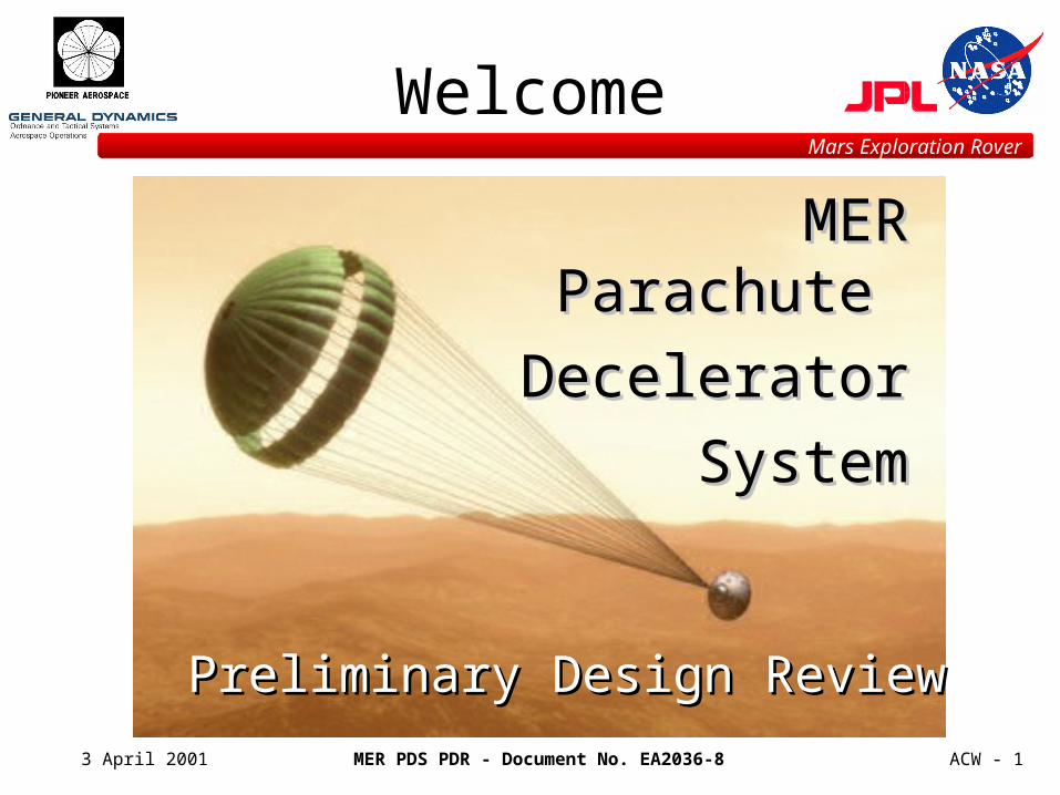
Welcome
MER Parachute MER Parachute
Decelerator Decelerator
SystemSystem
Preliminary Design ReviewPreliminary Design Review
MER PDS PDR - Document No. EA2036-8
Mars Exploration Rover
3 April 2001 ACW - 2
Program Objectives
• MER Parachute Deceleration Subsystem (PDS) is to deliver the landing vehicle, in the atmosphere of Mars, to a point and flight condition where Rocket Assisted Descent and Airbag Impact Attenuation Systems can complete the descent to the surface
• Resultant design should retain as much heritage as possible with previous Mars programs (MPF / MPL / MSP01 / Viking)
MER PDS PDR - Document No. EA2036-8
Mars Exploration Rover
3 April 2001 ACW - 3
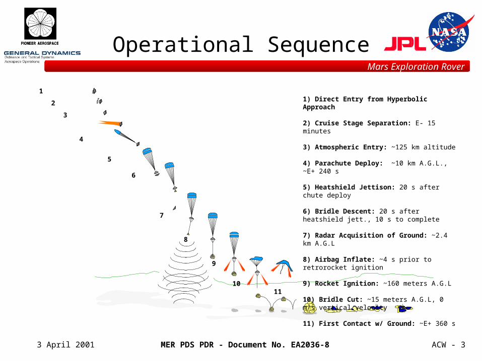
Operational Sequence
1) Direct Entry from Hyperbolic Approach
2) Cruise Stage Separation: E- 15 minutes
3) Atmospheric Entry: ~125 km altitude
4) Parachute Deploy: ~10 km A.G.L., ~E+ 240 s
5) Heatshield Jettison: 20 s after chute deploy
6) Bridle Descent: 20 s after heatshield jett., 10 s to complete
7) Radar Acquisition of Ground: ~2.4 km A.G.L
8) Airbag Inflate: ~4 s prior to retrorocket ignition
9) Rocket Ignition: ~160 meters A.G.L
10) Bridle Cut: ~15 meters A.G.L, 0 m/s vertical velocity
11) First Contact w/ Ground: ~E+ 360 s
1
2
3
4
5
6
8
7
9
1011
MER PDS PDR - Document No. EA2036-8
Mars Exploration Rover
3 April 2001 ACW - 4
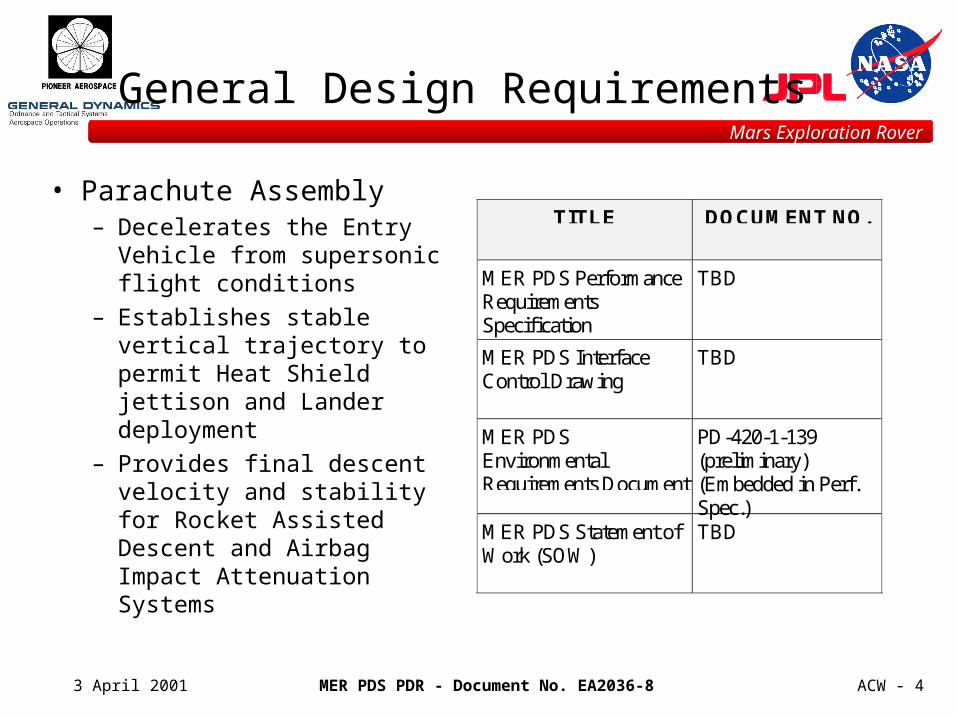
General Design Requirements
• Parachute Assembly– Decelerates the Entry Vehicle
from supersonic flight conditions
– Establishes stable vertical trajectory to permit Heat Shield jettison and Lander deployment
– Provides final descent velocity and stability for Rocket Assisted Descent and Airbag Impact Attenuation Systems
TITLE DOCUMENT NO.
MER PDS PerformanceRequirementsSpecification
TBD
MER PDS InterfaceControl Drawing
TBD
MER PDSEnvironmentalRequirements Document
PD-420-1-139(preliminary)(Embedded in Perf.Spec.)
MER PDS Statement ofWork (SOW)
TBD
MER PDS PDR - Document No. EA2036-8
Mars Exploration Rover
3 April 2001 ACW - 5
General Design Requirements
• Mortar Deployment Assembly– Interfaces with Backshell structure
– Provides deceleration parachute structural attachment points
– Packages and protects the Deceleration Parachute Assembly
– Ejects the packed parachute from the stowed configuration
– Accelerates parachute beyond the recirculating wake for controlled and reliable inflation
MER PDS PDR - Document No. EA2036-8
Mars Exploration Rover
3 April 2001 ACW - 6
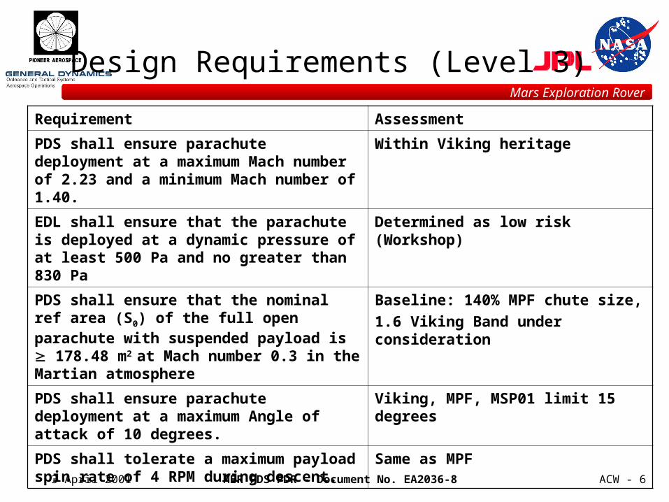
Design Requirements (Level 3)
Requirement Assessment
PDS shall ensure parachute deployment at a maximum Mach number of 2.23 and a minimum Mach number of 1.40.
Within Viking heritage
EDL shall ensure that the parachute is deployed at a dynamic pressure of at least 500 Pa and no greater than 830 Pa
Determined as low risk (Workshop)
PDS shall ensure that the nominal ref area (S0) of the full open parachute with suspended payload is 178.48 m2 at Mach number 0.3 in the Martian atmosphere
Baseline: 140% MPF chute size,
1.6 Viking Band under consideration
PDS shall ensure parachute deployment at a maximum Angle of attack of 10 degrees.
Viking, MPF, MSP01 limit 15 degrees
PDS shall tolerate a maximum payload spin rate of 4 RPM during descent.
Same as MPF
MER PDS PDR - Document No. EA2036-8
Mars Exploration Rover
3 April 2001 ACW - 7
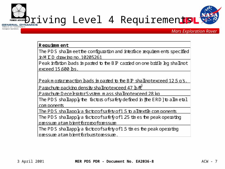
RequirementThe PDS shall meet the configuration and interface requirements specified in MICD drawing no. 10205261Peak inflation loads imparted to the BIP carried on one bridle leg shall not exceed 15,600 lbs.
Peak mortar reaction loads imparted to the BIP shall not exceed 12.5 g's.
Parachute packing density shall not exceed 47 lb/ft3
Parachute Decelerator System mass shall not exceed 28 kgThe PDS shall apply the factors of safety defined in [the ERD] to all metal componentsThe PDS shall apply a factor of safety of 1.5 to all textile componentsThe PDS shall apply a factor of safefy of 1.25 times the peak operating pressure at ambient for proof pressureThe PDS shall apply a factor of safety of 1.5 times the peak operating pressure at ambient for burst pressure.
Driving Level 4 Requirements
MER PDS PDR - Document No. EA2036-8
Mars Exploration Rover
3 April 2001 ACW - 8
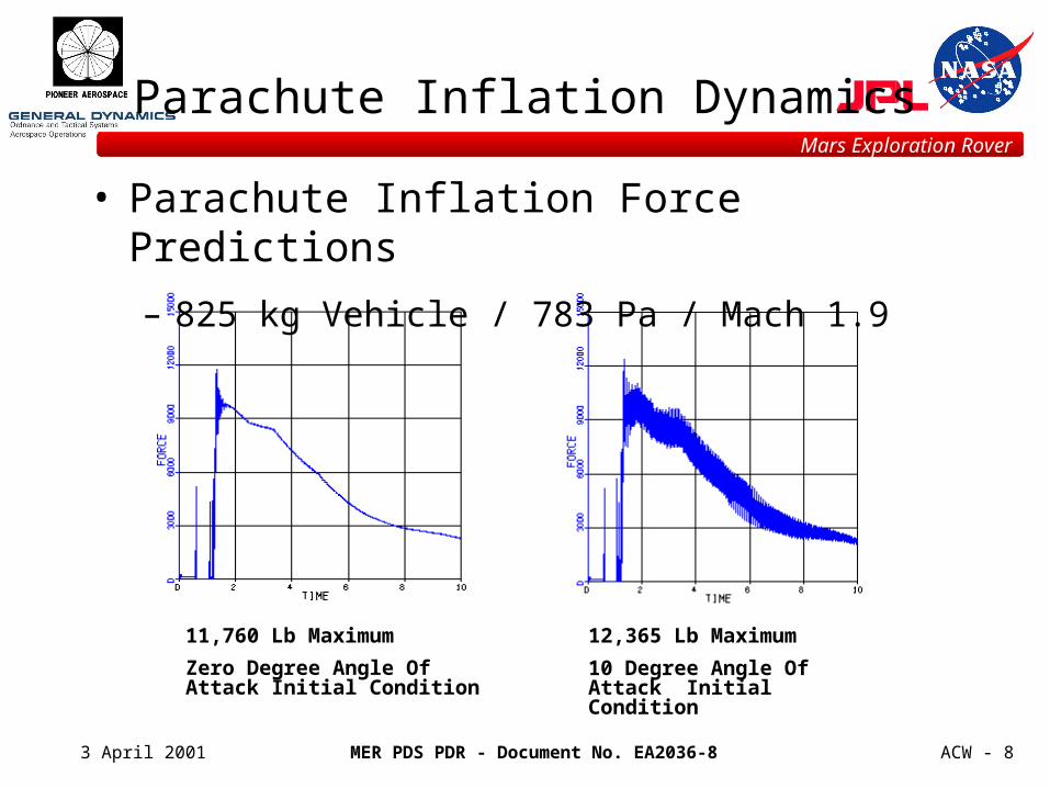
Parachute Inflation Dynamics
• Parachute Inflation Force Predictions
– 825 kg Vehicle / 783 Pa / Mach 1.9
11,760 Lb Maximum
Zero Degree Angle Of Attack Initial Condition
12,365 Lb Maximum
10 Degree Angle Of Attack Initial Condition
MER PDS PDR - Document No. EA2036-8
Mars Exploration Rover
3 April 2001 ACW - 9
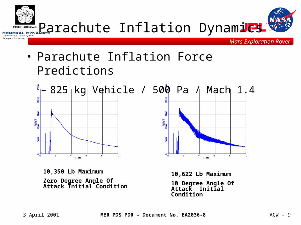
Parachute Inflation Dynamics
• Parachute Inflation Force Predictions
– 825 kg Vehicle / 500 Pa / Mach 1.4
10,350 Lb Maximum
Zero Degree Angle Of Attack Initial Condition
10,622 Lb Maximum
10 Degree Angle Of Attack Initial Condition
MER PDS PDR - Document No. EA2036-8
Mars Exploration Rover
3 April 2001 ACW - 10
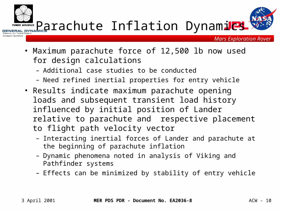
Parachute Inflation Dynamics
• Maximum parachute force of 12,500 lb now used for design calculations– Additional case studies to be conducted– Need refined inertial properties for entry vehicle
• Results indicate maximum parachute opening loads and subsequent transient load history influenced by initial position of Lander relative to parachute and respective placement to flight path velocity vector– Interacting inertial forces of Lander and parachute at the beginning
of parachute inflation– Dynamic phenomena noted in analysis of Viking and Pathfinder
systems– Effects can be minimized by stability of entry vehicle
MER PDS PDR - Document No. EA2036-8
Mars Exploration Rover
3 April 2001 ACW - 11
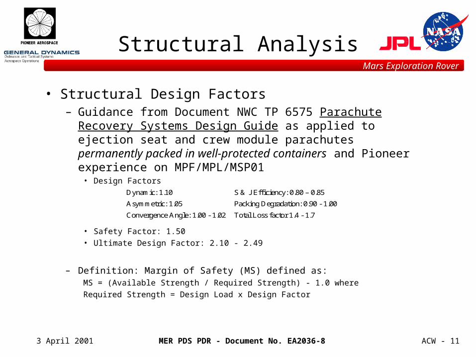
• Structural Design Factors– Guidance from Document NWC TP 6575 Parachute Recovery
Systems Design Guide as applied to ejection seat and crew module parachutes permanently packed in well-protected containers and Pioneer experience on MPF/MPL/MSP01
• Design Factors
• Safety Factor: 1.50
• Ultimate Design Factor: 2.10 - 2.49
– Definition: Margin of Safety (MS) defined as:MS = (Available Strength / Required Strength) - 1.0 where
Required Strength = Design Load x Design Factor
Structural Analysis
Dynamic: 1.10 S & J Efficiency: 0.80 – 0.85
Asymmetric: 1.05 Packing Degradation: 0.90 - 1.00
Convergence Angle: 1.00 - 1.02 Total Loss factor 1.4 - 1.7
MER PDS PDR - Document No. EA2036-8
Mars Exploration Rover
3 April 2001 ACW - 12
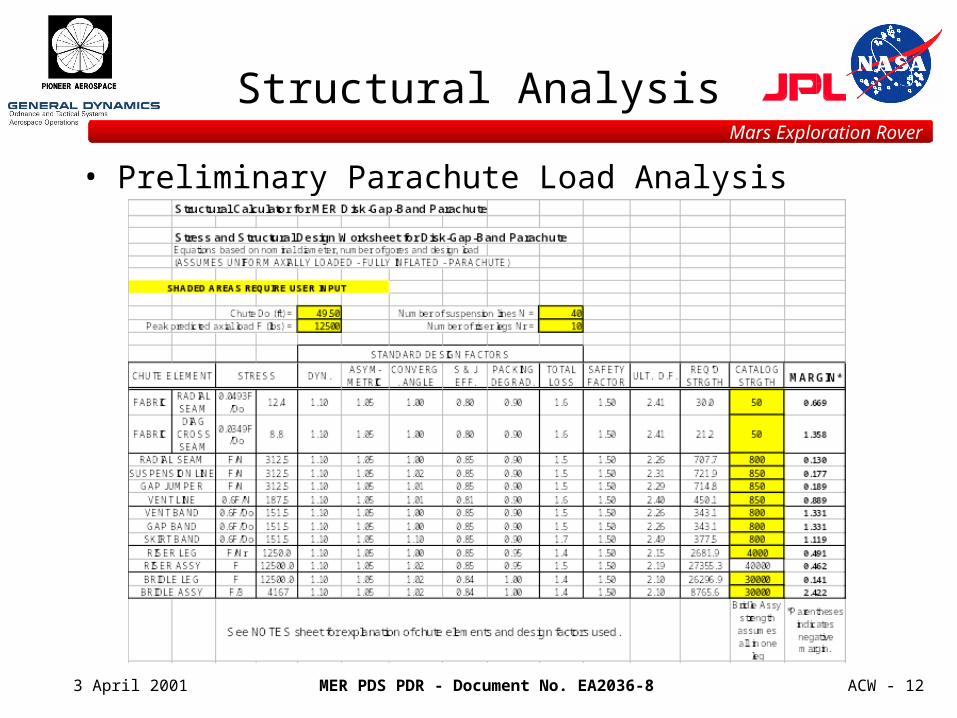
Structural Analysis
• Preliminary Parachute Load Analysis
MER PDS PDR - Document No. EA2036-8
Mars Exploration Rover
3 April 2001 ACW - 13
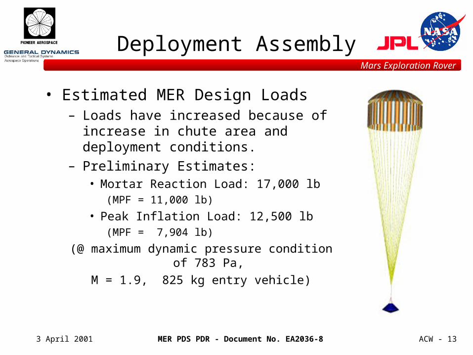
• Estimated MER Design Loads– Loads have increased because of increase in
chute area and deployment conditions.
– Preliminary Estimates:• Mortar Reaction Load: 17,000 lb
(MPF = 11,000 lb)
• Peak Inflation Load: 12,500 lb (MPF = 7,904 lb)
(@ maximum dynamic pressure condition of 783 Pa,
M = 1.9, 825 kg entry vehicle)
Deployment Assembly
MER PDS PDR - Document No. EA2036-8
Mars Exploration Rover
3 April 2001 ACW - 14
Deployment Assembly
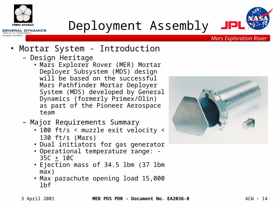
• Mortar System - Introduction– Design Heritage
• Mars Explorer Rover (MER) Mortar Deployer Subsystem (MDS) design will be based on the successful Mars Pathfinder Mortar Deployer System (MDS) developed by General Dynamics (formerly Primex/Olin) as part of the Pioneer Aerospace team
– Major Requirements Summary• 100 ft/s < muzzle exit velocity < 130 ft/s
(Mars)• Dual initiators for gas generator • Operational temperature range: -35C + 10C• Ejection mass of 34.5 lbm (37 lbm max)• Max parachute opening load 15,000 lbf
MER PDS PDR - Document No. EA2036-8
Mars Exploration Rover
3 April 2001 ACW - 15
Deployment Assembly
• Mortar System - Introduction (cont’d)
– Principal Similarities - Pathfinder vs. MER• Same propellant, initiators and design approach• Very similar parachute deployment velocity• Development, LAT and qualification approach
– Principal Differences - Pathfinder vs. MER• Deployment mass (34.5 lbm vs. 21.5 lbm)• Parachute volume (1620 in.3 vs. 953 in3)• Larger parachute inflation load (15,000 lbf vs. 12,000 lbf - MSP01)
MER PDS PDR - Document No. EA2036-8
Mars Exploration Rover
3 April 2001 ACW - 16
Deployment Assembly
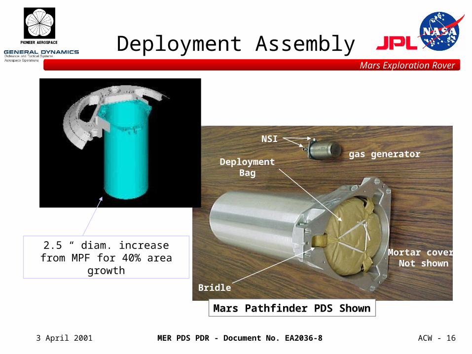
Bridle
Deployment Bag
Mortar cover Not shown
gas generator
NSI
Mars Pathfinder PDS Shown
2.5 “ diam. increase from MPF for 40% area growth
MER PDS PDR - Document No. EA2036-8
Mars Exploration Rover
3 April 2001 ACW - 17
Deployment Assembly
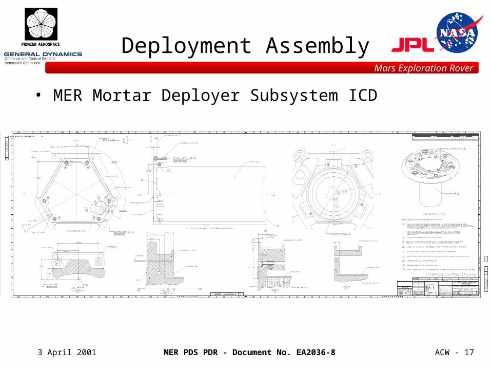
• MER Mortar Deployer Subsystem ICD
IN WORK 01-03-27 <FOR REF ONL Y>
MER PDS PDR - Document No. EA2036-8
Mars Exploration Rover
3 April 2001 ACW - 18
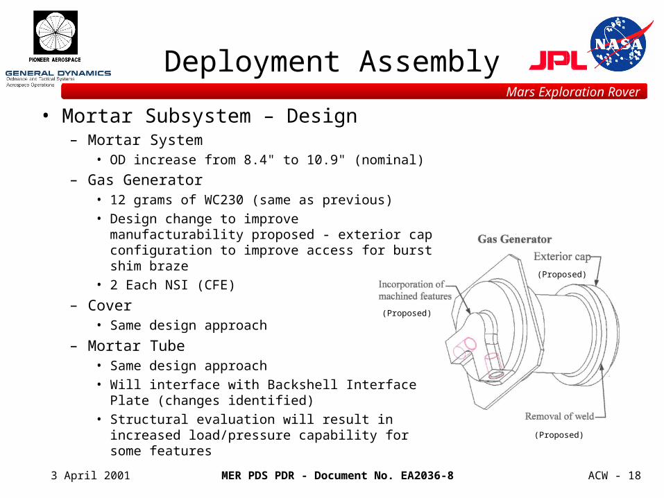
Deployment Assembly
• Mortar Subsystem – Design– Mortar System
• OD increase from 8.4" to 10.9" (nominal)
– Gas Generator • 12 grams of WC230 (same as previous)
• Design change to improve manufacturability proposed - exterior cap configuration to improve access for burst shim braze
• 2 Each NSI (CFE)
– Cover• Same design approach
– Mortar Tube• Same design approach
• Will interface with Backshell Interface Plate (changes identified)
• Structural evaluation will result in increased load/pressure capability for some features
(Proposed)
(Proposed)
(Proposed)
MER PDS PDR - Document No. EA2036-8
Mars Exploration Rover
3 April 2001 ACW - 19
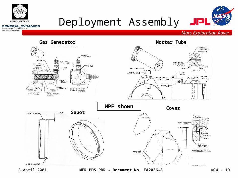
Deployment Assembly
Mortar TubeGas Generator
SabotCoverMPF shown
MER PDS PDR - Document No. EA2036-8
Mars Exploration Rover
3 April 2001 ACW - 20
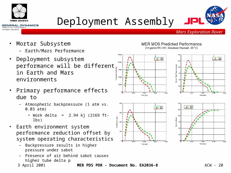
Deployment Assembly
• Mortar Subsystem– Earth/Mars Performance
• Deployment subsystem performance will be different in Earth and Mars environments
• Primary performance effects due to– Atmospheric backpressure (1 atm vs. 0.03 atm)
• Work delta = 2.94 kj (2169 ft-lbs)
• Earth environment system performance reduction offset by system operating characteristics
– Backpressure results in higher pressure under sabot
– Presence of air behind sabot causes higher tube delta p
MER PDS PDR - Document No. EA2036-8
Mars Exploration Rover
3 April 2001 ACW - 21
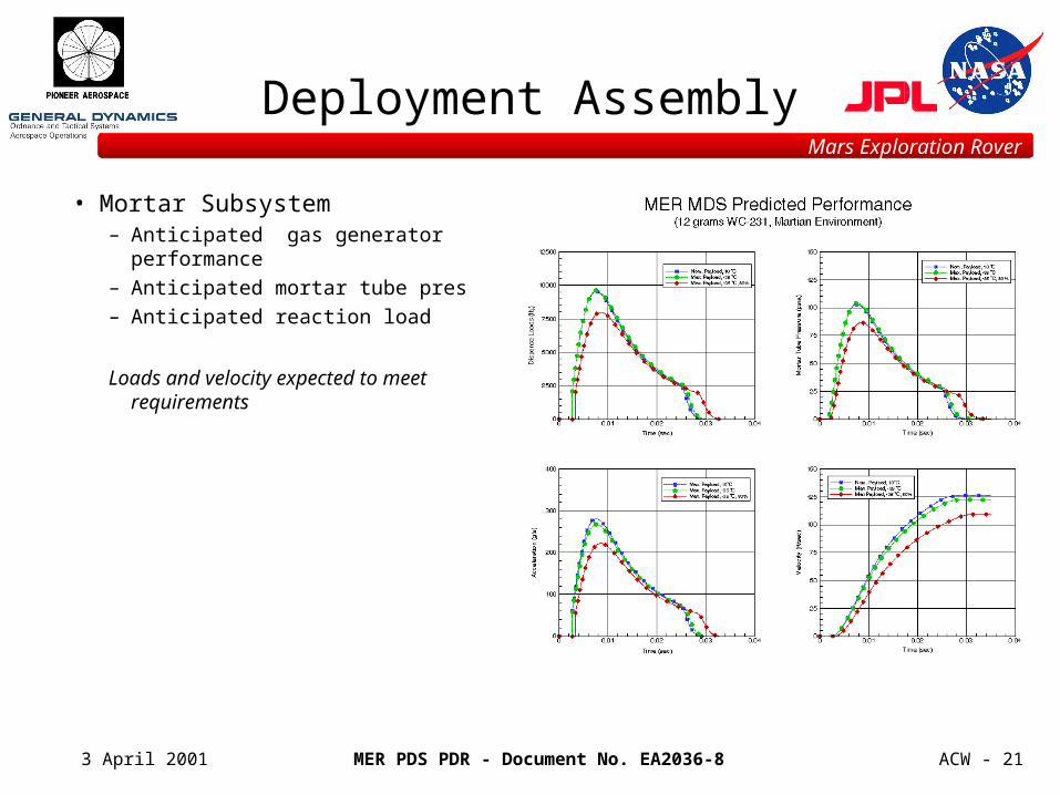
Deployment Assembly
• Mortar Subsystem– Anticipated gas generator performance
– Anticipated mortar tube pressure
– Anticipated reaction load
Loads and velocity expected to meet requirements
MER PDS PDR - Document No. EA2036-8
Mars Exploration Rover
3 April 2001 ACW - 22
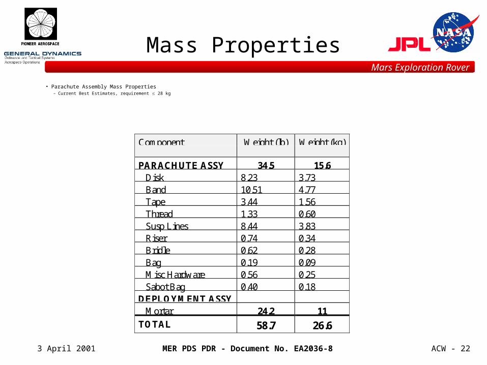
• Parachute Assembly Mass Properties– Current Best Estimates, requirement 28 kg
Mass Properties
Component Weight (lb) Weight (kg)
PARACHUTE ASSY 34.5 15.6 Disk 8.23 3.73 Band 10.51 4.77 Tape 3.44 1.56 Thread 1.33 0.60 Susp Lines 8.44 3.83 Riser 0.74 0.34 Bridle 0.62 0.28 Bag 0.19 0.09 Misc Hardware 0.56 0.25 Sabot Bag 0.40 0.18DEPLOYMENT ASSY Mortar 24.2 11
TOTAL 58.7 26.6
MER PDS PDR - Document No. EA2036-8
Mars Exploration Rover
3 April 2001 ACW - 23
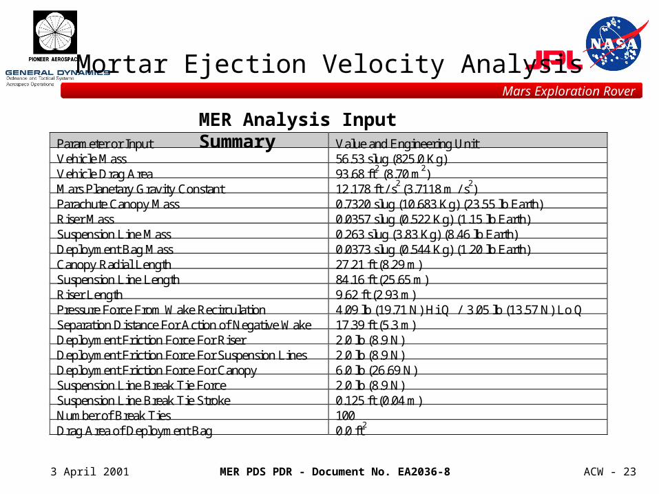
Mortar Ejection Velocity Analysis
Parameter or Input Value and Engineering UnitVehicle Mass 56.53 slug (825.0 Kg)Vehicle Drag Area 93.68 ft2 (8.70 m2)Mars Planetary Gravity Constant 12.178 ft / s2 (3.7118 m / s2)Parachute Canopy Mass 0.7320 slug (10.683 Kg) (23.55 lb Earth)Riser Mass 0.0357 slug (0.522 Kg) (1.15 lb Earth)Suspension Line Mass 0.263 slug (3.83 Kg) (8.46 lb Earth)Deployment Bag Mass 0.0373 slug (0.544 Kg) (1.20 lb Earth)Canopy Radial Length 27.21 ft (8.29 m)Suspension Line Length 84.16 ft (25.65 m)Riser Length 9.62 ft (2.93 m)Pressure Force From Wake Recirculation 4.09 lb (19.71 N) Hi Q / 3.05 lb (13.57 N) Lo QSeparation Distance For Action of Negative Wake 17.39 ft (5.3 m)Deployment Friction Force For Riser 2.0 lb (8.9 N)Deployment Friction Force For Suspension Lines 2.0 lb (8.9 N)Deployment Friction Force For Canopy 6.0 lb (26.69 N)Suspension Line Break Tie Force 2.0 lb (8.9 N)Suspension Line Break Tie Stroke 0.125 ft (0.04 m)Number of Break Ties 100Drag Area of Deployment Bag 0.0 ft2
MER Analysis Input Summary