Embed Size (px)
Citation preview
MERITOR® SPRING BRAKE CHAMBERS
PB-1404
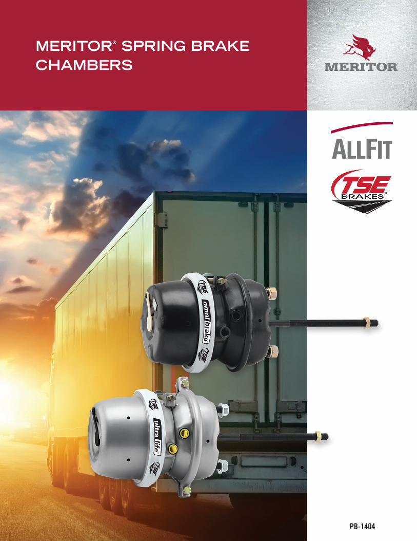
TSE BRAKES INC.
Part Description (Can be different from Customer Specifi ed Part Name)
U.S. SIZE SERVICE
U.S. SIZE PARKING TYPE STYLE Pushrod Style
STROKE mm = METRIC PRODUCT LINE
20 24 T L D 64 H
Defi nes
Type of
Service
Chamber
Defi nes
Type of
Parking
Chamber
Defi nes
as Single,
Tandem
or Service
Chamber
Defi nes Style/ Make of Unit Defi nes Applica-
tion: Disc Brake or
S-Cam
Specifi es Stroke
of Unit
Additional Features otherwise
leave blank
Service Parking
Adapter
Base Skip if OMNI or standard
Sizes
Available
1214161820222427303336etc.
Sizes
Available
243036etc.
S = Single
T = Tandem
SC = Service
Chamber
L = Sealed
N = Clamped
M = Clamped
Z = Sealed
Y = Clamped
A = Clamped
B = Clamped
Sealed
Sealed
Clamped
RPSEAL
RPSeal
Sealed
Clamped
Steel
Steel
Steel
Steel
Steel
Alum
Alum
D if unit is for Disc
Brake Application
Leave blank if
unit is for Drum
Brake application
W if unit has
welded Clevis
P/R
Metric Ports
Metric Mounting
Bolts
57mm64mm65mm76mmStroke
English Ports
English Mounting
Bolts***
0 = 1.75”1 = 2.25”2 = 2.50”3 = 3.00”
UL = Ultra-Life
P = (Plus) Non contact Spring
F = HD Spring Force
K = Add Service Clamps &
Diaphragm (No NPH for SC Type)D = Dura Brake
R = Remote
DX = Disc - Welded ClevisG = Pin Lock chamber
A = Alumline
H = HOT (Piston Performance)
***Disc Brakes
use Metric
mounting Bolts
Only.
HOT PERFORMANCE KEY
SIZE 24 = PERFORMANCE SIZE 30
SIZE 30 = PERFORMANCE SIZE 33
SIZE 36 = PERFORMANCE SIZE 40
TABLE OF CONTENTS
High Output Technology (H.O.T.) ................................................................................. 9
Installation Guide .................................................................................................... 14
Meritor® AllFit .......................................................................................................... 11
Meritor AllFit Parts List ............................................................................................ 12
Meritor Warranty ....................................................................................................... 27
Omnibrake ................................................................................................................. 6
Other TSE Components ............................................................................................. 10
Severe Duty ................................................................................................................ 8
TSE® Brake Codes .................................................................................................... 26
TSE Parts List ........................................................................................................... 10
TSE Recommended Torque ....................................................................................... 21
TSE Troubleshooting Guide ....................................................................................... 22
TSE Warranties ......................................................................................................... 24
Ultralife ...................................................................................................................... 4
Welded Clevis Explanation ....................................................................................... 20
4 U.S. 888-725-9355
Canada 800-387-3889
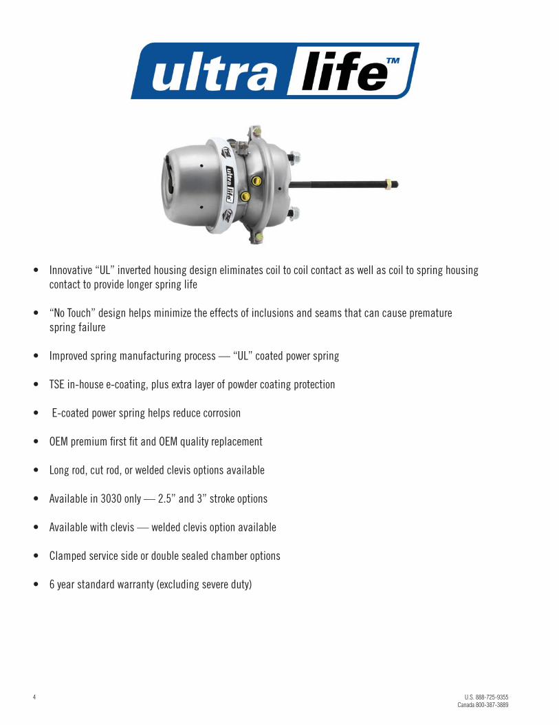
• Innovative “UL” inverted housing design eliminates coil to coil contact as well as coil to spring housing
contact to provide longer spring life
• “No Touch” design helps minimize the effects of inclusions and seams that can cause premature
spring failure
• Improved spring manufacturing process — “UL” coated power spring
• TSE in-house e-coating, plus extra layer of powder coating protection
• E-coated power spring helps reduce corrosion
• OEM premium fi rst fi t and OEM quality replacement
• Long rod, cut rod, or welded clevis options available
• Available in 3030 only — 2.5” and 3” stroke options
• Available with clevis — welded clevis option available
• Clamped service side or double sealed chamber options
• 6 year standard warranty (excluding severe duty)
U.S. 888-725-9355 MeritorPartsOnline.com 5
Canada 800-387-3889
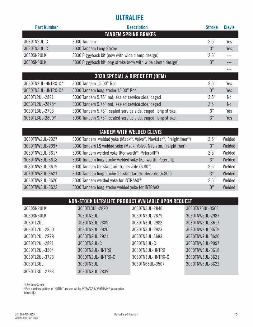
ULTRALIFEPart Number Description Stroke Clevis
TANDEM SPRING BRAKES3030TN2UL-C 3030 Tandem 2.5” Yes
3030TN3UL-C 3030 Tandem Long Stroke 3” Yes
3030SN2ULK 3030 Piggyback kit (now with wide clamp design) 2.5” ---
3030SN3ULK 3030 Piggyback kit long stroke (now with wide clamp design) 3” ---
---
3030 SPECIAL & DIRECT FIT (OEM)3030TN2UL-HNTRX-C* 3030 Tandem 15.00” Rod 2.5” Yes
3030TN3UL-HNTRX-C* 3030 Tandem long stroke 15.00” Rod 3” Yes
3030TL2UL-2891 3030 Tandem 5.75” rod, sealed service side, caged 2.5” No
3030TL2UL-2878* 3030 Tandem 9.75” rod, sealed service side, caged 2.5” No
3030TL3UL-2793 3030 Tandem 5.75”, sealed service side, caged, long stroke 3” Yes
3030TL3UL-2890* 3030 Tandem 9.75”, sealed service side, caged, long stroke 3” Yes
TANDEM WITH WELDED CLEVIS3030TNW2UL-2927 3030 Tandem welded yoke (Mack®, Volvo®, Navistar®, Freightliner®) 2.5” Welded
3030TNW3UL-2997 3030 Tandem LS welded yoke (Mack, Volvo, Navistar, Freightliner) 3” Welded
3030TNW2UL-3617 3030 Tandem welded yoke (Kenworth®, Peterbilt®) 2.5” Welded
3030TNW3UL-3618 3030 Tandem long stroke welded yoke (Kenworth, Peterbilt) 3” Welded
3030TNW2UL-3619 3030 Tandem for standard trailer axle (6.80”) 2.5” Welded
3030TNW3UL-3621 3030 Tandem long stroke for standard trailer axle (6.80”) 3” Welded
3030TNW2UL-3620 3030 Tandem welded yoke for INTRAAX® 2.5” Welded
3030TNW3UL-3622 3030 Tandem long stroke welded yoke for INTRAAX 3” Welded
NON-STOCK ULTRALIFE PRODUCT AVAILABLE UPON REQUEST3030SN2ULK 3030TL3UL-2890 3030TN3UL-2840 3030TN76UL-3508
3030SN3ULK 3030TN2UL 3030TN3UL-2879 3030TNW2UL-2927
3030TL2UL 3030TN2UL-2889 3030TN3UL-2922 3030TNW2UL-3617
3030TL2UL-2850 3030TN2UL-2920 3030TN3UL-2923 3030TNW2UL-3619
3030TL2UL-2878 3030TN2UL-2921 3030TN3UL-3683 3030TNW2UL-3620
3030TL2UL-2891 3030TN2UL-C 3030TN3UL-C 3030TNW3UL-2997
3030TL2UL-3504 3030TN2UL-HNTRX 3030TN3UL-HNTRX 3030TNW3UL-3618
3030TL2UL-3723 3030TN2UL-HNTRX-C 3030TN3UL-HNTRX-C 3030TNW3UL-3621
3030TL3UL 3030TN3UL 3030TN65UL-3507 3030TNW3UL-3622
3030TL3UL-2793 3030TN3UL-2839
*LS= Long Stroke
*Part numbers ending in “HNTRX” are pre-cut for INTRAAX® & VANTRAAX® suspension
(direct fi t)
6 U.S. 888-725-9355
Canada 800-387-3889
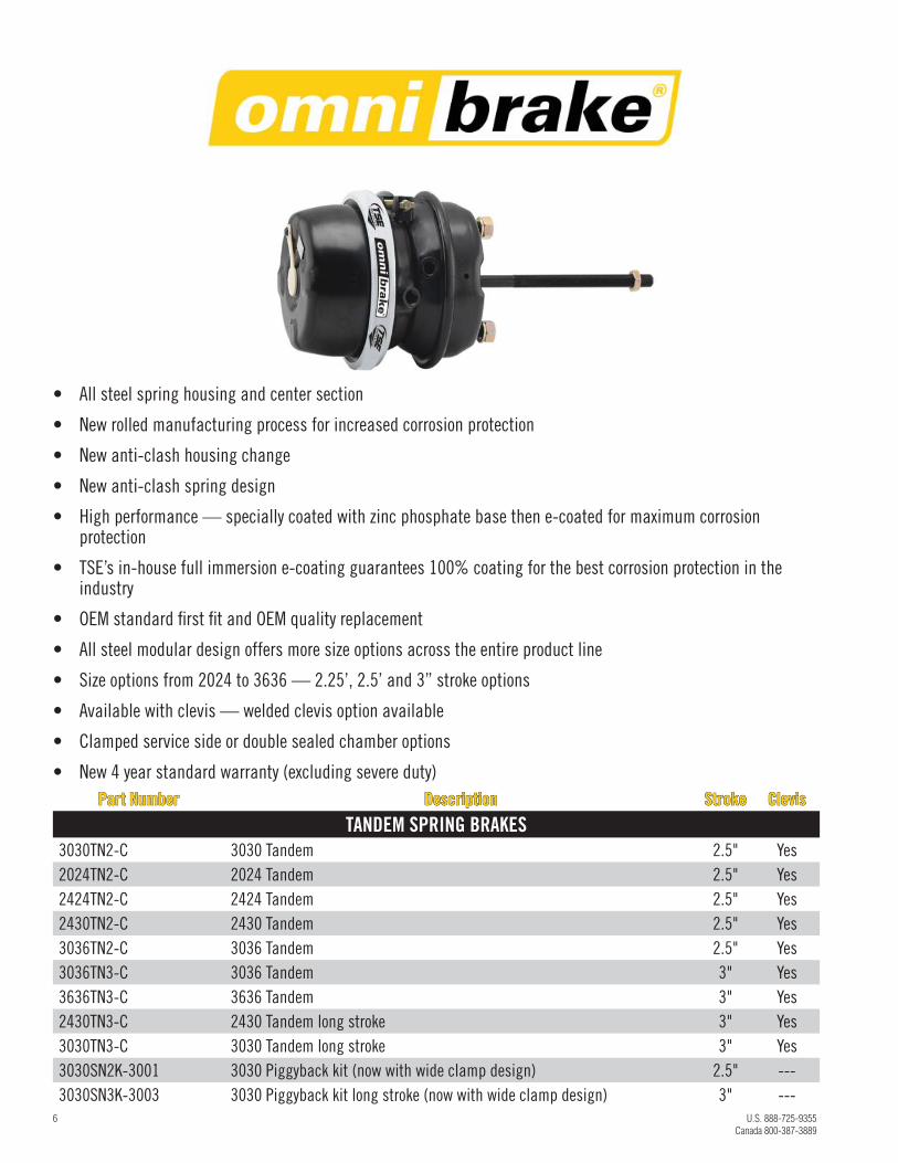
Part NumberPart Number DescriptionDescription StrokeStroke ClevisClevis
TANDEM SPRING BRAKES3030TN2-C 3030 Tandem 2.5" Yes
2024TN2-C 2024 Tandem 2.5" Yes
2424TN2-C 2424 Tandem 2.5" Yes
2430TN2-C 2430 Tandem 2.5" Yes
3036TN2-C 3036 Tandem 2.5" Yes
3036TN3-C 3036 Tandem 3" Yes
3636TN3-C 3636 Tandem 3" Yes
2430TN3-C 2430 Tandem long stroke 3" Yes
3030TN3-C 3030 Tandem long stroke 3" Yes
3030SN2K-3001 3030 Piggyback kit (now with wide clamp design) 2.5" ---
3030SN3K-3003 3030 Piggyback kit long stroke (now with wide clamp design) 3" ---
• All steel spring housing and center section
• New rolled manufacturing process for increased corrosion protection
• New anti-clash housing change
• New anti-clash spring design
• High performance — specially coated with zinc phosphate base then e-coated for maximum corrosion protection
• TSE’s in-house full immersion e-coating guarantees 100% coating for the best corrosion protection in the industry
• OEM standard fi rst fi t and OEM quality replacement
• All steel modular design offers more size options across the entire product line
• Size options from 2024 to 3636 — 2.25’, 2.5’ and 3” stroke options
• Available with clevis — welded clevis option available
• Clamped service side or double sealed chamber options
• New 4 year standard warranty (excluding severe duty)
U.S. 888-725-9355 MeritorPartsOnline.com 7
Canada 800-387-3889
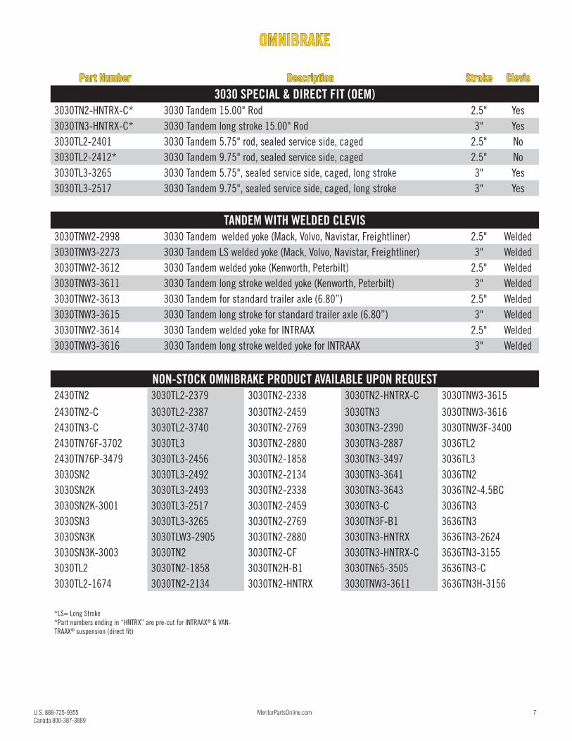
OMNIBRAKEOMNIBRAKE
Part NumberPart Number DescriptionDescription StrokeStroke ClevisClevis
3030 SPECIAL & DIRECT FIT (OEM)3030TN2-HNTRX-C* 3030 Tandem 15.00" Rod 2.5" Yes
3030TN3-HNTRX-C* 3030 Tandem long stroke 15.00" Rod 3" Yes
3030TL2-2401 3030 Tandem 5.75" rod, sealed service side, caged 2.5" No
3030TL2-2412* 3030 Tandem 9.75" rod, sealed service side, caged 2.5" No
3030TL3-3265 3030 Tandem 5.75", sealed service side, caged, long stroke 3" Yes
3030TL3-2517 3030 Tandem 9.75", sealed service side, caged, long stroke 3" Yes
TANDEM WITH WELDED CLEVIS3030TNW2-2998 3030 Tandem welded yoke (Mack, Volvo, Navistar, Freightliner) 2.5" Welded
3030TNW3-2273 3030 Tandem LS welded yoke (Mack, Volvo, Navistar, Freightliner) 3" Welded
3030TNW2-3612 3030 Tandem welded yoke (Kenworth, Peterbilt) 2.5" Welded
3030TNW3-3611 3030 Tandem long stroke welded yoke (Kenworth, Peterbilt) 3" Welded
3030TNW2-3613 3030 Tandem for standard trailer axle (6.80”) 2.5" Welded
3030TNW3-3615 3030 Tandem long stroke for standard trailer axle (6.80”) 3" Welded
3030TNW2-3614 3030 Tandem welded yoke for INTRAAX 2.5" Welded
3030TNW3-3616 3030 Tandem long stroke welded yoke for INTRAAX 3" Welded
NON-STOCK OMNIBRAKE PRODUCT AVAILABLE UPON REQUEST2430TN2 3030TL2-2379 3030TN2-2338 3030TN2-HNTRX-C 3030TNW3-3615
2430TN2-C 3030TL2-2387 3030TN2-2459 3030TN3 3030TNW3-3616
2430TN3-C 3030TL2-3740 3030TN2-2769 3030TN3-2390 3030TNW3F-3400
2430TN76F-3702 3030TL3 3030TN2-2880 3030TN3-2887 3036TL2
2430TN76P-3479 3030TL3-2456 3030TN2-1858 3030TN3-3497 3036TL3
3030SN2 3030TL3-2492 3030TN2-2134 3030TN3-3641 3036TN2
3030SN2K 3030TL3-2493 3030TN2-2338 3030TN3-3643 3036TN2-4.5BC
3030SN2K-3001 3030TL3-2517 3030TN2-2459 3030TN3-C 3036TN3
3030SN3 3030TL3-3265 3030TN2-2769 3030TN3F-B1 3636TN3
3030SN3K 3030TLW3-2905 3030TN2-2880 3030TN3-HNTRX 3636TN3-2624
3030SN3K-3003 3030TN2 3030TN2-CF 3030TN3-HNTRX-C 3636TN3-3155
3030TL2 3030TN2-1858 3030TN2H-B1 3030TN65-3505 3636TN3-C
3030TL2-1674 3030TN2-2134 3030TN2-HNTRX 3030TNW3-3611 3636TN3H-3156
*LS= Long Stroke
*Part numbers ending in “HNTRX” are pre-cut for INTRAAX® & VAN-
TRAAX® suspension (direct fi t)
8 U.S. 888-725-9355
Canada 800-387-3889
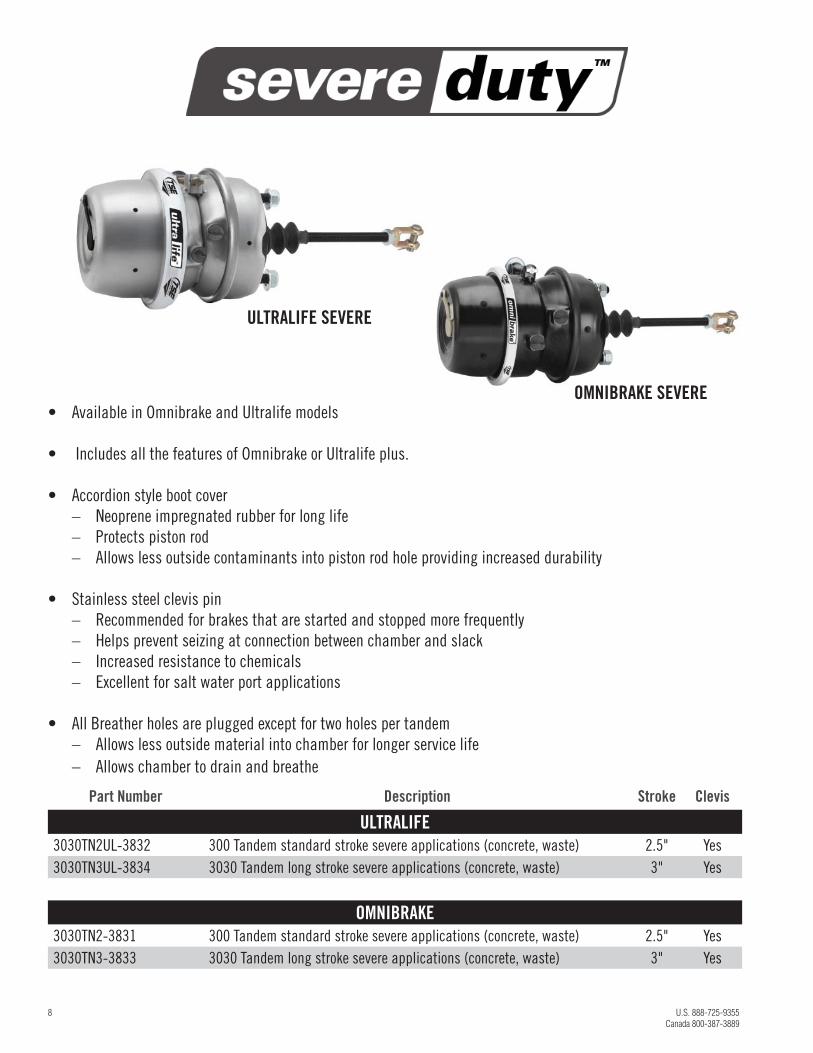
• Available in Omnibrake and Ultralife models
• Includes all the features of Omnibrake or Ultralife plus.
• Accordion style boot cover
– Neoprene impregnated rubber for long life
– Protects piston rod
– Allows less outside contaminants into piston rod hole providing increased durability
• Stainless steel clevis pin
– Recommended for brakes that are started and stopped more frequently
– Helps prevent seizing at connection between chamber and slack
– Increased resistance to chemicals
– Excellent for salt water port applications
• All Breather holes are plugged except for two holes per tandem
– Allows less outside material into chamber for longer service life
– Allows chamber to drain and breathe
Part Number Description Stroke Clevis
ULTRALIFE3030TN2UL-3832 300 Tandem standard stroke severe applications (concrete, waste) 2.5" Yes
3030TN3UL-3834 3030 Tandem long stroke severe applications (concrete, waste) 3" Yes
OMNIBRAKE3030TN2-3831 300 Tandem standard stroke severe applications (concrete, waste) 2.5" Yes
3030TN3-3833 3030 Tandem long stroke severe applications (concrete, waste) 3" Yes
OMNIBRAKE SEVERE
ULTRALIFE SEVERE
U.S. 888-725-9355 MeritorPartsOnline.com 9
Canada 800-387-3889
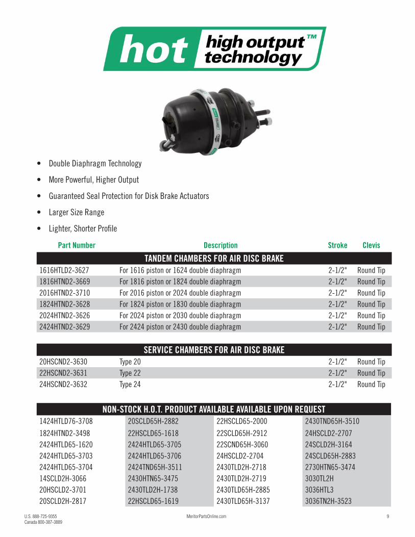
• Double Diaphragm Technology
• More Powerful, Higher Output
• Guaranteed Seal Protection for Disk Brake Actuators
• Larger Size Range
• Lighter, Shorter Profi le
Part Number Description Stroke Clevis
TANDEM CHAMBERS FOR AIR DISC BRAKE 1616HTLD2-3627 For 1616 piston or 1624 double diaphragm 2-1/2" Round Tip
1816HTND2-3669 For 1816 piston or 1824 double diaphragm 2-1/2" Round Tip
2016HTND2-3710 For 2016 piston or 2024 double diaphragm 2-1/2" Round Tip
1824HTND2-3628 For 1824 piston or 1830 double diaphragm 2-1/2" Round Tip
2024HTND2-3626 For 2024 piston or 2030 double diaphragm 2-1/2" Round Tip
2424HTND2-3629 For 2424 piston or 2430 double diaphragm 2-1/2" Round Tip
SERVICE CHAMBERS FOR AIR DISC BRAKE 20HSCND2-3630 Type 20 2-1/2" Round Tip
22HSCND2-3631 Type 22 2-1/2" Round Tip
24HSCND2-3632 Type 24 2-1/2" Round Tip
NON-STOCK H.O.T. PRODUCT AVAILABLE AVAILABLE UPON REQUEST1424HTLD76-3708 20SCLD65H-2882 22HSCLD65-2000 2430TND65H-3510
1824HTND2-3498 22HSCLD65-1618 22SCLD65H-2912 24HSCLD2-2707
2424HTLD65-1620 2424HTLD65-3705 22SCND65H-3060 24SCLD2H-3164
2424HTLD65-3703 2424HTLD65-3706 24HSCLD2-2704 24SCLD65H-2883
2424HTLD65-3704 2424TND65H-3511 2430TLD2H-2718 2730HTN65-3474
14SCLD2H-3066 2430HTN65-3475 2430TLD2H-2719 3030TL2H
20HSCLD2-3701 2430TLD2H-1738 2430TLD65H-2885 3036HTL3
20SCLD2H-2817 22HSCLD65-1619 2430TLD65H-3137 3036TN2H-3523
10 U.S. 888-725-9355
Canada 800-387-3889
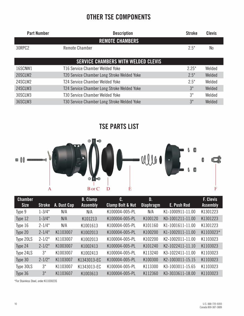
OTHER TSE COMPONENTS
Part Number Description Stroke Clevis
REMOTE CHAMBERS30RPC2 Remote Chamber 2.5" No
SERVICE CHAMBERS WITH WELDED CLEVIS 16SCNW1 T16 Service Chamber Welded Yoke 2.25" Welded
20SCLW2 T20 Service Chamber Long Stroke Welded Yoke 2.5" Welded
24SCLW2 T24 Service Chamber Welded Yoke 2.5" Welded
24SCLW3 T24 Service Chamber Long Stroke Welded Yoke 3" Welded
30SCLW3 T30 Service Chamber Welded Yoke 3" Welded
36SCLW3 T30 Service Chamber Long Stroke Welded Yoke 3" Welded
TSE PARTS LIST
Chamber Size Stroke A. Dust Cap
B. Clamp Assembly
C. Clamp Bolt & Nut
D. Diaphragm E. Push Rod
F. Clevis Assembly
Type 9 1-3/4" N/A N/A K100004-005-PL N/A K1-1000911-11.00 K1301223
Type 12 1-3/4" N/A K101213 K100004-005-PL K100120 K0-1001211-11.00 K1301223
Type 16 2-1/4" N/A K1001613 K100004-005-PL K101160 K1-1001611-11.00 K1301223
Type 20 2-1/4" K1103007 K1002013 K100004-005-PL K100200 K1-1002011-11.00 K1103023*
Type 20LS 2-1/2" K1103007 K1002013 K100004-005-PL K102200 K2-1002011-11.00 K1103023
Type 24 2-1/2" K1003007 K1002413 K100004-005-PL K101240 K2-1022411-11.10 K1103023
Type 24LS 3" K1003007 K1002413 K100004-005-PL K113240 K3-1022411-11.00 K1103023
Type 30 2-1/2" K1103007 K1343013-EC K100004-005-PL K100300 K2-1003011-15.15 K1103023
Type 30LS 3" K1103007 K1343013-EC K100004-005-PL K113300 K3-1003011-15.65 K1103023
Type 36 3" K1103607 K1003613 K100004-005-PL K112360 K3-3033611-18.00 K1103023
*For Stainless Steel, order K1103023S
U.S. 888-725-9355 MeritorPartsOnline.com 11
Canada 800-387-3889
Part Number Description Stroke Clevis
SEALED SPRING BRAKE COMBINATION UNITS FOR S-CAM BRAKESR872024C 2-1/2" Yes
R872430C 2-1/2" Yes
R872430C-EL 3" Yes
R873030C 2-1/2" Yes
R873030C-EL 3" Yes
RINT3030C-1EL INTRAAX Low Mount 3" Yes
RINT3030C-2 INTRAAX Top Mount 2-1/2" Yes
RINT3030C-2EL INTRAAX Top Mount 3" Yes
R873036C 3" Yes
R873636C 3" Yes
SEALED SPRING BRAKE PIGGYBACK UNITS FOR S-CAM BRAKESR872024P 2-1/2" Yes
R872424P 2-1/2" Yes
R872430P-L 2-1/2" Yes
R873030P-L 2-1/2" Yes
R873030P-EL 3" Yes
R873036P 2-1/2" Yes
R873636P 2-1/2" Yes
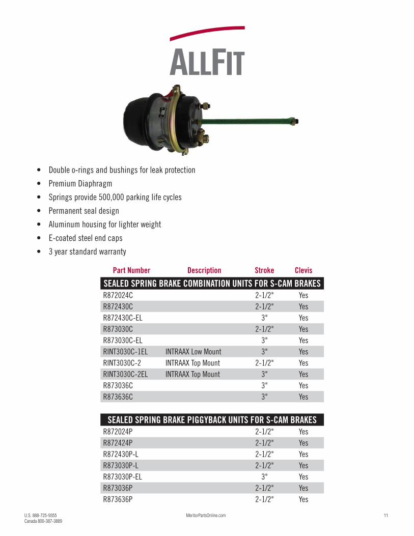
• Double o-rings and bushings for leak protection
• Premium Diaphragm
• Springs provide 500,000 parking life cycles
• Permanent seal design
• Aluminum housing for lighter weight
• E-coated steel end caps
• 3 year standard warranty
12 U.S. 888-725-9355
Canada 800-387-3889
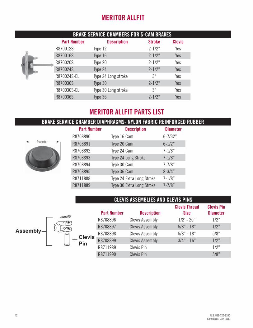
BRAKE SERVICE CHAMBER DIAPHRAGMS- NYLON FABRIC REINFORCED RUBBERPart Number Description Diameter
R8708890 Type 16 Cam 6-7/32”
R8708891 Type 20 Cam 6-1/2”
R8708892 Type 24 Cam 7-1/8”
R8708893 Type 24 Long Stroke 7-1/8”
R8708894 Type 30 Cam 7-7/8”
R8708895 Type 36 Cam 8-3/4”
R8711888 Type 24 Extra Long Stroke 7-1/8”
R8711889 Type 30 Extra Long Stroke 7-7/8”
MERITOR ALLFIT PARTS LIST
BRAKE SERVICE CHAMBERS FOR S-CAM BRAKESPart Number Description Stroke Clevis
R870012S Type 12 2-1/2" Yes
R870016S Type 16 2-1/2" Yes
R870020S Type 20 2-1/2" Yes
R870024S Type 24 2-1/2" Yes
R870024S-EL Type 24 Long stroke 3" Yes
R870030S Type 30 2-1/2" Yes
R870030S-EL Type 30 Long stroke 3" Yes
R870036S Type 36 2-1/2" Yes
MERITOR ALLFIT
Diameter
CLEVIS ASSEMBLIES AND CLEVIS PINS
Part Number DescriptionClevis Thread
SizeClevis Pin Diameter
R8708896 Clevis Assembly 1/2’ - 20” 1/2”
R8708897 Clevis Assembly 5/8” - 18” 1/2”
R8708898 Clevis Assembly 5/8” - 18” 5/8”
R8708899 Clevis Assembly 3/4” - 16” 1/2”
R8711989 Clevis Pin 1/2”
R8711990 Clevis Pin 5/8”
U.S. 888-725-9355 MeritorPartsOnline.com 13
Canada 800-387-3889
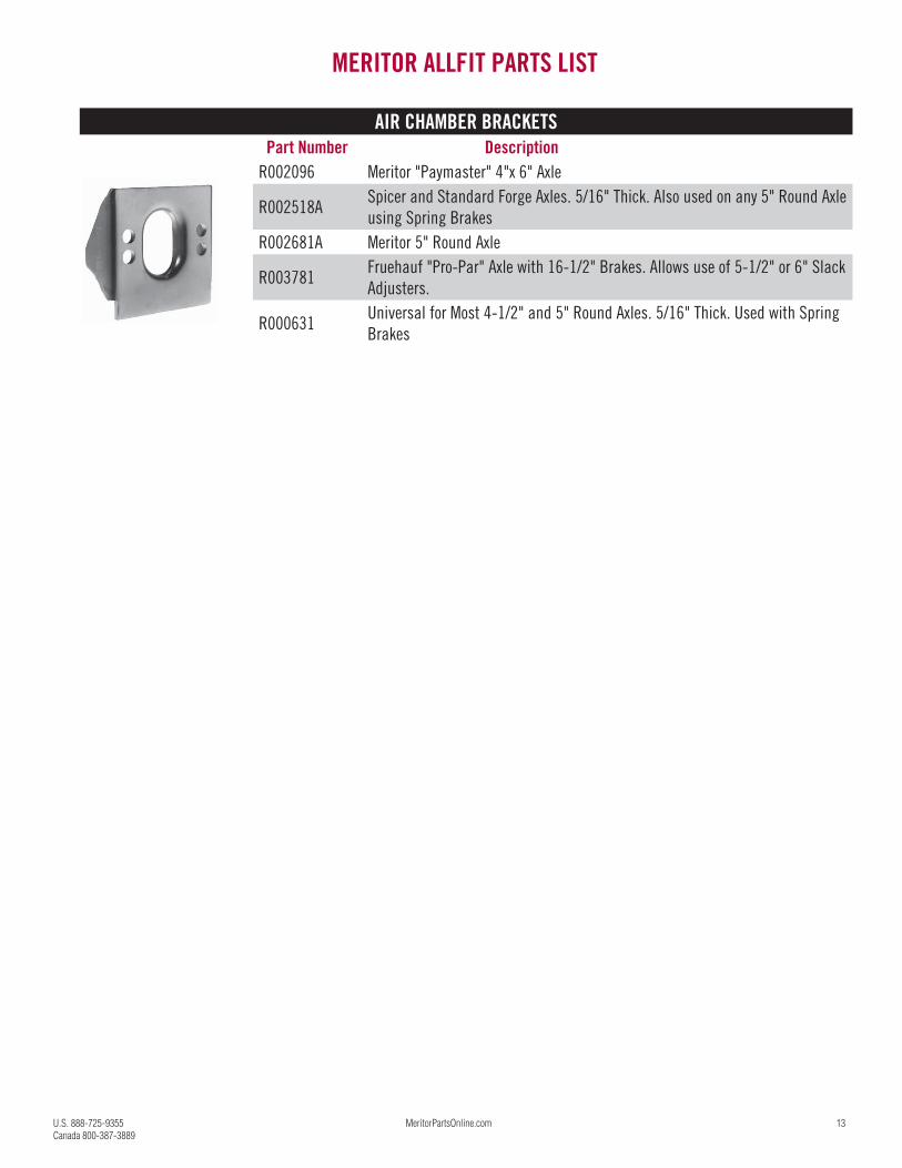
AIR CHAMBER BRACKETSPart Number Description
R002096 Meritor "Paymaster" 4"x 6" Axle
R002518ASpicer and Standard Forge Axles. 5/16" Thick. Also used on any 5" Round Axle
using Spring Brakes
R002681A Meritor 5" Round Axle
R003781Fruehauf "Pro-Par" Axle with 16-1/2" Brakes. Allows use of 5-1/2" or 6" Slack
Adjusters.
R000631Universal for Most 4-1/2" and 5" Round Axles. 5/16" Thick. Used with Spring
Brakes
MERITOR ALLFIT PARTS LIST
14 U.S. 888-725-9355
Canada 800-387-3889
Hazard Alert MessagesRead and observe all Warning and Caution hazard alert messages in this publication. They provide information that can help prevent serious personal injury, damage to components, or both.
WARNING
To prevent serious eye injury, always wear safe eye protection when you perform vehicle maintenance or service.Park the vehicle on a level surface. Block the wheels to prevent the vehicle from moving. Support the vehicle with safety
stands. Do not work under a vehicle supported only by jacks. Jacks can slip and fall over. Serious personal injury and damage
to components can result.
Brake Chamber Clamp Repositioning Procedure
WARNING
Remove the brake chamber from the vehicle before you remove or install the brake chamber spring clamp. Do not
perform these procedures with the brake chamber installed on the vehicle. Serious personal injury and damage to
components can result.
1. Wear safe eye protection. Park the vehicle on a level surface. Block the wheels to prevent the vehicle from moving.
2. Remove the brake chamber from the vehicle. Do not perform these procedures with the brake chamber installed. Place the brake chamber on a shop bench or similar work area.
WARNING
Before you service a spring chamber, carefully follow the manufacturer’s instructions to compress and lock the spring to com-
pletely release the brake. Verify that no air pressure remains in the service chamber before you proceed. Sudden release of
compressed air can cause serious personal injury and damage to components.
3. Cage the brake chamber on spring brakes. Refer to the instructions in this bulletin.
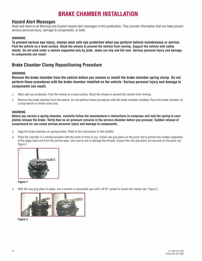
4. Place the chamber in a vertical position with the ports in front of you. Install vise grip pliers on the push rod to prevent the sudden separation of the piggy back unit from the service base. Use care to not to damage the threads. Ensure the vise grip pliers are secured on the push rod. Figure 1.
Figure 1
5. With the vise grip pliers in place, use a wrench or pneumatic gun with a 9/16” socket to loosen the clamp nuts. Figure 2.
Figure 2
BRAKE CHAMBER INSTALLATION
U.S. 888-725-9355 MeritorPartsOnline.com 15
Canada 800-387-3889
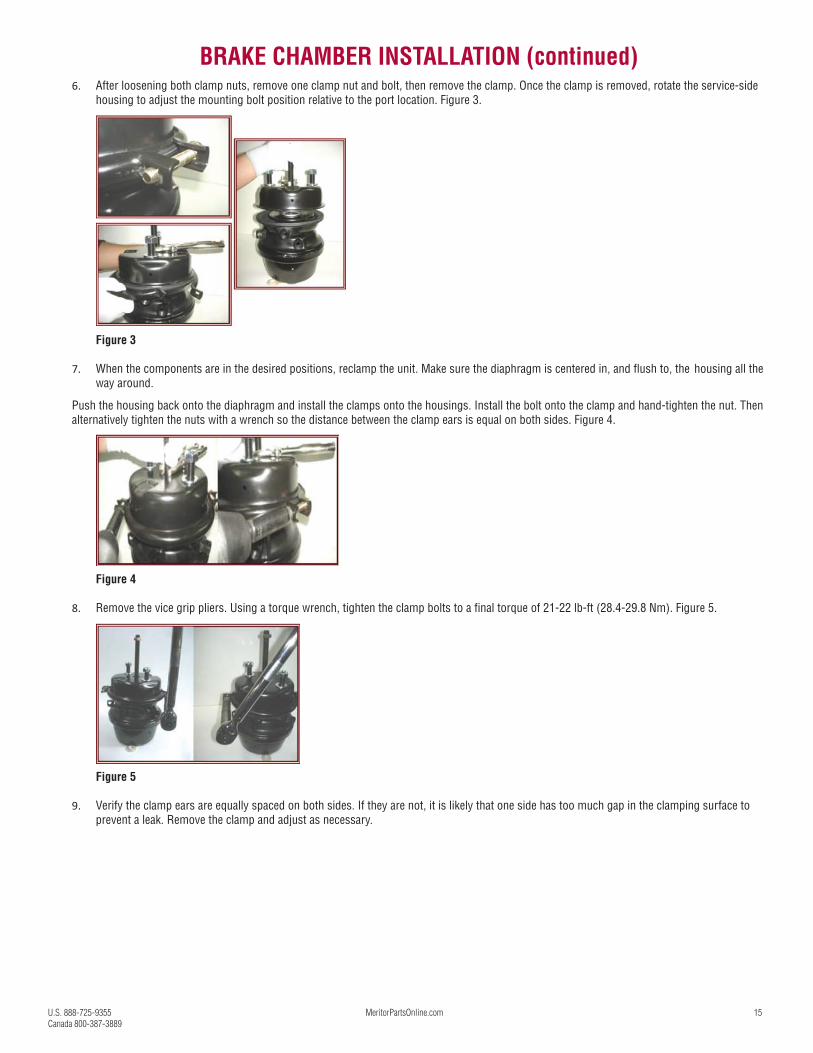
6. After loosening both clamp nuts, remove one clamp nut and bolt, then remove the clamp. Once the clamp is removed, rotate the service-side housing to adjust the mounting bolt position relative to the port location. Figure 3.
Figure 3
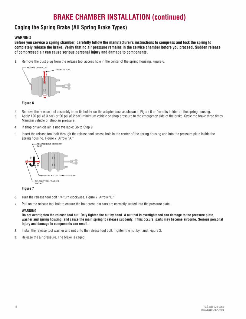
7. When the components are in the desired positions, reclamp the unit. Make sure the diaphragm is centered in, and flush to, the housing all the way around.
Push the housing back onto the diaphragm and install the clamps onto the housings. Install the bolt onto the clamp and hand-tighten the nut. Then alternatively tighten the nuts with a wrench so the distance between the clamp ears is equal on both sides. Figure 4.
Figure 4
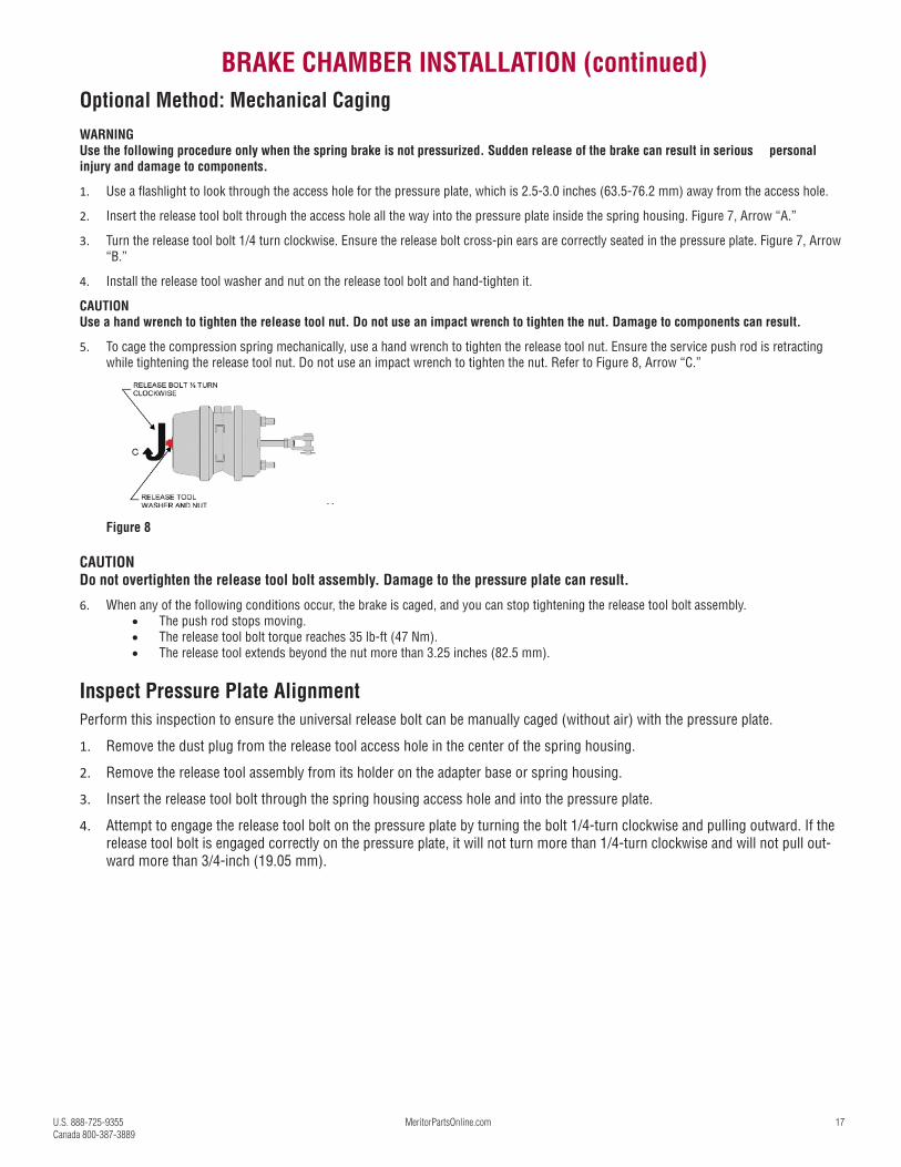
8. Remove the vice grip pliers. Using a torque wrench, tighten the clamp bolts to a final torque of 21-22 lb-ft (28.4-29.8 Nm). Figure 5.
Figure 5
9. Verify the clamp ears are equally spaced on both sides. If they are not, it is likely that one side has too much gap in the clamping surface to prevent a leak. Remove the clamp and adjust as necessary.
BRAKE CHAMBER INSTALLATION (continued)
16 U.S. 888-725-9355
Canada 800-387-3889
Caging the Spring Brake (All Spring Brake Types)
WARNING
Before you service a spring chamber, carefully follow the manufacturer’s instructions to compress and lock the spring to
completely release the brake. Verify that no air pressure remains in the service chamber before you proceed. Sudden release
of compressed air can cause serious personal injury and damage to components.
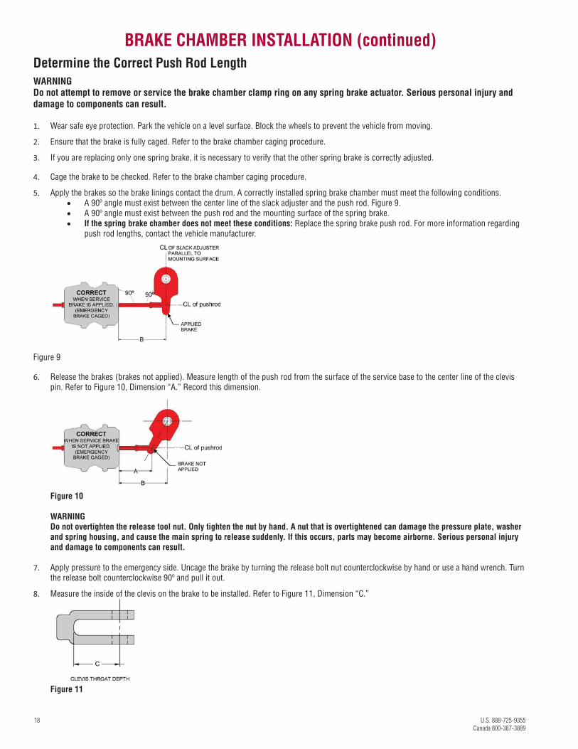
1. Remove the dust plug from the release tool access hole in the center of the spring housing. Figure 6.
Figure 6
2. Remove the release tool assembly from its holder on the adapter base as shown in Figure 6 or from its holder on the spring housing. 3. Apply 120 psi (8.3 bar) or 90 psi (6.2 bar) minimum vehicle or shop pressure to the emergency side of the brake. Cycle the brake three times.
Maintain vehicle or shop air pressure.
4. If shop or vehicle air is not available: Go to Step 9.
5. Insert the release tool bolt through the release tool access hole in the center of the spring housing and into the pressure plate inside the spring housing. Figure 7, Arrow “A.”
Figure 7
6. Turn the release tool bolt 1/4 turn clockwise. Figure 7, Arrow “B.”
7. Pull on the release tool bolt to ensure the bolt cross-pin ears are correctly seated into the pressure plate.
WARNING
Do not overtighten the release tool nut. Only tighten the nut by hand. A nut that is overtightened can damage to the pressure plate,
washer and spring housing, and cause the main spring to release suddenly. If this occurs, parts may become airborne. Serious personal
injury and damage to components can result.
8. Install the release tool washer and nut onto the release tool bolt. Tighten the nut by hand. Figure 2.
9. Release the air pressure. The brake is caged.
BRAKE CHAMBER INSTALLATION (continued)
U.S. 888-725-9355 MeritorPartsOnline.com 17
Canada 800-387-3889
Optional Method: Mechanical Caging
WARNING
Use the following procedure only when the spring brake is not pressurized. Sudden release of the brake can result in serious personal
injury and damage to components.
1. Use a flashlight to look through the access hole for the pressure plate, which is 2.5-3.0 inches (63.5-76.2 mm) away from the access hole.
2. Insert the release tool bolt through the access hole all the way into the pressure plate inside the spring housing. Figure 7, Arrow “A.”
3. Turn the release tool bolt 1/4 turn clockwise. Ensure the release bolt cross-pin ears are correctly seated in the pressure plate. Figure 7, Arrow “B.”
4. Install the release tool washer and nut on the release tool bolt and hand-tighten it.
CAUTION
Use a hand wrench to tighten the release tool nut. Do not use an impact wrench to tighten the nut. Damage to components can result.
5. To cage the compression spring mechanically, use a hand wrench to tighten the release tool nut. Ensure the service push rod is retracting while tightening the release tool nut. Do not use an impact wrench to tighten the nut. Refer to Figure 8, Arrow “C.”
Figure 8
CAUTION
Do not overtighten the release tool bolt assembly. Damage to the pressure plate can result.
6. When any of the following conditions occur, the brake is caged, and you can stop tightening the release tool bolt assembly. The push rod stops moving. The release tool bolt torque reaches 35 lb-ft (47 Nm). The release tool extends beyond the nut more than 3.25 inches (82.5 mm).
Inspect Pressure Plate Alignment
Perform this inspection to ensure the universal release bolt can be manually caged (without air) with the pressure plate.
1. Remove the dust plug from the release tool access hole in the center of the spring housing.
2. Remove the release tool assembly from its holder on the adapter base or spring housing.
3. Insert the release tool bolt through the spring housing access hole and into the pressure plate.
4. Attempt to engage the release tool bolt on the pressure plate by turning the bolt 1/4-turn clockwise and pulling outward. If the release tool bolt is engaged correctly on the pressure plate, it will not turn more than 1/4-turn clockwise and will not pull out-ward more than 3/4-inch (19.05 mm).
BRAKE CHAMBER INSTALLATION (continued)
18 U.S. 888-725-9355
Canada 800-387-3889
Determine the Correct Push Rod Length
WARNING
Do not attempt to remove or service the brake chamber clamp ring on any spring brake actuator. Serious personal injury and
damage to components can result.
1. Wear safe eye protection. Park the vehicle on a level surface. Block the wheels to prevent the vehicle from moving.
2. Ensure that the brake is fully caged. Refer to the brake chamber caging procedure.
3. If you are replacing only one spring brake, it is necessary to verify that the other spring brake is correctly adjusted.
4. Cage the brake to be checked. Refer to the brake chamber caging procedure.
5. Apply the brakes so the brake linings contact the drum. A correctly installed spring brake chamber must meet the following conditions. A 90º angle must exist between the center line of the slack adjuster and the push rod. Figure 9. A 90º angle must exist between the push rod and the mounting surface of the spring brake. If the spring brake chamber does not meet these conditions: Replace the spring brake push rod. For more information regarding
push rod lengths, contact the vehicle manufacturer.
Figure 9
6. Release the brakes (brakes not applied). Measure length of the push rod from the surface of the service base to the center line of the clevis pin. Refer to Figure 10, Dimension “A.” Record this dimension.
Figure 10
WARNING
Do not overtighten the release tool nut. Only tighten the nut by hand. A nut that is overtightened can damage the pressure plate, washer
and spring housing, and cause the main spring to release suddenly. If this occurs, parts may become airborne. Serious personal injury
and damage to components can result.
7. Apply pressure to the emergency side. Uncage the brake by turning the release bolt nut counterclockwise by hand or use a hand wrench. Turn the release bolt counterclockwise 90º and pull it out.
8. Measure the inside of the clevis on the brake to be installed. Refer to Figure 11, Dimension “C.”
Figure 11
BRAKE CHAMBER INSTALLATION (continued)
U.S. 888-725-9355 MeritorPartsOnline.com 19
Canada 800-387-3889
9. To determine the correct push rod length, subtract dimension “C” from dimension “A. ” This will give you the correct push rod length.
Example: Dimension “A” Minus Dimension“C” = Push Rod Length
5.00-inches (127 mm) Minus 1.25-inches (31.75 mm) = 3.75-inches (95.25 mm)
Dimension “A” = 5.00 inches (127 mm) push rod with clevis length (old brake installed)
Dimension “C” = 1.25 inches (31.75 mm) clevis length of the spring brake to be installed
“A” minus “C” = Push rod length of 3.75-inches (95.25 mm)
10. Use the jam nut to mark the correct length on the push rod. Cut the push rod using a suitable cutting tool.
11. Attach the clevis to the push rod. Verify that no more than two threads (approximately 0.12-inch [3.048 mm]) extend into the clevis to prevent interference with the push rod. Verify that at least one thread is recessed into the clevis. Tighten the jam nut to 45-50 lb-ft (61 to 69 Nm).
Replacing Both Spring Brakes on the Axle
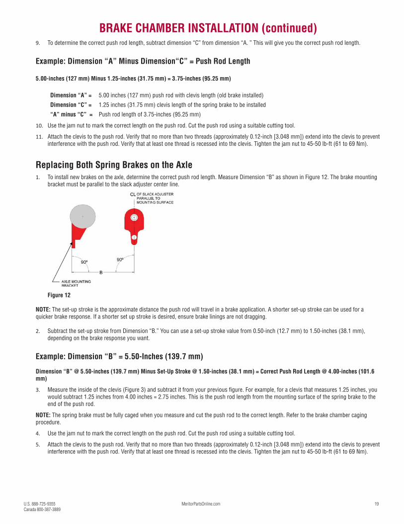
1. To install new brakes on the axle, determine the correct push rod length. Measure Dimension “B” as shown in Figure 12. The brake mounting bracket must be parallel to the slack adjuster center line.
Figure 12
NOTE: The set-up stroke is the approximate distance the push rod will travel in a brake application. A shorter set-up stroke can be used for a quicker brake response. If a shorter set up stroke is desired, ensure brake linings are not dragging.
2. Subtract the set-up stroke from Dimension “B.” You can use a set-up stroke value from 0.50-inch (12.7 mm) to 1.50-inches (38.1 mm), depending on the brake response you want.
Example: Dimension “B” = 5.50-Inches (139.7 mm)
Dimension “B” @ 5.50-inches (139.7 mm) Minus Set-Up Stroke @ 1.50-inches (38.1 mm) = Correct Push Rod Length @ 4.00-inches (101.6
mm)
3. Measure the inside of the clevis (Figure 3) and subtract it from your previous figure. For example, for a clevis that measures 1.25 inches, you would subtract 1.25 inches from 4.00 inches = 2.75 inches. This is the push rod length from the mounting surface of the spring brake to the end of the push rod.
NOTE: The spring brake must be fully caged when you measure and cut the push rod to the correct length. Refer to the brake chamber caging procedure.
4. Use the jam nut to mark the correct length on the push rod. Cut the push rod using a suitable cutting tool.
5. Attach the clevis to the push rod. Verify that no more than two threads (approximately 0.12-inch [3.048 mm]) extend into the clevis to prevent interference with the push rod. Verify that at least one thread is recessed into the clevis. Tighten the jam nut to 45-50 lb-ft (61 to 69 Nm).
BRAKE CHAMBER INSTALLATION (continued)
20 U.S. 888-725-9355
Canada 800-387-3889
WELDED CLEVIS EXPLANATION
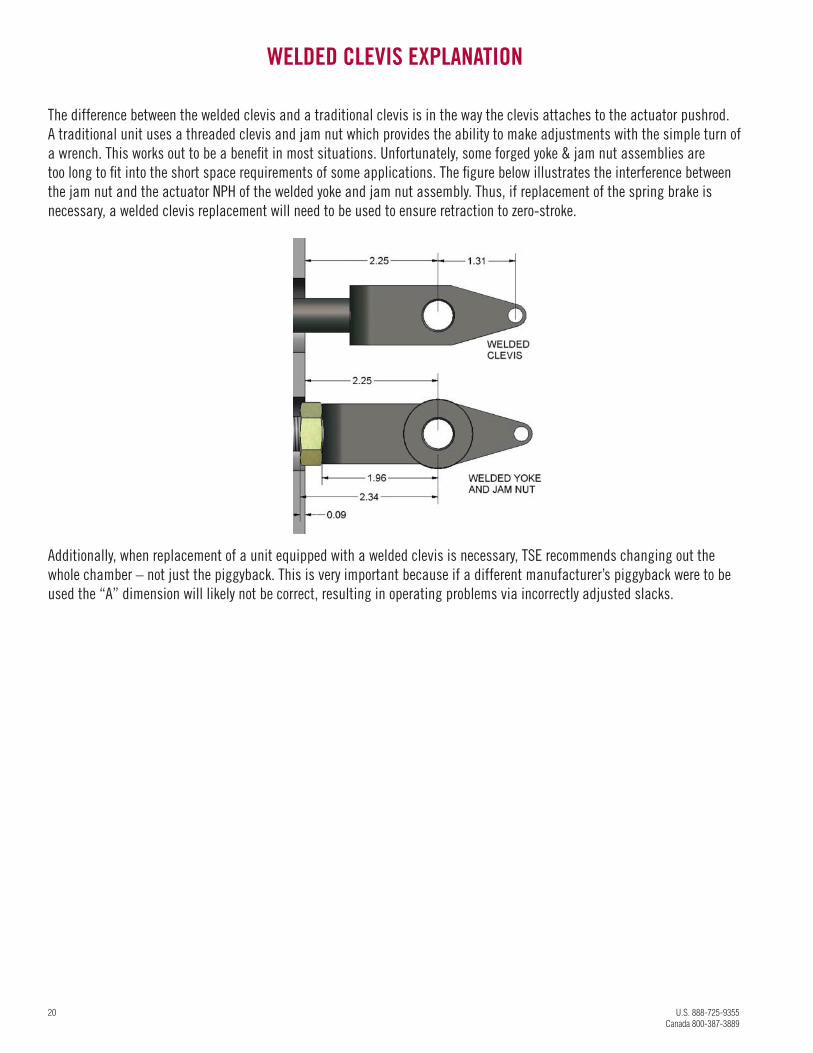
The difference between the welded clevis and a traditional clevis is in the way the clevis attaches to the actuator pushrod.
A traditional unit uses a threaded clevis and jam nut which provides the ability to make adjustments with the simple turn of
a wrench. This works out to be a benefi t in most situations. Unfortunately, some forged yoke & jam nut assemblies are
too long to fi t into the short space requirements of some applications. The fi gure below illustrates the interference between
the jam nut and the actuator NPH of the welded yoke and jam nut assembly. Thus, if replacement of the spring brake is
necessary, a welded clevis replacement will need to be used to ensure retraction to zero-stroke.
Additionally, when replacement of a unit equipped with a welded clevis is necessary, TSE recommends changing out the
whole chamber – not just the piggyback. This is very important because if a different manufacturer’s piggyback were to be
used the “A” dimension will likely not be correct, resulting in operating problems via incorrectly adjusted slacks.
U.S. 888-725-9355 MeritorPartsOnline.com 21
Canada 800-387-3889
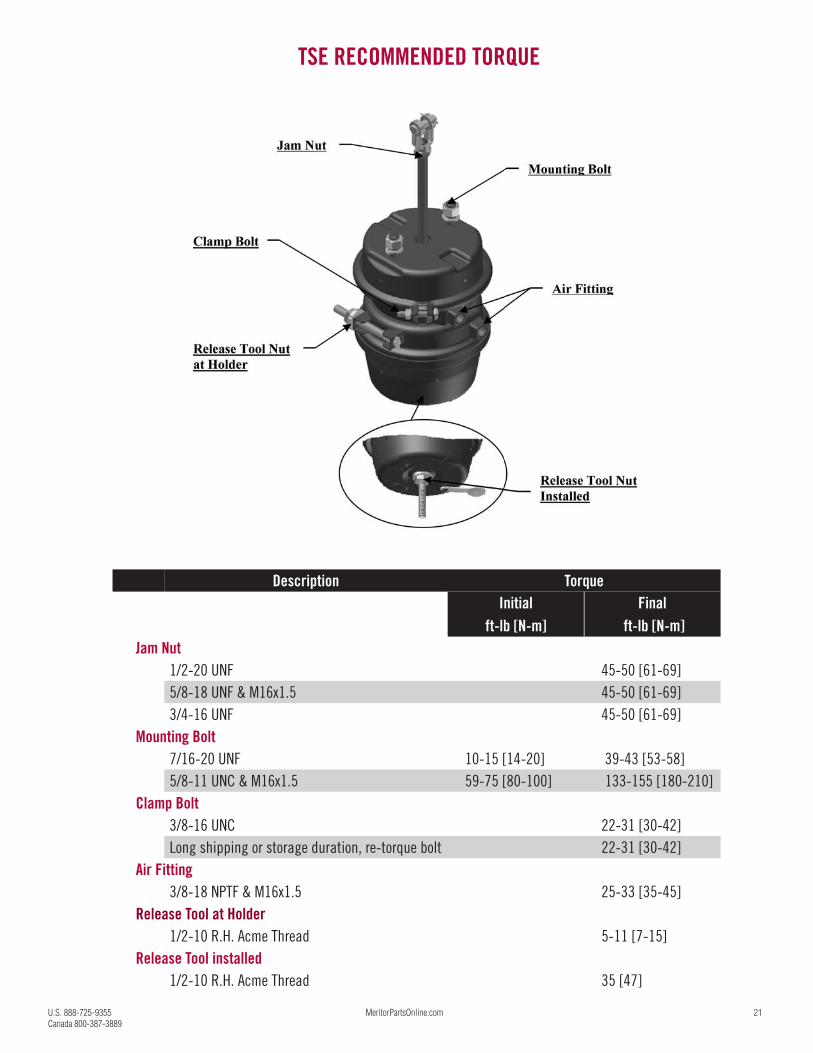
Description Torque Initial Final
ft-lb [N-m] ft-lb [N-m] Jam Nut
1/2-20 UNF 45-50 [61-69]
5/8-18 UNF & M16x1.5 45-50 [61-69]
3/4-16 UNF 45-50 [61-69]
Mounting Bolt
7/16-20 UNF 10-15 [14-20] 39-43 [53-58]
5/8-11 UNC & M16x1.5 59-75 [80-100] 133-155 [180-210]
Clamp Bolt
3/8-16 UNC 22-31 [30-42]
Long shipping or storage duration, re-torque bolt 22-31 [30-42]
Air Fitting
3/8-18 NPTF & M16x1.5 25-33 [35-45]
Release Tool at Holder
1/2-10 R.H. Acme Thread 5-11 [7-15]
Release Tool installed
1/2-10 R.H. Acme Thread 35 [47]
TSE RECOMMENDED TORQUE
22 U.S. 888-725-9355
Canada 800-387-3889
TSE TROUBLE SHOOTING GUIDE
The most common spring brake complaints, possible causes and how to correct them.
The service brake is not applying adequate force.
1. Improper brake adjustment. With brakes applied, check the brake chamber push rod to see if the orange Stroke Indicator band is showing. If so, readjust the slack adjuster
in accordance with its manufacturer’s instructions. Be certain that the spring parking brake chamber is fully released during this adjustment.
(Please note, TSE along with most other spring brake manufactures, will have 2 separate orange stripes. Don’t confuse the “Stroke Alert” band,
which is located approximately 2” down the push rod. The stroke alert stripe indicates that your spring brake has a “Stroke Indicator.”)
2. Available air pressure to brake chamber insuffi cient. Is the system air pressure gage reading normal? If it’s reading low, check compressor for proper operation. Look for kinked or blocked air lines.
Check for defective valves.
3. Excessive brake lining or drum wear. Handle in accordance with the manufacturer’s inspection instruction. Check for incompatibility of truck and trailer valve system. Check brake
chambers to insure they are fully released when brakes are not applied.
4. Improper slack adjuster operation or set-up. The angle made by the brake actuator push rod with respect to the mounting surface should be perpendicular within plus minus 3 degrees from
zero stroke to full stroke. The rod clearance hole in the non-pressure chamber (mounting plate) for the brake actuator push rod should not be
elongated or show evidence of rubbing from the rod. With brakes applied, using 80/90 P.S.I., the angle between the push rod and slack adjuster
should never be less than 90 degrees. Consult the slack adjuster manufacturer’s literature for proper operation and set-up.
5. Damage to mounting bracket or non-pressure chamber. Check bracket and non-pressure chamber for cracks or signs of damage. Verify that mounting nut torque is between 113 to 118 foot pounds.
If structural damage is found, replace the defective parts immediately. Be sure to follow TSE Installation Instruction for proper removal and
reinstallation.
6. Brake chamber or air system (lines, fi tting, valves) leakage. There may be a system leak if the compressor comes on often, or pressure is unable to be maintained. Examine all lines, fi ttings and valves for
proper connection and leakage. If no problems are found, inspect brake chambers for leakage. Listen for an audible sound, or spray the clamp
bands with a soap/water solution. If leakage is found at the service side clamp area, check the torque on the clamp band ears and verify it
is adequate, 25 to 28 foot pounds is recommended. If the leakage persists, replace the diaphragm and clamp band, or replace with new TSE
tandem spring brake unit.
CAUTION:
If leakage is found at:
a. spring side clamp area (double clamp units only)
b. end plug
c. fi rst valve in air line ahead of the spring brake (emergency release)
DO NOT ATTEMPT TO REMOVE OR TIGHTEN SPRING CHAMBER CLAMP BOLTS. Replace the valve if required, the entire
piggyback or the entire spring brake chamber. Be sure to install the release bolt and cage the spring. Never attempt to work on any spring brake
without fi rst caging the spring brake.
7. Improper pushrod length.This may be the problem if proper rod angularity is diffi cult to achieve, and/or frequent readjustment is necessary. Consult the vehicle
manufacturer for proper rod length.
U.S. 888-725-9355 MeritorPartsOnline.com 23
Canada 800-387-3889
TSE TROUBLE SHOOTING GUIDE (CONTINUED)
The parking brake is not holding. There is insuffi cient force.
1. Refer to the possible causes just discussed under “Service brake not applying adequate force.”
2. Broken power spring.Remove the end plug from the release bolt access hole of the brake chamber. Use a fl ashlight to check for evidence of spring breakage. OR
- observe brake chamber stroke while applying and releasing the parking brake. If the expected range of motion is not observed, the spring
may be broken. Also, the contents will rattle if the spring brake or piggyback is removed and shaken, indicating a probable broken spring.
The parking brake will not stay released. (Dragging brakes)
1. Available air pressure to brake chamber insuffi cient. Is the system air pressure gage reading normal? If it’s low, check the compressor for proper operation. Look for kinked or blocked air lines.
Check for defective valves.
2. Service application air is not exhausting properly. Apply and release service brakes while listening to exhaust. If the sound is not normal, check for kinked or blocked air lines or defective valves.
3. The spring brake piston is binding before the piston is fully retracted. Release the parking brake (Remove the end plug. Apply 90-100 P.S.I. air pressure.) Look to see if the top of the piston is approximately .200
inches from the head. If not, replace with a new TSE spring brake assembly.
4. Broken return spring in the service chamber. Remove piggyback and service diaphragm and inspect the return spring. If broken, replace with new return spring and new diaphragm or a new
tandem unit. For best performance specify only new TSE replace parts.
5. Ruptured diaphragm or damaged pushrod seal. Look for leakage at the parking chamber clamp bands. Remove release bolt access hole end cap and apply air to spring brakes (release). If you
hear or feel air through the hole, the diaphragm is defective.
WARNING
DO NOT ATTEMPT TO REPLACE THE DIAPHRAGM. REPLACE THE PIGGYBACK OR COMPLETE 3030T SPRING BRAKE.If air applied to the spring chamber has a tendency to apply the service brake, or to cause the service exhaust valve to leak, the pushrod seal is
leaking. (To verify, remove the service air line and apply air to the parking chamber. If air is detected coming through the open service air port,
the pushrod seal is leaking.) Replace piggyback or new TSE 3030T spring brake chamber.
6. Autoslack over-adjustment or camshaft linkage binding. Consult the manufacturer’s service manual.
7. Broken power spring or return spring in parking brake section. A broken power spring can be diagnosed as discussed in the previous section. A broken return spring in the parking chamber is diffi cult to
diagnose. Either case requires the complete replacement of the piggyback or new TSE tandem unit.
Service brakes apply or the service exhaust valve leaks when air is applied to the parking brake.
1. Air is leaking through the pushrod seal.Replace the entire piggyback unit or install a new TSE tandem unit.
24 U.S. 888-725-9355
Canada 800-387-3889
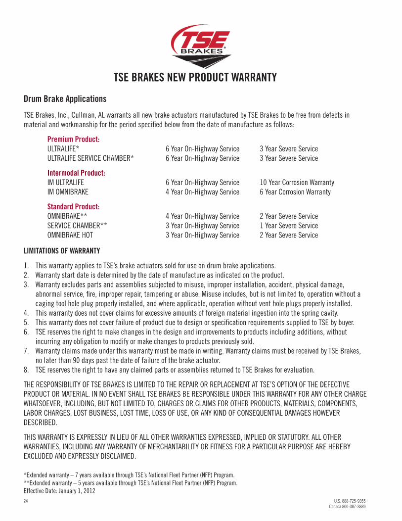
TSE BRAKES NEW PRODUCT WARRANTY
Drum Brake Applications
TSE Brakes, Inc., Cullman, AL warrants all new brake actuators manufactured by TSE Brakes to be free from defects in
material and workmanship for the period specifi ed below from the date of manufacture as follows:
Premium Product: ULTRALIFE* 6 Year On-Highway Service 3 Year Severe Service
ULTRALIFE SERVICE CHAMBER* 6 Year On-Highway Service 3 Year Severe Service
Intermodal Product: IM ULTRALIFE 6 Year On-Highway Service 10 Year Corrosion Warranty
IM OMNIBRAKE 4 Year On-Highway Service 6 Year Corrosion Warranty
Standard Product: OMNIBRAKE** 4 Year On-Highway Service 2 Year Severe Service
SERVICE CHAMBER** 3 Year On-Highway Service 1 Year Severe Service
OMNIBRAKE HOT 3 Year On-Highway Service 2 Year Severe Service
LIMITATIONS OF WARRANTY
1. This warranty applies to TSE’s brake actuators sold for use on drum brake applications.
2. Warranty start date is determined by the date of manufacture as indicated on the product.
3. Warranty excludes parts and assemblies subjected to misuse, improper installation, accident, physical damage,
abnormal service, fi re, improper repair, tampering or abuse. Misuse includes, but is not limited to, operation without a
caging tool hole plug properly installed, and where applicable, operation without vent hole plugs properly installed.
4. This warranty does not cover claims for excessive amounts of foreign material ingestion into the spring cavity.
5. This warranty does not cover failure of product due to design or specifi cation requirements supplied to TSE by buyer.
6. TSE reserves the right to make changes in the design and improvements to products including additions, without
incurring any obligation to modify or make changes to products previously sold.
7. Warranty claims made under this warranty must be made in writing. Warranty claims must be received by TSE Brakes,
no later than 90 days past the date of failure of the brake actuator.
8. TSE reserves the right to have any claimed parts or assemblies returned to TSE Brakes for evaluation.
THE RESPONSIBILITY OF TSE BRAKES IS LIMITED TO THE REPAIR OR REPLACEMENT AT TSE’S OPTION OF THE DEFECTIVE
PRODUCT OR MATERIAL. IN NO EVENT SHALL TSE BRAKES BE RESPONSIBLE UNDER THIS WARRANTY FOR ANY OTHER CHARGE
WHATSOEVER, INCLUDING, BUT NOT LIMITED TO, CHARGES OR CLAIMS FOR OTHER PRODUCTS, MATERIALS, COMPONENTS,
LABOR CHARGES, LOST BUSINESS, LOST TIME, LOSS OF USE, OR ANY KIND OF CONSEQUENTIAL DAMAGES HOWEVER
DESCRIBED.
THIS WARRANTY IS EXPRESSLY IN LIEU OF ALL OTHER WARRANTIES EXPRESSED, IMPLIED OR STATUTORY. ALL OTHER
WARRANTIES, INCLUDING ANY WARRANTY OF MERCHANTABILITY OR FITNESS FOR A PARTICULAR PURPOSE ARE HEREBY
EXCLUDED AND EXPRESSLY DISCLAIMED.
*Extended warranty – 7 years available through TSE’s National Fleet Partner (NFP) Program.
**Extended warranty – 5 years available through TSE’s National Fleet Partner (NFP) Program.
Effective Date: January 1, 2012
U.S. 888-725-9355 MeritorPartsOnline.com 25
Canada 800-387-3889
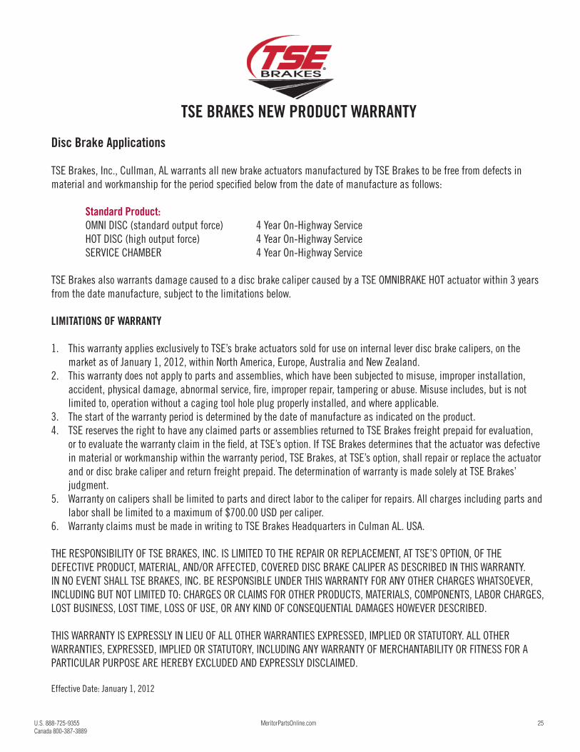
TSE BRAKES NEW PRODUCT WARRANTY
Disc Brake Applications
TSE Brakes, Inc., Cullman, AL warrants all new brake actuators manufactured by TSE Brakes to be free from defects in
material and workmanship for the period specifi ed below from the date of manufacture as follows:
Standard Product: OMNI DISC (standard output force) 4 Year On-Highway Service
HOT DISC (high output force) 4 Year On-Highway Service
SERVICE CHAMBER 4 Year On-Highway Service
TSE Brakes also warrants damage caused to a disc brake caliper caused by a TSE OMNIBRAKE HOT actuator within 3 years
from the date manufacture, subject to the limitations below.
LIMITATIONS OF WARRANTY
1. This warranty applies exclusively to TSE’s brake actuators sold for use on internal lever disc brake calipers, on the
market as of January 1, 2012, within North America, Europe, Australia and New Zealand.
2. This warranty does not apply to parts and assemblies, which have been subjected to misuse, improper installation,
accident, physical damage, abnormal service, fi re, improper repair, tampering or abuse. Misuse includes, but is not
limited to, operation without a caging tool hole plug properly installed, and where applicable.
3. The start of the warranty period is determined by the date of manufacture as indicated on the product.
4. TSE reserves the right to have any claimed parts or assemblies returned to TSE Brakes freight prepaid for evaluation,
or to evaluate the warranty claim in the fi eld, at TSE’s option. If TSE Brakes determines that the actuator was defective
in material or workmanship within the warranty period, TSE Brakes, at TSE’s option, shall repair or replace the actuator
and or disc brake caliper and return freight prepaid. The determination of warranty is made solely at TSE Brakes’
judgment.
5. Warranty on calipers shall be limited to parts and direct labor to the caliper for repairs. All charges including parts and
labor shall be limited to a maximum of $700.00 USD per caliper.
6. Warranty claims must be made in writing to TSE Brakes Headquarters in Culman AL. USA.
THE RESPONSIBILITY OF TSE BRAKES, INC. IS LIMITED TO THE REPAIR OR REPLACEMENT, AT TSE’S OPTION, OF THE
DEFECTIVE PRODUCT, MATERIAL, AND/OR AFFECTED, COVERED DISC BRAKE CALIPER AS DESCRIBED IN THIS WARRANTY.
IN NO EVENT SHALL TSE BRAKES, INC. BE RESPONSIBLE UNDER THIS WARRANTY FOR ANY OTHER CHARGES WHATSOEVER,
INCLUDING BUT NOT LIMITED TO: CHARGES OR CLAIMS FOR OTHER PRODUCTS, MATERIALS, COMPONENTS, LABOR CHARGES,
LOST BUSINESS, LOST TIME, LOSS OF USE, OR ANY KIND OF CONSEQUENTIAL DAMAGES HOWEVER DESCRIBED.
THIS WARRANTY IS EXPRESSLY IN LIEU OF ALL OTHER WARRANTIES EXPRESSED, IMPLIED OR STATUTORY. ALL OTHER
WARRANTIES, EXPRESSED, IMPLIED OR STATUTORY, INCLUDING ANY WARRANTY OF MERCHANTABILITY OR FITNESS FOR A
PARTICULAR PURPOSE ARE HEREBY EXCLUDED AND EXPRESSLY DISCLAIMED.
Effective Date: January 1, 2012
26 U.S. 888-725-9355
Canada 800-387-3889
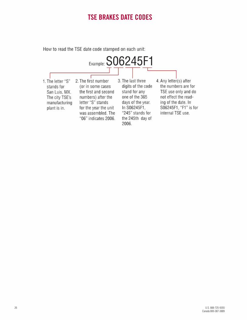
TSE BRAKES DATE CODES
U.S. 888-725-9355 MeritorPartsOnline.com 27
Canada 800-387-3889
MERITOR ALLFIT BRAKE CHAMBERS WARRANTY
We warrant all new parts to the buyer against defective material or workmanship (but not against damage caused by
accident, abuse or improper installation, maintenance or repair) when such parts are used on vehicles the specifi cations of
which have been approved by our Engineering Department. AllFit Brake Chambers are covered as follows:
AllFit Spring Brakes 3 Year On-Highway Service 1 Year Severe Service
AllFit Service Chambers 3 Year On-Highway Service 1 Year Severe Service
As the exclusive remedy under this warranty, we will, at our option, repair or replace such parts free of charge, or take
back the nonconforming parts and refund the monies paid by buyer for such parts, if found on examination by us to be
nonconforming and if any necessary return charges are prepaid.
If it is necessary to return any parts under this warranty, buyer agrees not to make any deduction on account thereof from
remittances on current accounts while claims are in the process of disposition. Any expense incurred without our consent
for repairs or replacement will not be allowed.
THIS WARRANTY IS EXPRESSLY IN LIEU OF ALL OTHER WARRANTIES OR CONDITIONS, EXPRESS, IMPLIED OR STATUTORY,
INCLUDING ANY IMPLIED WARRANTY OF MERCHANTABILITY OR FITNESS FOR PARTICULAR PURPOSE. IN NO EVENT SHALL
SELLER BE LIABLE FOR INCIDENTAL OR CONSEQUENTIAL DAMAGES OF ANY NATURE.
Only genuine Meritor replacement parts are covered by this aftermarket parts warranty.

888-725-9355 U.S.800-387-3889 CanadaMeritorPartsOnline.commeritor.com
©2016 Meritor, Inc.Litho in USA, PB-1404Revised 02-16 (47865/70906)
Meritor Heavy Vehicle Systems, LLC7975 Dixie HighwayFlorence, Kentucky 41042 USA
Vehicle models, brands and names depicted herein are the property of their respective owners, and are not in any way associated with Meritor, Inc., or its affiliates.