Embed Size (px)
Citation preview

Meritor TireInflation Systems (MTIS)
by P.S.I.
Installation and Maintenance Manual 14P
Revised 09-02

Service Notes
Copyright 2002 Maintenance Manual 14PPage -ii ArvinMeritor, Inc. Revised 09-02
Service Notes
Before You Begin
This manual provides installation and maintenance procedures for the Meritor Tire Inflation Systems by P.S.I.
Use the procedures in this manual to install the tire inflation system on either new trailer axles at original equipment manufacturers (OEM) or in-service trailer axles at fleets. Before you begin procedures:
1. Read and understand all instructions and procedures before you begin to service components.
2. Read and observe all Caution and Warning safety alerts that precede instructions or procedures you will perform. These alerts help to avoid damage to components, serious personal injury, or both.
3. Follow your company’s maintenance and service, installation, and diagnostics guidelines.
4. Use special tools when required to help avoid serious personal injury and damage to components.
Safety Alerts, Torque Symbol and Notes
Access Product and Service Information on Our Website
Visit the DriveTrain Plus
TM
by ArvinMeritor Tech Library at arvinmeritor.com to access and order product and service information.
To Order Information by Phone
Call ArvinMeritor’s Customer Service Center at 800-535-5560 to order publications.
O
Meritor Tire Inflation Systems (MTIS) by P.S.I. Technical Guide (TP-9914)
O
Trailer Axles (Maintenance Manual 14)
O
Drivetrain Plus
TM
by ArvinMeritor Technical Electronic Library on CD. Features product and service information on most Meritor, ZF Meritor and Meritor WABCO products. $20. Order TP-9853.
How to Order Tools and Supplies Specified in This Manual
Call ArvinMeritor’s Commercial Vehicle Aftermarket at 888-725-9355 to order Meritor tools and supplies. For Grainger tools, visit their website at www.grainger.com to locate a branch near you.
WARNING
A Warning alerts you to an instruction or procedure that you must follow exactly to avoid serious personal injury.
CAUTION
A Caution alerts you to an instruction or procedure that you must follow exactly to avoid damage to components.
A torque symbol alerts you to tighten fasteners to a specified torque value.
NOTE
A Note provides information or suggestions that help you correctly service a component.

Table of Contents
System Overview
. . . . . . . . . . . . . . . . . . . . . . . . . . . . . . . . . . . . . . . . . . . . . . . . . . . . . . . . . . . . . . . . . . . . . . i
Section 1: Introduction
For Complete Maintenance and Service Procedures for Meritor Trailer Axles . . . . . . . . . . . . . . . . . . . .1System Overview How the Meritor Tire Inflation System (MTIS) by P.S.I. Works Wheel End Assembly Controls Indicator Light . . . . . . . . . . . . . . . . . . . . . . . . . . . . . . . . . . . . . . . . . . . . . . . . . . . . . . . . . . . . . . . . . . . . . . . .2Installation Types Axle Types
Section 2: Installation
Axle Air Fitting . . . . . . . . . . . . . . . . . . . . . . . . . . . . . . . . . . . . . . . . . . . . . . . . . . . . . . . . . . . . . . . . . . . . . . . .4Prepare Axles with Hollow Spindles . . . . . . . . . . . . . . . . . . . . . . . . . . . . . . . . . . . . . . . . . . . . . . . . . . . . . .5Prepare Axles with Solid Spindles . . . . . . . . . . . . . . . . . . . . . . . . . . . . . . . . . . . . . . . . . . . . . . . . . . . . . . .10Stator . . . . . . . . . . . . . . . . . . . . . . . . . . . . . . . . . . . . . . . . . . . . . . . . . . . . . . . . . . . . . . . . . . . . . . . . . . . . . .13Wheel-End Components Air Components . . . . . . . . . . . . . . . . . . . . . . . . . . . . . . . . . . . . . . . . . . . . . . . . . . . . . . . . . . . . . . . . . . . . . .15Electrical Components . . . . . . . . . . . . . . . . . . . . . . . . . . . . . . . . . . . . . . . . . . . . . . . . . . . . . . . . . . . . . . . . .18Wheel-End Oil . . . . . . . . . . . . . . . . . . . . . . . . . . . . . . . . . . . . . . . . . . . . . . . . . . . . . . . . . . . . . . . . . . . . . . .20Decals
Section 3: Check System Operation
Check System Operation . . . . . . . . . . . . . . . . . . . . . . . . . . . . . . . . . . . . . . . . . . . . . . . . . . . . . . . . . . . . . . .21
Section 4: Pre-Service Check
Pre-Service Check . . . . . . . . . . . . . . . . . . . . . . . . . . . . . . . . . . . . . . . . . . . . . . . . . . . . . . . . . . . . . . . . . . . .25
Section 5: Inspection and Maintenance
Tire Inflation System Inspection . . . . . . . . . . . . . . . . . . . . . . . . . . . . . . . . . . . . . . . . . . . . . . . . . . . . . . . . .27Indicator Light Tires Check Tire PressureTire Test Gauge . . . . . . . . . . . . . . . . . . . . . . . . . . . . . . . . . . . . . . . . . . . . . . . . . . . . . . . . . . . . . . . . . . . . . .28Change Tire Inflation System Tire Pressure Setting Maintenance Turn OFF the System Before Performing Maintenance Remove and Replace a Tire Hose Valve Cores . . . . . . . . . . . . . . . . . . . . . . . . . . . . . . . . . . . . . . . . . . . . . . . . . . . . . . . . . . . . . . . . . . . . .29Remove the Through-Tee Before Installing a Hubcap . . . . . . . . . . . . . . . . . . . . . . . . . . . . . . . . . . . . . . .30
Section 6: Troubleshooting
. . . . . . . . . . . . . . . . . . . . . . . . . . . . . . . . . . . . . . . . . . . . . . . . . . . . . . . . . . 31
Section 7: Special Tools and Supplies
. . . . . . . . . . . . . . . . . . . . . . . . . . . . . . . . . . . . . . . . . . . . . . . 32

System Overview
Maintenance Manual 14P Copyright 2002Revised 09-02 ArvinMeritor, Inc. Page i
System Overview
HOSE
HUBCAP
VENT
THROUGH-TEE
STATOR
HOSE
DEFLECTOR SHIELD
WHEEL-END ASSEMBLY
TRAILERAIR TANK
AIR SUPPLYLINE
PRESSUREPROTECTION VALVE
30"(76 CM)
INDICATORLIGHT
INDICATOR LIGHT
AXLESPINDLE
PRESS PLUG
PETCOCK
SELF-DRAININGFILTER
FLOW SENSINGSWITCH
SHUT-OFFVALVE SYSTEM PRESSURE
ADJUSTMENT KNOB
PRESSUREPROTECTIONVALVE (PPV)
CONTROLS

Section 1Introduction
Maintenance Manual 14P Copyright 2002Revised 09-02 ArvinMeritor, Inc. Page 1
Section 1Introduction
For Complete Maintenance and Service Procedures for Meritor Trailer Axles
Refer to Maintenance Manual 14, Trailer Axles. To obtain this publication, refer to the Service Notes page on the front inside cover of this manual. For trailer axles not manufactured by Meritor, refer to the trailer axle manufacturer’s procedures.
System Overview
How the Meritor Tire Inflation System (MTIS) by P.S.I. Works
The MTIS uses compressed air from the trailer to inflate any tire that falls below the system air pressure setting during operation. Air from the existing trailer air supply is routed to a control box, then into each axle.
Acting as a conduit, axles carry air through a rotary union assembly at the spindle end, which then distributes air to each tire as needed.
An indicator light informs the driver of an excessive air pressure loss, providing advanced warning of maintenance or service requirements.
If a tire failure should occur, check valves in the tire delivery lines prevent loss of pressure from the remaining tires.
Wheel-End Assembly
Hoses
A hose is a flexible valve stem extension, which mechanically opens the tire valve stem and allows air to pass into a tire. There are two sizes of tire inflation system hoses: short, for 17- and 19-inch wheels; and long, for 22.5- and 24.5-inch wheels.
A check valve located at the knurled end of a hose allows air to flow in only one direction — to a tire. This protects each tire from loss of air pressure if the tire inflation system, or any tire, loses air pressure during operation.
Stator and Through-Tee
The stator is located inside the axle spindle and the through-tee is
attached to the hubcap. Pressurized air passes from the axle interior to the rotating hub through a tube extending from the through-tee into the stator. A dynamic seal, located in the through-tee, allows rotation without loss of air pressure.
Vent
The vent ensures that there is no pressure buildup in the wheel end.
Deflector Shield
The deflector shield helps keep contaminants such as dirt and water from entering the wheel end.
Hubcap
The hubcap features a vent and breather to prevent pressure buildup in the wheel end and a deflector shield to help prevent outside contaminants from entering the wheel end. Hubcaps for oil-lubricated wheel ends have a fill plug for adding lubricant.
Press Plug
The press plug is used in axles with hollow spindles to seal off the pressurized axle interior from the wheel end and provide a means of holding and securing the stator.
Controls
Shut-Off Valve
The shut-off valve stops air delivery to the system.
Self-Draining Filter
The self-draining filter automatically removes liquids and contaminants from the system.
Petcock
The petcock drains pressure from the tire inflation system. This enables you to perform maintenance on either the trailer axle components or the tire inflation system.

Section 1Introduction
Copyright 2002 Maintenance Manual 14PPage 2 ArvinMeritor, Inc. Revised 09-02
Pressure Protection Valve (PPV)
The pressure protection valve (PPV) ensures that air is available for other trailer functions. Air will not be delivered to the tire inflation system until the trailer air system is charged to at least 80 psi (551 kPa). The PPV also maintains air tank pressure if a tire or a tire inflation system component is damaged.
System Pressure Adjustment Knob
The system pressure adjustment knob adjusts system air pressure.
Flow Sensing Switch
The flow sensing switch illuminates the indicator light when the system delivers an excessive amount of air to either a leaking tire or a leaking tire inflation system component.
Indicator Light
An indicator light mounted on the front of the trailer comes ON when the system delivers an excessive amount of air due to air leaking from a tire or a tire inflation system component.
Installation Types
OEM and Fleets
Use the procedures in this manual to install the tire inflation system on either new trailer axles at original equipment manufacturers (OEM) or in-service trailer axles at fleets.
Axle Manufacturers
The tire inflation system can be installed on trailer axles manufactured by Meritor, Holland, Hendrickson, Ingersoll, Dana, Eaton and Sudisa. When installing the system, follow the maintenance instructions from the various axle manufacturers.
Axle Types
The installation sequence for tire inflation system components can vary according to axle type. Refer to the following guidelines.
Hollow Spindle
Most of the time, a hollow spindle trailer axle has a spindle that’s integrally formed out of axle tube material. A welsh plug is pressed into a machined recess in the spindle end. If you’re unsure of the axle type, contact the axle manufacturer.
Figure 1.1
.
Installation Sequence
1. Install the axle air fitting.2. Prepare the axle.3. Install the stator.4. Install wheel-end components.5. Follow remaining sections in the manual.
Solid Spindle
A solid spindle trailer axle has a flat end and a forged spindle welded to the axle tube. If you’re unsure of the axle type, contact the axle manufacturer.
Figure 1.2
.
Installation Sequence
1. Install the axle air fitting.2. Prepare the axle.3. Install the stator.4. Install wheel-end components.5. Follow remaining sections in the manual.
Figure 1.1
WELSHPLUG
HOLLOW SPINDLE

Section 1Introduction
Maintenance Manual 14P Copyright 2002Revised 09-02 ArvinMeritor, Inc. Page 3
Prepared by the Manufacturer
A prepped trailer axle has the following provisions.
O
The top-center hole is tapped to accept the tire inflation system axle air fitting, and a plug is installed in this hole. Some axle manufacturers may select an alternate location for this hole.
Figure 1.3
.
O
The system press plug and stator are installed in the axle spindle.
Figure 1.4
.
O
Debris has been cleaned from the axle interior.
Installation Sequence
1. Remove the plug from the tapped axle top-center hole.
2. Install the axle air fitting.3. Install wheel-end components.4. Follow remaining sections in the manual.
Figure 1.2
Figure 1.3
SOLID SPINDLE
TAPPED TOP-CENTER HOLE
PLUG
Figure 1.4
PRESS PLUG
STATOR
Section 2Installation
Copyright 2002 Maintenance Manual 14PPage 4 ArvinMeritor, Inc. Revised 09-02
Section 2Installation
WARNING
To prevent serious eye injury, always wear safe eye protection when you perform vehicle maintenance or service.
Park the vehicle on a level surface. Block the wheels to prevent the vehicle from moving. Support the vehicle with safety stands. Do not work under a vehicle supported only by jacks. Jacks can slip and fall over. Serious personal injury and damage to components can result.
Axle Air Fitting
1. Park the vehicle on a level surface. Block the wheels to prevent the vehicle from moving.
NOTE:
If the axle manufacturer has installed a top-center hole in the axle, use this hole as a pilot when you drill a hole for the air fitting.
2. Locate the top-center of the axle, which is the preferred location for the axle air fitting.
Figure 2.1
.
3. Use drilling lubricant and a variable speed electrical drill to drill an 11/32-inch diameter hole STRAIGHT into the top-center of the axle.
Figure 2.2
.
4. Use tapping lubricant and a 1/8-inch NPT tap to tap the drilled hole STRAIGHT into the axle. Do not run the tap completely through the hole. Leave some thread taper in the tapped hole.
Figure 2.3
.
5. Apply Teflon
®
tape to the 1/8-inch NPT threads of the axle air fitting. Hand-tighten the fitting into the tapped hole.
Figure 2.4
.
6. Use a 1/2-inch wrench to tighten the fitting two additional turns. Continue to tighten it until the fitting faces TOWARD the side of the trailer where you’ll install the system control box.
Figure 2.5
.
Figure 2.1
Figure 2.2
Figure 2.3
AXLETOP-CENTER
DRILL
TAP

Section 2Installation
Maintenance Manual 14P Copyright 2002Revised 09-02 ArvinMeritor, Inc. Page 5
Prepare Axles with Hollow Spindles
CAUTION
Cover wheel ends at both ends of the axle during system installation to prevent contaminants from entering the wheel end. Damage to the bearings and seals can result.
NOTE:
Do not reuse either the hubcap gasket or the oil.
1. Place a container under the hubcap to receive the draining oil. Remove the hubcap and hubcap gasket.
Figure 2.6
.
2. Cover the wheel ends at both ends of the axle with a clean towel.
Figure 2.7
.
NOTE:
A slide hammer and welsh plug removal spear are available from Meritor to help remove spindle welsh plugs. Refer to Section 7.
Figure 2.8
.
3. Use a slide hammer fitted with the welsh plug removal spear to remove the spindle welsh plugs from both ends of the axle. Be careful to not score the inside diameter of the spindle bore.
Figure 2.9
.
Figure 2.4
Figure 2.5
AXLEAIR FITTING
AXLEAIR FITTING
Figure 2.6
Figure 2.7
Figure 2.8
TOWEL
WELSH PLUGREMOVAL SPEAR
SLIDE HAMMER

Section 2Installation
Copyright 2002 Maintenance Manual 14PPage 6 ArvinMeritor, Inc. Revised 09-02
CAUTION
Use a bore polisher to remove all old adhesive from the spindle bore before you apply retaining compound to install the press plug. If retaining compound does not contact a metal surface, it will not harden. Damage to components can result.
4. Choose the correct sized bore polisher by matching the axle manufacturer and model to the bore polishers listed in Section 7.
Figure 2.10
.
5. Polish the spindle bore to remove all adhesive residue left from the old spindle plug and any machining marks on the spindle bore surface.
Figure 2.11
.
O
If the axle spindle is equipped with cotter pin holes:
Use a round abrasive tool to remove all metal burrs and sharp edges from the spindle bore side of the cotter pin holes.
Figure 2.12
.
Figure 2.9
SLIDE HAMMER
WELSH PLUGREMOVAL SPEAR
Figure 2.10
Figure 2.11
Figure 2.12
STRAIGHT DIE GRINDER BORE
POLISHER
MANDREL
BORE POLISHING
ABRASIVETOOL
COTTERPIN HOLE

Section 2Installation
Maintenance Manual 14P Copyright 2002Revised 09-02 ArvinMeritor, Inc. Page 7
CAUTION
Use a cleaning wand and high-volume air to clean debris from the axle interior before you installthe Meritor Tire Inflation Systems by P.S.I. Check that the axle is clear of debris, including loose rust, scale and machining residue. A contaminated axle can damage the tire inflation system and void the warranty.
NOTE: Refer to Section 7 for instructions on how to build a cleaning wand.
6. Connect a cleaning wand to a high-volume air supply. Slowly push the wand through the axle, until it exits the opposite end. During this operation a steady stream of air will be blowing from the axle spindle. Figure 2.13.
7. Check the inside of the axle tube with a flashlight by shining the light at one end of the spindle and looking through the opposite end. Confirm that all debris, including loose rust, scale and machining residue has been removed. Figure 2.14.
O If necessary: Repeat the cleaning procedure until the axle is clear of debris. For debris that’s difficult to remove, it may be helpful to push the cleaning wand through the axle from the opposite end.
NOTE: Current production press plug drive adaptors are identified with a number stamped on the part. Earlier adaptors were not marked.
8. Choose the correct press plug drive adaptor by matching the axle manufacturer and model to the press plug drive adaptors listed in Section 7. Figure 2.15.
9. Install the press plug drive adaptor onto the drive handle. Figure 2.16.
Figure 2.13
CLEANINGWAND
SHOP AIRSUPPLY
CLEANINGWAND
Figure 2.14
Figure 2.15
Figure 2.16
FLASHLIGHT
SPINDLEEND
SPINDLEEND
DRIVE HANDLE
PRESS PLUG DRIVE ADAPTORS
-01 -02 -03 -04
PRESS PLUGDRIVE ADAPTOR
DRIVE HANDLE

Section 2Installation
Copyright 2002 Maintenance Manual 14PPage 8 ArvinMeritor, Inc. Revised 09-02
10. Clean the exposed O-ring surface and outside diameter surface of one press plug using a towelette provided in the kit. Use a new towelette provided in the kit for each wheel end. Protect the cleaned plug from additional contaminants. Figure 2.17.
11. Use the same towelette to clean one spindle bore of contaminants such as grinding dust, grease and oil. Protect the cleaned bore from additional contaminants. Figure 2.18.
CAUTION
Only use the retaining compound supplied in the tire inflation system kit when you install the press plug. Only apply retaining compound to the OUTSIDE diameter of the press plug. Do not apply it to the inside diameter of the spindle bore, press plug stator threads or axle spindle threads. Damage to components can result.
NOTE: The installation kit contains enough retaining compound for four wheel ends. Divide the material equally among the wheel ends. The press plug must be installed within 10 minutes of applying the retaining compound to ensure that the compound hardens correctly.
12. Put on a new pair of latex gloves. Apply the retaining compound included in the installation kit evenly to the OUTSIDE diameter of the press plug. Figure 2.19.
13. Insert the press plug into the spindle bore until the plug stops in the bore. Figure 2.20.
O For Holland Propar Axles Only: The press plug slots must align with the spindle cotter pin holes. Figure 2.21.
14. Check that the press plug protrudes from 1/8-1/4-inch (3.175 mm to 6.35 mm) from the end of the spindle. Figure 2.22.
O If the press plug protrudes outside this acceptable range: Contact ArvinMeritor’s Customer Service Center at 800-535-5560 before proceeding.
15. Insert the press plug drive adaptor into the press plug. Figure 2.23.
Figure 2.17
Figure 2.18
PRESS PLUG
TOWELETTE
TOWELETTE
Figure 2.19
Apply retaining compoundto this surface.
PRESSPLUG

Section 2Installation
Maintenance Manual 14P Copyright 2002Revised 09-02 ArvinMeritor, Inc. Page 9
CAUTION
The installed press plug must be seated square to the end of the spindle and inset at or below any chamfer in the axle spindle bore. A press plug that is flush with the spindle end is not seated correctly. Damage to components can result.
NOTE: The drive adaptor sets the press plug installation depth. The tire inflation system can be pressurized 30 minutes after installation of the press plug.
16. Use a four-pound hammer to drive the press plug into the spindle bore, until the drive adaptor bottoms out squarely on the end of the spindle. There will be a definite change in the sound and feel of the hammering when the drive adaptor bottoms out. Figure 2.24.
Figure 2.20
Figure 2.21
Figure 2.22
PRESSPLUG
PRESSPLUG
SLOT
SPINDLECOTTER
PIN HOLE
HOLLAND PROPAR AXLES
PRESSPLUG
1/8-1/4-INCH(3.175-6.35 MM)
Figure 2.23
Figure 2.24
PRESSPLUG
PRESS PLUGDRIVE
ADAPTOR
PRESS PLUG
PRESS PLUGDRIVE
ADAPTOR
BOTTOMS OUT HERE

Section 2Installation
Copyright 2002 Maintenance Manual 14PPage 10 ArvinMeritor, Inc. Revised 09-02
17. Remove any retaining compound from the spindle and press plug drive adaptor.Figure 2.25.
Prepare Axles with Solid Spindles
CAUTION
Use only Meritor drill jig, part number 81023-00, when you drill a hole into a solid spindle axle to install the tire inflation system. The drill jig helps to ensure that the hole will be square to the spindle end. Do not drill a hole into the axle by hand, use a drill jig from another manufacturer or install the drill jig as an assembly. Damage to components can result.
NOTE: To obtain Meritor’s drill jig, refer to the Service Notes page on the front inside cover of this manual.
1. Only use Meritor’s drill jig, part number 81023-00, to drill a hole into a solid spindle axle. Figure 2.26. Correctly support the drill jig with at least two full spindle threads. Figure 2.27. If necessary, remove the trailer axle outer spindle nut to expose at least two full threads. Do not drill a hole into the axle by hand, use a drill jig from another manufacturer, or install the drill jig as an assembly.
2. Cover the wheel end at both axle ends with a clean towel to prevent contaminants from entering the wheel ends. Figure 2.28.
3. Clean the drill jig spindle installation nut and the axle spindle nut. This will allow the drill jig to be correctly squared to the axle.
Figure 2.25
PRESS PLUGDRIVE
ADAPTOR
Figure 2.26 MERITOR’S DRILL JIG
Figure 2.27
Figure 2.28
GUIDERAILS
DRILLBIT
SPINDLEINSTALLATION
NUT
FEEDGUIDE
DRILL MOTORASSEMBLY
GUIDE RAILBUSHINGS
ADVANCINGHANDLE
ADVANCINGSCREW
DRILLBIT
GUIDE
OUTERSPINDLE
NUT
TWOTHREADS
TOWEL

Section 2Installation
Maintenance Manual 14P Copyright 2002Revised 09-02 ArvinMeritor, Inc. Page 11
4. Install the 12 x 7/16-inch diameter drill bit into the drill.
5. Thread the guide rails onto the axle spindle. Use a bar to tighten the rails. Figure 2.29.
6. Slide the drill motor assembly onto the guide rails. Insert the drill bit into the drill bit guide. Figures 2.30 and 2.31.
7. Tighten the feed guide onto the guide rails. Figure 2.32.
8. Turn the advancing handle CLOCKWISE until the drill bit bottoms out on the spindle. Back off the handle one full turn. Figure 2.33.
Figure 2.29
Figure 2.30
BAR
GUIDERAILS
DRILLMOTORASSEMBLY
GUIDERAILS
Figure 2.31
Figure 2.32
Figure 2.33
DRILL BITGUIDE
DRILL BIT
FEEDGUIDE
GUIDERAILS
ADVANCINGHANDLE

Section 2Installation
Copyright 2002 Maintenance Manual 14PPage 12 ArvinMeritor, Inc. Revised 09-02
Section 2Installation NOTE: No lubrication is needed during the drilling operation.
9. Turn the motor ON and drill into the spindle by slowly turning the advancing handle CLOCKWISE with a smooth, steady feed. Remove the drill bit guide periodically to remove metal shavings. Check that the guide rails are clean to ensure that the drill will operate correctly. Figures 2.33 and 2.34.
O If the drill stalls or lags: Back off the advancing handle counterclockwise a few turns while the drill is on, then resume drilling. Figure 2.35.
O When the drill bottoms out or breaks through the solid spindle: Turn the advancing handle counterclockwise a few turns while the drill is on. Release the feed guide and pull the drill out of the hole.
O If the 12-inch drill bit does not break through: Install the 18 x 7/16-inch drill bit. Use the same procedure to continue to drill until you break through the solid spindle.
10. Remove the drill jig components from the spindle. Clean the axle end. Use shop air to clean the drilled hole. Figure 2.36.
CAUTION
Always use a tap guide and tapping lubricant when you tap a hole into an axle spindle. This will help to ensure that you tap the spindle correctly and prevent damage to components.
11. Install the tap guide onto the axle spindle. Tap the axle spindle with a 1/4-inch NPT tap. Use tapping lubricant. Figure 2.37. Refer to Section 7.
12. Remove the tap guide. Clean the axle end. Use shop air to clean the drilled and tapped hole. Figure 2.36.
O If the outer spindle nut was removed to install the drill jig: Reinstall the spindle nut using the axle manufacturer’s instructions. Verify that wheel end play is correct. For Meritor axles, refer to Maintenance Manual 14, Trailer Axles. To obtain this publication, refer to the Service Notes page on the front inside cover of this manual.
Figure 2.34
METAL SHAVINGS
Figure 2.35
Figure 2.36
Figure 2.37
DRILL JIGINSTALLED
SHOPAIR
TOWEL
TAPGUIDE
TOWEL

Section 2Installation
Maintenance Manual 14P Copyright 2002Revised 09-02 ArvinMeritor, Inc. Page 13
Stator
1. Use the following procedure to install a new current production stator or reinstall one you’ve removed.
O If you’re installing a new stator: Current production stators have pre-applied sealant on the threads. It is not necessary to use Teflon® tape. Figure 2.38. Proceed to Step 2.
O If you’re removing and reinstalling a stator: Apply Teflon® tape to the stator threads. Figure 2.38. Proceed to Step 2.
2. Hand-tighten the stator into the spindle. Use a 5/8-inch wrench to tighten the stator approximately 2-1/2 additional turns. Figures 2.39 and 2.40.
Wheel-End Components
Hubcaps are available in bolt-on or screw-on models, and either grease or oil models. All tire inflation system hubcaps include three vent holes designed to prevent pressure buildup in the wheel end.
Oil hubcaps feature a side-mounted oil fill plug and vent extensions located in the hubcap interior to keep oil from leaking from the hubcap vent holes. Grease hubcaps do not include these features. Figures 2.41, 2.42 and 2.43.
The through-tee assembly consists of the tube, vent, deflector shield and tee. Figure 2.44.
Figure 2.38
Figure 2.39
TEFLON®
TAPE
NEW STATOR
PRE-APPLIEDSEALANT REINSTALLING STATOR
STATOR
TOWEL
Figure 2.40
Figure 2.41
STATOR
INTERIOR GREASE HUBCAP
THREEVENTS

Section 2Installation
Copyright 2002 Maintenance Manual 14PPage 14 ArvinMeritor, Inc. Revised 09-02
WARNING
Verify that the vents in a greased wheel end are not blocked with grease. Clear blocked vents, which will prevent system air from venting through the wheel end. Serious personal injury and damage to components can result.
1. Follow the manufacturer’s instructions to install the hubcap. For oil hubcaps, locate the oil fill plug on the top. Figure 2.43.
2. Use your fingers to check to ensure there is no debris on the through-tee tube. Figure 2.45.
NOTE: When you insert the through-tee tube into the stator, it’s normal to feel some resistance when the tube contacts the stator O-ring.
3. Carefully install the through-tee assembly STRAIGHT into the hubcap to insert the tube into the stator. Figure 2.46.
4. Check that the tire valve stems are 180 degrees opposite each other. Figure 2.47. The valve stems must be in this position to install the tire inflation system.
CAUTION
When you install the through-tee assembly during tire inflation system installation procedures, do not overtighten the through-tee. Damage to the through-tee and hubcap threads can result.
5. Hand-tighten the through-tee assembly. Then use a 5/8-inch wrench to tighten the through-tee until the fittings point TOWARD the tire valve stems. Figures 2.47 and 2.48. Do not exceed one full turn with the wrench. Do not over-tighten the through-tee.
Figure 2.42
Figure 2.43
Figure 2.44
INTERIOR OIL HUBCAP
THREE VENT EXTENSIONS
OIL FILL PLUG
THREEWHEEL-END
VENTS
DEFLECTORSHIELD
VENT
TEE
THROUGH-TEEASSEMBLY
TUBE
Figure 2.45
TUBE

Section 2Installation
Maintenance Manual 14P Copyright 2002Revised 09-02 ArvinMeritor, Inc. Page 15
CAUTION
During installation, hand-tighten the tire inflation system hoses to the tire valve stems, then use a wrench to tighten the hoses to the correct specification. Do not overtighten the connection, which can damage the hose seal and cause a tire to deflate when the trailer is parked. Damage to components can result.
6. Hand-tighten the tire inflation system hoses to the tire valve stems. Then use a 7/16-inch wrench to tighten the connections an additional half-turn. Do not overtighten the connection, which can damage the hose seal and cause a tire to deflate when the trailer is parked.
Figure 2.49
.
7. Hand-tighten the tire inflation system hoses to the through-tee. Do not use pliers.
Air Components
Control Box
In most situations, install the tire inflation system control box to the ROADSIDE REAR of the subframe facing the REAR of the trailer. Mount the box in a location that’s accessible, free of hazards and positioned so the box door can be opened. Use the following procedure to mount the box either to the supplied mounting bracket or directly to the trailer subframe.
Figure 2.46
Figure 2.47
Figure 2.48
THROUGH-TEEASSEMBLY
TUBE
TIREVALVESTEMS
THROUGH-TEE
THROUGH-TEETHROUGH-TEE
Figure 2.49
TIREVALVESTEM
TIREINFLATION
SYSTEMHOSE
TIREVALVESTEM
TIREINFLATIONSYSTEMHOSE

Section 2Installation
Copyright 2002 Maintenance Manual 14PPage 16 ArvinMeritor, Inc. Revised 09-02
Mounting Bracket Installation
NOTE: You can either weld or bolt the supplied mounting bracket to the trailer subframe.
1. Install the mounting bracket to position the control box as described above under Control Box. Use one of the following installation procedures.
O Weld the bracket to the subframe; or
O Use the supplied mounting bracket as a template and drill two 5/16-inch (0.80 cm) holes into the trailer subframe. Use the supplied fasteners, washers and locknuts to secure the bracket to the subframe. Figures 2.50 and 2.51.
2. Use the supplied 1/4-inch (6.36 mm) fasteners, washers and locknuts to install the control box to the mounting bracket. Figures 2.52 and 2.53.
Trailer Subframe Installation
1. Locate the control box as described in Control Box in this section. Use the supplied mounting bracket as a template and drill three 1/4-inch (6.36 mm) holes into an appropriate mounting surface. Figure 2.54.
2. Use the supplied 1/4-inch (6.36 mm) fasteners, washers and locknuts to install the control box directly to the subframe. Figures 2.53 and 2.55.
Figure 2.50
Figure 2.51
MOUNTINGBRACKET
WASHER
FASTENER
WASHER
SUBFRAMEMEMBER
LOCKNUT
MOUNTINGBRACKET
TYPICAL TWOLOCATIONS
Figure 2.52
Figure 2.53
Figure 2.54
CONTROL BOX
Inflation System Control Box
Meritor Tire Inflation System
FASTENER
LOCKNUT
CONTROLBOX
WASHER
TYPICAL THREELOCATIONS
MOUNTINGBRACKET

Section 2Installation
Maintenance Manual 14P Copyright 2002Revised 09-02 ArvinMeritor, Inc. Page 17
Pressure Protection Valve (PPV)
1. Drain air from the trailer air system service tank.
2. Use an 11/16-inch wrench to mount the PPV in a spare port, preferably on the top half of the air tank, with the slotted screw in the PPV facing DOWN. Figure 2.56.
Air Lines
NOTE: When you route air lines, use grommets to protect them from contacting sharp edges at hole locations. Use tie wraps to secure the lines to existing trailer brake air lines.
1. Route an air line from the PPV to the control box input port. Figures 2.57 and 2.58. Hand-tighten air line compression fittings, then use a 9/16-inch wrench to tighten them approximately three additional turns.
2. Route an air line from the control box output port to the air line tee. Suspend the tee AWAY from the brake lines to protect these lines from damage. Figures 2.58 and 2.59. Hand-tighten air line compression fittings, then use a 9/16-inch wrench to tighten them approximately three additional turns.
Figure 2.55
Figure 2.56
CONTROLBOX
Inflation System Control Box
Meritor Tire Inflation System
PRESSURE PROTECTION VALVE
AIR TANK
Figure 2.57
Figure 2.58
Figure 2.59
PRESSURE PROTECTION
VALVE
OUTPUTPORT
INPUTPORT
GROMMET
CONTROL BOX
TIE WRAPS
AIR LINE TEE
INFLATIONSYSTEMAIR LINE
BRAKE LINE

Section 2Installation
Copyright 2002 Maintenance Manual 14PPage 18 ArvinMeritor, Inc. Revised 09-02
3. Route air lines from the tee to the axle air fittings. Provide sufficient slack in the lines to allow for suspension movement. Use the slack in existing brake lines as a guide. Figure 2.60. Hand-tighten air line compression fittings, then use a 9/16-inch wrench to tighten them approximately three additional turns.
Electrical Components
WARNING
When working on an electrical system, the possibility of electrical shock exists, and sparks can ignite flammable substances. Always disconnect the battery ground cable before working on an electrical system to prevent serious personal injury and damage to components.
1. Connect the pigtail connectors to the electrical cable, then connect the pigtails to the indicator light. Figure 2.61.
NOTE: The driver should be able to see the indicator light from the roadside rear view mirror.
2. Mount the indicator light vertically onto the roadside front of the trailer, approximately 30-inches (76 cm) from the bottom of the coupler and as close to the outside of the trailer as possible. Figure 2.62.
3. Route the electrical cable from the indicator light to the trailer seven-way box. Figure 2.63.
Figure 2.60
AXLEAIR FITTING
BRAKELINES
INFLATIONSYSTEMAIR LINE
Figure 2.61
Figure 2.62
Figure 2.63
INDICATORLIGHT
ELECTRICALCABLE
PIGTAILCONNECTORS
30" (76 CM)
INDICATORLIGHT
FLEETSPECIFIED
POWERSOURCE
WHITE
WH
ITE
BLACK
BLA
CK
FLOWSENSING
SWITCH
CONTROLBOX
INDICATORLIGHT
GROUNDPIN
TRAILER SEVEN-WAY BOX
Section 2Installation
Maintenance Manual 14P Copyright 2002Revised 09-02 ArvinMeritor, Inc. Page 19
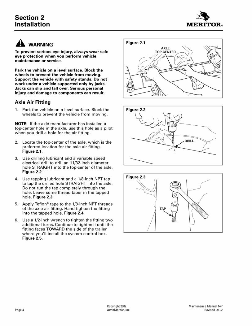
4. Secure the wire to the front of the trailer using the supplied P-clamps. Figure 2.64.
NOTE: When you route electrical cable, use grommets to protect the cable from contacting sharp edges at hole locations. Use tie wraps to secure the cable to existing air and electrical lines.
5. Route the electrical cable from the trailer seven-way box to the tire inflation system control box. Figure 2.63.
O If the trailer is equipped with a sliding subframe: Provide sufficient slack in the cable to allow for suspension movement. Use the slack in existing brake lines as a guide.
6. Connect the electrical cable to the flow sensing switch in the control box. Figure 2.65.
7. In the trailer seven-way box, connect the eye connectors to the white wires coming from the indicator light and the control box. Figure 2.66.
NOTE: The system must be tapped into a power source in the trailer seven-way box that will provide constant 12V power. The fleet must decide which pin will supply this requirement.
8. In the trailer seven-way box, connect one of the white wire eye connectors to ground and the other to a pin that will supply constant 12-volt power. Figure 2.63.
9. In the trailer seven-way box, use the butt connector to connect the black wires from the indicator light and the control box. Figure 2.66.
Figure 2.64
Figure 2.65
ELECTRICALCABLEP-CLAMPS
ELECTRICALCABLE
ELECTRICALCONTACTS
FLOW SENSING SWITCH
CONTROL BOX
Figure 2.66
BUTTCONNECTOR
EYECONNECTOR

Section 2Installation
Copyright 2002 Maintenance Manual 14PPage 20 ArvinMeritor, Inc. Revised 09-02
Wheel-End Oil
NOTE: Refer to the trailer axle manufacturer literature for service instructions. For Meritor trailer axles, refer to Maintenance Manual 14, Trailer Axles. To obtain this publication, refer to the Service Notes page on the front inside cover of this manual.
If the wheel end is oil-lubricated, add oil through the hubcap fill plug to the manufacturer’s recommended level. The oil level must be below the level of the three wheel-end vents. Figures 2.67 and 2.68.
Decals
Three decals identify the tire inflation system.
1. Install a decal on each side of trailer above the tandem to indicate the trailer is equipped with the system. Figure 2.69.
2. Install the indicator light decal below the light to provide operating information. Figure 2.70.
Figure 2.67
Figure 2.68
OIL LEVELBELOW THE WHEEL-END VENTS
OIL FILL PLUG
THREEWHEEL-END
VENTS
Figure 2.69
Figure 2.70
Meritor Tire Inflation Systemsby P.S.I.
(888) 725-9355 / (800) 535-5560
Meritor Tire Inflation Systemsby P.S.I.
(888) 725-9355 / (800) 535-5560
S 6856
INDICATORLIGHT
Meritor Tire Inflation Systems by P.S.I.When the tire light is on for more than 10 minutes, report it to yourdispatcher or maintenance supervisor. The light means your tire is
being inflated to the proper cold temperature pressure and may havea serious leak that will need repair.
(888) 725-9355 / (800) 535-5560
This Trailer Is Equipped With:

Section 3Check System Operation
Maintenance Manual 14P Copyright 2002Revised 09-02 ArvinMeritor, Inc. Page 21
Section 3Check System Operation
WARNING
To prevent serious eye injury, always wear safe eye protection when you perform vehicle maintenance or service.
Check System Operation
1. Check that the shut-off valve is ON. When the valve is ON, the knob aligns with the valve body. Check that the petcock is closed by turning it CLOCKWISE. Figure 3.1.
NOTE: The tire inflation system must be fully-pressurized before proceeding. This may take up to 10 minutes, since the axles, tires and possibly the brake system will have to be pressurized. A shop air source will charge the system more quickly than a tractor compressor.
2. Fully-pressurize the tire inflation system by connecting the trailer to a pressure source that can deliver 105-130 psi (723.5-895.7 kPa) to the trailer gladhands. Ensure that 12 volts are supplied to the seven-way box. Allow the air pressure source sufficient time to pressurize the system, which may take up to 10 minutes.
3. Push a short piece of tire inflation system air line into the through-tee. Air should flow from the through-tee. Figure 3.2.
4. Check that the indicator light comes ON as air flows from the through-tee and turns off when air flow stops. Figure 3.3.
5. Push on the valve cores at the ends of the hoses attached to the tires. Air should flow from the tires. Figure 3.4.
Figure 3.1
Inflation System Control Box
Meritor Tire Inflation System
PETCOCK
SHUT-OFFVALVE
CONTROL BOX
KNOB
Figure 3.2
Figure 3.3
Figure 3.4
AIR LINE
THROUGH-TEE
30" (76 CM)
INDICATORLIGHT
VALVE CORE

Section 3Check System Operation
Copyright 2002 Maintenance Manual 14PPage 22 ArvinMeritor, Inc. Revised 09-02
NOTE: A sticker located inside the control box door indicates the tire pressure that the inflation system will deliver. Unless another pressure is specified, the system will deliver a tire pressure of 100 psi (689 kPa). Figure 3.5.
6. Use the valve cores in the hoses to reduce pressure in all the tires 5 to 10 psi below the desired tire pressure. For example, if the fleet runs 100 psi (689 kPa), reduce the tire pressure to 90 to 95 psi. Figure 3.4.
7. Choose a tire to test. Hand-tighten the hose to the through-tee. Figure 3.6.
8. Allow sufficient time for the pressure to build up in the test-tire. This may take up to 10 minutes, depending on system pressure and other vehicle air requirements.
9. Disconnect a test-tire hose from thethrough-tee. Check the test-tire pressure using an accurate air pressure gauge. Tire pressure should equal the fleet tire pressure specification. Figure 3.7.
O To increase tire pressure: Turn the system pressure adjustment knob in the control box CLOCKWISE approximately 1/8 turn(45 degrees). Hand-tighten the hose to the through-tee. Repeat Steps 8 and 9. Figure 3.8.
O To decrease tire pressure: Reduce pressure on the test-tire 5 to 10 psi below the desired air pressure. Turn the system pressure adjustment knob in the control box COUNTERCLOCKWISE approximately 1/8 turn (45 degrees). Hand-tighten the hose to the through-tee. Do not use pliers. Repeat Steps 8 and 9. Figure 3.8.
Figure 3.5
Figure 3.6
PRESSURESETTINGSTICKER
WASHERADDJKAKJAJAKJAKJGAKJAKGFJKAGAJKDAJKDFAFGJAHGFA;AJDROIUROIAGHAWASHERADDJKAKJAJAKJAKJGAKJAKGFJKAGAJKDAJKDFAFGJAHGFA;A
JDROIUROIAGHAGWASHERADDJKAKJAJAKJAKJGAKJAKGFJKAGAJKDAJKDFAFGJAHGFA;AJDROIUROIAGHAGWASHERADDJKAKJAJAKJAKJGAKJAKGFJKAGAJKD
AJKDFAFGJAHGFA;AJDROIUROIAGHAGWASHERADDJKAKJAJAKJAKJGAKJAKGFJKAGAJKDAJKDFAFGJAHGFA;AJDROIUROIAGHAGWASHERADDJKAKJAJAKJAKJG
AKJAKGFJKAGAJKDAJKDFAFGJAHGFA;AJDROIUROIAGHAGWASHERADDJKAKJAJAKJAKJGAKJAKGFJKAGAJKDAJKDFAFGJAHGFA;AJDROIUROIAGHAGWASHERA
DDJKAKJAJAKJAKJGAKJAKGFJKAGAJKDAJKDFAFGJAHGFA;AJDROIUROIAGHAGWASHERADDJKAKJAJAKJAKJGAKJAKGFJKAGAJKDAJKDFAFGJAHGFA;AJDROIUR
OIAGHAGWASHERADDJKAKJAJAKJAKJGAKJAKGFJKAGAJKDAJKDFAFGJAHGFA;AJDROIUROAKJDDDDDDDWASHERADDJKAKJAJAKJAKJGAKJAKGFJKAGAJKDAJK
DFAFGJAHGFA;AJDROIUROIAGHAGWASHERADDJKAKJAJAKJAKJGAKJAKGFJKAGAJKDAJKDFAFGJAHGFA;AJDROIUROIAGHAGWASHERADDJKAKJAJAKJAKJGAKJ
AKGFJKAGAJKDAJKDFAFGJAHGFA;AJDROIUROIAGHAGWASHERADDJKAKJAJAKJAKJGAKJAKGFJKAGAJKDAJKDFAFGJAHGFA;AJDROIUROIAGHAGWASHERADDJK
AKJAJAKJAKJGAKJAKGFJKAGAJKDAJKDFAFGJAHGFA;AJDROIUROIAGHAGWASHERADDJKAKJAJAKJAKJGAKJAKGFJKAGAJKDAJKDFAFGJAHGFA;AJDROIUROIAG
HAGWASHERADDJKAKJAJAKJAKJGAKJAKGFJKAGAJKDAJKDFAFGJAHGFA;AJDROIUROIAGHAGWASHERADDJKAKJAJAKJAKJGAKJAKGFJKAGAJKDAJKDFAFGJAHG
FA;AJDROIUROIAGHAGWASHERADDJKAKJAJAKJAKJGAKJAKGFJKAGAJKDAJKDFAFGJAHGFA;AJDROIUROIAGHAGWASHERADDJKAKJAJAKJAKJGAKJAKGFJKAGAJ
KDAJKDFAFGJAHGFA;AJDROIUROIAGHAGWASHERADDJKAKJAJAKJAKJGAKJAKGFJKAGAJKDAJKDFAFGJAHGFA;AJDROIUROIAGHAGWASHERADDJKAKJAJAKJAKJ
GAKJAKGFJKAGAJKDAJKDFAFGJAHGFA;AJDROIUROIAGHAGWASHERADDJKAKJAJAKJAKJGAKJAKGFJKAGAJKDAJKDFAFGJAHGFA;AJDROIUROIAGHAGWASHERA
DDJKAKJAJAKJAKJGAKJAKGFJKAGAJKDAJKDFAFGJAHGFA;AJDROIUROIAGHAGWASHERADDJKAKJAJAKJAKJGAKJAKGFJKAGAJKDAJKDFAFGJAHGFA;AJDROIURO
IAGHAGWASHERADDJKAKJAJAKJAKJGAKJAKGFJKAGAJKDAJKDFAFGJAHGFA;AJDROIUROIAGHAGWASHERADDJKAKJAJAKJAKJGAKJAKGFJKAGAJKDAJKDFAFGJAH
WASHERADDJKAKJAJAKJAKJGAKJAKGFJKAGAJKDWAS
HERADDJKAKJAJAKJAKJGAKJAKGFJKAGAJKDAJKDFAF
GJAHGFA;AJDROIUROIAGHAGWASHERADDJKAKJAJAKJ
AKJGAKJAKGFJKAGAJKDAJKDFAFGJAHGFA;AJDROIURO
TEST-TIREHOSE
THROUGH-TEE
Figure 3.7
Figure 3.8
AIRPRESSUREGAUGE
SYSTEM PRESSUREADJUSTMENT KNOB
CONTROLBOX

Section 3Check System Operation
Maintenance Manual 14P Copyright 2002Revised 09-02 ArvinMeritor, Inc. Page 23
10. When the test-tire pressure is correct, hand-tighten the remaining tire hoses to the through-tees. Do not use pliers. The tire inflation system will inflate all of the tires to the specified pressure. At this point, the system is fully assembled.
11. Check the wheel ends to verify that hoses do not contact the wheels. Figure 3.9.
O If a hose contacts a wheel: Use a wrench to slightly rotate the through-tee to reposition the hose.
CAUTION
Test the tire inflation system for air leaks before you put the vehicle into service. Spray a soap-and-water solution at all fittings and connections. Listen for audible leaks and check for bubbles. If you detect a leak, identify the source and replace parts as required. Air leaks in the tire inflation system can cause damage to components during operation.
12. Spray a soap-and-water solution on all fittings and hose connections to check for leaks. Look for bubbling and listen for audible leaks. Tighten or replace fittings that leak. Figure 3.10.
13. Spray a soap-and-water solution to check the hose to through-tee connections and hubcap vents for leaks. Look for bubbling and listen for audible leaks. Figure 3.11.
Figure 3.9
THROUGH-TEE
HOSE
Figure 3.10
Figure 3.11
AIRFITTING
SOAP-AND-WATER SPRAY SOLUTION
HOSECONNECTION
HOSECONNECTIONS
SOAP-AND-WATERSPRAY
SOLUTION
AXLEAIR FITTING
SOAP-AND-WATER SPRAY SOLUTION
VENT
SOAP-AND-WATERSPRAY SOLUTION
Section 3Check System Operation
Copyright 2002 Maintenance Manual 14PPage 24 ArvinMeritor, Inc. Revised 09-02
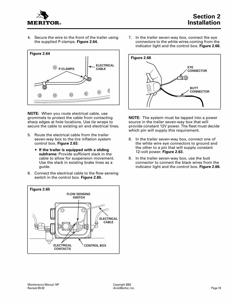
If Air is Leaking from a Hubcap Vent
The through-tee, stator or press plug is leaking. Use the following procedure to check for leaks. Figure 3.12.
A. Turn the system OFF. Remove the hoses from the through-tee. Remove the through-tee and the hubcap.
B. Cover the wheel end with a clean towel to protect the bearings from contaminants.
C. Insert the through-tee into the stator. Turn the system ON. Spray the press plug with a soap-and-water solution.
D. Replace damaged components and tighten loose fittings.
If Air is Leaking from the Press Plug to the Axle Spindle Joint
A. Use a slide hammer fitted with a press plug remover to remove the press plug. Refer to Section 7.
B. Install a new press plug. Refer to Prepare Axles with Hollow Spindles in Section 2.
Figure 3.12
SOAP-AND-WATERSPRAY SOLUTION

Section 4Pre-Service Check
Maintenance Manual 14P Copyright 2002Revised 09-02 ArvinMeritor, Inc. Page 25
Section 4Pre-Service Check
WARNING
To prevent serious eye injury, always wear safe eye protection when you perform vehicle maintenance or service.
Pre-Service Check
After receiving a trailer and before placing it in service, check the tire inflation system to ensure it operates correctly.
1. Check that the trailer has the correct air supply (105-130 psi [723.5-895.7 kPa]) and the system is connected to a 12-volt power source.
2. Check that the shut-off valve is ON. When the valve is ON, the knob aligns with the valve body. Check that the petcock is closed by turning it CLOCKWISE. Figure 4.1.
3. Check the indicator light by opening the petcock at the control box. The light will come ON to indicate that it’s operating correctly. Figure 4.2.
4. Use an accurate air pressure gauge to check tire pressure at the system hose. Figure 4.3.
O If tire pressure is not correct: Refer toSection 3 to adjust tire pressure.
5. Use a soap-and-water solution to check the hose-to-valve stem connections, hose-to-through-tee connections and hubcap vents for leaks. Figure 4.4. Repair or replace parts as required. Refer to Section 3.
Figure 4.1
Inflation System Control Box
Meritor Tire Inflation System
PETCOCK
CONTROL BOXSHUT-OFF
VALVE
KNOB
Figure 4.2
Figure 4.3
Figure 4.4
INDICATORLIGHT
AIRPRESSUREGAUGE
SOAP-AND-WATERSPRAY SOLUTION
HOSE-TO-VALVESTEM CONNECTION
HOSE-TO-THROUGH-TEECONNECTION

Section 4Pre-Service Check
Copyright 2002 Maintenance Manual 14PPage 26 ArvinMeritor, Inc. Revised 09-02
6. Check the wheel ends to verify that hoses do not contact the wheels. Figure 4.5.
O If a hose contacts a wheel: Use a wrench to slightly rotate the through-tee to reposition the hose.
Figure 4.5
THROUGH-TEE
HOSE

Section 5Inspection and Maintenance
Maintenance Manual 14P Copyright 2002Revised 09-02 ArvinMeritor, Inc. Page 27
Section 5Inspection and Maintenance
WARNING
To prevent serious eye injury, always wear safe eye protection when you perform vehicle maintenance or service.
Tire Inflation System Inspection
The recommended inspection intervals for the tire inflation system depend on factors that affect the system, such as applications, vehicle speed and environment.
For example, an application such as on-highway container chassis service puts limited stress on the system, and inspection intervals can be extended. However, an application such as off-highway dump trailer service stresses the system more severely and requires that you perform inspections more frequently. Refer to the table below for guidelines.
Additionally, inspect the tire inflation system whenever you remove a tire.
Inspect the following components for correct operation at the recommended inspection intervals. Refer to Section 3.
O Indicator light
O Tire hose valve cores
O Tire pressure
O Tire hose-to-wheel interference
O Tire hose-to-through-tee connections
O Tire hose-to-valve stem connections
O Air line-to-axle fitting connections
O Air line-to-air line tee connections
O Hubcap vents
O Remove the bowl from the self-draining filter. Check the filter for obstructions. Figure 5.1.
Indicator Light
If the indicator light comes ON during operation, stop the vehicle. Inspect the tires and tire inflation system components for leaks. Refer to Section 3. Repair as necessary. Figure 5.2.
During initial system charging, the indicator light will come ON and remain ON for up to 10 minutes, depending on the system pressure setting and other vehicle air requirements.
O If the indicator light remains ON for more than 10 minutes: Refer to Section 6.
Tires
Check Tire Pressure
Although the tire inflation system can charge a leaking tire during vehicle operation, Meritor recommends that you inspect tires for wear and damage, and check tire pressure at regular intervals.
1. Remove the hand-tightened knurled fitting at the hubcap.
Application Inspection Interval
Standard-duty (on-highway)
Every 100,000 miles or 12 months, whichever comes first.
Heavy-duty (on-highway, off-highway or combined on-highway/off-highway)
Every 30,000 miles or six months, whichever comes first.
Figure 5.1
Figure 5.2
Inflation System Control Box
Meritor Tire Inflation System
CONTROL BOXSELF-DRAINING
FILTER
INDICATORLIGHT

Section 5Inspection and Maintenance
Copyright 2002 Maintenance Manual 14PPage 28 ArvinMeritor, Inc. Revised 09-02
2. Press the tire pressure gauge to the hose. Read the pressure.
Figure 5.3
.
O
If tire pressure is correct:
Reconnect the hose to the through-tee by hand-tightening (Do not tighten with pliers) the knurled fitting.
O
If tire pressure is not correct:
Refer to Section 6.
Tire Test Gauge
To assist in checking tire pressure, you can assemble a tire test gauge. Refer to Section 7 for instructions.
Change Tire Inflation System Tire Pressure Setting
If you need to change the tire inflation system pressure setting, refer to Section 3.
Maintenance
Turn OFF the System Before Performing Maintenance
WARNING
The tire inflation system uses compressed air. Turn the system OFF and drain the system at the petcock before you perform maintenance or service to avoid serious personal injury and damage to components.
1. Turn the shut-off valve OFF to stop air delivery to the system. When the shut-off valve is OFF, the knob is perpendicular to the valve body.
Figure 5.4
.
2. Turn the petcock COUNTERCLOCKWISE to open it and drain air from the system.
Figure 5.4
.
Remove and Replace a Tire
WARNING
Park the vehicle on a level surface. Block the wheels to prevent the vehicle from moving. Support the vehicle with safety stands. Do not work under a vehicle supported only by jacks. Jacks can slip and fall over. Serious personal injury and damage to components can result.
1. Raise the trailer until the tires are off the ground. Place safety stands under the trailer frame or under each axle spring seat. Do not support the vehicle only by jacks.
Figure 5.5
.
2. Remove the tire inflation system hoses.
Figure 5.3
AIRPRESSUREGAUGE
Figure 5.4
Figure 5.5
Inflation System Control Box
Meritor Tire Inflation System
PETCOCK
SHUT-OFFVALVE
CONTROL BOX
KNOB

Section 5Inspection and Maintenance
Maintenance Manual 14P Copyright 2002Revised 09-02 ArvinMeritor, Inc. Page 29
NOTE: A wheel dolly will help protect the through-tee when you remove and replace the tire and wheel assembly.
3. Use a wheel dolly and pull the tire and wheel assembly STRAIGHT off the hub. Figure 5.6.
O If a wheel dolly isn’t available: Meritor recommends that you follow one of the following steps to prevent damaging the through-tee.
A. Turn the system OFF. Refer to instructions in this section. Remove the through-tee, and then remove the tire and wheel assembly.
B. Remove the tire and wheel assembly very carefully if you don’t remove the through-tee.
4. Service the tire.
5. Follow the wheel manufacturer’s instructions to reinstall the wheels. Verify that the through-tee fittings point toward the tire valve stems to ensure that you’ll be able to correctly route tire inflation system hoses. Figure 5.7.
6. Install the tire inflation system hoses to the tire valve stems. Refer to Wheel-End Components in Section 2.
7. Reduce tire pressure 5-10 psi (0.034-0.069 MPa) below the fleet’s tire pressure specification. Figure 5.8.
8. Hand-tighten the hoses to the through-tee. Do not use pliers. The tire inflation system will charge the tires to the specified tire setting.
9. Check the hoses for leaks. Refer to Check System Operation in Section 3.
Hose Valve Cores
CAUTION
Only install Meritor original equipment parts when you service the tire inflation system. Non-original equipment parts will fit the system, but can prevent correct air pressure from being delivered to a leaking tire during operation. Damage to components can result.
The tire inflation system is designed to operate with valve cores that open at 3 psi (0.02 MPa) pressure. Only install Meritor original equipment valve cores when you replace this part on a tire inflation system hose. Valve cores not manufactured by Meritor will fit tire inflation system hoses, but these valve cores can affect the pressure delivered to a leaking tire during operation. Figure 5.8.
Figure 5.6
Figure 5.7
Figure 5.8
TIREVALVESTEMS
THROUGH-TEE
VALVE CORE

Section 5Inspection and Maintenance
Copyright 2002 Maintenance Manual 14PPage 30 ArvinMeritor, Inc. Revised 09-02
Remove the Through-Tee Before Installing a Hubcap
CAUTION
Do not bend or damage the through-tee when you remove and install a hubcap. A bent or damaged through-tee can cause the tire inflation system to leak. Damage to components can result.
Remove the through-tee before you remove or install a hubcap to prevent bending or damaging the through-tee, which can cause the tire inflation system to leak. Figure 5.9.
Figure 5.9
THROUGH-TEE
TUBE

Section 6Troubleshooting
Maintenance Manual 14P Copyright 2002Revised 09-02 ArvinMeritor, Inc. Page 31
Section 6Troubleshooting
WARNING
To prevent serious eye injury, always wear safe eye protection when you perform vehicle maintenance or service.
Condition Possible Causes Actions
Indicator light ON System delivering air during initial system charging.
System functioning correctly.
System delivering air to leaking tire. Repair tire.
System delivering air to leaking system component.
Repair system component.
System delivering air to cracked axle. Repair axle.
System wiring incorrect. Correct system wiring.
Indicator light OFF during system operation
Trailer not supplied with 12-volt power. Supply 12-volt power to trailer.
Indicator light inoperative. Replace indicator light.
Flow sensing switch inoperative. Replace flow sensing switch.
System wiring damaged. Repair system wiring.
System wiring incorrect. Correct system wiring.
Lubricant leaking from wheel-end vent
Wheel end overfilled with lubricant. Fill wheel end to correct level.
Hubcap without vent extensions installed on oil-lubricated wheel end.
Install hubcap with vent extensions.
Through-tee leaking. Replace through-tee.
Stator O-ring leaking. Replace stator.
Stator threads leaking. Seal stator threads.
Press plug leaking. Replace press plug.
Air leaking from wheel-end vent Through-tee leaking. Replace through-tee.
Stator O-ring leaking. Replace stator.
Stator threads leaking. Seal stator threads.
Press plug leaking. Replace press plug.
Low tire pressure Shut-off valve is off. Turn on shut-off valve.
System pressure setting too low. Increase system pressure setting.
Incorrect valve cores installed. Replace with Meritor original equipment.
High tire pressure Tire manually over inflated. Reduce tire pressure; system will inflate to correct level.
System pressure setting too high. Lower system pressure setting.
Parked trailer tire deflates System hose/tire valve stem connection leaking.
Correctly tighten connection or replaceO-rings.
Hose valve core leaking. Clean or replace hose valve core.
Tire leaking. Repair tire.

Section 7Special Tools and Supplies
Copyright 2002 Maintenance Manual 14PPage 32 ArvinMeritor, Inc. Revised 09-02
Section 7Special Tools and SuppliesSpecialty ToolsTo obtain these tools and supplies, refer to the Service Notes page on the front inside cover of this manual.
Bore Polishing Tools Part Number Quantity Supplier
Dana/Eaton D22 — Bore Polisher 3T524 1
Grainger
Hendrickson HN — Bore Polisher 3T524 1
Holland Trade — Bore Polisher 3T524 1
Ingersoll F-22 — Bore Polisher 3T524 1
Meritor TN/TQ/TK — Bore Polisher 3T524 1
Sudisa 12R/11M — Bore Polisher 3T524 1
Dana/Eaton P22 — Bore Polisher 3T534 1
Hendrickson HP — Bore Polisher 3T534 1
Hendrickson TP — Bore Polisher 3T534 1
Holland Propar — Bore Polisher 3T534 1
Meritor TP/TB/WP — Bore Polisher 3T534 1
Mandrel 3T564 1
Straight die grinder 6Z562 1
Drive Tools Part Number Quantity Supplier
Holland Propar — Press Plug Drive Adaptor 51011-01 1
Meritor
Dana/Eaton D22 — Press Plug Drive Adaptor 51011-02 1
Hendrickson HN — Press Plug Drive Adaptor 51011-02 1
Meritor TN/TQ/TK — Press Plug Drive Adaptor 51011-02 1
Sudisa 12R — Press Plug Drive Adaptor 51011-03 1
Sudisa 11M — Press Plug Drive Adaptor 51011-04 1
Holland Trade — Press Plug Drive Adaptor 51011-05 1
Hendrickson TP — Press Plug Drive Adaptor 51011-06 1
Meritor TP/TB — Press Plug Drive Adaptor 51011-06 1
Meritor WP — Press Plug Drive Adaptor 51011-07 1
Ingersoll F-22 — Press Plug Drive Adaptor 51011-08 1
Drive Handle 51011-10 1
Dana P-22 — Press Plug Drive Adaptor 51011-13 1
Hendrickson HP — Press Plug Drive Adaptor 51011-13 1
Supplies Part Number Quantity Supplier
Retaining Compound 32621-00 1Meritor
Towelettes 32632-00 1
Specialty Tools Part Number Quantity Supplier
System Pressure Test Gauge 81014-00 1
Meritor
Drill Jig — Solid Spindle 81023-00 1
Tap Guide 81023-10 1
Slide Hammer Kit 81044-00 1
Welsh Plug Removal Spear 81044-01 1
Press Plug Remover 81044-02 1

Section 7Special Tools and Supplies
Maintenance Manual 14P Copyright 2002Revised 09-02 ArvinMeritor, Inc. Page 33
Build from 1/2" galvanized pipe.
Overalllength mustexceed the
interiorlength of thetrailer axle.
Drill pipe capwith 3/32" drill positioned as shown.
45°
6 HOLES
Cleaning Wand
ON-OFFVALVE
45°

Section 7Special Tools and Supplies
Copyright 2002 Maintenance Manual 14PPage 34 ArvinMeritor, Inc. Revised 09-02
0-160 GAUGE (HIGH QUALITY PREFERRED)
TEE (PIPE THREADS)
PETCOCK (OR BALL VALVE)
TANK VALVE (VALVE STEM WITH PIPE THREADS)
TIRE INFLATION SYSTEM HOSE(PART NUMBER 31373-00)
Tire Test Gauge

Meritor Heavy Vehicle Systems, LLC2135 West Maple RoadTroy, MI 48084 USA800-535-5560arvinmeritor.com
Information contained in this publication was in effect at the time the publication was approved for printing and is subject to change without notice or liability. Meritor Heavy Vehicle Systems, LLC, reserves the right to revise the information presented or discontinue the production of parts described at any time.
Copyright 2002 Maintenance Manual 14PArvinMeritor, Inc. Revised 09-02All Rights Reserved Printed in the USA 16579/24240