Embed Size (px)
Citation preview

Mesh Network Components
This chapter describes the mesh network components.
The Cisco wireless mesh network has four core components:
• Cisco Aironet 1500 series mesh access points
Cisco Aironet 1505 and 1510 mesh access points are not supported because of theirEnd-of-Life status.
Note
• Cisco Wireless LAN Controller (hereafter referred to as controller)
• Cisco Prime Infrastructure
• Mesh software architecture
This chapter contains the following sections:
• Mesh Access Points, page 1
• Cisco Wireless LAN Controllers, page 40
• Cisco Prime Infrastructure, page 40
• Architecture, page 40
Mesh Access Points
Licensing for Mesh Access Points on a 5500 Series ControllerTo use both mesh and nonmesh access points with a Cisco 5500 Series Controller, only the base license(LIC-CT5508-X) is required from the 7.0 release and later releases. For more information about obtainingand installing licenses, see the Cisco Wireless LAN Controller Configuration Guide at http://www.cisco.com/en/US/products/ps10315/products_installation_and_configuration_guides_list.html.
Cisco Wireless Mesh Access Points, Design and Deployment Guide, Release 7.3 OL-27593-01 1
Access Point RolesAccess points within a mesh network operate in one of the following two ways:
1 Root access point (RAP)
2 Mesh access point (MAP)
All access points are configured and shipped as mesh access points. To use an access point as a root accesspoint, you must reconfigure the mesh access point to a root access point. In all mesh networks, ensure thatthere is at least one root access point.
Note
While the RAPs have wired connections to their controller, the MAPs have wireless connections to theircontroller.
MAPs communicate among themselves and back to the RAP using wireless connections over the 802.11a/nradio backhaul. MAPs use the Cisco Adaptive Wireless Path Protocol (AWPP) to determine the best paththrough the other mesh access points to the controller.
Bridge mode access points support CleanAir in mesh backhaul at 5GHz frequency and provides only theinterference device report (IDR) and Air Quality Index (AQI)reports.
The RAP orMAP does not generate Bridge Protocol Data Unit (BPDU) itself. However, the RAP orMAPforwards the BPDU to upstream devices if the RAP or MAP received the BPDU from its connected wiredor wireless interface across the network.
Note
Cisco Wireless Mesh Access Points, Design and Deployment Guide, Release 7.32 OL-27593-01
Mesh Network ComponentsAccess Point Roles
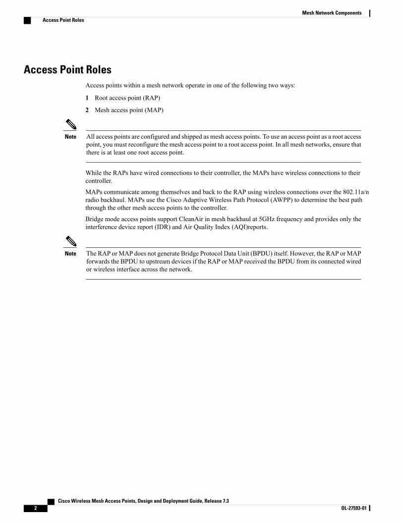
This figure shows the relationship between RAPs and MAPs in a mesh network.Figure 1: Simple Mesh Network Hierarchy
Network AccessWireless mesh networks can simultaneously carry two different traffic types. They are as follows:
•Wireless LAN client traffic
• MAP Ethernet port traffic
Wireless LAN client traffic terminates on the controller, and the Ethernet traffic terminates on the Ethernetports of the mesh access points.
Access to the wireless LANmesh for mesh access points is managed by the following authenticationmethods:
• MAC authentication—Mesh access points are added to a database that can be referenced to ensure theyare provided access to a given controller and mesh network.
• External RADIUS Authentication—Mesh access points can be externally authorized using a RADIUSserver such as Cisco ACS (4.1 and later) that supports the client authentication type of ExtensibleAuthentication Protocol-FAST (EAP-FAST) with certificates.
Cisco Wireless Mesh Access Points, Design and Deployment Guide, Release 7.3 OL-27593-01 3
Mesh Network ComponentsNetwork Access
Network SegmentationMembership to the wireless LAN mesh network for mesh access points is controlled by the bridge groupnames (BGNs). Mesh access points can be placed in similar bridge groups to manage membership or providenetwork segmentation.
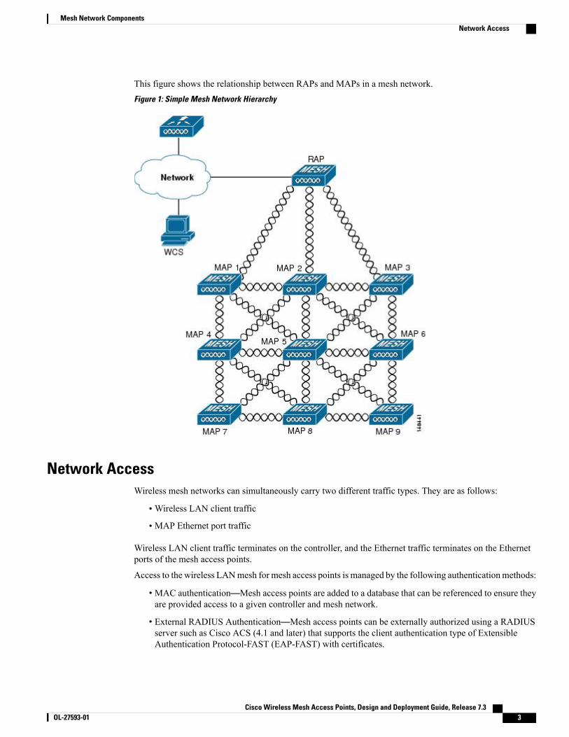
Cisco Indoor Mesh Access PointsIndoor mesh is available on the following access points:
• 802.11a/b/g
• 1130
• 1240
• 802.11n
• 1040
• 1140
• 1250
• 1260
• 802.11n+CleanAir
• 2600
• 3500e
• 3500i
• 3600
• 802.11ac+CleanAir
For more information about controller software support for access points, see theCiscoWireless SolutionsSoftware Compatibility Matrix at http://www.cisco.com/en/US/docs/wireless/controller/5500/tech_notes/Wireless_Software_Compatibility_Matrix.html.
Note
Enterprise 11n mesh is an enhancement added to the CUWN feature to work with the 802.11n access points.Enterprise 11n mesh features are compatible with non-802.11n mesh but adds higher backhaul and clientaccess speeds. The 802.11n indoor access points are two-radio Wi-Fi infrastructure devices for select indoordeployments. One radio can be used for local (client) access for the access point and the other radio can beconfigured for wireless backhaul. The backhaul is supported only on the 5-GHz radio. Enterprise 11n meshsupports P2P, P2MP, and mesh types of architectures.
You have a choice of ordering indoor access points directly into the bridge mode, so that these access pointscan be used directly as mesh access points. If you have these access points in a local mode (nonmesh), thenyou have to connect these access points to the controller and change the AP mode to the bridge mode (mesh).
Cisco Wireless Mesh Access Points, Design and Deployment Guide, Release 7.34 OL-27593-01
Mesh Network ComponentsNetwork Segmentation
This scenario can become cumbersome particularly if the volume of the access points being deployed is largeand if the access points are already deployed in the local mode for a traditional nonmesh wireless coverage.
The Cisco indoor mesh access points are equipped with the following two simultaneously operating radios:
• 2.4-GHz radio used for client access
• 5-GHz radio used for data backhaul
The 5-GHz radio supports the 5.15 GHz, 5.25 GHz, 5.47 GHz, and 5.8 GHz bands.
Cisco Outdoor Mesh Access PointsCisco outdoor mesh access points comprise of the Cisco Aironet 1500 series access points. The 1500 seriesincludes 1552 11n outdoor mesh access points, 1522 dual-radio mesh access points, and 1524 multi-radiomesh access points. There are two models of the 1524, which are the following:
• The public safety model, 1524PS
• The serial backhaul model, 1524SB
In the 6.0 release, the AP1524SB access point was launched in A, C, and N domains.In the 7.0 release, the AP1524SB access point was launched in the -E, -M, -K, -S, and-T domains.
Note
Cisco 1500 series mesh access points are the core components of the wireless mesh deployment. AP1500sare configured by both the controller (GUI and CLI) and Cisco Prime Infrastructure. Communication betweenoutdoor mesh access points (MAPs and RAPs) is over the 802.11a/n radio backhaul. Client traffic is generallytransmitted over the 802.11b/g/n radio (802.11a/n can also be configured to accept client traffic), and publicsafety traffic (AP1524PS only) is transmitted over the 4.9-GHz radio.
The mesh access point can also operate as a relay node for other access points not directly connected to awired network. Intelligent wireless routing is provided by the Adaptive Wireless Path Protocol (AWPP). ThisCisco protocol enables each mesh access point to identify its neighbors and intelligently choose the optimalpath to the wired network by calculating the cost of each path in terms9 of the signal strength and the numberof hops required to get to a controller.
AP1500s are manufactured in two different configurations: cable and noncable.
• The cable configuration can be mounted to a cable strand and supports power-over-cable (POC).
• The noncable configuration supports multiple antennas. It can be mounted to a pole or building walland supports several power options.
Uplinks support includes Gigabit Ethernet (1000BASE-T) and a small form-factor (SFP) slot that can beplugged for a fiber or cable modem interface. Both single mode and multimode SFPs up to 1000BASE-BXare supported. The cable modem can be DOCSIS 2.0 or DOCSIS/EuroDOCSIS 3.0 depending upon the typeof mesh access point.
AP1500s are available in a hazardous location hardware enclosure. When configured, the AP1500 complieswith safety standards for Class I, Division 2, Zone 2 hazardous locations.
Cisco Wireless Mesh Access Points, Design and Deployment Guide, Release 7.3 OL-27593-01 5
Mesh Network ComponentsCisco Outdoor Mesh Access Points

See theCisco Aironet 1520 Series Lightweight Outdoor Access Point Ordering Guide for power, mounting,antenna, and regulatory support by model: http://www.cisco.com/en/US/prod/collateral/wireless/ps5679/ps8368/product_data_sheet0900aecd8066a157.html
Note
The mesh access points, can operate, apart from the mesh mode, in the following modes:
• Local mode—In this mode, the AP can handle clients on its assigned channel or while monitoring allchannels on the band over a 180-second period. During this time, the AP listens on each channel for 50milliseconds for rogue client beacons, noise floor measurements, interference, and IDS events. The APalso scans for CleanAir interference on the channel.
• FlexConnect mode—FlexConnect is a wireless solution for branch office and remote office deployments.The FlexConnect mode enables you to configure and control access points in a branch or remote officefrom the corporate office through a WAN link without having to deploy a controller in each office. TheFlexConnect mode can switch client data traffic locally and perform client authentication locally whenthe connection to the controller is lost. When connected to the controller, the FlexConnect mode canalso tunnel traffic back to the controller.
• Monitor mode—In this mode, the AP radios are in the receive state. The AP scans all the channels every12 seconds for rogue client beacons, noise floor measurements, interference, IDS events, and CleanAirintruders.
• Rogue Detector mode—In this mode, the AP radio is turned off, and the AP listens only to the wiredtraffic. The controller passes the APs that are configured as rogue detectors as well as lists of suspectedrogue clients and APMAC addresses. The rogue detector listens for ARP packets and can be connectedto all broadcast domains through a trunk link.
• Sniffer mode—In this mode, the AP captures and forwards all packets on a channel to a remote devicethat decodes the packets with packet analyzer software such as Wireshark.
• Bridge mode—In this mode, the AP is configured to build a wireless mesh network where wired networkcabling is not available.
You can configure these modes using both the GUI and CLI. For configuration instructions, see the CiscoWireless LAN Controller Configuration Guide.
Note
MAPs can only be configured in Bridge mode regardless of their wired or wireless backhaul. If the MAPshave a wired backhaul, you must change their AP role to RAP before you change the AP Mode.
Note
Cisco Aironet 1552 Mesh Access PointThe Cisco Aironet 1550 Series Outdoor Mesh Access Point is a modularized wireless outdoor 802.11n accesspoint designed for use in a mesh network. The access point supports point-to-multipoint mesh wirelessconnectivity and wireless client access simultaneously. The access point can also operate as a relay node forother access points that are not directly connected to a wired network. Intelligent wireless routing is providedby the Adaptive Wireless Path Protocol (AWPP). This enables the access point to identify its neighbors and
Cisco Wireless Mesh Access Points, Design and Deployment Guide, Release 7.36 OL-27593-01
Mesh Network ComponentsCisco Outdoor Mesh Access Points
intelligently choose the optimal path to the wired network by calculating the cost of each path in terms ofsignal strength and the number of hops required to get to a controller.
The 1550 series access points leverage 802.11n technology with integrated radio and internal/external antennas.The 1552 outdoor platform consists of Multiple Input Multiple Output (MIMO) WLAN radios. It offers 2x3MIMO with two spatial streams, Beamforming, and comes with integrated spectrum intelligence (CleanAir).
CleanAir provides full 11n data rates while detecting, locating, classifying, and mitigating radio frequency(RF) interference to provide the best client experience possible. CleanAir technology on the outdoor 11nplatform mitigates Wi-Fi and non-Wi-Fi interference on 2.4-GHz radios.
The 1550 series access points have two radios—2.4-GHz and 5-GHzMIMO radios.While the 2.4-GHz radiosare used primarily for local access, the 5-GHz radios are used for both local access and wireless backhaul inmesh mode.
The wIPS submode is not supported on the Cisco 1552 Series Mesh Access Points.Note
The 2.4-GHz radios cannot be used for backhaul in 1552 APs.Note
The 2-GHz b/g/n radio has the following features:
• Operates in the 2.4-GHz ISM band.
• Supports channels 1-11 in the United States, 1-13 in Europe, and 1-13 in Japan.
• Has two transmitters for 802.11b/g/n operation.
• You can configure the output power for 5 power levels.
• The radio has three receivers that enable maximum-ratio combining (MRC).
The 5-GHz a/n radio has the following feature:
• Operates in the UNII-2 band (5.25 to 5.35 GHz), UNII-2 Extended/ETSI band (5.47 to 5.725 GHz), andthe upper ISM band (5.725 to 5.850 GHz).
• Has two transmitters for 802.11a operation.
• Power settings can change depending on the regulatory domain. You can configure the output powerfor 5 power levels in 3 dB steps.
• The radio has three receivers that enable maximum-ratio combining (MRC).
The 1550 series access points have the following features:
• Supports modularity of the 1520 series and allows flexibility in radio configuration
• Fully interoperable with the 1520 series access points
• Can also interoperate with legacy clients and offers enhanced backhaul performance
• Multicast VideoStream and HotSpot 2.0 are supported when the AP is configured in Local mode.
• AP1552 is QoS capable of supporting quality VoWLAN calls.
• Band Select, which notifies a connected client to roam from 2.4 GHz to 5 GHz, is supported.
Cisco Wireless Mesh Access Points, Design and Deployment Guide, Release 7.3 OL-27593-01 7
Mesh Network ComponentsCisco Outdoor Mesh Access Points
• DTLS support allows AP1552 to encrypt data in all supported AP modes except Bridge mode.
• You can enable CleanAir on the 5-GHz radio by navigating toWireless > Radios > 802.11a > Configureon the controller GUI.
• If AP1552 is in Bridge mode, CleanAir Advisor becomes operational. CleanAir Advisor generatesCleanAir reports and identifies interference. The event driven RRM is disabled. Therefore, the radiodoes not change the transmission power level or channel.
The models can be classified as models with external antennas and models with built-in antennas. The 1552Cmodel is configured with an integrated DOCSIS/EuroDOCSIS 3.0 cable modem. The DOCSIS 3.0 cablemodem provides 8 DS and 4 US (8x4), 304x108 Mbps. The EuroDOCSIS 3.0 cable modem provides 4 USand 4 DS (4x4), 152x108 Mbps. While a DOCSIS 2.0 cable modem could provide throughput of up to 40Mbps only, a DOCSIS 3.0 cable modem can provide a DS throughput of 290 Mbps and a US throughput of100 Mbps.
The 1552 Access Point is available in these models:
• 1552E, on page 8
• 1552C, on page 9
• 1552I, on page 10
• 1552H, on page 10
• 1552CU, on page 11
• 1552EU, on page 11
For more information about the Cisco 1550 Series Access Points, see http://www.cisco.com/en/US/products/ps11451/index.html.
1552E
The Cisco Aironet 1552E Outdoor Access Point is the standard model, dual-radio system with dual-bandradios that are compliant with IEEE 802.11a/n (5-GHz) and 802.11b/g/n standards (2.4 GHz). The 1552E hasthree external antenna connections for three dual-band antennas. It has Ethernet and fiber Small Form FactorPluggable (SFP) backhaul options, along with the option of a battery backup. This model also has a PoE-outport and can power a video surveillance camera. A highly flexible model, the Cisco Aironet 1552E is wellequipped for municipal and campus deployments, video surveillance applications, mining environments, anddata offload.
The 1552E model has the following features:
•Weighs 17.3 lbs (7.9 kg) excluding external antennas
• Two radios (2.4 GHz and 5 GHz)
• Three external dual-band omnidirectional antennas with 4 dBi in 2.4 GHz and 7 dBi in 5 GHz
• Vertical beamwidth: 29° at 2.4 GHz, 15° at 5 GHz
• Aligned console port
• Higher equivalent isotropically radiated power (EIRP)
• Multiple uplinks with Ethernet and fiber
Cisco Wireless Mesh Access Points, Design and Deployment Guide, Release 7.38 OL-27593-01
Mesh Network ComponentsCisco Outdoor Mesh Access Points

• An optional Small Form Factor Pluggable (SFP) fiber module that can be ordered with the AP. The APcan use SFP fiber or copper module.
• 802.3af-compliant PoE-Out option to connect IP devices (such as video cameras)
• AC Powered (100 to 480 VAC)
• PoE-In using Power Injector
• Battery backup option (6 AH)
The 1552E model has no cable modem. The 1552E battery cannot be used for 1552H.Note
• AP1552E can be ordered with an Ethernet Passive Optical Network SFP as an add-on. The EPON SFPprovides Gigabit data rates.
The EPON SFP feature must be ordered separately and installed.Note
1552C
Where service providers have already invested in a broadband cable network, the Cisco next-generationoutdoor wireless mesh can seamlessly extend network connectivity with the Cisco Aironet 1552C access pointby connecting to its integrated cable modem interface. The Cisco Aironet 1552C Outdoor Mesh Access Pointis a dual-radio system with DOCSIS 3.0/EuroDOCSIS 3.0 (8x4 HFC) cable modem for power and backhaul.It has dual-band radios that are compliant with IEEE 802.11a/n (5 GHz) and 802.11b/g/n standards (2.4 GHz).The 1552C has an integrated, three- element, dual-band antenna and easily fits within the 30 cm heightrestriction for service providers. This model is suitable for 3G data offload applications and public Wi-Fi.
The 1552C model has the following features:
• Lightweight (14 lbs or 6.4 kg), low-profile AP
• Two radios (2.4 GHz and 5 GHz)
• DOCSIS/EuroDOCSIS 3.0 Cable Modem
• Aligned console port
• It supports cable modem backhaul
• Has an integrated 3-element array antenna with 2 dBi in 2.4 GHz and 4 dBi in 5 GHz
• Input module, power-over-cable supply (40 to 90 VAC)
• Stamped cover with two convenient holes to tighten the seizure screw for stringer connector (RF/PowerInput) and to adjust the fuse pad to attenuate the signal
The 1552C model has no battery backup, no fiber SFP support, no PoE Out, no PoE Inusing Power Injector or Ethernet port, and no AC power option.
Note
Cisco Wireless Mesh Access Points, Design and Deployment Guide, Release 7.3 OL-27593-01 9
Mesh Network ComponentsCisco Outdoor Mesh Access Points
1552I
The Cisco Aironet 1552I Outdoor Access Point is a low-profile, lighter weight model. The smaller size andsleeker look helps it blend with the surrounding environment. The smaller power supply also makes it anenergy efficient product. The 1552I does not have PoE-Out or a fiber SFP port.
The 1552I model has the following features:
• Lightweight (14 lbs or 6.4 kg), low-profile version
• Two radios (2.4 GHz and 5 GHz)
• Aligned console port
• AC powered (100 to 277 VAC)
• Stamped cover with no holes
• Supports street light power TAP
The 1552I model has no battery backup, no fiber SFP support, no cable modem, and noPoE Out.
Note
1552H
This access point is designed for hazardous environments like oil and gas refineries, chemical plants, miningpits, and manufacturing factories. The Cisco Aironet 1552H Outdoor Access Point is Class 1, Div 2/Zone 2hazardous location certified. The features are similar to the 1552E model, with the exception of the batterybackup.
The 1552H model has the following features:
•Weighs 14 lbs (6.4 kg)
• Two radios (2.4 GHz and 5 GHz)
• Hazardous Location (Haz Loc) version.
• Power-over-Ethernet (PoE) input using Power Injector
• Aligned console port
• Three dual-band external omnidirectional antennas
• AC entry module with terminal block
• AC powered (100 to 240 VAC, as per ATEX certification requirement)
• Fiber SFP backhaul option
• 802.3af-compliant PoE Out option to connect IP devices (such as video cameras)
• Battery backup option (special battery for hazardous locations)
For more information about Cisco Aironet 1552 mesh access point hardware and installation instructions, seehttp://www.cisco.com/en/US/products/ps11451/prod_installation_guides_list.html
Cisco Wireless Mesh Access Points, Design and Deployment Guide, Release 7.310 OL-27593-01
Mesh Network ComponentsCisco Outdoor Mesh Access Points
1552CU
The 1552CU model has the following features:
• Two radios (2.4 GHz and 5 GHz)
• Aligned console port
• AC powered (40 to 90 VAC)
• Stamped cover with no holes
• External high-gain antennas (13 dBi in 2.4 GHz, 14 dBi in 5 GHz)
• Cable modem
1552EU
The 1552EU model has the following features:
• Two radios (2.4 GHz and 5 GHz)
• Aligned console port
• AC powered (90 to 480 VAC)
• PoE 802.3af
• External high-gain antennas (13 dBi in 2.4 GHz, 14 dBi in 5 GHz)
• Battery
• AP1552EU can be ordered with an Ethernet Passive Optical Network SFP as an add-on. The EPONSFP provides Gigabit data rates.
The EPON SFP feature must be ordered separately and installed.Note
Cisco 1522 Mesh Access PointThe AP1522 mesh access point (part numbers: AIR–LAP1522AG–X–K9, AIR–LAP1522HZ–X–K9,AIR–LAP1522PC–X–K9) includes two radios: a 2.4-GHz and a 4.9- to 5.8-GHz radio. The 2.4-GHz (802.11b/g)radio is for client access and the 5-GHz (802.11a) radio is used as the backhaul. With the 7.0.116.0 releaseand later releases, 2.4 GHz is available for backhaul. This feature is applicable only to AP1522.
The 5-GHz radio is a 802.11a radio that covers the 4.9- to 5.8-GHz frequency band and is used as a backhaul.It can also be used for client access if the backhaul client access feature is enabled.
AP1522s with serial numbers prior to FTX1150XXXX do not support 5- and 10-MHz channels on the4.9-GHz radio; however, a 20-MHz channel is supported.
Note
Those AP1522s with serial numbers after FTX1150XXXX support 5-, 10-, and 20-MHz channels.Note
Cisco Wireless Mesh Access Points, Design and Deployment Guide, Release 7.3 OL-27593-01 11
Mesh Network ComponentsCisco Outdoor Mesh Access Points
Cisco 1524PS Mesh Access PointThe AP1524PS mesh access point (part number: AIR–LAP1524PS–X–K9) includes three radios: a 2.4-GHz,a 5.8-GHz, and a 4.9-GHz radio. The 2.4-GHz radio is for client access (nonpublic safety traffic) and the4.9-GHz radio is for public safety client access traffic only. The 5.8-GHz radio can be used as the backhaulfor both public safety and nonpublic safety traffic.
The 4.9-GHz and 5.8-GHz radios are 802.11a subband radios that support a subset of specific 802.11a channelsand include a subband specific filter designed to lessen interference from other 11a subband radios within thesame mesh access point.
The 4.9-GHz subband radio on the AP1524 supports public safety channels within the 5-MHz (channels 1 to10), 10-MHz (channels 11 to 19), and 20-MHz (channels 20 to 26) bandwidths.
• The data rates supported within the 5-MHz bandwidth are 1.5, 2.25, 3, 4.5, 6, 9, 12, and 13.5 Mbps. Thedefault rate is 6 Mbps.
• The data rates supported within the 10-MHz bandwidth are 3, 4.5, 6, 9, 12, 18, 24, and 27 Mbps. Thedefault rate is 12 Mbps.
Cisco 1524SB Mesh Access PointTheAP1524SBmesh access point (part number: AIR–LAP1524SB–X–K9) includes three radios: one 2.4-GHzradio and two 5-GHz radios.
The 2.4-GHz radio is for client access (nonpublic safety traffic). The two 5-GHz radios serve as serial backhauls:one uplink and one downlink. The AP1524SB is suitable for linear deployments.
In the 6.0 release, the 5-GHz radios in the –A domain could be operated only in the 5.8-GHz band with5 channels. In the 7.0 release, these radios cover the whole 5-GHz band.
Note
Each 5-GHz radio backhaul is configured with a different backhaul channel. There is no need to use the sameshared wireless medium between the north-bound and south-bound traffic in a mesh tree-based network.
On the RAP, the radio in slot 2 is used to extend the backhaul in the downlink direction; the radio in slot 1 isused only for client access and not mesh.
On the MAP, the radio in slot 2 is used for the backhaul in the uplink direction; the radio in slot 1 is used forthe backhaul in the downlink direction.
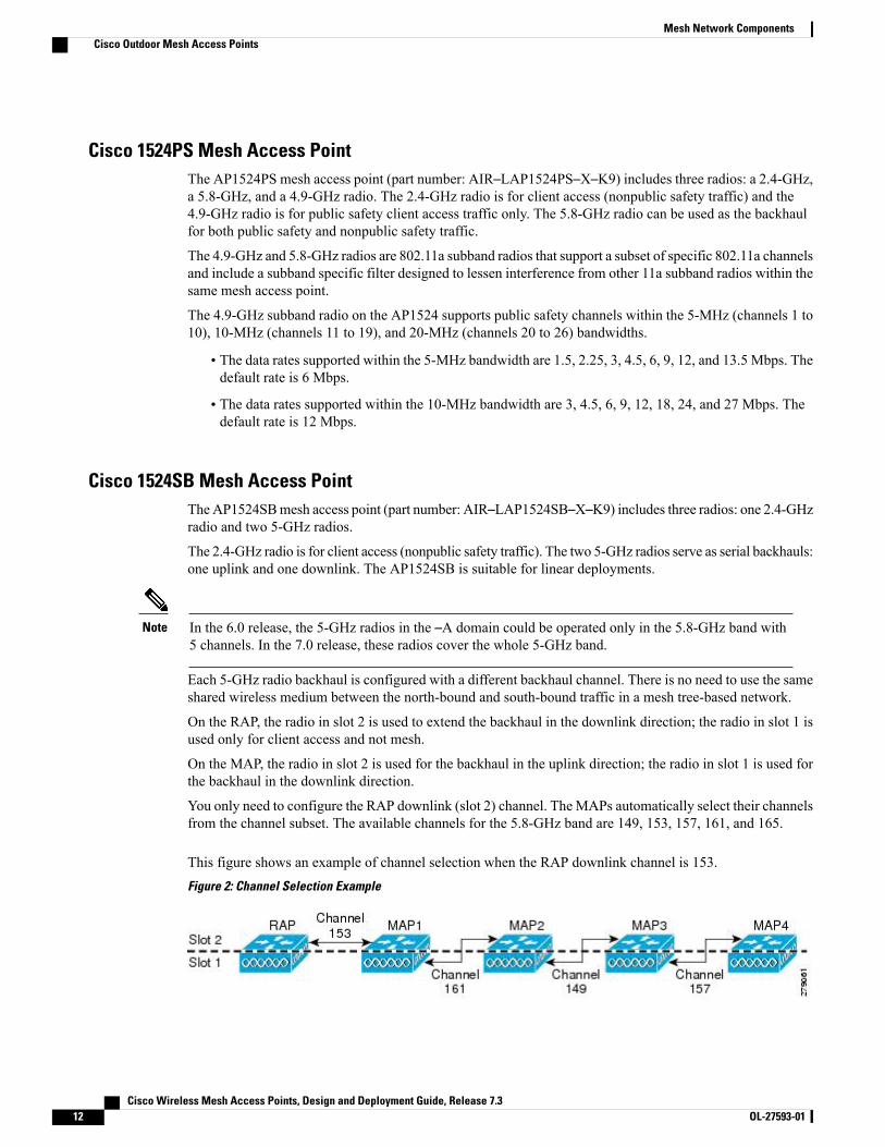
You only need to configure the RAP downlink (slot 2) channel. TheMAPs automatically select their channelsfrom the channel subset. The available channels for the 5.8-GHz band are 149, 153, 157, 161, and 165.
This figure shows an example of channel selection when the RAP downlink channel is 153.Figure 2: Channel Selection Example
Cisco Wireless Mesh Access Points, Design and Deployment Guide, Release 7.312 OL-27593-01
Mesh Network ComponentsCisco Outdoor Mesh Access Points
Fall Back Mode
Slot 1 in a 5-GHz radio in a MAP can act as an uplink radio for the backhaul in any one of the followingscenarios:
• Slot 2 radio fails.
• Antenna for slot 2 radio goes bad.
• Slot 2 radio is unable to find the uplink because of a bad RF design.
• Interference and long-term fades disturb the uplink to the extent that the slot 2 radio loses its uplinkconnection.
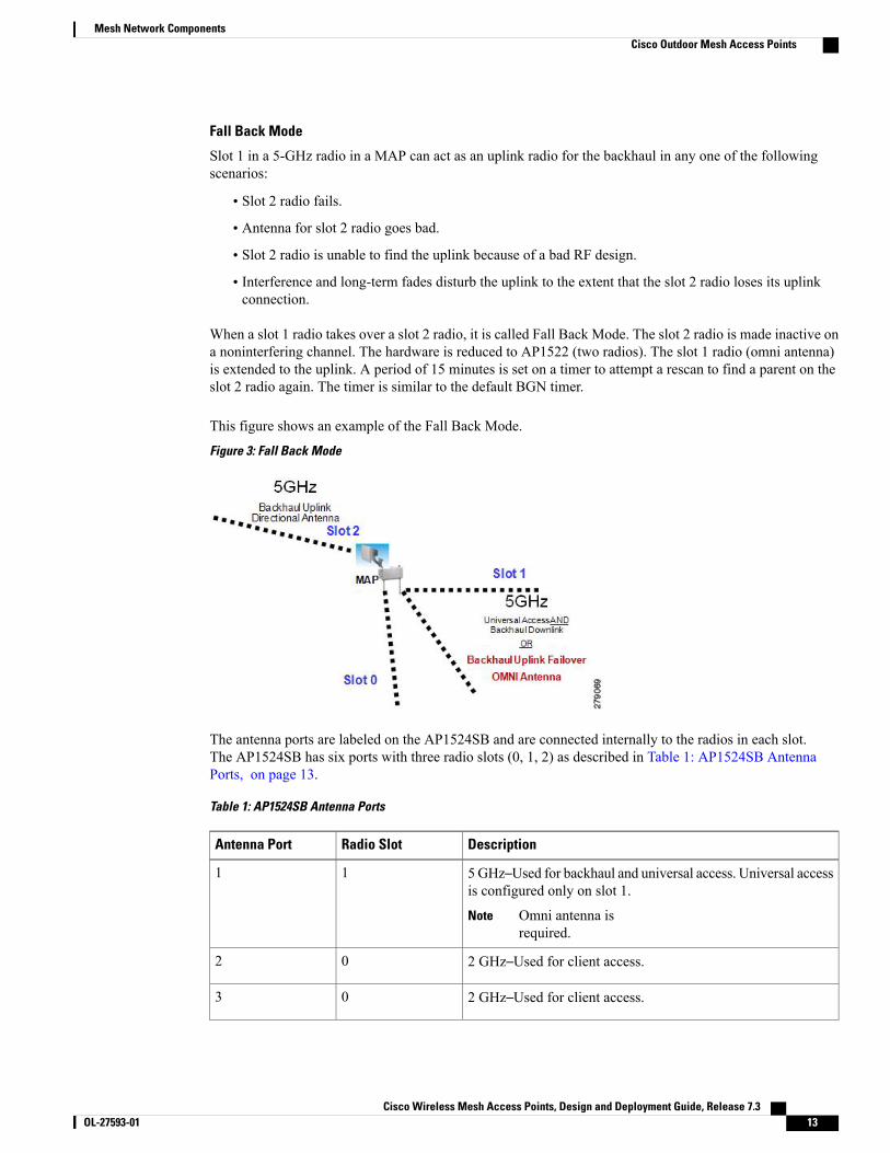
When a slot 1 radio takes over a slot 2 radio, it is called Fall Back Mode. The slot 2 radio is made inactive ona noninterfering channel. The hardware is reduced to AP1522 (two radios). The slot 1 radio (omni antenna)is extended to the uplink. A period of 15 minutes is set on a timer to attempt a rescan to find a parent on theslot 2 radio again. The timer is similar to the default BGN timer.
This figure shows an example of the Fall Back Mode.
Figure 3: Fall Back Mode
The antenna ports are labeled on the AP1524SB and are connected internally to the radios in each slot.The AP1524SB has six ports with three radio slots (0, 1, 2) as described in Table 1: AP1524SB AntennaPorts, on page 13.
Table 1: AP1524SB Antenna Ports
DescriptionRadio SlotAntenna Port
5GHz–Used for backhaul and universal access. Universal accessis configured only on slot 1.
Omni antenna isrequired.
Note
11
2 GHz–Used for client access.02
2 GHz–Used for client access.03
Cisco Wireless Mesh Access Points, Design and Deployment Guide, Release 7.3 OL-27593-01 13
Mesh Network ComponentsCisco Outdoor Mesh Access Points
DescriptionRadio SlotAntenna Port
2 GHz–Used for client access.04
Not connected.—5
5 GHz–Used for backhaul.Directional antenna isrequired.
Note
26
Depending on the product model, the AP1524SB could have either 5-GHz radios or 5.8-GHz subbandradios installed in slot 1 and slot 2. Regardless of the radios installed, the AP1524SB running controllersoftware release 6.0 is restricted to the UNII-3 channels (149, 153, 157, 161, and 165) in slot 1 and slot2.
Note
Ethernet PortsAP1500s support four Gigabit Ethernet interfaces.
• Port 0 (g0) is a Power over Ethernet (PoE) input port–PoE (in)
• Port 1 (g1) is a PoE output port–PoE (out)
• Port 2 (g2) is a cable connection
• Port 3 (g3) is a fiber connection
You can query the status of these four interfaces in the controller CLI and Cisco Prime Infrastructure.
In the controller CLI, the show mesh env summary command is used to display the status of the ports.
• The Up or Down (Dn) status of the four ports is reported in the following format:
◦port0(PoE-in):port1(PoE-out):port2(cable):port3(fiber)
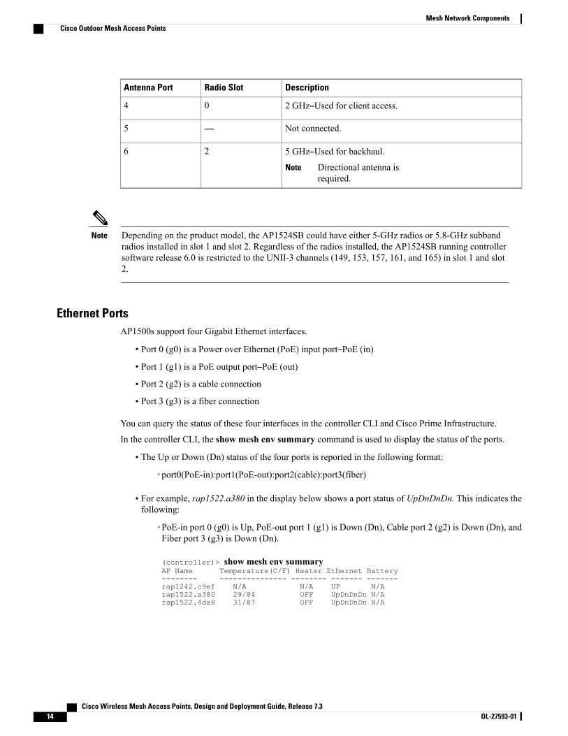
• For example, rap1522.a380 in the display below shows a port status of UpDnDnDn. This indicates thefollowing:
◦PoE-in port 0 (g0) is Up, PoE-out port 1 (g1) is Down (Dn), Cable port 2 (g2) is Down (Dn), andFiber port 3 (g3) is Down (Dn).
(controller)> show mesh env summaryAP Name Temperature(C/F) Heater Ethernet Battery-------- --------------- -------- ------- -------rap1242.c9ef N/A N/A UP N/Arap1522.a380 29/84 OFF UpDnDnDn N/Arap1522.4da8 31/87 OFF UpDnDnDn N/A
Cisco Wireless Mesh Access Points, Design and Deployment Guide, Release 7.314 OL-27593-01
Mesh Network ComponentsCisco Outdoor Mesh Access Points
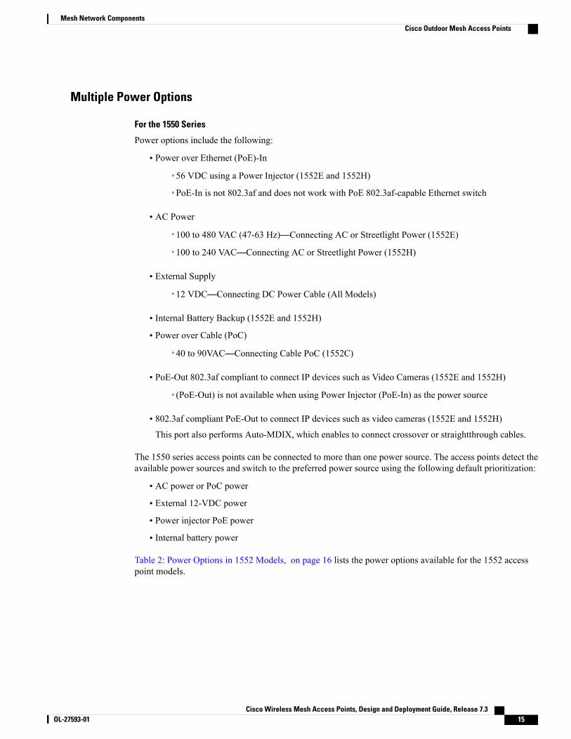
Multiple Power Options
For the 1550 Series
Power options include the following:
• Power over Ethernet (PoE)-In
◦56 VDC using a Power Injector (1552E and 1552H)
◦PoE-In is not 802.3af and does not work with PoE 802.3af-capable Ethernet switch
• AC Power
◦100 to 480 VAC (47-63 Hz)—Connecting AC or Streetlight Power (1552E)
◦100 to 240 VAC—Connecting AC or Streetlight Power (1552H)
• External Supply
◦12 VDC—Connecting DC Power Cable (All Models)
• Internal Battery Backup (1552E and 1552H)
• Power over Cable (PoC)
◦40 to 90VAC—Connecting Cable PoC (1552C)
• PoE-Out 802.3af compliant to connect IP devices such as Video Cameras (1552E and 1552H)
◦(PoE-Out) is not available when using Power Injector (PoE-In) as the power source
• 802.3af compliant PoE-Out to connect IP devices such as video cameras (1552E and 1552H)
This port also performs Auto-MDIX, which enables to connect crossover or straightthrough cables.
The 1550 series access points can be connected to more than one power source. The access points detect theavailable power sources and switch to the preferred power source using the following default prioritization:
• AC power or PoC power
• External 12-VDC power
• Power injector PoE power
• Internal battery power
Table 2: Power Options in 1552 Models, on page 16 lists the power options available for the 1552 accesspoint models.
Cisco Wireless Mesh Access Points, Design and Deployment Guide, Release 7.3 OL-27593-01 15
Mesh Network ComponentsCisco Outdoor Mesh Access Points
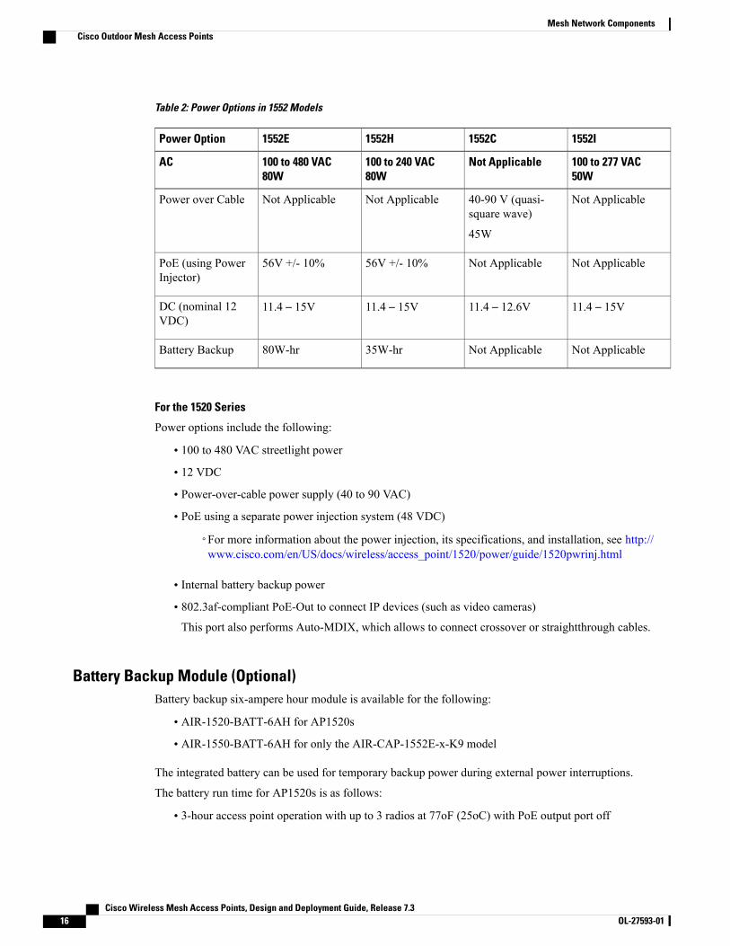
Table 2: Power Options in 1552 Models
1552I1552C1552H1552EPower Option
100 to 277 VAC50W
Not Applicable100 to 240 VAC80W
100 to 480 VAC80W
AC
Not Applicable40-90 V (quasi-square wave)
45W
Not ApplicableNot ApplicablePower over Cable
Not ApplicableNot Applicable56V +/- 10%56V +/- 10%PoE (using PowerInjector)
11.4 – 15V11.4 – 12.6V11.4 – 15V11.4 – 15VDC (nominal 12VDC)
Not ApplicableNot Applicable35W-hr80W-hrBattery Backup
For the 1520 Series
Power options include the following:
• 100 to 480 VAC streetlight power
• 12 VDC
• Power-over-cable power supply (40 to 90 VAC)
• PoE using a separate power injection system (48 VDC)
◦For more information about the power injection, its specifications, and installation, see http://www.cisco.com/en/US/docs/wireless/access_point/1520/power/guide/1520pwrinj.html
• Internal battery backup power
• 802.3af-compliant PoE-Out to connect IP devices (such as video cameras)This port also performs Auto-MDIX, which allows to connect crossover or straightthrough cables.
Battery Backup Module (Optional)Battery backup six-ampere hour module is available for the following:
• AIR-1520-BATT-6AH for AP1520s
• AIR-1550-BATT-6AH for only the AIR-CAP-1552E-x-K9 model
The integrated battery can be used for temporary backup power during external power interruptions.
The battery run time for AP1520s is as follows:
• 3-hour access point operation with up to 3 radios at 77oF (25oC) with PoE output port off
Cisco Wireless Mesh Access Points, Design and Deployment Guide, Release 7.316 OL-27593-01
Mesh Network ComponentsCisco Outdoor Mesh Access Points
• 2-hour access point operation with up to 3 radios at 77oF (25oC) with PoE output port on
The battery run time for AP1550s is as follows:
• 2-hour access point operation using two radios at 77oF (25oC) with PoE output port off
• 1.5-hour access point operation using two radios at 77oF (25oC) with PoE output port on
The battery pack is not supported on the access point cable configuration.
For a complete listing of optional hardware components for AP1520s such as mounting brackets, powerinjectors, and power tap adapters, see http://www.cisco.com/en/US/prod/collateral/wireless/ps5679/ps8368/product_data_sheet0900aecd8066a157.html
Note
Reset ButtonA 1500 series access point has a reset button located on the bottom of the unit. The reset button is recessedin a small hole that is sealed with a screw and a rubber gasket. The reset button can be used to perform thefollowing functions:
• Reset the access point—Press the reset button for less than 10 seconds, and the LEDs turn off duringthe reset and then reactivate when the reset is complete.
• Disable battery backup power—Press the reset button for more than 10 seconds, and the LEDs turn off,then on, and then stay off.
◦You can also disable the battery remotely by entering the following command:config mesh battery-state disable AP_name
• Switch off LEDs—Press the reset button for more than 10 seconds, and the LEDs turn off, then on, andthen stay off.
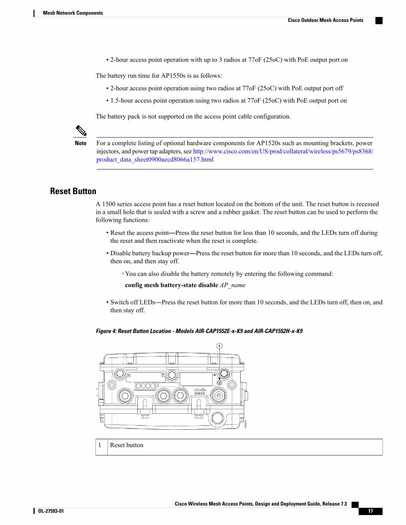
Figure 4: Reset Button Location - Models AIR-CAP1552E-x-K9 and AIR-CAP1552H-x-K9
Reset button1
Cisco Wireless Mesh Access Points, Design and Deployment Guide, Release 7.3 OL-27593-01 17
Mesh Network ComponentsCisco Outdoor Mesh Access Points
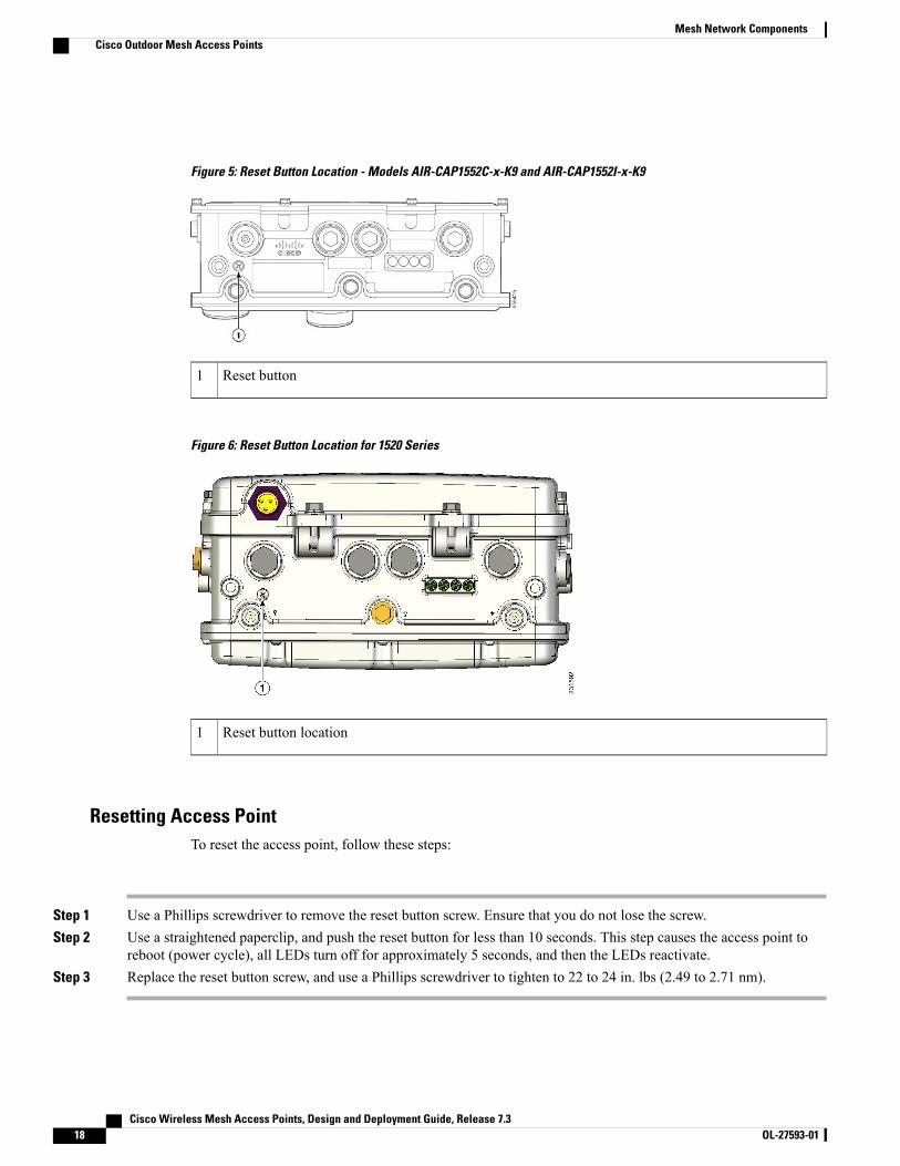
Figure 5: Reset Button Location - Models AIR-CAP1552C-x-K9 and AIR-CAP1552I-x-K9
Reset button1
Figure 6: Reset Button Location for 1520 Series
Reset button location1
Resetting Access PointTo reset the access point, follow these steps:
Step 1 Use a Phillips screwdriver to remove the reset button screw. Ensure that you do not lose the screw.Step 2 Use a straightened paperclip, and push the reset button for less than 10 seconds. This step causes the access point to
reboot (power cycle), all LEDs turn off for approximately 5 seconds, and then the LEDs reactivate.Step 3 Replace the reset button screw, and use a Phillips screwdriver to tighten to 22 to 24 in. lbs (2.49 to 2.71 nm).
Cisco Wireless Mesh Access Points, Design and Deployment Guide, Release 7.318 OL-27593-01
Mesh Network ComponentsCisco Outdoor Mesh Access Points
Monitoring the LED StatusThe four-status LEDs on AP1500s are useful during the installation process to verify connectivity, radio status,access point status, and software status. However, once the access point is up and running and no furtherdiagnosis is required, we recommend that you turn off the LEDs to discourage vandalism.
If your access point is not working as expected, see the LEDs at the bottom of the unit. You can use them toquickly assess the status of the unit.
LEDs are enabled or disabled using the config ap led-state {enable | disable} {cisco_ap_name | all}command.
Note
There are four LED status indicators on AP1500s.
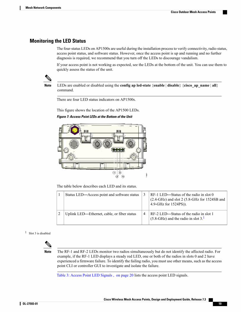
This figure shows the location of the AP1500 LEDs.Figure 7: Access Point LEDs at the Bottom of the Unit
The table below describes each LED and its status.
RF-1 LED—Status of the radio in slot 0(2.4-GHz) and slot 2 (5.8-GHz for 1524SB and4.9-GHz for 1524PS)).
3Status LED—Access point and software status1
RF-2 LED—Status of the radio in slot 1(5.8-GHz) and the radio in slot 3.1
4Uplink LED—Ethernet, cable, or fiber status2
1 Slot 3 is disabled
The RF-1 and RF-2 LEDs monitor two radios simultaneously but do not identify the affected radio. Forexample, if the RF-1 LED displays a steady red LED, one or both of the radios in slots 0 and 2 haveexperienced a firmware failure. To identify the failing radio, you must use other means, such as the accesspoint CLI or controller GUI to investigate and isolate the failure.
Note
Table 3: Access Point LED Signals , on page 20 lists the access point LED signals.
Cisco Wireless Mesh Access Points, Design and Deployment Guide, Release 7.3 OL-27593-01 19
Mesh Network ComponentsCisco Outdoor Mesh Access Points
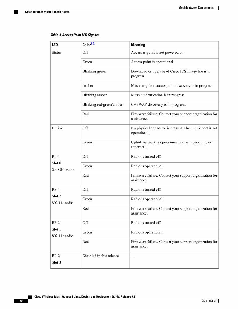
Table 3: Access Point LED Signals
MeaningColor2 3LED
Access is point is not powered on.OffStatus
Access point is operational.Green
Download or upgrade of Cisco IOS image file is inprogress.
Blinking green
Mesh neighbor access point discovery is in progress.Amber
Mesh authentication is in progress.Blinking amber
CAPWAP discovery is in progress.Blinking red/green/amber
Firmware failure. Contact your support organization forassistance.
Red
No physical connector is present. The uplink port is notoperational.
OffUplink
Uplink network is operational (cable, fiber optic, orEthernet).
Green
Radio is turned off.OffRF-1
Slot 0
2.4-GHz radioRadio is operational.Green
Firmware failure. Contact your support organization forassistance.
Red
Radio is turned off.OffRF-1
Slot 2
802.11a radioRadio is operational.Green
Firmware failure. Contact your support organization forassistance.
Red
Radio is turned off.OffRF-2
Slot 1
802.11a radioRadio is operational.Green
Firmware failure. Contact your support organization forassistance.
Red
—Disabled in this release.RF-2
Slot 3
Cisco Wireless Mesh Access Points, Design and Deployment Guide, Release 7.320 OL-27593-01
Mesh Network ComponentsCisco Outdoor Mesh Access Points
2 If all LEDs are off, the access point has no power.3 When the access point power supply is initially turned on, all LEDs are amber.
Serial Backhaul Access Point Guidelines for the Rest of the World (ROW)In the 7.0 release, new 1524 SKUs are released, with both 802.11a radio units supporting the entire 5-GHzband from 4.9 GHz to 5.8 GHz. This release also opens the 5-GHz band for the -A domain as well on theexisting hardware. The radios can also operate in UNII-2 (5.25 to 5.35 GHz), UNII-2 plus (5.47 to 5.725GHz), and the upper ISM (5.725 to 5.850 GHz) bands.
The public safety band (4.94 to 4.99 GHz) is not supported for backhaul and for client access.
For information about the channels and maximum power levels of the AP1500 supported within the world'sregulatory domains, see the Channels and Maximum Power Settings for Cisco Aironet Lightweight AccessPoints manual at:
• AP1520: http://www.cisco.com/en/US/docs/wireless/access_point/channels/lwapp/reference/guide/1520_chp.html
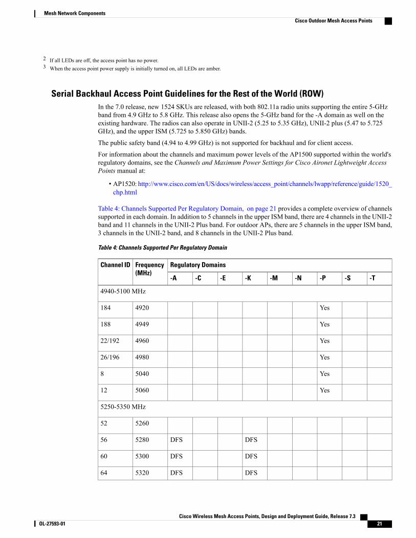
Table 4: Channels Supported Per Regulatory Domain, on page 21 provides a complete overview of channelssupported in each domain. In addition to 5 channels in the upper ISM band, there are 4 channels in the UNII-2band and 11 channels in the UNII-2 Plus band. For outdoor APs, there are 5 channels in the upper ISM band,3 channels in the UNII-2 band, and 8 channels in the UNII-2 Plus band.
Table 4: Channels Supported Per Regulatory Domain
Regulatory DomainsFrequency(MHz)
Channel ID
-T-S-P-N-M-K-E-C-A
4940-5100 MHz
Yes4920184
Yes4949188
Yes496022/192
Yes498026/196
Yes50408
Yes506012
5250-5350 MHz
526052
DFSDFS528056
DFSDFS530060
DFSDFS532064
Cisco Wireless Mesh Access Points, Design and Deployment Guide, Release 7.3 OL-27593-01 21
Mesh Network ComponentsCisco Outdoor Mesh Access Points

Regulatory DomainsFrequency(MHz)
Channel ID
-T-S-P-N-M-K-E-C-A
5470-5725 MHz
DFSDFSDFSDFSDFS5500100
DFSDFSDFSDFSDFS5520104
DFSDFSDFSDFSDFS5540108
DFSDFSDFSDFSDFS5560112
DFSDFSDFSDFSDFS5580116
DFSDFS5580120
DFSDFS5620124
DFS5640128
DFSDFSDFSDFS5660132
DFSDFSDFSDFS5680136
DFSDFSDFSDFS5700140
5725-5875 MHz
YesYesYesDFSYesYes5745149
YesYesYesDFSYesYes5765153
YesYesYesDFSYesYes5785157
YesYesYesDFSYesYes5805161
YesYesYesYesYes5825165
Channels marked Yes/DFS are channels supported in that domain. Channels marked DFS areadditional DFS-enabled channels and require checks for radar detection. This table is for up to 8-Bi antennas. For higher gain antennas, see http://www.cisco.com/en/US/docs/wireless/access_point/channels/lwapp/reference/guide/1520_chp.html.
Note
With the expansion of the channel set, DFS-enabled channels are also supported. Radar detection and automaticchannel reassignment in case of radar detection on RAP/MAPs are also supported. When there is a channelchange, it is also propagated to the corresponding parent/child access point (if applicable) so that the channelchange is synchronized between the parent and child so that there is no link downtime. For example, if radaris detected on the uplink radio of a child access point, the parent is informed so that it can change the channel
Cisco Wireless Mesh Access Points, Design and Deployment Guide, Release 7.322 OL-27593-01
Mesh Network ComponentsCisco Outdoor Mesh Access Points

of the downlink radio. The parent in turn informs the child about the channel change, so that the child accesspoint can set the new channel on its uplink radio as well and does not have to scan again to rejoin the parenton the new channel.
For countries in the Middle East such as Saudi Arabia and Kuwait, a new regulatory domain for outdoor APs,the -M domain, has been mandated. With this release, outdoor APs will now support this new -M domain.Earlier, these countries were part of the -E domain, which supported a channel set of 100 to 140. However,in the -M domain, channels 149 to 161 are also supported with the 100 to 140 band. Also, in the -M domain,channels 149 to 161 are DFS enabled, unlike other domains such as -A, -C, -N, and so on, where these channelsare non-DFS. Radar detection is also enabled on these channels. Because the countries that are now part ofthe -M domain (that is, Saudi Arabia and Kuwait) were earlier part of the -E domain, both the -E domain andthe -M domain APs are supported, when any of these countries is configured on the controller, which ensuresbackward compatibility with the existing -E domain APs in these countries. However, you will have to ensurethat only a valid set of channels (the channels common to both the -E and the -M domains) is selected as partof the 802.11a DCA list, and that the backhaul channel deselection feature is enabled to ensure correct operationof the -E domain APs, as these APs can support 100 to 140 channels and not the extended list of 149 to 161channels available in the -M domain.
Discontinuation of the 116 and 132 Channels from the UNII-2 Extended BandWith the 7.0 release, in AP1522 and AP1524SB platforms, in addition to the 5 channels in the upper ISMband, there are 3 channels in the UNII-2 band and 8 channels in the UNII-2 Extended band. There are 11channels in the UNII-2 Extended band, but only 8 are applicable in the outdoors due to stringent dynamicfrequency selection (DFS) conditions for Canada because Canada requires a channel availability check every10 minutes compared to every 60 seconds in the USA. The 120 (5600MHz), 124 (5620MHz), and 128 (5640MHz) channels have had to be dropped.
The Federal Communications Commission (FCC) has issued a guideline to protect Terminal DopplerWeatherRadar (TDWR) systems operating in the 5600- to 5650-MHz band from interference. Also, the UNII-2 Wi-Fioperating channels are interfering with the TDWR band. Therefore, with the 7.0.116.0 release, the 116 and132 channels are dropped in addition to the 120, 124, and 128 channels. The guidelines also require that youavoid operation in the TDWR band and operate at least 30 MHz away from the TDWR operation frequencieswhen devices are installed within 35 km (about 21 miles) or the line-of-sight of the TDWR sites.
Your outdoor installation should be registered in the outdoor database. No fee is required to register yourcompany. The TDWR location sites can be found on the Internet.
Note
The FCC, the National Telecommunications and Information Administration (NTIA), and the FederalAviation Administration (FAA) are continuing to investigate and eliminate cases of interference to TDWRs.For more information about FCC guidelines for outdoor installations, see http://www.cisco.com/en/US/prod/collateral/routers/ps272/data_sheet_c78-647116_ps11451_Products_Data_Sheet.html.
Note
Cisco Wireless Mesh Access Points, Design and Deployment Guide, Release 7.3 OL-27593-01 23
Mesh Network ComponentsCisco Outdoor Mesh Access Points
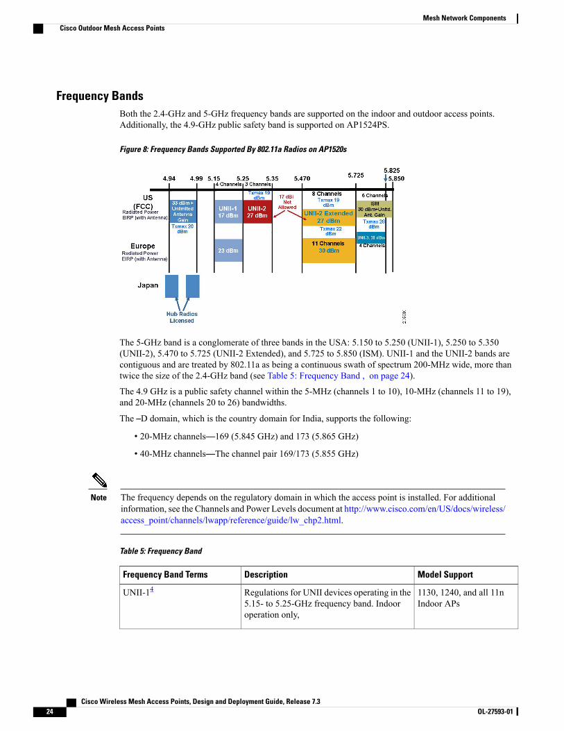
Frequency BandsBoth the 2.4-GHz and 5-GHz frequency bands are supported on the indoor and outdoor access points.Additionally, the 4.9-GHz public safety band is supported on AP1524PS.
Figure 8: Frequency Bands Supported By 802.11a Radios on AP1520s
The 5-GHz band is a conglomerate of three bands in the USA: 5.150 to 5.250 (UNII-1), 5.250 to 5.350(UNII-2), 5.470 to 5.725 (UNII-2 Extended), and 5.725 to 5.850 (ISM). UNII-1 and the UNII-2 bands arecontiguous and are treated by 802.11a as being a continuous swath of spectrum 200-MHz wide, more thantwice the size of the 2.4-GHz band (see Table 5: Frequency Band , on page 24).
The 4.9 GHz is a public safety channel within the 5-MHz (channels 1 to 10), 10-MHz (channels 11 to 19),and 20-MHz (channels 20 to 26) bandwidths.
The –D domain, which is the country domain for India, supports the following:
• 20-MHz channels—169 (5.845 GHz) and 173 (5.865 GHz)
• 40-MHz channels—The channel pair 169/173 (5.855 GHz)
The frequency depends on the regulatory domain in which the access point is installed. For additionalinformation, see the Channels and Power Levels document at http://www.cisco.com/en/US/docs/wireless/access_point/channels/lwapp/reference/guide/lw_chp2.html.
Note
Table 5: Frequency Band
Model SupportDescriptionFrequency Band Terms
1130, 1240, and all 11nIndoor APs
Regulations for UNII devices operating in the5.15- to 5.25-GHz frequency band. Indooroperation only,
UNII-14
Cisco Wireless Mesh Access Points, Design and Deployment Guide, Release 7.324 OL-27593-01
Mesh Network ComponentsCisco Outdoor Mesh Access Points
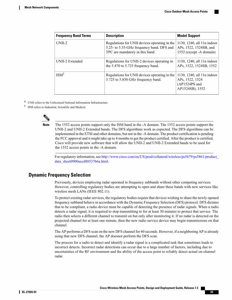
Model SupportDescriptionFrequency Band Terms
1130, 1240, all 11n indoorAPs, 1522, 1524SB, and1552 (except -A domain)
Regulations for UNII devices operating in the5.25- to 5.35-GHz frequency band. DFS andTPC are mandatory in this band.
UNII-2
1130, 1240, all 11n indoorAPs, 1522, 1524SB, 1552
Regulations for UNII-2 devices operating inthe 5.470 to 5.725 frequency band.
UNII-2 Extended
1130, 1240, all 11n indoorAPs, 1522, 1524(AP1524PS andAP1524SB), 1552
Regulations for UNII devices operating in the5.725 to 5.850 GHz frequency band.
ISM5
4 UNII refers to the Unlicensed National Information Infrastructure.5 ISM refers to Industrial, Scientific and Medical.
The 1552 access points support only the ISM band in the -A domain. The 1552 access points support theUNII-2 and UNII-2 Extended bands. The DFS algorithms work as expected. The DFS algorithms can beimplemented in the ETSI and other domains, but not in the -A domain. The product certification is pendingthe FCC approval and it might take up to 4 months to get the product certified. After the product is certified,Cisco will provide new software that will allow the UNII-2 and UNII-2 Extended bands to be used forthe 1552 access points in the -A domain.
Note
For regulatory information, see http://www.cisco.com/en/US/prod/collateral/wireless/ps5679/ps5861/product_data_sheet0900aecd80537b6a.html.
Dynamic Frequency SelectionPreviously, devices employing radar operated in frequency subbands without other competing services.However, controlling regulatory bodies are attempting to open and share these bands with new services likewireless mesh LANs (IEEE 802.11).
To protect existing radar services, the regulatory bodies require that devices wishing to share the newly openedfrequency subband behave in accordance with the Dynamic Frequency Selection (DFS) protocol. DFS dictatesthat to be compliant, a radio device must be capable of detecting the presence of radar signals. When a radiodetects a radar signal, it is required to stop transmitting to for at least 30 minutes to protect that service. Theradio then selects a different channel to transmit on but only after monitoring it. If no radar is detected on theprojected channel for at least one minute, then the new radio service device may begin transmissions on thatchannel.
The AP performs a DFS scan on the newDFS channel for 60 seconds. However, if a neighboring AP is alreadyusing that new DFS channel, the AP doesnot perform the DFS scan.
The process for a radio to detect and identify a radar signal is a complicated task that sometimes leads toincorrect detects. Incorrect radar detections can occur due to a large number of factors, including due touncertainties of the RF environment and the ability of the access point to reliably detect actual on-channelradar.
Cisco Wireless Mesh Access Points, Design and Deployment Guide, Release 7.3 OL-27593-01 25
Mesh Network ComponentsCisco Outdoor Mesh Access Points
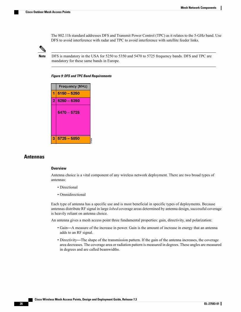
The 802.11h standard addresses DFS and Transmit Power Control (TPC) as it relates to the 5-GHz band. UseDFS to avoid interference with radar and TPC to avoid interference with satellite feeder links.
DFS is mandatory in the USA for 5250 to 5350 and 5470 to 5725 frequency bands. DFS and TPC aremandatory for these same bands in Europe.
Note
Figure 9: DFS and TPC Band Requirements
Antennas
Overview
Antenna choice is a vital component of any wireless network deployment. There are two broad types ofantennas:
• Directional
• Omnidirectional
Each type of antenna has a specific use and is most beneficial in specific types of deployments. Becauseantennas distribute RF signal in large lobed coverage areas determined by antenna design, successful coverageis heavily reliant on antenna choice.
An antenna gives a mesh access point three fundamental properties: gain, directivity, and polarization:
• Gain—A measure of the increase in power. Gain is the amount of increase in energy that an antennaadds to an RF signal.
• Directivity—The shape of the transmission pattern. If the gain of the antenna increases, the coveragearea decreases. The coverage area or radiation pattern is measured in degrees. These angles are measuredin degrees and are called beamwidths.
Cisco Wireless Mesh Access Points, Design and Deployment Guide, Release 7.326 OL-27593-01
Mesh Network ComponentsCisco Outdoor Mesh Access Points
Beamwidth is defined as a measure of the ability of an antenna to focus radio signalenergy toward a particular direction in space. Beamwidth is usually expressed in degreesHB ?(Horizontal Beamwidth); usually, the most important one is expressed in a VB(Vertical Beamwidth) (up and down) radiation pattern. When viewing an antenna plotor pattern, the angle is usually measured at half-power (3 dB) points of the main lobewhen referenced to the peak effective radiated power of the main lobe.
Note
An 8-dBi antenna transmits with a horizontal beamwidth of 360 degrees, causing theradio waves to disperse power in all directions. Therefore, radio waves from an 8-dBiantenna do not go nearly as far as those radio waves sent from a 17-dBi patch antenna(or a third-party dish) that has a more narrow beamwidth (less than 360 degrees).
Note
• Polarization—The orientation of the electric field of the electromagnetic wave through space. Antennascan be polarized either horizontally or vertically, though other kinds of polarization are available. Bothantennas in a link must have the same polarization to avoid an additional unwanted loss of signal. Toimprove the performance, an antenna can sometimes be rotated to alter polarization, which reducesinterference. A vertical polarization is preferable for sending RF waves down concrete canyons, andhorizontal polarization is generally more preferable for wide area distribution. Polarization can also beharnessed to optimize for RF bleed-over when reducing RF energy to adjacent structures is important.Most omnidirectional antennas ship with vertical polarization as their default.
Antenna Options
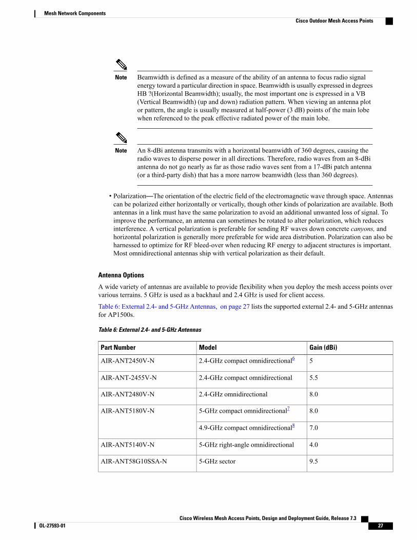
A wide variety of antennas are available to provide flexibility when you deploy the mesh access points overvarious terrains. 5 GHz is used as a backhaul and 2.4 GHz is used for client access.
Table 6: External 2.4- and 5-GHz Antennas, on page 27 lists the supported external 2.4- and 5-GHz antennasfor AP1500s.
Table 6: External 2.4- and 5-GHz Antennas
Gain (dBi)ModelPart Number
52.4-GHz compact omnidirectional6AIR-ANT2450V-N
5.52.4-GHz compact omnidirectionalAIR-ANT-2455V-N
8.02.4-GHz omnidirectionalAIR-ANT2480V-N
8.05-GHz compact omnidirectional7AIR-ANT5180V-N
7.04.9-GHz compact omnidirectional8
4.05-GHz right-angle omnidirectionalAIR-ANT5140V-N
9.55-GHz sectorAIR-ANT58G10SSA-N
Cisco Wireless Mesh Access Points, Design and Deployment Guide, Release 7.3 OL-27593-01 27
Mesh Network ComponentsCisco Outdoor Mesh Access Points
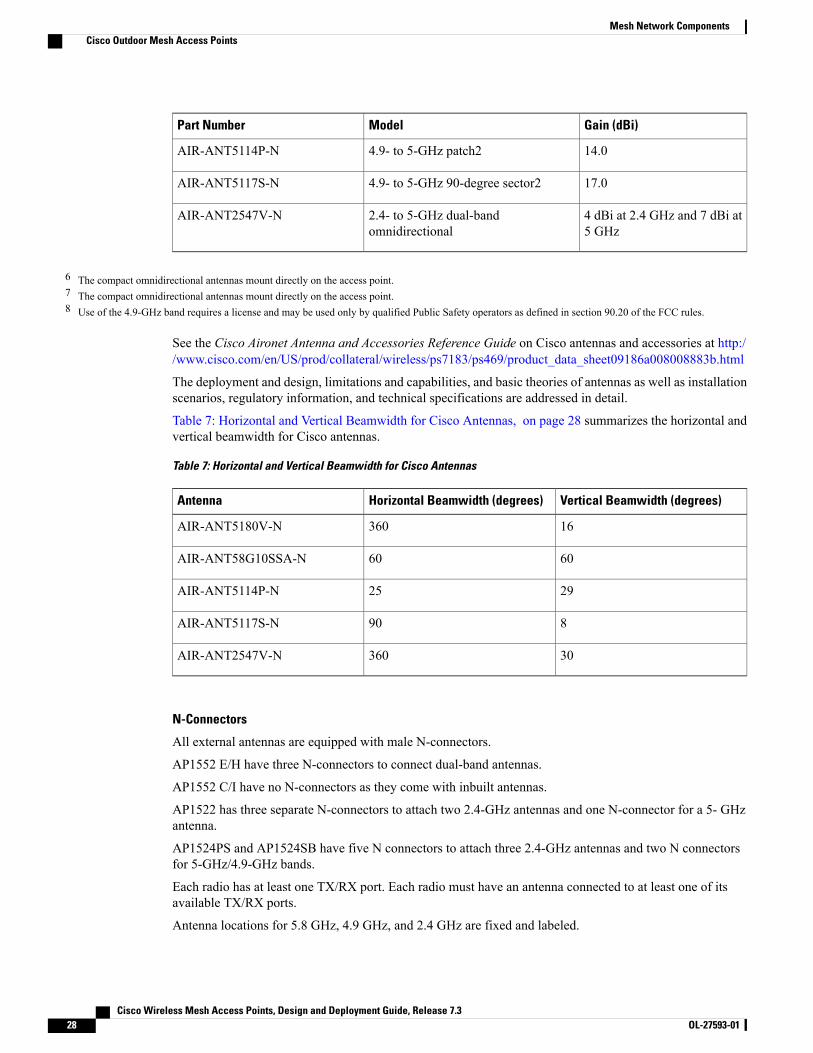
Gain (dBi)ModelPart Number
14.04.9- to 5-GHz patch2AIR-ANT5114P-N
17.04.9- to 5-GHz 90-degree sector2AIR-ANT5117S-N
4 dBi at 2.4 GHz and 7 dBi at5 GHz
2.4- to 5-GHz dual-bandomnidirectional
AIR-ANT2547V-N
6 The compact omnidirectional antennas mount directly on the access point.7 The compact omnidirectional antennas mount directly on the access point.8 Use of the 4.9-GHz band requires a license and may be used only by qualified Public Safety operators as defined in section 90.20 of the FCC rules.
See the Cisco Aironet Antenna and Accessories Reference Guide on Cisco antennas and accessories at http://www.cisco.com/en/US/prod/collateral/wireless/ps7183/ps469/product_data_sheet09186a008008883b.html
The deployment and design, limitations and capabilities, and basic theories of antennas as well as installationscenarios, regulatory information, and technical specifications are addressed in detail.
Table 7: Horizontal and Vertical Beamwidth for Cisco Antennas, on page 28 summarizes the horizontal andvertical beamwidth for Cisco antennas.
Table 7: Horizontal and Vertical Beamwidth for Cisco Antennas
Vertical Beamwidth (degrees)Horizontal Beamwidth (degrees)Antenna
16360AIR-ANT5180V-N
6060AIR-ANT58G10SSA-N
2925AIR-ANT5114P-N
890AIR-ANT5117S-N
30360AIR-ANT2547V-N
N-Connectors
All external antennas are equipped with male N-connectors.
AP1552 E/H have three N-connectors to connect dual-band antennas.
AP1552 C/I have no N-connectors as they come with inbuilt antennas.
AP1522 has three separate N-connectors to attach two 2.4-GHz antennas and one N-connector for a 5- GHzantenna.
AP1524PS and AP1524SB have five N connectors to attach three 2.4-GHz antennas and two N connectorsfor 5-GHz/4.9-GHz bands.
Each radio has at least one TX/RX port. Each radio must have an antenna connected to at least one of itsavailable TX/RX ports.
Antenna locations for 5.8 GHz, 4.9 GHz, and 2.4 GHz are fixed and labeled.
Cisco Wireless Mesh Access Points, Design and Deployment Guide, Release 7.328 OL-27593-01
Mesh Network ComponentsCisco Outdoor Mesh Access Points
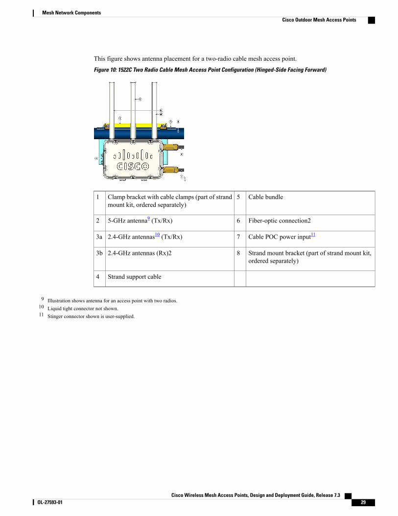
This figure shows antenna placement for a two-radio cable mesh access point.
Figure 10: 1522C Two Radio Cable Mesh Access Point Configuration (Hinged-Side Facing Forward)
Cable bundle5Clamp bracket with cable clamps (part of strandmount kit, ordered separately)
1
Fiber-optic connection265-GHz antenna9 (Tx/Rx)2
Cable POC power input1172.4-GHz antennas10 (Tx/Rx)3a
Strand mount bracket (part of strand mount kit,ordered separately)
82.4-GHz antennas (Rx)23b
Strand support cable4
9 Illustration shows antenna for an access point with two radios.10 Liquid tight connector not shown.11 Stinger connector shown is user-supplied.
Cisco Wireless Mesh Access Points, Design and Deployment Guide, Release 7.3 OL-27593-01 29
Mesh Network ComponentsCisco Outdoor Mesh Access Points
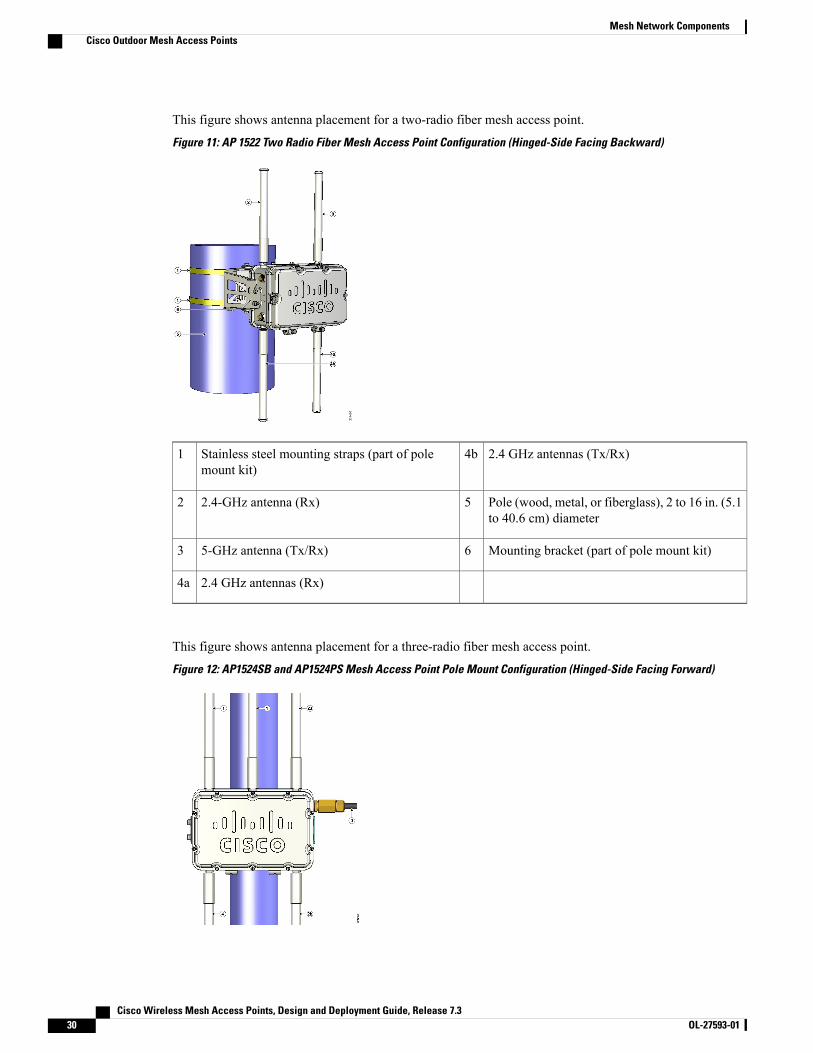
This figure shows antenna placement for a two-radio fiber mesh access point.
Figure 11: AP 1522 Two Radio Fiber Mesh Access Point Configuration (Hinged-Side Facing Backward)
2.4 GHz antennas (Tx/Rx)4bStainless steel mounting straps (part of polemount kit)
1
Pole (wood, metal, or fiberglass), 2 to 16 in. (5.1to 40.6 cm) diameter
52.4-GHz antenna (Rx)2
Mounting bracket (part of pole mount kit)65-GHz antenna (Tx/Rx)3
2.4 GHz antennas (Rx)4a
This figure shows antenna placement for a three-radio fiber mesh access point.
Figure 12: AP1524SB and AP1524PS Mesh Access Point Pole Mount Configuration (Hinged-Side Facing Forward)
Cisco Wireless Mesh Access Points, Design and Deployment Guide, Release 7.330 OL-27593-01
Mesh Network ComponentsCisco Outdoor Mesh Access Points
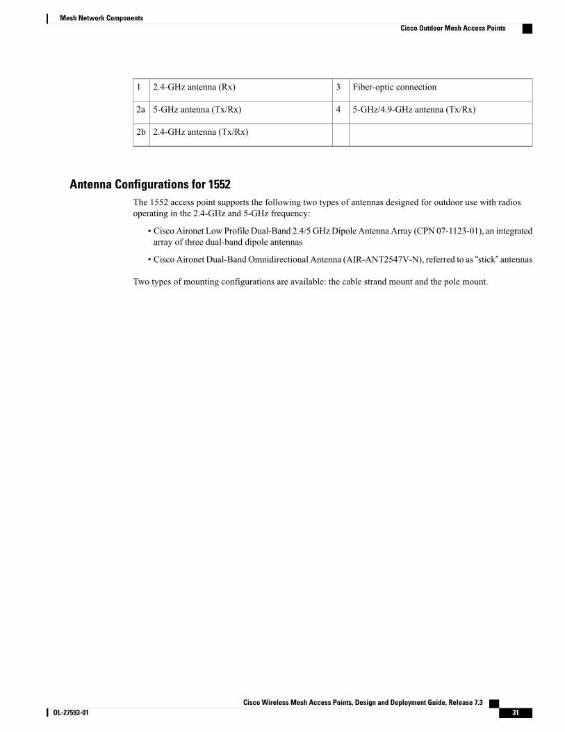
Fiber-optic connection32.4-GHz antenna (Rx)1
5-GHz/4.9-GHz antenna (Tx/Rx)45-GHz antenna (Tx/Rx)2a
2.4-GHz antenna (Tx/Rx)2b
Antenna Configurations for 1552The 1552 access point supports the following two types of antennas designed for outdoor use with radiosoperating in the 2.4-GHz and 5-GHz frequency:
• Cisco Aironet Low Profile Dual-Band 2.4/5 GHzDipole Antenna Array (CPN 07-1123-01), an integratedarray of three dual-band dipole antennas
• Cisco Aironet Dual-Band Omnidirectional Antenna (AIR-ANT2547V-N), referred to as “stick” antennas
Two types of mounting configurations are available: the cable strand mount and the pole mount.
Cisco Wireless Mesh Access Points, Design and Deployment Guide, Release 7.3 OL-27593-01 31
Mesh Network ComponentsCisco Outdoor Mesh Access Points
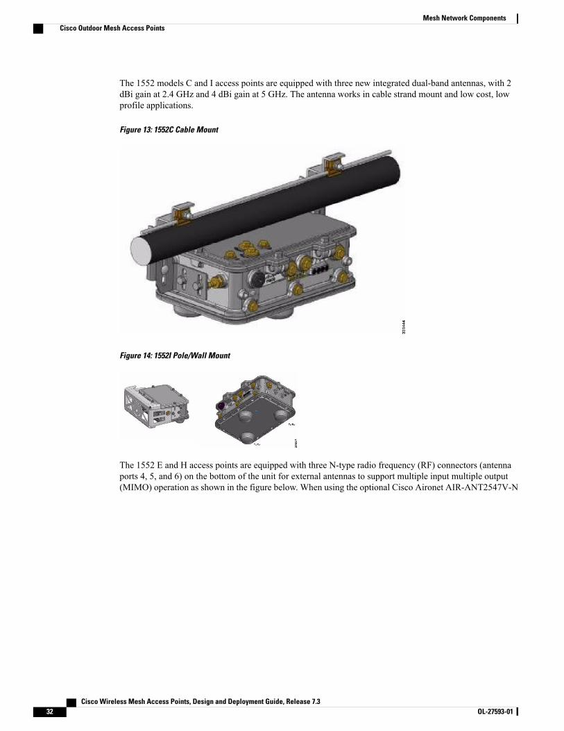
The 1552 models C and I access points are equipped with three new integrated dual-band antennas, with 2dBi gain at 2.4 GHz and 4 dBi gain at 5 GHz. The antenna works in cable strand mount and low cost, lowprofile applications.
Figure 13: 1552C Cable Mount
Figure 14: 1552I Pole/Wall Mount
The 1552 E and H access points are equipped with three N-type radio frequency (RF) connectors (antennaports 4, 5, and 6) on the bottom of the unit for external antennas to support multiple input multiple output(MIMO) operation as shown in the figure below. When using the optional Cisco Aironet AIR-ANT2547V-N
Cisco Wireless Mesh Access Points, Design and Deployment Guide, Release 7.332 OL-27593-01
Mesh Network ComponentsCisco Outdoor Mesh Access Points
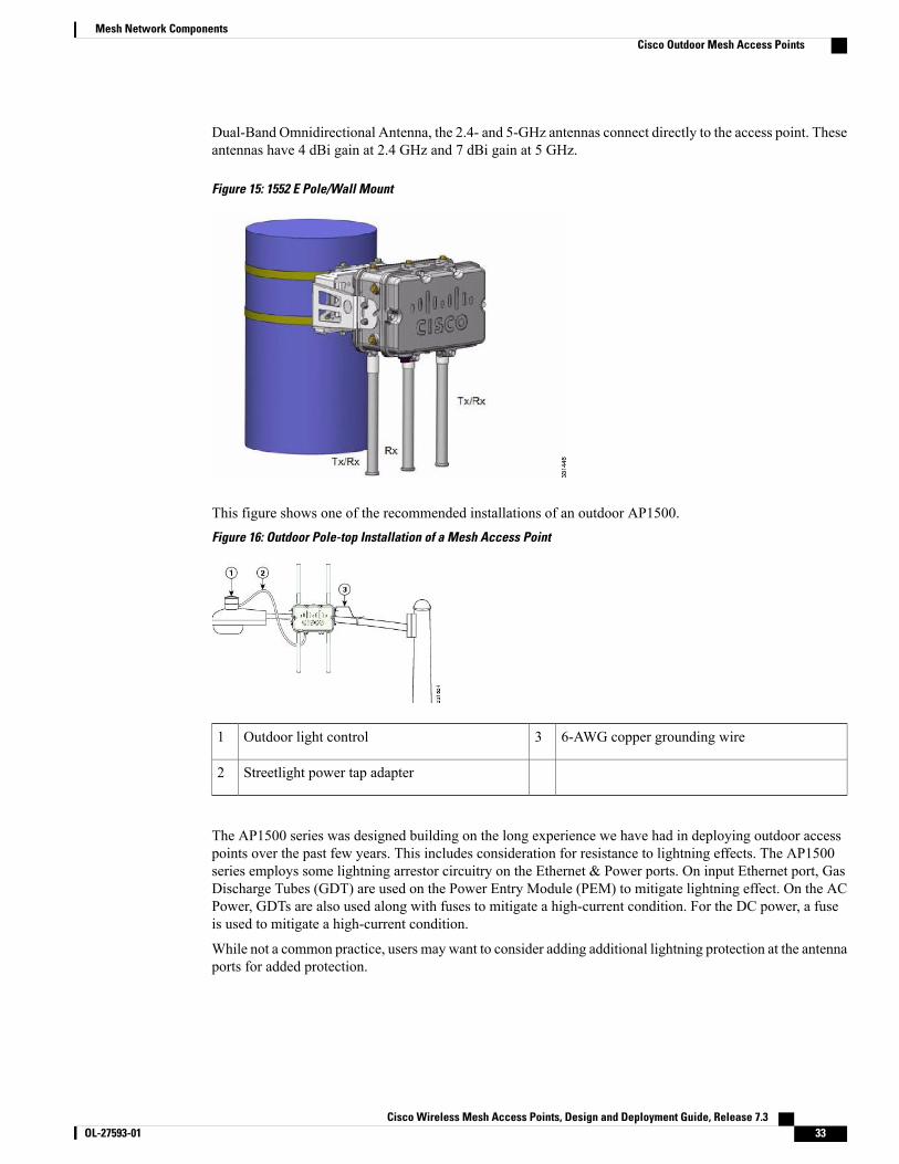
Dual-Band Omnidirectional Antenna, the 2.4- and 5-GHz antennas connect directly to the access point. Theseantennas have 4 dBi gain at 2.4 GHz and 7 dBi gain at 5 GHz.
Figure 15: 1552 E Pole/Wall Mount
This figure shows one of the recommended installations of an outdoor AP1500.Figure 16: Outdoor Pole-top Installation of a Mesh Access Point
6-AWG copper grounding wire3Outdoor light control1
Streetlight power tap adapter2
The AP1500 series was designed building on the long experience we have had in deploying outdoor accesspoints over the past few years. This includes consideration for resistance to lightning effects. The AP1500series employs some lightning arrestor circuitry on the Ethernet & Power ports. On input Ethernet port, GasDischarge Tubes (GDT) are used on the Power Entry Module (PEM) to mitigate lightning effect. On the ACPower, GDTs are also used along with fuses to mitigate a high-current condition. For the DC power, a fuseis used to mitigate a high-current condition.
While not a common practice, users may want to consider adding additional lightning protection at the antennaports for added protection.
Cisco Wireless Mesh Access Points, Design and Deployment Guide, Release 7.3 OL-27593-01 33
Mesh Network ComponentsCisco Outdoor Mesh Access Points
Client Access Certified Antennas (Third-Party Antennas)You can use third-party antennas with AP1500s. However, note the following:
• Cisco does not track or maintain information about the quality, performance, or reliability of thenoncertified antennas and cables.
• RF connectivity and compliance is the customer’s responsibility.
• Compliance is only guaranteed with Cisco antennas or antennas that are of the same design and gain asCisco antennas.
• Cisco Technical Assistance Center (TAC) has no training or customer history with regard to nonCiscoantennas and cables.
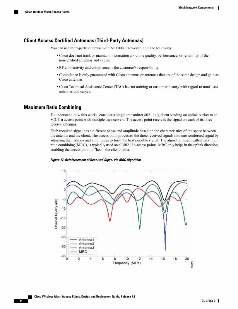
Maximum Ratio CombiningTo understand how this works, consider a single transmitter 802.11a/g client sending an uplink packet to an802.11n access point with multiple transceivers. The access point receives the signal on each of its threereceive antennas.
Each received signal has a different phase and amplitude based on the characteristics of the space betweenthe antenna and the client. The access point processes the three received signals into one reinforced signal byadjusting their phases and amplitudes to form the best possible signal. The algorithm used, called maximumratio combining (MRC), is typically used on all 802.11n access points. MRC only helps in the uplink direction,enabling the access point to "hear" the client better.
Figure 17: Reinforcement of Received Signal via MRC Algorithm
Cisco Wireless Mesh Access Points, Design and Deployment Guide, Release 7.334 OL-27593-01
Mesh Network ComponentsCisco Outdoor Mesh Access Points
For the 1520 Series
AP1520 radios have a much higher transmit power, better receiver sensitivity, and broader outdoor temperaturerange as compared to AP1510 and AP1505 mesh access points.
• The 5-GHz radio (802.11a) is a Single-in-Single-Out (SISO) architecture and the 2.4-GHz radio (802.11b/g) is 1x3 Single-in-Multiple-Out (SIMO) architecture.
• The 2.4-GHz radio has one transmitter and three receivers. Output power is configurable to 5 levels.With its 3 receivers enabling maximum-ratio combining (MRC), this radio has better sensitivity andrange than a typical SISO 802.11b/g radio for OFDM rates.
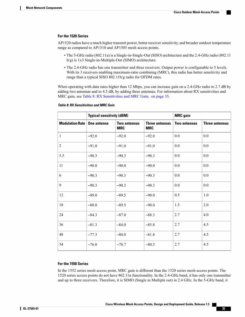
When operating with data rates higher than 12 Mbps, you can increase gain on a 2.4-GHz radio to 2.7 dB byadding two antennas and to 4.5 dB, by adding three antennas. For information about RX sensitivities andMRC gain, see Table 8: RX Sensitivities and MRC Gain, on page 35.
Table 8: RX Sensitivities and MRC Gain
MRC gainTypical sensitivity (dBM)
Three antennasTwo antennasThree antennasMRC
Two antennasMRC
One antennaModulation Rate
0.00.0–92.0–92.0–92.01
0.00.0–91.0–91.0–91.02
0.00.0–90.3–90.3–90.35.5
0.00.0–90.0–90.0–90.011
0.00.0–90.3–90.3–90.36
0.00.0–90.3–90.3–90.39
1.00.5–90.0–89.5–89.012
2.01.5–90.0–89.5–88.018
4.02.7–88.3–87.0–84.324
4.52.7–85.8–84.0–81.336
4.52.7–81.8–80.0–77.348
4.52.7–80.5–78.7–76.054
For the 1550 Series
In the 1552 series mesh access point, MRC gain is different than the 1520 series mesh access points. The1520 series access points do not have 802.11n functionality. In the 2.4-GHz band, it has only one transmitterand up to three receivers. Therefore, it is SIMO (Single in Multiple out) in 2.4 GHz. In the 5-GHz band, it
Cisco Wireless Mesh Access Points, Design and Deployment Guide, Release 7.3 OL-27593-01 35
Mesh Network ComponentsCisco Outdoor Mesh Access Points
has only one transmitter and one receiver. Therefore, it is SISO (Single in Single out) in the 5-GHz band. TheMRC gain is important only for the 2.4-GHz radio in the 1552 access points. The MRC is not available forthe 5-GHz radio. The 2.4-GHz radio has one Tx and up to three Rx antennas depending on the AP configuration.
In the 1522 access points, users have an option to use one, two, or three 2.4-GHz Rx antennas. With thisoption, users get around 3 dB MRC gain with 2 Rx antennas and a 4.5-dB MRC gain with 3 Rx antennas fordata rates of 24 Mbps or higher.
For the 1552 access points, both the 2.4- and 5-GHz radios are 2x3MIMO. Therefore, they have two transmittersand three receivers. Because the antennas are dual band and there is no option to have less than three Rxantennas, the MRC is added to the RX sensitivity always as it is embedded into the baseband chipset.
The number for typical Rx sensitivity in our customer data sheet assume 3 Rx antennas for both the 1520 andthe 1550 series access points.
With the chipset used in the AP1520 series radios, there was a start-of-packet problem at lower data rates thatwiped out the gain. Therefore, the MRC gain became useful from a data rate of 12 Mbps onwards in the 1520series access points. This problem has been corrected in the current chipset used in the 1552 access points.The MRC gain has improved for lower data rates as well in the 1552 access points. You get a 4.7-dBimprovement in sensitivity with the 2x3 MIMO radio over a 1x1 SISO implementation.
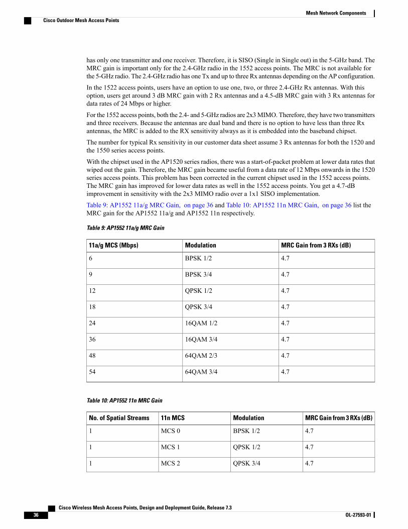
Table 9: AP1552 11a/g MRC Gain, on page 36 and Table 10: AP1552 11n MRC Gain, on page 36 list theMRC gain for the AP1552 11a/g and AP1552 11n respectively.
Table 9: AP1552 11a/g MRC Gain
MRC Gain from 3 RXs (dB)Modulation11a/g MCS (Mbps)
4.7BPSK 1/26
4.7BPSK 3/49
4.7QPSK 1/212
4.7QPSK 3/418
4.716QAM 1/224
4.716QAM 3/436
4.764QAM 2/348
4.764QAM 3/454
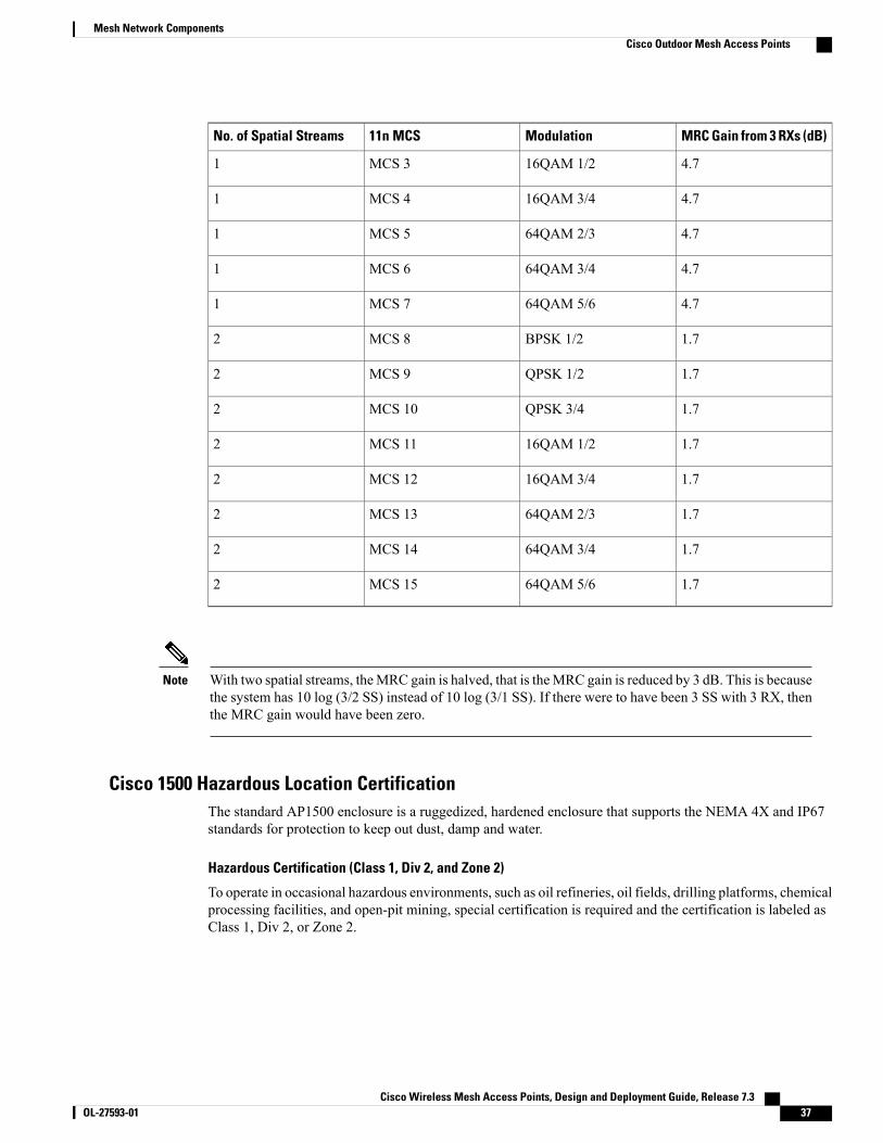
Table 10: AP1552 11n MRC Gain
MRC Gain from 3 RXs (dB)Modulation11n MCSNo. of Spatial Streams
4.7BPSK 1/2MCS 01
4.7QPSK 1/2MCS 11
4.7QPSK 3/4MCS 21
Cisco Wireless Mesh Access Points, Design and Deployment Guide, Release 7.336 OL-27593-01
Mesh Network ComponentsCisco Outdoor Mesh Access Points
MRC Gain from 3 RXs (dB)Modulation11n MCSNo. of Spatial Streams
4.716QAM 1/2MCS 31
4.716QAM 3/4MCS 41
4.764QAM 2/3MCS 51
4.764QAM 3/4MCS 61
4.764QAM 5/6MCS 71
1.7BPSK 1/2MCS 82
1.7QPSK 1/2MCS 92
1.7QPSK 3/4MCS 102
1.716QAM 1/2MCS 112
1.716QAM 3/4MCS 122
1.764QAM 2/3MCS 132
1.764QAM 3/4MCS 142
1.764QAM 5/6MCS 152
With two spatial streams, theMRC gain is halved, that is theMRC gain is reduced by 3 dB. This is becausethe system has 10 log (3/2 SS) instead of 10 log (3/1 SS). If there were to have been 3 SS with 3 RX, thenthe MRC gain would have been zero.
Note
Cisco 1500 Hazardous Location CertificationThe standard AP1500 enclosure is a ruggedized, hardened enclosure that supports the NEMA 4X and IP67standards for protection to keep out dust, damp and water.
Hazardous Certification (Class 1, Div 2, and Zone 2)
To operate in occasional hazardous environments, such as oil refineries, oil fields, drilling platforms, chemicalprocessing facilities, and open-pit mining, special certification is required and the certification is labeled asClass 1, Div 2, or Zone 2.
Cisco Wireless Mesh Access Points, Design and Deployment Guide, Release 7.3 OL-27593-01 37
Mesh Network ComponentsCisco Outdoor Mesh Access Points
For USA and Canada, this certification is CSA Class 1, Division 2. For Europe (EU), it is ATEX or IECClass 1, Zone 2.
Note
Cisco has Hazardous Certified SKUs for USA and EU: AIR-LAP1522HZ-x-K9, AIR-LAP1524HZ-x-K9,and AIR-LAP1552H-x-K9. These SKUs are modified, as per the certification requirements. The hazardouslocations certificate requires that all electrical power cables be run through conduit piping to protect againstaccidental damage to the electrical wiring that could cause a spark and possible explosion. Access points forhazardous locations contain an internal electrical mounting connect that receives discrete wires from a conduitinterface coupler entering from the side of the housing. After the electrical wiring is installed, a cover housingis installed over the electrical connector to prevent exposure to the electrical wiring. The outside of the housinghas a hazardous location certification label (CSA, ATEX, or IEC) that identifies the type of certifications andenvironments that the equipment is approved for operation.
Power entry module for CSA (USA and Canada) is Power Entry Module, Groups A, B, C, and D withT5v(120° C) temp code. Power Entry Module for ATEX (EU) is Power entry module Groups IIC, IIB,IIA with T5 (120° C) temp code.
Note
Hazardous Certification (Div 1 > Div 2 and Zone 1 > Zone 2)
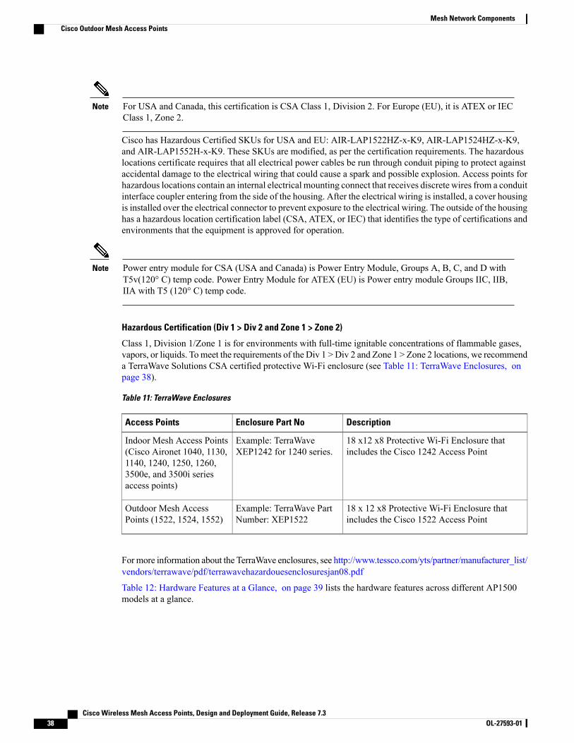
Class 1, Division 1/Zone 1 is for environments with full-time ignitable concentrations of flammable gases,vapors, or liquids. Tomeet the requirements of the Div 1 >Div 2 and Zone 1 > Zone 2 locations, we recommenda TerraWave Solutions CSA certified protective Wi-Fi enclosure (see Table 11: TerraWave Enclosures, onpage 38).
Table 11: TerraWave Enclosures
DescriptionEnclosure Part NoAccess Points
18 x12 x8 Protective Wi-Fi Enclosure thatincludes the Cisco 1242 Access Point
Example: TerraWaveXEP1242 for 1240 series.
Indoor Mesh Access Points(Cisco Aironet 1040, 1130,1140, 1240, 1250, 1260,3500e, and 3500i seriesaccess points)
18 x 12 x8 Protective Wi-Fi Enclosure thatincludes the Cisco 1522 Access Point
Example: TerraWave PartNumber: XEP1522
Outdoor Mesh AccessPoints (1522, 1524, 1552)
Formore information about the TerraWave enclosures, see http://www.tessco.com/yts/partner/manufacturer_list/vendors/terrawave/pdf/terrawavehazardouesenclosuresjan08.pdf
Table 12: Hardware Features at a Glance, on page 39 lists the hardware features across different AP1500models at a glance.
Cisco Wireless Mesh Access Points, Design and Deployment Guide, Release 7.338 OL-27593-01
Mesh Network ComponentsCisco Outdoor Mesh Access Points
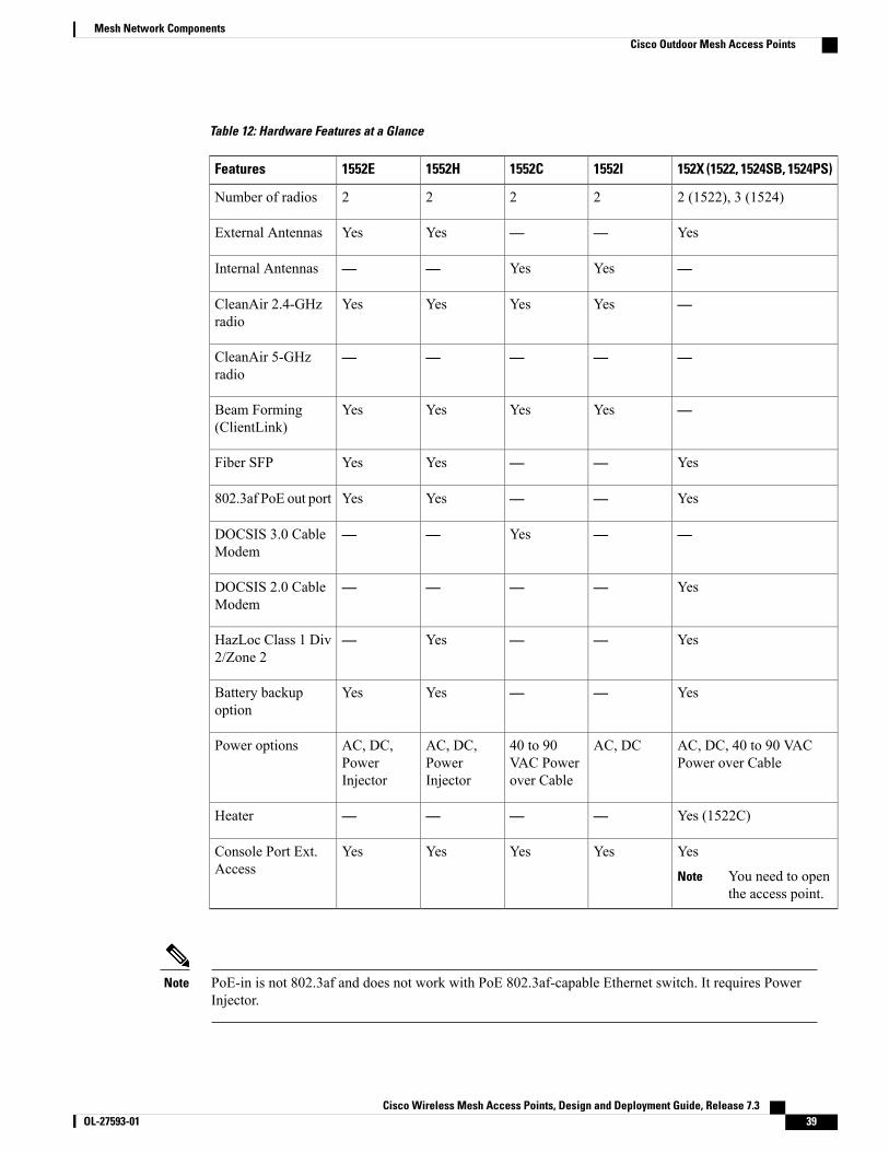
Table 12: Hardware Features at a Glance
152X (1522, 1524SB, 1524PS)1552I1552C1552H1552EFeatures
2 (1522), 3 (1524)2222Number of radios
Yes——YesYesExternal Antennas
—YesYes——Internal Antennas
—YesYesYesYesCleanAir 2.4-GHzradio
—————CleanAir 5-GHzradio
—YesYesYesYesBeam Forming(ClientLink)
Yes——YesYesFiber SFP
Yes——YesYes802.3af PoE out port
——Yes——DOCSIS 3.0 CableModem
Yes————DOCSIS 2.0 CableModem
Yes——Yes—HazLoc Class 1 Div2/Zone 2
Yes——YesYesBattery backupoption
AC, DC, 40 to 90 VACPower over Cable
AC, DC40 to 90VAC Powerover Cable
AC, DC,PowerInjector
AC, DC,PowerInjector
Power options
Yes (1522C)————Heater
Yes
You need to openthe access point.
Note
YesYesYesYesConsole Port Ext.Access
PoE-in is not 802.3af and does not work with PoE 802.3af-capable Ethernet switch. It requires PowerInjector.
Note
Cisco Wireless Mesh Access Points, Design and Deployment Guide, Release 7.3 OL-27593-01 39
Mesh Network ComponentsCisco Outdoor Mesh Access Points
Cisco Wireless LAN ControllersThe wireless mesh solution is supported on Cisco 2500, 5500, and 8500 Series Wireless LAN Controllers.
For more information about the Cisco 2500, 5500, and 8500 Series Wireless LAN Controllers, see http://www.cisco.com/en/US/products/ps6302/Products_Sub_Category_Home.html.
Cisco Prime InfrastructureThe Cisco Prime Infrastructure provides a graphical platform for wireless mesh planning, configuration, andmanagement. Network managers can use the Prime Infrastructure to design, control, and monitor wirelessmesh networks from a central location.
With the Prime Infrastructure, network administrators have a solution for RF prediction, policy provisioning,network optimization, troubleshooting, user tracking, security monitoring, and wireless LAN systemsmanagement. Graphical interfaces make wireless LAN deployment and operations simple and cost-effective.Detailed trending and analysis reports make the Prime Infrastructure vital to ongoing network operations.
The Prime Infrastructure runs on a server platform with an embedded database, which provides scalabilitythat allows hundreds of controllers and thousands of Cisco mesh access points to be managed. Controllerscan be located on the same LAN as the Prime Infrastructure, on separate routed subnets, or across a wide-areaconnection.
Architecture
Control and Provisioning of Wireless Access PointsControl and provisioning of wireless access points (CAPWAP) is the provisioning and control protocol usedby the controller to manage access points (mesh and nonmesh) in the network. In release 5.2, CAPWAPreplaced lightweight access point protocol (LWAPP).
CAPWAP significantly reduces capital expenditures (CapEx) and operational expenses (OpEx), whichenables the Cisco wireless mesh networking solution to be a cost-effective and secure deployment optionin enterprise, campus, and metropolitan networks.
Note
CAPWAP Discovery on a Mesh NetworkThe process for CAPWAP discovery on a mesh network is as follows:
1 A mesh access point establishes a link before starting CAPWAP discovery, whereas a nonmesh accesspoint starts CAPWAP discovery using a static IP for the mesh access point, if any.
2 The mesh access point initiates CAPWAP discovery using a static IP for the mesh access point on theLayer 3 network or searches the network for its assigned primary, secondary, or tertiary controller. Amaximum of 10 attempts are made to connect.
Cisco Wireless Mesh Access Points, Design and Deployment Guide, Release 7.340 OL-27593-01
Mesh Network ComponentsCisco Wireless LAN Controllers
The mesh access point searches a list of controllers configured on the access point (primed) during setup.Note
3 If Step 2 fails after 10 attempts, the mesh access point falls back to DHCP and attempts to connect in 10tries.
4 If both Steps 2 and 3 fail and there is no successful CAPWAP connection to a controller, then the meshaccess point falls back to LWAPP.
5 If there is no discovery after attempting Steps 2, 3, and 4, the mesh access point tries the next link.
Dynamic MTU DetectionIf the MTU is changed in the network, the access point detects the new MTU value and forwards that to thecontroller to adjust to the new MTU. After both the access point and the controller are set at the new MTU,all data within their path are fragmented into the new MTU. The new MTU size is used until it is changed.The default MTU on switches and routers is 1500 bytes.
XML Configuration FileMesh features within the controller’s boot configuration file are saved in an XML file in ASCII format. TheXML configuration file is saved in the flash memory of the controller.
The current release does not support binary configuration files; however, configuration files are in thebinary state immediately after an upgrade from a mesh release to controller software release 7.0. Afterreset, the XML configuration file is selected.
Note
Do not edit the XML file. Downloading a modified configuration file onto a controller causes a cyclicredundancy check (CRC) error on boot and the configuration is reset to the default values.
Caution
You can easily read and modify the XML configuration file by converting it to CLI format. To convert fromXML to CLI format, upload the configuration file to a TFTP or an FTP server. The controller initiates theconversion from XML to CLI during the upload.
Once on the server, you can read or edit the configuration file in CLI format. Then, you can download thefile back to the controller. The controller converts the configuration file back to XML format, saves it to flashmemory, and reboots using the new configuration.
The controller does not support uploading and downloading of port configuration CLI commands. If you wantto configure the controller ports, enter the relevant commands summarized below:
Cisco Wireless Mesh Access Points, Design and Deployment Guide, Release 7.3 OL-27593-01 41
Mesh Network ComponentsXML Configuration File
The commands listed below are manually entered after the software upgrade to release 7.0.Note
• config port linktrap {port | all} {enable | disable}–Enables or disables the up and down link trapsfor a specific controller port or for all ports.
• config port adminmode {port | all} {enable | disable}–Enables or disables the administrative modefor a specific controller port or for all ports.
• config port multicast appliance port {enable | disable}–Enables or disables the multicast applianceservice for a specific controller port.
• config port power {port | all} {enable | disable}–Enables or disables power over Ethernet (PoE)for a specific controller port or for all ports.
CLI commands with known keywords and proper syntax are converted to XMLwhile improper CLI commandsare ignored and saved to flash memory. Any field with an invalid value is filtered out and set to a default valueby the XML validation engine.Validation occurs during bootup.
To see any ignored commands or invalid configuration values, enter the following command:
show invalid-config
You can only execute this command before either the clear config or save config command. If thedownloaded configuration contains a large number of invalid CLI commands, you might want to uploadthe invalid configuration to the TFTP or FTP server for analysis.
Note
Access passwords are hidden (obfuscated) in the configuration file. To enable or disable access point orcontroller passwords, enter the following command:
config switchconfig secret-obfuscation {enable | disable}
Adaptive Wireless Path ProtocolThe AdaptiveWireless Path Protocol (AWPP) is designed specifically for wireless mesh networking to provideease of deployment, fast convergence, and minimal resource consumption.
AWPP takes advantage of the CAPWAP WLAN, where client traffic is tunneled to the controller and istherefore hidden from the AWPP process. Also, the advance radio management features in the CAPWAPWLAN solution are available to the wireless mesh network and do not have to be built into AWPP.
AWPP enables a remote access point to dynamically find the best path back to a RAP for each MAP that ispart of the RAP’s bridge group (BGN). Unlike traditional routing protocols, AWPP takes RF details intoaccount.
To optimize the route, a MAP actively solicits neighbor MAP. During the solicitation, the MAP learns all ofthe available neighbors back to a RAP, determines which neighbor offers the best path, and then synchronizeswith that neighbor. The path decisions of AWPP are based on the link quality and the number of hops.
AWPP automatically determines the best path back to the CAPWAP controller by calculating the cost of eachpath in terms of the signal strength and number of hops. After the path is established, AWPP continuouslymonitors conditions and changes routes to reflect changes in conditions. AWPP also performs a smoothing
Cisco Wireless Mesh Access Points, Design and Deployment Guide, Release 7.342 OL-27593-01
Mesh Network ComponentsAdaptive Wireless Path Protocol
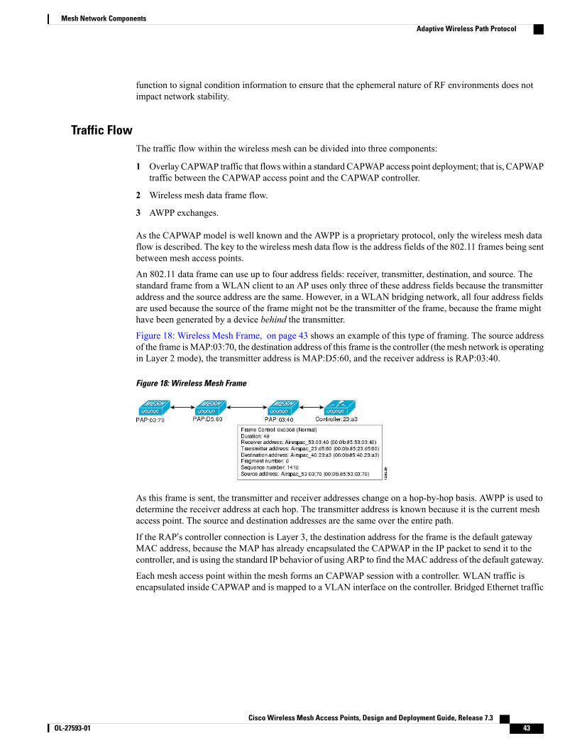
function to signal condition information to ensure that the ephemeral nature of RF environments does notimpact network stability.
Traffic FlowThe traffic flow within the wireless mesh can be divided into three components:
1 Overlay CAPWAP traffic that flowswithin a standard CAPWAP access point deployment; that is, CAPWAPtraffic between the CAPWAP access point and the CAPWAP controller.
2 Wireless mesh data frame flow.
3 AWPP exchanges.
As the CAPWAP model is well known and the AWPP is a proprietary protocol, only the wireless mesh dataflow is described. The key to the wireless mesh data flow is the address fields of the 802.11 frames being sentbetween mesh access points.
An 802.11 data frame can use up to four address fields: receiver, transmitter, destination, and source. Thestandard frame from a WLAN client to an AP uses only three of these address fields because the transmitteraddress and the source address are the same. However, in a WLAN bridging network, all four address fieldsare used because the source of the frame might not be the transmitter of the frame, because the frame mighthave been generated by a device behind the transmitter.
Figure 18: Wireless Mesh Frame, on page 43 shows an example of this type of framing. The source addressof the frame isMAP:03:70, the destination address of this frame is the controller (the mesh network is operatingin Layer 2 mode), the transmitter address is MAP:D5:60, and the receiver address is RAP:03:40.
Figure 18: Wireless Mesh Frame
As this frame is sent, the transmitter and receiver addresses change on a hop-by-hop basis. AWPP is used todetermine the receiver address at each hop. The transmitter address is known because it is the current meshaccess point. The source and destination addresses are the same over the entire path.
If the RAP’s controller connection is Layer 3, the destination address for the frame is the default gatewayMAC address, because the MAP has already encapsulated the CAPWAP in the IP packet to send it to thecontroller, and is using the standard IP behavior of using ARP to find theMAC address of the default gateway.
Each mesh access point within the mesh forms an CAPWAP session with a controller. WLAN traffic isencapsulated inside CAPWAP and is mapped to a VLAN interface on the controller. Bridged Ethernet traffic
Cisco Wireless Mesh Access Points, Design and Deployment Guide, Release 7.3 OL-27593-01 43
Mesh Network ComponentsAdaptive Wireless Path Protocol
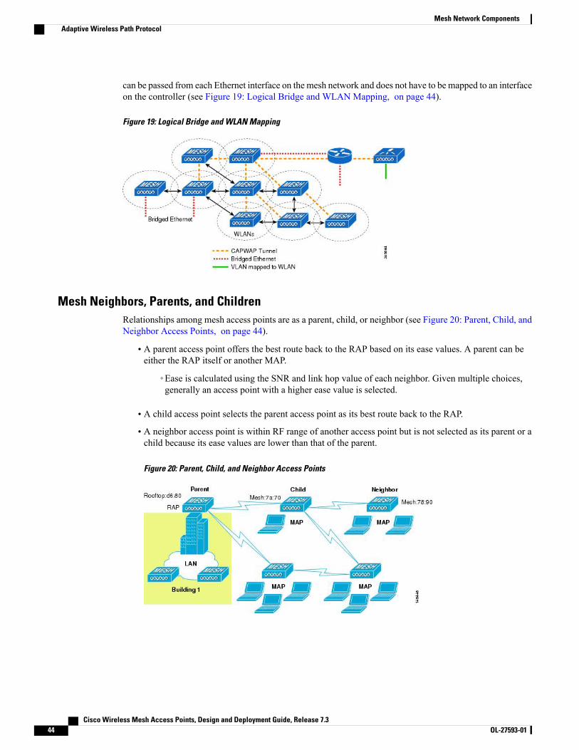
can be passed from each Ethernet interface on the mesh network and does not have to be mapped to an interfaceon the controller (see Figure 19: Logical Bridge and WLAN Mapping, on page 44).
Figure 19: Logical Bridge and WLAN Mapping
Mesh Neighbors, Parents, and ChildrenRelationships among mesh access points are as a parent, child, or neighbor (see Figure 20: Parent, Child, andNeighbor Access Points, on page 44).
• A parent access point offers the best route back to the RAP based on its ease values. A parent can beeither the RAP itself or another MAP.
◦Ease is calculated using the SNR and link hop value of each neighbor. Given multiple choices,generally an access point with a higher ease value is selected.
• A child access point selects the parent access point as its best route back to the RAP.
• A neighbor access point is within RF range of another access point but is not selected as its parent or achild because its ease values are lower than that of the parent.
Figure 20: Parent, Child, and Neighbor Access Points
Cisco Wireless Mesh Access Points, Design and Deployment Guide, Release 7.344 OL-27593-01
Mesh Network ComponentsAdaptive Wireless Path Protocol
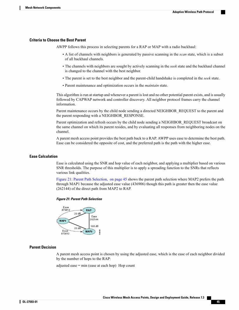
Criteria to Choose the Best Parent
AWPP follows this process in selecting parents for a RAP or MAP with a radio backhaul:
• A list of channels with neighbors is generated by passive scanning in the scan state, which is a subsetof all backhaul channels.
• The channels with neighbors are sought by actively scanning in the seek state and the backhaul channelis changed to the channel with the best neighbor.
• The parent is set to the best neighbor and the parent-child handshake is completed in the seek state.
• Parent maintenance and optimization occurs in the maintain state.
This algorithm is run at startup and whenever a parent is lost and no other potential parent exists, and is usuallyfollowed by CAPWAP network and controller discovery. All neighbor protocol frames carry the channelinformation.
Parent maintenance occurs by the child node sending a directed NEIGHBOR_REQUEST to the parent andthe parent responding with a NEIGHBOR_RESPONSE.
Parent optimization and refresh occurs by the child node sending a NEIGHBOR_REQUEST broadcast onthe same channel on which its parent resides, and by evaluating all responses from neighboring nodes on thechannel.
A parent mesh access point provides the best path back to a RAP. AWPP uses ease to determine the best path.Ease can be considered the opposite of cost, and the preferred path is the path with the higher ease.
Ease Calculation
Ease is calculated using the SNR and hop value of each neighbor, and applying a multiplier based on variousSNR thresholds. The purpose of this multiplier is to apply a spreading function to the SNRs that reflectsvarious link qualities.
Figure 21: Parent Path Selection, on page 45 shows the parent path selection where MAP2 prefers the paththrough MAP1 because the adjusted ease value (436906) though this path is greater then the ease value(262144) of the direct path from MAP2 to RAP.
Figure 21: Parent Path Selection
Parent Decision
A parent mesh access point is chosen by using the adjusted ease, which is the ease of each neighbor dividedby the number of hops to the RAP:
adjusted ease = min (ease at each hop) Hop count
Cisco Wireless Mesh Access Points, Design and Deployment Guide, Release 7.3 OL-27593-01 45
Mesh Network ComponentsAdaptive Wireless Path Protocol
SNR Smoothing
One of the challenges in WLAN routing is the ephemeral nature of RF, which must be considered whenanalyzing an optimal path and deciding when a change in path is required. The SNR on a given RF link canchange substantially from moment to moment, and changing route paths based on these fluctuations resultsin an unstable network, with severely degraded performance. To effectively capture the underlying SNR butremove moment-to-moment fluctuations, a smoothing function is applied that provides an adjusted SNR.
In evaluating potential neighbors against the current parent, the parent is given 20 percent of bonus-ease ontop of the parent's calculated ease, to reduce the ping-pong effect between parents. A potential parent mustbe significantly better for a child to make a switch. Parent switching is transparent to CAPWAP and otherhigher-layer functions.
Loop Prevention
To ensure that routing loops are not created, AWPP discards any route that contains its own MAC address.That is, routing information apart from hop information contains the MAC address of each hop to the RAP;therefore, a mesh access point can easily detect and discard routes that loop.
Cisco Wireless Mesh Access Points, Design and Deployment Guide, Release 7.346 OL-27593-01
Mesh Network ComponentsAdaptive Wireless Path Protocol