Embed Size (px)
Citation preview

Metal-induced fluorescence properties of three-dimensionally ordered macroporoussilver inverse opal platformsWeon-Sik Chae, Myung-Jin Lee, Kisun Kim, Jerome K. Hyun, and Seokwoo Jeon Citation: Applied Physics Letters 108, 071909 (2016); doi: 10.1063/1.4942397 View online: http://dx.doi.org/10.1063/1.4942397 View Table of Contents: http://scitation.aip.org/content/aip/journal/apl/108/7?ver=pdfcov Published by the AIP Publishing Articles you may be interested in Three-dimensional ferromagnetic architectures with multiple metastable states Appl. Phys. Lett. 98, 222506 (2011); 10.1063/1.3595339 Surface-enhanced fluorescence from metal sculptured thin films with application to biosensing in water Appl. Phys. Lett. 94, 063106 (2009); 10.1063/1.3081031 Conversion of just-continuous metallic films to large particulate substrates for metal-enhanced fluorescence J. Appl. Phys. 103, 084307 (2008); 10.1063/1.2905319 Metal-enhanced fluorescence: Surface plasmons can radiate a fluorophore’s structured emission Appl. Phys. Lett. 90, 053107 (2007); 10.1063/1.2435661 Electrical properties of superfilled sub-micrometer silver metallizations J. Appl. Phys. 96, 759 (2004); 10.1063/1.1757655
Reuse of AIP Publishing content is subject to the terms at: https://publishing.aip.org/authors/rights-and-permissions. Download to IP: 143.248.118.108 On: Fri, 01 Apr 2016
02:17:55
Metal-induced fluorescence properties of three-dimensionally orderedmacroporous silver inverse opal platforms
Weon-Sik Chae,1,a) Myung-Jin Lee,2 Kisun Kim,3 Jerome K. Hyun,4 and Seokwoo Jeon3,a)
1Analysis Research Division, Daegu Center, Korea Basic Science Institute, Daegu 702-701, South Korea2Gangneung Center, Korea Basic Science Institute, Gangneung 210-702, South Korea3Department of Materials Science and Engineering, KAIST Institute for the Nanocentury, Korea AdvancedInstitute of Science and Technology (KAIST), Daejeon 305-338, South Korea4Department of Chemistry and Nano Science, Ewha Womans University, Seoul 120-750, South Korea
(Received 15 December 2015; accepted 7 February 2016; published online 19 February 2016)
This study examined the metal-induced fluorescence properties of three-dimensionally ordered
macroporous silver inverse opal (IO) films. Electrochemically synthesized silver IO films with a
micrometer cavity exhibited notable fluorescence enhancement at the silver frame, and a decrease
in fluorescence lifetime. Numerical calculations supported the observations of a higher fluorescence
efficiency at the frame than in the cavity. VC 2016 AIP Publishing LLC.
[http://dx.doi.org/10.1063/1.4942397]
Fluorescent molecules near a plasmonic metal surface
possess interesting emission properties, which are manifested
by modulations in intensity, wavelength, and lifetime.1 In
particular, nanostructured plasmonic metals enable remark-
able amplification of the optical characteristics due to
enhanced electromagnetic interactions between the adjacent
fluorophores and metal surface.2–7 One of the most fre-
quently observed phenomena is the so-called optical antenna
effect, in which the accumulation of an electric field around
a metal surface reinforces the excitation probability for mol-
ecules, typically resulting in amplified emission.8–12
Furthermore, plasmonic metals provide an additional direct
radiative pathway for excited electrons, resulting in
enhanced quantum yields and blue-shifted emission.1,13,14
On the other hand, the strong coupling of fluorophores
with a metal at the interface can also result in emission
quenching.15–17 The photoexcited electrons in a molecule
can be transferred easily to bound metal nanoparticles, dis-
rupting the radiative recombination. According to theoretical
calculations18,19 and experimental observations,20,21 larger
particles and skeletons are suitable for reducing the absorp-
tion cross-section of a metal while increasing the scattering
cross-section. This minimizes emission quenching and
enhances the fluorescence (FL) due to the optical antenna
effect.22,23
A film-type porous skeleton composed of a plasmonic
metal has obvious advantages. Porous metal films have a non-
dispersible robust configuration in a fluidic system compared
to mobile nanoparticles in solution, thereby reducing the
accompanying secondary problems, such as environmental
and cytotoxic issues for further applications. The current tech-
nology provides versatile fabrication routes via chemical
reduction,24,25 electrochemical deposition,26–28 and evapora-
tion29,30 for forming and removing templates to prepare po-
rous metal skeletons. Recently, three-dimensionally ordered
macroporous (3DOM) materials with a range of compositions
were prepared successfully via a colloidal opal templating
route.24,26,28,31 The noble metal 3DOM structures have been
proven to be highly efficient as substrates for surface-
enhanced Raman scattering.3,6,27 Nevertheless, 3DOM materi-
als have not been applied to the study of metal-induced FL
(MIF).
This study examined the MIF characteristics of the
3DOM Ag inverse opal (IO) skeletons, which were prepared
by electrochemical deposition using colloidal opals as the
template film (see supplementary material32). A standard flu-
orescent dye molecule, rhodamine 123, in solution was intro-
duced to the porous Ag IO skeletons. The FL properties were
examined using time-resolved FL lifetime imaging micros-
copy (FLIM), where the position-dependent MIF modula-
tions in intensity and lifetime could be measured directly.
These results showed that the 3DOM Ag IO frame performs
as a stable and uniform platform for FL enhancement.
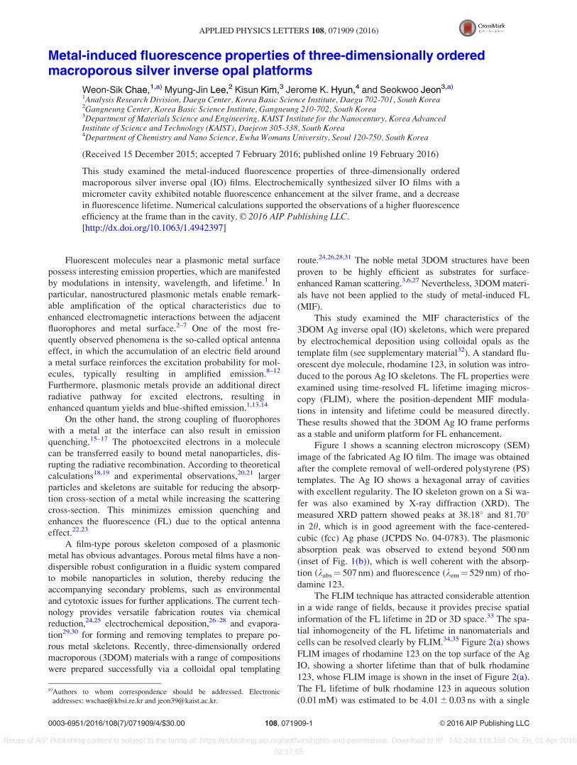
Figure 1 shows a scanning electron microscopy (SEM)
image of the fabricated Ag IO film. The image was obtained
after the complete removal of well-ordered polystyrene (PS)
templates. The Ag IO shows a hexagonal array of cavities
with excellent regularity. The IO skeleton grown on a Si wa-
fer was also examined by X-ray diffraction (XRD). The
measured XRD pattern showed peaks at 38.18� and 81.70�
in 2h, which is in good agreement with the face-centered-
cubic (fcc) Ag phase (JCPDS No. 04-0783). The plasmonic
absorption peak was observed to extend beyond 500 nm
(inset of Fig. 1(b)), which is well coherent with the absorp-
tion (kabs¼ 507 nm) and fluorescence (kem¼ 529 nm) of rho-
damine 123.
The FLIM technique has attracted considerable attention
in a wide range of fields, because it provides precise spatial
information of the FL lifetime in 2D or 3D space.33 The spa-
tial inhomogeneity of the FL lifetime in nanomaterials and
cells can be resolved clearly by FLIM.34,35 Figure 2(a) shows
FLIM images of rhodamine 123 on the top surface of the Ag
IO, showing a shorter lifetime than that of bulk rhodamine
123, whose FLIM image is shown in the inset of Figure 2(a).
The FL lifetime of bulk rhodamine 123 in aqueous solution
(0.01 mM) was estimated to be 4.01 6 0.03 ns with a single
a)Authors to whom correspondence should be addressed. Electronic
addresses: [email protected] and [email protected].
0003-6951/2016/108(7)/071909/4/$30.00 VC 2016 AIP Publishing LLC108, 071909-1
APPLIED PHYSICS LETTERS 108, 071909 (2016)
Reuse of AIP Publishing content is subject to the terms at: https://publishing.aip.org/authors/rights-and-permissions. Download to IP: 143.248.118.108 On: Fri, 01 Apr 2016
02:17:55
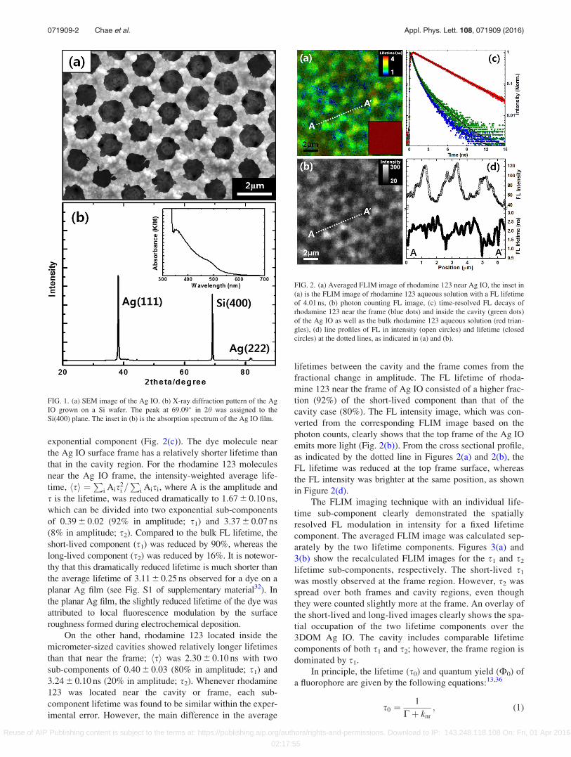
exponential component (Fig. 2(c)). The dye molecule near
the Ag IO surface frame has a relatively shorter lifetime than
that in the cavity region. For the rhodamine 123 molecules
near the Ag IO frame, the intensity-weighted average life-
time, hsi ¼P
i Ais2i =P
i Aisi, where A is the amplitude and
s is the lifetime, was reduced dramatically to 1.67 6 0.10 ns,
which can be divided into two exponential sub-components
of 0.39 6 0.02 (92% in amplitude; s1) and 3.37 6 0.07 ns
(8% in amplitude; s2). Compared to the bulk FL lifetime, the
short-lived component (s1) was reduced by 90%, whereas the
long-lived component (s2) was reduced by 16%. It is notewor-
thy that this dramatically reduced lifetime is much shorter than
the average lifetime of 3.11 6 0.25 ns observed for a dye on a
planar Ag film (see Fig. S1 of supplementary material32). In
the planar Ag film, the slightly reduced lifetime of the dye was
attributed to local fluorescence modulation by the surface
roughness formed during electrochemical deposition.
On the other hand, rhodamine 123 located inside the
micrometer-sized cavities showed relatively longer lifetimes
than that near the frame; hsi was 2.30 6 0.10 ns with two
sub-components of 0.40 6 0.03 (80% in amplitude; s1) and
3.24 6 0.10 ns (20% in amplitude; s2). Whenever rhodamine
123 was located near the cavity or frame, each sub-
component lifetime was found to be similar within the exper-
imental error. However, the main difference in the average
lifetimes between the cavity and the frame comes from the
fractional change in amplitude. The FL lifetime of rhoda-
mine 123 near the frame of Ag IO consisted of a higher frac-
tion (92%) of the short-lived component than that of the
cavity case (80%). The FL intensity image, which was con-
verted from the corresponding FLIM image based on the
photon counts, clearly shows that the top frame of the Ag IO
emits more light (Fig. 2(b)). From the cross sectional profile,
as indicated by the dotted line in Figures 2(a) and 2(b), the
FL lifetime was reduced at the top frame surface, whereas
the FL intensity was brighter at the same position, as shown
in Figure 2(d).
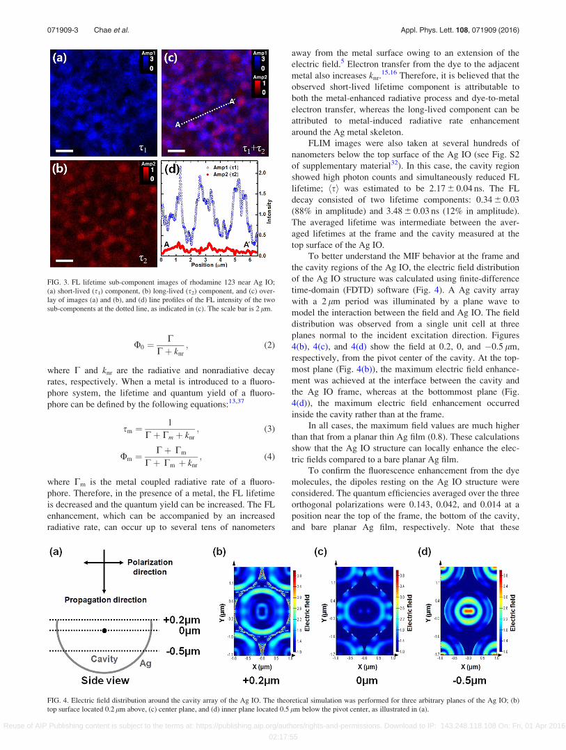
The FLIM imaging technique with an individual life-
time sub-component clearly demonstrated the spatially
resolved FL modulation in intensity for a fixed lifetime
component. The averaged FLIM image was calculated sep-
arately by the two lifetime components. Figures 3(a) and
3(b) show the recalculated FLIM images for the s1 and s2
lifetime sub-components, respectively. The short-lived s1
was mostly observed at the frame region. However, s2 was
spread over both frames and cavity regions, even though
they were counted slightly more at the frame. An overlay of
the short-lived and long-lived images clearly shows the spa-
tial occupation of the two lifetime components over the
3DOM Ag IO. The cavity includes comparable lifetime
components of both s1 and s2; however, the frame region is
dominated by s1.
In principle, the lifetime (s0) and quantum yield (A0) of
a fluorophore are given by the following equations:13,36
s0 ¼1
Cþ knr
; (1)
FIG. 1. (a) SEM image of the Ag IO. (b) X-ray diffraction pattern of the Ag
IO grown on a Si wafer. The peak at 69.09� in 2h was assigned to the
Si(400) plane. The inset in (b) is the absorption spectrum of the Ag IO film.
FIG. 2. (a) Averaged FLIM image of rhodamine 123 near Ag IO, the inset in
(a) is the FLIM image of rhodamine 123 aqueous solution with a FL lifetime
of 4.01 ns, (b) photon counting FL image, (c) time-resolved FL decays of
rhodamine 123 near the frame (blue dots) and inside the cavity (green dots)
of the Ag IO as well as the bulk rhodamine 123 aqueous solution (red trian-
gles), (d) line profiles of FL in intensity (open circles) and lifetime (closed
circles) at the dotted lines, as indicated in (a) and (b).
071909-2 Chae et al. Appl. Phys. Lett. 108, 071909 (2016)
Reuse of AIP Publishing content is subject to the terms at: https://publishing.aip.org/authors/rights-and-permissions. Download to IP: 143.248.118.108 On: Fri, 01 Apr 2016
02:17:55
U0 ¼C
Cþ knr
; (2)
where C and knr are the radiative and nonradiative decay
rates, respectively. When a metal is introduced to a fluoro-
phore system, the lifetime and quantum yield of a fluoro-
phore can be defined by the following equations:13,37
sm ¼1
Cþ Cm þ knr
; (3)
Um ¼Cþ Cm
Cþ Cm þ knr
; (4)
where Cm is the metal coupled radiative rate of a fluoro-
phore. Therefore, in the presence of a metal, the FL lifetime
is decreased and the quantum yield can be increased. The FL
enhancement, which can be accompanied by an increased
radiative rate, can occur up to several tens of nanometers
away from the metal surface owing to an extension of the
electric field.5 Electron transfer from the dye to the adjacent
metal also increases knr.15,16 Therefore, it is believed that the
observed short-lived lifetime component is attributable to
both the metal-enhanced radiative process and dye-to-metal
electron transfer, whereas the long-lived component can be
attributed to metal-induced radiative rate enhancement
around the Ag metal skeleton.
FLIM images were also taken at several hundreds of
nanometers below the top surface of the Ag IO (see Fig. S2
of supplementary material32). In this case, the cavity region
showed high photon counts and simultaneously reduced FL
lifetime; hsi was estimated to be 2.17 6 0.04 ns. The FL
decay consisted of two lifetime components: 0.34 6 0.03
(88% in amplitude) and 3.48 6 0.03 ns (12% in amplitude).
The averaged lifetime was intermediate between the aver-
aged lifetimes at the frame and the cavity measured at the
top surface of the Ag IO.
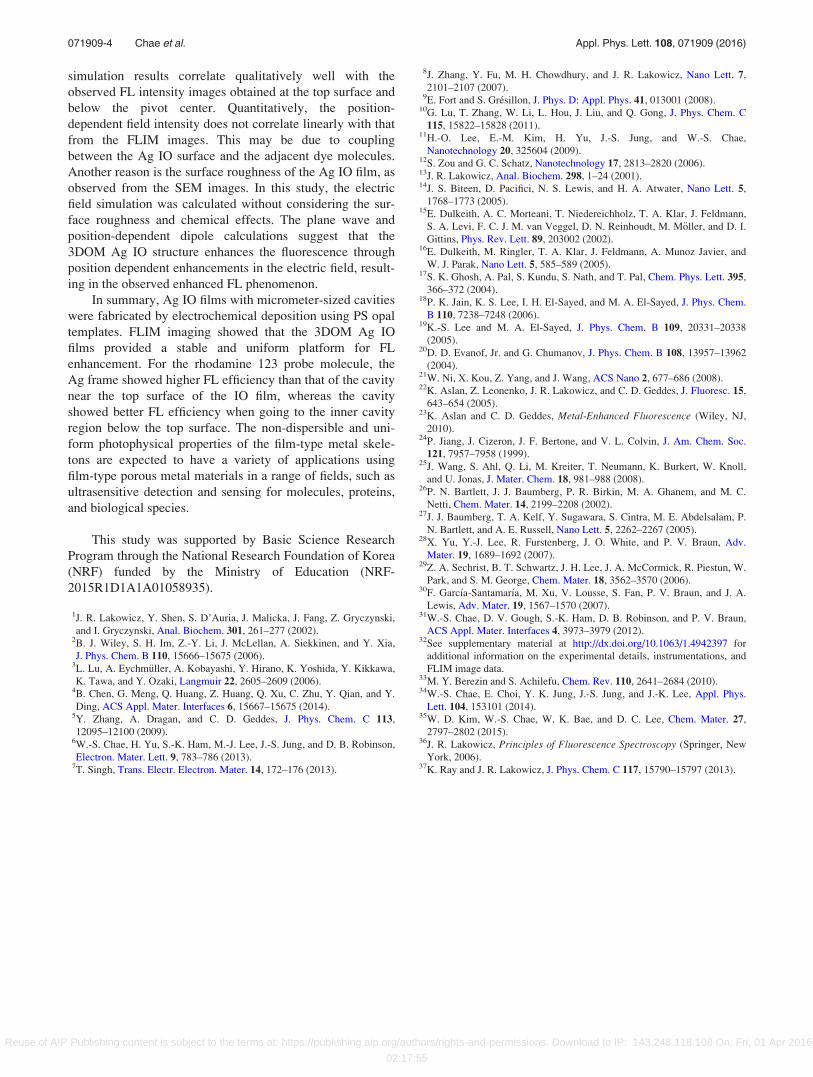
To better understand the MIF behavior at the frame and
the cavity regions of the Ag IO, the electric field distribution
of the Ag IO structure was calculated using finite-difference
time-domain (FDTD) software (Fig. 4). A Ag cavity array
with a 2 lm period was illuminated by a plane wave to
model the interaction between the field and Ag IO. The field
distribution was observed from a single unit cell at three
planes normal to the incident excitation direction. Figures
4(b), 4(c), and 4(d) show the field at 0.2, 0, and �0.5 lm,
respectively, from the pivot center of the cavity. At the top-
most plane (Fig. 4(b)), the maximum electric field enhance-
ment was achieved at the interface between the cavity and
the Ag IO frame, whereas at the bottommost plane (Fig.
4(d)), the maximum electric field enhancement occurred
inside the cavity rather than at the frame.
In all cases, the maximum field values are much higher
than that from a planar thin Ag film (0.8). These calculations
show that the Ag IO structure can locally enhance the elec-
tric fields compared to a bare planar Ag film.
To confirm the fluorescence enhancement from the dye
molecules, the dipoles resting on the Ag IO structure were
considered. The quantum efficiencies averaged over the three
orthogonal polarizations were 0.143, 0.042, and 0.014 at a
position near the top of the frame, the bottom of the cavity,
and bare planar Ag film, respectively. Note that these
FIG. 3. FL lifetime sub-component images of rhodamine 123 near Ag IO;
(a) short-lived (s1) component, (b) long-lived (s2) component, and (c) over-
lay of images (a) and (b), and (d) line profiles of the FL intensity of the two
sub-components at the dotted line, as indicated in (c). The scale bar is 2 lm.
FIG. 4. Electric field distribution around the cavity array of the Ag IO. The theoretical simulation was performed for three arbitrary planes of the Ag IO; (b)
top surface located 0.2 lm above, (c) center plane, and (d) inner plane located 0.5 lm below the pivot center, as illustrated in (a).
071909-3 Chae et al. Appl. Phys. Lett. 108, 071909 (2016)
Reuse of AIP Publishing content is subject to the terms at: https://publishing.aip.org/authors/rights-and-permissions. Download to IP: 143.248.118.108 On: Fri, 01 Apr 2016
02:17:55
simulation results correlate qualitatively well with the
observed FL intensity images obtained at the top surface and
below the pivot center. Quantitatively, the position-
dependent field intensity does not correlate linearly with that
from the FLIM images. This may be due to coupling
between the Ag IO surface and the adjacent dye molecules.
Another reason is the surface roughness of the Ag IO film, as
observed from the SEM images. In this study, the electric
field simulation was calculated without considering the sur-
face roughness and chemical effects. The plane wave and
position-dependent dipole calculations suggest that the
3DOM Ag IO structure enhances the fluorescence through
position dependent enhancements in the electric field, result-
ing in the observed enhanced FL phenomenon.
In summary, Ag IO films with micrometer-sized cavities
were fabricated by electrochemical deposition using PS opal
templates. FLIM imaging showed that the 3DOM Ag IO
films provided a stable and uniform platform for FL
enhancement. For the rhodamine 123 probe molecule, the
Ag frame showed higher FL efficiency than that of the cavity
near the top surface of the IO film, whereas the cavity
showed better FL efficiency when going to the inner cavity
region below the top surface. The non-dispersible and uni-
form photophysical properties of the film-type metal skele-
tons are expected to have a variety of applications using
film-type porous metal materials in a range of fields, such as
ultrasensitive detection and sensing for molecules, proteins,
and biological species.
This study was supported by Basic Science Research
Program through the National Research Foundation of Korea
(NRF) funded by the Ministry of Education (NRF-
2015R1D1A1A01058935).
1J. R. Lakowicz, Y. Shen, S. D’Auria, J. Malicka, J. Fang, Z. Gryczynski,
and I. Gryczynski, Anal. Biochem. 301, 261–277 (2002).2B. J. Wiley, S. H. Im, Z.-Y. Li, J. McLellan, A. Siekkinen, and Y. Xia,
J. Phys. Chem. B 110, 15666–15675 (2006).3L. Lu, A. Eychm€uller, A. Kobayashi, Y. Hirano, K. Yoshida, Y. Kikkawa,
K. Tawa, and Y. Ozaki, Langmuir 22, 2605–2609 (2006).4B. Chen, G. Meng, Q. Huang, Z. Huang, Q. Xu, C. Zhu, Y. Qian, and Y.
Ding, ACS Appl. Mater. Interfaces 6, 15667–15675 (2014).5Y. Zhang, A. Dragan, and C. D. Geddes, J. Phys. Chem. C 113,
12095–12100 (2009).6W.-S. Chae, H. Yu, S.-K. Ham, M.-J. Lee, J.-S. Jung, and D. B. Robinson,
Electron. Mater. Lett. 9, 783–786 (2013).7T. Singh, Trans. Electr. Electron. Mater. 14, 172–176 (2013).
8J. Zhang, Y. Fu, M. H. Chowdhury, and J. R. Lakowicz, Nano Lett. 7,
2101–2107 (2007).9E. Fort and S. Gr�esillon, J. Phys. D: Appl. Phys. 41, 013001 (2008).
10G. Lu, T. Zhang, W. Li, L. Hou, J. Liu, and Q. Gong, J. Phys. Chem. C
115, 15822–15828 (2011).11H.-O. Lee, E.-M. Kim, H. Yu, J.-S. Jung, and W.-S. Chae,
Nanotechnology 20, 325604 (2009).12S. Zou and G. C. Schatz, Nanotechnology 17, 2813–2820 (2006).13J. R. Lakowicz, Anal. Biochem. 298, 1–24 (2001).14J. S. Biteen, D. Pacifici, N. S. Lewis, and H. A. Atwater, Nano Lett. 5,
1768–1773 (2005).15E. Dulkeith, A. C. Morteani, T. Niedereichholz, T. A. Klar, J. Feldmann,
S. A. Levi, F. C. J. M. van Veggel, D. N. Reinhoudt, M. M€oller, and D. I.
Gittins, Phys. Rev. Lett. 89, 203002 (2002).16E. Dulkeith, M. Ringler, T. A. Klar, J. Feldmann, A. Munoz Javier, and
W. J. Parak, Nano Lett. 5, 585–589 (2005).17S. K. Ghosh, A. Pal, S. Kundu, S. Nath, and T. Pal, Chem. Phys. Lett. 395,
366–372 (2004).18P. K. Jain, K. S. Lee, I. H. El-Sayed, and M. A. El-Sayed, J. Phys. Chem.
B 110, 7238–7248 (2006).19K.-S. Lee and M. A. El-Sayed, J. Phys. Chem. B 109, 20331–20338
(2005).20D. D. Evanof, Jr. and G. Chumanov, J. Phys. Chem. B 108, 13957–13962
(2004).21W. Ni, X. Kou, Z. Yang, and J. Wang, ACS Nano 2, 677–686 (2008).22K. Aslan, Z. Leonenko, J. R. Lakowicz, and C. D. Geddes, J. Fluoresc. 15,
643–654 (2005).23K. Aslan and C. D. Geddes, Metal-Enhanced Fluorescence (Wiley, NJ,
2010).24P. Jiang, J. Cizeron, J. F. Bertone, and V. L. Colvin, J. Am. Chem. Soc.
121, 7957–7958 (1999).25J. Wang, S. Ahl, Q. Li, M. Kreiter, T. Neumann, K. Burkert, W. Knoll,
and U. Jonas, J. Mater. Chem. 18, 981–988 (2008).26P. N. Bartlett, J. J. Baumberg, P. R. Birkin, M. A. Ghanem, and M. C.
Netti, Chem. Mater. 14, 2199–2208 (2002).27J. J. Baumberg, T. A. Kelf, Y. Sugawara, S. Cintra, M. E. Abdelsalam, P.
N. Bartlett, and A. E. Russell, Nano Lett. 5, 2262–2267 (2005).28X. Yu, Y.-J. Lee, R. Furstenberg, J. O. White, and P. V. Braun, Adv.
Mater. 19, 1689–1692 (2007).29Z. A. Sechrist, B. T. Schwartz, J. H. Lee, J. A. McCormick, R. Piestun, W.
Park, and S. M. George, Chem. Mater. 18, 3562–3570 (2006).30F. Garc�ıa-Santamar�ıa, M. Xu, V. Lousse, S. Fan, P. V. Braun, and J. A.
Lewis, Adv. Mater. 19, 1567–1570 (2007).31W.-S. Chae, D. V. Gough, S.-K. Ham, D. B. Robinson, and P. V. Braun,
ACS Appl. Mater. Interfaces 4, 3973–3979 (2012).32See supplementary material at http://dx.doi.org/10.1063/1.4942397 for
additional information on the experimental details, instrumentations, and
FLIM image data.33M. Y. Berezin and S. Achilefu, Chem. Rev. 110, 2641–2684 (2010).34W.-S. Chae, E. Choi, Y. K. Jung, J.-S. Jung, and J.-K. Lee, Appl. Phys.
Lett. 104, 153101 (2014).35W. D. Kim, W.-S. Chae, W. K. Bae, and D. C. Lee, Chem. Mater. 27,
2797–2802 (2015).36J. R. Lakowicz, Principles of Fluorescence Spectroscopy (Springer, New
York, 2006).37K. Ray and J. R. Lakowicz, J. Phys. Chem. C 117, 15790–15797 (2013).
071909-4 Chae et al. Appl. Phys. Lett. 108, 071909 (2016)
Reuse of AIP Publishing content is subject to the terms at: https://publishing.aip.org/authors/rights-and-permissions. Download to IP: 143.248.118.108 On: Fri, 01 Apr 2016
02:17:55