Embed Size (px)
Citation preview
Ms
Ya
b
Itatt
1
pifiahtccecmosadb
att
0h
Nuclear Engineering and Design 269 (2014) 286– 290
Contents lists available at ScienceDirect
Nuclear Engineering and Design
jo u r n al hom epa ge: www.elsev ier .com/ locate /nucengdes
ethod on the aging evaluation in nuclear power plant concretetructures
oshinori Kitsutakaa,∗, Masayuki Tsukagoshib
Department of Architecture and Building Engineering, Tokyo Metropolitan University, Tokyo, JapanDepartment of Civil and Environmental Engineering, The University of Tokushima, Tokushima, Japan
a b s t r a c t
n this paper, method on the durability evaluation in nuclear power plant concrete structures was investigated. In view of the importance of evaluatinghe degree of deterioration of reinforced concrete structures, relationships should be formulated among the number of years elapsed, t, the amount ofction of a deteriorative factor, F, the degree of material deterioration, D, and the performance of the structure, P. Evaluation by PDFt diagrams combininghese relationships may be effective. A detailed procedure of durability evaluation for a reinforced concrete structure using PDFt concept is presented forhe deterioration factors of thermal effect, irradiation, neutralization and penetration of salinity by referring to the recent papers.
. Introduction
Important reinforced concrete structures in nuclear powerlant require aging management and evaluation, which comprise
ntegrity evaluation assuming their use for decades ahead to con-rm the effectiveness of the current maintenance program, as wells extraction of new maintenance measures as required. Thereas been an enormous accumulation of study results regardinghe durability evaluation and deterioration prediction of reinforcedoncrete structures. However, durability evaluation of reinforcedoncrete structures generally involves the problems of a wide vari-ty of external factors and a combination of reinforcing steel andoncrete. In view of the importance of evaluating not only eachaterial but also the composite body for evaluating the degree
f deterioration of reinforced concrete structures, relationshipshould be formulated among the number of years elapsed, t, themount of action of a deteriorative factor, F, the degree of materialeterioration, D, and the performance of the structure, P. Evaluationy PDFt diagrams combining these relationships may be effective.
In this paper, a detailed procedure of durability evaluation for reinforced concrete structure using PDFt concept is presented forhe deterioration factors of thermal effect, irradiation, neutraliza-ion and penetration of salinity by referring to the recent papers.
∗ Corresponding author.E-mail address: [email protected] (Y. Kitsutaka).
029-5493/$ – see front matter © 2013 Published by Elsevier B.V.ttp://dx.doi.org/10.1016/j.nucengdes.2013.08.041
© 2013 Published by Elsevier B.V.
2. Thermal effect
2.1. Current evaluation method
In the current evaluation method contained in the “ReviewManual for Age-Related Technical Assessment” (JNES, 2009), thedegradation of concrete is evaluated according to whether or notthe temperature levels of concrete structures over the life span ofthe structure is less than reference levels (the reference levels oftemperature of 90 ◦C for concrete structures in designated areasand 65 ◦C for structures elsewhere indicate the risk for thermaldegradation.)
2.2. F-t diagram. Relation between the amount of action of adeteriorative factor, F, and the number of years elapsed, t
F3 (subscript “3” represents the thermal deterioration) is theamount of action of a thermal deteriorative factor, which is relatedto the change of cement hydrates due to thermal effect. Relationbetween this factor and time t (year) is shown in the extrapolationformula (1).
F3 = ˛3 · t (1)
where ˛3 is the thermal deterioration coefficient for change ofcement hydrates due to thermal effect. As on example, based onthe chemical kinetics, this reaction can be shown as Eq. (2). Where,a and b is constant. T is temperature (◦C).
˛3 = a · exp(
− b
T
)(2)
Y. Kitsutaka, M. Tsukagoshi / Nuclear Engineering and Design 269 (2014) 286– 290 287
press
2D
spRW
pr(
D
w
orr
Fe
(Fig. 4) and 2.0 × 10¹⁰ (rad) for gamma-rays (Fig. 5) are obtained
Fig. 1. Relation between the temperatures and the com
.3. D–F Diagram. Relation the degree of material deterioration,, and the amount of action of a deteriorative factor, F
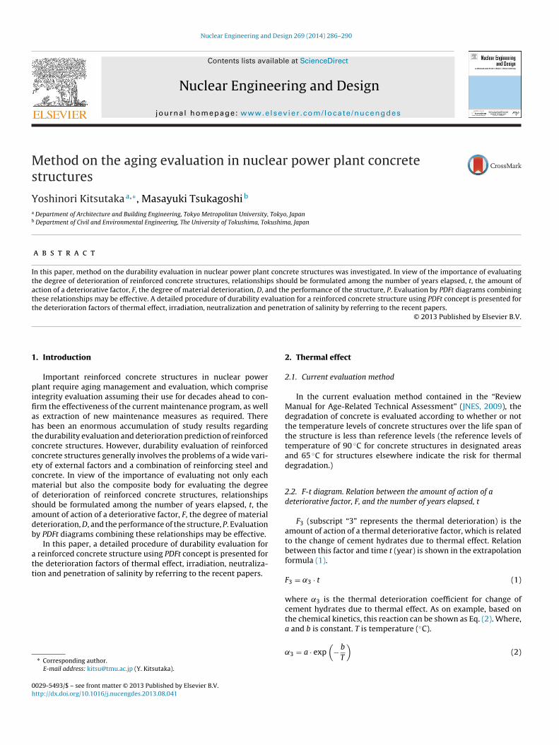
The compressive strength of concrete has a tendency towardignificant decreases in the early stages of exposure to a high tem-erature environment. Fig. 1 shows test results of U.S. Nuclearegulatory Commission Office of Nuclear Regulatory Researchashington (US Nuclear, 2006).Based on the experimental formula of Abe et al. (2007) the pro-
osed equation of the convergence value of compressive strengtheduction of concrete Du (–) is shown in Eq. (3) (Abe et al., 2007)Fig. 2).
u = (1 − 0.2� + 0.45�2 − 0.0436�3) exp(−0.413�) �
= 1.5T − 20
100(3)
here T is the temperature (◦C), T: 20–400 ◦C.Relation between the rate of compressive strength reduction
f concrete D1 (subscript “1” represents the compressive strengtheduction of concrete) and the amount of action of a thermal dete-iorative factor F3 is shown in Eq. (4). Fig. 3 shows relation between
ig. 2. The convergence value of compressive strength reduction of concrete (Abet al., 2007).
ive strength reduction of concrete (US Nuclear, 2006).
the rate of compressive strength reduction of concrete and theamount of action of a thermal deteriorative factor.
D1 = e−F3(1 − Du) + Du (4)
where Du is convergence value of compressive strength reductionof concrete depending on temperature (–).
3. Irradiation (neutron radiations and gamma ray)
3.1. Current evaluation method
In the current evaluation method of “Review Manual forAge-Related Technical Assessment”, the strength of concrete isevaluated according to whether or not the radiation levels overthe life span of the structure are less than reference levels. The ref-erence levels of 1.0 × 10²⁰ (n/cm2) for fluence of neutron radiation
from the Hilsdorf’s paper and are employed in assessing soundnessof irradiated concrete (Hilsdorf et al., 1978).
The
degr
ee o
f mat
eria
l det
erio
ratio
nD
The
rate
of c
ompr
essi
ve s
tren
gth
redu
ctio
n of
con
cret
eD1
The amo unt of action of a deterior ative facto r FThe amount of ac tion of a thermal deteriora tive fac tor F3(= 3 t)
Du-T1
0
1
Du-T2
Fig. 3. Relation between the rate of compressive strength reduction of concrete andthe amount of action of a thermal deteriorative factor.
288 Y. Kitsutaka, M. Tsukagoshi / Nuclear Engineering and Design 269 (2014) 286– 290
Ft
3d
ia
F
wri
3D
pr
D
w(
D
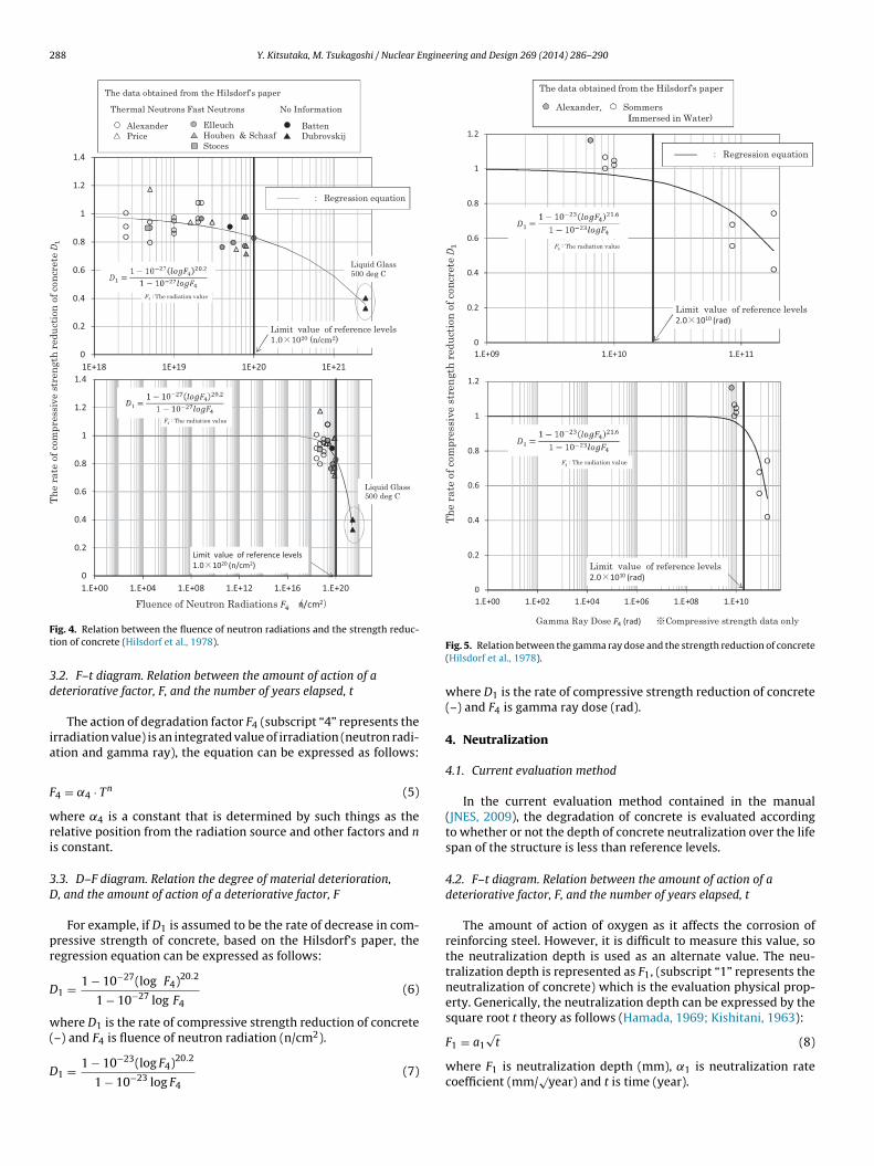
ig. 4. Relation between the fluence of neutron radiations and the strength reduc-ion of concrete (Hilsdorf et al., 1978).
.2. F–t diagram. Relation between the amount of action of aeteriorative factor, F, and the number of years elapsed, t
The action of degradation factor F4 (subscript “4” represents therradiation value) is an integrated value of irradiation (neutron radi-tion and gamma ray), the equation can be expressed as follows:
4 = ˛4 · Tn (5)
here ˛4 is a constant that is determined by such things as theelative position from the radiation source and other factors and ns constant.
.3. D–F diagram. Relation the degree of material deterioration,, and the amount of action of a deteriorative factor, F
For example, if D1 is assumed to be the rate of decrease in com-ressive strength of concrete, based on the Hilsdorf’s paper, theegression equation can be expressed as follows:
1 = 1 − 10−27(log F4)20.2
1 − 10−27 log F4(6)
here D1 is the rate of compressive strength reduction of concrete
–) and F4 is fluence of neutron radiation (n/cm2).1 = 1 − 10−23(log F4)20.2
1 − 10−23 log F4(7)
Fig. 5. Relation between the gamma ray dose and the strength reduction of concrete(Hilsdorf et al., 1978).
where D1 is the rate of compressive strength reduction of concrete(–) and F4 is gamma ray dose (rad).
4. Neutralization
4.1. Current evaluation method
In the current evaluation method contained in the manual(JNES, 2009), the degradation of concrete is evaluated accordingto whether or not the depth of concrete neutralization over the lifespan of the structure is less than reference levels.
4.2. F–t diagram. Relation between the amount of action of adeteriorative factor, F, and the number of years elapsed, t
The amount of action of oxygen as it affects the corrosion ofreinforcing steel. However, it is difficult to measure this value, sothe neutralization depth is used as an alternate value. The neu-tralization depth is represented as F1, (subscript “1” represents theneutralization of concrete) which is the evaluation physical prop-erty. Generically, the neutralization depth can be expressed by thesquare root t theory as follows (Hamada, 1969; Kishitani, 1963):
F1 = a1√
t (8)
where F1 is neutralization depth (mm), ˛1 is neutralization ratecoefficient (mm/
√year) and t is time (year).
Y. Kitsutaka, M. Tsukagoshi / Nuclear Engine
Ctn
tn
Chl
orid
e co
ncen
trat
ionCt(kg/m3 )
Elapse d time t (year)
(Amount of action of chlo ride ion)
Ccr
tcr
F
4D
eomrcaT
W
w(iiori
D
wicc
5
5
2ocl
5d
t
as follows (Japan, 2004),
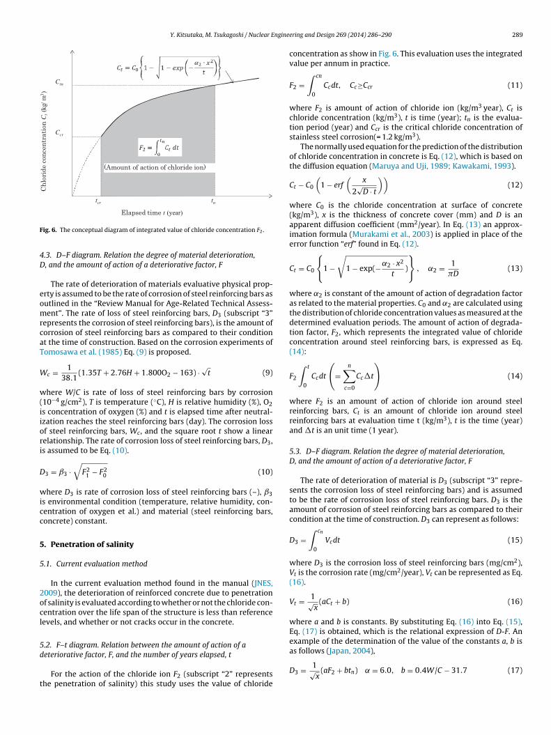
ig. 6. The conceptual diagram of integrated value of chloride concentration F2.
.3. D–F diagram. Relation the degree of material deterioration,, and the amount of action of a deteriorative factor, F
The rate of deterioration of materials evaluative physical prop-rty is assumed to be the rate of corrosion of steel reinforcing bars asutlined in the “Review Manual for Age-Related Technical Assess-ent”. The rate of loss of steel reinforcing bars, D3 (subscript “3”
epresents the corrosion of steel reinforcing bars), is the amount oforrosion of steel reinforcing bars as compared to their conditiont the time of construction. Based on the corrosion experiments ofomosawa et al. (1985) Eq. (9) is proposed.
c = 138.1
(1.35T + 2.76H + 1.800O2 − 163) ·√
t (9)
here W/C is rate of loss of steel reinforcing bars by corrosion10−4 g/cm2), T is temperature (◦C), H is relative humidity (%), O2s concentration of oxygen (%) and t is elapsed time after neutral-zation reaches the steel reinforcing bars (day). The corrosion lossf steel reinforcing bars, Wc, and the square root t show a linearelationship. The rate of corrosion loss of steel reinforcing bars, D3,s assumed to be Eq. (10).
3 = ˇ3 ·√
F21 − F2
0 (10)
here D3 is rate of corrosion loss of steel reinforcing bars (–), ˇ3s environmental condition (temperature, relative humidity, con-entration of oxygen et al.) and material (steel reinforcing bars,oncrete) constant.
. Penetration of salinity
.1. Current evaluation method
In the current evaluation method found in the manual (JNES,009), the deterioration of reinforced concrete due to penetrationf salinity is evaluated according to whether or not the chloride con-entration over the life span of the structure is less than referenceevels, and whether or not cracks occur in the concrete.
.2. F–t diagram. Relation between the amount of action of a
eteriorative factor, F, and the number of years elapsed, tFor the action of the chloride ion F2 (subscript “2” representshe penetration of salinity) this study uses the value of chloride
ering and Design 269 (2014) 286– 290 289
concentration as show in Fig. 6. This evaluation uses the integratedvalue per annum in practice.
F2 =∫ cn
0
Ccdt, Cc≥Ccr (11)
where F2 is amount of action of chloride ion (kg/m3 year), Ct ischloride concentration (kg/m3), t is time (year); tn is the evalua-tion period (year) and Ccr is the critical chloride concentration ofstainless steel corrosion(= 1.2 kg/m3).
The normally used equation for the prediction of the distributionof chloride concentration in concrete is Eq. (12), which is based onthe diffusion equation (Maruya and Uji, 1989; Kawakami, 1993).
Ct − C0
(1 − erf
(x
2√
D · t
))(12)
where C0 is the chloride concentration at surface of concrete(kg/m3), x is the thickness of concrete cover (mm) and D is anapparent diffusion coefficient (mm2/year). In Eq. (13) an approx-imation formula (Murakami et al., 2003) is applied in place of theerror function “erf” found in Eq. (12).
Ct = C0
{1 −√
1 − exp(−˛2 · x2
t)
}, ˛2 = 1
�D(13)
where ˛2 is constant of the amount of action of degradation factoras related to the material properties. C0 and ˛2 are calculated usingthe distribution of chloride concentration values as measured at thedetermined evaluation periods. The amount of action of degrada-tion factor, F2, which represents the integrated value of chlorideconcentration around steel reinforcing bars, is expressed as Eq.(14):
F2
∫ t
0
Ccdt
(=
n∑c=0
Cc�t
)(14)
where F2 is an amount of action of chloride ion around steelreinforcing bars, Ct is an amount of chloride ion around steelreinforcing bars at evaluation time t (kg/m3), t is the time (year)and �t is an unit time (1 year).
5.3. D–F diagram. Relation the degree of material deterioration,D, and the amount of action of a deteriorative factor, F
The rate of deterioration of material is D3 (subscript “3” repre-sents the corrosion loss of steel reinforcing bars) and is assumedto be the rate of corrosion loss of steel reinforcing bars. D3 is theamount of corrosion of steel reinforcing bars as compared to theircondition at the time of construction. D3 can represent as follows:
D3 =∫ cn
0
Vcdt (15)
where D3 is the corrosion loss of steel reinforcing bars (mg/cm2),Vt is the corrosion rate (mg/cm2/year), Vt can be represented as Eq.(16).
Vt = 1√x
(aCt + b) (16)
where a and b is constants. By substituting Eq. (16) into Eq. (15),Eq. (17) is obtained, which is the relational expression of D-F. Anexample of the determination of the value of the constants a, b is
D3 = 1√x
(aF2 + btn) ̨ = 6.0, b = 0.4W/C − 31.7 (17)
2 ngine
wds
5s
owb
D
wa(craboc
P
6
bofardc
of reinforcement. Summaries of Technical Papers of Annual Meeting, AIJ 9 (60),
90 Y. Kitsutaka, M. Tsukagoshi / Nuclear E
here W/C is water to cement ratio (%). If the diagram is to beetermined by the measurement value, then the corrosion loss ofteel reinforcing bars should use a multi-year measurement.
.4. P–D diagram. The relation between the performance of thetructure, P, and the degree of material degradation, D
The performance of the structure, P is assumed to be the widthf cracks in the concrete surface. The relation between when cracksill occur in the concrete and the corrosion loss of steel reinforcing
ars is shown as follows (Kitsutaka et al., 2011):
u = −(0.19d + 0.06x + 2.0) · ln(Fc) + 0.1d + 47 (19)
here Du is the critical corrosion loss of steel reinforcing bars toffect a crack in the concrete at a width of 0.1 mm by FEM analysismg/cm2), d is the diameter of steel reinforcing bars (mm), Fc is theompressive strength of concrete (N/mm2). There exists a linearelationship between the corrosion loss of steel reinforcing barsnd width of cracks in the concrete (Kitsutaka, 1998). The relationetween the corrosion loss of steel reinforcing bars, D3, and widthf cracks in the concrete, P8 (subscript “8” represents the crack ofoncrete) is expressed as follows:
B = 0.1D3
Du(20)
. Conclusion
In view of the importance of evaluating not only each materialut also the composite body for evaluating the degree of deteri-ration of reinforced concrete structures, relationships should beormulated among the number of years elapsed, t, the amount of
ction of a deteriorative factor, F, the degree of material deterio-ation, D, and the performance of the structure, P. In this paper, aetailed procedure of durability evaluation for a reinforced con-rete structure using PDFt concept is proposed by referring to theering and Design 269 (2014) 286– 290
recent papers for the deterioration factors of thermal effect, irradi-ation, neutralization and penetration of salinity.
Acknowledgement
A part of this study was supported by a grant from the JapaneseMinistry of Economy, Trade and Industry.
References
Abe, T., Ohtsuka, T., Kobayashi, Y., Michikoshi, S., 2007. Mechanical properties ofmoderate strength concrete at high temperatures. J. Struct. Construct. Eng. AIJ615 (5), 7–13.
Hamada, M., 1969. Neutralization (carbonation) of concrete and corrosion ofreinforcing steel. Cem. Concr. 10 (272), 2–18.
Hilsdorf, H.K., Kropp, J., Koch, H.J., 1978. The effects of nuclear radiation on theMechanical Properties of concrete, ACI SP-55.
Japan Concrete Institute, 2004. Commission’s Report, Symposium of Development ofSimulation Model for Detecting Long-term Performance of Concrete Structure,Equation of Tottori, 10., pp. 204.
Japan Nuclear Energy Safety Organization (JNES), 2009. “Review Manual for Age-related Technical assessment Reduction in Strength and Reduction in RadiationShielding Capability of Concrete”, JNES-SS-0512-04, 4.
Kawakami, H., Waki, K., 1993. Chloride permeation into concrete and estimation ofsaline environment. J. Struct. Construct. Eng. AIJ 11 (453), 9–14.
Kishitani, K., 1963. Durability of Reinforced Concrete. Kajima Publishing Co. Ltd.Kitsutaka, Y., 1998. Fracture-mechanical interpretation of prediction of corrosion
rate of steel bar by Crack Width in the concrete. In: Japan Concrete Institute,Symposium of Rehabilitation System of Concrete Structures, pp. 21–28.
Kitsutaka, Y., Nguyen, L.P., Tsukagoshi, M., Matsuzawa, K., 2011. Study of initialcracking in concrete and the corrosion loss of steel reinforcing bars. JCI Ann.Conven. Proc. CD-ROM 7, 1145–1150.
Maruya, T., Uji, K., 1989. Prediction of diffusive salt penetration into concrete. JCIAnn. Conven. Proc. 1 (1), 597–602.
Murakami, Y., Suda, K., Nagata, S., 2003. The square root theory on chloride ingress.Proc. 58th Ann. Conf. Jpn. Soc. Civil Eng. V-5 (9), 9–10.
Tomosawa, F., Fukushi, I., Morinaga, S., 1985. A preliminary study on the predic-tion of service life of reinforced concrete based on carbonation and corrosion
101–102.U.S. Nuclear Regulatory Commission Office of Nuclear Regulatory Research Wash-
ington, 2006. Primer on Durability of Nuclear Power Plant Reinforced ConcreteStructures – A Review of Pertinent Factors.