Embed Size (px)
Citation preview
Michelin Aircraft Tire
care & service manual


MAT-CSM 32-45-01 Revision E Title Page 1Revision: 1 January 2016
MICHELIN AIRCRAFT TIRECARE AND SERVICE MANUAL
For
MICHELIN® AIRCRAFT TIRES AND TUBES
Commercial
Regional
General Aviation
Military
Document Revision Date MAT-CSM 32-45-01 E 1 January 2016
The information contained herein is PROPRIETARY to Michelin. It is intended for the benefi t and use of owners and maintenance personnel of Michelin Aircraft Tires.
Contact Michelin for reproduction authorization.
Reproduction for other commercial purpose is not permitted.
Important Note: Any copy of this document may not be the updated document currently in effect. The current version is located on the Michelin aircraft tire website: www.airmichelin.com.
32-45-01
MAT-CSM 32-45-01 Revision E Title Page 2Revision: 1 January 2016
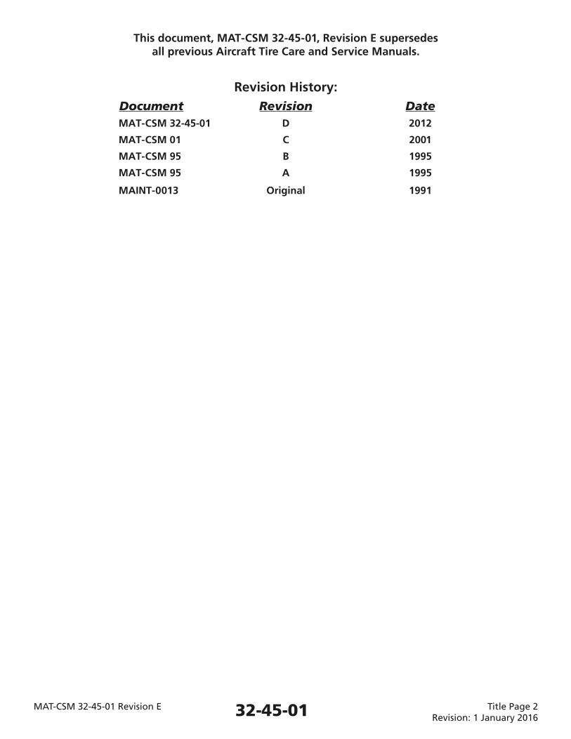
This document, MAT-CSM 32-45-01, Revision E supersedes all previous Aircraft Tire Care and Service Manuals.
Revision History: Document Revision Date MAT-CSM 32-45-01 D 2012
MAT-CSM 01 C 2001
MAT-CSM 95 B 1995
MAT-CSM 95 A 1995
MAINT-0013 Original 1991
32-45-01
SUBJECT TITLE PAGE
INTRODUCTION 1 1. General 1
2. Installation Approval 1
3. Warnings for the Full Manual 1
4. Related Source Documents 2
5. Related Source Organizations 2
6. Michelin Contacts 3
7. Cage Code 4
CHAPTER 1 AIRCRAFT TIRE DESCRIPTION/CONSTRUCTION 101 1. General 101
2. Tire Zones 102
3. Aircraft Tire Construction (Bias and Radial) 103
4. Components Unique to MICHELIN® Radial Aircraft Tires 104
5. Components Unique to MICHELIN® Bias Aircraft Tires 105
6. Sidewall Venting 107
7. Chine Tires 109
CHAPTER 2 AIRCRAFT TIRE TERMINOLOGY AND TIRE MARKINGS (Branding) 201 1. Tire Terminology 201
2. Tire Sizes 201
3. Tire Markings (Branding) 202
4. Retread Markings 211
5. Tube Markings 213
CHAPTER 3 RECEIVING AND STORING 301 1. Handling of Tires and Tubes 301
2. Storage of Unmounted Tires and Tubes 303
CHAPTER 4 MOUNTING INSTRUCTIONS (Assembly) 401 1. WARNINGS and NOTES for This Chapter 401
2. Materials 402
3. Tools, Fixtures and Equipment 403
4. Pre-Assembly Checklist for the Tire/Wheel Assembly (Hub) 404
5. Mounting (Assembly) – Tubeless Tires 407
6. Mounting (Assembly) – Tube-Type Tires 409
7. Infl ation of a Tire/Wheel Assembly to Operational Pressure 411
MAT-CSM 32-45-01 Revision E Table of Contents: Page 1 of 2Revision: 1 January 2016
MICHELINAIRCRAFT TIRE
CARE AND SERVICE MANUAL
TABLE OF CONTENTS
32-45-01
CHAPTER 4 MOUNTING INSTRUCTIONS (Assembly) Continued 8. Pressure Retention Check (Leak Check) – After Mounting 412
9. Investigation for the Cause of Pressure Loss 419
10. Transportation of an Infl ated Tire/Wheel Assembly 420
11. Storage of an Infl ated Tire/Wheel Assembly 421
12. Periodic Re-inspection of an Infl ated Tire 422
13. Mounting the Tire/Wheel Assembly on the Aircraft 422
CHAPTER 5 OPERATION ON AIRCRAFT 501 1. Proper Infl ation Pressure Maintenance 501
2. WARNINGS, CAUTIONS, and NOTES for This Chapter 501
3. Pressure Checks 502
4. Measure the Pressure When Tires Are “Cold” 503
5. Maintenance Action 504
6. Hot Tire Pressure Checks 506
7. Normal Wear Removal Criteria 506
8. Tire Damage to the Tread 508
9. Tire Damage to the Sidewall 521
10. Operating Conditions and Considerations 525
11. Matching and Mixability of Aircraft Tires 530
12. Tire Creep 531
13. Static Discharge 531
14. Tire Marking Tools 532
15. Military Arresting Cables 532
CHAPTER 6 DISMOUNTING (Disassembly) 601 1. General 601
2. WARNINGS and CAUTIONS for This Chapter 601
3. Track the Reasons for Tire Removal 601
4. Tools, Fixtures, and Equipment 602
5. Disassembly (Dismounting) of the Tire From the Wheel 606
6. Troubleshooting Disassembly (Dismounting) Issues 609
7. Tire Inspection After Dismounting 611
CHAPTER 7 RETREAD/REPAIR 701 1. General 701
2. Retreading Aircraft Tires 702
3. Repairing Aircraft Tires 702
MAT-CSM 32-45-01 Revision E Table of Contents: Page 2 of 2Revision: 1 January 2016
MICHELINAIRCRAFT TIRE
CARE AND SERVICE MANUAL
TABLE OF CONTENTS
32-45-01
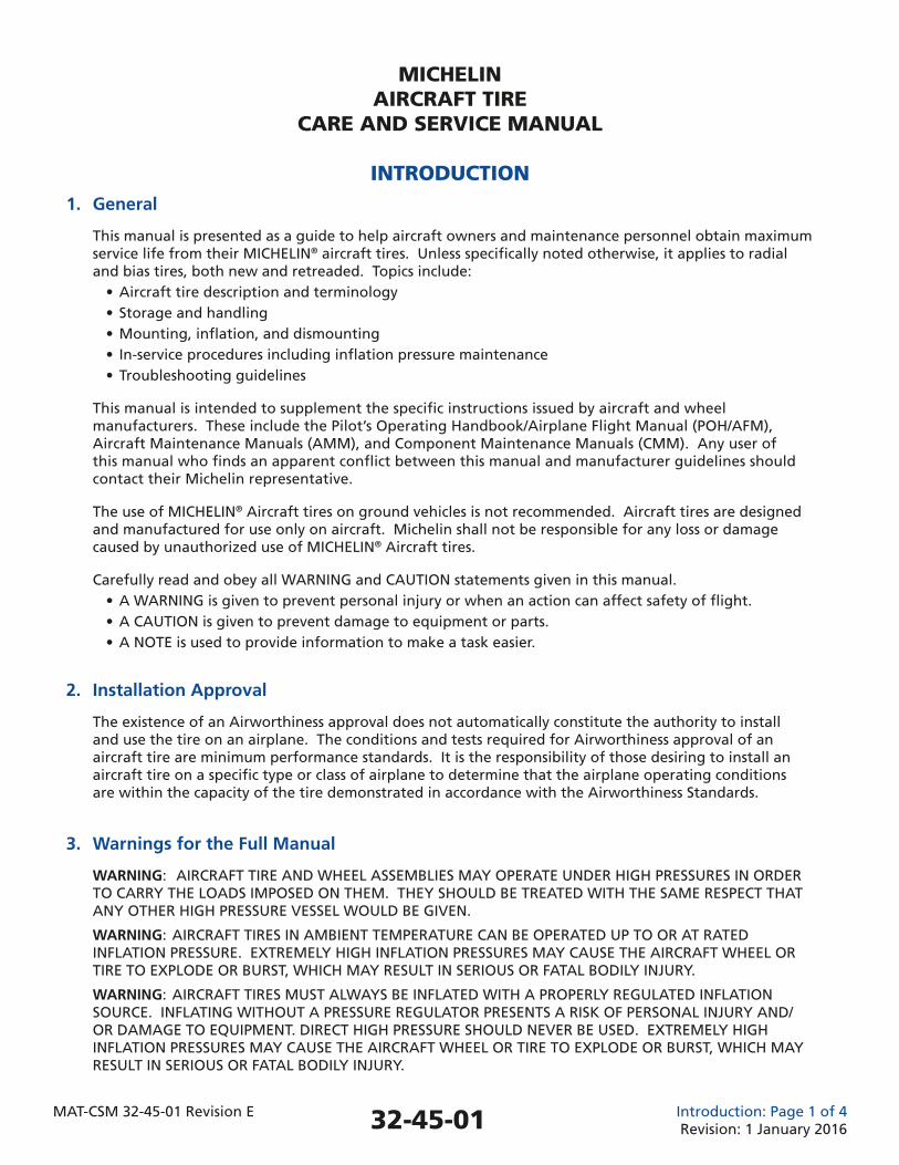
1. General
This manual is presented as a guide to help aircraft owners and maintenance personnel obtain maximum service life from their MICHELIN® aircraft tires. Unless specifi cally noted otherwise, it applies to radial and bias tires, both new and retreaded. Topics include: • Aircraft tire description and terminology • Storage and handling • Mounting, infl ation, and dismounting • In-service procedures including infl ation pressure maintenance • Troubleshooting guidelines
This manual is intended to supplement the specifi c instructions issued by aircraft and wheel manufacturers. These include the Pilot’s Operating Handbook/Airplane Flight Manual (POH/AFM), Aircraft Maintenance Manuals (AMM), and Component Maintenance Manuals (CMM). Any user of this manual who fi nds an apparent confl ict between this manual and manufacturer guidelines should contact their Michelin representative.
The use of MICHELIN® Aircraft tires on ground vehicles is not recommended. Aircraft tires are designed and manufactured for use only on aircraft. Michelin shall not be responsible for any loss or damage caused by unauthorized use of MICHELIN® Aircraft tires.
Carefully read and obey all WARNING and CAUTION statements given in this manual. • A WARNING is given to prevent personal injury or when an action can affect safety of fl ight. • A CAUTION is given to prevent damage to equipment or parts. • A NOTE is used to provide information to make a task easier.
2. Installation Approval
The existence of an Airworthiness approval does not automatically constitute the authority to install and use the tire on an airplane. The conditions and tests required for Airworthiness approval of an aircraft tire are minimum performance standards. It is the responsibility of those desiring to install an aircraft tire on a specifi c type or class of airplane to determine that the airplane operating conditions are within the capacity of the tire demonstrated in accordance with the Airworthiness Standards.
3. Warnings for the Full Manual
WARNING: AIRCRAFT TIRE AND WHEEL ASSEMBLIES MAY OPERATE UNDER HIGH PRESSURES IN ORDER TO CARRY THE LOADS IMPOSED ON THEM. THEY SHOULD BE TREATED WITH THE SAME RESPECT THAT ANY OTHER HIGH PRESSURE VESSEL WOULD BE GIVEN.
WARNING: AIRCRAFT TIRES IN AMBIENT TEMPERATURE CAN BE OPERATED UP TO OR AT RATED INFLATION PRESSURE. EXTREMELY HIGH INFLATION PRESSURES MAY CAUSE THE AIRCRAFT WHEEL OR TIRE TO EXPLODE OR BURST, WHICH MAY RESULT IN SERIOUS OR FATAL BODILY INJURY.
WARNING: AIRCRAFT TIRES MUST ALWAYS BE INFLATED WITH A PROPERLY REGULATED INFLATION SOURCE. INFLATING WITHOUT A PRESSURE REGULATOR PRESENTS A RISK OF PERSONAL INJURY AND/OR DAMAGE TO EQUIPMENT. DIRECT HIGH PRESSURE SHOULD NEVER BE USED. EXTREMELY HIGH INFLATION PRESSURES MAY CAUSE THE AIRCRAFT WHEEL OR TIRE TO EXPLODE OR BURST, WHICH MAY RESULT IN SERIOUS OR FATAL BODILY INJURY.
MICHELINAIRCRAFT TIRE
CARE AND SERVICE MANUAL
INTRODUCTION
MAT-CSM 32-45-01 Revision E Introduction: Page 1 of 4Revision: 1 January 201632-45-01
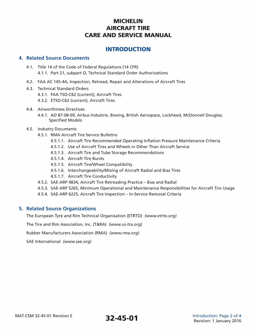
4. Related Source Documents
4.1. Title 14 of the Code of Federal Regulations (14 CFR) 4.1.1. Part 21, subpart O, Technical Standard Order Authorizations
4.2. FAA AC 145-4A, Inspection, Retread, Repair and Alterations of Aircraft Tires
4.3. Technical Standard Orders 4.3.1. FAA TSO-C62 (current), Aircraft Tires 4.3.2. ETSO-C62 (current), Aircraft Tires
4.4. Airworthiness Directives 4.4.1. AD 87-08-09, Airbus Industrie, Boeing, British Aerospace, Lockheed, McDonnell Douglas; Specifi ed Models
4.5. Industry Documents 4.5.1. RMA Aircraft Tire Service Bulletins 4.5.1.1. Aircraft Tire Recommended Operating Infl ation Pressure Maintenance Criteria 4.5.1.2. Use of Aircraft Tires and Wheels in Other Than Aircraft Service 4.5.1.3. Aircraft Tire and Tube Storage Recommendations 4.5.1.4. Aircraft Tire Bursts 4.5.1.5. Aircraft Tire/Wheel Compatibility 4.5.1.6. Interchangeability/Mixing of Aircraft Radial and Bias Tires 4.5.1.7. Aircraft Tire Conductivity 4.5.2. SAE-ARP 4834, Aircraft Tire Retreading Practice – Bias and Radial 4.5.3. SAE-ARP 5265, Minimum Operational and Maintenance Responsibilities for Aircraft Tire Usage 4.5.4. SAE-ARP 6225, Aircraft Tire Inspection – In-Service Removal Criteria
5. Related Source Organizations The European Tyre and Rim Technical Organisation (ETRTO) (www.etrto.org)
The Tire and Rim Association, Inc. (T&RA) (www.us-tra.org)
Rubber Manufacturers Association (RMA) (www.rma.org)
SAE International (www.sae.org)
MICHELINAIRCRAFT TIRE
CARE AND SERVICE MANUAL
INTRODUCTION
MAT-CSM 32-45-01 Revision E Introduction: Page 2 of 4Revision: 1 January 201632-45-01
6. Michelin Contacts
6.1. World Headquarters 6.1.1. Michelin Aircraft Tyre 23, Place des Carmes-Dechaux 63040 Clermont-Ferrand Cedex 9 France 6.2. Commercial Offi ces 6.2.1. North, Central and South America Michelin Aircraft Tire Company One Parkway South Greenville, SC 29615 U.S.A. 6.2.2. Europe, CIS, Middle East, Africa Michelin Aircraft Tyre 23, Place des Carmes-Dechaux 63040 Clermont-Ferrand Cedex 9 France 6.2.3. Far East and Oceania Michelin Siam Co. Aircraft Tyre Operations SPE Tower 11th Floor 252 Phaholyothin Road Samsaen Nai, Payathai Bangkok 10400 Thailand
NOTE: For more information, visit http://airmichelin.com
MICHELINAIRCRAFT TIRE
CARE AND SERVICE MANUAL
INTRODUCTION
MAT-CSM 32-45-01 Revision E Introduction: Page 3 of 4Revision: 1 January 201632-45-01
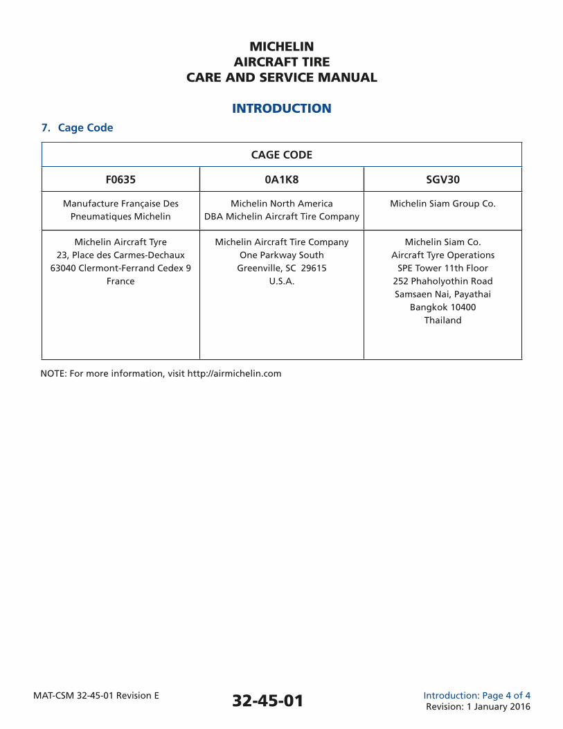
7. Cage Code
CAGE CODE
F0635 0A1K8 SGV30
Manufacture Française DesPneumatiques Michelin
Michelin North AmericaDBA Michelin Aircraft Tire Company
Michelin Siam Group Co.
Michelin Aircraft Tyre23, Place des Carmes-Dechaux
63040 Clermont-Ferrand Cedex 9France
Michelin Aircraft Tire CompanyOne Parkway South
Greenville, SC 29615U.S.A.
Michelin Siam Co.Aircraft Tyre Operations
SPE Tower 11th Floor252 Phaholyothin RoadSamsaen Nai, Payathai
Bangkok 10400Thailand
MICHELINAIRCRAFT TIRE
CARE AND SERVICE MANUAL
INTRODUCTION
MAT-CSM 32-45-01 Revision E Introduction: Page 4 of 4Revision: 1 January 2016
NOTE: For more information, visit http://airmichelin.com
32-45-01
101
MICHELINAIRCRAFT TIRE
CARE AND SERVICE MANUAL
CHAPTER 1 - AIRCRAFT TIRE DESCRIPTION/CONSTRUCTION
MAT-CSM 32-45-01 Revision E Description/Construction: Page 101 of 110Revision: 1 January 2016
1. General
1.1. An aircraft tire must withstand a wide range of operational conditions. While on the ground, it must support the weight of the aircraft. During taxi, it must provide a stable, cushioned ride while resisting heat generation, abrasion, and wear. During take-off, the tire structure must be able to endure not only the aircraft load, but also the forces generated at high angular velocities. Landing requires the tire to absorb impact shocks while also transmitting high dynamic braking loads to the ground. All of this must be accomplished while providing a long and reliable service life.
1.2. These extreme demands require a tire that is highly engineered and precisely manufactured. The tire is a composite of a number of different rubber compounds, fabric material and steel. Each component and rubber compound serves a specifi c purpose in the performance of the tire.
1.2.1. All MICHELIN® manufactured aircraft tires are certifi ed for in-service operation to -55°C (-67°F) ambient.
1.3. Two different and distinct aircraft tire constructions are produced and provided on the market. Both nomenclatures describe the differences in casing construction. 1.3.1. The Bias tire (cross-ply construction). 1.3.2. The Radial tire.
1.4. Many of the components of bias and radial tires have the same terminology. However, the technologies and process assemblies utilized are quite different requiring different design parameters, compounds, and materials.
1.5. This chapter describes the different components that make up the construction of an aircraft tire. Understanding these components and their purpose will help with the understanding of the MICHELIN Aircraft Tire Care and Service Manual and the recommendations contained herein.
1.6. While the technologies between bias tire and radial tire perform very differently, their in-service maintenance procedures and removal limit criteria remain similar.
1.7. An aircraft tire is received as a complete component. NOTE: A visual inspection of the tire is required to assure no handling damage has occurred during transport.
1.8. The tire must be mounted on a wheel to form a tire/wheel assembly prior to service use. NOTE: Refer to Chapter 4 – MOUNTING INSTRUCTIONS (Assembly), in this manual.
1.9. Many aircraft tires are designed to be retreaded. Retreading is the process of renewing the tread products of the tire allowing the casings to be used multiple times. Tires damaged in service may also be repairable. Retreading and repairing extends the service life of a casing, reducing operational costs and minimizing environmental impact. Refer to Chapter 7, RETREAD/REPAIR.
1.10. The FAA, EASA and regulatory organizations in other countries require that retreading and/or repair of aircraft tires be performed only by a certifi ed facility. The certifi cation is determined by the governing authority under which the operator is authorized.
1.11. Michelin meets or exceeds all testing requirements of the FAA/EASA for retreaded aircraft tires.
32-45-01
MICHELINAIRCRAFT TIRE
CARE AND SERVICE MANUAL
CHAPTER 1 - AIRCRAFT TIRE DESCRIPTION/CONSTRUCTION
MAT-CSM 32-45-01 Revision E Description/Construction: Page 102 of 110Revision: 1 January 2016
102
2. Tire Zones
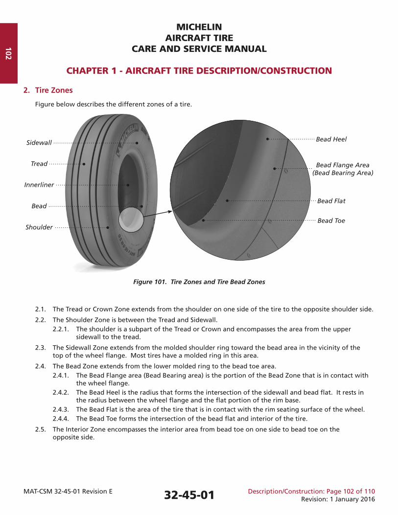
Figure below describes the different zones of a tire.
Figure 101. Tire Zones and Tire Bead Zones
2.1. The Tread or Crown Zone extends from the shoulder on one side of the tire to the opposite shoulder side.
2.2. The Shoulder Zone is between the Tread and Sidewall. 2.2.1. The shoulder is a subpart of the Tread or Crown and encompasses the area from the upper sidewall to the tread.
2.3. The Sidewall Zone extends from the molded shoulder ring toward the bead area in the vicinity of the top of the wheel fl ange. Most tires have a molded ring in this area.
2.4. The Bead Zone extends from the lower molded ring to the bead toe area. 2.4.1. The Bead Flange area (Bead Bearing area) is the portion of the Bead Zone that is in contact with the wheel fl ange. 2.4.2. The Bead Heel is the radius that forms the intersection of the sidewall and bead fl at. It rests in the radius between the wheel fl ange and the fl at portion of the rim base. 2.4.3. The Bead Flat is the area of the tire that is in contact with the rim seating surface of the wheel. 2.4.4. The Bead Toe forms the intersection of the bead fl at and interior of the tire.
2.5. The Interior Zone encompasses the interior area from bead toe on one side to bead toe on the opposite side.
32-45-01
Tread
Shoulder
Bead
Innerliner
Sidewall Bead Heel
Bead Flange Area(Bead Bearing Area)
Bead Flat
Bead Toe
103
MICHELINAIRCRAFT TIRE
CARE AND SERVICE MANUAL
CHAPTER 1 - AIRCRAFT TIRE DESCRIPTION/CONSTRUCTION
MAT-CSM 32-45-01 Revision E Description/Construction: Page 103 of 110Revision: 1 January 2016
3. Aircraft Tire Construction (Bias and Radial)
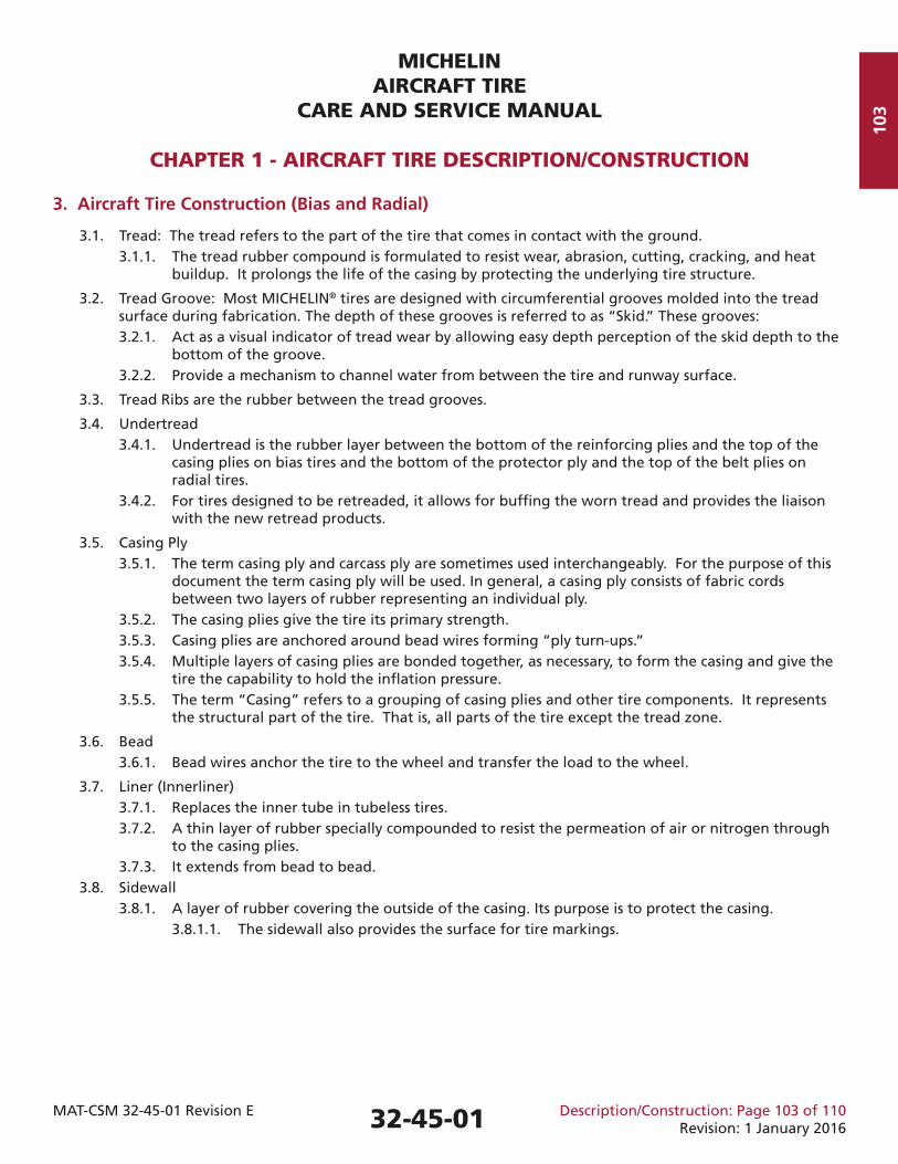
3.1. Tread: The tread refers to the part of the tire that comes in contact with the ground. 3.1.1. The tread rubber compound is formulated to resist wear, abrasion, cutting, cracking, and heat buildup. It prolongs the life of the casing by protecting the underlying tire structure.
3.2. Tread Groove: Most MICHELIN® tires are designed with circumferential grooves molded into the tread surface during fabrication. The depth of these grooves is referred to as “Skid.” These grooves: 3.2.1. Act as a visual indicator of tread wear by allowing easy depth perception of the skid depth to the bottom of the groove. 3.2.2. Provide a mechanism to channel water from between the tire and runway surface.
3.3. Tread Ribs are the rubber between the tread grooves.
3.4. Undertread 3.4.1. Undertread is the rubber layer between the bottom of the reinforcing plies and the top of the casing plies on bias tires and the bottom of the protector ply and the top of the belt plies on radial tires. 3.4.2. For tires designed to be retreaded, it allows for buffi ng the worn tread and provides the liaison with the new retread products.
3.5. Casing Ply 3.5.1. The term casing ply and carcass ply are sometimes used interchangeably. For the purpose of this document the term casing ply will be used. In general, a casing ply consists of fabric cords between two layers of rubber representing an individual ply. 3.5.2. The casing plies give the tire its primary strength. 3.5.3. Casing plies are anchored around bead wires forming “ply turn-ups.” 3.5.4. Multiple layers of casing plies are bonded together, as necessary, to form the casing and give the tire the capability to hold the infl ation pressure. 3.5.5. The term “Casing” refers to a grouping of casing plies and other tire components. It represents the structural part of the tire. That is, all parts of the tire except the tread zone.
3.6. Bead 3.6.1. Bead wires anchor the tire to the wheel and transfer the load to the wheel.
3.7. Liner (Innerliner) 3.7.1. Replaces the inner tube in tubeless tires. 3.7.2. A thin layer of rubber specially compounded to resist the permeation of air or nitrogen through to the casing plies. 3.7.3. It extends from bead to bead. 3.8. Sidewall 3.8.1. A layer of rubber covering the outside of the casing. Its purpose is to protect the casing. 3.8.1.1. The sidewall also provides the surface for tire markings.
32-45-01
MICHELINAIRCRAFT TIRE
CARE AND SERVICE MANUAL
CHAPTER 1 - AIRCRAFT TIRE DESCRIPTION/CONSTRUCTION
MAT-CSM 32-45-01 Revision E Description/Construction: Page 104 of 110Revision: 1 January 2016
104
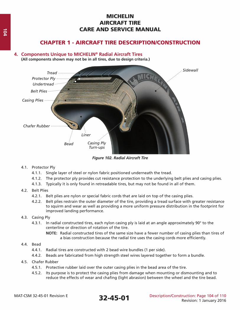
4. Components Unique to MICHELIN® Radial Aircraft Tires (All components shown may not be in all tires, due to design criteria.)
Figure 102. Radial Aircraft Tire
4.1. Protector Ply 4.1.1. Single layer of steel or nylon fabric positioned underneath the tread. 4.1.2. The protector ply provides cut resistance protection to the underlying belt plies and casing plies. 4.1.3. Typically it is only found in retreadable tires, but may not be found in all of them.
4.2. Belt Plies 4.2.1. Belt plies are nylon or special fabric cords that are laid on top of the casing plies. 4.2.2. Belt plies restrain the outer diameter of the tire, providing a tread surface with greater resistance to squirm and wear as well as providing a more uniform pressure distribution in the footprint for improved landing performance.
4.3. Casing Ply 4.3.1. In radial constructed tires, each nylon casing ply is laid at an angle approximately 90° to the centerline or direction of rotation of the tire. NOTE: Radial constructed tires of the same size have a fewer number of casing plies than tires of a bias construction because the radial tire uses the casing cords more effi ciently.
4.4. Bead 4.4.1. Radial tires are constructed with 2 bead wire bundles (1 per side). 4.4.2. Beads are fabricated from high strength steel wires layered together to form a bundle.
4.5. Chafer Rubber 4.5.1. Protective rubber laid over the outer casing plies in the bead area of the tire. 4.5.2. Its purpose is to protect the casing plies from damage when mounting or dismounting and to reduce the effects of wear and chafi ng (light abrasion) between the wheel and the tire bead.
Liner
Casing Ply Turn-ups
Sidewall
32-45-01
TreadProtector PlyUndertread
Belt Plies
Casing Plies
Chafer Rubber
Bead
105
MICHELINAIRCRAFT TIRE
CARE AND SERVICE MANUAL
CHAPTER 1 - AIRCRAFT TIRE DESCRIPTION/CONSTRUCTION
MAT-CSM 32-45-01 Revision E Description/Construction: Page 105 of 110Revision: 1 January 2016
4.6. Near Zero Growth (NZG) 4.6.1. NZG technology is a development by Michelin for radial tires. This technology uses a newly developed ultra-high tensile composite cord with less elongation than nylon cords. 4.6.2. Tires constructed with NZG cord may use fewer plies to achieve the same tire strength and capability. As such, NZG tires are lighter in weight and grow less than nylon constructed tires. The technology results in better resistance to foreign object damage (FOD) and landing performance, in addition to the lighter weight. 4.6.3. The use of NZG technology is not currently identifi ed in the sidewall marking.
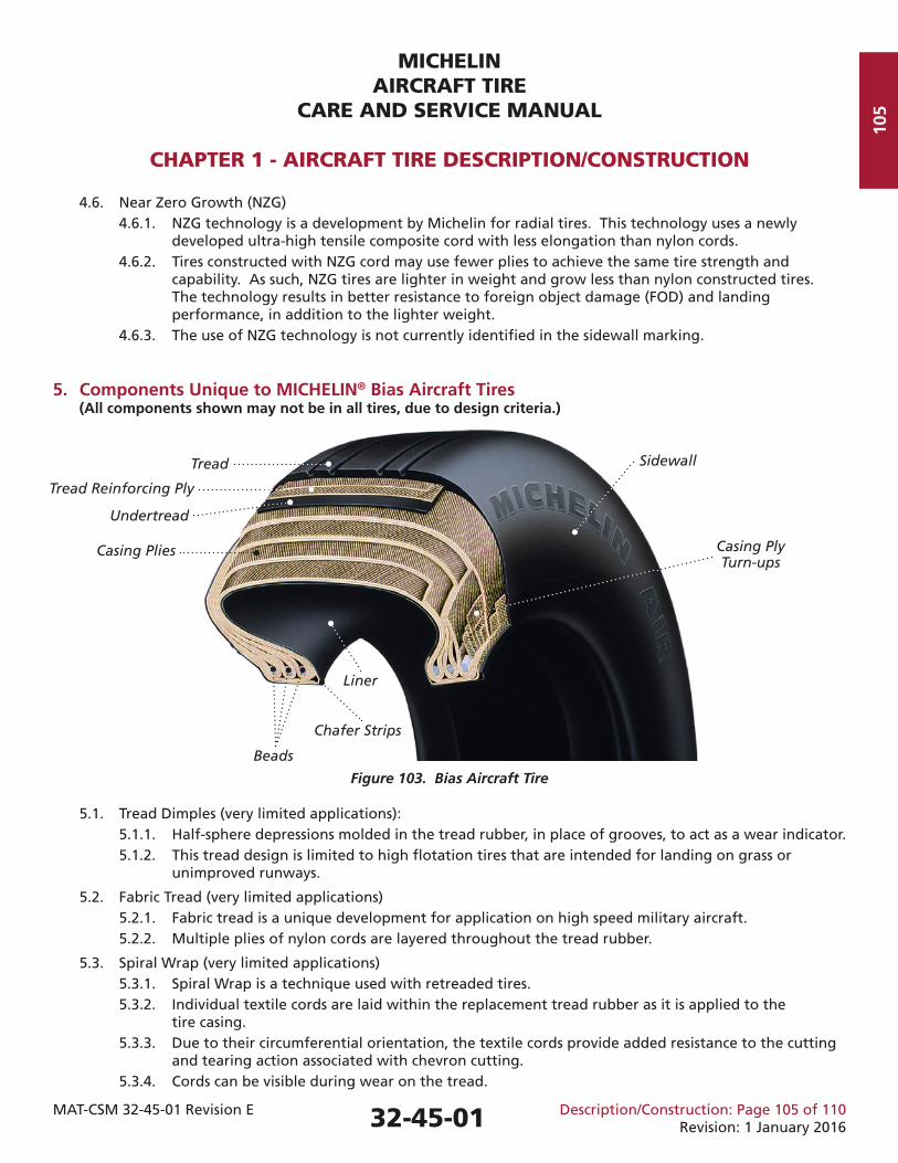
5. Components Unique to MICHELIN® Bias Aircraft Tires (All components shown may not be in all tires, due to design criteria.)
Figure 103. Bias Aircraft Tire
5.1. Tread Dimples (very limited applications): 5.1.1. Half-sphere depressions molded in the tread rubber, in place of grooves, to act as a wear indicator. 5.1.2. This tread design is limited to high fl otation tires that are intended for landing on grass or unimproved runways.
5.2. Fabric Tread (very limited applications) 5.2.1. Fabric tread is a unique development for application on high speed military aircraft. 5.2.2. Multiple plies of nylon cords are layered throughout the tread rubber.
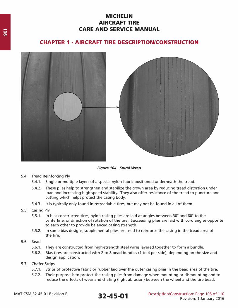
5.3. Spiral Wrap (very limited applications) 5.3.1. Spiral Wrap is a technique used with retreaded tires. 5.3.2. Individual textile cords are laid within the replacement tread rubber as it is applied to the tire casing. 5.3.3. Due to their circumferential orientation, the textile cords provide added resistance to the cutting and tearing action associated with chevron cutting. 5.3.4. Cords can be visible during wear on the tread.
Liner
Casing Ply Turn-ups
SidewallTread
Tread Reinforcing Ply
Undertread
Casing Plies
Chafer Strips
Beads
32-45-01
MICHELINAIRCRAFT TIRE
CARE AND SERVICE MANUAL
CHAPTER 1 - AIRCRAFT TIRE DESCRIPTION/CONSTRUCTION
MAT-CSM 32-45-01 Revision E Description/Construction: Page 106 of 110Revision: 1 January 2016
106
Figure 104. Spiral Wrap
5.4. Tread Reinforcing Ply 5.4.1. Single or multiple layers of a special nylon fabric positioned underneath the tread.
5.4.2. These plies help to strengthen and stabilize the crown area by reducing tread distortion under load and increasing high speed stability. They also offer resistance of the tread to puncture and cutting which helps protect the casing body.
5.4.3. It is typically only found in retreadable tires, but may not be found in all of them.
5.5. Casing Ply 5.5.1. In bias constructed tires, nylon casing plies are laid at angles between 30° and 60° to the centerline, or direction of rotation of the tire. Succeeding plies are laid with cord angles opposite to each other to provide balanced casing strength. 5.5.2. In some bias designs, supplemental plies are used to reinforce the casing in the tread area of the tire.
5.6. Bead 5.6.1. They are constructed from high-strength steel wires layered together to form a bundle. 5.6.2. Bias tires are constructed with 2 to 8 bead bundles (1 to 4 per side), depending on the size and design application.
5.7. Chafer Strips 5.7.1. Strips of protective fabric or rubber laid over the outer casing plies in the bead area of the tire. 5.7.2. Their purpose is to protect the casing plies from damage when mounting or dismounting and to reduce the effects of wear and chafi ng (light abrasion) between the wheel and the tire bead.
32-45-01
107
MICHELINAIRCRAFT TIRE
CARE AND SERVICE MANUAL
CHAPTER 1 - AIRCRAFT TIRE DESCRIPTION/CONSTRUCTION
MAT-CSM 32-45-01 Revision E Description/Construction: Page 107 of 110Revision: 1 January 2016
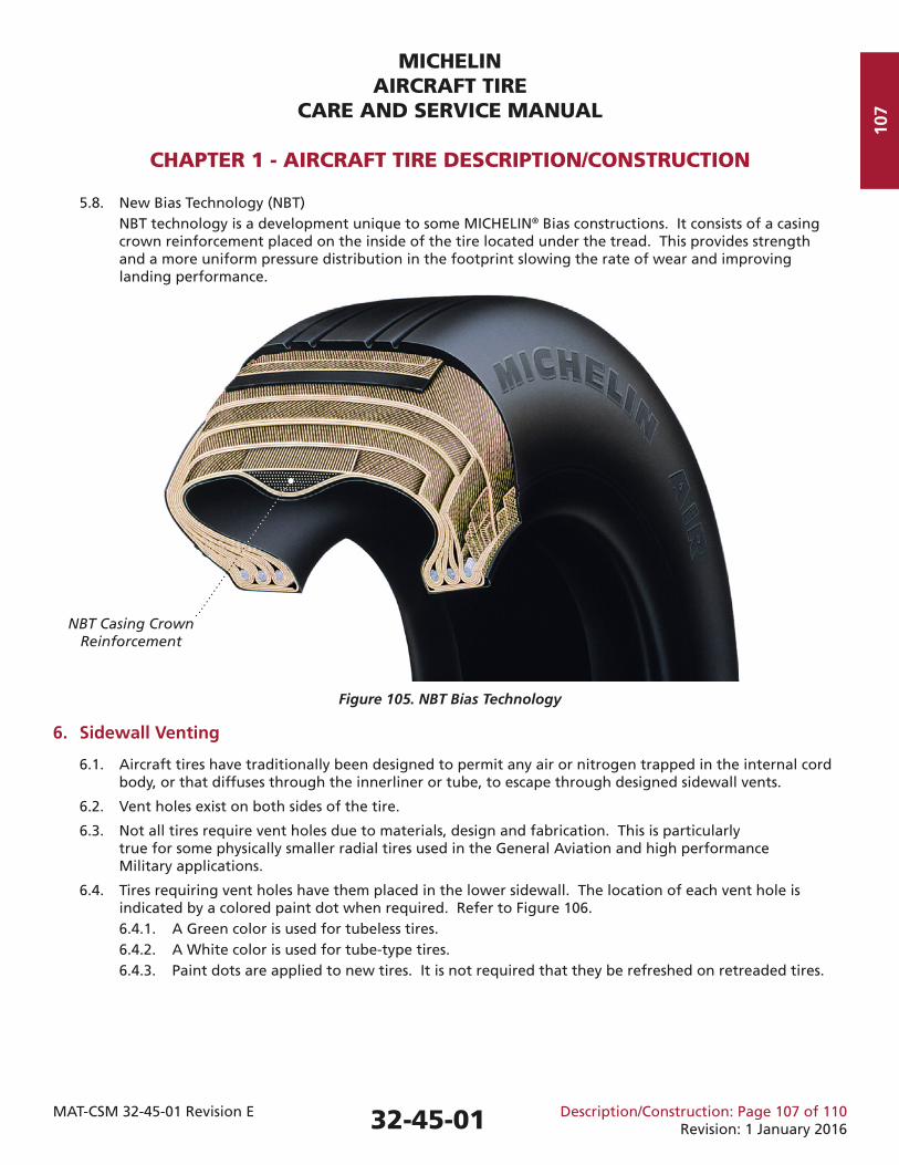
5.8. New Bias Technology (NBT) NBT technology is a development unique to some MICHELIN® Bias constructions. It consists of a casing crown reinforcement placed on the inside of the tire located under the tread. This provides strength and a more uniform pressure distribution in the footprint slowing the rate of wear and improving landing performance.
Figure 105. NBT Bias Technology
6. Sidewall Venting
6.1. Aircraft tires have traditionally been designed to permit any air or nitrogen trapped in the internal cord body, or that diffuses through the innerliner or tube, to escape through designed sidewall vents.
6.2. Vent holes exist on both sides of the tire.
6.3. Not all tires require vent holes due to materials, design and fabrication. This is particularly true for some physically smaller radial tires used in the General Aviation and high performance Military applications.
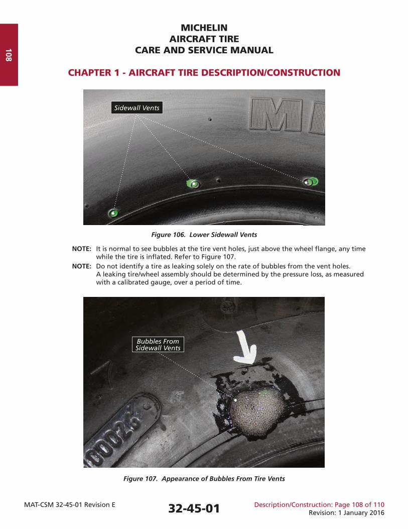
6.4. Tires requiring vent holes have them placed in the lower sidewall. The location of each vent hole is indicated by a colored paint dot when required. Refer to Figure 106. 6.4.1. A Green color is used for tubeless tires. 6.4.2. A White color is used for tube-type tires. 6.4.3. Paint dots are applied to new tires. It is not required that they be refreshed on retreaded tires.
32-45-01
NBT Casing Crown Reinforcement
MICHELINAIRCRAFT TIRE
CARE AND SERVICE MANUAL
CHAPTER 1 - AIRCRAFT TIRE DESCRIPTION/CONSTRUCTION
MAT-CSM 32-45-01 Revision E Description/Construction: Page 108 of 110Revision: 1 January 2016
108
Figure 106. Lower Sidewall Vents
NOTE: It is normal to see bubbles at the tire vent holes, just above the wheel fl ange, any time while the tire is infl ated. Refer to Figure 107. NOTE: Do not identify a tire as leaking solely on the rate of bubbles from the vent holes. A leaking tire/wheel assembly should be determined by the pressure loss, as measured with a calibrated gauge, over a period of time.
Figure 107. Appearance of Bubbles From Tire Vents
Sidewall Vents
Bubbles From Sidewall Vents
32-45-01
109
MICHELINAIRCRAFT TIRE
CARE AND SERVICE MANUAL
CHAPTER 1 - AIRCRAFT TIRE DESCRIPTION/CONSTRUCTION
MAT-CSM 32-45-01 Revision E Description/Construction: Page 109 of 110Revision: 1 January 2016
7. Chine Tires
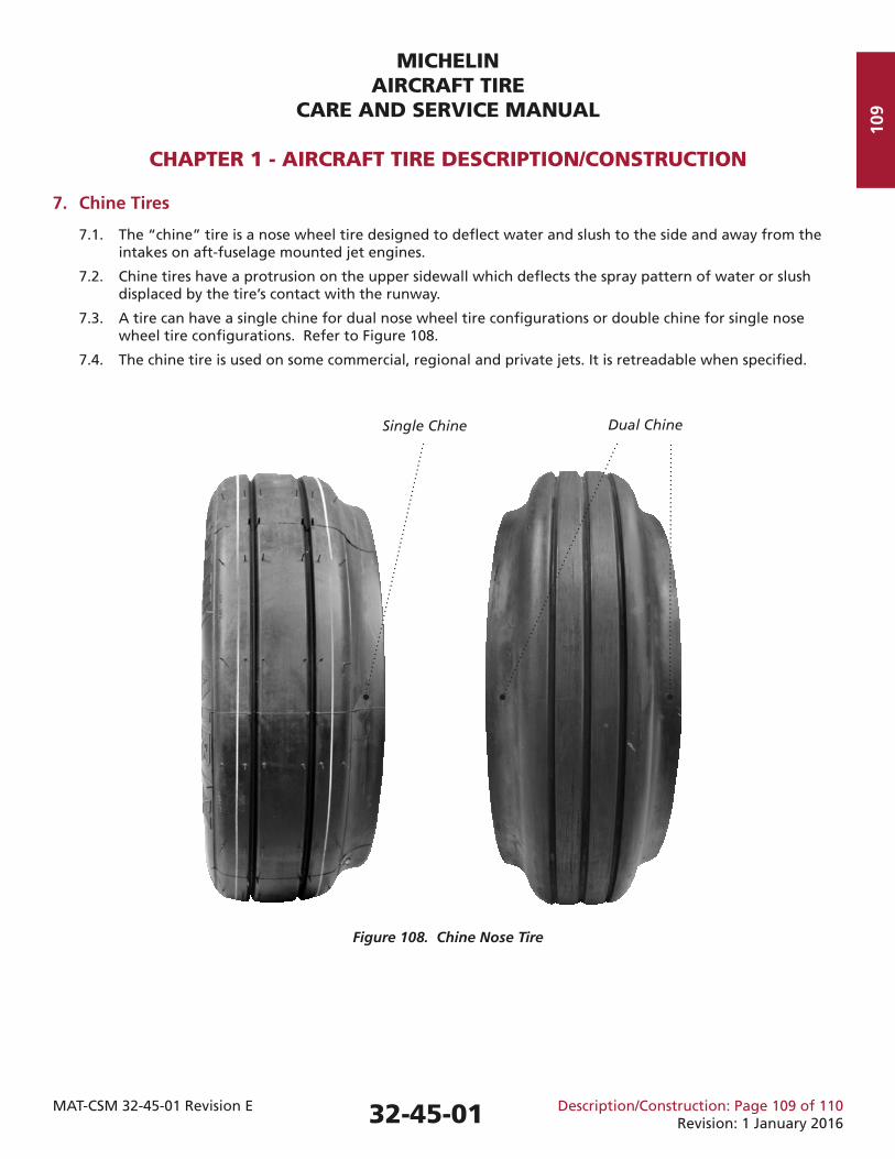
7.1. The “chine” tire is a nose wheel tire designed to defl ect water and slush to the side and away from the intakes on aft-fuselage mounted jet engines.
7.2. Chine tires have a protrusion on the upper sidewall which defl ects the spray pattern of water or slush displaced by the tire’s contact with the runway.
7.3. A tire can have a single chine for dual nose wheel tire confi gurations or double chine for single nose wheel tire confi gurations. Refer to Figure 108.
7.4. The chine tire is used on some commercial, regional and private jets. It is retreadable when specifi ed.
Figure 108. Chine Nose Tire
Single Chine Dual Chine
32-45-01
MICHELINAIRCRAFT TIRE
CARE AND SERVICE MANUAL
CHAPTER 1 - AIRCRAFT TIRE DESCRIPTION/CONSTRUCTION
MAT-CSM 32-45-01 Revision E Description/Construction: Page 110 of 110Revision: 1 January 2016
110
This Page IntentionallyLeft Blank
32-45-01
MICHELINAIRCRAFT TIRE
CARE AND SERVICE MANUAL
CHAPTER 2 - AIRCRAFT TIRE TERMINOLOGY AND TIRE MARKINGS (BRANDING)
MAT-CSM 32-45-01 Revision E Marking and Terminology: Page 201 of 214Revision: 1 January 2016
201
1. Tire Terminology
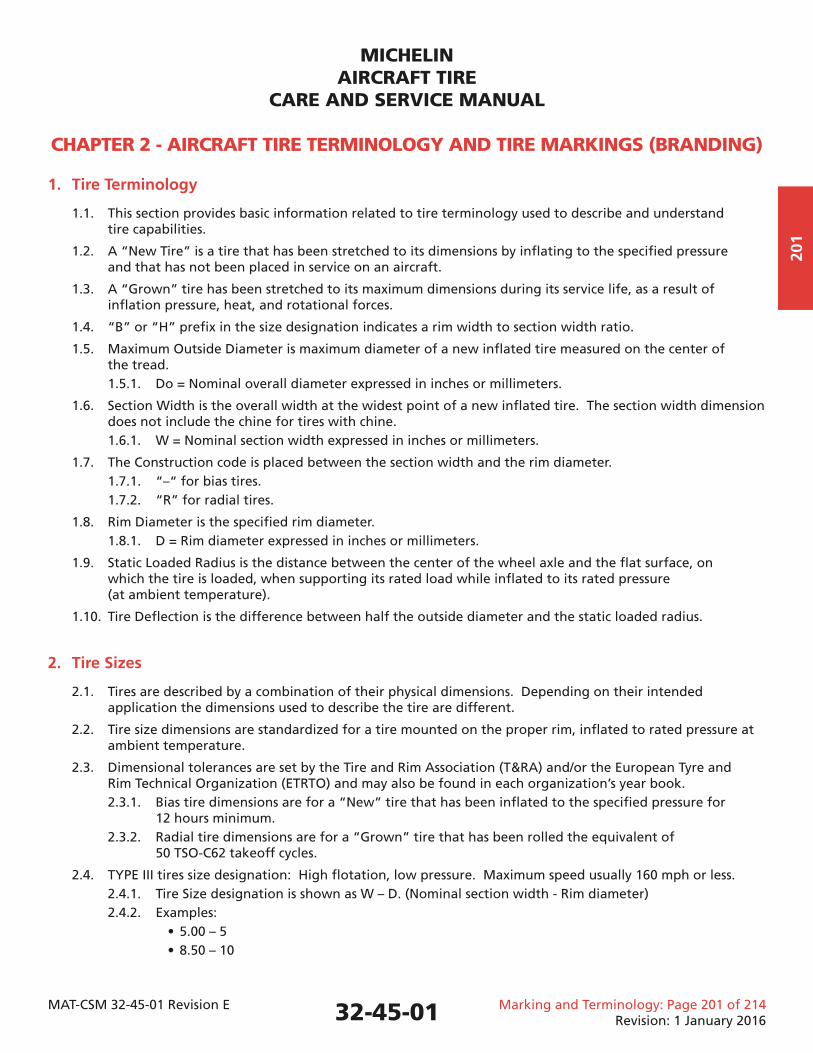
1.1. This section provides basic information related to tire terminology used to describe and understand tire capabilities.
1.2. A “New Tire” is a tire that has been stretched to its dimensions by infl ating to the specifi ed pressure and that has not been placed in service on an aircraft.
1.3. A “Grown” tire has been stretched to its maximum dimensions during its service life, as a result of infl ation pressure, heat, and rotational forces.
1.4. “B” or “H” prefi x in the size designation indicates a rim width to section width ratio.
1.5. Maximum Outside Diameter is maximum diameter of a new infl ated tire measured on the center of the tread. 1.5.1. Do = Nominal overall diameter expressed in inches or millimeters.
1.6. Section Width is the overall width at the widest point of a new infl ated tire. The section width dimension does not include the chine for tires with chine. 1.6.1. W = Nominal section width expressed in inches or millimeters.
1.7. The Construction code is placed between the section width and the rim diameter. 1.7.1. “–“ for bias tires. 1.7.2. “R” for radial tires.
1.8. Rim Diameter is the specifi ed rim diameter. 1.8.1. D = Rim diameter expressed in inches or millimeters.
1.9. Static Loaded Radius is the distance between the center of the wheel axle and the fl at surface, on which the tire is loaded, when supporting its rated load while infl ated to its rated pressure (at ambient temperature).
1.10. Tire Defl ection is the difference between half the outside diameter and the static loaded radius.
2. Tire Sizes
2.1. Tires are described by a combination of their physical dimensions. Depending on their intended application the dimensions used to describe the tire are different.
2.2. Tire size dimensions are standardized for a tire mounted on the proper rim, infl ated to rated pressure at ambient temperature.
2.3. Dimensional tolerances are set by the Tire and Rim Association (T&RA) and/or the European Tyre and Rim Technical Organization (ETRTO) and may also be found in each organization’s year book. 2.3.1. Bias tire dimensions are for a “New” tire that has been infl ated to the specifi ed pressure for 12 hours minimum. 2.3.2. Radial tire dimensions are for a “Grown” tire that has been rolled the equivalent of 50 TSO-C62 takeoff cycles.
2.4. TYPE III tires size designation: High fl otation, low pressure. Maximum speed usually 160 mph or less. 2.4.1. Tire Size designation is shown as W – D. (Nominal section width - Rim diameter) 2.4.2. Examples: • 5.00 – 5 • 8.50 – 10
32-45-01
MICHELINAIRCRAFT TIRE
CARE AND SERVICE MANUAL
CHAPTER 2 - AIRCRAFT TIRE TERMINOLOGY AND TIRE MARKINGS (BRANDING)
MAT-CSM 32-45-01 Revision E Marking and Terminology: Page 202 of 214Revision: 1 January 2016
202
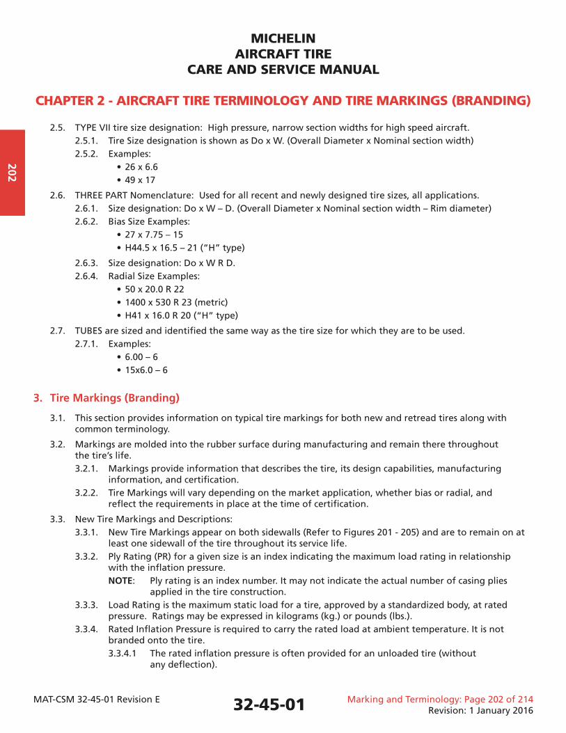
2.5. TYPE VII tire size designation: High pressure, narrow section widths for high speed aircraft. 2.5.1. Tire Size designation is shown as Do x W. (Overall Diameter x Nominal section width) 2.5.2. Examples: • 26 x 6.6 • 49 x 17
2.6. THREE PART Nomenclature: Used for all recent and newly designed tire sizes, all applications. 2.6.1. Size designation: Do x W – D. (Overall Diameter x Nominal section width – Rim diameter) 2.6.2. Bias Size Examples: • 27 x 7.75 – 15 • H44.5 x 16.5 – 21 (“H” type)
2.6.3. Size designation: Do x W R D. 2.6.4. Radial Size Examples: • 50 x 20.0 R 22 • 1400 x 530 R 23 (metric) • H41 x 16.0 R 20 (“H” type)
2.7. TUBES are sized and identifi ed the same way as the tire size for which they are to be used. 2.7.1. Examples: • 6.00 – 6 • 15x6.0 – 6
3. Tire Markings (Branding)
3.1. This section provides information on typical tire markings for both new and retread tires along with common terminology.
3.2. Markings are molded into the rubber surface during manufacturing and remain there throughout the tire’s life. 3.2.1. Markings provide information that describes the tire, its design capabilities, manufacturing information, and certifi cation. 3.2.2. Tire Markings will vary depending on the market application, whether bias or radial, and refl ect the requirements in place at the time of certifi cation.
3.3. New Tire Markings and Descriptions: 3.3.1. New Tire Markings appear on both sidewalls (Refer to Figures 201 - 205) and are to remain on at least one sidewall of the tire throughout its service life. 3.3.2. Ply Rating (PR) for a given size is an index indicating the maximum load rating in relationship with the infl ation pressure. NOTE: Ply rating is an index number. It may not indicate the actual number of casing plies applied in the tire construction. 3.3.3. Load Rating is the maximum static load for a tire, approved by a standardized body, at rated pressure. Ratings may be expressed in kilograms (kg.) or pounds (lbs.). 3.3.4. Rated Infl ation Pressure is required to carry the rated load at ambient temperature. It is not branded onto the tire. 3.3.4.1 The rated infl ation pressure is often provided for an unloaded tire (without any defl ection).
32-45-01
MICHELINAIRCRAFT TIRE
CARE AND SERVICE MANUAL
CHAPTER 2 - AIRCRAFT TIRE TERMINOLOGY AND TIRE MARKINGS (BRANDING)
MAT-CSM 32-45-01 Revision E Marking and Terminology: Page 203 of 214Revision: 1 January 2016
203
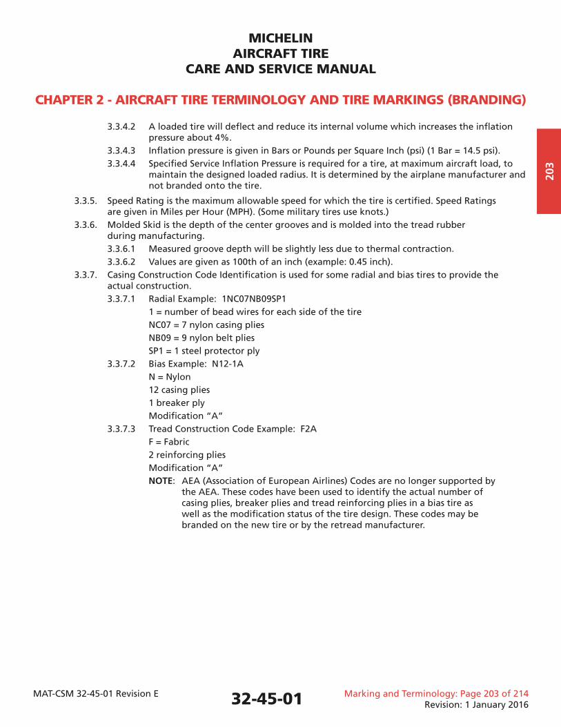
3.3.4.2 A loaded tire will defl ect and reduce its internal volume which increases the infl ation pressure about 4%. 3.3.4.3 Infl ation pressure is given in Bars or Pounds per Square Inch (psi) (1 Bar = 14.5 psi). 3.3.4.4 Specifi ed Service Infl ation Pressure is required for a tire, at maximum aircraft load, to maintain the designed loaded radius. It is determined by the airplane manufacturer and not branded onto the tire.
3.3.5. Speed Rating is the maximum allowable speed for which the tire is certifi ed. Speed Ratings are given in Miles per Hour (MPH). (Some military tires use knots.) 3.3.6. Molded Skid is the depth of the center grooves and is molded into the tread rubber during manufacturing. 3.3.6.1 Measured groove depth will be slightly less due to thermal contraction. 3.3.6.2 Values are given as 100th of an inch (example: 0.45 inch). 3.3.7. Casing Construction Code Identifi cation is used for some radial and bias tires to provide the actual construction. 3.3.7.1 Radial Example: 1NC07NB09SP1 1 = number of bead wires for each side of the tire NC07 = 7 nylon casing plies NB09 = 9 nylon belt plies SP1 = 1 steel protector ply 3.3.7.2 Bias Example: N12-1A N = Nylon 12 casing plies 1 breaker ply Modifi cation “A” 3.3.7.3 Tread Construction Code Example: F2A F = Fabric 2 reinforcing plies Modifi cation “A” NOTE: AEA (Association of European Airlines) Codes are no longer supported by the AEA. These codes have been used to identify the actual number of casing plies, breaker plies and tread reinforcing plies in a bias tire as well as the modifi cation status of the tire design. These codes may be branded on the new tire or by the retread manufacturer.
32-45-01
MICHELINAIRCRAFT TIRE
CARE AND SERVICE MANUAL
CHAPTER 2 - AIRCRAFT TIRE TERMINOLOGY AND TIRE MARKINGS (BRANDING)
MAT-CSM 32-45-01 Revision E Marking and Terminology: Page 204 of 214Revision: 1 January 2016
204
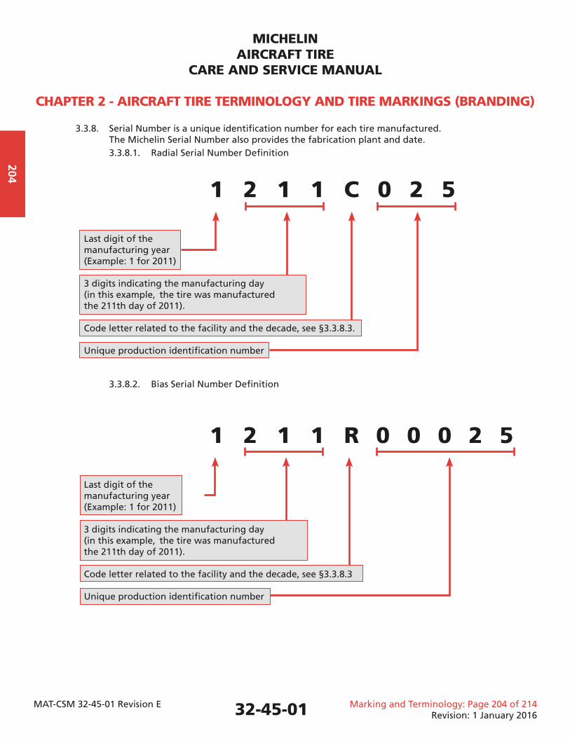
3.3.8. Serial Number is a unique identifi cation number for each tire manufactured. The Michelin Serial Number also provides the fabrication plant and date. 3.3.8.1. Radial Serial Number Defi nition
1 2 1 1 C 0 2 5
Last digit of the manufacturing year (Example: 1 for 2011)
3 digits indicating the manufacturing day (in this example, the tire was manufactured the 211th day of 2011).
Code letter related to the facility and the decade, see §3.3.8.3.
Unique production identifi cation number
3.3.8.2. Bias Serial Number Defi nition
1 2 1 1 R 0 0 0 2 5
Last digit of the manufacturing year (Example: 1 for 2011)
3 digits indicating the manufacturing day (in this example, the tire was manufactured the 211th day of 2011).
Code letter related to the facility and the decade, see §3.3.8.3
Unique production identifi cation number
32-45-01
MICHELINAIRCRAFT TIRE
CARE AND SERVICE MANUAL
CHAPTER 2 - AIRCRAFT TIRE TERMINOLOGY AND TIRE MARKINGS (BRANDING)
MAT-CSM 32-45-01 Revision E Marking and Terminology: Page 205 of 214Revision: 1 January 2016
205
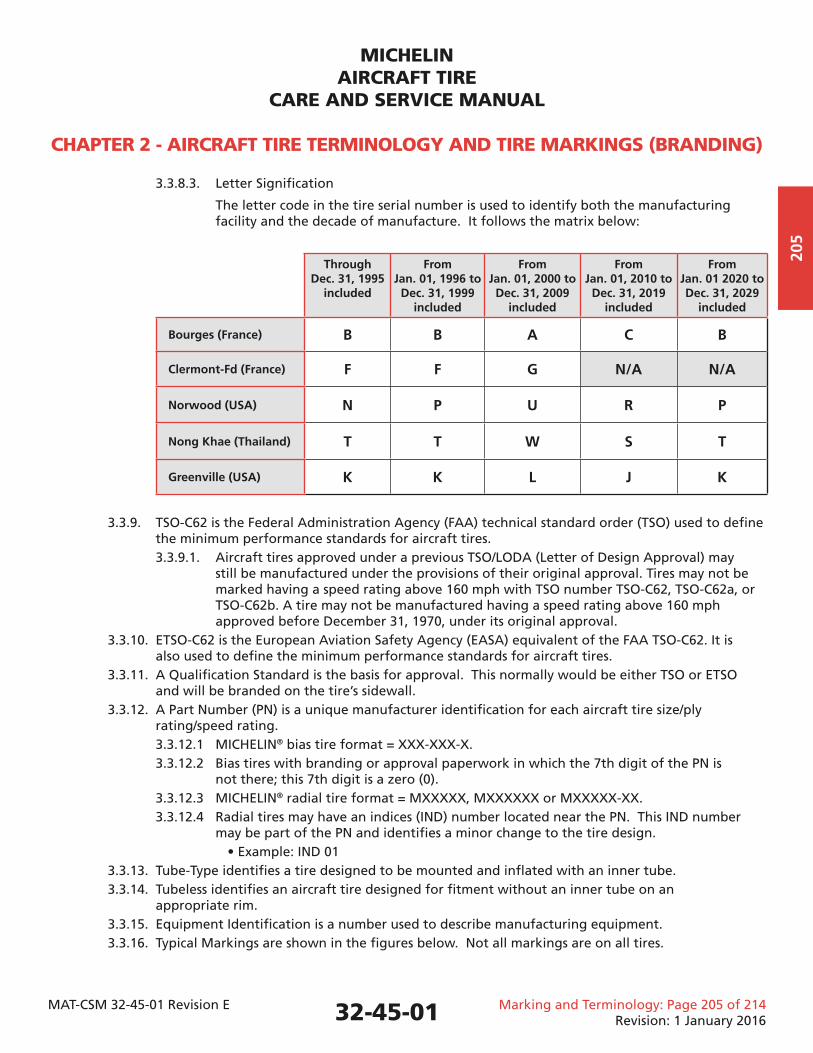
3.3.8.3. Letter Signifi cation
The letter code in the tire serial number is used to identify both the manufacturing facility and the decade of manufacture. It follows the matrix below:
ThroughDec. 31, 1995
included
FromJan. 01, 1996 to Dec. 31, 1999
included
FromJan. 01, 2000 to Dec. 31, 2009
included
FromJan. 01, 2010 to Dec. 31, 2019
included
FromJan. 01 2020 to Dec. 31, 2029
included
Bourges (France) B B A C B
Clermont-Fd (France) F F G N/A N/A
Norwood (USA) N P U R P
Nong Khae (Thailand) T T W S T
Greenville (USA) K K L J K
3.3.9. TSO-C62 is the Federal Administration Agency (FAA) technical standard order (TSO) used to defi ne the minimum performance standards for aircraft tires. 3.3.9.1. Aircraft tires approved under a previous TSO/LODA (Letter of Design Approval) may still be manufactured under the provisions of their original approval. Tires may not be marked having a speed rating above 160 mph with TSO number TSO-C62, TSO-C62a, or TSO-C62b. A tire may not be manufactured having a speed rating above 160 mph approved before December 31, 1970, under its original approval. 3.3.10. ETSO-C62 is the European Aviation Safety Agency (EASA) equivalent of the FAA TSO-C62. It is also used to defi ne the minimum performance standards for aircraft tires. 3.3.11. A Qualifi cation Standard is the basis for approval. This normally would be either TSO or ETSO and will be branded on the tire’s sidewall. 3.3.12. A Part Number (PN) is a unique manufacturer identifi cation for each aircraft tire size/ply rating/speed rating. 3.3.12.1 MICHELIN® bias tire format = XXX-XXX-X. 3.3.12.2 Bias tires with branding or approval paperwork in which the 7th digit of the PN is not there; this 7th digit is a zero (0). 3.3.12.3 MICHELIN® radial tire format = MXXXXX, MXXXXXX or MXXXXX-XX. 3.3.12.4 Radial tires may have an indices (IND) number located near the PN. This IND number may be part of the PN and identifi es a minor change to the tire design. • Example: IND 01 3.3.13. Tube-Type identifi es a tire designed to be mounted and infl ated with an inner tube. 3.3.14. Tubeless identifi es an aircraft tire designed for fi tment without an inner tube on an appropriate rim. 3.3.15. Equipment Identifi cation is a number used to describe manufacturing equipment. 3.3.16. Typical Markings are shown in the fi gures below. Not all markings are on all tires.
32-45-01
MICHELINAIRCRAFT TIRE
CARE AND SERVICE MANUAL
CHAPTER 2 - AIRCRAFT TIRE TERMINOLOGY AND TIRE MARKINGS (BRANDING)
MAT-CSM 32-45-01 Revision E Marking and Terminology: Page 206 of 214Revision: 1 January 2016
206
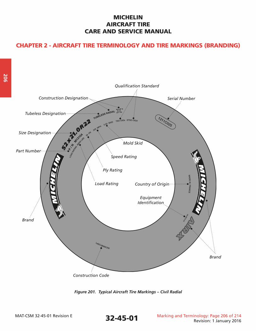
Figure 201. Typical Aircraft Tire Markings – Civil Radial
32-45-01
Brand
Part Number
Size Designation
Tubeless Designation
Construction Designation Serial Number
Qualifi cation Standard
Brand
Country of Origin
Equipment Identifi cation
Construction Code
Mold Skid
Speed Rating
Ply Rating
Load Rating
MICHELINAIRCRAFT TIRE
CARE AND SERVICE MANUAL
CHAPTER 2 - AIRCRAFT TIRE TERMINOLOGY AND TIRE MARKINGS (BRANDING)
MAT-CSM 32-45-01 Revision E Marking and Terminology: Page 207 of 214Revision: 1 January 2016
207
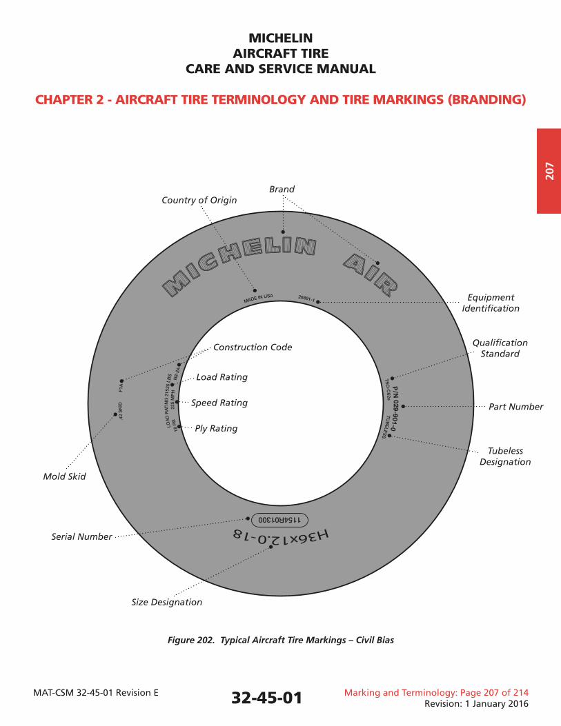
Figure 202. Typical Aircraft Tire Markings – Civil Bias
32-45-01
Mold Skid
Part Number
Size Designation
Tubeless Designation
Equipment Identifi cation
Brand
Serial Number
Qualifi cation Standard
Country of Origin
Construction Code
Speed Rating
Ply Rating
Load Rating
MICHELINAIRCRAFT TIRE
CARE AND SERVICE MANUAL
CHAPTER 2 - AIRCRAFT TIRE TERMINOLOGY AND TIRE MARKINGS (BRANDING)
MAT-CSM 32-45-01 Revision E Marking and Terminology: Page 208 of 214Revision: 1 January 2016
208
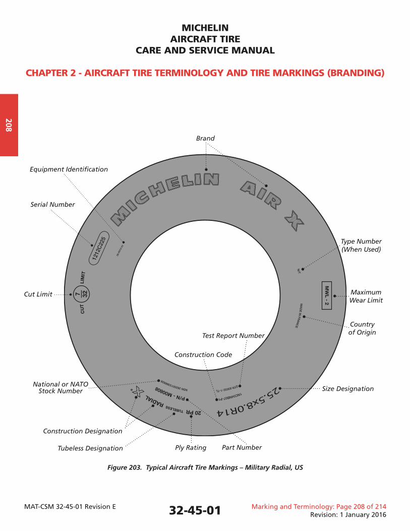
Figure 203. Typical Aircraft Tire Markings – Military Radial, US
32-45-01
Part Number
Size Designation
Tubeless Designation
Equipment Identifi cation
Serial Number
National or NATO Stock Number
Construction Designation
Cut Limit
Ply Rating
Construction Code
Country of Origin
Maximum Wear Limit
Type Number (When Used)
Test Report Number
Brand
MICHELINAIRCRAFT TIRE
CARE AND SERVICE MANUAL
CHAPTER 2 - AIRCRAFT TIRE TERMINOLOGY AND TIRE MARKINGS (BRANDING)
MAT-CSM 32-45-01 Revision E Marking and Terminology: Page 209 of 214Revision: 1 January 2016
209
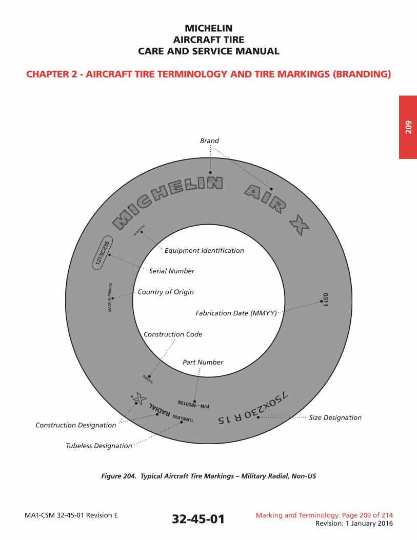
Figure 204. Typical Aircraft Tire Markings – Military Radial, Non-US
32-45-01
Country of Origin
Equipment Identifi cation
Serial Number
Construction Code
Part Number
Fabrication Date (MMYY)
Size Designation
Tubeless Designation
Construction Designation
Brand
MICHELINAIRCRAFT TIRE
CARE AND SERVICE MANUAL
CHAPTER 2 - AIRCRAFT TIRE TERMINOLOGY AND TIRE MARKINGS (BRANDING)
MAT-CSM 32-45-01 Revision E Marking and Terminology: Page 210 of 214Revision: 1 January 2016
210
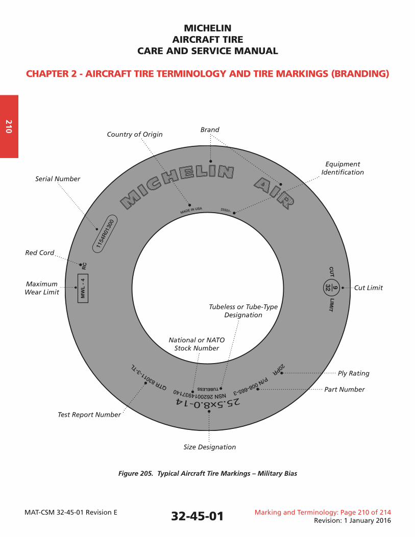
Figure 205. Typical Aircraft Tire Markings – Military Bias
32-45-01
Part Number
Size Designation
Tubeless or Tube-Type Designation
Equipment Identifi cation
Serial Number
National or NATO Stock Number
Cut Limit
Ply Rating
Test Report Number
Maximum Wear Limit
Country of Origin
Red Cord
Brand
MICHELINAIRCRAFT TIRE
CARE AND SERVICE MANUAL
CHAPTER 2 - AIRCRAFT TIRE TERMINOLOGY AND TIRE MARKINGS (BRANDING)
MAT-CSM 32-45-01 Revision E Marking and Terminology: Page 211 of 214Revision: 1 January 2016
211
4. Retread Markings
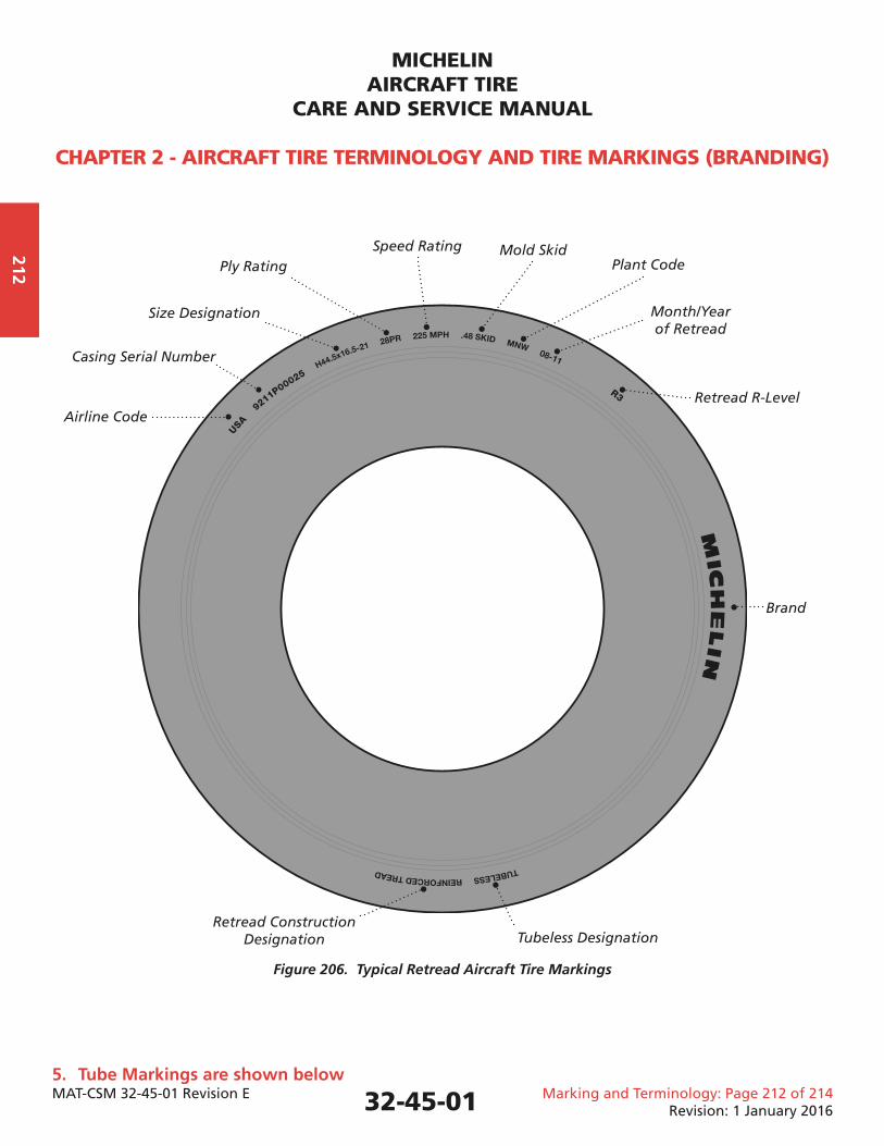
4.1. Retread brandings provide information related to the retread and are molded into the shoulder. New tire branding will remain on the sidewall of a retreaded tire. Some retreads will have additional brandings applied to the sidewall during the retread process. Retread brandings may include some or all of the following markings. 4.1.1. Retread brandings are removed and replaced at each retread. 4.1.2. Some retread brandings repeat information molded on the sidewall to ensure it is readable over time. 4.1.3. Brand – retread manufacturer (MICHELIN). 4.1.4. Tire Size/Ply Rating/Speed Rating. 4.1.5. Retread Groove Depth (Skid) in 100th of an inch. 4.1.6. Casing Manufacturer 2-Digit code when MICHELIN® retreads bias tires from other manufacturers. (Radial tires are retreaded only by the original manufacturer.) MA = MICHELIN® Air GY = Goodyear DU = Dunlop BR = Bridgestone 4.1.7. Airline code – 3 digit ICAO airline code. 4.1.7.1. In some cases, Michelin assigns a unique 3-digit code. 4.1.8. Casing original Serial Number is included in the shoulder area of bias tires only. 4.1.9. Retread Level (example: R04). 4.1.10. MM/YY of retreading (example: 02/08). 4.1.11. Retread Facility Code. MNK = Michelin Nong Khae (Thailand) MBO = Michelin Bourges (France) MNW = Michelin Norwood (USA) 4.1.11.1. Retread: Typical brandings for bias and radial retreaded tires are shown in Figure 206.
32-45-01
MICHELINAIRCRAFT TIRE
CARE AND SERVICE MANUAL
CHAPTER 2 - AIRCRAFT TIRE TERMINOLOGY AND TIRE MARKINGS (BRANDING)
MAT-CSM 32-45-01 Revision E Marking and Terminology: Page 212 of 214Revision: 1 January 2016
212
Figure 206. Typical Retread Aircraft Tire Markings
5. Tube Markings are shown below
32-45-01
USA
9
211P00025
R3
Brand
Plant Code
Size Designation
Tubeless Designation
Casing Serial Number
Retread R-Level
Month/Year of Retread
Mold SkidSpeed RatingPly Rating
Retread Construction Designation
Airline Code
MICHELINAIRCRAFT TIRE
CARE AND SERVICE MANUAL
CHAPTER 2 - AIRCRAFT TIRE TERMINOLOGY AND TIRE MARKINGS (BRANDING)
MAT-CSM 32-45-01 Revision E Marking and Terminology: Page 213 of 214Revision: 1 January 2016
213
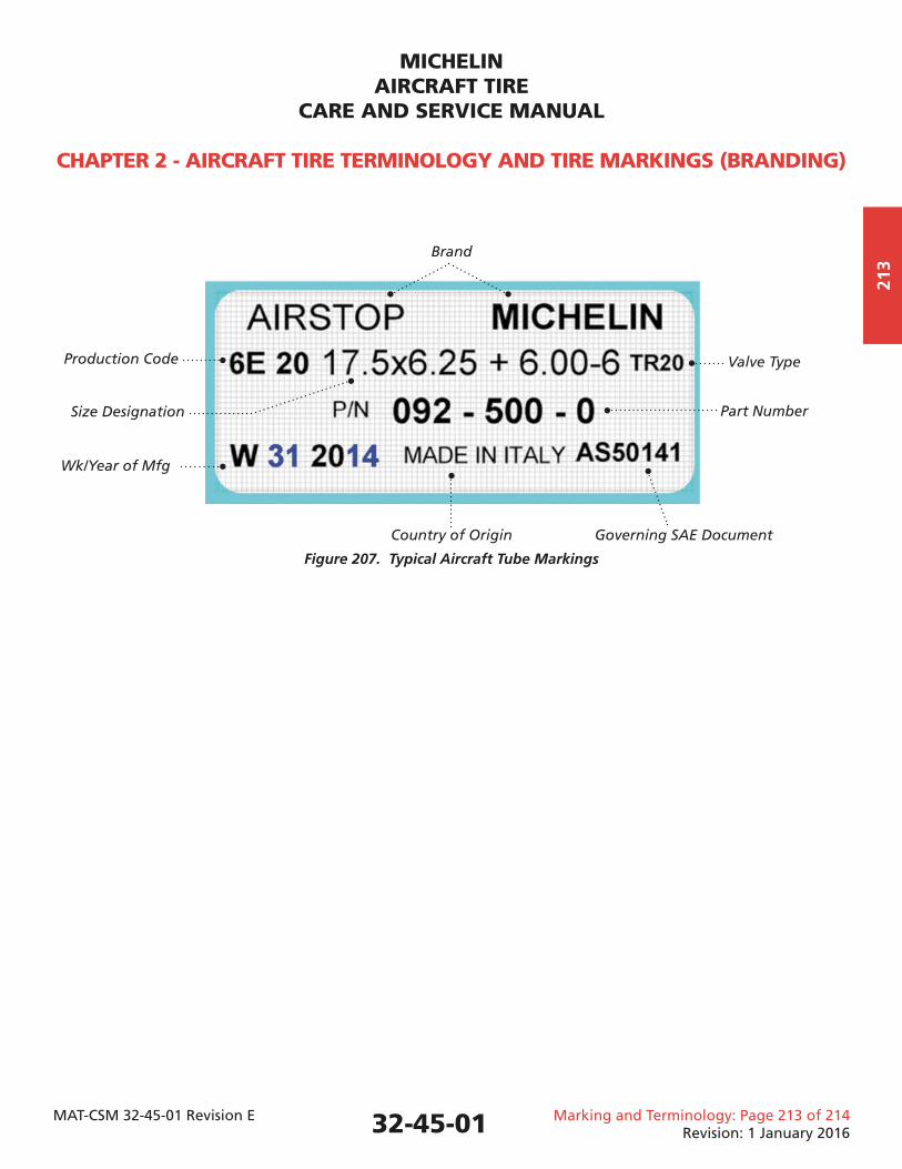
Figure 207. Typical Aircraft Tube Markings
32-45-01
Part NumberSize Designation
Country of Origin Governing SAE Document
Production Code
Wk/Year of Mfg
Valve Type
Brand
MICHELINAIRCRAFT TIRE
CARE AND SERVICE MANUAL
CHAPTER 2 - AIRCRAFT TIRE TERMINOLOGY AND TIRE MARKINGS (BRANDING)
MAT-CSM 32-45-01 Revision E Marking and Terminology: Page 214 of 214Revision: 1 January 2016
214
This Page IntentionallyLeft Blank
32-45-01
MICHELINAIRCRAFT TIRE
CARE AND SERVICE MANUAL
CHAPTER 3 - RECEIVING AND STORING AIRCRAFT TIRES
MAT-CSM 32-45-01 Revision E Receiving and Storing: Page 301 of 306Revision: 1 January 2016
301
1. Handling of Tires and Tubes
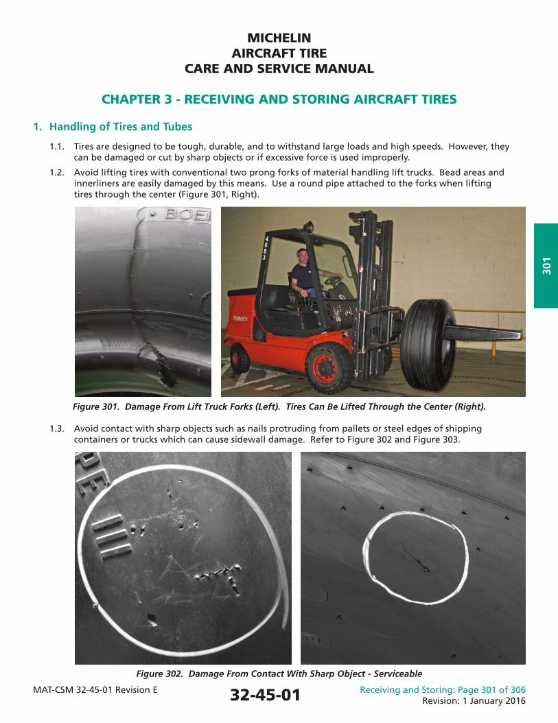
1.1. Tires are designed to be tough, durable, and to withstand large loads and high speeds. However, they can be damaged or cut by sharp objects or if excessive force is used improperly.
1.2. Avoid lifting tires with conventional two prong forks of material handling lift trucks. Bead areas and innerliners are easily damaged by this means. Use a round pipe attached to the forks when lifting tires through the center (Figure 301, Right).
Figure 301. Damage From Lift Truck Forks (Left). Tires Can Be Lifted Through the Center (Right).
1.3. Avoid contact with sharp objects such as nails protruding from pallets or steel edges of shipping containers or trucks which can cause sidewall damage. Refer to Figure 302 and Figure 303.
Figure 302. Damage From Contact With Sharp Object - Serviceable
32-45-01
MICHELINAIRCRAFT TIRE
CARE AND SERVICE MANUAL
CHAPTER 3 - RECEIVING AND STORING AIRCRAFT TIRES
MAT-CSM 32-45-01 Revision E Receiving and Storing: Page 302 of 306Revision: 1 January 2016
302
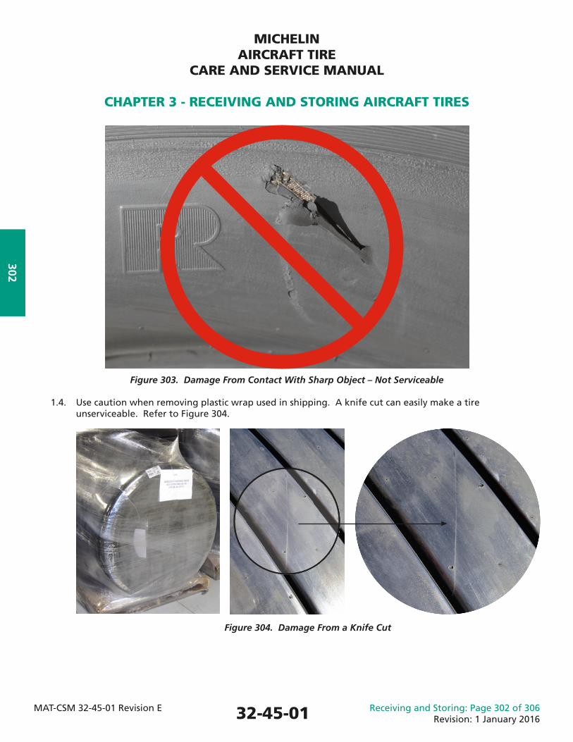
Figure 303. Damage From Contact With Sharp Object – Not Serviceable
1.4. Use caution when removing plastic wrap used in shipping. A knife cut can easily make a tire unserviceable. Refer to Figure 304.
32-45-01
Figure 304. Damage From a Knife Cut
MICHELINAIRCRAFT TIRE
CARE AND SERVICE MANUAL
CHAPTER 3 - RECEIVING AND STORING AIRCRAFT TIRES
MAT-CSM 32-45-01 Revision E Receiving and Storing: Page 303 of 306Revision: 1 January 2016
303
2. Storage of Unmounted Tires and Tubes
2.1. Proper storage of a tire will extend its serviceable life, reducing costs and helping to avoid reliability issues.
2.2. The ideal location for tire and tube storage is a cool, dry and reasonably dark location, free from air currents and dirt.
2.3. Tire or tube age limit 2.3.1. MICHELIN® aircraft tires or tubes have no age limit and may be placed in service, regardless of their age, provided all inspection criteria for service/storage/mounting and individual customer- imposed restrictions are met.
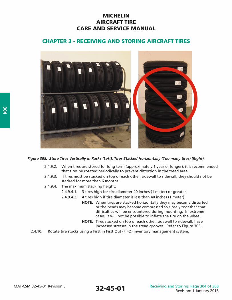
2.4. Storage conditions 2.4.1. Avoid concentrations of ozone if possible. Minimize exposure to sources of ozone such as fl uorescent lights, electric motors, battery chargers, electric welding equipment, electric generators and similar electrical devices, since they all create ozone. NOTE: Most natural and synthetic elastomers used in aircraft tires are susceptible to ozone attack. Ozone breaks the molecular bonds, degrading the rubber and causing cracks. NOTE: Ozone cracking is most likely to appear in the tread grooves or sidewall when tires are stored for an extended period of time in an environment with high ozone concentration. 2.4.2. Avoid strong air currents as these bring in fresh sources of ozone. 2.4.3. Air conditioning, exhaust fans, or other sources of ventilation should not be used as the air currents contain new sources of ozone. 2.4.4. Storage rooms should be dark. 2.4.4.1. Avoid direct sunlight. Sunlight is a source of ultraviolet rays. 2.4.4.2. Darken windows with paint or black plastic. 2.4.5. Avoid wet or moist conditions. CAUTION: DO NOT STORE TUBES IN EXTREME COLD (<0°C/32°F). CRACKS MAY DEVELOP ALONG RUBBER PACKAGING FOLDS CAUSING POTENTIAL LOSS OF PRESSURE WHEN PLACED IN SERVICE. 2.4.6. Store tires and tubes between 0°C/32°F and 35°C/95°F. Room temperatures consistently above 35°C/95°F should be avoided. 2.4.7. Avoid contact with hydrocarbon-based contaminants such as oil, gasoline, jet fuel, hydraulic fl uids, brake fl uids, or other similar solvents. Hydrocarbon contaminants will deteriorate rubber. 2.4.8. If tires become contaminated, wash them with denatured alcohol and then with a soap and water solution. If the rubber is soft or spongy, the tire is not suitable for service. 2.4.9. Store tires vertically in tire racks. Refer to Figure 305. 2.4.9.1. The surface of the tire rack on which the weight of the tire rests should be fl at and, if possible, 7 to 10 cm (3 to 4 in) wide to prevent permanent distortion of the tire.
32-45-01
MICHELINAIRCRAFT TIRE
CARE AND SERVICE MANUAL
CHAPTER 3 - RECEIVING AND STORING AIRCRAFT TIRES
MAT-CSM 32-45-01 Revision E Receiving and Storing: Page 304 of 306Revision: 1 January 2016
304
Figure 305. Store Tires Vertically in Racks (Left). Tires Stacked Horizontally (Too many tires) (Right).
2.4.9.2. When tires are stored for long term (approximately 1 year or longer), it is recommended that tires be rotated periodically to prevent distortion in the tread area. 2.4.9.3. If tires must be stacked on top of each other, sidewall to sidewall, they should not be stacked for more than 6 months. 2.4.9.4. The maximum stacking height: 2.4.9.4.1. 3 tires high for tire diameter 40 inches (1 meter) or greater. 2.4.9.4.2. 4 tires high if tire diameter is less than 40 inches (1 meter). NOTE: When tires are stacked horizontally they may become distorted or the beads may become compressed so closely together that diffi culties will be encountered during mounting. In extreme cases, it will not be possible to infl ate the tire on the wheel. NOTE: Tires stacked on top of each other, sidewall to sidewall, have increased stresses in the tread grooves. Refer to Figure 305. 2.4.10. Rotate tire stocks using a First in First Out (FIFO) inventory management system.
32-45-01
MICHELINAIRCRAFT TIRE
CARE AND SERVICE MANUAL
CHAPTER 3 - RECEIVING AND STORING AIRCRAFT TIRES
MAT-CSM 32-45-01 Revision E Receiving and Storing: Page 305 of 306Revision: 1 January 2016
305
2.4.11. Store tubes in their original cartons to protect them from light and air currents. CAUTION: DO NOT HANG TUBES OVER NAILS, PEGS, OR ANY OTHER OBJECT THAT MIGHT CAUSE A CREASE IN THE TUBE. A CREASE WILL EVENTUALLY PRODUCE A CRACK IN THE RUBBER AND CAUSE TUBE FAILURE. 2.4.11.1. If the original carton is damaged, wrap the tube in several layers of heavy paper or store in a sealed plastic bag with most of the air removed. 2.4.11.2. Tubes may be slightly infl ated (not more than 1 psi (0.06 bar)) and inserted in the correct size tire. 2.4.11.3. Before mounting a tire with a tube inside, always remove the tube from the tire and inspect the inside of the tire to avoid foreign material which could cause irreparable damage to both the tire and tube, if not removed. 2.4.12. Keep worn tires which will be returned to Michelin in a dry, covered environment – protecting them from environmental hazards and contact with hazardous materials - while awaiting return to Michelin.
Refer to Chapter 4 for storage of mounted tires.
32-45-01
MICHELINAIRCRAFT TIRE
CARE AND SERVICE MANUAL
CHAPTER 3 - RECEIVING AND STORING AIRCRAFT TIRES
MAT-CSM 32-45-01 Revision E Receiving and Storing: Page 306 of 306Revision: 1 January 2016
306
This Page IntentionallyLeft Blank
32-45-01
MICHELINAIRCRAFT TIRE
CARE AND SERVICE MANUAL
CHAPTER 4 - MOUNTING INSTRUCTIONS (ASSEMBLY)
MAT-CSM 32-45-01 Revision E Mounting Instructions: Page 401 of 424Revision: 1 January 2016
401
This Chapter includes the necessary procedures for installing (mounting), infl ating, and verifying pressure retention of an aircraft tire prior to releasing the tire/wheel (hub) assembly for service. The following warnings and cautions apply whenever tires are being mounted and infl ated for installation.
1. WARNINGS and NOTES for This Chapter.
WARNING: AIRCRAFT TIRES SHOULD BE MOUNTED ONLY WITH THE PROPER EQUIPMENT, INSTRUCTIONS, AND OPERATOR TRAINING. SERIOUS INJURY MAY OCCUR AS A RESULT OF IMPROPER EQUIPMENT OR PROCEDURES.
WARNING: FOLLOW THE INSTRUCTIONS AND PROCEDURES OF THE WHEEL MANUFACTURER FOR THE ASSEMBLY OF THE WHEEL (HUB) COMPONENTS TO ENSURE PROPER SERVICING OF AIRCRAFT TIRE/WHEEL ASSEMBLIES. FAILURE TO USE THE PROPER PROCEDURES WILL INCREASE THE RISK OF DAMAGE OR PERSONAL INJURY.
WARNING: AIRCRAFT TIRES MUST ALWAYS BE INFLATED WITH A PROPERLY REGULATED INFLATION SOURCE. REGULATE THE SUPPLY LINE TO A PRESSURE NO GREATER THAN 1.5 TIMES THE OPERATING INFLATION PRESSURE. INFLATING A TIRE WITHOUT A PRESSURE REGULATOR PRESENTS A RISK OF PERSONAL INJURY AND/OR DAMAGE TO EQUIPMENT.
WARNING: USE A SUITABLE INFLATION CAGE WHEN INFLATING A NEWLY MOUNTED TIRE WHEEL (HUB) ASSEMBLY. ANY DAMAGE TO THE TIRE, THE WHEEL, AND WHEEL BOLTS OR IMPROPER PROCEDURE, MAY CAUSE THE TIRE/WHEEL ASSEMBLY TO BURST DURING THE INFLATION PROCESS, WHICH MAY RESULT IN SERIOUS OR FATAL INJURY.
WARNING: AIRCRAFT TIRE AND WHEEL ASSEMBLIES SHOULD BE TREATED WITH THE SAME CARE AS ANY OTHER HIGH PRESSURE VESSEL. IMPROPER HANDLING MAY LEAD TO SERIOUS INJURY.
NOTE: Wheel manufacturers publish specifi c instructions in their Component Maintenance Manuals (CMM). Follow the recommendations and procedures for equipment, materials, and proper wheel assembly in accordance with the applicable CMM.
32-45-01
MICHELINAIRCRAFT TIRE
CARE AND SERVICE MANUAL
CHAPTER 4 - MOUNTING INSTRUCTIONS (ASSEMBLY)
MAT-CSM 32-45-01 Revision E Mounting Instructions: Page 402 of 424Revision: 1 January 2016
402
2. Materials
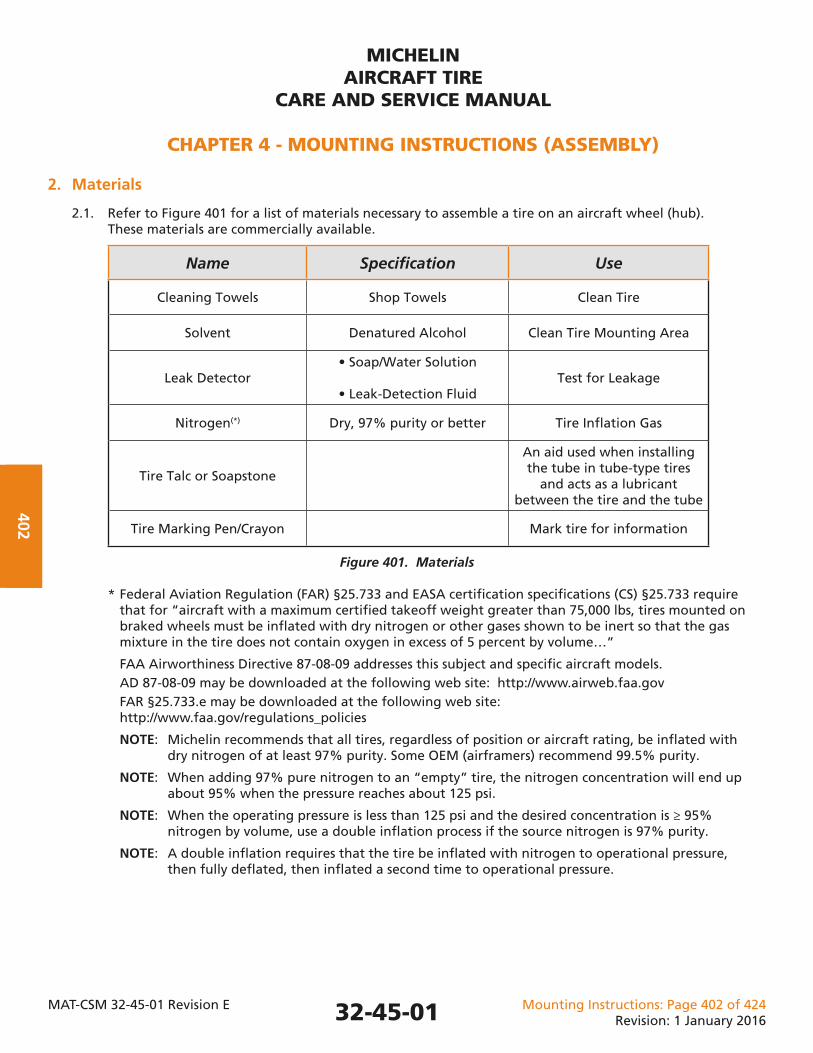
2.1. Refer to Figure 401 for a list of materials necessary to assemble a tire on an aircraft wheel (hub). These materials are commercially available.
Name Specifi cation Use
Cleaning Towels Shop Towels Clean Tire
Solvent Denatured Alcohol Clean Tire Mounting Area
Leak Detector• Soap/Water Solution
• Leak-Detection FluidTest for Leakage
Nitrogen(*) Dry, 97% purity or better Tire Infl ation Gas
Tire Talc or Soapstone
An aid used when installing the tube in tube-type tires
and acts as a lubricant between the tire and the tube
Tire Marking Pen/Crayon Mark tire for information
Figure 401. Materials
* Federal Aviation Regulation (FAR) §25.733 and EASA certifi cation specifi cations (CS) §25.733 require that for “aircraft with a maximum certifi ed takeoff weight greater than 75,000 lbs, tires mounted on braked wheels must be infl ated with dry nitrogen or other gases shown to be inert so that the gas mixture in the tire does not contain oxygen in excess of 5 percent by volume…”
FAA Airworthiness Directive 87-08-09 addresses this subject and specifi c aircraft models. AD 87-08-09 may be downloaded at the following web site: http://www.airweb.faa.gov FAR §25.733.e may be downloaded at the following web site: http://www.faa.gov/regulations_policies
NOTE: Michelin recommends that all tires, regardless of position or aircraft rating, be infl ated with dry nitrogen of at least 97% purity. Some OEM (airframers) recommend 99.5% purity.
NOTE: When adding 97% pure nitrogen to an “empty” tire, the nitrogen concentration will end up about 95% when the pressure reaches about 125 psi.
NOTE: When the operating pressure is less than 125 psi and the desired concentration is ≥ 95% nitrogen by volume, use a double infl ation process if the source nitrogen is 97% purity.
NOTE: A double infl ation requires that the tire be infl ated with nitrogen to operational pressure, then fully defl ated, then infl ated a second time to operational pressure.
32-45-01
MICHELINAIRCRAFT TIRE
CARE AND SERVICE MANUAL
CHAPTER 4 - MOUNTING INSTRUCTIONS (ASSEMBLY)
MAT-CSM 32-45-01 Revision E Mounting Instructions: Page 403 of 424Revision: 1 January 2016
403
CAUTION: DO NOT USE A MOUNTING LUBRICANT. IN-SERVICE TIRE/WHEEL SLIPPAGE MAY RESULT.
CAUTION: ALTHOUGH MICHELIN RECOMMENDS NOT USING LUBRICANTS/ CHEMICALS WHEN MOUNTING AIRCRAFT TIRES, IN THE EVENT CHEMICALS ARE USED ON THE TIRE, PROVIDE MICHELIN WITH A LIST OF AS WELL AS THE MATERIAL SAFETY DATA SHEETS (MSDS) FOR ANY PRODUCTS THAT ARE APPLIED TO THE TIRE AND/OR WHEEL DURING THE MOUNTING, STORAGE, USAGE, OR DISMOUNTING PROCESS THAT MAY END UP ON OR IN THE CASING. THESE PRODUCTS MUST BE REMOVED BEFORE RETURNING TO MICHELIN FOR PROCESSING TO AVOID POSSIBLE CONTAMINATION.
3. Tools, Fixtures and Equipment
3.1. Most modern aircraft wheels are of two types: Split wheel type (i.e., two “halves” joined by removable tie bolts), or the removable fl ange type. Both designs facilitate the mounting (and dismounting) of the tire.
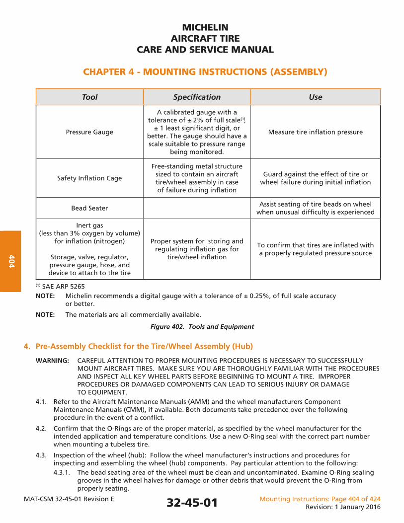
3.2. Refer to Figure 402 for a list of tools and equipment necessary or helpful to assemble a tire on an aircraft wheel (hub). NOTE: Equivalent alternatives can be used.
32-45-01
MICHELINAIRCRAFT TIRE
CARE AND SERVICE MANUAL
CHAPTER 4 - MOUNTING INSTRUCTIONS (ASSEMBLY)
MAT-CSM 32-45-01 Revision E Mounting Instructions: Page 404 of 424Revision: 1 January 2016
404
Tool Specifi cation Use
Pressure Gauge
A calibrated gauge with a tolerance of ± 2% of full scale(1),
± 1 least signifi cant digit, or better. The gauge should have a scale suitable to pressure range
being monitored.
Measure tire infl ation pressure
Safety Infl ation Cage
Free-standing metal structure sized to contain an aircraft tire/wheel assembly in case of failure during infl ation
Guard against the effect of tire or wheel failure during initial infl ation
Bead SeaterAssist seating of tire beads on wheel
when unusual diffi culty is experienced
Inert gas (less than 3% oxygen by volume)
for infl ation (nitrogen)
Storage, valve, regulator, pressure gauge, hose, and device to attach to the tire
Proper system for storing and regulating infl ation gas for
tire/wheel infl ation
To confi rm that tires are infl ated with a properly regulated pressure source
(1) SAE ARP 5265 NOTE: Michelin recommends a digital gauge with a tolerance of ± 0.25%, of full scale accuracy or better.
NOTE: The materials are all commercially available.
Figure 402. Tools and Equipment
4. Pre-Assembly Checklist for the Tire/Wheel Assembly (Hub)
WARNING: CAREFUL ATTENTION TO PROPER MOUNTING PROCEDURES IS NECESSARY TO SUCCESSFULLY MOUNT AIRCRAFT TIRES. MAKE SURE YOU ARE THOROUGHLY FAMILIAR WITH THE PROCEDURES AND INSPECT ALL KEY WHEEL PARTS BEFORE BEGINNING TO MOUNT A TIRE. IMPROPER PROCEDURES OR DAMAGED COMPONENTS CAN LEAD TO SERIOUS INJURY OR DAMAGE TO EQUIPMENT. 4.1. Refer to the Aircraft Maintenance Manuals (AMM) and the wheel manufacturers Component Maintenance Manuals (CMM), if available. Both documents take precedence over the following procedure in the event of a confl ict.
4.2. Confi rm that the O-Rings are of the proper material, as specifi ed by the wheel manufacturer for the intended application and temperature conditions. Use a new O-Ring seal with the correct part number when mounting a tubeless tire.
4.3. Inspection of the wheel (hub): Follow the wheel manufacturer’s instructions and procedures for inspecting and assembling the wheel (hub) components. Pay particular attention to the following: 4.3.1. The bead seating area of the wheel must be clean and uncontaminated. Examine O-Ring sealing grooves in the wheel halves for damage or other debris that would prevent the O-Ring from properly seating.
32-45-01
MICHELINAIRCRAFT TIRE
CARE AND SERVICE MANUAL
CHAPTER 4 - MOUNTING INSTRUCTIONS (ASSEMBLY)
MAT-CSM 32-45-01 Revision E Mounting Instructions: Page 405 of 424Revision: 1 January 2016
405
4.3.2. Nicks, burrs, small dents, or other damage that could prevent the surfaces from properly mating or sealing must be repaired. 4.3.3. Painted or coated surfaces should be in good condition; not badly chafed, chipped, etc. 4.3.4. Confi rm that the fuse plugs, overinfl ation plugs, infl ation valves and wheel plugs are in good condition, properly sealed against loss of pressure. Consult the manufacturer’s instructions for proper torque values. 4.3.5. Replace O-Rings that have cracks, cuts, permanent deformations, or other damages.
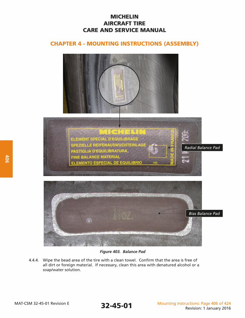
4.4. Inspection of the tire: Confi rm that the tire is correct for the intended application. 4.4.1. Confi rm the size, ply rating, speed rating, and part number. Refer to Chapter 2, as required. NOTE: Refer to the Chapter 5 for serviceability criteria. 4.4.2. Examine the outside of the tire and reject it for service if any of the following conditions are found: 4.4.2.1. Cuts, tears, cracks, or foreign objects that penetrate the external rubber and expose ply cords. 4.4.2.2. Permanent deformations. 4.4.2.3. Cuts on the bead seating surfaces. 4.4.2.4. Debris on the bead seating surfaces that cannot be removed with reasonable cleaning effort. 4.4.2.5. Bead distortions. 4.4.2.6. Contamination from foreign substances (oil, grease, brake fl uid, hydraulic fl uid, etc.). NOTE: Contaminated rubber will be soft and may have blisters or swelling of the rubber. 4.4.3. Examine the inside of the tire and remove any debris (trash, screws, rivets, etc.) from inside the tire. The tire is serviceable if there is no damage to the innerliner rubber. CAUTION: OPERATING A TIRE WITH FOREIGN MATERIAL LEFT IN THE INTERIOR MAY DAMAGE THE INNERLINER RUBBER CAUSING A PRESSURE LOSS AND POSSIBLE TIRE FAILURE WHILE IN SERVICE. CAUTION: DO NOT REMOVE THE BALANCE PAD. REMOVAL MAY DAMAGE THE INNERLINER RUBBER CAUSING A PRESSURE LOSS AND POSSIBLE TIRE FAILURE WHILE IN SERVICE. NOTE: It is normal and acceptable to see a balance pad (Figure 403) attached to the interior of some aircraft tires. This pad is applied at the factory and brings tire balance within industry and regulatory standards. Do not confuse this pad with a repair. NOTE: The writing on the MICHELIN® radial pad indicates the mass of the balance pad and a date that has no meaning after installation at the factory. The bias balance pad indicates the mass of the pad only. Refer to Figure 403.
32-45-01
MICHELINAIRCRAFT TIRE
CARE AND SERVICE MANUAL
CHAPTER 4 - MOUNTING INSTRUCTIONS (ASSEMBLY)
MAT-CSM 32-45-01 Revision E Mounting Instructions: Page 406 of 424Revision: 1 January 2016
406
Figure 403. Balance Pad
4.4.4. Wipe the bead area of the tire with a clean towel. Confi rm that the area is free of all dirt or foreign material. If necessary, clean this area with denatured alcohol or a soap/water solution.
32-45-01
Radial Balance Pad
Bias Balance Pad
MICHELINAIRCRAFT TIRE
CARE AND SERVICE MANUAL
CHAPTER 4 - MOUNTING INSTRUCTIONS (ASSEMBLY)
MAT-CSM 32-45-01 Revision E Mounting Instructions: Page 407 of 424Revision: 1 January 2016
407
5.2.1. The Tire Bead area must be free of all dirt or foreign material. 5.2.1.1. If necessary, clean this area with denatured alcohol or a soap/water solution. Allow drying time prior to assembly.
CAUTION: DO NOT USE A MOUNTING LUBRICANT. IN-SERVICE TIRE/WHEEL SLIPPAGE MAY RESULT. ALTHOUGH MICHELIN RECOMMENDS NOT USING LUBRICANTS/CHEMICALS WHEN MOUNTING AIRCRAFT TIRES, IN THE EVENT CHEMICALS ARE USED ON THE TIRE, PROVIDE MICHELIN WITH A LIST OF AS WELL AS THE MATERIAL SAFETY DATA SHEETS (MSDS) FOR ANY PRODUCTS THAT ARE APPLIED TO THE TIRE AND/OR WHEEL DURING THE MOUNTING, STORAGE, USAGE, OR DISMOUNTING PROCESS THAT MAY END UP ON OR IN THE CASING. THESE PRODUCTS MUST BE REMOVED BEFORE RETURNING TO MICHELIN FOR PROCESSING TO AVOID POSSIBLE CONTAMINATION.
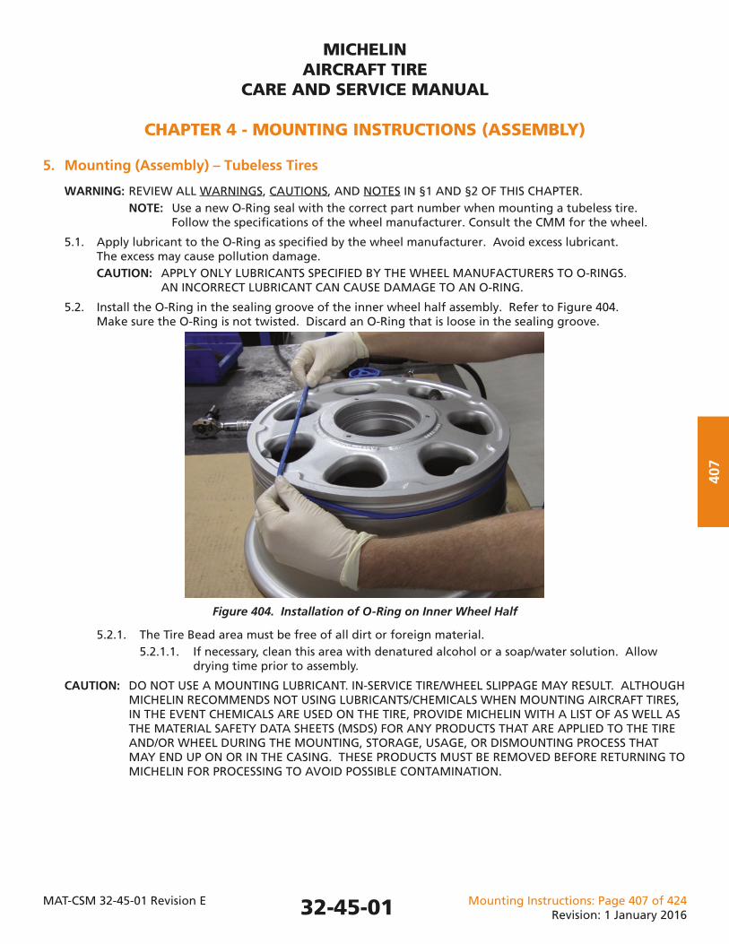
Figure 404. Installation of O-Ring on Inner Wheel Half
5. Mounting (Assembly) – Tubeless Tires
WARNING: REVIEW ALL WARNINGS, CAUTIONS, AND NOTES IN §1 AND §2 OF THIS CHAPTER. NOTE: Use a new O-Ring seal with the correct part number when mounting a tubeless tire. Follow the specifi cations of the wheel manufacturer. Consult the CMM for the wheel.
5.1. Apply lubricant to the O-Ring as specifi ed by the wheel manufacturer. Avoid excess lubricant. The excess may cause pollution damage. CAUTION: APPLY ONLY LUBRICANTS SPECIFIED BY THE WHEEL MANUFACTURERS TO O-RINGS. AN INCORRECT LUBRICANT CAN CAUSE DAMAGE TO AN O-RING.
5.2. Install the O-Ring in the sealing groove of the inner wheel half assembly. Refer to Figure 404. Make sure the O-Ring is not twisted. Discard an O-Ring that is loose in the sealing groove.
32-45-01
MICHELINAIRCRAFT TIRE
CARE AND SERVICE MANUAL
CHAPTER 4 - MOUNTING INSTRUCTIONS (ASSEMBLY)
MAT-CSM 32-45-01 Revision E Mounting Instructions: Page 408 of 424Revision: 1 January 2016
408
5.3. Install the tire on the inner wheel half. 5.3.1. Mount the tire so that the serial number will show (away from the strut) when the tire is installed on the aircraft. 5.3.2. Press against the tire sidewalls to begin to seat the bead on the inner wheel half tube well. Center the tire on the inner wheel half so that the bead toe is in complete contact with the tube well (360 degrees). NOTE: The tire will not completely seat against the wheel fl ange at this time.
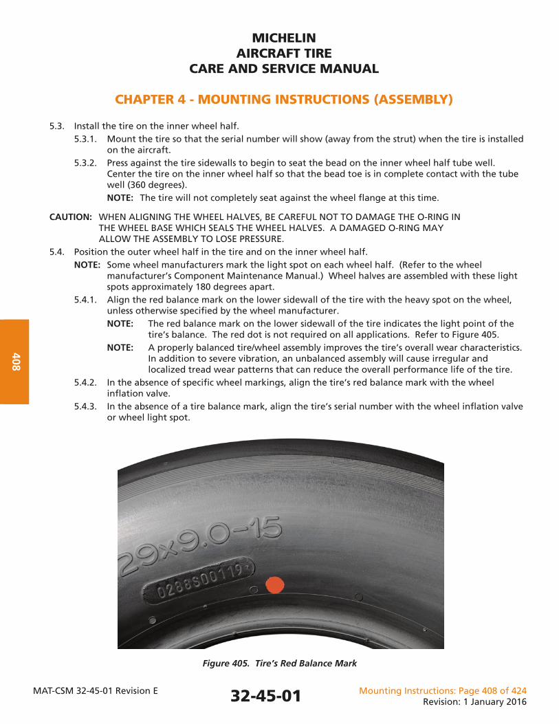
CAUTION: WHEN ALIGNING THE WHEEL HALVES, BE CAREFUL NOT TO DAMAGE THE O-RING IN THE WHEEL BASE WHICH SEALS THE WHEEL HALVES. A DAMAGED O-RING MAY ALLOW THE ASSEMBLY TO LOSE PRESSURE. 5.4. Position the outer wheel half in the tire and on the inner wheel half. NOTE: Some wheel manufacturers mark the light spot on each wheel half. (Refer to the wheel manufacturer’s Component Maintenance Manual.) Wheel halves are assembled with these light spots approximately 180 degrees apart. 5.4.1. Align the red balance mark on the lower sidewall of the tire with the heavy spot on the wheel, unless otherwise specifi ed by the wheel manufacturer. NOTE: The red balance mark on the lower sidewall of the tire indicates the light point of the tire’s balance. The red dot is not required on all applications. Refer to Figure 405. NOTE: A properly balanced tire/wheel assembly improves the tire’s overall wear characteristics. In addition to severe vibration, an unbalanced assembly will cause irregular and localized tread wear patterns that can reduce the overall performance life of the tire. 5.4.2. In the absence of specifi c wheel markings, align the tire’s red balance mark with the wheel infl ation valve. 5.4.3. In the absence of a tire balance mark, align the tire’s serial number with the wheel infl ation valve or wheel light spot.
Figure 405. Tire’s Red Balance Mark
32-45-01
MICHELINAIRCRAFT TIRE
CARE AND SERVICE MANUAL
CHAPTER 4 - MOUNTING INSTRUCTIONS (ASSEMBLY)
MAT-CSM 32-45-01 Revision E Mounting Instructions: Page 409 of 424Revision: 1 January 2016
409
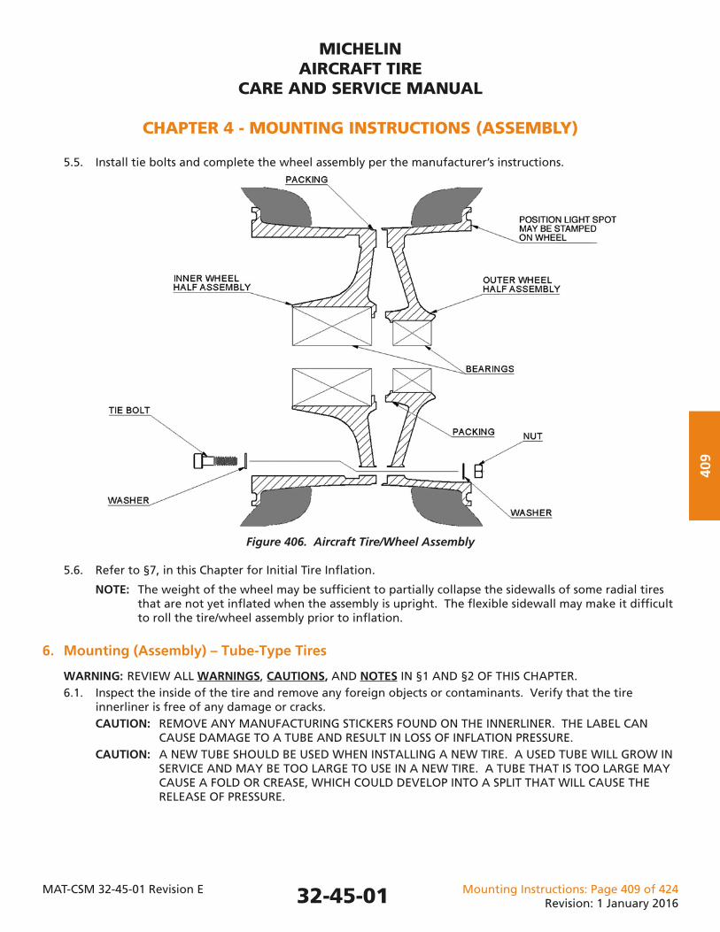
5.5. Install tie bolts and complete the wheel assembly per the manufacturer’s instructions.
Figure 406. Aircraft Tire/Wheel Assembly
5.6. Refer to §7, in this Chapter for Initial Tire Infl ation.
NOTE: The weight of the wheel may be suffi cient to partially collapse the sidewalls of some radial tires that are not yet infl ated when the assembly is upright. The fl exible sidewall may make it diffi cult to roll the tire/wheel assembly prior to infl ation.
6. Mounting (Assembly) – Tube-Type Tires
WARNING: REVIEW ALL WARNINGS, CAUTIONS, AND NOTES IN §1 AND §2 OF THIS CHAPTER. 6.1. Inspect the inside of the tire and remove any foreign objects or contaminants. Verify that the tire innerliner is free of any damage or cracks. CAUTION: REMOVE ANY MANUFACTURING STICKERS FOUND ON THE INNERLINER. THE LABEL CAN CAUSE DAMAGE TO A TUBE AND RESULT IN LOSS OF INFLATION PRESSURE. CAUTION: A NEW TUBE SHOULD BE USED WHEN INSTALLING A NEW TIRE. A USED TUBE WILL GROW IN SERVICE AND MAY BE TOO LARGE TO USE IN A NEW TIRE. A TUBE THAT IS TOO LARGE MAY CAUSE A FOLD OR CREASE, WHICH COULD DEVELOP INTO A SPLIT THAT WILL CAUSE THE RELEASE OF PRESSURE.
32-45-01
MICHELINAIRCRAFT TIRE
CARE AND SERVICE MANUAL
CHAPTER 4 - MOUNTING INSTRUCTIONS (ASSEMBLY)
MAT-CSM 32-45-01 Revision E Mounting Instructions: Page 410 of 424Revision: 1 January 2016
410
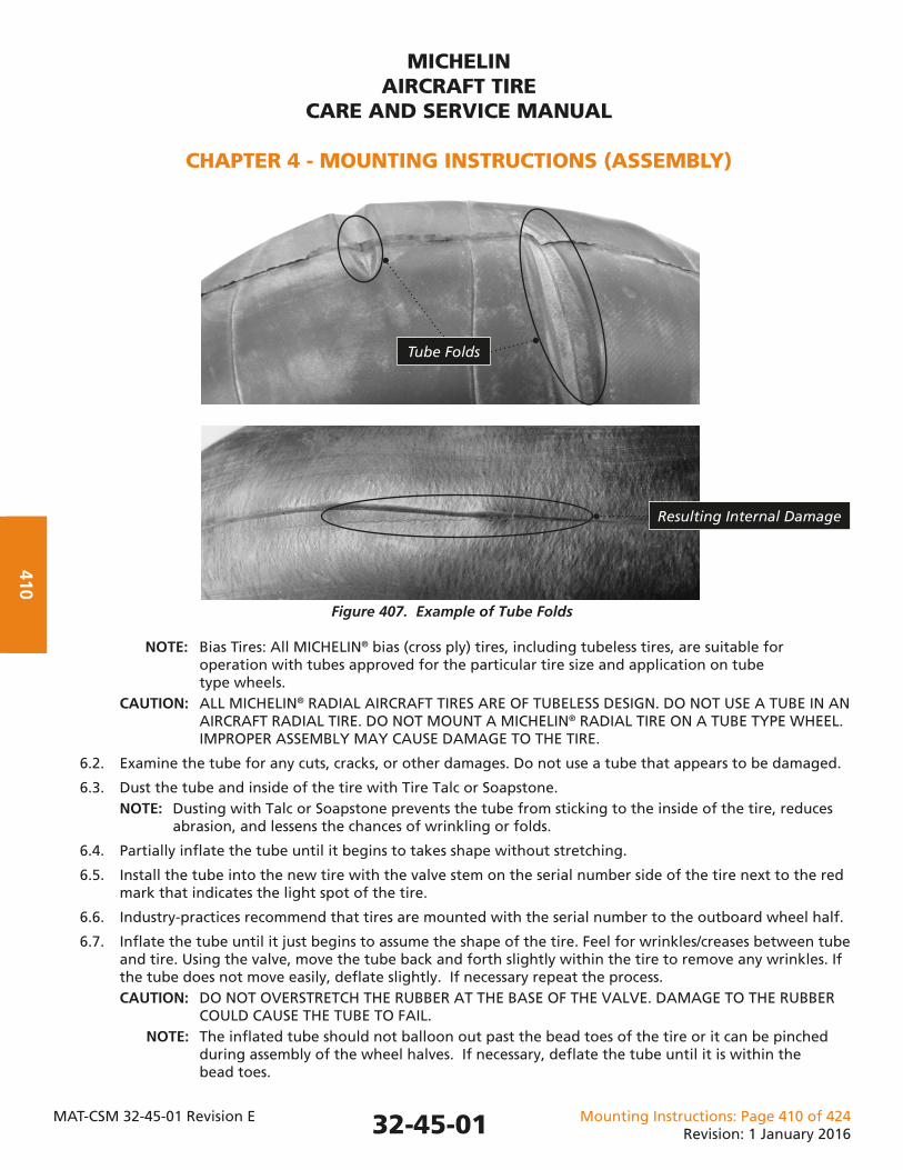
Figure 407. Example of Tube Folds
NOTE: Bias Tires: All MICHELIN® bias (cross ply) tires, including tubeless tires, are suitable for operation with tubes approved for the particular tire size and application on tube type wheels. CAUTION: ALL MICHELIN® RADIAL AIRCRAFT TIRES ARE OF TUBELESS DESIGN. DO NOT USE A TUBE IN AN AIRCRAFT RADIAL TIRE. DO NOT MOUNT A MICHELIN® RADIAL TIRE ON A TUBE TYPE WHEEL. IMPROPER ASSEMBLY MAY CAUSE DAMAGE TO THE TIRE.
6.2. Examine the tube for any cuts, cracks, or other damages. Do not use a tube that appears to be damaged.
6.3. Dust the tube and inside of the tire with Tire Talc or Soapstone. NOTE: Dusting with Talc or Soapstone prevents the tube from sticking to the inside of the tire, reduces abrasion, and lessens the chances of wrinkling or folds.
6.4. Partially infl ate the tube until it begins to takes shape without stretching.
6.5. Install the tube into the new tire with the valve stem on the serial number side of the tire next to the red mark that indicates the light spot of the tire.
6.6. Industry-practices recommend that tires are mounted with the serial number to the outboard wheel half.
6.7. Infl ate the tube until it just begins to assume the shape of the tire. Feel for wrinkles/creases between tube and tire. Using the valve, move the tube back and forth slightly within the tire to remove any wrinkles. If the tube does not move easily, defl ate slightly. If necessary repeat the process. CAUTION: DO NOT OVERSTRETCH THE RUBBER AT THE BASE OF THE VALVE. DAMAGE TO THE RUBBER COULD CAUSE THE TUBE TO FAIL. NOTE: The infl ated tube should not balloon out past the bead toes of the tire or it can be pinched during assembly of the wheel halves. If necessary, defl ate the tube until it is within the bead toes.
Tube Folds
Resulting Internal Damage
32-45-01
MICHELINAIRCRAFT TIRE
CARE AND SERVICE MANUAL
CHAPTER 4 - MOUNTING INSTRUCTIONS (ASSEMBLY)
MAT-CSM 32-45-01 Revision E Mounting Instructions: Page 411 of 424Revision: 1 January 2016
411
6.8. Place the outer wheel half onto the tire/tube assembly.
6.9. Position the outer wheel half in the tire and on the inner wheel half. When marked, the wheel light spots should be assembled approximately 180 degrees apart (refer to the wheel manufacturer’s CMM). NOTE: Many wheel manufacturers today mark the light spot on each wheel half. NOTE: Confi rm that the tube valve stem (heavy spot) or the wheel light spot is aligned with the tire’s red mark (light spot). NOTE: A properly balanced tire/wheel assembly improves the tire’s overall wear characteristics. In addition to severe vibration, an unbalanced assembly will cause irregular and localized tread wear patterns that can reduce the overall performance life of the tire.
6.9.1. Install tie bolts and complete the wheel assembly per the manufacturer’s instructions.
7. Infl ation of a Tire/Wheel Assembly to Operational Pressure
7.1. WARNINGS, CAUTIONS, and NOTES for this section. WARNING: AIRCRAFT TIRES, AT AMBIENT TEMPERATURE, CAN BE OPERATED UP TO OR AT RATED INFLATION PRESSURE. EXTREMELY HIGH INFLATION PRESSURES MAY CAUSE THE AIRCRAFT WHEEL OR TIRE TO BURST, WHICH MAY RESULT IN SERIOUS OR FATAL BODILY INJURY. WARNING: FOLLOW THE INSTRUCTIONS AND PROCEDURES OF THE WHEEL MANUFACTURER FOR THE ASSEMBLY OF THE WHEEL (HUB) COMPONENTS TO ENSURE PROPER SERVICING OF AIRCRAFT TIRE/WHEEL ASSEMBLIES. FAILURE TO USE THE PROPER PROCEDURES WILL INCREASE THE RISK OF DAMAGE OR PERSONAL INJURY. WARNING: AIRCRAFT TIRES MUST ALWAYS BE INFLATED WITH A PROPERLY REGULATED INFLATION SOURCE. REGULATE THE SUPPLY LINE TO A PRESSURE NO GREATER THAN 1.5 TIMES THE OPERATING INFLATION PRESSURE. INFLATING A TIRE WITHOUT A PRESSURE REGULATOR PRESENTS A RISK OF PERSONAL INJURY AND/OR DAMAGE TO EQUIPMENT. WARNING: USE A SUITABLE INFLATION CAGE WHEN INFLATING A NEWLY MOUNTED TIRE WHEEL (HUB) ASSEMBLY. ANY DAMAGE TO THE TIRE, THE WHEEL, AND WHEEL BOLTS OR IMPROPER PROCEDURE, MAY CAUSE THE TIRE/WHEEL ASSEMBLY TO BURST DURING THE INFLATION PROCESS, WHICH MAY RESULT IN SERIOUS OR FATAL INJURY. CAUTION: CONFIRM THAT ALL WHEEL TIE BOLTS, VALVES, OVERINFLATION PLUGS, FUSE PLUGS, ETC. HAVE BEEN PROPERLY INSTALLED AND TORQUED TO WHEEL MANUFACTURER’S SPECIFICATIONS BEFORE BEGINNING INFLATION. IMPROPER ASSEMBLY COULD ALLOW THE ASSEMBLY TO LEAK. WARNING: THE INFLATION PRESSURE SOURCE SHOULD BE LOCATED 10 METERS (30 FEET) AWAY FROM THE SAFETY CAGE WITH A VALVE, REGULATOR, AND PRESSURE GAUGE INSTALLED AT THAT POINT. THE INFLATION LINE SHOULD THEN BE RUN TO THE SAFETY CAGE AND ATTACHED TO THE WHEEL VALVE. PERSONNEL NEAR THE SAFETY CAGE INCREASES THE RISK OF INJURY. CAUTION: REFER TO THE AIRCRAFT MAINTENANCE MANUAL (AMM) TO DETERMINE THE OPERATING PRESSURE. DIFFERENT OPERATING PRESSURES ARE USED DEPENDING ON TIRE SIZE, AIRCRAFT LOADS, AND OPERATING CONDITIONS. INCORRECT OPERATING PRESSURE CAN CAUSE DAMAGE TO TIRES, WHEELS, AND AIRCRAFT.
7.2. Initial Infl ation of tire/wheel assemblies. 7.2.1. Place the tire/wheel assembly into a suitable safety cage for infl ation. NOTE: A suitable infl ation safety cage must consider the largest tire size and greatest operational infl ation pressure. 7.2.2. Attach the infl ation line to the valve stem.
32-45-01
MICHELINAIRCRAFT TIRE
CARE AND SERVICE MANUAL
CHAPTER 4 - MOUNTING INSTRUCTIONS (ASSEMBLY)
MAT-CSM 32-45-01 Revision E Mounting Instructions: Page 412 of 424Revision: 1 January 2016
412
7.2.3. Infl ate the tire/wheel assembly to the correct operating pressure for the intended use. NOTE: Some tire/wheel assemblies may be suitable for different aircraft. Confi rm the recommended pressure for the aircraft on which it is to be mounted. 7.2.4. Additional steps for tube type tires: 7.2.4.1. Completely defl ate the tube/tire. 7.2.4.2. Re-infl ate the tube/tire to the correct operating pressure. NOTE: This procedure helps to remove any wrinkles in the tube and allows any trapped air between the tire and tube to escape. 7.2.4.3. Check pressure in 24 hours. Re-infl ate to operating pressure (assumes trapped air escaped). Repeat each day until all trapped air has escaped and pressure stabilizes. NOTE: Tube-type tires require special pressure maintenance for several days after being placed in service due to air possibly being trapped between the tube and the tire. Once the tire is placed in service, this trapped air escapes through the valve stem hole of the wheel. The trapped air that escapes will reduce the gauge pressure. 7.2.5. Complete the pressure retention check.
8. Pressure Retention Check (Leak Check) – After Mounting
WARNING: REVIEW ALL WARNINGS, CAUTIONS, AND NOTES IN §1, §2, AND §7 OF THIS CHAPTER.
8.1. Refer to Figures 401 and 402, for materials, tools, and equipment.
8.2. Pressure-retention checks are designed to make sure that tire/wheel assemblies meet industry-accepted standards for pressure retention prior to releasing them for service on aircraft. This important process confi rms the tire/wheel assembly is ready for service on the aircraft and helps avoid damages due to underinfl ation conditions. NOTE: The pressure check validates the ability of both the tire and wheel to hold pressure. Attention must be directed to both the tire and wheel if a pressure loss is detected. 8.2.1. The procedure is essentially the same for all aircraft tires: bias, radial, tubeless, and tube-type. 8.2.2. Tire stretch - It is normal for aircraft tires to become larger (stretch or grow) when infl ated to operating pressure. Any procedure used to properly check for tire leakage must allow for tire stretch. 8.2.2.1. Tire stretch can take up to 12 hours. Tire stretch increases the internal volume of the tire, which reduces the infl ation pressure. 8.2.2.2. Initial tire stretch (12 hours) and ambient temperature must be stable in order to know if any pressure change is a result of leakage.
8.3. Three (3) pressure-retention procedures are described below: • Industry Standard procedure • Alternate procedure • Emergency procedure 8.3.1. The Industry Standard-retention procedure has been the standard of the aircraft tire industry for many years. It is designed to provide a complete check of tire/wheel assembly pressure retention prior to releasing them for use on aircraft. This procedure requires a 12-hour stretch period and a 24-hour period to measure pressure loss. It is recommended by most airframers. NOTE: Airbus SIL 32-119 and Boeing SL of 6 December 2006, titled “Suggested Shop Maintenance Procedures for Wheel and Tire Assemblies,” recommend the 12-hour stretch and the 24-hour leak check.
32-45-01
MICHELINAIRCRAFT TIRE
CARE AND SERVICE MANUAL
CHAPTER 4 - MOUNTING INSTRUCTIONS (ASSEMBLY)
MAT-CSM 32-45-01 Revision E Mounting Instructions: Page 413 of 424Revision: 1 January 2016
413
8.3.2. The Alternate-retention procedure is used by some operators in order to reduce the time required for the process. The time allocated for stretch, and the time for the leak check are reduced. The tolerance allowed is also reduced. This procedure requires a calibrated gauge with a tolerance of ±0.25% of full scale, or better, and with a scale suitable to the pressure range being monitored (Note that the tolerance here is less than the tolerance recommended in Figure 402.) 8.3.3. The Emergency-retention procedure may be used to perform a pressure retention check on a newly mounted tire/wheel assembly when time does not allow the Industry Standard or Alternative procedure to be used. 8.3.3.1. The Emergency procedure should be used only when faced with an Aircraft on Ground (AOG) type situation. This procedure requires a calibrated gauge with a tolerance of ±0.25% of full scale, or better. The gauge should have a scale suitable to the pressure range being monitored (Note that the tolerance here is less than the tolerance recommended in Figure 402.)
8.4. Industry Standard Pressure-Retention Procedure WARNING: REVIEW ALL WARNINGS, CAUTIONS, AND NOTES IN §1, §2, AND §7 OF THIS CHAPTER. 8.4.1. Infl ate the newly mounted tire/wheel assembly to operating pressure (PN) for the aircraft application as specifi ed in the Aircraft Maintenance Manual (AMM). NOTE: Refer to Figure 409. 8.4.2. Store the infl ated tire/wheel assembly for 12 hours to allow for tire stretch. 8.4.3. After the 12-hour stretch period, measure the infl ation pressure (PG). Confi rm that the ambient temperature of the tire/wheel assembly has not changed by more than 3°C (5°F). NOTE: Changes in ambient temperature will cause a corresponding change in infl ation pressure (gauge pressure). A 3°C (5°F) decrease in temperature will result in a 1% decrease in infl ation pressure. An increase in temperature will cause an increase in the infl ation pressure. Refer to Figure 409. 8.4.4. A pressure drop of less than or equal to (≤) 10% during the stretch period is considered normal. Any loss more than that may indicate a leakage problem. 8.4.5. Re-infl ate the tire to the specifi ed operating pressure (PN). 8.4.6. Wait 24 hours to allow for any pressure loss. 8.4.7. After a 24-hour wait, measure the infl ation pressure (PG). Confi rm that the ambient temperature of the tire/wheel assembly has not changed by more than 3°C (5°F). 8.4.7.1. If infl ation pressure (PG) is equal to or greater than (≥) 95% of the specifi ed operating pressure (PN), accept the tire/wheel assembly for in-service usage or line maintenance storage. (Refer to §12, in this chapter, for recommendations on line maintenance storage.)
Or
8.4.7.2. If the infl ation pressure (PG) is less than (<) 95% of the specifi ed operating pressure (PN), inspect the tire/wheel assembly for leaks. Refer to §9, in this chapter. • Use a soap solution on tire beads and other susceptible wheel components (valves, fuse plugs, over-pressurization plugs, wheel half parting line, etc.). If soap bubbles or leaks are found. Repair any leak. • Return to 8.4.1. NOTE: It is normal to see bubbles at the tire vent holes, just above the wheel fl ange, any time while the tire is infl ated. Refer to Chapter 1, §6, Figure 107. NOTE: Do not identify a tire as leaking solely on the rate of bubbles from the vent holes. A leaking tire/wheel assembly should be determined by the pressure loss, as measured with a calibrated gauge, over a period of time.
32-45-01
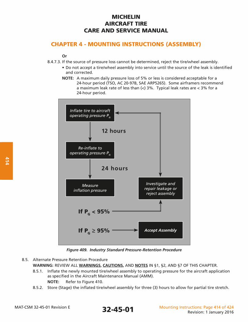
MICHELINAIRCRAFT TIRE
CARE AND SERVICE MANUAL
CHAPTER 4 - MOUNTING INSTRUCTIONS (ASSEMBLY)
MAT-CSM 32-45-01 Revision E Mounting Instructions: Page 414 of 424Revision: 1 January 2016
414
Or 8.4.7.3. If the source of pressure loss cannot be determined, reject the tire/wheel assembly. • Do not accept a tire/wheel assembly into service until the source of the leak is identifi ed and corrected. NOTE: A maximum daily pressure loss of 5% or less is considered acceptable for a 24-hour period (TSO, AC 20-97B, SAE ARP5265). Some airframers recommend a maximum leak rate of less than (<) 3%. Typical leak rates are < 3% for a 24-hour period.
Figure 409. Industry Standard Pressure-Retention Procedure
8.5. Alternate Pressure Retention Procedure WARNING: REVIEW ALL WARNINGS, CAUTIONS, AND NOTES IN §1, §2, AND §7 OF THIS CHAPTER. 8.5.1. Infl ate the newly mounted tire/wheel assembly to operating pressure for the aircraft application as specifi ed in the Aircraft Maintenance Manual (AMM). NOTE: Refer to Figure 410. 8.5.2. Store (Stage) the infl ated tire/wheel assembly for three (3) hours to allow for partial tire stretch.
32-45-01
12 hours
24 hours
If PG < 95%
If PG ≥ 95%
Infl ate tire to aircraft operating pressure PN
Re-infl ate to operating pressure PN
Measure infl ation pressure
Investigate andrepair leakage or reject assembly
Accept Assembly
MICHELINAIRCRAFT TIRE
CARE AND SERVICE MANUAL
CHAPTER 4 - MOUNTING INSTRUCTIONS (ASSEMBLY)
MAT-CSM 32-45-01 Revision E Mounting Instructions: Page 415 of 424Revision: 1 January 2016
415
8.5.3. After the three (3)-hour stretch, measure the infl ation pressure (PG). Confi rm that the ambient temperature of the tire/wheel assembly has not changed by more than 3°C (5°F). 8.5.3.1. If infl ation pressure (PG) is equal to or greater than (≥) 90% of the specifi ed operating pressure (PN), proceed to §8.5.4. Or 8.5.3.2. If infl ation pressure (PG) is less than (<) 90% of the specifi ed operating pressure (PN), inspect the tire/wheel assembly for leaks. Refer to §9, in this chapter. • Use a soap solution on tire beads and other susceptible wheel components (valves, fuse plugs, over-pressurization plugs, wheel half parting line, etc.). If soap bubbles or leaks are found, repair any leak. • Return to §8.5.1, in this chapter. NOTE: It is normal to see bubbles at the tire vent holes, just above the wheel fl ange, any time while the tire is infl ated. (Refer to Chapter 1, §6.) NOTE: Do not identify a tire as leaking solely on the rate of bubbles from the vent holes. A leaking tire/wheel assembly should be determined by the pressure loss, as measured with a calibrated gauge, over a period of time. 8.5.4. Re-infl ate the tire to the specifi ed operating pressure (PN). 8.5.5. Wait 12 hours to allow for any pressure loss. 8.5.6. After 12-hour storage period, measure infl ation pressure (PG). Confi rm that the ambient temperature of the tire/wheel assembly has not changed by more than 3°C (5°F). 8.5.6.1. If infl ation pressure (PG) is equal to or greater than (≥) 97.5% of the specifi ed operating pressure (PN), accept the tire/wheel assembly for in-service usage or line maintenance storage. 8.5.6.2. Re-infl ate the tire to the specifi ed operating pressure (PN). (Refer to §12, in this chapter, for recommendations on line maintenance.) Or 8.5.6.3. If the infl ation pressure (PG) is less than (<) 97.5% of the specifi ed operating pressure (PN), re-infl ate the tire to operating pressure, then wait 24 hours to allow for any pressure loss. 8.5.7. After 24-hour wait, measure the infl ation pressure (PG). Confi rm that the ambient temperature of the tire/wheel assembly has not changed by more than 3°C (5°F). 8.5.7.1. If infl ation pressure (PG) is equal to or greater than (≥) 95% of the specifi ed operating pressure (PN), accept the tire/wheel assembly for in-service usage or line maintenance storage. (Refer to §12, in this chapter, for recommendations on line maintenance.) Or 8.5.7.2. If the infl ation pressure (PG) is less than (<) 95% of the specifi ed operating pressure (PN), • Reject the tire/wheel assembly. Or • Use a soap solution on tire beads and other susceptible wheel components (valves, fuse plugs, over-pressurization plugs, wheel half parting line, etc.). If soap bubbles or leaks are found, repair any leak. • Return to §8.5.1. 8.5.7.3. Record the measured pressure loss (psi/bar) and time.
32-45-01
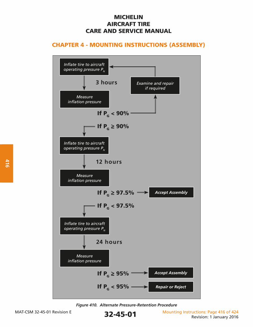
MICHELINAIRCRAFT TIRE
CARE AND SERVICE MANUAL
CHAPTER 4 - MOUNTING INSTRUCTIONS (ASSEMBLY)
MAT-CSM 32-45-01 Revision E Mounting Instructions: Page 416 of 424Revision: 1 January 2016
416
Figure 410. Alternate Pressure-Retention Procedure
3 hours
12 hours
If PG < 90%
If PG ≥≥ 90%
Infl ate tire to aircraft operating pressure PN
Measure infl ation pressure
Accept Assembly
24 hours
Examine and repair if required
Infl ate tire to aircraft operating pressure PN
Measure infl ation pressure
If PG ≥≥ 97.5%
If PG < 97.5%
Infl ate tire to aircraft operating pressure PN
Measure infl ation pressure
If PG ≥≥ 95%
If PG < 95%
Accept Assembly
Repair or Reject
32-45-01
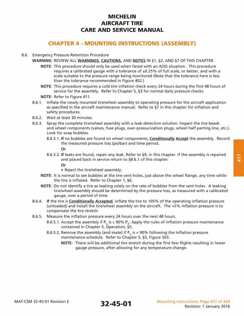
MICHELINAIRCRAFT TIRE
CARE AND SERVICE MANUAL
CHAPTER 4 - MOUNTING INSTRUCTIONS (ASSEMBLY)
MAT-CSM 32-45-01 Revision E Mounting Instructions: Page 417 of 424Revision: 1 January 2016
417
8.6. Emergency Pressure-Retention Procedure WARNING: REVIEW ALL WARNINGS, CAUTIONS, AND NOTES IN §1, §2, AND §7 OF THIS CHAPTER. NOTE: This procedure should only be used when faced with an AOG situation. This procedure requires a calibrated gauge with a tolerance of ±0.25% of full scale, or better, and with a scale suitable to the pressure range being monitored (Note that the tolerance here is less than the tolerance recommended in Figure 402.) NOTE: This procedure requires a cold tire infl ation check every 24 hours during the fi rst 48 hours of service for the assembly. Refer to Chapter 5, §3 for normal daily pressure checks. NOTE: Refer to Figure 411. 8.6.1. Infl ate the newly mounted tire/wheel assembly to operating pressure for the aircraft application as specifi ed in the aircraft maintenance manual. Refer to §7 in this chapter for infl ation and safety procedures. 8.6.2. Wait at least 30 minutes. 8.6.3. Spray the complete tire/wheel assembly with a leak-detection solution. Inspect the tire beads and wheel components (valves, fuse plugs, over-pressurization plugs, wheel half parting line, etc.). Look for soap bubbles. 8.6.3.1. If no bubbles are found on wheel components, Conditionally Accept the assembly. Record the measured pressure loss (psi/bar) and time period. Or 8.6.3.2. If leaks are found, repair any leak. Refer to §9, in this chapter. If the assembly is repaired and placed back in service return to §8.6.1 of this chapter. Or • Reject the tire/wheel assembly. NOTE: It is normal to see bubbles at the tire vent holes, just above the wheel fl ange, any time while the tire is infl ated. Refer to Chapter 1, §6. NOTE: Do not identify a tire as leaking solely on the rate of bubbles from the vent holes. A leaking tire/wheel assembly should be determined by the pressure loss, as measured with a calibrated gauge, over a period of time. 8.6.4. If the tire is Conditionally Accepted, infl ate the tire to 105% of the operating infl ation pressure (unloaded) and install the tire/wheel assembly on the aircraft. The +5% infl ation pressure is to compensate the tire stretch. 8.6.5. Measure the infl ation pressure every 24 hours over the next 48 hours. 8.6.5.1. Accept the assembly if PG is ≥ 90% PN. Apply the rules of infl ation pressure maintenance contained in Chapter 5, Operation, §5. 8.6.5.2. Remove the assembly (and mate) if PG is < 90% following the infl ation pressure maintenance schedule. Refer to Chapter 5, §5, Figure 503. NOTE: There will be additional tire stretch during the fi rst few fl ights resulting in lower gauge pressure, after allowing for any temperature change.
32-45-01

MICHELINAIRCRAFT TIRE
CARE AND SERVICE MANUAL
CHAPTER 4 - MOUNTING INSTRUCTIONS (ASSEMBLY)
MAT-CSM 32-45-01 Revision E Mounting Instructions: Page 418 of 424Revision: 1 January 2016
418
Figure 411. Emergency Pressure-Retention Procedure
Wait at least 30 minutes
If PG ≥≥ 90%
If PG < 90%
Infl ate tire to aircraft operating pressure PN
Spray with a leak- detection solution
or submergence test
Repair the tire/wheel assembly
Measure the cold infl ation pressure before each fl ight, at least once every 24 hours, for the
next 48 hours
If bubbles are found on any wheel hardware
or component
Accept Assembly and apply the rules of infl ation pressure
maintenance
No bubbles are found on any wheel hardware
or component
Install tire on aircraftat operating pressure
+ 5% (PN + 5%)
Remove the assembly per the infl ation
maintenance schedule
32-45-01
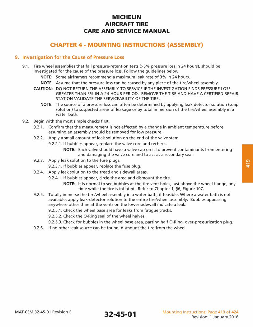
MICHELINAIRCRAFT TIRE
CARE AND SERVICE MANUAL
CHAPTER 4 - MOUNTING INSTRUCTIONS (ASSEMBLY)
MAT-CSM 32-45-01 Revision E Mounting Instructions: Page 419 of 424Revision: 1 January 2016
419
9. Investigation for the Cause of Pressure Loss
9.1. Tire wheel assemblies that fail pressure-retention tests (>5% pressure loss in 24 hours), should be investigated for the cause of the pressure loss. Follow the guidelines below. NOTE: Some airframers recommend a maximum leak rate of 3% in 24 hours. NOTE: Assume that the pressure loss can be caused by any piece of the tire/wheel assembly. CAUTION: DO NOT RETURN THE ASSEMBLY TO SERVICE IF THE INVESTIGATION FINDS PRESSURE LOSS GREATER THAN 5% IN A 24-HOUR PERIOD. REMOVE THE TIRE AND HAVE A CERTIFIED REPAIR STATION VALIDATE THE SERVICEABILITY OF THE TIRE. NOTE: The source of a pressure loss can often be determined by applying leak detector solution (soap solution) to suspected areas of leakage or by total immersion of the tire/wheel assembly in a water bath.
9.2. Begin with the most simple checks fi rst. 9.2.1. Confi rm that the measurement is not affected by a change in ambient temperature before assuming an assembly should be removed for low pressure. 9.2.2. Apply a small amount of leak solution on the end of the valve stem. 9.2.2.1. If bubbles appear, replace the valve core and recheck. NOTE: Each valve should have a valve cap on it to prevent contaminants from entering and damaging the valve core and to act as a secondary seal. 9.2.3. Apply leak solution to the fuse plugs. 9.2.3.1. If bubbles appear, replace the fuse plug. 9.2.4. Apply leak solution to the tread and sidewall areas. 9.2.4.1. If bubbles appear, circle the area and dismount the tire. NOTE: It is normal to see bubbles at the tire vent holes, just above the wheel fl ange, any time while the tire is infl ated. Refer to Chapter 1, §6, Figure 107. 9.2.5. Totally immerse the tire/wheel assembly in a water bath, if feasible. Where a water bath is not available, apply leak-detector solution to the entire tire/wheel assembly. Bubbles appearing anywhere other than at the vents on the lower sidewall indicate a leak. 9.2.5.1. Check the wheel base area for leaks from fatigue cracks. 9.2.5.2. Check the O-Ring seal of the wheel halves. 9.2.5.3. Check for bubbles in the wheel base area, parting half O-Ring, over-pressurization plug. 9.2.6. If no other leak source can be found, dismount the tire from the wheel.
32-45-01
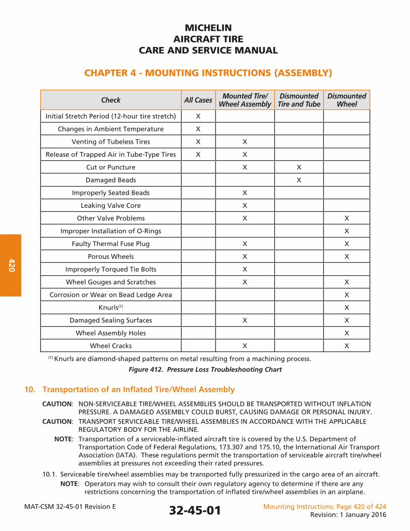
MICHELINAIRCRAFT TIRE
CARE AND SERVICE MANUAL
CHAPTER 4 - MOUNTING INSTRUCTIONS (ASSEMBLY)
MAT-CSM 32-45-01 Revision E Mounting Instructions: Page 420 of 424Revision: 1 January 2016
420
Check All Cases Mounted Tire/Wheel Assembly
Dismounted Tire and Tube
Dismounted Wheel
Initial Stretch Period (12-hour tire stretch) X
Changes in Ambient Temperature X
Venting of Tubeless Tires X X
Release of Trapped Air in Tube-Type Tires X X
Cut or Puncture X X
Damaged Beads X
Improperly Seated Beads X
Leaking Valve Core X
Other Valve Problems X X
Improper Installation of O-Rings X
Faulty Thermal Fuse Plug X X
Porous Wheels X X
Improperly Torqued Tie Bolts X
Wheel Gouges and Scratches X X
Corrosion or Wear on Bead Ledge Area X
Knurls(1) X
Damaged Sealing Surfaces X X
Wheel Assembly Holes X
Wheel Cracks X X
(1) Knurls are diamond-shaped patterns on metal resulting from a machining process.
Figure 412. Pressure Loss Troubleshooting Chart
10. Transportation of an Infl ated Tire/Wheel Assembly
CAUTION: NON-SERVICEABLE TIRE/WHEEL ASSEMBLIES SHOULD BE TRANSPORTED WITHOUT INFLATION PRESSURE. A DAMAGED ASSEMBLY COULD BURST, CAUSING DAMAGE OR PERSONAL INJURY. CAUTION: TRANSPORT SERVICEABLE TIRE/WHEEL ASSEMBLIES IN ACCORDANCE WITH THE APPLICABLE REGULATORY BODY FOR THE AIRLINE. NOTE: Transportation of a serviceable-infl ated aircraft tire is covered by the U.S. Department of Transportation Code of Federal Regulations, 173.307 and 175.10, the International Air Transport Association (IATA). These regulations permit the transportation of serviceable aircraft tire/wheel assemblies at pressures not exceeding their rated pressures.
10.1. Serviceable tire/wheel assemblies may be transported fully pressurized in the cargo area of an aircraft. NOTE: Operators may wish to consult their own regulatory agency to determine if there are any restrictions concerning the transportation of infl ated tire/wheel assemblies in an airplane.
32-45-01
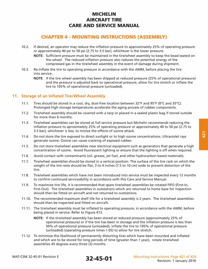
MICHELINAIRCRAFT TIRE
CARE AND SERVICE MANUAL
CHAPTER 4 - MOUNTING INSTRUCTIONS (ASSEMBLY)
MAT-CSM 32-45-01 Revision E Mounting Instructions: Page 421 of 424Revision: 1 January 2016
421
10.2. If desired, an operator may reduce the infl ation pressure to approximately 25% of operating pressure or approximately 40 psi to 50 psi (2.75 to 3.5 bar), whichever is the lower pressure. NOTE: Suffi cient pressure must be maintained in the tire/wheel assembly to keep the bead seated on the wheel. The reduced infl ation pressure also reduces the potential energy of the compressed gas in the tire/wheel assembly in the event of damage during shipment.
10.3. Re-infl ate the tire to operating pressure in accordance with the AMM, before placing the tire into service. NOTE: If the tire wheel assembly has been shipped at reduced pressure (25% of operational pressure) and the pressure is adjusted back to operational pressure, allow for tire stretch or infl ate the tire to 105% of operational pressure (unloaded).
11. Storage of an Infl ated Tire/Wheel Assembly
11.1. Tires should be stored in a cool, dry, dust-free location between 32°F and 95°F (0°C and 35°C). Prolonged high storage temperatures accelerate the aging process of rubber components.
11.2. Tire/wheel assembly should be covered with a tarp or placed in a sealed plastic bag if stored outside for more than 6 months.
11.3. Tire/wheel assemblies can be stored at full service pressure but Michelin recommends reducing the infl ation pressure to aproximately 25% of operating pressure or approximately 40 to 50 psi (2.75 to 3.5 bar), whichever is less, to minize the effects of ozone attack.
11.4. Do not store the tire exposed to direct sunlight or to high ozone concentrations. Ultraviolet rays generate ozone. Ozone can cause cracking of exposed rubber.
11.5. Do not store tire/wheel assemblies near electrical equipment such as generators that generate a high concentration of ozone. Avoid fl uorescent lighting or ensure that the lighting is off when required.
11.6. Avoid contact with contaminants (oil, grease, jet fuel, and other hydrocarbon based materials).
11.7. Tire/wheel assemblies should be stored in a vertical position. The surface of the tire rack on which the weight of the tire rests should be fl at, 3 to 4 inches (7.5 to 10 cm) wide to prevent distortion of the tire.
11.8. Tire/wheel assemblies which have not been introduced into service must be inspected every 12 months to confi rm continued serviceability in accordance with this Care and Service Manual.
11.9. To maximize tire life, it is recommended that spare tire/wheel assemblies be rotated FIFO (First-In, First-Out). The tire/wheel assemblies in outstations which are returned to home base for inspection should then be fi tted on aircraft and not returned to outstations.
11.10. The recommended maximum shelf life for a tire/wheel assembly is 2 years. The tire/wheel assemblies should then be inspected and fi tted on aircraft.
11.11. The tire/wheel assembly must be infl ated to operating pressure, in accordance with the AMM, before being placed in service. Refer to Figure 413.
NOTE: If the tire/wheel assembly has been stored at reduced pressure (approximately 25% of operational pressure) or if the tire has been in storage and the infl ation pressure is less than 50% of operational pressure (unloaded), infl ate the tire to 105% of operational pressure (unloaded) (operating pressure times 1.05) to allow for tire stretch.
11.12 To minimize the likelihood of permanently distorting tires which have been mounted and infl ated and which are to be stored for long periods of time (greater than 1 year), rotate tire/wheel assemblies 45 degrees every three (3) months.
32-45-01
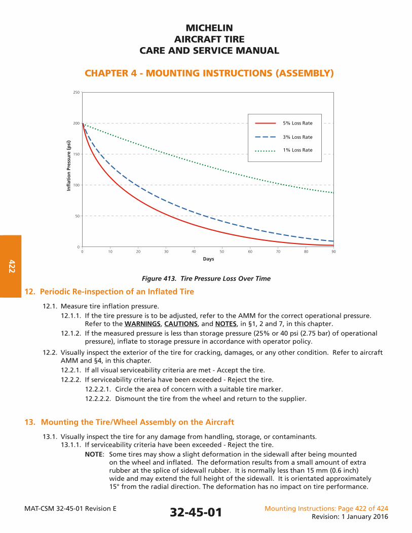
MICHELINAIRCRAFT TIRE
CARE AND SERVICE MANUAL
CHAPTER 4 - MOUNTING INSTRUCTIONS (ASSEMBLY)
MAT-CSM 32-45-01 Revision E Mounting Instructions: Page 422 of 424Revision: 1 January 2016
422
Figure 413. Tire Pressure Loss Over Time
12. Periodic Re-inspection of an Infl ated Tire
12.1. Measure tire infl ation pressure. 12.1.1. If the tire pressure is to be adjusted, refer to the AMM for the correct operational pressure. Refer to the WARNINGS, CAUTIONS, and NOTES, in §1, 2 and 7, in this chapter. 12.1.2. If the measured pressure is less than storage pressure (25% or 40 psi (2.75 bar) of operational pressure), infl ate to storage pressure in accordance with operator policy.
12.2. Visually inspect the exterior of the tire for cracking, damages, or any other condition. Refer to aircraft AMM and §4, in this chapter. 12.2.1. If all visual serviceability criteria are met - Accept the tire. 12.2.2. If serviceability criteria have been exceeded - Reject the tire. 12.2.2.1. Circle the area of concern with a suitable tire marker. 12.2.2.2. Dismount the tire from the wheel and return to the supplier.
13. Mounting the Tire/Wheel Assembly on the Aircraft
13.1. Visually inspect the tire for any damage from handling, storage, or contaminants. 13.1.1. If serviceability criteria have been exceeded - Reject the tire. NOTE: Some tires may show a slight deformation in the sidewall after being mounted on the wheel and infl ated. The deformation results from a small amount of extra rubber at the splice of sidewall rubber. It is normally less than 15 mm (0.6 inch) wide and may extend the full height of the sidewall. It is orientated approximately 15° from the radial direction. The deformation has no impact on tire performance.
250
200
150
100
50
00 10 20 30 40 50 60 70 80 90
5% Loss Rate
3% Loss Rate
1% Loss Rate
Infl
atio
n P
ress
ure
(p
si)
Days
32-45-01
MICHELINAIRCRAFT TIRE
CARE AND SERVICE MANUAL
CHAPTER 4 - MOUNTING INSTRUCTIONS (ASSEMBLY)
MAT-CSM 32-45-01 Revision E Mounting Instructions: Page 423 of 424Revision: 1 January 2016
423
13.2. Install the tire/wheel assembly on aircraft in accordance with the AMM.
13.3. Confi rm that the tire infl ation pressure is set in accordance with the AMM using a calibrated gauge with a tolerance of ± 2% of full scale, or better.
13.4. Set the pressure to consider changes in ambient temperature.
NOTE: Changes in ambient temperature will cause a corresponding change in infl ation pressure (gauge pressure). A 3°C (5°F) decrease in temperature will result in a 1% decrease in infl ation pressure. An increase in temperature will cause a corresponding increase in the infl ation pressure. (Example: A temperature drop of 28°C (50°F) will result in a pressure loss of 10%.)
NOTE: The ambient temperature will vary over the course of the day, from location to location, and from season the season. The tire infl ation pressure specifi ed by the airframe manufacturer for each aircraft confi guration is required to carry the load of the aircraft. This pressure value is needed regardless of the ambient temperature. While it is not practical to make small adjustments, the pressure should be set for the most adverse conditions (coldest temperature expected for operation).
NOTE: Tire pressure maintenance operations in cold climates must consider the effect of performing tire pressure maintenance on aircraft in a hangar that is warmer than the ambient temperature for normal operations. When the tire pressure is measured in a warm hangar and the aircraft is parked outside in a colder ambient temperature, the pressure will decrease.
NOTE: If the infl ation pressure is set with the weight on the wheels, the infl ation pressure is 4% greater than if the aircraft is on jacks (Operational Infl ation Pressure Loaded = 1.04 x Operational Infl ation Pressure Unloaded).
NOTE: If the tire wheel assembly has been stored at reduced pressure (approximately 25% of operational pressure) or if the tire has been in storage and the infl ation pressure is less than 50% of operational pressure, infl ate the tire to 105% of operational pressure to allow for stretch.
32-45-01
MICHELINAIRCRAFT TIRE
CARE AND SERVICE MANUAL
CHAPTER 4 - MOUNTING INSTRUCTIONS (ASSEMBLY)
MAT-CSM 32-45-01 Revision E Mounting Instructions: Page 424 of 424Revision: 1 January 2016
424 This Page IntentionallyLeft Blank
32-45-01
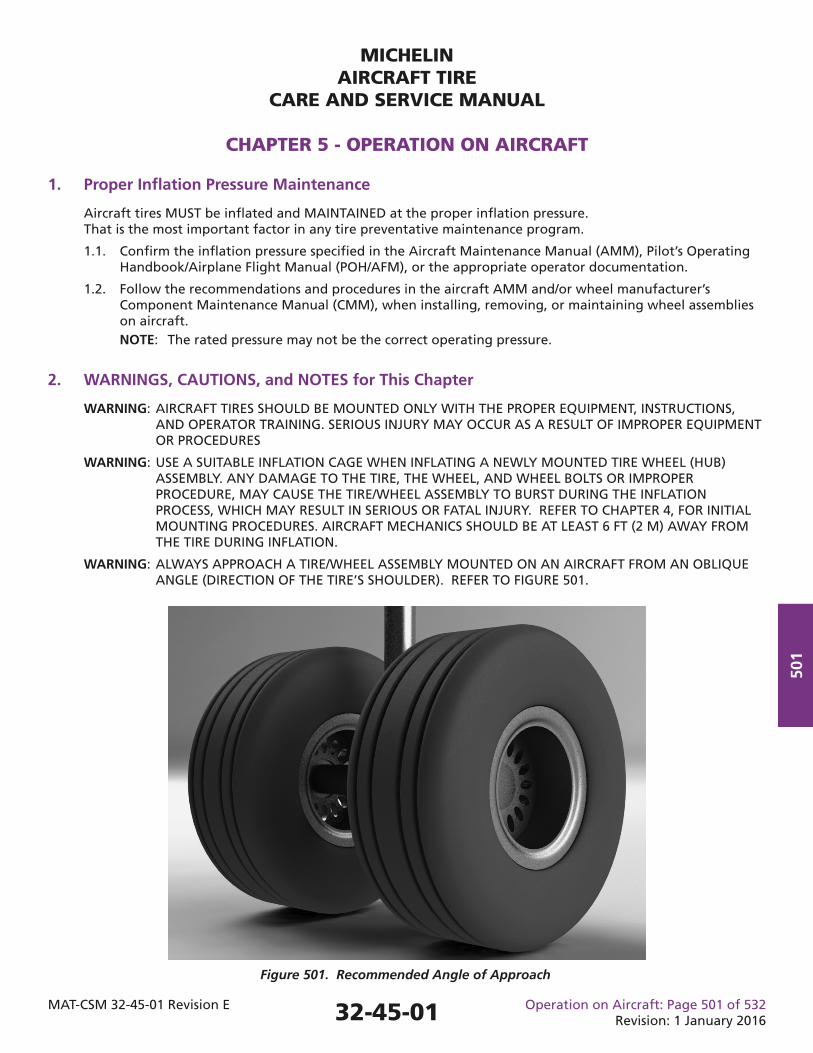
MICHELINAIRCRAFT TIRE
CARE AND SERVICE MANUAL
CHAPTER 5 - OPERATION ON AIRCRAFT
MAT-CSM 32-45-01 Revision E Operation on Aircraft: Page 501 of 532Revision: 1 January 2016
501
1. Proper Infl ation Pressure Maintenance
Aircraft tires MUST be infl ated and MAINTAINED at the proper infl ation pressure. That is the most important factor in any tire preventative maintenance program.
1.1. Confi rm the infl ation pressure specifi ed in the Aircraft Maintenance Manual (AMM), Pilot’s Operating Handbook/Airplane Flight Manual (POH/AFM), or the appropriate operator documentation.
1.2. Follow the recommendations and procedures in the aircraft AMM and/or wheel manufacturer’s Component Maintenance Manual (CMM), when installing, removing, or maintaining wheel assemblies on aircraft. NOTE: The rated pressure may not be the correct operating pressure.
2. WARNINGS, CAUTIONS, and NOTES for This Chapter
WARNING: AIRCRAFT TIRES SHOULD BE MOUNTED ONLY WITH THE PROPER EQUIPMENT, INSTRUCTIONS, AND OPERATOR TRAINING. SERIOUS INJURY MAY OCCUR AS A RESULT OF IMPROPER EQUIPMENT OR PROCEDURES
WARNING: USE A SUITABLE INFLATION CAGE WHEN INFLATING A NEWLY MOUNTED TIRE WHEEL (HUB) ASSEMBLY. ANY DAMAGE TO THE TIRE, THE WHEEL, AND WHEEL BOLTS OR IMPROPER PROCEDURE, MAY CAUSE THE TIRE/WHEEL ASSEMBLY TO BURST DURING THE INFLATION PROCESS, WHICH MAY RESULT IN SERIOUS OR FATAL INJURY. REFER TO CHAPTER 4, FOR INITIAL MOUNTING PROCEDURES. AIRCRAFT MECHANICS SHOULD BE AT LEAST 6 FT (2 M) AWAY FROM THE TIRE DURING INFLATION.
WARNING: ALWAYS APPROACH A TIRE/WHEEL ASSEMBLY MOUNTED ON AN AIRCRAFT FROM AN OBLIQUE ANGLE (DIRECTION OF THE TIRE’S SHOULDER). REFER TO FIGURE 501.
Figure 501. Recommended Angle of Approach
32-45-01
MICHELINAIRCRAFT TIRE
CARE AND SERVICE MANUAL
CHAPTER 5 - OPERATION ON AIRCRAFT
MAT-CSM 32-45-01 Revision E Operation on Aircraft: Page 502 of 532Revision: 1 January 2016
502
WARNING: AIRCRAFT TIRE AND WHEEL ASSEMBLIES SHOULD BE TREATED WITH THE SAME CARE AS ANY OTHER HIGH PRESSURE VESSEL. IMPROPER HANDLING MAY LEAD TO SERIOUS INJURY.
WARNING: AIRCRAFT TIRES MUST ALWAYS BE INFLATED WITH A PROPERLY REGULATED INFLATION SOURCE. REGULATE THE SUPPLY LINE TO A PRESSURE NO GREATER THAN 1.5 TIMES THE OPERATING INFLATION PRESSURE. INFLATING A TIRE WITHOUT A PRESSURE REGULATOR PRESENTS A RISK OF PERSONAL INJURY AND/OR DAMAGE TO EQUIPMENT.
CAUTION: BE CAREFUL WHEN HANDLING, ASSEMBLING, AND DISASSEMBLING WHEEL COMPONENTS TO AVOID DAMAGE.
WARNING: DO NOT PROBE CUTS OR EMBEDDED OBJECTS WHILE A TIRE IS INFLATED. SUCH ACTION COULD FURTHER DAMAGE A TIRE CAUSING IT TO RUPTURE RESULTING IN PERSONAL INJURY OR EQUIPMENT DAMAGE.
WARNING: A TIRE/WHEEL ASSEMBLY THAT HAS KNOWN DAMAGE SHOULD BE ALLOWED TO COOL TO AMBIENT TEMPERATURE (A MINIMUM OF 3 HOURS) BEFORE THE TIRE IS DEFLATED.
WARNING: USE CARE WHEN REMOVING THE VALVE CORE FROM AN INFLATED TIRE. USE OF A VALVE CORE REMOVAL TOOL IS RECOMMENDED. THE VALVE CORE OF AN INFLATED TIRE CAN BE PROJECTED AT A HIGH SPEED AND POSSIBLY CAUSE INJURY.
3. Pressure Checks
Use a calibrated gauge with a minimum tolerance of ±2% of full scale, or better, and with a scale suitable to the pressure range being monitored. Michelin recommends the use of a calibrated gauge with a tolerance of ±0.25% of full scale. Refer to Chapter 4, §3.
3.1. Check the infl ation pressure before the fi rst fl ight of aircraft that fl y daily or before each fl ight for aircraft that operate less frequently. Ideally this check should be done at ambient, outside conditions. When this is not possible, refer to para 3.3. NOTE: Any measurement below 95% of nominal infl ation pressure requires maintenance action (refer to Figure 503). Underinfl ation increases the defl ection of the tire which may result in overheating, abnormal tire wear, shortened tire life, and possible tire failure. NOTE: Overinfl ation can increase tread cutting, foreign object damage (FOD), abnormal tread wear, and stress on the wheel. 3.2. Confi rm that the pressure required is specifi ed for “weight on wheels” or with the tire unloaded. (The tire/wheel assembly is not installed on the aircraft or the aircraft is on jacks.) A loaded tire will have an infl ation pressure 4% higher than when unloaded (loaded pressure = 1.04 times unloaded pressure).
3.3. Set the pressure to consider changes in ambient temperature. NOTE: Changes in ambient temperature will cause a corresponding change in infl ation pressure (gauge pressure). A 3°C (5°F) decrease in temperature will result in a 1% decrease in infl ation pressure. An increase in temperature will cause a corresponding increase in the infl ation pressure. (Example: A temperature drop of 28°C (50°F) will result in a pressure loss of 10%.) NOTE: The ambient temperature will vary over the course of the day, from location to location, and from season the season. The tire pressure specifi ed by the airframe manufacturer for each aircraft confi guration is required to carry the load of the aircraft. This pressure value is needed regardless of the ambient temperature. While it is not practical to make small adjustments, the pressure should be set for the most adverse conditions (coldest temperature expected for operation). NOTE: Other methods exist in the tire industry that may be used to estimate the pressure adjustment due to changes in temperature. They will provide a value that may be slightly different due to rounding.
32-45-01
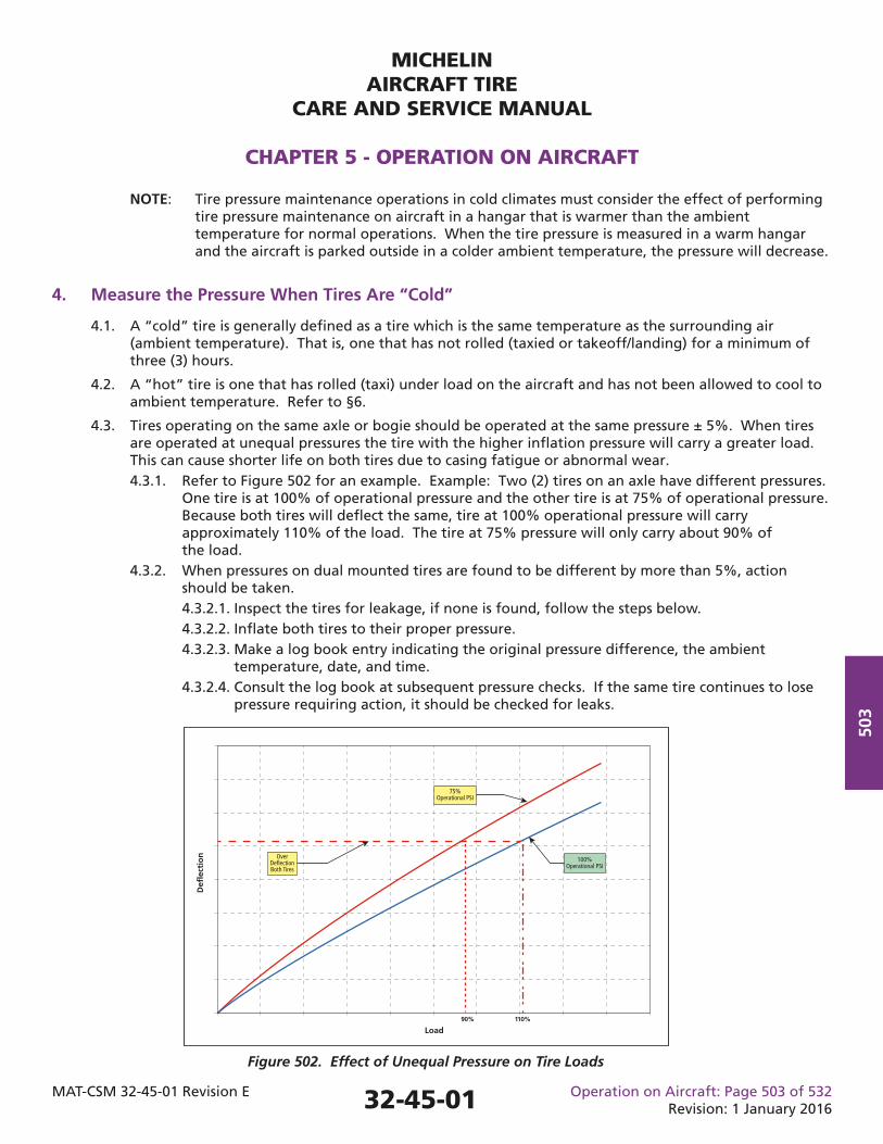
MICHELINAIRCRAFT TIRE
CARE AND SERVICE MANUAL
CHAPTER 5 - OPERATION ON AIRCRAFT
MAT-CSM 32-45-01 Revision E Operation on Aircraft: Page 503 of 532Revision: 1 January 2016
503
Defl
ecti
on
Load90% 110%
Over Deflection Both Tires
75% Operational PSI
100% Operational PSI
NOTE: Tire pressure maintenance operations in cold climates must consider the effect of performing tire pressure maintenance on aircraft in a hangar that is warmer than the ambient temperature for normal operations. When the tire pressure is measured in a warm hangar and the aircraft is parked outside in a colder ambient temperature, the pressure will decrease.
4. Measure the Pressure When Tires Are “Cold”
4.1. A “cold” tire is generally defi ned as a tire which is the same temperature as the surrounding air (ambient temperature). That is, one that has not rolled (taxied or takeoff/landing) for a minimum of three (3) hours.
4.2. A “hot” tire is one that has rolled (taxi) under load on the aircraft and has not been allowed to cool to ambient temperature. Refer to §6.
4.3. Tires operating on the same axle or bogie should be operated at the same pressure ± 5%. When tires are operated at unequal pressures the tire with the higher infl ation pressure will carry a greater load. This can cause shorter life on both tires due to casing fatigue or abnormal wear. 4.3.1. Refer to Figure 502 for an example. Example: Two (2) tires on an axle have different pressures. One tire is at 100% of operational pressure and the other tire is at 75% of operational pressure. Because both tires will defl ect the same, tire at 100% operational pressure will carry approximately 110% of the load. The tire at 75% pressure will only carry about 90% of the load. 4.3.2. When pressures on dual mounted tires are found to be different by more than 5%, action should be taken. 4.3.2.1. Inspect the tires for leakage, if none is found, follow the steps below. 4.3.2.2. Infl ate both tires to their proper pressure. 4.3.2.3. Make a log book entry indicating the original pressure difference, the ambient temperature, date, and time. 4.3.2.4. Consult the log book at subsequent pressure checks. If the same tire continues to lose pressure requiring action, it should be checked for leaks.
Figure 502. Effect of Unequal Pressure on Tire Loads
32-45-01
MICHELINAIRCRAFT TIRE
CARE AND SERVICE MANUAL
CHAPTER 5 - OPERATION ON AIRCRAFT
MAT-CSM 32-45-01 Revision E Operation on Aircraft: Page 504 of 532Revision: 1 January 2016
504
4.4. Effects of Underinfl ation: 4.4.1. Underinfl ation or underinfl ation over time can cause casing fatigue which can result in partial or full tire failure. 4.4.2. Reduced retreadability. 4.4.3. Excessive shoulder wear. 4.4.4. Tires can creep or slip on the wheel during braking. Valve stems on tube-type tires can be damaged or sheared off and the tire, tube or complete wheel assembly can be damaged. 4.4.5. High lateral (side) forces or landing impact may cause the wheel to pinch the tire, strike the runway or the tire to interfere with other landing gear components.
4.5. Tire Pressure Monitoring System (TPMS) may be used to check infl ation pressure provided the TPMS is calibrated periodically.
5. Maintenance Action
Action is required if the pressure is not within the range specifi ed for the operational pressure. The action required depends on the pressure measured and should be accomplished in accordance with the AMM, or a maintenance procedure approved by the proper authority.
5.1. Figure 503 provides maintenance action based on measured cold (ambient temperature) pressure as a percentage of operating pressure. Gauge accuracy and calibration should be confi rmed. A course of action is provided for each percentage range. Figure 503 is applicable to all aircraft tires. NOTE: When the infl ation pressure is set in the warm hangar and aircraft is parked outside in a colder ambient temperature, the infl ation pressure should be adjusted to compensate for the drop in pressure resulting from the change in temperature. Refer to Note in §3.3 in this chapter.
32-45-01
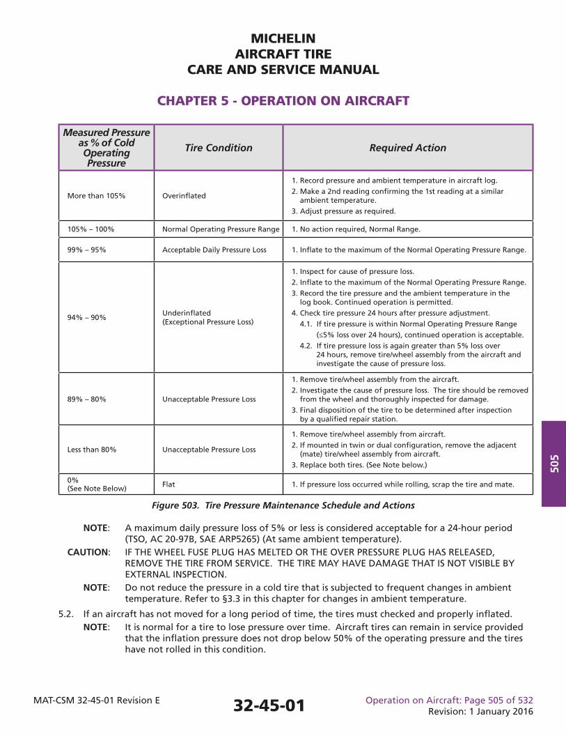
MICHELINAIRCRAFT TIRE
CARE AND SERVICE MANUAL
CHAPTER 5 - OPERATION ON AIRCRAFT
MAT-CSM 32-45-01 Revision E Operation on Aircraft: Page 505 of 532Revision: 1 January 2016
505
Measured Pressure as % of Cold Operating Pressure
Tire Condition Required Action
More than 105% Overinfl ated
1. Record pressure and ambient temperature in aircraft log.2. Make a 2nd reading confi rming the 1st reading at a similar ambient temperature.3. Adjust pressure as required.
105% – 100% Normal Operating Pressure Range 1. No action required, Normal Range.
99% – 95% Acceptable Daily Pressure Loss 1. Infl ate to the maximum of the Normal Operating Pressure Range.
94% – 90%Underinfl ated (Exceptional Pressure Loss)
1. Inspect for cause of pressure loss.2. Infl ate to the maximum of the Normal Operating Pressure Range.3. Record the tire pressure and the ambient temperature in the log book. Continued operation is permitted.4. Check tire pressure 24 hours after pressure adjustment.
4.1. If tire pressure is within Normal Operating Pressure Range (≤5% loss over 24 hours), continued operation is acceptable.4.2. If tire pressure loss is again greater than 5% loss over 24 hours, remove tire/wheel assembly from the aircraft and investigate the cause of pressure loss.
89% – 80% Unacceptable Pressure Loss
1. Remove tire/wheel assembly from the aircraft.2. Investigate the cause of pressure loss. The tire should be removed from the wheel and thoroughly inspected for damage.3. Final disposition of the tire to be determined after inspection by a qualifi ed repair station.
Less than 80% Unacceptable Pressure Loss
1. Remove tire/wheel assembly from aircraft.2. If mounted in twin or dual confi guration, remove the adjacent (mate) tire/wheel assembly from aircraft.3. Replace both tires. (See Note below.)
0% (See Note Below) Flat 1. If pressure loss occurred while rolling, scrap the tire and mate.
Figure 503. Tire Pressure Maintenance Schedule and Actions
NOTE: A maximum daily pressure loss of 5% or less is considered acceptable for a 24-hour period (TSO, AC 20-97B, SAE ARP5265) (At same ambient temperature). CAUTION: IF THE WHEEL FUSE PLUG HAS MELTED OR THE OVER PRESSURE PLUG HAS RELEASED, REMOVE THE TIRE FROM SERVICE. THE TIRE MAY HAVE DAMAGE THAT IS NOT VISIBLE BY EXTERNAL INSPECTION. NOTE: Do not reduce the pressure in a cold tire that is subjected to frequent changes in ambient temperature. Refer to §3.3 in this chapter for changes in ambient temperature.
5.2. If an aircraft has not moved for a long period of time, the tires must checked and properly infl ated. NOTE: It is normal for a tire to lose pressure over time. Aircraft tires can remain in service provided that the infl ation pressure does not drop below 50% of the operating pressure and the tires have not rolled in this condition.
32-45-01
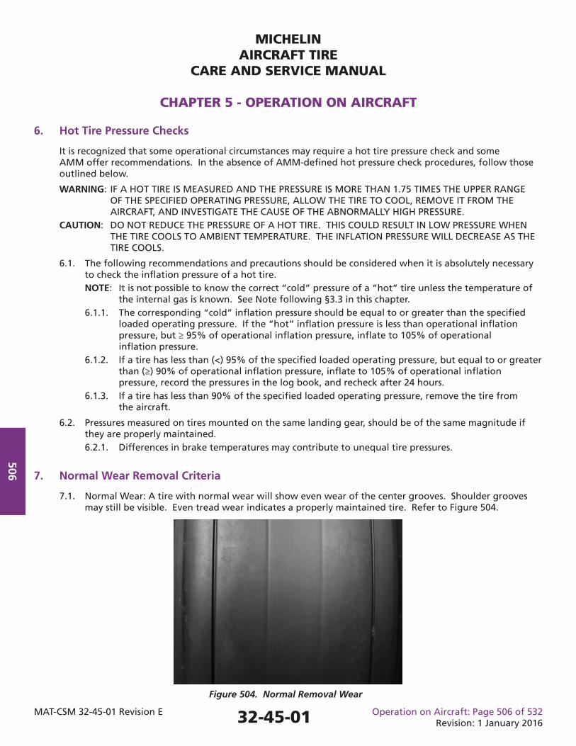
MICHELINAIRCRAFT TIRE
CARE AND SERVICE MANUAL
CHAPTER 5 - OPERATION ON AIRCRAFT
MAT-CSM 32-45-01 Revision E Operation on Aircraft: Page 506 of 532Revision: 1 January 2016
506
6. Hot Tire Pressure Checks
It is recognized that some operational circumstances may require a hot tire pressure check and some AMM offer recommendations. In the absence of AMM-defi ned hot pressure check procedures, follow those outlined below.
WARNING: IF A HOT TIRE IS MEASURED AND THE PRESSURE IS MORE THAN 1.75 TIMES THE UPPER RANGE OF THE SPECIFIED OPERATING PRESSURE, ALLOW THE TIRE TO COOL, REMOVE IT FROM THE AIRCRAFT, AND INVESTIGATE THE CAUSE OF THE ABNORMALLY HIGH PRESSURE. CAUTION: DO NOT REDUCE THE PRESSURE OF A HOT TIRE. THIS COULD RESULT IN LOW PRESSURE WHEN THE TIRE COOLS TO AMBIENT TEMPERATURE. THE INFLATION PRESSURE WILL DECREASE AS THE TIRE COOLS.
6.1. The following recommendations and precautions should be considered when it is absolutely necessary to check the infl ation pressure of a hot tire. NOTE: It is not possible to know the correct “cold” pressure of a “hot” tire unless the temperature of the internal gas is known. See Note following §3.3 in this chapter. 6.1.1. The corresponding “cold” infl ation pressure should be equal to or greater than the specifi ed loaded operating pressure. If the “hot” infl ation pressure is less than operational infl ation pressure, but ≥ 95% of operational infl ation pressure, infl ate to 105% of operational infl ation pressure. 6.1.2. If a tire has less than (<) 95% of the specifi ed loaded operating pressure, but equal to or greater than (≥) 90% of operational infl ation pressure, infl ate to 105% of operational infl ation pressure, record the pressures in the log book, and recheck after 24 hours. 6.1.3. If a tire has less than 90% of the specifi ed loaded operating pressure, remove the tire from the aircraft.
6.2. Pressures measured on tires mounted on the same landing gear, should be of the same magnitude if they are properly maintained. 6.2.1. Differences in brake temperatures may contribute to unequal tire pressures.
7. Normal Wear Removal Criteria
7.1. Normal Wear: A tire with normal wear will show even wear of the center grooves. Shoulder grooves may still be visible. Even tread wear indicates a properly maintained tire. Refer to Figure 504.
Figure 504. Normal Removal Wear
32-45-01
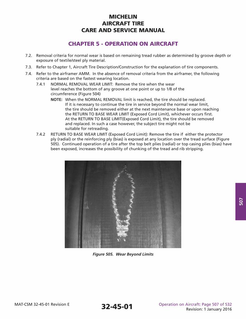
MICHELINAIRCRAFT TIRE
CARE AND SERVICE MANUAL
CHAPTER 5 - OPERATION ON AIRCRAFT
MAT-CSM 32-45-01 Revision E Operation on Aircraft: Page 507 of 532Revision: 1 January 2016
507
7.2. Removal criteria for normal wear is based on remaining tread rubber as determined by groove depth or exposure of textile/steel ply material.
7.3. Refer to Chapter 1, Aircraft Tire Description/Construction for the explanation of tire components.
7.4. Refer to the airframer AMM. In the absence of removal criteria from the airframer, the following criteria are based on the fastest wearing location. 7.4.1 NORMAL REMOVAL WEAR LIMIT: Remove the tire when the wear level reaches the bottom of any groove at one point or up to 1/8 of the circumference (Figure 504) NOTE: When the NORMAL REMOVAL limit is reached, the tire should be replaced. If it is necessary to continue the tire in service beyond the normal wear limit, the tire should be removed either at the next maintenance base or upon reaching the RETURN TO BASE WEAR LIMIT (Exposed Cord Limit), whichever occurs fi rst. At the RETURN TO BASE LIMIT(Exposed Cord Limit), the tire should be removed and replaced. In such a case however, the subject tire might not be suitable for retreading. 7.4.2 RETURN TO BASE WEAR LIMIT (Exposed Cord Limit): Remove the tire if either the protector ply (radial) or the reinforcing ply (bias) is exposed at any location over the tread surface (Figure 505). Continued operation of a tire after the top belt plies (radial) or top casing plies (bias) have been exposed, increases the possibility of chunking of the tread and rib stripping.
Figure 505. Wear Beyond Limits
32-45-01
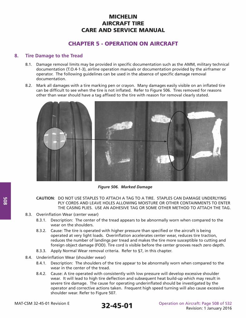
MICHELINAIRCRAFT TIRE
CARE AND SERVICE MANUAL
CHAPTER 5 - OPERATION ON AIRCRAFT
MAT-CSM 32-45-01 Revision E Operation on Aircraft: Page 508 of 532Revision: 1 January 2016
508 CAUTION: DO NOT USE STAPLES TO ATTACH A TAG TO A TIRE. STAPLES CAN DAMAGE UNDERLYING PLY CORDS AND LEAVE HOLES ALLOWING MOISTURE OR OTHER CONTAINMENTS TO ENTER THE CASING PLIES. USE AN ADHESIVE TAG OR SOME OTHER METHOD TO ATTACH THE TAG.
8.3. Overinfl ation Wear (center wear) 8.3.1. Description: The center of the tread appears to be abnormally worn when compared to the wear on the shoulders. 8.3.2. Cause: The tire is operated with higher pressure than specifi ed or the aircraft is being operated at very light loads. Overinfl ation accelerates center wear, reduces tire traction, reduces the number of landings per tread and makes the tire more susceptible to cutting and foreign object damage (FOD). Tire cord is visible before the center grooves reach zero depth. 8.3.3. Apply Normal Wear removal criteria. Refer to §7, in this chapter.
8.4. Underinfl ation Wear (shoulder wear) 8.4.1. Description: The shoulders of the tire appear to be abnormally worn when compared to the wear in the center of the tread. 8.4.2. Cause: A tire operated with consistently with low pressure will develop excessive shoulder wear. It will lead to high tire defl ection and subsequent heat build-up which may result in severe tire damage. The cause for operating underinfl ated should be investigated by the operator and corrective actions taken. Frequent high speed turning will also cause excessive shoulder wear. Refer to Figure 507.
8. Tire Damage to the Tread
8.1. Damage removal limits may be provided in specifi c documentation such as the AMM, military technical documentation (T.O.4-1-3), airline operation manuals or documentation provided by the airframer or operator. The following guidelines can be used in the absence of specifi c damage removal documentation.
8.2. Mark all damages with a tire marking pen or crayon. Many damages easily visible on an infl ated tire can be diffi cult to see when the tire is not infl ated. Refer to Figure 506. Tires removed for reasons other than wear should have a tag affi xed to the tire with reason for removal clearly stated.
Figure 506. Marked Damage
32-45-01
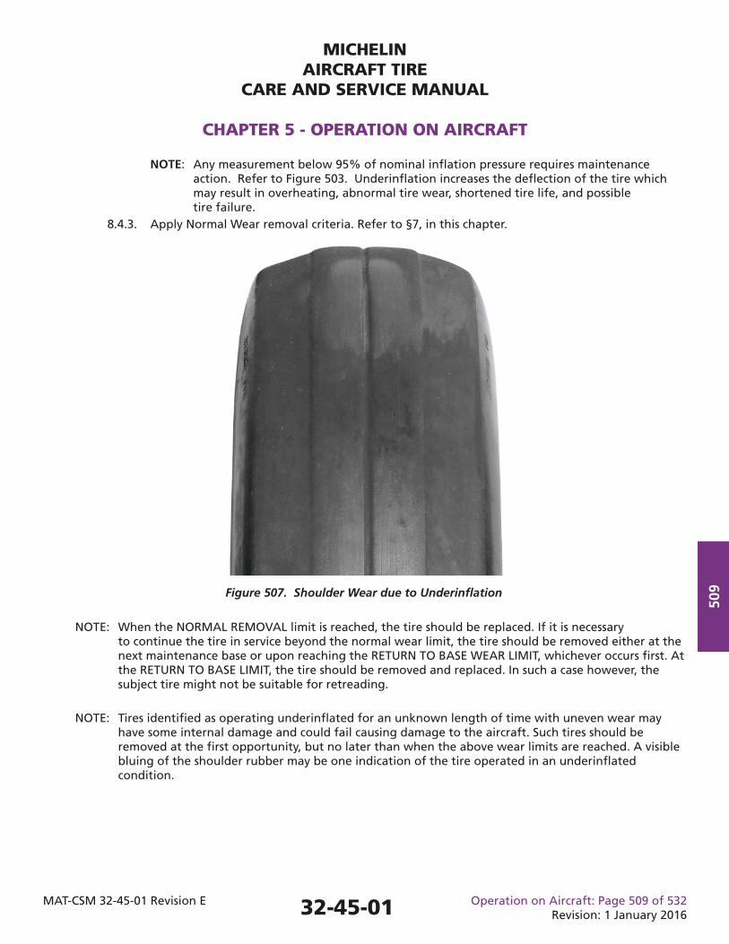
MICHELINAIRCRAFT TIRE
CARE AND SERVICE MANUAL
CHAPTER 5 - OPERATION ON AIRCRAFT
MAT-CSM 32-45-01 Revision E Operation on Aircraft: Page 509 of 532Revision: 1 January 2016
509
NOTE: When the NORMAL REMOVAL limit is reached, the tire should be replaced. If it is necessary to continue the tire in service beyond the normal wear limit, the tire should be removed either at the next maintenance base or upon reaching the RETURN TO BASE WEAR LIMIT, whichever occurs fi rst. At the RETURN TO BASE LIMIT, the tire should be removed and replaced. In such a case however, the subject tire might not be suitable for retreading.
NOTE: Tires identifi ed as operating underinfl ated for an unknown length of time with uneven wear may have some internal damage and could fail causing damage to the aircraft. Such tires should be removed at the fi rst opportunity, but no later than when the above wear limits are reached. A visible bluing of the shoulder rubber may be one indication of the tire operated in an underinfl ated condition.
NOTE: Any measurement below 95% of nominal infl ation pressure requires maintenance action. Refer to Figure 503. Underinfl ation increases the defl ection of the tire which may result in overheating, abnormal tire wear, shortened tire life, and possible tire failure. 8.4.3. Apply Normal Wear removal criteria. Refer to §7, in this chapter.
Figure 507. Shoulder Wear due to Underinfl ation
32-45-01
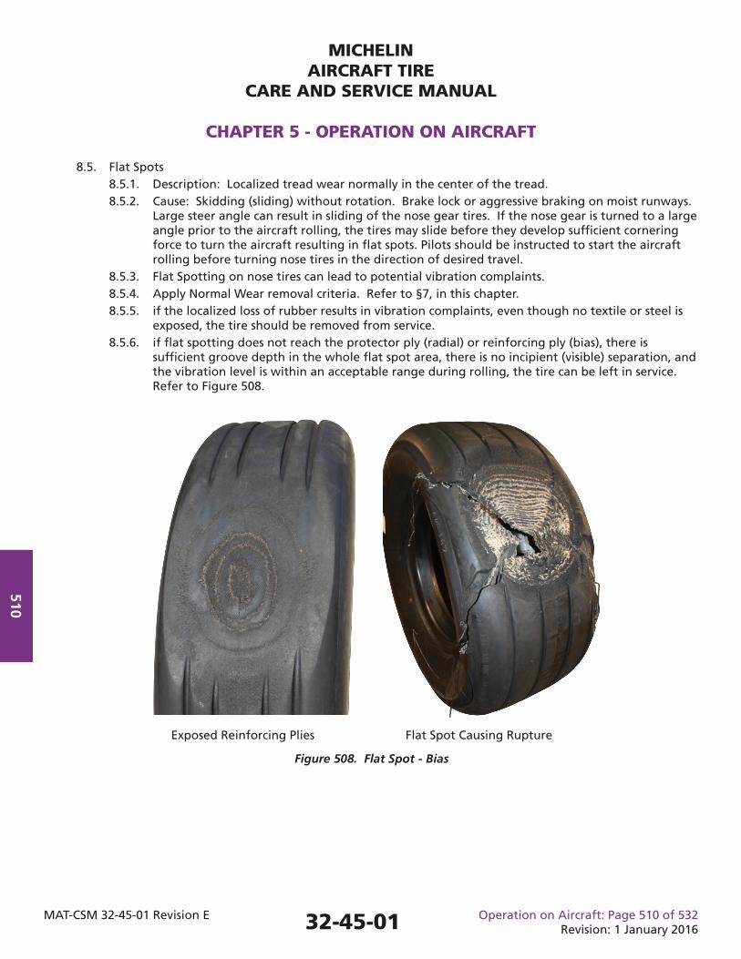
MICHELINAIRCRAFT TIRE
CARE AND SERVICE MANUAL
CHAPTER 5 - OPERATION ON AIRCRAFT
MAT-CSM 32-45-01 Revision E Operation on Aircraft: Page 510 of 532Revision: 1 January 2016
510
8.5. Flat Spots 8.5.1. Description: Localized tread wear normally in the center of the tread. 8.5.2. Cause: Skidding (sliding) without rotation. Brake lock or aggressive braking on moist runways. Large steer angle can result in sliding of the nose gear tires. If the nose gear is turned to a large angle prior to the aircraft rolling, the tires may slide before they develop suffi cient cornering force to turn the aircraft resulting in fl at spots. Pilots should be instructed to start the aircraft rolling before turning nose tires in the direction of desired travel. 8.5.3. Flat Spotting on nose tires can lead to potential vibration complaints. 8.5.4. Apply Normal Wear removal criteria. Refer to §7, in this chapter. 8.5.5. if the localized loss of rubber results in vibration complaints, even though no textile or steel is exposed, the tire should be removed from service. 8.5.6. if fl at spotting does not reach the protector ply (radial) or reinforcing ply (bias), there is suffi cient groove depth in the whole fl at spot area, there is no incipient (visible) separation, and the vibration level is within an acceptable range during rolling, the tire can be left in service. Refer to Figure 508.
Exposed Reinforcing Plies Flat Spot Causing Rupture
Figure 508. Flat Spot - Bias
32-45-01
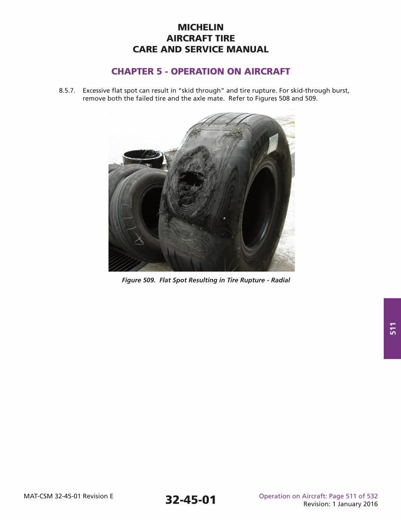
MICHELINAIRCRAFT TIRE
CARE AND SERVICE MANUAL
CHAPTER 5 - OPERATION ON AIRCRAFT
MAT-CSM 32-45-01 Revision E Operation on Aircraft: Page 511 of 532Revision: 1 January 2016
511
8.5.7. Excessive fl at spot can result in “skid through” and tire rupture. For skid-through burst, remove both the failed tire and the axle mate. Refer to Figures 508 and 509.
Figure 509. Flat Spot Resulting in Tire Rupture - Radial
32-45-01
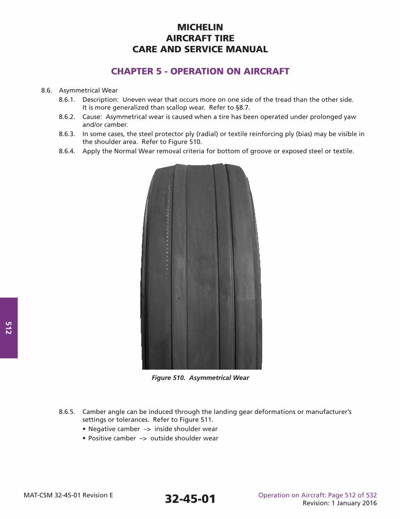
MICHELINAIRCRAFT TIRE
CARE AND SERVICE MANUAL
CHAPTER 5 - OPERATION ON AIRCRAFT
MAT-CSM 32-45-01 Revision E Operation on Aircraft: Page 512 of 532Revision: 1 January 2016
512
8.6.5. Camber angle can be induced through the landing gear deformations or manufacturer’s settings or tolerances. Refer to Figure 511. • Negative camber –> inside shoulder wear • Positive camber –> outside shoulder wear
8.6. Asymmetrical Wear 8.6.1. Description: Uneven wear that occurs more on one side of the tread than the other side. It is more generalized than scallop wear. Refer to §8.7. 8.6.2. Cause: Asymmetrical wear is caused when a tire has been operated under prolonged yaw and/or camber. 8.6.3. In some cases, the steel protector ply (radial) or textile reinforcing ply (bias) may be visible in the shoulder area. Refer to Figure 510. 8.6.4. Apply the Normal Wear removal criteria for bottom of groove or exposed steel or textile.
Figure 510. Asymmetrical Wear
32-45-01
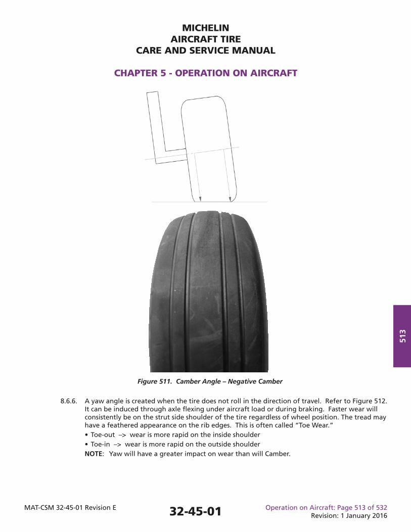
MICHELINAIRCRAFT TIRE
CARE AND SERVICE MANUAL
CHAPTER 5 - OPERATION ON AIRCRAFT
MAT-CSM 32-45-01 Revision E Operation on Aircraft: Page 513 of 532Revision: 1 January 2016
513
8.6.6. A yaw angle is created when the tire does not roll in the direction of travel. Refer to Figure 512. It can be induced through axle fl exing under aircraft load or during braking. Faster wear will consistently be on the strut side shoulder of the tire regardless of wheel position. The tread may have a feathered appearance on the rib edges. This is often called “Toe Wear.” • Toe-out –> wear is more rapid on the inside shoulder • Toe-in –> wear is more rapid on the outside shoulder NOTE: Yaw will have a greater impact on wear than will Camber.
Figure 511. Camber Angle – Negative Camber
32-45-01
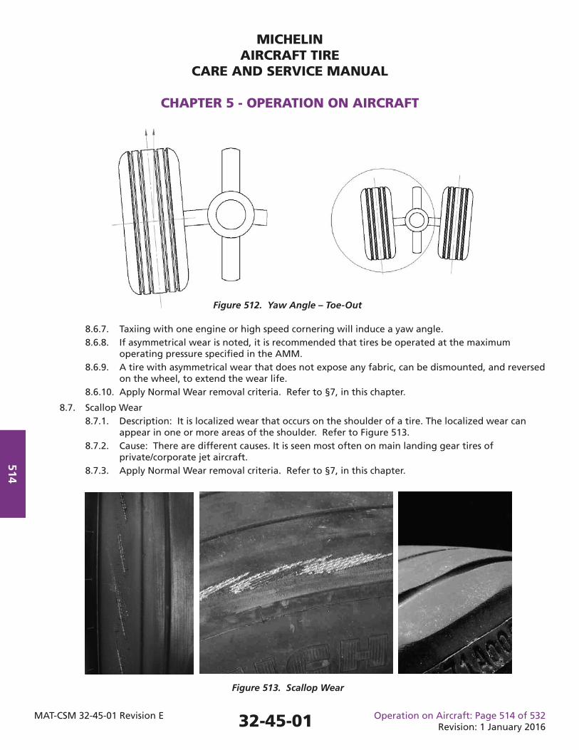
MICHELINAIRCRAFT TIRE
CARE AND SERVICE MANUAL
CHAPTER 5 - OPERATION ON AIRCRAFT
MAT-CSM 32-45-01 Revision E Operation on Aircraft: Page 514 of 532Revision: 1 January 2016
514
8.6.7. Taxiing with one engine or high speed cornering will induce a yaw angle. 8.6.8. If asymmetrical wear is noted, it is recommended that tires be operated at the maximum operating pressure specifi ed in the AMM. 8.6.9. A tire with asymmetrical wear that does not expose any fabric, can be dismounted, and reversed on the wheel, to extend the wear life. 8.6.10. Apply Normal Wear removal criteria. Refer to §7, in this chapter.
8.7. Scallop Wear 8.7.1. Description: It is localized wear that occurs on the shoulder of a tire. The localized wear can appear in one or more areas of the shoulder. Refer to Figure 513. 8.7.2. Cause: There are different causes. It is seen most often on main landing gear tires of private/corporate jet aircraft. 8.7.3. Apply Normal Wear removal criteria. Refer to §7, in this chapter.
Figure 512. Yaw Angle – Toe-Out
Figure 513. Scallop Wear
32-45-01
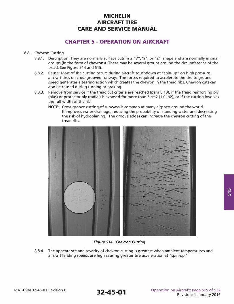
MICHELINAIRCRAFT TIRE
CARE AND SERVICE MANUAL
CHAPTER 5 - OPERATION ON AIRCRAFT
MAT-CSM 32-45-01 Revision E Operation on Aircraft: Page 515 of 532Revision: 1 January 2016
515
8.8.4. The appearance and severity of chevron cutting is greatest when ambient temperatures and aircraft landing speeds are high causing greater tire acceleration at “spin-up.”
8.8. Chevron Cutting 8.8.1. Description: They are normally surface cuts in a “V”,”S”, or “Z” shape and are normally in small groups (in the form of chevrons). There may be several groups around the circumference of the tread. See Figure 514 and 515. 8.8.2. Cause: Most of the cutting occurs during aircraft touchdown at “spin-up” on high pressure aircraft tires on cross-grooved runways. The forces required to accelerate the tire to ground speed generates a tearing action which creates the chevron in the tread ribs. Chevron cuts can also be caused during turning or braking. 8.8.3. Remove from service if the tread cut criteria are reached (para 8.10), if the tread reinforcing ply (bias) or protector ply (radial) is exposed for more than 6 cm2 (1.0 in2), or if the cutting involves the full width of the rib. NOTE: Cross-groove cutting of runways is common at many airports around the world. It improves water drainage, reducing the probability of standing water and decreasing the risk of hydroplaning. The groove edges can increase the chevron cutting of the tread ribs.
Figure 514. Chevron Cutting
32-45-01
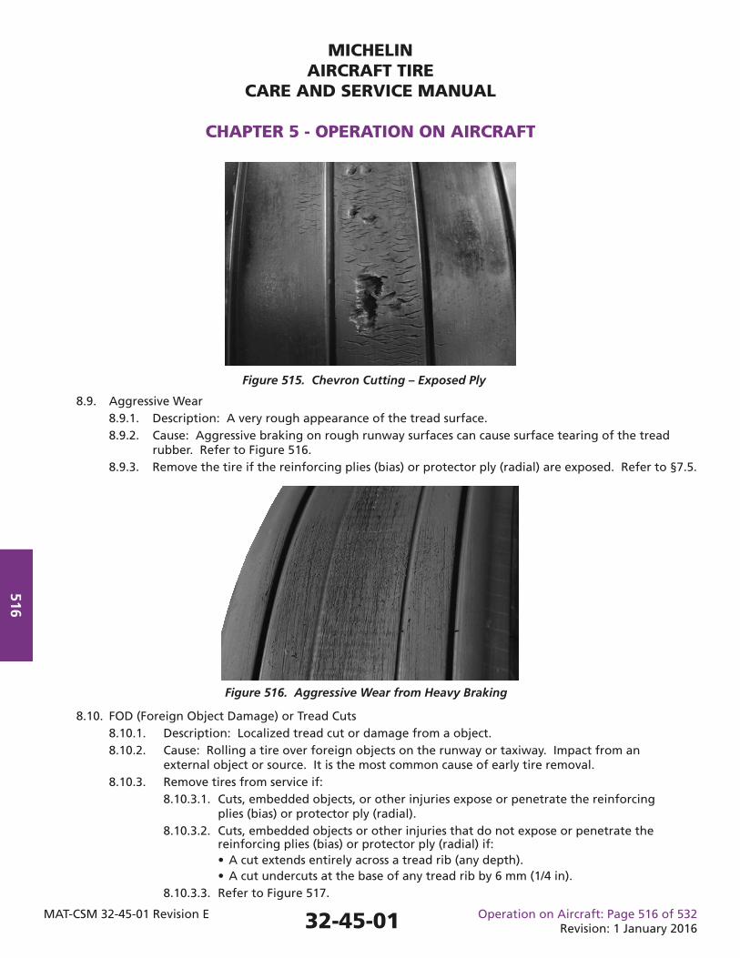
MICHELINAIRCRAFT TIRE
CARE AND SERVICE MANUAL
CHAPTER 5 - OPERATION ON AIRCRAFT
MAT-CSM 32-45-01 Revision E Operation on Aircraft: Page 516 of 532Revision: 1 January 2016
516
8.9. Aggressive Wear 8.9.1. Description: A very rough appearance of the tread surface. 8.9.2. Cause: Aggressive braking on rough runway surfaces can cause surface tearing of the tread rubber. Refer to Figure 516. 8.9.3. Remove the tire if the reinforcing plies (bias) or protector ply (radial) are exposed. Refer to §7.5.
Figure 515. Chevron Cutting – Exposed Ply
Figure 516. Aggressive Wear from Heavy Braking
8.10. FOD (Foreign Object Damage) or Tread Cuts 8.10.1. Description: Localized tread cut or damage from a object. 8.10.2. Cause: Rolling a tire over foreign objects on the runway or taxiway. Impact from an external object or source. It is the most common cause of early tire removal. 8.10.3. Remove tires from service if: 8.10.3.1. Cuts, embedded objects, or other injuries expose or penetrate the reinforcing plies (bias) or protector ply (radial). 8.10.3.2. Cuts, embedded objects or other injuries that do not expose or penetrate the reinforcing plies (bias) or protector ply (radial) if: • A cut extends entirely across a tread rib (any depth). • A cut undercuts at the base of any tread rib by 6 mm (1/4 in). 8.10.3.3. Refer to Figure 517.
32-45-01
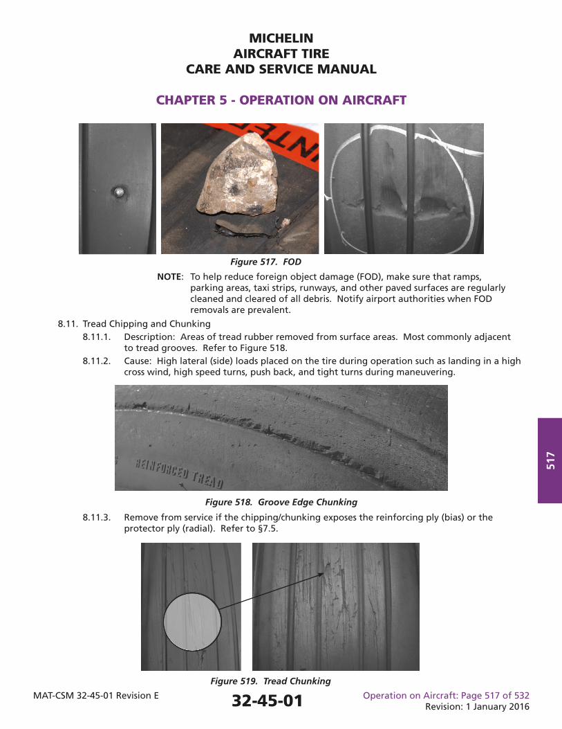
MICHELINAIRCRAFT TIRE
CARE AND SERVICE MANUAL
CHAPTER 5 - OPERATION ON AIRCRAFT
MAT-CSM 32-45-01 Revision E Operation on Aircraft: Page 517 of 532Revision: 1 January 2016
517
8.11.3. Remove from service if the chipping/chunking exposes the reinforcing ply (bias) or the protector ply (radial). Refer to §7.5.
Figure 517. FOD
Figure 518. Groove Edge Chunking
Figure 519. Tread Chunking
NOTE: To help reduce foreign object damage (FOD), make sure that ramps, parking areas, taxi strips, runways, and other paved surfaces are regularly cleaned and cleared of all debris. Notify airport authorities when FOD removals are prevalent.
8.11. Tread Chipping and Chunking 8.11.1. Description: Areas of tread rubber removed from surface areas. Most commonly adjacent to tread grooves. Refer to Figure 518. 8.11.2. Cause: High lateral (side) loads placed on the tire during operation such as landing in a high cross wind, high speed turns, push back, and tight turns during maneuvering.
32-45-01
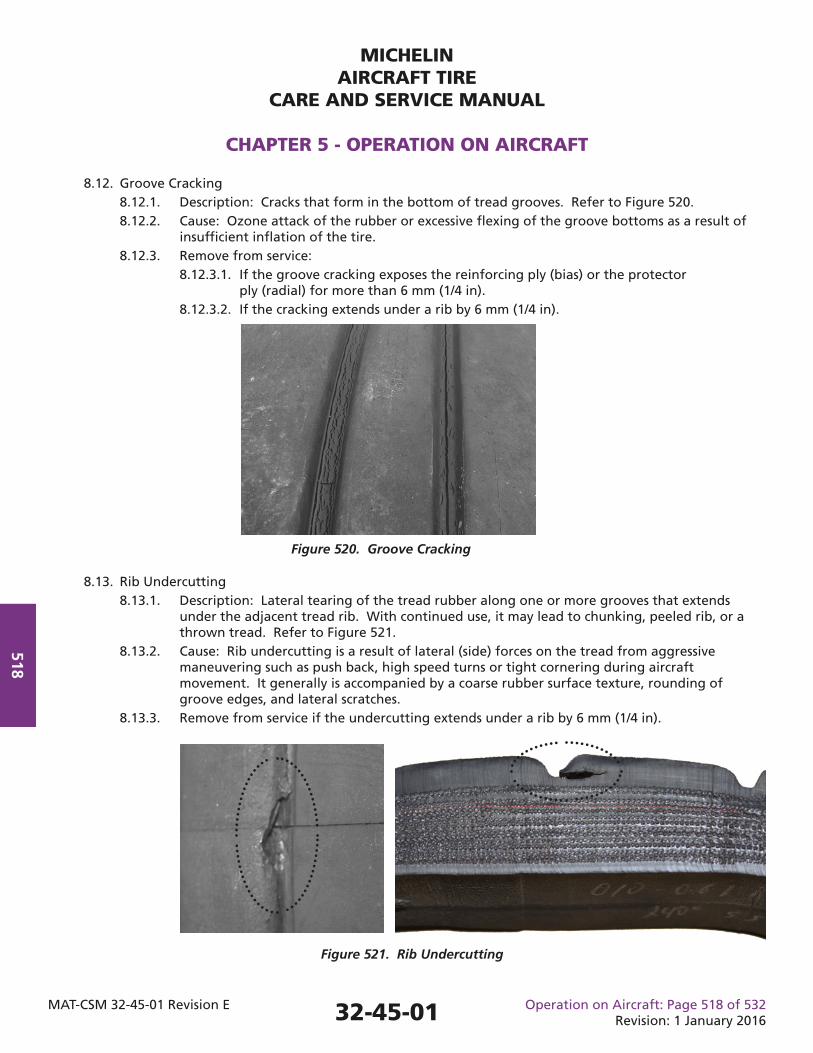
MICHELINAIRCRAFT TIRE
CARE AND SERVICE MANUAL
CHAPTER 5 - OPERATION ON AIRCRAFT
MAT-CSM 32-45-01 Revision E Operation on Aircraft: Page 518 of 532Revision: 1 January 2016
518
Figure 521. Rib Undercutting
8.12. Groove Cracking 8.12.1. Description: Cracks that form in the bottom of tread grooves. Refer to Figure 520. 8.12.2. Cause: Ozone attack of the rubber or excessive fl exing of the groove bottoms as a result of insuffi cient infl ation of the tire. 8.12.3. Remove from service: 8.12.3.1. If the groove cracking exposes the reinforcing ply (bias) or the protector ply (radial) for more than 6 mm (1/4 in). 8.12.3.2. If the cracking extends under a rib by 6 mm (1/4 in).
Figure 520. Groove Cracking
8.13. Rib Undercutting 8.13.1. Description: Lateral tearing of the tread rubber along one or more grooves that extends under the adjacent tread rib. With continued use, it may lead to chunking, peeled rib, or a thrown tread. Refer to Figure 521. 8.13.2. Cause: Rib undercutting is a result of lateral (side) forces on the tread from aggressive maneuvering such as push back, high speed turns or tight cornering during aircraft movement. It generally is accompanied by a coarse rubber surface texture, rounding of groove edges, and lateral scratches. 8.13.3. Remove from service if the undercutting extends under a rib by 6 mm (1/4 in).
32-45-01
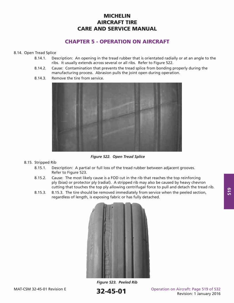
MICHELINAIRCRAFT TIRE
CARE AND SERVICE MANUAL
CHAPTER 5 - OPERATION ON AIRCRAFT
MAT-CSM 32-45-01 Revision E Operation on Aircraft: Page 519 of 532Revision: 1 January 2016
519
8.15. Stripped Rib 8.15.1. Description: A partial or full loss of the tread rubber between adjacent grooves. Refer to Figure 523. 8.15.2. Cause: The most likely cause is a FOD cut in the rib that reaches the top reinforcing ply (bias) or protector ply (radial). A stripped rib may also be caused by heavy chevron cutting that touches the top ply allowing centrifugal force to pull and detach the tread rib. 8.15.3. 8.15.3. The tire should be removed immediately from service when the peeled section, regardless of length, is exposing fabric or has fully detached.
Figure 522. Open Tread Splice
Figure 523. Peeled Rib
8.14. Open Tread Splice 8.14.1. Description: An opening in the tread rubber that is orientated radially or at an angle to the ribs. It usually extends across several or all ribs. Refer to Figure 522. 8.14.2. Cause: Contamination that prevents the tread splice from bonding properly during the manufacturing process. Abrasion pulls the joint open during operation. 8.14.3. Remove the tire from service.
32-45-01
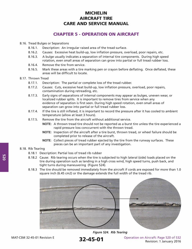
MICHELINAIRCRAFT TIRE
CARE AND SERVICE MANUAL
CHAPTER 5 - OPERATION ON AIRCRAFT
MAT-CSM 32-45-01 Revision E Operation on Aircraft: Page 520 of 532Revision: 1 January 2016
520
8.16. Tread Bulges or Separations 8.16.1. Description: An irregular raised area of the tread surface. 8.16.2. Causes: Excessive heat build-up, low infl ation pressure, overload, poor repairs, etc. 8.16.3. A bulge usually indicates a separation of internal tire components. During high speed rotation, even small areas of separation can grow into partial or full tread rubber loss. 8.16.4. Remove the tire from service. 8.16.5. Mark these areas with a tire marking pen or crayon before defl ating. Once defl ated, these areas will be diffi cult to locate.
8.17. Thrown Tread 8.17.1. Description: The partial or complete loss of the tread rubber. 8.17.2. Causes: Cuts, excessive heat build-up, low infl ation pressure, overload, poor repairs, contamination during retreading, etc. 8.17.3. Early signs of separations of internal components may appear as bulges, uneven wear, or localized rubber splits. It is important to remove tires from service when any evidence of separation is fi rst seen. During high speed rotation, even small areas of separation can grow into partial or full tread rubber loss. 8.17.4. If the tire is still infl ated, it is important to record the pressure after it has cooled to ambient temperature (allow at least 3 hours). 8.17.5. Remove the tire from the aircraft without additional service.
NOTE: A thrown tread tire should not be reported as a burst tire unless the tire experienced a rapid pressure loss conccurrent with the thrown tread.
NOTE: Inspection of the aircraft after a tire burst, thrown tread, or wheel failure should be completed prior to release of the aircraft. NOTE: Collect pieces of tread rubber ejected by the tire from the runway surfaces. These pieces can be an important part of any investigation. 8.18. Rib Tearing 8.18.1 Description: Partial loss of tread rib rubber 8.18.2 Cause: Rib tearing occurs when the tire is subjected to high lateral (side) loads placed on the tire during operation such as landing in a high cross wind, high speed turns, push back, and tight turns during maneuvering (Figure 524). 8.18.3 The tire should be removed immediately from the aircraft if cords are exposed for more than 1.0 square inch (6.45 cm2) or the damage extends the full width of the tread rib.
Figure 524. Rib Tearing
32-45-01
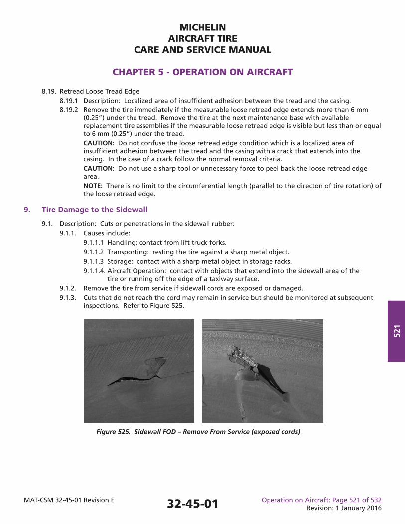
MICHELINAIRCRAFT TIRE
CARE AND SERVICE MANUAL
CHAPTER 5 - OPERATION ON AIRCRAFT
MAT-CSM 32-45-01 Revision E Operation on Aircraft: Page 521 of 532Revision: 1 January 2016
521
8.19. Retread Loose Tread Edge 8.19.1 Description: Localized area of insuffi cient adhesion between the tread and the casing. 8.19.2 Remove the tire immediately if the measurable loose retread edge extends more than 6 mm (0.25”) under the tread. Remove the tire at the next maintenance base with available replacement tire assemblies if the measurable loose retread edge is visible but less than or equal to 6 mm (0.25”) under the tread. CAUTION: Do not confuse the loose retread edge condition which is a localized area of insuffi cient adhesion between the tread and the casing with a crack that extends into the casing. In the case of a crack follow the normal removal criteria. CAUTION: Do not use a sharp tool or unnecessary force to peel back the loose retread edge area. NOTE: There is no limit to the circumferential length (parallel to the directon of tire rotation) of the loose retread edge.
9. Tire Damage to the Sidewall
9.1. Description: Cuts or penetrations in the sidewall rubber: 9.1.1. Causes include: 9.1.1.1 Handling: contact from lift truck forks. 9.1.1.2 Transporting: resting the tire against a sharp metal object. 9.1.1.3 Storage: contact with a sharp metal object in storage racks. 9.1.1.4. Aircraft Operation: contact with objects that extend into the sidewall area of the tire or running off the edge of a taxiway surface. 9.1.2. Remove the tire from service if sidewall cords are exposed or damaged. 9.1.3. Cuts that do not reach the cord may remain in service but should be monitored at subsequent inspections. Refer to Figure 525.
Figure 525. Sidewall FOD – Remove From Service (exposed cords)
32-45-01
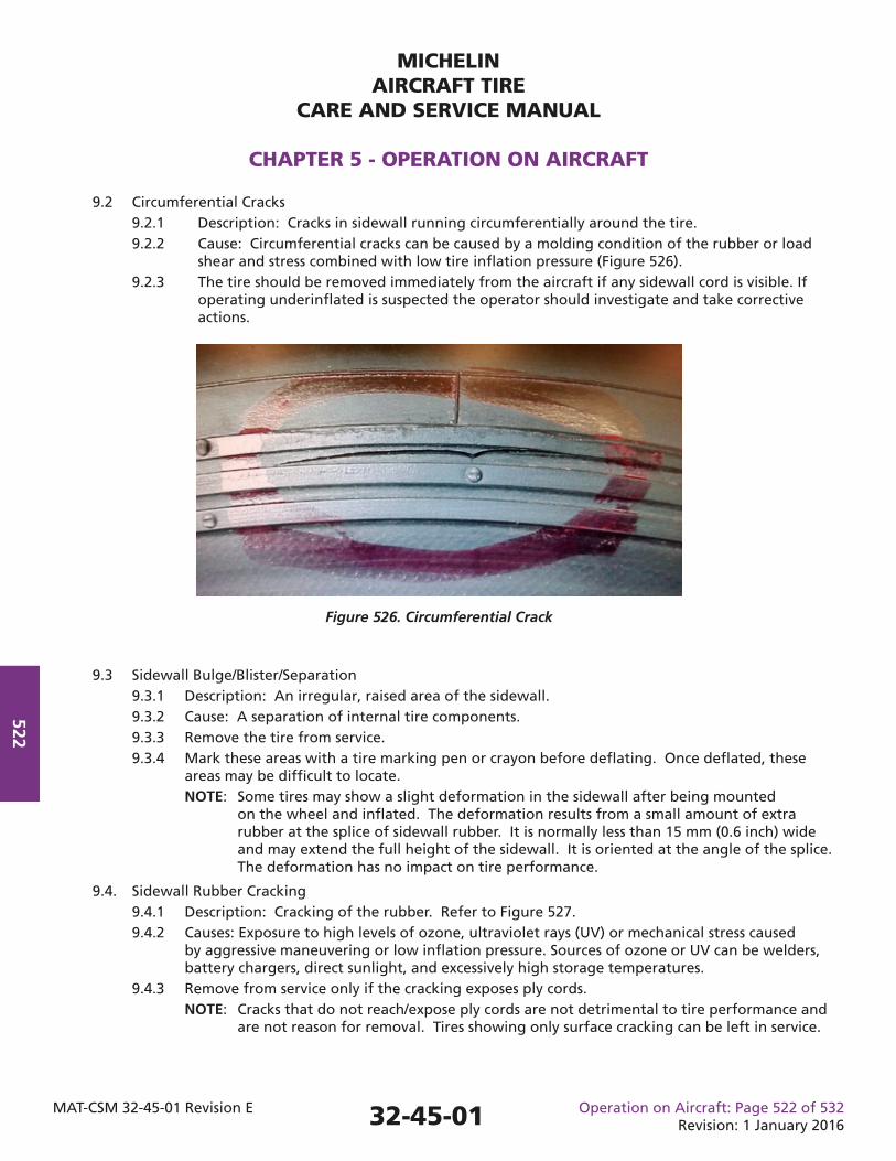
MICHELINAIRCRAFT TIRE
CARE AND SERVICE MANUAL
CHAPTER 5 - OPERATION ON AIRCRAFT
MAT-CSM 32-45-01 Revision E Operation on Aircraft: Page 522 of 532Revision: 1 January 2016
522
9.2 Circumferential Cracks 9.2.1 Description: Cracks in sidewall running circumferentially around the tire. 9.2.2 Cause: Circumferential cracks can be caused by a molding condition of the rubber or load shear and stress combined with low tire infl ation pressure (Figure 526). 9.2.3 The tire should be removed immediately from the aircraft if any sidewall cord is visible. If operating underinfl ated is suspected the operator should investigate and take corrective actions.
Figure 526. Circumferential Crack
9.3 Sidewall Bulge/Blister/Separation 9.3.1 Description: An irregular, raised area of the sidewall. 9.3.2 Cause: A separation of internal tire components. 9.3.3 Remove the tire from service. 9.3.4 Mark these areas with a tire marking pen or crayon before defl ating. Once defl ated, these areas may be diffi cult to locate. NOTE: Some tires may show a slight deformation in the sidewall after being mounted on the wheel and infl ated. The deformation results from a small amount of extra rubber at the splice of sidewall rubber. It is normally less than 15 mm (0.6 inch) wide and may extend the full height of the sidewall. It is oriented at the angle of the splice. The deformation has no impact on tire performance.
9.4. Sidewall Rubber Cracking 9.4.1 Description: Cracking of the rubber. Refer to Figure 527. 9.4.2 Causes: Exposure to high levels of ozone, ultraviolet rays (UV) or mechanical stress caused by aggressive maneuvering or low infl ation pressure. Sources of ozone or UV can be welders, battery chargers, direct sunlight, and excessively high storage temperatures. 9.4.3 Remove from service only if the cracking exposes ply cords. NOTE: Cracks that do not reach/expose ply cords are not detrimental to tire performance and are not reason for removal. Tires showing only surface cracking can be left in service.
32-45-01
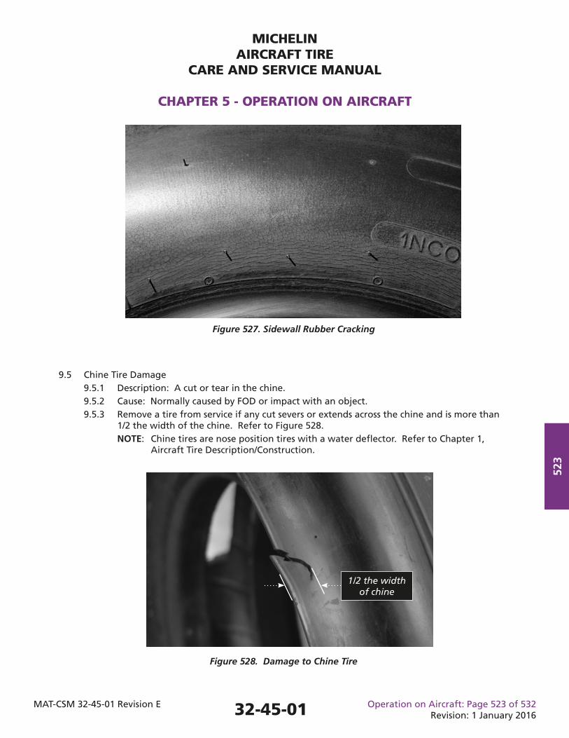
MICHELINAIRCRAFT TIRE
CARE AND SERVICE MANUAL
CHAPTER 5 - OPERATION ON AIRCRAFT
MAT-CSM 32-45-01 Revision E Operation on Aircraft: Page 523 of 532Revision: 1 January 2016
523
9.5 Chine Tire Damage 9.5.1 Description: A cut or tear in the chine. 9.5.2 Cause: Normally caused by FOD or impact with an object. 9.5.3 Remove a tire from service if any cut severs or extends across the chine and is more than 1/2 the width of the chine. Refer to Figure 528. NOTE: Chine tires are nose position tires with a water defl ector. Refer to Chapter 1, Aircraft Tire Description/Construction.
Figure 527. Sidewall Rubber Cracking
1/2 the width of chine
Figure 528. Damage to Chine Tire
32-45-01
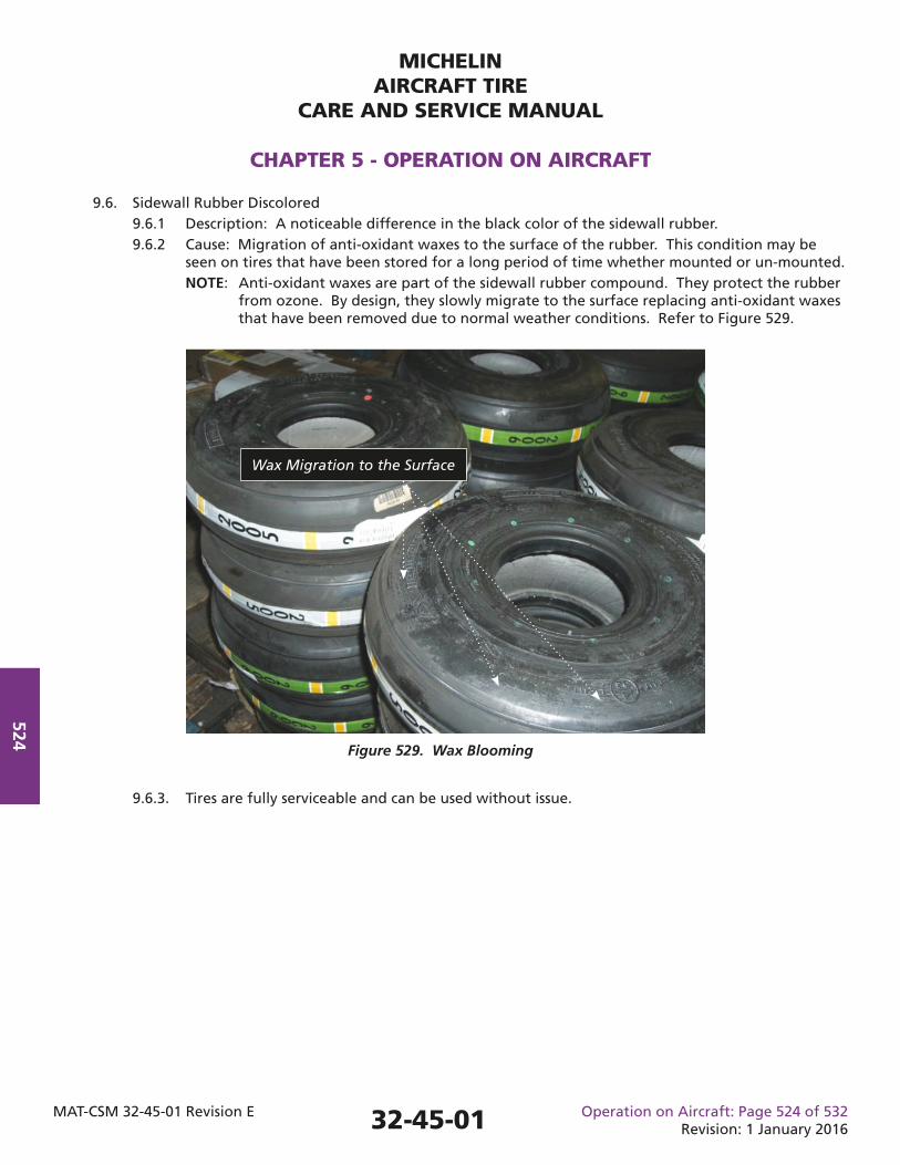
MICHELINAIRCRAFT TIRE
CARE AND SERVICE MANUAL
CHAPTER 5 - OPERATION ON AIRCRAFT
MAT-CSM 32-45-01 Revision E Operation on Aircraft: Page 524 of 532Revision: 1 January 2016
524
9.6. Sidewall Rubber Discolored 9.6.1 Description: A noticeable difference in the black color of the sidewall rubber. 9.6.2 Cause: Migration of anti-oxidant waxes to the surface of the rubber. This condition may be seen on tires that have been stored for a long period of time whether mounted or un-mounted. NOTE: Anti-oxidant waxes are part of the sidewall rubber compound. They protect the rubber from ozone. By design, they slowly migrate to the surface replacing anti-oxidant waxes that have been removed due to normal weather conditions. Refer to Figure 529.
Wax Migration to the Surface
Figure 529. Wax Blooming
9.6.3. Tires are fully serviceable and can be used without issue.
32-45-01
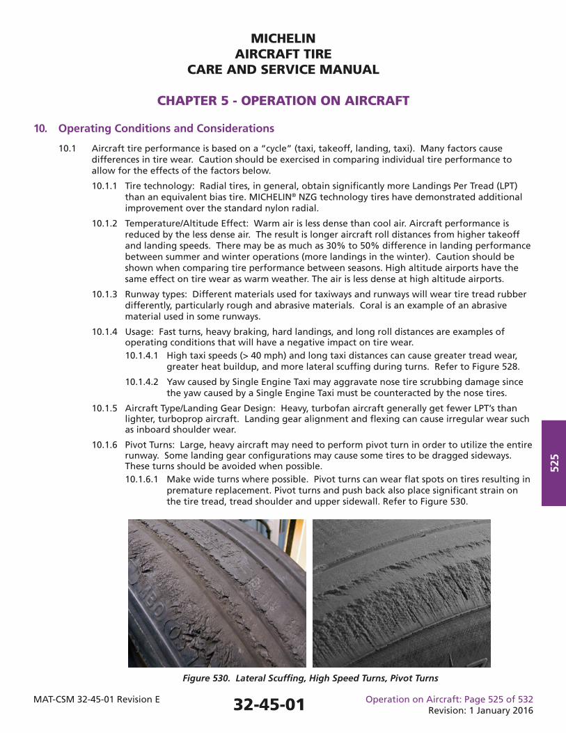
MICHELINAIRCRAFT TIRE
CARE AND SERVICE MANUAL
CHAPTER 5 - OPERATION ON AIRCRAFT
MAT-CSM 32-45-01 Revision E Operation on Aircraft: Page 525 of 532Revision: 1 January 2016
525
10. Operating Conditions and Considerations
10.1 Aircraft tire performance is based on a “cycle” (taxi, takeoff, landing, taxi). Many factors cause differences in tire wear. Caution should be exercised in comparing individual tire performance to allow for the effects of the factors below.
10.1.1 Tire technology: Radial tires, in general, obtain signifi cantly more Landings Per Tread (LPT) than an equivalent bias tire. MICHELIN® NZG technology tires have demonstrated additional improvement over the standard nylon radial.
10.1.2 Temperature/Altitude Effect: Warm air is less dense than cool air. Aircraft performance is reduced by the less dense air. The result is longer aircraft roll distances from higher takeoff and landing speeds. There may be as much as 30% to 50% difference in landing performance between summer and winter operations (more landings in the winter). Caution should be shown when comparing tire performance between seasons. High altitude airports have the same effect on tire wear as warm weather. The air is less dense at high altitude airports.
10.1.3 Runway types: Different materials used for taxiways and runways will wear tire tread rubber differently, particularly rough and abrasive materials. Coral is an example of an abrasive material used in some runways.
10.1.4 Usage: Fast turns, heavy braking, hard landings, and long roll distances are examples of operating conditions that will have a negative impact on tire wear. 10.1.4.1 High taxi speeds (> 40 mph) and long taxi distances can cause greater tread wear, greater heat buildup, and more lateral scuffi ng during turns. Refer to Figure 528.
10.1.4.2 Yaw caused by Single Engine Taxi may aggravate nose tire scrubbing damage since the yaw caused by a Single Engine Taxi must be counteracted by the nose tires.
10.1.5 Aircraft Type/Landing Gear Design: Heavy, turbofan aircraft generally get fewer LPT’s than lighter, turboprop aircraft. Landing gear alignment and fl exing can cause irregular wear such as inboard shoulder wear.
10.1.6 Pivot Turns: Large, heavy aircraft may need to perform pivot turn in order to utilize the entire runway. Some landing gear confi gurations may cause some tires to be dragged sideways. These turns should be avoided when possible. 10.1.6.1 Make wide turns where possible. Pivot turns can wear fl at spots on tires resulting in premature replacement. Pivot turns and push back also place signifi cant strain on the tire tread, tread shoulder and upper sidewall. Refer to Figure 530.
Figure 530. Lateral Scuffi ng, High Speed Turns, Pivot Turns
32-45-01
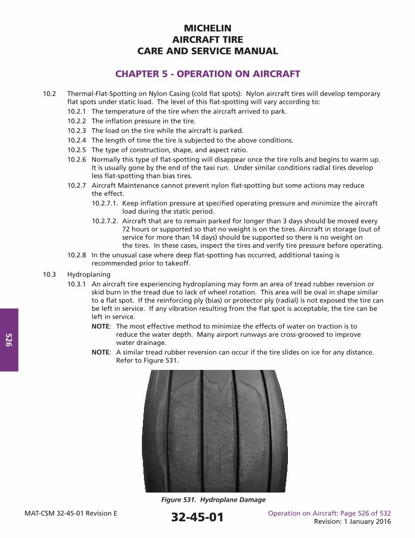
MICHELINAIRCRAFT TIRE
CARE AND SERVICE MANUAL
CHAPTER 5 - OPERATION ON AIRCRAFT
MAT-CSM 32-45-01 Revision E Operation on Aircraft: Page 526 of 532Revision: 1 January 2016
526
10.2 Thermal-Flat-Spotting on Nylon Casing (cold fl at spots): Nylon aircraft tires will develop temporary fl at spots under static load. The level of this fl at-spotting will vary according to: 10.2.1 The temperature of the tire when the aircraft arrived to park. 10.2.2 The infl ation pressure in the tire. 10.2.3 The load on the tire while the aircraft is parked. 10.2.4 The length of time the tire is subjected to the above conditions. 10.2.5 The type of construction, shape, and aspect ratio. 10.2.6 Normally this type of fl at-spotting will disappear once the tire rolls and begins to warm up. It is usually gone by the end of the taxi run. Under similar conditions radial tires develop less fl at-spotting than bias tires. 10.2.7 Aircraft Maintenance cannot prevent nylon fl at-spotting but some actions may reduce the effect. 10.2.7.1. Keep infl ation pressure at specifi ed operating pressure and minimize the aircraft load during the static period. 10.2.7.2. Aircraft that are to remain parked for longer than 3 days should be moved every 72 hours or supported so that no weight is on the tires. Aircraft in storage (out of service for more than 14 days) should be supported so there is no weight on the tires. In these cases, inspect the tires and verify tire pressure before operating. 10.2.8 In the unusual case where deep fl at-spotting has occurred, additional taxing is recommended prior to takeoff.
10.3 Hydroplaning 10.3.1 An aircraft tire experiencing hydroplaning may form an area of tread rubber reversion or skid burn in the tread due to lack of wheel rotation. This area will be oval in shape similar to a fl at spot. If the reinforcing ply (bias) or protector ply (radial) is not exposed the tire can be left in service. If any vibration resulting from the fl at spot is acceptable, the tire can be left in service. NOTE: The most effective method to minimize the effects of water on traction is to reduce the water depth. Many airport runways are cross-grooved to improve water drainage. NOTE: A similar tread rubber reversion can occur if the tire slides on ice for any distance. Refer to Figure 531.
Figure 531. Hydroplane Damage
32-45-01
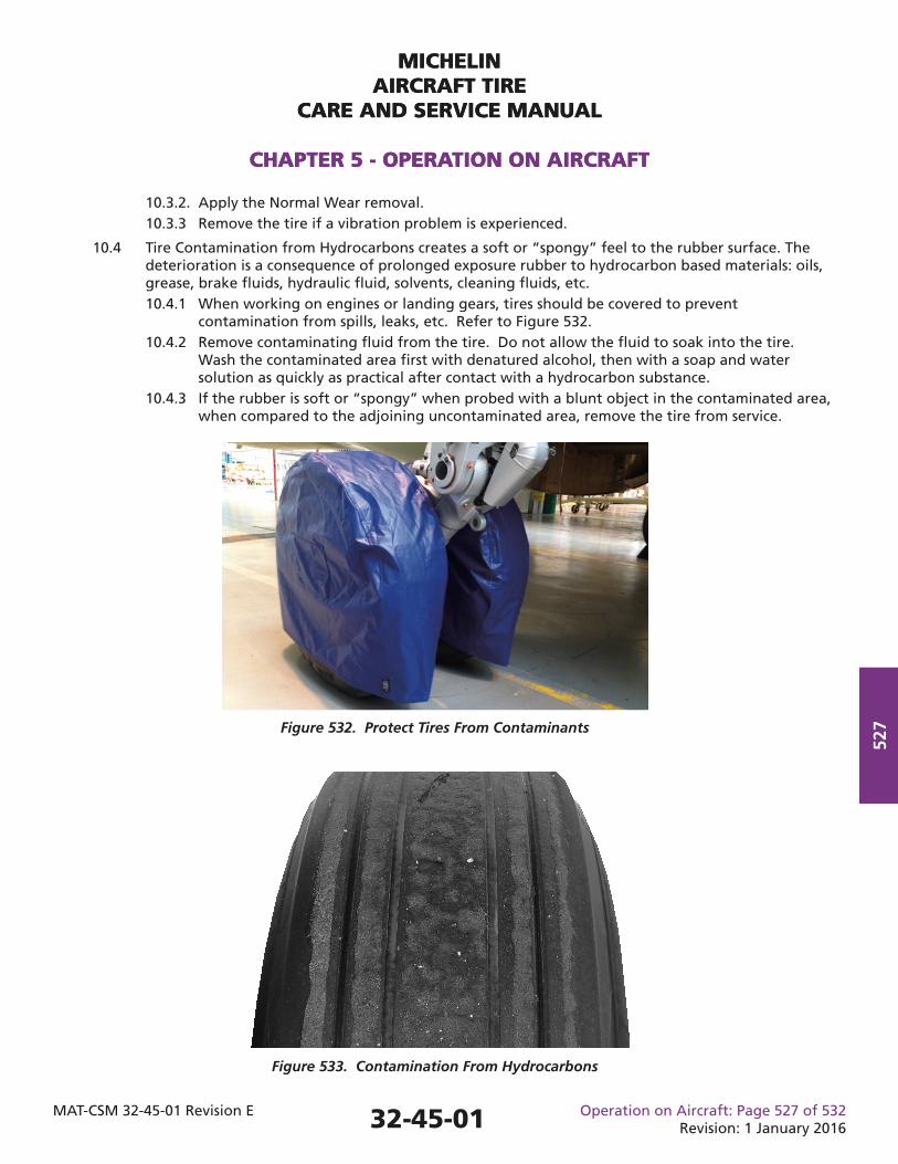
MICHELINAIRCRAFT TIRE
CARE AND SERVICE MANUAL
CHAPTER 5 - OPERATION ON AIRCRAFT
MAT-CSM 32-45-01 Revision E Operation on Aircraft: Page 527 of 532Revision: 1 January 2016
527
MICHELINAIRCRAFT TIRE
CARE AND SERVICE MANUAL
CHAPTER 5 - OPERATION ON AIRCRAFT
10.3.2. Apply the Normal Wear removal. 10.3.3 Remove the tire if a vibration problem is experienced.
10.4 Tire Contamination from Hydrocarbons creates a soft or “spongy” feel to the rubber surface. The deterioration is a consequence of prolonged exposure rubber to hydrocarbon based materials: oils, grease, brake fl uids, hydraulic fl uid, solvents, cleaning fl uids, etc. 10.4.1 When working on engines or landing gears, tires should be covered to prevent contamination from spills, leaks, etc. Refer to Figure 532. 10.4.2 Remove contaminating fl uid from the tire. Do not allow the fl uid to soak into the tire. Wash the contaminated area fi rst with denatured alcohol, then with a soap and water solution as quickly as practical after contact with a hydrocarbon substance. 10.4.3 If the rubber is soft or “spongy” when probed with a blunt object in the contaminated area, when compared to the adjoining uncontaminated area, remove the tire from service.
Figure 532. Protect Tires From Contaminants
Figure 533. Contamination From Hydrocarbons
32-45-01
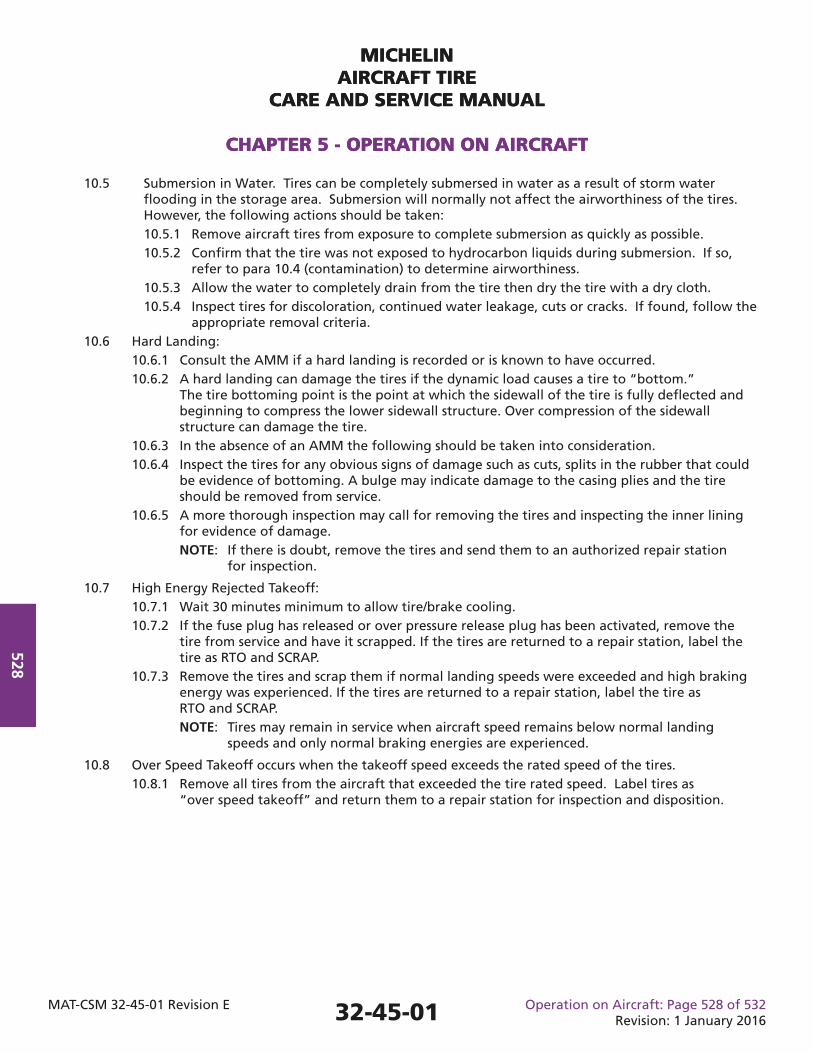
MICHELINAIRCRAFT TIRE
CARE AND SERVICE MANUAL
CHAPTER 5 - OPERATION ON AIRCRAFT
MAT-CSM 32-45-01 Revision E Operation on Aircraft: Page 528 of 532Revision: 1 January 2016
528
MICHELINAIRCRAFT TIRE
CARE AND SERVICE MANUAL
CHAPTER 5 - OPERATION ON AIRCRAFT
10.5 Submersion in Water. Tires can be completely submersed in water as a result of storm water fl ooding in the storage area. Submersion will normally not affect the airworthiness of the tires. However, the following actions should be taken: 10.5.1 Remove aircraft tires from exposure to complete submersion as quickly as possible. 10.5.2 Confi rm that the tire was not exposed to hydrocarbon liquids during submersion. If so, refer to para 10.4 (contamination) to determine airworthiness. 10.5.3 Allow the water to completely drain from the tire then dry the tire with a dry cloth. 10.5.4 Inspect tires for discoloration, continued water leakage, cuts or cracks. If found, follow the appropriate removal criteria. 10.6 Hard Landing: 10.6.1 Consult the AMM if a hard landing is recorded or is known to have occurred. 10.6.2 A hard landing can damage the tires if the dynamic load causes a tire to “bottom.” The tire bottoming point is the point at which the sidewall of the tire is fully defl ected and beginning to compress the lower sidewall structure. Over compression of the sidewall structure can damage the tire. 10.6.3 In the absence of an AMM the following should be taken into consideration. 10.6.4 Inspect the tires for any obvious signs of damage such as cuts, splits in the rubber that could be evidence of bottoming. A bulge may indicate damage to the casing plies and the tire should be removed from service. 10.6.5 A more thorough inspection may call for removing the tires and inspecting the inner lining for evidence of damage. NOTE: If there is doubt, remove the tires and send them to an authorized repair station for inspection.
10.7 High Energy Rejected Takeoff: 10.7.1 Wait 30 minutes minimum to allow tire/brake cooling. 10.7.2 If the fuse plug has released or over pressure release plug has been activated, remove the tire from service and have it scrapped. If the tires are returned to a repair station, label the tire as RTO and SCRAP. 10.7.3 Remove the tires and scrap them if normal landing speeds were exceeded and high braking energy was experienced. If the tires are returned to a repair station, label the tire as RTO and SCRAP. NOTE: Tires may remain in service when aircraft speed remains below normal landing speeds and only normal braking energies are experienced.
10.8 Over Speed Takeoff occurs when the takeoff speed exceeds the rated speed of the tires. 10.8.1 Remove all tires from the aircraft that exceeded the tire rated speed. Label tires as “over speed takeoff” and return them to a repair station for inspection and disposition.
32-45-01
MICHELINAIRCRAFT TIRE
CARE AND SERVICE MANUAL
CHAPTER 5 - OPERATION ON AIRCRAFT
MAT-CSM 32-45-01 Revision E Operation on Aircraft: Page 529 of 532Revision: 1 January 2016
529
10.9 Vibration and Balance NOTE: Vibration is the act of moving back and forth rapidly. Vibration is caused by a rapidly changing force. Operating conditions such as fl at-spotting can cause the rotating tires to generate a force that will initiate a vibration. NOTE: Vibration can be blamed on improper tire balance. Imbalance is easily understood as a cause for vibration, but in many cases, improper balance may not be the cause. There are a number of factors of the tire, wheel, and landing gear assembly which contribute to aircraft vibration. A systematic approach should be taken to isolating the cause. NOTE: Some aircraft may be more sensitive to vibration than others and may require that tire wheel assemblies be balanced. Wheel weights may be added when needed. 10.9.1 If vibration (shake or shimmy) is unacceptable to fl ight operations, remove the tire from service. For dual tires in nose positions, both tires should be removed unless vibration can be linked to just one tire. 10.9.2 Check that the tire has the proper infl ation pressure, using a calibrated gauge. Follow the airframer’s recommendations for the proper pressure. If the tires are mounted in twin or dual confi guration, confi rm the pressure in both tires. 10.9.3 Inspect the tire for fl at-spotting, out of round, bulges, or other damage. If found, remove the tire(s) from service. 10.9.4 Verify that tires have been properly mounted and that the tire was allowed to stretch 12 hours at operating pressure. 10.9.5 Check that the beads of the tire are properly seated. The small circular mold line on the lower sidewall of the tire should be equal distant from the top of the wheel fl ange (concentric). If the distance is not uniform, on either side, remove the tire/wheel assembly from the aircraft and send it to the wheel shop for further examination. 10.9.6 If there is insuffi cient time to change nose tires, a temporary fi x may be to jack the nose of the aircraft, rotate one (1) tire 180 degrees then lower the aircraft. This may offset imbalance enough to allow fl ight operations to continue. 10.9.7 Check the wheel for damage. 10.9.8 Check the wheel for incorrect assembly that would cause it to be out of balance. 10.9.9 Check that the red balance mark on the lower sidewall of the tire is aligned with the wheel valve, unless specifi ed otherwise by the wheel manufacturer. 10.9.10 Check for a loose wheel bearing caused by an improperly torqued axle nut. 10.9.11 Check for worn or loose landing gear components. 10.9.12 Check for worn hydraulic components, particularly steering control units. 10.9.13 Check for poor gear alignment as evidenced by uneven tire wear. 10.9.14 Additional steps for Tube-Type Tires include a check for trapped air between the tire and tube. 10.9.14.1 Use a soapy solution to check for leakage at the base of the tube valve stem where it exits the wheel. 10.9.14.2 Rolling the tire by taxiing will generally work any trapped air out from between the tube and tire. 10.9.14.3 Check if the tube is wrinkled because of improper mounting/infl ation procedures. Refer to Chapter 4 §6 for mounting tube-type tires.
32-45-01
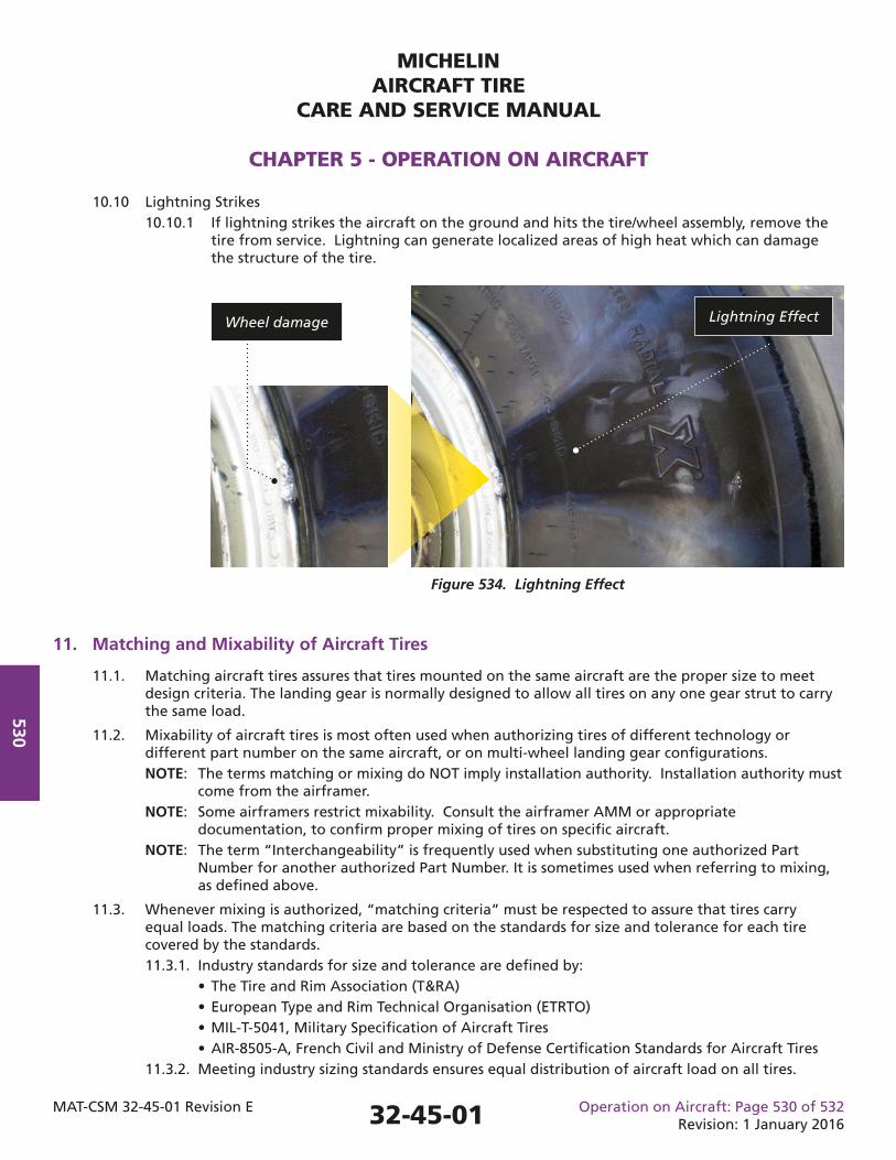
MICHELINAIRCRAFT TIRE
CARE AND SERVICE MANUAL
CHAPTER 5 - OPERATION ON AIRCRAFT
MAT-CSM 32-45-01 Revision E Operation on Aircraft: Page 530 of 532Revision: 1 January 2016
530
11. Matching and Mixability of Aircraft Tires
11.1. Matching aircraft tires assures that tires mounted on the same aircraft are the proper size to meet design criteria. The landing gear is normally designed to allow all tires on any one gear strut to carry the same load.
11.2. Mixability of aircraft tires is most often used when authorizing tires of different technology or different part number on the same aircraft, or on multi-wheel landing gear confi gurations. NOTE: The terms matching or mixing do NOT imply installation authority. Installation authority must come from the airframer. NOTE: Some airframers restrict mixability. Consult the airframer AMM or appropriate documentation, to confi rm proper mixing of tires on specifi c aircraft. NOTE: The term “Interchangeability” is frequently used when substituting one authorized Part Number for another authorized Part Number. It is sometimes used when referring to mixing, as defi ned above.
11.3. Whenever mixing is authorized, “matching criteria” must be respected to assure that tires carry equal loads. The matching criteria are based on the standards for size and tolerance for each tire covered by the standards. 11.3.1. Industry standards for size and tolerance are defi ned by: • The Tire and Rim Association (T&RA) • European Type and Rim Technical Organisation (ETRTO) • MIL-T-5041, Military Specifi cation of Aircraft Tires • AIR-8505-A, French Civil and Ministry of Defense Certifi cation Standards for Aircraft Tires 11.3.2. Meeting industry sizing standards ensures equal distribution of aircraft load on all tires.
10.10 Lightning Strikes 10.10.1 If lightning strikes the aircraft on the ground and hits the tire/wheel assembly, remove the tire from service. Lightning can generate localized areas of high heat which can damage the structure of the tire.
32-45-01
Figure 534. Lightning Effect
Wheel damage Lightning Effect
MICHELINAIRCRAFT TIRE
CARE AND SERVICE MANUAL
CHAPTER 5 - OPERATION ON AIRCRAFT
MAT-CSM 32-45-01 Revision E Operation on Aircraft: Page 531 of 532Revision: 1 January 2016
531
11.4. It is common practice to mix the following combinations on both the aircraft and on the same landing gear or bogie. • Bias – Bias • Radial – Radial
11.5. Mixability of bias tires and radial tires on the same aircraft is determined by the airframer. The possible combinations are: 11.5.1. Bias tires on the nose landing gear and radial tires on the main landing gear. 11.5.2. Radial tires on the nose landing gear and bias on the main landing gear. 11.5.3. Bias tires on one main landing gear and radial tires on the other main landing gear. (The nose landing gear could have either bias or radial.) 11.5.4. On a landing gear with twin tires (or dual tires), or for landing gear with tandem confi guration: A bias tire on one axle and a radial tire on another axle.
11.6. Tires approved for the same application must have the same Static Loaded Radius (SLR) (within standards) to respect the matching criteria. It is acceptable if they appear to have different overall diameters when stood side by side, properly infl ated.
11.7. Mixing New Tires and Retreaded Tires: It is acceptable to mount both new and retreaded tires on the same axle and/or landing gear if both are designed to the same standard and meet matching criteria. 11.7.1. The guidelines for mixability of new and retreaded tires for bias tires and radial tires on the same aircraft are the same as for new tires. Mixability of bias and radial tires is determined by the airframer.
12. Tire Creep
A small amount of relative circumferential movement between the tire and the wheel is the commonly known as tire creep. 12.1. Some tire creep may be observed on a new assembly. Up to fi ve (5) cycles may be necessary to properly position the tire bead on the wheel. 12.2. Tire creep is not an issue for tubeless tires as long as the tire does not rotate on the wheel to an extent where the braking capability is in question or causes air loss. 12.3. Underinfl ated tires can creep or slip on the wheel under stress or when brakes are applied.
12.4. SAE ARP5507 recommends a maximum of 20 degrees following installation. ARP 5507 further recommends that tires which move in excess of 20 degrees should be disassembled and evaluated for appropriate action. NOTE: If the circumferential distance of slippage along the top of the fl ange exceeds 20 degs (or 0.1745 x fl ange diameter), the tire should be removed.
13. Static Discharge
Tires are not designed to discharge the buildup of static electricity.
32-45-01
MICHELINAIRCRAFT TIRE
CARE AND SERVICE MANUAL
CHAPTER 5 - OPERATION ON AIRCRAFT
MAT-CSM 32-45-01 Revision E Operation on Aircraft: Page 532 of 532Revision: 1 January 2016
532
14. Tire Marking Tools
Tools for marking tires are available from commercial sources. Tire marking pens or crayons are commonly used. Michelin has no data to suggest tire damage from marking pens or crayons.
15. Military Arresting Cables
Some airports may have military arresting cables as emergency standby gear for arresting hook equipped aircraft. The cable is nominally 31.74 mm (1 1/4 inches) or 35 mm (1 3/8 inches) in diameter and installed approximately 457 to 610 m (1500 ft. to 2000 ft.) from the end of the runway. It is supported off of the runway surface approximately 14 to 18 cm (5 to 7 inches). Michelin has no data to suggest tire damage from cable roll over. NOTE: Do not confuse cable roll over with cable crush that is associated with landing on an aircraft carrier.
32-45-01
MICHELINAIRCRAFT TIRE
CARE AND SERVICE MANUAL
CHAPTER 6 - DISMOUNTING (DISASSEMBLY)
MAT-CSM 32-45-01 Revision E Dismounting: Page 601 of 612Revision: 1 January 2016
601
1. General
This chapter includes the necessary information and procedures for dismounting (disassembly of) aircraft tires when removing them from service or for retread. The following warnings and cautions apply whenever tires are being dismounted.
1.1. Reference the Aircraft Maintenance Manuals (AMM) and the wheel manufacturers Component Maintenance Manuals (CMM), if available. The AMM and CMM documents take precedence over these recommendations in the event of a confl ict.
2. WARNINGS and CAUTIONS for This Chapter
WARNING: AIRCRAFT TIRE AND WHEEL ASSEMBLIES MAY OPERATE UNDER HIGH PRESSURES IN ORDER TO CARRY THE LOADS IMPOSED ON THEM. THEY SHOULD BE TREATED WITH THE SAME RESPECT THAT ANY OTHER HIGH PRESSURE VESSEL WOULD BE GIVEN.
WARNING: ALWAYS APPROACH A TIRE/WHEEL ASSEMBLY FROM AN OBLIQUE ANGLE (DIRECTION OF THE TIRE’S SHOULDER).
WARNING: DO NOT PROBE CUTS OR EMBEDDED OBJECTS WHILE A TIRE IS INFLATED. SUCH ACTION COULD FURTHER DAMAGE A TIRE CAUSING IT TO RUPTURE RESULTING IN PERSONAL INJURY OR EQUIPMENT DAMAGE.
WARNING: DEFLATE ANY DAMAGED OR NON-SERVICEABLE WHEEL ASSEMBLY BEFORE REMOVING IT FROM THE AIRCRAFT. HANDLING DAMAGED ASSEMBLIES WHILE INFLATED INCREASES THE RISK OF ACCIDENTAL BURST OR FAILURE. SERVICEABLE UNITS MAY BE LEFT INFLATED.
WARNING: USE CARE WHEN REMOVING THE VALVE CORE FROM AN INFLATED TIRE. USE OF A VALVE CORE REMOVAL TOOL THAT CAPTURES THE VALVE CORE IS RECOMMENDED. THE VALVE CORE OF AN INFLATED TIRE CAN BE PROJECTED AT A HIGH SPEED AND POSSIBLY CAUSE INJURY.
WARNING: FULLY DEFLATE THE TIRE BEFORE LOOSENING THE TIE BOLTS THAT HOLD THE WHEEL HALVES TOGETHER. WHEEL PARTS COULD COME APART WITH FORCE CAUSING PERSONAL INJURY.
CAUTION: FOLLOW THE WHEEL MANUFACTURER’S INSTRUCTIONS, PROCEDURES, MATERIALS AND EQUIPMENT FOR DISASSEMBLING THE WHEEL COMPONENTS. IMPROPER PROCEDURES CAN CAUSE DAMAGE TO THE WHEEL OR ASSOCIATED COMPONENTS.
3. Track the Reasons for Tire Removal
Tracking the reasons for removal helps the repair station take appropriate corrective action decisions concerning inspections and the future use of the tire. 3.1. Use a tag or label attached to the tire with self-sticking adhesive or by use of a heavy string. Figure 601 lists the information requested.
3.2. Apply a self-sticking label to the tread of the tire. This will make removal during retreading easier. CAUTION: DO NOT USE STAPLES OR OTHER METAL DEVICES FOR AFFIXING TAGS OR LABELS TO TIRES OR INNER TUBES. THESE DEVICES CAN DAMAGE INTERNAL PLY CORDS RESULTING IN POSSIBLE TIRE FAILURE.
32-45-01
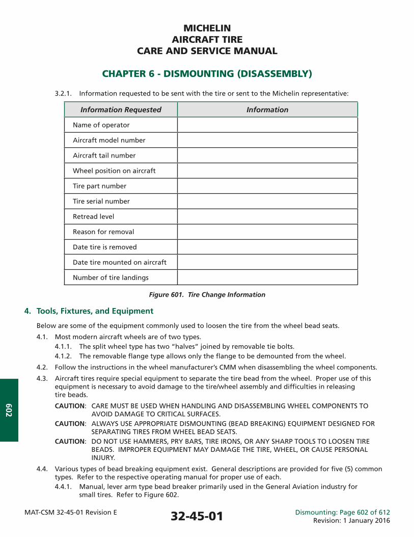
MICHELINAIRCRAFT TIRE
CARE AND SERVICE MANUAL
CHAPTER 6 - DISMOUNTING (DISASSEMBLY)
MAT-CSM 32-45-01 Revision E Dismounting: Page 602 of 612Revision: 1 January 2016
602
3.2.1. Information requested to be sent with the tire or sent to the Michelin representative:
Information Requested Information
Name of operator
Aircraft model number
Aircraft tail number
Wheel position on aircraft
Tire part number
Tire serial number
Retread level
Reason for removal
Date tire is removed
Date tire mounted on aircraft
Number of tire landings
Figure 601. Tire Change Information
4. Tools, Fixtures, and Equipment
Below are some of the equipment commonly used to loosen the tire from the wheel bead seats.
4.1. Most modern aircraft wheels are of two types. 4.1.1. The split wheel type has two “halves” joined by removable tie bolts. 4.1.2. The removable fl ange type allows only the fl ange to be demounted from the wheel.
4.2. Follow the instructions in the wheel manufacturer’s CMM when disassembling the wheel components.
4.3. Aircraft tires require special equipment to separate the tire bead from the wheel. Proper use of this equipment is necessary to avoid damage to the tire/wheel assembly and diffi culties in releasing tire beads.
CAUTION: CARE MUST BE USED WHEN HANDLING AND DISASSEMBLING WHEEL COMPONENTS TO AVOID DAMAGE TO CRITICAL SURFACES. CAUTION: ALWAYS USE APPROPRIATE DISMOUNTING (BEAD BREAKING) EQUIPMENT DESIGNED FOR SEPARATING TIRES FROM WHEEL BEAD SEATS. CAUTION: DO NOT USE HAMMERS, PRY BARS, TIRE IRONS, OR ANY SHARP TOOLS TO LOOSEN TIRE BEADS. IMPROPER EQUIPMENT MAY DAMAGE THE TIRE, WHEEL, OR CAUSE PERSONAL INJURY.
4.4. Various types of bead breaking equipment exist. General descriptions are provided for fi ve (5) common types. Refer to the respective operating manual for proper use of each. 4.4.1. Manual, lever arm type bead breaker primarily used in the General Aviation industry for small tires. Refer to Figure 602.
32-45-01
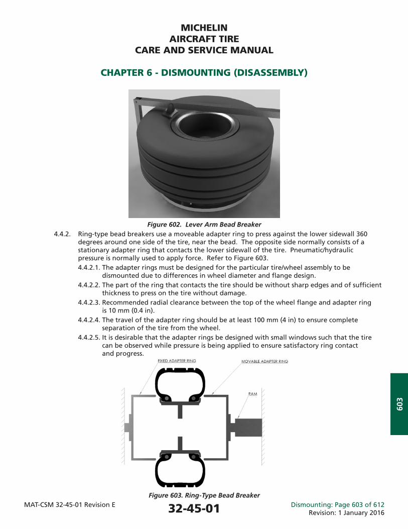
MICHELINAIRCRAFT TIRE
CARE AND SERVICE MANUAL
CHAPTER 6 - DISMOUNTING (DISASSEMBLY)
MAT-CSM 32-45-01 Revision E Dismounting: Page 603 of 612Revision: 1 January 2016
603
Figure 602. Lever Arm Bead Breaker
4.4.2. Ring-type bead breakers use a moveable adapter ring to press against the lower sidewall 360 degrees around one side of the tire, near the bead. The opposite side normally consists of a stationary adapter ring that contacts the lower sidewall of the tire. Pneumatic/hydraulic pressure is normally used to apply force. Refer to Figure 603. 4.4.2.1. The adapter rings must be designed for the particular tire/wheel assembly to be dismounted due to differences in wheel diameter and fl ange design. 4.4.2.2. The part of the ring that contacts the tire should be without sharp edges and of suffi cient thickness to press on the tire without damage. 4.4.2.3. Recommended radial clearance between the top of the wheel fl ange and adapter ring is 10 mm (0.4 in). 4.4.2.4. The travel of the adapter ring should be at least 100 mm (4 in) to ensure complete separation of the tire from the wheel. 4.4.2.5. It is desirable that the adapter rings be designed with small windows such that the tire can be observed while pressure is being applied to ensure satisfactory ring contact and progress.
Figure 603. Ring-Type Bead Breaker
32-45-01
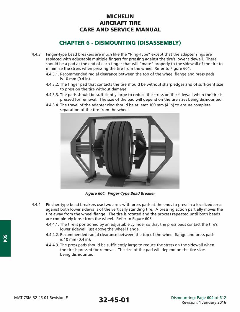
MICHELINAIRCRAFT TIRE
CARE AND SERVICE MANUAL
CHAPTER 6 - DISMOUNTING (DISASSEMBLY)
MAT-CSM 32-45-01 Revision E Dismounting: Page 604 of 612Revision: 1 January 2016
604
4.4.3. Finger-type bead breakers are much like the “Ring-Type” except that the adapter rings are replaced with adjustable multiple fi ngers for pressing against the tire’s lower sidewall. There should be a pad at the end of each fi nger that will “mate” properly to the sidewall of the tire to minimize the stress when pressing the tire from the wheel. Refer to Figure 604. 4.4.3.1. Recommended radial clearance between the top of the wheel fl ange and press pads is 10 mm (0.4 in). 4.4.3.2. The fi nger pad that contacts the tire should be without sharp edges and of suffi cient size to press on the tire without damage. 4.4.3.3. The pads should be suffi ciently large to reduce the stress on the sidewall when the tire is pressed for removal. The size of the pad will depend on the tire sizes being dismounted. 4.4.3.4. The travel of the adapter ring should be at least 100 mm (4 in) to ensure complete separation of the tire from the wheel.
Figure 604. Finger-Type Bead Breaker
4.4.4. Pincher-type bead breakers use two arms with press pads at the ends to press in a localized area against both lower sidewalls of the vertically standing tire. A pressing action partially moves the tire away from the wheel fl ange. The tire is rotated and the process repeated until both beads are completely loose from the wheel. Refer to Figure 605. 4.4.4.1. The tire is positioned by an adjustable cylinder so that the press pads contact the tire’s lower sidewall just above the wheel fl ange. 4.4.4.2. Recommended radial clearance between the top of the wheel fl ange and press pads is 10 mm (0.4 in). 4.4.4.3. The press pads should be suffi ciently large to reduce the stress on the sidewall when the tire is pressed for removal. The size of the pad will depend on the tire sizes being dismounted.
32-45-01
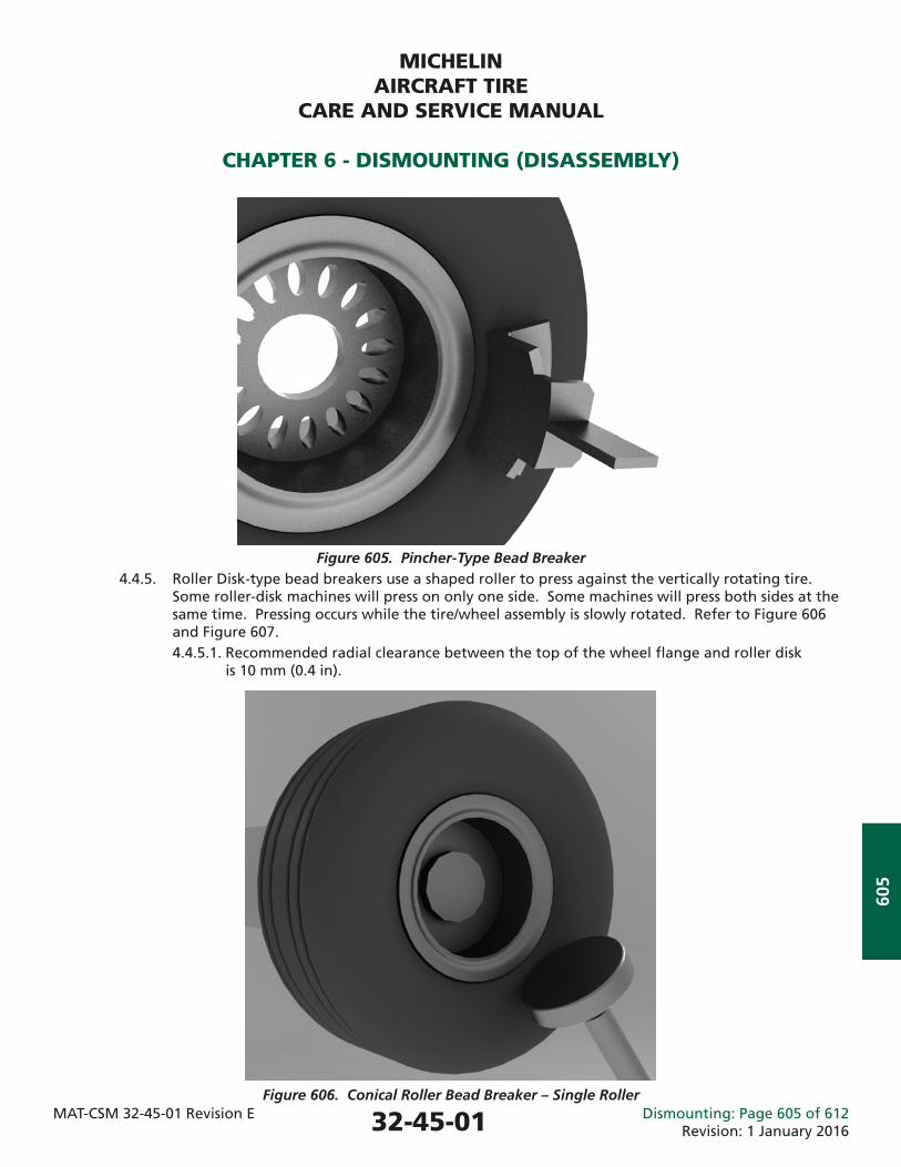
MICHELINAIRCRAFT TIRE
CARE AND SERVICE MANUAL
CHAPTER 6 - DISMOUNTING (DISASSEMBLY)
MAT-CSM 32-45-01 Revision E Dismounting: Page 605 of 612Revision: 1 January 2016
605
Figure 605. Pincher-Type Bead Breaker 4.4.5. Roller Disk-type bead breakers use a shaped roller to press against the vertically rotating tire. Some roller-disk machines will press on only one side. Some machines will press both sides at the same time. Pressing occurs while the tire/wheel assembly is slowly rotated. Refer to Figure 606 and Figure 607. 4.4.5.1. Recommended radial clearance between the top of the wheel fl ange and roller disk is 10 mm (0.4 in).
Figure 606. Conical Roller Bead Breaker – Single Roller
32-45-01
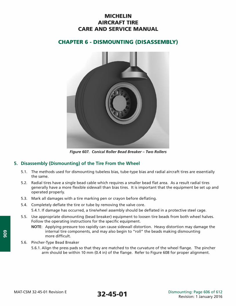
MICHELINAIRCRAFT TIRE
CARE AND SERVICE MANUAL
CHAPTER 6 - DISMOUNTING (DISASSEMBLY)
MAT-CSM 32-45-01 Revision E Dismounting: Page 606 of 612Revision: 1 January 2016
606
Figure 607. Conical Roller Bead Breaker – Two Rollers
5. Disassembly (Dismounting) of the Tire From the Wheel
5.1. The methods used for dismounting tubeless bias, tube-type bias and radial aircraft tires are essentially the same.
5.2. Radial tires have a single bead cable which requires a smaller bead fl at area. As a result radial tires generally have a more fl exible sidewall than bias tires. It is important that the equipment be set up and operated properly.
5.3. Mark all damages with a tire marking pen or crayon before defl ating.
5.4. Completely defl ate the tire or tube by removing the valve core. 5.4.1. If damage has occurred, a tire/wheel assembly should be defl ated in a protective steel cage.
5.5. Use appropriate dismounting (bead breaker) equipment to loosen tire beads from both wheel halves. Follow the operating instructions for the specifi c equipment. NOTE: Applying pressure too rapidly can cause sidewall distortion. Heavy distortion may damage the internal tire components, and may also begin to “roll” the beads making dismounting more diffi cult.
5.6. Pincher-Type Bead Breaker 5.6.1. Align the press pads so that they are matched to the curvature of the wheel fl ange. The pincher arm should be within 10 mm (0.4 in) of the fl ange. Refer to Figure 608 for proper alignment.
32-45-01
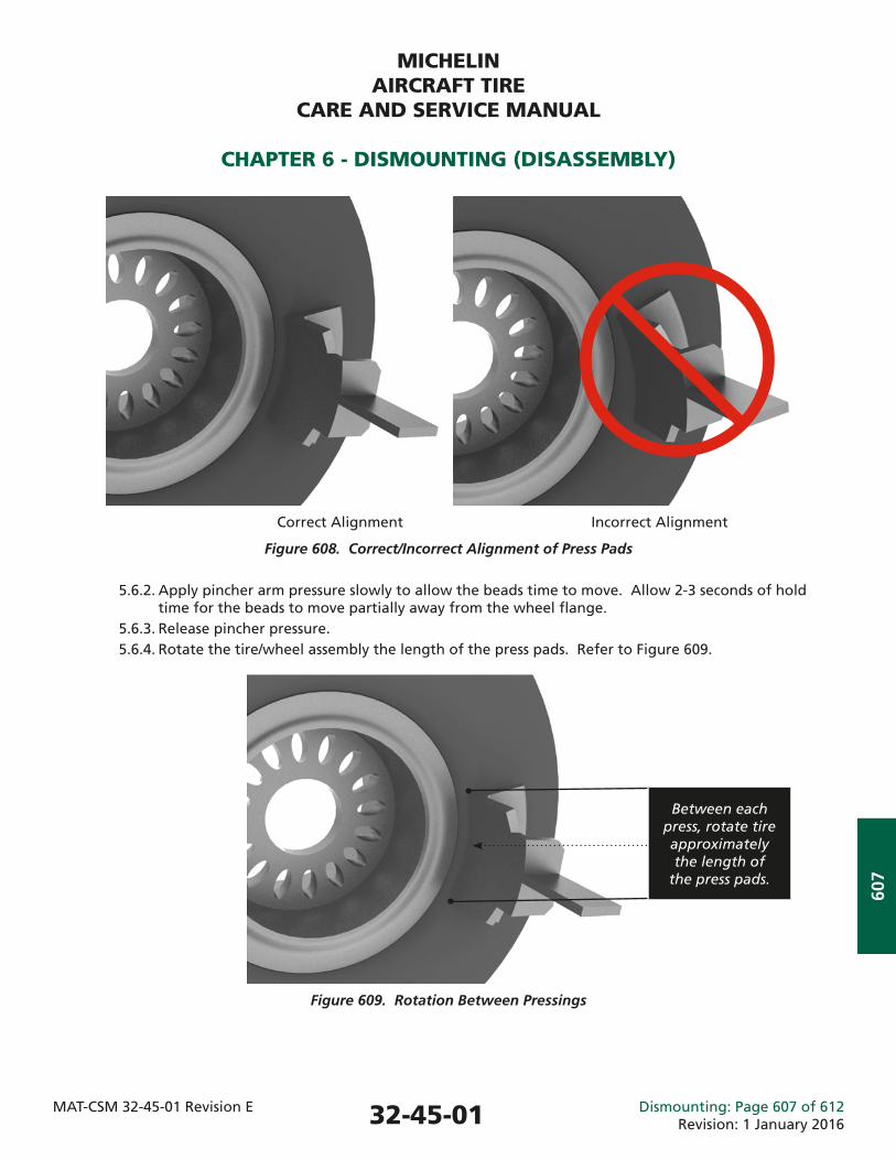
MICHELINAIRCRAFT TIRE
CARE AND SERVICE MANUAL
CHAPTER 6 - DISMOUNTING (DISASSEMBLY)
MAT-CSM 32-45-01 Revision E Dismounting: Page 607 of 612Revision: 1 January 2016
607
Correct Alignment Incorrect Alignment
Figure 608. Correct/Incorrect Alignment of Press Pads
5.6.2. Apply pincher arm pressure slowly to allow the beads time to move. Allow 2-3 seconds of hold time for the beads to move partially away from the wheel fl ange. 5.6.3. Release pincher pressure. 5.6.4. Rotate the tire/wheel assembly the length of the press pads. Refer to Figure 609.
Figure 609. Rotation Between Pressings
Between each press, rotate tire approximately the length of
the press pads.
32-45-01
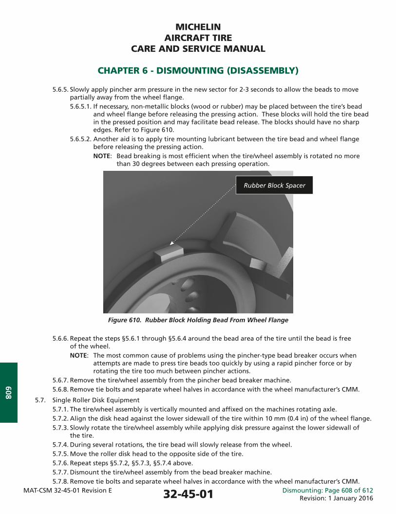
MICHELINAIRCRAFT TIRE
CARE AND SERVICE MANUAL
CHAPTER 6 - DISMOUNTING (DISASSEMBLY)
MAT-CSM 32-45-01 Revision E Dismounting: Page 608 of 612Revision: 1 January 2016
608
5.6.5. Slowly apply pincher arm pressure in the new sector for 2-3 seconds to allow the beads to move partially away from the wheel fl ange. 5.6.5.1. If necessary, non-metallic blocks (wood or rubber) may be placed between the tire’s bead and wheel fl ange before releasing the pressing action. These blocks will hold the tire bead in the pressed position and may facilitate bead release. The blocks should have no sharp edges. Refer to Figure 610. 5.6.5.2. Another aid is to apply tire mounting lubricant between the tire bead and wheel fl ange before releasing the pressing action. NOTE: Bead breaking is most effi cient when the tire/wheel assembly is rotated no more than 30 degrees between each pressing operation.
Figure 610. Rubber Block Holding Bead From Wheel Flange
5.6.6. Repeat the steps §5.6.1 through §5.6.4 around the bead area of the tire until the bead is free of the wheel.
NOTE: The most common cause of problems using the pincher-type bead breaker occurs when attempts are made to press tire beads too quickly by using a rapid pincher force or by rotating the tire too much between pincher actions. 5.6.7. Remove the tire/wheel assembly from the pincher bead breaker machine. 5.6.8. Remove tie bolts and separate wheel halves in accordance with the wheel manufacturer’s CMM.
5.7. Single Roller Disk Equipment 5.7.1. The tire/wheel assembly is vertically mounted and affi xed on the machines rotating axle. 5.7.2. Align the disk head against the lower sidewall of the tire within 10 mm (0.4 in) of the wheel fl ange. 5.7.3. Slowly rotate the tire/wheel assembly while applying disk pressure against the lower sidewall of the tire. 5.7.4. During several rotations, the tire bead will slowly release from the wheel. 5.7.5. Move the roller disk head to the opposite side of the tire. 5.7.6. Repeat steps §5.7.2, §5.7.3, §5.7.4 above. 5.7.7. Dismount the tire/wheel assembly from the bead breaker machine. 5.7.8. Remove tie bolts and separate wheel halves in accordance with the wheel manufacturer’s CMM.
Rubber Block Spacer
32-45-01
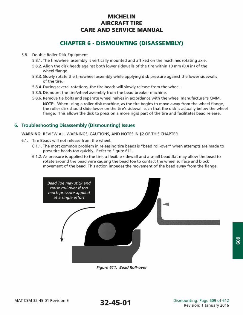
MICHELINAIRCRAFT TIRE
CARE AND SERVICE MANUAL
CHAPTER 6 - DISMOUNTING (DISASSEMBLY)
MAT-CSM 32-45-01 Revision E Dismounting: Page 609 of 612Revision: 1 January 2016
609
5.8. Double Roller Disk Equipment 5.8.1. The tire/wheel assembly is vertically mounted and affi xed on the machines rotating axle. 5.8.2. Align the disk heads against both lower sidewalls of the tire within 10 mm (0.4 in) of the wheel fl ange. 5.8.3. Slowly rotate the tire/wheel assembly while applying disk pressure against the lower sidewalls of the tire. 5.8.4. During several rotations, the tire beads will slowly release from the wheel. 5.8.5. Dismount the tire/wheel assembly from the bead breaker machine. 5.8.6. Remove tie bolts and separate wheel halves in accordance with the wheel manufacturer’s CMM. NOTE: When using a roller disk machine, as the tire begins to move away from the wheel fl ange, the roller disk should slide lower on the tire’s sidewall such that the disk is actually below the wheel fl ange. This allows the disk to press on a more rigid part of the tire and facilitates bead release.
6. Troubleshooting Disassembly (Dismounting) Issues
WARNING: REVIEW ALL WARNINGS, CAUTIONS, AND NOTES IN §2 OF THIS CHAPTER.
6.1. Tire Beads will not release from the wheel. 6.1.1. The most common problem in releasing tire beads is “bead roll-over” when attempts are made to press tire beads too quickly. Refer to Figure 611. 6.1.2. As pressure is applied to the tire, a fl exible sidewall and a small bead fl at may allow the bead to rotate around the bead wire causing the bead toe to contact the wheel surface and block movement of the bead. This action impedes the movement of the bead away from the fl ange.
Figure 611. Bead Roll-over
Bead Toe may stick and cause roll-over if too
much pressure applied at a single effort
32-45-01
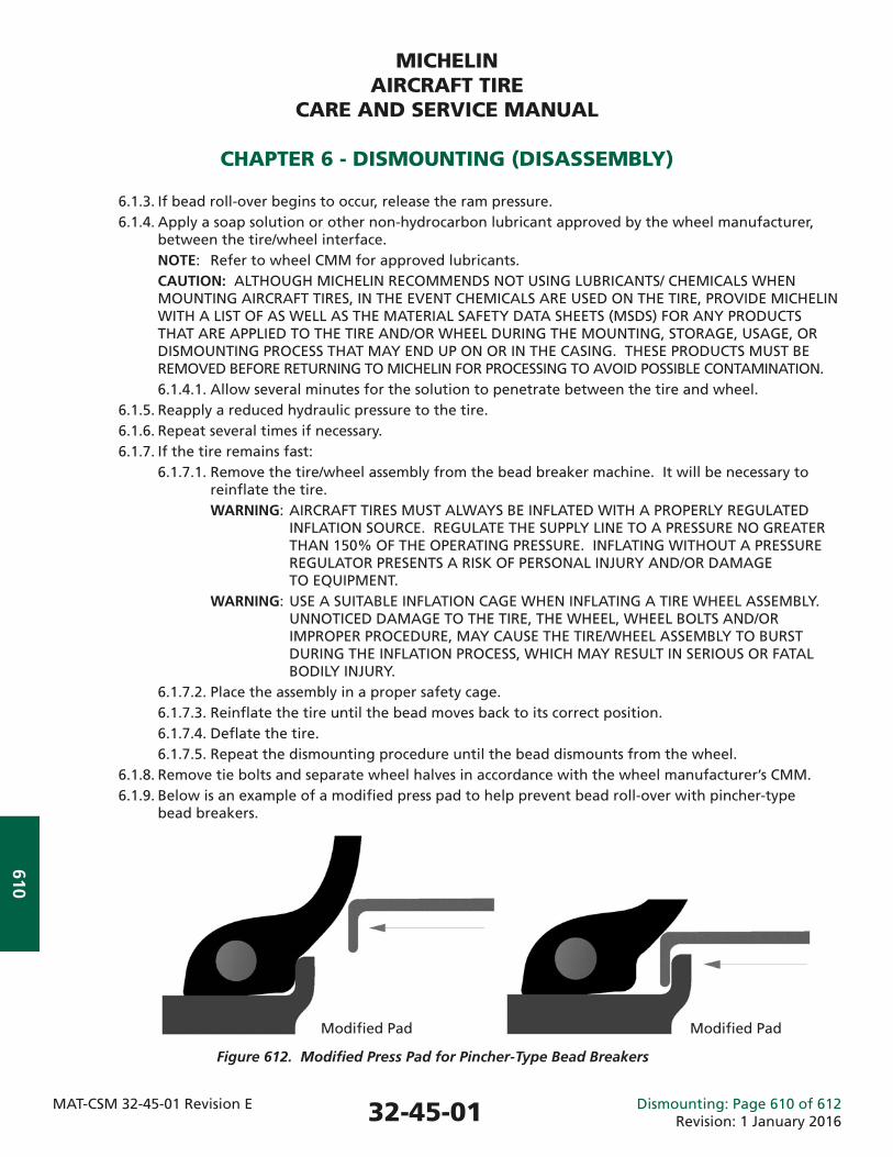
MICHELINAIRCRAFT TIRE
CARE AND SERVICE MANUAL
CHAPTER 6 - DISMOUNTING (DISASSEMBLY)
MAT-CSM 32-45-01 Revision E Dismounting: Page 610 of 612Revision: 1 January 2016
610
6.1.3. If bead roll-over begins to occur, release the ram pressure. 6.1.4. Apply a soap solution or other non-hydrocarbon lubricant approved by the wheel manufacturer, between the tire/wheel interface. NOTE: Refer to wheel CMM for approved lubricants. CAUTION: ALTHOUGH MICHELIN RECOMMENDS NOT USING LUBRICANTS/ CHEMICALS WHEN MOUNTING AIRCRAFT TIRES, IN THE EVENT CHEMICALS ARE USED ON THE TIRE, PROVIDE MICHELIN WITH A LIST OF AS WELL AS THE MATERIAL SAFETY DATA SHEETS (MSDS) FOR ANY PRODUCTS THAT ARE APPLIED TO THE TIRE AND/OR WHEEL DURING THE MOUNTING, STORAGE, USAGE, OR DISMOUNTING PROCESS THAT MAY END UP ON OR IN THE CASING. THESE PRODUCTS MUST BE REMOVED BEFORE RETURNING TO MICHELIN FOR PROCESSING TO AVOID POSSIBLE CONTAMINATION. 6.1.4.1. Allow several minutes for the solution to penetrate between the tire and wheel. 6.1.5. Reapply a reduced hydraulic pressure to the tire. 6.1.6. Repeat several times if necessary. 6.1.7. If the tire remains fast: 6.1.7.1. Remove the tire/wheel assembly from the bead breaker machine. It will be necessary to reinfl ate the tire. WARNING: AIRCRAFT TIRES MUST ALWAYS BE INFLATED WITH A PROPERLY REGULATED INFLATION SOURCE. REGULATE THE SUPPLY LINE TO A PRESSURE NO GREATER THAN 150% OF THE OPERATING PRESSURE. INFLATING WITHOUT A PRESSURE REGULATOR PRESENTS A RISK OF PERSONAL INJURY AND/OR DAMAGE TO EQUIPMENT. WARNING: USE A SUITABLE INFLATION CAGE WHEN INFLATING A TIRE WHEEL ASSEMBLY. UNNOTICED DAMAGE TO THE TIRE, THE WHEEL, WHEEL BOLTS AND/OR IMPROPER PROCEDURE, MAY CAUSE THE TIRE/WHEEL ASSEMBLY TO BURST DURING THE INFLATION PROCESS, WHICH MAY RESULT IN SERIOUS OR FATAL BODILY INJURY. 6.1.7.2. Place the assembly in a proper safety cage. 6.1.7.3. Reinfl ate the tire until the bead moves back to its correct position. 6.1.7.4. Defl ate the tire. 6.1.7.5. Repeat the dismounting procedure until the bead dismounts from the wheel. 6.1.8. Remove tie bolts and separate wheel halves in accordance with the wheel manufacturer’s CMM. 6.1.9. Below is an example of a modifi ed press pad to help prevent bead roll-over with pincher-type bead breakers.
Modifi ed Pad Modifi ed Pad
Figure 612. Modifi ed Press Pad for Pincher-Type Bead Breakers
32-45-01
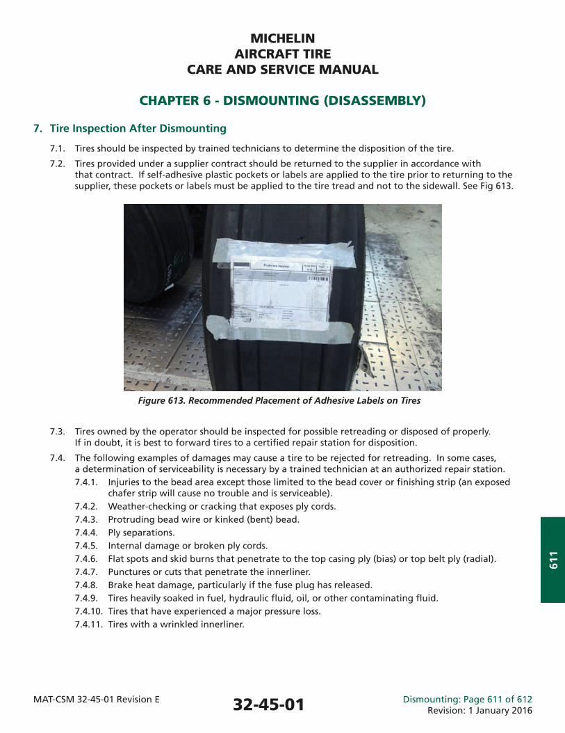
MICHELINAIRCRAFT TIRE
CARE AND SERVICE MANUAL
CHAPTER 6 - DISMOUNTING (DISASSEMBLY)
MAT-CSM 32-45-01 Revision E Dismounting: Page 611 of 612Revision: 1 January 2016
611
7. Tire Inspection After Dismounting
7.1. Tires should be inspected by trained technicians to determine the disposition of the tire.
7.2. Tires provided under a supplier contract should be returned to the supplier in accordance with that contract. If self-adhesive plastic pockets or labels are applied to the tire prior to returning to the supplier, these pockets or labels must be applied to the tire tread and not to the sidewall. See Fig 613.
7.3. Tires owned by the operator should be inspected for possible retreading or disposed of properly. If in doubt, it is best to forward tires to a certifi ed repair station for disposition.
7.4. The following examples of damages may cause a tire to be rejected for retreading. In some cases, a determination of serviceability is necessary by a trained technician at an authorized repair station. 7.4.1. Injuries to the bead area except those limited to the bead cover or fi nishing strip (an exposed chafer strip will cause no trouble and is serviceable). 7.4.2. Weather-checking or cracking that exposes ply cords. 7.4.3. Protruding bead wire or kinked (bent) bead. 7.4.4. Ply separations. 7.4.5. Internal damage or broken ply cords. 7.4.6. Flat spots and skid burns that penetrate to the top casing ply (bias) or top belt ply (radial). 7.4.7. Punctures or cuts that penetrate the innerliner. 7.4.8. Brake heat damage, particularly if the fuse plug has released. 7.4.9. Tires heavily soaked in fuel, hydraulic fl uid, oil, or other contaminating fl uid. 7.4.10. Tires that have experienced a major pressure loss. 7.4.11. Tires with a wrinkled innerliner.
Figure 613. Recommended Placement of Adhesive Labels on Tires
32-45-01
MICHELINAIRCRAFT TIRE
CARE AND SERVICE MANUAL
CHAPTER 6 - DISMOUNTING (DISASSEMBLY)
MAT-CSM 32-45-01 Revision E Dismounting: Page 612 of 612Revision: 1 January 2016
612
This Page IntentionallyLeft Blank
32-45-01
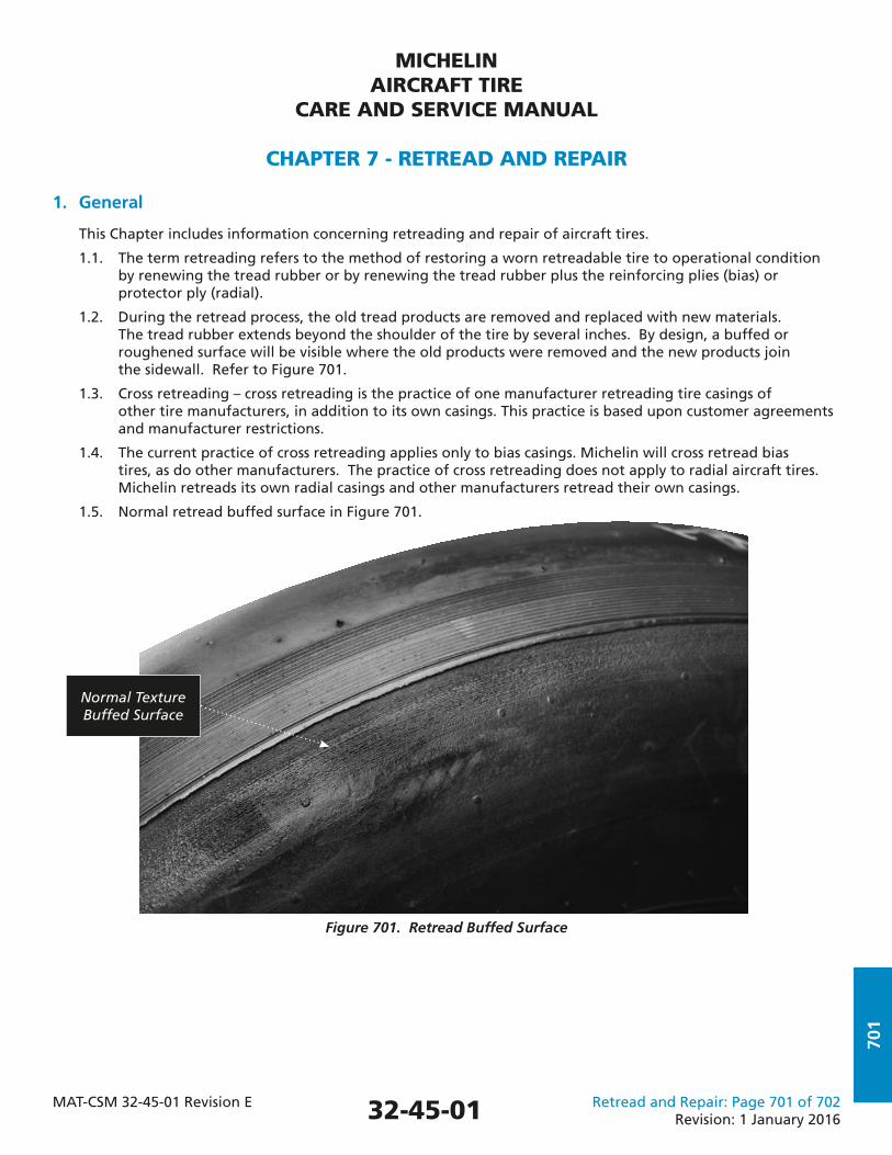
MICHELINAIRCRAFT TIRE
CARE AND SERVICE MANUAL
CHAPTER 7 - RETREAD AND REPAIR
MAT-CSM 32-45-01 Revision E Retread and Repair: Page 701 of 702Revision: 1 January 2016
701
1. General
This Chapter includes information concerning retreading and repair of aircraft tires.
1.1. The term retreading refers to the method of restoring a worn retreadable tire to operational condition by renewing the tread rubber or by renewing the tread rubber plus the reinforcing plies (bias) or protector ply (radial).
1.2. During the retread process, the old tread products are removed and replaced with new materials. The tread rubber extends beyond the shoulder of the tire by several inches. By design, a buffed or roughened surface will be visible where the old products were removed and the new products join the sidewall. Refer to Figure 701.
1.3. Cross retreading – cross retreading is the practice of one manufacturer retreading tire casings of other tire manufacturers, in addition to its own casings. This practice is based upon customer agreements and manufacturer restrictions.
1.4. The current practice of cross retreading applies only to bias casings. Michelin will cross retread bias tires, as do other manufacturers. The practice of cross retreading does not apply to radial aircraft tires. Michelin retreads its own radial casings and other manufacturers retread their own casings.
1.5. Normal retread buffed surface in Figure 701.
Figure 701. Retread Buffed Surface
Normal Texture Buffed Surface
32-45-01
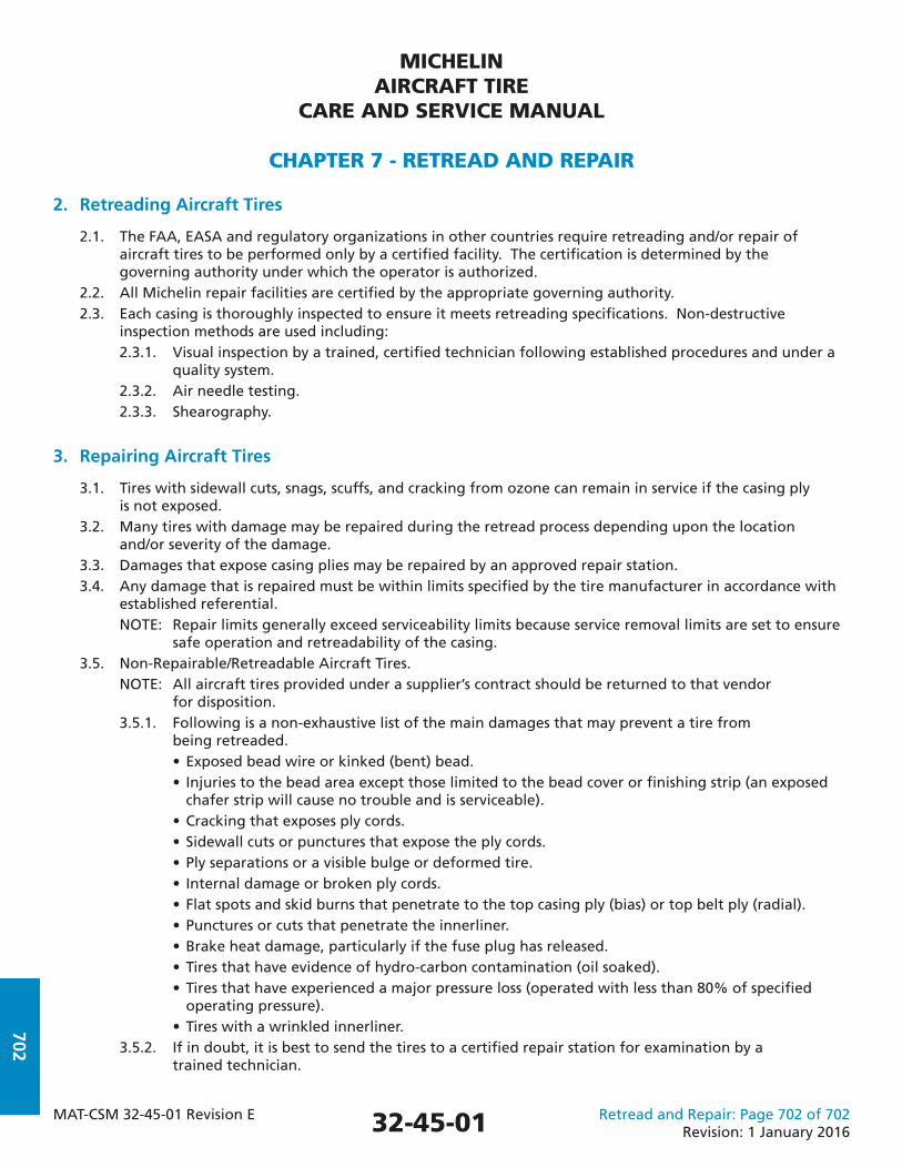
MICHELINAIRCRAFT TIRE
CARE AND SERVICE MANUAL
CHAPTER 7 - RETREAD AND REPAIR
MAT-CSM 32-45-01 Revision E Retread and Repair: Page 702 of 702Revision: 1 January 2016
702
2. Retreading Aircraft Tires
2.1. The FAA, EASA and regulatory organizations in other countries require retreading and/or repair of aircraft tires to be performed only by a certifi ed facility. The certifi cation is determined by the governing authority under which the operator is authorized. 2.2. All Michelin repair facilities are certifi ed by the appropriate governing authority. 2.3. Each casing is thoroughly inspected to ensure it meets retreading specifi cations. Non-destructive inspection methods are used including: 2.3.1. Visual inspection by a trained, certifi ed technician following established procedures and under a quality system. 2.3.2. Air needle testing. 2.3.3. Shearography.
3. Repairing Aircraft Tires
3.1. Tires with sidewall cuts, snags, scuffs, and cracking from ozone can remain in service if the casing ply is not exposed. 3.2. Many tires with damage may be repaired during the retread process depending upon the location and/or severity of the damage. 3.3. Damages that expose casing plies may be repaired by an approved repair station. 3.4. Any damage that is repaired must be within limits specifi ed by the tire manufacturer in accordance with established referential. NOTE: Repair limits generally exceed serviceability limits because service removal limits are set to ensure safe operation and retreadability of the casing. 3.5. Non-Repairable/Retreadable Aircraft Tires. NOTE: All aircraft tires provided under a supplier’s contract should be returned to that vendor for disposition. 3.5.1. Following is a non-exhaustive list of the main damages that may prevent a tire from being retreaded. • Exposed bead wire or kinked (bent) bead. • Injuries to the bead area except those limited to the bead cover or fi nishing strip (an exposed chafer strip will cause no trouble and is serviceable). • Cracking that exposes ply cords. • Sidewall cuts or punctures that expose the ply cords. • Ply separations or a visible bulge or deformed tire. • Internal damage or broken ply cords. • Flat spots and skid burns that penetrate to the top casing ply (bias) or top belt ply (radial). • Punctures or cuts that penetrate the innerliner. • Brake heat damage, particularly if the fuse plug has released. • Tires that have evidence of hydro-carbon contamination (oil soaked). • Tires that have experienced a major pressure loss (operated with less than 80% of specifi ed operating pressure). • Tires with a wrinkled innerliner. 3.5.2. If in doubt, it is best to send the tires to a certifi ed repair station for examination by a trained technician.
32-45-01

Copy
right
©20
16 M
ichel
in N
orth
Am
erica
, Inc
. All
Righ
ts R
eser
ved.
The
Mich
elin
Man
is
a re
gist
ered
trad
emar
k ow
ned
by M
ichel
in N
orth
Am
erica
, Inc
. ©
Mich
elin
-T. G
rom
ik.
$35.00 US
MICHELIN BRINGS TOP-QUALITY SERVICE AROUND THE GLOBE
Highly-Experienced Aviation ExpertsÜ Michelin’s aviation business
unit includes a dedicated team of technical experts and sales professionals devoted strictly to aircraft tires
Ü Michelin provides expert tire program solutions including tire care, service training and technical visits
Ü Michelin offers worldwide coverage through an integrated global team that shares best practices across all disciplines
Ü Michelin has a long and storied history in aviation dating back to 1908
Download the FREE MICHELIN® Aircraft Tire APPÜ Includes a searchable copy of the Michelin Care &
Service Manual, tire fi tment guide, tire wear guide, product information, troubleshooting help (with photos), dealer locator and more
Ü Available from the App Store and Google Play
A WEALTH OF INFORMATION AT YOUR FINGERTIPS
Scan to Download
Europe, CIS, Middle East & AfricaMichelin Aircraft Tyre23, Place des Carmes-Déchaux63040 Clermont-Ferrand Cedex 9FrancePh: +33 (0) 4 73 30 14 85Fax: +33 (0) 4 73 30 41 21
North, Central & South AmericaMichelin Aircraft Tire CompanyOne Parkway SouthGreenville, South Carolina 29615USAPh: +1-877-503-8071Fax: +1-864-458-4011
Asia and OceaniaThailand (Main Offi ce)Michelin Siam Co. Ltd.Aircraft Tyre OperationsSPE Tower 11th Floor252 Phaholyothin RoadSamsaen Nai, PayathaiBangkok 10400, ThailandPh: +66 (2) 619-3524Fax: +66 (2) 619-3529
Asia and Oceania (continued)AustraliaMichelin Aircraft Tire CompanySuite 416, 33 Lexington DriveBella VistaNSW 2154PH +61 (2) 8882 7906Fax: +61 (2) 8814 6048
ChinaMichelin (Shanghai) Aircraft Tire Trading Co., Ltd. Block 7, No. 518, Fuquan Bei Road, Changning District, Shanghai Municipality, PRC Ph: +86 (21) 22855000
JapanNihon Michelin Tire Co., Ltd.Aircraft Tire Product LineShinjuku Park Tower 13F,3-7-1, Nishi-Shinjuku, Shinjuku-ku,Tokyo, 163-1073, JapanPh: +81 (3) 6756-8121Fax: +81 (3) 5990-5621
www.airmichelin.com
http://youtube.com/airmichelin