Embed Size (px)
Citation preview
MICRO SWITCH™ Compact Precision Limit Switches914CE Series
Datasheet
2 sensing.honeywell.com
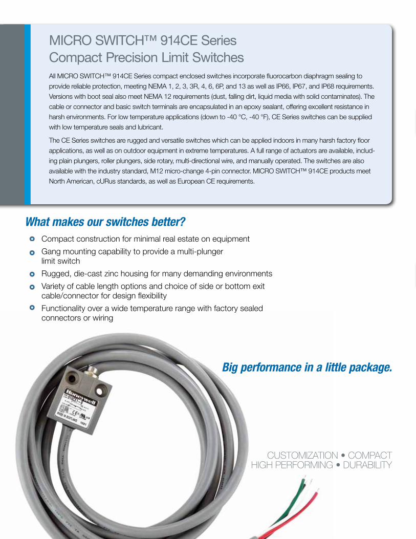
What makes our switches better? Compact construction for minimal real estate on equipment
Gang mounting capability to provide a multi-plunger limit switch
Rugged, die-cast zinc housing for many demanding environments
Variety of cable length options and choice of side or bottom exit cable/connector for design flexibility
Functionality over a wide temperature range with factory sealed connectors or wiring
MICRO SWITCH™ 914CE Series Compact Precision Limit SwitchesAll MICRO SWITCH™ 914CE Series compact enclosed switches incorporate fluorocarbon diaphragm sealing to
provide reliable protection, meeting NEMA 1, 2, 3, 3R, 4, 6, 6P, and 13 as well as IP66, IP67, and IP68 requirements.
Versions with boot seal also meet NEMA 12 requirements (dust, falling dirt, liquid media with solid contaminates). The
cable or connector and basic switch terminals are encapsulated in an epoxy sealant, offering excellent resistance in
harsh environments. For low temperature applications (down to -40 °C, -40 °F), CE Series switches can be supplied
with low temperature seals and lubricant.
The CE Series switches are rugged and versatile switches which can be applied indoors in many harsh factory floor
applications, as well as on outdoor equipment in extreme temperatures. A full range of actuators are available, includ-
ing plain plungers, roller plungers, side rotary, multi-directional wire, and manually operated. The switches are also
available with the industry standard, M12 micro-change 4-pin connector. MICRO SWITCH™ 914CE products meet
North American, cURus standards, as well as European CE requirements.
CUSTOMIZATION • COMPACTHIGH PERFORMING • DURABILITY
Big performance in a little package.
3sensing.honeywell.com
Features and Benefits Features and Benefits
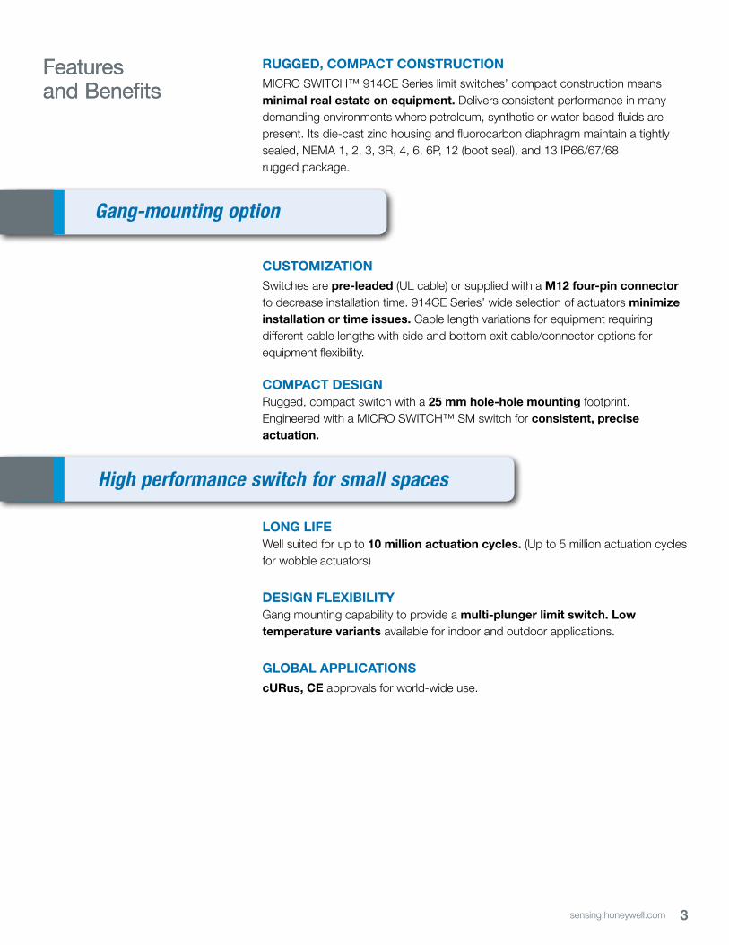
RUGGED, COMPACT CONSTRUCTIONMICRO SWITCH™ 914CE Series limit switches’ compact construction means minimal real estate on equipment. Delivers consistent performance in many demanding environments where petroleum, synthetic or water based fluids are present. Its die-cast zinc housing and fluorocarbon diaphragm maintain a tightly sealed, NEMA 1, 2, 3, 3R, 4, 6, 6P, 12 (boot seal), and 13 IP66/67/68 rugged package.
CUSTOMIZATIONSwitches are pre-leaded (UL cable) or supplied with a M12 four-pin connector to decrease installation time. 914CE Series’ wide selection of actuators minimize installation or time issues. Cable length variations for equipment requiring different cable lengths with side and bottom exit cable/connector options for equipment flexibility.
COMPACT DESIGNRugged, compact switch with a 25 mm hole-hole mounting footprint. Engineered with a MICRO SWITCH™ SM switch for consistent, precise actuation.
LONG LIFEWell suited for up to 10 million actuation cycles. (Up to 5 million actuation cycles for wobble actuators)
DESIGN FLEXIBILITYGang mounting capability to provide a multi-plunger limit switch. Low temperature variants available for indoor and outdoor applications.
GLOBAL APPLICATIONScURus, CE approvals for world-wide use.
High performance switch for small spaces
Gang-mounting option

4 sensing.honeywell.com
MACHINE TOOLSDetects tool and piece part location on CNC and other machining equipment
OFF-ROAD EQUIPMENTUsed as a cab door switch on crane booms
MATERIAL HANDLING
Used in dock locks for trucks and trailers, and vehicle wash systems
ACCESS AND MOBILITY SOLUTIONS
Often used on vehicle wheelchair lifts and stairway lifts
TEXTILE MACHINERY
Senses roll size, tensioning, and other functions
ROBOTICS
Controls arm movement limits
PACKAGING EQUIPMENT
Often used on stretch pallet wrapping equipment
COMMERCIAL APPLIANCES
Functions as a door switch
PRINT TRADE MACHINERY
Senses roll size, tensioning, along with controlling gates and panels
AGRICULTURAL MACHINERY
Used on grain and livestock equipment
Potential Applications
5sensing.honeywell.com
MICRO SWITCH™ Compact Precision Limit Switches
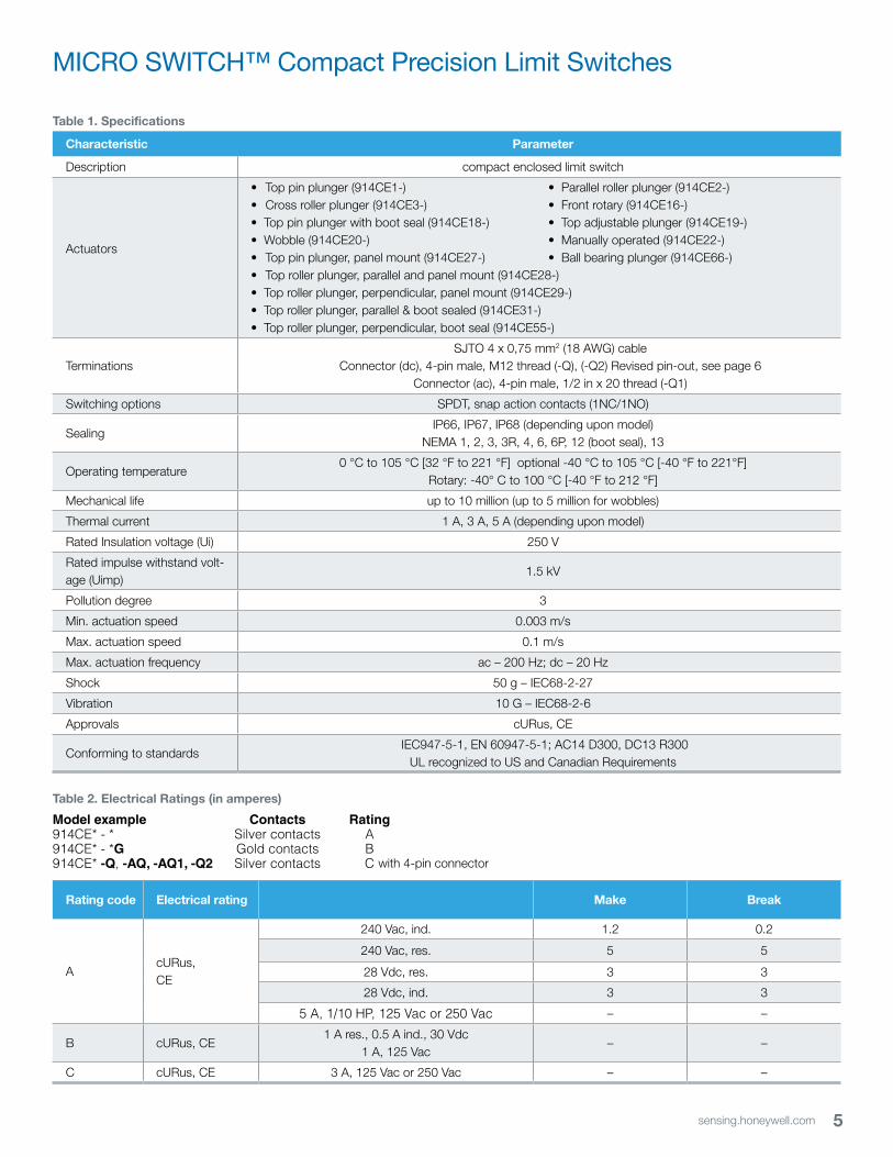
Table 1. Specifications
Characteristic Parameter
Description compact enclosed limit switch
Actuators
• Top pin plunger (914CE1-) • Parallel roller plunger (914CE2-) • Cross roller plunger (914CE3-) • Front rotary (914CE16-)• Top pin plunger with boot seal (914CE18-) • Top adjustable plunger (914CE19-)• Wobble (914CE20-) • Manually operated (914CE22-)• Top pin plunger, panel mount (914CE27-) • Ball bearing plunger (914CE66-)• Top roller plunger, parallel and panel mount (914CE28-) • Top roller plunger, perpendicular, panel mount (914CE29-)• Top roller plunger, parallel & boot sealed (914CE31-)• Top roller plunger, perpendicular, boot seal (914CE55-)
Terminations SJTO 4 x 0,75 mm2 (18 AWG) cable Connector (dc), 4-pin male, M12 thread (-Q), (-Q2) Revised pin-out, see page 6 Connector (ac), 4-pin male, 1/2 in x 20 thread (-Q1)
Switching options SPDT, snap action contacts (1NC/1NO)
SealingIP66, IP67, IP68 (depending upon model)
NEMA 1, 2, 3, 3R, 4, 6, 6P, 12 (boot seal), 13
Operating temperature0 °C to 105 °C [32 °F to 221 °F] optional -40 °C to 105 °C [-40 °F to 221°F]
Rotary: -40° C to 100 °C [-40 °F to 212 °F]
Mechanical life up to 10 million (up to 5 million for wobbles)
Thermal current 1 A, 3 A, 5 A (depending upon model)
Rated Insulation voltage (Ui) 250 V
Rated impulse withstand volt-age (Uimp)
1.5 kV
Pollution degree 3
Min. actuation speed 0.003 m/s
Max. actuation speed 0.1 m/s
Max. actuation frequency ac – 200 Hz; dc – 20 Hz
Shock 50 g – IEC68-2-27
Vibration 10 G – IEC68-2-6
Approvals cURus, CE
Conforming to standards IEC947-5-1, EN 60947-5-1; AC14 D300, DC13 R300
UL recognized to US and Canadian Requirements
Table 2. Electrical Ratings (in amperes)
Model example Contacts Rating914CE* - * Silver contacts A914CE* - *G Gold contacts B914CE* -Q, -AQ, -AQ1, -Q2 Silver contacts C
Rating code Electrical rating Make Break
AcURus,CE
240 Vac, ind. 1.2 0.2
240 Vac, res. 5 5
28 Vdc, res. 3 3
28 Vdc, ind. 3 3
5 A, 1/10 HP, 125 Vac or 250 Vac – –
B cURus, CE1 A res., 0.5 A ind., 30 Vdc
1 A, 125 Vac– –
C cURus, CE 3 A, 125 Vac or 250 Vac – –
with 4-pin connector
6 sensing.honeywell.com
914CE Series
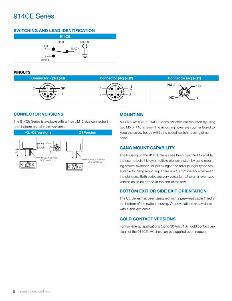
SWITCHING AND LEAD IDENTIFICATION914CE
GREEN
BLACK1
RED2
3WHITE
SPDT
PINOUTSConnector - (dc) (-Q) Connector (dc) (-Q2) Connector (ac) (-Q1)
13
2
13NO
NC
C
31
2
13
2
13NO
NC
C
CONNECTOR VERSIONS
The 914CE Series is available with a 4-pin, M12 size connector in
both bottom and side exit versions.
-Q, -Q2 Versions Q1 Version
8.0
Brad Harrison connectorCAT. No.80466 M12 Thread
15
OPTION Q
dc type 4 pin male,M12 thread
15
OPTION Q1
ac type, 4 pin male,1/2 in x 20 thread
MOUNTING
MICRO SWITCH™ 914CE Series switches are mounted by using
two M5 or #10 screws. The mounting holes are counter bored to
keep the screw heads within the overall switch housing dimen-
sions.
GANG MOUNT CAPABILITY
The housing on the 914CE Series has been designed to enable
the user to build his own multiple plunger switch by gang mount-
ing several switches. All pin plunger and roller plunger types are
suitable for gang mounting. There is a 16 mm distance between
the plungers. Both series are very versatile that even a lever-type
version could be added at the end of the row.
BOTTOM EXIT OR SIDE EXIT ORIENTATION
The CE Series has been designed with a pre-wired cable fittied in
the bottom of the switch housing. Other variations are available
with a side exit cable.
GOLD CONTACT VERSIONS
For low energy applications (up to 30 Vdc, 1 A), gold contact ver-
sions of the 914CE switches can be supplied upon request.
7sensing.honeywell.com
MICRO SWITCH™ Compact Precision Limit Switches
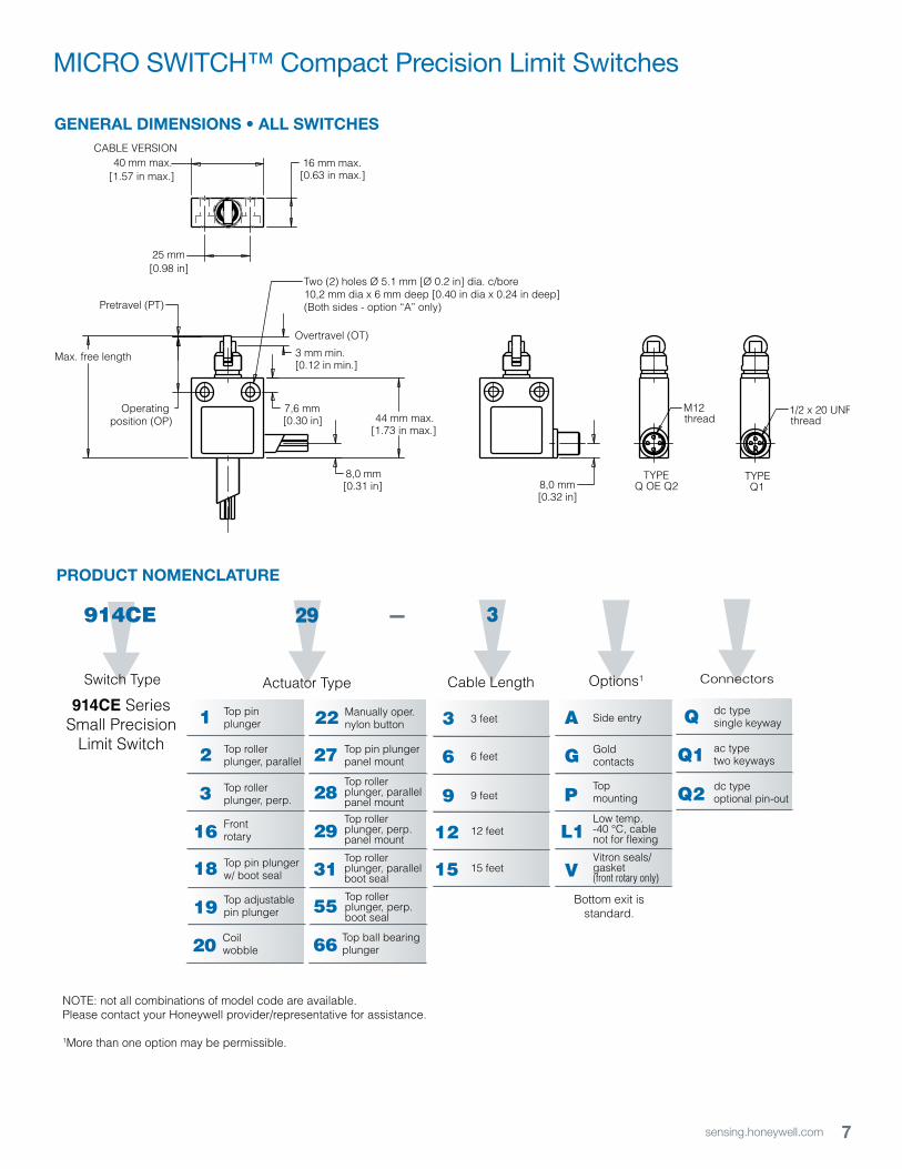
44 mm max.[1.73 in max.]
25 mm[0.98 in]
16 mm max.[0.63 in max.]
40 mm max.[1.57 in max.]
Max. free length
Operating position (OP)
3 mm min. [0.12 in min.]
8,0 mm[0.31 in] 8,0 mm
[0.32 in]
7,6 mm[0.30 in]
Pretravel (PT)
Overtravel (OT)
CABLE VERSION
TYPEQ OE Q2
TYPEQ1
M12thread
1/2 x 20 UNFthread
Two (2) holes Ø 5.1 mm [Ø 0.2 in] dia. c/bore10,2 mm dia x 6 mm deep [0.40 in dia x 0.24 in deep](Both sides - option “A” only)
GENERAL DIMENSIONS • ALL SWITCHES
PRODUCT NOMENCLATURE
3
16
2
1 Top pinplunger
Top rollerplunger, parallel
Top rollerplunger, perp.
Frontrotary
914CE
Switch Type
29
Actuator Type Options1
P
G
A Side entry
Goldcontacts
Topmounting
MICRO SWITCH™ 914CE Miniature Limit SwitchProduct Nomenclature
19
18 Top pin plungerw/ boot seal
Top adjustablepin plunger
29
31
28
27 Top pin plungerpanel mount
Top roller plunger, parallelpanel mountTop rollerplunger, perp.panel mount
Top roller plunger, parallelboot seal
66
55Top rollerplunger, perp.boot seal
Top ball bearingplunger
914CE SeriesSmall Precision
Limit Switch
L1Low temp.-40 °C, cablenot for flexing
–
9
6
3 3 feet
6 feet
9 feet
12 12 feet
15 15 feet
3
Cable Length
20 Coilwobble
22 Manually oper.nylon button
VVitron seals/gasket(front rotary only)
Connectors
Q2
Q1
Q dc typesingle keyway
ac typetwo keyways
dc typeoptional pin-out
Bottom exit isstandard.
NOTE: not all combinations of model code are available.Please contact your Honeywell provider/representative for assistance.
1More than one option may be permissible.
8 sensing.honeywell.com
914CE Series
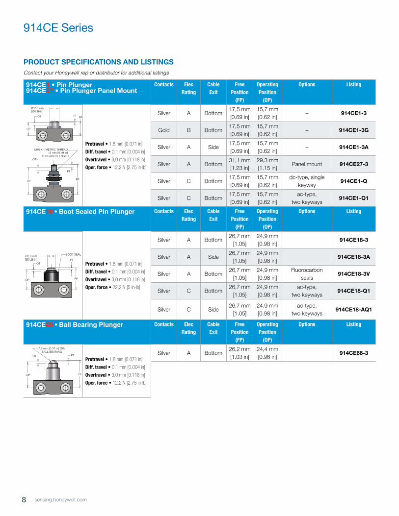
914CE1 • Pin Plunger914CE27 • Pin Plunger Panel Mount
Contacts Elec Rating
Cable Exit
Free Position
(FP)
Operating Position
(OP)
Options Listing
FP
PT
OP
OT
M10 X 1 METRIC THREAD12 mm [0.49 in]
THREADED LENGTH
Pretravel • 1,8 mm [0.071 in]
Diff. travel • 0,1 mm [0.004 in]
Overtravel • 3,0 mm [0.118 in]
Oper. force • 12,2 N [2.75 in-lb]
Silver A Bottom17,5 mm [0.69 in]
15,7 mm[0.62 in]
– 914CE1-3
Gold B Bottom17,5 mm [0.69 in]
15,7 mm[0.62 in]
– 914CE1-3G
Silver A Side17,5 mm [0.69 in]
15,7 mm[0.62 in]
– 914CE1-3A
Silver A Bottom31,1 mm [1.23 in]
29,3 mm[1.15 in]
Panel mount 914CE27-3
Silver C Bottom17,5 mm [0.69 in]
15,7 mm[0.62 in]
dc-type, single keyway
914CE1-Q
Silver C Bottom17,5 mm [0.69 in]
15,7 mm[0.62 in]
ac-type, two keyways
914CE1-Q1
914CE18 • Boot Sealed Pin Plunger Contacts Elec Rating
Cable Exit
Free Position
(FP)
Operating Position
(OP)
Options Listing
FPOP
OTPT
BOOT SEALØ7,0 mm[Ø0.28 in]
Pretravel • 1,8 mm [0.071 in]
Diff. travel • 0,1 mm [0.004 in]
Overtravel • 3,0 mm [0.118 in]
Oper. force • 22,2 N [5 in-lb]
Silver A Bottom26,7 mm
[1.05]24,9 mm[0.98 in]
914CE18-3
Silver A Side26,7 mm
[1.05]24,9 mm[0.98 in]
914CE18-3A
Silver A Bottom26,7 mm
[1.05]24,9 mm[0.98 in]
Fluorocarbon seals
914CE18-3V
Silver C Bottom26,7 mm
[1.05]24,9 mm[0.98 in]
ac-type, two keyways
914CE18-Q1
Silver C Side26,7 mm
[1.05]24,9 mm[0.98 in]
ac-type, two keyways
914CE18-AQ1
914CE66 • Ball Bearing Plunger Contacts Elec Rating
Cable Exit
Free Position
(FP)
Operating Position
(OP)
Options Listing
FPOP
OT PT
7,9 mm [0.31 in] DIA BALL BEARING
Pretravel • 1,8 mm [0.071 in]
Diff. travel • 0,1 mm [0.004 in]
Overtravel • 3,0 mm [0.118 in]
Oper. force • 12,2 N [2.75 in-lb]
Silver A Bottom26,2 mm[1.03 in]
24,4 mm[0.96 in]
914CE66-3
Ø10,0 mm[Ø0.39 in]
FP
OP
OT PT
PRODUCT SPECIFICATIONS AND LISTINGSContact your Honeywell rep or distributor for additional listings
9sensing.honeywell.com
MICRO SWITCH™ Compact Precision Limit Switches
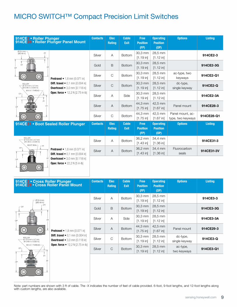
914CE2 • Roller Plunger914CE28 • Roller Plunger Panel Mount
Contacts Elec Rating
Cable Exit
Free Position
(FP)
Operating Position
(OP)
Options Listing
FP
PT
OP
OT
M14 X 1 THREAD
ROLLERØ 12,4 mm x 4,7 mm[Ø 0.48 in x 0.020 in]
Pretravel • 1,8 mm [0.071 in]
Diff. travel • 0,1 mm [0.004 in]
Overtravel • 3,0 mm [0.118 in]
Oper. force • 12,2 N [2.75 in-lb]
Silver A Bottom30,3 mm[1.19 in]
28,5 mm[1.12 in]
914CE2-3
Gold B Bottom30,3 mm[1.19 in]
28,5 mm[1.12 in]
914CE2-3G
Silver C Bottom30,3 mm[1.19 in]
28,5 mm[1.12 in]
ac-type, two keyways
914CE2-Q1
Silver C Bottom30,3 mm[1.19 in]
28,5 mm[1.12 in]
dc-type,single keyway
914CE2-Q
Silver A Side30,3 mm[1.19 in]
28,5 mm[1.12 in]
914CE2-3A
Silver A Bottom44,3 mm[1.75 in]
42,5 mm[1.67 in]
Panel mount 914CE28-3
Silver C Bottom44,3 mm[1.75 in]
42,5 mm[1.67 in]
Panel mount, ac-type, two keyways
914CE28-Q1
914CE31 • Boot Sealed Roller Plunger Contacts Elec Rating
Cable Exit
Free Position
(FP)
Operating Position
(OP)
Options Listing
FPOP
OTPT
BOOT SEAL
ROLLERØ 12,4 mm x 4,7 mmØ 0.48 in x 0.020 in]
Pretravel • 1,8 mm [0.071 in]
Diff. travel • 0,1 mm [0.004 in]
Overtravel • 3,0 mm [0.118 in]
Oper. force • 22,2 N [5 in-lb]
Silver A Bottom36,2 mm[1.43 in]
34,4 mm[1.36 in]
914CE31-3
Silver A Bottom36,2 mm[1.43 in]
34,4 mm[1.36 in]
Fluorocarbon seals
914CE31-3V
914CE3 • Cross Roller Plunger914CE29 • Cross Roller Panel Mount
Contacts Elec Rating
Cable Exit
Free Position
(FP)
Operating Position
(OP)
Options Listing
FP
PT
OP
OT
M14 X 1 THREAD
ROLLERØ 12,4 mm x 4,7 mmØ 0.48 in x 0.020 in]
Pretravel • 1,8 mm [0.071 in]
Diff. travel • 0,1 mm [0.004 in]
Overtravel • 3,0 mm [0.118 in]
Oper. force • 12,2 N [2.75 in-lb]
Silver A Bottom30,3 mm[1.19 in]
28,5 mm[1.12 in]
914CE3-3
Gold B Bottom30,3 mm[1.19 in]
28,5 mm[1.12 in]
914CE3-3G
Silver A Side30,3 mm[1.19 in]
28,5 mm[1.12 in]
914CE3-3A
Silver A Bottom 44,3 mm[1.75 in]
42,5 mm[1.67 in]
Panel mount 914CE29-3
Silver C Bottom30,3 mm[1.19 in]
28,5 mm[1.12 in]
dc-type,single keyway
914CE3-Q
Silver C Bottom30,3 mm[1.19 in]
28,5 mm[1.12 in]
ac-type, two keyways
914CE3-Q1
FPOP
OT
PTØ12,4 mm[Ø0.49 in]
Ø12,4 mm[Ø0.49 in]
FPOP
OTPT
Note: part numbers are shown with 3 ft of cable. The -X indicates the number of feet of cable provided. 6-foot, 9-foot lengths, and 12-foot lengths along with custom lengths, are also available.
10 sensing.honeywell.com
914CE Series
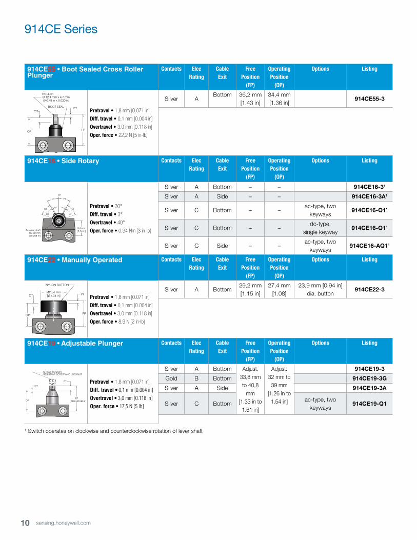
914CE55 • Boot Sealed Cross Roller Plunger
Contacts Elec Rating
Cable Exit
Free Position
(FP)
Operating Position
(OP)
Options Listing
FPOP
OTPT
BOOT SEAL
ROLLERØ 12,4 mm x 4,7 mmØ 0.48 in x 0.020 in]
Pretravel • 1,8 mm [0.071 in]
Diff. travel • 0,1 mm [0.004 in]
Overtravel • 3,0 mm [0.118 in]
Oper. force • 22,2 N [5 in-lb]
Silver ABottom 36,2 mm
[1.43 in]34,4 mm[1.36 in]
914CE55-3
914CE16 • Side Rotary Contacts Elec Rating
Cable Exit
Free Position
(FP)
Operating Position
(OP)
Options Listing
PT
OT
PT
OT
18,9 mm[0.74 in]Actuator shaft
Ø7,32 mm[Ø0.288 in]
DTDT
FP
Pretravel • 30°
Diff. travel • 3°
Overtravel • 40°
Oper. force • 0,34 Nm [3 in-lb]
Silver A Bottom – – 914CE16-31
Silver A Side – – 914CE16-3A1
Silver C Bottom – –ac-type, two
keyways914CE16-Q11
Silver C Bottom – –dc-type,
single keyway914CE16-Q11
Silver C Side – –ac-type, two
keyways914CE16-AQ11
914CE22 • Manually Operated Contacts Elec Rating
Cable Exit
Free Position
(FP)
Operating Position
(OP)
Options Listing
FP
PT
OP
OTØ26,4 mm[Ø1.04 in]
NYLON BUTTON
Pretravel • 1,8 mm [0.071 in]
Diff. travel • 0,1 mm [0.004 in]
Overtravel • 3,0 mm [0.118 in]
Oper. force • 8,9 N [2 in-lb]
Silver A Bottom29,2 mm[1.15 in]
27,4 mm[1.08]
23,9 mm [0.94 in] dia. button
914CE22-3
914CE19 • Adjustable Plunger Contacts Elec Rating
Cable Exit
Free Position
(FP)
Operating Position
(OP)
Options Listing
FP[ADJUSTABLE]OP
OT
PT
M4 CORROSION RESISTANT SCREW AND LOCKNUT
Pretravel • 1,8 mm [0.071 in]
Diff. travel • 0,1 mm [0.004 in]Overtravel • 3,0 mm [0.118 in]Oper. force • 17,5 N [5 lb]
Silver A Bottom Adjust.33,8 mm to 40,8
mm[1.33 in to 1.61 in]
Adjust.32 mm to
39 mm[1.26 in to
1.54 in]
914CE19-3
Gold B Bottom 914CE19-3G
Silver A Side 914CE19-3A
Silver C Bottomac-type, two
keyways914CE19-Q1
1 Switch operates on clockwise and counterclockwise rotation of lever shaft
11sensing.honeywell.com
MICRO SWITCH™ Compact Precision Limit Switches
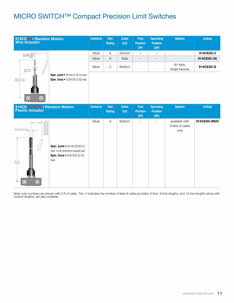
914CE20 • Random Motion Wire Actuator
Contacts Elec Rating
Cable Exit
Free Position
(FP)
Operating Position
(OP)
Options Listing
OPALL DIRECTIONSEXCEPT DIRECT
PULL
335,0 mm max.[13,98 mm max.]
Ø1.8 mm[Ø0.07 in]
Oper. point • 28 mm [1.10 in] max.Oper. force • 0,55 N [0.12 lb] max.
Silver A Bottom – – 914CE20-3
Silver A Side – – 914CE20-3A
Silver C Bottomdc-type,
single keyway914CE20-Q
914CE20-9N24 • Random Motion Plastic Actuator
Contacts Elec Rating
Cable Exit
Free Position
(FP)
Operating Position
(OP)
Options Listing
101 mm[3.97 in]
Ø 5,0 mm [Ø 0.20 in]
25 m
m [1
.00
in] m
ax.
oper
atin
g po
sitio
n in
all
dire
ctio
ns e
xcep
t pul
l
Oper. point • 25 mm [0.93 in] max. in all directions except pullOper. force • 0,55 N [0.12 lb] max.
Silver A Bottom – – available with 9-feet of cable
only
914CE20-9N24
Note: part numbers are shown with 3 ft of cable. The -X indicates the number of feet of cable provided. 6-foot, 9-foot lengths, and 12-foot lengths along with custom lengths, are also available.
12 sensing.honeywell.com
914CE Series
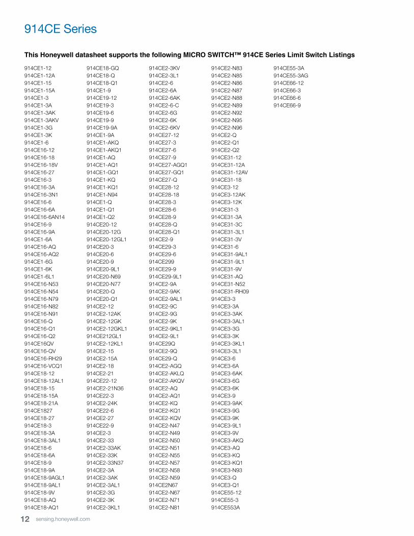
This Honeywell datasheet supports the following MICRO SWITCH™ 914CE Series Limit Switch Listings
914CE1-12914CE1-12A914CE1-15914CE1-15A914CE1-3914CE1-3A914CE1-3AK914CE1-3AKV914CE1-3G914CE1-3K914CE1-6914CE16-12914CE16-18914CE16-18V914CE16-27914CE16-3914CE16-3A914CE16-3N1914CE16-6914CE16-6A914CE16-6AN14914CE16-9914CE16-9A914CE1-6A914CE16-AQ914CE16-AQ2914CE1-6G914CE1-6K914CE1-6L1914CE16-N53914CE16-N54914CE16-N79914CE16-N82914CE16-N91914CE16-Q914CE16-Q1914CE16-Q2914CE16QV914CE16-QV914CE16-RH29914CE16-VCQ1914CE18-12914CE18-12AL1914CE18-15914CE18-15A914CE18-21A914CE1827914CE18-27914CE18-3914CE18-3A914CE18-3AL1914CE18-6914CE18-6A914CE18-9914CE18-9A914CE18-9AGL1914CE18-9AL1914CE18-9V914CE18-AQ914CE18-AQ1
914CE18-GQ914CE18-Q914CE18-Q1914CE1-9914CE19-12914CE19-3914CE19-6914CE19-9914CE19-9A914CE1-9A914CE1-AKQ914CE1-AKQ1914CE1-AQ914CE1-AQ1914CE1-GQ1914CE1-KQ914CE1-KQ1914CE1-N94914CE1-Q914CE1-Q1914CE1-Q2914CE20-12914CE20-12G914CE20-12GL1914CE20-3914CE20-6914CE20-9914CE20-9L1914CE20-N69914CE20-N77914CE20-Q914CE20-Q1914CE2-12914CE2-12AK914CE2-12GK914CE2-12GKL1914CE212GL1914CE2-12KL1914CE2-15914CE2-15A914CE2-18914CE2-21914CE22-12914CE2-21N36914CE22-3914CE2-24K914CE22-6914CE2-27914CE22-9914CE2-3914CE2-33914CE2-33AK914CE2-33K914CE2-33N37914CE2-3A914CE2-3AK914CE2-3AL1914CE2-3G914CE2-3K914CE2-3KL1
914CE2-3KV914CE2-3L1914CE2-6914CE2-6A914CE2-6AK914CE2-6-C914CE2-6G914CE2-6K914CE2-6KV914CE27-12914CE27-3914CE27-6914CE27-9914CE27-AGQ1914CE27-GQ1914CE27-Q914CE28-12914CE28-18914CE28-3914CE28-6914CE28-9914CE28-Q914CE28-Q1914CE2-9914CE29-3914CE29-6914CE299914CE29-9914CE29-9L1914CE2-9A914CE2-9AK914CE2-9AL1914CE2-9C914CE2-9G914CE2-9K914CE2-9KL1914CE2-9L1914CE29Q914CE2-9Q914CE29-Q914CE2-AGQ914CE2-AKLQ914CE2-AKQV914CE2-AQ914CE2-AQ1914CE2-KQ914CE2-KQ1914CE2-KQV914CE2-N47914CE2-N49914CE2-N50914CE2-N51914CE2-N55914CE2-N57914CE2-N58914CE2-N59914CE2N67914CE2-N67914CE2-N71914CE2-N81
914CE2-N83914CE2-N85914CE2-N86914CE2-N87914CE2-N88914CE2-N89914CE2-N92914CE2-N95914CE2-N96914CE2-Q914CE2-Q1914CE2-Q2914CE31-12914CE31-12A914CE31-12AV914CE31-18914CE3-12914CE3-12AK914CE3-12K914CE31-3914CE31-3A914CE31-3C914CE31-3L1914CE31-3V914CE31-6914CE31-9AL1914CE31-9L1914CE31-9V914CE31-AQ914CE31-N52914CE31-RH09914CE3-3914CE3-3A914CE3-3AK914CE3-3AL1914CE3-3G914CE3-3K914CE3-3KL1914CE3-3L1914CE3-6914CE3-6A914CE3-6AK914CE3-6G914CE3-6K914CE3-9914CE3-9AK914CE3-9G914CE3-9K914CE3-9L1914CE3-9V914CE3-AKQ914CE3-AQ914CE3-KQ914CE3-KQ1914CE3-N93914CE3-Q914CE3-Q1914CE55-12914CE55-3914CE553A
914CE55-3A914CE55-3AG914CE66-12914CE66-3914CE66-6914CE66-9
13sensing.honeywell.com
MICRO SWITCH™ Compact Precision Limit Switches
ADDITIONAL INFORMATIONThe following associated literature is available on the Web at sensing.honeywell.com:• Product installation instructions
• Product range guide
• Product nomenclature tree
• Product application-specific information
– Limit and enclosed switches application information
– Limit and enclosed switches operating characteristics
– Limit and enclosed switches reference standards
– Limit and enclosed switches typical applications
– Product flyer: CE Family Miniature Limit Switches
WARNINGPERSONAL INJURYDO NOT USE these products as safety or emergency stop devices or in any other application where failure of the product could result in personal injury.
Failure to comply with these instructions could result in death or serious injury.
WARNINGMISUSE OF DOCUMENTATION• The information presented in this product sheet is for
reference only. Do not use this document as a product installation guide.
• Complete installation, operation, and maintenance information is provided in the instructions supplied with each product.
Failure to comply with these instructions could result in death or serious injury.
WARRANTY/REMEDYHoneywell warrants goods of its manufacture as being free of defective materials and faulty workmanship. Honeywell’s standard product warranty applies unless agreed to otherwise by Honeywell in writing; please refer to your order acknowledgement or consult your local sales office for specific warranty details. If warranted goods are returned to Honeywell during the period of coverage, Honeywell will repair or replace, at its option, without charge those items it finds defective. The foregoing is buyer’s sole remedy and is in lieu of all other warranties, expressed or implied, including those of merchantability and fitness for a particu-lar purpose. In no event shall Honeywell be liable for conse-quential, special, or indirect damages.
While we provide application assistance personally, through our literature and the Honeywell website, it is up to the customer to determine the suitability of the product in the application.
Specifications may change without notice. The information we supply is believed to be accurate and reliable as of this printing. However, we assume no responsibility for its use.

002381-3-EN IL50 GLO December 2013Copyright © 2013 Honeywell International Inc. All rights reserved.
Sensing and Control
Honeywell
1985 Douglas Drive North
Golden Valley, MN 55422
honeywell.com
Find out moreHoneywell serves its customers through a worldwide network of sales offices, representatives and distributors. For application assistance, current specifications, pricing or name of the nearest Authorized Distributor, contact your local sales office.
To learn more about Honeywell’s
sensing and control products,
call +1-815-235-6847 or
1-800-537-6945,
visit sensing.honeywell.com,
or e-mail inquiries to


![Precision Limit Switches - AutomationDirectDimensions mm [inches] Precision Limit Switches Dimensions Precision Touch: CS / CSJ / CSS / CSK / CSP Series See our website, , for complete](https://img.pdfslide.net/doc/110x75/5e98b3c0f672cc5b6847765d/precision-limit-switches-automationdirect-dimensions-mm-inches-precision-limit.jpg)