Embed Size (px)
Citation preview
MICRO SWITCH Weather-Sealed, Explosion-Proof SwitchesCX Series
Datasheet
2 sensing.honeywell.com
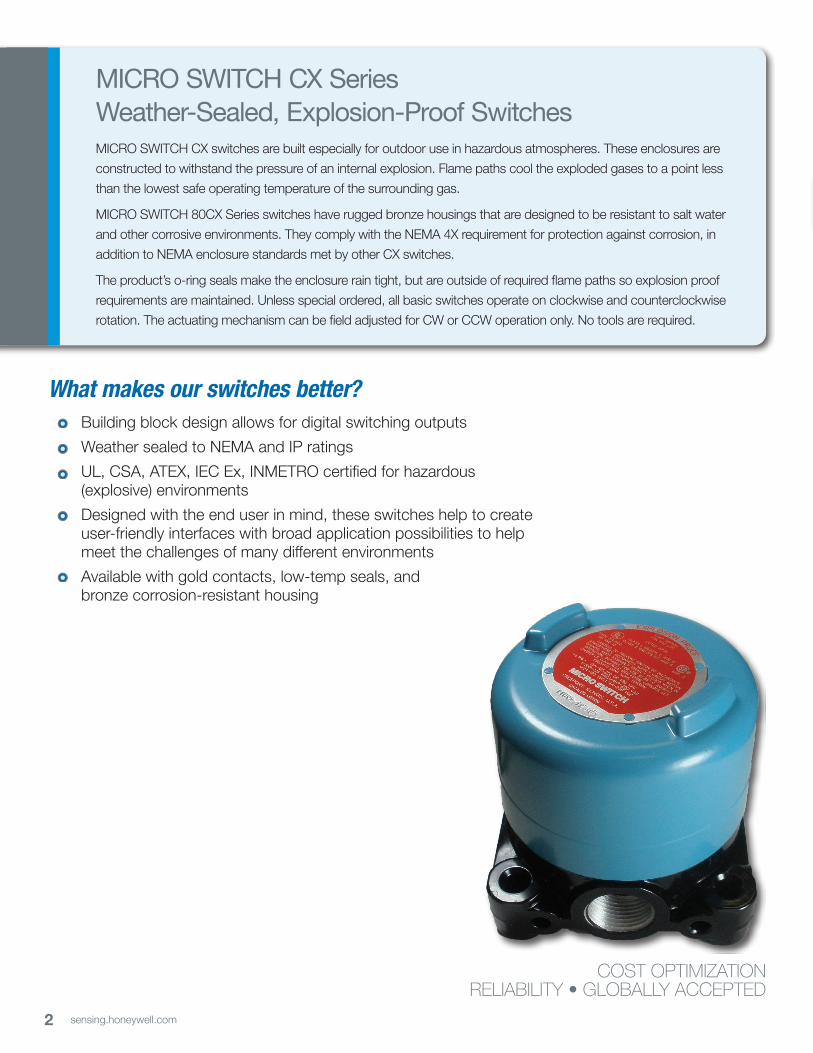
What makes our switches better? Building block design allows for digital switching outputs
Weather sealed to NEMA and IP ratings
UL, CSA, ATEX, IEC Ex, INMETRO certified for hazardous (explosive) environments
Designed with the end user in mind, these switches help to create user-friendly interfaces with broad application possibilities to help meet the challenges of many different environments
Available with gold contacts, low-temp seals, and bronze corrosion-resistant housing
MICRO SWITCH CX Series Weather-Sealed, Explosion-Proof SwitchesMICRO SWITCH CX switches are built especially for outdoor use in hazardous atmospheres. These enclosures are
constructed to withstand the pressure of an internal explosion. Flame paths cool the exploded gases to a point less
than the lowest safe operating temperature of the surrounding gas.
MICRO SWITCH 80CX Series switches have rugged bronze housings that are designed to be resistant to salt water
and other corrosive environments. They comply with the NEMA 4X requirement for protection against corrosion, in
addition to NEMA enclosure standards met by other CX switches.
The product’s o-ring seals make the enclosure rain tight, but are outside of required flame paths so explosion proof
requirements are maintained. Unless special ordered, all basic switches operate on clockwise and counterclockwise
rotation. The actuating mechanism can be field adjusted for CW or CCW operation only. No tools are required.
COST OPTIMIZATIONRELIABILITY • GLOBALLY ACCEPTED
3sensing.honeywell.com
Features and Benefits Features and Benefits
WELL-SUITED FOR EXPLOSIVE ENVIRONMENTSMICRO SWITCH CX Series switches are certified for applicable portions of NEMA 7 and 9 for hazardous locations (explosive environments). Select CX switches are certified to ATEX, IEC Ex, and INMETRO specifications for global applications.
WATERTIGHT AND DUST-TIGHT FOR OUTDOOR USEDue to its engineering design and sealing (NEMA 1, 3, 4, 4X, 6, 6P, and 13), the MICRO SWITCH CX Series is rated for rain, wind, snow, ice, and blowing dust environments.
CORROSION RESISTANTBronze housing material is available on 80CX Series catalog listings.
MEETS HAZARDOUS AREA REQUIREMENTSUL Listed, file #E14274, CSA Certified, file #LR57324, ATEX certificate KEMA 01ATEX2111 X, IEC Ex certificate IEC Ex TSA 06.003X, and INMETRO certificate TUV 14.0553.
OPTIONAL HOUSING CHOICESCX Series switches offer a choice of rugged cast aluminum or bronze housings. Both housings withstand harsh environments, and bronze is available for use in corrosive environments.
UNIQUE DESIGN FEATURESFeaturing field-adjustability, the CX Series allows pretravel, overtravel, and actuating sequence to be field adjusted without tools (all basics can be adjusted individually). Rotary types convert in seconds to clockwise, counterclockwise, or both-way operation. These features may help to reduce set up time while allowing for quick and easy changes to switch operation.
Available with digital or analog outputs
4 sensing.honeywell.com
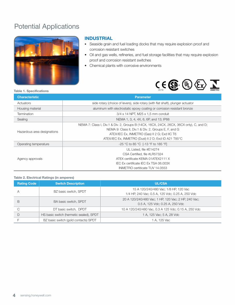
INDUSTRIAL• Seaside grain and fuel loading docks that may require explosion proof and
corrosion resistant switches• Oil and gas wells, refineries, and fuel storage facilities that may require explosion
proof and corrosion resistant switches• Chemical plants with corrosive environments
Potential Applications
Table 1. Specifications
Characteristic Parameter
Actuators side rotary (choice of levers), side rotary (with flat shaft), plunger actuator
Housing material aluminum with electrostatic epoxy coating or corrosion resistant bronze
Termination 3/4 x 14 NPT, M25 x 1,5 mm conduit
Sealing NEMA 1, 3, 4, 4X, 6, 6P, and 13; IP66
Hazardous area designations
NEMA 7: Class I, Div.1 & Div. 2, Groups B (14CX, 16CX, 24CX, 26CX, 36CX only), C, and D; NEMA 9: Class II, Div.1 & Div. 2, Groups E, F, and G
ATEX/IEC Ex, INMETRO (Gas) II 2 G; Exd IIC T6ATEX/IEC Ex, INMETRO (Dust) II 2 D; Exd tD A21 T85°C
Operating temperature -25 °C to 85 °C [-13 °F to 185 °F]
Agency approvals
UL Listed, file #E14274CSA Certified, file #LR57324
ATEX certificate KEMA 01ATEX2111 XIEC Ex certificate IEC Ex TSA 06.003X
INMETRO certiticate TUV 14.0553
Table 2. Electrical Ratings (in amperes)
Rating Code Switch Description UL/CSA
A BZ basic switch, SPDT15 A 120/240/480 Vac; 1/8 HP, 120 Vac
1/4 HP, 240 Vac; 0.5 A, 125 Vdc; 0.25 A, 250 Vdc
B BA basic switch, SPDT 20 A 120/240/480 Vac; 1 HP, 120 Vac; 2 HP, 240 Vac;
0.5 A, 125 Vdc; 0.25 A, 250 Vdc
C DT basic switch, DPDT 10 A 120/240/480 Vac, 0.3 A 125 Vdc; 0.15 A, 250 Vdc
D HS basic switch (hermetic sealed), SPDT 1 A, 125 Vac; 5 A, 28 Vdc
F BZ basic switch (gold contacts) SPDT 1 A, 125 Vac
0518
�
5sensing.honeywell.com
MICRO SWITCH Weather-Sealed, Explosion-Proof Switches
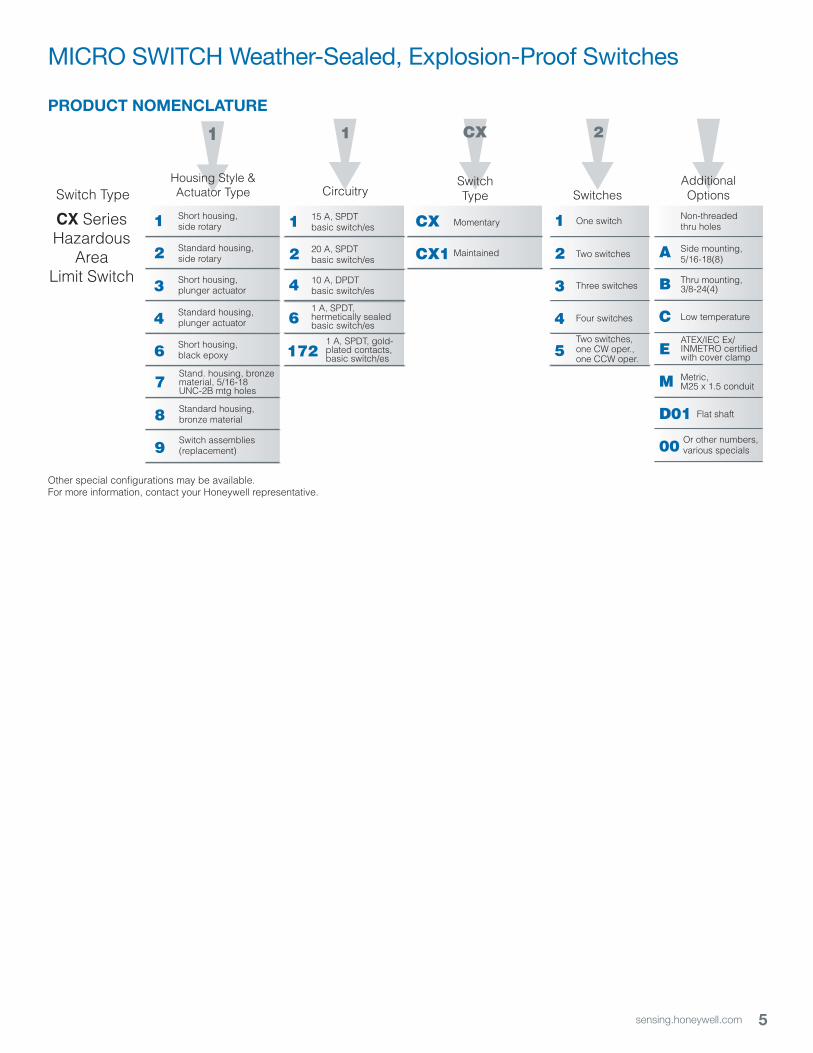
PRODUCT NOMENCLATURE
Switch Type
CX SeriesHazardous
AreaLimit Switch 3
4
6
2
1 Short housing,side rotary
Standard housing,side rotary
Short housing,plunger actuator
Standard housing,plunger actuator
Short housing,black epoxy
2
Switches
1
Housing Style &Actuator Type
1
CircuitrySwitchType
1
2
4
6
15 A, SPDTbasic switch/es
20 A, SPDTbasic switch/es
10 A, DPDTbasic switch/es
1 A, SPDT,hermetically sealedbasic switch/es
2
3
4
1 One switch
Two switches
Three switches
Four switches
CX1
CX Momentary
CX
AdditionalOptions
B
A Side mounting,5/16-18(8)
Thru mounting,3/8-24(4)
C
E
Low temperature
ATEX/IEC Ex/INMETRO certifiedwith cover clamp
Non-threaded thru holes
8
9
7Stand. housing, bronze material, 5/16-18 UNC-2B mtg holes
Standard housing,bronze material
Switch assemblies(replacement)
Maintained
5Two switches,one CW oper.,one CCW oper.
M Metric, M25 x 1.5 conduit
D01
00
Flat shaft
Or other numbers,various specials
Other special configurations may be available.For more information, contact your Honeywell representative.
1721 A, SPDT, gold-plated contacts,basic switch/es
6 sensing.honeywell.com
CX Series
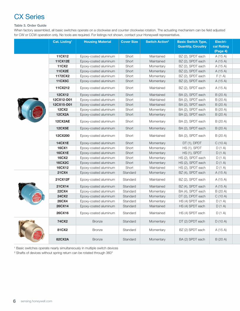
Cat. Listing1 Housing Material Cover Size Switch Action2 Basic Switch Type, Quantity, Circuitry
Electri-cal Rating (Page 4)
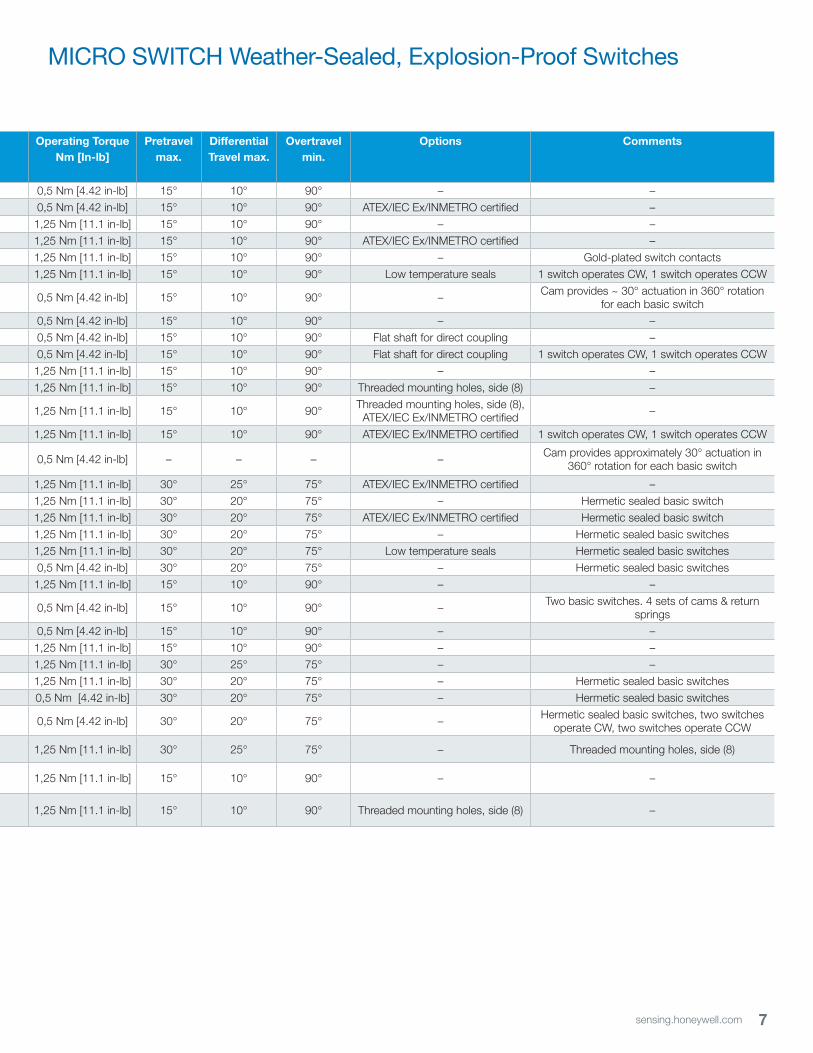
Operating Torque Nm [In-lb]
Pretravel max.
Differential Travel max.
Overtravelmin.
Options Comments
11CX12 Epoxy-coated aluminum Short Maintained BZ (2), SPDT each A (15 A) 0,5 Nm [4.42 in-lb] 15° 10° 90° – –
11CX12E Epoxy-coated aluminum Short Maintained BZ (2), SPDT each A (15 A) 0,5 Nm [4.42 in-lb] 15° 10° 90° ATEX/IEC Ex/INMETRO certified –
11CX2 Epoxy-coated aluminum Short Momentary BZ (2), SPDT each A (15 A) 1,25 Nm [11.1 in-lb] 15° 10° 90° – –
11CX2E Epoxy-coated aluminum Short Momentary BZ (2), SPDT each A (15 A) 1,25 Nm [11.1 in-lb] 15° 10° 90° ATEX/IEC Ex/INMETRO certified –
1172CX2 Epoxy-coated aluminum Short Momentary BZ (2), SPDT each F (1 A) 1,25 Nm [11.1 in-lb] 15° 10° 90° – Gold-plated switch contacts
11CX5C Epoxy-coated aluminum Short Momentary BZ (2), SPDT each A (15 A) 1,25 Nm [11.1 in-lb] 15° 10° 90° Low temperature seals 1 switch operates CW, 1 switch operates CCW
11CX212 Epoxy-coated aluminum Short Maintained BZ (2), SPDT each A (15 A) 0,5 Nm [4.42 in-lb] 15° 10° 90° – Cam provides ~ 30° actuation in 360° rotation for each basic switch
12CX12 Epoxy-coated aluminum Short Maintained BA (2), SPDT each B (20 A) 0,5 Nm [4.42 in-lb] 15° 10° 90° – –
12CX12-D01 Epoxy-coated aluminum Short Maintained BA (2), SPDT each B (20 A) 0,5 Nm [4.42 in-lb] 15° 10° 90° Flat shaft for direct coupling –
12CX15-D01 Epoxy-coated aluminum Short Maintained BA (2), SPDT each B (20 A) 0,5 Nm [4.42 in-lb] 15° 10° 90° Flat shaft for direct coupling 1 switch operates CW, 1 switch operates CCW
12CX2 Epoxy-coated aluminum Short Momentary BA (2), SPDT each B (20 A) 1,25 Nm [11.1 in-lb] 15° 10° 90° – –
12CX2A Epoxy-coated aluminum Short Momentary BA (2), SPDT each B (20 A) 1,25 Nm [11.1 in-lb] 15° 10° 90° Threaded mounting holes, side (8) –
12CX2AE Epoxy-coated aluminum Short Momentary BA (2), SPDT each B (20 A) 1,25 Nm [11.1 in-lb] 15° 10° 90° Threaded mounting holes, side (8), ATEX/IEC Ex/INMETRO certified –
12CX5E Epoxy-coated aluminum Short Momentary BA (2), SPDT each B (20 A) 1,25 Nm [11.1 in-lb] 15° 10° 90° ATEX/IEC Ex/INMETRO certified 1 switch operates CW, 1 switch operates CCW
12CX200 Epoxy-coated aluminum Short Maintained BA (2), SPDT each B (20 A) 0,5 Nm [4.42 in-lb] – – – – Cam provides approximately 30° actuation in 360° rotation for each basic switch
14CX1E Epoxy-coated aluminum Short Momentary DT (1), DPDT C (10 A) 1,25 Nm [11.1 in-lb] 30° 25° 75° ATEX/IEC Ex/INMETRO certified –
16CX1 Epoxy-coated aluminum Short Momentary HS (1), SPDT D (1 A) 1,25 Nm [11.1 in-lb] 30° 20° 75° – Hermetic sealed basic switch
16CX1E Epoxy-coated aluminum Short Momentary HS (1), SPDT D (1 A) 1,25 Nm [11.1 in-lb] 30° 20° 75° ATEX/IEC Ex/INMETRO certified Hermetic sealed basic switch
16CX2 Epoxy-coated aluminum Short Momentary HS (2), SPDT each D (1 A) 1,25 Nm [11.1 in-lb] 30° 20° 75° – Hermetic sealed basic switches
16CX2C Epoxy-coated aluminum Short Momentary HS (2), SPDT each D (1 A) 1,25 Nm [11.1 in-lb] 30° 20° 75° Low temperature seals Hermetic sealed basic switches
16CX12 Epoxy-coated aluminum Short Maintained HS (2), SPDT each D (1 A) 0,5 Nm [4.42 in-lb] 30° 20° 75° – Hermetic sealed basic switches
21CX4 Epoxy-coated aluminum Standard Momentary BZ (4), SPDT each A (15 A) 1,25 Nm [11.1 in-lb] 15° 10° 90° – –
21CX12F Epoxy-coated aluminum Standard Maintained BZ (2), SPDT each A (15 A) 0,5 Nm [4.42 in-lb] 15° 10° 90° – Two basic switches. 4 sets of cams & return springs
21CX14 Epoxy-coated aluminum Standard Maintained BZ (4), SPDT each A (15 A) 0,5 Nm [4.42 in-lb] 15° 10° 90° – –
22CX4 Epoxy-coated aluminum Standard Momentary BA (4), SPDT each B (20 A) 1,25 Nm [11.1 in-lb] 15° 10° 90° – –
24CX2 Epoxy-coated aluminum Standard Momentary DT (2), DPDT each C (10 A) 1,25 Nm [11.1 in-lb] 30° 25° 75° – –
26CX4 Epoxy-coated aluminum Standard Momentary HS (4) SPDT each D (1 A) 1,25 Nm [11.1 in-lb] 30° 20° 75° – Hermetic sealed basic switches
26CX14 Epoxy-coated aluminum Standard Maintained HS (4) SPDT each D (1 A) 0,5 Nm [4.42 in-lb] 30° 20° 75° – Hermetic sealed basic switches
26CX16 Epoxy-coated aluminum Standard Maintained HS (4) SPDT each D (1 A) 0,5 Nm [4.42 in-lb] 30° 20° 75° – Hermetic sealed basic switches, two switches operate CW, two switches operate CCW
74CX2 Bronze Standard Momentary DT (2) DPDT each D (10 A) 1,25 Nm [11.1 in-lb] 30° 25° 75° – Threaded mounting holes, side (8)
81CX2 Bronze Standard Momentary BZ (2) SPDT each A (15 A) 1,25 Nm [11.1 in-lb] 15° 10° 90° – –
82CX2A Bronze Standard Momentary BA (2) SPDT each B (20 A) 1,25 Nm [11.1 in-lb] 15° 10° 90° Threaded mounting holes, side (8) –
¹ Basic switches operate nearly simultaneously in multiple switch devices² Shafts of devices without spring return can be rotated through 360°
Table 3. Order GuideWhen factory assembled, all basic switches operate on a clockwise and counter clockwise rotation. The actuating mechanism can be field adjusted for CW or CCW operation only. No tools are required. For listings not shown, contact your Honeywell representative.
7sensing.honeywell.com
MICRO SWITCH Weather-Sealed, Explosion-Proof Switches
Cat. Listing1 Housing Material Cover Size Switch Action2 Basic Switch Type, Quantity, Circuitry
Electri-cal Rating (Page 4)
Operating Torque Nm [In-lb]
Pretravel max.
Differential Travel max.
Overtravelmin.
Options Comments
11CX12 Epoxy-coated aluminum Short Maintained BZ (2), SPDT each A (15 A) 0,5 Nm [4.42 in-lb] 15° 10° 90° – –
11CX12E Epoxy-coated aluminum Short Maintained BZ (2), SPDT each A (15 A) 0,5 Nm [4.42 in-lb] 15° 10° 90° ATEX/IEC Ex/INMETRO certified –
11CX2 Epoxy-coated aluminum Short Momentary BZ (2), SPDT each A (15 A) 1,25 Nm [11.1 in-lb] 15° 10° 90° – –
11CX2E Epoxy-coated aluminum Short Momentary BZ (2), SPDT each A (15 A) 1,25 Nm [11.1 in-lb] 15° 10° 90° ATEX/IEC Ex/INMETRO certified –
1172CX2 Epoxy-coated aluminum Short Momentary BZ (2), SPDT each F (1 A) 1,25 Nm [11.1 in-lb] 15° 10° 90° – Gold-plated switch contacts
11CX5C Epoxy-coated aluminum Short Momentary BZ (2), SPDT each A (15 A) 1,25 Nm [11.1 in-lb] 15° 10° 90° Low temperature seals 1 switch operates CW, 1 switch operates CCW
11CX212 Epoxy-coated aluminum Short Maintained BZ (2), SPDT each A (15 A) 0,5 Nm [4.42 in-lb] 15° 10° 90° – Cam provides ~ 30° actuation in 360° rotation for each basic switch
12CX12 Epoxy-coated aluminum Short Maintained BA (2), SPDT each B (20 A) 0,5 Nm [4.42 in-lb] 15° 10° 90° – –
12CX12-D01 Epoxy-coated aluminum Short Maintained BA (2), SPDT each B (20 A) 0,5 Nm [4.42 in-lb] 15° 10° 90° Flat shaft for direct coupling –
12CX15-D01 Epoxy-coated aluminum Short Maintained BA (2), SPDT each B (20 A) 0,5 Nm [4.42 in-lb] 15° 10° 90° Flat shaft for direct coupling 1 switch operates CW, 1 switch operates CCW
12CX2 Epoxy-coated aluminum Short Momentary BA (2), SPDT each B (20 A) 1,25 Nm [11.1 in-lb] 15° 10° 90° – –
12CX2A Epoxy-coated aluminum Short Momentary BA (2), SPDT each B (20 A) 1,25 Nm [11.1 in-lb] 15° 10° 90° Threaded mounting holes, side (8) –
12CX2AE Epoxy-coated aluminum Short Momentary BA (2), SPDT each B (20 A) 1,25 Nm [11.1 in-lb] 15° 10° 90° Threaded mounting holes, side (8), ATEX/IEC Ex/INMETRO certified –
12CX5E Epoxy-coated aluminum Short Momentary BA (2), SPDT each B (20 A) 1,25 Nm [11.1 in-lb] 15° 10° 90° ATEX/IEC Ex/INMETRO certified 1 switch operates CW, 1 switch operates CCW
12CX200 Epoxy-coated aluminum Short Maintained BA (2), SPDT each B (20 A) 0,5 Nm [4.42 in-lb] – – – – Cam provides approximately 30° actuation in 360° rotation for each basic switch
14CX1E Epoxy-coated aluminum Short Momentary DT (1), DPDT C (10 A) 1,25 Nm [11.1 in-lb] 30° 25° 75° ATEX/IEC Ex/INMETRO certified –
16CX1 Epoxy-coated aluminum Short Momentary HS (1), SPDT D (1 A) 1,25 Nm [11.1 in-lb] 30° 20° 75° – Hermetic sealed basic switch
16CX1E Epoxy-coated aluminum Short Momentary HS (1), SPDT D (1 A) 1,25 Nm [11.1 in-lb] 30° 20° 75° ATEX/IEC Ex/INMETRO certified Hermetic sealed basic switch
16CX2 Epoxy-coated aluminum Short Momentary HS (2), SPDT each D (1 A) 1,25 Nm [11.1 in-lb] 30° 20° 75° – Hermetic sealed basic switches
16CX2C Epoxy-coated aluminum Short Momentary HS (2), SPDT each D (1 A) 1,25 Nm [11.1 in-lb] 30° 20° 75° Low temperature seals Hermetic sealed basic switches
16CX12 Epoxy-coated aluminum Short Maintained HS (2), SPDT each D (1 A) 0,5 Nm [4.42 in-lb] 30° 20° 75° – Hermetic sealed basic switches
21CX4 Epoxy-coated aluminum Standard Momentary BZ (4), SPDT each A (15 A) 1,25 Nm [11.1 in-lb] 15° 10° 90° – –
21CX12F Epoxy-coated aluminum Standard Maintained BZ (2), SPDT each A (15 A) 0,5 Nm [4.42 in-lb] 15° 10° 90° – Two basic switches. 4 sets of cams & return springs
21CX14 Epoxy-coated aluminum Standard Maintained BZ (4), SPDT each A (15 A) 0,5 Nm [4.42 in-lb] 15° 10° 90° – –
22CX4 Epoxy-coated aluminum Standard Momentary BA (4), SPDT each B (20 A) 1,25 Nm [11.1 in-lb] 15° 10° 90° – –
24CX2 Epoxy-coated aluminum Standard Momentary DT (2), DPDT each C (10 A) 1,25 Nm [11.1 in-lb] 30° 25° 75° – –
26CX4 Epoxy-coated aluminum Standard Momentary HS (4) SPDT each D (1 A) 1,25 Nm [11.1 in-lb] 30° 20° 75° – Hermetic sealed basic switches
26CX14 Epoxy-coated aluminum Standard Maintained HS (4) SPDT each D (1 A) 0,5 Nm [4.42 in-lb] 30° 20° 75° – Hermetic sealed basic switches
26CX16 Epoxy-coated aluminum Standard Maintained HS (4) SPDT each D (1 A) 0,5 Nm [4.42 in-lb] 30° 20° 75° – Hermetic sealed basic switches, two switches operate CW, two switches operate CCW
74CX2 Bronze Standard Momentary DT (2) DPDT each D (10 A) 1,25 Nm [11.1 in-lb] 30° 25° 75° – Threaded mounting holes, side (8)
81CX2 Bronze Standard Momentary BZ (2) SPDT each A (15 A) 1,25 Nm [11.1 in-lb] 15° 10° 90° – –
82CX2A Bronze Standard Momentary BA (2) SPDT each B (20 A) 1,25 Nm [11.1 in-lb] 15° 10° 90° Threaded mounting holes, side (8) –
¹ Basic switches operate nearly simultaneously in multiple switch devices² Shafts of devices without spring return can be rotated through 360°
8 sensing.honeywell.com
CX Series
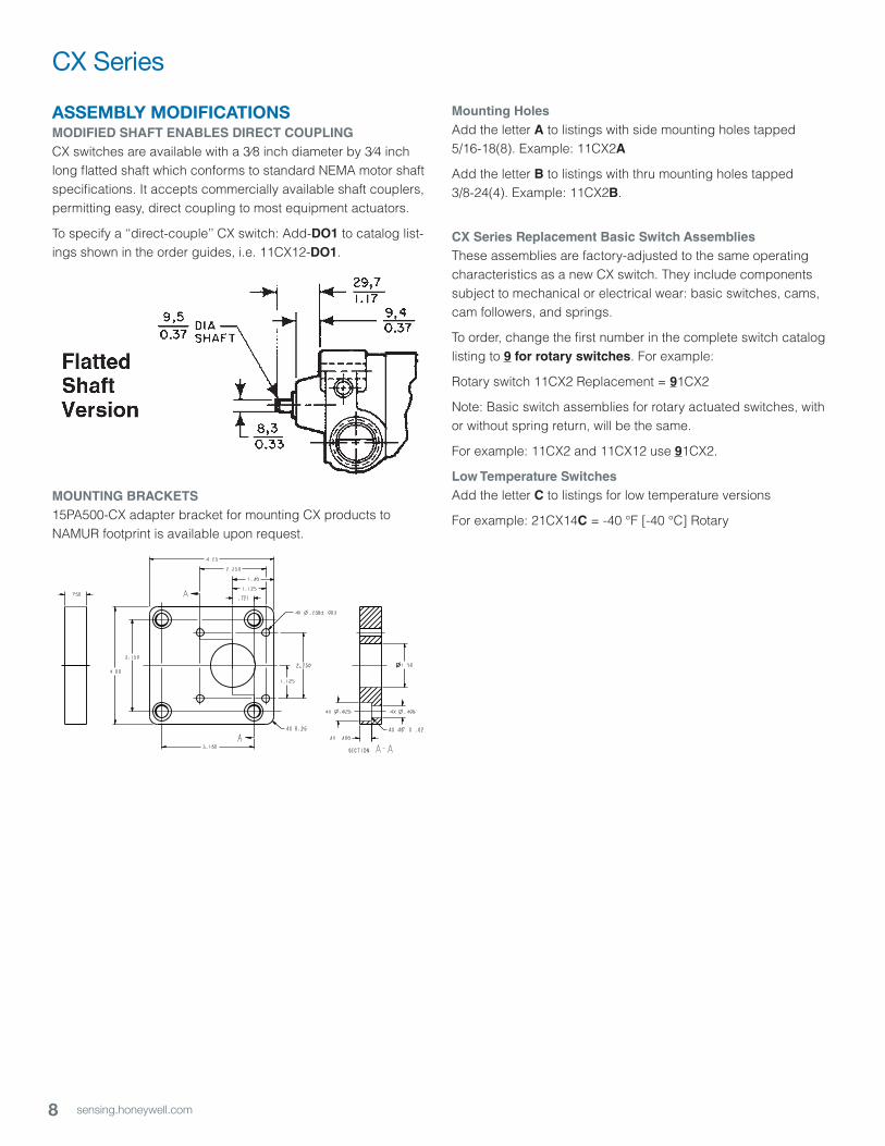
ASSEMBLY MODIFICATIONSMODIFIED SHAFT ENABLES DIRECT COUPLINGCX switches are available with a 3⁄8 inch diameter by 3⁄4 inch long flatted shaft which conforms to standard NEMA motor shaft specifications. It accepts commercially available shaft couplers, permitting easy, direct coupling to most equipment actuators.
To specify a ‘‘direct-couple’’ CX switch: Add-DO1 to catalog list-ings shown in the order guides, i.e. 11CX12-DO1.
MOUNTING BRACKETS15PA500-CX adapter bracket for mounting CX products to NAMUR footprint is available upon request.
A
A.750
1.50
2.250
2.250
3.150
.721
3.150
4.00
4.25
1.40
4X .400
4X 45 X .0204X R .25
4X .4064X .625
1.125
1.125
4X .258 .003
SECTION A-A
Mounting HolesAdd the letter A to listings with side mounting holes tapped 5/16-18(8). Example: 11CX2A
Add the letter B to listings with thru mounting holes tapped 3/8-24(4). Example: 11CX2B.
CX Series Replacement Basic Switch AssembliesThese assemblies are factory-adjusted to the same operating characteristics as a new CX switch. They include components subject to mechanical or electrical wear: basic switches, cams, cam followers, and springs.
To order, change the first number in the complete switch catalog listing to 9 for rotary switches. For example:
Rotary switch 11CX2 Replacement = 91CX2
Note: Basic switch assemblies for rotary actuated switches, with or without spring return, will be the same.
For example: 11CX2 and 11CX12 use 91CX2.
Low Temperature SwitchesAdd the letter C to listings for low temperature versions
For example: 21CX14C = -40 °F [-40 °C] Rotary
9sensing.honeywell.com
MICRO SWITCH Weather-Sealed, Explosion-Proof Switches
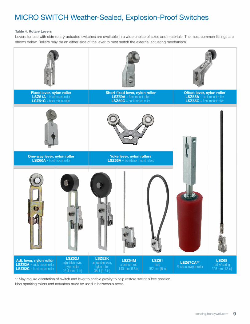
Table 4. Rotary Levers
Levers for use with side-rotary-actuated switches are available in a wide choice of sizes and materials. The most common listings are shown below. Rollers may be on either side of the lever to best match the external actuating mechanism.
Fixed lever, nylon rollerLSZ51A - front mount rollerLSZ51C - back mount roller
Short fixed lever, nylon rollerLSZ59A - front mount rollerLSZ59C - back mount roller
Offset lever, nylon rollerLSZ55A - back mount rollerLSZ55C - front mount roller
One-way lever, nylon rollerLSZ60A - front mount roller
Yoke lever, nylon rollersLSZ53A - front/back mount rollers
Adj. lever, nylon roller LSZ52A - back mount rollerLSZ52C - front mount roller
LSZ52Jadjustable lever,
nylon roller 25,4 mm [1 in]
LSZ52Kadjustable lever,
nylon roller38,1 [1.5 in]
LSZ54Maluminum rod
140 mm [5.5 in]
LSZ61loop
152 mm [6 in]
LSZ67CA**Plastic conveyor roller
LSZ68rod w/ spring
305 mm [12 in]
** May require orientation of switch and lever to enable gravity to help restore switch’s free position.Non-sparking rollers and actuators must be used in hazardous areas.
10 sensing.honeywell.com
CX Series
Catalog Listing
Material Roller Dia. mm [in]
Roller Width mm [in]
Roller Mounting
Fixed – 38,1 [1.5] inch radiusLSZ51 Rollerless n/a n/a n/a
LSZ51A Nylon 19 [0.75] 6,35 [0.25] Front
LSZ51C Nylon 19 [0.75] 6,35 [0.25] Back
LSZ51F Nylon 25,4 [1.0] 12,7 [0.50] Front
LSZ51G Nylon 38,1 [1.5] 6,35 [0.25] Front
LSZ51J Nylon 25,4 [1.0] 12,7 [0.50] Back
LSZ51M Nylon 19 [0.75] 31,7 [1.25] Back
LSZ51P Nylon 19 [0.75] 12,7 [0.50] Front
LS2Z51A (sst) Nylon 19 [0.75] 6,35 [0.25] Front
LS2Z51C (sst) Nylon 19 [0.75] 6,35 [0.25] Back
LS2Z51E (sst) Copper alloy 19 [0.75] 6,35 [0.25] Front
LS2Z51F (sst) Copper alloy 19 [0.75] 6,35 [0.25] Back
Adjustable – 38,1 [1.5] in to 3.5 in radiusLSZ52 Rollerless n/a n/a n/a
LSZ52A Nylon 19 [0.75] 6,35 [0.25] Back
LSZ52C Nylon 19 [0.75] 6,35 [0.25] Front
LSZ52E Nylon 19 [0.75] 33,0 [1.30] Front
LSZ52J Nylon 25,4 [1.0] 12,7 [0.50] Front
LSZ52K Nylon 38,1 [1.5] 6,35 [0.25] Front
LSZ52M Nylon 50,8 [2.0] 6,35 [0.25] Front
LSZ52N Nylon 19 [0.75] 12,7 [0.50] Front
LS2Z52A (sst) Nylon 19 [0.75] 6,35 [0.25] Front
LS2Z52C (sst) Nylon 19 [0.75] 6,35 [0.25] Back
LS2Z52E (sst) Copper alloy 19 [0.75] 6,35 [0.25] Front
LS2Z52F (sst) Copper alloy 19 [0.75] 6,35 [0.25] Back
Yoke – 38,1 [1.5] in radiusLSZ53A Nylon 19 [0.75] 6,35 [0.25] Front/Back
LSZ53E Nylon 19 [0.75] 6,35 [0.25] Back/Front
LSZ53M Nylon 19 [0.75] 31,7 [1.25] Back/Front
LSZ53S Nylon 19 [0.75] 6,35 [0.25] Back/Back
RodLSZ54 Hub only n/a n/a n/a
LSZ54M Alum, 140 mm [5.5 in]
Ø 3,2[Ø 0.125]
n/a n/a
LSZ54N Stainless, 330 mm [13 in]
Ø 3,2[Ø 0.125]
n/a n/a
LSZ54P Plastic rod, 305 mm [12 in]
Ø6,85[Ø 0.27]
n/a n/a
LSZ54W Plastic rod, 183 mm [7.2 in]
Ø6,85[Ø 0.27]
n/a n/a
Offset – 38,1 [1.5] in radiusLSZ55 Rollerless n/a n/a n/a
LSZ55A Nylon 19 [0.75] 6,35 [0.25] Back
LSZ55C Nylon 19 [0.75] 6,35 [0.25] Front
LSZ55E Nylon 19 [0.75] 12,7 [0.50] Front
LSZ55K Nylon 38,1 [1.5] 6,35 [0.25] Front
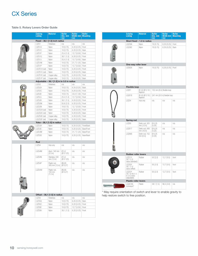
Table 5. Rotary Levers Order Guide
Catalog Listing
Material Roller Dia. mm [in]
Roller Width mm [in]
Roller Mounting
Short fixed – 1.3 in radiusLSZ59A Nylon 19 [0.75] 6,35 [0.25] Front
LSZ59C Nylon 19 [0.75] 6,35 [0.25] Back
One-way roller leverLSZ60A Nylon 19 [0.75] 6,35 [0.25] Front
Flexible loop
LSZ61 Ø 4,8 [Ø 0.19 ]Nylatron
152 mm [6 in] flexible loop
LSZ618 Ø 4,8 [Ø 0.19 ] Nylatron
241 mm [9.5 in] flexible loop
LSZ54 Hub only n/a n/a n/a
Spring rodLSZ68 Delrin rod, 305
mm [12 in]Ø 6,35 [0.25]
n/a n/a
LSZ617 Delrin rod, 406 mm [16 in]
Ø 6,35 [0.25]
n/a n/a
LSZ686 Delrin rod, 152 mm [6 in]
Ø 6,35 [0.25]
n/a n/a
Rubber roller levers
LSZ51Y 38,1 [1.5] radius (standard)
Rubber 50 [2.0] 12,7 [0.5] front
LSZ55Y 38,1 [1.5] radius (offset)
Rubber 50 [2.0] 12,7 [0.5] front
LSZ52Y 38,1 to 89 [1.5 to 3.5] radius (adjustable)
Rubber 50 [2.0] 12,7 [0.5] front
Plastic roller levers
LSZ67AA (conveyor)*
Plastic 38,1 [1.5] 96,5 [3.8] n/a
* May require orientation of switch and lever to enable gravity to help restore switch to free position.
11sensing.honeywell.com
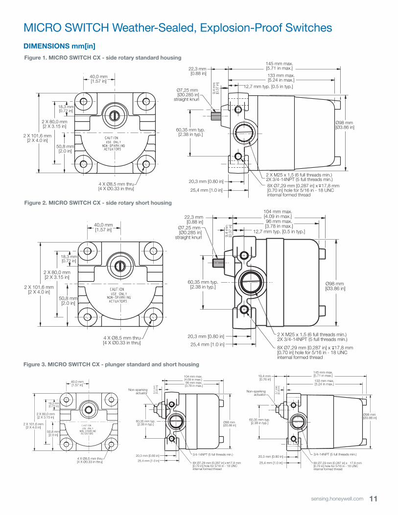
MICRO SWITCH Weather-Sealed, Explosion-Proof Switches
Figure 1. MICRO SWITCH CX - side rotary standard housing
DIMENSIONS mm[in]
Figure 2. MICRO SWITCH CX - side rotary short housing
40,0 mm[1.57 in]
18,3 mm[0.72 in]
2 X 80,0 mm[2 X 3.15 in]
2 X 101,6 mm[2 X 4.0 in]
4 X Ø8,5 mm thru[4 X Ø0.33 in thru]
Ø7,25 mm [Ø0.285 in]
straight knurl
60,35 mm typ.[2.38 in typ.]
22,3 mm[0.88 in]
9,4
mm
[0.3
7 in
]
145 mm max.[5.71 in max.]
133 mm max.[5.24 in max.]
12,7 mm typ. [0.5 in typ.]
Ø98 mm [Ø3.86 in]
20,3 mm [0.80 in]
25,4 mm [1.0 in]
2 X M25 x 1,5 (6 full threads min.)2X 3/4-14NPT (5 full threads min.)8X Ø7,29 mm [0.287 in] x 17,8 mm [0.70 in] hole for 5/16 in - 18 UNC internal formed thread
50,8 mm[2.0 in]
Ø7,25 mm [Ø0.285 in]
straight knurl
60,35 mm typ.[2.38 in typ.]
22,3 mm[0.88 in]
9,4
mm
[0.3
7 in
]
104 mm max.[4.09 in max.]96 mm max.[3.78 in max.]
12,7 mm typ. [0.5 in typ.]
Ø98 mm [Ø3.86 in]
20,3 mm [0.80 in]
25,4 mm [1.0 in]
2 X M25 x 1,5 (6 full threads min.)2X 3/4-14NPT (5 full threads min.)
8X Ø7,29 mm [0.287 in] x 17,8 mm [0.70 in] hole for 5/16 in - 18 UNC internal formed thread
40,0 mm[1.57 in]
18,3 mm[0.72 in]
2 X 80,0 mm[2 X 3.15 in]
2 X 101,6 mm[2 X 4.0 in]
4 X Ø8,5 mm thru[4 X Ø0.33 in thru]
50,8 mm[2.0 in]
Figure 3. MICRO SWITCH CX - plunger standard and short housing
Non-sparkingactuator
60,35 mm typ.[2.38 in typ.]
19,4 mm[0.76 in]
5,1
mm
[0.2
0 in
]
145 mm max.[5.71 in max.]
133 mm max.[5.24 in max.]
Ø98 mm [Ø3.86 in]
20,3 mm [0.80 in]
25,4 mm [1.0 in]
3/4-14NPT (5 full threads min.)
60,35 mm typ.[2.38 in typ.]
104 mm max.[4.09 in max.]96 mm max.[3.78 in max.]
Ø98 mm [Ø3.86 in]
20,3 mm [0.80 in]
25,4 mm [1.0 in]
3/4-14NPT (5 full threads min.)
8X Ø7,29 mm [0.287 in] x 17,8 mm [0.70 in] hole for 5/16 in - 18 UNC internal formed thread
5,1
mm
[0.2
0 in
]
Non-sparkingactuator
8X Ø7,29 mm [0.287 in] x 17,8 mm [0.70 in] hole for 5/16 in - 18 UNC internal formed thread
40,0 mm[1.57 in]
18,3 mm[0.72 in]
2 X 80,0 mm[2 X 3.15 in]
2 X 101,6 mm[2 X 4.0 in]
4 X Ø8,5 mm thru[4 X Ø0.33 in thru]
50,8 mm[2.0 in]
12 sensing.honeywell.com
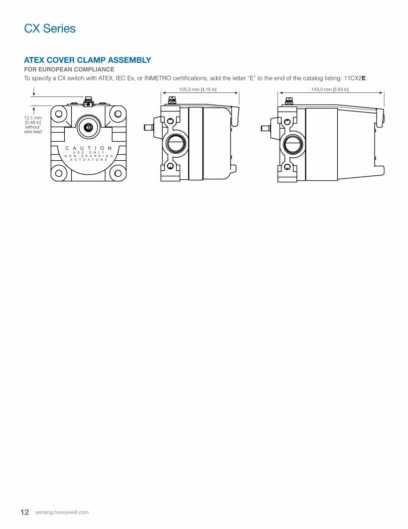
CX Series
ATEX COVER CLAMP ASSEMBLYFOR EUROPEAN COMPLIANCETo specify a CX switch with ATEX, IEC Ex, or INMETRO certifications, add the letter “E” to the end of the catalog listing: 11CX2E.
C A U T I O NU S E O N L Y
N O N - S P A R K I N GA C T U A T O R S
12,1 mm[0.48 in]without wire lead
105,3 mm [4.15 in] 143,0 mm [5.63 in]
002388-3-EN | 3 | 12/19Copyright © 2015 Honeywell International Inc. All rights reserved.
Sensing and Productivity Solutions
Honeywell
1985 Douglas Drive North
Golden Valley, MN 55422
honeywell.com
Find out moreHoneywell serves its customers through a worldwide network of sales offices, representatives and distributors. For application assistance, current specifications, pricing or name of the nearest Authorized Distributor, contact your local sales office.
To learn more about Honeywell’s
sensing and switching products,
call +1-815-235-6847 or
1-800-537-6945,
visit sensing.honeywell.com,
or e-mail inquiries to
ADDITIONAL INFORMATIONThe following associated literature is available on the Honeywell web site at sensing.honeywell.com:• Product installation instructions
• Product range guide
• Product nomenclature tree
• MICRO SWITCH Hazardous Area Switches Brochure
• Product application-specific information
– Limit and enclosed switch reference standards
– Application Note: Sensors and switches for industrial manual process valves
– Application Note: Sensors and switches in oil rig applications
– Application Note: Sensors and switches n valve actuators and valve positioners
– Application Note: Sensors and switches in valves and flow meters
WARNINGPERSONAL INJURYDO NOT USE these products as safety or emergency stop devices or in any other application where failure of the product could result in personal injury.
Failure to comply with these instructions could result in death or serious injury.
WARNINGMISUSE OF DOCUMENTATION• The information presented in this product sheet is for
reference only. Do not use this document as a product installation guide.
• Complete installation, operation, and maintenance information is provided in the instructions supplied with each product.
Failure to comply with these instructions could result in death or serious injury.
WARRANTY/REMEDYHoneywell warrants goods of its manufacture as being free of defective materials and faulty workmanship. Honeywell’s standard product warranty applies unless agreed to otherwise by Honeywell in writing; please refer to your order acknowledgement or consult your local sales office for specific warranty details. If warranted goods are returned to Honeywell during the period of coverage, Honeywell will repair or replace, at its option, without charge those items it finds defective. The foregoing is buyer’s sole remedy and is in lieu of all other warranties, expressed or implied, including those of merchantability and fitness for a particu-lar purpose. In no event shall Honeywell be liable for conse-quential, special, or indirect damages.
While we provide application assistance personally, through our literature and the Honeywell website, it is up to the customer to determine the suitability of the product in the application.
Specifications may change without notice. The information we supply is believed to be accurate and reliable as of this printing. However, we assume no responsibility for its use.
Mouser Electronics
Authorized Distributor
Click to View Pricing, Inventory, Delivery & Lifecycle Information: Honeywell:
1172CX12 1172CX2 11CX1 11CX11B-D01 11CX12 11CX12C 11CX12-D01 11CX12E 11CX1C 11CX2
11CX2E 12CX1 12CX12 12CX2 12CX2A 14CX1 14CX11 16CX1 16CX12 16CX12C 16CX1C 16CX2 16CX2C
21CX12 21CX13 21CX14 21CX14-D01 21CX16 21CX4 21CX6 22CX4 24CX12 24CX2 26CX14 26CX16
26CX4 26CX4C 81CX4 82CX2 82CX2A 84CX2 86CX2