Embed Size (px)
Citation preview
International Journal of Advanced Research in Electronics and Communication Engineering (IJARECE)
Volume 3, Issue 12, December 2014
1876
ISSN: 2278 – 909X All Rights Reserved © 2014 IJARECE
Microcontroller Based Transformer Monitoring
and Controlling System Using Zigbee
M.Anand, R.Sumi, G.Nithya, B.Mahalakshmi
Abstract - The objective of this paper is to monitor the
transformer parameters such as voltage, current, frequency and
temperature and to control using microcontroller with the help
of zigbee transceiver. This paper prescribe about the transformer
which is used for powering the machines where the
incoming supply voltage and the rated voltage of the
distribution system are different. The transformer windings and
insulation may get damaged due to severe fault conditions .In
many cases the transformer may burst. It explain how to monitor
the above parameters and isolate the power supply during
emergencies. The output voltage is measured with the help of
potential transformer. The output current is measured with the
help of current transformer, similarly temperature sensor is used
to monitor temperature rise in the transformer. Zigbee is
wireless transceiver where we can send and receive the data
through this module. The monitored parameters will be sent to
the PC through zigbee. The cooling system of the transformer is
performed if winding temperature exceeds a certain value.
During severe fault conditions, relay is operated and the power
supply to the transformer is isolated.
Index Terms – Current, Frequency, Microcontroller,
Temperature, Transformer, Voltage and ZigBee.
I.INTRODUCTION
Nowadays industries are shifting towards
automation. two components of today‟s industrial
automations are programmable controllers and robots. In
order to aid the tedious work and to serve the mankind, today
there is a general tendency to develop an intelligent
operation. In my paper each transformer is designed
with a microcontroller based kit and also attached with
ZigBee transceiver for monitoring and controlling the
transformer p a r a m e t e r s . The monitored p a r a m e t e r s
o f multiple transformers are transmitted through their
respected ZigBee transceiver and are processed in a PC
connected with ZigBee transceiver. If the monitored
parameters of transformers are equal or less than pre-set
value then the transformer will continue its normal
functions . But i f moni to red parameters exceed pre-set
value, measures will be taken to ensure normal functioning o f
the transformer. Under e x t r e m e c o n d i t i o n s
transformer will be isolated.
M.Anand PG scholar, Bannari Amman Institute of
technology, Erode, India Mobile No: 9443437731.
R.Sumi PG scholar, Bannari Amman Institute of Technology,
Erode, India ,Phone No: 9842428490
II. EXISTING SYSTEM
At present PLC based kits are used with wired
connection for monitoring. These kits have a fixed input
and output ports and also it is costly. It is difficult while
connecting many device together as it uses star topology.
III.PROPOSED SYSTEM
In this paper we implemented microcontroller and
ZIGBEE for data processing and transmission respectively
and also using ZIGBEE protocol which enables us to connect
more than 200 devices together without any interference.
ZIGBEE network is a low power signal transceiver which
reduces power consumption and is also a listen-before-talk
network. Microcontroller allows us to use multi ported pin
A. Block Diagram
Fig. 1 PC Side Block Diagram
In this side transformer parameters such as
voltage, current values are obtained by Zigbee transceiver
and displayed in monitor screen, Loading and tripping
operation of the transformer are also done from this section
G.Nithya PG scholar, Bannari Amman Institute of
technology, Erode, India Mobile No:9865033082.
B.Mahalakshmi PG scholar, Bannari Amman
Institute of Technology, Erode, India ,Phone No: 8883795455
International Journal of Advanced Research in Electronics and Communication Engineering (IJARECE)
Volume 3, Issue 12, December 2014
1877
ISSN: 2278 – 909X All Rights Reserved © 2014 IJARECE
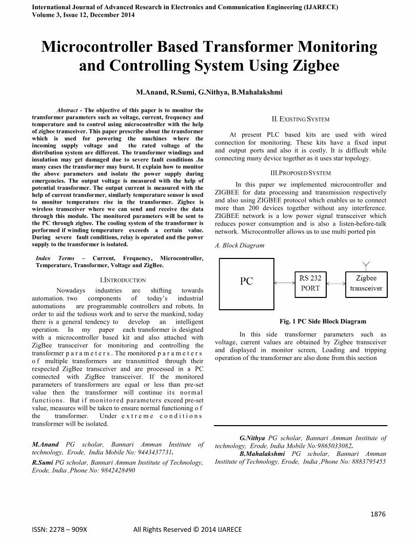
Fig. 2 Transformer Side Block Diagram
IV.HARDWARE DESCRIPTION
A. Liquid Crystal Display (LCD)
Liquid crystal cell displays (LCDs) are used in similar applications where LEDs are used. These applications are display of numeric and alphanumeric characters in dot matrix and segmental displays.
LCDs are of two types:
1. Dynamic scattering type
2. Field effect type
1. Dynamic Scattering Type
The liquid crystal material may be one of the several
components, which exhibit optical properties of a crystal
though they remain in liquid form. Liquid crystal is layered
between glass sheets with transparent electrodes deposited
on the inside faces. When a potential is applied across the
cell, charge carriers flowing through the liquid disrupt the
molecular alignment and produce turbulence. When the
liquid is not activated, it is transparent. When the liquid is
activated the molecular turbulence causes light to be
scattered in all directions and the cell appears to be bright.
This phenomenon is called dynamic scattering.
2. Field Effect Type
The construction of a field effect liquid crystal display
is similar to that of the dynamic scattering type, with the
exception that two thin polarizing optical filters are placed
at the inside of is also of different type from employed in the
dynamic scattering cell.
Fig.3 LCD Interfacing with microcontroller
The LCDs used exclusively in watches, calculators
and measuring instruments are the simple seven-segment
displays, having a limited amount of numeric data. The recent
advances in technology have resulted in better legibility, more
information displaying capability and a wider temperature
range. These have resulted in the LCDs being extensively
used in telecommunications and entertainment electronics.
V.SENSORS
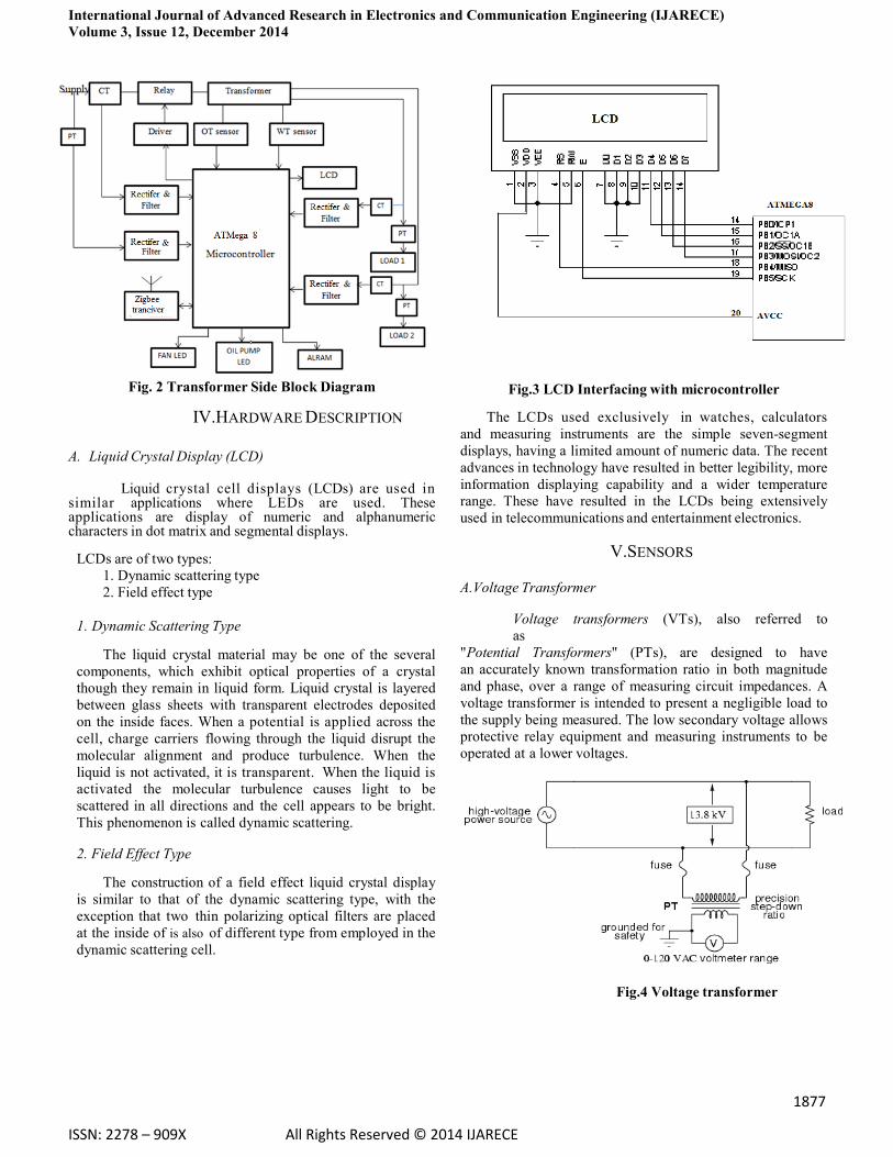
A.Voltage Transformer
Voltage transformers (VTs), also referred to
as
"Potential Transformers" (PTs), are designed to have
an accurately known transformation ratio in both magnitude
and phase, over a range of measuring circuit impedances. A
voltage transformer is intended to present a negligible load to
the supply being measured. The low secondary voltage allows
protective relay equipment and measuring instruments to be
operated at a lower voltages.
Fig.4 Voltage transformer
International Journal of Advanced Research in Electronics and Communication Engineering (IJARECE)
Volume 3, Issue 12, December 2014
1878
ISSN: 2278 – 909X All Rights Reserved © 2014 IJARECE
B. Current Transformer
In electrical engineering, a current transformer
(CT) is used for measurement of electrical currents.
Current transformers, together with potential transformers
(PT), are known as instrument transformers.
When current in a circuit is too high to directly
apply to measuring instruments, a current transformer
produces a reduced current accurately proportional to the
current in the circuit, which can be conveniently
connected to measuring and recording instruments. A
current transformer also isolates the measuring instruments
from what may be very high voltage in the monitored
circuit. Current transformers are commonly used in
metering and protective relays in the electrical power
industry.
Fig.5 Current transformer C. LM35- Temperature Sensor
We can measure temperature more accurately by
using LM35 than using a thermistor. It has an output voltage
that is proportional to the Celsius temperature. The scale
factor is
.01V/oC. The LM35 does not require any external calibration or trimming and maintains an accuracy of
+/-0.4oC at room temperature and +/- 0.8oCover a
range of 0oC to +100oC.
Another important characteristic of the LM35DZ is that it
draws only 60 micro amps from its supply and possesses a
low self- heating capability. The sensor self-heating
causes less than 0.1oC temperature rise in still air.
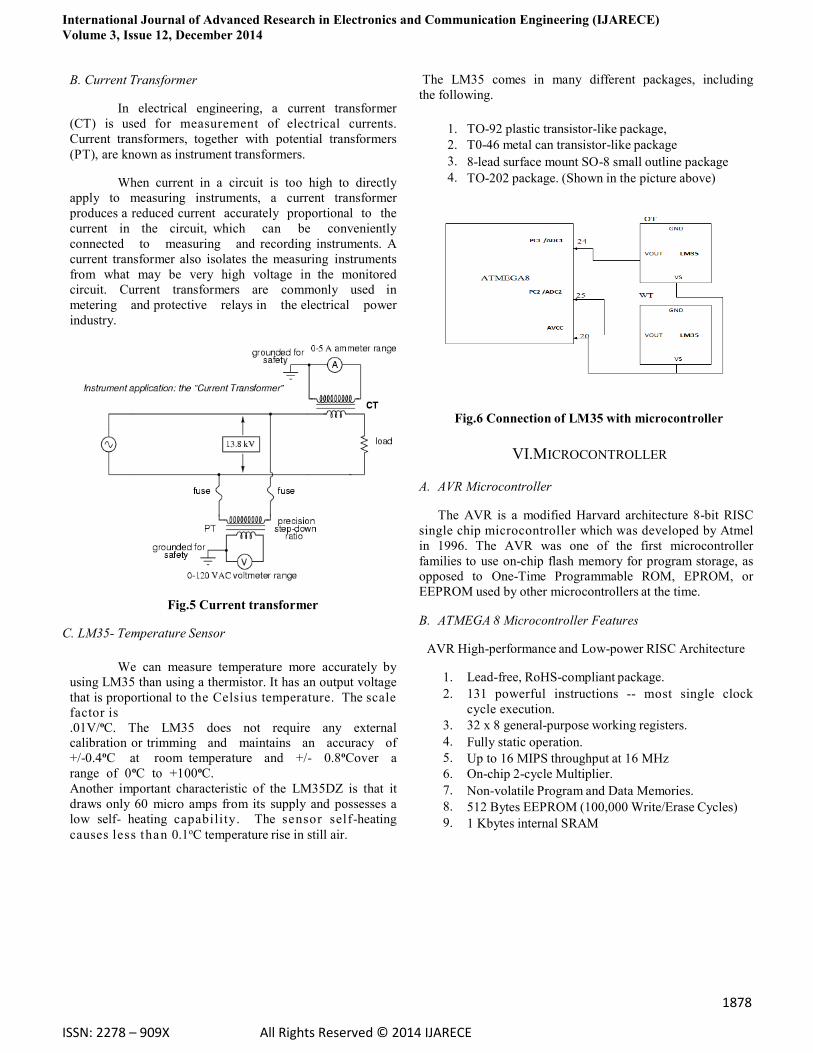
The LM35 comes in many different packages, including
the following.
1. TO-92 plastic transistor-like package,
2. T0-46 metal can transistor-like package
3. 8-lead surface mount SO-8 small outline package
4. TO-202 package. (Shown in the picture above)
Fig.6 Connection of LM35 with microcontroller
VI.MICROCONTROLLER
A. AVR Microcontroller
The AVR is a modified Harvard architecture 8-bit RISC
single chip microcontroller which was developed by Atmel
in 1996. The AVR was one of the first microcontroller
families to use on-chip flash memory for program storage, as
opposed to One-Time Programmable ROM, EPROM, or
EEPROM used by other microcontrollers at the time. B. ATMEGA 8 Microcontroller Features
AVR High-performance and Low-power RISC Architecture
1. Lead-free, RoHS-compliant package.
2. 131 powerful instructions -- most single clock
cycle execution.
3. 32 x 8 general-purpose working registers.
4. Fully static operation.
5. Up to 16 MIPS throughput at 16 MHz
6. On-chip 2-cycle Multiplier.
7. Non-volatile Program and Data Memories.
8. 512 Bytes EEPROM (100,000 Write/Erase Cycles)
9. 1 Kbytes internal SRAM
International Journal of Advanced Research in Electronics and Communication Engineering (IJARECE)
Volume 3, Issue 12, December 2014
1879
ISSN: 2278 – 909X All Rights Reserved © 2014 IJARECE
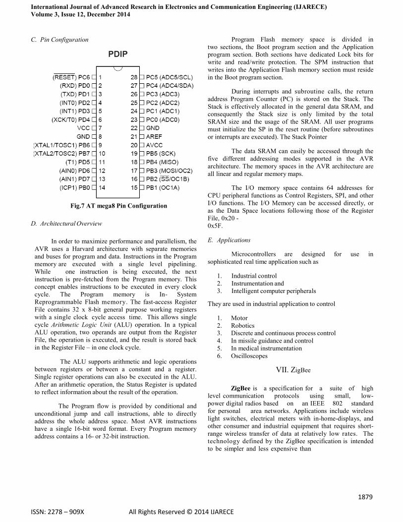
C. Pin Configuration
Fig.7 AT mega8 Pin Configuration
D. Architectural Overview
In order to maximize performance and parallelism, the
AVR uses a Harvard architecture with separate memories
and buses for program and data. Instructions in the Program
memory are executed with a single level pipelining.
While one instruction is being executed, the next
instruction is pre-fetched from the Program memory. This
concept enables instructions to be executed in every clock
cycle. The Program memory is In- System
Reprogrammable Flash memory. The fast-access Register
File contains 32 x 8-bit general purpose working registers
with a single clock cycle access time. This allows single
cycle Arithmetic Logic Unit (ALU) operation. In a typical
ALU operation, two operands are output from the Register
File, the operation is executed, and the result is stored back
in the Register File – in one clock cycle.
The ALU supports arithmetic and logic operations
between registers or between a constant and a register.
Single register operations can also be executed in the ALU.
After an arithmetic operation, the Status Register is updated
to reflect information about the result of the operation.
The Program flow is provided by conditional and
unconditional jump and call instructions, able to directly
address the whole address space. Most AVR instructions
have a single 16-bit word format. Every Program memory
address contains a 16- or 32-bit instruction.
Program Flash memory space is divided in
two sections, the Boot program section and the Application
program section. Both sections have dedicated Lock bits for
write and read/write protection. The SPM instruction that
writes into the Application Flash memory section must reside
in the Boot program section.
During interrupts and subroutine calls, the return
address Program Counter (PC) is stored on the Stack. The
Stack is effectively allocated in the general data SRAM, and
consequently the Stack size is only limited by the total
SRAM size and the usage of the SRAM. All user programs
must initialize the SP in the reset routine (before subroutines
or interrupts are executed). The Stack Pointer
The data SRAM can easily be accessed through the
five different addressing modes supported in the AVR
architecture. The memory spaces in the AVR architecture are
all linear and regular memory maps.
The I/O memory space contains 64 addresses for
CPU peripheral functions as Control Registers, SPI, and other
I/O functions. The I/O Memory can be accessed directly, or
as the Data Space locations following those of the Register
File, 0x20 -
0x5F. E. Applications
Microcontrollers are designed for use in
sophisticated real time application such as
1. Industrial control
2. Instrumentation and
3. Intelligent computer peripherals
They are used in industrial application to control
1. Motor
2. Robotics
3. Discrete and continuous process control
4. In missile guidance and control
5. In medical instrumentation
6. Oscilloscopes
VII. ZigBee
ZigBee is a specification for a suite of high
level communication protocols using small, low-
power digital radios based on an IEEE 802 standard
for personal area networks. Applications include wireless
light switches, electrical meters with in-home-displays, and
other consumer and industrial equipment that requires short-
range wireless transfer of data at relatively low rates. The
technology defined by the ZigBee specification is intended
to be simpler and less expensive than
International Journal of Advanced Research in Electronics and Communication Engineering (IJARECE)
Volume 3, Issue 12, December 2014
1880
ISSN: 2278 – 909X All Rights Reserved © 2014 IJARECE
other wpans, such as Bluetooth. ZigBee is targeted at
radio- frequency (RF) applications that require a low data
rate, long battery life, and secure networking. ZigBee has a
defined rate of
250 kbps best suited for periodic or intermittent data or a
single transmission from a sensor or input device. The name refers to the waggle dance of honey bees after their return to
the beehive.
A. Technical Overview
ZigBee is a low-cost, low-power, wireless
mesh network standard. The low cost allows the
technology to be widely deployed in wireless control and
monitoring applications. Low power-usage allows longer life
with smaller batteries. Mesh networking provides high
reliability and more extensive range. ZigBee chip vendors
typically sell integrated radios and microcontrollers with
between 60 KB and 256 KB flash memory.
ZigBee operates in the industrial, scientific and
medical (ISM) radio bands; 868 MHz in Europe, 915 MHz
in the USA and Australia, and 2.4 GHz in most
jurisdictions worldwide. Data transmission rates vary from
20 to 900 kilobits/second.
The ZigBee network layer natively
supports both star and tree typical networks, and generic
mesh networks. Every network must have one coordinator
device, tasked with its creation, the control of its parameters
and basic maintenance. Within star networks, the
coordinator must be the central node. Both trees and
meshes allows the use of ZigBee routers to extend
communication at the network level.
B. Device Types
There are three different types of ZigBee devices
1. Zigbee Coordinator (ZC)
The most capable device, the coordinator forms the
root of the network tree and might bridge to other
networks. There is exactly one ZigBee coordinator in
each network since it is the device that started the
network originally. It is able to store information about
the network, including acting as the Trust Centre &
repository for security keys.
2. Zigbee Router (ZR)
As well as running an application function, a router
can act as an intermediate router, passing on data
from other devices.
3. ZigBee End Device (ZED)
Contains just enough functionality to talk to the
parent node (either the coordinator or a router); it cannot
relay data from other devices. This relationship allows the
node to be asleep a significant amount of the time thereby
giving long battery life. A ZED requires the least amount of
memory, and therefore can be less expensive to manufacture
than a ZR or
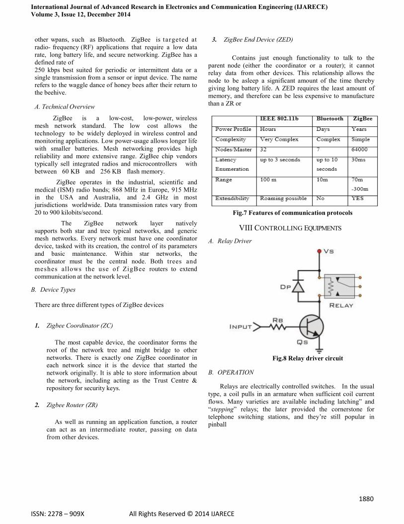
Fig.7 Features of communication protocols
VIII CONTROLLING EQUIPMENTS
A. Relay Driver
Fig.8 Relay driver circuit
B. OPERATION
Relays are electrically controlled switches. In the usual
type, a coil pulls in an armature when sufficient coil current
flows. Many varieties are available including latching” and
“stepping” relays; the later provided the cornerstone for
telephone switching stations, and they‟re still popular in
pinball
International Journal of Advanced Research in Electronics and Communication Engineering (IJARECE)
Volume 3, Issue 12, December 2014
1881
ISSN: 2278 – 909X All Rights Reserved © 2014 IJARECE
machines. relays are available for dc or ac excitation, and
coil voltages from 5 volts up to 110 volts are common.
“mercury- wetted” are “reed” relays are intended for high-
speed (~ 1ms) applications, and giant relays intended to
switch thousands of amps are used by power companies.
Many previous relay applications are now handled with
transistor or fet switches, and devices known, as solid-state
relays are now available to handle ac switching applications.
The primary uses of relays are in remote switching and
high-voltage switching because it is important to keep
electronic circuits electrically isolated from the ac power
line, relays are useful to switch ac power while keeping the
control signals electrically isolated. The electrical relay
offers a simple on / off switching action in response to a
control signal. When a current flows through the coil of wire
a magnetic field is produced. This pulls a movable arm, the
armature, that forces the contacts to open are close; usually
there are two sets of contacts with one being opened and the
other closed by the action. This perhaps an electric heater in
a temperature controls system.
C. Transformer Oil Cooling
Enerfin‟s transformer oil coolers are custom
designed for each application, in keeping with your needs.
We have three types of coolers to suit most applications.
The OFAF (Oil Forced Air Forced) model is
designed and manufactured with our extruded aluminium fin
tubes. The coolers are delivered with motors and fans
assembled and connected.
The OFWF (Oil Forced Water Forced) model is of
the shell and tube type. This model can be manufactured
using two concentric tubes with a double tube plate,
equipped with a leak detector (optional).
The ONWF (Oil Natural Water Forced) model has
a natural convection design. This model is manufactured
using our extruded aluminium fin tubes inside a rectangular
shell to optimize thermal performance. This model can also
be manufactured using two tubes with a double tube plate,
equipped with a leak detector (optional).
D. Transformer Fan Cooling
Heat from core losses and copper losses must be
dissipated to the environment. In dry type transformers,
cooling is accomplished simply by circulating air around and
through the coil and core assembly, either by natural
convection or by forced air flow from fans. This cooling
method is usually limited to low-voltage indoor
transformers (5 kV and below) having a three-phase rating
below 1500 KVA. At higher voltages, oil is required to
insulate the windings, which prevents the use of air
for cooling the core and coils directly. At higher KVA
ratings, the losses are just too high for direct air cooling to be
effective.
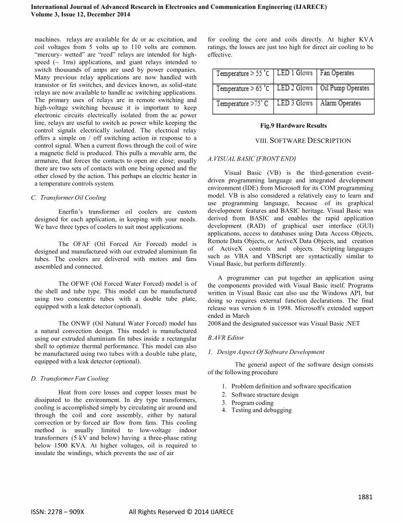
Fig.9 Hardware Results
VIII. SOFTWARE DESCRIPTION
A.VISUAL BASIC (FRONT END)
Visual Basic (VB) is the third-generation event-
driven programming language and integrated development
environment (IDE) from Microsoft for its COM programming
model. VB is also considered a relatively easy to learn and
use programming language, because of its graphical
development features and BASIC heritage. Visual Basic was
derived from BASIC and enables the rapid application
development (RAD) of graphical user interface (GUI)
applications, access to databases using Data Access Objects,
Remote Data Objects, or ActiveX Data Objects, and creation
of ActiveX controls and objects. Scripting languages
such as VBA and VBScript are syntactically similar to
Visual Basic, but perform differently.
A programmer can put together an application using
the components provided with Visual Basic itself. Programs
written in Visual Basic can also use the Windows API, but
doing so requires external function declarations. The final
release was version 6 in 1998. Microsoft's extended support
ended in March
2008 and the designated successor was Visual Basic .NET B.AVR Editor
1. Design Aspect Of Software Development
The general aspect of the software design consists
of the following procedure
1. Problem definition and software specification
2. Software structure design
3. Program coding
4. Testing and debugging
International Journal of Advanced Research in Electronics and Communication Engineering (IJARECE)
Volume 3, Issue 12, December 2014
1882
ISSN: 2278 – 909X All Rights Reserved © 2014 IJARECE
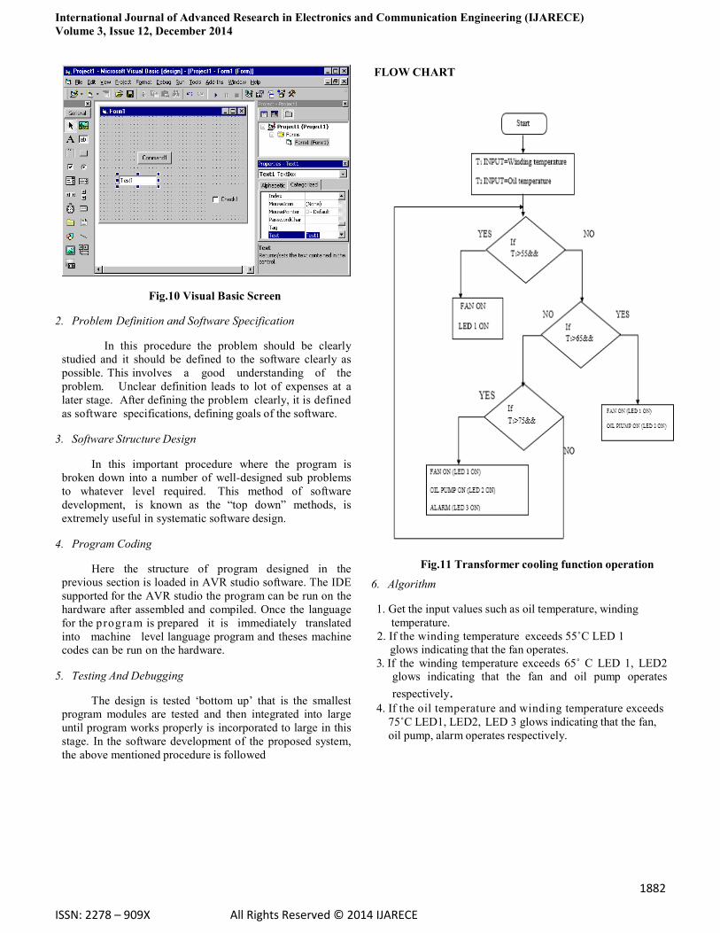
Fig.10 Visual Basic Screen
2. Problem Definition and Software Specification
In this procedure the problem should be clearly
studied and it should be defined to the software clearly as
possible. This involves a good understanding of the
problem. Unclear definition leads to lot of expenses at a
later stage. After defining the problem clearly, it is defined
as software specifications, defining goals of the software. 3. Software Structure Design
In this important procedure where the program is
broken down into a number of well-designed sub problems
to whatever level required. This method of software
development, is known as the “top down” methods, is
extremely useful in systematic software design. 4. Program Coding
Here the structure of program designed in the
previous section is loaded in AVR studio software. The IDE
supported for the AVR studio the program can be run on the
hardware after assembled and compiled. Once the language
for the program is prepared it is immediately translated
into machine level language program and theses machine
codes can be run on the hardware. 5. Testing And Debugging
The design is tested „bottom up‟ that is the smallest
program modules are tested and then integrated into large
until program works properly is incorporated to large in this
stage. In the software development of the proposed system,
the above mentioned procedure is followed
FLOW CHART
Fig.11 Transformer cooling function operation
6. Algorithm
1. Get the input values such as oil temperature, winding
temperature.
2. If the winding temperature exceeds 55˚C LED 1
glows indicating that the fan operates.
3. If the winding temperature exceeds 65˚ C LED 1, LED2 glows indicating that the fan and oil pump operates
respectively. 4. If the oil temperature and winding temperature exceeds
75˚C LED1, LED2, LED 3 glows indicating that the fan,
oil pump, alarm operates respectively.
International Journal of Advanced Research in Electronics and Communication Engineering (IJARECE)
Volume 3, Issue 12, December 2014
1883
ISSN: 2278 – 909X All Rights Reserved © 2014 IJARECE
IX. RESULT AND DISCUSSION
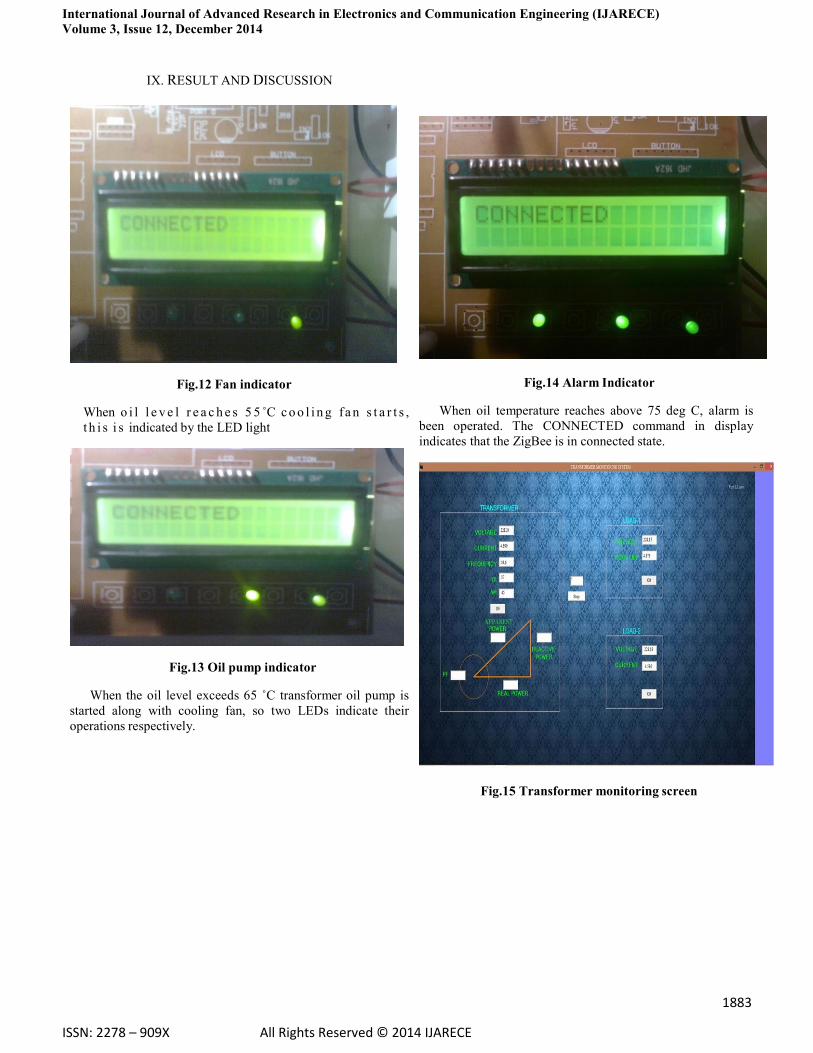
Fig.12 Fan indicator
When o i l l e v e l r e a c h e s 5 5 ˚C c o o l i n g fa n s t a r t s ,
t h i s i s indicated by the LED light
Fig.13 Oil pump indicator
When the oil level exceeds 65 ˚C transformer oil pump is
started along with cooling fan, so two LEDs indicate their
operations respectively.
Fig.14 Alarm Indicator
When oil temperature reaches above 75 deg C, alarm is
been operated. The CONNECTED command in display
indicates that the ZigBee is in connected state.
Fig.15 Transformer monitoring screen
International Journal of Advanced Research in Electronics and Communication Engineering (IJARECE)
Volume 3, Issue 12, December 2014
1884
ISSN: 2278 – 909X All Rights Reserved © 2014 IJARECE
X.CONCLUSION
In this paper we have presented a design of a
system based on AT mega 8 microcontroller that is used
to monitor and control the voltage, current and
temperature of a distribution transformer. The proposed
system has been designed to monitor the transformer‟s
essential parameters which continuously monitor the
parameters throughout its operation. If the microcontroller
recognizes any increase in the level of voltage, current or
temperature values the unit has been made shutdown in
order to prevent it from further damages. The system not
only controls the distribution transformer in the substation
by shutting it down, but also displays the values
throughout the process for user‟s reference. This claims
that the proposed design of the system makes the
distribution transformer more robust, against some key
power quality issues which makes the voltage, current or
temperature to peak. Hence the distribution is made more
secure, reliable and efficient by means of the proposed
system.
REFERENCES
[1] Hongyan Mao (2010) „Research of Wireless
Monitoring System in Power Distribution Transformer
Station Based on GPRS‟,Vol.5, PP.386-389
[2] Riaz Ahamed .S.S (2009)‟The Role of ZigBee
Technology In Future Data Communication System‟,
IEEE Journal of Theoretical and Applied Information
Technology, PP.129-135.
[3] Sen Ouyang, Jian Hua Wang, „A New
Morphology Method For Enhancing Power Quality
Monitoring System‟, International Journal Of Electrical
Power & Energy Systems Vol.29, No.2, Pp.121-128,
February 2007.
[4] Sofie Pollin, Mustafa Ergen, Sinem Coleri
Ergen,Bruno Bougard,Liesbet Van der Perre, Francky
Catthoor, Ingrid Moerman, Ahmad Bahai and Pravin
Varaiya,(2006)‟Performance Analysis of Slotted
Carrier Sense IEEE 802.15.4 Medium Access Layer‟,
IEEE.
[5] Thiyagarajan,V. and Palanivel,T.G.(2010),‟An
Efficient Monitoring Of Substations Using
Microcontroller Based Monitoring System‟ Ijrras
M.Anand completed Bachelor of
Engineering (B.E) in year of 2013
currently pursuing Master of
Engineering (M.E) in Power
Electronics and drives. I completed my
research in wireless communication for
transformer monitoring .Now I started a research on
Multilevel inverter for PV application using Space
vector modulation technique. I have presented the paper
on Piezo electric energy harvester and secured first place
R.Sumi completed bachelor of
engineering (B.E) in year of
2013. Currently pursuing Master of
Engineering (M.E) in Power Electronics
and drives. I completed my research in
Multilevel inverter for motor application. Now I started
research analysis of shunt active filter based on pq
theory.
G.Nithya completed bachelor of
engineering (B.E) in year of
2013 .Currently pursuing Master of
Engineering (M.E) in Power Electronics
and drives. I completed my research in
DC to DC converters. Now I started research in analysis
of electronic ballast for fluorescent lamp
B.Mahalakshmi completed bachelor of
engineering (B.E) in year of
2013. Currently pursuing Master of
engineering (M.E) in Power Electronics
and drives. I completed my research in
cascaded H bridge multilevel inverter
DC link inverter fed induction motor. Now I started my
research on design of SI –NPC for grid connected PV
system