Embed Size (px)
Citation preview
TECHNICAL ARTICLE
Microstructural Analysis of Ballistic Tests on WeldedArmor Steel Joints
M. Balakrishnan • V. Balasubramanian •
G. Madhusudhan Reddy
Received: 12 September 2012 / Revised: 25 December 2012 / Accepted: 13 April 2013 / Published online: 15 May 2013
� Springer Science+Business Media New York and ASM International 2013
Abstract The deformation and fracture behavior of
welded joints made from quenched and tempered steel
closely conforming to AISI 4340 were investigated. Due to
weld thermal cycles and under matching fillers, the welded
armor steel joints showed poor ballistic performance
compared with the base metal (BM). The problems
encountered in the past were reduced by depositing a soft
austenitic stainless-steel buttering layer in between the BM
and the hardfaced layer. This method showed enhancement
in ballistic performance and good weld integrity. In this
investigation, an attempt is made to investigate the
microstructure after ballistic testing on the weld metal zone
consisting of the hardfaced interlayer. The results reveal
the microstructural characteristics before and after ballistic
testing of armor steel welds fabricated using the shielded
metal arc welding (SMAW) process.
Keywords Welding � Hardfacing � Sandwich structures �Ballistic impact � Microstructures
Introduction
Armor-grade quenched and tempered (Q&T) steel is used
for protection of military and nonmilitary vehicles, because
of its high energy-absorbing properties. Q&T steels used
for armor applications require high strength, notch tough-
ness, and hardness [1–3]. Most of the research carried out
in the past on Q&T armor steel has concentrated on
hydrogen-induced cracking (HIC) [4–6], heat-affected
zone (HAZ) softening [7–9], ceramic front layer and
metallic back layer composites, or fiber-encapsulated
composites [10]. It was recently reported that the presence
of an austenitic stainless-steel (SS) buttering layer between
the armor plate [base metal (BM)] and weld metal/hard-
faced metal resulted in enhanced ballistic performance and
successfully held the weld layers intact when a projectile
was fired at interfaces and the heat-affected zone (HAZ)
[11]. It was also reported that the ballistic performance of
the weld metal is enhanced, resulting in shattering of the
projectile [12].
High-strain-rate fracture and failure of a high-strength
low-alloy steel in compression were investigated by Odeshi
et al. [13]. It was observed that thermal softening as a
result of adiabatic heating in the materials controls the
deformation and fracture behavior. The role of retained
austenite, twinned plate martensite interfaces, and grain
boundaries in determining the ballistic performance of steel
was explored by Maweja and Stumpf [14]. The effect of the
target plate’s strength on the perforation of steel plates was
also studied by Deya et al. [15]. The experimental results
indicated that, for perforation by blunt projectiles, the
ballistic limit velocity decreased with increasing strength,
while the opposite trend was found in tests with conical and
ogival projectiles. The structure, dislocation substructure,
and mechanical properties of targets made of four
M. Balakrishnan � V. Balasubramanian (&)
Center for Materials Joining & Research (CEMAJOR),
Department of Manufacturing Engineering, Annamalai
University, Annamalai Nagar 608 002, Tamil Nadu, India
e-mail: [email protected]
G. Madhusudhan Reddy
Solidification Technology Division, Metal Joining Group,
Defense Metallurgical Research Laboratory (DMRL),
Kanchanbagh, Hyderabad 500058, India
123
Metallogr. Microstruct. Anal. (2013) 2:125–139
DOI 10.1007/s13632-013-0069-5
aluminum alloys after impact loading by a kinetic energy
projectile were investigated by Milman et al. [16]. Murr
et al. [17] explored the novel deformation processes,
microstructures involving ballistic penetrator formation,
hypervelocity impact, and penetration phenomena using
light and transmission electron microscopy. From this lit-
erature review, it is apparent that the reported work on the
microstructural characteristics of ballistic tested weld metal
region is very scant. Hence, this investigation aims to
evaluate the microstructural features of ballistic tested
armor steel welds (before and after ballistic testing) in
continuation of the study reported by Balakrishnan et al.
[12]. This article reports the changes observed in the
microstructural features along the projectile trajectory in a
multilayered armor steel joint after ballistic testing.
Experimental Work
The BM used in this study was 18-mm-thick high-strength,
low-alloy Q&T steel closely conforming to the AISI 4340
specification. Heat treatment applied to the BM consisted
of austenizing at 900 �C followed by oil quenching and
subsequent tempering at 250 �C. This heat treatment yields
high hardness and strength, and good toughness for this
BM. The chemical compositions of BM and filler metal are
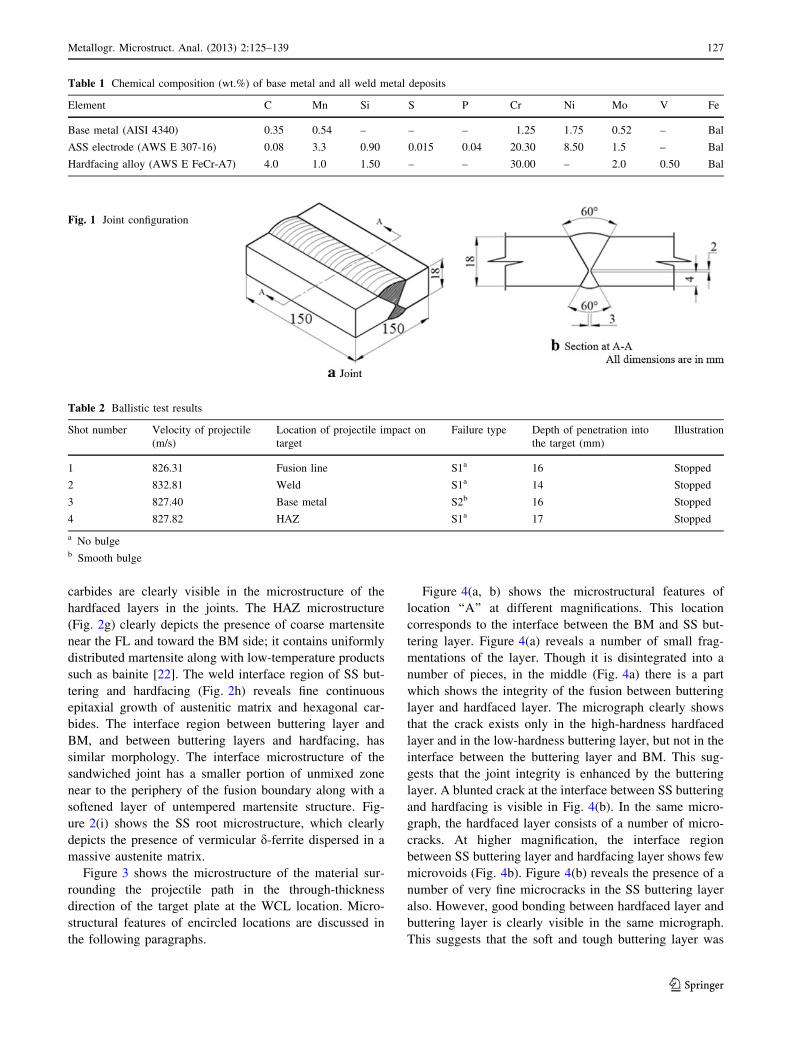
presented in Table 1. In this investigation, an unequal
double V-joint configuration was prepared as shown in
Fig. 1. The beveled edges were buttered with SS electrodes
and hardfaced with 5.5-mm-thick chromium carbide; the
result was a hardfaced interlayer between SS root and
capping weld layers. The specifics of the buttering proce-
dure are discussed elsewhere [11, 12]. The shielded metal
arc welding (SMAW) process was selected because it is
commonly employed in the fabrication of combat vehicles
[18]. The SS electrode was selected because it avoids the
time-delayed cracking tendency of Q&T steel weldments
[3]. The preheating and interpass temperatures were
maintained at 150 �C during welding. The fabricated target
was subjected to standard ballistic testing, and its perfor-
mance was compared with that of the armor-grade Q&T
steel BM. The ballistic test procedure was discussed in
previous publications [2, 7, 8, 10–12]. Four shots were fired
into the welded target plate to evaluate its ballistic per-
formance. The depth of penetration (DOP) of the projectile
into the target plate was the metric used for evaluating
ballistic performance. The weldment was characterized by
microstructural analysis and hardness measurements. Et-
chants used included 2 % Nital for BM and HAZ region,
aqua regia for the SS weld metal region, and Vilella’s
reagent for the hardfaced region. After ballistic testing, the
weld metal region (where the projectile impacted) was
carefully extracted in the through-thickness direction for
analysis via light microscopy. Hardness measurements
were carried out as per the ASTM E-384-05 standard [19]
before and after ballistic testing. A Vickers microhardness
testing machine was employed to measure the hardness
along the weld center line (WCL) and across the WCL with
500 g load for dwell time of 15 s. X-ray diffraction (XRD)
patterns were obtained from sections containing only BM
and sections containing both weld metal (SS root, hard-
faced middle layer, and SS capping) and BM. The fracture
surfaces of impacted targets were analyzed by scanning
electron microscopy (SEM).
Results
Ballistic Performance
The ballistic test results are presented in Table 2. In all four
locations, namely fusion line (FL), WCL, HAZ, and BM,
the target offers maximum resistance and thus successfully
stopped the projectiles. Of the four locations, the WCL
offers the highest resistance compared with other locations
(DOP of only 14 mm).
Microstructure
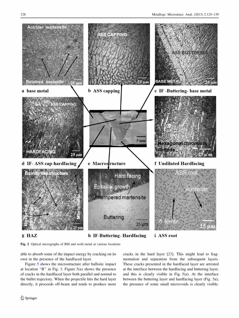
Light micrographs of various locations before ballistic
testing are shown in Fig. 2. The microstructure of the BM
(Fig. 2a) consists of acicular martensite with fine needles
of lath martensite, in addition to some retained austenite
[20]. The image analysis result revealed the presence of
97.2 % martensite and 2.7 % retained austenite in the BM
microstructure. The microstructures of various locations of
the multilayered joint are presented in Fig. 2(b–i). The
undiluted weld metal microstructure in the SS buttering
and SS capping (Fig. 2b) contains grain boundary d-ferrite
in a plain austenitic matrix. The weld interface (IF) region
of the SS buttering and BM (Fig. 2c) contains a continuous
epitaxial growth of austenite. The weld interface region of
hardfacing and SS capping (Fig. 2d) shows an epitaxial
growth of d-ferrite in austenitic matrix. Fig-
ure 2(e) presents the macrostructure of the welded joint
and shows the different layers/regions of the joint. From
this macrograph, it is clear that the joint has very good
integrity and complete fusion at all interfaces was
achieved. The HAZ is also visible in the macrostructure.
The undiluted hardfaced region (Fig. 2f) contains homo-
geneous cast-like structure and is composed of hard phase
precipitates of hexagonal chromium carbides of different
sizes on softer austenitic matrix [21]. Large spine-like
126 Metallogr. Microstruct. Anal. (2013) 2:125–139
123
carbides are clearly visible in the microstructure of the
hardfaced layers in the joints. The HAZ microstructure
(Fig. 2g) clearly depicts the presence of coarse martensite
near the FL and toward the BM side; it contains uniformly
distributed martensite along with low-temperature products
such as bainite [22]. The weld interface region of SS but-
tering and hardfacing (Fig. 2h) reveals fine continuous
epitaxial growth of austenitic matrix and hexagonal car-
bides. The interface region between buttering layer and
BM, and between buttering layers and hardfacing, has
similar morphology. The interface microstructure of the
sandwiched joint has a smaller portion of unmixed zone
near to the periphery of the fusion boundary along with a
softened layer of untempered martensite structure. Fig-
ure 2(i) shows the SS root microstructure, which clearly
depicts the presence of vermicular d-ferrite dispersed in a
massive austenite matrix.
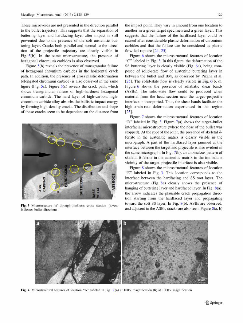
Figure 3 shows the microstructure of the material sur-
rounding the projectile path in the through-thickness
direction of the target plate at the WCL location. Micro-
structural features of encircled locations are discussed in
the following paragraphs.
Figure 4(a, b) shows the microstructural features of
location ‘‘A’’ at different magnifications. This location
corresponds to the interface between the BM and SS but-
tering layer. Figure 4(a) reveals a number of small frag-
mentations of the layer. Though it is disintegrated into a
number of pieces, in the middle (Fig. 4a) there is a part
which shows the integrity of the fusion between buttering
layer and hardfaced layer. The micrograph clearly shows
that the crack exists only in the high-hardness hardfaced
layer and in the low-hardness buttering layer, but not in the
interface between the buttering layer and BM. This sug-
gests that the joint integrity is enhanced by the buttering
layer. A blunted crack at the interface between SS buttering
and hardfacing is visible in Fig. 4(b). In the same micro-
graph, the hardfaced layer consists of a number of micro-
cracks. At higher magnification, the interface region
between SS buttering layer and hardfacing layer shows few
microvoids (Fig. 4b). Figure 4(b) reveals the presence of a
number of very fine microcracks in the SS buttering layer
also. However, good bonding between hardfaced layer and
buttering layer is clearly visible in the same micrograph.
This suggests that the soft and tough buttering layer was
Fig. 1 Joint configuration
Table 2 Ballistic test results
Shot number Velocity of projectile
(m/s)
Location of projectile impact on
target
Failure type Depth of penetration into
the target (mm)
Illustration
1 826.31 Fusion line S1a 16 Stopped
2 832.81 Weld S1a 14 Stopped
3 827.40 Base metal S2b 16 Stopped
4 827.82 HAZ S1a 17 Stopped
a No bulgeb Smooth bulge
Table 1 Chemical composition (wt.%) of base metal and all weld metal deposits
Element C Mn Si S P Cr Ni Mo V Fe
Base metal (AISI 4340) 0.35 0.54 – – – 1.25 1.75 0.52 – Bal
ASS electrode (AWS E 307-16) 0.08 3.3 0.90 0.015 0.04 20.30 8.50 1.5 – Bal
Hardfacing alloy (AWS E FeCr-A7) 4.0 1.0 1.50 – – 30.00 – 2.0 0.50 Bal
Metallogr. Microstruct. Anal. (2013) 2:125–139 127
123
able to absorb some of the impact energy by cracking on its
own in the presence of the hardfaced layer.
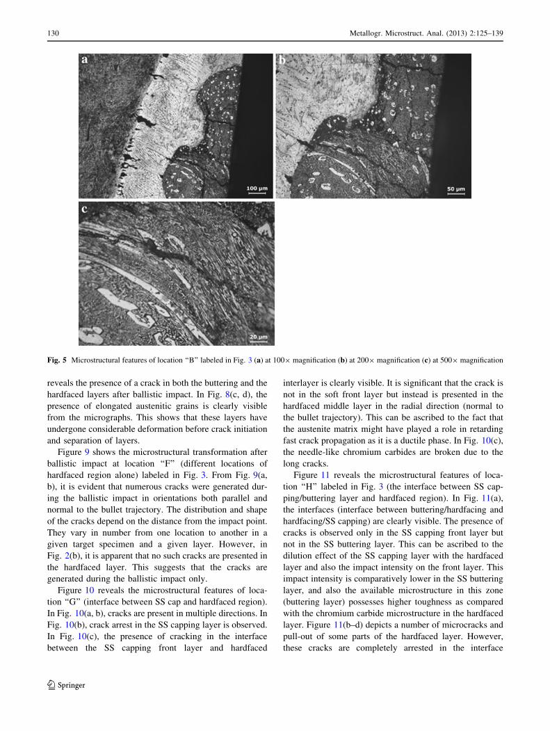
Figure 5 shows the microstructure after ballistic impact
at location ‘‘B’’ in Fig. 3. Figure 5(a) shows the presence
of cracks in the hardfaced layer both parallel and normal to
the bullet trajectory. When the projectile hits the hard layer
directly, it proceeds off-beam and tends to produce more
cracks in the hard layer [23]. This might lead to frag-
mentation and separation from the subsequent layers.
These cracks presented in the hardfaced layer are arrested
at the interface between the hardfacing and buttering layer,
and this is clearly visible in Fig. 5(a). At the interface
between the buttering layer and hardfacing layer (Fig. 5a),
the presence of some small microvoids is clearly visible.
Fig. 2 Optical micrographs of BM and weld metal at various locations
128 Metallogr. Microstruct. Anal. (2013) 2:125–139
123
These microvoids are not presented in the direction parallel
to the bullet trajectory. This suggests that the separation of
buttering layer and hardfacing layer after impact is still
prevented due to the presence of the soft austenitic but-
tering layer. Cracks both parallel and normal to the direc-
tion of the projectile trajectory are clearly visible in
Fig. 5(b). In the same microstructure, the presence of
hexagonal chromium carbides is also observed.
Figure 5(b) reveals the presence of transgranular failure
of hexagonal chromium carbides in the horizontal crack
path. In addition, the presence of gross plastic deformation
(elongated chromium carbide) is also observed in the same
figure (Fig. 5c). Figure 5(c) reveals the crack path, which
shows transgranular failure of high-hardness hexagonal
chromium carbide. The hard layer of high-carbon, high-
chromium carbide alloy absorbs the ballistic impact energy
by forming high-density cracks. The distribution and shape
of these cracks seem to be dependent on the distance from
the impact point. They vary in amount from one location to
another in a given target specimen and a given layer. This
suggests that the failure of the hardfaced layer could be
caused after considerable plastic deformation of chromium
carbides and that the failure can be considered as plastic
flow led rupture [24, 25].
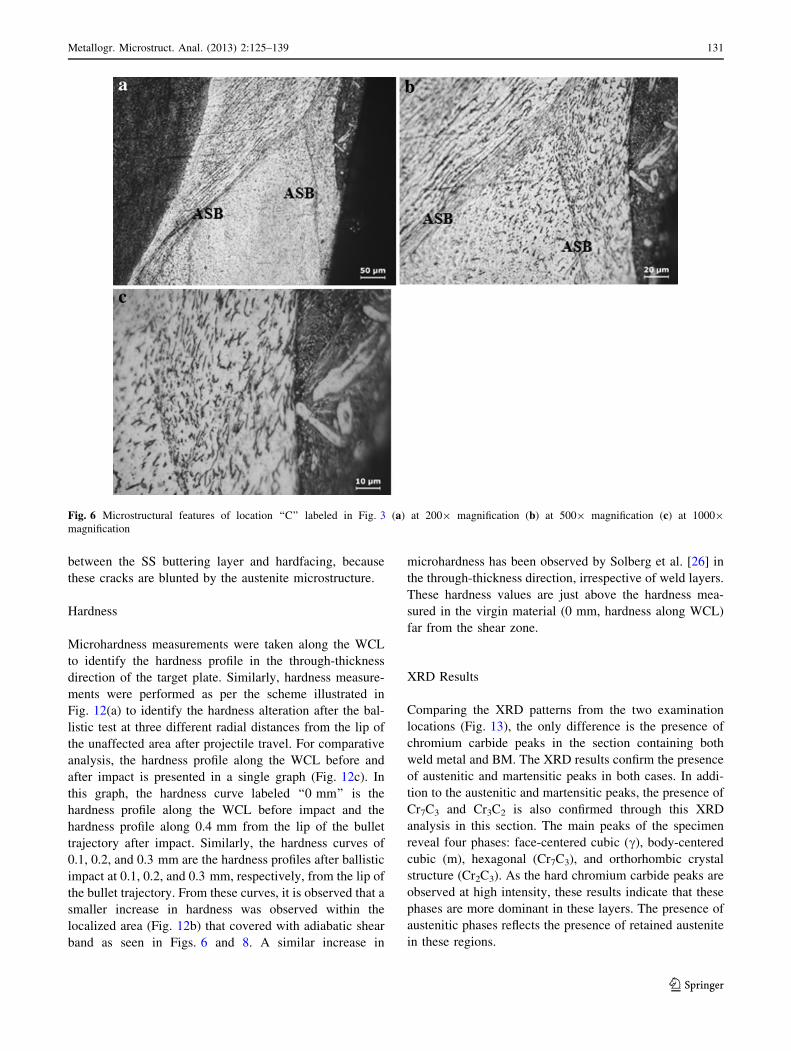
Figure 6 shows the microstructural features of location
‘‘C’’ labeled in Fig. 3. In this figure, the deformation of the
SS buttering layer is clearly visible (Fig. 6a), being com-
posed of solid-state flow of austenitic buttering layer in
between the bullet and BM, as observed by Pizana et al.
[25]. The solid-state flow is clearly visible in Fig. 6(b, c).
Figure 6 shows the presence of adiabatic shear bands
(ASBs). The solid-state flow could be produced when
material from the head section near the target–projectile
interface is transported. Thus, the shear bands facilitate the
high-strain-rate deformation experienced in this region
[25].
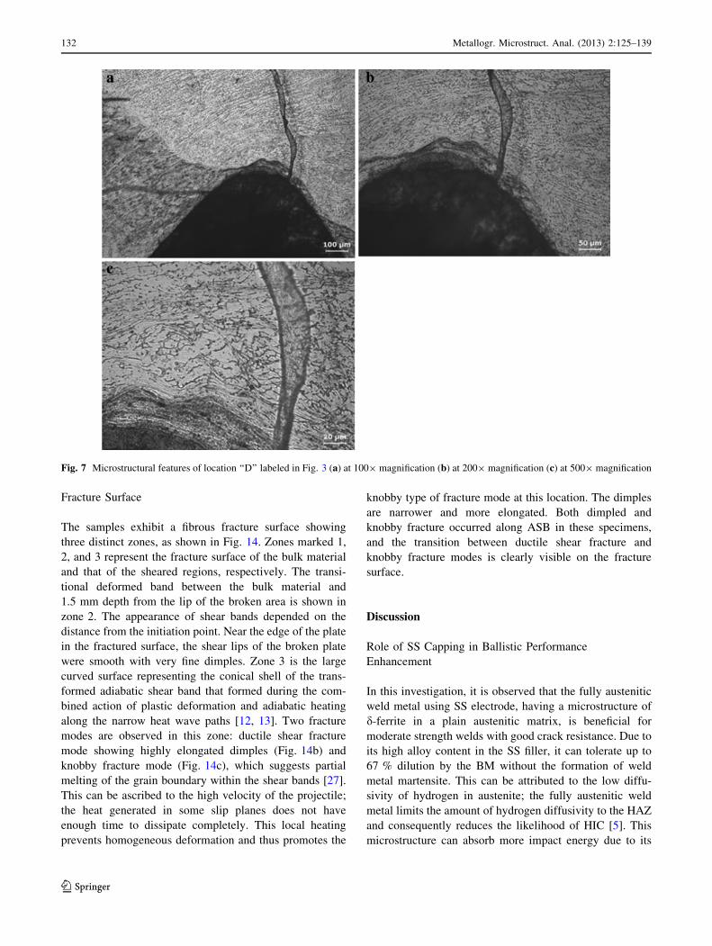
Figure 7 shows the microstructural features of location
‘‘D’’ labeled in Fig. 3. Figure 7(a) shows the target–bullet
interfacial microstructure (where the nose of the bullet was
stopped). At the root of the joint, the presence of skeletal d-
ferrite in the austenitic matrix is clearly visible in the
micrograph. A part of the hardfaced layer jammed at the
interface between the target and projectile is also evident in
the same micrograph. In Fig. 7(b), an anomalous pattern of
skeletal d-ferrite in the austenitic matrix in the immediate
vicinity of the target–projectile interface is also visible.
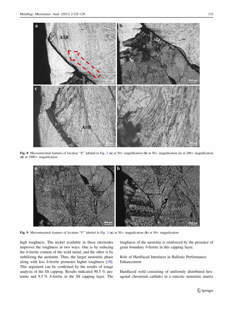
Figure 8 shows the microstructural features of location
‘‘E’’ labeled in Fig. 3. This location corresponds to the
interface between the hardfacing and SS root layer. The
microstructure (Fig. 8a) clearly shows the presence of
hanging of buttering layer and hardfaced layer. In Fig. 8(a),
the arrow indicates the plausible crack propagation direc-
tion starting from the hardfaced layer and propagating
toward the soft SS layer. In Fig. 8(b), ASBs are observed,
and adjacent to the ASBs, cracks are also seen. Figure 8(a, b)Fig. 3 Microstructure of through-thickness cross section (arrow
indicates bullet direction)
Fig. 4 Microstructural features of location ‘‘A’’ labeled in Fig. 3 (a) at 1009 magnification (b) at 10009 magnification
Metallogr. Microstruct. Anal. (2013) 2:125–139 129
123
reveals the presence of a crack in both the buttering and the
hardfaced layers after ballistic impact. In Fig. 8(c, d), the
presence of elongated austenitic grains is clearly visible
from the micrographs. This shows that these layers have
undergone considerable deformation before crack initiation
and separation of layers.
Figure 9 shows the microstructural transformation after
ballistic impact at location ‘‘F’’ (different locations of
hardfaced region alone) labeled in Fig. 3. From Fig. 9(a,
b), it is evident that numerous cracks were generated dur-
ing the ballistic impact in orientations both parallel and
normal to the bullet trajectory. The distribution and shape
of the cracks depend on the distance from the impact point.
They vary in number from one location to another in a
given target specimen and a given layer. However, in
Fig. 2(b), it is apparent that no such cracks are presented in
the hardfaced layer. This suggests that the cracks are
generated during the ballistic impact only.
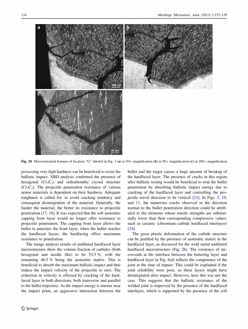
Figure 10 reveals the microstructural features of loca-
tion ‘‘G’’ (interface between SS cap and hardfaced region).
In Fig. 10(a, b), cracks are present in multiple directions. In
Fig. 10(b), crack arrest in the SS capping layer is observed.
In Fig. 10(c), the presence of cracking in the interface
between the SS capping front layer and hardfaced
interlayer is clearly visible. It is significant that the crack is
not in the soft front layer but instead is presented in the
hardfaced middle layer in the radial direction (normal to
the bullet trajectory). This can be ascribed to the fact that
the austenite matrix might have played a role in retarding
fast crack propagation as it is a ductile phase. In Fig. 10(c),
the needle-like chromium carbides are broken due to the
long cracks.
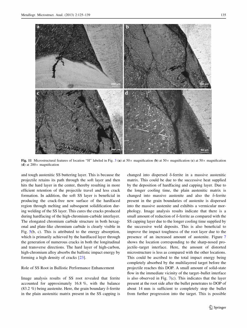
Figure 11 reveals the microstructural features of loca-
tion ‘‘H’’ labeled in Fig. 3 (the interface between SS cap-
ping/buttering layer and hardfaced region). In Fig. 11(a),
the interfaces (interface between buttering/hardfacing and
hardfacing/SS capping) are clearly visible. The presence of
cracks is observed only in the SS capping front layer but
not in the SS buttering layer. This can be ascribed to the
dilution effect of the SS capping layer with the hardfaced
layer and also the impact intensity on the front layer. This
impact intensity is comparatively lower in the SS buttering
layer, and also the available microstructure in this zone
(buttering layer) possesses higher toughness as compared
with the chromium carbide microstructure in the hardfaced
layer. Figure 11(b–d) depicts a number of microcracks and
pull-out of some parts of the hardfaced layer. However,
these cracks are completely arrested in the interface
Fig. 5 Microstructural features of location ‘‘B’’ labeled in Fig. 3 (a) at 1009 magnification (b) at 2009 magnification (c) at 5009 magnification
130 Metallogr. Microstruct. Anal. (2013) 2:125–139
123
between the SS buttering layer and hardfacing, because
these cracks are blunted by the austenite microstructure.
Hardness
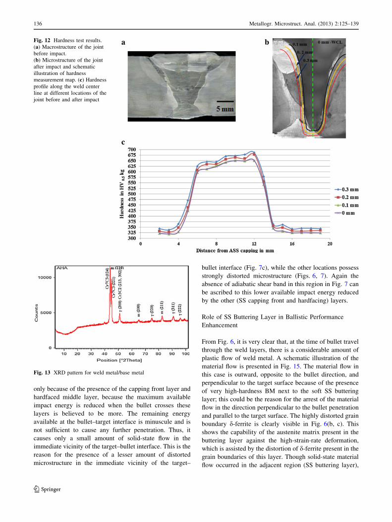
Microhardness measurements were taken along the WCL
to identify the hardness profile in the through-thickness
direction of the target plate. Similarly, hardness measure-
ments were performed as per the scheme illustrated in
Fig. 12(a) to identify the hardness alteration after the bal-
listic test at three different radial distances from the lip of
the unaffected area after projectile travel. For comparative
analysis, the hardness profile along the WCL before and
after impact is presented in a single graph (Fig. 12c). In
this graph, the hardness curve labeled ‘‘0 mm’’ is the
hardness profile along the WCL before impact and the
hardness profile along 0.4 mm from the lip of the bullet
trajectory after impact. Similarly, the hardness curves of
0.1, 0.2, and 0.3 mm are the hardness profiles after ballistic
impact at 0.1, 0.2, and 0.3 mm, respectively, from the lip of
the bullet trajectory. From these curves, it is observed that a
smaller increase in hardness was observed within the
localized area (Fig. 12b) that covered with adiabatic shear
band as seen in Figs. 6 and 8. A similar increase in
microhardness has been observed by Solberg et al. [26] in
the through-thickness direction, irrespective of weld layers.
These hardness values are just above the hardness mea-
sured in the virgin material (0 mm, hardness along WCL)
far from the shear zone.
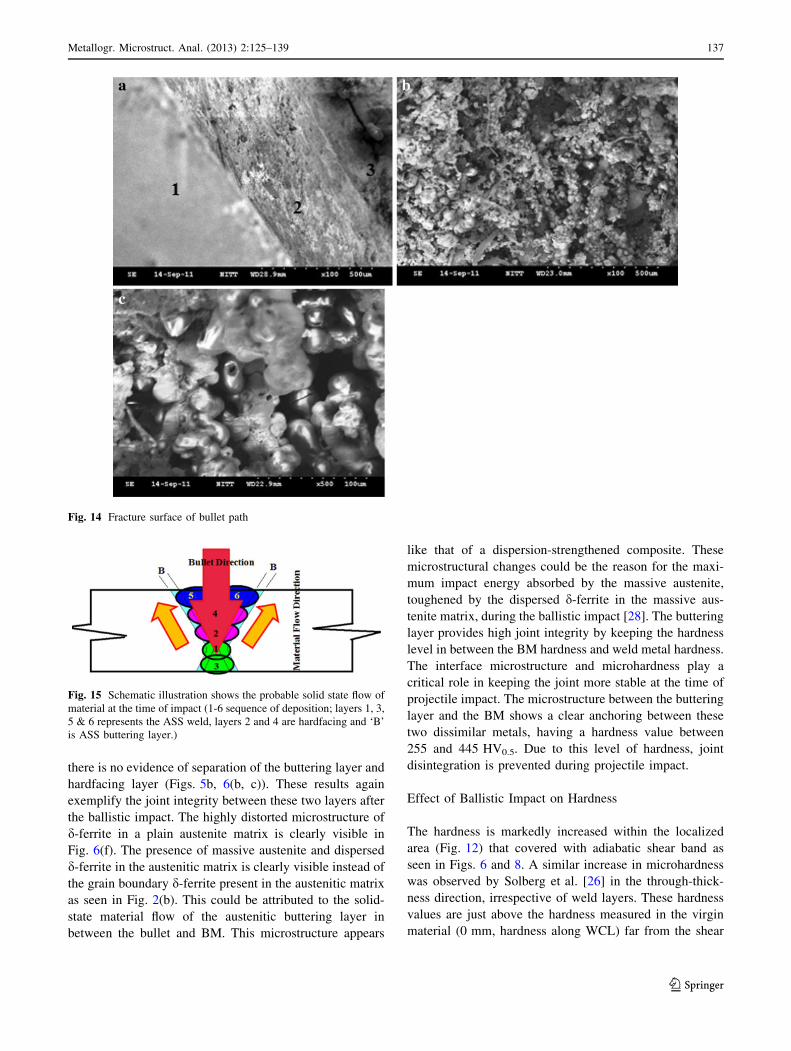
XRD Results
Comparing the XRD patterns from the two examination
locations (Fig. 13), the only difference is the presence of
chromium carbide peaks in the section containing both
weld metal and BM. The XRD results confirm the presence
of austenitic and martensitic peaks in both cases. In addi-
tion to the austenitic and martensitic peaks, the presence of
Cr7C3 and Cr3C2 is also confirmed through this XRD
analysis in this section. The main peaks of the specimen
reveal four phases: face-centered cubic (c), body-centered
cubic (m), hexagonal (Cr7C3), and orthorhombic crystal
structure (Cr2C3). As the hard chromium carbide peaks are
observed at high intensity, these results indicate that these
phases are more dominant in these layers. The presence of
austenitic phases reflects the presence of retained austenite
in these regions.
Fig. 6 Microstructural features of location ‘‘C’’ labeled in Fig. 3 (a) at 2009 magnification (b) at 5009 magnification (c) at 10009
magnification
Metallogr. Microstruct. Anal. (2013) 2:125–139 131
123
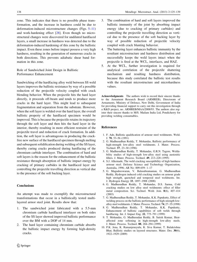
Fracture Surface
The samples exhibit a fibrous fracture surface showing
three distinct zones, as shown in Fig. 14. Zones marked 1,
2, and 3 represent the fracture surface of the bulk material
and that of the sheared regions, respectively. The transi-
tional deformed band between the bulk material and
1.5 mm depth from the lip of the broken area is shown in
zone 2. The appearance of shear bands depended on the
distance from the initiation point. Near the edge of the plate
in the fractured surface, the shear lips of the broken plate
were smooth with very fine dimples. Zone 3 is the large
curved surface representing the conical shell of the trans-
formed adiabatic shear band that formed during the com-
bined action of plastic deformation and adiabatic heating
along the narrow heat wave paths [12, 13]. Two fracture
modes are observed in this zone: ductile shear fracture
mode showing highly elongated dimples (Fig. 14b) and
knobby fracture mode (Fig. 14c), which suggests partial
melting of the grain boundary within the shear bands [27].
This can be ascribed to the high velocity of the projectile;
the heat generated in some slip planes does not have
enough time to dissipate completely. This local heating
prevents homogeneous deformation and thus promotes the
knobby type of fracture mode at this location. The dimples
are narrower and more elongated. Both dimpled and
knobby fracture occurred along ASB in these specimens,
and the transition between ductile shear fracture and
knobby fracture modes is clearly visible on the fracture
surface.
Discussion
Role of SS Capping in Ballistic Performance
Enhancement
In this investigation, it is observed that the fully austenitic
weld metal using SS electrode, having a microstructure of
d-ferrite in a plain austenitic matrix, is beneficial for
moderate strength welds with good crack resistance. Due to
its high alloy content in the SS filler, it can tolerate up to
67 % dilution by the BM without the formation of weld
metal martensite. This can be attributed to the low diffu-
sivity of hydrogen in austenite; the fully austenitic weld
metal limits the amount of hydrogen diffusivity to the HAZ
and consequently reduces the likelihood of HIC [5]. This
microstructure can absorb more impact energy due to its
Fig. 7 Microstructural features of location ‘‘D’’ labeled in Fig. 3 (a) at 1009 magnification (b) at 2009 magnification (c) at 5009 magnification
132 Metallogr. Microstruct. Anal. (2013) 2:125–139
123
high toughness. The nickel available in these electrodes
improves the toughness in two ways. One is by reducing
the d-ferrite content of the weld metal, and the other is by
stabilizing the austenite. Thus, the larger austenitic phase
along with less d-ferrite promotes higher toughness [18].
This argument can be confirmed by the results of image
analysis of the SS capping. Results indicated 90.5 % aus-
tenite and 9.5 % d-ferrite in the SS capping layer. The
toughness of the austenite is reinforced by the presence of
grain boundary d-ferrite in this capping layer.
Role of Hardfaced Interlayer in Ballistic Performance
Enhancement
Hardfaced weld consisting of uniformly distributed hex-
agonal chromium carbides in a eutectic austenitic matrix
Fig. 8 Microstructural features of location ‘‘E’’ labeled in Fig. 3 (a) at 509 magnification (b) at 509 magnification (c) at 2009 magnification
(d) at 10009 magnification
Fig. 9 Microstructural features of location ‘‘F’’ labeled in Fig. 3 (a) at 509 magnification (b) at 509 magnification
Metallogr. Microstruct. Anal. (2013) 2:125–139 133
123
possessing very high hardness can be beneficial to resist the
ballistic impact. XRD analysis confirmed the presence of
hexagonal (Cr7C3) and orthorhombic crystal structure
(Cr2C3). The projectile penetration resistance of various
armor materials is dependent on their hardness. Adequate
toughness is called for, to avoid cracking tendency and
consequent disintegration of the material. Generally, the
harder the material, the better its resistance to projectile
penetration [17, 18]. It was expected that the soft austenitic
capping front layer would no longer offer resistance to
projectile penetration. The capping front layer allows the
bullet to puncture the front layer; when the bullet reaches
the hardfaced layers, the hardfacing offers maximum
resistance to penetration.
The image analysis results of undiluted hardfaced layer
microstructure show the volume fraction of carbides (both
hexagonal and needle like) to be 53.5 %, with the
remaining 46.5 % being the austenitic matrix. This is
beneficial to absorb the maximum ballistic impact and thus
reduce the impact velocity of the projectile to zero. The
reduction in velocity is effected by cracking of the hard-
faced layer in both directions, both transverse and parallel
to the bullet trajectory. As the impact energy is intense near
the impact point, an aggressive interaction between the
bullet and the target causes a large amount of breakup of
the hardfaced layer. The presence of cracks in this region
after ballistic testing would be beneficial to stop the bullet
penetration by absorbing ballistic impact energy due to
cracking of the hardfaced layer and controlling the pro-
jectile travel direction to be vertical [23]. In Figs. 5, 10,
and 11, the numerous cracks observed in the direction
normal to the bullet penetration direction could be attrib-
uted to the elements whose tensile strengths are substan-
tially lower than their corresponding compressive values,
such as ceramic (chromium carbide hardfaced interlayer)
[24].
The gross plastic deformation of the carbide structure
can be justified by the presence of austenitic matrix in the
hardfaced layer, as discussed for the weld metal undiluted
hardfaced microstructure (Fig. 2b). The existence of mi-
crovoids at the interface between the buttering layer and
hardfaced layer in Fig. 6(d) reflects the competence of the
joint at the time of impact. This could be explained if the
joint reliability were poor, so these layers might have
disintegrated after impact. However, here this was not the
case. This suggests that the ballistic resistance of the
welded joint is improved by the presence of the hardfaced
interlayer, which is supported by the presence of the soft
Fig. 10 Microstructural features of location ‘‘G’’ labeled in Fig. 3 (a) at 509 magnification (b) at 509 magnification (c) at 2009 magnification
134 Metallogr. Microstruct. Anal. (2013) 2:125–139
123
and tough austenitic SS buttering layer. This is because the
projectile retains its path through the soft layer and then
hits the hard layer in the center, thereby resulting in more
efficient retention of the projectile travel and less crack
formation. In addition, the soft SS layer is beneficial in
producing the crack-free new surface of the hardfaced
region through melting and subsequent solidification dur-
ing welding of the SS layer. This cures the cracks produced
during hardfacing of the high-chromium-carbide interlayer.
The elongated chromium carbide structure in both hexag-
onal and plate-like chromium carbide is clearly visible in
Fig. 5(b, c). This is attributed to the energy absorption,
which is primarily achieved by the hardfaced layer through
the generation of numerous cracks in both the longitudinal
and transverse directions. The hard layer of high-carbon,
high-chromium alloy absorbs the ballistic impact energy by
forming a high density of cracks [23].
Role of SS Root in Ballistic Performance Enhancement
Image analysis results of SS root revealed that ferrite
accounted for approximately 16.8 %, with the balance
(83.2 %) being austenite. Here, the grain boundary d-ferrite
in the plain austenitic matrix present in the SS capping is
changed into dispersed d-ferrite in a massive austenitic
matrix. This could be due to the successive heat supplied
by the deposition of hardfacing and capping layer. Due to
the longer cooling time, the plain austenitic matrix is
changed into massive austenite and also the d-ferrite
present in the grain boundaries of austenite is dispersed
into the massive austenite and exhibits a vermicular mor-
phology. Image analysis results indicate that there is a
small amount of reduction of d-ferrite as compared with the
SS capping layer due to the longer cooling time supplied by
the successive weld deposits. This is also beneficial to
improve the impact toughness of the root layer due to the
presence of an increased amount of austenite. Figure 7
shows the location corresponding to the sharp-nosed pro-
jectile–target interface. Here, the amount of distorted
microstructure is less as compared with the other locations.
This could be ascribed to the total impact energy being
completely absorbed by the multilayered target before the
projectile reaches this DOP. A small amount of solid-state
flow in the immediate vicinity of the target–bullet interface
is also observed in Fig. 7(c). This indicates that the layer
present at the root side after the bullet penetrates to DOP of
about 14 mm is sufficient to completely stop the bullet
from further progression into the target. This is possible
Fig. 11 Microstructural features of location ‘‘H’’ labeled in Fig. 3 (a) at 509 magnification (b) at 509 magnification (c) at 509 magnification
(d) at 2009 magnification
Metallogr. Microstruct. Anal. (2013) 2:125–139 135
123
only because of the presence of the capping front layer and
hardfaced middle layer, because the maximum available
impact energy is reduced when the bullet crosses these
layers is believed to be more. The remaining energy
available at the bullet–target interface is minuscule and is
not sufficient to cause any further penetration. Thus, it
causes only a small amount of solid-state flow in the
immediate vicinity of the target–bullet interface. This is the
reason for the presence of a lesser amount of distorted
microstructure in the immediate vicinity of the target–
bullet interface (Fig. 7c), while the other locations possess
strongly distorted microstructure (Figs. 6, 7). Again the
absence of adiabatic shear band in this region in Fig. 7 can
be ascribed to this lower available impact energy reduced
by the other (SS capping front and hardfacing) layers.
Role of SS Buttering Layer in Ballistic Performance
Enhancement
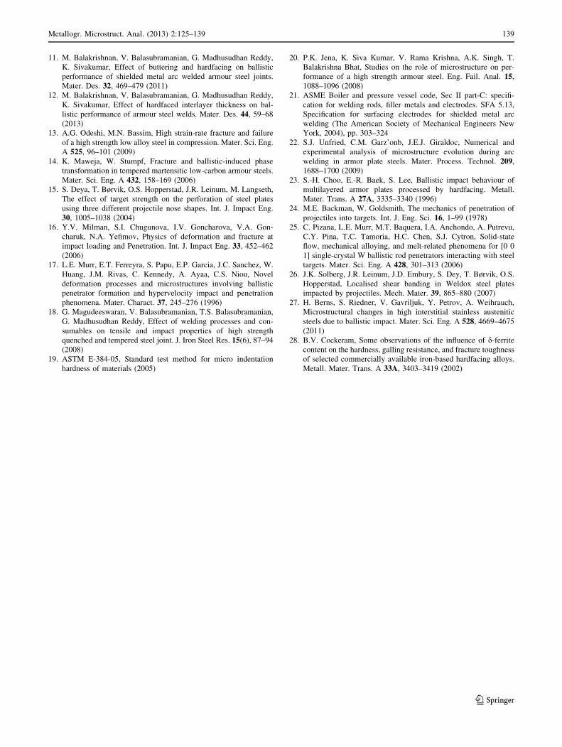
From Fig. 6, it is very clear that, at the time of bullet travel
through the weld layers, there is a considerable amount of
plastic flow of weld metal. A schematic illustration of the
material flow is presented in Fig. 15. The material flow in
this case is outward, opposite to the bullet direction, and
perpendicular to the target surface because of the presence
of very high-hardness BM next to the soft SS buttering
layer; this could be the reason for the arrest of the material
flow in the direction perpendicular to the bullet penetration
and parallel to the target surface. The highly distorted grain
boundary d-ferrite is clearly visible in Fig. 6(b, c). This
shows the capability of the austenite matrix present in the
buttering layer against the high-strain-rate deformation,
which is assisted by the distortion of d-ferrite present in the
grain boundaries of this layer. Though solid-state material
flow occurred in the adjacent region (SS buttering layer),
Fig. 12 Hardness test results.
(a) Macrostructure of the joint
before impact.
(b) Microstructure of the joint
after impact and schematic
illustration of hardness
measurement map. (c) Hardness
profile along the weld center
line at different locations of the
joint before and after impact
Fig. 13 XRD pattern for weld metal/base metal
136 Metallogr. Microstruct. Anal. (2013) 2:125–139
123
there is no evidence of separation of the buttering layer and
hardfacing layer (Figs. 5b, 6(b, c)). These results again
exemplify the joint integrity between these two layers after
the ballistic impact. The highly distorted microstructure of
d-ferrite in a plain austenite matrix is clearly visible in
Fig. 6(f). The presence of massive austenite and dispersed
d-ferrite in the austenitic matrix is clearly visible instead of
the grain boundary d-ferrite present in the austenitic matrix
as seen in Fig. 2(b). This could be attributed to the solid-
state material flow of the austenitic buttering layer in
between the bullet and BM. This microstructure appears
like that of a dispersion-strengthened composite. These
microstructural changes could be the reason for the maxi-
mum impact energy absorbed by the massive austenite,
toughened by the dispersed d-ferrite in the massive aus-
tenite matrix, during the ballistic impact [28]. The buttering
layer provides high joint integrity by keeping the hardness
level in between the BM hardness and weld metal hardness.
The interface microstructure and microhardness play a
critical role in keeping the joint more stable at the time of
projectile impact. The microstructure between the buttering
layer and the BM shows a clear anchoring between these
two dissimilar metals, having a hardness value between
255 and 445 HV0.5. Due to this level of hardness, joint
disintegration is prevented during projectile impact.
Effect of Ballistic Impact on Hardness
The hardness is markedly increased within the localized
area (Fig. 12) that covered with adiabatic shear band as
seen in Figs. 6 and 8. A similar increase in microhardness
was observed by Solberg et al. [26] in the through-thick-
ness direction, irrespective of weld layers. These hardness
values are just above the hardness measured in the virgin
material (0 mm, hardness along WCL) far from the shear
Fig. 14 Fracture surface of bullet path
Fig. 15 Schematic illustration shows the probable solid state flow of
material at the time of impact (1-6 sequence of deposition; layers 1, 3,
5 & 6 represents the ASS weld, layers 2 and 4 are hardfacing and ‘B’
is ASS buttering layer.)
Metallogr. Microstruct. Anal. (2013) 2:125–139 137
123
zone. This indicates that there is no possible phase trans-
formation, and the increase in hardness could be due to
deformation-induced microstructure changes (Figs. 5–11)
and work-hardening effect [28]. Even though no micro-
structural changes were discovered for undiluted hardfaced
layers, a small increase in hardness was detected due to the
deformation-induced hardening of this zone by the ballistic
impact. Even these zones before impact possess a very high
hardness, resulting in the generation of numerous cracks in
both directions. This prevents adiabatic shear band for-
mation in this zone.
Role of Sandwiched Joint Design in Ballistic
Performance Enhancement
Sandwiching of the hardfacing alloy weld between SS weld
layers improves the ballistic resistance by way of a possible
reduction of the projectile velocity coupled with crack
blending behavior. When the projectile hits the hard layer
directly, it proceeds off-beam and tends to produce more
cracks in the hard layer. This might lead to subsequent
fragmentation and separation from the substrate. However,
when the soft layer is welded over the hard layer, the overall
ballistic property of the hardfaced specimen would be
improved. This is because the projectile retains its trajectory
through the soft layer and then hits the hard layer in the
interior, thereby resulting in more efficient restraint of the
projectile travel and reduction of crack formation. In addi-
tion, the soft layer is advantageous in producing the crack-
free new surface of the hardfaced specimen through melting
and subsequent solidification during welding of the SS layer,
thereby curing cracks produced during hardfacing of the
chromium carbide interlayer. The combination of hard and
soft layers is the reason for the enhancement of the ballistic
resistance through absorption of ballistic impact energy by
cracking of primary carbides in the hardfaced layer and
controlling the projectile travelling direction as vertical due
to the presence of the soft backing layer.
Conclusions
An attempt was made to exemplify the microstructural
transformations that occur in a ballistically tested multi-
layered armor steel joint. Results show that:
1. The sandwiched joint fabricated with a 5.5-mm
chromium carbide hardfaced interlayer on both sides
of the SS layer showed improved ballistic performance
over the BM with a DOP of 14 mm.
2. The hard layer containing chromium carbide absorbs
the ballistic impact energy by forming high-density
cracks.
3. The combination of hard and soft layers improved the
ballistic immunity of the joint by absorbing impact
energy (due to cracking of primary carbides) and
controlling the projectile travelling direction as verti-
cal due to the presence of the soft backing layer by
way of possible reduction of projectile velocity
coupled with crack blunting behavior.
4. The buttering layer enhances ballistic immunity by the
resultant microstructure and hardness distribution and
successfully keeps the weld layers intact when the
projectile is fired at the WCL, interfaces, and HAZ.
5. At the WCL, further investigation is required for
analytical correlation of the projectile shattering
mechanism and resulting hardness distribution,
because this study correlated the ballistic test results
with the resultant microstructure and microhardness
values.
Acknowledgments The authors wish to record their sincere thanks
to the Armament Research Board (ARMREB), Directorate of
Armaments, Ministry of Defence, New Delhi, Government of India
for providing financial support to carry out this investigation through
a R&D project, no. ARMREB/MAA/2008/93. The authors also reg-
ister their sincere thanks to M/S. Mailam India Ltd, Pondicherry for
providing welding consumables.
References
1. F. Ade, Ballistic qualification of armour steel weldments. Weld.
J. 70, 53–56 (1991)
2. G. Madhusudhan Reddy, T. Mohandas, Ballistic performance of
high-strength low-alloy steel weldments. J. Mater. Process.
Technol. 57, 23–30 (1996)
3. G. Madhusudhan Reddy, T. Mohandas, G.R.N. Tagore, Welda-
bility studies of high-strength low-alloy steel using austenitic
fillers. J. Mater. Process. Technol. 49, 213–228 (1995)
4. S.J. Alkemade, The weld cracking susceptibility of high hardness
armour steel. Defense Science and Technology Organization,
Australia, 1996; AR No: 009-659: 1–17
5. G. Magudeeswaran, V. Balasubramanian, G. Madhusudhan
Reddy, Hydrogen induced cold cracking studies on armour grade
high strength, quenched and tempered steel weldments. Int.
J. Hydrogen Energy 33, 1897–1908 (2008)
6. G. Madhusudhan Reddy, T. Mohandas, D.S. Sarma, Cold
cracking studies on low alloy steel weldments: effect of filler
metal composition. Sci. Technol. Weld. Join. 8(6), 407–414
(2003)
7. G. Madhusudhan Reddy, T. Mohandas, K.K. Papukutty, Effect of
welding process on the ballistic performance of high-strength low-
alloy steel weldments. J. Mater. Process. Technol. 74, 27–35 (1998)
8. G. Madhusudhan Reddy, T. Mohandas, K.K. Papukutty,
Enhancement of ballistic capabilities of soft welds through
hardfacing. Int. J. Impact Eng. 22, 775–791 (1999)
9. T. Mohandas, G. Madhusudan Reddy, B. Satish Kumar, Heat-
affected zone softening in high-strength low-alloy steels.
J. Mater. Process. Technol. 88, 284–294 (1999)
10. P.K. Jena, K. Ramanjeneyulu, K. Siva Kumar, T. Balakrishna
Bhat, Ballistic studies on layered structures. Mater. Des. 30(6),
1922–1929 (2009)
138 Metallogr. Microstruct. Anal. (2013) 2:125–139
123
11. M. Balakrishnan, V. Balasubramanian, G. Madhusudhan Reddy,
K. Sivakumar, Effect of buttering and hardfacing on ballistic
performance of shielded metal arc welded armour steel joints.
Mater. Des. 32, 469–479 (2011)
12. M. Balakrishnan, V. Balasubramanian, G. Madhusudhan Reddy,
K. Sivakumar, Effect of hardfaced interlayer thickness on bal-
listic performance of armour steel welds. Mater. Des. 44, 59–68
(2013)
13. A.G. Odeshi, M.N. Bassim, High strain-rate fracture and failure
of a high strength low alloy steel in compression. Mater. Sci. Eng.
A 525, 96–101 (2009)
14. K. Maweja, W. Stumpf, Fracture and ballistic-induced phase
transformation in tempered martensitic low-carbon armour steels.
Mater. Sci. Eng. A 432, 158–169 (2006)
15. S. Deya, T. Børvik, O.S. Hopperstad, J.R. Leinum, M. Langseth,
The effect of target strength on the perforation of steel plates
using three different projectile nose shapes. Int. J. Impact Eng.
30, 1005–1038 (2004)
16. Y.V. Milman, S.I. Chugunova, I.V. Goncharova, V.A. Gon-
charuk, N.A. Yefimov, Physics of deformation and fracture at
impact loading and Penetration. Int. J. Impact Eng. 33, 452–462
(2006)
17. L.E. Murr, E.T. Ferreyra, S. Papu, E.P. Garcia, J.C. Sanchez, W.
Huang, J.M. Rivas, C. Kennedy, A. Ayaa, C.S. Niou, Novel
deformation processes and microstructures involving ballistic
penetrator formation and hypervelocity impact and penetration
phenomena. Mater. Charact. 37, 245–276 (1996)
18. G. Magudeeswaran, V. Balasubramanian, T.S. Balasubramanian,
G. Madhusudhan Reddy, Effect of welding processes and con-
sumables on tensile and impact properties of high strength
quenched and tempered steel joint. J. Iron Steel Res. 15(6), 87–94
(2008)
19. ASTM E-384-05, Standard test method for micro indentation
hardness of materials (2005)
20. P.K. Jena, K. Siva Kumar, V. Rama Krishna, A.K. Singh, T.
Balakrishna Bhat, Studies on the role of microstructure on per-
formance of a high strength armour steel. Eng. Fail. Anal. 15,
1088–1096 (2008)
21. ASME Boiler and pressure vessel code, Sec II part-C: specifi-
cation for welding rods, filler metals and electrodes. SFA 5.13,
Specification for surfacing electrodes for shielded metal arc
welding (The American Society of Mechanical Engineers New
York, 2004), pp. 303–324
22. S.J. Unfried, C.M. Garz’onb, J.E.J. Giraldoc, Numerical and
experimental analysis of microstructure evolution during arc
welding in armor plate steels. Mater. Process. Technol. 209,
1688–1700 (2009)
23. S.-H. Choo, E.-R. Baek, S. Lee, Ballistic impact behaviour of
multilayered armor plates processed by hardfacing. Metall.
Mater. Trans. A 27A, 3335–3340 (1996)
24. M.E. Backman, W. Goldsmith, The mechanics of penetration of
projectiles into targets. Int. J. Eng. Sci. 16, 1–99 (1978)
25. C. Pizana, L.E. Murr, M.T. Baquera, I.A. Anchondo, A. Putrevu,
C.Y. Pina, T.C. Tamoria, H.C. Chen, S.J. Cytron, Solid-state
flow, mechanical alloying, and melt-related phenomena for [0 0
1] single-crystal W ballistic rod penetrators interacting with steel
targets. Mater. Sci. Eng. A 428, 301–313 (2006)
26. J.K. Solberg, J.R. Leinum, J.D. Embury, S. Dey, T. Børvik, O.S.
Hopperstad, Localised shear banding in Weldox steel plates
impacted by projectiles. Mech. Mater. 39, 865–880 (2007)
27. H. Berns, S. Riedner, V. Gavriljuk, Y. Petrov, A. Weihrauch,
Microstructural changes in high interstitial stainless austenitic
steels due to ballistic impact. Mater. Sci. Eng. A 528, 4669–4675
(2011)
28. B.V. Cockeram, Some observations of the influence of d-ferrite
content on the hardness, galling resistance, and fracture toughness
of selected commercially available iron-based hardfacing alloys.
Metall. Mater. Trans. A 33A, 3403–3419 (2002)
Metallogr. Microstruct. Anal. (2013) 2:125–139 139
123