Embed Size (px)
Citation preview
a3 I,c ^^ sJ
NASA
AVSCOMTechnical Memorandum 103772
Technical Report 91-C-014
Microstructural and Strength Stabilityof CVD SiC Fibers in ArgonEnvironment
Ramakrishna T. BllattPropulsion DirectorateU.S. Army Aviation Systems Command
Lewis Research CenterCleveland, Ohio
and
David R. HullLewis Research CenterCleveland, Ohio
Prepared for the15th Annual Conference on Composites and Advanced Ceramicssponsored by the American Ceramic SocietyCocoa Beach, Florida, January 13-16, 1991
US ARMY
NASA SYSTEMSAVIATION
COMMAND
https://ntrs.nasa.gov/search.jsp?R=19910019936 2018-07-15T13:53:35+00:00Z
MICROSTRUCTURAL AND STRENGTH STABILITY OF CVD SiC FIBERS
IN ARGON ENVIRONMENT
Ramakrishna T. BhattPropulsion Directorate
U.S. Army Aviation Systems CommandLewis Research CenterCleveland, Ohio 44135
and
David R. HullNational Aeronautics and Space Administration
Lewis Research CenterCleveland, Ohio 44135
ABSTRACT
The room temperature tensile strength and microstructure of three
types of commercially available chemically vapor deposited silicon
carbide fibers were measured after 1, 10, and 100 hr heat-treatments
under argon pressures of 0.1 to 310 MPa at temperatures to 21000C.
Two types of fiber had carbon-rich surface coatings and the other
contained no coating. All three fiber types showed strength
degradation beyond 1400 0C. Time and temperature of exposure had
greater influence on strength degradation than argon pressure.
Recrystallization and growth of near-stoichiometric SiC grains appears
to be the dominant mechanism for the strength degradation.
INTRODUCTION
Because of their high as-fabricated strength, modulus, chemical
compatibility, and purity, chemically vapor deposited (CVD) SiC fibers
are currently being used as reinforcement for silicon-based ceramic
matrix composites. These composites are being developed for potential_
application in advanced heat engines where service temperatures may
exceed 1400 0C. Previous studies' have shown that reinforced silicon
nitride matrix composites fabricated by reaction forming methods show
good room-temperature mechanical properties because at the fabrication
temperatures near 1200 0 C the CVD SiC fibers retain a great fraction of
their as-fabricated strength. However, because of interconnected
matrix porosity, these composites show poor oxidative stability at
intermediate temperatures. This problem can be avoided by higher
temperature fabrication approaches that yield fully dense matrices.
But fully dense matrices fabricated by methods such as hot-pressing
and hot-isostatic pressing show significantly lower ultimate tensile
strength, primarily due to strength degradation of the fiber at the
fabrication temperature and possibly due to reaction between the fiber
and the matrix 2-3 . For optimizing the processing variables and for
predicting long term durability of fully dense CVD SiC fiber
reinforced composites, a basic understanding of thermo-mechanical
stability of the fibers in fabrication environments and in contact
with the matrix containing sintering additives are required.
This study had three major objectives: first, to determine the
strength and microstructural stability of CVD SiC fibers in high
temperature argon environments; second, to investigate the intrinsic
strength degrading mechanisms; third, to suggest possible methods of
improving their thermal stability.
2
EXPERIMENTAL
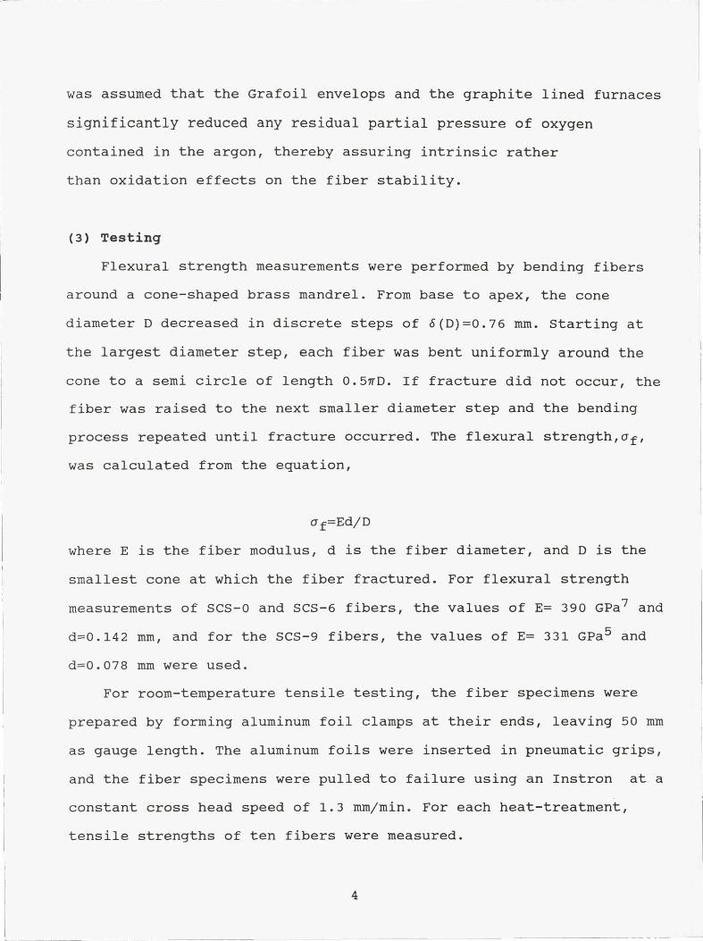
(1) Materials
Three types CVD SiC fibers produced by Textron Specialty Materials
Division were studied. Manufacturers designations for these fibers
are SCS-0, SCS-6, and SCS-9. The fibers were produced by chemical
vapor deposition of SiC onto a heated pyrolytic graphite coated
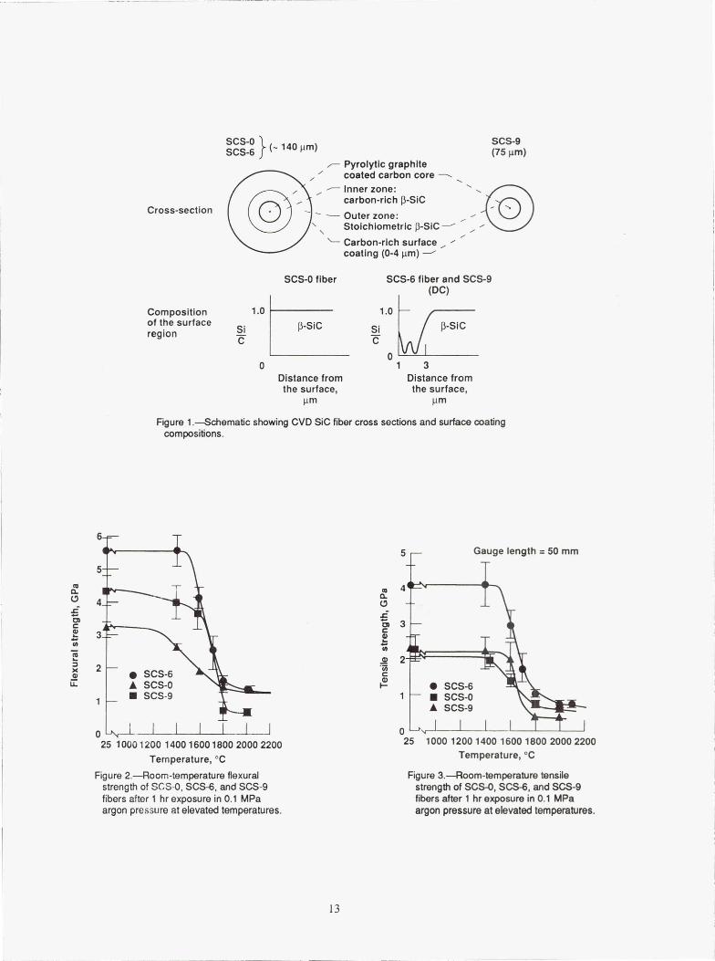
carbon core with an outer diameter of 37 µm. Schematics of the fiber
cross-sections are shown in Fig. 1(a). Both SCS-0 and SCS-6 fibers
were grown to a diameter of - 140 µm and consist of two distinct
zones. The inner zone consists of carbon-rich Q-SiC grains and the
outer zone of near-stoichoimetric Q-SiC grains4.
The SCS-9 was grown to a diameter of 75 µm and contained a
single zone of near-stoichiometric SiC grains 5 . A complex carbon-rich
coating 6 was also deposited on SCS-6 and SCS-9 fibers while SCS-0
fibers contained no surface coating. The approximate composition of
this surface coating is shown in Fig. 1(b)
(2) Heat Treatments
The SiC fibers were heat-treated under argon pressures of 0.1,
138, and 310 MPa from 1200 0 to 2200 0 C at 200 0 C interval for 1, 10, and
100 hr. For all heat-treatments, batches of twenty-five individual
fibers of length 125 mm were placed in grafoil envelopes and loaded in
graphite furnaces. The type of furnaces used depended on argon
pressure. For 0.1 MPa heat-treatment, a graphite lined induction
furnace was used, whereas for high pressure argon treatments, a
graphite resistance heated hot-isostatic press was used. Because
graphite will oxidize more readily at lower temperature than SiC, it
3
was assumed that the Grafoil envelops and the graphite lined furnaces
significantly reduced any residual partial pressure of oxygen
contained in the argon, thereby assuring intrinsic rather
than oxidation effects on the fiber stability.
(3) Testing
Flexural strength measurements were performed by bending fibers
around a cone-shaped brass mandrel. From base to apex, the cone
diameter D decreased in discrete steps of b(D)=0.76 mm. Starting at
the largest diameter step, each fiber was bent uniformly around the
cone to a semi circle of length 0.5vD. If fracture did not occur, the
fiber was raised to the next smaller diameter step and the bending
process repeated until fracture occurred. The flexural strength,cf,
was calculated from the equation,
u f=Ed/D
where E is the fiber modulus, d is the fiber diameter, and D is the
smallest cone at which the fiber fractured. For flexural strength
measurements of SCS-0 and SCS-6 fibers, the values of E= 390 GPa 7 and
d=0.142 mm, and for the SCS-9 fibers, the values of E= 331 GPa 5 and
d=0.078 mm were used.
For room-temperature tensile testing, the fiber specimens were
prepared by forming aluminum foil clamps at their ends, leaving 50 mm
as gauge length. The aluminum foils were inserted in pneumatic grips,
and the fiber specimens were pulled to failure using an Instron at a
constant cross head speed of 1.3 mm/min. For each heat-treatment,
tensile strengths of ten fibers were measured.
4
(4) Microstructural Characterization
For microstructural analysis and grain size measurements, - 2 cm
long fibers, both as-received and heat-treated, were embedded in an
epoxy mold. The mold was initially ground on diamond impregnated metal
discs and finally polished on a vibratory polisher using micro-cloth
and 0.03 µm diamond slurry. The polished specimens were etched with
Murakami's reagent or with flurocarbon plasma to delineate the grain
boundaries, coated with a thin layer of palladium, and examined in a
scanning electron microscope equipped with an energy dispersive X-Ray
spectrometer (XEDS).
To determine phase stability, heat-treated fibers were analyzed by
X-Ray diffraction (XRD). The XRD runs were made at a scanning speed of
1 deg/min using standard equipment with a Ni filter and Cu Ka
radiation.
RESULTS
Strength After Exposure
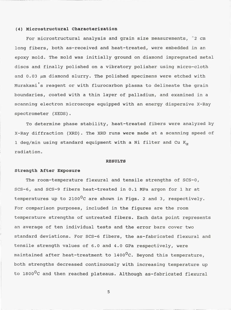
The room-temperature flexural and tensile strengths of SCS-0,
SCS-6, and SCS-9 fibers heat-treated in 0.1 MPa argon for 1 hr at
temperatures up to 2100 0C are shown in Figs. 2 and 3, respectively.
For comparison purposes, included in the figures are the room
temperature strengths of untreated fibers. Each data point represents
an average of ten individual tests and the error bars cover two
standard deviations. For SCS-6 fibers, the as-fabricated flexural and
tensile strength values of 6.0 and 4.0 GPa respectively, were
maintained after heat-treatment to 1400 0C. Beyond this temperature,
both strengths decreased continuously with increasing temperature up
to 1800 0C and then reached plateaus. Although as-fabricated flexural
5
and tensile strengths of SCS-0 and SCS-9 were significantly lower than
those of SCS-6 fibers, both fibers showed strength loss trends similar
to that of SCS-6 fibers.
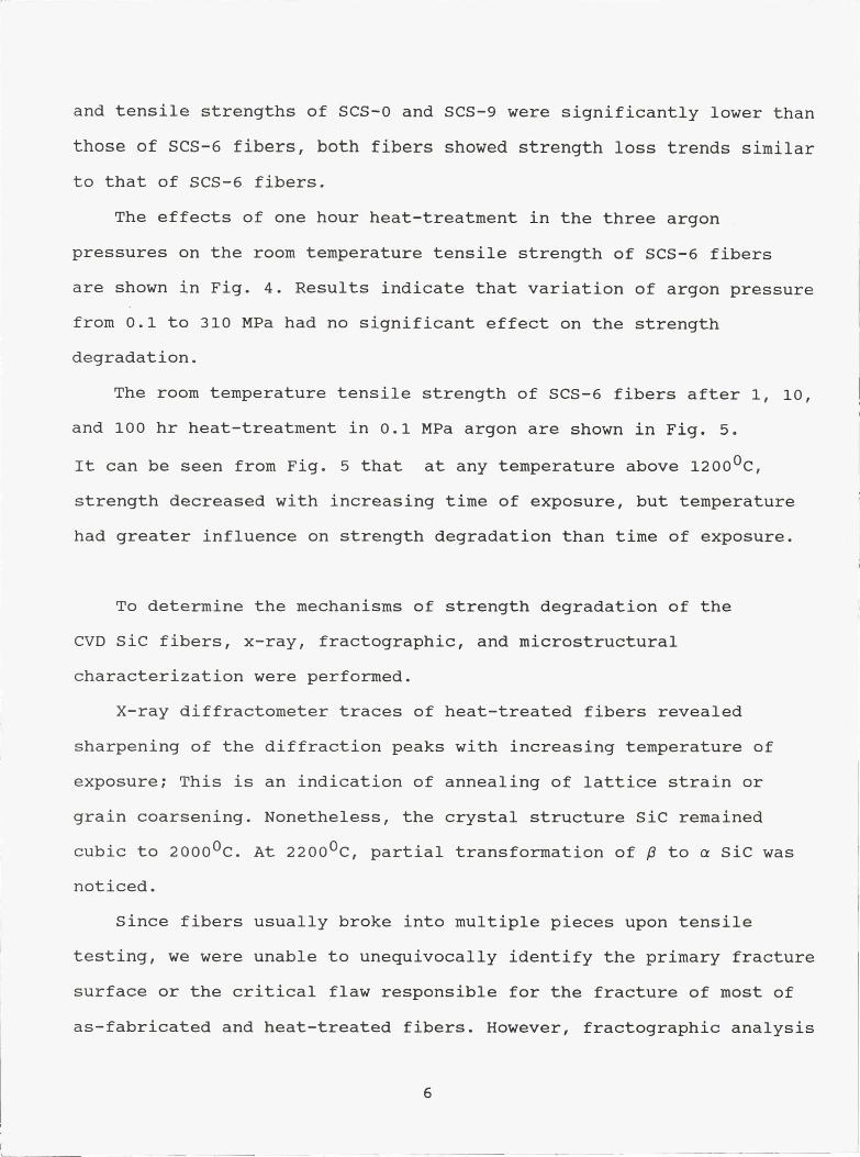
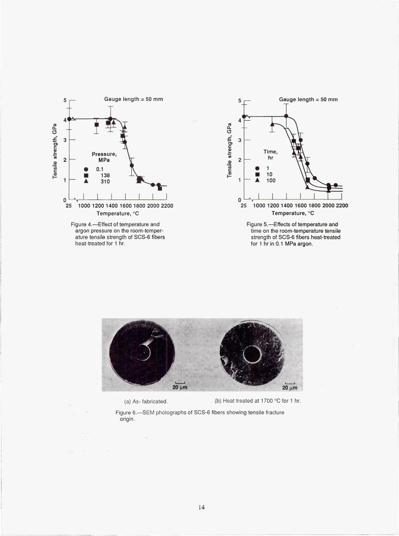
The effects of one hour heat-treatment in the three argon
pressures on the room temperature tensile strength of SCS-6 fibers
are shown in Fig. 4. Results indicate that variation of argon pressure
from 0.1 to 310 MPa had no significant effect on the strength
degradation.
The room temperature tensile strength of SCS-6 fibers after 1, 10,
and 100 hr heat-treatment in 0.1 MPa argon are shown in Fig. 5.
It can be seen from Fig. 5 that at any temperature above 12000C,
strength decreased with increasing time of exposure, but temperature
had greater influence on strength degradation than time of exposure.
To determine the mechanisms of strength degradation of the
CVD SiC fibers, x-ray, fractographic, and microstructural
characterization were performed.
X-ray diffractometer traces of heat-treated fibers revealed
sharpening of the diffraction peaks with increasing temperature of
exposure; This is an indication of annealing of lattice strain or
grain coarsening. Nonetheless, the crystal structure SiC remained
cubic to 2000 0 C. At 2200 0 C, partial transformation of Q to a SiC was
noticed.
Since fibers usually broke into multiple pieces upon tensile
testing, we were unable to unequivocally identify the primary fracture
surface or the critical flaw responsible for the fracture of most of
as-fabricated and heat-treated fibers. However, fractographic analysis
6
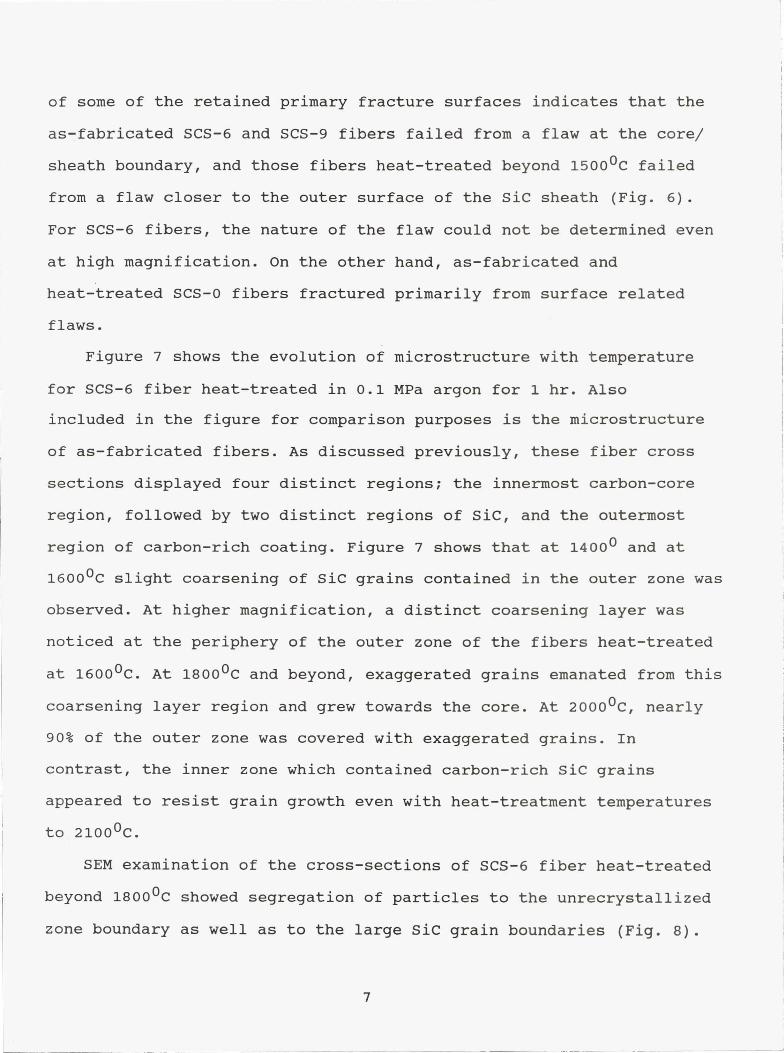
of some of the retained primary fracture surfaces indicates that the
as-fabricated SCS-6 and SCS-9 fibers failed from a flaw at the core/
sheath boundary, and those fibers heat-treated beyond 1500 0C failed
from a flaw closer to the outer surface of the SiC sheath (Fig. 6).
For SCS-6 fibers, the nature of the flaw could not be determined even
at high magnification. On the other hand, as-fabricated and
heat-treated SCS-0 fibers fractured primarily from surface related
flaws.
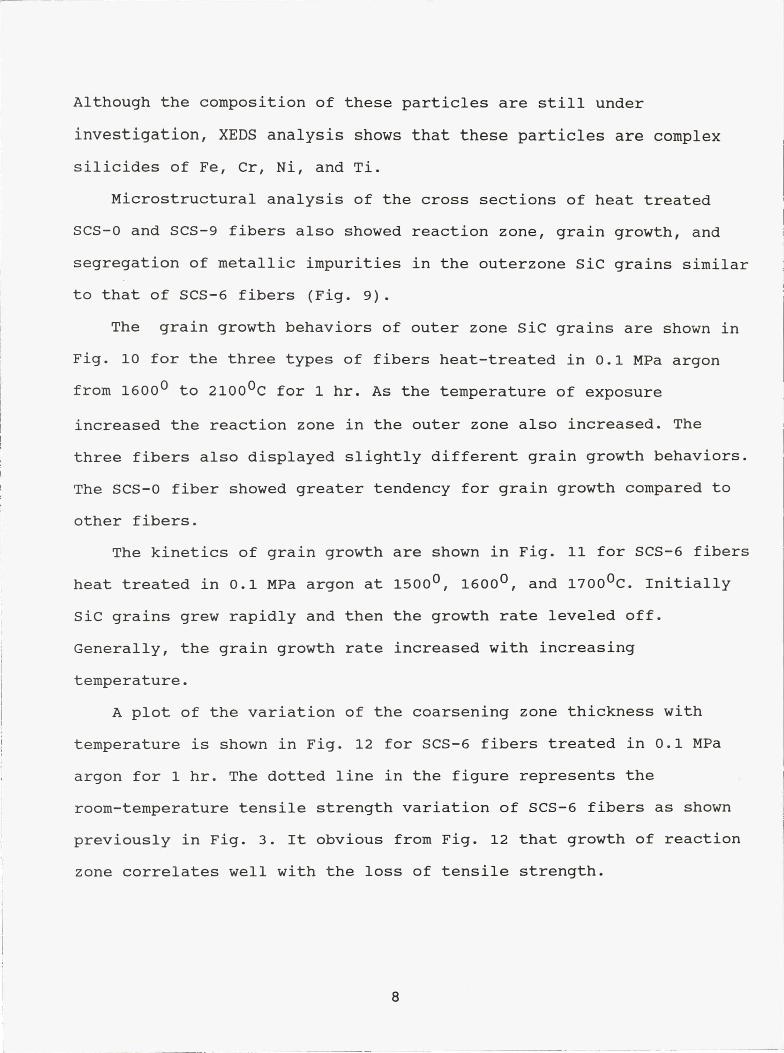
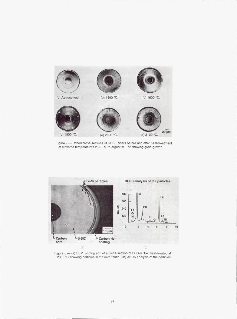
Figure 7 shows the evolution of microstructure with temperature
for SCS-6 fiber heat-treated in 0.1 MPa argon for 1 hr. Also
included in the figure for comparison purposes is the microstructure
of as-fabricated fibers. As discussed previously, these fiber cross
sections displayed four distinct regions; the innermost carbon-core
region, followed by two distinct regions of SiC, and the outermost
region of carbon-rich coating. Figure 7 shows that at 1400 0 and at
1600 0C slight coarsening of SiC grains contained in the outer zone was
observed. At higher magnification, a distinct coarsening layer was
noticed at the periphery of the outer zone of the fibers heat-treated
at 1600 0C. At 1800 0 C and beyond, exaggerated grains emanated from this
coarsening layer region and grew towards the core. At 2000 0C, nearly
90% of the outer zone was covered with exaggerated grains. In
contrast, the inner zone which contained carbon-rich SiC grains
appeared to resist grain growth even with heat-treatment temperatures
to 21000C.
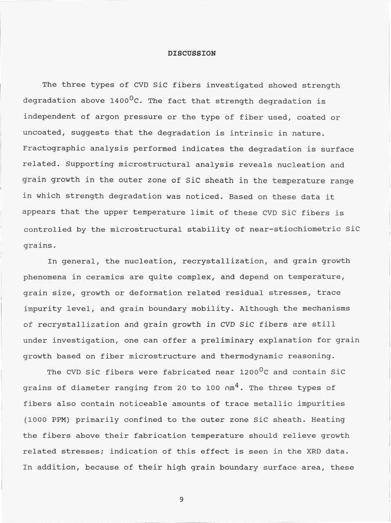
SEM examination of the cross-sections of SCS-6 fiber heat-treated
beyond 1800 0 C showed segregation of particles to the unrecrystallized
zone boundary as well as to the large SiC grain boundaries (Fig. 8).
7
Although the composition of these particles are still under
investigation, XEDS analysis shows that these particles are complex
silicides of Fe, Cr, Ni, and Ti.
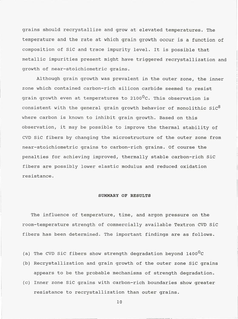
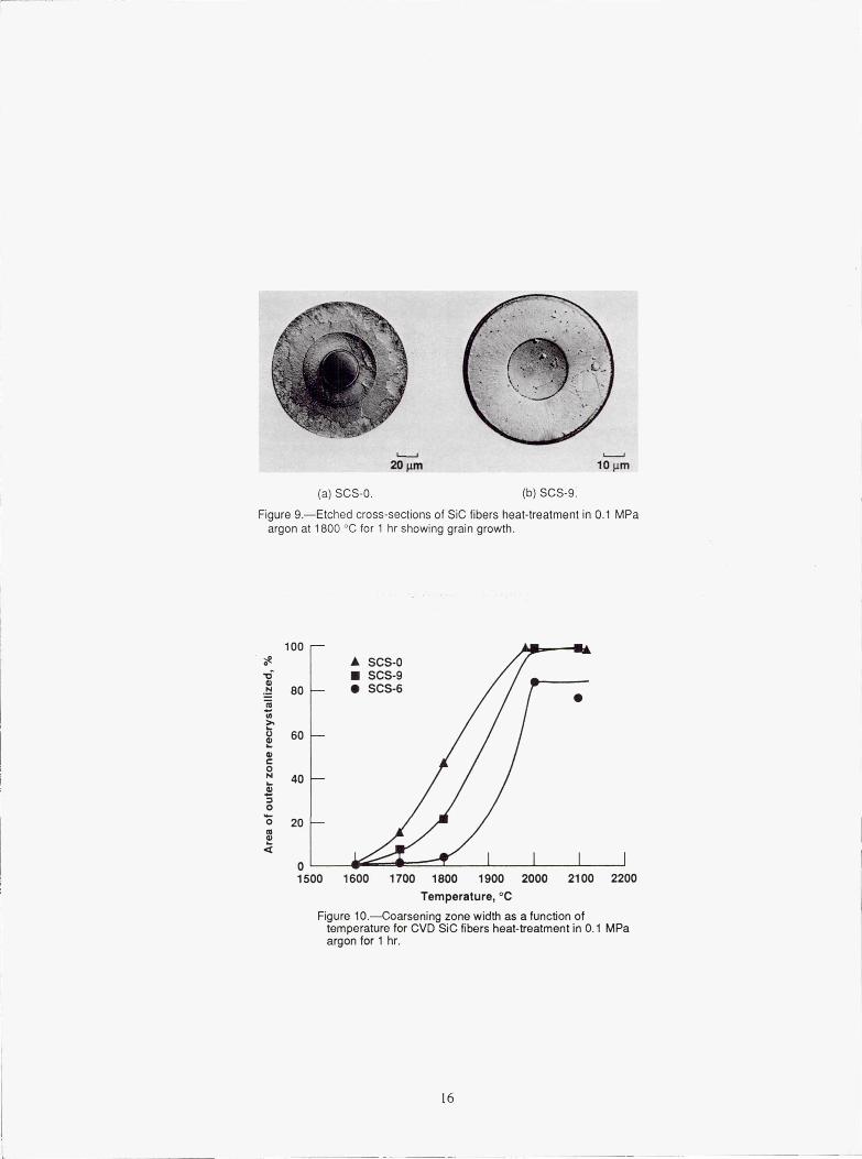
Microstructural analysis of the cross sections of heat treated
SCS-0 and SCS-9 fibers also showed reaction zone, grain growth, and
segregation of metallic impurities in the outerzone SiC grains similar
to that of SCS-6 fibers (Fig. 9).
The grain growth behaviors of outer zone SiC grains are shown in
Fig. 10 for the three types of fibers heat-treated in 0.1 MPa argon
from 1600 0 to 2100 0C for 1 hr. As the temperature of exposure
increased the reaction zone in the outer zone also increased. The
three fibers also displayed slightly different grain growth behaviors.
The SCS-0 fiber showed greater tendency for grain growth compared to
other fibers.
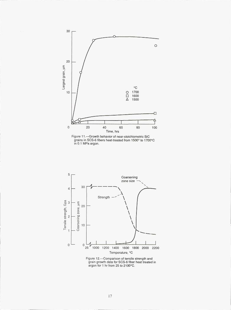
The kinetics of grain growth are shown in Fig. 11 for SCS-6 fibers
heat treated in 0.1 MPa argon at 1500 0 , 1600 0 , and 1700 0C. Initially
SiC grains grew rapidly and then the growth rate leveled off.
Generally, the grain growth rate increased with increasing
temperature.
A plot of the variation of the coarsening zone thickness with
temperature is shown in Fig. 12 for SCS-6 fibers treated in 0.1 MPa
argon for 1 hr. The dotted line in the figure represents the
room-temperature tensile strength variation of SCS-6 fibers as shown
previously in Fig. 3. It obvious from Fig. 12 that growth of reaction
zone correlates well with the loss of tensile strength.
8
DISCUSSION
The three types of CVD Sic fibers investigated showed strength
degradation above 1400 0C. The fact that strength degradation is
independent of argon pressure or the type of fiber used, coated or
uncoated, suggests that the degradation is intrinsic in nature.
Fractographic analysis performed indicates the degradation is surface
related. Supporting microstructural analysis reveals nucleation and
grain growth in the outer zone of Sic sheath in the temperature range
in which strength degradation was noticed. Based on these data it
appears that the upper temperature limit of these CVD Sic fibers is
controlled by the microstructural stability of near-stiochiometric Sic
grains.
In general, the nucleation, recrystallization, and grain growth
phenomena in ceramics are quite complex, and depend on temperature,
grain size, growth or deformation related residual stresses, trace
impurity level, and grain boundary mobility. Although the mechanisms
of recrystallization and grain growth in CVD Sic fibers are still
under investigation, one can offer a preliminary explanation for grain
growth based on fiber microstructure and thermodynamic reasoning.
The CVD Sic fibers were fabricated near 1200 0C and contain Sic
grains of diameter ranging from 20 to 100 nm 4 . The three types of
fibers also contain noticeable amounts of trace metallic impurities
(1000 PPM) primarily confined to the outer zone Sic sheath. Heating
the fibers above their fabrication temperature should relieve growth
related stresses; indication of this effect is seen in the XRD data.
In addition, because of their high grain boundary surface area, these
9
grains should recrystallize and grow at elevated temperatures. The
temperature and the rate at which grain growth occur is a function of
composition of Sic and trace impurity level. It is possible that
metallic impurities present might have triggered recrystallization and
growth of near-stoichiometric grains.
Although grain growth was prevalent in the outer zone, the inner
zone which contained carbon-rich silicon carbide seemed to resist
grain growth even at temperatures to 2100 0C. This observation is
consistent with the general grain growth behavior of monolithic SiC8
where carbon is known to inhibit grain growth. Based on this
observation, it may be possible to improve the thermal stability of
CVD Sic fibers by changing the microstructure of the outer zone from
near-stoichiometric grains to carbon-rich grains. Of course the
penalties for achieving improved, thermally stable carbon-rich Sic
fibers are possibly lower elastic modulus and reduced oxidation
resistance.
SUMMARY OF RESULTS
The influence of temperature, time, and argon pressure on the
room-temperature strength of commercially available Textron CVD Sic
fibers has been determined. The important findings are as follows.
(a) The CVD Sic fibers show strength degradation beyond 14000C
(b) Recrystallization and grain growth of the outer zone Sic grains
appears to be the probable mechanisms of strength degradation.
(c) Inner zone Sic grains with carbon-rich boundaries show greater
resistance to recrystallization than outer grains.
10
(d) X-ray data show that Q-SiC composition is stable to '20000C.
(e) The CVD SiC fibers contain appreciable amounts of Fe, Cr, Ni, and
Ti impurities which appear to be confined to the outer zone and
may play a role in the recrystallization process.
CONCLUSIONS
Thermal stability of CVD fibers appears to be dependent on the
recrystallization and grain growth of the outer zone. Grain growth
appears to be related to diffusion of impurities and/or stoichiometry
of the grain boundary phases. Slow grain growth in the inner zone with
carbon-rich boundaries suggests that this microstructure the fiber can
improve strength stability of CVD SiC fibers.
ACKNOWLEDGMENTS
The authors wish to thank T.A. Leonhardt for cermographic work and
R.G. Garlick for x-ray diffraction studies.
REFERENCES
(1) R.T. Bhatt, " The properties of Silicon Carbide Fiber Reinforced
Silicon Nitride Composites," pp. 199-208 in Whisker and
Fiber-Toughened Ceramics. Edited by R.A. Bradley, D.E. Clark,
D.C. Larsen, and J.O. Stiegler, ASM International, 1988.
(2) R.T. Bhatt and J.D. Kiser, "Matrix Density Effects on the
Mechanical properties of SiC/RBSN Composites," NASA TM-103098
(1990).
11
(3) W. Foulds, J.F. Lecostaouec, C. Landry, S. Dipietro, and T.
Vasilos, "Tough Silicon Nitride Matrix Composites Using Textron
Silicon Carbide Monofilaments" Ceram. Eng. Sci. Proc, 10 [9-10],
1083-1091 (1989).
(4) F.W. Wawner, A.Y. Teng, and S.R. Nutt, "Microstructural
Characterization of SiC (SCS) Filaments," SAMPE Q., Vol. 4, #3,
39-45 (1983).
(5) Private Communication, Textron Specialty Materials.
(6) P. Pirouz, G. Morscher, and J. Chang, "Importance of Interfacial
Strength on Fracture Toughness of Brittle Matrix Composites,"
12
SCS-0 140 µm) SCS-9SCS-6 (75 pm)
Pyrolytic graphite
' coated carbon core^Innerzone:
O carbon-rich ( -SiCCross-section - — Outer zone:
` \ Stolchiometric ( -SICCarbon-rich surfacecoating (0-4 µm)
SCS-0 fiber SCS-6 fiber and SCS-9(DC)
Composition 1.0 1.0 ^of the surfaceregion
Si p-SiC Si
p-sic
C C0
0 1 3
Distance from Distance fromthe surface, the surface,
pm µm
Figure 1—Schematic showing CVD SiC fiber cross sections and surface coatingcompositions.
5 Gauge length = 50 mm
a T 4a
4-= c7r
r
°1C w 3(D
N3-= aC
`°
2
N
m 2
v SCS-6LL ♦ SCS-0 • SCS-6
1 n SCS-9 1 n SCS-0SCS-9
0 l ^- I I 1 I 11_^
25 110001200 1400 16001800 2000 2200Temperature, °C
Figure 2.—Room-temperature flexuralstrength of SCS-0, SCS-6, and SCS-9fibers after 1 hr exposure in 0.1 MPaargon pressure at elevated temperatures.
0 `ter —25 1000 1200 1400 1600 1800 2000 2200
Temperature, °C
Figure 3.—Room-temperature tensilestrength of SCS-0, SCS-6, and SCS-9fibers after 1 hr exposure in 0.1 MPaargon pressure at elevated temperatures.
13
5 F-- Gauge length = 50 mm 5
4 4Wa
2 Mo_
C7 C7
3 3
c CCm
Pressure,`
m2 MPa m 2
• 0.1 C
n 138
1 ♦ 310
025 1000 1200 1400 1600 1800 2000 2200
Temperature, °C
Figure 4.—Effect of temperature andargon pressure on the room-temper-ature tensile strength of SCS-6 fibersheat-treated for 1 hr.
0 "1 1 1 1 1 1 1
25 1000 1200 1400 1600 1800 2000 2200Temperature, °C
Figure 5.—Effects of temperature andtime on the room-temperature tensilestrength of SCS-6 fibers heat-treatedfor 1 hr in 0.1 MPa argon.
u ^ uN µm 20 pm
(a) As- fabricated. (b) Heat treated at 1700 °C for 1 hr.
Figure 6.—SEM photographs of SCS-6 fibers showing tensile fractureorigin.
14
NW
(a) As-received. (b) 1400 °C. (c) 1600 °C.
^^ u
(d) 1800 °C.20µm
(e) 2000 'c. (f) 2100
Figure 7.—Etched cross-sections of SCS-6 fibers before and after heat-treatmentat elevated temperatures in 0.1 MPa argon for 1 hr showing grain growth.
XEDS analysis of the particles
480 siFe
360
C240
0
Pd
0 Fe
U Cr
120 Ni Ti Fe
Cr Ni
_ 0 2 4 6 8 10
1 10 µmt
L Carbon LP-Sic Carbon-richcore coating
(a) (b)
Figure 8.— (a) SEM photograph of a cross-section of SCS-6 fiber heat-treated at2000 °C showing particles in the outer zone. (b) XEDS analysis of the particles.
15
yS;: L ..
u20 pm 10µm
(a) SCS-0. (b) SCS-9.
Figure 9.—Etched cross-sections of SiC fibers heat-treatment in 0.1 MPaargon at 1800 °C for 1 hr showing grain growth.
1000VdN 80
NT
60CCO
40`m
O
0 20COaQ
0 l f It-- , I 1 1
1500 1600 1700 1800 1900 2000 2100 2200
Temperature, °C
Figure 10.—Coarsening zone width as a function oftemperature for CVD SiC fibers heat-treatment in 0.1 MPaargon for 1 hr.
16
4 ^— 30
n3^ E- 20L N
C
C ON N
2N CO Nc 10
O^ 1 U
025 1000 1200 1400 1600 1800 2000 2200
Temperature, °C
0
Excmrn
NQ1
`roJ
30
20
10
0
20 40 60 80 100
Time, hrsFigure 11.Growth behavior of near-stoichiometric SiC
grains in SCS-6 fibers heat-treated from 1500° to 1700 °Cin 0.1 MPa argon.
5Coarseningzone size
Figure 12.—Comparison of tensile strength andgrain growth data for SCS-6 fiber heat treated inargon for 1 hr from 25 to 2100°C.
17
NASA Report Documentation PageNational Aeronautics andSpace Administration
1. Report No. NASA TM -103772 2 Government Accession No. 3. Recipient's Catalog No.
AVSCOM TR-91 -C-0144. Title and Subtitle 5. Report Date
Microstructural and Strength Stability of CVD SiC Fibersin Argon Environment
6. Performing Organization Code
7. Author(s) 8. Performing Organization Report No.
Ramakrishna T. Bhatt and David R. Hull E - 5957
10. Work Unit No.
510-01-019. Performing Organization Name and AddressNASA Lewis Research Center 1L161102AH45Cleveland, Ohio 44135 - 3191
11. Contract or Grant No.andPropulsion DirectorateU.S. Army Aviation Systems CommandCleveland, Ohio 44135 - 3191 13. Type of Report and Period Covered
Technical Memorandum12. Sponsoring Agency Name and Address
National Aeronautics and Space Administration14. Sponsoring Agency CodeWashington, D.C. 20546 - 0001
andU.S. Army Aviation Systems CommandSt. Louis, Mo. 63120 - 1798
15. Supplementary Notes
Prepared for the 15th Annual Conference on Composites and Advanced Ceramics sponsored by the American CeramicSociety, Cocoa Beach, Florida, January 13-16, 1991. Ramakrishna T. Bhatt, Propulsion Directorate, U. S. ArmyAviation Systems Command. David R. Hull, NASA Lewis Research Center. Responsible person, Ramakrishna T.Bhatt, (216) 433-5513.
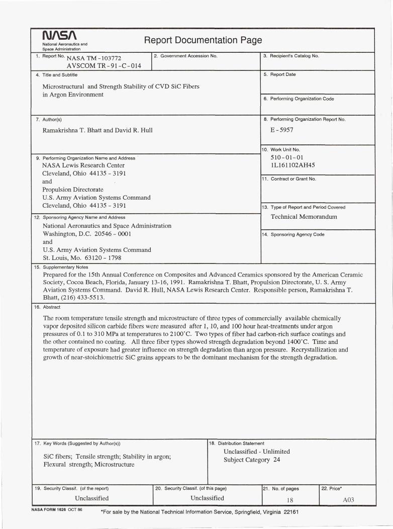
16. Abstract
The room temperature tensile strength and microstructure of three types of commercially available chemicallyvapor deposited silicon carbide fibers were measured after 1, 10, and 100 hour heat-treatments under argonpressures of 0.1 to 310 MPa at temperatures to 2100°C. Two types of fiber had carbon-rich surface coatings andthe other contained no coating. All three fiber types showed strength degradation beyond 1400°C. Time andtemperature of exposure had greater influence on strength degradation than argon pressure. Recrystallization andgrowth of near-stoichiometric SiC grains appears to be the dominant mechanism for the strength degradation.
17. Key Words (Suggested by Author(s)) 18. Distribution Statement
Unclassified - UnlimitedSiC fibers; Tensile strength; Stability in argon; Subject Category 24Flexural strength; Microstructure
19. Security Classif. (of the report) 20. Security Classif. (of this page) 21. No. of pages 22. Price'
Unclassified Unclassified 18 A03NASA FORM 1626 OCT 86 *For sale by the National Technical Information Service, Springfield, Virginia 22161