Embed Size (px)
Citation preview
UNCONTROLLED WHEN PRINTED
MID WEST PORTS
TECHNICAL GUIDELINE
MWPA404 – CATHODIC PROTECTION GUIDELINE

UNCONTROLLED WHEN PRINTED
MWPA404 – Cathodic Protection Guideline
Version Revision dated Details Prepared by Authorised by
Draft 28/08/2015 Draft SMEC
Rev 0 05/09/2017 Document approved for use SMEC P. Blundell
UNCONTROLLED WHEN PRINTED
MWPA404 – Cathodic Protection Guideline
CONTENTS
1. PREFACE ...................................................................................................................................... 1
2. SCOPE .......................................................................................................................................... 2
2.1. GENERAL ................................................................................................................................. 2
2.2. EXCLUSIONS ............................................................................................................................ 2
3. GLOSSARY .................................................................................................................................... 3
4. RELEVANT DOCUMENTATION ..................................................................................................... 7
4.1. GUIDELINE SERIES ................................................................................................................... 7
4.2. MID WEST PORTS POLICIES AND PROCEDURES ...................................................................... 7
4.3. LOCAL, STATE AND FEDERAL STATUTORY REQUIREMENTS ................................................... 7
4.4. AUSTRALIAN STANDARDS AND DESIGN CODES ...................................................................... 8
4.4.1. AUSTRALIAN STANDARDS AND DESIGN CODES .............................................................. 8
4.5. INTERNATIONAL STANDARDS ................................................................................................. 8
4.5.1. INTERNATIONAL STANDARDS AND DESIGN CODES ........................................................ 8
4.6. ADDITIONAL REFERENCES ....................................................................................................... 9
4.7. PRECEDENCE ......................................................................................................................... 10
5. ASSETS REQUIRING CATHODIC PROTECTION ........................................................................... 11
5.1. GENERAL ............................................................................................................................... 11
5.2. DESIGN PHILOSOPHY ............................................................................................................ 11
6. COMPETENCE OF PERSONNEL .................................................................................................. 13
6.1. GENERAL ............................................................................................................................... 13
6.2. IMPRESSED CURRENT SYSTEM SPECIFIC REQUIREMENTS .................................................... 13
7. DESIGN OBJECTIVES .................................................................................................................. 14
7.1. GENERAL ............................................................................................................................... 14
7.2. DESIGN PARAMETERS ........................................................................................................... 14
7.3. CATHODIC PROTECTION CRITERIA ........................................................................................ 14
7.4. ELECTRICAL CURRENT DEMANDS ......................................................................................... 15
7.5. COATING BREAK DOWN FACTORS ........................................................................................ 17
7.6. CONSIDERATIONS WHEN CHOOSING CATHODIC PROTECTION SYSTEMS ............................ 18
7.7. ELECTRICAL CONTINUITY ...................................................................................................... 19
7.8. STRAY CURRENT AND OTHER INTERACTIONS ....................................................................... 19
8. GALVANIC ANODE SYSTEMS ..................................................................................................... 20
8.1. GENERAL ............................................................................................................................... 20
8.1.1. SUBMERGED ‐ STEEL ASSETS ......................................................................................... 20
8.1.2. ATMOSPHERIC EXPOSED – CONCRETE ASSETS ............................................................. 20
8.2. SYSTEM DESIGN .................................................................................................................... 20
8.3. GENERAL COMPONENTS ....................................................................................................... 21
9. IMPRESSED CURRENT SYSTEMS ................................................................................................ 22
9.1. GENERAL ............................................................................................................................... 22
UNCONTROLLED WHEN PRINTED
MWPA404 – Cathodic Protection Guideline
9.1.1. SUBMERGED ‐ STEEL ASSETS ......................................................................................... 22
9.1.2. ATMOSPHERIC EXPOSED – CONCRETE ASSETS ............................................................. 23
9.2. SYSTEM DESIGN .................................................................................................................... 24
9.3. GENERAL COMPONENTS ....................................................................................................... 25
10. HYBRID ANODE SYSTEMS .......................................................................................................... 26
10.1. GENERAL ........................................................................................................................... 26
11. GUIDANCE TO DESIGNERS ........................................................................................................ 27
11.1. SAFETY IN DESIGN ............................................................................................................. 27
11.2. DESIGN TO ACHIEVE CATHODIC PROTECTION .................................................................. 27
11.3. SERVICE LIFE REQUIREMENTS ........................................................................................... 27
11.4. MONITORING AND MAINTENANCE .................................................................................. 28
12. GUIDANCE TO CONTRACTORS .................................................................................................. 29
12.1. PRE‐CONTRACT MEETING ................................................................................................. 29
12.2. SYSTEM INSTALLATION PRACTICE ..................................................................................... 29
12.3. SYSTEM COMMISSIONING ................................................................................................ 29
12.4. ONGOING SYSTEM PERFORMANCE MONITORING ........................................................... 29
13. QUALITY CONTROL AND QUALITY ASSURANCE – GUIDANCE TO INSPECTORS ........................ 32
13.1. GENERAL REQUIREMENTS ................................................................................................ 32
13.2. INSPECTION AND TESTING PLAN ...................................................................................... 32
13.3. IDENTIFICATION AND TRACEABILITY................................................................................. 32
13.4. COMPLIANCE INSPECTIONS AND TESTING ....................................................................... 32
14. DOCUMENTS TO BE SUBMITTED .............................................................................................. 34
14.1. GENERAL ........................................................................................................................... 34
14.1.1. SYSTEM DESIGN DOCUMENTATION ............................................................................. 34
14.1.2. COMMISSIONING DOCUMENTATION ........................................................................... 34
APPENDICES APPENDIX A – EXAMPLE CATHODIC PROTECTION SYSTEM INFORMATION
APPENDIX B – EXAMPLE TEST INSPECTION RECORD

UNCONTROLLED WHEN PRINTED 1
MWPA404 – Cathodic Protection Guideline
1. PREFACE This document has been compiled for the Mid West Ports (MWPA) to provide developers, designers,
contractors and inspectors guidance on the corrosion protection by cathodic protection of MWPA’s
berth and wharf assets. It does not replace bespoke project basis of design, design criteria or
specifications but it is intended to provide designers, contractors and inspectors with a benchmark for
the minimum technical requirements for designing, installing, commissioning and maintaining
cathodic protection systems.
The chapters of this guide include methods and guidance on the statutory requirements; MWPA
health; safety, environment, quality and operational policies and procedures; cathodic protection
materials: protection criteria; installation, commissioning, inspection and testing information to
undertake a project with MWPA assets.
This document will be used as a basis for identifying any shortcomings in the technical content and
ultimately accepting or rejecting proposed, underway or completed projects.
UNCONTROLLED WHEN PRINTED 2
MWPA404 – Cathodic Protection Guideline
2. SCOPE
2.1. GENERAL This document provides information and guidance on the design, installation, commissioning and on‐
going monitoring and maintenance of Cathodic Protection (CP) systems with a particular focus on
Galvanic (Sacrificial) Anode Cathodic Protection systems and forms part of the MWPA Technical
Guidelines Series.
It includes guidance on the technical requirements for the design, installation, commissioning and on‐
going monitoring and maintenance of the various types of CP systems, including:
specific system design criteria
description of the various system components
Installation testing procedures
commissioning
on‐going operation, and monitoring of existing and future cathodic protection systems within the port area.
2.2. EXCLUSIONS This guideline focuses solely on the cathodic protection of marine assets including atmospherically
exposed, immersed and buried steel and reinforced concrete structures specifically relating to Port
berths and wharves. It does not account for the design or recommendations of cathodic protection
systems for other structures or assets such as tanks, tank bottoms, pipelines and the like which often
require unique and detailed system designs to meet safety and other statutory regulatory
requirements. If cathodic protection of such assets is required, then future revisions of this document
shall be created.
UNCONTROLLED WHEN PRINTED 3
MWPA404 – Cathodic Protection Guideline
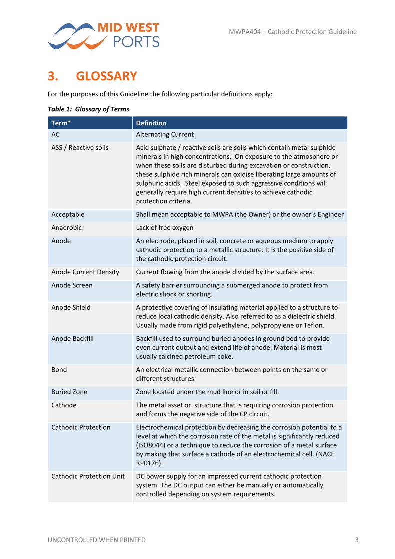
3. GLOSSARY For the purposes of this Guideline the following particular definitions apply:
Table 1: Glossary of Terms
Term* Definition
AC Alternating Current
ASS / Reactive soils Acid sulphate / reactive soils are soils which contain metal sulphide minerals in high concentrations. On exposure to the atmosphere or when these soils are disturbed during excavation or construction, these sulphide rich minerals can oxidise liberating large amounts of sulphuric acids. Steel exposed to such aggressive conditions will generally require high current densities to achieve cathodic protection criteria.
Acceptable Shall mean acceptable to MWPA (the Owner) or the owner’s Engineer
Anaerobic Lack of free oxygen
Anode An electrode, placed in soil, concrete or aqueous medium to apply cathodic protection to a metallic structure. It is the positive side of the cathodic protection circuit.
Anode Current Density Current flowing from the anode divided by the surface area.
Anode Screen A safety barrier surrounding a submerged anode to protect from electric shock or shorting.
Anode Shield A protective covering of insulating material applied to a structure to reduce local cathodic density. Also referred to as a dielectric shield. Usually made from rigid polyethylene, polypropylene or Teflon.
Anode Backfill Backfill used to surround buried anodes in ground bed to provide even current output and extend life of anode. Material is most usually calcined petroleum coke.
Bond An electrical metallic connection between points on the same or different structures.
Buried Zone Zone located under the mud line or in soil or fill.
Cathode The metal asset or structure that is requiring corrosion protection and forms the negative side of the CP circuit.
Cathodic Protection Electrochemical protection by decreasing the corrosion potential to a level at which the corrosion rate of the metal is significantly reduced (ISO8044) or a technique to reduce the corrosion of a metal surface by making that surface a cathode of an electrochemical cell. (NACE RP0176).
Cathodic Protection Unit DC power supply for an impressed current cathodic protection system. The DC output can either be manually or automatically controlled depending on system requirements.
UNCONTROLLED WHEN PRINTED 4
MWPA404 – Cathodic Protection Guideline
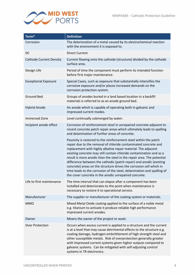
Term* Definition
Corrosion The deterioration of a metal caused by its electrochemical reaction with the environment it is exposed to.
DC Direct Current
Cathode Current Density Current flowing onto the cathode (structure) divided by the cathode surface area.
Design Life Period of time the component must perform its intended function before first major maintenance.
Exceptional Exposure Special Cases, such as exposure that substantially intensifies the corrosive exposure and/or places increased demands on the corrosion protection system.
Ground Bed Groups of anodes buried in a land based location in a backfill materials is referred to as an anode ground bed.
Hybrid Anode An anode which is capable of operating both in galvanic and impressed current modes.
Immersed Zone Level continually submerged by water.
Incipient anode effect Corrosion of reinforcement steel in unrepaired concrete adjacent to recent concrete patch repair areas which ultimately leads to spalling and delamination of further areas of concrete.
Passivity is restored to the reinforcement steel within the patch repair due to the removal of chloride contaminated concrete and replacement with highly alkaline repair material. The adjacent existing concrete may still contain chloride contamination and as a result is more anodic than the steel in the repair area. The potential difference between the cathodic (patch repair) and anodic (existing concrete) areas on the structure drives the corrosion cell which in time leads to the corrosion of the steel, delamination and spalling of the cover concrete in the anodic unrepaired concrete.
Life to first maintenance The time interval that can elapse after a component has been installed and deteriorates to the point when maintenance is necessary to restore it to operational service.
Manufacturer The supplier or manufacturer of the coating system or materials.
MMO Mixed Metal Oxide coating applied to the surface of a noble metal e.g. titanium to activate it produce reliable high performance impressed current anodes.
Owner Means the owner of the project or asset.
Over Protection Occurs when excess current is applied to a structure and the current is at a level that may cause detrimental effects to the structure e.g. coating damage, hydrogen embrittlement of high strength steel and other susceptible metals. Risk of overprotection generally greater with impressed current systems given higher outputs compared to galvanic systems. Can be mitigated with self‐adjusting control systems in TR electronics.
UNCONTROLLED WHEN PRINTED 5
MWPA404 – Cathodic Protection Guideline
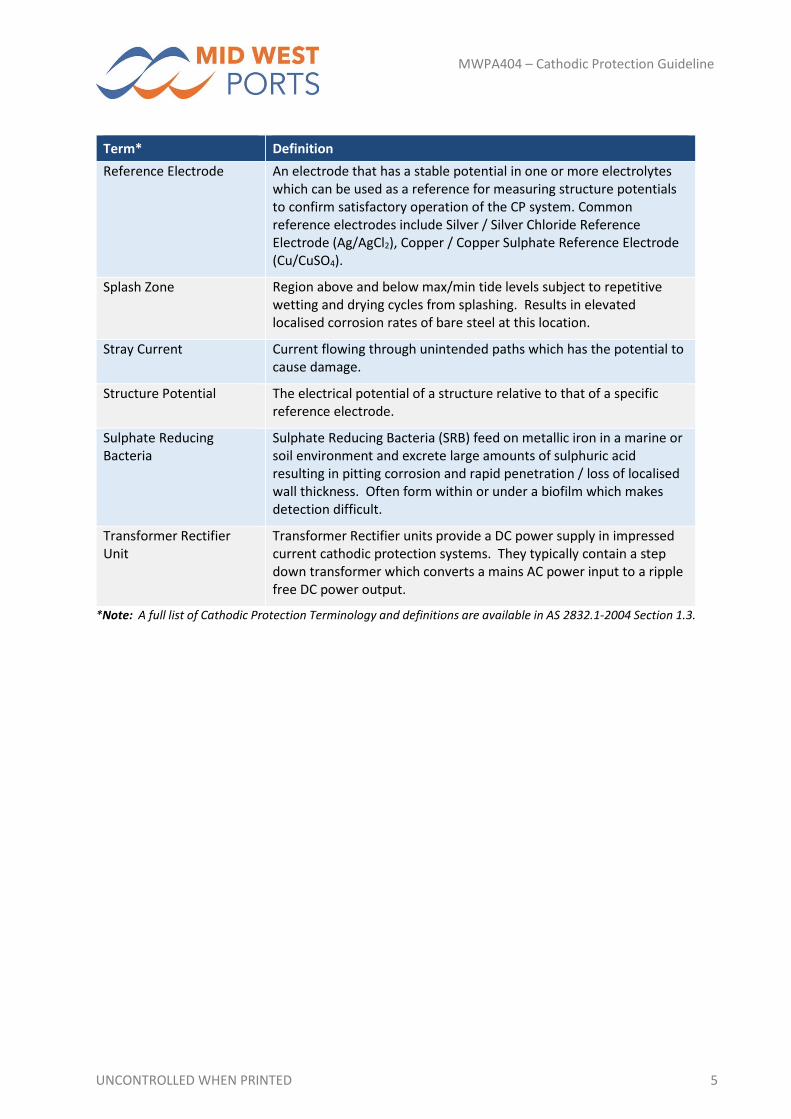
Term* Definition
Reference Electrode An electrode that has a stable potential in one or more electrolytes which can be used as a reference for measuring structure potentials to confirm satisfactory operation of the CP system. Common reference electrodes include Silver / Silver Chloride Reference Electrode (Ag/AgCl2), Copper / Copper Sulphate Reference Electrode (Cu/CuSO4).
Splash Zone Region above and below max/min tide levels subject to repetitive wetting and drying cycles from splashing. Results in elevated localised corrosion rates of bare steel at this location.
Stray Current Current flowing through unintended paths which has the potential to cause damage.
Structure Potential The electrical potential of a structure relative to that of a specific reference electrode.
Sulphate Reducing Bacteria
Sulphate Reducing Bacteria (SRB) feed on metallic iron in a marine or soil environment and excrete large amounts of sulphuric acid resulting in pitting corrosion and rapid penetration / loss of localised wall thickness. Often form within or under a biofilm which makes detection difficult.
Transformer Rectifier Unit
Transformer Rectifier units provide a DC power supply in impressed current cathodic protection systems. They typically contain a step down transformer which converts a mains AC power input to a ripple free DC power output.
*Note: A full list of Cathodic Protection Terminology and definitions are available in AS 2832.1‐2004 Section 1.3.
UNCONTROLLED WHEN PRINTED 6
MWPA404 – Cathodic Protection Guideline
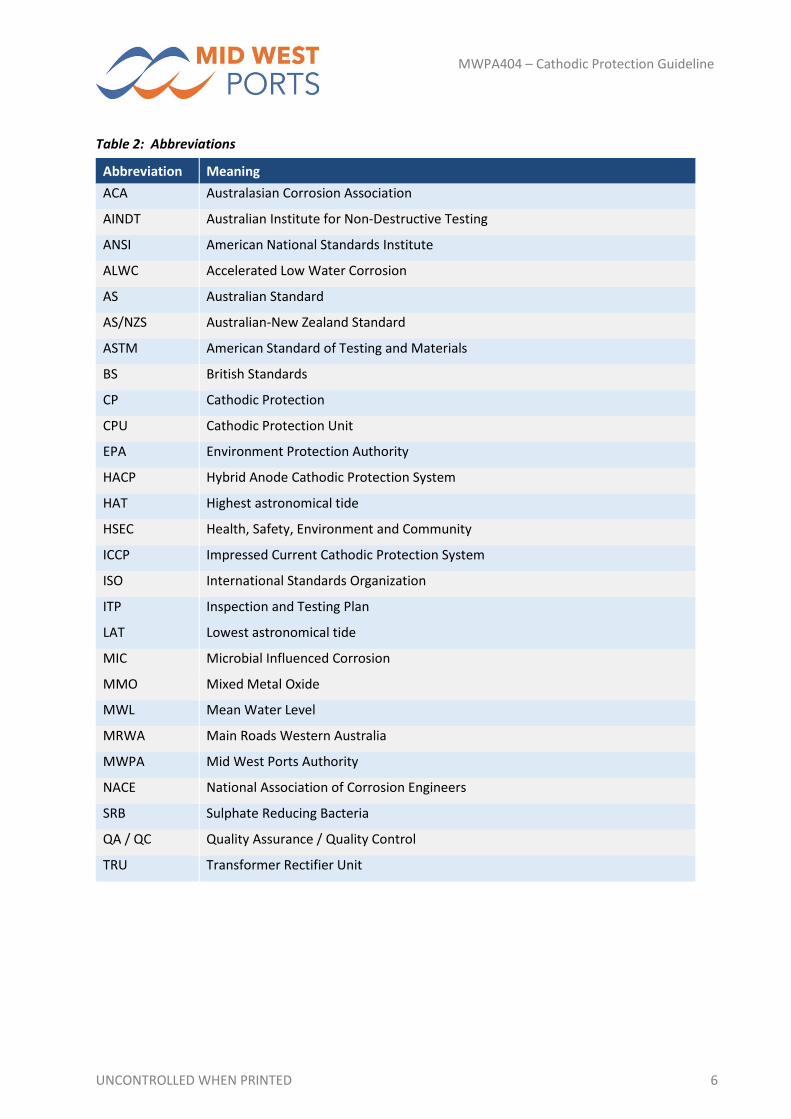
Table 2: Abbreviations
Abbreviation Meaning
ACA Australasian Corrosion Association
AINDT Australian Institute for Non‐Destructive Testing
ANSI American National Standards Institute
ALWC Accelerated Low Water Corrosion
AS Australian Standard
AS/NZS Australian‐New Zealand Standard
ASTM American Standard of Testing and Materials
BS British Standards
CP Cathodic Protection
CPU Cathodic Protection Unit
EPA Environment Protection Authority
HACP Hybrid Anode Cathodic Protection System
HAT Highest astronomical tide
HSEC Health, Safety, Environment and Community
ICCP Impressed Current Cathodic Protection System
ISO International Standards Organization
ITP Inspection and Testing Plan
LAT Lowest astronomical tide
MIC Microbial Influenced Corrosion
MMO Mixed Metal Oxide
MWL Mean Water Level
MRWA Main Roads Western Australia
MWPA Mid West Ports Authority
NACE National Association of Corrosion Engineers
SRB Sulphate Reducing Bacteria
QA / QC Quality Assurance / Quality Control
TRU Transformer Rectifier Unit

UNCONTROLLED WHEN PRINTED 7
MWPA404 – Cathodic Protection Guideline
4. RELEVANT DOCUMENTATION
4.1. GUIDELINE SERIES This guideline should be read in conjunction with other parts of the MWPA Technical Guideline series,
where relevant, and these are listed below:
MWPA 000 Series – Port Development Guidelines;
MWPA 100 Series – Technical Guidelines – General;
MWPA 200 Series – Drafting Guidelines and AutoCAD Standards;
MWPA 300 Series – Mechanical Guidelines;
MWPA 400 Series – Guidelines for Maritime Structures;
MWPA 500 Series – Civil Engineering Guidelines;
MWPA 600 Series – Buildings and Structures Guidelines;
MWPA 700 Series – Electrical and Instrumentation;
MWPA 800 Series – T.B.A; and
MWPA 900 Series – T.B.A.
4.2. MID WEST PORTS POLICIES AND PROCEDURES All parties developing, designing, specifying, preparing, applying and inspecting any aspect of a MWPA
coating project should be aware and abide with MWPA policies and procedures. A full list of MWPA’s
policies and procedures can be found in MWPA 100 and obtained either from the MWPA website
(https://www.midwestports.com.au) or requested from the MWPA Project Coordinator or Owner’s
Engineer.
4.3. LOCAL, STATE AND FEDERAL STATUTORY REQUIREMENTS In addition to the requirements of this part of the MWPA Technical Guidelines, all protective coating
works shall meet the requirements of Local, State and Federal statutory, health, safety and
environmental requirements and regulations and include, but not be limited to the following:
Western Australian Environmental Protection
Western Australian Occupational Safety and Health Act (1984) and Regulations (1996)
Western Australian Occupational Safety and Health Legislation Amendment Act (1984)
Western Australian (Certificates of Competency and Safety Manning) Regulations (1983)
Transport Operation (Marine Safety) Act
Western Australian Mines Safety and Inspection Act 2005 and Regulations (2005)
Dangerous Goods Safety Act (2004)
Port Authorities Act (1999)
Maritime Transport and Offshore Facilities Security Act (MTOFSA) (2003)
Environmental Protection Act and Regulations (1986)
UNCONTROLLED WHEN PRINTED 8
MWPA404 – Cathodic Protection Guideline
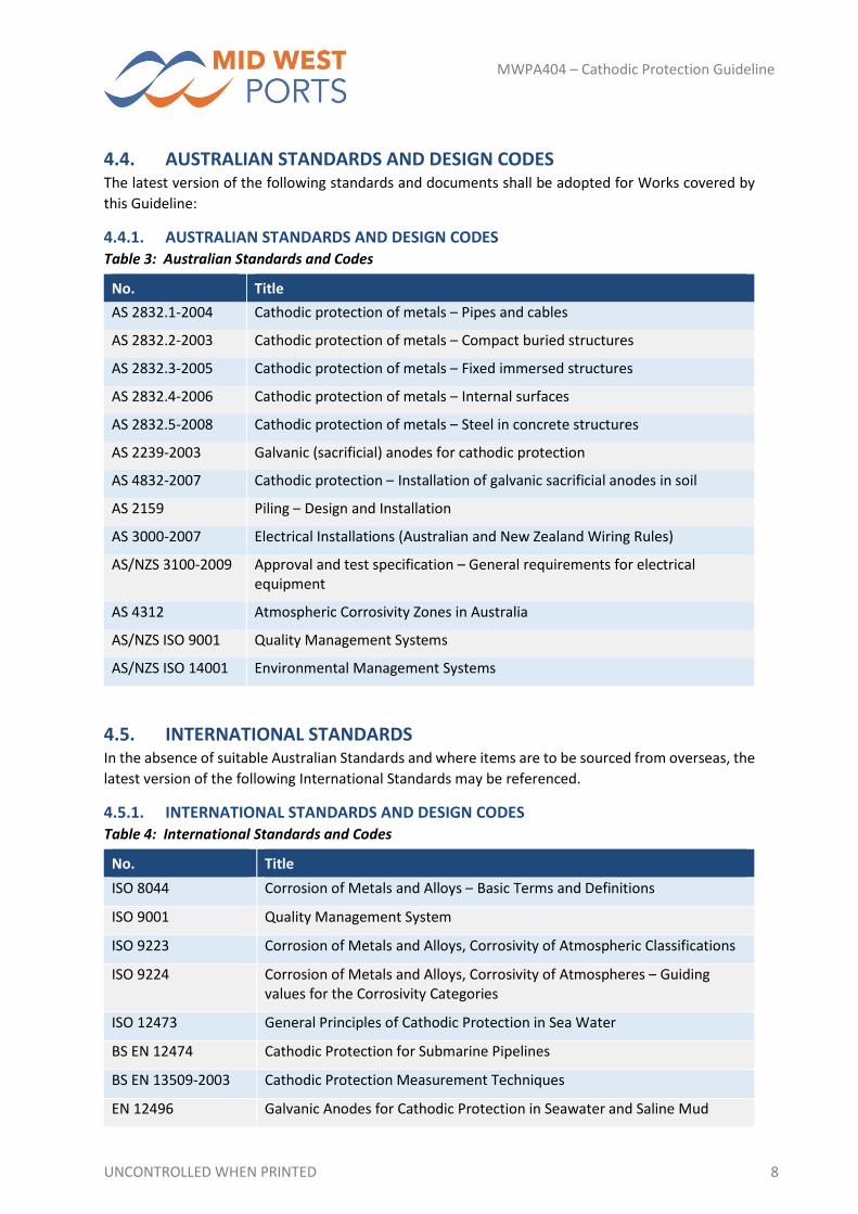
4.4. AUSTRALIAN STANDARDS AND DESIGN CODES The latest version of the following standards and documents shall be adopted for Works covered by
this Guideline:
4.4.1. AUSTRALIAN STANDARDS AND DESIGN CODES Table 3: Australian Standards and Codes
No. Title
AS 2832.1‐2004 Cathodic protection of metals – Pipes and cables
AS 2832.2‐2003 Cathodic protection of metals – Compact buried structures
AS 2832.3‐2005 Cathodic protection of metals – Fixed immersed structures
AS 2832.4‐2006 Cathodic protection of metals – Internal surfaces
AS 2832.5‐2008 Cathodic protection of metals – Steel in concrete structures
AS 2239‐2003 Galvanic (sacrificial) anodes for cathodic protection
AS 4832‐2007 Cathodic protection – Installation of galvanic sacrificial anodes in soil
AS 2159 Piling – Design and Installation
AS 3000‐2007 Electrical Installations (Australian and New Zealand Wiring Rules)
AS/NZS 3100‐2009 Approval and test specification – General requirements for electrical equipment
AS 4312 Atmospheric Corrosivity Zones in Australia
AS/NZS ISO 9001 Quality Management Systems
AS/NZS ISO 14001 Environmental Management Systems
4.5. INTERNATIONAL STANDARDS In the absence of suitable Australian Standards and where items are to be sourced from overseas, the
latest version of the following International Standards may be referenced.
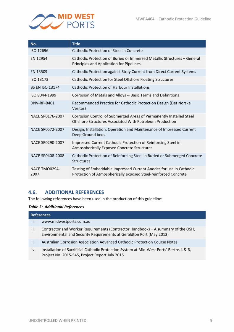
4.5.1. INTERNATIONAL STANDARDS AND DESIGN CODES Table 4: International Standards and Codes
No. Title
ISO 8044 Corrosion of Metals and Alloys – Basic Terms and Definitions
ISO 9001 Quality Management System
ISO 9223 Corrosion of Metals and Alloys, Corrosivity of Atmospheric Classifications
ISO 9224 Corrosion of Metals and Alloys, Corrosivity of Atmospheres – Guiding values for the Corrosivity Categories
ISO 12473 General Principles of Cathodic Protection in Sea Water
BS EN 12474 Cathodic Protection for Submarine Pipelines
BS EN 13509‐2003 Cathodic Protection Measurement Techniques
EN 12496 Galvanic Anodes for Cathodic Protection in Seawater and Saline Mud
UNCONTROLLED WHEN PRINTED 9
MWPA404 – Cathodic Protection Guideline
No. Title
ISO 12696 Cathodic Protection of Steel in Concrete
EN 12954 Cathodic Protection of Buried or Immersed Metallic Structures – General Principles and Application for Pipelines
EN 13509 Cathodic Protection against Stray Current from Direct Current Systems
ISO 13173 Cathodic Protection for Steel Offshore Floating Structures
BS EN ISO 13174 Cathodic Protection of Harbour Installations
ISO 8044‐1999 Corrosion of Metals and Alloys ‐‐ Basic Terms and Definitions
DNV‐RP‐B401 Recommended Practice for Cathodic Protection Design (Det Norske Veritas)
NACE SP0176‐2007 Corrosion Control of Submerged Areas of Permanently Installed Steel Offshore Structures Associated With Petroleum Production
NACE SP0572‐2007 Design, Installation, Operation and Maintenance of Impressed Current Deep Ground beds
NACE SP0290‐2007 Impressed Current Cathodic Protection of Reinforcing Steel in Atmospherically Exposed Concrete Structures
NACE SP0408‐2008 Cathodic Protection of Reinforcing Steel in Buried or Submerged Concrete Structures
NACE TMO0294‐2007
Testing of Embeddable Impressed Current Anodes for use in Cathodic Protection of Atmospherically exposed Steel‐reinforced Concrete
4.6. ADDITIONAL REFERENCES The following references have been used in the production of this guideline:
Table 5: Additional References
References
i. www.midwestports.com.au
ii. Contractor and Worker Requirements (Contractor Handbook) – A summary of the OSH, Environmental and Security Requirements at Geraldton Port (May 2013)
iii. Australian Corrosion Association Advanced Cathodic Protection Course Notes.
iv. Installation of Sacrificial Cathodic Protection System at Mid‐West Ports’ Berths 4 & 6, Project No. 2015‐545, Project Report July 2015

UNCONTROLLED WHEN PRINTED 10
MWPA404 – Cathodic Protection Guideline
4.7. PRECEDENCE As a general guide, where particular aspects are not covered in the MWPA Technical Guidelines or
where conflict between documents exists, the following precedence for standards applies:
1. Statutory Regulations
2. Design Codes and Standards
3. Project Specific Specification
4. MWPA Technical Guidelines; and
5. Other References (e.g. Recognised Industry Best Practice)
Regardless of the general order of precedence, if there is a conflict between documents, the clause
presenting the more conservative and pragmatic guidance will govern. If in doubt, or in all cases where
noncompliance is anticipated, clarification shall be sought from the MWPA.
UNCONTROLLED WHEN PRINTED 11
MWPA404 – Cathodic Protection Guideline
5. ASSETS REQUIRING CATHODIC PROTECTION
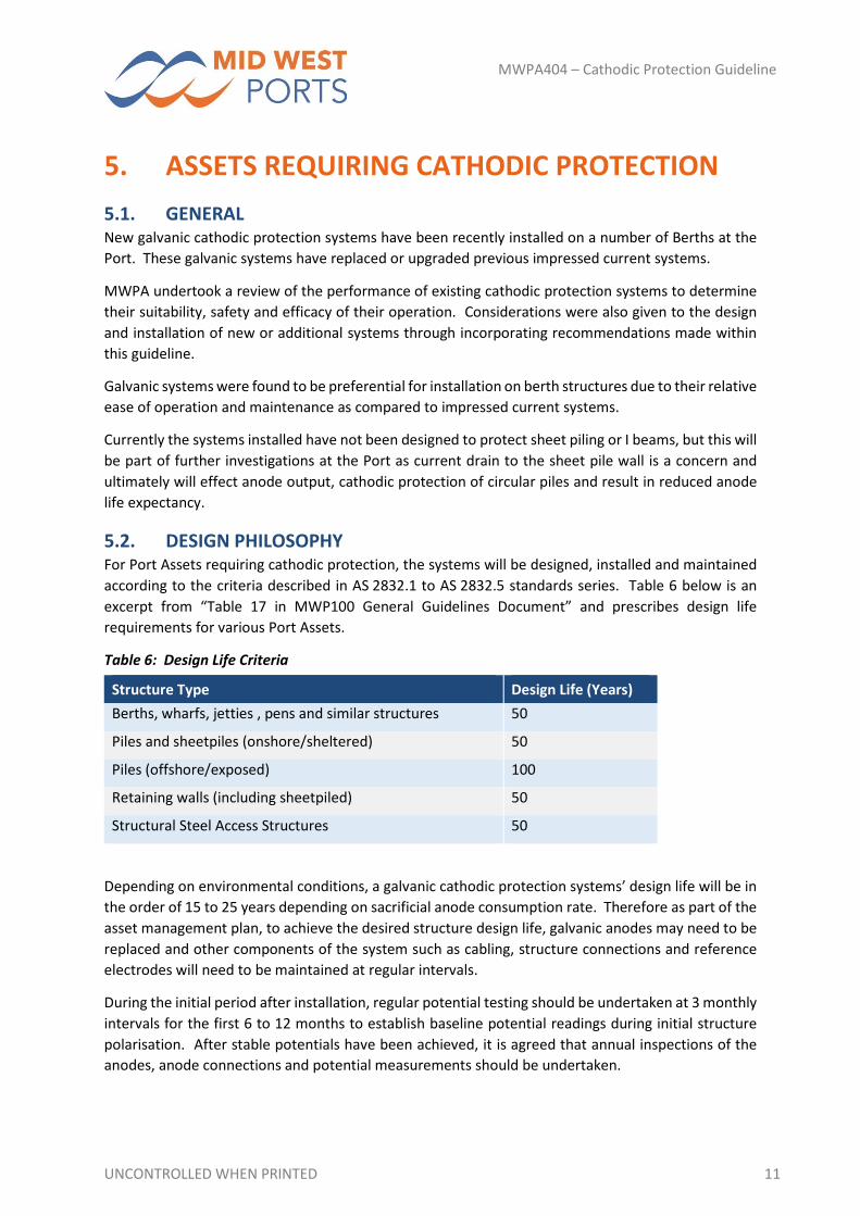
5.1. GENERAL New galvanic cathodic protection systems have been recently installed on a number of Berths at the
Port. These galvanic systems have replaced or upgraded previous impressed current systems.
MWPA undertook a review of the performance of existing cathodic protection systems to determine
their suitability, safety and efficacy of their operation. Considerations were also given to the design
and installation of new or additional systems through incorporating recommendations made within
this guideline.
Galvanic systems were found to be preferential for installation on berth structures due to their relative
ease of operation and maintenance as compared to impressed current systems.
Currently the systems installed have not been designed to protect sheet piling or I beams, but this will
be part of further investigations at the Port as current drain to the sheet pile wall is a concern and
ultimately will effect anode output, cathodic protection of circular piles and result in reduced anode
life expectancy.
5.2. DESIGN PHILOSOPHY For Port Assets requiring cathodic protection, the systems will be designed, installed and maintained
according to the criteria described in AS 2832.1 to AS 2832.5 standards series. Table 6 below is an
excerpt from “Table 17 in MWP100 General Guidelines Document” and prescribes design life
requirements for various Port Assets.
Table 6: Design Life Criteria
Structure Type Design Life (Years)
Berths, wharfs, jetties , pens and similar structures 50
Piles and sheetpiles (onshore/sheltered) 50
Piles (offshore/exposed) 100
Retaining walls (including sheetpiled) 50
Structural Steel Access Structures 50
Depending on environmental conditions, a galvanic cathodic protection systems’ design life will be in
the order of 15 to 25 years depending on sacrificial anode consumption rate. Therefore as part of the
asset management plan, to achieve the desired structure design life, galvanic anodes may need to be
replaced and other components of the system such as cabling, structure connections and reference
electrodes will need to be maintained at regular intervals.
During the initial period after installation, regular potential testing should be undertaken at 3 monthly
intervals for the first 6 to 12 months to establish baseline potential readings during initial structure
polarisation. After stable potentials have been achieved, it is agreed that annual inspections of the
anodes, anode connections and potential measurements should be undertaken.

UNCONTROLLED WHEN PRINTED 12
MWPA404 – Cathodic Protection Guideline
Whilst the use of smaller anodes will greatly assist in ease of inspection, future designers should
ensure that the design of the anode suspension system will:
be of sufficient length to ensure the anode remains fully submerged even at Lowest Astronomical Tide (LAT);
suspension system is strong enough to support anodes in strong currents;
anodes are installed in a location that minimises disturbance from prop‐wash effects.
Thus ensuring cathodic protection is maintained as intended.
UNCONTROLLED WHEN PRINTED 13
MWPA404 – Cathodic Protection Guideline
6. COMPETENCE OF PERSONNEL
6.1. GENERAL As outlined in Section 1.4 AS 2832.1, persons responsible for the design, survey, inspection, testing
and maintenance of cathodic protection systems shall have the requisite minimum experience and
qualifications in cathodic protection. The Australasian Corrosion Association provides training and
accreditation for personnel in the corrosion prevention industry.
6.2. IMPRESSED CURRENT SYSTEM SPECIFIC REQUIREMENTS Due to potentially dangerous operating currents and voltages output by impressed current systems,
all installation and commissioning work on impressed current cathodic protection systems should be
overseen by certified licenced electricians and/or electrical engineers.
UNCONTROLLED WHEN PRINTED 14
MWPA404 – Cathodic Protection Guideline
7. DESIGN OBJECTIVES
7.1. GENERAL The purpose of this section is to provide information specific to the design and operation of cathodic
protection systems.
7.2. DESIGN PARAMETERS There are two common types of cathodic protection systems available:
1. Galvanic systems, which rely on buried or submerged metallic anodes which sacrificially
corrode to provide a source of direct current for the corrosion protection of a structure.
2. Impressed current systems, which use an external electrical power supply to apply direct
current for the corrosion protection of the structure.
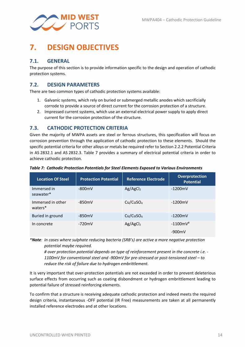
7.3. CATHODIC PROTECTION CRITERIA Given the majority of MWPA assets are steel or ferrous structures, this specification will focus on
corrosion prevention through the application of cathodic protection to these elements. Should the
specific potential criteria for other alloys or metals be required refer to Section 2.2.2 Potential Criteria
in AS 2832.1 and AS 2832.3. Table 7 provides a summary of electrical potential criteria in order to
achieve cathodic protection.
Table 7: Cathodic Protection Potentials for Steel Elements Exposed to Various Environments
Location Of Steel Protection Potential Reference Electrode Overprotection
Potential
Immersed in seawater*
‐800mV Ag/AgCl2 ‐1200mV
Immersed in other waters*
‐850mV Cu/CuSO4 ‐1200mV
Buried in ground ‐850mV Cu/CuSO4 ‐1200mV
In concrete ‐720mV Ag/AgCl2 ‐1100mV#
‐900mV
*Note: In cases where sulphate reducing bacteria (SRB’s) are active a more negative protection
potential maybe required.
# over protection potential depends on type of reinforcement present in the concrete i.e. ‐
1100mV for conventional steel and ‐900mV for pre‐stressed or post‐tensioned steel – to
reduce the risk of failure due to hydrogen embrittlement.
It is very important that over‐protection potentials are not exceeded in order to prevent deleterious
surface effects from occurring such as coating disbondment or hydrogen embrittlement leading to
potential failure of stressed reinforcing elements.
To confirm that a structure is receiving adequate cathodic protection and indeed meets the required
design criteria, instantaneous ‐OFF potential (IR Free) measurements are taken at all permanently
installed reference electrodes and at other locations.
UNCONTROLLED WHEN PRINTED 15
MWPA404 – Cathodic Protection Guideline
Potential measurements are taken a short period of time after switching off DC power supplies for
impressed current systems or disconnecting galvanic anode systems. This measurement gives an
indication as to how well a structure is maintaining the desired protection potential which will protect
the structure from corrosion.
Each standard will cover system or structure specific potential requirements depending on whether
or not the steel is coated, in concrete, immersed or buried. Further detailed information can be found
in Section 3.2 of AS 2832.2, Section 2.2 of AS 2832.3 and Section 7.6 of AS 2832.5.
7.4. ELECTRICAL CURRENT DEMANDS Cathode current density is defined simply as the amount of current applied per square meter of steel
structure being protected. Generally, there are three critical electrical design current densities (as
defined by BS EN ISO 13174) which need to be considered for the successful operation of any cathodic
protection system. They are as follows:
Initial Current Density – used to verify that the output current capacity of the new anodes, is capable of obtaining complete initial polarisation of the structure;
Maintenance Current Density – used to determine the approximate mass of the galvanic anodes material required. This is the cathode current density considered necessary to maintain the desired polarisation criteria of the structure during the cathodic protection systems design life. Seasonal variations in current requirements between summer and winter months can be negated by using a conservative current density during the design process;
Repolarisation Current Density – is used to verify that the output current capacity of the anodes when they are consumed to their utilization factor, i.e. at their final usable (end of life) dimensions, allows to repolarise the structure after severe storms or marine growth cleaning operations.
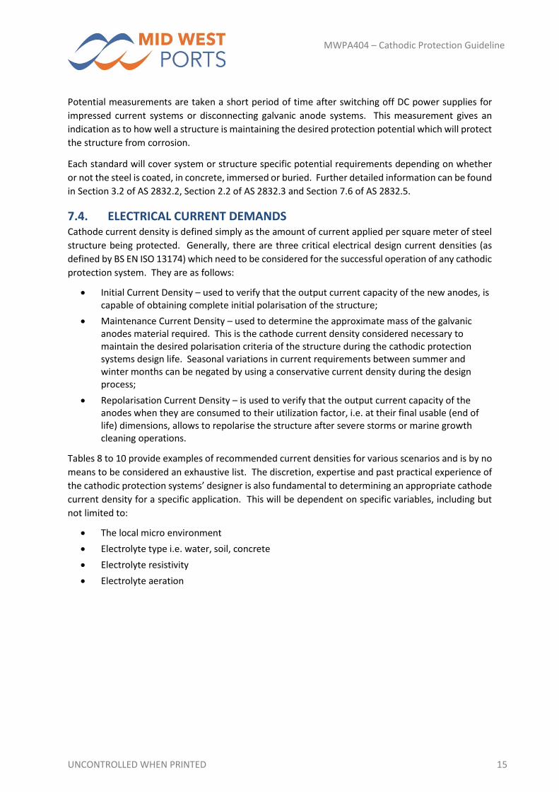
Tables 8 to 10 provide examples of recommended current densities for various scenarios and is by no
means to be considered an exhaustive list. The discretion, expertise and past practical experience of
the cathodic protection systems’ designer is also fundamental to determining an appropriate cathode
current density for a specific application. This will be dependent on specific variables, including but
not limited to:
The local micro environment
Electrolyte type i.e. water, soil, concrete
Electrolyte resistivity
Electrolyte aeration
UNCONTROLLED WHEN PRINTED 16
MWPA404 – Cathodic Protection Guideline
Table 8: Typical Design Current Densities for Bare Steel Immersed in Seawater
Water Condition/ Description*
Current Densities (mA/m2)
Initial Value Maintenance Value Repolarisation Value
Poorly Aerated Waters
Well Aerated Waters
Poorly Aerated Waters
Well Aerated Waters
Poorly Aerated Waters
Well Aerated Waters
Tidal Flow <0.5m/s 80 – 120 120 – 150 50 – 65 65 – 80 60 – 80 80 – 100
Tidal Flow >0.5m/s 120 – 150 170 – 200 60 – 80 80 – 100 80 – 100 100 – 130
ALWC or Active MIC1 170 – 200 60 – 100 80 – 130
*Table 7 excerpt from BS EN ISO13174 Annex A.2, 1.Table A1) ALWC – Accelerated Low Water
Corrosion, MIC – Microbial Influenced Corrosion
Table 9: Typical Design in Current Densities for Bare Steel Buried in Saline Mud
Description
Current Densities (mA/m2)
Initial Value Maintenance
Value Repolarisation
Value
All types of structures in normal saline muds
25 20 20
Conditions with established microbial corrosion
30 – 50 25 – 30 25 – 30
*Values obtained from BS EN ISO13174 Table A.2 –
Table 10: Typical Design Current Densities for Steel in Other Specific Conditions
Description* Current Densities (mA/m2)
Reinforcing steel in concrete 5 ‐ 20
Poorly coated steel in ground or water 1
Well coated steel in earth or water 0.03
Very well coated steel <0.01
*Values obtained from Section A4 – AS 2832.5‐2008
UNCONTROLLED WHEN PRINTED 17
MWPA404 – Cathodic Protection Guideline
7.5. COATING BREAK DOWN FACTORS Additional protection for steel assets can be afforded by the combined use of a suitable coating and
cathodic protection. This can significantly reduce the current density demand and improve current
distribution and corrosion protection across the structures surface. As with all coatings however, as
the coating deteriorates over time, the current density required for protection will increase.
For marine assets, cathodic protection of bare steel maybe more cost effective than the cathodic
protection of coated steel over the life of the asset. However, corrosion protection at and above the
mid tide level is not possible by cathodic protection and therefore coatings may be necessary to satisfy
durability or aesthetic requirements.
Coating breakdown factors are used to account for the increased current demands required to protect
a structure where mechanical damage or degradation to a coating has occurred. Initial coating
breakdown factors are often applied to account for coating loss during fabrication and installation of
the structure.
Coating breakdown factors are strongly influenced by the following:
Actual coating type
Surface preparation and how the coating is applied
Construction and operational conditions
Severity of the exposure environment
Interactions between the coating and cathodic protection systems (coating disbondment possible if the structure is suffering from overprotection or if incompatible coatings are used).
Guidelines for the values of coating breakdown factors (fc) are presented in Annexure A of
BS EN ISO13174. The formula for calculating the resulting current density required for the protection
of coated steel is as follows:
Jc = Jb x fc …………………………………………………………………………………..Equation 1
where:
Jc is the protection current density for coated steel (mA/m2);
Jb is the protection current density for bare steel (mA/m2);
fc is the coating breakdown factor which varies with time due to ageing and or extent of
mechanical damage to the coating.
Generally, fc = 0 for a perfectly insulating coating, fc = 1 for a bare structure. This formula should be
applied to each individual component or zone as defined in Section 5.3 of BS EN ISO 13174 where the
coating, or the current density for bare steel can differ significantly.
Table 11 offers guidance values to be used when calculating coating breakdown factors for a particular
structure.
UNCONTROLLED WHEN PRINTED 18
MWPA404 – Cathodic Protection Guideline
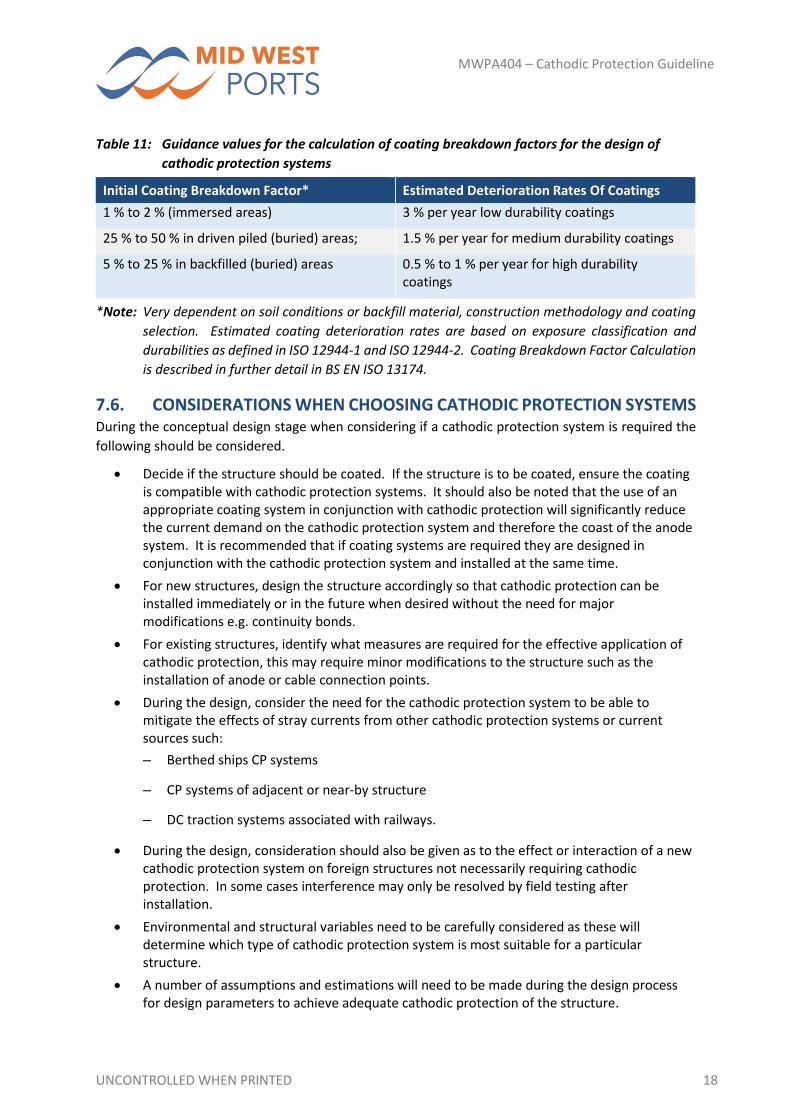
Table 11: Guidance values for the calculation of coating breakdown factors for the design of
cathodic protection systems
Initial Coating Breakdown Factor* Estimated Deterioration Rates Of Coatings
1 % to 2 % (immersed areas) 3 % per year low durability coatings
25 % to 50 % in driven piled (buried) areas; 1.5 % per year for medium durability coatings
5 % to 25 % in backfilled (buried) areas 0.5 % to 1 % per year for high durability coatings
*Note: Very dependent on soil conditions or backfill material, construction methodology and coating
selection. Estimated coating deterioration rates are based on exposure classification and
durabilities as defined in ISO 12944‐1 and ISO 12944‐2. Coating Breakdown Factor Calculation
is described in further detail in BS EN ISO 13174.
7.6. CONSIDERATIONS WHEN CHOOSING CATHODIC PROTECTION SYSTEMS During the conceptual design stage when considering if a cathodic protection system is required the
following should be considered.
Decide if the structure should be coated. If the structure is to be coated, ensure the coating is compatible with cathodic protection systems. It should also be noted that the use of an appropriate coating system in conjunction with cathodic protection will significantly reduce the current demand on the cathodic protection system and therefore the coast of the anode system. It is recommended that if coating systems are required they are designed in conjunction with the cathodic protection system and installed at the same time.
For new structures, design the structure accordingly so that cathodic protection can be installed immediately or in the future when desired without the need for major modifications e.g. continuity bonds.
For existing structures, identify what measures are required for the effective application of cathodic protection, this may require minor modifications to the structure such as the installation of anode or cable connection points.
During the design, consider the need for the cathodic protection system to be able to mitigate the effects of stray currents from other cathodic protection systems or current sources such:
– Berthed ships CP systems
– CP systems of adjacent or near‐by structure
– DC traction systems associated with railways.
During the design, consideration should also be given as to the effect or interaction of a new cathodic protection system on foreign structures not necessarily requiring cathodic protection. In some cases interference may only be resolved by field testing after installation.
Environmental and structural variables need to be carefully considered as these will determine which type of cathodic protection system is most suitable for a particular structure.
A number of assumptions and estimations will need to be made during the design process for design parameters to achieve adequate cathodic protection of the structure.
UNCONTROLLED WHEN PRINTED 19
MWPA404 – Cathodic Protection Guideline
Before installation of a cathodic protection system can occur, as part of the due diligence process and in some states, a legislative requirement in some Australian states, assets owners require a permit to be issued by relevant bodies such as electrolysis committees before a system can be commissioned. The contact details for the Western Australia – Electrolysis Subcommittee (ACA) as supplied as follows : Water Corporation Western Australia, 629 Newcastle Street, Leederville WA 6007) – for further details refer Appendix K AS 2832.1)
Commissioning the new system will require site measurements to determine that sufficient protection is being provided to the structure and the overprotection and stray currents are mitigated accordingly.
Monitoring cathodic protection systems at regular predetermined intervals by qualified persons is key to the successful maintenance and operation of any system.
Sufficient easy access to all parts of the asset will be required to enable the completion of the commissioning and on‐going monitoring in an efficient manner and to enable confirmation that the CP system is providing satisfactory corrosion protection to all parts.
7.7. ELECTRICAL CONTINUITY To ensure the effectiveness and efficiency of cathodic protection systems, it is necessary to ensure
that the structure or sections of the structure are electrically connected or continuous. Bonds may be
necessary to connect isolated parts of the structure together to ensure electrical continuity. For
example across bolted connections or where adequate contact is uncertain such as between individual
sheet, tubular or fender piling. The bond shall be designed for ease of installation and access for
maintenance purposes.
The continuity bond shall be of low resistance so as not to adversely interfere with the performance
and operation of the cathodic protection system.
Continuity bonds, where possible, shall utilise solid metal conductors welded to each asset, rather
than cables and crimped connections, as they provide a more durable maintenance free connection
with less likelihood of failure which can lead to loss of adequate corrosion protection and the risk of
stray current corrosion on electrically discontinuous structures.
7.8. STRAY CURRENT AND OTHER INTERACTIONS Cathodic Protection systems shall be designed as to minimise the risk of corrosion caused by
interference currents to other structures. Section 6.2 and Section 8 of AS 2832.3 discuss at length the
general and regulatory requirements for the minimisation of stray current and other interactions.
UNCONTROLLED WHEN PRINTED 20
MWPA404 – Cathodic Protection Guideline
8. GALVANIC ANODE SYSTEMS
8.1. GENERAL Galvanic (Sacrificial) anode cathodic protection (GACP) systems are generally easier to install, operate
and maintain than the more complex impressed current cathodic protection (ICCP) systems. However,
in high resistivity environments, the output current of the anode is limited by the driving voltage of
the anode material (potential difference between the anode and cathode); hence the variable driving
voltage provided by ICCP systems is required to provide sufficient polarisation of the asset to achieve
satisfactory corrosion protection. Galvanic systems are generally self‐regulating cathodic protection
systems only applying a corrosion current when corrosion on the structure is active.
8.1.1. SUBMERGED ‐ STEEL ASSETS Generally the types of steel assets requiring impressed current cathodic protection are steel piles,
steel sheet pile walls and other retaining wall structures around berths, wharfs, jetties and pens.
The general protection criteria for steel structures submerged in seawater is obtained from AS 832.3.
A structure is considered protected when a potential equivalent to or more negative than ‐800 mV
with respect to a silver/silver chloride reference electrode. For structures submerged in other waters
(including drinking water) the potential required is ‐850 mV with respect to a copper / copper sulphate
reference electrode.
In some cases the potential required may be more negative to mitigate the effects of sulphate
reducing bacteria.
Generally galvanic cathodic protection systems function best when used in conjunction with
protective coatings and or pile wraps etc. If the environment is particularly aggressive or there are
large surfaces of bare steel requiring protection, impressed current systems may prove to be more
cost effective due to their higher output levels.
8.1.2. ATMOSPHERIC EXPOSED – CONCRETE ASSETS Port assets which may require galvanic cathodic protection would generally be concrete decks, beams
/ soffits of berths and wharfs where reinforcement corrosion may be occurring or where localised
concrete repairs have been undertaken and small anodes are installed around the repair to prevent
incipient anode effects.
The general protection criteria for galvanic concrete cathodic protection systems according to
AS 2832.5, is that no instantaneous off steel / concrete potential shall be more negative than ‐1100
mV for plain reinforcing steel or no more negative than ‐900 mV for prestressing steel with respect to
a saturated silver/silver chloride reference electrode. Further detailed protection criteria for concrete
cathodic protection is provided in Section 9.1.2 of this guideline.
8.2. SYSTEM DESIGN When commencing the design of a GACP system, the following process should be considered:
Divide the structure into various zones requiring protection in order to simplify the design process;
Calculate surface area of steel to be protected in each zone
Determine design protection criteria and appropriate current densities based on exposure environment, expected corrosion rates and coating status (as discussed in Section 7);
UNCONTROLLED WHEN PRINTED 21
MWPA404 – Cathodic Protection Guideline
Record assumed anode performance data based on theoretical efficiency and output potential for the entire design life of the anode;
Calculate and record the number of anodes required, their mass, specification, alloy composition, effective consumption rate. Ensure the anodes are installed in such a way that they remain fully submerged at all times but are also retrievable for inspection to avoid having to involve a diver in the routine system assessment;
Record the proposed manufacturer / suppliers details and ensure anodes are properly QA/QC inspected and certified before installation. Galvanic anodes shall be supplied and installed in accordance with AS 2399. Provide copies of anode certification to MWPA;
Agree on and record proposed location of any switching, control or monitoring devices including reference electrodes. Ensure monitoring devices and reference electrodes are certified by their manufacturers and test certificates are supplied;
Provide MWPA a detailed Operation and Maintenance Manual which shall address the operation of the as‐built system, commissioning, monitoring, inspection and testing intervals and procedures;
Record commissioning results including potential survey data to MWPA;
Record periodic maintenance inspection survey data including current and protection potential measurements, equipment and the measuring technique to follow the changes of the protection potential status of the structure.
8.3. GENERAL COMPONENTS Common components of a GACP system are as follows:
Anodes
Anode to structure connections e.g. fixing brackets, bracelets, sleds etc.
Test Points
Junction Boxes
Reference Electrodes
Structure bonding (continuity connections)
UNCONTROLLED WHEN PRINTED 22
MWPA404 – Cathodic Protection Guideline
9. IMPRESSED CURRENT SYSTEMS
9.1. GENERAL Impressed current cathodic protection (ICCP) systems are generally more complex than GACP systems,
as they have more components and also require increased on‐going monitoring and maintenance.
ICCP systems are generally chosen to operate in places where the current output of GACP systems
cannot meet protection criteria. This can be due to a number of reasons, including but not limited to
some or all of the following:
Presence of high resistivity electrolytes;
Requirement for high cathode current densities due to the aggressive nature of the exposure environment or higher current demand for large surface area assets;
Limitations to the size, weight and number of galvanic anodes that can be accommodated on the asset requiring protection;
Accommodation of current drainage to adjacent structures.
Unlike GACP systems where the anodes are consumed over a period of time, impressed current
anodes have extremely low consumption rates and rely on an external DC current source to provide
the cathodic protection current from the anode. This is often in the form of a Transformer Rectifier
Unit (TRU). The TRU utilises an external power supply (often Mains AC) and steps down the voltage
and converts the AC input current to ripple free DC to power to the anodes.
TRU unit(s) are often manually controlled with the end user adjusting the output voltage and current
in order to achieve the desired protection criteria. Auto‐potential control and remote controlled TRU
systems are also available which use proprietary computer hardware and software to autonomously
monitor structure potentials via permanent reference electrodes then adjust the ICCP systems output
current and/or voltage within user defined parameters to maintain adequate levels of protection
during variations in the operational environment e.g. tide level, electrolyte resistivity etc. Such
systems have a variable reliability track record. The TRU manufacturers QA/QC and ongoing support
and maintenance of their products should be evaluated closely during the procurement phase of the
project.
9.1.1. SUBMERGED ‐ STEEL ASSETS Generally the types of steel assets requiring impressed current cathodic protection are steel piles,
steel sheet pile walls and other retaining wall structures around berths, wharfs, jetties and pens.
The general protection criteria for steel structures submerged in seawater is obtained from AS 2832.3.
A structure is considered to be protected when it is maintaining a structure potential equivalent to or
more negative than ‐800 mV with respect to a silver/silver chloride reference electrode. For structures
submerged in other waters (including drinking water) the potential required is ‐850 mV with respect
to a copper/copper sulphate reference electrode.
In some cases the potential required may be more negative to mitigate the effects of sulphate
reducing bacteria.
UNCONTROLLED WHEN PRINTED 23
MWPA404 – Cathodic Protection Guideline
9.1.2. ATMOSPHERIC EXPOSED – CONCRETE ASSETS Port assets requiring impressed current cathodic protection would generally be concrete decks,
beams/soffits of berths and wharfs where reinforcement corrosion may be occurring.
The impressed current cathodic protection criteria for concrete is taken from AS 2832.5 Cathodic
Protection of Metals – Part 5 Steel in Concrete Structures. In general the criteria is as follows:
No instantaneous off steel/concrete potential shall be more negative than ‐1100 mV for black reinforcing steel and ‐900 mV for prestressing steel with respect to Ag/AgCl reference electrode.
Potential decay criterion: shall not fall further than a maximum of 100 mV from the instantaneous off potential over a 24 hour period;
Extended potential decay criterion: A potential decay over a maximum of 72 hours of at least 100mV from the instantaneous off potential subject to a continuing decay and the use reference electrodes.
Absolute potential criterion: An instantaneous off potential (measured between 0.1s and 1s after switching the DC circuit open. More negative than ‐720 mV with respect to Ag/AgCl reference electrode.
Absolute passive criterion: A fully depolarised potential, or a potential which is continuing to depolarize over a maximum of 72 hours after the cathodic protection system has been switched off, which is consistently less negative than ‐150 mV with respect to Ag/AgCl reference electrode.
Compliance with at least one of the above criteria shall be generally be achieved within 6 months or
alternatively, within a longer period subject to agreement with MWPA. . A careful monitoring plan
shall be developed to specifically determine when a specific system would be expected to meet the
protection criteria detailed above.
At this point it should be noted if any structure receiving impressed current from an ICCP system has
pre‐stressed or post‐tensioned steel reinforcement, great care must be taken to avoid over protection.
Overprotection will result in the generation of excessive amounts of hydrogen gas on the surface of
the steel. High tensile steel is extremely sensitive to hydrogen embrittlement leading to cracking and
catastrophic failure of highly stressed elements.
For a concrete element requiring cathodic protection, firstly the continuity of the reinforcement needs
to be confirmed by site testing as per AS 2832.5 Section 3.2.8. If the reinforcement is found to be
discontinuous then the reinforcement will need to be made electrically continuous to achieve full
protection and prevent stray current corrosion of any discontinuous reinforcement steel or embedded
metallic fixtures and fittings.
An assessment should also be undertaken to determine the risk of alkali aggregate reactions in the
concrete as the cathodic protection system can exacerbate the condition. Potential mapping and
concrete electrical resistivity measurements shall be undertaken as per AS 2832.5, Section 3.2.9 and
3.2.10.
UNCONTROLLED WHEN PRINTED 24
MWPA404 – Cathodic Protection Guideline
9.2. SYSTEM DESIGN When commencing the design of an impressed current cathodic protection system, the following
process should be considered:
Divide the structure into various zones requiring protection in order to simplify the design process. Often various areas of large structures will have different current demands or will require multiple TRU units to power the system;
Determine:
– design protection criteria
– appropriate current densities
– anode current densities and output currents based on exposure environment
– expected corrosion rates
– coating status and break down factors (as discussed in Chapter 7);
Undertake detailed design calculations including the calculations of:
– surface areas to be protected
– current demands
– distribution of anodes and zoning
– cable requirements
– power supply requirements;
Other data including:
– number of anodes including size, current output
– specification
– description of anodic equipment i.e. cables, connection details, jointing systems
– effective anode output current densities
– acceptable anode operating voltage ranges
– cable volt
– Manufacturer/supplier data and documentation.
(Note: AS 2832 has specific requirements regarding the safe design and operation of
impressed current systems and these include maximum allowable voltage
gradients around immersed anodes as well as maximum circuit voltages in
cabling.)
Provide a description for method of attachment of anodes, the composition and location of any dielectric shield (if applicable), as well as the specification, characteristics and attachment method of the connecting cables and cable management system e.g. location of junction boxes and cable runs;
UNCONTROLLED WHEN PRINTED 25
MWPA404 – Cathodic Protection Guideline
Record the location of each anode as checked during construction, all deviations from the design location being highlighted and the date of installation; this data should be updated during the life of the structure;
Record the location, detailed specification, drawings, and output characteristics of each TRU with their factory test reports and provide copies to MWPA;
Record location, description and specification of any protection, potential control or monitoring device, including reference electrodes, measuring equipment and connecting cables;
Provide a detailed report on the commissioning results including potential survey data, current and voltage output values of each TRU, individual anode current and any adjustment made for non‐automatic devices to MWPA;
Provide a report detailing the results of any interaction testing of adjacent structures to MWPA;
Provide any data recorded during periodic maintenance inspection including protection potential values, DC output values, maintenance data on DC power sources and downtime periods to follow the changes of the protection potential level status of the structure to MWPA;
Provide a detailed Operation and Maintenance Manual to MWPA which shall detail the as‐built system, inspection and testing procedures, inspection and testing intervals and a fault finding guide. The data detailed above may in addition be incorporated into this document.
9.3. GENERAL COMPONENTS Common components of an impressed current cathodic protection system are as follows:
Mixed Metal Oxide (MMO) Coated Titanium Anodes
Anode Feeder Cables
Anode Header Cables
Structure Negative Return Cables
Junction Boxes
Test Points
Reference Electrodes
Power Supply
Transformer Rectifier Unit(s) or Cathodic Protection Unit(s)
Structure bonding (continuity connections)
UNCONTROLLED WHEN PRINTED 26
MWPA404 – Cathodic Protection Guideline
10. HYBRID ANODE SYSTEMS
10.1. GENERAL Hybrid anode cathodic protection (HACP) systems are a relatively new concept in the Australian
industry; hence they are not explicitly discussed in any of the relevant cathodic protection standards
listed in Section 4.4. To date the technology is only available from a single source technology supplier.
The following points should be considered in detail before deciding to use a Hybrid Cathodic
Protection System:
The hybrid concept currently has only been applied to corroding reinforcing steel in concrete which is also often heavily contaminated with chlorides.
The system is designed to initially “rapidly re‐passivate” the surface of the steel to “arrest corrosion” whilst operating under an accelerated impressed current regime.
The power supply is the switched off and removed allowing the system to operate as a galvanic system with the intent to provide continued corrosion protection.
Cathodic protection of steel reinforcement in concrete is difficult with galvanic anodes due to the limited driving voltage of the anodes and relatively high resistivity of the concrete, which is often why impressed current cathodic protection of steel reinforcement is preferred
Hybrid systems require a large number of closely spaced anodes to be installed in the concrete structure to achieve sufficient protection.
Steel reinforcement in concrete requiring cathodic protection still requires appropriate zoning (i.e. exposure zone dependent on current demands).
It should be noted that there is significant debate across the corrosion prevention industry as to the
long term efficacy or applicability of the technology so caution is urged when considering the use of
this technology for corrosion prevention. Generally a well‐designed galvanic anode system should be
capable of meeting required potential criteria for most reinforced concrete structures in most
circumstances.
UNCONTROLLED WHEN PRINTED 27
MWPA404 – Cathodic Protection Guideline
11. GUIDANCE TO DESIGNERS
11.1. SAFETY IN DESIGN It is the responsibility of the cathodic protection system designer to ensure the following:
The system has sufficient current capacity to meet the required protection criteria;
The risk of over protection or current drain to surrounding structures is mitigated accordingly through design;
Standard specific requirements such as maximum allowable voltage drops/gradients are met and maintained for the safety of personal and the asset structure (Section 5.2 AS 2382.1);
General compliance to electrical standards and electrolysis committee guidelines requirements are met.
11.2. DESIGN TO ACHIEVE CATHODIC PROTECTION Guidelines for achieving system and asset specific cathodic protection criteria for each type of
cathodic protection system/asset are detailed in Section 2 of AS 2832 Parts 1‐5.
11.3. SERVICE LIFE REQUIREMENTS As per Table 6 in Section 5.1 of this guideline and according to the full table in MWPA100 ‐ General
Guidelines document, asset life requirements for individual structures and components have been
defined. For new structures, the cathodic protection systems shall be designed accordingly so that
they also have equivalent service design lives. If cathodic protection systems are not required initially
for new structures, it is recommended that provisions are made during design and constructions such
that cathodic protection can be “retrofit” at a later stage.
For existing structures, the design and installation of cathodic protection systems will be used as a
method of extending service life of the asset and thus the required service life of the cathodic
protection system in this case will need to be specified by MWPA.
GACP systems generally have a service design life 10 to 20 years for anodes depending on anode
current demand, size and consumption rates and 25 years for all other system components including
wiring, test points and junction boxes etc. Appropriate anode sizing should be undertaken during the
design process to suit alignment with design life in maritime structures guidelines. As part of the asset
management and maintenance plans, anode replacement or system upgrades should also be allowed
for so that the cathodic protection system continues to provide suitable protection from corrosion.
ICCP systems are generally design to have service lives of up to 50 years for the anode system with all
electrical system components having a minimum durability requirement of 25 years. In the case of
cable insulation for example, which may be subject to years of ultraviolet light degradation from sun
exposure, secondary encasement in ultraviolet resistant PVC conduits would be recommended.
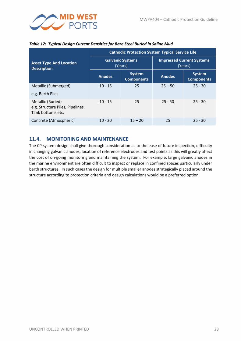
Table 12 provides a summary of anticipated cathodic protection system service lives for various
system components and anodes. This is an indicative guide only as environmental conditions will
heavily influence the service life of the system, particularly with respect to galvanic anodes. Regular
routine system performance monitoring is key to ensuring the systems are providing continued
protection to the specific port asset.
UNCONTROLLED WHEN PRINTED 28
MWPA404 – Cathodic Protection Guideline
Table 12: Typical Design Current Densities for Bare Steel Buried in Saline Mud
Asset Type And Location Description
Cathodic Protection System Typical Service Life
Galvanic Systems (Years)
Impressed Current Systems (Years)
Anodes System
Components Anodes
System Components
Metallic (Submerged)
e.g. Berth Piles
10 ‐ 15 25 25 – 50 25 ‐ 30
Metallic (Buried) e.g. Structure Piles, Pipelines, Tank bottoms etc.
10 ‐ 15 25 25 ‐ 50 25 ‐ 30
Concrete (Atmospheric) 10 ‐ 20 15 – 20 25 25 ‐ 30
11.4. MONITORING AND MAINTENANCE The CP system design shall give thorough consideration as to the ease of future inspection, difficulty
in changing galvanic anodes, location of reference electrodes and test points as this will greatly affect
the cost of on‐going monitoring and maintaining the system. For example, large galvanic anodes in
the marine environment are often difficult to inspect or replace in confined spaces particularly under
berth structures. In such cases the design for multiple smaller anodes strategically placed around the
structure according to protection criteria and design calculations would be a preferred option.
UNCONTROLLED WHEN PRINTED 29
MWPA404 – Cathodic Protection Guideline
12. GUIDANCE TO CONTRACTORS
12.1. PRE‐CONTRACT MEETING Contractors should refer to Section 7 Installation of Cathodic Protection Systems in AS 2832.1. Prior
to system installation, contractors must obtain approval to install a cathodic protection system not
only from the asset owner requiring cathodic protection but also from neighbouring asset owners
who’s structures/assets may be subject to unwanted effects of cathodic protection and other
regulatory bodies as defined by state statutes. Unwanted effects of cathodic protection systems may
include potential current drain in galvanic systems resulting in decreased protection performance and
increased anode consumption rates or detrimental stray current effects from higher output impressed
current systems.
12.2. SYSTEM INSTALLATION PRACTICE The installer shall be familiar with the specifications outlined in this document and covered in the
relevant Australian Standards. Works shall be completed in accordance with good industry practice
and to the satisfaction of MWPA. Additional requirements are as follows:
Any deviations from original design shall be first approved by MWPA and permanently recorded for future reference;
Installation of all electrical work shall be in accordance with local regulations and relevant standards;
Cable connections shall be clean, dry and free of damage at the time of connection;
Test point, anode and structure connections shall be mechanically secure and electrically conductive for the entire design life of the system;
All cable attachments shall be coated with an electrically insulating material that prevents ingress of moisture and shall be compatible with various structure coatings and have good adhesion to all surfaces;
All ground surfaces that are disturbed during the installation of reference electrodes or anode ground beds etc. shall be suitably reinstated.
12.3. SYSTEM COMMISSIONING Contractors are to advise MWPA of all stages of the commissioning process including recording the
performance and system parameter data in accordance with AS 2832. An example format of the
system record is provided in Appendix A.
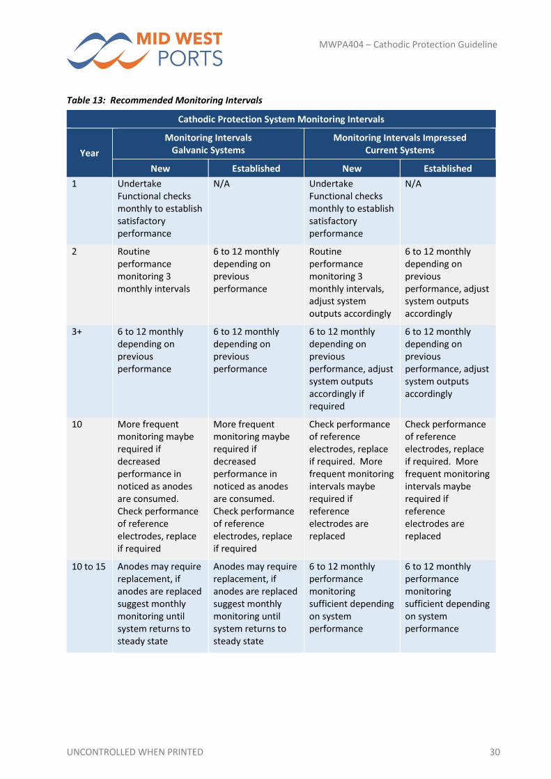
12.4. ONGOING SYSTEM PERFORMANCE MONITORING Table 13 provides an indicative guide to monitoring intervals based on requirements detailed in
AS 2382.1 to AS 2382.5. This table is a guide only as monitoring intervals are ultimately determined
by specific system performance.
UNCONTROLLED WHEN PRINTED 30
MWPA404 – Cathodic Protection Guideline
Table 13: Recommended Monitoring Intervals
Cathodic Protection System Monitoring Intervals
Year
Monitoring Intervals Galvanic Systems
Monitoring Intervals Impressed Current Systems
New Established New Established
1 Undertake Functional checks monthly to establish satisfactory performance
N/A Undertake Functional checks monthly to establish satisfactory performance
N/A
2 Routine performance monitoring 3 monthly intervals
6 to 12 monthly depending on previous performance
Routine performance monitoring 3 monthly intervals, adjust system outputs accordingly
6 to 12 monthly depending on previous performance, adjust system outputs accordingly
3+ 6 to 12 monthly depending on previous performance
6 to 12 monthly depending on previous performance
6 to 12 monthly depending on previous performance, adjust system outputs accordingly if required
6 to 12 monthly depending on previous performance, adjust system outputs accordingly
10 More frequent monitoring maybe required if decreased performance in noticed as anodes are consumed. Check performance of reference electrodes, replace if required
More frequent monitoring maybe required if decreased performance in noticed as anodes are consumed. Check performance of reference electrodes, replace if required
Check performance of reference electrodes, replace if required. More frequent monitoring intervals maybe required if reference electrodes are replaced
Check performance of reference electrodes, replace if required. More frequent monitoring intervals maybe required if reference electrodes are replaced
10 to 15 Anodes may require replacement, if anodes are replaced suggest monthly monitoring until system returns to steady state
Anodes may require replacement, if anodes are replaced suggest monthly monitoring until system returns to steady state
6 to 12 monthly performance monitoring sufficient depending on system performance
6 to 12 monthly performance monitoring sufficient depending on system performance

UNCONTROLLED WHEN PRINTED 31
MWPA404 – Cathodic Protection Guideline
Cathodic Protection System Monitoring Intervals
Year
Monitoring Intervals Galvanic Systems
Monitoring Intervals Impressed Current Systems
New Established New Established
20 to 25 Major system overhaul required, replace wiring junction boxes etc., monthly system monitoring required until system returns to steady state
6 to 12 monthly performance monitoring sufficient depending on system performance. Will become more frequent if system components are upgraded or replaced
6 to 12 monthly performance monitoring sufficient depending on system performance. Will become more frequent if system components are upgraded or replaced
UNCONTROLLED WHEN PRINTED 32
MWPA404 – Cathodic Protection Guideline
13. QUALITY CONTROL AND QUALITY ASSURANCE
– GUIDANCE TO INSPECTORS
13.1. GENERAL REQUIREMENTS This section aims to list the minimum requirements for quality control and quality assurance to ensure
the cathodic protection systems operate with minimum maintenance and as the detailed design
intended.
13.2. INSPECTION AND TESTING PLAN Section 10.3 AS 2831.1 and Appendix L provides detailed information on the required inspection and
testing of Cathodic Protection systems. As a minimum to ensure the correct operation of a cathodic
protection system the following items should be verified regularly:
All cathodic protection system equipment is sound and operating as intended
Condition of continuity bonds where accessible
Earthing systems installed to control induced voltages and operating correctly
Foreign Structure bonds and stray current drainage bonds
All electrical equipment, including rectifiers, transformers and switchgear is kept clean to ensure adequate ventilation for cooling
Where a structure has been exposed for any purpose it shall be examined for corrosion and if coated, the condition of the coating should be assessed and repaired as required.
Periodic Potential Surveys should be undertaken as determined by the system designer as it is structure dependent refer Section 10.4 AS 2832.1, Section 10.3 AS 2832.3 and Section 7 AS 2382.5 for maximum time intervals between cathodic protection potential surveys.
An example test record form has been provided in Appendix B of this document.
13.3. IDENTIFICATION AND TRACEABILITY The following certification and accreditation should be used to confirm the quality of the anodes and
other system components before installation:
The Anode manufacturer shall supply MWPA with the following items:
A copy of the anode certification (including mass, dimensions, core material data and chemical analysis of anode purity).
ISO 9001 accreditation of any company providing cathodic protection system components is recommended.
13.4. COMPLIANCE INSPECTIONS AND TESTING The purpose of an independent review is to confirm that the system meets the intended design
requirements and protection criteria. This shall include but not be limited to the following:
Current densities and current requirements are appropriate for all cathodic protection zones;
Anode materials and anode operational parameters are suitable for the intended purpose;
Confirm that the reference electrodes, cables, conduits, connections, DC power supplies (where impressed current system is used) and all other equipment are suitably rated;

UNCONTROLLED WHEN PRINTED 33
MWPA404 – Cathodic Protection Guideline
Ensure all drawings adequately reflect the proposed system and contain sufficient detail to enable correct installation of the system;
Ensure all installation procedures are adequate;
Ensure that the inspection and testing methods are appropriate to ensure the system will be installed and perform as designed;
Ensure all aspects of the design, specification, drawings, installation, commissioning, records, documentation and operation conform to the requirements of AS 2832 and this guideline.
UNCONTROLLED WHEN PRINTED 34
MWPA404 – Cathodic Protection Guideline
14. DOCUMENTS TO BE SUBMITTED
14.1. GENERAL
14.1.1. SYSTEM DESIGN DOCUMENTATION Example system information, design documentation system operating provided in Appendix A. Prior
to the installation, the design documentation must be submitted to the relevant state authority such
as the local electrolysis committee for review and accepted.
14.1.2. COMMISSIONING DOCUMENTATION Commissioning documentation must be submitted to the relevant state authority once a system is
commissioned. Commission reports and documentation will also be submitted to MWPA and any
deviations from original design or intended operating parameters must be brought to the attention of
the project engineer.
UNCONTROLLED WHEN PRINTED 35
MWPA404 – Cathodic Protection Guideline
APPENDIX A
EXAMPLE CATHODIC PROTECTION SYSTEM INFORMATION
UNCONTROLLED WHEN PRINTED 36
MWPA404 – Cathodic Protection Guideline
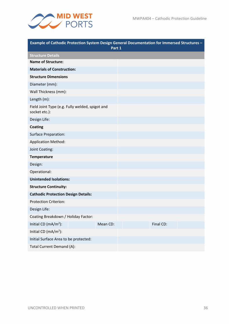
Example of Cathodic Protection System Design General Documentation for Immersed Structures – Part 1
Structure Details
Name of Structure:
Materials of Construction:
Structure Dimensions
Diameter (mm):
Wall Thickness (mm):
Length (m):
Field Joint Type (e.g. Fully welded, spigot and socket etc.):
Design Life:
Coating
Surface Preparation:
Application Method:
Joint Coating:
Temperature
Design:
Operational:
Unintended Isolations:
Structure Continuity:
Cathodic Protection Design Details:
Protection Criterion:
Design Life:
Coating Breakdown / Holiday Factor:
Initial CD (mA/m2): Mean CD: Final CD:
Initial CD (mA/m2):
Initial Surface Area to be protected:
Total Current Demand (A):
UNCONTROLLED WHEN PRINTED 37
MWPA404 – Cathodic Protection Guideline
Example of Cathodic Protection System Design Documentation for Immersed Structures – Part 2 – Site Details – Impressed Current Systems
Location:
Resistivity:
Cables (core size, length, insulation)
Ground bed Feeder:
Structure Negative:
Anode Header:
Anode:
Material:
Design Life:
Backfill
Type:
Resistivity:
Layout
Anode Orientation:
Anode Spacing:
Length:
Design Resistance:
Actual Resistance:
T/R Unit Capacity
Size:
Power Source:
Surge Protection:
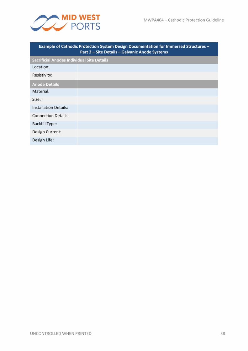
UNCONTROLLED WHEN PRINTED 38
MWPA404 – Cathodic Protection Guideline
Example of Cathodic Protection System Design Documentation for Immersed Structures – Part 2 – Site Details – Galvanic Anode Systems
Sacrificial Anodes Individual Site Details
Location:
Resistivity:
Anode Details
Material:
Size:
Installation Details:
Connection Details:
Backfill Type:
Design Current:
Design Life:
UNCONTROLLED WHEN PRINTED 39
MWPA404 – Cathodic Protection Guideline
APPENDIX B
EXAMPLE TEST INSPECTION RECORD
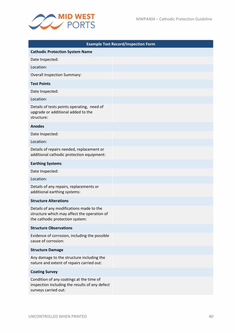
UNCONTROLLED WHEN PRINTED 40
MWPA404 – Cathodic Protection Guideline
Example Test Record/Inspection Form
Cathodic Protection System Name
Date Inspected:
Location:
Overall Inspection Summary:
Test Points
Date Inspected:
Location:
Details of tests points operating, need of upgrade or additional added to the structure:
Anodes
Date Inspected:
Location:
Details of repairs needed, replacement or additional cathodic protection equipment:
Earthing Systems
Date Inspected:
Location:
Details of any repairs, replacements or additional earthing systems:
Structure Alterations
Details of any modifications made to the structure which may affect the operation of the cathodic protection system:
Structure Observations
Evidence of corrosion, including the possible cause of corrosion:
Structure Damage
Any damage to the structure including the nature and extent of repairs carried out:
Coating Survey
Condition of any coatings at the time of inspection including the results of any defect surveys carried out: