Embed Size (px)
Citation preview
06/2009
MIDI BOX and MIDI BOX Pluswall formwork
ASSEMBLY INSTRUCTIONS2009
ASSEMBLY INSTRUCTIONS FOR MIDI BOX WALL FORMWORK
NOTE!Assembly instructions do not replace safety instructions on the Site!
The responsibility for formwork assembly and check-over is borne by the Site Engineer!
3
page 23
page 20
page 13
page 6
CONTENTS
page 16
page 18
page 4
page 24
page 26
1. Techical Descryption
1.1. Characteristics of MIDI BOX formwork
1.2. Characteristics of MIDI BOX Plus formwork
1.3. Basic assembly and disassembly operations
2. MIDI BOX formwork
2.1 Straight formwork
2.1.1. Walls 150, 2700 or 300 cm high
2.2. Formwork with superstructures
2.3. Adjustment of the wall length using complementary filling inserts
2.4. Formwork end closure (common for MIDI BOX and MIDI BOX Plus)
2.5. Forming variable thickness walls
2.6. Forming high walls
2.7. Working Platforms
3. MIDI BOX formwork
3.1. Straight walls
3.2. Formwork with superstructures
3.3. Transport of the Elements on the Site
4. Corners
4.1. Internal Corners
4.2. External Corners
4.3. Obtuse and Acute Angle Corners
5. Forming columns
5.1. Use of Zero Corner and Shuttering Boards (ordinary)
5.2. SP Shuttering Boards (column shuttering)
6. Lift Shaft Forming
6.1. Lift Shaft Formwork
6.2. Lift shaft formwork assembly and stripping
7. Circular Wall Erection
8. Plumbing of walls and columns
8.1. 3.0 m High Walls and Columns
8.2. Walls and Columns over 3 m high
9. ANNEX No 1
4
4
5
6
6
6
7
8
10
11
12
13
14
15
16
16
17
18
19
20
20
24
25
ASSEMBLY INSTRUCTIONS FOR MIDI BOX WALL FORMWORK
NOTE!Assembly instructions do not replace safety instructions on the Site!
The responsibility for formwork assembly and check-over is borne by the Site Engineer!
1. TECHNICAL DESCRIPTION
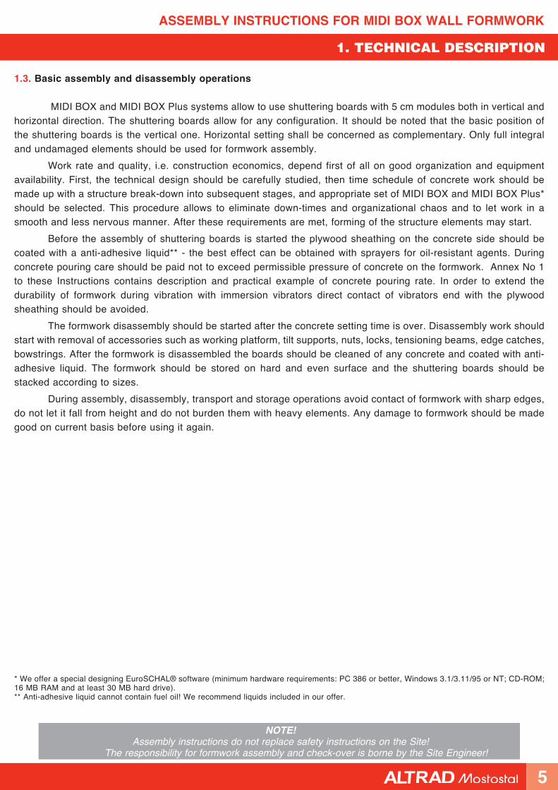
1. Technical Description
MIDI BOX and MIDI BOX Plus formwork is a spatial reusable product. Formwork is designed for construction of continuous foundations, medium-size walls and heavy gauge rectangular columns, girders, lift shafts and many other structural elements of buildings and structures. Formwork system elements include a series of types of framework filled with plywood, a complete set of connecting, stiffening, compensating and plumbing elements.
1.1. Characteristics of MIDI BOX formwork
MIDI BOX is a medium load wall formwork - permissible concrete pressure is 60 kN/m2 for formwork erected without superstructure, or 55 kN/m2 for formwork erected with superstructures. The basic elements of the system include shuttering boards 150, 270, 300 cm high and 25 to 90 cm wide. The shuttering boards are ribbed frames made of box profiles manufactured of high quality steel grades. The sheathing is made of water-resistant multilayer plywood coated with resin layer on both sides. Therefore, high quality of concrete surface and long life of sheathing are ensured. After stripping of formwork the concrete surface is so smooth that, apart from thin-layer plasters or patching, plastering is not needed.
Dense ribbing of frames does not allow the plywood to deform under concrete pressure. Hoisting hooks provided in the frame ribs ensure solid grip and easy handling of shuttering boards. Working platform supports may be fitted on the outer side (ribbed side) of formwork. The platforms allow to inspect the formwork inside. This is useful when vibrating the concrete mix.
Each steel frame structure has a number of systematically arranged holes which allow to join the shuttering boards with each other and with the elements of formwork system. Multifunctional BM boarding lock ensures reliable connections of shuttering boards and other elements. The lock also acts a compensating and stiffening element.
Apart from the shuttering locks, bowstrings and centring nuts are used to join the elements. The corners are formed of external, external and hinged corner pieces of various dimensions. The system includes members for upright setting of formwork: tilt supports and raking shores. In the case of larger wall surfaces additional stiffening is ensured by means of boarding transoms and stiffening beams which ensure horizontal and vertical stiffness. The opposite shuttering boards of formwork are joined by mans of Diwidag D15 couplers (bowstrings) and collar nuts. With such connection the permissible load is 90 kN. The bowstrings are protected by PVC spacer pipes which are cut to size corresponding to the wall thickness.
1.2. Characteristics of MIDI BOX Plus formwork
MIDI BOX Plus is a heavy duty type formwork. The system withstands permissible concrete pressure of 80 kN/m2. The basic elements of the system include large-sized shuttering boards 270 and 300 cm high with width ranging between 90 and 240 cm. MIDI BOX and MIDI BOX Plus systems are fully compatible. All joining elements and auxiliaries used for MIDI BOX system are applicable for MIDI BOX Plus system. Combination of both systems allows for an efficient and optimal setting of any shuttering.
NOTE! The MIDI BOX system includes shuttering boards of width ranging between 25 and 90 cm which have
declared bearing strength of 60 kN/m2. However, the strength of MIDI BOX shuttering boards up to
70 cm in width combined with MIDI BOX Plus system is 80 kN/m2.
Transportation hooks are used in order to move the whole sets of MIDI BOX and MIDI BOX Plus without
disassembling.
4
ASSEMBLY INSTRUCTIONS FOR MIDI BOX WALL FORMWORK
NOTE!Assembly instructions do not replace safety instructions on the Site!
The responsibility for formwork assembly and check-over is borne by the Site Engineer!
1. TECHNICAL DESCRIPTION
1.3. Basic assembly and disassembly operations
MIDI BOX and MIDI BOX Plus systems allow to use shuttering boards with 5 cm modules both in vertical and horizontal direction. The shuttering boards allow for any configuration. It should be noted that the basic position of the shuttering boards is the vertical one. Horizontal setting shall be concerned as complementary. Only full integral and undamaged elements should be used for formwork assembly.
Work rate and quality, i.e. construction economics, depend first of all on good organization and equipment availability. First, the technical design should be carefully studied, then time schedule of concrete work should be made up with a structure break-down into subsequent stages, and appropriate set of MIDI BOX and MIDI BOX Plus* should be selected. This procedure allows to eliminate down-times and organizational chaos and to let work in a smooth and less nervous manner. After these requirements are met, forming of the structure elements may start.
Before the assembly of shuttering boards is started the plywood sheathing on the concrete side should be coated with a anti-adhesive liquid** - the best effect can be obtained with sprayers for oil-resistant agents. During concrete pouring care should be paid not to exceed permissible pressure of concrete on the formwork. Annex No 1 to these Instructions contains description and practical example of concrete pouring rate. In order to extend the durability of formwork during vibration with immersion vibrators direct contact of vibrators end with the plywood sheathing should be avoided.
The formwork disassembly should be started after the concrete setting time is over. Disassembly work should start with removal of accessories such as working platform, tilt supports, nuts, locks, tensioning beams, edge catches, bowstrings. After the formwork is disassembled the boards should be cleaned of any concrete and coated with anti-adhesive liquid. The formwork should be stored on hard and even surface and the shuttering boards should be stacked according to sizes.
During assembly, disassembly, transport and storage operations avoid contact of formwork with sharp edges, do not let it fall from height and do not burden them with heavy elements. Any damage to formwork should be made good on current basis before using it again.
* We offer a special designing EuroSCHAL® software (minimum hardware requirements: PC 386 or better, Windows 3.1/3.11/95 or NT; CD-ROM; 16 MB RAM and at least 30 MB hard drive).** Anti-adhesive liquid cannot contain fuel oil! We recommend liquids included in our offer.
5
ASSEMBLY INSTRUCTIONS FOR MIDI BOX WALL FORMWORK
NOTE!Assembly instructions do not replace safety instructions on the Site!
The responsibility for formwork assembly and check-over is borne by the Site Engineer!
Stiffening beam
a0960001Collar nut a2510110
Shuttering board
BM260 locka0901260
Fig. 2.3
2. MIDI BOX FORMWORK
2. MIDI BOX formwork
2.1. Straight formwork
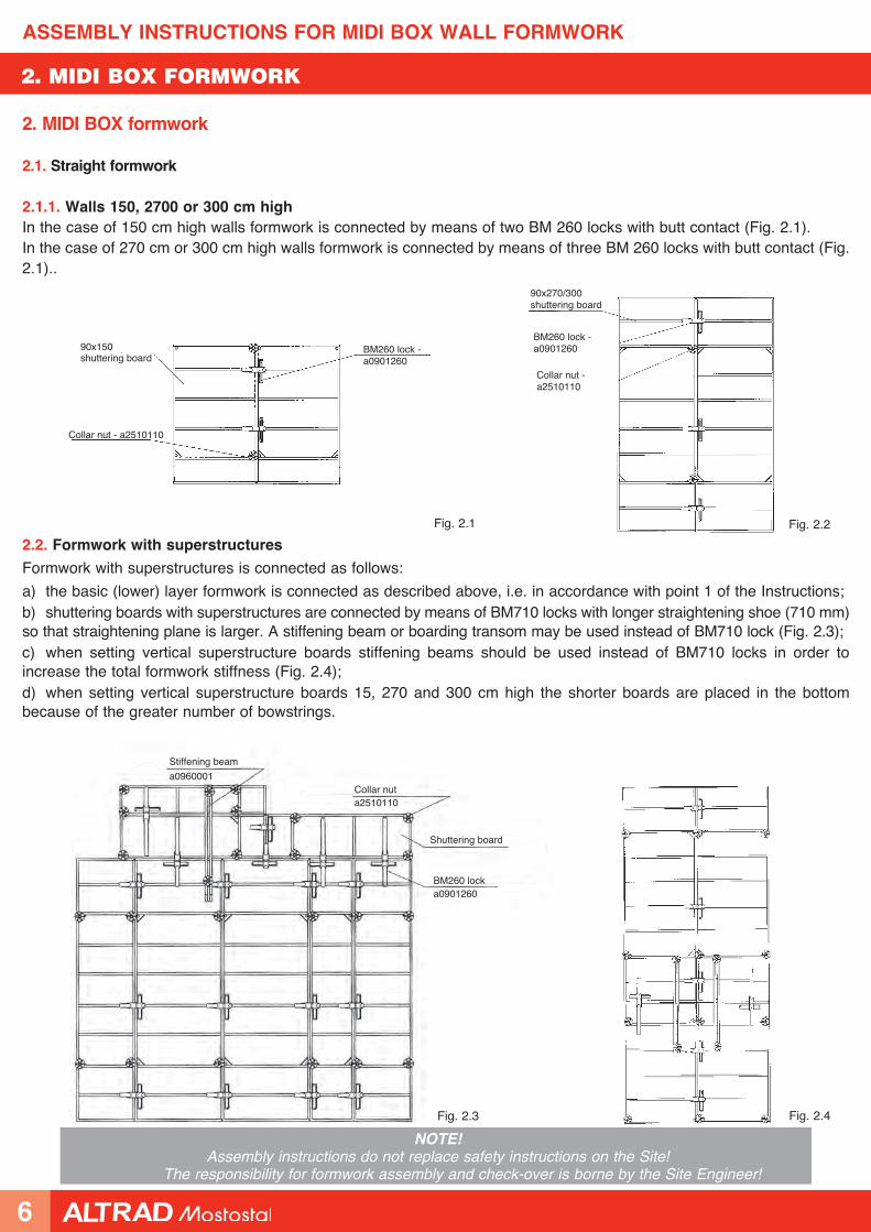
2.1.1. Walls 150, 2700 or 300 cm highIn the case of 150 cm high walls formwork is connected by means of two BM 260 locks with butt contact (Fig. 2.1).In the case of 270 cm or 300 cm high walls formwork is connected by means of three BM 260 locks with butt contact (Fig. 2.1)..
2.2. Formwork with superstructures
Formwork with superstructures is connected as follows:
a) the basic (lower) layer formwork is connected as described above, i.e. in accordance with point 1 of the Instructions;b) shuttering boards with superstructures are connected by means of BM710 locks with longer straightening shoe (710 mm) so that straightening plane is larger. A stiffening beam or boarding transom may be used instead of BM710 lock (Fig. 2.3);c) when setting vertical superstructure boards stiffening beams should be used instead of BM710 locks in order to increase the total formwork stiffness (Fig. 2.4);d) when setting vertical superstructure boards 15, 270 and 300 cm high the shorter boards are placed in the bottom because of the greater number of bowstrings.
Fig. 2.1
90x150 shuttering board
Collar nut - a2510110
BM260 lock - a0901260
Fig. 2.2
90x270/300 shuttering board
BM260 lock - a0901260
Fig. 2.4
Collar nut - a2510110
6
ASSEMBLY INSTRUCTIONS FOR MIDI BOX WALL FORMWORK
NOTE!Assembly instructions do not replace safety instructions on the Site!
The responsibility for formwork assembly and check-over is borne by the Site Engineer!
2. MIDI BOX FORMWORK
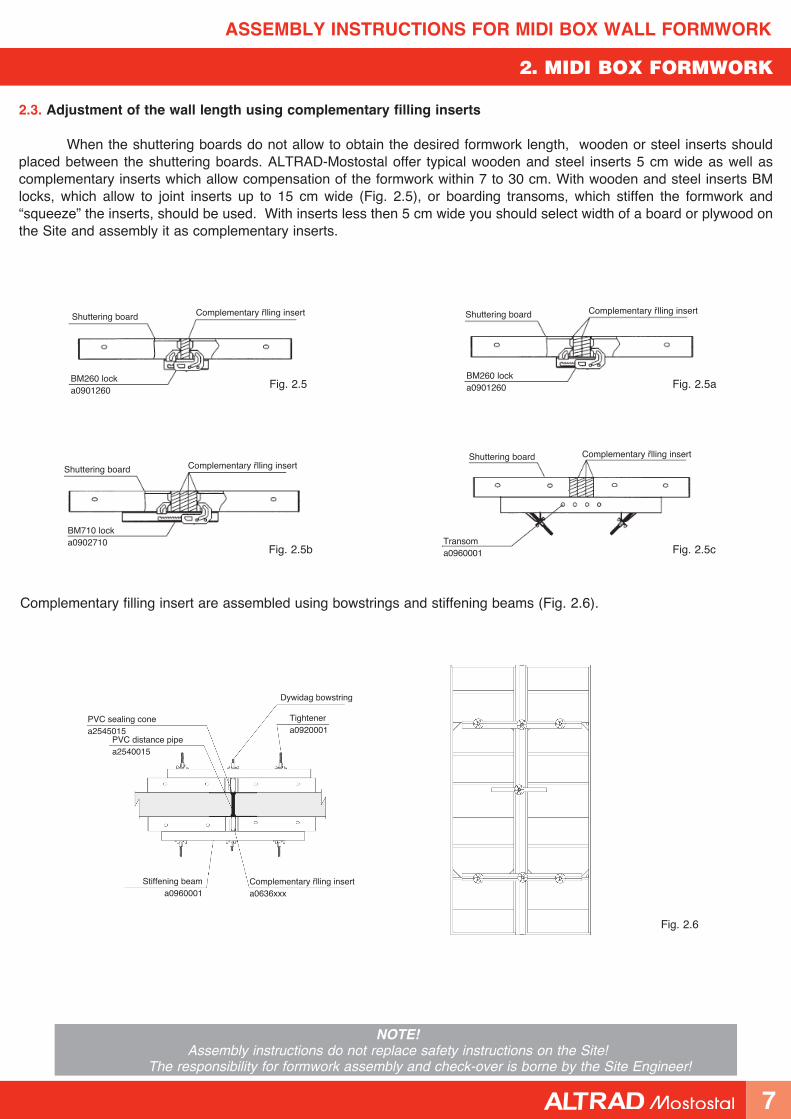
Complementary filling insert are assembled using bowstrings and stiffening beams (Fig. 2.6).
Fig. 2.6
PVC sealing cone a2545015
Dywidag bowstring
Tightener a0920001
Stiffening beama0960001
Complementary filling insert a0636xxx
2.3. Adjustment of the wall length using complementary filling inserts
When the shuttering boards do not allow to obtain the desired formwork length, wooden or steel inserts should placed between the shuttering boards. ALTRAD-Mostostal offer typical wooden and steel inserts 5 cm wide as well as complementary inserts which allow compensation of the formwork within 7 to 30 cm. With wooden and steel inserts BM locks, which allow to joint inserts up to 15 cm wide (Fig. 2.5), or boarding transoms, which stiffen the formwork and “squeeze” the inserts, should be used. With inserts less then 5 cm wide you should select width of a board or plywood on the Site and assembly it as complementary inserts.
PVC distance pipe a2540015
Fig. 2.5 Fig. 2.5a
Fig. 2.5c
Shuttering board
BM260 lock a0901260
Complementary filling insert Shuttering board
BM260 lock a0901260
Complementary filling insert
Complementary filling insertShuttering board
Transom a0960001
Complementary filling insertShuttering board
BM710 lock a0902710
Fig. 2.5b
7
ASSEMBLY INSTRUCTIONS FOR MIDI BOX WALL FORMWORK
NOTE!Assembly instructions do not replace safety instructions on the Site!
The responsibility for formwork assembly and check-over is borne by the Site Engineer!
2. MIDI BOX FORMWORK
Fig. 2.7
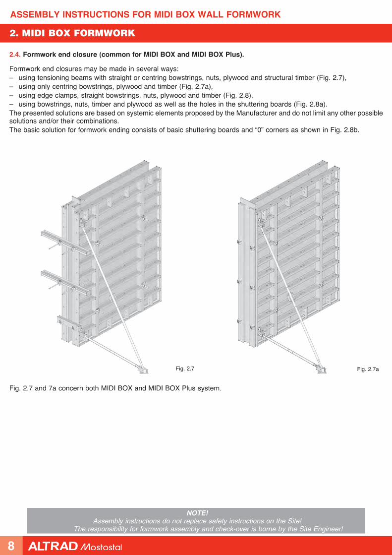
2.4. Formwork end closure (common for MIDI BOX and MIDI BOX Plus).
Fig. 2.7a
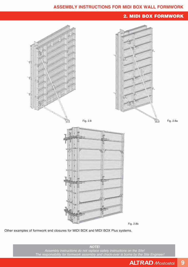
Formwork end closures may be made in several ways:– using tensioning beams with straight or centring bowstrings, nuts, plywood and structural timber (Fig. 2.7),– using only centring bowstrings, plywood and timber (Fig. 2.7a),– using edge clamps, straight bowstrings, nuts, plywood and timber (Fig. 2.8),– using bowstrings, nuts, timber and plywood as well as the holes in the shuttering boards (Fig. 2.8a).The presented solutions are based on systemic elements proposed by the Manufacturer and do not limit any other possible solutions and/or their combinations.The basic solution for formwork ending consists of basic shuttering boards and “0” corners as shown in Fig. 2.8b.
Fig. 2.7 and 7a concern both MIDI BOX and MIDI BOX Plus system.
8
ASSEMBLY INSTRUCTIONS FOR MIDI BOX WALL FORMWORK
NOTE!Assembly instructions do not replace safety instructions on the Site!
The responsibility for formwork assembly and check-over is borne by the Site Engineer!
2. MIDI BOX FORMWORK
Fig. 2.8 Fig. 2.8a
Fig. 2.8b
Other examples of formwork end closures for MIDI BOX and MIDI BOX Plus systems.
9
ASSEMBLY INSTRUCTIONS FOR MIDI BOX WALL FORMWORK
NOTE!Assembly instructions do not replace safety instructions on the Site!
The responsibility for formwork assembly and check-over is borne by the Site Engineer!
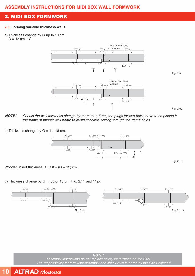
Fig. 2.9
Fig. 2.9a
c) Thickness change by G = 30 or 15 cm (Fig. 2.11 and 11a).
Fig. 2.11 Fig. 2.11a
2.5. Forming variable thickness walls
a) Thickness change by G up to 10 cm. D = 12 cm – G
b) Thickness change by G = 1 ÷ 18 cm.
Wooden insert thickness D = 30 – (G + 12) cm.
Fig. 2.10
NOTE! Should the wall thickness change by more than 5 cm, the plugs for ova holes have to be placed in the frame of thinner wall board to avoid concrete flowing through the frame holes.
Plug for oval holesa2565004
Plug for oval holesa2565004
2. MIDI BOX FORMWORK
10

ASSEMBLY INSTRUCTIONS FOR MIDI BOX WALL FORMWORK
NOTE!Assembly instructions do not replace safety instructions on the Site!
The responsibility for formwork assembly and check-over is borne by the Site Engineer!
2.6. Forming high walls
The climbing shuttering bracket is intended for external wall shuttering erection. The brackets may be used up the height H = 1 m. Maximum formwork height: 4.2 m without additional anchoring of shuttering boards. Maximum spacing of the brackets: 1.35 m. The brackets should be anchored using SKK cones and wobble or loop anchors B15. The anchor to which climbing formwork bracket has been fixed should be embedded at the stage of lower level wall concrete pouring. When erecting formwork on the hanging bracket SKK cone has to be fixed to the board sheathing to get ready for higher level anchor installation (Fig. 2.12).
Fig. 2.12
Tilt supporta0904001
Working platform bracket a0951000
Working platform posta0970002
Tilt supporta0904001
Square-sawn timber or girder H20Bracket grip
a0915004Hook or wobble anchor
Max
. 420
0
X +
100
1450
SKK metal cone
Working platform bracketa0952000
Working platform
Climbing formwork bracket a0915003
Tilt support grip
Working platform post a097002
Bolt M24x40-8.8-B, hot dip galvanized
X – square-sawn timber height
Working platform
Board #30x150xL (handrail, toeboard)
Wooden girder H20
Universal pipe 48.3 dia x 3.2 (bracing)
Working platform
2. MIDI BOX FORMWORK
11
ASSEMBLY INSTRUCTIONS FOR MIDI BOX WALL FORMWORK
NOTE!Assembly instructions do not replace safety instructions on the Site!
The responsibility for formwork assembly and check-over is borne by the Site Engineer!
2. MIDI BOX FORMWORK
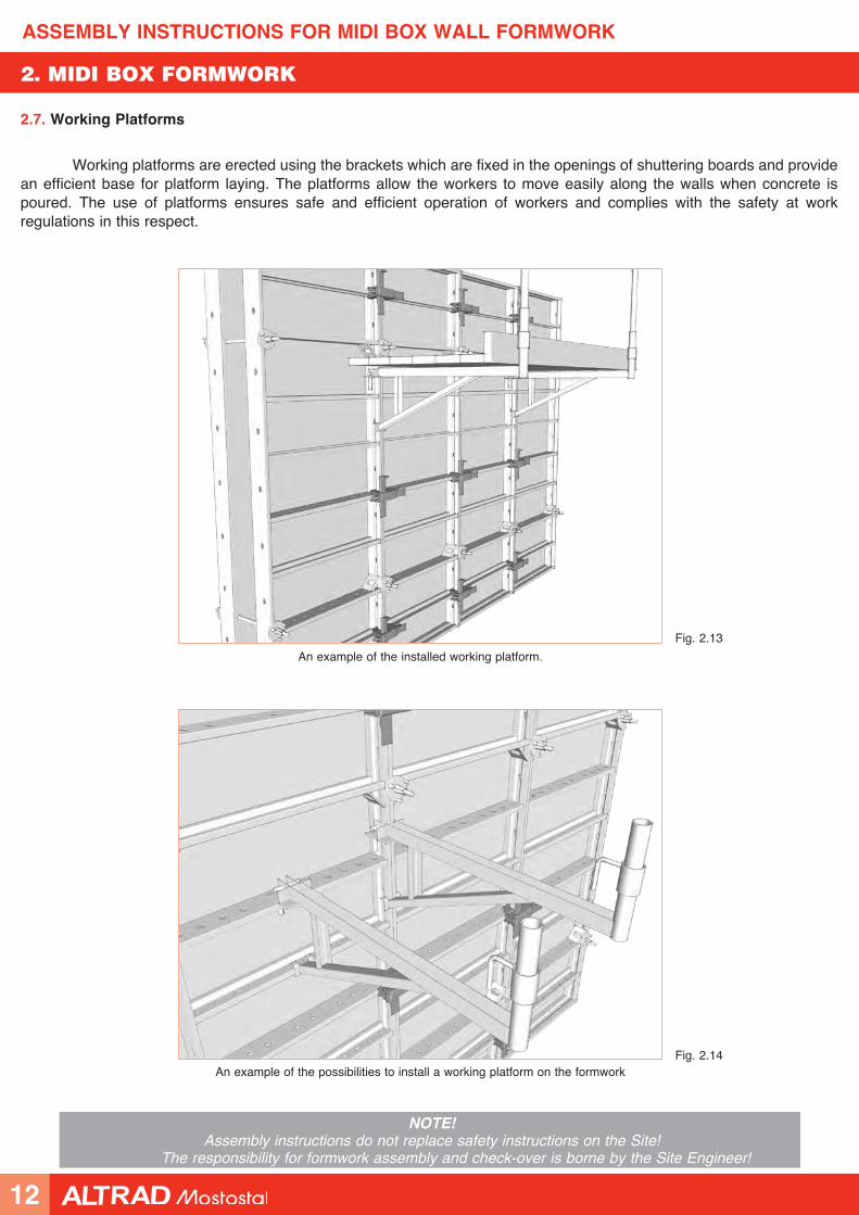
2.7. Working Platforms
Working platforms are erected using the brackets which are fixed in the openings of shuttering boards and provide an efficient base for platform laying. The platforms allow the workers to move easily along the walls when concrete is poured. The use of platforms ensures safe and efficient operation of workers and complies with the safety at work regulations in this respect.
An example of the installed working platform.
An example of the possibilities to install a working platform on the formwork
Fig. 2.13
Fig. 2.14
12
ASSEMBLY INSTRUCTIONS FOR MIDI BOX WALL FORMWORK
NOTE!Assembly instructions do not replace safety instructions on the Site!
The responsibility for formwork assembly and check-over is borne by the Site Engineer!
3. MIDI BOX Plus FORMWORK
3. MIDI BOX Plus FORMWORK
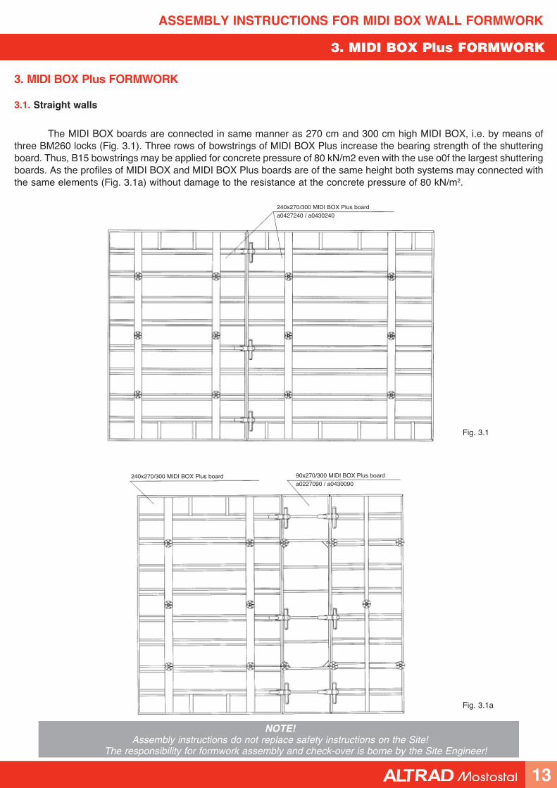
3.1. Straight walls
The MIDI BOX boards are connected in same manner as 270 cm and 300 cm high MIDI BOX, i.e. by means of three BM260 locks (Fig. 3.1). Three rows of bowstrings of MIDI BOX Plus increase the bearing strength of the shuttering board. Thus, B15 bowstrings may be applied for concrete pressure of 80 kN/m2 even with the use o0f the largest shuttering boards. As the profiles of MIDI BOX and MIDI BOX Plus boards are of the same height both systems may connected with the same elements (Fig. 3.1a) without damage to the resistance at the concrete pressure of 80 kN/m2.
240x270/300 MIDI BOX Plus board
Fig. 3.1
Fig. 3.1a
90x270/300 MIDI BOX Plus boarda0227090 / a0430090
240x270/300 MIDI BOX Plus boarda0427240 / a0430240
13
ASSEMBLY INSTRUCTIONS FOR MIDI BOX WALL FORMWORK
NOTE!Assembly instructions do not replace safety instructions on the Site!
The responsibility for formwork assembly and check-over is borne by the Site Engineer!
3. MIDI BOX Plus FORMWORK
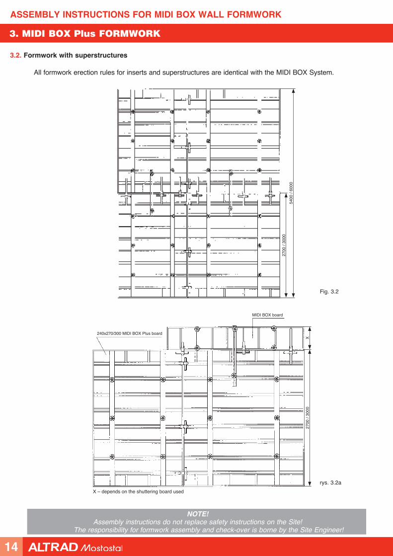
3.2. Formwork with superstructures
All formwork erection rules for inserts and superstructures are identical with the MIDI BOX System.
Fig. 3.2
rys. 3.2a
240x270/300 MIDI BOX Plus board
MIDI BOX board
5400
/ 60
00
2700
/ 30
00
2700
/ 30
00X
X – depends on the shuttering board used
14
ASSEMBLY INSTRUCTIONS FOR MIDI BOX WALL FORMWORK
NOTE!Assembly instructions do not replace safety instructions on the Site!
The responsibility for formwork assembly and check-over is borne by the Site Engineer!
3. MIDI BOX Plus FORMWORK
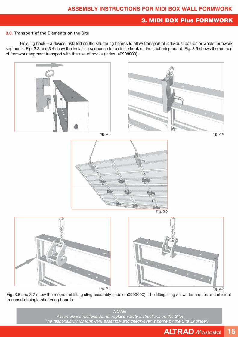
3.3. Transport of the Elements on the Site
Hoisting hook – a device installed on the shuttering boards to allow transport of individual boards or whole formwork segments. Fig. 3.3 and 3.4 show the installing sequence for a single hook on the shuttering board. Fig. 3.5 shows the method of formwork segment transport with the use of hooks (index: a0908000).
Fig. 3.6 and 3.7 show the method of lifting sling assembly (index: a0909000). The lifting sling allows for a quick and efficient transport of single shuttering boards.
Fig. 3.3 Fig. 3.4
Fig. 3.5
Fig. 3.6 Fig. 3.7
15
ASSEMBLY INSTRUCTIONS FOR MIDI BOX WALL FORMWORK
NOTE!Assembly instructions do not replace safety instructions on the Site!
The responsibility for formwork assembly and check-over is borne by the Site Engineer!
4. CORNERS
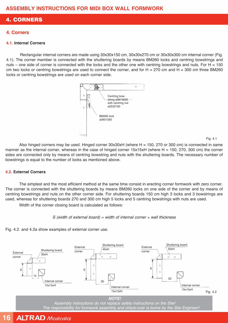
Also hinged corners may be used. Hinged corner 30x30xH (where H = 150, 270 or 300 cm) is connected in same manner as the internal corner, whereas in the case of hinged corner 15x15xH (where H = 150, 270, 300 cm) the corner sides are connected only by means of centring bowstring and nuts with the shuttering boards. The necessary number of bowstrings is equal to the number of locks as mentioned above.
4.2. External Corners
The simplest and the most efficient method at the same time consist in erecting corner formwork with zero corner. The corner is connected with the shuttering boards by means BM260 locks on one side of the corner and by means of centring bowstrings and nuts on the other corner side. For shuttering boards 150 cm high 3 locks and 3 bowstrings are used, whereas for shuttering boards 270 and 300 cm high 5 locks and 5 centring bowstrings with nuts are used.
Width of the corner closing board is calculated as follows:
S (width of external board) = width of internal corner + wall thickness
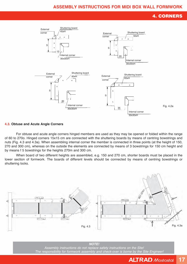
Fig. 4.2. and 4.2a show examples of external corner use.
4. Corners
4.1. Internal Corners
Rectangular internal corners are made using 30x30x150 cm, 30x30x270 cm or 30x30x300 cm internal corner (Fig. 4.1). The corner member is connected with the shuttering boards by means BM260 locks and centring bowstrings and nuts – one side of corner is connected with the locks and the other one with centring bowstrings and nuts. For H = 150 cm two locks or centring bowstrings are used to connect the corner, and for H = 270 cm and H = 300 cm three BM260 locks or centring bowstrings are used on each corner side.
Fig. 4.1
BM260 locka0901260
30
15
S
35
Fig. 4.2
Centring bow-string a0815000with centring nut a2532100
S S
Shuttering board
30xHExternal
corner
External
corner
External
corner
Shuttering board
45xH
Shuttering board
50xH
Internal corner
15x15xH Internal corner
15x15xH
Internal corner
15x15xH
16
ASSEMBLY INSTRUCTIONS FOR MIDI BOX WALL FORMWORK
NOTE!Assembly instructions do not replace safety instructions on the Site!
The responsibility for formwork assembly and check-over is borne by the Site Engineer!
4. CORNERS
4.3. Obtuse and Acute Angle Corners
For obtuse and acute angle corners hinged members are used as they may be opened or folded within the range of 60 to 270o. Hinged corners 15x15 cm are connected with the shuttering boards by means of centring bowstrings and nuts (Fig. 4.3 and 4.3a). When assembling internal corner the member is connected in three points (at the height of 150, 270 and 300 cm), whereas on the outside the elements are connected by means of 3 bowstrings for 150 cm height and by means f 5 bowstrings for the heights 270m and 300 cm.
When board of two different heights are assembled, e.g. 150 and 270 cm, shorter boards must be placed in the lower section of formwork. The boards of different levels should be connected by means of centring bowstrings or shuttering locks.
Fig. 4.3 Fig. 4.3a
60° ÷
270°
15
External
External
corner
corner
20
S
cornercorner ExternalExternal
30
35
S
S
S
Fig. 4.2a
Shuttering board
45xH Shuttering board
50xH
Shuttering board
60xHShuttering board
65xH
Internal corner
30x30xH Internal corner
30x30xH
Internal corner
30x30xH Internal corner
30x30xH
17
ASSEMBLY INSTRUCTIONS FOR MIDI BOX WALL FORMWORK
NOTE!Assembly instructions do not replace safety instructions on the Site!
The responsibility for formwork assembly and check-over is borne by the Site Engineer!
Kraw´dê Kraw´dê Kraw´dê
Fig. 5.2H = 150 cm H = 270 cm H = 300 cm H = 420 cm H = 540 cm
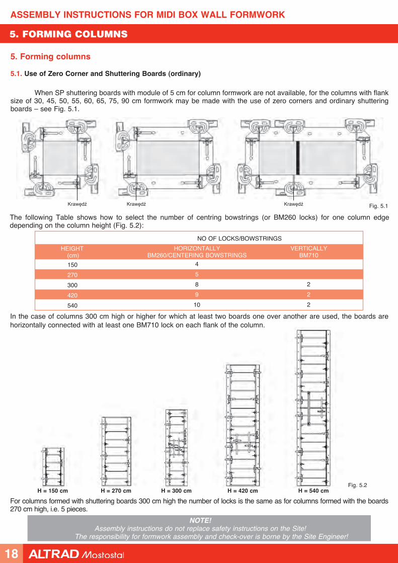
In the case of columns 300 cm high or higher for which at least two boards one over another are used, the boards are horizontally connected with at least one BM710 lock on each flank of the column.
NO OF LOCKS/BOWSTRINGS
HEIGHT (cm)
HORIZONTALLY BM260/CENTERING BOWSTRINGS
VERTICALLYBM710
150
270
300
420
540
4
5
8
9
10
2
2
2
The following Table shows how to select the number of centring bowstrings (or BM260 locks) for one column edge depending on the column height (Fig. 5.2):
For columns formed with shuttering boards 300 cm high the number of locks is the same as for columns formed with the boards 270 cm high, i.e. 5 pieces.
5. Forming columns
5.1. Use of Zero Corner and Shuttering Boards (ordinary)
When SP shuttering boards with module of 5 cm for column formwork are not available, for the columns with flank size of 30, 45, 50, 55, 60, 65, 75, 90 cm formwork may be made with the use of zero corners and ordinary shuttering boards – see Fig. 5.1.
Fig. 5.1
5. FORMING COLUMNS
18
ASSEMBLY INSTRUCTIONS FOR MIDI BOX WALL FORMWORK
NOTE!Assembly instructions do not replace safety instructions on the Site!
The responsibility for formwork assembly and check-over is borne by the Site Engineer!
5. FORMING COLUMNS
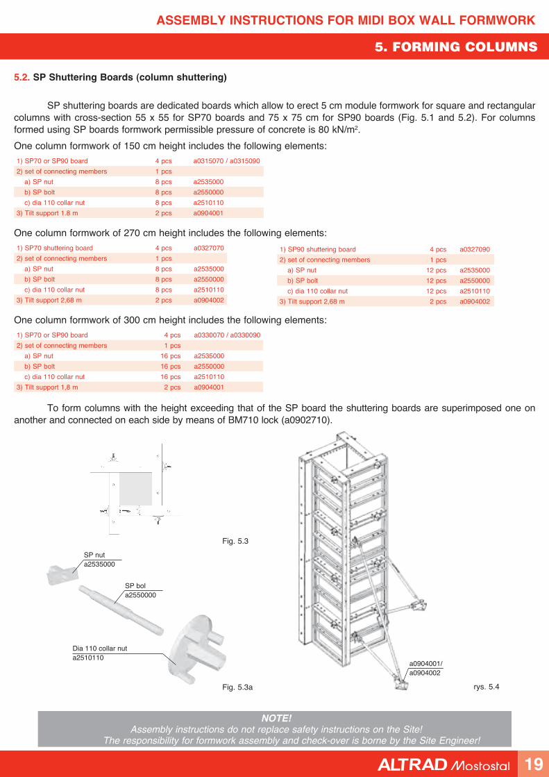
5.2. SP Shuttering Boards (column shuttering)
SP shuttering boards are dedicated boards which allow to erect 5 cm module formwork for square and rectangular columns with cross-section 55 x 55 for SP70 boards and 75 x 75 cm for SP90 boards (Fig. 5.1 and 5.2). For columns formed using SP boards formwork permissible pressure of concrete is 80 kN/m2.
One column formwork of 150 cm height includes the following elements:
1) SP70 or SP90 board 4 pcs a0315070 / a0315090
2) set of connecting members 1 pcs
a) SP nut 8 pcs a2535000
b) SP bolt 8 pcs a2550000
c) dia 110 collar nut 8 pcs a2510110
3) Tilt support 1.8 m 2 pcs a0904001
One column formwork of 270 cm height includes the following elements:
1) SP70 shuttering board 4 pcs a0327070
2) set of connecting members 1 pcs
a) SP nut 8 pcs a2535000
b) SP bolt 8 pcs a2550000
c) dia 110 collar nut 8 pcs a2510110
3) Tilt support 2,68 m 2 pcs a0904002
One column formwork of 300 cm height includes the following elements:
1) SP70 or SP90 board 4 pcs a0330070 / a0330090
2) set of connecting members 1 pcs
a) SP nut 16 pcs a2535000
b) SP bolt 16 pcs a2550000
c) dia 110 collar nut 16 pcs a2510110
3) Tilt support 1,8 m 2 pcs a0904001
To form columns with the height exceeding that of the SP board the shuttering boards are superimposed one on another and connected on each side by means of BM710 lock (a0902710).
1) SP90 shuttering board 4 pcs a0327090
2) set of connecting members 1 pcs
a) SP nut 12 pcs a2535000
b) SP bolt 12 pcs a2550000
c) dia 110 collar nut 12 pcs a2510110
3) Tilt support 2,68 m 2 pcs a0904002
Dia 110 collar nut a2510110
SP bola2550000
SP nuta2535000
Fig. 5.3a
Fig. 5.3
rys. 5.4
a0904001/a0904002
19
ASSEMBLY INSTRUCTIONS FOR MIDI BOX WALL FORMWORK
NOTE!Assembly instructions do not replace safety instructions on the Site!
The responsibility for formwork assembly and check-over is borne by the Site Engineer!
6. LIFT SHAFT FORMING
Fig. 6.1 Fig. 6.2
Lift shaft formwork assembly diagramStripping elementa0640xxx
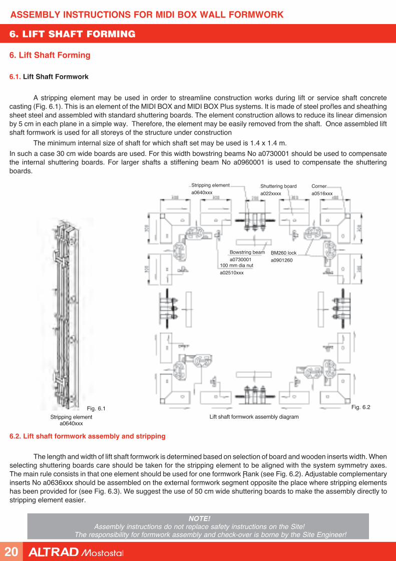
6. Lift Shaft Forming
6.1. Lift Shaft Formwork
A stripping element may be used in order to streamline construction works during lift or service shaft concrete casting (Fig. 6.1). This is an element of the MIDI BOX and MIDI BOX Plus systems. It is made of steel profiles and sheathing sheet steel and assembled with standard shuttering boards. The element construction allows to reduce its linear dimension by 5 cm in each plane in a simple way. Therefore, the element may be easily removed from the shaft. Once assembled lift shaft formwork is used for all storeys of the structure under construction
The minimum internal size of shaft for which shaft set may be used is 1.4 x 1.4 m.
In such a case 30 cm wide boards are used. For this width bowstring beams No a0730001 should be used to compensate the internal shuttering boards. For larger shafts a stiffening beam No a0960001 is used to compensate the shuttering boards.
6.2. Lift shaft formwork assembly and stripping
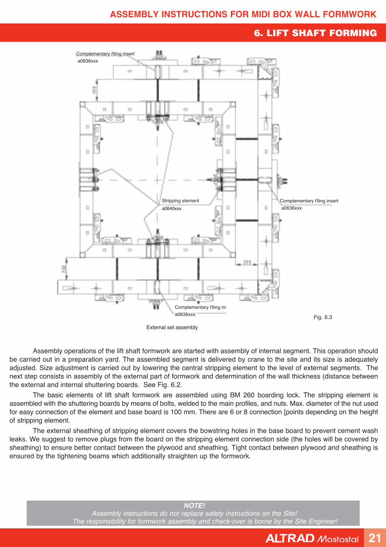
The length and width of lift shaft formwork is determined based on selection of board and wooden inserts width. When selecting shuttering boards care should be taken for the stripping element to be aligned with the system symmetry axes. The main rule consists in that one element should be used for one formwork flank (see Fig. 6.2). Adjustable complementary inserts No a0636xxx should be assembled on the external formwork segment opposite the place where stripping elements has been provided for (see Fig. 6.3). We suggest the use of 50 cm wide shuttering boards to make the assembly directly to stripping element easier.
Stripping element
a0640xxxShuttering board
a022xxxx
Corner
a0516xxx
BM260 lock
a0901260
Bowstring beam
a0730001100 mm dia nut
a02510xxx
20
ASSEMBLY INSTRUCTIONS FOR MIDI BOX WALL FORMWORK
NOTE!Assembly instructions do not replace safety instructions on the Site!
The responsibility for formwork assembly and check-over is borne by the Site Engineer!
6. LIFT SHAFT FORMING
Fig. 6.3
External set assembly
Assembly operations of the lift shaft formwork are started with assembly of internal segment. This operation should be carried out in a preparation yard. The assembled segment is delivered by crane to the site and its size is adequately adjusted. Size adjustment is carried out by lowering the central stripping element to the level of external segments. The next step consists in assembly of the external part of formwork and determination of the wall thickness (distance between the external and internal shuttering boards. See Fig. 6.2.
The basic elements of lift shaft formwork are assembled using BM 260 boarding lock. The stripping element is assembled with the shuttering boards by means of bolts, welded to the main profiles, and nuts. Max. diameter of the nut used for easy connection of the element and base board is 100 mm. There are 6 or 8 connection [points depending on the height of stripping element.
The external sheathing of stripping element covers the bowstring holes in the base board to prevent cement wash leaks. We suggest to remove plugs from the board on the stripping element connection side (the holes will be covered by sheathing) to ensure better contact between the plywood and sheathing. Tight contact between plywood and sheathing is ensured by the tightening beams which additionally straighten up the formwork.
Complementary filling insert
a0636xxx
Complementary filling insert
a0636xxx
Complementary filling insert
a0636xxx
Stripping element
a0640xxx
21
ASSEMBLY INSTRUCTIONS FOR MIDI BOX WALL FORMWORK
NOTE!Assembly instructions do not replace safety instructions on the Site!
The responsibility for formwork assembly and check-over is borne by the Site Engineer!
6. LIFT SHAFT FORMING
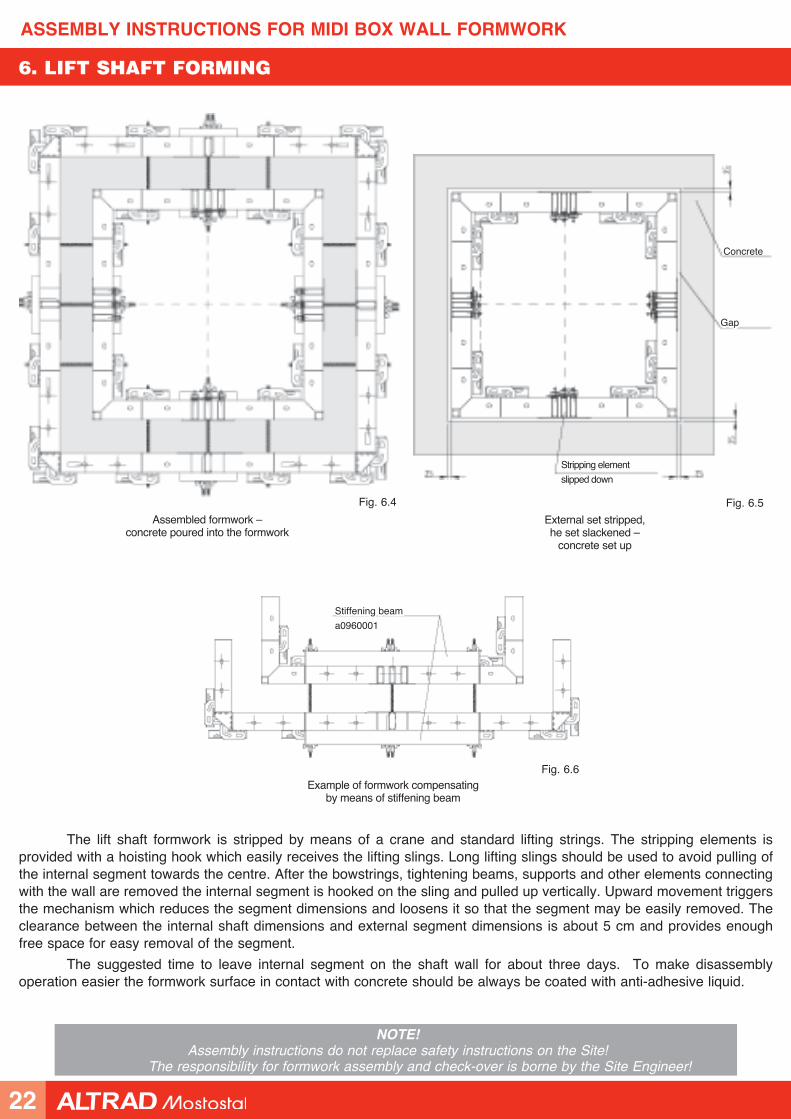
Assembled formwork – concrete poured into the formwork
Fig. 6.4
Fig. 6.6Example of formwork compensating
by means of stiffening beam
External set stripped, he set slackened –
concrete set up
Fig. 6.5
The lift shaft formwork is stripped by means of a crane and standard lifting strings. The stripping elements is provided with a hoisting hook which easily receives the lifting slings. Long lifting slings should be used to avoid pulling of the internal segment towards the centre. After the bowstrings, tightening beams, supports and other elements connecting with the wall are removed the internal segment is hooked on the sling and pulled up vertically. Upward movement triggers the mechanism which reduces the segment dimensions and loosens it so that the segment may be easily removed. The clearance between the internal shaft dimensions and external segment dimensions is about 5 cm and provides enough free space for easy removal of the segment.
The suggested time to leave internal segment on the shaft wall for about three days. To make disassembly operation easier the formwork surface in contact with concrete should be always be coated with anti-adhesive liquid.
Concrete
Gap
Stripping element
slipped down
Stiffening beam
a0960001
22
ASSEMBLY INSTRUCTIONS FOR MIDI BOX WALL FORMWORK
NOTE!Assembly instructions do not replace safety instructions on the Site!
The responsibility for formwork assembly and check-over is borne by the Site Engineer!
7. CIRCULAR WALL ERECTION
Circular slata0715270, a0720270
Bowstring beama0730001
BM260 locka0901260
Shuttering boarda021xxxx, a022xxxx
Fig. 7.1 Fig. 7.2
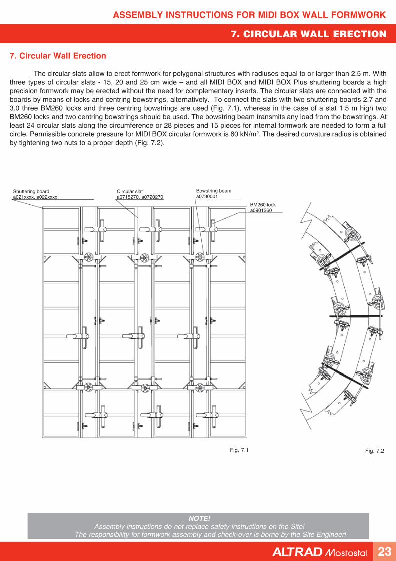
7. Circular Wall Erection
The circular slats allow to erect formwork for polygonal structures with radiuses equal to or larger than 2.5 m. With three types of circular slats - 15, 20 and 25 cm wide – and all MIDI BOX and MIDI BOX Plus shuttering boards a high precision formwork may be erected without the need for complementary inserts. The circular slats are connected with the boards by means of locks and centring bowstrings, alternatively. To connect the slats with two shuttering boards 2.7 and 3.0 three BM260 locks and three centring bowstrings are used (Fig. 7.1), whereas in the case of a slat 1.5 m high two BM260 locks and two centring bowstrings should be used. The bowstring beam transmits any load from the bowstrings. At least 24 circular slats along the circumference or 28 pieces and 15 pieces for internal formwork are needed to form a full circle. Permissible concrete pressure for MIDI BOX circular formwork is 60 kN/m2. The desired curvature radius is obtained by tightening two nuts to a proper depth (Fig. 7.2).
23
ASSEMBLY INSTRUCTIONS FOR MIDI BOX WALL FORMWORK
NOTE!Assembly instructions do not replace safety instructions on the Site!
The responsibility for formwork assembly and check-over is borne by the Site Engineer!
8. PLUMBING OF WALLS AND COLUMNS
Table of support spacing for wall formwork:
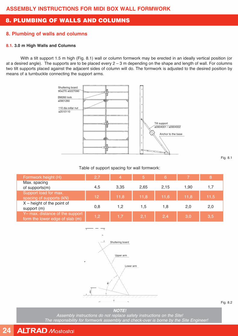
Formwork height (H)Max. spacingof supports(m)Support load for max. spacing of supports (kN)X – height of the point of support (m)Y– max. distance of the support form the lower edge of slab (m)
2,7 4 5 6 7 8
4,5 3,35 2,65 2,15 1,90 1,7
12 11,8 11,8 11,6 11,8 11,5
0,8 1,2 1,5 1,8 2,0 2,0
1,2 1,7 2,1 2,4 3,0 3,5
8. Plumbing of walls and columns
8.1. 3.0 m High Walls and Columns
With a tilt support 1.5 m high (Fig. 8.1) wall or column formwork may be erected in an ideally vertical position (or at a desired angle). The supports are to be placed every 2 – 3 m depending on the shape and length of wall. For columns two tilt supports placed against the adjacent sides of column will do. The formwork is adjusted to the desired position by means of a turnbuckle connecting the support arms.
Fig. 8.1
Anchor to the base
Tilt supporta0904001 / a0904002
110 dia collar nuta2510110
BM260 locka0901260
Shuttering board90x270 a0227090
Fig. 8.2
Upper arm
Lower arm
Shuttering board
24
ASSEMBLY INSTRUCTIONS FOR MIDI BOX WALL FORMWORK
NOTE!Assembly instructions do not replace safety instructions on the Site!
The responsibility for formwork assembly and check-over is borne by the Site Engineer!
8. PLUMBING OF WALLS AND COLUMNS
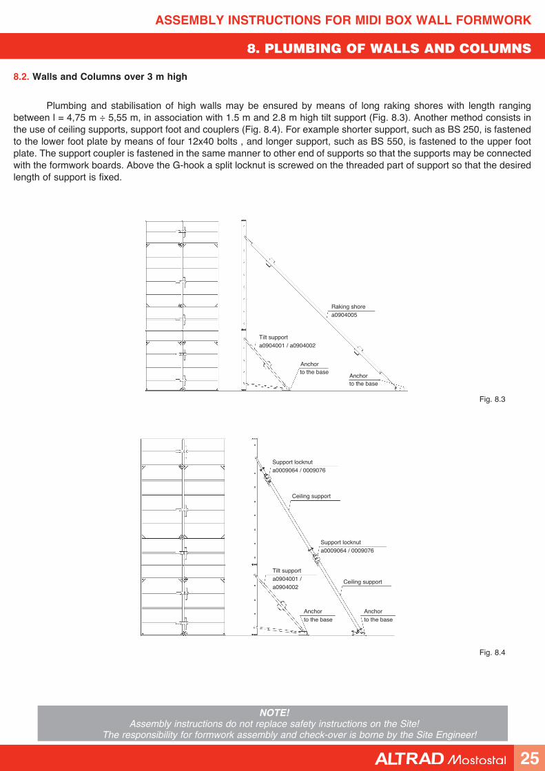
8.2. Walls and Columns over 3 m high
Plumbing and stabilisation of high walls may be ensured by means of long raking shores with length ranging between l = 4,75 m ÷ 5,55 m, in association with 1.5 m and 2.8 m high tilt support (Fig. 8.3). Another method consists in the use of ceiling supports, support foot and couplers (Fig. 8.4). For example shorter support, such as BS 250, is fastened to the lower foot plate by means of four 12x40 bolts , and longer support, such as BS 550, is fastened to the upper foot plate. The support coupler is fastened in the same manner to other end of supports so that the supports may be connected with the formwork boards. Above the G-hook a split locknut is screwed on the threaded part of support so that the desired length of support is fixed.
Fig. 8.3
Fig. 8.4
Anchorto the base
to the base
Tilt supporta0904001 / a0904002
Support locknuta0009064 / 0009076
Anchor to the base
Anchor to the base
Support locknuta0009064 / 0009076
Ceiling support
Ceiling support
Anchor
Tilt supporta0904001 / a0904002
Raking shorea0904005
25
ASSEMBLY INSTRUCTIONS FOR MIDI BOX WALL FORMWORK
NOTE!Assembly instructions do not replace safety instructions on the Site!
The responsibility for formwork assembly and check-over is borne by the Site Engineer!
9. ANNEX No 1
PRACTICAL METHOD FOR DETERMINATION OF MAXIMUM
CONCRETE CASTING RATE IN FORMWORKS
MIDI BOX AND MIDI BOX Plus MANUFACTURED BY ALTRAD-Mostostal
We recommend to use CIRIA method in practice. The following reasons are behind this recommendation:
• this method takes into account greater number of factors affecting the volume of maximum pressure,• it provides results better coinciding with the experimental data,• the results are safer.
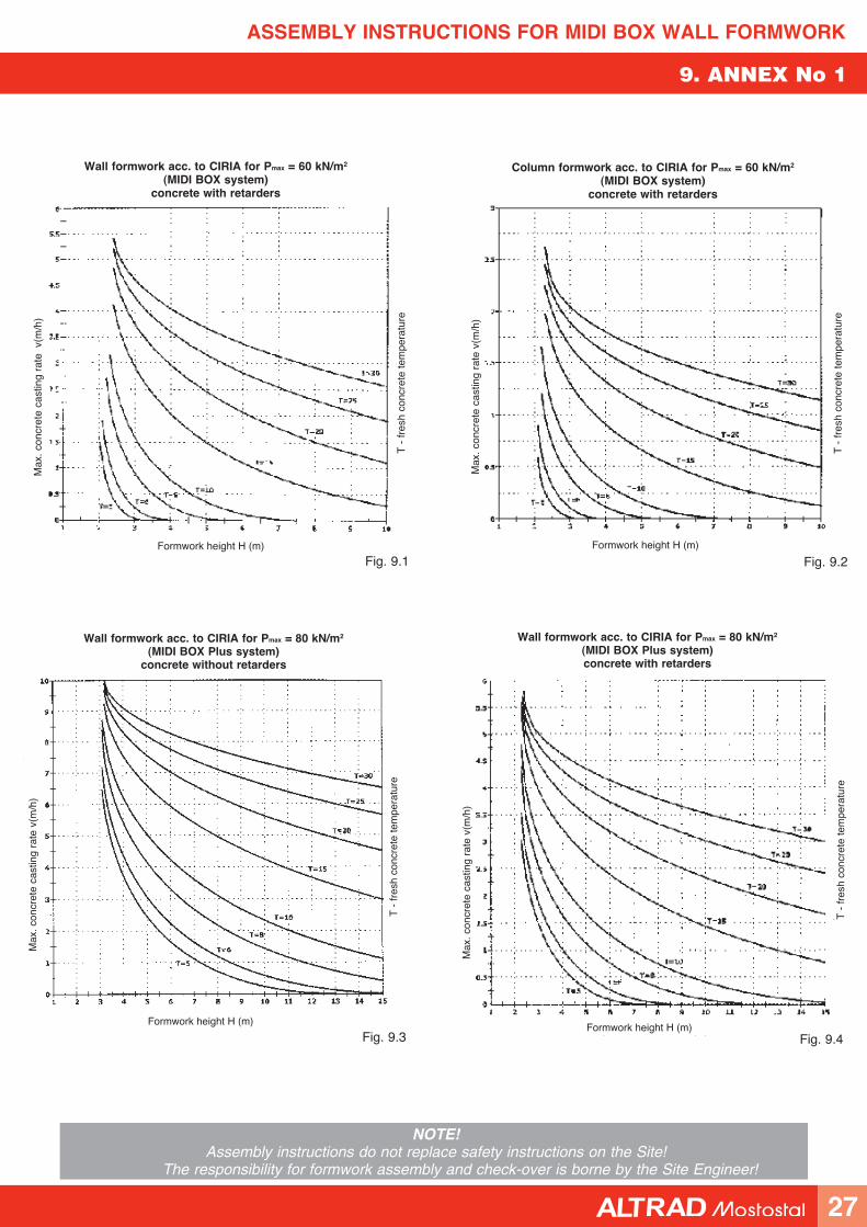
The method has been adapted to the bearing capacity of MIDI BOX and MIDI BOX Plus formwork manufactured by ALTRAD-Mostostal, and six nomographs have been plotted to determine maximum concrete casting rate for the assumed formwork bearing capacity of 60 kN/m2 and 80 kN/m2. The nomographs determine relationships between the height of the element and maximum concrete casting rate at different temperatures.
• Fig. 9.1 is for wall concrete casting rate (with the use of MIDI BOX formwork) and concrete with retarders.
• Fig. 9.2 is for column concrete casting rate (with the use of MIDI BOX formwork) and concrete with retarders.
• Fig. 9.3 is for wall concrete casting rate (with the use of MIDI BOX formwork) and concrete without retarders.
• Fig. 9.4 is for wall concrete casting rate (with the use of MIDI BOX Plus formwork) and concrete with retarders).
• Fig. 9.5 is for column concrete casting rate (with the use of MIDI BOX formwork) and concrete without retarders.
• Fig. 9.6 is for wall concrete casting rate (with the use of MIDI BOX formwork) and concrete without retarders.
In order to determine maximum concrete casting rate the height of erected element should be found on the axis of abscissa and a vertical line should be drawn to the point of intersection with the curve corresponding to the given concrete pouring temperature. From the point of intersection a horizontal line should be drawn and the point of intersection with the axis of ordinates will determine the value of concrete pouring rate.
When using the nomographs the following comments should be observed:
1. The maximum thickness of a single concrete mix layer cannot exceed 2 m.
2. The concrete pouring rate read on the nomographs is understood here as an average rate for the whole height of wall, i.e. a rate calculated as a ratio of v = H/t, where H is the height of the wall and t is the time of formwork filling to the height H.
3. Nomographs have been conceived for the following mix temperatures: 5, 6, 8, 10, 15, 20, 25 and 30oC. If the mix temperature falls in between the above mentioned values the results should be interpolated for two curves the best corresponding to the real conditions.
4. If the curve is closing to the horizontal axis, i.e. to the maximum rate of zero, the concrete poring must be broken down into stages (thickness of one stage layer cannot exceed 2 m according to point 1) and the second stage cannot be started before the poured mix in the first stage sets up (from several to a dozen or so hours, depending on the setting rate and mix temperature)
26
ASSEMBLY INSTRUCTIONS FOR MIDI BOX WALL FORMWORK
NOTE!Assembly instructions do not replace safety instructions on the Site!
The responsibility for formwork assembly and check-over is borne by the Site Engineer!
9. ANNEX No 1
T -
fres
h co
ncre
te te
mpe
ratu
re
Formwork height H (m)
Max
. con
cret
e ca
stin
g ra
te v
(m/h
)
Fig. 9.2
Wall formwork acc. to CIRIA for Pmax = 60 kN/m2
(MIDI BOX system)concrete with retarders
Fig. 9.3
Column formwork acc. to CIRIA for Pmax = 60 kN/m2
(MIDI BOX system) concrete with retarders
Max
. con
cret
e ca
stin
g ra
te v
(m/h
)
T -
fres
h co
ncre
te te
mpe
ratu
re
Formwork height H (m)
Wall formwork acc. to CIRIA for Pmax = 80 kN/m2
(MIDI BOX Plus system) concrete without retarders
Wall formwork acc. to CIRIA for Pmax = 80 kN/m2
(MIDI BOX Plus system)concrete with retarders
Fig. 9.4
Max
. con
cret
e ca
stin
g ra
te v
(m/h
)
T -
fres
h co
ncre
te te
mpe
ratu
re
Formwork height H (m)
Max
. con
cret
e ca
stin
g ra
te v
(m/h
)
T -
fres
h co
ncre
te te
mpe
ratu
re
Formwork height H (m)
Fig. 9.1
27
ASSEMBLY INSTRUCTIONS FOR MIDI BOX WALL FORMWORK
NOTE!Assembly instructions do not replace safety instructions on the Site!
The responsibility for formwork assembly and check-over is borne by the Site Engineer!
9. ANNEX No 1
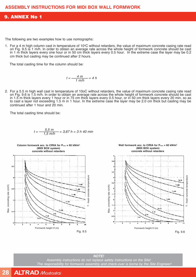
The following are two examples how to use nomographs:
1. For a 4 m high column cast in temperature of 10oC without retarders, the value of maximum concrete casing rate read on Fig. 9.5 is 1 m/h. In order to obtain an average rate across the whole height of formwork concrete should be cast in 1 m thick layers every one hour or in 50 cm thick layers every 0.5 hour. In the extreme case the layer may be 0.2 cm thick but casting may be continued after 2 hours.
The total casting time for the column should be:
t = = 4 h4 m1 m/h
Column formwork acc. to CIRIA for Pmax = 60 kN/m2
(MIDI BOX system) concrete without retarders
Max
. con
cret
ing
rate
v(m
/h)
T -
fres
h co
ncre
te te
mpe
ratu
re
Formwork height H (m)
Fig. 9.5
Wall formwork acc. to CIRIA for Pmax = 60 kN/m2
(MIDI BOX system) concrete without retarders
Fig. 9.6
Max
. con
cret
ing
rate
v(m
/h)
T -
fres
h co
ncre
te te
mpe
ratu
re
Formwork height H (m)
2. For a 5.5 m high wall cast in temperature of 10oC without retarders, the value of maximum concrete casing rate read on Fig. 9.6 is 1.5 m/h. In order to obtain an average rate across the whole height of formwork concrete should be cast in 1.5 m thick layers every 1 hour or in 75 cm thick layers every 0.5 hour, or in 50 cm thick layers every 20 min, so as to cast a layer not exceeding 1.5 m in 1 hour. In the extreme case the layer may be 2.0 cm thick but casting may be continued after 1 hour and 20 min.
The total casting time should be:
t = = 3,67 h = 3 h 40 min5,5 m
1,5 m/h
28
ASSEMBLY INSTRUCTIONS FOR MIDI BOX WALL FORMWORK
NOTE!Assembly instructions do not replace safety instructions on the Site!
The responsibility for formwork assembly and check-over is borne by the Site Engineer!
NOTES
29
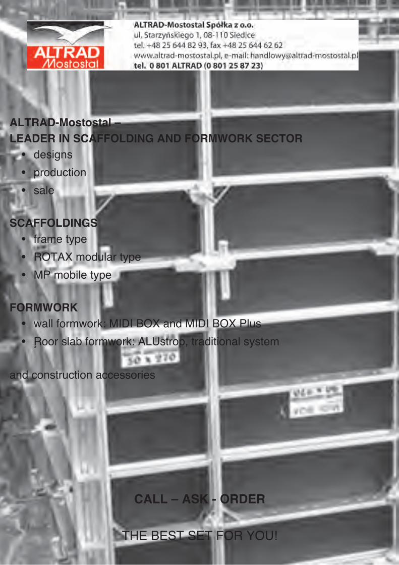
ALTRAD-Mostostal – LEADER IN SCAFFOLDING AND FORMWORK SECTOR
• designs
• production
• sale
SCAFFOLDINGS• frame type
• ROTAX modular type
• MP mobile type
FORMWORK• wall formwork: MIDI BOX and MIDI BOX Plus
• floor slab formwork: ALUstrop, traditional system
and construction accessories
CALL – ASK - ORDER
THE BEST SET FOR YOU!

ALTRAD-Mostostal Spó∏ka z o.o.tel. 0 801 ALTRAD (0 801 2 5 8 7 2 3)
tel. +48 25 644 82 93, fax +48 25 644 62 62ul. Starzyƒskiego 1, 08-110 Siedlce
www.altrad-mostostal.pl