Embed Size (px)
Citation preview
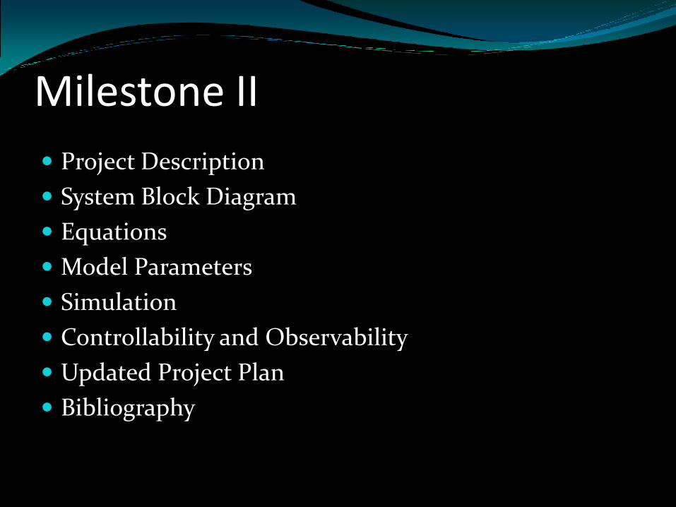
Milestone II
Project Description
System Block Diagram
Equations
Model Parameters
Simulation
Controllability and Observability
Updated Project Plan
Bibliography
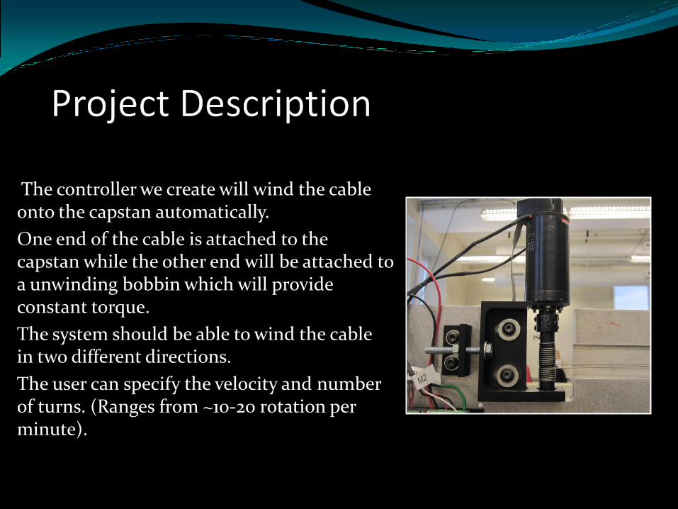
The controller we create will wind the cable onto the capstan automatically.
One end of the cable is attached to the capstan while the other end will be attached to a unwinding bobbin which will provide constant torque.
The system should be able to wind the cable in two different directions.
The user can specify the velocity and number of turns. (Ranges from ~10-20 rotation per minute).
Performance CriteriaThe controller should be able to track the specified velocity with 95%+ accuracy.
The controller should detect and stop the motor in under 1sec if the cable gets dislodged from the capstan.
The system should hold the position of the capstan at a reasonable amount of time (~1-5minute) after the cable is wound.
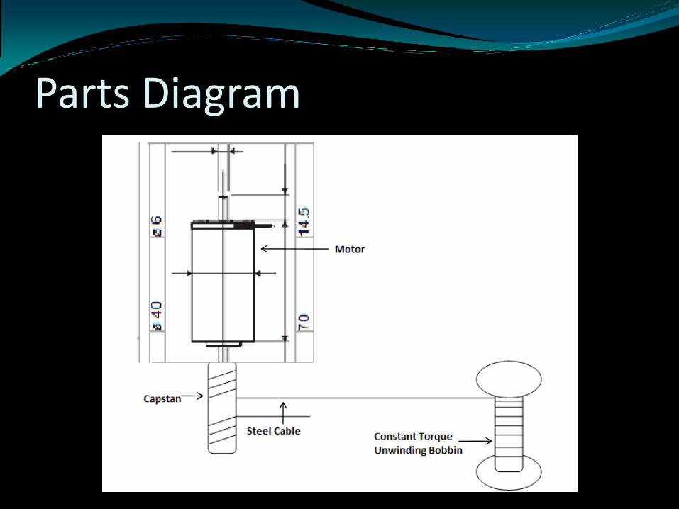
Parts Diagram
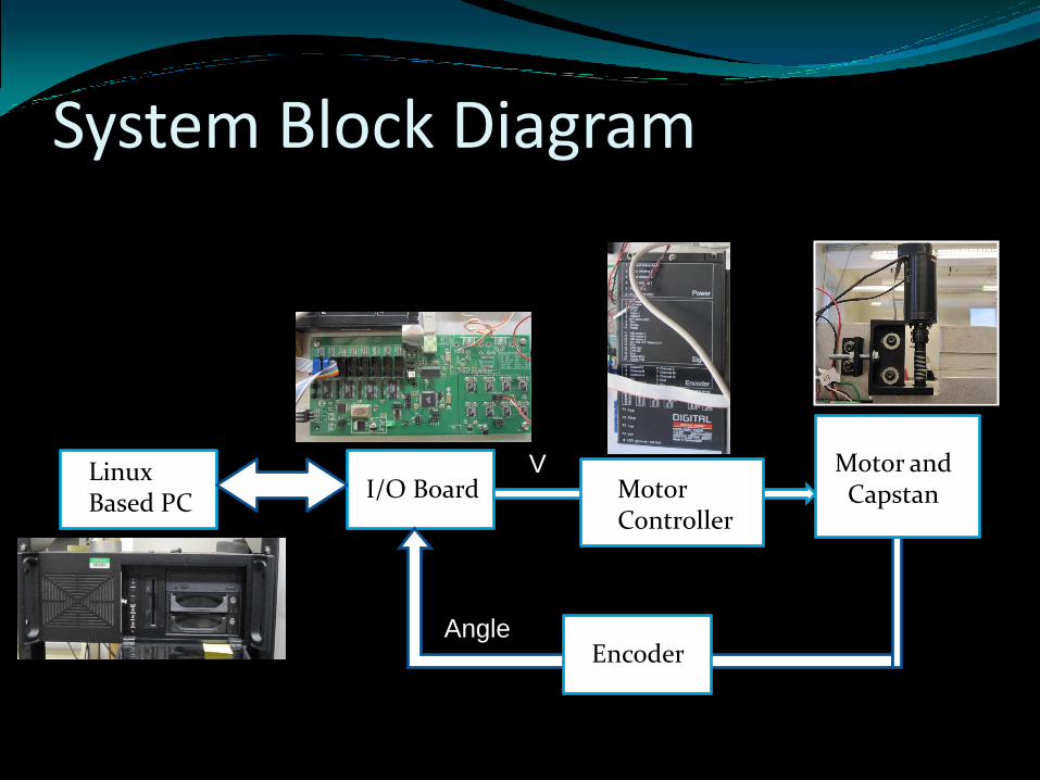
System Block Diagram
Linux Based PC
I/O Board Motor Controller
Encoder
Motor and Capstan
V
Angle
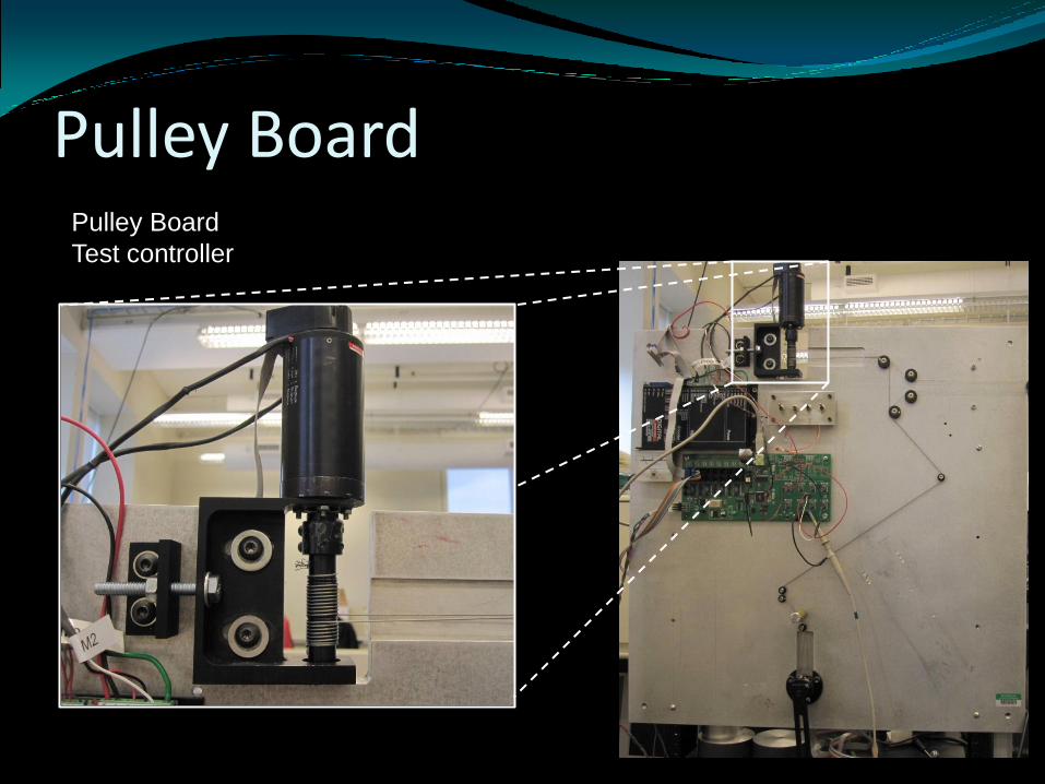
Pulley BoardPulley Board
Test controller
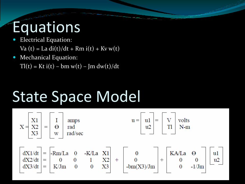
Equations Electrical Equation:
Va (t) = La di(t)/dt + Rm i(t) + Kv w(t)
Mechanical Equation:
Tl(t) = Kt i(t) – bm w(t) – Jm dw(t)/dt
State Space Model
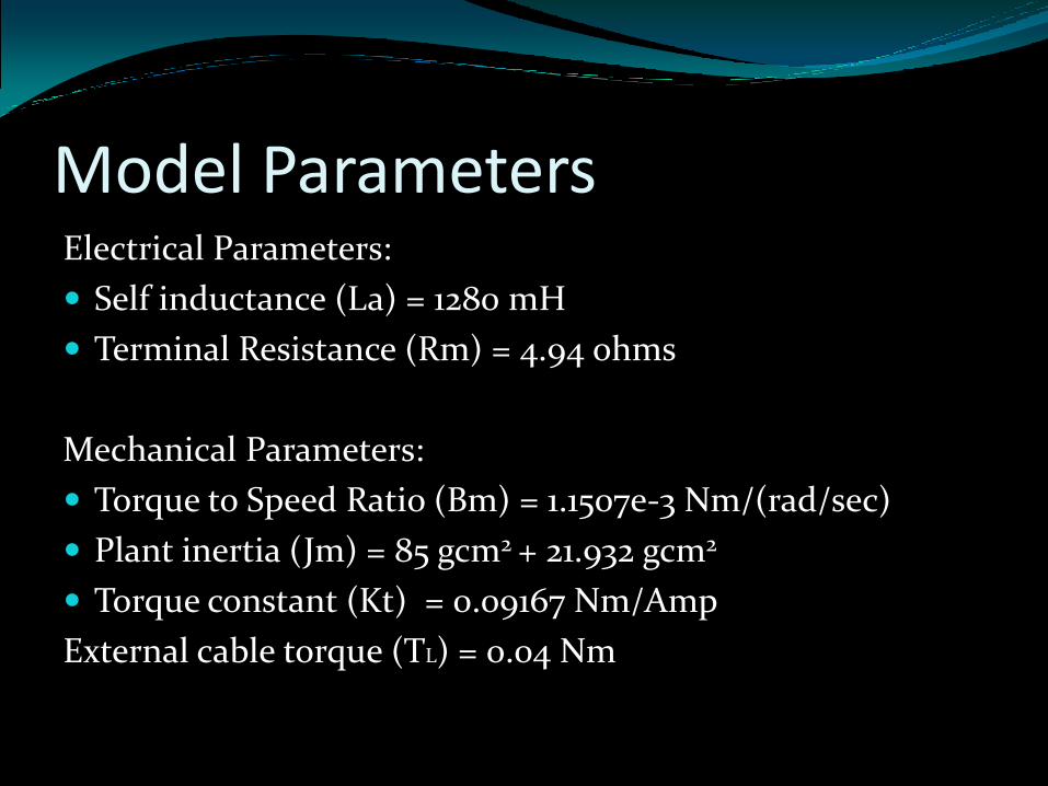
Model ParametersElectrical Parameters:
Self inductance (La) = 1280 mH
Terminal Resistance (Rm) = 4.94 ohms
Mechanical Parameters:
Torque to Speed Ratio (Bm) = 1.1507e-3 Nm/(rad/sec)
Plant inertia (Jm) = 85 gcm2 + 21.932 gcm2
Torque constant (Kt) = 0.09167 Nm/Amp
External cable torque (TL) = 0.04 Nm
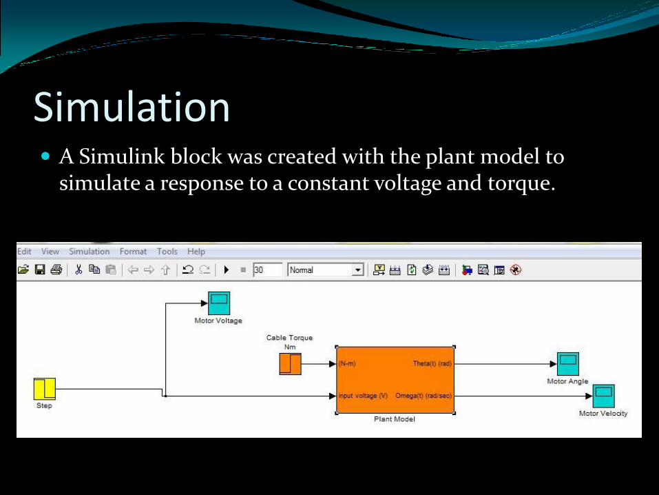
Simulation A Simulink block was created with the plant model to
simulate a response to a constant voltage and torque.
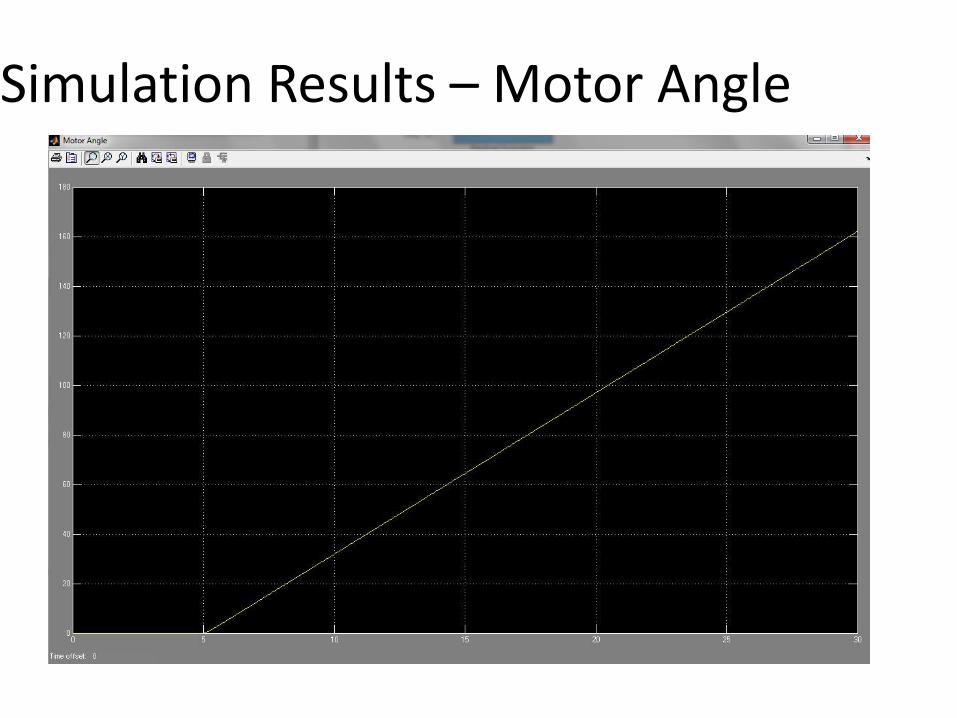
Simulation Results – Motor Angle
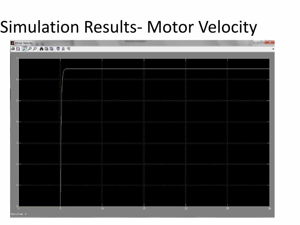
Simulation Results- Motor Velocity
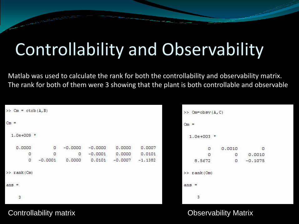
Controllability and ObservabilityMatlab was used to calculate the rank for both the controllability and observability matrix. The rank for both of them were 3 showing that the plant is both controllable and observable
Controllability matrix Observability Matrix
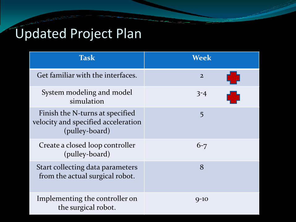
Updated Project Plan
Task Week
Get familiar with the interfaces. 2
System modeling and modelsimulation
3-4
Finish the N-turns at specified velocity and specified acceleration
(pulley-board)
5
Create a closed loop controller (pulley-board)
6-7
Start collecting data parameters from the actual surgical robot.
8
Implementing the controller on the surgical robot.
9-10
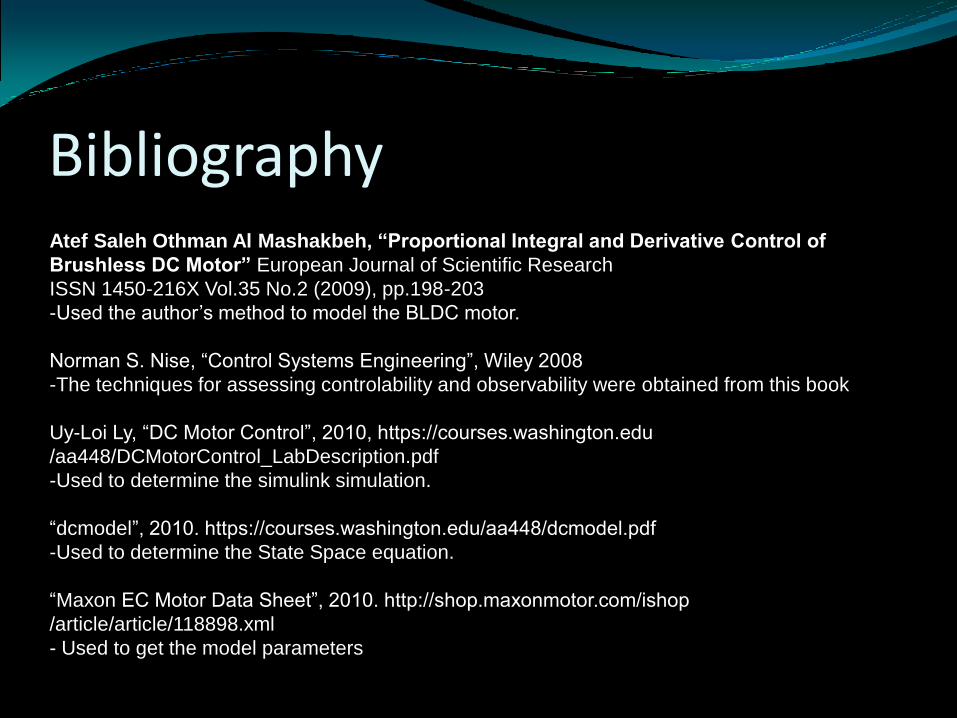
BibliographyAtef Saleh Othman Al Mashakbeh, “Proportional Integral and Derivative Control of
Brushless DC Motor” European Journal of Scientific Research
ISSN 1450-216X Vol.35 No.2 (2009), pp.198-203
-Used the author’s method to model the BLDC motor.
Norman S. Nise, “Control Systems Engineering”, Wiley 2008
-The techniques for assessing controlability and observability were obtained from this book
Uy-Loi Ly, “DC Motor Control”, 2010, https://courses.washington.edu
/aa448/DCMotorControl_LabDescription.pdf
-Used to determine the simulink simulation.
“dcmodel”, 2010. https://courses.washington.edu/aa448/dcmodel.pdf
-Used to determine the State Space equation.
“Maxon EC Motor Data Sheet”, 2010. http://shop.maxonmotor.com/ishop
/article/article/118898.xml
- Used to get the model parameters