Embed Size (px)
Citation preview

Editor: Prof. Dr.-Ing. habil. Heinz Konietzky Layout: Gunther Lüttschwager
TU Bergakademie Freiberg, Institut für Geotechnik, Gustav-Zeuner-Straße 1, 09599 Freiberg [email protected]
Mine backfill – an overview Author: Prof. Dr. habil. Heinz Konietzky (TU Bergakademie Freiberg, Geotechnical Insti-tute)
1 Introduction .......................................................................................................... 2
2 Backfill types, technologies and properties .......................................................... 2
3 Planning and quality control ................................................................................ 5
4 Selected applications ........................................................................................... 6
Shaft backfilling ............................................................................................. 6
Backfilling in potash and salt mining .............................................................. 8
Backfilling in radioactive waste repositories .................................................. 9
Backfilling in coal room and pillar mining ..................................................... 10
Backfilling in longwall coal mining................................................................ 12
5 References ........................................................................................................ 15
Mine backfill – an overview
Only for private and internal use! Updated: 25 May 2018
Page 2 of 15
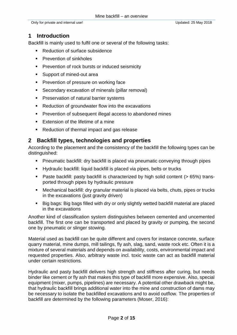
1 Introduction
Backfill is mainly used to fulfil one or several of the following tasks:
Reduction of surface subsidence
Prevention of sinkholes
Prevention of rock bursts or induced seismicity
Support of mined-out area
Prevention of pressure on working face
Secondary excavation of minerals (pillar removal)
Preservation of natural barrier systems
Reduction of groundwater flow into the excavations
Prevention of subsequent illegal access to abandoned mines
Extension of the lifetime of a mine
Reduction of thermal impact and gas release
2 Backfill types, technologies and properties
According to the placement and the consistency of the backfill the following types can be distinguished:
Pneumatic backfill: dry backfill is placed via pneumatic conveying through pipes
Hydraulic backfill: liquid backfill is placed via pipes, belts or trucks
Paste backfill: pasty backfill is characterized by high solid content (> 65%) trans-ported through pipes by hydraulic pressure
Mechanical backfill: dry granular material is placed via belts, chuts, pipes or trucks in the excavations (just gravity driven)
Big bags: Big bags filled with dry or only slightly wetted backfill material are placed in the excavations
Another kind of classification system distinguishes between cemented and uncemented backfill. The first one can be transported and placed by gravity or pumping, the second one by pneumatic or slinger stowing. Material used as backfill can be quite different and covers for instance concrete, surface quarry material, mine dumps, mill tailings, fly ash, slag, sand, waste rock etc. Often it is a mixture of several materials and depends on availability, costs, environmental impact and requested properties. Also, arbitrary waste incl. toxic waste can act as backfill material under certain restrictions. Hydraulic and pasty backfill delivers high strength and stiffness after curing, but needs binder like cement or fly ash that makes this type of backfill more expensive. Also, special equipment (mixer, pumps, pipelines) are necessary. A potential other drawback might be, that hydraulic backfill brings additional water into the mine and construction of dams may be necessary to isolate the backfilled excavations and to avoid outflow. The properties of backfill are determined by the following parameters (Moser, 2016):
Mine backfill – an overview
Only for private and internal use! Updated: 25 May 2018
Page 3 of 15
Mineralogy of ingredients
Grain size distribution
Type and amount of binder
Type and amount of additives
Water content
Water-binder-ratio
Porosity / density
Cohesion and friction
Permeability
Viscosity / consistency
Weight-volume-ratio
The specification of certain requirements on the backfill is mainly based on geomechani-cal calculations and dimensioning. Based on these requirements the intended backfill material has to be investigated by lab tests. Depending on the backfill type some of the following tests are used:
Sieve analysis or sedimentation tests (grain size distribution)
Gravimetry, volumetry (density)
Triaxial or uniaxial compression tests (strength and stiffness)
Oedometer tests (volumetric compaction)
Vicat needle tests (setting time, strength)
Uniaxial or triaxial creep tests (rheological behaviour, long-term strength and stiff-ness)
Permeability tests (hydraulic behaviour)
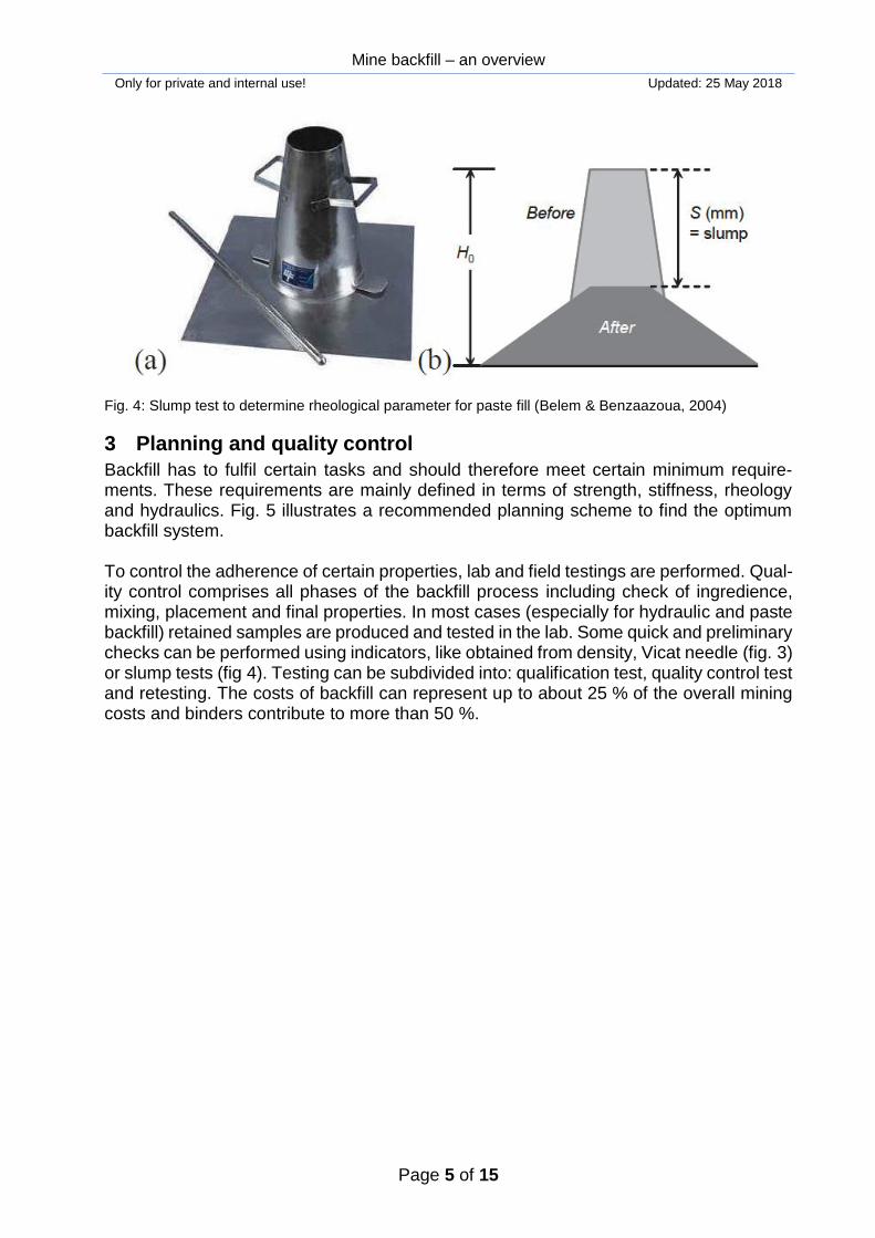
Slump test (rheological behaviour)
Please note, that these macroscopic properties depend on micro-properties like particle size and particle shape as well as on chemical reactions and used additives, especially in case of hydraulic and paste backfill. Simple, but specific test apparatuses used for backfill beyond the classical rock and soil mechanical equipment are shown in figures 3 and 4. Exemplarily, Shen et al. (2017) describe in detail the geomechanical and chemical pa-rameter determination for fly ash backfill used in abandoned mines including application and monitoring. Also exemplarily, Panchal et al. (2018) provide a description of paste fill characteristics based on detailed lab investigations. They show how composition of back-fill components influence the behaviour (rheology, strength, stiffness).
Mine backfill – an overview
Only for private and internal use! Updated: 25 May 2018
Page 4 of 15
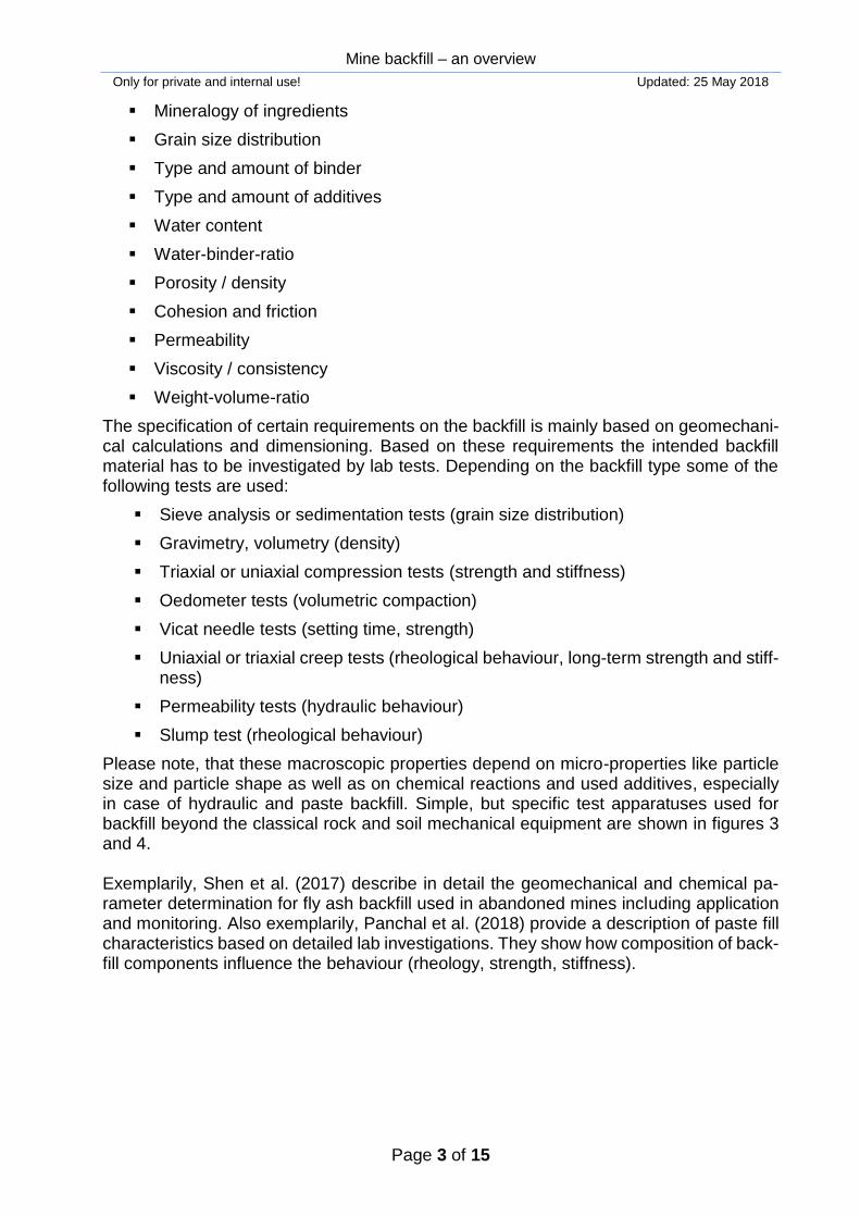
Fig. 1: Different types of backfill, left: paste fill; right: rock fill (Sivakuga et al. 2015)
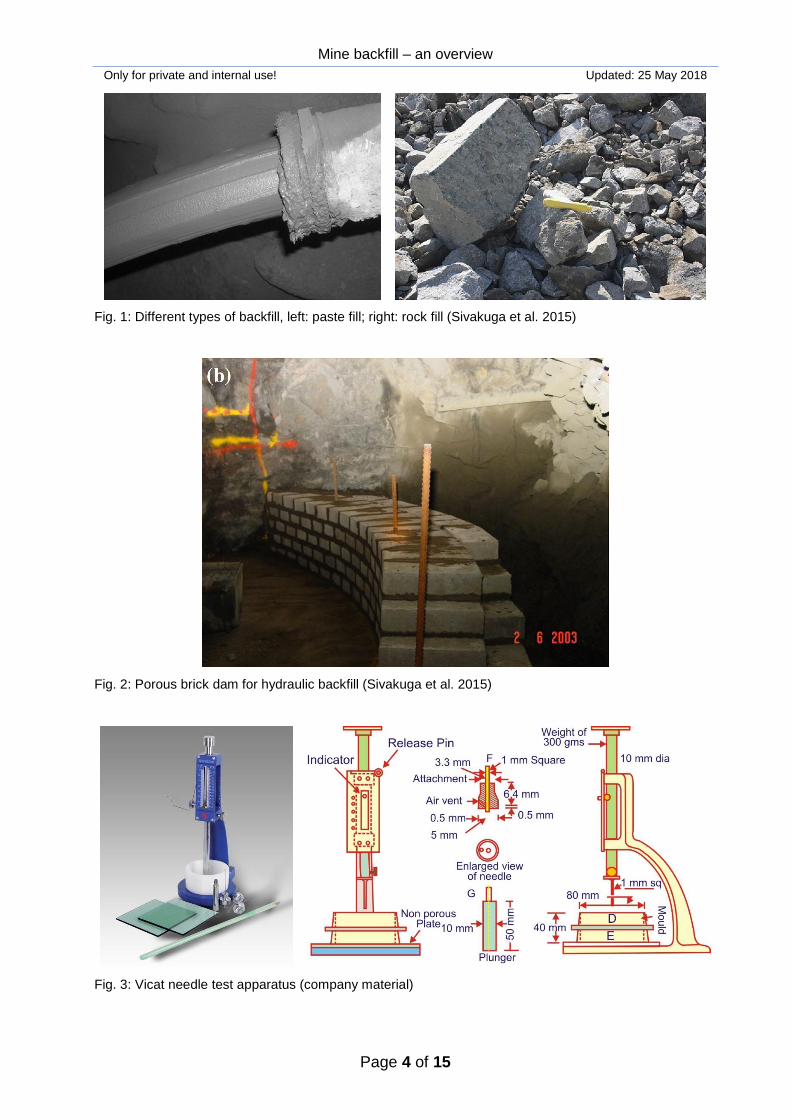
Fig. 2: Porous brick dam for hydraulic backfill (Sivakuga et al. 2015)
Fig. 3: Vicat needle test apparatus (company material)
Mine backfill – an overview
Only for private and internal use! Updated: 25 May 2018
Page 5 of 15
Fig. 4: Slump test to determine rheological parameter for paste fill (Belem & Benzaazoua, 2004)
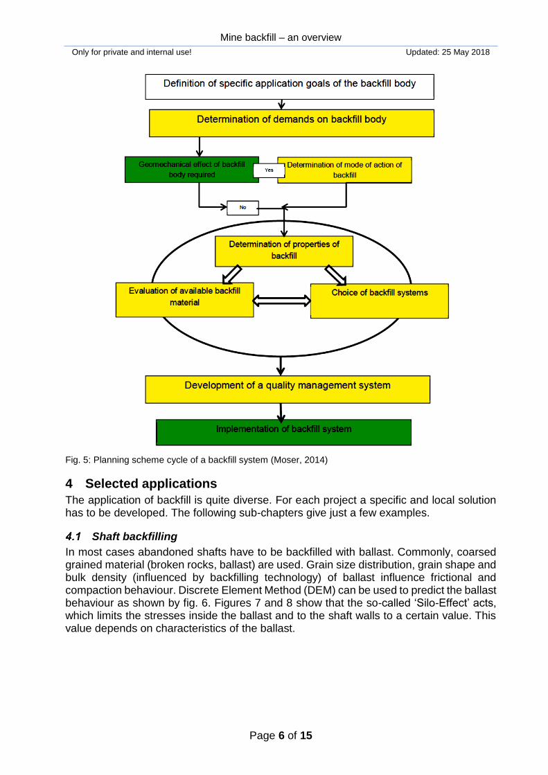
3 Planning and quality control
Backfill has to fulfil certain tasks and should therefore meet certain minimum require-ments. These requirements are mainly defined in terms of strength, stiffness, rheology and hydraulics. Fig. 5 illustrates a recommended planning scheme to find the optimum backfill system. To control the adherence of certain properties, lab and field testings are performed. Qual-ity control comprises all phases of the backfill process including check of ingredience, mixing, placement and final properties. In most cases (especially for hydraulic and paste backfill) retained samples are produced and tested in the lab. Some quick and preliminary checks can be performed using indicators, like obtained from density, Vicat needle (fig. 3) or slump tests (fig 4). Testing can be subdivided into: qualification test, quality control test and retesting. The costs of backfill can represent up to about 25 % of the overall mining costs and binders contribute to more than 50 %.
Mine backfill – an overview
Only for private and internal use! Updated: 25 May 2018
Page 6 of 15
Fig. 5: Planning scheme cycle of a backfill system (Moser, 2014)
4 Selected applications
The application of backfill is quite diverse. For each project a specific and local solution has to be developed. The following sub-chapters give just a few examples.
Shaft backfilling
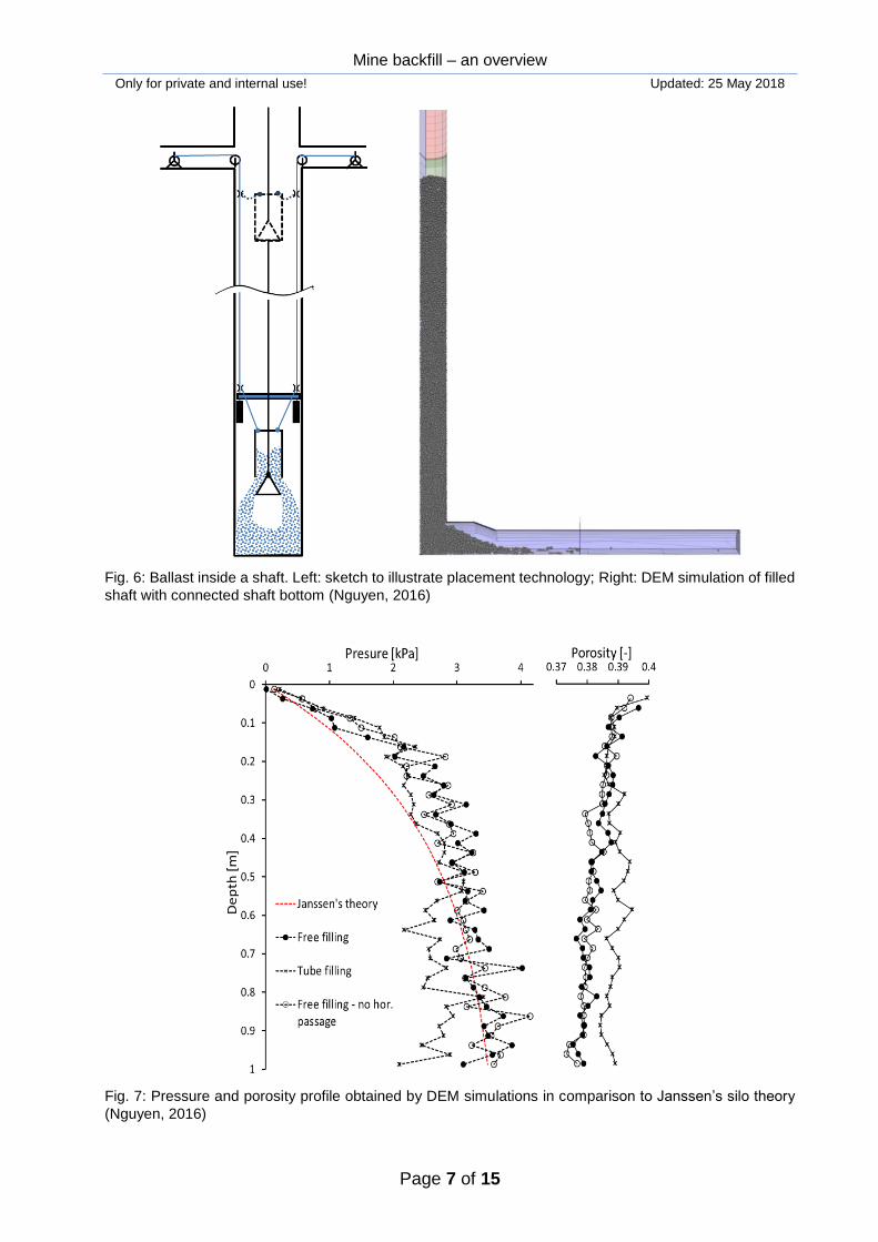
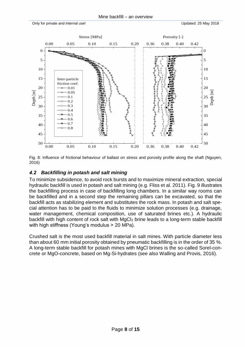
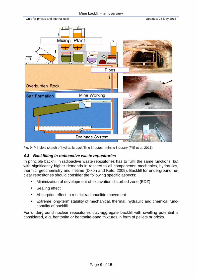
In most cases abandoned shafts have to be backfilled with ballast. Commonly, coarsed grained material (broken rocks, ballast) are used. Grain size distribution, grain shape and bulk density (influenced by backfilling technology) of ballast influence frictional and compaction behaviour. Discrete Element Method (DEM) can be used to predict the ballast behaviour as shown by fig. 6. Figures 7 and 8 show that the so-called ‘Silo-Effect’ acts, which limits the stresses inside the ballast and to the shaft walls to a certain value. This value depends on characteristics of the ballast.
Mine backfill – an overview
Only for private and internal use! Updated: 25 May 2018
Page 7 of 15
Fig. 6: Ballast inside a shaft. Left: sketch to illustrate placement technology; Right: DEM simulation of filled
shaft with connected shaft bottom (Nguyen, 2016)
Fig. 7: Pressure and porosity profile obtained by DEM simulations in comparison to Janssen’s silo theory
(Nguyen, 2016)
Mine backfill – an overview
Only for private and internal use! Updated: 25 May 2018
Page 8 of 15
Fig. 8: Influence of frictional behaviour of ballast on stress and porosity profile along the shaft (Nguyen,
2016)
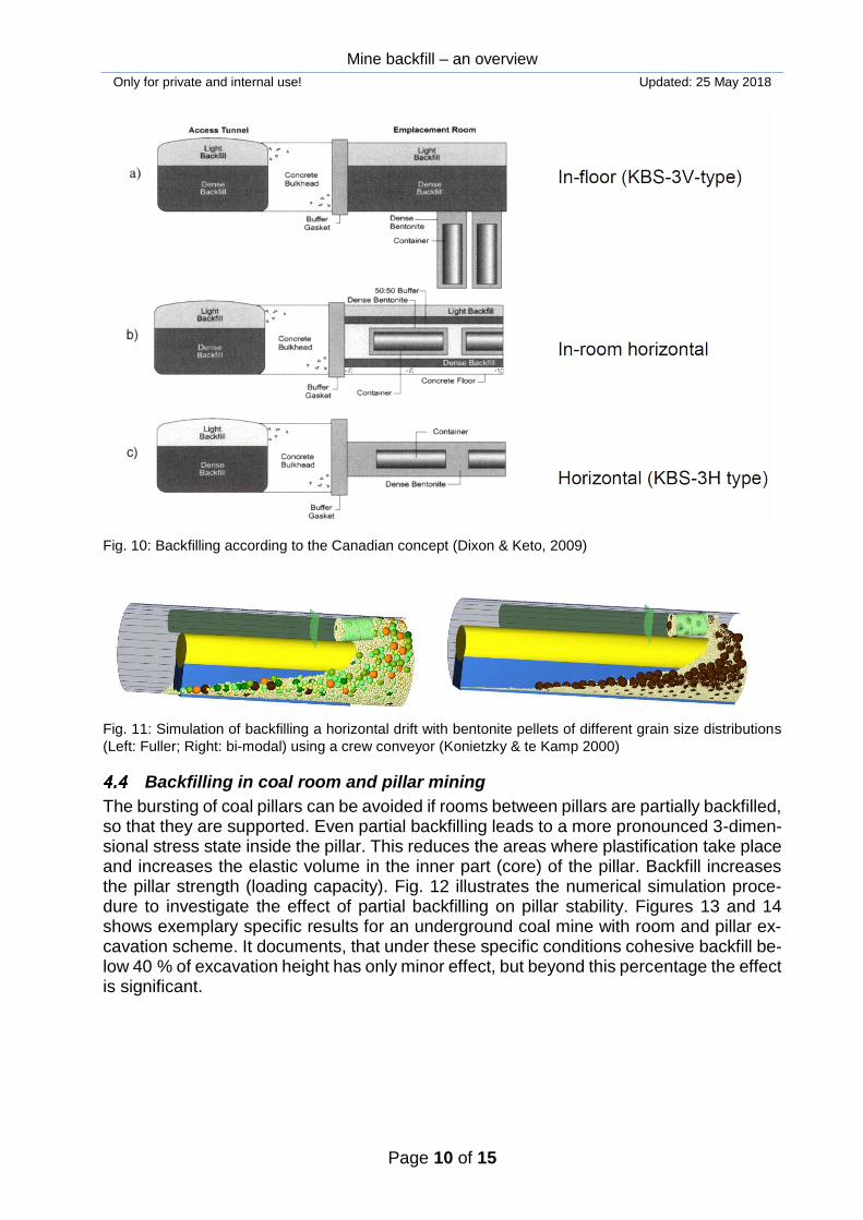
Backfilling in potash and salt mining
To minimize subsidence, to avoid rock bursts and to maximize mineral extraction, special hydraulic backfill is used in potash and salt mining (e.g. Fliss et al. 2011). Fig. 9 illustrates the backfilling process in case of backfilling long chambers. In a similar way rooms can be backfilled and in a second step the remaining pillars can be excavated, so that the backfill acts as stabilizing element and substitutes the rock mass. In potash and salt spe-cial attention has to be paid to the fluids to minimize solution processes (e.g. drainage, water management, chemical composition, use of saturated brines etc.). A hydraulic backfill with high content of rock salt with MgCl2 brine leads to a long-term stable backfill with high stiffness (Young’s modulus > 20 MPa). Crushed salt is the most used backfill material in salt mines. With particle diameter less than about 60 mm initial porosity obtained by pneumatic backfilling is in the order of 35 %. A long-term stable backfill for potash mines with MgCl brines is the so-called Sorel-con-crete or MgO-concrete, based on Mg-Si-hydrates (see also Walling and Provis, 2016).
50
45
40
35
30
25
20
15
10
5
0
0.00 0.05 0.10 0.15 0.20
0.00 0.05 0.10 0.15 0.20
Inter-particle
friction coef.
0.01
0.05
0.1
0.2
0.3
0.4
0.5
0.6
0.7
0.8
Stress [MPa]D
epth
[m
]
0.36 0.38 0.40 0.4250
45
40
35
30
25
20
15
10
5
0
0.36 0.38 0.40 0.42
Dep
th [
m]
Porosity [-]
Mine backfill – an overview
Only for private and internal use! Updated: 25 May 2018
Page 9 of 15
Fig. 9: Principle sketch of hydraulic backfilling in potash mining industry (Fliß et al. 2011)
Backfilling in radioactive waste repositories
In principle backfill in radioactive waste repositories has to fulfil the same functions, but with significantly higher demands in respect to all components: mechanics, hydraulics, thermic, geochemistry and lifetime (Dixon and Keto, 2009). Backfill for underground nu-clear repositories should consider the following specific aspects:
Minimization of development of excavation disturbed zone (EDZ)
Sealing effect
Absorption effect to restrict radionuclide movement
Extreme long-term stability of mechanical, thermal, hydraulic and chemical func-tionality of backfill
For underground nuclear repositories clay-aggregate backfill with swelling potential is considered, e.g. bentonite or bentonite-sand mixtures in form of pellets or bricks.
Mine backfill – an overview
Only for private and internal use! Updated: 25 May 2018
Page 10 of 15
Fig. 10: Backfilling according to the Canadian concept (Dixon & Keto, 2009)
Fig. 11: Simulation of backfilling a horizontal drift with bentonite pellets of different grain size distributions
(Left: Fuller; Right: bi-modal) using a crew conveyor (Konietzky & te Kamp 2000)
Backfilling in coal room and pillar mining
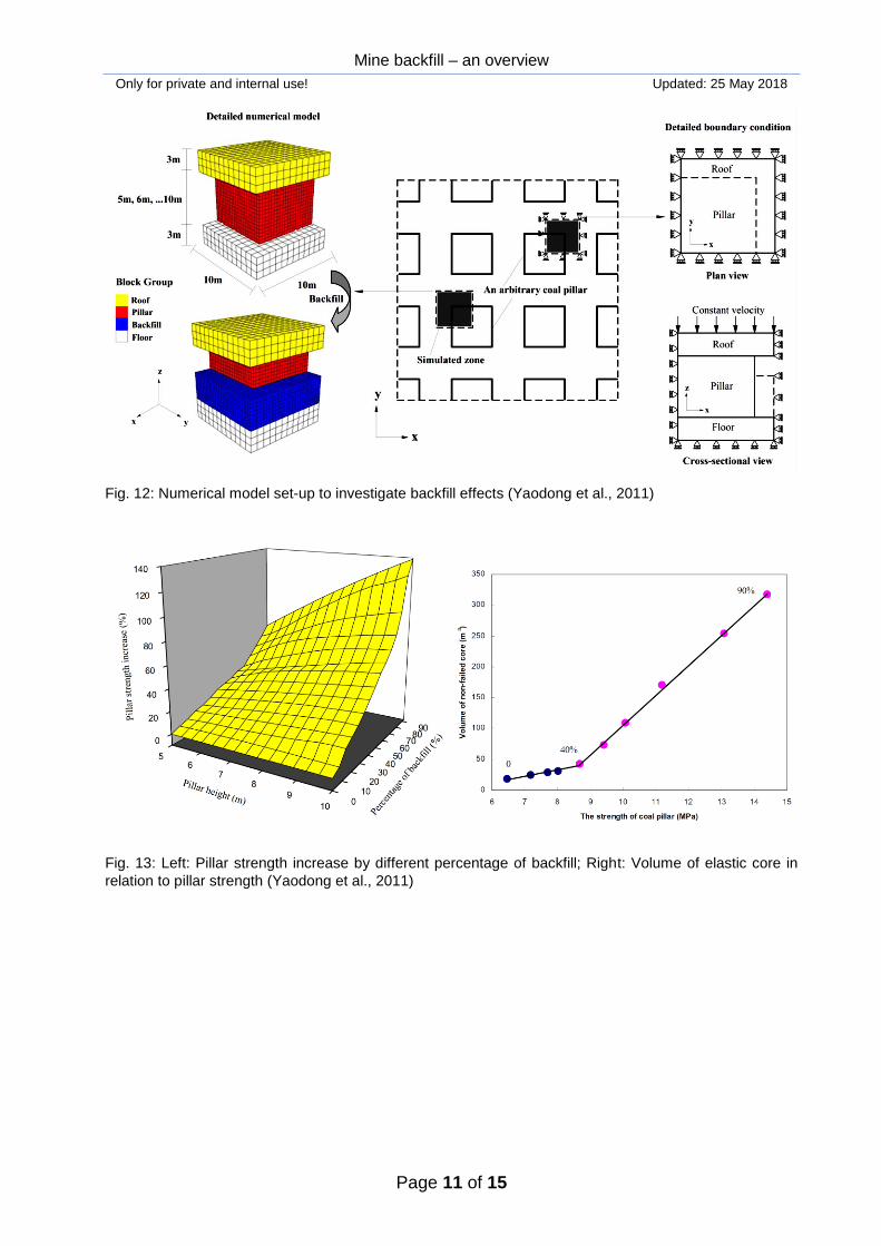
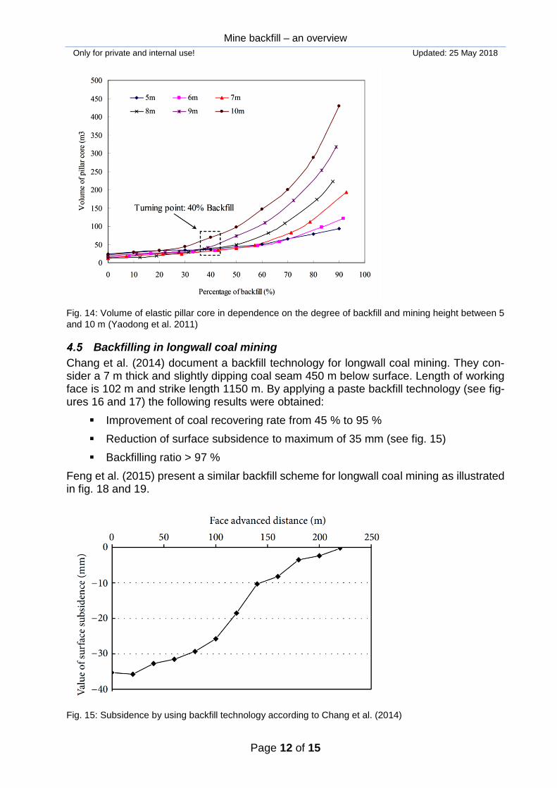
The bursting of coal pillars can be avoided if rooms between pillars are partially backfilled, so that they are supported. Even partial backfilling leads to a more pronounced 3-dimen-sional stress state inside the pillar. This reduces the areas where plastification take place and increases the elastic volume in the inner part (core) of the pillar. Backfill increases the pillar strength (loading capacity). Fig. 12 illustrates the numerical simulation proce-dure to investigate the effect of partial backfilling on pillar stability. Figures 13 and 14 shows exemplary specific results for an underground coal mine with room and pillar ex-cavation scheme. It documents, that under these specific conditions cohesive backfill be-low 40 % of excavation height has only minor effect, but beyond this percentage the effect is significant.
Mine backfill – an overview
Only for private and internal use! Updated: 25 May 2018
Page 11 of 15
Fig. 12: Numerical model set-up to investigate backfill effects (Yaodong et al., 2011)
Fig. 13: Left: Pillar strength increase by different percentage of backfill; Right: Volume of elastic core in
relation to pillar strength (Yaodong et al., 2011)
Mine backfill – an overview
Only for private and internal use! Updated: 25 May 2018
Page 12 of 15
Fig. 14: Volume of elastic pillar core in dependence on the degree of backfill and mining height between 5
and 10 m (Yaodong et al. 2011)
Backfilling in longwall coal mining
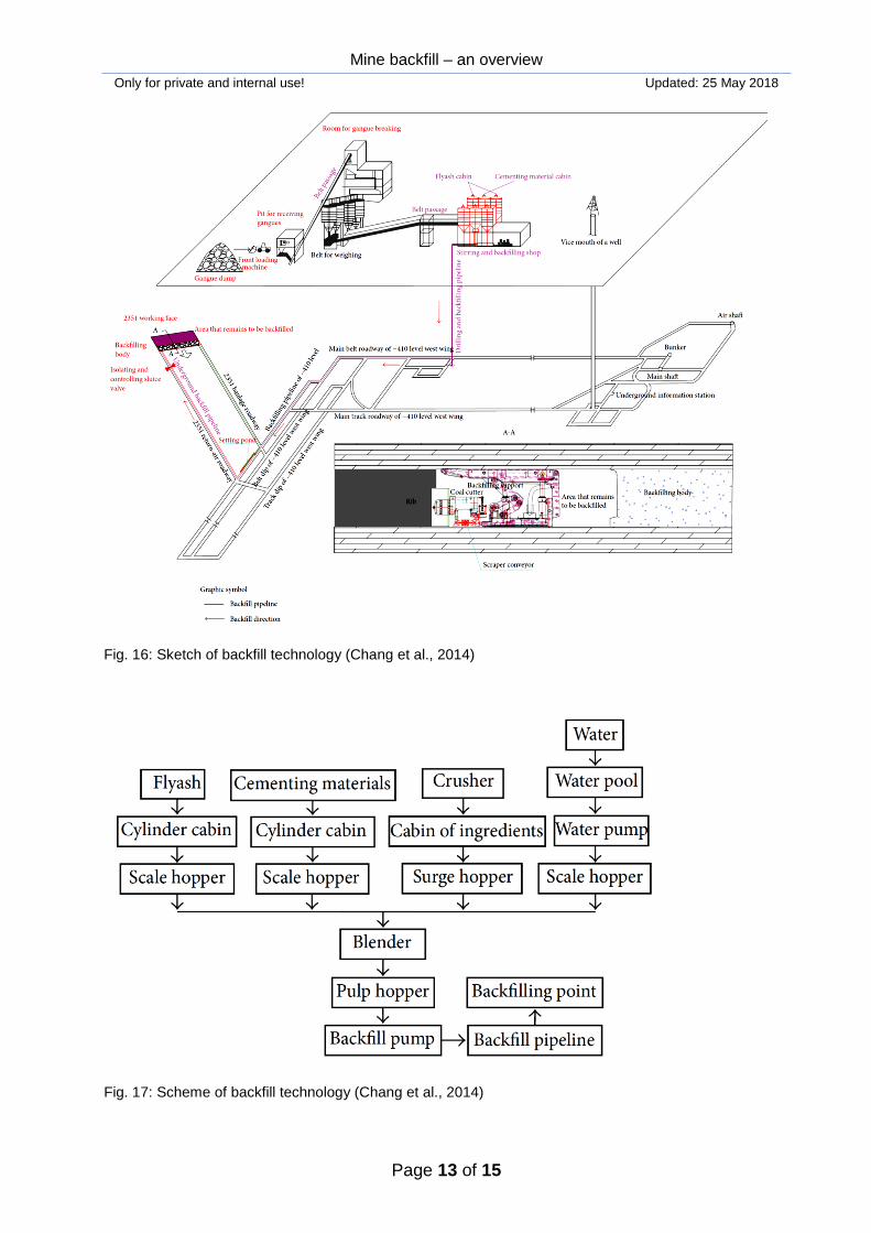
Chang et al. (2014) document a backfill technology for longwall coal mining. They con-sider a 7 m thick and slightly dipping coal seam 450 m below surface. Length of working face is 102 m and strike length 1150 m. By applying a paste backfill technology (see fig-ures 16 and 17) the following results were obtained:
Improvement of coal recovering rate from 45 % to 95 %
Reduction of surface subsidence to maximum of 35 mm (see fig. 15)
Backfilling ratio > 97 %
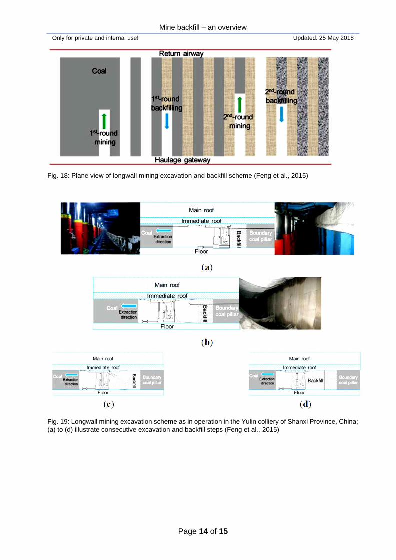
Feng et al. (2015) present a similar backfill scheme for longwall coal mining as illustrated in fig. 18 and 19.
Fig. 15: Subsidence by using backfill technology according to Chang et al. (2014)
Mine backfill – an overview
Only for private and internal use! Updated: 25 May 2018
Page 13 of 15
Fig. 16: Sketch of backfill technology (Chang et al., 2014)
Fig. 17: Scheme of backfill technology (Chang et al., 2014)
Mine backfill – an overview
Only for private and internal use! Updated: 25 May 2018
Page 14 of 15
Fig. 18: Plane view of longwall mining excavation and backfill scheme (Feng et al., 2015)
Fig. 19: Longwall mining excavation scheme as in operation in the Yulin colliery of Shanxi Province, China;
(a) to (d) illustrate consecutive excavation and backfill steps (Feng et al., 2015)
Mine backfill – an overview
Only for private and internal use! Updated: 25 May 2018
Page 15 of 15
5 References
Belem, T. & Benzaazoua, M. (2004): An overview on the use of paste backfill technology as a ground support method in cut-and-fill mines, Proc. 5th Symp. Groudn Support in Minign and Undeground Construction, Tayler & Francis, 637-650
Chang, Q. et al. (2014): Implementation of paste backfill mining technology in Chinese
coal mines, The Scientific World Journal, 214: ID 821025 Dixon, D.A. & Keto, P. (2009): Backfilling techniques and materials in undeground exca-
vations: Potential alternative backfill materials in use in posiva’s spent fuel reposi-tory concept, Working report 2008-56, Posiva, Finland
Feng, X. et al. (2015): Application of a backfilling method in coal mining to realise an
ecological sensitive ‘black gold’ industry, Energies, 8: 3628-3639 Fliß, T. et al. (2011): Backfilling and pillar re-mining in potash industry, Proc. Int. Confer-
ence on Mining with Backfill: 1-14 Konietzky, H. & te Kamp, L. (2000): Preliminary study to simulate pellets based backfilling
process, unpublished internal report Moser, A. (2014): State of the art of backfill technology in underground mining excava-
tions, Diplomarbeit, Montan-Universität Leoben Moser, A. (2016): Stand der Technik der Versatztechnologie im untertägigen Bergbau,
BHM, 161(8): 345-350 Nguyen, Q.T. (2016): Shafts backfilled with ballast: stability and settlement predcitions
via DEM simulations, PhD thesis, Geotechnical Institute, TU Bergakademie Freiberg, Germany
Panchal, S. et al. (2018): Mill tailings based composits as paset backfill in mines of U-
bearing dolomitic limestones ore, J. Rock Mech. Geotechn. Eng., 10: 310-322 Sivakuga, N. et al. (2015): Underground mine backfilling in Australia using paste fills and
hydraulic fills, Int. J Geosynth. And Ground Engineering, 1: 18 Shen, B. et al. (2017): Remediation and monitoring of abandoned mines, Int. J. Rock
Mech. Min. Sci., 27: 803-811 Wagner, H. (2009): Die Rolle von Versatz im Bergbau, BHM, 154(2): 52-59 Walling, A.A. & Provis, J.L. (2016): Magnesia-based cements: A journey of 150 years,
and cements for the future?, Chemical Reviews, 116: 4170-4204 Yaodong, J. et al. (2011): The influence of roadway backfill on bursting liability and
strength of coal pillar yb numerical investigations, Procedia Engineering, 26: 1125-1143


![Seismic Monitoring Strategies for Deep Longwall Coal … · Seismic Monitoring Strategies for Deep Longwall Coal ... [2016]. Seismic monitoring strategies for deep longwall coal](https://img.pdfslide.net/doc/110x75/5b40c06e7f8b9a2f138d8854/seismic-monitoring-strategies-for-deep-longwall-coal-seismic-monitoring-strategies.jpg)