Embed Size (px)
Citation preview

MINI LATHE OWNERS MANUAL
MODEL : W815
Charnwood, Cedar Court, Walker Road,
Hilltop Industrial Estate, Bardon Hill, Leicestershire, LE67 1TU
Tel. 01530 516 926 Fax. 01530 516 929
email: [email protected] website: www.charnwood.net
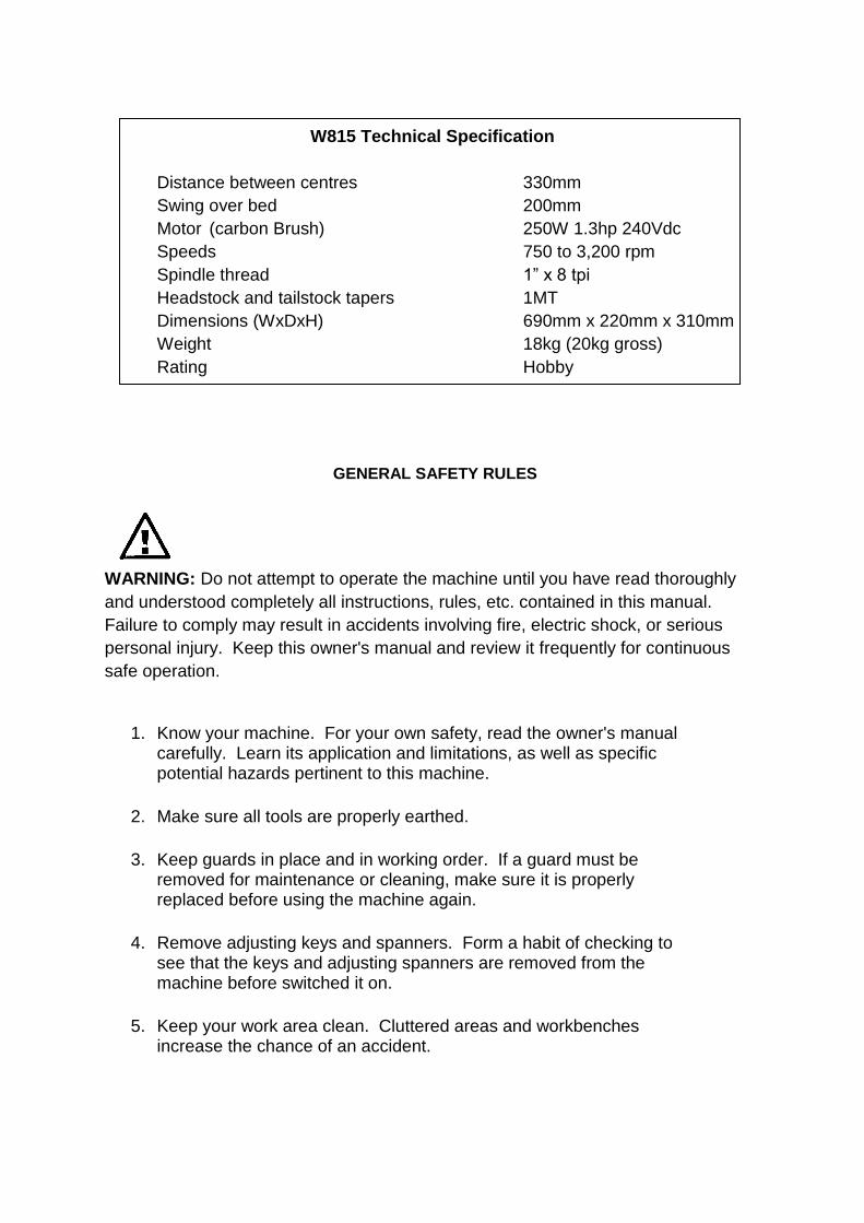
W815 Technical Specification
Distance between centres 330mm
Swing over bed 200mm
Motor (carbon Brush) 250W 1.3hp 240Vdc
Speeds 750 to 3,200 rpm
Spindle thread 1” x 8 tpi
Headstock and tailstock tapers 1MT
Dimensions (WxDxH) 690mm x 220mm x 310mm
Weight 18kg (20kg gross)
Rating Hobby
GENERAL SAFETY RULES
WARNING: Do not attempt to operate the machine until you have read thoroughly
and understood completely all instructions, rules, etc. contained in this manual.
Failure to comply may result in accidents involving fire, electric shock, or serious
personal injury. Keep this owner's manual and review it frequently for continuous
safe operation.
1. Know your machine. For your own safety, read the owner's manual carefully. Learn its application and limitations, as well as specific potential hazards pertinent to this machine.
2. Make sure all tools are properly earthed.
3. Keep guards in place and in working order. If a guard must be removed for maintenance or cleaning, make sure it is properly replaced before using the machine again.
4. Remove adjusting keys and spanners. Form a habit of checking to see that the keys and adjusting spanners are removed from the machine before switched it on.
5. Keep your work area clean. Cluttered areas and workbenches increase the chance of an accident.

6. Do not use in dangerous environments. Do not use power tools in damp or wet locations, or expose them to rain. Keep work areas well illuminated.
7. Keep children away. All visitors should be kept a safe distance from the work area.
8. Make workshop childproof. Use padlocks, master switches and remove starter keys.
9. Do not force the machine. It will do the job better and be safer at the rate for which it is designed.
10. Use the right tools. Do not force the machine or attachments to do a job for which they are not designed. Contact the manufacturer or distributor if there is any question about the machine's suitability for a particular job.
11. Wear proper apparel. Avoid loose clothing, gloves, ties, rings, bracelets, and jewellery which could get caught in moving parts. Non-slip footwear is recommended. Wear protective hair covering to contain long hair.
12. Always use safety glasses. Normal spectacles only have impact resistant lenses. They are not safety glasses.
13. Do not over-reach. Keep proper footing and balance at all times.
14. Maintain machine in good condition. Keep machine clean for best and safest performance. Follow instructions for lubrication and changing accessories.
15. Disconnect the machine from power source before servicing and when changing the drive belt.
16. To avoid accidental starting, make sure the switch is in the OFF position before plugging in the mains cable.
17. Never leave the machine running unattended. Turn the power off. Do not leave the machine until it comes to a complete stop.
18. Do not use any power tools while under the effects of drugs, alcohol or medication.
19. Always wear a face or dust mask if operation creates a lot of dust and/or chips. Always operate the tool in a well ventilated area and provide for proper dust removal. Use a suitable dust extractor.

ADDITIONAL RULES FOR LATHES
1. Never attempt to adjust any part of the workpiece whilst the lathe is still in motion. Wait until the workpiece has come to a complete stop.
2. Ensure that chuck keys, tommy bars and similar items are removed before the lathe is started.
3. Always stand to one side when you start the lathe so that if anything does fly off e.g. a loose piece of bark, you will be out of the line-of-fire.
4. When mounting a new piece of timber, rotate the wood through 360o by hand to ensure that it will not hit the toolrest or the bed of the lathe and then start the lathe at its slowest speed. When you are certain that that the work is secure and not too out of balance set the lathe to the normal turning speed.
5. Always check the rotation speed before switching the lathe on to avoid the risk of starting it whilst it is set to run at too high a speed.
6. The speed of the lathe must be adjusted to suit the size, balance, length and condition of the timber being turned. The greater the diameter of the work, the slower the rotation speed needs to be. If the piece you are turning is out of balance, then you must start turning at a low speed, until it is balanced.
7. The tool must rest firmly on the toolrest before it is brought into contact with the rotating wood and must never be lifted off the toolrest as long as it is in contact with the timber.
8. Before sanding, polishing or doing anything else that brings your fingers close to the work, remove the toolrest. Getting your fingers trapped between the toolrest and the work will at least be very painful and may cause serious injury.
9. Never wrap the sandpaper of polishing cloth round the work. If it tightens up it will pull your fingers into contact with the timber and may lead to serious injury.
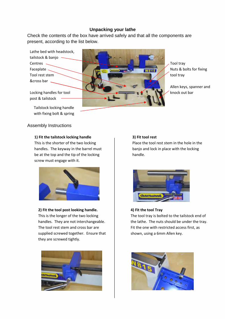
Unpacking your lathe
Check the contents of the box have arrived safely and that all the components are
present, according to the list below.
Tailstock locking handle
with fixing bolt & spring
Assembly Instructions
Lathe bed with headstock,
tailstock & banjo
Centres
Faceplate
Tool rest stem
&cross bar
Locking handles for tool
post & tailstock
Tool tray
Nuts & bolts for fixing
tool tray
Allen keys, spanner and
knock out bar
1) Fit the tailstock locking handle
This is the shorter of the two locking
handles. The keyway in the barrel must
be at the top and the tip of the locking
screw must engage with it.
2) Fit the tool post looking handle.
This is the longer of the two locking
handles. They are not interchangeable.
The tool rest stem and cross bar are
supplied screwed together. Ensure that
they are screwed tightly.
3) Fit tool rest
Place the tool rest stem in the hole in the
banjo and lock in place with the locking
handle.
4) Fit the tool Tray
The tool tray is bolted to the tailstock end of
the lathe. The nuts should be under the tray.
Fit the one with restricted access first, as
shown, using a 6mm Allen key.
Your new lathe is now ready for use with either the faceplate or the drive centres
supplied. A spanner is supplied to facilitate removal of the faceplate and there is a
knock out bar provided for easy removal of the centres.
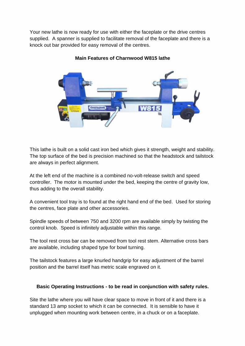
Main Features of Charnwood W815 lathe
This lathe is built on a solid cast iron bed which gives it strength, weight and stability.
The top surface of the bed is precision machined so that the headstock and tailstock
are always in perfect alignment.
At the left end of the machine is a combined no-volt-release switch and speed
controller. The motor is mounted under the bed, keeping the centre of gravity low,
thus adding to the overall stability.
A convenient tool tray is to found at the right hand end of the bed. Used for storing
the centres, face plate and other accessories.
Spindle speeds of between 750 and 3200 rpm are available simply by twisting the
control knob. Speed is infinitely adjustable within this range.
The tool rest cross bar can be removed from tool rest stem. Alternative cross bars
are available, including shaped type for bowl turning.
The tailstock features a large knurled handgrip for easy adjustment of the barrel
position and the barrel itself has metric scale engraved on it.
Basic Operating Instructions - to be read in conjunction with safety rules.
Site the lathe where you will have clear space to move in front of it and there is a
standard 13 amp socket to which it can be connected. It is sensible to have it
unplugged when mounting work between centre, in a chuck or on a faceplate.
It is essential to have it unplugged when tensioning/changing the drive belt or
replacing the brushes.
When you have mounted a piece of wood, position the tool rest and always rotate
the work piece by had to ensure that it is clear of the crossbar.
Select a low speed on the control dial (turn the knob anticlockwise) and press the
green button on the NVR switch. ALWAYS start at a low speed. When you are sure
that the work is firmly held in place, the speed may be increased to that which is
correct for the job in hand. Do not run the lathe at a speed which causes excessive
vibration when the work piece is in a ‘raw’ state and still unbalanced.
Cut gently with well sharpened chisels and gouges. Do not force the work or allow a
tool to dig in.
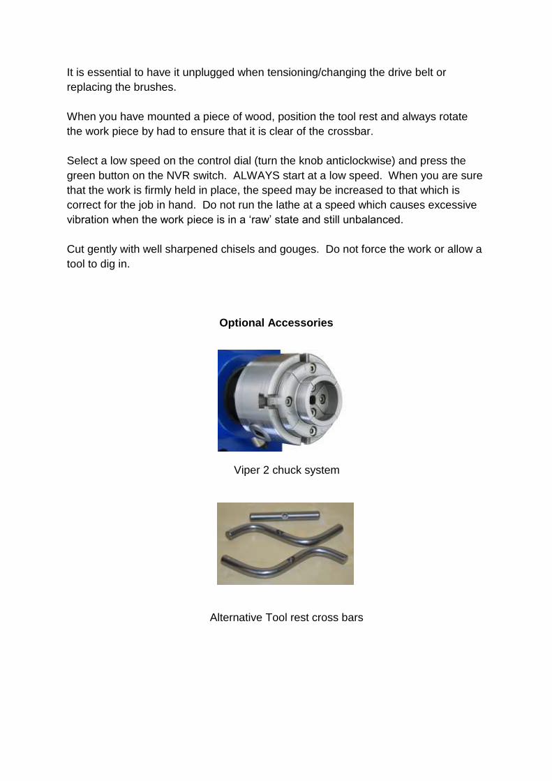
Optional Accessories
Viper 2 chuck system
Alternative Tool rest cross bars
Routine Maintenance
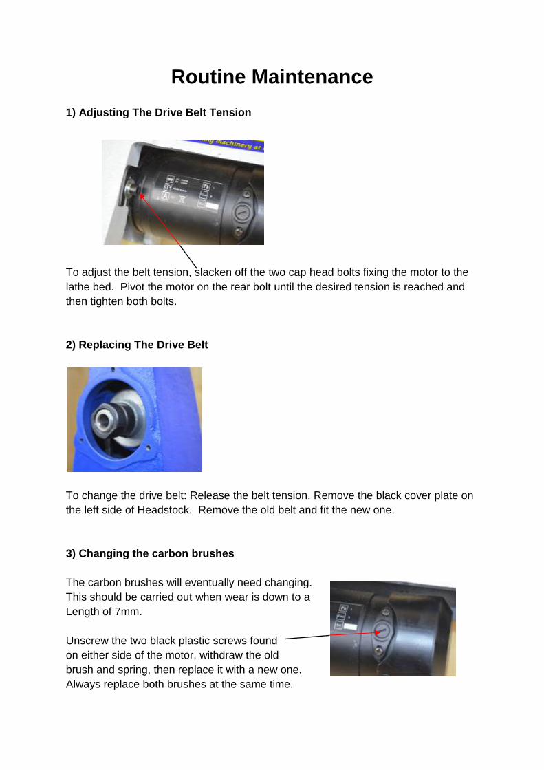
1) Adjusting The Drive Belt Tension
To adjust the belt tension, slacken off the two cap head bolts fixing the motor to the
lathe bed. Pivot the motor on the rear bolt until the desired tension is reached and
then tighten both bolts.
2) Replacing The Drive Belt
To change the drive belt: Release the belt tension. Remove the black cover plate on
the left side of Headstock. Remove the old belt and fit the new one.
3) Changing the carbon brushes
The carbon brushes will eventually need changing.
This should be carried out when wear is down to a
Length of 7mm.
Unscrew the two black plastic screws found
on either side of the motor, withdraw the old
brush and spring, then replace it with a new one.
Always replace both brushes at the same time.

Fault Possible Cause Remedy
Machine will not start Power supply not connected Check plug socket is switched on
Fuse in plug has blown Replace fuse
Fuse in control panel has blown Replace fuse
Break in power supply cable Visually check cable, replace in necessary
Loose terminal on switch Remove speed controller and check
connections
Switch failed Replace switch
Machine will not start, switch latches Speed controller failed Replace speed controller
Machine will not start, but a buzz is heard On/Off Switch has failed (when holding down
green button the machine starts)
Replace switch
Machine starts to turn but slow speed only Failed variable speed circuit Check connection to speed dial
Replace speed controller
Spindle stalls but motor still running Loose drive belt Increase belt tension
Motor is running but spindle not turning Broken drive belt Replace drive belt
Motor is overheating Too much load on motor Reduce load on motor, make shallower cuts
Airflow to cooling fan is blocked Remove fan cover and clean grill
Spindle rotation slows during cut Excessive depth of cut Make shallower cuts
Chisels are dull Sharpen chisels
Worn out carbon brushes Replace carbon brushes (see page 8)
Loose drive belt Increase belt tension
CHARNWOOD W815 LATHE TROUBLESHOOTING GUIDE
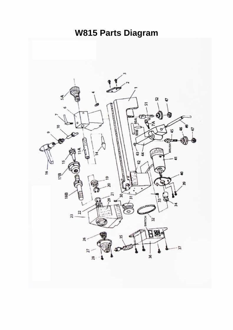
W815 Parts Diagram

W815 Parts List
Part No. Description Part No. Description
01 Bed 02 Restraining Plate
03 Bolt 04 Bolt
05A Handgrip (Chrome) 06 Tailstock
07 Locking Handle – Tailstock 18mm 07A Locking Handle – Toolrest 28mm
08 Bolt 09 Sleeve
10 Eccentric Axis 11A Barrel 1MT
14 Tail Centre 15 Drive Centre
16 Tailstock Locking Handle 17B Faceplate 1” x 8 tpi
18B Headstock Spindle 1” x 8 tpi 1MT 19 Bearing
20 Circlip 21 Circlip
22 Bearing 23 Headstock
26 Headstock Spindle Nut 27 Cover Plate
28 Bolt 29 Label
30 Bolt 31 Drive Pulley
32 Drive Belt 33 Bolt
34 Motor Pulley 35 Mains Cable
36 NVR Switch and Speed Control 37 Bolt
39 Bolt 40 Motor Plate
41 Motor 42 Warning Label
43 Circlip 44 Banjo
45 Cam Hanger 46 Plate
47 Hex Nut 49 Eccentric Rod
50A Toolrest Stem 50B Toolrest Crossbar
51 Cam Hanger 52 Plate
59 Knock Out Bar 60 Tool Tray
SWITCH KJD6 On/Off Switch BRUSH Carbon Brushes - Pair

Updated: October 2016
Charnwood, Cedar Court, Walker Road,
Hilltop Industrial Estate, Bardon Hill, Leicestershire, LE67 1TU
Tel. 01530 516 926 Fax. 01530 516 929
email: [email protected] website: www.charnwood.net