Embed Size (px)
Citation preview
00P3H510CZXSEA4
Mini Speed Dome Camera
Indoor Dome Camera
User’s Manual Version 1.4
User’s Manual
1
Preface The information given in this manual was current when published. The company reserves the right to revise and improve its products. All specifications are subject to change without notice.
Notice To work with the Mini Speed Dome Cameras, any installer or technician must have the following minimum qualifications:
• A basic knowledge of CCTV systems and components • A basic knowledge of electrical wiring and low-voltage electrical
hookups • A basic knowledge of network system setting • Have read this manual completely
Copyright Under copyright laws, the contents of this user manual may not be copied, photocopied, translated, reproduced or reduced to any electronic medium or machine-readable format, in whole or in part, without prior written permission of the company. Important Information Before proceeding, please read and observe all instructions and warnings in this manual. Retain this manual with the original bill of sale for future reference and, if necessary, warranty service. When unpacking your unit, check for missing or damaged items. If any item is missing, or if damage is evident, DO NOT INSTALL OR OPERATE THIS PRODUCT. Contact your dealer for assistance.
Regulation
This device complies with Part 15 of the FCC Rules. Operation is subject to the following two conditions: (1) this device may not cause harmful interference, and (2) this device must accept any interference received, including interference that may cause undesired operation.
User’s Manual
2
This symbol on the product or on its packaging indicates that this product shall not be treated as household waste in accordance with Directive 2002/96/EC. Instead it shall be handed over to the applicable collection point for the recycling of electrical and electronic equipment. By proper waste handling of this product you ensure that it has no negative consequences for the environment and human health, which could otherwise be caused if this product is thrown into the garbage bin. The recycling of materials will help to conserve natural resources. For more details information about recycling of this product, please contact your local city office, your household waste disposal service or the shop where you purchased the product.
Compliance is evidenced by written declaration from our suppliers, assuring that any potential trace contamination levels of restricted substances are below the maximum level set by EU Directive 2002/95/EC, or are exempted due to their application.
User’s Manual
3
Cautions • Handle the camera carefully
Do not abuse the camera. Avoid striking, shaking, etc. The camera could be damaged by improper handing or storage.
• Installing electricity wiring carefully Ask qualified personnel of electrical wiring for the installation. Please note that input electricity to the unit is at tolerance of DC 12V/AC 24V ± 10%. The camera is capable of surge protection; ensure AC power model unit grounded appropriately against damage of heavy current or electric shock.
• Do not disassemble the camera To prevent electric shock, do not remove screws or covers. There are no user serviceable parts inside. Ask a qualified service person for servicing.
• Do not block cooling holes on the bracket This camera has a cooling fan inside. Blocking the cooling holes leads to build up heat of the camera and may cause malfunction.
• Do not operate the camera beyond the specified temperature, humidity or power source ratings Use the indoor dome camera under conditions where temperature is between 0°C ~ 40°C (32°F ~ 104°F) and the outdoor camera under conditions where temperature is between -30°C~45°C (-22°F~113°F), and humidity is below 90%.
• Do not expose the indoor dome camera to rain or moisture, or try to operate it in wet areas The indoor dome camera is designed for indoor use or locations where it is protected from rain and moisture. Turn the power off immediately if the camera is wet and ask a qualified service person for servicing. Moisture can damage the camera and also create the danger of electric shock.
• Do not use strong or abrasive detergents when cleaning the camera body Use a dry cloth to clean the camera when it is dirty. In case the dirt is hard to be removed, use a mild detergent and wipe gently.

User’s Manual
4
• Never face the camera towards the sun Do not aim the camera at bright objects. Whether the camera is in use or not, never aim it at the sun or other extremely bright objects. Otherwise, the camera may be smeared or damaged.
User’s Manual
5
Table of Contents 1. Overview .................................................................................................................................... 7
1.1 Product Features .............................................................................................................. 8 1.2 Product Application........................................................................................................... 9
2. Connecting the Mini Speed Dome Camera........................................................................... 10 2.1 Package Content ............................................................................................................ 10 2.2 Switch/Connector Definition ............................................................................................11 2.3 Communication Switch Setting....................................................................................... 12 2.4 ID Setup.......................................................................................................................... 13 2.5 Camera Control Protocol Setup...................................................................................... 14 2.6 22-Pin Connector Definition............................................................................................ 15 2.7 RS-485 Connector Definition.......................................................................................... 17
3. Operation and Configuration ................................................................................................. 18 3.1 OSD Display Format....................................................................................................... 18 3.2 OSD Menu Tree.............................................................................................................. 19 3.3 Configuration Menu ........................................................................................................ 23
3.3.1 LANGUAGE ...................................................................................................... 23 3.3.2 DEFAULT CAMERA.......................................................................................... 24 3.3.3 BACKLIGHT...................................................................................................... 24 3.3.4 FOCUS ............................................................................................................. 24 3.3.5 AE MODE ......................................................................................................... 25 3.3.6 WBC MODE...................................................................................................... 26 3.3.7 SETUP MENU 1................................................................................................ 27
DIGITAL ZOOM................................................................................................. 27 SLOW SHUTTER ............................................................................................. 27 DIGITAL NOISE REDUCTION (D.N.R.)............................................................ 28 IMAGE INVERSE.............................................................................................. 28 FREEZE............................................................................................................ 28 APERTURE....................................................................................................... 28 EXIT .................................................................................................................. 29
3.3.8 SETUP MENU 2................................................................................................ 29 FLIP .................................................................................................................. 29 ANGLE ADJUSTER .......................................................................................... 30 SPEED BY ZOOM ............................................................................................ 30 AUTO CALI. (Auto Calibration) ......................................................................... 30 PASSWORD ..................................................................................................... 30 OSD AUTO CLOSE .......................................................................................... 31 SYSTEM RESET .............................................................................................. 31 EXIT .................................................................................................................. 32
3.3.9 ID DISPLAY....................................................................................................... 32 3.3.10 TITLE DISPLAY ................................................................................................ 32 3.3.11 TITLE SETTING................................................................................................ 33
User’s Manual
6
3.3.12 PRESET............................................................................................................ 34 3.3.13 SEQUENCE...................................................................................................... 35 3.3.14 AUTOPAN......................................................................................................... 36 3.3.15 CRUISE ............................................................................................................ 38 3.3.16 HOME SETTING............................................................................................... 40 3.3.17 IR FUNCTION................................................................................................... 42 3.3.18 ALARM SETTING ............................................................................................. 43 3.3.19 ALARM DETECT .............................................................................................. 45 3.3.20 WDR FUNCTION.............................................................................................. 48 3.3.21 PRIVACY MASK ............................................................................................... 49 3.3.22 TIME SETTING................................................................................................. 51 3.3.23 SCHEDULE FUNCTION................................................................................... 52 3.3.24 EXIT OSD ......................................................................................................... 53
Appendix A: Technical Specification .......................................................................................... 54 Appendix B: Switch Settings Index Table................................................................................... 56
Camera ID Setup ...................................................................................................................... 56 Protocol Setup .......................................................................................................................... 63
Appendix C: OSD Menu Notes..................................................................................................... 64
User’s Manual
7
1. Overview The Mini Speed Dome Camera is an innovative Speed Dome Camera designed for middle and small surveillance applications and possesses true speed dome camera features, such as high speed and accurate Pan/Tilt, up to 12×12 zoom ratio, 180° Digital Image Flip, Speed by Zoom, and Preset Speed up to 400°/s. Additionally, it contains 256 Preset Points, 8 Sequence Lines, 4 Auto Pan Lines and 8 Cruise Lines to support automatic operations. It is ideal for all surveillance requirements in hotels, department stores, intelligent buildings, amusement parks, parking lots, factories, hospitals, schools, stations etc. The Mini Speed Dome Camera contains various solutions for low light and high contrast conditions. For example, a bright background or shade can result in the subject of the image appearing darker. The backlight compensation function gives a bright and beautiful image. The Mini Speed Dome Camera supports one cabling for easy installation, and can be integrated with various digital surveillance products, such as DVRs, Control Keyboards and various sorts of accessories for a total surveillance solution. The camera is incorporated with multiple protocols: DynaColor, Pelco, VCL, Philips, etc. to enhance powerful connectivity.
User’s Manual
8
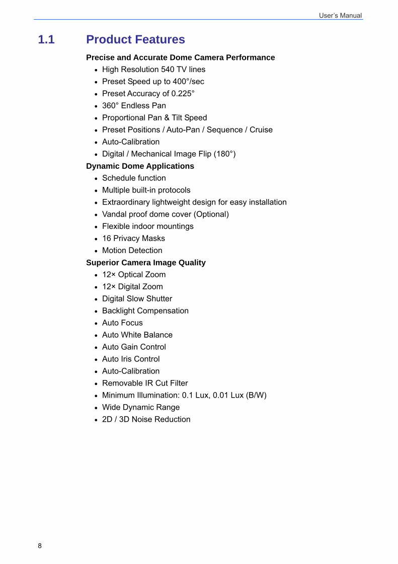
1.1 Product Features Precise and Accurate Dome Camera Performance
• High Resolution 540 TV lines • Preset Speed up to 400°/sec • Preset Accuracy of 0.225° • 360° Endless Pan • Proportional Pan & Tilt Speed • Preset Positions / Auto-Pan / Sequence / Cruise • Auto-Calibration • Digital / Mechanical Image Flip (180°)
Dynamic Dome Applications • Schedule function • Multiple built-in protocols • Extraordinary lightweight design for easy installation • Vandal proof dome cover (Optional) • Flexible indoor mountings • 16 Privacy Masks • Motion Detection
Superior Camera Image Quality • 12× Optical Zoom • 12× Digital Zoom • Digital Slow Shutter • Backlight Compensation • Auto Focus • Auto White Balance • Auto Gain Control • Auto Iris Control • Auto-Calibration • Removable IR Cut Filter • Minimum Illumination: 0.1 Lux, 0.01 Lux (B/W) • Wide Dynamic Range • 2D / 3D Noise Reduction
User’s Manual
9
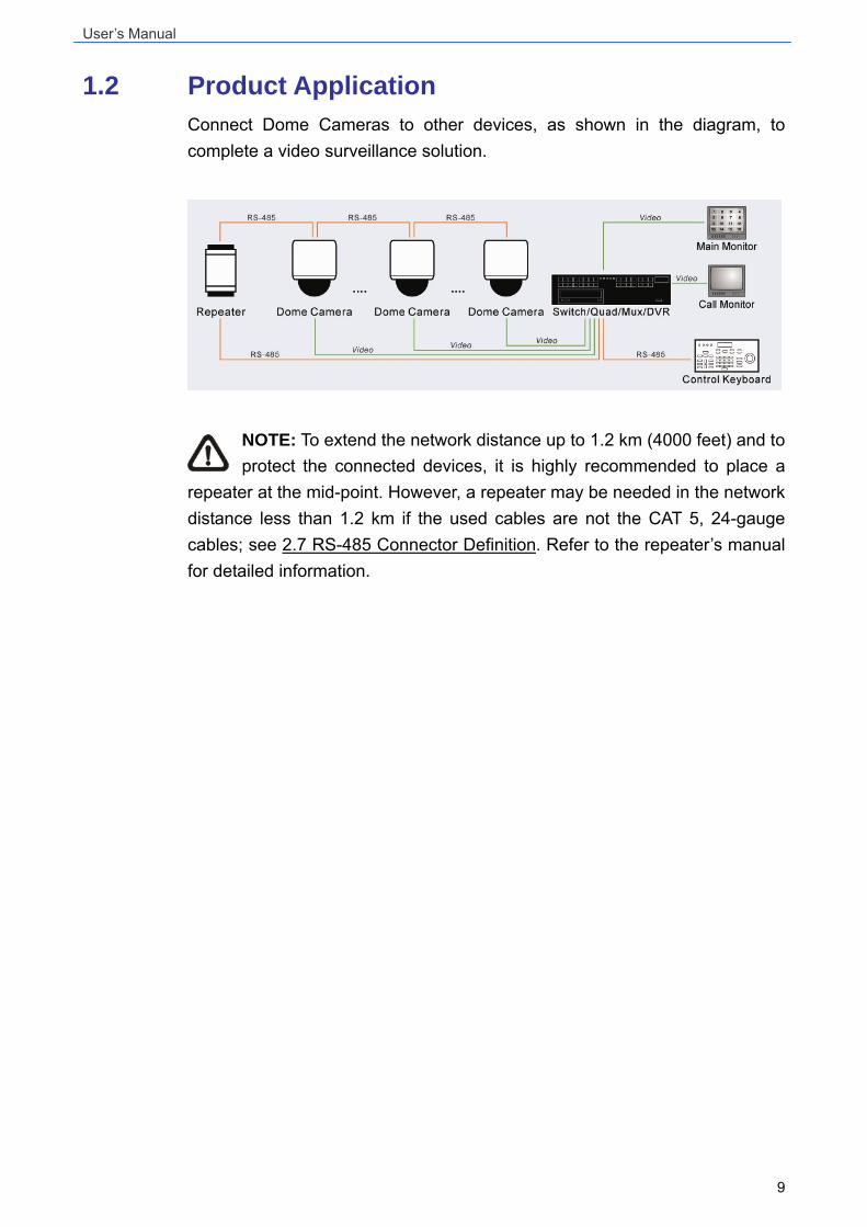
1.2 Product Application Connect Dome Cameras to other devices, as shown in the diagram, to complete a video surveillance solution.
NOTE: To extend the network distance up to 1.2 km (4000 feet) and to protect the connected devices, it is highly recommended to place a
repeater at the mid-point. However, a repeater may be needed in the network distance less than 1.2 km if the used cables are not the CAT 5, 24-gauge cables; see 2.7 RS-485 Connector Definition. Refer to the repeater’s manual for detailed information.
User’s Manual
10
2. Connecting the Mini Speed Dome Camera Please refer to the following sections to connect, set and operate the Dome Camera. In order to control the camera, basically a control keyboard or other control device is required.
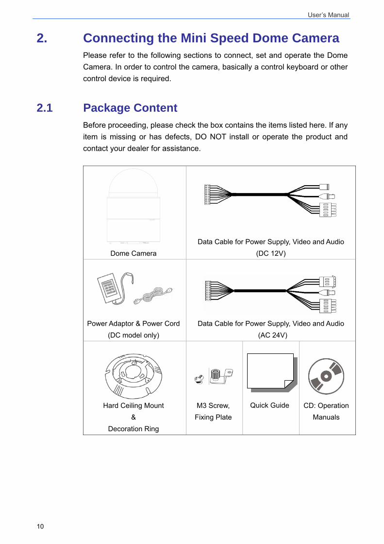
2.1 Package Content Before proceeding, please check the box contains the items listed here. If any item is missing or has defects, DO NOT install or operate the product and contact your dealer for assistance.
Dome Camera
Data Cable for Power Supply, Video and Audio
(DC 12V)
Power Adaptor & Power Cord (DC model only)
Data Cable for Power Supply, Video and Audio
(AC 24V)
Hard Ceiling Mount
& Decoration Ring
M3 Screw, Fixing Plate
Quick Guide
CD: Operation Manuals
User’s Manual
11
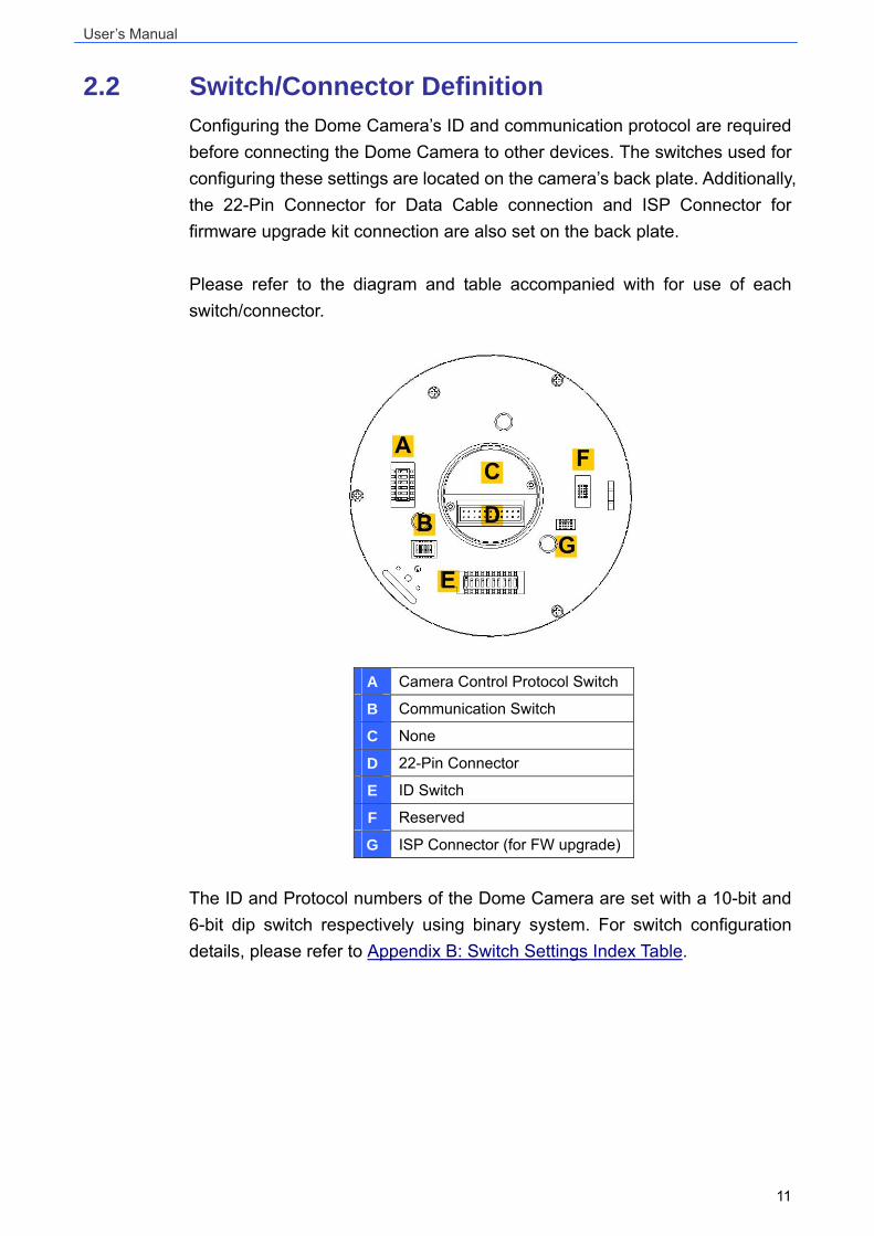
2.2 Switch/Connector Definition Configuring the Dome Camera’s ID and communication protocol are required before connecting the Dome Camera to other devices. The switches used for configuring these settings are located on the camera’s back plate. Additionally, the 22-Pin Connector for Data Cable connection and ISP Connector for firmware upgrade kit connection are also set on the back plate. Please refer to the diagram and table accompanied with for use of each switch/connector.
A Camera Control Protocol Switch
B Communication Switch
C None
D 22-Pin Connector
E ID Switch
F Reserved
G ISP Connector (for FW upgrade)
The ID and Protocol numbers of the Dome Camera are set with a 10-bit and 6-bit dip switch respectively using binary system. For switch configuration details, please refer to Appendix B: Switch Settings Index Table.
User’s Manual
12
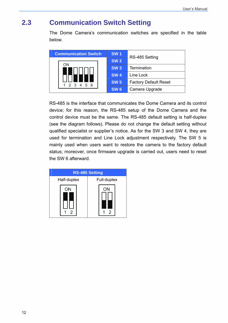
2.3 Communication Switch Setting The Dome Camera’s communication switches are specified in the table below.
Communication Switch SW 1 SW 2
RS-485 Setting
SW 3 Termination
SW 4 Line Lock
SW 5 Factory Default Reset SW 6 Camera Upgrade
RS-485 is the interface that communicates the Dome Camera and its control device; for this reason, the RS-485 setup of the Dome Camera and the control device must be the same. The RS-485 default setting is half-duplex (see the diagram follows). Please do not change the default setting without qualified specialist or supplier’s notice. As for the SW 3 and SW 4, they are used for termination and Line Lock adjustment respectively. The SW 5 is mainly used when users want to restore the camera to the factory default status; moreover, once firmware upgrade is carried out, users need to reset the SW 6 afterward.
RS-485 Setting Half-duplex
Full-duplex
User’s Manual
13
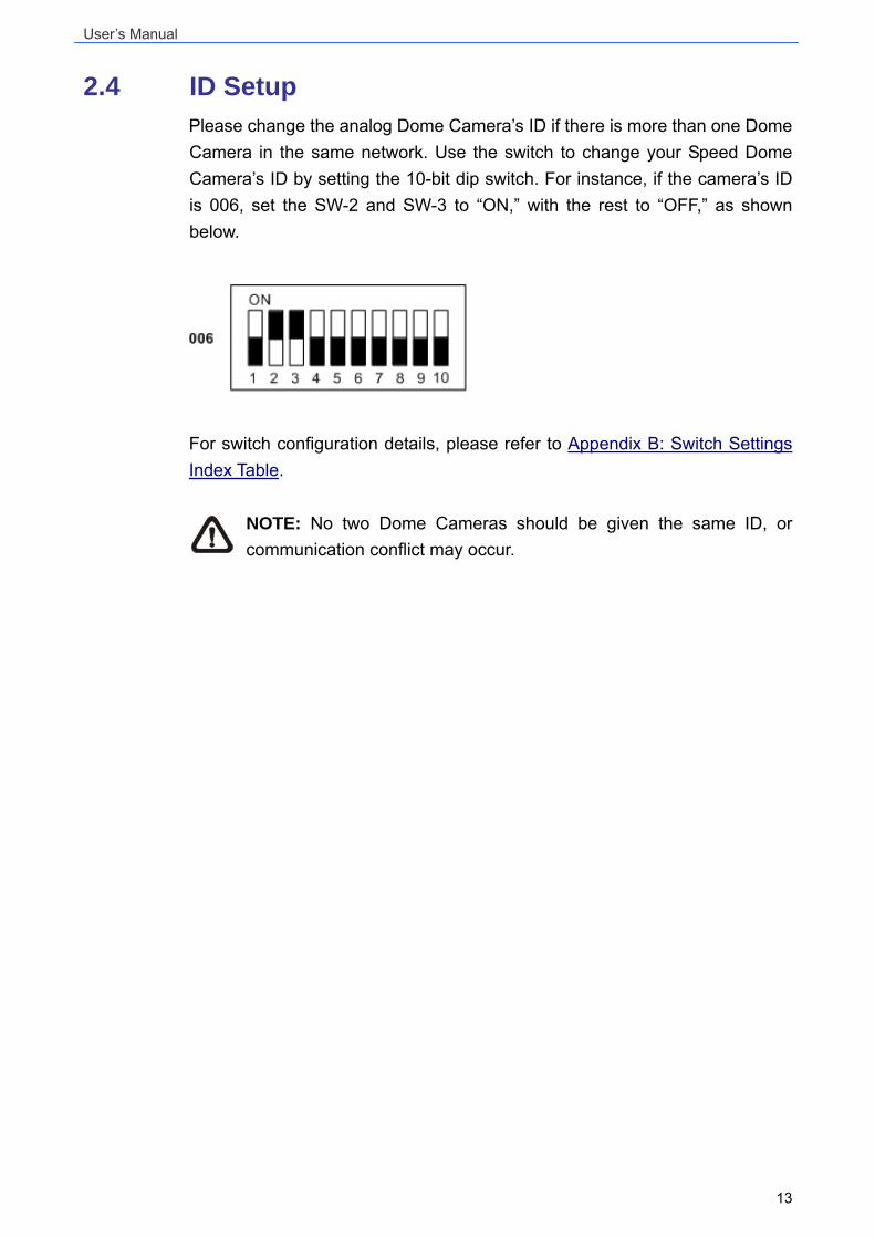
2.4 ID Setup Please change the analog Dome Camera’s ID if there is more than one Dome Camera in the same network. Use the switch to change your Speed Dome Camera’s ID by setting the 10-bit dip switch. For instance, if the camera’s ID is 006, set the SW-2 and SW-3 to “ON,” with the rest to “OFF,” as shown below.
For switch configuration details, please refer to Appendix B: Switch Settings Index Table.
NOTE: No two Dome Cameras should be given the same ID, or communication conflict may occur.
User’s Manual
14
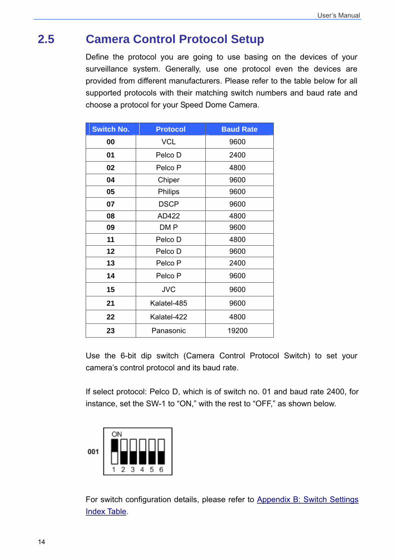
2.5 Camera Control Protocol Setup Define the protocol you are going to use basing on the devices of your surveillance system. Generally, use one protocol even the devices are provided from different manufacturers. Please refer to the table below for all supported protocols with their matching switch numbers and baud rate and choose a protocol for your Speed Dome Camera.
Switch No. Protocol Baud Rate
00 VCL 9600
01 Pelco D 2400
02 Pelco P 4800
04 Chiper 9600 05 Philips 9600
07 DSCP 9600 08 AD422 4800 09 DM P 9600
11 Pelco D 4800 12 Pelco D 9600 13 Pelco P 2400
14 Pelco P 9600
15 JVC 9600
21 Kalatel-485 9600
22 Kalatel-422 4800
23 Panasonic 19200
Use the 6-bit dip switch (Camera Control Protocol Switch) to set your camera’s control protocol and its baud rate. If select protocol: Pelco D, which is of switch no. 01 and baud rate 2400, for instance, set the SW-1 to “ON,” with the rest to “OFF,” as shown below.
For switch configuration details, please refer to Appendix B: Switch Settings Index Table.
User’s Manual
15
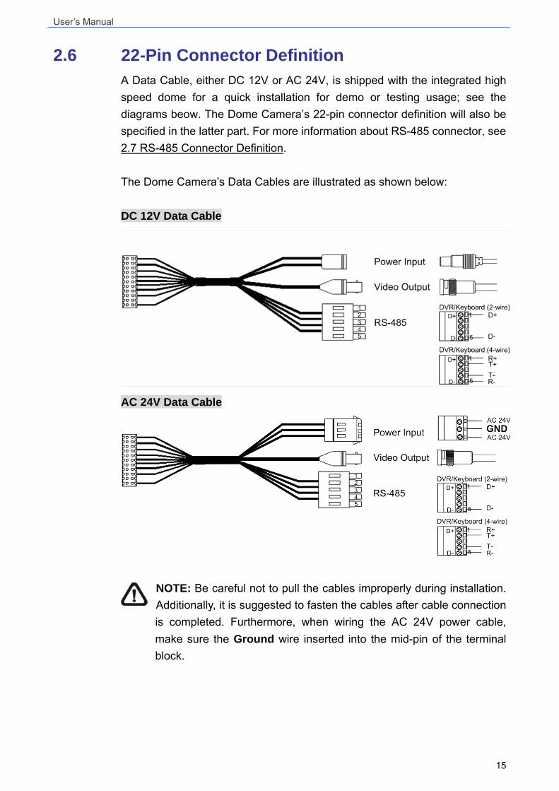
2.6 22-Pin Connector Definition A Data Cable, either DC 12V or AC 24V, is shipped with the integrated high speed dome for a quick installation for demo or testing usage; see the diagrams beow. The Dome Camera’s 22-pin connector definition will also be specified in the latter part. For more information about RS-485 connector, see 2.7 RS-485 Connector Definition.
The Dome Camera’s Data Cables are illustrated as shown below: DC 12V Data Cable
AC 24V Data Cable
NOTE: Be careful not to pull the cables improperly during installation. Additionally, it is suggested to fasten the cables after cable connection is completed. Furthermore, when wiring the AC 24V power cable, make sure the Ground wire inserted into the mid-pin of the terminal block.
User’s Manual
16
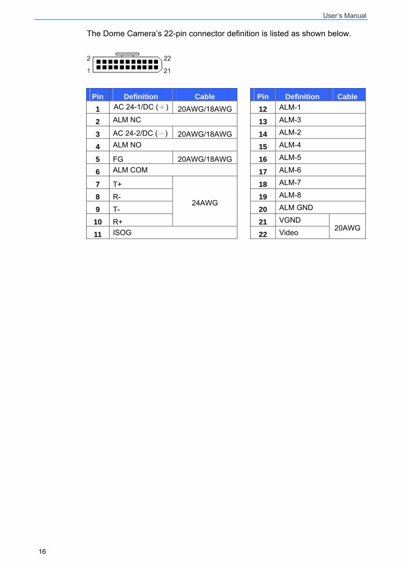
The Dome Camera’s 22-pin connector definition is listed as shown below.
Pin Definition Cable Pin Definition Cable
1 AC 24-1/DC (+) 20AWG/18AWG 12 ALM-1
2 ALM NC 13 ALM-3
3 AC 24-2/DC (-) 20AWG/18AWG 14 ALM-2
4 ALM NO 15 ALM-4
5 FG 20AWG/18AWG 16 ALM-5
6 ALM COM 17 ALM-6
7 T+ 18 ALM-7
8 R- 19 ALM-8
9 T- 20 ALM GND
10 R+
24AWG
21 VGND
11 ISOG 22 Video 20AWG
User’s Manual
17
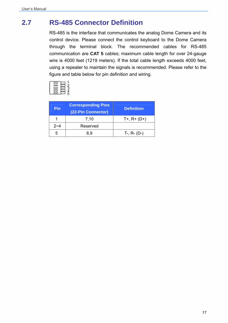
2.7 RS-485 Connector Definition RS-485 is the interface that communicates the analog Dome Camera and its control device. Please connect the control keyboard to the Dome Camera through the terminal block. The recommended cables for RS-485 communication are CAT 5 cables; maximum cable length for over 24-gauge wire is 4000 feet (1219 meters). If the total cable length exceeds 4000 feet, using a repeater to maintain the signals is recommended. Please refer to the figure and table below for pin definition and wiring.
Pin Corresponding Pins (22-Pin Connector)
Definition
1 7,10 T+, R+ (D+)
2~4 Reserved
5 8,9 T-, R- (D-)
User’s Manual
18
3. Operation and Configuration
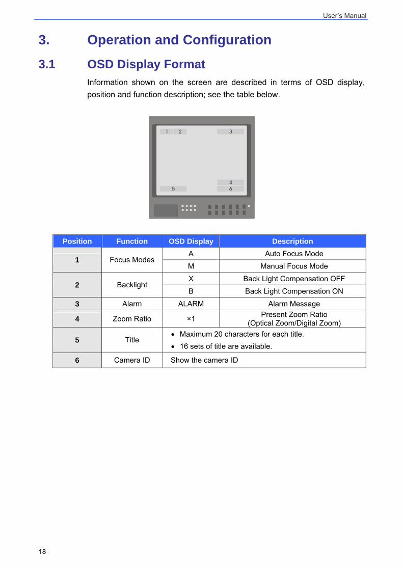
3.1 OSD Display Format Information shown on the screen are described in terms of OSD display, position and function description; see the table below.
1 2 3
45 6
Position Function OSD Display Description A Auto Focus Mode
1 Focus Modes M Manual Focus Mode
X Back Light Compensation OFF 2 Backlight
B Back Light Compensation ON
3 Alarm ALARM Alarm Message
4 Zoom Ratio ×1 Present Zoom Ratio (Optical Zoom/Digital Zoom)
5 Title • Maximum 20 characters for each title. • 16 sets of title are available.
6 Camera ID Show the camera ID
User’s Manual
19
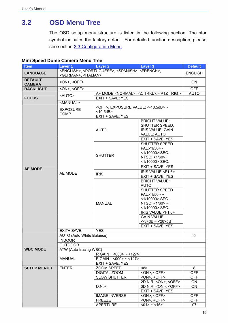
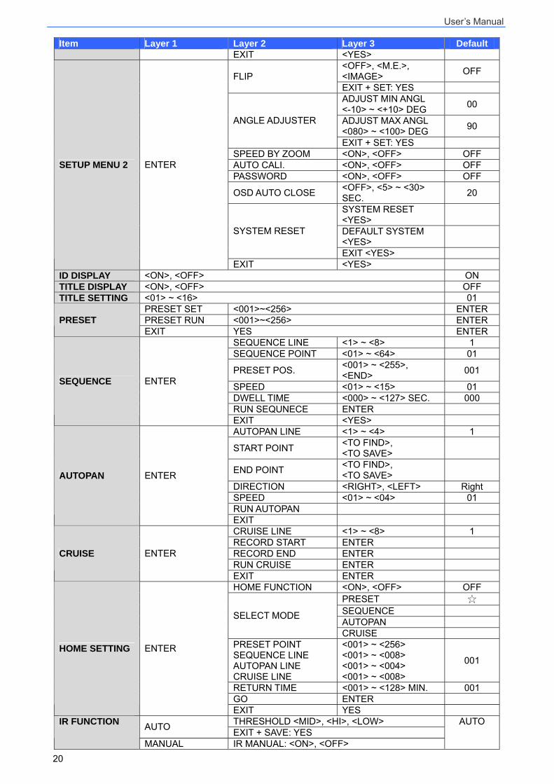
3.2 OSD Menu Tree The OSD setup menu structure is listed in the following section. The star symbol indicates the factory default. For detailed function description, please see section 3.3 Configuration Menu.
Mini Speed Dome Camera Menu Tree Item Layer 1 Layer 2 Layer 3 Default
LANGUAGE <ENGLISH>, <PORTUGUESE>, <SPANISH>, <FRENCH>, <GERMAN>, <ITALIAN> ENGLISH
DEFAULT CAMERA <ON>, <OFF> ON
BACKLIGHT <ON>, <OFF> OFF AF MODE <NORMAL>, <Z. TRIG.>, <PTZ TRIG.> AUTO <AUTO> EXIT + SAVE: YES FOCUS
<MANUAL> <OFF>, EXPOSURE VALUE: <-10.5dB> ~ <10.5dB> EXPOSURE
COMP. EXIT + SAVE: YES
BRIGHT VALUE; SHUTTER SPEED; IRIS VALUE; GAIN VALUE: AUTO
AUTO
EXIT + SAVE: YES
SHUTTER SPEED PAL:<1/50>~ <1/10000> SEC. NTSC: <1/60>~ <1/10000> SEC.
SHUTTER
EXIT + SAVE: YES
IRIS VALUE <F1.6> IRIS EXIT + SAVE: YES
BRIGHT VALUE: AUTO SHUTTER SPEED PAL:<1/50> ~ <1/10000> SEC. NTSC: <1/60> ~ <1/10000> SEC. IRIS VALUE <F1.6> GAIN VALUE <-3>dB ~ <28>dB
AE MODE
MANUAL
EXIT + SAVE: YES
AE MODE
EXIT+ SAVE: YES AUTO (Auto White Balance) INDOOR OUTDOOR ATW (Auto-tracing WBC)
R GAIN <000> ~ <127> B GAIN <000> ~ <127>
WBC MODE
MANUAL EXIT + SAVE: YES ZOOM SPEED <8> 8 DIGITAL ZOOM <ON>, <OFF> OFF SLOW SHUTTER <ON>, <OFF> OFF
2D N.R. <ON>, <OFF> ON 3D N.R. <ON>, <OFF> ON D.N.R. EXIT + SAVE: YES
IMAGE INVERSE <ON>, <OFF> OFF FREEZE <ON>, <OFF> OFF
SETUP MENU 1 ENTER
APERTURE <01> ~ <16> 07
User’s Manual
20
Item Layer 1 Layer 2 Layer 3 Default EXIT <YES>
<OFF>, <M.E.>, <IMAGE> OFF FLIP EXIT + SET: YES ADJUST MIN ANGL <-10> ~ <+10> DEG 00
ADJUST MAX ANGL <080> ~ <100> DEG 90 ANGLE ADJUSTER
EXIT + SET: YES SPEED BY ZOOM <ON>, <OFF> OFF AUTO CALI. <ON>, <OFF> OFF PASSWORD <ON>, <OFF> OFF
OSD AUTO CLOSE <OFF>, <5> ~ <30> SEC. 20
SYSTEM RESET <YES>
DEFAULT SYSTEM <YES> SYSTEM RESET
EXIT <YES>
SETUP MENU 2 ENTER
EXIT <YES> ID DISPLAY <ON>, <OFF> ON TITLE DISPLAY <ON>, <OFF> OFF TITLE SETTING <01> ~ <16> 01
PRESET SET <001>~<256> ENTER PRESET RUN <001>~<256> ENTER PRESET EXIT YES ENTER
SEQUENCE LINE <1> ~ <8> 1 SEQUENCE POINT <01> ~ <64> 01
PRESET POS. <001> ~ <255>, <END> 001
SPEED <01> ~ <15> 01 DWELL TIME <000> ~ <127> SEC. 000 RUN SEQUNECE ENTER
SEQUENCE ENTER
EXIT <YES> AUTOPAN LINE <1> ~ <4> 1
START POINT <TO FIND>, <TO SAVE>
END POINT <TO FIND>, <TO SAVE>
DIRECTION <RIGHT>, <LEFT> Right SPEED <01> ~ <04> 01 RUN AUTOPAN
AUTOPAN ENTER
EXIT CRUISE LINE <1> ~ <8> 1 RECORD START ENTER RECORD END ENTER RUN CRUISE ENTER
CRUISE ENTER
EXIT ENTER HOME FUNCTION <ON>, <OFF> OFF
PRESET SEQUENCE AUTOPAN
SELECT MODE
CRUISE PRESET POINT SEQUENCE LINE AUTOPAN LINE CRUISE LINE
<001> ~ <256> <001> ~ <008> <001> ~ <004> <001> ~ <008>
001
RETURN TIME <001> ~ <128> MIN. 001 GO ENTER
HOME SETTING ENTER
EXIT YES THRESHOLD <MID>, <HI>, <LOW> AUTO EXIT + SAVE: YES
IR FUNCTION
MANUAL IR MANUAL: <ON>, <OFF>
AUTO
User’s Manual
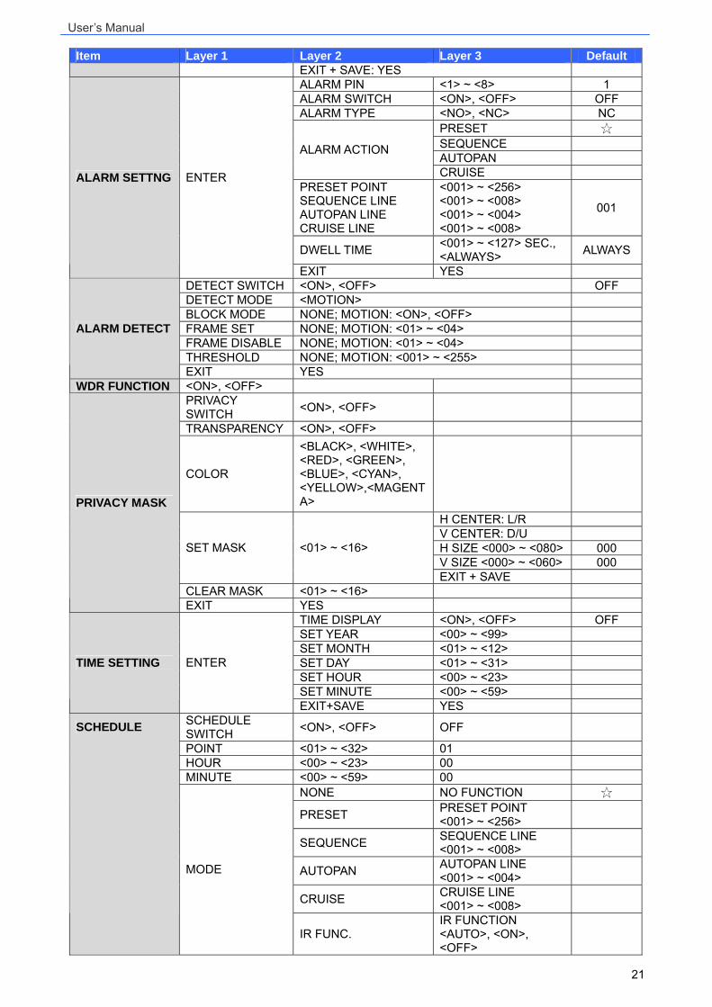
21
Item Layer 1 Layer 2 Layer 3 Default EXIT + SAVE: YES ALARM PIN <1> ~ <8> 1 ALARM SWITCH <ON>, <OFF> OFF ALARM TYPE <NO>, <NC> NC
PRESET SEQUENCE AUTOPAN
ALARM ACTION
CRUISE PRESET POINT SEQUENCE LINE AUTOPAN LINE CRUISE LINE
<001> ~ <256> <001> ~ <008> <001> ~ <004> <001> ~ <008>
001
DWELL TIME <001> ~ <127> SEC., <ALWAYS> ALWAYS
ALARM SETTNG ENTER
EXIT YES DETECT SWITCH <ON>, <OFF> OFF DETECT MODE <MOTION> BLOCK MODE NONE; MOTION: <ON>, <OFF> FRAME SET NONE; MOTION: <01> ~ <04> FRAME DISABLE NONE; MOTION: <01> ~ <04> THRESHOLD NONE; MOTION: <001> ~ <255>
ALARM DETECT
EXIT YES WDR FUNCTION <ON>, <OFF>
PRIVACY SWITCH <ON>, <OFF>
TRANSPARENCY <ON>, <OFF>
COLOR
<BLACK>, <WHITE>, <RED>, <GREEN>, <BLUE>, <CYAN>, <YELLOW>,<MAGENTA>
H CENTER: L/R V CENTER: D/U H SIZE <000> ~ <080> 000 V SIZE <000> ~ <060> 000
SET MASK <01> ~ <16>
EXIT + SAVE CLEAR MASK <01> ~ <16>
PRIVACY MASK
EXIT YES TIME DISPLAY <ON>, <OFF> OFF SET YEAR <00> ~ <99> SET MONTH <01> ~ <12> SET DAY <01> ~ <31> SET HOUR <00> ~ <23> SET MINUTE <00> ~ <59>
TIME SETTING ENTER
EXIT+SAVE YES SCHEDULE SWITCH <ON>, <OFF> OFF
POINT <01> ~ <32> 01 HOUR <00> ~ <23> 00 MINUTE <00> ~ <59> 00
NONE NO FUNCTION
PRESET PRESET POINT <001> ~ <256>
SEQUENCE SEQUENCE LINE <001> ~ <008>
AUTOPAN AUTOPAN LINE <001> ~ <004>
CRUISE CRUISE LINE <001> ~ <008>
SCHEDULE
MODE
IR FUNC. IR FUNCTION <AUTO>, <ON>, <OFF>

User’s Manual
22
Item Layer 1 Layer 2 Layer 3 Default SCHEDULE RESET YES
EXIT OSD YES
User’s Manual
23
3.3 Configuration Menu The detailed functions and parameter setting of your speed dome can be set by the OSD (On Screen Display) menu with a control device such as a control keyboard. The tables below show each page of the OSD menu. Additionally, Appendix B provides a table for user’s setting record.
To enter the OSD menu of the selected camera, press <CAMERA MENU> key on the control keyboard and hold for 3 seconds to enter the OSD menu. To select the setup item, use direction keys on keyboard to move the OSD cursor in the OSD menu. To setup item, use direction keys on keyboard to move the OSD cursor in the OSD menu. For items with →, press right/left direction keys on the control keyboard to select. For items with ↓, press the <CAMERA MENU> key on the control keyboard to enter the sub menu. For items with →↓, users can use the right/left direction keys to select functions, and then press the <CAMERA MENU> key on the control keyboard to enter their sub menu. For further detailed setup procedures, please refer to the user’s manual of your installed control devices.
NOTE: In the Camera OSD menu, the <CAMERA MENU> key functions as “ENTER” and “EXIT.”
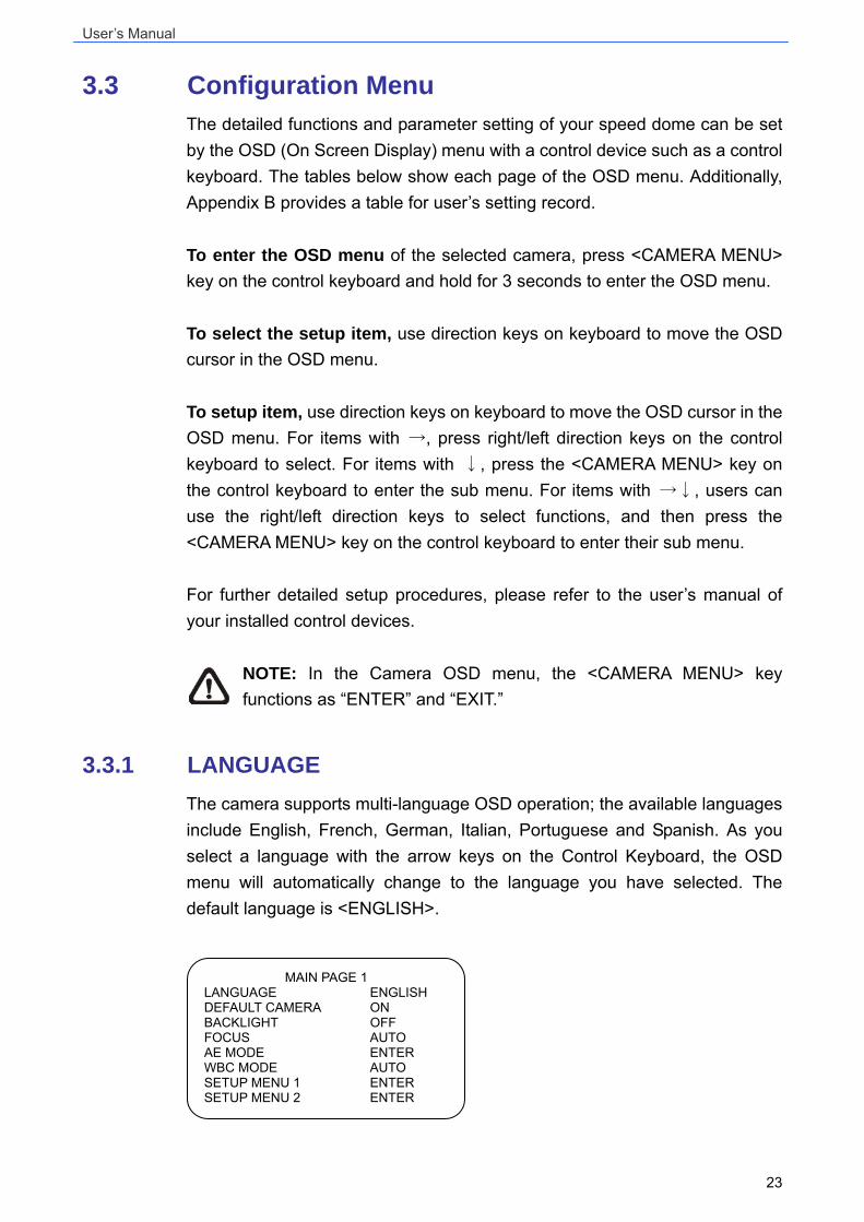
3.3.1 LANGUAGE The camera supports multi-language OSD operation; the available languages include English, French, German, Italian, Portuguese and Spanish. As you select a language with the arrow keys on the Control Keyboard, the OSD menu will automatically change to the language you have selected. The default language is <ENGLISH>.
MAIN PAGE 1 LANGUAGE ENGLISH DEFAULT CAMERA ON BACKLIGHT OFF FOCUS AUTO AE MODE ENTER WBC MODE AUTO SETUP MENU 1 ENTER SETUP MENU 2 ENTER
User’s Manual
24
3.3.2 DEFAULT CAMERA The item is for restoring the camera settings, including Backlight, Focus, AE, WBC, Digital Zoom, Slow Shutter, Image Inverse and Aperture, to factory defaults. Once any one of the parameters mentioned above is modified, The DEFAULT CAMERA item will become <OFF> automatically. Select <ON> to recall these camera parameters to default settings.
3.3.3 BACKLIGHT The Backlight Compensation function prevents the center object from being too dark in surroundings where excessive light is behind the center object. Set this item to <ON>; the center object will be brightened in contrast to the edge of the picture (where backlight would most likely be located).
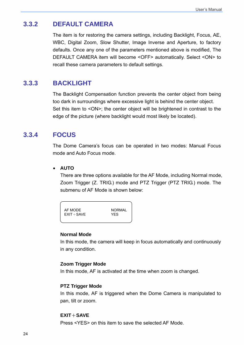
3.3.4 FOCUS The Dome Camera’s focus can be operated in two modes: Manual Focus mode and Auto Focus mode. • AUTO
There are three options available for the AF Mode, including Normal mode, Zoom Trigger (Z. TRIG.) mode and PTZ Trigger (PTZ TRIG.) mode. The submenu of AF Mode is shown below:
Normal Mode In this mode, the camera will keep in focus automatically and continuously in any condition. Zoom Trigger Mode In this mode, AF is activated at the time when zoom is changed. PTZ Trigger Mode In this mode, AF is triggered when the Dome Camera is manipulated to pan, tilt or zoom. EXIT+SAVE Press <YES> on this item to save the selected AF Mode.
AF MODE NORMAL EXIT+SAVE YES
User’s Manual
25
• MANUAL
In this mode, users can adjust focus near/far via the control keyboard’s Focus Near/Far key.
3.3.5 AE MODE Exposure is the amount of light received by the image sensor and is determined by how wide you open the lens diaphragm (iris adjustment), by how long you keep the sensor exposed (shutter speed), and by other exposure parameters. With this item, users can define how the Auto Exposure (AE) function works. • EXPOSURE COMPENSATION
The exposure value rages from -10.5dB ~ 10.5dB. Select <OFF> to disable the function.
• AE MODE AUTO
In this mode, the camera’s Brightness, Shutter Speed, IRIS and AGC (Auto Gain Control) control circuits work together automatically to get consistent video output level. SHUTTER With this option, Shutter Speed takes main control of exposure, and both IRIS and AGC will function automatically in cooperation with shutter speed to achieve consistent exposure output. The shutter speed ranges from 1/10000 ~ 1/50.
IRIS In this mode, the IRIS function adjusts exposure in higher property. SHUTTER speed and AGC circuit will function automatically in cooperating with IRIS to get consistent exposure output. The IRIS value is fixed at f1.6. Manual In the mode, users can adjust shutter speed (1/10000 ~ 1/50 for PAL; 1/10000 ~ 1/60 for NTSC) and gain value (-3dB ~ 28dB) for optimized video output.
User’s Manual
26
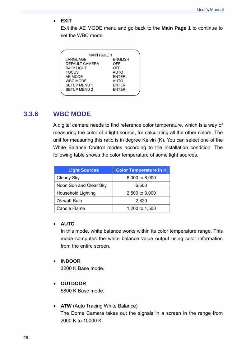
• EXIT Exit the AE MODE menu and go back to the Main Page 1 to continue to set the WBC mode.
3.3.6 WBC MODE A digital camera needs to find reference color temperature, which is a way of measuring the color of a light source, for calculating all the other colors. The unit for measuring this ratio is in degree Kelvin (K). You can select one of the White Balance Control modes according to the installation condition. The following table shows the color temperature of some light sources.
Light Sources Color Temperature in KCloudy Sky 6,000 to 8,000
Noon Sun and Clear Sky 6,500
Household Lighting 2,500 to 3,000
75-watt Bulb 2,820
Candle Flame 1,200 to 1,500
• AUTO In this mode, white balance works within its color temperature range. This mode computes the white balance value output using color information from the entire screen.
• INDOOR 3200 K Base mode.
• OUTDOOR 5800 K Base mode.
• ATW (Auto Tracing White Balance) The Dome Camera takes out the signals in a screen in the range from 2000 K to 10000 K.
MAIN PAGE 1 LANGUAGE ENGLISH DEFAULT CAMERA OFF BACKLIGHT OFF FOCUS AUTO AE MODE ENTER WBC MODE AUTO SETUP MENU 1 ENTER SETUP MENU 2 ENTER
User’s Manual
27
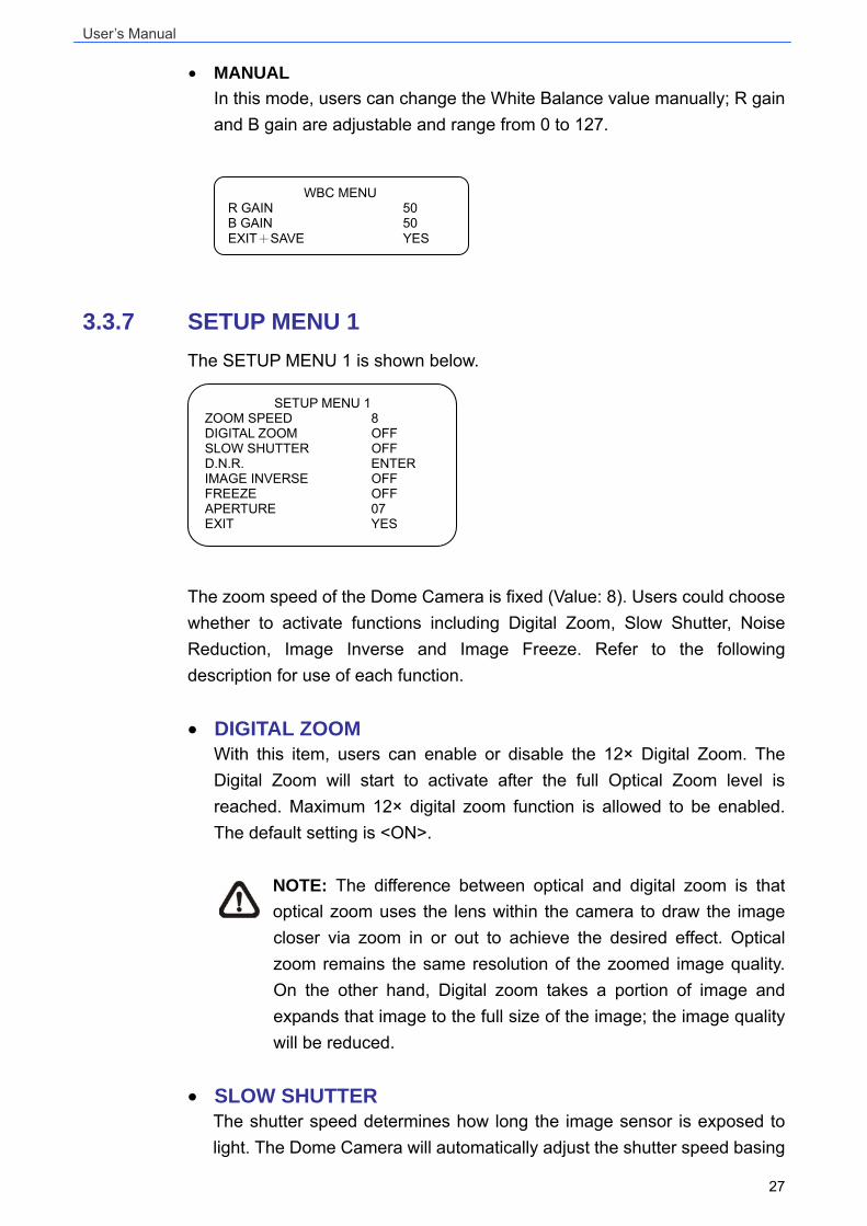
• MANUAL In this mode, users can change the White Balance value manually; R gain and B gain are adjustable and range from 0 to 127.
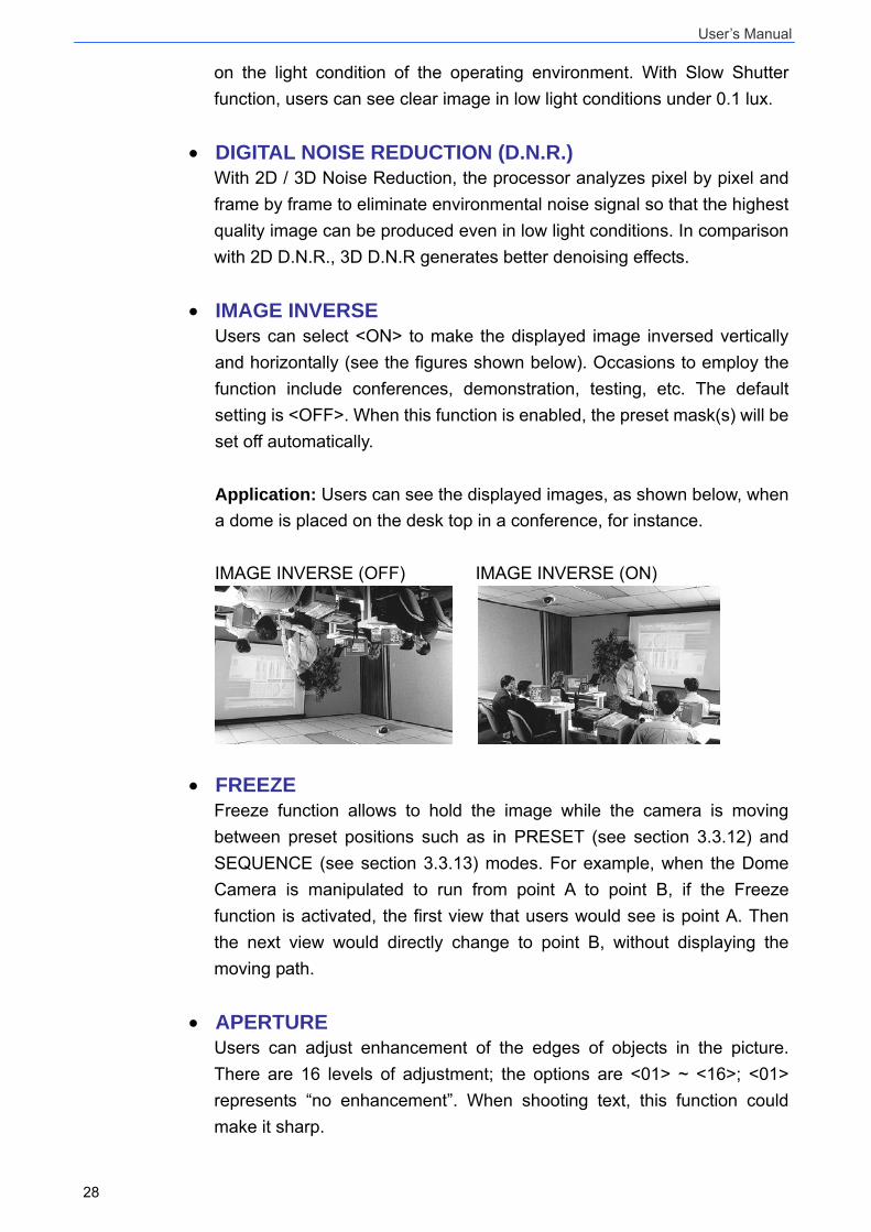
3.3.7 SETUP MENU 1 The SETUP MENU 1 is shown below.
The zoom speed of the Dome Camera is fixed (Value: 8). Users could choose whether to activate functions including Digital Zoom, Slow Shutter, Noise Reduction, Image Inverse and Image Freeze. Refer to the following description for use of each function. • DIGITAL ZOOM
With this item, users can enable or disable the 12× Digital Zoom. The Digital Zoom will start to activate after the full Optical Zoom level is reached. Maximum 12× digital zoom function is allowed to be enabled. The default setting is <ON>.
NOTE: The difference between optical and digital zoom is that optical zoom uses the lens within the camera to draw the image closer via zoom in or out to achieve the desired effect. Optical zoom remains the same resolution of the zoomed image quality. On the other hand, Digital zoom takes a portion of image and expands that image to the full size of the image; the image quality will be reduced.
• SLOW SHUTTER
The shutter speed determines how long the image sensor is exposed to light. The Dome Camera will automatically adjust the shutter speed basing
SETUP MENU 1 ZOOM SPEED 8 DIGITAL ZOOM OFF SLOW SHUTTER OFF D.N.R. ENTER IMAGE INVERSE OFF FREEZE OFF APERTURE 07 EXIT YES
WBC MENU R GAIN 50 B GAIN 50 EXIT+SAVE YES
User’s Manual
28
on the light condition of the operating environment. With Slow Shutter function, users can see clear image in low light conditions under 0.1 lux.
• DIGITAL NOISE REDUCTION (D.N.R.) With 2D / 3D Noise Reduction, the processor analyzes pixel by pixel and frame by frame to eliminate environmental noise signal so that the highest quality image can be produced even in low light conditions. In comparison with 2D D.N.R., 3D D.N.R generates better denoising effects.
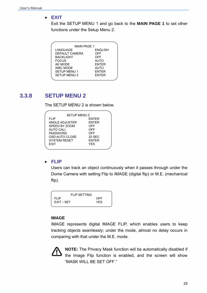
• IMAGE INVERSE Users can select <ON> to make the displayed image inversed vertically and horizontally (see the figures shown below). Occasions to employ the function include conferences, demonstration, testing, etc. The default setting is <OFF>. When this function is enabled, the preset mask(s) will be set off automatically. Application: Users can see the displayed images, as shown below, when a dome is placed on the desk top in a conference, for instance. IMAGE INVERSE (OFF) IMAGE INVERSE (ON)
• FREEZE Freeze function allows to hold the image while the camera is moving between preset positions such as in PRESET (see section 3.3.12) and SEQUENCE (see section 3.3.13) modes. For example, when the Dome Camera is manipulated to run from point A to point B, if the Freeze function is activated, the first view that users would see is point A. Then the next view would directly change to point B, without displaying the moving path.
• APERTURE Users can adjust enhancement of the edges of objects in the picture. There are 16 levels of adjustment; the options are <01> ~ <16>; <01> represents “no enhancement”. When shooting text, this function could make it sharp.
User’s Manual
29
• EXIT Exit the SETUP MENU 1 and go back to the MAIN PAGE 1 to set other functions under the Setup Menu 2.
3.3.8 SETUP MENU 2 The SETUP MENU 2 is shown below.
• FLIP
Users can track an object continuously when it passes through under the Dome Camera with setting Flip to IMAGE (digital flip) or M.E. (mechanical flip).
IMAGE IMAGE represents digital IMAGE FLIP, which enables users to keep tracking objects seamlessly; under the mode, almost no delay occurs in comparing with that under the M.E. mode.
NOTE: The Privacy Mask function will be automatically disabled if the Image Flip function is enabled, and the screen will show “MASK WILL BE SET OFF.”
FLIP SETTING FLIP OFF EXIT+SET YES
SETUP MENU 2 FLIP ENTER ANGLE ADJUSTER ENTER SPEED BY ZOOM OFF AUTO CALI. OFF PASSWORD OFF OSD AUTO CLOSE 20 SEC SYSTEM RESET ENTER EXIT YES
MAIN PAGE 1 LANGUAGE ENGLISH DEFAULT CAMERA OFF BACKLIGHT OFF FOCUS AUTO AE MODE ENTER WBC MODE AUTO SETUP MENU 1 ENTER SETUP MENU 2 ENTER
User’s Manual
30
M.E. M.E. is a standard mechanical operation. As the Dome Camera tilts to the maximum angle, it will pan 180°, and then continue tilting to keep tracking objects. OFF Select this item to disable the flip function.
NOTE: To make the Dome Camera tilt between a specific range, such as -10° to +100°, please go to ANGLE ADJUSTER (see next section) to set the angle range of tilt. Otherwise, the camera will tilt 90° as the default setting.
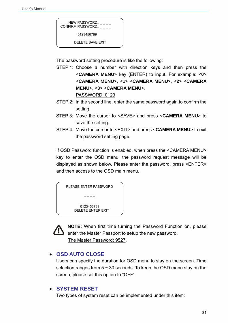
• ANGLE ADJUSTER
The item is for adjusting the camera view angle. The range of view angle is between -10° and +100°.
• SPEED BY ZOOM If the item is set to <ON>, the pan/tilt speed will be adjusted by internal algorithm when zooming automatically. The larger zoom ratio leads to the lower rotation speed.
• AUTO CALI. (Auto Calibration) There are one horizontal and one vertical infrared ray check points in each dome. When the dome camera’s position is moved during installation or maintenance, the relative distance between the original set point and the check point could be changed. Enable the Auto Calibration function, the dome will automatically detect the distance change and reset the point back to the original position.
• PASSWORD The administrator can activate OSD Password function for security concerns. Once the function is turned on, users are required to enter the password every time when accessing to the OSD menu. The Password setting menu is shown below:
ANGLE ADJUSTER ADJUST MIN ANGLE -10 DEG ADJUST MAX ANGLE 100 DEG EXIT+SET YES
User’s Manual
31
The password setting procedure is like the following: STEP 1: Choose a number with direction keys and then press the
<CAMERA MENU> key (ENTER) to input. For example: <0> <CAMERA MENU>, <1> <CAMERA MENU>, <2> <CAMERA MENU>, <3> <CAMERA MENU>.
PASSWORD: 0123 STEP 2: In the second line, enter the same password again to confirm the
setting. STEP 3: Move the cursor to <SAVE> and press <CAMERA MENU> to
save the setting. STEP 4: Move the cursor to <EXIT> and press <CAMERA MENU> to exit
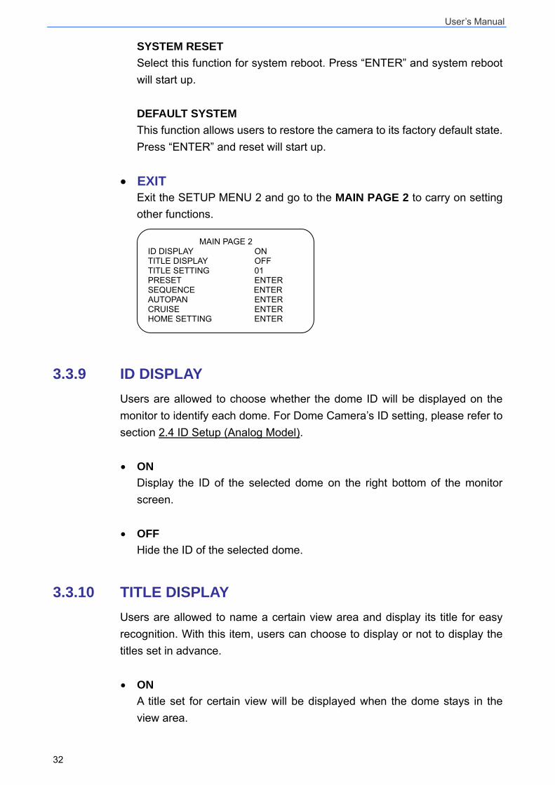
the password setting page. If OSD Password function is enabled, when press the <CAMERA MENU> key to enter the OSD menu, the password request message will be displayed as shown below. Please enter the password, press <ENTER> and then access to the OSD main menu.
NOTE: When first time turning the Password Function on, please enter the Master Passport to setup the new password.
The Master Password: 9527.
• OSD AUTO CLOSE Users can specify the duration for OSD menu to stay on the screen. Time selection ranges from 5 ~ 30 seconds. To keep the OSD menu stay on the screen, please set this option to “OFF”.
• SYSTEM RESET Two types of system reset can be implemented under this item:
PLEASE ENTER PASSWORD
_ _ _ _
0123456789 DELETE ENTER EXIT
NEW PASSWORD:: _ _ _ _ CONFIRM PASSWORD:: _ _ _ _
0123456789
DELETE SAVE EXIT
User’s Manual
32
SYSTEM RESET Select this function for system reboot. Press “ENTER” and system reboot will start up. DEFAULT SYSTEM This function allows users to restore the camera to its factory default state. Press “ENTER” and reset will start up.
• EXIT Exit the SETUP MENU 2 and go to the MAIN PAGE 2 to carry on setting other functions.
3.3.9 ID DISPLAY Users are allowed to choose whether the dome ID will be displayed on the monitor to identify each dome. For Dome Camera’s ID setting, please refer to section 2.4 ID Setup (Analog Model). • ON
Display the ID of the selected dome on the right bottom of the monitor screen.
• OFF Hide the ID of the selected dome.
3.3.10 TITLE DISPLAY Users are allowed to name a certain view area and display its title for easy recognition. With this item, users can choose to display or not to display the titles set in advance. • ON
A title set for certain view will be displayed when the dome stays in the view area.
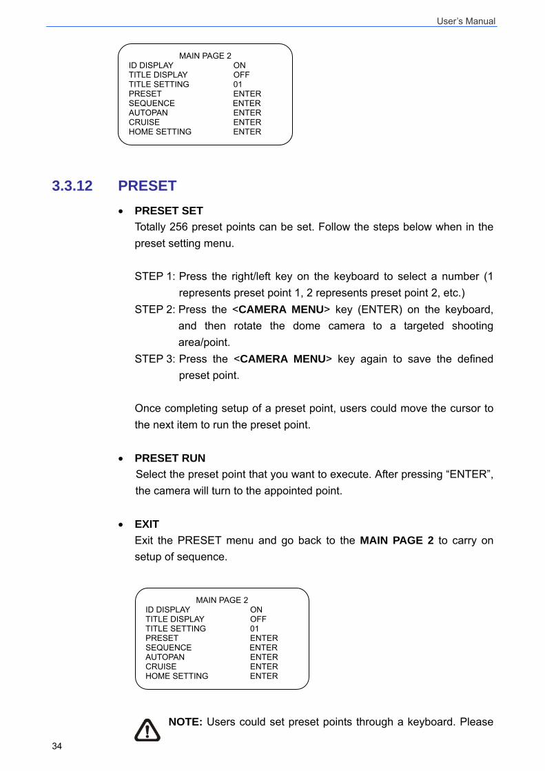
MAIN PAGE 2 ID DISPLAY ON TITLE DISPLAY OFF TITLE SETTING 01 PRESET ENTER SEQUENCE ENTER AUTOPAN ENTER CRUISE ENTER HOME SETTING ENTER
User’s Manual
33
• OFF When the TITLE DISPLAY is set <OFF>, no title will be displayed on the screen even titles are set in advance.
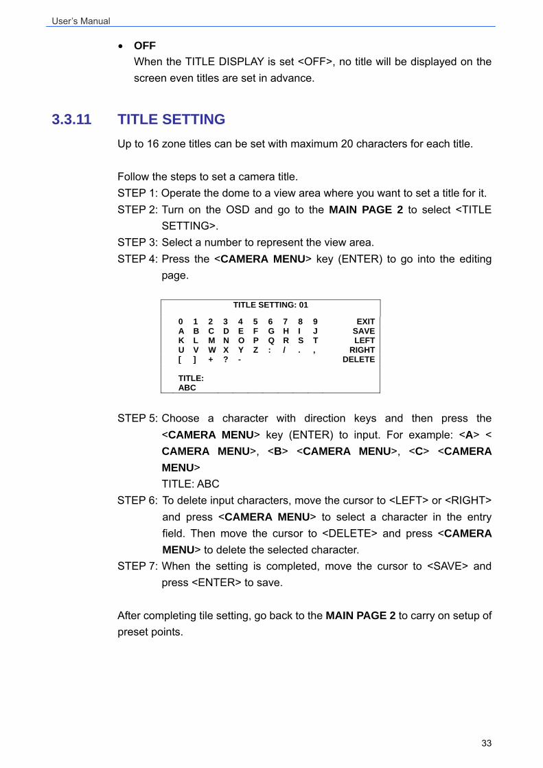
3.3.11 TITLE SETTING Up to 16 zone titles can be set with maximum 20 characters for each title. Follow the steps to set a camera title. STEP 1: Operate the dome to a view area where you want to set a title for it. STEP 2: Turn on the OSD and go to the MAIN PAGE 2 to select <TITLE SETTING>. STEP 3: Select a number to represent the view area. STEP 4: Press the <CAMERA MENU> key (ENTER) to go into the editing page.
TITLE SETTING: 01
0 1 2 3 4 5 6 7 8 9 EXITA B C D E F G H I J SAVEK L M N O P Q R S T LEFTU V W X Y Z : / . , RIGHT[ ] + ? - DELETE TITLE: ABC
STEP 5: Choose a character with direction keys and then press the <CAMERA MENU> key (ENTER) to input. For example: <A> < CAMERA MENU>, <B> <CAMERA MENU>, <C> <CAMERA MENU> TITLE: ABC STEP 6: To delete input characters, move the cursor to <LEFT> or <RIGHT> and press <CAMERA MENU> to select a character in the entry field. Then move the cursor to <DELETE> and press <CAMERA MENU> to delete the selected character. STEP 7: When the setting is completed, move the cursor to <SAVE> and press <ENTER> to save. After completing tile setting, go back to the MAIN PAGE 2 to carry on setup of preset points.
User’s Manual
34
3.3.12 PRESET • PRESET SET
Totally 256 preset points can be set. Follow the steps below when in the preset setting menu. STEP 1: Press the right/left key on the keyboard to select a number (1 represents preset point 1, 2 represents preset point 2, etc.) STEP 2: Press the <CAMERA MENU> key (ENTER) on the keyboard, and then rotate the dome camera to a targeted shooting area/point. STEP 3: Press the <CAMERA MENU> key again to save the defined preset point. Once completing setup of a preset point, users could move the cursor to the next item to run the preset point.
• PRESET RUN Select the preset point that you want to execute. After pressing “ENTER”, the camera will turn to the appointed point.
• EXIT Exit the PRESET menu and go back to the MAIN PAGE 2 to carry on setup of sequence.
NOTE: Users could set preset points through a keyboard. Please
MAIN PAGE 2 ID DISPLAY ON TITLE DISPLAY OFF TITLE SETTING 01 PRESET ENTER SEQUENCE ENTER AUTOPAN ENTER CRUISE ENTER HOME SETTING ENTER
MAIN PAGE 2 ID DISPLAY ON TITLE DISPLAY OFF TITLE SETTING 01 PRESET ENTER SEQUENCE ENTER AUTOPAN ENTER CRUISE ENTER HOME SETTING ENTER
User’s Manual
35
refer to the control keyboard’s quick guide for further information.
3.3.13 SEQUENCE The function executes pre-positioning of the pan, tilt, zoom and focus features in a certain sequence for a camera. Before setting this function, users must preset at least two preset points.
• SEQUENCE LINE There are eight sets of sequence lines built in the Dome Camera. Using LEFT/RIGHT direction keys to select a line first and then set its sequence points.
• SEQUENCE POINT Up to 64 points can be specified for each sequence line. The sequence points represent order of the preset points that the Dome Camera will automatically run. The following setup items, including PRESET POSITION, SPEED and DWELL TIME, will influence how the camera runs through each sequence point.
• PRESET POSITION Users can assign a specific preset position to the selected sequence point with this item.
• SPEED Users can set the speed of one sequence point to the next one, and the range of setup speed is from 1 to 15. Within the range, PAN and Tilt speed varies from 5 ~ 300(degree/sec.)
• DWELL TIME The DWELL TIME is the duration time that the Dome Camera will stay at a sequence point, and the range is from <0> to <127> seconds. The Dome Camera will go to the next sequence point when the DEWEL TIME expires. If the setting is <0>, the Dome Camera will stay at this sequence point until users manually move the camera.
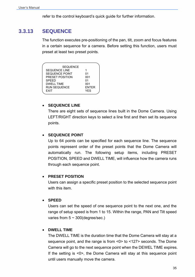
SEQUENCE SEQUENCE LINE 1 SEQUENCE POINT 01 PRESET POSITION 001 SPEED 01 DWELL TIME 001 RUN SEQUENCE ENTER EXIT YES
User’s Manual
36
• RUN SEQUENCE Users can command the Dome Camera to run the selected sequence line manually.
• EXIT Select the item to exit the SEQUENCE menu; go back to the MAIN PAGE 2 to carry on setup of auto-pan.
NOTE: Users could execute the sequence function through a keyboard. Please refer to the control keyboard’s quick guide for further information.
3.3.14 AUTOPAN Auto-pan means motion of scanning an area horizontally so that the Dome Camera can catch horizontal view. The parameters are listed as follows.
• AUTOPAN LINE There are four sets of auto-pan line built in a Dome Camera. Users can choose a line to execute using LEFT/RIGHT direction keys. In addition, users are able to command the Dome Camera to do endless panning by setting the start point the same as the end point.
• START POINT Follow the description below to set the start position of the AUTOPAN path. 1. Move the cursor to <START POINT> and press <ENTER> while the
item, <TO FIND>, is flashing. Then the item will turn <TO SAVE> automatically.
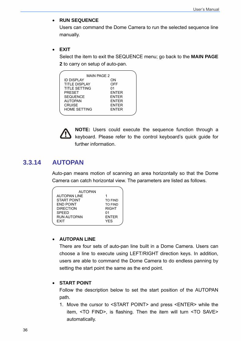
AUTOPAN AUTOPAN LINE 1 START POINT TO FINDEND POINT TO FINDDIRECTION RIGHT SPEED 01 RUN AUTOPAN ENTER EXIT YES
MAIN PAGE 2 ID DISPLAY ON TITLE DISPLAY OFF TITLE SETTING 01 PRESET ENTER SEQUENCE ENTER AUTOPAN ENTER CRUISE ENTER HOME SETTING ENTER
User’s Manual
37
2. Move the Dome Camera to a desired position and press <ENTER> to save the position as the start point; the cursor will move to <END POINT> automatically. Ensure setting the end point to complete auto-pan setting.
NOTE: The tilt and zoom values of the start point will be recorded and fixed for the selected auto-pan line.
• END POINT
Users are able to set the end point after the start point is defined. Pan the Dome Camera to another position and press <ENTER> to save the position as the end point.
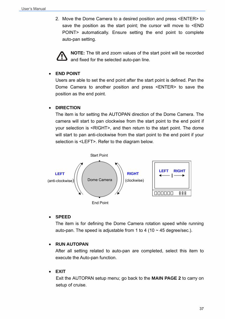
• DIRECTION The item is for setting the AUTOPAN direction of the Dome Camera. The camera will start to pan clockwise from the start point to the end point if your selection is <RIGHT>, and then return to the start point. The dome will start to pan anti-clockwise from the start point to the end point if your selection is <LEFT>. Refer to the diagram below.
• SPEED
The item is for defining the Dome Camera rotation speed while running auto-pan. The speed is adjustable from 1 to 4 (10 ~ 45 degree/sec.).
• RUN AUTOPAN After all setting related to auto-pan are completed, select this item to execute the Auto-pan function.
• EXIT Exit the AUTOPAN setup menu; go back to the MAIN PAGE 2 to carry on setup of cruise.
LEFT
(anti-clockwise) RIGHT
(clockwise)
End Point
Dome Camera
RIGHT LEFT
Start Point
User’s Manual
38
NOTE: Users could execute the auto-pan function through a keyboard. Please refer to the control keyboard’s quick guide for further information.
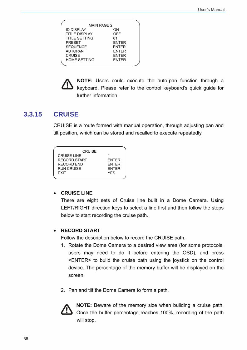
3.3.15 CRUISE CRUISE is a route formed with manual operation, through adjusting pan and tilt position, which can be stored and recalled to execute repeatedly.
• CRUISE LINE There are eight sets of Cruise line built in a Dome Camera. Using LEFT/RIGHT direction keys to select a line first and then follow the steps below to start recording the cruise path.
• RECORD START Follow the description below to record the CRUISE path. 1. Rotate the Dome Camera to a desired view area (for some protocols,
users may need to do it before entering the OSD), and press <ENTER> to build the cruise path using the joystick on the control device. The percentage of the memory buffer will be displayed on the screen.
2. Pan and tilt the Dome Camera to form a path.
NOTE: Beware of the memory size when building a cruise path. Once the buffer percentage reaches 100%, recording of the path will stop.
CRUISE CRUISE LINE 1 RECORD START ENTER RECORD END ENTER RUN CRUISE ENTER EXIT YES
MAIN PAGE 2 ID DISPLAY ON TITLE DISPLAY OFF TITLE SETTING 01 PRESET ENTER SEQUENCE ENTER AUTOPAN ENTER CRUISE ENTER HOME SETTING ENTER
User’s Manual
39
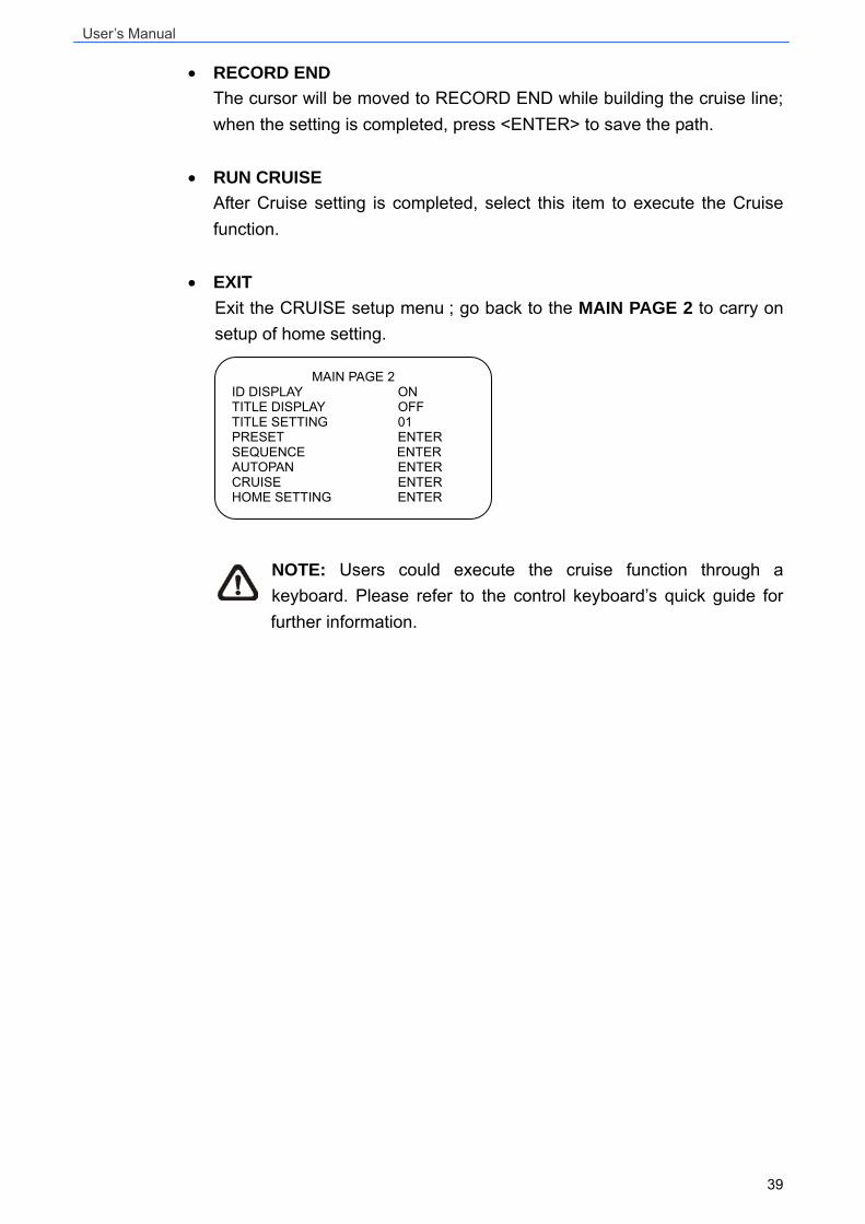
• RECORD END The cursor will be moved to RECORD END while building the cruise line; when the setting is completed, press <ENTER> to save the path.
• RUN CRUISE After Cruise setting is completed, select this item to execute the Cruise function.
• EXIT Exit the CRUISE setup menu ; go back to the MAIN PAGE 2 to carry on setup of home setting.
NOTE: Users could execute the cruise function through a keyboard. Please refer to the control keyboard’s quick guide for further information.
MAIN PAGE 2 ID DISPLAY ON TITLE DISPLAY OFF TITLE SETTING 01 PRESET ENTER SEQUENCE ENTER AUTOPAN ENTER CRUISE ENTER HOME SETTING ENTER
User’s Manual
40
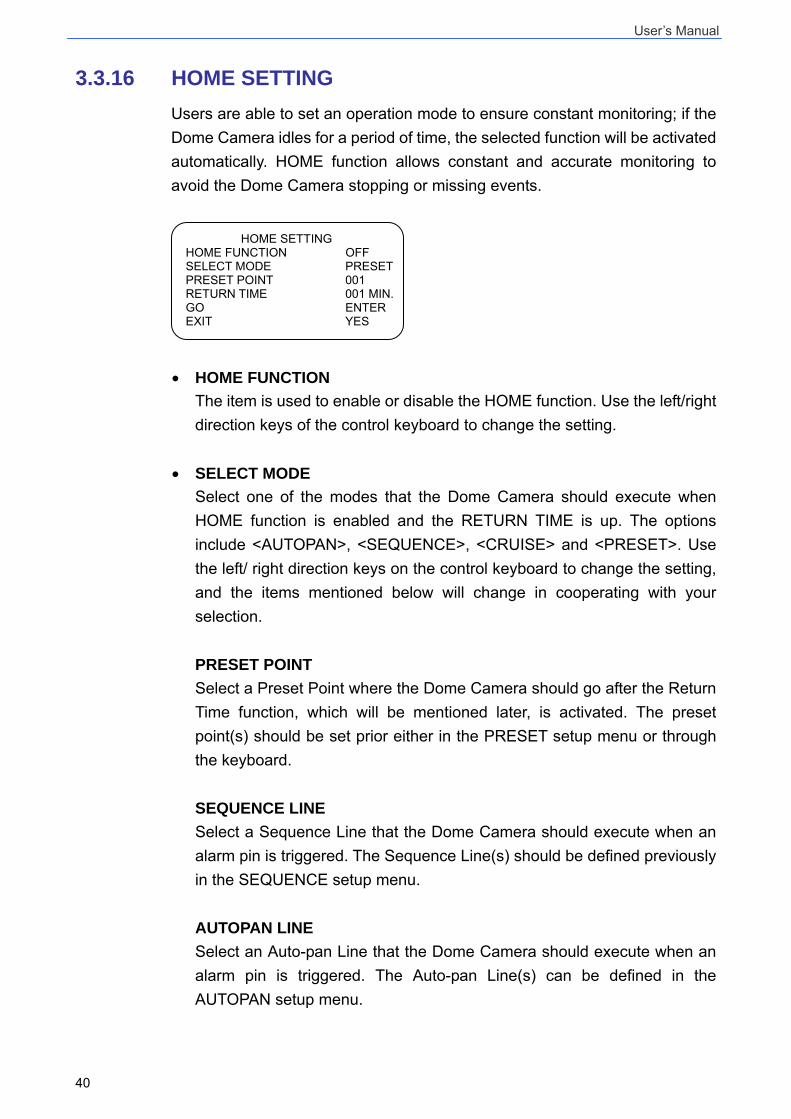
3.3.16 HOME SETTING Users are able to set an operation mode to ensure constant monitoring; if the Dome Camera idles for a period of time, the selected function will be activated automatically. HOME function allows constant and accurate monitoring to avoid the Dome Camera stopping or missing events.
• HOME FUNCTION The item is used to enable or disable the HOME function. Use the left/right direction keys of the control keyboard to change the setting.
• SELECT MODE Select one of the modes that the Dome Camera should execute when HOME function is enabled and the RETURN TIME is up. The options include <AUTOPAN>, <SEQUENCE>, <CRUISE> and <PRESET>. Use the left/ right direction keys on the control keyboard to change the setting, and the items mentioned below will change in cooperating with your selection. PRESET POINT Select a Preset Point where the Dome Camera should go after the Return Time function, which will be mentioned later, is activated. The preset point(s) should be set prior either in the PRESET setup menu or through the keyboard. SEQUENCE LINE Select a Sequence Line that the Dome Camera should execute when an alarm pin is triggered. The Sequence Line(s) should be defined previously in the SEQUENCE setup menu. AUTOPAN LINE Select an Auto-pan Line that the Dome Camera should execute when an alarm pin is triggered. The Auto-pan Line(s) can be defined in the AUTOPAN setup menu.
HOME SETTING HOME FUNCTION OFF SELECT MODE PRESETPRESET POINT 001 RETURN TIME 001 MIN.GO ENTER EXIT YES
User’s Manual
41
CRUISE LINE Select a Cruise Line that the dome camera should execute when an alarm pin is triggered. The Cruise Line(s) can be defined in the CRUISE setup menu.
• RETURN TIME The Dome Camera starts to count down RETURN TIME when the camera idles, and it will execute the SELECT MODE function if the return time is up. The RETURN TIME ranges from 1 to 128 minutes.
• GO If HOME function is enabled, the users are allowed to execute HOME function manually by selecting this item.
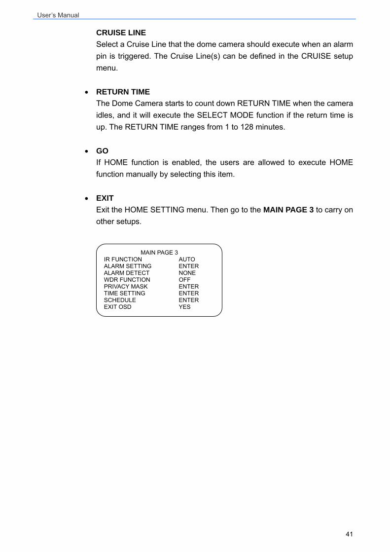
• EXIT Exit the HOME SETTING menu. Then go to the MAIN PAGE 3 to carry on other setups.
MAIN PAGE 3 IR FUNCTION AUTO ALARM SETTING ENTER ALARM DETECT NONE WDR FUNCTION OFF PRIVACY MASK ENTER TIME SETTING ENTER SCHEDULE ENTER EXIT OSD YES
User’s Manual
42
3.3.17 IR FUNCTION With the IR cut filter, the Dome Camera can still catch clear image at night time or in the very dark light condition. During day time, the IR cut filter will be on to block the infrared light for clear image; during night time or in dark light condition, the IR cut filter will be removed to catch infrared light, and the displayed images will become black and white. • AUTO
The Internal circuit will automatically decide the occasion to remove the IR cut filter according to the value of light condition calculated by the internal light algorithm. The options include <LOW>, <MID> and <HI>. <LOW> indicates a higher sensitivity and can improve reliability of lens so that it is easier to switch to Day mode and relatively difficult to change into Night mode; while <HI> indicates that it is easier to switch to Night mode and difficult to change into Day mode.
• MANUAL
IR MANUAL ON Select the item to remove the IR cut filter; the camera will be in B/W (Night) mode.
IR MANUAL OFF Select the item to attach the IR cut filter; the camera will be in Color (Day) mode to disable the IR function.
User’s Manual
43
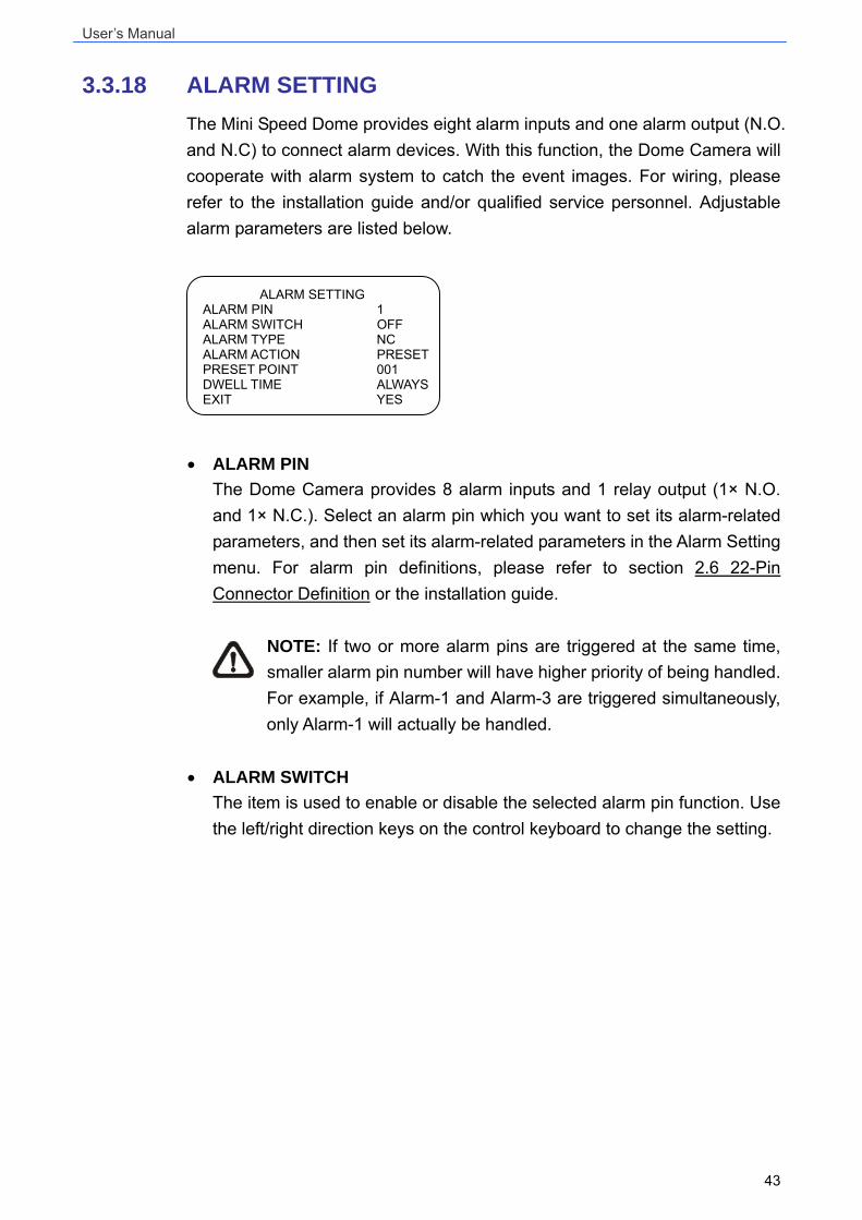
3.3.18 ALARM SETTING The Mini Speed Dome provides eight alarm inputs and one alarm output (N.O. and N.C) to connect alarm devices. With this function, the Dome Camera will cooperate with alarm system to catch the event images. For wiring, please refer to the installation guide and/or qualified service personnel. Adjustable alarm parameters are listed below.
• ALARM PIN The Dome Camera provides 8 alarm inputs and 1 relay output (1× N.O. and 1× N.C.). Select an alarm pin which you want to set its alarm-related parameters, and then set its alarm-related parameters in the Alarm Setting menu. For alarm pin definitions, please refer to section 2.6 22-Pin Connector Definition or the installation guide.
NOTE: If two or more alarm pins are triggered at the same time, smaller alarm pin number will have higher priority of being handled. For example, if Alarm-1 and Alarm-3 are triggered simultaneously, only Alarm-1 will actually be handled.
• ALARM SWITCH
The item is used to enable or disable the selected alarm pin function. Use the left/right direction keys on the control keyboard to change the setting.
ALARM SETTING ALARM PIN 1 ALARM SWITCH OFF ALARM TYPE NC ALARM ACTION PRESETPRESET POINT 001 DWELL TIME ALWAYSEXIT YES
User’s Manual
44
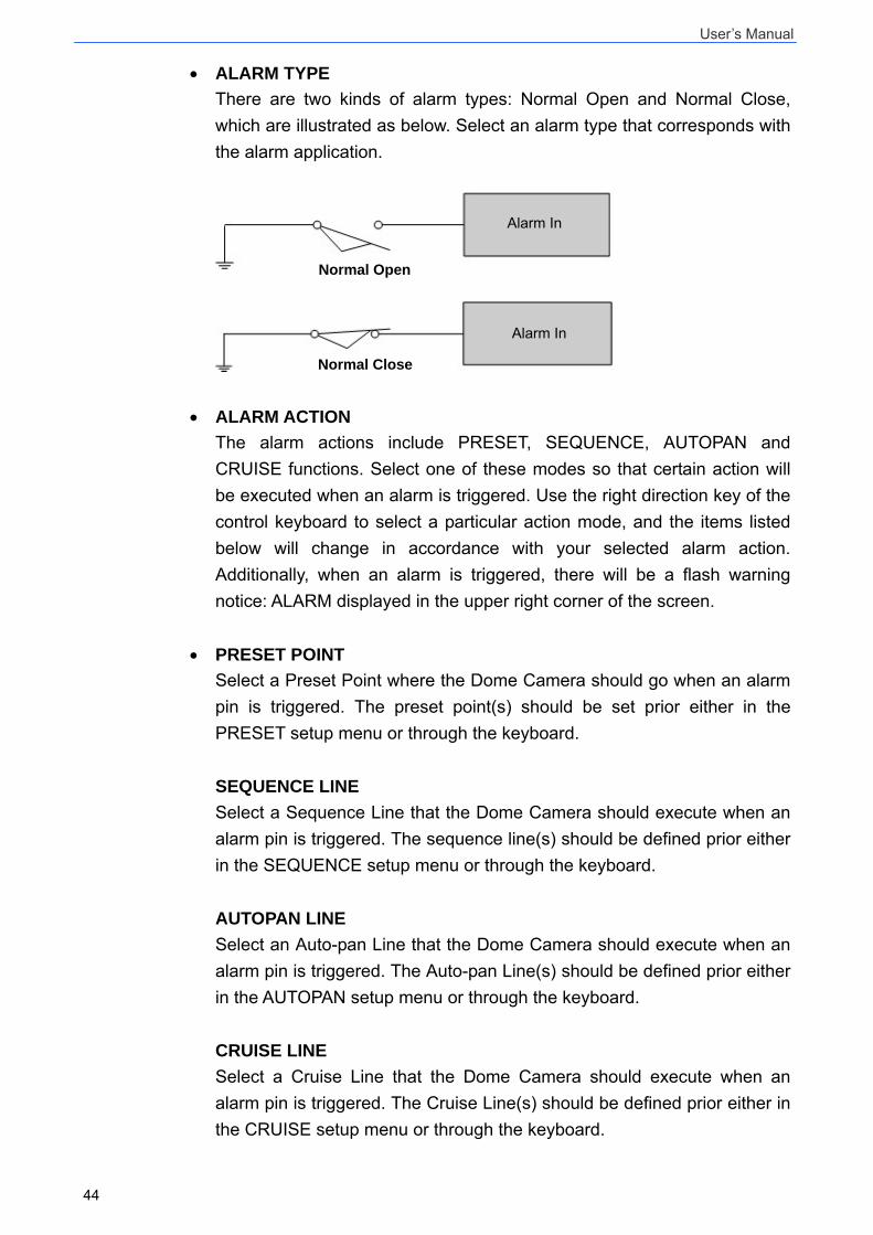
• ALARM TYPE There are two kinds of alarm types: Normal Open and Normal Close, which are illustrated as below. Select an alarm type that corresponds with the alarm application.
• ALARM ACTION The alarm actions include PRESET, SEQUENCE, AUTOPAN and CRUISE functions. Select one of these modes so that certain action will be executed when an alarm is triggered. Use the right direction key of the control keyboard to select a particular action mode, and the items listed below will change in accordance with your selected alarm action. Additionally, when an alarm is triggered, there will be a flash warning notice: ALARM displayed in the upper right corner of the screen.
• PRESET POINT Select a Preset Point where the Dome Camera should go when an alarm pin is triggered. The preset point(s) should be set prior either in the PRESET setup menu or through the keyboard. SEQUENCE LINE Select a Sequence Line that the Dome Camera should execute when an alarm pin is triggered. The sequence line(s) should be defined prior either in the SEQUENCE setup menu or through the keyboard. AUTOPAN LINE Select an Auto-pan Line that the Dome Camera should execute when an alarm pin is triggered. The Auto-pan Line(s) should be defined prior either in the AUTOPAN setup menu or through the keyboard. CRUISE LINE Select a Cruise Line that the Dome Camera should execute when an alarm pin is triggered. The Cruise Line(s) should be defined prior either in the CRUISE setup menu or through the keyboard.
Normal Open
Alarm In
Normal Close
Alarm In
User’s Manual
45
• DWELL TIME The DWELL TIME is duration of executing an alarm action. If select the PRESET mode is selected, when alarm takes place, the Dome Camera will go to the selected preset position and stay there for a user-defined period of time (1~127seconds/Always) when alarm takes place. If select other modes (SEQUENCE/AUTOPAN/CRUISE) have been selected, the camera will keep executing the selected mode (DWELL TIME: ALWAYS) until alarm condition is released or users rotate the joystick to change the status of the Dome Camera.
NOTE: The dwell time is only adjustable when selecting Preset as the alarm action. When the dwell time is up, the Dome Camera will go back to its trigger position and recheck alarm pin status.
• EXIT
Exit the ALARM SETTING menu and go back to the MAIN PAGE 3 to carry on Privacy Mask setup.
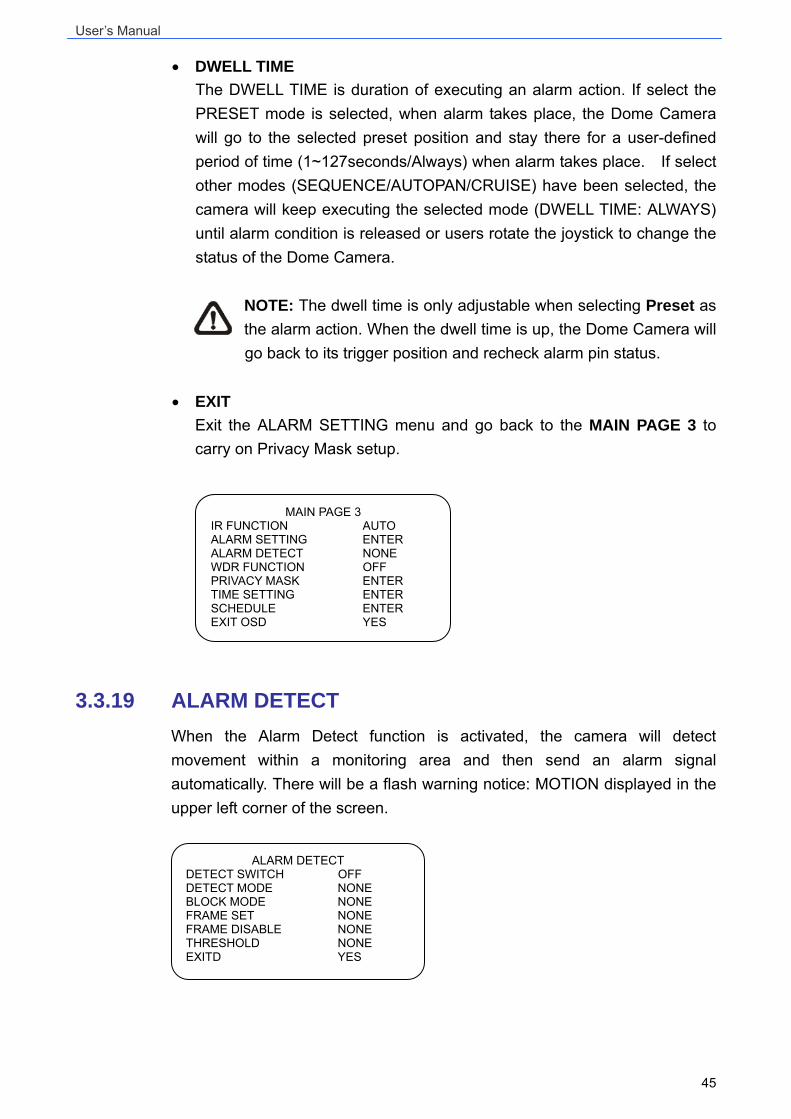
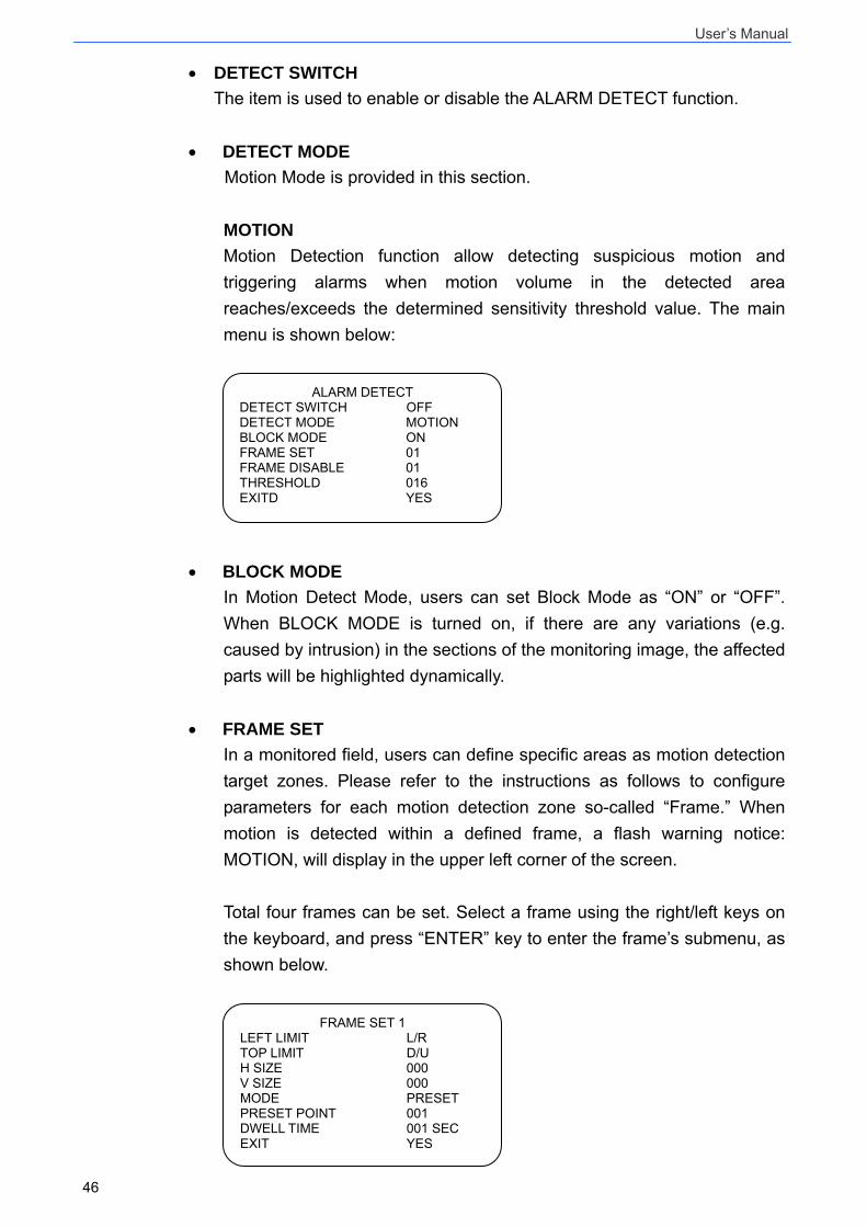
3.3.19 ALARM DETECT When the Alarm Detect function is activated, the camera will detect movement within a monitoring area and then send an alarm signal automatically. There will be a flash warning notice: MOTION displayed in the upper left corner of the screen.
MAIN PAGE 3 IR FUNCTION AUTO ALARM SETTING ENTER ALARM DETECT NONE WDR FUNCTION OFF PRIVACY MASK ENTER TIME SETTING ENTER SCHEDULE ENTER EXIT OSD YES
ALARM DETECT DETECT SWITCH OFF DETECT MODE NONE BLOCK MODE NONE FRAME SET NONE FRAME DISABLE NONE THRESHOLD NONE EXITD YES
User’s Manual
46
• DETECT SWITCH The item is used to enable or disable the ALARM DETECT function.
• DETECT MODE Motion Mode is provided in this section. MOTION Motion Detection function allow detecting suspicious motion and triggering alarms when motion volume in the detected area reaches/exceeds the determined sensitivity threshold value. The main menu is shown below:
• BLOCK MODE In Motion Detect Mode, users can set Block Mode as “ON” or “OFF”. When BLOCK MODE is turned on, if there are any variations (e.g. caused by intrusion) in the sections of the monitoring image, the affected parts will be highlighted dynamically.
• FRAME SET In a monitored field, users can define specific areas as motion detection target zones. Please refer to the instructions as follows to configure parameters for each motion detection zone so-called “Frame.” When motion is detected within a defined frame, a flash warning notice: MOTION, will display in the upper left corner of the screen. Total four frames can be set. Select a frame using the right/left keys on the keyboard, and press “ENTER” key to enter the frame’s submenu, as shown below.
FRAME SET 1 LEFT LIMIT L/R TOP LIMIT D/U H SIZE 000 V SIZE 000 MODE PRESET PRESET POINT 001 DWELL TIME 001 SEC EXIT YES
ALARM DETECT DETECT SWITCH OFF DETECT MODE MOTION BLOCK MODE ON FRAME SET 01 FRAME DISABLE 01 THRESHOLD 016 EXITD YES
User’s Manual
47
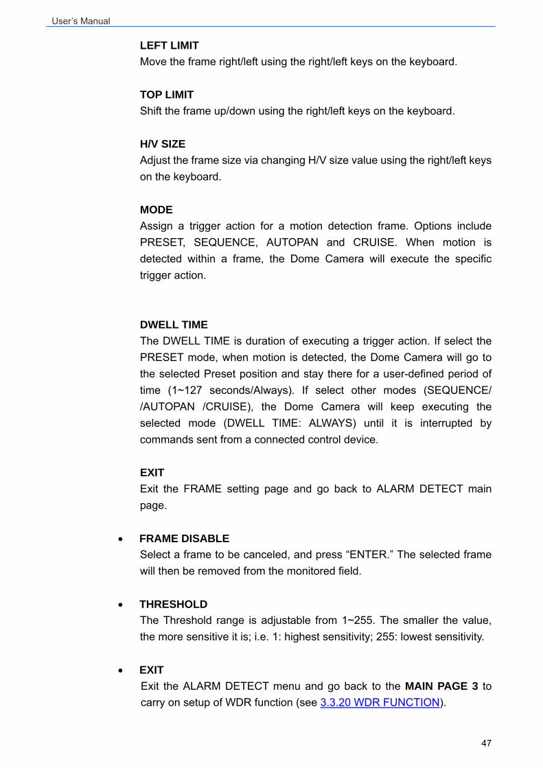
LEFT LIMIT Move the frame right/left using the right/left keys on the keyboard. TOP LIMIT Shift the frame up/down using the right/left keys on the keyboard. H/V SIZE Adjust the frame size via changing H/V size value using the right/left keys on the keyboard. MODE Assign a trigger action for a motion detection frame. Options include PRESET, SEQUENCE, AUTOPAN and CRUISE. When motion is detected within a frame, the Dome Camera will execute the specific trigger action. DWELL TIME The DWELL TIME is duration of executing a trigger action. If select the PRESET mode, when motion is detected, the Dome Camera will go to the selected Preset position and stay there for a user-defined period of time (1~127 seconds/Always). If select other modes (SEQUENCE/ /AUTOPAN /CRUISE), the Dome Camera will keep executing the selected mode (DWELL TIME: ALWAYS) until it is interrupted by commands sent from a connected control device. EXIT Exit the FRAME setting page and go back to ALARM DETECT main page.
• FRAME DISABLE Select a frame to be canceled, and press “ENTER.” The selected frame will then be removed from the monitored field.
• THRESHOLD
The Threshold range is adjustable from 1~255. The smaller the value, the more sensitive it is; i.e. 1: highest sensitivity; 255: lowest sensitivity.
• EXIT Exit the ALARM DETECT menu and go back to the MAIN PAGE 3 to carry on setup of WDR function (see 3.3.20 WDR FUNCTION).
User’s Manual
48
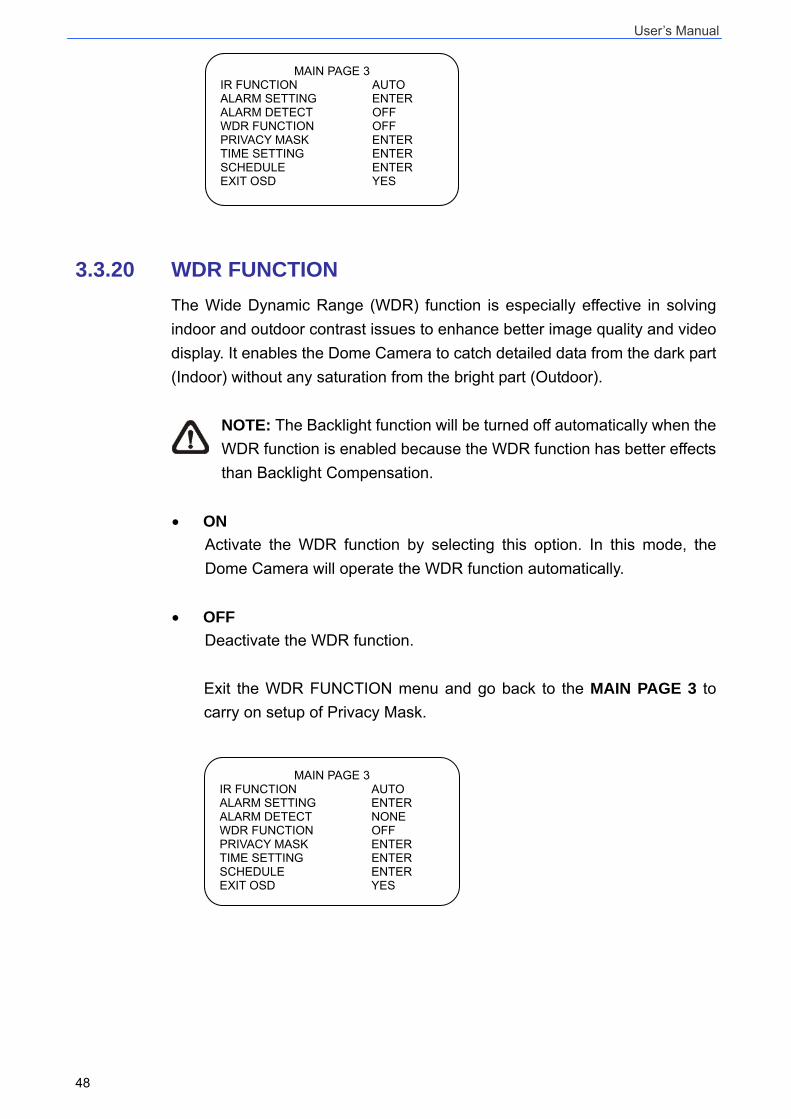
3.3.20 WDR FUNCTION The Wide Dynamic Range (WDR) function is especially effective in solving indoor and outdoor contrast issues to enhance better image quality and video display. It enables the Dome Camera to catch detailed data from the dark part (Indoor) without any saturation from the bright part (Outdoor).
NOTE: The Backlight function will be turned off automatically when the WDR function is enabled because the WDR function has better effects than Backlight Compensation.
• ON Activate the WDR function by selecting this option. In this mode, the Dome Camera will operate the WDR function automatically.
• OFF Deactivate the WDR function. Exit the WDR FUNCTION menu and go back to the MAIN PAGE 3 to carry on setup of Privacy Mask.
MAIN PAGE 3 IR FUNCTION AUTO ALARM SETTING ENTER ALARM DETECT NONE WDR FUNCTION OFF PRIVACY MASK ENTER TIME SETTING ENTER SCHEDULE ENTER EXIT OSD YES
MAIN PAGE 3 IR FUNCTION AUTO ALARM SETTING ENTER ALARM DETECT OFF WDR FUNCTION OFF PRIVACY MASK ENTER TIME SETTING ENTER SCHEDULE ENTER EXIT OSD YES
User’s Manual
49
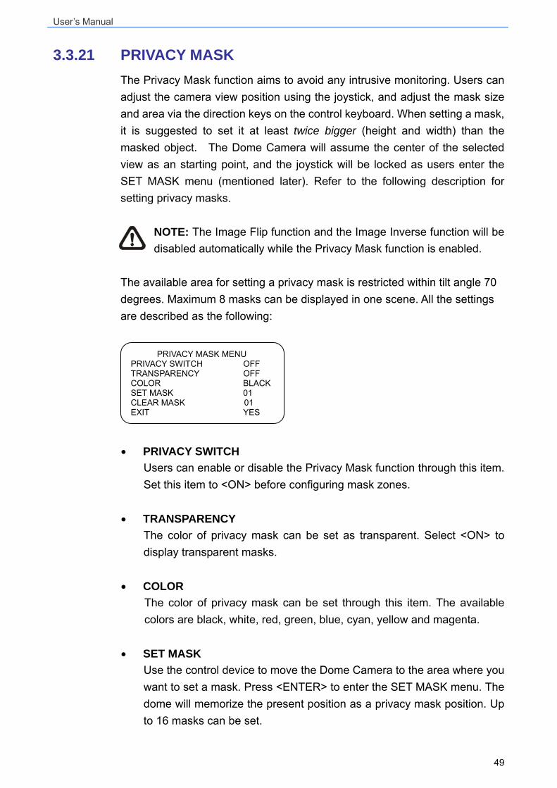
3.3.21 PRIVACY MASK The Privacy Mask function aims to avoid any intrusive monitoring. Users can adjust the camera view position using the joystick, and adjust the mask size and area via the direction keys on the control keyboard. When setting a mask, it is suggested to set it at least twice bigger (height and width) than the masked object. The Dome Camera will assume the center of the selected view as an starting point, and the joystick will be locked as users enter the SET MASK menu (mentioned later). Refer to the following description for setting privacy masks.
NOTE: The Image Flip function and the Image Inverse function will be disabled automatically while the Privacy Mask function is enabled.
The available area for setting a privacy mask is restricted within tilt angle 70 degrees. Maximum 8 masks can be displayed in one scene. All the settings are described as the following:
• PRIVACY SWITCH Users can enable or disable the Privacy Mask function through this item. Set this item to <ON> before configuring mask zones.
• TRANSPARENCY The color of privacy mask can be set as transparent. Select <ON> to display transparent masks.
• COLOR The color of privacy mask can be set through this item. The available colors are black, white, red, green, blue, cyan, yellow and magenta.
• SET MASK Use the control device to move the Dome Camera to the area where you want to set a mask. Press <ENTER> to enter the SET MASK menu. The dome will memorize the present position as a privacy mask position. Up to 16 masks can be set.
PRIVACY MASK MENU PRIVACY SWITCH OFF TRANSPARENCY OFF COLOR BLACK SET MASK 01 CLEAR MASK 01 EXIT YES
User’s Manual
50
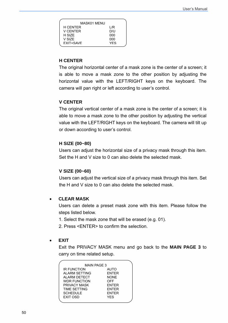
H CENTER The original horizontal center of a mask zone is the center of a screen; it is able to move a mask zone to the other position by adjusting the horizontal value with the LEFT/RIGHT keys on the keyboard. The camera will pan right or left according to user’s control. V CENTER The original vertical center of a mask zone is the center of a screen; it is able to move a mask zone to the other position by adjusting the vertical value with the LEFT/RIGHT keys on the keyboard. The camera will tilt up or down according to user’s control. H SIZE (00~80) Users can adjust the horizontal size of a privacy mask through this item. Set the H and V size to 0 can also delete the selected mask. V SIZE (00~60) Users can adjust the vertical size of a privacy mask through this item. Set the H and V size to 0 can also delete the selected mask.
• CLEAR MASK Users can delete a preset mask zone with this item. Please follow the steps listed below. 1. Select the mask zone that will be erased (e.g. 01). 2. Press <ENTER> to confirm the selection.
• EXIT Exit the PRIVACY MASK menu and go back to the MAIN PAGE 3 to carry on time related setup.
MAIN PAGE 3 IR FUNCTION AUTO ALARM SETTING ENTER ALARM DETECT NONE WDR FUNCTION OFF PRIVACY MASK ENTER TIME SETTING ENTER SCHEDULE ENTER EXIT OSD YES
MASK01 MENU H CENTER L/R V CENTER D/U H SIZE 000 V SIZE 000 EXIT+SAVE YES
User’s Manual
51
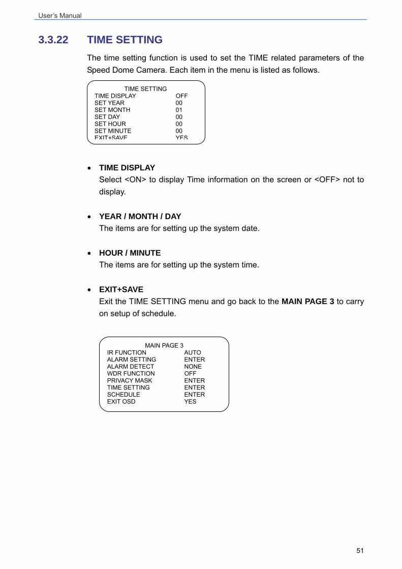
3.3.22 TIME SETTING The time setting function is used to set the TIME related parameters of the Speed Dome Camera. Each item in the menu is listed as follows.
• TIME DISPLAY
Select <ON> to display Time information on the screen or <OFF> not to display.
• YEAR / MONTH / DAY
The items are for setting up the system date.
• HOUR / MINUTE The items are for setting up the system time.
• EXIT+SAVE Exit the TIME SETTING menu and go back to the MAIN PAGE 3 to carry on setup of schedule.
MAIN PAGE 3 IR FUNCTION AUTO ALARM SETTING ENTER ALARM DETECT NONE WDR FUNCTION OFF PRIVACY MASK ENTER TIME SETTING ENTER SCHEDULE ENTER EXIT OSD YES
TIME SETTING TIME DISPLAY OFF SET YEAR 00 SET MONTH 01 SET DAY 00 SET HOUR 00 SET MINUTE 00 EXIT+SAVE YES
User’s Manual
52
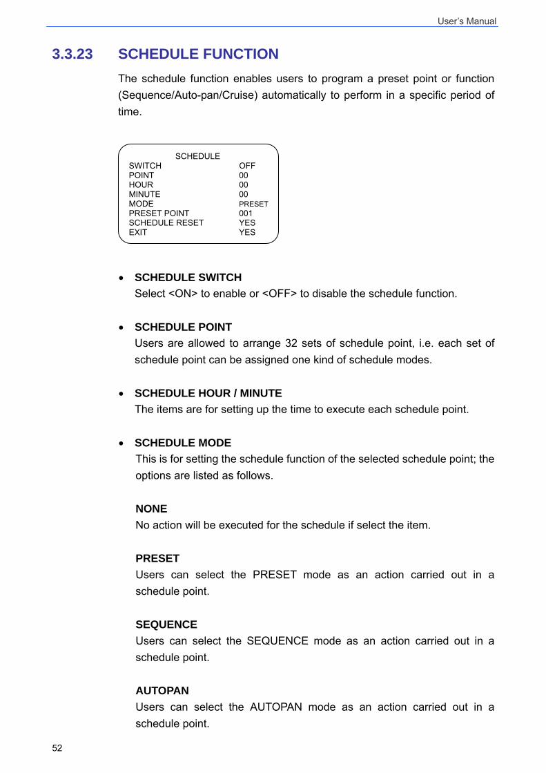
3.3.23 SCHEDULE FUNCTION The schedule function enables users to program a preset point or function (Sequence/Auto-pan/Cruise) automatically to perform in a specific period of time.
• SCHEDULE SWITCH Select <ON> to enable or <OFF> to disable the schedule function.
• SCHEDULE POINT Users are allowed to arrange 32 sets of schedule point, i.e. each set of schedule point can be assigned one kind of schedule modes.
• SCHEDULE HOUR / MINUTE The items are for setting up the time to execute each schedule point.
• SCHEDULE MODE This is for setting the schedule function of the selected schedule point; the options are listed as follows. NONE No action will be executed for the schedule if select the item. PRESET Users can select the PRESET mode as an action carried out in a schedule point. SEQUENCE Users can select the SEQUENCE mode as an action carried out in a schedule point. AUTOPAN Users can select the AUTOPAN mode as an action carried out in a schedule point.
SCHEDULE SWITCH OFF POINT 00 HOUR 00 MINUTE 00 MODE PRESETPRESET POINT 001 SCHEDULE RESET YES EXIT YES
User’s Manual
53
CRUISE Users can select the CRUISE mode as an action carried out in a schedule point. IR FUNC. (IR Function) If the IR function mode is selected, the AUTO IR FUNCTION will be activated for a schedule point.
• SCHEDULE RESET Users can reset the whole schedule with the item.
• SCHEDULE EXIT Exit the SCHEDULE menu and go back to the MAIN PAGE 3.
3.3.24 EXIT OSD To exit the OSD setup menu, users can either select this item on the bottom of MAIN PAGE 3 or press the ESC key on the control keyboard.
User’s Manual
54
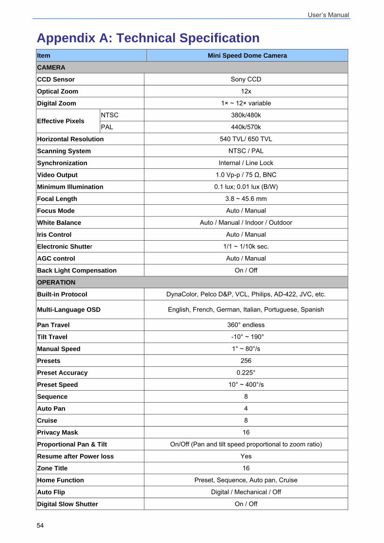
Appendix A: Technical Specification Item Mini Speed Dome Camera
CAMERA
CCD Sensor Sony CCD
Optical Zoom 12x
Digital Zoom 1× ~ 12× variable
NTSC 380k/480k Effective Pixels
PAL 440k/570k
Horizontal Resolution 540 TVL/ 650 TVL
Scanning System NTSC / PAL
Synchronization Internal / Line Lock
Video Output 1.0 Vp-p / 75 Ω, BNC
Minimum Illumination 0.1 lux; 0.01 lux (B/W)
Focal Length 3.8 ~ 45.6 mm
Focus Mode Auto / Manual
White Balance Auto / Manual / Indoor / Outdoor
Iris Control Auto / Manual
Electronic Shutter 1/1 ~ 1/10k sec.
AGC control Auto / Manual
Back Light Compensation On / Off
OPERATION
Built-in Protocol DynaColor, Pelco D&P, VCL, Philips, AD-422, JVC, etc.
Multi-Language OSD English, French, German, Italian, Portuguese, Spanish
Pan Travel 360° endless
Tilt Travel -10° ~ 190°
Manual Speed 1° ~ 80°/s
Presets 256
Preset Accuracy 0.225°
Preset Speed 10° ~ 400°/s
Sequence 8
Auto Pan 4
Cruise 8
Privacy Mask 16
Proportional Pan & Tilt On/Off (Pan and tilt speed proportional to zoom ratio)
Resume after Power loss Yes
Zone Title 16
Home Function Preset, Sequence, Auto pan, Cruise
Auto Flip Digital / Mechanical / Off
Digital Slow Shutter On / Off
User’s Manual
55
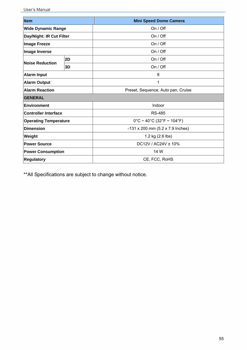
Item Mini Speed Dome Camera
Wide Dynamic Range On / Off
Day/Night: IR Cut Filter On / Off
Image Freeze On / Off
Image Inverse On / Off
2D On / Off Noise Reduction
3D On / Off
Alarm Input 8
Alarm Output 1
Alarm Reaction Preset, Sequence, Auto pan, Cruise
GENERAL
Environment Indoor
Controller Interface RS-485
Operating Temperature 0°C ~ 40°C (32°F ~ 104°F)
Dimension ∅131 x 200 mm (5.2 x 7.9 Inches)
Weight 1.2 kg (2.6 lbs)
Power Source DC12V / AC24V ± 10%
Power Consumption 14 W
Regulatory CE, FCC, RoHS
**All Specifications are subject to change without notice.
User’s Manual
56
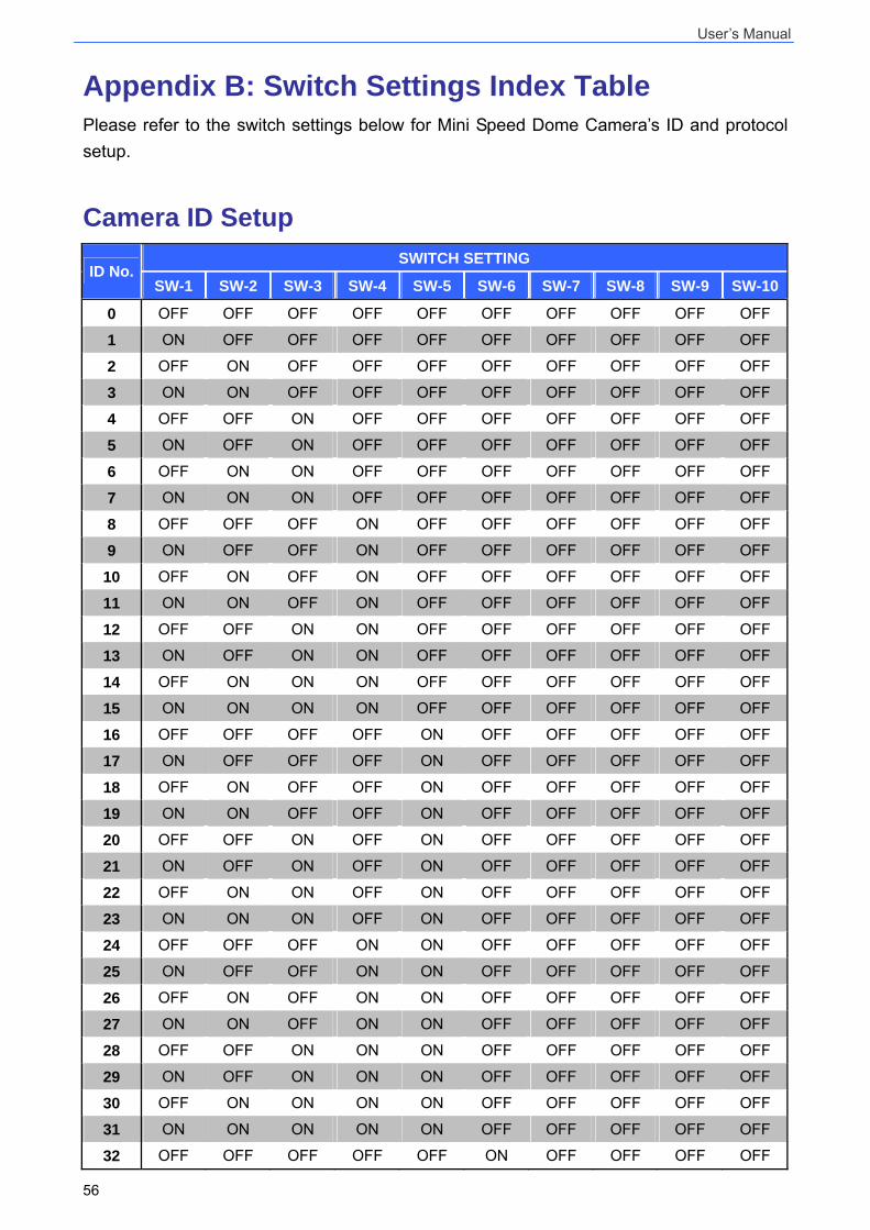
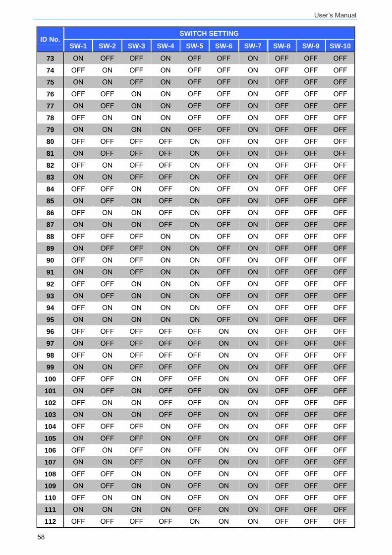
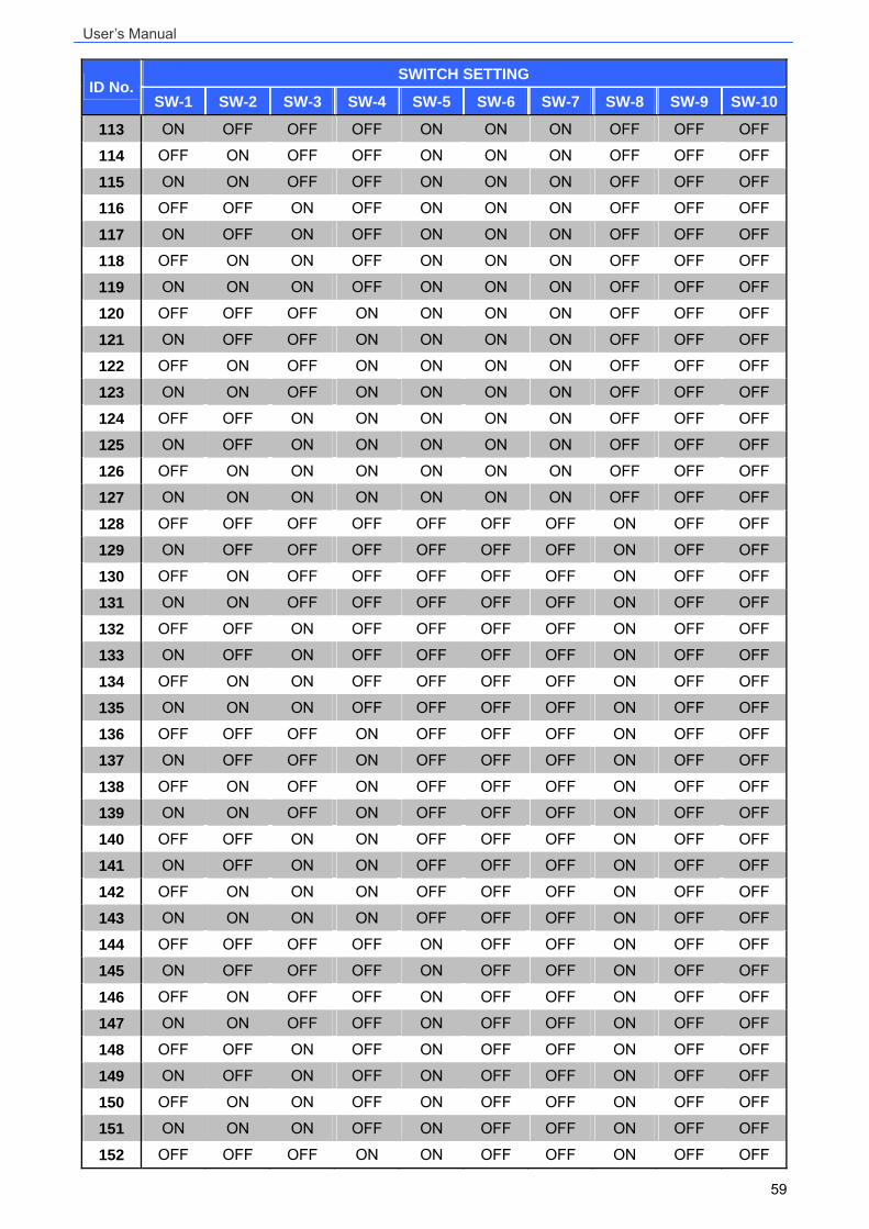
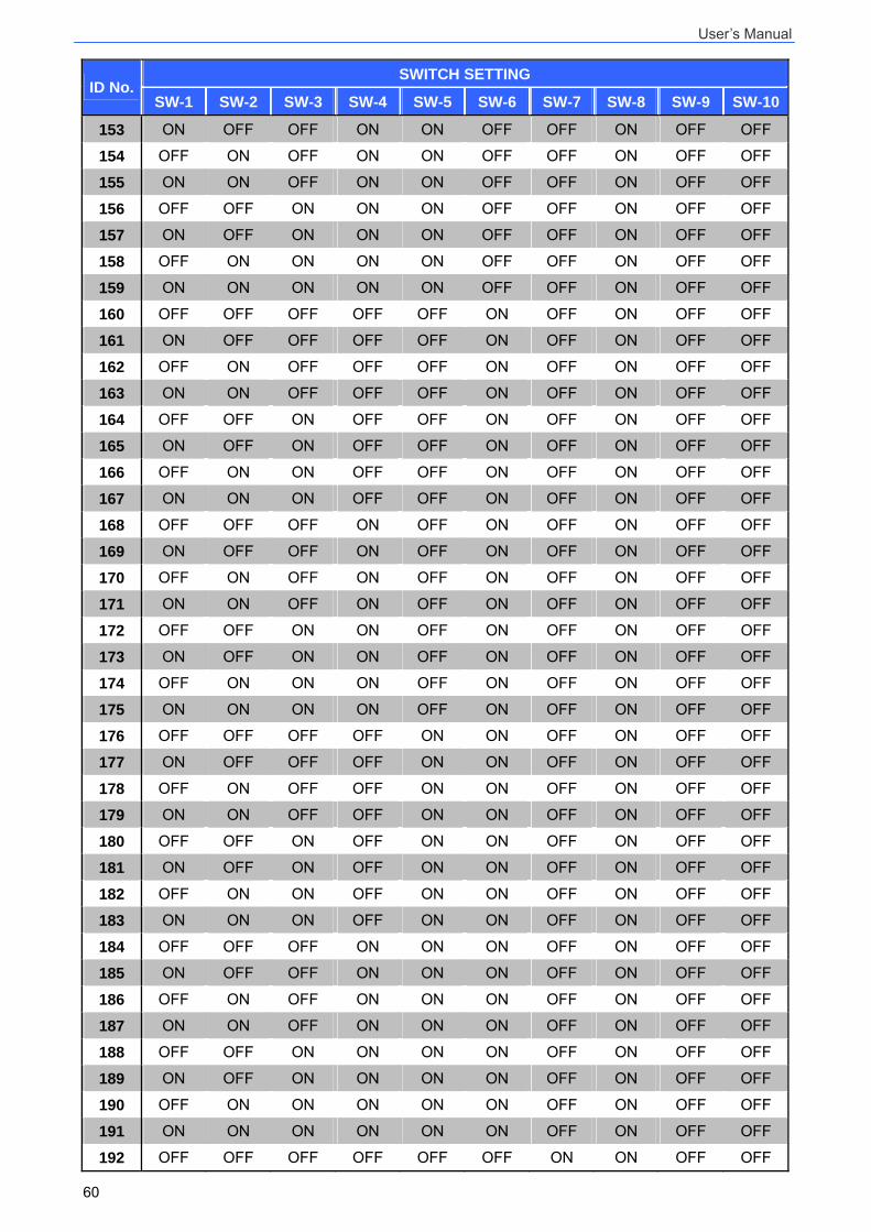
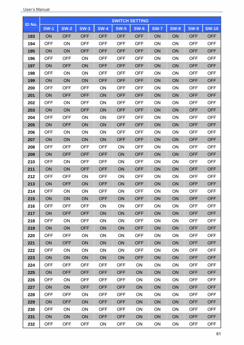
Appendix B: Switch Settings Index Table Please refer to the switch settings below for Mini Speed Dome Camera’s ID and protocol setup.
Camera ID Setup SWITCH SETTING
ID No. SW-1 SW-2 SW-3 SW-4 SW-5 SW-6 SW-7 SW-8 SW-9 SW-10
0 OFF OFF OFF OFF OFF OFF OFF OFF OFF OFF
1 ON OFF OFF OFF OFF OFF OFF OFF OFF OFF
2 OFF ON OFF OFF OFF OFF OFF OFF OFF OFF
3 ON ON OFF OFF OFF OFF OFF OFF OFF OFF
4 OFF OFF ON OFF OFF OFF OFF OFF OFF OFF
5 ON OFF ON OFF OFF OFF OFF OFF OFF OFF
6 OFF ON ON OFF OFF OFF OFF OFF OFF OFF
7 ON ON ON OFF OFF OFF OFF OFF OFF OFF
8 OFF OFF OFF ON OFF OFF OFF OFF OFF OFF
9 ON OFF OFF ON OFF OFF OFF OFF OFF OFF
10 OFF ON OFF ON OFF OFF OFF OFF OFF OFF
11 ON ON OFF ON OFF OFF OFF OFF OFF OFF
12 OFF OFF ON ON OFF OFF OFF OFF OFF OFF
13 ON OFF ON ON OFF OFF OFF OFF OFF OFF
14 OFF ON ON ON OFF OFF OFF OFF OFF OFF
15 ON ON ON ON OFF OFF OFF OFF OFF OFF
16 OFF OFF OFF OFF ON OFF OFF OFF OFF OFF
17 ON OFF OFF OFF ON OFF OFF OFF OFF OFF
18 OFF ON OFF OFF ON OFF OFF OFF OFF OFF
19 ON ON OFF OFF ON OFF OFF OFF OFF OFF
20 OFF OFF ON OFF ON OFF OFF OFF OFF OFF
21 ON OFF ON OFF ON OFF OFF OFF OFF OFF
22 OFF ON ON OFF ON OFF OFF OFF OFF OFF
23 ON ON ON OFF ON OFF OFF OFF OFF OFF
24 OFF OFF OFF ON ON OFF OFF OFF OFF OFF
25 ON OFF OFF ON ON OFF OFF OFF OFF OFF
26 OFF ON OFF ON ON OFF OFF OFF OFF OFF
27 ON ON OFF ON ON OFF OFF OFF OFF OFF
28 OFF OFF ON ON ON OFF OFF OFF OFF OFF
29 ON OFF ON ON ON OFF OFF OFF OFF OFF
30 OFF ON ON ON ON OFF OFF OFF OFF OFF
31 ON ON ON ON ON OFF OFF OFF OFF OFF
32 OFF OFF OFF OFF OFF ON OFF OFF OFF OFF
User’s Manual
57
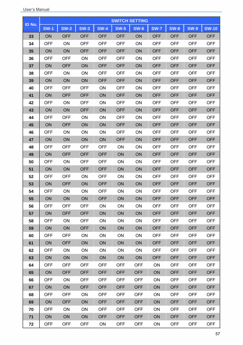
SWITCH SETTING ID No.
SW-1 SW-2 SW-3 SW-4 SW-5 SW-6 SW-7 SW-8 SW-9 SW-10
33 ON OFF OFF OFF OFF ON OFF OFF OFF OFF
34 OFF ON OFF OFF OFF ON OFF OFF OFF OFF
35 ON ON OFF OFF OFF ON OFF OFF OFF OFF
36 OFF OFF ON OFF OFF ON OFF OFF OFF OFF
37 ON OFF ON OFF OFF ON OFF OFF OFF OFF
38 OFF ON ON OFF OFF ON OFF OFF OFF OFF
39 ON ON ON OFF OFF ON OFF OFF OFF OFF
40 OFF OFF OFF ON OFF ON OFF OFF OFF OFF
41 ON OFF OFF ON OFF ON OFF OFF OFF OFF
42 OFF ON OFF ON OFF ON OFF OFF OFF OFF
43 ON ON OFF ON OFF ON OFF OFF OFF OFF
44 OFF OFF ON ON OFF ON OFF OFF OFF OFF
45 ON OFF ON ON OFF ON OFF OFF OFF OFF
46 OFF ON ON ON OFF ON OFF OFF OFF OFF
47 ON ON ON ON OFF ON OFF OFF OFF OFF
48 OFF OFF OFF OFF ON ON OFF OFF OFF OFF
49 ON OFF OFF OFF ON ON OFF OFF OFF OFF
50 OFF ON OFF OFF ON ON OFF OFF OFF OFF
51 ON ON OFF OFF ON ON OFF OFF OFF OFF
52 OFF OFF ON OFF ON ON OFF OFF OFF OFF
53 ON OFF ON OFF ON ON OFF OFF OFF OFF
54 OFF ON ON OFF ON ON OFF OFF OFF OFF
55 ON ON ON OFF ON ON OFF OFF OFF OFF
56 OFF OFF OFF ON ON ON OFF OFF OFF OFF
57 ON OFF OFF ON ON ON OFF OFF OFF OFF
58 OFF ON OFF ON ON ON OFF OFF OFF OFF
59 ON ON OFF ON ON ON OFF OFF OFF OFF
60 OFF OFF ON ON ON ON OFF OFF OFF OFF
61 ON OFF ON ON ON ON OFF OFF OFF OFF
62 OFF ON ON ON ON ON OFF OFF OFF OFF
63 ON ON ON ON ON ON OFF OFF OFF OFF
64 OFF OFF OFF OFF OFF OFF ON OFF OFF OFF
65 ON OFF OFF OFF OFF OFF ON OFF OFF OFF
66 OFF ON OFF OFF OFF OFF ON OFF OFF OFF
67 ON ON OFF OFF OFF OFF ON OFF OFF OFF
68 OFF OFF ON OFF OFF OFF ON OFF OFF OFF
69 ON OFF ON OFF OFF OFF ON OFF OFF OFF
70 OFF ON ON OFF OFF OFF ON OFF OFF OFF
71 ON ON ON OFF OFF OFF ON OFF OFF OFF
72 OFF OFF OFF ON OFF OFF ON OFF OFF OFF
User’s Manual
58
SWITCH SETTING ID No.
SW-1 SW-2 SW-3 SW-4 SW-5 SW-6 SW-7 SW-8 SW-9 SW-10
73 ON OFF OFF ON OFF OFF ON OFF OFF OFF
74 OFF ON OFF ON OFF OFF ON OFF OFF OFF
75 ON ON OFF ON OFF OFF ON OFF OFF OFF
76 OFF OFF ON ON OFF OFF ON OFF OFF OFF
77 ON OFF ON ON OFF OFF ON OFF OFF OFF
78 OFF ON ON ON OFF OFF ON OFF OFF OFF
79 ON ON ON ON OFF OFF ON OFF OFF OFF
80 OFF OFF OFF OFF ON OFF ON OFF OFF OFF
81 ON OFF OFF OFF ON OFF ON OFF OFF OFF
82 OFF ON OFF OFF ON OFF ON OFF OFF OFF
83 ON ON OFF OFF ON OFF ON OFF OFF OFF
84 OFF OFF ON OFF ON OFF ON OFF OFF OFF
85 ON OFF ON OFF ON OFF ON OFF OFF OFF 86 OFF ON ON OFF ON OFF ON OFF OFF OFF 87 ON ON ON OFF ON OFF ON OFF OFF OFF 88 OFF OFF OFF ON ON OFF ON OFF OFF OFF 89 ON OFF OFF ON ON OFF ON OFF OFF OFF 90 OFF ON OFF ON ON OFF ON OFF OFF OFF 91 ON ON OFF ON ON OFF ON OFF OFF OFF 92 OFF OFF ON ON ON OFF ON OFF OFF OFF 93 ON OFF ON ON ON OFF ON OFF OFF OFF 94 OFF ON ON ON ON OFF ON OFF OFF OFF 95 ON ON ON ON ON OFF ON OFF OFF OFF 96 OFF OFF OFF OFF OFF ON ON OFF OFF OFF 97 ON OFF OFF OFF OFF ON ON OFF OFF OFF 98 OFF ON OFF OFF OFF ON ON OFF OFF OFF 99 ON ON OFF OFF OFF ON ON OFF OFF OFF 100 OFF OFF ON OFF OFF ON ON OFF OFF OFF 101 ON OFF ON OFF OFF ON ON OFF OFF OFF 102 OFF ON ON OFF OFF ON ON OFF OFF OFF 103 ON ON ON OFF OFF ON ON OFF OFF OFF 104 OFF OFF OFF ON OFF ON ON OFF OFF OFF 105 ON OFF OFF ON OFF ON ON OFF OFF OFF 106 OFF ON OFF ON OFF ON ON OFF OFF OFF 107 ON ON OFF ON OFF ON ON OFF OFF OFF 108 OFF OFF ON ON OFF ON ON OFF OFF OFF 109 ON OFF ON ON OFF ON ON OFF OFF OFF 110 OFF ON ON ON OFF ON ON OFF OFF OFF 111 ON ON ON ON OFF ON ON OFF OFF OFF 112 OFF OFF OFF OFF ON ON ON OFF OFF OFF
User’s Manual
59
SWITCH SETTING ID No.
SW-1 SW-2 SW-3 SW-4 SW-5 SW-6 SW-7 SW-8 SW-9 SW-10
113 ON OFF OFF OFF ON ON ON OFF OFF OFF 114 OFF ON OFF OFF ON ON ON OFF OFF OFF 115 ON ON OFF OFF ON ON ON OFF OFF OFF 116 OFF OFF ON OFF ON ON ON OFF OFF OFF 117 ON OFF ON OFF ON ON ON OFF OFF OFF 118 OFF ON ON OFF ON ON ON OFF OFF OFF 119 ON ON ON OFF ON ON ON OFF OFF OFF 120 OFF OFF OFF ON ON ON ON OFF OFF OFF 121 ON OFF OFF ON ON ON ON OFF OFF OFF 122 OFF ON OFF ON ON ON ON OFF OFF OFF 123 ON ON OFF ON ON ON ON OFF OFF OFF 124 OFF OFF ON ON ON ON ON OFF OFF OFF 125 ON OFF ON ON ON ON ON OFF OFF OFF 126 OFF ON ON ON ON ON ON OFF OFF OFF 127 ON ON ON ON ON ON ON OFF OFF OFF 128 OFF OFF OFF OFF OFF OFF OFF ON OFF OFF 129 ON OFF OFF OFF OFF OFF OFF ON OFF OFF 130 OFF ON OFF OFF OFF OFF OFF ON OFF OFF 131 ON ON OFF OFF OFF OFF OFF ON OFF OFF 132 OFF OFF ON OFF OFF OFF OFF ON OFF OFF 133 ON OFF ON OFF OFF OFF OFF ON OFF OFF 134 OFF ON ON OFF OFF OFF OFF ON OFF OFF 135 ON ON ON OFF OFF OFF OFF ON OFF OFF 136 OFF OFF OFF ON OFF OFF OFF ON OFF OFF 137 ON OFF OFF ON OFF OFF OFF ON OFF OFF 138 OFF ON OFF ON OFF OFF OFF ON OFF OFF 139 ON ON OFF ON OFF OFF OFF ON OFF OFF 140 OFF OFF ON ON OFF OFF OFF ON OFF OFF 141 ON OFF ON ON OFF OFF OFF ON OFF OFF 142 OFF ON ON ON OFF OFF OFF ON OFF OFF 143 ON ON ON ON OFF OFF OFF ON OFF OFF 144 OFF OFF OFF OFF ON OFF OFF ON OFF OFF 145 ON OFF OFF OFF ON OFF OFF ON OFF OFF 146 OFF ON OFF OFF ON OFF OFF ON OFF OFF 147 ON ON OFF OFF ON OFF OFF ON OFF OFF 148 OFF OFF ON OFF ON OFF OFF ON OFF OFF 149 ON OFF ON OFF ON OFF OFF ON OFF OFF 150 OFF ON ON OFF ON OFF OFF ON OFF OFF 151 ON ON ON OFF ON OFF OFF ON OFF OFF 152 OFF OFF OFF ON ON OFF OFF ON OFF OFF
User’s Manual
60
SWITCH SETTING ID No.
SW-1 SW-2 SW-3 SW-4 SW-5 SW-6 SW-7 SW-8 SW-9 SW-10
153 ON OFF OFF ON ON OFF OFF ON OFF OFF 154 OFF ON OFF ON ON OFF OFF ON OFF OFF 155 ON ON OFF ON ON OFF OFF ON OFF OFF 156 OFF OFF ON ON ON OFF OFF ON OFF OFF 157 ON OFF ON ON ON OFF OFF ON OFF OFF 158 OFF ON ON ON ON OFF OFF ON OFF OFF 159 ON ON ON ON ON OFF OFF ON OFF OFF 160 OFF OFF OFF OFF OFF ON OFF ON OFF OFF 161 ON OFF OFF OFF OFF ON OFF ON OFF OFF 162 OFF ON OFF OFF OFF ON OFF ON OFF OFF 163 ON ON OFF OFF OFF ON OFF ON OFF OFF 164 OFF OFF ON OFF OFF ON OFF ON OFF OFF 165 ON OFF ON OFF OFF ON OFF ON OFF OFF 166 OFF ON ON OFF OFF ON OFF ON OFF OFF 167 ON ON ON OFF OFF ON OFF ON OFF OFF 168 OFF OFF OFF ON OFF ON OFF ON OFF OFF
169 ON OFF OFF ON OFF ON OFF ON OFF OFF
170 OFF ON OFF ON OFF ON OFF ON OFF OFF
171 ON ON OFF ON OFF ON OFF ON OFF OFF
172 OFF OFF ON ON OFF ON OFF ON OFF OFF
173 ON OFF ON ON OFF ON OFF ON OFF OFF
174 OFF ON ON ON OFF ON OFF ON OFF OFF
175 ON ON ON ON OFF ON OFF ON OFF OFF
176 OFF OFF OFF OFF ON ON OFF ON OFF OFF 177 ON OFF OFF OFF ON ON OFF ON OFF OFF 178 OFF ON OFF OFF ON ON OFF ON OFF OFF 179 ON ON OFF OFF ON ON OFF ON OFF OFF 180 OFF OFF ON OFF ON ON OFF ON OFF OFF 181 ON OFF ON OFF ON ON OFF ON OFF OFF 182 OFF ON ON OFF ON ON OFF ON OFF OFF 183 ON ON ON OFF ON ON OFF ON OFF OFF 184 OFF OFF OFF ON ON ON OFF ON OFF OFF 185 ON OFF OFF ON ON ON OFF ON OFF OFF 186 OFF ON OFF ON ON ON OFF ON OFF OFF 187 ON ON OFF ON ON ON OFF ON OFF OFF 188 OFF OFF ON ON ON ON OFF ON OFF OFF 189 ON OFF ON ON ON ON OFF ON OFF OFF 190 OFF ON ON ON ON ON OFF ON OFF OFF 191 ON ON ON ON ON ON OFF ON OFF OFF 192 OFF OFF OFF OFF OFF OFF ON ON OFF OFF
User’s Manual
61
SWITCH SETTING ID No.
SW-1 SW-2 SW-3 SW-4 SW-5 SW-6 SW-7 SW-8 SW-9 SW-10
193 ON OFF OFF OFF OFF OFF ON ON OFF OFF 194 OFF ON OFF OFF OFF OFF ON ON OFF OFF 195 ON ON OFF OFF OFF OFF ON ON OFF OFF 196 OFF OFF ON OFF OFF OFF ON ON OFF OFF 197 ON OFF ON OFF OFF OFF ON ON OFF OFF 198 OFF ON ON OFF OFF OFF ON ON OFF OFF 199 ON ON ON OFF OFF OFF ON ON OFF OFF 200 OFF OFF OFF ON OFF OFF ON ON OFF OFF 201 ON OFF OFF ON OFF OFF ON ON OFF OFF 202 OFF ON OFF ON OFF OFF ON ON OFF OFF 203 ON ON OFF ON OFF OFF ON ON OFF OFF 204 OFF OFF ON ON OFF OFF ON ON OFF OFF 205 ON OFF ON ON OFF OFF ON ON OFF OFF 206 OFF ON ON ON OFF OFF ON ON OFF OFF 207 ON ON ON ON OFF OFF ON ON OFF OFF 208 OFF OFF OFF OFF ON OFF ON ON OFF OFF 209 ON OFF OFF OFF ON OFF ON ON OFF OFF 210 OFF ON OFF OFF ON OFF ON ON OFF OFF 211 ON ON OFF OFF ON OFF ON ON OFF OFF 212 OFF OFF ON OFF ON OFF ON ON OFF OFF 213 ON OFF ON OFF ON OFF ON ON OFF OFF 214 OFF ON ON OFF ON OFF ON ON OFF OFF 215 ON ON ON OFF ON OFF ON ON OFF OFF 216 OFF OFF OFF ON ON OFF ON ON OFF OFF 217 ON OFF OFF ON ON OFF ON ON OFF OFF 218 OFF ON OFF ON ON OFF ON ON OFF OFF 219 ON ON OFF ON ON OFF ON ON OFF OFF 220 OFF OFF ON ON ON OFF ON ON OFF OFF 221 ON OFF ON ON ON OFF ON ON OFF OFF 222 OFF ON ON ON ON OFF ON ON OFF OFF
223 ON ON ON ON ON OFF ON ON OFF OFF
224 OFF OFF OFF OFF OFF ON ON ON OFF OFF
225 ON OFF OFF OFF OFF ON ON ON OFF OFF 226 OFF ON OFF OFF OFF ON ON ON OFF OFF 227 ON ON OFF OFF OFF ON ON ON OFF OFF 228 OFF OFF ON OFF OFF ON ON ON OFF OFF 229 ON OFF ON OFF OFF ON ON ON OFF OFF 230 OFF ON ON OFF OFF ON ON ON OFF OFF 231 ON ON ON OFF OFF ON ON ON OFF OFF 232 OFF OFF OFF ON OFF ON ON ON OFF OFF
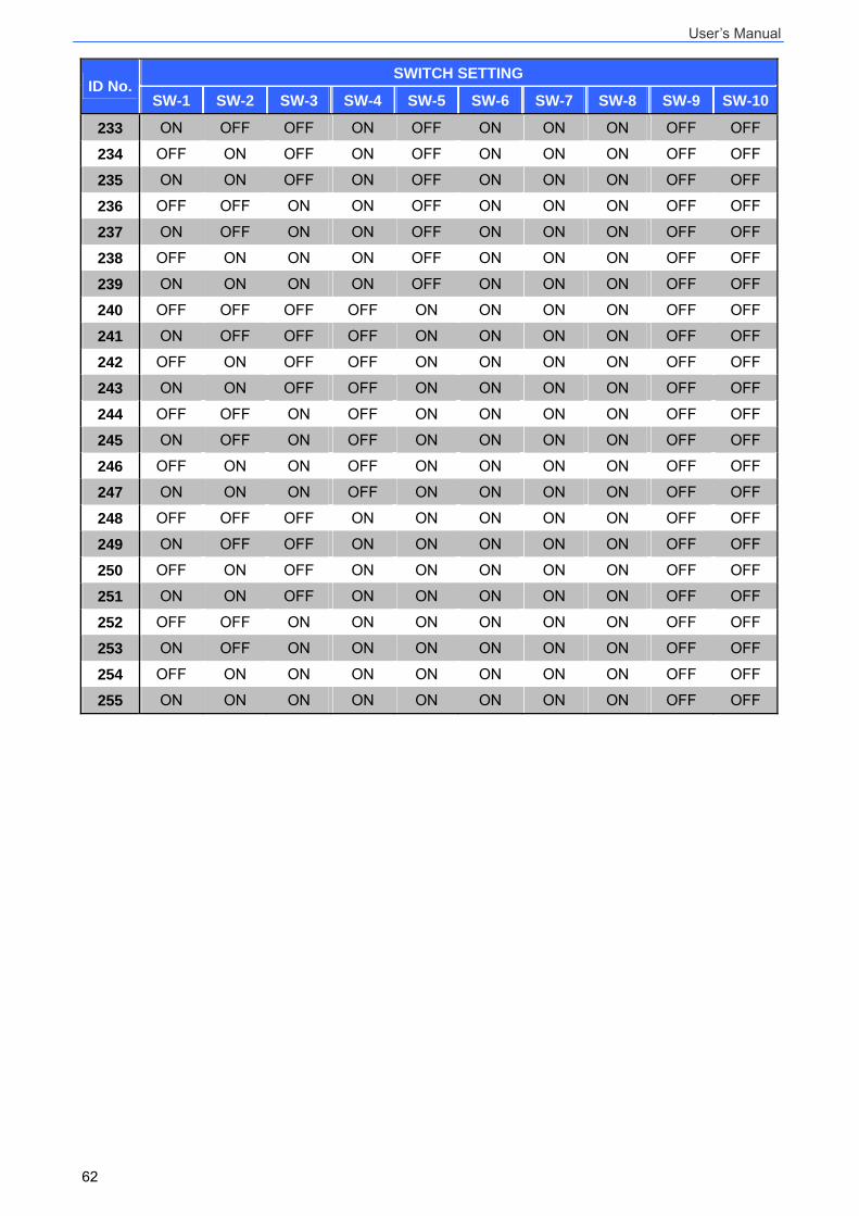
User’s Manual
62
SWITCH SETTING ID No.
SW-1 SW-2 SW-3 SW-4 SW-5 SW-6 SW-7 SW-8 SW-9 SW-10
233 ON OFF OFF ON OFF ON ON ON OFF OFF 234 OFF ON OFF ON OFF ON ON ON OFF OFF 235 ON ON OFF ON OFF ON ON ON OFF OFF 236 OFF OFF ON ON OFF ON ON ON OFF OFF 237 ON OFF ON ON OFF ON ON ON OFF OFF 238 OFF ON ON ON OFF ON ON ON OFF OFF 239 ON ON ON ON OFF ON ON ON OFF OFF 240 OFF OFF OFF OFF ON ON ON ON OFF OFF 241 ON OFF OFF OFF ON ON ON ON OFF OFF 242 OFF ON OFF OFF ON ON ON ON OFF OFF 243 ON ON OFF OFF ON ON ON ON OFF OFF 244 OFF OFF ON OFF ON ON ON ON OFF OFF 245 ON OFF ON OFF ON ON ON ON OFF OFF 246 OFF ON ON OFF ON ON ON ON OFF OFF 247 ON ON ON OFF ON ON ON ON OFF OFF 248 OFF OFF OFF ON ON ON ON ON OFF OFF 249 ON OFF OFF ON ON ON ON ON OFF OFF 250 OFF ON OFF ON ON ON ON ON OFF OFF 251 ON ON OFF ON ON ON ON ON OFF OFF 252 OFF OFF ON ON ON ON ON ON OFF OFF 253 ON OFF ON ON ON ON ON ON OFF OFF 254 OFF ON ON ON ON ON ON ON OFF OFF 255 ON ON ON ON ON ON ON ON OFF OFF
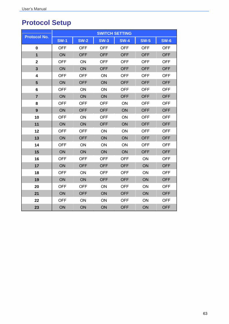
User’s Manual
63
Protocol Setup SWITCH SETTING
Protocol No. SW-1 SW-2 SW-3 SW-4 SW-5 SW-6
0 OFF OFF OFF OFF OFF OFF
1 ON OFF OFF OFF OFF OFF
2 OFF ON OFF OFF OFF OFF
3 ON ON OFF OFF OFF OFF
4 OFF OFF ON OFF OFF OFF
5 ON OFF ON OFF OFF OFF
6 OFF ON ON OFF OFF OFF
7 ON ON ON OFF OFF OFF
8 OFF OFF OFF ON OFF OFF
9 ON OFF OFF ON OFF OFF
10 OFF ON OFF ON OFF OFF
11 ON ON OFF ON OFF OFF
12 OFF OFF ON ON OFF OFF
13 ON OFF ON ON OFF OFF
14 OFF ON ON ON OFF OFF
15 ON ON ON ON OFF OFF
16 OFF OFF OFF OFF ON OFF
17 ON OFF OFF OFF ON OFF
18 OFF ON OFF OFF ON OFF
19 ON ON OFF OFF ON OFF
20 OFF OFF ON OFF ON OFF
21 ON OFF ON OFF ON OFF
22 OFF ON ON OFF ON OFF
23 ON ON ON OFF ON OFF
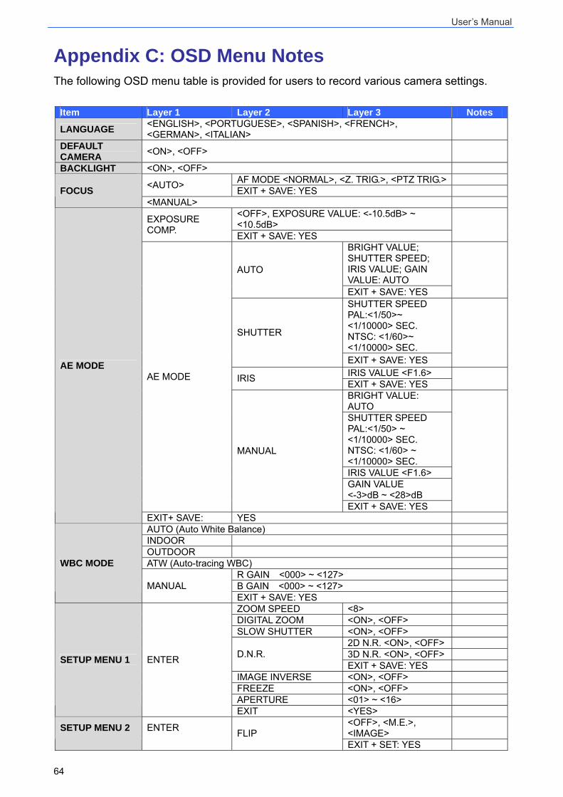
User’s Manual
64
Appendix C: OSD Menu Notes The following OSD menu table is provided for users to record various camera settings.
Item Layer 1 Layer 2 Layer 3 Notes
LANGUAGE <ENGLISH>, <PORTUGUESE>, <SPANISH>, <FRENCH>, <GERMAN>, <ITALIAN>
DEFAULT CAMERA <ON>, <OFF>
BACKLIGHT <ON>, <OFF> AF MODE <NORMAL>, <Z. TRIG.>, <PTZ TRIG.> <AUTO> EXIT + SAVE: YES FOCUS
<MANUAL> <OFF>, EXPOSURE VALUE: <-10.5dB> ~ <10.5dB> EXPOSURE
COMP. EXIT + SAVE: YES
BRIGHT VALUE; SHUTTER SPEED; IRIS VALUE; GAIN VALUE: AUTO
AUTO
EXIT + SAVE: YES
SHUTTER SPEED PAL:<1/50>~ <1/10000> SEC. NTSC: <1/60>~ <1/10000> SEC.
SHUTTER
EXIT + SAVE: YES
IRIS VALUE <F1.6> IRIS EXIT + SAVE: YES
BRIGHT VALUE: AUTO SHUTTER SPEED PAL:<1/50> ~ <1/10000> SEC. NTSC: <1/60> ~ <1/10000> SEC. IRIS VALUE <F1.6> GAIN VALUE <-3>dB ~ <28>dB
AE MODE
MANUAL
EXIT + SAVE: YES
AE MODE
EXIT+ SAVE: YES AUTO (Auto White Balance) INDOOR OUTDOOR ATW (Auto-tracing WBC)
R GAIN <000> ~ <127> B GAIN <000> ~ <127>
WBC MODE
MANUAL EXIT + SAVE: YES ZOOM SPEED <8> DIGITAL ZOOM <ON>, <OFF> SLOW SHUTTER <ON>, <OFF>
2D N.R. <ON>, <OFF> 3D N.R. <ON>, <OFF> D.N.R. EXIT + SAVE: YES
IMAGE INVERSE <ON>, <OFF> FREEZE <ON>, <OFF> APERTURE <01> ~ <16>
SETUP MENU 1 ENTER
EXIT <YES> <OFF>, <M.E.>, <IMAGE> SETUP MENU 2 ENTER FLIP EXIT + SET: YES
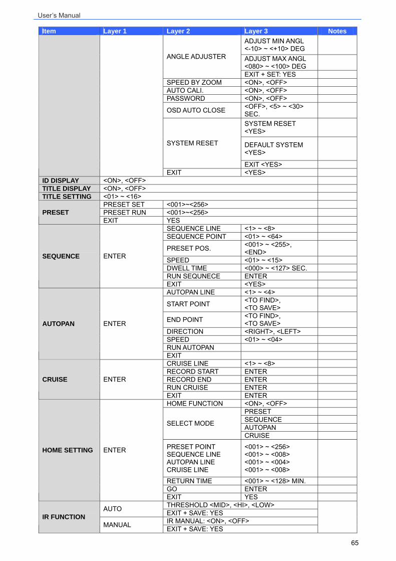
User’s Manual
65
Item Layer 1 Layer 2 Layer 3 Notes ADJUST MIN ANGL <-10> ~ <+10> DEG
ADJUST MAX ANGL <080> ~ <100> DEG
ANGLE ADJUSTER
EXIT + SET: YES SPEED BY ZOOM <ON>, <OFF> AUTO CALI. <ON>, <OFF> PASSWORD <ON>, <OFF>
OSD AUTO CLOSE <OFF>, <5> ~ <30> SEC.
SYSTEM RESET <YES>
DEFAULT SYSTEM <YES>
SYSTEM RESET
EXIT <YES> EXIT <YES>
ID DISPLAY <ON>, <OFF> TITLE DISPLAY <ON>, <OFF> TITLE SETTING <01> ~ <16>
PRESET SET <001>~<256> PRESET RUN <001>~<256> PRESET EXIT YES
SEQUENCE LINE <1> ~ <8> SEQUENCE POINT <01> ~ <64>
PRESET POS. <001> ~ <255>, <END>
SPEED <01> ~ <15> DWELL TIME <000> ~ <127> SEC. RUN SEQUNECE ENTER
SEQUENCE ENTER
EXIT <YES> AUTOPAN LINE <1> ~ <4>
START POINT <TO FIND>, <TO SAVE>
END POINT <TO FIND>, <TO SAVE>
DIRECTION <RIGHT>, <LEFT> SPEED <01> ~ <04> RUN AUTOPAN
AUTOPAN ENTER
EXIT CRUISE LINE <1> ~ <8> RECORD START ENTER RECORD END ENTER RUN CRUISE ENTER
CRUISE ENTER
EXIT ENTER HOME FUNCTION <ON>, <OFF>
PRESET SEQUENCE AUTOPAN SELECT MODE
CRUISE
PRESET POINT SEQUENCE LINE AUTOPAN LINE CRUISE LINE
<001> ~ <256> <001> ~ <008> <001> ~ <004> <001> ~ <008>
RETURN TIME <001> ~ <128> MIN. GO ENTER
HOME SETTING ENTER
EXIT YES THRESHOLD <MID>, <HI>, <LOW> AUTO EXIT + SAVE: YES IR MANUAL: <ON>, <OFF> IR FUNCTION
MANUAL EXIT + SAVE: YES
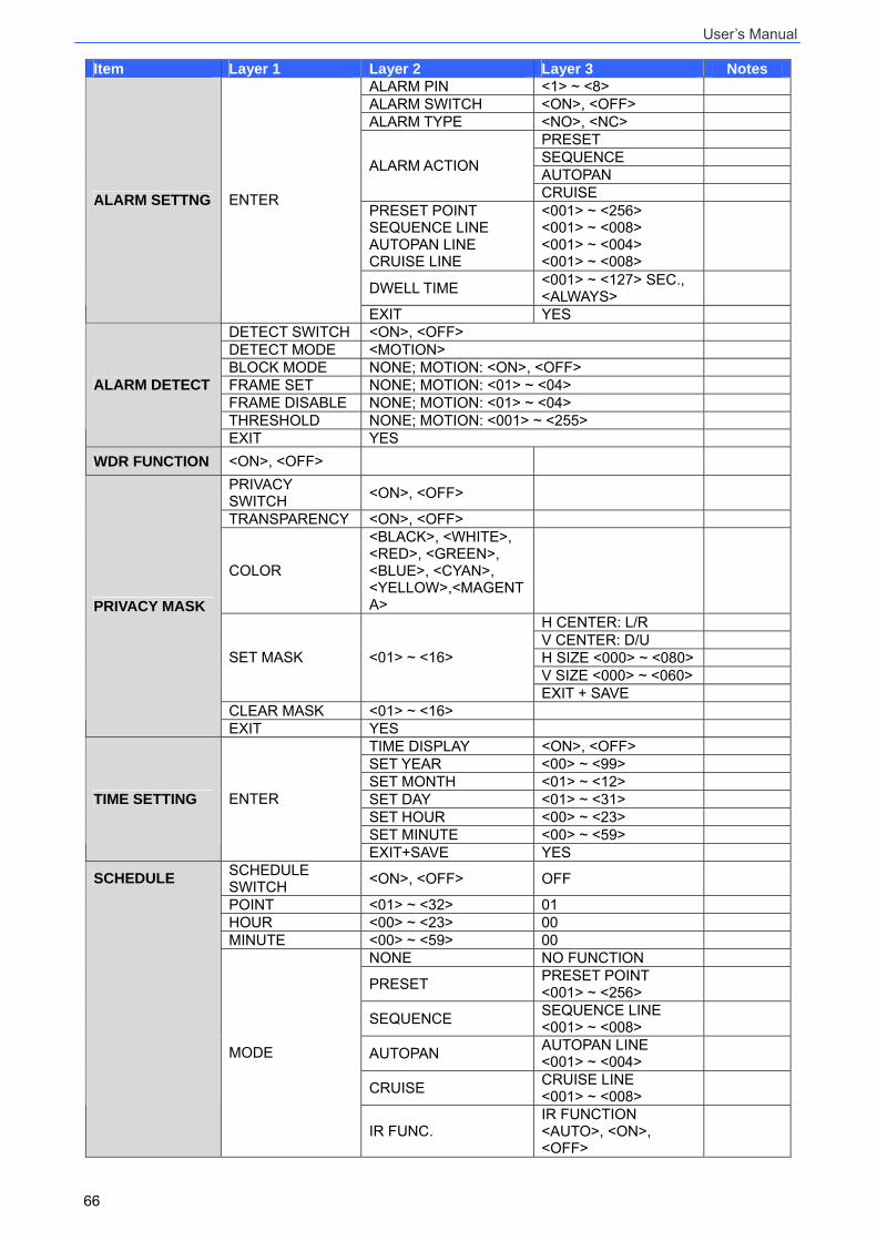
User’s Manual
66
Item Layer 1 Layer 2 Layer 3 Notes ALARM PIN <1> ~ <8> ALARM SWITCH <ON>, <OFF> ALARM TYPE <NO>, <NC>
PRESET SEQUENCE AUTOPAN ALARM ACTION
CRUISE PRESET POINT SEQUENCE LINE AUTOPAN LINE CRUISE LINE
<001> ~ <256> <001> ~ <008> <001> ~ <004> <001> ~ <008>
DWELL TIME <001> ~ <127> SEC., <ALWAYS>
ALARM SETTNG ENTER
EXIT YES DETECT SWITCH <ON>, <OFF> DETECT MODE <MOTION> BLOCK MODE NONE; MOTION: <ON>, <OFF> FRAME SET NONE; MOTION: <01> ~ <04> FRAME DISABLE NONE; MOTION: <01> ~ <04> THRESHOLD NONE; MOTION: <001> ~ <255>
ALARM DETECT
EXIT YES WDR FUNCTION <ON>, <OFF>
PRIVACY SWITCH <ON>, <OFF>
TRANSPARENCY <ON>, <OFF>
COLOR
<BLACK>, <WHITE>, <RED>, <GREEN>, <BLUE>, <CYAN>, <YELLOW>,<MAGENTA>
H CENTER: L/R V CENTER: D/U H SIZE <000> ~ <080> V SIZE <000> ~ <060>
SET MASK <01> ~ <16>
EXIT + SAVE CLEAR MASK <01> ~ <16>
PRIVACY MASK
EXIT YES TIME DISPLAY <ON>, <OFF> SET YEAR <00> ~ <99> SET MONTH <01> ~ <12> SET DAY <01> ~ <31> SET HOUR <00> ~ <23> SET MINUTE <00> ~ <59>
TIME SETTING ENTER
EXIT+SAVE YES SCHEDULE SWITCH <ON>, <OFF> OFF
POINT <01> ~ <32> 01 HOUR <00> ~ <23> 00 MINUTE <00> ~ <59> 00
NONE NO FUNCTION
PRESET PRESET POINT <001> ~ <256>
SEQUENCE SEQUENCE LINE <001> ~ <008>
AUTOPAN AUTOPAN LINE <001> ~ <004>
CRUISE CRUISE LINE <001> ~ <008>
SCHEDULE
MODE
IR FUNC. IR FUNCTION <AUTO>, <ON>, <OFF>

User’s Manual
67
Item Layer 1 Layer 2 Layer 3 Notes SCHEDULE RESET YES
EXIT OSD YES