Embed Size (px)
Citation preview
MPSHRe rev04, draft-02, publicly released 5Mar2010
1 of 50
Minimum Performance Standards for Halon 1301 Replacement in
the Fire Extinguishing Agents/Systems of Civil Aircraft Engine and
Auxiliary Power Unit Compartments
(MPSHRe rev04)
MPSHRe rev04, draft-02, publicly released 5Mar2010
2 of 50
EDITORIAL COMMENTS. THIS PAGE WILL BE DELETED UPON FORMAL PUBLICATION.
“TBD” = to be determined; either a result of incomplete outcome from rev04 ancillary testing or a basic
lack of information
HISTORY.
4Jan2010, Mon : begin revising/authoring various portions of the rev03 into the rev04 process
1Feb2010, Mon : print 1st (-01) draft of compiled document, for personal pencil mark-up
2Feb2010, Tues : complete 1st pencil markup; begin computer file edits
3Feb2010, Wed : finish computer file edits for draft -01 and submit to task group for rvw
23Feb2010, Tues : task group telephone conference call to discuss draft-01; 23Feb2010, Tues : received
comments regarding draft-01 from Mr. S. Pugliese, Airbus, via electronic mail
1Mar2010, Mon : begin revising draft-01 to create draft-02
3Mar2010, Wed : received comments regarding draft-01 from Mr. R. Wright, Boeing, via electronic mail
4Mar2010, Thurs : print 2nd (-02) draft of compiled document, for personal pencil mark-up
5Mar2010, Fri : revise draft-02 with pencil mark-ups and publicly release
MPSHRe rev04, draft-02, publicly released 5Mar2010
3 of 50
Table of Contents.
1. Introduction. ............................................................................................................................................... 4 1.A. Discussion........................................................................................................................................... 5 1.B. Overview of the Test Procedure.......................................................................................................... 7 1.C. References......................................................................................................................................... 10
2. Requirements for Candidates in Addition to Testing in a Generic Nacelle Fire Simulator. ..................... 12 2.A. Requirements for All Candidates that are not Addressed by this Document..................................... 12 2.B. Possible Additional Requirements for Novel Solutions. ................................................................... 14
3. Infrastructure. ........................................................................................................................................... 15 3.A. Establish the Test Fixture.................................................................................................................. 15 3.B. Establish the operational test environment within the test fixture ..................................................... 16 3.C. Operating, Monitoring, and Maintaining the Test Fixture and its Environment during its Life-span.21
4. Testing Procedures. .................................................................................................................................. 22 4.A. Important Definitions........................................................................................................................ 22 4.B. Describing the Testing Cycle. ........................................................................................................... 24
5. Additional Commentary ........................................................................................................................... 40 5.A. Structure............................................................................................................................................ 40 5.B. Telemetry .......................................................................................................................................... 40 5.C. Ventilation Regimes.......................................................................................................................... 41 5.D. Candidate Storage, Delivery, and Quantification.............................................................................. 42 5.E. Fire Threats. ...................................................................................................................................... 47 5.F. Life-span Benchmarks. ...................................................................................................................... 50
List of Figures.
Figure 1. Illustrating the Complete Cycle of MPSHRe rev04 Process. .......................................................... 30 Figure 2. Illustrating the Evaluation Concept for Proposed Candidate Design Criteria. ................................ 31 Figure 3. Illustrating the Testing Cycle of MPSHRe rev04............................................................................ 32 Figure 4. The Historical Performance of Halon 1301 in the FAATC Nacelle Fire Simulator........................ 33 Figure 5. The Historical Candidate Performances During Fuel Verification Testing in the FAATC Nacelle
Fire Simulator. .............................................................................................................................. 34 Figure 6. Illustrating the Full Testing Cycle of MPSHRe rev04 for a Generic Test Environment. ................ 35 Figure 7. Illustrating the Process of Monitoring and the Assessment of the Reignition Time Delay for a Fire
Threat/Ventilation Condition for a Generic Test Environment. .................................................... 36 Figure 8. Illustrating the Process for the Large Bracket Boundary Associated with 115% of the Candidate
Design Concentration.................................................................................................................... 37 Figure 9. Illustrating the Process for the Small Bracket Boundary Associated with 85% of the Candidate
Design Concentration.................................................................................................................... 38 Figure 10. Illustrating the Process of Fuel Verification Testing for a Generic Test Environment. ................ 39
MPSHRe rev04, draft-02, publicly released 5Mar2010
4 of 50
1. Introduction.
A fire extinguishing system (“system”) is required for each engine nacelle and auxiliary
power unit (APU) compartment for certain categories of civilian aircraft. To address these
requirements for large transport aircraft, 2 considerations are typically made. First, an
applicant satisfactorily stores and delivers some form of fire extinguishing agent
(“agent”) to the protected compartment, typically halon 1301. This distribution of the
halon 1301 can described by a set of distribution criteria; a concentration is resident from
some duration. Second, an applicant measures the quantity of the agent within the
protected compartment over time during and following the agent injection event. The
principal success of such a system is based upon the measured history of the agent
distribution meeting or exceeding the minimum level of safety as required by the
appropriate regulatory authority. The culmination of these 2 considerations represents
approximately 60 years of knowledge and experience exchanged between regulatory
authority and industry.
To preclude confusion regarding the use of the word “fuel” in this document, fuel is
defined here as any substance that can combust in an unintended manner in an engine
nacelle or APU compartment. Fuel, as commonly understood, is not defined in this
document as the substance used for propulsion, although turbine fuel can fuel an
unintended fire in an engine nacelle or APU compartment. Further, since FAA
regulations do not address combustible metal fires by the regulations cited, metals acting
as fuel, as described here, are excluded from consideration. Additionally, the cited
regulations do not apply when the containment of the engine core combustion processes
fail, permitting “cutting torch” flames to enter these fire zones, where turbine fuel and
oxidizer are reacting at temperatures and pressures which are multiples larger than those
found at atmospheric conditions.
Commonly accepted practice for this application, demonstrated by the typical
circumstances found in existing civil aircraft, has 3 components. First is the use of halon
1301, a total-flooding agent. Second, the fire extinguishment system used to deliver the
halon is composed of at least one storage vessel containing the agent and some super-
pressurizing nitrogen, release valving, plumbing fittings, distribution plumbing, and
nozzling for injection into the protected compartment. Third and finally, during
developmental and certification evaluations, a gas analyzer utilizing a pressure drop
across an orifice, commonly referred to as a Statham- or Halonyzer-variant gas analyzer,
is used to measure the distribution behavior of the halon 1301 inside the protected
compartment. The sample histories evaluated are drawn from locations in the tested
environment through tubes to the remotely located sensors.
The goal of this document is to provide a process for an applicant, or its designee(s), to
determine some quantity of a replacement candidate (“candidate”) that can be used
acceptably for fire extinguishment in place of halon 1301 for these applications.
Explanatory descriptions potentially valuable to an entity using this process are included
in the procedural documentation. The process requires a test fixture, the ability to produce
2 different fire threats based on flammable fluids typically found in a nacelle or APU
compartment, a system to deliver a conditioned candidate, and some means to measure
MPSHRe rev04, draft-02, publicly released 5Mar2010
5 of 50
the time-varying behavior of the agent during its delivery to and transport through the test
environment. The experience to develop this process is contained in a report titled
“TBD”, of which this document is an appendix. The reader should know that at some
point in the future, halon 1301 will no longer be the commonly accepted practice.
Knowledge and judgment regarding what is acceptable will always change. To account
for this, the definition for a candidate within this process can span from a substance that
may “drop-in” the hardware used to store the halon 1301 with little or no modification
and use the existing gas analysis technique for quantification to something requiring
novel methods unfamiliar to civil aviation for storage, delivery, and/or quantification.
This process is currently fit to the commonly accepted practice relating to the halon 1301
system and Statham/Halonyzer analysis concept. Provisions have been made to permit
variation, as needed.
An applicant must assess the applicability of this process to their own halon replacement
efforts based on their own circumstances. There are 2 scenarios for replacing halon. One
is for an existing airplane and the second for a new. Given an existing airplane, this
process is the likely method to complete a replacement effort based on the economic
considerations of fire testing with actual aircraft components versus a simulation model.
For a new airplane, an applicant may elect to forego this process and directly engage the
pertinent regulations since no halon 1301 baseline exists. However, an applicant in either
scenario may capitalize on results from this process if information is already publicly
available for a candidate that is desirable.
Any entity using this process must remain diligent during testing. Observations will be
the most important aspect to assess whether a candidate will acceptably perform.
Additionally, observations may lead to changes in current philosophy regarding fire
protection for these applications. One should recognize that a notable shift in design
philosophy may again require a revision of this document.
A successful application of the process described herein will allow the definition of an
equivalent level of safety in terms of the performance of the candidate, as compared to
that of halon 1301.
An applicant intending to use this process in a stand-alone approach to replace halon
1301 is clearly advised to involve their certifying, regulatory authority at the earliest
possible point in the program to prevent the loss of time and money associated with later
discrepancy related to differing opinion or experience. Additionally, successfully
completing this process does NOT satisfy the requirements for certification by the Federal
Aviation Administration (FAA) or any other regulatory authority recognizing the use of
this process. An applicant must adequately address all issues that are not evaluated by this
process for these applications.
1.A. Discussion.
U.S. Federal Airworthiness Regulations (FAR) 23.1195, 25.1195 are the regulations that
require fire extinguishment systems for the engine nacelle and APU compartments in
certain types of U.S. aircraft. In the case of U.S. general aviation airplanes, special
MPSHRe rev04, draft-02, publicly released 5Mar2010
6 of 50
conditions may exist requiring the applicant to provide fire extinguishment systems as
well. Similar regulations are also found in other aviation regulatory bodies located on the
continents of Asia, Australia, Europe, North America, and South America.
The current fire extinguishing systems using halon 1301 are deemed to satisfy these
requirements if the system can distribute halon 1301 in the compartment in accordance
with guidance provided in FAA Advisory Circular 20-100 (FAA AC 20-100). This AC
reports the performance of halon 1301 from historical testing including high-fidelity,
large-scale fire tests. The process described here is intended for use in large-scale fire
testing for the purpose of developing design criteria for systems using candidates.
One challenge for this process is to reasonably represent a nacelle fire but not restrict the
applicability of the outcomes to one particular nacelle, knowing the purpose to use an
agent in a nacelle or APU fire extinguishment system is to extinguish the unintended fire
threat. Therefore, this process was tuned to minimize any flame extinction mechanisms
that are not related to an agent, based on the assumption that the agent is the main factor
in flame extinction. Flame strain is the principal example of a minimized flame extinction
mechanism. Agent injection is specified not to “blow” the fire out. If the flame-straining
effect is notable, as a planned or unintended component of a candidate’s function, this
process will require modification. Appropriate planning must occur to account for this
deviation and, at a minimum, would require involvement from the regulatory authority.
However, this revision is perceived and intended to permit evaluating aerosols.
The process to demonstrate equivalence is based on 4 test configurations. Each of these 4
configurations is intended to represent pertinent factors found in a nacelle or APU fire.
By varying parameters to achieve these 4 configurations, a spread of behavior can be
observed.
One can readily reason that 4 points is a small sample of a potentially infinite array of
possible solutions when considering the numbers of engine nacelles and APU
compartments flying today, in addition to each’s varied attendant operational regimes.
However, those involved in the work to develop this process believe this spread, and that
buried within to attain the spread, is adequate to challenge and provide a method to
compare and ultimately quantify a candidate for the purpose of replacing halon 1301. As
a precaution, the testing entity is required to identify any deficiency and respond
accordingly, if a candidate possessed a potential weakness entering into testing or such
observations were made during testing.
The 4 test configurations are each a unique combination of compartment ventilation and
fire threat. Inherent to all are flame-holding geometries, persistent ignition threats
represented by electrical arc and/or hot surfaces, and the persistent presence of fuel during
candidate injection and transport through the test fixture.
An important practical aspect for this testing will be the maintained control of the
experiment. The highest state of cleanliness within the test fixture must be maintained.
Additionally, processes like candidate handling while servicing, and candidate and fuel
conditioning prior to test, require consistent procedure and endpoint to effect reliable test
MPSHRe rev04, draft-02, publicly released 5Mar2010
7 of 50
behavior. Understanding the tolerances in cleanliness and conditioning and their impact
on test outcome will likely be an evolving experience as any testing progresses.
The evaluation method of this revision is conceptually simple. It is a proof-test of some
consistent distribution criteria for a candidate challenged by 4 acceptably intense test
configurations and smaller sets of verification tests, resulting in a go/no-go outcome.
The comparison with halon 1301 is provided by the character of the test environment in
which the evaluations occur. One of 2 environments is possible. First, a nacelle fire
simulator (NFS) has existed at the FAA’s WJ Hughes Technical Center (FAATC). A test
database, including halon 1301 performance, exists for the FAATC NFS, based on
previous work related to MPSHRe rev03. Any testing conducted in the FAATC NFS will
reference that information as the assessment threshold. The second possible environment
is some future, new test fixture. Its test environment will relate to the FAATC NFS in
terms of combustion character and flame extinction performance for its associated fire
threats.
The candidate performance is assessed based on the interaction with the different fire
threat and ventilation combinations. The behavior tracked to make the assessment is
simply a duration observed between the times of flame extinction and reignition as an
agent pulse moves through the test fixture while enduring persistent fuel flow and
ignition threat(s). This duration is an effective indicator of agent performance and should
demonstrate a direct relationship with varying quantities of agent discharged into a test
fixture. As agent quantity increases, the duration the fire is extinguished increases. The
relationship appears linear in the normal ranges of interest but eventually ceases at some
low endpoint once a threshold mass of agent is crossed. In simple words, if an amount of
agent discharged into the test section does not extinguish a fire, there is no duration
between flame extinguishment and reignition. Although not observed to date, and likely
impractical, there is a theoretical point where there would be such a large quantity of
agent released into a test fixture, the fire would be permanently extinguished based on the
test parameters used. For this case, the duration is infinite.
The final outcome, the successful design criteria, for any given candidate from this
process, would be the distribution criteria which succeeds in equaling or exceeding the
respective flame extinction duration for the 4 test configurations. Also, a final report will
require describing attendant observations, particularly those which are noteworthy. The
expected activities after completing such a project would then be moving forward with
recommending the successful design criteria for any certification effort, resolve any
anomalous behaviors discovered during this testing, acceptably satisfy all other remaining
issues not evaluated by this process, and finally, demonstrate all required goals are
satisfied for the aircraft installation to the applicable regulatory authority.
1.B. Overview of the Test Procedure.
The process is composed of three groups of requirements and a group of comments
providing additional background. The first set describes what is expected of the candidate
by the regulatory authority and industry before any candidate is considered for evaluation
by use of this process. Any future candidate must meet operational demands if it were to
MPSHRe rev04, draft-02, publicly released 5Mar2010
8 of 50
be considered for use. These operational demands are not directly related to fire
extinguishment performance and will be evaluated elsewhere. Additionally, any methods
not consistent with commonly accepted practice will require identification, discussion,
review, and acceptance from the applicable regulatory authority. The second set describes
the infrastructure required to accomplish comparative testing between agents. The
infrastructure would require design, investigation, and optimization, typically requiring
attention for a single period of time. Once these infrastructure issues are resolved, they
will be taken as constant, but should be maintained and checked on some basis in a
sensible manner to ensure continuity. The third set describes the comparative testing.
These requirements will be repeatedly visited and will become familiar to any testing
entity. See figure 1 for a diagrammatic flow.
The process requires a test fixture, 2 ventilation regimes, 2 fire scenarios, the delivery of
the candidate, and methods to capture the test environment’s behaviors. The following
comments relate to the infrastructure and must be fulfilled prior to beginning any
evaluative testing.
The test fixture will be some size larger than an acceptable minimum, defined by cross
section and volume. Within the test fixture, the testing entity must establish 2
representative, ventilation regimes. Additionally, 2 fire threats must be designed within
the test fixture so that they demonstrate adequate combustion intensity. Both threats will
be based on diffusion combustion of fuels representative of the engine nacelle and APU
compartments. One scenario will be based on a fuel spray and the other on a residual
pool. The spray scenario will have persistent ignition threats represented by an electrical
arc and a hot surface. The residual pool will have a persistent ignition threat represented
by an electrical arc. Fuels feeding the spray at any given point during testing will be
turbine fuel, lubricant or hydraulic fluid. Turbine fuel will be the basis for the residual
pool.
By pairing 1 ventilation regime with 1 fire threat, a single test configuration is specified.
The pairings create the 4 major test configurations.
For each ventilation regime, the candidate must challenge a spray fire threat, based on the
fuel producing the most severe fire threat, being indicated by the largest measured
thermal output, and a pool fire threat. In the spray fire configurations, the candidate must
also be evaluated with verification testing against different fuels to ensure test outcomes
with these other fuels remain acceptable.
The evaluation of a candidate requires establishing distributions of the substance in the
ventilation flows, as measured by a collection of a minimum of 12 concentration
sampling points. The ability of the candidate to distribute is challenged by requiring a
separation between injection locations and fire threat, plus concentration sampling in at
least 1 wake region, where the wake region is associated with flame-holding structure in
the test fixture. Different distributions will be used to assess the acceptability of a
candidate’s initial design criteria, where the initial criteria must be identified prior to
commencing any formal MPSHRe evaluative testing.
MPSHRe rev04, draft-02, publicly released 5Mar2010
9 of 50
The process to prove the initial design criteria requires the testing of distribution criteria
smaller and larger than the initial, in concentration alone, by approximately 15%, for each
combination of fire threat and ventilation rate. By performing testing in this bracketed
manner, the systemic behavior of a candidate is observed, which contributes to
experiential understanding, and permits arithmetical manipulation to assess the ability of
the candidate’s initial design criteria. See figure 2 for a conceptual illustration.
Given the systemic behavior of the candidate, performance is assessed by comparing a
calculated flame extinction duration associated with the concentration of some initial
candidate design criteria to some appropriate halon 1301 threshold criteria. The analytic
assessment is first begun by coupling 2 points, 1 at the lower bracket boundary and the
2nd
at the larger, with the concentration of the evaluated design criteria, and interpolating
an average flame extinction duration. The interpolated average flame extinction duration
is associated to the evaluated candidate design concentration. The assessment concludes
by comparing the interpolated average flame extinction duration to the appropriate halon
1301 threshold criterion. Success requires showing the evaluated candidate design criteria
will produce a flame extinction duration which is the same or larger than the threshold
criterion. If successful behavior can be shown for the 4 major test configurations and no
faults are noted during fuel verification testing, the criteria are considered successful and
would then be considered the design criteria.
If a fault occurs during evaluation, the initial design criteria would require review and
modification. At this time, the singular modification expected would be the enlargement
of the concentration parameter contained in the design criteria. Subsequently, the
outcomes from the test process at the time of fault would require review, and a new plan
would require development to efficiently incorporate that known with what requires
completion to successfully prove a set of design criteria.
Upon completion, a report capturing all observations and pertinent information must then
be written and submitted for consideration to the regulatory authority upon program
completion.
MPSHRe rev04, draft-02, publicly released 5Mar2010
10 of 50
1.C. References.
The following references form the basis to understand the current halon 1301
performance criteria for aircraft engine and APU fire extinguishing systems (refs 1 - 7).
The balance are included to enhance a reader’s knowledge regarding other discussions
which occur within this document.
ASTM Standard E681, 2009, "Standard Test Method for Concentration Limits of
Flammability of Chemicals (Vapors and Gases)," ASTM International, West
Conshohocken, PA, 2003, DOI: 10.1520/E0681-09, www.astm.org.
ASTM Standard E918, 2005, "Standard Practice for Determining Limits of Flammability
of Chemicals at Elevated Temperature and Pressure," ASTM International, West
Conshohocken, PA, 2003, DOI: 10.1520/E0918-83R05, www.astm.org.
Federal Aviation Administration Advisory Circular AC 20-100, 1977.”General
Guidelines for Measuring Fire Extinguishing Agent Concentrations in Powerplant
Compartments.”
Middlesworth, C.M., 1952, "Aircraft Fire Extinguishment, Part I - A Study of Factors
Influencing Extinguishing System Design," Technical Development Report No. 184,
Civil Aeronautics Administration Technical Development and Evaluation Center,
Indianapolis, IN.
Hughes, C.A., 1953, "Aircraft Fire Extinguishment, Part II - The Effect of Air Flow on
Extinguishing Requirements of a Jet Power-Plant Fire Zone," Technical Development
Report No. 205, Civil Aeronautics Administration Technical Development and
Evaluation Center, Indianapolis, IN.
New, J.D., and Middlesworth, C.M., 1953, "Aircraft Fire Extinguishment, Part III - An
Instrument for Evaluating Extinguishing Systems," Technical Development Report No.
206, Civil Aeronautics Administration Technical Development and Evaluation Center,
Indianapolis, IN.
Hughes, C.A., and Middlesworth, C.M., 1954, "Aircraft Fire Extinguishment, Part IV -
Evaluation of a Bromochloromethane Fire Extinguishing System for the XB-45
Airplane," Technical Development Report No. 240, Civil Aeronautics Administration
Technical Development and Evaluation Center, Indianapolis, IN.
Hansberry, H.L., 1956, "Aircraft Fire Extinguishment, Part V - Preliminary Report on
High-Rate-Discharge Fire Extinguishing Systems for Aircraft Power Plants," Technical
Development Report No. 260, Civil Aeronautics Administration Technical Development
and Evaluation Center, Indianapolis, IN.
Klueg, E.P., and Demaree, J.E., 1969, "An Investigation of In-Flight Fire Protection with
a Turbofan Powerplant Installation," Report No. NA-69-26, Federal Aviation
Administration, National Aviation Facilities Experimental Center, Atlantic City, NJ.
Bennett, J.M., Caggianelli, G.M., Kolleck, M.L., and Wheeler, J.A., 1997a, "Halon
Replacement for Aviation, Aircraft Engine Nacelle Application Phase I - Operational
MPSHRe rev04, draft-02, publicly released 5Mar2010
11 of 50
Parameters Study," Report No. WL-TR-95-3077, Wright Laboratories and Booz, Allen,
and Hamilton, Incorporated, Wright Patterson Air Force Base, OH.
Bennett, J.M., Caggianelli, G.M., Kolleck, M.L., and Wheeler, J.A., 1997b, "Halon
Replacement for Aviation, Aircraft Engine Nacelle Application Phase II - Operational
Comparison of Selected Extinguishants," Report No. WL-TR-97-3076, Wright
Laboratories and Booz, Allen, and Hamilton, Incorporated, Wright Patterson Air Force
Base, OH.
Bennett, J.M., Bennett, M.V., 1999, "Aircraft Engine/APU Fire Extinguishing System
Design Model (HFC-125)," Report No. AFRL-VA-WP-TR-1999-3068, Air Force
Research Laboratory and Booz, Allen, and Hamilton, Incorporated, Wright Patterson Air
Force Base, OH.
Gann, R.G., Bennett J.M., 2007, “Verification of Fire Suppression Principles,” Chapter
11 from NIST Special Publication 1069, “Advanced Technology for Fire Suppression in
Aircraft,” National Institute of Standards and Technology, Gaithersburg, MD.
Hamins, A., et al, 1994, “Flame Suppression Effectiveness,” Section 4, Special
Publication 861, “Evaluation of Alternative In-Flight Fire Suppressants for Full-Scale
Testing in Simulated Aircraft Engine Nacelles and Dry Bays,” National Institute of
Standards and Technology, Gaithersburg, MD.
Hamins, A., et al, 1995, “Suppression of Engine Nacelle Fires,” Chapter 9, Special
Publication 890, “Fire Suppression System Performance of Alternative Agents in Aircraft
Engine and Dry Bay Laboratory Simulations,” Volume 2, National Institute of Standards
and Technology, Gaithersburg, MD.
Johnson A.M., Grenich, A.F., “Vulnerability Methodology and Protective Measures for
Aircraft Fire and Explosion Hazards / Fire Detection, Fire Extinguishment, and Surface
Ignition Studies,” AFWAL-TR-85-2060, Volume II, pt. I, USAF Wright Aeronautical
Laboratories, Wright Patterson Air Force Base, OH.
Myronuk, D.J., Oct 1980, “Dynamic, Hot Surface Ignition of Aircraft Fuels and
Hydraulics Fluids,” AFAPL-TR-79-2095, Aero Propulsion Laboratory, USAF Wright
Aeronautical Laboratories, Wright Patterson Air Force Base, OH.
National Fire Protection Association, 2008, “NFPA 2001 Standard on Clean Agent Fire
Extinguishing Systems,” Quincy, MA.
Zabetakis, M.G., “Flammability Characteristics of Combustible Gases and Vapors,”
Bureau of Mines bulletin 627, US Department of the Interior, Bureau of Mines,
Washington, D.C.
MPSHRe rev04, draft-02, publicly released 5Mar2010
12 of 50
2. Requirements for Candidates in Addition to Testing in a Generic
Nacelle Fire Simulator.
2.A. Requirements for All Candidates that are not Addressed by this Document.
Any candidate considered for use in an engine nacelle or APU fire extinguishing
system must adequately satisfy the following requirements. These requirements are
evaluated elsewhere.
2.A-1. Environmental Characteristics.
2.A-1.a. The environmental characteristics of a candidate must comply with
international laws and agreements.
2.A-1.b. The candidate should be listed in the US Environmental Protection
Agency’s Significant New Alternatives Policy program. Since engine nacelle
and APU compartments are not normally occupied spaces, candidates
identified for use in such spaces are permissible.
2.A-1.c. The candidate does not require listing with the US Environmental
Protection Agency’s Significant New Alternatives Policy program, if the
candidate :
2.A-1.c-i. has an demonstrably acceptable service history.
2.A-1.c-ii. it has no ozone depletion potential.
2.A-1.d. Health and Safety. Processes and equipment associated with a
candidate’s service life, from conception to completion, must employ features
which prevent workers from hazardous exposure during all related activities.
2.A-1.e. Flight Safety. The use and operation of the candidate in the aircraft
should not result in any additional hazard such as:
2.A-1.e-i. Malfunction of components critical for flight control necessary for
continued safety of flight.
2.A-1.e-ii. Damage to other critical components and areas within the
compartment being protected, which would create a hazard either
immediately or remain undetected and be a hazard after a passage of time.
2.A-1.e-iii. Products resulting from the discharge of the neat candidate or
decomposition by-products resulting from combustion exposure in these
compartments must not be conveyed into spaces occupied by living things
within the pressure vessel of the aircraft
2.A-1.e-iv. Ignition sources in any area of the aircraft not designed for
accommodating ignition sources
2.A-2. The candidate, whether neat or decomposed, should be compatible with all
materials of construction for :
2.A-2.a. its storage and delivery system
2.A-2.b. the protected compartment in which it will be injected
2.A-2.b-i. This applies to all definitely and potentially wetted boundaries of
any test apparatus and any aircraft installation.
2.A-2.b-ii. Decomposition products resulting from fire and extinguishment
exposure are aggressive. This is not avoidable. However, post-incident
evaluation and related cleaning or repair are the mechanisms used to
thwart negative material compatibility outcomes.
MPSHRe rev04, draft-02, publicly released 5Mar2010
13 of 50
2.A-3. The candidate must have an acceptable shelf-life while installed on the
aircraft.
2.A-4. The candidate must have acceptable performance for the aircraft’s
operational envelope.
2.A-4.a. The testing entity must know by reasonable evaluation that the
candidate can demonstrate any future design point recommended as
certification for all storage conditions that will be found on the associated
airframe.
2.A-4.b. The applicant will be required to demonstrate adequate distribution at
the thermal endpoints of the airplane’s operational envelope to the respective
airworthiness authority.
2.A-4.c. This test procedure does not require hot- or cold-soaked storage
conditions for gaseous candidate testing. The disparity of the environments
between the test process and the end-use is explained by accounting for the
environment in the nacelle and understanding how flammable systems
generally behave when exposed to varied levels of thermal energy.
2.A-4.c-i. The general behavior of flammable systems indicates decreasing
temperature offers decreasing flammability.
2.A-4.c-i.A. Persistent hot surface areas in the presence of spilling liquid
fuel may exist, thus producing an environment where air and fuel
vapors may be mixing. A measure related to this condition, although
not identical, is the testing related to determining flammability limits,
such as ASTM E-681 or E-918. Regardless, a system of air and fuel in a
gaseous state is more hazardous (favoring combustion) than that of air
and a liquid fuel, where the liquid fuel must change phase and diffuse.
2.A-4.c-i.B. Flammability envelopes produced for premixed, gaseous,
flammable systems incorporating various mixtures of an agent, fuel,
and oxygen, within a detonation tube or an explosion sphere,
demonstrate that :
2.A-4.c-i.B-i. peak inerting agent concentrations decrease when the
temperature for the flammable system is decreasing.
2.A-4.c-i.B-ii. the areas inside these flammability curves decrease with
decreasing temperature, implying the flammable range is decreasing
also.
2.A-4.c-i.C. Given two flammable systems, the colder of the two will
require a lower inerting agent concentration
2.A-4.c-ii. The environment at a cruise altitude is not consistent with the
nacelle ambient environment. Citing the standard atmosphere, one will
find at altitudes in the 9.1 km (30,000 ft) range having ambient
temperatures on the order of -40°C (-40°F). The average operational
environment within the nacelle will be on the order of 38°C (100°F).
2.A-4.c-iii. Consider the accepted practice to demonstrate FAA certification
with halon 1301. A fire extinguisher bottle cold-soaked to -54°C (-65°F) is
discharged into the fire zone. For success, the measurement history must
MPSHRe rev04, draft-02, publicly released 5Mar2010
14 of 50
indicate all points simultaneously achieve 6%v/v halon 1301 for 0.5
second.
2.A-4.c-iii.A. The cold-soaked bottle condition is related to the storage
environment of the bottle outside the nacelle that is conditioned by
exposure to the ambient environmental conditions.
2.A-4.c-iii.B. The 6%v/v Halon 1301 can be traced back to flammability
testing completed at room temperature.
2.A-4.c-iv. Conclusions.
2.A-4.c-iv.A. The cold-soaked bottle is not related to the fire
extinguishment demand. Instead, the cold-soaked condition is related to
the agent storage environment which inhibits its ability to diffuse upon
expulsion. This is an agent delivery issue. This issue does not require
fire testing to establish behavior.
2.A-4.c-iv.B. The fire extinguishment demand is similar to the nacelle
environment. This test process is intended to establish the fire
extinguishment demand.
2.B. Possible Additional Requirements for Novel Solutions.
Commentary is provided here which identifies additional demands requiring attention
due to the deviation from commonly accepted practice.
2.B-1. Proving the viability of novel measurement equipment.
2.B-1.a. If measurement equipment is planned for use during testing and future
certification activities which is atypical, the testing and/or regulatory
authority will require review and decision regarding the acceptance of the
novel equipment. The principle example cited here is the development of
some new machine to measure the concentration history of a fire
extinguishing agent in a given environment. Commonly accepted practice is
defined by a Statham-derivative gas analyzer.
2.B-1.b. This issue must be satisfactorily resolved prior to the commencement of
evaluative equivalence testing for any candidate.
2.B-2. A requirement for candidate demonstration testing.
2.B-2.a. Depending upon the nature of the proposed fire extinguishing concept,
the regulatory authority may require additional testing.
2.B-2.b. The determination of the extent of the additional testing will be based
on the novelty of the proposed concept (i.e., differences from the commonly
accepted practice), and will depend upon the observations and conclusions of
the testing meeting the requirements of this document.
MPSHRe rev04, draft-02, publicly released 5Mar2010
15 of 50
3. Infrastructure.
The items contained within this section must be completed then proven reliable and
repeatable prior to attempting any equivalence testing.
3.A. Establish the Test Fixture.
3.A-1. Specifications regarding specific machinery and components to fabricate a
nacelle fire simulator are not provided in this document. However, details which
can be used to select such components follow.
3.A-2. Structure.
3.A-2.a. The materials of construction for current nacelles consist of either metal
or composite fiber construction. Either material is permissible for use
providing the structural design of a nacelle fire simulator includes
3.A-2.a-i. allowances for :
3.A-2.a-i.A. the stresses of repeated fire testing without significant
alteration
3.A-2.a-i.B. environmental behaviors which would not unreasonably
interfere with interpreting equivalence testing results (i.e. agent
distribution versus flame extinction)
3.A-2.a-i.C. reasonable access to the interior for cleaning, maintenance,
and alteration or repair
3.A-2.a-i.D. the ability to observe and record the internal environmental
behaviors
3.A-2.a-ii. the ability to accept :
3.A-2.a-ii.A. various forced ventilation flows.
3.A-2.a-ii.B. two fire scenarios plus their related workings.
3.A-2.a-ii.C. the injection hardware for the fire extinguishing system.
3.A-2.a-ii.D. all required telemetry to record environmental behavior.
3.A-2.b. Geometry.
3.A-2.b-i. The engine compartment (nacelle fire) simulator should have an
annular fire zone having a minimum volume 1.84 m^3 (65 ft^3) and a
minimum annular cross section of 0.511 m^2 (5.5 feet^2), both before
reductions due to clutter.
3.A-2.b-ii. The volume of the nacelle fire simulator excludes any internal
volume representing flow path required to deliver ventilation air.
3.A-2.b-iii. Non-specified clutter must be incorporated in the flow path of the
nacelle fire simulator. The clutter must present some resistance to the
distribution of a candidate in the ventilation flow.
3.A-2.b-iii.A. Some clutter will necessarily result, given pending
comments regarding fire intensity.
3.A-2.b-iii.B. Flame-holding structure should not be the only clutter in the
fixture’s cross section.
3.A-2.b-iv. The inner cylinder in this configuration will represent the engine
case.
3.A-2.b-v. The test section must be equipped to allow a real time visual
observation of the fire.
MPSHRe rev04, draft-02, publicly released 5Mar2010
16 of 50
3.A-3. Telemetry.
3.A-3.a. The histories of events occurring in each test must be captured to record
the environmental behavior. These behaviors will be used to observe and
learn about what is occurring within the environment of the test fixture,
compare consistency or difference between tests, evaluate a candidate, and
track the changes of the fixture over its life time.
3.A-3.b. A complete record is required for each evaluation test accomplished.
The complete record requires individual records from visual and non-visual
sensors.
3.A-3.b-i. Each record should focus on the regions containing the fire threats.
3.A-3.b-ii. A non-visual telemetry package should be used to capture and
review the history of the test environment during each test. This record
should include :
3.A-3.b-ii.A. methods using sensors such as thermocouples and pressure
transducers to capture thermal and pressure gradients related to the test
environment. Other sensors may also be used to enhance understanding.
3.A-3.b-ii.B. methods to quantify the varying concentration behavior of
the candidate, resulting from its injection into the test environment. If
different than accepted practice, review comments under the section
“Possible Additional Requirements for Novel Solutions”.
3.A-3.b-ii.C. some non-concentration sample points well away from the
fire threats so the behavior of the test environment can be monitored
over time.
3.A-3.b-iii. A visual record will be the principal means to observe the
performances of a candidate, which should :
3.A-3.b-iii.A. come from a camera located to acceptably view the fire
threat behavior.
3.A-3.b-iii.B. include appropriate date and time indications.
3.A-3.b-iv. Recommended minimum requirements.
3.A-3.b-iv.A. Must be able to appropriately record the histories of :
3.A-3.b-iv.A-i. the visible behavior of the fire threat
3.A-3.b-iv.A-ii. mass flow of the air through the test fixture
3.A-3.b-iv.A-iii. temperature of the :
3.A-3.b-iv.A-iii.a. air through the test fixture
3.A-3.b-iv.A-iii.b. fuel in each fire threat
3.A-3.b-iv.A-iii.c. candidate in the firex
3.A-3.b-iv.A-iv. the pressure of the fire extinguisher storage vessel
3.A-3.b-iv.A-v. concentration of the candidate in the test fixture
3.A-3.b-iv.B. Judgment is left to the discretion of the testing entity.
Including the applicable regulatory authority regarding the decisions of
type, number, and location of the sensors in the telemetry package is
advised.
3.A-3.b-iv.C. Data must be collected reliably at rates sufficient to produce
useful data from the testing environment for review.
3.B. Establish the operational test environment within the test fixture
MPSHRe rev04, draft-02, publicly released 5Mar2010
17 of 50
3.B-1. Ventilation Regimes.
3.B-1.a. At least two internal (ventilation) airflow rates should be selected, one
each from the following two ranges.
3.B-1.a-i. high, 1.0 – 1.4 kg/s (2.2 - 3.0 lbm/sec).
3.B-1.a-ii. low, 0.091 – 0.45 kg/s (0.2 – 1.0 lbm/sec).
3.B-1.b. At least two (ventilation) air temperatures of 38°C (100°F) and 121°C
(250°F) or greater should be used.
3.B-2. Fire Threats within the test fixture.
3.B-2.a. Ignition sources for the fire scenarios.
3.B-2.a-i. Initiating ignition sources are those used to reliably ignite test fires.
They can be any concept that can reliably ignite a test fire. If an initiating
ignition source is foreign to a nacelle, control must be employed to ensure
it does not interfere with test results.
3.B-2.a-ii. Secondary ignition sources are those providing a persistent
reignition threat in the fire scenario during flame extinguishment by the
agent.
3.B-2.a-ii.A. They must be related to features that exist in a nacelle or
APU compartment.
3.B-2.a-ii.B. Electrical arc and/or hot surface threats are acceptable due to
their presence in actual aircraft engine nacelle and APU fire zones.
3.B-2.b. General comments regarding the fuels used during testing.
3.B-2.b-i. The fuels used in this evaluation must include those expected in the
protected compartment; typically a turbine fuel, a lubricant, and a
hydraulic fluid.
3.B-2.b-ii. The fuel temperature should begin each test near 66°C (+/- 5.5°C)
(150°F +/-10°F) for both fire scenarios. Fuel-flow path should be
temperature-controlled throughout the test fixture to ensure this control
remains reasonably intact during the length of a test. Any fuel-flow
temperature should be measured as close to the fire as possible.
3.B-2.b-iii. Fire tests should be run without discharging any fire extinguishing
agent so the combustion behaviors of the various fuel types can be
observed and understood. They should be understood and ranked in terms
of thermal output.
3.B-2.b-iv. Large batches of fuel stock should be acquired before embarking
on equivalence testing to ensure that batching changes will not confound
test results. A prime example for this concern is the use of 2 separate bulk
sources of turbine fuel within one test program. If noticeable changes in
test result are observed, a change in fuel flash point between the batches
should be checked and eliminated as a cause for the discrepancy.
3.B-2.c. Acceptable fire intensity.
The fire intensity must be adequate or misleading outcome may result.
Acceptable fire threat intensity will be shown by 2 means.
3.B-2.c-i. Attain a minimum measured thermal output.
3.B-2.c-i.A. For the spray fire based on turbine fuel, “TBD” (kW?) at high
ventilation and “TBD” (kW?) at low.
MPSHRe rev04, draft-02, publicly released 5Mar2010
18 of 50
3.B-2.c-i.B. For the pool fire, “TBD” (kW?) at high ventilation, and
“TBD” (kW?) at low.
3.B-2.c-ii. Maintaining notable flaming combustion when the 4
ventilation/fire threat configurations are exposed to the discharge of a fire
extinguisher storage vessel filled with pressurized gaseous nitrogen.
3.B-2.c-ii.A. The expansion of the injected nitrogen shall undergo at least
a 100-fold volume increase, as referenced between storage and ambient
conditions.
3.B-2.c-ii.B. The nitrogen shall be :
3.B-2.c-ii.B-i. stored in a volume comparable to that used in service
3.B-2.c-ii.B-ii. injected through hardware reasonably similar to what is
expected during testing. Typically, this will mean the plumbing is
composed of properly rated metallic tube and fittings.
3.B-2.c-ii.C. The discharge of nitrogen stored in 5.2 L (315 in^3) at 10.3
MPa (1500 psig) and 16°C (61°F) within 1 second, to the test
environment, satisfies this demand.
3.B-2.d. There should be structural features in both fire threats to provide flame
attachment so the associated flaming combustion is self-sustaining once the
initiating ignition source is removed.
3.B-2.e. During each test, the fire should burn for some consistent, prescribed
preburn duration to permit heating the local structure prior to discharging the
candidate. Temperature histories are needed to understand what rates of
change are occurring. The test length should be chosen to permit the fixture to
attain a near-steady-state condition when agent is discharged. Preburn
durations of 45-90 seconds are typically reasonable.
3.B-2.f. The geometric position and operational condition of the following
should be consistently and rigorously maintained during any test program.
3.B-2.f-i. All initiating ignition sources.
3.B-2.f-ii. All secondary ignition sources.
3.B-2.f-iii. Any nozzle(s) delivering fuel to the test fires.
3.B-2.f-iv. The vessel containing the pool fire.
3.B-2.g. Describing the fire threats.
3.B-2.g-i. The test fixture must provide the simulation of a flaring fire
(leaking fuel stream on fire, also called a spray fire) and a residual fire
(baffle stabilized pan fire due to the ignition of pooled fuel in some part of
the fire zone).
3.B-2.g-ii. Spray fire scenario
3.B-2.g-ii.A. Provide a fuel flow rate of 0.1 to 1 gpm. The fuel flow rate
should remain constant for the length of testing during any test
program. The choice of fuel flow may be an arbitrary one. It does not
necessarily need to reflect an actual aircraft. What it must do is provide
an adequate fire intensity that is described in the comments pertaining
to “Acceptable fire intensity”.
3.B-2.g-ii.B. The fuel flow and reignition threats must remain active
before and after the candidate discharge to ensure that the flame
MPSHRe rev04, draft-02, publicly released 5Mar2010
19 of 50
extinction duration will end. This persistence also assures that the
candidate extinguished the flames, and flame extinction did not result
from ignition deprivation nor fuel starvation.
3.B-2.g-ii.C. The secondary ignition sources must be located in the fuel
spray pattern to ensure effective operation. Both types of ignition
source are required to simultaneously provide fire ignition opportunity.
At least one reliable, persistent, ignition source must be provided from
each of the following types.
3.B-2.g-ii.C-i. an electrical arc
3.B-2.g-ii.C-ii. a hot surface
3.B-2.g-ii.D. The spray fire scenario at varying times in a test program will
be based on turbine fuel, a lubricant or a hydraulic fluid.
3.B-2.g-ii.D-i. The fire threat intensity for the 3 fuels must be
understood as related to fuel type and ventilation regime, then
ranked from least to most severe, as indicated by measured thermal
output.
3.B-2.g-ii.D-ii. The less-severe fuels should be delivered through the
same nozzles and at the same flow conditions as the most-severe
fuel.
3.B-2.g-iii. Pool fire scenario
3.B-2.g-iii.A. The singular secondary ignition source is an electrical arc.
3.B-2.g-iii.B. The pool fire is based on turbine fuel (Jet-A, JP-8).
3.B-2.g-iii.C. Experimentation will be important to determine the optimal
reignition characteristics of this fire scenario.
3.B-2.g-iii.C-i. The area of the exposed fuel surface for combustion is
not specified. It can either be selected by expected pool sizes that
may be found in an actual aircraft or it can be sized to the confines
of the test fixture.
3.B-2.g-iii.C-ii. The recirculation zone that sets up over the fuel surface
behind flame attaching structure will vary with free-stream flow
speed. Ensure that the recirculation aerodynamics do not provide an
opportunity to confuse the interpretation of test results.
3.B-2.g-iii.C-iii. Observing flame spread across the fuel surface to
understand the different behaviors and then permit optimizing the
reignition event prior to any equivalence testing is recommended.
3.B-3. Candidate Storage, Delivery, and Concentration Measurement.
3.B-3.a. Candidate Storage.
3.B-3.a-i. Requirements for candidates stored in a pressurized vessel and
subsequently expelled.
3.B-3.a-i.A. The candidate must be appropriately and safely stored in some
containment that is acting as a fire extinguisher vessel. Thermal and
pressure vessel ratings must appropriately relate to the work expected.
3.B-3.a-i.B. The containment will serve multiple purposes for each test.
3.B-3.a-i.B-i. Candidate conditioning during test preparation.
3.B-3.a-i.B-ii. Candidate discharge into the test fixture during a test.
MPSHRe rev04, draft-02, publicly released 5Mar2010
20 of 50
3.B-3.a-i.C. There must be an ability to persistently observe the
candidate’s temperature and pressure during pre-test conditioning and
test.
3.B-3.a-i.D. The candidate should be conditioned to a storage temperature
of 38°C (100°F) for each test.
3.B-3.a-i.D-i. It should be stored consistent with industry practice, if
such guidance exists.
3.B-3.a-i.D-ii. This requirement is likely unnecessary for solid aerosol
candidates. Discussion with the applicable regulatory authority
before summarily dismissing this requirement is advised.
3.B-3.a-i.E. The storage vessel must have a releasing mechanism that can
be remotely and reliably actuated to discharge the candidate into the test
fixture.
3.B-3.a-ii. Requirements for other means of candidate storage.
3.B-3.a-ii.A. Other means of storage are known at this time
3.B-3.a-ii.B. The maturity of these technologies within the civil aviation
community are infantile, thus the lack of maturity prevents the
inclusion of specification or guidance here at this time.
3.B-3.a-ii.C. Discussions within the community will be required at the
time of consideration of such atypical solutions. See comments for
“Possible Additional Requirements for Novel Solutions”.
3.B-3.a-ii.C-i. The applicability of this document to the proposed
solution should be determined by discussions with the pertinent
regulatory authority.
3.B-3.a-ii.C-ii. Secondarily, input from the the task group overseeing
this activity may be needed to revise this document.
3.B-3.b. Candidate Delivery.
3.B-3.b-i. All candidate injection plumbing must be capable of the thermal
and pressure insults typical of candidate injection (discharge) events. It
must be secured to prevent damage to persons or structure during normal
testing in the event of failure.
3.B-3.b-ii. Candidate injection must minimize the insult on the fire threats
from phenomena not evaluated. Injection nozzles should :
3.B-3.b-ii.A. be located some distance away from the fire scenarios.
3.B-3.b-ii.B. not be pointed at or in the general direction of the fire
scenarios. When oriented to the direction of the bulk ventilation flow,
the plumbing should direct the candidate injection jet(s) :
3.B-3.b-ii.B-i. perpendicular
3.B-3.b-ii.B-ii. upstream
3.B-3.b-ii.B-iii. some combination of each
3.B-3.b-iii. There is no constraint on the duration of the candidate injection.
3.B-3.c. Candidate Concentration Measurement.
3.B-3.c-i. A minimum of 12 sample points is required. They should provide
behavioral indications within some volume of the test fixture for the full
cross section that encompasses the fire threats.
MPSHRe rev04, draft-02, publicly released 5Mar2010
21 of 50
3.B-3.c-i.A. The sampling points must be chosen wisely and then
consistently maintained during each test program. Reviewing FAA
Advisory Circular 20-100 is advised.
3.B-3.c-i.B. The sampled volume will likely be smaller than the test
fixture volume.
3.B-3.c-i.C. At least 1 wake region of flame-holding structure must be
sampled.
3.B-3.c-i.C-i. Testing not related to evaluating a candidate by this
process will likely require accomplishment.
3.B-3.c-i.C-ii. A more challenging wake region is a logical and
reasonable choice for this measurement location. Placement behind a
wall-mounted obstruction is more challenging than one suspended in
the ventilation flow.
3.B-3.c-ii. Measurement methods.
3.B-3.c-ii.A. Gaseous candidates. A Statham-derivative analyzer is widely
recognized in this community as the appropriate tool for this need. If
the analyzer planned for use is not of this lineage, then see comments
under “Possible Additional Requirements for Novel Solutions” for
guidance.
3.B-3.c-ii.B. Non-gaseous candidates. The technology being used to
quantify the candidate is novel. It will require appropriate regulatory
consideration prior to testing. See comments under “Possible
Additional Requirements for Novel Solutions” for guidance.
3.C. Operating, Monitoring, and Maintaining the Test Fixture and its Environment
during its Life-span.
3.C-1. The test fixture must be appropriately operated, monitored, and maintained
during its life-span
3.C-2. A life-span may have the duration of 1 test program or several programs.
3.C-3. If operated through multiple programs, life-span benchmarks must be
captured during each test program to permit monitoring the test environment and
its changes over time.
3.C-3.a. Each life-span benchmark should be captured for a consistent
configuration of fixture and environment.
3.C-3.b. This configuration should be consistent for the fixture’s life-span.
3.C-3.c. One life-span benchmark is required when the fire threat/ventilation
configuration includes a spray fire. The spray fire should be based on a
turbine fuel.
3.C-3.d. Monitoring the pool fire in similar manner is optional.
MPSHRe rev04, draft-02, publicly released 5Mar2010
22 of 50
4. Testing Procedures.
By attaining this part of the process, the testing entity, in accordance with all previous
descriptions, has successfully addressed and satisfied all applicable items discussed under
the heading “Additional requirements for candidates that are not addressed by this
document”. The entity also has access to an instrumented generic nacelle fire simulator,
where it can be reliably operated, monitored, and maintained, the behaviors of the 2 fire
threats in its test environment are understood, and a candidate can be reliably delivered to
its test environment. If true, evaluative testing by this process is now possible.
4.A. Important Definitions.
4.A-1. Distribution Criteria.
4.A-1.a. These criteria are generally used to characterize the diffusion of a
substance in a ventilation stream resulting from its attendant injection.
4.A-1.b. Two parameters define the criteria.
4.A-1.b-i. The concentration of the substance.
4.A-1.b-ii. The residence time of the substance’s concentration.
4.A-1.c. Distribution criteria are measured in the test environment over a
minimum of 12 sampling points, where these points are specified elsewhere
in this document.
4.A-1.d. Two sets of distribution criteria per ventilation regime will be used to
evaluate future candidate design criteria.
4.A-1.d-i. One should produce distribution criteria where the concentration is
15-20% larger than the concentration of the design criteria being
evaluated, given constant residence time.
4.A-1.d-ii. The second should produce distribution criteria where the
concentration is 15-20% smaller than the concentration of the design
criteria being evaluated, given constant residence time.
4.A-1.d-iii. Reasonable judgment must be applied here regarding the
tolerance of the distribution criteria surrounding the design criteria being
evaluated, given the future possibilities of candidates to be evaluated.
4.A-1.d-iv. Any reference elsewhere in this document to concentrations,
distribution criteria or candidate configurations that :
4.A-1.d-iv.A. are 115%, are being related to distribution criteria which
have a concentration 15-20% larger than the concentration of the
evaluated design criteria.
4.A-1.d-iv.B. are 85%, are being related to distribution criteria which have
a concentration 15-20% smaller than the concentration of the evaluated
design criteria.
4.A-2. Design Criteria.
4.A-2.a. Design criteria are a sub-set of distribution criteria.
4.A-2.b. The candidate design criteria successfully resulting from this test
process are intended to extinguish fire threats in the end-use.
4.A-2.c. The design criteria discussed in the various parts of this document
indicate the status of the evaluation.
MPSHRe rev04, draft-02, publicly released 5Mar2010
23 of 50
4.A-2.c-i. The descriptions indicate whether the design criteria are initial,
faulted, or successful.
4.A-2.c-ii. Successful design criteria will be the initial recommendation for
certification criteria.
4.A-2.d. Requirements for the initial design criteria.
4.A-2.d-i. They must be identified before evaluation testing commences.
4.A-2.d-ii. The initial design concentration will not be less than the 30%
increase of a measured cup-burner flame extinction value, where n-
heptane of 99% purity is used as the fuel in the cup-burner test apparatus.
4.A-2.d-iii. The residence time can be any value. The FAA typically
recognizes 0.5 second as being sufficient.
4.A-3. Candidate Configuration.
4.A-3.a. This is a unique arrangement of candidate storage and injection
conditions which provides a specific set of distribution criteria.
4.A-3.b. Different configurations will result, where they relate to distribution
criteria which are smaller or larger than the design criteria being evaluated,
when measured at the specified concentration sampling points in the test
environment.
4.A-3.c. Two configurations per ventilation regime will require determination.
4.A-3.d. During a completed test program in the generic test environment, if the
test process :
4.A-3.d-i. concluded successfully without flaw, there would be 4 candidate
configurations defined and used; 2 were needed for the high ventilation
regime and 2 for low.
4.A-3.d-ii. concluded successfully with a single flaw,
4.A-3.d-ii.A. the design criteria required modification
4.A-3.d-ii.B. six or more candidate configurations required definition by
the end of the test program. The actual number of configurations would
depend upon when the fault condition occurred and the logical
relationship with the work already completed.
4.A-3.e. Successfully demonstrating a candidate configuration requires equaling
or reasonably exceeding the distribution criteria for a minimum of 3 repeated
candidate distribution tests.
4.A-4. Reignition Time Delay (RTD).
4.A-4.a. This is the difference in time between the 2 events of fire extinction and
reignition related to a candidate discharge in the test fixture. The duration of
time is the direct result of a candidate concentration pulse passing through the
actively combusting fire threat in the presence of a forced ventilation flow,
persistent ignition source(s), and the persistent presence of fuel.
4.A-4.b. This duration should be assessed from a visual record. i.e. the fire
extinguished at 04:23.06, indicated by a superimposed stop watch in the
video record, and then reignited at 04:24.37. The RTD = 24.37-23.06 = 1.31
seconds.
4.A-4.c. An near-zero RTD indicates a test fire threat was not extinguished.
4.A-5. Principal Fuel.
MPSHRe rev04, draft-02, publicly released 5Mar2010
24 of 50
4.A-5.a. This fuel produces the largest measured energy release from the spray
fire threat in the generic test fixture for a given ventilation regime.
4.A-5.b. The initial evaluation of a candidate’s performance against the spray
fire threats is completed with the principal fuel being delivered to the spray
fire threat.
4.A-6. Fuel Verification Testing.
4.A-6.a. The assessment compares candidate performance against spray fire
threats using other fuels typically found in an aircraft engine nacelle.
4.A-6.b. If the fire threat is a spray fire, this smaller testing activity is completed
when the candidate is delivered to extinguish spray fires based on other fuels
to assure test outcome remains acceptable.
4.A-7. Life-span benchmark.
4.A-7.a. This is a collection of 5 repeated fire extinguishment tests.
4.A-7.b. The set of test conditions/configurations can be arbitrary. However, the
conditions/configurations should preferably relate to something of meaning.
4.A-7.c. The outcome from a single life-span benchmark test should be equal to
or larger than 1 second, and smaller than or equal to 6 seconds. After
completing the benchmark, the standard deviation of the RTDs resulting from
the 5 repeated tests should be no more than 20% of the average RTD.
4.A-7.d. This collection of repeated tests will provide insight regarding the
changes in the generic test environment over time. Such observations may
contribute to explaining anomalous behavior during future efforts.
4.A-8. High-fidelity Demonstration Testing.
4.A-8.a. This testing activity is conducted in a test environment that is very
similar to or is an actual aircraft engine nacelle, where the conditions tested
within the structure are representative of conditions experienced in flight.
4.A-8.b. This testing activity will occur in a test fixture which may not meet the
fixture descriptions provided in the commentary under the heading of
“Infrastructure”. The commentary under the heading “Infrastructure” is
intended to provide a generic nacelle fire simulator.
4.A-8.c. The requirement to perform this testing activity is optional and subject
to the decision of the applicable regulatory authority.
4.B. Describing the Testing Cycle.
The test cycle includes testing specific to this process. The activity requires testing
within a generic nacelle fire simulator and possible demonstration testing in a high-
fidelity test environment. See figure 3 for a diagrammatic flow.
4.B-1. Prove the acceptability of the candidate’s design criteria by fire test.
4.B-1.a. Assessing the candidate’s performance in a generic test environment.
4.B-1.a-i. Monitoring, assessing, and defining successful performance.
4.B-1.a-i.A. The individual RTDs and their accumulating behavior,
resulting from repeated tests for various conditions, are the primary
metrics used to observe, monitor, and/or assess systemic behavior.
4.B-1.a-i.B. The candidate’s successful design criteria require the
indication of successful behavior for the following conditions.
MPSHRe rev04, draft-02, publicly released 5Mar2010
25 of 50
4.B-1.a-i.B-i. against each of the fire threats presented by the 4 fire
threat/ventilation test conditions.
4.B-1.a-i.B-ii. during fuel verification testing.
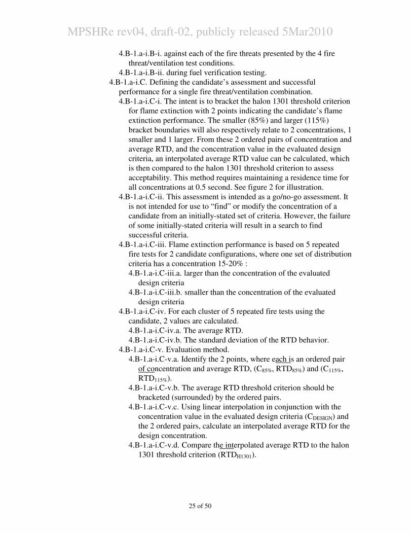
4.B-1.a-i.C. Defining the candidate’s assessment and successful
performance for a single fire threat/ventilation combination.
4.B-1.a-i.C-i. The intent is to bracket the halon 1301 threshold criterion
for flame extinction with 2 points indicating the candidate’s flame
extinction performance. The smaller (85%) and larger (115%)
bracket boundaries will also respectively relate to 2 concentrations, 1
smaller and 1 larger. From these 2 ordered pairs of concentration and
average RTD, and the concentration value in the evaluated design
criteria, an interpolated average RTD value can be calculated, which
is then compared to the halon 1301 threshold criterion to assess
acceptability. This method requires maintaining a residence time for
all concentrations at 0.5 second. See figure 2 for illustration.
4.B-1.a-i.C-ii. This assessment is intended as a go/no-go assessment. It
is not intended for use to “find” or modify the concentration of a
candidate from an initially-stated set of criteria. However, the failure
of some initially-stated criteria will result in a search to find
successful criteria.
4.B-1.a-i.C-iii. Flame extinction performance is based on 5 repeated
fire tests for 2 candidate configurations, where one set of distribution
criteria has a concentration 15-20% :
4.B-1.a-i.C-iii.a. larger than the concentration of the evaluated
design criteria
4.B-1.a-i.C-iii.b. smaller than the concentration of the evaluated
design criteria
4.B-1.a-i.C-iv. For each cluster of 5 repeated fire tests using the
candidate, 2 values are calculated.
4.B-1.a-i.C-iv.a. The average RTD.
4.B-1.a-i.C-iv.b. The standard deviation of the RTD behavior.
4.B-1.a-i.C-v. Evaluation method.
4.B-1.a-i.C-v.a. Identify the 2 points, where each is an ordered pair
of concentration and average RTD, (C85%, RTD85%) and (C115%,
RTD115%).
4.B-1.a-i.C-v.b. The average RTD threshold criterion should be
bracketed (surrounded) by the ordered pairs.
4.B-1.a-i.C-v.c. Using linear interpolation in conjunction with the
concentration value in the evaluated design criteria (CDESIGN) and
the 2 ordered pairs, calculate an interpolated average RTD for the
design concentration.
4.B-1.a-i.C-v.d. Compare the interpolated average RTD to the halon
1301 threshold criterion (RTDH1301).
MPSHRe rev04, draft-02, publicly released 5Mar2010
26 of 50
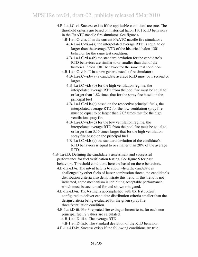
4.B-1.a-i.C-vi. Success exists if the applicable conditions are true. The
threshold criteria are based on historical halon 1301 RTD behaviors
in the FAATC nacelle fire simulator. See figure 4.
4.B-1.a-i.C-vi.a. If in the current FAATC nacelle fire simulator :
4.B-1.a-i.C-vi.a-(a) the interpolated average RTD is equal to or
larger than the average RTD of the historical halon 1301
behavior for the same test condition.
4.B-1.a-i.C-vi.a-(b) the standard deviation for the candidate’s
RTD behaviors are similar to or smaller than that of the
historical halon 1301 behavior for the same test condition.
4.B-1.a-i.C-vi.b. If in a new generic nacelle fire simulator :
4.B-1.a-i.C-vi.b-(a) a candidate average RTD must be 1 second or
larger.
4.B-1.a-i.C-vi.b-(b) for the high ventilation regime, the
interpolated average RTD from the pool fire must be equal to
or larger than 1.82 times that for the spray fire based on the
principal fuel
4.B-1.a-i.C-vi.b-(c) based on the respective principal fuels, the
interpolated average RTD for the low ventilation spray fire
must be equal to or larger than 2.05 times that for the high
ventilation spray fire
4.B-1.a-i.C-vi.b-(d) for the low ventilation regime, the
interpolated average RTD from the pool fire must be equal to
or larger than 3.15 times larger that for the high ventilation
spray fire based on the principal fuel
4.B-1.a-i.C-vi.b-(e) the standard deviation of the candidate’s
RTD behaviors is equal to or smaller than 20% of the average
RTD.
4.B-1.a-i.D. Defining the candidate’s assessment and successful
performance for fuel verification testing. See figure 5 for past
behaviors. Threshold conditions here are based on these behaviors.
4.B-1.a-i.D-i. The intent here is to show when the candidate is
challenged by other fuels of lesser combustion threat, the candidate’s
distribution criteria also demonstrate this trend. If this trend is not
indicated, some mechanism is inhibiting acceptable performance
which must be accounted for and shown mitigated.
4.B-1.a-i.D-ii. The testing is accomplished with the test fixture
configured to deliver candidate distribution criteria smaller than the
design criteria being evaluated for the given spray fire
threat/ventilation condition.
4.B-1.a-i.D-iii. For 3 repeated fire extinguishment tests, for each non-
principal fuel, 2 values are calculated.
4.B-1.a-i.D-iii.a. The average RTD.
4.B-1.a-i.D-iii.b. The standard deviation of the RTD behavior.
4.B-1.a-i.D-iv. Success exists if the following conditions are true.
MPSHRe rev04, draft-02, publicly released 5Mar2010
27 of 50
4.B-1.a-i.D-iv.a. the candidate’s average RTD, against a non-
principal fuel, is equal to or larger than the related average RTD
against the principal fuel.
4.B-1.a-i.D-iv.b. the standard deviation for each of the candidate’s
RTD behaviors is less than 20% of the related average RTD.
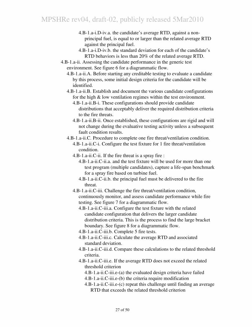
4.B-1.a-ii. Assessing the candidate performance in the generic test
environment. See figure 6 for a diagrammatic flow.
4.B-1.a-ii.A. Before starting any creditable testing to evaluate a candidate
by this process, some initial design criteria for the candidate will be
identified.
4.B-1.a-ii.B. Establish and document the various candidate configurations
for the high & low ventilation regimes within the test environment.
4.B-1.a-ii.B-i. These configurations should provide candidate
distributions that acceptably deliver the required distribution criteria
to the fire threats.
4.B-1.a-ii.B-ii. Once established, these configurations are rigid and will
not change during the evaluative testing activity unless a subsequent
fault condition results.
4.B-1.a-ii.C. Procedure to complete one fire threat/ventilation condition.
4.B-1.a-ii.C-i. Configure the test fixture for 1 fire threat/ventilation
condition.
4.B-1.a-ii.C-ii. If the fire threat is a spray fire :
4.B-1.a-ii.C-ii.a. and the test fixture will be used for more than one
test program (multiple candidates), capture a life-span benchmark
for a spray fire based on turbine fuel.
4.B-1.a-ii.C-ii.b. the principal fuel must be delivered to the fire
threat.
4.B-1.a-ii.C-iii. Challenge the fire threat/ventilation condition,
continuously monitor, and assess candidate performance while fire
testing. See figure 7 for a diagrammatic flow.
4.B-1.a-ii.C-iii.a. Configure the test fixture with the related
candidate configuration that delivers the larger candidate
distribution criteria. This is the process to find the large bracket
boundary. See figure 8 for a diagrammatic flow.
4.B-1.a-ii.C-iii.b. Complete 5 fire tests.
4.B-1.a-ii.C-iii.c. Calculate the average RTD and associated
standard deviation.
4.B-1.a-ii.C-iii.d. Compare these calculations to the related threshold
criteria.
4.B-1.a-ii.C-iii.e. If the average RTD does not exceed the related
threshold criterion
4.B-1.a-ii.C-iii.e-(a) the evaluated design criteria have failed
4.B-1.a-ii.C-iii.e-(b) the criteria require modification
4.B-1.a-ii.C-iii.e-(c) repeat this challenge until finding an average
RTD that exceeds the related threshold criterion
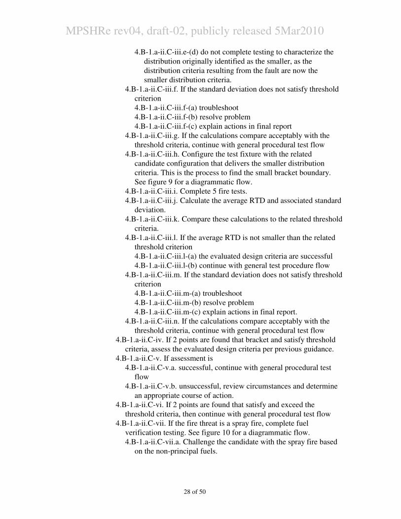
MPSHRe rev04, draft-02, publicly released 5Mar2010
28 of 50
4.B-1.a-ii.C-iii.e-(d) do not complete testing to characterize the
distribution originally identified as the smaller, as the
distribution criteria resulting from the fault are now the
smaller distribution criteria.
4.B-1.a-ii.C-iii.f. If the standard deviation does not satisfy threshold
criterion
4.B-1.a-ii.C-iii.f-(a) troubleshoot
4.B-1.a-ii.C-iii.f-(b) resolve problem
4.B-1.a-ii.C-iii.f-(c) explain actions in final report
4.B-1.a-ii.C-iii.g. If the calculations compare acceptably with the
threshold criteria, continue with general procedural test flow
4.B-1.a-ii.C-iii.h. Configure the test fixture with the related
candidate configuration that delivers the smaller distribution
criteria. This is the process to find the small bracket boundary.
See figure 9 for a diagrammatic flow.
4.B-1.a-ii.C-iii.i. Complete 5 fire tests.
4.B-1.a-ii.C-iii.j. Calculate the average RTD and associated standard
deviation.
4.B-1.a-ii.C-iii.k. Compare these calculations to the related threshold
criteria.
4.B-1.a-ii.C-iii.l. If the average RTD is not smaller than the related
threshold criterion
4.B-1.a-ii.C-iii.l-(a) the evaluated design criteria are successful
4.B-1.a-ii.C-iii.l-(b) continue with general test procedure flow
4.B-1.a-ii.C-iii.m. If the standard deviation does not satisfy threshold
criterion
4.B-1.a-ii.C-iii.m-(a) troubleshoot
4.B-1.a-ii.C-iii.m-(b) resolve problem
4.B-1.a-ii.C-iii.m-(c) explain actions in final report.
4.B-1.a-ii.C-iii.n. If the calculations compare acceptably with the
threshold criteria, continue with general procedural test flow
4.B-1.a-ii.C-iv. If 2 points are found that bracket and satisfy threshold
criteria, assess the evaluated design criteria per previous guidance.
4.B-1.a-ii.C-v. If assessment is
4.B-1.a-ii.C-v.a. successful, continue with general procedural test
flow
4.B-1.a-ii.C-v.b. unsuccessful, review circumstances and determine
an appropriate course of action.
4.B-1.a-ii.C-vi. If 2 points are found that satisfy and exceed the
threshold criteria, then continue with general procedural test flow
4.B-1.a-ii.C-vii. If the fire threat is a spray fire, complete fuel
verification testing. See figure 10 for a diagrammatic flow.
4.B-1.a-ii.C-vii.a. Challenge the candidate with the spray fire based
on the non-principal fuels.
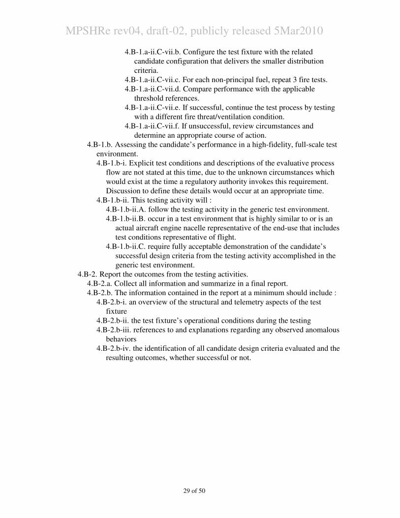
MPSHRe rev04, draft-02, publicly released 5Mar2010
29 of 50
4.B-1.a-ii.C-vii.b. Configure the test fixture with the related
candidate configuration that delivers the smaller distribution
criteria.
4.B-1.a-ii.C-vii.c. For each non-principal fuel, repeat 3 fire tests.
4.B-1.a-ii.C-vii.d. Compare performance with the applicable
threshold references.
4.B-1.a-ii.C-vii.e. If successful, continue the test process by testing
with a different fire threat/ventilation condition.
4.B-1.a-ii.C-vii.f. If unsuccessful, review circumstances and
determine an appropriate course of action.
4.B-1.b. Assessing the candidate’s performance in a high-fidelity, full-scale test
environment.
4.B-1.b-i. Explicit test conditions and descriptions of the evaluative process
flow are not stated at this time, due to the unknown circumstances which
would exist at the time a regulatory authority invokes this requirement.
Discussion to define these details would occur at an appropriate time.
4.B-1.b-ii. This testing activity will :
4.B-1.b-ii.A. follow the testing activity in the generic test environment.
4.B-1.b-ii.B. occur in a test environment that is highly similar to or is an
actual aircraft engine nacelle representative of the end-use that includes
test conditions representative of flight.
4.B-1.b-ii.C. require fully acceptable demonstration of the candidate’s
successful design criteria from the testing activity accomplished in the
generic test environment.
4.B-2. Report the outcomes from the testing activities.
4.B-2.a. Collect all information and summarize in a final report.
4.B-2.b. The information contained in the report at a minimum should include :
4.B-2.b-i. an overview of the structural and telemetry aspects of the test
fixture
4.B-2.b-ii. the test fixture’s operational conditions during the testing
4.B-2.b-iii. references to and explanations regarding any observed anomalous
behaviors
4.B-2.b-iv. the identification of all candidate design criteria evaluated and the
resulting outcomes, whether successful or not.
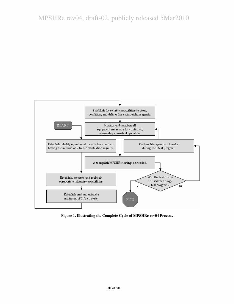
MPSHRe rev04, draft-02, publicly released 5Mar2010
30 of 50
Figure 1. Illustrating the Complete Cycle of MPSHRe rev04 Process.
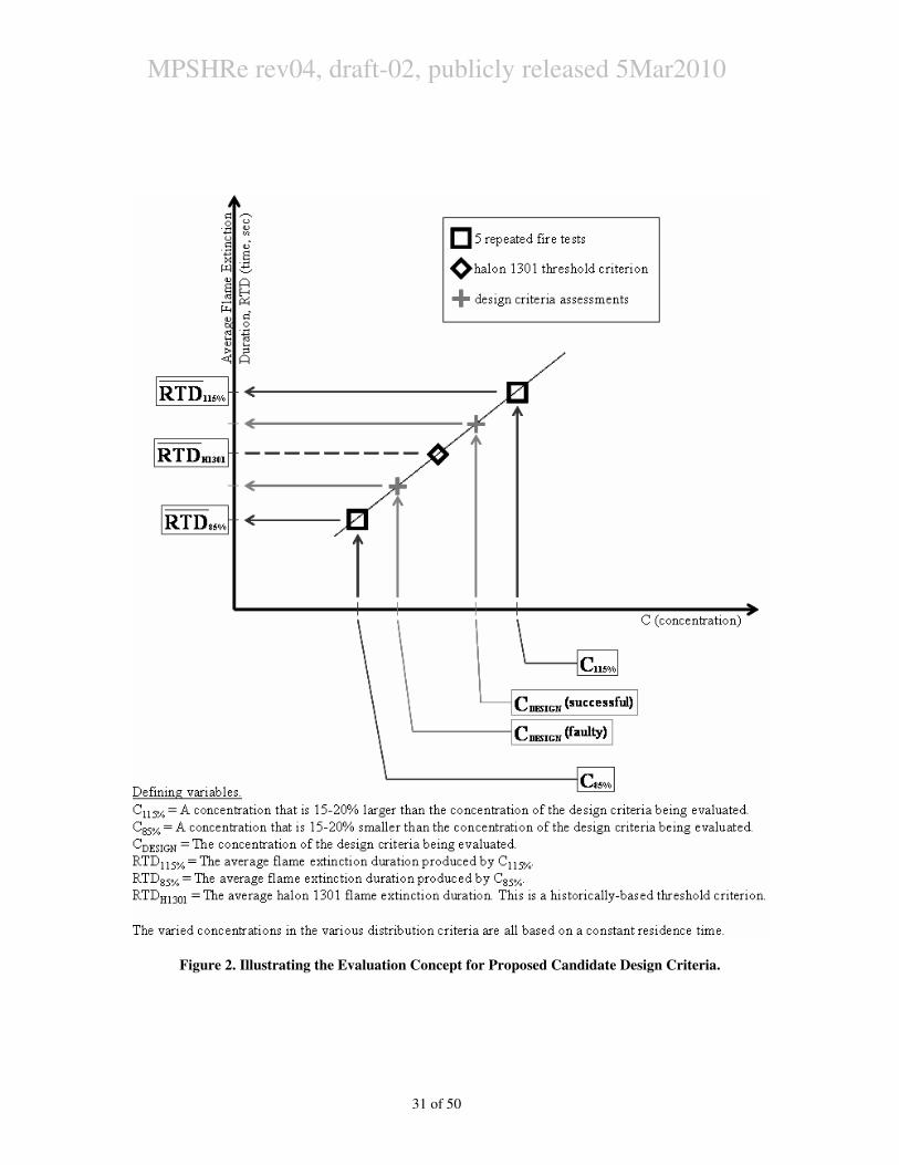
MPSHRe rev04, draft-02, publicly released 5Mar2010
31 of 50
Figure 2. Illustrating the Evaluation Concept for Proposed Candidate Design Criteria.
MPSHRe rev04, draft-02, publicly released 5Mar2010
32 of 50
Figure 3. Illustrating the Testing Cycle of MPSHRe rev04.
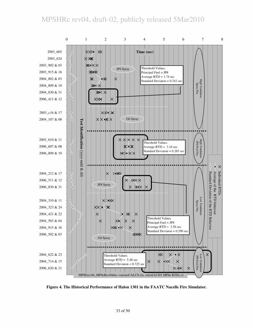
MPSHRe rev04, draft-02, publicly released 5Mar2010
33 of 50
Figure 4. The Historical Performance of Halon 1301 in the FAATC Nacelle Fire Simulator.
0 1 2 3 4 5 6 7 8
2003_605
2003_624
2003_902 & 03
2003_915 & 16
2004_802 & 03
2004_809 & 10
2004_830 & 31
2006_411 & 12
2003_c16 & 17
2004_107 & 08
2003_610 & 11
2006_607 & 08
2006_809 & 10
2004_212 & 17
2006_511 & 12
2006_830 & 31
2004_310 & 11
2004_323 & 24
2004_421 & 22
2004_503 & 04
2004_915 & 16
2006_502 & 03
2004_622 & 23
2004_714 & 15
2006_620 & 21
Test Id
entifica
tion
(yyyy-m
dd &
dd)
Time (sec)
Indiv
idu
al R
TD
s
Avera
ge o
f the R
TD
beh
avio
r
Sta
ndard
Dev
iatio
n o
f the R
TD
Beh
avio
r
MPSErev04_MPSeRev04doc-variousCALCS.xls, selctd h1301 MPSe RTDs c1
JP8 Spray
Oil Spray
JP8 Spray
Oil Spray
Threshold Values.
Principal Fuel = JP8
Average RTD = 1.74 sec
Standard Deviaton = 0.242 sec
Threshold Values.
Principal Fuel = JP8
Average RTD = 3.56 sec
Standard Deviaton = 0.290 sec
Threshold Values.
Average RTD = 3.16 sec
Standard Deviaton = 0.265 sec
Threshold Values.
Average RTD = 5.48 sec
Standard Deviaton = 0.725 sec
Hig
h V
entilatio
n
Sp
ray F
ire
Hig
h V
entilatio
n
JP8 P
oo
l Fire
Lo
w V
entilatio
n
Spra
y F
ire
Lo
w V
entilatio
n
JP8 P
oo
l Fire
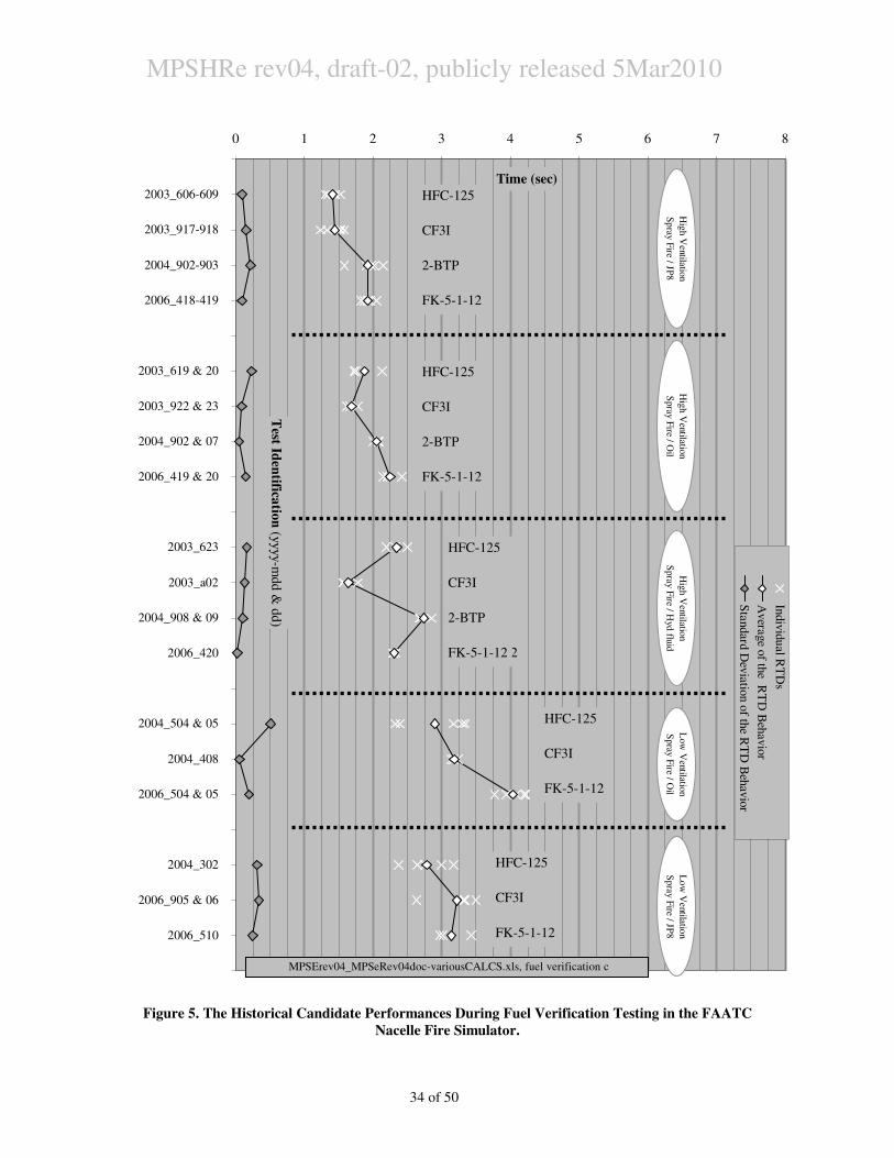
MPSHRe rev04, draft-02, publicly released 5Mar2010
34 of 50
Figure 5. The Historical Candidate Performances During Fuel Verification Testing in the FAATC
Nacelle Fire Simulator.
0 1 2 3 4 5 6 7 8
2003_606-609
2003_917-918
2004_902-903
2006_418-419
2003_619 & 20
2003_922 & 23
2004_902 & 07
2006_419 & 20
2003_623
2003_a02
2004_908 & 09
2006_420
2004_504 & 05
2004_408
2006_504 & 05
2004_302
2006_905 & 06
2006_510
Test Id
entifica
tion
(yyyy-m
dd
& d
d)
Time (sec)
Indiv
idu
al R
TD
s
Avera
ge o
f the R
TD
Beh
avio
r
Sta
ndard
Dev
iatio
n o
f the R
TD
Beh
avio
r
Hig
h V
entilation
Spray
Fire / O
il
Hig
h V
entilation
Spra
y F
ire / Hyd
fluid
Low
Ventilatio
n
Spray
Fire / O
il
Lo
w V
entilatio
n
Spra
y F
ire / JP8
HFC-125
CF3I
2-BTP
FK-5-1-12
HFC-125
CF3I
FK-5-1-12
MPSErev04_MPSeRev04doc-variousCALCS.xls, fuel verification c
Hig
h V
entilatio
n
Sp
ray F
ire / JP
8
HFC-125
CF3I
2-BTP
FK-5-1-12
HFC-125
CF3I
FK-5-1-12
HFC-125
CF3I
2-BTP
FK-5-1-12
HFC-125
CF3I
2-BTP
FK-5-1-12
HFC-125
CF3I
2-BTP
FK-5-1-12
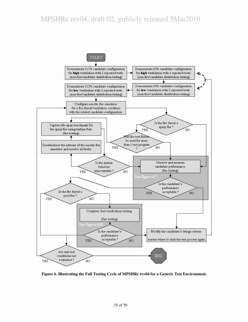
MPSHRe rev04, draft-02, publicly released 5Mar2010
35 of 50
Figure 6. Illustrating the Full Testing Cycle of MPSHRe rev04 for a Generic Test Environment.
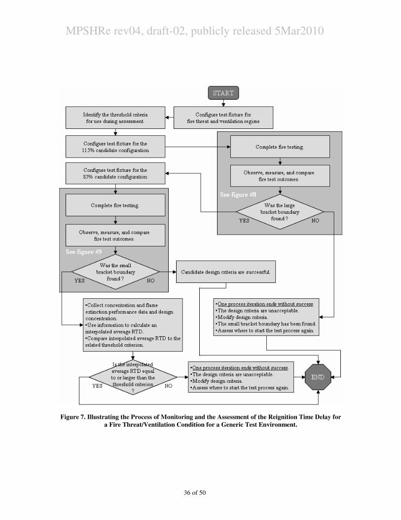
MPSHRe rev04, draft-02, publicly released 5Mar2010
36 of 50
Figure 7. Illustrating the Process of Monitoring and the Assessment of the Reignition Time Delay for
a Fire Threat/Ventilation Condition for a Generic Test Environment.
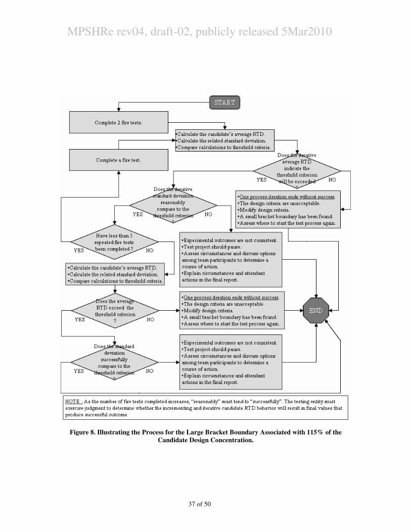
MPSHRe rev04, draft-02, publicly released 5Mar2010
37 of 50
Figure 8. Illustrating the Process for the Large Bracket Boundary Associated with 115% of the
Candidate Design Concentration.
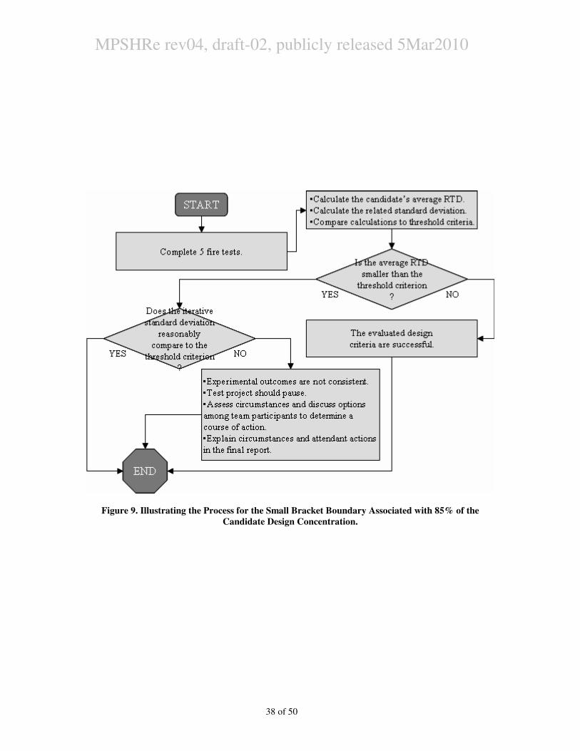
MPSHRe rev04, draft-02, publicly released 5Mar2010
38 of 50
Figure 9. Illustrating the Process for the Small Bracket Boundary Associated with 85% of the
Candidate Design Concentration.
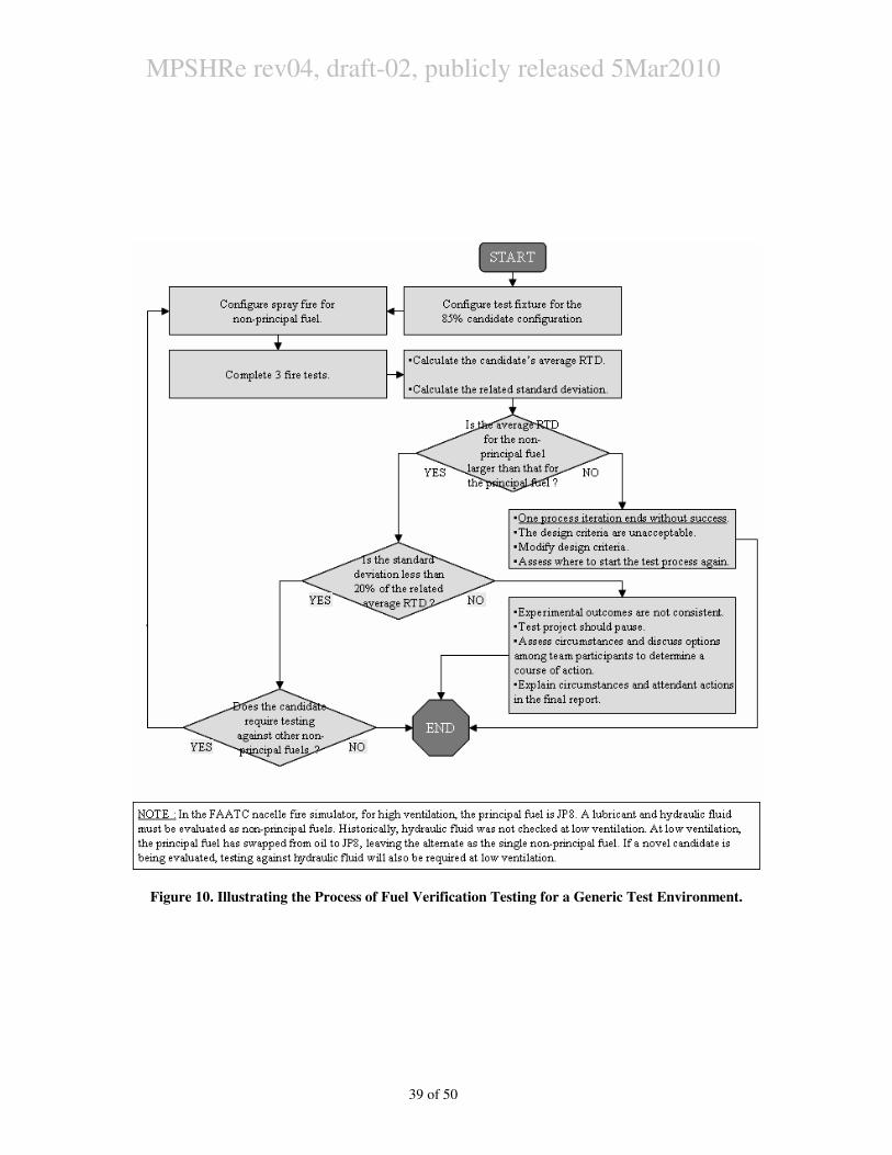
MPSHRe rev04, draft-02, publicly released 5Mar2010
39 of 50
Figure 10. Illustrating the Process of Fuel Verification Testing for a Generic Test Environment.
MPSHRe rev04, draft-02, publicly released 5Mar2010
40 of 50
5. Additional Commentary
5.A. Structure.
5.A-1. The size of the zone was selected on the basis of the range of fire zone sizes
of actual aircraft installations and considerations for a practical simulator where
physical parameters can be properly simulated and controlled.
5.A-2. A separate simulator for APU compartments is not necessary because
experience from testing by the U. S. Air Force has shown that the requirements
developed for the engine compartment provide equal or higher level of safety for
the APU compartment.
5.A-3. The FAATC nacelle fire simulator sits on a 372 m^2 (4000 ft^2) concrete
floor. It is composed of 27 m (90 ft) of air flow pathway. The test section, the
nacelle fire simulator, has an approximate volume of 2.83 m^3 (100 ft^3) with
an annular cross section of 0.873 m^2 (9.4 ft^2). Its core is a 6.4 mm x 610 mm
(0.25 x 24 inch) outside diameter steel tube surrounded by a steel skeleton
holding 5 pairs of steel doors that are hinged at the top and close to form a
concentric shell around the core. The up- and down-stream duct transitions are
fabricated from 16 gage, galvanized, sheet metal. This fixture has withstood
some 7 years of active fire testing using appropriate fire hardening, maintenance,
and repair as required. The access to the interior of the test section’s full length
is possible after every test.
5.B. Telemetry
5.B-1. The duration fire extinguishes then reignites is typically too quick to
interpret from thermocouple response, even if fine-wire, due to the sensor’s
thermal inertia. Comparison of various recording methods (thermocouple, video,
photodiode) from FAATC records clearly demonstrated superiority laid with
visual means to observe the fire extinction. Since the human interpretation from
video tape was the initial means to assess performance, it remains the choice
method so links to historical data can be maintained.
5.B-2. The visual records created at the FAATC reside on standard VHS tape as
recorded by a surveillance camera. The camera image passes through a video
time-date generator, having a stop watch capable of 0.01 second, before being
recorded to tape. The limitation of the store-bought video cassette recorder
permits a viewer to observe test behavior one video frame at a time, which
represents a duration of 0.02-0.04 second between frames.
5.B-2.a. These definitions are simplistic and have not been modified through the
various programs.
5.B-2.b. Fire extinction was defined by the complete lack of persistent flame in
the camera’s view field.
5.B-2.c. Fire reignition was defined as the “notable” change in the camera’s
view field that indicated the onset of the sequential and incrementally
intensifying change resulting with the fire again attaining the intensity
observed before candidate discharge.
MPSHRe rev04, draft-02, publicly released 5Mar2010
41 of 50
5.B-2.d. The pool and spray fire behaviors each had different characters, which
required variations of the aforementioned definitions of extinction and
reignition.
5.B-2.e. For a new simulator, testing is required prior to any evaluation
programs to understand how to reliably and consistently determine the fire
extinction duration.
5.B-3. Data-collection hardware and telemetry used at the FAATC includes :
5.B-3.a. There are two pieces of non-visual data collection hardware used at the
FAATC.
5.B-3.a-i. The first system has 88 channels. The unit is dedicated to capture
thermocouple and pressure transducer histories. Events for the pressure
transducers require sampling rates of 25 Hz or greater, whereas 5 Hz
provides useful thermocouple data. A single test is controlled by the data
collection system, given its ability to control relay functions.
5.B-3.a-ii. The second system has 13 channels. The unit is dedicated to
capturing the varying concentrations of gaseous fire extinguishing agents.
It samples at 10 Hz.
5.B-3.b. Fine-wire (28-32 AWG), exposed bead, thermocouples sense air
temperatures inside the test section at different locations to assess the air
temperature. The bulk ventilation temperature is calculated at one of these
locations (not exposed to fire). Other thermocouples are located inside the
volume of flame resulting from the fire threat.
5.B-3.c. Probe thermocouples measured agent temperature and air temperatures
where the air-sensing thermocouples were persistently bathed in flame during
testing.
5.B-3.d. No thermocouples were corrected for radiation heat transfer error
(analytically or physically).
5.B-3.e. A hot wire anemometer measured the center-line airflow of the inlet
duct for the nacelle fire simulator so the air mass flow passing through the
fixture could be recorded.
5.B-3.f. Pressure transducers were used to measure agent storage pressure in the
fire extinguisher assembly, static pressure at the inlet, in the test section, and
the exhaust duct; the static pressure transducers were added later in the
project.
5.B-3.g. Additional sensors have been employed over time on an as-needed basis
to better observe events of interest.
5.C. Ventilation Regimes
5.C-1. High ventilation corresponds to about 57 air changes per minute for the fire
zone having 1.84 m^3 (65 ft^3) volume and 0.511 m^2 (5.5 feet^2) cross
sectional area. For significantly different volume and cross section, the airflow
rates should be adjusted appropriately. These flow rates cover the significant
range of air flows in modern engine installations. This information is based on a
US Air Force survey. Note that ventilation airflow is a commonly used term for
airflow through the engine compartment.
MPSHRe rev04, draft-02, publicly released 5Mar2010
42 of 50
5.C-2. Air temperature as low as -40°C (-40°F) could exist in some cases.
Measurements have been made showing these temperatures can be experienced
in different places in a flight envelope. However, under these conditions an
engine fire threat is unlikely due to low power demand from the engine, cold
fuel and relatively cooler surfaces in the fire zone. In addition, these conditions
could delay the detection of a small fire which could result in an increase in air
temperature. These are adequate reasons to conclude that this fire threat could be
easily overcome by a system designed for larger fire threats which are likely
when the air and surface temperatures are higher. Therefore, it is not necessary
to simulate air temperatures below the ambient conditions in the test facility.
However, for consistency between tests conducted during different ambient
conditions, a controlled air temperature is preferred. Therefore 38°C (100°F) is
selected to represent the lower end of the temperature range.
5.C-3. FAATC test fixture.
5.C-3.a. The amount of air flow through the test fixture is controlled by
perforated baffles that choke the inlet suction of the supply blower that
pressurizes the simulator. A more restrictive baffle is used to provide the
lower air flow rate, a less restrictive baffle for the higher. Recent
measurements and somewhat more complex calculations based on flows
through the inlet duct indicate the low ventilation rate is around 0.45 kg/s (1.0
lbm/s) and the high ventilation rate around 1.2 kg/s (2.7 lbm/s). Variation is
observed to be +/- 0.1 lbm/s for both instances.
5.C-3.b. The air heating is completed by electrical resistance heaters upstream of
the test section to attain the 38°C (100°F) design point. The same heaters are
used in conjunction with an oil burner to attain the second design point. The
oil burner is ducted into roughly the first half of internal volume of the core.
Its effluent is exhausted through pipes downstream from and around the fire
scenarios. The core surface is known to reach 371°C (700°F) at one location
away from the fire scenarios during this type of operation.
5.C-3.c. The average airflow temperature is calculated from a collection of 8
type-K thermocouples distributed over the free-stream path in one cross
section near the front of the test section, approximately 1.2 m (4 ft) forward
of the fire threats.
5.D. Candidate Storage, Delivery, and Quantification.
5.D-1. Candidate Storage.
5.D-1.a. The fire extinguisher storage vessel used at the FAATC has varied
between a frequently-used, uniquely-designed assembly and true aircraft fire
extinguisher bottles.
5.D-1.b. The fire extinguisher at the FAATC is a unit formerly provided to the
FAA by the USAF.
5.D-1.b-i. The unit is a uniquely designed/fabricated assembly composed of a
modified, steel, 20.7 MPa (3000 psig), 18.9 L (5 gal) hydraulic
accumulator, strapped by circular band heaters with electric controls, and
capped by a 31.8 mm (1.25 inch) pneumatically-controlled ball valve to
discharge the agent. The agent containment can be varied both in volume
MPSHRe rev04, draft-02, publicly released 5Mar2010
43 of 50
and temperature. The firex valve is remotely actuated by electrical signal,
either manually or from a data collection system.
5.D-1.b-ii. The agent storage temperature is indicated by a probe
thermocouple in the center of the discharge throat cross section at the
bottom of the assembly just above the discharge valve. A pressure
transducer records the pressure inside the containment in the discharge
throat from a tap 90° from the thermocouple tap.
5.D-2. Candidate Delivery.
5.D-2.a. The specifications in the section are purposely vague. The future can
not be predicted well. However, an applicant must meet the intent of this
section, yet reasonably deliver the candidate being considered.
5.D-2.b. Candidate injection must reasonably minimize the insult on the fire
threats from phenomena not evaluated by this process.
5.D-2.b-i. The parameters being evaluated per this process are candidate
concentration and residence time. The phenomena being evaluated are the
effects of a dispersed agent concentration and residence time on the fire
threat behaviors. Nothing else.
5.D-2.b-ii. Injection plumbing must be installed in the test section to
reasonably minimize, if not eliminate, any flame extinguishment
mechanisms except for the candidate concentration.
5.D-2.c. The injection plumbing used at the FAATC has typically been bent
stainless steel tubes of varying diameter from 12.7 – 31.8 mm (0.5 – 1.25
inch), wall thickness, and length with hand-swaged compression fittings that
connect the agent containment to the interior of the test section.
5.D-2.d. No injection plumbing points at or in the general direction of the fire
threats and separation exists between the injection planes and the fire threats.
5.D-2.d-i. Halon 1301 Injection
5.D-2.d-i.A. For high ventilation, halon 1301 injection occurs
approximately 1.8 m (6 ft) forward of the fire scenarios and at low,
approximately 1.5 m (5 ft) forward.
5.D-2.d-i.B. Nozzle orientation
5.D-2.d-i.B-i. The high ventilation nozzles inject agent through 6
nozzles. There are 3 on either side of the core in the test fixture. One
nozzle, one each at approximately 02:00 and 10:00, directs agent
upstream 45° above horizontal and into the ventilation stream at
12:00. A tee provides 2 nozzles, one each at 04:00 and 08:00, that
radially inject opposed jets impacting the core and shell surfaces.
Radial injection is perpendicular to the bulk flow.
5.D-2.d-i.B-ii. Low ventilation nozzles inject agent through 6 nozzles,
3 per side, at approximately 1:00 and 11:00. The injection is
perpendicular to the bulk ventilation. On each side, two tees form a
single injection nozzle assembly. One tee ends the branch line,
where one outlet feeds the 2nd
tee and the other opposed outlet
discharges fire extinguishing agent on the shell. The 2nd
tee produces
2 opposed jets, one directed at 12:00 on the shell and the opposed jet
MPSHRe rev04, draft-02, publicly released 5Mar2010
44 of 50
to hit another location on the shell., as described by the chord of a
circle.
5.D-2.d-ii. Past Candidate Injection.
5.D-2.d-ii.A. The injection plumbing was conceptually similar for all
candidate configurations.
5.D-2.d-ii.B. There were 8 nozzles which injected the candidate. The
nozzles result from the use of 4 tees which provide opposed injection
jets during agent discharge.
5.D-2.d-ii.C. The tees were positioned near where the branch lines
penetrated the test fixture’s shell at approximately 01:30, 04:30, 07:30,
and 10:30. The bodies of the tees were aligned so the opposed jets laid
against and ran along the inner surface of the test fixture shell.
Hypothetically, the agent formed a circumferential cloud when injected.
5.D-2.d-ii.D. The line diameters were varied to choke the agent flow
during discharge, dependent on needed outcome.
5.D-3. Quantification
5.D-3.a. A cup-burner assay will be the basis for the smallest design
concentration to be evaluated by MPSHRe rev04 processes, due to similarity
of combustion challenge posed by an accidental nacelle fire and that of the
cup-burner flame.
5.D-3.a-i. Acceptable guidance describing a cup-burner assay is offered by
the National Fire Protection Association.
5.D-3.a-ii. Work has also been accomplished at the U.S. National Institute of
Standards and Technology.
5.D-3.b. Candidate Concentration Measurement.
5.D-3.b-i. Ancillary testing was accomplished during May-September 2009
looking at the wake region behaviors of some flow obstructions relating to
the FAATC nacelle fire simulator. Outcomes are used here to assist with
identifying how sample points to measure candidate concentration should
be selected.
5.D-3.b-i.A. Two efforts were accomplished.
5.D-3.b-i.A-i. Wake regions behind 2 flow-obstructions similar to those
in the FAATC nacelle fire simulator were observed in a small-scale
wind tunnel using smoke-laden flow visualization. The observations
were used to guide the placement of hot-wire anemometer and gas
analyzer sample points in the FAATC nacelle fire simulator for
subsequent testing.
5.D-3.b-i.A-ii. The wake regions behind 2 flow obstructions in the
FAATC nacelle fire simulator were observed during varied
ventilation conditions during the discharges of halon 1301, HFC-
125, and CF3I. The data collected included gas analysis and hot-wire
anemometry histories. One flow obstruction was the tube bundle,
representing the hot surface reignition threat for the spray fire threat.
The second flow obstruction was the forward lip of the fuel pan used
in the pool fire threat.
MPSHRe rev04, draft-02, publicly released 5Mar2010
45 of 50
5.D-3.b-i.B. Outcomes.
5.D-3.b-i.B-i. In both efforts, the concentration behaviors in the wake
regions were expectedly seen deficient to or lagging behind the free-
stream flow behaviors, as indicated by measured concentration from
the different markers (smoke and fire extinguishing agents).
5.D-3.b-i.B-ii. When considering the flow obstructions presented by the
tube bundle and fuel pan lip, the more challenging wake region was
behind the fuel pan lip.
5.D-3.b-i.B-ii.a. Such observation is reasonable, given the fuel pan
lip is attached to a wall, and the tube bundle is not.
5.D-3.b-i.B-ii.a-(a) The geometric height of both obstructions
were similar, approximately 25 mm (1 inch) each, as seen by
the flow.
5.D-3.b-i.B-ii.a-(b) The tube bundle is suspended in and
perpendicular to the bulk flow. The flow splits around the
obstruction’s cross section, where its wake forms downstream
from the cross section.
5.D-3.b-i.B-ii.a-(c) The fuel pan lip is attached to a wall and
perpendicular to the flow. The flow does not split around the
obstruction’s cross section. It passes to one side, where its
wake forms downstream from the cross section.
5.D-3.b-i.B-ii.b. The practical understanding relates to the increased
washing of the tube bundle’s wake region by a larger flow
volume.
5.D-3.b-i.B-ii.b-(a) Due to the bundle’s suspension in the flow,
the wake is washed by flow passing around and coming from
both sides of the assembly’s cross section.
5.D-3.b-i.B-ii.b-(b) The wake region of the fuel pan lip is washed
from only one side of the lip’s cross section.
5.D-3.b-i.B-iii. The fire extinguishing system configurations originally
used in the FAATC nacelle fire simulator to meet the intent of FAA
certification for halon 1301 maintained acceptable behavior when
the wake regions behind the tube bundle and the fuel pan lip were
sampled for both ventilation regimes.
5.D-3.b-ii. Agent concentration measurement at the FAATC.
5.D-3.b-ii.A. General comments.
5.D-3.b-ii.A-i. A modified, Pacific Scientific HTL Halonyzer II is used
to capture the behaviors of gaseous agents within the FAATC test
fixture.
5.D-3.b-ii.A-ii. A varying 0-5 direct current voltage is used to indicate
the gaseous concentration.
5.D-3.b-ii.A-iii. Twelve sample points are captured for each
distribution test.
5.D-3.b-ii.A-iv. The analyzer is maintained on-site.
5.D-3.b-ii.B. Gas analyzer sample probe installation per MPSHRe rev03.
MPSHRe rev04, draft-02, publicly released 5Mar2010
46 of 50
5.D-3.b-ii.B-i. The 12 sample points were separated into 3 rings of 4
points.
5.D-3.b-ii.B-ii. Each point was positioned at the midpoint between any
structural surfaces inside the test section proximal to the sampling
point. The intent was to capture the free stream concentration
behavior.
5.D-3.b-ii.B-iii. The forward and aft rings were separated by 0.61 m (2
ft) and have the same clock positions of 12:00, 03:00, 06:00, and
09:00 for the sampling points.
5.D-3.b-ii.B-iv. The mid ring was positioned at the flame front, was
equidistant between the fore and aft rings, and had a pseudo-120°
separation scheme in the simulator’s cross section. The fourth point
on the ring was a redundant sample point used at the flame front.
Clock positions were chosen based on the fire scenario; a pool fire
had 01:30, 05:45, 06:15, and 10:30 positions, and the spray fire had
12:15, 04:30, 07:30, and 11:45 positions.
5.D-3.b-ii.B-v. The tubing used for sampling was a 3.6 m (12 ft) length
of 3.18 mm (0.125 inch) outside diameter soft copper refrigeration
line. The tube dimensions were chosen to minimize the internal
volume to enhance the analyzer response yet access the internal
sampling locations. The material was chosen to resist the thermal
insult from low ventilation air flow. The orifice’s circular plane for
each tube end was parallel to the average direction of the ventilation
flow.
5.D-3.b-ii.C. Gas analyzer sample probe installation per MPSHRe rev04.
5.D-3.b-ii.C-i. All previous statements remain accurate with one
modification.
5.D-3.b-ii.C-ii. The modification affects the mid ring of sample points.
5.D-3.b-ii.C-ii.a. The mid ring will remain positioned at the cross
section of the fire threat flame fronts, equidistant between the
fore and aft rings.
5.D-3.b-ii.C-ii.b. A 120° separation will again be used, and a single
point will removed and placed to sample the wake region behind
the fuel pan lip of the pool fire.
5.D-3.b-ii.C-ii.b-(a) The 3 points of the mid ring will be located
at the geometric midpoint between the shell and core structure
on the radius.
5.D-3.b-ii.C-ii.b-(b) One point will be located each at clock
positions of 04:30, 07:30, and near 12:00.
5.D-3.b-ii.C-ii.b-(c) The fourth point of the mid ring will be
removed and placed in the wake region of the fuel pan lip of
pool fire threat. The point will be 25 mm (1 inch) aft of the lip
and 13 mm (0.5 inch) below the top of the lip. This location is
approximately at 06:00 in the cross section of the FAATC
nacelle fire simulator.
MPSHRe rev04, draft-02, publicly released 5Mar2010
47 of 50
5.E. Fire Threats.
5.E-1. General Comments.
5.E-1.a. A fire in an engine or an APU compartment is probable when a fuel and
air mixture come in contact with an ignition source and result in a sustainable
combustion reaction. Airflow through an engine or APU compartment is
normal and a fuel source is possible due to leakage of aviation engine fuel,
hydraulic fluid or engine oil or due to a failure expelling these fuels. The
ignition source could be any surface at a temperature above the hot surface
ignition temperature for the fuel in the compartment. Electrical arcs or
frictional sparks as a result of a failure may also provide potential ignition
sources. Ignition can also occur if the fuel enters an environment in which
rapid heating causes it to exceed its autoignition temperature. Three typical
combustible fluids for the fire must be considered: aviation engine fuel,
hydraulic fluid and engine oil.
5.E-1.b. In an aircraft installation, when the fire alarm is received an action is
initiated resulting in a sequence of events. The engine fuel supply is shut off
first. Hot air and electrical sources may also be shut off before activation of
the fire extinguishing system. If the alarm occurs during the climb phase of
the flight, more than a minute may elapse between the alarm and the
discharge of the agent. In other cases, this elapsed time may be shorter than a
minute.
5.E-1.c. Proper operation of the fuel delivery system for a simulator, including
nozzles, should be checked to assure that the fire size and intensity are
reproducible in tests with similar conditions. A measurement of heat flux
density to characterize the fire is not necessary. Undue importance could be
attached to this parameter as a means to determine reproducibility of fires
while the measurement itself could depend on a variety of different factors.
5.E-1.d. If keeping the candidate’s injection duration reasonably similar, when
the injected mass is increased, the RTD should increase.
5.E-1.d-i. If mapping the RTD behavior as related to injected candidate mass,
the relationship has demonstrated a linearity for gaseous candidates, in
particular HFC-125.
5.E-1.d-ii. However, the limitations imposed by the injection plumbing on the
discharge flow and/or the candidate properties may invalidate this
observation.
5.E-1.d-iii. Testing required to define the candidate configurations will
provide insight.
5.E-1.e. Fuel verification failed once during testing at the FAATC for the
duration between 2003-2006 while evaluating HFC-125, CF3I, and FK-5-1-
12.
5.E-1.f. A second concept is rationalized to assist with evaluating a candidate’s
design criteria in a more confident manner, beyond the go/no-go conditions
offered in this document. This process requires the assessment of 2 design
criteria. One would be deficient, and the second successful. This
MPSHRe rev04, draft-02, publicly released 5Mar2010
48 of 50
methodology perhaps offers more confidence in the subsequent outcome for
successful criteria.
5.E-2. Fire Threat Intensity
5.E-2.a. The fire scenario intensity is established purely by experimentation.
Combinations of ventilation rate, flame-holder (clutter) geometry, fuel spray
flow rate or pool geometry, electrical arc type and position, and hot surface
type and position are all factors which require investigation so that the
collective scenario can produce a sufficiently intense fire consistent with
citation “Acceptable fire intensity”.
5.E-2.b. Since halon 1301 will not be discharged in MPSHRe rev04 and beyond,
any new test fixture will be subject to multi-point verification to prove
sufficiently intense fire threats exist.
5.E-2.c. The existing test fixture at the FAA Technical Center has been shown to
provide conditions for adequately intense fire threats, and that experience is
the basis for the criteria specified.
5.E-2.c-i. Intensity in the FAATC nacelle fire simulator was established by :
5.E-2.c-i.A. not attaining any fire extinction by injecting half the design
criteria for halon 1301 for the total residence time.
5.E-2.c-i.B. injection of volumes of pressurized nitrogen over past test
activities spanning the last 7 years. The nitrogen discharge portrayed in
this document represents the most invasive insult offered in the test
database for the FAATC nacelle fire simulator.
5.E-2.c-ii. Combustion intensity was calculated for the fire threats in the
FAATC nacelle fire simulator.
5.E-2.c-ii.A. These calculations were based on measurements made with
type-K thermocouples that surrounded a portion of the flame volume
for the respective fire threats. Symmetry was invoked where
advantageous.
5.E-2.c-ii.B. The thermocouples measured temperature histories of steel
boundaries and the airflow moving through the a portion of the cross
section. These temperature histories were analyzed. A representative
temperature increase was calculated.
5.E-2.c-ii.C. Thermal energy output was calculated by summing the
products of an individual temperature increase, mass of the substance
related to the temperature increase, and the specific heat related to the
substance and appropriately accounting for the duration of measure.
5.E-2.c-ii.D. The thermocouple indications were not corrected for
radiation error.
5.E-3. FAATC spray fire scenario.
5.E-3.a. The fuel line supplying the 2 fuel nozzles is contained within a water
jacket for 95% of its length inside and outside of the test section. Reasonable
control for the fuel temperature is maintained during testing.
5.E-3.b. Flame attachment provision is accomplished by discharging the fuel
sprays from the 2 nozzles whose orifices are each approximately 25 mm (1
inch) above a 50.8 mm tall x 6.4 mm thick (2 x 0.25 inch) rib fastened to the
MPSHRe rev04, draft-02, publicly released 5Mar2010
49 of 50
core surface. The nozzle spray plumes are directed downstream along the
core parallel to the ventilation flow. Upon attaining the initial ignition, if the
arc is turned off, the fire continues at its initial intensity. The spray fire
demonstrates repeatable and acceptable intensity at a total flow rate of 0.25
gpm.
5.E-3.c. The electrical arc is maintained in the right-most fuel spray cone and
left continually operating for the full length of the test. It is persistently
checked and maintained.
5.E-3.c-i. The tips are cleaned after every test by wiping off debris and
residue with a cloth wetted by a non-aggressive cleaner.
5.E-3.c-ii. The tips are maintained at a consistent gap in a consistent location.
5.E-3.c-iii. The tips are stainless steel electrodes which can be found at any
company capable of repairing most home-heating, oil burning appliances.
5.E-3.c-iv. The arc is provided by stepping up 120 VAC, 60 Hz electricity to
10,000 VAC using a transformer. A suitable transformer can be taken
from any home-heating oil burning appliance.
5.E-3.c-v. The electrical arc used in the FAATC facility is based on locally
available hardware. A testing entity can use resources readily available to
them ranging from store-bought material from local stores to parts
scavenged from aircraft. Regardless of approach, note that the arc must be
shown to reliably ignite the fuel spray and be persistently present during
any test.
5.E-3.d. The hot surface is an array of tubes.
5.E-3.d-i. A tube array is located roughly 381 mm (15 inch) downstream from
the fuel nozzles. It is a collection of four 12.7 mm (0.5 inch) diameter, 864
mm (34 inch) long x 0.889 mm (0.035 inch) wall stainless steel tubes.
Cutting a cross section through one finds the centers of the four circles
making the corners of a rhombus. The upper pair of tubes straddles the top
of the rear tube in the lower pair. They are bent to a radius which is
concentric with the core. They are held approximately 64 mm (2.5 inch)
above the core surface. The four tubes are bound tightly together with
safety wire and worm-gear clamps and are wired to a pair of rigid core
mounting bracket. A probe thermocouple is bound in between the tubes
and the bead sits near 12:00.
5.E-3.d-ii. Typical temperatures observed from this thermocouple range
between 760 - 982°C (400-1800°F). The range of temperature is related to
the structural alteration of the tube array during repeated heating and
cooling cycles resulting from testing. The tip is exposed to direct flame
(higher temperature) or hidden by tube (lower temperature). In the testing
between 2003 – 2006, there is only one observed instance that the tube
array alteration affected the behavior of the test outcomes. A problem was
discovered then resolved, and normal test behavior subsequently resumed.
5.E-3.d-iii. The tube array is heated by the preburn duration of the fire threat
and functions as a hot surface ignition threat reliably. It has a finite life
MPSHRe rev04, draft-02, publicly released 5Mar2010
50 of 50
span of 10 tests, as its properties begin to change somewhere beyond this
number which then affects the reliability of the reignition delay.
5.E-4. FAATC pool fire scenario
5.E-4.a. The pool of fuel is 13 mm deep x 274 mm wide x 521 mm long (0.5 x
10.8 x 20.5 inch). The long dimension is parallel to the central axis of the test
fixture and ventilation stream. The pool sits inside a steel pan assembly that
has water passages in its bottom to cool the fuel and assembly to a reasonable
extent during each fire test. The forward lip of the pool provides a 25 mm (1
inch) tall baffle for flame attachment purposes.
5.E-4.b. There is no active effort to maintain a constant fuel depth during a test.
5.E-4.c. The electrical arc is found on the longitudinal center-line 432 mm (17
inch) aft of the forward lip for high ventilation and 254 mm (10 inch) aft for
low. The actual arc gap is located at the fuel surface because testing indicated
the reliability of reignition was an abrupt function of height above the fuel’s
surface. The electrical arc is maintained on for the full length of each test and
is cleaned afterwards. Descriptions of the electrical system producing the arc
and the cleaning process are provided in comments in this section for the
spray fire threat, titled “FAATC spray fire scenario”.
5.E-4.d. The preburn duration is 90 seconds.
5.E-5. Ranking the spray fire intensities in the FAATC nacelle fire simulator.
5.E-5.a. Establishing the relationship was completed by simply recording the
thermal energy behaviors of the fire by thermocouple.
5.E-5.b. Intensity ranking proved easily at high ventilation. The largest areas
under the thermocouple traces indicated which fuel was most severe for the
evaluated conditions. The duration the fire was extinguished given a constant
agent and mass corroborated the thermal observations. Turbine fuel is the
most severe for these conditions in the FAACT nacelle fire simulator.
5.E-5.c. Intensity ranking at low ventilation was confounding. Early thermal
histories recorded for oil produced larger areas under the thermocouple traces
instead of the turbine fuel. Hydraulic fluid character was similar to oil. As a
contradiction, during work with FK-5-1-12 in 2006, the duration the fire was
extinguished for an oil spray fire was longer than that for turbine fuel. Halon
1301 repeated the contradiction. Work in 2003 with HFC-125 did not indicate
this contradiction. During the fuel verification testing, the contradiction was
caught and permitted determining outcome based on the most severe fire
threat condition (turbine fuel). As of this writing, reasons explaining why this
change occurred remain unclear and will not be investigated.
5.F. Life-span Benchmarks.
5.F-1. In the case of the FAATC nacelle fire simulator, the life-span benchmark
configurations are being worked to relate to previous experimentation.
5.F-2. The configurations are planned to relate to the performance of HFC-125,
based its recommended criteria from MPSHRe rev03 of 17.6%v/v HFC-125 for
0.5 second..