Embed Size (px)
Citation preview

DORCHESTER COUNTY
WATER & SEWER DEPARTMENT
MINIMUM STANDARDS FOR THE DESIGN AND
CONSTRUCTION OF WATER AND SANITARY
SEWER SYSTEMS

DORCHESTER COUNTY
WATER & SEWER DEPARTMENT
MINIMUM STANDARDS FOR THE DESIGN AND
CONSTRUCTION OF WATER AND SANITARY
SEWER SYSTEMS
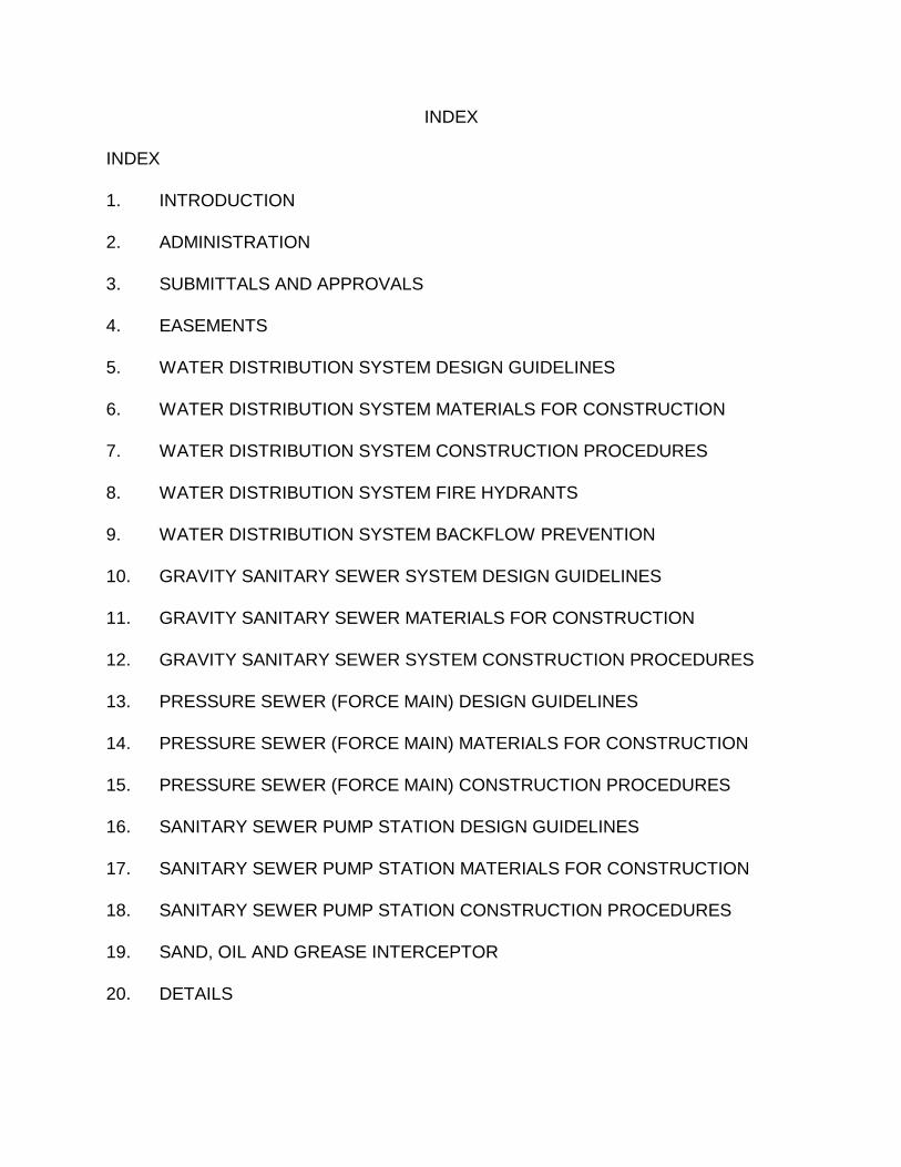
INDEX
INDEX
1. INTRODUCTION
2. ADMINISTRATION
3. SUBMITTALS AND APPROVALS
4. EASEMENTS
5. WATER DISTRIBUTION SYSTEM DESIGN GUIDELINES
6. WATER DISTRIBUTION SYSTEM MATERIALS FOR CONSTRUCTION
7. WATER DISTRIBUTION SYSTEM CONSTRUCTION PROCEDURES
8. WATER DISTRIBUTION SYSTEM FIRE HYDRANTS
9. WATER DISTRIBUTION SYSTEM BACKFLOW PREVENTION
10. GRAVITY SANITARY SEWER SYSTEM DESIGN GUIDELINES
11. GRAVITY SANITARY SEWER MATERIALS FOR CONSTRUCTION
12. GRAVITY SANITARY SEWER SYSTEM CONSTRUCTION PROCEDURES
13. PRESSURE SEWER (FORCE MAIN) DESIGN GUIDELINES
14. PRESSURE SEWER (FORCE MAIN) MATERIALS FOR CONSTRUCTION
15. PRESSURE SEWER (FORCE MAIN) CONSTRUCTION PROCEDURES
16. SANITARY SEWER PUMP STATION DESIGN GUIDELINES
17. SANITARY SEWER PUMP STATION MATERIALS FOR CONSTRUCTION
18. SANITARY SEWER PUMP STATION CONSTRUCTION PROCEDURES
19. SAND, OIL AND GREASE INTERCEPTOR
20. DETAILS

SECTION 1
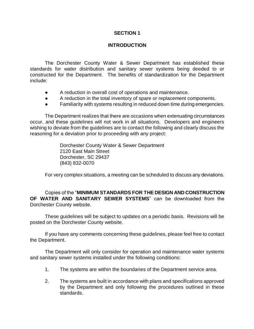
INTRODUCTION
SECTION 1
INTRODUCTION
The Dorchester County Water & Sewer Department has established these
standards for water distribution and sanitary sewer systems being deeded to or
constructed for the Department. The benefits of standardization for the Department
include:
● A reduction in overall cost of operations and maintenance.
● A reduction in the total inventory of spare or replacement components.
● Familiarity with systems resulting in reduced down time during emergencies.
The Department realizes that there are occasions when extenuating circumstances
occur, and these guidelines will not work in all situations. Developers and engineers
wishing to deviate from the guidelines are to contact the following and clearly discuss the
reasoning for a deviation prior to proceeding with any project:
Dorchester County Water & Sewer Department
2120 East Main Street
Dorchester, SC 29437
(843) 832-0070
For very complex situations, a meeting can be scheduled to discuss any deviations.
Copies of the “MINIMUM STANDARDS FOR THE DESIGN AND CONSTRUCTION
OF WATER AND SANITARY SEWER SYSTEMS” can be downloaded from the
Dorchester County website.
These guidelines will be subject to updates on a periodic basis. Revisions will be
posted on the Dorchester County website.
If you have any comments concerning these guidelines, please feel free to contact
the Department.
The Department will only consider for operation and maintenance water systems
and sanitary sewer systems installed under the following conditions:
1. The systems are within the boundaries of the Department service area.
2. The systems are built in accordance with plans and specifications approved
by the Department and only following the procedures outlined in these
standards.

3. Prior to any project’s approval the Developer makes the necessary
arrangements with the Department of the commitment of water and/or
sanitary sewer system capacity. Projects will not be submitted to the South
Carolina Department of Health and Environmental Control (SCDHEC) until
such commitments are obtained.

SECTION 2
ADMINISTRATIVE

SECTION 2
ADMINISTRATION
The following is a general description of the responsibilities of the parties
involved with the design, review and approval of projects for the Department.
A. DORCHESTER COUNTY WATER & SEWER DEPARTMENT
1. The Department will review plans and specifications submitted and grant
approval after all requested revisions, if any, have been completed.
2. The Department will reserve the right to request changes in the work that is
not in accordance with the Department’s Design and Construction
Specifications or if work is being performed in an improper manner that may
result in incorrect installation of the water distribution system and/or the
sanitary sewer system.
3. All work rejected by the Department shall be removed and redone to the
satisfaction of the Department.
4. The Department reserves the right to request any work to be uncovered if
the work was covered contrary to the Department’s request, if defective work
is suspected or to correct defects discovered during the Department’s
inspections.
5. The Department reserves the right to disallow work from an Engineer or
Developer who consistently does not comply with the Department’s Design
and Construction Guidelines.
6. The Department reserves the right to request revisions to the Developer’s or
to the Developer’s Design Engineer’s plans for any discrepancies found
during construction that may have been overlooked during review of the
plans and specifications.
B. DEVELOPER’S DESIGN ENGINEER
1. The Developer’s Design Engineer is the Engineer hired by a Developer or
property owner to prepare a set of plans and specifications and/or an
Engineer hired by a Developer who is responsible for construction
administration of a project from plans and specifications prepared by another
Engineer.
2. The Developer’s Design Engineer will:
a. Prepare plans and specifications in accordance with the Department’s
Design and Construction Guidelines, South Carolina Department of
Health and Environmental Control Regulations and all other local,
state and federal regulations pertaining to the project.
b. Submit plans and specifications for review to the Department.
c. Make revisions necessary for the plans and specifications to comply
with the Department’s Design and Construction Standards.
d. Review all phases of the work in progress during construction and
observe required testing of systems with the Department’s field
representative.
e. Certify that work performed is in accordance with the plans and
specifications and the Department’s Design and Construction
Specifications.
f. Promptly furnish the Department with pertinent information
concerning any changes which may be necessary during the progress
of the work. No major changes shall be performed without the prior
approval of the Department.
g. Obtain final approval from the Department and applicable local, state,
and federal agencies.
C. DEVELOPER
1. The Developer shall be considered the person or entity initiating the development of
a new residential, commercial, industrial or institutional property. The Developer
may or may not be the property owner. This person or entity shall have the legal
authority to execute necessary permits, applications, and legal documents which
require the Developer’s/Owner’s signature. This same person or entity will execute
all documents throughout the project unless the project is sold, in which case this
authority is transferred to the new Developer.
2. The Developer will:
a. Provide accurate information as to the person or entity responsible for the
development and their contact information.
b. Be responsible for payment of all fees required in accordance with
Department Standards.
c. Be financially responsible for future requests for repairs if any arise during
the bond period after take-over of the system.
SECTION 3
SUBMITTALS AND APPROVALS
SECTION 3
SUBMITTALS AND APPROVALS
In order to expedite the approval process of new water distribution systems
and sanitary sewer collection system extensions, the Department has divided the
process into the following: Preliminary Approval, Final Approval, Shop Drawings,
Project Completion, Operation and Maintenance Manuals and Project Completion
and Takeover. The submittals required for each part are described herein:
A. GENERAL
1. Developers shall secure all necessary permits for any projects that are
submitted to the Department office for review. Copies of permits shall be
forwarded to the Department for final approval and signature.
2. All connections to the existing Department water system or sanitary sewer
system must be approved and inspected by the Department’s personnel.
3. No water or sanitary sewer system shall be put into service, nor will any
service application be accepted, until all approved project completion and
closeout documents, all required fees and the permit to operate as issued by the
South Carolina Department of Health and Environmental Control (SCDHEC) are
received by the Department.
4. The Department shall have exclusive retail rights.
5. Prior to designing water and wastewater systems, the Developer and the
Developer’s Engineer are encouraged to take into careful consideration the
County’s Water and Sewer Ordinance. The Developer and Engineer may want
to see the Department’s Developer Guide as well.
6. Submittal packages are to be sent to the Department as follows:
Dorchester County Water & Sewer Department
2120 East Main Street
Dorchester, SC 29437
B. PRELIMINARY APPROVAL
1. Developers, Designers, Planners, Engineers and others associated with
implementing projects should meet with the Department’s Engineering Staff
to review plans and specifications and coordinate proposed projects with the
Department.
2. The Developer’s Design Engineer shall submit a preliminary review package
to the Department. The package shall include the following:
a. Two (2) complete sets of Plans should include:
i. Complete system design
ii. Location and width of all the Department’s easements
iii. All rights-of-way indicated as either public or private. Plans
should also indicate ownership of existing roadways (City,
County, or State). Indicate the agency to operate and maintain
proposed roadways. Show all easements and rights-of-way
and their ownership (SCE&G, SCPSA, Bell South, etc.)
iv. Location and size of all proposed water and sewer services
and size
v. County Tax Map Reference Number of Property
vi. All other items on the plan review checklist in Appendix B
b. One (1) set of typed and bound, or stapled, Specifications if required
by the Department.
c. One (1) copy of all design calculations.
3. The Department will return to the engineer:
a. Written design change comments and, if applicable one, (1) set of
plans/specifications, which will indicate corrections if necessary. If
there are no comments, written Preliminary Approval will be returned.
b. Notification of any required encroachment applications, certifications,
permits, or easements known by the Department. The Developer’s
Engineer is still responsible for determining other permits or
easements that may affect the project.
c. Request for any other required information pertinent to the proposed
project.
C. FINAL APPROVAL
1. Once preliminary approval is received and all required fees in the Ordinance
are paid, the Developer’s Design Engineer is to submit the following:
a. For sewer projects, the complete SCDHEC DRP submittal package
except the transmittal and acceptance letters from the Department.
The package will be checked by the Department before submitting to
SCDHEC. For water projects, the engineer shall
b. One (1) copy of each item in the water and/or sewer SCDHEC
submittal packages plus two (2) additional copies of the plans.
D. SHOP DRAWINGS
1. The Developer’s Design Engineer shall review shop drawings in compliance
with the Department’s approved plans and specifications and the
Department’s Design and Construction Minimum Standards.
2. Make shop drawings accurately to a scale sufficiently large to show all
pertinent aspects of the item and its method of connection to the Project.
3. Where contents of submittal literature from manufacturers includes data not
pertinent to the submittal, clearly show which portions of the contents are
being submitted for review.
E. PROJECT CONSTRUCTION
1. The Developer’s Contractor shall notify the Department in writing of
commencement of work three (3) working days prior to starting
construction.
2. A pre-construction conference shall be held with the Department Inspector,
the Developer’s Contractor, and the Developer’s Engineer
F. OPERATION AND MAINTENANCE MANUALS
1. Prior to start-up, provide the Department with operation, maintenance, and
service manuals (O&M Manuals) for each piece of equipment.
2. Prepare and submit two (2) copies of O&M Manuals for each piece of
equipment.
3. The O&M Manuals will be prepared in the format that follows:
a. Manuals shall be specific to the equipment supplied.
1) Manuals applicable to many different configurations and which
require the operator to selectively read portions of the
instructions will not be accepted.
2) The equipment model that the manual applies to shall be
indicated by an arrow.
b. Table of Contents specific to each manual.
c. At the beginning of each manual, provide a description of the
equipment to include model numbers, purchase order numbers, serial
numbers, motor information, and performance and design criteria.
d. Correlate manuals with approved shop drawings and include the
following minimum information:
1) Parts list, including recommended spare parts list.
2) Guaranties.
3) Recommended maintenance instructions.
4) Recommended lubricants and lubrication instructions.
5) Address and telephone numbers of the source for repairs,
spare parts, and service.
6) Detailed description of operating procedures for the item of
equipment specifically written for this installation, including
start-up and shut-down procedures.
7) Equipment performance specifications, including pump curves.
8) Results of start-up and any further recommendations resulting
from start-up.
e. Provide a maintenance and lubrication schedule to be a summary of
all preventative maintenance and lubrication, including the following
information:
1) Title
2) Type of activity (inspection, adjustment, oil changes, etc.)
3) Brief description of activity
4) Type of lubricant
5) Frequency (daily, weekly, etc.)
f. Provide clear and legible copies. Type parts lists, etc.
g. Layout and detail drawings shall be reduced to a maximum size of 11"
x 17", unless written approval is received from the Department prior to
submittal of manuals.
h. Provide a clearly labeled three-ring binder for manuals having
thickness greater than ¼”.
1) Provide sheet lifters.
G. PROJECT COMPLETION AND TAKEOVER
1. Upon completion of construction, the Developer’s Design Engineer shall
submit two copies of the record drawings and request an inspection by the
Department’s Utility Inspector.
2. The Developer’s Design Engineer shall provide one review copy of each
required plat and legal document prior to recording of documents and
submittal of the final closeout documents. The final closeout submittal shall
include following as one package:
a. Certification in writing from the Developer’s Design Engineer that the
water and/or sanitary sewer system has been constructed in
accordance with the Department’s approved Plans, Specifications,
applicable permits and good engineering practice.
b. Statement from the Design Engineer of the value of the water system
and the value of the sewer system, as applicable.
c. One (1) set of white mylar reproducible (not sepia mylar), one (1) set
of full size prints and one (1) set of half size or 11x17 prints of “As
Constructed Record Drawings”. These drawings shall reflect all
“as constructed” conditions for mains, water service and sewer lateral
placement in the format that follows:
1) Plan View for all water and wastewater systems.
2) Profile View for all wastewater mains of any size and water
mains 12” and larger.
3) Plan view of the pump station site.
4) Cross section of the pump station wetwell.
5) Property lines, block designations, lot numbers and, when
available, TMS numbers.
6) Station and state plane coordinates at all valves, manholes,
fire hydrants, bends, blow-offs, tees, reducers, increasers,
water and sewer services and air release valves.
7) Line lengths, connection points and termination points.
8) Valves located by distance to two permanent reference points.
9) Indicate top elevations and invert elevations of manholes.
10) Reference benchmarks on drawings and elevation datum
used.
11) All recorded plat and easement information.
12) Drawings clearly legible and of good quality.
13) The Department will review the “Record Drawings” but the
Department is not responsible for the accuracy of record
drawings. If the drawings indicate inaccuracies, they will be
returned to the Developer’s Design Engineer for revisions. The
system acceptance letter will not be issued until the drawings
are acceptable.
14) Engineer’s certification, seal, and signature. The engineer
may use the following statement: “It is my opinion that the
water/sewer system shown hereon has been constructed
substantially in accordance with the plans and specifications
approved by Dorchester County Water and Sewer and
SCDHEC.
e. Digital Data Submission
1) A completed original CAD drawing in Autocad 2007 or earlier
format of each record drawing and valve card. The files shall
be named using the development name or Department project
number.
2) The water and sewer lines shall be easily identified by layer
name (i.e. New_Water, N-W, etc.)
3) The drawings shall use South Carolina State Plane (SCSP)
coordinates. Features in drawing files that are stored in
drawing units must be translated to represent real world
locations as referenced by SCSP coordinates.
4) Each record drawing or valve card in .pdf format
f. Legal documents in the Department’s standard form. The documents
shall be prepared and signed by the Developer and recorded by the
Department. The Developer shall provide the required Register of
Deed (ROD) recording fee. The documents shall include:
1) Title to the water and/or sewer systems.
2) Bill of Sale
3) Easement (if the Department must access private property to
maintain the system.
4) Title to real estate for projects with pump stations, wells or
water towers.
g. One (1) print of the recorded easement and/or subdivision plats.
Each must have original signature and seal and must be no larger
than 22" x 34" in accordance with Register of Deeds (ROD) Office
requirements. The Department may record plats if they are for the
sole purpose of providing an easement. The Developer will be
responsible for providing the appropriate recording fee. The
Department will not accept compiled maps as land surveys. The
width of the easements for water and sewer mains shall be a
minimum of twenty (20) feet. All water and sewer mains within the
easement shall be platted so as to provide equal distance on each
side of the as-construction location of the main. Plats cannot be
accepted unless these requirements are met.
h. Certified Contractor’s Affidavit and Final Waiver of Lien.
i. Results and documentation of all testing and inspections except items
prepared by the County.
j. Payment of all fees, bonds, and other financial obligations as required
in the current Dorchester County Water and Sewer Ordinance.

3. When the above items are completed to the Department’s satisfaction, the
Department will issue an acceptance letter to SCDHEC with copies to all
involved parties. Until such time as this letter is provided and SCDHEC’s
letter allowing the systems to be placed into operation has been received,
NO CONNECTIONS TO THE SYSTEMS WILL BE PERMITTED.
SECTION 4
EASEMENTS
SECTION 4
EASEMENTS
1. Easements shall be conveyed to the Department in a standard acceptable form.
2. The Developer will record all easements.
1. All water mains and sanitary sewer facilities shall be installed outside of
pavement when possible.
4. The width of the easements for water mains, sewer mains, and force mains shall
be a minimum of twenty (20) feet.
5. Widths of easements for gravity sewers greater than fourteen (14) feet in depth
or between buildings shall be a minimum of thirty (30) feet. Widths of
easements for gravity sewers greater than eighteen (18) feet in depth shall be a
minimum of forty (40) feet.
6. Widths of easements for facility access roads shall be a minimum of twenty-five
(25) feet.
7. All water and sewer mains within the easement shall be platted so as to provide
equal distance on each side unless the Department determines this to be
impractical.
8. Structures are not permitted within the easement.
9. When water and sewer mains are placed in the same easement, increase the
width of the easement to comply with the “Recommended Standards for Water
Works” and “Recommended Standards for Wastewater Facilities” (“Ten States
Standard”) with a distance from the edge of the easement to the sewer main not
less than ten (10) feet.
10. Clear all easements of trees and debris unless an exception is approved during
design review to meet the applicable tree ordinance or to avoid disturbing
wetlands. The easement is to be grassed unless other treatment is specifically
approved by the Department.
11. When a water or wastewater main within a public right-of-way is within 5 feet of
the right-of-way line, an easement will be required. The easements shall be
determined by 4 and 5 above or as otherwise determined by the Department.

12. The Department reserves the right to increase the width of easements when
conditions are determined to require the increase.
SECTION 5
WATER DISTRIBUTION SYSTEM
DESIGN GUIDELINES
SECTION 5
WATER DISTRIBUTION SYSTEM
DESIGN GUIDELINES
A. GENERAL
1. The following water system design guidelines are based on Federal, State
and local health requirements and the Department’s engineering design
criteria.
2. Design criteria not indicated herein shall comply with “Ten States Standards”
where applicable.
3. All installations are to meet the bacteriological and chemical quality
standards of the South Carolina Department of Health and Environmental
Control (SCDHEC).
4. These design guidelines are applicable to all developments including but not
limited to residential, commercial and industrial developments, subdivisions,
and/or parks requiring water service from the Department.
B. SYSTEM DESIGN CRITERIA
1. Distribution main size: minimum 6" diameter unless otherwise approved by
the Department. Water main providing fire service shall be a minimum of 6".
2. Arrange mains so they are looped and interconnected at intersections.
3. Comply with all application requirements of Federal, State, and local
regulations.
4. When a design is being considered for a project, a main depth of between 3'-
5' below finish grade should be used to establish main and branch line
profiles.
C. SIZING OF LINES
1. Pipe size 6" and larger:
a. Size piping based on either 1/5 the maximum instantaneous demand
plus fire flow or maximum instantaneous demand, whichever is
greater. When fire protection is to be provided, system design should
be such that fire flows and facilities are in accordance with the
requirements of the Department and the state Insurance Service
Office (ISO). Minimum fire flow shall be 1000 gpm unless it is
determined by the Developer’s Engineer and the Department that this
requirement cannot be met and a lower flow will be sufficient. The
design flow to fire hydrants shall not be less than 500 gpm over and
above the total peak hourly flow.
2. Design for 2.5 feet per second flushing velocity per SCDHEC regulations.
3. All water mains, including those not designed to provide fire protection, shall
be sized using a hydraulic analysis based on flow demands and pressure
requirements. The minimum pressure in all public water mains under
conditions of maximum instantaneous demand shall be twenty-five (25)
pounds per square inch at every customer’s tap. Twenty (20) pounds per
square inch will be acceptable at any tap when fire flows are provided in
excess of maximum peak hourly flow [R61-58.4(D)(4)(a)]. The normal
working pressure in the distribution system should be approximately 60 psi
and not less than 35 psi.
4. The Developer’s Design Engineer is to determine available static and
residual pressures at the delivery point for the water to a new development.
The pressure and flow shall be certified by an engineer who is registered in
the State of South Carolina.
5. The Developer’s Design Engineer shall use a maximum Hazen-Williams
design coefficient of 130 for PVC and PE pipe or 120 for ductile iron pipe.
6. The maximum instantaneous demand is to be calculated using the
Community Water System Source Book by Joseph S. Ameen or other
method approved by the Department.
D. VALVES
1. Provide three (3) valves for a tee intersection.
2. Provide four (4) valves for a cross intersection.
3. Sufficient valves shall be provided on water mains so that inconvenience
and sanitary hazards will be minimized during repairs. Valves should be
located at not more than 500 foot intervals in commercial districts and one
block or 800 foot intervals in other districts. Valves should be placed to
minimize the number of the Department’s customers out of service due to a
main break and/or any maintenance operation. The Department reserves
the right to require additional valves if it is deemed in the best interest of
current and future Department customers.
E. INDUSTRIAL OR SPECIAL DESIGN CONDITIONS
1. Design of water systems for industrial or other systems not covered under
this section shall be approved on a special case basis only. Special
requests need to be made to the Department.
2. Fire line sprinkler systems and dedicated fire lines, except those in the high
hazard category, as defined by SCDHEC, shall be protected by an approved
double check valve assembly.
F. DEAD ENDS
1. Minimize dead ends by looping of all mains.
2. Where dead ends occur, provide a fire hydrant on lines 6" and larger. The
Department does not permit installation of Post Hydrants for the purposes of
flushing. Flushing devices should be sized to provide flows which will give a
velocity of at least 2.5 feet per second in the water main being flushed. No
flushing device shall be directly connected to any sewer or storm sewer.
3. Blowoffs on dead ends will be considered on a case by case basis where fire
flow is not feasible and not required by the appropriate fire department
and/or fire inspector. Blowoffs on temporary dead ends will be considered
on a case by case basis.
G. SEPARATION OF WATER MAINS AND SEWERS
1. Where possible, locate water line at least ten (10) feet away horizontally
from sewer mains. The distance shall be measured to outside edges of
pipes.
2. Should ten (10) foot separation not be practical, then the water main may be
located closer provided:
a. It is laid in a separate trench.
b. It is laid in the same trench with the water main located at one side of
a bench of undistributed earth.
c. In either of the above cases, crown elevation of the sewer shall be at
least 18" below invert elevation of water line at a diagonal of 45.
3. Where water lines cross over or under sewers, maintain 18" minimum
vertical distance between the outside of the water main and the outside of
the sewer. If water mains are within 18” of a sewer main, both the water and
sewer main will be ductile iron. At crossings, one full length of water pipe
shall be located so both joints will be as far from the sewer as possible.
Special structural support for the water and sewer pipes may be required.
a. Special Cases
1) Water mains may not be placed in contaminated areas unless
piping material is adequate to protect the water quality [R.61-
58.4(D)(11)(h)].
2) Water mains may not be less than 25 feet from any waste
water tile field or spray field [R.61-58.4(D)(12)(f)].
3) There may not be any connection between the distribution
system and any pipes, pumps, hydrants, or tanks whereby
unsafe water or other contaminated materials may be
discharged or drawn into the system [R.61-58.4(D)(14)(a)].
4) Neither stream condensate nor cooling water from jackets or
other heat exchange devices may be returned to the potable
water supply [R.61-58.4(D)(14)(b)].
H. SEWER AND STORM DRAINAGE SYSTEM INTERFERENCE
1. No water pipe shall pass through or come in contact with any part of a sewer
manhole or storm drainage pipe or structure.
I. EXCEPTION
1. The Department must specifically approve any variance from any
requirements when it is impossible to obtain the specified distances.
J. SURFACE WATER AND WETLANDS CROSSINGS
1. Surface water and wetland crossings, whether over or under water, present
special problems. The Department should be consulted before plans are
prepared. Water mains crossing surface waters must be adequately
supported and anchored, protected from damage and freezing, and be
accessible for repair or replacement [R.61-58.4(D)(13)(a)]. Maintain a
minimum cover of 2 feet for water mains crossing under water. When
crossing water courses which are greater than 15 feet in width, the following
must be provided.
a. The pipe material and joints shall be designed appropriately [R.61-
58.4(D)(13)(b)(I)].
b. Valves must be located so that the section can be isolated for testing
or repair; the valves must be easily accessible, and not subject to
flooding; and [R.61-58.4(D)(13)(b)(ii)],
c. A blow-off must be provided on the side opposite the supply service,
sized in accordance with [R.61-58.4(D)(7)[R.61-58.4(D)(13)(b)(iii)].
K. WATER MAIN RESTRAINT
1. Provide restrained joint pipe and fittings in accordance with Section 6 Part I.
2. The Department may approve the use of thrust blocks on a case by case
basis. The concrete mix shall have 28-day compressive strength of not less
than 3,000 pounds per square inch. The design shall use a maximum soil
pressure of 2000 lbs/sq ft and a safety factor of 2. Place the block so that the
pipe and fitting joints will be accessible to repairs, unless otherwise shown.
L. COVER
1. Provide suitable cover on all distribution mains. Minimal cover depth as
follows:
a. Typical minimum cover: 36".
b. All piping located within the right-of-way of the South Carolina
Department of Transportation and the Department shall have a
minimum cover of 48" below the crown of the road when installed
within the limits of the paved roadway, 36" cover when installed in the
shoulder of right-of-way and a minimum of 18" separation under the
design invert of drainage structures. The greater dimension of the
above shall dictate minimum depth where applicable.
c. Special conditions other than those listed above may be approved if
requested in writing from the Department.
d. Water lines crossing open ditches shall have a minimum of 24" of
cover from bottom of ditch invert to top of pipe. If this is not possible,
install ductile iron pipe (DIP) with a minimum cover of 12".
M. DUCTILE IRON PIPE LOCATIONS
1. Where water crosses beneath the sewer, the sewer main shall transition to
ductile iron pipe and the length of pipe shall be centered on the water main
so that joints will be equidistant.
2. Main lines on residential lots shall be ductile iron. Other main lines outside
of a public right-of-way will be reviewed on a case by case basis to
determine if ductile iron will be required.
.
N. TAP SIZE IN RELATION TO MAIN SIZE
1. Water taps shall not be larger than the main being tapped.
2. The Department reserves the right to stipulate the maximum size tap
available off of any water main regardless of the main size and configuration.
O. AIR RELEASE VALVES
1. Mains shall be designed to minimize high points. At high points in water
mains where air can accumulate, provisions shall be made to remove the air
by means of an air release valve. Automatic air release valves shall not be
used in situations where flooding of the manhole or chamber may occur. Air
valves should be sized based on the size of the water main. Air valves
should be detailed on the design drawings and approved by the Department.
Air release valves must incorporate an open end of an air relief pipe from
automatic valves or from a manually operated valve must be extended to the
top of the pit and provided with a screened downward facing elbow
[R.61.58.4(10)(b)].
P. BLOW OFF CHAMBERS
1. General
a. Lines 6" and larger require 500 gpm to achieve a 2.5 fps scouring
velocity. This would require a standard fire hydrant or other approved
blow-off for flushing. The line must be designed to provide at least
500 gpm in excess of peak hourly flow and a minimum residual
pressure of 20 psi. [R.61-58.4.D(7)(e)].
b. Chambers, pits, or manholes containing valves, blow-offs, or other
such appurtenances on a distribution system shall not be connected
directly to any storm drain or sanitary sewer, nor shall blow-offs or air
relief valves be connected directly to any sewer.

c. The Department may allow a temporary blowoff on a case by case
basis where the main is to be extended in the near future.
SECTION 6
WATER DISTRIBUTION SYSTEM
MATERIALS FOR
CONSTRUCTION
SECTION 6
WATER DISTRIBUTION SYSTEM
MATERIALS FOR CONSTRUCTION
A. GENERAL
1. Unless otherwise noted or approved by the Department all materials shall be
manufactured in the United States. This section includes pipe and fitting material
specification, joint material and encasement requirements.
B. MATERIALS
1. General:
a. All standards cited in the text refer to the latest revision of that
standard under the same specification number or to superseding
specifications under a new number.
b. All chemicals/products added to public water supply must be third
party certified as meeting the specifications of ANSI/NSF Standard
60.
c. All materials/products that contact potable water must be third party
certified as meeting the specifications of ANSI/NSF Standard 61.
d. The pressure rating of pipe must be capable of handling 1.5 times the
normal working pressure.
e. No asbestos cement pipe allowed except in the repair of existing
asbestos cement lines.
f. PVC pipe may not be used above grade.
g. All pipe fitting, packing, jointing materials, and valves must conform to
Section C of the AWWA Standards.
h. Previously used water lines that have been out of service will not be
accepted by the Department.
C. POLYVINYLCHLORIDE (PVC) PIPE
1. Plastic pipe (PVC):
a. General:
1) Marked with National Sanitation Foundation approval at 18"
intervals.
2) Gaskets to comply with ASTM F477.
a) Natural rubber gaskets are not acceptable.
b. 6" - 12":
1) Comply with ANSI/AWWA C900, Table 2, Pressure Class 150
marked with National Sanitary Foundation (NSF) approved at
18" intervals. Solvent-weld PVC pipe and fittings will not be
accepted by the Department.
c. 14" and larger:
1) Comply with ANSI/AWWA C905 Table 2, pressure class 165
marked with National Sanitary Foundation (NSF) approved at
18" intervals. Solvent-weld PVC pipe and fittings will not be
accepted by the Department.
D. DUCTILE IRON PIPE (DIP
1. All sizes of pipe shall be laying length of 18'-0" to 20'-0" and shall only be
used on ditch crossings or when crossing above or below sewer mains.
2. Quality Assurance
a. Reference Standards of the American National Standards Institute
(ANSI)
1) A21.4 Cement-mortar lining for cast iron and ductile
iron pipe and fittings for water (AWWA C104).
2) A21.10 Gray iron and ductile iron fittings, 3" through 48"
for water and other liquids (AWWA C110).
3) A21.11 Rubber gasket joints for cast iron and ductile
iron pressure pipe and fittings (AWWA C111).
4) A21.15 Flanged cast iron and ductile iron pipe with
threaded flanges (AWWA C115).
5) A21.50 Thickness design of ductile iron pipe (AWWA
C150).
6) A21.51 Ductile iron pipe centrifugally cast, in metal
molds or sand lined molds, for water or other
liquids (AWWA C151).
7) A21.53 Ductile iron compact fitting for 3" through 12"
(AWWA C153).
8) B16.1 Cast iron pipe flanges and flanged fittings, Class 25, 125, 250,
and 800.
b. Reference Standards of the American Water Works Association
(AWWA)
1) C600 Installation of ductile iron water mains and their appurtenances.
2) C651 Disinfecting water mains.
3. Wall thickness in accordance with Table 51.1 of ANSI/AWWA C151/A21.51
with working pressure of 150 psi, depth of cover indicated and Type 2
bedding conditions. Final pipe class shall be determined based on specific
structural calculations as they relate to conditions encountered during
design. The Department reserves the right to designate the final pipe
thickness.
a. 6" - 12" class 52
b. 14" - 64" pressure class 250
c. Flanged pipe shall be class 53 (minimum)
d. Underwater pipe shall be a minimum of class 52.
4. Use cement mortar lining: ANSI/AWWA C104/A21.4, standard thickness.
5. Use mechanical or push-on joints: ANSI/AWWA C111/A21.11 as modified by
ANSI/AWWA C151/A21.51.
6. Use rubber gaskets and lubricant: ANSI/AWWA C111/A21.11.
a. Natural rubber gaskets are not acceptable.
7. No metric sized pipe shall be permitted.
8. All pipe to be shipped with gaskets, glands, and bolts unless specified
otherwise. High tensile strength tee bolts and nuts shall be low alloy steel.
Bolted joints for underwater pipe shall be furnished with 316 stainless steel
nuts and bolts. The 316 grade shall be clearly indicated with marks on the
bolt and nut.
9. All pipe lengths must be tested to 500 psi working pressure prior to shipping.
10. Threaded flange pipe must be tested after the installation of the threaded
flange. Pipe with threaded components, i.e. flange or bell must be tested
after installation of threaded component.
11. All new transmission water mains must be permanently marked in the
Department’s easement with Department-approved above-ground markers.
12. Acceptable products: American Cast Iron Pipe Company, Griffin Pipe
Company, U.S. Pipe Company, and McWane Cast Iron Pipe Company
E. HIGH DENSITY POLYETHYLENE (HDPE) PIPE
3. High Density Polyethylene (HDPE) pipe shall be used only for directional
drilling under creeks or marsh crossings unless otherwise approved by the
Department.
2. Comply with AWWA C-906, SDR 11 and working pressure of 160 psi
minimum.
3. The pipe supplied shall be SDR high performance, high molecular weight,
high density polyethylene pipe, and shall conform to ASTM D 1248 (Type III
C, Category 5, P34). Minimum cell classifications values shall be 345434C
as referenced in ASTM D-3350 - latest edition. All pipe resin shall be
manufactured by the same company that manufactures the pipe itself in
accordance with these specifications to insure complete resin compatibility
and total product accountability. The fittings supplied in this specification
shall be molded or manufactured from a polyethylene compound having a
cell classification equal to or exceeding the compound used in the pipe. To
insure compatibility of polyethylene resins, all fittings supplied under this
specification shall be of the same manufacture as the pipe being supplied.
4. Physical properties:
a. The pipe shall conform to the physical properties as described herein.
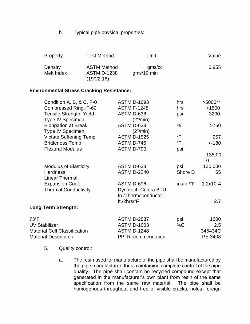
b. Typical pipe physical properties:
Property Test Method Unit Value
Density ASTM Method gms/cc 0.955
Melt Index ASTM D-1238 gms/10 min
(190/2.16)
Environmental Stress Cracking Resistance:
Condition A, B, & C, F-0 ASTM D-1693 hrs >5000**
Compressed Ring, F-60 ASTM F-1248 hrs >1500
Tensile Strength, Yield ASTM D-638 psi 3200
Type IV Specimen (2"/min)
Elongation at Break ASTM D-638 % >750
Type IV Specimen (2"/min)
Victate Softening Temp ASTM D-1525 F 257
Brittleness Temp ASTM D-746 F <-180
Flexural Modulus ASTM D-790 psi
135,00
0
Modulus of Elasticity ASTM D-638 psi 130,000
Hardness ASTM D-2240 Shore D 65
Linear Thermal
Expansion Coef. ASTM D-696 in./in./F 1.2x10⁻⁴
Thermal Conductivity Dynatech-Colora BTU,
In./Thermoconductor
ft./2hrs/F 2.7
Long Term Strength:
73F ASTM D-2837 psi 1600
UV Stabilizer ASTM D-1603 %C 2.5
Material Cell Classification ASTM D-1248 345434C
Material Description PPI Recommendation PE 3408
5. Quality control:
a. The resin used for manufacture of the pipe shall be manufactured by
the pipe manufacturer, thus maintaining complete control of the pipe
quality. The pipe shall contain no recycled compound except that
generated in the manufacturer’s own plant from resin of the same
specification from the same raw material. The pipe shall be
homogenous throughout and free of visible cracks, holes, foreign
inclusions, or other deleterious defects and shall be identical in color,
density, melt index, and other physical properties.
The polyethylene resin used shall have all ingredients pre-compound
prior to extrusion of pipe, in plant blending is not acceptable. Owner
may request, as part of the quality control records submittal,
certification that the pipe produced is represented by the quality
assurance testing. Additionally, test results from manufacturer’s
testing or random sampling by the Engineer that do not meet
appropriate ASTM standards or manufacturer’s representation, may
be cause for rejection of pipe represented by the testing. These tests
may include density and flow rate measurements from samples taken
at selected locations within the pipe wall and thermal stability
determinations according to ASTM D 3350, 10.1.9. Certified lab data
may be requested to verify the physical properties of the materials
supplied under this specification or may take random samples and
have them tested by an independent laboratory.
6. Rejection:
a) The Department reserves the right to reject any polyethylene pipe and
fittings failing to meet any of the requirements of this specification.
F. FUSABLE POLYVINYLCHLORIDE (FPVC) PIPE
FPVC pipe shall be used only for directional drilling under creeks or marsh
crossings. All other uses of FPVC pipe shall be approved by the
Department.
2. Comply with AWWA C900 for 6”-12” diameter pipe and AWWA C905 for 14”
and larger diameter pipe. Comply with manufacturer’s specifications.
FPVC pipe shall be extruded with plain ends. The ends shall be square to the pipe
and free of any bevel or chamfer. There shall be no bell or gasket of any
kind incorporated into the pipe.
FPVC shall be blue in color for potable water use.
Unless otherwise specified, FVPC pipe lengths shall be assembled in the field with
butt-fused joints. The Contractor shall follow the pipe supplier’s guidelines
for this procedure.
F. SERVICE PIPE
1. Minimum size - 3/4"
2. High molecular weight polyethylene pipe complying with ASTM D1248, Type
III, and AWWA C-901 for flexible pipe with SDR 9.
a) Pipe shall be stamped with National Sanitation Foundation approval
for use with potable water at 18" intervals.
G. FITTINGS AND SPECIALS
1. General:
a. Cast iron fittings are not acceptable.
b. Comply with ANSI A 21.4 (AWWA C104), ANSI A 21.53 (AWWA
C153), and ANSI A 21.51 (AWWA C151)
2. PVC
a. Plastic pipe 4" and larger:
1) Use 150 psi pressure rated ductile iron fittings or specials
unless otherwise indicated, complying with ANSI/AWWA
C110/A21.10.
2) Provide adapter glands, gaskets, etc. as required to
accommodate any differences in pipe and fitting dimensions.
b. Plastic pipe 3" and smaller:
1) Use PVC fittings, 160 psi at 73F pressure rating, joint design to
conform to pipe joints.
3. Ductile iron pipe:
a. Use 250 psi pressure rated ductile iron fittings or specials unless
otherwise indicated.
1) ANSI/AWWA C110/A21.10.
2) ANSI/AWWA C153.
b. Fittings for use with push-on joint pipe.
1) ANSI/AWWA C111/A21.11.
c. Compact fittings for piping 3" - 16" may be provided in accordance
with ANSI/AWWA C153/A21.53.88.
d. Use cement mortar lining: ANSI/AWWA C104/A21.4, Standard
thickness.
4. No metric sized fittings shall be permitted.
5. All fittings to be shipped with gaskets, glands, nuts, and bolts unless
specified otherwise. Nuts and bolts shall be low alloy steel. Tee bolts and
nuts shall be high tensile strength, low alloy steel or 316 stainless steel.
Material shall be marked on the nuts and bolts.
6. Acceptable products: American Cast Iron Pipe Company, Griffin Pipe
Company, U.S. Pipe Company, Tyler Pipe Company, Harco Company, and
McWane Cast Iron Pipe Company
H. JOINT MATERIAL
1. Push-on joints, mechanical joints and restrained joints conform to: ANSI
A21.11 (AWWA C111).
a. Lubricants
1) Lubricants which will support microbiological growth shall not
be used for slip-on joints. Vegetable shortening shall not be
used to lubricate joints.
2) Natural rubber or other material which will support
microbiological growth may not be used for any gaskets, O-
rings, and other products used for joining pipes, setting meters
or valves, or other appurtenances which will expose the
material to the water.
2. Flanged joints conform to ANSI A21.15 (AWWA C115) ANSI B16.1 Faced
and drilled 125 pound.
3. Bolts, Nuts, and All-Threaded Rod:
a. Tee bolts shall be made of high tensile strength low alloy steel
containing a minimum of 0.50 percent copper, or high-strength low
carbon steel per ASTM A307, specifications for carbon steel
externally threaded standard fasteners, Grade B, having a minimum
yield strength of 45,000 psi.
b. Stainless steel materials shall be grade 316 and shall contain
sufficient chromium to resist corrosion, oxidation, and rust.
c. Materials shall be sound, clean, and coated with a rust resistant
lubricant.
d. Threads shall be in accordance with ANSI B1.1, Unified Inch Screw
Threads, and with B1.2, Screw Threads, Gages, and Gagging,
conforming to the coarse thread series (UNC) Unified Coarse, with
threads Class 2A internal and Class 2B external.
e. Bolts ¾” and smaller shall be furnished with heavy hex heads
conforming to ANSI B18.2.1.
f. Bolts larger than ¾” may have either standard or heavy hex heads
conforming to ANSI B18.2.1.
g. Bolts and nuts shall be a high strength, low alloy steel tee head or
hex head and shall comply with the dimensions outlined in
ANSI/AWWA C111/A.21.11. The steel shall have a minimum yield
strength of 45,000 psi and contain the levels of carbon, manganese,
sulfur, nickel, copper and chromium.
I. RESTRAINED JOINT PIPE AND FITTINGS
1. Provide restrained joint pipe and fittings on all piping at each fitting, valve,
fire hydrant connection, and on the pipe joints to a minimum distance of 18'
on each side of the fitting or valve for 12" piping and smaller and to a
minimum distance of 36' on each side of the fitting for piping over 12" as a
minimum. Use the ductile iron pipe research association (DIPRA) procedure
for calculating restrained joint lengths.
2. Provide for use with mechanical joint pipe and fittings.
3. Quality Assurance:
a. Reference Standards of the American National Standards Institute
(ANSI).
1) A21.11 Rubber gasket joints for cast iron and ductile iron
pressure pipe and fittings (AWWA C111).
2) A21.53 Ductile iron compact fittings for 3" through 48"
(AWWA C153).
3) A21.51 Ductile iron pipe centrifugally cast in metal molds or
sand lined for water or other liquids (AWWA C151).
b. Reference Standards of the American Standards for Testing and
Materials (ASTM).
1) A536-84 Specifications for ductile iron castings (AWWA
C110).
4. Acceptable products:
a. American cast iron pipe: Fast Grip, Flex-Ring, Field Flex-Ring or
Lock-Ring.
b. US Pipe: TR Flex or Field Loc 350 Gaskets.
c. Griffin Pipe: Snap-Lok Restrained Joint.
d. EBBA: Megalug Restraint Gland.
4. Restrained joint pipe will be indicated clearly on plans. The length of
restrained joint pipe will be clearly marked on the drawings for all points
where the direction or cross-sectional area of the pipe changes as well as at
all bends, reducers, offsets, tees, wyes, deadends, valves, and fire hydrants.
Restrained lengths may be shown in plan view or in a table.
5. Components
a. Ductile iron glands sizes 4" through 24" shall conform to ASTM A536-
80 Specification for ductile iron casting.
b. Coating shall be a bituminous seal coat to conform with ANSI/AWWA
C151/A21.51. Ductile iron pipe centrifugally cast in metal molds or
sand lined molds for water or other liquids.
6. Joint Sizes
a. Dimensions of gland shall be such that it can be used with the
standardized mechanical joint bell and tee-head bolts conforming to:
1) ANSI/AWWA C111/A21.11 Rubber gasket joints for gray iron
and ductile iron pressure pipe and fittings.
2) ANSI/AWWA C153/A21.53 Ductile iron compact fittings for 3"
through 48".
7. Other Requirements
a. The gland shall have a working pressure of at least 250 psi with a
minimum safety factor of 2:1.
b. No metric sized nuts or bolts shall be permitted.
c. Twist off nuts shall be used to insure proper actuating of restraining devices.
J. COUPLINGS - 6" AND LARGER
1. Provide couplings where needed to make piping connections.
2. Provide full length mechanical joint ductile iron sleeve, 12" minimum length.
3. Provide cutting-in sleeve where installing fittings in an existing line.
a. Provide ductile iron with mechanical joint.
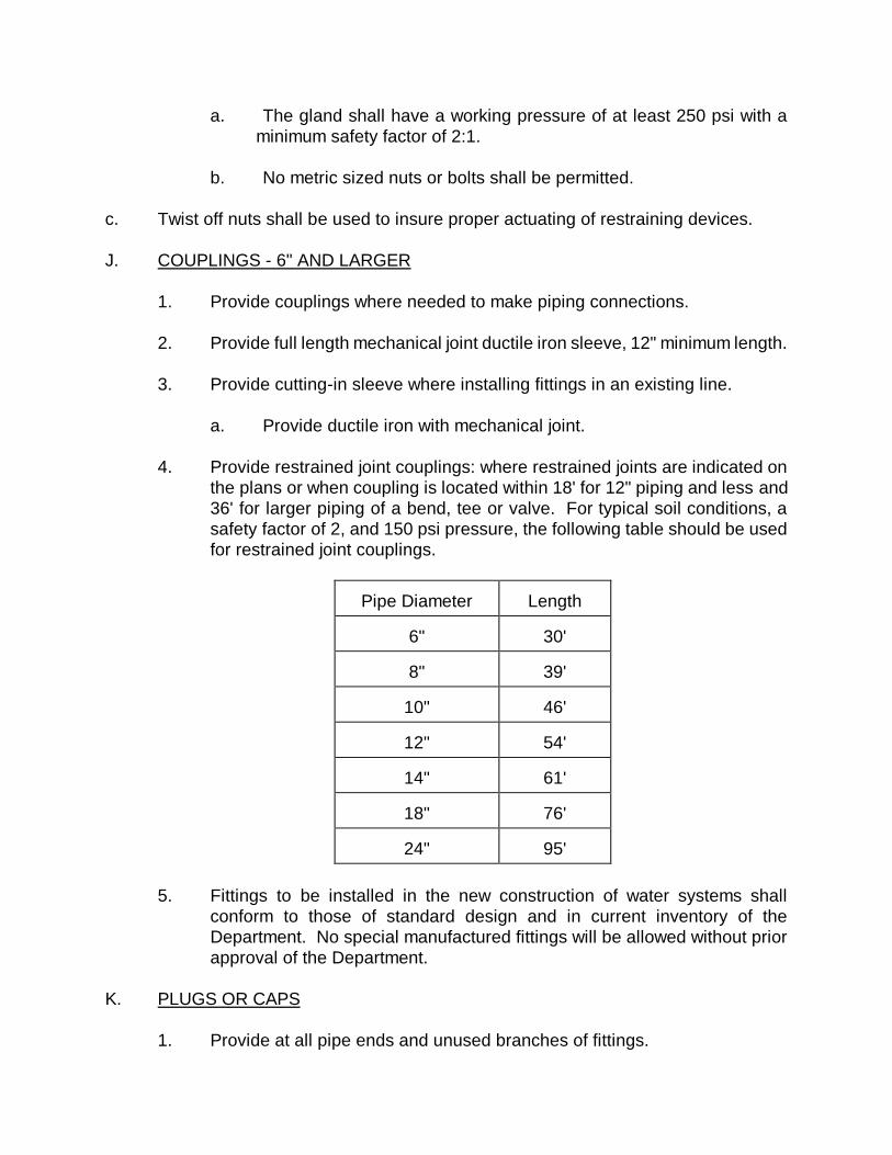
4. Provide restrained joint couplings: where restrained joints are indicated on
the plans or when coupling is located within 18' for 12" piping and less and
36' for larger piping of a bend, tee or valve. For typical soil conditions, a
safety factor of 2, and 150 psi pressure, the following table should be used
for restrained joint couplings.
Pipe Diameter
Length
6"
30'
8"
39'
10"
46'
12"
54'
14"
61'
18"
76'
24"
95'
5. Fittings to be installed in the new construction of water systems shall
conform to those of standard design and in current inventory of the
Department. No special manufactured fittings will be allowed without prior
approval of the Department.
K. PLUGS OR CAPS
1. Provide at all pipe ends and unused branches of fittings.
2. Tap and provide with 2" plug for installation of blow off.
3. Provide restrained joint.
L. METALLIC DETECTION TAPE AND TRACER WIRE
1. Provide 2" wide metallic detection tape and tracer wire on all buried piping.
a. Provide 5.0 mil overall thickness with no less than a 50 gauge solid
aluminum foil core.
b. Foil to be visible from both sides.
c. No inks or printing extended to the edges of the tape.
d. Encase printing to avoid ink rub-off.
e. Tensile strength - 28 lbs/inch.
f. Use heat set mylar inks.
2. Locate 12" below ground surface in pipe trench.
3. Color to be Safety Precaution Blue.
4. Wording on tape to indicate “Potable Water” at no greater than 24" on
center.
5. All water main installations shall also include the installation of metallic
tracer wire laid 6" above the pipe.
M. VALVES
1. General:
a. 6" through 12": Use gate valves.
b. 14" and larger: Use butterfly valves.
c. Open by turning counter clockwise with arrow cast in top indicating
the direction of the opening.
d. End connections as required for the piping in which they are installed.
e. Two inch metal operating nut with arrow indicating direction of
opening.
f. Use valves designed for a working pressure of not less than 150 psi
unless otherwise specified herein.
g. Provide stem extensions on all valves where the top of the operator
nut is located greater than 36" below the top of the valve box.
2. Quality Assurance
a. Reference Standards of the American National Standards Institute
(ANSI)
1) A21.5 Polyethylene encasement for gray and ductile cast iron
piping for water and other liquids (AWWA C105).
2) A21.11 Rubber gasket joints for cast iron and ductile iron
pressure pipe and fittings (AWWA C111).
3) B16.1 Cast iron pipe flanges and flanged fittings, Class 25,
125, 250, and 800.
b. Reference Standards of the American Water Works Association
(AWWA).
1) C600 Installation of Ductile Iron Water Mains and Their
Appurtenances.
2) 601 Disinfecting Water Mains
3) C504 Rubber Seated Butterfly Valves
4) C509 Resilient Seated Gate Valves
3. Gate valves:
a. Use resilient seated wedge valves: ANSI/AWWA C500/C509.
b. Internal ferrous metal surfaces to be fully coated with two part
thermosetting epoxy conforming to AWWA C550 or fusion bonded,
holiday free epoxy coating material to be AWWA and U.S. Food and
Drug Administration approved for use with potable water.
c. Provide fusion bonded or two part thermosetting epoxy coating on
valve exterior conforming to AWWA C550.
d. Provide integrally cast bronze or stainless steel stem nut.
e. Design for external stem failure when excessive closing torque is
applied with no failure of the pressure retaining parts.
f. Gate valves to have bevel gears with grease case, provide all
necessary appurtenances for horizontal installation.
g. Provide valves with working pressure of not less than 250 psi and a
500 psig static test pressure.
h. Provide 316 stainless steel fasteners.
i. Ends shall be mechanical joint conforming to ANSI/AWWA
C111/A21.11.
j. Acceptable product: Mueller, American AVK, American-AD, or
American Flow Control.
4. Butterfly valves:
a. Provide butterfly valves conforming to AWWA Standard C504, latest
revision, for Class 150B, unless otherwise specified.
b. Resilient seats are to be synthetic rubber (BUNA N).
c. Shafts to be turned, ground and polished, constructed of 18-8 Type
316 stainless steel.
1) Shafts to be of one piece design.
2) Attach disc to shaft with stainless steel tapered pins and locking
nuts.
d. Spray coat all interior wetted ferrous surface with two component
epoxy applied to a nominal thickness of 3 to 4 mils.
1) Coating material to be AWWA and U.S. Food and Drug
Administration approved for use with potable water.
e. Provide operators with not less than maximum operator torque, as
determined in accordance with Appendix A of AWWA C504, to
operate valves under actual line pressures and velocities.
1) Provide worm and gear, or traveling nut type, self-locking to
prevent the valve disc from creeping or fluttering when it is in any
intermediate position between open and closed.
2) Gear operators to be permanently lubricated, totally enclosed,
with adjustable stops for the open and closed position, and
except on units for buried service, shall have a valve disc
position indicator.
f. Provide position indicator and extension shaft for all valves and
operators.
1) Position indicator shall be hermetically sealed for installation in a
C.I. valve box.
2) Show valve disc position, direction of rotation and number of
turns from full open to full close.
3) Shaft extension and pins to be stainless steel.
4) Base plate and housing to be aluminum.
5) Provide all bronze gearing.
6) Provide 2" AWWA square nut.
7) Approved manufacturer: Dyna-Torque, Inc. of Mukegon,
Michigan.
g. Epoxy coated inside and outside conforming to AWWA C550.
h. Ends shall be flanged conforming to ANSI B16.1, Class 125.
i. Rated for a 150 psi working pressure.
j. Acceptable product: DeZurik, Mueller, American AD, Valmatic, or
Pratt.
5. Tapping Valves 12" and smaller shall conform to the following:
a. Resilient seat type conforming to AWWA C509.
b. Epoxy coated inside and outside conforming to AWWA C550.
c. Ends shall be flanged by mechanical joint conforming to ANSI B16.1,
Class 125 and ANSI/AWWA C111/A21.11 respectively.
d. Rated for a 250 psi working pressure.
6. Tapping valves 14" and larger shall conform to the following:
a. Bronze seat, double disk type conforming to AWWA C500.
b. Epoxy coated inside and out conforming to AWWA C550.
c. Equipped with 4" by-pass valves.
d. Ends shall be flanged by mechanical joint conforming to ANSI B16.1,
Class 125 and ANSI/AWWA C111/A21.11 respectively.
e. Allow full port opening cutters up to 24".
f. Rated for a 150 psi working pressure.
7. Other Requirements
a. All valves shall have Grade B cast iron or ductile iron bodies
conforming to ASTM A126 or ductile iron ASTM A536.
b. All valves shall have a 2" square operating nut for buried service.
c. All valves shall have open left operation.
d. All valves shall be equipped with a non-rising stem.
e. All valves shall be constructed with 316 stainless steel bolts on
bonnets, thrust collars, and operating nuts.
f. All valves shall be in conformance with the latest revision of all
reference standards of AWWA or ANSI.
g. Valve boxes with drop covers will be of cast iron.
N. VALVE OPERATOR
1. Provide one T-handle operator for each ten buried valves with nut operator.
2. Operator to be epoxy coated.
O. VALVE BOXES
1. Provide at each buried valve.
2. Shall be full cast iron with cast iron covers suitable for heavy traffic use and
conform to ASTM A-48, Class 20 Specifications.
3. Valve boxes shall be screw type and have a 5 ¼” inside shaft diameter.
4. Have the word “WATER” cast into the cover.
5. No part of the valve box is to rest on the buried valve.
6. Acceptable product: Products of Tyler Pipe/Utility Division #6850 Series and
Bingham and Taylor #4905 of U.S. manufacture only.
P. VALVE BOX PROTECTION RING
1. Provide at each valve box a precast concrete protection ring.
2. Provide two (2) rings of #3 reinforcing steel, one (1) 21" in diameter, and one
(1) 24" in diameter; or one (1) ring of #3 reinforcing steel, 22" in diameter
with fibermesh concrete.
3. Inside dimensions to be 9 ¼”.
4. Outside diameter to be 27".
5. Provide 5" thickness at interior with a continuous slope to 2" thickness at the
outside.
6. Minimum weight of 110 lbs.
Q. SERVICE AND TAPPING SADDLES
1. Provide of the following materials:
a. Body - Ductile Iron ASTM-A536.
b. Bales and straps - Type 316 stainless steel.
c. Studs - Type 316 stainless steel.
d. Hardware - Type 316 stainless steel.
e. Copper tube size (CTS).
2. Provide double strap for sizes 5" and larger.
3. Finish - Provide fusion bonded nylon to an average thickness of 12 mils.
4. Acceptable product: Smith Blair 317, Ford 202, Romac 202N, Mueller, or
JCM 406.
R. TAPPING SLEEVE AND VALVE
1. Tapping sleeve:
a. Provide ductile iron, split-type sleeve with flanged outlet.
b. Provide bolts, follower rings and gaskets on each end of the sleeve.
c. Provide for maximum working pressure of 150 psi.
d. Provide square head bolts with hexagonal nuts.
e. Provide ¾” NPT test plug.
2. Tapping valve:
a. Construct of material compatible with tapping sleeve.
b. Valve to conform to gate valve specifications.
c. Joints - Flange to tapping sleeve, for pipe end.
d. Acceptable product: Mueller, American Darling
S. AIR RELEASE VALVES
1. Provide cast iron body with stainless steel internal trim and float.
2. Provide stainless steel seat with BUNA-N rubber valve.
3. Provide 1" NPT inlet with 1" x ¾” bronze bushing.
4. Provide Crispin Type “N” Model PL10, Golden Anderson Figure 912.
a. ¼” orifice.
b. 0 to 150 psi working pressure.
c. 1" NPT connection.
5. Provide a heavy duty cast iron meter box to house valve.
T. CORPORATION STOPS
1. Acceptable product:
a. Ford Model F1100 with compression nut, gasket, and gripper inlet;
iron pipe thread outlet. IPT x grip nut.
b. Mueller Model H-15028; McDonald - 4707T.
U. CURB STOPS
1. Acceptable product:
a. Ford Model #B11, iron pipe threads inlet and outlet with lockwing.
b. Mueller, McDonald #6101W.
V. REPAIR COUPLINGS
1. Pipe larger than 2 ½”: Full length mechanical joint ductile iron couplings, 12"
minimum length.
W. MISCELLANEOUS PARTS AND ACCESSORIES
1. Use standard commercial grade suitable for the type of installation or system
involved, and conforming to the applicable standards and specifications of
the AWWA.
X. CASING, SPACERS AND END SEALS FOR UTILITIES
1. General
a. Provide bore and jack with casing for pipes larger than 2".
b. Casing pipe to be 2" larger in diameter than the bell of the carrier pipe
based on the following:
1) Casing pipe to be a minimum of 2" larger than the largest outside
diameter of the carrier pipe (joints and couplings) if the carrier
pipe is less than 6" in diameter. If the diameter of the carrier pipe
is 6" or larger, the diameter of the casing pipe shall be a
minimum of 4" larger than the largest outside diameter of the
carrier pipe (joints and couplings).
2) The end of casing pipe to extend a minimum of six (6) feet from
the edge of pavement/back of curb.
3) The top of the casing pipe shall be a minimum of four (4) feet
below the crown of the finished asphalt roadway.
4) The top of the casing pipe shall be a minimum of two (2) feet
below the design invert of roadside drainage ditches and pipes.
c. Carrier pipe shall be restrained joint.
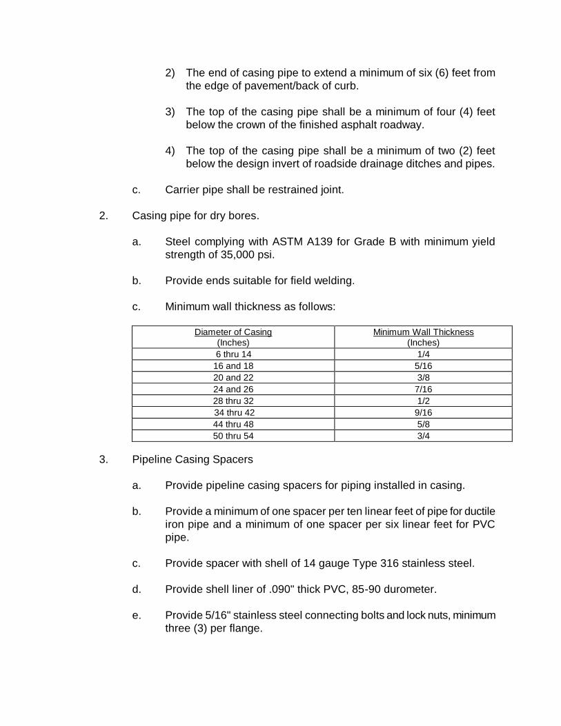
2. Casing pipe for dry bores.
a. Steel complying with ASTM A139 for Grade B with minimum yield
strength of 35,000 psi.
b. Provide ends suitable for field welding.
c. Minimum wall thickness as follows:
Diameter of Casing
(Inches) Minimum Wall Thickness
(Inches)
6 thru 14 1/4
16 and 18 5/16
20 and 22 3/8
24 and 26 7/16
28 thru 32 1/2
34 thru 42 9/16
44 thru 48 5/8
50 thru 54 3/4
3. Pipeline Casing Spacers
a. Provide pipeline casing spacers for piping installed in casing.
b. Provide a minimum of one spacer per ten linear feet of pipe for ductile
iron pipe and a minimum of one spacer per six linear feet for PVC
pipe.
c. Provide spacer with shell of 14 gauge Type 316 stainless steel.
d. Provide shell liner of .090" thick PVC, 85-90 durometer.
e. Provide 5/16" stainless steel connecting bolts and lock nuts, minimum
three (3) per flange.
f. Runners from 2" wide ultra high molecular weight polymer with a high
resistance to abrasion and a coefficient of friction of 0.11-0.13 in
accordance with ASTM D-1894.
g. Support runners on 14 gauge reinforced Type 316 stainless steel
risers welded to shell.
h. All metal surfaces to be fully passivated.
i. The diameter as measured over the runners shall exceed the pipeline
bell or coupling outside diameter.
j. Acceptable product: Cascade Manufacturing or approved equal.
4. End Seals
a. Seal each end with brick and mortar to prevent entrance of foreign
material.
Y. USE OF LEAD FREE SOLDER
1. Note: Section 1417 of the federal safe drinking water act has mandated that
any pipe, solder, or flux used after June 19, 1986, in the installation or repair
of public water systems and plumbing used for drinking water must be "lead
free". The act defines "lead free" as less than 0.2 percent lead in solder and
flux and less than 0.8 percent lead in pipes and fittings.
SECTION 7
WATER DISTRIBUTION SYSTEM
CONSTRUCTION PROCEDURES
SECTION 7
WATER DISTRIBUTION SYSTEM
CONSTRUCTION PROCEDURES
This section covers construction procedures normally required for work. It
does not cover any special construction procedures which may be encountered for
abnormal conditions.
Special construction procedures are to be presented to the Department by the
Developer’s Design Engineer.
A. HANDLING OF MATERIALS
1. Handle pipe so as to ensure delivery to the trench in sound, undamaged
condition:
a. Carry pipe into position - do not drag.
b. Use pinch bars or tongs for aligning or turning the pipe only on the
bare end of the pipe.
c. Use care not to injure pipe linings.
B. PIPE CUTTING
1. Cut pipe neatly and without damage to the pipe or lining.
2. Unless otherwise recommended by the pipe manufacturer, cut pipe with
milling type cutter, rolling pipe cutter, or abrasive saw cutter. Do not flame
cut. Use wheel cutters when practicable. Cuts must be even and
perpendicular with length of pipe. Dress cut ends of pipe in accordance with
manufacturer’s directives for the type of joint to be made.
C. LOCATING
1. Service lines:
a. Provide a water service to each subdivision lot.
b. Install service lines from the distribution main to the property lines at
each lot, or at each location indicated or directed by the Engineer.
Normally installed on opposite side from the sewer service.
D. PIPE, VALVE, AND APPURTENANCE INSTALLATION
1. General:
a. The installation of water mains and appurtenances shall be
conducted in accordance with the latest revision of Section C of the
AWWA Standards and/or the manufacture’s recommended
installation procedures.
b. Lower pipe and accessories into trench by means of derrick, ropes,
belt slings, or other equipment approved by the manufacturer.
c. Do not dump or drop any of the materials into the trench.
d. Except where necessary in making connections to other lines, lay
pipe with the bells facing in the direction of laying.
e. Rest the full length of each section of pipe solidly on the pipe bed,
with recesses excavated to accommodate bells, couplings, and joints.
f. Take up and relay pipe that has the grade or joint disturbed after
laying.
g. Do not lay pipe in water, or when trench conditions are unsuitable for
the work; keep water out of the trench until jointing is completed.
h. Securely close open ends of pipe, fittings, and valves when work is
not in process.
i. Replace pipe where any part of coating or lining is damaged.
j. Bell pipe using manufacturer’s approved leverage bar.
1) Home line is to be clearly visible when pipe is joined.
2. Ductile iron pipe:
a. Mechanical and push on joints, install in accordance with
ANSI/AWWA C600.
b. Gaskets: Handle, lubricate where necessary and install in strict
accordance with manufacturer’s recommendations.
3. PVC
a. Clean gasket, bell or coupling interior, especially groove area.
b. Lubricate and insert gasket as recommended by manufacturer.
c. Align spigot to bell, insert spigot into bell until it contacts gasket
uniformly.
d. Bell pipe using manufacturer’s approved leverage bar.
1) Home line is to be clearly visible when pipe is joined.
4. FPVC
a. Pipe manufacturer’s and supplier’s procedures shall be followed at all
times.
b. FPVC will be fused by qualified fusion technicians holding current
qualification credentials for the pipe size being fused, as documented
by the pipe supplier.
c. Only appropriately sized and outfitted fusion machines that have been
approved by the pipe supplier shall be use for the fusion process.
This includes requirements for safety, maintenance and operation
with minor modifications made for PVC.
d. FPVC pipe will be installed in a manner so as not to exceed the
recommended bending radius.
e. Where FPVC pipe is installed by pulling in tension, the recommended
Safe Pulling Force, according to the pipe supplier, will not be
exceeded.
4. Restrained joints:
a. Install in accordance with manufacturer’s instructions.
b. Tighten set screws to the manufacturer’s rated torque using a torque
wrench.
1) If twist-off nuts are provided, tighten screws until nut breaks
loose.
5. Underwater crossings:
a. Use ductile iron pipe, FPVC or HDPE.
b. Provide a minimum cover of two (2) feet.
c. Crossings greater than fifteen (15) feet in width:
1) Provide ball joint pipe for ductile iron pipe (DIP).
2) Provide valves at both ends of the water crossing.
3) A fire hydrant must be provided on the side opposite the
supply service, sized in accordance with [R.61-
58.4(D)(7)[R.61-58.4(D)(13)(b)(iii)].
6. Above-water crossings:
a. Use ductile iron pipe with flanged joints.
b. Adequately support and anchor the pipe, protect from damage and
freezing and be accessible for repair.
c. Hardware, straps, etc. to be 316 stainless steel.
7. Alignment and Grade
a. Fittings, valves and other appurtenances shall be located where
shown on the approved plans, with the pipe being cut if necessary to
assure accurate placement. Install the pipe, valves, and
appurtenances to the alignment and profile shown on the approved
drawings. Maintain a minimum depth of cover of 3' unless actual
depths are shown on the approved drawings.
8. Rights-of-way, Easements, and Permits
a. It is the responsibility of the developer/engineer to obtain all
necessary legal documentation and permits and advise Department of
the status of each prior to the commencement of work. All installation
is to be conducted within the parameters stipulated in the rights-of-
way, easements, and permits, etc. Any damages caused by
encroachment beyond the legal limits stipulated shall be the
responsibility of the Developer and/or Contractor.
9. Protection of Pipe, Valves, and Appurtenances
a. Protection of Pipe, Gaskets, and Polyethylene Film
1) Store rubber gaskets and polyethylene film under cover and
out of direct sunlight. Do not store nuts, bolts, glands, and
other accessories directly on the ground. Keep inside of pipe
and fittings free of dirt and debris.
b. Protection of Valves
1) Keep materials off the ground and keep interiors free of dirt
and debris. Do not expose valve interior to direct sunlight.
10. Pipe, Valve, Blow-Off and Appurtenance Installation
a. Pipe Distribution
1) Deliver the pipe to the job site from the designated storage
area in a safe manner.
b. Installation of Pipe and Valves
1) Inspect pipe for damage. Remove damaged and unacceptable
pipe. Keep interior and joint surfaces clean and free of foreign
materials. Install a M.J. or push-on type ductile iron plug
whenever work stops for a period of a day or greater.
2) Provide and use proper implements, tools, and facilities for the
safe and proper installation of the work. Lower all pipe,
fittings, and appurtenances into the trench, piece by piece, by
means of crane, slings, or other suitable tools or equipment, in
such a manner as to prevent damage to the pipeline materials
and protective coatings and linings. Do not drop or dump
pipeline materials into the trench.
3) Remove all lumps, blisters, and excess bituminous coating
from the bell-and-spigot ends of each pipe. Clean the spigot
and the inside of the bell and wipe clean and dry. Insure
surfaces are free from oil and grease before the pipe is laid.
4) Wipe the ends of mechanical joint pipe and fittings and rubber
gasket joint pipe and fittings clean of all dirt, grease, and
foreign matter.
c. Installation of Blow-Offs
1) All working parts shall be serviceable from above grade with
no digging. See Detail Section.
d. Installation of Retainer Glands
1) Adjoining surfaces shall be clean, and lubricated meeting with
requirements of ANSI/AWWA C111/A21.11.
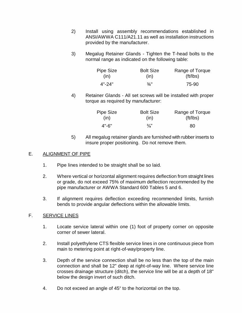
2) Install using assembly recommendations established in
ANSI/AWWA C111/A21.11 as well as installation instructions
provided by the manufacturer.
3) Megalug Retainer Glands - Tighten the T-head bolts to the
normal range as indicated on the following table:
Pipe Size
(in)
Bolt Size
(in)
Range of Torque
(ft/lbs)
4"-24" ¾" 75-90
4) Retainer Glands - All set screws will be installed with proper
torque as required by manufacturer:
Pipe Size
(in)
Bolt Size
(in)
Range of Torque
(ft/lbs)
4"-6" ¾” 80
5) All megalug retainer glands are furnished with rubber inserts to
insure proper positioning. Do not remove them.
E. ALIGNMENT OF PIPE
1. Pipe lines intended to be straight shall be so laid.
2. Where vertical or horizontal alignment requires deflection from straight lines
or grade, do not exceed 75% of maximum deflection recommended by the
pipe manufacturer or AWWA Standard 600 Tables 5 and 6.
3. If alignment requires deflection exceeding recommended limits, furnish
bends to provide angular deflections within the allowable limits.
F. SERVICE LINES
1. Locate service lateral within one (1) foot of property corner on opposite
corner of sewer lateral.
2. Install polyethylene CTS flexible service lines in one continuous piece from
main to metering point at right-of-way/property line.
3. Depth of the service connection shall be no less than the top of the main
connection and shall be 12" deep at right-of-way line. Where service line
crosses drainage structure (ditch), the service line will be at a depth of 18"
below the design invert of such ditch.
4. Do not exceed an angle of 45 to the horizontal on the top.
5. Connections to mains:
a. PVC mains:
1. Use approved tapping saddle.
6. Provide corporation stops on all mains.
7. Terminate each service line with a Mueller institite ¼” NPT plug.
a. Mark with a wooden stake installed to 3' above grade.
G. SETTING VALVES AND VALVE BOXES
1. Center valve boxes on the valves, setting plumb. Valve box shall not at any
point rest on any part of the valve.
2. Tamp earth fill around each valve box to a distance of 4' on all sides, or to
the undisturbed trench face if less than 4'.
3. Install shaft extensions plumb without any binding.
4. Fully open and close each valve to assure that all parts are in working
condition.
H. VALVE BOX PROTECTION RING
1. Place valve box protection ring around top of valve box as detailed.
a. Install ring level with top 1" above finished grade.
b. Top of ring to be level with or no more than 1" above the top of the
valve box.
I. THRUST BLOCKS
1. The Department will approve the use of thrust block on a case by case
basis.
2. Maximum soil pressure: 2000 lbs/sq ft. Minimize the use of thrust blocking
by installing thrust restraint fittings when possible.
3. Minimum water pressure: 150 psi.
4. Safety factor: 2
5. Concrete: 3000 psi.
6. Locate thrust blocking between solid ground and the fitting to be anchored.
7. Provide 8 mil polyethylene film between the thrust block and fitting.
8. Place the base and thrust bearing sides of thrust blocking directly against
undisturbed earth.
9. Sides of thrust blocking not subject to thrust may be placed against forms.
10. Place thrust blocking so the fitting joints will be accessible for repair.
J. JOINING PIPE, VALVES, AND APPURTENANCES
1. Mechanical, Push-On, and Restrained Joint
a. Join pipe with mechanical or push-on type joints in accordance with
the manufacturer’s recommendations. Provide all special tools and
devices, such as special jacks, chokers, and similar items required for
proper installation. Lubricants for the pipe gaskets shall be used and
shall be manufacturer’s standard. All mechanical joints used on
hydrants, hydrant leads, taps and valves should have retainer glands.
2. Flanged
a. Prior to connecting flanged pipe, the faces of the flanges shall be
thoroughly cleaned of all oil, grease, and foreign material. The
rubber gaskets shall be checked for proper fit and thoroughly
cleaned. Care shall be taken to ensure proper seating of the flange
gasket. Bolts shall be tightened so that the pressure on the gasket is
uniform. Torque-limiting wrenches shall be used to ensure uniform
bearing insofar as possible. If joints leak when the hydrostatic test is
applied, the gaskets shall be removed and reset and bolts re-
tightened.
3. Pipe Bedding
a. Excavate trench bottom to provide a level cross section with vertical
walls extending to the top of the pipe zone. Excavate evenly to
provide smooth profile grade without holes and ridges. Keep trench
dewatered.
b. Lay pipe on bedding such that it is continuously supported along the
barrel, and is not bearing on the bell. After joint construction, place
bedding material under bell. Unless otherwise directed, lay pipe with
bell end facing in the direction of the laying.
4. Valves
a. Valves shall be carefully handled, cleaned and checked for operation
prior to backfilling. Care shall be taken to insure that no dirt, rock, or
other obstacles that would interfere with the operation are left in the
valve. Valves shall be installed in a position such that the plane of
operation or rotation for the operating nut is parallel to the ground
surface.
b. Approximately ½” space shall be left to provide "play" for future
removal of flanged valves.
5. Valve Box
a. A valve box shall be installed on each underground valve. They shall
be carefully set, centered exactly over the operating nut and truly
plumbed. The base shall be set, and so arranged that the weight of
the valve box and superimposed loads will bear on the base and not
on the valve or pipe. Extension stems shall be installed where depth
of bury places operating nut in excess of 4' beneath finished grade.
K. ANCHORAGE
1. All pipelines shall be securely anchored. Retainer glands or megalugs shall
be used on all mechanical joint fittings. All tees, plugs, caps and bends
which are equal to or greater than 11¼ , and at other locations where
unbalanced forces exist, must have acceptable thrust restraint.
2. Blocking
a. The concrete mix used for thrust blocking shall have 28 days
compressive strength of not less than 3,000 pounds per square inch.
Place blocking between the undisturbed ground and the fitting to be
anchored. Place the blocking so that the pipe and fitting joints will be
accessible to repairs, unless otherwise shown.
3. Restrained Joints
a. Restrained joints shall be used in lieu of reaction blocking or in
combination with blocking where appropriate and as designated by
the Engineer or the Department.
L. WET TAP CONNECTIONS
1. Connections to existing water mains shall be done by use of wet taps using
tapping sleeves or tapping saddles and tapping valves.
M. HIGHWAY AND RAILROAD CROSSINGS
1. General
a. Installation shall conform to the permits of all agencies having
jurisdiction. Method of installation shall be specified by the Engineer.
2. Casing Pipe
a. Continuously weld lengths of casing pipe to the preceding section in
accordance with AWS recommended procedures. Clean all debris
from casing interior after casing installation is complete. Pressure
grout any void areas apparent outside the casing.
N. INSTALLATION OF CASING, SPACERS AND END SEALS FOR UTILITIES
1. Locate to avoid interference with traffic, adjacent structures, etc. to such
extent possible.
2. Excavate to required depth, providing sheeting and shoring necessary for
protection of the work and for safety of personnel.
3. Maintain entry pits in dry condition by use of pumps, drains or other
approved method.
4. Install casings by dry-boring through the casing while simultaneously jacking
the casing.
5. Any proposed alternate method shall be approved in writing by the
Department.
6. Weld joints to provide a watertight joint.
7. Install casings for gravity sanitary sewer to grade, not varying more than
3/32" per foot of length from the indicated grade.
8. Installing pipe in casing:
a. Inspect carefully, insuring that all foreign material is removed from the
casing and the casing meets alignment criteria for the type of carrier
pipe being used.
b. For pressure systems, the casing deflection shall not exceed the
maximum deflection recommended by the carrier pipe.
c. Install casing spacers on the carrier pipe per the manufacturer's
instructions.
d. For sanitary sewer provide spacer sizing and length necessary to
obtain the pipe slope and elevations as shown on the plans.
e. Provide restrained configuration.
f. Install the carrier pipe in the casing insuring each joint is pushed
"home" before the joint is installed into the casing.
9. Seal each end with brick and mortar to prevent entrance of foreign material.
O. PREPARATION OF RIGHT-OF-WAY
1. Remove obstructions within the trench area or adjacent thereto such as but
not limited to tree roots, stumps, abandoned piling, buildings and concrete
structures, logs, and debris of all types.
2. Properly dispose of obstructions removed from the excavation in accordance
with local municipality directives.
3. Pavement, Curb, and Sidewalk Removal
a. Cut all bituminous and concrete pavements, regardless of thickness,
and all curbs and sidewalks, prior to excavation of the trenches as
specified in the South Carolina Department of Transportation Policy.
Width of the pavement cut shall be at least equal to the required
width of the trench at ground surface. Pavement cut lines shall be
even and parallel. Any ragged or uneven cuts shall be cut smooth
before patching. Pavement and concrete materials removed shall be
hauled from the site and not used for trench backfill.
P. TRENCH EXCAVATION
1. Trench Width
a. Maximum width of unsheeted trenches in which pipe is to be laid shall
be 18" greater than the inside diameter of the pipe, but not less than
that required for proper compaction around the pipe. Sheeting
requirements shall be independent of trench widths.
b. The maximum trench width at the top of the pipe zone is limited to
1.33 times the pipe outside diameter plus 18".
c. In general, the maximum width at the top of the trench will not be
limited, except where excess width of excavation would cause
damage to adjacent structures or property. However, confine trench
widths to dedicated rights-of-way or construction easements, unless
special prior written agreements have been made with the affected
property owner.
2. Grade
a. Excavate the trench to the lines and grades shown on the plans with
proper allowance for pipe thickness and for pipe base or special
bedding when required. If the trench is over excavated below the
required grade, correct any part of the trench excavated below the
grade with crushed stone or Class II backfill as specified herein.
b. Place the pipe bedding material over the full width of trench in
compacted layers not exceeding 6" deep to the established grade.
3. Shoring, Sheeting and Bracing of Trenches
a. Sheet and brace the trench consistent with OSHA Regulations when
necessary to prevent caving in during excavation or to protect
adjacent structures, property, workmen, and the public. Increase
trench widths accordingly by the thickness of the sheeting. Maintain
sheeting in place until the pipe has been placed and backfilled at the
pipe zone. Shoring and sheeting shall be removed in accordance
with OSHA Regulations and, as the backfilling is done, in a manner
that will not damage the pipe or permit voids in the backfill. All
sheeting, shoring, and bracing of trenches shall conform to the safety
requirements of the Federal, State or local public agency having
jurisdiction. The most stringent of these requirements shall apply.
4. Dewatering
a. Provide and operate equipment adequate to keep all excavations and
trenches free of water. Remove all water during period when
concrete is being deposited, when pipe is being laid, during tunneling
or jack and bore operations, during the placing of backfill, and at such
other times as required for efficient and safe execution of the work.
Prevent settlement or damage to adjacent property. Dispose of water
in a manner that will not damage adjacent property. When
dewatering open excavations, dewater from outside the structural
limits and from a point below the bottom of the excavation. Design a
dewatering system to prevent removal of fines from existing ground.
5. Foundation Stabilization
a. When the existing material in the bottom of the trench is unsuitable
for supporting the pipe, provide foundation stabilization as described
here. Excavate below the pipe zone and backfill to specified grade
with crushed stone or Class II backfill. Place the crushed stone or
Class II backfill over the full width of the trench and compact to the
required grade.
Q. TRENCH BACKFILL
1. When backfill is mechanically placed, push the backfill material onto the
slope of the previously placed and allow it to slide down into the trench. Do
not push backfill into the trench in such a way as to permit free fall of the
material until at least 2' of cover is provided over the top of the pipe. Under
no circumstances allow sharp and/or heavy pieces of material to drop
directly onto the pipe or the tamped material around the pipe. Do not use
backfill material of consolidated masses larger than ½ cubic foot.
2. Backfill material types
a. Class I (Concrete) Backfill
1. Conform to ASTM C94, Alternate 3. Proportion to obtain a 28
day compressive strength of 2,500 pounds per square inch.
b. Class II Backfill
1. Material suitable for backfill in a properly dewatered
trench shall consist of any of the following: Well graded
coarse granular materials free of roots, branches,
stumps, or other material not so suited, with maximum
particle size not exceeding 1"; sands, silty-sand or clayey
sands. Soils having more than 25% of its weight passing
a No. 200 sieve shall not be used for backfill. Soils shall
be compacted to 95% dry density (modified proctor).
c. Class III Backfill
1. Class III backfill will be used where suitable throughout the
project and will generally be excavated trench material free of
roots, branches, stumps, or other organic or unsuitable
materials.
3. Backfill the trench for one (1) foot above the pipe with approved backfill
material (Type II). Backfill shall consist of approved backfill material free
from organic matter and deleterious substances, containing no rocks or
lumps over 2" in any dimension. Backfill shall be deposited in 6-inch layers
(before compaction) and thoroughly compacted with power tools to 95% of
theoretical maximum density, modified Proctor as determined by ASTM
D1557.
4. Backfill with Type II material under all culverts, water, gas, irrigation, and
sewer lines, buried telephone, power and television cable, and any other
buried pipelines or cables that cross
5. Pipes not installed under pavement in a public right-of-way
a. Backfill the trench for one (1) foot above the pipe with approved
backfill material (Type II). Backfill shall consist of approved backfill
material free from organic matter and deleterious substances,
containing no rocks or lumps over 2" in any dimension. Backfill shall
be deposited in 6-inch layers (before compaction) and thoroughly
compacted with power tools to 95% of theoretical maximum density,
modified Proctor as determined by ASTM D1557.
d. Unless otherwise required, the remaining backfill material can be
Type III.
6. Pipes installed under pavement in a public right-of-way
a. Backfill with flowable fill for a minimum of 36-inches below the
pavement. For trenches less than 36-inches deep, backfill with
flowable fill to the bottom of the trench.
b. Backfill the remaining trench with Type II material or with #57 stone.
c. Backfill shall meet all requirements of the agency with maintenance
responsibility of the road.
7. Moisture Control - Backfill
a. During all compacting operations, maintain optimum practicable
moisture content required for compaction purposes in each lift of the
earth fill. Maintain moisture content uniform throughout the lift.
Supplement, if required, by sprinkling the earth fill. During all
compaction, the water content of the material shall be at optimum
moisture content, plus or minus 2 percentage points.
b. Do not attempt to compact fill material that contains excessive
moisture. Aerate material by blading, discing, harrowing, or other
methods to hasten the drying process.
8. Maintenance of Trench Backfill
a. Maintain the surface of the backfilled trench level with the existing
grade until the entire project is accepted. Any subsequent settlement
of the finished surface during the warranty period shall be considered
to be a result of improper or insufficient compaction and shall be
promptly repaired at no cost to the Department.
b. Maintain backfilled trench surface until the following operations have
been completed and approved by the Department.
1) Valves and valve boxes installed.
2) Hydrostatic testing.
3) Cleanup and restoration of all physical features, utilities
restored to their original condition or better, and, in general, all
work required with the exception of repaving.
c. Maintenance shall include, but not be limited to, the addition of
crushed stone backfill material to keep the surface of backfilled
trenches reasonably smooth, free from ruts and pot-holes, and
suitable for normal traffic flow.
9. Compaction Tests
a. The Department, or other agencies having jurisdiction over the work,
reserves the right to require the Contractor to provide, at his expense,
all testing necessary to determine the in-place density and moisture
content of the subgrade and compacted fill according to ASTM
D1556. Test results and a certified statement by the soil testing
company that the actual soil compaction found meets these
specifications shall be submitted to the Department as soon as it is
available to the Contractor.
R. COMPACTION
1. Utilize compaction equipment of suitable type and adequate to obtain a
compaction in accordance with ASTM D1557. Operate in strict accordance
with the manufacturer’s instructions and recommendations and maintain in
such condition that it will deliver the manufacturer’s rated compactive effort.
2. Impact type compactors are suitable. Rubber tired rollers and track type
equipment are not suitable and are not allowed for Class II or III backfill.
S. SETTLEMENT POLICY
1. Any subsequent settlement of the finished surfacing during the warranty
period shall be considered to be a result of improper or insufficient
compaction and shall be promptly repaired at no cost to the Department.
5. Foundation Stabilization
a. When the existing material in the bottom of the trench is unsuitable
for supporting the pipe, provide foundation stabilization as described
here. Excavate below the pipe zone and backfill to specified grade
with crushed stone or Class II backfill. Place the crushed stone or
Class II backfill over the full width of the trench and compact to the
required grade.
T. HYDROSTATIC TESTING
1. Conduct hydrostatic testing in accordance with AWWA C600.
a. Conduct tests on each line or valved section of line.
b. Clean and flush line of dirt and foreign material.
c. Do not perform hydrostatic tests until at least five days after
installation of concrete thrust blocking.
d. Test pressures shall be 150 psi based on the elevation of the lowest
point of the section under test and corrected to the elevation of the
test gauge.
e. Slowly fill main in order to expel air from the main through the air
release valves or other appurtenances.
f. Tests are to be conducted in the presence of a representative of the
Department and the Design Engineer.
2. Pressure tests:
a. Pressure leakage test must be conducted in accordance with AWWA
C600. Each section of the pipeline shall be subjected to and
successfully meet a pressure test of 150% of its working pressure, but
not less than 150 psi. The line shall be slowly filled with water and all
air expelled through the air valves or other means.
b. A suitable test pump, furnished by the Contractor, shall be connected
to the line by means of a tap in the line, and the proper test pressure
slowly applied to the line. The test pressure shall be maintained for
at least two (2) hours. Leaks, if found shall be immediately repaired.
The Department representatives must be on site to witness the test.
No leaks will be allowed.
c. Open and close each valve within the section being tested several
times during the test period.
d. Replace cracked pipe, defective pipe, and cracked or defective joints,
fittings and valves with new material and repeat the test until results
are satisfactory.
3. Leakage test:
a. Conduct leakage test after the pressure has been satisfactorily
completed.
b. Duration of each leakage test: minimum of two (2) hours.
c. Leakage is defined as the quantity of water to be supplied into the
newly laid pipe, or any valved or approved section thereof, necessary
to maintain the specified leakage test pressure after the pipe has
been filled with water and the air expelled.
1) No piping installation will be accepted until the leakage is less
than the number of gallons per hour as determined by the
appropriate formula below:
Ductile Iron Piping:
L = 0.000007 SD x sq. root of P; where
L = allowable leakage in gallons per hour;
S = length of pipe tested in feet;
D = nominal diameter of pipe in inches; and
P = average test pressure psi gauge.
PVC Piping:
L = [ND(P)1/2
]/7,400
L = allowable leakage (gals./hr.)
N = # of joints in pipeline being tested
D = diameter of pipe (inches)
P = average test pressure (psig)
2) When testing against closed metal seated valves, an
additional leakage per closed valve of 0.0078 gallons per hour
per inch of nominal valve size may be allowed.
3) Should any test of pipe disclose leakage greater than that
specified above, locate and repair the defective joint or joints
until the leakage is within the specified allowance.
4) DCWS reserves the right to require that no measureable
leakage be allowed during the pressure test.
U. DISINFECTION
1. Conduct disinfection in accordance with AWWA C651 before being placed in
service.
a. Upon completion of testing, disinfect all water lines to meet
requirements of the South Carolina Department of Health and
Environmental Control.
b. Newly laid valves or other appurtenances shall be operated several
times while line is filled with chlorinating agent.
c. Should initial treatment fail to meet results specified, repeat
procedures until satisfactory results are obtained.
2. Procedure:
a. Flush line to extent possible with available pressure and outlets, prior
to disinfection.
1) Hydrant openings required to produce proper flushing velocity
at 40 psi are:
Pipe Size (Inches) Hydrant Openings
6 through 12 one 2 ½”
14 through 18 two 2 ½”
20 one 4 ½”
b. Apply chlorine as liquid chlorine and chlorine compound such as
calcium hypochlorite with known chlorine content. Water from the
existing distribution system or other source of supply should be
controlled so as to flow slowly into the newly laid pipeline during the
application of chlorine.
c. Apply through corporation cock in top of main, at beginning of section
being sterilized.
d. Use proper feeder and flow regulator to introduce chlorinating agent.
e. Application rate shall be not less than 50 ppm.
f. Retain chlorinated water in main not less than 24 hours.
g. At end of retention period, at least 10 ppm of chlorine shall remain in
the water at the extreme end of section.
h. Flush the system with potable water and the sampling program
begins.
3. Acceptance:
a. Provide two (2) separate samples for each sample location, taken at
24 hour intervals, free of coliform bacteria. The Contractor working
with the developer shall pull the water samples to SCDHEC
specifications and provide the Department and Engineer with copies
of the water sample reports with chain of custody.
1) Prior to sampling, the chlorine residual must be reduced to
normal system residual levels or be non-detectable in those
systems not chlorinating.
2) If the non-coliform growth is greater than eighty (80) colonies
per one hundred (100) milliliters, the sample result is invalid
and must be repeated.
3) Contractor to take first and second samples, deliver to South
Carolina Department of Health and Environmental Control
(SCDHEC) approved laboratory for testing with the registered
professional engineer’s letter of certification. The Contractor
shall furnish all necessary pipe or hose extension or
transportation to the point of use and shall exercise care in the
use of water.
4) The first and second sample results shall include the free
chlorine residual at the time the samples were collected.
5) Notify the Department/SCDHEC to take a third sample.
6) If the membrane filter method of coliform analysis is used, non-
coliform growth must also be reported.
b. At a minimum, sample locations shall be as required by SCDHEC and
the following:
1) The tie-in location of new and existing water lines.
2) The end of all dead end lines.
3) At intervals of no more than 1,200 feet for all new lines longer
than 1,200 feet in length.
c. All sample locations are to be given an identifying label and a
corresponding identification label is to be included on the record
drawings indicting each sample location.
V. DECHLORINATION OF CHLORINATED DISINFECTION WATER
1. Dechlorinate the chlorinated water used for disinfected water lines to meet
requirements of the South Carolina Department of Health and Environmental
Control.
W. OPERATION OF DEPARTMENT VALVES AND HYDRANTS
1. No Department valve or hydrant shall be opened by the contractor without
prior approval of the Department.
2. All hydrant and blowoff operations shall be done in a manner so that there is
no impact to private property and there is no flooding of streets or roadways
or any other traffic problems created.
3. The Contractor shall monitor pressure on the existing main to insure
operating pressure is maintained.
X. ASPHALT PAVEMENT
1. Applicable Standards
a. All construction, repair, and resurfacing of asphalt pavement shall be
conducted in accordance with South Carolina Department of
Transportation Standard Specification for Highway Construction.
2. Guarantee
a. The Developer and Contractor shall guarantee all pavement work and
repair completed incidental to the installation of the water distribution
system for a period of two (2) years following acceptance by the
Department, and shall repair or replace, at no cost to the Department,
any pavement or pavement repair which crumbles, cracks, settles, or
is otherwise unsound or unacceptable during this two (2) year period.
SECTION 8
WATER DISTRIBUTION SYSTEM
FIRE HYDRANTS
SECTION 8
WATER DISTRIBUTION SYSTEM
FIRE HYDRANTS
A. GENERAL
1. Comply with the local Fire Code.
2. Fire hydrant spacing:
a. The Department reserves the right to require additional fire hydrants
to provide the maximum and most efficient emergency fire protection
response time to customers.
3. Fire hydrant leads to be a minimum of 6" diameter DIP. Larger size mains
will be required as necessary to allow the withdrawal of the required fire flow
while maintaining the minimum residual pressure. A hydrant control valve
shall be installed on all hydrant leads.
4. Fire hydrants must be provided with a gravel pocket or dry well. Hydrant
drains must not be connected to or located within ten (10) feet of sanitary
sewers [R.61-58.4(D)(9)(ii)].
5. No privately owned fire hydrants will be permitted.
6. Conform to Section C of the AWWA Standards.
B. CONSTRUCTION
1. Compression type, opening against pressure and closing with pressure,
comply with ANSI/AWWA C502 dry-barrel fire hydrants, existing national
standards and ANSI B26.
2. Waterway valve opening, 5 ¼” with EPDM main valve. Minimum 200 psi
working pressure.
3. Six inch (6") bell connection, two (2) 2 ½” hose connections, one (1) 4 ½”
pumper nozzle with mechanical removal feature, set screw, lock ring, etc.,
and shall conform to existing national standard specifications and ANSI B26,
but will not have chains attaching the hydrant clip to the upper barrel.
4. National Standard screw threads on outlet nozzles.
5. Open by turning counter clockwise, with arrow cast in top indicating direction
of opening.
6. Two part breakable safety flange shall be an integral part of barrel casting at
least 2" above bury line.
7. Barrel lengths shall generally be for 3'6" bury.
8. Interior shall be two (2) part thermosetting, or fusion bonded, coated holiday
free to a minimum thickness of 4 mil conforming to AWWA C550 protective
interior coatings for valves and hydrants.
9. Exterior coating shall be as follows:
a. Hydrant barrel, operating nut and nozzle caps will be painted
Industrial Safety Red enamel or epoxy coated.
b. Weather cap (bonnet) and arm caps will be painted white.
c. The ring of the weather cap (bonnet) will be painted in accordance
with the level of service color code as shown below:
Color Level of Service
Light Blue 1,500 GPM or greater
Green 1,000 to 1,499 GPM
Orange 500 to 999 GPM
Red Less than 500 GPM
Black For drafting use only
White Cross on top For filling tankers only
When the level of service is near a dividing point, the lower level of
service shall be marked unless otherwise approved by the
Department.
c. Exterior hydrant parts below ground will be asphaltic or epoxy coated.
10. Provide one (1) hydrant wrench for each ten (10) hydrants. Provide at least
one hydrant wrench.
11. An all bronze seat ring shall thread directly into an all bronze drain ring or
heavy bronze bushing located between the lower hydrant barrel and shoe
securely retained in this position, or it may be threaded into a heavy bronze
bushing in the hydrant shoe. Drain rings cast into iron body are not
acceptable.
12. All bronze or brass internal working parts in contact with service water are to
be maximum 16% in zinc content and 79% minimum in copper.
13. Acceptable product: Mueller Company (Super Centurion A-423), American
AVK Model 2780, or American Darling (B-84-B).
C. FIRE HYDRANT REFLECTOR
1. Provide industry standard blue hydrant reflector for paved roadway - South
Carolina Department of Transportation approved.
D. FIRE HYDRANT OFFSET FITTING
1. Locate between the shut-off valve and each hydrant where required to match
finished grade.
2. Provide a 12" offset.
3. Provide Grade Lok as manufactured by Assured Flow Sales, Inc., or
approved equal.
E. INSTALLATION OF HYDRANTS
1. General:
a. Inspect carefully, insuring that all foreign material is removed from the
barrel. Inspect materials upon receipt for damaged or missing items.
Store rubber gaskets under cover out of direct sunlight. Do not store
nuts, bolts, glands, and other appurtenances directly on the ground.
Keep interiors free of dirt and debris.
b. Hydrants shall be carefully handled, cleaned and checked for
operation prior to backfilling. Care shall be taken to insure that no
dirt, rock and other obstacles that would interfere with the operation
are left in the hydrant. The Contractor will provide proper anchorage
to fire hydrant installations by means of retainer glands.
c. Rotate Grade Lok fitting so hydrant is plumb and at the elevation
detailed, or install extension kit as necessary to position the bury line
at grade.
d. Install stone drainage bed and thrust blocking. Insure the weepholes
in hydrant boot are not obstructed.
e. Fully open and close each hydrant to assure that all parts are in
working condition.
f. Install blue hydrant reflector on centerline of paved roadway marking
the perpendicular location of hydrant with reference to the road
centerline.
g. Paint fire hydrant according to the Department’s current standards.
h. Install with breakaway flange at a minimum of 2" above finished
grade.
F. QUALITY ASSURANCE
1. Reference Standards of the American National Standards Institute (ANSI).
a. A21.11 Rubber gasket joints for cast iron and ductile iron
pressure pipe and fittings (AWWA C111).
b. B16.1 Cast iron pipe flanges and flanged fittings, Class 25,
125, 250, and 800.
2. Reference Standards of the American Water Works Association (AWWA).
a. C600 Installation of Ductile Iron Water Mains and Appurtenances
b. C601 Disinfecting Water Mains
c. C502 Dry-Barrel Hydrants
d. C509 Resilient Seated Gate Valves
3. Acceptable Manufacturers
a. Joint Material
1) Connections between the hydrant and the water main shall be
mechanical joint with retainer glands and conforming to
ANSI/AWWA Rubber Gasket Joints for Grey-Iron and Ductile
and C111/A21.11 Iron Pressure Pipe and Fittings.
b. Other Requirements
1) Hydrants shall have a 6" mechanical joint connection with a
53" main valve. EPDM rubber will be specified on all hydrants
and hydrant replacement parts to guard against chloramine
deterioration.
2) Hydrants shall have a 1 ½” pentagon shaped operating stem
nut and shall open "Left" (counter clockwise) unless otherwise
specified.
3) Hydrants shall have a 250 psi minimum working pressure,
factory tested to a minimum of 500 psi.
4) Hydrants shall have a traffic breakaway feature.
5) Retaining bolts of shoe to lower barrel shall be 316 stainless
steel.
6) Upper assembly shall be provided with a grease or oil
reservoir that automatically lubricates all operating stem
threads and bearing surfaces each time of operation. The
system shall be completely sealed from waterway and external
contaminants. The reservoir is to have an external filler point
that does not require dismantling any portion of the hydrant
during regular maintenance and all hydrants are to be
completely lubricated with food grade product prior to leaving
the factory.
7) Exterior casting shall indicate type, design, date, and location
of manufacture.
8) All fire hydrants shall be tested to 500 psi test pressure before
shipping.
9) Upper and lower main stem rods shall be stainless steel.
10) The Department shall perform a post-construction fire flow test
on all newly installed fire hydrants and report static, residual,
and Q20 data prior to issuing a letter accepting operation and
maintenance of the system.
SECTION 9
WATER DISTRIBUTION SYSTEM
BACKFLOW PREVENTION
SECTION 9
WATER DISTRIBUTION SYSTEM
BACKFLOW PREVENTION
A. REDUCED PRESSURE PRINCIPLE (RP) BACKFLOW PREVENTER
1. General:
a. ¾” through 2": Use Febco Model 825Y reduced pressure backflow
preventer, or approved equal.
b. 2 ½” through 10" On services other than unmetered fire services, use
Febco Model 825YD reduced pressure backflow preventer, or
approved equal. On unmetered fire services, use Febco Model
826YD or approved equal. Backflow preventers on unmetered fire
services must have a detector check.
c. Must be on the approved list published by SCDHEC and tested by a
certified tester before placing into service. Provide two (2) copies of
the test results to the Owner and one (1) copy to the Department.
d. Bypasses not allowed unless equipped with an equal backflow
protection.
e. High hazard category cross connections, as defined by SCDHEC,
shall require an air gap separation or an approved reduced pressure
backflow preventor.
f. All piping must be AWWA and ANSI/NSF standard 61 approved.
2. ¾” through 2" reduced pressure backflow preventers to consist of the
following:
a. Two (2) independently operating, spring-loaded, "Y" pattern check
valves and one (1) hydraulically dependent differential relief valve.
b. Designed to automatically reduce the pressure in the zone between
check valves to at least 5 psi lower than inlet pressure.
c. The differential relief valve will open and maintain proper differential
should differential between upstream and the zone drop to 2 psi.
d. Mainline valve body and caps including relief valve body and cover to
be Bronze, ASTM B584-78.
e. Center stem guided check valve moving member.
f. All springs to be stainless steel, 300 series.
g. Internally locate all hydraulic sensing passages within mainline relief
valve bodies and relief valve cover.
h. Diaphragm to seal area ratio to be 10:1 minimum, nitrile, fabric
reinforced.
i. Removable seat ring on relief valve.
j. Construct check valve and relief valve components so they may be
serviced without removing the valve body from the line.
k. Reversible, nitrile ASTM D-2000 seats.
l. Full ported ball valves for shut-off valves and test locks.
m. Rate assembly to 175 psi water working pressure and water
temperature range from 32F to 180F
n. Assemblies to meet requirements of ASSE Standard 1013; AWWA
Standard Code C511-92, or latest revision; and USC Foundation of
Cross Connection Control and Hydraulic Research, latest edition.
3. 2 ½” through 10" reduced pressure backflow preventers to consist of the
following:
a. Two (2) independent "Y" configured check valves and one (1)
differential relief valve.
b. To automatically reduce pressure in zone between check valves.
Should differential between zone and upstream pressure drop to 2
psi, differential relief valve will open, maintaining proper zone
differential.
c. Series 300 stainless steel internal parts containing no dissimilar
metals.
d. Reversible elastomeric seat discs on check valves and relief valves.
Seat rings to be B-61 Bronze or Series 300 stainless steel.
e. Check assembly to be center stem guided at seat ring with
replaceable non-corrosive bushings at the cover.
f. Series 300 stainless steel relief valve spring.
g. Design with ductile iron ASTM A-536, Grade 65-45-12 valve bodies
and cover to withstand a 10:1 safety factor over rated cold water
working pressure.
h. Flanged ductile iron bodies, ANSI B16-1, Class 125, epoxy coated
internally 10-20 mils.
i. Locate all orifices of the pressure sensing passages out of the normal
debris flow path or settling areas.
j. Copper, ASTM B-280 external sensing tubing.
k. Assemblies must be flanged, full port resilient wedge shut-off valves
and four vandal resistant ball valve test cocks, integral to assemblies.
l. Factory-assemble and backflow test all assemblies.
m. Construct assemblies so all internal parts, including seat rings, can
be serviced from the top or side removed while assemblies are in line.
n. Assemblies to be rated 175 MWWP (32-140F).
4. Other RP backflow preventers may be considered by the Department if they
are approved by the USC-Foundation for Cross-Connection Control and
Hydraulic Research and SCDHEC and they can be tested.
B. DOUBLE-CHECK BACKFLOW PREVENTER
1. General:
a. 2 ½” through 10": On services other than unmetered fire services,
use Febco Model 805YD double-check backflow preventer, or
approved equal. On unmetered fire services, use Febco Model
806YD or approved equal. Backflow preventers on unmetered fire
services must have a detector check.
b. Must be on the approved list published by SCDHEC and tested by a
certified tester before placing into service. Provide two (2) copies of
the test results to the Owner and one (1) copy to the Department.
c. Bypasses not allowed unless equipped with an equal backflow
protection.
d. All piping must be AWWA and ANSI/NSF standard 61 approved.
2. 2 ½” through 10" double-check backflow preventers to consist of the
following:
a. Two independent "Y" configured check valves.
b. Must be spring-loaded, center stem guided type.
c. Series 300 stainless steel internal parts.
d. Elastomeric seat disc must be reversible.
e. Bronze, ASTM B-61 or series 300 stainless steel seat rings bolted to
valve bodies incorporating an o-ring to facilitate field removal and
replacement.
f. Guide double-check assemblies at the seat ring and at the cover by
replaceable non-corrosive bushings to assure positive check seating.
g. Head loss through assemblies not to exceed 5.5 psi at velocities from
0, up to and including 7.5 fps.
h. Document flow curves by independent laboratory testing.
i. Design ductile iron ASTM A536, Grade 65-45-12 valve bodies and
cover to withstand 10:1 safety factor over rated cold water working
pressure.
j. Ductile iron bodies flanged, ANSI B16-1, Class 125, epoxy coated
internally 10-20 mils. and prime coated externally.
k. Assemblies to include flanged, full port resilient wedge shut-off valves
and four vandal-resistant full port ball valve test cocks, considered
integral to assemblies.
l. Factory-assemble and backflow test all assemblies.
m. Construct double-check assemblies so all internal parts, including
seat rings, can be serviced while in line.
n. Assemblies to be rated 175 MWWP (32-140F).
o. Assemblies to meet requirements of ASSE Standard 1015; AWWA
Standard Code C510-92, or latest revision; and USC Foundation of
Cross Connection Control and Hydraulic Research, latest edition.
3. Other double check valve backflow preventers may be considered by the
Department if they are approved by the USC-Foundation for Cross-
Connection Control and Hydraulic Research and SCDHEC and they can be
tested.
C. INSTALLATION OF REDUCE PRESSURE PRINCIPLE BACKFLOW PREVENTER
1. General:
a. Minimum clearance of 12" and a maximum clearance of 30" between
port and floor or grade.
b. Install where no discharge is objectionable and can be positively
drained away.
c. Must be easily accessible for testing and maintenance and protected
from freezing.
d. Eliminate excessive pressure situations to avoid possible damage to
system and assemblies.
D. INSTALLATION OF DOUBLE-CHECK BACKFLOW PREVENTER
1. Maintain adequate clearance and easy accessibility for testing and
maintenance.
SECTION 10
GRAVITY SANITARY SEWER
SYSTEM DESIGN GUIDELINES
SECTION 10
GRAVITY SANITARY SEWER SYSTEM
DESIGN GUIDELINES
A. GENERAL
1. The following sanitary sewer system design guidelines are based on
Federal, State and local health requirements and the Department
engineering design criteria.
2. These design guidelines are applicable to all developments including but not
limited to residential, commercial and industrial developments, subdivisions
and/or parks requiring sanitary sewer service from the Department.
B. GRAVITY SEWER SYSTEM DESIGN CRITERIA
1. Minimum main line size: 8".
2. Service lines:
a. Minimum size: 6".
b. A 6” service line may serve up to two residential units or one non-
residential building.
c. 8” or larger service lines shall connect to a manhole.
3. Minimum pipe slope:
a. Minimum main line design slope:
1) 8-inch: 0.40%
2) 10-inch: 0.30%
3) 12-inch: 0.22%
4) 15-inch: 0.15%
5) 18-inch: 0.12%
6) 21-inch: 0.10%
7) 24-inch: 0.08%
b. Main line slope in as-constructed conditions shall meet minimum
SCDHEC requirements.
c. Service lines:
1) 6-inch: 0.5%
2) 8-inch: 0.4%
h. Main line runs through a residential lot or is to be in close proximity to an
existing or proposed building.
C. CAPACITY DESIGN
1. Comply with the unit contributory loading criteria, Appendix A of the South
Carolina Department of Health and Environmental Control Standards for
Wastewater Facility Construction: R.61-67 to determine average daily flow
except that residential units shall not be greater than 250 gallons per day
(GPD).
2. Minimum peak factor shall be 2.5.
D. INFILTRATION
1. Maximum infiltration: 100 gallons per inch of pipe diameter per mile per day.
E. SEWER PIPES
1. Straight alignment.
2. Depth adequate to receive wastewater from the lowest service and prevent
freezing.
3. Sewers on 20% slopes or grater shall be anchored securely with concrete
anchors or approved equal spaced per DHEC standard.
4. Where a smaller sewer joins a larger one, match the crowns of each.
5. Service laterals: Locate one (1) foot from property pin from opposite corner
of water service lateral.
6. Locate sewer mains and manholes outside of paved roadway where
possible. If manholes must be in paved areas, manholes are to be
located and the cones rotated so that the lids are in a parking area or
centered in a driving lane.
F. SEPARATION OF WATER MAINS AND SEWERS
1. Where possible, locate sewer pipe at least ten (10) feet away, horizontally,
from water lines.
2. Should ten (10) feet separation not be practical, then the sewer pipe may be
located closer provided:
a. It is laid in a separate trench.
b. It is laid in the same trench with the water main located at one side on
a bench of undisturbed earth.
c. In either of the above cases, crown elevation of the sewer pipe shall
be at least 18" below invert elevation of water line.
3. Where sewer pipes cross over or under water lines, maintain 18" minimum
clearance between outside edges of the two pipes.
G. COVER
1. Provide suitable cover on all lines. Minimal cover depth as follows:
a. Less than 8" diameter: 30".
b. 8" and above: 36".
c. All piping located within the right-of-way of the South Carolina
Department of Transportation and Dorchester County shall have a
cover of 48" below the crown of the road when installed within the
limits of the paved roadway, 36" cover when installed in the shoulder
of right-of-way and a minimum of 18" separation under the design
invert of drainage structures. The greater dimension of the above
shall dictate minimum depth where applicable. Any other
requirements of SCDOT or Dorchester County shall be met.
d. Special conditions other than those listed above may be approved if
requested in writing from the Department.
H. DUCTILE IRON PIPE LOCATIONS
1. Use ductile iron pipe as follows:
a. Where sewer lines cross over water mains, the sewer main shall
transition to ductile iron pipe. A full length of ductile iron pipe shall be
installed in the sewer main centered so that each joint is equidistant
from the water main. Joint of ductile iron pipe water main shall also
be installed so that each joint is equidistant from the ductile iron pipe
section of the sewer main.
b. Crosses beneath storm drainage pipe with less than three (3) feet of
clearance.
c. Crosses above a storm drainage or other pipe with less than 18" of
clearance.
d. Crosses creeks, rivers and other water bodies.
e. Cover is less than minimum as in Part G above.
f. Cover is greater than 16’.
g. Main line is under pavement.
h. Main line runs through a residential lot or is to be in close proximity to
an existing or proposed building.
i. The Department reserves the right to require ductile iron pipe in
specific locations.
j. The Department may allow C900 PVC in lieu of DIP in c, d, f, g, and h
above and where a sewer line crosses under a stormdrain with more than 18
inches of cover.
I. MANHOLES
1. Maximum manhole spacing: 400 feet.
2. Minimal angle between sewer mains intersecting at manhole: 90.
3. Manhole top elevations:
a. One (1) foot above the fifty year flood elevation where possible.
b. If located lower than fifty year flood elevation, use water tight ring and
cover.
4. Use outside drop manholes where the difference in incoming and outgoing
pipe elevation is two (2) feet or greater. Inside drops may be considered on
a case by case basis.
SECTION 11
GRAVITY SANITARY SEWER
MATERIALS FOR
CONSTRUCTION
SECTION 11
GRAVITY SANITARY SEWER
MATERIALS FOR CONSTRUCTION
A. GENERAL
1. Unless otherwise noted or approved by the Department all materials shall be
manufactured in the United States.
B. PIPE AND FITTINGS
1. Pipe Size and Type Selections
a. On depths of 1' to 3' use DIP.
b. On depths of 3' to 16' use PVC SDR-26 minimum.
c. On depths of 16' and greater use DIP or C900 PVC.
2. Ductile-iron pipe and fittings (DIP):
a. Ductile iron pipe and fittings shall be not less than the thickness
Class 50; and for fittings, shall be pressure Class 150, meeting the
requirements of ANSI A21.50 (AWWA C150) and of ANSI A21.51
(AWWA C151) with a standard outside coating of coal tar or asphalt
base material and inside lining of an approved material. Pipe shall
have push-on-joints, mechanical joints, flanged joints, or restrained
joints as required. Pipe joints including gaskets shall meet the
requirement of ANSI A21.11 (AWWA C111). Fittings shall meet the
requirements of ANSI A21.10 (AWWA C110).
b. Use wall thickness in accordance with Section 12 for depth and
bedding conditions.
c. Use fittings with pressure rating of 150 psi: ANSI/AWWA
C110/A21.10.
d. Lining:
1) Amine cured Novalac Epoxy polymeric lining, 40 mils nominal
thickness.
2) Acceptable products:
a) Protecto 401 by Vulcan Painters, Birmingham,
Alabama. 40 mils nominal thickness.
e. When transition is required from PVC sewer main to ductile iron pipe
sewer main, mechanical joints will be used. No Fernco will be
allowed.
f. All DIP gravity line installations shall also include the installation of an
electronically or magnetically detectable safety tape buried directly
over the pipe 12" below the ground surface continuously. The tape
shall be at least 2" wide, be green on top, and be boldly labeled every
18" to 32" as follows "CAUTION SEWER LINE BURIED BELOW".
The tape shall have a tensile strength of not less than 4000 psi, a dart
impact strength of not less than 120 grams per 1.5 mils, be not less
than 0.0055" thick, and include sufficient metal to allow easy
detection at the above stated depths. The tape shall be designed to
last as long as the pipe it is installed over, even in adverse soils.
3. Polyvinyl chloride pipe and fittings (PVC):
a. PVC gravity sewer pipe and fittings shall conform to the requirements
of ASTM specifications D3034. Wall thickness shall be SDR26.
Saddle type fittings shall not be used.
b. All PVC gravity line installations shall also include the installation of
an electronically or magnetically detectable safety tape buried directly
over the pipe 12" below the ground surface continuously. The tape
shall be at least 2" wide, be green on top, and be boldly labeled every
18" to 32" as follows "CAUTION SEWER LINE BURIED BELOW".
The tape shall have a tensile strength of not less than 4000 psi, a dart
impact strength of not less than 120 grams per 1.5 mils, be not less
than 0.0055" thick, and include sufficient metal to allow easy
detection at the above stated depths. The tape shall be designed to
last as long as the pipe it is installed over, even in adverse soils.
4. General Information
a. All materials used in the construction of sewers shall be new and
unused when delivered on-site and shall be suitable for installation
and operation under the conditions for which they are to be used.
b. Casing pipes shall be installed at:
1) Railroad crossings, as directed by the railroad;
2) highway crossings, as directed by SCDOT, or;
3) as designated by the Department.
c. No sewer line of any type shall be allowed to pass through any storm
drainage structure.
C. MANHOLES
1. Use precast manholes:
a. Comply with ASTM C478.
b. Portland cement: ASTM C150, Type II, 4,000 psi and absorption shall
not exceed 6%.
c. The minimum wall thickness of the manhole riser sections shall be:
4' Diameter 5"
5' Diameter 5"
6' Diameter 6"
Cone sections shall have a minimum wall thickness of 8" at their top.
d. Monolithic base slab with walls. Bottoms cast with invert and bench
are acceptable.
Minimum thickness of bottom:
4' diameter 6"
5' and 6' diameter 8"
e. Flat slab top sections: HS-20 traffic loadings.
f. Suitable openings for inlet and outlet sewer pipe shall be cast into the
base sections and into riser sections for drop connections. These
openings shall be circular, accurately made, and located as required
for each manhole. Base riser sections shall be set on compacted #57
stone, 12" in thickness.
g. Provide flexible pipe boot conforming to ASTM C923m. Attach boot
to piping with dual stainless steel straps.
h. The manhole sections may be jointed with either O-ring seals or butyl
rubber type sealer. If O-rings are used, they shall conform to ASTM
C443 and shall be set in a rectangular groove cast into the tongue
section of each manhole. O-rings shall be installed as recommended
by the manhole manufacturer. If butyl rubber sealer is used it shall be
"Ram-Nek" joint sealer or equal. "Ram-Nek" shall be set on only
clean and dry surfaces and placed as recommended by the
manufacturer.
In both cases, after manhole sections are joined, the inside of the
joint shall be covered with a smooth tapered coat of premixed non-
shrink grout to a thickness of ½” at the joint.
i. Manhole inverts shall be constructed of cement grout and shall have
the same cross section as the invert of the sewers which they
connect. The manhole invert shall be carefully formed to the required
size and grade by gradual and even changes in sections. Changes in
direction to flow through the sewer shall be made to a true curve with
as large a radius as the size of the manhole will permit. Concrete
brick will be used only to form the invert channel walls. All other
annular space shall be filled with non-shrink concrete grout. No fillers
such as broken block, gravel, sand, or excavated material, is allowed
in the construction of fillets (benches). Inverts shall be "U" design
with top of "U" even with b the diameter of pipe. Invert piping shall
not extend inside manhole any further than 2". The slope of the invert
benches shall provide a minimum of 2" higher than the crown of the
pipe. When dissimilar pipe size occur, the elevation of the crown of
the pipes must be the same.
j. Manhole sections shall be free from large honeycomb, cracks, spalds,
large chips, exposed reinforcing, and broken bells or spigots.
Allowable deviation in form joints shall be ¼”. Edges of bells and
spigots shall be even and straight.
k. Size lift holes and inserts for a precision fit with the lift devices.
1) Do not penetrate through the manhole wall.
2) Comply with OSHA Standard 1926.704.
l. Provide flat slab tops where manhole depth is less than 4'-0".
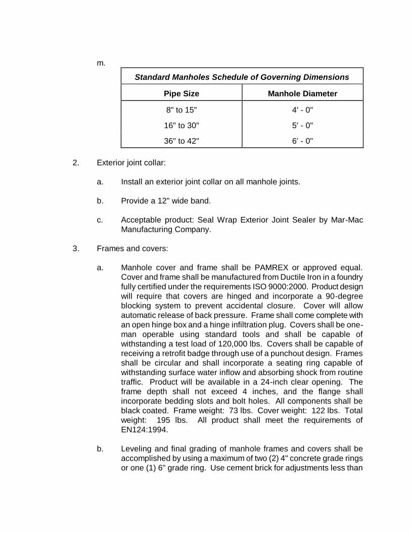
m.
Standard Manholes Schedule of Governing Dimensions
Pipe Size
Manhole Diameter
8" to 15"
4' - 0"
16" to 30"
5' - 0"
36" to 42"
6' - 0"
2. Exterior joint collar:
a. Install an exterior joint collar on all manhole joints.
b. Provide a 12" wide band.
c. Acceptable product: Seal Wrap Exterior Joint Sealer by Mar-Mac
Manufacturing Company.
3. Frames and covers:
a. Manhole cover and frame shall be PAMREX or approved equal.
Cover and frame shall be manufactured from Ductile Iron in a foundry
fully certified under the requirements ISO 9000:2000. Product design
will require that covers are hinged and incorporate a 90-degree
blocking system to prevent accidental closure. Cover will allow
automatic release of back pressure. Frame shall come complete with
an open hinge box and a hinge infiltration plug. Covers shall be one-
man operable using standard tools and shall be capable of
withstanding a test load of 120,000 lbs. Covers shall be capable of
receiving a retrofit badge through use of a punchout design. Frames
shall be circular and shall incorporate a seating ring capable of
withstanding surface water inflow and absorbing shock from routine
traffic. Product will be available in a 24-inch clear opening. The
frame depth shall not exceed 4 inches, and the flange shall
incorporate bedding slots and bolt holes. All components shall be
black coated. Frame weight: 73 lbs. Cover weight: 122 lbs. Total
weight: 195 lbs. All product shall meet the requirements of
EN124:1994.
b. Leveling and final grading of manhole frames and covers shall be
accomplished by using a maximum of two (2) 4" concrete grade rings
or one (1) 6" grade ring. Use cement brick for adjustments less than
4". The total number of grade rings shall not exceed 8" in thickness.
Grade rings and cement brick shall be laid in a full bed of non-shrink
grout and covered after laying with a smooth coating of non-shrink
grout or hydraulic cement a minimum of ½” thick.
c. After the manhole has been set in its final position, the ductile iron
frame for the cover shall be carefully set above finished grade and
properly bonded to the masonry with non-shrinking cement grout or
hydraulic cement. Where manholes are constructed in paved areas,
sidewalks, etc., the top surface of the frame and cover shall be tilted
so as to conform to the exact slope crown and grade of the existing
pavement.
d. Locking kits will be required unless approved otherwise by the
Department.
5. General
a. All manholes over 12' deep shall be reviewed during design with the
Department.
b. Where the difference in the invert elevation between an intersecting
sewer and a manhole is 2' or more, a drop manhole shall be
constructed. They shall be similar in construction to the standard
manhole except that a drop connection of pipe and fittings of the
proper size and material shall be constructed outside the manhole.
Inside drop can be considered on a case by case basis.
c. Where the work requires special stream or railroad crossings or other
extraordinary conditions, or where alternate types of construction that
are not covered by these specifications, the materials and
construction methods shall be submitted for approval to the
Department.
D. PIPE AND MANHOLE FOUNDATION AND BACKFILL MATERIALS
1. Pipe Bedding Materials
a. Crushed stone shall be granite, or well graded approved slag rock.
Crushed stone shall be No. 57.
2. Backfill Materials
a. Reuse of existing excavated materials will be allowed provided the
materials are compactable, dried or dampened to their optimum
moisture content, are free from roots, large clods of clay, and are
granular and non-cohesive in nature.
b. Select fill shall be sand-clay, fine sand or sand gravel mixes with a
maximum of 25% passing a wash #200 sieve.
3. Manhole Bedding Materials
a. Shall be crushed stone as noted in Section D.1.a.
E. CASING, SPACERS AND END SEALS FOR UTILITIES
1. General
a. Provide bore and jack with casing for pipes larger than 2".
b. Casing pipe to be 2" larger in diameter than the bell of the carrier pipe
based on the following:
1) Casing pipe to be a minimum of 2" larger than the largest
outside diameter of the carrier pipe (joints and couplings) if the
carrier pipe is less than 6" in diameter. If the diameter of the
carrier pipe is 6" or larger, the diameter of the casing pipe
shall be a minimum of 4" larger than the largest outside
diameter of the carrier pipe (joints and couplings).
2) The end of casing pipe to extend a minimum of six (6) feet
from the edge of pavement/back of curb.
3) The top of the casing pipe shall be a minimum of four (4) feet
below the crown of the finished asphalt roadway.
4) The top of the casing pipe shall be a minimum of two (2) feet
below the design invert of roadside drainage ditches and
pipes.
2. Casing pipe for dry bores
a. Steel complying with ASTM A139 for Grade B with minimum yield
strength of 35,000 psi.
b. Provide ends suitable for field welding.
c. Minimum wall thickness as follows:
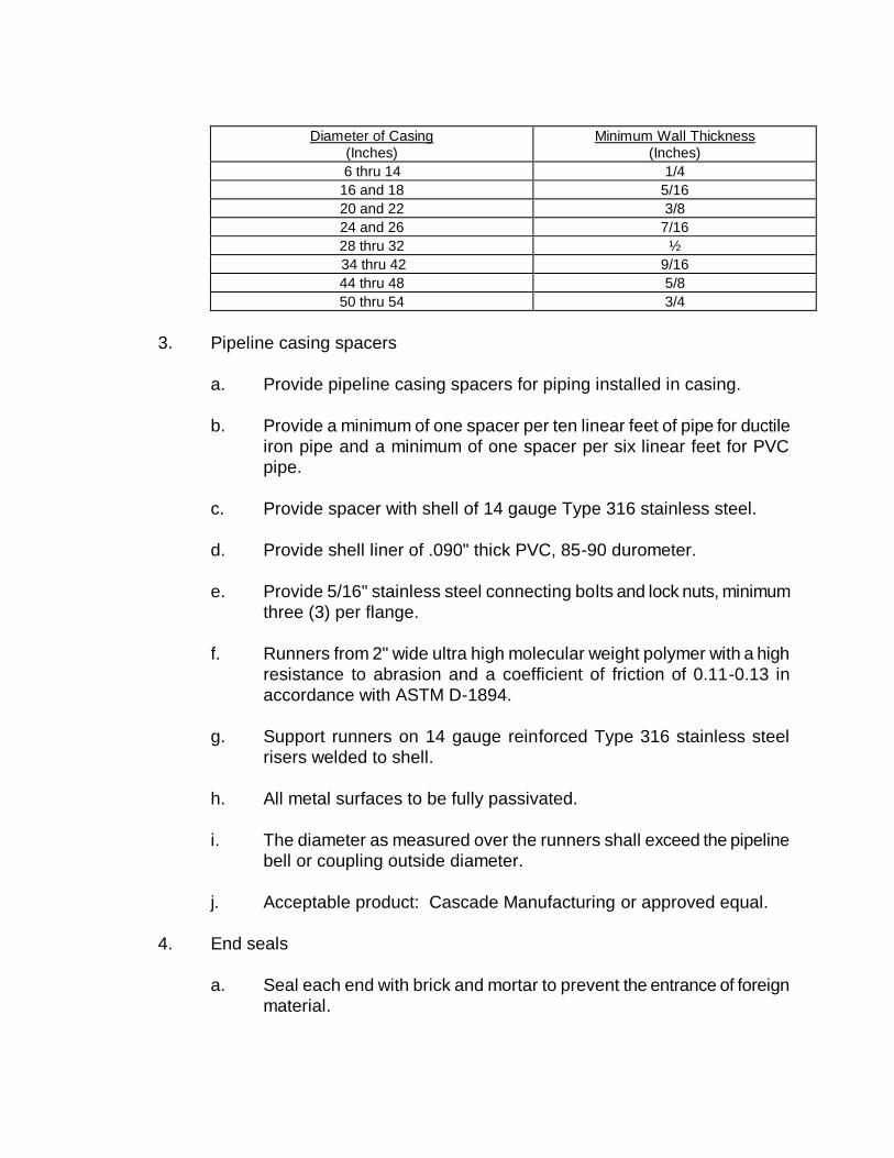
Diameter of Casing
(Inches) Minimum Wall Thickness
(Inches)
6 thru 14 1/4
16 and 18 5/16
20 and 22 3/8
24 and 26 7/16
28 thru 32 ½
34 thru 42 9/16
44 thru 48 5/8
50 thru 54 3/4
3. Pipeline casing spacers
a. Provide pipeline casing spacers for piping installed in casing.
b. Provide a minimum of one spacer per ten linear feet of pipe for ductile
iron pipe and a minimum of one spacer per six linear feet for PVC
pipe.
c. Provide spacer with shell of 14 gauge Type 316 stainless steel.
d. Provide shell liner of .090" thick PVC, 85-90 durometer.
e. Provide 5/16" stainless steel connecting bolts and lock nuts, minimum
three (3) per flange.
f. Runners from 2" wide ultra high molecular weight polymer with a high
resistance to abrasion and a coefficient of friction of 0.11-0.13 in
accordance with ASTM D-1894.
g. Support runners on 14 gauge reinforced Type 316 stainless steel
risers welded to shell.
h. All metal surfaces to be fully passivated.
i. The diameter as measured over the runners shall exceed the pipeline
bell or coupling outside diameter.
j. Acceptable product: Cascade Manufacturing or approved equal.
4. End seals
a. Seal each end with brick and mortar to prevent the entrance of foreign
material.

SECTION 12
GRAVITY SANITARY SEWER
SYSTEM CONSTRUCTION
PROCEDURES
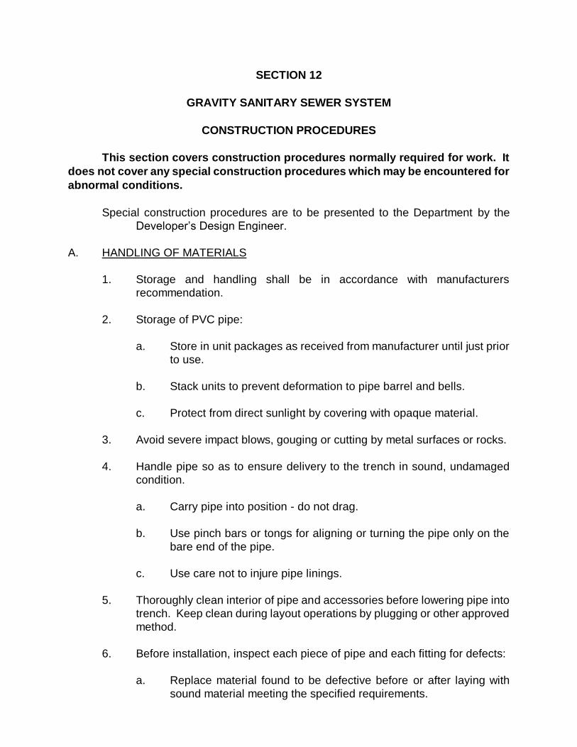
SECTION 12
GRAVITY SANITARY SEWER SYSTEM
CONSTRUCTION PROCEDURES
This section covers construction procedures normally required for work. It
does not cover any special construction procedures which may be encountered for
abnormal conditions.
Special construction procedures are to be presented to the Department by the
Developer’s Design Engineer.
A. HANDLING OF MATERIALS
1. Storage and handling shall be in accordance with manufacturers
recommendation.
2. Storage of PVC pipe:
a. Store in unit packages as received from manufacturer until just prior
to use.
b. Stack units to prevent deformation to pipe barrel and bells.
c. Protect from direct sunlight by covering with opaque material.
3. Avoid severe impact blows, gouging or cutting by metal surfaces or rocks.
4. Handle pipe so as to ensure delivery to the trench in sound, undamaged
condition.
a. Carry pipe into position - do not drag.
b. Use pinch bars or tongs for aligning or turning the pipe only on the
bare end of the pipe.
c. Use care not to injure pipe linings.
5. Thoroughly clean interior of pipe and accessories before lowering pipe into
trench. Keep clean during layout operations by plugging or other approved
method.
6. Before installation, inspect each piece of pipe and each fitting for defects:
a. Replace material found to be defective before or after laying with
sound material meeting the specified requirements.
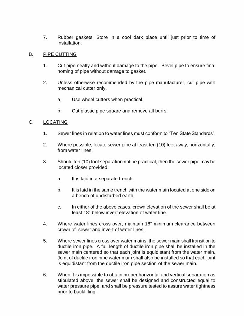
7. Rubber gaskets: Store in a cool dark place until just prior to time of
installation.
B. PIPE CUTTING
1. Cut pipe neatly and without damage to the pipe. Bevel pipe to ensure final
homing of pipe without damage to gasket.
2. Unless otherwise recommended by the pipe manufacturer, cut pipe with
mechanical cutter only.
a. Use wheel cutters when practical.
b. Cut plastic pipe square and remove all burrs.
C. LOCATING
1. Sewer lines in relation to water lines must conform to “Ten State Standards”.
2. Where possible, locate sewer pipe at least ten (10) feet away, horizontally,
from water lines.
3. Should ten (10) foot separation not be practical, then the sewer pipe may be
located closer provided:
a. It is laid in a separate trench.
b. It is laid in the same trench with the water main located at one side on
a bench of undisturbed earth.
c. In either of the above cases, crown elevation of the sewer shall be at
least 18" below invert elevation of water line.
4. Where water lines cross over, maintain 18" minimum clearance between
crown of sewer and invert of water lines.
5. Where sewer lines cross over water mains, the sewer main shall transition to
ductile iron pipe. A full length of ductile iron pipe shall be installed in the
sewer main centered so that each joint is equidistant from the water main.
Joint of ductile iron pipe water main shall also be installed so that each joint
is equidistant from the ductile iron pipe section of the sewer main.
6. When it is impossible to obtain proper horizontal and vertical separation as
stipulated above, the sewer shall be designed and constructed equal to
water pressure pipe, and shall be pressure tested to assure water tightness
prior to backfilling.
7. Water Supply Interconnections
There shall be no physical connections between a public or private potable
water supply system and a sewer, or appurtenances thereto which would
permit the passage of any sewage or polluted water into the potable supply.
No water pipe shall pass through or come in contact with any part of a sewer
manhole.
8. Relation to Water Works Structures
While no general statement can be made to cover all conditions, it is
generally recognized that sewers shall meet the requirements of the
appropriate reviewing agency with respect to minimum distances from public
water supply wells or other water supply sources and structures.
D. INSTALLATION
1. Trench, backfill and compact for the work of this Section in strict accordance
with pertinent provisions of these specifications, and the following
requirement:
a. Maximum trench widths, depths and bedding methods.
1) Install all sewers complying with tables for depths of cut and
class of bedding included hereinafter.
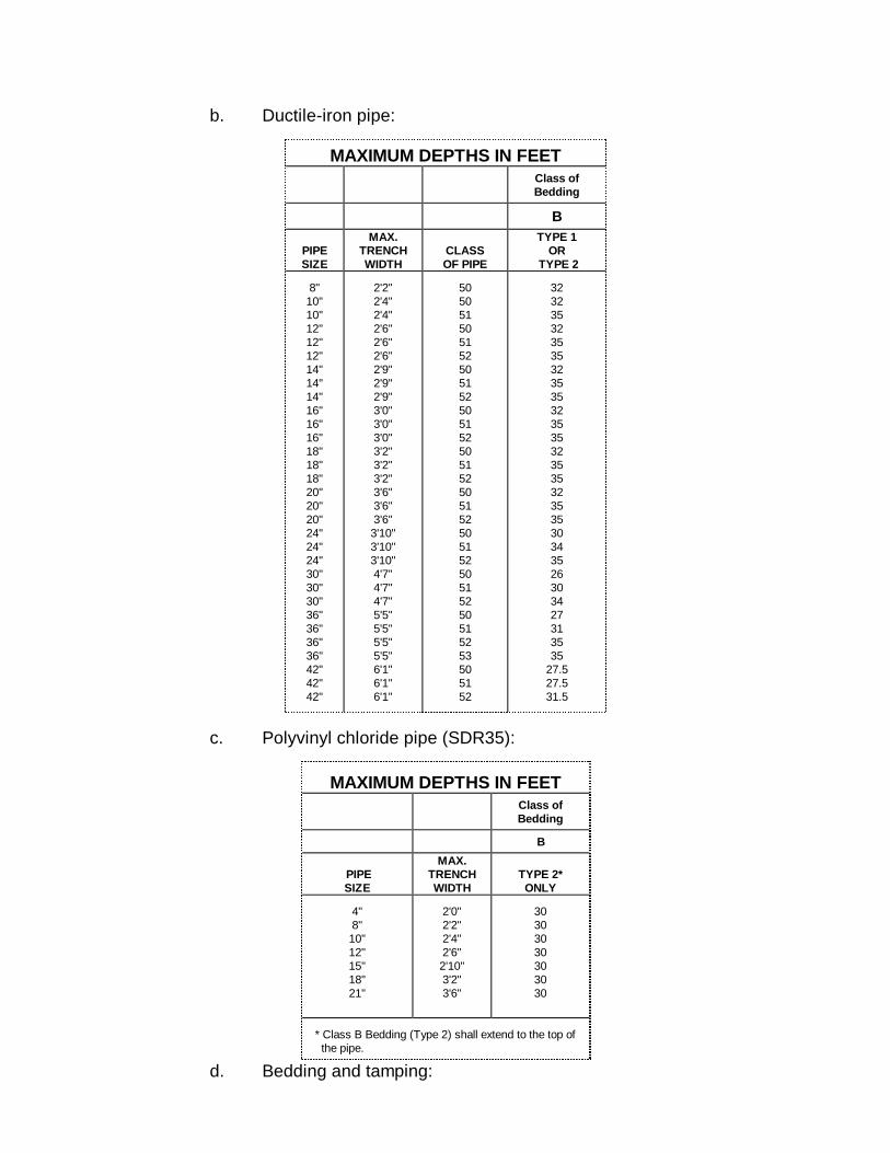
b. Ductile-iron pipe:
MAXIMUM DEPTHS IN FEET
Class of
Bedding
B
PIPE
SIZE
MAX.
TRENCH
WIDTH
CLASS
OF PIPE
TYPE 1
OR
TYPE 2
8"
10"
10"
12"
12"
12"
14"
14"
14"
16"
16"
16"
18"
18"
18"
20"
20"
20"
24"
24"
24"
30"
30"
30"
36"
36"
36"
36"
42"
42"
42"
2'2"
2'4"
2'4"
2'6"
2'6"
2'6"
2'9"
2'9"
2'9"
3'0"
3'0"
3'0"
3'2"
3'2"
3'2"
3'6"
3'6"
3'6"
3'10"
3'10"
3'10"
4'7"
4'7"
4'7"
5'5"
5'5"
5'5"
5'5"
6'1"
6'1"
6'1"
50
50
51
50
51
52
50
51
52
50
51
52
50
51
52
50
51
52
50
51
52
50
51
52
50
51
52
53
50
51
52
32
32
35
32
35
35
32
35
35
32
35
35
32
35
35
32
35
35
30
34
35
26
30
34
27
31
35
35
27.5
27.5
31.5
c. Polyvinyl chloride pipe (SDR35):
MAXIMUM DEPTHS IN FEET
Class of
Bedding
B
PIPE
SIZE
MAX.
TRENCH
WIDTH
TYPE 2*
ONLY
4"
8"
10"
12"
15"
18"
21"
2'0"
2'2"
2'4"
2'6"
2'10"
3'2"
3'6"
30
30
30
30
30
30
30
* Class B Bedding (Type 2) shall extend to the top of
the pipe.
d. Bedding and tamping:
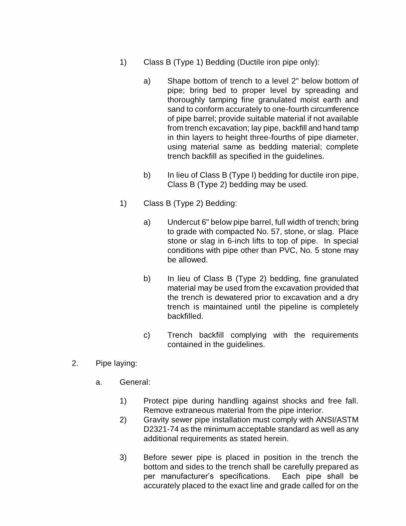
1) Class B (Type 1) Bedding (Ductile iron pipe only):
a) Shape bottom of trench to a level 2" below bottom of
pipe; bring bed to proper level by spreading and
thoroughly tamping fine granulated moist earth and
sand to conform accurately to one-fourth circumference
of pipe barrel; provide suitable material if not available
from trench excavation; lay pipe, backfill and hand tamp
in thin layers to height three-fourths of pipe diameter,
using material same as bedding material; complete
trench backfill as specified in the guidelines.
b) In lieu of Class B (Type I) bedding for ductile iron pipe,
Class B (Type 2) bedding may be used.
1) Class B (Type 2) Bedding:
a) Undercut 6" below pipe barrel, full width of trench; bring
to grade with compacted No. 57, stone, or slag. Place
stone or slag in 6-inch lifts to top of pipe. In special
conditions with pipe other than PVC, No. 5 stone may
be allowed.
b) In lieu of Class B (Type 2) bedding, fine granulated
material may be used from the excavation provided that
the trench is dewatered prior to excavation and a dry
trench is maintained until the pipeline is completely
backfilled.
c) Trench backfill complying with the requirements
contained in the guidelines.
2. Pipe laying:
a. General:
1) Protect pipe during handling against shocks and free fall.
Remove extraneous material from the pipe interior.
2) Gravity sewer pipe installation must comply with ANSI/ASTM
D2321-74 as the minimum acceptable standard as well as any
additional requirements as stated herein.
3) Before sewer pipe is placed in position in the trench the
bottom and sides to the trench shall be carefully prepared as
per manufacturer’s specifications. Each pipe shall be
accurately placed to the exact line and grade called for on the
plans. Laser equipment shall be used in setting pipe in lieu of
the batter board method.
4) Pipe shall be laid in a full bed of crushed stone (ASTM C33,
Gradation 67). Pipe laying shall proceed upgrade, starting at
the lower end of the grade and with the bells upgrade. Pipe
shall be straight when placed in the trench. Trench bottoms
found to be at incorrect grade after pipe laying operations
have begun shall be corrected and brought to exact line and
grade.
5) After each line of pipe has been laid, it shall be carefully
inspected and all earth, trash, rags, and other foreign matter
removed from the interior.
6) Each joint shall be laid so that it will form a close concentric
joint with adjoining pipe and so as to avoid sudden offsets.
7) All jointing of pipe and fittings shall be in accordance with the
pipe manufacturer’s recommendations.
8) Any leaks or defects discovered at any time after completion of
the work shall be repaired immediately. All pipe in place shall
be carefully protected from damage until the backfilling
operations have been completed.
9) Water shall not be allowed to run through the pipe or stand in
the trench.
b. Polyvinyl chloride pipe:
1) Use proper bedding as specified above.
2) Comply with ASTM D2321, except as otherwise specified
herein.
c. Ductile-iron pipe:
1) Use proper bedding as specified above.
2) Comply with ANSI/AWWA C600, except as otherwise specified
herein.
E. MANHOLES
1. Set bases level so that walls will be plumb.
2. Clean bells and spigots.
3. Apply joint sealer, or ring gasket to wall section(s), set firmly in place to
assure watertight joints.
4. Connect pipe boot to piping with dual stainless steel straps.
5. Grout lift holes from the outside using non-shrink grout.
6. Install exterior joint collar.
a. Follow manufacturer’s recommendations.
b. Clean the surface.
c. Remove the protective paper and place the band around the
manhole, mastic side to the manhole and spanning the joint.
7. Form the invert channels directly in the concrete of the manhole base, with
mortar and brick. Smooth the floor of the manhole outside the channels, and
slope toward the channels at not less than 1" per foot nor more than 2" per
foot.
a. Shape the invert channels to be smooth and semi-circular,
conforming to the inside of the adjacent sewer section. Inverts shall
be to crown of pipe.
b. Make changes in direction of flow with a smooth curve of as large a
radius as the size of the manhole will permit.
c. Make changes in size and grade of channels smoothly and evenly.
d. Slope invert uniformly from invert of inlet to invert of outlet.
8. Match manhole top to grade utilizing concrete grade rings or cement brick as
specified, maximum height 8".
F. MANHOLE COATINGS
1. Provide in manholes (new or existing) where a force main enters and in the
next manhole down stream. The Department reserves the right to require
coatings in additional down stream manholes.
a. Acceptable product for coating:
1) 125 mills Raven 405 Epoxy.
2) 240 mils Neopoxy NPL 5300.
3) Others as approved by the Department.
b. Surface preparation:
1) Follow all manufacturers’ recommendations for surface
preparation for new or existing manholes.
G. CONNECTIONS TO EXISTING SYSTEM
1. Connections to existing manholes shall be made in the presence of the
Department. The Contractor shall notify the Department 48 hours before
starting a connection. All new holes in existing manholes shall be core
drilled.
2. Construct new manhole over existing gravity main breaking upper half of
existing pipe after base of manhole is completed so as not to obstruct flow of
the existing pipe.
3. At existing manhole tie-ins, temporarily block and/or divert sewage flows,
perform other miscellaneous work.
a) Use high-early strength cement for mortar, forming proper channels
with minimum interruption to service of the existing sewer.
H. SERVICE LATERALS
1. Service laterals shall be installed where required to provide a connection
from the sanitary sewer to all lots. For a single residence, the elder valve
shall not be placed in a driveway or sidewalk.
2. Service laterals shall consist of 6" diameter DIP or PVC and conform to the
requirements of these guidelines. A service wye shall be installed at the end
of each service lateral and plugged in a manner to allow for air testing. The
depth of a service shall be a minimum of 36" below finished grade, and a
maximum of 60". Service laterals will not exceed 75' in length, however,
laterals that are less than 20' in length on single family dwellings may be 4"
in diameter with approval by the Department.
3. All sewer services shall have elder valves installed during construction and
the cleanout pipe for the elder valve shall rise at least three (3’) feet above
grade and be capped.
4. All services that are in an area where new curb and gutter will be provided
shall be marked with an "X" on the curb and gutter to mark the location of the
service lateral.
5. Service laterals shall be connected at manholes whenever possible and
installed so the crown of main sewer line and service lateral are the same
elevation.
6. Connect to street sewers using wye branches and ells.
7. Do not stack service lines vertically over the sewer main.
8. Comply with details in the Details Section.
9. Locate service lateral within one (1) foot from property corner on opposite
corner of water lateral.
10. Minimum cover required by SCDOT and the Department of service lateral is
24". SCDOT and the Department may require concrete encasement under
drainage ditch on an individual review.
I. INSPECTIONS AND TESTING
1. General:
a. The Department will require that all sanitary sewer systems pass the
following test prior to acceptance: (Department shall be notified 72
hours before inspections).
2. Air Testing:
The Contractor shall conduct low pressure air tests on all completed
sections of gravity sewer. The air test results will be used to evaluate
construction methods on the sewer line sections.
The Contractor shall furnish an air compressor which will provide at least
300 cubic feet of air per minute at 100 psi, air hose, connection and other
equipment necessary to conduct the air tests. Plugs in sewers 18" in size
and larger shall be connected by cable for thrust reaction. The following
provisions will be adhered to when conducting low pressure air tests:
3. Equipment
a. Plug Design
Either mechanical or pneumatic plugs may be used. All plugs shall
be designed to resist internal testing pressures without the aid of
external bracing or blocking. However, the Contractor should
internally restrain or externally brace the plugs to the manhole wall as
an added safety precaution throughout the test.
b. Singular Control
To facilitate test verification by the inspecting Engineer, all air used
shall pass through a single, above ground control panel.
c. Equipment Controls
The above ground air control equipment shall include a shut-off valve,
pressure regulating valve, input pressure gauge, and a continuous
monitoring pressure gauge having a pressure range from 0 to at least
10 psi. The continuous monitoring gauge shall be no less than 4" in
diameter with minimum divisions of 0.10 psi and
psi.
d. Separate Hoses
Two separate hoses shall be used to: (1) connect the control panel
to the sealed line for introducing low pressure air, and (2) a separate
hose connection for constant monitoring of air pressure build-up in
the line. This requirement greatly diminishes any chance for over-
pressurizing the line.
e. Pneumatic Plugs
If pneumatic plugs are utilized, a separate hose shall also be required
to inflate the pneumatic plugs from the above ground control panel.
4. Line Preparation
a. Laterals, Stubs, and Fittings
During sewer construction all service laterals, stubs, and fittings into
the sewer test section shall be properly capped or plugged so as not
to allow for air loss that could cause an erroneous air test result. It
may be necessary and is always advisable to restrain gasketed caps,
plugs, or short pipe lengths with bracing stakes, clamps and tie-rods,
or wire harnesses over the pipe bells.
5. Test Procedure
a. Plug Installation and Testing
After a manhole to manhole reach of pipe has been backfilled to final
grade, prepared for testing, and the specified waiting period has
elapsed, the plugs shall be placed in the line at each manhole and
secured.
It is advisable to seal test all plugs before use. Seal testing may be
accomplished by laying one length of pipe on the ground and sealing
it at both ends with the plugs to be checked. The sealed pipe should
be pressurized to 9 psig. The plugs should hold against this pressure
without bracing and without any movement of the plugs out of the
pipe. No persons shall be allowed in the alignment of the pipe during
plug testing.
It is advisable to plug the upstream end of the line first to prevent any
upstream water from collecting in the test line. This is particularly
important in high groundwater situations.
When plugs are being placed, the pipe adjacent to the manhole shall
be visually inspected to detect any evidence of shear in the pipe due
to differential settlement between the pipe and the manhole. A
probable point of leakage is at the junction of the manhole and the
pipe, and this fault may be covered by the pipe plug, and thus not
revealed by the air test.
b. Line Pressurization
Low pressure air shall be slowly introduced into the sealed line until
the internal air pressure reaches 4.0 psig greater than the average
back pressure of any groundwater above the pipe, but not greater
than 9.0 psig. Immediately before testing, if groundwater is present,
the groundwater elevation must be determined by appropriate means.
c. Pressure Stabilization
After a constant pressure of 4.0 psig (greater than the average
groundwater back pressures), is reached, the air supply shall be
throttled to maintain that internal pressure for at least 2 minutes. This
time permits the temperature of the entering air to equalize with the
temperature of the pipe walls.
d. Timing Pressure Loss
When temperatures have been equalized and the pressure stabilized
at 4.0 psig (greater than the average groundwater back pressure), the
air hose from the control panel to the air supply shall be shut off or
disconnected. The continuous monitoring pressure gauge shall then
be observed while the pressure is decreased to no less than 3.5 psig
(greater than the average back pressure of any groundwater over the
pipe). At a reading of 3.5 psig, or any convenient observed pressure
reading between 3.5 psig and 4.0 psig (greater than the average
groundwater back pressure), timing shall commence with a stop
watch or other timing device that is at least 99.8% accurate.
A predetermined required time for a specified pressure drop shall be
used to determine the lines acceptability. Traditionally, a pressure
drop of 1.0 psig has been specified. However, other pressure drop
values may be specified, provided that the required holding times are
adjusted accordingly. If the specified pressure drop is 0.5 psig rather
than the more traditional 1.0 psig, then the required test times for a
1.0 psig pressure must be halved. Specifying a 0.5 psig pressure
drop is desirable in that it can reduce the time needed to accomplish
the air test without sacrificing test integrity. Therefore, the following
subsections contain provisions for both the traditional 1.0 psig
pressure drop and the more efficient 0.5 psig pressure drop. All
requirements for a specified 0.5 psig drop are given in parentheses.
e. Determination of Line Failure
If the time shown in Table I (or Table II), for the designated pipe size
and length, elapses before the air pressure drops 1.0 psig (or 0.5
psig); the section undergoing test shall have passed and shall be
presumed to be free of defects. The test may be discontinued once
the prescribed time has elapsed even though the 1.0 psig (or 0.5
psig) drop has not occurred.
f. Determination of Line Failure
If the pressure drops 1.0 psig (or 0.5 psig) before the appropriate time
shown in Table I (or Table II) has elapsed, the air loss rate shall be
considered excessive and the section of pipe has failed the test.
g. Line Repair or Replacement
If the section fails to meet these requirements, the Contractor shall
determine at his own expense the source, or sources of leakage, and
he shall repair or replace all defective materials and/or workmanship
to the satisfaction of the Department. The extent and type of repair
which may be allowed, as well as results, shall be subject to the
approval of Department. The completed pipe installation shall then
be retested and required to meet the requirements of the test.
h. Specified Time Tables
To facilitate the proper use of this recommended practice for air
testing, the following tables are provided. Table I contains the
specified minimum times required for a 1.0 psig pressure drop from a
starting pressure of at least 3.5 psig greater than the average back
pressure of any groundwater above the pipe’s invert. Table II
contains specified minimum times required for a 0.5 psig pressure
drop from a starting pressure of at least 3.5 psig greater than the
average back pressure of any groundwater above the pipe’s invert.
Both Tables also include easy to use formulas for calculating required
test times for various pipe sizes and odd lengths. A series of
examples are provided in the Appendix to this recommended practice
that demonstrate proper use of the Tables.
6. Pipe Deflection
All PVC gravity sewer pipe, 8" diameter and larger, shall be tested after
installation and backfill by the Contractor. Testing shall be performed at the
Contractor’s expense using a 5% mandrel acceptable to the Department to
insure that initial deflection of pipe does not exceed 5%. The Mandrel pull
shall be as described in the Ten State Standards. The Contractor shall not
use any mechanical device in the Mandrel pull. All deflection testing shall be
performed in the presence of the Engineer and Department. Contractor shall
notify the Engineer and the Department in sufficient time to insure that the
both will be present during deflection tests. Deflection test records shall
identify the location and deflection amount at all points where deflection
exceeds the specified limit. Such records shall be certified by the
Contractor, and shall be furnished to the Engineer prior to acceptance and
payment. Pipe with initial deflection exceeding the specified limit will be
unacceptable, and shall be re-bedded to the correct deflection and retested
for deflection, at the Contractor’s expense.
7. Visual Inspection
All gravity sewer manholes and pipelines shall be visually inspected by the
Department’s Inspector prior to acceptance. Gravity sewer manholes shall
be to final grade, have no visible infiltration, contain properly formed and
sloped inverts, and be properly coated as outlined in previous sections.
Gravity sewer pipelines shall be of uniform slope with no portion holding
water. Repairs to gravity sewer pipelines shall be performed in manner
equivalent to new construction. Fernco style couplings or repair bands shall
not be used.
8. Camera Inspection
a. Standard
Gravity sewer mains shall be inspected using the Pipeline
Assessment Certification Program (PACP) inspection standards and
closed-circuit television techniques.
b. Scope of work
1. The video shall include all mainline sections from manhole to
manhole from the right-of-way boundary to the mainline
connection or manhole connection.
2. Video inspection shall be performed after the pipe has been
laid and passed the air pressure and Mandrel tests.
3. Prior to the performing the CCTV inspection, the Contractor
shall thoroughly clean the sewer mains and laterals to be
inspected. After cleaning, all equipment will be removed from
thesewer line(s). Just prior to performing the inspection, water
is to be sent into the nearest upstream manhole until it is
observed at the nearest downstream manhole. This will insure
that any pipe segments with bellies are easily identified during
the CCTV inspection.
c. CCTV and Equipment
1. Television inspection equipment shall have an accurate
footage counter that will display on the monitor and record the
camera distance from the manhole and pipe connection. Prior
to the beginning of each CCTV inspection, manhole
identification numbers as shown on the record drawing will be
displayed in the title.
2. The camera shall be of the remotely operated pan and tilt type.
The rotating camera and light head configuration shall have
the capability of panning 360 degrees with tilt capability of
providing a full view of the pipe to ensure complete inspection
of the main line and laterals.
3. The camera, television monitor and other components shall be
color. To ensure peak picture quality throughout all conditions
encountered, the color camera shall be equipped with the
necessary circuitry to allow for the remote adjustment of the
optical focus iris from the power control unit at the viewing
station. A variable intensity control of the camera lights shall
also be located at the viewing station.
4. All fog shall be evacuated from the pipeline and the pipeline
kept clear of any fog during the CCTV inspection process.
5. Lighting and camera quality shall be suitable to allow a clear,
in-focus picture inside the pipelines extending at least ten (10)
feet in front of the camera. In High Density Polyethylene
(HDPE) or ductile iron pipe (DIP), lighting should be sufficient
enough to provide a clear view at least two (2) feet in front of
the camera. The replay of the recorded video information shall
be free of electrical interference and shall provide a clear
stable image.
d. Execution
1. The CCTV inspection may be performed by a contractor or
Department Personnel. Inspections performed by a contractor
must be observed by a Department Inspector. The
Developer’s Engineer may observe the inspection as well.
2. The Contractor shall provide the personnel performing the
CCTV inspection a copy of the record drawing.
3. Line segment inspection shall be made manhole to manhole.
4. The pipe must be clear and free of any dirt and/or debris. The
travel speed of the camera shall be variable but uniform and
shall not exceed 30 feet per minute. Any means of propelling
the camera through the sewer line which would produce
nonuniform or jerky movement of the camera will not be
acceptable.
5. The camera shall be propelled through the camera at a
uniform rate that will allow for a clear view of the pipe.
6. The camera shall be stopped to view and study potentially
deficient areas when directed by the Department’s Inspector or
the Developer’s Engineer’s representative.
6. The interior of the pipe shall be carefully inspected to
determine the location and extent of all deficiencies. Pipe
conditions that result in a question of proper installation
procedures shall be noted so that these conditions can be
reviewed and, if necessary, corrected before actual
acceptance of the sewer system.
7. CCTV inspection will take place as soon as possible after
testing.
9. The camera shall be stopped to get a clear view of each defect
and service connection. At each service lateral, the camera
shall be panned to view up each lateral or point of connection.
10. The CCTV technician shall record the inspection in a PACP
format, and the video shall be recorded in an extra-high
CD/DVD format. The title block shall include the following
information:
a. Date
b. Television operator’s name
c. Sewer segment number
d. Upstream manhole number
e. Downstream manhole number
f. Size of sewer pipe
g. Pipe material
h. Direction of movement of camera and direction of
normal flow.
i. Location of service connections indicated by clock
position and with counter distance in feet from
beginning of pipe.
k. Distance from beginning of pipe and description of
obstructions, structural defects, longitudinal and/or
circumferential cracking, faulty joints including open
and offset joints, ovality, leakage or evidence thereof,
break in connections, protruding connections, mineral
deposits, roots, previous repairs, deposits on pipe
walls, sags, and other abnormalities in the sewer.
The CCTV technician’s log shall include the same information.
11. The CD/DVD shall visually display, at a minimum, the CCTV
technician’s name project name, date of inspection, pipe
segment number, manhole numbers and, if applicable, lateral
lot numbers.
12. The CD/DVD shall be maintained and delivered to the
Department in a hard case along with a copy of the field logs.
The disk or case shall be labeled with the project name,
Department project number, date of inspection, manhole
segment number(s) inspected, and CCTV technician’s
identification.
13. If during video operations the camera cannot pass safely
through the entire sewer segment being inspected, the CCTV
technician shall set up the equipment in reverse and perform
the inspection from the other manhole. The forward distance
traveled shall be entered into the log and noted on the video.
If the video cannot pass the entire length safely in reverse, the
inspection of the segment shall stop.
14. All services shall be inspected with a push camera.
e. Acceptance
1. A section of sewer shall be recleaned and reinspected if the
video is not clear, does not show the entire internal surface of
the pipe or is not accompanied by a complete inspection log.
2. Any of the following shall be considered defects:
a. Bellies
b. Joint separations
c. Offset joints
d. Chips in pipe ends
e. Cracked or damaged pipe
f. Evidence of the presence of an external object bearing
upon the pipe
g. Infiltration
h. Roots
i. Debris or other objects
j. Other inconsistencies with the approved plans and
specifications
3. Any deficient sections of sewer pipe must be repaired by the
contractor. The section of pipe must be fully reinspected and
retested including CCTV inspection, air test and Mandrel test.
2. At the discretion of the Department, and in addition to air testing, pipe
deflection test, and visual inspection and CCTV inspection, the Department
may require the following:
a. Leaking and Infiltration Test
All pipe joints shall be watertight. Infiltration of groundwater or other
leakage into the sewer (including manholes) shall not exceed 50 gallons per
mile of sewer per inch of inside diameter of the sewer per 24 hours in any
section of the completed work, and in no case shall it exceed 3,000 gallons
per mile per 24 hours. The infiltration rate into each section of the sewer
shall be measured by the temporary installation of suitable metal or wooden
weirs as authorized by the Department. These weirs shall be furnished,
installed, and removed by the Contractor. Any leaks into the sewer shall be
located, repaired and corrected.
b. Soil Compaction Test
All trenches suspected of not meeting the compaction requirements stated
previously shall be tested for conformance by a Department approved
testing lab and at the locations and depths requested by the Department.
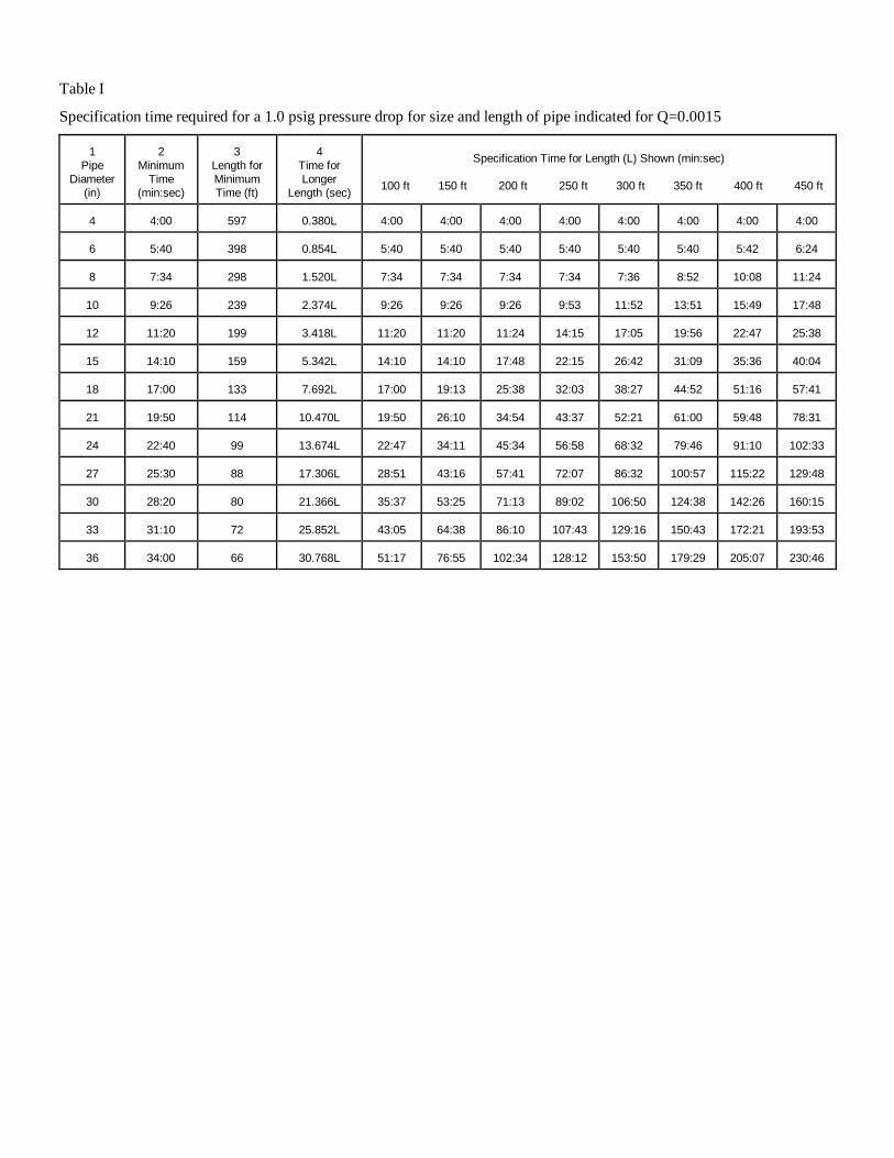
Table I
Specification time required for a 1.0 psig pressure drop for size and length of pipe indicated for Q=0.0015
1
Pipe
Diameter
(in)
2
Minimum
Time
(min:sec)
3
Length for
Minimum
Time (ft)
4
Time for
Longer
Length (sec)
Specification Time for Length (L) Shown (min:sec)
100 ft 150 ft 200 ft 250 ft 300 ft 350 ft 400 ft 450 ft
4
4:00
597
0.380L
4:00
4:00
4:00
4:00
4:00
4:00
4:00
4:00
6
5:40
398
0.854L
5:40
5:40
5:40
5:40
5:40
5:40
5:42
6:24
8
7:34
298
1.520L
7:34
7:34
7:34
7:34
7:36
8:52
10:08
11:24
10
9:26
239
2.374L
9:26
9:26
9:26
9:53
11:52
13:51
15:49
17:48
12
11:20
199
3.418L
11:20
11:20
11:24
14:15
17:05
19:56
22:47
25:38
15
14:10
159
5.342L
14:10
14:10
17:48
22:15
26:42
31:09
35:36
40:04
18
17:00
133
7.692L
17:00
19:13
25:38
32:03
38:27
44:52
51:16
57:41
21
19:50
114
10.470L
19:50
26:10
34:54
43:37
52:21
61:00
59:48
78:31
24
22:40
99
13.674L
22:47
34:11
45:34
56:58
68:32
79:46
91:10
102:33
27
25:30
88
17.306L
28:51
43:16
57:41
72:07
86:32
100:57
115:22
129:48
30
28:20
80
21.366L
35:37
53:25
71:13
89:02
106:50
124:38
142:26
160:15
33
31:10
72
25.852L
43:05
64:38
86:10
107:43
129:16
150:43
172:21
193:53
36
34:00
66
30.768L
51:17
76:55
102:34
128:12
153:50
179:29
205:07
230:46
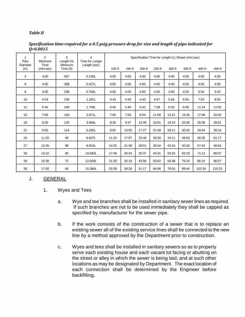
Table II
Specification time required for a 0.5 psig pressure drop for size and length of pipe indicated for Q=0.0015
1
Pipe
Diameter
(in)
2
Minimum
Time
(min:sec)
3
Length for
Minimum
Time (ft)
4
Time for Longer
Length (sec)
Specification Time for Length (L) Shown (min:sec)
100 ft 150 ft 200 ft 250 ft 300 ft 350 ft 400 ft 450 ft
4
4:00
597
0.190L
4:00
4:00
4:00
4:00
4:00
4:00
4:00
4:00
6
4:00
398
0.427L
4:00
4:00
4:00
4:00
4:00
4:00
4:00
4:00
8
4:00
298
0.760L
4:00
4:00
4:00
4:00
4:00
4:26
5:04
5:42
10
4:43
239
1.187L
4:43
4:43
4:43
4:57
5:56
6:55
7:54
8:54
12
5:40
199
1.709L
5:40
5:40
5:42
7:08
8:33
9:58
11:24
12:50
15
7:05
159
2.671L
7:05
7:05
8:54
11:08
13:21
15:35
17:48
20:02
18
8:30
133
3.846L
8:30
9:37
12:49
16:01
19:14
22:26
25:38
28:51
21
9:55
114
5.235L
9:55
13:05
17:27
21:49
26:11
30:32
34:54
39:16
24
11:20
99
6.837L
11:24
17:57
22:48
28:30
34:11
39:53
45:35
51:17
27
12:45
88
8.653L
14:25
21:38
28:51
36:04
43:16
50:30
57:43
46:54
30
14:10
80
10.683L
17:48
26:43
35:37
44:31
53:25
62:19
71:13
80:07
33
15:35
72
12.926L
21:33
32:19
43:56
53:52
64:38
75:24
86:10
96:57
36
17:00
66
15.384L
25:39
38:28
51:17
64:06
76:55
89:44
102:34
115:23
J. GENERAL
1. Wyes and Tees
a. Wye and tee branches shall be installed in sanitary sewer lines as required.
If such branches are not to be used immediately they shall be capped as
specified by manufacturer for the sewer pipe.
b. If the work consists of the construction of a sewer that is to replace an
existing sewer all of the existing service lines shall be connected to the new
line by a method approved by the Department prior to construction.
c. Wyes and tees shall be installed in sanitary sewers so as to properly
serve each existing house and each vacant lot facing or abutting on
the street or alley in which the sewer is being laid, and at such other
locations as may be designated by Department. The exact location of
each connection shall be determined by the Engineer before
backfilling.
d. Wyes and tees shall be of the same material and strength as the
sewers on which they are installed.
2. Service Laterals
a. Service laterals shall be installed where required to provide a
connection from the sanitary sewer to all lots.
b. Service laterals shall consists of 6" diameter DIP or PVC and conform
to the requirements of these guidelines. A service wye shall be
installed at the end of each service lateral and plugged in a manner to
allow for air testing. The depth of a service shall be a minimum of 36"
below finished grade, and a maximum of 60". Service laterals will not
exceed 76' in length. However, laterals that are less than 20' in
length on single family dwellings may be 4" in diameter with approval
by the Department.
3. Connections to Existing Sewers
a. Connections to existing manholes shall be made in the presence of
the Department Inspector. The Contractor shall notify the Department
48 hours before starting a connection. All new holes in existing
manholes shall be core drilled.
4. Pipe Protection
a. Sewer pipe which, when completed, will have less than 3' of cover
shall be constructed of ductile iron pipe.
b. Where foundation conditions are not satisfactory as determined by
the soil conditions, sewer pipe shall be either laid on a Class B
concrete cradle, pipe foundation material, or constructed of ductile
iron pipe, as approved in advance by Department.
c. Where sewer pipe is laid under storm drainage pipe, there must be a
minimum of 18" of separation or more. If unable to obtain 18" of
clearance, use one joint of DIP centered under the drainage line.
5. Pipe storage and handling shall be in accordance with the pipe
manufacturer’s recommendations. Pipe shall be stored on a smooth surface
to avoid point loadings. Pipe shall be handled with care so as to prevent
damage. Correct equipment should be used to load or unload pipe so as to
eliminate dropping, etc.
6. All excavated areas, backfills, embankments, trenches and access roads,
grading and ditches shall be maintained by the Contractor in good condition
at all times until final acceptance by the Department. Where trench backfill
has settled, trenches shall be brought back to grade.
K. TRENCH EXCAVATION
This section of the guidelines is provided to outline most types of laying conditions,
but is not intended to cover all special laying conditions or the Engineer’s special
requirements.
1. Trench excavation shall be made in open cut and true to the lines and
grades shown on the plans, unless boring is necessary or required. Banks
of the trenches shall be cut in vertical, parallel planes equidistant from the
pipe center line. The horizontal distance between such planes, or the
overall width of trench, shall vary with the size of the pipe to be installed.
The overall width of trench shall be as recommended by the manufacturer.
When vertical banks for trench excavation are not practical to construct or
create dangerous conditions to workmen, the banks may be sloped provided
that such excavation does not damage adjacent structures. When trench
banks are sloped, such banks shall be cut to vertical planes as specified
above for that part of the ditch below the level of 12" above the top of the
pipeline. The bottom of the trench shall be level in cross section and shall
be cut true to the required grade of the pipe and pipe embedment materials.
2. Bell holes for bell-and-spigot pipe shall be excavated at proper intervals so
that the barrel of the pipe will rest for its entire length upon the bottom of the
trench. Bell holes shall be large enough to permit proper installation of joints
in the pipe.
3. When muck, quicksand, soft clay, swampy or other material unsuitable for
foundations or sub-grade are encountered, such material shall be removed
and replaced with crushed stone.
4. After excavation, the area between the final pipe grade and the trench soil
bottom shall be filled with crushed stone materials as required, compacted to
proper grade, and made ready for pipe laying.
5. Debris encountered in trench excavation for sewers and other pipelines shall
be removed for the overall width of trench which shall be as shown on the
plans. It shall be removed to a depth of 6" below the bottom of the pipe for
pipes smaller than 24" in size; 8" below the bottom of the pipe for pipes 24"
to 36" in size; and 12" below the bottom of the pipe for pipes larger than 36"
in size, if debris extends to such depth.
6. In all cases, materials deposited shall be placed so that in the event of rain,
no damage will result to the work.
7. The sides of all excavations shall be sufficiently sheeted, shored and braced
whenever necessary to prevent slides, cave-ins, settlements or movement of
the banks and to maintain the excavation clear of obstructions. Wood or
steel sheet piling of ample design and type shall have sufficient strength and
rigidity to withstand the pressures exerted and to maintain the walls of the
excavation properly in place and protect all persons and property from injury
or damage. Sheeting, shoring or bracing materials shall not be left in place
unless as shown by the plans or permitted by the Department. All trench
sheeting and bracing shall be left in place until the trench has been
backfilled one foot above the top of the pipe.
3. Comply with all OSHA guidelines.
L. TRENCH BACKFILL
1. The backfilling of pipeline trenches shall be started immediately after the
pipe work has been inspected. The initial backfill material, placed to a
height of one (1) foot above the top of the pipe, shall consist of approved
backfill material free from organic matter and deleterious substances,
containing no rocks or lumps over 2" in any dimension.
It shall be carefully placed and compacted through compaction of the entire
area backfilled.
Backfill shall be deposited in 6" layers (before compaction) and thoroughly
compacted with power tools to 95% of theoretical maximum density, modified
Proctor ASTM-D-1557.
2. Where trenches are not under pavement, sidewalks, or in alleys, the backfill
material above pipe zone shall be compacted to a sufficient density to
prevent settlement. Any deficiency in backfilling the trenches, or
depressions caused by settlement, shall be repaired.
3. Where pipe trenches are cut across or along pavement, trenches shall be
backfilled with select fill material placed and compacted in 6" lifts.
Replacement of road base and asphalt shall be in accordance with South
Carolina Department of Transportation (SCDOT) regulations.
4. Backfilling around structures shall be done in the manner specified above for
pipe trenches by power tamping for the full depth of cut from the bottom of
the finished grade.
5. All backfilling shall be done in such a manner as will not disturb or injure the
pipe or structure over or against which it is being placed. Any pipe or
structure injured, damaged or moved from its proper line or grade during
backfilling operations shall be uncovered, repaired, and then re-backfilled as
herein specified.
M. INSTALLATION OF CASING, SPACERS, AND END SEALS
1. Locate to avoid interference with traffic, adjacent structures, etc. to such
extent possible.
2. Excavate to required depth, providing sheeting and shoring necessary for
protection of the work and for safety of personnel.
3. Maintain entry pits in dry condition by use of pumps, drains or other
approved method.
4. Install casings by dry-boring through the casing while simultaneously jacking
the casing.
5. Any proposed alternate method shall be approved in writing by Department.
6. Weld joints to provide a watertight joint.
7. Install casings for gravity sanitary sewer to grade, not varying more than
3/32" per foot of length from the indicated grade.
8. Installing pipe in casing:
a. Inspect carefully, insuring that all foreign material is removed from the
casing and the casing meets alignment criteria for the type of carrier
pipe being used.
b. Install casing spacers on the carrier pipe per the manufacturer's
instructions.
c. For sanitary sewer provide spacer sizing and length necessary to
obtain the pipe slope and elevations as shown on the plans.
d. Provide restrained configuration.
e. Install the carrier pipe in the casing insuring each joint is pushed
"home" before the joint is installed into the casing.

9. Seal each end with brick and mortar to prevent the entrance of foreign
material.
SECTION 13
PRESSURE SEWER (FORCE
MAIN) DESIGN GUIDELINES
SECTION 13
PRESSURE SEWER (FORCE MAIN)
DESIGN GUIDELINES
A. GENERAL
1. The following pressure sewer system design guidelines are based on
Federal, State and local health requirements and the Department
engineering design criteria.
2. These design guidelines are applicable to all developments including, but
not limited to, residential, commercial and industrial developments,
subdivisions and/or parks requiring sewer service from the Department.
B. PRESSURE SEWER DESIGN CRITERIA
1. Minimum pipe size: 4".
2. Design velocity.
a. Minimum: 2 feet per second.
3. Maximum pipe size:
a. Provide so as to maintain the minimum 2 feet per second velocity and
minimize pump head.
C. AIR RELEASE VALVES
1. Provide at high points in the force main.
2. Design force main to minimize the number of air release valves.
3. Maintain a minimum 54-inch cover over the force main at air release valves.
D. PLUG VALVES
1. Provide a plug valve at the half way point, or approximately every 1,000 feet.
E. FORCE MAINS ENTERING MANHOLES
1. No more than two (2) feet, vertically, above the receiving manhole’s flowline.
4. Coat manholes per Section 12.
3. The Department reserves the right to require a manhole vent where force
mains are entering manholes.
F. FORCE MAINS CONNECTING TO EXISTING FORCE MAINS
1. Force mains will not be allowed to manifold into existing force mains unless
no other option is deemed practical by the Department. Cost shall not be a
consideration in determining if another option is practical.
2. Where a manifold to an existing force main is allowed:
a. The engineer shall prepare a hydraulic model of all manifolded force
mains affected by the new force main to determine if all stations will
continue to function within acceptable limits.
b. At a minimum, a plug valve shall be installed at the tie-in point.
c. The Department may require a check valve with plug valves immediately
upstream and downstream of the check valve.
G. SEPARATION OF PRESSURE SEWER AND WATER MAINS
1. Where possible, locate pressure sewer at least ten (10) feet away,
horizontally, from water mains.
2. Should ten (10) foot separation not be practical, then the pressure sewer
may be located closer provided:
a. It is laid in a separate trench.
b. It is laid in the same trench with the water main located at one side on
a bench of undisturbed earth.
c. In either of the above cases, crown elevation of the pressure sewer
shall be at least 18" below invert elevation of water line.
3. Where pressure sewers cross over or under water lines, maintain 18"
minimum clearance between outside edges of the two pipes.
a. Use full length of pressure sewer pipe located so that the joints will be
equal distance from the water main.
H. COVER
1. Provide suitable cover on all pressure sewers. Minimal cover depth as
follows:
a. Typical for 4" and larger: 36".
b. At air release valves: 54”
2. All piping located within the right-of-way of the South Carolina Department of
Transportation and the Department shall have a minimum cover of 48" below
the crown of the road when installed within the limits of the paved roadway,
36" cover when installed in the shoulder of right-of-way and a minimum of
18" separation under the design invert of drainage structures. The greater
dimension of the above shall dictate minimum depth where applicable.
3. Special conditions other than those listed above may be approved if
requested in writing from the Department.
I. DUCTILE IRON PIPE LOCATIONS
1. Use ductile iron pipe for the following:
a. Where sewer mains cross over water mains, the sewer main shall
transition to ductile iron pipe. A full length of ductile iron pipe shall be
installed in the sewer main centered so that each joint is equidistant
from the water main. Joint of ductile iron pipe water main shall also
be installed so that each joint is equidistant from the ductile iron pipe
section of the sewer main.
b. Crosses beneath storm drainage pipe with less than three (3) feet of
clearance.
c. Crosses above storm drainage pipe with less than 18" of clearance.
d. Crosses creeks, rivers and other water bodies. The Department may
allow Fusible Polyvinyl chloride (FPVC) or High Density Polyethylene
(HDPE) on a case by case basis.
e. Cover is less than the depth prescribed in Part G above.
SECTION 14
PRESSURE SEWER (FORCE
MAIN) MATERIALS FOR
CONSTRUCTION
SECTION 14
PRESSURE SEWER (FORCE MAIN)
MATERIALS FOR CONSTRUCTION
A. GENERAL
1. Unless otherwise noted or approved by the Department all materials shall be
manufactured in the United States.
B. PIPE AND FITTINGS
1. Ductile-iron pipe and fittings (DIP):
a. 4" - 12" class 52
b. 14" - 64" pressure class 250
c. Flanged pipe shall be class 53 (minimum)
d. Underwater pipe shall be a minimum of class 52.
e. Use mechanical or push-on joints: ANSI/AWWA C111/A21.11 as
modified by ANSI/AWWA C151/A21.51.
f. Use rubber gaskets and lubricant: ANSI/AWWA C111/A21.11.
g. Use fittings with pressure rating of 150 psi: ANSI/AWWA
C110/A21.10.
h. Lining:
1) Amine cured Novalac Epoxy polymeric lining, 40 mils nominal
thickness. Protecto 401 by Vulcan Painters, Birmingham,
Alabama 40 mils nominal thickness.
i. All DIP force main and house sewer installations shall also include
the installation of an electronically or magnetically detectable safety
tape buried directly over the pipe 12" below the ground surface
continuously. The tape shall be at least 2" wide, be green on top, and
be boldly labeled every 18" to 32" as follows "CAUTION SEWER
LINE BURIED BELOW". The tape shall have a tensile strength of not
less than 4000 psi, a dart impact strength of not less than 120 grams
per 1.5 mils, be not less than 0.0055" thick, and include sufficient
metal to allow easy detection at the above stated depths. The tape
shall be designed to last as long as the pipe it is installed over, even
in adverse soils.
j. All DIP force main and house sewer installations shall also include
the installation of metallic tracer wire laid 6" above the pipe.
2. Polyvinyl chloride pipe and fittings (PVC):
a. 1) Gaskets to comply with ASTM F477.
a) Natural rubber gaskets are not acceptable.
b. 4" - 12":
1) Comply with ANSI/AWWA C900, Table 2, Pressure Class 150.
c. 14" and larger:
2) Comply with ANSI/AWWA C905 Table 2, pressure class 165.
d. Plastic pipe 3" and smaller:
1) Comply with ASTM D2241 for PVC 1120, SDR 26.
e. Use integral bell or coupling type with elastomeric gaskets.
f. Factory-install gaskets integral with the pipe.
g. Use ductile iron fittings with pressure rating of 150 psi: ANSI/AWWA
C110/A21.10 or ANSI/AWWA C153/A21.53.88.
1) Lining per Part B.1.h. above.
h. Provide adaptor glands, gaskets, etc. as required to accommodate
any differences in pipe and fitting dimensions.
i. Couplings:
1) Ductile iron, minimum Class 52, full length.
j. All PVC force main installations shall also include the installation of
an electronically or magnetically detectable safety tape buried directly
over the pipe 12" below the ground surface continuously. The tape
shall be at least 2" wide, be green on top, and be boldly labeled every
18" to 32" as follows "CAUTION SEWER LINE BURIED BELOW".
The tape shall have a tensile strength of not less than 4000 psi, a dart
impact strength of not less than 120 grams per 1.5 mils, be not less
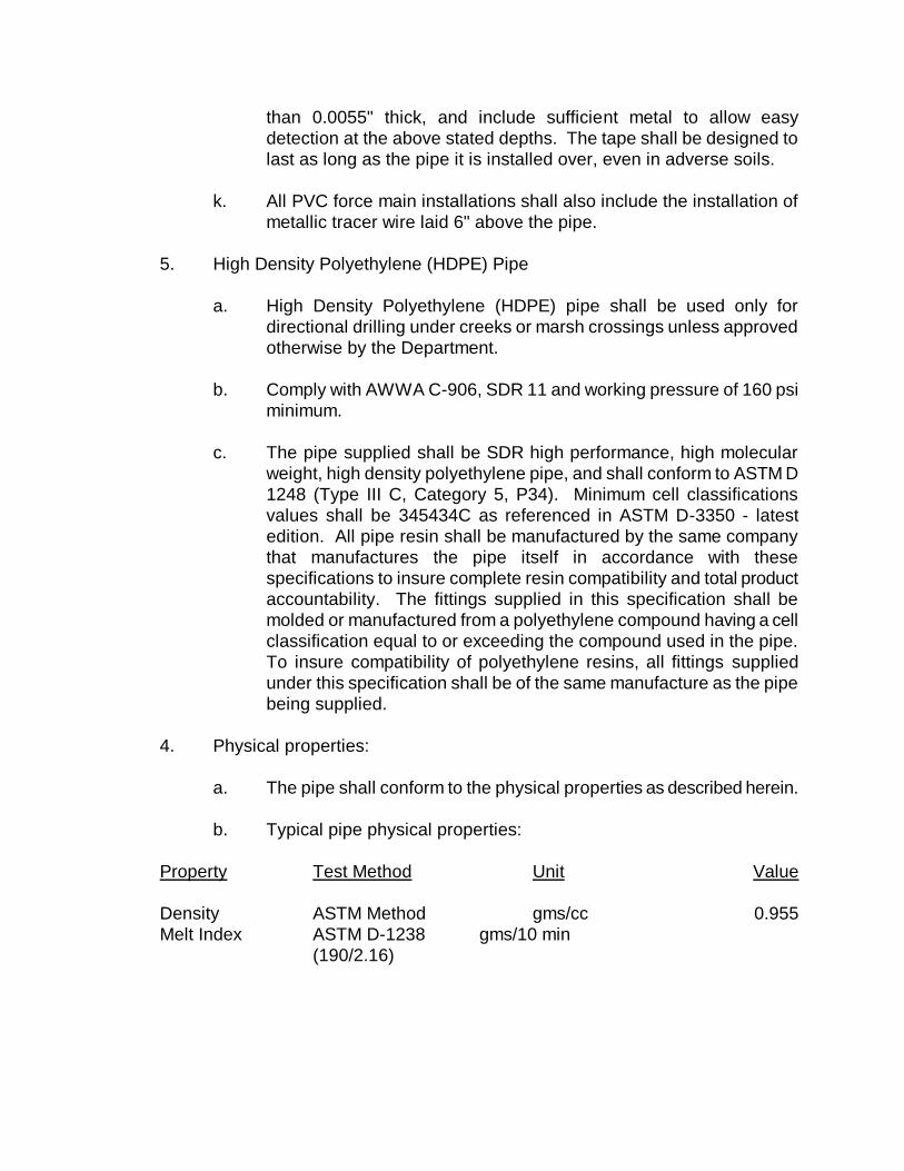
than 0.0055" thick, and include sufficient metal to allow easy
detection at the above stated depths. The tape shall be designed to
last as long as the pipe it is installed over, even in adverse soils.
k. All PVC force main installations shall also include the installation of
metallic tracer wire laid 6" above the pipe.
5. High Density Polyethylene (HDPE) Pipe
a. High Density Polyethylene (HDPE) pipe shall be used only for
directional drilling under creeks or marsh crossings unless approved
otherwise by the Department.
b. Comply with AWWA C-906, SDR 11 and working pressure of 160 psi
minimum.
c. The pipe supplied shall be SDR high performance, high molecular
weight, high density polyethylene pipe, and shall conform to ASTM D
1248 (Type III C, Category 5, P34). Minimum cell classifications
values shall be 345434C as referenced in ASTM D-3350 - latest
edition. All pipe resin shall be manufactured by the same company
that manufactures the pipe itself in accordance with these
specifications to insure complete resin compatibility and total product
accountability. The fittings supplied in this specification shall be
molded or manufactured from a polyethylene compound having a cell
classification equal to or exceeding the compound used in the pipe.
To insure compatibility of polyethylene resins, all fittings supplied
under this specification shall be of the same manufacture as the pipe
being supplied.
4. Physical properties:
a. The pipe shall conform to the physical properties as described herein.
b. Typical pipe physical properties:
Property Test Method Unit Value
Density ASTM Method gms/cc 0.955
Melt Index ASTM D-1238 gms/10 min
(190/2.16)
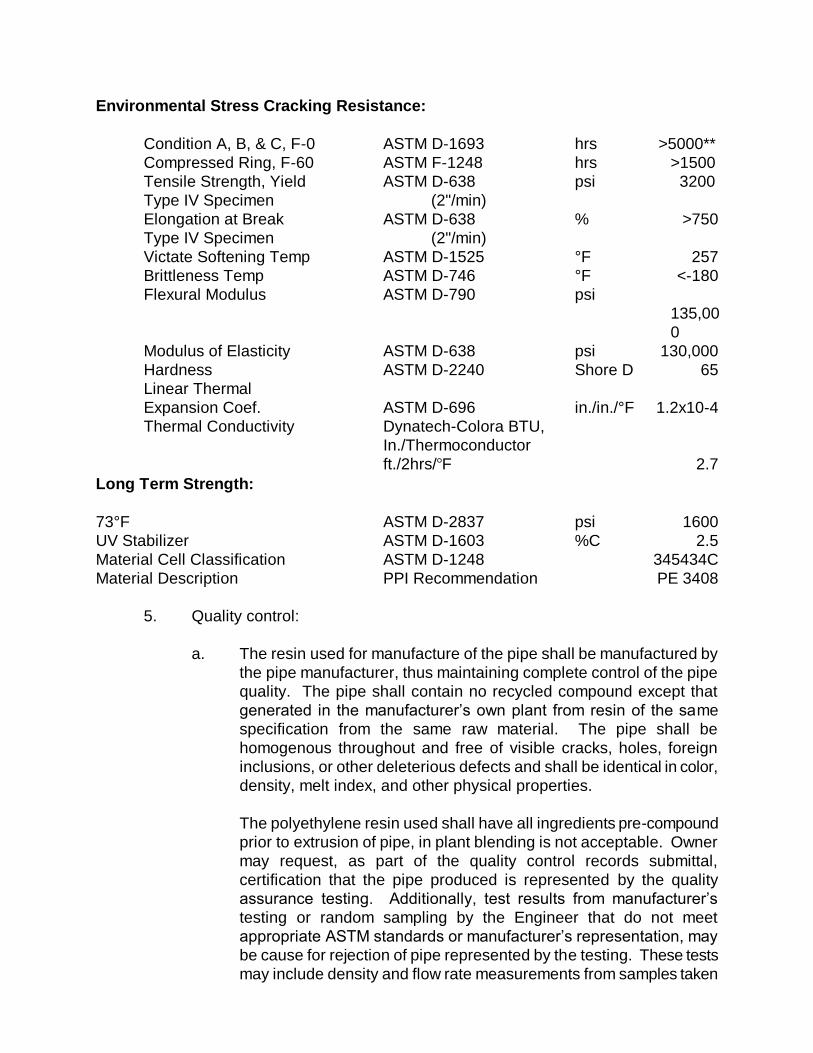
Environmental Stress Cracking Resistance:
Condition A, B, & C, F-0 ASTM D-1693 hrs >5000**
Compressed Ring, F-60 ASTM F-1248 hrs >1500
Tensile Strength, Yield ASTM D-638 psi 3200
Type IV Specimen (2"/min)
Elongation at Break ASTM D-638 % >750
Type IV Specimen (2"/min)
Victate Softening Temp ASTM D-1525 °F 257
Brittleness Temp ASTM D-746 °F <-180
Flexural Modulus ASTM D-790 psi
135,00
0
Modulus of Elasticity ASTM D-638 psi 130,000
Hardness ASTM D-2240 Shore D 65
Linear Thermal
Expansion Coef. ASTM D-696 in./in./°F 1.2x10⁻⁴
Thermal Conductivity Dynatech-Colora BTU,
In./Thermoconductor
ft./2hrs/F 2.7
Long Term Strength:
73°F ASTM D-2837 psi 1600
UV Stabilizer ASTM D-1603 %C 2.5
Material Cell Classification ASTM D-1248 345434C
Material Description PPI Recommendation PE 3408
5. Quality control:
a. The resin used for manufacture of the pipe shall be manufactured by
the pipe manufacturer, thus maintaining complete control of the pipe
quality. The pipe shall contain no recycled compound except that
generated in the manufacturer’s own plant from resin of the same
specification from the same raw material. The pipe shall be
homogenous throughout and free of visible cracks, holes, foreign
inclusions, or other deleterious defects and shall be identical in color,
density, melt index, and other physical properties.
The polyethylene resin used shall have all ingredients pre-compound
prior to extrusion of pipe, in plant blending is not acceptable. Owner
may request, as part of the quality control records submittal,
certification that the pipe produced is represented by the quality
assurance testing. Additionally, test results from manufacturer’s
testing or random sampling by the Engineer that do not meet
appropriate ASTM standards or manufacturer’s representation, may
be cause for rejection of pipe represented by the testing. These tests
may include density and flow rate measurements from samples taken
at selected locations within the pipe wall and thermal stability
determinations according to ASTM D 3350, 10.1.9. Certified lab data
may be requested to verify the physical properties of the materials
supplied under this specification or may take random samples and
have them tested by an independent laboratory.
6. Rejection:
a) The Department reserves the right to reject any polyethylene pipe and
fittings failing to meet any of the requirements of this specification.
C. RESTRAINED JOINT PIPE AND FITTINGS
1. Provide restrained joint pipe and fittings on all piping at each fitting, valve,
and on the pipe joints to a minimum distance of 18' on each side of the fitting
or valve for 12" piping and smaller and to a minimum distance of 36' on each
side of the fitting for piping over 12" as a minimum. Use the ductile iron pipe
research association (DIPRA) procedure for calculating restrained joint
lengths.
2. Provide for use with mechanical joint pipe and fittings.
3. Acceptable products: Megalug as manufactures by EBAA Iron Sales, Inc.
4. Concrete thrust blocking can be used on a case-by-case basis as approved
by Department.
5. Restrained joint pipe will be indicated clearly on plans. The location and
length of restrained joint pipe will be clearly marked on the drawings at all
points where the direction or cross-sectional area of the pipe changes as
well as at all bends, reducers, offsets, tees, wyes and valves.
D. AIR RELEASE AND VACUUM VALVES
1. Single body universal type with compound lever system.
2. Internal linkage and float of stainless steel.
3. Capacity: At 10 lbs. working pressure, vent not less than 25 cfm of free air.
4. Provide the following:
a. 2" inlet.
b. 2" stainless steel T-handle ball valve.
c. 1" blowoff stainless steel T-handle ball valve.
d. Quick disconnect couplings.
e. Back flushing hose.
f. “Protectop” cover.
g. Piping, nipples, plugs, etc.: Schedule 40, type 316 stainless steel.
5. 6. Acceptable product: H-TEC Model #986 or approved equal.
7. Valve manhole:
a. Use manhole wall sections.
b. Provide manhole frame and cover in accordance with Section 11.C.
E. CASING, SPACERS AND END SEALS FOR UTILITIES
1. General
a. Provide bore and jack with casing for pipes larger than 2".
b. Casing pipe to be 2" larger in diameter than the bell of the carrier
pipe.
1) Casing pipe to be a minimum of 2" larger than the largest
outside diameter of the carrier pipe (joints and couplings) if the
carrier pipe is less than 6" in diameter. If the diameter of the
carrier pipe is 6" or larger, the diameter of the casing pipe
shall be a minimum of 4" larger than the largest outside
diameter of the carrier pipe (joints and couplings).
2) The end of casing pipe to extend a minimum of six (6) feet
from the edge of pavement/back of curb.
3) The top of the casing pipe shall be a minimum of four (4) feet
below the crown of the finished asphalt roadway.
4) The top of the casing pipe shall be a minimum of two (2) feet
below the design invert of roadside drainage ditches and
pipes.
2. Casing pipe for dry bores
a. Steel complying with ASTM A139 for Grade B with minimum yield
strength of 35,000 psi.
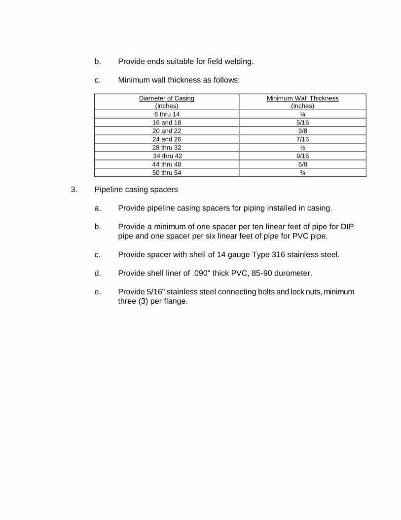
b. Provide ends suitable for field welding.
c. Minimum wall thickness as follows:
Diameter of Casing
(Inches) Minimum Wall Thickness
(Inches)
6 thru 14 ¼
16 and 18 5/16
20 and 22 3/8
24 and 26 7/16
28 thru 32 ½
34 thru 42 9/16
44 thru 48 5/8
50 thru 54 ¾
3. Pipeline casing spacers
a. Provide pipeline casing spacers for piping installed in casing.
b. Provide a minimum of one spacer per ten linear feet of pipe for DIP
pipe and one spacer per six linear feet of pipe for PVC pipe.
c. Provide spacer with shell of 14 gauge Type 316 stainless steel.
d. Provide shell liner of .090" thick PVC, 85-90 durometer.
e. Provide 5/16" stainless steel connecting bolts and lock nuts, minimum
three (3) per flange.
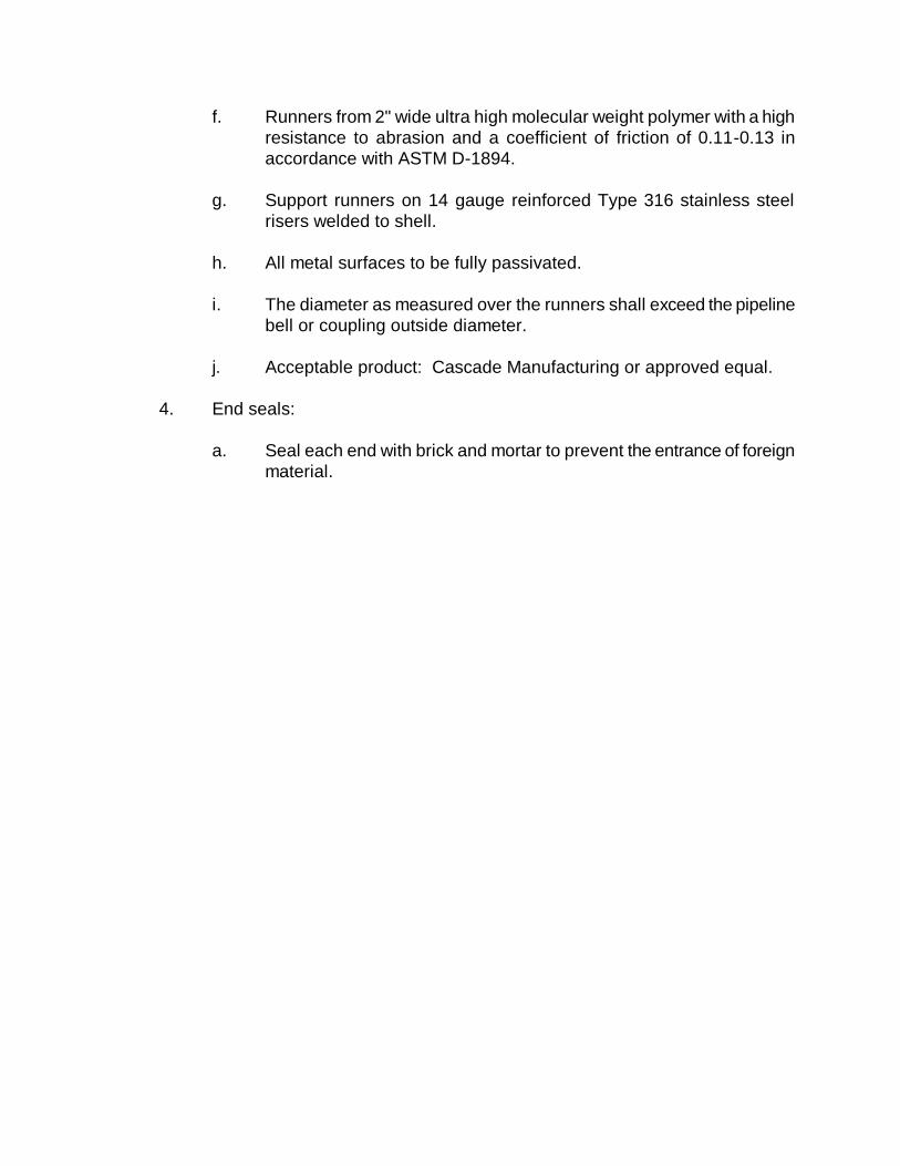
f. Runners from 2" wide ultra high molecular weight polymer with a high
resistance to abrasion and a coefficient of friction of 0.11-0.13 in
accordance with ASTM D-1894.
g. Support runners on 14 gauge reinforced Type 316 stainless steel
risers welded to shell.
h. All metal surfaces to be fully passivated.
i. The diameter as measured over the runners shall exceed the pipeline
bell or coupling outside diameter.
j. Acceptable product: Cascade Manufacturing or approved equal.
4. End seals:
a. Seal each end with brick and mortar to prevent the entrance of foreign
material.
SECTION 15
PRESSURE SEWER (FORCE
MAIN) CONSTRUCTION
PROCEDURES
SECTION 15
PRESSURE SEWER (FORCE MAIN)
CONSTRUCTION PROCEDURES
This section covers construction procedures normally required for work. It
does not cover any special construction procedures which may be encountered for
abnormal conditions.
Special construction procedures are to be presented to the Department by the
Developer’s Design Engineer.
A. HANDLING OF MATERIALS
1. Handle pipe so as to ensure delivery to the trench in sound, undamaged
condition:
a. Carry pipe into position - do not drag.
b. Use pinch bars or tongs for aligning or turning the pipe only on the
bare end of the pipe.
c. Use care not to injure pipe linings.
2. Thoroughly clean interior of pipe and accessories before lowering pipe into
trench. Keep clean during layout operations by plugging or other approved
method.
3. Before installation, inspect each piece of pipe and each fitting for defects:
a. Replace material found to be defective before or after laying with
sound material meeting the specified requirements.
4. Rubber gaskets: Store in a cool dark place until just prior to time of
installation.
B. PIPE CUTTING
1. Cut pipe neatly and bevel pipe end without damage to the pipe.
2. Unless otherwise recommended by the pipe manufacturer, cut pipe with
mechanical cutter only.
a. Use wheel cutters when practicable.
b. Cut plastic pipe square and remove all burrs.
C. LOCATING
1. Where possible, locate pressure sewer at least ten (10) feet away,
horizontally, from water mains.
2. Should ten (10) foot separation not be practical, then the pressure sewer
may be located closer provided:
a. It is laid in a separate trench.
b. It is laid in the same trench with the water main located at one side on
a bench of undisturbed earth.
c. In either of the above cases, crown elevation of the pressure sewer
shall be at least 18" below invert elevation of water line.
3. Where pressure sewers cross over or under water lines, maintain 18"
minimum clearance between outside edges of the two pipes.
a. Use full length of pressure sewer pipe located so that the joints will be
equal distance from the water main.
D. ALIGNMENT OF PIPE
1. Pipe lines intended to be straight shall be so laid.
2. Where vertical or horizontal alignment requires deflection from straight lines
or grade, do not exceed 75% of maximum deflection recommended by the
pipe manufacturer.
3. If alignment requires deflection exceeding recommended limits, furnish
bends to provide angular deflections within the allowable limits.
E. PLACING AND LAYING
1. General:
a. Lower pipe and accessories into trench by means of derrick, ropes,
belt slings, or other equipment approved by the manufacturer.
b. Do not dump or drop any of the materials into the trench.
c. Except where necessary in making connections to other lines, lay
pipe with the bells facing in the direction of laying.
d. Rest the full length of each section of pipe solidly on the pipe bed,
with recesses excavated to accommodate bells, couplings, and joints.
e. Take up and relay pipe that has the grade or joint disturbed after
laying.
f. Do not lay pipe in water, or when trench conditions are unsuitable for
the work; keep water out of the trench until jointing is completed.
g. Securely close open ends of pipe, fittings, and valves when work is
not in progress.
h. Replace pipe where any part of lining is damaged.
i. Lay pipe to the grades indicated on the plans. Avoid excessive high
points in the force main.
j. After each line of pipe has been laid, it shall be carefully inspected
and all earth, trash, rags, and other foreign matter removed from the
interior.
k. Each joint shall be laid so that it will form a close concentric joint with
adjoining pipe and so as to avoid sudden offsets.
l. All jointing of pipe and fittings shall be in accordance with the pipe
manufacturer’s recommendations.
2. Ductile iron pipe:
a. Mechanical and push on joints, install in accordance with
ANSI/AWWA C600.
b. Gaskets: Handle, lubricate where necessary and install in strict
accordance with manufacturer’s recommendations.
3. Plastic pipe:
a. Install in accordance with ASTM D-2321, latest revision.
b. Clean gasket, bell or coupling interior, especially groove area.
c. Lubricate gasket as recommended by manufacturer.
d. Align spigot to bell, insert spigot into bell until it contacts gasket
uniformly.
e. Use manufactures approved leverage bar to bell pipe.
1) Home line is to be clearly visible when pipe is joined.
4. Restrained joints:
a. Install in accordance with manufacturer’s instructions.
b. Tighten set screws to the manufacturer’s rated torque using a torque
wrench.
1) If twist-off nuts are provided, tighten screws until nut breaks
loose.
F. INSTALLATION OF AIR RELEASE VALVES
1. Compact backfill thoroughly over pressure sewer.
2. Install gravel drainage bed.
3. Set valve plumb, use a 316 stainless steel nipple between pressure sewer
and valve.
4. Install manhole wall sections plumb and level.
G. INSPECTIONS AND TESTING
1. General:
a. The Department will require that all sanitary sewer systems pass the
following test prior to acceptance: (the Department shall be notified
72 hours before inspections).
b. Soil Compaction Test
All trenches suspected of not meeting the compaction requirements
stated previously shall be tested for conformance by a Department
approved testing lab and at the locations and depths requested by the
Department.
c. Pressure Test
All force mains shall successfully pass a pressure test of one and one
half times working pressure, but in no case less than 100 psi. The
pressure test is to hold for two (2) hours.
Typically, no measureable leakage will be allowed for wastewater
force mains. The force main will be unacceptable if the leakage
exceeds the following AWWA formula of allowable leakage:
where, L = Allowable Leakage in gal/hr
S = Length of Pipe Tested in feet
D = Nominal Diameter in inches
P = Average Test Pressure in psig
H. INSTALLATION OF CASING, SPACERS, AND END SEALS
1. Locate to avoid interference with traffic, adjacent structures, etc. to such
extent possible.
2. Excavate to required depth, providing sheeting and shoring necessary for
protection of the work and for safety of personnel.
3. Maintain entry pits in dry condition by use of pumps, drains or other
approved method.
4. Install casings by dry-boring through the casing while simultaneously jacking
the casing.
5. Any proposed alternate method shall be approved in writing by the
Department.
6. Weld joints to provide a watertight joint.
7. Installing pipe in casing:
133200
PSD=L
a. Inspect carefully, insuring that all foreign material is removed from the
casing and the casing meets alignment criteria for the type of carrier
pipe being used.
b. For pressure systems, the casing deflection shall not exceed the
maximum deflection recommended by the carrier pipe.
c. Install casing spacers on the carrier pipe per the manufacturer's
instructions.
d. Provide centered or restrained configuration.
e. Install the carrier pipe in the casing insuring each joint is pushed
"home" before the joint is installed into the casing.
8. Seal each end with brick and mortar to prevent the entrance of foreign
material.
I. TRENCH EXCAVATION
This section of the guidelines is provided to outline most types of laying conditions,
but is not intended to cover all special laying conditions or the Engineer’s special
requirements.
1. Trench excavation shall be made in open cut and true to the lines and
grades shown on the plans, unless boring is necessary or required. Banks
of the trenches shall be cut in vertical, parallel planes equidistant from the
pipe center line. The horizontal distance between such planes, or the
overall width of trench, shall vary with the size of the pipe to be installed.
The overall width of trench shall be as recommended by the manufacturer.
When vertical banks for trench excavation are not practical to construct or
create dangerous conditions to workmen, the banks may be sloped provided
that such excavation does not damage adjacent structures. When trench
banks are sloped, such banks shall be cut to vertical planes as specified
above for that part of the ditch below the level of 12" above the top of the
pipeline. The bottom of the trench shall be level in cross section and shall
be cut true to the required grade of the pipe and pipe embedment materials.
2. Bell holes for bell-and-spigot pipe shall be excavated at proper intervals so
that the barrel of the pipe will rest for its entire length upon the bottom of the
trench. Bell holes shall be large enough to permit proper installation of joints
in the pipe.
3. When muck, quicksand, soft clay, swampy or other material unsuitable for
foundations or sub-grade are encountered such material shall be removed
and replaced with crushed stone.
4. After excavation, the area between the final pipe grade and the trench soil
bottom shall be filled with crushed stone materials as required, compacted to
proper grade, and made ready for pipe laying.
5. Debris encountered in trench excavation for sewers and other pipelines shall
be removed for the overall width of trench which shall be as shown on the
plans. It shall be removed to a depth of 6" below the bottom of the pipe for
pipes smaller than 24" in size; 8" below the bottom of the pipe for pipes 24"
to 36" in size; and 12" below the bottom of the pipe for pipes larger than 36"
in size, if debris extends to such depth.
6. In all cases, materials deposited shall be placed so that in the event of rain,
no damage will result to the work.
7. The sides of all excavations shall be sufficiently sheeted, shored and braced
whenever necessary to prevent slides, cave-ins, settlements or movement of
the banks and to maintain the excavation clear of obstructions. Wood or
steel sheet piling of ample design and type shall have sufficient strength and
rigidity to withstand the pressures exerted and to maintain the walls of the
excavation properly in place and protect all persons and property from injury
or damage. Sheeting, shoring or bracing materials shall not be left in place
unless as shown by the plans or permitted by the Department. All trench
sheeting and bracing shall be left in place until the trench has been
backfilled one foot above the top of the pipe.
3. Comply with OSHA guidelines.
J. TRENCH BACKFILL
1. The backfilling of pipeline trenches shall be started immediately after the
pipe work has been inspected. The initial backfill material, placed to a
height of one (1) foot above the top of the pipe, shall consist of approved
backfill material free from organic matter and deleterious substances,
containing no rocks or lumps over 2" in any dimension.
It shall be carefully placed and compacted through compaction of entire area
backfilled.
Backfill shall be deposited in 6" layers (before compaction) and thoroughly
compacted with power tools to 95% of theoretical maximum density, modified
Proctor ASTM-D-1557.
2. Where trenches are not under pavement, sidewalks, or in alleys, the backfill
material above pipe zone shall be compacted to a sufficient density to
prevent settlement. Any deficiency in backfilling the trenches, or
depressions caused by settlement, shall be repaired.
3. Where pipe trenches are cut across or along pavement, trenches shall be
backfilled with select fill material placed and compacted in 6" lifts.
Replacement of road base and asphalt shall be in accordance with South
Carolina Department of Transportation (SCDOT) regulations.
4. Backfilling around structures shall be done in the manner specified above for
pipe trenches by power tamping for the full depth of cut from the bottom of
the finished grade.
5. All backfilling shall be done in such a manner as will not disturb or injure the
pipe or structure over or against which it is being placed. Any pipe or
structure injured, damaged or moved from its proper line or grade during
backfilling operations shall be uncovered, repaired, and then re-backfilled as
herein specified.
SECTION 16
SANITARY SEWER PUMP
STATION DESIGN GUIDELINES
SECTION 16
SANITARY SEWER PUMP STATION
DESIGN GUIDELINES
A. GENERAL
1. The following sanitary sewer pump station design guidelines are based on
Federal, State and local health requirements and the Department’s
engineering design criteria.
2. These design guidelines are applicable to all developments including but not
limited to residential, commercial and industrial developments, subdivisions
and/or parks requiring sewer service from the Department.
3. Design criteria for other than normal circumstances are to be presented to
the Department for approval prior to preparation of plans and specifications.
4. The Engineer should submit the following design calculations:
a. Station service area ultimate loading.
b. Flotation calculation (weight of station without pumps vs. uplift).
c. Cycle time calculation maximum of six (6) cycles/hour at the average
daily flow rate.
d. Provide certification that motor and control circuit will permit twelve
(12) cycles/hour.
B. GENERAL PUMP STATION DESIGN
1. Minimum of two (2) pumps of equal capacity, each capable of handling the
design peak flow.
2. Capable of passing 3" diameter spherical solids, minimum.
3. Discharge piping: 4" diameter, minimum.
4. Peaking factor:
a. Based on the following population based equation:
)(P + 4
)(P + 18 = PF
0.5
0.5
Where P = 20-year sewered population in thousands
b. Minimum, 2.5.
c. Based on the source of the wastewater and the distance of the pump
station from the source.
6. Wetwell level settings:
a. Distance between pump “OFF” and lead pump “ON”: Based on cycle
time.
b. Distance between lead pump “ON” and lag pump “ON” and alarm “ON”: 1'-
0", minimum.
c. Distance between lag pump “ON” and alarm “ON”: 1'-0", minimum.
d. Distance between alarm elevation and inlet pipe: 6", minimum.
7. Provide a check valve and gate valve on each pump discharge line. A surge
relief valve may be required by the Department on larger pump stations.
8. Pumps shall have an operating point at or near peak efficiency.
9. Pumps shall be non-overloading for all duty points.
2. Provide by-pass connection per detail section.
3. Provide receiving manhole on influent line within pump station fence for by-
pass pumping.
4. Provide a gate valve on the influent line between the receiving manhole and
wetwell.
C. SUBMERSIBLE PUMP STATION
1. Opposite opening, dual access covers with safety hatch.
2. Provide components of the pump station per detail section.
D. PUMPS AND MOTORS
1. Acceptable pump manufacturers for submersible pumps are:
a. Flygt
b. Fairbanks Morse
c. ABS
No other manufacturers shall be used.
2. Pumps shall be equipped as follows:
a. Pumps shall be designed to handle peak flow with largest pump out of
service.
b. Motors shall be non-overloading over entire pumping range.
c. Motors shall have Class F (155C) insulation and withstand Class B
(130C) temperature rise with a service factor of 1.0 at the efficient
point of the curve.
d. Motor rpm shall not exceed 1800 rpms. Wire to water efficiency
curves shall be submitted for approval.
e. Three (3) phase power shall be required on all motors.
f. Unbalanced voltage on motors under load shall not exceed 1.0%
when measured at the motor terminals. Voltage shall be read with an
accurate digital voltmeter; and recorded as part of the final inspection;
calculation shall be NEMA Standard MG1-1972 (See Vol. la-11, No.
1, Jan/Feb 1974 IEEE Transaction Industrial Application).
g. Power factor correction shall be required to 85%.
h. Lightning arresters are required for all services.
i. Pump and motor shall have a minimum of 400 series stainless steel
shaft on motors under 10 Hp, above 10 Hp motors can have a chrome
plated steel shaft.
j. Impeller shall be keyed to shaft and be single vane.
k. Pump volute shall have replaceable wear rings.
l. Lower seals shall be silicone carbide to silicone carbide.
m. B-10 bearing lift shall be a minimum of 50,000 hours.
n. Pump and motors shall have adequately sized 316 stainless steel
lifting chain; length shall reach top of station plus an additional 6'.
Chain shall be ¼” welded 316 stainless steel link chain.
o. Adequate designed lift chain hooks shall be imbedded into the side of
the top slab and situated to facilitate easy removal of units.
p. All piping shall be Class 53 DIP and all fittings shall be Class 150
DIP. All pipe and fittings shall be lined in accordance with Section 14.
q. Motor shall be equipped with moisture detection probe and have
moisture detection indication lamp mounted on control panel.
Moisture detection shall cause motor shut down.
r. Motor shall be equipped with overheat sensor and shall shut down
the motor. Control panel shall have separate indicator lamp for
overheat shut down.
s. Motor shall be wired for lead-lag operation and shall be equipped for
alternate cycle operation.
t. Each motor shall have a separate run time totalizer and H-O-A switch.
u. Pump and motor shall be shipped with non-wicking electrical power
cable, overheat cable and seal failure cable, factory installed. Cut
ends are to be sealed and tagged at the factory for shipping.
v. The Department may require VFD’s at their discretion.
w. Large pump stations shall have variable speed pumps with soft starts
where practical.
E. PUMP STATION PIPING
1. All piping shall be arranged as shown in the detail section.
2. Each pump discharge line shall have a weighted arm cushioned swing check
valve and a gate valve. All fittings to be flanged.
3. Provide ½” tap with pressure gauge connection after the true wye.
4. Provide air release valve as shown in the detail section.
5. All bolts, nuts and washers shall be 316 stainless steel.
F. WETWELL DESIGN CRITERIA
1. Size the wetwell based on the following:
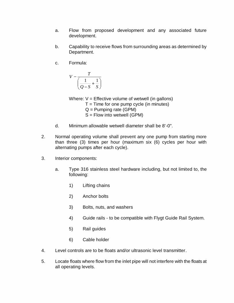
a. Flow from proposed development and any associated future
development.
b. Capability to receive flows from surrounding areas as determined by
Department.
c. Formula:
SSQ
TV
11
Where: V = Effective volume of wetwell (in gallons)
T = Time for one pump cycle (in minutes)
Q = Pumping rate (GPM)
S = Flow into wetwell (GPM)
d. Minimum allowable wetwell diameter shall be 8'-0".
2. Normal operating volume shall prevent any one pump from starting more
than three (3) times per hour (maximum six (6) cycles per hour with
alternating pumps after each cycle).
3. Interior components:
a. Type 316 stainless steel hardware including, but not limited to, the
following:
1) Lifting chains
2) Anchor bolts
3) Bolts, nuts, and washers
4) Guide rails - to be compatible with Flygt Guide Rail System.
5) Rail guides
6) Cable holder
4. Level controls are to be floats and/or ultrasonic level transmitter.
5. Locate floats where flow from the inlet pipe will not interfere with the floats at
all operating levels.
6. Provide a stainless steel hanger for the float cables and/or ultrasonic level
transmitter.
7. Line interior of wetwell and all piping located within wetwell with 125 mills of
Raven 405 Epoxy, 240 mills of NEOPOXY NPR 5300 or other approved by
the Department.
8. Where an increase in main size is required, provide a reducing elbow at the
horizontal/vertical transition inside the wetwell.
9. Locate to allow access with vacuum truck and boom truck.
10. Minimum slope of one to one and half (1 to 1.5) on the floor to the hopper
bottom.
11. Horizontal area of hopper bottom shall be no larger than necessary for
proper installation and operation of the pump or pump inlet.
12. Provide 4" DIP with vent cap for venting the wetwell.
13. The bottom slab of the wetwell shall be set on a minimum of 12" of gravel.
All over-excavated areas 12" below the wetwell bottom shall be filled with
gravel.
14. Top of slab shall be 1' above the 100-year flood elevation.
15. Steps should NOT be used in wetwells.
16. Influent line shall terminate a minimum of ½” inside the wetwell.
17. All hatches shall be aluminum with stainless steel hasp, hinge and safety
hatch.
G. ELECTRICAL
1. Electrical design of pump station shall conform to current editions of NFPA
70 (National Electric Code) and NFPA 820 (Standard for Fire Protection in
Wastewater Treatment and Collection Facilities).
2. All areas designated as hazardous as defined by NFPA 820 shall be so
delineated on the contract documents.
3. Electrical service shall be designated to accommodate the ultimate capacity
of the pump station. Coordinate three phase service with utility company
prior to ordering pumps. Add a phase shall not be accepted without prior
written approval from the Department.
4. Coordinate location of meter pole with local utility and the Department.
Install main breaker with lightening arrestor on meter pole. Main breaker
shall be NEMA 12 stainless steel, gasketed with drip shield.
5. Provide adequately sized emergency generator and automatic transfer
unit on all stations. Contact the Department for specifications on this
equipment.
6. All electrical cables from the motors and float switches shall be terminated in
a NEMA 3/7 explosion-proof junction box located adjacent to or directly
below the pump control panel. The junction box shall contain power
distribution blocks (Square D Type LB or equal) for the termination of the
power cables and terminal blocks (Square D Type G or equal) for the
termination of the float cables and sensor cables. The conduits entering the
box from the wetwell shall be sealed with duct seal.
7. The conduits from the junction box to the pump control panel shall be sealed
with Condulet type seals or Type ES sealing hubs. All seals shall be made
with Chico brand sealing compound poured to a thickness of no less than
the trade size of the sealing fitting end, in no case less than 5/8”.
8. All electrical equipment shall be located outside of the hazardous areas, but
the conduit seals shall be located within 10' of the classification boundary.
9. All conduit shall be full weight, hot dipped galvanized rigid conduit.
10. Provide support for electrical equipment in accordance with details.
11. Provide 70-watt high pressure sodium floodlight with weatherproof switch at
each site. Mount on top of control panel support structure to light wetwell
and valve vault area.
12. Wetwell float switch and/or ultrasonic level transmitter hangers shall be
located at the edge of the hatch.
13. Provide concrete pad for pump control panel only, when supported on legs
to extend out 3' from the face control panel.
14. Provide a complete addition to the Department’s Supervisory Control and
Data Acquisition System (SCADA).
H. PUMP STATION SITE
1. Minimum property size: 50' x 50'. A 20' landscape buffer in front of the
station to be deeded to the Department may be required.
2. Site shall be serviced by an all weather road with top of road above the 25-
year flood elevation. Road and site drainage shall be included and
approved by appropriate agency.
3. Access road:
a. Minimum 20 foot wide.
b. Asphalt paving.
4. Area within pump station site:
a. Asphalt paving.
5. Fencing of Lift Station Site
a. Pump stations located in a residential development may be wooden
per the detail in the detail section unless otherwise approved by the
Department.
b. Pump stations located in commercial and/or industrial areas shall be
chain link.
c. Chain Link Fence Materials. (All materials Class I Galvanized
Coated.)
1) Fabric shall be 6' high, ends twisted and barbed, commercial
grade 9 gauge. 2" mesh with galvanized coating.
2) End, cover and pull posts to be 2 ½” O.D. galvanized coated.
3) Top and line posts to be 2" O.D. galvanized coated.
4) Bottom tension wire shall be 7 gauge spring coil wire with
galvanized coating.
5) Barb wire shall be 12 ½ gauge galvanized twisted line wires
with four point, 14 gauge barbs spaced 5" on centers, three (3)
rows of outward facing barbed wire shall be used.
6) Gate posts shall be 3" O.D. galvanized coated.
7) Gate shall be a pair of 10’ long 6’ high sections constructed of
2" O.D. pipe. Gate shall be equipped with a prop post center
latch and hasp assembly. A ground anchor cast in concrete
shall be provided. Gates shall be factory fabricated and
equipped with gate hold backs. Panel shall have a horizontal
brace center of fabric height.
6. Design gate to allow entrance of service trucks and vacuum truck without
blocking the main roadway.
7. Design site layout to allow access of service trucks and vacuum truck to the
wetwell.
8. Power pole should be located within the fence area and should be located in
such a manner so the electric meter can be easily read from outside the
fenced area.
9. All power lines within the site shall be underground. No overhead power line
will be allowed to cross the site.
I. SPARE PARTS FOR SUBMERSIBLE PUMP STATION
1. Contractor shall furnish on or before final inspection spare parts identified in
Section 17.
SECTION 17
SANITARY SEWER PUMP
STATION MATERIALS FOR
CONSTRUCTION
SECTION 17
SANITARY SEWER PUMP STATION
MATERIALS FOR CONSTRUCTION
A. WETWELLS
1. Use manhole sections complying with Section 11.
2. Wetwell structure.
a. Comply with pump station details.
3. Wetwell vent:
a. Cast iron vent cap.
1) Josam Model 26704.
2) Smith Model 1744.
b. 4" ductile iron connection pipe.
c. Finish:
1) Primer - one (1) coat of Tnemec Polyuraprime.
2) Paint - two (2) coats of Tnemec Epoxyl Polyurethane Series 66
or 69 high build epoxoline at 5 mil’s thickness.
4. Cable holders:
a. Use six (6) hook, 316L stainless steel
b. Acceptable manufacturer: Halliday Metals.
5. Interior piping and wetwell coating:
a. Provide 125 mills of Raven 405 Epoxy.
6. Other pump station appurtenances.
a. Comply with pump station details.
B. SUBMERSIBLE PUMP STATION
1. Acceptable pump manufacturer: Flygt, Fairbanks Morse, and ABS.
2. Provide a service engineer for the following periods of time for each pump
station.
a. Start-up and performance testing: One day - One trip.
3. Spare parts:
a. Provide the following minimum spare parts:
1) One of each seal assemblies.
2) One complete set of bearings.
3) One set of wear rings.
4) One of each type relay.
5) One pump starter.
6) One pump alternator.
7) One float switch with cable.
8) One of each type pilot light.
9) One box of each type lamp.
b. Two (2) complete sets of record drawings for wetwell, electrical,
electronic schematics (and six (6) copies of O&M Manuals, with
factory pump curves for pumps installed), copies of all certified test
and inspection data, and a completed start-up report by the pump
manufacturer.
c. Package in one container all spare parts and clearly identify on the
outside what the unit is for.
1) Seal tightly, properly protect for long term storage, and deliver
to the Department.
4. Warranty:
a. The pump manufacturer shall warrant the units being supplied against
defects in workmanship and material for a period of five (5) years or
10,000 hours under the Municipal Wastewater Permanent Installation
Warranty Policy under normal use, operating and service. The
warranty shall be in printed form and apply to all similar units.
5. Pumps:
a. General:
1) ANSI 125 lb standard cast iron flange fitting or cast with volute.
2) Pump components: cast iron, ASTM A48, Class 30.
3) All exposed fasteners and washers: Type 316L stainless steel.
4) Pump lift handle:
a) Type 316 stainless steel.
5) Coating:
a) All components coming into contact with sewage,
except stainless steel, with a sewage resistant coating.
b) Pump exterior: PVC epoxy primer and a chlorine rubber
paint finish.
b. Impeller:
1) Double shrouded non-clog type.
2) Gray cast iron, Class 30, balanced dynamically to 0.5".
3) Paint with one coat of alkyd resin primer.
4) Provide wear ring consisting of a replaceable stationary ring
made of brass, drive fitted to the volute inlet.
5) Sliding fit between the impeller and the shaft with one key.
c. Volute:
1) Single piece, non-concentric design.
d. Shaft:
1) Less than 10 Hp ANSI Type 420 stainless steel.
4) 2) 10 Hp and above chrome planted steel.
e. Bearings:
1) Two (2) permanently lubricated bearings.
2) B-10 bearing life of 50,000 hours.
3) Upper bearing: single deep groove ball bearing.
4) Lower bearing: two row angular contact ball bearing.
f. Watertight seals:
1) Nitrile rubber o-rings.
2) Fittings:
a) Accomplished sealing by metal-to-metal contact
between machined surfaces.
3) Gaskets, elliptical o-rings, grease or other devices are not
acceptable.
g. Mechanical seals:
1) Tandem mechanical shaft seal system.
2) Operate the upper of the tandem set of seals in an oil
chamber.
3) Upper seal set: one stationary tungsten carbide ring soldered
to a holder of stainless steel and one positively driven rotating
carbon ring to function as an independent secondary barrier
between the pumped liquid and the stator bearings.
4) Lower seal set: a stationary ring soldered to a holder of
stainless steel and a positively driven rotating ring, both of
tungsten carbide.
a) Hold each interface in contact by its own spring system.
5) Require neither maintenance nor adjustment, easily inspected
and replaced.
6) Provide all seal hardware of stainless steal.
6. Pump motor:
a. General:
1) Submersible, explosion proof type, designed for continuous
duty, capable of sustaining a minimum of fifteen (15) starts per
hour.
2) Integral motor and pump.
3) Air filled, squirrel cage induction, shell type design, Class F
insulation system, Class F materials rated for continuous duty
in 40°C (104°F) liquids.
4) Cast iron motor frame and end shields.
5) Stainless steel hardware and shaft.
6) Service factor: 1.15.
7) Stator:
a) Heat-shrink fitted to shaft.
b) Dip and bake in Class F varnish.
c) Do not use bolts, pins or other fastening devices
requiring penetration of the stator housing.
8) Aluminum rotor bars and short circuit rings.
b. Cable entry water seal system.
1) Single cylindrical elastomer grommet, flanked by stainless
steel washers, all having a close tolerance fit against the cable
outside diameter and the entry inside diameter and
compressed by the entry body containing a strain relief
function, separate from the function of sealing the cable.
2) Bear assembly against a shoulder in the pump top.
3) Separate the cable entry junction chamber and motor by a
stator lead sealing gland or terminal board to isolate the motor
interior from foreign material gaining access through the pump
top.
a) Do not use epoxies, silicones, or other secondary
sealing systems.
c. Provide pre-lubricated bearings:
1) Minimum B-10 life of 50,000 hours.
d. Thermal protection:
1) Motor rated thermally to NEMA MG1-12.42.
2) Three (3) thermostatic switches (one in each phase) in the
stator windings.
e. Junction chamber:
1) Seal from the motor by elastomer compression seal (o-ring).
2) Connect between the cable conductors and stator leads with
threaded compressed type binding, post permanently affixed to
a terminal board.
7. Discharge connection:
a. Permanently installed discharge connection system.
b. Pump(s) automatically connected to the discharge connection elbow
when lowered into place.
1) Easily removed for inspection or service.
c. Accomplish sealing of the pump unit to the discharge connection
elbow by a simple linear downward motion of the pump.
d. Stainless steel sliding guide bracket to be an integral part of the pump
unit.
e. Guide the entire weight of the pumping unit by no less than two guide
bars and press tightly against the discharge connection elbow with
metal-to-metal contact.
f. A diaphragm, o-ring or other devices to interface sealing of the
discharge are not acceptable.
g. No portion of the pump to bear directly on the floor of the sump.
8. Discharge elbow:
a. Gray cast iron: ASTM A48, Class 30.
b. Vertical leg:
1) ANSI Class 125 lb. flange.
c. Provide integral cast iron base.
d. If necessary, size elbow with a reducer to match discharge piping.
e. Provide a discharge elbow cable of accepting a Flygt pump with no
modifications.
9. Guide rails (per pump):
a. Provide two lengths of Schedule 40, Type 316 stainless steel pipe,
with diameter as specified by manufacturer.
b. 316 stainless steel bottom and top pilots.
1) Acceptable manufacturer: Halliday Metals.
10. Pump guides:
a. Attach to pump volute with stainless steel hex head cap screws.
11. Lift chain:
a. Provide each pump and motor with adequately sized Type 316
stainless steel lifting chain.
1) Minimum ¼” welded stainless steel link chain.
b. Length to reach top of station plus an additional 6'.
c. Attach upper end of chain to wetwell access frame with Type 316
stainless steel clip and stainless steel eye nut.
d. Connect chain to pump using Type 316 stainless steel screw pin and
shackle.
12. Hardware:
a. All bolts, machine screws, nuts, washers, and lockwashers for
complete assembly of wetwell access cover, guide rails, and
discharge elbow to be Type 316 stainless steel.
13. Wetwell access:
a. Fabricate from welded aluminum sections.
b. Provide dual hinged door of ¼” aluminum treadplate for each pump.
c. Flush upper surface.
d. Fit door with recessed latch.
e. Provide safety hatch.
f. All hardware: Stainless steel.
g. Type 316 stainless steel support bracing with a self-locking hinge
mechanism.
h. Acceptable: Halliday Metals, Bilco, or Flygt.
14. Pump control panel:
a. Enclosure:
1) Code gauge stainless steel: NEMA 12, gasketed with drip
shield.
a) Provide for rack mounting with exterior flanges.
b) Provide leg stand kit for enclosures with a height
greater than 48".
2) Single 3-point locking latch.
a) Attach with stainless steel screws.
3) Removable aluminum inner swing panel.
a) Minimum thickness of 0.125".
b) Continuous stainless steel piano type hinge.
c) Minimum horizontal swing of 90°.
4) Use removable aluminum back panel.
a) 0.125" minimum thickness.
b) Attach to enclosure on collar studs.
c) Do not use self-tapping screws.
5) Engraved nameplates on door mounted hardware.
a) Attach with stainless steel screws.
b. Motor starting components:
1) NEMA rated magnetic motor starters.
a) Acceptable products: Square D (Class 8606), or
General Electric.
b) Use motor starter contacts easily replaceable without
removing the motor’s starter from its mounted position.
c) Provide phase failure, undervoltage release and
overload protection on all three phases.
i) Acceptable product: Allen Bradley 813S or
Diversified SLA-230-ASA.
d) For motors 20 hp or less in size provide open frame,
across the line, type.
e) For motors larger than 20 Hp in size provide open
frame, reduced voltage, closed transition type.
f) The Department may require the use of VFD’s in a
climate controlled panel. Acceptable manufacture shall
be Allen Bradley.
2) Circuit breaker and operating mechanism:
a) Provide thermal magnetic air circuit breaker having a
minimum symmetrical RMS interrupting rating of 10,000
amperes at 240V or 14,000 amperes at 480V.
b) Provide padlockable operating mechanism on each
motor circuit breaker.
c) Locate mechanism operator handles on exterior of the
inner swing panel with interlocks which permit the panel
to be opened only when circuit breakers are in the OFF
position.
d) Provide Square D or General Electric.
c. Components:
1) Provide “H-O-A” switches for each motor.
a) UL rated, heavy duty, 600 VAC, NEMA 4X, oil-tight
switches.
b) Acceptable products: Allen Bradley 800H or Square D
Class 9001 SK.
c) “Hand” position not to override motor overload
shutdown.
2) Provide the following components with the panel:
a) Pilot run light for each motor.
b) Lockable enclosure.
c) Condensation heater.
d) High level alarm indication light.
e) Alarm bell silence.
f) GFI 20A duplex receptacle with stainless steel cover.
g) Weatherproof switch for flood lights.
h) Control relays.
i) Remote alarm terminals.
j) “Seal failure” indicator lamp.
k) “High temperature” indicator lamp.
l) “Power on” indicating lamp.
m) Temperature failure test push-button.
n) Seal failure test push-button.
o) Temperature and seal failure resets.
3) Provide spring-loaded test switches.
a) Return to normal position when released.
b) Arrange float switches from left to right as follows:
i) A “Momentarily On” switch for the pumps off
float.
ii) A “Momentarily Off” switch for the pumps off
float.
iii) A “Momentarily On” switch for the lead pump
float.
iv) A “Momentarily On” switch for the lag pump float.
v) A “Momentarily On” switch for the high level
alarm float.
d. Pump alternator relay:
1) Provide electrical/mechanical industrial design, Class 47.
a) Acceptable product: Model 47AB10AF by Furnas
Electric.
2) Provide pump sequence selector switch.
a) Provide manual selection of either Pump No. 1 or No. 2
as the “LEAD” pump.
b) Acceptable products: Allen Bradley Series 800H or
Square D Class 9001SK.
e. High temperature shutdown:
1) Provide high temperature shutdown for each motor utilizing the
temperature switches embedded in the motor windings.
a) Under high temperature conditions the switch shall
open, de-energize the motor starter and stop the pump
motor.
b) Automatic reset type.
f. Moisture detector control (seal failure):
1) Provide for each pump a float switch sensor to detect moisture
in the stator chamber.
2) Detection of moisture by the sensor shall disrupt the motor
starting circuit of the pump.
3) Motor shall remain inoperative until problem is corrected and
the control circuit is manually reset.
g. Provide overload reset device:
1) Operable without opening the inner swing panel.
h. Provide the following components mounted on the back plate:
1) 120V control circuit transformer (open core and coil type) with
primary circuit breaker and secondary circuit breakers for (for
240V installations no control transformer is required):
a) Control.
b) Duplex receptacle.
c) Condensation heater.
d) Flood light (100 watts).
e) Remote telemetry unit (1200 watts minimum).
f) Gas alarm panel (300 watts).
g) High Level alarm light and bell.
h) Generator auxiliaries.
2) Lightning arrestor.
a) Acceptable product: Delta Type “LA”.
3) Provide power terminals and control terminals.
i. Design control sequence so that panel is functioning automatically
again after a power failure and manual reset is not necessary.
1) Provide a time delay relay to prevent both pumps from starting
simultaneously after power failure.
j. Provide a terminal board for connection of line, pump leads, level
sensors and remote power and alarms.
k. Provide elapsed time meter wired to each motor starter at the bottom
of the heater block.
1) Six digit, non-resettable.
2) Indicate total run time in hours and tenths.
l. Provide high water alarm activated by mercury float switch.
1) Front panel mounted silence switch.
2) 120V AC.
3) Utilize standard 40 watt incandescent bulb, vapor tight, alarm
light with red globe, guard and mounting hardware.
a) Mount on side of panel.
b) Provide threaded type globe.
4) 120V AC alarm bell
a) Weatherproof housing
b) Mounting lugs
c) Conduit tap
d) Acceptable product: Edwards No. 340-4N5/348
5) Bell and light
a) Operate simultaneously under alarm conditions.
b) On at high level.
m. Provide a motor ammeter:
1) Panel mounted.
a) Scale range greater than pump rating.
b) Provide an “Off-L1-L2-L3” selector switch.
c) Provide a “Pump 1 - Pump 2” selector switch.
d) Acceptable manufacturer: General Electric.
n. Control relays:
1) Heavy-duty industrial grade, tube base, plug-in type.
2) Silver cadmium oxide contacts and LED indicating light.
3) Acceptable products:
a) Allen Bradley, Bulletin 700, Type H.
b) Square D, Class 8501, Type K
o. Electrical schematic:
1) Provide a number indexed, laminated electrical schematic
diagram of the pump controls including terminal board
connections.
2) Permanently mount on the inside of the enclosure door.
p. Attachment screws.
1) 316 stainless steel.
q. Wiring:
1) Factory wired completely, except for power supply, motor,
temperature switches and moisture sensor, connections, and,
mercury float switches. Provide terminal strip for all exterior
connections.
a) Comply with applicable standards of National Electric
Code.
b) Color code and number as indicated on factory wiring
diagram.
c) Control wire: MTW 90°C #14 AWG.
2) Electrically ground all components to a common ground screw
mounted on the removable back panel.
3) Group all wiring in plastic wire troughs except wiring from the
14 gauge backplate to the door shall be done in separate
bundled harnesses for control circuits.
4) Provide sufficient motor lead wiring and float control wiring to
make connections in the junction box.
r. Level control and motor power cable:
1) Provide cable of adequate length to terminate in control panel
junction box without splicing.
s. Acceptable manufacturer:
1) Control panel: Sta Con, Control Interface, or as approved by
the Department.
2) Switches, push-buttons and indicator lamps:
a) Allen Bradley Series 800H or Square D Class 9001 SK.
t. Remote alarm contacts and terminals to RTU:
1) Provide contacts for the following:
a) Motor overload (all pumps).
b) Over temperature (all pumps).
c) Moisture (seal failure) - (all pumps).
d) Power off.
e) High level.
f) Pump on (all pumps).
g) Phase failure.
15. Pressure gauges:
a. Provide on the discharge side of the gate valves after the true wye.
b. Range - nearest available upper range above pump shut off head.
c. Provide rounded type, stainless steel case, 4 ½” nominal diameter
with phosphor-bronze bourdon tubes, glycerin filled, ½” NPT bottom
male threaded connections, stainless steel rack and pinion
movement, black micro-adjusted corners and black figures with white
plastic dials, and a threaded ring.
1) Acceptable product: Ashcroft Model No. 1279SSL (specify
Range).
d. Gauge accuracy:
1) Within ½ % of the total scale range.
e. Provide diaphragm isolators on all gauges.
1) Provide diaphragm material resistant to chemicals in the
process line being measured.
a) Acceptable product: Ashcroft Diaphragm Isolator/Seal
Flushing Type – Model No. 50-101SS-04T-CG.
f. Gauge connections to consist of the following:
1) ½” Type 316 stainless steel shutoff valve with Viton seals.
a) Acceptable product: Whitey ball valve.
2) ½” stainless steel piping connections.
16. Gas detection system.
a. Provide combustible gas sensor module suitable for installation in
wetwell. (SMC Model 201 from J.H. Instruments, Charlotte, NC
(704)527-6920).
b. Provide dual channel gas alarm panel for local alarm. (SMC Model
2102 from J.C. Instruments, Charlotte, NC (704)527-6920).
C. GRINDER STATIONS
It is not the policy of Department to allow grinder pump stations. However, under
unusual conditions that arise, where normal installation of the standard pump
station cannot be implemented, Department will consider such installations after all
other possibilities have been exhausted. When it has been approved, the following
criteria will be used.
1. Duplex station only - with guide rails.
2. No motors larger than 3 Hp.
3. Only ABS Piranha S-Series will be allowed.
4. A 4' diameter precast concrete wetwell may be used.
5. All discharge piping shall be arranged same as standard pump stations. No
valve vaults will be accepted.
6. Furnish control panel as specified in Part B.14 of this Section.
7. All piping shall be 304SS.
D. LEVEL CONTROL SYSTEM
1. Use four (4) mercury ultrasonic float switches for pump stations less than 5
Hp. For pump stations 5 Hp and larger use two (2) float switches and an
ultrasonic level transmitter.
2. Floats
a. Single action design.
b. Capable of withstanding water penetration under 25' of water.
c. 3 to 1 safety factor, minimum.
d. Use integrally weighted floats, do not use float switches that require
pole mounting.
3. Ultrasonic level transmitter:
a. Provide a microprocessor based echo-time measuring type consisting
of a transmitter and transducer.
b. Transducer:
1) Internal temperature sensor.
2) Range of the transducer: 1’ to 50’.
3) KYNAR transducer housing.
4) 1” NPT conduit connection.
5) Operating ambient temperature shall be -40°F to 203°F.
6) 6-degree beam angle.
7) Adequate cable to run to transmitter location.
8) Acceptable product: Milltronics Echomax XPS-15.
c. Transmitter:
1) Mount inside pump station control panel.
2) Suitable for operation from a 100-230 VAC ±15% @ 50-60 Hz
power supply or a 12-30 VDC power supply, depending on
application.
3) NEMA 4X polycarbonate enclosure.
4) Operating ambient temperature shall be -58° to 302°F.
5) Outputs:
a) 4-20mA into 750 ohms (isolated).
b) 1 form C, SPDT multi-purpose relay rated at 5A/250
VAC non-inductive.
6) Programming: Enter all parameters and commands via a
hand-held infrared keypad.
7) Multi-field backlit LCD indicator, with parameters displayed
during setup and with eight digits for totalizer.
8) Range: 1 to 50’, depending on transducer.
9) Acceptable product: Milltronics Hydro-Ranger 200.
d. Ultrasonic level transmitter shall not be used as an alternating method
of pump control.
4. Provide for duplex operation:
a. Utilize “LEAD/LAG” principal using four (4) float switches.
1) One for “LEAD” pump start.
2) One for “LAG” pump start.
3) One for a common “OFF” level.
4) One in high level.
b. Design circuitry so that operation of the “LAG” pump start circuit is not
contingent on proper operation of the “LEAD” pump start circuit.
5. Switches:
a. Mercury type.
b. Seal in a polypropylene housing.
c. No less than 40' of cable.
d. Polypropylene cord grips and mounting hardware.
6. Cable holder:
a. 316L stainless steel, six hook design.
b. Mount with 316 stainless steel anchors.
c. Acceptable manufacturer: Halliday Metals.
7. For pumps stations 5 Hp and larger, configure the control panel to allow the
floats to control the pumps in the event the ultrasonic level fails.
E. CUSHIONED SWING CHECK VALVES
1. Cast iron body with bronze seating ring and stainless steel shaft for
attachment of weight and lever with non-corrosive adjustable air cushioned
shock chamber.
2. Mount the cushioned chamber to the side of the valve body with piston
operating in the chamber which will prevent valve closing without any
hammering action.
3. Shock absorption by air:
a. Adjustable closing speed.
4. Approved manufacturer: G. A. Industries, Inc. Figure 250-D.
F. PLUG VALVES
1. One on each discharge pipe to permit either or both pumps to be isolated
from the header.
2. Plug valves shall comply with AWWA Standard C517
G. Addition to Existing Supervisory Control and Data Acquisition System (SCADA)
1. Provide remote telemetry unit (RTU) located at the pump station complete
with radio modem that will provide communications medium between the
Department’s master station and the RTU.
2. System shall be configured using Allen Bradley PLC and Electronic Systems
Technology (EST) hardware.
3. Radio modem shall operate on a frequency compatible with the
Department’s existing equipment (verify).
4. Add the RTU to the appropriate screen on the Department’s existing
RSView32 software at the master station.
5. The RTU shall consist of, but not be limited to, the following:
a) An Allen-Bradley Micrologix PLC controller.
b) An Electronic Systems Technology Esteem radio modem of frequency
to match existing system.
c) Wall or rack mounted NEMA 4 white fiberglass enclosure having 3-
point locking handle and latch and necessary backplate
(40"x32"x12").
d) Miscellaneous associated electrical components and hardware.
e) Surge arrestors.
f) Unit shall contain 12 digital inputs and 6 outputs (connect pump
station alarms and control as directed by Owner).
g) A 5 element Yagi antenna and 25 feet (minimum) of RG-8 coax cable.
h) Necessary wiring, labels and mounting hardware.
i) A 60-foot tall Class 3 pressure treated pole may be required to
support the antenna. Contact the Department to determine if this will
be a requirement for each pump station site.
6. The RTU shall monitor the following:
a) Motor overload (all pumps).
b) Over temperature (all pumps).
c) Moisture (seal failure) - (all pumps).
d) Power off.
e) High level.
f) Pump on (all pumps).
g) Phase failure.
h) Transfer switch position.
i) Generator running.
j) Generator alarm.
k) Low fuel alarm.
7. Acceptable system supplier: RCI Enterprises, Inc.
SECTION 18
SANITARY SEWER PUMP
STATION CONSTRUCTION
PROCEDURES
SECTION 18
SANITARY SEWER PUMP STATION
CONSTRUCTION PROCEDURES
This section covers construction procedures normally required for work. It
does not cover any special construction procedures which may be encountered for
abnormal conditions.
Special construction procedures are to be presented to the Department by the
Developer’s Design Engineer.
A. GENERAL
1. An inspection of the rebar and electrical conduit by the Department will be
required prior to the pouring of any concrete.
2. Contact the Department to schedule an inspection.
B. SUBMERSIBLE SEWAGE PUMPS
1. Use base plate as a template for drilling individual hole patterns.
a. Mount base plates using ¾” Type 316 stainless steel expansion
anchors.
2. Set up 60 slope on both sides of wetwell using portland cement grout.
3. Assemble guide rails to access frame and plumb the assembly.
4. Install float switch cable holder and/or ultrasonic level transmitter hanger to
precast top:
a. Use Type 316 stainless steel anchors.
5. Install pumps and piping, plumbing assembly for proper alignment and fit.
6. Seal around inlet and discharge piping with non-shrink grout.
7. Install power cables using cable strain reliefs and cord grips (stainless
steel).
8. Field wiring:
a. Extend grounding wire from control panel main ground screw to
external ground as shown in details.
1) Comply with NEC and local electrical codes.
b. Make motor lead, mercury float switch, temperature sensor, moisture
sensor, and power supply connections.
c. Seal all conduits between junction box and control panel as shown in
details.
1) Comply with all pertinent National Electric Code requirements.
d. Seal conduit terminations in control panel with duct seal.
e. Use licensed personnel.
3. Pump testing:
a. Provide the following inspections and tests on each pump before
shipment from factory by the manufacturer:
1) Check impeller, motor rating and electrical connections for
compliance to the customer’s purchase order.
2) Make a motor and cable insulation test for:
a) Moisture content.
b) Insulation defects.
3) Prior to submergence, run the pump dry to establish correct
rotation and mechanical integrity.
4) Run the pump for 30 minutes submerged, at a minimum of 6'
underwater.
5) After operational test No. 4, perform the insulation test (No. 2)
again.
6) Supply a written report stating the foregoing steps have been
done with each pump at the time of shipment.
b. Provide the following tests after installation:
1) In presence of the Developer’s Engineer and the Department:
a) Remove pump from structure.
b) Replace, demonstrating proper alignment and operation
of mating parts.
2) Operate pumps utilizing manual and automatic modes.
3) Demonstrate proper operational sequences, including alarm
conditions.
4) Measure amperage, voltage, pumping rate and discharge
pressure for:
a) Each pump operating separately.
b) Both pumps operating simultaneously.
5) The design engineer shall conduct testing of pump station
pumps and controls to verify operating parameters are met per
design criteria. The design engineer shall be responsible for
coordinating the pump manufacturers, the Department
representative, and the contractor for draw down testing.
6) The design engineer shall submit six (6) copies of final test
report to the Department.
C. REMOTE TELEMETRY UNIT (RTU)
1. Install in strict accordance with the details and the manufacturer’s
recommended installation procedures.
2. Upon completion of the installation a joint inspection shall be
conducted of the installed equipment by a Tegron representative and
a Department Inspector.
3. The Department shall be responsible for placing the RTU in operation.
SECTION 19
SAND, OIL, AND GREASE
INTERCEPTOR
SECTION 19
SAND, OIL AND GREASE INTERCEPTOR
This section includes guidelines for design and installing a sand, oil and
grease interceptor.
A. GENERAL
1. Grease, oil, and sand interceptors or traps shall be provided when, in the
opinion of the Department, they are necessary for the proper handling of
liquid wastes containing grease in excessive amounts, any flammable
wastes, sand, grit, or other harmful ingredients. All interceptors or traps
shall be of a type and capacity approved by the Department and shall be
located so as to be readily and easily accessible for cleaning and inspection.
All interceptors shall be supplied and properly maintained continuously in
satisfactory and effective operation by the Owner at his expense.
2. It is the intent of the Department to provide for specific standards for grease
trap location, design, installation, construction, operation and maintenance
so as to comply with the above requirements. It should be noted that failure
to comply shall be considered violation subject to applicable penalties and/or
denial or discontinuance of water and/or sewer service.
B. DEFINITIONS
1. Food Service Establishment
Any commercial facility discharging kitchen or food preparation wastewaters
including restaurants, motels, hotels, cafeterias, hospitals, schools, bars, etc.
and any other facility which, in the Department’s opinion, would require a
grease trap installation by virtue of its operation. Such definition normally
includes any establishment which is required to have a South Carolina
Department of Health and Environmental Control (SCDHEC) food service
license.
2. Grease Trap/Grease Interceptor
The device which is utilized to effect the separation of grease and oils in
wastewater effluents from food service establishments. Such traps or
interceptors may be of the "outdoor" or "underground" type normally referred
to as large grease interceptors. However, for the purposes of this Standard,
the words "trap" and "interceptor" are generally used interchangeably.
C. GENERAL REQUIREMENTS
The following administrative, operational, and other general requirements are
applicable to all food service establishments, new or existing. Particular
requirements for grease trap/interceptor construction, specifically pertaining to both
new and existing food service establishments, can be found in Section D of this
Standard.
1. All food service establishments in the Department’s sewer service area shall
have grease handling facilities approved by the Department. Establishments
whose grease handling facilities are not in accordance with this Standard
shall be given a compliance schedule with a deadline not to exceed three (3)
months from initial notification date.
2. All food service establishment grease handling facilities/operations shall be
subject to periodic review, evaluations, and inspections by the Department
representatives at any time.
3. Violations of the Department’s Grease Trap and Grease Interceptor
Standard will be considered grounds for discontinuance of water and/or
sewer service.
4. In the maintaining of the grease interceptors, the Owner(s) shall be
responsible for the proper removal and disposal by appropriate means of the
captured material by the Department’s Wastewater Collection Department.
Any removal and hauling of the collected materials not performed by
Owner(s) personnel must be performed by currently licensed waste disposal
firms.
5. All grease traps/interceptors shall be designed, installed and located in
accordance with this Standard to allow for complete access to inspection,
maintenance, etc.
6. All grease traps/interceptors must be installed by properly licensed plumbing
contractors.
D. CONSTRUCTION STANDARDS
1. New Facilities
a. All newly constructed (or newly located) food service establishments
shall be required to install a grease interceptor, approved by the
Department. Grease interceptors shall be sized at 20 gallons per
food service seat, with no interceptor less than 1,000 gallons total
capacity, unless such interceptors are not feasible to install.
b. All grease trap/interceptor plans and specifications must be reviewed
and approved by the Department prior to installation. An approval
letter for each new trap will be issued by the Department prior to
construction and/or installation.
c. The construction and location criteria for grease interceptors shall be
in accordance with Environmental Protection Agency (EPA) Guidance
Document, "On site Wastewater Treatment and Disposal Systems,"
Chapter 8. Typical construction detail drawings for acceptable
grease traps are attached to this Standard.
d. All grease interceptors, whether singular or in series, must be directly
accessible from the surface and must be fitted with an extended outlet
sanitary tee that terminates 6" to 12" above the tank floor. The
minimum access opening dimensions shall be 18" x 18" or a minimum
of 24" in diameter. Two (2) access openings (inlet and outlet) to
underground traps are required and should be removable with ease
by one person.
See typical detail for 1,000 gallon capacity trap in detail section.
e. All below ground grease interceptors must either be two-chambered
or individual tanks in series. If two-chambered, the dividing wall must
be equipped with an extended elbow or sanitary tee terminating 6" to
12" above the tank floor. An extended outlet sanitary tee must also
be provided at the outlet of the second chamber. Both chambers
must be directly accessible from the surface. See drawings included
in the detail section for underground type grease traps.
f. Maintenance of grease traps/interceptors must include thorough
pump-out and/or cleaning as needed, with a minimum frequency of
four (4) times per year. The Owner is ultimately responsible for the
proper maintenance of the grease trap facility(ies).
g. No new food service facility will be allowed to initiate operations until
grease handling facilities are installed and approved by the
Department.
2. Existing Facilities
a. All existing food service establishments (or renovated or expanded
establishments) shall have grease handling facilities approved by the
Department. Food service establishments without any grease
handling facilities will be given a compliance deadline not to exceed
three (3) months from date of notification to have approved and
installed grease handling equipment in compliance with this Standard.
Failure to do so will be considered a violation and will subject the
establishment to penalties regarding water and/or sewer service
discontinuance.
b. Exclusive use of enzymes or other grease solvents, emulsifiers, etc.
in lieu of physical cleaning is not considered acceptable grease trap
maintenance practice.
3. New Food Service Establishments in Existing Buildings
a. Where practical, new food service establishments locating in existing
buildings will be required to comply with the Grease Trap Standards
applicable to new facilities, i.e., outdoor type grease trap units
(minimum size 1,000 gallons) shall be installed.
E. SAND, OIL AND GREASE INTERCEPTOR
1. Provide precast concrete vault.
a. 4000 psi concrete.
2. See detail in Section 20.
F. LOCATING
1. Easily accessible for cleaning and solids removal.
a. Remove solids when approximately 75% of the interceptors capacity
is reached.
G. MANHOLE FRAMES AND COVER
1. Provide grey iron castings, ASTM A48, Class 30 iron.
2. Machine all bearing surfaces.
3. Provide watertight covers, where below the 50-year flood elevation.
4. Acceptable manufacturers: Pamrex.