Embed Size (px)
Citation preview
This
refe
renc
e do
cum
ent p
rovi
des
gene
ral f
amilia
rizat
ion
with
the
Min
utem
an W
eapo
n S
yste
m a
nd
its h
isto
ry.
It di
scus
ses
the
vario
us c
onfig
urat
ions
of M
inut
eman
faci
litie
s an
d th
e ai
rbor
ne v
ehic
le
equi
pmen
t. It
is in
tend
ed to
sup
plem
ent t
he p
rogr
am ta
bula
tions
in th
e IC
BM M
aste
r Pl
an a
nd a
id
the
read
er to
vis
ualiz
e th
e ef
fect
of t
he p
rogr
ams
on th
e sy
stem
hard
war
e.
The
ICB
M M
aste
r Pla
n w
ill be
revi
sed
annu
ally
, but
this
doc
umen
twill
only
be
reis
sued
whe
n th
ere
are
sign
ifica
nt c
hang
es in
the
conf
igur
atio
n of
the
wea
pon
syst
em.
This
ver
sion
upd
ates
the
May
1996
edi
tion
and
brin
gs th
e hi
stor
y an
d de
scrip
tion
curre
nt th
roug
h 30
Jul
y 20
01.
FOR
EWO
RD
I
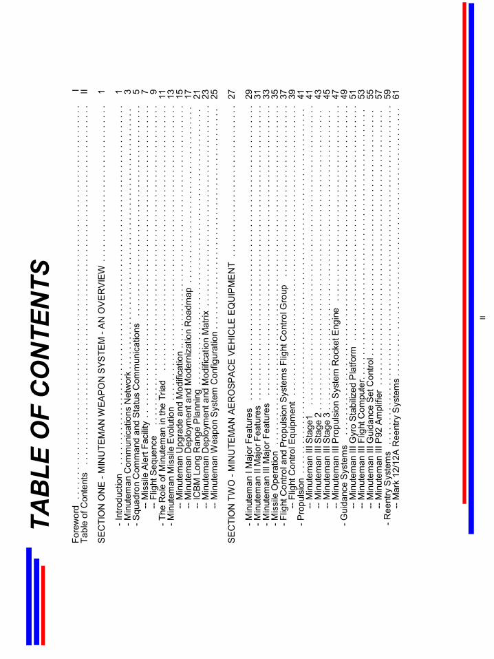
TAB
LE O
F C
ON
TEN
TSFo
rew
ord
. . .
. . .
. . .
. . .
. . .
. . .
. . .
. . .
. . .
. . .
. . .
. . .
. . .
. . .
. . .
. . .
. . .
. . .
. . .
. . .
. . .
. . .
. . .
. . .
. . .
. . .
. .I
Tabl
e of
Con
tent
s. .
. . .
. . .
. . .
. . .
. . .
. . .
. . .
. . .
. . .
. . .
. . .
. . .
. . .
. . .
. . .
. . .
. . .
. . .
. . .
. . .
. . .
. . .
. . .
. .
II
SE
CTI
ON
ON
E -
MIN
UTE
MA
N W
EAP
ON
SYS
TEM
-A
N O
VE
RV
IEW
. . .
. . .
. . .
. . .
. . .
. . .
. . .
. . .
. . .
. . .
. .1
-Int
rodu
ctio
n. .
. . .
. . .
. . .
. . .
. . .
. . .
. . .
. . .
. . .
. . .
. . .
. . .
. . .
. . .
. . .
. . .
. . .
. . .
. . .
. . .
. . .
. . .
. . .
. .
1-M
inut
eman
Com
mun
icat
ions
Net
wor
k . .
. . .
. . .
. . .
. . .
. . .
. . .
. . .
. . .
. . .
. . .
. . .
. . .
. . .
. . .
. . .
. . .
. . .
3-S
quad
ron
Com
man
d an
d S
tatu
s C
omm
unic
atio
ns. .
. . .
. . .
. . .
. . .
. . .
. . .
. . .
. . .
. . .
. . .
. . .
. . .
. . .
. .
5--
Mis
sile
Ale
rt Fa
cilit
y. .
. .
. . .
. . .
. . .
. . .
. . .
. . .
. . .
. . .
. . .
. . .
. . .
. . .
. . .
. . .
. . .
. . .
. . .
. . .
. . .
. .7
--Fl
ight
Seq
uenc
e. .
. . .
. . .
. . .
. . .
. . .
. . .
. . .
. . .
. . .
. . .
. . .
. . .
. . .
. . .
. . .
. . .
. . .
. . .
. . .
. . .
. . .
9-T
he R
ole
of M
inut
eman
in th
e Tr
iad
. . .
. . .
. . .
. . .
. . .
. . .
. . .
. . .
. . .
. . .
. . .
. . .
. . .
. . .
. . .
. . .
. . .
. . .
11-M
inut
eman
Mis
sile
Evo
lutio
n. .
. . .
. . .
. . .
. . .
. . .
. . .
. . .
. . .
. . .
. . .
. . .
. . .
. . .
. . .
. . .
. . .
. . .
. . .
. . .
.13
--M
inut
eman
Upg
rade
and
Mod
ifica
tion
.. . .
. . .
. . .
. . .
. . .
. . .
. . .
. . .
. . .
. . .
. ..
. . .
. . .
. . .
. . .
. . .
.15
--M
inut
eman
Dep
loym
ent a
nd M
oder
niza
tion
Roa
dmap
. .
. . .
. . .
. . .
. . .
. . .
. . .
. . .
. . .
. . .
. . .
. . .
.17
--IC
BM
Lon
g R
ange
Pla
nnin
g .
. . .
. . .
. . .
. . .
. . .
. . .
. . .
. . .
. . .
. . .
. . .
. . .
. . .
. . .
. . .
. . .
. .. .
. . .
21
--M
inut
eman
Dep
loym
ent a
nd M
odifi
catio
n M
atrix
. . .
. . .
. . .
. . .
. . .
. . .
. . .
. . .
. . .
. . .
. . .
. . .
. . .
. .23
--M
inut
eman
Wea
pon
Sys
tem
Con
figur
atio
n . .
. . .
. . .
. . .
. ..
. . .
. . .
. . .
. . .
. . .
. . .
. . .
. . .
. . .
. . .
.25
SE
CTI
ON
TW
O -
MIN
UTE
MA
N A
ER
OSP
AC
E V
EH
ICLE
EQ
UIP
ME
NT
. . .
. . .
. . .
. . .
. . .
. . .
. . .
. . .
. . .
. . .
.27
-Min
utem
an I
Maj
or F
eatu
res
. . .
. . .
. . .
. . .
. . .
. . .
. . .
. . .
. . .
. . .
. . .
. . .
. . .
. . .
. . .
. . .
. . .
. . .
. . .
. . .
29-M
inut
eman
II M
ajor
Fea
ture
s. .
. . .
. . .
. . .
. . .
. . .
. . .
. . .
. . .
. . .
. . .
. . .
. . .
. . .
. . .
. . .
. . .
. . .
. . .
. . .
.31
-Min
utem
an II
I Maj
or F
eatu
res
. . .
. . .
. . .
. . .
. . .
. . .
. . .
. . .
. . .
. . .
. . .
. . .
. . .
. . .
. . .
. . .
. . .
. . .
. . .
. .33
-Mis
sile
Ope
ratio
n. .
. . .
. . .
. . .
. . .
. . .
. . .
. . .
. . .
. . .
. . .
. . .
. . .
. . .
. . .
. . .
. . .
. . .
. . .
. . .
. . .
. . .
. . .
.35
-Flig
ht C
ontro
l and
Pro
puls
ion
Sys
tem
s Fl
ight
Con
trol G
roup
. . .
. . .
. . .
. . .
. . .
. . .
. . .
. . .
. . .
. . .
. .. .
.37
--Fl
ight
Con
trol E
quip
men
t. .
. . .
. . .
. . .
. . .
. . .
. . .
. . .
. . .
. . .
. . .
. . .
. . .
. . .
. . .
. . .
. . .
. . .
. . .
. . .
39-P
ropu
lsio
n .
. . .
. . .
. . .
. . .
. . .
. . .
. . .
. . .
.. .
. . .
. . .
. . .
. . .
. . .
. . .
. . .
. . .
. . .
. . .
. . .
. . .
. . .
. . .
. . .
.41
--M
inut
eman
III S
tage
1. .
. . .
. . .
. . .
. . .
. . .
. . .
. . .
. . .
. . .
. . .
. . .
. . .
. . .
. . .
. . .
. . .
. . .
. . .
. . .
. .
41--
Min
utem
an II
I Sta
ge 2
. . .
. . .
. . .
. . .
. . .
. . .
. . .
. . .
. . .
. . .
. . .
. . .
. . .
. . .
. . .
. . .
. . .
. .. .
. . .
. . .
43--
Min
utem
an II
I Sta
ge 3
. . .
. . .
. . .
. . .
. . .
. . .
. . .
. . .
. . .
. . .
. . .
. . .
. . .
. . .
. . .
. . .
. . .
. .. .
. . .
. . .
45--
Min
utem
an II
I Pro
puls
ion
Sys
tem
Roc
ket E
ngin
e. .
. . .
. . .
. . .
. . .
. . .
. . .
. . .
. . .
. . .
. . .
. . .
. . .
. .
47-G
uida
nce
Sys
tem
s. .
. . .
. . .
. . .
. . .
. . .
. . .
. . .
. . .
. . .
. . .
. . .
. . .
. . .
. . .
. . .
. . .
. . .
. . .
. . .
. . .
. . .
. .
49--
Min
utem
an II
I Gyr
o S
tabi
lized
Pla
tform
. . .
. . .
. . .
. . .
. . .
. . .
. . .
. . .
. . .
. . .
. . .
. . .
. . .
. . .
. . .
. . .
51--
Min
utem
an II
I Flig
ht C
ompu
ter.
. . .
. . .
. . .
. . .
. . .
. . .
. . .
. . .
. . .
. . .
. . .
. . .
. . .
. . .
. . .
. . .
. . .
. . .
53--
Min
utem
an II
I Gui
danc
e S
et C
ontro
l . .
. . .
. . .
. . .
. . .
. . .
. . .
. . .
. . .
. . .
. . .
. . .
. . .
. . .
. . .
. . .
. . .
55--
Min
utem
an II
I P92
Am
plifi
er .
. . .
. . .
. . .
. . .
. . .
. . .
. . .
. . .
. . .
. . .
. . .
. . .
. . .
. . .
. . .
. . .
. . .
. . .
.57
-Ree
ntry
Sys
tem
s. .
. . .
. . .
. . .
. . .
. . .
. . .
. . .
. . .
. . .
. . .
. . .
. . .
. . .
. . .
. . .
. . .
. . .
. . .
. . .
. . .
. .. .
. . .
59--
Mar
k 12
/12A
Ree
ntry
Sys
tem
s . .
. . .
. . .
. .
. . .
. . .
. . .
. . .
. . .
. . .
. . .
. . .
. . .
. . .
. . .
. . .
. . .
. . .
. .
61
II
III
SE
CTI
ON
TH
RE
E -
MIN
UTE
MA
N O
PE
RA
TIO
NA
L G
RO
UN
D E
QU
IPM
EN
T. .
. . .
. . .
. . .
. .. .
. . .
. . .
. . .
. . .
.63
-Mis
sile
Ale
rt Fa
cilit
y. .
. . .
. . .
. . .
. . .
. . .
. . .
. . .
. . .
. . .
. . .
. . .
. . .
. . .
. . .
. . .
. . .
. . .
. . .
. . .
. . .
. . .
. .
65--
Laun
ch C
ontro
l Sup
port
Bui
ldin
g. .
. . .
. . .
. . .
. . .
. . .
. . .
. . .
. . .
. . .
. . .
. . .
. . .
. . .
. . .
. . .
. . .
. . .
67--
Laun
ch C
ontro
l Equ
ipm
ent B
uild
ing
. . .
. . .
. . .
. . .
. . .
. . .
. . .
. . .
. . .
. . .
. . .
. . .
. . .
. . .
. . .
. . .
. . .
69--
Laun
ch C
ontro
l Cen
ter
. . .
. . .
. . .
. . .
. . .
. . .
. . .
. . .
. . .
. . .
. . .
. . .
. . .
. . .
. . .
. . .
. . .
. . .
. . .
. . .
.71
-Lau
nch
Faci
lity
. . .
. . .
. . .
. . .
. . .
. . .
. . .
. . .
. . .
. . .
. . .
. . .
. . .
. . .
. . .
. . .
. . .
. . .
. .. .
. . .
. . .
. . .
. . .
.73
--La
unch
er S
truct
ure
. . .
. . .
. . .
. . .
. . .
. . .
. . .
. . .
. . .
. . .
. . .
. . .
. . .
. . .
. . .
. . .
. . .
. . .
. . .
. . .
. . .
.75
--La
unch
er E
quip
men
t Roo
m. .
. . .
. . .
. . .
. . .
. . .
. . .
. . .
. . .
. . .
. . .
. . .
. . .
. . .
. . .
. . .
. . .
. . .
. . .
.77
--La
unch
er S
uppo
rt B
uild
ing
. . .
. . .
. . .
. . .
. . .
. . .
. . .
. . .
. . .
. . .
. . .
. . .
. . .
. . .
. . .
. . .
. . .
. . .
. . .
79--
Laun
cher
Equ
ipm
ent B
uild
ing
. . .
. . .
. . .
. . .
. . .
. . .
. . .
. . .
. . .
. . .
. . .
. . .
. . .
. . .
. . .
. . .
. . .
. . .
.81
--La
unch
Fac
ility
Sec
urity
Sys
tem
. . .
. . .
. . .
. . .
. . .
. . .
. . .
. . .
. . .
. . .
. . .
. . .
. . .
. . .
. . .
. . .
. . .
. .83
SE
CTI
ON
FO
UR
-M
INU
TEM
AN
OR
DN
AN
CE
. .
. . .
. . .
. . .
. . .
. . .
. . .
. .. .
. . .
. . .
. . .
. . .
. . .
. . .
. . .
. . .
. .
85
-Int
erst
age
Ord
nanc
e. .
. . .
. . .
. . .
. . .
. . .
. . .
. . .
. . .
. . .
. . .
. . .
. . .
. . .
. . .
. . .
. . .
. . .
. . .
. . .
. . .
. . .
.87
-Thr
ust T
erm
inat
ion
Sys
tem
Ord
nanc
e. .
. . .
. . .
. . .
. . .
. . .
. . .
. . .
. . .
. . .
. . .
. . .
. . .
. . .
. . .
. . .
. . .
. . .
89-R
eent
ry S
yste
m O
rdna
nce
. . .
. . .
. . .
. . .
. . .
. . .
. . .
. . .
. . .
. . .
. . .
. . .
. . .
. . .
. . .
. . .
. . .
. . .
. . .
. . .
.91
-Ope
ratio
nal G
roun
d E
quip
men
t Ord
nanc
e. .
. . .
. . .
. . .
. . .
. . .
. . .
. . .
. . .
. . .
. . .
. . .
. . .
. . .
. . .
. . .
. .93
SE
CTI
ON
FIV
E -
CH
RO
NO
LOG
Y O
F M
INU
TEM
AN
DE
VELO
PM
EN
T A
ND
DEP
LOYM
EN
T. .
. . .
. . .
. . .
. . .
.95
-Chr
onol
ogy
1956
-19
65. .
. . .
. . .
. . .
. . .
. . .
. . .
. . .
. . .
. . .
. . .
. . .
. . .
. . .
. . .
. . .
. . .
. . .
. . .
. . .
. . .
.96
-Chr
onol
ogy
1966
-19
74. .
. . .
. . .
. . .
. . .
. . .
. . .
. . .
. . .
. . .
. . .
. . .
. . .
. . .
. . .
. . .
. . .
. . .
. . .
. . .
. . .
.97
-Chr
onol
ogy
1975
-19
80. .
. . .
. . .
. . .
. . .
. . .
. . .
. . .
. . .
. . .
. . .
. . .
. . .
. . .
. . .
. . .
. . .
. . .
. . .
. . .
. . .
.98
-Chr
onol
ogy
1981
-19
89. .
. . .
. . .
. . .
. . .
. . .
. . .
. . .
. . .
. . .
. . .
. . .
. . .
. . .
. . .
. . .
. . .
. . .
. . .
. . .
. . .
.99
-Chr
onol
ogy
1991
-20
01. .
. . .
. . .
. . .
. . .
. . .
. . .
. . .
. . .
. . .
. . .
. . .
. . .
. . .
. . .
. . .
. . .
. . .
. . .
. . .
. . .
.10
0
AC
RO
NYM
LIS
T. .
. . .
. . .
. . .
. . .
. . .
. . .
. . .
. . .
. . .
. . .
. . .
. . .
. . .
. . .
. . .
. . .
. . .
. . .
. . .
. . .
. . .
. . .
. . .
. . .
101
The
Min
utem
an W
eapo
n S
yste
m w
as c
once
ived
in t
he la
te 1
950s
, an
dde
velo
ped
and
depl
oyed
in t
he 1
960s
. T
he
syst
em w
as d
esig
ned
to d
eter
any
agg
ress
or,
but i
f de
terr
ence
faile
d, to
be
able
to w
ithst
and
an a
ttack
and
pro
vide
inst
ant
reta
liatio
n ca
pabi
lity.
At
the
tim
e of
its
con
cept
ion,
Min
utem
an r
epre
sent
ed a
new
dim
ensi
on i
n w
eapo
nry.
Wid
ely
disp
ersi
ng m
issi
les
in n
ucle
ar-h
arde
ned
laun
cher
s w
as a
nov
el i
dea
that
was
dev
elop
ed i
nto
the
pres
ent
Min
utem
an W
eapo
n Sy
stem
by
the
Ballis
tic M
issi
le O
rgan
izat
ion
ofth
e Ai
r Fo
rce
Sys
tem
s C
omm
and
(AFS
C).
Tod
ay,
engi
neer
ing
and
mai
nten
ance
of
Min
utem
an i
s m
anag
ed b
y th
e In
terc
ontin
enta
l Ba
llistic
Mis
sile
(IC
BM)
Sys
tem
Pro
gram
Offi
ce (S
PO
) at t
he O
gden
Air
Logi
stic
s C
ente
r (O
O-A
LC) u
nder
Air
Forc
e M
ater
iel C
omm
and
(AFM
C).
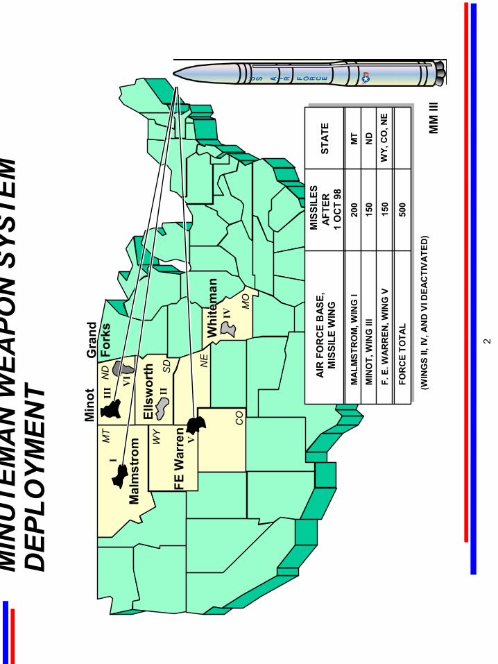
The
figur
e be
low
sho
ws
the
loca
tion
and
conf
igur
atio
n of
the
thre
e cu
rren
t Mis
sile
Sup
port
Base
s an
d th
e di
strib
utio
n of
the
Min
utem
an II
I mis
sile
s at
thos
e lo
catio
ns.
Win
gs II
, IV
, and
VI,
loca
ted
at E
llsw
orth
, Whi
tem
an, a
nd G
rand
For
ks
AFB
s, w
ere
deac
tivat
ed w
ith th
e re
tirem
ent o
f Min
utem
an II
and
as
a re
sult
of th
e ba
se c
losu
re a
nd re
alig
nmen
t act
ions
.
The
Min
utem
an II
I mis
sile
s fro
m W
ing
VI w
ere
trans
ferre
d to
the
form
er M
inut
eman
II s
ites
at M
alm
stom
AFB
by
the
end
of F
Y98.
The
dar
kene
d ar
eas
repr
esen
t th
e lo
catio
n of
the
mis
sile
squ
adro
ns a
t ea
ch b
ase.
E
ach
mis
sile
squ
adro
n
cons
ists
of f
ive
fligh
ts; e
ach
fligh
t con
sist
s of
one
Mis
sile
Ale
rt Fa
cilit
y (M
AF)
and
ten
Laun
ch F
acilit
ies
(LFs
).
SEC
TIO
N O
NE
MIN
UTE
MA
N W
EAPO
N S
YSTE
M-A
N O
VER
VIEW
-IN
TRO
DU
CTI
ON
1
MM
III
MO
Mal
mst
rom
Ells
wor
th
FE W
arre
n
MT
ND SD
WY
CO
I
II
V
III
IV
VI
NE
Whi
tem
an
Min
otG
rand
Fork
s
MIN
UTE
MA
N W
EAPO
N S
YSTE
M
DEP
LOYM
ENT
AFT
ER1
OC
T 98
MIS
SILE
S
MA
LMST
RO
M, W
ING
I20
0M
TM
INO
T, W
ING
III
150
ND
F. E
. WA
RR
EN, W
ING
V15
0W
Y, C
O, N
E
FOR
CE
TOTA
L50
0
AIR
FO
RC
E B
ASE,
MIS
SILE
WIN
GST
ATE
(WIN
GS
II, IV
, AN
D V
I DEA
CTI
VAT
ED)
2
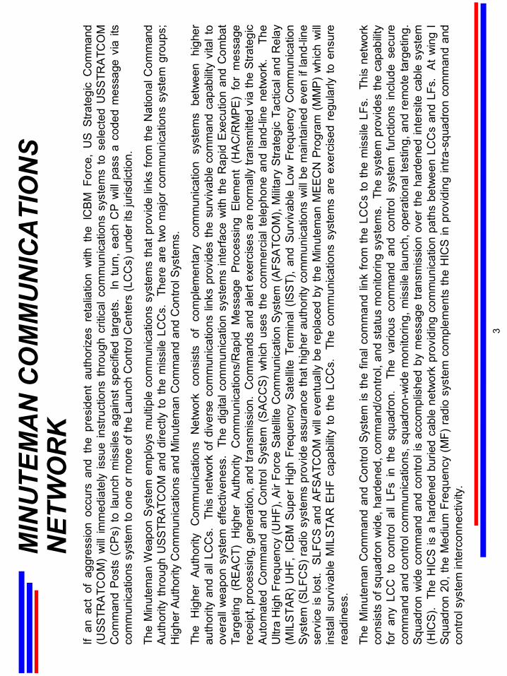
If an
act
of
aggr
essi
on o
ccur
s an
d th
e pr
esid
ent
auth
oriz
es r
etal
iatio
n w
ith t
he I
CB
M F
orce
, U
S S
trate
gic
Com
man
d (U
SSTR
ATC
OM
) w
ill im
med
iate
ly is
sue
inst
ruct
ions
thr
ough
crit
ical
com
mun
icat
ions
sys
tem
s to
sel
ecte
d U
SSTR
ATC
OM
C
omm
and
Pos
ts (
CP
s) t
o la
unch
mis
sile
s ag
ains
t sp
ecifi
ed t
arge
ts.
In t
urn,
eac
h C
P w
ill pa
ss a
cod
ed m
essa
ge v
ia it
s co
mm
unic
atio
ns s
yste
m to
one
or m
ore
of th
e La
unch
Con
trol C
ente
rs (L
CC
s) u
nder
its
juris
dict
ion.
The
Min
utem
an W
eapo
n S
yste
m e
mpl
oys
mul
tiple
com
mun
icat
ions
sys
tem
s th
at p
rovi
de li
nks
from
the
Nat
iona
l Com
man
d A
utho
rity
thro
ugh
USS
TRAT
CO
M a
nd d
irect
ly t
o th
e m
issi
leLC
Cs.
Th
ere
are
two
maj
or c
omm
unic
atio
ns s
yste
m g
roup
s;
Hig
her A
utho
rity
Com
mun
icat
ions
and
Min
utem
an C
omm
and
and
Con
trol S
yste
ms.
The
Hig
her
Auth
ority
Com
mun
icat
ions
Net
wor
k co
nsis
ts o
f co
mpl
emen
tary
com
mun
icat
ion
syst
ems
betw
een
high
er
auth
ority
and
all
LCC
s.
This
net
wor
k of
div
erse
com
mun
icat
ions
link
s pr
ovid
es th
e su
rviv
able
com
man
d ca
pabi
lity
vita
l to
over
all w
eapo
n sy
stem
effe
ctiv
enes
s.
The
digi
tal c
omm
unic
atio
n sy
stem
s in
terfa
ce w
ith th
e R
apid
Exe
cutio
n an
d C
omba
t Ta
rget
ing
(REA
CT)
Hig
her
Auth
ority
Com
mun
icat
ions
/Rap
id M
essa
ge P
roce
ssin
g E
lem
ent
(HA
C/R
MPE
) fo
r m
essa
ge
rece
ipt,
proc
essi
ng, g
ener
atio
n, a
nd tr
ansm
issi
on.
Com
man
ds a
ndal
ert e
xerc
ises
are
nor
mal
ly tr
ansm
itted
via
the
Stra
tegi
c A
utom
ated
Com
man
d an
d C
ontro
l Sys
tem
(S
AC
CS
) w
hich
use
s th
e co
mm
erci
al t
elep
hone
and
land
-line
net
wor
k.
The
U
ltra
Hig
h Fr
eque
ncy
(UH
F), A
ir Fo
rce
Sate
llite
Com
mun
icat
ion
Syst
em (A
FSA
TCO
M),
Milit
ary
Stra
tegi
c Ta
ctic
al a
nd R
elay
(M
ILS
TAR
)U
HF,
IC
BM
Sup
er H
igh
Freq
uenc
y Sa
tellit
e Te
rmin
al (
ISS
T),
and
Surv
ivab
le L
ow F
requ
ency
Com
mun
icat
ion
Sys
tem
(SLF
CS)
radi
o sy
stem
s pr
ovid
e as
sura
nce
that
hig
her a
utho
rity
com
mun
icat
ions
will
be m
aint
aine
d ev
en if
land
-line
se
rvic
e is
lost
. SL
FCS
and
AFSA
TCO
M w
ill ev
entu
ally
be
repl
aced
by
the
Min
utem
an M
EEC
NPr
ogra
m (
MM
P) w
hich
will
inst
all s
urvi
vabl
eM
ILS
TAR
EH
F ca
pabi
lity
to t
heLC
Cs.
Th
e co
mm
unic
atio
ns s
yste
ms
are
exer
cise
d re
gula
rly t
o en
sure
re
adin
ess.
The
Min
utem
an C
omm
and
and
Con
trol S
yste
m is
the
final
com
man
d lin
k fro
m th
eLC
Cs
to th
e m
issi
leLF
s.
This
net
wor
k co
nsis
ts o
f squ
adro
n w
ide,
har
dene
d, c
omm
and/
cont
rol,
and
stat
usm
onito
ring
syst
ems.
The
sys
tem
pro
vide
s th
e ca
pabi
lity
for
any
LCC
to
cont
rol
all
LFs
in t
he s
quad
ron.
Th
e va
rious
com
man
d an
d co
ntro
l sy
stem
fun
ctio
ns i
nclu
de s
ecur
e co
mm
and
and
cont
rol c
omm
unic
atio
ns, s
quad
ron-
wid
e m
onito
ring,
mis
sile
laun
ch, o
pera
tiona
l tes
ting,
and
rem
ote
targ
etin
g.
Squ
adro
n w
ide
com
man
d an
d co
ntro
l is
acco
mpl
ishe
d by
mes
sage
tran
smis
sion
ove
r th
e ha
rden
edin
ters
iteca
ble
syst
em
(HIC
S).
The
HIC
S is
a h
arde
ned
burie
d ca
ble
netw
ork
prov
idin
g co
mm
unic
atio
n pa
ths
betw
een
LCC
san
dLF
s.
At w
ing
I S
quad
ron
20, t
he M
ediu
m F
requ
ency
(M
F) r
adio
sys
tem
com
plem
ents
the
HIC
S in
pro
vidi
ng in
tra-s
quad
ron
com
man
d an
d co
ntro
l sys
tem
inte
rcon
nect
ivity
.
MIN
UTE
MA
N C
OM
MU
NIC
ATI
ON
S N
ETW
OR
K
3
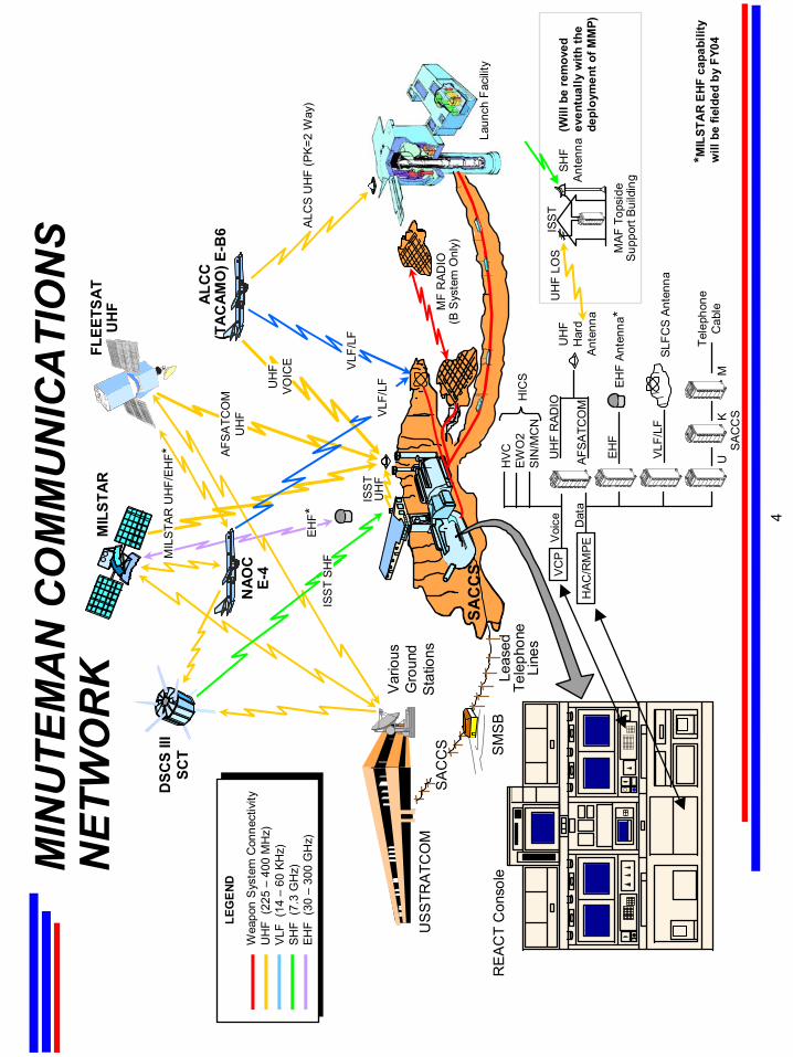
MIN
UTE
MA
N C
OM
MU
NIC
ATI
ON
S N
ETW
OR
K
.
FLEE
TSA
TU
HF A
LCC
(TA
CA
MO
) E-B
6
MIL
STA
R
MF
RAD
IO(B
Sys
tem
Onl
y)
HIC
S
SA
CC
SU
SS
TRA
TCO
M
NAO
CE-
4
DSC
S III
SCT S
MS
B
Var
ious
Gro
und
Sta
tions
SAC
CS VC
PV
oice
HAC
/RM
PED
ata
HVC
EWO
2SI
N/M
CN
HIC
S
UH
F R
ADIO
AFSA
TCO
M
VLF/
LF
SAC
CS
UK
M
Tele
phon
eC
able
SLFC
S An
tenn
a
UH
FH
ard
Ante
nna
UH
F LO
SIS
ST
SHF
Ante
nna
MAF
Top
side
Supp
ort B
uild
ing
RE
AC
T C
onso
le
ALC
S U
HF
(PK=
2 W
ay)
ISS
T U
HF
VLF/
LF
Leas
edTe
leph
one
Line
s
VLF/
LF
EHF
Ante
nna*
EHF*
Wea
pon
Sys
tem
Con
nect
ivity
UH
F (2
25 –
400
MH
z)VL
F (1
4 –
60 K
Hz)
SHF
(7.3
GH
z)EH
F (3
0 –
300
GH
z)
LEG
END
*MIL
STA
R EH
F ca
pabi
lity
will
be
field
ed b
y FY
04
(Will
be
rem
oved
ev
entu
ally
with
the
depl
oym
ent o
f MM
P)
Laun
ch F
acilit
y
MIL
STAR
UH
F/EH
F*
ISS
T SH
F
AFSA
TCO
MU
HF
UH
F VO
ICE
4
EHF
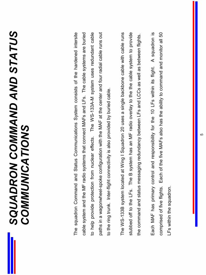
The
squa
dron
Com
man
d an
d St
atus
Com
mun
icat
ions
Sys
tem
con
sist
s of
the
har
dene
d in
ters
ite
cabl
e sy
stem
and
the
MF
radi
o sy
stem
s th
at c
onne
ctM
AFs
and
LFs.
The
cab
le s
yste
ms
are
burie
d
to h
elp
prov
ide
prot
ectio
n fro
m n
ucle
ar e
ffect
s.
The
WS
-133
A-M
sys
tem
use
s re
dund
ant
cabl
e
path
s in
a w
agon
whe
el-s
poke
con
figur
atio
n w
ith th
e M
AF
at th
e ce
nter
and
four
radi
al c
able
runs
out
to th
e rin
g tru
nk.
Inte
r-fli
ght c
onne
ctiv
ity is
als
o pr
ovid
ed b
y bu
ried
cabl
e.
The
WS-
133B
sys
tem
loca
ted
at W
ing
I Squ
adro
n 20
use
s a
sing
le b
ackb
one
cabl
e w
ith c
able
run
s
stub
bed
off t
o th
e LF
s.
The
B sy
stem
has
an
MF
radi
o ov
erla
y to
the
the
cabl
e sy
stem
to p
rovi
de
the
com
man
d an
d st
atus
mes
sagi
ng re
dund
ancy
bet
wee
n LF
san
d LC
Cs
as w
ell a
s be
twee
n fli
ghts
.
Each
MA
F ha
s pr
imar
y co
ntro
l an
d re
spon
sibi
lity
for
the
10 L
Fs w
ithin
its
fligh
t. A
squ
adro
n is
com
pris
ed o
f fiv
e fli
ghts
. Ea
ch o
f the
five
MA
Fs a
lso
has
the
abilit
y to
com
man
d an
d m
onito
r all
50
LFs
with
in th
e sq
uadr
on.
SQU
AD
RO
N C
OM
MA
ND
AN
D S
TATU
S C
OM
MU
NIC
ATI
ON
S
5
SQU
AD
RO
N C
OM
MA
ND
AN
D S
TATU
S C
OM
MU
NIC
ATI
ON
S
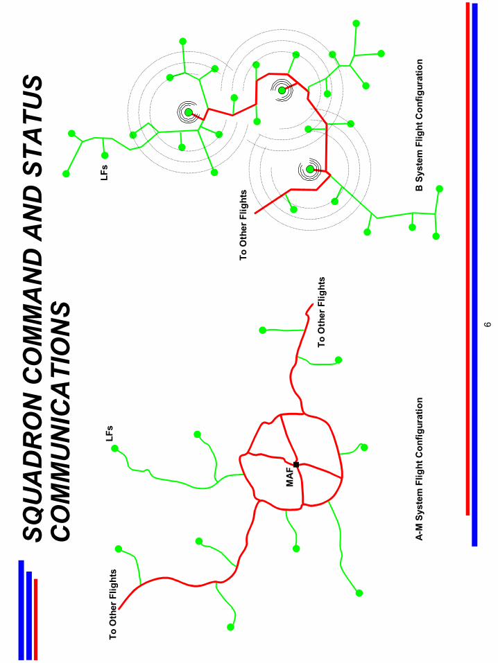
A-M
Sys
tem
Flig
ht C
onfig
urat
ion
To O
ther
Flig
hts B
Sys
tem
Flig
ht C
onfig
urat
ion
LFs
To O
ther
Flig
hts
LFs
MA
F
To O
ther
Flig
hts
6
MA
Fsar
e lo
cate
d at
eac
h op
erat
iona
l mis
sile
win
g fo
r co
mm
and,
con
trol,
and
mon
itorin
g of
the
Min
utem
anLF
s.
The
MA
F co
nsis
ts o
f a b
urie
d an
d ha
rden
ed L
CC
, an
abov
e-gr
ound
Lau
nch
Con
trol S
uppo
rt B
uild
ing
(LC
SB
) at
Win
g I,
and
at W
ings
III,
V, a
nd I/
Squ
adro
n 20
, a b
urie
d an
d ha
rden
ed L
aunc
h C
ontro
l Equ
ipm
ent B
uild
ing
(LC
EB)
to h
ouse
the
cool
ing
and
gene
rato
r sy
stem
s.
The
com
man
d an
d co
ntro
l equ
ipm
ent i
s lo
cate
d in
the
LCC
. E
ach
LCC
has
prim
ary
cont
rol a
nd re
spon
sibi
lity
for
the
10LF
sw
ithin
its
fligh
t. A
squ
adro
n is
com
pris
ed o
f fiv
e fli
ghts
.
Eac
h of
the
five
LCC
sal
so h
as th
e ab
ility
to c
omm
and
and
mon
itor a
ll 50
LFs
with
in th
e sq
uadr
on.
Whe
n a
valid
em
erge
ncy
actio
n m
essa
ge (E
AM
) di
rect
ing
laun
ch is
rec
eive
d at
the
LCC
, the
two
Mis
sile
Com
bat
Cre
w M
embe
rs (M
CC
Ms)
take
the
requ
ired
actio
ns to
con
figur
e th
e m
issi
les
for l
aunc
h. T
his
incl
udes
sen
ding
the
enab
le c
odes
to th
e m
issi
les
and
trans
mitt
ing
the
prop
er p
repa
rato
ry la
unch
com
man
d (P
LC).
The
PLC
con
tain
s
all
info
rmat
ion
to e
xecu
te t
he d
esig
nate
d w
ar p
lan.
Th
e of
ficer
s th
en s
imul
tane
ousl
y tu
rn l
aunc
h sw
itche
s in
phys
ical
ly s
epar
ated
pan
els
on t
he R
EAC
T co
nsol
e to
sta
rt th
e au
tom
atic
lau
nch
sequ
ence
. T
his
begi
ns a
prec
isel
y se
quen
ced
serie
s of
aut
omat
ic o
pera
tions
: 1)
a fin
al c
heck
of t
he s
yste
m fo
r co
mba
t rea
dine
ss is
mad
e;
2) th
e la
unch
er c
losu
re d
oor i
s re
mov
ed; 3
) the
upp
er u
mbi
lical
is r
etra
cted
from
the
mis
sile
; and
4)
the
first
sta
ge
rock
et m
otor
is ig
nite
d.
The
entir
e la
unch
seq
uenc
e ta
kes
less
than
60
seco
nds.
N
orm
ally
, tw
oLC
Cs
are
requ
ired
to “v
ote”
to e
xecu
te a
laun
ch.
A s
ingl
e vo
te c
apab
ility
and
the
Airb
orne
Lau
nch
Con
trol C
ente
r (A
LCC
) pro
vide
bac
k-up
cap
abilit
y.
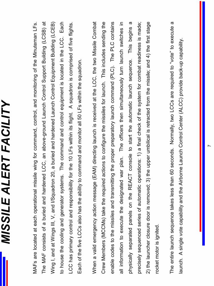
MIS
SILE
ALE
RT
FAC
ILIT
Y
7
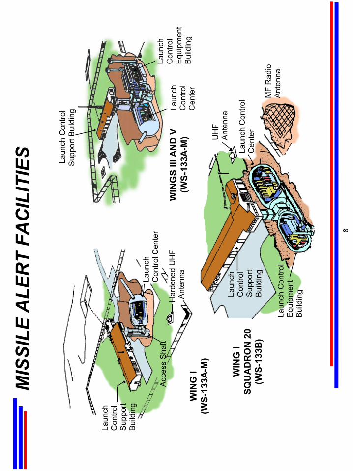
MIS
SILE
ALE
RT
FAC
ILIT
IES
Laun
chC
ontro
lSu
ppor
tBu
ildin
g
Acc
ess
Sha
ftH
arde
ned
UH
FA
nten
naLaun
chC
ontro
l Cen
ter
WIN
G I
SQU
AD
RO
N 2
0(W
S-13
3B)
Laun
chC
ontro
lSu
ppor
tBu
ildin
g
Laun
ch C
ontro
lS
uppo
rt Bu
ildin
g
Laun
ch C
ontro
lE
quip
men
tB
uild
ing
MF
Rad
ioAn
tenn
a
Laun
ch C
ontro
lC
ente
r
UH
FAn
tenn
a
WIN
G I
(WS-
133A
-M)
WIN
GS
III A
ND
V(W
S-13
3A-M
)La
unch
Con
trol
Cen
ter
Laun
chC
ontro
lE
quip
men
tB
uild
ing
8
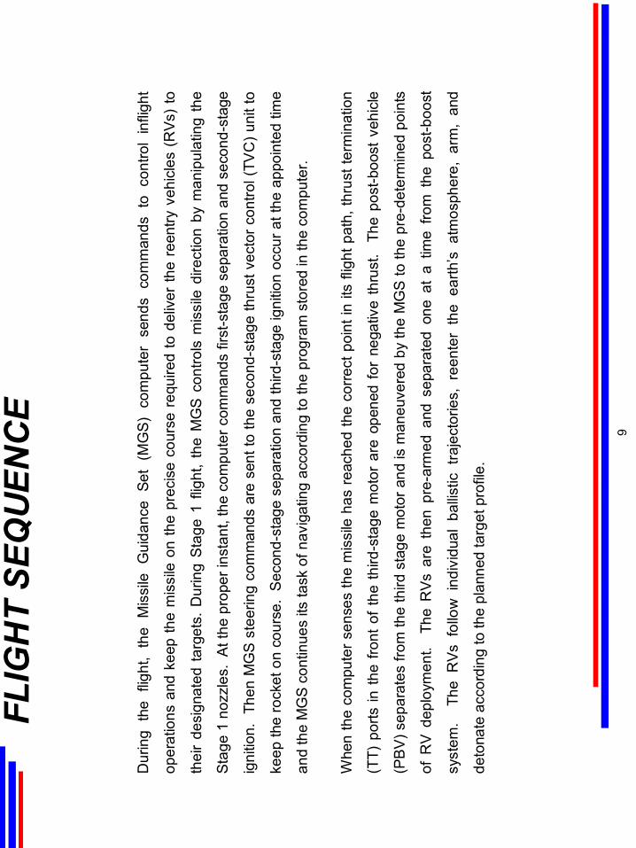
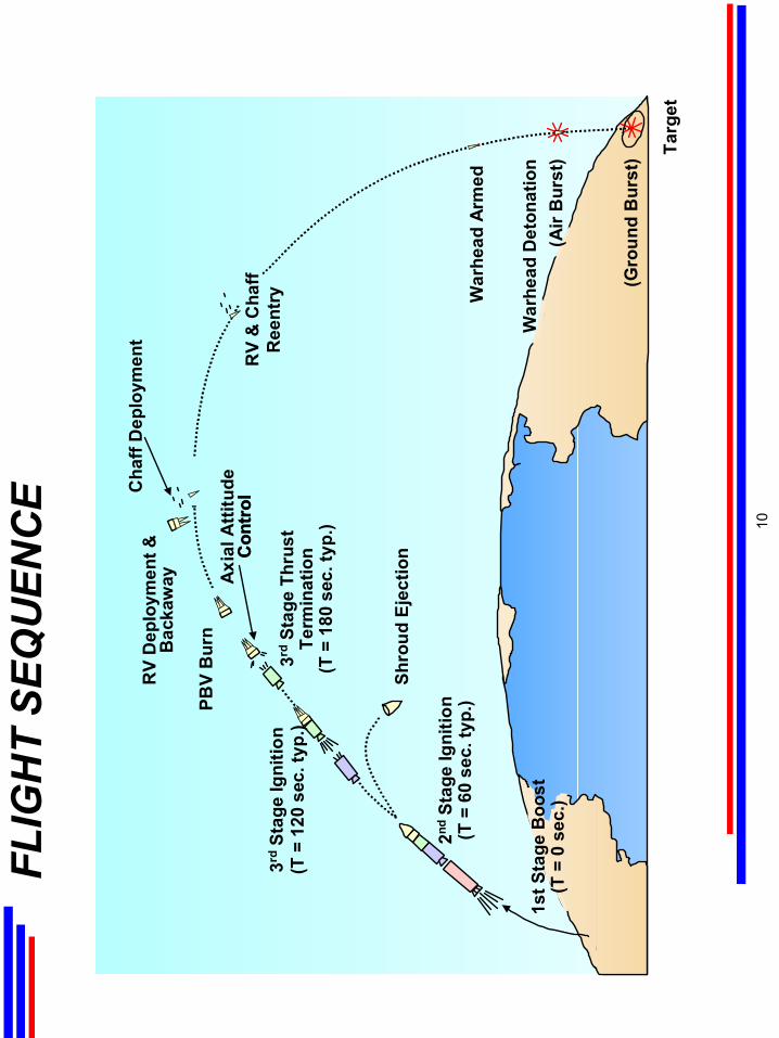
Dur
ing
the
fligh
t, th
e M
issi
le G
uida
nce
Set
(MG
S) c
ompu
ter
send
sco
mm
ands
to
cont
rol
infli
ght
oper
atio
ns a
nd k
eep
the
mis
sile
on
the
prec
ise
cour
se r
equi
red
to d
eliv
er th
e re
entry
veh
icle
s (R
Vs)
to
thei
r de
sign
ated
targ
ets.
Dur
ing
Sta
ge 1
flig
ht,
the
MG
S c
ontro
ls m
issi
le d
irect
ion
by m
anip
ulat
ing
the
Stag
e 1
nozz
les.
At t
he p
rope
r ins
tant
, the
com
pute
r com
man
ds fi
rst-s
tage
sep
arat
ion
and
seco
nd-s
tage
igni
tion.
The
n M
GS
ste
erin
g co
mm
ands
are
sen
t to
the
seco
nd-s
tage
thru
st v
ecto
r con
trol (
TVC
) uni
t to
keep
the
rock
et o
n co
urse
. S
econ
d-st
age
sepa
ratio
n an
d th
ird-s
tage
igni
tion
occu
r at t
he a
ppoi
nted
tim
e
and
the
MG
S co
ntin
ues
its ta
sk o
f nav
igat
ing
acco
rdin
g to
the
prog
ram
sto
red
in th
e co
mpu
ter.
Whe
n th
e co
mpu
ter s
ense
s th
e m
issi
le h
as re
ache
d th
e co
rrect
poi
nt in
its
fligh
t pat
h, th
rust
term
inat
ion
(TT)
por
ts in
the
fron
t of
the
third
-sta
ge m
otor
are
ope
ned
for
nega
tive
thru
st.
The
pos
t-boo
st v
ehic
le
(PB
V) s
epar
ates
from
the
third
sta
ge m
otor
and
is m
aneu
vere
d by
the
MG
S to
the
pre-
dete
rmin
ed p
oint
s
of R
V de
ploy
men
t. T
he R
Vs
are
then
pre
-arm
ed a
ndse
para
ted
one
at a
tim
e fro
m t
he p
ost-b
oost
syst
em.
The
RV
s fo
llow
ind
ivid
ual
ballis
tic t
raje
ctor
ies,
ree
nter
the
ear
th’s
atm
osph
ere,
arm
, an
d
deto
nate
acc
ordi
ng to
the
plan
ned
targ
et p
rofil
e.
FLIG
HT
SEQ
UEN
CE
9
FLIG
HT
SEQ
UEN
CE
XXXX
XXXX
XXXX
XXXX
XX
3rdSt
age
Igni
tion
(T =
120
sec
. typ
.)
Shro
ud E
ject
ion
RV
& C
haff
Ree
ntry
Cha
ff D
eplo
ymen
tR
V D
eplo
ymen
t &B
acka
way Ax
ial A
ttitu
deC
ontr
ol
2ndSt
age
Igni
tion
(T =
60
sec.
typ.
)
3rdSt
age
Thru
stTe
rmin
atio
n(T
= 1
80 s
ec. t
yp.)
PBV
Bur
n
Con
trol
War
head
Arm
ed
Targ
et
War
head
Det
onat
ion
(Air
Bur
st)
(Gro
und
Bur
st)
1st S
tage
Boo
st(T
= 0
sec
.)
.
10
Land
-bas
ed IC
BM
s pr
ovid
e on
e of
the
thre
e el
emen
ts o
f the
nat
ion’
s st
rate
gic
forc
e, th
e “T
riad.
” T
he T
riad
cons
ists
of
the
Air
Forc
e bo
mbe
r fle
et,
the
land
-bas
ed b
allis
tic m
issi
le f
leet
, an
d th
e N
avy’
s se
a-la
unch
ed
ballis
tic m
issi
le fl
eet.
Eac
h el
emen
t co
mpl
emen
ts t
he o
ther
tw
o.
For
exam
ple,
eac
h el
emen
t de
pend
s on
a d
iffer
ent
mod
e fo
r
prel
aunc
hsu
rviv
al: t
he la
nd-b
ased
mis
sile
s, u
pon
disp
ersi
on a
nd h
ardn
ess;
the
sea-
laun
ched
mis
sile
s, u
pon
unce
rtain
ty o
f lo
catio
n; a
nd t
he b
ombe
r fo
rce,
upo
n ta
ctic
al w
arni
ng c
oupl
ed w
ith q
uick
rea
ctio
n.
The
dive
rsifi
ed c
once
pt o
f th
e Tr
iad
prov
ides
a r
easo
nabl
e as
sura
nce
of d
epriv
ing
an e
nem
y of
the
abi
lity
to
“kno
ck o
ut”
mor
e th
an o
ne o
f the
ele
men
ts in
a s
urpr
ise
atta
ck.
This
com
plic
ates
eco
nom
ical
ly, a
s w
ell a
s
phys
ical
ly, a
n ag
gres
sor’s
ow
n de
fens
e pr
oble
m.
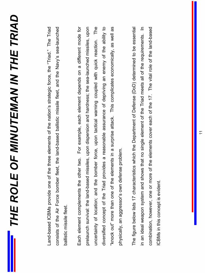
The
figur
e be
low
list
s 17
cha
ract
eris
tics
whi
ch th
e D
epar
tmen
t of D
efen
se (D
oD) d
eter
min
ed to
be
esse
ntia
l
in a
n id
eal w
eapo
n sy
stem
and
sho
ws
that
no
sing
le e
lem
ent o
f the
Tria
d m
eets
all
of th
e re
quire
men
ts.
In
com
bina
tion,
how
ever
, one
or
mor
e of
the
elem
ents
cov
er e
ach
of th
e 17
. Th
e vi
tal r
ole
of t
he la
nd-b
ased
ICB
Ms
in th
is c
once
pt is
evi
dent
.
THE
RO
LE O
F M
INU
TEM
AN
IN T
HE
TRIA
D
11
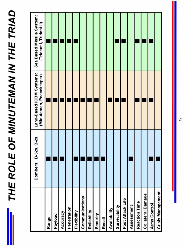
THE
RO
LE O
F M
INU
TEM
AN
IN T
HE
TRIA
D
Ran
gePa
yloa
dAc
cura
cyPe
netr
atio
nFl
exib
ility
Com
mun
icat
ions
Rel
iabi
lity
Secu
rity
Rec
all
Avai
labi
lity
Surv
ivab
ility
Post
Atta
ck L
ifeAs
sess
men
tR
eact
ion
Tim
eC
olla
tera
l Dam
age
Arm
s C
ontr
olC
risis
Man
agem
ent
Bom
bers
: B
-52s
, B-2
sLa
nd-B
ased
ICB
M S
yste
ms:
(Min
utem
an, P
eace
keep
er)
Sea
Bas
ed M
issi
le S
yste
m:
(Trid
ent I
, Trid
ent I
I)
12
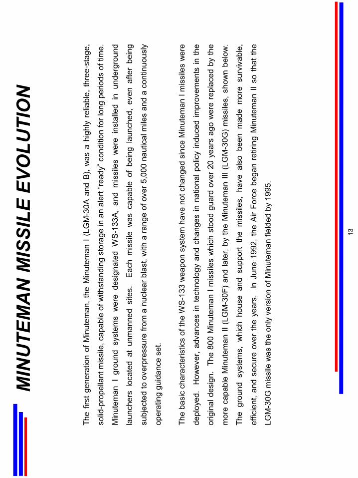
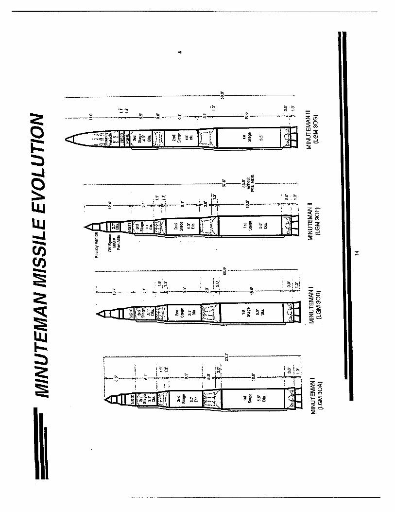
The
first
gen
erat
ion
of M
inut
eman
, the
Min
utem
an I
(LG
M-3
0A a
nd B
), w
as a
hig
hly
relia
ble,
thre
e-st
age,
solid
-pro
pella
nt m
issi
le, c
apab
le o
f with
stan
ding
sto
rage
in a
n al
ert “
read
y” c
ondi
tion
for l
ong
perio
ds o
f tim
e.
Min
utem
an I
gro
und
syst
ems
wer
e de
sign
ated
WS
-133
A,
and
mis
sile
s w
ere
inst
alle
d in
und
ergr
ound
laun
cher
s lo
cate
d at
unm
anne
d si
tes.
E
ach
mis
sile
was
cap
able
of
bein
g la
unch
ed,
even
afte
r be
ing
subj
ecte
d to
ove
rpre
ssur
e fro
m a
nuc
lear
bla
st, w
ith a
rang
e of
ove
r 5,0
00 n
autic
al m
iles
and
a co
ntin
uous
ly
oper
atin
g gu
idan
ce s
et.
The
basi
c ch
arac
teris
tics
of th
e W
S-1
33 w
eapo
n sy
stem
hav
e no
t cha
nged
sin
ce M
inut
eman
I m
issi
les
wer
e
depl
oyed
. H
owev
er, a
dvan
ces
in te
chno
logy
and
cha
nges
in n
atio
nal p
olic
y in
duce
d im
prov
emen
ts in
the
orig
inal
des
ign.
Th
e 80
0 M
inut
eman
I m
issi
les
whi
ch s
tood
gua
rdov
er 2
0 ye
ars
ago
wer
e re
plac
ed b
y th
e
mor
e ca
pabl
e M
inut
eman
II (
LGM
-30F
) an
d la
ter,
by th
e M
inut
eman
III (
LGM
-30G
) m
issi
les,
sho
wn
belo
w.
The
grou
nd s
yste
ms,
whi
ch h
ouse
and
sup
port
the
mis
sile
s, h
ave
also
bee
n m
ade
mor
e su
rviv
able
,
effic
ient
, and
sec
ure
over
the
year
s.
In J
une
1992
, the
Air
Forc
e be
gan
retir
ing
Min
utem
an II
so
that
the
LGM
-30G
mis
sile
was
the
only
ver
sion
of M
inut
eman
fiel
ded
by 1
995.
MIN
UTE
MA
N M
ISSI
LE E
VOLU
TIO
N
13
MIN
UTE
MA
N U
PGR
AD
E A
ND
M
OD
IFIC
ATI
ON
By
1964
maj
or im
prov
emen
ts h
ad b
een
mad
e to
the
orig
inal
gro
und
syst
em a
nd m
issi
le d
esig
n, a
nd W
ing
VI w
as b
uilt
with
the
se im
prov
emen
ts t
o ac
com
mod
ate
the
Min
utem
an I
I mis
sile
.Th
is g
roun
d sy
stem
was
des
igna
ted
WS
-133
B.
Afte
r W
ing
VI d
eplo
ymen
t, th
e sa
me
new
gro
und
syst
em w
as u
sed
toad
d on
e sq
uadr
on o
f M
inut
eman
II m
issi
les
to
Win
g I.
Thi
s is
Squ
adro
n 4
of W
ing
I, bu
t has
bee
n re
ferre
d to
as
the
“Col
ocat
edsq
uadr
on” o
r “Sq
uadr
on 2
0,” a
s it
was
th
e 20
th M
inut
eman
squ
adro
n de
ploy
ed in
the
forc
e.
Afte
r the
WS-
133B
gro
und
syst
em w
as b
uilt,
the
WS
-133
A gr
ound
sys
tem
at W
ings
I an
d III
thr
ough
V w
as m
odifi
ed to
inco
rpor
ate
char
acte
ristic
s si
mila
r to
tho
se o
f th
e W
S-1
33B
syst
em in
ord
er t
o ac
com
mod
ate
eith
er M
inut
eman
II
or
Min
utem
an II
I mis
sile
s. T
his
incl
uded
the
inst
alla
tion
of th
e C
omm
and
Dat
a Bu
ffer (
CD
B) a
t all
win
gs e
xcep
t Win
g II
to
prov
ide
rem
ote
reta
rget
ing
capa
bilit
y an
d ot
her
upgr
ades
. A
lso,
new
req
uire
men
ts w
ere
esta
blis
hed
to in
crea
se t
he
syst
em’s
“nu
clea
r ha
rdne
ss.”
Nuc
lear
har
dnes
s is
a t
erm
rep
rese
ntin
g ho
w r
esis
tant
a s
yste
m is
to
nucl
ear
effe
cts.
In
itial
ly,
the
hard
ness
was
upg
rade
d to
a li
mite
d ex
tent
at
Win
gII.
La
ter,
a m
ore
exte
nsiv
e ha
rdne
ss u
pgra
de w
as
perfo
rmed
at
the
rem
aini
ng w
ings
beg
inni
ng w
ith W
ing
V.
The
chan
ges
wer
e im
plem
ente
d as
par
t of
the
For
ce
Mod
ifica
tion
and
Silo
Upg
rade
Pro
gram
s.
Afte
r a
WS
-133
A w
ing
was
mod
ified
, it w
as g
iven
the
new
des
igna
tion
WS-
133A
-M.
The
conc
rete
-wal
led
subs
urfa
ce L
aunc
her S
uppo
rt Bu
ildin
g (L
SB) a
t Win
gs I
-V
was
orig
inal
ly c
onst
ruct
ed w
ith o
nly
a lim
ited
degr
ee o
f nu
clea
r ha
rdne
ss.
The
Lau
nche
r E
quip
men
t Bu
ildin
g (L
EB)
at
Win
g VI
and
Squ
adro
n 20
was
en
caps
ulat
ed a
nd b
urie
d un
derg
roun
d to
incr
ease
nuc
lear
har
dnes
s.
Dire
ct a
ttack
har
dnes
s re
quire
men
ts fo
r bo
th th
e LS
B an
d LE
B w
ere
dele
ted
in th
e 19
80s,
leav
ing
only
ele
ctro
mag
netic
pul
se (E
MP
) req
uire
men
ts fo
r the
se fa
cilit
ies.
Par
t of t
he e
quip
men
t in
the
LCSB
at W
ings
I an
d II
(the
stan
dby
elec
tric
pow
er a
nd th
e en
viro
nmen
tal c
ontro
l for
the
build
ing
and
for t
he L
CC
cap
sule
) was
mov
ed u
nder
grou
nd a
t Win
gsIII
, IV
, and
V a
nd w
as e
ncap
sula
ted
at W
ing
VI a
nd
Squ
adro
n 20
. (S
ee th
e M
inut
eman
Dep
loym
ent a
nd M
odifi
catio
n M
atrix
at t
he e
nd o
f thi
s se
ctio
n.)
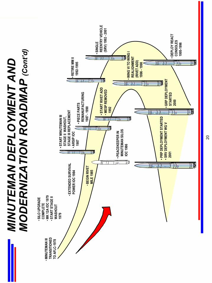
15
An
inte
grat
ed im
prov
emen
t pro
gram
was
sta
rted
in th
e ea
rly 1
970s
. Th
is p
rogr
am in
corp
orat
ed th
e fo
llow
ing
impr
ovem
ents
: EM
P ha
rden
ing,
silo
upg
rade
to
impr
ove
hard
ness
, th
e C
omm
and
Dat
a Bu
ffer
for
rem
ote
prog
ram
min
g of
the
gui
danc
e sy
stem
, an
d du
st h
arde
ning
of
the
MM
III P
ropu
lsio
n S
yste
m R
ocke
t En
gine
(P
SR
E) b
y in
stal
ling
cove
rs o
ver t
he a
ttitu
de c
ontro
l mot
ors.
Oth
er s
igni
fican
t mile
ston
es in
the
Min
utem
an s
yste
m d
eplo
ymen
t wer
e th
e R
ivet
SAV
E p
rogr
am w
hich
allo
wed
a
one-
third
red
uctio
n in
the
cre
w f
orce
; th
e St
age
2 W
asho
ut a
nd S
tage
3 re
plac
emen
t of
age
d-ou
t bo
oste
r m
otor
s; th
e Ac
cura
cy, R
elia
bilit
y, a
nd S
uppo
rtabi
lity
Impr
ovem
ent P
rogr
am (A
RS
IP) f
or th
e M
M II
NS-
17 M
GS
; th
e pa
rtial
repl
acem
ent o
f LF
batte
ries
with
hig
h-lif
e lit
hium
sto
rage
bat
terie
s fo
r ext
ende
d su
rviv
able
pow
er; a
nd
the
Riv
et M
inut
eman
Inte
grat
ed L
ife E
xten
sion
(MIL
E) d
epot
leve
lmai
nten
ance
pro
gram
.
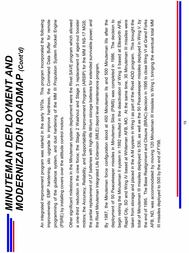
By
1987
, th
e M
inut
eman
for
ce c
onfig
urat
ion
stoo
d at
450
Min
utem
anIIs
and
500
Min
utem
anIII
saf
ter
the
depl
oym
ent o
f 50
Pea
ceke
eper
mis
sile
s in
Min
utem
an S
ilos
(PIM
S)
was
com
plet
ed in
198
6.
The
deci
sion
to
begi
n re
tirin
g th
e M
inut
eman
II s
yste
m in
199
2 re
sulte
d in
the
deac
tivat
ion
of W
ing
II ba
sed
at E
llsw
orth
AFB
, R
apid
City
, SD
and
Win
g IV
bas
ed a
tWhi
tem
anA
FB, M
O.
At t
he s
ame
time,
30
Min
utem
an II
I mis
sile
s w
ere
take
n fro
m s
tora
ge a
nd p
lace
d in
the
A-M
sys
tem
in W
ing
I as
part
of th
e R
ivet
AD
D p
rogr
am.
This
bro
ught
the
tota
l of M
inut
eman
III m
issi
les
depl
oyed
to 5
30, a
s w
ell a
s th
e 50
Pea
ceke
eper
mis
sile
s de
ploy
ed in
Win
g V
, by
the
end
of 1
995.
The
Bas
e R
ealig
nmen
t and
Clo
sure
(BR
AC) d
ecis
ion
in 1
995
to c
lose
Win
g V
I at G
rand
For
ks
AFB
, ND
, was
acc
omm
odat
ed b
y m
ovin
g 12
0 M
inut
eman
III m
issi
les
to W
ing
I, br
ingi
ng th
e ev
entu
al to
tal M
M
III m
issi
les
depl
oyed
to 5
00 b
y th
e en
d of
FY9
8.
MIN
UTE
MA
N D
EPLO
YMEN
T A
ND
M
OD
ERN
IZA
TIO
N R
OA
DM
AP
(Con
t’d)
19
MIN
UTE
MA
N D
EPLO
YMEN
T A
ND
M
OD
ERN
IZA
TIO
N R
OA
DM
AP
(Con
t’d)
•EXT
ENDE
D SU
RVIV
ALPO
WER
IOC
1984
•PRP
DEP
LOYM
ENT
STAR
TED
•SRV
DEP
LOYM
ENT
WG
V20
01
• PEA
CEKE
EPER
INMI
NUTE
MAN
SILO
SIO
C 19
86
•BEG
IN R
IVET
MILE
1985
• STA
RT M
INUT
EMAN
IIIST
AGE
II W
ASHO
UT,
STAG
E III
REPL
ACEM
ENT
• ARS
IP IO
C19
87
• STA
RT R
IVET
ADD
•MES
P RE
MOVE
D19
92
• RET
IRE
MM II
1992
-199
5
•SIL
O UP
GRAD
ECO
MPLE
TE•M
K 12
A IO
C 19
79•S
TART
STA
GE II
WAS
HOUT
1979
• DEP
LOY
REAC
TCO
NSOL
ES19
95-1
996
• GRP
DEP
LOYM
ENT
STAR
TED
2000
•MIN
UTEM
AN III
TRAN
SITI
ONED
TO A
FLC-
1978
• PIE
CE P
ARTS
REMA
NUFA
CTUR
ING
1987
-19
90
• WIN
G VI
TO
WIN
G I
REAL
IGNM
ENT
(RIV
ET A
DD)
1996
-19
98
• SIN
GLE
REEN
TRY
VEHI
CLE
(SRV
) 199
2 -20
01
20
ICB
M L
ON
G-R
AN
GE
REQ
UIR
EMEN
TS P
LAN
NIN
GTh
e ob
ject
ive
of th
e IC
BM
Lon
g-ra
nge
Req
uire
men
ts P
lann
ing
(ILR
P)
Pro
gram
is to
iden
tify
the
requ
irem
ents
and
prog
ram
s ne
eded
to s
usta
in IC
BM
per
form
ance
and
sup
port,
mee
t evo
lvin
g m
issi
on r
equi
rem
ents
, and
pro
vide
the
just
ifica
tion
for
prog
ram
adv
ocac
y in
the
bud
get
cycl
e.
The
ILR
P or
gani
zatio
n co
nsis
ts o
f a
wor
king
gro
up a
nd
stee
ring
grou
p he
aded
by
an e
xecu
tive
leve
l com
mitt
ee.
The
ILR
PW
orki
ng a
nd S
teer
ing
Gro
ups,
whi
ch in
clud
e
repr
esen
tativ
es fr
om H
Q A
FSPC
, IC
BM
SP
O, H
Q U
SA
F, 2
0AF,
USS
TRA
TCO
M, S
AF,
and
oth
er a
genc
ies
addr
ess
mis
sion
obj
ectiv
es, l
ogis
tics
supp
ort r
equi
rem
ents
, and
sys
tem
opt
ions
. Th
e us
ing
com
man
d, H
Q A
FSP
C, d
efin
es
perfo
rman
ce s
hortf
alls
and
/or
need
ed s
yste
m e
nhan
cem
ents
whi
le t
he I
CB
M S
PO
det
erm
ines
the
acq
uisi
tion
appr
oach
and
ass
ocia
ted
sche
dule
and
cos
t est
imat
es fo
r th
e IC
BM
Mas
ter
Pla
n (fo
rmer
ly c
alle
d th
e Tw
enty
-yea
r
Tech
nica
l Pla
n).
The
first
Tw
enty
-Yea
r Tec
hnic
al P
lan
was
initi
ated
in 1
985.
It u
sed
exis
ting
Pro
gram
Obj
ectiv
e M
emor
andu
m (P
OM
)
year
pro
gram
s as
a s
tarti
ng p
oint
, de
fined
ord
erly
and
cos
t-effe
ctiv
e fu
ture
sys
tem
req
uire
men
ts,
and
stru
ctur
ed
prog
ram
s to
acc
ompl
ish
coor
dina
ted
syst
em im
prov
emen
ts to
ext
end
the
Min
utem
an II
and
III
life
cycl
es.
Due
to
adva
ncin
g ag
e, n
umer
ous
com
pone
nts
in t
he m
issi
le a
nd o
pera
tiona
l gr
ound
equ
ipm
ent
(OG
E)
wer
e be
com
ing
logi
stic
ally
uns
uppo
rtabl
e. M
ajor
ext
ende
d lif
e an
d m
issi
on e
nhan
cem
ent p
rogr
ams
wer
e di
rect
ed to
mee
t pro
ject
ed
long
rang
e ne
eds,
as
show
n in
the
road
map
bel
ow.
21
MIN
UTE
MA
N R
OA
DM
AP
-WH
ERE
WE
AR
E G
OIN
G
CONT
INUE
D DE
POT
MAIN
TENA
NCE
RIVE
T MI
LE
• GUI
DANC
ERE
PLAC
EMEN
TPR
OGRA
M (G
RP)
FOC
-200
8• P
ROPU
LSIO
N RE
PLAC
EMEN
TPR
OGRA
M (P
RP)
FOC
-200
8
• MIL
STAR
EHF
FOC
-200
3
• SAF
ETY
ENHA
NCED
REEN
TRY
VEHI
CLE
(SER
V) F
OC -
2009
• PSR
E LI
FEEX
TENS
ION
PROG
RAM
FOC
-201
0
MINU
TEMA
N IV
PLAN
NING
AND
DEV
ELOP
MENT
22
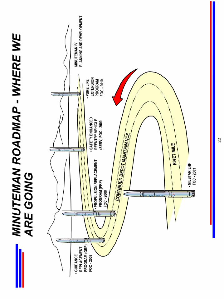
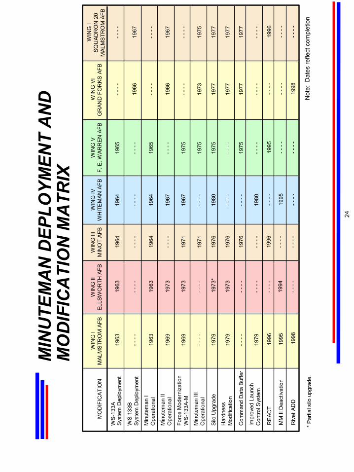
The
follo
win
g ta
ble
show
s th
e in
itial
dep
loym
ent d
ates
for t
he M
inut
eman
I sy
stem
(WS
-133
A) a
nd
Min
utem
an II
sys
tem
(WS
-133
B) a
long
with
sub
sequ
ent m
oder
niza
tion
and
mod
ifica
tion
com
plet
ion
date
s.
For
a de
taile
d re
view
of t
he M
inut
eman
Wea
pon
Sys
tem
ref
er to
the
follo
win
g M
inut
eman
Aer
ospa
ce V
ehic
le, O
GE
, Ord
nanc
e an
d C
hron
olog
y se
ctio
ns.
MIN
UTE
MA
N D
EPLO
YMEN
T A
ND
M
OD
ERN
IZA
TIO
N M
ATR
IX
23
MIN
UTE
MA
N D
EPLO
YMEN
T A
ND
M
OD
IFIC
ATI
ON
MA
TRIX
MO
DIF
ICA
TIO
NW
ING
IM
ALM
STR
OM
AFB
WIN
G II
ELL
SWO
RTH
AFB
WIN
G II
IM
INO
T AF
BW
ING
IVW
HIT
EM
AN A
FBW
ING
VF.
E. W
ARR
EN
AFB
WIN
G V
IG
RAN
D F
OR
KS
AFB
WIN
G I
SQ
UAD
RO
N 2
0M
ALM
STR
OM
AFB
WS-
133A
Sys
tem
Dep
loym
ent
WS
133B
Sys
tem
Dep
loym
ent
Min
utem
an I
Ope
ratio
nal
Min
utem
an II
Ope
ratio
nal
Forc
e M
oder
niza
tion
WS-
133A
-M
Min
utem
an II
IO
pera
tiona
l
Silo
Upg
rade
Har
dnes
sM
odifi
catio
n
Com
man
d D
ata
Buf
fer
Impr
oved
Lau
nch
Con
trol S
yste
m
1963
----
1963
1969
1969
----
1979
1979
----
1979
1963
----
1963
1973
1973
----
1973
*
1973
----
----
1964
----
1964
----
1971
1971
1976
1976
1976
----
1964
----
1964
1967
1967
----
1980
----
----
1980
----
1966
----
1966
----
1973
1977
1977
1977
----
1965
----
1965
----
1975
1975
1975
----
1975
----
----
1967
----
1967
----
1975
1977
1977
1977
----
* P
artia
l silo
upg
rade
.
RE
ACT
1996
----
----
1995
1996
----
1996
MM
II D
eact
ivat
ion
1995
1995
----
----
----
1994
----
Riv
et A
DD
1998
----
1998
----
----
----
----
Not
e: D
ates
refle
ct c
ompl
etio
n
24
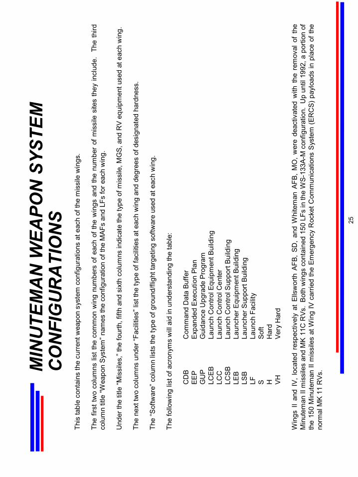
This
tabl
e co
ntai
ns th
e cu
rren
t wea
pon
syst
em c
onfig
urat
ions
at e
ach
of th
e m
issi
le w
ings
.
The
first
two
colu
mns
list
the
com
mon
win
g nu
mbe
rs o
f eac
h of
the
win
gs a
nd th
e nu
mbe
r of
mis
sile
site
s th
ey in
clud
e.
The
third
colu
mn
title
“Wea
pon
Sys
tem
” nam
es th
e co
nfig
urat
ion
of th
eM
AFs
and
LFs
for e
ach
win
g.
Und
er th
e tit
le “M
issi
les,
” the
four
th, f
ifth
and
sixt
h co
lum
ns in
dica
te th
e ty
pe o
f mis
sile
, MG
S, a
nd R
V eq
uipm
ent u
sed
at e
ach
win
g.
The
next
two
colu
mns
und
er “F
acili
ties”
list
the
type
of f
acili
ties
at e
ach
win
g an
d de
gree
s of
des
igna
ted
hard
ness
.
The
“Sof
twar
e” c
olum
n lis
ts th
e ty
pe o
f gro
und/
fligh
t tar
getin
g so
ftwar
e us
ed a
t eac
h w
ing.
The
follo
win
g lis
t of a
cron
yms
will
aid
in u
nder
stan
ding
the
tabl
e:
CD
BC
omm
and
Dat
a Bu
ffer
EEP
Expa
nded
Exe
cutio
n Pl
anG
UP
Gui
danc
e U
pgra
de P
rogr
amLC
EB
Laun
ch C
ontro
l Equ
ipm
ent B
uild
ing
LCC
Laun
ch C
ontro
l Cen
ter
LCS
BLa
unch
Con
trol S
uppo
rt Bu
ildin
gLE
BLa
unch
er E
quip
men
t Bui
ldin
gLS
BLa
unch
er S
uppo
rt Bu
ildin
gLF
Laun
ch F
acili
tyS
Soft
HH
ard
VHVe
ry H
ard
Win
gs I
I an
d IV
, lo
cate
d re
spec
tivel
y at
Ells
wor
th A
FB,
SD,
and
Whi
tem
an A
FB,
MO
, w
ere
deac
tivat
ed w
ith t
he r
emov
al o
f th
e M
inut
eman
II m
issi
les
and
MK
11C
RVs
. B
oth
win
gs c
onta
ined
150
LFs
in th
e W
S-13
3A-M
con
figur
atio
n. U
p un
til 1
992,
a p
ortio
n of
th
e 15
0 M
inut
eman
II m
issi
les
at W
ing
IV c
arrie
d th
e Em
erge
ncy
Roc
ket C
omm
unic
atio
ns S
yste
m (E
RC
S) p
aylo
ads
in p
lace
of t
he
norm
al M
K 11
RVs
.MIN
UTE
MA
N W
EAPO
N S
YSTE
M
CO
NFI
GU
RA
TIO
NS 25
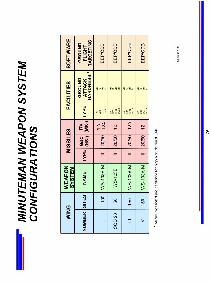
MIN
UTE
MA
N W
EAPO
N S
YSTE
M
CO
NFI
GU
RA
TIO
NS
WIN
GW
EAPO
NSY
STEM
MIS
SILE
SFA
CIL
ITIE
SSO
FTW
ARE
FLIG
HT
TAR
GET
ING
150
IIII
20/5
0E
EP
/CD
B12
/12
AW
S-1
33A
-MLF LS
BLC
CLC
SB
VH S VH S
150
IIIIII
20/5
0E
EP
/CD
B12
AW
S-1
33A
-MLF LS
BLC
CLC
EB
VH S VH H
150
VIII
20/5
0E
EP
/CD
B12
WS
-133
A-M
LF LSB
LCC
LCE
B
VH S VH H
50S
QD
20
III20
/50
EE
P/C
DB
12W
S-1
33B
LF LEB
LCC
LCE
B
VH S VH
VH
NU
MB
ERSI
TES
NAM
ETY
PEG
&C
(NS-
)TY
PER
V(M
K-)
GR
OU
ND
ATTA
CK
HAR
DN
ESS
*
GR
OU
ND
*All
faci
litie
s lis
ted
are
hard
ened
for h
igh
altit
ude
burs
t EM
P
Upd
ated
4/0
1
26
This
sec
tion
prov
ides
an
over
view
of
maj
or f
eatu
res
of e
ach
Min
utem
an m
issi
le c
onfig
urat
ion
and
disc
usse
s M
inut
eman
flig
ht c
ontro
l, pr
opul
sion
, mis
sile
gui
danc
e an
d re
entry
sys
tem
s. T
he
tabl
e be
low
pro
vide
s so
me
mas
s pr
oper
ties
data
for M
inut
eman
I, M
inut
eman
II, a
nd M
inut
eman
III.
The
cha
rts w
hich
fol
low
det
ail
info
rmat
ion
conc
erni
ng e
ach
stag
e of
Min
utem
an I
I an
d
Min
utem
an II
I mis
sile
s, a
nd d
escr
ibe
the
mis
sile
gui
danc
e, fl
ight
con
trol,
and
reen
try s
yste
ms.
SEC
TIO
N T
WO
MIN
UTE
MA
N
AER
OSP
AC
E VE
HIC
LE E
QU
IPM
ENT
27
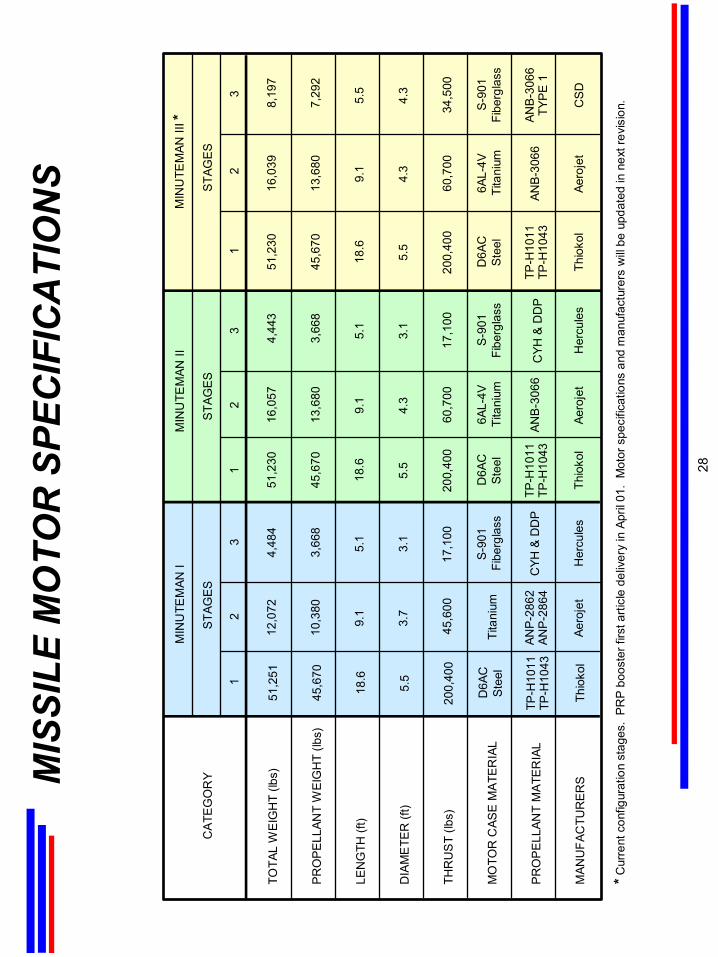
MIS
SILE
MO
TOR
SPE
CIF
ICA
TIO
NS
TOTA
L W
EIG
HT
(lbs)
PR
OP
ELL
ANT
WE
IGH
T (lb
s)
LEN
GTH
(ft)
DIA
ME
TER
(ft)
THR
US
T (lb
s)
MO
TOR
CAS
E M
ATE
RIA
L
PR
OP
ELL
ANT
MA
TER
IAL
MAN
UFA
CTU
RE
RS
MIN
UTE
MAN
IM
INU
TEM
AN II
MIN
UTE
MAN
III *
STA
GE
SS
TAG
ES
STA
GE
S
12
31
23
12
3
51,2
51
45,6
70
18.6
5.5
200,
400
D6A
CS
teel
TP-H
1011
TP-H
1043
Thio
kol
12,0
72
10,3
80
9.1
3.7
45,6
00
Tita
nium
ANP-
2862
ANP-
2864
Aero
jet
4,48
4
3,66
8
5.1
3.1
17,1
00
S-9
01Fi
berg
lass
CYH
& D
DP
Her
cule
s
51,2
30
45,6
70
18.6
5.5
200,
400
D6A
CS
teel
TP-H
1011
TP-H
1043
Thio
kol
16,0
57
13,6
80
9.1
4.3
60,7
00
6AL-
4VTi
tani
um
ANB-
3066
Aero
jet
4,44
3
3,66
8
5.1
3.1
17,1
00
S-9
01Fi
berg
lass
CYH
& D
DP
Her
cule
s
51,2
30
45,6
70
18.6
5.5
200,
400
D6A
CS
teel
TP-H
1011
TP-H
1043
Thio
kol
16,0
39
13,6
80
9.1
4.3
60,7
00
6AL-
4VTi
tani
um
ANB-
3066
Aero
jet
8,19
7
7,29
2
5.5
4.3
34,5
00
S-9
01Fi
berg
lass
ANB-
3066
TYPE
1
CS
D
CA
TEG
OR
Y
*Cur
rent
con
figur
atio
n st
ages
. P
RP
boo
ster
firs
t arti
cle
deliv
ery
in A
pril
01.
Mot
or s
peci
ficat
ions
and
man
ufac
ture
rs w
ill be
upd
ated
in n
ext r
evis
ion.
28

Min
utem
an I
was
a h
ighl
y re
liabl
e, th
ree-
stag
e, s
olid
-pro
pella
nt w
eapo
n, c
apab
le o
f with
stan
ding
stor
age
in a
n al
ert
read
y co
nditi
on f
or lo
ng p
erio
ds o
f tim
e.
It ha
d a
rang
e of
wel
l ove
r 5,
000
naut
ical
mile
s an
d its
iner
tial g
uida
nce
syst
em o
pera
ted
cont
inuo
usly
. A
dvan
ces
in te
chno
logy
and
chan
ges
in n
atio
nal p
olic
y in
duce
d im
prov
emen
ts in
the
orig
inal
des
ign.
Phys
ical
cha
nges
in M
inut
eman
I, II
, and
III m
issi
les
are
the
resu
lt of
per
form
ance
impr
ovem
ents
that
hav
e ta
ken
plac
e ov
er th
e lif
e of
the
wea
pon
syst
em.
MIN
UTE
MA
N I
MA
JOR
FEA
TUR
ES
29
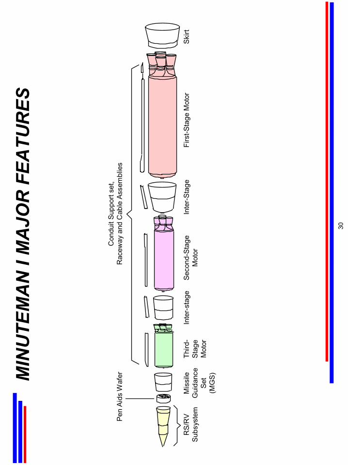
MIN
UTE
MA
N I
MA
JOR
FEA
TUR
ES
Con
duit
Supp
ort s
et,
Rac
eway
and
Cab
le A
ssem
blie
s
RS/
RV
Subs
yste
mM
issi
leG
uida
nce
Set
(MG
S)
Third
-St
age
Mot
or
Seco
nd-S
tage
Mot
orIn
ter-
Stag
eFi
rst-S
tage
Mot
orSk
irtIn
ter-
stag
e
Pen
Aids
Waf
er
30
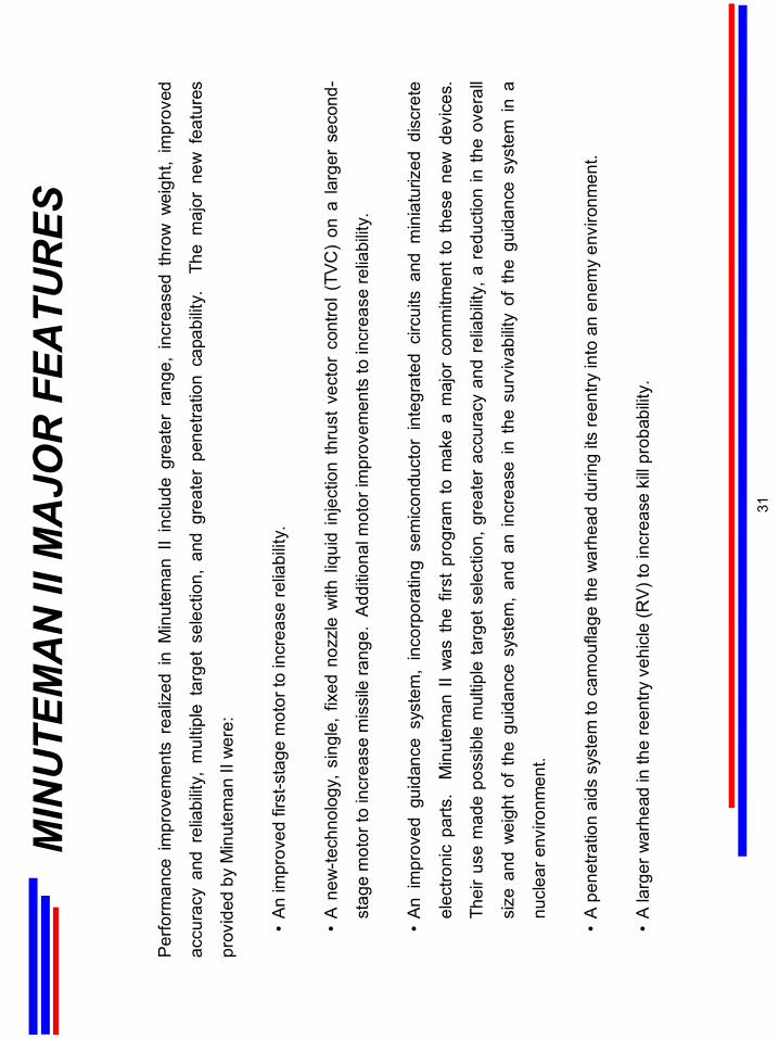
Perfo
rman
ce i
mpr
ovem
ents
rea
lized
in
Min
utem
an I
I in
clud
e gr
eate
r ra
nge,
inc
reas
ed t
hrow
wei
ght,
impr
oved
accu
racy
and
rel
iabi
lity,
mul
tiple
tar
get
sele
ctio
n, a
nd g
reat
erpe
netra
tion
capa
bilit
y.
The
maj
or n
ew f
eatu
res
prov
ided
by
Min
utem
an II
wer
e:
•An
impr
oved
firs
t-sta
ge m
otor
to in
crea
se re
liabi
lity.
•A
new
-tech
nolo
gy, s
ingl
e, f
ixed
noz
zle
with
liqu
id in
ject
ion
thru
st v
ecto
r co
ntro
l (TV
C)
on a
larg
er s
econ
d-
stag
e m
otor
to in
crea
se m
issi
le ra
nge.
Add
ition
al m
otor
impr
ovem
ents
to in
crea
se re
liabi
lity.
•An
im
prov
ed g
uida
nce
syst
em,
inco
rpor
atin
g se
mic
ondu
ctor
int
egra
ted
circ
uits
and
min
iatu
rized
dis
cret
e
elec
troni
c pa
rts.
Min
utem
an I
I w
as t
he f
irst
prog
ram
to
mak
e a
maj
or c
omm
itmen
t to
the
se n
ew d
evic
es.
Thei
r us
e m
ade
poss
ible
mul
tiple
targ
et s
elec
tion,
gre
ater
acc
urac
y an
d re
liabi
lity,
a r
educ
tion
in th
e ov
eral
l
size
and
wei
ght
of t
he g
uida
nce
syst
em,
and
an in
crea
se in
the
sur
viva
bilit
y of
the
gui
danc
e sy
stem
in a
nucl
ear e
nviro
nmen
t.
•A
pene
tratio
n ai
ds s
yste
m to
cam
oufla
ge th
e w
arhe
ad d
urin
g its
reen
try in
to a
n en
emy
envi
ronm
ent.
•A
larg
er w
arhe
ad in
the
reen
try v
ehic
le (R
V) to
incr
ease
kill
prob
abilit
y.
MIN
UTE
MA
N II
MA
JOR
FEA
TUR
ES
31
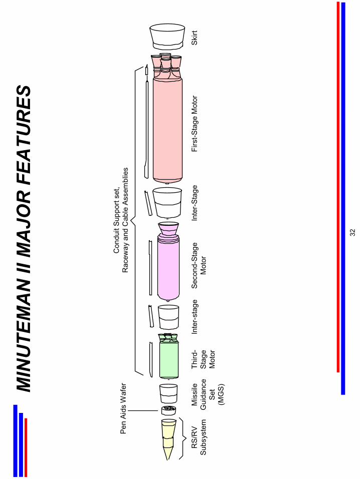
MIN
UTE
MA
N II
MA
JOR
FEA
TUR
ES
Con
duit
Supp
ort s
et,
Rac
eway
and
Cab
le A
ssem
blie
s
RS/
RV
Subs
yste
mM
issi
leG
uida
nce
Set
(MG
S)
Third
-St
age
Mot
or
Seco
nd-S
tage
Mot
orIn
ter-
Stag
eFi
rst-S
tage
Mot
orSk
irtIn
ter-
stag
e
Pen
Aids
Waf
er
32
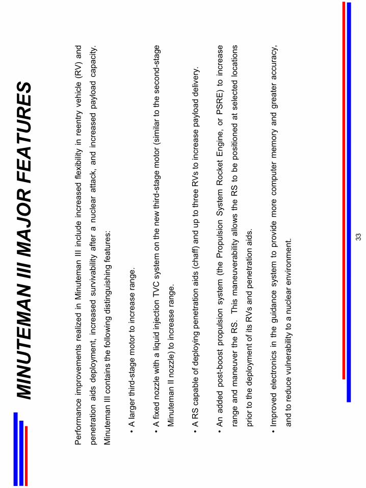
MIN
UTE
MA
N II
I MA
JOR
FEA
TUR
ES
Per
form
ance
impr
ovem
ents
rea
lized
in M
inut
eman
III
incl
ude
incr
ease
d fle
xibi
lity
in r
eent
ry v
ehic
le (
RV)
and
pene
tratio
n ai
ds d
eplo
ymen
t, in
crea
sed
surv
ivab
ility
afte
r a
nucl
ear
atta
ck,
and
incr
ease
d pa
yloa
d ca
paci
ty.
Min
utem
an II
I con
tain
s th
e fo
llow
ing
dist
ingu
ishi
ng fe
atur
es:
•A
larg
er th
ird-s
tage
mot
or to
incr
ease
rang
e.
•A
fixe
d no
zzle
with
a li
quid
inje
ctio
n TV
C s
yste
m o
n th
e ne
w th
ird-s
tage
mot
or (s
imila
r to
the
seco
nd-s
tage
Min
utem
an II
noz
zle)
to in
crea
se ra
nge.
•A
RS
capa
ble
of d
eplo
ying
pen
etra
tion
aids
(cha
ff) a
nd u
p to
thre
e R
Vs to
incr
ease
pay
load
del
iver
y.
•A
n ad
ded
post
-boo
st p
ropu
lsio
n sy
stem
(th
e Pr
opul
sion
Sys
tem
Roc
ket
Eng
ine,
or
PS
RE)
to
incr
ease
rang
e an
d m
aneu
ver
the
RS.
Th
is m
aneu
vera
bilit
y al
low
s th
e R
S to
be
posi
tione
d at
sel
ecte
d lo
catio
ns
prio
r to
the
depl
oym
ent o
f its
RVs
and
pen
etra
tion
aids
.
•Im
prov
ed e
lect
roni
cs in
the
gui
danc
e sy
stem
to
prov
ide
mor
e co
mpu
ter
mem
ory
and
grea
ter
accu
racy
,
and
to re
duce
vul
nera
bilit
y to
a n
ucle
ar e
nviro
nmen
t. 33
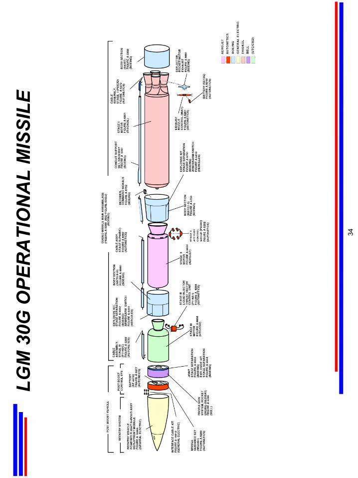
LGM
30G
OPE
RA
TIO
NA
L M
ISSI
LE
34
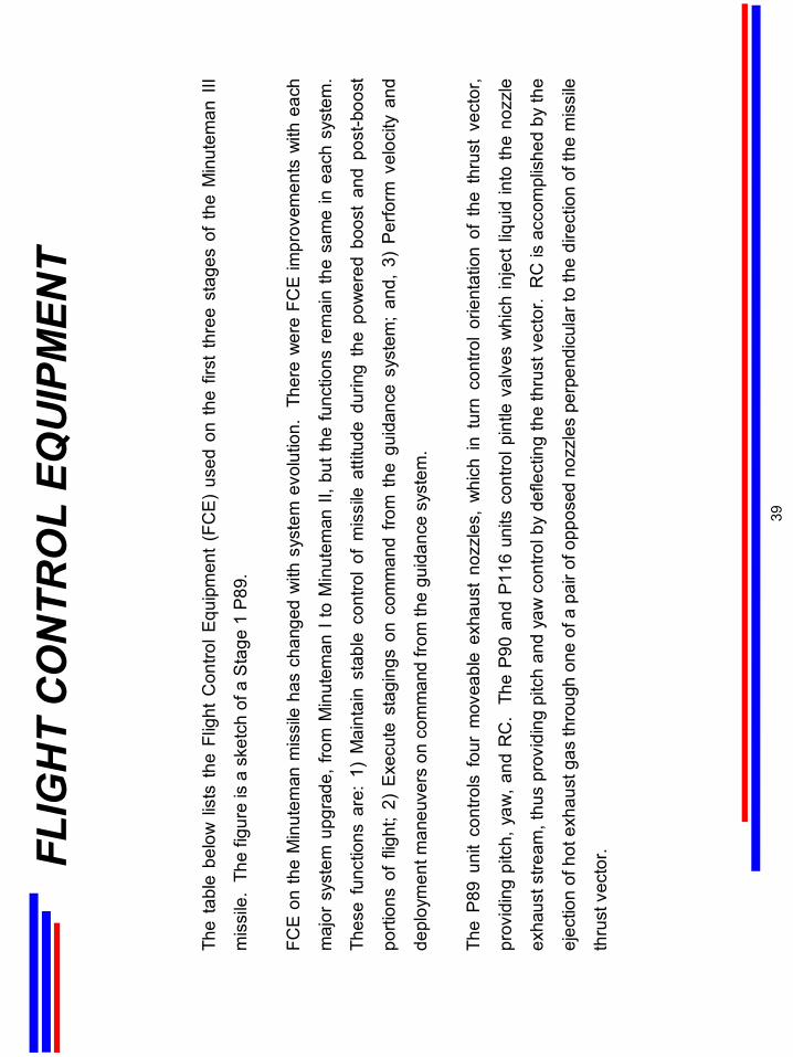
The
tabl
e be
low
list
s th
e Fl
ight
Con
trol E
quip
men
t (F
CE
) us
ed o
nth
e fir
st t
hree
sta
ges
of t
he M
inut
eman
III
mis
sile
. Th
e fig
ure
is a
ske
tch
of a
Sta
ge 1
P89
.
FCE
on th
e M
inut
eman
mis
sile
has
cha
nged
with
sys
tem
evo
lutio
n.
Ther
e w
ere
FCE
impr
ovem
ents
with
eac
h
maj
or s
yste
m u
pgra
de, f
rom
Min
utem
an I
to M
inut
eman
II, b
ut th
e fu
nctio
ns r
emai
n th
e sa
me
in e
ach
syst
em.
Thes
e fu
nctio
ns a
re:
1) M
aint
ain
stab
le c
ontro
l of
mis
sile
atti
tude
dur
ing
the
pow
ered
boo
st a
nd p
ost-b
oost
porti
ons
of f
light
; 2)
Exe
cute
sta
ging
son
com
man
d fro
m t
he g
uida
nce
syst
em;
and,
3)
Perfo
rm v
eloc
ity a
nd
depl
oym
ent m
aneu
vers
on
com
man
d fro
m th
e gu
idan
ce s
yste
m.
The
P89
unit
cont
rols
fou
r m
ovea
ble
exha
ust
nozz
les,
whi
ch in
tur
n co
ntro
l or
ient
atio
n of
the
thr
ust
vect
or,
prov
idin
g pi
tch,
yaw
, and
RC
. Th
e P9
0 an
d P1
16 u
nits
con
trolp
intle
valv
es w
hich
inje
ct li
quid
into
the
nozz
le
exha
ust s
tream
, thu
s pr
ovid
ing
pitc
h an
d ya
w c
ontro
l by
defle
ctin
g th
e th
rust
vec
tor.
RC
is a
ccom
plis
hed
by th
e
ejec
tion
of h
ot e
xhau
st g
as th
roug
h on
e of
a p
air o
f opp
osed
noz
zles
per
pend
icul
ar to
the
dire
ctio
n of
the
mis
sile
thru
st v
ecto
r.FLIG
HT
CO
NTR
OL
EQU
IPM
ENT
39
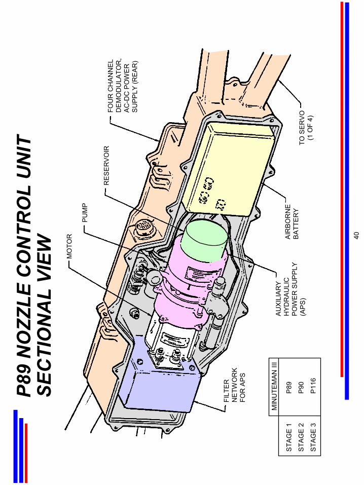
P89
NO
ZZLE
CO
NTR
OL
UN
IT
SEC
TIO
NA
L VI
EW
STA
GE
1P
89
STA
GE
2P
90
STA
GE
3P
116
MIN
UTE
MA
N II
I
MO
TOR
PU
MP
RE
SE
RV
OIR
FOU
R C
HA
NN
EL
DE
MO
DU
LATO
R,
AC
-DC
PO
WE
RS
UP
PLY
(RE
AR
)
FILT
ER
NE
TWO
RK
FOR
AP
S
AU
XIL
IAR
YH
YDR
AU
LIC
PO
WE
R S
UP
PLY
(AP
S)
AIR
BO
RN
EB
ATT
ER
YTO
SE
RV
O(1
OF
4)
40
The
first
-sta
ge m
otor
(com
mon
to b
oth
Min
utem
an II
and
Min
utem
an II
I) co
nsis
ts o
f a s
teel
mot
or c
ase,
a C
lass
1.3
sol
id
prop
ella
nt, a
n ig
nite
r, a
stee
l aft
clos
ure
with
four
mov
eabl
e no
zzle
s, a
nd a
Noz
zle
Con
trol U
nit (
NC
U)
for
TVC
. E
ach
nozz
le is
cap
able
of p
ivot
ing
thro
ugh
an a
ngle
of ±
8 d
egre
es fr
om n
ull,
in a
pla
ne p
aral
lel t
o th
e m
otor
cen
terli
ne a
nd
perp
endi
cula
r to
the
pivo
t pla
nes
of th
e ad
jace
nt n
ozzl
es.
The
mot
or w
as d
esig
ned
and
built
by
the
Thio
kol C
orpo
ratio
n;
the
NC
Us,
whi
ch a
re p
art o
f the
gui
danc
e sy
stem
(Sec
tion
Thre
e), w
ere
desi
gned
and
bui
lt by
Roc
kwel
l Int
erna
tiona
l.
A si
ngle
hig
h-pe
rform
ance
sol
id p
rope
llant
is c
ast i
nto
the
mot
or c
ase
with
a s
ix-p
oint
sta
r ho
llow
cor
e, w
hich
mai
ntai
ns
thru
st b
y ke
epin
g a
cons
tant
sur
face
are
a as
the
pro
pella
nt b
urns
aw
ay.
The
pro
pella
nt c
onsi
sts
of a
n am
mon
ium
perc
hlor
ate
oxid
izer
, alu
min
um p
owde
r fue
l, a
poly
buta
dien
eac
rylic
aci
d bi
nder
, and
an
epox
y-re
sin
curin
g ag
ent.
The
case
ser
ves
as th
e m
issi
le s
truct
ure
with
the
inte
rsta
geat
tach
ed a
t its
forw
ard
end
and
the
skirt
at t
he a
ft en
d. T
he
clos
ure
and
nozz
les
are
insu
late
d fro
m t
he t
herm
al e
ffect
s of
the
cha
mbe
r te
mpe
ratu
re b
y m
olde
d pl
astic
, B
una-
N
rubb
er, m
astic
insu
latio
n, a
nd h
igh-
dens
ity g
raph
ite p
arts
. A
low
-tem
pera
ture
abl
ativ
e ep
oxy
insu
latio
n (A
vcoa
t) pr
otec
ts
the
mot
or c
ase
exte
rior
from
silo
laun
ch, n
ucle
ar th
erm
al, a
nd a
erod
ynam
ic h
eatin
g.
This
mat
eria
l will
be c
hang
ed to
Vam
acru
bber
with
boo
ster
pro
duct
ion
unde
r the
Pro
puls
ion
Rep
lace
men
tPro
gram
(PR
P).
The
nozz
les,
whi
ch m
ove
in re
spon
se to
com
man
ds is
sued
by
the
guid
ance
sys
tem
to th
eN
CU
s, c
ontro
l the
atti
tude
of
the
mis
sile
dur
ing
the
first
sta
ge o
f flig
ht.
The
pair
of la
tera
lly o
ppos
ed n
ozzl
es p
ivot
up
and
dow
n fo
r pitc
h co
ntro
l. T
he
verti
cally
opp
osed
pai
r pi
vot
side
way
s fo
r ya
w c
ontro
l, an
d in
opp
ositi
on f
or r
oll c
ontro
l. A
ll fo
ur n
ozzl
es a
re u
sed
to
mai
ntai
n ro
ll st
abilit
y.
PRO
PULS
ION
STA
GE
1
41
MIN
UTE
MA
N II
I STA
GE
1IG
NIT
ER
PR
OP
ELL
AN
T
STE
EL
CAS
E
NO
ZZLE
S(4
EA
CH
)
29 S
EC
58 S
EC
43.5
SE
C
0 S
EC
6-P
OIN
T S
TAR
CO
RE
YX
ZR
OLL
AX
IS
YAW
AX
IS
MIS
SIL
E A
TTIT
UD
E C
ON
TRO
L
1ST-
STA
GE
PR
OPE
LLA
NT
BU
RN
ING
AFT
CLO
SU
RE
PIT
CH
AX
IS
42
MIN
UTE
MA
N II
IPR
OPU
LSIO
N S
YSTE
M R
OC
KET
EN
GIN
E
PR
OP
ELL
ANT
STO
RA
GE
AS
SEM
BLY
(FU
EL)
180°
PIT
CH
NO
. 3R
OLL
NO
. 3
FOR
WA
RD
YAW
NO
. 2
270°
RO
LL N
O. 4
ARM
/DIS
ARM
SW
ITC
HES
0°PI
TCH
NO
. 4
PITC
H N
O. 1
PRO
PE
LLAN
T S
TOR
AGE
AS
SEM
BLY
OXI
DIZ
ER
AXI
AL
GA
S S
TOR
AGE
AS
SY
YAW
NO
. 1
90°
PIT
CH
NO
. 2RO
LL N
O. 2
48
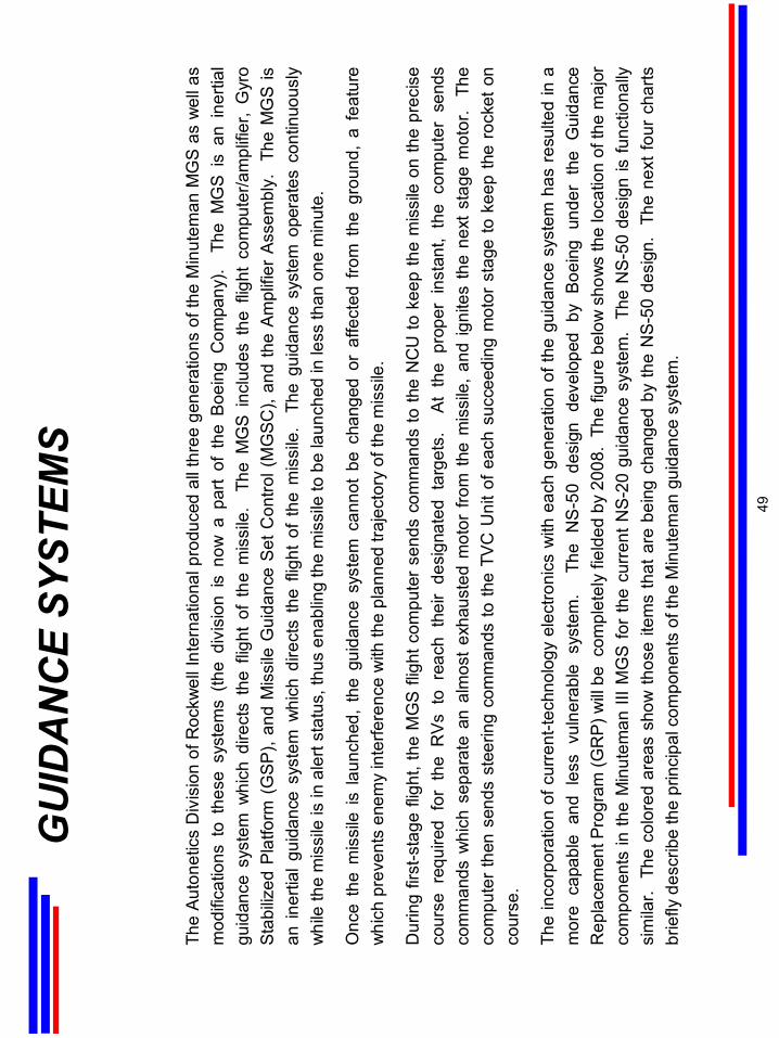
GU
IDA
NC
E SY
STEM
S
The
Auto
netic
sD
ivis
ion
of R
ockw
ell I
nter
natio
nal p
rodu
ced
all t
hree
gen
erat
ions
of t
he M
inut
eman
MG
S a
s w
ell a
s m
odifi
catio
ns t
o th
ese
syst
ems
(the
divi
sion
is
now
a p
art
of t
he B
oein
g C
ompa
ny).
The
MG
S i
s an
ine
rtial
gu
idan
ce s
yste
m w
hich
dire
cts
the
fligh
t of
the
mis
sile
. T
he M
GS
incl
udes
the
flig
ht c
ompu
ter/a
mpl
ifier
, G
yro
Stab
ilized
Pla
tform
(G
SP),
and
Mis
sile
Gui
danc
e S
et C
ontro
l (M
GS
C),
and
the
Am
plifi
er A
ssem
bly.
Th
e M
GS
is
an in
ertia
l gui
danc
e sy
stem
whi
ch d
irect
s th
e fli
ght
of t
he m
issi
le.
The
gui
danc
e sy
stem
ope
rate
s co
ntin
uous
ly
whi
le th
e m
issi
le is
in a
lert
stat
us, t
hus
enab
ling
the
mis
sile
to b
e la
unch
ed in
less
than
one
min
ute.
Onc
e th
e m
issi
le is
laun
ched
, th
e gu
idan
ce s
yste
m c
anno
t be
cha
nged
or
affe
cted
fro
m t
he g
roun
d, a
fea
ture
w
hich
pre
vent
s en
emy
inte
rfere
nce
with
the
plan
ned
traje
ctor
y of
the
mis
sile
.
Dur
ing
first
-sta
ge fl
ight
, the
MG
S fli
ght c
ompu
ter
send
s co
mm
ands
to th
e N
CU
to k
eep
the
mis
sile
on
the
prec
ise
cour
se r
equi
red
for
the
RV
s to
rea
ch t
heir
desi
gnat
ed t
arge
ts.
At
the
prop
er i
nsta
nt,
the
com
pute
r se
nds
com
man
ds w
hich
sep
arat
e an
alm
ost
exha
uste
d m
otor
fro
m t
he m
issi
le,
and
igni
tes
the
next
sta
ge m
otor
. T
he
com
pute
r the
n se
nds
stee
ring
com
man
ds to
the
TVC
Uni
t of e
ach
succ
eedi
ng m
otor
sta
ge to
kee
p th
e ro
cket
on
cour
se.
The
inco
rpor
atio
n of
cur
rent
-tech
nolo
gy e
lect
roni
cs w
ith e
ach
gene
ratio
n of
the
guid
ance
sys
tem
has
res
ulte
d in
a
mor
e ca
pabl
e an
d le
ss v
ulne
rabl
e sy
stem
. T
he N
S-5
0 de
sign
dev
elop
ed b
y Bo
eing
und
er t
he G
uida
nce
Rep
lace
men
t Pro
gram
(GR
P) w
ill be
com
plet
ely
field
ed b
y 20
08.
The
figur
e be
low
sho
ws
the
loca
tion
of th
e m
ajor
co
mpo
nent
s in
the
Min
utem
an II
I MG
S fo
r th
e cu
rren
t NS
-20
guid
ance
sys
tem
. Th
e N
S-50
des
ign
is fu
nctio
nally
si
mila
r. T
he c
olor
ed a
reas
sho
w th
ose
item
s th
at a
re b
eing
cha
nged
by
the
NS-
50 d
esig
n.
The
next
four
cha
rts
brie
fly d
escr
ibe
the
prin
cipa
l com
pone
nts
of th
e M
inut
eman
gui
danc
e sy
stem
.
49
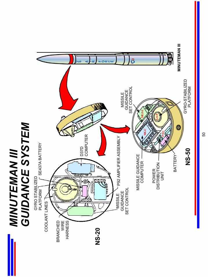
MIN
UTE
MA
N II
I G
UID
AN
CE
SYST
EM
MIN
UTE
MA
N II
I
SE
437A
BA
TTE
RY
GYR
O S
TAB
ILIZ
ED
P
LATF
OR
MC
OO
LAN
T LI
NE
S
BR
AN
CH
ED
WIR
EH
AR
NE
SS
MIS
SIL
EG
UID
AN
CE
SE
T C
ON
TRO
L
P92
AM
PLI
FIE
R A
SSE
MB
LY
D37
DC
OM
PU
TER
NS-
20
NS-
50G
YRO
-STA
BIL
IZE
DP
LATF
OR
M
BA
TTE
RY
PO
WE
R
DIS
TRIB
UTI
ON
U
NIT
MGSC
MGC
GSP
MIS
SIL
E G
UID
AN
CE
C
OM
PU
TER
PDU
50
MIS
SIL
EG
UID
AN
CE
SE
T C
ON
TRO
L
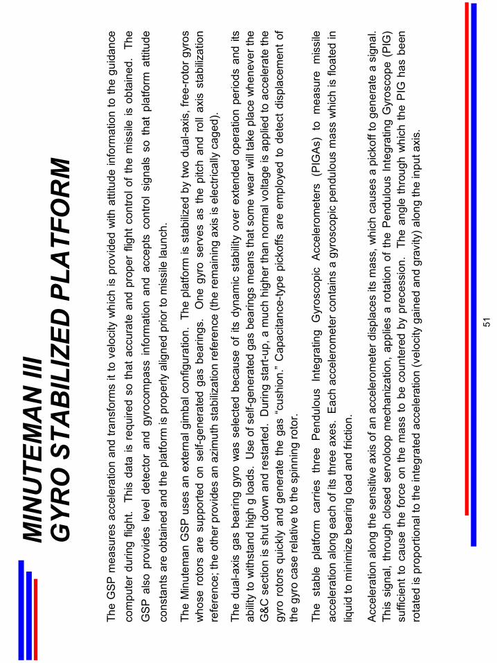
MIN
UTE
MA
N II
I G
YRO
STA
BIL
IZED
PLA
TFO
RM
The
GSP
mea
sure
s ac
cele
ratio
n an
d tra
nsfo
rms
it to
vel
ocity
whi
ch is
pro
vide
d w
ith a
ttitu
de in
form
atio
n to
the
guid
ance
co
mpu
ter
durin
g fli
ght.
Thi
s da
ta is
req
uire
d so
that
acc
urat
e an
d pr
oper
flig
ht c
ontro
l of t
he m
issi
le is
obt
aine
d.
The
GS
P a
lso
prov
ides
lev
el d
etec
tor
and
gyro
com
pass
info
rmat
ion
and
acce
pts
cont
rol
sign
als
so t
hat
plat
form
atti
tude
co
nsta
nts
are
obta
ined
and
the
plat
form
is p
rope
rly a
ligne
d pr
ior t
o m
issi
le la
unch
.
The
Min
utem
an G
SP u
ses
an e
xter
nalg
imba
lcon
figur
atio
n. T
he p
latfo
rm is
sta
biliz
ed b
y tw
o du
al-a
xis,
free
-rot
or g
yros
w
hose
rot
ors
are
supp
orte
d on
sel
f-gen
erat
ed g
as b
earin
gs.
One
gyr
o se
rves
as
the
pitc
h an
d ro
ll ax
is s
tabi
lizat
ion
refe
renc
e; th
e ot
her p
rovi
des
an a
zim
uth
stab
ilizat
ion
refe
renc
e(th
e re
mai
ning
axi
s is
ele
ctric
ally
cag
ed).
The
dual
-axi
s ga
s be
arin
g gy
ro w
as s
elec
ted
beca
use
of it
s dy
nam
ic s
tabi
lity
over
ext
ende
d op
erat
ion
perio
ds a
nd it
s ab
ility
to w
ithst
and
high
g lo
ads.
Use
of s
elf-g
ener
ated
gas
bea
rings
mea
ns th
at s
ome
wea
r will
take
pla
ce w
hene
ver t
he
G&C
sec
tion
is s
hut d
own
and
rest
arte
d. D
urin
g st
art-u
p, a
muc
h hi
gher
than
nor
mal
vol
tage
is a
pplie
d to
acc
eler
ate
the
gyro
rot
ors
quic
kly
and
gene
rate
the
gas
“cus
hion
.” C
apac
itanc
e-ty
pe p
icko
ffs a
re e
mpl
oyed
to d
etec
t di
spla
cem
ent
of
the
gyro
cas
e re
lativ
e to
the
spin
ning
roto
r.
The
stab
le p
latfo
rm c
arrie
s th
ree
Pend
ulou
s In
tegr
atin
g G
yros
copi
c A
ccel
erom
eter
s (P
IGA
s) t
o m
easu
re m
issi
le
acce
lera
tion
alon
g ea
ch o
f its
thre
e ax
es.
Eac
h ac
cele
rom
eter
con
tain
s a
gyro
scop
ic p
endu
lous
mas
s w
hich
is fl
oate
d in
liq
uid
to m
inim
ize
bear
ing
load
and
fric
tion.
Acce
lera
tion
alon
g th
e se
nsiti
ve a
xis
of a
n ac
cele
rom
eter
dis
plac
es it
s m
ass,
whi
ch c
ause
s a
pick
off t
o ge
nera
te a
sig
nal.
Th
is s
igna
l, th
roug
h cl
osed
serv
oloo
pm
echa
niza
tion,
app
lies
a ro
tatio
n of
the
Pen
dulo
us In
tegr
atin
g G
yros
cope
(PI
G)
suffi
cien
t to
caus
e th
e fo
rce
on th
e m
ass
to b
e co
unte
red
by p
rece
ssio
n.
The
angl
e th
roug
h w
hich
the
PIG
has
bee
n ro
tate
d is
pro
porti
onal
to th
e in
tegr
ated
acc
eler
atio
n (v
eloc
ityga
ined
and
gra
vity
) alo
ng th
e in
put a
xis.
51
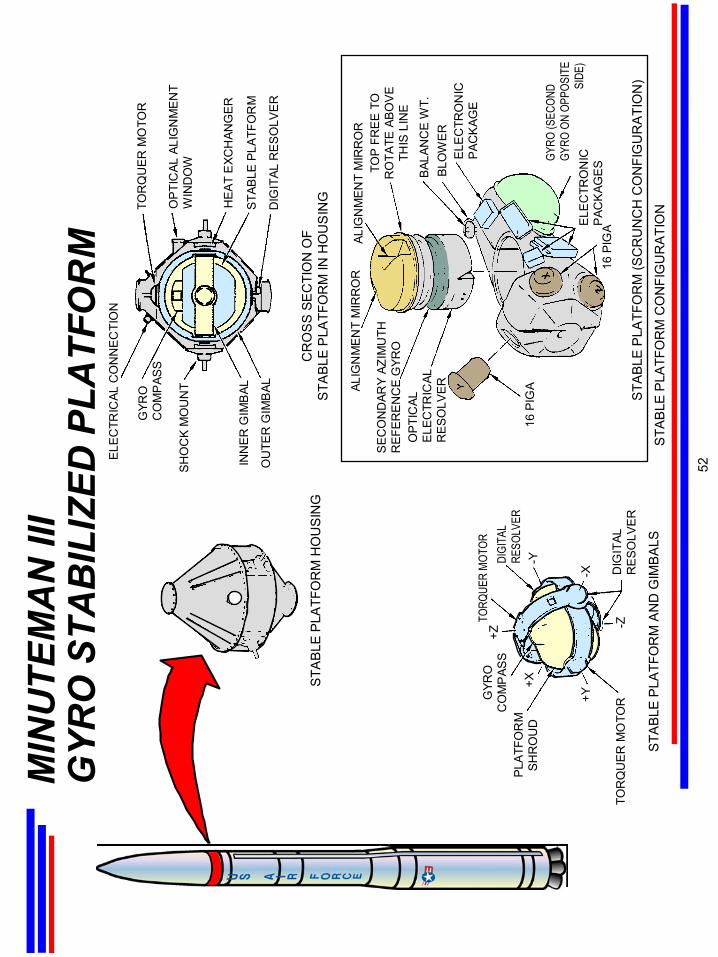
MIN
UTE
MA
N II
I G
YRO
STA
BIL
IZED
PLA
TFO
RM
ALIG
NM
EN
T M
IRR
OR
SE
CO
ND
ARY
AZIM
UTH
R
EFE
RE
NC
E G
YRO
OP
TIC
ALE
LEC
TRIC
ALR
ES
OLV
ER
DIG
ITAL
RE
SO
LVE
R
TOP
FR
EE
TO
RO
TATE
AB
OV
ETH
IS L
INE
BLO
WE
R
GYRO
(SEC
OND
GYRO
ON
OPPO
SITE
SIDE
)E
LEC
TRO
NIC
PAC
KAG
ES
DIG
ITAL
RE
SO
LVE
R
STA
BLE
PLA
TFO
RM
CO
NFI
GU
RA
TIO
N
STA
BLE
PLA
TFO
RM
(SC
RU
NC
H C
ON
FIG
UR
ATI
ON
)
16 P
IGA
BAL
ANC
E W
T.
STA
BLE
PLA
TFO
RM
AN
D G
IMB
ALS
STA
BLE
PLA
TFO
RM
HE
AT
EXC
HAN
GE
R
OP
TIC
AL A
LIG
NM
EN
TW
IND
OW
TOR
QU
ER
MO
TOR
OU
TER
GIM
BAL
INN
ER
GIM
BAL
SH
OC
K M
OU
NT
ELE
CTR
ICAL
CO
NN
EC
TIO
N
ALIG
NM
EN
T M
IRR
OR
STA
BLE
PLA
TFO
RM
HO
US
ING
CR
OS
S S
EC
TIO
N O
FS
TAB
LE P
LATF
OR
M IN
HO
US
ING
-X
-YDIGI
TAL
RESO
LVER
TORQ
UER
MOTO
R+Z
-Z
+X
+YGYR
OC
OM
PAS
SP
LATF
OR
MS
HR
OU
D
TOR
QU
ER
MO
TOR
GYR
OC
OM
PAS
S
ELE
CTR
ON
ICP
ACK
AGE
16 P
IGA
52
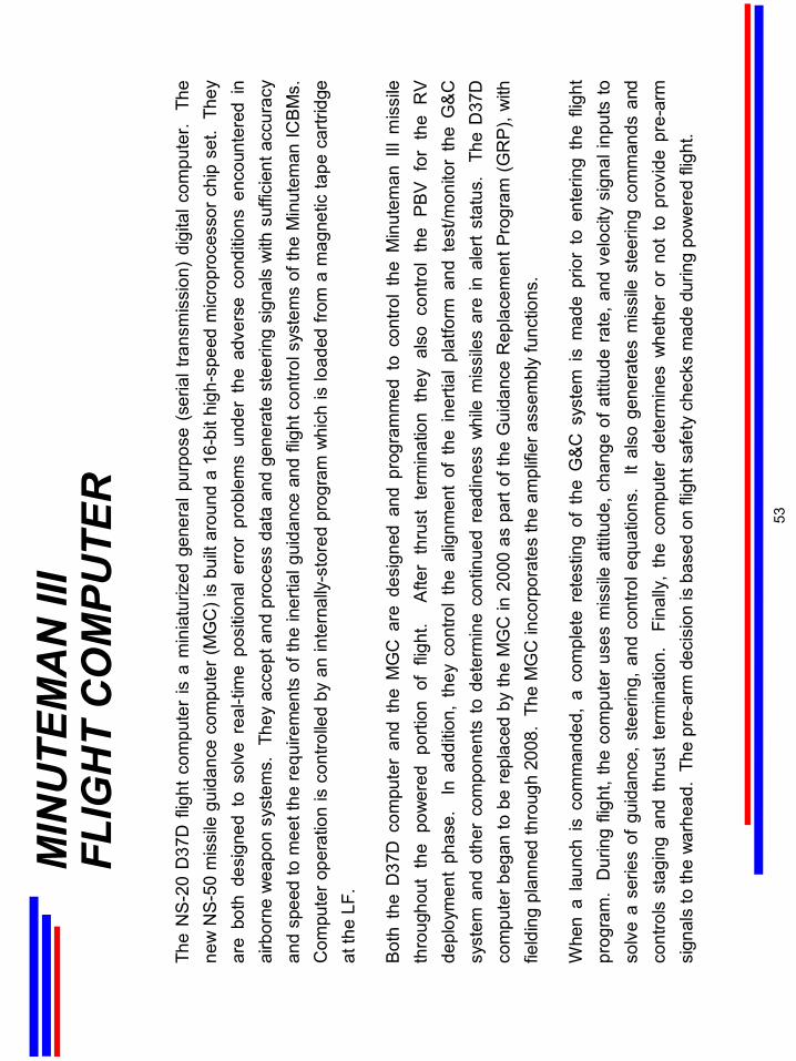
MIN
UTE
MA
N II
I FL
IGH
T C
OM
PUTE
R
The
NS-
20 D
37D
flig
ht c
ompu
ter
is a
min
iatu
rized
gen
eral
pur
pose
(se
rial t
rans
mis
sion
) di
gita
l com
pute
r. T
he
new
NS-
50 m
issi
le g
uida
nce
com
pute
r (M
GC
) is
built
aro
und
a 16
-bit
high
-spe
ed m
icro
proc
esso
r chi
p se
t. T
hey
are
both
des
igne
d to
sol
ve r
eal-t
ime
posi
tiona
l er
ror
prob
lem
s un
der
the
adve
rse
cond
ition
s en
coun
tere
d in
ai
rbor
ne w
eapo
n sy
stem
s. T
hey
acce
pt a
nd p
roce
ss d
ata
and
gene
rate
ste
erin
g si
gnal
s w
ith s
uffic
ient
acc
urac
y an
d sp
eed
to m
eet t
he re
quire
men
ts o
f the
iner
tial g
uida
nce
and
fligh
t con
trol s
yste
ms
of th
e M
inut
eman
ICB
Ms.
C
ompu
ter o
pera
tion
is c
ontro
lled
by a
n in
tern
ally
-sto
red
prog
ram
whi
ch is
load
ed fr
om a
mag
netic
tape
car
tridg
e at
the
LF.
Bot
h th
e D
37D
com
pute
r an
d th
e M
GC
are
des
igne
d an
d pr
ogra
mm
ed t
o co
ntro
l th
e M
inut
eman
III
mis
sile
th
roug
hout
the
pow
ered
por
tion
of f
light
. A
fter
thru
st t
erm
inat
ion
they
als
o co
ntro
l th
e PB
V f
or t
he R
V de
ploy
men
t ph
ase.
In
add
ition
, th
ey c
ontro
l th
e al
ignm
ent
of t
he i
nerti
al p
latfo
rm a
nd t
est/m
onito
r th
e G
&C
sy
stem
and
oth
er c
ompo
nent
s to
det
erm
ine
cont
inue
d re
adin
ess
whi
le m
issi
les
are
in a
lert
stat
us.
The
D37
D
com
pute
r beg
an to
be
repl
aced
by
the
MG
C in
200
0 as
par
t of t
he G
uida
nce
Rep
lace
men
t Pro
gram
(GR
P), w
ith
field
ing
plan
ned
thro
ugh
2008
. Th
e M
GC
inco
rpor
ates
the
ampl
ifier
ass
embl
y fu
nctio
ns.
Whe
n a
laun
ch i
s co
mm
ande
d, a
com
plet
e re
test
ing
of t
he G
&C s
yste
m i
s m
ade
prio
r to
ent
erin
g th
e fli
ght
prog
ram
. D
urin
g fli
ght,
the
com
pute
r us
es m
issi
le a
ttitu
de, c
hang
e of
atti
tude
rat
e, a
nd v
eloc
ity s
igna
l inp
uts
to
solv
e a
serie
s of
gui
danc
e, s
teer
ing,
and
con
trol e
quat
ions
. It
also
gen
erat
es m
issi
le s
teer
ing
com
man
ds a
nd
cont
rols
sta
ging
and
thr
ust
term
inat
ion.
Fi
nally
, th
e co
mpu
ter
dete
rmin
es w
heth
er o
r no
t to
pro
vide
pre
-arm
si
gnal
s to
the
war
head
. Th
e pr
e-ar
m d
ecis
ion
is b
ased
on
fligh
t saf
ety
chec
ks m
ade
durin
g po
wer
ed fl
ight
.
53
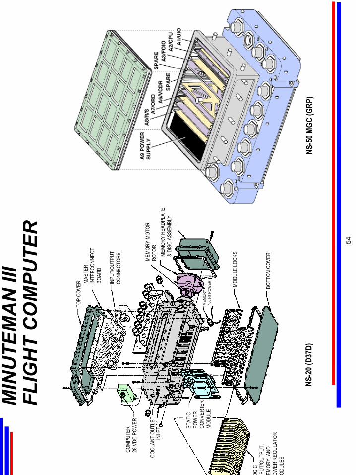
MIN
UTE
MA
N II
I FL
IGH
T C
OM
PUTE
R
COMP
UTER
28 V
DC P
OWER
COOL
ANT
OUTL
ET
STAT
ICPO
WER
CONV
ERTE
RMO
DULE
TOP
COVE
R MAST
ERIN
TERC
ONNE
CTBO
ARD
INPU
T/OU
TPUT
CONN
ECTO
RS MEMO
RY M
OTOR
ROTO
R
MEM
ORY
400 H
ZPO
WER MO
DULE
LOCK
S
BOTT
OM C
OVER
OGIC
NPUT
/OUT
PUT,
EMOR
Y, A
NDOW
ER R
EGUL
ATOR
ODUL
ES
NS-2
0 (D3
7D)
INLE
T
NS-5
0 MGC
(GRP
)
MEMO
RY H
EADP
LATE
& DI
SC A
SSEM
BLY
54
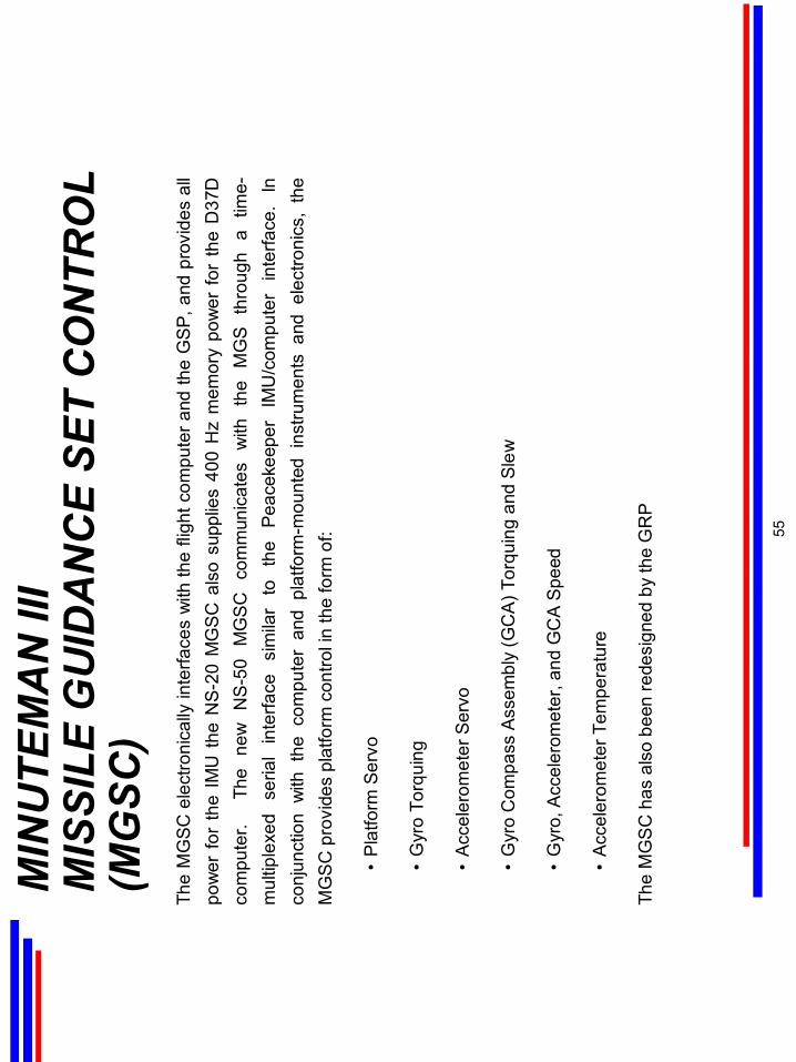
MIN
UTE
MA
N II
IM
ISSI
LE G
UID
AN
CE
SET
CO
NTR
OL
(MG
SC)
The
MG
SC e
lect
roni
cally
inte
rface
s w
ith th
e fli
ght c
ompu
ter a
nd th
e G
SP,
and
pro
vide
s al
l po
wer
for
the
IMU
the
NS-
20 M
GS
C a
lso
supp
lies
400
Hz
mem
ory
pow
er f
or t
he D
37D
co
mpu
ter.
Th
e ne
w
NS
-50
MG
SC
co
mm
unic
ates
w
ith
the
MG
S th
roug
h a
time-
mul
tiple
xed
seria
l in
terfa
ce
sim
ilar
to
the
Pea
ceke
eper
IM
U/c
ompu
ter
inte
rface
. In
co
njun
ctio
n w
ith t
he c
ompu
ter
and
plat
form
-mou
nted
ins
trum
ents
and
ele
ctro
nics
, th
e M
GS
C p
rovi
des
plat
form
con
trol i
n th
e fo
rm o
f:
•P
latfo
rm S
ervo
•G
yro
Torq
uing
•A
ccel
erom
eter
Ser
vo
•G
yro
Com
pass
Ass
embl
y (G
CA
)Tor
quin
gan
d Sl
ew
•G
yro,
Acc
eler
omet
er, a
nd G
CA
Spe
ed
•A
ccel
erom
eter
Tem
pera
ture
The
MG
SC
has
als
o be
en re
desi
gned
by
the
GR
P
55
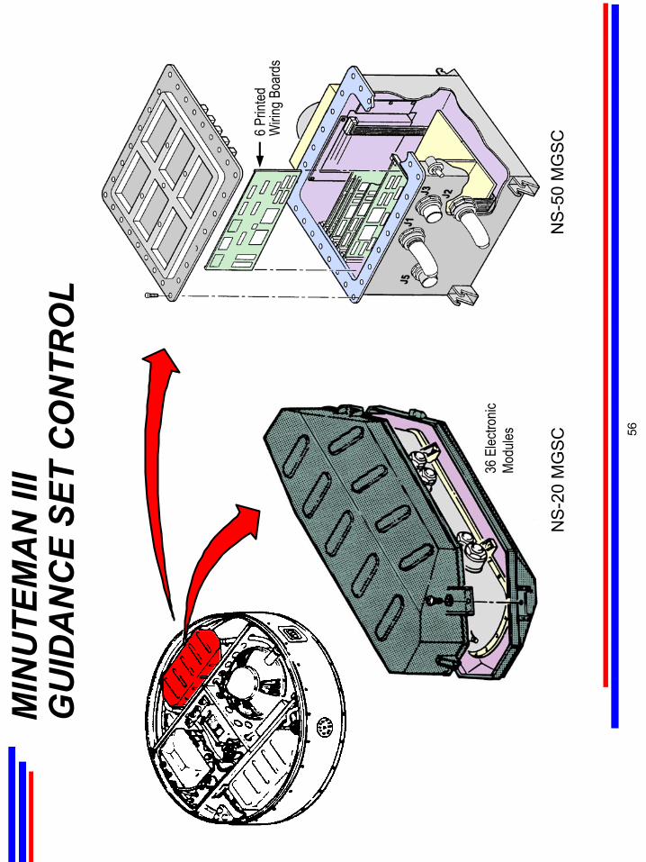
MIN
UTE
MA
N II
IG
UID
AN
CE
SET
CO
NTR
OL
NS-
20 M
GSC
NS-
50 M
GSC
36 E
lectro
nicMo
dules
6 Prin
tedW
iring B
oard
s
56
MIN
UTE
MA
N II
IP9
2 A
MPL
IFIE
R
The
P92A
3 Am
plifi
er e
lect
rical
ly c
oupl
es t
he D
37D
com
pute
r (N
S-2
0 on
ly)
with
the
mis
sile
dow
nsta
ge a
nd th
e R
S, p
rovi
ding
mis
sile
atti
tude
and
eve
nt c
ontro
l dur
ing
fligh
t and
ser
ving
as
an
Aero
spac
e Ve
hicl
e E
quip
men
t (A
VE)
safe
ty c
ontro
l dev
ice.
A
ctin
gon
ste
erin
g, s
tage
sel
ectio
n,
and
ordn
ance
initi
atio
n co
mm
ands
rece
ived
from
the
com
pute
r, th
eP9
2 is
sues
am
plifi
ed s
igna
ls to
valv
es,
actu
ator
s, a
nd o
rdna
nce
devi
ces.
U
nles
s th
e P9
2 is
arm
ed b
y an
app
ropr
iate
cod
e, a
ll
ordn
ance
ini
tiatio
n ou
tput
sig
nals
are
dis
able
d (g
roun
ded)
. T
heas
sem
bly
com
pris
es a
cas
e,
elec
troni
c m
odul
es,
and
an in
terc
onne
ct b
oard
. T
he f
unct
ions
of
the
curr
ent
P92
A3 h
ave
been
inco
rpor
ated
into
the
NS-
50 M
GC
dur
ing
GR
P.
57
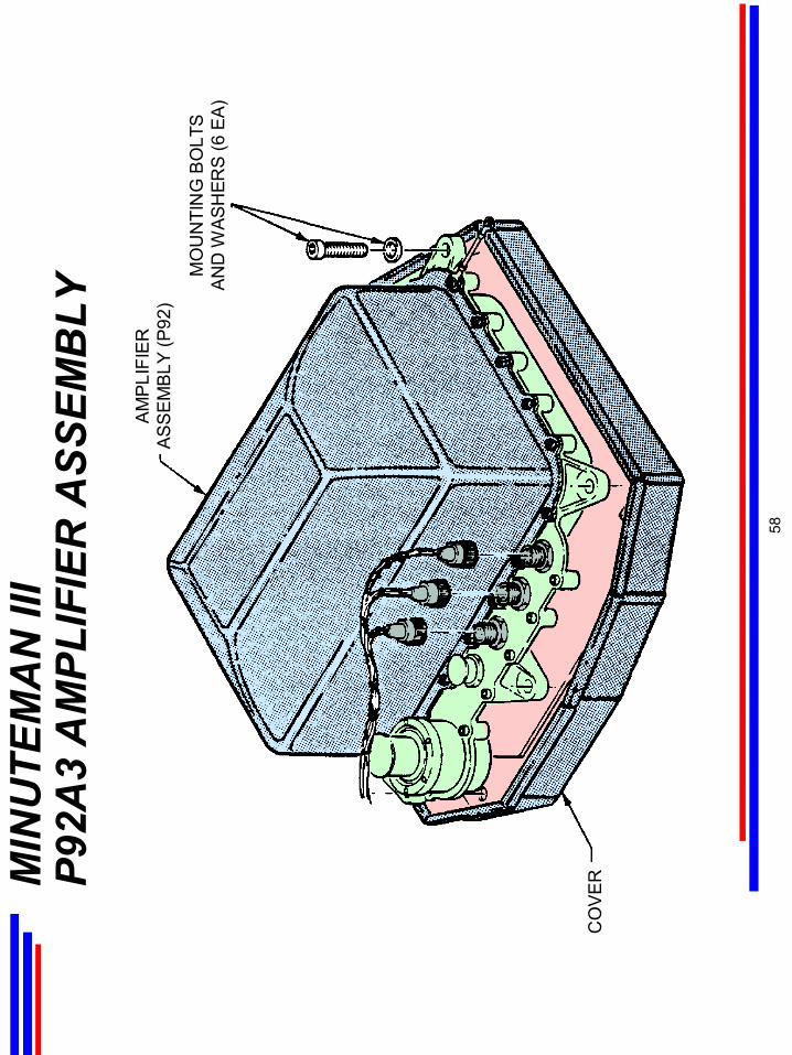
MIN
UTE
MA
N II
IP9
2A3
AM
PLIF
IER
ASS
EMB
LYA
MP
LIFI
ERA
SS
EM
BLY
(P92
)
MO
UN
TIN
G B
OLT
SA
ND
WAS
HER
S (6
EA
)
CO
VER
58
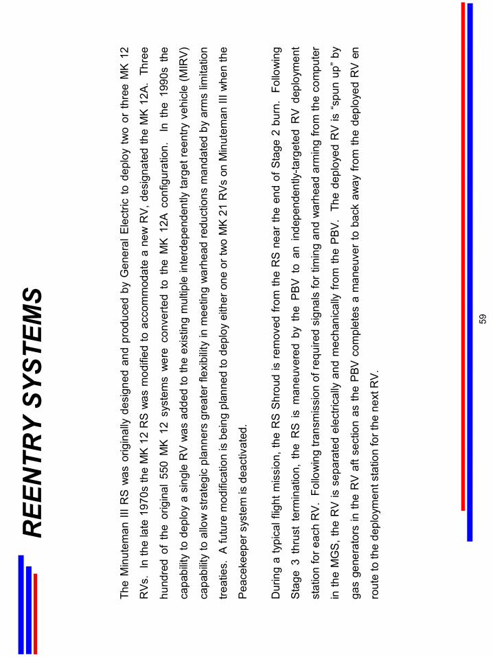
REE
NTR
Y SY
STEM
S
The
Min
utem
an II
I RS
was
orig
inal
ly d
esig
ned
and
prod
uced
by
Gen
eral
Ele
ctric
to d
eplo
y tw
o or
thre
e M
K 1
2
RVs
. In
the
late
197
0s th
e M
K 12
RS
was
mod
ified
to a
ccom
mod
ate
a ne
w R
V, d
esig
nate
d th
e M
K 12
A.
Thre
e
hund
red
of t
he o
rigin
al 5
50 M
K 12
sys
tem
s w
ere
conv
erte
d to
the
MK
12A
conf
igur
atio
n.
In t
he 1
990s
the
capa
bilit
y to
dep
loy
a si
ngle
RV
was
add
ed to
the
exis
ting
mul
tiple
inte
rdep
ende
ntly
targ
et re
entry
veh
icle
(MIR
V)
capa
bilit
y to
allo
w s
trate
gic
plan
ners
gre
ater
flex
ibilit
y in
mee
ting
war
head
redu
ctio
ns m
anda
ted
by a
rms
limita
tion
treat
ies.
A fu
ture
mod
ifica
tion
is b
eing
pla
nned
to d
eplo
y ei
ther
one
or t
wo
MK
21
RV
s on
Min
utem
an II
I whe
n th
e
Pea
ceke
eper
sys
tem
is d
eact
ivat
ed.
Dur
ing
a ty
pica
l flig
ht m
issi
on, t
he R
S Sh
roud
is r
emov
ed fr
om th
e R
S n
ear
the
end
of S
tage
2 b
urn.
Fo
llow
ing
Sta
ge 3
thr
ust
term
inat
ion,
the
RS
is m
aneu
vere
d by
the
PBV
to
an i
ndep
ende
ntly
-targ
eted
RV
dep
loym
ent
stat
ion
for e
ach
RV
. Fo
llow
ing
trans
mis
sion
of r
equi
red
sign
als
for t
imin
g an
d w
arhe
ad a
rmin
g fro
m th
e co
mpu
ter
in th
e M
GS
, the
RV
is s
epar
ated
ele
ctric
ally
and
mec
hani
cally
from
the
PBV
. Th
e de
ploy
ed R
V is
“sp
un u
p” b
y
gas
gene
rato
rs in
the
RV
aft s
ectio
n as
the
PBV
com
plet
es a
man
euve
r to
bac
k aw
ay fr
om th
e de
ploy
ed R
V en
rout
e to
the
depl
oym
ent s
tatio
n fo
r the
nex
t RV.
59
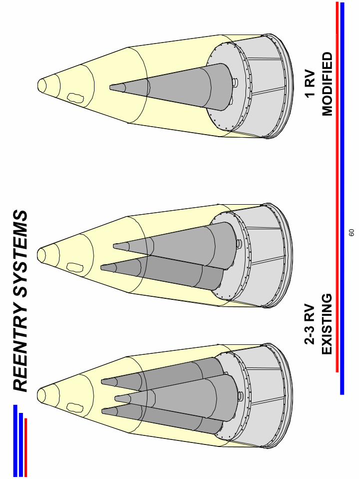
REE
NTR
Y SY
STEM
S
2-3
RV
EXIS
TIN
G1
RV
MO
DIF
IED
60
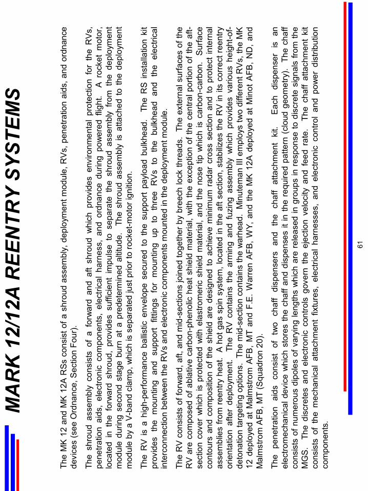
MA
RK
12/
12A
REE
NTR
Y SY
STEM
S
The
MK
12 a
nd M
K 1
2AR
Ssco
nsis
t of a
shr
oud
asse
mbl
y, d
eplo
ymen
t mod
ule,
RV
s, p
enet
ratio
n ai
ds, a
nd o
rdna
nce
devi
ces
(see
Ord
nanc
e, S
ectio
n Fo
ur).
The
shro
ud a
ssem
bly
cons
ists
of
a fo
rwar
d an
d af
t sh
roud
whi
ch p
rovi
des
envi
ronm
enta
l pr
otec
tion
for
the
RV
s,
pene
tratio
n ai
ds,
elec
troni
c co
mpo
nent
s, e
lect
rical
har
ness
, an
dor
dnan
ce d
urin
g po
wer
ed f
light
. A
roc
ket
mot
or,
loca
ted
in t
he f
orw
ard
shro
ud,
prov
ides
suf
ficie
nt i
mpu
lse
to s
epar
ate
the
shro
ud a
ssem
bly
from
the
dep
loym
ent
mod
ule
durin
g se
cond
sta
ge b
urn
at a
pre
dete
rmin
ed a
ltitu
de.
The
shro
ud a
ssem
bly
is a
ttach
ed to
the
depl
oym
ent
mod
ule
by a
V-b
and
clam
p, w
hich
is s
epar
ated
just
prio
r to
rock
et-m
otor
igni
tion.
The
RV
is a
hig
h-pe
rform
ance
bal
listic
env
elop
e se
cure
d to
the
sup
port
payl
oad
bulk
head
. T
he R
S in
stal
latio
n ki
t pr
ovid
es t
he m
ount
ing
and
supp
ort
fittin
gs f
or m
ount
ing
up t
o th
ree
RV
s to
the
bul
khea
d an
d th
e el
ectri
cal
inte
rcon
nect
ion
betw
een
the
RVs
and
ele
ctro
nic
com
pone
nts
mou
nted
in th
e de
ploy
men
t mod
ule.
The
RV
con
sist
s of
forw
ard,
aft,
and
mid
-sec
tions
join
ed to
geth
er b
y br
eech
lock
thre
ads.
The
ext
erna
l sur
face
s of
the
RV
are
com
pose
d of
abl
ativ
e ca
rbon
-phe
nolic
heat
shi
eld
mat
eria
l, w
ith th
e ex
cept
ion
of th
e ce
ntra
l por
tion
of th
e af
t-se
ctio
n co
ver
whi
ch is
pro
tect
ed w
ithel
astro
mer
icsh
ield
mat
eria
l, an
d th
e no
se ti
p w
hich
is c
arbo
n-ca
rbon
. S
urfa
ce
cont
ours
and
com
posi
tion
of th
e sh
ield
are
des
igne
d to
ach
ieve
min
imum
rad
ar c
ross
sec
tion
and
to p
rote
ct in
tern
al
asse
mbl
ies
from
reen
try h
eat.
A h
ot g
as s
pin
syst
em, l
ocat
ed in
the
aft s
ectio
n, s
tabi
lizes
the
RV
in it
s co
rrec
t ree
ntry
or
ient
atio
n af
ter
depl
oym
ent.
The
RV
cont
ains
the
arm
ing
and
fuzi
ngas
sem
bly
whi
ch p
rovi
des
vario
us h
eigh
t-of-
deto
natio
n ta
rget
ing
optio
ns.
The
mid
-sec
tion
cont
ains
the
war
head
. M
inut
eman
III e
mpl
oys
two
diffe
rent
RV
s, th
e M
K
12 d
eplo
yed
at M
alm
stro
m A
FB,
MT
and
F.E
. W
arre
n AF
B, W
Y, a
nd t
he M
K 1
2A d
eplo
yed
at M
inot
AFB
, ND
, an
d M
alm
stro
m A
FB, M
T (S
quad
ron
20).
The
pene
tratio
n ai
ds
cons
ist
of
two
chaf
f di
spen
sers
an
d th
e ch
aff
atta
chm
ent
kit.
Ea
ch
disp
ense
r is
an
el
ectro
mec
hani
cal d
evic
e w
hich
sto
res
the
chaf
f and
dis
pens
es it
in th
e re
quire
d pa
ttern
(cl
oud
geom
etry
). T
he c
haff
cons
ists
of n
umer
ous
dipo
les
of v
aryi
ng le
ngth
s w
hich
are
rel
ease
d in
gro
ups
in re
spon
se to
dis
cret
e si
gnal
s fro
m th
e M
GS
. T
hedi
scre
tes
and
elec
troni
c co
ntro
ls g
over
n th
e ej
ectio
n ve
loci
ty a
nd f
eed
rate
. T
he c
haff
atta
chm
ent
kit
cons
ists
of
the
mec
hani
cal
atta
chm
ent
fixtu
res,
ele
ctric
al h
arne
sses
, an
d el
ectro
nic
cont
rol
and
pow
er d
istri
butio
n co
mpo
nent
s.
61
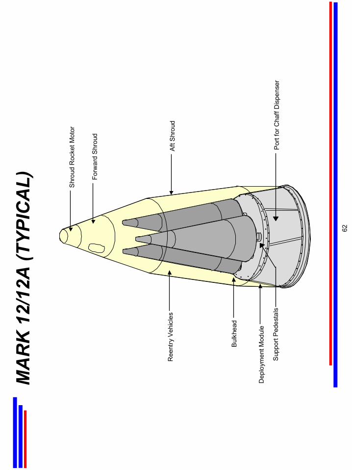
MA
RK
12/
12A
(TYP
ICA
L)
Ree
ntry
Veh
icle
s
Forw
ard
Shr
oud
Aft
Shr
oud
Por
t for
Cha
ff D
ispe
nser
Bul
khea
d
Dep
loym
ent M
odul
e
Sup
port
Ped
esta
ls
Shr
oud
Roc
ket M
otor
62
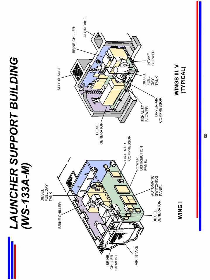
LAU
NC
HER
SU
PPO
RT
BU
ILD
ING
(WS-
133A
-M)
BR
INE
CH
ILLE
R
DIE
SE
L FU
EL D
AY
TAN
K
DR
IER
-AIR
C
OM
PR
ES
SO
R
PO
WE
R
DIS
TRIB
UTI
ON
P
ANE
L
AUTO
MA
TIC
SW
ITC
HIN
G
PAN
EL
DIE
SE
L G
EN
ER
ATO
R
AIR
INTA
KE
BR
INE
C
HIL
LER
E
XHAU
ST
AIR
EXH
AUS
T
BR
INE
CH
ILLE
R
AIR
INTA
KE
INTA
KE
B
LOW
ER
DIE
SE
L G
EN
ER
ATO
R
DIE
SE
L FU
EL
DA
Y TA
NK
DR
YER
-AIR
C
OM
PR
ES
SO
R
EXH
AUS
T B
LOW
ER
WIN
G I
WIN
GS
III, V
(TYP
ICA
L)
80

LAU
NC
HER
EQ
UIP
MEN
T B
UIL
DIN
G
(WS-
133B
)
In th
e W
S-13
3B S
yste
m, t
he L
aunc
her
Equi
pmen
t Bui
ldin
g (L
EB)
is a
har
dene
d un
derg
roun
d
stru
ctur
e of
rei
nfor
ced
conc
rete
and
ste
el d
esig
ned
to s
urvi
ve n
ucle
ar w
eapo
n ef
fect
s.
The
LEB
is lo
cate
d ad
jace
nt to
the
laun
cher
. A
ver
tical
sha
ft w
ith a
rem
ovab
le c
over
and
two
stee
l
hatc
hes
prov
ides
acc
ess.
A
blas
t do
or s
epar
ates
the
LEB
fro
m t
he a
cces
s sh
aft.
Sup
port
equi
pmen
t in
the
bui
ldin
g is
mou
nted
on
a sh
ock-
isol
ated
flo
or a
nd in
clud
es:
1) t
he s
ervi
ce
entra
nce
for
the
com
mer
cial
pow
er s
ourc
e; 2
) th
e th
ree-
phas
e 60
-Hz
stan
dby
dies
el e
ngin
e-
gene
rato
r co
mpl
ete
with
vol
tage
sen
sing
, ph
ase
sens
ing,
vol
tage
reg
ulat
ing,
and
aut
omat
ic
star
ting
and
stop
ping
equ
ipm
ent;
and,
3) t
he b
rine
chille
r for
the
envi
ronm
enta
l con
trol s
yste
m.
81
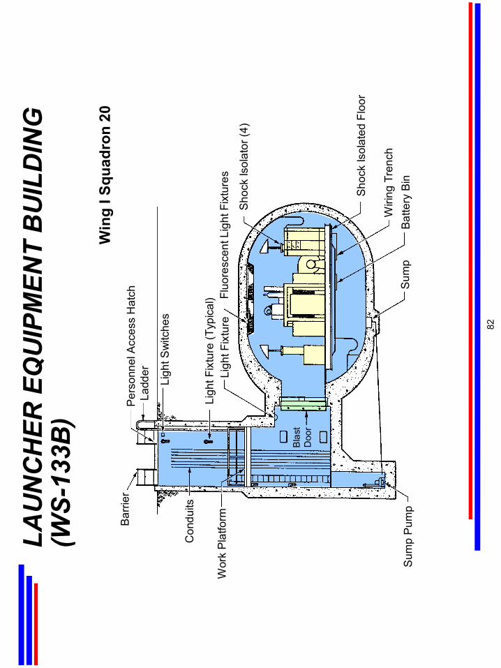
LAU
NC
HER
EQ
UIP
MEN
T B
UIL
DIN
G
(WS-
133B
)
Ladd
erP
erso
nnel
Acc
ess
Hat
ch
Ligh
t Sw
itche
s
Ligh
t Fix
ture
(Typ
ical
) Fluo
resc
ent L
ight
Fix
ture
sLi
ght F
ixtu
re
Shoc
k Is
olat
or (4
)
Shoc
k Is
olat
ed F
loor
Wiri
ng T
renc
hBa
ttery
Bin
Sum
pS
ump
Pum
p
Bla
stD
oor
Wor
k Pl
atfo
rm
Con
duits
Bar
rier
Win
g I S
quad
ron
20
82

LAU
NC
H F
AC
ILIT
Y SE
CU
RIT
Y SY
STEM
The
func
tion
of th
e se
curit
y sy
stem
is to
det
ect u
naut
horiz
ed a
ctiv
ity a
t the
LF.
Th
e sy
stem
is d
ivid
ed in
to o
uter
and
inne
r zon
e fu
nctio
ns.
All
dete
cted
sec
urity
vio
latio
ns a
re d
ispl
ayed
on
a st
atus
con
sole
in th
e LC
C. T
he e
arlie
r
oute
r zo
ne s
ecur
ity s
yste
ms
expe
rienc
ed e
xces
sive
nui
sanc
e an
d fa
lse
alar
m r
ates
, and
the
syst
em m
ean-
time-
betw
een-
failu
re (
MTB
F) r
ates
wer
e si
gnifi
cant
ly b
elow
the
spe
cifie
d 37
,000
hou
rs.
To
solv
e th
is p
robl
em,
an
Impr
oved
Min
utem
an P
hysi
cal S
ecur
ity S
yste
m (
IMP
SS)
was
dev
elop
ed a
nd in
stal
led
at a
ll si
x w
ings
as
part
of
the
Riv
et M
inut
eman
Inte
grat
ed L
ife E
xten
sion
(M
ILE)
pro
gram
dur
ing
1987
to 1
992.
Th
e m
odifi
catio
n re
plac
ed
the
bist
atic
rada
r sy
stem
and
ala
rm s
et e
lect
roni
cs (o
uter
zon
e pr
otec
tion)
with
a s
ingl
em
onos
tatic
rada
r sy
stem
whe
re th
e tra
nsm
it an
d re
ceiv
e el
emen
ts a
re c
onta
ined
in a
sin
gle
mas
t loc
ated
nea
r the
laun
cher
clo
sure
.
The
secu
rity
inne
r zo
ne s
yste
m i
nclu
des
switc
hes
on t
he l
aunc
her
clos
ure
and
lock
ing
pin,
the
prim
ary
door
,
com
bina
tion
lock
s on
the
prim
ary
door
, se
curit
y sw
itche
s on
the
sec
onda
ry d
oor,
and
pene
tratio
n de
tect
ion
devi
ces
on th
e va
ult d
oor.
In a
dditi
on, v
ibra
tion-
sens
itive
tran
sduc
ers
are
stra
tegi
cally
loca
ted
with
in th
e la
unch
er.
83
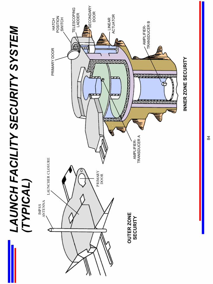
LAU
NC
H F
AC
ILIT
Y SE
CU
RIT
Y SY
STEM
(TYP
ICA
L)IM
PS
S
ANTE
NN
ALA
UN
CH
ER
CLO
SU
RE
PR
IMAR
Y D
OO
R
OU
TER
ZO
NE
SEC
UR
ITY
INN
ER Z
ON
E SE
CU
RIT
Y
HA
TCH
PO
SIT
ION
SWIT
CH
PR
IMAR
Y D
OO
R
SE
CO
ND
ARY
DO
OR
LIN
EAR
ACTU
ATO
R
TELE
SC
OP
ING
LAD
DER
AM
PLI
FIE
R-
TRAN
SD
UC
ER
AA
MP
LIFI
ER
-TR
ANS
DU
CE
R B
84

MIN
UTE
MA
N
OR
DN
AN
CE
SEC
TIO
N F
OU
R
This
sec
tion
prov
ides
an
over
view
of M
inut
eman
Ord
nanc
e. T
he p
rimar
y or
dnan
ce a
pplic
atio
ns
incl
ude
mot
or ig
nite
r,in
ters
tage
, ree
ntry
sys
tem
(R
S)/p
enet
ratio
n ai
ds, a
nd o
pera
tiona
l gro
und
equi
pmen
t (O
GE)
. I
n ad
ditio
n gu
idan
ce a
nd f
light
con
trol
ordn
ance
inc
lude
squ
ib-in
itiat
ed
batte
ries
and
the
criti
cal l
ead
disc
onne
ct s
witc
h. T
he c
ritic
alle
ad d
isco
nnec
t sw
itch
for e
xam
ple
is u
sed
to c
ut c
ritic
al c
ompu
ter
lines
to p
reve
nt in
adve
rtent
sig
nals
to th
e co
mpu
ter
at th
e tim
e
of u
mbi
lical
dis
conn
ect.
Eac
h of
the
mai
n or
dnan
ce ty
pes
are
disc
usse
d in
the
follo
win
g ch
arts
.
(The
figu
re b
elow
is a
Sta
ge 2
igni
ter.)
85
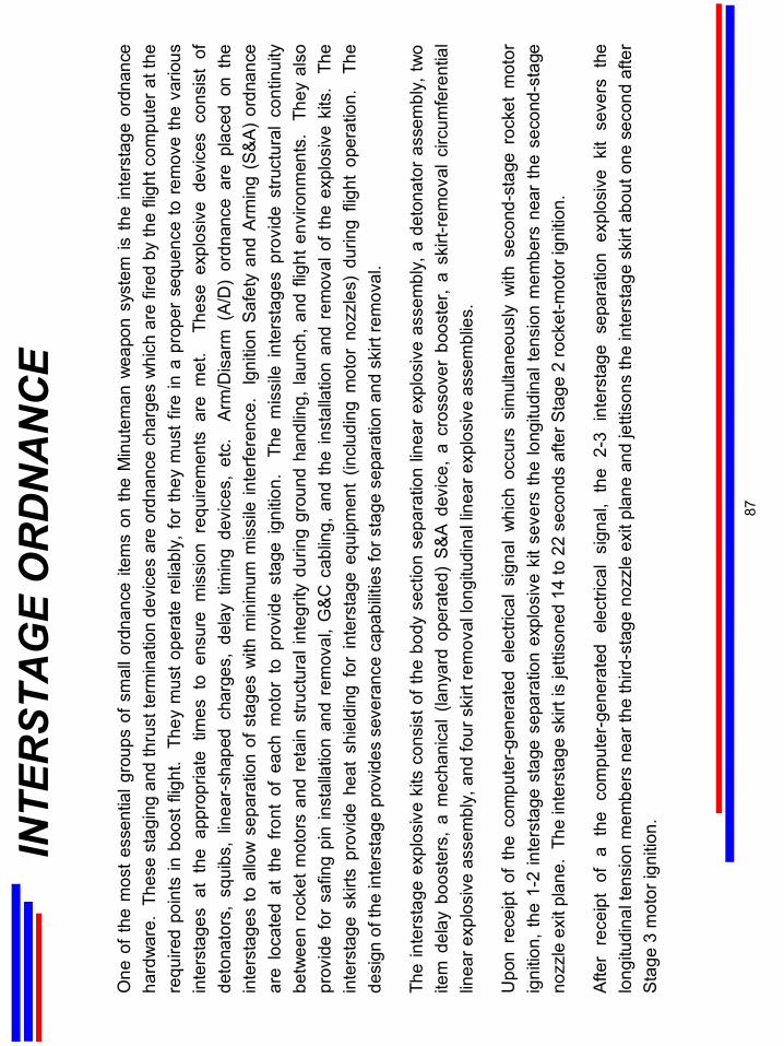
INTE
RST
AG
E O
RD
NA
NC
E
One
of t
he m
ost e
ssen
tial g
roup
s of
sm
all o
rdna
nce
item
s on
the
Min
utem
an w
eapo
n sy
stem
is th
ein
ters
tage
ordn
ance
ha
rdw
are.
The
se s
tagi
ng a
nd th
rust
term
inat
ion
devi
ces
are
ordn
ance
cha
rges
whi
ch a
re fi
red
by th
e fli
ght c
ompu
ter a
t the
re
quire
d po
ints
in b
oost
flig
ht.
They
mus
t ope
rate
rel
iabl
y, fo
r th
ey m
ust f
ire in
a p
rope
r se
quen
ce to
rem
ove
the
vario
usin
ters
tage
sat
the
app
ropr
iate
tim
es t
o en
sure
mis
sion
req
uire
men
ts a
re m
et.
The
se e
xplo
sive
dev
ices
con
sist
of
deto
nato
rs,
squi
bs,
linea
r-sh
aped
cha
rges
, de
lay
timin
g de
vice
s, e
tc.
Arm
/Dis
arm
(A
/D)
ordn
ance
are
pla
ced
on t
hein
ters
tage
s to
allo
w s
epar
atio
n of
sta
ges
with
min
imum
mis
sile
inte
rfere
nce.
Igni
tion
Safe
ty a
nd A
rmin
g (S
&A)
ordn
ance
ar
e lo
cate
d at
the
fro
nt o
f ea
ch m
otor
to
prov
ide
stag
e ig
nitio
n.
The
mis
sile
inte
rsta
ges
prov
ide
stru
ctur
al c
ontin
uity
be
twee
n ro
cket
mot
ors
and
reta
in s
truct
ural
inte
grity
dur
ing
grou
nd h
andl
ing,
laun
ch, a
nd fl
ight
env
ironm
ents
. Th
ey a
lso
prov
ide
for
safin
gpi
n in
stal
latio
n an
d re
mov
al,
G&C
cab
ling,
and
the
inst
alla
tion
and
rem
oval
of
the
expl
osiv
e ki
ts.
The
inte
rsta
gesk
irts
prov
ide
heat
shi
eldi
ng f
orin
ters
tage
equi
pmen
t (in
clud
ing
mot
or n
ozzl
es)
durin
g fli
ght
oper
atio
n.
The
desi
gn o
f the
inte
rsta
gepr
ovid
es s
ever
ance
cap
abilit
ies
for s
tage
sep
arat
ion
and
skirt
rem
oval
.
The
inte
rsta
geex
plos
ive
kits
con
sist
of t
he b
ody
sect
ion
sepa
ratio
n lin
ear
expl
osiv
e as
sem
bly,
a d
eton
ator
ass
embl
y, tw
o ite
m d
elay
boo
ster
s, a
mec
hani
cal (
lany
ard
oper
ated
) S
&A
dev
ice,
a cr
osso
ver
boos
ter,
a sk
irt-r
emov
al c
ircum
fere
ntia
l lin
ear e
xplo
sive
ass
embl
y, a
nd fo
ur s
kirt
rem
oval
long
itudi
nal l
inea
r exp
losi
ve a
ssem
blie
s.
Upo
n re
ceip
t of
the
com
pute
r-gen
erat
ed e
lect
rical
sig
nal
whi
ch o
ccur
s si
mul
tane
ousl
y w
ith s
econ
d-st
age
rock
et m
otor
ig
nitio
n, th
e 1-
2in
ters
tage
stag
e se
para
tion
expl
osiv
e ki
t sev
ers
the
long
itudi
nal t
ensi
on m
embe
rs n
ear
the
seco
nd-s
tage
no
zzle
exi
t pla
ne.
The
inte
rsta
gesk
irt is
jetti
sone
d 14
to 2
2 se
cond
s af
ter S
tage
2 ro
cket
-mot
or ig
nitio
n.
Afte
r re
ceip
t of
a t
he c
ompu
ter-
gene
rate
d el
ectri
cal
sign
al,
the
2-3
inte
rsta
gese
para
tion
expl
osiv
e ki
t se
vers
the
lo
ngitu
dina
l ten
sion
mem
bers
nea
r the
third
-sta
ge n
ozzl
e ex
it pl
ane
and
jetti
sons
the
inte
rsta
gesk
irt a
bout
one
sec
ond
afte
r S
tage
3 m
otor
igni
tion.
87

S&A
and
A/D
Sw
itch
Loca
tions
RS/
RV
STA
GE
3ST
AG
E 2
STA
GE
1
G&C
PSRE
STA
GE
SEP
A/D
IGN
ITIO
N S
&A
AC
G A
/DIG
NIT
ION
S&
A
ENA
BLE
A/D
ISO
LATI
ON
VA
LVE
A/D
s (2)
STA
GE
SEP
A/D
IGN
ITIO
N S
&A
AO
TTS
A/D
S&A
ATT
ITU
DE
CO
NTR
OL
GR
OU
P
and
Sta
ge S
epar
atio
n
88

THR
UST
TER
MIN
ATI
ON
SYS
TEM
O
RD
NA
NC
E
The
Thru
st T
erm
inat
ion
Syst
em O
rdna
nce,
on
com
man
d fro
m th
e gu
idan
ce s
yste
m, o
pens
por
ts in
the
Min
utem
an II
and
III
third
-sta
ge m
otor
s. T
his
resu
lts in
redu
ced
mot
or p
ress
ure
and
prov
ides
reve
rse
thru
st fo
r thi
rd-s
tage
dec
eler
atio
n an
d se
para
tion
from
the
post
-boo
st v
ehic
le (P
BV).
For
Min
utem
an II
I, th
e TT
sys
tem
, cal
led
the
All-O
rdna
nce
Thru
st T
erm
inat
ion
Sys
tem
(AO
TTS)
, con
sist
s of
six
equ
ally
sp
aced
TT
ports
pla
ced
at th
e to
p of
the
rock
et m
otor
. In
stal
led
at th
e ba
se o
f eac
h AO
TTS
por
t nex
t to
the
top
of th
e m
otor
cas
e is
a r
ing
asse
mbl
y co
nsis
ting
of a
ret
aini
ng r
ing,
lin
ear-
shap
ed c
harg
e (L
SC),
char
ge r
etai
ner,
and
othe
r m
isce
llane
ous
hard
war
e. W
hen
TT is
initi
ated
by
the
guid
ance
sys
tem
, a fi
ring
sign
al is
sen
t thr
ough
the
A/D
dev
ice
to th
e LS
C.
A pl
asm
a je
t fro
m th
e LS
C c
uts
thro
ugh
the
mot
or c
ase,
allo
win
g th
e m
otor
com
bust
ion
gase
s to
esc
ape
thro
ugh
the
TT s
tack
s. T
his
caus
es d
ecel
erat
ion
of th
e th
ird s
tage
and
pos
itive
sep
arat
ion
from
the
PB
V c
onta
inin
g th
e R
Vs.
89
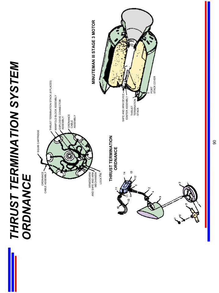
THR
UST
TER
MIN
ATI
ON
SYS
TEM
O
RD
NA
NC
E THR
UST
TER
MIN
ATI
ON
OR
DN
ANC
E
MIN
UTE
MA
N II
I STA
GE
3 M
OTO
R
IGN
ITE
R A
SSE
MB
LY
THR
US
TTE
RM
INAT
ION
STA
CK
POR
TST
ACK
CO
VER
SAFE
AN
D A
RM
DE
VIC
E
THR
US
T TE
RM
INA
TIO
N S
TAC
K (8
PLA
CES
)
MAN
IFO
LD B
LOC
K A
SS
EM
BLY
EXP
LOS
IVE
CO
NN
EC
TOR
ASS
EM
BLY
OR
DN
AN
CE
CAB
LEAS
SE
MB
LY
AR
M/D
ISA
RM
AN
D S
AFE
AND
AR
MM
EC
HA
NIS
M
OR
DN
ANC
EC
ABLE
AS
SEM
BLY
SQ
UIB
CAR
TRID
GE
LOC
K P
IN
90

REE
NTR
Y SY
STEM
OR
DN
AN
CE
Ree
ntry
sys
tem
(R
S)
ordn
ance
incl
udes
pitc
h an
d sp
in r
ocke
ts, g
as g
ener
ator
s w
ithin
the
sep
arat
ion
syst
em, a
nd e
lect
rical
cab
le s
epar
atio
n sq
uibs
. Fai
lure
of a
ny o
ne o
f the
RS
ordn
ance
dev
ices
wou
ld
not c
ause
a c
ritic
al re
liabi
lity
failu
re, b
ut w
ould
deg
rade
the
effe
ctiv
enes
s of
the
Min
utem
an m
issi
on.
Pen
etra
tion
Aid
s or
dnan
ce in
clud
es s
mal
l roc
kets
, fus
es, d
eton
ator
s, s
quib
car
tridg
es,
gas
gene
rato
rs,
linea
r-sh
aped
cha
rges
, and
del
ay ti
min
g de
vice
s. P
enet
ratio
n of
the
RV
is e
nhan
ced
by d
eplo
ymen
t of
the
Pen
Aid
s co
unte
rmea
sure
s by
the
ordn
ance
har
dwar
e.
91
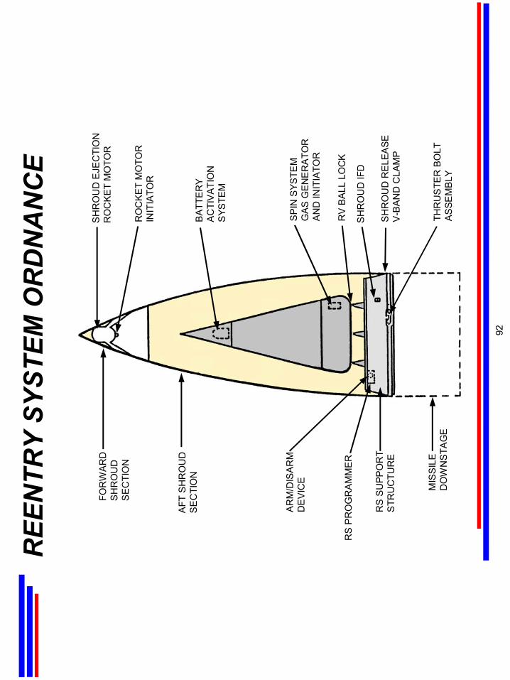
REE
NTR
Y SY
STEM
OR
DN
AN
CE
FOR
WA
RD
SH
RO
UD
SE
CTI
ON
AFT
SH
RO
UD
SE
CTI
ON
AR
M/D
ISA
RM
DE
VIC
E
RS
PR
OG
RA
MM
ER
RS
SU
PPO
RT
STR
UC
TUR
E
MIS
SIL
ED
OW
NS
TAG
E
SH
RO
UD
EJE
CTI
ON
RO
CK
ET
MO
TOR
RO
CK
ET
MO
TOR
INIT
IATO
R
BA
TTE
RY
AC
TIV
ATI
ON
SYS
TEM
SP
IN S
YSTE
MG
AS
GE
NE
RA
TOR
AN
D IN
ITIA
TOR
RV
BA
LL L
OC
K
SH
RO
UD
IFD
SH
RO
UD
RE
LEA
SEV
-BA
ND
CLA
MP
THR
US
TER
BO
LTA
SSE
MB
LY
92
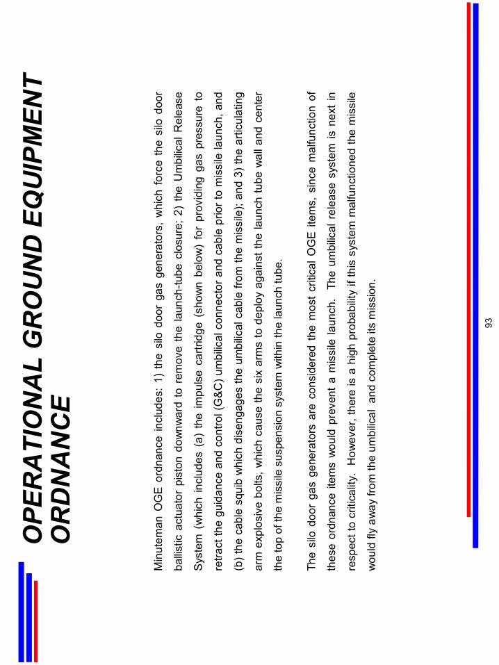
OPE
RA
TIO
NA
L G
RO
UN
D E
QU
IPM
ENT
OR
DN
AN
CE
Min
utem
an O
GE
ord
nanc
e in
clud
es:
1) t
he s
ilo d
oor
gas
gene
rato
rs,
whi
ch f
orce
the
silo
doo
r
ballis
tic a
ctua
tor
pist
on d
ownw
ard
to r
emov
e th
e la
unch
-tube
clo
sure
; 2)
the
Um
bilic
al R
elea
se
Syst
em (
whi
ch in
clud
es (
a) t
he im
puls
e ca
rtrid
ge (
show
n be
low
) fo
r pr
ovid
ing
gas
pres
sure
to
retra
ct th
e gu
idan
ce a
nd c
ontro
l (G
&C) u
mbi
lical
con
nect
or a
nd c
able
prio
r to
mis
sile
laun
ch, a
nd
(b) t
he c
able
squ
ib w
hich
dis
enga
ges
the
umbi
lical
cab
le fr
om th
e m
issi
le);
and
3) th
e ar
ticul
atin
g
arm
exp
losi
ve b
olts
, whi
ch c
ause
the
six
arm
s to
dep
loy
agai
nst t
he la
unch
tube
wal
l and
cen
ter
the
top
of th
e m
issi
le s
uspe
nsio
n sy
stem
with
in th
e la
unch
tube
.
The
silo
doo
r ga
s ge
nera
tors
are
con
side
red
the
mos
t cr
itica
l OG
E it
ems,
sin
ce m
alfu
nctio
n of
thes
e or
dnan
ce it
ems
wou
ld p
reve
nt a
mis
sile
laun
ch.
The
um
bilic
al r
elea
se s
yste
m is
nex
t in
resp
ect t
o cr
itica
lity.
H
owev
er, t
here
is a
hig
h pr
obab
ility
ifth
is s
yste
m m
alfu
nctio
ned
the
mis
sile
wou
ld fl
y aw
ay fr
om th
e um
bilic
al a
nd c
ompl
ete
its m
issi
on.
93
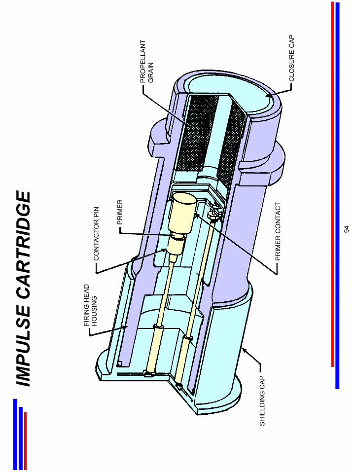
IMPU
LSE
CA
RTR
IDG
E
FIR
ING
HE
AD
HO
US
ING
CO
NTA
CTO
R P
IN
PR
IME
R
PR
OP
ELL
AN
TG
RA
IN
CLO
SU
RE
CAP
PR
IME
R C
ON
TAC
T
SH
IELD
ING
CA
P
94
CH
RO
NO
LOG
Y O
F M
INU
TEM
AN
D
EVEL
OPM
ENT
AN
D D
EPLO
YMEN
T
SEC
TIO
N F
IVE
A d
etai
led
chro
nolo
gy o
f Min
utem
an d
evel
opm
ent a
nd fo
llow
-on
impr
ovem
ents
is p
rese
nted
in
the
next
few
cha
rts.
95
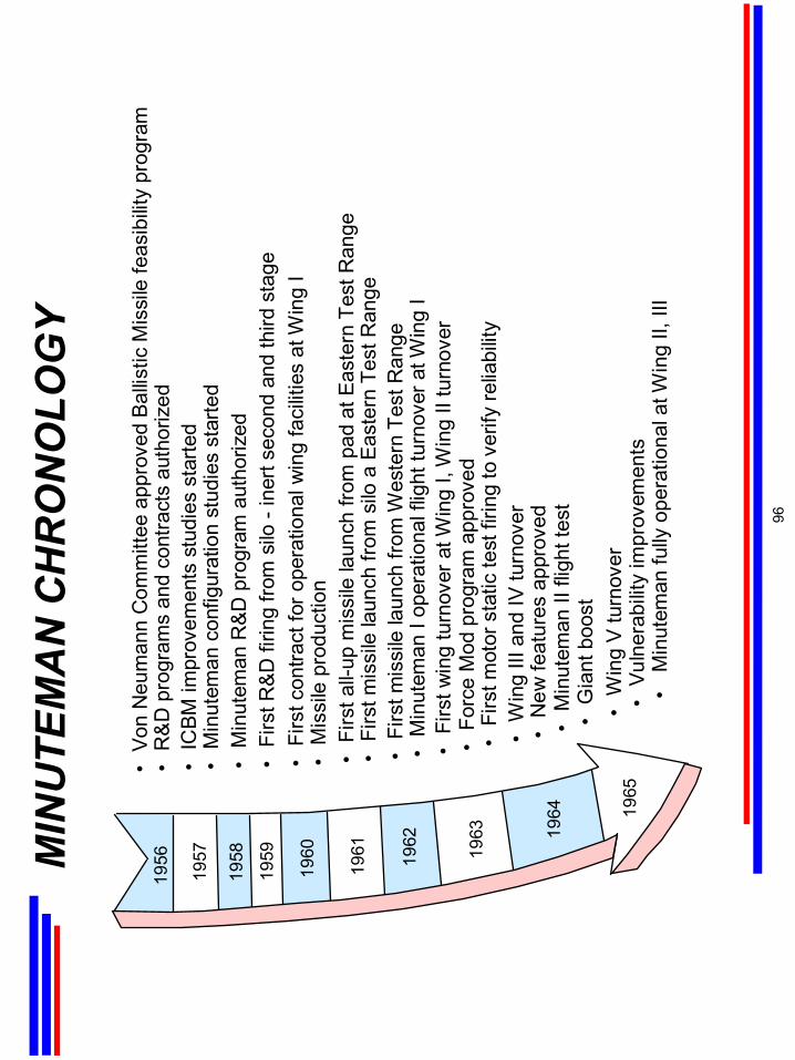
MIN
UTE
MA
N C
HR
ON
OLO
GY
•Fi
rst a
ll-up
mis
sile
laun
ch fr
om p
ad a
t Eas
tern
Tes
t Ran
ge
•Vo
n N
eum
ann
Com
mitt
ee a
ppro
ved
Ballis
tic M
issi
le fe
asib
ility
prog
ram
•IC
BM im
prov
emen
ts s
tudi
es s
tarte
d •
Min
utem
an c
onfig
urat
ion
stud
ies
star
ted
•M
inut
eman
R&D
pro
gram
aut
horiz
ed
•Fi
rst c
ontra
ct fo
r ope
ratio
nal w
ing
faci
litie
s at
Win
g I
•Fi
rst m
issi
le la
unch
from
silo
a E
aste
rn T
est R
ange
•Fi
rst m
issi
le la
unch
from
Wes
tern
Tes
t Ran
ge•
Min
utem
an I
oper
atio
nal f
light
turn
over
at W
ing
I •
Firs
t win
g tu
rnov
er a
t Win
g I,
Win
g II
turn
over
•Fo
rce
Mod
pro
gram
app
rove
d
•R
&D
pro
gram
s an
d co
ntra
cts
auth
oriz
ed
•M
issi
le p
rodu
ctio
n
•Fi
rst m
otor
sta
tic te
st fi
ring
to v
erify
relia
bilit
y
•M
inut
eman
fully
ope
ratio
nal a
t Win
g II,
III
•W
ing
III a
nd IV
turn
over
•N
ew fe
atur
es a
ppro
ved
•W
ing
V tu
rnov
er•
Vuln
erab
ility
impr
ovem
ents
•M
inut
eman
II fl
ight
test
•G
iant
boo
st
•Fi
rst R
&D fi
ring
from
silo
-in
ert s
econ
d an
d th
ird s
tage
1956
1957
1958
1959
1960
1961 1962
1963 19
64 1965
96

MIN
UTE
MA
N C
HR
ON
OLO
GY (Cont’d)
•W
ing
VI tu
rnov
er•
Min
utem
an II
I app
rova
l•
Agin
g su
rvei
llanc
e pr
ogra
m in
itiat
ed•
Min
utem
an II
ope
ratio
nal a
t Win
g VI
•ER
CS
depl
oyed
•Sq
uadr
on 2
0 tu
rnov
er
•H
ard
rock
silo
pro
gram
sta
rted
•Fi
rst M
inut
eman
III R
&D fl
ight
•Fo
rce
Mod
at W
ing
IV
•Fo
rce
Mod
rate
dec
reas
e•
Forc
e M
od a
t Win
g I c
ompl
eted
•S
ervi
ce S
tar t
estin
g be
gan
forR
Ss
•Fi
rst M
inut
eman
III a
t Win
g III
•U
pgra
de s
ilo a
nd C
DB
pro
gram
s st
arte
d•
Firs
t MO
M te
st a
t Win
g V
I•
Min
utem
an II
I dus
t pro
gram
sta
rted
•Fo
rce
Mod
at W
ing
III c
ompl
eted
•M
inut
eman
III d
eplo
yed
at W
ing
VI
•Fi
rst d
ust h
arde
ned
Min
utem
an II
I dep
loye
d at
Win
g V
I•
Min
utem
an o
rdna
nce
serv
ice
life
anal
ysis
pro
gram
dev
elop
ed•
Res
pons
ibilit
y fo
r ser
vice
life
test
ing
trans
ferr
ed to
OO
-ALC
•U
pgra
de s
ilo a
nd C
DB
IOC
at W
ing
V•
Forc
e M
od a
nd u
pgra
de s
ilo c
ompl
eted
at W
ing
II•
Last
MO
M a
t Win
g III
•Fu
ll Fo
rce
upgr
ade
silo
app
rove
d•
MK
12A
and
Pav
e P
eppe
r pro
gram
s st
arte
d•
SS
AS w
as d
eplo
yed
for M
inut
eman
II
1966
1967
1968
1969
1970 1971 1972 19
73 1974
97
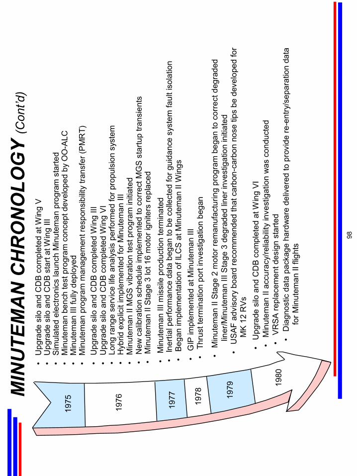
MIN
UTE
MA
N C
HR
ON
OLO
GY (Cont’d)
1975
1976
1977
1978 19
79 1980
•U
pgra
de s
ilo a
nd C
DB
com
plet
ed a
t Win
g V
•U
pgra
de s
ilo a
nd C
DB
sta
rt at
Win
g III
•S
imul
ated
ele
ctro
nics
laun
ch M
inut
eman
pro
gram
sta
rted
•M
inut
eman
ben
ch te
st p
rogr
am c
once
pt d
evel
oped
by
OO
-ALC
•M
inut
eman
III f
ully
dep
loye
d•
Min
utem
an p
rogr
am m
anag
emen
t res
pons
ibilit
y tra
nsfe
r (P
MR
T)•
Upg
rade
silo
and
CD
B co
mpl
eted
Win
g III
•U
pgra
de s
ilo a
nd C
DB
com
plet
ed W
ing
VI
•Lo
ng ra
nge
serv
ice
life
anal
ysis
per
form
ed fo
r pro
puls
ion
syst
em•
Hyb
rid e
xplic
it im
plem
ente
d fo
r Min
utem
an II
I
•N
ew c
alib
ratio
n sc
hedu
le im
plem
ente
d to
cor
rect
MG
S st
artu
p tra
nsie
nts
•M
inut
eman
II S
tage
3 lo
t 16
mot
or ig
nite
rs re
plac
ed•
Min
utem
an II
I mis
sile
pro
duct
ion
term
inat
ed•
Iner
tial p
erfo
rman
ce d
ata
bega
n to
be
colle
cted
for g
uida
nce
syst
em fa
ult i
sola
tion
•Be
gan
impl
emen
tatio
n of
ILC
S at
Min
utem
an II
Win
gs•
GIP
impl
emen
ted
at M
inut
eman
III
•Th
rust
term
inat
ion
port
inve
stig
atio
n be
gan
•M
inut
eman
II M
GS
vib
ratio
n te
st p
rogr
am in
itiat
ed
•M
inut
eman
II S
tage
2 m
otor
rem
anuf
actu
ring
prog
ram
beg
an to
cor
rect
deg
rade
dlin
er/M
inut
eman
III S
tage
3 d
egra
ded
liner
inve
stig
atio
n in
itiat
ed•
US
AF a
dvis
ory
boar
d re
com
men
ded
that
car
bon-
carb
on n
ose
tips
be d
evel
oped
for
MK
12 R
Vs•
Upg
rade
silo
and
CD
B c
ompl
eted
at W
ing
VI•
Min
utem
an II
acc
urac
y/re
liabi
lity
inve
stig
atio
n w
as c
ondu
cted
•V
RSA
repl
acem
ent d
esig
n st
arte
d•
Dia
gnos
tic d
ata
pack
age
hard
war
e de
liver
ed to
pro
vide
re-e
ntry
/sep
arat
ion
data
for M
inut
eman
II fl
ight
s
98
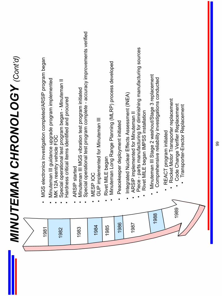
MIN
UTE
MA
N C
HR
ON
OLO
GY (Cont’d)
•M
GS
elec
troni
cs in
vest
igat
ion
com
plet
ed/A
RSI
P pr
ogra
m b
egan
•M
inut
eman
III g
uida
nce
upgr
ade
prog
ram
impl
emen
ted
•M
K 1
2A re
entry
veh
icle
FO
C•
Spe
cial
ope
ratio
nal t
est p
rogr
am b
egan
-M
inut
eman
II•
Har
dnes
s cr
itica
l ite
ms
iden
tifie
d an
d pr
ocur
ed
•AR
SIP
sta
rted
•M
inut
eman
III M
GS
vibr
atio
n te
st p
rogr
am in
itiat
ed•
Spec
ial o
pera
tiona
l tes
t pro
gram
com
plet
e -a
ccur
acy
impr
ovem
ents
ver
ified
1981
1982
1983
1984
1985 19
86
1987
1988 19
89
•M
ESP
IOC
•G
UP
impl
emen
ted
for M
inut
eman
III
•R
ivet
MIL
E b
egan
•M
inut
eman
Lon
g R
ange
Pla
nnin
g (M
LRP)
pro
cess
dev
elop
ed•
Peac
ekee
per d
eplo
ymen
t ini
tiate
d
•In
tegr
ated
Nuc
lear
Effe
cts
Ass
essm
ent (
INEA
)•
AR
SIP
impl
emen
ted
for M
inut
eman
II•
Piec
e -p
arts
man
ufac
turin
g fo
r dim
inis
hing
man
ufac
turin
g so
urce
s•
Riv
et M
ILE
beg
an IM
PSS
inst
alla
tion
•M
inut
eman
III S
tage
2 w
asho
ut/S
tage
3 re
plac
emen
t•
Com
preh
ensi
ve re
liabi
lity
inve
stig
atio
ns c
ondu
cted
•R
EAC
T pr
ogra
m in
itiat
ed
• T
rans
porte
r-Ere
ctor
Rep
lace
men
t•
Cod
e C
hang
e Ve
rifie
r Rep
lace
men
t•
Roc
ket M
otor
Tra
nspo
rter r
epla
cem
ent
99
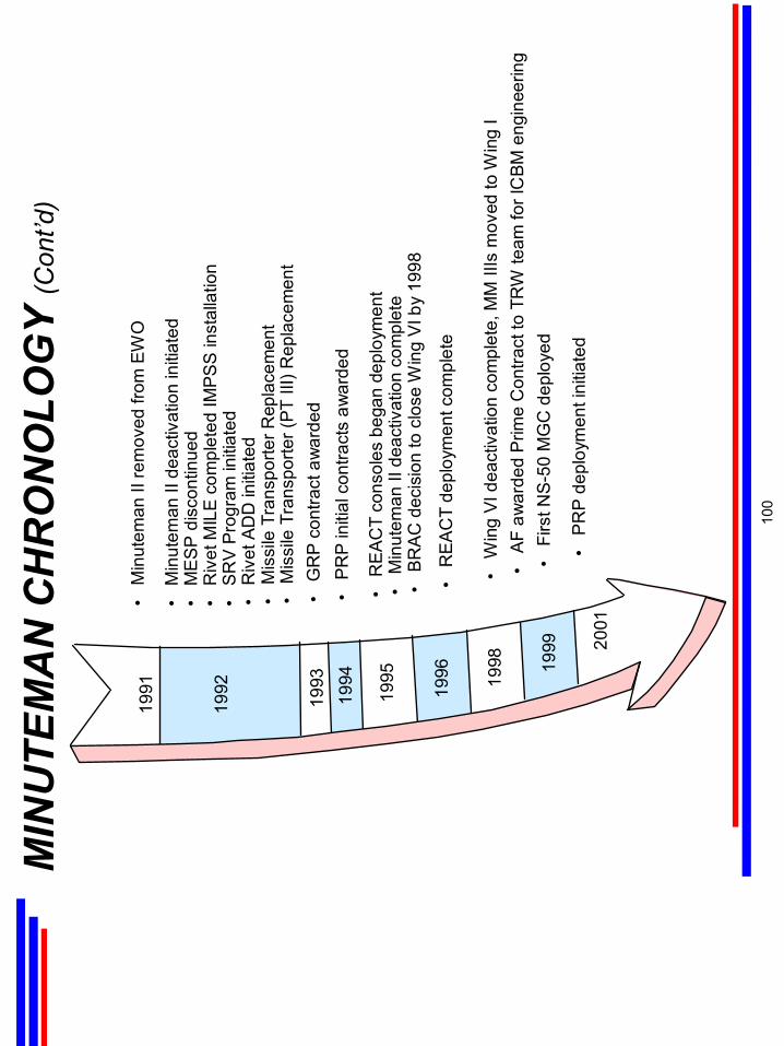
MIN
UTE
MA
N C
HR
ON
OLO
GY (Cont’d)
1991
1992
1993
1994
1995
•M
inut
eman
II re
mov
ed fr
om E
WO
•M
inut
eman
II d
eact
ivat
ion
initi
ated
•M
ESP
dis
cont
inue
d•
Riv
et M
ILE
com
plet
ed IM
PSS
inst
alla
tion
•S
RV
Pro
gram
initi
ated
•G
RP
cont
ract
aw
arde
d•
PR
P in
itial
con
tract
s aw
arde
d
•R
EAC
T co
nsol
es b
egan
dep
loym
ent
•M
inut
eman
II d
eact
ivat
ion
com
plet
e•
BR
AC d
ecis
ion
to c
lose
Win
g V
I by
1998
•M
issi
le T
rans
porte
r (PT
III)
Rep
lace
men
t•
Mis
sile
Tra
nspo
rter R
epla
cem
ent
•R
ivet
AD
D in
itiat
ed
•R
EA
CT
depl
oym
ent c
ompl
ete
•W
ing
VI d
eact
ivat
ion
com
plet
e, M
MIII
sm
oved
to W
ing
I•
AF
awar
ded
Prim
e C
ontra
ct to
TR
W te
am fo
r IC
BM e
ngin
eerin
g •
Firs
t NS-
50 M
GC
dep
loye
d
•P
RP
dep
loym
ent i
nitia
ted
1996 19
98 1999 20
01
100

AC
RO
NYM
LIS
T20
AF
Twen
tieth
Air
Forc
eA
/DA
rm/D
isar
mA
BN
CP
Airb
orne
Nat
iona
l Com
man
d Po
stA
CA
ltern
atin
g C
urre
ntA
CG
Atti
tude
Con
trol
Gro
upA
FMC
Air
Forc
e M
ater
iel C
omm
and
AFP
EOA
ir Fo
rce
Prog
ram
Exe
cutiv
e O
ffice
AFS
ATC
OM
Air
Forc
e Sa
telli
te C
omm
unic
atio
n Sy
stem
AFS
CA
ir Fo
rce
Syst
ems
Com
man
dA
FSPC
Air
Forc
e Sp
ace
Com
man
dA
LCC
Airb
orne
Lau
nch
Con
trol
Cen
ter
ALC
SA
irbor
ne L
aunc
h C
ontr
ol S
yste
mA
OTT
SA
ll O
rdna
nce
Thru
st T
erm
inat
ion
Syst
emA
PSA
uxili
ary
Pow
er S
uppl
yA
RS
IPA
ccur
acy,
Rel
iabi
lity,
Sup
port
abili
ty Im
prov
emen
t Pro
gram
AU
TOD
INA
utom
atic
Dig
ital I
nfor
mat
ion
Net
wor
kA
VEA
eros
pace
Veh
icle
Equ
ipm
ent
BR
ACB
ase
Rea
lignm
ent a
nd C
losu
reC
&S
Com
man
d &
Sta
tus
CD
BC
omm
and
Dat
a B
uffe
rC
PC
omm
and
Post
DC
Dire
ct C
urre
ntD
CU
Dig
ital C
ontr
ol U
nit
DoD
Dep
artm
ent o
f Def
ense
DSC
SD
efen
se S
atel
lite
Com
mun
icat
ion
Syst
emD
SND
efen
se S
witc
hing
Net
wor
kE
AMEm
erge
ncy
Act
ion
Mes
sage
EMP
Elec
trom
agne
tic P
ulse
ENC
Exha
ust N
ozzl
e C
ontr
olER
CS
Emer
genc
y R
ocke
t Com
mun
icat
ion
Syst
em
EWO
Emer
genc
y W
ar O
rder
FCE
Flig
ht C
ontr
ol E
quip
men
tFD
EFo
rce
Dev
elop
men
t Eva
luat
ion
FLTS
AT
Flee
t Sat
ellit
e Sy
stem
FOC
Fina
l Ope
ratio
nal C
apab
ility
G&
CG
uida
nce
& C
ontr
olG
CA
Gyr
o C
ompa
ss A
ssem
bly
GIP
Gui
danc
e Im
prov
emen
t Pro
gram
GR
PG
uida
nce
Rep
lace
men
t Pro
gram
GSP
Gyr
o St
abili
zed
Plat
form
GSP
PG
yro
Stab
ilize
d Pl
atfo
rm P
rogr
amG
UP
Gui
danc
e U
pgra
de P
rogr
amH
ICS
Har
dene
dIn
ters
iteC
able
Sys
tem
HQ
AFM
CH
eadq
uart
ers,
Air
Forc
e M
ater
ial C
omm
and
HQ
AFS
PCH
eadq
uart
ers,
Air
Forc
e Sp
ace
Com
man
dH
Q U
SAF
Hea
dqua
rter
s, U
nite
d St
ates
Air
Forc
eIC
BM
Inte
rcon
tinen
tal B
allis
tic M
issi
leIL
CS
Impr
oved
Lau
nch
Con
trol
Sys
tem
ILR
PIC
BM
Lon
g-ra
nge
Req
uire
men
ts P
lann
ing
IMP
ICB
M M
aste
r Pla
nIM
PSS
Impr
oved
Min
utem
an P
hysi
cal S
ecur
ity S
yste
mIM
UIn
ertia
l Mea
sure
men
t Uni
tIN
EA
Inte
grat
ed N
ucle
ar E
ffect
s A
sses
smen
tIO
CIn
itial
Ope
ratio
nal C
apab
ility
ISST
ICB
M S
uper
Hig
h Fr
eque
ncy
Sate
llite
Ter
min
alLC
CLa
unch
Con
trol
Cen
ter
LCEB
Lanc
hC
ontr
ol E
quip
men
t Bui
ldin
gLC
FLa
unch
Con
trol
Fac
ility
LCSB
Laun
ch C
ontr
ol S
uppo
rt B
uild
ing
LEB
Laun
cher
Equ
ipm
ent B
uild
ing
LER
Laun
ch E
quip
men
t Roo
m
101
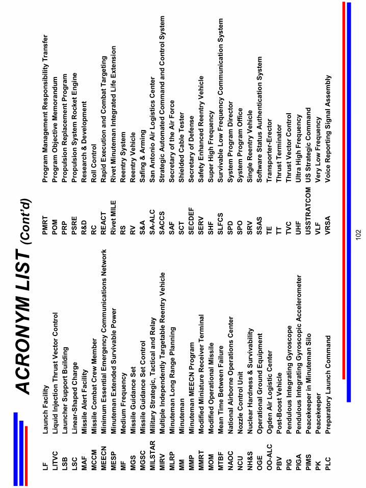
LFLa
unch
Fac
ility
LITV
CLi
quid
Inje
ctio
n Th
rust
Vec
tor C
ontr
olLS
BLa
unch
er S
uppo
rt B
uild
ing
LSC
Line
ar-S
hape
d C
harg
eM
AF
Mis
sile
Ale
rt F
acili
tyM
CC
MM
issi
le C
omba
t Cre
w M
embe
rM
EEC
NM
inim
um E
ssen
tial E
mer
genc
y C
omm
unic
atio
ns N
etw
ork
MES
PM
inut
eman
Ext
ende
d S
urvi
vabl
e Po
wer
MF
Med
ium
Fre
quen
cyM
GS
Mis
sile
Gui
danc
e Se
tM
GSC
Mis
sile
Gui
danc
e Se
t Con
trol
MIL
STA
RM
ilita
ry S
trat
egic
, Tac
tical
and
Rel
ayM
IRV
Mul
tiple
Inde
pend
ently
Targ
etab
leR
eent
ry V
ehic
leM
LRP
Min
utem
an L
ong
Ran
ge P
lann
ing
MM
Min
utem
anM
MP
Min
utem
an M
EEC
N P
rogr
amM
MR
TM
odifi
ed M
inia
ture
Rec
eive
r Ter
min
alM
OM
Mod
ified
Ope
ratio
nal M
issi
leM
TBF
Mea
n Ti
me
Bet
wee
n Fa
ilure
NAO
CN
atio
nal A
irbor
ne O
pera
tions
Cen
ter
NC
UN
ozzl
e C
ontr
ol U
nit
NH
&S
Nuc
lear
Har
dnes
s &
Sur
viva
bilit
yO
GE
Ope
ratio
nal G
roun
d Eq
uipm
ent
OO
-ALC
Ogd
en A
ir Lo
gist
ic C
ente
rPB
VPo
st-B
oost
Veh
icle
PIG
Pend
ulou
s In
tegr
atin
g G
yros
cope
PIG
APe
ndul
ous
Inte
grat
ing
Gyr
osco
pic
Acc
eler
omet
erPI
MS
Peac
ekee
per i
n M
inut
eman
Silo
PKPe
acek
eepe
rPL
CPr
epar
ator
y La
unch
Com
man
d
AC
RO
NYM
LIS
T (C
ont’d
)PM
RT
Prog
ram
Man
agem
ent R
espo
nsib
ility
Tra
nsfe
rPO
MPr
ogra
m O
bjec
tive
Mem
oran
dum
PRP
Prop
ulsi
on R
epla
cem
ent P
rogr
amPS
RE
Prop
ulsi
on S
yste
m R
ocke
t Eng
ine
R&
DR
esea
rch
& D
evel
opm
ent
RC
Rol
l Con
trol
RE
ACT
Rap
id E
xecu
tion
and
Com
bat T
arge
ting
Riv
et M
ILE
Riv
et M
inut
eman
Inte
grat
ed L
ife E
xten
sion
RS
Ree
ntry
Sys
tem
RV
Ree
ntry
Veh
icle
S&A
Safin
g&
Arm
ing
SA-
ALC
San
Ant
onio
Air
Logi
stic
s C
ente
rS
ACC
SSt
rate
gic
Aut
omat
ed C
omm
and
and
Con
trol
Sys
tem
SAF
Secr
etar
y of
the
Air
Forc
eSC
TSh
ield
ed C
able
Tes
ter
SEC
DEF
Secr
etar
y of
Def
ense
SER
VSa
fety
Enh
ance
d R
eent
ry V
ehic
leSH
FSu
per H
igh
Freq
uenc
ySL
FCS
Surv
ivab
le L
ow F
requ
ency
Com
mun
icat
ion
Syst
emSP
DSy
stem
Pro
gram
Dire
ctor
SPO
Syst
em P
rogr
am O
ffice
SRV
Sing
le R
eent
ry V
ehic
leSS
ASSo
ftwar
e St
atus
Aut
hent
icat
ion
Syst
emTE
Tran
spor
ter-
Erec
tor
TTTh
rust
Ter
min
ator
TVC
Thru
st V
ecto
r Con
trol
UH
FU
ltra
Hig
h Fr
eque
ncy
USS
TRAT
CO
MU
S St
rate
gic
Com
man
dVL
FVe
ry L
ow F
requ
ency
VRSA
Voic
e R
epor
ting
Sign
al A
ssem
bly
102