Embed Size (px)
Citation preview

MKS TyThrottle Valv
Instructio
pe 153Fe Controller
n Manual
123057-P1Rev. A, 06/04
Instruction Manual
Six Shattuck RoadAndoverMA 01810-2449
Main: 978.975.2350Fax: 978.975.0093www.mksinst.com
WARRANTYTypes 153F Throttle Valve Controller
MKS Instruments, Inc. (MKS) warrants that for two years from the date of shipmentthe equipment described above (the “equipment”) manufactured by MKS shall befree from defects in materials and workmanship and will correctly perform all date-related operations, including without limitation accepting data entry, sequencing,sorting, comparing, and reporting, regardless of the date the operation is performedor the date involved in the operation, provided that, if the equipment exchangesdata or is otherwise used with equipment, software, or other products of others,such products of others themselves correctly perform all date-related operationsand store and transmit dates and date-related data in a format compatible withMKS equipment. THIS W ARRANTY IS MKS’ SOLE W ARRANTY CONCERNINGDATE-RELATED OPERATIONS.
For the period commencing with the date of shipment of this equipment and endingtwo years later, MKS will, at its option, either repair or replace any part which isdefective in materials or workmanship or with respect to the date-related operationswarranty without charge to the purchaser. The foregoing shall constitute theexclusive and sole remedy of the purchaser for any breach by MKS of thiswarranty.
The purchaser, before returning any equipment covered by this warranty, which isasserted to be defective by the purchaser, shall make specific written arrange-ments with respect to the responsibility for shipping the equipment and handlingany other incidental charges with the MKS sales representative or distributor fromwhich the equipment was purchased or, in the case of a direct purchase from MKS,with the MKS home office in Andover, Massachusetts, USA.
This warranty does not apply to any equipment which has not been installed andused in accordance with the specifications recommended by MKS for the properand normal use of the equipment. MKS shall not be liable under any circumstancesfor indirect, special, consequential, or incidental damages in connection with, orarising out of, the sale, performance, or use of the equipment covered by thiswarranty.
MKS recommends that all MKS pressure and flow products be calibratedperiodically (typically every 6 to 12 months) to ensure accurate readings. W hen aproduct is returned to MKS for this periodic re-calibration it is considered normalpreventative maintenance not covered by any warranty.
THIS W ARRANTY IS IN LIEU OF ALL OTHER RELEVANT WARRANTIES,EXPRESSED OR IMPLIED, INCLUDING THE IMPLIED W ARRANTY OFMERCHANTABILITY AND THE IMPLIED W ARRANTY OF FITNESS FOR APARTICULAR PURPOSE, AND ANY W ARRANTY AGAINST INFRINGEMENT OFANY PATENT.
06/04 123057-1 Rev. A

123057-P1Rev A, 6/04
Throttle Valve Controller
J1Input
J2 Power
Power
OPEN CLOSE
TYPE 153CONTROL VALVE


Copyright © 2004 by MKS Instruments, Inc.
All rights reserved. No part of this work may be reproduced or transmitted in any form or by anymeans, electronic or mechanical, including photocopying and recording, or by any informationstorage or retrieval system, except as may be expressly permitted in writing by MKS Instruments,Inc.
Printed in the United States of America
Cluster Gauge™ is trademark of MKS Instruments, Inc., Andover, MA
Parker® is a registered trademark of Parker Seals, Lexington, KY
Viton® is a registered trademark of DuPont Dow Elastomers, Inc., Wilmington, DE
Firmware version: 1.1x

Table of Contents
v
Table of Contents
Valve Safety Information.............................................................................................................1
Symbols Used in This Instruction Manual......................................................................1
Symbols Found on the Unit ............................................................................................2
Safety Procedures and Precautions .................................................................................3
Sicherheitshinweise für das Ventil...............................................................................................5
In dieser Betriebsanleitung vorkommende Symbole ......................................................5
Erklärung der am Gerät angebrachten Symbole .............................................................6
Sicherheitsvorschriften und Vorsichtsmaßnahmen.........................................................7
Informations relatives à la sécurité pour la valve.........................................................................9
Symboles utilisés dans ce manuel d'utilisation ...............................................................9
Symboles apparaissant sur l'unité ...................................................................................10
Mesures de sécurité et précautions .................................................................................11
Medidas de seguridad de la válvula .............................................................................................13
Símbolos usados en este manual de instrucciones ..........................................................13
Símbolos hallados en la unidad.......................................................................................14
Procedimientos y precauciones de seguridad..................................................................15
Chapter One: General Information .............................................................................................17
Introduction.....................................................................................................................17
How This Manual is Organized ......................................................................................18
Customer Support ...........................................................................................................18
Chapter Two: Installation ...........................................................................................................19
How To Unpack the Type 153 Unit................................................................................19
Unpacking Checklist..........................................................................................19
Interface Cables ..............................................................................................................20
Generic Shielded Cables ....................................................................................21
Setup ...............................................................................................................................24
Dimensions ........................................................................................................24
Power Requirements ..........................................................................................29
Table of Contents
vi
Grounding ..........................................................................................................29
Mounting Instructions........................................................................................31
Connectors ......................................................................................................................33
Power Connector (J2) ........................................................................................33
Input Connector (J1) ..........................................................................................34
How To Connect to a PT-1 Portable RS-232 Terminal ..................................................37
How To Connect to a Computer .....................................................................................38
How To Connect to a Type 146 Cluster Gauge™ ..........................................................39
Chapter Three: Overview............................................................................................................41
Control Mode..................................................................................................................41
Lead and Gain....................................................................................................41
External Connectors and Controls ..................................................................................44
Power On LED...................................................................................................44
Input Connector (J1) ..........................................................................................44
Power Connector (J2) ........................................................................................44
Hold/Normal Switch ..........................................................................................45
Manual Valve Switch.........................................................................................45
Valve Open LED ...............................................................................................45
Valve Close LED ...............................................................................................45
Internal Controls .............................................................................................................46
Dipswitch Bank..................................................................................................46
How To Change the Dipswitch Settings............................................................49
Power-Down Constants ..................................................................................................50
Power Up Conditions......................................................................................................50
Labels..............................................................................................................................51
Pump Label ........................................................................................................51
Serial Number Label ..........................................................................................51
Chapter Four: Operation .............................................................................................................53
General Information........................................................................................................53
Control Parameters..........................................................................................................53
RS-232 Communication Parameters ...............................................................................54
How To Change the Communication Parameters..............................................55
RS-232 Protocol..............................................................................................................56
Table of Contents
vii
Message Format .................................................................................................56
Message Syntax .................................................................................................57
RS-232 Communication Commands ..............................................................................58
Operating Value Messages .............................................................................................59
How To Set the Lead and Gain..........................................................................60
How To Set the Set Point...................................................................................60
Valve Position Messages ................................................................................................61
How To Control the Valve.................................................................................62
How To Set the Valve Position..........................................................................62
How To Return to Normal Operation ................................................................63
Calibration Messages ......................................................................................................64
How To Learn the System Characteristics.........................................................64
How To Calibrate the System for Output Errors ...............................................70
Informational Messages ..................................................................................................74
How To Report the Pressure Reading................................................................74
How To Report the Analog Set Point Input Voltage .........................................75
How To Report the Status of the Valve Slipped Signal.....................................75
How To Use the Pressure Control Mode ........................................................................76
How To Select the Pressure Control Mode........................................................76
How To Use an Analog Set Point for Pressure Control.....................................76
How To Use a Digital Set Point for Pressure Control .......................................77
How To Override the Pressure Control Mode ...................................................77
How To Use the Position Control Mode.........................................................................78
How To Select the Position Control Mode........................................................78
How To Use an Analog Set Point for Position Control .....................................78
How To Use a Digital Set Point for Position Control........................................79
How To Tune the Controller...........................................................................................80
How To Reset the Controller ..........................................................................................82
Chapter Five: Maintenance and Troubleshooting.......................................................................85
General Information........................................................................................................85
Maintenance....................................................................................................................85
How To Clean the Unit ......................................................................................85
Troubleshooting ..............................................................................................................86
Table of Contents
viii
Valve Slipped Signal .........................................................................................86
Appendix A: Product Specifications...........................................................................................87
Valve Specifications .......................................................................................................87
ASA Flange Specifications .............................................................................................89
KF Style ISO Flange Specifications ...............................................................................91
NW Style ISO Flange Specifications..............................................................................93
CF Flange Specifications ................................................................................................94
JIS Flange Specifications................................................................................................96
Appendix B: Model Code Explanation.......................................................................................97
Model Code.....................................................................................................................97
Type 153 Controller Model Codes .................................................................................99
Type 153 Units with ASA Flanges ....................................................................99
Type 153 Controller with KF or NW ISO Flanges............................................100
Type 153 Controller with CF Flanges ...............................................................101
Type 153 Controller with JIS Flanges ...............................................................102
Portable RS-232 Terminal Model Code..........................................................................102
Index ............................................................................................................................................103
List of Figures
ix
List of Figures
Figure 1: Preferred Method To Connect an Overall Metal Braided Shielded Cable ..................22
Figure 2: Alternate Method To Connect an Overall Metal Braided Shielded Cable ..................23
Figure 3: Type 153 Controller Dimensions ................................................................................24
Figure 4: Outline Dimensions of an ASA Flange .......................................................................25
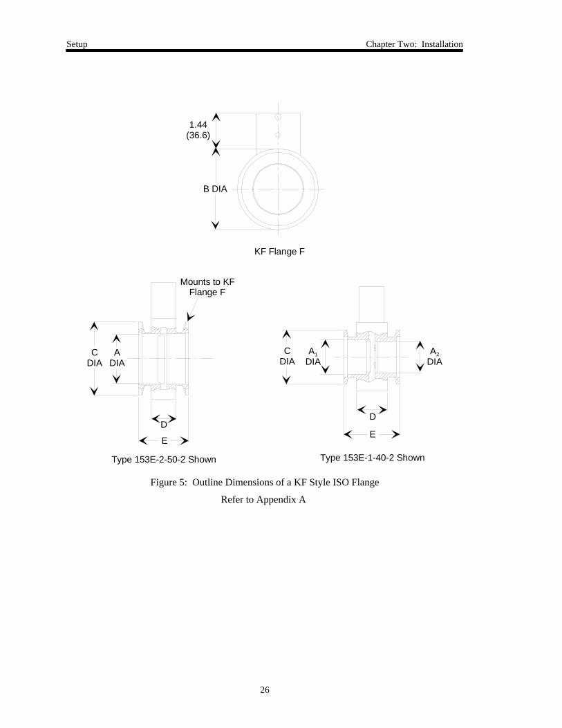
Figure 5: Outline Dimensions of a KF Style ISO Flange ...........................................................26
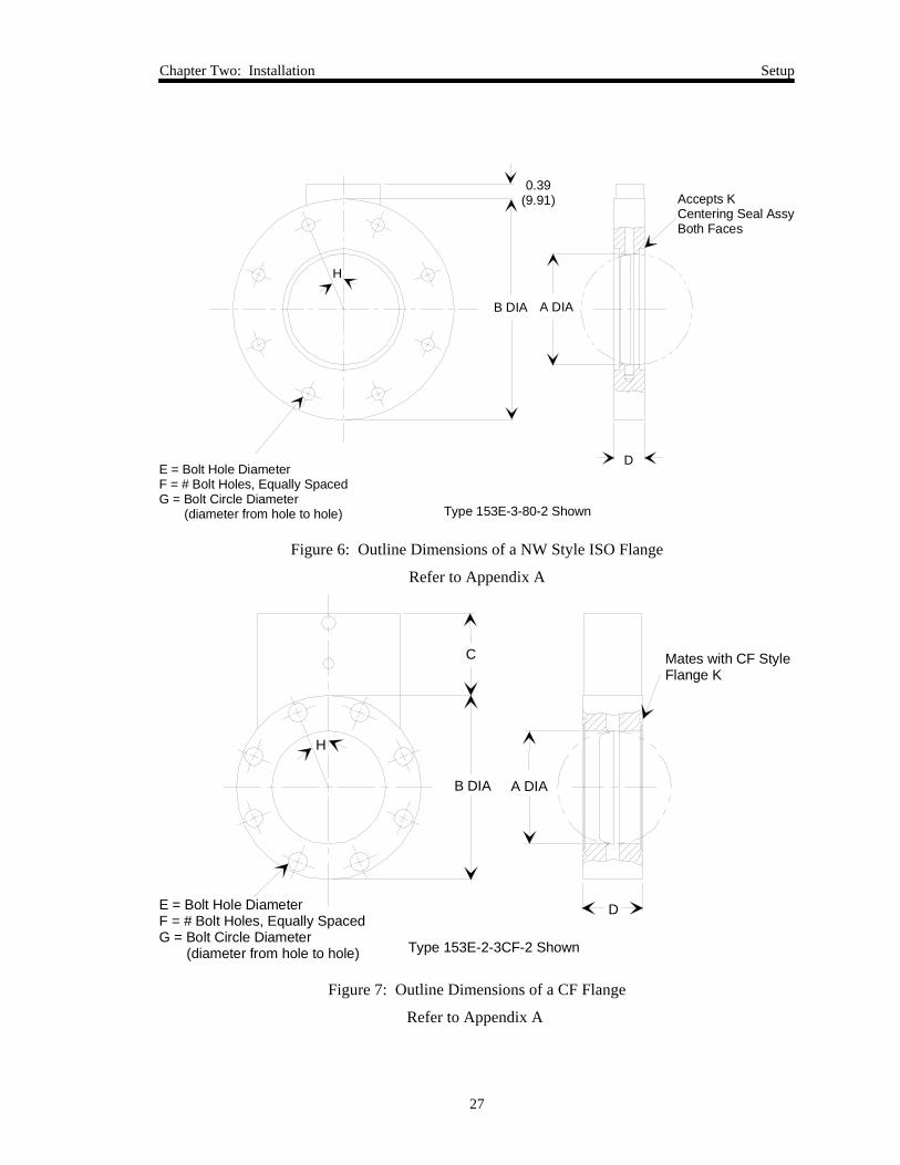
Figure 6: Outline Dimensions of a NW Style ISO Flange..........................................................27
Figure 7: Outline Dimensions of a CF Flange ............................................................................27
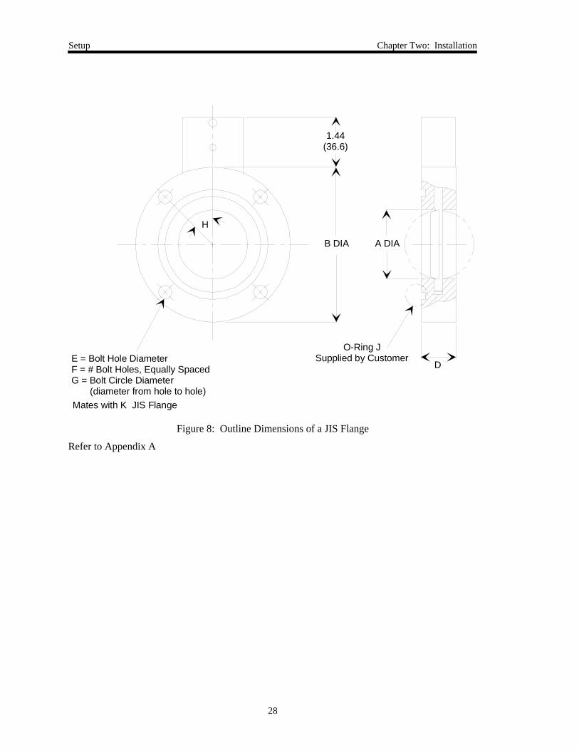
Figure 8: Outline Dimensions of a JIS Flange............................................................................28
Figure 9: Returned Leads Tied to System Ground .....................................................................30
Figure 10: Typical System Configuration...................................................................................32
Figure 11: Null Modem RS-232 Communication Cable ............................................................38
Figure 12: Lead Set Too High ....................................................................................................42
Figure 13: Lead Set Too Low .....................................................................................................42
Figure 14: Gain Set Too High.....................................................................................................43
Figure 15: Gain Set Too Low .....................................................................................................43
Figure 16: Top Panel of the 153 Controller ................................................................................44
Figure 17: Location of the Dipswitch Bank on the CPU Board .................................................46
Figure 18: Pump Label................................................................................................................51
Figure 19: Serial Number Label .................................................................................................51

List of Tables
xi
List of Tables
Table 1: Definition of Symbols Found on the Unit ........................................................................ 2
Tabelle 2: Bedeutung der am Gerät angebrachten Symbole........................................................... 6
Tableau 3: Définition des symboles apparaissant sur l'unité ........................................................ 10
Tabla 4: Definición de los símbolos hallados en la unidad........................................................... 14
Table 5: Interface Cables .............................................................................................................. 20
Table 6: Power Connector (J2) Pinout.......................................................................................... 33
Table 7: Input Connector (J1) Pinout............................................................................................ 34
Table 8: Example Pressure Outputs for Input Connector Pin 4 .................................................... 36
Table 9: Example Valve Position Outputs for Input Connector Pin 6.......................................... 36
Table 10: Dipswitch Functions and Settings ................................................................................ 47
Table 11: Initial Control Parameters............................................................................................. 53
Table 12: Initial RS-232 Communication Parameters .................................................................. 54
Table 13: RS-232 Operating Value Messages .............................................................................. 59
Table 14: RS-232 Valve Position Messages ................................................................................. 61
Table 15: RS-232 Learn Messages ............................................................................................... 64
Table 16: RS-232 Calibration for Output Error Messages ........................................................... 70
Table 17: RS-232 Informational Messages................................................................................... 74
Table 18: Settings Established by the Reset [B] Command ....................................................... 82
Table 19: Model Codes for Type 153 Units with ASA Flanges................................................... 99
Table 20: Model Codes for Type 153 Units with KF or NW ISO Flanges ................................ 100
Table 21: Model Codes for Type 153 Units with CF Flanges .................................................... 101
Table 22: Model Codes for Type 153 Units with CF Flanges .................................................... 102

Valve Safety Information Symbols Used in This Instruction Manual
1
Valve Safety Information
Symbols Used in This Instruction Manual
Definitions of WARNING, CAUTION, and NOTE messages used throughout the manual.
Warning The WARNING sign denotes a hazard to personnel. It callsattention to a procedure, practice, condition, or the like,which, if not correctly performed or adhered to, could result ininjury to personnel.
Caution The CAUTION sign denotes a hazard to equipment. It calls attentionto an operating procedure, practice, or the like, which, if not correctlyperformed or adhered to, could result in damage to or destruction ofall or part of the product.
Note The NOTE sign denotes important information. It calls attention to aprocedure, practice, condition, or the like, which is essential to highlight.
Symbols Found on the Unit Valve Safety Information
2
Symbols Found on the Unit
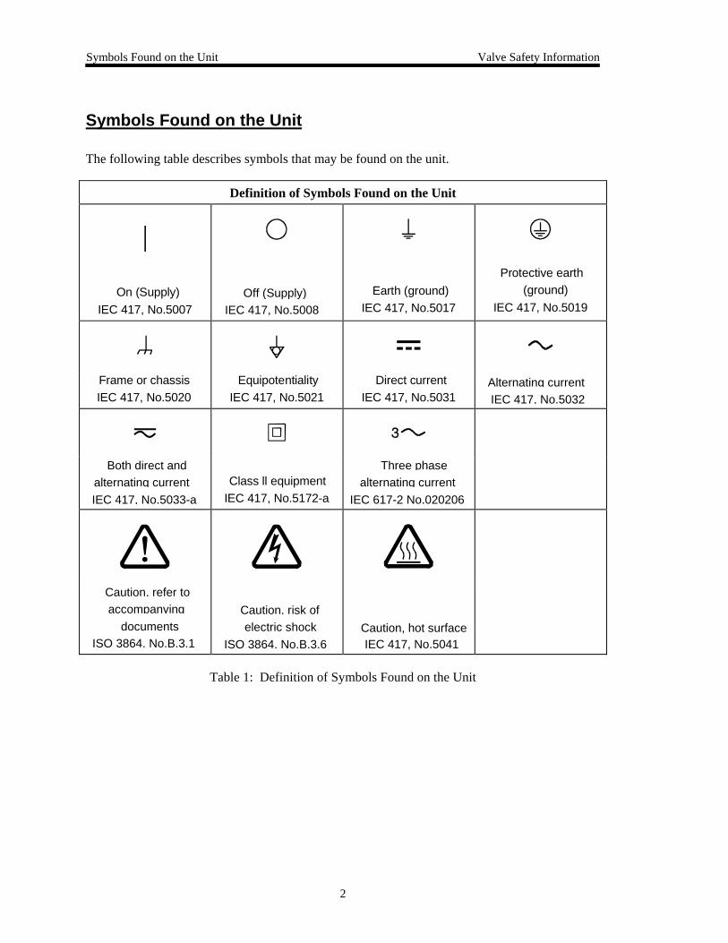
The following table describes symbols that may be found on the unit.
Definition of Symbols Found on the Unit
|
On (Supply) IEC 417, No.5007
Off (Supply)IEC 417, No.5008
Earth (ground) IEC 417, No.5017
Protective earth (ground)
IEC 417, No.5019
Frame or chassis IEC 417, No.5020
Equipotentiality IEC 417, No.5021
Direct current IEC 417, No.5031
Alternating currentIEC 417, No.5032
Both direct andalternating currentIEC 417, No.5033-a
Class ll equipment IEC 417, No.5172-a
Three phasealternating current
IEC 617-2 No.020206
Caution, refer toaccompanying
documentsISO 3864, No.B.3.1
Caution, risk ofelectric shock
ISO 3864, No.B.3.6Caution, hot surfaceIEC 417, No.5041
Table 1: Definition of Symbols Found on the Unit
Valve Safety Information Safety Procedures and Precautions
3
Safety Procedures and Precautions
Observe the following general safety precautions during all phases of valve operation. Failure tocomply with these precautions or with specific warnings elsewhere in this manual violates safetystandards of intended use of the valve and may impair the protection provided by theequipment. MKS Instruments, Inc. assumes no liability for the customer’s failure to complywith these requirements.
Warning Moving parts in the valve create a risk of personal injury untilthe valve is securely incorporated into a system. To avoidinjury, keep all bodily parts away from any valve opening.
1. Do not insert objects into openings where contact withmoving parts is possible.
2. Isolate the valve from any electrical or pneumatic powersupply before handling the valve.
DO NOT SUBSTITUTE PARTS OR MODIFY VALVE
Do not install substitute parts or perform any unauthorized modification to the valve. Return thevalve to an MKS Calibration and Service Center for service and repair to ensure that all safetyfeatures are maintained.
SERVICE BY QUALIFIED PERSONNEL ONLY
Operating personnel must not attempt component replacement and internal adjustments. Anyservice must be performed by qualified service personnel only.
USE CAUTION WHEN OPERATING WITH HAZARDOUS MATERIALS
If hazardous materials are used, observe the proper safety precautions, completely purge the valvewhen necessary, and ensure that the material used is compatible with the wetted materials in thisproduct, including any sealing materials.
PURGE THE VALVE
After installing the unit, or before removing it from a system, purge the unit completely with aclean, dry gas to eliminate all traces of the previously used flow material.
USE PROPER PROCEDURES WHEN PURGING
This valve must be purged under a ventilation hood, and gloves must be worn for protection.
DO NOT OPERATE IN AN EXPLOSIVE ENVIRONMENT
To avoid explosion, do not operate this product in an explosive environment unless it has beenspecifically certified for such operation.
Safety Procedures and Precautions Valve Safety Information
4
USE PROPER FITTINGS AND TIGHTENING PROCEDURES
All valve fittings must be consistent with valve specifications, and compatible with the intendeduse of the valve. Assemble and tighten fittings according to manufacturer’s directions.
CHECK FOR LEAK-TIGHT FITTINGS
Carefully check all vacuum component connections to ensure leak-tight installation.
OPERATE AT SAFE INLET PRESSURES
Never operate the valve at pressures higher than the rated maximum pressure (refer to the productspecifications for the maximum allowable pressure).
INSTALL A SUITABLE BURST DISC
When operating from a pressurized gas source, install a suitable burst disc in the vacuum systemto prevent system explosion should the system pressure rise.
KEEP THE UNIT FREE OF CONTAMINANTS
Do not allow contaminants to enter the unit before or during use. Contamination such as dust,dirt, lint, glass chips, and metal chips may permanently damage the unit or contaminate theprocess.
KEEP AWAY FROM VALVE OPENING
Keep fingers, other body parts, and other materials away from the valve opening when the valveis in operation.
Sicherheitshinweise für das Ventil In dieser Betriebsanleitung vorkommende Symbole
5
Sicherheitshinweise für das Ventil
In dieser Betriebsanleitung vorkommende Symbole
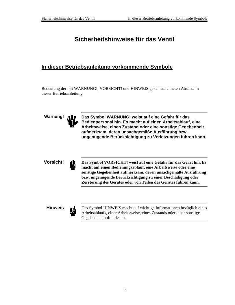
Bedeutung der mit WARNUNG!, VORSICHT! und HINWEIS gekennzeichneten Absätze indieser Betriebsanleitung.
Warnung! Das Symbol WARNUNG! weist auf eine Gefahr für dasBedienpersonal hin. Es macht auf einen Arbeitsablauf, eineArbeitsweise, einen Zustand oder eine sonstige Gegebenheitaufmerksam, deren unsachgemäße Ausführung bzw.ungenügende Berücksichtigung zu Verletzungen führen kann.
Vorsicht! Das Symbol VORSICHT! weist auf eine Gefahr für das Gerät hin. Esmacht auf einen Bedienungsablauf, eine Arbeitsweise oder einesonstige Gegebenheit aufmerksam, deren unsachgemäße Ausführungbzw. ungenügende Berücksichtigung zu einer Beschädigung oderZerstörung des Gerätes oder von Teilen des Gerätes führen kann.
Hinweis Das Symbol HINWEIS macht auf wichtige Informationen bezüglich einesArbeitsablaufs, einer Arbeitsweise, eines Zustands oder einer sonstigeGegebenheit aufmerksam.
Erklärung der am Gerät angebrachten Symbole Sicherheitshinweise für das Ventil
6
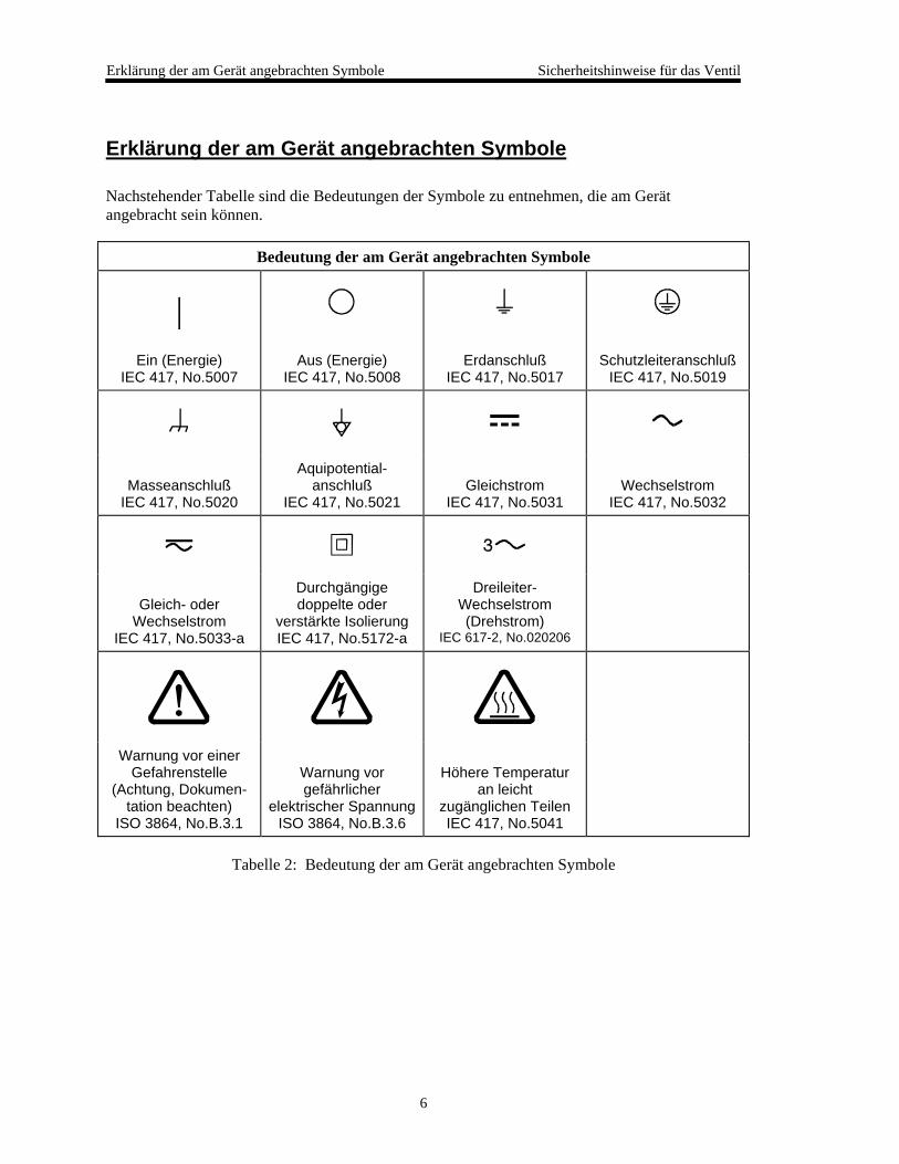
Erklärung der am Gerät angebrachten Symbole
Nachstehender Tabelle sind die Bedeutungen der Symbole zu entnehmen, die am Gerätangebracht sein können.
Bedeutung der am Gerät angebrachten Symbole
|Ein (Energie)
IEC 417, No.5007Aus (Energie)
IEC 417, No.5008Erdanschluß
IEC 417, No.5017Schutzleiteranschluß
IEC 417, No.5019
MasseanschlußIEC 417, No.5020
Aquipotential-anschluß
IEC 417, No.5021Gleichstrom
IEC 417, No.5031Wechselstrom
IEC 417, No.5032
Gleich- oderWechselstrom
IEC 417, No.5033-a
Durchgängigedoppelte oder
verstärkte IsolierungIEC 417, No.5172-a
Dreileiter-Wechselstrom(Drehstrom)
IEC 617-2, No.020206
Warnung vor einerGefahrenstelle
(Achtung, Dokumen-tation beachten)
ISO 3864, No.B.3.1
Warnung vorgefährlicher
elektrischer SpannungISO 3864, No.B.3.6
Höhere Temperaturan leicht
zugänglichen TeilenIEC 417, No.5041
Tabelle 2: Bedeutung der am Gerät angebrachten Symbole
Sicherheitshinweise für das Ventil Sicherheitsvorschriften und Vorsichtsmaßnahmen
7
Sicherheitsvorschriften und Vorsichtsmaßnahmen
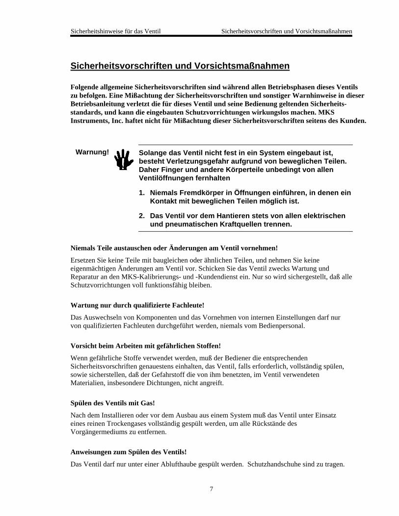
Folgende allgemeine Sicherheitsvorschriften sind während allen Betriebsphasen dieses Ventilszu befolgen. Eine Mißachtung der Sicherheitsvorschriften und sonstiger Warnhinweise in dieserBetriebsanleitung verletzt die für dieses Ventil und seine Bedienung geltenden Sicherheits-standards, und kann die eingebauten Schutzvorrichtungen wirkungslos machen. MKSInstruments, Inc. haftet nicht für Mißachtung dieser Sicherheitsvorschriften seitens des Kunden.
Warnung! Solange das Ventil nicht fest in ein System eingebaut ist,besteht Verletzungsgefahr aufgrund von beweglichen Teilen.Daher Finger und andere Körperteile unbedingt von allenVentilöffnungen fernhalten
1. Niemals Fremdkörper in Öffnungen einführen, in denen einKontakt mit beweglichen Teilen möglich ist.
2. Das Ventil vor dem Hantieren stets von allen elektrischenund pneumatischen Kraftquellen trennen.
Niemals Teile austauschen oder Änderungen am Ventil vornehmen!
Ersetzen Sie keine Teile mit baugleichen oder ähnlichen Teilen, und nehmen Sie keineeigenmächtigen Änderungen am Ventil vor. Schicken Sie das Ventil zwecks Wartung undReparatur an den MKS-Kalibrierungs- und -Kundendienst ein. Nur so wird sichergestellt, daß alleSchutzvorrichtungen voll funktionsfähig bleiben.
Wartung nur durch qualifizierte Fachleute!
Das Auswechseln von Komponenten und das Vornehmen von internen Einstellungen darf nurvon qualifizierten Fachleuten durchgeführt werden, niemals vom Bedienpersonal.
Vorsicht beim Arbeiten mit gefährlichen Stoffen!
Wenn gefährliche Stoffe verwendet werden, muß der Bediener die entsprechendenSicherheitsvorschriften genauestens einhalten, das Ventil, falls erforderlich, vollständig spülen,sowie sicherstellen, daß der Gefahrstoff die von ihm benetzten, im Ventil verwendetenMaterialien, insbesondere Dichtungen, nicht angreift.
Spülen des Ventils mit Gas!
Nach dem Installieren oder vor dem Ausbau aus einem System muß das Ventil unter Einsatzeines reinen Trockengases vollständig gespült werden, um alle Rückstände desVorgängermediums zu entfernen.
Anweisungen zum Spülen des Ventils!
Das Ventil darf nur unter einer Ablufthaube gespült werden. Schutzhandschuhe sind zu tragen.

Sicherheitsvorschriften und Vorsichtsmaßnahmen Sicherheitshinweise für das Ventil
8
Nicht zusammmen mit explosiven Stoffen, Gasen oder Dämpfen benutzen!
Um der Gefahr einer Explosion vorzubeugen, darf dieses Produkt niemals zusammen mitexplosiven Stoffe aller Art eingesetzt werden, sofern es nicht ausdrücklich für diesen Zweckzugelassen ist.
Anweisungen zum Installieren der Armaturen!
Alle Ventilanschlußstücke und Armaturenteile müssen mit den Ventilspezifikationenübereinstimmen, und mit dem geplanten Einsatz des Ventils kompatibel sein. Der Einbau,insbesondere das Anziehen und Abdichten, muß gemäß den Anweisungen des Herstellersvorgenommen werden.
Ventil auf Undichtigkeiten prüfen!
Überprüfen Sie sorgfältig alle Verbindungen auf undichte Stellen.
Nur unter zulässigen Anschlußdrücken betreiben!
Betreiben Sie das Ventil niemals unter Drücken, die den maximal zulässigen Druck (sieheProduktspezifikationen) übersteigen.
Geeignete Berstscheibe installieren!
Wenn mit einer unter Druck stehenden Gasquelle gearbeitet wird, sollte eine geeigneteBerstscheibe in das Vakuumsystem installiert werden, um eine Explosionsgefahr aufgrund vonsteigendem Systemdruck zu vermeiden.
Verunreinigungen vermeiden!
Stellen Sie sicher, daß Verunreinigungen jeglicher Art weder vor dem Einsatz noch während desBetriebs in das Innere gelangen können. Staub- und Schmutzpartikel, Glassplitter oderMetallspäne können das Produkt dauerhaft beschädigen oder Prozeß und Meßwerte verfälschen.
Hände weg von der Ventilöffnung!
Körperteile, insbesondere Finger, sowie Fremdobjekte während des Betriebes von derVentilöffnung fernhalten.
Informations relatives à la sécurité pour la valve Symboles utilisés dans ce manuel d'utilisation
9
Informations relatives à la sécurité pour la valve
Symboles utilisés dans ce manuel d'utilisation
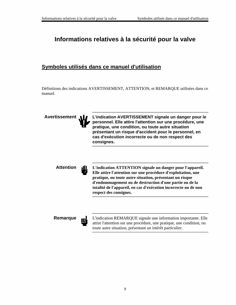
Définitions des indications AVERTISSEMENT, ATTENTION, et REMARQUE utilisées dans cemanuel.
Avertissement L'indication AVERTISSEMENT signale un danger pour lepersonnel. Elle attire l'attention sur une procédure, unepratique, une condition, ou toute autre situationprésentant un risque d'accident pour le personnel, encas d'exécution incorrecte ou de non respect desconsignes.
Attention L'indication ATTENTION signale un danger pour l'appareil.Elle attire l'attention sur une procédure d'exploitation, unepratique, ou toute autre situation, présentant un risqued'endommagement ou de destruction d'une partie ou de latotalité de l'appareil, en cas d'exécution incorrecte ou de nonrespect des consignes.
Remarque L'indication REMARQUE signale une information importante. Elleattire l'attention sur une procédure, une pratique, une condition, outoute autre situation, présentant un intérêt particulier.
Symboles apparaissant sur l'unité Informations relatives à la sécurité pour la valve
10
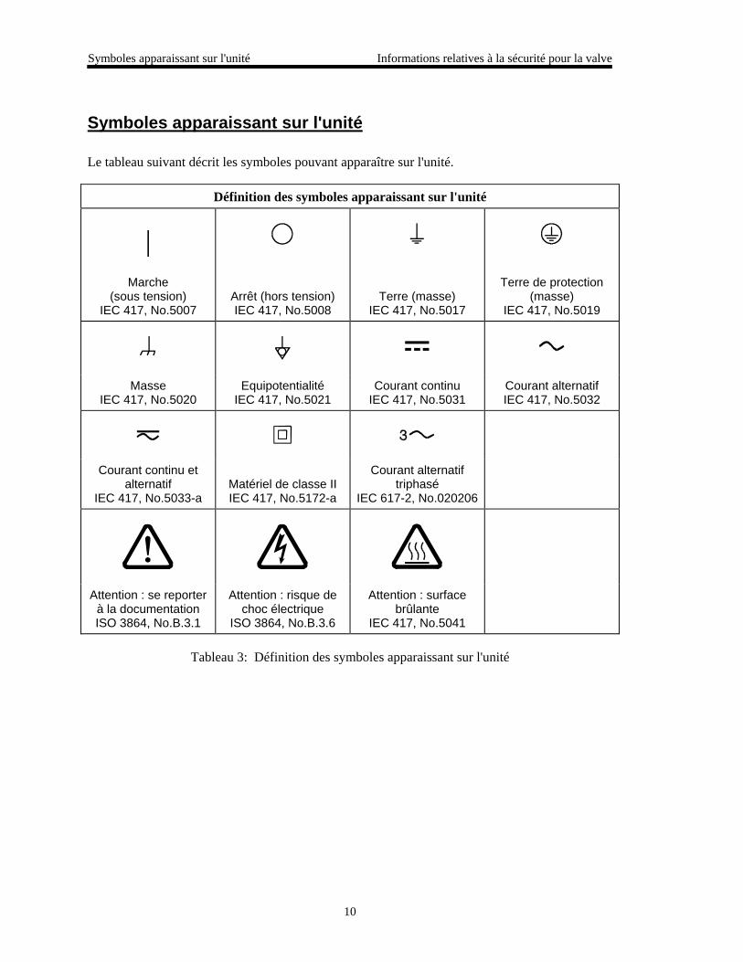
Symboles apparaissant sur l'unité
Le tableau suivant décrit les symboles pouvant apparaître sur l'unité.
Définition des symboles apparaissant sur l'unité
|Marche
(sous tension)IEC 417, No.5007
Arrêt (hors tension)IEC 417, No.5008
Terre (masse)IEC 417, No.5017
Terre de protection(masse)
IEC 417, No.5019
MasseIEC 417, No.5020
EquipotentialitéIEC 417, No.5021
Courant continuIEC 417, No.5031
Courant alternatifIEC 417, No.5032
Courant continu etalternatif
IEC 417, No.5033-aMatériel de classe IIIEC 417, No.5172-a
Courant alternatiftriphasé
IEC 617-2, No.020206
Attention : se reporterà la documentationISO 3864, No.B.3.1
Attention : risque dechoc électrique
ISO 3864, No.B.3.6
Attention : surfacebrûlante
IEC 417, No.5041
Tableau 3: Définition des symboles apparaissant sur l'unité
Informations relatives à la sécurité pour la valve Mesures de sécurité et précautions
11
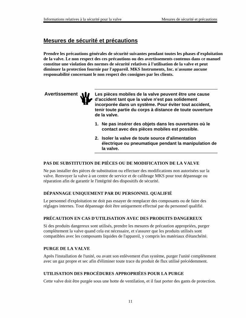
Mesures de sécurité et précautions
Prendre les précautions générales de sécurité suivantes pendant toutes les phases d'exploitationde la valve. Le non respect des ces précautions ou des avertissements contenus dans ce manuelconstitue une violation des normes de sécurité relatives à l'utilisation de la valve et peutdiminuer la protection fournie par l'appareil. MKS Instruments, Inc. n'assume aucuneresponsabilité concernant le non respect des consignes par les clients.
Avertissement Les pièces mobiles de la valve peuvent être une caused'accident tant que la valve n'est pas solidementincorporée dans un système. Pour éviter tout accident,tenir toute partie du corps à distance de toute ouverturede la valve.
1. Ne pas insérer des objets dans les ouvertures où lecontact avec des pièces mobiles est possible.
2. Isoler la valve de toute source d'alimentationélectrique ou pneumatique pendant la manipulation dela valve.
PAS DE SUBSTITUTION DE PIÈCES OU DE MODIFICATION DE LA VALVE
Ne pas installer des pièces de substitution ou effectuer des modifications non autorisées sur lavalve. Renvoyer la valve à un centre de service et de calibrage MKS pour tout dépannage ouréparation afin de garantir le l'intégrité des dispositifs de sécurité.
DÉPANNAGE UNIQUEMENT PAR DU PERSONNEL QUALIFIÉ
Le personnel d'exploitation ne doit pas essayer de remplacer des composants ou de faire desréglages internes. Tout dépannage doit être uniquement effectué par du personnel qualifié.
PRÉCAUTION EN CAS D'UTILISATION AVEC DES PRODUITS DANGEREUX
Si des produits dangereux sont utilisés, prendre les mesures de précaution appropriées, purgercomplètement la valve quand cela est nécessaire, et s'assurer que les produits utilisés sontcompatibles avec les composants liquides de l'appareil, y compris les matériaux d'étanchéité.
PURGE DE LA VALVE
Après l'installation de l'unité, ou avant son enlèvement d'un système, purger l'unité complètementavec un gaz propre et sec afin d'éliminer toute trace du produit de flux utilisé précédemment.
UTILISATION DES PROCÉDURES APPROPRIÉES POUR LA PURGE
Cette valve doit être purgée sous une hotte de ventilation, et il faut porter des gants de protection.
Mesures de sécurité et précautions Informations relatives à la sécurité pour la valve
12
PAS D'EXPLOITATION DANS UN ENVIRONNEMENT EXPLOSIF
Pour éviter toute explosion, ne pas utiliser cet appareil dans un environnement explosif, sauf encas d'homologation spécifique pour une telle exploitation.
UTILISATION D'ÉQUIPEMENTS APPROPRIÉS ET PROCÉDURES DE SERRAGE
Tous les équipements de la valve doivent être cohérents avec ses spécifications, et compatiblesavec l'utilisation prévue de la valve. Assembler et serrer les équipements conformément auxdirectives du fabricant.
VÉRIFICATION DE L'ÉTANCHÉITÉ DES CONNEXIONS
Vérifier attentivement toutes les connexions des composants pour le vide afin de garantirl'étanchéité de l'installation.
EXPLOITATION AVEC DES PRESSIONS D'ENTRÉE NON DANGEREUSES
Ne jamais utiliser la valve avec des pressions supérieures à la pression nominale maximum (sereporter aux spécifications de l'unité pour la pression maximum admissible).
INSTALLATION D'UN DISQUE D'ÉCHAPPEMENT ADAPTÉ
En cas d'exploitation avec une source de gaz pressurisé, installer un disque d'échappement adaptédans le système à vide afin d'éviter une explosion du système en cas d'augmentation de lapression.
MAINTIEN DE L'UNITÉ À L'ABRI DES CONTAMINATIONS
Ne pas laisser des produits contaminants pénétrer dans l'unité avant ou pendant l'utilisation. Desproduits contaminants tels que des poussières et des fragments de tissu, de glace et de métalpeuvent endommager l'unité d'une manière permanente ou contaminer le processus.
PRÉCAUTION AVEC L'OUVERTURE DE LA VALVE
Éviter tout contact des mains, toute autre partie du corps, ou tout autre matériel avec l'ouverturede la valve quand celle-ci est en fonctionnement.
Medidas de seguridad de la válvula Símbolos usados en este manual de instrucciones
13
Medidas de seguridad de la válvula
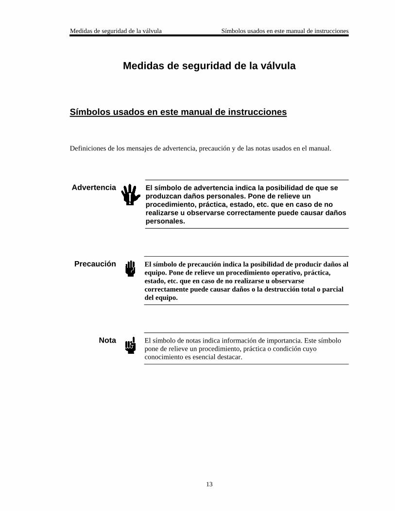
Símbolos usados en este manual de instrucciones
Definiciones de los mensajes de advertencia, precaución y de las notas usados en el manual.
Advertencia El símbolo de advertencia indica la posibilidad de que seproduzcan daños personales. Pone de relieve unprocedimiento, práctica, estado, etc. que en caso de norealizarse u observarse correctamente puede causar dañospersonales.
Precaución El símbolo de precaución indica la posibilidad de producir daños alequipo. Pone de relieve un procedimiento operativo, práctica,estado, etc. que en caso de no realizarse u observarsecorrectamente puede causar daños o la destrucción total o parcialdel equipo.
Nota El símbolo de notas indica información de importancia. Este símbolopone de relieve un procedimiento, práctica o condición cuyoconocimiento es esencial destacar.
Símbolos hallados en la unidad Medidas de seguridad de la válvula
14
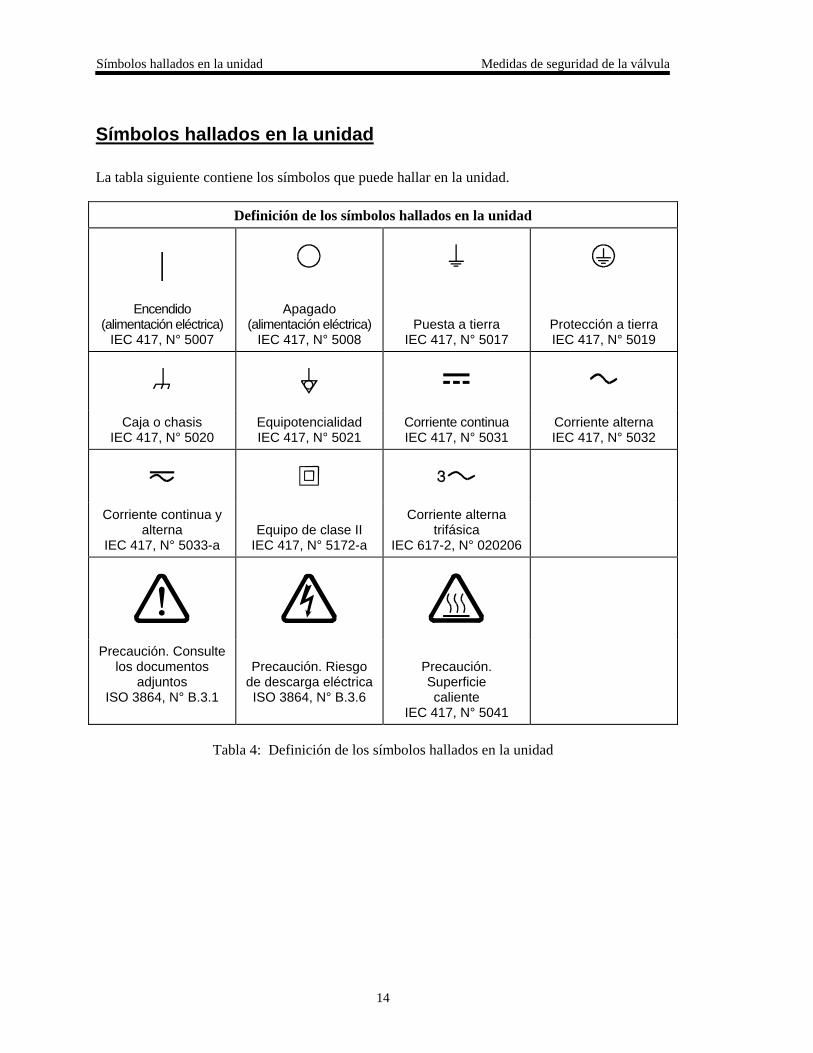
Símbolos hallados en la unidad
La tabla siguiente contiene los símbolos que puede hallar en la unidad.
Definición de los símbolos hallados en la unidad
|Encendido
(alimentación eléctrica)IEC 417, N° 5007
Apagado(alimentación eléctrica)
IEC 417, N° 5008Puesta a tierra
IEC 417, N° 5017Protección a tierraIEC 417, N° 5019
Caja o chasisIEC 417, N° 5020
EquipotencialidadIEC 417, N° 5021
Corriente continuaIEC 417, N° 5031
Corriente alternaIEC 417, N° 5032
Corriente continua yalterna
IEC 417, N° 5033-aEquipo de clase II
IEC 417, N° 5172-a
Corriente alternatrifásica
IEC 617-2, N° 020206
Precaución. Consultelos documentos
adjuntosISO 3864, N° B.3.1
Precaución. Riesgode descarga eléctricaISO 3864, N° B.3.6
Precaución.Superficiecaliente
IEC 417, N° 5041
Tabla 4: Definición de los símbolos hallados en la unidad
Medidas de seguridad de la válvula Procedimientos y precauciones de seguridad
15
Procedimientos y precauciones de seguridad
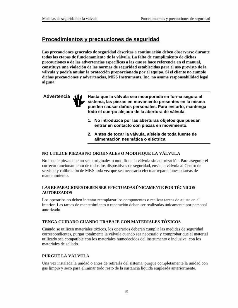
Las precauciones generales de seguridad descritas a continuación deben observarse durantetodas las etapas de funcionamiento de la válvula. La falta de cumplimiento de dichasprecauciones o de las advertencias específicas a las que se hace referencia en el manual,constituye una violación de las normas de seguridad establecidas para el uso previsto de laválvula y podría anular la protección proporcionada por el equipo. Si el cliente no cumpledichas precauciones y advertencias, MKS Instruments, Inc. no asume responsabilidad legalalguna.
Advertencia Hasta que la válvula sea incorporada en forma segura alsistema, las piezas en movimiento presentes en la mismapueden causar daños personales. Para evitarlo, mantengatodo el cuerpo alejado de la abertura de válvula.
1. No introduzca por las aberturas objetos que puedanentrar en contacto con piezas en movimiento.
2. Antes de tocar la válvula, aíslela de toda fuente dealimentación neumática o eléctrica.
NO UTILICE PIEZAS NO ORIGINALES O MODIFIQUE LA VÁLVULA
No instale piezas que no sean originales o modifique la válvula sin autorización. Para asegurar elcorrecto funcionamiento de todos los dispositivos de seguridad, envíe la válvula al Centro deservicio y calibración de MKS toda vez que sea necesario efectuar reparaciones o tareas demantenimiento.
LAS REPARACIONES DEBEN SER EFECTUADAS ÚNICAMENTE POR TÉCNICOSAUTORIZADOS
Los operarios no deben intentar reemplazar los componentes o realizar tareas de ajuste en elinterior. Las tareas de mantenimiento o reparación deben ser realizadas únicamente por personalautorizado.
TENGA CUIDADO CUANDO TRABAJE CON MATERIALES TÓXICOS
Cuando se utilicen materiales tóxicos, los operarios deberán cumplir las medidas de seguridadcorrespondientes, purgar totalmente la válvula cuando sea necesario y comprobar que el materialutilizado sea compatible con los materiales humedecidos del instrumento e inclusive, con losmateriales de sellado.
PURGUE LA VÁLVULA
Una vez instalada la unidad o antes de retirarla del sistema, purgue completamente la unidad congas limpio y seco para eliminar todo resto de la sustancia líquida empleada anteriormente.
Procedimientos y precauciones de seguridad Medidas de seguridad de la válvula
16
USE PROCEDIMIENTOS ADECUADOS PARA REALIZAR LA PURGA
La válvula debe purgarse debajo de una campana de ventilación y deben utilizarse guantesprotectores.
NO HAGA FUNCIONAR LA VÁLVULA EN UN AMBIENTE CON RIESGO DEEXPLOSIONES
Para evitar que se produzcan explosiones, no haga funcionar este producto en un ambiente conriesgo de explosiones, excepto cuando el mismo haya sido certificado específicamente para taluso.
USE ACCESORIOS ADECUADOS Y REALICE CORRECTAMENTE LOSPROCEDIMIENTOS DE AJUSTE
Todos los accesorios de la válvula deben cumplir las especificaciones de la misma y sercompatibles con el uso que se debe dar a la válvula. Arme y ajuste los accesorios de acuerdo conlas instrucciones del fabricante.
COMPRUEBE QUE LAS CONEXIONES SEAN A PRUEBA DE FUGAS
Inspeccione cuidadosamente las conexiones de los componentes de vacío para comprobar quehayan sido instalados a prueba de fugas.
HAGA FUNCIONAR LA VÁLVULA CON PRESIONES DE ENTRADA SEGURAS
No haga funcionar nunca la válvula con presiones superiores a la máxima presión nominal (en lasespecificaciones del instrumento hallará la presión máxima permitida).
INSTALE UNA CÁPSULA DE SEGURIDAD ADECUADA
Cuando el instrumento funcione con una fuente de gas presurizado, instale una cápsula deseguridad adecuada en el sistema de vacío para evitar que se produzcan explosiones cuando subala presión del sistema.
MANTENGA LA UNIDAD LIBRE DE CONTAMINANTES
No permita el ingreso de contaminantes en la unidad antes o durante su uso. Los productoscontaminantes tales como polvo, suciedad, pelusa, lascas de vidrio o virutas de metal puedendañar irreparablemente la unidad o contaminar el proceso.
MANTÉNGASE ALEJADO DE LA ABERTURA DE LA VÁLVULA
Cuando la válvula esté funcionando, mantenga los dedos, otras partes del cuerpo y otrosmateriales alejados de la abertura.
Chapter One: General Information Introduction
17
Chapter One: General Information
Introduction
The Type 153F “Smart” Throttle Valve Controller is designed for use in downstream pressurecontrol applications. The 153 unit includes a “built-in” MKS Type 253 Throttle Valve, amicroprocessor, RS-232 communication connections, and driver circuits. The driver circuitseliminate the need for a separate controller box.
The 153 controller contains a digital pressure/position control algorithm that directs the 253 valveto the proper position for either pressure or position control. The pressure or position set pointmay be an external voltage applied to the Input connector, or sent as a digital RS-232 message.The 153 unit reads the pressure signal used for control applications directly from a pressuretransducer.
Power for the 153 unit can be a single DC supply of +15 to +30 Volts. You can use a +15 VDC,+24 VDC, or +28 VDC supply. The unit requires approximately 6 Watts of power.
Note Use a ±15 V supply to power the 153 unit if you plan to power atransducer from the 153 unit.
When the controller is turned off, or experiences an unexpected power loss, all calibrationconstants and the last valve position are saved in non-volatile memory. Therefore, when yourepower the unit, it will be calibrated and ready for operation.
A switch on the top of the controller allows for off-line operation of the valve fortroubleshooting. Dipswitches inside the controller allow you to select the:
• Set Point Control (pressure or position)
• Set Point Signal (analog or digital)
• Valve Action (normal or reverse)
• Output Voltage Range (0 to 10 V or 0 to 5 V)
• RS-232 Operating Protocol (portable terminal or computer)
• RS-232 Communication Parameters (baud rate, parity,end-of-line delimiter)
The 153 controller meets the testing standards required for the European CE mark when usedwith an overall metal braided shielded cable, properly grounded at both ends. The unit isavailable with a variety of flanges and has an ambient operating temperature range of 15° to50° C (59° to 122° F).
How This Manual is Organized Chapter One: General Information
18
How This Manual is Organized
This manual is designed to provide instructions on how to set up, install, and operate a Type 153unit.
Before installing your Type 153 unit in a system and/or operating it, carefully read andfamiliarize yourself with all precautionary notes in the Safety Messages and Proceduressection at the front of this manual. In addition, observe and obey all WARNING andCAUTION notes provided throughout the manual.
Chapter One, General Information, (this chapter) introduces the product and describes theorganization of the manual.
Chapter Two, Installation, explains the environmental requirements and describes how to mountthe instrument in your system.
Chapter Three, Overview, gives a brief description of the instrument and its functionality.
Chapter Four, Operation, describes how to use the instrument and explains all the functions andfeatures.
Chapter Five, Maintenance and Troubleshooting, lists any maintenance required to keep theinstrument in good working condition, and provides information for reference should theinstrument malfunction.
Appendix A, Product Specifications, lists the specifications of the instrument.
Appendix B, Model Code Explanation, describes the model code used to order the instrument.
Customer Support
Standard maintenance and repair services are available at all of our regional MKS Calibration andService Centers, listed on the back cover. In addition, MKS accepts the instruments of othermanufacturers for recalibration using the Primary and Transfer Standard calibration equipmentlocated at all of our regional service centers. Should any difficulties arise in the use of your Type153 instrument, or to obtain information about companion products MKS offers, contact anyauthorized MKS Calibration and Service Center. If it is necessary to return the instrument toMKS, please obtain an RMA Number (Return Material Authorization Number) from the MKSCalibration and Service Center before shipping. The RMA Number expedites handling andensures proper servicing of your instrument.
Please refer to the inside of the back cover of this manual for a list of MKS Calibration andService Centers.
Warning All returns to MKS Instruments must be free of harmful,corrosive, radioactive, or toxic materials.
Chapter Two: Installation How To Unpack the Type 153 Unit
19
Chapter Two: Installation
How To Unpack the Type 153 Unit
MKS has carefully packed the Type 153 unit so that it will reach you in perfect operating order.Upon receiving the unit, however, you should check for defects, cracks, broken connectors, etc.,to be certain that damage has not occurred during shipment.
Note 1. Do not discard any packing materials until you have completed yourinspection and are sure the unit arrived safely.
2. Leave the protective plastic caps, which are placed over the ports forshipment, on the valve until it is installed in the system. Do notdiscard the protective plastic caps; if you remove the valve from yoursystem, use the plastic caps to protect the ports.
If you find any damage, notify your carrier and MKS immediately. If it is necessary to return theunit to MKS, obtain an RMA Number (Return Material Authorization Number) from the MKSService Center before shipping. Please refer to the inside of the back cover of this manual for alist of MKS Calibration and Service Centers.
Caution Only qualified individuals should perform the installation and anyuser adjustments. They must comply with all the necessary ESD andhandling precautions while installing and adjusting the instrument.Proper handling is essential when working with all highly sensitiveprecision electronic instruments.
Unpacking Checklist
Standard Equipment:
• Type 153 Unit• Type 153 Instruction Manual (this book)
Optional Equipment:
• Electrical Connector Accessory Kit (153F-K1)• Power Supply: 260 PS-1 (±15 V, 1.5 Amps)
260 PS-3 (±15 V, 3.2 Amps)• PT-1 Portable RS-232 Terminal• Interface Cables (refer to Table 5, page 20)
Interface Cables Chapter Two: Installation
20
Interface Cables
As of January 1, 1996, most products shipped to the European Community must comply with theEMC Directive 89/336/EEC, which covers radio frequency emissions and immunity tests. Inaddition, as of January 1, 1997, some products shipped to the European Community must alsocomply with the Product Safety Directive 92/59/EEC and Low Voltage Directive 73/23/EEC,which cover general safety practices for design and workmanship. MKS products that meet theserequirements are identified by application of the CE Mark.
To ensure compliance with EMC Directive 89/336/EEC, an overall metal braided shielded cable,properly grounded at both ends, is required during use. No additional installation requirementsare necessary to ensure compliance with Directives 92/59/EEC and 73/23/EEC.
Note 1. An overall metal braided shielded cable, properly grounded at bothends, is required during use to meet CE specifications.
2. To order an overall metal braided shielded cable, add an “S” after thecable type designation. For example, to order a standard cable toconnect a 153 unit to a 627 transducer, use part number CB153-7-10;for a metal braided shielded cable, use part number CB153S-7-10.
You can purchase interface cables to all MKS companion products from MKS (refer to Table 5),or optionally, you can make cables that meet the appropriate cable specifications.
For cables that will be connected to non-MKS products, MKS can provide normal shielding orbraided shielded cable assemblies in a nominal 10’ (3m) length, terminating in flying leads(pigtail) fashion at both ends. MKS recommends braided shielded cable assemblies if theenvironment contains high EMI/RFI noise.
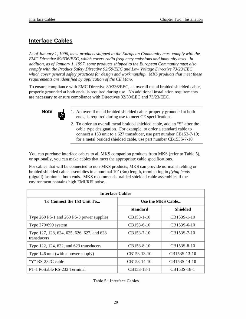
Interface Cables
To Connect the 153 Unit To... Use the MKS Cable...
Standard Shielded
Type 260 PS-1 and 260 PS-3 power supplies CB153-1-10 CB153S-1-10
Type 270/690 system CB153-6-10 CB153S-6-10
Type 127, 128, 624, 625, 626, 627, and 628transducers
CB153-7-10 CB153S-7-10
Type 122, 124, 622, and 623 transducers CB153-8-10 CB153S-8-10
Type 146 unit (with a power supply) CB153-13-10 CB153S-13-10
“Y” RS-232C cable CB153-14-10 CB153S-14-10
PT-1 Portable RS-232 Terminal CB153-18-1 CB153S-18-1
Table 5: Interface Cables
Chapter Two: Installation Interface Cables
21
Generic Shielded Cables
Should you choose to manufacture your own cables, follow the guidelines listed below:
1. The cable must have an overall metal braided shield, covering all wires. Neither aluminumfoil nor spiral shielding will be as effective; using either may nullify regulatory compliance.
2. The connectors must have a metal case which has direct contact to the cable’s shield on thewhole circumference of the cable. The inductance of a flying lead or wire from the shield tothe connector will seriously degrade the shield’s effectiveness. The shield should begrounded to the connector before its internal wires exit.
3. With very few exceptions, the connector(s) must make good contact to the device’s case(ground). “Good contact” is about 0.01 ohms; and the ground should surround all wires.Contact to ground at just one point may not suffice.
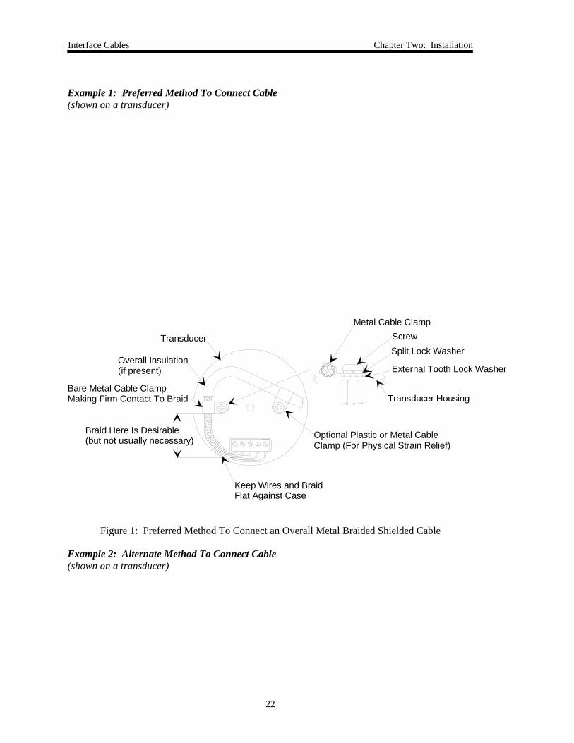
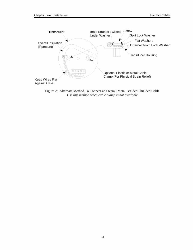
4. For shielded cables with flying leads at one or both ends; it is important at each such end, toground the shield before the wires exit. Make this ground with absolute minimum length.Refer to Figures 1 and 2, page 22. (A ¼ inch piece of #22 wire may be undesirably longsince it has approximately 5 nH of inductance, equivalent to 31 ohms at 1000 MHz). Afterpicking up the braid’s ground, keep wires and braid flat against the case. With very fewexceptions, grounded metal covers are not required over terminal strips. If one is required, itwill be stated in the Declaration of Conformity or in the instruction manual.
5. In selecting the appropriate type and wire size for cables, consider:
A. The voltage ratings.
B. The cumulative I2R heating of all the conductors (keep them safely cool).
C. The IR drop of the conductors, so that adequate power or signal voltage gets to thedevice.
D. The capacitance and inductance of cables which are handling fast signals, (such as datalines or stepper motor drive cables).
E. That some cables may need internal shielding from specific wires to others; please see theinstruction manual for details regarding this matter.
Interface Cables Chapter Two: Installation
22
Example 1: Preferred Method To Connect Cable(shown on a transducer)
Transducer
Overall Insulation(if present)
Bare Metal Cable ClampMaking Firm Contact To Braid
Braid Here Is Desirable(but not usually necessary)
Keep Wires and BraidFlat Against Case
Metal Cable ClampScrewSplit Lock Washer
External Tooth Lock Washer
Transducer Housing
Optional Plastic or Metal CableClamp (For Physical Strain Relief)
Figure 1: Preferred Method To Connect an Overall Metal Braided Shielded Cable
Example 2: Alternate Method To Connect Cable(shown on a transducer)
Chapter Two: Installation Interface Cables
23
Transducer
Overall Insulation(if present)
Braid Strands TwistedUnder Washer
Keep Wires Flat Against Case
Optional Plastic or Metal CableClamp (For Physical Strain Relief)
ScrewSplit Lock Washer
Flat WashersExternal Tooth Lock Washer
Transducer Housing
Figure 2: Alternate Method To Connect an Overall Metal Braided Shielded CableUse this method when cable clamp is not available
Setup Chapter Two: Installation
24
Setup
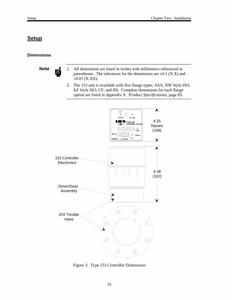
Dimensions
Note 1. All dimensions are listed in inches with millimeters referenced inparentheses. The tolerances for the dimensions are ±0.1 (X.X) and±0.01 (X.XX).
2. The 153 unit is available with five flange types: ASA, NW Style ISO,KF Style ISO, CF, and JIS. Complete dimensions for each flangeoption are listed in Appendix A: Product Specifications, page 85.
J1Input
J2 Power
Power
OPEN CLOSE
NORMAL
HOLD
TYPE 153CONTROL VALVE
6.38(162)
4.25Square(108)
153 ControllerElectronics
Driver/Gear Assembly
253 ThrottleValve
Figure 3: Type 153 Controller Dimensions
Chapter Two: Installation Setup
25
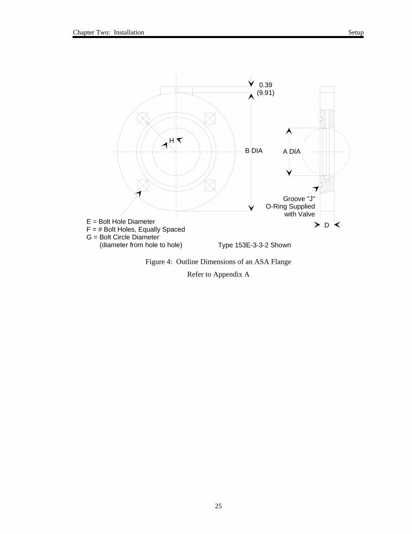
0.39(9.91)
E = Bolt Hole DiameterF = # Bolt Holes, Equally SpacedG = Bolt Circle Diameter (diameter from hole to hole)
HB DIA A DIA
D
Groove "J" O-Ring Supplied
with Valve
Type 153E-3-3-2 Shown
Figure 4: Outline Dimensions of an ASA Flange
Refer to Appendix A
Setup Chapter Two: Installation
26
CDIA
ADIA
D
E
Type 153E-2-50-2 Shown
Mounts to KF Flange F
Type 153E-1-40-2 Shown
E
CDIA
A1DIA
A2DIA
D
1.44(36.6)
B DIA
KF Flange F
Figure 5: Outline Dimensions of a KF Style ISO Flange
Refer to Appendix A
Chapter Two: Installation Setup
27
0.39(9.91)
B DIA
DE = Bolt Hole DiameterF = # Bolt Holes, Equally SpacedG = Bolt Circle Diameter (diameter from hole to hole)
A DIA
Accepts K Centering Seal AssyBoth Faces
H
Type 153E-3-80-2 Shown
Figure 6: Outline Dimensions of a NW Style ISO Flange
Refer to Appendix A
E = Bolt Hole DiameterF = # Bolt Holes, Equally SpacedG = Bolt Circle Diameter (diameter from hole to hole)
C
B DIA
H
A DIA
D
Mates with CF Style Flange K
Type 153E-2-3CF-2 Shown
Figure 7: Outline Dimensions of a CF Flange
Refer to Appendix A
Setup Chapter Two: Installation
28
E = Bolt Hole DiameterF = # Bolt Holes, Equally SpacedG = Bolt Circle Diameter (diameter from hole to hole)
1.44(36.6)
H
B DIA A DIA
O-Ring JSupplied by Customer
D
Mates with K JIS Flange
Figure 8: Outline Dimensions of a JIS Flange
Refer to Appendix A
Chapter Two: Installation Setup
29
O-Ring MaterialValves that have an O-ring sealed flapper are called sealing butterfly valves. This design ensuresclosed leak rates less than 1.3 x 10⁻⁷ scc/sec when new. Ensure that the O-ring material iscompatible with the gases it will be exposed to in the system.
Power RequirementsThe 253 valve, enclosed in the 153 unit, requires +15 to +30 Volts. If you need to power apressure transducer, you must supply ±15 VDC to the 153 unit. The 153 unit uses the +15 Voltsand sends the ±15 Volts on to the pressure transducer. Both the Input connector and the Powerconnector provide connections for ±15 Volts and the pressure signal. The system shown inFigure 10, page 31, receives ±15 Volts through the Input connector and interfaces with thepressure transducer through the Power connector. The interface cables are listed in Table 5,page 20.
The 153 controller can receive a set point signal from either an external voltage source or anRS-232 signal. In either case, the Input connector (which incorporates the RS-232communications) acts as the interface. Figure 10, page 31, shows an external voltage sourceconnected as the set point signal. Refer to Table 7, page 33, for the Input connector pinout.
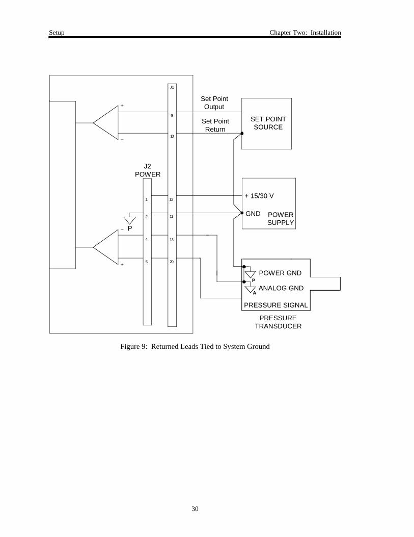
GroundingThe pressure and set point inputs to the 153 controller are both differential inputs that are notinternally referenced to ground. Tie the returns to the system ground at a single point. Figure 9,page 29, illustrates this type of grounding.
Note Not grounding the set point return or the pressure return (floating) caninduce noise into the signals.
The 153 controller uses true differential inputs for the pressure and set point input signals. Youmust connect the return leads to the power supply ground at a single point. Grounding at multiplepoints will produce ground loops and IR drops which will degrade performance.
Setup Chapter Two: Installation
30
J1
10
9
P
1 12
2
4
5
11
13
20
P
A
J2POWER
PRESSURETRANSDUCER
Set PointOutput
POWER GND
ANALOG GND
PRESSURE SIGNAL
+ 15/30 V
GND
Set PointReturn
SET POINTSOURCE
POWERSUPPLY
Figure 9: Returned Leads Tied to System Ground
Chapter Two: Installation Setup
31
Mounting Instructions
Warning!
The moving parts in the valve create a risk of personal injuryuntil the valve is securely incorporated into a system. Toavoid injury keep all objects away from any valve opening.
The 153 unit can be mounted in a vacuum exhaust line with the proper fittings and connectors.The unit consists of a 253 exhaust valve with an electronic housing attached to the motor plate.
Although the unit was designed and tested to operate in the most extreme conditions (with no aircirculation and a heated valve at 80° C), it will operate cooler if the air slots in the side of thehousing are clear to allow convection air circulation. Typically, electronic components lastlonger in cooler environments.
Heated Valves
The 153 unit is not designed to operate with a heated valve unless certain modifications are made.Some installations require that the exhaust line and throttle valve be heated to prevent exhaustvapors from precipitating out in the exhaust line. For these types of applications, contact MKSInstruments.
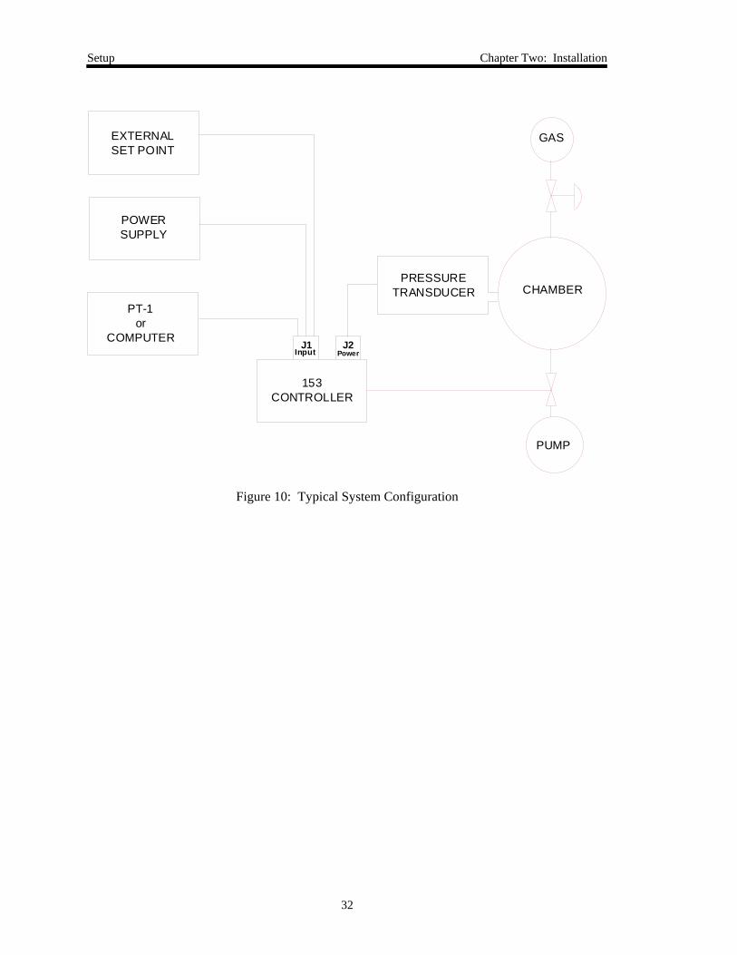
System Configuration
For best pressure control, locate the pressure transducer and exhaust valve as close as practical tothe process chamber. This minimizes the time constants associated with these items. Use tubingthat is less than 6 inches long and no less than ¼ inch in diameter to connect the transducer andchamber. If the distance must exceed 6 inches, use larger diameter tubing to compensate forconductance losses. A typical system setup is shown in Figure 10, page 31.
Setup Chapter Two: Installation
32
EXTERNAL SET POINT
POWERSUPPLY
PT-1or
COMPUTER
153CONTROLLER
J1Input
J2Power
PRESSURETRANSDUCER CHAMBER
PUMP
GAS
Figure 10: Typical System Configuration
Chapter Two: Installation Connectors
33
Connectors
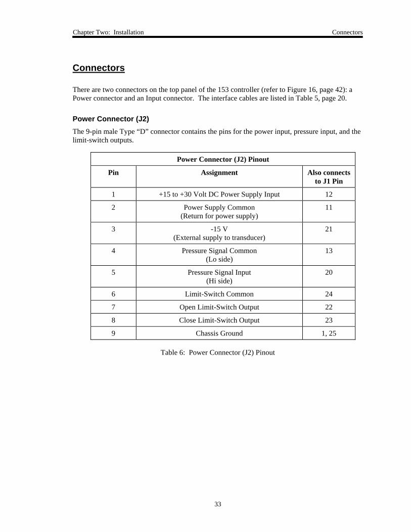
There are two connectors on the top panel of the 153 controller (refer to Figure 16, page 42): aPower connector and an Input connector. The interface cables are listed in Table 5, page 20.
Power Connector (J2)The 9-pin male Type “D” connector contains the pins for the power input, pressure input, and thelimit-switch outputs.
Power Connector (J2) Pinout
Pin Assignment Also connectsto J1 Pin
1 +15 to +30 Volt DC Power Supply Input 12
2 Power Supply Common(Return for power supply)
11
3 -15 V(External supply to transducer)
21
4 Pressure Signal Common(Lo side)
13
5 Pressure Signal Input(Hi side)
20
6 Limit-Switch Common 24
7 Open Limit-Switch Output 22
8 Close Limit-Switch Output 23
9 Chassis Ground 1, 25
Table 6: Power Connector (J2) Pinout
Connectors Chapter Two: Installation
34
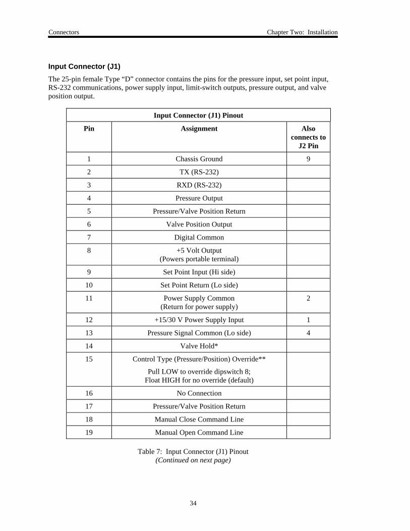
Input Connector (J1)The 25-pin female Type “D” connector contains the pins for the pressure input, set point input,RS-232 communications, power supply input, limit-switch outputs, pressure output, and valveposition output.
Input Connector (J1) Pinout
Pin Assignment Alsoconnects to
J2 Pin
1 Chassis Ground 9
2 TX (RS-232)
3 RXD (RS-232)
4 Pressure Output
5 Pressure/Valve Position Return
6 Valve Position Output
7 Digital Common
8 +5 Volt Output(Powers portable terminal)
9 Set Point Input (Hi side)
10 Set Point Return (Lo side)
11 Power Supply Common(Return for power supply)
2
12 +15/30 V Power Supply Input 1
13 Pressure Signal Common (Lo side) 4
14 Valve Hold*
15 Control Type (Pressure/Position) Override**
Pull LOW to override dipswitch 8;Float HIGH for no override (default)
16 No Connection
17 Pressure/Valve Position Return
18 Manual Close Command Line
19 Manual Open Command Line
Table 7: Input Connector (J1) Pinout(Continued on next page)
Chapter Two: Installation Connectors
35
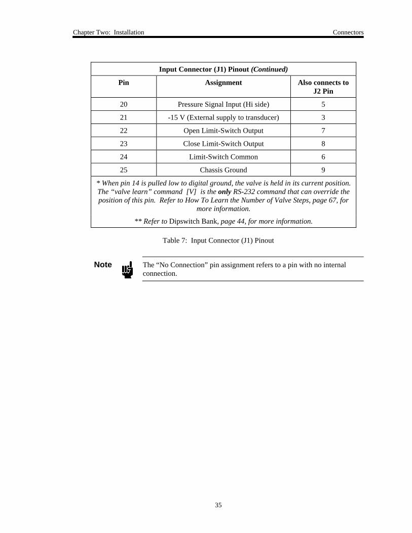
Input Connector (J1) Pinout (Continued)
Pin Assignment Also connects toJ2 Pin
20 Pressure Signal Input (Hi side) 5
21 -15 V (External supply to transducer) 3
22 Open Limit-Switch Output 7
23 Close Limit-Switch Output 8
24 Limit-Switch Common 6
25 Chassis Ground 9
* When pin 14 is pulled low to digital ground, the valve is held in its current position.The “valve learn” command [V] is the only RS-232 command that can override theposition of this pin. Refer to How To Learn the Number of Valve Steps, page 67, for
more information.
** Refer to Dipswitch Bank, page 44, for more information.
Table 7: Input Connector (J1) Pinout
Note The “No Connection” pin assignment refers to a pin with no internalconnection.
Connectors Chapter Two: Installation
36
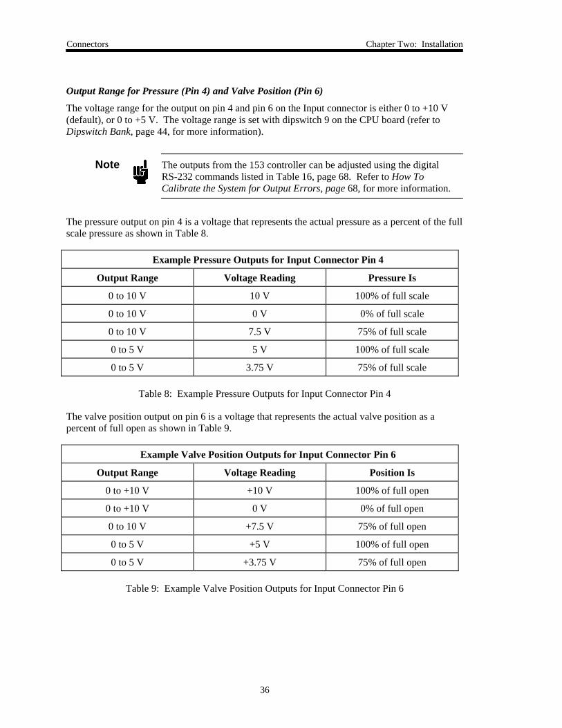
Output Range for Pressure (Pin 4) and Valve Position (Pin 6)
The voltage range for the output on pin 4 and pin 6 on the Input connector is either 0 to +10 V(default), or 0 to +5 V. The voltage range is set with dipswitch 9 on the CPU board (refer toDipswitch Bank, page 44, for more information).
Note The outputs from the 153 controller can be adjusted using the digitalRS-232 commands listed in Table 16, page 68. Refer to How ToCalibrate the System for Output Errors, page 68, for more information.
The pressure output on pin 4 is a voltage that represents the actual pressure as a percent of the fullscale pressure as shown in Table 8.
Example Pressure Outputs for Input Connector Pin 4
Output Range Voltage Reading Pressure Is
0 to 10 V 10 V 100% of full scale
0 to 10 V 0 V 0% of full scale
0 to 10 V 7.5 V 75% of full scale
0 to 5 V 5 V 100% of full scale
0 to 5 V 3.75 V 75% of full scale
Table 8: Example Pressure Outputs for Input Connector Pin 4
The valve position output on pin 6 is a voltage that represents the actual valve position as apercent of full open as shown in Table 9.
Example Valve Position Outputs for Input Connector Pin 6
Output Range Voltage Reading Position Is
0 to +10 V +10 V 100% of full open
0 to +10 V 0 V 0% of full open
0 to 10 V +7.5 V 75% of full open
0 to 5 V +5 V 100% of full open
0 to 5 V +3.75 V 75% of full open
Table 9: Example Valve Position Outputs for Input Connector Pin 6
Chapter Two: Installation How To Connect to a PT-1 Portable RS-232 Terminal
37
How To Connect to a PT-1 Portable RS-232 Terminal
Note The 153 controller’s default communication parameters configure it tocommunicate with the PT-1 portable RS-232 terminal, rather than with acomputer. The default communication parameters are listed in Table 12,page 52.The default dipswitch settings are listed in Table 10, page 45. Refer toHow To Change the Dipswitch Settings, page 47, for more information.
The PT-1 portable terminal is shipped with its RS-232 communication cable attached. Toconnect the PT-1 unit to the 153 controller:
1. Ensure that dipswitch 6 on the CPU board is in the ON (closed) position.
This is the default position for dipswitch 6. When dipswitch 6 is ON, the 153 unit isconfigured to communicate with the PT-1 unit.
2. Plug the Type “D” connector from the cable on the PT-1 unit into the Input connector onthe top of the 153 unit.
Refer to Figure 16, page 42.
How To Connect to a Computer Chapter Two: Installation
38
How To Connect to a Computer
Note The default communication parameters configure the 153 unit tocommunicate with the portable RS-232 terminal, rather than with acomputer. To configure the 153 unit so that it can communicate with acomputer, you must change the setting of dipswitch 6 on the CPU boardto the OFF (open) position.The default dipswitch settings are listed in Table 10, page 45. Refer toHow To Change the Dipswitch Settings, page 47, for more information.
To connect your 153 controller to a computer:
1. Ensure that dipswitch 6 on the CPU board is in the OFF (open) position.
This is not the default position for dipswitch 6. When dipswitch 6 is OFF the 153 unit isconfigured to communicate with a computer.
2. Connect a null modem cable from your computer to the Input connector on the top of the153 unit.
Refer to Figure 16, page 42.
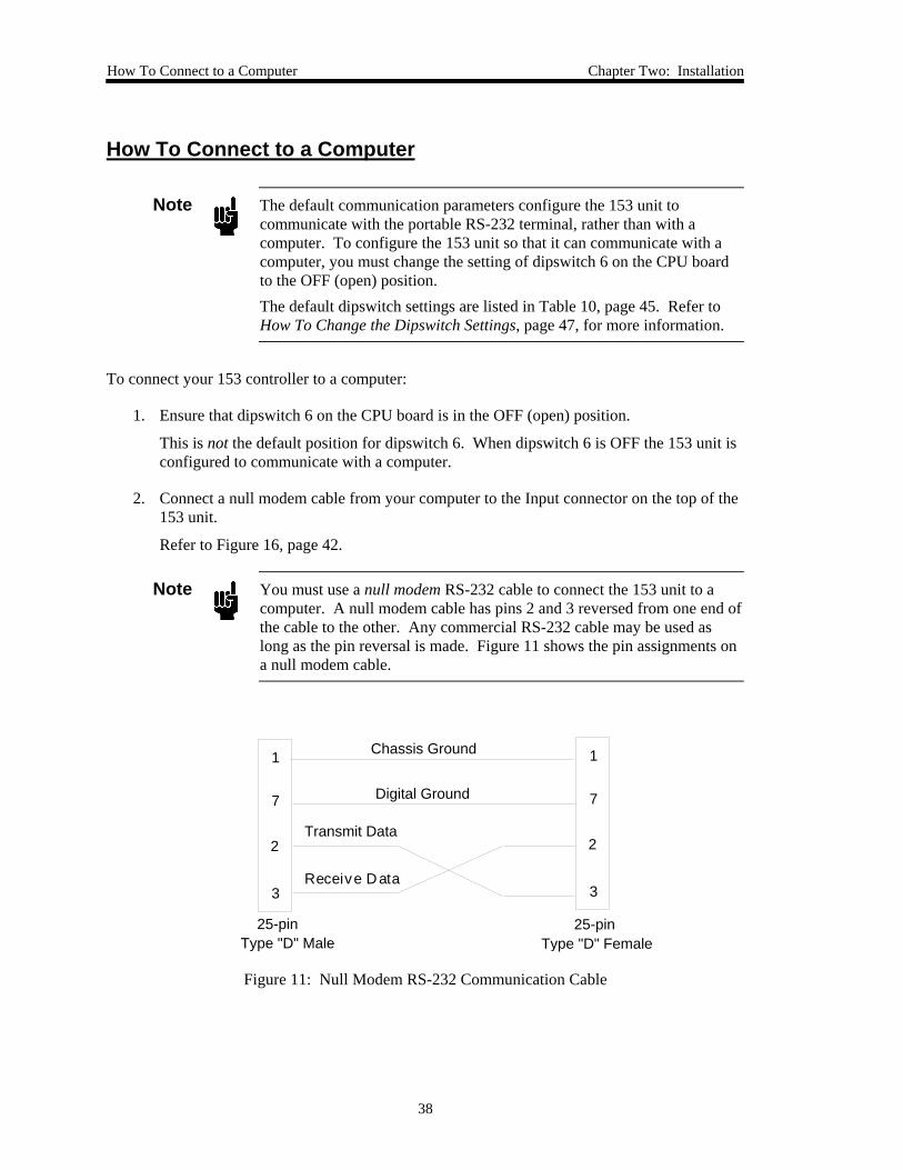
Note You must use a null modem RS-232 cable to connect the 153 unit to acomputer. A null modem cable has pins 2 and 3 reversed from one end ofthe cable to the other. Any commercial RS-232 cable may be used aslong as the pin reversal is made. Figure 11 shows the pin assignments ona null modem cable.
1
7
2
3
1
7
2
3
Chassis Ground
Digital Ground
Transmit Data
Receive D ata
25-pin Type "D" Male
25-pin Type "D" Female
Figure 11: Null Modem RS-232 Communication Cable
Chapter Two: Installation How To Connect to a Type 146 Cluster Gauge™
39
How To Connect to a Type 146 Cluster Gauge™
The MKS Type 146 Cluster Gauge can be used to control the 153 unit. To configure the 153 unitto communicate with the 146 instrument, leave the dipswitches at the default settings (refer toTable 10, page 45) except for switch 8. Set switch 8 to the OFF (Closed) position, so the 153unit will act as a position controller. The system will then use the PID control on the 146instrument to control the valve. Refer to How To Change the Dipswitch Settings, page 47, forinstructions on how to change the position of dipswitch 8.
Note The 146 instrument must contain the optional “M” board (Control Board)to control the 153 unit.
1. Connect the 153 controller to the “M” board (Control Board) in the 146 instrument usingthe appropriate cable.
The Control Board has two 9-pin Type “D” connectors: one male and one female. Thecable uses the 146 instrument to power the 153 unit and provides the analog voltage toposition the valve to control pressure. The interface cables are listed in Table 5, page 20.
2. Use the Setup Mode Code 14x on the 146 instrument to select the control action (directfor downstream control) and the pressure reference channel.
3. Use the Open and Close commands on the 146 instrument to move the valve from fullyopen to fully closed.
4. Watch the Open and Close LED lights on the 153 unit.
Refer to Figure 16, page 42. If the appropriate light is illuminated when the valve is inposition, the zero and full scale settings are correct. If the appropriate light is notilluminated correctly, proceed to step 5.
5. Calibrate the 153 controller using either a computer or a PT-1 portable terminal.
The controller will learn the new values for zero and full scale for the controller andtransducer. Refer to Calibration Messages, page 62, for more information.

Chapter Three: Overview Control Mode
41
Chapter Three: Overview
Control Mode
The 153 controller controls a vacuum system using either Pressure or Position control. In eitherthe Pressure Control or Position Control mode, the 153 controller accepts the following types ofset points:
• An analog set point sent to the controller via the Input connector
• A digital set point sent to the controller using RS-232 commands form acomputer or a PT-1 unit
In Pressure Control, the 153 unit moves the valve in order to maintain a desired pressure (the setpoint). The controller uses a Proportional, Integral, and Derivative (PID) algorithm to determinethe valve position and make position adjustments. The set point uses two parameters—the leadand gain—to optimize the response from set point to set point. Although there are default valuesfor these parameters, you should adjust the values for optimum control (refer to How To Tune theController, page 78, for more information). The feedback is an analog pressure signal. Thissignal is normally 0 to 10 Volts, but the zero and full scale voltages can be adapted to individualapplications. Refer to Calibration Messages, page 62, for more information.
In Position Control, the 153 unit moves the valve to a desired position (the set point). In thismode, the valve is moved to the desired set point but no feedback signal is generated. It is notnecessary for the controller to make adjustments once the valve reaches its set point.
Lead and GainThe 153 unit uses a PID compensator to control pressure in a vacuum system. When a new setpoint is commanded, the unit responds by changing the pressure smoothly to the desired value. Ifthe pressure is slow to change or oscillates, the PID compensator must be re-tuned. The lead andgain values can be manually adjusted to provide the best response to the set point. By carefuladjustment of each value, it is possible to achieve optimum control throughout a wide range ofpressure regions.
The lead and gain values used in the control algorithm are set at the factory. You can changethese parameters by using either a computer or a PT-1 unit to send the RS-232 commands listedin Table 13, page 57. These parameters are adjusted using the procedure described in How ToTune the Controller, page 78.
Control Mode Chapter Three: Overview
42
Lead
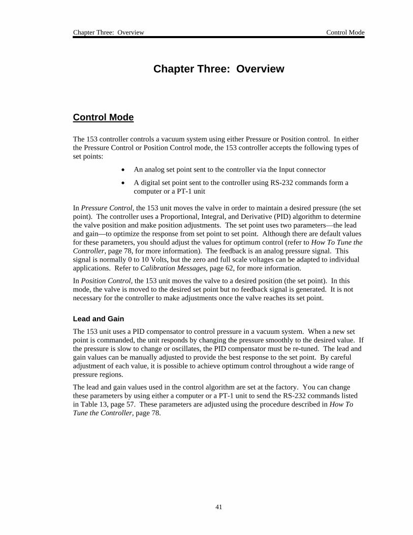
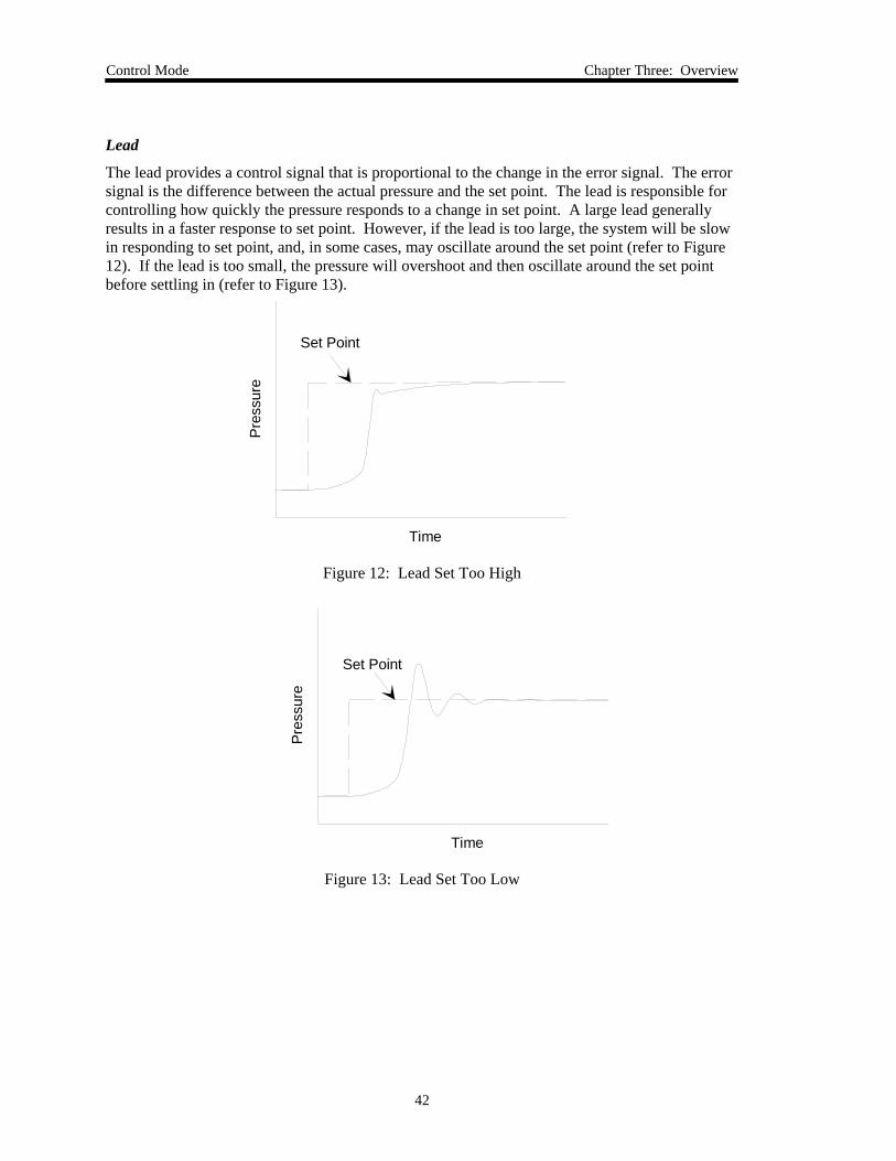
The lead provides a control signal that is proportional to the change in the error signal. The errorsignal is the difference between the actual pressure and the set point. The lead is responsible forcontrolling how quickly the pressure responds to a change in set point. A large lead generallyresults in a faster response to set point. However, if the lead is too large, the system will be slowin responding to set point, and, in some cases, may oscillate around the set point (refer to Figure12). If the lead is too small, the pressure will overshoot and then oscillate around the set pointbefore settling in (refer to Figure 13).
Pre
ssur
e
Time
Set Point
Figure 12: Lead Set Too High
Pre
ssur
e
Time
Set Point
Figure 13: Lead Set Too Low
Chapter Three: Overview Control Mode
43
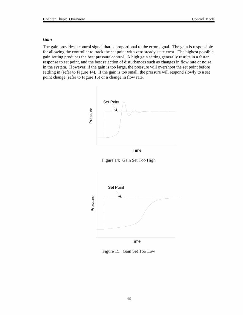
Gain
The gain provides a control signal that is proportional to the error signal. The gain is responsiblefor allowing the controller to track the set point with zero steady state error. The highest possiblegain setting produces the best pressure control. A high gain setting generally results in a fasterresponse to set point, and the best rejection of disturbances such as changes in flow rate or noisein the system. However, if the gain is too large, the pressure will overshoot the set point beforesettling in (refer to Figure 14). If the gain is too small, the pressure will respond slowly to a setpoint change (refer to Figure 15) or a change in flow rate.
Pre
ssur
e
Time
Set Point
Figure 14: Gain Set Too High
Pre
ssur
e
Set Point
Time
Figure 15: Gain Set Too Low

External Connectors and Controls Chapter Three: Overview
44
External Connectors and Controls
Figure 16 shows the location of the controls on the top panel of the 153 controller.
Valve Open LED Valve Close LED
Manual Valve Switch
Power On LED
Power Connector (J2)
Input Connector (J1)
Hold/NormalSwitch
J1Input
J2 Power
Power
OPEN CLOSE
TYPE 153CONTROL VALVE
Figure 16: Top Panel of the 153 Controller
Power On LEDThis LED indicator illuminates green when the unit is powered on.
Input Connector (J1)The 25-pin female Type “D” contains the pins for the pressure input, set point input, RS-232communications, power supply input, limit-switch outputs, pressure output, and valve positionoutput. Refer to Table 7, page 33, for the Input connector pinout.
Power Connector (J2)The 9-pin male Type “D” connector contains the pins for the power input, pressure input, and thelimit-switch outputs. Refer to Table 6, page 32, for the Power connector pinout.
Chapter Three: Overview External Connectors and Controls
45
Hold/Normal SwitchThis switch allows you to manually hold the valve in a constant position. When the switch is inthe NORMAL position, the valve operates in the standard way. When the switch is placed in theHOLD position, the valve is held in a constant position, and does not respond to the pressure orset point signals.
You can override the HOLD position by moving the manual valve switch from the OPEN orCLOSE position, or by using the OPEN or CLOSE RS-232 commands (refer to Valve PositionMessages, page 59, for more information).
Manual Valve SwitchThis switch allows you to manually drive the valve to the open or closed position.
Valve Open LEDThe OPEN indicator light illuminates red when the valve is fully open.
Valve Close LEDThe CLOSE indicator light illuminates red when the valve is fully closed.
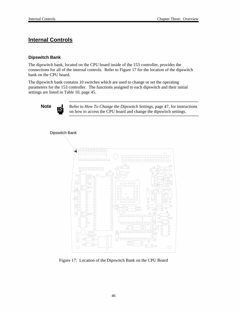
Internal Controls Chapter Three: Overview
46
Internal Controls
Dipswitch BankThe dipswitch bank, located on the CPU board inside of the 153 controller, provides theconnections for all of the internal controls. Refer to Figure 17 for the location of the dipswitchbank on the CPU board.
The dipswitch bank contains 10 switches which are used to change or set the operatingparameters for the 153 controller. The functions assigned to each dipswitch and their initialsettings are listed in Table 10, page 45.
Note Refer to How To Change the Dipswitch Settings, page 47, for instructionson how to access the CPU board and change the dipswitch settings.
Dipswitch Bank
Figure 17: Location of the Dipswitch Bank on the CPU Board
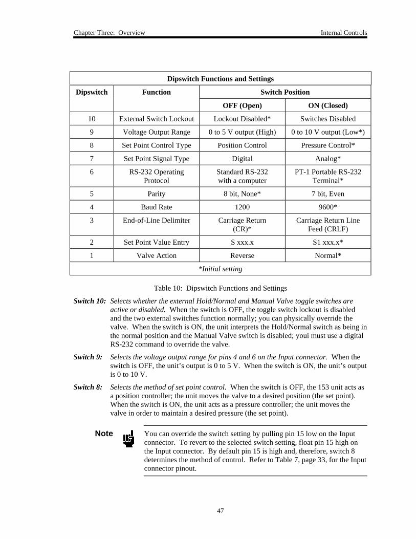
Chapter Three: Overview Internal Controls
47
Dipswitch Functions and Settings
Dipswitch Function Switch Position
OFF (Open) ON (Closed)
10 External Switch Lockout Lockout Disabled* Switches Disabled
9 Voltage Output Range 0 to 5 V output (High) 0 to 10 V output (Low*)
8 Set Point Control Type Position Control Pressure Control*
7 Set Point Signal Type Digital Analog*
6 RS-232 OperatingProtocol
Standard RS-232with a computer
PT-1 Portable RS-232Terminal*
5 Parity 8 bit, None* 7 bit, Even
4 Baud Rate 1200 9600*
3 End-of-Line Delimiter Carriage Return(CR)*
Carriage Return LineFeed (CRLF)
2 Set Point Value Entry S xxx.x S1 xxx.x*
1 Valve Action Reverse Normal*
*Initial setting
Table 10: Dipswitch Functions and Settings
Switch 10: Selects whether the external Hold/Normal and Manual Valve toggle switches areactive or disabled. When the switch is OFF, the toggle switch lockout is disabledand the two external switches function normally; you can physically override thevalve. When the switch is ON, the unit interprets the Hold/Normal switch as being inthe normal position and the Manual Valve switch is disabled; youi must use a digitalRS-232 command to override the valve.
Switch 9: Selects the voltage output range for pins 4 and 6 on the Input connector. When theswitch is OFF, the unit’s output is 0 to 5 V. When the switch is ON, the unit’s outputis 0 to 10 V.
Switch 8: Selects the method of set point control. When the switch is OFF, the 153 unit acts asa position controller; the unit moves the valve to a desired position (the set point).When the switch is ON, the unit acts as a pressure controller; the unit moves thevalve in order to maintain a desired pressure (the set point).
Note You can override the switch setting by pulling pin 15 low on the Inputconnector. To revert to the selected switch setting, float pin 15 high onthe Input connector. By default pin 15 is high and, therefore, switch 8determines the method of control. Refer to Table 7, page 33, for the Inputconnector pinout.
Internal Controls Chapter Three: Overview
48
Switch 7: Selects the source of the set point signal. When the switch is OFF, the 153 controllerexpects to receive a digital set point signal through the RS-232 interface. When theswitch is ON, the controller expects an external analog voltage set point signal on theInput connector.
You can override the analog set point by sending a Valve Position RS-232 commandto the 153 controller (refer to Table 14, page 59). Use the standard protocol [A]command to revert back to an analog set point. Refer to How To Return to NormalOperation, page61, for more information.
Switch 6: Establishes the RS-232 operating protocol. When the switch is OFF, standardRS-232 protocol (via a computer) is accepted. When the switch is ON, the controlleruses the PT-1 portable terminal protocol.
Switch 5: Sets the parity setting. The OFF setting selects 8 bit, no parity. The ON settingselects 7 bit, even parity.
Switch 4: Sets the baud rate. When OFF, the baud rate is 1200. When ON, the baud rate is9600.
Switch 3: Selects the end-of-line delimiter. When the switch is OFF, the delimiter is a CarriageReturn (CR). When the switch is ON, the delimiter is a Carriage Return Line Feed(CRLF).
Switch 2: Controls the RS-232 compatibility for the set point value entry. When the switch isOFF, the set point entry command is “S xxx.x.” When the switch is ON, the set pointentry is “S1 xxx.x.” The extra “1” makes this entry downwardly compatible withother MKS products such as the Type 152, 153A, and 112 units.
Switch 1: Selects the valve action. The valve can be set to use either normal or reverse valveaction; that is, the direction the valve uses for its open and closed positions.
Normal: When the switch is OFF, the valve is open at 100% of it’s full scaleposition and closed at 0%. Pressure above the set point causes the valve tomove toward the open position.
Reverse: When the switch is ON, the valve is open at 0% of it’s full scale positionand closed at 100%. Pressure above the set point causes the valve to movetoward the close position.
Chapter Three: Overview Internal Controls
49
How To Change the Dipswitch SettingsThe dipswitches, located on the CPU board (refer to Figure 17, page 44), control the operatingand communication parameters for the 153 controller. To set or change any of these parameters,you must change the position of the appropriate dipswitch.
Caution You must comply with all the necessary ESD and handlingprecautions while installing and adjusting the instrument. Properhandling is essential when working with all highly sensitive precisionelectronic instruments.
Note Refer to Table 10, page 45, for a complete listing of the functionsassigned to each dipswitch and their initial settings.
To change the dipswitch settings:
1. Disconnect the power source from the 153 controller.
Warning To avoid an electrical shock, disconnect the power cordbefore opening the unit.
2. Unscrew the two screws on the top of the unit and lift off the cover.
3. Locate the CPU board and the dipswitch bank.
There are two boards inside of the 153 unit; the CPU board is the small, top most board.Refer to Figure 17, page 44, for the location of the dipswitch bank.
4. Change the position of any of the dipswitches as required.
Refer to Table 10, page 45, for a complete listing of the functions assigned to eachdipswitch and their initial settings.
5. Replace the cover of the unit and the secure it in place with the two screws removed instep 2.
6. Power up the 153 controller.
Note You must repower the system before any changes to the dipswitch settingare recognized by the 153 unit.
Power-Down Constants Chapter Three: Overview
50
Power-Down Constants
The 153 unit saves the several constants in non-volatile memory (RAM) when the power isturned off. When the power is restored, the 153 unit “remembers” these settings.
The parameters saved in non-volatile memory are:
• Lead
• Gain
• Present valve position
• Analog set point zero (input)
• Analog set point full scale (input)
• Analog pressure zero (input)
• Analog pressure full scale (input)
• Number of valve steps
• Position zero (output)
• Position full scale (output)
• Pressure zero (output)
• Pressure full scale (output)
Power Up Conditions
The following conditions apply at power up:
• The processor checks the position of all switches on the dipswitch bank
• The operational mode is determined by dipswitches 7 and 8
If dipswitches 7 and 8 are ON, the unit “wakes up” in pressure control mode and uses ananalog set point.
If dipswitches 7 and 8 are OFF, the unit “wakes up” in position control mode and uses adigital set point.
For more information on the operational modes, refer to How To Select the Pressure ControlMode, page 74, and How To Select the Position Control Mode, page 76.
• The stored constants are recalled and used in all subsequent operations
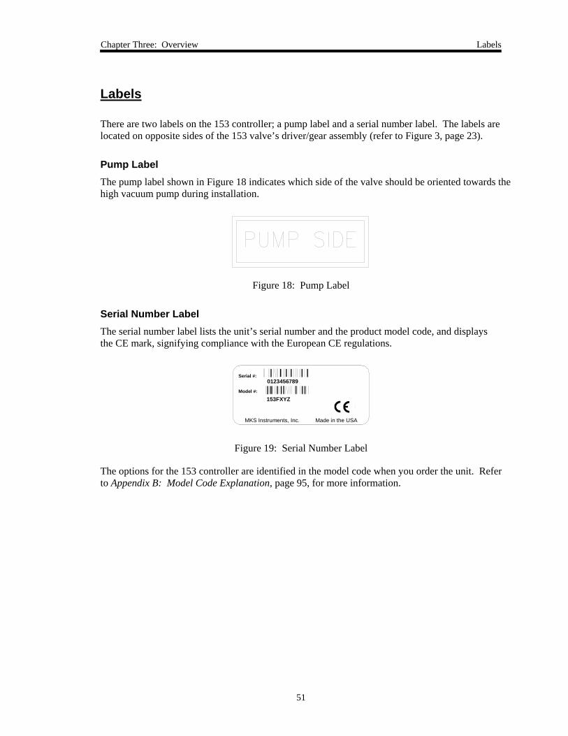
Chapter Three: Overview Labels
51
Labels
There are two labels on the 153 controller; a pump label and a serial number label. The labels arelocated on opposite sides of the 153 valve’s driver/gear assembly (refer to Figure 3, page 23).
Pump LabelThe pump label shown in Figure 18 indicates which side of the valve should be oriented towards thehigh vacuum pump during installation.
Figure 18: Pump Label
Serial Number LabelThe serial number label lists the unit’s serial number and the product model code, and displaysthe CE mark, signifying compliance with the European CE regulations.
153FXYZ
Serial #:
Model #:
0123456789
MKS Instruments, Inc. Made in the USA
Figure 19: Serial Number Label
The options for the 153 controller are identified in the model code when you order the unit. Referto Appendix B: Model Code Explanation, page 95, for more information.

Labels Chapter Three: Overview
52
This page intentionally left blank.
Chapter Four: Operation General Information
53
Chapter Four: Operation
General Information
MKS products are designed and tested to provide the highest degree of safety attainable. To useyour MKS valve safely, you must always conform to the following instructions:
Warning!
The moving parts in the valve create a risk of personal injuryuntil the valve is securely incorporated into a system. Toavoid injury keep all objects away from any valve opening.
• Do not insert objects into openings where contact with moving parts is possible
• Isolate the equipment from any electrical or pneumatic power supply before handling thevalve
Control Parameters
The initial control parameters for the 153 unit are listed in Table 11. To change any of theseparameters, you must change the position of the appropriate dipswitch. Refer to How To Changethe Dipswitch Settings, page 47, for more information.
Initial Control Parameters
Parameter Setting
Set Point Control Type Pressure
Set Point Signal Type Analog
Valve Action Normal
Pressure Full Scale +10 V
Set Point Full Scale +10 V
Lead 4.0%
Gain 90.0%
Table 11: Initial Control Parameters

RS-232 Communication Parameters Chapter Four: Operation
54
RS-232 Communication Parameters
The 153 controller can communicate with an external computer or a PT-1 portable terminal throughthe RS-232 interface. Using digital commands you can read the pressure, valve position, and thetuning parameters. You can also change the set point, open and close the valve, and adjust thetuning parameters. The initial RS-232 communication parameters for the 153 unit are listed inTable 12.
Note Ensure that both your 153 controller and your computer are configuredwith the same communication parameters.
Initial RS-232 Communication Parameters
Parameter Setting
Baud Rate 9600
Data Bits* 8
Parity None
Stop Bits* 1
Operating Protocol PT-1 Portable RS-232 Terminal
End-of-Line Delimiter Carriage Return (CR)
Handshaking* None (off)
* These parameters are factory set and cannot be adjusted.
Table 12: Initial RS-232 Communication Parameters
Chapter Four: Operation RS-232 Communication Parameters
55
How To Change the Communication ParametersTo change any of the user-adjustable communication parameters, you must change the dipswitchsettings on the CPU board. Refer to How To Change the Dipswitch Settings, page 47, forinstructions on how to access the CPU board and change the dipswitch settings. The defaultdipswitch settings and their corresponding functions are listed in Table 10, page 45.
Note When using the PT-1 unit, the 153 unit must be configured with thedefault dipswitch settings (refer to Table 10, page 45). When configuredproperly, the 153 unit accepts RS-232 characters from the PT-1 withoutneeding the shift key on the portable terminal.
To change the communications parameters:
1. To use the PT-1 terminal protocol, leave switch 6 in the default ON position or switch itON, if necessary.
To use the standard RS-232 protocol, flip switch 6 to the OFF position.
2. To use 8 bit no parity, leave switch 5 in the default OFF position or switch it OFF, ifnecessary.
To use 7 bit even parity, flip switch 5 to the ON position.
3. To use 9600 baud communications rate, leave switch 4 in the default ON position orswitch it ON, if necessary.
To use 1200 baud communications rate, flip switch 5 to the OFF position.
4. To use a carriage return delimiter, leave switch 3 in the default OFF position or switch itOFF, if necessary.
To use a carriage return + line feed delimiter, flip switch 3 to the ON position.
Note You must reboot the system before any changes to the dipswitch settingare recognized by the controller.
RS-232 Protocol Chapter Four: Operation
56
RS-232 Protocol
All RS-232 messages used by the 153 unit are composed of variable length ASCII strings.Messages sent to the unit from a remote computer or portable terminal are either commands thatinstruct the instrument to change an operating parameter, or requests that prompt the instrumentto report information. Messages sent by the unit to a remote computer or portable terminal areresponses. Responses either acknowledge a command issued by the host computer, or reply to arequest sent by the host computer.
Message Format
Commands
The format of the commands sent to the 153 controller appear as:
command value
where command is a label that allows you to identify the command, and value identifies thetask or parameter to be changed.
Requests
Requests (R) are numbered from 1 to 13, where each request has a different function, and appearas:
R #
Responses
Messages sent by the 153 controller to a remote computer are responses. Responses eitheracknowledge a command or reply to a request sent by the host computer.
The format of responses sent by the 153 controller to the computer appear as:
response value
where response is a label that allows you to identify the response, and value is therequested information.
Chapter Four: Operation RS-232 Protocol
57
Message SyntaxRS-232 message syntax uses the following conventions:
Note 1. Commands and requests are not case sensitive.2. Spaces are included in the syntax for clarity only. Do not include
spaces in actual commands.
bold Commands that you must enter exactly as shown in the manual.Do not include any spaces in the message string.
italic Placeholder representing text or numeric values that you mustsupply.
response Information returned from the controller in response to acommand or request.
ENTER Represents the end-of-line delimiter. All messages must use acarriage return-line feed (CRLF) or carriage return (CR) as theend-of-line delimiter. Use your host computer’s communicationssoftware to assign the desired action to the ENTER key. The153 controller appends an end-of-line delimiter to the end ofevery response.
RS-232 Communication Commands Chapter Four: Operation
58
RS-232 Communication Commands
The RS-232 communication commands are separated into 3 functional groups: Operating Value,Valve Position, and Calibration. The communication commands are the same regardless ofwhether you are using a computer or the PT-1 portable terminal.
Note Ensure that all of the dipswitch settings are properly configured (refer toTable 10, page 45) for your application. Dipswitch 6 must be OFF if youare using a computer, and ON if you are using the PT-1 portable terminal.
For each message, the following information is supplied:
• Description
• Command Message
• Request Message
• Response Message
• Factory Default Setting(value set with the Reset [B] command)
• Non-Volatile Memory(yes “Y”, stored in non-volatile RAM; orno “N”, not stored in non-volatile RAM)
Note The operating values stored in non-volatile RAM are saved when thepower is turned off. When power is restored, the 153 controller“remembers” the latest configuration, not the default setting. To restorethe various parameters to their factory default settings, you must use theReset [B] command (refer to How To Reset the Controller, page 80, formore information).
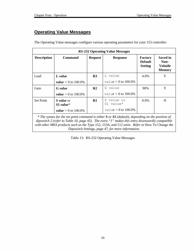
Chapter Four: Operation Operating Value Messages
59
Operating Value Messages
The Operating Value messages configure various operating parameters for your 153 controller.
RS-232 Operating Value Messages
Description Command Request Response FactoryDefaultSetting
Saved inNon-
VolatileMemory
Lead L value
value = 0 to 100.0%
R3 L value
value = 0 to 100.0%4.0% Y
Gain G value
value = 0 to 100.0%
R2 G value
value = 0 to 100.0%90% Y
Set Point S value orS1 value*
value = 0 to 100.0%
R1 S value orS1 value*
value = 0 to 100.0%
0.0% N
* The syntax for the set point command is either S or S1 (default), depending on the position ofdipswitch 2 (refer to Table 10, page 45). The extra “1” makes this entry downwardly compatible
with other MKS products such as the Type 152, 153A, and 112 units. Refer to How To Change theDipswitch Settings, page 47, for more information.
Table 13: RS-232 Operating Value Messages
Operating Value Messages Chapter Four: Operation
60
How To Set the Lead and Gain
Note The procedure for how to adjust the lead and gain values is described inHow To Tune the Controller, page 78.
How To Set the Lead
The command [L value] sets the lead value for the set point, where:
value: 0 to 100.0%
The default value is 4.0%. Refer to Lead, page 40, for more information.
To report the lead value, issue the request:
R3
The controller responds with the message [L value], where:
value: 0 to 100.0%
How To Set the Gain
The command [G value] sets the gain value for the set point, where:
value: 0 to 100.0%
The default setting is 90%. Refer to Gain, page 41, for more information.
To report the gain value, issue the request:
R2
The controller responds with the message [G value], where:
value: 0 to 100.0%
How To Set the Set PointThe command [S value] or [S1 value] sets the value for the set point, where:
value: 0 to 100.0%
The default setting is 0.0%. The syntax for the set point command is either S or S1 (default),depending on the position of dipswitch 2 (refer to Table 10, page 45). The extra “1” makes thisentry downwardly compatible with other MKS products such as the Type 152, 153A, and 112units. Refer to How To Change the Dipswitch Settings, page 47, for more information.
To report the value of the set point, issue the request:
R1
The controller responds with the message [S value] or [S1 value], where:
value: 0 to 100.0%
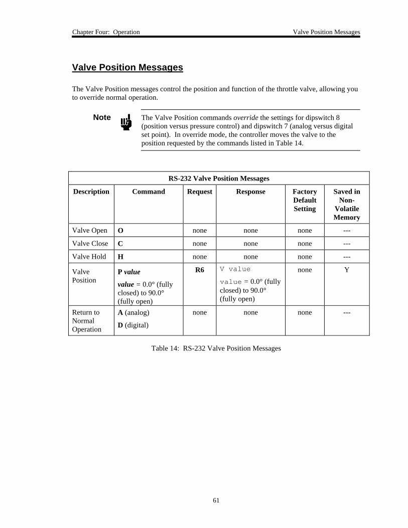
Chapter Four: Operation Valve Position Messages
61
Valve Position Messages
The Valve Position messages control the position and function of the throttle valve, allowing youto override normal operation.
Note The Valve Position commands override the settings for dipswitch 8(position versus pressure control) and dipswitch 7 (analog versus digitalset point). In override mode, the controller moves the valve to theposition requested by the commands listed in Table 14.
RS-232 Valve Position Messages
Description Command Request Response FactoryDefaultSetting
Saved inNon-
VolatileMemory
Valve Open O none none none ---
Valve Close C none none none ---
Valve Hold H none none none ---
ValvePosition
P value
value = 0.0° (fullyclosed) to 90.0°(fully open)
R6 V value
value = 0.0° (fullyclosed) to 90.0°(fully open)
none Y
Return toNormalOperation
A (analog)
D (digital)
none none none ---
Table 14: RS-232 Valve Position Messages
Valve Position Messages Chapter Four: Operation
62
How To Control the ValveThe 153 unit can drive the throttle valve to full open or full close, or stop it at its current position.There are no requests associated with these functions.
Note The RS-232 commands to open, close, or stop the valve override theactive set point control of the valve.After issuing a valve control command you must send either the [A] or[D] command to return the controller to normal analog or digitaloperation. Refer to How To Return to Normal Operation, page 61, formore information.
How to Drive the Valve to Full Open
To drive the valve to full open, issue the command:
O
How to Drive the Valve to Full Close
To drive the valve to full close, issue the command:
C
How to Stop the Valve
To stop (hold) the valve in its current position, issue the command:
H
How To Set the Valve PositionThe command [P value] sets the valve position, where:
value: 0° to 90.0°
To report the valve position, issue the request:
R6
The controller responds with the message [V value], where:
value: 0° to 90.0°
Chapter Four: Operation Valve Position Messages
63
How To Return to Normal OperationThe O, C, H, and P value commands override the normal operation of the valve. To return thecontroller to normal operation (as defined by the dipswitch settings listed in Table 10, page 45)after issuing a valve control command, send either of the following commands:
A
or
D
The controller exits from override mode and returns to the normal operating mode.
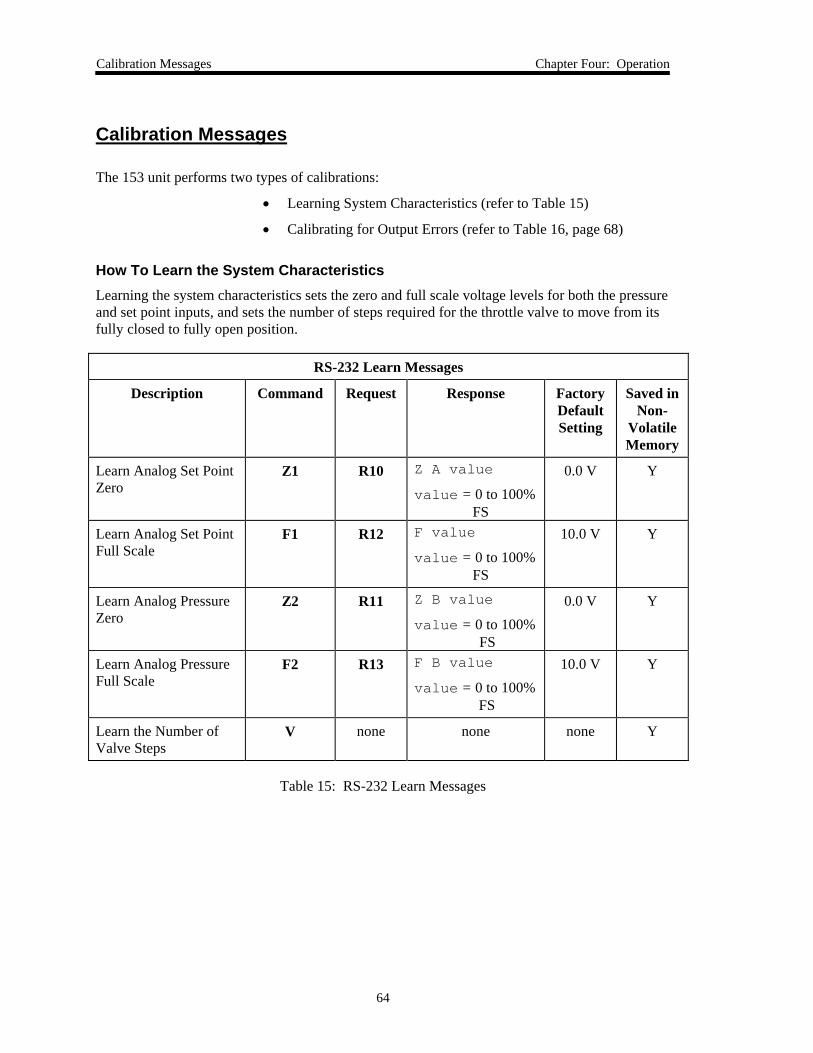
Calibration Messages Chapter Four: Operation
64
Calibration Messages
The 153 unit performs two types of calibrations:
• Learning System Characteristics (refer to Table 15)
• Calibrating for Output Errors (refer to Table 16, page 68)
How To Learn the System CharacteristicsLearning the system characteristics sets the zero and full scale voltage levels for both the pressureand set point inputs, and sets the number of steps required for the throttle valve to move from itsfully closed to fully open position.
RS-232 Learn Messages
Description Command Request Response FactoryDefaultSetting
Saved inNon-
VolatileMemory
Learn Analog Set PointZero
Z1 R10 Z A value
value = 0 to 100%FS
0.0 V Y
Learn Analog Set PointFull Scale
F1 R12 F value
value = 0 to 100%FS
10.0 V Y
Learn Analog PressureZero
Z2 R11 Z B value
value = 0 to 100%FS
0.0 V Y
Learn Analog PressureFull Scale
F2 R13 F B value
value = 0 to 100%FS
10.0 V Y
Learn the Number ofValve Steps
V none none none Y
Table 15: RS-232 Learn Messages
Chapter Four: Operation Calibration Messages
65
How To Learn the Analog Set Point Zero
The command [Z1] instructs the controller to take the current value of the external analog setpoint for its zero value. Zeroing the analog set point allows you to correct any controller zerooffsets. There is no request associated with this function.
To zero the analog set point:
1. Apply zero input voltage to pin 9 on the Input connector.
Refer to Table 7, page 33, for the Input connector pinout.
2. Enter the command:Z1
The analog set point zero voltage is set to 0.0 V at the factory.
The actual voltage input to the unit must be measured. However, you can report the voltage inputapplied as a percentage of the full scale voltage range by using the [R10] command. To reportthe value of the analog set point zero as a percentage of the full scale voltage range, send thecommand:
R10
The controller responds with the message [Z A value], where:
value: 0 to 100% FS
Calibration Messages Chapter Four: Operation
66
How To Learn the Analog Set Point Full Scale
The analog set point can be configured for 5 Volt or 10 Volt (default) full scale input. Thevoltage range is set with dipswitch 9 on the CPU board (refer to Table 10, page 45). You can,however, operate the 153 controller at a different full scale input, for example, 9.5 V, byrecalibrating the full scale of the analog set point.
To calibrate the full scale of the analog set point:
1. Apply full scale input voltage (for example, 9.5 V) to pin 9 on the Input connector.
Refer to Table 7, page 33, for the Input connector pinout.
Before you proceed, ensure that the input voltage is at least 9% of the 10 V full scalevoltage. If the voltage is less than 9% of the typical full scale voltage, the controllerignores the Learn Analog Set Point Full Scale command and retains the previous value.This eliminates the possibility of learning an erroneous voltage value.
2. Send the command:F1
The 9.5 V input to the Interface connector is now the full scale value.
This command instructs the controller to assign the voltage applied in step 1 as the newfull scale value for the analog set point, in this example, 9.5 V. This command alsoallows you to correct any full scale offsets.
The analog set point full scale voltage must be between +1 and +10.0 V. The analog setpoint full scale voltage is set to +10.0 V at the factory.
The actual voltage input to the unit must be measured. However, you can report the voltage inputapplied as a percentage of the full scale voltage range by using the [R12] command. To reportthe value of the analog set point full scale as a percentage of the full scale voltage range, send thecommand:
R12
The controller responds with the message [F A value], where:*
value: 0 to 100% FS
For example, if the analog set point is configured for 10 V full scale input and the actual inputapplied is 10 V, the unit reports a value of 100%. However, if the actual input applied is 5.0 V,the unit reports a value of 50%.
Chapter Four: Operation Calibration Messages
67
How To Learn the Analog Pressure Zero
The command [Z2] zeros the base pressure in systems where the known base pressure is not at,but near zero (as measured by another transducer in the system). There is no request associatedwith this function.
To set the pressure zero:
1. Warm-up the transducer and pump it below its resolution.
2. Send the command:Z2
The controller learns the pressure input that corresponds to the analog pressure zerovalue. The analog pressure zero value is factory set to 0.0 Volts.
Note If the pressure reading (at base pressure) is greater than 4% of full range,the sensor will not be zeroed.
The actual voltage input to the unit must be measured. However, you can report the voltage inputapplied as a percentage of the full scale voltage range by using the [R11] command. To reportthe value of the pressure zero as a percentage of the full scale voltage range, send the command:
R11
The controller responds with the message [Z B value], where:
value: 0 to 100% FS
Note When a voltage enters the controller as a calibration signal, for a pressurezero reading, the controller scales the signal to allow for a slightlyoverrange or underrange signal. The controller does not convert thesignal back to a full 0 to 10 V range.Therefore, when you query the controller for a pressure zero readingusing the [R11] request, it returns the offset value, rather than the truezero voltage reading.
Calibration Messages Chapter Four: Operation
68
How To Learn the Analog Pressure Full Scale
1. Warm-up the transducer and set up the pressure system for full scale pressure.
2. Send the command:F2
The controller raises the pressure to the full scale value of the transducer and learns thepressure input that corresponds to the analog pressure full scale value. The analogpressure full scale value is factory set to +10.0 Volts.
Note If a transducer is not connected to your system, apply full scale inputvoltage to pin 20 on the Input connector before sending the [F2]command.Refer to Table 7, page 33, for the Input connector pinout. Ensure that thepressure input voltage on Input connector, pin 20, is at least 9% of the10 V full scale voltage. If the voltage is less than 9% of the typical fullscale voltage, the controller ignores the learn command and retains theprevious value. This eliminates the possibility of learning an erroneousvoltage value.
The actual voltage input to the unit must be measured. However, you can report the voltage inputapplied as a percentage of the full scale voltage range by using the [R13] command. To reportthe value of the pressure full scale as a percentage of the full scale voltage range, send thecommand:
R13
The controller responds with the message [F B value], where:
value: 0 to 100% FS
Note When a voltage enters the controller as a calibration signal, for a pressurefull scale reading, the controller scales the signal to allow for a slightlyoverrange or underrange signal. The controller does not convert thesignal back to a full 0 to 10 V range.Therefore, when you query the controller for a pressure full scale readingusing the [R13] request, it returns the offset value, rather than the true fullscale voltage reading.
Chapter Four: Operation Calibration Messages
69
How To Learn the Number of Valve Steps
Caution The procedure for learning the valve steps involves opening andclosing the valve. Be certain that the system can withstand valvecycling before proceeding.
The [V] command sets or learns the number of steps required for the throttle valve to movefrom its fully closed (0) to fully open (100) position. There is no request associated with thiscommand.
To learn the number of valve steps, send the command:
V
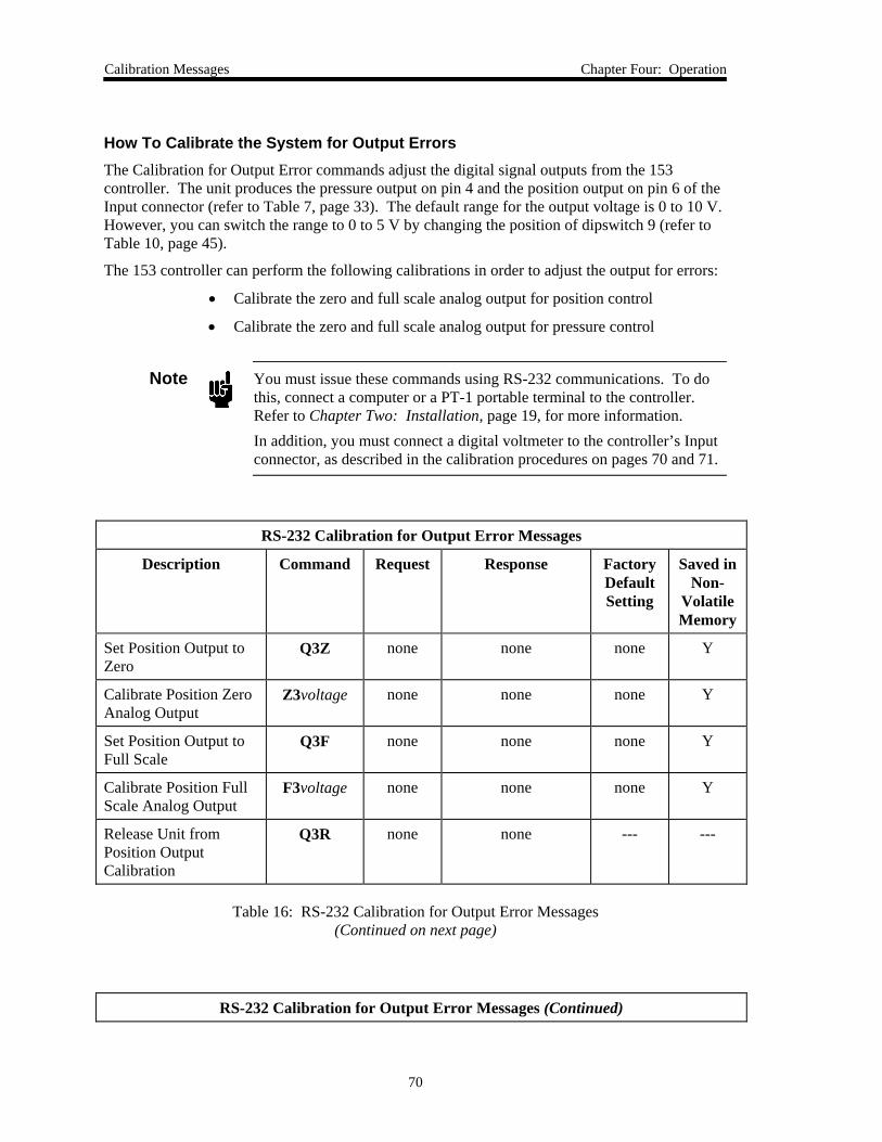
Calibration Messages Chapter Four: Operation
70
How To Calibrate the System for Output ErrorsThe Calibration for Output Error commands adjust the digital signal outputs from the 153controller. The unit produces the pressure output on pin 4 and the position output on pin 6 of theInput connector (refer to Table 7, page 33). The default range for the output voltage is 0 to 10 V.However, you can switch the range to 0 to 5 V by changing the position of dipswitch 9 (refer toTable 10, page 45).
The 153 controller can perform the following calibrations in order to adjust the output for errors:
• Calibrate the zero and full scale analog output for position control
• Calibrate the zero and full scale analog output for pressure control
Note You must issue these commands using RS-232 communications. To dothis, connect a computer or a PT-1 portable terminal to the controller.Refer to Chapter Two: Installation, page 19, for more information.In addition, you must connect a digital voltmeter to the controller’s Inputconnector, as described in the calibration procedures on pages 70 and 71.
RS-232 Calibration for Output Error Messages
Description Command Request Response FactoryDefaultSetting
Saved inNon-
VolatileMemory
Set Position Output toZero
Q3Z none none none Y
Calibrate Position ZeroAnalog Output
Z3voltage none none none Y
Set Position Output toFull Scale
Q3F none none none Y
Calibrate Position FullScale Analog Output
F3voltage none none none Y
Release Unit fromPosition OutputCalibration
Q3R none none --- ---
Table 16: RS-232 Calibration for Output Error Messages(Continued on next page)
RS-232 Calibration for Output Error Messages (Continued)
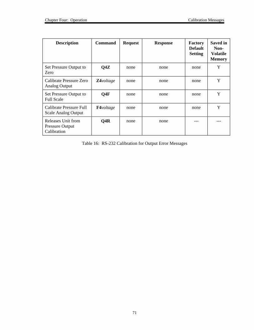
Chapter Four: Operation Calibration Messages
71
Description Command Request Response FactoryDefaultSetting
Saved inNon-
VolatileMemory
Set Pressure Output toZero
Q4Z none none none Y
Calibrate Pressure ZeroAnalog Output
Z4voltage none none none Y
Set Pressure Output toFull Scale
Q4F none none none Y
Calibrate Pressure FullScale Analog Output
F4voltage none none none Y
Releases Unit fromPressure OutputCalibration
Q4R none none --- ---
Table 16: RS-232 Calibration for Output Error Messages
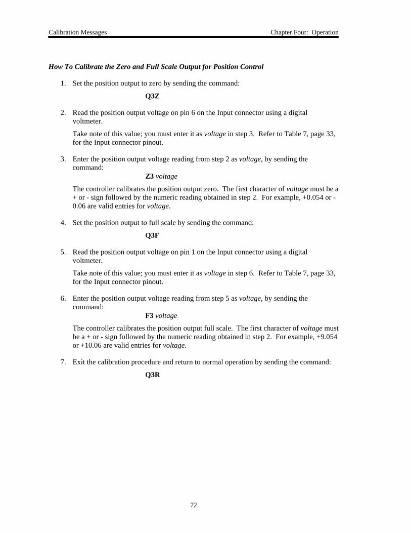
Calibration Messages Chapter Four: Operation
72
How To Calibrate the Zero and Full Scale Output for Position Control
1. Set the position output to zero by sending the command:
Q3Z
2. Read the position output voltage on pin 6 on the Input connector using a digitalvoltmeter.
Take note of this value; you must enter it as voltage in step 3. Refer to Table 7, page 33,for the Input connector pinout.
3. Enter the position output voltage reading from step 2 as voltage, by sending thecommand:
Z3 voltage
The controller calibrates the position output zero. The first character of voltage must be a+ or - sign followed by the numeric reading obtained in step 2. For example, +0.054 or -0.06 are valid entries for voltage.
4. Set the position output to full scale by sending the command:
Q3F
5. Read the position output voltage on pin 1 on the Input connector using a digitalvoltmeter.
Take note of this value; you must enter it as voltage in step 6. Refer to Table 7, page 33,for the Input connector pinout.
6. Enter the position output voltage reading from step 5 as voltage, by sending thecommand:
F3 voltage
The controller calibrates the position output full scale. The first character of voltage mustbe a + or - sign followed by the numeric reading obtained in step 2. For example, +9.054or +10.06 are valid entries for voltage.
7. Exit the calibration procedure and return to normal operation by sending the command:
Q3R
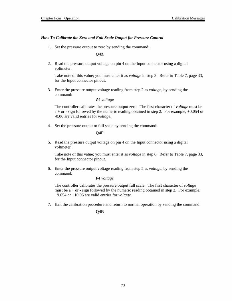
Chapter Four: Operation Calibration Messages
73
How To Calibrate the Zero and Full Scale Output for Pressure Control
1. Set the pressure output to zero by sending the command:
Q4Z
2. Read the pressure output voltage on pin 4 on the Input connector using a digitalvoltmeter.
Take note of this value; you must enter it as voltage in step 3. Refer to Table 7, page 33,for the Input connector pinout.
3. Enter the pressure output voltage reading from step 2 as voltage, by sending thecommand:
Z4 voltage
The controller calibrates the pressure output zero. The first character of voltage must bea + or - sign followed by the numeric reading obtained in step 2. For example, +0.054 or-0.06 are valid entries for voltage.
4. Set the pressure output to full scale by sending the command:
Q4F
5. Read the pressure output voltage on pin 4 on the Input connector using a digitalvoltmeter.
Take note of this value; you must enter it as voltage in step 6. Refer to Table 7, page 33,for the Input connector pinout.
6. Enter the pressure output voltage reading from step 5 as voltage, by sending thecommand:
F4 voltage
The controller calibrates the pressure output full scale. The first character of voltagemust be a + or - sign followed by the numeric reading obtained in step 2. For example,+9.054 or +10.06 are valid entries for voltage.
7. Exit the calibration procedure and return to normal operation by sending the command:
Q4R
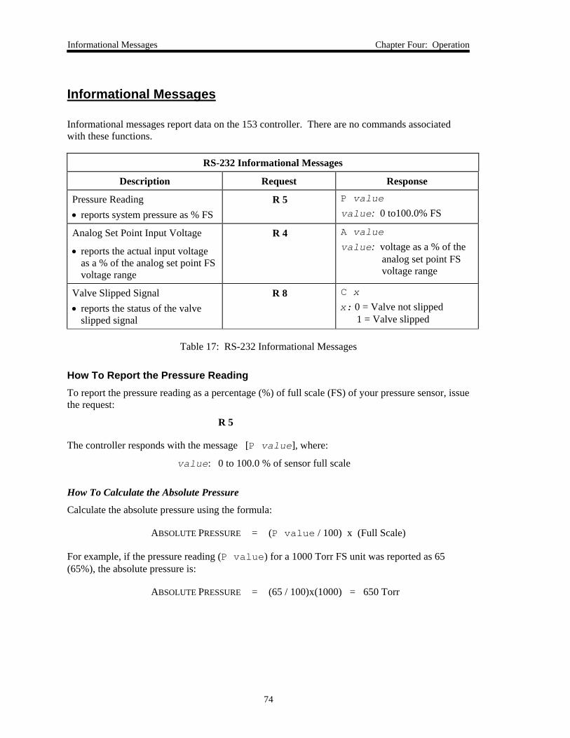
Informational Messages Chapter Four: Operation
74
Informational Messages
Informational messages report data on the 153 controller. There are no commands associatedwith these functions.
RS-232 Informational Messages
Description Request Response
Pressure Reading• reports system pressure as % FS
R 5 P value
value: 0 to100.0% FS
Analog Set Point Input Voltage
• reports the actual input voltageas a % of the analog set point FSvoltage range
R 4 A value
value: voltage as a % of theanalog set point FSvoltage range
Valve Slipped Signal• reports the status of the valve
slipped signal
R 8 C x
x: 0 = Valve not slipped1 = Valve slipped
Table 17: RS-232 Informational Messages
How To Report the Pressure ReadingTo report the pressure reading as a percentage (%) of full scale (FS) of your pressure sensor, issuethe request:
R 5
The controller responds with the message [P value], where:
value: 0 to 100.0 % of sensor full scale
How To Calculate the Absolute Pressure
Calculate the absolute pressure using the formula:
ABSOLUTE PRESSURE = (P value / 100) x (Full Scale)
For example, if the pressure reading (P value) for a 1000 Torr FS unit was reported as 65(65%), the absolute pressure is:
ABSOLUTE PRESSURE = (65 / 100)x(1000) = 650 Torr
Chapter Four: Operation Informational Messages
75
How To Report the Analog Set Point Input VoltageTo report the actual input voltage as a percent of the analog set point full scale voltage range,enter:
R 4
The controller responds with the message [A value], where:
value: % of the analog set point FS voltage range
Note The request [R 4] reports the analog set point value as a percentage ofthe analog set point full scale range; it does not report the percentage ofthe controlling transducer’s range.
How To Report the Status of the Valve Slipped SignalTo report the status of the valve slipped signal, issue the command:
R 8
The controller responds with the message:
C x
where x: 0 = Valve not slipped1 = Valve slipped
Note If the valve slipped signal is set to “1”, the valve must be re-calibrated.Refer How To Reset the Controller, page 80, for more information.
How To Use the Pressure Control Mode Chapter Four: Operation
76
How To Use the Pressure Control Mode
How To Select the Pressure Control ModeTo select the pressure control mode:
1. Place switch 8 in the dipswitch bank to the ON (Closed) position.
This is the default setting for switch 8.
2. Verify that pin 15 on the Input connector is high (default).
Refer to Table 7, page 33, for the Input connector pinout. If pin 15 is low, it overridesthe switch 8 setting in step 1.
3. Send the controller an analog or digital set point.
How To Use an Analog Set Point for Pressure ControlTo use an analog set point:
1. Place switch 7 in the dipswitch bank to the ON (Closed) position.
This is the default setting for switch 7.
2. Supply a voltage to pin 9 on the Input connector.
Refer to Table 7, page 33, for the Input connector pinout. The set point is expressed as apercent of full scale pressure, where:
set point = analog set point voltage on pin 9analog set point full scale voltage
For example, if the analog set point full scale voltage is 10 Volts and you supply a setpoint voltage of 5 Volts, you are establishing a set point of 50% of full scale pressure.
Note Even if you are using an analog set point, you must connect a computer orPT-1 unit to the controller in order to calibrate and tune the controller, andlearn the valve. The analog set point zero and full scale voltages arecalibrated using the procedures described in How To Learn the SystemCharacteristics, page 62.
Chapter Four: Operation How To Use the Pressure Control Mode
77
How To Use a Digital Set Point for Pressure ControlTo use a digital set point:
1. Place switch 7 in the dipswitch bank to the OFF (Open) position.
This is not the default setting for switch 7.
2. Connect the controller to a computer or PT-1 unit.
Refer to Chapter Two: Installation, page 19, for more information.
3. Send the RS-232 Pressure Set Point command (refer to Table 13, page 57):
S1 value
where value is a percent value representing the pressure set point as a percent of full scalepressure. For example, to send a pressure set point of 25% of full scale pressure, send thecommand:
S1 25
How To Override the Pressure Control ModeEven though you are using the 153 unit as a pressure controller, there may be times when youwant to temporarily suspend the Pressure Control mode and move the valve to a specific position.
To override the Pressure Control mode:
1. Ensure that the controller is connected to a computer or PT-1 unit.
Refer to Chapter Two: Installation, page 19, for more information.
2. Send the unit the appropriate Valve Position command.
The RS-232 Valve Position commands are listed in Table 14, page 59.
3. Send the [A] or [D] command to return operation to either the analog or digitalPressure Control mode.
How To Use the Position Control Mode Chapter Four: Operation
78
How To Use the Position Control Mode
How To Select the Position Control ModeTo select the position control mode:
1. Place switch 8 in the dipswitch bank to the OFF (Open) position.
This is not the default setting for switch 8. Alternately, you can leave switch 8 in thedefault ON (Closed) position and pull pin 15 low on the Input connector. If pin 15 islow, it will override the switch 8 setting. Refer to Table 7, page 33, for the Inputconnector pinout.
2. Send the controller an analog or digital set point.
How To Use an Analog Set Point for Position ControlTo use an analog set point:
1. Place switch 7 in the dipswitch bank to the ON (Closed) position.
This is the default setting for switch 7.
2. Supply a voltage to pin 9 on the Input connector.
Refer to Table 7, page 33, for the Input connector pinout. The set point is expressed as apercent of full scale position, where:
set point = analog set point voltage on pin 9analog set point full scale voltage
For example, if the analog set point full scale voltage is 10 Volts and you supply a setpoint voltage of 5 Volts, you are establishing a set point of 50% of full open or 45°.
Chapter Four: Operation How To Use the Position Control Mode
79
How To Use a Digital Set Point for Position ControlTo use a digital set point:
1. Connect the controller to a computer or the PT-1 portable terminal.
Refer to Chapter Two: Installation, page 19, for more information.
2. Place switch 7 in the dipswitch bank to the OFF (Open) position.
This is not the default setting for switch 7.
3. Send the RS-232 Position Set Point command (refer to Table 14, page 59):
P value
where value is the position in degrees. The acceptable input range is 0 (fully closed) to90 (fully open). For example, to send a position set point of half open (45 degrees), sendthe command:
P 45
Note Sending the [P value] command overrides the Pressure Control mode.Refer to How To Override the Pressure Control Mode, page 75, for moreinformation.
How To Tune the Controller Chapter Four: Operation
80
How To Tune the Controller
The 153 controller is tuned by adjusting the lead and gain parameters with the RS-232 commandslisted in Table 13, page 57.
Note The “optimal” lead and gain settings result in the best response when thepressure is near the set point. That is, when there is minimal overshootand no oscillation. Refer to Lead and Gain, page 39, for additionalinformation.
To tune the controller:
1. Apply power to the unit and turn on the upstream gas source(s).
2. Apply the desired analog set point signal or RS-232 message.
The unit responds by changing the pressure smoothly to the desired value. If the pressureis slow changing to the desired value (over 30 seconds), or oscillates, then adjust the leadand/or gain values.
3. Start with a high gain setting; however, do not adjust the value at this time.
The gain value depends on the process being controlled. The acceptable input range is0 to 100%; the default value is 90.0%.
4. Adjust the lead setting.
• If the pressure overshoots the set point, increase the lead setting.
• If there is no overshoot, and particularly if the pressure is slow approaching the setpoint, then reduce the lead setting.
The acceptable input range is 0 to 100%; the default value is 4.0%.
5. Repeat step 4 to confirm that the lead setting is appropriate.
Note The correct lead setting for a rise in pressure is normally not the same fora drop in pressure. Therefore, adjust the lead parameter using the sameset point and direction as required in your process.
Chapter Four: Operation How To Tune the Controller
81
6. Reduce the gain setting.
Only adjust the gain setting if the pressure continues to oscillate around the set point, andit cannot be corrected by adjusting the lead.
Note The highest possible gain setting produces the best pressure control,therefore, reduce the gain setting in very small increments.The speed of pressure response is relative and depends on chamber sizeand absolute pressure. Lower pressures (less than 10 microns) are usuallyslower because of the slower molecular flow and reduced pumping speed.
The maximum rate of rise of pressure is determined by the following formula (with the exhaustvalve fully closed:
Pr = F/V
where: Pr = pressure rate of rise in Torr/sec.F = flow in Torr-liters/sec.V = volume in liters.
Consequently, in systems with small input flows and relatively large volumes, the pressure willrise slowly even when the control valve is fully closed.
If the controller cannot achieve good control, the problem may be caused by improper pneumaticconnections. Refer to System Configuration, page 30, for more information about factors whicheffect pressure control.
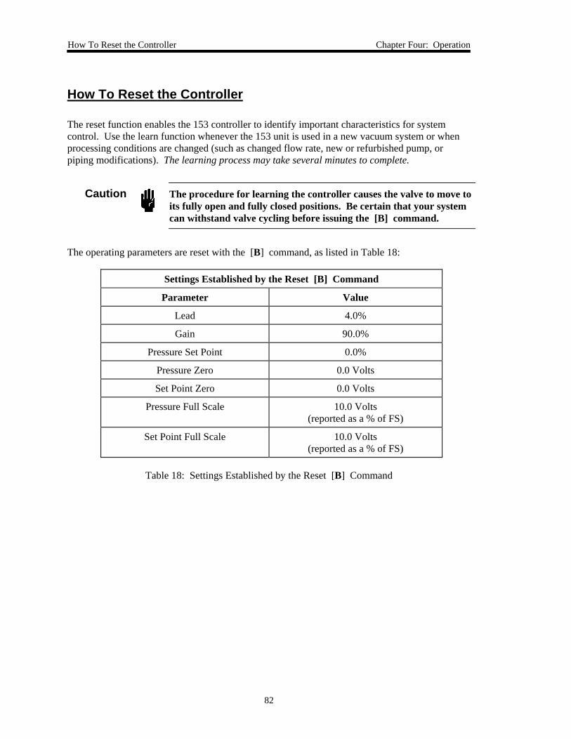
How To Reset the Controller Chapter Four: Operation
82
How To Reset the Controller
The reset function enables the 153 controller to identify important characteristics for systemcontrol. Use the learn function whenever the 153 unit is used in a new vacuum system or whenprocessing conditions are changed (such as changed flow rate, new or refurbished pump, orpiping modifications). The learning process may take several minutes to complete.
Caution The procedure for learning the controller causes the valve to move toits fully open and fully closed positions. Be certain that your systemcan withstand valve cycling before issuing the [B] command.
The operating parameters are reset with the [B] command, as listed in Table 18:
Settings Established by the Reset [B] Command
Parameter Value
Lead 4.0%
Gain 90.0%
Pressure Set Point 0.0%
Pressure Zero 0.0 Volts
Set Point Zero 0.0 Volts
Pressure Full Scale 10.0 Volts(reported as a % of FS)
Set Point Full Scale 10.0 Volts(reported as a % of FS)
Table 18: Settings Established by the Reset [B] Command
Chapter Four: Operation How To Reset the Controller
83
To reset the controller:
1. Initiate the proper gas flow into the system.
The gas flow rate should be close to that used for the actual process (use the maximumflow rate if several flow rates are used in the process). Do not vary the gas flow rateduring learning.
Note The system pressure will vary during the learn cycle to as low and high asis possible for the current flow rate.
2. Send the command:
B
The command resets the controller, re-learns the valve, and resets the values for the lead,gain, set point, and the zero and full scale voltage levels for both the pressure and setpoint inputs to the values listed in Table 18, page 80.
You may need to reset the lead, gain, zero, and full scale values to those used prior toresetting the controller. To reset the lead and gain values, refer to How To Tune theController, page 78. To reset the set point, refer to How To Set the Set Point, page 58.To reset the zero and full scale settings, refer to How To Learn the SystemCharacteristics, page 62.

How To Reset the Controller Chapter Four: Operation
84
This page intentionally left blank.
Chapter Five: Maintenance and Troubleshooting General Information
85
Chapter Five: Maintenance and Troubleshooting
General Information
If your controller fails to operate properly upon receipt, check for shipping damage, and check thepower/signal cable for proper continuity. Any damage should be reported to the carrier and MKSInstruments immediately. If there is no obvious damage and the continuity is correct, obtain anRMA Number (Return Material Authorization Number) before returning the unit to MKSInstruments for service.
Note MKS recommends that the zero adjustment be the only adjustment madein the field. Return the transducer to MKS Instruments for otheradjustments, calibrations, or servicing.
Maintenance
In general, no maintenance is required other than proper installation and operation, and anoccasional zero adjustment. Periodically check for wear on the cables and inspect the enclosurefor visible signs of damage.
How To Clean the UnitPeriodically wipe down the unit with a damp cloth.

Troubleshooting Chapter Five: Maintenance and Troubleshooting
86
Troubleshooting
Valve Slipped SignalThe 153 unit has a “valve slipped” signal that can be useful when diagnosing exhaust valve orsystem problems. The valve slipped signal is only available through the RS-232 interface.
When the 153 unit contacts either of the limit switches, the internal position signal should equalthe appropriate valve position (0 for close, 100% for open). If the position signal is more than3% different from the appropriate value, the valve slipped signal is set to “1” (meaning slipped).
When the request R8 is sent to the 153 unit, the unit returns either “C0” or “C1” (refer to Table17, page 72). The response “C0” indicates the valve has not slipped. The response “C1”indicates the valve has slipped since the last time the request was issued. The signal is reset to 0when it is read by the computer or PT-1 unit.
Situations that can cause the valve to slip include:
• The flapper is moved while the 153 unit is turned off
• The flapper is rubbing or contacting part of the plumbing
• Particulates are depositing on the wall and slowing the flapper motion
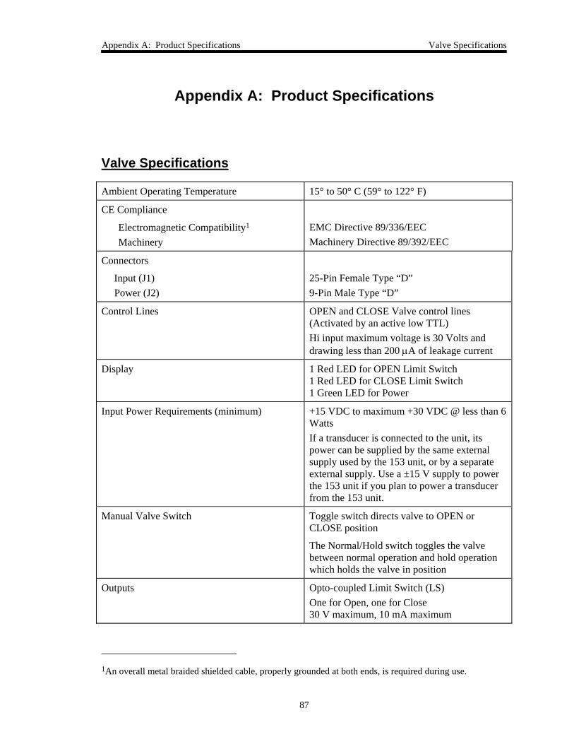
Appendix A: Product Specifications Valve Specifications
87
Appendix A: Product Specifications
Valve Specifications
Ambient Operating Temperature 15° to 50° C (59° to 122° F)
CE Compliance
Electromagnetic Compatibility1
MachineryEMC Directive 89/336/EECMachinery Directive 89/392/EEC
Connectors
Input (J1)Power (J2)
25-Pin Female Type “D”9-Pin Male Type “D”
Control Lines OPEN and CLOSE Valve control lines(Activated by an active low TTL)Hi input maximum voltage is 30 Volts anddrawing less than 200 µA of leakage current
Display 1 Red LED for OPEN Limit Switch1 Red LED for CLOSE Limit Switch1 Green LED for Power
Input Power Requirements (minimum) +15 VDC to maximum +30 VDC @ less than 6WattsIf a transducer is connected to the unit, itspower can be supplied by the same externalsupply used by the 153 unit, or by a separateexternal supply. Use a ±15 V supply to powerthe 153 unit if you plan to power a transducerfrom the 153 unit.
Manual Valve Switch Toggle switch directs valve to OPEN orCLOSE position
The Normal/Hold switch toggles the valvebetween normal operation and hold operationwhich holds the valve in position
Outputs Opto-coupled Limit Switch (LS)One for Open, one for Close30 V maximum, 10 mA maximum
1An overall metal braided shielded cable, properly grounded at both ends, is required during use.
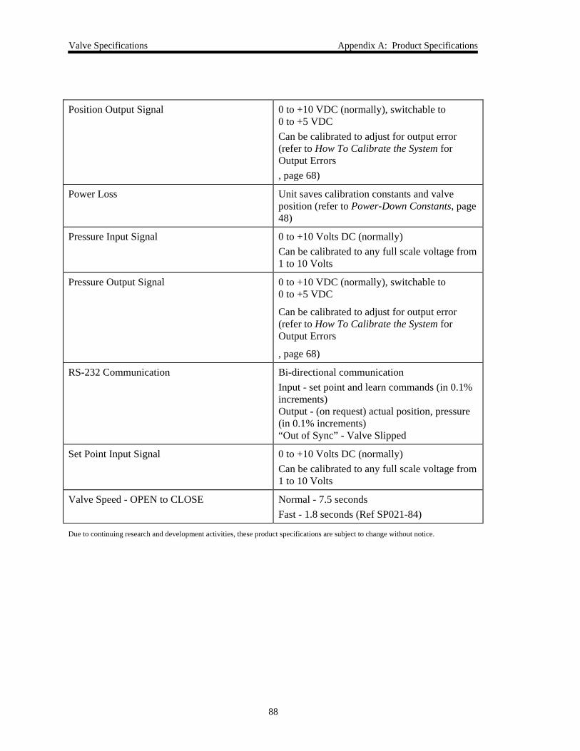
Valve Specifications Appendix A: Product Specifications
88
Position Output Signal 0 to +10 VDC (normally), switchable to0 to +5 VDCCan be calibrated to adjust for output error(refer to How To Calibrate the System forOutput Errors, page 68)
Power Loss Unit saves calibration constants and valveposition (refer to Power-Down Constants, page48)
Pressure Input Signal 0 to +10 Volts DC (normally)Can be calibrated to any full scale voltage from1 to 10 Volts
Pressure Output Signal 0 to +10 VDC (normally), switchable to0 to +5 VDC
Can be calibrated to adjust for output error(refer to How To Calibrate the System forOutput Errors
, page 68)
RS-232 Communication Bi-directional communicationInput - set point and learn commands (in 0.1%increments)Output - (on request) actual position, pressure(in 0.1% increments)“Out of Sync” - Valve Slipped
Set Point Input Signal 0 to +10 Volts DC (normally)Can be calibrated to any full scale voltage from1 to 10 Volts
Valve Speed - OPEN to CLOSE Normal - 7.5 secondsFast - 1.8 seconds (Ref SP021-84)
Due to continuing research and development activities, these product specifications are subject to change without notice.
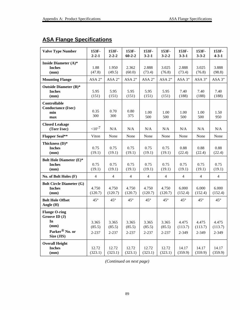
Appendix A: Product Specifications ASA Flange Specifications
89
ASA Flange Specifications
Valve Type Number 153F-2-2-1
153F-2-2-2
153F-60-2-2
153F-3-2-1
153F-3-2-2
153F-3-3-1
153F-3-3-2
153F-4-3-1
Inside Diameter (A)*Inches(mm)
1.88(47.8)
1.950(49.5)
2.362(60.0)
2.888(73.4)
3.025(76.8)
2.888(73.4)
3.025(76.8)
3.888(98.8)
Mounting Flange ASA 2” ASA 2” ASA 2” ASA 2” ASA 2” ASA 3” ASA 3” ASA 3”
Outside Diameter (B)*Inches(mm)
5.95(151)
5.95(151)
5.95(151)
5.95(151)
5.95(151)
7.40(188)
7.40(188)
7.40(188)
ControllableConductance (l/sec)
minmax
0.35300
0.70300
0.80375
1.00500
1.00500
1.00500
1.00500
1.50950
Closed Leakage(Torr l/sec) <10-7 N/A N/A N/A N/A N/A N/A N/A
Flapper Seal** Viton None None None None None None None
Thickness (D)*Inches(mm)
0.75(19.1)
0.75(19.1)
0.75(19.1)
0.75(19.1)
0.75(19.1)
0.88(22.4)
0.88(22.4)
0.88(22.4)
Bolt Hole Diameter (E)*Inches(mm)
0.75(19.1)
0.75(19.1)
0.75(19.1)
0.75(19.1)
0.75(19.1)
0.75(19.1)
0.75(19.1)
0.75(19.1)
No. of Bolt Holes (F) 4 4 4 4 4 4 4 4
Bolt Circle Diameter (G)Inches(mm)
4.750(120.7)
4.750(120.7)
4.750(120.7)
4.750(120.7)
4.750(120.7)
6.000(152.4)
6.000(152.4)
6.000(152.4)
Bolt Hole OffsetAngle (H)
45° 45° 45° 45° 45° 45° 45° 45°
Flange O-ringGroove ID (J)
In(mm)Parker® No. orSize (JIS)
3.365(85.5)2-237
3.365(85.5)2-237
3.365(85.5)2-237
3.365(85.5)2-237
3.365(85.5)2-237
4.475(113.7)2-349
4.475(113.7)2-349
4.475(113.7)2-349
Overall HeightInches(mm)
12.72(323.1)
12.72(323.1)
12.72(323.1)
12.72(323.1)
12.72(323.1)
14.17(359.9)
14.17(359.9)
14.17(359.9)
(Continued on next page)
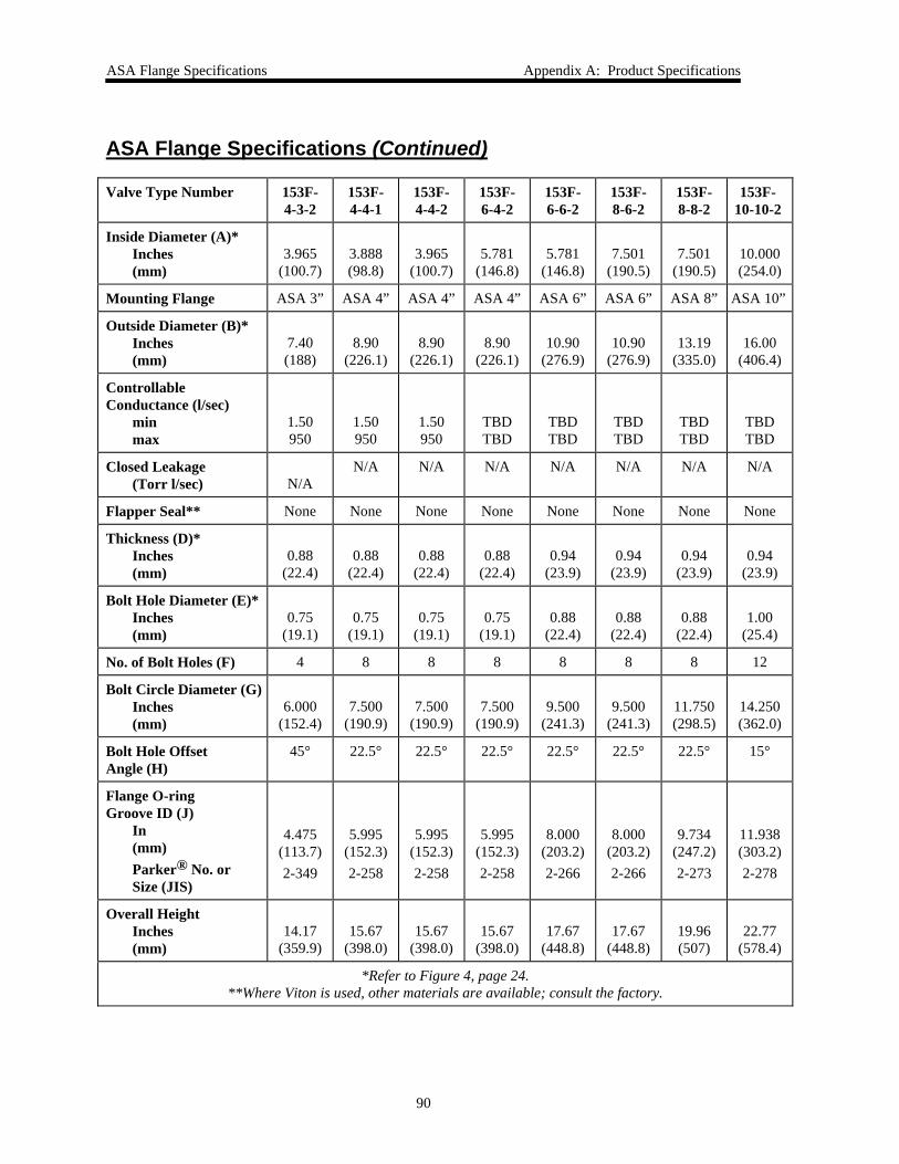
ASA Flange Specifications Appendix A: Product Specifications
90
ASA Flange Specifications (Continued)
Valve Type Number 153F-4-3-2
153F-4-4-1
153F-4-4-2
153F-6-4-2
153F-6-6-2
153F-8-6-2
153F-8-8-2
153F-10-10-2
Inside Diameter (A)*Inches(mm)
3.965(100.7)
3.888(98.8)
3.965(100.7)
5.781(146.8)
5.781(146.8)
7.501(190.5)
7.501(190.5)
10.000(254.0)
Mounting Flange ASA 3” ASA 4” ASA 4” ASA 4” ASA 6” ASA 6” ASA 8” ASA 10”
Outside Diameter (B)*Inches(mm)
7.40(188)
8.90(226.1)
8.90(226.1)
8.90(226.1)
10.90(276.9)
10.90(276.9)
13.19(335.0)
16.00(406.4)
ControllableConductance (l/sec)
minmax
1.50950
1.50950
1.50950
TBDTBD
TBDTBD
TBDTBD
TBDTBD
TBDTBD
Closed Leakage(Torr l/sec) N/A
N/A N/A N/A N/A N/A N/A N/A
Flapper Seal** None None None None None None None None
Thickness (D)*Inches(mm)
0.88(22.4)
0.88(22.4)
0.88(22.4)
0.88(22.4)
0.94(23.9)
0.94(23.9)
0.94(23.9)
0.94(23.9)
Bolt Hole Diameter (E)*Inches(mm)
0.75(19.1)
0.75(19.1)
0.75(19.1)
0.75(19.1)
0.88(22.4)
0.88(22.4)
0.88(22.4)
1.00(25.4)
No. of Bolt Holes (F) 4 8 8 8 8 8 8 12
Bolt Circle Diameter (G)Inches(mm)
6.000(152.4)
7.500(190.9)
7.500(190.9)
7.500(190.9)
9.500(241.3)
9.500(241.3)
11.750(298.5)
14.250(362.0)
Bolt Hole OffsetAngle (H)
45° 22.5° 22.5° 22.5° 22.5° 22.5° 22.5° 15°
Flange O-ringGroove ID (J)
In(mm)Parker® No. orSize (JIS)
4.475(113.7)2-349
5.995(152.3)2-258
5.995(152.3)2-258
5.995(152.3)2-258
8.000(203.2)2-266
8.000(203.2)2-266
9.734(247.2)2-273
11.938(303.2)2-278
Overall HeightInches(mm)
14.17(359.9)
15.67(398.0)
15.67(398.0)
15.67(398.0)
17.67(448.8)
17.67(448.8)
19.96(507)
22.77(578.4)
*Refer to Figure 4, page 24.**Where Viton is used, other materials are available; consult the factory.
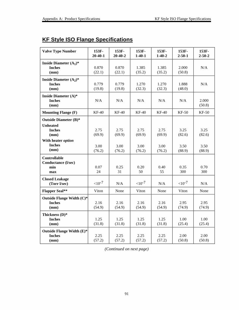
Appendix A: Product Specifications KF Style ISO Flange Specifications
91
KF Style ISO Flange Specifications
Valve Type Number 153F-20-40-1
153F-20-40-2
153F-1-40-1
153F-1-40-2
153F-2-50-1
153F-2-50-2
Inside Diameter (A1)*Inches(mm)
0.870(22.1)
0.870(22.1)
1.385(35.2)
1.385(35.2)
2.000(50.8)
N/A
Inside Diameter (A2)*Inches(mm)
0.779(19.8)
0.779(19.8)
1.270(32.3)
1.270(32.3)
1.888(48.0)
N/A
Inside Diameter (A)*Inches(mm)
N/A N/A N/A N/A N/A 2.000(50.8)
Mounting Flange (F) KF-40 KF-40 KF-40 KF-40 KF-50 KF-50
Outside Diameter (B)*Unheated
Inches(mm)
With heater optionInches(mm)
2.75(69.9)
3.00(76.2)
2.75(69.9)
3.00(76.2)
2.75(69.9)
3.00(76.2)
2.75(69.9)
3.00(76.2)
3.25(82.6)
3.50(88.9)
3.25(82.6)
3.50(88.9)
ControllableConductance (l/sec)
minmax
0.0724
0.2531
0.2050
0.4055
0.35300
0.70300
Closed Leakage(Torr l/sec) <10-7 N/A <10-7 N/A <10-7 N/A
Flapper Seal** Viton None Viton None Viton None
Outside Flange Width (C)*Inches(mm)
2.16(54.9)
2.16(54.9)
2.16(54.9)
2.16(54.9)
2.95(74.9)
2.95(74.9)
Thickness (D)*Inches(mm)
1.25(31.8)
1.25(31.8)
1.25(31.8)
1.25(31.8)
1.00(25.4)
1.00(25.4)
Outside Flange Width (E)*Inches(mm)
2.25(57.2)
2.25(57.2)
2.25(57.2)
2.25(57.2)
2.00(50.8)
2.00(50.8)
(Continued on next page)
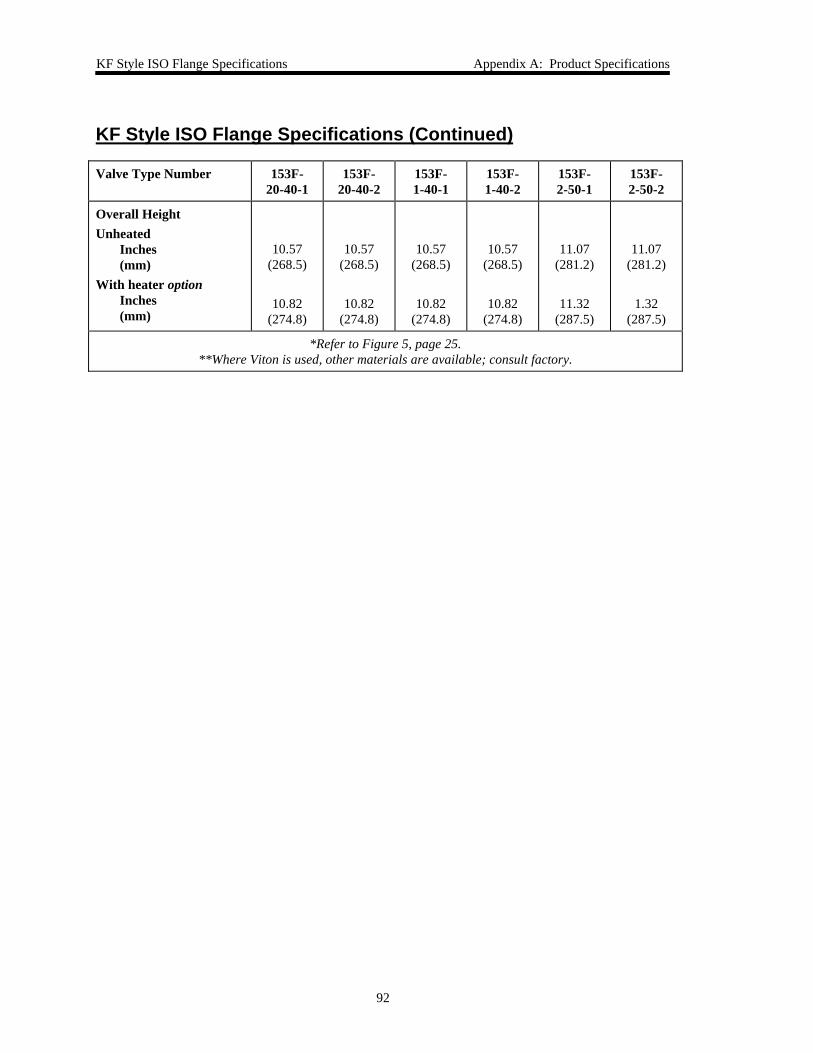
KF Style ISO Flange Specifications Appendix A: Product Specifications
92
KF Style ISO Flange Specifications (Continued)
Valve Type Number 153F-20-40-1
153F-20-40-2
153F-1-40-1
153F-1-40-2
153F-2-50-1
153F-2-50-2
Overall HeightUnheated
Inches(mm)
With heater optionInches(mm)
10.57(268.5)
10.82(274.8)
10.57(268.5)
10.82(274.8)
10.57(268.5)
10.82(274.8)
10.57(268.5)
10.82(274.8)
11.07(281.2)
11.32(287.5)
11.07(281.2)
1.32(287.5)
*Refer to Figure 5, page 25.**Where Viton is used, other materials are available; consult factory.
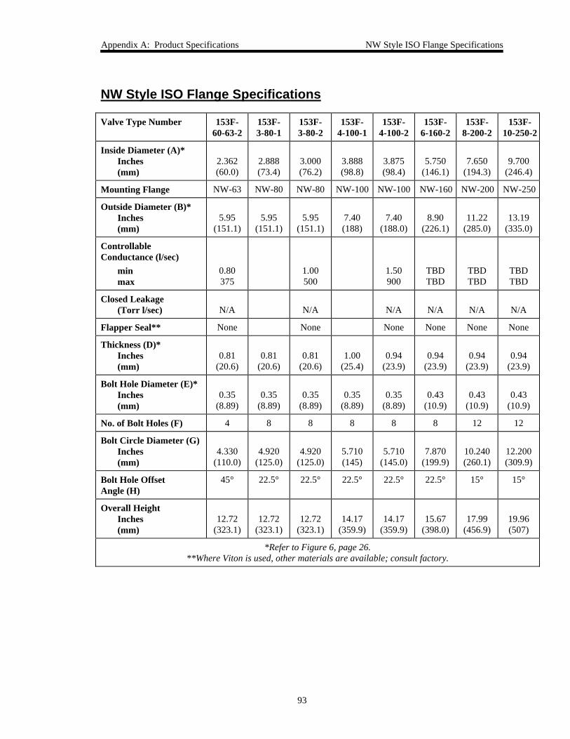
Appendix A: Product Specifications NW Style ISO Flange Specifications
93
NW Style ISO Flange Specifications
Valve Type Number 153F-60-63-2
153F-3-80-1
153F-3-80-2
153F-4-100-1
153F-4-100-2
153F-6-160-2
153F-8-200-2
153F-10-250-2
Inside Diameter (A)*Inches(mm)
2.362(60.0)
2.888(73.4)
3.000(76.2)
3.888(98.8)
3.875(98.4)
5.750(146.1)
7.650(194.3)
9.700(246.4)
Mounting Flange NW-63 NW-80 NW-80 NW-100 NW-100 NW-160 NW-200 NW-250
Outside Diameter (B)*Inches(mm)
5.95(151.1)
5.95(151.1)
5.95(151.1)
7.40(188)
7.40(188.0)
8.90(226.1)
11.22(285.0)
13.19(335.0)
ControllableConductance (l/sec)
minmax
0.80375
1.00500
1.50900
TBDTBD
TBDTBD
TBDTBD
Closed Leakage(Torr l/sec) N/A N/A N/A N/A N/A N/A
Flapper Seal** None None None None None None
Thickness (D)*Inches(mm)
0.81(20.6)
0.81(20.6)
0.81(20.6)
1.00(25.4)
0.94(23.9)
0.94(23.9)
0.94(23.9)
0.94(23.9)
Bolt Hole Diameter (E)*Inches(mm)
0.35(8.89)
0.35(8.89)
0.35(8.89)
0.35(8.89)
0.35(8.89)
0.43(10.9)
0.43(10.9)
0.43(10.9)
No. of Bolt Holes (F) 4 8 8 8 8 8 12 12
Bolt Circle Diameter (G)Inches(mm)
4.330(110.0)
4.920(125.0)
4.920(125.0)
5.710(145)
5.710(145.0)
7.870(199.9)
10.240(260.1)
12.200(309.9)
Bolt Hole OffsetAngle (H)
45° 22.5° 22.5° 22.5° 22.5° 22.5° 15° 15°
Overall HeightInches(mm)
12.72(323.1)
12.72(323.1)
12.72(323.1)
14.17(359.9)
14.17(359.9)
15.67(398.0)
17.99(456.9)
19.96(507)
*Refer to Figure 6, page 26.**Where Viton is used, other materials are available; consult factory.
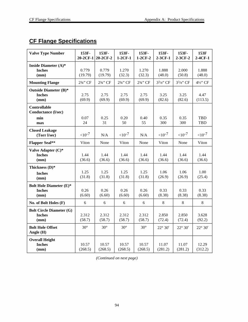
CF Flange Specifications Appendix A: Product Specifications
94
CF Flange Specifications
Valve Type Number 153F-20-2CF-1
153F-20-2CF-2
153F-1-2CF-1
153F-1-2CF-2
153F-2-3CF-1
153F-2-3CF-2
153F2-4CF-1
Inside Diameter (A)*Inches(mm)
0.779(19.79)
0.779(19.79)
1.270(32.3)
1.270(32.3)
1.888(48.0)
2.000(50.8)
1.888(48.0)
Mounting Flange 2¾” CF 2¾” CF 2¾” CF 2¾” CF 33/8” CF 33/8” CF 4½” CF
Outside Diameter (B)*Inches(mm)
2.75(69.9)
2.75(69.9)
2.75(69.9)
2.75(69.9)
3.25(82.6)
3.25(82.6)
4.47(113.5)
ControllableConductance (l/sec)
minmax
0.0724
0.2531
0.2050
0.4055
0.35300
0.35300
TBDTBD
Closed Leakage(Torr l/sec) <10-7 N/A <10-7 N/A <10-7 <10-7 <10-7
Flapper Seal** Viton None Viton None Viton None Viton
Valve Adapter (C)*Inches(mm)
1.44(36.6)
1.44(36.6)
1.44(36.6)
1.44(36.6)
1.44(36.6)
1.44(36.6)
1.44(36.6)
Thickness (D)*Inches(mm)
1.25(31.8)
1.25(31.8)
1.25(31.8)
1.25(31.8)
1.06(26.9)
1.06(26.9)
1.00(25.4)
Bolt Hole Diameter (E)*Inches(mm)
0.26(6.60)
0.26(6.60)
0.26(6.60)
0.26(6.60)
0.33(8.38)
0.33(8.38)
0.33(8.38)
No. of Bolt Holes (F) 6 6 6 6 8 8 8
Bolt Circle Diameter (G)Inches(mm)
2.312(58.7)
2.312(58.7)
2.312(58.7)
2.312(58.7)
2.850(72.4)
2.850(72.4)
3.628(92.2)
Bolt Hole OffsetAngle (H)
30° 30° 30° 30° 22° 30' 22° 30' 22° 30'
Overall HeightInches(mm)
10.57(268.5)
10.57(268.5)
10.57(268.5)
10.57(268.5)
11.07(281.2)
11.07(281.2)
12.29(312.2)
(Continued on next page)
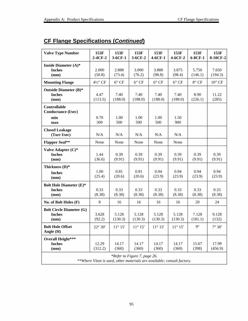
Appendix A: Product Specifications CF Flange Specifications
95
CF Flange Specifications (Continued)
Valve Type Number 153F2-4CF-2
153F3-6CF-1
153F3-6CF-2
153F4-6CF-1
153F4-6CF-2
153F6-8CF-1
153F8-10CF-2
Inside Diameter (A)*Inches(mm)
2.000(50.8)
2.888(73.4)
3.000(76.2)
3.888(98.8)
3.875(98.4)
5.750(146.1)
7.650(194.3)
Mounting Flange 4½” CF 6” CF 6” CF 6” CF 6” CF 8” CF 10” CF
Outside Diameter (B)*Inches(mm)
4.47(113.5)
7.40(188.0)
7.40(188.0)
7.40(188.0)
7.40(188.0)
8.90(226.1)
11.22(285)
ControllableConductance (l/sec)
minmax
0.70300
1.00500
1.00500
1.00500
1.50900
Closed Leakage(Torr l/sec) N/A N/A N/A N/A N/A
Flapper Seal** None None None None None
Valve Adapter (C)*Inches(mm)
1.44(36.6)
0.39(9.91)
0.39(9.91)
0.39(9.91)
0.39(9.91)
0.39(9.91)
0.39(9.91)
Thickness (D)*Inches(mm)
1.00(25.4)
0.81(20.6)
0.81(20.6)
0.94(23.9)
0.94(23.9)
0.94(23.9)
0.94(23.9)
Bolt Hole Diameter (E)*Inches(mm)
0.33(8.38)
0.33(8.38)
0.33(8.38)
0.33(8.38)
0.33(8.38)
0.33(8.38)
0.33(8.38)
No. of Bolt Holes (F) 8 16 16 16 16 20 24
Bolt Circle Diameter (G)Inches(mm)
3.628(92.2)
5.128(130.3)
5.128(130.3)
5.128(130.3)
5.128(130.3)
7.128(181.1)
9.128(132)
Bolt Hole OffsetAngle (H)
22° 30' 11° 15' 11° 15' 11° 15' 11° 15' 9° 7° 30'
Overall Height***Inches(mm)
12.29(312.2)
14.17(360)
14.17(360)
14.17(360)
14.17(360)
15.67(398)
17.99(456.9)
*Refer to Figure 7, page 26.**Where Viton is used, other materials are available; consult factory.
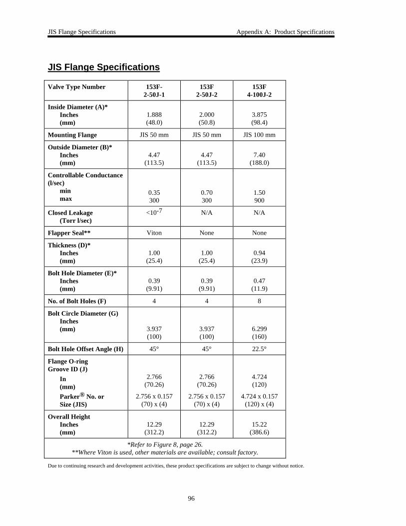
JIS Flange Specifications Appendix A: Product Specifications
96
JIS Flange Specifications
Valve Type Number 153F-2-50J-1
153F2-50J-2
153F4-100J-2
Inside Diameter (A)*Inches(mm)
1.888(48.0)
2.000(50.8)
3.875(98.4)
Mounting Flange JIS 50 mm JIS 50 mm JIS 100 mm
Outside Diameter (B)*Inches(mm)
4.47(113.5)
4.47(113.5)
7.40(188.0)
Controllable Conductance(l/sec)
minmax
0.35300
0.70300
1.50900
Closed Leakage(Torr l/sec)
<10-7 N/A N/A
Flapper Seal** Viton None None
Thickness (D)*Inches(mm)
1.00(25.4)
1.00(25.4)
0.94(23.9)
Bolt Hole Diameter (E)*Inches(mm)
0.39(9.91)
0.39(9.91)
0.47(11.9)
No. of Bolt Holes (F) 4 4 8
Bolt Circle Diameter (G)Inches(mm) 3.937
(100)3.937(100)
6.299(160)
Bolt Hole Offset Angle (H) 45° 45° 22.5°
Flange O-ringGroove ID (J)
In(mm)Parker® No. orSize (JIS)
2.766(70.26)
2.756 x 0.157(70) x (4)
2.766(70.26)
2.756 x 0.157(70) x (4)
4.724(120)
4.724 x 0.157(120) x (4)
Overall HeightInches(mm)
12.29(312.2)
12.29(312.2)
15.22(386.6)
*Refer to Figure 8, page 26.**Where Viton is used, other materials are available; consult factory.
Due to continuing research and development activities, these product specifications are subject to change without notice.
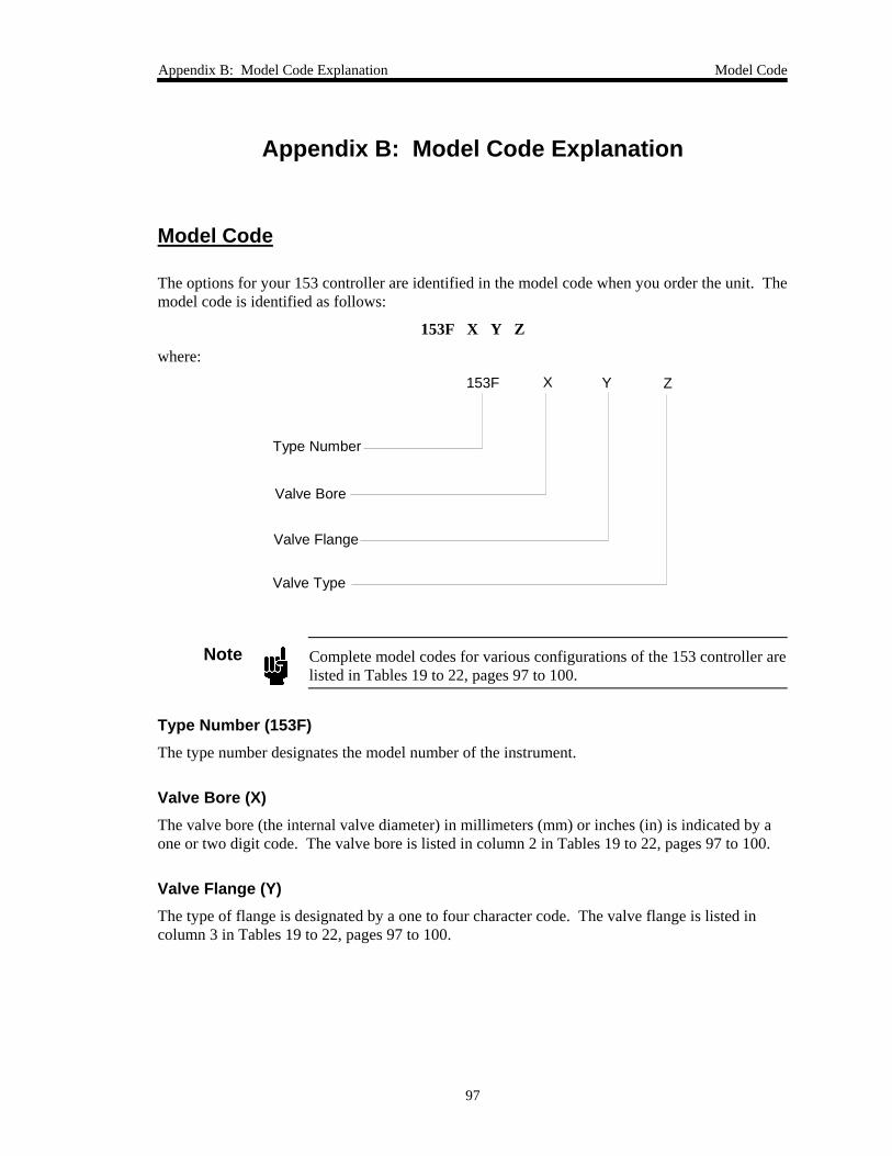
Appendix B: Model Code Explanation Model Code
97
Appendix B: Model Code Explanation
Model Code
The options for your 153 controller are identified in the model code when you order the unit. Themodel code is identified as follows:
153F X Y Z
where:
Type Number
Valve Flange
ZX Y153F
Valve Type
Valve Bore
Note Complete model codes for various configurations of the 153 controller arelisted in Tables 19 to 22, pages 97 to 100.
Type Number (153F)The type number designates the model number of the instrument.
Valve Bore (X)The valve bore (the internal valve diameter) in millimeters (mm) or inches (in) is indicated by aone or two digit code. The valve bore is listed in column 2 in Tables 19 to 22, pages 97 to 100.
Valve Flange (Y)The type of flange is designated by a one to four character code. The valve flange is listed incolumn 3 in Tables 19 to 22, pages 97 to 100.
Model Code Appendix B: Model Code Explanation
98
Valve Type (Z)The type of valve (sealing or non-sealing) is designated by a single number code. The valve typeis listed in column 4 in Tables 19 to 22, pages 97 to 100.
Valve Type Ordering Code
Sealing 1Non-sealing 2
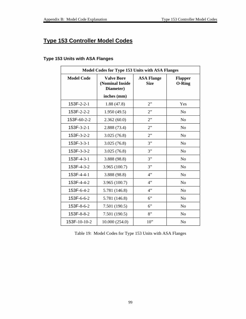
Appendix B: Model Code Explanation Type 153 Controller Model Codes
99
Type 153 Controller Model Codes
Type 153 Units with ASA Flanges
Model Codes for Type 153 Units with ASA Flanges
Model Code Valve Bore(Nominal Inside
Diameter)
inches (mm)
ASA FlangeSize
FlapperO-Ring
153F-2-2-1 1.88 (47.8) 2” Yes
153F-2-2-2 1.950 (49.5) 2” No
153F-60-2-2 2.362 (60.0) 2” No
153F-3-2-1 2.888 (73.4) 2” No
153F-3-2-2 3.025 (76.8) 2” No
153F-3-3-1 3.025 (76.8) 3” No
153F-3-3-2 3.025 (76.8) 3” No
153F-4-3-1 3.888 (98.8) 3” No
153F-4-3-2 3.965 (100.7) 3” No
153F-4-4-1 3.888 (98.8) 4” No
153F-4-4-2 3.965 (100.7) 4” No
153F-6-4-2 5.781 (146.8) 4” No
153F-6-6-2 5.781 (146.8) 6” No
153F-8-6-2 7.501 (190.5) 6” No
153F-8-8-2 7.501 (190.5) 8” No
153F-10-10-2 10.000 (254.0) 10” No
Table 19: Model Codes for Type 153 Units with ASA Flanges
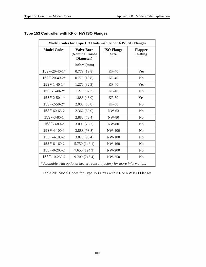
Type 153 Controller Model Codes Appendix B: Model Code Explanation
100
Type 153 Controller with KF or NW ISO Flanges
Model Codes for Type 153 Units with KF or NW ISO Flanges
Model Codes Valve Bore(Nominal Inside
Diameter)
inches (mm)
ISO FlangeSize
FlapperO-Ring
153F-20-40-1* 0.779 (19.8) KF-40 Yes
153F-20-40-2* 0.779 (19.8) KF-40 No
153F-1-40-1* 1.270 (32.3) KF-40 Yes
153F-1-40-2* 1.270 (32.3) KF-40 No
153F-2-50-1* 1.888 (48.0) KF-50 Yes
153F-2-50-2* 2.000 (50.8) KF-50 No
153F-60-63-2 2.362 (60.0) NW-63 No
153F-3-80-1 2.888 (73.4) NW-80 No
153F-3-80-2 3.000 (76.2) NW-80 No
153F-4-100-1 3.888 (98.8) NW-100 No
153F-4-100-2 3.875 (98.4) NW-100 No
153F-6-160-2 5.750 (146.1) NW-160 No
153F-8-200-2 7.650 (194.3) NW-200 No
153F-10-250-2 9.700 (246.4) NW-250 No
* Available with optional heater; consult factory for more information.
Table 20: Model Codes for Type 153 Units with KF or NW ISO Flanges
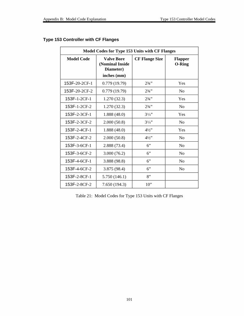
Appendix B: Model Code Explanation Type 153 Controller Model Codes
101
Type 153 Controller with CF Flanges
Model Codes for Type 153 Units with CF Flanges
Model Code Valve Bore(Nominal Inside
Diameter)inches (mm)
CF Flange Size FlapperO-Ring
153F-20-2CF-1 0.779 (19.79) 2¾” Yes
153F-20-2CF-2 0.779 (19.79) 2¾” No
153F-1-2CF-1 1.270 (32.3) 2¾” Yes
153F-1-2CF-2 1.270 (32.3) 2¾” No
153F-2-3CF-1 1.888 (48.0) 33/8” Yes
153F-2-3CF-2 2.000 (50.8) 33/8” No
153F-2-4CF-1 1.888 (48.0) 4½” Yes
153F-2-4CF-2 2.000 (50.8) 4½” No
153F-3-6CF-1 2.888 (73.4) 6” No
153F-3-6CF-2 3.000 (76.2) 6” No
153F-4-6CF-1 3.888 (98.8) 6” No
153F-4-6CF-2 3.875 (98.4) 6” No
153F-2-8CF-1 5.750 (146.1) 8”
153F-2-8CF-2 7.650 (194.3) 10”
Table 21: Model Codes for Type 153 Units with CF Flanges
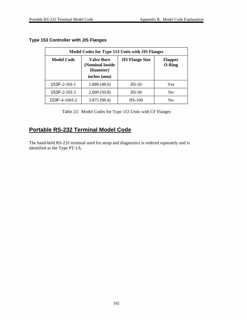
Portable RS-232 Terminal Model Code Appendix B: Model Code Explanation
102
Type 153 Controller with JIS Flanges
Model Codes for Type 153 Units with JIS Flanges
Model Code Valve Bore(Nominal Inside
Diameter)inches (mm)
JIS Flange Size FlapperO-Ring
153F-2-50J-1 1.888 (48.0) JIS-50 Yes
153F-2-50J-2 2.000 (50.8) JIS-50 No
153F-4-100J-2 3.875 (98.4) JIS-100 No
Table 22: Model Codes for Type 153 Units with CF Flanges
Portable RS-232 Terminal Model Code
The hand-held RS-232 terminal used for setup and diagnostics is ordered separately and isidentified as the Type PT-1A.
Index
103
Index
A
Absolute pressure, calculating, 72
Analog set point
full scale, 64, 73
zero, 63
ASA flanges, 24, 87–88, 97
B
Baud rate, 46
C
Cables
generic shielded, 21
interface, 20
null modem, 37
portable terminal, 36
Calibration
adjusting for output error, 68–71
scaling voltage signals, 65, 66
system characteristics, 62–67
CE Mark, 17, 20, 49, 85
CF flanges, 26, 92–93, 99
Commands, format of, 54
Connectors, 85
Input connector J1, 33, 42
Power connector J2, 32, 42
Control mode
description of, 39
selection of, 45
Customer support, 18
D
Dimensions, 23–27
Dipswitch bank
changing settings, 47, 51
description of, 44
functions and settings, 45
E
End-of-line delimiter, 46
F
Full scale
analog set point, 64
pressure, 66
G
Gain
command, 58
description of, 41
Grounding, 28
H
Heated valves, 30
Hold/Normal switch, 43
I
Initial settings
reset command, 80
RS-323 communication, 52
Input connector J1, 33, 42
Introduction, 17

Index
104
J
JIS flanges, 27, 94, 100
K
KF ISO flanges, 25, 89–90, 98
L
Labels, 49
Lead
adjusting, 78
command, 58
description of, 40
LEDs, 43, 85
power up sequence, 48
M
Maintenance, 83
Manual organization, 18
Manual valve switch, 43
Model code
description of, 95–96
examples of, 97–100
Mounting instructions, 30
heated valves, 30
system configuration, 30
N
Non-volatile memory, 48
Normal valve control, 46
Null modem cable, 37
NW ISO flanges, 26, 91, 98
O
Output signals, adjusting, 35
P
Parity, 46
Portable terminal
cable, 36
dipswitch settings, 53
Position control
calibrating zero and FS outputs, 70
description of, 39
Power connector J2, 32, 42
Power down constants, 48
Power requirements, 17, 28, 85
Power up, 48
Pressure
full scale, 66
reporting, 72
Pressure control
calibrating zero and FS outputs, 71
description of, 39
Pressure zero, 65
Pump label, 49
R
RAM, 48
Requests, format of, 54
Reset command, 80
Responses, format of, 54
Returning the product, 18, 19
Reverse valve control, 46
RS-232
calibration messages, 62–71
Index
105
commands, 56–73
communication parameters, 53
message protocol, 54
operating protocol, selection of, 46
operating value messages, 57–58
valve position messages, 59–61
S
Safety information, 1–16, 51
Sealing/non-sealing valves, 28, 96
Serial number label, 49
Set point
commands, 58
control type, 45
format of, 46
signal source, 46
Specifications
flanges, 87–94
standard valve, 85
System configuration, 30
T
Temperature, operating, 17, 85
Troubleshooting
reset command, 80
valve slipped signal, 73, 84
Tuning, 78–82
V
Valve
action, 46
bore, 95
control direction, 46
flange, 95
position command, 60
steps, 67
type, 96
Valve safety, 51
Valve slipped signal, 73, 84
Z
Zero
analog set point, 63
pressure, 65