Embed Size (px)
Citation preview
MASTER MINIMUM EQUIPMENT LIST
a
EASA ACCEPTED AS 350 00.00.00.P1A 09 - 44 Page 1
MASTER MINIMUM EQUIPMENT LIST
AS 350 (All models)
“This Master Minimum Equipment List (MMEL) is accepted by the European Aviation Safety Agency (EASA) at the hereafter revision and is recommended for approval as the basis of the preparation and approval of individual operators’ Minimum Equipment Lists (MELs) for aircraft of this type, as certified by the European Aviation Safety Agency and operated under the jurisdiction of EASA member states National Authorities.”
Normal Revision 0 Issue 2 - Date-Code 09-44 Signed by: Evan Nielsen Head of Certification Flight Standards for and on behalf of EASA Date of acceptance: Correspondence concerning this document should be addressed to the offices listed below:
EASA MMEL Section Manager FLIGHT STANDARDS DEPARTMENT CERTIFICATION DIRECTORATE European Aviation Safety Agency (EASA) Postfach 10 12 53, D-50452 Köln, Germany
and
EUROCOPTER Direction Technique Support Aéroport international Marseille-Provence 13725 Marignane Cedex-France
MASTER MINIMUM EQUIPMENT LIST
EASA ACCEPTED AS 350 00.00.00.P5A 09 - 44 Page 1
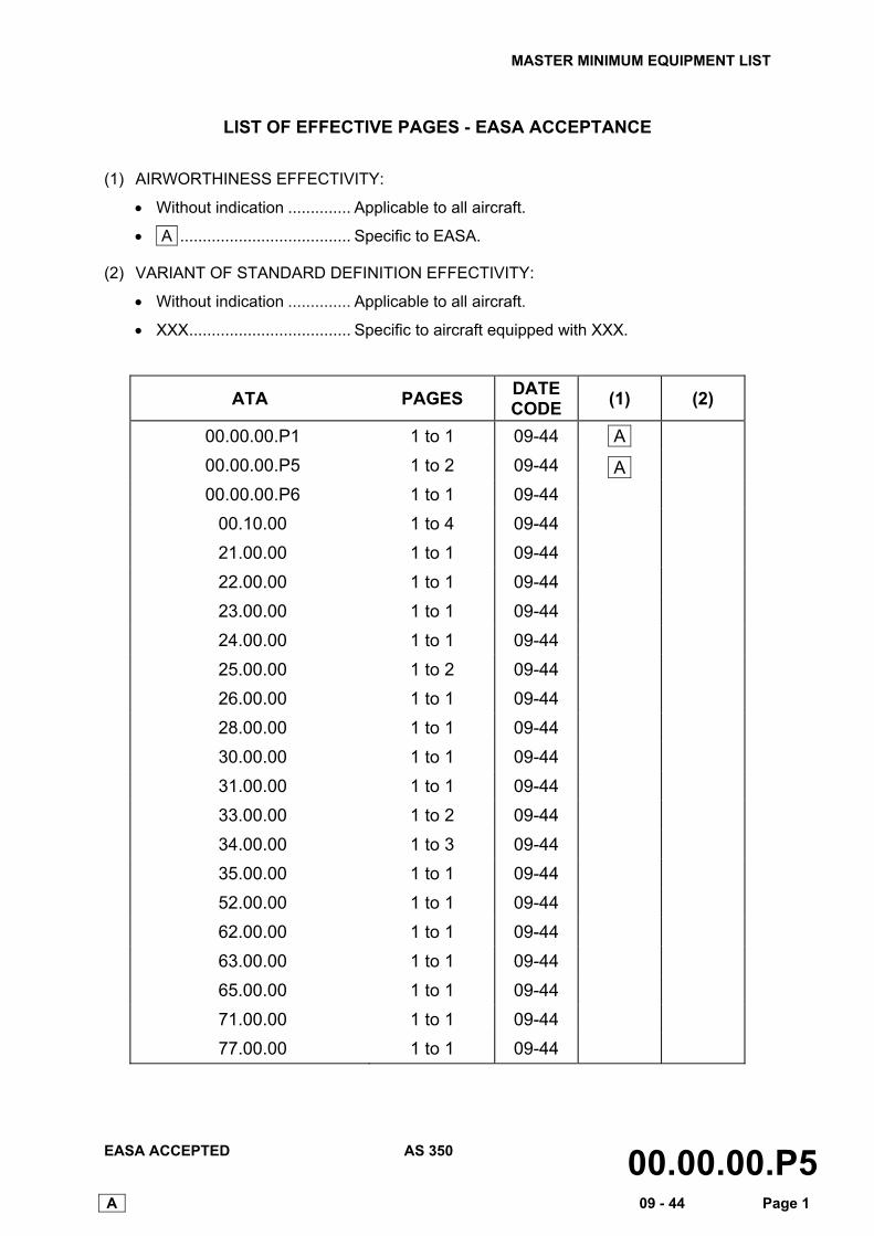
LIST OF EFFECTIVE PAGES - EASA ACCEPTANCE
(1) AIRWORTHINESS EFFECTIVITY:
• Without indication .............. Applicable to all aircraft.
• A ...................................... Specific to EASA.
(2) VARIANT OF STANDARD DEFINITION EFFECTIVITY:
• Without indication .............. Applicable to all aircraft.
• XXX.................................... Specific to aircraft equipped with XXX.
ATA PAGES DATE CODE (1) (2)
00.00.00.P1 1 to 1 09-44 A
00.00.00.P5 1 to 2 09-44 A
00.00.00.P6 1 to 1 09-44
00.10.00 1 to 4 09-44
21.00.00 1 to 1 09-44
22.00.00 1 to 1 09-44
23.00.00 1 to 1 09-44
24.00.00 1 to 1 09-44
25.00.00 1 to 2 09-44
26.00.00 1 to 1 09-44
28.00.00 1 to 1 09-44
30.00.00 1 to 1 09-44
31.00.00 1 to 1 09-44
33.00.00 1 to 2 09-44
34.00.00 1 to 3 09-44
35.00.00 1 to 1 09-44
52.00.00 1 to 1 09-44
62.00.00 1 to 1 09-44
63.00.00 1 to 1 09-44
65.00.00 1 to 1 09-44
71.00.00 1 to 1 09-44
77.00.00 1 to 1 09-44
MASTER MINIMUM EQUIPMENT LIST
EASA ACCEPTED AS 350 00.00.00.P5A 09 - 44 Page 2
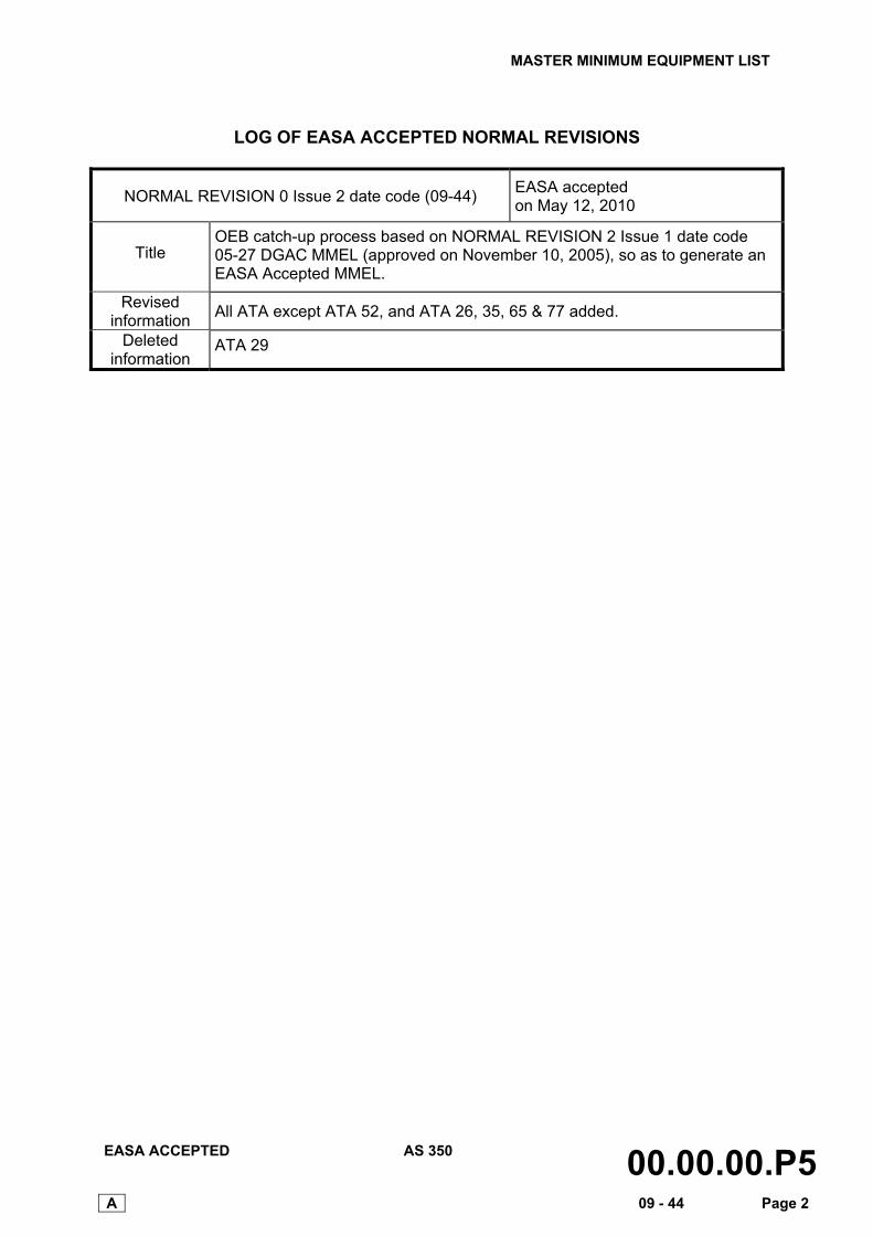
LOG OF EASA ACCEPTED NORMAL REVISIONS
NORMAL REVISION 0 Issue 2 date code (09-44) EASA accepted on May 12, 2010
Title OEB catch-up process based on NORMAL REVISION 2 Issue 1 date code 05-27 DGAC MMEL (approved on November 10, 2005), so as to generate an EASA Accepted MMEL.
Revised information All ATA except ATA 52, and ATA 26, 35, 65 & 77 added.
Deleted information
ATA 29
MASTER MINIMUM EQUIPMENT LIST
EASA ACCEPTED AS 350 00.00.00.P6 09 - 44 Page 1
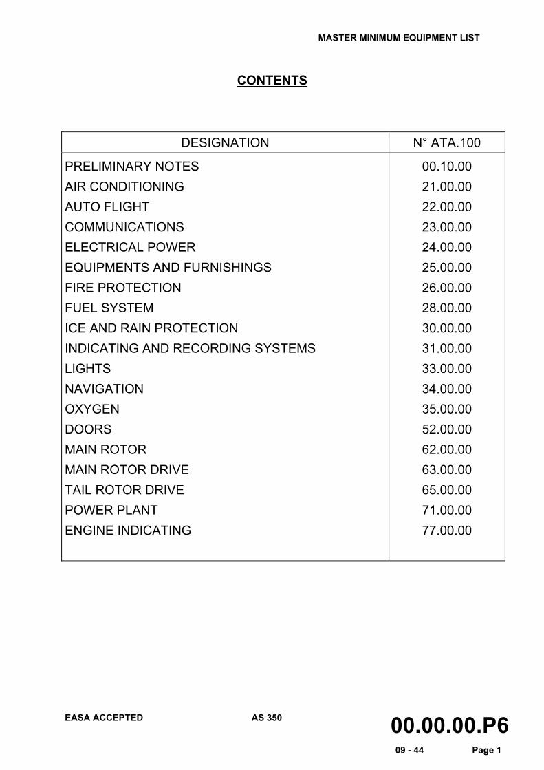
CONTENTS
DESIGNATION N° ATA.100
PRELIMINARY NOTES AIR CONDITIONING AUTO FLIGHT COMMUNICATIONS ELECTRICAL POWER EQUIPMENTS AND FURNISHINGS FIRE PROTECTION FUEL SYSTEM ICE AND RAIN PROTECTION INDICATING AND RECORDING SYSTEMS LIGHTS NAVIGATION OXYGEN DOORS MAIN ROTOR MAIN ROTOR DRIVE TAIL ROTOR DRIVE POWER PLANT ENGINE INDICATING
00.10.00 21.00.00 22.00.00 23.00.00 24.00.00 25.00.00 26.00.00 28.00.00 30.00.00 31.00.00 33.00.00 34.00.00 35.00.00 52.00.00 62.00.00 63.00.00 65.00.00 71.00.00 77.00.00
MASTER MINIMUM EQUIPMENT LIST
EASA ACCEPTED AS 350 00.10.00 09 - 44 Page 1
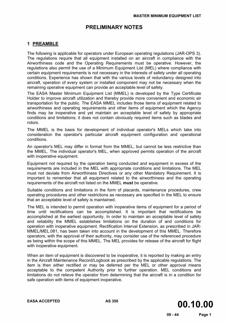
PRELIMINARY NOTES
1 PREAMBLE
The following is applicable for operators under European operating regulations (JAR-OPS 3). The regulations require that all equipment installed on an aircraft in compliance with the Airworthiness code and the Operating Requirements must be operative. However, the regulations also permit the use of a Minimum Equipment List (MEL) where compliance with certain equipment requirements is not necessary in the interests of safety under all operating conditions. Experience has shown that with the various levels of redundancy designed into aircraft, operation of every system or installed component may not be necessary when the remaining operative equipment can provide an acceptable level of safety. The EASA Master Minimum Equipment List (MMEL) is developed by the Type Certificate Holder to improve aircraft utilization and thereby provide more convenient and economic air transportation for the public. The EASA MMEL includes those items of equipment related to airworthiness and operating requirements and other items of equipment which the Agency finds may be inoperative and yet maintain an acceptable level of safety by appropriate conditions and limitations; it does not contain obviously required items such as blades and rotors.
The MMEL is the basis for development of individual operator's MELs which take into consideration the operator's particular aircraft equipment configuration and operational conditions.
An operator's MEL may differ in format from the MMEL, but cannot be less restrictive than the MMEL. The individual operator's MEL, when approved permits operation of the aircraft with inoperative equipment.
Equipment not required by the operation being conducted and equipment in excess of the requirements are included in the MEL with appropriate conditions and limitations. The MEL must not deviate from Airworthiness Directives or any other Mandatory Requirement. It is important to remember that all equipment related to the airworthiness and the operating requirements of the aircraft not listed on the MMEL must be operative.
Suitable conditions and limitations in the form of placards, maintenance procedures, crew operating procedures and other restrictions as necessary are specified in the MEL to ensure that an acceptable level of safety is maintained.
The MEL is intended to permit operation with inoperative items of equipment for a period of time until rectifications can be accomplished. It is important that rectifications be accomplished at the earliest opportunity. In order to maintain an acceptable level of safety and reliability the MMEL establishes limitations on the duration of and conditions for operation with inoperative equipment. Rectification Interval Extension, as prescribed in JAR-MMEL/MEL.081, has been taken into account in the development of this MMEL. Therefore operators, with the approval of their authority, may consider use of the referenced procedure as being within the scope of this MMEL. The MEL provides for release of the aircraft for flight with inoperative equipment. When an item of equipment is discovered to be inoperative, it is reported by making an entry in the Aircraft Maintenance Record/Logbook as prescribed by the applicable regulations. The item is then either rectified or may be deferred per the MEL or other approval means acceptable to the competent Authority prior to further operation. MEL conditions and limitations do not relieve the operator from determining that the aircraft is in a condition for safe operation with items of equipment inoperative.
MASTER MINIMUM EQUIPMENT LIST
EASA ACCEPTED AS 350 00.10.00 09 - 44 Page 2
When these requirements are met, an Airworthiness Release, Aircraft Maintenance Record/Logbook entry, or other approved documentation is issued as prescribed by the applicable regulations. Such documentation is required prior to operation with any item of equipment inoperative. Operators are responsible for exercising the necessary operational control to ensure that an acceptable level of safety is maintained. The exposure to additional failures during continued operation with inoperative systems or components must also be considered. Wherever, possible account has been taken in this MMEL of multiple inoperative items. However, it is unlikely that all possible combinations of this nature have been accounted for. Therefore, when operating with multiple inoperative items, the inter-relationships between those items and the effect on aircraft operation and crew workload must be considered.
Operators are to establish a controlled and sound rectification program including the parts, personnel, facilities, procedures and schedules to ensure timely rectification. This program should identify the actions required for Maintenance discrepancy messages.
MASTER MINIMUM EQUIPMENT LIST
EASA ACCEPTED AS 350 00.10.00 09 – 44 Page 3
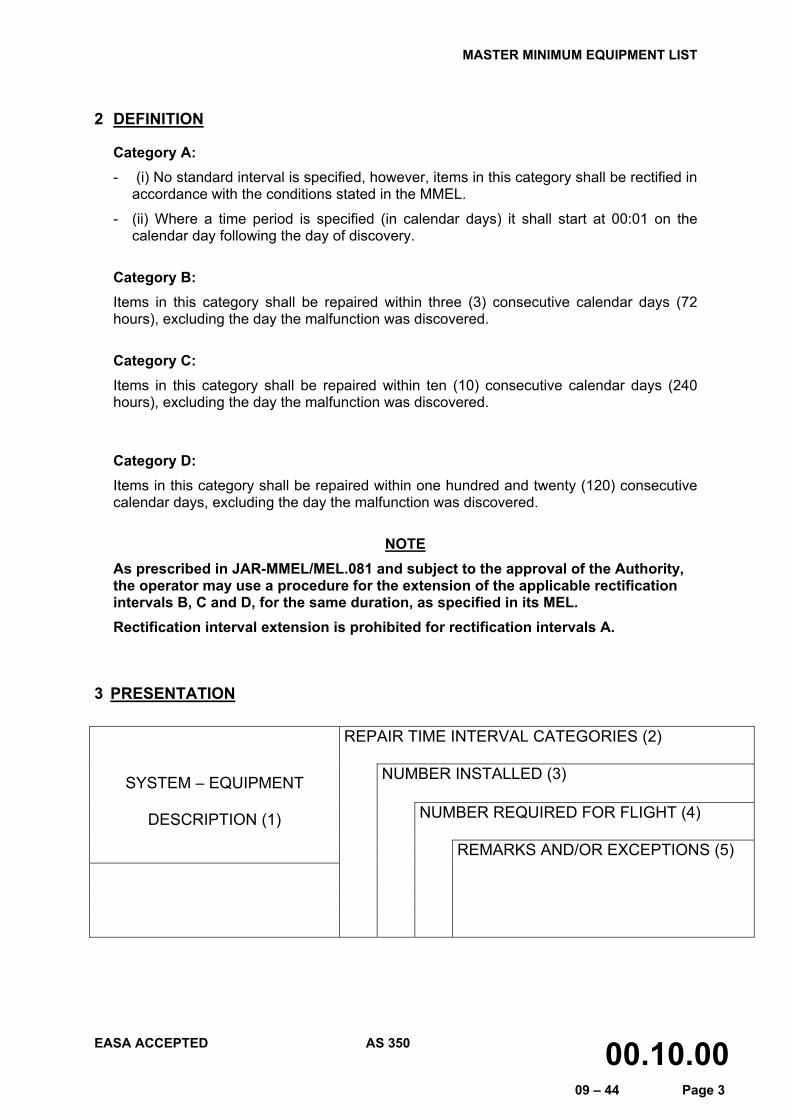
2 DEFINITION
Category A: - (i) No standard interval is specified, however, items in this category shall be rectified in
accordance with the conditions stated in the MMEL.
- (ii) Where a time period is specified (in calendar days) it shall start at 00:01 on the calendar day following the day of discovery.
Category B: Items in this category shall be repaired within three (3) consecutive calendar days (72 hours), excluding the day the malfunction was discovered.
Category C: Items in this category shall be repaired within ten (10) consecutive calendar days (240 hours), excluding the day the malfunction was discovered.
Category D: Items in this category shall be repaired within one hundred and twenty (120) consecutive calendar days, excluding the day the malfunction was discovered.
NOTE
As prescribed in JAR-MMEL/MEL.081 and subject to the approval of the Authority, the operator may use a procedure for the extension of the applicable rectification intervals B, C and D, for the same duration, as specified in its MEL. Rectification interval extension is prohibited for rectification intervals A.
3 PRESENTATION
REPAIR TIME INTERVAL CATEGORIES (2)
NUMBER INSTALLED (3) SYSTEM – EQUIPMENT
DESCRIPTION (1) NUMBER REQUIRED FOR FLIGHT (4)
REMARKS AND/OR EXCEPTIONS (5)
MASTER MINIMUM EQUIPMENT LIST
EASA ACCEPTED AS 350 00.10.00 09 – 44 Page 4
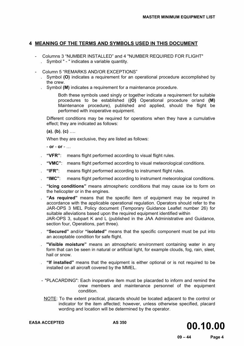
4 MEANING OF THE TERMS AND SYMBOLS USED IN THIS DOCUMENT
- Columns 3 “NUMBER INSTALLED” and 4 "NUMBER REQUIRED FOR FLIGHT" . Symbol " - " indicates a variable quantity.
- Column 5 “REMARKS AND/OR EXCEPTIONS” . Symbol (O) indicates a requirement for an operational procedure accomplished by
the crew. . Symbol (M) indicates a requirement for a maintenance procedure.
Both these symbols used singly or together indicate a requirement for suitable procedures to be established ((O) Operational procedure or/and (M) Maintenance procedure), published and applied, should the flight be performed with inoperative equipment.
Different conditions may be required for operations when they have a cumulative effect; they are indicated as follows:
(a), (b), (c) ….
When they are exclusive, they are listed as follows:
- or - or - …
. “VFR”: means flight performed according to visual flight rules.
. “VMC”: means flight performed according to visual meteorological conditions.
. “IFR”: means flight performed according to instrument flight rules.
. “IMC”: means flight performed according to instrument meteorological conditions.
. “Icing conditions” means atmospheric conditions that may cause ice to form on the helicopter or in the engines.
. “As required” means that the specific item of equipment may be required in accordance with the applicable operational regulation. Operators should refer to the JAR-OPS 3 MEL Policy document (Temporary Guidance Leaflet number 26) for suitable alleviations based upon the required equipment identified within
JAR-OPS 3, subpart K and L (published in the JAA Administrative and Guidance, section four, Operations, part three).
. “Secured” and/or “isolated” means that the specific component must be put into an acceptable condition for safe flight.
. "Visible moisture” means an atmospheric environment containing water in any form that can be seen in natural or artificial light, for example clouds, fog, rain, sleet, hail or snow.
. “If installed” means that the equipment is either optional or is not required to be installed on all aircraft covered by the MMEL.
- "PLACARDING": Each inoperative item must be placarded to inform and remind the crew members and maintenance personnel of the equipment condition.
NOTE: To the extent practical, placards should be located adjacent to the control or indicator for the item affected; however, unless otherwise specified, placard wording and location will be determined by the operator.
MASTER MINIMUM EQUIPMENT LIST
EASA ACCEPTED AS 350 21.00.00 09 - 44 Page 1
REPAIR TIME INTERVAL CATEGORIES
NUMBER INSTALLED SYSTEM – EQUIPMENT
DESCRIPTION NUMBER REQUIRED FOR FLIGHT
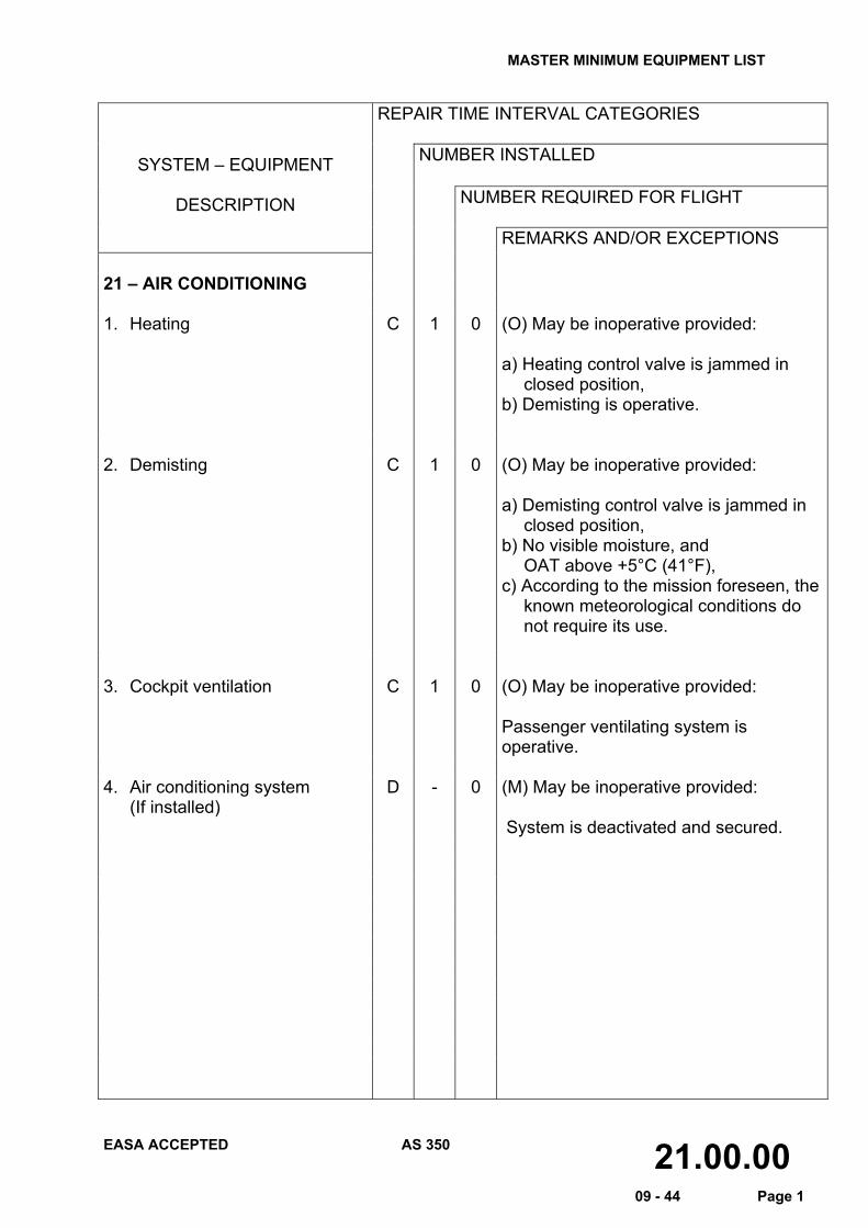
REMARKS AND/OR EXCEPTIONS 21 – AIR CONDITIONING 1. Heating C 1 0 (O) May be inoperative provided:
a) Heating control valve is jammed in
closed position, b) Demisting is operative.
2. Demisting C 1 0 (O) May be inoperative provided:
a) Demisting control valve is jammed in
closed position, b) No visible moisture, and OAT above +5°C (41°F), c) According to the mission foreseen, the
known meteorological conditions do not require its use.
3. Cockpit ventilation C 1 0 (O) May be inoperative provided:
Passenger ventilating system is operative.
4. Air conditioning system
(If installed) D - 0 (M) May be inoperative provided:
System is deactivated and secured.
MASTER MINIMUM EQUIPMENT LIST
EASA ACCEPTED AS 350 22.00.00 09 - 44 Page 1
REPAIR TIME INTERVAL CATEGORIES
NUMBER INSTALLED SYSTEM – EQUIPMENT
DESCRIPTION NUMBER REQUIRED FOR FLIGHT
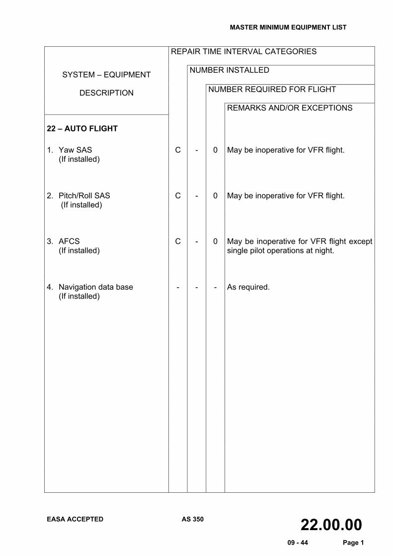
REMARKS AND/OR EXCEPTIONS 22 – AUTO FLIGHT 1. Yaw SAS
(If installed) C - 0 May be inoperative for VFR flight.
2. Pitch/Roll SAS
(If installed) C - 0 May be inoperative for VFR flight.
3. AFCS
(If installed) C - 0 May be inoperative for VFR flight except
single pilot operations at night.
4. Navigation data base
(If installed)
- - - As required.
MASTER MINIMUM EQUIPMENT LIST
EASA ACCEPTED AS 350 23.00.00 09 - 44 Page 1
REPAIR TIME INTERVAL CATEGORIES
NUMBER INSTALLED SYSTEM – EQUIPMENT
DESCRIPTION NUMBER REQUIRED FOR FLIGHT
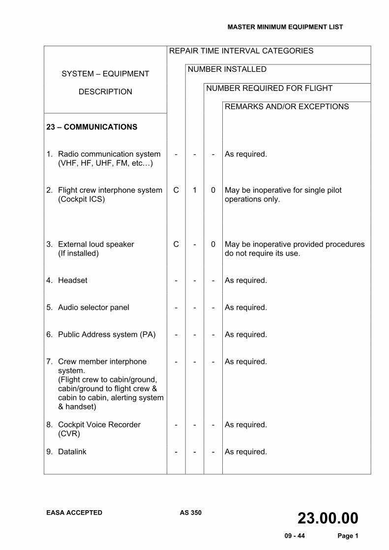
REMARKS AND/OR EXCEPTIONS 23 – COMMUNICATIONS 1. Radio communication system
(VHF, HF, UHF, FM, etc…) - - - As required.
2. Flight crew interphone system
(Cockpit ICS) C 1 0 May be inoperative for single pilot
operations only. 3. External loud speaker
(If installed) C - 0 May be inoperative provided procedures
do not require its use. 4. Headset - - - As required. 5. Audio selector panel - - - As required. 6. Public Address system (PA) - - - As required. 7. Crew member interphone
system. (Flight crew to cabin/ground, cabin/ground to flight crew & cabin to cabin, alerting system & handset)
- - - As required.
8. Cockpit Voice Recorder (CVR)
- - - As required.
9. Datalink
- - - As required.
MASTER MINIMUM EQUIPMENT LIST
EASA ACCEPTED AS 350 24.00.00 09 - 44 Page 1
REPAIR TIME INTERVAL CATEGORIES
NUMBER INSTALLED SYSTEM – EQUIPMENT
DESCRIPTION NUMBER REQUIRED FOR FLIGHT
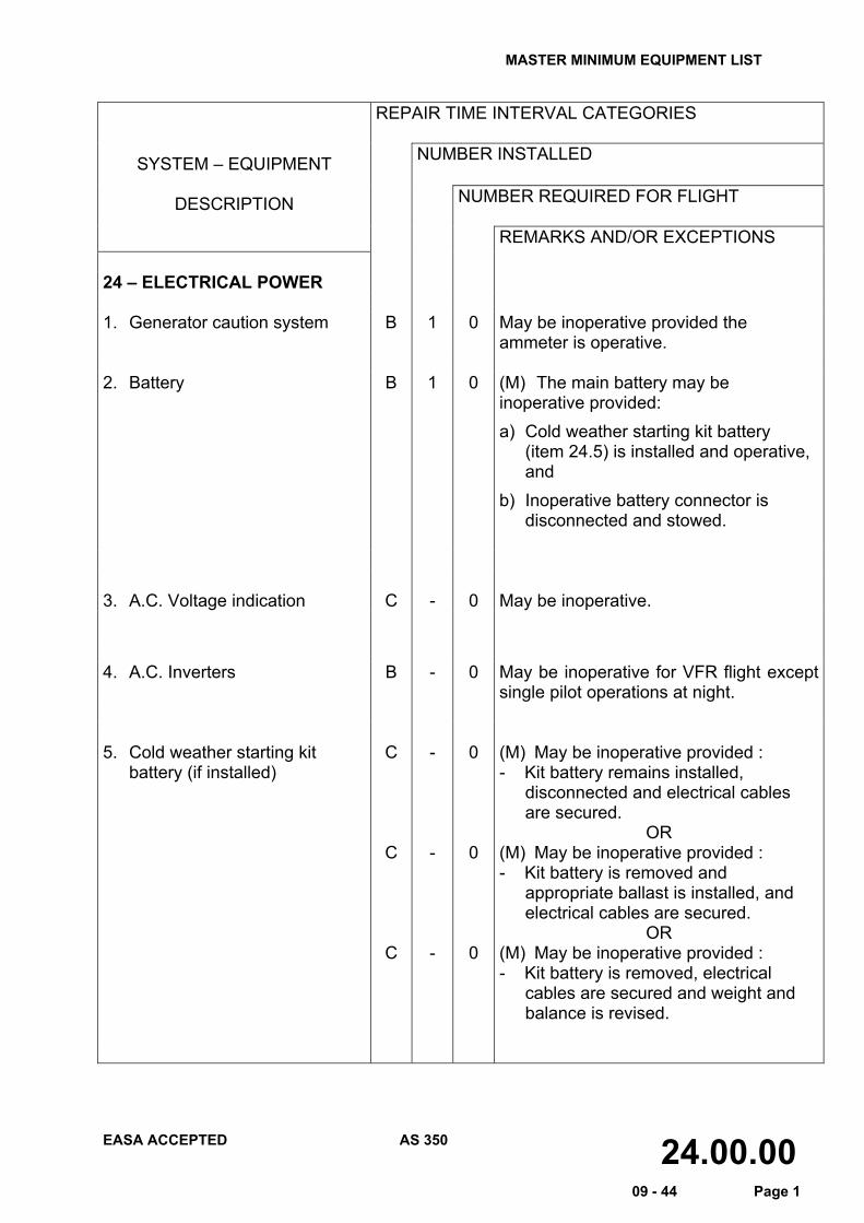
REMARKS AND/OR EXCEPTIONS 24 – ELECTRICAL POWER 1. Generator caution system B 1 0 May be inoperative provided the
ammeter is operative. 2. Battery B 1 0 (M) The main battery may be
inoperative provided: a) Cold weather starting kit battery
(item 24.5) is installed and operative, and
b) Inoperative battery connector is disconnected and stowed.
3. A.C. Voltage indication C - 0 May be inoperative.
4. A.C. Inverters B - 0 May be inoperative for VFR flight except
single pilot operations at night. 5. Cold weather starting kit
battery (if installed) C
C
C
-
-
-
0
0
0
(M) May be inoperative provided : - Kit battery remains installed,
disconnected and electrical cables are secured.
OR (M) May be inoperative provided : - Kit battery is removed and
appropriate ballast is installed, and electrical cables are secured.
OR (M) May be inoperative provided : - Kit battery is removed, electrical
cables are secured and weight and balance is revised.
MASTER MINIMUM EQUIPMENT LIST
EASA ACCEPTED AS 350 25.00.00 09 - 44 Page 1
REPAIR TIME INTERVAL CATEGORIES
NUMBER INSTALLED SYSTEM – EQUIPMENT
DESCRIPTION NUMBER REQUIRED FOR FLIGHT
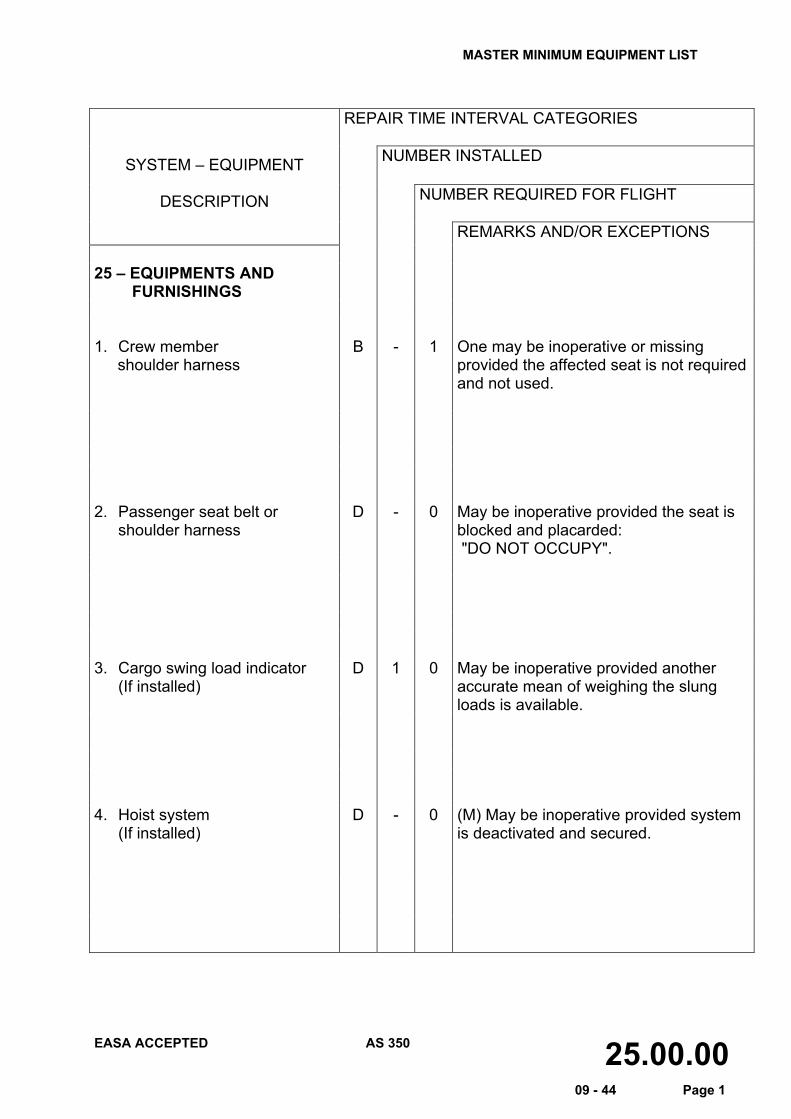
REMARKS AND/OR EXCEPTIONS 25 – EQUIPMENTS AND FURNISHINGS
1. Crew member
shoulder harness B - 1 One may be inoperative or missing
provided the affected seat is not required and not used.
2. Passenger seat belt or
shoulder harness D - 0 May be inoperative provided the seat is
blocked and placarded: "DO NOT OCCUPY".
3. Cargo swing load indicator (If installed)
D 1 0 May be inoperative provided another accurate mean of weighing the slung loads is available.
4. Hoist system
(If installed) D - 0 (M) May be inoperative provided system
is deactivated and secured.
MASTER MINIMUM EQUIPMENT LIST
EASA ACCEPTED AS 350 25.00.00 09 - 44 Page 2
REPAIR TIME INTERVAL CATEGORIES
NUMBER INSTALLED SYSTEM – EQUIPMENT
DESCRIPTION NUMBER REQUIRED FOR FLIGHT
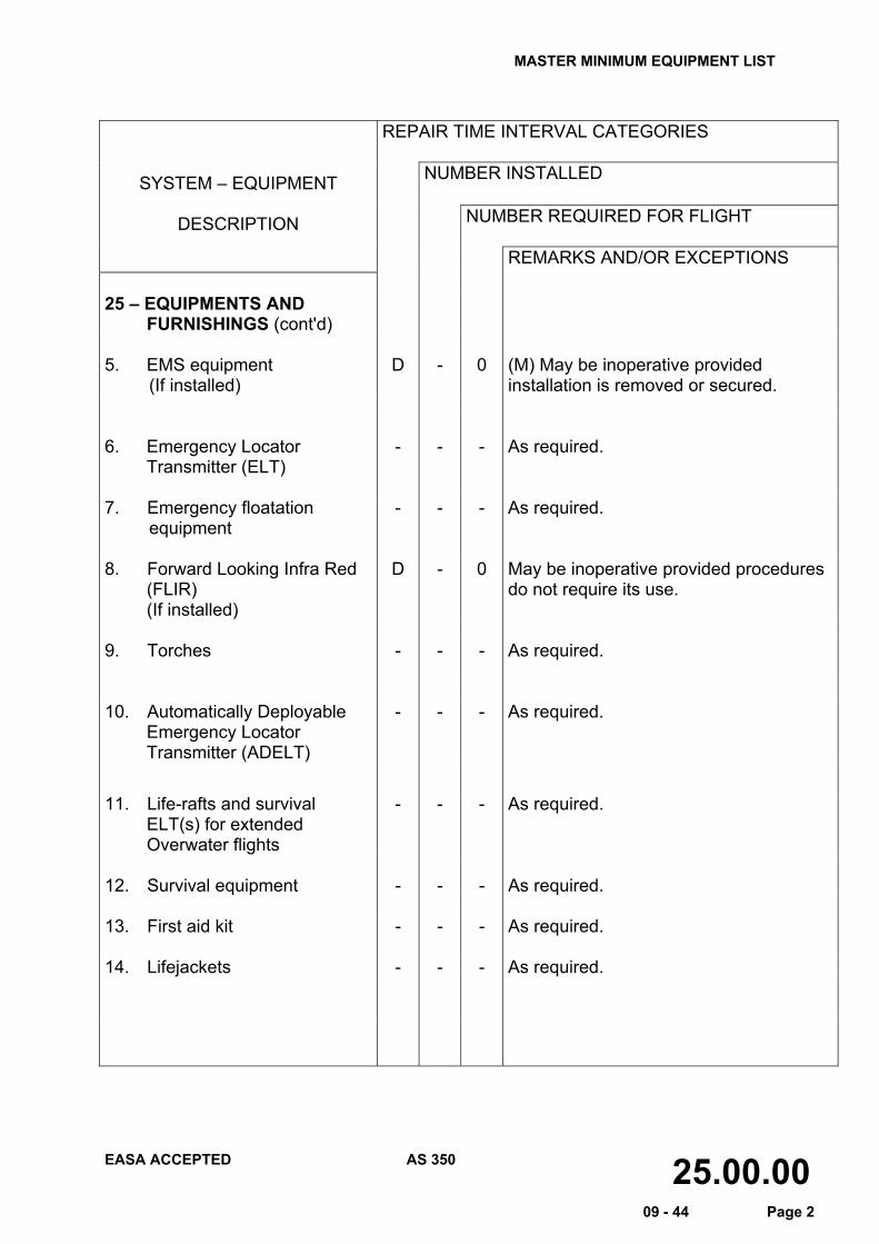
REMARKS AND/OR EXCEPTIONS 25 – EQUIPMENTS AND FURNISHINGS (cont'd)
5. EMS equipment
(If installed) D - 0 (M) May be inoperative provided
installation is removed or secured. 6. Emergency Locator
Transmitter (ELT) - - - As required.
7. Emergency floatation
equipment - - - As required.
8. Forward Looking Infra Red
(FLIR) (If installed)
D - 0 May be inoperative provided procedures do not require its use.
9. Torches - - - As required. 10. Automatically Deployable
Emergency Locator Transmitter (ADELT)
- - - As required.
11. Life-rafts and survival ELT(s) for extended Overwater flights
- - - As required.
12. Survival equipment - - - As required. 13. First aid kit - - - As required. 14. Lifejackets - - - As required.
MASTER MINIMUM EQUIPMENT LIST
EASA ACCEPTED AS 350 26.00.00 09 - 44 Page 1
REPAIR TIME INTERVAL CATEGORIES
NUMBER INSTALLED SYSTEM – EQUIPMENT
DESCRIPTION NUMBER REQUIRED FOR FLIGHT
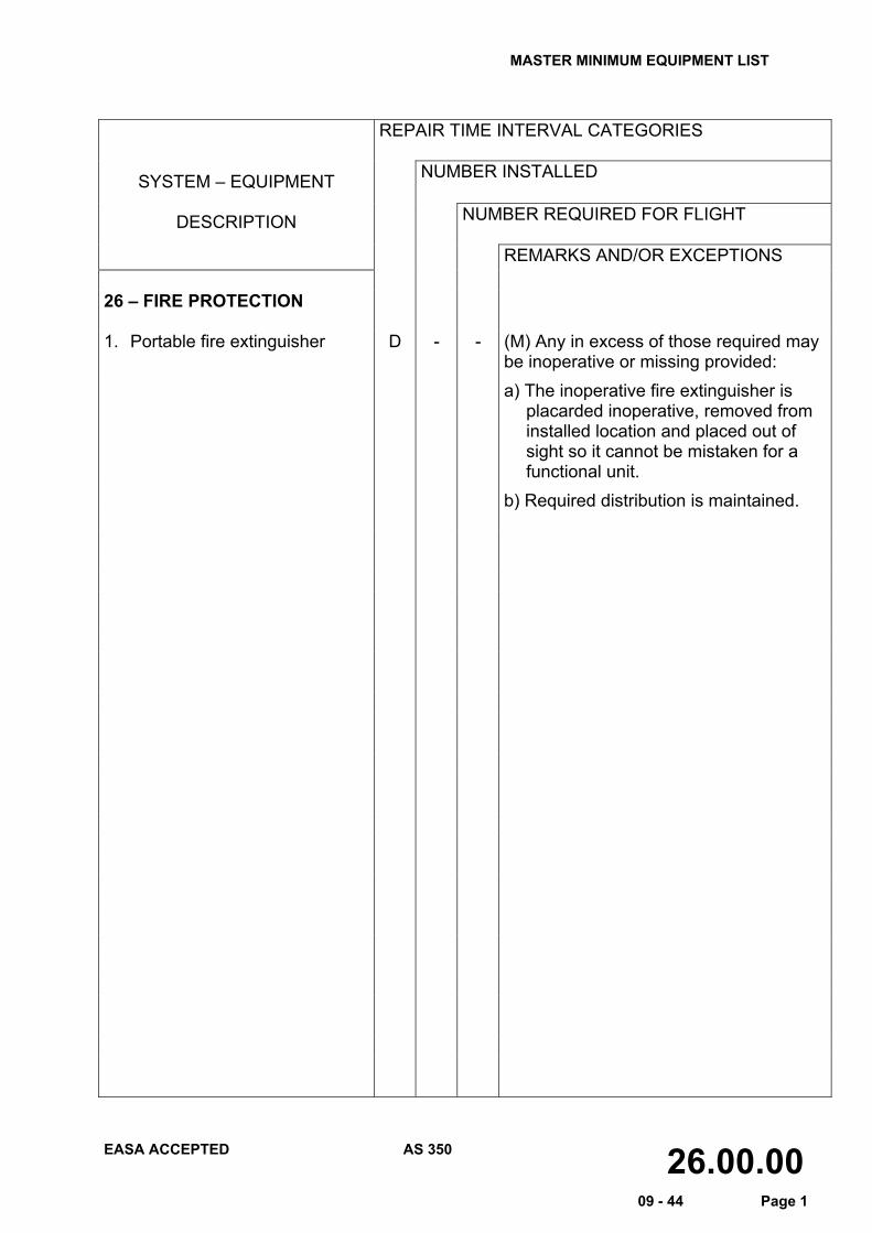
REMARKS AND/OR EXCEPTIONS 26 – FIRE PROTECTION 1. Portable fire extinguisher D - - (M) Any in excess of those required may
be inoperative or missing provided: a) The inoperative fire extinguisher is
placarded inoperative, removed from installed location and placed out of sight so it cannot be mistaken for a functional unit.
b) Required distribution is maintained.
MASTER MINIMUM EQUIPMENT LIST
EASA ACCEPTED AS 350 28.00.00 09 - 44 Page 1
REPAIR TIME INTERVAL CATEGORIES
NUMBER INSTALLED SYSTEM – EQUIPMENT
DESCRIPTION NUMBER REQUIRED FOR FLIGHT
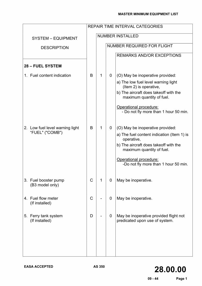
REMARKS AND/OR EXCEPTIONS 28 – FUEL SYSTEM 1. Fuel content indication
B 1 0 (O) May be inoperative provided: a) The low fuel level warning light
(Item 2) is operative, b) The aircraft does takeoff with the
maximum quantity of fuel.
Operational procedure: - Do not fly more than 1 hour 50 min.
2. Low fuel level warning light “FUEL" ("COMB")
B 1 0 (O) May be inoperative provided: a) The fuel content indication (Item 1) is
operative, b) The aircraft does takeoff with the
maximum quantity of fuel.
Operational procedure: -Do not fly more than 1 hour 50 min.
3. Fuel booster pump
(B3 model only) C 1 0 May be inoperative.
4. Fuel flow meter (If installed)
C - 0 May be inoperative.
5. Ferry tank system (If installed)
D - 0 May be inoperative provided flight not predicated upon use of system.
MASTER MINIMUM EQUIPMENT LIST
EASA ACCEPTED AS 350 30.00.00 09 - 44 Page 1
REPAIR TIME INTERVAL CATEGORIES
NUMBER INSTALLED SYSTEM – EQUIPMENT
DESCRIPTION NUMBER REQUIRED FOR FLIGHT
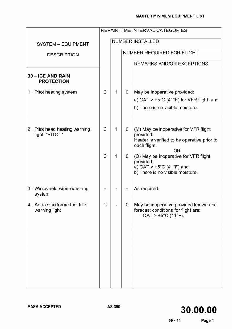
REMARKS AND/OR EXCEPTIONS 30 – ICE AND RAIN PROTECTION
1. Pitot heating system C 1 0 May be inoperative provided:
a) OAT > +5°C (41°F) for VFR flight, and b) There is no visible moisture.
2. Pitot head heating warning
light "PITOT" C
C
1
1
0
0
(M) May be inoperative for VFR flight provided: Heater is verified to be operative prior to each flight.
OR (O) May be inoperative for VFR flight provided: a) OAT > +5°C (41°F) and b) There is no visible moisture.
3. Windshield wiper/washing
system - - - As required.
4. Anti-ice airframe fuel filter
warning light C - 0 May be inoperative provided known and
forecast conditions for flight are: - OAT > +5°C (41°F).
MASTER MINIMUM EQUIPMENT LIST
EASA ACCEPTED AS 350 31.00.00 09 - 44 Page 1
REPAIR TIME INTERVAL CATEGORIES
NUMBER INSTALLED SYSTEM – EQUIPMENT
DESCRIPTION NUMBER REQUIRED FOR FLIGHT
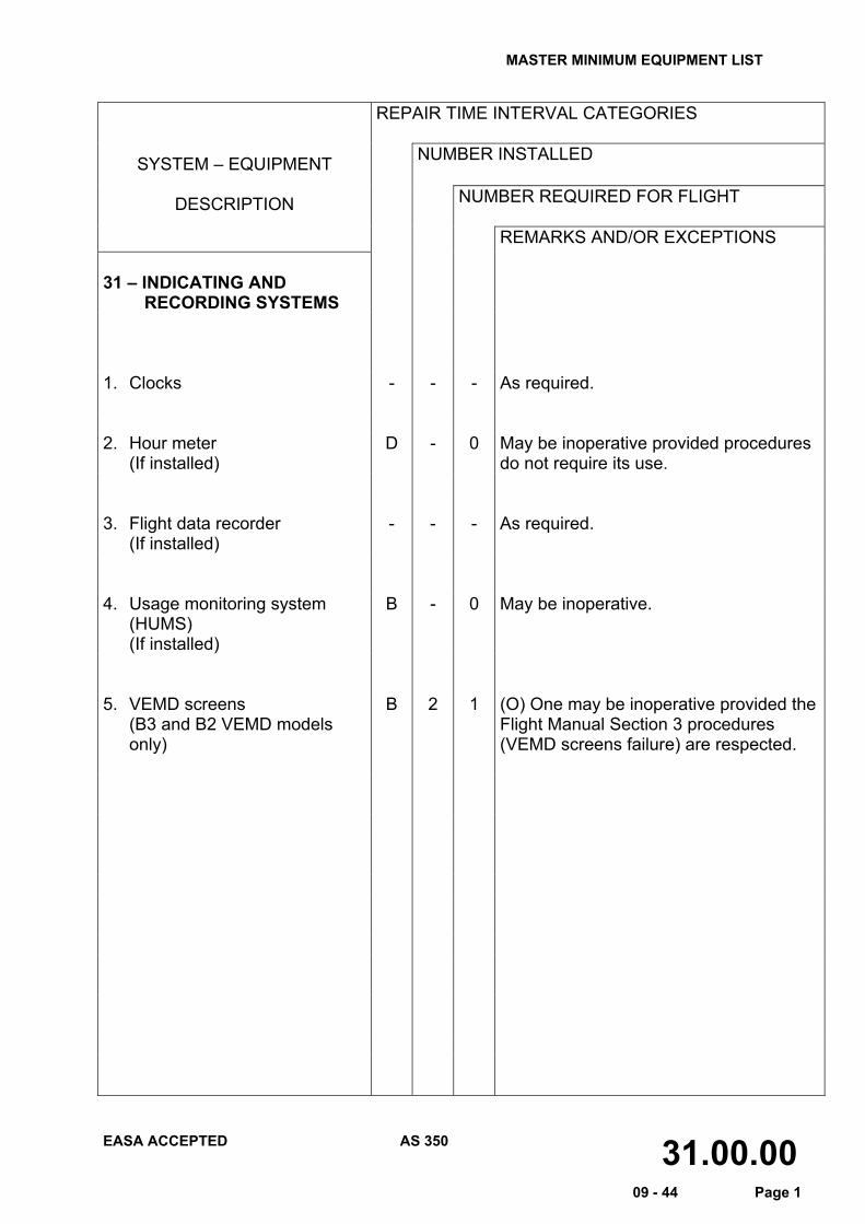
REMARKS AND/OR EXCEPTIONS 31 – INDICATING AND RECORDING SYSTEMS
1. Clocks - - - As required. 2. Hour meter
(If installed) D - 0 May be inoperative provided procedures
do not require its use. 3. Flight data recorder
(If installed) - - - As required.
4. Usage monitoring system
(HUMS) (If installed)
B - 0 May be inoperative.
5. VEMD screens
(B3 and B2 VEMD models only)
B 2 1 (O) One may be inoperative provided the Flight Manual Section 3 procedures (VEMD screens failure) are respected.
MASTER MINIMUM EQUIPMENT LIST
EASA ACCEPTED AS 350 33.00.00 09 - 44 Page 1
REPAIR TIME INTERVAL CATEGORIES
NUMBER INSTALLED SYSTEM – EQUIPMENT
DESCRIPTION NUMBER REQUIRED FOR FLIGHT
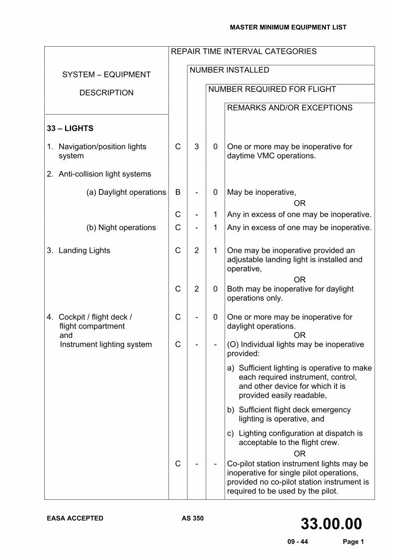
REMARKS AND/OR EXCEPTIONS 33 – LIGHTS 1. Navigation/position lights
system C 3 0 One or more may be inoperative for
daytime VMC operations. 2. Anti-collision light systems
(a) Daylight operations B
C
- -
0
1
May be inoperative, OR
Any in excess of one may be inoperative. (b) Night operations C - 1 Any in excess of one may be inoperative.
3. Landing Lights C
C
2
2
1
0
One may be inoperative provided an adjustable landing light is installed and operative,
OR Both may be inoperative for daylight operations only.
4. Cockpit / flight deck / flight compartment and Instrument lighting system
C
C
- -
0 -
One or more may be inoperative for daylight operations.
OR (O) Individual lights may be inoperative provided:
a) Sufficient lighting is operative to make each required instrument, control, and other device for which it is provided easily readable,
b) Sufficient flight deck emergency lighting is operative, and
c) Lighting configuration at dispatch is acceptable to the flight crew.
OR C - - Co-pilot station instrument lights may be
inoperative for single pilot operations, provided no co-pilot station instrument is required to be used by the pilot.
MASTER MINIMUM EQUIPMENT LIST
EASA ACCEPTED AS 350 33.00.00 09 - 44 Page 2
REPAIR TIME INTERVAL CATEGORIES
NUMBER INSTALLED SYSTEM – EQUIPMENT
DESCRIPTION NUMBER REQUIRED FOR FLIGHT
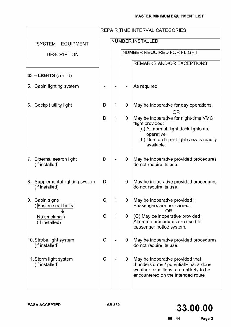
REMARKS AND/OR EXCEPTIONS 33 – LIGHTS (cont'd) 5. Cabin lighting system
-
-
-
As required
6. Cockpit utility light D 1 0 May be inoperative for day operations. OR D 1 0 May be inoperative for night-time VMC
flight provided: (a) All normal flight deck lights are
operative. (b) One torch per flight crew is readily
available.
7. External search light (If installed)
D - 0 May be inoperative provided procedures do not require its use.
8. Supplemental lighting system
(If installed) D - 0 May be inoperative provided procedures
do not require its use. 9. Cabin signs ( Fasten seat belts
& No smoking ) (If installed)
C
C
1
1
0
0
May be inoperative provided : Passengers are not carried,
OR (O) May be inoperative provided : Alternate procedures are used for passenger notice system.
10. Strobe light system
(If installed) C - 0 May be inoperative provided procedures
do not require its use.
11. Storm light system (If installed)
C - 0 May be inoperative provided that thunderstorms / potentially hazardous weather conditions, are unlikely to be encountered on the intended route
MASTER MINIMUM EQUIPMENT LIST
EASA ACCEPTED AS 350 34.00.00 09 - 44 Page 1
REPAIR TIME INTERVAL CATEGORIES
NUMBER INSTALLED SYSTEM – EQUIPMENT
DESCRIPTION NUMBER REQUIRED FOR FLIGHT
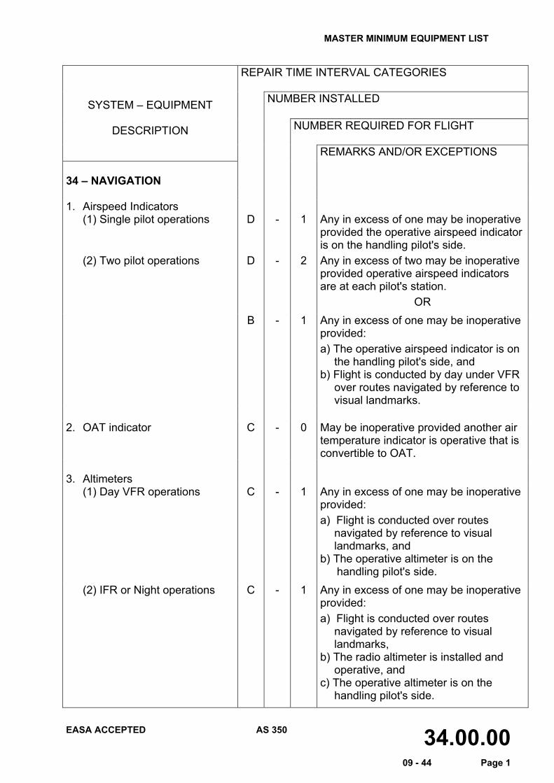
REMARKS AND/OR EXCEPTIONS 34 – NAVIGATION 1. Airspeed Indicators
(1) Single pilot operations D - 1 Any in excess of one may be inoperative provided the operative airspeed indicator is on the handling pilot's side.
(2) Two pilot operations D - 2 Any in excess of two may be inoperative provided operative airspeed indicators are at each pilot's station.
OR B - 1 Any in excess of one may be inoperative
provided: a) The operative airspeed indicator is on
the handling pilot's side, and b) Flight is conducted by day under VFR
over routes navigated by reference to visual landmarks.
2. OAT indicator C - 0 May be inoperative provided another air
temperature indicator is operative that is convertible to OAT.
3. Altimeters
(1) Day VFR operations C - 1 Any in excess of one may be inoperative provided: a) Flight is conducted over routes
navigated by reference to visual landmarks, and
b) The operative altimeter is on the handling pilot's side.
(2) IFR or Night operations C - 1 Any in excess of one may be inoperative provided: a) Flight is conducted over routes
navigated by reference to visual landmarks,
b) The radio altimeter is installed and operative, and
c) The operative altimeter is on the handling pilot's side.
MASTER MINIMUM EQUIPMENT LIST
EASA ACCEPTED AS 350 34.00.00 09 - 44 Page 2
REPAIR TIME INTERVAL CATEGORIES
NUMBER INSTALLED SYSTEM – EQUIPMENT
DESCRIPTION NUMBER REQUIRED FOR FLIGHT
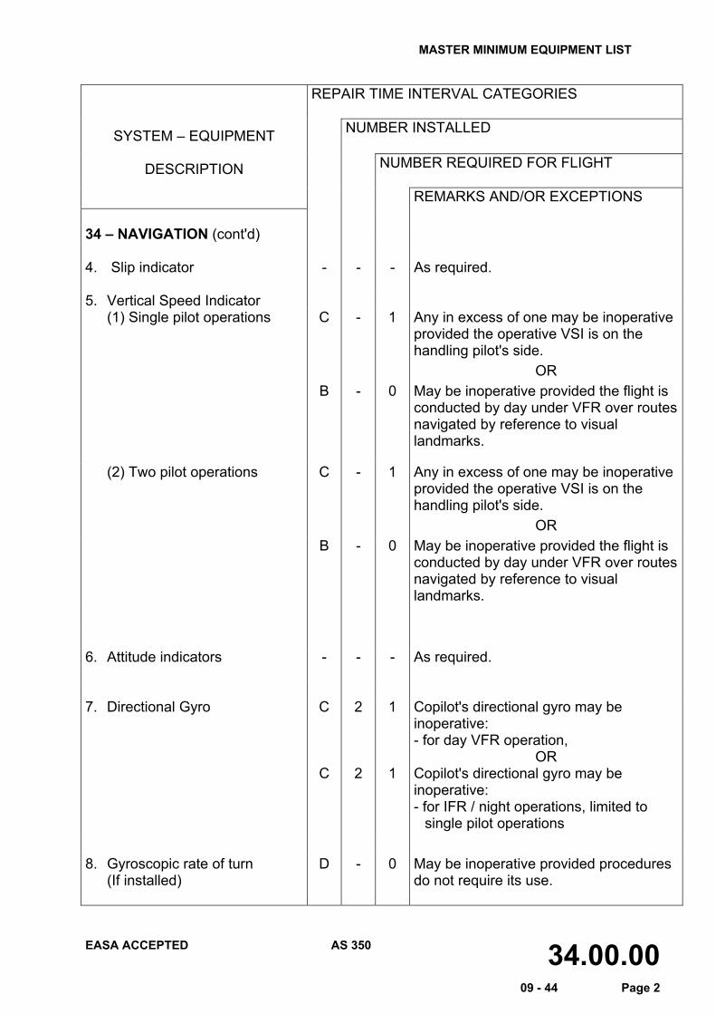
REMARKS AND/OR EXCEPTIONS 34 – NAVIGATION (cont'd) 4. Slip indicator - - - As required. 5. Vertical Speed Indicator
(1) Single pilot operations C - 1 Any in excess of one may be inoperative provided the operative VSI is on the handling pilot's side.
OR B - 0 May be inoperative provided the flight is
conducted by day under VFR over routes navigated by reference to visual landmarks.
(2) Two pilot operations C - 1 Any in excess of one may be inoperative provided the operative VSI is on the handling pilot's side.
OR B - 0 May be inoperative provided the flight is
conducted by day under VFR over routes navigated by reference to visual landmarks.
6. Attitude indicators - - - As required. 7. Directional Gyro C
C
2
2
1
1
Copilot's directional gyro may be inoperative: - for day VFR operation,
OR Copilot's directional gyro may be inoperative: - for IFR / night operations, limited to
single pilot operations 8. Gyroscopic rate of turn
(If installed) D - 0 May be inoperative provided procedures
do not require its use.
MASTER MINIMUM EQUIPMENT LIST
EASA ACCEPTED AS 350 34.00.00 09 - 44 Page 3
REPAIR TIME INTERVAL CATEGORIES
NUMBER INSTALLED SYSTEM – EQUIPMENT
DESCRIPTION NUMBER REQUIRED FOR FLIGHT
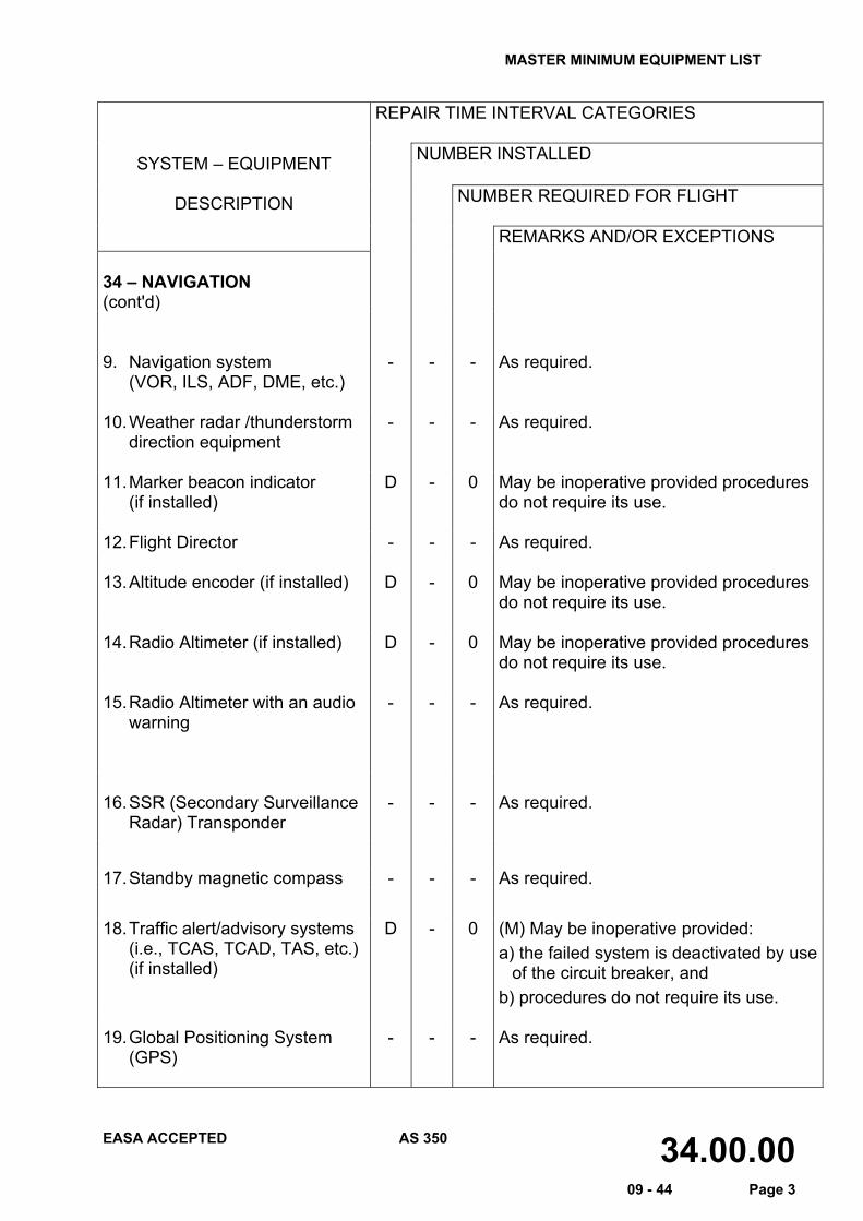
REMARKS AND/OR EXCEPTIONS 34 – NAVIGATION (cont'd)
9. Navigation system
(VOR, ILS, ADF, DME, etc.) - - - As required.
10. Weather radar /thunderstorm
direction equipment - - - As required.
11. Marker beacon indicator
(if installed) D - 0 May be inoperative provided procedures
do not require its use. 12. Flight Director - - - As required. 13. Altitude encoder (if installed) D - 0 May be inoperative provided procedures
do not require its use. 14. Radio Altimeter (if installed)
D - 0 May be inoperative provided procedures
do not require its use. 15. Radio Altimeter with an audio
warning
- - - As required.
16. SSR (Secondary Surveillance
Radar) Transponder - - - As required.
17. Standby magnetic compass - - - As required.
18. Traffic alert/advisory systems (i.e., TCAS, TCAD, TAS, etc.)(if installed)
D - 0 (M) May be inoperative provided: a) the failed system is deactivated by use
of the circuit breaker, and b) procedures do not require its use.
19. Global Positioning System
(GPS) - - - As required.
MASTER MINIMUM EQUIPMENT LIST
EASA ACCEPTED AS 350 35.00.00 09 - 44 Page 1
REPAIR TIME INTERVAL CATEGORIES
NUMBER INSTALLED SYSTEM – EQUIPMENT
DESCRIPTION NUMBER REQUIRED FOR FLIGHT
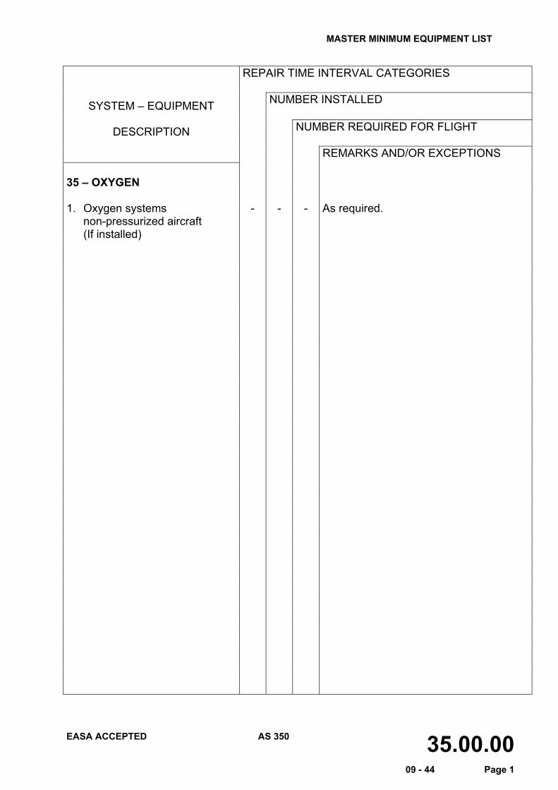
REMARKS AND/OR EXCEPTIONS 35 – OXYGEN 1. Oxygen systems non-pressurized aircraft (If installed)
- - - As required.
MASTER MINIMUM EQUIPMENT LIST
EASA ACCEPTED AS 350 52.00.00 09 - 44 Page 1
REPAIR TIME INTERVAL CATEGORIES
NUMBER INSTALLED SYSTEM – EQUIPMENT
DESCRIPTION NUMBER REQUIRED FOR FLIGHT
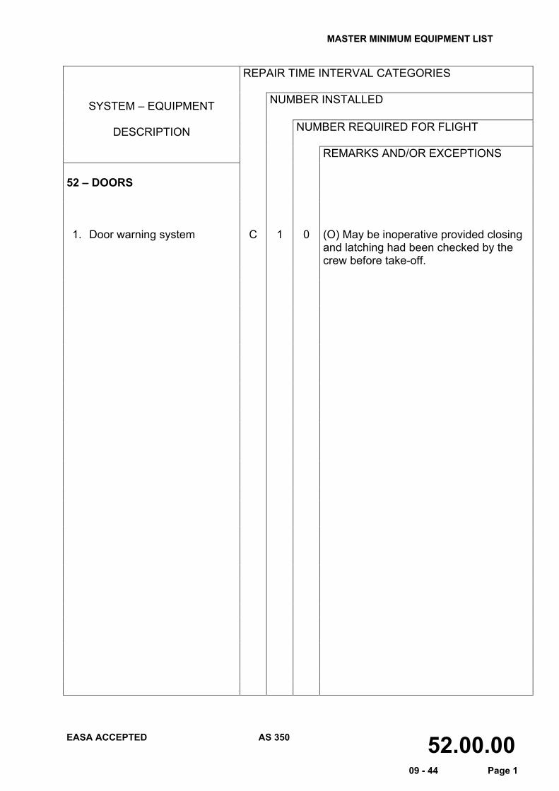
REMARKS AND/OR EXCEPTIONS 52 – DOORS 1. Door warning system C 1 0 (O) May be inoperative provided closing
and latching had been checked by the crew before take-off.
MASTER MINIMUM EQUIPMENT LIST
EASA ACCEPTED AS 350 62.00.00 09 - 44 Page 1
REPAIR TIME INTERVAL CATEGORIES
NUMBER INSTALLED SYSTEM – EQUIPMENT
DESCRIPTION NUMBER REQUIRED FOR FLIGHT
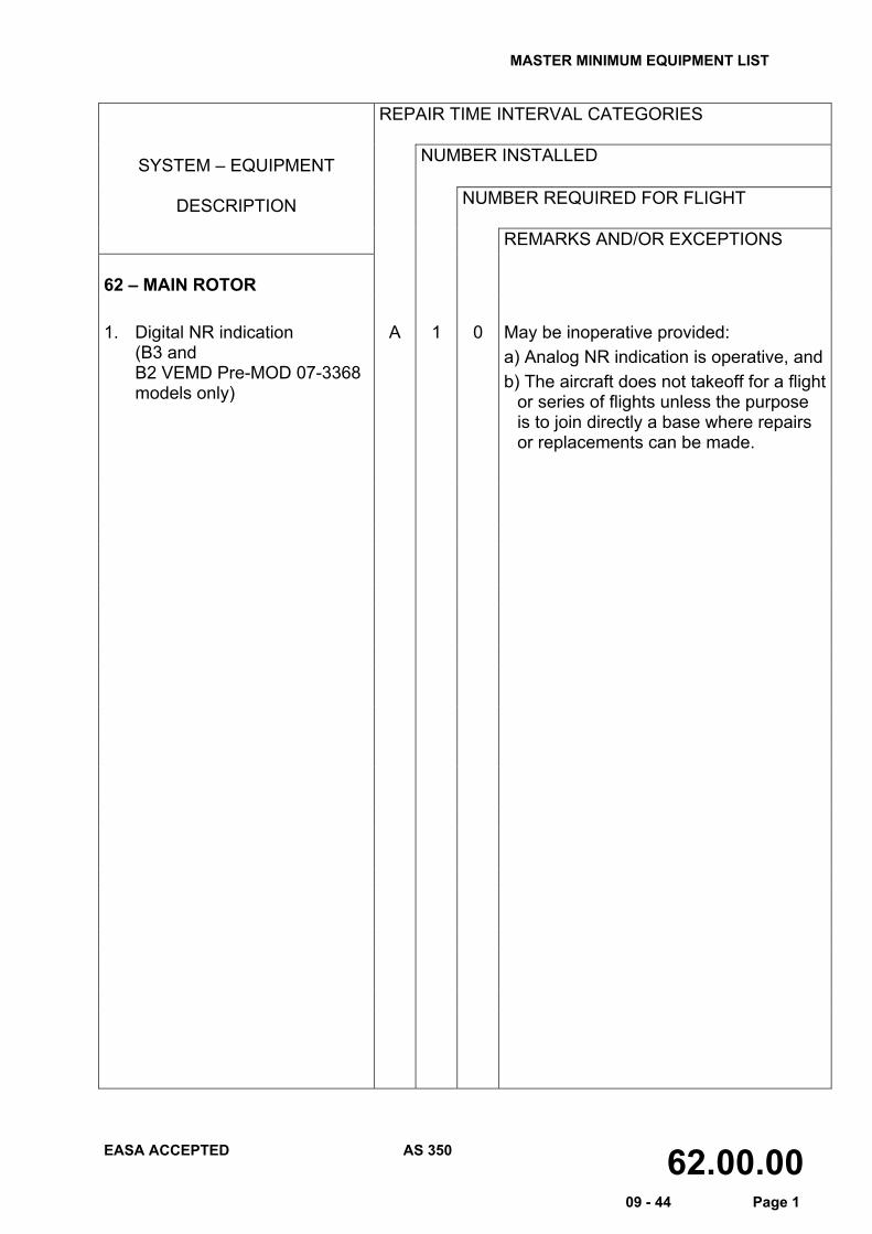
REMARKS AND/OR EXCEPTIONS 62 – MAIN ROTOR 1. Digital NR indication
(B3 and B2 VEMD Pre-MOD 07-3368 models only)
A 1 0 May be inoperative provided: a) Analog NR indication is operative, andb) The aircraft does not takeoff for a flight
or series of flights unless the purpose is to join directly a base where repairs or replacements can be made.
MASTER MINIMUM EQUIPMENT LIST
EASA ACCEPTED AS 350 63.00.00 09 - 44 Page 1
REPAIR TIME INTERVAL CATEGORIES
NUMBER INSTALLED SYSTEM – EQUIPMENT
DESCRIPTION NUMBER REQUIRED FOR FLIGHT
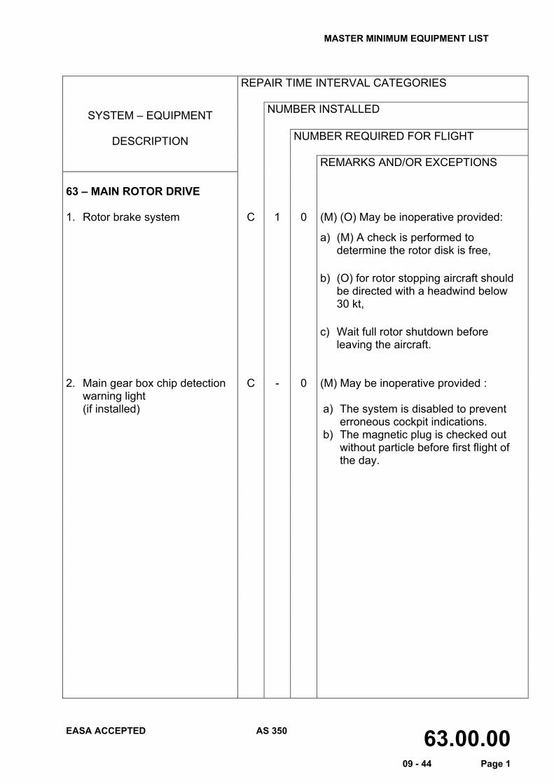
REMARKS AND/OR EXCEPTIONS 63 – MAIN ROTOR DRIVE 1. Rotor brake system
C 1 0 (M) (O) May be inoperative provided:
a) (M) A check is performed to determine the rotor disk is free,
b) (O) for rotor stopping aircraft should be directed with a headwind below 30 kt,
c) Wait full rotor shutdown before leaving the aircraft.
2. Main gear box chip detection
warning light (if installed)
C - 0 (M) May be inoperative provided : a) The system is disabled to prevent
erroneous cockpit indications. b) The magnetic plug is checked out
without particle before first flight of the day.
MASTER MINIMUM EQUIPMENT LIST
EASA ACCEPTED AS 350 65.00.00 09 - 44 Page 1
REPAIR TIME INTERVAL CATEGORIES
NUMBER INSTALLED SYSTEM – EQUIPMENT
DESCRIPTION NUMBER REQUIRED FOR FLIGHT
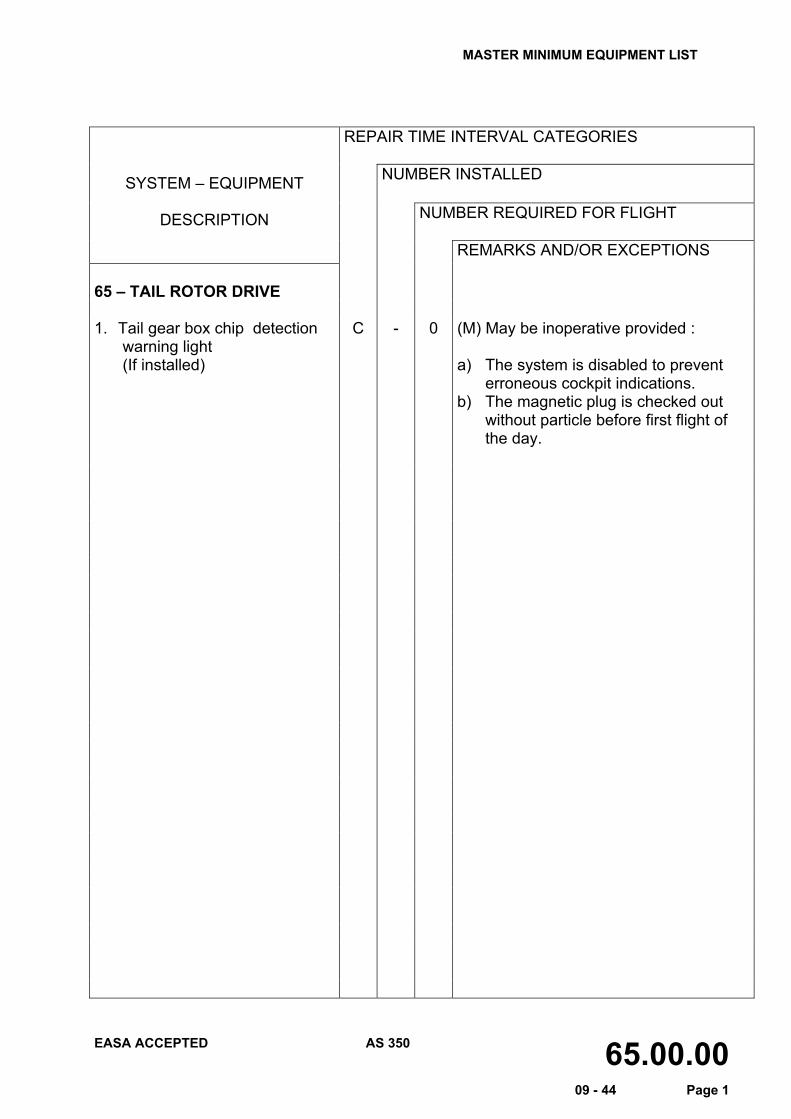
REMARKS AND/OR EXCEPTIONS 65 – TAIL ROTOR DRIVE 1. Tail gear box chip detection
warning light (If installed)
C - 0 (M) May be inoperative provided : a) The system is disabled to prevent
erroneous cockpit indications. b) The magnetic plug is checked out
without particle before first flight of the day.
MASTER MINIMUM EQUIPMENT LIST
EASA ACCEPTED AS 350 71.00.00 09 - 44 Page 1
REPAIR TIME INTERVAL CATEGORIES
NUMBER INSTALLED SYSTEM – EQUIPMENT
DESCRIPTION NUMBER REQUIRED FOR FLIGHT
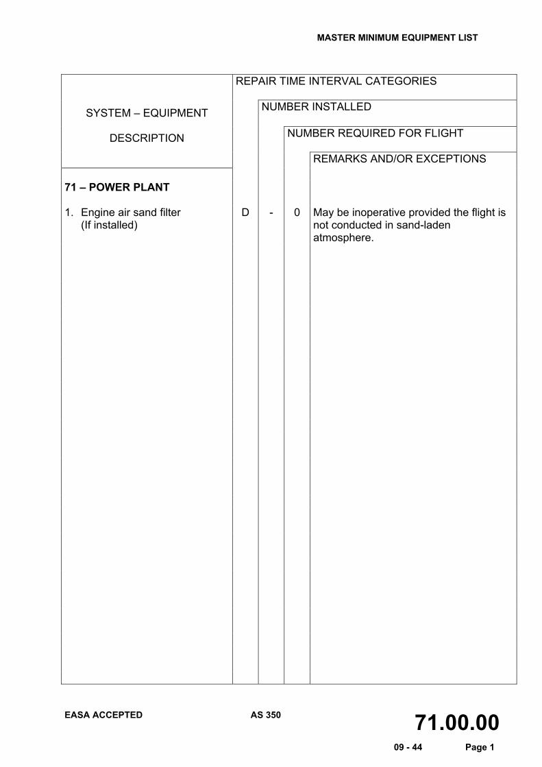
REMARKS AND/OR EXCEPTIONS 71 – POWER PLANT 1. Engine air sand filter
(If installed)
D - 0 May be inoperative provided the flight is not conducted in sand-laden atmosphere.
MASTER MINIMUM EQUIPMENT LIST
EASA ACCEPTED AS 350 77.00.00 09 - 44 Page 1
REPAIR TIME INTERVAL CATEGORIES
NUMBER INSTALLED SYSTEM – EQUIPMENT
DESCRIPTION NUMBER REQUIRED FOR FLIGHT
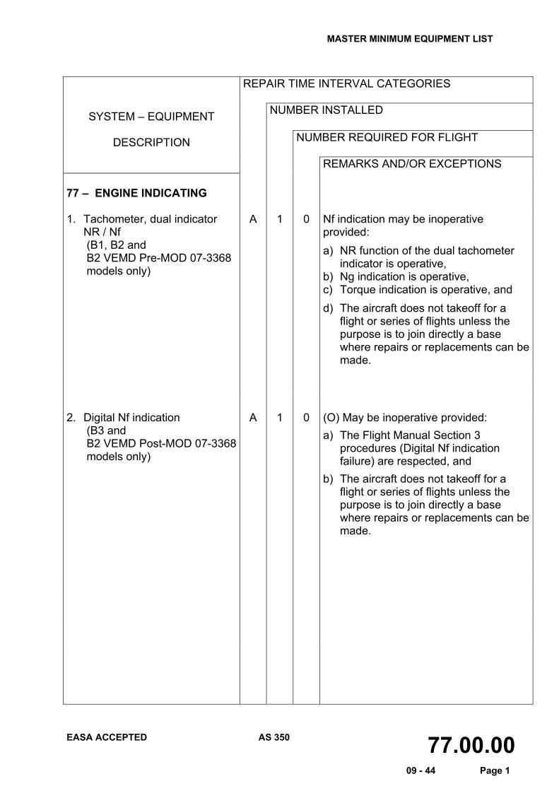
REMARKS AND/OR EXCEPTIONS 77 – ENGINE INDICATING 1. Tachometer, dual indicator
NR / Nf (B1, B2 and B2 VEMD Pre-MOD 07-3368 models only)
A 1 0 Nf indication may be inoperative provided: a) NR function of the dual tachometer
indicator is operative, b) Ng indication is operative, c) Torque indication is operative, and d) The aircraft does not takeoff for a
flight or series of flights unless the purpose is to join directly a base where repairs or replacements can be made.
2. Digital Nf indication (B3 and B2 VEMD Post-MOD 07-3368 models only)
A 1 0 (O) May be inoperative provided: a) The Flight Manual Section 3
procedures (Digital Nf indication failure) are respected, and
b) The aircraft does not takeoff for a flight or series of flights unless the purpose is to join directly a base where repairs or replacements can be made.