Embed Size (px)
Citation preview
GSM 1
Mobile Communications
GSM
Manuel P. Ricardo
Faculdade de Engenharia da Universidade do Porto
GSM 2
Acknowledgements
♦ These slides are based on the slides developed by
» Prof. Jochen Schiller
– Slides from the book “Mobile Communication: Wireless Telecommunication Systems”
– http://www.jochenschiller.de
» Prof. Mário Jorge Leitão
– http://www.fe.up.pt/~mleitao/
GSM 3
♦ What are the main network elements of GSM?
♦ What are the GSM addresses?
♦ How is the data transmitted over the air interface?
♦ What are the main logical channels?
♦ What is the GSM protocol stack for signalling?
♦ How is a Mobile Terminated Call processed?
♦ How is a Mobile Initiated Call processed?
GSM 4
GSM - Overview
♦ Formerly: Groupe Spéciale Mobile (founded 1982)
♦ Now: Global System for Mobile Communication
♦ Pan-European standard
» ETSI, European Telecommunications Standardisation Institute
♦ Seamless roaming within Europe possible
♦ Many providers all over the world
GSM 5
Services
♦ Basic services
» voice services, data services, short message service
♦ Additional services
» emergency number, group 3 fax
♦ Supplementary services
» identification: forwarding of caller number
» suppression of number forwarding
» automatic call-back
GSM 6
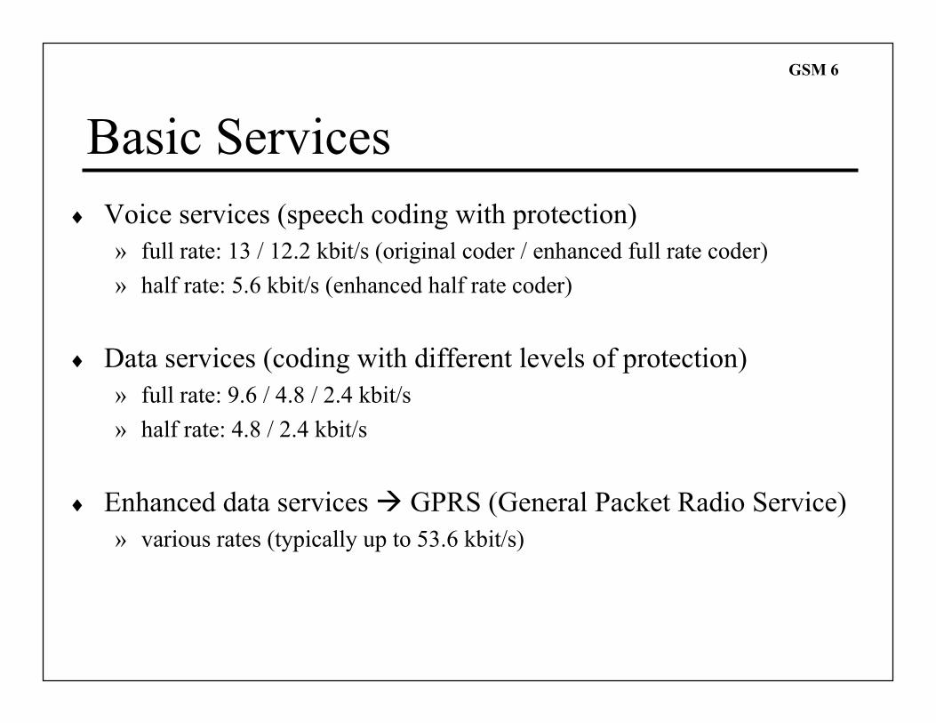
Basic Services
♦ Voice services (speech coding with protection)
» full rate: 13 / 12.2 kbit/s (original coder / enhanced full rate coder)
» half rate: 5.6 kbit/s (enhanced half rate coder)
♦ Data services (coding with different levels of protection)
» full rate: 9.6 / 4.8 / 2.4 kbit/s
» half rate: 4.8 / 2.4 kbit/s
♦ Enhanced data services � GPRS (General Packet Radio Service)
» various rates (typically up to 53.6 kbit/s)
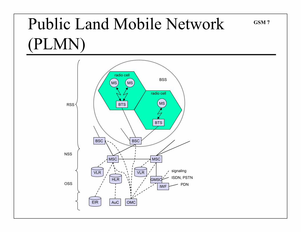
GSM 7Public Land Mobile Network
(PLMN)
NSS
MS MS
BTS
BSC
GMSC
IWF
OMC
BTS
BSC
MSC MSC
EIR
HLR
VLR VLR
BSS
PDN
ISDN, PSTN
RSS
radio cell
radio cell
MS
AuC
OSS
signaling
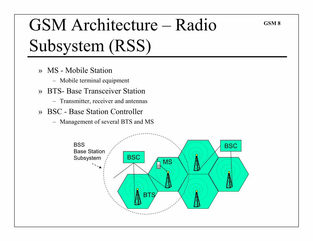
GSM 8GSM Architecture – Radio
Subsystem (RSS)
» MS - Mobile Station
– Mobile terminal equipment
» BTS- Base Transceiver Station
– Transmitter, receiver and antennas
» BSC - Base Station Controller
– Management of several BTS and MS
BSC
BSC
BTS
MS
BSS
Base Station
Subsystem
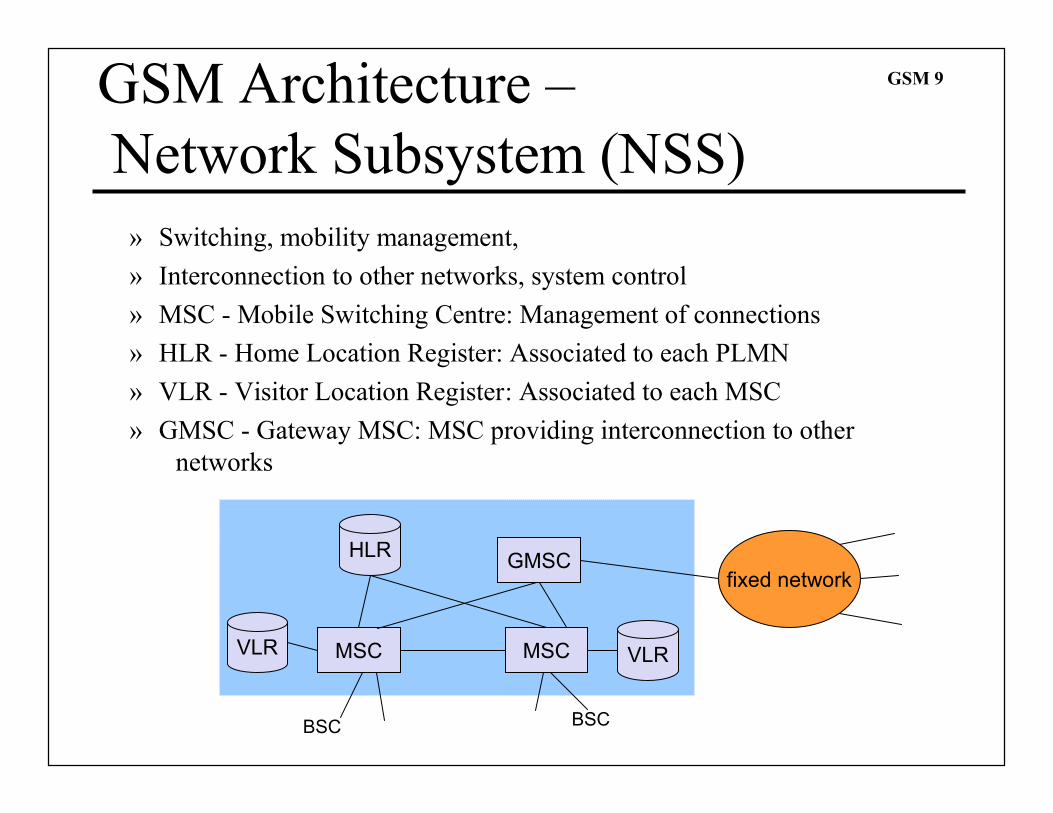
GSM 9GSM Architecture –
Network Subsystem (NSS)
» Switching, mobility management,
» Interconnection to other networks, system control
» MSC - Mobile Switching Centre: Management of connections
» HLR - Home Location Register: Associated to each PLMN
» VLR - Visitor Location Register: Associated to each MSC
» GMSC - Gateway MSC: MSC providing interconnection to other
networks
MSC
GMSC
VLR
HLR
VLR
fixed network
BSC BSC
MSC
GSM 10GSM Architecture –
Operation Subsystem (OSS)
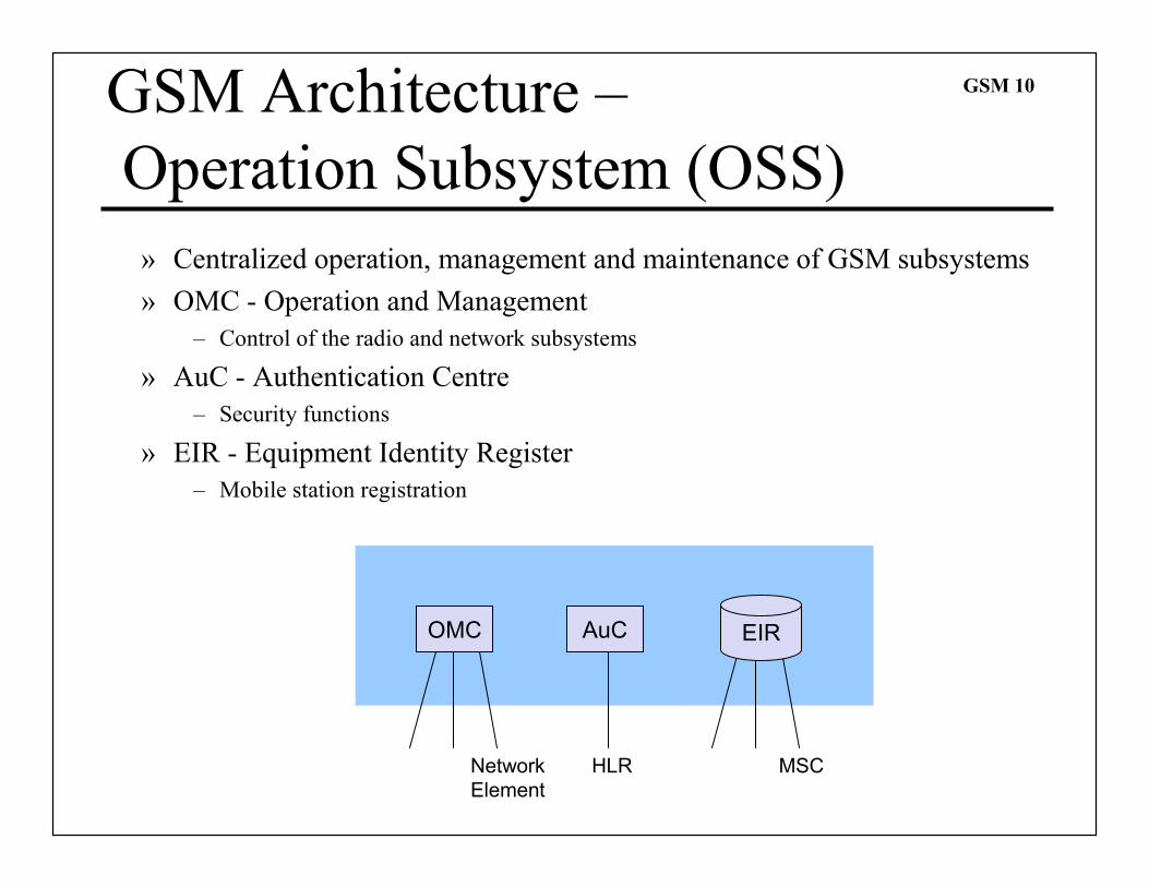
» Centralized operation, management and maintenance of GSM subsystems
» OMC - Operation and Management
– Control of the radio and network subsystems
» AuC - Authentication Centre
– Security functions
» EIR - Equipment Identity Register
– Mobile station registration
OMC AuC
HLR MSC
EIR
Network
Element
GSM 11
Um
Abis
A
BSS
radio
subsystem
MS MS
BTS
BSCBTS
BTS
BSCBTS
network and
switching subsystem
MSC
fixed
partner networks
ISDN
PSTN
SS7
HLR
VLR
ISDN
PSTN
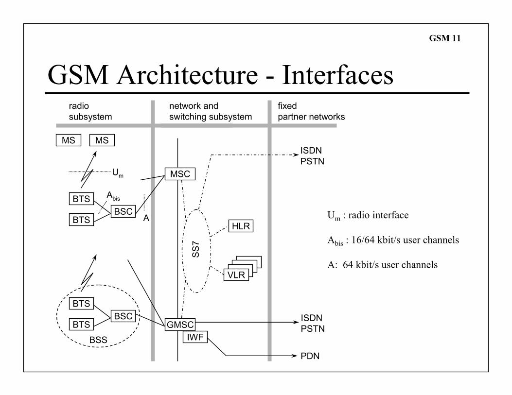
GSM Architecture - Interfaces
GMSC
IWF
PDN
Um : radio interface
Abis : 16/64 kbit/s user channels
A: 64 kbit/s user channels
GSM 12Voice Transcoding and Rate
Adaptation
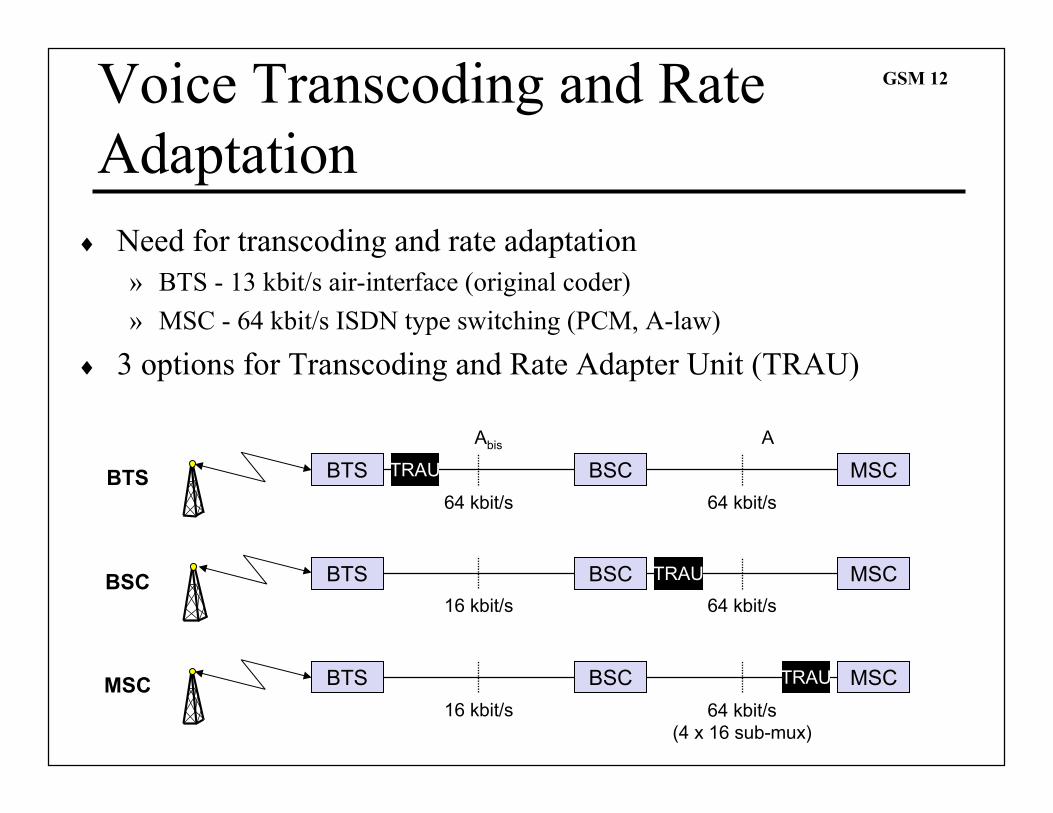
♦ Need for transcoding and rate adaptation
» BTS - 13 kbit/s air-interface (original coder)
» MSC - 64 kbit/s ISDN type switching (PCM, A-law)
♦ 3 options for Transcoding and Rate Adapter Unit (TRAU)
BTS TRAU BSC MSC
Abis
64 kbit/s
A
64 kbit/s
BTS
BTS BSC MSC
16 kbit/s 64 kbit/s
BSC TRAU
BTS BSC MSC
16 kbit/s 64 kbit/s
(4 x 16 sub-mux)
MSC TRAU
GSM 13
Mobile Addresses
♦ Several mobile numbers are needed
» IMSI - International Mobile Subscriber Identity
– Mobile Country Code (MCC) + Mobile Network Code (MNC) + Mobile Subscriber
Identification Number (MSIN)
– uniquely identifies the user (SIM card)
» TMSI - Temporary Mobile Subscriber Identity
– 32 bits
– local number allocated by VLR; may be changed periodically
– hides the IMSI over the air interface; transmitted instead of IMSI
» MSRN - Mobile Station Roaming Number
– Visitor Country Code (VCC) + Visitor National destination Code (VNDC) + Current
MSC code + temporary subscriber number
– generated by VLR for all visiting users
– helps HLR to determine current location area
– hides the IMSI inside the network
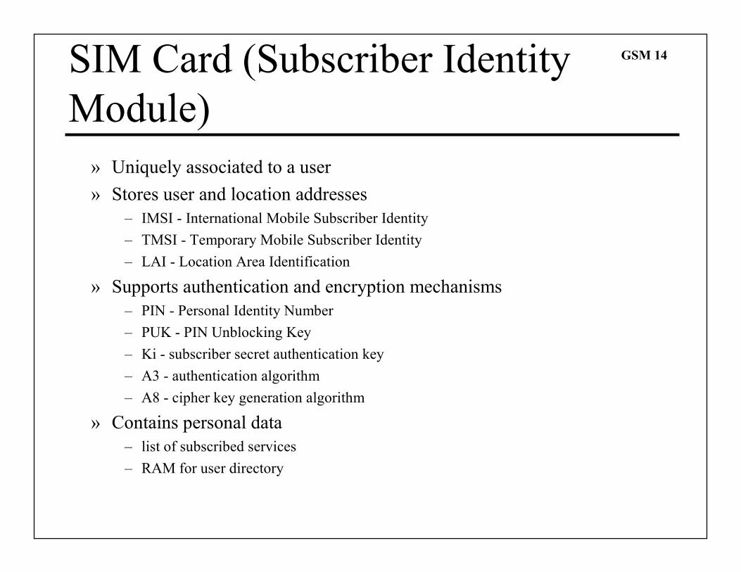
GSM 14SIM Card (Subscriber Identity
Module)
» Uniquely associated to a user
» Stores user and location addresses
– IMSI - International Mobile Subscriber Identity
– TMSI - Temporary Mobile Subscriber Identity
– LAI - Location Area Identification
» Supports authentication and encryption mechanisms
– PIN - Personal Identity Number
– PUK - PIN Unblocking Key
– Ki - subscriber secret authentication key
– A3 - authentication algorithm
– A8 - cipher key generation algorithm
» Contains personal data
– list of subscribed services
– RAM for user directory
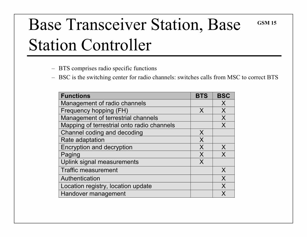
GSM 15Base Transceiver Station, Base
Station Controller
– BTS comprises radio specific functions
– BSC is the switching center for radio channels: switches calls from MSC to correct BTS
Functions BTS BSC
Management of radio channels X
Frequency hopping (FH) X X
Management of terrestrial channels X
Mapping of terrestrial onto radio channels X
Channel coding and decoding X
Rate adaptation X
Encryption and decryption X X
Paging X X
Uplink signal measurements X
Traffic measurement X
Authentication X
Location registry, location update X
Handover management X
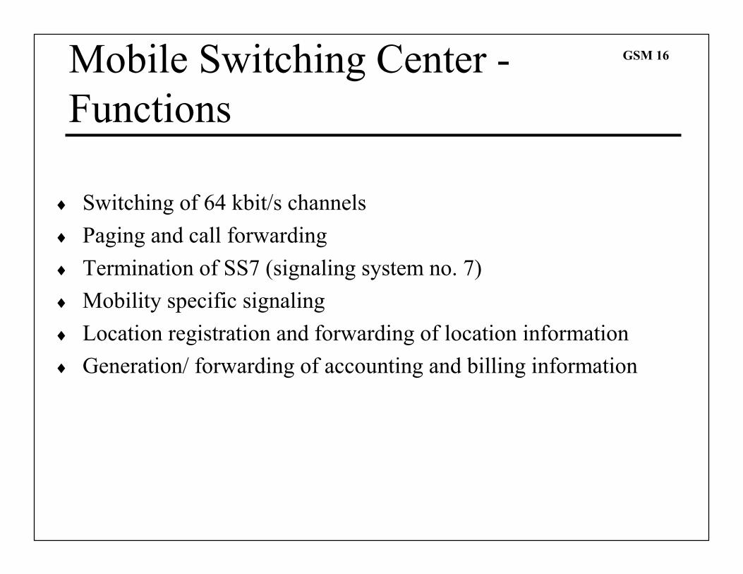
GSM 16Mobile Switching Center -
Functions
♦ Switching of 64 kbit/s channels
♦ Paging and call forwarding
♦ Termination of SS7 (signaling system no. 7)
♦ Mobility specific signaling
♦ Location registration and forwarding of location information
♦ Generation/ forwarding of accounting and billing information
GSM 17
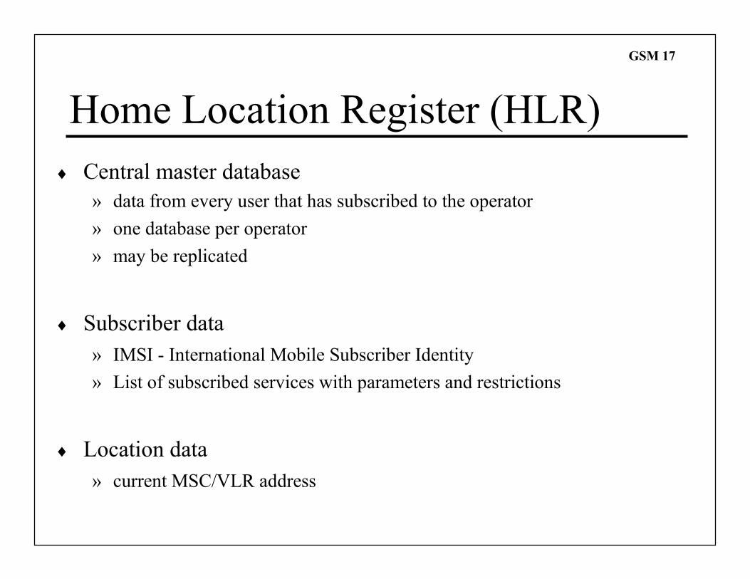
Home Location Register (HLR)
♦ Central master database
» data from every user that has subscribed to the operator
» one database per operator
» may be replicated
♦ Subscriber data
» IMSI - International Mobile Subscriber Identity
» List of subscribed services with parameters and restrictions
♦ Location data
» current MSC/VLR address
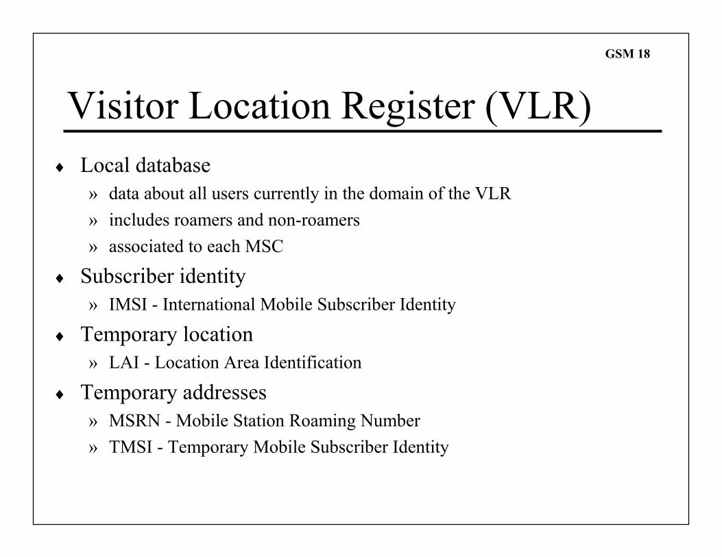
GSM 18
Visitor Location Register (VLR)
♦ Local database
» data about all users currently in the domain of the VLR
» includes roamers and non-roamers
» associated to each MSC
♦ Subscriber identity
» IMSI - International Mobile Subscriber Identity
♦ Temporary location
» LAI - Location Area Identification
♦ Temporary addresses
» MSRN - Mobile Station Roaming Number
» TMSI - Temporary Mobile Subscriber Identity
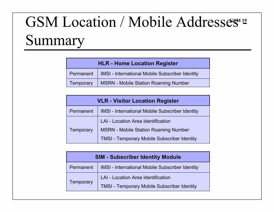
GSM 19GSM Location / Mobile Addresses -
Summary
HLR - Home Location Register
IMSI - International Mobile Subscriber Identity
VLR - Visitor Location Register
IMSI - International Mobile Subscriber Identity
SIM - Subscriber Identity Module
IMSI - International Mobile Subscriber Identity
Permanent
LAI - Location Area Identification
TMSI - Temporary Mobile Subscriber Identity
Temporary
LAI - Location Area Identification
MSRN - Mobile Station Roaming Number
TMSI - Temporary Mobile Subscriber Identity
Permanent
Temporary
Permanent
Temporary MSRN - Mobile Station Roaming Number
GSM 20
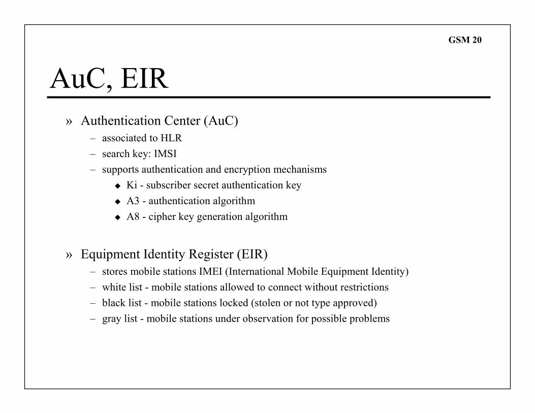
AuC, EIR
» Authentication Center (AuC)
– associated to HLR
– search key: IMSI
– supports authentication and encryption mechanisms
� Ki - subscriber secret authentication key
� A3 - authentication algorithm
� A8 - cipher key generation algorithm
» Equipment Identity Register (EIR)
– stores mobile stations IMEI (International Mobile Equipment Identity)
– white list - mobile stations allowed to connect without restrictions
– black list - mobile stations locked (stolen or not type approved)
– gray list - mobile stations under observation for possible problems
GSM 21
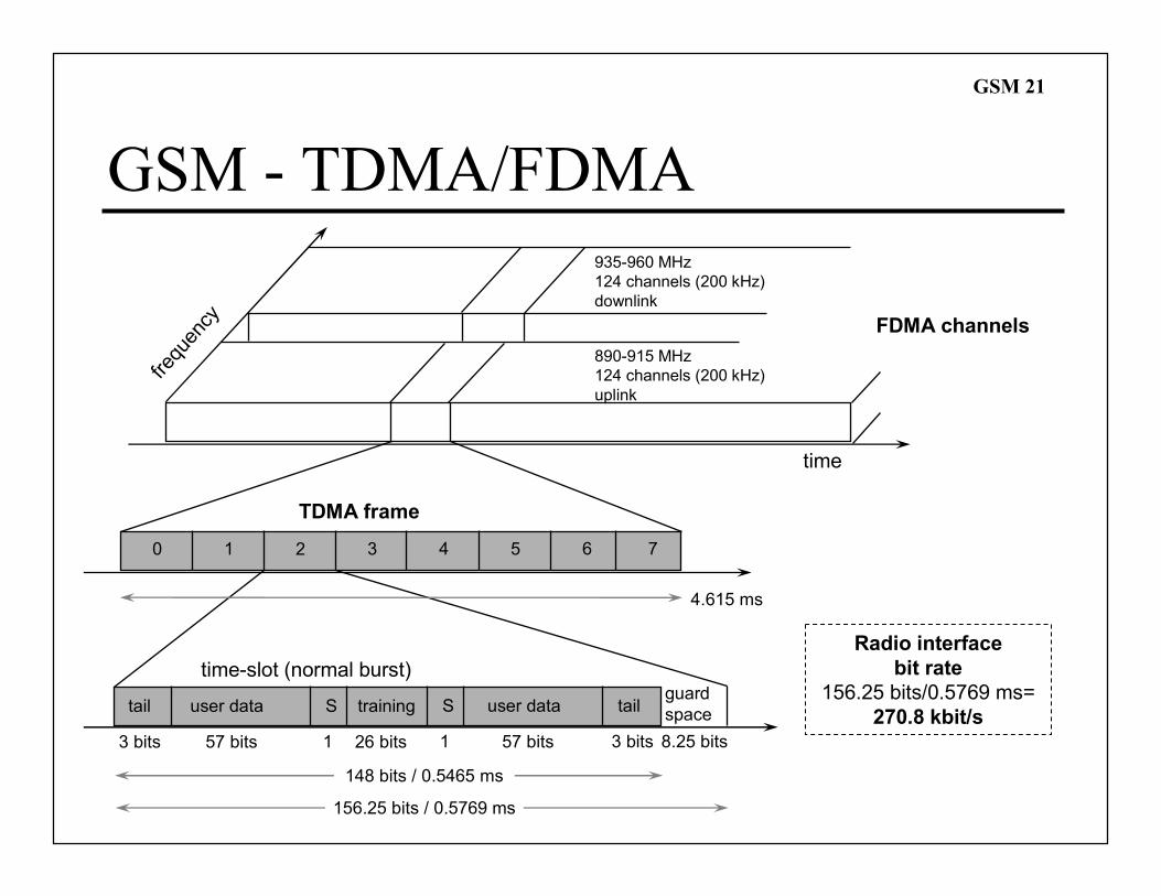
935-960 MHz
124 channels (200 kHz)
downlink
890-915 MHz
124 channels (200 kHz)
uplink
frequency
time
GSM - TDMA/FDMA
0 1 2 3 4 5 6 7
TDMA frame
time-slot (normal burst)
4.615 ms
148 bits / 0.5465 ms
156.25 bits / 0.5769 ms
tail user data trainingS S user data tailguard
space
3 bits 57 bits 26 bits 57 bits1 1 3 bits 8.25 bits
Radio interface
bit rate
156.25 bits/0.5769 ms=
270.8 kbit/s
FDMA channels
GSM 22
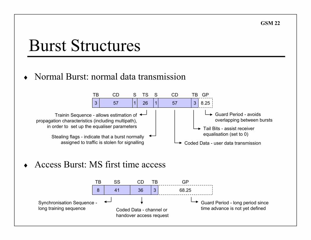
Burst Structures
♦ Normal Burst: normal data transmission
♦ Access Burst: MS first time access
3 57 1 26 1 57 3 8.25
8 41 36 68.253
Guard Period - avoids
overlapping between bursts
Tail Bits - assist receiver
equalisation (set to 0)
GPTBCD
Coded Data - user data transmission
CDTB TS
Trainin Sequence - allows estimation of
propagation characteristics (including multipath),
in order to set up the equaliser parameters
SS
Stealing flags - indicate that a burst normally
assigned to traffic is stolen for signalling
TB SS CD TB GP
Guard Period - long period since
time advance is not yet defined
Synchronisation Sequence -
long training sequence Coded Data - channel or
handover access request
GSM 23
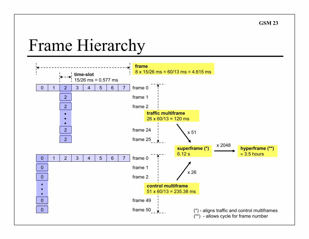
Frame Hierarchy
time-slot
15/26 ms = 0.577 ms
frame
8 x 15/26 ms = 60/13 ms = 4.615 ms
0 1 2 3 4 5 6 7
2
2
2
frame 0
frame 1
frame 2
2
frame 24
frame 25
0 1 2 3 4 5 6 7
0
0
0
frame 0
frame 1
frame 2
0
frame 49
frame 50
superframe (*)
6.12 s
traffic multiframe
26 x 60/13 = 120 ms
control multiframe
51 x 60/13 = 235.38 ms
hyperframe (**)
≈ 3.5 hours
x 51
x 26
x 2048
(*) - aligns traffic and control multiframes
(**) - allows cycle for frame number
GSM 24
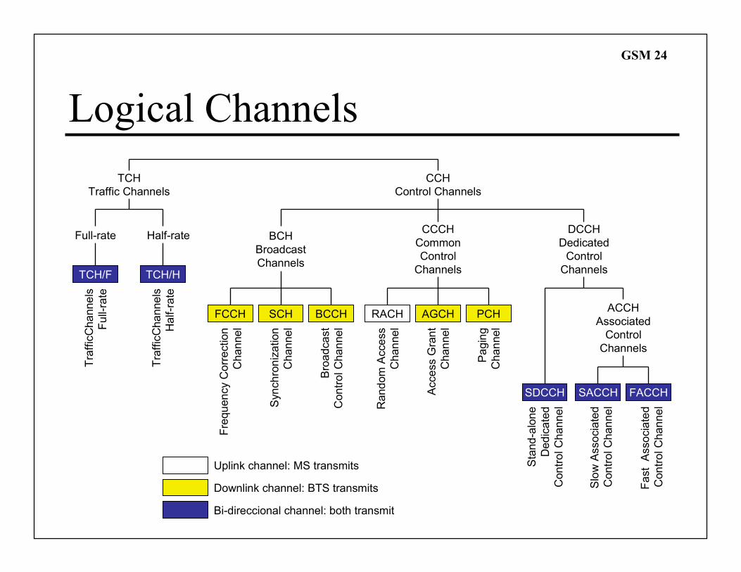
Logical Channels
TCH
Traffic Channels
TCH/F
CCH
Control Channels
Full-rate Half-rate
TCH/H
BCH
Broadcast
Channels
FCCH SCH BCCH
CCCH
Common
Control
Channels
RACH AGCH
DCCH
Dedicated
Control
Channels
ACCH
Associated
Control
Channels
SACCH FACCH
TrafficChannels
Full-rate
TrafficChannels
Half-rate
Frequency Correction
Channel
Synchronization
Channel
Broadcast
Control Channel
Random Access
Channel
Access Grant
Channel
Slow Associated
Control Channel
Fast Associated
Control Channel
Uplink channel: MS transmits
Bi-direccional channel: both transmit
Downlink channel: BTS transmits
PCH
Paging
Channel
SDCCH
Stand-alone
Dedicated
Control Channel
GSM 25
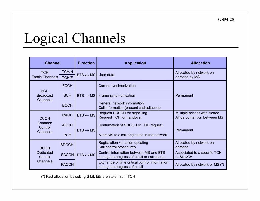
Logical Channels
TCH
Traffic Channels
BCH
Broadcast
Channels
User data
ApplicationChannel Allocation
BTS → MS
General network information
Cell information (present and adjacent)
FCCH
SCH
BCCH
Frame synchronisation
Carrier synchronization
CCCH
Common
Control
Channels
RACH
AGCH
PCH
BTS ← MS
BTS → MS
Request SDCCH for signalling
Request TCH for handover
Confirmation of SDCCH or TCH request
Allert MS to a call originated in the network
DCCH
Dedicated
Control
Channels
SDCCHRegistration / location updating
Call control procedures
Allocated by network on
demand by MS
Permanent
Multiple access with slotted
Alhoa contention between MS
Permanent
Allocated by network on
demand
SACCH
FACCH
BTS ↔ MSControl information between MS and BTS
during the progress of a call or call set up
Allocated by network or MS (*)Exchange of time critical control information
during the progress of a call
Associated to a specific TCH
or SDCCH
(*) Fast allocation by setting S bit; bits are stolen from TCH
BTS ↔ MS
Direction
TCH/H
TCH/F
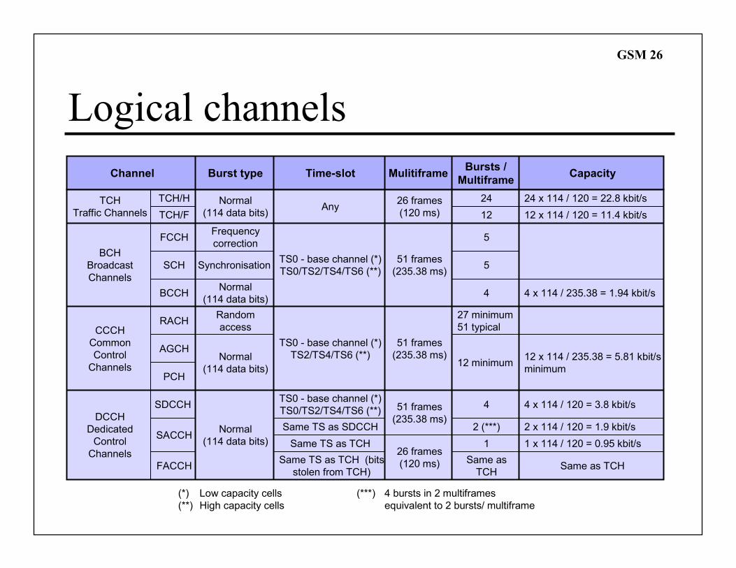
GSM 26
Logical channels
TCH
Traffic Channels
BCH
Broadcast
Channels
Normal
(114 data bits)
Burst typeChannel
Normal
(114 data bits)
FCCH
SCH
BCCH
Synchronisation
Frequency
correction
CCCH
Common
Control
Channels
RACH
AGCH
PCH
Random
access
Normal
(114 data bits)
DCCH
Dedicated
Control
Channels
SDCCH
Normal
(114 data bits)SACCH
FACCH
26 frames
(120 ms)
Mulitiframe
26 frames
(120 ms)
51 frames
(235.38 ms)
51 frames
(235.38 ms)
51 frames
(235.38 ms)
TCH/H
TCH/F
(*) Low capacity cells
(**) High capacity cells
Capacity
24
Time-slot
Any
TS0 - base channel (*)
TS0/TS2/TS4/TS6 (**)
TS0 - base channel (*)
TS2/TS4/TS6 (**)
Same TS as SDCCH
Same TS as TCH
Same TS as TCH (bits
stolen from TCH)
TS0 - base channel (*)
TS0/TS2/TS4/TS6 (**)
Bursts /
Multiframe
5
12
5
4
27 minimum
51 typical
12 minimum
4
1
Same as
TCH
2 (***)
(***) 4 bursts in 2 multiframes
equivalent to 2 bursts/ multiframe
24 x 114 / 120 = 22.8 kbit/s
12 x 114 / 120 = 11.4 kbit/s
4 x 114 / 235.38 = 1.94 kbit/s
12 x 114 / 235.38 = 5.81 kbit/s
minimum
4 x 114 / 120 = 3.8 kbit/s
2 x 114 / 120 = 1.9 kbit/s
1 x 114 / 120 = 0.95 kbit/s
Same as TCH
GSM 27
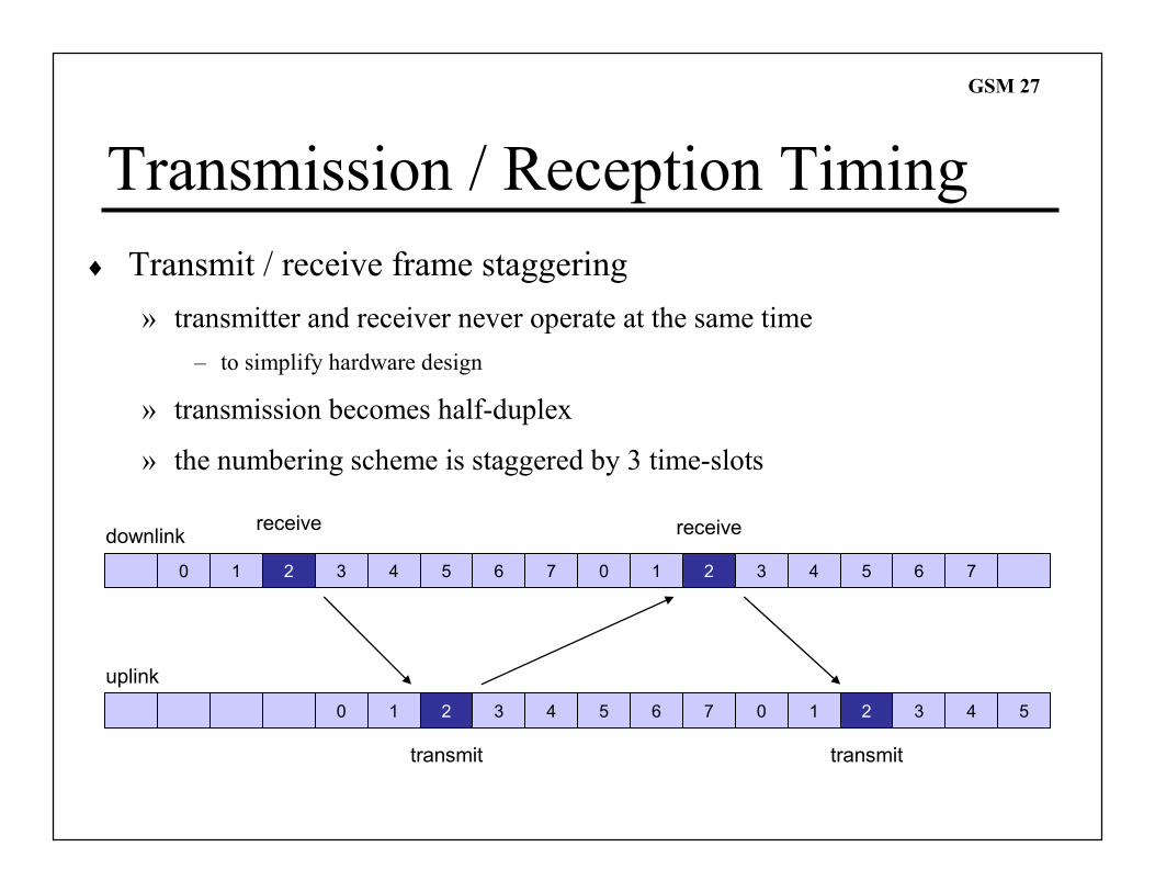
Transmission / Reception Timing
♦ Transmit / receive frame staggering
» transmitter and receiver never operate at the same time
– to simplify hardware design
» transmission becomes half-duplex
» the numbering scheme is staggered by 3 time-slots
0 1 2 3 4 5 6 7 0 1 2 3 4 5 6 7
downlinkreceive receive
0 1 2 3 4 5 6 7 0 1 2 3 4 5
uplink
transmit transmit
GSM 28
Transmit Time Advance
» Principle of operation
– correct timing of uplink bursts at the BTS is required to avoid overlapping
– different path delays (MS-BTS distances) must be compensated
– transmission from the MS is advanced 0-63 bits under BTS control
– maximum time advance of 63 bits allows 0.233 ms round trip delay
– maximum cell radius is approximately 35 km
» Initial ranging
– Access Burst is transmitted without time advance
– Guard Period of 68.25 bits allows for a path delay due to 37 km distance
– BTS measures path delay and sends required time advance on SACCH
– MS introduces time advance on all bursts
» Adaptive control
– BTS monitors burst and measures delays with specified time advance
– if path delay varies more than 1 bit period, the new value is signalled on SACCH
GSM 29
Frequency hopping
» Application of frequency hoping
– optional, but usually implemented
– channels with no frequency hopping: BCH and CCCH
» Hoping sequence
– several possible hoping algorithms
– selected algorithm broadcast on BCCH
» Slow frequency hopping characteristics
– in a given time-slot, successive TDMA frame are transmitted on different carriers
– main hoping parameters
� period: 4.615 ms
� frequency: 217 hops/s
� number of bits: 1250 bits/hop
GSM 30
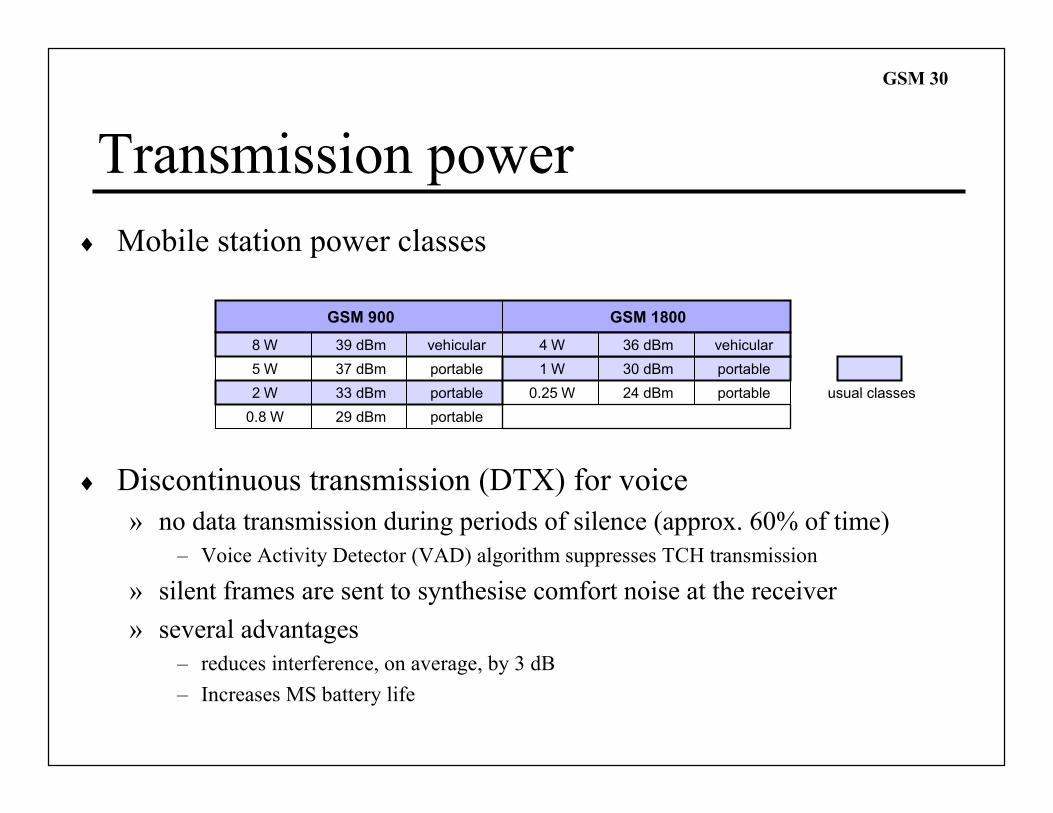
Transmission power
♦ Mobile station power classes
♦ Discontinuous transmission (DTX) for voice
» no data transmission during periods of silence (approx. 60% of time)
– Voice Activity Detector (VAD) algorithm suppresses TCH transmission
» silent frames are sent to synthesise comfort noise at the receiver
» several advantages
– reduces interference, on average, by 3 dB
– Increases MS battery life
8 W
GSM 900
39 dBm
GSM 1800
4 W 36 dBmvehicular
portable
vehicular
5 W 37 dBm
portable2 W 33 dBm
portable0.8 W 29 dBm
portable1 W 30 dBm
portable0.25 W 24 dBm usual classes
GSM 31
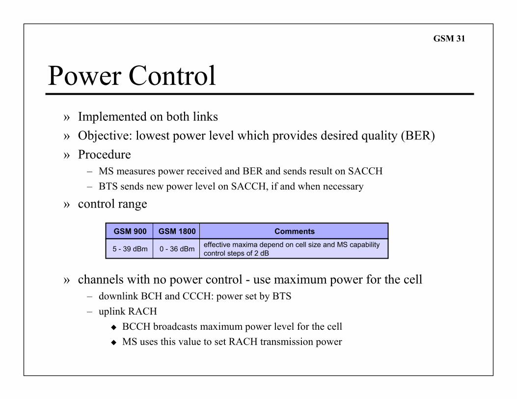
Power Control
» Implemented on both links
» Objective: lowest power level which provides desired quality (BER)
» Procedure
– MS measures power received and BER and sends result on SACCH
– BTS sends new power level on SACCH, if and when necessary
» control range
» channels with no power control - use maximum power for the cell
– downlink BCH and CCCH: power set by BTS
– uplink RACH
� BCCH broadcasts maximum power level for the cell
� MS uses this value to set RACH transmission power
GSM 900
5 - 39 dBm
GSM 1800
0 - 36 dBm
Comments
effective maxima depend on cell size and MS capability
control steps of 2 dB
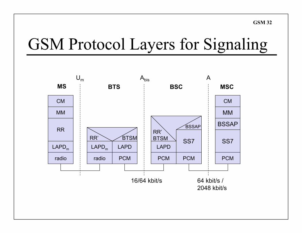
GSM 32
GSM Protocol Layers for Signaling
CM
MM
RR
MM
LAPDm
radio
LAPDm
radio
LAPD
PCM
RR’ BTSM
CM
LAPD
PCM
RR’
BTSM
16/64 kbit/s
Um Abis A
SS7
PCM
SS7
PCM
64 kbit/s /
2048 kbit/s
MS BTS BSC MSC
BSSAP BSSAP
GSM 33
GSM Protocol Layers for Signaling
» CM (Connection Management)
– call control, short message service and supplementary service
» MM (Mobility Management)
– registration, authentication, location and handover management
» RR (Radio Resource Management)
– setup, maintenance and release of radio channels
– control of radio transmission quality
» LAPDm (“Link Access Protocol D-channel” modified)
– modified version of ISDN LAPD protocol
» BTSM (Base Transceiver Station Management)
– radio resources control messages between BSC and BTS
» BSSAP (Base Station System Application Part)
– control of BSC by MSC
GSM 34
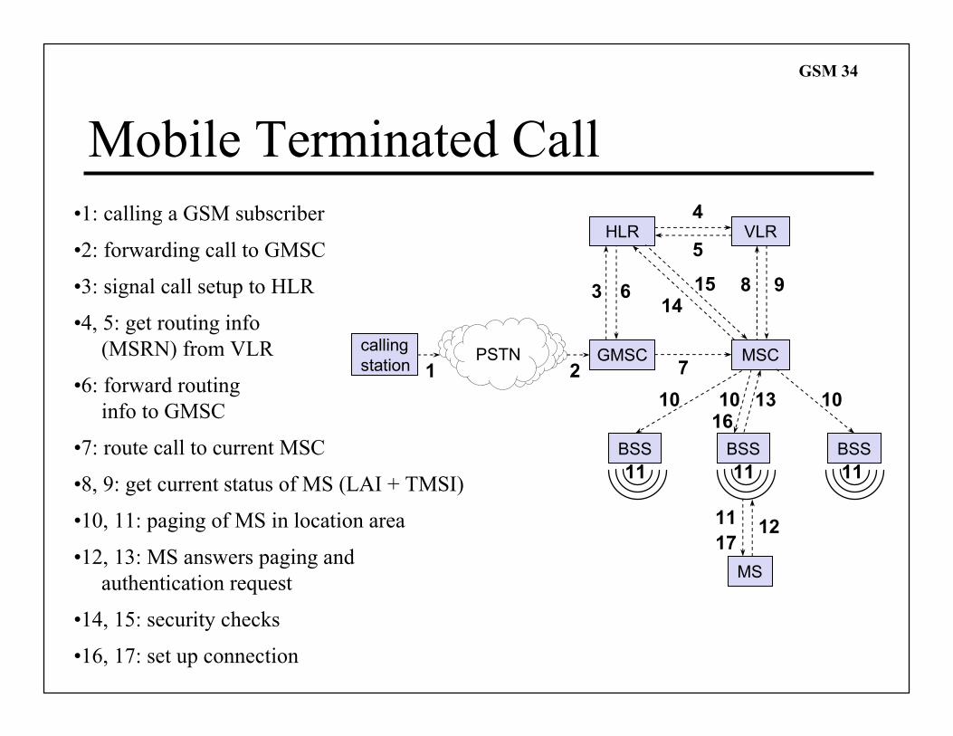
Mobile Terminated Call
PSTNcalling
stationGMSC
HLR VLR
BSSBSSBSS
MSC
MS
1 2
3
4
5
6
7
8 9
10
1112
131610 10
11 11 11
1415
17
•1: calling a GSM subscriber
•2: forwarding call to GMSC
•3: signal call setup to HLR
•4, 5: get routing info
(MSRN) from VLR
•6: forward routing
info to GMSC
•7: route call to current MSC
•8, 9: get current status of MS (LAI + TMSI)
•10, 11: paging of MS in location area
•12, 13: MS answers paging and
authentication request
•14, 15: security checks
•16, 17: set up connection
GSM 35
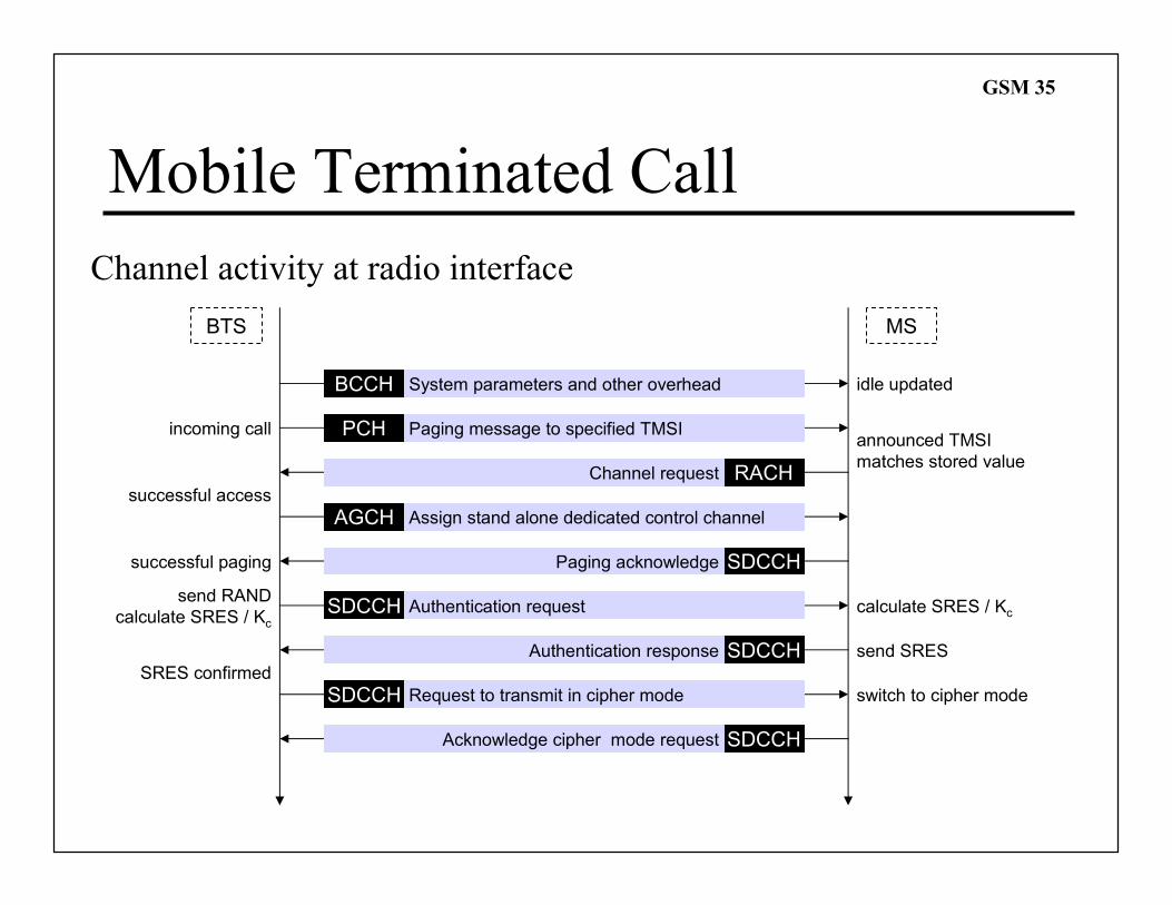
Mobile Terminated Call
Channel activity at radio interface
BTS MS
idle updated
incoming callannounced TMSI
matches stored value
send RAND
calculate SRES / Kc
send SRES
calculate SRES / Kc
BCCH
PCH
RACH
AGCH
SDCCH
SDCCH
SDCCH
SDCCH
successful access
SRES confirmed
SDCCH
switch to cipher mode
System parameters and other overhead
Assign stand alone dedicated control channel
Authentication request
Request to transmit in cipher mode
Paging message to specified TMSI
Channel request
Paging acknowledge
Authentication response
Acknowledge cipher mode request
successful paging
GSM 36
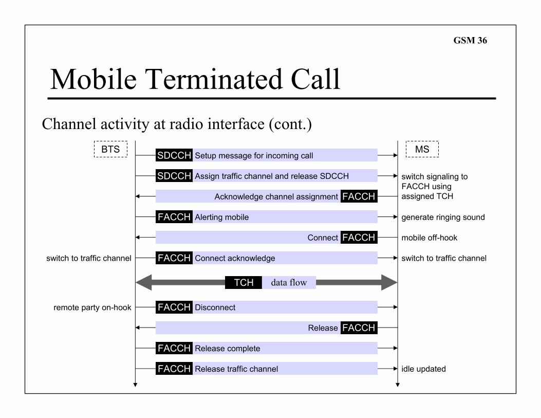
Mobile Terminated Call
Channel activity at radio interface (cont.)
BTS MS
switch signaling to
FACCH using
assigned TCH
generate ringing sound
mobile off-hook
switch to traffic channelswitch to traffic channel
TCH
remote party on-hook
SDCCH Setup message for incoming call
SDCCH Assign traffic channel and release SDCCH
FACCH Alerting mobile
FACCH Connect acknowledge
FACCH Disconnect
FACCH Release complete
FACCHAcknowledge channel assignment
FACCHConnect
FACCHRelease
FACCH Release traffic channel
data flow
idle updated
GSM 37
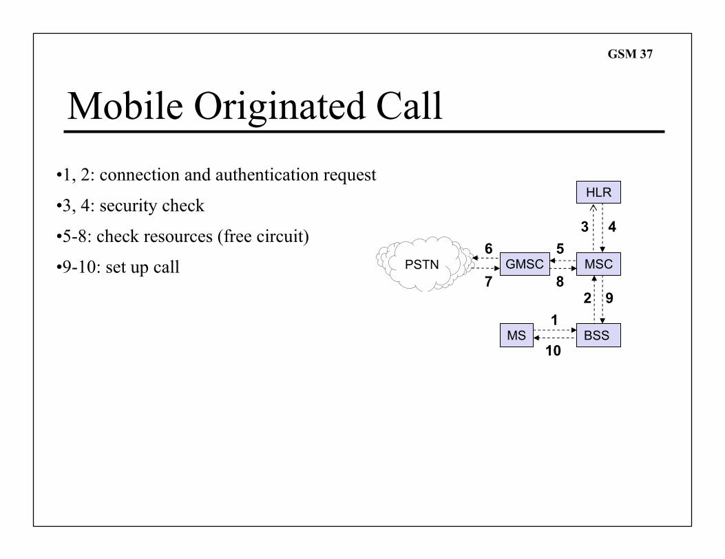
Mobile Originated Call
PSTN GMSC
HLR
BSS
MSC
MS1
2
6 5
3 4
9
10
7 8
•1, 2: connection and authentication request
•3, 4: security check
•5-8: check resources (free circuit)
•9-10: set up call
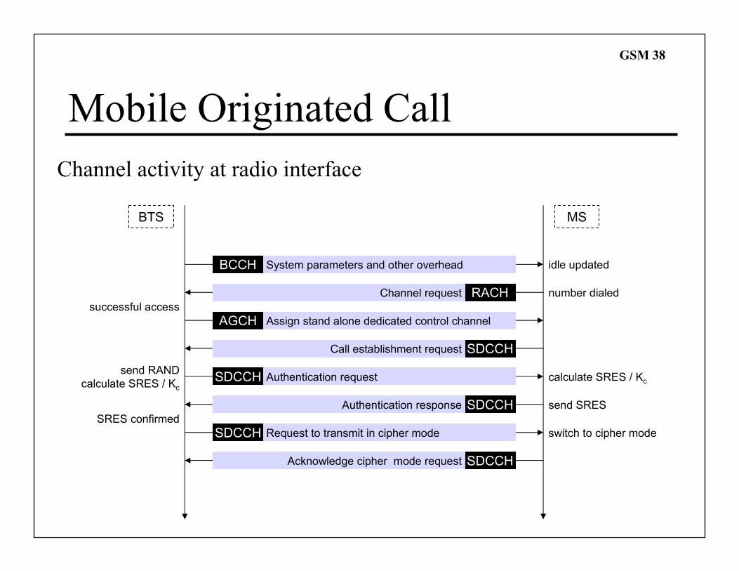
GSM 38
Mobile Originated Call
Channel activity at radio interface
BTS MS
idle updated
send RAND
calculate SRES / Kc
send SRES
calculate SRES / Kc
BCCH
RACH
AGCH
SDCCH
SDCCH
SDCCH
SDCCH
successful access
SRES confirmed
SDCCH
switch to cipher mode
System parameters and other overhead
Assign stand alone dedicated control channel
Authentication request
Request to transmit in cipher mode
Channel request
Call establishment request
Authentication response
Acknowledge cipher mode request
number dialed
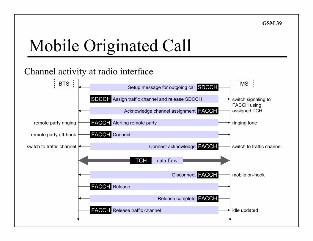
GSM 39
Mobile Originated Call
Channel activity at radio interface
BTS MS
switch signaling to
FACCH using
assigned TCH
switch to traffic channelswitch to traffic channel
TCH
SDCCHSetup message for outgoing call
SDCCH Assign traffic channel and release SDCCH
FACCH Alerting remote party
FACCHConnect acknowledge
FACCHDisconnect
FACCHRelease complete
FACCHAcknowledge channel assignment
FACCH Connect
FACCH Release
FACCH Release traffic channel
data flow
mobile on-hook
remote party off-hook
remote party ringing ringing tone
idle updated


![RSS-170 [Satellite Mobile Earth Stations]](https://img.pdfslide.net/doc/110x75/577d274a1a28ab4e1ea38a47/rss-170-satellite-mobile-earth-stations.jpg)