Embed Size (px)
Citation preview
High Quality Groundwater and Surface Water Monitoring Instrumentation(Page 1 of 2)
Cable Splice InstructionsModel 102
Coaxial Cable Splice Kit (#111058)
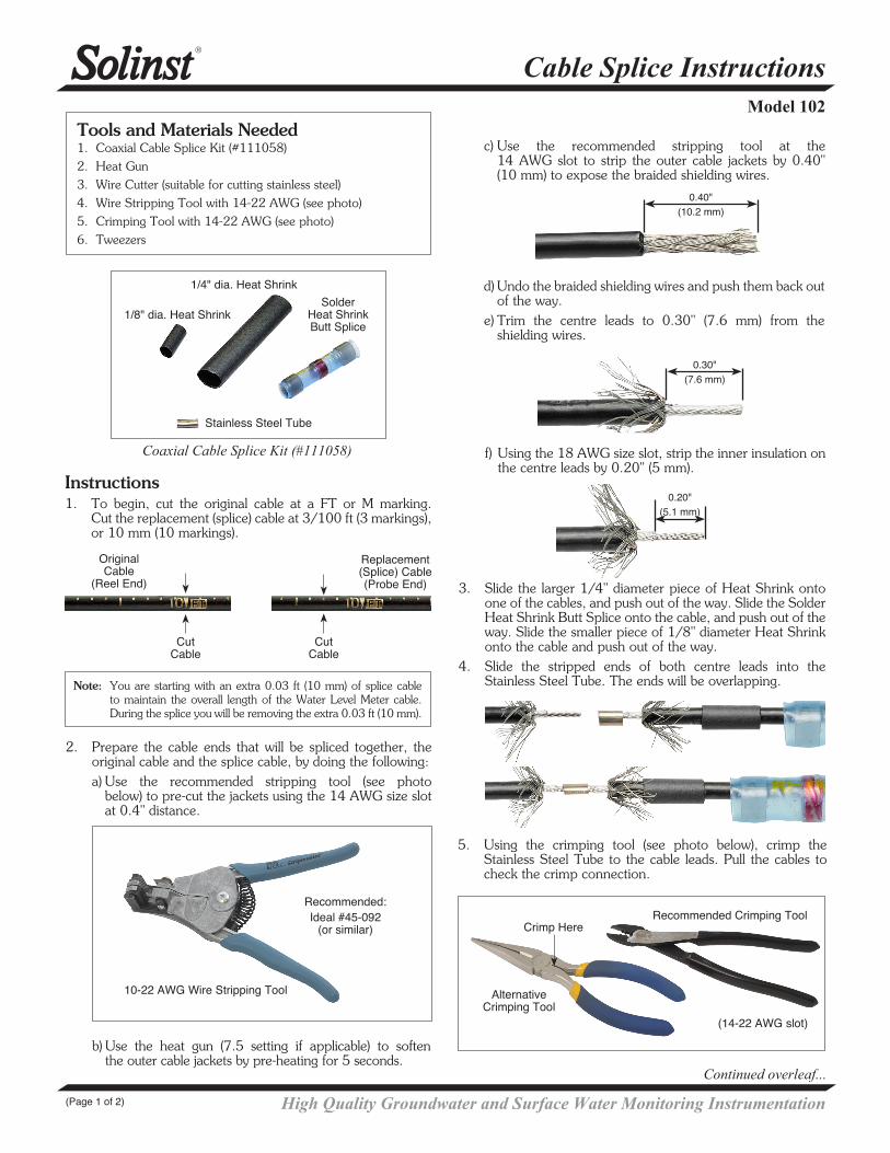
Tools and Materials Needed1. Coaxial Cable Splice Kit (#111058) 2. Heat Gun3. Wire Cutter (suitable for cutting stainless steel)4. Wire Stripping Tool with 14-22 AWG (see photo)5. Crimping Tool with 14-22 AWG (see photo)6. Tweezers
1/4" dia. Heat Shrink
Stainless Steel Tube
Solder Heat Shrink Butt Splice
Instructions1. To begin, cut the original cable at a FT or M marking.
Cut the replacement (splice) cable at 3/100 ft (3 markings), or 10 mm (10 markings).
Note: You are starting with an extra 0.03 ft (10 mm) of splice cable to maintain the overall length of the Water Level Meter cable. During the splice you will be removing the extra 0.03 ft (10 mm).
Continued overleaf...
d) Undo the braided shielding wires and push them back out of the way.
e) Trim the centre leads to 0.30" (7.6 mm) from the shielding wires.
f) Using the 18 AWG size slot, strip the inner insulation on the centre leads by 0.20" (5 mm).
3. Slide the larger 1/4" diameter piece of Heat Shrink onto one of the cables, and push out of the way. Slide the Solder Heat Shrink Butt Splice onto the cable, and push out of the way. Slide the smaller piece of 1/8" diameter Heat Shrink onto the cable and push out of the way.
4. Slide the stripped ends of both centre leads into the Stainless Steel Tube. The ends will be overlapping.
0.40" (10.2 mm)
0.30" (7.6 mm)
0.20" (5.1 mm)
2. Prepare the cable ends that will be spliced together, the original cable and the splice cable, by doing the following:
a) Use the recommended stripping tool (see photo below) to pre-cut the jackets using the 14 AWG size slot at 0.4" distance.
Original Cable
(Reel End)
Replacement (Splice) Cable (Probe End)
Cut Cable
Cut Cable
5. Using the crimping tool (see photo below), crimp the Stainless Steel Tube to the cable leads. Pull the cables to check the crimp connection.
10-22 AWG Wire Stripping Tool
Recommended:Ideal #45-092
(or similar)
b) Use the heat gun (7.5 setting if applicable) to soften the outer cable jackets by pre-heating for 5 seconds.
1/8" dia. Heat Shrink
Recommended Crimping Tool
Alternative Crimping Tool
(14-22 AWG slot)
c) Use the recommended stripping tool at the 14 AWG slot to strip the outer cable jackets by 0.40" (10 mm) to expose the braided shielding wires.
Crimp Here
Printed in Canada August 13, 2014(#111081)(Page 2 of 2)
For further information contact: Solinst Canada Ltd.Fax: +1 (905) 873-1992; (800) 516-9081 Tel: +1 (905) 873-2255; (800) 661-2023
35 Todd Road, Georgetown, Ontario Canada L7G 4R8Web Site: www.solinst.com E-mail: [email protected]
®Solinst is a registered trademark of Solinst Canada Ltd.
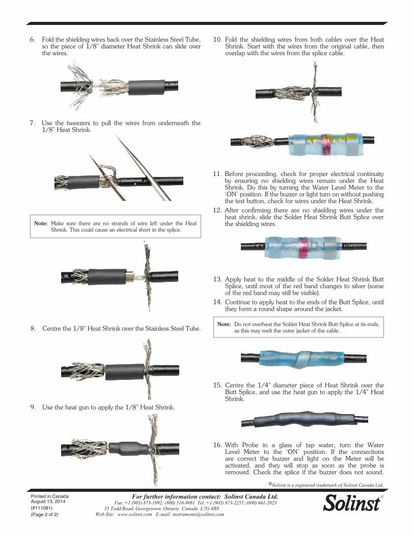
11. Before proceeding, check for proper electrical continuity by ensuring no shielding wires remain under the Heat Shrink. Do this by turning the Water Level Meter to the ‘ON’ position. If the buzzer or light turn on without pushing the test button, check for wires under the Heat Shrink.
12. After confirming there are no shielding wires under the heat shrink, slide the Solder Heat Shrink Butt Splice over the shielding wires.
Note: Do not overheat the Solder Heat Shrink Butt Splice at its ends, as this may melt the outer jacket of the cable.
Note: Make sure there are no strands of wire left under the Heat Shrink. This could cause an electrical short in the splice.
8. Centre the 1/8" Heat Shrink over the Stainless Steel Tube.
9. Use the heat gun to apply the 1/8" Heat Shrink.
10. Fold the shielding wires from both cables over the Heat Shrink. Start with the wires from the original cable, then overlap with the wires from the splice cable.
13. Apply heat to the middle of the Solder Heat Shrink Butt Splice, until most of the red band changes to silver (some of the red band may still be visible).
14. Continue to apply heat to the ends of the Butt Splice, until they form a round shape around the jacket.
15. Centre the 1/4" diameter piece of Heat Shrink over the Butt Splice, and use the heat gun to apply the 1/4" Heat Shrink.
7. Use the tweezers to pull the wires from underneath the 1/8" Heat Shrink.
6. Fold the shielding wires back over the Stainless Steel Tube, so the piece of 1/8" diameter Heat Shrink can slide over the wires.
16. With Probe in a glass of tap water, turn the Water Level Meter to the ‘ON’ position. If the connections are correct the buzzer and light on the Meter will be activated, and they will stop as soon as the probe is removed. Check the splice if the buzzer does not sound.