Embed Size (px)
Citation preview

CAT. NO. 46500-88
PORTABLE TURBIDIMETERModel 2100P
Instrument and Procedure Manual
© Hach Company, 1991-2004, 2008. 4/08 9edAll rights reserved. Printed in China.

2
3
TABLE OF CONTENTS
TABLE OF CONTENTS ................................................................ 3CERTIFICATION ............................................................................ 5SAFETY PRECAUTIONS ............................................................. 7SPECIFICATIONS .......................................................................... 9
OPERATION ....................................................................................11
SECTION 1 DESCRIPTION....................................................... 131.1 General Description....................................................................... 131.2 Accessories .................................................................................... 141.3 Principle of Operation ................................................................... 141.4 Preparation for Use........................................................................ 15
1.4.1 Unpacking ............................................................................ 151.4.2 Battery Installation............................................................... 161.4.3 Using the Battery Eliminator and Rechargeable Batteries... 161.4.4 Calibration............................................................................ 16
SECTION 2 TURBIDITY MEASUREMENT ........................ 192.1 Operating Controls and Indicators................................................. 192.2 Turbidity Measurement ................................................................. 19
2.2.1 Turbidity Measurement Procedure....................................... 202.2.2 Measurement Notes ............................................................. 22
2.3 Measurement Techniques .............................................................. 222.3.1 Cleaning Sample Cells ......................................................... 232.3.2 Oiling the Sample Cell......................................................... 232.3.3 Orienting Sample Cells ........................................................ 242.3.4 Matching multiple sample cells ........................................... 262.3.5 Removing Bubbles (Degassing) .......................................... 282.3.6 Measuring Overrange Samples ............................................ 312.3.7 Condensation (fogging) ....................................................... 312.3.8 Calibration............................................................................ 312.3.9 Representative Sampling ..................................................... 32
4
TABLE OF CONTENTS, continued
SECTION 3 OPERATION .......................................................... 333.1 Operational Controls and Indicators ............................................. 333.2 Using the Read Key ...................................................................... 35
3.2.1 Continuous Reading ............................................................ 353.3 Using the Signal Averaging Key .................................................. 353.4 Using the Range Selection Key .................................................... 363.5 Restoring the Default Calibration ................................................. 363.6 Calibration .................................................................................... 37
3.6.1 StablCal Stabilized Formazin Standards ............................. 373.6.2 Formazin Primary Standards ............................................... 403.6.3 Calibrating the Turbidimeter ............................................... 443.6.4 Using Gelex® Secondary Turbidity Standards.................... 54
MAINTENANCE ............................................................................ 57
SECTION 4 MAINTENANCE ................................................... 594.1 Cleaning........................................................................................ 594.2 Battery Replacement..................................................................... 594.3 Lamp Replacement ....................................................................... 59
SECTION 5 TROUBLESHOOTING ....................................... 675.1 Using the Diagnostic Functions Key ............................................ 67
5.1.1 Basic Diagnostic Codes....................................................... 675.2 The Diagnostic Procedure............................................................. 685.3 Other Instrument Diagnostics ....................................................... 70
5.3.1 Display Test......................................................................... 705.4 Error Messages ............................................................................. 70
5.4.1 Flashing Numeric Display................................................... 705.4.2 E Messages.......................................................................... 705.4.3 CAL? ................................................................................... 70
GENERAL INFORMATION....................................................... 73Replacement Parts & Accessories .............................................. 74HOW TO ORDER ......................................................................... 76REPAIR SERVICE........................................................................ 77WARRANTY................................................................................... 78
5
CERTIFICATION
Hach Company certifies this instrument was tested thoroughly, inspected and found to meet its published specifications when it was shipped from the factory.The Model 2100P Portable Turbidimeter has been tested and is certified as indicated to the following instrumentation standards:
Product SafetyBattery/Eliminator Power Supply Only:120 Vac, 60 Hz, UL Listed & CSA Certified, Class 2230 Vac, 50 Hz, VDE Approved, GS & CE marked
Immunity2100P Turbidimeter Tested with external Battery/Eliminator Power Supply:EN 50082-1 (European Generic Immunity Standard) per 89/336/EEC EMC: Supporting test records with Dash Straus and Goodhue, Inc. (now Intertek Testing Services), certified compliance by Hach Company.Standards include:IEC 801-2 Electro-Static DischargeIEC 801-3 Radiated RF Electro-Magnetic FieldsIEC 801-4 Electrical Fast Transients/Burst
Emissions2100P Turbidimeter Tested with external Battery/Eliminator Power Supply:EN 50081-1 (Emissions) per 89/336/EEC EMC: Supporting test records by Amador Corp. (now TUV Product Services), certified compliance by Hach CompanyStandards include:EN 55022 (CISPR 22) Emissions, Class B LimitsCanadian Radio Interference-Causing Regulation, Chapter 1374, Class A: Supporting test records by Amador Corp. (now TUV Product Services), certified compliance by Hach CompanyThis Class A digital apparatus meets all requirements of the Canadian Interference-Causing Equipment Regulations.
Cet appareil numérique de la classe A respecte toutes les exigences du Règlement sur le matériel brouilleur du Canada.
6
CERTIFICATION, continued
FCC Part 15, Class “A” Limits: Supporting test records by Amador Corp. (now TUV Product Services), certified compliance by Hach Company.This device complies with Part 15 of the FCC Rules. Operation is subject to the following two conditions:1. this device may not cause harmful interference, and2. this device must accept any interference received, including
interference that may cause undesired operation.Changes or modifications to this unit not expressly approved by the party responsible for compliance could void the user’s authority to operate the equipment.This equipment has been tested and found to comply with the limits for a Class A digital device, pursuant to Part 15 of the FCC Rules. These limits are designed to provide reasonable protection against harmful interference when the equipment is operated in a commercial environment. This equipment generates, uses, and can radiate radio frequency energy and, if not installed and used in accordance with the instruction manual, may cause harmful interference to radio communications. Operation of this equipment in a residential area may cause harmful interference in which case the user will be required to correct the interference at his own expense.The following techniques of reducing interference problems are applied easily:1. Disconnect the battery eliminator from it’s power source and
from the 2100P Portable Turbidimeter to verify if it is the source of the interference
2. If the battery eliminator for the 2100P Portable Turbidimeter is plugged into the same outlet as the device with which it is interfering, try another outlet.
3. Move the 2100P Portable Turbidimeter away from the device receiving the interference.
4. Reposition the receiving antenna for the device receiving the interference.
5. Try combinations of the above.
7
SAFETY PRECAUTIONS
Please read this entire manual before unpacking, setting up, or operating this instrument. Pay particular attention to all danger and caution statements. Failure to do so could result in serious injury to the operator or damage to the equipment.To ensure the protection provided by this equipment is not impaired, do not use or install this equipment in any manner other than that which is specified in this manual.
Use of Hazard InformationIf multiple hazards exist, this manual will use the signal word (Danger, Caution, Note) corresponding to the greatest hazard.DANGERIndicates a potentially or imminently hazardous situation which, if not avoided, could result in death or serious injury.
CAUTIONIndicates a potentially hazardous situation that may result in minor or moderate injury.
NOTEInformation that requires special emphasis.
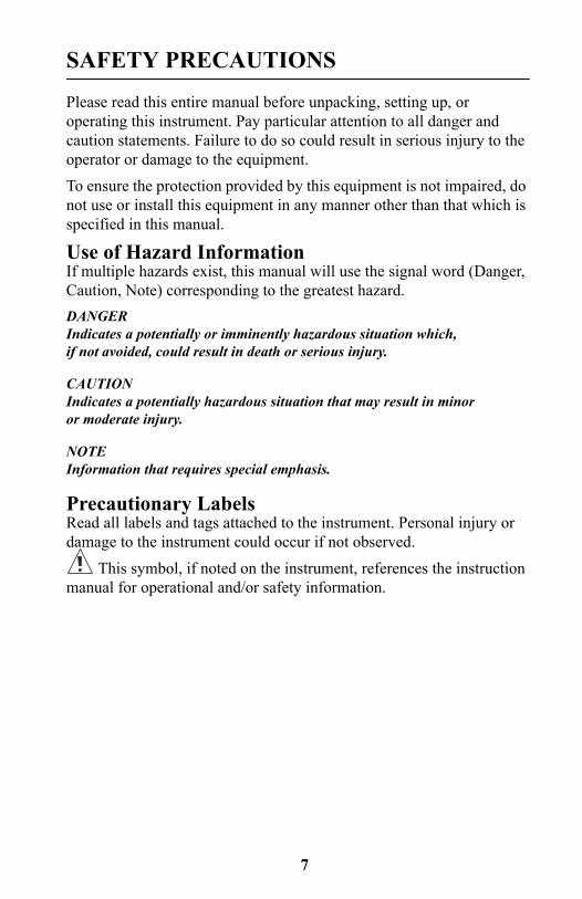
Precautionary LabelsRead all labels and tags attached to the instrument. Personal injury or damage to the instrument could occur if not observed.
This symbol, if noted on the instrument, references the instruction manual for operational and/or safety information.

8
9
SPECIFICATIONS
Specifications subject to change without notice.Operating specifications applicable at 25 °C unless noted.Program software copyrighted by Hach Company, 1991.
Measurement Method: Ratio Nephelometric signal (90°) scatter light ratio to transmitted light
Range: 0-1000 NTU with automatic decimal point placement or manual range selection of 0-9.99, 0-99.9 and 0-1000 NTU
Accuracy: ± 2% of reading plus stray light from 0-1000 NTU
Resolution: 0.01 NTU on lowest range
Repeatability: ±1% of reading or 0.01 NTU, whichever is greater (with Gelex standards)
Response Time: 6 seconds for full step change without signal averaging in constant reading mode
Stray Light: <0.02 NTU
Standardization: StablCal® Stabilized Formazin primary standards or Formazin primary standards
Secondary Standards: Gelex® Secondary Standards
Display: Four-digit liquid crystal; 10.16 mm (0.4 in) high digits with custom icons
Light Source: Tungsten filament lamp; lamp life typically greater than 100,000 readings
Detectors: Silicon photovoltaic
Signal Averaging: Operator selectable on or off
Sample Cells: (Height X width) 60.0 X 25 mm (2.36 X 1 in) Borosilicate glass with screw caps, marking band and fill line
Sample Required: 15 mL (0.5 oz.)
Storage Temperature: -40 to 60 °C (-40 to 140 °F) (instrument only)
10
SPECIFICATIONS, continued
Operating Temperature: 0 to 50 °C (32 to 122 °F) (instrument only)
Operating Humidity Range: 0 to 90% RH noncondensing at 30 °C; 0 to 80% RH noncondensing at 40 °C; 0 to 70% RH noncondensing at 50 °C
Power Requirements: Four AA Alkaline cells or optional battery eliminator
Battery Life: Typically 300 tests with signal average mode off; 180 tests with signal average mode onBattery Eliminator (optional):
For 120 V eliminator: CSA and UL approved for 120 VAC ±10%, 60 Hz, 6 V at 800 mA DC output
For 230 V eliminator: CE (VDE) approval pending for 230 VAC ±10%, 50 Hz, 6 V at 900 mA DC output
Enclosure: High impact ABS plastic
Dimensions: 22.2 X 9.5 X 7.9 cm (8.75 X 3.75 X 3.12 in)
Instrument Weight: 520 kg (1 lb 2.5 oz)
Shipping Weight: 3.1 kg (6 lbs 8.5 oz)
DANGERHandling chemical samples, standards, and reagents can be dangerous. Review the necessary Material Safety Data Sheets and become familiar with all safety procedures before handling any chemicals.
DANGERLa manipulation des échantillons chimiques, étalons et réactifs peut être dangereuse. Lire les Fiches de Données de Sécurité des Produits (FDSP) et se familiariser avec toutes les procédures de sécurité avant de manipuler tous les produits chimiques.
PELIGROLa manipulación de muestras químicas, estándares y reactivos puede ser peligrosa. Revise las fichas de seguridad de materiales y familiarícese con los procedimientos de seguridad antes de manipular productos químicos.
GEFAHRDas Arbeiten mit chemischen Proben, Standards und Reagenzien ist mit Gefahren verbunden. Es wird dem Benutzer dieser Produkte empfohlen, sich vor der Arbeit mit sicheren Verfahrensweisen und dem richtigen Gebrauch der Chemikalien vertraut zu machen und alle entsprechenden Materialsicherheitsdatenblätter aufmerksam zu lesen.
PERIGOA manipulação de amostras, padrões e reagentes químicos pode ser perigosa. Reveja a folha dos dados de segurança do material e familiarize-se com todos os procedimentos de segurança antes de manipular quaisquer produtos químicos.
PERICOLOLa manipolazione di campioni, standard e reattivi chimici può essere pericolosa. La preghiamo di prendere conoscenza delle Schede Techniche necessarie legate alla Sicurezza dei Materiali e di abituarsi con tutte le procedure di sicurezza prima di manipolare ogni prodotto chimico.
11
OPERATION

12
13
SECTION 1 DESCRIPTION
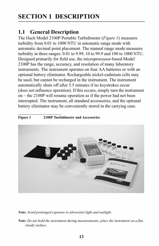
1.1 General DescriptionThe Hach Model 2100P Portable Turbidimeter (Figure 1) measures turbidity from 0.01 to 1000 NTU in automatic range mode with automatic decimal point placement. The manual range mode measures turbidity in three ranges: 0.01 to 9.99, 10 to 99.9 and 100 to 1000 NTU. Designed primarily for field use, the microprocessor-based Model 2100P has the range, accuracy, and resolution of many laboratory instruments. The instrument operates on four AA batteries or with an optional battery eliminator. Rechargeable nickel-cadmium cells may be used, but cannot be recharged in the instrument. The instrument automatically shuts off after 5.5 minutes if no keystrokes occur (does not influence operation). If this occurs, simply turn the instrument on – the 2100P will resume operation as if the power had not been interrupted. The instrument, all standard accessories, and the optional battery eliminator may be conveniently stored in the carrying case.
Figure 1 2100P Turbidimeter and Accessories
Note: Avoid prolonged exposure to ultraviolet light and sunlight.
Note: Do not hold the instrument during measurements; place the instrument on a flat, steady surface.
14
SECTION 1, continued
1.2 AccessoriesAccessories supplied with the turbidimeter include nine sample cells; three Gelex® Secondary Standards (included with 4650000 only); one sealed vial each of: <0.1-NTU, 20-NTU, 100-NTU, and 800-NTU StablCal® Stabilized Formazin Standards; 4 AA alkaline batteries; 15 mL of silicone oil; oiling cloth; carrying case; instrument manual; and quick reference card.
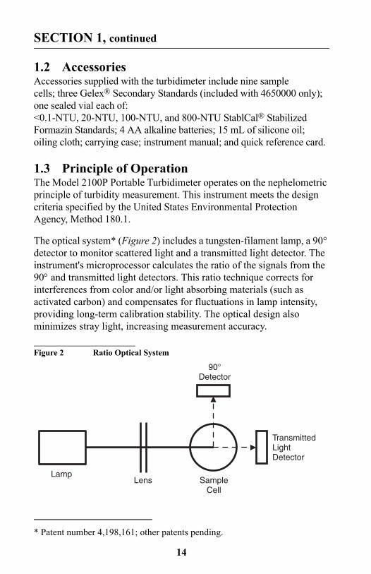
1.3 Principle of OperationThe Model 2100P Portable Turbidimeter operates on the nephelometric principle of turbidity measurement. This instrument meets the design criteria specified by the United States Environmental Protection Agency, Method 180.1.
The optical system* (Figure 2) includes a tungsten-filament lamp, a 90° detector to monitor scattered light and a transmitted light detector. The instrument's microprocessor calculates the ratio of the signals from the 90° and transmitted light detectors. This ratio technique corrects for interferences from color and/or light absorbing materials (such as activated carbon) and compensates for fluctuations in lamp intensity, providing long-term calibration stability. The optical design also minimizes stray light, increasing measurement accuracy.
Figure 2 Ratio Optical System
* Patent number 4,198,161; other patents pending.
Lamp
TransmittedLightDetector
90°Detector
SampleCell
Lens
15
SECTION 1, continued
1.4 Preparation for Use
1.4.1 UnpackingRemove the instrument and accessories from the shipping box and inspect them for damage that may have occurred due to rough handling or extreme weather conditions. Verify the following are present:
• Model 2100P Portable Turbidimeter
• Instrument Manual (with quick reference card)
• Set of StablCal Primary Standards in sealed vials, one each of:<0.1 NTU*20 NTU100 NTU800 NTU
• Standardization Kit containing Gelex Secondary Standards (0-10, 0-100 and 0-1000 ranges) (included with 4650000 only) plus nine sample cells with caps.
• Silicone Oil, 15-mL (0.5 oz) dropping bottle
• Oiling Cloth
• Carrying Case
• Four AA alkaline batteries
If any of the items are missing or damaged, please contact the Customer Service Department, Hach Company, Loveland, Colorado. The toll-free number in the United States is 800-227-4224. International customers should contact the Hach office or authorized distributor serving your area. Refer to REPAIR SERVICE on page 77. Please do not return the instrument without prior authorization from Hach.
* Used in place of the dilution water standard when performing acalibration.
16
SECTION 1, continued
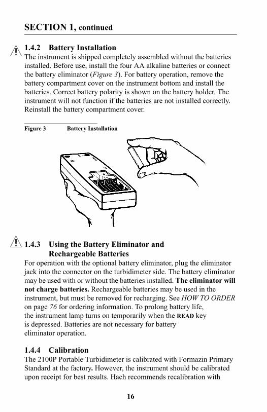
1.4.2 Battery InstallationThe instrument is shipped completely assembled without the batteries installed. Before use, install the four AA alkaline batteries or connect the battery eliminator (Figure 3). For battery operation, remove the battery compartment cover on the instrument bottom and install the batteries. Correct battery polarity is shown on the battery holder. The instrument will not function if the batteries are not installed correctly. Reinstall the battery compartment cover.
Figure 3 Battery Installation
1.4.3 Using the Battery Eliminator and Rechargeable Batteries
For operation with the optional battery eliminator, plug the eliminator jack into the connector on the turbidimeter side. The battery eliminator may be used with or without the batteries installed. The eliminator will not charge batteries. Rechargeable batteries may be used in the instrument, but must be removed for recharging. See HOW TO ORDER on page 76 for ordering information. To prolong battery life, the instrument lamp turns on temporarily when the READ key is depressed. Batteries are not necessary for battery eliminator operation.
1.4.4 CalibrationThe 2100P Portable Turbidimeter is calibrated with Formazin Primary Standard at the factory. However, the instrument should be calibrated upon receipt for best results. Hach recommends recalibration with

17
SECTION 1, continued
formazin once every three months, or more often as experience dictates. The Gelex Secondary Standards supplied with the instrument (included with 4650000 only) are labelled with general ranges for application, but must be assigned values before use from formazin calibration. See Section 3.6 on page 37 for calibration instructions.

18
19
SECTION 2 TURBIDITY MEASUREMENT
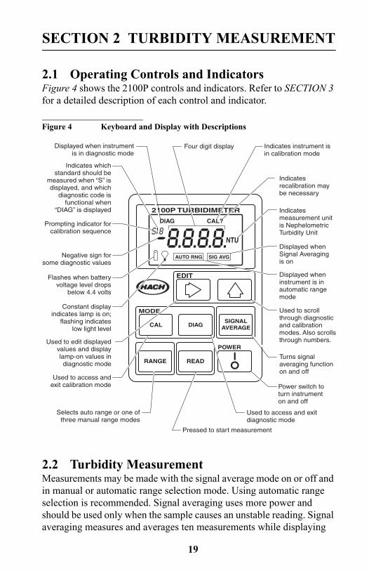
2.1 Operating Controls and IndicatorsFigure 4 shows the 2100P controls and indicators. Refer to SECTION 3 for a detailed description of each control and indicator.
Figure 4 Keyboard and Display with Descriptions
2.2 Turbidity MeasurementMeasurements may be made with the signal average mode on or off and in manual or automatic range selection mode. Using automatic range selection is recommended. Signal averaging uses more power and should be used only when the sample causes an unstable reading. Signal averaging measures and averages ten measurements while displaying
2100P TURBIDIMETER
EDIT
DIAG
NTU
CAL?
POWER
MODE
CAL DIAGSIGNAL
AVERAGE
AUTO RNG SIG AVG
RANGE READ
Indicates instrument isin calibration mode
Indicatesrecalibration maybe necessary
Indicatesmeasurement unitis NephelometricTurbidity Unit
Displayed whenSignal Averagingis on
Displayed wheninstrument is inautomatic rangemode
Used to scrollthrough diagnosticand calibrationmodes. Also scrollsthrough numbers.
Turns signalaveraging functionon and off
Power switch toturn instrumenton and off
Used to access andexit calibration mode
Used to edit displayedvalues and displaylamp-on values indiagnostic mode
Constant displayindicates lamp is on;
flashing indicateslow light level
Flashes when batteryvoltage level drops
below 4.4 volts
Negative sign forsome diagnostic values
Prompting indicator forcalibration sequence
Displayed when instrumentis in diagnostic mode
Four digit display
Indicates whichstandard should be
measured when “S” isdisplayed, and which
diagnostic code isfunctional when
“DIAG” is displayed
Used to access and exitdiagnostic mode
Pressed to start measurement
Selects auto range or one ofthree manual range modes
20
SECTION 2, continued
intermediate results. The initial value is displayed after about 11 seconds and the display is updated every 1.2 seconds until all ten measurements are taken (about 20 seconds). After this, the lamp turns off, but the final measured turbidity value continues to be displayed until another key is pressed.
When not in signal average mode, the final value is displayed after about 13 seconds.
Accurate turbidity measurement depends on good measurement technique by the analyst, such as using clean sample cells in good condition and removing air bubbles (degassing). Refer to Section 2.3 on page 22 for a detailed discussion of measurement techniques.
2.2.1 Turbidity Measurement Procedure
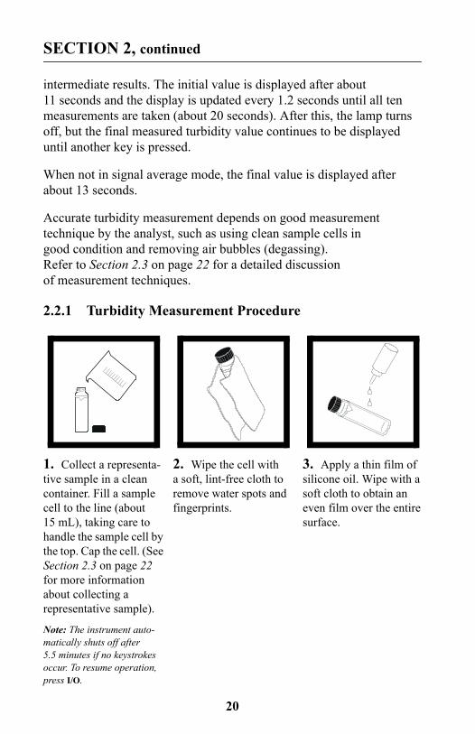
1. Collect a representa-tive sample in a clean container. Fill a sample cell to the line (about 15 mL), taking care to handle the sample cell by the top. Cap the cell. (See Section 2.3 on page 22 for more information about collecting a representative sample).
Note: The instrument auto-matically shuts off after 5.5 minutes if no keystrokes occur. To resume operation, press I/O.
2. Wipe the cell with a soft, lint-free cloth to remove water spots and fingerprints.
3. Apply a thin film of silicone oil. Wipe with a soft cloth to obtain an even film over the entire surface.
21
SECTION 2, continued
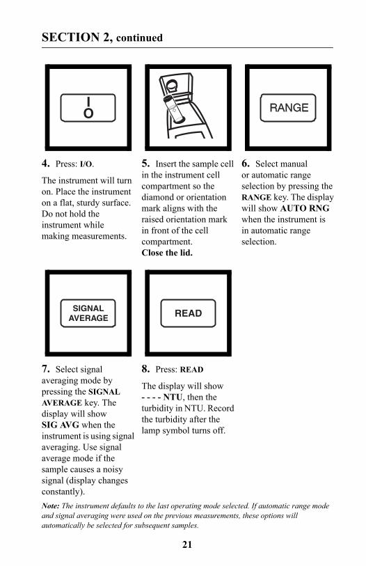
4. Press: I/O.
The instrument will turn on. Place the instrument on a flat, sturdy surface. Do not hold the instrument while making measurements.
5. Insert the sample cell in the instrument cell compartment so the diamond or orientation mark aligns with the raised orientation mark in front of the cell compartment. Close the lid.
6. Select manual or automatic range selection by pressing the RANGE key. The display will show AUTO RNG when the instrument is in automatic range selection.
7. Select signal averaging mode by pressing the SIGNAL AVERAGE key. The display will show SIG AVG when the instrument is using signal averaging. Use signal average mode if the sample causes a noisy signal (display changes constantly).
8. Press: READ
The display will show - - - - NTU, then the turbidity in NTU. Record the turbidity after the lamp symbol turns off.
Note: The instrument defaults to the last operating mode selected. If automatic range mode and signal averaging were used on the previous measurements, these options will automatically be selected for subsequent samples.
IO
SIGNALAVERAGE READ
22
SECTION 2, continued
2.2.2 Measurement Notes
• Always cap the sample cell to prevent spillage of sample into the instrument.
• When taking a reading, place the instrument on a level, stationary surface. It should not be held in the hand during measurement.
• Always close the sample compartment lid during measurement and storage.
• Always use clean sample cells in good condition. Dirty, scratched, or damaged cells can cause inaccurate readings.
• Do not leave a sample cell in the cell compartment for extended periods of time. This may compress the spring in the cell holder.
• Remove sample cell and batteries from instrument if the instrument is stored for extended time period (more than a month).
• Avoid operating in direct sunlight.
• Make certain cold samples do not “fog” the sample cell.
• Avoid settling of sample prior to measurement.
• Keep sample compartment lid closed to prevent dust and dirt from entering.
2.3 Measurement TechniquesProper measurement techniques are important in minimizing the effects of instrument variation, stray light and air bubbles. Regardless of the instrument used, measurements are more accurate, precise and repeatable if the analyst pays close attention to proper measurement techniques.
Measure samples immediately to prevent temperature changes and settling. Avoid sample dilution when possible. Particles suspended in the original sample may dissolve or otherwise change characteristics when the sample temperature changes or when the sample is diluted, resulting in a non-representative sample measurement.
23
SECTION 2, continued
2.3.1 Cleaning Sample CellsCells must be extremely clean and free from significant scratches. The glass used to make cells is easily scratched – manufacturing cells free of minor scratches and other imperfections is difficult. However, minor imperfections are effectively masked by applying silicone oil as outlined in Section 2.3.2.
Clean the inside and outside of the cells by washing with laboratory detergent. Follow with multiple rinses of distilled or deionized water. Allow cells to air dry. Handle cells only by the top to minimize dirt, scratches and fingerprints in the light path.
2.3.2 Oiling the Sample CellApplying a thin coat of silicone oil will mask minor imperfections and scratches which may contribute to turbidity or stray light. Use silicone oil equivalent to Hach Cat. No. 1269-36. This silicone oil has the same refractive index as glass. When applied in a thin, uniform coat, the oil fills in and masks minor scratches and other imperfections in the glass. Apply the oil uniformly by wiping with a soft, lint-free cloth. Avoid application of excess oil. Applying excess oil may retain dirt and contaminate the instrument's cell compartment.
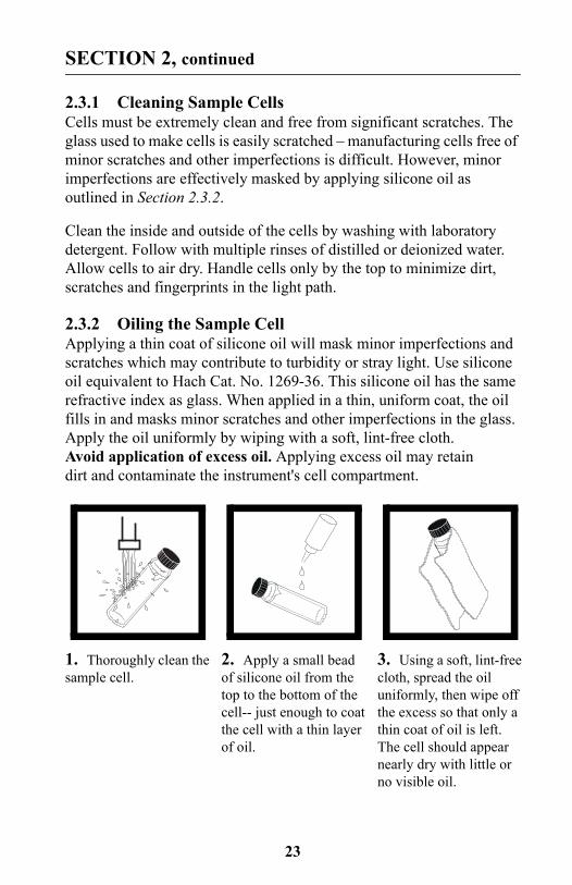
1. Thoroughly clean the sample cell.
2. Apply a small bead of silicone oil from the top to the bottom of the cell-- just enough to coat the cell with a thin layer of oil.
3. Using a soft, lint-free cloth, spread the oil uniformly, then wipe off the excess so that only a thin coat of oil is left. The cell should appear nearly dry with little or no visible oil.
24
SECTION 2, continued
Note: Soft, lint-free cloth (velvet) works well for oiling. Store the oiling cloth with the sample cells and keep it free of dirt. After a few applications of oil, the cloth will contain enough residual oil that simply wiping the cell with the oiled cloth will provide a sufficient oil coat on the sample cell. Periodically, add a small amount of oil to the sample cell surface to replenish the oil in the cloth.
Note: Only a thin coat of oil on the sample cells is necessary. Avoid using excessive amounts of oil.
2.3.3 Orienting Sample Cells
Note: When orienting and matching cells, it may be more efficient to use the continuous reading mode. The instrument performs continuous readings if the READ key is pressed and held. As long as the key is held, the lamp remains on and the display is updated every 1.2 seconds. The instrument cannot be used in continuous read mode if the Signal Averaging mode is on.
Precise measurements for very low turbidity samples require using a single cell for all measurements or optically matching the cells. Using one cell provides the best precision and repeatability. When one cell is used, an orientation mark (other than the factory-placed diamond) can be placed on the cell so it’s inserted into the instrument with the same orientation each time.
2.3.3.1 Orienting a single cellWhen using a single cell, make an index or orientation mark on the cell as follows:
25
SECTION 2, continued
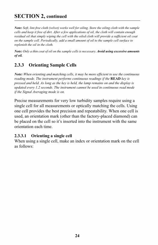
1. Fill the clean sample cell to the line with high quality water (< 0.5 NTU). Cap and wipe with lint-free cloth. Apply silicone oil. See Section 3.6.2.2 on page 40 for more information about high quality water.
2. Press: I/O to turn the instrument on.
3. Insert the sample cell into the sample compartment. Close the cover.
4. Press: READ
Record the cell's position in the cell compartment and the displayed reading.
Note: This procedure may be easier if the user holds the READ key through the whole process. This allows the lamp to remain on and make continuous readings.
5. Remove the cell, rotate it slightly and reinsert it into the cell compartment. Close the cover, then press READ. Record the cell's position and the displayed reading.
6. Repeat step 5 until the lowest reading is displayed. Place an orientation mark on the cell's marking band near the top of the cell so the cell can be consistently inserted in the position that yields the lowest reading. When using the cell, always place it in the instrument so the orientation mark aligns with the raised mark on the instrument.
IO
READ
26
SECTION 2, continued
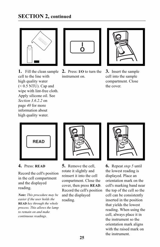
2.3.4 Matching multiple sample cellsPrecise measurements of very low turbidity samples require the cells be optically matched or a single cell be used for all measurements. If more than one cell is used, follow this procedure to match (index) the cells:
1. Clean and oil the sample cells as instructed in Section 2.3.1 on page 23 and Section 2.3.2 on page 23.
2. Fill the clean sample cells to the line with the same sample.
3. Press: I/O to turn the instrument on.
4. Insert the first sample cell into the sample compartment and close the cover.
5. Press: READ
Record the cell's position in the cell compartment and the displayed reading. Place an orientation mark on the cell’s marking band.
Note: This procedure may be easier if the user holds the READ key through the whole process. This allows the lamp to remain on and make con-tinuous readings.
6. Insert the second sample cell into the cell compartment and close the cover.
IO
READ
27
SECTION 2, continued
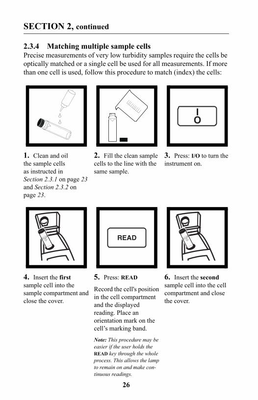
7. Press: READ
Record the cell’s position in the cell compartment and the displayed reading.
8. Remove the cell, rotate it slightly and reinsert into the cell compartment. Close the cover, then press READ again. Record the cell’s position and the displayed reading.
9. Repeat step 8 until the value displayed for the second cell is within 0.01 NTU (or 1%) of the value obtained for the first cell. Place an orientation mark on the second cell's marking band so it is consistently inserted in this position.
Note: Due to variability in glass, it may not be possible to match all cells.
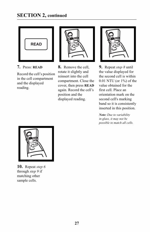
10. Repeat step 6 through step 9 if matching other sample cells.
READ
28
SECTION 2, continued
2.3.5 Removing Bubbles (Degassing)Before measurement, removing air and other trapped gasses from the sample is strongly recommended, even if bubbles are not visible. Four degassing methods are commonly used:
1. applying a partial vacuum
2. adding a surfactant
3. using an ultrasonic bath
4. heating the sample
In some cases, more than one method may be necessary for effective bubble removal. For example, use of both a surfactant and ultrasonic bath may be necessary for some severe conditions. Use care with these techniques. If misused, sample turbidity can be altered.
Removing air bubbles by letting the sample stand for a period of time is not recommended. Particulates that cause turbidity may settle and the sample temperature may change. Both conditions may alter sample turbidity, resulting in measurements not representative of the original turbidity.
2.3.5.1 Application of vacuumApply a vacuum with any convenient, clean, oil-free vacuum source. The vacuum lowers the atmospheric pressure, allowing trapped bubbles to escape into the air above the sample. Vacuum works well with non-viscous samples (such as water) that don’t contain volatile components. Applying vacuum to viscous, volatile-containing samples (paint resins) may cause the volatile components to come out of solution and aggravate the bubble problem.
To apply a vacuum, use a sample degassing kit equivalent to Cat No. 43975-00 (Degassing Kit) or 43975-10 (Degassing and Filtration Kit). These kits contain a syringe and rubber stopper for vacuum degassing. An electric or hand-operated pump equivalent to Cat No. 14283-00 or 14697-00, respectively, may also be used.
29
SECTION 2, continued
2.3.5.2 Adding a surfactantSurfactants should be limited to severe problems when other degassing methods are ineffective. Surfactants change the surface tension of the water, which releases trapped gases. Hach recommends a surfactant such as Triton X-100 or the equivalent, Hach Cat No. 14096-37. Put one drop of Triton X-100 in the sample cell before adding sample.
Note: Any turbidity contributed by surfactant addition is negligible.
This technique is very effective when the water is super-saturated with air. However, changing the surface tension may accelerate settling of turbidity-causing particles. Mix the sample gently, but thoroughly, and analyze as soon as possible after adding the surfactant. Avoid vigorous mixing as the surfactant may foam. Rinse the sample cells thoroughly between samples to prevent surfactant accumulation.
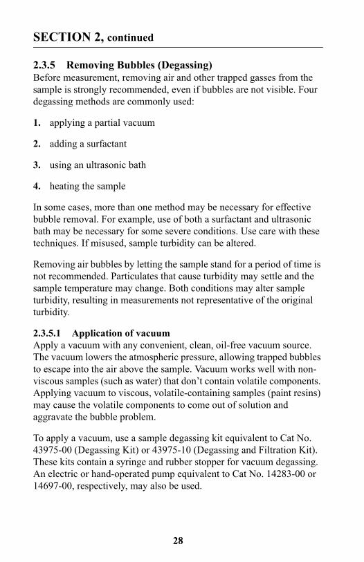
1. Fill a sample cell to the mark with sample. Insert a #2 single-hole rubber stopper and syringe into the cell. If using a pump, insert a piece of glass tubing into the stopper.
2. Slowly apply the vacuum by carefully pulling the plunger upward, then holding it. If using a hand or electric pump, connect the tubing to the vacuum pump with vacuum hose. Apply vacuum until visible gas bubbles disappear. Slowly release the vacuum. Remove the vacuum apparatus and cap the cell.
30
SECTION 2, continued
2.3.5.3 Using an ultrasonic bath
Note: The time necessary to expel bubbles may vary from a few seconds to a minute or more. To avoid excessive application of ultrasound, a simple procedure can be followed. First, apply ultrasound until all visible bubbles are absent. Then measure the sample turbidity. Apply ultrasound for a short time period and again measure turbidity. Continue for several repetitions, noting the treatment time and turbidity readings. If turbidity begins to increase instead of decrease, the ultrasound waves have probably started to alter the suspended particles. Note the time it takes for this to occur and record it as the maximum time limit for ultrasonic treatment.
Ultrasonic baths effectively remove gas bubbles from most samples, especially viscous liquids. However, the ultrasonic waves which cause degassing may also alter the characteristics of the particles causing the turbidity. Turbidity depends on the size, shape, composition and refractive index of the suspended particles. Excessive ultrasound application may alter particle size and shape, thus changing sample turbidity. In some cases, ultrasound may aggravate air bubble removal by fracturing the bubbles, making degassing more difficult.
1. Fill a clean sample cell to the line with sample. Leave uncapped.
2. Immerse the cell (1/2 to 2/3 immersed) in an ultrasonic bath and allow it to stand until visible bubbles are expelled.
3. Remove the cell, cap, then thoroughly dry the cell. Apply silicone oil as directed.
2.3.5.4 Application of heatWhenever possible, avoid using heat to degas samples because heat may change the characteristics of the suspended particles and cause volatile components to come out of solution. Gentle heating may be helpful for degassing some very viscous samples when combined with application of vacuum or ultrasound. If heat is necessary, heat the sample only until degassing occurs. The simplest technique is to prepare a warm water bath and partially immerse the filled sample cell. Use the shortest time necessary for expelling visible bubbles. Cool sample to original sample temperature before taking measurements.
31
SECTION 2, continued
2.3.6 Measuring Overrange SamplesNephelometric turbidity measurement depends on detection of light scattered from particles suspended in the liquid. If the turbidity is very high, a significant amount of light is blocked or absorbed by the particles and only a small amount of light reaches the detector. This results in a negative interference – the measured turbidity is lower than the actual turbidity. This condition is called “going blind”. A multidetector ratioing instrument, such as the Hach 2100P Turbidimeter, minimizes this effect and extends the instrument range. Highly turbid samples may also be diluted, but this should be avoided when possible since it may alter the characteristics of the suspended particles and produce erroneous results.
Light absorbing particles such as activated carbon and highly colored samples may also cause an instrument to “go blind”. Dilution may not correct for these interferences. A ratioing instrument will correct for the presence of light absorbing particles and color.
2.3.7 Condensation (fogging)Condensation may occur on the outside of the sample cell when measuring a cold sample in a warm, humid environment. Condensation interferes with turbidity measurement, so all moisture must be thoroughly wiped off the sample cell before measurement. If fogging recurs, let the sample warm slightly by standing at room temperature or immersing it in a warm bath for a short period. After warming, mix the sample thoroughly before measurement. Allowing samples to warm can alter sample turbidity, so it is best to avoid warming samples before measurement when possible.
2.3.8 CalibrationTurbidimeters must be properly calibrated with a primary standard. Hach recommends formazin or StablCal Stabilized Formazin for calibration. For U.S. Environmental Protection Agency (USEPA) reporting, calibrate at least as often as required by the appropriate regulatory agencies. The frequency of calibration depends on environmental conditions (humidity, temperature) and use. If necessary, calibrate more frequently.
32
SECTION 2, continued
Use secondary standards for periodic calibration checks. Please note that Gelex® standards must be assigned values after StablCal Stabilized Formazin calibration or formazin calibration and before use as secondary standards. Gelex standards must be recalibrated (values assigned) each time the instrument is calibrated with StablCal Stabilized Formazin or formazin. See Section 3.6 on page 37 for detailed information on the use of StablCal Stabilized Formazin, formazin, and Gelex standards.
2.3.9 Representative SamplingA representative sample accurately reflects the true condition of the water source from which the sample was taken. To ensure a representative sample, gently, but thoroughly, mix every sample before aliquots are taken. Do not allow the sample to settle.
When sampling from a tap in a distribution system or treatment plant, allow the water to run for at least five minutes before sampling. When sampling from a stream, reservoir, clarifier, or storage tank, collect at least one liter (l quart) and thoroughly mix before measurement. If the water source is not uniform, it may be necessary to sample several locations at varying depths and combine the samples into a single, well-mixed composite sample before measurement.
33
SECTION 3 OPERATION
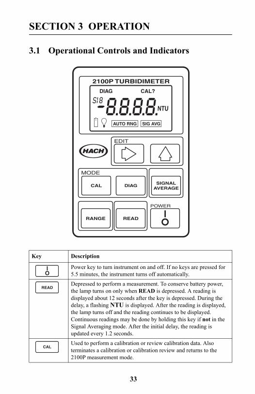
3.1 Operational Controls and Indicators
Key Description
Power key to turn instrument on and off. If no keys are pressed for 5.5 minutes, the instrument turns off automatically.
Depressed to perform a measurement. To conserve battery power, the lamp turns on only when READ is depressed. A reading is displayed about 12 seconds after the key is depressed. During the delay, a flashing NTU is displayed. After the reading is displayed, the lamp turns off and the reading continues to be displayed. Continuous readings may be done by holding this key if not in the Signal Averaging mode. After the initial delay, the reading is updated every 1.2 seconds.
Used to perform a calibration or review calibration data. Also terminates a calibration or calibration review and returns to the 2100P measurement mode.
2100P TURBIDIMETER
EDIT
DIAG
NTU
CAL?
POWER
MODE
CAL DIAG SIGNALAVERAGE
AUTO RNG SIG AVG
RANGE READ
IO
READ
CAL
34
SECTION 3, continued
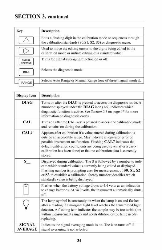
Edits a flashing digit in the calibration mode or sequences through the calibration standards (S0,S1, S2, S3) or diagnostic menu.
Used to move the editing cursor to the digits being edited in the calibration mode or initiate editing of a standard value.
Turns the signal averaging function on or off.
Selects the diagnostic mode.
Selects Auto Range or Manual Range (one of three manual modes).
Display Icon Description
DIAG Turns on after the DIAG is pressed to access the diagnostic mode. A number displayed under the DIAG icon (1-9) indicates which diagnostic function is active. See Section 5.1 on page 67 for more information on diagnostic codes.
CAL Turns on after the CAL key is pressed to access the calibration mode and remains on during the calibration.
CAL? Appears after calibration if a value entered during calibration is outside an acceptable range. May indicate an operator error or possible instrument malfunction. Flashing CAL? indicates the default calibration coefficients are being used (even after a user-calibration has been done) or that no calibration data is currently stored.
S__ Displayed during calibration. The S is followed by a number to indi-cate which standard value is currently being edited or displayed. Flashing number is prompting user for measurement of S0, S1, S2 or S3 to establish a calibration. Steady number identifies which standard's value is being displayed.
Flashes when the battery voltage drops to 4.4 volts as an indication to change batteries. At <4.0 volts, the instrument automatically shuts off.
The lamp symbol is constantly on when the lamp is on and flashes after a reading if a marginal light level reaches the transmitted light detector. A flashing icon indicates the sample may be too turbid (not within measurement range) and needs dilution or the lamp needs replacing.
SIGNAL AVERAGE
Indicates the signal averaging mode is on. The icon turns off if signal averaging is not selected.
Key Description
SIGNALAVERAGE
DIAG
35
SECTION 3, continued
3.2 Using the Read KeyTo preserve battery power and prolong lamp life, the lamp turns on only after the READ key is pressed. Pressing the key turns the instrument lamp on; after about 12 seconds, the lamp turns off, but the measurement value continues to be displayed. After the first measurement, a four-second recovery time occurs before another measurement can be started. If READ is pressed during the recovery time, the display will begin flashing, but the lamp will not turn on until the full four seconds have passed. If no other key strokes occur within 5.5 minutes, the instrument turns off.
3.2.1 Continuous ReadingThe instrument cannot be used in continuous read mode if the Signal Averaging mode is on.
The instrument will perform continuous readings if the READ key is pressed and held. As long as the key is held, the lamp remains on and the display is updated every 1.2 seconds.
3.3 Using the Signal Averaging KeyThe signal averaging mode compensates for reading fluctuations caused by drifting of sample particles through the light path. Signal averaging is turned on or off by pressing the SIGNAL AVERAGE key. The SIG AVG icon is displayed when signal averaging is on.
Signal averaging measures and averages ten measurements while displaying intermediate results. The initial value is displayed after about 11 seconds and the display is updated every 1.2 seconds until all ten measurements are taken (about 22 seconds). After 22 seconds, the lamp
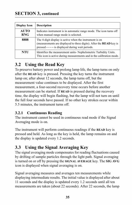
AUTO RNG
Indicates instrument is in automatic range mode. The icon turns off when manual range mode is selected.
8888 The 4-digit display is active when the instrument is on (measurements are displayed to three digits). After the READ key is pressed - - - - is displayed during wait periods.
NTU Identifies the measurement units- Nephelometric Turbidity Units. This icon is active during measurements and in the calibration mode.
Display Icon Description
36
SECTION 3, continued
turns off, but the final measured turbidity value continues to be displayed until another key is pressed.
When signal averaging is off, the instrument takes three measurements, the microprocessor averages them, then displays the average. If the READ key is held during measurement, the initial value is displayed in 12 seconds and is updated every 1.2 seconds as long as the READ key is held.
When the instrument is turned on, the instrument defaults to the signal averaging mode which was used during the last measurement.
3.4 Using the Range Selection KeyAs shipped, the instrument defaults to automatic range mode. The first time the RANGE key is pressed, the instrument goes into manual range mode. The second, third, and fourth key strokes put the instrument in the 0.00-9.99, 10 to 99.9 or 100-1000 NTU range, respectively. Another key stroke brings the selection back to automatic range mode. When the automatic range mode is selected, the AUTO RNG icon is displayed. Range selection can be done any time except when a measurement or calibration is in progress.
When the instrument is turned on, the instrument defaults to the range mode and measurement range which was used during the last measurement.
3.5 Restoring the Default CalibrationTo restore and use the default calibration, turn the instrument off. Press and hold DIAG, then press and release I/O. Release DIAG when the software version number disappears from the display. (For models with serial number less than 920300000800, 2100 disappears). This clears any user-entered calibration from memory; the 2100P will use the default calibration for measurement. CAL? will appear and continue to flash until a user-entered calibration is successfully completed.
For best results, a user-entered calibration should be done every three months.
37
SECTION 3, continued
3.6 CalibrationCalibration of the 2100P Turbidimeter is based on formazin, the primary standard for turbidity. The instrument's electronic and optical design provide long-term stability and minimize the need for frequent calibration. The two-detector ratioing system compensates for most fluctuations in lamp output. A formazin recalibration should be performed at least once every three months, more often if experience indicates the need. When calibration is necessary, use a primary standard such as StablCal™ Stabilized Standards or formazin standards.
Hach Company only recommends the use of StablCal® Stabilized Formazin or formazin standards for the calibration of Hach turbidimeters. Hach Company cannot guarantee the performance of the turbidimeter if calibrated with co-polymer styrene divinylbenzene beads or other suspensions.
Important Note: DO NOT calibrate with Gelex® Secondary Standards. Gelex standards are designed for instrument verification, not calibration.
3.6.1 StablCal Stabilized Formazin Standards*Most consistent results will be achieved with the use of StablCal Stabilized Formazin Standards for calibration. Refer to Section 3.6.1.2 and Section 3.6.1.3 for information on preparing the standards for use.
Note: Hach StablCal Stabilized Formazin in 20-, 100-, and 800-NTU values is packaged in convenient sets for calibration of the 2100P Turbidimeter. The set may be ordered in 500-mL size bottles by specifying Cat. No. 26594-00, in 100-mL size bottles by specifying Cat. No. 26594-10 or in sealed vials by ordering Cat. No. 26594-05. (See OPTIONAL ACCESSORIES AND REAGENTS on page 74.)
3.6.1.1 Storing and Handling StablCal Stabilized StandardsFor optimum results when using StablCal Stabilized Standards, adhere to the following recommendations:
* StablCal Stabilized Formazin is cited as a primary standard in Hach Method 8195, an acceptable version of USEPA Method 180.1.
38
SECTION 3, continued
• Do not transfer the standard to another container for storage.
• Do not return standard from the sample cell back into the its original container. Standard contamination will result.
• Store standards between 0 and 25 °C.
• For long-term storage, refrigeration at 5 °c is recommended. Do not store above 25 °C.
• Allow the standard to acclimate to ambient instrument conditions before use (not to exceed 40 °C).
• Store away from direct sunlight. Store vials in their respective kit or shipping box with the cover in place.
3.6.1.2 Preparing Bulk StablCal Stabilized StandardsBulk standards that have been sitting undisturbed for longer than a month must be shaken to break the condensed suspension into its original particle size. Start at step 1 for these standards. If the standards are used on at least a weekly interval, start at step 3.
Important Note: These instructions do not apply to <0.1-NTU* StablCal Standards; <0.1NTU StablCal Standards should not be shaken or inverted.
1. Shake the standard vigorously for 2-3 minutes to resuspend any particles.
2. Allow the standard to stand undisturbed for 5 minutes.
3. Gently invert the bottle of StablCal 5 to 7 times.
4. Prepare the sample cell for measurement using traditional preparation techniques. This usually consists of oiling the sample cell (seeSection 2.3.2 on page 23) and marking the cell to maintain the same orientation in the sample cell compartment (see Section 2.3.3 on page 24). This step will eliminate any optical variations in the sample cell.
* Used in place of the dilution water standard when performing a calibration.
39
SECTION 3, continued
5. Rinse the sample cell at least one time with the standard and discard the rinse.
6. Immediately fill the sample cell with the standard. Cap the sample cell and let it stand for one minute. The standard is now ready for use in the calibration procedure, Section 3.6.3.
3.6.1.3 Preparing StablCal Stabilized Standards in Sealed VialsSealed vials that have been sitting undisturbed for longer than a month must be shaken to break the condensed suspension into its original particle size. Start at step 1 for these standards. If the standards are used on at least a weekly interval, start at step 3
Important Note: These instructions do not apply to <0.1-NTU* StablCal Standards; <0.1NTU StablCal Standards should not be shaken or inverted.
1. Shake the standard vigorously for 2-3 minutes to resuspend any particles.
2. Allow the standard to stand undisturbed for 5 minutes.
3. Gently invert the vial of StablCal 5 to 7 times.
4. Prepare the vial for measurement using traditional preparation techniques. This usually consists of oiling the vial (see Section 2.3.2 on page 23) and marking the vial to maintain the same orientation in the sample cell compartment (see Section 2.3.3 on page 24). This step will eliminate any optical variations in the sample vial.
5. Let the vial stand for one minute. The standard is now ready for use in the calibration procedure, Section 3.6.3.
40
SECTION 3, continued
3.6.2 Formazin Primary StandardsPerform the procedure in Section 3.6.2.1 to prepare a 4000-NTU standard. Alternately, order a 4000-NTU stock solution from Hach by specifying Cat. 2461-49. Prepare the dilutions from the 4000-NTU stock solution by following the instructions in Section 3.6.2.4.
3.6.2.1 Preparing Formazin Stock SolutionDilute formazin standard solutions from a 4000 NTU stock solution equivalent to Hach Cat. No. 2461-49. The prepared stock solution is stable for up to one year when properly prepared. An alternative to purchasing the 4000 NTU stock solution is preparing a stock solution as follows:
1. Dissolve 5.000 grams of reagent grade hydrazine sulfate (N2H4•H2SO4) in 400 mL of distilled water.
2. Dissolve 50.000 grams of pure hexamethylenetetramine in 400 mL of distilled water.
3. Pour the two solutions into a 1000-mL volumetric flask and dilute to the mark with distilled water.
4. Let the solution stand for 48 hours at 25 °C (77 °F) to develop the 4000-NTU stock suspension. The standing temperature is critical for correct formation of formazin polymers.
5. Mix the 4000 NTU suspension for at least ten minutes before use. Then it can be diluted with distilled or demineralized water to achieve a solution of the desired NTU value.
Instead of diluting a formazin stock solution, StablCal Stabilized Formazin Standards may be used. Order the StablCal Calibration Set for the 2100P Turbidimeter, Cat.No. 26594-00 (500-mL bottles), Cat. No. 26594-10 (100 mL bottles), or Cat. No. 26594-05 (sealed vials). (See OPTIONAL ACCESSORIES AND REAGENTS on page 74.)
3.6.2.2 Correcting for Turbidity of Dilution WaterThe 2100P Turbidimeter automatically compensates for turbidity contributed by dilution water when calculating the true value of the lowest formazin standard. Use high quality distilled or deionized water less than 0.5 NTU. The instrument will display E 1 after calibration if
41
SECTION 3, continued
the dilution water turbidity is greater than 0.5 NTU. In this case, prepare the water as directed below.
The value of the dilution water can be arbitrarily forced to zero (see calibration procedure). This is not recommended for most applications and, if done, should be done only if the dilution water turbidity is less than 0.2 NTU.
3.6.2.3 Preparing Dilution Water
Note: Use the same dilution water for all dilutions and the sample blank.
Collect at least 1000 mL of high quality dilution water (distilled or deionized water). The 2100P Turbidimeter, as received from the factory, is precalibrated and may be used to check the dilution water turbidity. If the turbidity is greater than 0.5 NTU, filter the water with the Sample Filtration and Degassing Kit (Cat. No. 43975-10) or equivalent. When measuring low range turbidity, clean all glassware with 1:1 hydrochloric acid and rinse several times with dilution water. If the glassware is not used immediately, use stoppers to prevent contamination from small particles.
42
SECTION 3, continued
3.6.2.4 Preparing Formazin Dilutions (Factory recommended)Hach Company recommends using 20, 100, and 800 NTU formazin standards for calibrating the 2100P Turbidimeter. Dilutions with other NTU values can be prepared and used (see Section 3.6.3.1 on page 48). If problems occur when using alternate solutions, use the dilutions specified here.
Prepare all formazin dilutions immediately before use and discard after calibration. The 4000 NTU solution is stable for up to a year, but dilutions deteriorate more rapidly. Use the same high quality water (turbidity <0.5 NTU) for the dilutions and the blank.
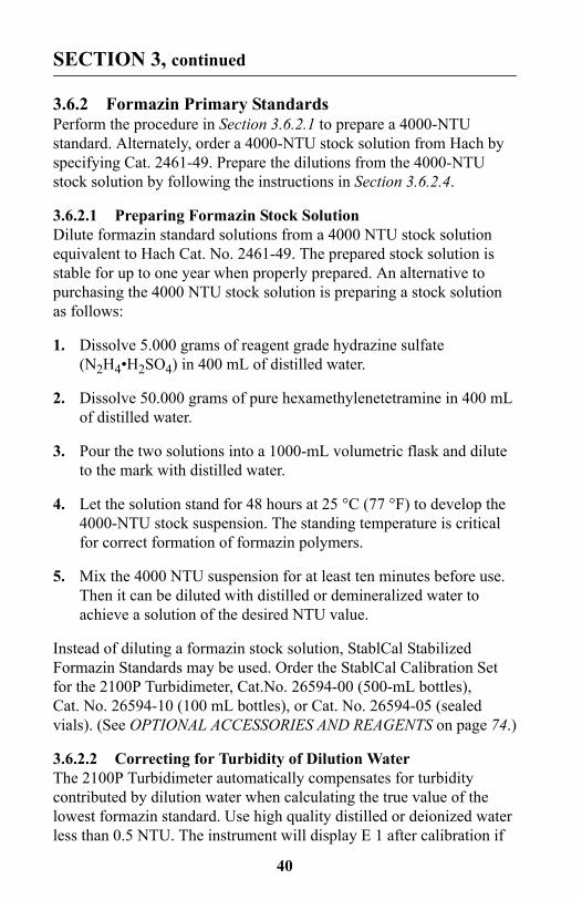
1. Attach the syringe to the 3-way valve by gently twisting the square end into the syringe tip. Attach the connector, tubing and a 0.2 micron filter (clear part faces syringe) as shown. Be sure the connections are tight.
2. Fill a beaker or container with the water to be filtered. Insert the tubing into the container. Slowly draw the water into the syringe by pulling up on the syringe plunger.
3. Draw about 50 mL of sample into the syringe. Slowly push on the plunger to force the water through the filter and into a graduated cylinder or volumetric flask. Repeat Steps 2 and 3 until the desired amount of water is obtained.
Note: As the filter clogs, it gets more difficult to push water through it. At this point, discard the filter and attach a new filter. Replacement filters are available in packages of 10 (Cat. No. 23238-10).
43
SECTION 3, continued
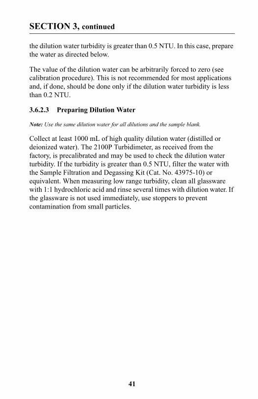
Preparing the 20, 100 and 800 NTU standards
Table 1 Formazin Standard Preparation
Step 1 Step 2 Step 3
Standards
20 NTU Add 100 mL of dilution water to a clean 200-mL class A volumetric flask.
With a TenSette* pipet, add 1.00 mL of well-mixed 4000 NTU Formazin stock solution to the 200-mL flask.
* A class A volumetric pipet may be used in place of a TenSette Pipet.
Dilute to the mark with dilution water. Stopper and mix.
100 NTU Add 100 mL of dilution water to a clean 200-mL class A volumetric flask.
With a TenSette pipet, add 5.00 mL of well-mixed 4000 NTU Formazin stock solution to the 200-mL flask.
Dilute to the mark with dilution water. Stopper and mix.
800 NTU Add 50 mL of dilution water to a clean 100-mL class A volumetric flask.
With a TenSette pipet, add 20.00 mL of well-mixed 4000 NTU Formazin stock solution to the 100-mL flask.
Dilute to the mark with dilution water. Stopper and mix.
44
SECTION 3, continued
3.6.3 Calibrating the Turbidimeter
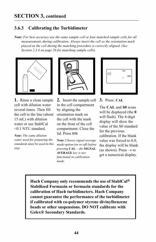
Note: For best accuracy use the same sample cell or four matched sample cells for all measurements during calibration. Always insert the cell so the orientation mark placed on the cell during the matching procedure is correctly aligned. (See Section 2.3.4 on page 26 for matching sample cells).
1. Rinse a clean sample cell with dilution water several times. Then fill the cell to the line (about 15 mL) with dilution water or use StablCal <0.1 NTU standard.
Note: The same dilution water used for preparing the standards must be used in this step.
2. Insert the sample cell in the cell compartment by aligning the orientation mark on the cell with the mark on the front of the cell compartment. Close the lid. Press I/O.
Note: Choose signal average mode option (on or off) before pressing CAL – the SIGNAL AVERAGE key is not functional in calibration mode.
3. Press: CAL
The CAL and S0 icons will be displayed (the 0 will flash). The 4-digit display will show the value of the S0 standard for the previous calibration. If the blank value was forced to 0.0, the display will be blank (as shown). Press → to get a numerical display.
NTU
CAL
Hach Company only recommends the use of StablCal® Stabilized Formazin or formazin standards for the calibration of Hach turbidimeters. Hach Company cannot guarantee the performance of the turbidimeter if calibrated with co-polymer styrene divinylbenzene beads or other suspensions. DO NOT calibrate with Gelex® Secondary Standards.
45
SECTION 3, continued
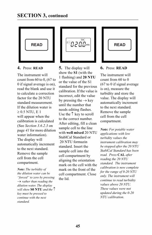
4. Press: READ
The instrument will count from 60 to 0, (67 to 0 if signal average is on), read the blank and use it to calculate a correction factor for the 20 NTU standard measurement. If the dilution water is ≥ 0.5 NTU, E 1 will appear when the calibration is calculated (See Section 3.6.2.3 on page 41 for more dilution water information). The display will automatically increment to the next standard. Remove the sample cell from the cell compartment.
Note: The turbidity of the dilution water can be “forced” to zero by pressing → rather than reading the dilution water. The display will show S0 NTU and the ↑ key must be pressed to continue with the next standard.
5. The display will show the S1 (with the 1 flashing) and 20 NTU or the value of the S1 standard for the previous calibration. If the value is incorrect, edit the value by pressing the → key until the number that needs editing flashes. Use the ↑ key to scroll to the correct number. After editing, fill a clean sample cell to the line with well mixed 20 NTU StablCal Standard or 20 NTU formazin
standard. Insert the sample cell into the cell compartment by aligning the orientation mark on the cell with the mark on the front of the cell compartment. Close the lid.
6. Press: READ
The instrument will count from 60 to 0 (67 to 0 if signal average is on), measure the turbidity and store the value. The display will automatically increment to the next standard. Remove the sample cell from the cell compartment.
Note: For potable water applications with low turbidity values the instrument calibration may be stopped after the 20 NTU StablCal Standard has been read. Press CAL after reading the 20 NTU standard. The instrument calibration is now complete for the range of 0-20 NTU only. The instrument will continue to read turbidity values above 20 NTU. These values were not updated during the 0-20 NTU calibration.
READ NTU
CAL
READ
46
SECTION 3, continued
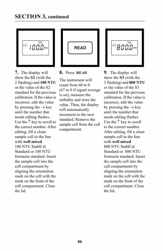
7. The display will show the S2 (with the 2 flashing) and 100 NTU or the value of the S2 standard for the previous calibration. If the value is incorrect, edit the value by pressing the → key until the number that needs editing flashes. Use the ↑ key to scroll to the correct number. After editing, fill a clean sample cell to the line with well mixed 100 NTU StablCal Standard or 100 NTU formazin standard. Insert the sample cell into the cell compartment by aligning the orientation mark on the cell with the mark on the front of the cell compartment. Close the lid.
8. Press: READ
The instrument will count from 60 to 0 (67 to 0 if signal average is on), measure the turbidity and store the value. Then, the display will automatically increment to the next standard. Remove the sample cell from the cell compartment.
9. The display will show the S3 (with the 3 flashing) and 800 NTU or the value of the S3 standard for the previous calibration. If the value is incorrect, edit the value by pressing the → key until the number that needs editing flashes. Use the ↑ key to scroll to the correct number. After editing, fill a clean sample cell to the line with well mixed 800 NTU StablCal Standard or 800 NTU formazin standard. Insert the sample cell into the cell compartment by aligning the orientation mark on the cell with the mark on the front of the cell compartment. Close the lid.
NTU
CAL
READ NTU
CAL
47
SECTION 3, continued
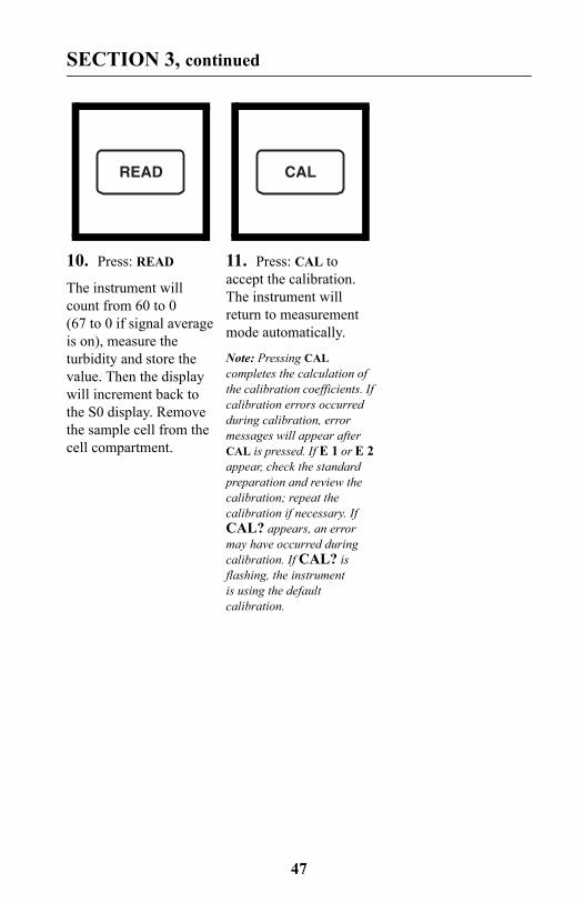
10. Press: READ
The instrument will count from 60 to 0 (67 to 0 if signal average is on), measure the turbidity and store the value. Then the display will increment back to the S0 display. Remove the sample cell from the cell compartment.
11. Press: CAL to accept the calibration. The instrument will return to measurement mode automatically.
Note: Pressing CAL completes the calculation of the calibration coefficients. If calibration errors occurred during calibration, error messages will appear after CAL is pressed. If E 1 or E 2 appear, check the standard preparation and review the calibration; repeat the calibration if necessary. If CAL? appears, an error may have occurred during calibration. If CAL? is flashing, the instrument is using the default calibration.
READ CAL
48
SECTION 3, continued
NOTES
• If the I/O key is pressed during calibration, the new calibration data is lost and the old calibration will be used for measurements. Once in calibration mode, only the READ, I/O, ↑, and → keys function. Signal averaging and range mode must be selected before entering the calibration mode.
• If E 1 or E 2 are displayed, an error occurred during calibration. Check the standard preparation and review the calibration; repeat the calibration if necessary. Press DIAG to cancel the error message (E 1 or E 2). To continue without repeating the calibration, press I/O twice to restore the previous calibration. If CAL? is displayed, an error may have occurred during calibration. The previous calibration may not be restored. Either recalibrate or use the calibration as is.
• To review a calibration, press CAL and then ↑ to view the calibration standard values. As long as READ is never pressed and CAL is not flashing, the calibration will not be updated. Press CAL again to return to the measurement mode.
3.6.3.1 Preparing User-selected Formazin DilutionsThe formazin solutions should span the entire range of the instrument. Hach recommends preparing three standards:
1. 10 to 30 NTU
2. 90 to 110 NTU
3. 700 to 900 NTU
The standards must have a difference of at least 60 NTU. In addition, a blank made from the dilution water should be prepared.
Prepare the formazin standard solutions from the well mixed 4000 NTU stock solution as specified in Section 3.6.2.4 on page 42 and dilution water as specified in Section 3.6.2.2 and Section 3.6.2.3 on page 41. Make the standards immediately before use and discard them after calibration is done.
49
SECTION 3, continued
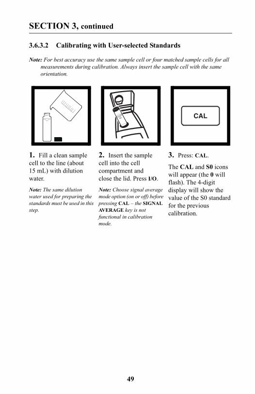
3.6.3.2 Calibrating with User-selected Standards
Note: For best accuracy use the same sample cell or four matched sample cells for all measurements during calibration. Always insert the sample cell with the same orientation.
1. Fill a clean sample cell to the line (about 15 mL) with dilution water.
Note: The same dilution water used for preparing the standards must be used in this step.
2. Insert the sample cell into the cell compartment and close the lid. Press I/O.
Note: Choose signal average mode option (on or off) before pressing CAL – the SIGNAL AVERAGE key is not functional in calibration mode.
3. Press: CAL.
The CAL and S0 icons will appear (the 0 will flash). The 4-digit display will show the value of the S0 standard for the previous calibration.
CAL
50
SECTION 3, continued
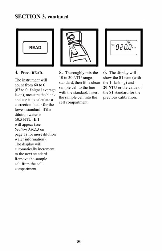
4. Press: READ.
The instrument will count from 60 to 0 (67 to 0 if signal average is on), measure the blank and use it to calculate a correction factor for the lowest standard. If the dilution water is ≥0.5 NTU, E 1 will appear (see Section 3.6.2.3 on page 41 for more dilution water information). The display will automatically increment to the next standard. Remove the sample cell from the cell compartment.
5. Thoroughly mix the 10 to 30 NTU range standard, then fill a clean sample cell to the line with the standard. Insert the sample cell into the cell compartment
6. The display will show the S1 icon (with the 1 flashing) and 20 NTU or the value of the S1 standard for the previous calibration.
READ NTU
CAL
51
SECTION 3, continued
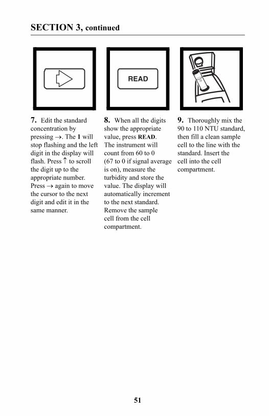
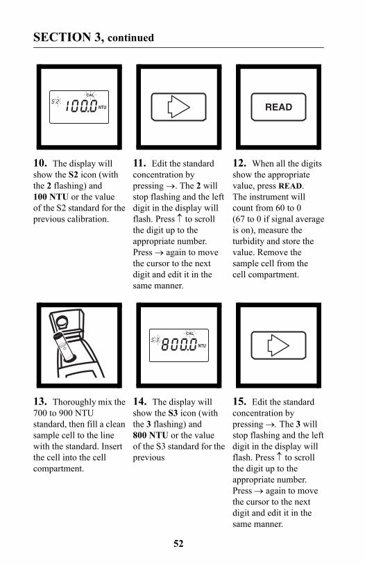
7. Edit the standard concentration by pressing →. The 1 will stop flashing and the left digit in the display will flash. Press ↑ to scroll the digit up to the appropriate number. Press → again to move the cursor to the next digit and edit it in the same manner.
8. When all the digits show the appropriate value, press READ. The instrument will count from 60 to 0 (67 to 0 if signal average is on), measure the turbidity and store the value. The display will automatically increment to the next standard. Remove the sample cell from the cell compartment.
9. Thoroughly mix the 90 to 110 NTU standard, then fill a clean sample cell to the line with the standard. Insert the cell into the cell compartment.
READ
52
SECTION 3, continued
10. The display will show the S2 icon (with the 2 flashing) and 100 NTU or the value of the S2 standard for the previous calibration.
11. Edit the standard concentration by pressing →. The 2 will stop flashing and the left digit in the display will flash. Press ↑ to scroll the digit up to the appropriate number. Press → again to move the cursor to the next digit and edit it in the same manner.
12. When all the digits show the appropriate value, press READ. The instrument will count from 60 to 0 (67 to 0 if signal average is on), measure the turbidity and store the value. Remove the sample cell from the cell compartment.
13. Thoroughly mix the 700 to 900 NTU standard, then fill a clean sample cell to the line with the standard. Insert the cell into the cell compartment.
14. The display will show the S3 icon (with the 3 flashing) and 800 NTU or the value of the S3 standard for the previous
15. Edit the standard concentration by pressing →. The 3 will stop flashing and the left digit in the display will flash. Press ↑ to scroll the digit up to the appropriate number. Press → again to move the cursor to the next digit and edit it in the same manner.
NTU
CAL
READ
NTU
CAL
53
SECTION 3, continued
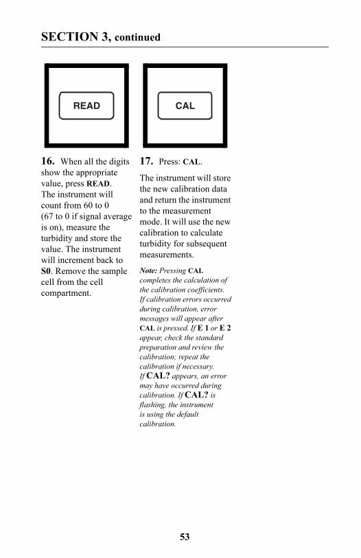
16. When all the digits show the appropriate value, press READ. The instrument will count from 60 to 0 (67 to 0 if signal average is on), measure the turbidity and store the value. The instrument will increment back to S0. Remove the sample cell from the cell compartment.
17. Press: CAL.
The instrument will store the new calibration data and return the instrument to the measurement mode. It will use the new calibration to calculate turbidity for subsequent measurements.
Note: Pressing CAL completes the calculation of the calibration coefficients. If calibration errors occurred during calibration, error messages will appear after CAL is pressed. If E 1 or E 2 appear, check the standard preparation and review the calibration; repeat the calibration if necessary. If CAL? appears, an error may have occurred during calibration. If CAL? is flashing, the instrument is using the default calibration.
READ CAL
54
SECTION 3, continued
NOTES
• If the I/O key is pressed during calibration, the new calibration data is lost and the old calibration will be used for measurements. Once in calibration mode, only the READ, I/O, ↑, and → keys function. Signal averaging and range mode must be selected before entering the calibration mode.
• If E 1 or E 2 are displayed, an error occurred during calibration. Check the standard preparation and review the calibration; repeat the calibration if necessary. If the error messages recur, calibrate using the factory specified standards, Section 3.6.2.4 on page 42 and Section 3.6.3 on page 44. Press DIAG to cancel the error message (E 1 or E 2). To continue without repeating the calibration, press I/O twice to restore the previous calibration. If CAL? is displayed, an error may have occurred during calibration. The previous calibration may not be restored. Either recalibrate or use the calibration as is.
• To review a calibration, press CAL and then only ↑ to view the calibration standard values. As long as READ is never pressed and CAL isn’t flashing, the calibration will not be updated. Press CAL again to return to the measurement mode.
3.6.4 Using Gelex® Secondary Turbidity Standards
Note: Store Gelex standards at room temperature. Do not allow to freeze or exceed 50 °C.
Gelex Secondary Standards (included with 4650000 only) are particulate suspensions similar to formazin primary standards in light scattering characteristics. NTU values on the Gelex standards indicate the range for which they should be used. Due to minor variations in glass and individual instrument optical systems, the true value of the Gelex standards must be determined against formazin in the same instrument they will be used with for later calibration checks.
55
SECTION 3, continued
3.6.4.1 Assigning Values to Gelex Standards
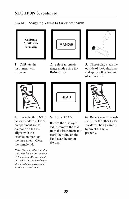
1. Calibrate the instrument with formazin.
2. Select automatic range mode using the RANGE key.
3. Thoroughly clean the outside of the Gelex vials and apply a thin coating of silicone oil.
4. Place the 0-10 NTU Gelex standard in the cell compartment so the diamond on the vial aligns with the orientation mark on the instrument. Close the sample lid.
Note: Correct cell orientation is essential to obtain accurate Gelex values. Always orient the cell so the diamond mark aligns with the orientation mark on the instrument.
5. Press: READ.
Record the displayed value, remove the vial from the instrument and mark the value on the band near the top of the vial.
6. Repeat step 3 through step 5 for the other Gelex standards, being careful to orient the cells properly.
Calibrate 2100P with formazin
READ
56
SECTION 3, continued
3.6.4.2 Routine Calibration Check With Gelex StandardsThe 2100P Turbidimeter does not require standardization before every measurement as some turbidimeters do. Periodically, as experience dictates, check the instrument calibration using the appropriate Gelex Secondary Standard. Be sure the Gelex standards are aligned correctly when inserting them (diamond aligns with orientation mark). If the reading is not within 5% of the previously established value, recalibrate the instrument with StablCal Stabilized Formazin Primary Standard or formazin primary standard (Section 3.6.3 on page 44).
Important Note: DO NOT calibrate with Gelex® Secondary Standards. Gelex standards are designed for instrument verification, not calibration.
7. Re-assign values to the Gelex standards each time the instrument is calibrated with formazin.
Re-assign with every formazin
calibration
Some of the following manual sections contain information in the form of warnings, cautions and notes that require special attention. Read and follow these instructions carefully to avoid personal injury and damage to the instrument. Only personnel qualified to do so, should conduct the maintenance tasks described in this portion of the manual.
Certains des chapitres suivants de ce mode d’emploi contiennent des informations sous la forme d’avertissements, messages de prudence et notes qui demandent une attention particulière. Lire et suivre ces instructions attentivement pour éviter les risques de blessures des personnes et de détoriation de l’appareil. Les tâches d’entretien décrites dans cette partie du mode d’emploi doivent être seulement effectuées par le personnel qualifié pour le faire.
Algunos de los capítulos del manual que presentamos contienen muy importante información en forma de alertas, notas y precauciones a tomar. Lea y siga cuidadosamente estas instrucciones a fin de evitar accidentes personales y daños al instrumento. Las tareas de mantenimiento descritas en la presente sección deberán ser efectuadas únicamente por personas debidamente cualificadas.
Einige der folgenden Abschnitte dieses Handbuchs enthalten Informationen in Form von Warnungen, Vorsichtsmaßnahmen oder Anmerkungen, die besonders beachtet werden müssen. Lesen und befolgen Sie diese Instruktionen aufmerksam, um Verletzungen von Personen oder Schäden am Gerät zu vyyyermeiden. In diesem Abschnitt beschriebene Wartungsaufgaben dürfen nur von qualifiziertem Personal durchgeführt werden.
Algumas das seguintes secções do manual contêm informações em forma de advertências, precauções e notas que requerem especial atenção. Leia e siga aten-tamente as presentes instruções para evitar ferimentos pessoais e não danificar o instrumento. As tarefas de manutenção descritas nesta parte do manual só poderão ser executadas por pessoal qualificado.
57
MAINTENANCE

58
59
SECTION 4 MAINTENANCE
4.1 CleaningKeep the turbidimeter and accessories as clean as possible and store the instrument in the carrying case when not in use. Avoid prolonged exposure to sunlight and ultraviolet light. Wipe spills up promptly. Wash sample cells with non-abrasive laboratory detergent, rinse with distilled or demineralized water, and air dry. Avoid scratching the cells and wipe all moisture and fingerprints off the cells before inserting them into the instrument. Failure to do so can give inaccurate readings. See Section 2.3.1 on page 23 for more information about sample cell care.
4.2 Battery ReplacementAA alkaline cells typically last for about 300 tests with the signal averaging mode off, about 180 tests if signal averaging is used. The “battery” icon flashes when battery replacement is needed. Refer to Section 1.4.2 on page 16 for battery installation instructions. If the batteries are changed within 30 seconds, the instrument retains the latest range and signal average selections. If it takes more than 30 seconds, the instrument uses the default settings.
If, after changing batteries, the instrument will not turn off or on and the batteries are good, remove the batteries and reinstall them. If the instrument still won't function, contact Hach Service or the nearest authorized dealer.
4.3 Lamp ReplacementThe procedure below explains lamp installation and electrical connections. Use a small screwdriver to remove and install the lamp leads in the terminal block. The instrument requires calibration after lamp replacement.
60
SECTION 4, continued
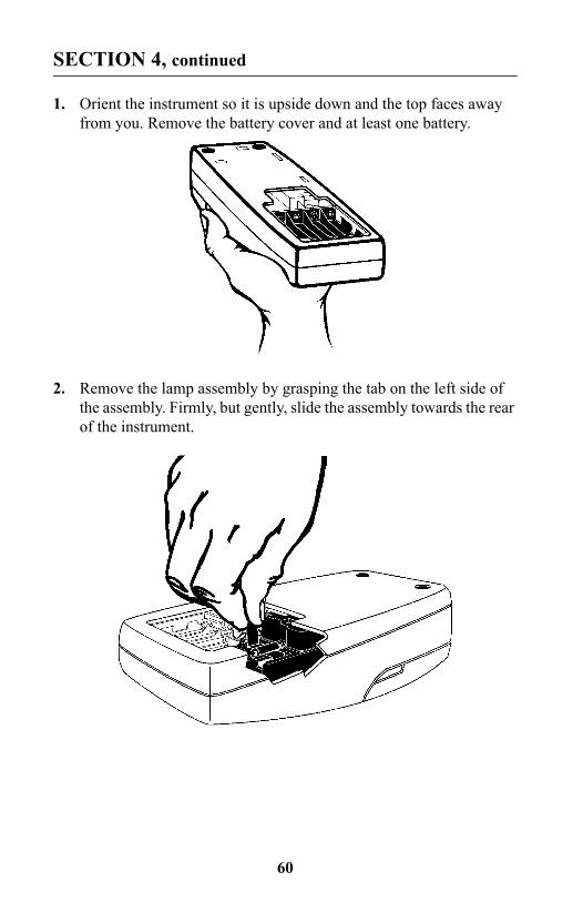
1. Orient the instrument so it is upside down and the top faces away from you. Remove the battery cover and at least one battery.
2. Remove the lamp assembly by grasping the tab on the left side of the assembly. Firmly, but gently, slide the assembly towards the rear of the instrument.
61
SECTION 4, continued
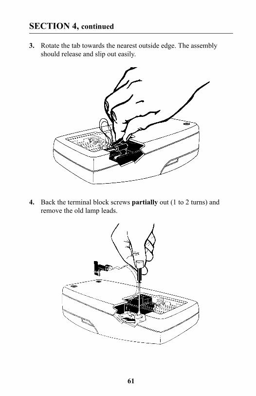
3. Rotate the tab towards the nearest outside edge. The assembly should release and slip out easily.
4. Back the terminal block screws partially out (1 to 2 turns) and remove the old lamp leads.
62
SECTION 4, continued
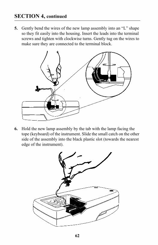
5. Gently bend the wires of the new lamp assembly into an “L” shape so they fit easily into the housing. Insert the leads into the terminal screws and tighten with clockwise turns. Gently tug on the wires to make sure they are connected to the terminal block.
6. Hold the new lamp assembly by the tab with the lamp facing the tope (keyboard) of the instrument. Slide the small catch on the other side of the assembly into the black plastic slot (towards the nearest edge of the instrument).
63
SECTION 4, continued
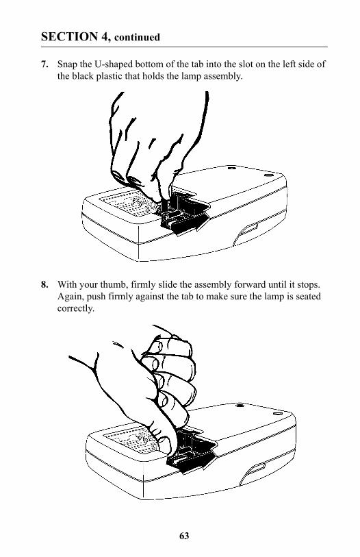
7. Snap the U-shaped bottom of the tab into the slot on the left side of the black plastic that holds the lamp assembly.
8. With your thumb, firmly slide the assembly forward until it stops. Again, push firmly against the tab to make sure the lamp is seated correctly.
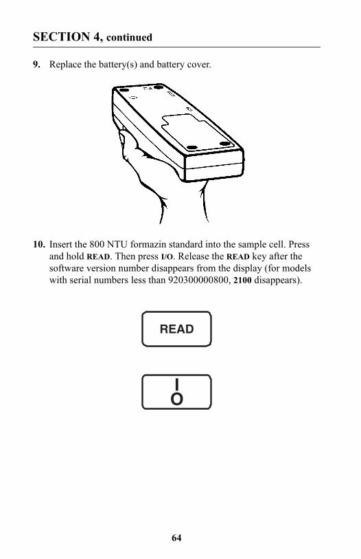
64
SECTION 4, continued
9. Replace the battery(s) and battery cover.
10. Insert the 800 NTU formazin standard into the sample cell. Press and hold READ. Then press I/O. Release the READ key after the software version number disappears from the display (for models with serial numbers less than 920300000800, 2100 disappears).
READ
IO
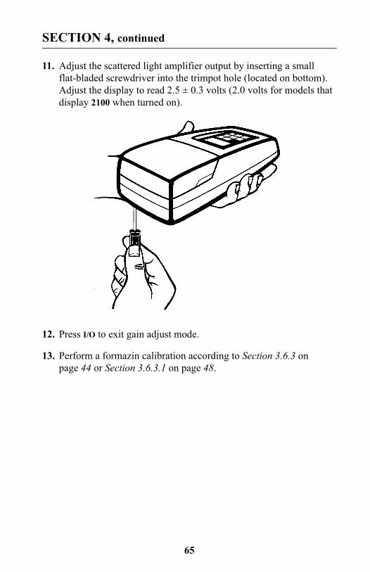
65
SECTION 4, continued
11. Adjust the scattered light amplifier output by inserting a small flat-bladed screwdriver into the trimpot hole (located on bottom). Adjust the display to read 2.5 ± 0.3 volts (2.0 volts for models that display 2100 when turned on).
12. Press I/O to exit gain adjust mode.
13. Perform a formazin calibration according to Section 3.6.3 on page 44 or Section 3.6.3.1 on page 48.

66
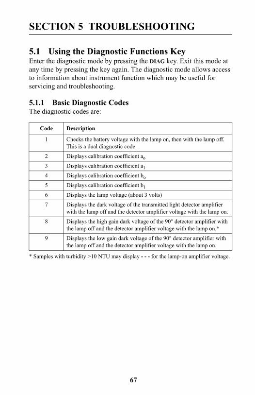
67
SECTION 5 TROUBLESHOOTING
5.1 Using the Diagnostic Functions KeyEnter the diagnostic mode by pressing the DIAG key. Exit this mode at any time by pressing the key again. The diagnostic mode allows access to information about instrument function which may be useful for servicing and troubleshooting.
5.1.1 Basic Diagnostic CodesThe diagnostic codes are:
Code Description
1 Checks the battery voltage with the lamp on, then with the lamp off. This is a dual diagnostic code.
2 Displays calibration coefficient ao
3 Displays calibration coefficient a1
4 Displays calibration coefficient bo
5 Displays calibration coefficient b1
6 Displays the lamp voltage (about 3 volts)
7 Displays the dark voltage of the transmitted light detector amplifier with the lamp off and the detector amplifier voltage with the lamp on.
8 Displays the high gain dark voltage of the 90° detector amplifier with the lamp off and the detector amplifier voltage with the lamp on.*
* Samples with turbidity >10 NTU may display - - - for the lamp-on amplifier voltage.
9 Displays the low gain dark voltage of the 90° detector amplifier with the lamp off and the detector amplifier voltage with the lamp on.
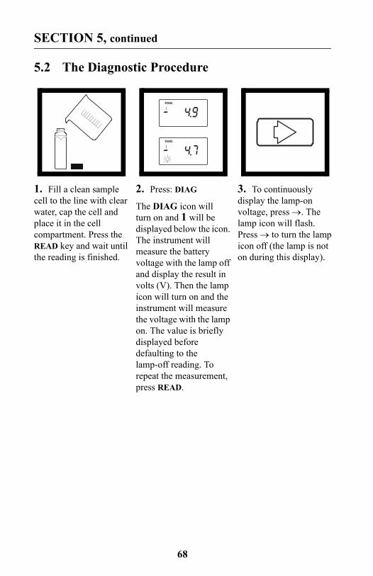
68
SECTION 5, continued
5.2 The Diagnostic Procedure
1. Fill a clean sample cell to the line with clear water, cap the cell and place it in the cell compartment. Press the READ key and wait until the reading is finished.
2. Press: DIAG
The DIAG icon will turn on and 1 will be displayed below the icon. The instrument will measure the battery voltage with the lamp off and display the result in volts (V). Then the lamp icon will turn on and the instrument will measure the voltage with the lamp on. The value is briefly displayed before defaulting to the lamp-off reading. To repeat the measurement, press READ.
3. To continuously display the lamp-on voltage, press →. The lamp icon will flash. Press → to turn the lamp icon off (the lamp is not on during this display).
DIAG
DIAG
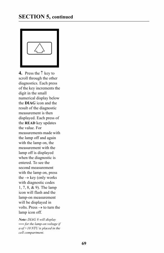
69
SECTION 5, continued
4. Press the ↑ key to scroll through the other diagnostics. Each press of the key increments the digit in the small numerical display below the DIAG icon and the result of the diagnostic measurement is then displayed. Each press of the READ key updates the value. For measurements made with the lamp off and again with the lamp on, the measurement with the lamp off is displayed when the diagnostic is entered. To see the second measurement with the lamp on, press the → key (only works with diagnostic codes 1, 7, 8, & 9). The lamp icon will flash and the lamp-on measurement will be displayed in volts. Press → to turn the lamp icon off.
Note: DIAG 8 will display ---- for the lamp-on voltage if a of >10 NTU is placed in the cell compartment.
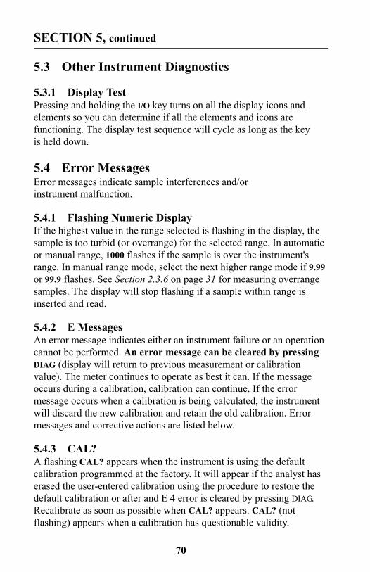
70
SECTION 5, continued
5.3 Other Instrument Diagnostics
5.3.1 Display TestPressing and holding the I/O key turns on all the display icons and elements so you can determine if all the elements and icons are functioning. The display test sequence will cycle as long as the key is held down.
5.4 Error MessagesError messages indicate sample interferences and/or instrument malfunction.
5.4.1 Flashing Numeric DisplayIf the highest value in the range selected is flashing in the display, the sample is too turbid (or overrange) for the selected range. In automatic or manual range, 1000 flashes if the sample is over the instrument's range. In manual range mode, select the next higher range mode if 9.99 or 99.9 flashes. See Section 2.3.6 on page 31 for measuring overrange samples. The display will stop flashing if a sample within range is inserted and read.
5.4.2 E MessagesAn error message indicates either an instrument failure or an operation cannot be performed. An error message can be cleared by pressing DIAG (display will return to previous measurement or calibration value). The meter continues to operate as best it can. If the message occurs during a calibration, calibration can continue. If the error message occurs when a calibration is being calculated, the instrument will discard the new calibration and retain the old calibration. Error messages and corrective actions are listed below.
5.4.3 CAL?A flashing CAL? appears when the instrument is using the default calibration programmed at the factory. It will appear if the analyst has erased the user-entered calibration using the procedure to restore the default calibration or after and E 4 error is cleared by pressing DIAG. Recalibrate as soon as possible when CAL? appears. CAL? (not flashing) appears when a calibration has questionable validity.
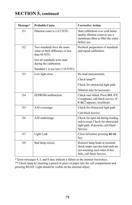
71
SECTION 5, continued
Message* Probable Cause Corrective Action
E1 Dilution water is ≥ 0.5 NTU. Start calibration over with better quality dilution water or use a membrane filter to filter the water before use.
E2 Two standards have the same value or their difference is less than 60 NTU.
Not all standards were read during the calibration.
Standard 1 is too low (<10 NTU).
Recheck preparation of standards and repeat calibration.
E3 Low light error. Re-read measurement.
Check lamp**
Check for obstructed light path.
Dilution may be necessary.
E4 EEPROM malfunction. Check sum failed. Press I/O. If E 4 reappears, call Hach service. If CAL? appears, recalibrate.
E5 A/D overrange. Check for obstructed light path.
Call Hach Service.
E6 A/D underrange. Check for open lid during reading and re-read. Check for obstructed light path. If persists, call Hach Service.
E7 Light Leak. Close lid before pressing READ key.
E8 Bad lamp circuit. Reinsert lamp leads at terminal block-make sure the lead ends are not touching each other.If this fails, call Hach Service.
* Error messages 4, 5, and 6 may indicate a failure in the internal electronics.** Check lamp by inserting a pencil or piece of paper into the cell compartment and pressing READ. Light should be visible on the inserted object.

72

At Hach Company, customer service is an important part of every product we make.
With that in mind, we have compiled the following information for your convenience.
73
GENERAL INFORMATION
74
Replacement Parts & Accessories
REPLACEMENT PARTSDescription Cat. No.StablCal Calibration Set for 2100P, Sealed Vials:
<0.1 NTU, 20 NTU, 100 NTU, and 800 NTU ...................... 26594-05AA Batteries, 4/pkg .................................................................. 19380-04Battery Door ............................................................................. 46005-00Carrying Case ........................................................................... 46506-00Gelex® Standards, set (includes standards and 3 sample cells) 24641-05Instrument Manual.................................................................... 46500-88Lamp Assembly, with leads ...................................................... 46539-00Oiling Cloth .............................................................................. 47076-00Sample Cells, 1 inch, with cap, 6/pkg....................................... 24347-06Silicone Oil, 15 mL..................................................................... 1269-36
OPTIONAL ACCESSORIES AND REAGENTSDeionized Water, 3.78 L ............................................................... 272-17Bath, Ultrasonic, 2.8 L (0.75-gal), w/heater ............................. 24895-00Battery Eliminator, 120 V......................................................... 46079-00Battery Eliminator, 230 V......................................................... 46080-00Filter, 0.2 micron, 10/pkg ......................................................... 23238-10Formazin, 4000 NTU, 500 mL ................................................... 2461-49Formazin, 4000 NTU,100 mL .................................................... 2461-42Hexamethylenetetramine, 500 g ................................................. 1878-34Hydrazine Sulfate, 100 g .............................................................. 742-26NiCad Rechargeable Battery (4 required) ................................ 16077-00
75
Replacement Parts & Accessories, continued
OPTIONAL ACCESSORIES AND REAGENTS, continuedDescription Cat. No.Pipet, TenSette®*, 1-10 mL...................................................... 19700-10Pipet Tips, for 1-10 mL TenSette Pipet, 50/pkg ....................... 21997-96Pipet Tips, for 1-10 mL TenSette Pipet, 1000/pkg ................... 21997-28Pipet, Volumetric, Class A, 1.00 mL ........................................ 14515-35Pipet, Volumetric, Class A, 5.00 mL ........................................ 14515-37Pump, Vacuum, Hand-Operated ............................................... 14283-00Sample Degassing Kit .............................................................. 43975-00Sample Filtration and Degassing Kit........................................ 43975-10StablCal® Calibration Set for 2100P Turbidimeter
<0.1, 20, 100, 800 NTU, 500 mL each ................................. 26594-00<0.1, 20, 100, 800 NTU, 100 mL each ................................. 26594-10
<0.1 NTU** StablCal®*** Stabilized Formazin Standard,100 mL................................................... 26597-42
20 NTU StablCal® Stabilized Formazin Standard, 100 mL..... 26601-42100 NTU StablCal® Stabilized Formazin Standard, 100 mL... 26602-42800 NTU StablCal® Stabilized Formazin Standard, 100 mL... 26605-42Triton-X Solution, 118 mL (4 oz)............................................. 14096-32Volumetric Flask, 100 mL ........................................................ 14574-42Volumetric Flask, 200 mL ........................................................ 14574-45
* TenSette™ is a Hach Company trademark.** <0.1 NTU StablCal® Standard is used in place of dilution waterstandard when performing a calibration. *** StablCal® is a registered trademark of Hach Company.

76
HOW TO ORDER
Information Required
Technical and Customer Service (U.S.A. only)Hach Technical and Customer Service Department personnel are eager to answer questions about our products and their use. Specialists in analytical methods, they are happy to put their talents to work for you.Call 1-800-227-4224 or E-mail [email protected].
International CustomersHach maintains a worldwide network of dealers and distributors. To locate the representative nearest you, send E-mail to intl@hach. com or contact:
In Canada, Latin America, Africa, Asia, Pacific Rim:Telephone: (970) 669-3050; FAX: (970) 669-2932
In Europe, the Middle East, or Mediterranean Africa:HACH Company, c/oDr. Bruno Lange GmbHWillstätterstr. 11D-40549 DüsseldorfGermanyTelephone: +49/[0]211.52.88.0Fax: +49/[0]211.52.88.231
By Telephone: By Mail:6:30 a.m. to 5:00 p.m. MSTMonday through Friday(800) 227-HACH(800-227-4224)By FAX: (970) 669-2932
Hach CompanyP.O. Box 389Loveland, CO 80539-0389U.S.A.
Ordering information by E-mail: [email protected]
• Hach account number (if available) • Billing address
• Your name and phone number • Shipping address
• Purchase order number • Catalog number
• Brief description or model number • Quantity

77
REPAIR SERVICE
Authorization must be obtained from Hach Company before sending any items for repair. Please contact the HACH Service Center serving your location.
In the United States:Hach Company100 Dayton AvenueAmes, Iowa 50010(800) 227-4224 (U.S.A. only)Telephone: (515) 232-2533FAX: (515) 232-1276
In Canada:Hach Sales & Service Canada Ltd.1313 Border Street, Unit 34Winnipeg, ManitobaR3H 0X4(800) 665-7635 (Canada only)Telephone: (204) 632-5598FAX: (204) 694-5134E-mail: [email protected]
In Latin America, the Caribbean, the Far East, theIndian Subcontinent, Africa, Europe, or the Middle East:Hach Company World HeadquartersP.O. Box 389Loveland, Colorado, 80539-0389U.S.A.Telephone: (970) 669-3050FAX: (970) 669-2932E-mail: [email protected]
78
WARRANTY
Hach warrants most products against defective materials or workmanship for at least one year from the date of shipment; longer warranties may apply to some items.
HACH WARRANTS TO THE ORIGINAL BUYER THAT HACH PRODUCTS WILL CONFORM TO ANY EXPRESS WRITTEN WARRANTY GIVEN BY HACH TO THE BUYER. EXCEPT AS EXPRESSLY SET FORTH IN THE PRECEDING SENTENCE, HACH MAKES NO WARRANTY OF ANY KIND WHATSOEVER WITH RESPECT TO ANY PRODUCTS. HACH EXPRESSLY DISCLAIMS ANY WARRANTIES IMPLIED BY LAW, INCLUDING BUT NOT BINDING TO ANY WARRANTY OF MERCHANTABILITY OR FITNESS FOR A PARTICULAR PURPOSE.
LIMITATION OF REMEDIES: Hach shall, at its option, replace or repair nonconforming products or refund all amounts paid by the buyer. THIS IS THE EXCLUSIVE REMEDY FOR ANY BREACH OF WARRANTY.
LIMITATION OF DAMAGES: IN NO EVENT SHALL HACH BE LIABLE FOR ANY INCIDENTAL OR CONSEQUENTIAL DAMAGES OF ANY KIND FOR BREACH OF ANY WARRANTY, NEGLIGENCE, ON THE BASIS OF STRICT LIABILITY, OR OTHERWISE.
This warranty applies only to Hach products purchased and delivered in the United States.
Catalog descriptions, pictures and specification, although accurate to the best of our knowledge, are not a guarantee or warranty.
For a complete description of Hach Company’s warranty policy, request a copy of our Terms and Conditions of Sale for U.S. Sales from our Customer Service Department.