Embed Size (px)
Citation preview
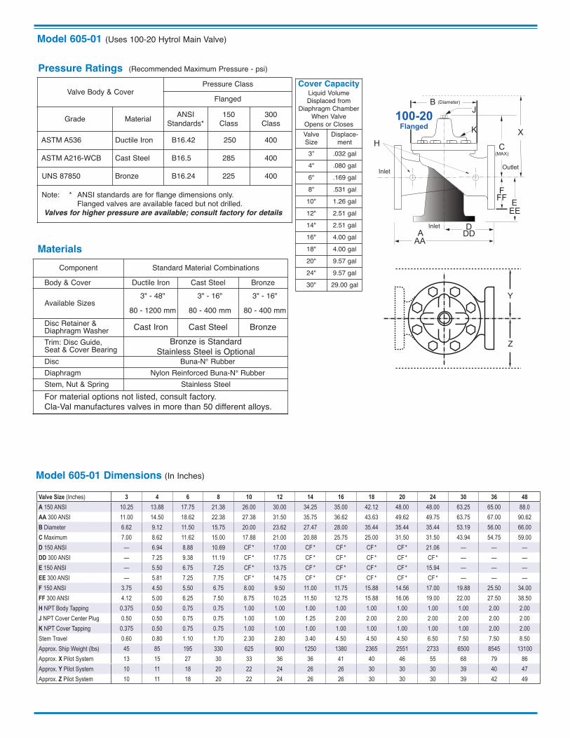
On a chilled water circulating loop system the 605-01 DifferentialPressure Relief Valve is installed between loop supply and returnlines to maintain a constant differential across the loop. The loopdifferential pressure remains constant regardless of the loopdemand change thereby increasing cooling system efficiency.
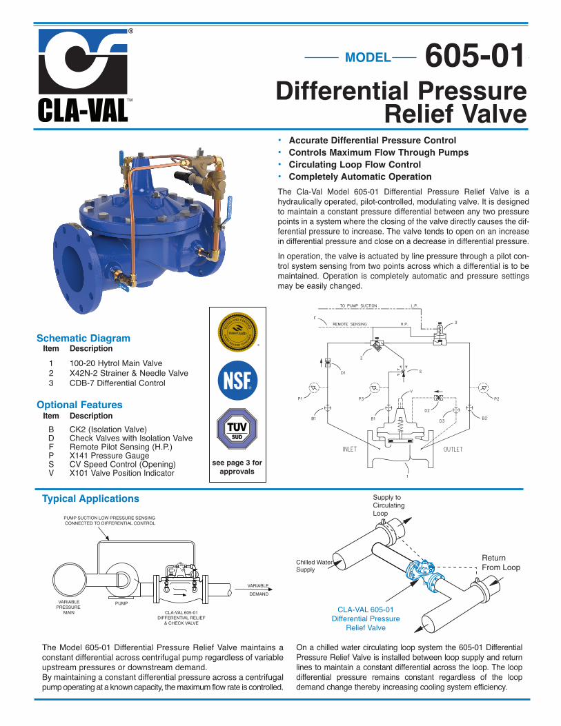
• Accurate Differential Pressure Control• Controls Maximum Flow Through Pumps• Circulating Loop Flow Control• Completely Automatic OperationThe Cla-Val Model 605-01 Differential Pressure Relief Valve is ahydraulically operated, pilot-controlled, modulating valve. It is designedto maintain a constant pressure differential between any two pressurepoints in a system where the closing of the valve directly causes the dif-ferential pressure to increase. The valve tends to open on an increasein differential pressure and close on a decrease in differential pressure.In operation, the valve is actuated by line pressure through a pilot con-trol system sensing from two points across which a differential is to bemaintained. Operation is completely automatic and pressure settingsmay be easily changed.
Schematic Diagram Item Description 1 100-20 Hytrol Main Valve 2 X42N-2 Strainer & Needle Valve 3 CDB-7 Differential Control
Optional Features Item Description B CK2 (Isolation Valve) D Check Valves with Isolation Valve F Remote Pilot Sensing (H.P.) P X141 Pressure Gauge S CV Speed Control (Opening) V X101 Valve Position Indicator
The Model 605-01 Differential Pressure Relief Valve maintains aconstant differential across centrifugal pump regardless of variableupstream pressures or downstream demand.By maintaining a constant differential pressure across a centrifugalpump operating at a known capacity, the maximum flow rate is controlled.
Supply toCirculatingLoop
Chilled Water Supply
Return From Loop
CLA-VAL 605-01Differential Pressure
Relief Valve
VARIABLEPRESSURE
MAIN
PUMP
CLA-VAL 605-01DIFFERENTIAL RELIEF
& CHECK VALVE
VARIABLE
DEMAND
PUMP SUCTION LOW PRESSURE SENSING CONNECTED TO DIFFERENTIAL CONTROL
Typical Applications
MODEL 605-01Differential Pressure
Relief Valve
see page 3 forapprovals
SUD
Model 605-01 (Uses 100-20 Hytrol Main Valve)
Cover CapacityLiquid VolumeDisplaced from
Diaphragm ChamberWhen Valve
Opens or ClosesValveSize
Displace-ment
3” .032 gal4" .080 gal6" .169 gal8" .531 gal
10" 1.26 gal12" 2.51 gal14" 2.51 gal16" 4.00 gal18" 4.00 gal20" 9.57 gal24" 9.57 gal30" 29.00 gal
EE
D
E
InletDD
AA
X
100-20Flanged
F
A
C(MAX)
K
J
H
InletOutlet
FF
B (Diameter)
Materials
Y
Z
Pressure Ratings (Recommended Maximum Pressure - psi)
Valve Body & CoverPressure Class
Flanged
Grade Material ANSIStandards*
150 Class
300 Class
ASTM A536 Ductile Iron B16.42 250 400
ASTM A216-WCB Cast Steel B16.5 285 400
UNS 87850 Bronze B16.24 225 400
Note: * ANSI standards are for flange dimensions only. Flanged valves are available faced but not drilled.Valves for higher pressure are available; consult factory for details
Component Standard Material CombinationsBody & Cover Ductile Iron Cast Steel Bronze
Available Sizes3" - 48"
80 - 1200 mm3" - 16"
80 - 400 mm3" - 16"
80 - 400 mmDisc Retainer &Diaphragm Washer Cast Iron Cast Steel BronzeTrim: Disc Guide, Seat & Cover Bearing
Bronze is StandardStainless Steel is Optional
Disc Buna-N® RubberDiaphragm Nylon Reinforced Buna-N® RubberStem, Nut & Spring Stainless SteelFor material options not listed, consult factory.Cla-Val manufactures valves in more than 50 different alloys.
Model 605-01 Dimensions (In Inches)
Valve Size (Inches) 3 4 6 8 10 12 14 16 18 20 24 30 36 48A 150 ANSI 10.25 13.88 17.75 21.38 26.00 30.00 34.25 35.00 42.12 48.00 48.00 63.25 65.00 88.0AA 300 ANSI 11.00 14.50 18.62 22.38 27.38 31.50 35.75 36.62 43.63 49.62 49.75 63.75 67.00 90.62B Diameter 6.62 9.12 11.50 15.75 20.00 23.62 27.47 28.00 35.44 35.44 35.44 53.19 56.00 66.00C Maximum 7.00 8.62 11.62 15.00 17.88 21.00 20.88 25.75 25.00 31.50 31.50 43.94 54.75 59.00D 150 ANSI — 6.94 8.88 10.69 CF * 17.00 CF * CF * CF * CF * 21.06 — — —DD 300 ANSI — 7.25 9.38 11.19 CF * 17.75 CF * CF * CF * CF * CF * — — —E 150 ANSI — 5.50 6.75 7.25 CF * 13.75 CF * CF * CF * CF * 15.94 — — —EE 300 ANSI — 5.81 7.25 7.75 CF * 14.75 CF * CF * CF * CF * CF * — — —F 150 ANSI 3.75 4.50 5.50 6.75 8.00 9.50 11.00 11.75 15.88 14.56 17.00 19.88 25.50 34.00FF 300 ANSI 4.12 5.00 6.25 7.50 8.75 10.25 11.50 12.75 15.88 16.06 19.00 22.00 27.50 38.50H NPT Body Tapping 0.375 0.50 0.75 0.75 1.00 1.00 1.00 1.00 1.00 1.00 1.00 1.00 2.00 2.00J NPT Cover Center Plug 0.50 0.50 0.75 0.75 1.00 1.00 1.25 2.00 2.00 2.00 2.00 2.00 2.00 2.00K NPT Cover Tapping 0.375 0.50 0.75 0.75 1.00 1.00 1.00 1.00 1.00 1.00 1.00 1.00 2.00 2.00Stem Travel 0.60 0.80 1.10 1.70 2.30 2.80 3.40 4.50 4.50 4.50 6.50 7.50 7.50 8.50Approx. Ship Weight (lbs) 45 85 195 330 625 900 1250 1380 2365 2551 2733 6500 8545 13100Approx. X Pilot System 13 15 27 30 33 36 36 41 40 46 55 68 79 86Approx. Y Pilot System 10 11 18 20 22 24 26 26 30 30 30 39 40 47Approx. Z Pilot System 10 11 18 20 22 24 26 26 30 30 30 39 42 49
EE
D
E
InletDD
AA
X
100-20Flanged
F
A
C(MAX)
K
J
H
InletOutlet
FF
B (Diameter)
Model 605-01 Dimensions (In mm)
Y
Z
Valve Size (mm) 80 100 150 200 250 300 350 400 450 500 600 750 900 1200A 150 ANSI 260 353 451 543 660 762 870 889 1070 1219 1219 1607 1651 2235AA 300 ANSI 279 368 473 568 695 800 908 930 1108 1260 1263 1619 1702 2302B Diameter 168 232 292 400 508 600 698 711 900 900 900 1351 1422 1676C Maximum 178 219 295 381 454 533 530 654 635 800 800 1116 1391 1499D 150 ANSI — 176 226 272 CF * 432 CF * CF * CF * CF * 535 — — —DD 300 ANSI — 184 238 284 CF * 451 CF * CF * CF * CF * CF * — — —E 150 ANSI — 140 171 184 CF * 349 CF * CF * CF * CF * 405 — — —EE 300 ANSI — 148 184 197 CF * 368 CF * CF * CF * CF * CF * — — —F 150 ANSI 95 114 140 171 203 241 279 289 403 370 432 505 648 864FF 300 ANSI 105 127 159 191 222 260 292 324 403 408 483 559 699 978H NPT Body Tapping 0.375 0.50 0.75 0.75 1.00 1.00 1.00 1.00 1.00 1.00 1.00 1.00 2.00 2.00J NPT Cover Center Plug 0.50 0.50 0.75 0.75 1.00 1.00 1.25 2.00 2.00 2.00 2.00 2.00 2.00 2.00K NPT Cover Tapping 0.375 0.50 0.75 0.75 1.00 1.00 1.00 1.00 1.00 1.00 1.00 1.00 2.00 2.00Stem Travel 15 20 28 43 58 71 86 86 114 114 114 165 191 216Approx. Ship Weight (kgs) 20 39 89 150 284 409 568 627 681 1157 1249 2951 3876 5942Approx. X Pilot System 331 381 686 762 839 915 915 1042 1016 1169 1397 1728 2007 2185Approx. Y Pilot System 254 280 458 508 559 610 661 661 762 762 762 991 1016 1194Approx. Z Pilot System 254 280 458 508 559 610 661 661 762 762 762 991 1067 1245
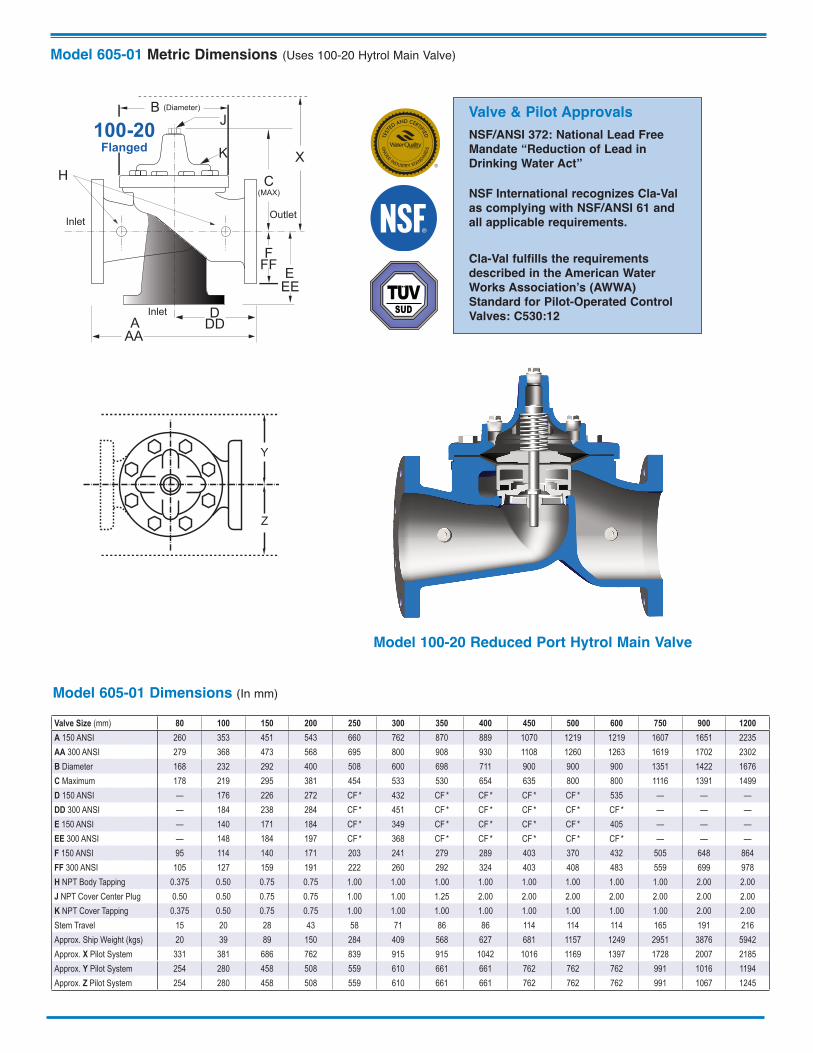
Cla-Val fulfills the requirementsdescribed in the American WaterWorks Association’s (AWWA)Standard for Pilot-Operated ControlValves: C530:12
NSF International recognizes Cla-Valas complying with NSF/ANSI 61 andall applicable requirements.
NSF/ANSI 372: National Lead FreeMandate “Reduction of Lead inDrinking Water Act”
Valve & Pilot Approvals
SUD
I
Model 605-01 Metric Dimensions (Uses 100-20 Hytrol Main Valve)
Model 100-20 Reduced Port Hytrol Main Valve
E-605-01 (R-07/2017)
605-01Valve
Selection
100-20 Pattern: Globe (G), Angle (A), End Connections: Flanged (F) Indicate Available Sizes
Inches 3 4 6 8 10 12 14 16 18 20 24 30 36 42 48
mm 80 100 150 200 250 300 350 400 450 500 600 750 900 1000 1200
Basic Valve100-20
Pattern G G, A G, A G, A G G G G G G G G G G G
End Detail F F F F F F F F F F F F F F F
Suggested Flow (gpm)
Maximum 260 580 1025 2300 4100 6400 9230 9230 16500 16500 16500 28000 33500 33500 33500
MaximumSurge 440 990 1760 3970 7050 11000 15900 15900 28200 28200 28200 56500 58600 58600 58600
Suggested Flow
(Liters/Sec)
Maximum 16 37 65 145 258 403 581 581 1040 1040 1040 1764 2115 2115 2115
MaximumSurge 28 62 111 250 444 693 1002 1002 1777 1777 1777 3560 3700 3700 3700
100-20 Series is the reduced internal port size version of the 100-01 Series.
When Ordering, Specify: 1. Catalog No. 605-01 2. Valve Size 3. Pattern - Globe or Angle 4. Pressure Class 5. Threaded or Flanged 6. Trim Material 7. Adjustment Range 8. Desired Options 9. When Vertically Installed
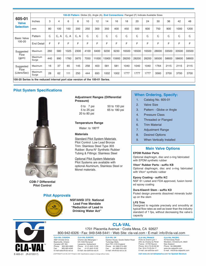
Pilot System SpecificationsAdjustment Ranges (DifferentialPressure) 0 to 7 psi 50 to 150 psi 5 to 25 psi 65 to 180 psi 20 to 80 psi
Temperature Range Water: to 180°FMaterialsStandard Pilot System Materials Pilot Control: Low Lead BronzeTrim: Stainless Steel Type 303 Rubber: Buna-N® Synthetic RubberTubing & Fittings: Stainless SteelOptional Pilot System MaterialsPilot Systems are available withoptional Aluminum, Stainless Steel orMonel materials.
CLA-VAL EUROPEChemin des Mésanges 1CH-1032 Romanel/Lausanne, SwitzerlandPhone: 41-21-643-15-55Fax: 41-21-643-15-50E-mail: [email protected]
CLA-VAL FRANCEPorte du Grand Lyon 1ZAC du Champ du PérierFrance - 01700 NeyronPhone: 33-4-72-25-92-93Fax: 33-4-72-25-04-17E-mail: [email protected]
CLA-VAL1701 Placentia Avenue • Costa Mesa, CA 92627
800-942-6326 Fax: 949-548-5441 Web Site: cla-val.com E-mail: [email protected]
©COPYRIGHT CLA-VAL 2017 Printed in USA Specifications subject to change without notice. visit www.cla-val-latinamerica.com for Spanish literature
CLA-VAL CANADA4687 Christie DriveBeamsville, OntarioCanada L0R 1B4Phone: 905-563-4963Fax: 905-563-4040E-mail [email protected]
CLA-VAL UKDainton House, Goods Station RoadTunbridge Wells Kent TN1 2 DH EnglandPhone: 44-1892-514-400Fax: 44-1892-543-423E-mail: [email protected]
CLA-VAL PACIFIC45 Kennaway RoadWoolston, Christchurch, 8023New ZealandPhone: 64-39644860www.cla-valpacific.comE-mail: [email protected]
Main Valve OptionsEPDM Rubber PartsOptional diaphragm, disc and o-ring fabricatedwith EPDM synthetic rubberViton® Rubber Parts - suffix KBOptional diaphragm, disc and o-ring fabricatedwith Viton® synthetic rubber
Epoxy Coating - suffix KCNSF 61 Listed and FDA approved, fusion bond-ed epoxy coatingDura-Kleen® Stem - suffix KDFluted design prevents dissolved minerals build-up on the stemLFS Trim Designed to regulate precisely and smoothly attypical flow rates as well as lower than the industrystandard of 1 fps, without decreasing the valve’scapacity
CDB-7 DifferentialPilot Control
Pilot ApprovalsNSF/ANSI 372: National
Lead Free Mandate“Reduction of Lead inDrinking Water Act”


![Codigos de Falla de JD 9230[1]](https://img.pdfslide.net/doc/110x75/577c845b1a28abe054b8959e/codigos-de-falla-de-jd-92301.jpg)


